stress wave propagation in electro-magneto-elastic plate
TRANSCRIPT

International Journal of Scientific & Engineering Research Volume 3, Issue 8, August-2012 1 ISSN 2229-5518
IJSER © 2012
http://www.ijser.org
Stress Wave propagation in Electro-Magneto-Elastic plate of arbitrary cross-sections
P. Ponnusamy
Department of Mathematics
Government Arts College, Coimbatore-641 018, Tamilnadu, INDIA.
+91 9791 532046
Abstract
Wave propagation in electro-magneto-elastic plate of arbitrary cross-sections is studied using Fourier Expansion Collocation
Method. A mathematical model is developed to study the wave propagation in a electro-magneto-elastic plate of arbitrary cross-
sections using the three- dimensional theory of elasticity. The frequency equations are obtained from the boundary conditions, since
the boundary is irregular in shape; it is difficult to satisfy the boundary conditions along the surface of the plate directly. Hence, the
Fourier Expansion Collocation Method is applied along the boundary to satisfy the boundary conditions. The roots of the frequency
equations are obtained by using the secant method, applicable for complex roots. The computed non-dimensional frequencies are
plotted in the form of dispersion curves and its characteristics are analyzed.
Keyword: Vibrations of cylinders, Generalized thermo-elastic cylinder/plate, Mechanical vibrations, Stress-strain analysis, Electro-
magneto-elastic materials, Piezoelectric plate.
I. Introduction
The wave propagation in magneto-electro-elastic materials has gained considerable importance since last decade. The electro-
magneto-elastic materials exhibit a desirable coupling effect between electric and magnetic fields, which are useful in smart
structure applications. These materials have the capacity to convert one form of energy namely, magnetic, electric and mechanical
energy to another form of energy. The composite consisting of piezoelectric and piezomagnetic components have found increasing
application in engineering structures, particularly in smart/intelligent structure system. The magneto-electro-elastic materials are
used as magnetic field probes, electric packing, acoustic, hydrophones, medical, ultrasonic image processing, sensors and actuators
with the responsibility of magnetic-electro-mechanical energy conversion.
A method, for solving wave propagation in arbitrary and polygonal cross-sectional plates and to find out the phase velocities in
different modes of vibrations namely longitudinal, torsional and flexural, by constructing frequency equations was devised by

International Journal of Scientific & Engineering Research Volume 3, Issue 8, August-2012 2 ISSN 2229-5518
IJSER © 2012
http://www.ijser.org
Nagaya [1-3]. He formulated the Fourier expansion collocation method for this purpose and the same method is used in this
problem.The three-dimensional behavior of magnetoelectroelastic laminates under simple support has been studied by Pan [4] and
Pan and Heyliger [5]. An exact solution for magnetoelectroelastic laminates in cylindrical bending has also been obtained by Pan
and Heyliger [6]. Pan and Han [7] studied the exact solution for functionally graded and layered magneto-electro-elastic plates.
Feng and Pan [8] discussed the dynamic fracture behavior of an internal interfacial crack between two dissimilar magneto-electro-
elastic plates. Buchanan [9] developed the free vibration of an infinite magneto-electro-elastic cylinder. Dai and Wang [10,11] have
studied thermo-electro-elastic transient responses in piezoelectric hollow structures and hollow cylinder subjected to complex
loadings. Later Kong et al [12] presented the thermo-magneto-dynamic stresses and perturbation of magnetic field vector in a non-
homogeneous hollow cylinder. Annigeri et al [13-15], studied respectively, the free vibration of clamped-clamped magneto-electro-
elastic cylindrical shells, free vibration behavior of multiphase and layered magneto-electro-elastic beam, free vibrations of simply
supported layered and multiphase magneto-electro-elastic cylindrical shells. Hon et al [16] analyzed a point heat source on the
surface of a semi-infinite transversely isotropic electro-magneto-thermo-elastic materials. Sharma and Mohinder Pal [17] developed
the Rayleigh-Lamb waves in magneto-thermo-elastic homogeneous isotropic plate. Later Sharma and Thakur [18] studied the effect
of rotation on Rayleigh-Lamb waves in magneto-thermo-elastic media. Gao and Noda [19] presented the thermal-induced interfacial
cracking of magnetoelectroelastic materials. Bin et al [20] studied the wave propagation in non-homogeneous magneto-electro-
elastic plates. Ponnusamy [21-23] have studied the wave propagation in generalized thermo-elastic cylinder of arbitrary cross
section, thermoelastic and generalized thermo elastic plates of arbitrary and polygonal cross-sections respectively. Ponnusamy and
Rajagopal [24,25] have studied, the wave propagation in a generalized thermo elastic solid cylinder of arbitrary cross-section and in
a homogeneous transversely isotropic thermo elastic solid cylinder of polygonal cross-sections respectively using the Fourier
expansion collocation method.
2. Formulation of the Problem
We consider a homogeneous transversely isotropic magneto-electro-elastic plate of arbitrary cross-sections. The system
displacements and stresses are defined by the cylindrical co-ordinates r, and z. The governing equations of motion, electric and
magnetic conduction equation in the absence of body force are

International Journal of Scientific & Engineering Research Volume 3, Issue 8, August-2012 3 ISSN 2229-5518
IJSER © 2012
http://www.ijser.org
1 1
, , , ,rr r r rz z rr ttr r u
1 1
, , , ,2r r z z r ttr r v
1 1
, , , ,rz r z zz z rz ttr r w . (1)
The electric conduction equation is
1 1
, , , , 0r r r z zD r D r D D
. (2)
The Magnetic conduction equation is
1 1
, , , 0r r r z zB r B r B B
. (3)
Where
11 12 13 31 31rr rr zz z zc e c e c e e E q H
12 11 13 31 31rr zz z zc e c e c e e E q H
13 13 33 33 33zz rr zz z zc e c e c e e E q H
44 15 152z zc e e E q H
44 15 152rz rz r rc e e E q H (4)
15 11 112r rz r rD e e E m H
15 11 112 zD e e E m H
31 33 33 33z rr zz z zD e e e e e E m H (5)
and
662r rc e

International Journal of Scientific & Engineering Research Volume 3, Issue 8, August-2012 4 ISSN 2229-5518
IJSER © 2012
http://www.ijser.org
15 11 112r rz r rB q e m E H
15 11 112 zB q e m E H
31 33 33 33z rr zz z zB q e e q e m E H . (6)
Where , , , ,rr r rz z are the stress components, 11 12 13 33 44, , , ,c c c c c and 66 11 12 2c c c are elastic constants, 11 33,
are the dielectric constants, 11 33, are the magnetic permeability coefficients, 31 33 15, ,e e e are the piezoelectric material
coefficients, 31 33 15, ,q q q are the piezomagnetic material coefficients, 11 33,m m are the magneto-electric material coefficients, is
the mass density of the material, ,rD D and zD are the electric displacements, ,rB B and zB are the magnetic displacements
components.
The strain ije are related to the displacements corresponding to the cylindrical coordinates , ,r z are given by
,rr re u , 1
,e r v u , ,zz ze w
1
, ,
1
2z ze v r w
, 1 1
, ,
1
2r re r u v r v
, , ,
1
2rz z re u w (7)
where u, v and w are the mechanical displacements along the radial, circumferential and axial directions respectively.
The Electric field vector , , ,iE i r z is related to the electric potential E as
r
EE
r
,
1 EE
r
and
,z
EE
z
(8)
Similarly, the magnetic field vector , , ,iH i r z is related to the magnetic potential H as
r
HH
r
,
1 HH
r
and
z
HH
z
(9)
Substituting the Eqs. (4)-(9) in the Eqs. (1)-(3), we obtain the set of displacement equations as follows;

International Journal of Scientific & Engineering Research Volume 3, Issue 8, August-2012 5 ISSN 2229-5518
IJSER © 2012
http://www.ijser.org
1 2 2 1 2
11 , , 66 , 44 , 66 12 , 11 66 ,
44 13 , 31 15 , 31 15 , ,
rr r zz r
rz rz rz tt
c u r u r u c r u c u c c r v c c r v
c c w e e E q q H u
(10a)
1 2 1 2 2
66 12 , 11 66 , 66 , , 44 , 11 ,
1 1 1
44 13 , 31 15 , 31 15 , ,
r rr r zz
z z z tt
c c r u c c r u c v r v r v c v c r v
c c r w e e r E q q r H v
(10b)
1 1 1
44 13 , , , 44 , , , 33 , 33 ,
1 2 1 2
33 , 15 , , , 15 , , , ,
rz z z rr r zz zz
zz rr r rr r tt
c c u r u r v c w r w w c w e E
q H e E r E r E q H r H r H w
(10c)
1 2 1 1
15 , , , 31 15 , , , 33 , 33 ,
1 2 1 2
33 , 11 , , , 11 , , , 0
rr r rz z z zz zz
zz rr r rr r
e w r w r w e e u r u r v e w E
m H E r E r E m H r H r H
(10d)
1 2 1 1
15 , , , 31 15 , , , 33 , 33 ,
1 2 1 2
33 , 11 , , , 11 , , , 0
rr r rz z z zz zz
zz rr r rr r
q w r w r w q q u r u r v q w m E
H m E r E r E H r H r H
(10e)
3. Solution of the Problem
The Eq. (10) is a coupled partial differential equation with three displacements and magnetic and electric conduction components.
To uncouple the Eq. (10), we follow Sharma and Sharma [26] and seek the solutions in the following form
1 1
, ,, , n n rn n n ru r r
1 1
, ,, , n n rn n n rv r r
,, n zn n zW W W
,, n zn n zE E E
,, n zn n zH H H (11)

International Journal of Scientific & Engineering Research Volume 3, Issue 8, August-2012 6 ISSN 2229-5518
IJSER © 2012
http://www.ijser.org
where 1 2n for 0n , 1n for 1n , ,n r , ,n r , ,nW r , ,nE r , ,nH r are the displacement
potentials for the symmetric mode and ,n r , ,n r , ,nW r , ,nE r and ,nH r are the displacement
potentials for the anti symmetric mode of vibrations.
Substituting the Eq.(11) in (10), we get
2 2
2
11 1 44 13 44 31 15 31 152 20n n n
n
W E Hc c c c e e q q
z t z z z
(12a)
2 2
2
11 1 44 13 44 31 15 31 152 20n n n
n
W E Hc c c c e e q q
z t z z z
(12b)
2 2 2
2 2 2
44 1 33 13 44 1 15 1 332 2 2
22
15 1 33 20
n n n
n
c c W c c e e Ez t z z
q q Hz
(12c)
2 2 2
2 2 2 2
15 1 33 31 15 1 11 1 33 11 1 332 2 20n n n ne e W e e E m m H
z z z z
(12d)
2 2 2
2 2 2 2
15 1 33 31 15 1 11 1 33 11 1 332 2 20n n n nq q W q q m m E H
z z z
(12e)
and
2 22
66 1 44 2 20nc c
z t
(13)
where
2 22
1 2 2 2
1 1
r r r r

International Journal of Scientific & Engineering Research Volume 3, Issue 8, August-2012 7 ISSN 2229-5518
IJSER © 2012
http://www.ijser.org
The Eq. (13) gives purely transverse wave, which is not affected by the electric and magnetic field. This wave is polarized in the
planes perpendicular to the z-axis and it may be referred as the simple harmonic wave. We assume that the disturbance is time
harmonic through the factor i te , is angular velocity and hence, the system of Eqs. (12a)-(12e) becomes
2
2 2
11 1 44 13 44 31 15 31 1520n n n
n
W E Hc c c c e e q q
z z z z
(14a)
2
2 2
11 1 44 13 44 31 15 31 1520n n n
n
W E Hc c c c e e q q
z z z z
(14b)
2 2
2 2 2 2
44 1 33 13 44 1 15 1 332 2
22
15 1 33 20
n n n
n
c c W c c e e Ez z z
q q Hz
(14c)
2 2 2
2 2 2 2
15 1 33 31 15 1 11 1 33 11 1 332 2 20n n n ne e W e e E m m H
z z z z
(14d)
2 2 2
2 2 2 2
15 1 33 31 15 1 11 1 33 11 1 332 2 20n n n nq q W q q m m E H
z z z z
(14e)
We consider the free vibration of arbitrary cross-sectional plate, so we assume that
, , , cos cosn nr z t r m z L n
, , , sin cosn nW r z t W r m z L n
44
33
, , , sin cosn n
cE r z t E r m z L n
q
44
33
, , , sin cosn n
cH r z t H r m z L n
q
(15)

International Journal of Scientific & Engineering Research Volume 3, Issue 8, August-2012 8 ISSN 2229-5518
IJSER © 2012
http://www.ijser.org
and
, , , cos sinn nr z t r m z L n (16)
Introducing the dimensionless quantities such as
rx
a ,
Lt a , m L
44
ijij
cc
c ,
33
ijij
ee
e ,
33
ij
ij
q ,
2 22
44
a
c
,
44
33 33
ijij
m cm
q e ,
44
2
33
ij
ij
c
q
,
44
2
33
ijij
c
e
, L is the length of the plate and using the Eqs. (15) and (16) in the Eqs. (14) and (13), we get
2 2 211 13 31 152 31 15
1 0L n L n L n L nc t c t W e e t E q q t H
2 2 2 2 2 2 2 233 13 152 2 2 215
1 0L n L n L n L nc t W c t e t E q t H
2 2 2 2 2 2 215 31 15 33 11 33 112 2 2 2 0L n L n L n L ne t W e e t t E m t m H
2 2 2 2 2 2 233 11 33 112 2 2 215 31 15
0L n L n L n L nq t W q q t m t m E t H (17)
and
2 2 266 2 0L nc t (18)
Where
2 22
2 2 2
1 n
x x x x
.
The Eq. (17) is a homogeneous linear equation which has a trivial solution to obtain the non-trivial solution, the determinant of the
coefficient matrix is equal to zero. Thus we get

International Journal of Scientific & Engineering Research Volume 3, Issue 8, August-2012 9 ISSN 2229-5518
IJSER © 2012
http://www.ijser.org
211 2 1 2 3 4
2 2 2 2 2 2152 2 2 5 2 215
2 2 2 2 215 11 113 2 2 6 2 7 2
2 2 2 2 211 114 2 2 7 2 8 215
, , , 0
L L L
L L L
n n n n
L L
L L
c g g t g t g t
g t g e t q tW E H
g t e t g g m
g t q t g m g
(19)
where
2 2
1 Lg t , 132 1g c , 31 153g e e , 4 31 15g q q , 2 2
335 Lg c t ,
2336 Lg t ,
2337 Lg m t ,
2
338 Lg t
Evaluating the determinant given in Eq. (19), we obtain the partial differential equation of the form
8 6 4 2
2 2 2 2 , , , 0n n n nA B C D E W E H (20)
where
2 2
11 11 15 11 11 1511 1115 152A c q e m m e q

International Journal of Scientific & Engineering Research Volume 3, Issue 8, August-2012 10 ISSN 2229-5518
IJSER © 2012
http://www.ijser.org
22
11 11 11 11 11 15 15 1111 11 116 8 7 5 8
2 22
11 11 15 11 15 11 11 1511 116 7 115 15 15 15 15
22
11 11 15 1111 112 2 3 4
2 2
2 2 2
L
L
L
B c g g g m g m e g e t m
q g q t m g e q g q e m m e q
g t g m e g g m
11 113 415
215 11 11 1511 113 2 3 4 3 415 15 15
211 15 11 11 11 15 154 2 3 4 3 415 15
L
L
q g m g
g t g e m q g g m q g q g e
g t g m e q g m g e g q g e
2 211 11 11 15116 8 7 5 6 8 7 8 7 7 815
24
11 11 11 11 11 1111 11 111 6 8 7 5
2 215 15 11 11 11 15118 6 715 15 15
2
2 2
2 2
2 2 2
L
L
L L
L
C c g g g g g g g m t e g g q g g
t m g g g g m g m
e g e t m q g q t m g e q
g t
211 11 15112 6 8 7 3 8 4 7 3 7 4 615
2 2 211 11 11 15 1111 113 4 3 4 3 2 8 7 3 815
2 211 15114 7 5 3 4 3 4 3 415 15
2154 2 7 6
2
L L L
L L
L
g g g g m e g g g g q g g g g
t g g m g m g g t g g e g q t m g g
g g g g g m q t g g t g q g e
g t g g e g
211 11 11 113 7 4 6 5 3 415
2 215 153 4 3 415
L
L L
q t m g g g g g g m g
e t g g t g q g e
2 4 2 211 5 6 8 7 8 7 6 4 2 7 6
4 211 11115 3 7 4 6 3 4 1 6 8 7 5 6 8 7
2 415 11 11118 7 7 815
2 2 2
2 2 6 8 7 3 8 4 7 3 7
2
2
2 2
L L L
L
L L
L L
D c g g g g t g g g g t g t g g
g g g g g t g g g g g g g g g g m
t e g g q g g t m
g t g g g g t g g g g g g
4 6
2 2 4
3 2 8 7 5 3 8 4 7 3 4L L L
g g
g t g t g g g g g g g t g g
2 4
1 5 6 8 7 8 7 62LE g g g g g t g g g
Solving the Eq. (20), the solution for the symmetric mode obtained as
4
*
1
cosn in n i
i
A J r n
4
*
1
cosn i in n i
i
W a A J r n
4
*
1
cosn i in n i
i
E b A J r n
International Journal of Scientific & Engineering Research Volume 3, Issue 8, August-2012 11 ISSN 2229-5518
IJSER © 2012
http://www.ijser.org
4
*
1
cosn i in n i
i
H c A J r n
(21a)
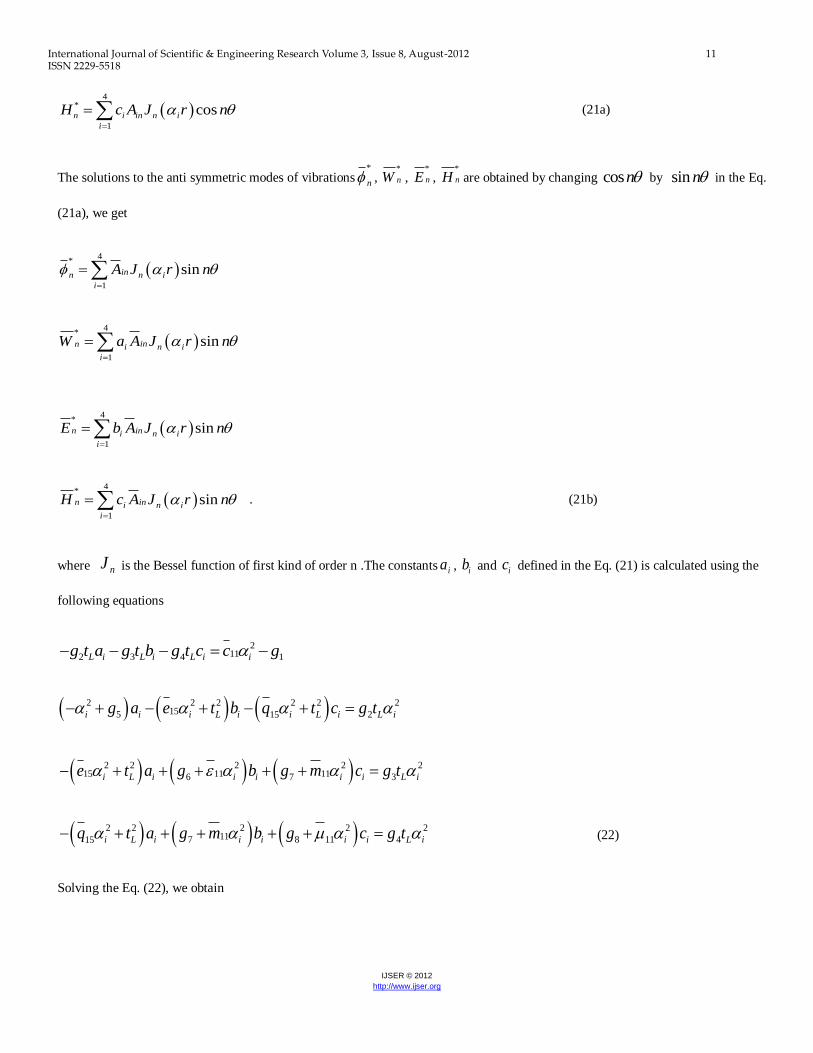
The solutions to the anti symmetric modes of vibrations*
n , *
nW , *
nE , *
nH are obtained by changing cosn by sin n in the Eq.
(21a), we get
4
*
1
sininn n i
i
A J r n
4
*
1
sinn ini n i
i
E b A J r n
4
*
1
sinn ini n i
i
H c A J r n
. (21b)
where nJ is the Bessel function of first kind of order n .The constants ia , ib and ic defined in the Eq. (21) is calculated using the
following equations
2112 3 4 1L i L i L i ig t a g t b g t c c g
2 2 2 2 2 2155 215i i i L i i L i L ig a e t b q t c g t
2 2 2 2 215 11 116 7 3i L i i i i i L ie t a g b g m c g t
2 2 2 2 211 117 8 415 i L i i i i i L iq t a g m b g c g t (22)
Solving the Eq. (22), we obtain
4
*
1
sininn i n i
i
W a A J r n

International Journal of Scientific & Engineering Research Volume 3, Issue 8, August-2012 12 ISSN 2229-5518
IJSER © 2012
http://www.ijser.org
2 211 113 7 4 6
2 2 211 152 6 3
i i
i
i i L
g g m g ga
g g g e t
2 2 2 211 113 4 1 7
2 2 211 152 6 3
L i i i
i
L i i L
g g t c g g mb
t g g g e t
2 2 2 2 211 151 2 3
2 2 211 152 6 3
i i L L i
i
L i i L
c g e t g g tc
t g g g e t
Solving the Eq. (13), we obtain the solution for symmetric mode as
*
5 5 sinn nA J r n (23a)
and the solution for anti symmetric mode is*
n obtained by changing sin n by cosn in the Eq. (23a), we get
*
5 5 cosn nA J r n (23b)
Where nJ is the Bessel functions of first kind of order n , and 2 2 2
5 66Lt c . If 2
0 1,2,3,4,5ia i , then the
Bessel function nJ is replaced by the modified Bessel function nI .
4. Boundary conditions and frequency Equations
In this problem, the vibration of arbitrary cross-sectional plate is considered. Since the boundary is irregular in shape, it is difficult to
satisfy the boundary conditions along the surface of the plate directly. Hence, the Fourier expansion collocation method is applied to
satisfy the boundary conditions. For the plate, the normal stress xx and shearing stresses ,xy xz , the electric field xD and the
magnetic field xB is equal to zero for stress free boundary. Thus the following types of boundary conditions are assumed for the
plate of arbitrary cross-section is

International Journal of Scientific & Engineering Research Volume 3, Issue 8, August-2012 13 ISSN 2229-5518
IJSER © 2012
http://www.ijser.org
0xx xy xz x xi i i iiD B (24)
where i is the value at the i th segment of the boundary, if the angle i between the normal to the segment and the
reference axis is assumed to be constant, then the transformed expression for the stresses are given by
2 2 1 2 2
11 12 , 11 12 ,
1
66 , , 13 , 31 , 31 ,
cos sin sin cos
sin 2 0
xx i i r i i
r i z z z
c c u r c c u v
c r v u v c W e E q H
1 1
66 , , , ,sin 2 cos 2 0xy r i r ic u r v u r u v v
1
44 , , , , 15 , 15 ,cos sin 0xz z r i z i r rc u W v r W e E q H
15 , , 11 , 11 , 0x z r r rD e u W E m H
15 , , 11 , 11 , 0x z r r rB q u W m E H (25)
Substituting the Eqs. (21) and (23) in the Eq. (24) and performing the Fourier series expansion to Eq.(24) along the boundary as
discussed in Ponnusamy [21-23], the boundary condition along the boundary of the surfaces are expanded in the form of double
Fourier series. When the plate is symmetric about more than one axis, the boundary conditions in the case of symmetric mode can be
written in the form of a matrix as given below:
1 2 3 4 1 1 2 2 3 3 4 4 5 5
00 00 00 00 01 0 01 0 01 0 01 0 01 0
1 2 3 4 1 1 2 2 3 3 4 4 5 5
0 0 0 0 1 1 1 1 1
1 2 3 4 1 1 2 2 3 3 4 4 5
00 00 00 00 01 0 01 0 01 0 01 0 01 0
0
0
0
N N N N N
N N N N N NN N NN N NN N NN N NN
N N N N N
E E E E E E E E E E E E E E
E E E E E E E E E E E E E E
F F F F F F F F F F F F F F
5
1 2 3 4 1 1 2 2 3 3 4 4 5 5
0 0 0 0 1 1 1 1 1
1 2 3 4 1 1 2 2 3 3 4 4 5 5
00 00 00 00 01 0 01 0 01 0 01 0 01 0
1 2 3 4 1 1 2 2 3 3
0 0 0 0 1 1 1
0
0
0
N N N N N NN N NN N NN N NN N NN
N N N N N
N N N N N NN N NN N NN
F F F F F F F F F F F F F F
G G G G G G G G G G G G G G
G G G G G G G G G G G
4 4 5 5
1 1
1 2 3 4 1 1 2 2 3 3 4 4 5 5
00 00 00 00 01 0 01 0 01 0 01 0 01 0
1 2 3 4 1 1 2 2 3 3 4 4 5 5
0 0 0 0 1 1 1 1 1
1 2 3 4 1 1 2 2 3 3
00 00 00 00 01 0 01 0 01 0
0
0
0
N NN N NN
N N N N N
N N N N N NN N NN N NN N NN N NN
N N N
G G G
H H H H H H H H H H H H H H
H H H H H H H H H H H H H H
I I I I I I I I I I
10
20
30
40
50
11
1
21
2
4 4 5 55101 0 01 0
1 2 3 4 1 1 2 2 3 3 4 4 5 550 0 0 0 1 1 1 1 10
N
N
N N
NN N N N N NN N NN N NN N NN N NN
A
A
A
A
A
A
A
A
A
AI I I I
AI I I I I I I I I I I I I I
0
(26)
where

International Journal of Scientific & Engineering Research Volume 3, Issue 8, August-2012 14 ISSN 2229-5518
IJSER © 2012
http://www.ijser.org
1
1
2, cos
i
i
Ij jn
mn n i
i
E e R m d
, 1
1
2, sin
i
i
Ij jn
mn n i
i
F f R m d
1
1
2, cos ,
i
i
Ij jn
mn n i
i
G g R m d
1
1
2, cos ,
i
i
Ij jn
mn n i
i
H h R m d
1
1
2, cos
i
i
Ij jn
mn n i
i
I i R m d
(27)
The coefficientsi i
n ne i are given in the Appendix A.
Similarly, the matrix for the anti symmetric mode is obtained as
5 1 1 2 2 3 3 4 4 5 5
10 11 1 11 1 11 1 11 1 11 1
5 1 1 2 2 3 3 4 4 5 5
0 1 1 1 1 1
5 1 1 2 2 3 3 4 4 5 5
10 11 1 11 1 11 1 11 1 11 1
5 1 1 2 2 3 3
0 1 1 1
N N N N N
N N NN N NN N NN N NN N NN
N N N N N
N N NN N NN N NN
E E E E E E E E E E E
E E E E E E E E E E E
F F F F F F F F F F F
F F F F F F F
4 4 5 5
1 1
5 1 1 2 2 3 3 4 4 5 5
10 11 1 11 1 11 1 11 1 11 1
5 1 1 2 2 3 3 4 4 5 5
0 1 1 1 1 1
5 1 1 2 2 3 3 4 4 5 5
10 11 1 11 1 11 1 11 1 11 1
5 1 1
0 1
N NN N NN
N N N N N
N N NN N NN N NN N NN N NN
N N N N N
N N NN
F F F F
G G G G G G G G G G G
G G G G G G G G G G G
H H H H H H H H H H H
H H H
2 2 3 3 4 4 5 5
1 1 1 1
5 1 1 2 2 3 3 4 4 5 5
10 11 1 11 1 11 1 11 1 11 1
5 1 1 2 2 3 3 4 4 5 5
0 1 1 1 1 1
N NN N NN N NN N NN
N N N N N
N N NN N NN N NN N NN N NN
H H H H H H H H
I I I I I I I I I I I
I I I I I I I I I I I
50
11
1
21
2
31
3
41
4
51
5
0
N
N
N
N
N
A
A
A
A
A
A
A
A
A
A
A
(28)
where
1
1
2, sin ,
i
i
Ij j
nmn n i
i
E e R m d
1
1
2, cos
i
i
Ij j
nmn in
i
F f R m d
1
1
2, sin ,
i
i
Ij j
nmn in
i
G g R m d
1
1
2, sin
i
i
Ij j
nmn n i
i
H h R m d

International Journal of Scientific & Engineering Research Volume 3, Issue 8, August-2012 15 ISSN 2229-5518
IJSER © 2012
http://www.ijser.org
1
1
2, sin
i
i
Ij j
nmn n i
i
I i R m d
(29)
where j=1,2,3,4 and 5, I is the number of segments, iR is the coordinate r at the boundary and N is the number of truncation of the
Fourier series. The frequency equations are obtained by truncating the series to N+1 terms, and equating the determinant of the
coefficients of the amplitude 0inA and 0inA (i=1,2,3,4 and 5), for symmetric and anti symmetric modes of vibrations.
5. Solid circular Plate
The frequency equation for solid circular plate can be written in the form
0A
(30)
where A is the 5 5 matrix with elements , 1,2,3,4,5ija i j are given by
266 11 13 311 1 31
[ 2 ( 1) [ ], 1,2,3,4i n i i n i i L i i i n ia c n n J ax ax J ax x c a t c a e b q c J ax i
6615 5 5 1 52 ( 1) n na nc n n J ax ax J ax
2 12 1 , 1,2,3,4i n i i n ia n n J ax ax J ax i
2
6625 5 5 1 5 52 1 n n n ia c n n J ax ax J ax ax J ax
153 115, 1, 2,3, 4i L i i i n i i n ia t a e b q c nJ ax ax J ax i
35 5L na nt J ax
15 11 114 1 , 1,2,3,4i L i i i n i i n ia e t a b m c nJ ax ax J ax i
1545 5L na e nt J a ax
11 115 115 , 1,2,3,4.i L i i i n i i n ia q t a m b c nJ ax ax J ax i

International Journal of Scientific & Engineering Research Volume 3, Issue 8, August-2012 16 ISSN 2229-5518
IJSER © 2012
http://www.ijser.org
55 515 L na q nt J a ax
6. Numerical results and Discussions
The electro-magnetic material constants based on graphical results of Aboudi, 2001[27] used for the numerical calculations is given
in the Table 1.
Table. 1 The material properties of the electro-magnetic material based on graphical
results of Aboudi [27] composites
Units:
9 2 9 2
6 2 2 9
10 / , 10 / , /
/ , 10 / , 10 /
ij ij ij
ij ij ij
c N m C Vm e C m
q N Am Ns C m Ns VC
In the numerical calculation, the angle is taken as an independent variable and the coordinate iR at the i th segment of the
boundary is expressed in terms of . Substituting iR and the angle i , between the reference axis and the normal to the i th
boundary line, the integrations of the Fourier coefficients i
ne , i
nf , i
ng , i
nh , i
ni ,i
ne , i
nf ,
i
ng ,
i
nh and i
ni can be expressed in
terms of the angle . Using these coefficients in to the Eqs. (27) and (29), the frequencies are obtained for electro-magneto-elastic
plate of arbitrary cross-sections. In the present problem, there are two kinds of basic independent modes of wave propagation have
been considered, namely, the longitudinal and flexural anti symmetric modes of vibrations.
6.1 Elliptic cross-section
The elliptic cross section of a plate is shown in Figure 1 and its geometric relations used for numerical calculations given
below are due to Nagaya [2] as,
1 222 2cos siniR b a b a b
, 21 *2 tan tani ib a ,for
* 2i
11c
12c 13c
33c 44c
66c
218 120 120 215 50 49
15e
31e 33e
15q 31q
33q
0 -2.5 7.5 200 265 345
11
33 11
33 11m
33m
0.4 5.8 -200 95 0.0074 2.82

International Journal of Scientific & Engineering Research Volume 3, Issue 8, August-2012 17 ISSN 2229-5518
IJSER © 2012
http://www.ijser.org
2i , for
* 2i ,
21 *2 tan tani ib a , for * 2.i (31)
where a is the semimajor axis and b is the semiminor axis of the elliptic plate and *
1 2i i i , iR is the coordinate r at the
boundary, i is the angle between the normal to the segment and the reference axis at the i th boundary.
Figure 1 Elliptic cross-sectional plate
6.2 Parabolic cross-section
The geometry of the parabolic cross section is given in Figure 2. The geometric relations of the parabolic cross section given by Nagaya [1] are as
follows:
1 2
2 22 2 2cos cos 2 sin 2siniR c e c c e
21
**
1tan
2 2sini
ii i
ce c
R
1tan 2e c for the parabolic curve, and (32a)
1 2cosiR c , l for the straight line boundary (32b)
where *
1 2i i i , iR is the coordinate r at the boundary and i is the angle between the normal to the segment and the reference axis at
i th boundary. The parameters e and c used in Eq. (32) are defined in Figure 2.

International Journal of Scientific & Engineering Research Volume 3, Issue 8, August-2012 18 ISSN 2229-5518
IJSER © 2012
http://www.ijser.org
Figure 2 Parabolic cross-section
6.3 Longitudinal mode
The geometrical relations for the elliptic cross-sections given in Eq. (31) are used directly for the numerical calculations,
and three kinds of basic independent modes of wave propagation are studied. In case of the longitudinal mode of elliptical cross-
section, the cross-section vibrates along the axis of the plate, so that the vibration and displacements in the cross-section is
symmetrical about both major and minor axes. Hence, the frequency equation is obtained by choosing both terms of n and m as
0,2,4,6,... in Eq. (26) for the numerical calculations. During the longitudinal motion of parabolic and cardioidal cross-sections,
the vibration and displacements are symmetrical about the major axis and hence the frequency equation is obtained from Eq. (26)
by taking , 0,1,2,3...n m .
Since the boundary of the cross-sections namely, elliptic, cardioid and parabolic are irregular in shape, it is difficult to
satisfy the boundary conditions along the curved surface, and hence Fourier expansion collocation method is applied. In this
method, the curved surface, in the range 0 and is divided into 20 segments, such that the distance between any two
segments is negligible and the integrations is performed for each segment numerically by using the Gauss five point formula .The
non-dimensional frequencies are computed for 0 1.0 , using the bi-section method (applicable for the complex roots Antia
[28])
6. 4 Flexural mode
In the case of flexural mode of elliptical cross-section, the vibration and displacements are anti symmetrical about the major
axis and symmetrical about the minor axis. Hence, the frequency equations are obtained from Eq. (28) by choosing
, 1,3,5,...n m . Since the vibration and displacements are anti symmetrical about the major axis for the parabolic and cardioidal
cross-sectional plates, the frequency equation is obtained by taking , 1,2,3...n m in Eq. (28).

International Journal of Scientific & Engineering Research Volume 3, Issue 8, August-2012 19 ISSN 2229-5518
IJSER © 2012
http://www.ijser.org
The geometric relations for the elliptic and parabolic cross-sections are given respectively in the Eqs. (31) , (32) and for the
cardioids cross-sectional plate, the geometric relations are considered from the Eqs. (24) and (26) of the reference Nagaya [3] are
used for the numerical calculations. The notations namely,1 2 3, , ...S S S and
1 2 3, , ...A A A used in the graphs and Table
respectively represents the symmetric and anti symmetric modes vibration, and the subscripts 1, 2, 3 etc.. represents the first,
second, third, fourth and fifth modes vibrations.
The frequency equation for the solid circular plate is obtained by exact method is given in Eq. (30), from the equation., the
frequencies are obtained by exact method are used to compare the results of the present method. The dimensionless frequencies are
computed for 0 1.0 for different aspect ratios a/b=1.0, 1.5 and 2.0 for longitudinal and flexural anti symmetric modes of
vibrations using bi-section method. The frequencies obtained for the longitudinal and flexural anti symmetric modes of vibration
by the exact method is matches well with the frequencies obtained for the aspect ratio a/b=1.0 for a elliptic cross-sectional plate is
given in the Table 2.The non-dimensional frequency of elliptic cross section for the aspect ratio a/b=1.0 will represent a circular
plate. Since the frequency for the elliptic cross section for the aspect ratio a/b=1.0 matches with the frequency obtained by the
exact method is shown in the Table 2. So the problem is extended for elliptic, cardioids and parabolic cross sectional plates.
A graph is drawn between the geometric ratio L/a=0.5 with the aspect ratio a/b=1.5 versus non-dimensional frequency for a
longitudinal mode of electro-magneto-elastic plate of elliptic cross-sectional plate is shown in Fig.3. From the Fig.3, it is observed
that the non-dimensional frequency increases for different modes of vibrations. The similar behavior is observed for a flexural anti
symmetric modes of elliptic cross-sectional electro-magneto-elastic plate is shown in Fig.4. A dispersion curve is drawn between the
geometrical ratio L/a=0.5 with the aspect ratio a/b= 0.5, 1.0, 1.5 and 2.0 versus the non-dimensional frequency for a
longitudinal modes of electro-magneto-elastic plate of elliptic cross-sectional plate is shown in Fig.5. From the Fig. 5, it is observed
that the non-dimensional frequencies are decreases by increasing the aspect ratios, this is the proper physical behavior of plate with
respect to its aspect ratios.
The Figs.6 and 7 respectively represents the relation between the geometric ratio L/a=0.5 with geometric parameter s= 0.0, 0.5
and the non-dimensional frequency for a longitudinal and flexural antisymmetric modes of a cardioid cross-sectional plate.
From the Figs.6 and 7 it is observed that the non-dimensional frequency increases linearly with respect to the Geometric ratio
L/a in both longitudinal and flexural antisymmetric modes of vibrations. The cross-over points shown in the longitudinal modes of
cardioidic cross sectional plates represents the transfer of electro-magnetic energy between the modes of vibration.

International Journal of Scientific & Engineering Research Volume 3, Issue 8, August-2012 20 ISSN 2229-5518
IJSER © 2012
http://www.ijser.org
A graph is drawn between the geometric ratio L/a=0.5 with e/c=1.5 versus non-dimensional frequency for a longitudinal
mode of electro-magneto-elastic plate of parabolic cross-sectional plate is shown in Fig.8. From the Fig.8, it is observed that the
non-dimensional frequency increases first and then it starts to decreases for a particular period. The cross-over points between the
waves represents the transfer of electro-magnetic energy between the modes of vibration. The similar behavior is observed for a
flexural antisymmetric modes of parabolic cross-sectional electro-magneto-elastic plate is shown in Fig.9.
7. Conclusions
In this paper, the wave propagation in a electro-magneto-elastic plate of arbitrary cross section are analyzed by satisfying the
boundary conditions on the irregular boundary using the Fourier expansion collocation method and the frequency equations for the
longitudinal and flexural anti symmetric modes of vibrations are obtained. Numerically the frequency equations are analyzed for the
plate of different cross-sections such as elliptic, cardioids and parabolic cross sectional plates. The computed dimensionless
frequencies are plotted in graphs for longitudinal and flexural anti symmetric modes of vibrations. The problem can be analyzed for
any other cross-section by using the proper geometric relation.
8. Acknowledgement
Dr. P. Ponnusamy is thankful to University Grants Commission, New Delhi, for funding to undertake this research work, Ref. F. No.
39-46 / 2010 (SR), and the Directorate of Collegiate Education, Tamil Nadu, for the permission rendered towards the same. His
gratitude also extends to Govt. Arts College (Autonomous), Coimbatore-18, for providing with the facilities to take up this work.
Appendix A
66 1
22 2 211 12
13 31 31
66 1
[ 2 cos 2 ( 1)
[ cos sin
]cos cos
2 ( 1) sin 2 cos sin , 1,2,3,4
i
n i n i i n i
i i i
L i i i n i L
n i i n i i L
e c n n J ax ax J ax
x a c c
t c a e b q c J ax t n
nc n n J ax ax J ax t n i
(A1)
566 5 5 1 5
266 5 5 1 5 5 5
[2 cos 2 1 cos cos
[2 1 ]cos sin sin 2
n i n n L
n n n L i
e c n n J a ax a ax J a ax t n
c n n J a ax a ax J a ax a ax J a ax t n
(A2)
2
1
1
2 1 cos cos sin 2
2 1 cos sin cos 2 , 1,2,3,4.
i
n n i i n i i n i L i
n i i n i L i
f n n J ax ax J ax ax J ax t n
n n J ax ax J ax t n i
(A3)

International Journal of Scientific & Engineering Research Volume 3, Issue 8, August-2012 21 ISSN 2229-5518
IJSER © 2012
http://www.ijser.org
5
5 5 1 5
2
5 5 1 5 5 5
2 1 cos cos sin 2
2 1 cos sin cos 2
n n n L i
n n n L i
f n n J a ax a ax J a ax t n
n n J a ax a ax J a ax a ax J a ax t n
(A4)
15 115cos sin cos
sin sin sin , 1,2,3,4.
i
n L i i i i n i i n i L
L i n i L i
g t a e b q c nJ ax ax J ax t n
t a nJ ax t n i
(A5)
5
5
5 5 1 5
sin cos cos
sin sin sin
n L n L i
n n L L i
g nt J a ax t n
nJ a ax a ax J a ax t t n
(A6)
15 11 11 1 sin cos , 1,2,3,4i
n L i i i n i i n i Lh e t a b m c nJ ax ax J ax t n i (A7)
515 5n L nh e nt J a ax
(A8)
11 11 115 , 1,2,3,4.i
n L i i i n i i n ii q t a m b c nJ ax ax J ax i (A9)
5
515n L ni q nt J a ax (A10)
References
[1] K. Nagaya, Method for solving vibration problems of plate with arbitrary shape, J. of Acoust. Soc. of Am. 66(6) (1980) 2029-
2033.
[2] K. Nagaya, Stress wave propagation in a bar of arbitrary cross-section, Transaction of the ASME 49 (1982) 157-164.
[3] K. Nagaya, Direct Method on the Determination of Eigen frequencies of Arbitrary shaped plates, Transaction of the ASME 105
(1983) 132-136.
[4] E. Pan, Exact solution for Simply Supported and Multilayered Magneto-electro-elastic plates, Transactions of the ASME 68 (
2002) 608-618.
[5] E. Pan and P.R. Heyliger, Free vibration of Simply Supported and Multilayered Magneto-electro-elastic Plates, J. of Sound and
Vib. 252 (2002) 429-442.
[6] E. Pan and P. R. Heyliger, Exact solutions for Magneto-electro-elastic Laminates in cylindrical bending, Int. J. of Solid and
Struct. 40 (2005) 6859-6876.

International Journal of Scientific & Engineering Research Volume 3, Issue 8, August-2012 22 ISSN 2229-5518
IJSER © 2012
http://www.ijser.org
[7] E. Pan and F. Han, Exact solution for functionally graded and layered magneto-electro-elastic plates, Int. J. of Engg. Sci. 43
(2005) 21-339.
[8] W. J. Feng and E. Pan, Dynamic fracture behavior of an internal interfacial crack between two dissimilar magneto-electro-
elastic plates, J. of Engg. Fracture Mech. 75 (2008) 1468-1487.
[9] G. R. Buchanan, Free vibration of an infinite magneto-electro-elastic cylinder, J. of Sound and Vib. 268 (2003) 413-426.
[10] H.L. Dai and X. Wang, Thermo-electro-elastic transient responses in piezoelectric hollow structures, Int. J. of Solid and
Struct. 42 (2005) 1151-1171.
[11] H.L. Dai and X. Wang, Magneto-thermo-electro-elastic transient response in a piezoelectric hollow cylinder subjected to
complex loadings, Int. J. of Solid and Struct. 43 (2006) 5628-5646.
[12] T. Kong, D. X. Li and X. Wang, Thermo-magneto-dynamic stresses and perturbation of magnetic field vector in non-
homgeneous hollow cylinder, Appl. Mathematical Modeling , 33 (2009) 2939-2950.
[13] A. R. Annigeri, N. Ganesan, and S. Swarnamani, Free vibration of clamped-clamped magneto-electro-elastic cylindrical shells,
J. of Sound and Vib. 292 (2001) 300-314.
[14] A.R. Annigeri, N. Ganesan, and S. Swarnamani, Free vibration behavior of multiphase and layered magneto-electro-elastic
beam, J. of Sound and Vib. 299 (2007) 44-63.
[15] A. R. Annigeri, N. Ganesan, and S. Swaranmani, Free vibrations of simply supported layered and multiphase magneto-electro-
elastic cylindrical shells, J. Smart Material and Struct. 15 (2006) 459-467.
[16] P.F. Hon, A.Y. Leung, and H.F. Ding, A point heat source on the surface of a semi-infinite transversely isotropic electro-
magneto-thermo-elastic material, Int. J. of Engg. Sci. 46 (2008) 273-285.
[17] J.N. Sharma and Mohinder Pal, Rayleigh-Lamb waves in magneto-thermoelastic homogeneous isotropic plate, Int. J. of
Engg. Sci. 42 (2004) 137-155.
[18] J.N. Sharma and M.D. Thakur, Effect of rotation on Rayleigh-Lamb waves in magneto-thermoelastic media, J. of Sound and
Vib. 296 (2006) 871-887.

International Journal of Scientific & Engineering Research Volume 3, Issue 8, August-2012 23 ISSN 2229-5518
IJSER © 2012
http://www.ijser.org
[19] G. F. Gao and N. Noda, Thermal-induced interfacial cracking of magnetoelectroelastic materials, Int. J. of Engg. Sci. 42
(2004) 1347-1360.
[20] W. Bin, Y. Jiangong and H. Cunfu, Wave propagation in non-homogeneous magneto-electro-elastic plates, J. of Sound and
Vib. 317 (2008)250-264.
[21] P. Ponnusamy, Wave propagation in a generalized thermo elastic solid cylinder of arbitrary cross- section, Int. J. of Solid
Struct. 44 (2007) 5336-5348.
[22] P. Ponnusamy, Wave propagation in thermo-elastic plate of arbitrary cross-sections, Multidiscipline Modeling in Materials and
Struct. 7 (2011) 329-350.
[23] P. Ponnusamy, Dispersion analysis of generalized thermo elastic plate of polygonal cross-sections cross-sections, J. of Appl.
Mathematical Modeling 36 (2012) 3343-3358.
[24] P. Ponnusamy and M. Rajagopal, Wave propagation in a homogeneous transversely isotropic thermo elastic solid cylinder of
polygonal cross-section, J. of Vib. and control 16 (5) (2010) 647-664.
[25] P. Ponnusamy and M. Rajagopal, Wave propagation in a transversely isotropic thermo elastic solid cylinder of arbitrary
cross-section, J. of Acta Mechanica Solida Sinica 24(6) (2011) 527-537.
[26] J.N Sharma and P. K. Sharma, Free vibration analysis of homogeneous transversely
isotropic thermo elastic cylindrical panel, J.of Thermal Stresses 25 (2002) 169-182.
[27] J. Aboudi, Micromechanical analysis of fully coupled electro-magneto-thermo-elastic multiphase composites, J. Smart Material
and Struct. 10 (2001) 867-877.
[28] H. M. Antia, Numerical Methods for Scientists and Engineers, Hindustan Book Agency, New Delhi,
2002.
Table. 1 The material properties of the electro-magnetic material based on graphical
results of Aboudi[27] composites
11c
12c 13c
33c 44c
66c
218 120 120 215 50 49

International Journal of Scientific & Engineering Research Volume 3, Issue 8, August-2012 24 ISSN 2229-5518
IJSER © 2012
http://www.ijser.org
Units:
9 2 9 2
6 2 2 9
10 / , 10 / , /
/ , 10 / , 10 /
ij ij ij
ij ij ij
c N m C Vm e C m
q N Am Ns C m Ns VC
Table 2.Comparison between the frequencies |Ω| obtained from the exact and present methods of longitudinal
and flexural anti symmetric modes of vibrations
Aspect ratio a/b 1.0 1.5 2.0
Mode Exact Method
Present Method
Present Method
Present Method
S1 1.4772 1.4772 0.1402 0.1362 Longitudinal S2 1.5573 1.5573 0.6871 0.6769 Mode S3 1.8067 1.8067 1.3589 1.2987 S4 2.2159 2.2159 2.2352 2.1058 S5 2.7243 2.7243 2.7729 2.6179 A1 0.2829 0.2829 0.2812 0.1924 Flexural A2 0.8491 0.8491 0.8434 0.6971 anti symmetric A3 1.5583 1.5583 1.5326 1.4982 Mode A4 2.4632 2.4632 2.4471 2.4059 A5 2.9709 2.9709 2.8862 2.7166
15e
31e 33e
15q 31q
33q
0 -2.5 7.5 200 265 345
11
33 11
33 11m
33m
0.4 5.8 -200 95 0.0074 2.82

International Journal of Scientific & Engineering Research Volume 3, Issue 8, August-2012 25 ISSN 2229-5518
IJSER © 2012
http://www.ijser.org
Fig. 3
Fig. 4
0
0.2
0.4
0.6
0.8
1
1.2
1.4
1.6
1.8
0 0.2 0.4 0.6 0.8 1
Dim
ensi
on
less
fr
equ
ency|Ω
|
Aspect ratio a/b=1.5, L/a=0.5
S1
S2
S3
0
0.2
0.4
0.6
0.8
1
1.2
1.4
1.6
1.8
0 0.2
Dim
ensi
onle
ss
freq
uen
cy|Ω
|
Aspect ratio a/b=1.5, L/a=0.5
A1
A2
A3
0
0.5
1
1.5
2
2.5
3
3.5
4
4.5
0 0.2 0.4 0.6 0.8 1
Dim
ensi
on
less
freq
uen
cy |Ω
|
Aspect ratio a/b=0.5, 1.0, 1.5 , 2.0, L/a=0.5
a/b=0.5a/b=1.0a/b=1.5

International Journal of Scientific & Engineering Research Volume 3, Issue 8, August-2012 26 ISSN 2229-5518
IJSER © 2012
http://www.ijser.org
Fig.5
Fig.6
Fig.7
0
0.1
0.2
0.3
0.4
0.5
0.6
0 0.2 0.4 0.6 0.8 1
Dim
ensi
on
less
fr
equ
ency
|Ω|
Geometric parameter s=0.0,0.5, L/a=0.5
S=0.0S=0.5
0.00
0.20
0.40
0.60
0.80
1.00
0 0.2 0.4 0.6 0.8 1
Dim
ensi
onle
ss
freq
uen
cy|Ω
|
Geometric parameter s =0.0,0.5, L/a=0.5
S=0.0
S=0.5

International Journal of Scientific & Engineering Research Volume 3, Issue 8, August-2012 27 ISSN 2229-5518
IJSER © 2012
http://www.ijser.org
Fig.8
Fig.9
Table Caption
Table. 1 The material properties of the electro-magnetic material based on graphical
results of Aboudi[27] composites
Table 2.Comparison between the frequencies |Ω| obtained from the exact and present
methods of longitudinal and flexural anti symmetric modes of vibrations
Figure Captions
Fig. 3 Aspect ratio a/b=1.5, L/a=0.5 versus dimensionless frequency|Ω| for longitudinal modes of elliptic cross-sectional
plate
0
0.1
0.2
0.3
0.4
0.5
0.6
0 0.2 0.4 0.6 0.8 1
Dim
ensi
on
less
fre
qu
ency
|Ω|
Aspect ratio e/c=1.5, L/a=1.0
S1 S2
S3 S4
0
0.1
0.2
0.3
0.4
0.5
0.6
0.7
0.8
0.9
0 0.2 0.4 0.6 0.8 1
Dim
ensi
onle
ss
freq
uen
cy|Ω
|
Aspect ratio e/c=1.5, L/a=1.0
A1 A2
A3 A4

International Journal of Scientific & Engineering Research Volume 3, Issue 8, August-2012 28 ISSN 2229-5518
IJSER © 2012
http://www.ijser.org
Fig. 4 Aspect ratio a/b=1.5, L/a=0.5 versus dimensionless frequency|Ω| of flexural antisymmetric modes of elliptic cross-
sectional plate
Fig. 5 Aspect ratio a/b=0.5, 1.0, 1.5, 2.0, L/a=0.5 versus dimensionless frequency|Ω| for longitudinal modes of elliptic
cross-sectional plate
Fig.6 Geometric parameter s =0.0,0.5, L/a=0.5 versus dimensionless frequency|Ω| for longitudinal modes of cardioidal
cross-sectional plate
Fig.7 Geometric parameter s =0.0,0.5, L/a=0.5 versus dimensionless frequency|Ω| for flexural anti symmetric modes of
cardioidal cross-sectional plate
Fig. 8 Aspect ratio e/c=1.5 with L/a=1.0 versus dimensionless frequency|Ω| of longitudinal modes of parabolic cross-
sectional plate
Fig. 9 Aspect ratio e/c=1.5 with L/a=1.0 versus dimensionless frequency|Ω| of flexural antisymmetric modes of parabolic
cross-sectional plate