effect of bipolar electrode spacing on phrenic nerve ... · mauro biffi, md institute of cardiology...
TRANSCRIPT
DOI: 10.1161/CIRCEP.112.971317
1
Effect of Bipolar Electrode Spacing on Phrenic Nerve Stimulation and Left
Ventricular Pacing Thresholds: An Acute Canine Study
Running title: Biffi et al.; Short bipolar pacing to avoid PNS in CRT
Mauro Biffi, MD1; Laurie Foerster, BS2; William Eastman, BS2; Michael Eggen, PhD2;
Nathan A Grenz, BS2; John Sommer, BS2; Tiziana De Santo, MSc3; Tarek Haddad, MSc2;
Annamaria Varbaro, MS3; Zhongping Yang, PhD2
1Institute of Cardiology, University of Bologna, Bologna, Italy;2Medtronic Inc., Minneapolis, MN;3Medtronic Italia S.p.A, Rome, Italy
Address for correspondence:
Mauro Biffi, MD
Institute of Cardiology
University of Bologna
Via Massarenti 9
40138 Bologna
Italy
Tel: +39 051 6363531
Fax: +39 051 344859
E-mail: [email protected]
Journal Subject Codes: [110] Congestive; [22] Ablation/ICD/surgery; [120] Pacemaker
MiMiMiMichchchchaeaeaeael l ll EgEgEgEggegegegen,n,n,n, P P P PhDhDhDhD2
3; Tarerererek k k k HaHaHaHaddddddddadadadad, , , , MSMMM
e p
Annamaria Varbaro, MS3; Zhongping Yang, PhD2
e of Cardiology, University of Bologna, Bologna, Italy;2Medtronic Inc., MinneapMN;3Medtronic Italia S.p.A, Rome, Italy

DOI: 10.1161/CIRCEP.112.971317
2
Abstract:
Background - Phrenic Nerve Stimulation (PNS) is a common complication of cardiac
resynchronization therapy (CRT) when left ventricular (LV) pacing occurs via a coronary vein.
The purpose of this study was to evaluate effects of bipolar electrode spacing on PNS and LV
pacing threshold.
Methods and Results - Electrophysiology (EP) catheters with standard (2mm-5mm-2mm) or
modified (1mm-5mm-1mm) inter-electrode spacing was respectively inserted in a
posterior/lateral cardiac vein in a randomized order in six anesthetized dogs via jugular access.
The phrenic nerve was dissected via a left mini-thoracotomy and repositioned over the vein, as
close as possible to one of the electrodes. The presence of PNS was verified (i.e. PNS threshold
<2V at 0.5 ms in unipolar configuration). Bipolar pacing was delivered using the electrode
closest to the phrenic nerve as the cathode, and multiple bipolar electrode spacing configurations
were tested. During bipolar pacing, PNS threshold increased as bipolar electrode spacing was
reduced (p<0.05), while LV pacing thresholds did not change significantly (p>0.05). Compared
with a standard bipolar electrode spacing of 20mm for LV leads, 1mm and 2mm bipolar
electrode spacing resulted in a PNS threshold increase of 5.5±2.2V (p=0.003) and 2.8±1.7V
(p<0.001), respectively. Similarly, PNS threshold increased by 6.5±3.7V with 1mm and by
3.8±1.9V with 2mm bipolar pacing (both p<0.001), as compared to unipolar pacing.
Conclusions - This study suggests that reducing LV bipolar electrode spacing from the standard
20 mm to 1 or 2 mm may significantly increase the PNS threshold without compromising LV
pacing thresholds.
Key words: bipolar electrode spacing; cardiac resynchronization therapy; phrenic nerve stimulation
eeeeriririrififififiedededed ( ( ((iii.i e.e.e.e. P PPPNSNSNSNS tthrhrhrhresesss
d usingngngng t t tthehehehe eeeelelelelectctctc rorororoded
h
d w
< p
p V
respectively. Similarly, PNS th y y
he phrenic nerve as the cathode, and multiple bipolar electrode spacing configur
d. During bipolar pacing, PNS threshold increased as bipolar electrode spacing w
<0.05), while LV pacing thresholds did not change significantly (p>0.05). Comp
dard bipolar electrode spacing of 20mm for LV leads, 1mm and 2mm bipolar
pacing resulted in a PNS threshold increase of 5.5±2.2V (p=0.003) and 2.8±1.7V
respectively. Similarly, PNS threshold increased by 6.5±3.7V with 1mm and by
DOI: 10.1161/CIRCEP.112.971317
3
Cardiac resynchronization therapy (CRT) is an established treatment of heart failure due to left
ventricular (LV) systolic dysfunction with evidence of electrical and mechanical dyssynchrony
(1, 2). The mechanism of improvement with CRT is based on the stimulation of the mostly
delayed LV sites (3-5). Phrenic nerve stimulation (PNS) is a major complication that may result
in withdrawal of CRT. PNS is observed in 33-37% of patients (6-8) and, although it is actively
addressed in different ways during implantation (6), it may be difficult to overcome in the long-
term management of CRT patients (9-11). Indeed, about 15% of patients need to be re-evaluated
after hospital discharge because of PNS occurrence at follow up (9-11), and about 6.6%
eventually report PNS symptoms at long-term follow up despite multiple attempts to avoid PNS
(10).
Device manufacturers have developed approaches to manage PNS, such as electronic
repositioning, multiple pacing vectors and modification of the pacing output, but no definite
solution has fully addressed this demanding challenge (12). We sought to investigate the
physiologic principles of PNS occurrence in an animal model, to develop a comprehensive
strategy aimed at PNS avoidance in the clinical practice.
Methods
This was an acute open chest study on six anesthetized adult dogs. The dogs were premedicated
with morphine (1mg/kg IM) and anesthesia was induced with propofol (120 mg IV) and
isoflurane to effect. ECG limb leads were placed and connected to an EP recording station
(Prucka, GE Medical Systems, US) for monitoring.
A jugular access was obtained and a standard Attain catheter (Model 6216A, Medtronic)
was introduced in the coronary sinus to perform a venogram (Figure 1A). An ICD lead (Model
), and about 6.6%
ple attttttttem tttpts ttott avovovovoidididid
v n
ng, multiple pacing vectors and modification of the pacing output, but no definit
a
i i l f PNS i i l d l t d l h i
vice manufacturers have developed approaches to manage PNS, such as electron
ng, multiple pacing vectors and modification of the pacing output, but no definit
as fully addressed this demanding challenge (12). We sought to investigate the
i i l f PNS i i l d l t d l h i

DOI: 10.1161/CIRCEP.112.971317
4
6935, Medtronic) was implanted in the right ventricle (RV) via jugular access to provide an
anodal electrode for unipolar measurements and to guarantee backup pacing, if necessary.
Decapolar EP catheter with standard (2mm-5mm-2mm) inter-electrode spacing
(Medtronic Torqr, Model 041590CS) and modified (1mm-5mm-1mm) inter-electrode spacing
was placed into a posterior/lateral cardiac vein, respectively, in a randomized order under
fluoroscopic guidance. The phrenic nerve was dissected via a left mini-thoracotomy and
repositioned over the vein, as close as possible to one of the electrodes. Radiopaque markers
(Model V60 U-Clips, Medtronic) were placed next to the nerve to document nerve location on
fluoroscopy after the chest was closed (Figure 1B). During pacing, PNS was detected using
tactile feel by placing a hand directly on the chest and the presence of PNS was verified (i.e. PNS
threshold <2V at 0.5 ms in unipolar configuration). Once the phrenic nerve was repositioned,
unipolar electrical measurements of PNS and LV pacing (LVP) thresholds were taken using all
the ten electrodes of the EP catheters as cathodes and the coil of the implanted RV lead as anode.
The electrode on the EP catheters with the lowest PNS threshold in unipolar configuration was
identified as the targeted phrenic nerve electrode (TPNE), which was considered to be closest to
the phrenic nerve (Figure 1B). Finally, Bipolar pacing was delivered using TPNE as cathode (the
electrode closest to the phrenic nerve), in order to test nine bipolar electrode spacing
configurations of the decapolar EP catheters . In each configuration PNS and LV Pacing (LVP)
thresholds were measured at 0.5ms pulse width by an amplitude step down protocol from 10V to
0.1V by pacing at 130 bpm using the analyzer (Model 2290, Medtronic Inc).The LV pacing
impedance at 5V and 0.5 ms, and the R-Wave were also measured using the same pacing
analyzer in all bipolar configurations. The surface EKG was used during the stimulation protocol
to validate true LV capture: anodal stimulation was always discarded for the measurement of
ument nerve locatitititionooo
NS was dddd tttetectttet dd d ususususininining
e
<
e g
c a
d th EP th t ith th l t PNS th h ld i i l fi ti
by placing a hand directly on the chest and the presence of PNS was verified (i.e
<2V at 0.5 ms in unipolar configuration). Once the phrenic nerve was reposition
ectrical measurements of PNS and LV pacing (LVP) thresholds were taken usingV
ctrodes of the EP catheters as cathodes and the coil of the implanted RV lead as a
d th EP th t ith th l t PNS th h ld i i l fi ti

DOI: 10.1161/CIRCEP.112.971317
5
LVP threshold. The actual bipolar electrode spacings were also measured on the EP catheter in
all bipolar configurations. This study setting closely mimics clinical practice in the worst-case
scenario, where the pacing lead is in proximity of the phrenic nerve. The study was reviewed and
approved by Medtronic’s Institutional Animal Care and Use Committee.
Statistical Analysis
A Parametric Survival Model was used to study the effect of cathode distance from phrenic nerve
for the unipolar configuration due to the fact that unipolar threshold greater than 10 V were
censored. Additionally a random effects term was incorporated into the survival model to
account for the multiple observations within a canine. A Linear mixed-effects model with
canines as the random effect was utilized to understand the effect of electrode spacing on
observed electrical measurements and safety margin. Natural cubic splines with 2 knots located
at the 1/3 and 2/3 percentiles of the predictor variables were used to address nonlinear
relationships in both models described above. To compare the effect of pacing configuration on
thresholds for both PNS and LV, a linear mixed-effects model that accounts for different
variances across the different levels of the predictor was used to account for the observed
heteroscedasticity across the pacing configurations. A Bonferroni correction was applied to the
alpha level for the multiple comparisons made across pacing configuration. All P-values for the
models described above were generated using Likelihood ratio tests. P-values < 0.05 were
considered significant.
All analysis was performed in the statistical analysis software R version 2.14.2.
Results
LVP and PNS threshold were measured in 6 dogs; the 1/5/1 mm catheter was not used in 1/6
e survival model totototo
d-efffectstt m dodddellll witititithhhh
t
l
a
p o
f b th PNS d LV li i d ff t d l th t t f diff t
the random effect was utilized to understand the effect of electrode spacing onf
lectrical measurements and safety margin. Natural cubic splines with 2 knots lo
and 2/3 percentiles of the predictor variables were used to address nonlinear
ps in both models described above. To compare the effect of pacing configuratio
f b th PNS d LV li i d ff t d l th t t f diff t

DOI: 10.1161/CIRCEP.112.971317
6
canines due to a surgical complication. Overall, 110 LVP threshold and 110 PNS threshold
measurements were carried out on the 6 animals.
Effect of cathode distance from phrenic nerve in the unipolar configuration
Figure 2 shows the effect of cathode distance from the TPNE (“phrenic nerve”) location on the
unipolar PNS and LVP threshold @ 0.5 ms to the RV coil. The PNS and LVP threshold was
positively correlated with the cathode distance from the TPNE, (p<0.001, respectively). The
effect of cathode distance from the TPNE on the unipolar PNS threshold is significantly stronger
than that on the LVP threshold (p<0.001). The unipolar PNS thresholds rapidly increased while
the cathode moving away from the TPNE and reached a maximum of 10 [email protected] ms at the
distance greater than 20 mm. However, the unipolar LVP thresholds appeared stable while
cathode distance to the TPNE was less than 20mm then increasing while cathode distance to the
TPNE was greater than 20mm. In fact, both unipolar PNS and LVP threshold showed large
variability at TPNE distance > 20 mm likely due to phrenic nerve anatomy (i.e. divergence in the
course of the phrenic nerve from coronary vein) (13) and to the larger vein diameter when
located more proximally (i.e. poor electrode contact) : in this experimental setting the TPNE was
located at the distal end of the decapolar catheter .
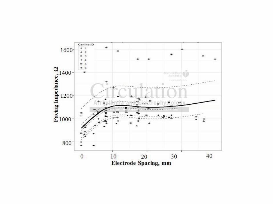
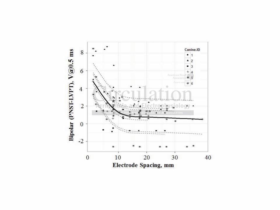
Effect of bipolar electrode spacing on bipolar PNS and LVP threshold, pacing impedance
and R-wave
Figure 3 shows the random correlation of bipolar PNS and LVP thresholds to the bipolar
electrode spacing when the TPNE was used as the cathode (the electrode closest to phrenic
nerve). PNS threshold was significantly inversely related to bipolar electrode spacing (p<0.001,
Fig.3 B), while no association was found for LVP threshold ( p=0.640; Figure 3A). Figure 4 and
5 show LV pacing impedance and R-wave amplitude relationship with the bipolar electrode
s rapidly increased dd d wwa
10 VVVV@0@0@0@0 55.55 ms at tttthehehehe
r e
s t
h h i f i ) (13) d t th l i di t h
reater than 20 mm. However, the unipolar LVP thresholds appeared stable while
stance to the TPNE was less than 20mm then increasing while cathode distance t
greater than 20mm. In fact, both unipolar PNS and LVP threshold showed large
at TPNE distance > 20 mm likely due to phrenic nerve anatomy (i.e. divergence
h h i f i ) (13) d t th l i di t h

DOI: 10.1161/CIRCEP.112.971317
7
spacing when the TPNE was used as the cathode. A decrease of LV pacing impedance and a
decrease of the intrinsic R-wave were respectively observed as the bipolar electrode spacing
shortened ( p<0.001, Figure 4; p=<0.001, Figure 5).
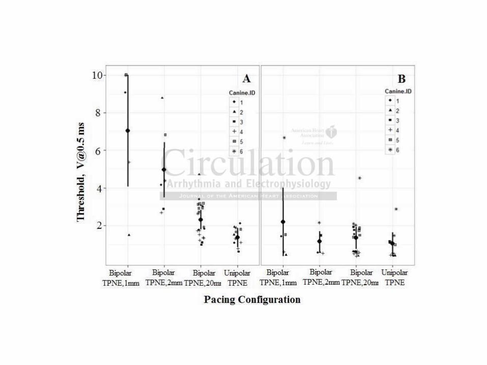
Figure 6 summarizes the comparison of pacing configurations: the unipolar pacing was
compared respectively to the 1mm-spaced, 2 mm-space and 20 mm-spaced (this last is
commonly available in clinical practice using market-released LV leads) bipolar pacing using
the TPNE as cathode. The pacing configuration affected the PNS thresholds (p<0.001). However,
the pacing configuration did not affect LVP thresholds (p=0.130). As compared with 20mm of
standard bipolar electrode spacing, 1mm and 2mm bipolar electrode spacing resulted in a PNS
threshold increase of 5.5±2.2V (p=0.003) and 2.8±1.7V (p<0.001), respectively. Similarly, PNS
threshold increased by 6.5±3.7V with 1mm and by 3.8±1.9V with 2mm bipolar pacing (both
p<0.001), as compared to unipolar TPNE pacing. The trend of the bipolar configuration was
clear: a shorter electrode spacing resulted in significantly higher PNS thresholds (Figure 6).
Effect of bipolar electrode spacing on safety margin of bipolar PNS to LVP
Figure 7 shows the significant relationship of the difference between the bipolar PNS and LVP
thresholds to the bipolar electrode spacing with the TPNE as the cathode. The difference between
PNS and LVP threshold is significantly inversely related to the bipolar electrode spacing
(p<0.001).
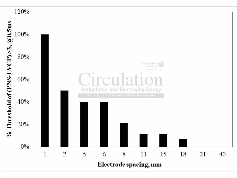
Figure 8 shows the effect of the bipolar electrode spacing on the probability to achieve a
safety margin greater than 3 V at the worst case scenario, using the TPNE as the cathode (closest
to phrenic nerve). This safety margin is obtained reliably in all the cases using 1mm bipolar
electrode spacing. The success rate dropped dramatically for bipolar electrode spacing > 6 mm,
which are those typically employed for LV leads in clinical practice.
compared with 20m0m0m0mm
pacingggg resulllltettt dddd inn aaaa P
n
n t
a a
o )
bi l l t d i f t i f bi l PNS t LVP
ncrease of 5.5±2.2V (p=0.003) and 2.8±1.7V (p<0.001), respectively. Similarly,
ncreased by 6.5±3.7V with 1mm and by 3.8±1.9V with 2mm bipolar pacing (botV
as compared to unipolar TPNE pacing. The trend of the bipolar configuration wa
orter electrode spacing resulted in significantly higher PNS thresholds (Figure 6)
bi l l t d i f t i f bi l PNS t LVP

DOI: 10.1161/CIRCEP.112.971317
8
Discussion
The main finding of our study is that both the distance from the LV cathode to the phrenic nerve
and bipolar electrode spacing affect the PNS threshold: the farther the LV cathode from the
phrenic nerve, or the shorter the bipolar electrode spacing, the lower the chance of PNS. The
difference between PNS threshold and LVP threshold was used to provide a “PNS safety margin”
in order to relate the results to clinical practice. Indeed, a difference 3V is associated with
freedom from PNS-related complications in the majority of clinical reports (6, 8, 10,11), which
involved about 600 patients. This safety margin was obtained reliably in all the cases using 1
mm bipolar electrode spacing and keeping the TPNE as cathode (Fig.8). The success rate
dropped dramatically for bipolar electrode spacing > 6 mm, which are those typically employed
for LV pacing in clinical practice. Two strategies for PNS management are highlighted by this
study: placing the LV cathode remote from the TPNE or shortening the bipolar electrode spacing
with the LV cathode at TPNE.
PNS needs to be managed at the same pacing sites that are deemed optimal for CRT (6,
7, 9, 11). When PNS is detected at implantation, several approaches are used: moving the lead to
a different position in the vein, programming the LV cathode to a different electrode in devices
featuring this technology or lowering the LV output to avoid PNS when the other options have
failed (6, 11, 14). LV lead repositioning to another vein is the last resort and is possible only
when other coronary veins are suitable for LV lead placement.
Each of these approaches has its own drawbacks: LV lead placement at an alternative site
poses an increased risk of a suboptimal LVP threshold and of LV lead dislodgement with need
for repeated surgery (6, 8). Surgery increases the risk of complications due to increased risk of
infection (15). Abandoning the target site or loss of capture because of a high LVP threshold may
yyy in all the cases uuuusisisisinn
8). The successs raatetetete
r l
i
p
V
S d b d h i i h d d i l f CRT
ramatically for bipolar electrode spacing > 6 mm, which are those typically empl
ing in clinical practice. Two strategies for PNS management are highlighted by
ing the LV cathode remote from the TPNE or shortening the bipolar electrode sp
V cathode at TPNE.
S d b d h i i h d d i l f CRT
DOI: 10.1161/CIRCEP.112.971317
9
cause failure to achieve CRT and clinical improvement (4,5).
Our observations highlight the need to develop new strategies for PNS management
through implant techniques and lead technology.
Impact of cathode distance from the phrenic nerve in unipolar configuration
PNS threshold has a linear relationship with distance from the phrenic nerve (Figure 2). This is
the physiological background for the strategy most commonly used in clinical practice to avoid
PNS: placement of the LV cathode far from the phrenic nerve. Nowadays this is achieved by re-
programming the LV cathode in multi-electrode leads in order to maintain lead stability and
decrease the risk of lead dislodgement (6, 8-10, 14). This strategy has not proved to ensure PNS
avoidance in 100% of patients (10-12, 16), most likely owing to the electrode spacing of bipolar
LV leads, that ranges from 10 to 20 mm, whereas our observation dictates that the LV cathode
needs to be at least 20~30 mm far from the TPNE. To overcome this limitation , a quadripolar S-
shaped LV lead that spans a length of approximately 50 mm from the tip to the proximal
electrode and allows 10 pacing configurations has been developed (16). The preliminary short-
term experience with this lead in highly trained centers reported that during implantation 5/75
(6.6%) patients had the lead placed at a vein different than the target one because of PNS that
could not be managed by re-programming (16). Moreover, the incidence of PNS at 7.5V when
programming the LV cathode 30 mm or 47 mm from the lead tip was 14% and 23%,
respectively, with an average PNS threshold around 5 ± 2 V (16). The LVP threshold in those
settings was respectively 2.5V and 3.5V on average, meaning that a 3V difference between PNS
and LVP threshold was not obtained in all patients, and that PNS avoidance was a trade-off with
a high LVP threshold. This represents a potential limitation in managing PNS at follow up (10).
Hence, owing to the variability of both coronary vein and phrenic nerve anatomy, a strategy
ntain lead stability y y y a
not ppproved ddd tottt ennnnsusususure
i b
h o
e o
d ll 10 i fi ti h b d l d (16) Th li i h
in 100% of patients (10-12, 16), most likely owing to the electrode spacing of b
hat ranges from 10 to 20 mm, whereas our observation dictates that the LV catho
e at least 20~30 mm far from the TPNE. To overcome this limitation , a quadripo
lead that spans a length of approximately 50 mm from the tip to the proximala
d ll 10 i fi ti h b d l d (16) Th li i h

DOI: 10.1161/CIRCEP.112.971317
10
based on a multi-electrode LV lead with conventional bipolar electrode spacing in the range of
10 to 20 mm does not seem to provide a comprehensive approach to manage PNS.
Impact of electrode spacing on PNS threshold and implications for a PNS-avoidance
strategy
We observed an inverse relationship of PNS threshold with bipole electrode spacing (Figure 3B),
that warrants a PNS-LVP threshold difference above 3V at a spacing < 2mm (Fig. 7,8).
This allows the implanting physician to keep the LV cathode at the target site for CRT (though
being the TPNE), thus minimizing the risk of non-response to CRT (5, 17-20), which carries the
risk of significant morbidity and mortality (1, 2, 5, 19, 20). Furthermore, this approach is neutral
on the LVP threshold compared to longer/standard electrode spacing (Fig. 6B), thus minimizing
the risk of a high LVP threshold and loss of ventricular capture when pacing elsewhere than lead
tip (16). Our results are in complete agreement with the recently published experience by Wecke
et al (21) that reported similar results in a canine model, using a networked multi-electrode LV
lead. They demonstrated (21) that a very short pacing dipole ( 1mm), obtained by pacing
between adjacent segments of networked electrodes, can achieve PNS avoidance in 100% of the
worst-case scenarios (Phrenic nerve dissected and positioned above the LV lead).
Practical implications: We believe that our study provides the rationale for the development of
multi-electrode LV leads with a 1 to 2 mm bipolar electrode spacing to maximize PNS
management either at implant or at follow up. The short-spaced dipole could be part of either
multi-electrode or active fixation leads, where all the efforts are focused to avoid both a high
LVP threshold and PNS at the same time. The advantage of such an approach is the use of an
already established and reliable LV lead technology, whereas the new lead technology described
by Wecke et al (21) might be vulnerable to the risks of any new highly sophisticated electronic
17-20), which cararararririrr e
re, thihihihis approach iiiissss ne
P i
a a
u W
h e
d t t d (21) th t h t i di l ( 1 ) bt i d b i
P threshold compared to longer/standard electrode spacing (Fig. 6B), thus minimid
a high LVP threshold and loss of ventricular capture when pacing elsewhere tha
ur results are in complete agreement with the recently published experience by W
hat reported similar results in a canine model, using a networked multi-electrode
d t t d (21) th t h t i di l ( 1 ) bt i d b i
DOI: 10.1161/CIRCEP.112.971317
11
technology.
Study Limitations: This was an acute animal study which requires confirmation firstly in acute
human studies and later during long-term follow-up. The healthy animals used in the study could
not mimic a high LVP threshold due to ischemic scars, that could possibly alter the study results.
We used commercially available electrophysiology catheters, both standard and modified, to
provide a shorter bipolar electrode spacing instead of leads designed for chronic pacing. This
catheter and electrode design may have increased the LV pacing threshold compared to
conventional LV pacing leads due to unpredictable electrode contact with the myocardium. PNS
was determined via tactile feel and this may not reflect the clinical perception of PNS felt by
patients. The phrenic nerve was surgically repositioned over a coronary vein and this difference
from physiological conditions could impact the contact between the nerve and the catheter within
the vein.
Conflict of Interest Disclosure: Dr. Biffi has received modest honoraria from Medtronic, Boston Scientific, and Biotronik for scientific presentations at Medical Simposia and for Educational Activity. All the other authors are employees of Medtronic.
References:
1. Bristow MR, Saxon LA, Boehmer J, Krueger S, Kass DA, De Marco T, Carson P, DiCarlo L, DeMets D, White BG, DeVries DW, Feldman AM. Cardiac-resynchronization therapy with or without an implantable defibrillator in advanced chronic heart failure. N Engl J Med.2004;350:2140-2150.
2. Cleland JG, Daubert JC, Erdmann E, Freemantle N, Gras D, Kappenberger L, Tavazzi L, for the Cardiac Resynchronization-Heart Failure (CARE-HF) Study Investigators. The effect of cardiac resynchronization on morbidity and mortality in heart failure. N Engl J Med. 2005;352:1539-1549.
3. Butter C, Auricchio A, Stellbrink C, Fleck E, Ding J, Yu Y, Huvelle E, Spinelli J on behalf of the Pacing Therapy for Chronic Heart Failure II (PATH-CHF-II) Study Group. Effect of resynchronization therapy stimulation site on the systolic function of heart failure patients. Circulation. 2001;104:3026-3029.
with the myoyy cardiuuuum.mmm
rceptiitiion of fff PNPNPNPNSS SS fefefefeltltltlt b
h r
f ,
he phrenic nerve was surgically repositioned over a coronary vein and this differ
ological conditions could impact the contact between the nerve and the catheter
f Interest Disclosure: Dr. Biffi has received modest honoraria from Medtronic,

DOI: 10.1161/CIRCEP.112.971317
12
4. Dekker AL, Phelps B, Dijkman B, Van Der Nagel T, Van Der Veen FH, Geskes GG, Maessen JG. Epicardial left ventricular lead placement for cardiac resynchronization therapy: Optimal pace site selection with pressure-volume loops. J Thorac Cardiovasc Surg. 2004; 127;1641-1647.
5. Ypenburg C, van Bommel RJ, Delgado V, Mollema SA, Bleeker GB, Boersma E, Schalij MJ, Bax JJ. Optimal Left Ventricular Lead Position Predicts Reverse Remodeling and Survival After Cardiac Resynchronization Therapy. J Am Coll Cardiol. 2008;52:1402-1409.
6. Biffi M, Moschini C, Bertini M, Saporito D, Ziacchi M, Diemberger I, Valzania C, Domenichini G, Cervi E, Martignani C, Sangiorgi D, Branzi A, Boriani G. Phrenic Stimulation: A Challenge for Cardiac Resynchronization Therapy. Circ Arrhythm Electrophysiol. 2009;2:402-410.
7. Seifert M, Schau T, Moeller V, Neuss M, Meyhoefer J, Butter C. Influence of pacing configurations, body mass index, and position of coronary sinus lead on frequency of phrenic nerve stimulation and pacing thresholds under cardiac resynchronization therapy. Europace.2010;12:961-967.
8. Gurevitz O, Nof E, Carasso S, Luria D, Bar-Lev D, Tanami N, Eldar M, Glikson M. Programmable multiple pacing configurations help to overcome high left ventricular pacing thresholds and avoid phrenic nerve stimulation. Pacing Clin Electrophysiol. 2005;28:1255-1259.
9. Champagne J, Healey JS, Krahn AD, Philippon F, Gurevitz O, Swearingen A, Glikson M; ELECTION Investigators. The effect of electronic repositioning on left ventricular pacing and phrenic nerve stimulation. Europace. 2011;13:409-415.
10. Biffi M, Bertini M, Ziacchi M, Gardini B, Mazzotti A, Massaro G, Diemberger I, Martignani C, Valzania C, Boriani G. Management of phrenic stimulation in CRT patients over the long term: still an unmet need ? Pacing Clin Electrophysiol. 2011;34:1201-1208.
11. Jastrzebski M, Bacior B, Wojciechowska W, Czarnecka W. Left ventricular lead implantation at a phrenic stimulation site is safe and effective. Europace. 2011;13:520-525.
12. Biffi M, Boriani G. Phrenic stimulation management in CRT patients: are we there yet? CurrOpin Cardiol. 2011,26:12-16.
13. Sanchez-Quintana D, Cabrera JA, Climent V, Farrè J, Weiglein A, SY Ho. How close are the phrenic nerves to cardiac structures? Implications for cardiac interventionalists. J Cardiovasc Electrophysiol. 2005:16;309-313.
14. Biffi M, Bertini M, Saporito D, Ziacchi M, Stabellini S, Valsecchi S, Ricci V, Boriani G. Automatic management of left ventricular stimulation: hints for technologic improvement. Pacing Clin Electrophysiol. 2009;32:346-353.
fffflulululuenenenencececece oooof f f f papapapacicicicingngngng on frequqq ency of fff phphphphrrrrenon theheeerarararapypypypy EuEuEuEurorororopapappace
6
zable multiple ci confi rations help to overcome high left ventricular acing
-
MN Investigators. The effect of electronic repositioning on left ventricular pacing a
ti l ti E 2011 13 409 415
61-967.
z O, Nof E, Carasso S, Luria D, Bar-Lev D, Tanami N, Eldar M, Glikson M. able multiple pacing configurations help to overcome high left ventricular pacingand avoid phrenic nerve stimulation. Pacing Clin Electrophysiol. 2005;28:1255-
gne J, Healey JS, Krahn AD, Philippon F, Gurevitz O, Swearingen A, Glikson MN Investigators. The effect of electronic repositioning on left ventricular pacing a
ti l ti E 2011 13 409 415

DOI: 10.1161/CIRCEP.112.971317
13
15. Poole JE, Gleva MJ, Mela T, Chung MK, Uslan DZ, Borge R, Gottipaty V, Shinn T, Dan D, Feldman LA, Seide H, Winston SA, Gallagher JJ, Langberg JJ, Mitchell K, Holcomb R, for the REPLACE Registry Investigators. Complication Rates Associated With Pacemaker or Implantable Cardioverter-Defibrillator Generator Replacements and Upgrade Procedures Circulation. 2010;122:1553-1561.
16. Sperzel J, Dänschel W, Gutleben KJ, Kranig W, Mortensen P, Connelly D, Trappe HJ, Seidl K, Duray G, Pieske B, Stockinger J, Boriani G, Jung W, Schilling R, Saberi L, Hallier B, Simon M, Rinaldi CA. First prospective, multi-centre clinical experience with a novel left ventricular quadripolar lead. Europace. 2012;14:365-372.
17. Macías A, Gavira J-J, Castaño S, Alegría E, García-Bolao I. Left ventricular pacing site in cardiac resynchronization therapy: Clinical follow-up and predictors of failed lateral implant.EurJ Heart Fail.. 2008:10;421–427.
18. Chung ES, Leon AR, Tavazzi L, Sun JP, Nihoyannopoulos P, Merlino J, Abraham WT, Ghio S, Leclercq C, Bax JJ, Yu CM, Gorcsan J 3rd, St John Sutton M, De Sutter J, Murillo J. Results of the Predictors of Response to CRT (PROSPECT) trial. Circulation. 2008;117:2608-2616.
19. Ypenburg C, van Bommel RJ, Borleffs CJW, Bleeker GB, Boersma E, Schalij MJ, Bax JJ. Long-Term Prognosis After Cardiac Resynchronization Therapy Is Related to the Extent of Left Ventricular Reverse Remodeling at Midterm Follow-Up. J Am Coll Cardiol. 2009;53:483-490.
20. Khan FZ, Virdee MS, Palmer CR, Pugh PJ, O’Halloran D, Read DA, Begley D, MD, Fynn SP, Dutka DP. Targeted Left Ventricular Lead Placement to Guide Cardiac Resynchronization Therapy. The TARGET Study: A Randomized, Controlled Trial. J Am Coll Cardiol.2012;59:1509-1518.
21. Wecke L, van Hunnik A, Thompson T, DiCarlo L, Zdeblick M, Auricchio A, Prinzen FW. Networked Multi-Electrode Left Ventricular Pacing Lead for Avoidance of Phrenic Nerve Stimulation in a Canine Model. Heart Rhythm. 2012;9:789-795.
Figure Legends:
Figure 1. Fluoro image of the coronary vein angiogram (A) and of catheter and phrenic nerve
location (B)
Figure 2 . Effect of cathode distance from the phrenic nerve on both LVP (A) and PNS (B)
iiiinononono J J JJ, ,,, AbAbAbAbrarararahahahaham mmm WTWTWTWT, utter J,JJJ MMMMurilililillolll J. ReReReRes2008888;1;1;1;117171717:2:2:2:2606060608888 2626262616
urg C, van Bommel RJ, Borleffs CJW, Bleeker GB, Boersma E, Schalij MJ, Baxm fr 4
FDP. Targeted Left Ventricular Lead Placement to Guide Cardiac Resynchronizati
509 1518
urg C, van Bommel RJ, Borleffs CJW, Bleeker GB, Boersma E, Schalij MJ, Baxm Prognosis After Cardiac Resynchronization Therapy Is Related to the Extent ofr Reverse Remodeling at Midterm Follow-Up. J Am Coll Cardiol. 2009;53:483-4
FZ, Virdee MS, Palmer CR, Pugh PJ, O’Halloran D, Read DA, Begley D, MD, DP. Targeted Left Ventricular Lead Placement to Guide Cardiac Resynchronizatihe TARGET Study: A Randomized, Controlled Trial. J Am Coll Cardiol.
509 1518

DOI: 10.1161/CIRCEP.112.971317
14
unipolar threshold. The dashed lines represent the effect in each animal and the solid line
represents the overall trend in the study
Figure 3. Effect of bipolar electrode spacing on bipolar LVP (A) and PNS (B) threshold .The
dashed lines represent the effect in each animal and the solid line represents the overall trend in
the study.
Figure 4. Effect of bipolar electrode spacing on pacing impedance. The dashed lines represent
the effect in each animal and the solid line represents the overall trend in the study..
Figure 5. Effect of bipolar electrode spacing on R-wave amplitude. The dashed lines represent
the effect in each animal and the solid line represents the overall trend in the study.
Figure 6. Comparison of pacing configurations of bipolar and unipolar PNS (A) and LVP (B)
using the TPNE as a cathode. The solid lines represent 95% confidence intervals.
Figure 7. Relationship of the difference between bipolar PNS and LVP threshold. The dashed
lines represent the effect in each animal and the solid line represents the overall trend in the
study.
Figure 8 . Probability of a PNS-LVP threshold difference >3 V, with bipolar electrode spacing.
he dashed lines reprprprpre
d in ththththe tstttuddddy..
E e
n
C i f i fi ti f bi l d i l PNS (A) d LVPf
Effect of bipolar electrode spacing on R-wave amplitude. The dashed lines repre
n each animal and the solid line represents the overall trend in the study.
C i f i fi ti f bi l d i l PNS (A) d LVPf