eed for ntrol? user’s guide - omega engineering · user’s guide 871a and 872a digital...
TRANSCRIPT

http://www.omega.com e-mail: [email protected]
®
User’s Guide
871A and 872ADigital Thermometers
eed for ntrol?
s & Assemblies
Only model 871A has CE certification

Servicing North America:USA: One Omega Drive, Box 4047ISO 9001 Certified Stamford, CT 06907-0047
Tel: (203) 359-1660 FAX: (203) 359-7700e-mail: [email protected]
Canada: 976 BergarLaval (Quebec) H7L 5A1Tel: (514) 856-6928 FAX: (514) 856-6886e-mail: [email protected]
For immediate technical or application assistance:USA and Canada: Sales Service: 1-800-826-6342 / 1-800-TC-OMEGASM
Customer Service: 1-800-622-2378 / 1-800-622-BESTSM
Engineering Service: 1-800-872-9436 / 1-800-USA-WHENSM
TELEX: 996404 EASYLINK: 62968934 CABLE: OMEGAMexico andLatin America: Tel: (95) 800-TC-OMEGASM FAX: (95) 203-359-7807
En Espanol: (203) 359-1660 ext: 2203 e-mail: [email protected]
Servicing Europe:Benelux: Postbus 8034, 1180 LA Amstelveen, The Netherlands
Tel: (31) 20 6418405 FAX: (31) 20 6434643Toll Free in Benelux: 06 0993344e-mail: [email protected]
Czech Republic: Ostravska 767, 733 01 KarvinaTel: 42 (69) 6311899 FAX: 42 (69) 6311114e-mail: [email protected]
France: 9, rue Denis Papin, 78190 TrappesTel: (33) 130-621-400 FAX: (33) 130-699-120Toll Free in France: 0800-4-06342e-mail: [email protected]
Germany/Austria: Daimlerstrasse 26, D-75392 Deckenpfronn, GermanyTel: 49 (07056) 3017 FAX: 49 (07056) 8540Toll Free in Germany: 0130 11 21 66e-mail: [email protected]
United Kingdom: 25 Swannington Road, P.O. Box 7, Omega Drive,ISO 9002 Certified Broughton Astley, Leicestershire, Irlam, Manchester,
LE9 6TU, England M44 5EX, England Tel: 44 (1455) 285520 Tel: 44 (161) 777-6611FAX: 44 (1455) 283912 FAX: 44 (161) 777-6622
Toll Free in England: 0800-488-488e-mail: [email protected]
omega.com TM
OMEGA®
OMEGAnetSM On-Line Service Internet e-mailhttp://www.omega.com [email protected]
It is the policy of OMEGA to comply with all worldwide safety and EMC/EMI regulations that apply. OMEGA isconstantly pursuing certification of its products to the European New Approach Directives. OMEGA will add theCE mark to every appropriate device upon certification.The information contained in this document is believed to be correct but OMEGA Engineering, Inc. accepts no liability for anyerrors it contains, and reserves the right to alter specifications without notice.WARNING: These products are not designed for use in, and should not be used for, patient connected applications.

TABLE OF CONTENTS
MODEL 871A AND MODEL 872ADIGITAL THERMOMETERS
SECTION PAGE
SECTION 1 INTRODUCTION .................................................................. 1
1.1 General Description ................................................................... 11.2 Features ..................................................................................... 12.1 Accessory Items......................................................................... 1
SECTION 2 INSTALLATION .................................................................... 2
2.1 Unpacking.................................................................................. 22.2 Battery Installation ..................................................................... 2
SECTION 3 OPERATION ......................................................................... 3
3.1 Controls and Indicators.............................................................. 33.2 Operating Procedure.................................................................. 5
SECTION 4 SERVICE INFORMATION .................................................... 5
4.1 Verification Check ...................................................................... 54.1.1 Functionality Check ................................................................... 54.1.2 Accuracy Check......................................................................... 64.2 Calibration for Model 871A ........................................................ 64.2.1 Equipment Needed .................................................................... 64.2.2 Environmental Conditions.......................................................... 64.2.3 Setup.......................................................................................... 74.2.4 Calibration Procedure ................................................................ 74.3 Calibration for Model 872A ........................................................ 84.3.1 Equipment Needed .................................................................... 84.3.2 Environmental Conditions.......................................................... 84.3.3 Setup.......................................................................................... 84.3.4 Calibration Procedure ................................................................ 94.4 Disassembly for Model 871A and Model 872A.........................104.5 Troubleshooting Guide .............................................................114.5.1 DC Voltage checks Model 871A ...............................................124.5.2 DC Voltage Checks Model 872A ..............................................124.5.3 Waveform Checks Model 871A ................................................134.5.4 Waveform Checks Model 872A ................................................13
SECTION 5 SPECIFICATIONS FOR MODEL 871AAND MODEL 872A .............................................................13
5.1 Parts List ...................................................................................16
i

SECTION 1 INTRODUCTION
1.1 GENERAL DESCRIPTION
The OMEGA® Model 871A and Model 872A Digital Thermometers are ultrasensitive hand held instruments. Low power LSI devices combinedwith a large 0.6" (15 mm) LCD, deliver reliability, extended battery life, andan extremely readable readout. One nine volt battery will deliver 100 hoursof continuous operation.
The 871A and 872A are operationally identical except for minor differencesrelated to each model’s thermocouple input: Model 871A is designed foruse with type K (Chromel-Alumel) thermocouples; Model 872A is designedfor use with type J (Iron-Constantan) thermocouples.
Cold junction electronic circuitry in the Model 871A and Model 872A automatically compensates for ambient temperature changes. A special integrating A/D converter corrects for thermocouple non-linearity duringeach digitization cycle. The resulting conformity to the standard thermocouple voltage table is within 1ºC over the entire measurement span ofthe instrument.
Although the 871A and 872A are ideal for temperature measurement in thefield, they also function well as bench instruments when equipped with theoptional tilt stand. The Model 871A and Model 872A provide dual inputs,selectable scales (ºF/ºC), 1.0º and 0.1º resolution, and an analog output.The versatile dual input configuration permits two point temperature measurement such as those required in process monitoring. The analogoutput allows interfacing with chart recorders or data acquisition system’sfunctioning as an electronic ice-point reference.
1.2 FEATURES
• Wide temperature range • Dual thermocouple inputs• Selectable scales (ºF/ºC) • Analog output• 0.1º and 1.0º resolution • Heavy duty construction• 0.25% accuracy
1.2.1 ACCESSORY ITEMS
SC-GG-[*]-30-36-SMP-M Thermocouple sensor (supplied with unit) if purchased separately.
KS-871 Tilt standSC-800 Soft carrying case880-A2 Deluxe carrying caseU9VL 9 V lithium batterySMP-[*]-M Subminiature thermocouple connector, maleSMP-[*]-F Subminiature thermocouple connector,
femaleOS-201-1 2 oz. jar of high thermal conductivity paste
for fast surface measurements
*Insert thermocouple type: J for Model 872, K for Model 871
1

SECTION 2 INSTALLATION
2.1 UNPACKING
Remove the Packing List and verify that all equipment has been received. If thereare any questions about the shipment, please call OMEGA Customer ServiceDepartment at 800-622-2378 or (203) 359-1660.
The following items are included:
Quantity Description1 871 or 872 Digital Thermometer2 Beaded Wire Thermocouples1 TAS Transition Adapter1 9 Volt Alkaline Battery1 Operator’s Manual
Upon receipt of shipment, inspect the container and equipment for any sign ofdamage. Take particular note of any evidence of rough handling in transit.Immediately report any damage to the shipping agent.
NOTE
The carrier will not honor any claims unless all shipping material issaved for their examination. After examining and removing contents,save packing material and carton in the event reshipment is necessary.
2.2 BATTERY INSTALLATION
A 9 V battery is supplied with the instrument but not installed. To install thebattery, remove the cover from the battery compartment by sliding it off in thedirection of the arrow located on the battery cover. The battery connector snapson and off the terminals of the battery. Improper installation of the battery willcause the connecting wires to be severed by excess strain. Proper installationrequires that the battery be positioned in such a manner (see Figure 2-1) that theleads protruding from the boot of the battery connector face toward the outsideof the battery compartment. If the instrument is going to be stored for a longperiod of time or in a high temperature environment, remove the battery to prevent damage due to leakage.
WARNING
Turn the model 871/872A off and disconnect the input probes beforereplacing the battery. Put the cover back into place on the battery com-partment before resuming use of the instrument.
2

Figure 2-1. Battery Installation
SECTION 3 OPERATION
The Model 871A is designed to work with any type K thermocouple probe or sen-sor, fitted with an OMEGA miniature thermocouple connector SMP-K-M or industryequivalent.
The Model 872A is designed to work with any type J thermocouple probeor sensor, f itted with an OMEGA miniature connector SMP-J-M or industry equivalent.
3.1 CONTROL AND INDICATORS
Figure 3-1 and Table 3-1 illustrate and describe the controls and indicators on the871A and 872A.
Figure 3-1. Model 871A Controls and Indicators
*Model 872A has same controls and indicators, only range selections differ.
3

TABLE 3-1
MODEL 871A AND MODEL 872A
CONTROLS AND INDICATORS
ITEM CONTROL/INDICATOR FUNCTION
1. ON/OFF switch Turns unit on or off.
2. Scale and range selector Allows user to select: ºF or ºC scale,any of four possible thermocoupleranges, and 1.0º or 0.1º resolution.
3. Thermocouple selector Allows user to read either of two thermocouples by simply turning the dial.
4. Thermocouple input jacks Allows direct connection of two thermocouples to the unit via anOMEGA miniature male connector.
5. Analog output jack, The analog output is a nonlinearized,+mV OUT and -mV OUT cold junction compensated, amplified
thermocouple output. (Not isolatedfrom selected TC input.) Use arecorder to monitor temperature or a sensitive DMM to make higher resolution reading. Refer to mV output specifications for mV output to temperature ratios.
6. Low battery indicator When the battery level is low, BAT will appear in upper left corner of the display. Battery should then bereplaced to avoid error erroneousreadings due to battery failure.
7. Overrange/open When an overrange indication or thermocouple indication open thermocouple condition exits,
a 1 followed by blanked digits willappear in the display.
4

3.2 OPERATING PROCEDURE
1. Turn power on.2. Select scale and range (see Tables 3-2 and 3-3).3. Select thermocouple TC1 or TC2.4. Connect one or two thermocouples to the input jacks.5. Connect a recorder to the analog output to monitor temperatures,
or connect DMM to make high resolution readings, if desired.
TABLE 3-2
MODEL 871A TEMPERATURE RANGE
TABLE 3-3
MODEL 872A TEMPERATURE RANGE
SECTION 4 SERVICE INFORMATION
4.1 VERIFICATION CHECK
4.1.1 Functionality Check
Attach the GG-TC-K-24-36-SMP beaded wire thermocouple probe (supplied) to the Model 871A and the GG-TC-J-24-36-SMP beaded wirethermocouple probe (supplied) to the Model 872A. Hold the sensor endbetween two fingers. The reading should change from ambient to between77º to 104º F (25º to 40ºC).
Range Span Resolution
200°F -40.0° to 199.9°F 0.1°F2000°F -40° to 1999°F 1°F200°C -40.0° to 199.9°C 0.1°C
1370°C -40° to 1370°C 1°C
Range Span Resolution
200°F -40.0° to 199.9°F 0.1°F1400°F -40° to 1400°F 1°F200°C -40.0° to 199.9°C 0.1°C760°C -40° to 760°C 1°C
5

4.1.2 Accuracy Check
1. Prepare a pure-water ice bath (see paragraph 4.2.3, step 5).2. Connect a thermocouple probe to input 1 of the unit.3. Immerse the probe into the pure-water ice bath and allow ten
minutes for thermal stabilization.4. Turn on the instrument and use Tables 4-1 and 4-2 to verify
that the readings on each range are within specification.
TABLE 4-1
MODEL 871A RANGE CHART
TABLE 4-2
MODEL 872A RANGE CHART
4.2 CALIBRATION FOR MODEL 871A
4.2.1 Equipment Needed
1. DC Voltage Calibrator with 1 ±0.01% of setting ± 20 µV accuracy.
2. 100: 1 divider: 1.98 kilohm and 20 ohm wirewound resistors with0.02% ratio accuracy or better.
3. OMEGA TRC III Ice Point Reference Chamber or distilled water icebath.
4. OMEGA type K TRP Reference Probe or make a thermocouple transi-tion junction (see paragraph 4.2.3).
4.2.2 Environmental Conditions
To meet all specifications, the conditions for calibration should be an ambient temperature 23º ± 1ºC; relative humidity less than 80%.
Range Allowable Reading
2000°F 32° ± 2°200°F 32.0° ± 1.8°
1370°C 0° ± 1°200°C 0.0° ± 1.0°
Range Allowable Reading
1400°F 32° ± 2°200°F 32.0° ± 1.8°760°C 0° ± 1°200°C 0.0° ± 1.0°
6

4.2.3 Setup
(Refer to Figure 4-1.)
1. To make a thermocouple transition junction, silver solder a piece ofcopper wire to each (type K) thermocouple wire and insulate the junction with a waterproof jacket.
2. Connect the thermocouple wires from the type K transition junction toan OMEGA miniature thermocouple connector SMP-K-M.
3. Plug in the miniature connector to input TC1 of the Model 871A.
4. Connect the copper wires to the 100:1 divider (see Figure 4-1) with thecopper/wire (positive) junction connected through the 1.98 kilohmresistor, to the dc calibrator positive terminal.
5. Prepare a distilled water ice bath as follows:
a. Drill a hole in the cap of a Dewar flask or ThermosTM to accommodatethe transition junction.
b. Firmly pack the flask with pea-size ice chips made from distilledwater and then fill the flask with distilled water.*
c. Replace the melted ice with more ice while removing excess water.
d. Place cap on the flask and insert the transition junction into theflask. Allow 20 minutes for temperature stabilization.
*Using tap water may cause inaccuracies due to contaminants.
*The 20Ω resistor must be held at a uniformtemperature during calibration.
Figure 4-1. Calibration Setup for Model 871A
4.2.4 Calibration Procedure
It is not necessary to disassemble the case for calibration. All adjustmentsare accessible by removing the covers shown in Figure 4-2.
1. Remove the battery and trimmer compartment covers from the Model 871A.
2. Turn the Model 871A on and perform the calibration adjustments listed in Table 4-3.
7

Figure 4-2. Access to Calibration Adjustments
TABLE 4-3
CALIBRATION ADJUSTMENTS FOR MODEL 871A
4.3 CALIBRATION FOR MODEL 872A
4.3.1 Equipment Needed
1. DC voltage calibrator with ±0.01% of setting and ± 20 µV accuracy.
2. 100: 1 divider: 1.98 kilohm and 20 ohm wirewound resistors with 0.02%ratio accuracy or better.
3. OMEGA TRC III Ice Point Reference Chamber or distilled water ice bath.
4. OMEGA type J TRP Reference Probe or make a thermocouple transition junction (see paragraph 4.3.3).
4.3.2 Environmental Conditions
To meet all specifications, the conditions for calibration should be: anambient temperature of 23º ± 1ºC; relative humidity less than 80%.
4.3.3 Setup
1. To make a thermocouple transition junction, silver solder a piece ofcopper wire to each (type J) thermocouple wire and insulate the junction with a waterproof jacket.
2. Connect the thermocouple wires from the type J transition junction toan OMEGA miniature connector SMP-J-M.
8
871 Calibrator Trimmer DesiredStep Adjustment Range Setting (V) Adjust Reading
1 Input Offset Null 220ºC 0.0000 R109 00.0ºC2 + Gain (X1) 1370ºC 5.3039 R104 1320ºC3 + Gain (X10) 200ºC 0.6939 R105 170.0ºC4 - Gain 200ºC -0.1527 R103 -40.0ºC5 ºF Offset 200ºF 0.000 R102 32.0ºF

3. Plug in the miniature connector to input TC1 of the Model 872A.
4. Connect the copper wires to the 100:1 divider (see Figure 4-3) with theiron wire connected through the 1.98 kilohm resistor, to the dc calibra-tor positive terminal.
5. Prepare a distilled water bath as outlined in paragraph 4.2.3, step 5.
*The 20Ω resistor must be held at a uniform
temperature during calibration.
Figure 4-3. Calibration Setup for Model 872A
4.3.4 Calibration Procedure
It is not necessary to disassemble the case for calibration. All adjustmentsare accessible by removing the covers shown in Figure 4.2.
1. Remove the battery and trimmer compartment covers from the Model872A.
2. Turn the Model 872A on and perform the calibration adjustments listedin Table 4-4.
TABLE 4-4
CALIBRATION ADJUSTMENTS FOR MODEL 872A
9
872A Calibrator Trimmer DesiredStep Adjustment Range Setting (V) Adjust Reading
1 Input Offset Null 200ºC 0.0000 R109 00.0ºC2 + Gain (X1) 760ºC 4.2922 R104 760ºC3 + Gain (X10) 200ºC 1.02217 R105 190.0ºC4 - Gain 200ºC -.19604 R103 -40.0ºC5 ºF Offset 200ºF 0.000 R102 32.0ºF
12
4.5.1 DC Voltage Checks For Model 871A
1. Battery: VBAT > 7 V2. Power Supplies:
V + to (Analog Ground) = +2.8 ± 0.4 VV + to (Digital Ground) = +5 ± 1 V
3. Reference Diode: CR101 to (Analog Ground) = -1.23 ± 0.03 V4. Negative Reference Divider: (Reference to Analog Ground)
R119
Pin mV* Pin mV* Pin mV*
2 -210 5 -204 8 -1953 -209 6 -199 9 -1864 -204 7 -198 10 -173
*The setting of R104 and the tolerances of the resistors within the network(R119) can affect these levels by ± 5%.
5. Deintegrate Comparators:U103A PIN 3 to = 150 ±25mVU103B, PIN 6 to = -150 ± 25 mV
6. Cold Junction Voltage:(Ambient temperature 25º ±3ºC)-COM to = 1.0 ±0.6 mV
4.5.2 DC Voltage Checks For Model 872A
1. Battery: VBAT > 7 V2. Power Supplies:
V + to (Analog Ground) = +2.8 ± 0.4 VV + to (Digital Ground) = +5 + 1 V
3. Reference Diode: CR101 to (Analog Ground)= -1.23 ±0.03 V4. Negative Reference Divider: (Reference to Analog Ground)
R119
Pin mV* Pin mV* Pin mV*
2 -312 5 -274 8 -2673 -293 6 -272 9 -2544 -277 7 -271 10 -242
*The setting of R104 and the tolerances of the resistors within the network(R119) can affect these levels by ±5%.
5. Deintegrate Comparators:U103, Pin 3 to =190 ±30 mVU103B, Pin 6 to = -180 ±30 mV
6. Cold Junction Voltage:(Ambient temperature 25º ±3ºC)-COM to = 1.3 mV ±0.6

4.4 DISASSEMBLY FOR MODEL 871A AND MODEL 872A
The PC board and LCD assembly are not secured once the case retainingscrews are removed. Be careful not to allow the PC board and LCDassembly to fall out or shift out of position.
1. Place the unit face down on a bench or other similar surface andremove the battery compartment cover. Remove and disconnect thebattery. Remove the two #4-40 x 7/8 retaining screws.
2. Grasp the bottom cover at the input jack end and with a lifting and forward pushing motion (see Figure 4-4 and Figure 4-5), carefullyremove the bottom cover. While removing the cover, feed the battery connector through the access hole in bottom of the battery compartment.
3. The component side of the PC board is now exposed and the batterycan be reconnected for troubleshooting. To read the display, some lightdownward pressure at the top end of the circuit board may be requiredin order to make contact through the conductive elastomer strip,between the circuit board and the LCD.
4. To remove the PC board from the top cover, grasp the TC switchassembly and lift until the input jacks become disengaged from thecover. The PC board can now be removed using a slight clockwisemotion to free the two switch knobs from their normal positions in the case.
5. The LCD assembly will remain in the top cover when the PC board isremoved. Again, be careful not to allow the LCD assembly to fall out accidentally.
6. The two switch knobs can be removed from the PC board assembly bysimply pulling them off the switch shafts.
7. The LCD assembly, along with the strip connector, lifts out of the case.
8. To reassemble the unit, reverse the above procedure.
NOTE
Proper alignment of the strip connector is necessary when reinstalling theLCD assembly. Make sure that the conductor side of the strip connector ispositioned against the plastic support of the assembly.
WARNING
Be sure to replace the on-off switch cover. Common-mode voltage will be present on the switch, creating a possible hazard ifthe cover is not replaced
10

Figure 4-4. Removing the Cover
Figure 4-5. Disassembled Model 871A and Model 872A
4.5 TROUBLESHOOTING GUIDE
The troubleshooting information is intended to be used by qualified elec-tronic maintenance personnel who are familiar with the proper use of stan-dard electronic test equipment.
To gain access to the PC board, refer to the first three paragraphs of thedisassembly instructions. Utilize the Parts List, Schematic and ComponentLayout for identifying parts and checkpoint locations. The following checksshould be made with the Models 871A and 872A set to the 200ºC Range.
11

12
4.5.1 DC Voltage Checks For Model 871A
1. Battery: VBAT > 7 V2. Power Supplies:
V + to È (Analog Ground) = +2.8 ± 0.4 VV + to È (Digital Ground) = +5 ± 1 V
3. Reference Diode: CR101 to È (Analog Ground) = -1.23 ± 0.03 V4. Negative Reference Divider: (Reference to È Analog Ground)
R119
Pin mV* Pin mV* Pin mV*
2 -210 5 -204 8 -1953 -209 6 -199 9 -1864 -204 7 -198 10 -173
*The setting of R104 and the tolerances of the resistors within the network(R119) can affect these levels by ± 5%.
5. Deintegrate Comparators:U103A PIN 3 to È = 150 ±25mVU103B, PIN 6 to È = -150 ± 25 mV
6. Cold Junction Voltage:(Ambient temperature 25º ±3ºC)-COM to È = 1.0 ±0.6 mV
4.5.2 DC Voltage Checks For Model 872A
1. Battery: VBAT > 7 V2. Power Supplies:
V + to È (Analog Ground) = +2.8 ± 0.4 VV + to È (Digital Ground) = +5 + 1 V
3. Reference Diode: CR101 to È (Analog Ground)= -1.23 ±0.03 V4. Negative Reference Divider: (Reference to È Analog Ground)
R119
Pin mV* Pin mV* Pin mV*
2 -312 5 -274 8 -2673 -293 6 -272 9 -2544 -277 7 -271 10 -242
*The setting of R104 and the tolerances of the resistors within the network(R119) can affect these levels by ±5%.
5. Deintegrate Comparators:U103, Pin 3 to È =190 ±30 mVU103B, Pin 6 to È = -180 ±30 mV
6. Cold Junction Voltage:(Ambient temperature 25º ±3ºC)-COM to È = 1.3 mV ±0.6

13
4.5.3 Waveform Checks For Model 871A
Waveform Checks: Referenced To È (Digital Ground)
Clock U111, Pin 3 360 kHz, 5V pp Square WaveA/D Clock U112, Pin 5 40 kHz, 5V pp Rectangular WaveRef. Clock 1 U102, Pin 9 60 kHz, 5V pp Rectangular WaveRef. Clock 2 U102, Pin 14 6 kHz, 5V pp Rectangular WaveBackplane U101, Pin 20 50 Hz, 5V pp Rectangular Wave
4.5.3 Waveform Checks For Model 872A
Waveform Checks: Referenced To È (Digital Ground)
Clock U111, Pin 3 360 kHz, 5V pp Square WaveA/D Clock U112, Pin 5 40 kHz, 5V pp Rectangular WaveRef. Clock 1 U102, Pin 9 90 kHz, 5V pp Rectangular WaveRef. Clock 2 U102, Pin 14 9 kHz, 5V pp Rectangular WaveBackplane U101, Pin 20 50 Hz, 5V pp Rectangular Wave
SECTION 5 SPECIFICATIONS FOR MODEL 871A ANDMODEL 872A
GENERAL
THERMOCOUPLE INPUTS: Two, switch selected
ACCURACY: ±0.25% of reading +1ºC (0.25% ±1.8ºF) forone year, 64º to 82ºF (10º to 28ºC) ambient
EXTENDED SPAN ACCURACY: -40º to -55ºC: +2ºC, -0ºC
REPEATABILITY: ±0.2ºC Typical (one hr., constantambient temperature)
TEMPERATURE COEFFICIENT: 64º to 82ºF (18º to 28ºC); Less than±(0.025% of reading +0.1ºC) 1ºC; for temperatures less than 64ºF (18ºC) orgreater than 82ºF (28ºC)
MAXIMUM ALLOWABLE TCINPUT OVERLOAD: 35Vdc (42 V peak AC)
NORMAL MODE REJECTIONRATIO: Greater than 45 dB at 50 and 60 Hz
COMMON MODE REJECTIONRATIO (1KΩ UNBALANCE): Greater than 120 dB at dc, 50 and 60 Hz
DISPLAY: 3¹⁄₂ digit LCD, 0.6" height. Polarity and decimal point indication
MAXIMUM COMMON MODEVOLTAGE: 500 V
14
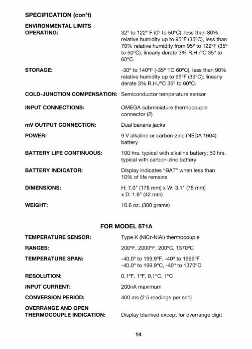
SPECIFICATION (con’t)
ENVIRONMENTAL LIMITSOPERATING: 32º to 122º F (0º to 50ºC), less than 80%
relative humidity up to 95ºF (35ºC), less than70% relative humidity from 95º to 122ºF (35ºto 50ºC); linearly derate 3% R.H./ºC 35º to60ºC.
STORAGE: -30º to 140ºF (-35º TO 60ºC), less than 90%relative humidity up to 95ºF (35ºC); linearlyderate 3% R.H./ºC 35º to 60ºC.
COLD-JUNCTION COMPENSATION: Semiconductor temperature sensor
INPUT CONNECTIONS: OMEGA subminiature thermocoupleconnector (2)
mV OUTPUT CONNECTION: Dual banana jacks
POWER: 9 V alkaline or carbon-zinc (NEDA 1604) battery
BATTERY LIFE CONTINUOUS: 100 hrs. typical with alkaline battery; 50 hrs.typical with carbon-zinc battery
BATTERY INDICATOR: Display indicates “BAT” when less than 10% of life remains
DIMENSIONS: H: 7.0" (178 mm) x W: 3.1" (78 mm)x D: 1.6" (42 mm)
WEIGHT: 10.6 oz. (300 grams)
FOR MODEL 871A
TEMPERATURE SENSOR: Type K (NiCr-NiAI) thermocouple
RANGES: 200ºF, 2000ºF, 200ºC, 1370ºC
TEMPERATURE SPAN: -40.0º to 199.9ºF, -40º to 1999ºF-40.0º to 199.9ºC, -40º to 1370ºC
RESOLUTION: 0.1ºF, 1ºF, 0.1ºC, 1ºC
INPUT CURRENT: 200nA maximum
CONVERSION PERIOD: 400 ms (2.5 readings per sec)
OVERRANGE AND OPENTHERMOCOUPLE INDICATION: Display blanked except for overrange digit

15
SPECIFICATION (con’t)
mV OUTPUT:Non-linearized, cold-junction compensated,amplified thermocouple output (Not isolatedfrom selected TC input.) On ºC Scale:1mV/ºC on 200º range 0.1mV/ºC on 1370º range 0ºC = OmV output On º F Scale:5/9 mV/ºF on 200º range5/90 mV/ºF on 2000º range0ºF = OmV output
mV OUTPUT ACCURACY(18º - 28ºC) ±(3% + 1mV) on 200º ranges;
±(3% + 0.1mV) on High rangesIncludes TC non-linearity, excludes TCerrors. Output resistance: 10k ohms
mV OUTPUT TEMPERATURE COEFFICIENT (0º - 18ºC & 28º -50ºC): Less than (0.1 x accuracy specification)/ºC
mV OUTPUT PROTECTION: 35 V dc (42 V peak) max; +mV to -mV and selected TC input to +mV or -mV.
THERMOCOUPLE LINEARIZATION: Multi-scope A/D with 11 piecewise linear
segments between -40º and 1370ºC
FOR MODEL 872A
TEMPERATURE SENSOR: Type J (Fe-CuNi) thermocouple
RANGES: 200ºF, 1400ºF, 200ºC, 760ºC
TEMPERATURE SPAN: -40.0º TO 199.9ºF, -40º to 1400ºF-40.0º TO 199.9ºC, -40º to 760ºC
RESOLUTION: 0.1ºF, 1ºF, 0.1ºC, 1ºC
INPUT CURRENT: 25 nA typical; 50 nA max
CONVERSION PERIOD: 400 ms (2.5 readings/sec.)
OVERRANGE AND OPENTHERMOCOUPLE INDICATION: 3 least significant digits blanked

5.1 PARTS LIST
Circuit DescriptionDesig.
BT101 Battery, 9V NEDA 1604C101 Cap, 0.22 µF, 100 V, PolyesterC102* Cap, 0.1 µF, 160 V,
PolypropyleneC102** Cap, 0.1 µF, 100 V,
PolypropyleneC103 Cap, 470pF, 1000 V, Ceramic
DiscC104 Cap, 220pF, 1000 V, Ceramic
DiscC105, 106 Cap, 10 µF, 16 V, Aluminum
ElectrolyticC107 Cap, 33pF, 1000 V, Ceramic
DiscC108 Cap, 47pF, 1000 V, Ceramic
DiscC109* Cap, 0.1 µF, 16 V, Ceramic C109** Cap, 0.1 µF, 50 V, Ceramic C110** Cap, 4.7 µF, 16 V, Aluminum
ElectrolyticCR101 Diode, Low Voltage ReferenceDS101 Liquid Crystal Display, 31⁄2 digitJ101, 102 TC Connector, FemaleJ103, J104** Jack, Female SMP ConnectorJ104, 105* Jack, FemaleJ105** Connector, BatteryJ106* Connector, BatteryQ101, 102 Transistor, NPN, Switch, 2N3904R101 Thick Film Resistor Network
Circuit DescriptionDesig.
R102 Pot, 100 kΩR103 Pot, 2 kΩR104 Pot, 1 kΩR105 Pot, 500 ΩR106* Resistor, 180 kΩ, 5%, 1/4W,
CompR106** Resistor, 240 kΩ, 5%, 1/4W,
CompR107 Resistor, 47 kΩ, 5%, 1/4W,
CompR108 Resistor, 470 kΩ, 5%, 1/4W,
CompR109 Pot, 2 kΩR110 Thick Film Resistor NetworkR111 Resistor, 10 kΩ, 10%, 2W,
CompR112 Resistor, 10 MΩ, 10%, 1/4W,
CompR113 Resistor, 5.1 kΩ, 5%, 1/4W,
CompR114* Resistor, 1 MΩ, 5%, 1/4W,
CompR114** Resistor, 1 MΩ, 10%, 1/4W,
CompR115, 116* Resistor, Selected, 1%, 1/8W,
Mtf.R115** R115 and U110 are a selected
set
SPECIFICATION (con’t)
mV OUTPUT: Non-linearized, cold-junction compen-sated, amplified thermocouple output(Not isolated from selected TC input.)On ºC Scale:1mV/ºC on 200º range0.1mVºC on 760º range0ºC = OmV outputOn ºF Scale:5/9 mV/ºF on 200º range5/90 mV/ºF on 1400º range0ºF = OmV output
mV OUTPUT ACCURACY(18º - 28º C) ±(5% + 1mV) on 200º ranges;
±(5% + 0.1mV) on High rangesIncludes TC non-linearity, excludes TCerrors. Output resistance: 10k ohms
mV OUTPUT TEMPERATURECOEFFICIENT (0º - 18ºC & 28º - 50°C) Less than (0.1 x accuracy specification)/ºC
mV OUTPUT PROTECTION: 35 V dc (42 V peak) max; +mV to -mV andselected thermocouple input to +mV or -mV.
THERMOCOUPLE LINEARIZATION: Multi-scope A/D with nine piecewise linearsegments between -40º and 760º C
16

TABLE 3-1
MODEL 871A AND MODEL 872A
CONTROLS AND INDICATORS
ITEM CONTROL/INDICATOR FUNCTION
1. ON/OFF switch Turns unit on or off.
2. Scale and range selector Allows user to select: ºF or ºC scale,any of four possible thermocoupleranges, and 1.0º or 0.1º resolution.
3. Thermocouple selector Allows user to read either of two thermocouples by simply turning the dial.
4. Thermocouple input jacks Allows direct connection of two thermocouples to the unit via anOMEGA miniature male connector.
5. Analog output jack, The analog output is a nonlinearized,+mV OUT and -mV OUT cold junction compensated, amplified
thermocouple output. (Not isolatedfrom selected TC input.) Use arecorder to monitor temperature or a sensitive DMM to make higher resolution reading. Refer to mV output specifications for mV output to temperature ratios.
6. Low battery indicator When the battery level is low, BAT will appear in upper left corner of the display. Battery should then bereplaced to avoid error erroneousreadings due to battery failure.
7. Overrange/open When an overrange indication or thermocouple indication open thermocouple condition exits,
a 1 followed by blanked digits willappear in the display.
4
Circuit DescriptionDesig.
R116** R116, R122, and U109 are a selected set
R117 Thick Film Resistor NetworkR118* Resistor, 150 kΩ, 5%, 1/4W,
CompR118** Resistor, 5.6 kΩ, 5%, 1/4W,
CompR119 Thick Film Resistor NetworkR120 Resistor, 10 kΩ, 5%, 1/4W,
CompR121** Resistor, 10.0 kΩ, 6.1%, Metal
FilmR122*† Resistor , Selected, 5%, 1/4W,
CompR122** R116, R122, and U109 are a
selected setR123* Resistor, 324 kΩ, 1%, 1/8W, Mtf.R123** Resistor, 316 kΩ, 1%, 1/8W, Mtf.R124** Resistor, 10.0 Ω, 0.1%, Metal
filmR126* Resistor, 10 kΩ, 0.1%, MFR127* Resistor, 9.9 kΩ, 0.1%, MFR128* Resistor, 4.7 kΩ, 5%, 1/4 W,
CompS101 Switch, RotaryS102 Switch, RotaryS103 Switch, SPDT, ON-OFFTC-1, 2 TC Cable
Circuit DescriptionDesig.
U101 31⁄2 Digit Single Chip A/D Converter
U102 Dual Synchronous Up CounterU103, U104* Low Power JFET Input Op AmpU103, U104** Dual JFET Input Op AmpU105 COS/MOS Quad Bilateral SwitchU106 CMOS Quad Exclusive OR GateU107 Dual “D” Type Flip-FlopU108 14 Stage Binary CounterU109* Linear Op AmpU109** R116, R222, and U109 are a
selected setU110* Current SourceU110** R115 and U110 are a
selected setU111 Quad, 2 Input NOR GateU112 COS/MOS Divide by “N”
CounterU113 Quad, 2 Input, AND GateU114 Analog MultiplexerY101 Resonator, 360 kHz
† Value selected during calibration at factory.* For Model 871A only** For Model 872A onlyTo order parts, specify model and circuit designation.
5.1 PARTS LIST (continued)
17
R120
R127
Jumper
R124
Jumper
R121
R118A
COMPONENT LAYOUT FOR MODEL 871A
COMPONENT LAYOUT FOR MODEL 872A

SCHEMATICMODEL 871A DIGITAL THERMOMETER
18

SCHEMATICMODEL 872A DIGITAL THERMOMETER
19

WARRANTY/DISCLAIMEROMEGA ENGINEERING, INC. warrants this unit to be free of defects in materials and workmanship for aperiod of 13 months from date of purchase. OMEGA Warranty adds an additional one (1) monthgrace period to the normal one (1) year product warranty to cover handling and shipping time.This ensures that OMEGA’s customers receive maximum coverage on each product.
If the unit should malfunction, it must be returned to the factory for evaluation. OMEGA’sCustomer Service Department will issue an Authorized Return (AR) number immediately uponphone or written request. Upon examination by OMEGA, if the unit is found to be defective it willbe repaired or replaced at no charge. OMEGA’s WARRANTY does not apply to defects resultingfrom any action of the purchaser, including but not limited to mishandling, improper interfacing,operation outside of design limits, improper repair, or unauthorized modification. This WARRANTY is VOID if the unit shows evidence of having been tampered with or shows evidenceof being damaged as a result of excessive corrosion; or current, heat, moisture or vibration;improper specification; misapplication; misuse or other operating conditions outside of OMEGA’scontrol. Components which wear are not warranted, including but not l imited tocontact points, fuses, and triacs.
OMEGA is pleased to offer suggestions on the use of its various products. However, OMEGA neither assumes responsibility for any omissions or errors nor assumes liability for anydamages that result from the use of its products in accordance with information provided byOMEGA, either verbal or written. OMEGA warrants only that the parts manufactured by it will be as specified and free of defects. OMEGA MAKES NO OTHER WARRANTIES OR REPRESENTATIONS OF ANY KIND WHATSOEVER, EXPRESSED OR IMPLIED,EXCEPT THAT OF TITLE, AND ALL IMPLIED WARRANTIES INCLUDING ANY WARRANTY OFMERCHANTABILITY AND FITNESS FOR A PARTICULAR PURPOSE ARE HEREBY DISCLAIMED.LIMITATION OF LIABILITY: The remedies of purchaser set forth herein are exclusive and the totalliability of OMEGA with respect to this order, whether based on contract, warranty, negligence,indemnification, strict liability or otherwise, shall not exceed the purchase price of the compo-nent upon which liability is based. In no event shall OMEGA be liable for consequential, inciden-tal or special damages.
CONDITIONS: Equipment sold by OMEGA is not intended to be used, nor shall it be used: (1) as a“Basic Component” under 10 CFR 21 (NRC), used in or with any nuclear installation or activity; or (2) inmedical applications or used on humans. Should any Product(s) be used in or with any nuclearinstallation or activity, medical application, used on humans, or misused in any way, OMEGA assumesno responsibility as set forth in our basic WARRANTY / DISCLAIMER language, and additionally,purchaser will indemnify OMEGA and hold OMEGA harmless from any liability or damage whatsoeverarising out of the use of the Product(s) in such a manner.
RETURN REQUESTS / INQUIRIESDirect all warranty and repair requests/inquiries to the OMEGA Customer Service Department.BEFORE RETURNING ANY PRODUCT(S) TO OMEGA, PURCHASER MUST OBTAIN AN AUTHORIZEDRETURN (AR) NUMBER FROM OMEGA’S CUSTOMER SERVICE DEPARTMENT (IN ORDER TO AVOIDPROCESSING DELAYS). The assigned AR number should then be marked on the outside of the returnpackage and on any correspondence.The purchaser is responsible for shipping charges, freight, insurance and proper packaging to preventbreakage in transit.FOR WARRANTY RETURNS, please have thefollowing information available BEFORE contacting OMEGA:1. P.O. number under which the product was
PURCHASED,2. Model and serial number of the product under
warranty, and3. Repair instructions and/or specific
problems relative to the product.
FOR NON-WARRANTY REPAIRS, consultOMEGA for current repair charges. Have the fol-lowing information available BEFORE contacting OMEGA:1. P.O. number to cover the COST
of the repair,2. Model and serial number of product, and3. Repair instructions and/or specific problems
relative to the product.OMEGA’s policy is to make running changes, not model changes, whenever an improvement is possible. This affords our customers the latest in technology and engineering.OMEGA is a registered trademark of OMEGA ENGINEERING, INC.© Copyright 1996 OMEGA ENGINEERING, INC. All rights reserved. This document may not be copied, photocopied, reproduced,translated, or reduced to any electronic medium or machine-readable form, in whole or in part, without prior written consent ofOMEGA ENGINEERING, INC.
USA MADE
IN

M618/0896
Where Do I Find Everything I Need for Process Measurement and Control?
OMEGA…Of Course!TEMPERATUREMU Thermocouple, RTD & Thermistor Probes, Connectors, Panels & AssembliesMU Wire: Thermocouple, RTD & ThermistorMU Calibrators & Ice Point ReferencesMU Recorders, Controllers & Process MonitorsMU Infrared Pyrometers
PRESSURE, STRAIN AND FORCEMU Transducers & Strain GaugesMU Load Cells & Pressure GaugesMU Displacement TransducersMU Instrumentation & Accessories
FLOW/LEVELMU Rotameters, Gas Mass Flowmeters & Flow ComputersMU Air Velocity IndicatorsMU Turbine/Paddlewheel SystemsMU Totalizers & Batch Controllers
pH/CONDUCTIVITYMU pH Electrodes, Testers & AccessoriesMU Benchtop/Laboratory MetersMU Controllers, Calibrators, Simulators & PumpsMU Industrial pH & Conductivity Equipment
DATA ACQUISITIONMU Data Acquisition & Engineering SoftwareMU Communications-Based Acquisition SystemsMU Plug-in Cards for Apple, IBM & CompatiblesMU Datalogging SystemsMU Recorders, Printers & Plotters
HEATERSMU Heating CableMU Cartridge & Strip HeatersMU Immersion & Band HeatersMU Flexible HeatersMU Laboratory Heaters
ENVIRONMENTALMONITORING AND CONTROLMU Metering & Control InstrumentationMU RefractometersMU Pumps & TubingMU Air, Soil & Water MonitorsMU Industrial Water & Wastewater TreatmentMU pH, Conductivity & Dissolved Oxygen Instruments