ecodrive dkc error and warnings codes
TRANSCRIPT
ECODRIVEDKC01.1/DKC11.1 Drive Controllers
DOK-ECODRV-ASE-04VRS**-WAR1-EN-P
Trouble Shooting Guide: ASE 04VRS
mannesmannRexroth
engineering
Indramat275271
ECODRIVE DKC01.1/DKC11.1 Drive Controllers
About this documentation
ECODRIVE Drive Controllers DKC01.1/DKC 11.1
Trouble Shooting Guide
DOK-ECODRV-ASE-04VRS**-WAR1-DE-P
• Map 56-04V/ Register 9
• 209-0073-4333-01
• Based on: 04V10
This document is design to assists maintenance personnel in identifingerrors with the machinery
It should:
• help in understanding error messages
• help in finding the causes of errors
• describe the procedure for trouble shooting
• simplify the process of establishing contact with the INDRAMATCustomer service department
This documentation is meant as a switch board panel supplement for themachine manufacturer.
Docu-identification of released up tothis point
Enable date Remarks
DOK-ECODRV-ASE-04VRS**-WAR1-EN-P 07.97 First release
INDRAMAT GmbH, 1997
Transmission as well as reproduction of this documentation, exploitationor communication of its contents is not permitted without expressedwritten permission. Violation of these stipulations will requirecompensation. All rights for the issuance of the patent or registereddesign reserved. (DIN 34-1)
INDRAMAT GmbH • Bgm.-Dr.-Nebel-Str. 2 • D-97816 Lohr a. Main
Telephone 09352/40-0 • Tx 689421 • Fax 09352/40-4885
Abt. .END (JR)
Changes in the contents of the documentation and the delivery rights forthe products are reserved.
Title
Type of documentation
Docum. type
Internal filing index
What is the purpose of thisdocument?
help you use thisdocumentation
Procedure for change
Copyright notice
Publisher
Liability
ECODRIVE DKC01.1/DKC11.1 Drive Controllers
DOK-ECODRV-ASE-04VRS**-WAR1-EN-P • 07.97 Contents I
Contents
1 Diagnostic Message Description 1-11.1 Overview of the Diagnostic Message Descriptions ..............................................................................1-1
Diagnostic Message Types ...........................................................................................................1-1
Construction of a diagnostic message ..........................................................................................1-1
2 Error Diagnostic Messages 2-1UL Motor Type not Reported .........................................................................................................2-1
PL Load Parameter Default Value.................................................................................................2-1
F207 Switching to an Uninitialized Operating Mode......................................................................2-2
F218 Heatsink Overtemperature Shutdown ..................................................................................2-2
F219 Motor Overtemperature Shutdown.......................................................................................2-2
F220 Bleeder Overtemperature Shutdown....................................................................................2-3
F226 Undervoltage Error ...............................................................................................................2-3
F228 Excessive Deviation .............................................................................................................2-4
F229 Motor Encoder Error: Quadrant Error...................................................................................2-4
F248 Low Battery Voltage .............................................................................................................2-5
F262 External Short at Status Outputs..........................................................................................2-5
F276 Absolute Encoder Error ........................................................................................................2-6
F629 Positive Travel Limit Value is Exceeded ..............................................................................2-6
F630 Negative Travel Limit Value is Exceeded.............................................................................2-7
F643 Positive Travel Limit Switch Detected ..................................................................................2-7
F644 Negative Travel Limit Switch Detected.................................................................................2-8
F822 Motor Encoder Failure: Signal too Small..............................................................................2-8
F860 Overcurrent: Short in Powerstage........................................................................................2-9
F870 +24 V Error...........................................................................................................................2-9
F873 Power Supply Driver Stage Fault .......................................................................................2-10
F878 Velocity Loop Error.............................................................................................................2-10
F879 Velocity Limit Value Exceeded (S-0-0092).........................................................................2-11
F895 4 kHz Signal Error ..............................................................................................................2-11
3 Warning Diagnostic Messages 3-1E209 Parameter storage activ.......................................................................................................3-1
E248 Interpolation acceleration equals 0 ......................................................................................3-1
E249 Positioning vel. (S-0-0259) greater S-0-0091.......................................................................3-1
E250 Heatsink Overtemperature Warning ....................................................................................3-2
E251 Motor Overtemperature Warning .........................................................................................3-2
E252 Bleeder Overtemperature Warning......................................................................................3-3
E253 Target Position Out of Range ..............................................................................................3-3
E254 Not Homed...........................................................................................................................3-4
ECODRIVE DKC01.1/DKC11.1 Drive Controllers
II Contents DOK-ECODRV-ASE-04VRS**-WAR1-EN-P • 07.97
E255 Feedrate-Override(S-0-0108) = 0 ........................................................................................3-4
E256 Torque Limit = 0 ...................................................................................................................3-4
E257 Continuous Current Limiting Active......................................................................................3-5
E258 Selected Process Block is not Programmed........................................................................3-5
E259 Command Velocity Limit Active............................................................................................3-5
E260 Current limitation active! ......................................................................................................3-6
E264 Target Position Out of Range .............................................................................................. 3-6
E825 Overvoltage Error.................................................................................................................3-6
E829 Positive Position Limit Value Exceeded ...............................................................................3-7
E830 Negative Position Limit Value Exceeded .............................................................................3-7
E831 Jog Position Limit Value Exceeded......................................................................................3-8
E843 Positive Travel Zone Limit Switch Activated ........................................................................3-8
E844 Negative Travel Zone Limit Switch Activated.......................................................................3-8
4 Command Diagnostic Messages 4-1C100 Communication Phase 3 Transition Check .........................................................................4-1
C101 Invalid Communication Parameters (S-0-0021) ..................................................................4-1
C102 Limit Error Communication Parameter (S-0-0021) ..............................................................4-1
C200 Communication Phase 4 Transition Check .........................................................................4-2
C201 Invalid Parameter Block (-> S-0-0022) ................................................................................4-2
C202 Limit Error Parameter (-> S-0-0022)....................................................................................4-2
C203 Parameter Calculation Error (-> S-0-0022)..........................................................................4-2
C207 Load Error LCA....................................................................................................................4-2
C208 Invalid SSI Parameter (-> S-0-0022) ...................................................................................4-3
C211 Invalid Feedback Data (-> S-0-0022)...................................................................................4-3
C212 Invalid Amplifier Data (-> S-0-0022) ....................................................................................4-3
C213 Position Data Scaling Error..................................................................................................4-4
C214 Velocity Data Scaling Error ..................................................................................................4-4
C215 Acceleration Data Scaling Error........................................................................................... 4-5
C216 Torque/Force Data Scaling Error.........................................................................................4-5
C217 Motor Feedback Data Reading Error...................................................................................4-6
C220 Motor Feedback Initializing Error .........................................................................................4-6
C227 Modulo Range Error.............................................................................................................4-6
C300 Command: Set Emulation - Absolute Value ........................................................................4-7
C300 Set Absolute Measuring.......................................................................................................4-7
C301 Setting Absolute Measuring not Allowed, Drive Enabled.....................................................4-7
C302 Absolute Measuring System not Installed............................................................................4-7
C400 Command: Switch To Parameter Mode ..............................................................................4-8
C401 Drive Active, Switch Not Allowed .........................................................................................4-8
C500 Reset Class 1 Diagnostic.....................................................................................................4-8
C600 Drive Controlled Homing Procedure Command ..................................................................4-8
C601 Homing Not Possible If Drive Is Not Enable ........................................................................4-8
C602 Distance Homing Switch Reference Mark Erroneous .........................................................4-9
C603 Homing Not Permitted in this Operating Mode ....................................................................4-9
C604 Homing of Absolute Encoder Not Possible..........................................................................4-9
C605, Homing velocity too great ...................................................................................................4-9
C700 Basic Load .........................................................................................................................4-10
ECODRIVE DKC01.1/DKC11.1 Drive Controllers
DOK-ECODRV-ASE-04VRS**-WAR1-EN-P • 07.97 Contents III
C800 Load Basic Parameters ..................................................................................................... 4-10
D900 D9 Command Automatic Loop Control ..............................................................................4-10
D901 Sart Only With RF..............................................................................................................4-11
D902 Motor Feedback Not Valid .................................................................................................4-11
D903 Inertia Detection Failed ......................................................................................................4-11
D904 Gain Adjustment Failed .....................................................................................................4-12
D905 Wrong Position Range.......................................................................................................4-12
D906 Position Range Exceeded..................................................................................................4-13
5 State diagnostic message 5-1A002 Communication Phase 2......................................................................................................5-1
A003 Communication Phase 3......................................................................................................5-1
A010 Drive Halt .............................................................................................................................5-1
A012 Control and Power Sections Ready for Operation ...............................................................5-1
A013 Ready for Power ON ............................................................................................................5-1
A100 Drive in Torque Mode...........................................................................................................5-1
A101 Drive in Velocity Mode..........................................................................................................5-2
A111 Velosity Synchronisation, Real Lead Drive ..........................................................................5-2
A118 Phase Synchr., Lagless, Encoder 1, Real Lead Drive .........................................................5-2
A203 Position Mode ......................................................................................................................5-2
A204 Position Mode / Lagless Positioning ....................................................................................5-2
A206 Position Mode / POSITION Encoder 1.................................................................................5-2
A207 Position Mode/POSITION Lagless Positioning Encoder 1...................................................5-3
AF Control Drive Enable................................................................................................................5-3
JF Jogging in the Positive Direction ..............................................................................................5-3
JB Jogging in the Negative Direction.............................................................................................5-3
6 Exchanging Drive Components 4-16.1 Procedure for Exchanging Devices......................................................................................................4-3
Exchange the DKC: .......................................................................................................................4-3
Motor exchange:............................................................................................................................4-4
Cable exchange:............................................................................................................................4-5
ECODRIVE DKC01.1/DKC11.1 Drive Controllers
IV Contents DOK-ECODRV-ASE-04VRS**-WAR1-EN-P • 07.97
Notes
ECODRIVE DKC01.1/DKC11.1 Drive Controllers
DOK-ECODRV-ASE-04VRS**-WAR1-EN-P • 07.97 Diagnostic Message Description 1-1
1 Diagnostic Message Description
1.1 Overview of the Diagnostic Message Descriptions
Diagnostic Message TypesEach operational state of the drive controller will be characterized with adiagnostic message.
Therein, it will be differentiated between:
• Error diagnostic message
• Warning diagnostic message
• Command diagnostic message
• State diagnostic message
• Process states
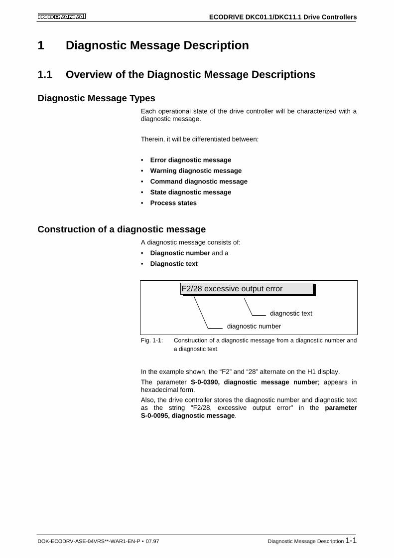
Construction of a diagnostic messageA diagnostic message consists of:
• Diagnostic number and a
• Diagnostic text
F2/28 excessive output error
diagnostic number
diagnostic text
Fig. 1-1: Construction of a diagnostic message from a diagnostic number anda diagnostic text.
In the example shown, the “F2” and “28” alternate on the H1 display.
The parameter S-0-0390, diagnostic message number ; appears inhexadecimal form.
Also, the drive controller stores the diagnostic number and diagnostic textas the string "F2/28, excessive output error" in the parameterS-0-0095, diagnostic message .
ECODRIVE DKC01.1/DKC11.1 Drive Controllers
1-2 Diagnostic Message Description DOK-ECODRV-ASE-04VRS**-WAR1-EN-P • 07.97
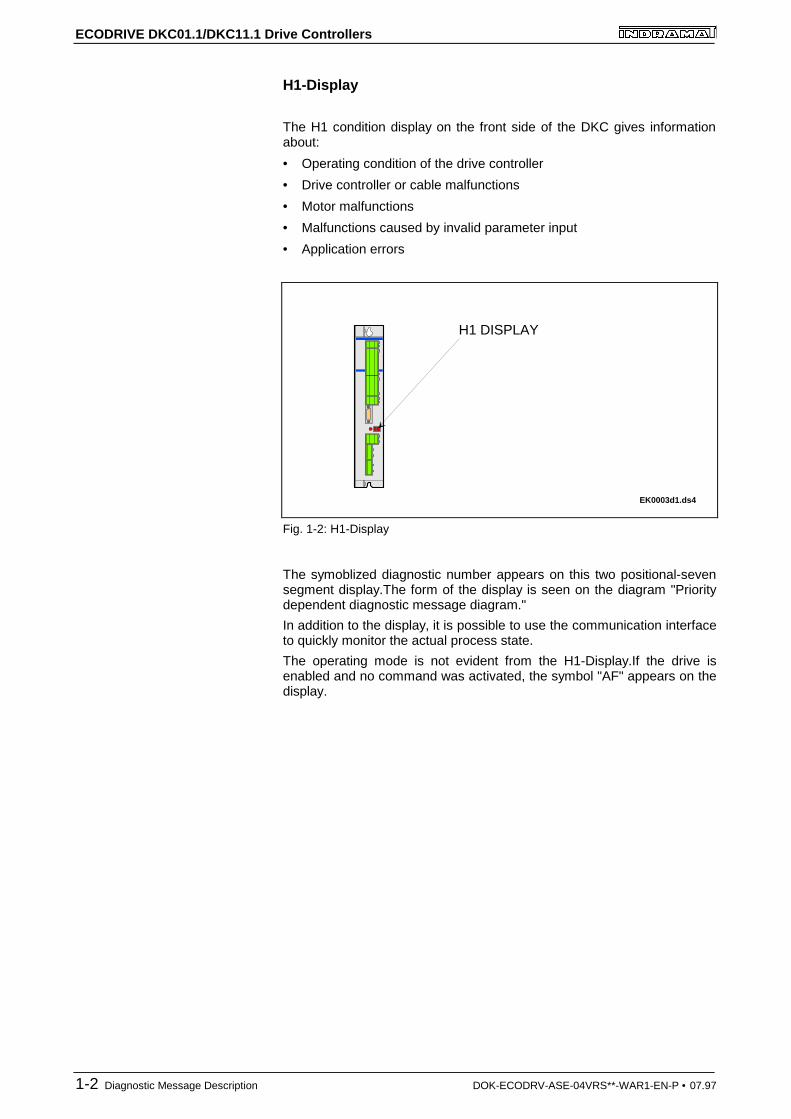
H1-Display
The H1 condition display on the front side of the DKC gives informationabout:
• Operating condition of the drive controller
• Drive controller or cable malfunctions
• Motor malfunctions
• Malfunctions caused by invalid parameter input
• Application errors
H1 DISPLAY
EK0003d1.ds4
Fig. 1-2: H1-Display
The symoblized diagnostic number appears on this two positional-sevensegment display.The form of the display is seen on the diagram "Prioritydependent diagnostic message diagram."
In addition to the display, it is possible to use the communication interfaceto quickly monitor the actual process state.
The operating mode is not evident from the H1-Display.If the drive isenabled and no command was activated, the symbol "AF" appears on thedisplay.
ECODRIVE DKC01.1/DKC11.1 Drive Controllers
DOK-ECODRV-ASE-04VRS**-WAR1-EN-P • 07.97 Diagnostic Message Description 1-3
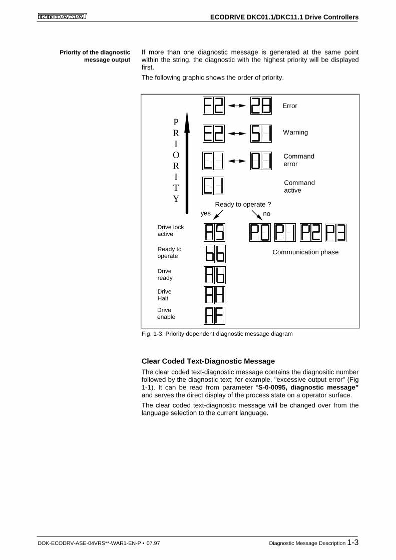
If more than one diagnostic message is generated at the same pointwithin the string, the diagnostic with the highest priority will be displayedfirst.
The following graphic shows the order of priority.
Error
Warning
Commanderror
PRIORITY
Commandactive
Ready to operate ?noyes
Communication phase
Drive lockactive
Ready tooperate
Driveready
DriveHalt
Driveenable
Fig. 1-3: Priority dependent diagnostic message diagram
Clear Coded Text-Diagnostic MessageThe clear coded text-diagnostic message contains the diagnositic numberfollowed by the diagnostic text; for example, "excessive output error" (Fig1-1). It can be read from parameter “S-0-0095, diagnostic message”and serves the direct display of the process state on a operator surface.
The clear coded text-diagnostic message will be changed over from thelanguage selection to the current language.
Priority of the diagnosticmessage output
ECODRIVE DKC01.1/DKC11.1 Drive Controllers
1-4 Diagnostic Message Description DOK-ECODRV-ASE-04VRS**-WAR1-EN-P • 07.97
Notes
ECODRIVE DKC01.1/DKC11.1 Drive Controllers
DOK-ECODRV-ASE-04VRS**-WAR1-EN-P •07.97 Error Diagnostic Messages 2-1
2 Error Diagnostic Messages
UL Motor Type not ReportedDescription:
The settings for current regulation, velocity command, and position loopare stored in the feedback of the motor. After powering up, the drivecompares the motor type stored in the parameters with the connectedmotor type. If the two do not match, then the drive remains in this state.
By pressing the S1 key, the drive overwrites its stored parameters withthe control loop parameters from the motor feedback.
Cause:
Motor was exchanged.Parameter file was loaded, but parameter “P-0-4036, motor typeconnected” contained a different motor type.
Remedy:
Command ”C700 Basic Load” or press the S1 button.
PL Load Parameter Default ValueDescription:
After the firmware is replaced (EPROMs), if the parameters have beenchanged in regards to the old product, the drive displays “PL”. Bypressing the S1 button on the drive or by starting the command “loadbasic parameters”, all the parameters will be erased and restored with thedefault values.
Cause:
Product was replaced. The number of parameters in comparison to thenew products has changed.
Remedy:
Press S1 button on the drive controller and all the paramters will beerased and restored with default values
WARNING
⇒ This overwrites all parameters and positioning blocks.
ECODRIVE DKC01.1/DKC11.1 Drive Controllers
2-2 Error Diagnostic Messages DOK-ECODRV-ASE-04VRS**-WAR1-EN-P •07.97
F207 Switching to an Uninitialized Operating ModeDescription:
A valid operating mode has not been defined.
This error cannot occur in the DKC01 because the input of the operatingmode will be tested at input.
Remedy:
Input correct operating mode
F218 Heatsink Overtemperature ShutdownDescription:
The temperature of the DKC heatsink will be monitored. If thetemperature of the heatsink is too high, the drive will power down in orderto protect against damage.
Cause:
1. Ambient temperature is too high. The specifiedoperational data is valid up to an ambient temperatureof 45°C.
2. The DKC's heatsink is dirty.
3. Air flow is prevented by other assembly parts or a control cabinet panel assembly.
4. Heatsink blower may be defective
Remedy:
For 1. Reduce the ambient temperature; for example, through cooling of the control cabinet
For 2. Remove any obstruction or dirt from the heatsink.
For 3. Install the device vertically and clear a large enough area for proper heatsink ventilation.
For 4. Exchange drive.
F219 Motor Overtemperature ShutdownDescription:
Motor temperature has risen to an unacceptable level. As soon astemperature threshold (155°C) is exceeded, the drive will immediately bebrought to a standstill as set in the error reaction (P-0-0119, best possiblestandstill).
It applies:
temperature warning threshold < temperture error threshold
ECODRIVE DKC01.1/DKC11.1 Drive Controllers
DOK-ECODRV-ASE-04VRS**-WAR1-EN-P •07.97 Error Diagnostic Messages 2-3
Cause:
1. The motor was overloaded. The effective torque demanded from the motor was above its allowable continuous torque level
for too long.
2. Break in line, ground short or short circuit in the motor temperature monitor line
3. Instability in the velocity loop.
Remedy:
For 1. Check the installation of the motor. If the systemhas been in operation for a long time, check to see if thethe operating conditions have changed. (in regards topollution, friction, moved components, etc.)
For 2. Check wires and cables to the motor temperature monitor for wire breaks, earth short and short circuits.
For 3. Check velocity loop parameters.
F220 Bleeder Overtemperature ShutdownDescription:
The regenerated energy from the mechanism of the machine via themotor has exceeded the power capability of the bleeder resistor. Byexceeding the maximum resistance energy, the drive will shutdownaccording to the set error reaction. Thereby protecting the bleeder fromtemperature damage.
Cause:
The reflected energy from the machine’s mechanism over the motor istoo large.
Remedy:
With too much power ---> reduce the acceleration value
With too much energy ---> reduce the velocity
Check the drive installation.
May require installation of an additional bleeder module.
F226 Undervoltage ErrorDescription:
The level of the DC bus voltage will be monitored by the drive controller. Ifthe DC bus voltage falls below a minimal threshold, the driveindependently shuts down according to the set error reaction.
Cause:
1. The power source has been interrupted without first switching off the drive enable (RF).
2. Disturbance in the power supply
ECODRIVE DKC01.1/DKC11.1 Drive Controllers
2-4 Error Diagnostic Messages DOK-ECODRV-ASE-04VRS**-WAR1-EN-P •07.97
Remedy:
For 1 Check the logic regarding the activation of the drive withinthe connected control.
For 2 Check the power supply.
The error can be cleared by removing the control enable signal.
F228 Excessive DeviationDescription:
The drive could not process the given command value and reactedaccording to the set error reaction.
Cause:
1. The acceleration ability of the drive was exceeded.
2. The motor shaft was blocked.
3. Parameterization error in the drive parameters.
4. "S-0-0159, Monitoring Window" was parameterized incorrectly
Remedy:
For 1. Check the Bipolar Torque Limit, S-0-0092 parameterand set it equal to the maximum allowable value forthe application.
For 2. Check the mechanical system and eliminate any jamming of the motor shaft
For 3. Check the drive parameters (control loop settings)
For 4. Parameterize "S-0-0159, Monitoring Window"
F229 Motor Encoder Error: Quadrant ErrorDescription:
An encoder signal error was found during the encoder evaluation.
Cause:
1. Defective encoder cable
2. Insulation disturbance on the encoder or the encoder cable
3. Defective drive controller
Remedy:
For 1. Check the encoder cable and change if necessary.
For 2. Use only insulated motor cable and power cables
Separate encoder cable from power cables
For 3. Exchange drive controller
ECODRIVE DKC01.1/DKC11.1 Drive Controllers
DOK-ECODRV-ASE-04VRS**-WAR1-EN-P •07.97 Error Diagnostic Messages 2-5
F248 Low Battery VoltageCause:
The connected motor has an absolute encoder. The absolute positioninformation is stored in the motor feedback. This memory has a batterypowered backup for the electronic circuit. The battery is designed for aoperating life of 10 years. If the battery voltage drops below 2.8 V, thismessage appears. The absolute encoder function is preserved for about2 weeks.
Instructions for Exchanging Batteries
Have the following tools and accessories ready:
• Torx screwdriver, size 10
• Needle nose pliers, torque wrench
• New packaged battery (Part No.: 257101)
If the control voltage of the installed battery is turned off, the absoluteposition is lost.
The absolute position must be re-established through the process of thecommand Set Absolute Measurement .
F262 External Short at Status OutputsDescription:
Status outputs are monitored for short circuits and thermal overload.
• If output current exceeds 350mA for about 1µs, then this isacknowledged as a short circuit and the pertinent channel is shut off.The output remains off unti the error is cleared.
• With thermal overload, the error is set and the output(s) shut off. Afterthe driver has cooled off, the outputs are switched back on and so on.The error, however, remains until it is cleared. Thermal overload canoccur if several outputs are overloaded in excess of 80 mA.
Note : Light bulbs, for example, cannot be controlled as their inrushcurrent causes a short-circuit.
Cause:
1. Short circuited outputs (X2/6, X2/7, X2/8, X2/9, X2/10, X2/20,X2/21, X2/22)
2. One or more outputs are overloaded.
Remedy:
For 1. Eliminate short circuit or limit switching current (< 350 mA)
For 2. Drop current, depending on output, to < 80 mA.

ECODRIVE DKC01.1/DKC11.1 Drive Controllers
2-6 Error Diagnostic Messages DOK-ECODRV-ASE-04VRS**-WAR1-EN-P •07.97
F276 Absolute Encoder ErrorDescription:
When turning off the drive controller with a absolute encoder (multiturn),the actual feedback position will be stored. When powered up, theabsolute position given by the encoder is compared to the storedposition. If the deviation is larger than the paramaterized "P-0-0097,AbsoluteEncoderMonitoring Window" , the error "F276, AbsoluteEncoder Error" will appear and be given to the control system.
Cause:
1. Turning on for the first time (invalid stored position).
2. The motor was moved further than allowed by the parameter inthe absolute encoder monitoring window, P-0-0097, while it wasturned off.
3. Incorrect position initialization
Remedy:
For 1. Press S1 to reset the error and set the absolute position.
For 2. The motor was moved while turned off and sits outside of itspermissible position. Check to see if the displayed position iscorrect in relation to the machine zero point. Reset subsequenterrors.
For 3. An accident may occur by accidental shaft movement.
Check absolute position informartion. A feedback defect ispresent if the absolute position information is false. The motorshould be exchanged and sent to the INDRAMAT CustomerService .
F629 Positive Travel Limit Value is ExceededThe drive has been provided with a command value that leads to an axisposition outside the positive travel range. The axis has been stopped andthe error reaction "set velocity command value to zero" issued. Bit 2 of P-0-0090, Travel limit parameter has been set to "Exceeding the travellimit is an error", or a drive control command has been started while theaxis limit value is exceeded (e.g. drive-controlled homing).
Cause:
S-0-0049, Positive position limit value is exceeded.
Remedial action:
1. Check S-0-0049, Positive position limit value
2. Check the controller software limits
3. Activate the axis after the error reaction
Procedure:
• Clear the error
• Activate power if it has been de-activated
• Move the axis to the permissible working range
ECODRIVE DKC01.1/DKC11.1 Drive Controllers
DOK-ECODRV-ASE-04VRS**-WAR1-EN-P •07.97 Error Diagnostic Messages 2-7
Note: Only command values that lead back into the permissibleworking range will be accepted. Any other command value willstop the drive again.
F630 Negative Travel Limit Value is ExceededThe drive has been provided with a command value that leads to an axisposition outside the negative travel range. The axis has been stopped andthe error reaction "set velocity command value to zero" issued. Bit 2 of P-0-0090, Travel limit parameter has been set to "Exceeding the travellimit is an error", or a drive control command has been started while theaxis limit value is exceeded (e.g. drive-controlled homing).
Cause:
S-0-0050, Negative position limit value is exceeded.
Remedial action:
1. Check S-0-0050, Negative position limit value
2. Check the controller software limits
3. Activate the axis after the error reaction
Procedure:
• Clear the error
• Activate power if it has been de-activated
• Move the axis to the permissible working range
Note: Only command values that lead back into the permissibleworking range will be accepted. Any other command value willstop the drive again.
F643 Positive Travel Limit Switch DetectedThe positive travel limit switch has been actuated. The axis has beenstopped with the error reaction "set velocity command value to zero". Bit 2of P-0-0090, Travel limit parameter has been set to "Exceeding thetravel limit is an error", or a drive control command has been started whilethe axis limit value is exceeded (e.g. drive-controlled homing).
Cause:
The positive travel limit switch has been actuated.
Remedial action:
1. Reset the error
2. Activate the power supply
3. Move the axis into the permissible working range
ECODRIVE DKC01.1/DKC11.1 Drive Controllers
2-8 Error Diagnostic Messages DOK-ECODRV-ASE-04VRS**-WAR1-EN-P •07.97
Note: The drive will not accept any command values that lead furtheraway from the permissible range. Specifying such a commandwill again generate this error.
F644 Negative Travel Limit Switch DetectedThe negative travel limit switch has been actuated. The axis has beenstopped with the error reaction "set velocity command value to zero". Bit 2of P-0-0090, Travel limit parameter has been set to "Exceeding thetravel limit is considered as an error", or a drive control command hasbeen started while the axis limit value is exceeded (e.g. drive-controlledhoming).
Cause:
The negative travel limit switch has been actuated.
Remedial action:
1. Reset the error
2. Activate the power supply
3. Move the axis into the permissible working range
Note: The drive will not accept any command values that lead furtheraway from the permissible range. Specifying such a commandwill again result in this error.
F822 Motor Encoder Failure: Signal too SmallDescription:
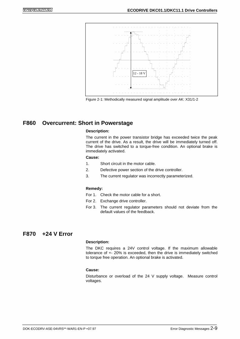
The motor encoder signals are monitored. If the signal amplitudes asmeasured via AK1 and AK2 are outside of the allowable region betweenUss = 12.0V and Uss = 18.0 V, then the error message appears. Thedrive becomes torque-free and an optional brake is immediately activated.
Cause:
1. Defective feedback cable.
2. Defective feedback.
Remedy:
For 1. Check the feedback cable.
Lay the power cables separate from the feedback cable.
The cable shield must be connected to the drive controller.
(See also project reference of the drive control).
For 2. Exchange motor.
Note : This error can only be cleared in parametrization mode (phase2). As a result of this error, the encoder emulation is switchedoff.
ECODRIVE DKC01.1/DKC11.1 Drive Controllers
DOK-ECODRV-ASE-04VRS**-WAR1-EN-P •07.97 Error Diagnostic Messages 2-9
12 - 18 V
Figure 2-1: Methodically measured signal amplitude over AK: X31/1-2
F860 Overcurrent: Short in PowerstageDescription:
The current in the power transistor bridge has exceeded twice the peakcurrent of the drive. As a result, the drive will be immediately turned off.The drive has switched to a torque-free condition. An optional brake isimmediately activated.
Cause:
1. Short circuit in the motor cable.
2. Defective power section of the drive controller.
3. The current regulator was incorrectly parameterized.
Remedy:
For 1. Check the motor cable for a short.
For 2. Exchange drive controller.
For 3. The current regulator parameters should not deviate from the default values of the feedback.
F870 +24 V ErrorDescription:
The DKC requires a 24V control voltage. If the maximum allowabletolerance of +- 20% is exceeded, then the drive is immediately switchedto torque free operation. An optional brake is activated.
Cause:
Disturbance or overload of the 24 V supply voltage. Measure controlvoltages.
ECODRIVE DKC01.1/DKC11.1 Drive Controllers
2-10 Error Diagnostic Messages DOK-ECODRV-ASE-04VRS**-WAR1-EN-P •07.97
Remedy:
Check wiring and/or replace power supply module.
Note : This error can only be cleared in parametrization mode (phase2). As a result of this error, the encoder emulation is switchedoff.
F873 Power Supply Driver Stage FaultDescription:
The voltage supply of the driver stage is monitored and if the voltage istoo low then the drive is turned off.
Cause:
Voltage supply of the driver stage is too low
Remedy:
Exchange drive controller
F878 Velocity Loop ErrorDescription:
The velocity loop monitor will appear when the following conditions occursimultaneously:
• The current command value is at the peak current limit
• The difference between the actual velocity and the command velocityis larger than 10% of the maximum motor velocity.
• actual speed > 1.25% of maximum speed
• command and actual acceleration have different qualifying signs
Cause:
1. Motor cable is connected incorrectly.
2. Defective controller section of the drive.
3. Defective feedback.
4. Velocity loop paramaterized incorrectly.
5. Incorrect commutation offset
Remedy:
For 1. Check motor cable connection.
For 2. Exchange drive controller.
For 3. Exchange motor.
For 4. Check velocity controller to see if it is within operationalparameters.
For 5. Exchange motor.
ECODRIVE DKC01.1/DKC11.1 Drive Controllers
DOK-ECODRV-ASE-04VRS**-WAR1-EN-P •07.97 Error Diagnostic Messages 2-11
F879 Velocity Limit Value Exceeded (S-0-0092)Description:
The actual velocity is monitored in torque regulation mode. This error isgenerated if the programmed velocity in the "S-0-0091, bipolar velocitylimit value" parameter is exceeded by 1.25 times or a maximum of 100Rpm.
Cause:
The load torque was smaller or larger than the torque command value fortoo long a time. This leads to an increase in the actual velocity up to themaximum possible motor velocity.
Remedy:
Check the primary control loop.
F895 4 kHz Signal ErrorDescription:
The 4kHz signal is synchronized with the software processing for creationof the resolver signal. This error message is created whensynchronization occurs improperly.
Cause:
1. The synchronization of the resolver controller voltage is invalidin regards to the software.
2. The error can be produced through an electrical discharge.
Remedy:
For 1. Exchange drive controller and return for testing.
For 2. Power down and then on. If this in not successful; exchange drive controller.
ECODRIVE DKC01.1/DKC11.1 Drive Controllers
2-12 Error Diagnostic Messages DOK-ECODRV-ASE-04VRS**-WAR1-EN-P •07.97
Notes
ECODRIVE DKC01.1/DKC11.1 Drive Controllers
DOK-ECODRV-ASE-04VRS**-WAR1-EN-P •07.97 Warning Diagnostic Messages 3-1
3 Warning Diagnostic Messages
E209 Parameter storage activDescription:
A storage procedure is running in the drive as long as this warning isdisplayed. This means that the drive may not yet be switched off.
Note : Wait until warning E209 fades before switching power off. Ifpower is switched off while the warning stands, then theparameters could be lost or some parameters could becomeinvalid.
E248 Interpolation acceleration equals 0Description:
Note that the currently effective acceleration in the position commandvalue is equal to zero.
This is possible, for example, if the selected positioning block has aparametrized acceleration of a=0.
Remedy:
Enter a sensible accel value >0.
E249 Positioning vel. (S-0-0259) greater S-0-0091Cause:
For modes "drive-internal interpolation" and the "block-controlled mode", aspeed must be entered in parameter S-0-0259, Positioning speed mustbe entered with which the target position can be reached.
If this exceeds permissible maximum value S-0-0091, bipolar speedlimit value, then message E249 is generated.
Remedy:
S-0-0259, Positioning speed or S-0-4007, process block speed mustbe reduced.
ECODRIVE DKC01.1/DKC11.1 Drive Controllers
3-2 Warning Diagnostic Messages DOK-ECODRV-ASE-04VRS**-WAR1-EN-P •07.97
E250 Heatsink Overtemperature WarningDescription:
The temperature of the heatsink in the drive controller has reached themaximum allowable temperature. Within a time frame of 30 seconds, thedrive follows the command value input. Consequently, there exists thepossibility to shut down the motor with the control so that it remains true tothe process. (For example close the operation, leave the collision area,etc.) After 30 seconds, the parameter "Best Possible Deceleration, P-0-0119" set reaction appears during operation.
Cause:
1. Deficiency of the drive's internal blower.
2. Deficiency of the control cabinet’s climate control.
3. Incorrect control cabinet dimensioning regarding the
head ventilation.
Remedy:
For 1. If the blower fails exchange the drive controller.
For 2. Install climitization feature to the cabinet.
For 3. Check the dimensions of the control cabinet.
E251 Motor Overtemperature WarningDescription:
As soon as the temperwature warning threshold (145°C) is exceeded,warnig E251 is generated and the drive complies with the commandvalue.
This state can last infinitely without a powering down occurring. Not untilthe temperature error threshold is exceeded will an immediate poweringdown take place.
See also F219 Motor Overtemperature Shutdown
Cause:
The motor became overloaded. The effective torque required of the motorwas above the allowable standstill continuous torque for too long.
Remedy:
Check the installation of the motor. For systems which have been in usefor a long time, check to see if the drive conditions have changed (inregards to pollution, friction, components which have been moved, etc).
ECODRIVE DKC01.1/DKC11.1 Drive Controllers
DOK-ECODRV-ASE-04VRS**-WAR1-EN-P •07.97 Warning Diagnostic Messages 3-3
E252 Bleeder Overtemperature WarningCause:
The dampening resistance in the DKC is balanced through the energythat is reflected from the motor (about 90%). The bleederovertemperature warning shows that an overload of the bleeder isexpected with continued increasing feedback energy.
Remedy:
Reduce acceleration value or velocity. Check the drive installation.
E253 Target Position Out of RangeDescription:
If a position is entered which would exceed the target position, it will notbe accepted. With “command controlled operation", the drive will notmove.
Cause:
1. Position limit value monitor was activated
2. In the "Drive Internal Interpolation" operating mode, theS-0-0258, Target Position will be checked to determine if it’sin the possible travel range of the drive.
3. In the "Command Controlled Operation" operating mode, thetarget position of the selected process block will be checked to
see if it lies within the travel range.
The possible travel range is defined through the two parameters S-0-0049Position Limit Positive and S-0-0050, Position Limit Nega-tive.
Remedy:
For 1. Deactivate the position limit monitor
For 2. Check the entered S-0-0258, target position and correct ifnecessary.
For 3. Check the target position of the process block. Add the relativepath of travel to the actual position.
Additionally, check the position limit value.
ECODRIVE DKC01.1/DKC11.1 Drive Controllers
3-4 Warning Diagnostic Messages DOK-ECODRV-ASE-04VRS**-WAR1-EN-P •07.97
E254 Not HomedDescription:
If "Absolute Positioning Commands" are selected while in "CommandControlled Operation" the control drive must be homed. If this is not thecase, an absolute position cannot be reached. The drive rejects thispositioning command and stops. The warning E254 will be given.
Cause:
Absolute positioning command was selected without the drive beingreferenced.
Remedy:
1. Reference the drive
2. Select "Relative Positioning Command"
E255 Feedrate-Override(S-0-0108) = 0Description:
The transversing velocity can be changed while jogging, homing andwhile in positioning operation with the "S-0-0108, Feedrate Override"parameter. Since the drive controller cannot follow command valueswhich do not move, the warning will be given if the value of this parameteris 0.
Cause:
1. Feedrate override is set at zero.
2. The "Feedrate Override Via Analog Output" field is activatedand the voltage there is 0V.
3. Positioning speed = 0
Remedy:
For 1. Set the S-0-0108 parameter to the correct value for the application.
For 2. Deactivate the field or establish a voltage larger than 0V.
For 3. Positioning speed greater than 0 must be selected.
E256 Torque Limit = 0Cause:
1. For protection against mechanical overload, the maximum torque can be limited by the "S-0-0092, Bipolar Torque Limit" parameter. If the actual value of this parameter is equal to 0, the motor does not develop torque and does not follow the
command value which has been entered.
2. Torque reduction is set through an analog channel and theestablished current amounts to 10 V.
Remedy:
For 1. Set the torque limit to a value larger than 0.
For 2. Establish the analog voltage so that it is smaller than 10 V.
ECODRIVE DKC01.1/DKC11.1 Drive Controllers
DOK-ECODRV-ASE-04VRS**-WAR1-EN-P •07.97 Warning Diagnostic Messages 3-5
E257 Continuous Current Limiting ActiveDescription:
The drive controller sets the peak current available for 400ms. Thereafter,the continuous current limit becomes active and dynamically limits thepeak current to the continuous current.
Cause:
More continuous torque was required than was available.
Remedy:
1. Check the drive installation.
2. Check the installation of the motor. For systems which havebeen in use for a long time, check to see if the drive conditionshave changed (in regards to pollution, friction, components whichhave been moved, etc).
E258 Selected Process Block is not ProgrammedCause:
A positioning block was selected for which there is no set target positionor positioning velocity, etc.
Remedy:
Select another positioning block or enter the required data.
E259 Command Velocity Limit ActiveDescription:
The velocity command value is limited to the value set in the S-0-0091,Bipolar Velocity Limit parameter when in the position and velocitycontrol operating modes. This warning is given if the value in the S-0-0036, Velocity Command Value parameter reaches this limit.
Cause:
S-0-0091, Bipolar Velocity Limit parameter was set too low.
Remedy:
In normal operation, set the S-0-0091, Bipolar Velocity Limit parameterto a value 10% higher than the NC operation velocity.
ECODRIVE DKC01.1/DKC11.1 Drive Controllers
3-6 Warning Diagnostic Messages DOK-ECODRV-ASE-04VRS**-WAR1-EN-P •07.97
E260 Current limitation active!Description:
The warning shows that the speed controller is entering its limit. Thismeans that the acceleration capacity of the drive has been exceeded. Inposition control mode this means that there is an ever-increasingdeviation between command and actual values (lag error).
Remedy:
• In position control, reduce parametrized accel value or speed value sothat the drive can follow the position command value.
• Increase torque limit value, if necessary.
E264 Target Position Out of RangeCause:
When using the operating mode "command controlled operation, thetarget position of the selected additive process block will be verified to seeif it lies within the represented range.
Remedy:
1. Check the target position and correct if necessary.
2. Select the position data display channel in modulo format.
E825 Overvoltage ErrorCause:
1. The mechanical system energy reflected via the motor was solarge for a moment that it could not be completely converted toheat by the bleeder. As a result, the DC Bus voltage rose abovethe maximum allowable value. The motor is then switched totorque free operation. If the DC Bus voltage falls below themaximum allowable value, the controller will be turned on again.
2. DC Bus voltage is too high
Remedy:
For 1. Reduce the acceleration value and check the drive controller layout if necessary.
Install an auxiliary bleeder, if necessary.
For 2. Check the supply voltage, if necessary.
WARNING
⇒ Danger of high-voltage shock!
ECODRIVE DKC01.1/DKC11.1 Drive Controllers
DOK-ECODRV-ASE-04VRS**-WAR1-EN-P •07.97 Warning Diagnostic Messages 3-7
E829 Positive Position Limit Value ExceededThe drive has received a command value that has led to an axis positionoutside the positive travel range. The axis is stopped by setting thevelocity command value to zero. A class 1 diagnostics error is notgenerated. The drive automatically follows command values that leadback to the valid range. Bit 2 of S-0-0090, Command Value TransmitTime (TMTSG) has been set to "Exceeding the travel limit is consideredas a warning".
Cause:
S-0-0049, Positive position limit value exceeded.
Remedial action:
Specify command values that lead back to the valid range.
E830 Negative Position Limit Value ExceededThe drive has received a command value that has led to an axis positionoutside the negative travel range. The axis is stopped by setting thevelocity command value to zero. A class 1 diagnostics error is notgenerated. The drive automatically follows command values that leadback to the valid range. Bit 2 of S-0-0090, Command Value TransmitTime (TMTSG) has been set to "Exceeding the travel limit is consideredas a warning".
Cause:
S-0-0050, Negative position limit value exceeded.
Remedial action:
Specify command values that lead back to the valid range.
ECODRIVE DKC01.1/DKC11.1 Drive Controllers
3-8 Warning Diagnostic Messages DOK-ECODRV-ASE-04VRS**-WAR1-EN-P •07.97
E831 Jog Position Limit Value ExceededDescription:
If the position limit value monitor is activated and the drive is “INREFERENCE", then it will be positioned during movement in the joggingoperation on the position limit value. If the drive is positioned on theposition limit value or on the other side of the position limit value, then thedrive stays still and signals „"position limit value reached during jogging."
Remedy:
1. Move the motor back within the allowable travel area with the jog function.
2. Turn off the position limit value monitor.
E843 Positive Travel Zone Limit Switch ActivatedThe drive has received a command value that has led to an axis positionoutside the positive travel range. The axis is stopped by setting thevelocity command value to zero. A class 1 diagnostics error is notgenerated. The drive automatically follows command values that leadback to the valid range. Bit 2 of S-0-0090, Command Value TransmitTime (TMTSG) has been set to "Exceeding the travel limit is consideredas a warning".
Cause:
The positive travel zone limit switch has been actuated.
Remedial action:
Specify command values that lead back to the valid range.
E844 Negative Travel Zone Limit Switch ActivatedThe drive has received a command value that has led to an axis positionoutside the negative travel range. The axis is stopped by setting thevelocity command value to zero. A class 1 diagnostics error is notgenerated. The drive automatically follows command values that leadback to the valid range. Bit 2 of S-0-0090, Command Value TransmitTime (TMTSG) has been set to "Exceeding the travel limit is consideredas a warning".
Cause:
The negative travel zone limit switch has been actuated.
Remedial action:
Specify command values that lead back to the valid range.
ECODRIVE DKC01.1/DKC11.1 Drive Controllers
DOK-ECODRV-ASE-04VRS**-WAR1-EN-P • 07.97 Command Diagnostic Messages 4-1
4 Command Diagnostic MessagesThe commands serve the control of complex features in the drive.
For example, the features "drive controlled homing procedure" or"communication phase 3 transition check" are defined as commands.
Commands can start, interrupt or erase a primary control.
A parameter belongs to each command whereby the command can becontrolled by the parameter.
During the command operation, the diagnostic message "Cx" appears inthe H1 display where the x stands for the number of the command.
The drive can distinguish between 3 types of commands.
• Drive Control Commands- Lead to an eventual automatic drive movement- Can be started only through an inputted control enable- Deactivates the active operating mode during its operation
• Monitor CommandsActivation or deactivation of monitors or features
• Management Commands- Lead management tasks that are not interruptable
C100 Communication Phase 3 Transition CheckDescription:
The command "S-0-0127, C1 Communication Phase 3 TransitionCheck" is activated. The drive switches from parameter mode intooperating mode.
C101 Invalid Communication Parameters (S-0-0021)Cause:
Invalid parameters were found during the switch from parameter mode tooperating mode.
Remedy:
Connect the control drive to a PC and activate DriveTop. Select the"Parameter List of Invalid Parameters" menu and set valid parameters.
C102 Limit Error Communication Parameter (S-0-0021)Cause:
Parameters which exceed their limits were found during the switch fromthe parameter mode to operating mode.
Remedy:
Connect the control drive to a PC and activate DriveTop. Select the"Parameter List of Invalid Parameters" menu and set valid parameters.
Command Types
ECODRIVE DKC01.1/DKC11.1 Drive Controllers
4-2 Command Diagnostic Messages DOK-ECODRV-ASE-04VRS**-WAR1-EN-P • 07.97
C200 Communication Phase 4 Transition CheckDescription:
The command C2 performs the last steps of the switch from parametermode to operational mode. Thereby, numerous parameter checks will beconducted.
C201 Invalid Parameter Block (-> S-0-0022)Cause:
Parameters which are necessary for the operation of the drive inoperating mode are invalid.
Remedy:
Connect the control drive to a PC and activate DriveTop. Select the"Parameter List of Invalid Parameters" menu and set valid parameters.
C202 Limit Error Parameter (-> S-0-0022)Cause:
Parameters which are necessary for the operation of the drive inoperating mode are outside of its minimum or maximum input values.
Remedy:
Connect the control drive to a PC and activate DriveTop. Select the"Parameter List of Invalid Parameters" menu and set valid parameters.
C203 Parameter Calculation Error (-> S-0-0022)Cause:
Parameters which are required for operation of the drive in the operationmode, found errors in the conversion that do not permit an orderlyoperation.
Remedy:
Connect the control drive to a PC and activate DriveTop. Select the"Parameter List of Invalid Parameters" menu and set valid parameters.
C207 Load Error LCACause:
Defective drive.
Remedy:
Power down and then on again. If this in not successfull, exchange drive.
ECODRIVE DKC01.1/DKC11.1 Drive Controllers
DOK-ECODRV-ASE-04VRS**-WAR1-EN-P • 07.97 Command Diagnostic Messages 4-3
C208 Invalid SSI Parameter (-> S-0-0022)Description:
When the motors are first distributed, the parameter for absolute controlemulation is purposely invalid to ensure that the "Set AbsoluteMeasurement Emulator Command" will be executed after a motor isexchanged.
Cause:
The SSI emulation was selected. The parameters required for emulationare invalid.
Remedy:
Connect the control drive to a PC and activate DriveTop.
"Actual Position Output" menu with controller emulation type "AbsoluteController Emulation (SSI)":
• Describe "Homing Position/Offset"
• Select "Absolute Control Directional Counter"
C211 Invalid Feedback Data (-> S-0-0022)Description:
Invalid data was found while processing the parameters stored in themotor feedback.
Causes:
1. Motor feedback cable not connected or it is defective
2. Defective motor feedback
3. Drive controller defective
Remedy:
For 1. Check motor feedback cable, connect at both ends
For 2. Exchange the motor
For 3. Exchange drive controller
C212 Invalid Amplifier Data (-> S-0-0022)Description:
During the installation of the drive, data from the drive controller will beprocessed for drive identification. If invalid data is detected, this errormessage will be displayed.
Cause:
Defective hardware in the drive controller
Remedy:
Exchange drive controller.
ECODRIVE DKC01.1/DKC11.1 Drive Controllers
4-4 Command Diagnostic Messages DOK-ECODRV-ASE-04VRS**-WAR1-EN-P • 07.97
C213 Position Data Scaling ErrorCause:
The display format of the position data can be set with the help of thescaling parameter. The internal drive format of the position data isdependent on the applied feedback and the controller resolution. Thefactor for the conversion of the position data from the internal drive formatinto the display format or the reverse conversion is outside of theworkable area because either:
• Rotary motor and linear positional scaling are not representable or
• the average factor for conversion of the position data from the displayformat into the internal format (or reverse process) is notrepresentable.
Remedy:
Connect the drive with a PC and start DriveTop. In the dialog box„Scaling/Mechanical system" select a scaling setting.
Should another scaling installation other than one from DriveTop be used,then the following parameters must be checked.
• S-0-0076, Position Data Scaling Type
• S-0-0077, Linear Position Data Scaling Factor
• S-0-0078, Linear Position Data Scaling Exponent
• S-0-0121, Input Revolutions of Load Gear
• S-0-0122, Output Revolutions of Load Gear
• S-0-0123, Feed Constant
C214 Velocity Data Scaling ErrorCause:
The display format of the velocity data can be set with the help of thescaling parameter. The internal drive format of the velocity data isdependent on the applied feedback and the controller resolution. Thefactor for the conversion of the velocity data from the internal drive formatinto the display format (or the reverse process) is outside of the workablearea.
Remedy:
Connect the drive with a PC and start DriveTop. In the dialog box„Scaling/Mechanical system" select a scaling setting.
Should another scaling installation other than one from DriveTop be used,then the following parameters must be checked.
• S-0-0044, Velocity Data Scaling Type
• S-0-0045, Velocity Data Scaling Factor
• S-0-0046, Velocity Data Scaling Exponent
• S-0-0121, Input Revolutions of Load Gear
• S-0-0122, Output Revolutions of Load Gear
• S-0-0123, Feed Constant
ECODRIVE DKC01.1/DKC11.1 Drive Controllers
DOK-ECODRV-ASE-04VRS**-WAR1-EN-P • 07.97 Command Diagnostic Messages 4-5
C215 Acceleration Data Scaling ErrorCause:
The display format of the acceleration data can be set with the help of thescaling parameter. The internal drive format of the acceleration data isdependent on the applied feedback and the controller resolution. Thefactor for the conversion of the acceleration data from the internal driveformat into the display format (or the reverse process) is outside of theworkable area.
Remedy:
Connect the drive with a PC and start DriveTop. In the dialog box„Scaling/Mechanical system" select a scaling setting.
Should another scaling installation other than one from DriveTop be used,then the following parameters must be checked.
• S-0-0160, Acceleration Data Scaling Type
• S-0-0161, Acceleration Data Scaling Factor
• S-0-0162, Acceleration Data Scaling Exponent
• S-0-0121, Input Revolutions of Load Gear
• S-0-0122, Output Revolutions of Load Gear
• S-0-0123, Feed Constant
C216 Torque/Force Data Scaling ErrorCause:
The display format of the torque data can be set with the help of thescaling parameter. The factor for the conversion of the torque data fromthe internal drive format into the display format (or the reverse process) isoutside of the workable area.
Remedy:
Connect the drive with a PC and start DriveTop. Select a scaling setting inthe "Scaling/Mechanical system" dialog box.
Should a scaling installation other than one from DriveTop be used, thenthe following parameters must be checked.
• S-0-0086, Torque/Force Data Scaling Type
• S-0-0093, Torque/Force Data Scaling Factor
• S-0-0094, Torque/Force Data Scaling Exponent
ECODRIVE DKC01.1/DKC11.1 Drive Controllers
4-6 Command Diagnostic Messages DOK-ECODRV-ASE-04VRS**-WAR1-EN-P • 07.97
C217 Motor Feedback Data Reading ErrorCause:
All MKD and MDD motors contain feedback data memory. From this, thesettings for the controller will be read. By processing these values, anerror is detected.
Remedy:
Check the feedback cable
Exchange the motor
C220 Motor Feedback Initializing ErrorDescription:
A number of tests are performed when the motor feedback is initialized.An error was detected while doing this. This error can be:
1. Disturbance in the communication with the controller
2. Invalid offset between the high and low dissipating path
3. Error in the micro-controller of the measuring system
Cause:
1. Defective motor feedback cable
2. Defective motor feedback
3. Defective measurement system interface
Remedy:
For 1. Check the motor feedback cable
For 2. Exchange the motor
For 3. Exchange the measuring system interface (module)
C227 Modulo Range ErrorCause:
The given modulo value is larger than half of the represented positioningarea of the drive. (Half of the represented positioning area for the DKC is2048 rotations.)
Remedy:
Select a smaller modulo value.
ECODRIVE DKC01.1/DKC11.1 Drive Controllers
DOK-ECODRV-ASE-04VRS**-WAR1-EN-P • 07.97 Command Diagnostic Messages 4-7
C300 Command: Set Emulation - Absolute ValueDescription:
The actual position of the motor can be given by means of an SSIemulation. The zero point of a given position can be fixed with the "C3Command set emulation-absolute value" command.
C300 Set Absolute MeasuringDescription:
The command "P-0-0012, Set Absolute Measurement was activated viathe control system.
C301 Setting Absolute Measuring not Allowed, Drive EnabledCause:
The command "C300 Command Setting of Absolute MeasurementEmulator" was started with the given drive enable.
Remedy:
End the command and deactivate the control enable.
C302 Absolute Measuring System not InstalledDescription:
The command "P-0-0012, command set absolute measurement" wouldbe started without an existing absolute measurement system.
The command can not be processed because there is no existingabsolute measurement system.
Cause:
1. The command was falsely activated.
2. The connected motor does not contain an absolute encoder.(Option)
Remedy:
For 1. Stop the command process.
For 2. Equip the motor or external measurement system with anabsolute encoder function.
ECODRIVE DKC01.1/DKC11.1 Drive Controllers
4-8 Command Diagnostic Messages DOK-ECODRV-ASE-04VRS**-WAR1-EN-P • 07.97
C400 Command: Switch To Parameter ModeDescription:
The command for transition is in parameter mode. While editing theparameters that can be edited only in parameter mode, this commandmust be processed.
C401 Drive Active, Switch Not AllowedCause:
The command C400 “switch from operational to parameter mode" wouldbe started without the control enable being activated.
Remedy:
End the command and turn off the drive enable, then the command canbe started from the beginning.
C500 Reset Class 1 DiagnosticDescription:
The command for erasing errors, "S-0-0099, Reset Class 1Diagnostics" was activated via the connected control system. All internaldrive errors are erased. However, the errors must have been previouslycorrected.
C600 Drive Controlled Homing Procedure CommandDescription:
The command "S-0-0148, Drive Controlled Homing Procedure" wasactivated via the connected control system. The control driveautomatically performs the internal drive homing procedure. Give thedrive a start command to do this. Prior to this the drive must be enabledand in motion.
C601 Homing Not Possible If Drive Is Not EnableCause:
The command would be started without drive enable being turned on.
Remedy:
1. Enable Drive
2. Restart the command.
ECODRIVE DKC01.1/DKC11.1 Drive Controllers
DOK-ECODRV-ASE-04VRS**-WAR1-EN-P • 07.97 Command Diagnostic Messages 4-9
C602 Distance Homing Switch Reference Mark ErroneousCause:
During the drive controlled homing procedure, an ambiguous position forthe home reference of the feedback and the switch flank of the homeswitch was determined.
Remedy:
The cam of the home switch must be shifted in such a manner such thatan accurate homing procedure is possible.
• Read the contents of parameter S-0-0298, reference cam shifting
• Mechanically shift the homing cam by the amount in the parameter.
• Re-perform the drive controlled homing procedure.
C603 Homing Not Permitted in this Operating ModeCause:
During operation of the drive in torque control or velocity control, thehoming command can not be processed.
Remedy:
Clear the homing command.
Set another operating mode.
C604 Homing of Absolute Encoder Not PossibleCause:
If the homing command is called up by the absolute value encoderwithout previously processing the command P-0-0012, setting theabsolute measurement, the reference command will be discontinuedwith this error.
If the encoder was able to be homed through the "set absolutemeasurement" , a position on the home value will be erased with thehoming command.
Remedy:
Home the absolute encoder with the command "Set AbsoluteMeasurement"
C605, Homing velocity too greatCause:
Unequivocal allocation of a reference marker to a zero switch is notpossible at a high velocity since the zero switch is only evaluated every2 ms.
Remedial action:
Reduce the value of S-0-0041, Homing velocity .
ECODRIVE DKC01.1/DKC11.1 Drive Controllers
4-10 Command Diagnostic Messages DOK-ECODRV-ASE-04VRS**-WAR1-EN-P • 07.97
C700 Basic LoadDescription:
When using MDD and MKD motors, the technical control adaptation ofthe mechanical system on the digital drive relates to the activation of thestored velocity control parameter in the motor feedback. The drivecontroller signals with the message C7 that the command C7 basic loadwas activated with the command "S-0-0262, command basic load."
C800 Load Basic ParametersDescription:
By pressing the S1 button on the controller with display PL or by startingthe P-0-4094, Command Parameter Default Set , all parameters will beerased and set with the default value.
The process blocks are lost also.
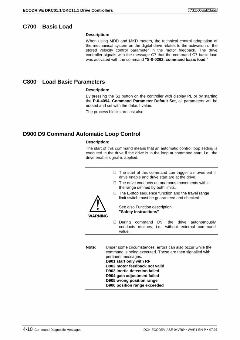
D900 D9 Command Automatic Loop ControlDescription:
The start of this command means that an automatic control loop setting isexecuted in the drive if the drive is in the loop at command start, i.e., thedrive enable signal is applied.
WARNING
⇒ The start of this command can trigger a movement ifdrive enable and drive start are at the drive.
⇒ The drive conducts autonomous movements withinthe range defined by both limits.
⇒ The E-stop sequence function and the travel rangelimit switch must be guaranteed and checked.
See also Function description:"Safety Instructions"
⇒ During command D9, the drive autonomouslyconducts motions, i.e., without external commandvalue.
Note : Under some circumstances, errors can also occur while thecommand is being executed. These are then signalled withpertinent messages.D901 start only with RFD902 motor feedback not validD903 inertia detection failedD904 gain adjustment failedD905 wrong position rangeD906 position range exceeded
ECODRIVE DKC01.1/DKC11.1 Drive Controllers
DOK-ECODRV-ASE-04VRS**-WAR1-EN-P • 07.97 Command Diagnostic Messages 4-11
D901 Sart Only With RFDescription:
To ensure that the drive is in the loop when starting the command P-0-0162, D9 automatic control loop setting, such is queried at commandstart.
Cause:
Drive enable not set at command start (NO-RF)
Remedy:
Set drive enable and restart command.
D902 Motor Feedback Not ValidDescription:
At the start of the automatic control loop setting (P-0-0162), the motorparameters
• torque constant
• rated current of unit are read out of the feedback.
Cause:
One of the above feedback data has a value smaller than or equal to zero(<=0). This means that the controller parameter is incorrectly calculated.
Remedy:
If known, write the correct values back into the parameter or contactIndramat Customer Service to obtain the feedback data valid for yourmotor.
In the worst case, it may be necessary to replace the motor.
D903 Inertia Detection FailedDescription:
At the start of the automatic control loop setting, the load moment ofinertia is determined with an "oscillation attempt".
This means that the speed change and the motor current must exceed aminimum value during acceleration or deceleration to guarantee asensible and sufficiently precise calculation of the moment of inertia.
Cause:
• drive acceleration too low
• number of measured value too small for automatic control loop setting
• motor speed too low
• load moment of inertia too big
ECODRIVE DKC01.1/DKC11.1 Drive Controllers
4-12 Command Diagnostic Messages DOK-ECODRV-ASE-04VRS**-WAR1-EN-P • 07.97
Remedy:
• increase bipolar torque/force value S-0-0092
• increase pos. accel S-0-0260
• increase pos. speed S-0-0259
• increase feedrate override S-0-0108
D904 Gain Adjustment FailedDescription:
In exceptional cases, difficulties in the automatic control loop setting mayarise. This means that an automatic setting is not possible. Standard ordefault values must therefore be loaded into the drive.
Cause:
• oscillating mechanical systems (resonance)
• high level of interference in the encoder signal
Remedy:
Satisfactory results can sometimes be achieved by starting the commandP-0-0162, D9 automatic control loop setting with a large P-0-0163,damping factor for automatic control loop setting , i.e., low dynamics.
This value can be reduced until the control loop behaves as needed.
If even then control loop settings remain unsuccessful, then the settingmust be manual.
Note : A manual setting should only be necessary in exceptionalcases!
D905 Wrong Position RangeDescription:
Before starting an automatic control loop setting, both travel range limits,i.e., upper and lower, must be defined.
When starting command P-0-0162, D9 automatic control loop settingthe number values are automatically checked for validity. It is checked ifthe traversing path is large enough and if sensible values have beenentered.
Possible fault causes:
• P-0-0167, upper traversing range smaller than P-0-0166, lowertraversing range
• Maximum traversing path (= upper - lower limits) is less than 6 motorrotations and thus too small to start the automatic control loop setting.
ECODRIVE DKC01.1/DKC11.1 Drive Controllers
DOK-ECODRV-ASE-04VRS**-WAR1-EN-P • 07.97 Command Diagnostic Messages 4-13
Remedy:
• clear command error by ending the command
• a) input new limits whereby:upper > lower limitsb) redefine limits to define a larger traversing range
• restart command with sensible traversing range
D906 Position Range ExceededDescription:
During automatic control loop setting, there is a constant monitoring of thevalid traversing range P-0-0166 and P-0-0167.
Cause:
If only one of these limits is exceeded, then command error D906 isgenerated and the drive brought to standstill speed controlled.
Possible causes:
• actual position outside of defined traversing range
• limits redefined after command start
Remedy:
• clear command error and end command
• redefine limits so that the actual position is within defined traversingrange
• retart command using sensible traversing range

ECODRIVE DKC01.1/DKC11.1 Drive Controllers
4-14 Command Diagnostic Messages DOK-ECODRV-ASE-04VRS**-WAR1-EN-P • 07.97
Notes
ECODRIVE DKC01.1/DKC11.1 Drive Controllers
DOK-ECODRV-ASE-04VRS**-WAR1-EN-P • 07.97 State diagnostic message 5-1
5 State diagnostic message
A002 Communication Phase 2Parameter Mode
A003 Communication Phase 3Parameter Mode
A010 Drive HaltDescription:
With the set control, the function drive halt would be activated. The drive-stop-function serves to stop the motor with a defined acceleration anddefined jerk.
The acceleration or the jerk limit of the inputted position block functionsduring "linked block operation."
The acceleration limit and bipolar jerk value function during joggingoperation and stepper motor interface.
The drive will be brought to stand still by the velocity command zeroswitch during torque regulation and velocity regulation.
A012 Control and Power Sections Ready for OperationDescription:
The drive is supplied with control voltage and the power is switched on.The drive is ready for power delivery.
A013 Ready for Power ONDescription:
The drive is supplied with a control voltage; there are no errors in thecontrol drive. The drive is ready to be turned on.
A100 Drive in Torque ModeDescription:
The drive is functioning in torque mode. The drive follows the given torquecommand value received over the analog channels E1 and E2.
ECODRIVE DKC01.1/DKC11.1 Drive Controllers
5-2 State diagnostic message DOK-ECODRV-ASE-04VRS**-WAR1-EN-P • 07.97
A101 Drive in Velocity ModeDescription:
The drive is functioning in velocity mode. The drive follows the givenvelocity command value received over the analog channels E1 and E2.
A111 Velosity Synchronisation, Real Lead DriveDescription:
The drive is in speed control. The speed command value is derived fromthe master axis position. The master axis position is generated from theincremental encoder signals of the master axis encoder inputs.
A118 Phase Synchr., Lagless, Encoder 1, Real Lead DriveDescription:
The drive is in lag-free position control. The position command value iscalculated based on the master axis position which is derived from theincremental encoder signals.
A203 Position ModeDescription:
The drive is functioning in position control with Stepper interface. Thedevice follows the position command which will be developed out of thestepper motor signals.
A204 Position Mode / Lagless PositioningDescription:
The drive is functioning in position regulation without lag/Stepper Driveinterface. The device follows the position command which will bedeveloped out of the stepper motor signals.
A206 Position Mode / POSITION Encoder 1Description:
The drive is functioning in position regulation/Positioning drive. The driveis positioned on the selected target position with the given acceleration,velocity and jerk.
ECODRIVE DKC01.1/DKC11.1 Drive Controllers
DOK-ECODRV-ASE-04VRS**-WAR1-EN-P • 07.97 State diagnostic message 5-3
A207 Position Mode/POSITION Lagless Positioning Encoder 1Description:
The drive is functioning in position regulation without lag/PositioningInterface. The drive is positioned on the selected target position with thegiven acceleration, velocity and jerk.
AF Control Drive EnableThe drive enable signal has been applied. The drive will follow thevelocity command (normal operation)
JF Jogging in the Positive DirectionThe drive moves with a jogging velocity (P-0-4030) in the positivedirection. The motor is turning clockwise, when viewing the motor shaft.
JB Jogging in the Negative DirectionThe drive moves with a jogging velocity (P-0-4030) in the negativedirection. The motor is turning counter clockwise, when viewing the motorshaft.
ECODRIVE DKC01.1/DKC11.1 Drive Controllers
5-4 State diagnostic message DOK-ECODRV-ASE-04VRS**-WAR1-EN-P • 07.97
Notes
ECODRIVE DKC01.1/DKC11.1 Drive Controllers
DOK-ECODRV-ASE-04VRS**-WAR1-EN-P • 07.97 Procedure for Exchanging Devices 4-1
6 Exchanging Dri ve Components
Lengthy error searches in individual devices and the repair devices in themachine should be avoided because of the loss of production that wouldresult.
As a result the diagnostic message displays from ECODRIVE makes itpossible to search for the error effectively.
Defective drive components can be exchanged without any difficultywhich guarantees the quickest possible resolution of the defect and returnto operation without the lengthy assembly and adjustment work.
When you return a defective device to Indramat please include acompleted copy of the defect report found at the conclusion of thischapter. When you do this, you will get the repaired drive componentback as soon as possible and/or you can receive further assistance fromINDRAMAT.
Note : The replacement component must have exactly the sametypecode description as the component that was removed! Toinsure that this is the case, let INDRAMAT know the typcodedescription for the replacement component.
ECODRIVE DKC01.1/DKC11.1 Drive Controllers
4-2 Procedure for Exchanging Devices DOK-ECODRV-ASE-04VRS**-WAR1-EN-P • 07.97
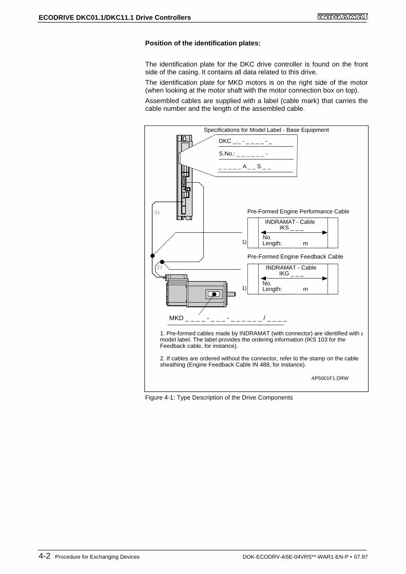
Position of the identification plates:
The identification plate for the DKC drive controller is found on the frontside of the casing. It contains all data related to this drive.
The identification plate for MKD motors is on the right side of the motor(when looking at the motor shaft with the motor connection box on top).
Assembled cables are supplied with a label (cable mark) that carries thecable number and the length of the assembled cable.
Specifications for Model Label - Base Equipment
DKC _._ - _ _ _ _ - _
S.No.: _ _ _ _ _ _ -
_ _ _ _ _ A _ _ S _ _
INDRAMAT - CableIKS _ _ _
No.Length: m
Pre-Formed Engine Performance Cable
1)
2)
2)
INDRAMAT - CableIKG _ _ _
No.Length: m
Pre-Formed Engine Feedback Cable
1)
MKD _ _ _ _ - _ _ _ - _ _ _ _ _ _ / _ _ _ _
1. Pre-formed cables made by INDRAMAT (with connector) are identified with amodel label. The label provides the ordering information (IKS 103 for the Feedback cable, for instance).
2. If cables are ordered without the connector, refer to the stamp on the cable sheathing (Engine Feedback Cable IN 488, for instance).
AP5001F1.DRW
Figure 4-1: Type Description of the Drive Components
ECODRIVE DKC01.1/DKC11.1 Drive Controllers
DOK-ECODRV-ASE-04VRS**-WAR1-EN-P • 07.97 Procedure for Exchanging Devices 4-3
6.1 Procedure for Exchanging De vices
Danger of an accident with life-threatenin g voltagelevels!
⇒ 1. Before working with electrical equipment, turn offthe main switch and take steps to insure that it will notbe switched on again.The drives must be at a stand still because motorrotations cause voltage to be generated back throughthe motor power cables.2. Do not separate live connections
Exchange the DKC:
• Turn off the main switch
• protect against the drive being turned back on prematurely
⇒ Before making contact with the connecting lines andclamps, wait for the capacitor to discharge for at least1 minute! Only then should you begin work with theconnecting cables!
• Separate the connecting lines from the DKC
• Remove the screws from the upper and lower portions of the casing.Remove the DKC from the drive package.
• Insert the new DKC and tighten the screws.
• Attach the new DKC according to the machine control plans.
• Load the parameter file from Drive Top which was saved during theinstallation into the DKC.
• Power up the machine.
ECODRIVE DKC01.1/DKC11.1 Drive Controllers
4-4 Procedure for Exchanging Devices DOK-ECODRV-ASE-04VRS**-WAR1-EN-P • 07.97
Motor exchange:
• Turn off the main switch
• protect against the drive being turned back on prematurely
Note: When the motor is exchanged, open connectors from powerconnections should be covered with protection caps to protectagainst the spread of coolant, lubricating fluid or dirt (adm.protection level V2).
• when exchanging mechanisms from the AC servo motor, pleaseobserve the directions from the machine manufacturer
⇒ Danger of accident due to undesired axismovements. For servo axes with indirect pathmeasuring systems through the motor, the absoluteposition will be lost when the motor is exchanged!This is why it is necessary to reconstruct the absoluteposition to the machine coordinate system after theexchange.
• Reconstruct the absolute position for servo axes. Acquire the positionfeedback value indirectly through the motor's own measurementsystem.
• Reconstruct the absolute position for the position feedback valueoutput when the feature "Indirect absolute position feedback valueoutput" is used.
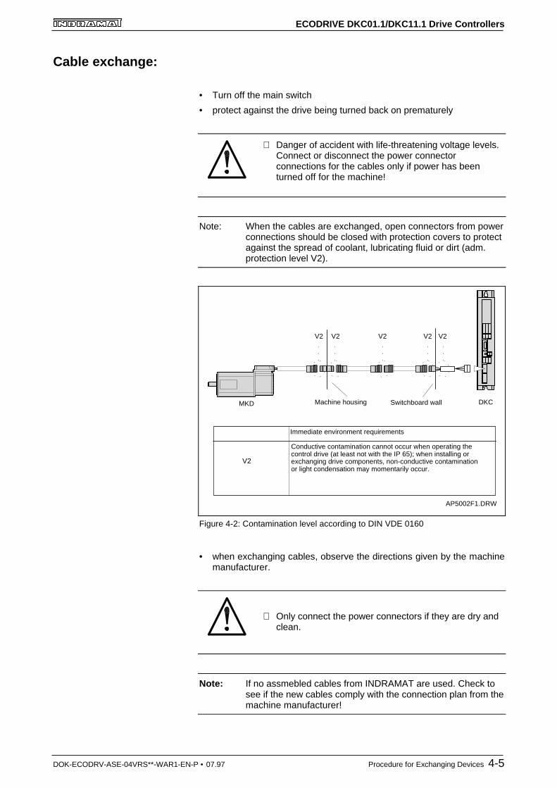
ECODRIVE DKC01.1/DKC11.1 Drive Controllers
DOK-ECODRV-ASE-04VRS**-WAR1-EN-P • 07.97 Procedure for Exchanging Devices 4-5
Cable exchange:
• Turn off the main switch
• protect against the drive being turned back on prematurely
⇒ Danger of accident with life-threatening voltage levels.Connect or disconnect the power connectorconnections for the cables only if power has beenturned off for the machine!
Note: When the cables are exchanged, open connectors from powerconnections should be closed with protection covers to protectagainst the spread of coolant, lubricating fluid or dirt (adm.protection level V2).
Switchboard wallMachine housing
V2 V2 V2 V2 V2
MKD DKC
V2
Immediate environment requirements
Conductive contamination cannot occur when operating the control drive (at least not with the IP 65); when installing or exchanging drive components, non-conductive contamination or light condensation may momentarily occur.
AP5002F1.DRW
Figure 4-2: Contamination level according to DIN VDE 0160
• when exchanging cables, observe the directions given by the machinemanufacturer.
⇒ Only connect the power connectors if they are dry andclean.
Note: If no assmebled cables from INDRAMAT are used. Check tosee if the new cables comply with the connection plan from themachine manufacturer!
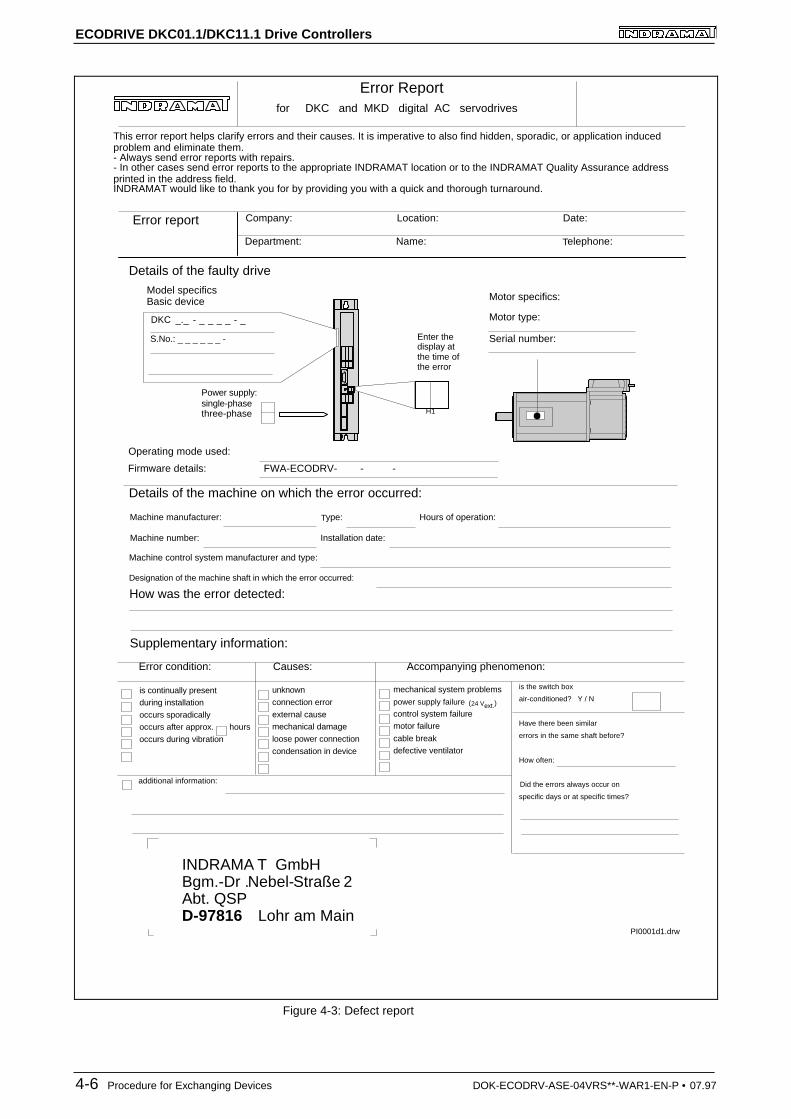
ECODRIVE DKC01.1/DKC11.1 Drive Controllers
4-6 Procedure for Exchanging Devices DOK-ECODRV-ASE-04VRS**-WAR1-EN-P • 07.97
Operating mode used:
Error Reportfor DKC and MKD digital AC servodrives
Error report Company: Date:
Error condition: Causes: Accompanying phenomenon:
is continually presentduring installation
occurs sporadicallyoccurs after approx. hours
occurs during vibration
unknown
connection error
external causemechanical damage
loose power connection
condensation in device
mechanical system problems
power supply failure (24 Vext.)
control system failuremotor failure
cable breakdefective ventilator
is the switch box
air-conditioned? Y / N
Have there been similar
errors in the same shaft before?
How often:
Did the errors always occur on
specific days or at specific times?
additional information:
Supplementary information:
Details of the machine on which the error occurred:
How was the error detected:
Machine manufacturer:
Machine number:
Type: Hours of operation:
Installation date:
Machine control system manufacturer and type:
Designation of the machine shaft in which the error occurred:
Location:
Department: Telephone:Name:
Details of the faulty drive
PI0001d1.drw
H1
Enter thedisplay atthe time ofthe error
Serial number:
Motor type:
Motor specifics:
Power supply:single-phasethree-phase
Model specificsBasic device
INDRAMA T GmbHBgm.-Dr .Nebel-Straße 2Abt. QSPD-97816 Lohr am Main
DKC _._ - _ _ _ _ - _
S.No.: _ _ _ _ _ _ -
Firmware details: FWA-ECODRV- - -
This error report helps clarify errors and their causes. It is imperative to also find hidden, sporadic, or application induced problem and eliminate them.- Always send error reports with repairs.- In other cases send error reports to the appropriate INDRAMAT location or to the INDRAMAT Quality Assurance address printed in the address field.INDRAMAT would like to thank you for by providing you with a quick and thorough turnaround.
Figure 4-3: Defect report
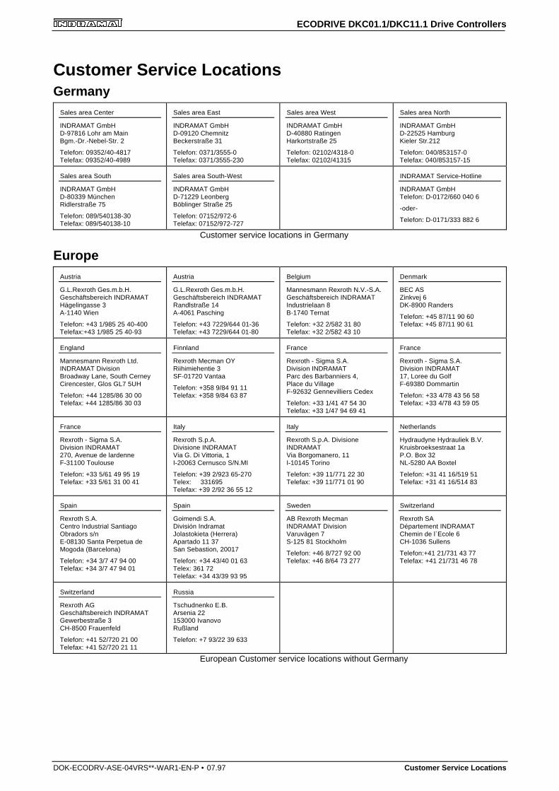
ECODRIVE DKC01.1/DKC11.1 Drive Controllers
DOK-ECODRV-ASE-04VRS**-WAR1-EN-P • 07.97 Customer Service Locations
Customer Service LocationsGermany
Sales area Center
INDRAMAT GmbHD-97816 Lohr am MainBgm.-Dr.-Nebel-Str. 2
Telefon: 09352/40-4817Telefax: 09352/40-4989
Sales area East
INDRAMAT GmbHD-09120 ChemnitzBeckerstraße 31
Telefon: 0371/3555-0Telefax: 0371/3555-230
Sales area West
INDRAMAT GmbHD-40880 RatingenHarkortstraße 25
Telefon: 02102/4318-0Telefax: 02102/41315
Sales area North
INDRAMAT GmbHD-22525 HamburgKieler Str.212
Telefon: 040/853157-0Telefax: 040/853157-15
Sales area South
INDRAMAT GmbHD-80339 MünchenRidlerstraße 75
Telefon: 089/540138-30Telefax: 089/540138-10
Sales area South-West
INDRAMAT GmbHD-71229 LeonbergBöblinger Straße 25
Telefon: 07152/972-6Telefax: 07152/972-727
INDRAMAT Service-Hotline
INDRAMAT GmbHTelefon: D-0172/660 040 6
-oder-
Telefon: D-0171/333 882 6
Customer service locations in Germany
EuropeAustria
G.L.Rexroth Ges.m.b.H.Geschäftsbereich INDRAMATHägelingasse 3A-1140 Wien
Telefon: +43 1/985 25 40-400Telefax:+43 1/985 25 40-93
Austria
G.L.Rexroth Ges.m.b.H.Geschäftsbereich INDRAMATRandlstraße 14A-4061 Pasching
Telefon: +43 7229/644 01-36Telefax: +43 7229/644 01-80
Belgium
Mannesmann Rexroth N.V.-S.A.Geschäftsbereich INDRAMATIndustrielaan 8B-1740 Ternat
Telefon: +32 2/582 31 80Telefax: +32 2/582 43 10
Denmark
BEC ASZinkvej 6DK-8900 Randers
Telefon: +45 87/11 90 60Telefax: +45 87/11 90 61
England
Mannesmann Rexroth Ltd.INDRAMAT DivisionBroadway Lane, South CerneyCirencester, Glos GL7 5UH
Telefon: +44 1285/86 30 00Telefax: +44 1285/86 30 03
Finnland
Rexroth Mecman OYRiihimiehentie 3SF-01720 Vantaa
Telefon: +358 9/84 91 11Telefax: +358 9/84 63 87
France
Rexroth - Sigma S.A.Division INDRAMATParc des Barbanniers 4,Place du VillageF-92632 Gennevilliers Cedex
Telefon: +33 1/41 47 54 30Telefax: +33 1/47 94 69 41
France
Rexroth - Sigma S.A.Division INDRAMAT17, Loree du GolfF-69380 Dommartin
Telefon: +33 4/78 43 56 58Telefax: +33 4/78 43 59 05
France
Rexroth - Sigma S.A.Division INDRAMAT270, Avenue de lardenneF-31100 Toulouse
Telefon: +33 5/61 49 95 19Telefax: +33 5/61 31 00 41
Italy
Rexroth S.p.A.Divisione INDRAMATVia G. Di Vittoria, 1I-20063 Cernusco S/N.MI
Telefon: +39 2/923 65-270Telex: 331695Telefax: +39 2/92 36 55 12
Italy
Rexroth S.p.A. DivisioneINDRAMATVia Borgomanero, 11I-10145 Torino
Telefon: +39 11/771 22 30Telefax: +39 11/771 01 90
Netherlands
Hydraudyne Hydrauliek B.V.Kruisbroeksestraat 1aP.O. Box 32NL-5280 AA Boxtel
Telefon: +31 41 16/519 51Telefax: +31 41 16/514 83
Spain
Rexroth S.A.Centro Industrial SantiagoObradors s/nE-08130 Santa Perpetua deMogoda (Barcelona)
Telefon: +34 3/7 47 94 00Telefax: +34 3/7 47 94 01
Spain
Goimendi S.A.División IndramatJolastokieta (Herrera)Apartado 11 37San Sebastion, 20017
Telefon: +34 43/40 01 63Telex: 361 72Telefax: +34 43/39 93 95
Sweden
AB Rexroth MecmanINDRAMAT DivisionVaruvägen 7S-125 81 Stockholm
Telefon: +46 8/727 92 00Telefax: +46 8/64 73 277
Switzerland
Rexroth SADépartement INDRAMATChemin de l`Ecole 6CH-1036 Sullens
Telefon:+41 21/731 43 77Telefax: +41 21/731 46 78
Switzerland
Rexroth AGGeschäftsbereich INDRAMATGewerbestraße 3CH-8500 Frauenfeld
Telefon: +41 52/720 21 00Telefax: +41 52/720 21 11
Russia
Tschudnenko E.B.Arsenia 22153000 IvanovoRußland
Telefon: +7 93/22 39 633
European Customer service locations without Germany
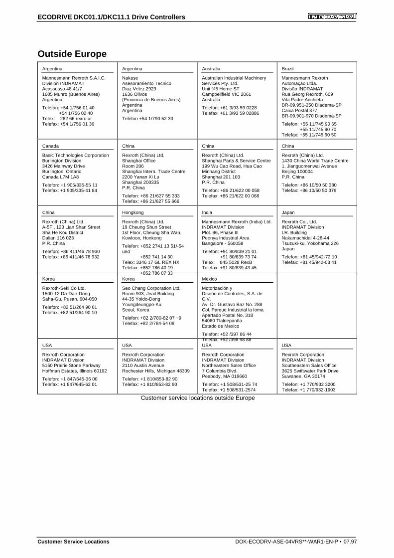
ECODRIVE DKC01.1/DKC11.1 Drive Controllers
Customer Service Locations DOK-ECODRV-ASE-04VRS**-WAR1-EN-P • 07.97
Outside EuropeArgentina
Mannesmann Rexroth S.A.I.C.Division INDRAMATAcassusso 48 41/71605 Munro (Buenos Aires)Argentina
Telefon: +54 1/756 01 40 +54 1/756 02 40Telex: 262 66 rexro arTelefax: +54 1/756 01 36
Argentina
NakaseAsesoramiento TecnicoDiaz Velez 29291636 Olivos(Provincia de Buenos Aires)ArgentinaArgentina
Telefon +54 1/790 52 30
Australia
Australian Industrial MachineryServices Pty. Ltd.Unit ¾5 Horne STCampbellfield VIC 2061Australia
Telefon: +61 3/93 59 0228Telefax: +61 3/93 59 02886
Brazil
Mannesmann RexrothAutomação Ltda.Divisão INDRAMATRua Georg Rexroth, 609Vila Padre AnchietaBR-09.951-250 Diadema-SPCaixa Postal 377BR-09.901-970 Diadema-SP
Telefon: +55 11/745 90 65 +55 11/745 90 70Telefax: +55 11/745 90 50
Canada
Basic Technologies CorporationBurlington Division3426 Mainway DriveBurlington, OntarioCanada L7M 1A8
Telefon: +1 905/335-55 11Telefax: +1 905/335-41 84
China
Rexroth (China) Ltd.Shanghai OfficeRoom 206Shanghai Intern. Trade Centre2200 Yanan Xi LuShanghai 200335P.R. China
Telefon: +86 21/627 55 333Telefax: +86 21/627 55 666
China
Rexroth (China) Ltd.Shanghai Parts & Service Centre199 Wu Cao Road, Hua CaoMinhang DistrictShanghai 201 103P.R. China
Telefon: +86 21/622 00 058Telefax: +86 21/622 00 068
China
Rexroth (China) Ltd.1430 China World Trade Centre1, Jianguomenwai AvenueBeijing 100004P.R. China
Telefon: +86 10/50 50 380Telefax: +86 10/50 50 379
China
Rexroth (China) Ltd.A-5F., 123 Lian Shan StreetSha He Kou DistrictDalian 116 023P.R. China
Telefon: +86 411/46 78 930Telefax: +86 411/46 78 932
Hongkong
Rexroth (China) Ltd.19 Cheung Shun Street1st Floor, Cheung Sha Wan,Kowloon, Honkong
Telefon: +852 2741 13 51/-54und +852 741 14 30Telex: 3346 17 GL REX HXTelefax: +852 786 40 19 +852 786 07 33
India
Mannesmann Rexroth (India) Ltd.INDRAMAT DivisionPlot. 96, Phase IIIPeenya Industrial AreaBangalore - 560058
Telefon: +91 80/839 21 01 +91 80/839 73 74Telex: 845 5028 RexBTelefax: +91 80/839 43 45
Japan
Rexroth Co., Ltd.INDRAMAT DivisionI.R. BuildingNakamachidai 4-26-44Tsuzuki-ku, Yokohama 226Japan
Telefon: +81 45/942-72 10Telefax: +81 45/942-03 41
Korea
Rexroth-Seki Co Ltd.1500-12 Da-Dae-DongSaha-Gu, Pusan, 604-050
Telefon: +82 51/264 90 01Telefax: +82 51/264 90 10
Korea
Seo Chang Corporation Ltd.Room 903, Jeail Building44-35 Yoido-DongYoungdeungpo-KuSeoul, Korea
Telefon: +82 2/780-82 07 ~9Telefax: +82 2/784-54 08
Mexico
Motorización yDiseño de Controles, S.A. deC.V.Av. Dr. Gustavo Baz No. 288Col. Parque Industrial la IomaApartado Postal No. 31854060 TlalnepantlaEstado de Mexico
Telefon: +52 /397 86 44Telefax: +52 /398 98 88
USA
Rexroth CorporationINDRAMAT Division5150 Prairie Stone ParkwayHoffman Estates, Illinois 60192
Telefon: +1 847/645-36 00Telefax: +1 847/645-62 01
USA
Rexroth CorporationINDRAMAT Division2110 Austin AvenueRochester Hills, Michigan 48309
Telefon: +1 810/853-82 90Telefax: +1 810/853-82 90
USA
Rexroth CorporationINDRAMAT DivisionNortheastern Sales Office7 Columbia Blvd.Peabody, MA 019660
Telefon: +1 508/531-25 74Telefax: +1 508/531-2574
USA
Rexroth CorporationINDRAMAT DivisionSoutheastern Sales Office3625 Swiftwater Park DriveSuwanee, GA 30174
Telefon: +1 770/932 3200Telefax: +1 770/932-1903
Customer service locations outside Europe
ECODRIVE DKC01.1/DKC11.1 Drive Controllers
DOK-ECODRV-ASE-04VRS**-WAR1-EN-P • 07.97 Customer Service Locations
Notes
ECODRIVE DKC01.1/DKC11.1 Drive Controllers
Customer Service Locations DOK-ECODRV-ASE-04VRS**-WAR1-EN-P • 07.97
Notes


Indramat