ece2262 electric circuits chapter 5: circuit...
TRANSCRIPT

1
ECE2262 Electric Circuits
Chapter 5: Circuit Theorems

2
Equivalence
Linearity
Superposition
Thevenin’s and Norton’s Theorems
Maximum Power Transfer
Analysis of Circuits Using Circuit Theorems

3
5. 1 Equivalence
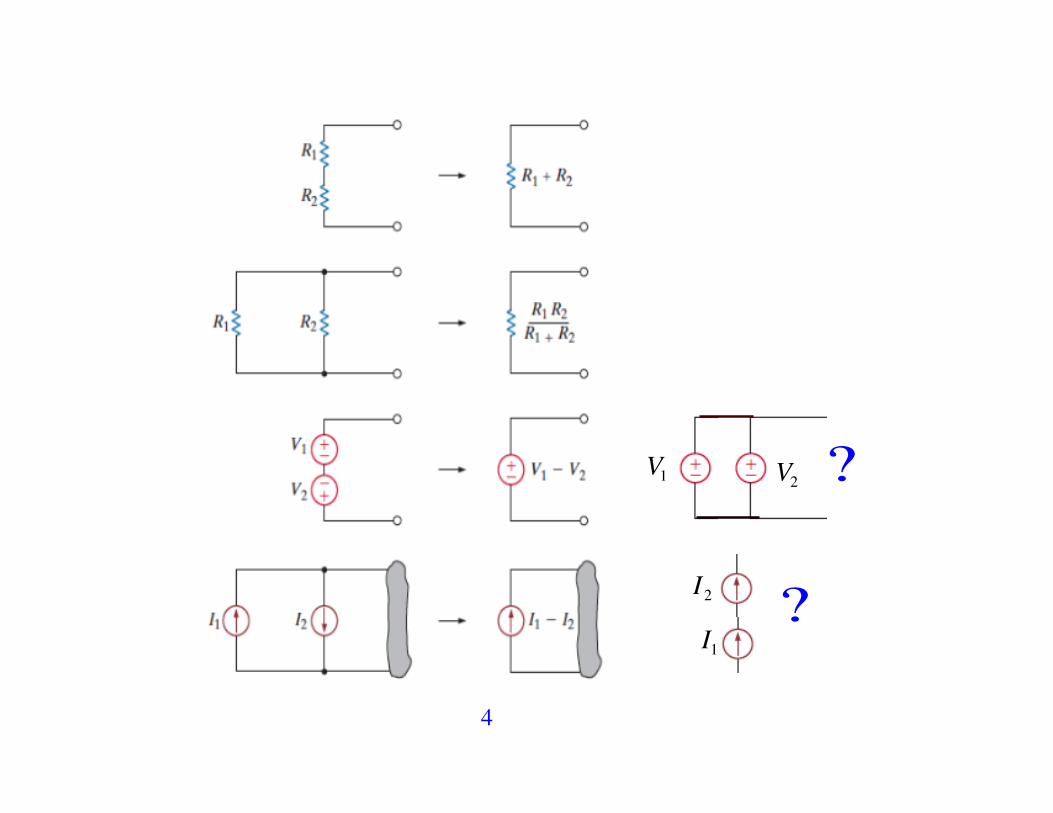
Two circuits are equivalent if they have the same i-v characteristics at a specified pair of terminals
Our aim is to simplify analysis replacing complicated sub-circuits by simpler equivalent circuits
4
V1 V2
I1
I2
?
?

5
Source Transformation A source transformation allows a voltage source in series with a resistor to be replaced by a current source in parallel with the same resistor or vice versa.
a
b
a
b
RL RL!
• The current in RL • The current in RL
iL =vs
R + RL
iL =R
R + RL
is
These circuits are equivalent if these resistor currents are the same
vsR + RL
= RR + RL
is ! is =vsR
vs = Ris

6
The resistance in parallel with the voltage source
The resistance in series with the current source
These circuits are equivalent with respect to terminals a,b since they produce the same voltage and current in any resistor RL inserted between nodes a,b .

7
Example Find the power P6V = 6V ! i6V
We could use the node-voltage method with 3 node-voltage equations
Let’s use the source transformation strategy by reducing the circuit in a way that preserves the identity of the branch containing the 6 V source.
!

8
Step 1
Step 2 20! || 5! = 4! and 4!" 8A = 32V
6 + 4 + 10 = 20! in series with 32 V source ! 32V20!
= 1.6A

9
Step 3
Step 4 30! || 20! = 12! and 12!"1.6A = 19.2V
The current in the direction of the voltage drop across the 6 V source is
i6V = 19.2 ! 616
= 0.825A ! P6V = 6V ! i6V = 4.95 W (absorbing)

10
Example Find v0 and P250V , P8A
Remove the resistors 125 ! and 10 ! , they do not influence the formula for
v0 ! equivalent circuit
source transformation

11
25 ||100 || 20 = 10 !
v0 = 2A!10" = 20V

12
P250V ! need I250V
I250V = 250125
+ 250 ! v025
= 250125
+ 250 ! 2025
= 11.2
P250V = 250 !11.2 = 2800 W (delivering)

13
P8A ! need V8A
v0 !10 " 8 !V8A = 0 ! V8A = 20 ! 80 = !60V
P8A =V8A ! 8A = "480 W (delivering)

14
5. 2 Linearity = additivity + homogeneity
v1v2 v3
ix
2ix
2!is
vs
4!
1!
The node-voltage method v1 : v1 = vs
v2 : v2 ! v14
+ 2 ixv1!v32
! + is = 0 ! 34v1 +
14v2 ! v3 = !is
v3 : v31+ v3 ! v1
2! is = 0 ! ! 1
2v1 +
32v3 = is
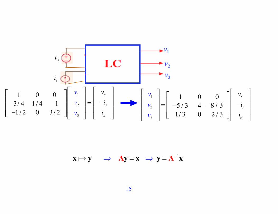
15
vs
is
1 0 03/ 4 1 / 4 !1!1 / 2 0 3 / 2
"
#
$$$
%
&
'''
v1v2v3
"
#
$$$
%
&
'''=
vs!isis
"
#
$$$
%
&
'''
v1v2v3
"
#
$$$
%
&
'''=
1 0 0!5 / 3 4 / 3 01/ 3 0 2 / 3
"
#
$$$
%
&
'''
vs!isis
"
#
$$$
%
&
'''
4 8 / 3
x! y ! Ay = x ! y = A!1x

16
Additivity: If x1! y1 and x2 ! y2 then x1 + x2 ! y1 + y2 Homogeneity: If x! y then
!x!!y for any number !
vs
is
!v
!
!
vs, is( ) = 4V, 2A( ) v = 3V
"8V ,"4A( ) v =

17
Additivity: If x1! y1 and x2 ! y2 then x1 + x2 ! y1 + y2
Homogeneity: If x! y then !x!!y for any number ! ! Linearity: x1! y1 and x2 ! y2 then
!1x1 +! 2x2 !!1y1 +! 2y2
for any numbers !1 , ! 2
18
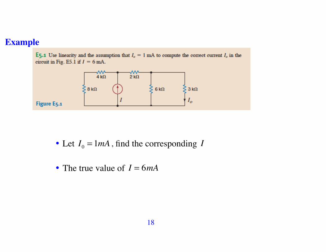
Example
• Let I0 = 1mA , find the corresponding I • The true value of I = 6mA

19
I2I3
I0 = 1mA
• CD: I0 =66 + 3
I2 =23I2 ! I2 =
32I0 =
32mA
• 3 || 6 + 2 = 4k! ! VI = I2 ! 4 = 6V • I3 =VI4 + 8
= 12
mA
• I = I2 + I3 =32+ 12= 2mA
Hence for the assumed I0 = 1mA we have I = 2mA , then by the linearity if I = 6mA = 3! 2 ! 3!1= 3mA ! I0

20
Example: Circuits 1 and 2 below are identical except for the voltage sources. Assuming that I1 = 5A then the value of I2 is ?
I2+

21
5. 3 Superposition
Superposition Principle:
Let f1,... fN be set of independent source strengths (vS ,iS ) in a linear resistive circuit. Then, any electrical response y in the circuit v,i( ) can be expressed as y = k1 f1 + k2 f2 + ....+ kN fN ,where k1,..,kN are constants coefficients, unique for each response

22
In any linear circuit containing multiple independent sources, the current or voltage at any point in the network may be calculated as the algebraic sum of the individual contributions of each source acting alone.
The principle of superposition allows us to reduce a complicated multi- source problem to several simple problems. Each problem contains only a single independent source.
= 0 = 0

23

24
Example
v1v2 v3
ix
2ix
2!is
vs
4!
1!
• If vs = 0 (short circuit) ! v1' = 0 , v2
' = ! 43is , v3
' = 23is
• If is = 0 (open circuit) ! v1'' = vs , v2
'' = ! 53vs , v3
'' = 13vs
• It is clear that v1 = v1' + v1
'' , v2 = v2' + v2
'' , v3 = v3' + v3
''

25

26
Example 5.3 Find V0
(a) Inactivate the 3V source ! Response to 2 mA
CD: I0 =1+ 21+ 2 + 6
! 2m = 23mA ! V0
' = I0 ! 6k = 4V

27
(b) Inactivate the 2mA source ! Response to 3 V
V0'' = 6
6 + 2 +1! 3V = 2 V
By the superposition principle: V0 =V0' +V0
'' = 4 + 2 = 6 V.

28
Example 5.4 Find V0
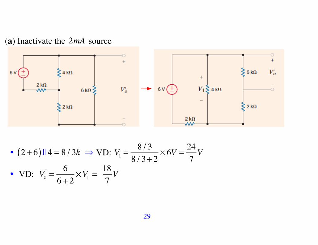
29
(a) Inactivate the 2mA source
• 2 + 6( ) || 4 = 8 / 3k ! VD: V1 =8 / 38 / 3+ 2
! 6V = 247V
• VD: V0' = 66 + 2
!V1 = 187V

30
(b) Inactivate the 6 V source
• 2 || 4 = 4 / 3k ! V0'' = 2 + 4
3!"#
$%& || 6 ' 2m = 30
7V
By the superposition principle: V0 =V0' +V0
'' = 187+ 307
= 487
! 6.86V

31
Example Find v0 : circuit with dependent sources
(a) Response to the 10 V source

32
• v!' = "0.4 # v!
'( )#10 ! v!' = 0 ! 0.4 ! v"
' = 0
• v0' = 205 + 20
!10 = 8V

33
(b) Response to the 5 A source
• KCL at a : v0''
5+ v0
''
20! 0.4 " v#
'' = 0 ! 5v0'' ! 8v"
'' = 0
• KCL at b: 0.4 ! v"'' + vb # 2i"
''
10# 5 = 0
! 4v!
'' + vb " 2i!'' = 50 ! v!
'' = vb " 2i!'' & i!
'' = "v0'' / 5

34
• Hence we have 5v0
'' ! 8v"'' = 0 and 4v!
'' + vb " 2i!'' = 50 ! v!
'' = vb " 2i!'' & i!
'' = "v0'' / 5
! 9v0
'' ! 40vb = 02v0
'' + 5vb = 50
"#$%
! v0'' = 16V & vb = 18 / 5V
• By the superposition principle: v0' + v0
'' = 8 +16 = 24 V

35
Example Superposition Applied to Op-Amp Circuits

36
• Contribution of V1
This is a basic inverting circuit: V01 = ! R2R1V1

37
• Contribution of V2
This is a basic non-inverting circuit: V02 = 1+ R2R1
!"#
$%&V2
Principle of Superposition: V0 =V01 +V02 = ! R2R1V1 + 1+ R2
R1
"#$
%&'V2

38

39

40
Warning: Power does not obey superposition

41
5. 4 Thevenin’s and Norton’s Theorems
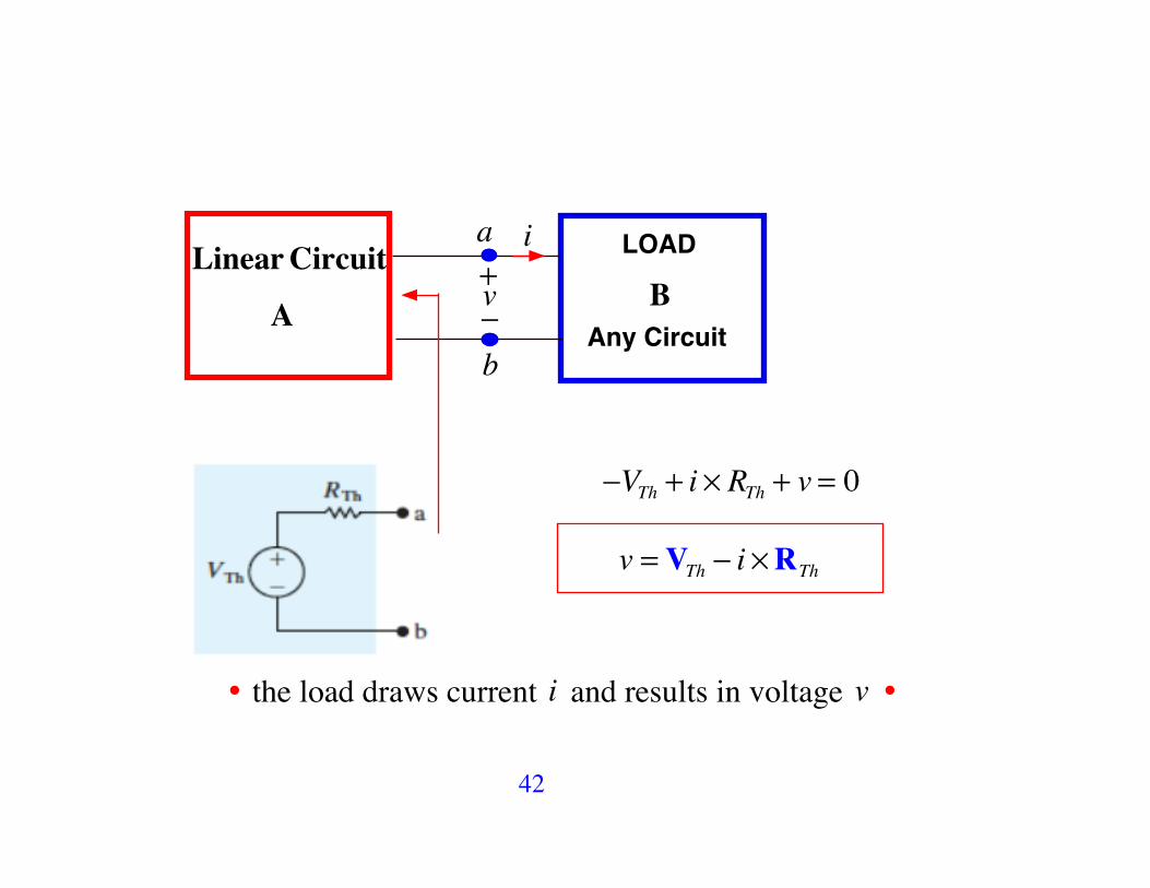
42
Linear Circuit
A BLOAD
Any Circuit
i
v+!
a
b
!VTh + i " RTh + v = 0
v = VTh ! i "RTh
• the load draws current i and results in voltage v •

43
Thevenin Equivalent of Circuit A
BLOAD
Any Circuit
i
v+!
a
b
v = VTh ! i "RTh
A
• The values of VTh (Thevenin voltage) and RTh may be either positive or negative
• RTh - the Thevenin resistance is a quantity in a mathematical model - it is not a physical resistor
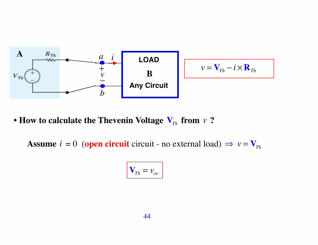
44
BLOAD
Any Circuit
i
v+!
a
b
v = VTh ! i "RTh
A
• How to calculate the Thevenin Voltage VTh from v ?
Assume i = 0 (open circuit circuit - no external load) ! v = VTh
VTh = voc

45
Norton Equivalent of Circuit A
BLOAD
Any Circuit
i
v+!
a
b
v = VTh ! i "RThIN
IN =VThRTh
ARTh
• How to calculate the Norton Current IN from v?
v = VTh ! i "RTh !
vRTh
= VThRThIN!
! i
Assume v = 0 (short circuit) ! IN = isc

46
RTh - The Thevenin Resistance 1. The most general way for obtaining RTh is to use
RTh =VThIN
,
where • VTh = voc - open circuit voltage
• IN = isc - short circuit current

47
2. The Thevenin resistance RTh can be determined directly by a source suppression method without finding the Thevenin voltage and Norton current. This applies directly to circuits that contain only independent sources. This is a result of the linearity property of the circuit.
RTh =VThIN
= VTh !!IN !!
! - scaling applied to independent sources
! ! 0 - the Thevenin resistance remains unchanged even in the limit case when all independent sources are suppressed to zero.

48
(1) Replace all independent voltage sources in the circuit by short circuits and all independent current sources by open circuits
a
b
Independent SourcesDeactivated
RThA
(2) If the remaining circuit contains no dependent sources, then RTh is the equivalent resistance, which can be determined by using series/parallel resistor combinations.

49
A. Thevenin/Norton Equivalent for Circuits with Independent Sources
Example Find a Thevenin/Norton Equivalent
1. Open circuit voltage at a ! b : vab = v1 ! the voltage across the 3 A source
KCL : v1 ! 255
+ v120
! 3 = 0 ! v1 = 32V ! voc = 32V

50
2. Short circuit current at a ! b :
KCL: v2 ! 255
+ v220
! 3+ v224= 0 ! v2 = 16 V
isc =164
= 4A ! RTh =vocisc
= 324
= 8 !

51
3. The Thevenin Equivalent
4. The Norton Equivalent

52
5. The Thevenin resistance ! Direct Method
RTh
RTh = 4 + 20 || 5 = 8!

53
6. The circuit with load
24!
24!
V24! = 2424 + 8
" 32 = 24V
I24! = 24V24!
= 1A ! P24! = 12 " 24 = 24W
54
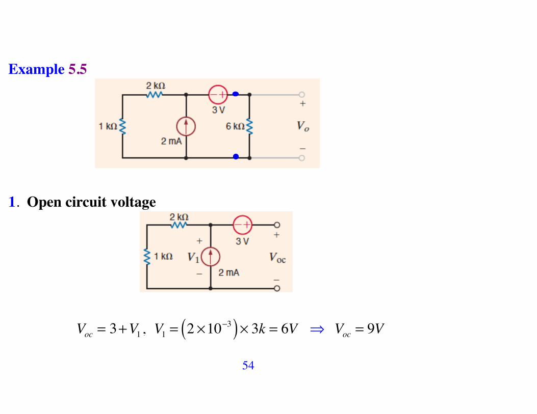
Example 5.5
1. Open circuit voltage
Voc = 3+V1 , V1 = 2 !10"3( )! 3k = 6V ! Voc = 9V

55
2. Short circuit current
Isc = 2m + I1
= 2m + 3V3k
= 2m +1m = 3mA
RTh =VocIsc
= 9V3m
= 3k

56
3. RTh
RTh = 3k! !

57
4. The circuit with load
V0 =66 + 3
! 9 = 6V ! P6k! = 62
6k= 6mW

58
Example 5.6 Find V0
12V

59
1. Open circuit voltage and RTh
Voc1 =V6k =66 + 3
!12 = 8V
RTh = 2 + 3 || 6 = 4k!

60
2. Circuit with load

61
3. Second Iteration

62
• Open circuit voltage and RTh
Voc2 = 8 + 2m ! 4k = 16V
RTh = 4k!

63
4. Circuit with load
16V
V0 =8
8 + 4 + 4!16 = 8V

64
Example 5.7 Find V0

65
1. Open circuit voltage and RTh
• Mesh-Current Method: !6 + 4k " I1 + 2k " I1 ! I2( ) = 0I2 = 2m
#$%
! I1 = 5 / 3 mA
• KVL: Voc = 4k ! I1 + 2k ! I2 "Voc =203+ 4 = 32
3V
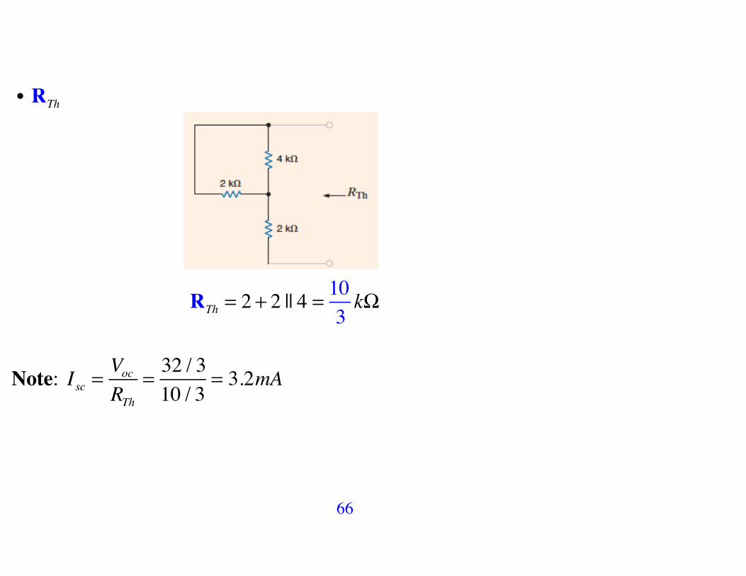
66
• RTh
RTh = 2 + 2 || 4 =103k!
Note: Isc =VocRTh
= 32 / 310 / 3
= 3.2mA

67
2. Thevenin Equivalent with Load
Thevenin
V0 =6
6 + 103
! 323
= 487
V = 6.857...V

68
B. Thevenin and Norton Equivalent for Circuits with Dependent Sources
Valid and Invalid Partitions
We cannot split the dependent source and its controlling variable when we break the circuit to find the equivalent Thevenin/Norton circuits

69
B1 Thevenin/Norton Equivalent for Circuits with Only Dependent Sources: Test Source Approach
I0
RTh =1VI0
RTh =V01mA
V0

70
Example 5.8 Find RTh
I0
RTh =1VI0
• Voc = ?
• Thevenin equivalent ?

71
I0 = I1 + I2 + I3 • KVL (big loop): !V1 !Vx +1 = 0 ! V1 = 1!Vx
• KCL (at V1 ): V11k
+ V1 ! 2Vx2k
+ V1 !11k
= 0 ! Vx =37V
• I0 = I1 + I2 + I3 ! I1 =Vx1k
= 37mA , I2 =
1! 2Vx1k
= 17mA , I3 =
12k
= 12mA
! I0 =1514
mA ! RTh =1 VI0
= 1415
k!

72
Example 5. 9 Find RTh
• Voc = ?
• Thevenin equivalent ?

73
V1
RTh =V2
1 mAV2
• KCL: V1 : V1 ! 2000Ix
2k+ V11k
+ V1 !V23k
= 0 ! Ix =V11k
V2 : V2 !V13k
+ V22k
!1m = 0
! V2 =107V ! RTh =
V2
1 mA= 10
7k!

74
B2 Thevenin/Norton Equivalent for Circuits with Both Independent and Dependent Sources
Example 5.10 Find V0

75
supernodeVoc +12
1. Open circuit voltage
• KCL at the supernode: Voc +12( )+ 2000Ix'
1k+ Voc +12
2k+ Voc2kIx'!
= 0
Since Ix' = Voc
2k ! Voc = !6V !VTh = "6V

76
2. Short circuit current and RTh
!
Isc = ! 121|| 2k
= ! 122 / 3k
= !18mA
RTh =VocIsc
= !6V!18mA
= 13k!

77
3. Circuit with Load
Thevenin
Vo =1
1+1+ 13
! "6( ) = "187V = - 2.57…V
78
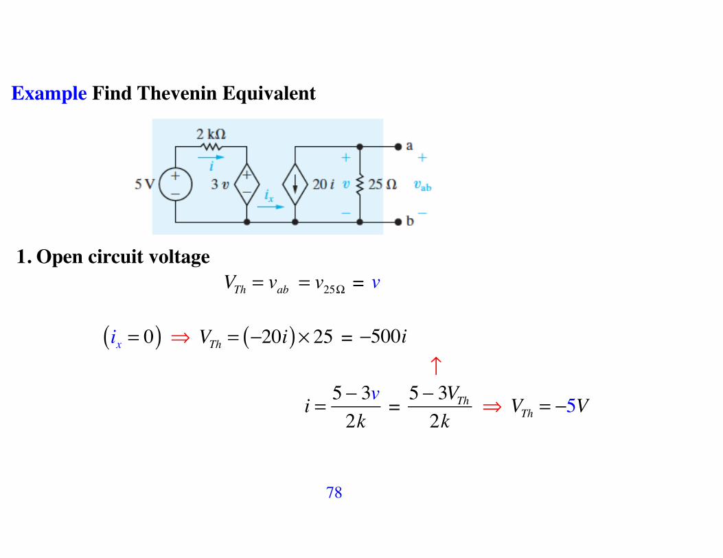
Example Find Thevenin Equivalent
1. Open circuit voltage VTh = vab = v25! = v
ix = 0( ) ! VTh = !20i( )" 25 = !500i !
i = 5 ! 3v2k
= 5 ! 3VTh2k
! VTh = !5V

79
2. Short circuit current and RTh
! v = 0 !
isc = !20i , i = 52k
= 2.5mA ! isc = !20 " 2.5 = !50mA
RTh =VThisc
= !5!50m
= 100"
Thevenin

80
Find the Thevenin Equivalent RTh Using a Test Source The equivalent method is to first deactivate all independent sources and then apply either a test voltage source or a test current source The Thevenin resistance RTh is calculated as
• RTh =VtestI0
• RTh =V0Itest

81
Example
Deactivate the independent sources and excite the circuit by a test source
Note: Use, e.g., vT = 1V

82
RTh =vTiT
• iT = vT25
+ 20i
• i = !3vT2k
= ! 32vTmA
! • iT = vT25
+ 20 ! " 32vTmA
#$%
&'( = = vT
25! 602000
vT
! • iTvT
= 125
! 6200
= 1100
! RTh =vTiT
= 100!

83

84
5. 5 Maximum Power Transfer
• Circuit analysis plays an important role in the analysis of systems designed to transfer power from a source to a load.
• The efficiency of the power transfer: power utility systems are a good example of this type because they are concerned with the generation, transmission, and distribution of large quantities of electric power. If a power utility system is inefficient, a large percentage of the power generated is lost in the transmission and distribution processes, and thus wasted.
•Power transferred: communication and instrumentation systems are good examples because in the transmission of information, or data, via electric signals, the power available at the transmitter or detector is limited. Thus, transmitting as much of this power as possible to the receiver, or load, is desirable. In such applications the amount of power being transferred is small, so the efficiency of transfer is not a primary concern.

85
• We consider maximum power transfer in systems that can be modeled by a purely resistive circuit.
VTh,RTh( )
We wish to determine the value of of RL that permits maximum power delivery to RL for the given circuit represented by the Thevenin Equivalent

86
• Represent the Resistive Network by its Thevenin Equivalent
Pload = i2RL =
VThRTh + RL
!"#
$%&
2
RL 'maxRL

87
Pload =VTh
RTh + RL
!"#
$%&
2
RL
Pload
RL

88
Maximum is reached at the point where dPloaddRL
= 0 ! Pload =VTh
RTh + RL
"#$
%&'
2
RL
dPloaddRL
=VTh2 ddRL
RL
RTh + RL( )2!"#
$#
%&#
'#
= VTh2 RTh + RL( )2 ! 2RL RTh + RL( )
RTh + RL( )4"
#$$
%
&''
= 0

89
Condition for Maximum Power Transfer
RL = RTh
The Maximum Power Delivered to RL
Pload =VTh
RTh + RL
!"#
$%&
2
RL !RL=RTh! Pmax =
VTh2RTh
!"#
$%&
2
RTh
Pmax =
VTh2
4RTh

90
Example Find RL that results in max. power and the corresponding max. power that can be delivered to RL .
• VTh =150
150 + 30! 360 = 300 V • RTh = 150 || 30 = 25!

91
iL ! maxvL !max
• Pload =VTh
RTh + RL
!"#
$%&
2
RL =300
25 + RL
!"#
$%&
2
RL
Pload
RL
! RL = 25! for the maximum power transfer with
Pmax =30025 + 25
!"#
$%&
2
25 = 900W

92
Example Find RL that results in max. power and the corresponding max. power that can be delivered to RL .

93
1. RTh
RTh = 4k + 3k || 6k = 6k This is the resistance for maximum power transfer
If we wish to find the value of the power that can be transferred then we need the Thevenin voltage !

94
2. Voc
* loop 1: I1 = 2mA * loop 2: 3k I2 ! I1( )+ 6kI2 + 3V = 0 ! I2 =13mA
* KVL: Voc = 6kI2 + 4kI1 ! Voc = 10V
* Pmax =VTh2
4RTh =
102
4 ! 6k= 256mW

95
Example Find RL that results in max. power and the corresponding max. power that can be delivered to RL .

96
1. Open circuit voltage Voc
Voc ! 2000Ix'
• KCL at the supernode:
Voc ! 2000Ix
'
3k +1k+ Voc2k
! 4m = 0 and Ix' = Voc
2k ! Voc = 8V

97
2. Short circuit current Isc and RTh
• Ix
'' = 0 ! dependent source is zero ! Isc = 4mA
• RTh =8V4mA
= 2k! <-------- Obtain by the test source approach

98
3. Circuit with Load
6
• Pload ==8V
6k + RL
!"#
$%&
2
RL is maximized by RL = 6k!
• The maximum power transfer: Pmax =8V
6k + 6k!"#
$%&
2
6k = 83mW

99
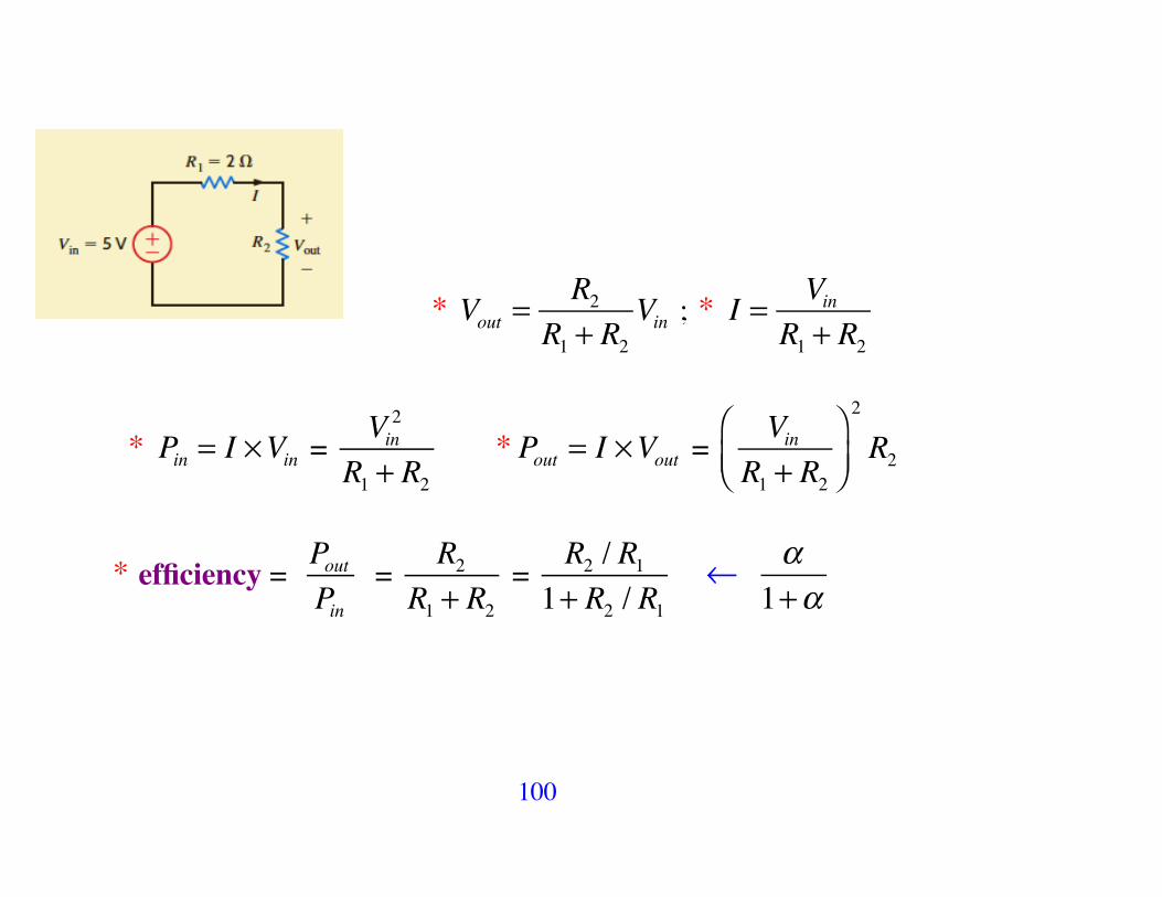
Example Plot Vout , I , Pin , Pout and Pout / Pin as a function of R2
iL ! maxvL !max
PL !max
100
* Vout =R2
R1 + R2Vin ; * I = Vin
R1 + R2
* Pin = I !Vin = Vin2
R1 + R2 * Pout = I !Vout =
VinR1 + R2
!"#
$%&
2
R2
* efficiency = PoutPin
= R2
R1 + R2 =
R2 / R11+ R2 / R1
! !1+!

101
10.5
102
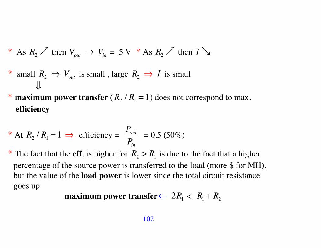
* As R2! then Vout ! Vin = 5 V * As R2! then I!
* small R2 ! Vout is small , large R2 ! I is small ! * maximum power transfer (R2 / R1 = 1) does not correspond to max. efficiency
* At R2 / R1 = 1 ! efficiency = PoutPin
= 0.5 (50%)
* The fact that the eff. is higher for R2 > R1 is due to the fact that a higher percentage of the source power is transferred to the load (more $ for MH), but the value of the load power is lower since the total circuit resistance goes up maximum power transfer! 2R1 < R1 + R2

103