ece 331 – digital system design counters (lecture #18)
TRANSCRIPT

ECE 331 – Digital System Design
Counters
(Lecture #18)
ECE 331 - Digital System Design 2
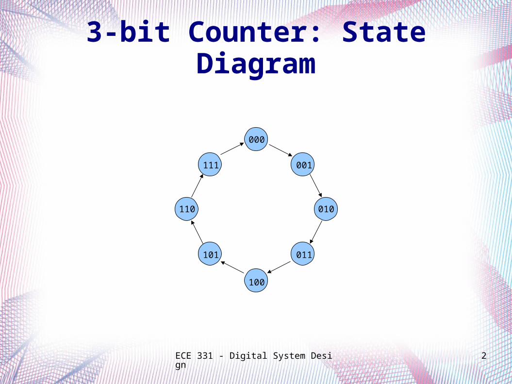
3-bit Counter: State Diagram
000
001
010
011
100
101
110
111

ECE 331 - Digital System Design 3
Asynchronous Counters
(aka. Ripple Counters)
Counters

ECE 331 - Digital System Design 4
3-bit (up) Counter
Let each bit in the counter be represented by the output of a flip-flop.
Count Q2
Q1
Q0
0 0 0 0
1 0 0 1
2 0 1 0
3 0 1 1
4 1 0 0
5 1 0 1
6 1 1 0
7 1 1 1
0 0 0 0

ECE 331 - Digital System Design 5
3-bit (up) Counter: T Flip-Flops
T Q
Q Clock
T Q
Q
T Q
Q
1
Q 0 Q 1 Q 2
Clock
Q 0
Q 1
Q 2
Count 0 1 2 3 4 5 6 7 0
AsynchronousCounter
Counter does not use a common clock.

ECE 331 - Digital System Design 6
Synchronous Counters
Counters

ECE 331 - Digital System Design 7
4-bit (up) Counter
As before, let each bit in the counter be represented by the output of a flip-flop.
Count Q3
Q2
Q1
Q0
0 0 0 0 0
1 0 0 0 1
2 0 0 1 0
3 0 0 1 1
4 0 1 0 0
5 0 1 0 1
6 0 1 1 0
7 0 1 1 1
Count Q3
Q2
Q1
Q0
8 1 0 0 0
9 1 0 0 1
10 1 0 1 0
11 1 0 1 1
12 1 1 0 0
13 1 1 0 1
14 1 1 1 0
15 1 1 1 1
0 0 0 0 0

ECE 331 - Digital System Design 8
4-bit (up) Counter: T Flip-Flops
T Q
Q Clock
T Q
Q
T Q
Q
1 Q 0 Q 1 Q 2
Clock
Q 0
Q 1
Q 2
Count 0 1 2 3 5 9 12 14 0
T Q
Q
Q 3
Q 3
4 6 8 7 10 11 13 15 1
SynchronousCounter
Counter uses a common clock.
ECE 331 - Digital System Design 9
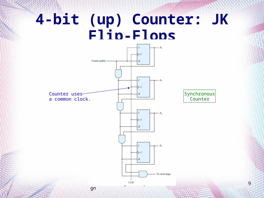
4-bit (up) Counter: JK Flip-Flops
SynchronousCounter
Counter uses a common clock.

ECE 331 - Digital System Design 10
4-bit Counter: D Flip-Flops
Clock
Enable D Q
Q
D Q
Q
D Q
Q
D Q
Q
Q0
Q1
Q2
Q3
Outputcarry
How does the XOR gatefunction when the Enablesignal is a logic-1?

ECE 331 - Digital System Design 11
Synchronous Counters
4-bit (up) Counter with Enable and Clear

ECE 331 - Digital System Design 12
T Q
Q Clock
T Q
Q
Enable
Clear
T Q
Q
T Q
Q
4-bit Counter with Enable and Clear
asynchronous control signals

ECE 331 - Digital System Design 13
Synchronous Counters
4-bit (up) Counter with Parallel Load

ECE 331 - Digital System Design 14
EnableD Q
Q
Q 0
D Q
Q
Q 1
D Q
Q
Q 2
D Q
Q
Q 3
D 0
D 1
D 2
D 3
LoadClock
Outputcarry
0 1
0 1
0 1
0 1
4-bit Counter with Parallel Load
Is the Load signalactive-high or active-low?

ECE 331 - Digital System Design 15
4-bit Counter with Parallel Load

ECE 331 - Digital System Design 16
Synchronous Counters
Modulo-6 Counter

ECE 331 - Digital System Design 17
Modulo-6 Counter: D Flip-Flops
0 1 2 3 4 5 0 1
Clock
Count
Q 0
Q 1
Q 2
Enable
Q 0 Q 1
Q 2
D 0 D 1
D 2
LoadClock
1
0
0
0
Clock
3-bit counterwith Parallel Load
Counter resets to zerowhen count reaches six.

ECE 331 - Digital System Design 18
Modulo-6 Counter: T Flip-Flops
T Q
Q Clock
T Q
Q
T Q
Q
1 Q 0 Q 1 Q 2
Clock
Q 0
Q 1
Q 2
Count 0 1 2 3 4 5 0 1 2
asynchronous clear signal Counter cleared when count reaches six.

ECE 331 - Digital System Design 19
Counters
BCD (Decimal) Counter
(aka. Modulo-10 Counter)

ECE 331 - Digital System Design 20
BCD Counter: State Diagram

ECE 331 - Digital System Design 21
BCD Counter: JK Flip-Flops
AsynchronousCounter

ECE 331 - Digital System Design 22
BCD Counter: D Flip-Flops
SynchronousCounter

ECE 331 - Digital System Design 23
Up / Down Counter
Synchronous Counters

ECE 331 - Digital System Design 24
4-bit Up / Down Counter

ECE 331 - Digital System Design 25
Acknowledgments
The slides used in this lecture were taken, with permission, from those provided by McGraw-Hill for
Fundamentals of Digital Logic with VHDL Design (3rd Edition).
They are the property of and are copyrighted by McGraw-Hill Higher Education.