ebw and lbw of additive manufactured ti6al4v products · welding research june 2018 / welding...
TRANSCRIPT

WELDING RESEARCH
JUNE 2018 / WELDING JOURNAL 179-s
Introduction
Additive manufacturing (AM) is a relatively new type ofmanufacturing technology. Unlike the conventional machin-ing technique that involves material removal, with AM tech-nology, a digital 3D design data set is applied to build upmaterial layer by layer. A high power source is used to melt afine powder form, stacking layers until the 3D part is built.This 3D printing process does not require the use of fix-tures, cutting tools, coolants, or other auxiliary resources(Ref. 1). Thus, AM enables high geometrical flexibility in themanufacturing process and facilitates the construction ofcomponents with highly complex shapes. The complex part
can be extremely light, with features that are difficult oreven impossible to obtain using any conventional manufac-turing technique (turning, milling, etc.). Once the process iscomplete, the part can be removed from the machine’s baseplatform. In most cases, additional postprocessing opera-tions are required, such as support structure removal, heattreatment, and surface finishing (Ref. 2). Because AM has become a competitive manufacturingtechnique in terms of cost, speed, reliability, and accuracy, itis marked as a “next generation” technology (Ref. 3). Never-theless, the AM technology currently has some drawbacks,particularly with regard to surface finish as well as part-sizelimits due to the build chamber size (Ref. 4). In powder bedfusion (PBF) systems, the build envelope is an enclosedchamber that can be operated in a vacuum or filled with aninert gas to prevent the oxidation of reactive metal powderssuch as titanium or aluminum (Ref. 5). The PBF system sizelimits preclude the manufacturing of large parts in one piece.An alternative option is to build subparts separately andthen weld them together in a postprocessing stage. Only afew studies in the scientific literature address the mechanicaland metallurgical properties of AM welds (Refs. 6–10). Matilainen et al. (Ref. 6) investigated the weldability as-pects of 316L stainless steel by comparing bead-on-platewelds between selective laser melting (SLM) and cold-rolled(CR) sheet metal parts. They concluded that SLM manufac-tured parts can be welded with good-quality results. Theirstudy showed that laser beam welding (LBW) of SLM stain-less steel differed slightly from LBW of CR stainless steel;when the energy input was low, complete joint penetrationcould be achieved in the SLM material. However, when theweld lacked penetration, large pores were found in the SLMmaterial welds. In addition, increased energy input affectedthe weld-cracking tendency in SLM material. Wits and Becker (Ref. 7) compared pulsed LBW ofTi6Al4V AM parts vs. wrought parts. They concluded thatLBW process parameters could not simply be transferredfrom wrought to AM parts. For the latter, more induced en-ergy per unit weld length should be applied to obtain anidentical weld geometry. Wits and Becker explained that thiseffect resulted from material consistency and imperfectionsdue to the AM process.
EBW and LBW of Additive Manufactured Ti6Al4V Products
The weld bead geometry of powder bed additive manufactured titanium alloys differed significantly from that of wrought material
BY B. TAVLOVICH, A. SHIRIZLY, AND R. KATZ
ABSTRACT This study investigated the weld joint properties of addi-tive manufactured (AM) titanium parts. The welding experi-ments were performed using 4-kW fiber laser beam welding(LBW) and 30-kW, 80-kV electron beam welding (EBW).Wrought Ti6Al4V welded parts were compared to AMwelded parts. In addition, the combination of welding AMparts to wrought (Ti6Al4V) parts was examined. The weldswere analyzed and compared in terms of weld bead profile,tensile strength, microhardness, macro examination, andnondestructive testing. The results revealed certain differ-ences between the welds of AM parts and the welds ofwrought parts. Significant differences were found in theweld fusion zone (FZ) and in the material’s thermal conduc-tivity below the transus. The FZ boundary on the AM sideof the joint was wider and had a straight shape versus theneck-shaped FZ boundary on the wrought material side. Athermal finite element model was used to simulate LBW.The simulation supported the experimental observations.The results indicate it is possible to achieve good-qualitywelds of AM to AM, and of AM to wrought material, foraerospace applications using both EBW and LBW.
KEYWORDS • Laser Beam Welding • Electron Beam Welding • Ti6Al4V • Additive Manufacturing • Thermal Conductivity
https://doi.org/10.29391/2018.97.016
Tavlovich 201778[2].qxp_Layout 1 5/10/18 12:33 PM Page 179
WELDING RESEARCH
WELDING JOURNAL / JUNE 2018, VOL. 97180-s
Casalino et al. (Ref. 8) studied the effects of hybrid-lasergas tungsten arc welding (GTAW) of wrought austeniticstainless steel to AM SLM stainless steel. A sound weld wasmade using the laser-leading configuration. The microhard-ness of the annealed steels was 70 HV lower than that ofSLM steels. Tensile tests showed the tested AM welds had ahigher tensile strength and a lower elongation than similarwelds in wrought material of the same composition. Nahmany et al. (Ref. 9) investigated electron beam auto-genously welded AlSi10Mg samples produced by the SLMAM method. Two main differences were observed whencomparing the EB-welded AM parts to the EB-welded castsamples: weld metal porosity and a negligible heat-affectedzone (HAZ) in the AM joints, and a low porosity level but asubstantial HAZ in the welded cast parts. Prashanth et al. (Ref. 10) investigated the effect of fric-tion welding (FW) on Al–12Si parts produced by SLM. Thetensile strength experiments revealed the yield strength ofthe friction-welded SLM sample was ~45 MPa lower thanthat of the SLM sample. However, the ductility increasedfrom ~3% in the as-built SLM case to ~10% after FW. Thecast samples displayed an opposite behavior. Those findingsdemonstrated that solid-state FW could be successfully usedto join materials produced by SLM, and helped to signifi-cantly improve their ductility. Tensile properties of Ti6Al4V fabricated by a number ofAM techniques show strength levels superior to or compara-ble with conventional manufactured parts (cast, forged, andwrought annealed). As-built materials in laser-basedprocesses exhibit less ductility; however, the ductility can beimproved through a subsequent hot isostatic pressingand/or a heat treatment operation (Ref. 11). The welding of titanium alloys is challenging and compli-cated. When the material is heated to above ~550°C, there isa strong reaction tendency with atmospheric gases or ele-ments such as hydrogen, oxygen, nitrogen, or carbon. Oncethe metal surface has been contaminated, the reweldingprocess is no longer efficient since there is no way to get ridof the contaminated volume of metal. The incidental ele-ments will cause severe embrittlement of the alloy and re-duce its ductility and toughness, while increasing its strengthand hardness (Refs. 12, 13). Discoloration of the surface ofthe weld, or of the metal adjacent to the weld or on the backside of the weld, is indicative of the presence of oxygen. Thediscoloration of the weld metal can be used as an indicator ofthe shielding adequacy. This discoloration is directly relatedto the degree of weld metal embrittlement and hardness ofthe weld metal. However, it is imperative the weld bead dis-coloration not be utilized as an inspection tool for shieldingadequacy, as the discoloration sequence will repeat itself asthe oxidation thickness increases (Ref. 14). Balasubramanian at el. (Ref. 13) presented GTAW as the
preferred welding method for reactive materials, like titani-um alloys, because of its comparatively easy applicabilityand better economy. However, for applications that requirehigh-quality welds, as in aerospace or biomedical applica-tions, LBW and electron beam welding (EBW) are the pre-ferred welding methods. A main drawback of GTAW is itshigh-heat input and the resultant greater distortion andhigher risk of contamination. High-energy beam techniquessuch as LBW or EBW are used to avoid these drawbacks. Themain advantages of the LBW and EBW processes are theirrelatively low-heat input and high welding speed. Addition-ally, the LBW and EBW profiles are relatively narrow anddeep, and have a small HAZ. EBW is the natural choice for use with materials suscepti-ble to oxidation, such as titanium. EBW operates in a high-vacuum environment that shields the hot metal from con-tamination during the joining process (Refs. 13, 15, 16). Onthe other hand, LBW can be performed under atmosphericpressure, and its fiber-optic delivery provides increased flex-ibility compared to EBW (Ref. 14). To avoid embrittlementin LBW, titanium alloys are ordinarily shielded with a high-purity inert gas; argon and helium are the only shieldinggases that should be considered when laser welding titaniumalloys. The goal of this study was to verify that the Ti6Al4Vparts produced using the AM process can be reliably weldedamong themselves and to parts produced from a wroughtTi6Al4V. Two welding processes were evaluated: EBW andLBW. We concentrated on welding butt joint configurationsusing wrought manufactured samples, AM manufacturedsamples, and a combination of both. The wrought sampleswere manufactured from extruded rod, whereas the AMparts were manufactured by SLM. The EBW and LBW weldswere compared in terms of weld bead profile, tensilestrength, hardness, macro examination, and nondestructivetesting.
Experimental Procedures
Materials Used in This Study
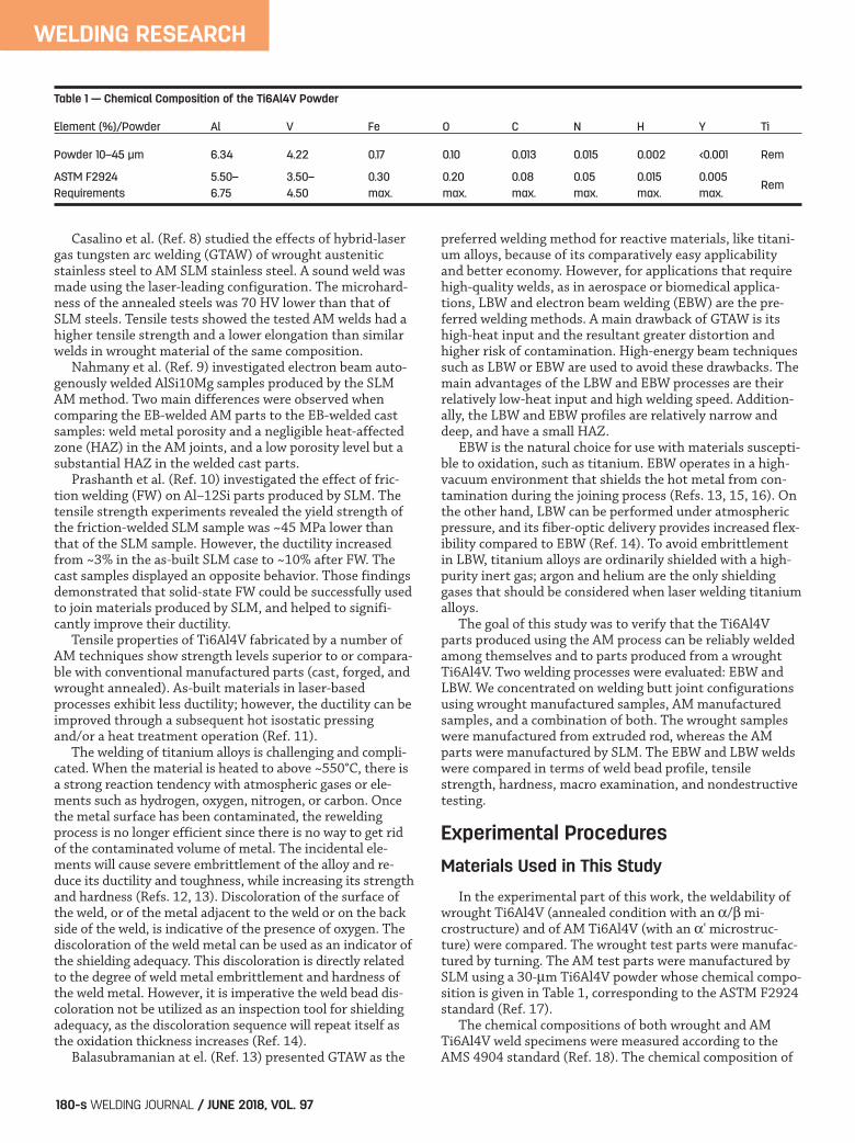
In the experimental part of this work, the weldability ofwrought Ti6Al4V (annealed condition with an / mi-crostructure) and of AM Ti6Al4V (with an ' microstruc-ture) were compared. The wrought test parts were manufac-tured by turning. The AM test parts were manufactured bySLM using a 30-m Ti6Al4V powder whose chemical compo-sition is given in Table 1, corresponding to the ASTM F2924standard (Ref. 17). The chemical compositions of both wrought and AMTi6Al4V weld specimens were measured according to theAMS 4904 standard (Ref. 18). The chemical composition of
Table 1 — Chemical Composition of the Ti6Al4V Powder
Element (%)/Powder Al V Fe O C N H Y Ti
Powder 10–45 μm 6.34 4.22 0.17 0.10 0.013 0.015 0.002 <0.001 Rem
ASTM F2924 5.50– 3.50– 0.30 0.20 0.08 0.05 0.015 0.005 RemRequirements 6.75 4.50 max. max. max. max. max. max.
Tavlovich 201778[2].qxp_Layout 1 5/10/18 12:33 PM Page 180

WELDING RESEARCH
JUNE 2018 / WELDING JOURNAL 181-s
the materials is presented in Table 2, and meets the AMS4904 standard requirements.
Part Geometry
AM and wrought manufactured specimens of similar di-mensions were produced, as shown in Fig. 1. AM sampleswere manufactured using an EOSINT M280 machine, with a200-W Yb-fiber laser. The scan pattern used was of 8-mmstrips with a 67.5-deg rotation between adjacent layers. Thebuilding direction is indicated in Fig. 1. The AM parts werestress relieved in a vacuum for 3 h at 650°C.
Preweld Sample Preparation
All samples were chemically etched (etching oxide: HNO3
370 gr/L, HF 30 gr/L for 5 min) to prevent any weld porosi-ty as a result of contamination. The time interval betweenwelding and etching was kept at a minimum and did not ex-ceed 40 h (Ref. 19) to prevent oxidation. Prior to welding, itis common practice to clean the parts with a cheeseclothsoaked with acetone. For AM parts, however, cleaning with acheesecloth is not recommended due to the high surfaceroughness. The cheesecloth fibers tend to remain attachedto the AM parts and may cause porosity; therefore, oneshould rely on the etching process. After etching, the sam-ples were tack welded using GTAW, as seen in Fig. 2, and di-vided into groups, as shown in Table 3.
Laser Beam Welding of the Test Parts
The IPG Ytterbium fiber laser system YLS-4000-CT-WWwas used for the LBW tests. To prevent titanium oxidationduring the welding process, a special shielding gas protec-tion jig was developed and applied as shown in Fig. 3. Argon was used as a shielding gas, with flow rates of 30L/min through the nozzle, 18 L/min between the jig covertube and the external side of the tube specimen, and an in-
Table 2 — Chemical Composition of AM and of Wrought Ti6Al4V Samples
Element AM Sample Wrought Sample AMS 4904 Measured (%) Measured (%) Requirement (%)
Al 6.16 6.19 5.50–6.75
Fe 0.18 0.17 0.30 max.
Ti Rem Rem Rem
V 4.01 3.90 3.50–4.50
Y <0.0003 <0.0003 0.005 max.
C 0.012 0.004 0.08 max.
H 0.0005 0.0030 0.015 max.
O 0.114 0.185 0.2 max.
N 0.017 0.003 0.05 max.
Fig. 1 — Test piece dimensions.
Fig. 2 — Tack-welded sample.
Table 3 — Specimen Group Description
Group Name Manufacturing Process Type of Weld
I AM Not welded
II Wrought Not welded
III AM LBW
IV AM EBW
V Wrought LBW
VI-1 Wrought + surface machined after weld EBW
VI-2 Wrought EBW
VII AM to wrought LBW
VIII AM to wrought EBW
IX AM + surface machined before weld LBW
Tavlovich 201778[2].qxp_Layout 1 5/10/18 12:33 PM Page 181

WELDING RESEARCH
WELDING JOURNAL / JUNE 2018, VOL. 97182-s
ternal flow rate of 6 L/min in the inner side of the tubespecimen. The welding parameters used during welding arepresented in Table 4. To configure the welding mode, the power density andthe aspect ratio (AR) for each LBW configuration was calcu-lated as shown in Equations 1 and 2 (Ref. 20).
The results in Table 5 indicate welding was performed inthe conduction mode.
Electron Beam Welding of the Test Parts
Electron beam welding was performed with a ProBeam K-140 system. The welding parameters used to weld thejoints are presented in Table 6. Similar welding parameterswere used for AM and wrought samples.
Thermal Conductivity Measurements
Veiga et al. (Ref. 21) published that in a wrought Ti6Al4Valloy, the thermal conductivity (TC) varies from about 6.6 to6.8 W/mK at near room temperature to about 16 to 19W/mK at 800°C. To investigate the differences between AM
I = PoutA
= 3000
��w2 / 4
W
mm2���
���
(1)
AR= pw
(2)
Fig. 3 — Laser beam jig welding setup with weld joint pro-tected by inert gas to prevent oxidation. Fig. 4 — Thermal conductivity () of AM and wrought Ti6Al4V.
Table 4 — Laser Beam Welding Parameters
Laser Power (W) Ramp-Up Time (s) Power Hold (s) Ramp-Down Time (s)
3000 0.5 2.876 0.5
Welding Speed Optical Fiber Focused Beam Spatial Profile of Beam Focus (mm/s) Diameter (mm) Diameter (mm) the Focused Position Laser Beam
101.66 0.3 0.5 Top hat On the part surface
Table 5 — Power Density and Aspect Ratio (AR) for Laser Welding
Group III AM to AM Group V AM to Wrought Group VII Wrought
w — Bead width (mm) 2.13 1.89 1.75
I — Power density (W/mm2) 1.32 E + 03 1.67 E + 03 1.95 E + 03
AR 0.82 1 1.1
Tavlovich 201778[2].qxp_Layout 1 5/10/18 12:33 PM Page 182

WELDING RESEARCH
JUNE 2018 / WELDING JOURNAL 183-s
and wrought Ti6Al4V, the TC of three specimens (4 and 15mm height) of each material (wrought and AM Ti6Al4V)were measured. The TC measurements were carried outfrom room temperatures up to 800°C utilizing a custom-made instrument per the ASTM E1225-13 standard (Ref.22). The measurements were carried out in steps of 100°Cincrements, with a 1.5-h isothermal hold at each tempera-ture in a vacuum environment. The data collected for eachspecimen is presented in Fig. 4. The wrought Ti6Al4V speci-mens displayed good measurement repeatability, while theAM specimen measurements were more scattered.
The TC data measured for both wrought and AM Ti6Al4Vin the temperature range of 0° to 800°C were fitted to a linear curve represented by Equations 3 and 4. The extrapo-lated higher temperatures are given by Equations 5 and 6.
According to Boivineau et al. (Ref. 23), the linear fit forthe phase was found to be
And for the liquid phase
Making reference to the transus (980°C) of the differ-ent materials, the thermal properties due to phase changehave been consequently shifted to coincide with the transi-tion area. Figure 5 describes the combined information wemeasured (Equations 3 and 4) and the data presented byBoivineau et al. (Ref. 23) (Equations 5 and 6) with the ap-propriate linear shifts.
LBW Simulation
A three-dimensional finite element model was developedto simulate the LBW process using Simufact Welding, Ver-sion 6 (MSC Software Co., Munich, Germany). The goal wasto validate and explain the experimental findings. The TCdata used in the LBW simulation is shown in Fig. 5. To simu-late the LBW process, the energy input from the laser wasdivided into surface and volumetric heat sources. The welding process starting position was marked as 0deg. The laser beam started a linear ramp-up while the tubewas rotating, until it reached the full welding power of 3 kWat 60 deg. The laser power was maintained constant for anadditional 340 deg, until a linear ramp-down started for anadditional 60 deg. Figure 6 shows the beam at 215 deg whilethe thermocouples were located at 180 deg at distances of 1,2, and 3 mm from the weld interface on both sides symmetrically.
� wmK���
���= 1.639+18.3103 T 1677<T <2427[°c] (6)
� wmK���
���=3.67+14.6�10�3 �T 1127<T <1577[°c] (5)
Wrought: � wmK���
���=6.19+4.3�10�3 �T 0<T <800[°c] (4)
AM: � wmK���
���=15.31+10.2�10�3 �T 0<T <800[°c] (3)
Fig. 5 — Combined plot of thermal conductivity ().
Fig. 6 — Thermal simulation of the LBW process of AM andwrought Ti6Al4V in an intermediate stage of the weld. Thelaser power was increased from 0 kW at 0 deg to 3 kW at 60deg, kept at the same power level up to 400 deg, and thendecreased gradually to 0 kW at an additional 60 deg. Thecolor change on both sides of the weld represents the tem-perature distribution.
Table 6 — Electron Beam Welding Parameters
Voltage Beam Current Focused Beam Welding Speed Gun-to-Work Power Density (kV) (mA) Diameter (mm) (mm/s) distance (mm) (W/mm2)
80 21 0.5 35 850 8.56 E + 03
Tavlovich 201778[2].qxp_Layout 1 5/10/18 12:33 PM Page 183

WELDING RESEARCH
WELDING JOURNAL / JUNE 2018, VOL. 97184-s
Microhardness and Oxygen Level Measurements
Microhardness measurements were carried out using aFuture-Tech microhardness tester (FM800) with a 1-kg loadfor 10 s. Measurements were performed according to theISO 22826 standard (Ref. 24) as shown in Fig. 7. The oxygenlevel in the base metal (BM) and fusion zone (FZ) weremeasured for the electron beam and laser beam welds tosupport the hardness results. All measurements were per-formed using x-ray photoelectron spectroscopy (XPS) ES-CALAB 250 on wrought and AM materials.
Tensile Tests Measurements
Tensile tests measurements were carried out with a load-ing rate of 0.12 mm/min, with tensile test specimens takenfrom each group (Table 3); the weld bead was oriented trans-versely to the applied load as shown in Fig. 8. To examinethe effect of heat treatment after welding, half of each ten-sile test specimen group was stress relieved for 3 h at 650°Cin a vacuum and then furnace cooled.
Results and Discussion
Destructive Tests
Weld bead geometry and thermal behavior. The crosssections of the welded samples were analyzed utilizing anoptical stereomicroscope (SMZ800) with modified Kroll’sreagent as the etchant. The cross section (presented in Fig.9C) revealed differences between the wrought and the AMsides of the weld joint’s HAZ. The HAZ of the wrought sideshas a fine-grained region that is not seen on the AM side. Asseen in Figs. 7 and 9, the wrought BM has fine grains, whilethe AM BM has coarse grains. Due to the high cooling rate inLBW and EBW, the size of the grains in the HAZ had minorchanges compared to the BM region. In addition, the cross section (presented in Fig. 9C) re-vealed a significant difference in the FZ boundary when awrought material was laser welded to an AM material. Thisphenomenon did not exist when two compatible materialswere laser welded, as shown in Fig. 9A and E. The FZ bound-ary in LBW on the AM material side of the joint was widerand had a straight shape compared to the neck-shaped fusion boundary of the weld of the wrought material. Laiti-nen (Ref. 25) observed a similar phenomenon during weld-ing of AM to wrought stainless steel sheet. He speculatedthe difference in the fusion zone boundaries might have de-rived from the initially lower-molten pool viscosity of theAM sheet vs. wrought sheet metal, and from the differencesin weld pool viscosities and material flows in a molten weld.In the following paragraphs, we propose a different explana-tion of this phenomenon. Figure 5 shows the TC of wrought and AM materials. It isimportant to note that, up to 800°C, the TC of the AM mate-rial was about 2.5 times as high as that of the wrought ma-terial; these results may explain the difference in the weldbead geometry between the materials. The heat transferredfaster in the AM material, resulting in a wider FZ and HAZ
Fig. 7 — Location of group indentations for hardness testing.Key numbers: 1 — Weld metal; 3, 5 — HAZ; 7, 8 — base metal.
Fig. 8 — Geometry of tensile test pieces.
Fig. 9 — Weld cross sections: A — LBW of wrought materials;B — EBW of wrought materials; C — LBW of AM to wroughtmaterials; D — EBW of AM to wrought materials; E — LBW ofAM materials; F — EBW of AM materials.
A
C D
E F
B
Tavlovich 201778[2].qxp_Layout 1 5/10/18 12:33 PM Page 184

WELDING RESEARCH
JUNE 2018 / WELDING JOURNAL 185-s
than in the wrought material. Ti6Al4V can be heat treatedto give a wide variety of microstructures with a diversity ofmechanical and physical properties. The differences in TCbetween the wrought mill-annealed Ti6l4V (with /) andSLM AM with an ' microstructure (Ref. 26) are not neces-sarily unusual. The same differences in conductivity are like-ly to be seen if the samples have been heat treated to pro-duce the same types of microstructures. For example, if theSLM AM sample is heat treated to produce the mill-annealedmicrostructure, it would likely have a TC similar to that ofthe wrought material. The difference in microstructure be-tween the wrought and AM parts results from variance inthe manufacturing process’s cooling rates, which influencesthe TC. The influence of the microstructure on the TC is il-lustrated by the comparison between the AM Ti6Al4V TC(Equation 3) and pure titanium, which has a TC of 21 to 22W/mK (Ref. 21). Both materials have a similar -phase microstructure and, as a result, a similar TC.
The facilities used to measure the TC allowed us to con-duct measurements up to 800°C. The relatively high value ofTC for the AM titanium alloy obtained in the 25° to 800°Ctemperature range reflects its crystal structure, namely thehigh fraction of phase. For higher temperatures, we ap-plied a linear extrapolation, as seen in Equations 5 and 6 aswell as Fig. 5. During welding, a local narrow zone is heated by the laserbeam; the material is melted and partially vaporized, and itthen rapidly solidifies. The elevated temperature gradientsalong and across the weld affect the mechanical properties andmicrostructures. As long as the weld is between two similarmaterials, it is expected to achieve symmetry in heat transferand mechanical properties across the weld. When weldingwrought to AM Ti6Al4V, the thermal properties are differentand heat transfers differently in each material — Figs. 10–13.
Fig. 10 — Temperature distribution for heat input and beamposition at 180 deg. The difference in thermal conductivity(Fig. 5) creates asymmetrical thermal gradients across theweld. (Thermocouple positions: Internal ring surface at 1, 2,and 3 mm from each side of the weld interface.)
Fig. 12 — Temperature distribution cross section at 180 degwhen the laser beam position reached 215 deg (0.28 s later).Thermocouple positions: Internal ring surface at 1, 2, and 3mm from each side of the weld interface.
Fig. 11 — Cross section of AM to wrought Ti6Al4V LBW: Asym-metrical fusion zone boundary.
Fig. 13 — Temperature variation versus time for given materi-als: — Solid lines: wrought material; dashed lines: AM mate-rial. Temperatures measured at 1 (TC1), 2 (TC2), and 3 (TC3)mm from the weld interface at an angle of 180 deg from theweld origin.
Tavlovich 201778[2].qxp_Layout 1 5/10/18 12:33 PM Page 185

WELDING RESEARCH
WELDING JOURNAL / JUNE 2018, VOL. 97186-s
Figure 10 shows the finite element mesh used in the sim-ulation, as well as the temperature distribution at a crosssection located at 180 deg when the laser beam is also posi-tioned at 180 deg. Figure 11 presents a cross section of aspecimen with dissimilar welded materials. The simulatedtemperature distribution shown in Fig. 10 and the weldedgeometry shown in Fig. 11 reveal a similar pattern. This mayexplain how the difference in TC creates a unique beadgeometry pattern in LBW between AM and wrought materi-als. Figure 12 shows the simulated temperature distributionat the same cross section (at 180 deg, where the thermocou-ples were placed) when the beam reaches 215 deg. The simu-lated temperatures as a function of time for each thermo-couple are presented in Fig. 13. The thermocouples TC1, lo-cated at 1 mm from both sides of the weld joint, measuredthe maximum temperature, which was approximately 45°Chigher in the wrought material than in the AM one. The AMmaterial resulted in a higher temperature than the wroughtmaterial when the distance was farther than approximately1.1 mm from the weld joint. At all positions, the measuredtemperatures were almost similar after approximately 3.5 s. Testing the effect of additive manufactured surfaceroughness on bead geometry. To validate whether the sur-face roughness (Fig. 16) affects laser beam emissivity andthus the weld cross-section profile, LBW tests were per-formed on a machined AM surface (Group IX). The crosssection of the weld is shown in Fig. 14; the same resultswere found in machined and as-built AM welded samples.The results indicate the surface roughness had no signifi-cant effect on the weld shape, and the emissivity change dueto surface roughness had a minor effect on the AM LBW. Microhardness and oxygen level tests. Microhardnessmeasurements were performed for all of the welds; the re-sults for each manufacturing process are shown in Table 7.On wrought Ti6Al4V EBW and LBW, the microhardness ofthe FZ was higher than that of the BM counterpart due tothe formation of an ' martensitic phase in the FZ. The HAZconsisted of a mixture of ' martensite and primary phas-es (Refs. 27, 28). AM Ti6Al4V microhardness was higherthan that of wrought Ti6Al4V by approximately 35 HV. Thehardness of AM Ti6Al4V was higher because the melt poolcools down very rapidly during the SLM process after thelaser beam has passed. Hence, fast cooling gives rise to amartensitic ' phase (Ref. 29). In electron beam welds, the oxygen level was higher inthe BM than in the FZ. In wrought Ti6Al4V, the oxygen levelwas 0.099% in the BM and 0.080% in the FZ. In AMTi6Al4V, the oxygen level was 0.051% in the BM and 0.047%
in the FZ, and vice versa in laser beam welds. In wroughtTi6Al4V, the oxygen level was 0.081% in the BM and 0.086%in the FZ. In AM Ti6Al4V, the oxygen level was 0.039% inthe BM and 0.043% in the FZ. The microhardness of laser beam welds is higher thanthat of EBW welds for both AM and wrought material welds.More oxygen is absorbed during LBW because EBW is per-formed in a high vacuum (hence almost no oxygen absorp-tion). Another reason for the difference in microhardness isthe faster cooling rate in LBW compared to EBW; duringLBW, the welding speed is faster, and so is the convectivecooling. For EBW of AM Ti6Al4V, the microhardness of theFZ is lower than that of the BM due to the controlled envi-ronment and slower cooling rate in the EBW process (with-out convective cooling) vs. the cooling rate in the AM manu-facturing process. Tensile properties tests. Wrought Ti6Al4V products areused predominantly in a mill-annealed or solution-treatedand aged condition with typical tensile properties of y =850−1050 MPa, UTS = 950−1200 MPa, and elongation val-ues of 10 to 15% (Ref. 30). With regard to the effect of cool-ing rate on ductility, Yung at el. (Ref. 31) found that thehigher the cooling rate, the larger the relative elongationand, hence, the higher the ductility of the weld. The mechanical properties for all nonheat-treated sam-ples vs. the heat-treated specimens are presented in Fig. 15.The results show that AM Ti6Al4V (Group I) has a highertensile strength and a significant decrease in ductility com-pared to wrought Ti6Al4V (Group II). The differences be-tween the materials rely on the hexagonal close-packed(HCP) martensitic microstructure of AM laser-melted materials, which renders a higher tensile strength and a low-er ductility (Ref. 3). All of the welded test specimens were
Fig. 14 — Effect of surface roughness on LBW cross sections of AM material: A — Weld of as-built material; B — weld of surface-machined material.
Table 7 — Microhardness Measured Values
Manufacturing Weld EBW Hardness LBW Hardness Process Zone (HV) (HV)
BM 375 9 AM HAZ 352 2 369 5 FZ 346 15 393 6
BM 339 11 Wrought HAZ 353 4 365 6 FZ 355 5 378 3
Mix (Wrought FZ 347 3 393 7 to AM)
A B
Tavlovich 201778[2].qxp_Layout 1 5/10/18 12:33 PM Page 186

fractured in the BM. Test specimens with combined materialconditions (AM and wrought) were fractured in the wroughtmaterial BM. LBW of AM (Group III) had a higher tensilestrength than EBW of AM (Group IV). Postprocess heattreatment after welding increased the tensile strength ofwelds, which included wrought material (Groups V–VIII). AllAM specimens underwent heat treatment prior to removalfrom the building platform; therefore, the reheat treatmentafter welding had no significant effect on the tensilestrength.
Nondestructive Tests
AWS D17.1, Specification for Fusion Welding of AerospaceApplications (Ref. 32), specifies the requirements for welding
aircraft and space hardware of titanium alloys and othermetallic materials. It covers electric arc, plasma arc, oxyfuel,laser beam, and electron beam welding processes. However,according to Engel (Ref. 20), AWS D17.1 is an international-ly accepted standard, but it does not include laser welding orthe laser welding of titanium. The ISO 13919-1 (Ref. 33)standard does not cover titanium alloys, but it does provideguidelines for laser weld profile and quality definitions —especially for “stringent quality” welds. Both the AWS D17.1and the ISO 13919-1 standards were used for performingnondestructive testing (NDT) of the welded parts. Eachwelded specimen was examined by visual testing, dye pene-tration (ultraviolet dye penetration), and x-ray (microfocussystem). Visual inspection of the welds showed both weld materi-als had no spatter on the face surface and very little spatter-ing near the weld root face, whereas LBW showed slightlymore spatter than EBW — Fig. 16. In the LBW samples,there was a minor color change near the weld, whereas nocolor change was noticed in the EBW samples. There is nospecific standard for color change of LBW of titanium alloys;
WELDING RESEARCH
JUNE 2018 / WELDING JOURNAL 187-s
Fig. 15 — Tensile test results: A — Yield strength (YS); B — ulti-mate tensile strength (UTS); C — elongation.
Fig. 16 — Visual inspection, wrought to AM Ti6Al4V welds: A —EBW face surface (external surface); B — EBW root surface(internal surface); C — LBW face surface; D — LBW root surface.
Fig. 17 — A — Surface roughness of AM material; B — surfaceroughness of wrought material; C — cross section of AM ma-terial; D — cross section of wrought material.
A
A
C
C
B
A
C
D
D
B
B
Tavlovich 201778[2].qxp_Layout 1 5/10/18 12:33 PM Page 187

Engel (Ref. 20) published in his guidelines that no colorchange is permitted in LBW. However, according to the AWSD17.1 standard recommendation, some color change is al-lowed. To verify the minor color change had no influence onweld metallurgical properties, the weld cross section was ex-amined for the presence of case — a continuous, hard, andbrittle layer that significantly reduces several important me-chanical properties of titanium alloys (Ref. 34) — and no ev-idence of it was found. As a result, both welding methods(EBW and LBW) fulfill the AWS D17.1 and ISO 13919-1standards requirements. Due to the rough surface of the AM material (Fig. 17), dyepenetrant examination was applicable only for wrought weld-ed materials, whereas for the AM material the dye penetrantcould not be fully removed from the surface (by solvent).When the developer was applied, it drew the dye penetrantfrom the AM material surface, and thus impeded the abilityto distinguish surface defects near the weld (Fig. 18). The x-ray inspection showed almost no porosity in EBWand very few pores in LBW. All of the welds were inspectedaccording to the AWS D17.1 and ISO 13919-1 standards,and met the specifications of both standards.
Conclusions The welding quality of Ti6Al4V additive manufactured(AM) parts was compared to the welding quality of wroughtmanufactured parts. The welding was performed using high-power fiber laser beam welding (LBW) and electron beamwelding (EBW) processes. Results show there are certain dif-ferences in the welded joints of AM parts compared towrought parts. The following conclusions were drawn from this study: 1) The fusion zone boundary in the AM material is widerand has a relatively straight shape compared to the neck-shaped weld interface in the wrought material. The HAZ islarger in the AM material. 2) The thermal conductivity of the AM material is about2.5 times as high as that of the wrought material. 3) Finite element simulation supported and explainedthe asymmetry in the temperature distributions and the ex-perimental results. The fusion zone is wider in the AM ma-terial than in the wrought material. 4) AM Ti6Al4V has a higher tensile strength but a signifi-cantly lower ductility than wrought Ti6Al4V.
WELDING RESEARCH
WELDING JOURNAL / JUNE 2018, VOL. 97188-s
Fig. 18 — Fluorescent dye penetrant inspection results: A — LBW of wrought materials; B — EBW of wrought materials; C — LBW ofwrought to AM materials; D — EBW of wrought to AM materials; E — LBW of AM materials; F — EBW of AM materials.
A
C D
E F
B
Tavlovich 201778[2].qxp_Layout 1 5/11/18 1:37 PM Page 188

5) LBW of AM produces a higher tensile strength thanEBW of AM. 6) The weld hardness of LBW is higher than the hardnessof EBW for both AM and wrought Ti6Al4V welds. 7) All of the weld test specimens were fractured in thebase metal, indicating that geometrical defects had no effectand that good quality joints were obtained. Test specimenswith combined material conditions (AM and wrought) werefractured in the wrought material base metal. 8) Heat treatment after welding increased the tensilestrength of welds in wrought material. 9) Due to the surface roughness of AM parts, cleaningwith a cheesecloth is not recommended. The cheeseclothfibers remain attached to the part’s rough surface and cancause porosity. 10) Dye penetrant inspection is possible only withwrought welded materials. Due to the rough surface qualityof the AM material, the dye cannot be fully removed fromthe surface (by solvent). This study has demonstrated that it is possible to weldAM parts to each other and to wrought Ti6Al4V parts, aswell as that it is possible to achieve good-quality welds usingeither LBW or EBW processes. Future research will addressthe temperature distribution during LBW of additively man-ufactured versus wrought Ti6Al4V, and the effect of the ma-terial thickness on the weld.
The authors would like to warmly acknowledge Simon L.Engel of HDE Technologies Inc. for his consulting and sup-port. The authors also wish to thank O. Dolev for his benefi-cial advice and help in preparing the AM samples; the peopleat Rafael Metal Technology Center, A. Uziel of the metallur-gical department; and N. Frage of the materials departmentat Ben-Gurion University of the Negev for their technical as-sistance in the performance and examination of the welds.
1. Huang, S. H., Liu, P., and Mokasdar, A. 2013. Additivemanufacturing and its societal impact: A literature review.International Journal of Advanced Manufacturing Technology67: 1191–1203. DOI: 10.1007/s00170-012-4558-5. 2. Gibson, I., Rosen, D. W., and Stucker, B. 2010. RapidPrototyping to Direct Digital Manufacturing. London:Springer, pp. 42–65. DOI 10.1007/978-1-4419-1120-9. 3. Gu, D. D., Meiners, W., Wissenbach, K., and Poprawe,R. 2012. Laser additive manufacturing of metallic compo-nents: Materials, processes and mechanisms. InternationalMaterials Reviews 57: 133–164. DOI: 10.1179/1743280411Y.0000000014. 4. Atzeni, E., and Salmi, A. 2012. Economics of additivemanufacturing for end-usable metal parts. InternationalJournal of Advanced Manufacturing Technology 62: 1147–
1155. DOI 10.1007/s00170-011-3878-1. 5. Herderick, E. 2011. October 16–20, 2011. Additivemanufacturing of metals: A review. MS&T 2011: Proceedingsfrom the Materials Science & Technology Conference, 1413–1425. Columbus, Ohio: ASM International. 6. Matilainen, V.-P., Pakkarinen, J., and Salminen, A.2016. Weldability of additive manufactured stainless steel.Physics Procedia 83: 808–817. DOI: 10.1016/j.phpro.2016.08.083. 7. Wits, W., and Becker, J. J. 2015. Laser beam welding of titanium additive manufactured parts. Procedia CIRP 28:70–75. DOI: 10.1016/j.procir.2015.04.013. 8. Casalino, G., Campanelli, S. L., and Ludovico, A. D.2013. Laser-arc hybrid welding of wrought to selective lasermolten stainless steel. International Journal of AdvancedManufacturing Technology 68: 209–216. DOI: 10.1007/s00170-012-4721-z. 9. Nahmany, M., Rosenthal, I., Benishti, I., Frage, N., andStern, A. 2015. Electron beam welding of AlSi10Mg work-pieces produced by selected laser melting additive manufac-turing technology. Additive Manufacturing 8: 63–70. DOI:https://doi.org/10.1016/j.addma.2015.08.002. 10. Prashanth, K., Damodaram, R., Scudino, Z. W. S.,Rao, K. P., and Eckert, J. 2014. Friction welding of Al–12Siparts produced by selective laser melting. Materials and De-sign 57: 632–637. DOI: http://dx.doi.org/10.1016/j.matdes.2014.01.026. 11. Dutta, B., and Froes, F. H. 2016. Additive Manufactur-ing of Titanium Alloys. London: Elsevier. DOI: http://dx.doi.org/10.1016/B978-0-12-804782-8.00001-X. 12. Wang, S., and Wu, X. 2012. Investigation on the mi-crostructure and mechanical properties of Ti–6Al–4V alloyjoints with electron beam welding. Materials and Design 36:663–670. DOI: 10.1016/j.matdes.2011.11.068. 13. Balasubramanian, T. S., Balakrishnan, M., Balasubra-manian, V., and Manickam, M. A. M. 2011. Influence ofwelding processes on microstructure, tensile and impactproperties of Ti–6Al–4V alloy joints. Transactions of Nonfer-rous Metals Society of China 21: 1253–1262. DOI: 10.1016/S1003-6326(11)60850-9. 14. Blackburn, J. 2012. Laser welding of metals for aero-space and other applications. Welding and Joining of Aero-space Materials. Ed. M. C. Chaturvedi. Oxford: Woodhead,pp. 75–108. DOI: https://doi.org/10.1533/9780857095169.1.75. 15. Tsai, C. J., and Wang, L. M. 2014. Improved mechani-cal properties of Ti–6Al–4V alloy by electron beam weldingprocess plus annealing treatments and its microstructuralevolution. Materials and Design 60: 587–598. DOI: http://dx.doi.org/10.1016/j.matdes.2014.04.037. 16. Saresh, N., Pillai, M. G., and Mathew, J. 2007. Investi-gations into the effects of electron beam welding on thickTi–6Al–4V titanium alloy. Journal of Materials Processing andTechnology 192: 83–88. DOI: 10.1016/j.jmatprotec.2007.04.048. 17. ASTM. 2014. F2924-14, Standard Specification for Ad-ditive Manufacturing Titanium-6 Aluminum-4 Vanadium withPowder Bed Fusion. West Conshohocken, Pa.: ASTM International. DOI: 10.1520/F2924. 18. SAE International. 2015. AMS4904C: Titanium AlloySheet, Strip, and Plate, 6Al - 4V, Solution Heat Treated and
WELDING RESEARCH
JUNE 2018 / WELDING JOURNAL 189-s
References
Acknowledgments
Tavlovich 201778[2].qxp_Layout 1 5/10/18 12:33 PM Page 189

Aged. Warrendale, Pa.: SAE International. DOI: https://doi.org/10.4271/AMS4904C. 19. SAE International. 2014. Welding, Electron-Beam.Warrendale, Pa.: SAE International. DOI: https://doi.org/10.4271/AMS2681. 20. Engel, S. L. 2016. Laser Welding Technology: Equipmentand Procedure Qualification. Elk Grove, CA: HDE Technologies. 21. Veiga, C., Davim, J., and Loureiro, A. 2012. Propertiesand applications of titanium alloys: A brief review. Reviewson Advanced Materials Science 32: 133–148. 22. ASTM. 2013. E1225-13, Standard Test Method for Thermal Conductivity of Solids Using the Guarded-Comparative-Longitudinal Heat Flow Technique. West Con-shohocken, Pa.: ASTM International. DOI: 10.1520/E1225. 23. Boivineau, M., Cagran, C., Doytier, D., Eyrand, V.,Nadal, M. H., Wilthan, B., and Pottlacher, G. 2006. Thermo-physical properties of solid and liquid Ti-6Al-4V (TA6V) al-loy. International Journal of Thermophysics 27: 507-529. DOI:https://doi.org/10.1007/PL00021868. 24. ISO. 2005. ISO 22826:2005: Destructive tests on weldsin metallic materials — Hardness testing of narrow joints weld-ed by laser and electron beam (Vickers and Knoop hardnesstests). Geneva: ISO Copyright Office. 25. Laitinen, V. 2015. Weldability of powder bed fusionfabricated stainless steel 316L sheets to cold rolled sheetmetal, pp. 52–57. Lappeenranta, Finland: LappeenrantaUniversity of Technology. 26. Vrancken, B., Thijs, L., Kruth, J. P., and Humbeeck, J.V. 2012. Heat treatment of Ti6Al4V produced by selectivelaser melting: Microstructure and mechanical properties.Journal of Alloys and Compounds 541: 177–185. 27. Cao, M. X. 2009. Effect of welding speed on butt joint
quality of Ti–6Al–4V alloy welded using a high-powerNd:YAG laser. Optics and Lasers in Engineering 47: 1231–1241. DOI: https://doi.org/10.1016/j.jallcom.2012.07.022. 28. Wang, S., and Wu, X. 2012. Investigation on the mi-crostructure and mechanical properties of Ti–6Al–4V alloyjoints with electron beam welding. Materials and Design 36:663–670. DOI: 10.1016/j.matdes.2011.11.068. 29. Hernandez, D. G. 2014. Mechanical behavior assess-ment of the Ti6Al4V alloy obtained by additive manufactur-ing towards aeronautical industry, pp. 37–38. M.S. thesis.Lisbon: Técnico Lisboa. 30. Wanjara, P., Brochu, M., and Jahazi, M. 2005. Ti–6Al–4V electron beam weld qualification using laser. MaterialsCharacterization 54: 254–262. DOI:10.1016/j.matchar.2004.12.002. 31. Yung, W. K., Ralph, B., Lee, W., and Fenn, R. 1997. Aninvestigation into welding parameters affecting the tensileproperties of titanium welds. Journal of Materials ProcessingTechnology 63: 759–764. DOI: 10.1016/S0924-0136(96)02719-7. 32. American Welding Society. 2010. AWS D17.1/D17.1M:2010-AMD1: Specification for Fusion Welding forAerospace Applications. Miami, Fla.: American WeldingSociety. 33. ISO. 1996. ISO 13919-1:1996: Welding — Electron andlaser-beam welded joints — Guidance on quality levels for im-perfections — Part 1: Steel. Geneva: ISO Copyright Office. 34. Sefer, B. 2014. Oxidation and alpha-case phenomenain titanium alloys used in aerospace industry: Ti–6Al–2Sn–4Zr–2Mo and Ti–6Al–4V, p. 31. Luleå, Sweden: Luleå Uni-versity of Technology. DOI:10.1088/1757-899X/48/1/012002.
WELDING RESEARCH
WELDING JOURNAL / JUNE 2018, VOL. 97190-s
BENNY TAVLOVICH ([email protected]) and AMNON SHIRIZLY are with the Metal Technology Center of Rafael, Haifa, Israel. REUVENKATZ is with the Department of Mechanical Engineering, Technion — Israel Institute of Technology, Haifa, Israel.
Tavlovich 201778[2].qxp_Layout 1 5/10/18 12:33 PM Page 190