e96-322 hydraulic servo module
TRANSCRIPT

®®
E96-322
Hydraulic Servo Module(IMHSS03)
Process Control andAutomation Solutionsfrom Elsag Bailey Group

WARNING notices as used in this instruction apply to hazards or unsafe practices that could result inpersonal injury or death.
CAUTION notices apply to hazards or unsafe practices that could result in property damage.
NOTES highlight procedures and contain information that assists the operator in understanding theinformation contained in this instruction.
WARNING
INSTRUCTION MANUALSDO NOT INSTALL, MAINTAIN, OR OPERATE THIS EQUIPMENT WITHOUT READING, UNDERSTANDING,AND FOLLOWING THE PROPER Elsag Bailey INSTRUCTIONS AND MANUALS; OTHERWISE, INJURY ORDAMAGE MAY RESULT.
RADIO FREQUENCY INTERFERENCEMOST ELECTRONIC EQUIPMENT IS INFLUENCED BY RADIO FREQUENCY INTERFERENCE (RFI). CAU-TION SHOULD BE EXERCISED WITH REGARD TO THE USE OF PORTABLE COMMUNICATIONS EQUIP-MENT IN THE AREA AROUND SUCH EQUIPMENT. PRUDENT PRACTICE DICTATES THAT SIGNSSHOULD BE POSTED IN THE VICINITY OF THE EQUIPMENT CAUTIONING AGAINST THE USE OF POR-TABLE COMMUNICATIONS EQUIPMENT.
POSSIBLE PROCESS UPSETSMAINTENANCE MUST BE PERFORMED ONLY BY QUALIFIED PERSONNEL AND ONLY AFTER SECURINGEQUIPMENT CONTROLLED BY THIS PRODUCT. ADJUSTING OR REMOVING THIS PRODUCT WHILE IT ISIN THE SYSTEM MAY UPSET THE PROCESS BEING CONTROLLED. SOME PROCESS UPSETS MAYCAUSE INJURY OR DAMAGE.
AVERTISSEMENT
MANUELS D’OPÉRATIONNE PAS METTRE EN PLACE, RÉPARER OU FAIRE FONCTIONNER L’ÉQUIPEMENT SANS AVOIR LU,COMPRIS ET SUIVI LES INSTRUCTIONS RÉGLEMENTAIRES DE Elsag Bailey . TOUTE NÉGLIGENCE ÀCET ÉGARD POURRAIT ÊTRE UNE CAUSE D’ACCIDENT OU DE DÉFAILLANCE DU MATÉRIEL.
PERTURBATIONS PAR FRÉQUENCE RADIOLA PLUPART DES ÉQUIPEMENTS ÉLECTRONIQUES SONT SENSIBLES AUX PERTURBATIONS PARFRÉQUENCE RADIO. DES PRÉCAUTIONS DEVRONT ÊTRE PRISES LORS DE L’UTILISATION DU MATÉ-RIEL DE COMMUNICATION PORTATIF. LA PRUDENCE EXIGE QUE LES PRÉCAUTIONS À PRENDREDANS CE CAS SOIENT SIGNALÉES AUX ENDROITS VOULUS DANS VOTRE USINE.
PERTURBATIONS DU PROCÉDÉL’ENTRETIEN DOIT ÊTRE ASSURÉ PAR UNE PERSONNE QUALIFIÉE EN CONSIDÉRANT L’ASPECTSÉCURITAIRE DES ÉQUIPEMENTS CONTRÔLÉS PAR CE PRODUIT. L’AJUSTEMENT ET/OU L’EXTRAC-TION DE CE PRODUIT PEUT OCCASIONNER DES À-COUPS AU PROCÉDÉ CONTRÔLE LORSQU’IL ESTINSÉRÉ DANS UNE SYSTÈME ACTIF. CES À-COUPS PEUVENT ÉGALEMENT OCCASIONNER DESBLESSURES OU DES DOMMAGES MATÉREILS.
NOTICE
The information contained in this document is subject to change without notice.
Elsag Bailey, its affiliates, employees, and agents, and the authors and contributors to this publication specif-ically disclaim all liabilities and warranties, express and implied (including warranties of merchantability andfitness for a particular purpose), for the accuracy, currency, completeness, and/or reliability of the informationcontained herein and/or for the fitness for any particular use and/or for the performance of any material and/or equipment selected in whole or part with the user of/or in reliance upon information contained herein.Selection of materials and/or equipment is at the sole risk of the user of this publication.
This document contains proprietary information of Elsag Bailey, Elsag Bailey Process Automation, andis issued in strict confidence. Its use, or reproduction for use, for the reverse engineering, developmentor manufacture of hardware or software described herein is prohibited. No part of this document may bephotocopied or reproduced without the prior written consent of Elsag Bailey.

I-E96-322A
Preface
The IMHSS03 Hydraulic Servo Module is a valve position con-trol module used in an INFI 90 ® system to control the speed ofa turbine. It interfaces a servo valve or an I/H converter to anIMMFP01, IMMFP02 or IMMFP03 Multi-Function ProcessorModule. The multi-function processor (MFP) module controlsthe position of a steam or gas turbine throttle valve by sendinga position demand to the hydraulic servo (HSS) module. TheHSS module drives its outputs to open or close the throttlevalve to match the position demand. The MFP module uses theIMFCS01 Frequency Counter Module to measure the turbinespeed. The frequency counter module measures turbine speedby counting and timing pulses from a magnetic pickup on theturbine shaft. The MFP module uses this count to calculateturbine speed and calculate a new demand based on a setpoint.
The IMHSS03 module is a compatible replacement of theIMHSS01 or IMHSS02 module and offers improved perfor-mance. The IMHSS03 module automatically tunes its demodu-lator gain, offering a more optimal response.
This instruction provides information and instructions onIMHSS03 module installation, calibration and tuning, opera-tion, maintenance and troubleshooting. Anyone installing, cal-ibrating, tuning or operating the IMHSS03 module should readand understand this instruction.
® INFI 90 is a registered trademark of Elsag Bailey Process Automation.

®
List of Effective Pages
Total number of pages in this instruction is 90, consisting of the following:
Page No. Change Date
Preface OriginalList of Effective Pages Original
iii through ix Original1-1 through 1-8 Original2-1 through 2-10 Original3-1 through 3-11 Original4-1 through 4-7 Original5-1 through 5-3 Original6-1 through 6-15 Original7-1 through 7-4 Original8-1 through 8-2 Original9-1 OriginalA-1 through A-4 OriginalB-1 through B-6 OriginalC-1 through C-3 OriginalD-1 through D-2 OriginalE-1 through E-3 Original
Index-1 through Index-2 Original
When an update is received, insert the latest changed pages and dispose of the super-seded pages.
NOTE: On an update page, the changed text or table is indicated by a vertical bar in the outer mar-gin of the page adjacent to the changed area. A changed figure is indicated by a vertical bar in theouter margin next to the figure caption. The date the update was prepared will appear beside thepage number.
I-E96-322A

Safety Summary
®
GENERAL WARNINGS
Equipment EnvironmentAll components, whether in transportation, operation or storage,must be in a noncorrosive environment.
Electrical Shock Hazard During MaintenanceDisconnect power or take precautions to insure that contact withenergized parts is avoided when servicing.
Special HandlingThis module uses electrostatic sensitive devices.
SPECIFICWARNINGS
Only qualified personnel should install the throttle valve, hydraulicactuator, servo valve and linear variable differential transformer.Improper installation can cause damage to plant equipment, reduceplant performance and compromise the safety of plant personnel.(p. 3-2)
Disconnect power before installing dipshunts on the module mount-ing unit backplane. Failure to do so will result in contact with cabinetareas that could cause severe or fatal shock. (p. 3-10)
There are exposed electrical connections inside the cabinet. Theseexposed electrical connections present a shock hazard that cancause injury or death. (p. 7-2)
Never clean electrical parts or components with live power present.Doing so exposes you to an electrical shock hazard. (p. 7-3)
Wear eye protection whenever working with cleaning solvents.When removing solvents from printed circuit boards using com-pressed air, injury to the eyes could result from splashing solvent asit is removed from the printed circuit board. (p. 7-3)
SPECIFIC CAUTIONS
Only qualified personnel should configure these dipswitches. Dam-age or misoperation could occur if dipswitches are improperly con-figured. (p. 3-4)
viii I-E96-322A

I-E96-322A
Sommaire de Sécurité
AVERTISSEMENTSD’ORDREGÉNÉRAL
Environnement de l’équipementNe pas soumettre les composants à une atmosphère corrosive lorsdu transport, de l’entreposage ou l’utilisation.
Possibilité de chocs électriques durant l’entretienDébrancher l’alimentation ou prendre les précautions pour évitertout contact avec des composants sous tension durant l’entretien.
Précautions de manutentionCe module contient des composants sensible aux décharges élec-trostatiques.
AVERTISSEMENTSD’ORDRE
SPÉCIFIQUE
Seulement un personnel qualifié devrait effectuer l'installation de lavanne de réglage, de l'actuateur hydraulique, de la servo-vanne, etdu transformateur à différentiel linéaire variable. Une mauvaiseinstallation peut causer des dommages à l'équipement, peut réduirela performance de l'usine et peut compromettre la sécurité du per-sonnel. (p. 3-22)
Interrompez l'alimentation avate d'installer des dipshunts sur le fondde panier du châssis de montage des modules. Sinon, tout contactavec cette zone entraîne des risques d'électrocution sérieuse oufatale. (p. 3-10)
L'intérieur de cette armoire contient des bornes électriques qui sont àdécouvert. Ces bornes électriques à découvert constituent un resquede choc qui pourrait causer blessure ou même la mort. (p. 7-2)
Ne jamais nettoyer des pièces ou composants électriques dont lescircuits sont sous tension; les circuits alimentés pourraient causerun choc électrique. (p. 7-3)
Des lunettes de protection devraient être portées lors de travailavec des solvants nettoyants. Lorsqu'on enlève les solvants des cir-cuits imprimés à l'aide d'air comprimé, les éclaboussures de solvantpourraient causer des blessures aux yeux. (p. 7-3)
ATTENTIONSD’ORDRE
SPÉCIFIQUE
Seulement un personnel qualifié devrait effectuer l'installation, laconfiguration et le réglage du module. Un mauvais fonctionnementou des dommages au module ou à l'équipement d'usine pourrait seproduire si les mini-interrupteurs ou les cavaliers étaient mal config-urés. (p. 3-4)
ix

Table of Contents
I-E96-322A
Page
SECTION 1 - INTRODUCTION....................................................................................................1-1OVERVIEW ..................................................................................................................1-1INTENDED USER.........................................................................................................1-1HSS MODULE DESCRIPTION.......................................................................................1-1HSS MODULE APPLICATION........................................................................................1-1FEATURES...................................................................................................................1-2INSTRUCTION CONTENT .............................................................................................1-3HOW TO USE THIS INSTRUCTION ...............................................................................1-4REFERENCE DOCUMENTS..........................................................................................1-4NOMENCLATURE ........................................................................................................1-5GLOSSARY OF TERMS AND ABBREVIATIONS .............................................................1-5SPECIFICATIONS.........................................................................................................1-6
SECTION 2 - DESCRIPTION AND OPERATION........................................................................2-1INTRODUCTION...........................................................................................................2-1CONTROL LOOP OPERATION.......................................................................................2-1
HSS Module...........................................................................................................2-1FCS Module ...........................................................................................................2-3MFP Module...........................................................................................................2-3
HSS MODULE OPERATION ..........................................................................................2-4HSS MODULE CIRCUITRY ...........................................................................................2-5
I/O Expander Bus Interface ...................................................................................2-5Status and Data Buffers ........................................................................................2-6Microprocessor ......................................................................................................2-7Position Demand and Output .................................................................................2-7
Digital-to-Analog Converter..............................................................................2-8Position Error ..................................................................................................2-8Servo Amplifier ................................................................................................2-8Dither Oscillator ..............................................................................................2-8
Position Feedback ..................................................................................................2-8Demodulator ...................................................................................................2-8Analog-to-Digital Converter..............................................................................2-9LVDT Oscillator ...............................................................................................2-9
Digital I/O ...........................................................................................................2-10
SECTION 3 - INSTALLATION .....................................................................................................3-1INTRODUCTION...........................................................................................................3-1SPECIAL HANDLING ....................................................................................................3-1UNPACKING AND INSPECTION ....................................................................................3-2INSTALLING THE PROCESS HARDWARE.....................................................................3-2INSTALLING THE TERMINATION UNIT OR MODULE....................................................3-2
NTHS03 Termination Unit Installation ...................................................................3-3NIDI01 Termination Module Installation.................................................................3-3NTDI01 Termination Unit Installation ....................................................................3-4
INITIAL IMHSS03 DIPSWITCH SETTINGS.....................................................................3-4Dipswitch S1 - I/O Expander Bus Address .............................................................3-4Dipswitch S2 - Demodulator Gain ..........................................................................3-5Dipswitch S3 - Controller Gain...............................................................................3-6Dipswitch S4 - LVDT Oscillator Frequency .............................................................3-7Dipswitch S5 - Dither and LVDT Oscillator ............................................................3-7
JUMPER SETTINGS .....................................................................................................3-8IMHSS03 MODULE INSTALLATION ............................................................................3-10
iii

Table of Contents (continued)
®
Page
SECTION 3 - INSTALLATION (continued)FUNCTION CODE 55 CONFIGURATION ..................................................................... 3-11FUNCTION CODE 150 CONFIGURATION ................................................................... 3-11
SECTION 4 - CALIBRATION.......................................................................................................4-1INTRODUCTION .......................................................................................................... 4-1NULL CHECK .............................................................................................................. 4-1AUTOMATIC TUNING (FUNCTION CODE 55) ............................................................... 4-2
Demodulator Gain ................................................................................................. 4-3Initial Calibration (Function Code 55) .................................................................... 4-4
MANUAL TUNING (FUNCTION CODE 55) ..................................................................... 4-5Demodulator Gain ................................................................................................. 4-5Controller Gain...................................................................................................... 4-7
SECTION 5 - OPERATING PROCEDURES................................................................................5-1INTRODUCTION .......................................................................................................... 5-1FACEPLATE LEDS ....................................................................................................... 5-1START-UP AND NORMAL OPERATION......................................................................... 5-2HARD MANUAL MODE OPERATION ............................................................................ 5-2TURBINE TRIP............................................................................................................. 5-3
SECTION 6 - TROUBLESHOOTING...........................................................................................6-1INTRODUCTION .......................................................................................................... 6-1IMHSS03 FACEPLATE LEDS........................................................................................ 6-1DIAGNOSTICS ............................................................................................................. 6-2DIAGNOSTIC DIPSWITCH SELECTION ........................................................................ 6-2ALARM AND EXCEPTION REPORTING ........................................................................ 6-4FUNCTION CODE 55 PROBLEM REPORTS .................................................................. 6-4FUNCTION CODE 150 PROBLEM REPORTS ................................................................ 6-6TROUBLESHOOTING HARDWARE FAILURES ............................................................. 6-6OFF-LINE FAILURE ..................................................................................................... 6-8ON-LINE FAILURE ..................................................................................................... 6-13
Module Failure .................................................................................................... 6-13Restoring Operation............................................................................................. 6-13
SECTION 7 - MAINTENANCE.....................................................................................................7-1INTRODUCTION .......................................................................................................... 7-1PREVENTIVE MAINTENANCE SCHEDULE................................................................... 7-1EQUIPMENT REQUIRED ............................................................................................. 7-2PREVENTIVE MAINTENANCE PROCEDURES .............................................................. 7-2
Checking Connections ........................................................................................... 7-2Printed Circuit Board Cleaning .............................................................................. 7-3
General Cleaning and Washing........................................................................ 7-3Edge Connector Cleaning ................................................................................ 7-4Cleaning Female Edge Connectors ................................................................... 7-4
LVDT and Hydraulic Actuator Calibration .............................................................. 7-4
SECTION 8 - REPAIR/REPLACEMENT PROCEDURES ...........................................................8-1INTRODUCTION .......................................................................................................... 8-1MODULE REPLACEMENT............................................................................................ 8-1TERMINATION UNIT/MODULE REPLACEMENT .......................................................... 8-2
iv I-E96-322A

I-E96-322A
Table of Contents (continued)
Page
SECTION 9 - SUPPORT SERVICES...........................................................................................9-1INTRODUCTION...........................................................................................................9-1REPLACEMENT PARTS AND ORDERING INFORMATION ..............................................9-1TRAINING ....................................................................................................................9-1TECHNICAL DOCUMENTATION ...................................................................................9-1
APPENDIX A - QUICK REFERENCE GUIDE ............................................................................ A-1INTRODUCTION.......................................................................................................... A-1IMHSS03 DIPSWITCH AND JUMPER SETTINGS ......................................................... A-1LED STATES............................................................................................................... A-4
APPENDIX B - FUNCTION CODE 150 CALIBRATION............................................................. B-1INTRODUCTION.......................................................................................................... B-1INITIAL CALIBRATION................................................................................................. B-1ANALOG CONTROL TUNING THEORY ......................................................................... B-3TUNING THE CONTROLLER GAIN............................................................................... B-4ON-LINE CALIBRATION .............................................................................................. B-5
APPENDIX C - NTHS03 TERMINATION UNIT .......................................................................... C-1INTRODUCTION.......................................................................................................... C-1QUICK REFERENCE ................................................................................................... C-1
APPENDIX D - NIDI01 TERMINATION MODULE...................................................................... D-1INTRODUCTION.......................................................................................................... D-1QUICK REFERENCE ................................................................................................... D-1
APPENDIX E - NTDI01 TERMINATION UNIT ............................................................................ E-1INTRODUCTION.......................................................................................................... E-1QUICK REFERENCE ................................................................................................... E-1
v

No. Title Page
List of Figures
®
1-1. HSS Module within the INFI 90 Hierarchy.............................................................. 1-22-1. Turbine Speed Control Loop .................................................................................. 2-22-2. Functional Block Diagram ..................................................................................... 2-52-3. Position Demand and Output Circuit ..................................................................... 2-72-4. Position Feedback Circuit ...................................................................................... 2-92-5. Typical Digital Input Circuit ................................................................................ 2-103-1. IMHSS03 Circuit Board Layout.............................................................................. 3-53-2. IMHSS03 Jumper Layout .................................................................................... 3-105-1. Faceplate LEDs ..................................................................................................... 5-16-1. Diagnostic LED Display ......................................................................................... 6-16-2. Diagnostic Dipswitch Settings ............................................................................... 6-36-3. Off-Line Failure Troubleshooting Flowchart ........................................................... 6-86-4. On-Line Failure Troubleshooting Flowchart ......................................................... 6-14C-1. NTHS03 Circuit Board Layout ...............................................................................C-1C-2. NTHS03 I/O Terminal Block Assignments .............................................................C-2C-3. NTHS03 Termination Cable Connection .................................................................C-3D-1. NIDI01 Circuit Board Layout .................................................................................D-1D-2. NIDI01 I/O Terminal Block Assignments ...............................................................D-2D-3. NIDI01 Termination Cable Connection ...................................................................D-2E-1. NTDI01 Circuit Board Layout ................................................................................E-1E-2. NTDI01 I/O Terminal Block Assignments ..............................................................E-3E-3. NTDI01 Termination Cable Connection ..................................................................E-3
vi I-E96-322A

List of Tables
No. Title Page
I-E96-322A
1-1. Reference Documents ............................................................................................1-41-2. Nomenclature ........................................................................................................1-51-3. Glossary of Terms and Abbreviations .....................................................................1-51-4. Specifications.........................................................................................................1-63-1. Dipswitch S1, I/O Expander Bus Address Example Settings ..................................3-53-2. Dipswitch S2, Demodulator Gain ...........................................................................3-63-3. Dipswitch S3, Controller Gain ................................................................................3-63-4. Dipswitch S4, LVDT Oscillator Frequency ..............................................................3-73-5. Dipswitch S5, Dither Oscillator Frequency/Amplitude and
LVDT Oscillator Amplitude.....................................................................................3-83-6. Jumpers J1 through J31 .......................................................................................3-85-1. LED States.............................................................................................................5-26-1. Diagnostic Test ID Numbers and Dipswitch S2 Settings .........................................6-36-2. Function Code 55 Module Problem Report..............................................................6-56-3. Function Code 150 Module Problem Report ............................................................6-76-4. Function Code 150 Output Errors ..........................................................................6-76-5. Troubleshooting Off-Line Failures ........................................................................6-116-6. Troubleshooting On-Line Failures ........................................................................6-157-1. Preventive Maintenance Schedule ..........................................................................7-18-1. Spare Parts List .....................................................................................................8-1A-1. Dipswitch S1, I/O Expander Bus Address Example Settings ................................. A-1A-2. Dipswitch S2, Demodulator Gain .......................................................................... A-1A-3. Dipswitch S3, Controller Gain ............................................................................... A-2A-4. Dipswitch S4, LVDT Oscillator Frequency ............................................................. A-2A-5. Dipswitch S5, Dither Oscillator Frequency/Amplitude
and LVDT Oscillator Amplitude ............................................................................. A-2A-6. Jumpers J1 through J31 ...................................................................................... A-3A-7. LED States............................................................................................................ A-4B-1. Controller Tuning Log ........................................................................................... B-6C-1. NTHS03 Jumper Settings...................................................................................... C-2C-2. NTHS03 Dipshunt Settings ................................................................................... C-2E-1. NTDI01 Dipshunt Settings .................................................................................... E-2
vii

SECTION 1 - INTRODUCTION
I-E96-322A
OVERVIEW
The IMHSS03 Hydraulic Servo Module is a valve position con-trol module. It provides an interface through which a processormodule can control a hydraulic actuator via a servo valve. Byregulating the current to the servo valve, it initiates a change inactuator position. A linear variable differential transformer(LVDT) provides actuator position feedback to the hydraulicservo (HSS) module. Typical uses for the HSS module are posi-tioning of steam turbine throttle and control valves, gas tur-bine fuel valves, inlet guide vanes and nozzle angle.
INTENDED USER
Anyone who installs, operates and maintains the HSS moduleshould read and understand this instruction before placing itinto service. Installation, troubleshooting and replacementrequires a technician or engineer with experience handlingelectronic circuitry and analog control tuning experience. Addi-tionally, experience with hydraulic actuators, servo valves, I/Hconverters and associated hardware installation and calibra-tion is required. Operation and maintenance requires an indi-vidual who knows turbine start-up and plant operatingprocedures.
HSS MODULE DESCRIPTION
The HSS module is an intelligent I/O module with micropro-cessor, memory and communication circuitry. The moduleconsists of a printed circuit board attached to a faceplate. Ninestatus LEDs (one red/green LED and eight red LEDs) are visi-ble through the faceplate. The HSS module occupies one slot inan INFI 90® module mounting unit.
HSS MODULE APPLICATION
The HSS module interfaces a processor module to a servo valveor I/H converter, providing control (manual or automatic) of ahydraulic actuator. The hydraulic actuator positions a gas tur-bine fuel valve or steam governor valve. As the fuel or steamvalve opens or closes, it regulates fuel or steam flow to the tur-bine, thus controlling the turbine speed. Figure 1-1 shows anexample of the HSS module within the INFI 90 hierarchy.
In most applications, the HSS module works with the fre-quency counter (FCS) module through a multi-function proces-sor (MFP) module. The FCS module counts and times pulseinputs from a magnetic sensing device on the turbine shaft.
OVERVIEW
1 - 1

INTRODUCTION ®
The MFP module uses the data from the FCS module to calcu-late turbine speed. The configuration within the MFP moduleuses the calculated speed to drive the servo valve outputsaccording to the control strategy.
FEATURES
Enhancements to the IMHSS03 module improve its perfor-mance over its predecessor, the IMHSS01 and IMHSS02 mod-ules. Performance improvements include:
• High resolution analog-to-digital and digital-to-analog con-verters, more accurate LVDT signal condition, an I/H con-verter interface, and improved digital and analog input/output isolation.
Figure 1-1. HSS Module within the INFI 90 Hierarchy
CONTROL FIELD I/O
I/O
POSITION DEMAND
TP50202B
INFI-NET
NIS NPM
CONTROLWAY
MFP
I/O EXPANDER BUS
FCS HSS
OIS
FREQUENCY COUNTER MODULE
HYDRAULIC SERVO MODULE
MULTI-FUNCTION PROCESSOR
NETWORK INTERFACE MODULE
NETWORK PROCESSOR MODULE
OPERATOR INTERFACE STATION
FCS
HSS
MFP
NIS
NPM
OIS
TURBINESPEED
FEATURES
1 - 2 I-E96-322A

INTRODUCTION
I-E96-322A
• The IMHSS03 module can automatically tune its demodu-lator gain, offering better control loop response.
• The redundant LVDT interface can handle AC or DC LVDTtransformers.
• Redundant servo valve outputs offer the choice of operatingtwo active controlling servo valves simultaneously or oneactive controlling servo valve with one servo valve instandby.
INSTRUCTION CONTENT
This instruction contains nine sections and five appendices.Read this document before installing or operating the HSSmodule. A summary of section content follows.
Introduction Contains general information and technical specifications.
Description andOperation
Uses block diagrams, schematics and text to explain moduleoperation.
Installation Covers the preliminary steps to prepare the module for opera-tion. It covers switch settings, configuration and field wiring.
Calibration Explains how to calibrate the module and LVDT transformer,and tune the control loop before placing it into operation.
Operating Procedures Provides information on daily use, start-up procedures andnormal operation.
Troubleshooting Explains LED conditions, lists status messages and lists cor-rective action if problems occur.
Maintenance Contains scheduled maintenance tasks and procedures.
Repair/ReplacementProcedures
Contains procedures that explain how to replace the module,and termination unit and module. It also has a spare parts listwith Bailey part numbers for related parts, cables, and fuses.
Support Services Explains the services and training that Bailey makes availableto their customers.
Appendices Provide a quick reference of HSS module dipswitch settings,explain calibration procedures using function code 150, andtermination unit/module dipshunt and jumper settings.
INSTRUCTION CONTENT
1 - 3

INTRODUCTION ®
HOW TO USE THIS INSTRUCTION
Read this instruction before handling the HSS module. Refer toa specific section for information as needed.
1. Read Section 5 before installing the HSS module.
2. Do the steps in Section 3.
3. Do the steps in Section 4.
4. Refer to Section 6 to resolve problems if they occur.
5. Refer to Section 7 for scheduled maintenance require-ments.
6. Refer to Section 8 to replace a part or find a part number.
7. Use Section 9 for information on ordering parts and war-ranty information.
8. Refer to the appendices for a quick reference of HSS mod-ule dipswitch and jumper settings, calibration and tuningusing function code 150, and termination unit/module jumperand dipshunt settings, cable connections and terminalassignments.
REFERENCE DOCUMENTS
Table 1-1 lists documents that provide reference material thatis useful to install, calibrate, tune and operate the IMHSS03module.
Table 1-1. Reference Documents
Number Title
I-E96-200 Function Code Application Manual
I-E96-201 Multi-Function Processor Module (IMMFP01)
I-E96-202 Multi-Function Processor Module (IMMFP02)
I-E96-203 Multi-Function Processor Module (IMMFP03)
I-E96-314 Frequency Counter Module (IMFCS01)
I-E96-410 Digital Input Termination Module (NIDI01)
I-E96-424 Digital Input Termination Unit (NTDI01)
I-E96-445 Hydraulic Servo Termination Unit (NTHS03)
TP89-2 Analog Control Techniques and Tuning
HOW TO USE THIS INSTRUCTION
1 - 4 I-E96-322A

INTRODUCTION
I-E96-322A
NOMENCLATURE
Table 1-2 lists nomenclatures associated with the IMHSS03module.
GLOSSARY OF TERMS AND ABBREVIATIONS
Table 1-3 contains a glossary of terms and abbreviations usedin this instruction.
Table 1-2. Nomenclature
Nomenclature Description
IEMMU01IEMMU02
Module mounting unit:Rear mountFront mount
IMFCS01 Frequency counter module
IMHSS03 Hydraulic servo module
IMMFP01/02/03 Multi-function processor modules
NIDI01 Digital I/O termination module
NKAS02 Termination cable, 2 NIDI01 modules to IMHSS03
NKHS03 Termination cable, NTHS03 to IMHSS03, or NTDI01 to IMHSS03 (using J2 only)
NTDI01 Digital I/O termination unit
NTHS03 Hydraulic servo termination unit
Table 1-3. Glossary of Terms and Abbreviations
Term Definition
Controlway High speed, redundant, peer-to-peer communication link. Used to transfer informa-tion between intelligent modules within a process control unit.
CTM Configuration and tuning module. Provides a local means for system configuration, tuning and monitoring of control modules over module bus.
CTT Configuration and tuning terminal. A handheld module with the same functionality as the configuration and tuning module.
Dipshunt Dual in-line package with shorting straps.
Dipswitch Dual in-line package that contains switches.
FCS Frequency counter module.
FTP Field termination panel. A panel inside the INFI 90 cabinet that provides a place to mount termination units.
Function Code An algorithm which manipulates specific functions. These functions are linked together to form the control strategy.
Hydraulic Actuator A cylinder that converts hydraulic power into mechanical work (opening or closing a valve).
Hydraulic Servo Valve
A valve, driven by a calibrated electrical signal, that loads or unloads hydraulic fluid to one side of a double acting hydraulic actuator.
I/H Converter A device, driven by a calibrated unipolar current signal, that loads or unloads hydrau-lic fluid to one side of a double acting hydraulic actuator.
NOMENCLATURE
1 - 5

INTRODUCTION ®
SPECIFICATIONS
Table 1-4 lists IMHSS03 module specifications.
I/O Expander Bus Parallel communication bus between the control and I/O modules.
LVDT Linear variable differential transformer. A transformer that provides actuator position feedback by inducing a differential voltage proportional to the core position (hydraulic actuator position) when driven by an excitation voltage.
MFP Multi-function processor module. A multiple loop controller with data acquisition and information processing capabilities.
MMU Module mounting unit. A card cage that provides electrical and communication support for INFI 90/Network 90® modules.
Module Bus Peer-to-peer communication link used to transfer information between intelligent modules within a process control unit.
OIS Operator interface station. Integrated operator console with data acquisition and reporting capabilities. It provides a digital access into the process for flexible control and monitoring.
Termination Module Provides input/output connection between plant equipment and the INFI 90/Network 90 modules.
Termination Unit Provides input/output connection between plant equipment and the INFI 90/Network 90 modules.
TMU Termination mounting unit. A card cage that provides housing for INFI 90/Network 90 termination modules.
Table 1-3. Glossary of Terms and Abbreviations (continued)
Term Definition
® Network 90 is a registered trademark of Elsag Bailey Process Automation.
Table 1-4. Specifications
Property Characteristic/Value
Power requirements
I/O requirements
LVDT secondary 2-position inputs
4 analog inputs total, 2 LVDT secondary inputs (each with 2 secondaries)
24 Vpp, ±7 VDC common mode, 10 kΩ differential input impedance
Voltage (VDC) Current (mA) Power (W)
Nom Max Nom Max
5 576 940 2.88 4.70
+15 15 27 0.23 0.41
-15 12 18 0.18 0.27
24 335 570 8.04 13.68
SPECIFICATIONS
1 - 6 I-E96-322A

INTRODUCTION
I-E96-322A
I/O requirements (continued)
LVDT supply primary excitation outputs
2 analog outputs: LVDT primary 1 and 2 Operating frequency: 400 Hz to 15 kHz
Servo valve coil outputs 4 analog outputs total, 2 redundant analog outputs (selectable) with servo output protection. Shorting or opening 1 output does not affect the other output.
I/H converter output 1 analog output
Position panel meter output 1 analog output (scaled feedback output)
Unscaled position feedback output
1 analog output
Table 1-4. Specifications (continued)
Property Characteristic/Value
LVDT Excitation Voltage (Vpp)
Min. LVDT Impedance ( Ω)
2.1 15.0
2.6 18.0
3.6 24.0
4.5 30.0
5.4 36.0
6.0 40.0
7.7 51.3
9.0 60.0
13.5 90.0
18.0 120.0
Output Current (mA)Max. Coil
Impedance ( Ω)
±8 750
±16 375
±24 250
±32 187
±40 150
±48 125
±56 107
±64 93
Output Current (mA) Max. Impedance ( Ω)
4 - 20 300
20 - 160 15
Output Current (mA) Max. Impedance ( Ω)
4 - 20 300
Output Current (mA) Min. Impedance ( Ω)
2 5000
SPECIFICATIONS
1 - 7

INTRODUCTION ®
I/O requirements (continued)
Test mode output 1 analog output
Digital inputs 3 optically isolated (250 VDC) contact inputs (raise, lower and trip bias)
Digital output 1 independent, optically isolated (250 VDC), open collector output (hard manual)
Environmental
Electromagnetic/radio frequency interference
Values not available at this time. Keep cabinet doors closed. Do not use communication equipment any closer than 2 meters from the cabinet.
Ambient temperature 0° to 70°C (32° to 158°F)
Atmospheric pressure Sea level to 3 km (1.86 mi)
Humidity 5% to 90% relative humidity up to 55°C (131°F) noncondensing5% to 40% relative humidity above 55°C (131°F) noncondensing
Air quality Noncorrosive
Mounting Occupies one slot in an INFI 90 module mounting unit
Surge protection Meets IEEE-472-1974 surge withstand capability test
Certification CSA certification pending for use as process control equipment in an ordi-nary (nonhazardous) location
SPECIFICATIONS SUBJECT TO CHANGE WITHOUT NOTICE.
Table 1-4. Specifications (continued)
Property Characteristic/Value
Output Current (mA) Min. Impedance ( Ω)
1 5000
State Voltage (VDC) Current
On 18 min. 2.8 mA nominal forward current1
Off 11 max.(turn-off voltage)
10 µA max. leakage current
NOTE:1. When Vin = 24 VDC nominal.
State Voltage (VDC) Current
On 2.4 250 mA
Off 24 10 µA
SPECIFICATIONS
1 - 8 I-E96-322A

SECTION 2 - DESCRIPTION AND OPERATION
I-E96-322A
INTRODUCTION
This section explains the operation of the IMHSS03 HydraulicServo Module. It gives an overview of the hydraulic servo (HSS)module and related modules within a process control systemand explains the operation of key module circuitry.
CONTROL LOOP OPERATION
The HSS module, frequency counter (FCS) module andmulti-function processor (MFP) module form the controllingsegment of a closed loop control system. The MFP moduledirects the control process. The HSS and FCS modules inter-face the process to the MFP module. Figure 2-1 shows a dia-gram of the turbine speed control loop and the control signalsto and from the process.
HSS Module
The HSS module provides control of throttle valve position in aturbine speed control system. The MFP module sends data tothe HSS module, which directs the control of a hydraulic actu-ator (via a servo valve or I/H converter). By sending a positiondemand to the HSS module, the MFP module initiates a changein turbine speed. The position demand travels over the I/Oexpander bus to the HSS module. An on-board microprocessorreads the demand and loads it into a digital-to-analog (D/A)converter. The resulting analog value drives the servo valve.
The servo valve loads hydraulic fluid to one side of a doubleacting hydraulic actuator. As the hydraulic actuator opens orcloses the throttle valve, the turbine speed changes. If thehydraulic actuator is being driven by an I/H converter, thenthe HSS module scales the signal sent by the MFP module to afour to 20 milliamp signal or 20 to 160 milliamp signal and thePID controller circuitry is bypassed. This four to 20 milliampsignal linearly drives the I/H converter to load hydraulic fluidto one side of the double acting actuator.
The MFP module requires function code 55 or 150 in its config-uration to direct the operation of the IMHSS03 module. Func-tion code 55 defines the module address, mode of operation(calibration or normal), calibration cycle time and stores cali-bration data. The ten output blocks include actuator position,digital-to-analog converter output, servo valve coil output cur-rent, and status outputs for the module and processequipment.
INTRODUCTION
2 - 1

DESCRIPTION AND OPERATION ®
A linear variable differential transformer (LVDT) measuresactuator position. The HSS module supplies a 400 to 15,000hertz excitation voltage (selected through function code 55) tothe LVDT primary. A zero in the LVDT frequency specificationof function code 55 enables an excitation voltage for a DCLVDT. A dipswitch on the HSS module selects the excitationvoltage amplitude ranging from 1.08 volts peak to 9.0 voltspeak.
The LVDT secondary develops a differential voltage propor-tional to the position of the hydraulic actuator. The HSS mod-ule converts the differential voltage to digital data and sends itto the MFP module. Using the data the MFP module stores(during valve calibration) in its configuration specifications(S18 through S21), it translates the LVDT secondary
Figure 2-1. Turbine Speed Control Loop
FUEL THROTTLEVALVE
TURBINE
HYDRAULICACTUATOR
SERVOVALVE
MAGNETICPICKUP
FCS HSS
POSITIONDEMAND
MODULE STATUS
MODULE STATUS
TURBINE SPEED
ALARMSDATAREQUEST
MFP
MONITOR TURBINE SPEED
CONFIGURE SYSTEM
MANUAL CONTROL
ALARMS
OPERATORINTERFACE
TP25013A
LVDTPRIMARY
POSITIONFEEDBACK
LVDTSECONDARY
CONTROL LOOP OPERATION
2 - 2 I-E96-322A

DESCRIPTION AND OPERATION
I-E96-322A
differential voltage into actuator position feedback. The HSSmodule is self-checking and notifies the MFP module if a fail-ure occurs.
The HSS module initiates manual control of the turbine throt-tle valve if an HSS module communication failure with the MFPmodule occurs (or the MFP module goes into configurationmode). The HSS module provides inputs that the user hardwires to a 24 VDC source. The user directs the HSS module toraise or lower the actuator through external inputs (pushbut-tons, contacts, etc.). Also, a trip bias circuit on the HSS moduledrives the fuel throttle valve to the closed position if necessary.
FCS Module
The FCS module detects turbine speed by counting pulses itreceives from a magnetic pickup on the turbine shaft. Addition-ally, it keeps a 24-bit timer value corresponding to the period ofthe pulse count. It stores these values in a buffer and sets adata available status bit to notify the MFP module that it hascurrent data. FCS module operation is automatic; it continu-ously updates the count and holds it for the MFP module.
For the MFP module to work with the FCS module, it requiresfunction code 145 in its configuration. Function code 145defines the module address, high/low speed alarms and high/low rate of change alarms. The block output is frequency ofinput pulses in hertz. The frequency counter continuouslychecks itself and notifies the MFP module if a failure occurs.
MFP Module
The MFP module is the controlling module of the control loopand controls turbine speed according to the control strategy ofthe user. The MFP module requests data from the FCS moduleto calculate turbine speed. If the FCS module has data avail-able, it sends it to the MFP module. If there is no data availablethe MFP module must make another request. If the turbinespeed goes above or below the speed set point in the MFP mod-ule configuration, the MFP module will send a position demandto the HSS module to adjust the throttle valve. This processrepeats continuously at the cycle time of the MFP module.
The user sets the turbine speed limits and high/low speedalarms during configuration of the MFP module and I/O mod-ules. Additionally, the user calibrates the hydraulic actuatorand LVDT transformer. The user also initiates auto tuning ofthe demodulator gain. Proportional gain is tuned manually(demodulator gain can also be tuned manually). The MFP mod-ule sends data, module status and alarms to the operatorinterface during normal operation. The operator can monitorsystem operation and initiate automatic or manual controlthrough the operator interface.
CONTROL LOOP OPERATION
2 - 3

DESCRIPTION AND OPERATION ®
HSS MODULE OPERATION
The HSS module interfaces the MFP module to a servo valve orI/H converter, providing the MFP module with position controlof a fuel throttle valve or steam governor valve. The HSS mod-ule microprocessor carries the workload. It is able to performmultiple tasks with the help of the module support circuitry.The microprocessor provides the intelligence (firmware) neededto relay position demands from the MFP module, read positionfeedback information, set targets for the output, and presentmodule status information to the MFP module, direct manualcontrol and perform self-check diagnostics. There are sevenfunctional blocks (see Figure 2-2):
• I/O expander bus interface.• Status and data buffers.• Microprocessor.• Position demand and output.• Position feedback input.• LVDT oscillator.
Digital I/OAll the blocks of the support circuitry help themicroprocessor direct module activity and interface the controlloop. Power enters the board by way of the module mountingunit backplane. The I/O expander bus interface provides I/Omodule communication with the multi-function processormodule. The position demand circuitry performs digi-tal-to-analog conversion of position demands, while the outputcircuitry amplifies the current driving the servo valve coils. Adither oscillator prevents fuel valves from freezing in one posi-tion. The position feedback block demodulates feedback fromthe LVDT secondary and converts it from an analog signal todigital data. A frequency selectable (400 hertz to 15 kilohertz)oscillator supplies the excitation voltage for the LVDT primary.The digital I/O circuitry provides isolated DC inputs to manu-ally control the turbine throttle valve. If there is a communica-tion failure between the MFP and HSS modules, this circuitryenables the operator to control turbine speed. The digital I/Ocircuitry provides a means to manually control the hydraulicactuator position by sending a raise or lower signal to servovalve or I/H converter.
HSS MODULE OPERATION
2 - 4 I-E96-322A

DESCRIPTION AND OPERATION
I-E96-322A
EXPAN
HSS MODULE CIRCUITRY
The following text explains the operation of the seven func-tional blocks that make up the HSS module.
I/O Expander Bus Interface
The I/O expander bus interface enables communicationbetween the processor module and the HSS module. This com-munication channel is an eight-bit parallel data bus with twocontrol lines. A Bailey designed integrated circuit performs thecommunications protocol for interfacing the data and statusinformation to the processor module. It performs address com-pare, read/write strobe generation and contains bus driversand receivers.
The I/O expander bus address is selected by setting adipswitch on the HSS module. The address byte precedes everydata transfer. The I/O expander bus integrated circuit does anaddress comparison before allowing data to transfer on the I/Oexpander bus. If the addresses match, the MFP module canstrobe data to or from the I/O expander bus.
Figure 2-2. Functional Block Diagram
RAISE/LOWERCONTACT INPUTS
ISOLATION/DEBOUNCE
MICROPROCESSOR
LVDT OSCILLATOR
D/A CONVERTER
STATUS ANDDATA STORAGE ISOLATION/
DEBOUNCE
D/A CONVERTERPOSITION ERRORAMPLIFICATIONDITHER OSCILLATORSERVO STATUSSERVO SELECT
LVDT STATUSLVDT SELECTDEMODULATORSAMPLE/HOLDA/D CONVERTER
TRIP BIASCONTACTINPUT
OUTPUTS TOSERVO VALVECOILS
LVDTSECONDARIES
UNSCALEDPOSITIONOUTPUT
TP25407A
DIGITAL I/O
POSITION DEMAND
POSITION FEEDBACK
XBUSI/ODER BUS
MANUALOUTPUT
LVDTPRIMARIES
SCALED 4-20 mAPOSITION OUTPUT
DIGITAL I/O
DATABUS
HSS MODULE CIRCUITRY
2 - 5

DESCRIPTION AND OPERATION ®
The MFP module sends the following information and com-mands to the HSS module by way of the I/O expander businterface:
• Position demand.• LVDT frequency.• Controller deadband.• Valve action on LVDT error.• Block output display units.• Calibration differential voltage values.• Demodulator and proportional gain values.• Hard manual mode enable.• Calibrate/operate mode select.• Calibrate go/hold status.• Calibration stroke time.• Number of calibration cycles.• Null check request.
The HSS module sends the following information and status tothe MFP module by way of the I/O expander bus interface:
• D/A demand value.• Servo or I/H output percent.• At null indicator.• Calculated demodulator and proportional gain inputs.• Actuator position.• Actuator at LVDT null.• New calibration data.• Module mode equals normal/hard manual.• Calibration status.• Good/bad status for:
Positioning.Analog-to-digital (A/D) and D/A converter.LVDT primaries.LVDT secondaries.Output one.Output two.
• Microprocessor/hardware.• Communications.• Contingency.
Status and Data Buffers
The status and data buffers hold status information and pro-cess data traveling between the microprocessor and the I/Oexpander bus. This allows the two asynchronous busses tooperate together and exchange information using handshakesignals.
HSS MODULE CIRCUITRY
2 - 6 I-E96-322A

DESCRIPTION AND OPERATION
I-E96-322A
MICROPRO
Microprocessor
The HSS module uses a 16-bit microprocessor to control boardfunctions and communicate with the MFP module through theI/O expander bus interface. The microprocessor controls theanalog-to-digital processing, passes position feedback and sta-tus information to the MFP module, reads control data fromthe MFP module, writes position demands to the D/A converterand does self checks.
The microprocessor also controls the hard manual circuit. Thiscircuit provides isolated contacts the user connects to 24 VDC,giving the operator a way to initiate control of the hydraulicactuator in the event the MFP module communications is lost.By activating the raise or lower contacts, the operator tells themicroprocessor to change the actuator position. The micropro-cessor also writes to a digital output to tell the operator themodule is in the hard manual mode of operation.
Position Demand and Output
There are four parts to the position demand and output block:
• D/A converter.• Position error.• Servo amplifier.• Dither oscillator.
The output circuit provides proportional plus integral plusderivative (PID) closed loop control on the entire servo valvesystem. Additionally, the microprocessor reads servo statusand selects which servo to output to through this output block.Figure 2-3 shows a simplified diagram of the position demandand output circuit.
Figure 2-3. Position Demand and Output Circuit
TP25409A
+-
DITHEROSCILLATOR
SWITCHSERVODRIVEOUTPUTS
DAC
SERVO AMP
POSITION ERROR
PROPORTIONALAMP
+-
+-
INTEGRAL ANDDERIVATIVE AMP
SWITCH
TRIPBIAS
POSITION FEEDBACKFROM
DEMODULATOR
POSITIONDEMAND
FROMCESSOR
HSS MODULE CIRCUITRY
2 - 7

DESCRIPTION AND OPERATION ®
DIGITAL-TO-ANALOG CONVERTER
The D/A converter receives the position demand from themicroprocessor. It converts the data from a digital word to anequivalent analog signal. The D/A converter outputs the ana-log position demand to the position error circuit.
POSITION ERROR
The position error circuit compares position demand with posi-tion feedback. The output of this circuit is the differencebetween the position feedback and the position demand signal.This signal goes to the servo amplifier. The position error out-put is zero when position demand and position feedback areequal. When the amplifier output is zero, indicating that theactuator is in the correct position, the servo amplifier holds theservo valve in place and the actuator holds its position.
SERVO AMPLIFIER
The servo amplifier provides the power to drive the servo valve.There are two servo drive outputs in parallel providing redun-dancy in the control output. Each output connects to separatecoils. Servo valve operation requires only one functioning coil.One output can short to ground or open without affecting theother servo drive output. If one servo drive output fails, theother output is able to drive the servo valve.
DITHER OSCILLATOR
The dither oscillator introduces an oscillation of small magni-tude to the servo valve to help it overcome the effect of friction.In systems where valve position rarely changes, the ditheroscillator prevents the valve from freezing in one position.
Position Feedback
There are three parts to the position feedback block (seeFigure 2-4):
• Demodulator.• A/D converter.• LVDT oscillator.
DEMODULATOR
The LVDT secondaries respond to the movement of the hydrau-lic actuator by generating a differential voltage that is propor-tional to the position of a transformer core that moves as theactuator moves. Since the LVDT secondary is linear, theinduced voltage on the transformer secondary is calibratedwith the full range of the throttle valve. There is a maximum
HSS MODULE CIRCUITRY
2 - 8 I-E96-322A
DESCRIPTION AND OPERATION
I-E96-322A
400 Hz T15 kHz
LVDTOSCILLAT
ACT
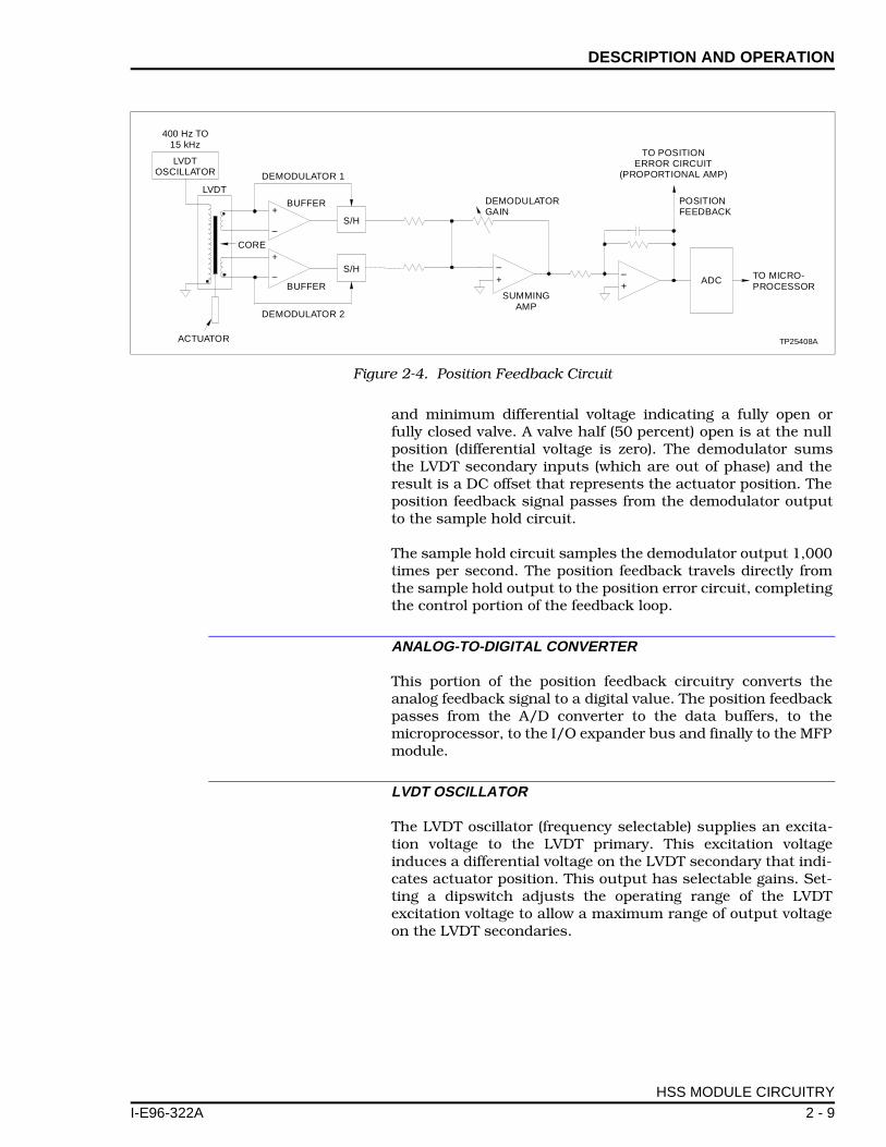
and minimum differential voltage indicating a fully open orfully closed valve. A valve half (50 percent) open is at the nullposition (differential voltage is zero). The demodulator sumsthe LVDT secondary inputs (which are out of phase) and theresult is a DC offset that represents the actuator position. Theposition feedback signal passes from the demodulator outputto the sample hold circuit.
The sample hold circuit samples the demodulator output 1,000times per second. The position feedback travels directly fromthe sample hold output to the position error circuit, completingthe control portion of the feedback loop.
ANALOG-TO-DIGITAL CONVERTER
This portion of the position feedback circuitry converts theanalog feedback signal to a digital value. The position feedbackpasses from the A/D converter to the data buffers, to themicroprocessor, to the I/O expander bus and finally to the MFPmodule.
LVDT OSCILLATOR
The LVDT oscillator (frequency selectable) supplies an excita-tion voltage to the LVDT primary. This excitation voltageinduces a differential voltage on the LVDT secondary that indi-cates actuator position. This output has selectable gains. Set-ting a dipswitch adjusts the operating range of the LVDTexcitation voltage to allow a maximum range of output voltageon the LVDT secondaries.
Figure 2-4. Position Feedback Circuit
O
OR
LVDTDEMODULATOR 1
DEMODULATORGAIN
POSITIONFEEDBACK
TO MICRO-PROCESSOR
ADC
TO POSITIONERROR CIRCUIT
(PROPORTIONAL AMP)
TP25408A
SUMMINGAMP
DEMODULATOR 2
UATOR
S/H
S/H
BUFFER
BUFFER
CORE
+
+
++
––
–
–
HSS MODULE CIRCUITRY
2 - 9

DESCRIPTION AND OPERATION ®
Digital I/O
If the HSS module loses communication with the MFP module,the manual control circuitry enables the operator to manuallychange actuator position. The HSS module provides two24 VDC isolated digital inputs as raise/lower commands froma manual station (pushbuttons, contacts, etc.). These inputsconnect to the microprocessor. The microprocessor incrementsor decrements a position demand to the servo valve when theoperator activates the contacts. Figure 2-5 shows a schematicof a typical isolated digital input circuit.
Trip bias is the third digital input. The trip bias input signal issent to the position error circuit (see Figure 2-3). Activating thetrip bias input drives the actuator to the zero percent position(fully closed) for shutdown. Hard manual is an isolated outputthat provides a connection for an external indicator (LED) oralarm. The indicator notifies the operator that the module is inthe hard manual mode.
Figure 2-5. Typical Digital Input Circuit
TP25410A
+
HSS DIGITAL INPUT
0.1 µF
2.2 K
PUSHBUTTONOR
CONTACTS
3 AMP
+24 VDC
SYSTEM POWERED24 VDC FROM
TERMINATION UNIT
2.2 K
Ω
Ω
-
HSS MODULE CIRCUITRY
2 - 10 I-E96-322A

SECTION 3 - INSTALLATION
I-E96-322A
INTRODUCTION
This section covers the proper handling of electrostatic sensi-tive devices, termination unit or module installation, prelimi-nary dipswitch settings, jumper settings, hydraulic servo (HSS)module installation and configuration. The steps in this sec-tion prepare the module for LVDT/actuator calibration andtuning.
SPECIAL HANDLING
The HSS module uses devices susceptible to electrostatic dis-charge. Follow these handling procedures:
NOTE: Always use Bailey's field static kit (part number 1948385_1 -consisting of two wrist straps, ground cord assembly, alligator clip,and static dissipative work surface) when working with the modules.The kit grounds a technician and the static dissipative work surfaceto the same ground point to prevent damage to the modules by elec-trostatic discharge.
1. Use Static Shielding Bag. Keep the modules in the staticshielding bag until you are ready to install them in the system.Save the bag for future use.
2. Ground Bag Before Opening. Before opening a bag con-taining an assembly with semiconductors, touch it to theequipment housing or a ground to equalize charges.
3. Avoid Touching Circuitry. Handle assemblies by theedges; avoid touching the circuitry.
4. Avoid Partial Connection of Semiconductors. Verifythat all devices connected to the modules are properlygrounded before using them.
5. Ground Test Equipment.
6. Use an Antistatic Field Service Vacuum. Remove dustfrom the module if necessary.
7. Use a Grounded Wrist Strap. Connect the wrist strap tothe appropriate grounding plug on the power entry panel. Thegrounding plug on the power entry panel must be effectivelyconnected to the earth grounding electrode system through theAC safety ground.
8. Do Not Use Lead Pencils to Set Dipswitches. To avoidcontamination of dipswitch contacts that can result in
INTRODUCTION
3 - 1

INSTALLATION ®
unnecessary circuit board malfunction, do not use a lead pen-cil to set a dipswitch.
UNPACKING AND INSPECTION
1. Examine the hardware immediately to verify that it has notbeen damaged in transit.
2. Notify the nearest Bailey sales office of any such damage.
3. File a claim for any damage with the transportation com-pany that handled the shipment.
4. Use the original packing material and container to store thehardware.
5. Store the hardware in an environment of good air quality,free from temperature and moisture extremes.
INSTALLING THE PROCESS HARDWARE
To install the throttle valve, hydraulic actuator, servo valve (orI/H converter) and LVDT transformer:
1. Follow the manufacturer’s directions and recommenda-tions for installation.
2. Use the size and type of cabling the manufacturerrecommends.
INSTALLING THE TERMINATION UNIT OR MODULE
For information about installing process wiring and thehydraulic servo termination unit (THS), digital I/O terminationunit (TDI), or digital I/O termination module (IDI), refer to theappropriate termination device instruction. Appendices Cthrough E contain quick reference information for each of thetermination devices.
WARNING
Only qualified personnel should install the throttle valve,hydraulic actuator, servo valve and linear variable differentialtransformer. Improper installation can cause damage to plantequipment, reduce plant performance and compromise thesafety of plant personnel.
AVERTISSEMENT
Seulement un personnel qualifié devrait effectuer l'installationde la vanne de réglage, de l'actuateur hydraulique, de laservo-vanne, et du transformateur à différentiel linéaire vari-able. Une mauvaise installation peut causer des dommages àl'équipement, peut réduire la performance de l'usine et peutcompromettre la sécurité du personnel.
UNPACKING AND INSPECTION
3 - 2 I-E96-322A
INSTALLATION
I-E96-322A
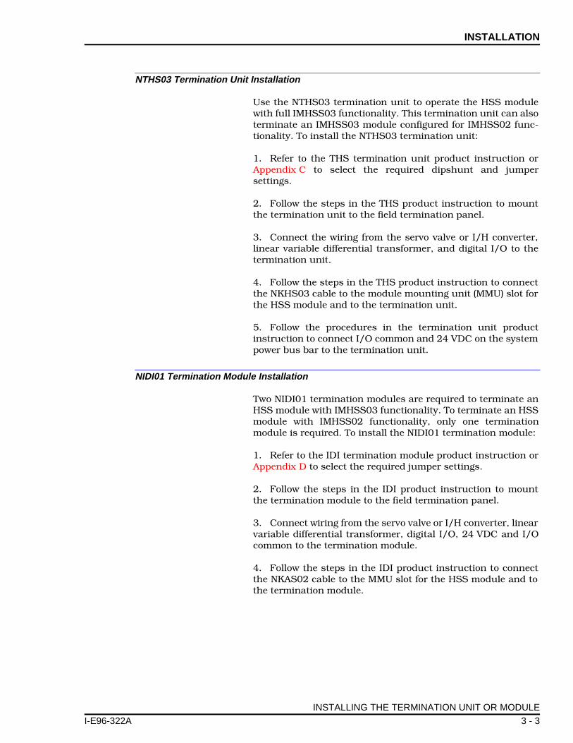
NTHS03 Termination Unit Installation
Use the NTHS03 termination unit to operate the HSS modulewith full IMHSS03 functionality. This termination unit can alsoterminate an IMHSS03 module configured for IMHSS02 func-tionality. To install the NTHS03 termination unit:
1. Refer to the THS termination unit product instruction orAppendix C to select the required dipshunt and jumpersettings.
2. Follow the steps in the THS product instruction to mountthe termination unit to the field termination panel.
3. Connect the wiring from the servo valve or I/H converter,linear variable differential transformer, and digital I/O to thetermination unit.
4. Follow the steps in the THS product instruction to connectthe NKHS03 cable to the module mounting unit (MMU) slot forthe HSS module and to the termination unit.
5. Follow the procedures in the termination unit productinstruction to connect I/O common and 24 VDC on the systempower bus bar to the termination unit.
NIDI01 Termination Module Installation
Two NIDI01 termination modules are required to terminate anHSS module with IMHSS03 functionality. To terminate an HSSmodule with IMHSS02 functionality, only one terminationmodule is required. To install the NIDI01 termination module:
1. Refer to the IDI termination module product instruction orAppendix D to select the required jumper settings.
2. Follow the steps in the IDI product instruction to mountthe termination module to the field termination panel.
3. Connect wiring from the servo valve or I/H converter, linearvariable differential transformer, digital I/O, 24 VDC and I/Ocommon to the termination module.
4. Follow the steps in the IDI product instruction to connectthe NKAS02 cable to the MMU slot for the HSS module and tothe termination module.
INSTALLING THE TERMINATION UNIT OR MODULE
3 - 3

INSTALLATION ®
NTDI01 Termination Unit Installation
The NTDI01 termination unit can terminate only an HSS mod-ule having IMHSS02 functionality. To install the NTDI01 termi-nation unit:
1. Refer to the TDI termination unit product instruction orAppendix E to select the required dipshunt settings.
2. Follow the steps in the TDI product instruction to mountthe termination unit to the field termination panel.
3. Connect the wiring from the servo valve, linear variable dif-ferential transformer, digital I/O, 24 VDC and I/O common tothe termination unit.
4. Follow the steps in the TDI product instruction to connectJ1 of the NKHS03 cable to the MMU slot for the HSS module.Connect J2 to P1 on the termination unit. Tie wrap the J3 legof the NKHS03 cable so that it is secured out of the way.
INITIAL IMHSS03 DIPSWITCH SETTINGS
The IMHSS03 module has five dipswitches and 31 jumpersthat must be configured. Dipswitch settings are applicationdependent. The information in this section covers the switchsettings needed for initial installation. Complete the steps inthis part of the installation procedure to prepare the modulefor automatic calibration and tuning.
Dipswitch S1 - I/O Expander Bus Address
Dipswitch S1 is an eight-pole dipswitch. Poles three througheight of this dipswitch set the I/O expander bus address. Poleone invokes module diagnostics. Refer to Section 6 for diagnos-tic dipswitch settings.
Set the HSS module I/O expander bus address to any unusedbinary address from zero to 63. Dipswitch poles one and twomust be in the closed position for normal operation. Use polesthree through eight to set the address. Table 3-1 lists examplesof I/O expander bus address dipswitch settings. See Figure 3-1
CAUTIONOnly qualified personnel should configure these dipswitches.Damage or misoperation could occur if dipswitches areimproperly configured.
ATTENTION
Seulement un personnel qualifié devrait configurer cesmicro-interupteurs. Un mauvais fonctionnement ou des dom-mages pourraient se produire suite à une mauvaise configura-tion des micro-interupteurs.
INITIAL IMHSS03 DIPSWITCH SETTINGS
3 - 4 I-E96-322A

INSTALLATION
I-E96-322A
for the location of S1 on the HSS module. Record the I/Oexpander bus address in the user setting column.
Dipswitch S2 - Demodulator Gain
Dipswitch S2 is an eight-pole dipswitch that sets the demodu-lator gain. This dipswitch is ignored if the module is configuredwith function code 55. Set the demodulator gain to a value oftwo.
The demodulator gain amplifies the feedback signal so that thepeak-to-peak span of the LVDT feedback signal is as close aspossible to the full range of the 16-bit resolution analog-to-dig-ital (A/D) converter. If the module is configured to operate asan IMHSS02 module using function code 150, this dipswitchmust have an initial setting for manual LVDT calibration. Refer
Table 3-1. Dipswitch S1, I/O Expander Bus Address Example Settings
Example Address
Dipswitch Pole(Binary Value) User
Setting1(128)
2(64)
3(32)
4(16)
5(8)
6(4)
7(2)
8(1)
15 0 0 0 0 1 1 1 1
32 0 0 1 0 0 0 0 0
63 0 0 1 1 1 1 1 1NOTE: 0 = CLOSED or ON, 1 = OPEN or OFF.
Figure 3-1. IMHSS03 Circuit Board Layout
P3
P1
TP25412A
P2
EXPANDER BUS ADDRESS
DEMODULATOR GAIN
S1
S3
S4S2
S5
DITHER OSCILLATOR FREQUENCY AND AMPLITUDE,AND LVDT OSCILLATOR AMPLITUDE AND SELECT
LVDT OSCILLATOR FREQUENCY
RED/GREENSTATUS LED
CONTROLLER GAIN
1 2 3 4 5 6 7 8
OPEN
1 2
1 2 3 4 5 6 7 8
OPEN
1
2
3
4
5
6
7
8
1 2 3 4 5 6 7 8 1 2 3 4 5 6 7 8
OPENOPEN
J25
J24
J23
J22
J21
J20
J19J9
J8
J18
J17
J16
J15J14
J13
J12
J11
J10J7
J31
J31
J27 J29
J3
J5
J6J1
J4
J26
J28
J30J2
INITIAL IMHSS03 DIPSWITCH SETTINGS
3 - 5

INSTALLATION ®
to Appendix B to set S2 for manual LVDT calibration . Refer toTable 3-2 for S2 dipswitch settings.
Dipswitch S3 - Controller Gain
Dipswitch S3 is an eight-pole dipswitch that sets the controllergain. This dipswitch is ignored if the module is configured withfunction code 55. Set the controller gain to one.
This amplifier compares position demand to position feedbackand outputs the difference of those signals. The controller gainaffects the response of the control loop. If the module is config-ured as an IMHSS02 module using function code 150, thisdipswitch must have an initial setting. Refer to CONTROLLERTUNING in Appendix B to initially set S2 for manual controllergain tuning. Refer to Table 3-3 for S3 dipswitch settings.
Table 3-2. Dipswitch S2, Demodulator Gain
GainDipswitch Pole
User Setting1 2 3 4 5 6 7 8
2.0 1 1 1 1 1 1 1 0
5.5 1 1 1 1 1 1 0 1
10.0 1 1 1 1 1 0 1 1
21.1 1 1 1 1 0 1 1 1
48.8 1 1 1 0 1 1 1 1
72.0 1 1 0 1 1 1 1 1
100.9 1 0 1 1 1 1 1 1
152.0 0 1 1 1 1 1 1 1NOTE: 0 = CLOSED or ON, 1 = OPEN or OFF.
Table 3-3. Dipswitch S3, Controller Gain
GainDipswitch Pole
User Setting1 2 3 4 5 6 7 8
1.00 1 1 1 1 1 1 1 0
2.00 1 1 1 1 1 1 0 1
5.00 1 1 1 1 1 0 1 1
10.50 1 1 1 1 0 1 1 1
13.35 1 1 1 0 1 1 1 1
14.46 1 1 0 1 1 1 1 1
18.10 1 0 1 1 1 1 1 1
20.52 0 1 1 1 1 1 1 1NOTE: 0 = CLOSED or ON, 1 = OPEN or OFF.
INITIAL IMHSS03 DIPSWITCH SETTINGS
3 - 6 I-E96-322A

INSTALLATION
I-E96-322A
Dipswitch S4 - LVDT Oscillator Frequency
Dipswitch S4 is a two-pole dipswitch that sets the LVDT oscil-lator frequency. This dipswitch is ignored if the module is con-figured as an IMHSS03 module using function code 55. Set allpoles to one (open).
If the module is configured as an IMHSS02 module using func-tion code 150, set the LVDT oscillator frequency to the fre-quency specified by the manufacturer. To set the LVDToscillator frequency:
1. Refer to the LVDT specifications for the recommendedLVDT primary excitation voltage frequency.
2. Refer to Table 3-4 for dipswitch settings and set S4 so thatthe LVDT oscillator meets the manufacturer’s specifications.
Dipswitch S5 - Dither and LVDT Oscillator
Dipswitch S5 is an eight-pole dipswitch that sets the ditheroscillator frequency and amplitude, and the LVDT oscillatoramplitude (LVDT primary excitation voltage).
Set the dither oscillator amplitude and frequency to the valuethe manufacturer of the servo valve recommends. Dipswitchpoles one and two set the dither oscillator frequency. Polesthree and four set the dither oscillator amplitude or disablesthe dither oscillator circuitry. Poles five through eight set theLVDT oscillator amplitude. Set the LVDT oscillator amplitudeto the value that the LVDT manufacturer recommends. To setdipswitch S5:
1. Refer to the servo valve specifications for the recommendeddither oscillator current amplitude and frequency.
2. Refer to Table 3-5 for dipswitch settings and set poles 1through 4 accordingly.
Table 3-4. Dipswitch S4, LVDT Oscillator Frequency
Frequency (kHz)
Dipswitch PoleUser Setting
1 2
1.0 1 1
2.5 1 0
5.0 0 0
10.0 0 1NOTE: 0 = CLOSED or ON, 1 = OPEN or OFF.
INITIAL IMHSS03 DIPSWITCH SETTINGS
3 - 7

INSTALLATION ®
3. Refer to the LVDT specifications for the recommendedLVDT oscillator amplitude.
4. Refer to Table 3-5 for dipswitch settings and set poles 5through 8 accordingly.
JUMPER SETTINGS
There are 31 jumpers on the HSS module. These jumpersselect options such as servo valve or I/H converter mode, fourto 20 milliamp positioning for contingency errors in I/H con-verter mode, servo valve output current, and AC or DC LVDTtransformers. Table 3-6 lists the HSS module jumper settings.Figure 3-2 shows details of the jumpers. Figure 3-1 shows thelocation of J31 on the HSS circuit board. Set the jumpers tomeet the requirements of your particular system.
Table 3-5. Dipswitch S5, Dither Oscillator Frequency/Amplitude and LVDT Oscillator Amplitude
SettingDipswitch Pole
User Setting1 2 3 4 5 6 7 8
Dither oscillator frequency = 300 Hz 0 1
Dither oscillator frequency = 200 Hz 1 0
Dither amplitude = 5% of current output 0 1
Dither amplitude = 10% of current output 1 0
Dither disabled 1 1
LVDT oscillator amplitude = 2.1 Vpp 0 0 0 0
LVDT oscillator amplitude = 2.6 Vpp 0 0 1 0
LVDT oscillator amplitude = 3.6 Vpp 0 1 1 0
LVDT oscillator amplitude = 4.5 Vpp 0 1 1 1
LVDT oscillator amplitude = 5.4 Vpp 1 0 0 1
LVDT oscillator amplitude = 6.0 Vpp 1 0 1 0
LVDT oscillator amplitude = 7.7 Vpp 1 1 0 0
LVDT oscillator amplitude = 9.0 Vpp 1 0 1 1
LVDT oscillator amplitude = 13.5 Vpp 1 1 0 1
LVDT oscillator amplitude = 18.0 Vpp 1 1 1 0NOTE: 0 = CLOSED or ON, 1 = OPEN or OFF.
Table 3-6. Jumpers J1 through J31
FunctionJumper Position
Jumper
Normal LVDT configuration 1-2 J1-J5
4 - 40 mA input (I/H converter con-tingency error, LVDT 2_1)
2-3
Servo valve mode 1-2 J6, J7, J26
I/H converter mode 2-3
JUMPER SETTINGS
3 - 8 I-E96-322A

INSTALLATION
I-E96-322A
20 - 160 mA I/H converter 1-2 J8
2-3 J9-J13, J18-J21
3-4 J14-J17, J22-J25
4 - 20 mA I/H converter 1-2 J9
2-3 J8, J10-J13, J18-J21
3-4 J14-J17, J22-J25
±8 mA servo outputs 1-2 J10, J18
2-3 J8, J9, J11-J14, J19-J22
3-4 J15-J17, J23-J25
±16 mA servo outputs 1-2 J10, J11, J18, J19
2-3 J8, J9, J12-J15, J20-J23
3-4 J16, J17, J24, J25
±24 mA servo outputs 1-2 J10-J12, J18-20
2-3 J8, J9, J13-J16, J21-J24
3-4 J17, J25
±32 mA servo outputs 1-2 J10-J13, J18-J21
2-3 J8, J9, J14-J17, J22-J25
±40 mA servo outputs (servo1/C1 and servo2/C1 outputs only)
1-2 J10-J14, J18-J22
2-3 J8, J9
3-4 J15-J17, J23-J25
±48 mA servo outputs (servo1/C1 and servo2/C1 outputs only)
1-2 J10-J15, J18-J23
2-3 J8, J9
3-4 J16, J17, J24, J25
±56 mA servo outputs (servo1/C1 and servo2/C1 outputs only)
1-2 J10-J16, J18-J24
2-3 J8, J9
3-4 J17, J25
±64 mA servo outputs (servo1/C1 and servo2/C1 outputs only)
1-2 J10-J25
2-3 J8, J9
AC LVDT (sine wave output to primary)
1-2 J27-J30
DC LVDT (15 VDC output for LVDT power)
2-3
Normal operation 1-2 J31
Microcontroller clock disabled (internal test only)
open
NOTE: To enable a function, place jumper straps over (short) the required jumper positions.
Table 3-6. Jumpers J1 through J31 (continued)
FunctionJumper Position
Jumper
JUMPER SETTINGS
3 - 9

INSTALLATION ®
IMHSS03 MODULE INSTALLATION
To install the HSS module in the module mounting unit:
1. Locate the module mounting unit slot assignment for themodule.
2. Check the I/O expander bus dipshunt socket on the back-plane of the module mounting unit. The dipshunt must beinstalled with all pins shorted. There must be a communica-tion path from the MFP module to the I/O module.
3. Align the top and bottom edges of the circuit card with thetop and bottom rails of the assigned slot in the module mount-ing unit.
4. Slide the module into the slot. Push until the module isseated in the backplane connector. Turn the 2 thumbscrewson the faceplate ½-turn until the module locks in place.
Figure 3-2. IMHSS03 Jumper Layout
J25
J24
J23
J22
J21
J20
J19J9
J8
J18
J17
J16
J15J14
J13
J12
J11
J10J7
J27 J29
J3J5
J6J1
J4
J26
J28
J30J23 1 3 1 3 1
3 1
31
31
31
3 13
1
3
1
3
1
3
1
3
1
3
1
4
1
4
1
41
41
41
41
41
41
3
1
3
1
3 1 3 1 3 1
3 1 3 1 3 1
TP25461A
WARNINGDisconnect power before installing dipshunts on the modulemounting unit backplane. Failure to do so will result in contactwith cabinet areas that could cause severe or fatal shock.
AVERTISSEMENT
Interrompez l'alimentation avate d'installer des dipshunts surle fond de panier du châssis de montage des modules. Sinon,tout contact avec cette zone entraîne des risques d'électrocu-tion sérieuse ou fatale.
IMHSS03 MODULE INSTALLATION
3 - 10 I-E96-322A

INSTALLATION
I-E96-322A
FUNCTION CODE 55 CONFIGURATION
If the jumpers and dipswitches in this section are set up foroperation with function code 55:
1. Configure the multi-function processor with functioncode 55. Refer to the Function Code Application Manual forinformation on how to configure function code 55.
2. Tune the demodulator gain, calibrate the LVDT trans-former, and tune the PID controller gain. Refer to Section 4 forprocedures explaining how to do either automatic (demodula-tor gain only) or manual calibration and tuning using functioncode 55.
FUNCTION CODE 150 CONFIGURATION
If the jumpers and dipswitches have been set up for operationwith function code 150:
1. Refer to the Function Code Application Manual for infor-mation on configuration instructions.
2. Configure the processor module with function code 150,specifications S1 and S2.
3. Leave the remaining specifications at their default values.They require modification during the module calibration proce-dure. Refer to Appendix B to calibrate the LVDT transformerand tune the PID controller gain using function code 150.
FUNCTION CODE 55 CONFIGURATION
3 - 11

SECTION 4 - CALIBRATION
I-E96-322A
INTRODUCTION
This section covers the module calibration procedure, demodu-lator gain tuning procedure, controller gain tuning procedureand automatic tuning procedure. Tuning and calibrating themodule insures accurate positioning of the turbine throttlevalve and the best possible frequency response.
Complete the steps in this section before placing the hydraulicservo (HSS) module in operation. The steps in this sectionapply only to IMHSS03 modules and multi-function processor(MFP) modules configured with function code 55. Refer toAppendix B for tuning and calibration procedures using func-tion code 150.
The demodulator gain tuning procedure can be done in one of twomodes: Manual or automatic. In manual mode, the user performsthe tuning procedure step by step. In automatic mode, the HSSmodule performs the same steps without user action. Demodula-tor gain and controller gain are independent of each other; there-fore, demodulator gain calibration can be done automatically ormanually, while controller gain must be done manually. New gainvalues and any error codes are stored in the function code so thatgain values can be viewed via the configuration device display(e.g., engineering work station, OIS monitor).
Perform IMHSS03 tuning and calibration in the following order:
1. Null check (manual only).
2. Demodulator gain tuning (automatic or manual).
3. LVDT calibration (automatic only).
4. Controller gain tuning (manual only).
NULL CHECK
To start the null check procedure, the MFP module must becommunicating with the IMHSS03 module. Additionally, thefollowing conditions must exist:
• The turbine is off-line.
• The valve (for turbine hydraulic system) must be in thecontrolling position and functioning properly.
• The multi-function processor module has function code 55in its configuration.
INTRODUCTION
4 - 1

CALIBRATION ®
• Calibrate mode enable must be set to disable, <S11> = 0.
• LVDT status must be good.
To perform the null check:
1. Go to the block address specified in S7. Set the LVDT nullcheck mode to 1 for the primary LVDT transformer.
2. Go to the block address specified in S11. Set the calibratemode enable to 1. This places the IMHSS03 module into cali-brate mode.
3. Go to the block address specified in S12. Set the GO/HOLDselect to 1 (GO).
4. Wait until the selected LVDT transformer at null point flagis set in block output N+7, bit 7.
5. Make the necessary adjustments to the servo valve and theLVDT position to adjust the actuator to its mechanical nullposition. For maximum LVDT linearity, the LVDT null pointshould occur at the actuator’s midtravel position. When S12 isin the GO mode, the actuator ramps to and holds at the LVDTnull point (LVDT secondaries have equal voltages). While theactuator is held at the LVDT null point, the mechanical zero onthe LVDT transformer can be adjusted until the actuator is atits midpoint position.
6. If there are redundant LVDT transformers, go to the blockaddress specified in S7. Set the LVDT null check mode to 2 forthe backup LVDT transformer.
7. Repeat Steps 4 and 5.
8. When the adjustments are complete, set GO/HOLD selectto a 0 (HOLD), set calibrate mode enable to a 0 (DISABLE) andset null check to 0 (DISABLE).
AUTOMATIC TUNING (FUNCTION CODE 55)
To start automatic tuning, the MFP module must be communi-cating with the IMHSS03 module and the following conditionsmust be met:
• The turbine is off-line.
• The servo valve or I/H converter (for turbine hydraulic sys-tem) must be in the controlling position and functioningproperly.
• The multi-function processor module has function code 55in its configuration.
AUTOMATIC TUNING (FUNCTION CODE 55)
4 - 2 I-E96-322A

CALIBRATION
I-E96-322A
Demodulator Gain
The HSS module automatically tunes the demodulator gainusing the same techniques a technician would use to manuallytune the gain. The auto tuning function selects the lowest gain.The actuator moves to the 100 percent and zero percent posi-tions. At each position the LVDT secondary voltage is read. Ifthe 100 percent position secondary voltage is less than 8.5volts or the zero percent LVDT secondary voltage is greaterthan -8.5 volts, the demodulator gain is increased. This proce-dure repeats until the 100 percent position LVDT secondaryvoltage is greater than 8.5 volts or the zero percent positionLVDT secondary voltage is less than -8.5 volts. Then thedemodulator gain is set to the next lower value.
The automatic tuning error bit is set if the lowest demodulatorgain causes the LVDT secondary voltages to go out of range orthe highest demodulator gain causes the LVDT secondary volt-ages to remain below range (±5 VDC). This error bit indicatesthat the automatic tuning procedure was unable to provide anoptimum gain value. A less than optimum gain value producesinaccurate position feedback information from the LVDT trans-former, so corrective action is required.
To automatically tune the demodulator gain:
1. Set the demodulator gain constant to 0, <S16> = 0. Thisinitiates the tuning procedure.
2. Observe the module status on the output block N+6, bits 0and 1. If these bits have a binary value of 0, tuning is inprogress. When tuning is complete, the binary value of thesebits is 1.
3. If these bits have a binary value of 3, then an error hasoccurred during the automatic tuning procedure. All block out-puts will show bad quality. The other error bits in the modulestatus output block N+6 and the LVDT status output blockN+7 will indicate the error. Refer to Section 6 for correctiveaction. After correcting the error, repeat the demodulator gaintuning procedure.
NOTE: To clear the automatic tuning of parameters (ATOP) errorstatus and bad output qualities without performing another auto-matic tuning of parameters, send any new demodulator gain valueto the IMHSS03 module.
If an error occurs during tuning, the previous value (before theATOP procedure was initiated) is displayed as the gain value. Ifthe error occurs while the gain is at the highest or the lowestvalue, the error is probably an out of range condition. If thishappens, the controller gain remains at the out of range valueto indicate that the error occurred because of an out of rangecondition.
AUTOMATIC TUNING (FUNCTION CODE 55)
4 - 3

CALIBRATION ®
Initial Calibration (Function Code 55)
To calibrate the LVDT transformer and actuator with the HSSmodule, the MFP module must be communicating with theHSS module and the following conditions must be met:
• Demodulator gain tuning must be complete.
• The turbine is off-line.
• The servo valve or I/H converter (for turbine hydraulic sys-tem) must be in the controlling position and functioningproperly.
• The multi-function processor module has function code 55in its configuration.
• The calibrate mode enable must be set to disable,<S11> = 0.
To calibrate the HSS module:
1. Verify that the block address specified in S9 contains theproper number of calibration cycles (from 1 to 8).
2. Verify that the block address specified in S8 contains theproper calibration stroke time. Values are selected in seconds.Calibration stroke times under 30 seconds are not recom-mended for on-line tuning.
3. Go to the block address specified in S11. Set the calibratemode enable to 1, <S11> = 1. This places the HSS module intocalibrate mode.
4. Go to the block address specified in S12. Set the GO/HOLDselect to 1 (GO).
5. The HSS module drives the actuator to the 100% positionat the selected stroke time specified in <S8>. While the actua-tor is held against the 100% end of travel, the LVDT differentialvoltage at 100% is recorded. If redundant LVDT transformersare configured, then the voltage at 100% will be recorded forboth LVDT transformers.
After recording the 100% reading, the HSS module drives theactuator to the 0% position at the selected stroke time. Whilethe actuator is held against the 0% end of travel stop, the LVDTdifferential voltage at 0% is recorded. If redundant LVDT trans-formers are configured, then the voltage at 0% will be recordedfor both LVDT transformers.
NOTE: The position feedback output block N will display the currentvalve position read by the primary LVDT transformer.
AUTOMATIC TUNING (FUNCTION CODE 55)
4 - 4 I-E96-322A

CALIBRATION
I-E96-322A
The 100% to 0% cycle repeats the number of calibration cyclesspecified in <S9>. After recording the final 0% reading, theactuator moves at the selected stroke time to the positiondemand from the MFP module. When the calibration cycles arecomplete, the actuator ramps to the position demand from theMFP module if the IMHSS03 module is in the automatic tuningmode. In manual tuning mode, the actuator ramps to its preca-libration position when the calibration cycles are complete.
Allow the cycle to complete. After completion of all cycles, thecalibrated differential voltages are written to HSS moduledual-port RAM.
6. Observe the module status output block N+6, bits 0 and 1.The binary value of these bits is 0 while the LVDT calibration isin progress. When the calibration is complete, these bits have abinary value of 1.
If a binary 2 appears in the module status bits, then an errorhas occurred during the calibration procedure. All outputs willshow bad quality and the HSS module will retain the previouscalibration values. The other error bits in the module statusoutput blocks N+6 and the LVDT status output blocks N+7 willshow which error has occurred. Refer to Section 6 and Table6-5 for corrective action. After correcting the error, repeat thecalibration procedure.
NOTE: To clear the calibration error status and bad output qualitieswithout performing another calibration, set calibrate mode to dis-able, <S11> = 0.
If the calibration was successful, the MFP reads the new differ-ential voltages from the HSS module. These new values arewritten to function code 55 specifications S18 through S21.Refer to Controller Gain to tune the controller gain.
MANUAL TUNING (FUNCTION CODE 55)
The following procedures are for manually tuning demodulatorgain and controller gain using function code 55.
Demodulator Gain
To start demodulator tuning, the MFP module must be com-municating with the HSS module and the following conditionsmust be met:
• The demodulator gain must be set to a value of one.
• The controller gain must be set to a value of one.
• The turbine is off-line.
MANUAL TUNING (FUNCTION CODE 55)
4 - 5

CALIBRATION ®
• The servo valve or I/H converter (for turbine hydraulic sys-tem) must be in the controlling position and functioningproperly.
• The multi-function processor module has function code 55in its configuration.
To manually tune the demodulator gain:
1. Go to S15 and set it to 1 so that volts are the display unitson output block N.
2. Go to the block specified in S6, and set it to 0%.
3. Observe the LVDT secondary voltage at output block N andwait until the value stops changing.
4. If the 0% position value of output block N is greater than-8.5 V, then increase the value of the demodulator gain by set-ting specification S16 to the next higher gain and repeatStep 3.
5. When the 0% value is less than -8.5 V, decrease thedemodulator gain to the next lower setting.
6. Go to the block specified in S6, and set it to the 100%position.
7. Observe the LVDT secondary voltage at the output block Nand wait until the value stops changing.
8. If the 100% position at output block N is greater than8.5 V, then decrease the value of the demodulator gain by set-ting specification S16 to the next lower gain and repeat Step 7.
9. If the demodulator gain has been changed from the valuedetermined in Step 4:
a. Go to the block specified in S6, and tune it to 0%.
b. Observe the LVDT secondary voltage at output block Nand wait until the value stops changing. When the valuestops changing, read the final value and verify that it isacceptable. None of the LVDT 0% values should be greaterthan -5 V and none of the LVDT 100% values should beless than 5 V.
10. If there are redundant LVDT transformers, repeat this pro-cedure for the backup LVDT transformer. Select the backup bychanging the value of S3 to select the other LVDT transformer.Use the lowest of the two gains for redundant LVDT transform-ers. Verify that both LVDT transformers are still within range.If any LVDT transformer is not within range, refer to Section 6
MANUAL TUNING (FUNCTION CODE 55)
4 - 6 I-E96-322A

CALIBRATION
I-E96-322A
and Table 6-5 for information on correcting the LVDTresponse.
11. Calibrate the LVDT transformer before tuning the control-ler gain. Refer to Initial Calibration (Function Code 55) forthe LVDT calibration procedure.
Controller Gain
To start controller tuning, the MFP module must be communi-cating with the IMHSS03 module and the following conditionsmust be met:
• The controller gain must be set to one.
• Demodulator gain tuning must be complete.
• The turbine is off-line.
• The servo valve or I/H converter (for turbine hydraulic sys-tem) must be in the controlling position and functioningproperly.
• The multi-function processor module has function code 55in its configuration.
• The block containing the calibrate mode enable specifica-tion is set to disable (S11 = 0).
To manually tune the controller gain:
1. Enter position demands using the block (specified in S6)containing the percent position demand. Enter values of 50%,75%, and 90%. Observe the response of the valve at eachdemand level. The valve should respond without oscillating ateach level of demand.
2. If the valve operates smoothly at all demand levels, thenincrease the controller gain to the next higher value and repeatSteps 1 and 2.
3. When the controller gain reaches a point where the valveoscillates at any demand level, decrease the controller gain tothe next lower value. Repeat Steps 1 through 3 to verify thatthe valve operates smoothly at all demand levels. This is thecorrect controller gain.
MANUAL TUNING (FUNCTION CODE 55)
4 - 7

SECTION 5 - OPERATING PROCEDURES
I-E96-322A
INTRODUCTION
This section explains how to place the IMHSS03 HydraulicServo Module in operation. This section includes informationabout the hydraulic servo module (HSS) faceplate LEDs, sys-tem start-up and operation, and manual operation.
FACEPLATE LEDS
There are nine LEDs visible through the faceplate of theIMHSS03 module. There is one red/green status LED and eightred LEDs (see Figure 5-1). Three of the red LEDs (one, four andeight) are used during normal operation. During diagnostics,all eight red LEDs indicate pass/fail counts or test number(refer to Section 6 for diagnostic LED states). Refer to Table 5-1for an explanation of the LED states.
Figure 5-1. Faceplate LEDs
IMHSS03
1/ATOP/CAL
2
3
4/OUT DIS
5
6
7
8/HARD MAN
RED/GREENSTATUS LED
TP25411A
INTRODUCTION
5 - 1

OPERATING PROCEDURES ®
START-UP AND NORMAL OPERATION
Only qualified personnel should perform plant start-up andoperation. To start up and operate the HSS module:
1. Start the turbine following the plant start-up procedure.
2. Enter a turbine speed demand or load demand set point viathe operator interface.
3. Operation continues according to the system control strat-egy in the MFP configuration.
HARD MANUAL MODE OPERATION
Operation enters the hard manual mode when the modulestarts up, an MFP communication failure occurs, or when it isinitiated from function code 55. Table 5-1 lists the faceplateLED status when the module enters the hard manual mode.Figure 5-1 shows the module faceplate LEDs. To manuallyposition the throttle valve:
1. Monitor the turbine speed or load through the operatorinterface.
2. Refer to your plant operating procedure to determine theactuator position needed to maintain turbine speed.
3. To maintain the load (or speed) demand, adjust thehydraulic actuator position by activating the raise or lowercontacts (customer installed). The raise contact opens the valve
Table 5-1. LED States
Red/Green Status LED
LED 1ATOP/CAL
LED 4 OUT DIS
LED 8 HARD MAN
Condition
Red On On On Initial power up. All LEDs are on momentarily.
Off Off On Off On-board diagnostics during power up.
Off Off On HSS module waiting for MFP initialization data.
Green Off Off Off Normal operation.
On Off Off Automatic tuning of parameters or calibration in progress.
Off Off On Hard manual mode. The MFP position demand is not equal to the HSS position demand or man-ual mode is enabled through function code 55.
Off On Off Servo output disabled (D/A error, all bad LVDT transformers in servo valve mode).
Blinking green
Off Off On MFP module is in configuration mode or failed. HSS module is operating.
Red Off On Off HSS module failure.
START-UP AND NORMAL OPERATION
5 - 2 I-E96-322A

OPERATING PROCEDURES
I-E96-322A
while the lower contact closes the valve. Use the 4 to 20 milli-amp position output to determine the valve position.
4. To return to automatic mode, the MFP module must becommunicating with the HSS module. If hard manual modewas selected through function code 55, specification S13 mustbe returned to auto mode, <S13> = 0. Finally, the operatormust match the D/A converter output value (block numberN+1) with the current position demand from the MFP module.
NOTE: If the HSS module enters hard manual mode by losing com-munication to the MFP module, the HSS module will exit hard man-ual mode when the MFP module establishes communication withthe HSS module, and when position demands from the MFP andHSS modules match. The MFP module resumes automatic opera-tion from the valve position held during manual operation.
TURBINE TRIP
Turbine trip provides quick shutdown by providing a way todrive the throttle valve closed. The trip bias circuit overridesposition control from the HSS microprocessor and drives thevalve closed. To drive the valve closed, close the trip bias switch(customer installed) to apply 24 VDC to the trip bias digitalinput.
TURBINE TRIP
5 - 3

SECTION 6 - TROUBLESHOOTING
I-E96-322A
INTRODUCTION
This section provides troubleshooting information for thehydraulic servo (HSS) module. This information includes diag-nostic testing, alarm and exception reporting, problem reportsand troubleshooting flowcharts. Additional reference docu-ments that are helpful for troubleshooting are product instruc-tions for the processor module, the operator interface (i.e.,OIS, EWS, etc.) and the Function Code Application Manual.
IMHSS03 FACEPLATE LEDS
There are nine LEDs visible through the IMHSS03 faceplate.The top LED (red/green) indicates communication statusbetween the HSS module and multi-function processor mod-ule, and overall status (see Figure 5-1). The next eight LEDs(labeled one through eight) are used for diagnostic purposes.LEDs one, four and eight are used during normal operation toindicate automatic tuning of parameters/calibration, outputsdisabled and hard manual mode. Table 5-1 lists the LEDstates for various operating conditions. In diagnostics mode,the eight red LEDs indicate either pass/fail count or test num-ber and status (pass/fail). Figure 6-1 shows the diagnosticLED display.
Figure 6-1. Diagnostic LED Display
TEST NUMBER
LED 1
LED 2
LED 3
LED 4
LED 5
LED 6
LED 7
LED 8
FAILURE COUNT
PASS COUNT
LSB
LSB
MSB
MSB
NOT USED
TEST NUMBERMODE FAIL
TP50335B
INTRODUCTION
6 - 1

TROUBLESHOOTING ®
DIAGNOSTICS
The IMHSS03 module firmware contains diagnostic routinesthat can be invoked from power up. The diagnostic routinesallow verification of the module components and circuitry.When the module is in diagnostic mode, it cannot perform thefunctions of an IMHSS03 module. Therefore, diagnosticsshould be used on modules that are off-line.
DIAGNOSTIC DIPSWITCH SELECTION
Pole one of dipswitch S1 puts the IMHSS03 module into diag-nostic mode (see Figure 6-2). Poles eight through five ofdipswitch S2 select the diagnostic test to run. Pole eight is theleast significant bit (binary weight one), pole five is the mostsignificant bit (binary weight eight). Test IDs range from zero tonine. Refer to Table 6-1 for test ID values.
Pole one of dipswitch S2 selects the LED display mode. Thepass/fail mode displays a composite of the incrementing passand fail counters. LEDs one through four indicate the numberof passes successfully completed. LEDs five through eight dis-play the number of failures (see Figure 6-1).
The test number mode (pole one of dipswitch S2) displays thediagnostic test number on LEDs one through four. LEDs fivethrough seven are not used; LED eight is the fail LED. The testnumber and the pass/fail status of the test is displayed uponcompletion (or failure) of the test. A passing test displays onlythe test number. A failing test also turns LED eight on to indi-cate a failure.
Pole two of dipswitch S2 selects the halt on error feature. Inthis mode, the IMHSS03 module will halt test execution when-ever the selected test detects an error. The number of the fail-ing test is displayed on the IMHSS03 LEDs.
The front panel LEDs are used during diagnostic mode opera-tion to display test results. On module reset, all eight LEDsilluminate. Next, the dipswitches are read, the selected test isexecuted and the result is displayed on the LEDs. The formatof the LED display depends upon the setting of dipswitch S2pole one. If this pole is set to zero (on), the test number is dis-played on LEDs one through four. LED eight illuminates if thetest fails. The test will repeat. If S2 pole one is set to one (off), arunning tally of successes and failures will be displayed on theLEDs. LEDs one through four tally the passes, LEDs fivethrough eight the failures (see Figure 6-1). If a test fails withhalt-on error selected (S2, pole two on), the status LED turnsred after the test status is displayed.
DIAGNOSTICS
6 - 2 I-E96-322A

TROUBLESHOOTING
I-E96-322A
Figure 6-2. Diagnostic Dipswitch Settings
HSS MODULE ADDRESS
TEST ID
HALT ON ERROR (ON = DISABLED, OFF = ENABLED)
TP25415A
OFF = PASS/FAIL, ON = TEST NUMBER DISPLAY
DIAGNOSTIC MODE (OFF = ENABLED, ON = DISABLED)
ON
ON
OFF
OFF
S1
S2
1
1
2
2
3
3
4
4
5
5
MSB
6
6
7
7
8
8
LSB
UN
US
ED
UN
US
ED
Table 6-1. Diagnostic Test ID Numbers and Dipswitch S2 Settings
Test Name IDDipswitch S2 Pole 1
Description12 23 3 4 5 6 7 8
Dipswitch and LED test
00 x y 0 0 0 0 0 0 Increments a count on the LEDs until all are illuminated. The status LED displays a logical and mathematical manipulation of the bytes on dipswitches S1 through S4. Off indicates even parity, green indicates odd parity.
Watchdog timer test
01 x y 0 0 0 0 0 1 The watchdog timer is started. An error code displays if it does not expire in 15 secs.
ROM test 02 x y 0 0 0 0 1 0 Verifies the checksum of the EPROM.
SRAM test 03 x y 0 0 0 0 1 1 Performs a walking ones and zeros test on the static RAM.
Timer test 04 x y 0 0 0 1 0 0 Initializes the timer and checks its operation.
DPRAM test 05 x y 0 0 0 1 0 1 Performs a walking ones and zeros test on dual port RAM.
A/D reference test
06 x y 0 0 0 1 1 0 Checks internal analog-to-digital reference voltages.
Output D/A test 07 x y 0 0 0 1 1 1 Checks analog output voltages of the 12-bit D/A converter.
Position D/A test
08 x y 0 0 1 0 0 0 Checks analog output voltages of the 16-bit D/A converter.
Group test(02-08)
09 x y 0 0 1 0 0 1 Performs tests 2 through 8 in numerical order.
NOTES:1. 0 = ON or CLOSED, 1 = OFF or OPEN.2. X = selects LED display mode. See Figure 6-2 for pole 1 settings.
3. Y = selects halt on error or continuously loop the tests. See Figure 6-2 for pole 2 settings.
DIAGNOSTIC DIPSWITCH SELECTION
6 - 3

TROUBLESHOOTING ®
For a group test (nine), tests two through eight run in numeri-cal order. On a failure, the test number that failed is displayedif the test number display mode is selected. A failure of a testwithin the group terminates the group test at that point if thehalt on error feature is selected. All tests after the failing testwill not execute until the fault is removed.
To invoke the IMHSS03 diagnostics:
1. Set dipswitch S1 pole 1 to position 1 (off) to select the diag-nostic mode (see Figure 6-2).
2. Set dipswitch S2 pole 1 to select the LED display mode.Figure 6-2 shows the display mode settings.
3. Set dipswitch S2 pole 2 to select the halt on error feature(see Figure 6-2).
4. Set dipswitch S2 poles 8 through 5 to select a test number.Table 6-1 lists the diagnostic tests and their ID number.
5. After correctly setting the dipswitches, reset the module tostart diagnostics.
Observe the test results on the IMHSS03 LED display (see Fig-ure 6-1). The selected tests will run repeatedly until theIMHSS03 module is reset. The module will halt diagnostics ifan error occurs while the module is in halt on error mode.
ALARM AND EXCEPTION REPORTING
IMHSS03 function codes do not directly generate alarm orexception reports. If exception reporting is required, send therequired outputs to standard exception reporting blocks. Formore information, refer to the instruction for the operatorinterface in use.
FUNCTION CODE 55 PROBLEM REPORTS
Function code 55 generates I/O module error reports. Theseproblem reports are report type 12. Function code 55 gener-ates five module problem report error types (refer to Table 6-2).
• Error type 1 - no response/wrong type. • Error type 2 - calibration error. • Error type 3 - channel failure/out of range. • Error type 9 - input failure. • Error type 12 - output fixed.
Problem reports are broken down into two categories: Major orfatal errors, and minor or nonfatal errors. Fatal errors indicatethat the given mode of operation will not function. Fatal errorsgenerate module problem reports having error types one, two
ALARM AND EXCEPTION REPORTING
6 - 4 I-E96-322A

TROUBLESHOOTING
I-E96-322A
or three. Nonfatal errors indicate that the module has discov-ered an error but will continue to function. Nonfatal errorsgenerate module problem reports having error types nine and12.
Table 6-2. Function Code 55 Module Problem Report
Error Type Module Error Corrective Action
1 - No response/ wrong type
Any I/O expander bus communication failure. Any command or data checksum failure. Error will also be indicated by FC 55 output N+9.
Check I/O expander bus dipshunts, remove IMHSS03 and reinsert. If error recurs, replace IMHSS03.
Hardware or D/A error. Error will also be indi-cated by FC 55 output N+8 or N+6, respectively.
1. Remove IMHSS03. Insert the module. If the error recurs, replace the module.
2. Cause may be isolated by running diagnostics.
2 - Calibration error
A hardware error occurred during calibration or demodulator automatic tuning. Error may also be indicated by FC 55 output N+6. Errors that can cause calibration or automatic tuning to fail are:
A/D error (indicated by output N+6).
D/A error (indicated by output N+6).
Replace IMHSS03.
An LVDT error occurred during calibration or demodulator automatic tuning. Error may also be indicated by FC 55 output N+7.
1. Refer to FC 55 output N+7 to isolate error.
2. Check LVDT connections. If error persists, replace indicated LVDT or IMHSS03.
An error occurred during demodulator auto-matic tuning. Errors that can cause automatic tuning to fail are:
Minimum demodulator gain produced out of range 100% or 0% LVDT values.
Maximum demodulator gain produced LVDT spans that are too small.
1. Refer to the value selected by the mod-ule in S16 to isolate the error.
2. Adjust the oscillator voltage amplitude, selected with SW5, based on value returned in S16. Retry procedure. If error persists, replace IMHSS03.
An error occurred during calibration. Errors that can cause calibration to fail are:
100% LVDT value < 0% LVDT value.
Servo outputs not saturated at 100% or 0% position.
1. Refer to the values returned by the IMHSS03 in S18 through S21 to isolate the problem.
2. Increase controller gain or decrease demodulator gain.
3. Retry procedure, if error persists, replace IMHSS03.
3 - Channel failure/out of range
Any fatal LVDT failure in servo mode:
Only using LVDT 1 (S3=0), and any LVDT 1 error.
Only using LVDT 2 (S3=1), and any LVDT 2 error.
Redundant LVDTs (S3=2 or 3), and LVDT 1 and LVDT 2 errors.
1. Refer to FC 55 output N+7 to isolate error.
2. Check LVDT connections. If error persists, replace indicated LVDT or IMHSS03.
FUNCTION CODE 55 PROBLEM REPORTS
6 - 5

TROUBLESHOOTING ®
FUNCTION CODE 150 PROBLEM REPORTS
Problem reports generated by function code 150 are I/O errorreports (report type 12). Function code 150 problem reportsgenerate one error type: Error type 1 - No response/wrong type(refer to Tables 6-3 and 6-4).
TROUBLESHOOTING HARDWARE FAILURES
Effectively troubleshoot a hardware failure by using the flow-charts to isolate the failure (see Figures 6-3 and 6-3). Afterlocating the failure, refer to the text or other reference docu-ments for more information about the failure and the correc-tive action. Contact the manufacturer for control loop process
3 - Channel failure/out of range(continued)
Any fatal servo output failure:
Nonredundant servo 1 outputs (S2=0) and both servo 1 coils failed.
Nonredundant servo 2 outputs (S2=1) and both servo 2 coils failed.
Redundant servo outputs (S2=2 or 3) and all servo coils failed.
I/H converter mode and output (S2=4 or 5) 1 coil 1 failure.
1. Refer to quality of FC 55 outputs N+2 through N+5 to isolate the error.
2. Check output field connections and servo valve or I/H converter. If error persists, replace IMHSS03 or indicated servo valve or I/H converter.
9 - Inputfailure
Any nonfatal LVDT failure:
Redundant LVDTs, LVDT 1 as primary (S3=2), and any LVDT 1 error.
Redundant LVDTs, LVDT 1 as primary (S3=2), and any LVDT 2 error.
Redundant LVDTs, LVDT 2 as primary (S3=3), and any LVDT 1 error.
Redundant LVDTs, LVDT as primary (S3=3), and any LVDT2 error.
I/H mode (S3=4 or 5) and any LVDT1 error.
1. Refer to FC 55 output N+7 to isolate error.
2. Check LVDT connections. If error persists, replace indicated LVDT or IMHSS03.
Module A/D error. Error will also be indicated in FC 55 output N+6.
Replace IMHSS03.
12 - Output fixed Any nonfatal servo output failure:
Nonredundant servo 1 outputs (S2=0) and any servo 1 single coil failure (1 or 2).
Nonredundant servo 2 outputs (S2=1) and any servo 2 single coil failure.
Redundant servo outputs (S2=2 or 3) and one, two or three coil failures.
1. Refer to quality of FC 55 outputs N+2 through N+5 to isolate the error.
2. Check servo field connections and servo valve. If error persists, replace IMHSS03 or indicated servo valve.
Contingency error. Error will also be indicated in FC 55 output N+6.
Check field connections. Check for valve errors.
Table 6-2. Function Code 55 Module Problem Report (continued)
Error Type Module Error Corrective Action
FUNCTION CODE 150 PROBLEM REPORTS
6 - 6 I-E96-322A

TROUBLESHOOTING
I-E96-322A
hardware troubleshooting information. The first part of thissection covers off-line failures. If the failure is preventing cali-bration, tuning or module start-up, refer to OFF-LINE FAIL-URE and the steps of the troubleshooting procedure. Thesecond part covers failures during operation. If the failureoccurs during operation, refer to ON-LINE FAILURE and thesteps of the troubleshooting procedure.
NOTE: Troubleshooting involves physical contact with the system,including the handling of boards with electrostatic sensitive devices.To avoid creating additional problems while troubleshooting, alwaysuse Bailey’s field static kit (part number 1948385_1) when workingwith the modules. The kit is designed to connect a technician andthe static dissipative work surface to the same ground point to pre-vent damage to the modules by electrostatic discharge.
Table 6-3. Function Code 150 Module Problem Report
Error Type Module Error Corrective Action
1 - No response/ wrong type
Any I/O expander bus communication failure. Error will also be indicated by FC 150 output N+11.
Remove IMHSS03 and reinsert. If error recurs, replace IMHSS03.
Hardware. Error will also be indicated by FC 150 output N+10.
1. Error may be isolated by running module diagnostics.
2. Replace IMHSS03.
Table 6-4. Function Code 150 Output Errors
Output Block Error Description Corrective Action
N+2 Actuator position, valve contingency error.
Check field connections. Check the valve.
N+3 A/D or D/A hardware error. 1. Error may be isolated by running module diagnostics.
2. Replace IMHSS03.
N+4, N+5 LVDT error. Check LVDT and LVDT field connections. If error persists, replace IMHSS03.
N+6, N+7 Servo output error. Check servo field connections and servo valve. If error per-sists, replace IMHSS03.
N+10 Module hardware error. 1. Error may be isolated by running module diagnostics.
2. Remove IMHSS03. Insert the module. If error recurs, replace the module.
N+11 I/O module communication/watchdog error. Any I/O expander bus communication failure.
1. Check I/O expander bus dipshunts.
2. Remove IMHSS03. Insert the module. If error recurs, replace the module.
TROUBLESHOOTING HARDWARE FAILURES
6 - 7

TROUBLESHOOTING ®
OFF-LINE FAILURE
This part of the troubleshooting section covers off-line failuresand how to troubleshoot those failures. Off-line failures occurduring module calibration and are a result of improper orincomplete installation or calibration.
If the HSS module fails to calibrate after completing the instal-lation procedure:
1. Locate the cause of the failure using the troubleshootingflowchart in Figure 6-3.
2. Refer to Table 6-5 for corrective action.
Figure 6-3. Off-Line Failure Troubleshooting Flowchart (Page 1 of 3)
START
DONE
DONE
CALIBRATELVDT AND
ACTUATOR?
CONFIGURATIONERRORS?
FC 150 SET FORCALIBRATION?
CALIBRATELVDT AND
ACTUATOR?
YES
YES
NO
NO
YES
YES
NO
NO
READ FC 55 OR 150BLOCK OUTPUTS AND
REQUEST MODULEPROBLEM REPORTS
VERIFY FC 55 OR 150IS SET FOR
CALIBRATION
CHECK HARDWAREINSTALLATION
REMOVE HSSMODULE FROM
MMU
A1
TP25416A
OFF-LINE FAILURE
6 - 8 I-E96-322A

TROUBLESHOOTING
I-E96-322A
3. If the HSS module continues to fail to calibrate and thefailure cannot be located using the troubleshooting flowchartor the steps in Table 6-5, replace the HSS module.
If replacing the module does not correct the problem callBailey technical support for assistance.
Figure 6-3. Off-Line Failure Troubleshooting Flowchart (Page 2 of 3)
HSSOPERATING?
TP27342A
EXPANDERBUS DIPSHUNT
CORRECT?
HSS SWITCHSETTINGS
CORRECT?
HSSOPERATING?
TU/TM CABLECONNECTED?
NO
NO
YES
YES
YES
NO
NO
NO
YES
YES
CORRECTLYINSTALL SLAVEEXPANDER BUS
DIPSHUNT
SET SWITCHESON HSS TO THESETTINGS FORINSTALLATION
INSERT HSSMODULE IN MMU
SECURE CABLECONNECTIONFROM MMU TO
TU/TM
DONEA2
A1
OFF-LINE FAILURE
6 - 9

TROUBLESHOOTING ®
Figure 6-3. Off-Line Failure Troubleshooting Flowchart (Page 3 of 3)
DONE
NO
YES
NO YES
NO
YES
NO YES
TERMINALCONNECTIONS
CORRECT?
NO
YES
NO
YES
TU DIPSHUNTS
SET?
A2
HSSOPERATING?
HSSOPERATING?
SERVO VALVEINSTALLEDPROPERLY?
NO
YES
HSS
OPERATING?REPLACE THE HSS
MODULE
CHECK ACTUATORAND LVDT
INSTALLATIONAND CABLE
CHECK THE SERVOVALVE AND CABLE
INSTALLATION
CONNECT FIELDWIRING TO TU
TERMINALS
CORRECTLY INSTALLTHE DIPSHUNTS
TP25256B
LVDT ANDACTUATOR INSTALLED
PROPERLY?
CONTACTBAILEY CONTROLS
COMPANYFOR ASSISTANCE
OFF-LINE FAILURE
6 - 10 I-E96-322A

TROUBLESHOOTING
I-E96-322A
Table 6-5. Troubleshooting Off-Line Failures
Problem Cause Corrective Action
IMHSS03 fails to cal-ibrate.
Configuration error.
Check function code 55 or 150 specifications. Verify that function code 55 or 150 is set for calibration.
IMHSS03 fails to cal-ibrate and there are no configuration errors.
Improper installation.
Check the installation of the IMHSS03 and related hardware.
1. Remove the IMHSS03 and check the I/O expander bus dipshunt. All the dipshunt pins should be shorted.
2. Check the dipswitch settings on the IMHSS03. Refer to Section 3 to verify that the dipswitches are properly set for module installa-tion.
3. Insert the module in the MMU.
4. Check the termination cable.
a. Verify that the cable is connected to the correct slot on the MMU backplane.
b. Verify that the cable connects P3 on the IMHSS03 to P1 on the termination unit or P3 on the termination module.
5. Check the dipshunt settings on the termination unit or the jumper settings on the termination module. Refer to the appendices for dipshunt or jumper settings.
6. Check the process wiring. Verify that the process wiring is connected to the correct terminals on the termination unit or module. Refer to the appendices for terminal assignments.
7. Check the valve, hydraulic actuator, LVDT and installation of the servo related hardware.
Contact the manufacturer for information on the servo valve, hydraulic actuator and LVDT.
IMHSS03 fails to calibrate and there are no configuration or installation errors.
Process hardware.
Check the process hardware.
LVDT calibration fails.
LVDT 100% voltage less than LVDT 0% voltage.
Check LVDT connection. Replace LVDT.
Cannot tune demodulator gain.
Primary oscilla-tor amplitude.
Adjust amplitude of primary oscillator.
No servo drive from the servo amplifiers.
Bad connection to the servo valve, defective servo valve.
Check the servo valve.
1. Connect an oscilloscope to the servo valve at the appropriate termination unit or module terminals (SERVO_C_). Connect the oscilloscope probes differentially across the + and – terminals of the servo output. Check the servo outputs by doing Steps 2 through 4. Repeat the procedure for each bad servo output.
2. Enter a position demand to change the actuator position.
3. Verify that there is a servo drive and return signal for each servo output.
4. If there is no servo valve drive signal or return signal, check the continuity of the connecting cables.
OFF-LINE FAILURE
6 - 11

TROUBLESHOOTING ®
No servo drive from the servo amplifiers.(continued)
Bad connection to the servo valve, defective servo valve.
5. If the connecting cables are open or show an unusually high impedance, replace the cables.
6. If the cable continuity is good and there is no servo drive output, check the servo valve and replace if defective.
No LVDT primary excitation voltage.
Bad LVDT, bad cable.
Check the LVDT primary.
1. Connect an oscilloscope to the bad LVDT primary at the appro-priate termination unit or module terminal (LVDT PWR OUT +). Ground the oscilloscope probe to the system common. Check the LVDT transformers by doing Steps 2 through 5. Repeat the procedure for each LVDT primary.
2. Verify that there is an excitation voltage on the primary side of the LVDT at the selected frequency.
3. Connect the oscilloscope to the return on the bad LVDT primary at appropriate termination unit or module terminal (LVDT PWR OUT -). Ground the oscilloscope probe to the system common.
4. Verify that there is a return signal on the primary side of the LVDT at the selected frequency.
5. If there is no LVDT excitation signal, check the continuity of the connecting cable.
6. If the connecting cables are open or show an unusually high impedance, replace the cables.
7. If the cable continuity is good and there is no LVDT excitation, check the LVDT and replace if defective.
No LVDT secondary response.
Bad connection to the LVDT, bad transformer.
Check the LVDT secondary.
1. Connect an oscilloscope differentially across the bad LVDT secondary at the appropriate termination unit or module terminals (LVDT_ S_). Ground the oscilloscope probe to the system common. Check the servo outputs and return line by doing Steps 2 through 4. Repeat the procedure for each LVDT secondary.
2. Enter a position demand to change the actuator position.
3. Verify that there is a differential voltage on each LVDT secondary at the selected frequency. The differential voltage will change during a position demand.
4. If there is no differential voltage on the LVDT secondaries, check the continuity of the connecting cables.
5. If the cable continuity is good and there is no differential voltage on the LVDT secondaries, check the LVDT and replace if defec-tive.
IMHSS03 fails to calibrate, all process hardware checks good, there are no configuration errors.
IMHSS03 failure.
Replace IMHSS03.
Replacing the IMHSS03 fails to correct the problem.
— Contact Bailey technical support.
Table 6-5. Troubleshooting Off-Line Failures (continued)
Problem Cause Corrective Action
OFF-LINE FAILURE
6 - 12 I-E96-322A

TROUBLESHOOTING
I-E96-322A
ON-LINE FAILURE
This part of the troubleshooting section covers on-line failuresand how to troubleshoot them. On-line failures are those thatoccur during the course of normal operation.
Module Failure
To check for a module failure:
1. Check the LEDs on the faceplate of the HSS module.
2. Refer to Table 5-1 for a listing of LED states.
Restoring Operation
To restore module operation:
1. Use the troubleshooting flowchart in Figure 6-4 to locatethe problem.
2. Refer to Table 6-6 for corrective action.
3. If the HSS module continues to fail after completingSteps 1 and 2, replace the module.
4. If replacing the module does not correct the problem, con-tact Bailey technical support for assistance.
ON-LINE FAILURE
6 - 13

TROUBLESHOOTING ®
Figure 6-4. On-Line Failure Troubleshooting Flowchart
START
DONE
MACHINEFAULT TIMER
TIMEOUT?
LOSS OFPOWER?
HSSOPERATING?
HSSOPERATING?
SYSTEM POWERCHECKS GOOD?
YES
NO
NO
YES
YES
YES
NO
NO
NO
YES
CHECK SYSTEMPOWER
REPLACEMODULE
CONTACT BAILEYTECHNICALSUPPORT
CORRECT POWERFAILURE, REFER
TO I-E96-506
RESET HSSMODULE
TP25054A
ON-LINE FAILURE
6 - 14 I-E96-322A

TROUBLESHOOTING
I-E96-322A
Table 6-6. Troubleshooting On-Line Failures
Condition LED/State Action
Machine fault timer time-out.
Status LED/red and OUT DIS LED/on.
Reset IMHSS03.
1. Turn the thumbscrews on the faceplate ½-turn to unlock the module.
2. Pull on the module faceplate until the module discon-nects from the MMU backplane connector.
3. Reseat the module by pushing on the module faceplate until the module connects with the MMU backplane connec-tor.
4. Turn the faceplate thumbscrews ½-turn until the module locks in place.
Reset module and machine fault timer time-out continues.
Status LED/red and OUT DIS LED/on.
Replace IMHSS03.
1. Turn the thumbscrews on the faceplate ½-turn to unlock the module.
2. Pull on the module faceplate, remove the module from the MMU.
3. Refer to Sections 3 and 4 to install and calibrate the replacement module.
Loss of power. All LEDs off. 1. Remove IMHSS03 and check the system power.
2. Refer to the appropriate power system instruction for troubleshooting procedures.
Loss of power and system power checks good.
All LEDs off. Replace IMHSS03.
1. Turn the thumbscrews on the faceplate ½-turn to unlock the module.
2. Pull on the module faceplate, remove the module from the MMU.
3. Refer to Sections 3 and 4 to install and calibrate the replacement module.
Actuator positioning alarm and possible bad primary status.
Status LED/green. Measure the LVDT primary voltage.
1. If the measured oscillator voltage is less than 0.7 VRMS then the LVDT primary has failed.
2. If the voltage is greater than 0.7 VRMS then the LVDT pri-mary is good and some other malfunction within the servo valve, actuator or related component has caused the error.
Actuator positioning alarm and possible bad secondary status.
Status LED/green. Measure the LVDT secondary voltages.
1. If no voltage is present on one or the other LVDT second-ary, that secondary output has failed.
2. If both secondaries have voltage, then the LVDT second-aries are good and some other malfunction has caused the error.
ON-LINE FAILURE
6 - 15

SECTION 7 - MAINTENANCE
I-E96-322A
INTRODUCTION
The reliability of any stand-alone product or control system isaffected by the maintenance of the equipment. Bailey ControlsCompany recommends that all equipment users practice a pre-ventive maintenance program that will keep the equipmentoperating at an optimum level.
This section presents procedures that can be performedon-site. These preventive maintenance procedures should beused as guidelines to assist you in establishing good preventivemaintenance practices. Select the minimum steps required tomeet the cleaning needs of your system.
Personnel performing preventive maintenance should meet thefollowing qualifications.
• Maintenance personnel should be qualified electrical tech-nicians or engineers that know the proper use of test equip-ment and how to handle electronic circuitry.
• Maintenance personnel should know turbine shutdownand start-up, and plant operating procedures.
PREVENTIVE MAINTENANCE SCHEDULE
Table 7-1 is the preventive maintenance schedule for theIMHSS03 Hydraulic Servo Module. The table lists the preven-tive maintenance tasks in groups according to their specifiedmaintenance interval. Some tasks in Table 7-1 are self explan-atory. Instruction for tasks that require further explanation arecovered under PREVENTIVE MAINTENANCE PROCEDURES.
NOTE: The preventive maintenance schedule is for general pur-poses only. Your application may require special attention.
Table 7-1. Preventive Maintenance Schedule
Task Frequency
Check the HSS module and module mounting unit for dust. Clean as necessary using an anti-static vacuum.
3 months
Check all signal, power and ground connections associated with the HSS module and its ter-mination unit or module. See procedure.
Inspect the HSS module and associated termination unit or module, giving particular attention to power supply contacts and edge connectors. Clean as necessary. See procedure.
12 months
Calibrate the LVDT and hydraulic actuator. See procedure. As needed
Complete all tasks in this table. Shutdown
INTRODUCTION
7 - 1

MAINTENANCE ®
EQUIPMENT REQUIRED
The tools and equipment required for the maintenance proce-dures include:
• Antistatic vacuum.
• Four-inch flat screwdriver (suitable for either terminationunit terminals or termination module terminals).
• Isopropyl alcohol (99.5 percent electronic grade).
• Eberhard Faber (400A) pink pearl eraser.
• Fiberglass burnishing brush.
• Lint free cloths.
• Function Code Application Manual.
• Small needle nose pliers.
PREVENTIVE MAINTENANCE PROCEDURES
This section covers tasks from Table 7-1 that require specificinstructions or further explanation:
• Checking signal, power and ground connections.• Cleaning printed circuit boards and edge connectors.• Calibrating the LVDT transformer and hydraulic actuator.
Checking Connections
Check all signal wiring, power and ground connections for theHSS module and its associated termination unit or module.When checking connections, always turn a screw, nut or otherfastening device in the direction to tighten only. If the connec-tion is loose, it will be tightened. If the connection is tight, thetightening action will verify that it is secure. There must not beany motion done to loosen the connection.
WARNINGThere are exposed electrical connections inside the cabinet.These exposed electrical connections present a shock hazardthat can cause injury or death.
AVERTISSEMENT
L'intérieur de cette armoire contient des bornes électriques quisont à découvert. Ces bornes électriques à découvert constitu-ent un resque de choc qui pourrait causer blessure ou même lamort.
EQUIPMENT REQUIRED
7 - 2 I-E96-322A

MAINTENANCE
I-E96-322A
NOTE: This preventive maintenance task should be performedwhile power to the cabinet is off.
1. Check module cable connections.
2. Verify that all power and field wiring connections to theNTHS03 or NTDI01 termination unit, or NIDI01 terminationmodule are secure.
Printed Circuit Board Cleaning
There are several circuit board cleaning procedures in this sec-tion. These procedures cover circuit board cleaning and clean-ing edge connectors. Use the procedures that meet the needs ofeach circuit board. Remove all dust, dirt, oil, corrosion or anyother contaminant from the circuit board.
Do all cleaning and handling of the printed circuit boards atstatic safe work stations. Always observe the steps under SPE-CIAL HANDLING in Section 3 when handling printed circuitboards.
GENERAL CLEANING AND WASHING
If the printed circuit board needs minor cleaning, remove dustand residue from the printed circuit board surface using clean,dry, filtered compressed air or an antistatic field service vac-uum cleaner.
To wash the printed circuit board:
1. Clean the printed circuit board by spraying or wiping itwith isopropyl alcohol (99.5% electronic grade). Use a foamtipped swab to wipe the circuit board.
WARNINGNever clean electrical parts or components with live powerpresent. Doing so exposes you to an electrical shock hazard.
AVERTISSEMENTNe jamais nettoyer des pièces ou composants électriques dontles circuits sont sous tension; les circuits alimentés pourraientcauser un choc électrique.
WARNING
Wear eye protection whenever working with cleaning solvents.When removing solvents from printed circuit boards usingcompressed air, injury to the eyes could result from splashingsolvent as it is removed from the printed circuit board.
AVERTISSEMENT
Des lunettes de protection devraient être portées lors de travailavec des solvants nettoyants. Lorsqu'on enlève les solvantsdes circuits imprimés à l'aide d'air comprimé, les éclabous-sures de solvant pourraient causer des blessures aux yeux.
PREVENTIVE MAINTENANCE PROCEDURES
7 - 3

MAINTENANCE ®
2. Remove excess solvent by using compressed air to blow itfree of the circuit board.
EDGE CONNECTOR CLEANING
To clean edge connector contacts:
1. Use a solvent mixture of 80% isopropyl alcohol (99.5% elec-tronic grade) and 20% distilled water.
2. Soak a lint free cloth with the solvent mixture.
3. Work the cloth back and forth parallel to the edge connec-tor contacts.
4. Repeat with a clean cloth that is soaked with the solventmixture.
5. Dry the edge connector contact area by wiping with a cleanlint free cloth.
To clean tarnished or deeply stained edge connector contacts:
1. Use an Eberhard Faber (400A) pink pearl eraser, or equiva-lent to remove tarnish or stains. Fiberglass or nylon burnish-ing brushes may also be used.
2. Minimize electrostatic discharge by using the 80/20 iso-propyl alcohol/water solution during burnishing.
3. Do not use excessive force while burnishing. Use onlyenough force to shine the contact surface. Inspect the edgeconnector after cleaning to assure no loss of contact surface.
CLEANING FEMALE EDGE CONNECTORS
1. Use a foam tipped swab or a lint free cloth wrapped over apiece of scrap circuit board. Soak the swab or cloth in elec-tronic grade isopropyl alcohol.
2. Insert the swab of cloth covered circuit board into edgeconnector and work it back and forth to clean the contacts.
3. Rinse the edge connector contacts by spraying with isopro-pyl alcohol.
4. Remove excess alcohol and dry using compressed air.
LVDT and Hydraulic Actuator Calibration
Calibrate the LVDT transformer and hydraulic actuator if servovalve or I/H converter positioning errors occur. Refer toSection 4 for calibration procedures.
PREVENTIVE MAINTENANCE PROCEDURES
7 - 4 I-E96-322A

SECTION 8 - REPAIR/REPLACEMENT PROCEDURES
I-E96-322A
INTRODUCTION
Repair procedures are limited to module replacement. If theIMHSS03 Hydraulic Servo Module fails, remove and replace itwith another. Refer to Table 8-1 for a list of spare parts andpart numbers.
MODULE REPLACEMENT
If it is determined that the hydraulic servo (HSS) module isfaulty, replace it with a new one. Do not attempt to repair themodule by replacing discrete circuit components. Replacingcomponents may affect the module performance and certifica-tion. The HSS module can be removed while the turbine ison-line provided there are other turbine speed control valvesoperating that can shut down operation if necessary.
Table 8-1. Spare Parts List
Part Number/ Nomenclature
Description
IMFCS01 Frequency counter module
IMHSS03 Hydraulic servo module
IMMFP01/02/03 Multi-function processor modules
NIDI01 Digital I/O termination module (2 required for full IMHSS03 functionality, 1 required for IMHSS02 functionality)
NKAS02/12 Termination module cable, IMHSS03 to 2 NIDI01 termination modules
NKHS03/13 Termination unit cable, IMHSS03 to NTHS03 and IMHSS03 to NTDI01
NTDI01 Digital I/O termination unit (IMHSS02 functionality only)
NTHS03 Hydraulic servo termination unit
1946715_8 Dipshunt
1946984_1 Jumper
194776_13001 3 A, 250 V slo blo fuse (for NTDI01)
1948182_33001 3 A, 250 V slo blo fuse (for NTHS03)
435862_1 Dipshunt cutting tool (Amp Incorporated part number)NOTE: It is impractical to specify a recommended quantity of spare parts because Bailey customdesigns every system. Contact Bailey for help determining the quantity of spare parts to keep onhand for your particular system.
INTRODUCTION
8 - 1

REPAIR/REPLACEMENT PROCEDURES ®
To replace the HSS module:
1. Turn the 2 latching screws on the HSS module ½-turneither way to release the module.
2. Grasp the screws and slide out the module.
3. Set dipswitches S1 through S5 and jumpers J1 throughJ31 to the proper settings. Tables 3-1 through 3-6 list thedipswitch and jumper setting options.
4. Hold the module by the faceplate and slide it into itsassigned slot; push until the rear edges of the module areseated in the backplane connectors.
5. Turn the 2 latching screws ½-turn to lock the modules inplace. The module is locked into the module mounting unitwhen the open end of the slots on the latching screws faces thecenter of the module faceplate.
TERMINATION UNIT/MODULE REPLACEMENT
To replace the NTHS03 or NTDI01 termination unit, refer to therepair/replacement procedures section in the applicable termi-nation unit product instruction. To replace the NIDI01 termi-nation module, refer to the repair/replacement proceduressection in its product instruction. These instructions containstep by step replacement procedures and a spare parts list.Table 7-1 also lists fuse part numbers for the terminationunits.
TERMINATION UNIT/MODULE REPLACEMENT
8 - 2 I-E96-322A

SECTION 9 - SUPPORT SERVICES
I-E96-322A
INTRODUCTION
Bailey Controls Company is ready to help in the use and repairof its products. Contact the nearest sales office to makerequests for sales, applications, installation, repair, overhauland maintenance contract services.
REPLACEMENT PARTS AND ORDERING INFORMATION
When making repairs at your facility, order replacement partsfrom a Bailey Controls Company sales office. Provide the fol-lowing information:
1. Part description, part number and quantity.
2. Model and serial numbers (if applicable).
3. Bailey instruction number, page number and reference fig-ure that identifies the part.
Order parts without commercial descriptions from the nearestBailey Controls Company sales office.
TRAINING
Bailey Controls Company has a modern training facility avail-able for training your personnel. On-site training is also avail-able. Contact a Bailey Controls Company sales office forspecific information and scheduling.
TECHNICAL DOCUMENTATION
Additional copies of this manual, or other Bailey Controls Com-pany manuals, can be obtained from the nearest Bailey Con-trols Company sales office at a reasonable charge.
INTRODUCTION
9 - 1

APPENDIX A - QUICK REFERENCE GUIDE
I-E96-322A
INTRODUCTION
Appendix A contains a quick reference guide of IMHSS03dipswitch and jumper settings, and operating LED states.Tables A-1 through A-5 list the operating options selected bysetting the IMHSS03 dipswitches. Table A-6 lists operatingoptions selected by setting jumpers. Table A-7 lists IMHSS03LED states.
IMHSS03 DIPSWITCH AND JUMPER SETTINGS
Table A-2 lists demodulator gain settings. Table A-3 lists con-troller gain settings. The gain values in these tables apply tomodules configured with function code 150. For gain values ofmodules using function 55, refer to the Function Code Appli-cation Manual. To start demodulator tuning using functioncode 55, set the demodulator gain (dipswitch S2) to two. Tostart controller tuning using function code 55, set the control-ler gain (dipswitch S3) to one.
Table A-1. Dipswitch S1, I/O Expander Bus Address Example Settings
Example Address
Dipswitch Pole(Binary Value)
1(128)
2(64)
3(32)
4(16)
5(8)
6(4)
7(2)
8(1)
15 0 0 0 0 1 1 1 1
32 0 0 1 0 0 0 0 0
63 0 0 1 1 1 1 1 1NOTE: 0 = CLOSED or ON, 1 = OPEN or OFF.
Table A-2. Dipswitch S2, Demodulator Gain
GainDipswitch Pole
1 2 3 4 5 6 7 8
2.0 1 1 1 1 1 1 1 0
5.5 1 1 1 1 1 1 0 1
10.0 1 1 1 1 1 0 1 1
21.1 1 1 1 1 0 1 1 1
48.8 1 1 1 0 1 1 1 1
72.0 1 1 0 1 1 1 1 1
100.9 1 0 1 1 1 1 1 1
152.0 0 1 1 1 1 1 1 1NOTE: 0 = CLOSED or ON, 1 = OPEN or OFF.
INTRODUCTION
A - 1

QUICK REFERENCE GUIDE ®
Table A-3. Dipswitch S3, Controller Gain
GainDipswitch Pole
1 2 3 4 5 6 7 8
1.00 1 1 1 1 1 1 1 0
2.00 1 1 1 1 1 1 0 1
5.00 1 1 1 1 1 0 1 1
10.50 1 1 1 1 0 1 1 1
13.35 1 1 1 0 1 1 1 1
14.46 1 1 0 1 1 1 1 1
18.10 1 0 1 1 1 1 1 1
20.52 0 1 1 1 1 1 1 1NOTE: 0 = CLOSED or ON, 1 = OPEN or OFF.
Table A-4. Dipswitch S4, LVDT Oscillator Frequency
Frequency (kHz)Dipswitch Pole
1 2
1.0 1 1
2.5 1 0
5.0 0 0
10.0 0 1NOTE: 0 = CLOSED or ON, 1 = OPEN or OFF.
Table A-5. Dipswitch S5, Dither Oscillator Frequency/Amplitude and LVDT Oscillator Amplitude
SettingDipswitch Pole
1 2 3 4 5 6 7 8
Dither oscillator frequency = 300 Hz 0 1
Dither oscillator frequency = 200 Hz 1 0
Dither amplitude = 5% of current output 0 1
Dither amplitude = 10% of current output 1 0
Dither disabled 1 1
LVDT oscillator amplitude = 2.1 Vpp 0 0 0 0
LVDT oscillator amplitude = 2.6 Vpp 0 0 1 0
LVDT oscillator amplitude = 3.6 Vpp 0 1 1 0
LVDT oscillator amplitude = 4.5 Vpp 0 1 1 1
LVDT oscillator amplitude = 5.4 Vpp 1 0 0 1
LVDT oscillator amplitude = 6.0 Vpp 1 0 1 0
LVDT oscillator amplitude = 7.7 Vpp 1 1 0 0
LVDT oscillator amplitude = 9.0 Vpp 1 0 1 1
LVDT oscillator amplitude = 13.5 Vpp 1 1 0 1
LVDT oscillator amplitude = 18.0 Vpp 1 1 1 0NOTE: 0 = CLOSED or ON, 1 = OPEN or OFF.
IMHSS03 DIPSWITCH AND JUMPER SETTINGS
A - 2 I-E96-322A

QUICK REFERENCE GUIDE
I-E96-322A
Table A-6. Jumpers J1 through J31
FunctionJumper Position
Jumper
Normal LVDT configuration 1-2 J1-J5
4 - 40 mA input (I/H converter con-tingency error, LVDT 2_1)
2-3
Servo valve mode 1-2 J6, J7, J26
I/H converter mode 2-3
20 - 160 mA I/H converter 1-2 J8
2-3 J9-J13, J18-J21
3-4 J14-J17, J22-J25
4 - 20 mA I/H converter 1-2 J9
2-3 J8, J10-J13, J18-J21
3-4 J14-J17, J22-J25
±8 mA servo outputs 1-2 J10, J18
2-3 J8, J9, J11-J14, J19-J22
3-4 J15-J17, J23-J25
±16 mA servo outputs 1-2 J10, J11, J18, J19
2-3 J8, J9, J12-J15, J20-J23
3-4 J16, J17, J24, J25
±24 mA servo outputs 1-2 J10-J12, J18-20
2-3 J8, J9, J13-J16, J21-J24
3-4 J17, J25
±32 mA servo outputs 1-2 J10-J13, J18-J21
2-3 J8, J9, J14-J17, J22-J25
±40 mA servo outputs (servo1/C1 and servo2/C1 outputs only)
1-2 J10-J14, J18-J22
2-3 J8, J9
3-4 J15-J17, J23-J25
±48 mA servo outputs (servo1/C1 and servo2/C1 outputs only)
1-2 J10-J15, J18-J23
2-3 J8, J9
3-4 J16, J17, J24, J25
±56 mA servo outputs (servo1/C1 and servo2/C1 outputs only)
1-2 J10-J16, J18-J24
2-3 J8, J9
3-4 J17, J25
±64 mA servo outputs (servo1/C1 and servo2/C1 outputs only)
1-2 J10-J25
2-3 J8, J9
AC LVDT (sine wave output to primary)
1-2 J27-J30
DC LVDT (15 VDC output for LVDT power)
2-3
Normal operation 1-2 J31
Microcontroller clock disabled (internal test only)
open
NOTE: To enable a function, place jumper straps over (short) the required jumper positions.
IMHSS03 DIPSWITCH AND JUMPER SETTINGS
A - 3

QUICK REFERENCE GUIDE ®
LED STATES
Table A-7 lists IMHSS03 LED states under normal operation.
Table A-7. LED States
Red/Green Status LED
LED 1ATOP/CAL
LED 4 OUT DIS
LED 8 HARD MAN
Condition
Red On On On Initial power up. All LEDs are on momentarily.
Off Off On Off On-board diagnostics during power up.
Off Off On HSS module waiting for MFP initialization data.
Green Off Off Off Normal operation.
On Off Off Automatic tuning of parameters or calibration in progress.
Off Off On Hard manual mode. The MFP position demand is not equal to the HSS position demand or manual mode is enabled through function code 55.
Off On Off Servo output disabled (D/A error, all bad LVDT transformers in servo valve mode).
Blinking green
Off Off On MFP module is in configuration mode or failed. HSS module is operating.
Red Off On Off HSS module failure.
LED STATES
A - 4 I-E96-322A

APPENDIX B - FUNCTION CODE 150 CALIBRATION
I-E96-322A
INTRODUCTION
Appendix B covers the IMHSS03 calibration procedure usingfunction code 150, analog control loop tuning theory and thecontroller gain tuning procedure. Completing the steps in thisappendix insures accurate positioning of the turbine throttlevalve and the best possible frequency response. Complete thesteps in this appendix before placing the hydraulic servo mod-ule (HSS) in operation.
INITIAL CALIBRATION
Before beginning the module calibration procedure:
1. Obtain the following documents and have them on hand:
a. Function Code Application Manual.
b. The instruction manual for the operator interface (i.e.,EWS, OIS, etc.).
2. Verify that the following conditions exist:
a. The valve (for turbine hydraulic system) must be in thecontrolling position and functioning properly.
b. The controller or processor module has functioncode 150 in its configuration.
c. The HSS controller gain (dipswitch S3) is set to 1 (pole 8is closed).
d. The HSS demodulator gain (dipswitch S2) is set to 2(pole 8 is closed).
e. The turbine should be off-line.
f. If the turbine is on-line, there must be other controllingvalves operating to compensate for position changes of thevalve in calibration.
To calibrate the HSS module:
1. Verify that the block address specified in S7 contains theproper number of calibration cycles (from 1 to 8).
2. Verify that the block address specified in S6 contains thedesired calibration cycle time. Values are 1 (30 seconds), 2 (60seconds), 3 (35 minutes) and 4 (70 minutes). 30 and 60
INTRODUCTION
B - 1

FUNCTION CODE 150 CALIBRATION ®
seconds are fast cycle times and are not recommended if theturbine is on-line.
3. Go to the block address specified in S3. Set the calibrationcommand bit to 1. This places the HSS module in the calibratemode.
4. Read the value of S8 with the valve in the 0% position(closed).
5. If the value of S8 is between 0 and -8.5 VDC, remove theHSS module and increase the demodulator gain (dipswitch S2)to the next higher value. For example, if the gain is 2 (pole 8closed), change the gain to 5.5 (close pole 7, open pole 8). Table3-2 lists the gain associated with each dipswitch pole.
6. Insert the HSS module in the module mounting unit.
7. Continue reading S8 and increase the demodulator gainuntil S8 displays a value of -8.5 VDC to -10.0 VDC. Record thedate, time, demodulator gain and names of personnel tuningthe demodulator gain in the space provided in Table B-1.Update the information every time the demodulator gain istuned.
8. Go to the block address specified in S5. Set the linear vari-able differential transformer (LVDT) null bit to 1.
9. Go to the block address specified in S4. Set the GO/HOLDselect bit to 1.
10. Monitor the output block (n+1) until it has a value of 1.This indicates the actuator is at the null point.
11. Make the necessary adjustments to the servo valve and theLVDT position to adjust the actuator to its mechanical nullposition.
For maximum LVDT linearity, the LVDT null point shouldoccur at the actuators midtravel position. When S4 is in theGO mode, the actuator ramps to and holds at the LVDT nullpoint (LVDT secondaries have equal voltages). While the actua-tor is held at the LVDT null point, the mechanical zero on theLVDT transformer can be adjusted until the actuator is at itsmid-travel position.
12. After LVDT zeroing, turn the null check mode off (S5=0).The HSS module drives the actuator to the 100% position atthe selected stroke time (S6). While the actuator is held againstthe 100% end of travel, function code 150 stores the LVDT dif-ferential voltage at 100% in specification S9.
After recording the 100% reading, the HSS module drives theactuator to the 0% actuator position at the selected stroke
INITIAL CALIBRATION
B - 2 I-E96-322A

FUNCTION CODE 150 CALIBRATION
I-E96-322A
time. While the actuator is held against the 0% end of travelstop, function code 150 records the LVDT differential voltage at0% in specification S8. After recording the 0% reading, theactuator moves at the selected stroke time to the positiondemand from the multi-function processor module. The 100%to 0% cycle repeats if the number of calibration cycles specifiedin S7 is more than 1. When the calibration cycles are complete,the actuator ramps to the position demand from themulti-function processor module.
13. Allow the cycle to complete. Specifications S8 (0%) and S9(100%) store the value of the LVDT differential voltages deter-mined during the calibration cycle. The new values replace theinitial values or previous calibration values.
ANALOG CONTROL TUNING THEORY
Because there are many aspects of a control loop that affect thesystem response, it is impractical to develop a mathematicalmodel to calculate the optimum controller gain. Control loopcharacteristics that affect the system response are:
1. The characteristics of the servo valve, LVDT transformerand hydraulic actuator such as operating specifications,impedance tolerances, line loses, hydraulic system efficiency,actuator spring tolerance and transformer performance.
2. Lag time inherent in a closed loop (feedback) controlsystem.
Response time and system stability are the primary concernsin determining the controller gain. The objective of analog con-trol tuning is to have a high frequency response while main-taining system stability. The hydraulic servo module is aproportional plus integral plus derivative controller (PID). PIDcontrollers readily meet the analog control tuning objectives.The derivative action of PID controllers increases and stabilizesthe frequency response by compensating for lag time in thecontrol loop.
PID controllers are complex and tuning them is difficult. Themost common method (90 to 95 percent of the time) of tuningPID controllers is the trial and error or practical method. TheHSS module is designed with the derivative and integral actionconstant (not tunable). Tuning is accomplished by changingthe proportional gain. Increasing the proportional gaindecreases system stability and increases frequency response.The practical method finds the gain that is one level below thegain that causes instability (oscillation).
ANALOG CONTROL TUNING THEORY
B - 3

FUNCTION CODE 150 CALIBRATION ®
TUNING THE CONTROLLER GAIN
The practical method of setting controller gain requires an indi-vidual with turbine control experience. The individual tuningthe system should be familiar with plant operation under nor-mal conditions, know turbine start-up procedures and haveexperience in tuning control systems. In cases where the valveis a distance from the control cabinet or separated by barriers,two people are needed to tune the system. One person observesthe valve operation while the other person sets the controllergain and enters position demand. Communication by tele-phone or intercom is recommended. The radio frequency inter-ference from walkie-talkies can cause problems with thecontrol system. Exercise extreme care if using a walkie-talkie.When keying the unit, the operator should be at least twometers away from the cabinet and the cabinet doors closed.
Before tuning the controller gain, verify that the following con-ditions exist:
1. Calibration of the HSS module, hydraulic actuator andLVDT transformer is complete.
2. The controller gain is set to 1 (dipswitch S3 pole 8 isclosed). Refer to Table 3-3 for controller gain switch settings.
3. The calibration command bit in the block address specifiedin S3 is set to 0 (normal operation).
4. The GO/HOLD bit in the block address specified in S4 isset to 0 (HOLD).
5. The turbine is off-line.
To tune the controller gain:
1. Enter position demands (via the operator interface) of 25%,50%, 75% and 90%, opening the valve. Observe the response ofthe throttle valve at each demand level. The valve shouldrespond without oscillating at any level of demand.
2. Enter position demands (via the operator interface) of 25%,50%, 75% and 90%, closing the valve. Observe the response ofthe throttle valve at each demand level. The valve shouldrespond without oscillating at each level of demand.
3. Check valve operation. If the valve operates smoothly at alldemand levels, continue. If the valve oscillates go to Step 7.
4. Remove the HSS module and raise the controller gain(switch 2) to the next setting. For example, if the gain is 1 (pole8 is closed), change the gain to 2 (close pole 7, open pole 8).
TUNING THE CONTROLLER GAIN
B - 4 I-E96-322A

FUNCTION CODE 150 CALIBRATION
I-E96-322A
5. Insert the module in the MMU card cage.
6. Repeat Steps 1 through 3.
7. If the valve oscillates at any demand level, remove the HSSmodule and lower the gain (dipswitch S2) to the next setting.For example, if the gain is 13 (pole 4 is closed), change the gainto 10 (close pole 5, open pole 4).
8. Insert the module in the MMU card cage.
9. Repeat Steps 1 and 2 to check valve operation at eachdemand level. The controller gain is set when this point isreached and smooth valve operation is obtained.
10. Record the date, time, controller gain setting and thenames of the personnel tuning the controller in the space pro-vided in Table B-1. Update the controller tuning log when mak-ing any adjustment in controller tuning.
NOTE: Do not start operating the HSS module until S3 of functioncode 150 is reset to 0. A calibration cycle could start if the module isreset and S3 is set to 1.
ON-LINE CALIBRATION
On-line calibration with function code 150 is possible whenthere are other controlling valves on-line that are operatingproperly. The HSS modules for those valves will compensate forthe repositioning of valve and actuator in calibration. Use acalibration cycle time of 35 minutes or more when doing anon-line calibration. To do an on-line calibration, refer to INI-TIAL CALIBRATION and do the steps of the servo valve andactuator calibration procedure.
ON-LINE CALIBRATION
B - 5

FUNCTION CODE 150 CALIBRATION ®
Table B-1. Controller Tuning Log
Date TimeDemodulator
GainController
GainName of Personnel Tuning System
ON-LINE CALIBRATION
B - 6 I-E96-322A

APPENDIX C - NTHS03 TERMINATION UNIT
I-E96-322A
INTRODUCTION
The IMHSS03 module uses an NTHS03 Hydraulic Servo Termi-nation Unit to terminate its I/O connections. Dipshunts andjumpers select the power source (system power or externalpower) for certain inputs and outputs. The IMHSS03 modulehas four analog inputs, nine analog outputs, three digitalinputs and one digital output that terminate at the NTHS03termination unit.
QUICK REFERENCE
Appendix C serves as a quick reference of NTHS03 I/O termi-nal assignments, jumper and dipshunt settings, circuit boardlayout and cable connections. Refer to the Hydraulic ServoTermination Unit (NTHS03) instruction for more information.
Figure C-1 shows the NTHS03 circuit board layout. Table C-1lists NTHS03 jumper settings. Table C-2 lists the termination
Figure C-1. NTHS03 Circuit Board Layout
1
1
13
8
8
20
1123
1022
921
7
7
19 1
1
J1
J2
1
1
J3
J4
2
2
14
6
6
18
5
5
17
4
4
16
3
3
15
12
1
8
11
10
9
7
2
6
5
4
3
1224
13
20
23
22
21
19
14
18
17
16
15
24
TB1 TB2
TB3
TP25417A
1
XU2 XU3 XU4 XU1
F1 E1 E2
P1 P2
NTHS03
1 12 2 2
7 7 76 6 65 5 54 4 43 3 3
8 8 8
INTRODUCTION
C - 1

NTHS03 TERMINATION UNIT ®
unit dipshunt settings. Figure C-2 shows terminal assign-ments and I/O signal polarity. Figure C-3 shows the termina-tion unit cable connection.
Table C-1. NTHS03 Jumper Settings
Option Jumper Setting Jumpers
IMHSS03 powers LVDT 1-2 J1-J4
External supply powers LVDT 2-3
Table C-2. NTHS03 Dipshunt Settings
Dipshunt I/O Signal
Dipshunt Strap
24 VDC System Power 24 VDC External Power
1 2 3 4 5 6 7 8 1 2 3 4 5 6 7 8
XU1 Hard manual
1 0 0 0 0 1 0 1 0 0 0 1 1 0 0 0XU2 Lower contact
XU3 Raise contact
XU4 Trip biasNOTE: 0 = open or cut dipshunt strap, 1 = shorted or intact dipshunt strap.
Figure C-2. NTHS03 I/O Terminal Block Assignments
RAISE
T_BIAS
H_MAN
LOWER
TB1 TB2
TB31+
11–
10+
9
8–
7+
6
5–
4+
3
2–
UNSCALEDFDBK
TESTMODE
OUT
4-20 mAFDBK
1+
8–
7+
6
5–
4+
3
2–
12
SERVO1C2
SERVO2C1
SERVO2C2
SERVO1C1
1+
11–
10+
9
8–
7+
6
5–
4+
3
2–
12
LVDT1S2
LVDT1PWR OUT
LVDT1AUX PWR IN
LVDT1S1
+
–
+
–
+
–
+
–
13
23
22
21
20
19
18
17
16
15
14
24
LVDT2S2
LVDT2PWR OUT
LVDT2AUX PWR IN
LVDT2S1
+
–
+
–
+
–
+
–
13
23
22
21
20
19
18
17
16
15
14
24
TP25418A
QUICK REFERENCE
C - 2 I-E96-322A

NTHS03 TERMINATION UNIT
I-E96-322A
NTHS0
Figure C-3. NTHS03 Termination Cable Connection
IMHSS03 MODULENKHS03
3 TERMINATIONUNIT
J1J3
P2
J2P1
P1
P3
P2
TP25419A
QUICK REFERENCE
C - 3

APPENDIX D - NIDI01 TERMINATION MODULE
I-E96-322A
INTRODUCTION
The IMHSS03 module can use an NIDI01 Digital I/O Termina-tion Module to terminate its I/O connections. Full IMHSS03functionality requires two NIDI01 modules with an NKAS02termination cable. One NIDI01 module can terminate theIMHSS03 module, but will only provide IMHSS02 functionality.Jumpers on the termination module configure the I/O signals.The IMHSS03 module has four analog inputs, nine analog out-puts, three digital inputs and one digital output that terminateat the NIDI01 termination module.
QUICK REFERENCE
Appendix D serves as a quick reference of NIDI01 I/O terminalassignments, jumper settings, circuit board layout and cableconnections. Refer to the Digital Input Termination Module(NIDI01) instruction for more information.
Figure D-1 shows the NIDI01 circuit board layout and requiredjumper settings. Figure D-2 shows the terminal assignmentsand I/O signal polarity. Figure D-3 shows termination cableconnections.
Figure D-1. NIDI01 Circuit Board Layout
P1 CARD EDGECONNECTOR FOR
NKAS02 CABLE
TERMINAL 32
TERMINAL 1 TP25422B
NIDI01
P1
J1
J10
INTRODUCTION
D - 1

NIDI01 TERMINATION MODULE ®
Figure D-2. NIDI01 I/O Terminal Block Assignments
TP25424A
+ + ++ ++ ++ +
321 3
– – –– –– –– –
2
NOTUSED
NOTUSED
NOTUSED
NOTUSED
-24V+24VI/OCOM
I/OCOM
H MAN LOWER TRIPBIAS
NOTUSED
RAISE SERVO1C1
LVDT1S2
SERVO1C2
LVDT1S1
LVDT1PWROUT
NIDI01 NO. 1
+ ++ ++++ +
321 3
– –– –––– –
2
NOTUSED
NOTUSED
NOTUSED
NOTUSED
NOTUSED
UNSCALEDFDBK
NOTUSED
SERVO2C1
LVDT2S2
SERVO2C2
TESTMODEOUT
4-20 mAFDBK
LVDT2S1
LVDT2PWROUT
NIDI01 NO. 2
NOTE: Use termination unit cable connector J2 when terminatingthe IMHSS03 module with one NIDI01 termination module. The J3connector should be secured out of the way with a cable tie. OneNIDI01 termination module can only provide termination forIMHSS02 functionality.
Figure D-3. NIDI01 Termination Cable Connection
HSS MODULE NIDI01
NIDI01
TP25423A
NKAS02P3
J1 J2
J3
P1
P1
QUICK REFERENCE
D - 2 I-E96-322A

APPENDIX E - NTDI01 TERMINATION UNIT
I-E96-322A
INTRODUCTION
The IMHSS03 module can use an NTDI01 Digital I/O Termina-tion Unit to terminate its I/O connections, but will only haveIMHSS02 functionality. The NTDI01 termination unit does notsupport the additional features of the IMHSS03 module. Dip-shunts on the termination unit configure the I/O signals. TheIMHSS03 module has four analog inputs, nine analog outputs,three digital inputs and one digital output that terminate atthe NTDI01 termination unit.
QUICK REFERENCE
Appendix E serves as a quick reference of NTDI01 I/O terminalassignments, dipshunt settings, circuit board layout and cableconnections. Refer to the Digital Input Termination Unit(NTDI01) instruction for more information.
Figure E-1 shows the NTDI01 circuit board layout. Table E-1lists dipshunt settings. Figure E-2 shows the terminal
Figure E-1. NTDI01 Circuit Board Layout
XU17
TB1TB3TB4
TP27171A
A4
A3
A2
A1 A5
A6
A7
A8
B5
B6
B7
B8
TB2
B1
B2
B3
B4
XU16
XU13
XU14
XU15
XU9
XU10
XU11
XU12
XU5
XU6
XU7
XU8
XU1
XU2
XU3
XU4
F2 F1
E2E3
E1
P1
2
3
4
5
6
8
7
1
2
3
4
5
6
8
7
1
2
3
4
5
6
8
7
1
2
3
4
5
6
8
7
1
12345678
INTRODUCTION
E - 1

NTDI01 TERMINATION UNIT ®
assignment and I/O signal polarity. Figure E-3 shows the ter-mination cable connection.
Table E-1. NTDI01 Dipshunt Settings
Application/Signal Type DipshuntDipshunt Pole
1 2 3 4 5 6 7 8
All applications and signal types XU17 0 0 0 0 0 0 0 0
Analog inputs
LVDT secondary 1
LVDT secondary 2
XU2
XU3
0 0 0 1 1 0 0 0
Analog outputs
LVDT primary drive
Simulation mode
Servo 1 drive
Servo 2 drive
4-20 mA feedback output
XU1
XU4
XU13
XU14
XU16
0 0 0 1 1 0 0 0
Digital inputs
Lower input/raise input/trip bias con-tacts powered by:
24 VDC external power source
24 VDC system power from E1
24 VDC system power from E2
XU5, XU9, XU11
0
1
0
0
0
1
0
0
0
1
0
0
1
0
0
0
1
1
0
0
0
0
1
1
Digital output
Hard manual contacts powered by:
24 VDC external power source
24 VDC system power from E1
24 VDC system power from E2
XU7
0
1
0
0
0
1
0
0
0
1
0
0
1
0
0
0
1
1
0
0
0
0
1
1
24 VDC XU6, XU8 0 0 0 0 1 0 1 0
I/O common XU10, XU12 0 0 0 0 1 0 0 1NOTE: 0 = open or cut strap, 1 = intact or shorted strap.
QUICK REFERENCE
E - 2 I-E96-322A

NTDI01 TERMINATION UNIT
I-E96-322A
Figure E-2. NTDI01 I/O Terminal Block Assignments
Figure E-3. NTDI01 Termination Cable Connection
TERMINALNUMBER
TB4 TB2 TB1TB3DIPSHUNT
USED
XU13
XU14
TP25421A
SERVO 2OUTPUT
SERVO 1OUTPUT
4-20 mAFDBK
1
2
3
4
5
6
7
8
+
+
+
+
–
–
–
–
DIPSHUNTUSED
XU9
XU11
RAISEINPUT
LOWERINPUT
LVDT PRIDRV OUT
TRIPBIASINPUT
EMER.MAN.OUTPUT
LVDTSEC. 2INPUT
SIMMODEOUTPUT
LVDTSEC. 1INPUT
+
+
+
+
–
–
–
–
DIPSHUNTUSED
XU5
XU7
+
+
+
+
–
–
–
–
DIPSHUNTUSED
XU1
XU2
XU3
XU4
+
1
1
–
2
2
HSS MODULENKHS03 J2J1
P1
P2
P3 P1 NTDI01
TP25420A
I/O
QUICK REFERENCE
E - 3

Index
C
Calibration .................................................................. 4-1Function code 150 ................................................B-1Function code 55 .................................................. 4-1
Automatic ........................................................ 4-2Manual ............................................................ 4-5
On-line ..................................................................B-5Control loop ................................................................ 2-1Controller gain
Dipswitch .............................................................. 3-6Tuning............................................................4-7, B-4
Controller tuning .........................................................B-3
D
Demodulator gainDipswitch .............................................................. 3-5Tuning............................................................ 4-3, 4-5
Diagnostic dipswitches ............................................... 6-2Dipshunts
I/O expander bus .................................................. 6-8NTDI01 .................................................................E-1NTHS03................................................................C-1
Documentation ........................................................... 9-1
E
Exception reports ....................................................... 6-4
F
Function code 150Calibration.............................................................B-1Configuration ...................................................... 3-11Problem reports .................................................... 6-6
Function code 55Calibration............................................................. 4-4Configuration ...................................................... 3-11Problem reports .................................................... 6-4Tuning................................................................... 4-2
G
Glossary ..................................................................... 1-5
H
Hard manual mode..................................................... 5-2
I
I/O expander bus address dipswitch...........................3-4IMFCS01 application............................................1-1, 2-3IMHSS03.................................................................... A-1
Application......................................................1-1, 2-1Calibration .............................................................4-1Circuit board layout ...............................................3-5Circuitry .................................................................2-5Diagnostics............................................................6-2Dipswitches ................................................... 3-4, A-1Jumpers ........................................................ 3-8, A-3LEDs ...................................................... 5-1, 6-1, A-4Operation ..............................................................5-1Quick reference.................................................... A-1Replacement .........................................................8-1Start-up .................................................................5-2Troubleshooting ....................................................6-6
Installation...................................................................3-1IMHSS03.............................................................3-10NIDI01 ...................................................................3-3NTDI01..................................................................3-4NTHS03 ................................................................3-3Process hardware .................................................3-2
L
LEDs ............................................................ 5-1, 6-1, A-4LVDT
Operation ..............................................................2-2Oscillator frequency dipswitch...............................3-7
M
Multi-function processor operation..............................2-3
N
NIDI01........................................................................ D-1Cable connections................................................ D-2Circuit board layout .............................................. D-1I/O terminal assignments ..................................... D-2Jumpers ............................................................... D-1
Nomenclature..............................................................1-5NTDI01....................................................................... E-1
Cable connections................................................ E-3Circuit board layout .............................................. E-1Dipshunts ............................................................. E-1I/O terminal assignments ..................................... E-3
I-E96-322A Index - 5

Index (continued)
®
NTHS03 ..................................................................... C-1Cable connections................................................ C-3Circuit board layout .............................................. C-1Dipshunts ............................................................. C-2I/O terminal assignments...................................... C-2Jumpers................................................................ C-2
Null check....................................................................4-1
O
Ordering information ...................................................9-1
P
Preventive maintenance..............................................7-1Procedures ............................................................7-2Schedule ...............................................................7-1
Problem reports...........................................................6-4
R
Raise/lower contacts ...................................................5-2Reference documents .................................................1-4Replacement procedures............................................8-1
S
Spare parts ................................................................. 8-1Special handling ......................................................... 3-1Specifications ............................................................. 1-6
T
Termination module replacement ............................... 8-2Termination unit replacment ....................................... 8-2Training....................................................................... 9-1Troubleshooting procedures....................................... 6-1Tuning
Automatic .............................................................. 4-2Controller gain ...............................................4-7, B-4Demodulator gain .......................................... 4-3, 4-5Manual .................................................................. 4-5
Turbine trip ................................................................. 5-3
Index - 6 I-E96-322A

Visit Elsag Bailey on the World Wide Web at http://www.bailey.com
Our worldwide staff of professionals is ready to meet your needs for process automation. For the location nearest you, please contact the appropriate regional office.
AMERICAS29801 Euclid AvenueWickliffe, Ohio USA 44092Telephone 1-216-585-8500Telefax 1-216-585-8756
ASIA/PACIFIC152 Beach RoadGateway East #20-04Singapore 189721Telephone 65-391-0800Telefax 65-292-9011
EUROPE, AFRICA, MIDDLE EASTVia Puccini 216154 Genoa, ItalyTelephone 39-10-6582-943Telefax 39-10-6582-941
GERMANYGraefstrasse 97D-60487 Frankfurt MainGermanyTelephone 49-69-799-0Telefax 49-69-799-2406
Form I-E96-322A Litho in U.S.A. 894Copyright © 1994 by Elsag Bailey Process Automation, As An Unpublished Work® Registered Trademark of Elsag Bailey Process Automation™ Trademark of Elsag Bailey Process Automation