dywidag geotechnical systems dywidag permanent · pdf filedywidag geotechnical systems...
TRANSCRIPT
DYWIDAG Geotechnical Systems
Permanent DYWIDAG Anchors (Single Bar Anchors) for Soil and Rock with steel tendons made of: BSt 500 S-GEWI® Ø 40 mm and Ø 50 mm andS 555/700-GEWI® Ø 63.5 mm
Approval NumberZ-34.11-225
ValidityApril 11, 2010 - April 11, 2015
DYWIDAG Permanent Bar Anchors
D E U T S C H E S I N S T I T U T F Ü R B A U T E C H N I K German Institute for Civil Engineering
Statutory Body
Approval office for construction products and construction Testing office for structural engineering Member of the EOTA, the UEAtc and the WFTAO Phone: +49 30 78730 - 0 Fax: +49 30 78730 - 320 E-Mail: [email protected] Date: November 11, 2011 Reference No.: I 63-1.34.11-3/10
APPROVAL CERTIFICATE
Approval Number: Z-34.11-225
Valid from: April 11, 2010
to: April 11, 2015
Applicant: DYWIDAG-Systems International GmbH Destouchesstraße 68, 80796 München
Object of Approval: Permanent DYWIDAG Anchors (Single Bar Anchors) for Soil and Rock with steel tendons made of: BSt 500 S-GEWI Ø 40 mm and Ø 50 mm and S 555/700-GEWI Ø 63,5 mm
The aforementioned object of approval is herewith generally approved by the construction supervision authority. This approval certificate comprises 15 pages and four appendices. The object was first granted general technical approval on March 30, 1994.
I DIBt I Kolonnenstraße 30 L I D – 10829 Berlin I Phone:+49 30 78730 – 0 I Fax:+49 30 78730 – 320 I E-Mail: [email protected] I www.dibt.de
Important Notice The approval in hand is the translation of a document originally prepared in German language which has not been verified and officially authorized by the “Deutsches Institut für Bautechnik“ (German Institute for Civil Engineering). In case of doubt in respect to wording and/or interpretation of this approval, the original German version of this document shall prevail exclusively. Therefore, no liability is assumed for translation errors or inaccuracies.
DIBT Approval Certificate Page 2 of 14 I November 11, 2011
Z-34.11-225
I. GENERAL REGULATIONS
1 This General Approval verifies the suitability (fitness for the intended purpose) of the subject of the approval in keeping with the state construction ordinances.
2 If requirements with regards to special expert knowledge and experience of the people who are responsible for assembling construction products and for different kinds of construction are made in the approval certificate in accordance with country specific regulations corresponding to § 17 section 5 of the Model Building Regulation, it has to be noted that this expert knowledge and experience can also be proven by equivalent certificates of other member states of the European Union. This also applies to equivalent certificates that are presented within the framework of the agreement about the European Economic Area [EEA] or other bilateral agreements.
3 The General Approval does not replace the permissions, agreements and
certifications required by law for a construction project to be carried out. 4 The General Approval is granted without prejudicing the rights of third
parties, especially private protection rights.
5 Manufacturers and sellers of the subject of the approval must submit copies of the General Approval to the user of the subject of the approval, notwithstanding any rulings to the contrary in the "Special regulations", and must point out that the General Approval must be available where the subject of the approval is used. Copies of the General Approval must be made available to involved authorities on request.
6 The General Approval may only be copied completely. The publication of
extracts is subject to approval by the DIBt. Texts and drawings of advertising material may not contradict the General Approval. Translations of the General Approval must contain the note "Translation of the German original which has not been checked by the DIBt".
7 The General Approval is granted, but is revocable. The regulations in the
General Approval can be subsequently supplemented or changed, especially if the latest technical findings give reason for this.
DIBT Approval Certificate Page 3 of 14 I November 11, 2011
Z-34.11-225
II. SPECIAL REGULATIONS
1 Subject of Approval and Applications
1.1 Subject of Approval Subject of the following General Approval is the permanent DYWIDAG Anchor (single bar anchor) for soil and rock of the company DYWIDAG-Systems International GmbH with steel tendons made of BSt 500 S-GEWI, Ø 40 mm and Ø 50 mm or S 555/700-GEWI, Ø 63.5 mm. Unless stated otherwise below, the specifications in DIN 4125
1 and DIN 1054² must
be observed for the execution (assembly) and testing. Structural design has to be realized according to DIN 1054² unless stated otherwise below.
1.2 Application Ground anchors may be used as permanent anchors. Their application is limited to such cases where the entire load transfer length of the anchor is located in non-cohesive or cohesive soils or in rock (cf. DIN 1054², sections 5.2.1 to 5.2.3). Deviating cases may only be executed subject to the permission of Geotechnical experts. As regards subsoil requirements, DIN 4125
1,
section 5.1, applies.
2 Regulations covering the Construction Product
2.1 Features and constituents
2.1.1 General Ground anchors must be designed as single bar anchors using the steel tendons listed in section 2.1.2.
2.1.2 Steel Tendon Only the following steel with rolled-on thread ribs on both sides, which has been approved by the building authorities, may be used as material for the steel tendon:
Reinforcing steel:
- BSt 500 S-GEWI Ø 40 mm and Ø 50 mm
Steel rods with threaded ribs:
- S 555/700-GEWI Ø 63.5 mm
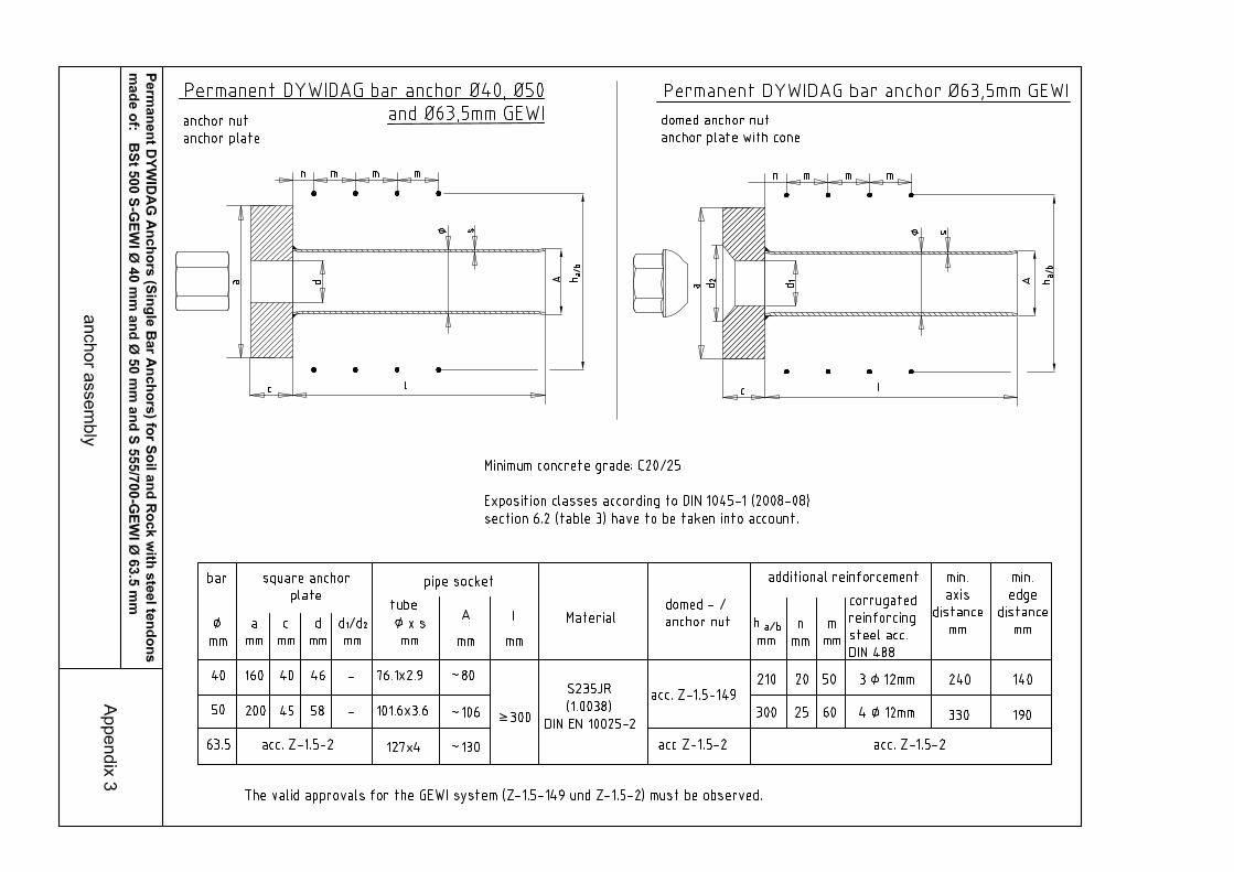
2.1.3 Anchor Head 2.1.3.1 General Requirements
The anchor head has to be designed according to Appendix 3. Assembly of the anchor head on site must be carried out in accordance with the description deposited at the German Institute for Civil Engineering. The anchor rods BSt 500 S-GEWI as well as S 555/700-GEWI must be anchored with anchor nuts of the DYWIDAG GEWI system (Z-1.5-149, Z-1.5-2), which have been approved by the building authorities. Also cf. Appendix 3.
1 DIN 4125:1990-11 Ground anchors; temporary and permanent anchors; design, realization and testing 2 DIN 1054:2005-01 Foundation soil – proof of safety in soil construction and foundation work DIN 1054 Ber. 1:2005-04 Revisions of DIN 1054:2005-01 DIN 1054 Ber. 2:2007-04 Revisions of DIN 1054:2005-01 DIN 1054 Ber. 3:2008-01 Revisions of DIN 1054:2005-01 DIN 1054 Ber. 4:2008-10 Revision of DIN 1054:2005-01 DIN 1054/A1:2009-07 Foundation soil – proof of safety in soil construction and foundation work; amendment A1
DIBT Approval Certificate Page 4 of 14 I November 11, 2011
Z-34.11-225
Anchor plates pursuant to Appendix 3 must be used for load transmission from the anchor nut to the structural element that is to be anchored. If the anchor plate is not fully concreted, it must be protected against corrosion by a corrosion protection systems in accordance with DIN EN ISO 12944-5³ depending on the determined category of corrosivity of the environment and provided with the protection duration “high (H)”. Surface preparation is carried out in accordance with DIN EN ISO 12944-4
4. When
carrying out the galvanization work, DIN EN ISO 12944-75 must be observed.
All of the surfaces of metal parts, e.g. of the pipe socket and the steel protection cap, that are bare or not sufficiently protected by a concrete cover (minimum 5 cm), must also be provided with one of these corrosion protection systems. The tendon must be anchored perpendicular to its axis in each direction. To ensure that the anchor head will be positioned vertically to the steel tendon, angular deviations are to be compensated (e.g. through a mortar bed).
2.1.3.2 Air-Side Anchorage via Rock For rock anchorages, the rated values of rock pressure are to be established on a case-to-case basis by an expert
6, taking into consideration a possible structural fault
in the immediate vicinity of the borehole. In case adapters are required, they are to be designed pursuant to relevant norms, taking into account the rated values of rock pressure.
2.1.3.3 Air-Side Anchorage via Steel and Reinforced Concrete Structures
For the design of structural elements to be anchored, DIN 10542 and DIN 4125
1
apply. For the anchorage of reinforced concrete structures, the additional reinforcement and the minimum distances of the anchorage for the plate anchorage pursuant to Appendix 3 as well as the General Technical Approvals of the GEWI system (Z-1.5-149, Z-1.5-2) must be observed. For supports on steel structures, sufficient bearing capacity and corrosion protection must be proven and determined for the anchor plates and transition structures (e.g. pipe for angular alignment). Neither of them is subject of the present General Approval.
2.1.4 Plastic Sheathings For the sheathing of the tendon’s free length and the bond length, only plastic sheathings may be used which consist of PVC-U as specified by DIN EN ISO 1163-1
7, polyethylene with a moulding compound as specified by DIN EN ISO
1872-18 - PE, E, 45 - T 022 - or polypropylene with a moulding compound as
specified by DIN 1873-19 - PP - B, EAGC, 10-16-003 or DIN EN ISO
1873-19 - PP - H, E, 06-35-012/022.
3 DIN EN ISO 12944-5:2008-01 Coating materials – corrosion protection of steel structures by coating systems – part 5: coating
systems (ISO 12944-5:2007); German version EN ISO 12944-5:2007 4 DIN EN ISO 12944-4:1998-07 Coating materials – corrosion protection of steel structures by coating systems – part 4: surface
types and surface preparation (ISO 12944-4:1998); German version EN ISO 12944-4:1998 5 DIN EN ISO 12944-7:1998-07 Coating materials – corrosion protection of steel structures by coating systems – part 7:
execution and supervision of coating work (ISO 12944-7:1998); German version EN ISO 12944-7:1998
6 Geotechnical experts have to be consulted for determining statical and constructional requirements as well as characteristic stress
7 DIN EN ISO 1163-1:1999-10 Plastics – unplasticized polyvinyl chloride (PVC-U) molding compounds – part 1: designation system and basis for specifications (ISO 1163-1:1995); German version EN ISO 1163-1:1999
8 DIN EN ISO 1872-1:1999-10 Plastics – polyethylene (PE) molding compounds – part 1: designation system and basis for specifications (ISO 1872-1:1993); German version EN ISO 1872-1:1999
9 DIN EN ISO 1873-1:1995-12 Plastics – polypropylene (PP) molding compounds – part 1: designation system and basis for specifications (ISO 1873-1:1995); German version EN ISO 1873-1:1995
DIBT Approval Certificate Page 5 of 14 I November 11, 2011
Z-34.11-225
The tubes must be straight and without trapped bubbles; they must have a uniform pigmentation. If individual sections of the PVC-U ducts are required, they must be screwed together and thoroughly sealed using glue that is suitable for PVC or wrapped with an adhesive tape that is suitable for PVC. In the case of PE or PP ducts, continuous ducts are to be used.
2.2 Manufacture, Storage, Transport and Marking
2.2.1 Corrosion Protection and Manufacture of Prefabricated Anchors for
Installation and Grouting 2.2.1.1 General
Dimensions and materials of the components used as well as the design must correspond to the specifications and work instructions deposited at the German Institute for Civil Engineering. The effectiveness of the corrosion protection depends on the integrity of the corrosion protection components. Therefore, special care is to be taken during transport and installation of the readily assembled permanent anchors so that sheathings will not be damaged as a result of improper handling.
Prior to its installation, the steel tendon must be treated as required by the approval provisions for the respective steel. For the fabrication of the anchor, the steel tendon must be clean and free of damaging rust.
2.2.1.2 Preassembled Anchor Design 2.2.1.2.1 Steel Tendon
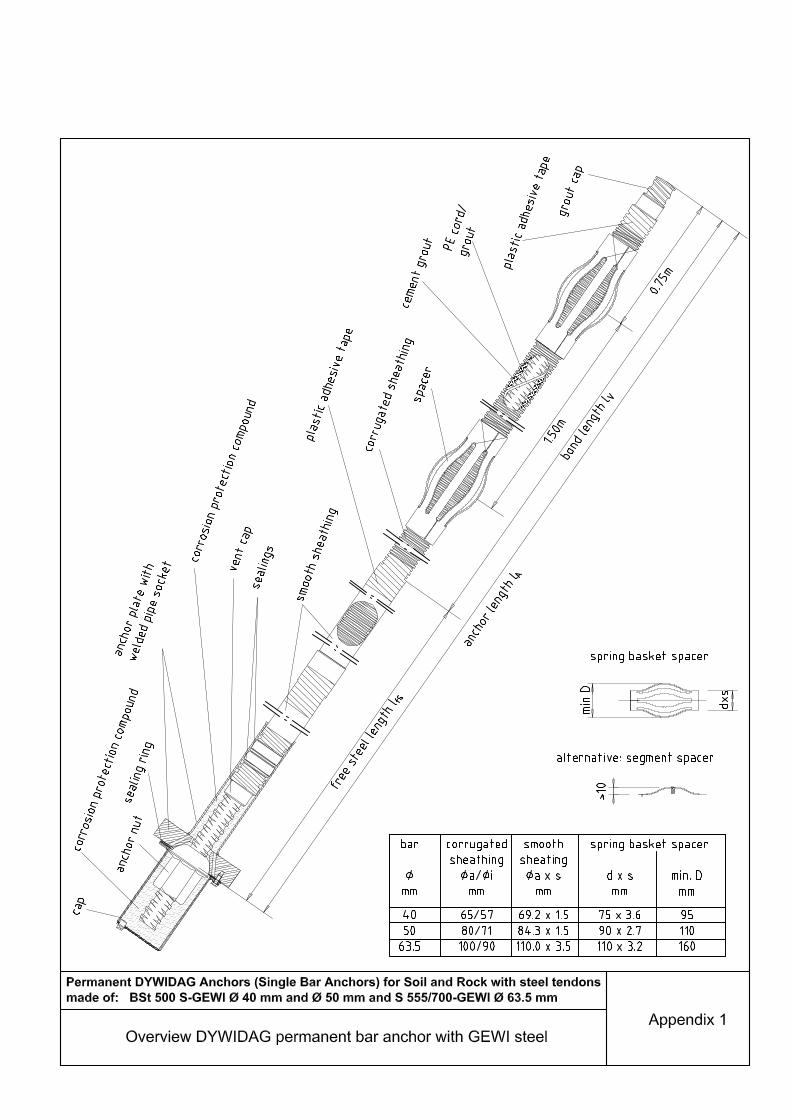
The steel tendon is to be protected approximately along the whole length (cf Appendix 1) by a corrugated tube (corrugated sheathing) consisting of plastic as specified in section 2.1.4. The corrugated sheathing must have a uniform wall thickness > 1mm. The dimensions of the corrugated sheathings are specified in Appendix 1. Bar sections that must remain screwable for anchoring our coupling are not encased, but puttied with viscous corrosion protection compound. The corrugated tube must be closed with caps on both ends and sealed. The annulus between the threadbar and sheathing of angular inclined anchors is to be grouted bottom-up with cement mortar specified in DIN EN 447
10, taking into
account the alterations in accordance with the valid Building Rules List A part 1 or in accordance with the General Technical Approval. The space compliance of ≥ 5 mm between tendon and corrugated sheathing is to be ascertained by spacers that are positioned at a distance of 1,0 m to each other or by a polyethylene helix, Ø 6 mm, gradient 0,5 m. Full grouting must be ensured by suitable measures. At the tendon free length, a smooth plastic tube according to section 2.1.4 with a wall thickness of > 1,5 mm is slipped over the corrugated sheathing. The basic dimensions of the smooth plastic tubes are mentioned in Appendix 1. The distance between the corrugated sheathing and the smooth plastic tube may only amount to a maximum of 2 mm. The smooth tube must be affixed at its position with a suitable adhesive tape or a fixed heat shrinkable sleeve (with an interior adhesive coating such as MWTM, cf. Appendix 1). Section 2.2.1.3.2 is to be observed regarding corrosion protection around the couplers.
10 DIN EN 447:1996-07 Cement grout for tendons – requirements for common grout – German version EN 447:1996
DIBT Approval Certificate Page 6 of 14 I November 11, 2011
Z-34.11-225
2.2.1.2.2 Connection of the anchor plate with the pipe socket Between the anchor plate and the upper rim of the duct, a steel pipe is to be assembled that must be welded to the anchor plate. The welding work in order to seal the pipe socket to the anchor plate is to be executed in the factory. A class A assembly qualification according to DIN 18800-7
11 is compulsory for the welding of
the anchor plates. In accordance with section 2.1.3.1, bare anchor plates and steel pipes are to be provided with a coating in accordance with DIN EN ISO 12944-5³ in the factory. This coating must provide a durable corrosion protection, taking into account the actual environment conditions.
2.2.1.3 Couplers 2.2.1.3.1. General Requirements
The steel tendons BSt 500 S-GEWI and S 555/700-GEWI can be spliced using a coupler in accordance with the General Technical Approval of the GEWI System (Z-1.5-149, Z-1.5-2, please also cf. Appendix 2). The tendon sections that are to be coupled must be prepared at the factory according to section 2.2.1.2.1. The surmounting steel of the coupled tendons must be puttied with Denso-Jet or Petroplast corrosion protection mass. A maximum of one splice may be applied in the anchoring area. Leading expansion distances according to Appendix 2 are to be selected equal or longer than the expected expansion distance for all building projects. The below mentioned types of splices are permissible subject to the overall corrosion protection system (cf. sections 2.2.1.2.1).
2.2.1.3.2 Splices
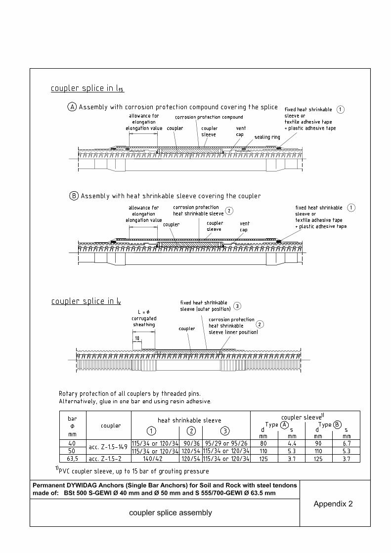
Two alternatives are available for a splice in the tendon free length Ifs
(cf. Appendix 2). Alternative A: The coupler connection is protected by corrosion protection compound inside the coupler tube. Then the coupler tube is arrested on both sides either with a plastic and texture adhesive tape or with fixed heat shrinkable sleeves (with interior adhesive coating). Alternative B: The coupler connection is protected by a corrosion protection heat shrinkable sleeve inside the coupler tube. The slipped on coupler tube is arrested as in A (cf Appendix 2). Material properties and dimensions must correspond to the specifications deposited at the German Institute for Civil Engineering. The heat shrinkable sleeves must be shrunk by hot air, infrared rays or the low flame of a gas burner. The heat shrinkable sleeves must have a minimum wall thickness of 1.5 mm when shrunk. The joint tube (cf. Appendix 2) consists of PVC-U complying with DIN EN ISO 1163-1
7. The surface of the plastic pipes to be wrapped must be clean and dry
before applying the adhesive tape or heat shrinkable sleeves. A splice in Iv is to be applied as described in Appendix 2. The coupler is to be wrapped in two layers of heat shrinkable sleeves (inside: corrosion protection heat shrinkable sleeve, outside: fixed heat shrinkable sleeve).
2.2.2 Storage Depending on the temperatures, the anchors may not be removed from the assembly platform at the factory for 24 hours after the grouting operation has taken place. Transportation and installation may only be carried out 3 days after grouting has taken place in the factory. 11 DIN 18800-7:2008-11 Steel structures – part 7: realization and construction qualification

DIBT Approval Certificate Page 7 of 14 I November 11, 2011
Z-34.11-225
The readily assembled anchors may not be stored on the ground. If the anchors are supported in intervals only, the support points may not be sharp-edged, but flat. If anchors are piled up, they must lie on top of each other in a parallel manner. If they are supported by square timbers or suitable spacers in intervals, the weight of the anchors on top may only be transferred via the timbers or the spacers.
2.2.3 Transport The anchors may neither be thrown nor dropped. They are to be carried such (e.g. by hand, on the shoulders or by means of carrying straps) that corrugated sheathings in particular will not be damaged. If transported by a crane hook, the anchor is to be carried at its stressing end, directly at the steel, or with carrying straps, or it must be placed in ducts.
2.2.4 Marking The delivery note for the prefabricated anchor must be marked by the manufacturer with the agreement mark (U-mark) according to the agreement ordinance of the German States. The marking may only be carried out if the requirements according to Section 2.3 have been met. Among other things, the delivery note must indicate for which pressure-grouted anchors the components (e.g. anchor plates chosen in relation to the intermediate structure) are determined and in which factory they have been produced. The delivery note must clearly indicate to which type of pressure-grouted anchor the components are assigned.
2.3 Verification of Agreement
2.3.1 General Each manufacturing plant must confirm that the anchor components and the prefabricated anchors for installation and grouting comply with the regulations in this General Approval by means of an agreement certificate based on the plant's own manufacturing control and regular external surveillance, including initial inspection I testing in accordance with the following regulations. The manufacturer of the anchor components and of the prefabricated anchors must organize a recognized certification authority and a recognized external surveillance authority for the issuing of an agreement certificate and for the external surveillance, including product inspection / testing, that has to be carried out. The manufacturer has to provide a declaration that an agreement certificate has been granted by marking the construction products with the agreement mark (U-mark), including a note of the designated use. The certification authority must send a copy of the agreement it issues to the DIBt. In addition, a copy of the report on the initial inspection is to be forwarded to the DIBt for information.
2.3.2 In-house Manufacturing Control 2.3.2.1 General
Each plant must set up and also carry out its own manufacturing control. In-house manufacturing control is understood to be the continuous monitoring of production by the manufacturer who thus ensures that the construction products manufactured by him meet the requirements of this General Approval. The results of the in-house production surveillance must be recorded and evaluated. The records must contain at least the following information:
DIBT Approval Certificate Page 8 of 14 I November 11, 2011
Z-34.11-225
- Designation I description of the construction product and I or the outset, material
and the components, - Kind of surveillance or inspection, - Date of manufacture and inspection/testing of the construction product and the
outset material or the components, - Results of surveillance and inspection and, if applicable, a comparison with
requirements, - A signature of the person responsible for in-house production surveillance. The records must be filed for at least five years and presented to the external instance assigned with surveillance. On request, they must be submitted to the DIBt and the highest construction supervisory authority responsible. If the inspection results are unsatisfactory, the manufacturer must immediately take the action necessary for elimination of the problem. Construction products which do not meet requirements must be treated in such a way that they cannot be mixed with conforming products. Once the problem has been eliminated, the original inspection must be repeated immediately, provided that this is technically possible and also required, to verify elimination of the problem. The in-house manufacture control must include at least the measures detailed below.
2.3.2.2 Steel Tendons Only steel tendons may be used for which an agreement certificate has been produced in compliance with the provisions of the relevant General Approval.
2.3.2.3 Anchor Nuts Only anchor nuts may be used for which a certificate of conformity has been produced within the scope of the General Technical Approval for the DYWIDAG GEWI System (Z-1.5-149, Z-1.5-2).
2.3.2.4 Plastic Sheathing The composition of the moulding compound is to be attested with the agreement certificate "2.1" as per DIN EN 10204
12. The wall thicknesses and diameters of the
plastic sheathings must be measured. In case of corrugated sheathings, one sheathing is to be taken from each batch (100 tubes) to measure the wall thickness at an internaI and external rib each and on the flank of the tubes as well as the diameter of the tubes. The dimensions must correspond to the drawings deposited at the German Institute for Civil Engineering. The decision of whether a batch is accepted or rejected must be made in accordance with section 2.3.2.11.
2.3.2.5 Couplers, coupler sleeves Only couplers may be used for which a certificate of conformity has been produced within the scope of the General Technical Approval for the DYWIDAG GEWI System (Z-1.5-149, Z-1.5-2). One sheathing is to be taken from each batch (100 tubes) to measure the wall thickness as well as the diameter of the tubes. The dimensions must correspond to the drawings deposited at the German Institute for Civil Engineering. The decision of whether a batch is accepted or rejected must be made in accordance with section 2.3.2.11.
DIBT Approval Certificate Page 9 of 14 I November 11, 2011
Z-34.11-225
12 DIN EN 10204:2005-01 Metal products; kinds of test certificates – German version EN 10204:2004
2.3.2.6 Vent Caps and Sealing Elements The material properties and dimensions must comply with the information filed with the DIBt. The values are to be attested by the agreement certificate "2.1" in keeping with DIN EN 10204
12.
At least 1% of the pipes sockets have to be tested in the factory to ensure that the sealing rings or the bead of the vent cap are tightly attached to the matching corrugated tube. The wall thicknesses and diameters or the widths and thicknesses respectively of the sealing rings are to be tested on 1 % or at least 5 pieces of each furnished batch. The decision of whether a batch is accepted or rejected must be made in accordance with section 2.3.2.11.
2.3.2.7 Heat shrinkable Sleeves The material properties of the heat shrinkable sleeves and of the bonding agent are to be attested by the agreement certificate "2.1" in keeping with DIN EN 10204
12.
For each batch (100 pieces), the wall thickness of the basic material is to be measured and the bonding job determined. The thickness of the heat shrinkable sleeves must be measured after shrinkage. To achieve this, a heat shrinkable sleeve has to be shrunk on a piece of sheathing parallel to the manufacture of an anchor type. The decision of whether a batch is accepted or rejected must be made in accordance with section 2.3.2.11.
2.3.2.8 Anchor Plates Only anchor plates may be used for which a certificate of conformity has been produced within the scope of the General Technical Approval No. Z-1.5-2. If anchor plates according to Appendix 3 are used or statically proven in isolated cases, the compliance with material properties must be proven by a factory certification “2.2” in accordance with DIN EN 10204
12. Furthermore, each anchor
plate must be tested with regards to dimensions and major deficits by means of a Yes/No test (these tests do not have to be recorded).
2.3.2.9 Corrosion protection coating, corrosion protection system materials The correct thickness of the corrosion protection coating of anchor plate, pipe socket and steel protection cap has to be checked on 5% of the corresponding number of produced parts in the factory. Proof of the material properties of all materials used for corrosion protection must be provided by an inspection certificate “3.1”of the producing factory according to
DIN EN 1020412
. Above all, this inspection certificate must state that the requirements determined in the description and the technical delivery conditions are met. DIN EN ISO 12944-7
5, section 6, applies to coating products pursuant to
DIN EN ISO 12944-53.
2.3.2.10 Assembly and Corrosion Protection
Checking on the cement grout is to be carried out pursuant to the “Guideline for the surveillance of the production and injection of cement grout in tension channels”
13.
The corrosion protection measures to be carried out at the factory pursuant to section 2.2.1 are to be verified by visual inspection on each anchor (statistical evaluation is not required).
DIBT Approval Certificate Page 10 of 14 I November 11, 2011
Z-34.11-225
13 Published in DIBt notifications 33 (2002), issue 3; available at Ernst & Sohn, Verlag für Architektur und technische Wissenschaften GmbH & Co. KG
2.3.2.11 Inspection Plan If each individual test value is equal to or higher than the required minimum value, the batch is to be accepted. Otherwise, additional samples can be taken. The same measurements have to be carried out on these samples as on the first samples. The measurement results must be summarized with previous measurements. An average value x and a standard deviation s have to be determined from all values. If the resulting test value (numerical value) z = x - 1.64 s is equal to or larger than the required minimum value, the batch must be accepted. Otherwise, it has to be rejected.
2.3.3 External Surveillance In each production plant, external surveillance must be set up and carried out regularly, but at least twice a year, to check the plant's own manufacturing control. During external surveillance, initial testing inspection of the anchors must be carried out and samples taken. Sampling and inspection are the responsibility of the recognized surveillance authority in each case. The results of certification and external surveillance must be filed for at least five years. On request, they must be presented to the DIBt and to the highest construction supervisory authority by the certifying body and the surveillance authority.
3 Regulations for Drafting and Design
3.1 General Unless stated otherwise below, DIN 1054² applies to the planning and design of structures that incorporate ground anchors.
3.2 Additional Proof
3.2.1 Maximum Values of Tensioning Loads Evidence must be provided that the permissible tensioning loads P0,max do not exceed the following constraint:
P0,max = 0.6 ‧ As ‧ ft0.2k
As = cross-section area of the steel tendon Ft0.2,k = characteristic value of the load of the steel tendon at a permanent
elongation of 0.2%
3.2.2 Change of Load in the Steel Tendon due to Frequently Repetitive Live Loads Evidence must be provided that the change of load (characteristic value) in the steel tendon due to frequently repetitive live loads (including wind) is not larger than 20% of the characteristic stress Ek. Evidence must be provided that the change in load at the air-side anchorage and possible couplers does not exceed the 0.7 fold of the proven load range of the valid General Technical Approval No. Z-1.5-149 or No. Z-1.5-2 respectively. Load cycle
values exceeding 2 ‧ 106 have not been proven by General Technical Approval
No. Z-1.5-149 or No. Z-1.5-2 respectively. Evidence is only necessary if the swelling load is not covered by tensioning.
3.3 Rock Anchors The overall safety of the rock mass anchored is the subject of rock mechanical stability evidences; the anchor forces required for stability are to be determined by an expert
6.
DIBT Approval Certificate Page 11 of 14 I November 11, 2011
Z-34.11-225
4 Regulations for Work Execution
4.1 General Assembly and installation of the ground anchors may only be carried out under the technical guidance of the company DYWIDAG-Systems International GmbH. Work has to be carried out in accordance with the job instructions deposited at the German Institute for Civil Engineering. The company DYWIDAG-Systems International GmbH must maintain a list of structures secured with permanent anchors pursuant to this General Approval indicating the structure anchored and the number of anchors installed.
4.2 Drilling the Boreholes
4.2.1 Borehole Diameter The minimum borehole diameter has to be chosen in such a fashion that the anchor can be properly inserted with the spacers. For minimum borehole diameters, DIN 4125
1, section 7.1, applies.
4.2.2 Boreholes in the Ground As a general rule, the borehole drillings are to be cased. The borehole may be drilled uncased or partly cased in cohesive soils, if evidence is produced within the scope of the suitability test that there is solid ground on the total length of the uncased part of the drilling, that the drill rods used are sufficiently rigid to assure a straight drilling and that the borehole can be properly cleaned.
4.2.3 Drilling of the Boreholes in Rock The drilling method will be defined by the specific rock properties. Evidence must be provided that in the area of the free anchor length perpendicular to the borehole axis - No joint movements will be anticipated, if the load transfer length has not been
limited (see section 4.4.3), or - Joint movements to be expected will be smaller than the difference between the
smooth sheathing and the borehole diameter, if the load transfer length has been limited.
Checking of the free passage of the boreholes by means of a template is recommended.
4.3 Installation into the Borehole According to Appendix 1, spring basket spacers are to be positioned at least every 1.5 m in the area of the bond length. In non-cohesive soils, the positioning of spacers may be abandoned if the wall thickness of the starting tube or the material thickness at the nipple passages is > 10 mm. If a lost drill or ram bit is used, it must be knocked off with a steel rod prior to the anchor installation. If in the case of a cased borehole, the projecting end of the drilling outfit features an edged internal thread or a sharp-edged pipe end, anchors prepared in accordance with section 2.2.1 may not be inserted into the borehole until an edge-free inserting trumpet or a pipe nipple which covers the internal thread of the sheathing completely has been placed onto the projecting end of the drill outfit. It must be made sure that the corrosion protection is not damaged when inserting the anchor. After filling the borehole with cement grout according to section 4.4.2 and after placing the grout cap, it must be injected at least up to the transition point from bond length Iv to tendon free length lfs while pulling out the casings step-by-step.
DIBT Approval Certificate Page 12 of 14 I November 11, 2011
Z-34.11-225
4.4 Production of the Ground Anchor
4.4.1 Composition of the Cement Grout Cements with special characteristics according to DIN 1164-10
14 and cements
according to DIN EN 197-115
– taking into account the present exposition class according to DIN EN 206-1
16 in conjunction with DIN 1045-2
17 (Tables 1, F.3.1 and
F.3.2) – , water according to DIN EN 100818
as well as, if applicable, admixtures according to DIN EN 934-2
19 in conjunction with DIN EN 206-1
16/DIN 1045-2
17 or
with general technical approval and aggregates for concrete with a maximum grain diameter of 4 mm according to DIN EN 12620
20 - taking into account DIN EN
206-116
/DIN 1045-217
- have to be used as source material for cement grout. The water-cement value must be between 0.35 and 0.7 and should be chosen as low as possible, especially in cohesive soils and in rock. The cement mortar must be mixed mechanically. Until grouting, neither demixing nor lumping may occur.
4.4.2 Fabrication of the Grout Body 4.4.2.1 Fabrication of the Grout Body in Soil
DIN 41251, section 7.3.3. applies for uncased boreholes.
In case of a cased borehole, the pipes will be drawn slowly and step by step after filling the sheathing with cement grout while maintaining the necessary grouting pressure. Injection for the production of the grout body must always be carried out from the deepest point of the grout body, the venting from the highest point. The grouting operation may not be stopped until cement grout emerges through the vent tube without any bubbles. In case of downwardly inclined anchors, the vent tube may be dispensed with, if the borehole is filled from the bottom until cement grout escapes at the top.
4.4.2.2 Fabrication of the Grout Body in Rock The rock must be so compact that a perfect fabrication of the grout body can be assured. Checking will be made in the necessary extent by special investigations (e.g. visual borehole inspection, gauge measurement of the grout level, Lugeon test). In each individual case, the mortar formula, grouting pressure and grouting operation is to be established by the field engineer in consultation with the expert
6
and the engineer based on the results of the rock explorations, water injection tests and the findings after the drilling of the boreholes.
14 DIN 1164-10:2004-08 Cement with special characteristics – part 10: composition, requirements and compliance certificate of normal cement with special characteristics
DIN 1164-10 Ber. 1: 2005-01 Amendment for DIN 1164-10:2004-08 15 DIN EN 197-1:2004-08 Cement- part 1: composition, requirements and criteria of conformity of normal cement;
German version EN 197-1:2000 + A1:2004 DIN EN 197-1 Ber. 1:2004-11 Amendment for DIN EN 197-1:2004-08 DIN EN 197-1/A3:2007-09 Cement- part 1: composition, requirements and criteria of conformity of normal cement;
German version EN 197-1:2000/A3:2007 16 DIN EN 206-1:2001-07 Cement- part 1: determination, characteristics, manufacturing and conformity
DIN EN 206-1/A1:2004-10 Cement- part 1: determination, characteristics, manufacturing and conformity; German version EN 206-1/A1:2004
DIN EN 206-1/A2:2005-09 Cement- part 1: determination, characteristics, manufacturing and conformity; German version EN 206-1: 2000/A2:2005
17 DIN 1045-2:2008-08 Bearing structures consisting of concrete, reinforced concrete and post-tensioned concrete – part 2: concrete – determination, characteristics, manufacturing and conformity – application guide for DIN EN 206-1
18 DIN EN 1008:2002-10 Water for concrete – determination for sample-taking, testing and evaluation of the suitability of water, including water accumulating during concrete production, as an additive for concrete; German version EN 1008:2002
19 DIN EN 934-2:2009-09 Additives for concrete, mortar and cement mortar – part 2: Concrete additives – definitions, requirements, conformity, marking and labeling; German version EN 934-2:2009
20 DIN EN 12620:2008-07 Granularity for concrete; German version EN 12620:2002+A1:2008
DIBT Approval Certificate Page 13 of 14 I November 11, 2011
Z-34.11-225
The proposed grouting technique is to be investigated within the scope of the suitability test. The amount of cement grout needed for one anchor, its composition and the grouting pressure are to be measured and recorded. The use of form Appendix A DIN 4125
1 is recommended.
4.4.3 Limitation of the Load Transfer Length In general, the load transfer length is to be limited by the following methods: a) by flushing out excess cement grout by means of a flushing hose mounted
on the sheathing. The flushing hose is to be arranged such that the first discharge openings are positioned 50 cm above the transition point between the tendon free length and the bond length. The verification of this value is to be confirmed in the drilling protocol. The flushing pressure applied is to be approximately 4 bar.
b) by flushing out excess cement grout by means of a lance. The flushing lance that is closed at the bottom and provided with lateral openings is to be inserted up to approx. 1.0 m above the transition point Iv/lfs. The flushing pressure applied is to be approximately 4 bar.
c) by blocking the load transfer length by means of a packer (see Appendix 4). The suitability of the packer is to be evidenced within the scope of the suitability test.
Methods a) and b) are to be applied for downwardly inclined ground anchors in soil and may also be used for downwardly inclined ground anchors in rock. Method c) is to be applied for upwardly inclined ground anchors and may also be used for downwardly inclined anchors. For rock anchors, the force transfer length may not be limited, if relations correspond to DIN 4125
1, section 7.5.
4.4.4 Post-Grouting Once the initial grouting has set or fully hardened, further injections of cement grout may be made in the area of the ground anchor. For this purpose, valve tubes or valve pipes with collars, or grout tubes with post-grouting valves are to be used. The grout body may be burst open using water; however, grouting is to be carried out as required by DIN 4125
1, section 7.4.
In case the force transfer length l0 must be limited (see section 4.4.3), the free load transfer length must subsequently be flushed again. To avoid leakages during
postgrouting, l0 = Iv + 2 m may apply; however, l0 - Iv may not be greater than 0.3‧Ifs. To this end, the required limitation of the grout body must be effected via a flushing lance which will be inserted up to 2.0 m before the beginning of Iv.
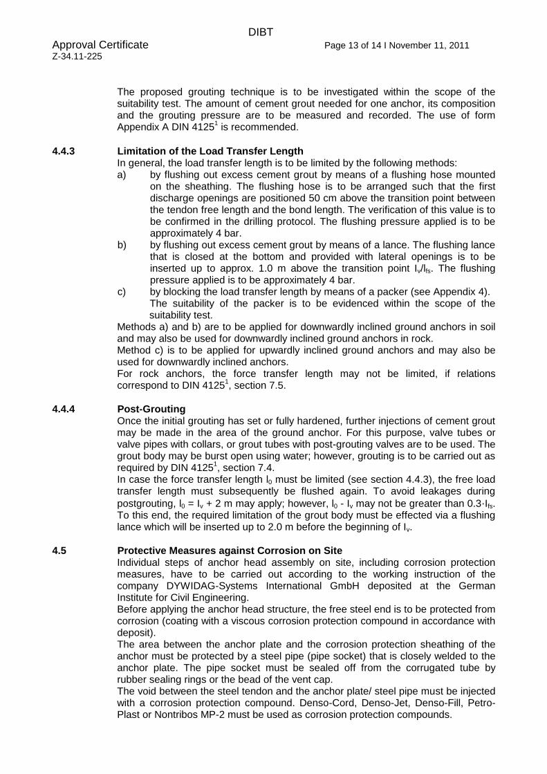
4.5 Protective Measures against Corrosion on Site Individual steps of anchor head assembly on site, including corrosion protection measures, have to be carried out according to the working instruction of the company DYWIDAG-Systems International GmbH deposited at the German Institute for Civil Engineering. Before applying the anchor head structure, the free steel end is to be protected from corrosion (coating with a viscous corrosion protection compound in accordance with deposit). The area between the anchor plate and the corrosion protection sheathing of the anchor must be protected by a steel pipe (pipe socket) that is closely welded to the anchor plate. The pipe socket must be sealed off from the corrugated tube by rubber sealing rings or the bead of the vent cap. The void between the steel tendon and the anchor plate/ steel pipe must be injected with a corrosion protection compound. Denso-Cord, Denso-Jet, Denso-Fill, Petro-Plast or Nontribos MP-2 must be used as corrosion protection compounds.
DIBT Approval Certificate Page 14 of 14 I November 11, 2011
Z-34.11-225
The cement grout surface of the corrugated tube must be previously sealed with Icosit 277, if the corrosion protection material Nontribos MP-2 is applied and if it is not protected by the vent cap. Corrosion protection compound that hast been removed during tensioning must be replaced. After stressing the anchor, the anchor nut and the steel protrusion must be protected by a cap, and the space between nut and cap must also be filled with the corrosion protection material described above. If the cap is not subject to mechanical load (e.g. subsequently embedded), it may consist of HDPE. In all other cases, a minimum 3 mm thick DIN EN ISO 1461
21 hot-dip galvanized
steel cap coated according to DIN EN ISO 1461-t Zn or a steel cap that is endowed with a corrosion protection system according to section 2.1.3.1 and that is screwed onto the anchor plate with an underlying nitrile rubber sealing washer must be applied. If anchors, due to maintenance inspection, must be subsequently tightened, then care must be taken that the removed corrosion protection material be refilled again.
4.6 Suitability and Acceptance Tests and Supervision of the Installation Suitability and acceptance tests are to be carried out on every construction site in compliance with DIN 4125
1.
The suitability tests for permanent anchors are to be supervised by a surveillance agency for the supervision of installing ground anchors being registered with the inspection, surveillance and certification authorities complying with the prevailing state building code, part V, in the valid version
22.
In the course of their surveillance activities for the suitability and acceptance tests, the commissioned surveillance agency must supervise at least randomly the assembly and installation of the permanent anchors at the construction site, especially the corrosion protection measures e.g. seeing to that the anchor head is completely filled. The surveillance agency must report to the building supervision authority concerned whenever facilities and the personnel on site do not assure proper installation. The beginning of such work is to be reported to the building supervision authority concerned.
5 Provisions for Usage, Maintenance and Service
5.1 Verification DIN 4125
1, section 13, applies.
If required, verification is to be made by the surveillance agency which has already performed the suitability tests.
21 DIN EN ISO 1461:2009-10 Zinc coatings applied on steel by hot-dip galvanizing (galvanization of pieces) – requirements and tests (ISO 1461:2009); German version EN ISO 1461:2009
22 Latest issue: register of inspection, surveillance and certification authorities complying with state building codes – version: June 2010 – DIBt – notifications, German Institute for Civil Engineering 41 (2010), special booklet No. 40

A u s t r i A
A r g e n t i n A
A u s t r A l i A
b e l g i u m
b o s n i A A n d h e r z e g o v i n A
b r A z i l
C A n A d A
C h i l e
C o l o m b i A
C o s t A r i C A
C r o A t i A
C z e C h r e p u b l i C
d e n m A r k
e g y p t
e s t o n i A
F i n l A n d
F r A n C e
g e r m A n y
g r e e C e
g u A t e m A l A
h o n d u r A s
h o n g k o n g
i n d o n e s i A
i t A l y
J A p A n
k o r e A
l e b A n o n
l u x e m b o u r g
m A l A y s i A
m e x i C o
n e t h e r l A n d s
n o r w A y
o m A n
p A n A m A
p A r A g u A y
p e r u
p o l A n d
p o r t u g A l
Q A t A r
s A u d i A r A b i A
s i n g A p o r e
s o u t h A F r i C A
s p A i n
s w e d e n
s w i t z e r l A n d
t A i w A n
t h A i l A n d
t u r k e y
u n i t e d A r A b e m i r A t e s
u n i t e d k i n g d o m
u r u g u A y
u s A
v e n e z u e l A
www.dywidag-systems.com
AustriaDYWIDAG-Systems International GmbHAlfred-Wagner-Strasse 14061 Pasching/Linz, AustriaPhone +43-7229-610 49 0Fax +43-7229-610 49 80 E-mail [email protected]
Belgium and LuxembourgDYWIDAG-Systems International N.V.Industrieweg 253190 Boortmeerbeek, BelgiumPhone +32-16-60 77 60Fax +32-16-60 77 66E-mail [email protected]
FranceDSI-Artéon146 Avenue du BicentenaireZ.I. Dagneux01122 Montluel Cedex, FrancePhone +33-4-78 79 27 82Fax +33-4-78 79 01 56E-mail [email protected]
GermanyDYWIDAG-Systems International GmbHGermanenstrasse 886343 Koenigsbrunn, GermanyPhone +49-8231-96 07 0Fax +49-8231-96 07 40E-mail [email protected]
DYWIDAG-Systems International GmbHMax-Planck-Ring 140764 Langenfeld, GermanyPhone +49-2173-79 02 0Fax +49-2173-79 02 20E-mail [email protected]
DYWIDAG-Systems International GmbHSchuetzenstrasse 2014641 Nauen, GermanyPhone +49-3321-44 18 0Fax +49-3321-44 18 38E-mail [email protected]
DYWIDAG-Systems International GmbHSiemensstrasse 885716 Unterschleissheim, GermanyPhone +49-89-30 90 50 100Fax +49-89-30 90 50 120E-mail [email protected]
ItalyDYWIT S.P.A.Viale Europa 72 Strada A 7/920090 Cusago (MI), ItalyPhone +39-02-901 65 71Fax +39-02-901 65 73 01E-mail [email protected]
NetherlandsDYWIDAG-Systems International B.V.Veilingweg 25301 KM Zaltbommel, NetherlandsPhone +31-418-57 89 22Fax +31-418-51 30 12E-mail [email protected]
PolandDYWIDAG-Systems International Sp. z o.o. ul. Przywidzka 4/6880-174 Gdansk, PolandPhone +48-58-300 13 53Fax +48-58-300 13 54E-mail [email protected]
DYWIDAG-Systems International Sp. z o.o. ul. Bojowników o Wolność i Demokrację 38/12141-506 Chorzów, PolandPhone +48-32-241 09 98Fax +48-32-241 09 28E-mail [email protected]
SpainDYWIDAG Sistemas Constructivos, S.A.Avd/de la Industria, 4Pol. Ind. la Cantuena28947 Fuenlabrada (Madrid), SpainPhone +34-91-642 20 72Fax +34-91-642 27 10E-mail [email protected]
United KingdomDYWIDAG-Systems International Ltd.Northfield RoadSoutham, WarwickshireCV47 0FG, Great BritainPhone +44-1926-81 39 80Fax +44-1926-81 38 17E-mail [email protected]/uk