dynamics of tilting proprotor aircraft in cruise …
TRANSCRIPT

NASA
!
g=
Z)..-
Z
TECHNICAL NOTE NASATN
i 2 "_"
D-7677
DYNAMICS
AIRCRAFT
OF TILTING PROPROTOR
IN CRUISE FLIGHT
by Wayne Johnson
Ames Research Center
and
U.S. Army Air Mobility R&D Laboratory
Moffett Field, Calif. 94035_._._9"_
NATIONAL AERONAUTICS AND SPACE ADMINISTRATION • WASHINGTON, D. C. • MAY 1974


1. Report No.
D- 7677
4. Title and Subtitle
7.
9.
12.
2. Government Accession No. 3. Recipient's Catalog No.
5. Report Date
MAY 197_
DYNAMICS OF TILTING PROPROTOR AIRCRAFT IN CRUISE FLIGHT
Author(s)
Wayne Johnson
Performing Organization Nameand Addre_
NASA Ames Research Center
and
U. S. Army Air Mobility R&D Laboratory
Moffett Field, Calif., 94035
Sponsoring A_ncy Name and Addr_s
National Aeronautics and Space Administration
Washington, D. C., 20546
6. Performing Organization Code
8. Performing Organization Report No.
A-5032
10. Work Unit No.
760-63-03
11, Contract or Grant No.
13. Type of Report and Period Covered
Technical Note
14. Sponsoring Agency Code
15. Supplementary Notes
16. Abstract
A nine degree-of-freedom theoretical model is developed for investigations of the dynamics
of a proprotor operating in high inflow axial flight on a cantilever wing. The basic character-
istics of the rotor high inflow aerodynamics and the resulting rotor aeroelastic behavior are
discussed. The problems of classical whirl flutter, the two-bladed rotor, and the influence of
the proprotor on the stability derivatives of the aircraft are treated briefly. The influence
of various elements of the theoretical model is discussed, including the modeling used for the
blade and wing aerodynamics, and the influence of the rotor lag degree of freedom. The results
from tests of two full-scale proprotors - a gimballed, stiff-inplane rotor and a hingeless, soft-
inplane rotor - are presented; comparisons with the theoretical results show good correlation.
17. Key Words(Suggested by Author(s))
Rotary wing dynamics
Tilt-rotor aircraft
Proprotor
18. Distribution Statement
Unclassified - Unlimited
CAT. 02
19. S_urity Classif.(ofthisreport)
Unclassified
20. Security Classif.(ofthis _1
Unclassified
21. No. of Pages 22. Dice"
253 _,6.50
"For sale by the National Technical Information Service, Springfield, Virginia 22151


TABLE OF CONTENTS
NOMENCLATURE ..............................
SUb_ARY .................................
INTRODUCTION ..............................
SECTION 1: BASIC THEORY FOR PROPROTOR DYNAMICS ............
Four-Degree-of-Freedom Model .....................
SECTION 2: THEORETICAL MODEL FOR A ROTOR IN HIGH INFLOW ........
Equations of blotion and Forces for the Rotor .............
The Rotor Aerodynamic Coefficients ..................
SECTION 3: BEHAVIOR OF ROTORS IN HIGll INFLOW .............
Elementary Dynamic Behavior .....................
Whirl Flutter ............................
Two-Bladed Rotor. ..........................
Aircraft Stability Derivatives ....................
SECTION 4: NINE-DEGREE-OF-FREEDOM MODEL FOR A PROPROTOR ON A
CANTILEVER WING ......................
Wing Equations of Motion .......................Air Resonance ............................
SECTION 5: RESULTS OF THE THEORY AND COMPARISON WITH FULL-SCALE
TESTS• , • ° . ° • ° • ° . • • • , • * ° • ° • • • ° . • .
Proprotor Dynamic Characteristics ..................
The Gimballed, Stiff-Inplane Rotor ..................
The Hingeless, Soft-Inplane Rotor ..................
SECTION 6: COMPARISONS WITH OTIIER INVESTIGATIONS ...........
CONCLUDING REMARKS ...........................
REFERENCES ...............................
FIGURES ................................
Page
V
27
27
40
60
60
76
90
93
106
106
132
135
135
145
151
156
159
161
165
iii


NOMENCLATURE
Conventional helicopter notation is followed in this report, for example,
for the rotor force and moment coefficients. Quantities are made dimension-
less with p, _, and R (air density, rotor rotational speed, and rotor radius).
a
A
d
ed
c£
cp
Cq I
Cq 2
Cx
cy
CH
%
%
ce
cQ
CT
rotor blade section two-dimensional lift curve slope
rotor disk area, _R 2
rotor blade chord
blade section drag coefficient
blade section lift coefficient
wing chord
wing torsion structural damping
wing vertical bending structural damping
wing chordwise bending structural damping
pylon yaw structural damping
pylon pitch structural damping
rotor vertical force coefficient,H
o_R2(C_R) 2
rotor lateral moment coefficient,
½
O'eR3(riB) 2
rotor longitudinal moment coefficient,P _R3 (f'a_') 2
rotor power coefficient,P
o_R 2 (f).R) 3
rotor torque coefficient, Q
o_R 3 G'_') 2
rotor thrust coefficient,T
onR 2 (92) 2
v

YCy rotor side force coefficient,
p_R2(92) 2
D blade section drag force per unit length
EZ section modulus/moment product
f aircraft equivalent parasite drag area
Fr blade section radial aerodynamic force per unit length
Fx blade section inplane aerodynamic force per unit length
Fz blade section out of plane aerodynamic force per unit length
gs structural damping coefficient
h rotor mast height, wing tip spar to rotor hub
hEA rotor mast height, wing tip effective elastic axis to rotor hub
H rotor vertical force; also rotor aerodynamic coefficient
CT
Zb characteristic inertia of blade bending, used to normalize rotor and
support inertias
Io f R r2m dr
lqw
wing torsion generalized mass
pylon yaw moment of inertia
pylon pitch moment of inertia
wing bending generalized mass
pylon yaw moment of inertia [including rotor, for four-degree-of-
freedom model)
pylon pitch moment of inertia [including rotor, for four-degree-of-freedom model)
vi

I B
R
f nB2m dr, blade flap inertia0
RIBa nBrm dr
o
R
I f n 2m dr, blade lag inertia
0
R
f _ rmdr
Kp wing torsion spying constant
Kql wing vertical bending spring constant
Kq2 wing chordwise bending spring constant
Kx pylon yaw spring constant
Ky pylon pitch spring constant
Kp rotor blade pitch/flap coupling, tan 6 3
L blade section lift force per unit length
m blade section mass per unit length
mp pylon mass
M rotor flap moment aerodynamic coefficient
M Mach number
R
f m dr, blade massMb _0
Mx rotor lateral (yaw) hub moment
My rotor longitudinal (yaw) hub moment
MF blade flap moment
vii

Mtip
N
N_
P
ql
q2
Q
r
r e
R
R
S
sgn
Sw
sB
S_
T
uG
Up
uR
UT
viii
blade lag moment
tip Mach number, 92 divided by the speed of sound
number of blades
\Be
-YM
wing torsion degree of freedom
wing vertical bending degree of freedom
wing chordwise bending degree of freedom
rotor torque; also rotor torque and Iag moment aerodynamic coefficient
blade radial station
effective radius " _
rotor blade radius
rotor radial force aerodynamic coefficient
Laplace variable in transfer functions
direction of rotation of rotor on right wing: +i for clockwise and -Ifor counterclockwise
wing bending/torsion inertial coupling, mPzPEAYTw
nsm dr
o
R
f n_m dr
o
rotor thrust; also rotor aerodynamic coefficient
longitudinal aerodynamic gust velocity
blade section out of plane velocity
blade section radial velocity
blade section inplane velocity

U
V
V
X
Xp
Xw
Y
YP
YBw
Yrw
Yw
Y
Z
ZEA
zp
ZPEA
Zw
(1
_G
ax
_y
o_z
g
8-1
blade section resultant velocity, (UT2 + Up2) I/2
rotor-induced inflow; when dimensionless, the inflow ratio (forward
speed divided by rotor tip speed)
rotor or aircraft forward velocity
vertical axis
rotor shaft vertical displacement
wing chordwise displacement
lateral axis
rotor shaft lateral displacement
wing sweep station
cantilever wing length (wing semispan)
wing spanwise station
rotor side force
longitudinal axis
wing tip elastic axis vertical shift due to dihedral
rotor shaft longitudinal displacement
pylon center-of-gravity location, forward of wing tip effective elasticaxis
wing vertical displacement
blade section angle of attack
rotor blade mean angle of attack
vertical aerodynamic gust velocity
rotor shaft yaw angle at pivot
rotor shaft pitch angle at pivot
rotor shaft roll angle at pivot
blade flap angle
low-frequency rotor flap mode

B+I
_G
SO
_IC
B1S
Y
sup A
6uPs
suR
surA
surs
_wl
_w2
_w k
63
_+i
_0
_lS
nB
n_
_W
X
high-frequency rotor flap mode
lateral aerodynamic gust velocity
rotor coning degree of freedom
rotor longitudinal flap degree of freedom
rotor lateral flap degree of freedom
pacR 4Lock number,
Ib
small change in a quantity
component of perturbation of Up independent of r
component of perturbation of up proportional to r
perturbation or uR (independent of r)
component of perturbation of u T proportional to r
component of perturbation of uT independent of r
wing dihedral angle
wing angle of attack
wing sweep angle
rotor blade pitch/flap coupling, Kp = tan 63
blade lag angle
damping ratio of oscillation, fraction of critical damping
low-frequency rotor lag mode
high-frequency rotor lag mode
rotor collective lag (or rotor speed perturbation) degree of freedom
rotor cyclic lag degree of freedom
rotor cyclic lag degree of freedom
blade flap mode shape
blade lag mode shape
wing bending mode shape

@
@w
@o
elC
@lS
_B
_8e
%
P
blade pitch angle
wing torsion angle
rotor collective pitch input
rotor lateral cyclic pitch input
rotor longitudinal cyclic pitch input
eigenvalue
blade flap rotating natural frequency
effective flap frequency, including pitch/flap coupling
blade lag rotating natural frequency
wing torsion mode shape
air density
Nc
rotor solidity, _-_
-itime constant of a real root, -_-
blade inflow angle, tan -l U_p_pUT
rotor blade azimuth angle, dimensionless time variable
frequency
rotor rotational speed
Subscripts
0
@
trim
blade pitch
hub inplane velocity
blade flapwise velocity
hub out-of-plane velocity
blade lagwise velocity
xi

N
Oj _j n8,
0
1C
1S
/7/
rotor nonrotating degrees of freedom
collective rotor mode
cyclic rotor mode
cyclic rotor mode
blade index, m = i, . , N
Superscripts
m
N
normalized (usually by dividing by Ib or _Ib)
blade index, m = i, . , N
Derivatives
d
d
d
d
xii

DYNAMICSOFTILTING PROPROTORAIRCRAFTIN CRUISEFLIGHT
WayneJohnson
AmesResearch Centerand
U.S. Army Air Mobility R&DLaboratory
SUMMARY
A theoretical model is developed for a proprotor on a cantilever wing,operating in high inflow axial flight. This theory is used to investigate thedynamic characteristics of tilting proprotor aircraft in cruise flight. Themodel, with a total of nine degrees of freedom, consists of first modeflapand lag blade motions of a rotor with three or more blades and the lowest fre-quency wing bending and torsion motions; rotor blade pitch control and aero-dynamic gust excitation are included. The equations of motion for a four-degree-of-freedom model (lateral and longitudinal tip path plane tilt, pylonpitch and yaw) are obtained, primarily to introduce the methods and formula-tion to be used in deriving the rotor and cantilever wing equations. Thebasic characteristics of the rotor high inflow aerodynamics and the resultingrotor aeroelastic behavior are discussed. The problems of classical whirlflutter (a truly rigid propeller on a pylon) and the two-bladed rotor arediscussed briefly. The influence of the proprotor on the stability deriva-tives of the aircraft is considered. The theoretical dynamic behavior of twofull-scale proprotors is studied, and comparisons are madewith the results oftests of these rotors in the Ames40- by 80-Foot Wind Tunnel and with theresults of other theories. These studies show the sensitivity of the theoreti-cal results to several features and parameters of the proprotor configurationand to various elements in the theoretical model. In particular, these studiesdemonstrate the important influence of the rotor blade lag degree of freedom onthe dynamics of both stiff inplane and soft inplane proprotor configurations,the dominanceof the section lift curve slope (c_) terms in the high inflowaerodynamics of a rotor and the importance of a good structural model of therotor blade and the wing in predicting the dynamic behavior of a proprotor. Thecomparisons also establish the theoretical model developed as an adequaterepresentation of the basic proprotor and wing dynamics, which then will be auseful tool for further investigations.
INTRODUCTION
The tilting proprotor aircraft is a promising concept for short-haulV/STOLmissions. This aircraft uses low disk loading rotors located on thewing tips to provide lift and control in hover and low-speed flight; it usesthe samerotors to provide propulsive force in high-speed cruise, the liftthen being supplied by a conventional wing. Such operation requires a 90°change in the rotor thrust angle, which is accomplished by mechanically tilt-
ing the rotor shaft axis. The rotor is vertical for helicopter mode

operation landing and takeoff, hover, and low-speed flight - and is tiltedforward for airplane mode, high-speed cruise flight. Thus the aircraft com-bines the efficient VTOLcapability of the helicopter with the efficient,high-speed cruise capability of a turboprop aircraft. With the flexible bladesof low disk loading rotors, the out-of-plane and inplane (flap and lag) motionsof the blades are significant, so the blade motion is as important an aspectof tilt rotor dynamics as it is for helicopters. Whenin the cruise mode(axial flight at high forward speed), the rotor is operating at high inflowratio (ratio of axial velocity to rotor tip speed); this introduces aerodynamicphenomenanot encountered with the helicopter rotor, which is characterized bylow inflow. _le combination of flapping rotors operating at a high inflowratio on the tips of flexible wings leads to dynamic and aerodynamic character-istics unique to this configuration, and which must be considered in the designof the aircraft. The combination of efficient VTOLand high-speed cruise capa-bilities is very attractive, so it is important to establish a clear under-standing of the behavior of this aircraft and to formulate adequate methods forpredicting it, to enable a confident design of the aircraft. Experimental andtheoretical investigations have been conducted over several years to providethis capability (refs. 1 to 30). This report develops a model of the aero-elastic system for use in someinitial studies of the system character andbehavior. Of particular interest are the features specific to the configura-tion: high inflow aerodynamics of a flapping rotor in axial flow and thecoupled dynamics of the rotor/pylon/wing aeroelastic system. Therefore, thiswork concentrates on the proprotor in airplane configuration: axial flow andhigh inflow ratio. In addition, rigid body degrees of freedom of the aircraftare not considered, only the elastic motion of a cantilevered wing. Manyfea-tures of tile coupled wing and rotor motion can be studied with such a model,theoretically and experimentally, with the understanding, of course, that themodel must eventually incorporate the entire aircraft.
An introduction to the problems characteristic of a high inflow proprotoris provided by the following discussion (found in tile early proprotor litera-ture, e.g., refs. 3 and 8). Consider the behavior of the rotor in response toshaft pitch or yaw angular velocity, with the rotor operating in high inflowaxial flight. A momenton the rotor disk is required to precess it to followthe shaft motion. With an articulated rotor (a rotor with a flap hinge at thecenter of rotation), this momentcannot be due to structural restraint betweenthe shaft and the blade root, so it must be provided by aerodynamic forces onthe blade. For example, pitch angular velocity of the shaft will require ayaw aerod)mamic momenton the disk to precess it to follow the shaft. Theaerodynamic momentis due to incremental lift changes on the blade sections;the componentnormal to the disk plane provides the yawing momentrequired.For high inflow flight, this incremental blade section lift also has a largeinplane componentand, as a result, the momentto precess the disk is accom-panied by a net inplane force on the rotor hub. This force is directed toincrease the rotor shaft angular velocity, so it is a negative damping forcethat increases with the inflow ratio. There is also the usual rotor positivedamping due to tip path plane tilt of the thrust vector, plus the dampingdueto the hub momentfor a hingeless rotor. If the inflow is high enough, thenegative inplane force (H force) damping can dominate. The rotor and aircraftcan be designed so that the velocity for any instability is well above the

flight regime, but the high inflow aerodynamics are always important in theanalysis and design.
The behavior of the proprotor in high inflow (as outlined above) impliesthe following characteristics: decreased rotor/pylon/wing aeroelastic stabil-ity since the negative H force damping of the high inflow aerodynamics canreduce the dynamic stability at high forward velocity; decreased damping ofthe aircraft short period modes, again due to the negative H force dampingcontribution of the rotor; and large flapping in maneuversand gusts. (Thelast arises because the momentto precess the rotor to follow the shaft is dueto the flapping motion of the blades with respect to the shaft; a given shaftvelocity requires a fixed componentof the section aerodynamic force normal tothe disk, which meansthen that increased incremental lift is required at highinflow and thus more flapping since flapping is the source of the lift.)These features were first delineated in the studies with the XV-3 aircraft(refs. 1 to 3), the first experimental tilting proprotor aircraft. Investiga-tions of the concept and its problems with the XV-3 provided the initial impe-tus for further theoretical and experimental work with the configuration, muchof which is still in progress. The work with proprotor dynamics has its basisin propeller/nacelle whirl flutter investigations (refs. 4 to 7); however, theflapping motion of the rotor introduces manynew features into the dynamics.Experimental and theoretical work has been done by several organizations inthe helicopter industry on the various features of tilting proprotor aircraftdynamics, aerodynamics, and design (refs. 8 to 24). This work has culminatedin tests of full-scale, flight-worthy proprotors (refs. 25 and 26) and prelim-inary design of prototype demonstrator vehicles (refs. 27 and 28) as part ofthe current NASA/Army-sponsoredtilt rotor research aircraft program. How-ever, in the literature there is little concerning the details of the analysisof proprotor behavior. There are someearly reports on very simple analyticalmodels (e.g., refs. 8 and 18), and somerecent reports on the most sophisti-cated analyses available (refs. 29 and 30). Further exploration of the basiccharacteristics of the proprotor dynamics is therefore desirable.
The objectives of this report are to establish a verified method topredict the dynamic behavior of the tilting proprotor aircraft in cruiseflight; to develop an understanding of the dynamics of the vehicle and of thetheory required to predict it; and to assess the applicability, validity, andaccuracy of the model developed. The model of the wing/rotor system developedhere will be useful for future investigations as well as for these initialstudies. The primary application of the theory in this report is a comparisonwith tests in the Ames40- by 80-Foot Wind Tunnel of two full-scale proprotors.The analysis begins with a treatment of the four-degree-of-freedom case:pylon pitch and yaw plus rotor longitudinal and lateral flapping (i.e., tippath plane pitch and yaw_. With this derivation as a guide, the equations ofmotion are derived for a rotor with flap and lag degrees of freedom and a six-degree-of-freedom shaft motion. The high inflow aerodynamics involved arediscussed, followed by someelementary considerations of the rotor behavior inhigh inflow. Next, the special cases of classical whirl flutter (no blademotion degrees of freedom) and the two-bladed rotor are considered briefly;the implications of the basic rotor behavior concerning the aircraft stabilityare investigated. After these preliminary discussions, the development of therotor and cantilever wing model is resumed. The equations of motion for a

cantilever wing with the rotor at the tip are obtained and combinedwith therotor equations of motion to produce a nine-degree-of-freedom model for tilt-ing proprotor aircraft wing/rotor dynamics. This model is applied to twoproprotor designs, in order to examine the basic features of the rotor andwing dynamics• Finally, the results of the theory are correlated with thosefrom full-scale tests of these two proprotors in the 40- by 80-Foot WindTunnel.
The author wishes to thank Troy M. Gaffey of the Bell Helicopter Companyand H. R. Alexander of the Boeing Vertol Companyfor their help in collectingthe descriptions of the full-scale rotors given in table Ill and figures 14 to17.
SECTIONl: BASICTHEORYFORPROPROTORDYNAMICS
Four-Degree-of-Freedom Model
Consider a flapping rotor on a pylon with pitch and yawdegrees offreedom operating in high inflow axial flight. Eventually, at least a fewmore degrees of freedom must be added to this model for both the rotor and thesupport. This limited model is examined first, however, to demonstrate themethods used to derive the equations of motion, and because this case isstudied in the literature.
The model is shown in figure I. The pylon has rigid-body pitch and yawmotion about a pivot, with the rotor forces acting at the hub forward of thepivot. The pylon degrees of freedom are pitch angle a_, positive for upwardrotation of the hub, and yaw angle _x, positive for left rotation of the hub.
The rigid-body pitch and yaw motion has inertia, damping, and elastic restraint
about the pivot. At the hub, a distance h forward of the pylon pivot (h is
the mast height) is a rotor with N blades• The rotor has clockwise rotation
when viewed from the rear, with azimuth angle _ measured from vertically
upward The azimuth position of the mth blade, m = 1 9 N is
_m = _ + _ where A_ = 2_/N is the angle between succeeding blades. The rotor
degrees of freedom are the out-of-plane motion given by the flapping anglesfl(m) for each blade, defined positive for forward displacement of the blade
tip from the disk plane (upward in helicopter mode, which is the usual heli-
copter convention). The blade out-of-plane deflection is assumed to be the
result of rigid-body rotation of the blade about a point at the center of
rotation (by the angle 8(m)). The dimensionless rotating natural frequency of
the flap motion is allowed to be greater than i/rev so that blades with canti-
lever root constraint may be treated as well as articulated blades (which have
an actual hinge at or near the center of rotation)• The mode shape for the
flap motion is assumed proportional to the radial distance r, that is, rigid-
body rotation. The net forces exerted by the rotor on the hub from all N
blades are rotor thrust T, rotor vertical force H, and rotor side force Y. It
is assumed in the derivation of the equations of moti0n that an engine governor

supplies the torque required to hold the rotor rotational speed _ constantduring any perturbed motion, and that the pivot supplies the reaction to therotor thrust T. The pivot also reacts the rotor vertical and side forces so
that the only pylon motion is pitch and yaw about the pivot. With a flap
natural frequency greater than I/rev, as with cantilever root restraint or
with a flap hinge offset or spring, blade flap motion results in a moment on
the hub. The rotor pitch moment on the hub is My and the rotor yaw moment, Mx.
The rotor is assumed to be operating in purely axial flow in the
equilibrium, unperturbed state, at velocity V. The inflow ratio V/93_ (which
may be written simply V, with the nondimensionalization implied) is assumed to
be of order i. Only rotor aerodynamics are considered; any pylon aerodynamic
forces are neglected.
Equilibrium of forces and moments gives the equations of motion: flap
moment equilibrium for each blade and pylon pitch and yaw moment equilibrium
(about the pivot). The linearized equations of motion, that is, for small
angles of the blade and pylon displacement, are then:
mth blade (m = i,
zb['_ (m) + _S2B(m)
Yaw :
., N):
- (_y 2_x)C°S Cm + (_x + 2_y)sin era] (1)
Zxax + cxa x + _x_x = Mx- hy (2)
Pitch:
(3)
where
flapping moment of inertia of the blade
flap motion of mth blade with respect to the hub
aerodynamic flap moment on the blade
rotating natural frequency of flap motion (I/rev for an articulated
blade with no hinge spring or offset; greater than i/rev for a
cantilever blade)
pitch and yaw moment of inertia of the pylon about the pivot, includ-
ing the mass of the rotor (as a point mass at the hub)
cy, cx pitch and yaw damping
pitch and yaw spring restraint of pylon motion about pivot

These equations are now madedimensionless with p, _, and R; the inertias are
normalized by dividing the flap equation of motion by Ib and the pylon equa-
tions of motion by (N/2)I b. The normalization of the pylon inertia, damping,
and spring constants (division by (N/2)Ib) are denoted by a superscript ,; for
example, Iu* = Iy/(N/2)I b. The rotor Lock number ¥ = oacR4/Ib and solidityo = Nc/_R -are introduced; the Lock number represents the ratio of aerodynamic
to inertia forces on the rotor blade, and the solidity is the ratio of totalblade area to disk area. Also notice that the normalized and dimensionlesshub force H may be written in terms of the rotor coefficient:
H/p_2R _ paoR 4 _R 2 H 2CH
(;_12) Fhlp£S Q_ No a p_£2 (_£) 2 oa
and, similarly, for the other forces and moments. The equations of motionthen become
M%,7g(m) + vS2S(m ) _ (a U 2ax)c°s ?m + (ax + 2du)sin em= Y ao
.... [m% _c.]
(4)
These equations are straightforward except perhaps for the pylon acceleration
terms in the flap moment equilibrium. Blade flap with respect to space is
composed of f3(m), flap with respect to the hub plane, plus %t and ax, which
give the tilt of the hub plane; hence the Ky and K_ contribuiions to the flap-wise acceleration. The remaining terms are due to'_Coriolis acceleration; the
blade has a velocity 2r in the hub plane, which has an angular velocity
a x cos _m + azd sin _m due to pylon motion, and the cross-product of these
gives a flapwlse Coriolis acceleration of the blade. In the flap equation,
the dimensionless aerodynamic flap moment MFm/pf?2R 5 is written as MFm forsimplicity; that is, the nondimensionalization is now implicit in the notation
MFm. This practice is followed in the following equations.
Now introduce a coordinate transform of the Fourier type, defining thenew degrees of freedom as
N
1 _, (m) 2f3o - 77 _ 6 5nc = 77 _, f_(m)c°s n_m
m= 1 r_l=1
2 k (m) l iv )m6ns - N B sin n_m 57tI2 - N E _(m) (-1
m=l m=l
(;7)
6

so that
B(m) = B0 + Z (Bnc cos nOm + Bns sin nO m) + 8N/2(-1) m
n
(6)
The coning angle is B0; BIC and BIS are tip path plane tilt coordinates; and
8N/2 is the reactionless flapping mode. The summation over n goes from 1 to
(N - 1)/2 for N odd, and from l to (N - 2)/2 for N even; the 8N/2 degree of
freedom appears only if N is even.
The quantities 8o, 8nc, Bns, and BN/2 are degrees of freedom, that is,functions of time (which, when dimensionless, is the rotor azimuth angle _)
just as the quantities 8(m) are. These degrees of freedom describe the rotor
motion as seen in the nonrotating frame, while the 8(m) terms describe the
motion in the rotating frame. This coordinate transform must be accompanied
by a conversion of the equations of motion for B(m) from the rotating frame to
the nonrotating frame. This is accomplished by operating on the equations of
motion with the summa'tion operators:
1 2 2 1_-_(. .), _Z(' ")c°s n_) m, _ Z(. .)sin n@m, _(. .)(-1) m
m m m m
The usefulness of the Fourier coordinate transformation lies in the
simplifications it produces in the equations of motion. The above equations
of motion have periodic coefficients because of the nonrotating degrees of
freedom in the rotating equations of motion and vice versa; the periodic coef-
ficients only appear explicitly so far with the pylon inertia terms in the
flapping equation, but there are actually many more in the aerodynamic forces
in all the equations. Since the Fourier coordinate transform converts the
rotor degrees of freedom and equations of motion to the nonrotating frame, the
result is constant coefficients for the inertia terms, and also for the aero-
dynamic terms for axial flow through the rotor (as considered here). In
addition, only a limited number of the rotor nonrotating degrees of freedom
couple with the pylon degrees of freedom; in this case, only the BIC and BIS
degrees of freedom couple with ay and _x. The other rotor degrees of freedomare coupled from the pylon motion and represent only internal rotor motion.
Thus the transformation reduced a set of N + 2 equations with periodic coef-
ficients to four equations (considering only those influenced by the pylon
motion) with constant coefficients. The rotor behavior for this problem is
basically part of the nonrotating system, so the transformation which converts
the rotor degrees of freedom and equations of motion to that frame is the
appropriate one.

Operating with (II_)_-_.(. .), (21_)_(. .)cos Cm, andm m
(2/N)_'-_ (. .)sin _m on the blade flapping equations gives the nonrotatingm
equations for coning and tip path plane tilt motion, assuming that N = 3;
where
_0 + _8280 : Y --
MF o
ac
MEIC"" 2 i) - _ + 2_ : y810 + 2_IS + I(_B - 81C y x ao
MEIS_ + 2 _ i) + _x + 21 = _81S 281C (_8 BIS y ac
1
m
(7)
2MFI C = -_ ___
m
Mpm cos _m
2MFiS = N _E_.MFm sin *m
m
The pitch and yaw moments on the rotor disk are MFI C and MFIs, respectively.
Note that the transformation introduces Coriolis and centrifugal acceleration
terms into the 81C and BIS equations. The equation for 80 does not couple
inertially with _y and ax, nor will such coupling be found in the aerodynamics;
hence it may be dropped. A set of four coupled equations remains for the
degrees of freedom that describe the rotor tip path plane tilt and the pylon
pitch and yaw motion: BIC , 81S, _, and ex" If N > 3, the equations for 80
81C, and 81S remain as above. To these are added equations of motion for the
degrees of freedom 8?C, 82S, .... 8nc ,Sn_ , and 8N/2 as appropriate; likethe 80 equation, the_e equations are not coupled with ey and ex, so they may
also he dropped from the set, since they represent only internal rotor motion.
The four-degree-of-freedom model then is sufficient to represent the coupled
rotor/pylon motion for the general case of a rotor with three or more blades.
The exception is a two-bladed rotor, N = 2, which is considered separately ina later section.
The equations of motion for the four degrees of freedom (81C, 81S, Sy,
and _x) are then

[i°100_1o1,,c)..[io 1// 18 + -:_y_ o/_o Zx'U\_x
,¢8 2 1 0 0
2 _ 1 00 "¢B+
0 0 Ky*
0 0 0
2o2],1c).0 Cy* _Cy
0 0 ax* x
ol{ .A / \°lib'q: 4 |oi_i U%/_a+ h(2an/oa)I
Kx,J_x/ _2CMx/aa - h(2ay/aa)! (8)
The rotor aerodynamic forces (right-hand side) introduce much more coupling of
the equations.
The hub pitch and yaw moments due to the rotor, My and Mx, might be found
by integrating the forces on the blade (as is done for the other forces on the
hub), but it is simpler to express them directly in terms of the rotor flap-
ping motion. The source of the hub moment is the bending moment at the blade
root due to flapping, Mm = Ib(`082 -l)B (m). Transforming the moment into the
nonrotating frame and summing over all N blades gives the hub pitch and yaw
moments:
= E C-Ib (`082
m
_ 1)B(m)cos Cm ] = _ __ib(`08N 2 _ I)BI C
(9)
M = E ('082" 1)8(m) N 2 _ 1)x [Ib sin Cm] = _-Ib(`0 8 81,9
m
where the definition of the tip path plane coordinates BIC and SIS has been
applied; `08 is the rotating natural frequency of the flap motion. If the
rotor blade has a flap hinge at the center of rotation, then the only spring
restraint of the blade is due to the centrifugal forces, resulting in v8 = l;
in that case, no moment on the hub is produced by tip path plane tilt 81C and
BIS (except for the torque terms), as required for a hinged blade. With hinge
offset, hinge spring, or a cantilever root, the natural frequency is greater
than i/rev and so tip path plane tilt produces a hub moment. Dividing by
y(N/2)I b gives
`082 - i
aa = y BIC
2CMx `082 - I
- 81Sc_a y
(10)
9

Rotor aerodynamics- Consider now the rotor aerodynamics. Figure 2 shows
the aerodynamic environment of the rotor blade section, and the definition of
the section velocities and forces. A hub plane reference frame is used, that
is, a coordinate frame fixed with respect to the shaft and tilting with pylon
pitch and yaw (ay and ax). All forces and velocities are resolved with
respect to the hub plane coordinate system, and the blade pitch angle and flap
angle are measured from the hub plane. Tile velocities seen by the blade sec-
tion are uT (in the hub plane, positive in the blade drag direction), up
(normal to the hub plane, positive rearward through tile disk), and uR (in the
hub plane, radially outward along the blade). The resultant of up and uT in
the blade section is U. Tile blade pitch angle, 0, is composed of collective
root pitch, built-in twist, and any increment due to control of the perturbed
blade motion, lqle inflow angle is _ = tan -I up/_T, and the section angle of
attack, a = @ - _. The aerodynamic forces on tile blade section are lift L,
drag _,, and radial force Fr. _ISe latter is positive outward (in the same
direction as positive UR) and has contributions from the tilt of the lift vec-
tor by blade flapping and from the radial drag due to u_.. The section lift
and drag are resolved with respect to the hub plane into normal and inplaneforces F s and Fx.
The section aerod>mamic lift and drag forces are expressed in terms ofthe lift and drag coefficients as
L = _ po(_T2 + Up2)C£ = _ U2_£
I.0 = -2 pc(ulp2 + _p2]ec f = cg U2cc[
(11)
Working with dimensionless quantities from this point on, the air density phas been dropped in the last step in equations (ll). The coefficients are
functions of the section angle of attack antl Mach number:
c _ = c _ (a,M)
,s _ (c, ,_r)
where
Upa : O - tan-t
uT
M = MtipU
U 2 + Up 2= uT2
and Mti p is the tip Mach number, Pd_ divided by the speed of sound.section forces resolved into the hub plane are then
10
The

Lu T - DUp
Fs - U lLup + Du T
u jFr - U _Fz
(12)
The radial force F r has terms due to radial drag and due to the tilt of Fa by
the flap angle 8. _le radial drag term in F r is derived assuming that the
viscous drag force on the section has the same sweep angle as the local sec-
tion velocity. Such a model for the radial drag force is only approximate,
but is adequate for proprotors since this term is not important in high inflow
aerodynamics. Substituting for L and D, and dividing by ac, where a is the
two-dimensional section lift curve slope and c is the section chord, yields
Fz lu C L Cd)-- = U Upac T 2a
-U +UT I
ac P _
Fr cd F_i
a-c = Uu_ 2a 8 a--c
(13)
l_e net rotor aerodynamic forces are obtained by integrating the section
forces over the span of the blade and summing over all N blades. The forces
required are thrust, rotor vertical force, rotor side force, and flap moment:
1
l
F dr + sin $m / Fx d
o
F dr - cos _m f F dr x
0
(14)
ii

or, in coefficient form,
CT i
_a N }__fi Fz dro
m
2Cll (:" :"4"2 __._. dr + sin Sm_a -,_ cos _m aT aTm 0 0
2Cy 2
aa N ( {'. i )sin Sm --r-r dr - cos Sm _xx drac ac
m 0
MF fo 1 ["_--- = r _ dr(A_. ac
(15)
and for the flap equations of motion
'EMFo = -N _Vm
m
'V.MF1C : _ ;fFm cos tm
m
MFI s = _ MFm sin $m
m
The net blade forces required then are, if one substitutes for Fz, Fx, and Fr:
s,. ..)_ZZacdr = U T 2{--_- Up v_a dr
o
___xdr = rU + u_
0 0
(16)
12
(Eqs. (16) continued on next page.)

s':s'{."')_ dr = V p _ + Ur T-J dr0 0
S,.r S, .. f,.dr = UuR _-_ dr - S -kz drao ac0 o o
s s'(. .)1 Fz
r ac--dr = rU T-2a- Up_ dro o
(16)
The expressions in equations (16) give the net blade force normal to the hub
plane (thrust) and its moment about the hub (flap moment), the net blade force
in the hub plane (blade drag force), and the net blade radial force.
To evaluate the blade forces, the blade section pitch angle and the
velocities seen by the blade section are required. Each velocity componenthas a trim component and a perturbation component, the latter due to the blade
and pylon degrees of freedom. When the differential equations of motion are
linearized, the perturbation components of the velocity are assumed to be
small. The trim velocity components for operation in purely axial flow are
uT =
Up=V+v
UR=0
The velocity uT is due to the rotation of the blade; the rotor rotation speed
is included here to show the source of this velocity, but it is usually
dropped when dimensionless quantities are used. The inflow Up is composed of
the forward velocity V plus the induced inflow v; the latter given by momentumtheory as
v = -Y12 + I ([7/2)2 + CT/2 (17)
or
Y + v = I'/2 + / (Y/2) 2 + CT/2
V + OTI2V
where the last approximation is valid for large inflow V (really, the inflow
ratio V/92, since it is dimensionless). The induced inflow will, in fact, be
very small, u/V << I, for typical proprotor operation; this is due to the high
inflow V, and also to the low working CT of a proprotor in cruise.
13

Consequently, induced inflow is not generally an important factor in highinflow proprotor aerodynamics, and the assumption of uniform induced inflow,or even neglecting it entirely, is reasonable for an investigation of the rotoraeroelastic behavior. Since the rotor in the unperturbed state is operatingin purely axial flow, the radial velocity componentuR has no trim term. The
trim blade pitch angle is determined by the collective pitch and the bladebuilt-in twist.
The perturbation velocities are due to the rotor and pylon degrees of
freedom (B, _y, _x here) and to the aerodynamic gusts. The convention usedfor the gust velocities is shown in figure i. The gust velocities are normal-
ized based on the forward speed V, so that the vertical and lateral gusts (_G
and BG) are angles, and the longitudinal gust (UG) is a fractional change in
the forward speed. This convention follows the usual practice for aircraft
stability and control investigations. The gust velocities are a small pertur-
bation to the direction and magnitude of the forward velocity V, assumed uni-
form over the entire flow field. The gust influence is entirely aerodynamic;
the gust velocities do not involve a change of the aircraft velocity with
respect to an inertial frame, but only a change with respect to the air.
Therefore, the gust velocities do not appear in the inertia terms of the equa-
tions of motion, but only in the aerodynamic terms. The perturbation
velocities are
6um_. = -h(C*y sin Om + C*x cos t m)
+ (V + v)(a sin t m + Ux cos Ore)
+ V(B G cos _m + aG sin _m)
Cup = r(_ - a cos _m + ay x
sin tm) + VuG
6z*R = h(-& cos _m + & sin _m)y x
+ (V + V)(a cos tpm - a sin tm )y x
+ V(-B G sin tm + a G cos tm )
(18)
In 8uT and 8uR there are three terms: inplane hub velocity due to theangular velocity of the pylon about the pivot; inplane component of the for-
ward velocity g + v due to the tilt of the pylon; and the inplane velocity due
to vertical and lateral gusts. In 8Up there are two terms: flapwise velocity
with respect to the air, due to both flapping with respect to the shaft and
angular velocity of the shaft (this term is proportional to r); and longitudi-
nal gusts (this term is independent of r). If gup in equations (18) iswritten as
8Up = rSupB + 6UpA(18a)
14

then 6UT, BUR, _UPB , and 8up.A are all independent of r, and so may be factored
out of the integrands in the aerodynamic forces. The perturbation of theblade pitch motion is
60 = 0 - Kp_ (19)
where now 0 is just the perturbation of the blade pitch, an input variable inthe equations of motion, also available for feedback control. Since this
pitch perturbation is made through the control system, it is uniform over the
blade span (independent of r). Also included above is pitch/flap coupling,
with Kp the gain of negative feedback of blade flap angle to pitch angle.This feedback is usually accomplished by mechanical means inherent in the
control-system geometry; it is then usually referred to as 63 coupling, wherehere Kp = tan 83 .
It is now possible to find the perturbations of the aerodynamic forces on
the blade, that is, the forces due to the rotor and pylon degrees of freedomand gusts. The following relations are made:
_c_ ac_
6cz = D--J-6a + _ 6M
_cd 9cd
6Cd = D--d--6a + _ 6M
8a = 60 -UT6U P - Up6U T
U 2
6U=UT6U T + Up6Up
U
_M = Mtip6U
(20)
where the coefficients of the perturbation quantities are evaluated at the
trim state. Hence the net blade forces may be expended as linear combinations
of the perturbations of the rotor blade velocity and pitch angle:
ac-kzdr = To + TuSu T + T_6up B + Tx6UPA + 2O6O
z M 8u T + Mt 6UPA +r ac--dr = M o + M_6up B + MOS@
l _ (21)--drac = HO + H_Su T + H_6UPB + Hl6up A + Ho6O
0
1 F 6UR /1 F_r dr = R - _ -_z drao _ ao
15

The coefficients are constants, independent of rotor azimuth @ since trim
axial flight is considered; they are integrals of the blade aerodynamics over
the span (expressions for them are obtained later). The first terms, subscript
o, are the trim forces and moments on the blade. The second terms, subscript
u, are forces and moments due to hub inplane velocity; the third terms, sub-
script _, are due to flapwise velocity of the blade; the fourth terms, sub-
script X, are due to axial velocity of the rotor; and the last terms, subscript
0, are due to blade pitch control. The thrust forces on the blade are T; the
the flap moments, M; the blade drag forces, H; and the blade radial force R.In the blade radial force, the trim value of the coefficient of 8
(fl Fz/a c dr) is required, which is just CT/_a; therefore,0
f R_u R CT1F__r_rdr = - -- 8 (22)
ao _a
The last term is the radial tilt of the blade thrust vector.
The blade forces may now be summed over all N blades to find the net
rotor forces. If the expressions for the blade forces (eqs. (21)) are substi-
tuted into those for the rotor forces (eqs. (15)), the aerodynamic coefficients
are independent of m (blade index) so the summation operates only on the per-turbations of the blade velocities and pitch. If the definitions of the rotor
nonrotating degrees of freedom (the Fourier coordinate transform described
above) are used, the following is obtained:
CT- T
oa o
2CH- + (V + v)_
_a (H + R)[-h&y Y
+ H_(_IS - SIC + ax)
+ He(els - KpSlS)
CT
oa 81C
2Cy
qa
+ V_ G]
-(H + R ) [-h&x + (V + v)_ x + VBG]
- H_(_lC + BlS - ay)
- H e (OlC
CT
_a BIS
- KpS ic)
_(23)
(Eqs. (23) continued on next page.)
16

@IS
ao - M_[-h&y + (V + v)_y + w_G]
+ M_(Sis - Sic + ix)
+ Me(sis - KPBIS)
(23)
The perturbations of the thrust are no longer needed (they are entirely reacted
by the pivot) so only the trim term, To, is retained. Again, N _ 3 has been
assumed in evaluating the sums. The fixed frame coordinates for the blade-_pit, ch motion are
I (m)o0 = N s
m
2 _--_o(m)cos _moic =m
2els - N _ o(m)sin _m
m
(24)
These coordin)tes represent control inputs by means of the usual rotor swash-
plate mechanism: O0 is the rotor collective control, and @IC and @IS arerotor lateral and longitudinal cyclic control (control plane tilt).
The decoupling of the equations of motion (which has been seen in the
inertia terms) is maintained by the aerodyanmics also because axial flow is
assumed for the trim operating state. In the forces that excite the four-
degree-of-freedom model (CH, Cy, MFIc, and MFI S) the only rotor degrees of
freedom involved are 81C and BIS. The aerodynamic forces introduce some inputvariables, but even with these, there is limited coupling: only lateral/
longitudinal Control plane tilt (@IC, @IS) and lateral�longitudinal gusts
appear in the four-degree-of-freedom set. As for the inertia terms, the aero-
dynamic terms due to the higher rotor degrees of freedom (B2c, B2S, • . -, Bnc,
Bn8 , BN/2 as appropriate for N > 3) do not involve any coupling with the shaftmotion or with the blade pitch control or gusts (assuming conventional
17

swashplate control inputs and uniform gusts); hence these degrees of freedom
remain internal rotor dynamics.
From helicopter rotor aerodynamics, the tilt of the tip path plane (BIC or
BIS) is expected to tilt the rotor thrust vector and hence give an inplane
force on the rotor hub. The tip path plane tilt terms in CH and Cy are (from
eqs. (23)):
A -- -_ -
c_a 7a + l! 61C,
A- = + H B1Scla
The first terms are the inplane forces due to radial tilt of the blade mean
thrust vector by the blade flapping. They are only half that expected because
of the tilt of the rotor thrust by tip path plane tilt, assuming that the
thrust vector remains perpendicular to the tip path plane. The other half is
in H_. Rotor tip path plane tilt B1C or B1S, steady in the fixed system,causes a flapping velocity in the rotating frame. This flapping velocity
changes the blade angle of attack and so tilts the blade mean thrust vector in
the chordwise direction (like induced drag). The inplane force due to flapping
velocity, H_, may be written
CT
where the first term is the tilt of the blade thrust, and HB* is due to the
rotor inflow. Thus the inplane hub forces due to tip path plane tilt are,
combining that due to direct radial tilt of the blade thrust by B, and that
due to chordwise tilt of the blade thrust by 8"
/ oC *I9:- _ |_ 7
_a _-a IC
z \Tg_a 12
The first term is the inplane component of the rotor thrust due to tip path
plane tilt, as expected, and the second is the inplane force due to the inflow
term of H_ acting on B. l_e inflow term H_* is negative, so it decreases the
inplane force due to tip path plane tilt. For low inflow, the effect of H_*is small, but for large inflow (as considered here) it dominates the thrust
vector tilt term. It is, in fact, the negative H force, already mentioned as
an important feature in high inflow rotor aerodynamics. Notice that H_ actson the blade flapwise velocity to produce an inplane force, regardless of the
source; hence the angular velocity of the tip path plane (with respect to the
18

hub plane) or the shaft (the hub 1)lane) also produces a hul) force, with no
corresponding term from the hlade radial force.
Substituting now For the rotor Forces and moments into equations (S], one
obtains the equations of motion For the four-degree-of-freedom model:
1
0
0
0
0 -i 0
1 0 I
0 I * 0U
0 0 Zx *
-y,'_:_ 2
- 2 - y,',7_
-_vuA o
'J B 2 _ I+}'J/,y?,l{)
y.V_
v2_l+;,x{2"-"+ ,./_*)8 " \av
Kphyi! o
B i (7 " "
_1_,,
yM_
:?) * +h 2y (//b +Rp )
2 +y ;!..',:rlJ
- y,Vk
C' *+_.2y [//U +/fU ]
/ ?'1_" /
BI,:
[-Y_
'oB2-1+EpyM 0
Kp;zyl/e
- +l/
Y)"fO
0=
0
_W£ O
,< *-ky (7+_,) (// +A'I )
0
• OlC +
_zyHO O it;
0
-y(_+ ],,
0
;',*-;:y(Y+,'_(./ +R ]
y _,,'-; 0b
0 "<:7.'
0 ;-fr' ::r. +;" ]
hyY(l# +/- ] 0;J i;
(2o]
I¸)Bl.l
,.t
:t
The influence of the rotor aerodynamics in this set of equations is as follows:
damping of the flap motion, MB, which also acts on flapping velocity due to
shaft angular velocity" and tip path plane tilt; speed stability flap moments
/4_ due to hub ve]ocity produced by' angular velocity" of the pylon about a pivot
aft of the hub, and due to the inplane component of the forward velocity pro-
duced by the shaft tilt; positive damping and a negative spring on the pylon
19

motion due to H_ + R_ (which is positive); and inplane hub forces on the pylon
acting through H_, due to flapping velocity produced by tip path plane tilt(_IC, B1S) or angular velocity (_IC, _1,?) or shaft angnllar velocity (&_, &x)"
The blade pitch input produces flap monlents and hub forces through Mo hnd 7:'c3;
through pitch/flap coupling Kp these coefficients onter the coefficients of
fll_: and ?_1,< also. Gusts produce flap moments and hub forces through the hub
inplane velocity coefficients, Mu and _'Y_ + R_.
Aerodynamic coefficients- _lle blade forces required are given in
eq_mtions (16). Substitute for the velocities and section force coefficients
in terms of the trim plus perturbation values, linoarize about the trim state,
and compare with the expanded forms (eqs. (21)) to identify the aerod._mmic
coefficients. For the moment, the effects of drag (:_,_') and of compressibility
(2,f) will be neglected. Moreover, only certain coefficients are required for
the four-degree-of-freedom model, namely, _o,•.... :co, ,'J_,, ;'J_:, .,_hi, !!_, W_, and .W_'_.....Only these coefficients will be examined now; in fact, this set is sufficient
to describe the general behavior of all the rotor aerodynamic coefficients
required here.
If the drag coefficient is neglected (except for ¢o), the forcesrequired are
- TO : U_T _ arua
0
J_
o_= Qo : Y'!' p _7_
o
1
r --aTr =ac
o
f 1 'gkrUu_ 2a ,_b_
l F fl o_XXac,_r = U_p _ dr
0 0
where c_ = c_(a), a = 0 tan -1 up/uT, and U 2 = ;{T 2 + up 2. With the perturba-
tions about the trim state, the flap moment becomes
2O

l F f 1 cao a
0 0
+ r (6Uu.,_ + i,'&_T) + b'z<., _- 6, 3'
1 o&rU'_T _Ta i_'
0
U2'2 _ z ,
H. d:i+ P -77-- * ,:'" + U_t,,, --
2
+ r2 _ b' ,Yii_, a 5" _i.qn B' _ 2a
fO I c'£ a+ rUu'r _a dr 6e
= M 0 + Mp6u T + M_6UPB + Me6e
and, similarly, the blade drag force is
_0 I _' fO,, 1
, 0 .£ draoZ _ir = u.p oT_a
+ (6Uup + U6up) + UUp _a a 6 dr
l 0£= UUp _ dr
+ _ -- + g/up aU 2a dr 6u T
r \ U + - 2a U2 J
+ Uup _a ar 8e
dr 8UPB
= tt o + HpSu m_ + I{_Su:?_,. + tt860
21

Also required is R_, but '_° is due to blade radial dra_• force and since alldrag terms are neglected for now, = O.
The coefficients are now:
HP
CT _ / _' 1 a.% ,
_a (_:0 --- _-( /''
M = r g + + ,kr,U 2a :' "-
/ ( "f)_'I f = Z, 2 ---- "l :_ _ _
2a U - 2a ,5'
= a_ rUuT ,{r516 2a
+R
['' =
_1 _C _ _IL_P= _a a +
1 c UZ_.p£c_ ' ,:fr
2a
I" £ p2@
2a U /
(27"}
The trim values of the veloc{ties (uf, up, and U) and of the blade loading
(:.'_ and o'_) should be substituted into these expressions. For the velocities,the trim values are
uT=r
Z_p = V + V
W = Jr 2 + (Y + t') 2
22

For the lift coefficient and lift curve slope, assuming small angle of attack
so that e_ = a (two-dimensional lift curve slope), tile trim values are
cta 1
2c 2
at a 1
2a 2 2[@ - tan-l(7 + _)/r]
where 0 is here the trim collective value plus the bt_ilt-in twist of the blade.
7he inplane force due to flapping velocity" is also written
tt_ = (CT/Oa) + H_*; substituting the expression for _7,,,,',/_._ from /i_ (with _,_.... .')yields
2{ l*1 o z._p2 a i,"_i _,5_ (2s)
Approximate expressions for the aerodymamic coefficients may be obtained
by evaluating the integrands at an effective radius. Since the inflow angleis ¢ = tan -1 up/uf, then also _,y/U = cos t and >.p/b' = sin _; from this, it is
possible to substitute for W_ and U in the integrands, in terms of .u7 and ¢.
Then e L and ¢ are evaluated at an effective radius r a (r c = 0.75 usually) and
;_-T = r is used in the integrand; c,ka/2a = 1/2 may" also be used. Then,
CT / 1 p2 a , i &Oa COS _ 9 :_r 2. cos ¢ 6
where /, is the rotor mean angle of attack. This expression is used to evaluate
in the aerodymamic coefficients. The coefficient Mu is approximately
fO o1_
1 a do_M : r a p 1 + + _ r sin ¢
2 cos $ cos2 $
(1)1 + +
- 6 cos ¢ cos2 $
sin ¢
sin $ 2CT-- +
6 aa
The last step follows since the CT term (,_ term) is significant only for lowinflow, when 6 is small; therefore, [1 + (cos ¢)-2j _ 2. Similar approximationsmay be found for the other coefficients.
23

The aerodynamic coefficients are then approximately:
CT &
_a 6 cos ¢
M _ sin t + 2CT6 _a
cos tM_ - 8
1M9 - 8 cos t
2C,pH + R _ V sin t +_
v 2 aa
sin t (%"t/_ - 6 +--_a
7
HO - 4 cos t
L;
(29)
where t is evaluated at re, so that
cos ¢ = ,_,://_.,c 2 + ye
sin ¢ = g//pe 2 + V 2
and usually r_ = 3/7 is satisfactory. 3_e thrust coefficient (cg) terms in
M_ (flap damping) are always negligible and were therefore dropped. There are
no c L terms in the pitch coefficients M 0 and 11o. For operation in high inflow,
V is of" order I ancl so cos t and sin t are of order 1 also; CT/aa << 1 (in
fact, for proprotor operation in cruise, the blade loading is even lower than
usual for helicopters). Hence for high inflow operation, the thrust effects
on all the aerodymamic coefficients (cg terms) may reasonably be neglected
compared with the :'_;-a terms. The reason the cga terms dominate the coeffi-
cients is that with high inflow both inplane and out-of-plane velocity pertur-
bations give large angle-of-attack changes. Therefore they give (through eta)large section lift perturbations, which have significant components in both
the out-of-plane and inplane directions. The high inflow thus allows a greatsimplification of the rotor aerodynamic derivatives.
24

Retaining now only the 0_, terms in equations (27), that is, assumingthat V is of order 1 and a << _, and substituting for the trim velocities, one
obtains the coefficients (writing V for V + v for convenience):
I o_a r2V arM_ = 2a Jp2 + 72
I og r 4
C_UP
pO 1 o_,a r2 /p2 + V2 dr
M(_ : 2a
H!J 1 o_ Y2+ R = 2a y2!J /p2 +
de
l ogHf_* = c, r2g0 2a 6, 2 + V2
d>
I 09_a Z_ep + 72 dr
H@ = 2a
CT _/I a r/r2 + V2 dr
If ct is assumed to be independent of r, that is, cz /2a = 1/2, the integrals
may b_ evaluated exactly as
V 3 1 + d + V2M W d + W2 __=_ 4 w
l 4 + W2 2 - 372 3 V4 _n 1 + C/i" + V2MA= - 7 8 16 v (Sl)
1 /i + w2 (2 + w2)M@ = 1-T _]--__n I + _ + V2
V
(Eqs. (31) continued on next page.)
25

V2 l + _ + V 2H +R = _£n
_ 2 V
V 3V¢_+ V2 + £n
1 + ¢_ + V2
V
V /_ + V2 V 3He = -4 + -T £n
I + ¢_ + V2
V
(31)
and with a mean angle of attack,
aa 6[(1 + V2) 3/2- V 3]
The behavior of these coefficients is clearer from the expansions for smalland large V:
small V .large V
V 1M
1 (1 + V2)M_ s1
lOV
1 (1 - V2) VMe B- _-
V 2 2 V
V 1L'_* - -_ _ _&
V V2
He T
6CT/ _a
&3V2 3 V
1+_- _-
This behavior is also shown in the approximate expressions based on the inflow
angle ¢ at an effective radius. These expressions (eqs. (29)) are in fact most
convenient for examining the general behavior, since they contain (in simpleform) the behavior over the complete range of inflow ratio. For numerical
26

work, it is straightforward to evaluate the coefficients by use of the exactintegrals (eqs. (31)) or even more complete expressions (as derived in a laterchapter).
The flap damping coefficient M_ is negative (which is positive damping);
the inplane force due to flapping velocity H i has the term CT/_a as expected,
and the inflow term H_* is negative and therefore opposes the contributions
from tip path plane tilt of the rotor thrust. The speed stability coefficients,
M_ and H_, and pitch control power coefficients, M@ and H@, are all positive.
All coefficients are of order 1 for high inflow. For low inflow only, the
flap damping and control, M R and M@, are of order l; the flap moment due to
inplane velocity is an order V smaller in low inflow, and all inplane force
coefficients are an order V smaller than the corresponding flap moment coeffi-
cients. Flap damping M_ and the mean blade angle of attack (for given rotorthrust) are decreased by high inflow, but remain the same order as for low
inflow; the other coefficients increase with increased inflow ratio. For low
inflow, the rotor thrust coefficient terms must be retained for My, H_, and H_(but not for HA* ; HO, of course, has only c_ terms), but for high inflow, they
may be neglected for all coefficients.
SECTION 2: THEORETICAL MODEL FOR A ROTOR IN HIGH INFLOW
Equations of Motion and Forces for the Rotor
With the procedures to be followed established from the derivation and
discussion of the simpler four-degree-of-freedom model, consider now a more
comprehensive model for the rotor motion. The blade motion is extended to both
flap and lag (first mode out of plane and inplane) degrees of freedom, and the
shaft motion to all six degrees of freedom; inputs from blade pitch and aero-
dynamic gusts complete the model. The equations of motion are derived for the
rotor degrees of freedom, and expressions for the rotor forces and moments
acting on the hub are obtained. In a later chapter, a wing is added to this
model, thereby completing the equations for use in the study of proprotor
dynamics.
The model considered and the conventions for the hub forces and moments,
pylon motion, and aerodynamic gust are shown in figure 3. The pylon motion is
defined about a pivot a distance h aft of the hub. The pivot linear displace-
ment degrees of freedom are xp, yp, and zp - vertical, lateral, and longitudi-
nal, respectively. The angular degrees of freedom are ax, ay, and _z (yaw,
pitch, and roll). The forces and moments exerted by the rotor on the hub and
the gust velocities are as defined in section I. The torque reaction between
the rotor and pylon is Q; following shaft-driven rotor convention, Q is the
torque exerted by the shaft on the rotor, hence the torque moment on the hub
due to the rotor is -Q (as indicated in fig. 3). The rotor blade azimuth
angle _ is measured with respect to the pylon, which is rotated by _z in roll;
so the rotational velocity of the blade with respect to space is _ + &z (with-
out blade flap or lag motion). The equilibrium velocity V with respect to the
27

air is assumedto be purely axial flow. The blade motion is defined by flapand lag (degrees of freedom) and pitch (input) motion with respect to the hubplane.
The blade motion is represented by two degrees of freedom per blade:flap and lag motion B and _, which are pure out-of-plane and pure inplanedeflection of the blade spar, respectively. The motion is defined with respectto the hub plane. The modeshape of the blade deflection is _8(r) for flapand n_(r) for lag Thesemodesare functions of r and are normalized 1a - " to
t the tip. The out-of-plane deflection of the blade is then a distance
8(_)nB(r) normal to the hub plane, with B defined positive for deflection above
the hub plane (forward in airplane cruise mode). The inplane deflection is a
_ance ¢(_)n¢(r)from the undeflected spar line, measured in the hub plane,defined positive for deflection opposing the rotor direction of rota-
tion. Rotating mode shapes are used, that is, natural vibration modes includ-
ing the centrifugal spring due to blade rotation. A major influence on the
mode shape is the root restraint, that is, either a hinged or a cantilever
root. However, the centrifugal stiffening is so strong that the effect of the
root restraint on the lowest flap and lag mode shapes is restricted mainly tothe root area. The influence of the root restraint on the natural frequencies
of the modes is of primary importance. The first (lowest frequency) flap and
lag bending modes even for a cantilever blade are then nearly n = r; near the
root of a cantilever blade, the mode shape must deviate from this, of course,to satisfy the boundary condition of zero slope.
The final form for the equations of motion is in terms of the nonrotating
rotor degrees of freedom. It is possible to have different mode shapes for
the various nonrotating degrees of freedom, for example, one for the coningmode and one for the tip path plane tilt modes, depending on how the hub
restraint appears during deflection of the blades in that particular rotor
model. Two rotors are considered in applications of this theory; a canti-
lever rotor and a gimballed rotor. For the cantilever rotor, the mode shape
for all nonrotating degrees of freedom of the blade is that of elastic bending
with cantilever root restraint. For the gimballed rotor, the mode shape fortip path plane tilt degrees of freedom BIC and glS is that of an articulated
blade, namely, rigid-body motion about a hinge at the center of rotation,
nB = r. For all other nonrotating modes of the gimballed rotor (specifically,for the coning and blade lag modes), the rotor blade acts as a cantilever
blade, with corresponding blade deflection mode shapes.
The motion of a cantilever rotor blade in elastic bending is actually
more complex than the representation used here. The inplane and out-of-planedeflections are highly coupled by the collective pitch and built-in twist of
the blade, which are large for the proprotor. Consequently, although the low-
est bending modes are usually still identifiable as predominantly flap or lagmotion, there is actually both inplane and out-of-plane motion in each mode.
The neglect of this effect, by assuming that the blade flap and lag degrees of
freedom are pure out-of-plane deflections and pure inplane deflections,
respectively, is probably the severest limitation of the theory presented here.
The basic features of the flap and lag motion are represented, so this model
may be expected to predict proprotor behavior fairly well.
28

The equations of motion are derived for a constant rotor rotational speed(with respect to the pylon); this is to be considered the model for powered
operation of the rotor. The autorotation case - where the rotor rotates freelyon the shaft, the rotor speed being determined by equilibrium of torques onthe rotor - can also be handled with this model if the collective lag mode_0is used. This modeinvolves the simultaneous motion of all blades in the lagdirection [opposite the rotor rotation direction); if there is no hub restraintfor this mode, it will be equivalent to a perturbation of the rotor azimuth orrotational speed. If the modeshape for rigid-body rotation is used, and ifthe natural frequency in the rotating frame is set to zero (_ = r and w = 0 for
the _0 mode), then, indeed, 40 will be just the degree of freedom that repre-sents the rotor rotational speed perturbation. This is a good representation
of the autorotation case. The other limit, a fixed rotor rotation speed _,
will be considered as powered operation. With a constant rotor rotation speed
the collective lag mode is then elastic bending of a cantilever blade with
respect to the hub (which rotates at a constant speed). This limit is, in
fact, the case of operation with a perfect governor on the engine or rotor
speed. For an actual rotor in powered flight, the engine/drive train/governor
dynamics must be included to give a complete representation of the behavior.
The blade also has pitch motion about the feathering axis at the blade
root (given by @), with the actual blade pitch measured from the hub plane.
The pitch has trim and perturbation contributions as before. The trim valueis due to root collective and built-in twist; the perturbation value is due
to a control input and pitch/flap coupling. Pitch/flap coupling (63 ) is
included for the gimballed rotor.
The equations of motion for flap and lag degrees of freedom are obtained
from equilibrium of moments on the blade. For the mth blade (m = I, ., N)
in the rotating frame, the equations are
"" - )cos _m + (ax + 2& ,)sin tm ] + SB'Zp = MFIS(_ + _S2s) + ISa[-(aW 2&x Y
I (_ + _r2_) + S [(FOp + hEy)Sin _m - (YP - hEx)C°S Cm ] - I_aEz = ML
The flap and lag aerodynamic moments on the blade are
1
MF= o( nsyz dr
(32)
29

and the inertia constants are integrals of the blade section m_s"
l
S B nsm
I
1
S : / m Urn{
The rotating natural frequencies of the flap and lag motions are v_ and v{,respectively. A subscript o will be added to the mode shape, inertias, and
natural frequency for the collective modes (conin_ or collective lag) since
these terms may not be identical to those for the cyclic modes (e.g., for thegimballed rotor or the autorotation case).
The flap equation is forced by pure out-of-plane aerodynamic forces (Fs)
and the lag by pure inplane forces (Fx), because of the assumption of decoupledflap and lag bending modes. The flap equation is as before, with the addition
of the acceleration due to longitudinal motion of the shaft. The flap mode
shape nB influences the effective inertias of the flap motion and the shaft
angular acceleration; with rigid-body flap motion, nB : r, the equation reduces
to that used for four-degree-of-freedom case. The lag motion couples with
inplane acceleration of the rotor hub (resolved into the rotating frame) and
with roll angular acceleration of the rotor shaft. The Coriolis inertial cou-
pling of the flap and lag equations has been neglected. The coefficients of
these terms would be proportional to the rotor trim coning angle, which is of
order YCT/ua" However, aerodynamic terms also contribute to this coupling,
and for high inf}ow these coefficients are of order 1. Hence the Coriolis
inertia coupling may be neglected compared with the high inflow aerodynamicforces.
1
Now let Ib =S r2m dr and normalize the inertias by dividing by Ib" this0
normalization is denoted by superscript ,, for example, I8" = IB/Ib. The Lock
3O

number is defined (as before) by ¥ = pacR_/fb. fb is only, a normalizationfactor - a representative momentof inertia of the blade. It is used in theblade Lock number (the ratio of blade aerodynamic to inertial forces) and tonormalize the blade massesso they are of order 1. A convenient inertia isthat of the blade about the shaft, that is, the rotary momentof inertia ofthe entire rotor divided by N. This inertia is a well-defined property, of the
rotor and also should be the largest possible moment of inertia of the blade.
This normalization yields the following equations:
IB*(i + vB2B ) + I*_a[-('dU - 2&x)C°S ?m + (_x + 2&2/)sin <_]....+ S3*:i[_,: y --,._<,
;¢,(_ + _¢2¢) + S<*[[_ + h_2/)sin _m' - (iip - h'_::)cos tin] I_<_[ : ¥-_, ao
(33)
If n =- n for the flap and lag modes, then the I* terms are all nearly l and the
,7* terms, nearly 3/2 (for constant mass distribution); with usual blade con-
struction, the I* terms are slightly, less than l, and the S* terms around I.
The Fourier coordinate transformation is now applied to convert the
equations of motion and degrees of freedom of the rotor from the rotatingframe to the nonrotating frame. Again, the nonrotating degrees of freedom
above O, 1C, and 1/; are not coupled with the shaft motion, so these higher
rotor degrees of freedom involve just internal rotor motion. In studies of
the coupled rotor and shaft motion then, the O, 1C, 1,(/ set is sufficient totreat the general case of /Y > 3. The nonrotating equations of motion for the
degrees of freedom B 0, glC' 81S' _0' ¢IC' and glS are'
50 + ,50.-, P
"'FO
TIC
+ 2 15 + 2 _ ] + Z (-aU + 2a) :
MF1S
I-B*'['_IS ')_lU + (vB2 - 1)B1S] + IBa(ax + 2&?/) = y ac
ZC l':.... ¢1S (re
* .. 2 I* KI¢ 0(<0 + v¢0¢0) ¢0a r;
= y
+ : --l)¢iC ] + S¢
1C
ac
ML 1 "• ° _'iJ
7¢ 1C 1C (re ¢15,] (Xp Y ac
(34)
31

where the flap aerodynamic forcing moments are
m
and, similarly., for the lag moments. The flap modes are coning (f_0) and tip
path plane tilt (_1,7, :?l_r). The collective lag mode ¢0 is simultaneous lagging
motion of all the blades (_,ith respect to the hub rotating at constant speed _,
for ttle powered case; for the autorotation case, ¢0 is the rotor speed pertur-bation degree of freedom). The cyclic lag modes ¢1C and _1.5- produce rectilin-
ear inplane motion of the net rotor center of gravity, laterally for ¢IC (-YT_direction) and vertically for _1,:;' (zh direction). Note that the equations
separate into a lateral/vertical group (127, 1,_, x, _j) and a longitudinal group(0, ::), with no inertia coupling between them. This decoupling is maintained
by the aerodynamics also (because of the trim axial flow); the shaft motion due
to the actual wing degrees of freedom will, in general, couple the two groupsof equations.
]lie hub moment due to the rotor may, be expressed (as before) in terms oftip path plane tilt #IC and #_17;:
_V("
o_
oC-M
x
oa
ZS*(>_ 2 - 1)
(35)
The inertia contributions to the rotor drag, side force, thrust, andtorque acting on the hub are
Hinerti a - M _ NMbC p h U)2 _IS +
Yinertia - 2 S_¢IC - NMb(Yp- h_x)
Tinerti a = -NSso_ 0 - NMb_ P
Qinertia = -NI¢oa¢O + NIoaz
(36)

The drag and side forces are the net inplane acceleration of the rotor due to
the motion of the shaft and blade; similarly, the thrust is the net longitudi-
nal acceleration of the rotor; and the torque, the net angular acceleration.
The new inertia constants are
1/-
= _ r2m drI o
41
Mb=j_ 0 mdr
Therefore, NI o is the moment of inertia of the entire rotor about the shaft,
and NMb, the mass of the entire rotor. When normalized (divided by Ib], Io*
is nearly l (exactly 1 if Io is used for Ib) and Mb* is around 3 for a uniform
mass distribution (Mb* is greater than 3 for usual rotors). In coefficient
form, dividing the side and drag forces by (N/2)Iby and the thrust and torque
by NIbY, these forces are
2CH S .. 2 -..-- + 1
\ _a----/inertia y _lS - _ Mb*(XP °%_)
_a--/inertia - y _IC - _ Mb* - _"
( C_alinertia =
C_alinertia -
$6o ....
-- Bo - -- zpY Y
I_ Oa Io *_o ÷
y 5'
(37 )
Rotor aerodynamics- The analysis follows that of the previous section;
the section aerodynamic environment, with the conventions for forces and
velocities, remains as shown in figure 2. With the present degrees of free-
dom and shaft motion, the perturbation velocities are
6u7 = "(&z - _) - _(ay sin % • &x cos _m )
+ (V + _,)(ay sin ¢m ÷ ax cos _m) + V(B G cos _m + aG sin _)
+ (!}p cos Cm - xP sin Cm]
: r6_TA ÷ 8UTB
Sap = r(_ - &y cos em + &x sin %) + (Vu g + Zp)
= nSapB ÷ 8u_
_u R = h(-&_ cos % +&x sin %) + (V + :q(ay cos % - a x sin %)
+ V(-8 G sin _m + aG cos Om) - (_p sin _m + xv. cos _m)
(3S)
33

_md the blade pitch perturbation is as before, including control and pitch/flapcoupling Kp:
= e - Kps
The trim velocities are, again, for equilibrium axial flow:and uR = 0.
(39)
uT = r, up = V +v,
The rotor motion contributions to the velocity perturbations (in _UTA and6_pB ) assume that nB= n¢ = r for the flap and lag mode shapes. This approxi-
mation is satisfactory for the aerodynamic forces. The first modes of flap
and lag are nearly this anyway, even for a cantilever blade. Also, this approx-
imate mode shape is correct at and near the tip, where the most important aero-
dynamic loading occurs. The mode shapes nB = n_ = P are used in the aerodynamicmoments on the blade so that
l
2
]
X
The use of this mode shape for the aerodynamic greatly simplifies the
aerodynamic coefficients involved or, at least, reduces the number of coeffi-
cients required. With the correct n_ and nC, separate coefficients are
required for blade motion and shaft angular motion, and for the lag moments
and torque moments on the blade. With n_ : n_ : r, only _ (to some power)
appears in the integrands of the aerodynamic coefficients, never n or n2.
hence the evaluation of the coefficients is also simplified.
The expressions for the section aerod_mamic forcos (L, D, and Fr, theirdecomposition into the hub plane F_ and Fx% and the rotor forces and moments
(T, Y, H, Q, and MF) in terms of the net rotating forces on the blade are the
same as in the previous section. Again, the net blade forces may be expandedas linear combinations o£ the velocity and pitch perturbations:
0 1 F z
-- =
1 F_
r --_{r =, + + Q_8"T A + _?_uPA + O_u>Bac _o _i'_1_t_T s + C.!e_ e
J_O CT1 F r dr = R u6`_}_,- _ --aa ca
34

where M is the flap moment; II, the blade inplane force (drag direction); f', the
blade thrust; Q, the blade torque moment; and R, the radial force. The sub-
scripts denote the source of the force or moment; subscript o indicates trim
values; subscript V, hub inplane velocity (speed); C, blade rotational velocity(lag damping); B, flapwise velocity (flap damping); _, hub longitudinal velocity
(inflow); and O, blade pitch control. The coefficients may be grouped as
inplane and out-of-plane forces, so the If and Q terms have similar behavior,and the :4 and T terms have similar behavior. Alternatively the coefficients
may be grouped as.inplane and out-of-plane velocities so the coefficients withsubscripts v and _ have similar behavior, and those with subscripts g and ),have similar behavior. The only difference between the coefficients within a
particular group (say, the out-of-plane forces due to out-of-plane velocities:
M_, Mt, T_, and T)_) is a factor of r more or less in the spanwise integration(the difference between the force and moment, and between the translation and
rotational velocities), hence just slightly different numerical constants. Thebehavior of the coefficients with a variation in the parameters (in particular,
with forward velocity V) is basically the same within a group; that is, it is
determined primarily by whether an inplane or out-of-plane force is involved,
and whether an inplane or out-of-plane velocity or blade pitch control is the
input. The fundamental set of coefficients is considered to be the :4 and :J
terms with subscripts'_, B, and @ - one each of inplane and out-of-plane types-
together with T O and Qo for the trim values. Then the behavior of all other
coefficients may be inferred from a knowledge of the behavior of this set.
Again, the inplane force due to flapping velocity is written:
CT
• - + II(_*
to show explicitly the contribution due to the thrust vector tilt.
(41)
The blade forces can now be summed over all N blades to find the net rotor
forces. The aerodynamic coefficients are independent of _m, so the summation
operates only on the blade velocity perturbations. With the definitions of the
rotor nonrotating degrees of freedom, the flap and lag moments required for the
equations of motion are
MF0-Mo +M_(a - _0) +:4_oao
MEIC
ac
+ Mx(Vu O + _p) + Me(eo - Kp6o)
M [-hax + (V + v)a x + VSa + ::r]
+ M[(-_IC - {1S ) + M_(_IC + _IS
+ /de (@IC - Kp61C)
aU) (42)
MFIs
ac - M [-h& + (V + V)ay + Vao - ]cp]Y
. M_(-_iS÷ _1c)* Mg(glS- BIC
+ M8(@IS - Kp81s)35

and, similarly, for the lag moments, with the M terms replaced by Q terms,
The aerodynamic contributions to the rotor drag force, side force, thrust andtorque on the hub are
°a/acro (H + [-h& + (W + v)_ + V_a: _ R) Y U - }P]
• . •
+ s_(-<is+ <it) + H_(BIS+ _x)
+ HO(elS _p_lS)- -_ + _ BIC
aa]aer o - -(_ + _ )[-_a + Cv + v)_ x + vBG + _p]_ x
- H.C- - _ - H_(_ 1 - & )_IC IS ) C y
C ¢- HO(@IC - KPSiC) - \-_-_ + H_ 81S
(cr)_ T_ o: T + T.(_ - _o) +_a ero o _ z,
+ TxCVuc + _p) + re Coo - ._rSo)
+ QxCVua + zp) + Qo(Oo_ X_So)
(43)
The aerodynamics maintain the separation into lateral/vertical and longitudinalgroups because of the purely axial flow in the trim state.
Equations of motion- The complete equations of motion can now be obtained
by combining the aerodynamic and inertia terms• For the lateral/verticalmotion group, the equations of motion are
36

o
+
0 0 0
IB* 0 0
O I * 0
O O f *
m
-fB* (v_2_1) +_pxNo
KpYQ o
xO_
-TBo _ 0
0 IBa
0 S *h
S *h 0
0
-¥ (V+v)M
0
-y (V+v)Q
I BIC I" "
BIS /- 21B*
+
-¥QA0
wfth the hub moment,
-yM_
-YQA
Kp¥_ o
yH_
2f_c _+yhM+
YQ_
yhQW
-y(V+v)M
0
-y fW+v)Q
o
2I8*
-yM_
0
-_
yM°
0
xQ_
-2I *
0
0
-S¢
o
-yM.
l{*(w_2-1)
-xc_
YMo
YQo
0
+
0
YQo
0
xM"
2I*
Yo__
¥M.
0
f * 2_1)
I_ BIC_
_1S I
_IC/
_/
_lS
_lC
m
-yM
0
-xq_
o
¥TiM
0
+
xVQU
0
(44)
37

o-_J'
2
/B*(v82-1) [45)
and the vertical and lateral forces on the hub,
•2C
"P'" O
Y C S' _,
2/. 7; +
-\-_ '% 1./
-1(:)I"( "1 //"
+
0 I 0
i̧ , oy _' 7j+
- i_ '+_'Z o:t.xo ,7, J_/ I +/? )
-/" (L"u u
+
I( 7/ ,_
Y+ _") (,.u +_,,i')
0
_t'
+
TO' t
38
.[o- (>_ +_ )"_ IJ
.[oI,"(;i u +,,¢ j
-,,o ojy,y
(4 ())

The longitudinal equations of motion are
+ + + - " * "" - yMlkp• * 2 KpyMo)SO yn[_ 0 yM_a z + SBoZ PZ_o_O- YM_Bo (Z_o_o
= YMoO 0 + y!1#_'l_{G + y_,_
+ + I _2 _0 - YQ 0 + KpYQoBO -I_o_O _0 _0 _0a z
= YQO o0 + YVQIuG + YQo
with the thrust and torque,
(47)
CT-- = Tga o + r[(Gz - [o) + T_o + r_Cvua + :p)
o_° i Hb,_p-v+ i_o(Oo - ZpBo)- Y
oaOQ_ Qo + Q_(&z - 40) + Q_Bo + QI(VUG + Zp)
+ Qe(Oo- Zp_o) - T oc_ T o z
(48)
Note that if, in CQ/oa, the substitution is made for _0 from the equation ofmotion:
_2 I* - I* I * - I*
CQ _ I* _0 _0_ _0 .. o _0_oa _0 _ _0 y _0 + y z
_2_0
= I* _0 (49)_0 Y
where the last expression holds if = r is assumed for the inertias, as it_0
was for the aerodynamic terms. That assumption is consistent with the use of
only one blade lag mode; this result is comparable to that for the hub moments
Mx and My in terms of rotor tip path plane tilt 81C and BIS"
The present model may be used for the case of the rotor operating in
autorotation, as is frequently done for proprotor dynamics wind-tunnel tests,
by use of the collective lag mode for the rotor speed perturbation degree of
freedom• It is important to include that degree of freedom so that proper
representation of the autorotation dynamics is obtained. In fact, the
39

representation used for the powered case, assuming that the rotor hubrotational speed _ is fixed by the engine and that the collective lag motionis elastic rotor deflection with respect to the hub, can only be considered alimiting case of a perfect governor. A model with true engine/governor/drivetrain dynamics would always allow somerotor speed perturbation, and hence thatmotion would also have an important influence on the powered case.
Autorotation operation meansno restraint of the rotor rotation about thehub. Therefore, no rotor torque is transmitted to the shaft, and no pylon rollmotion is transmitted to the rotor. The collective lag degree of freedom isthen rigid-body rotation of the entire rotor about the shaft. The collectivelag modeshape is then n_0 = r; with no restraint of this degree of freedom,
v_0 = 0. The lag motion of the blade is defined with respect to the pylon,
which is rolled by __, rather than with respect to an inertia frame; there will
then be a response o_ _0 to pylon roll _z, but the zero spring rate for col-
lective lag motion (_0 = 0) assures that this motion will be only that
required to hold the rotor fixed with respect to space. Since no torque is
transmitted through the rotor shaft during autorotation, any CQ forcing termsin the pylon/wing equations of motion should be dropped. This would auto-
matically be accomplished by the zero spring rate (_ = 0, as in eq. (49)),S0
but actually dropping CQ would result in a better conditioned numerical prob-
lem. With _0 = r, it follows that I* = I* = I_* _and all are equal to 1 ifSO _0 _Ib = Io is used); and the zero collective lag spring rate means that _ = 0.
_0
These changes are all that are required in the equations of motion to accommo-date the autorotation case.
The Rotor Aerodynamic Coefficients
In this section, the aerodynamic coefficients of the rotor forces
defined in equations (40) are derived and discussed. The derivation follows
that used for the four-degree-of-freedom model; all the coefficients required
will now be derived, and the effects of drag and compressibility retained.
First, the basic set of coefficients is considered; the M and H terms (out-of-
plane and inplane forces) with subscripts u, _, and @ (inplane and out-of-
plane velocities and blade pitch control), with TO and Qo for the trim forces.
The trim thrust and torque follow directly from integration of the section
forces (no perturbation process required) as
_0 1 (u C_C-Z = TO = U T 2aoa
c_a = Qo = rU +-- PTJa uTT a dr0
4O

From the perturbations about the trim state, the flap momentis
/0•l r ac-ZZdr = rU T _ - Up -_a dr
I cI_}__ c _a+ r C_Uu T + U_UT) ÷ Uu T--_ 6a
cd
_M- _a (_UUp + U_Up)
°s °SM ]- Uup --_ _a - UUp _a _M dr
/ I= ru r fSa-upTSa dr
uTUp _ UT2
+ r + U + 2a U + 2a U
cded u_p _ Up 2
2a U 2a U
fo l i_a c_ upUT
+ r 2 upUT a UT2 MC_MU 2a U + 2a U
- 2-a + U + 2a U MCdM ]UP2 dr _UPB2a U
+ a UUp 2a]dr 60r uT 2a
= Mo + _6urB + M_6upB + Mo6o
and, for the blade drag force,
41

:IF /0Z Xdr=ac U p _-_ + UT _a dr
f l [ c_, c£+ _ (SUUp + U6up) ÷ Uup Ta Sa
c_M Cd
+ uup _ 6M + _ (6uu r + u6u2)
c_ c ]+ U_T _a _a + UuT _a _M dr
/01= U -- + uT drP _a
/olbc_ UTUP _ _pa
+ U + 2a U +
Cd {UT 2 ) Cd upuT+ 2--a\--_- + U + 2a U
M°A M UpU T
2a U
k_d: UT2 ]':" dr 6UTB2a U
/0 1 OIT_a { t_P2 ) O_'a _'ll)+ r \_7- + U 2a U
Mc £M UP 2+
2a U
,, c., 2 :IczM u_,p]
"d z{pu_; aa _T dr 6uPB2,a b' 2a U + 2a U
+ U p 2---a+ _T 2a/
= Ho + q 8t_CB + r_6_XpB H8
The radial force is slmply
42

rl.(/i)r dr = uOd
]o aa 7jadr _,- _ --
WT
The coefficients may be identified now; the trim values of the blade
section force coefficients (at, od, and their derivatives, evaluated at the
angle of attack and Mach number of the radical station) must be used in theintegrands, and the trim velocities are
uT=r
Up: V+V
U = /r 2 + (V + v) 2
For convenience, V + v will be written as V in the following expressions. If
one substitutes for the trim velocities, the rotor aerodynamic coefficients are
CT /i Ir c_oa 2a
I iv czCQ rUEE = _Ja
/ol' M = r U +
..)v Eja dr
c_ M_ r 2 Cd rV
+ T - + /
o_ Cd )-d]V a V
+ r 2-- _ - _ dr
r2 + --_--/ U 2a
dr
I <2_ o£= _ _
M e rU 2a
y _
(Eqs. (50] continued on next page.)
(50)
43

H +RP /oLVa .aj.,a
I.,% %\ _7.,
* = _ _ '-7- '¥s;,-,-- -S_ + 2a ,,/Gr {50)_a _a J _a P _as% Jo L\ t \{.."_-._%},71.t v 2a +? 2aluJ ar
1 o of / _, d \
T O_ O_ 4/ _.'t_+ __) _"10 \ _ z. ,,'
He =
where U = (n2 + V2) I/2 The expression for L;'_*was obtained from
H@ = C%_/d:_ + !/_* using the result for CT/Ua. The effect of R u in the sum
+ R;_ is .i_mt a term (_d/2a)W in the integrand. So R_ only adds to the drag
terms of ,_p, which are usually negligible for high inflow aerod)mamics anyway.
The following expressions for L7u and _]_ are also required, at least to findthe other coefficients:
[( "-"qi O,
0£ rV a c_Z r 2
H : _+ + U + +
_ W+ V __.am+ r dr
2a 2a I
/i" = U + + + +'6 2a _ -0-- 2a T
- V _ + r 2a I dr
The behavior of (and the expressions for} all the other coefficients can
be inferred from a knowledge of the above set. The other coefficients follow
immediately from the fact that, in the spanwise integration, the !F terms have
one less r than tile M terms, the Q terms have one more r than the H terms,
subscripts _ have one more r than subscripts p, and subscripts X have one
less :_,than subscripts B. The basic behavior of the coefficient is determined
by whether it is an out-of-plane force or an inplane force, produced by an
44

out-of-plane or inplane velocity or blade pitch control. The combinationsH_ + R_ and H_* = H_ - CT/_a are special effects that do not have comparable
forms In the other coefficients. There is no radial drag due to blade lagging
velocity (no _UR) and no torque moment due to the radial drag force, so there
are no R contributions to H_ or any of the Q terms. The inplane force due to
flapping velocity is written H_ = CT/_a + H_* only to show explicitly the term
due to tilt of the thrust vector, so it is not extended to Hh or any of the
terms. Hence the coefficients HV and H_ are used to derive the other
coefficients, not H_ + R_ and H_*.
If all terms but cz and cz are dropped from these expressions (and the
degrees of freedom reduced to glC' B1S' ay. and ax) , the results of theprevious section are recovered.
Evaluation of the coefficients- Approximate expressions for the
aerodynamic coefficients are obtained by evaluating the integrands at an effec-
tive radius, with the techniques of the previous section. The results for the
complete set of coefficients required are (dropping terms that are negligiblefor both high and low inflow):
Mo = (3/4) (@lcsa)
M = (sin ,)/6 + 2CT/(_a
M_ = (sin ,)/8 + 3/2(CT/ea )
M_ = -(cos ,)/8
Mx = -(cos ,)/6
Me = 1/(8 cos *)
r o = Cr/_a = _/(6 cos ,)
T = (sin _)/4 + 3CT/ea
T_ = (sin ,)/6 + 2CT/_a
r_ = -(cos ,)/6
r_ = -(cos *)/4
T O = 1/(6 cos ,)
Ho = (4/3) (CQ/ea)
H + R = (V sin *)/2 - 4V(CT/aa ) + 6(CQ/_a)v
(52)
H_ = (W sin ,)/4 (4/3)V(CT/c_a) + (8/3)(CQ/ea)
H_ = -(sin *)/6 + CT/qa
(Eqs. (52) continued on next page.)
45

H X = -(sin ¢)/4 + (312)(CT/_a)
H e = 7/(4 cos ¢)
Qo = aQlda = V(CT/(_a) + cdlSa
Q = iv sin ¢)I4- (413)v(cml_a) + (813)(00I_a)
Q_ = (V sin ¢)/6 - V(CTIc_a) + 2CQIoa
QB = -(sin ¢)/8 + (314)(CT/aa)
QX = -(sin ¢)/6 + CTIoa
QO = V/ (6 cos ¢)
where the inflow angle is evaluated at an effective radius re (re = 0.75
usually works well) so that
sin ¢ = V//re 2 + V 2
/dr 2 + V2COS _ : rC (9
a(re) : O(rg) - tan -I V/r_
(52)
Wherever V occurs in these expressions, V + v is really meant, but the effect
of the induced velocity v is important only for low inflow. The similar behav-
ior of the coefficients within a group (as discussed above) appears in these
approximations.
The cd(CQ) terms are important only for the inplane Forces due to inplane
velocities at low inflow. _e c_(CT) terms are important For low V, but never
for the out-of-plane Forces due to out-of-plane velocities. All CT and CQ
terms may be dropped for high inflow, where V is of order I; in that case,
V + v may be replaced by V also. The compressibility influence, especially CdM
and CZM, may result in important contributions from the lift and drag terms
even in high inflow; stalled flow may affect c_ and c4 . In general, however,
for high inflow the behavior of the coefflclents is given primarily by the c_a
terms alone; this is expected to occur so long as significant stall or com-
pressibility effects in the trim operating state are avoided.
The basic features of the rotor aerodynamic coefficients in high inflow
are obtained then the c_a terms. Of particular interest is the variation with
forward speed V. If it is assumed that V/_R is of order l, that all the blade
section coefficients are small compared with c_a, and that c_ /2a = 1/2, thenthe coefficients reduce to
46

I1 r2V
M_ =7 _ + w2dr
1
I r 4
H'_- 2 _ + v_dr
I_ 1 r 2 _lr2 + V2 dr
Me 2
1H I V 2- dr
2 _Ir2 + V2
1
1 r2Vdr
i_ 1 V_lr 2 + V 2 dr
He 2
(53)
These coefficients were obtained in the discussion of the aerodynamics for the
four-degree-of-freedom model, and the integrals were evaluated in that section
(eqs. (31)). The variation of these coefficients with forward velocity is
shown in figure 4. The behavior of any of the remaining coefficients is simi-
lar to one in this set, but with slightly different numerical constants.
If only the c_ terms are retained and with c_/2a = 1/2, the entire setof aerodynamic coefficients is
M = Vf H = V2f2 p 0
M_ = Vf3 H_ = V2fl
Mk = -f3 Hk = -Vf 1
M e : g2 H e = Vg 0
T = Vfl Qp = V2fl
T_ : vf 2 Q_= v2f2
T_ : -f3 Q_ : -vf3
Tk = -f2 Qk = -Vf2
Te = gt qe = vg_
(54)
47

where
<_n
1
2
1
gn =
The integrals required are
I
0
1
/0
rn dr
/r2 + v2
rn /r 2 + V2 dr
1 1 + /[+ Y 2
fo = 2- £n V
1 (,/f + v2 v)fl = 2
1 /i- + V2f2 = 1 V2fo
1f3 = [ [/i + V-I (i - 2V 2) + 2V 3]
f_ - 161 ¢_ + V2 (2 - 3V 2) + 83 V_fo
1 _ I V2fo
lg_ : _ [($f-i-_)3 _ v3]
_2 : i---61/_ + V2 (2 + V2) _ 81 V4fo
The aerodynamic coefficients can also be evaluated using the exact
expressions (eqs. (S0)), including the effects of the blade lift and drag, and
of stall and compressibility - the only approximation then being in the knowl-
edge of the section aerodynamics. To evaluate the coefficients requires the
blade section force coefficients and their derivatives with respect to angle
of attack and Mach number: c_ /2a, c£/2a, Cd/2a , Cd /2a , c£/2a + MC_M/2a ,
and Cd/2a + MCdM. The coefficients are to be evaluated at the blade trim
angle of attack and Mach number:
48

= 0 - tan-l(v + v)/r
M = Mtip/r2 ÷ (V + v) 2
The blade twist and the collective pitch required for a given flight condition
are then required to evaluate the section aerodynamic, in contrast to the
results with only c_ terms where only V is required. The section coefficients
may be evaluated fro_ tables of airfoil section data, appropriate to the rotor
blade being considered.
Alternatively, representative analytic expressions may be used for the
blade section coefficients. While a particular section may not be considered
then, a representation that includes typical stall and compressibility effects
will allow a general study of the influence of these effects on the rotor
aeroelastic behavior. The following expressions for the section coefficients
are used here. Below a stall angle of attack as (typically 12°), a constant
lift curve slope is assumed, with a Prandtl-Glauert correction for compressi-
bility, so that c_ = aa(l - M2) -I/2, and the lift coefficients required are
c_
2a 2(1 M2) -1/2
- a (1 - M2) -1/2 (55)2a 2
c_ MC_M - _ (1 - M2) -3/22-a + 2a 2
In practice, the Prandtl-Glauert factor (1 M2) -1/2 is truncated at its value
at M = 0.95, say, to avoid numerical problems near M = 1. The drag forunstalled flow is
cd = 0.0065 - 0.0216a + 0.4_ 2 + _cd I
0 43(M + ] l/o.26 - 0.9) if l-I > _div : 0.26(0.9 M) (56a)}
Acd =0 otherwise
This is the classical result of Bailey (ref. 31) with a lower c_i n as
appropriate for current proprotor sections, and With a compressibility term
obtained from section tests on rotating blades. The compressibility drag
increment has a critical Mach number of 0.9 at zero angle of attack; above the
critical Mach number, there is a large increase in ed. The drag coefficient
and its derivatives must be divided by 2a; a = 5.7 is used for the two-
dimensional lift curve slope. For stalled flow, ]_[ > as, the following
approximation is used:
49

c = a_s sgn(a)
ICd = Cds (sin a) 2
(56b)
where, typically, CZs = 1.0 and Cds = 2.0. Combined compressibility and stall
effects are not included. A very important influence of stalled flow is that
possibly c_a = 0 there, so the c£, Cd, Cda , CZM , and CdM terms in the coeffi-
cients dominate the behavior even in high inflow (if a large enough portion ofthe blade is stalled).
With these analytical, semiempirical expressions for the section
aerodynamics, the influence of the drag and lift terms and of stall and com-
pressibility on the rotor aerodynamic coefficients is examined. For the
design of a specific rotor and the prediction of its behavior, the section
characteristics appropriate for the actual blade sections should be used. For
the present work, it is desired only to check the relative importance of these
effects so approximate lift and drag coefficients are satisfactory. The
influence of these effects on the rotor coefficients is shown in figure 5, for
H@, HU, H_, M0, 3_, and '_!li. _e coefficients were calculated using the exact
expressions (eqs. (50)), with the above approximations for the section aero-
dynamics, for two rotors. I _le collective required to give the rotor thrust
for equilibrium cruise at a given V is used. In figure 5, the results for
these two rotors are compared with the coefficients found using only the c£a
terms. The coefficients with only the cz_ terms are given by equations (31)(fig. 4); the approximation is the same for the two rotors since it is inde-
pendent of the section characteristics. The most important difference between
the two rotors so far as the behavior of the coefficients is concerned is that
they have different tip speeds. Therefore for a given forward speed V/92, the
blades have a different resultant Mach number 3{ = M_ ._(r2 + V2) 172 at a sec-
tion. The tip resultant Math number M = _/ti_(] + 1,2)I/2 is shown in figure5(b) for the two rotors.
The exact coefficients in figure 5 show a significant difference from the
coefficients based only on the cLa terms; the difference is particularly largewhen the tip critical b_ach number (0.9 for _ = 0 with the section characteris-
tics used) is exceeded. The following conclusions are reached then: the
terms in the rotor aerodynamic coefficients give the basic behavior, at c£a
least so long as the section critical Mach number is not exceeded; the other
terms in the coefficients are not negligible, however, and should be included
to properly evaluate the behavior of a real rotor, especially when operating
at high section a or :V. When the section aerodynamics other than cga arerequired, actual section characteristics should be used rather than
representative expressions.
Three methods for evaluating the rotor aerod)mamic coefficients have beendescribed:
ISpecifical]y, this is for the two full-scale rotors examined in later
chapters, hence the labels "Bell" and "Boeing" in figure 5.
5O

(a) Approximations based on evaluating the integrands at anequivalent radius.
(b) Approximations based on the retention of only the c_a terms,
with c_a/2a = 1/2; the integrals may be evaluated, givingthe coefficients as functions of V alone.
(c) Approximations based on analytical expressions for the blade
section aerodynamics in the exact coefficients; representa-
tive stall and compressibility effects are included, but no
specific section is modeled.
The coefficients based on the equivalent radius approximation (method (a)) are
used only for the expository development, never in the calculations. Method
(b) treats the c_a terms correctly and exactly, and if the other terms arerequired method (c) should be used rather than method (a). The coefficients
based on just the cz terms (method (b)) will normally be used in the calcula-. . .
tions here. These coefficients include the basic behavior with inflow ratio,
which is of primary interest here. In fact, this level is usually a good
approximation for calculating the dynamic behavior (as shown later). Method
(c), the coefficients based on the exact expressions (eqs. (50)), is used here
only to check the influence of the terms other than c_ .
The method used here allows the derivation of rotor aerodynamic
coefficients, including the influence of lift and drag and of stall and com-
pressibility, with no more difficulty than a derivation that includes only cza
terms. Therefore, a good representation of the rotor aerodynamics is available
if one chooses to use it (and if enough information on the section aerodynamics
is available). Evaluation of the coefficients in method (c), or even including
tabular data for the actual bladesections used, requires numerical integration
over the span, but that is no problem for numerical work. There is only one
real complication in evaluating the coefficients by the exact expressions: the
trim angle-of-attack distribution is required, which means that the blade col-
lective pitch at the given operating state must be known. Hence a preliminary
solution of the rotor performance to find the collective pitch is required
before the coefficients can be evaluated for the dynamics. In contrast, with
only the c_ terms (method (b)) only V/fZ_ is required to evaluate thecoeff_clents.
Discussion of the coefficients- Some properties of the coefficients are
discussed here; in particular, certain useful equivalence among the coeffi-
cients are derived. A helicopter rotor in hover (low inflow axial flight)
exhibits equivalence of control plane, hub plane, and tip path plane tilt;
that is, these inputs produce the same forces on the helicopter (with certain
exceptions). This behavior translates into certain equalities among the rotor
aerodynamic coefficients. The influence of high inflow operation on the
behavior of the rotor, and on the basic set of coefficients in general is
examined now.
Consider the longitudinal moment on the rotor disk due to tip path plane
tilt (B1C, _IS), hub plane til_ (_y, _x), and control plane tilt (@IC, @IS);from equation (42), this moment is
51

v y IS - 81C + ax ) + MS@IS
Hub plane tilt aW gives an inplane component of V + v, hence a flap moment
through the speea stability coefficient MU. Tip path plane tilt 81C (with
respect to the hub plane) gives a flapping velocity in the rotating frame,
hence a flap moment through the flap damping coefficient M_. Control plane
tilt 017 produces a flap moment through the pitch control power coefficient
M o. For low inflow,
1Me = =
so the flapping produced by blade pitch is BIC/@IS = Mo/-M_ = 1 (if _6 = i).That is the familiar result of helicopter hover control (wlth a low inflow
rotor): the tip path plane remains parallel to the control plane. In high
inflow operation, however, M@ and -M R are not equal. Based on the equivalentradius approximation,
1
M0 = 8 cos 6
cos ¢M_ = 8
so that M@ 1
-M_ cos2 ¢
Pitch control power M@ increases with V, while the flap damping M_ decreases;the ratio then increases with V. For a Y/_ up to 1 or so, there are no
drastic changes in the magnitudes of the coefficients, but the effect is
important. Based on just the c£_ terms, the coefficients are
I c_aMs = rurU _ dr
I UT 2 c£-M R = r 2 a drU2 2a
The integrand of M_ is a factor uTr/U2 = r2/(r 2 + g 2) smaller than that of
M@; therefore, the ratio of the coefficients is of the order re2/(re 2 + V 2) =cos 2 t (as above). This high inflow effect results from the fact that the 8_
due to B is not the same as that due to @ when the inflow angle t is large.
The flapping term comes from _Up = r8 so that
UT6U P8a = 80 - 88
U2
which gives the additional factor uTr/U 2 in M_.52

Consider now the hub moment in terms of flapping with respect to space
(in an inertia frame), that is,
81CI = BIC - _y
81SI = 81S + ax
so that the longitudinal moment on the rotor disk due to flapping (with respect
to space), hub plane tilt, and control plane tilt is
MEIS
ao - [-M_ + (V + v)Mlj]C_y + M_(BIS I -81SI ) + M081S
Flapping with respect to space acts through M_ to give a hub moment as usual.
The moment due to hub plane tilt _y is [-M_ + (V + v)M_], while that due to
control plane tilt is M@. In high inflow, these moments are not equal, for
while both _y and @IS tilt the control plane, only _y tilts the hub planereference frame also. The difference is, in fact, small. From the definitions
of the coefficients (eqs. (S0)), it follows that
-M_ + (V + v)_p = a V 2aJ Ur rU + 2a
v--_
/, cd)= M@ + rU -_a + r _ dr
Hence
-M_ + (V + v)M = M0 + --sa(57)
Now M@ ~ 1/(8 cos @), so that M@ >> CQ/(_a (which is of the order of VCT/C_a) for
all V, both high and low inflow. So for all V,
+ (v - M0
which means that hub plane tilt and control plane tilt are equivalent. For
low inflow, (V + v)M_ is of order V 2 small, while M_ and MO are of order 1 and
both equal 1/8.
Similar results may be obtained for the inplane forces. Consider the
vertical hub force due to flapping, hub plane tilt, and control plane tilt:
53

_a p)ay _1S _x ) - _a + IC + WeOIs
Tip path plane tilt fllC gives an inplane hub force by tilt of the thrust vec-
tor, while blade pitch control has no such effect. The corresponding hub
forces due to flapping and pitch, [!_* and }Io, are equal for low inflow where
l:O = -ll_* ~ V4
In high inflow, these forces, like the flap moments, are no longer equal. On
the basis of the equivalent radius approximation,
so that
£0 - 4 cos t
sin ¢_Y_* - 6
]/0 1
-/:' * cos? t8
Both forces increase _,'ith V, but ::0 increases faster by a factor:}
(COS. %5) -2 = (rU'- + V2)/>,. 2_e • On the basi<, of _iust the c£a terms, thecoefficients are
l oga
1 ,J£-- 7/" * = "_a 61
;7!' " :.... 2a
The integrand of H_* is a factor 2;:T_,,/g;2 = :,,2/(p? + :¢) smaller than that of
L:0, which agrees with the result from the equivalent radius expressions.Also, it is the same factor found between the inte_,]'ands of "" and '_ as
• ":5 -"e,expected since the difference between the coefficients has the same source in
both cases, namely, the difference between _,:_ due to 0 and due to _ when the
inflow ¢ is large. In terms of" f]al)pinp, with respect to space, the hubforce is
-- 7: r'7
= _ + /:' * + (Y + :,)(£cy_ _I + l;' :2 + ":R_TI" + '5" ' l:2'_ '0"1,(/
Z
54

The equivalence of hub plane tilt and control plane tilt mayagain bedemonstrated; from the expressions for the coefficients, there follows exactly
-H_* + (V + v)(11' + R.) : ti e + (V + v]_(58j
which is, for all 7, approximately
-H_* + (V + v)(H + R u) _ H o
and if only high inflow is considered, so II_ = H_*, it follows that
-li_ + (v + v)(H + R ) _ IIe
The speed stability coefficients M_ and H_ + Rp produce moments and
forces due to hub inplane velocity - that is, due to shaft linear velocity,
aerodynamic gusts, or angular velocity of the pylon about a pivot aft of the
hub. For low inflow, these coefficients are an order V smaller than the other
moments and forces. For high inflow, however, the speed stability coefficients
are of the same order as the others, and this difference between the low inflow
and high inflow aerodynamics may be expected to have an important influence on
the aeroelastic behavior. The speed stability coefficients usually produce
positive damping of the motion (see, e.g., the four-degree-of-freedom model,
eqs. (26)). With high inflow, hub plane tilt results in an inplane component
of V that produces forces and moments through the speed stability coefficients.
These forces are in the same direction as the displacement, so they act as
negative springs (eqs. (26) again). The speed stability coefficients often
appear in the equations of motion as coupling terms rather than as direct
damping or spring terms. In such cases, the effect of the coefficients may be
significant since their magnitude is of order 1 in high inflow, the overall
effect may be stabilizing or destabilizing, depending on the coupled motion
involved.
The inplane forces on the hub due to tip path plane tilt have
contributions from the direct tilt of the thrust vector (2CT/oa term) and from
the inflow (H_ term). From the equivalent radius approximation, the relativesize of these two terms is
2CT/oa &/(3 cos ¢) 3 &
H_ r-= (sin %)/6 - 2 V cos 2
Thus the ratio is of order a/V. In high inflow, CT/oa may be neglected since
V is of order I, and also because the working angle of attack a of the prop-
rotor is low. These terms are very important for flapping rotor dynamics.
The response of the rotor to low-frequency excitation, say, control plane tilt
or shaft motion, is tilt of the tip path plane. Through 2CT/_a + H_*, the tip
path plane tilt gives a hub inplane force that couples the rotor and vehicle
motion or is used to control the vehicle. For high inflow, H_* dominates the
55

thrust term, so the inplane force on the hub is not only an order larger, butalso of opposite sign. This effect is expected to produce dynamic behaviorsignificantly different from that of low inflow rotors. Hub plane angularvelocity and tip path plane angular velocity act through H_ to produce inplane
forces also. In high inflow, the thrust term may be neglected, so H_ _ H_*"the coefficient is then the same as for tip path plane tilt.
Consider now the cross derivatives M. and H;, which are out-of-plane force• g D
due to inplane velocity and Inplane force due to out-of-plane velocity, respec-
tively. On the basis of only the c_a terms, these coefficients are equal:
I c_MIj = -H_ = p2V a
+ V2 2aa>
This equality is useful in simplifying the whirl flutter equations of motion
in a later chapter. Examine, therefore, whether it remains valid with the
more complete expressions for the coefficients. From equations (50),
M + H_ if _M c,j- + U _ + 3V dr (59)_a 2a _- r 2aJ
The right-hand side is negligible for large V, compared with M_ or H_; forhigh inflow, one has always then
lligh inflow, V/P_ of order I, influences the rotor aerodynamic
coefficients substantially.. It follows then that the features of high inflow
aerodynamics are an important factor in the aeroelastic behavior of the rotor
and wing system. In summary, the combinations of the coefficients derived are
-M_ + (V + v),V --- _'O
-itS* + (v + v)(H + _ ) _ il
M _ -/I"
(60)
The first two approximations are valid for all V, while the last is only for
high inflow; to these may" also be added H_ _ H_* for high inflow.
Performance considerations- The evaluation of the rotor aerodynamiccoefficients for the analysis of the proprotor dynamics requires a considera-
tion of the proprotor performance. First, to obtain the rotor collective
5O
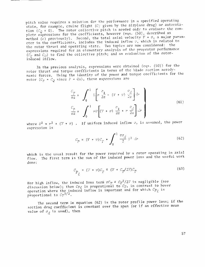
pitch value requires a solution for the performance in a specified operating
state, for example, cruise flight (CT given by the airplane drag) or autorota-
tion (CQ = 0). The rotor collective pitch is needed only to evaluate the com-
plete expressions for the coefficients, however (eqs. (S0), described as
method (c) previously). Second, the total axial velocity V + v, a major param-eter in the coefficients, includes the induced inflow v, which is related to
the rotor thrust and operating state. _¢o topics are now considered: the
expressions required for an elementary analysis of the proprotor performance
(CT and CQ) to find the collective pitch; and an evaluation of the rotor-induced inflow.
In the previous analysis, expressions were obtained (eqs. (50)) for the
rotor thrust and torque coefficients in terms of the blade section aerody-
namic forces. Using the identity of the power and torque coefficients for the
rotor iCp = CQ since P = Q_), these expressions are
f
Op_ /c_a
where U 2 = r 2 + iV + v)
expression is
2avvv(61)
If uniform induced inflow v, is assumed, the power
I _o dCp = IV + v)O T + 2U3 dr i62)
which is the usual result for the power required by a rotor operating in axial
flow. The first term is the sum of the induced power loss and the useful work
done:
Cp. = (V + v)C T _ (V + CT/2V)C 2 (63)%
For high inflow, the induced loss term vC T _ CT2/2V is negligible (see
discussion below); then CPi is proprotional to CT, in contrast to hover
operation where the induced inflow is important and for which CPi is
proportional to CT 3/2
The second term in equation (62) is the rotor profile power loss; if the
section drag coefficient is constant over the span (or if an effective mean
value of od is used), then
57

fl [r 2 + (v +
UOd[
CPo =o) 213/2_r
2
_ad8 /1 + (v + _,)2 1 + 7
+ 5 (v + v) _ _n 1 + /1 + (V + z,) "_V + V (64)
ac d--g- [l + 3(V + u) 2] low V
(70 ,
-_ (6.27) V + g) = 1
gCcZ
(473) high V
The two rotor operating conditions of primary interest here are: operation
with the rotor providing the propulsive force required for equilibrium cruise
flight, and autorotation operation (no net power supplied to the rotor through
the shaft). The latter corresponds to the condition in which dymamic tests ofthe proprotor and wing are often performed. The performance problem involved
is then to find the rotor collective pitch required (and the other coefficient)
for a given CT (thrust required for equilibrium cruise flight) or CO (zero forautorotation).
The rotor aerod3mamic coefficients require an estimate of the rotor
induced velocity v. For high inflow, however, the induced velocity is much
less than the forward speed of the rotor (as shown below), so great attention
to the inflow calculation is not required to satisfactorily evaluate the coef-
ficients. 3q_e assumption of uniform inflow is adequate then, and it may, in
fact, be possible to neglect the induced inflow entirely. The rotor CT
required in cruise flight is obtained by equating the rotor thrust (for two
rotors) with the aircraft drag, and expressing the drag in terms of an
equivalent flat-plate area f for the aircraft (L = (I/2)0V2f). Therefore, forthe thrust required of the rotor,
I ,, r,_2CT - 4A
where A is the disk area of the rotor. Momentum theory can be used to estimate
the induced inflow; the usual result (ref. 32) for axial flow operation atthrust CT is:
Y + v = vI2 + /(v12) 2 + 0/2 (6s)
58

Substituting for CT yields
v /f + (:72.4) - 1g 2
or, since f/d and hence CT/V 2 is small,
CT7) ~ l ("
V 2V 2 8 A
TyTical values of proprotor aircraft drag and radius give f/.4 _ 0.0033; itfollows then that v/V = 0.0017 typically, which is indeed much less than 1.
For the proprotor in equilibrium cruise flight, neglecting 7;/Y is a reasonable
approximation then.
When the rotor is operated in autorotation, the performance requirement
is that Co = O, which requires that CT = -Coo/(V + _) _ -C(2o/V. With the high
inflow result for the profile power, C@ -- lacd/2)V, the thrust required inautorotation is
aod V2CT- 2
For the proprotor in axial flight at high inflow, autorotation occurs in thewindmill brake state (i.e., at V > 2/]CTI/2, or ICT/2V2! _ Iv/V1 < I/4); hence
momentum theory may again be used to estimate the induced inflow (ref. -o).
The same conventions are used for the directions of V and CT_ (so the CT
required in autorotation is negative, as given previously]; the momentum theor,v
result is
v (6(_]V+v =7+ +-T
Substituting for the required C T yields
v CT aCd_ 0
V 2V 2 4
Typical values of proprotor drag coefficient and solidity yield
OOdo/2 _ 0.0004. Hence the typical induced inflow v/g _ -0.0002, which issmaller than in cruise flight. Again, the induced inflow may be neglected.
The effect of the induced inflow on the blade load distribution (that
required to evaluate the aerodynamic coefficients for the dynamics analysis),
may be investigated by considering the change in angle of attack due to v/Y:
V + v v V/fm_a = _ tan -1
ar V1 + (V/far) 2
which has a maximum value of 6a = (1/2)v/V. Use of the momentum theory
result v/Y _ CT/2V 2 (valid for both powered and autorotation operation in
59

high inflow) and the mean angle of attack _ = 6CT/a a yield the maximum changein angle of attack:
_ot ~ ua
a 24V2
For typical values of rotor solidity, _a/a = O.02V -2 which is a small fractionfor high infiow (V of order 1).
Numerical calculations were performed to verify that V + v _ V is a good
approximation in the calculation of the aerodynamic coefficients. The impor-
tant consideration in the dynamics analysis is that the performance calcula-
tion and the calculation of the aerod?mamic coefficients be consistent, either
neglecting the induced inflow v/V or using the same estimate of v/V for both
calculations. Any error in estimating the rotor performance or the collective
pitch required is not relevant to the dynamics analysis. The aerodynamic coef-
ficients that correspond to the operation of the rotor at a given value of CT
or C0 :ire obtained, the only error being a small change in the angle-of-attackd. _lstribution over the blade'.
SECTION 3: BEIIAVIOR OF ROTORS IN tIIGII INFLOW
In the next four chapters, several topics on the behavior of high inflow
proprotors are investigated, based on the equations of motion derived pre-viously. The development of the proprotor and cantilever wing model is
resumed in section 4. The reader interested in that topic may skip the fourchapters in this section.
Elementary Dynamic Behavior
Some aspects of the dynnamic behavior t_ical of proprotor aircraft are
examined. First, the fundamental stability of the blade motion is examined
through the eigenvalues of the uncoupled blade motion. Then the influence of
the transformation to nonrotating degrees of freedom and equations of motion
on the eigenvalues of the rotor is examined. The actual coupled motion of the
proprotor and wing system is considerably more complex, but these considera-
tions are useful in the interpretation of the results for the complete model.
The equations of motion and the hub forces for the rotor were found to separate
into longitudinal and lateral/vertical groups (eqs. (44) to (48)). The wingmotion, in fact, couples these groups, but it is useful for a preliminary
study of the dynamics to neglect that coupling, and examine the rotor responseto shaft motion, gust, or blade pitch control in the longitudinal or in the
lateral/vertical systems. Attention is directed to the low-frequency response,
since that response is useful in evaluating the influence of the proprotor onthe aircraft stability.
60

Blade stability- Consider the uncoupled, shaft fixed flapping motion of a
single blade. The equation of motion (in the rotating frame) is
IB* _ - _M_ + (I_*v82 + KF_M0) B : YM0@ (67)
The roots (eigenvalues) of this equation are
/
X - ,(M_ _+i /v 2 + Kp ....
2I B*
(68)
For low inflow, -M_ = M@ = 1/8, and equation (68) reduces then to the usualresult for the flapping motion of a hovering rotor. The flap damping is posi-
tive, M_ < 0, so the real part of X is negative and the flap motion is stable.As V/fag increases, the flap damping -N_ decreases and the pitch control power
M@ increases. Then the real part of _ decreases in magnitude as V/_R increases,and the stability of the flapping motion decreases. The change is not great
for V/f_R of order l, however; and M'@ is always negative (at least the c_contribution is) so the motion remains stable for even extremely high in_low.
Pitch/flap coupling Kp introduces a flap spring term through the
aerodynamic force M@, which changes the effective flap natural frequency:
TMO (69)2
vB = + Kp --e vB2 IB*
Negative pitch/flap coupling, fp > 0, increases the effective flap frequency
VBe. Increasing V/FaR increases M 8, and so increases the effectiveness of Kp.
Again, the influence is not great for g/gR of order l or less.
Consider the uncoupled lag motion with the rotating equation of motion
(homogeneous form):
I *_ + XQ_ + I{*_ 2{ = 0 (70)
The roots for this motion are
2iB, v¢ 2 -
The lag damping Q_ is positive, Q_ > 0, so the motion is stable. The coeffi-
cient Q_ increases with V/FaR, hence the stability of the lag motion increases.For low inflow, the lag aerodynamic damping is very low. For high inflow,
however, there is a significant increase in lag damping, which is important in
proprotor dynamics. In high inflow, the source of lag damping is the same as
for the flap damping, namely, the lift change due to angle-of-attack
61

perturbations (i.e., the oz terms). Therefore, both flap damping and lagc_ .
damping are of the same order in high inflow.
The flap and lag motions of the blade are strongly coupled by the
aerodynamic forces in high inflow; specifically, they are coupled by the cross
aerodynamic coefficients M_ and Q_, which are of order 1 in high inflow (likeall the coefficients).
Nonrotating system eigenvalues- Consider the blade uncoupled flap motion,as observed in--the nonrotating frame. The coning mode 8o has an equation of
motion (eqs. (47)) identical to that of tile blade in tile rotating frame, so
tile eigenvalues of its motion are the same as those given previously. The
equations of motion for the tip path plane tilt coordinates, _IC and _IS, aremodified by tile transformation to the nonrotating frame; centrifugal and
Coriolis terms are introduced, which have the effect of coupling the 81C andB1S motions.
The homogeneous equations of motion in Laplace form for 81C and 81S are(from eqs. (44)):
I_ *82-yM_o +/8 *(vB 2_ i)+Epy?_']O
- (2_B<_-yM_): 0 (72)
The characteristic equation for this system is the fourth-order polynomial:
: 2 1) + + = 0A [_B *_2 - r_ + _*(v_ - £prNo]2 (-2_B, _ _ yM_)2 (73)
The eigenvalues are then the solutions of this polynomial; writing the roots
of the flapping motion in the rotating frame (eq. (68)) as _ = XR, IR, thenonrotating system eigenvalues (roots of eq. (73)) are then
INR = IR _ i (74)
and the conjugates. The nonrotating eigenvalues have the same real parts as
the rotating roots, but the frequency is greater or less than that of the
rotating roots by i/rev. On the root locus plane (Im_ vs. Rel), the nonrotat-
ing roots are then shifted vertically by fl/rev from the rotating roots.
For a three-bladed rotor, the rotating roots on the _,-plane are a pair of
triple poles at _R and its conjugate. The nonrotating roots are a single pair
at IR and its conjugate for the 80 mode, plus a pair at 1R+i and tR-i andtheir conjugates for the B1C and gl£' modes. In both the rotating and non-
rotating frame, there are then six roots, corresponding to the three blades
each with a second-order differential equation. The eigenvectors of equa-
tion (72) give the coupled motion of 8IC and 81S corresponding to the eigen-values. There are two modes (and their conjugates); each eigenvector defines
a wobbling motion of the tip path plane, at frequency ImXg - 1/rev for the
62

low-frequency mode and at frequency fmX R + i/rev for the high-frequency mode.
The high-frequency mode wobbles in the same direction as the rotor rotational
direction, and so is called a progressive mode. The low-frequency mode wobbles
opposite the rotor direction if imXR > I/rev, so it is a regressive mode. If
irmxR < I/rev, however, the low-frequency mode wobbles in the same direction as
the rotor rotation and so is another progressive mode. The two modes are
denoted here by B ± 1 for the flap modes at frequencies fm,_,E ± I/rev,
respectively.
The behavior of the roots of the lag motion in the nonrotating frame is
similar to that of the flap motion (the influence of the transformation from
the rotating to nonrotating frame is a general result for all rotor degrees of
freedom). The coupled motion of CiC and _IL7 is a low-frequency and high-
frequency mode, denoted by _ ± I, each a whirling of the net rotor center of
gravity about the shaft. This motion has an important role in proprotor
dynamics. The blade flap and lag motions are, of course, highly coupled, with
each other and with the shaft degrees of freedom. The basic flap and lag roots
remain identifiable even for the coupled motion, however, both by the frequency
of the eigenvalue and by the participation of the degrees of freedom in the
eigenvectors. The characteristic location of the nonrotatin£ roots, at the
low-frequency and high-frequency rotor modes, remains an important feature of
the dynamics.
Longitudinal system - Consider the longitudinal dynamics of the rotor,
described by equations (47) and (48). It consists of two degrees of freedom
(coning B0 and collec-tivc lag _0) excited by longitudinal shaft motion (hub
velocity sp and roll angle as), longitudinal gust (VzqT), and rotor collective
pitch control (60). The influence of the rotor is transmitted to the shaft asa thrust force and a torque moment (CT and C_) acting on the hub.
]'he equations of motion for the longitudinal system are, in transfer
function form (and matrix notation),
o " B Bo 6o z_ u
"" * v2 _0-yQ_s+yKpQ e -T_OS2+y_r4_+fCO
= eO + + s2+y _ z yQ_ iv
(75)
The thrust and torque are
63

CT
(Ta - -- s 2 + Ths Zpz y
_ _ rq* S 2 _ yT_s + )S O - ]'.S_ 0¥ w_ KpyT e0
To simplify the notation, subscript 0 on the inert|as and frequencies is
dropped in the rest of the discussion of the longitudinal system; only the
longitudinal dynamics are involved, so the values appropriate to the coningand collective lag modes are implied throughout.
For the low-frequency response, the equations of motion to lowest orderin s reduce to
(76)
II *v 2
8e 0
YA'p_?0 I *w
The rotor thrust and torque are
0 +[ |(Vu a + Zp) + _. (77)
\%/ VQ / z
ea - reeo + :e_,(vua+ zp) + T_Lz _ zpreB°
da y _ _0
The solution for the low-frequency response of the rotor coning mode tocollective pitch, longitudinal gusts, and shaft motion is then
(78)
0• °
['fMee o + YN:_(w_o + zp) + ylv_%] (79)
The response of the rotor thrust to these inputs, including the influence of
the rotor dynamics, is obtained by substituting for S0 in the expression forCT/oa (eqs. (78)):
64

CT IT KpyT@- @ - M8 .... 0°
aa TB,v82 + KpyM8/
l i8,w82 + KpyM6/ + _P)
IT KpyT@ 1
M ..... &
+ [ - < IS*vS2 + KpyM z
This result can be simplified by use of the relations:
(80)
1 sin ¢ sin _ 1
m =- _O 8 cos $ 6 8 6 cos- 0
and, similarly, M@Tx - MIT @ _ O. With these relations, the expression for
thrust reduces to
2
CT -_ • _B
oa [T@@0 + Tx(VUG + :Zp) + T_a z] w 2
8e
(81)
The factor in brackets is the direct response of the rotor thrust to the
inputs• The only influence of the rotor flap dynamics (B0 term in eqs. (78))
is to reduce (if Kp > 0) the direct low-frequency response by the ratio
vo2/v_ . The effective flap frequency vSe includes the aerodynamic spring due
t_ Di_h/flaD couvling Kp. The ratio vR/_8o = 1 if Kp = 0 and, for values of
_B0 and Kp typical of proprotor coning mode, it w111 always be nearly .
With a procedure similar to that used for the rotor thrust, the flap
dynamics are eliminated from the low-frequency lag response to give
_0 - i [YQo0o + yQI(Vu G + Zp) + YQ_z - YKPQBBo]I*_ 2
2
• _8 (82)= 1 [yQe@o + yQx(VUG + Zp) + yQ_a z] 2
*v 2 vI{ _ Be
Again, the only influence of the flap dynamics on the direct response is the
factor wB2/w_ • The rotor torque follows directly from the solution for _0"e
The low-frequency response of the rotor coning and collective lag motion
to collective pitch, longitudinal gust, and shaft motion is then
65

ZB * v 13 YMe
: 1 @ + (V_(; + "kp) +
Se
The low-frequency response of the rotor thrust and torque is
(83)
0 + rv_ a + _p) + v_2 (84)2
An important term in the response is tile shaft torque due to longitudinal
gust. The direct response has the magnitude Z?h _ -(V sin ¢)/6. The aerody-
namic torque FQI increases greatly with inflow (the behavior of (_i is similar
to that of H_, which is shown in fig. 4; in fact, with only the c_ terms,
Qh = H_ exactly) - the source of a fundamental problem of the highainflow
rotor response to longitudinal gusts, namely, u great increase in shaft anddrive train loads with forward speed.
The rotor aerodynamic coefficients T t and _ result in hub thrust andtorque terms that damp the zp and a. motions, respectively. SinceT_ _ -(cos ¢)/4 and o-
_c, _ (I/ sin _)/{], the damping of s[_ decreases slightly as gil]creases (its behavior is like that of /<'_), while the damping of a z increases
greatly with V (its behavior is like that of WU). The thrust force due to
inflow T_ is a usual feature of rotor dynamics; the influence of the torque due
to rotational speed &t_ is much different than for low inflow rotors, however,because the coefficient is orders of magnitude larEer in high inflow.
In the derivation ot" the low-frequency results, it was assumed that
v¢O # 0; for the autorotation case, however, re0 = 0. Then CQ = 0 always; and
the characteristic equation has a factor _, that is, one root at the origin,
which indicates that the proper degree of freedom is <0, the rotor speed per-
turbation. The other root of the collective lag mode is at _ = -yQ_/2I_o
(uncoupled), that is, a real root with time constant T =2I_o/y Q --" 12/yV in ¢The low-frequency response of _0 is then & s .
_0 -1
o. [:?e eo + ¢x(7:_-, , ";p) + " ";,,_ + ,Paa] (85)
There is a response of ¢0 to shaft roll d.. even though v : O, because CO has_, • c_0been defined with respect to the roiled shaft position; the response is such
that ¢0 - &s, the rotor speed perturbation with respect to space, is exactly
zero. From the expressions for the coefficients with only the c_. a terms, it
66

follows that VQ_/Q_ = -V2]'2/V2f2 : -1 exactly (eqs. (34)); hence the responseof the rotor speed perturbation to a longitudinal gust (at low frequency] is
- -1 (s(,5u G
This is the response required to keep the inflow ratio constant, including the
velocity and rotational speed perturbations, as shown in the following
ann 1ys i s :
(V) 6V V6(g_R)_ = _--_ - (9J75 2
v [_ 6i_5]= e-_ - eR
V
tlence 6(V/gdg5 : 0 implies [o/uG = -1 as given above. This result holds even
for the complete model of the rotor and cantilever wing.
Lateral/vertical system: Flap response- Consider the lateral/vertical
group of degrees of freedom, inputs, and hub forces (eqs. (445 to (4655. The
cyclic lag degrees of freedom, ¢lC and {1_, are dropped to obtain a manageable
set of equations. The rotor motion is then described by' two degrees of free-
dom (tip path plane tilt 81C and 81S) excited by lateral and vertical shaft
motions (shaft tilt, a m and azj and hub inplane velocity, _['p and 7)p5, aerody-
namic gust (angle of attack ag and sideslip 8G), and cyclic pitch control (_10
and elS). The influence of the rotor is transmitted to the shaft as rotordrag force and side force (C H and Cy) and pitch and yaw moments (CMU and CMa:)
acting on the hub.
The low-frequency response is of interest here so that the basic responseof the rotor in high inflow can be examined, and also as a basis for investi-
gating (in a later section) the influence of the rotor forces on the aircraftstability and control characteristics. For stability and control problems, itis convenient to obtain the equations of motion in a body-axis system rather
than in the inertia axis system used so far (the inertia axes are most conveni-
ent for the cantilever wing problem, which is the main subject of this report).
In body axes, the trim velocity of the rotor (V + v) remains axial during
shaft tilt by a m and a_; then converting to body axes requires that the terms
in the equations of mo_ion and hub forces due to the inplane component of
( V + u) produced by the shaft tilt (i.e., the (V + v)%0 and (V + v)%j terms)
be dropped. The shaft angular velocity &x and &. must then involve a centrif-
ugal acceleration in order to turn the vector ( V_+ v5 to keep it aligned withthe shaft. This may be accounted for by simply adding the rotor mass to the
aircraft mass; hence the equations presented here do not incorporate these
centrifugal acceleration terms. The perturbations to the aircraft velocity
iV + v) are given by the hub velocities Xp, yp, and ap. These motions and
67

aerodynamic gusts are the only sources of inplane velocity of the hub in bodyaxes.
The equations of motion for 81C and BIS (in transfer function form with
the ax and ay terms dropped as discussed previously) are
Zfl*s2-xM_s+I B* (v82_ 1)+KpyM O
- (::8*8-YM_)
1C + yVM + 8a '5
: %\°iJ vM -;: +
Is*s2-yMfls+II3*(vfl2-1)+KPYM,oJ 1:
- I* o_v'_.'_I ,:'_( rsa'- "'_' d
(8 7)
Consider the response of the rotor to cyclic control, gust, inplane hub
velocity, and shaft angular velocity,. For the low-frequency response, onlythe lowest order terms in s are required and the equations become
= +_a
(88)
Only the steady-state terms in the flap response are retained. A steady" tippath plane tilt gives a flapping velocity in the rotating frame so there are
moments through M_; since shaft angular velocity involves a Coriolis accelera-
tion of the rotating blades in the hub plane (SiC and 81 _ are flapping withrespect to the hub plane), inertia terms also appear.
Inverting the matrix on the left-hand side of equation (88) gives the
solution for fllC and B1S:
: + _ _ + _a + X
\ YI.J
(89)
68

who re
"I,'__ =
I *(v# 2 - l) + EpyM 0 (90]
-y?_J,_
The parameter ,"J, is a measure of the lateral/vertical coupling of the rotor
response (lateral/longitudinal fc,r helicopter orientation); ?.,_, = 0 for v_. = 1
and kL'i) : 0, that is, for an articltlated rotor with no binge spring or offset,
and no pitch/flap cout_ling. [:rorl equation (09], it also follows that ,Y._ canbe written if, : ;;:x('0[_ - l}/-Y?.!i_, _o the parameter is _{ measure of the(effective) stm_ctura] restraint of the blade flapping motion.
In the flapping response (eel. (89)), the bracketed qu_ntities give thebasic effectiveness of each kind of excitation, while the factor involvin_ _:'
accounts for the rotor flapping dwmmics. Inside the brackets, most of theLock number factors cancelled, irldicating that the response is main]v a bal-
ance of aerodynamic forces; the (,xception is the third term, which is a bal-.
ance of the inertial forces t,_F_._ j due to shaft an_,ulnr velocity &:. and :% _ndnerodynamic forces (-yH_) due tO tip path plane ti it fSl57 and ?1." Cyclic'
pitch control, hub inplane velocity, and hub plane angulnr velocit\" result in
aerodynamic moments on the disk. These moments c,'mse the rotor to flap untilthe moment on the disk due to thc. flapping cancels the applied moment, thus
achieving equilibrium deflection. The coefficie;_t ?_:"_ is the effectiveness of
flapping in producing a moment or the rotor disk, hence its appearance in thedenominators always. Blade cyclic pitch producc.s an aerodynamic moment on the
disk through ?40 , so the net centre] effectiveness is. _'0"_0/-7¢_'_ tlub inplanevelocity produces an aerodynamic moment on the disk througt_ 5J:., with a net
effectiveness of MJ-N_. With the present model, there are three sources ofhub inl)lane velocity: shaft velocity g[, and _/p, vertical and lnter:tl aerody-
namic gusts a d and Bg7 (which are angles, so Vu¢ and VS,Z are the correspondingvelocity perturbations), and angular velocit'/ of the shaft about a pivot a
distance )'. aft of the hub producing hub velc, cities ;/_a: and L,:_,.
Consider the response to sha:ft angulaT" velocity ,-'i::: and :'_. The inplane
velocity due to angular velocity _tbout a pivot aft of the hub_gives a moment
on the disk (hence flapping) throt_gh 74u a_; discussed previously. The third
term in equation (89), with effectiveness 22_a/-yN _, is the lag of the tip
path plane required to precess the, rotor to follow the shaft (_'1!' and BI.C are
flapping with respect to the shaft). For the tip path plane to follow theangular velocity of the hub plane requil:es a Coriolis acceleration of the disk
of magnitude 22_,a_, because of the rotation of the blades. A moment is
required to produce this accelerat:ion, that is, to precess the rotor disk, andthat moment is supplied by aerodynsmic forces on the disk that result from the
flapping velocity of the rotating blade's. The tip path plane tilts back, lag-
ging the shaft tilt, until the aerodyn;amic moment due to flapping (of magni-
tude -¥M_81C) is just large enough to provide the required acceleration.There is a 90 ° azimuthal phase difference in the response, characteristic of
rotor or gyro dynamics: shaft pitch 5.7/ requires a lateral moment on the disk
to precess it; that lateral moment is supplied by the flapping velocity in the
rotating frame due to steady tip path plane pitch _1(7" TI_o flapping dxmamics
also introduce a phase shift if N, ¢ ().
09

The last term in equation (89) is also a flapping response due to shaft
angular velocity. Hub plane angular velocity dtle to _g or &x produces a flap-
ping velocity of the rotating blade, hence a monmnt on the disk through -¥M_.The rotor flaps until the moment on the disk du_ to tip path plane tilt, which
also acts through -yM_, is just large enough to cancel the exciting moment.
Both moments in the equilibrium are aerodynamic, so the Lock numbers cancel.
Both are due to the flapwise velocity of the bl_de so the coefficients M_ also
cancel. The net effectiveness, then, is exactl3r i. The last term in equa-
tion (89) results in a coupling of the lateral _md vertical response of the
rotor to shaft angular velocity (_x and _y), ev(m if ?J, = 0. The basic flap-ping dynamics in the nonrotating frame ias disctlssed previously) consists of
low-frequency and high-frequency flapping modes (_ :_ 1), each of which appearsas a wobble in the tip path plane. The basic rc_sponse of the rotor theninvolves coupling of the lateral and vertical mention, a fundamental character-
istic that results from the rotation of the blacles. The low-frequency responseshould involve only excitation of the low-frequcmcy flap mode (_ - 1), but thelateral/vertical coupling is still expected.
When ;]_ = 0, the first factor in equation (89), representing the influence
of the rotor flap dynamics, reduces to a unity matrix. With a hingeless rotor
(v B > 1) or pitch/flap coupling (Kp ¢ 0), /V_ is no longer zero and the flap
dynamics matrix introduces a phase shift and a nmgnitude change in the flapping
response. An example is the re:q_onse to cyclic pitch control, 010 and @IS.
The diagonal terms in the flap dynamics matrix produce a tip path plane tilt
following the control,plane tilt, through equil_'Lbrium of the aerodynamic
moments due to blade pitch and flapping. The o_f-diagonal terms correspond tolateral/vertical coupling of the tip path plane/control plane tilt, which
results from the aerodyqmmic pitch moment being reacted by a moment due to
structural flap restraint (v8 > 1) or pitch/fla t) coupling (lip 6 0), hence due
to ]g_ _ 0. The two sources of tip j_ath plane tilt produced by control planetilt (or any other excitation) have a 90 ° azimuthal phase difference because
the diagonal terms are due to flapping velocity (in the rotating frame), whilethe off-diagonal terms are due to flapping displacement.
Consider the individual terms in the flap responses - each has the form
of a basic control power multiplied by a factoi. (involving ?J_) that accounts
for the flap d_mmics. The effectiveness of cyclic pitch is given by" (usingthe approximations based on the inflow :_t an ei'fective radius)
AO _ 1__,. - - 1 + tan2 _ = 1 +
_g cos 2 qb ,_(9l)
The pitch control power increases with V then, due to both an increase in the
pitch moment _I_ and a decrease in the flap da!nping ;4_ (as shown in fig. 4).uthe increase Is slow for the usual range of F' (up to 1 or so). With theinfluence of the flap dynamics, the response to control is
70
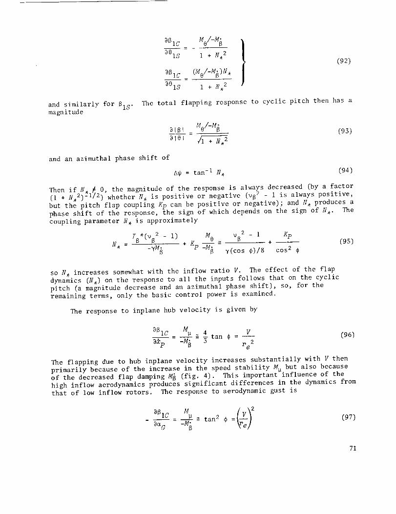
and similarly for SIS.magnitude
BlC Me/-M
881S 1 + N, 2(92)
_Sl C (Me/-M[)N,
_@IS I + N, 2
The total flapping response to cyclic pitch then has a
aIB MO/-M _ (93)
2101 _1 + N, 2
and an azimuthal phase shift of
A_ = tan -I N, (94)
Then if N, _ O, the magnitude of the response is always decreased (by a factor
(l + N,2) -I/2) whether N, is positive or negative (vB2 - 1 is always positive,
but the pitch flap coupling Kp can be positive or negative); and N, produces a
phase shift of the response, the sign of which depends on the sign of N,. The
coupling parameter N, is approximately
N_ =
I*(_S2 - I) MO ~ V2 _ i Kp+
+ Kp = .f(cos )IS cos2(95)
so N, increases somewhat with the inflow ratio V. The effect of the flap
dynamics (N,) on the response to all the inputs follows that on the cyclic
pitch (a magnitude decrease and an azimuthal phase shift), so, for the
remaining terms, only the basic control power is examined.
The response to inplane hub velocity is given by
_SIC _ Mp =-_4 tan ¢ = V
_d:p -M R 3 re2
(96)
The flapping due to hub inplane velocity increases substantially with V then
primarily because of the increase in the speed stability Mp but also because
of the decreased flap damping M R (fig. 4). This important influence of the
high inflow aerodynamics produces significant differences in the dynamics from
that of low inflow rotors. The response to aerodynamic gust is
aaGaSlC M _r__Ve/2_ P
_MI_ tan 2 _b =(97)
71

This is the response to angle-of-attack changes rather than just velocityperturbations, hence the extra factor of V (though both are hub inplane
velocity changes). The substantial increase in high inflow of the flapping
produced by hub velocity results in problems characteristic of the proprotor
aircraft: high flapping or blade loads in maneuvers and gusts and substantialcoupling of the rotor dynamics with the shaft motion.
The flapping response to shaft angular velocity Gy is (for N, = O)
_810 2I_ M 16
-yM + h i = 4_ay _ y cos ¢ + h y tan ¢ (98)
The second term is due to the hub inplane velocity with shaft angular motion
about the pivot a distance h aft of the hub (its behavior was discussed pre-
viously). The first term is the flapping required to produce a moment to
precess the disk to follow the hub plane; it increases somewhat with V because
of the decrease in the flap damping H_. The response to &x is
_810
3_. - -I (99)x
the equilibrium of the moment due to flapping velocity due to _x and 81C ,
which does not change with V. For values of the Lock number, mast height, and
inflow velocity (y, h, V) typical of proprotor operation, the primary contri-
bution to the flapping response due to angular velocity of the shaft is theterm required to precess the disk:
m _ 16
26. ad y cosY Y
(lOO)
With only the inertia term of the response to shaft tilt, the influence of N,is the same as for the response to cyclic pitch.
Lateral/vertical system: Hub forces and moments- Consider the lateral/
vertical hub forces and moments: rotor drag force CH, side force Cy, hub
pitch moment CMy, and hub yaw moment CMx. Retaining only the flap degrees of
freedom, dropping the ax and ay terms (giving inplane components of V + v) to
convert to body axes, and then retaining only the lowest order terms in s,yields the following hub forces:
72

\-_a [ -HeXP
, (H + R) )P
2CT 81S/
[
+ He I-@ISI
\ elC/
+
\/8 G
h(Hp + R -&x
(101)
The hub moments are simply
/2CM_
\--_-/ \ _is/
(lO2)
If one substitutes for the low-frequency flapping response,
----_- +
__ da2C 1 + N, 2
M /[_p-VOLG÷haY_ 2I_o_( &y _l
+_w._t J"_',u_'-_x"
+ H"8*-HeKPN,
the hub forces are
@IC
'-CT
_--i- N, (M,H_+HeKP)2CT
/2C T C T
da N,(N,H_+HoK P)
i + N, 2 &
(103)
73

Basically, the response for each input is a direct H force plus a contribution
from the rotor flapping motion; the last term is the aerodynamic force pro-
duced by the flapping velocity due to shaft angular velocity, combining the
direct and flapping terms. Note that the hub force response is considerably
simplified if N, = 0; then the tip path plane tilt produces hub forces through
only 2CT/_a + H_*, and the matrix in the last term reduces to simply CT/_a
(which may then be neglected for high inflow operation). The hub moment is
simply a constant times the flap response.
Pivot moment - The total moment about the pivot a distance h aft of the
hub is given by the hub moment plus the hub forces acting on the arm h:
oa /pivot
. 2CII- + h
ua csa/
(]04)
The hub moment is directly proportional to the tip path plane tilt, B1C and
BIS; hub forces (eq. (101)) are also produced by the tip path plane tilt
through 2CT/csa + H_*, the first term being the thrust vector tilt and thesecond, the negative H force contribution of high inflow. (The off-diagonal
terms that result from pitch/flap coupling are not considered now, that is,
it is assumed that Kp = 0.) The total moments about the pivot due to the tippath plane tilt are then (after the hub moment and hub force terms arecombined) :
I::'iI: .iIcaa ,(v 2 _ + h{2C T f31
A . Mx Y (105)
1)
_e combination of terms appearing on the right-hand side has already
appeared in the equations of motion for the four-degree-of-freedom model
(eq. (26)). With this result, a simple design criterion can be derived for
optimum proprotor/pylon dynamic stability. If the total factor of BIC and _lSis set to zero, with a proper choice of the parameters, the moments due to the
rotor flapping dynamics (at least the low-frequency response) will not be
transmitted to the pylon. Then the pylon is effectively decoupled from the
rotor and will not respond to rotor flapping motion: this is expected to
improve the stability of the proprotor/pylon system. W_en the rotor lags the
shaft in response to shaft angular velocity, that tip path plane tilt produces
a hub force through 2C_/_a.+ H_*, which is dominated by the negative H forceterm H_* hence it results _n negative damping of the shaft tilt motion. Thiseffect, in particular, is nullified by setting the total tip path plane tilt
74

factor of equation (10S) to zero. _]_e thrust vector tilt term 2CT/c_a
contributes positive damping, but it is negligible compared to H_{* for high
inflow. Thus the criterion essentially is to use the positive damping avail-
able from the hub moment of a hingeless rotor to counter the negative aerody-
namic damping of H'B*, and the design rule becomes a specification of the flap
frequency v B required to satisfy that criterion.
Setting the coefficient of BIC and BIS in equation (105) to zero gives the
design choice for v_:
IB * (106)
---1 + yh sin6
For typical values of y, h, and V for proprotor operation, equation (106)
requires that v B _ I.I or so such a frequency is easily obtained with currenthingeless rotor technology or even with an offset hinge on an articulated
rotor. An obvious ]imitation is that H_* is a function of V while v B is not,
so the design criterion can be met only at one design speed.
This result was first obtained by Young and Lytwyn (ref. 18). On the
basis of optimum flutter stability with the pylon decoupled from the rotor,
they obtained the above result for the optimum flap frequency vR" Numericalcalculations of the flutter boundaries for a four-degree-of-freSdom model (a
flapping rotor on a pylon with pitch and yaw motion) show that the optimum
flap stiffness is actually somewhat above this. _J_ey suggested that a value
about 5 percent higher be used:
(107)
With this choice of _, the remaining rotor force acting on the pylon ismainly a negative spring force due to the speed stability coefficient H_*;
this force leads to a divergence criterion, which does not require very much
pylon stiffness. They also point out that the only parameter of the pylon to
enter this criterion on vB is the mast height h, because it is essentially a
static decoupling criterion, so the pylon dynamics do not enter at all.
Unfortunately, the problem of proprotor dynamic stability is not so
easily resolved. This criterion for v B is based on pylon pitch and yaw motion,
while, for the rotor on the cantilever wing, the degrees of freedom produce
much different shaft motion and respond differently to hub forces and moments.
This criterion is based on only the low-frequency response of the rotor, and
only the flap motion at that; the dynamics involved with high inflow proprotor
instabilities is more complex. However, many other design considerations are
involved in the choice of wing stiffnesses and blade frequencies; therefore,
75

while the proprotor dynamic stability must be verified, and perhaps theparameters modified somewhatto increase the margins, the actual choice of therotor and wing configuration (including the placement of the fundamental fre-quencies) is not necessarily based on the criterion for optimum dynamic sta-bility. The above result indicates that, for practical applications, aflapping frequency greater than 1/rev should be favorable for rotor and wingdynamic stability.
Whirl Flutter
This chapter examines the classical whirl flutter problem: a truly rigidpropeller on a pylon with pitch and yaw degrees of freedom. With the infinite
blade stiffness of a truly rigid propeller, there is no blade flapping motion.
The theory developed here may accommodate the rigid propeller by letting the
flap natural frequency _B go to infinity; in that limit, the four-degree-of-freedom model reduces to two degrees of freedom, pylon pitch a7 and yaw ax,which is the usual whirl flutter formulation. Nomenclature particular to thewhirl flutter analysis is given at the end of this section.
The whirl flutter model may exhibit instabilities at high forward speed
or low pylon stiffness, primarily because of the high inflow aerodynamics. In
fact, it has much different behavior than the flapping rotor case. The whirl
flutter problem is considered here because it is a special limit of proprotor
dynamics, often mentioned in the literature as an ancestor of the current
preprotor analyses; and because, as a two-degree-of-freedom problem, exact
expressions for the stability boundaries may be obtained. However, the
dynamics and aerodynamics of the whirl flutter model are found to bear little
relation to those of the flapping proprotor.
The whirl flutter equations can be derived from the four-degree-of-freedom
equations of motion already given (eqs. (26)), with the limits v8 ÷ _ and
I31C,_IS -_ O. tlowever, (_2 _ 1)_1C and (v_ 2 - 1)B1S must remain finite in thislimit because the propeller can still transmit a hub moment to the pylon; then
the _IC and B1/7 equations become simple substitution relations for the pylonequations. A more direct approach is to first substitute for the hub moment
(._ 2 _ 1)_1C and (vB2 1)B1S in the pylon equations of motion, and then take
the limit of B10, B1S ÷ 0. The pylon equations of motion for the four-degree-of freedom model (eq. (8)) are
[ ](1 ](t ?0 ]<)
2C _1tll1
= T _,a +
CI_ 2CH<I
yh _a
aa/
(lO8)
76
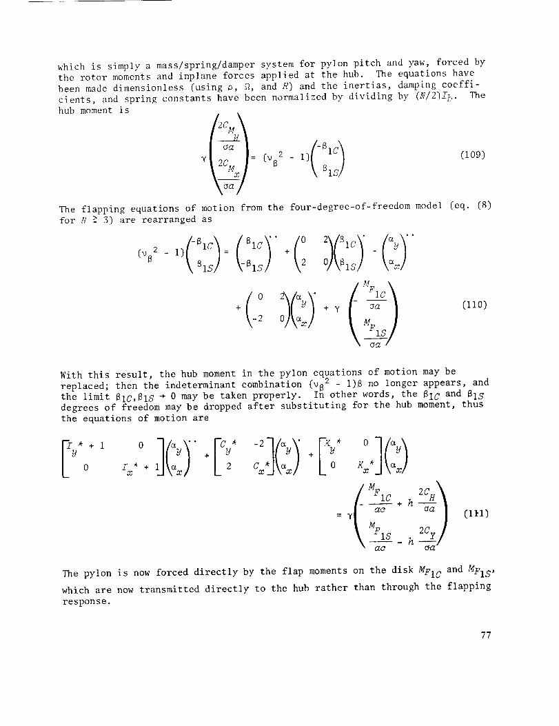
which is simply a mass/spring/damper system for pylon pitch and yaw, forced by
the rotor moments and inplane forces applied at the hub. The equations have
been made dimensionless (using p, _, and R) and the inertias, damping coeffi-The
cients, and spring constants have been normalized by dividing by (N/2]I_.
hub moment is
The flapping equations of motion from the four-degree-of-freedom model (eq. (8)
for N -> 3) are rearranged as
+ y - _ (110]
-2 x MF1
With this result, the hub moment in the pylon equations of motion may be
replaced; then the indeterminant combination [v82 - I)B no longer appears, and
the limit 81C, BIS + 0 may be taken properly. In other words, the BIC and BIS
degrees of freedom may be dropped after substituting for the hub moment, thus
the equations of motion are
11CI'0 _y " *+
÷_ x
MFlC h _ao + --_a
= y
2Cy
(i_1)
The pylon is now forced directly by the flap moments on the disk MFI C and ME1 S,
which are now transmitted directly to the hub rather than through the flapping
response.
77

The aerodynamic forces follow directly from equations (23) for the four-degree-of-freedom mode,with the 81Cand SIS terms dropped, of course. Thehub momentsand hub forces are then (hub momentis obtained by use of eqs.(109) and (ll0) with eqs. (23)):
d 'c ii[0IC") •o _ L-_:% H;Jk.xl
[o4- _ +
(Y + v)M u 0 c_ ,% 0 J\Olc, /
(112)
(_ E taa -h (,_'u + :_;L) ::iS _y " +
-:/_ -h(:: u + n u kC_x/
() :")elS v(:: R )4- + 4- _'
t/O el C u p k8 G
(P + v)(itp + R ]:_Y_
(11.3)
A comparison of these expressions with the results obtained for the
flapping proprotor dynamics shows that the whirl flutter problem involves con-
siderably different behavior. Comparing the hub forces with equations (101)
indicates that the response to shaft tilt, cyclic control, and gusts is the
same (except that eqs. (101) are in body axes, so the _x and ay terms aredropped). With the rigid propeller, however, there are no longer hub forces
caused by flapping, acting through the thrust vector tilt and the negative :!
force due to inflow (the 2CC/aa + H_* factor). 145b forces due to the tip path
plane tilt are naturally not part of the whirl flutter problem since they arise
only with the flapping rotor, and that difference is very significant.
Comparing the hub moment with equation (89) (the hub moment for the
flapping rotor if it is multiplied by (uS2 - 1)/y) shows that the role of the
flap moments is altered. "_le rigid propeller limit of uS2 ÷ _ corresponds to
78

the limit N, ÷ _ in equation (89), and with that the two results are identical
(except that in eq. (89) the ax and aW terms were dropped again for body axes,
and the inertia terms _x and _y were _ropped for the low-frequency approxima-tion). The more appropriate llmit for studying the flapping rotor dynamics is
_82 ÷ l, that is, N, ÷ 0. Between N, ÷ _ and N, + 0 there is a 90 ° azimuthal
phase shift in the influence of all flap moments. For the rigid propeller,
the flap moments on the disk are transmitted directly to the hub while, for
the flapping rotor, there is a 90 ° azimuth lag (for _8 = i) from the applica-
tion of the flap moment to the achievement of maximum tip path plane tilt.
IIence the role of the rotor in the whirl flutter behavior changes greatly
from that for the flapping rotor. The Coriolis flap moment and the speed sta-
bility moments on the disk (Mv) now are off-diagonal terms (i.e., coupling
terms), while the flap damping disk moment (M_) now contributes directly to
the damping of the pylon motion. The hub inplane forces are given solely by
the direct terms Hv and H i, with no contributions from tip path plane tilt.
The speed stability coefficients, M_ and H_, have a dominant role in whirl
flutter dynamics.
If one substitutes for the hub forces and moments, the equations of motion
for the pitch and yaw motions o£ a pylon with a rigid propeller are
E• ay
+ _Ky*-hy(V+v) (H+R )
m -y(v+v)M _*-h_ (V+v) (H+R. _x
: [hyHo
L YM o h Hd l L(114)
These equations are valid for propellers with three or more blades. As usual,
the notation of the aerodynamic coefficients indicates their source: H, for
hub forces; M, for flap moments; subscript v, for inplane velocities; and sub-
script _, for flapwise velocities.
The inertia terms are the sum of the pylon and rotor inertias:
I I + (N/2)Ib
79

where Iy + (N/2)I b is the total moment of inertia of the pylon and rotor (for
N _ 3); _ already includes the contribution h2NMb of the rotor mass to the
moment of Jinertia about the pylon. The damping terms (diagonal) have contri-
butions from the structural or mechanical damping of the pylon (Cy* or Cx*and from the aerodynamic forces on the rotor. All contributions to the
diagonal damping terms are positive (H_ and -M_ are positive) so the net damp-
ing is always positive. The aerodynamic contributions result from the flap
damping of the rotation of the hub plane by _x or _y, and from the inplane
force due to the hub inplane velocity during pylon an_ular velocity. Based on
the equivalent radius approximations, the aerodynamic damping terms are
y[-M_ + h2(_u + R)] _ Y_/c°s__ + _2 v sin2_)
The first term decreases some with V, while the second term increases. The
spring terms (diagonal) have contributions from the structural restraint of
the pylon deflection (Ky* or Kx* ) and from the aerodynamic forces on the rotor.
The aerodynamic term, a negative spring (Hv > 0) from the inplane force due to
the inplane component of (V + v) produced by pylon pitch or yaw, isapproximately
-hy(V + v)(HIj + RI;) _ -hy 2V2 sin
which increases with V. The coupling spring term (off-diagonal) is entirely
aerodynamic, from the flap moment on the disk due to the inplane component of
V + v produced by pylon pitch or yaw; it is approximately
V sin_(v + v) G _ 6
which increases with V. The coupling damping terms (off-diagonal) have inertia
and aerodynamic contributions. The inertia term (-2& x or 2&_) is the Coriolis
acceleration produced by the pitch or yaw angular velocity of a rotating body.
The aerodynamic terms are from the flap moment due to the inplane velocity
produced by the pylon angular velocity, and from the inplane force due to the
angular velocity of the hub plane. From equation (59), it follows that
3C T
_a<< 2
hence the aerodynamic contributions may be neglected compared with thegyroscopic coupling.
The whirl flutter model then consists of a mass/spring/damper system for
pitch and yaw, with positive aerodynamic damping, a negative aerodynamic
spring, gyroscopic coupling in the damping, and aerodynamic coupling in thesprings.
8O

Consider the single-degree-of-freedom problem: Kx* _ _ so _x + O; the
equation reduces to
(fy_ + 1)_y + [cu_ + h2¥( G + G) yM_l_y + [_y_ - h_(v + v)( G + R_)]_y
= hyH@@IS + hyV(H_ + Rv)a G (I15)
The damping is always positive, so the system is stable in this limit so long
as the net spring constant (structural plus aerodynamic) is positive:
Ky* > hy(V + v)(Hv + RV)(116)
This is simply a static stability boundary, that is, the divergence criterion
(for Kx* _ _). With one spring stiff enough, the system always has dynamic
stability; the only stability criterion remaining is the divergence boundary
for the other spring, due to the negative aerodynamic spring term.
Consider the case of no aerodynamics, but with gyroscopic (Coriolis)
coupling included. For the isotropic case (same mass/spring/damping constants
for both pitch and yaw), the characteristic equation is
[(I* + l)l 2 + C*I + K*] 2 + (2_) 2 = 0 (liT)
The four roots will have negative real parts so long as y, K*, and I* are all
positive. Therefore, the system is always stable, even with gyroscopic
coupling, if there are no aerodynamic forces on the rotor•
It follows then that any dynamic whirl flutter instability can only be
due to the aerodynamic cross-coupling of the pitch and yaw motion; there is
only one such term, namely, the off-diagonal spring terms ¥VM_. Since this
aerodynamic force increases with forward speed V, an instability is expected
to occur eventually as the inflow is increased for a given pylon and rotor.
Of course, there is the possibility of a static instability (divergence) due
to the negative aerodynamic spring term. Whirl flutter instability is then
the result of the high inflow rotor aerodynamics.
In Laplace form, the homogeneous equations of motion are
"(_Ty*+ I )s2 + [Cy*+h2y(Htl+R_l)-yM_]8-2s+y(V+v)M v
+ [_*-hy (v+v) (S_+_) ]
2s-y(v+v)G(_rx*+i) s2+[Cx*+hay (H#+R_)-yM_] s
+[_x*-hy(V÷v) (S_+R_)]
(ii8)
81

To simplify the notation, write V for V + u, H_ for /:_ + R_, and I* for I* + I:
sD_-Lp
= 0 (119)
where
Cv = h2yHp - yM_
Kp = hyVHp
DV=2
Lu = y VMp
These are, respectively, the aerodynamic damping and negative spring, thegyroscopic coupling (which is given a symbol so that its influence can be
identified in the results), and the aerodynamic cross spring. Combining the
structural and aerodynamic terms in the spring and damping coefficients yields
yS 2 + Cys + KysD - L= o (12o)
This last and simplest expression is used for the derivations.
The characteristic equation for the whirl flutter eigenvalues I is then:
(zux2 + cu , + ::y)(z=x2 + c=x + Kx) + (-xD + s)2 = o (121)
The stability of the system may be investigated by examination of the root
loci, that is, the behavior of the eigenvalues with variations in V or some
other parameters. For a two-degree-of-freedom problem, however, it is possi-
ble to solve explicitly for the stability boundaries. The stability boundaries
on the Kx* , Ky* plane (i.e., as a function of the pylon stiffnesses) is the
usual form for the presentation of the whirl flutter solution. The other major
parameter is the inflow ratio V. Two kinds of instabilities are possible with
a system that can be described by linear constant coefficient differential
equations. The first is divergence, a static instability that, on the I plane
(root locus), takes the form of one root on the real axis that passes through
the origin into the right half plane. The second type of instability is
flutter, a dynamic instability that takes the form of a complex conjugate pair
of roots that cross the imaginary axis (at finite frequency) into the right
half plane. The stability boundaries for these two types of motion areexamined.
82

Divergence- The divergence b_)undary is defined by the requirement that
one of the roots of the character:istic equation be at the origin. For _ = O,
the characteristic equation gives
KyK x + L 2 = 0 (122)
or
(Ky*- - + 2 : 0 (123)
therefore,
(Ky* - hyVHp)(Kx* -- hyVHp) + (XV?JV)2 : 0(124)
This sum must be greater than zero :for divergence stability. An instability
may be encountered if one of the spring constants, Xy* or Kx*, is too small,
so the negative aerodynamic spring make:; the first term and hence, perhaps,
the sum negative. Sufficiently large structural spring restraint of pylon
pitch and yaw motion guarantees diw)rgence stability.
T
The equation for the divergence boundary is a hyperbola on the Ky , Kx*
plane; the divergence hyperbola is shown jn figure 6. The asymptotes are the
fx, fy axes, that is, Kx* or Ky* = K_ : h_VH The asymptotes give the diver-gence criterion when one of the springs is very stiff; for Kx* ÷ _, equation
(124) reduces to (for stability)
xU > 0 (12s)
or
Ky* > Kp = hyVH v (126)
which, indeed, is the criterion obtained pre_'iously for the single-degree-of-
freedom limit. This criterion is that the total spring constant - aerodynamic
plus structural - be positive. For finite Kx "_, the cross spring LU = y_fp• . • . K _
introduces coupling of the am and a_ motiorl, which eases the crlterlon on w •O
The hyperbola intersects the line i_m = -K u (th(. -45 line on the Kx, Kz_ plane)
at points K;_ = ±Lp = ±yVMn, where the closest a.pproach of the two hyperbolabranches occurs. The minimum width of the divergence-stable corridor is thus
2/2L_ = 2¢r2yVM_. These points occur in the fir_;t quadrant of the Kx*,Ky*
plane (fig. 6), only if Lp/Kp < 1 (which is. in fact, true only for rather
large V]. In any case, the cross spring LV is a good measure of the corridor
width at low Kx* and Ky*
In terms of the approximation based on the equivalent radius, the
negative aerodynamic spring - which determines the asymptotes of the divergence
boundaries - is
V_'-sin__.Kp = hyVHp _ hy 2
83

which increases with both V and h, so both decrease divergence stability. Theminimum width of the divergence-free corriJor at low >:* is
2¢'2-25p = 2¢"Z2yYH_ -_ 2/2-2y 7 sin t6
which increases with V.
_I1_edivergence boundary is then determined by two aerodynamic influences:
the ,_i_ 'ct negative spring Kp = /zyrq/_;, _kich gives the location of the asymp-
totes, and the cross spring coupling gl_ =: y_!p, which gives the width of thecorridor at low Y_' independent of A'p. ]'}:e first is the direct hub force due
to the rotor and the second is the flap u_oment on the rotor - both react to
the inplane hub velocity component of 'J + _) due to the shaft tilt by pylonpitch or yaw. Both spring terms increasc with inflm, ratio V; the effect ofthe direct negative spring also incre_se._; with h since it is a hub force.
The pylon and rotor will always be .';tatically stable if both Kx* and KU*are greater than the negative aerodynamic spring /f;;, which is usually not avery stringent criterion on the pylen st!illness. Static stability is also
achieved always for the nearly i sotJ'opic case, ;4x* _ K7/*, even if the stiff-nesses are smaller than t2_. The cross spring L,j = ¥Z_ stabilizes the diver-gence motion if the springs are not. too stiff, so that both degrees of freedom
are active and the coupling of the aerodynamic spring may be effective. This
effect produces the divergence-free corridor at low ;(*.. floweret, the low Ky*and Kx* region will be within the fiutter instability region, so the presenceof the divergence-free corridor has little practical application.
Flutter: Some preliminary c:onsiderations- Some general results for whirl
flutter d)mamic instability are !presented here; they were originally obtained
by Young and Lytwym (ref. 18). Yh(, equations of motion are
= 0 (lZ7)
Forming the vector product wi'¢h [_g &a:] (i.e., the sum of &y times the firsteqtv_tion and ,'_j: times the second), one obtains
- [Cy&!/2 + ? & 2 , • •_:c x + _l_('-_x%/ - aya x) ] (128)
']_is equation is an energ,z balance for the whirl flutter motion. The left-
hand side is the t:ime rate of ckange of the sum of the kinetic and potential
energies of the ._vste_, *,:hich mt_st always be positive (assuming that the diver-
gence criterion is satis4:'ied). If the right-hand side is negative, the total
84

energy is decreasing with time, hence the system is stable; if it is positive,
the total energy is increasing with time, so the system is unstab]e. The damp-
ing contributions are always stabilizing and extracting energy from the system.
An instability is possible only if L_(axGy - _yGx) is sufficiently large and
negative. Again, whirl flutter is a direct result of the aerodynamic spring
coupling L_ = yVM_ e yV(sin _)/6. Since this coupling increases with V, anincrease in the forward speed eventually produces an instability (if the term
is negative). The gyro coupling due to the rotor (D_) does not appear in this
result, but it does influence the mode of motion of _x and _ and hence may
influence the stability. Without L_, no instability is posslble no matter
what influence D_ has on the motion.
Since the aerodynamic coefficient L_ is positive, a necessary condition
for an instability to occur is that ax&_ - ay& x < 0. Writing ay = q sin @
and _x = q cos @, it follows that ax&y _ ay& x = q2_ Hence the" requirement is
that _ < 0, which means a mode of motlon in which the shaft whirls in the
direction opposite the rotor rotation. This mode is called a backward whirl
mode; the motion with the shaft whirling the same direction as the rotor is
called forward whirl.
These considerations show that a whirl flutter dynamic instability for a
rigid propeller on a pylon occurs only in a backward whirl mode, and that it
is a high inflow instability due to the aerodynamic spring coupling My.
Flutter- The flutter boundary is defined by the requirement that a complex
conjugate pair of the roots of the characteristic equation be on the imaginary
axis, that is, that roots with zero real part be a solution. For I = i_,
where _ is real (_2 > 0), the characteristic equation becomes
(i oy ÷ - 2 y)(i cx + _ 2Sx) + (-i D ÷ L)2 = 0(129)
The real and imaginary parts of this equation are
(Ky - oO2Iy) [Kx - co2-Tx) - oj2OxOy + L2 - D2_o2 = 0 1
!iw[ (Ky - oo2I_]Cx + (Kx - cO2Ix)Cy - 2DL] = 0
If it is assumed that _ _ 0, the imaginary part may be solved for w2:
(13o]
co2 = KyC x + KxCy - 2DL
IY Cx + IxOy (1"31)
Substituting the solution for _2 from the imaginary part (eqs. (130))
into the real part produces
85

K2Z2OO + K2Z 2OC - 2Z_OOKK + K [Oo(_C + _O)(OvC + D2)y x x y x y x y x U Y x x .V Y x , .
+ 2Ds<_(oj, - cu_.) ] + x:, B,,,,(ruc %c.:'? <.<_.., _2) 2psz (cr - az)]Y U U x
[L2(I C + _ <' 2- i, ) + C I 4,U2L2] = 0....._x _=_u) + _-z_z<_ox + _<_) (c'uQ. + "< = u
This general second-order equation for Kx and '<7_defines the flutter stabilityboundary; it is, in fact, the equation for a pa)abola. The equation is
simplified by a transformation to a new axis syst:e_, Y and Y defined by
T U T
Y : -C <v + -Y >%,
y __ ___Ix CU _,I I "'"
(133)
where 12 = Ix 2 + I_/2. This transformation is a rotation by the angle
tan -1 I,f/Ya: from the .<,,, and .<a: axes; for isotropic inertias, 1-7_ = Ix, therotatioii angle is 450. _ "l]le X and Y axes remain orthonormal uniter this rota-
tion. The relation o[' the .'" and Y axes to the o)'i_inal ]:_. and KT. axes is
shown in figure 7; the J_. and .C_t_ axes are, of course, already shifted by K_
(the negative aerodynamic spring) from the structural sprlno axes, _-x' and h!/i_'ith this rotation of the axes, the equation for the flutter boundary becomes
IL([/'I' (C 2 '" 2) "_ ° £'_:] ..... s "r'" _C CI }
.. + ,- 2-:< C + (2 L, - i _ )- - z -] C _,," __,_.....F2 + y,___ d x ,7 (_''" : _______ , __
] 2(7 _i' T20 71
+z c -,,- -,l F z <. +: c 2,?,.</.,.+z c ) cS+ z,,(;t '< i/ + / 2 /_'> :/ /C &" Q' -/ &" X _/ "
L t2C C j L I2C ,c F,:: C I
F._IT_4,G2L 2 ]
* _" " J : o (134)'x<'?j
which is, indeed, the equation for a parabola.
1]_is equation may be simplified further by expressing it in a form based
on the _sotropic case. Let sI and ¢C be measures of the anisotropy of themoments of inertia and damping coefficients that
I a. - 2_/
tan CI : _ + I_ Icb _utan co _ + C_
(i.:5]
86

and, as representative inertia and damping, use
= 2 + 7f I (136:1
C = V'Cx2 + Cy 2 tThe angle EI is the rotation of the X axis from the 45 ° line on the Kx,Ky
plane (fig. 7). With these definitions, the equation for the boundary becomes
_in 2(El + _C) (_cos 2c0 D2) 4DLsin(Ec-_i I)]
c + + c cos o j
+ X I cos _s C cos 2s C + D 2
= L2 aO) 4DL (eI eC ) 4D2L a cos 2eI
cos 2sC + I----C-- cos 2cO cos 2_O + D 2 + C2 cos 2s C
(137)
The equation is now in the standard form for a parabola, namely,
(Y + sy) 2 + 4dX = 4dh v (i38)
The geometry of the parabola is described by the shape factor d and the vertex
hv (fig. 7). The axis of the parabola is parallel to the X axis, but shifted
a distance Ey below it. The maximum value of X on the boundary occurs at the
vertex, a distance hv from the Y axis. The parameter d describes the shape of
the parabola: at a distance d from the vertex, the parabola has a width of 4d.
Moreover, the isotropic inertias (so cy = O and the parabola axis is parallel
to the 45 ° line on the Ky*,Kx* plane), the shape factor points (points A in
fig. 7) give the maximum values of Ky* and Kx* on the parabola.
To first order in cI and cO, that is, for small anisotropy, the parabola
axis shift, vertex, and shape factor are given by:
cy ---C 2 + 2D 2
2I
2DL
(cI + CO) + --'C- (CO - cI)(139)
hv "---0- I-C+(140)
d _ C2 + 2D2 " (141)4I
For small anisotropy, there is no first-order influence on hv and d, which
describe the parabola shape and position; there is only a small effect on the
orientation of the parabola axis, which is rotated by cI and translated by cy
87

from the 45° line on the Ky, Kx plane. In terms of the approximation based onthe equivalent radius, the vertex is
where
Izv:-T _+
= * C* + C u + DU
Y VM (I yVM: /-j-_. P ,
C* + _2yH U - yM_ C* + h2yHp -(142)
L yVMU _ iJ _ yV/sin $)/6
C* + C u C* + h2yHv - yM_ a* + y[[cos $)18 + h2[V sin %)/2](143)
The farthest penetration of the parabola that defines the dynamic stability
boundary is governed by the vertex hv. The size of hv is determined primarily
by L/C, the ratio of the coupling aerodynamic spring to the total pylon damp-
ing; The damping of the pylon, with structural and aerodynamic contributions,
decreases hv. The aerodynamic damping probably does not change much with V,
the larger term (M_) decreasing somewhat while the other increases. An increase
in mast height h is helpful for stability since it increases the aerodynamic
damping. The major influence of V is on the coupling spring Lu = yVMp
yV(sin t)/6, which increases with V, and so hv does also. The gyroscopic cou-
pling D v contributes to the instability, but the primary source is the cross
spring L u (the direct hub moment due to the inplane component of V + v pro-
duced by the pylon tilt, LU : yVMp). The shape factor is approximately
C 2 (C* + C_) 2 + 0 2d + 2024I
242 I*
(C* + h2yH_ - yM_)2 + 4
2¢'2 I*
iv* + V[(COS %)/8 + k2(V sin %)/2]} 2 + 4
26_ T*(144)
Small d means a flatter parabola; therefore, in this respect, damping
(C* + Cp) is bad for stability and the inertia I* is good, in contrast to their
influence on hv. The shape factor is relatively independent of V, however;
hence the main influence of an increase in the inflow ratio is to increase hv,which shifts the parabola outward without changing its shape much.
88

It may be concluded then that the whirl flutter dynamic instability isdue to the aerodynamic spring coupling Lp = yVM_, as suggested by earlier dis-
cussions. The shape of the flutter parabola is relatively independent of V,
while the vertex hv increases greatly with V; forward speed therefore decreases
the flutter stability by shifting the parabola outward. Since an increase in
damping, either structural or aerodynamic, makes the parabola broader, but
decreases the vertex size, the overall effect on stability is favorable. Con-
versely, an increase in the inertia is unfavorable. The mast height h onlyenters into the aerodynamic damping of the pylon, where its influence is favor-
able. The gyroscopic coupling participates in the instability, but cannot
cause it if L_ is small enough.
Construction of boundaries- From the previous solutions, the whirl flutter
stability boundaries can be easily sketched on the Kx*,Ky* plane for a given V.
The relevant axes for both flutter and divergence are the Kx,Ky axes on the
Kx*,Ky* plane, which are offset from the Kx*,K * (structural spring) axes bythe negative aerodynamic spring K_ = hyVH v. T_e lines Kx* = K_ and Ky* = Ku
are constructed first.
The divergence hyperbola has as asymptotes the Kx and K_ axes, and a
minimum width for small Kx* and Ky* of 2_2 Lv = 2_-y_4_. S_nce the portions
of the divergence boundaries withzn the flutter boundary are not of practical
interest, the divergence boundaries are defined primarily by the asymptotes.
The flutter boundary construction begins at the 45 ° line from the Ky and
Kx axes. The X and Y axes are constructed, then rotated an angle _I from the
45 ° line; the parabola axis is then constructed a distance _y below the X axis.
The vertex of the parabola is given by the distance hv from the Y axis; from
the shape factor d, four more points on the parabola are easily found (on the
Y axis, and points A as in fig. 7). The shape factor points (A in fig. 7)
give the points of maximum Ky* and Kx*, at least for isotropic inertias
(_z = 0).
It is almost as easy to construct the boundaries exactly as it is to
sketch them. From the equations for the divergence hyperbola and the flutter
parabola (eqs. (124) and (138)), a number of points on each boundary can be
obtained quickly. Typical results are shown in figure 8, for V/fd{ = i,
h = 0.3, ¥ = 4, Ix* = Iy* = 2, and Cm* = Cy* = 0 (high inflow, typical prop-
rotor mast height and Lock number, isotropzc inertia of the pylon, and no
pylon structural damping). Also shown for the Kx* axis is the equivalent
pylon natural frequency, Wx 2 = Kx*/Ix* (per rev), to aid in the interpretation
of the results.
Whirl Flutter Nomenclature
Cp = h2yHp - yM_
Kp = hyVHp
D = Dp = 2
L = Lp = yVMv
direct aerodynamic damping
direct aerodynamic spring
Coriolis coupling
cross aerodynamic spring
89

Whirl Flutter Nomenclature (Concl.)
Ky = Ky* - K_a
Kx = }iX* - KZ
Cy = ay* + C_
Cx = Cx* + C_
I - I
EI : tan_ l x y
total pitch spring
total yaw spring
total pitch damping
total yaw damping
inertia anisotropy
¢C = tan- lcx+% damping anisotropy
<z
_y
d
representative inertia
representative damping
whirl flutter parabola axes
whirl flutter parabola axis offset
whirl flutter parabola shape factor
whirl flutter parabola vertex
Two-Bladed Rotor
A two-bladed rotor on a pylon is discussed briefly because early
experiments (the XV-3) and analyses (ref. 8) have dealt with this case. The
primary intention of this chapter is to indicate how special the N = 2 case is,because of the fact that this system is described by periodic coefficientdifferential equations.
Consider a two-bladed flapping rotor on a pylon with pitch and yaw degrees
of freedom. The rotor flapping motion is composed of a teetering mode and a
coning mode. As for N > 3, the coning mode does not transmit any net force or
moment to the pylon to excite its pitch or yaw motion. Moreover, the usual
case of a two-bladed rotor is the teetering rotor, which has both blades canti-
levered to the hub, which is then attached to the shaft by a single flap hinge.For the teetering mode, the rotor acts as an articulated rotor, while, for the
coning mode, it acts as a hingeless rotor with a very high natural frequency.Thus the coning mode may be neglected in this model, and the problem reduces
to three degrees of freedom: rotor teetering and pylon pitch and yaw. (This
differs from that for three or more blades, where the equivalent model has
9O

four degrees of freedom.) For N _ 3, the rotor motion in the fixed frame is
described by tip path plane tilt degrees of freedom (plus N-2 other modes that
do not couple with ax and ay). For N = 2, however, such a description over-describes the transient motion since only one degree of freedom is involved -
the teetering mode. For N _ 3, the use of tip path plane coordinates resultsin constant coefficient differential equations, even though the equations ofmotion for the individual blades in the rotating frame involve a periodicvariation of the inertia and aerodynamic forces. For N = 2, the periodic coef-ficients remain in the equations of motion since the teetering :node is really
a rotating degree of freedom. The fundamental difference between the dynamicsof the N _ 3 and N = 2 cases, which makes the two-bladed rotor much more dif-ficult to analyze, is that fact: for N = 2, the equations of motion for the
coupled rotor and pylon system involve periodic coefficients even in purely
axial equilibrium flow.
The equations of motion for the pylon and rotating blades are the same asfor the four-degree-of-freedom development (eqs. (4)). If the coning mode is
neglected, since it does not influence the coupled dynamics anyway, the flap-ping angle of the mth blade (m = 1, 2 here) is given by the teetering degreeof freedom B: _(2) = B for the blade at azimuth position _, and B(1) = -B
for the blade at azimuth position _ + _. The equation of motion for the tee-
tering mode is obtained by operating on the rotating equation with
1/2_7 _ (_l)m(. .); this operation yields the total teetering moment on them
rotor. With sin _m = (-1)m sin _ and cos _m = ( -1)m cos _, the equation for B
isMF
k (145)g + uB2B - (a U - 2&x)COS ¢ + (ax + 2_y)sin _ = ¥ a---c
m Already,where MF1 = 1/2_'_. (-1) MFm is the aerodynamic teetering moment.
periodic coefficients appear with the pylon inertia terms as seen by the rotat-ing blade. The evaluation of the hub moment and force for the pylon equationsand the flap moment for the rotor equation follows exactly that for the four-degree-of-freedom model, up to the point where the summation over the N bladesis performed. At this point, the influence of N = 2 appears, usually theintroduction of periodic coefficients.
The following equations of motion are obtained (for convenience, V is
written for V + v, except in the gust terms, where it really is just V); and
H_ for H_ + Ru):
91

l -cos0 _/*
) 0oIt'O
-" _y,:!#
+ I -hW7_2 sin
L-hy/l_2 cos t
(2+yhMtj)sin _+y?4_ cos
Cy*+h2ytt_( 1-cos 2_)+hytI_3 sin 2_
h2yk_ sin 2_+hy/#_(l+cos 2_)
h2yH_ sin 2q_-hyH_(1-cos 2V_) c_y
cx*+h2y[[_(l+cos 2_)-hyH_ sin 2qJ x
Vfl2+y?qoKp
,,jB2-1+Y ]__ - cos eg+;Zyl/O_2 sin
-t%2-1+yh _)2 sin qa+I i' K _ cos _yO2"
-yVM sin
Ky*-hY_f!j [1-cos 2¢,)
-hyF/f u sin 2_b
-YVMu cos
-hyVHla sin 2tp
Kx*-hyI/'k'_ (l+cos 2_)
F yM 6= I hY_/@2 sin @
LhYH@ 2 cos
F yr_ sin
1 + I hYVH_(1-cos 2_)
L hyWf_ sin 2_
yTM_ cos 2_ I
VhyPT/_(l÷cos 2_d 5"I
[146)
This three-degree-of-freedom set of differential equations has periodic
coefficients, with a period of 27. These equations can be solved, by the
techniques of Floquet theory, for the eigenvalues of the system, which indi-
cate the stability (as described, e.g., in ref. 33). These equations agree
with those derived by Hall (ref. 8) for the two-bladed rotor (that work
involved the XV-3, which had teetering rotors). Hall did not obtain the linear
differential equations, however; he solved the equations by numerical integra-
tion to find the transient motion, which a11owed him to keep the equations in
a more general form and even to include nonlinear aerodynamics.
The pitch input 01 is the differential blade pitch, a degree of freedom
corresponding to the teetering mode; 01 = [@(2) _ 0(i)]/2. If the blade pitch
control is achieved by a conventional swashplate, then the input variables are
really @IC and @Ig' where @1 = OlC cos @ + @Ig sin _.
The whirl flutter equations for N = 2 are obtained much as for N _ 3:
eliminate the combination wB2B from the pylon equations of motion by use of
the flapping equation, then drop the fl degree of freedom in taking the limit to
a truly rigid propeller. The result, for homogeneous equations, is
92

sin2 (%1L -sin 2_ /-m*÷l-cos 2 \C_ml
To'7 *+h2yHu(l-cos 2w)-yM_(l+cos 2_b)-(2+2hy,%)sin 2t_ h2_H u sin 2,'.+y7% sin 2_-2(I+cos 2,_)-2h'#41_ cos 2gJ C_y+
h2yW_ sin 2t+¥M_ sin 2_÷2(i-cos 2,#)-2_¥N_ cos 2t_ ,gm*+_i2-fWu(1+cos 2_,)-y..%(1-cos 2_J]+(2+2_!y;%)sin 2%.]\%r!
L-_yn.%2 sin 2¢-¥V,%(l-cas 2,_) }/.*_h_,yH, L(l+cos 2t,'}-_GT,,!L sln 2_J\axl
(147)
This is a two-degree-of-freedom problem again, but now with periodic
coefficients (of period _) because of the two-bladed rotor; the solution for
the stability is obtained by Floquet theory techniques. Typical results for
the stability boundaries on the Kx and K,, plane are shown in figure 9, for
V/_ = I, h _ 0.3, y = 4, Ix*[= Ixl(Nl2)_b] = I_* = 2, and ay* : Cx* : O. The
divergence and flutter boundaries are much as _or the N 7 3 whirl flutter
problem (fig. 8). The periodicity of the system also introduces the possibil-
ity of a divergence-like instability that occurs with a frequency I/rev in
addition to occurring on the real axis. (Such an instability may occur at any
multiple of one-half the fundamental frequency of the system, which is 2/rev
for the present case with a period of _.) Such instability regions appear in
the solution presented in figure 9. One region occurs for low stiffness,
where the natural frequencies of the pylon (_x and _y) are near zero; that
region is buried in the classical flutter region though. A i/rev divergence
also appears where _x or _y is near 1/rev, since that is where one eigenvalue
would be expected to be near i/rev. This new kind of instability for the
proprotor and pylon system, introduced by the periodic coefficients, illustrates
how special the two-bladed rotor is.
AIRCRAFT STABILITY DERIVATIVES
This chapter examines the contributions of the proprotor to the aircraft
stability derivatives, and hence the influence of the proprotor on the entire
aircraft. The aircraft rigid-body motions are assumed to occur at low fre-
quency, and are transmitted to the rotor shaft without modification by the wing
motion. The expressions obtained previously for the response of the flapping
rotor to low-frequency shaft motion are used to estimate the rotor contribu-
tions to the forces and moments on the aircraft. This means, of course, that
the influence of the rotor lag and the wing motion is being neglected. The
rotor contributions are compared with the usual airplane contributions to the
stability derivatives, from the tail and wing in particular, to evaluate the
relative importance of the rotor terms. Nomenclature particular to the air-
craft stability derivative analysis is given at the end of the chapter.
While the assumption that the motion occurs at low frequencies for the
aircraft rigid-body degrees of freedom is valid, it is not quite correct to
93

neglect the influence of the wing degrees of freedom and of the rotor lagmotion in determining the low-frequency rotor response. Usually, there is notthat muchfrequency separation between the aircraft rigid-body motions and therotor flapping motions (_ 1) and the wing modes and rotor lag motion (_ - 1)(i.e., between the motion included and the motion neglected in deriving therotor low-frequency response). Although the results given here are thus no
more than a qualitative assessment of the rotor influence, they are veryuseful as that.
"II_e aircraft axis system and geometry considered are shown in figure 10.
The forces and moments about the aircraft center of gravity are required. 'llle
wing span is _j, so the rotor at the wing tip acts a distance ,%w/2 laterallyfrom the aircraft center of gravity and a distance i: forward. 7t_e forces and
moments and the rigid-body motions of the aircraft are defined in the body axissystem in figure 10; the corresponding rotor forces and shaft motion are shown
in figure 5. It follows then that the rotor forces and moments acting at thecenter of gravity, along the a:, y, and a directions are
Fz_ = 2YL
F_ = -2]1
: 2 (,:j,,_ + ,'_</)
.-, -- --__ rr7}./_, : a. -'Ja: + ,'iY 2 _ n',_}:;; _2
T]IO factor of 2 accoulltS for the two contrarotating rotors. ]'he rotor modelin figure 5 assumes a specific direction of rotation (clockwise viewed from
the rear) for the rotor placed on the right win,g as in figure 10. The oppositedirection of rotation is accounted for by use of the model in figure 3 for the
rotor on the left wing. This feature is the source of the influence of the
sivm of" s'_ C;_7n s<,) in /_"_ and Nz, and in x> and _.[,; _2 positive is taken to be the
standnrd direction shown in figure 5, pl_tced on the right wing. The rotor
shaft motion due to the six rigid-body degrees of freedom of the center ofgr:_vity is then " "
gz4[Vp = -ga- _ p sg'n _2
_p Vu ;_w,2.
dx = -r (149)
&y : g
&,v, = P
94

where Vu, VB, Va are the velocity perturbations along the aircraft x, y, and z
axes, respectively, and p, q, and r are the angular velocities about these
axes.
Now examine some of the aircraft derivatives to which there are
contributions from the proprotors. First, consider the pitch moment due to
angle of attack, Cm , from its definition,
_Ny/qSwCw 4 My + hH
= _a VSw _w _P
_2C /_a + h(2CH/°a) 1= 2_Toa . My
gSw_w _P
12CMy/°G + h(2CH/(_G)I= _ (_a . --
V (Sw/2A) cw Xp
ACm
(15o)
where Sw/2A is the ratio of the wing area to the total rotor disk area (two
rotors), and _w is the wing mean aerodynamic chord. This equation gives the
rotor contribution in terms of the rotor coefficients times a factor that
involves the ratio of the rotor and wing geometric parameters to account for
the difference in the normalization of the rotor and airplane coefficients.
Now the coefficient Cma is directly related to the aircraft static margin by
Cm _ = CL_(hc G _ hn) , where CL_ is the aircraft lift curve slope and hn is the
position of the stick-fixed neutral point (as a fraction of Cw)" The changein the aircraft static margin due to the rotors is
12CMy/_a + h(2CH/_a) l_a (151)
= &pAhn V(Sw/2A)_wCLa
where Ahn < 0 means a decrease in the static margin and hn is moved forward by
the rotors, which decreases the aircraft longitudinal stability.
The vertical force due to angle of attack, Cz a, is
aFz/qSw 4 H _ _a (152)
= as vsw w(sJ2A) }
The contribution from the rest of the aircraft, primarily from the wing, is
Cz a = _CLa ; therefore,
ACz_ - _a 12CH/ _a_
-Ca a - V(Sw/2A)CLo_ _, kp } (153)
95

A positive value meansan increment in the samedirection as the wingcontribution.
The drag force due to the longitudinal velocity, Cxu ' is
Acx -- V_ w _ V(Swl2A3 V(Swl2A) (Tx)
Because of the rest of the aircraft Cxuthe rotors is ' =
(154)
-2C D _i _= -_Z_'w and the influence of
kCxu 2aa
Cx u - Vf/----A (-Th) (155)
where a positive value means a contribution in the same direction as the
aircraft drag (a damping term). Using the approximation based on the equiva-lent radius for TX yields
ACxu _ 2aa cos
Cxu Vf-7_ 4
Since the rotor contribution remains fairly constant while the aircraft dragcontribution increases with speed, the relative rotor contribution decreases
with V. The rotor thr_st due to inflow, 2),, is always negative, so the rotorcontribution is always in the same direction as the aircraft drag term.
The pitch moment due to pitching velocity, Cmq ' is
_Cm = _____,7_- w W 2aa /aa + h(2aH/aa )
q _qCw/2V V(_/2A)Cw2 - & (156),J
The contribution due to the horizontal tail is Cmq _- -2atSt2t2/Swcw 2, where at
S t, and _t are, respectively, the horizontal tail lift curve slope, area, andarm. Then the increment required to counter the rotor contribution is
(la
A 2A Vat - & _ (157)Y
where a positive value means that more tail is required. This coefficient may
also be expressed in terms of the maneuver margin change: _h m = _(PSwcw/4M)ACma 'where H is the aircraft mass. A positive _Cma due to the rotor then decreases,
the stick-fixed maneuver margin, moves ]am for_ard, or equivalently requiresmore horizontal tail to maintain the same margin as without the rotors.
96

The rolling moment due to roll rate, Ogp, is
{2C loa S CUba)_Nx/qSw_w aa _ _ _ .
Xp gw 2 a z_C_p =ap_w/2V 2V(Sw/2A)
The contribution due to the wing is approximately C_p = -CLa/8, and with
a(OQloa]l_&z : Q_,
(lS8)
( 2CH/_a 8 Q_)4aa + _ (159)
= _p _ 2C_p V(Sw/2A)CL a w
The Q_ term is due to the change in the rotor rotational velocity with respectto air, which is produced by the rolling rate of the aircraft; Q[ _ g[sin t)/6,
so this contribution is always in the same direction as the wing term, and
increases with V.
The yawing moment due to sideslip, Cn 8, is
_Nz/qSw_w _ aa _ = . (160)
ACn B - _B V(Sw/2A) _w YP
The contribution of the vertical tail is CnF3 = avSv_v/Sw_w' so the tail
required to counter the rotor contribution is
SV_ v aa [2CMx/aa - h(2Cy/aa]] (161)A - 2A vav Yp
where a positive value means that more tail is required.
The yaw moment due to yawing rate, Cn r, is
[2CMJaa-h (2Cy/aa) _w2 CT/aa I (162)_Nz/qSw_w _ 2_a + _ _p j
ACn r = _r_J2V V(Sw/2A) _w2 ax
The contribution of the vertical tail is Cnr _ -2avSv_v 2/SwLw2 and, with
a(aT/(_a)/a£ P = T x,
[_ 2CMm - h(2Cy/(_a) _" 2 ,]Sv_'v 2 c_a - _ T (16.%)
X
97

where a positive value means that more tail is required to counter the rotor.
The thrust coefficient T is negative, so at least that term requires less tail
that is, the rotor thrust damping contributes to the yaw damping of theaircraft.
The rolling moment due to sideslip, isC_ B ,
The contribution due to wing dihedral is C_8 _= _(C L /4)P, where P is the wing
dihedral angle (in radians, positive uo) Then theaequivalent dihedral due tothe rotors is _ "
V (Sw/ 2A )CLo_ -_p --/ (165)
where a positive value means that more wing dihedral is required to counterthe rotor contributions.
The above coefficients are of primary interest for their influence on
the aircraft dynamics_ a few others to which the rotor contributes are also
examined. The vertical force due to pitch rate, Czq ' is
aCzq - aq ol' w_V(Swl2A)5w 2/ a--C--
y I(166)
The horizontal tail contribution is =CZq -2aStzt/Swa w, so
St_t 4_a ( 2Cy/aa]
where a positive value means that more tai] is required.
The side force due to sideslip, CyB, is
- _ .
(167)
(168)
Because of the vertical tail, Cy8 : _avSv/Sw; therefore,
98

r
.7 +
(169]
where a positive value means that more tail is required.
The yawing moment due to rolling rate, Cnp, is
_Nz/qSwL w oa(sJn __) ..... h(2Cy/oa)
ACnp V V (Sw/ 2A ) _'w
The contribution of the wing is approximately Cnp = -CL/8' and
_(CT/Oa)/_&z = T_; therefore,
+ 2T (171)
= 8oaa (sgn _) - ------ _p
Cnp V(Sw/2A)_wC L
where a positive wilue means that the rotor contribution is in the samedirection as that of the wing. Now T_ _ (sin _)/6 is positive, so that contri-
for the wing if g > 0, and opposite if g < 0.
bution is at least the same as
The rolling moment due to yawing rate, C_r,is
_N/qSw_w _a(sgn_) (_ 2Cdaa I (172)Aa_r= ---ar_w12V VCSwl 2A)-_w • + _----U-_-p]
The contribution of the wing is C_r _ aLl4, and _(CQ/_a)/_Zp = QX; therefore,
AC_ r _ 4oa (sgn _)(_+ 2Qx) (173)
C_ r V(SwI2A)_wC L
wherc a positive value means a contribution in the same direction as from the
wing. The torque due to inflow is QX _ -(sin _)/6, which is always negative at
least.
The influence of the proprotor forces and moments on the aircraft
stability derivatives may be estimated with these expressions- Table 1 gives
the values of the parameters required. Two topes of rotors are considered: a
gimballed rotor and a cantilever rotor. The gimballed rotor has a flap fre-
quency of exactly 1/rev because of the hinge at the center of rotation; it also
has positive pitch/flap coupling, Kp < 0 (negative 83 of about 15°), and the
rotor rotates clockwise (from the rear) on the right wing. The cantilever
rotor has a flap frequency above i/rev, namely, _S = 1.35; it has no pitch/flap
99

coupling, Kp = 0, and rotor rotation is counterclockwise on the right wing.Th.e gimballed rotor has a somewhat 1
p_ng clearance requlred. These vara_ mast helght to account for_ale rotors aiscussed later M._ _:_ers are representative of ÷_ _ flaff-
a proprotor aircraft Th_ ___ ,,,_ uther parameters in tab_^ , _-_ _wu full-around V = 3)c _--- " _ to[or Influence i - *= _ are typical of
-_o _,ocs, approximately t _ .... s evaluated at V/_ = 1 ,.,_-_ •
craft Generally, the influence of the rotor increases with speed, hence the
• : ,Lc maXimUm cruise sneed o _ .... _ -_,sun isr * _ucn an air-
coefficients are evaluated at high velocity•
TABLE 1.- TYPICAL AIRCRAFT PARAMETERS USED TO EVALUATE THE
INFLUENCE OF _tE PROPROTOR ON AIRCRAFT STABILITY
v B
h/R
sgn
u
a
Y
VJ2A
_w/R
at
av
CL at Vma_
f/A
StZt/2AR
av/2A
XvZv/2AR.
Sv _v 2/2AR
Cantilever rotor
1.3S
0
0.28
-1
Gimballed rotor
1.0
-0.25
0.34
l
0.1
5.7
4
0.19
0.44
2.65
4.2
3
3
1
0.20
0.013
0.09
0.05
0.07 to 0.09
0.10 to 0.16
The rotor force and moment derivatives are given in table 2 for these
two rotors; the first number is for the gimballed rotor; the second, for the100

E-.
_4
Z
C_
r_
o
E_
or_
b0
°
(--
_4 r,Jo
0 _
r- ,.._.,
Z
r_
rT1
r_0
r_
o
I
r_
%
d)
%
t
o_I
.;%
P,,Ir_
oI
0
I
L_
I
r_
dI
0
I
0
I
I_.t-.0
I
0
c_!
-I<o,I
c_
c;
t)(x4
L_
o0
0
o0
C_
0
_D
o0
L_
o0
0
c_0
tDcq
_g
0
gI
oC_
0
g
cq
oG_I"-.,.0
oI
ooL_
0
oI
0'_0
o
0
c_I
L_
op_L_0
c;
c'q
+
t_
I
0
©
c_
4_
0
0
0>©
,r-,I
0
0
0
0
0
°;.-I
0
0_
>
101

cantilever rotor. These low-frequency derivatives, obtained with equations
(102) and (103), were evaluated using the parameters in table l; only wB; Kp,
hj y, and V are required for the rotor derivatives, the others are aircraft
parameters. The flap frequency is the primary parameter, responsible for the
major differences between the derivatives for the gimballed and cantilever
rotors; KF is also important for the cross-derivatives of the gimballed rotor.
'H_e rotor forces and moments due to the hub inplane velocity xp or yf_
are basically produced by the coefficients flljand Mu. The derivative -H/_'p,
always positive and generally larger for the cantilever blade, gives positive
damping then. The corresponding pivot moment derivative -(M._ + l_H)/.#p is also
always positive. The cross-derivative -H/_jp is always negat'ive for the canti-
lever rotor, while it is proportional to Kp for the gimbalied rotor and there-
fore has its sign. _e pivot moment derivative -(M_¢ + hH)/_p is also
proportional to KI) for the gimballed rotor and has its sign; while, for thecantilever rotor, the hub moment dominates the hub force acting on the arm h,
so the net pivot moment is always positive. The hub force due to the shaft
angular velocity' -/!/_/ is large and always negative for the gimballed rotorbecause of the flappiY1g required to precess the rotor acting through the nega-
tive i{ force (H_) to give a hub force; the derivative is small for the canti-lever rotor. The corresponding pivot moment -(b!_ + ]zlJ)/&y is then also negative
for the gimballed rotor (negative damping); for _he cantilever rotor, it is
always positive because of the hub moment. The cross-derivative /I/&x is nega-tive for the cantilever rotor, and has the sign of Kp for the gimballed rotor.
The moment derivative (2,_ + IzH)/&:c also has the sign of Kp for the gimballed
rotor, and is positive f_r the cantilever rotor because of the hub moment.
The longitudinal derivatives required (-'_ -QX, ff'_,and Q_) are all positiveand increases with V (all equal 0.133 at _'= l, ba._ed on just the ¢_ terms as
in eqs. (54)).
_ the basis o_" the expressions above and the values given for the rotor
derivatives, the following influence of the proprotor on the aircraft dynamics
is found. The change in £m_ due to the rotor always results in decreased
static longitudinal stability, that is, a forward movement of the neutral
point Jzn" T_icaly, Jzn moves forward I0 to 20 percent of the wing mean aero-
dyq_amic chord, with the larger value for the cantilever rotors. Like many ofthe rotor effects, this change is roughly proportional to HIJV, which, from
the equivalent radius approximation, is proportional to sin _; hence the rotor
effect increases with V.
The rotor increases 5', somewhat over the wing contribution; that is,
the rotor contributes to th_ total lift curve slope of the aircraft by about
l0 to 30 percent (the higher value for cantilever rotors) of the wing contri-
bution in the same direction, thereby increasing the total aircraft CLa.
_is effect is also proportional to IIlj/V, hence to sin _ (roughly). _lq_e
increase in the magnitude of Cza (the coefficient is negative) produces some
increase in the damping of the aircraft longitudinal short period mode.
The rotor contributes to Cx u in the same direction as the aircraft drag
contribution (making _r_ more negative). The rotor contribution is due to the
102

rotor thrust damping T_ and hence is an order of magnitude larger than the
aircraft drag contribution. The result is an increase in the phugoid mode
damping and also in the sensitivity to longitudinal gusts. The great increase
in Cx over the usual aircraft values also may change the motion involved inU
the longitudinal modes.
The rotor contribution to Cmq moves the maneuver point hm, typically 5 to7 percent of the MAC. The maneuver margin is decreased for the gimballed rotor
because of the negative H force and is increased for the cantilever rotor
because of the hub moment capability. This indicates the need for about 40 per-
cent more and less horizontal tail effectiveness, respectively. Equivalently,
because of the rotor, the short period mode damping and frequency are decreased
for the gimballed rotor and increased for the cantilever rotor. Note that, with
the high wing configuration of the tilt rotor aircraft, pitching about the cen-
ter of gravity also introduces a T_ contribution to which always increase_hm _less horizontal tail effectiveness required). Cmq'
The rotor contribution to CZp is of the same order and sign as the wing
contribution. Both the rotor H force and torque terms have the same sign, and
both (H_/V and Q_/V) increase with V approximately as sin 0. The H force con-
tribution is about the same as that of the torque for the gimballed rotor, but
larger for the cantilever rotor. As a result, the aircraft roll damping is
increased significantly, and hence the roll mode time control is decreased to
typically half the value due to the wing alone.
The rotor contribution to Cn_ is always negative and, compared with thepositive term from the vertical tail, the rotor term is small for the gimballed
rotor but more significant for the cantilever rotor. An increase in vertical
tail effectiveness is then required, especially for a cantilever rotor or,
equivalently, the rotor decreases the aircraft Dutch roll mode frequency.
The rotor contributes to Cnr by a T_ term and a pivot moment term. To
counter the rotor contribution (maintain the same net Cnr), the TX term always
requlres less tail; the pi,ot moment term requires more tail for the gimballed
rotor because of the negative H force, but less tail for a cantilever rotor
because of the hub moment. The T_ term dvminates, though just barely for the
gimballed rotor, so the net result is a requirement for less vertical tail to
maintain the same value of Cnr, especially for the cantilever rotor. Equiva-
lently, the rotor influence means an increase in the Dutch roll damping.
The rotor contribution to C_ is typically equivalent to about 5 ° of wingdihedral Cby the present estimate_. The rotor derivative involved is a cross
term - a vertical force due to a lateral velocity - so it is proportional to
N, (Kp for the gimballed rotor), and the contribution to the aircraft deriva-
tive is proportional to the rotational direction of the rotor _sgn _). The
rotor contribution, in terms of the wing dihedral required to counter it, has
the same sign as -sgn _ for the cantilever rotor, and the same sign as
Kp sgn _ for the gimballed rotor. For the rotors considered here, more wing
dihedral is required for the cantilever (sgn _ = -I) and less for the gimballed
rotor (Kp < 0 and sgn _ = i); or, equivalently, the rotor produces worse and
103

better spiral modestability, respectively. Generally, the rotor contributessignificantly to C£8, the direction depending on the rotor rotation direction,whether a cantilever or articulated rotor is involved, and on pitch/flap cou-
pling for the articulated rotor. Note that the large tip pylons usually asso-
ciated with the tilt rotor configuration also contribute significantly to C£B.
The rotor contribution to C,. is negative and several times the negativecontribution of the vertical tai_ Hence it requires less vertical tail or,
equivalently, increases the Dutch roll damping. The influence of Cy B is
usually considered secondary to that of Cn r, however.
The rotor contribution to Cn is an order of magnitude larger than the
wing term; Cnp < 0 is adverse ya_, which is the direction of the wing contri-bution. There is a thrust term and a pivot moment term from the rotor. In
comparison to the wing term (so that positive ratio means adverse yaw), the T_
term has the same sign as s_rn _; the pivot moment term has the same sign as
8gn _ for a cantilever rotor and the same sign as Kp sgn _ for a gimballed
rotor. The pivot moment contribution is small, however, especially for the
gimballed rotor, and the T_ term dominates. Hence the net contribution to
AC£_/C£p has the same sign as 8gn _ and, with variations in V, it behaves as
V s%n ¢ (T_/VCL). For the rotors used here, the rotor contribution for thegimballed rotor is adverse yaw and, for the cantilever rotor, it is favorable
yaw. Since the rotor results in a coefficient larger by an order of magnitude
than usual for aircraft, however, it is expected to significantly alter the
lateral modes of:the aircraft.
The rotor contribution to CZr, like that to Cnp, is an order of magnitude
larger than the wing contribution. Relative to the wing term (i.e., AC£r/C£r),
the torque term has the same sign as -sgn _, while the hub force term has the
same sign as -sgn _ for the cantilever rotor and the same sign as Kp sgn _ for
the gimballed rotor. The hub force and torque terms have approximately equal
magnitudes; hence the sum would be small for an articulated rotor with Kp > O.
With the present examples then, the rotor contribution is in the same direction
as the wing contribution for the cantilever rotor and opposite for the gimbal-
led rotor. The increase in the magnitude of CZr is expected to significantlyalter the lateral modes of the aircraft.
In summary, the influence of the proprotor on the aircraft dynamics is as
follows. The static longitudinal stability (static margin) is decreased (Cmq);
the phugoid damping is increased (Cxu); the short period damping is increasea
somewhat by Czs (but influenced primarily by Cmq); the roll damping is
increased (C£v); the Dutch roll frequency is decreased, especially for thecantilever rotor; and the Dutch roll damping is increased, especially for the
cantilever rotor (Cnr, and also CyB). Because of Cmq, the short-period damp-ing and frequency (i.e., maneuver margin) are decreased for the gimballed rotor
(due to the negative H force damping) and are increased for the cantilever
rotor (due to the hub moment capability). The rotor significantly influences
the spiral mode stability (C£B), the direction depending on the rotor rotation
direction and also on _8 and Kp. Three of the rotor contributions - C£8, Cn n,
and C£ - are lateral/vertical coupling rotor coefficients, hence they _re
proportional to 8gn _ and also depend on WB and Kp, the rotor coupling param-
eters (N,). Three of the rotor contributions - Cxu, Cnp, and C£r - are an
104

order of magnitude larger than the usual aircraft derivatives and thereforemaybe expected to significantly alter both the longitudinal and lateral modesof motion of the aircraft.
It is concluded that flapping rotors operating in high inflow contributesubstantially to the aircraft derivatives. A numerical estimate of the rotorcontributions to the aircraft stability derivatives, from the expressions givenhere, would probably not be adequate, primarily because rotor lag and wingmotions were neglected.
Stability Derivative Nomenclature
Fx, Fy, Fz
_, _, NZ
Uj _ j O_
p, q, r
lw
h
9w
Sw
cc
S t
_t
a t
So
av
sgn
q
hn
aircraft longitudinal, lateral, and vertical forces (subscriptsx, y, z for coefficients)
aircraft roll, pitch, and yaw moments (subscripts £, m, n for
coefficients)
aircraft longitudinal, lateral (sideslip), and vertical (angle
of attack) velocity perturbations
aircraft roll, pitch, and yaw angular velocities
wing span
mast height (aircraft center of gravity to rotor hub)
wing chord
wing area
aircraft lift curve slope
aircraft lift coefficient
horizontal tail area
horizontal tail arm
horizontal tail lift 'curve slope
vertical tail area
vertical tail arm
vertical tail lift curve slope
rotor rotation direction
in coefficients, dynamic pressure (I/2)P V2
neutral point
105

Stability Derivative Nomenclature (Concl.)
hm maneuver point
F wing dihedral
The aircraft stability derivatives are defined as they are introduced.
SECTION 4: NINE-DEGREE-OF-FREEDOM MODEL FOR A PROPROTOR ON A CANTILEVER WING
Wing Equations of Motion
In this chapter, the equations of motion for a proprotor on a cantilever
wing are derived. The equations of motion and the hub forces and moments were
obtained previously for the six rotor degrees of freedom (blade collective and
cyclic flap and lag motion), including the excitation by the six degrees of
freedom of the shaft motion (eqs. (44) to (48)). The equations of motion for
the wing elastic bending and torsion motion are now derived. The wing degrees
of freedom are forced by the rotor hub forces and moments, and each mode of
wing motion produces a corresponding shaft motion. Thus the two sets of equa-
tions, for the rotor and for the wing, are combined by substituting the wing
degrees of freedom for the shaft motion in the rotor equations of motion and
forces, and then substituting for the rotor forces in the wing equations of
motion. The result is a coupled set of equations that describes the
aeroelastic behavior of the proprotor and wing system.
The proprotor aircraft configuration consists of large diameter flapping
rotors mounted on the wing tips. Usually, the engine and transmission are also
mounted in the pylon at the wing tip; hence there is a large mass and inertia
at the wing tip. The rotor hub forces are transmitted to the wing tip through
a mast of height h (i.e., forward of the pylon pivot).
The dynamics specific to the proprotor configuration are of primary
interest here, that is, the high inflow rotor dynamics coupled with the wing/
pylon motion. Hence the model considered is restricted entirely to the air-
plane cruise mode configuration, with the shaft parallel to the free-stream
velocity. The model is restricted also to the frequency range most important
to the coupled wing and rotor motion. Only the lowest frequency wing modes
are considered, and the elastic motion of the pylon with respect to the wing
tip is neglected since it usually has a much higher natural frequency than the
lowest wing modes. The motion considered then is the wing elastic motion with
the pylon and the rotor shaft rigidly attached to the wing tip. The aircraft
rigid-body motions are also neglected since they are degrees of freedom of
low frequency and are not highly coupled with the motions to be examined.
Neglecting the rigid-body motion places the primary emphasis on the basic rotor
and wing dynamics, as is desired here, and so may be justified as an appropri-
ate first step at least. Indeed this rotor and cantilever wing model is very
useful in establishing the behavior of the proprotor aircraft. Hence a
106

cantilever wing model is used for the fixed system motion, with theunderstanding, of course, that eventually a more complete model including theaircraft motion must be used. In addition, the cantilever model correspondsto the configuration of manyproprotor models that have been tested in windtunnels, including the full-scale tests considered later.
The model considered consists of a wing and rotor in cruise flightconfiguration, operating in a free-stream velocity V with the shaft always
parallel to V so that the rotor equilibrium flow is purely axial. The rotor
operates in high inflow. The wing root is attached to an immovable support
with cantilever root restraint. The wing motion consists of elastic bending,
vertical and chordwise, and elastic torsion. A pylon with large mass and
moment of inertia is rigidly attached to the wing tip. The rotor is mounted
o11 the pylon with the hub forward of the wing elastic axis, with the rotor
shaft horizontal (parallel to V). The rotor has three or more blades, with
first mode flap and lag motion for each blade. The rotor hub forces and
moments are transmitted through the pylon to the wing tip.
The wing is assumed to have a high aspect ratio so that strip theory can
be used for the wing aerodynamics and engineering beam theory for the elastic
bending; this assumption is well justified for the tilt rotor aircraft, which
have, typically, an aspect ratio around 6. Wing sweep, dihedral, and angle of
attack are considered, but the major effect is that of the wing sweep on the
position of the effective elastic axis of the wing, hence on the effective
mast height for the transmission of the rotor hub forces to the wing bending
and torsion motion. Regardless of the wing sweep, dihedral, or angle of attack,
the rotor shaft is assumed to be maintained parallel to the free-stream veloc-
ity in equilibrium trim flight. This assumption is required to avoid periodic
coefficients in the rotor equations of motion due to an inplane component ofthe trim velocity.
Wing geometry and motion- The wing geometry is defined by a straight spar
line that is the locus of the local elastic axis. _le wing root is supported
with cantilever restraint; the rotor shaft is attached rigidly to the wing tip.
The wing geometry is shown in figure II. The wing has a constant chord ow and
a length Y2 from root to tip (semispan). The distance along the spar is Yw,measured from the root. The shaft has length h, the distance the rotor hub is
forward of the wing tip elastic axis (mast height). The wing spar is basically
perpendicular to the forward velocity V, but small wing sweep, dihedral, and
angle of attack are considered. The wing root is attached to a plane defined
by the forward velocity V and the vertical; then three rotation angles define
the orientation of the spar with respect to the free-stream velocity: dihedral
_w I (positive for upward rotation of the wing tip), sweep _w3 (positive forsweep aft), and angle of attack.6w2 (positive nose-up). All these angles are
a_sumed to be small, an approprlate assumption for proprotor aircraft in cruise.
The rotor shaft must then be rotated by the angles -_wl, -_w2, and -6w3 to keepthe shaft parallel to the free-stream velocity.
The rotor (fig. 3) is placed on the tip of the wing (fig. ll) so that the
wing tip motion is transmitted directly to the rotor shaft. It is also neces-
sary to account for the rotational direction of the rotors. The aircraft has
two counterrotating rotors, one on each wing tip, but the rotational direction
107

of the rotor on the right wing (fig. ll) maybe either clockwise or counter-clockwise. The equations of motion and hub forces for the rotor are derivedfor the rotor model in figure 3, that is, assuming clockwise rotation. Thismodel is always used for the rotor, and then the rotational direction of therotor is accounted for by placing the rotor on a right-hand wing (fig. ll) oron a left-hand wing as appropriate. The influence of the rotational directionis a numberof sign changes in the equations of motion, which reflect how thehub forces and momentsof the standard rotor (fig. 3) excite the right or leftwing, and how the right or left wing produces motion of the rotor shaft.
The notation _ indicates the influence of the rotational direction of therotor. The clock_ise rotating rotor on tile right wing (figs. 3 and I1) isdenoted by _ = I; the clockwise rotor on the left wing (fig. 3 and the mirrorimage in fig. ll) is denoted by _ = -I:
+i; rotor rotation clockwise on right wing,
counterclockwise on left wing=
- ; rotor rotation counterclockwise on right wing,clockwise on left wing
(174)
The wing motion is described by elastic bending and torsion of the wing
spar; the wing displacement is shown in figure ii. The pylon (and with it the
shaft) is rigidly attached to the wing tip. The existence of an elastic axis
of the wing (assumed to be a straight line) means that the wing distortion may
be described first by elastic torsion of the wing about the local elastic axis,
without bending the wing; and then by, elastic bending of the spar, which
deflects the elastic axis from the undistorted position without changing the
torsional deflection.
A modal description of the wing elastic deformation is used, and only the
lowest frequency modes are retained. The elastic torsion of the wing results
in a pitch change 0w(t,y w) of the local wing section (positive nose-up as
shown in fig. ll). With a modal representation, this motion is written
ew = _ Pi(t)_w_" (Yw)
i
which is an expansion of 0w in a series of the mode shapes Cwi of the elastic
torsion motion. The generalized coordinates Pi are the degrees of freedom.
The modal representation is useful because it separates the time and space
dependence of @w. Associated with each degree of freedom Pi, there is an
equation of motion with appropriate generalized mass and stiffness, hence a
natural frequency of each mode. Only the lowest frequency degrees of freedom
are retained in this study, of the basic dynamics; it is sufficient, in fact,
to consider only one wing torsion mode. Then,
@w = p(t) _w(Yw ) (175)
108

describes the motion. If the modeshape is normalized to unity at the tip,_w(YTw)= I, then p gives the nose-up torsion angle in radians at the tip.
The elastic bending of the wing results in the deflection of the wing sparwith components both perpendicular to the wing surface Cvertical or beamwise
bending) and parallel to the wing surface (chordwise bending). The deflection
of the spar line normal to the wing surface is _w( , Yw) defined positive fort
upward deflection. The deflection in the plane of the wing is Xw(t , Yw),
defined positive for rearward deflection. The vertical and chordwise bending
zw and xw are defined with respect to the direction of the local principle axes
of the section. With no built-in wing twist, these axes are the same all along
the wing spar, but they are not vertical or horizontal because of the wing
sweep, dihedral, and angle of attack. A modal representation is used for the
bending deflections, both vertical and chordwise, and only the lowest frequency
modes are retained. For this analysis, it is sufficient to retain only onemode each for the zw and xw representations; hence
zw = ql(t)qw(Yw) }XW = q2(t)nw(Yw) (176)
where _w is the mode shape of elastic bending of the wing. For the presentpurposes, it is sufficient to use the same mode shape for both vertical and
chordwise bending, but including different modes would be straightforward.
The generalized coordinates _I and q2 are the degrees of freedom that represent
wing vertical and chordwise bending, respectively. If the mode shape is nor-
malized to Y_w at the tip, nw(YT.) = YTw' then the degree of freedom qlrepresents the ratio of the tip _eflectlon to the semispan and, similarly, forq2"
The degrees of freedom that represent the wing motion are thus:
p, wing elastic torsion, positive nose-up (p = @w at the tip);
ql' wing vertical or beamwise bending, positive upward (ql = Zw/YT w at the tip);
q2' wing chordwise bending, positive rearward (q2 = Xw/YT w at the tip)
Associated with these degrees of freedom are mode shape _(yw) for torsion and
nw(y w) for bending, which are normalized to g and Y_w' respectively, at the
tip. The assumption of cantilever root restraint also gives the boundaryconditions _(0) = _w(O) = nw'(O) = 0 at the root.
Consider the motion of the rotor shaft in terms of the wing degrees of
freedom. The shaft displacement and rotation (Xp, yp, Zp, _x, ay, az) at apoint h aft of the hub are required because of the motion at the wing tip,
which is specified by the wing degrees of freedom (ql' q2' and p). If one
neglects for the moment the effects of the rotor rotation direction and wing
sweep, dihedral, and angle of attack, the following shaft motion is produced.
The wing torsion deflection p results in shaft p_tch _y. The wing vertical
bending ql results in vertical displacement Xp of the shaft; and since bending
also produces a slope of the elastic axis at the tip, it results in shaft roll
109

az. The wing chordwise bending q2 results in longitudinal displacement Spof the shaft and also shaft yaw angle ax. With this model, there is no first-
order source of shaft lateral displacement _Ip. If the magnitude of the dis-
placement and rotation at the tip due to the wing degrees of freedom (given by
the mode shapes) are accounted for, the shaft motion is _for a clockwise rotat-
ing rotor on the right wing, figures 3 and II, with 6to = _w2 = 6w3 = 0)
ax = -q2nw' (Yi'w)
_n = -q lnw '(YT w)
xp = qlnw (_ ) = _"_w _1'dTw
yF: 0
sp = -q 2nw (Y Tw) = -q 2Y'_Z'w
(177)
Note that the wing bending motion produces coupling of the longitudinal and the
lateral/vertical groups of the rotor, ql and o 2, g_ving both longitudinal
motion of the shaft (ap and a zl and lateral/vertical motion (Xp and ax). The
coupling is not strong, however, and it is found from the behavior of the sys-
tem that wing chordwise bending q2 is basically a lonpitudinal motion, and
vertical bending and torsion (ql "_nd p) belong with the lateral/vertical group.
Consider the clockwise rotating rotor on the left wing, that is, _ = -l:
the only change is in the direction of the shaft angle due to the slope of the
elastic axis at the tip during bending (consider the mirror image in fig. Ii,
including the definitions of the bending and torsion deflection). If this
change in sign is incorporated by use of the _ notation,
ax = -q2S_rlW' (YTw) } (178)ay = -q 1_2r1w' (YT w)
and the rest of the shaft motion in equations (177) is unchanged. If the wing
motion produced a lateral shaft displacement L_p, that, too, would change sign
with the direction of rotor rotation.
Consider the effect of wing sweep, dihedral, and angle of attack. The
wing tip displacement and rotations, along with the wing motion, are defined
with respect to the wing spar and the section principal axes - which are
rotated by 8wl, _w2, and _w3 with respect to the wind axes. Hence the wing tip
motion will have a slightly different decomposition into the shaft motion,
which remains in the wind axes. For example, vertical bending ql produces, in
addition to vertical displacement Xp and shaft roll a:; as given previously,
some shaft pitch a. due to the wing sweep 6 ^, some lateral displacement yp due
to the wing dihedral _w ' and some shaft yaw ax and axial displacement Zp due
to angle of attack _w2" I After a consideration of the complete set of wing and
shaft motions, the result is
ii0

ax = -q2_w ,(YTw) + p_6wl - ql6w2_nw' (YTw)
_y = p ÷ q2_6Wl_w'(YTw) - ql_W3_nw'(YTw )
az = -ql_nw' (YTw) - p_Sw3 + q2Sw2_w '(YTw)
xp = %yrw _ % w2UTw
yp = -ql_SwlYTw - q2_SW3YTw
Zp = -q2YTw _ qlSw2YTw
(179)
Note that the effect of the rotational direction of the rotor, _, is only to
change the signs of ax, az, and yp.
The influence of the wing sweep (and dihedral) requires more attention
than given above. Consider the unswept wing, represented by a straight unsweptelastic axis line with cantilever restraint at the root. This structure has
these characteristics: elastic torsion at an inboard wing section results in
pitch changes at outboard sections, but produces no vertical or chordwise dis-
placement of the elastic axis from its undistorted position; and a force
applied to the wing tip at the elastic axis results in bending of the wing, but
produces no torsion motion since there is no torsion moment about any section
due to this force. Thus, there is no elastic couplirg of the wing bendingand torsion motions.
If the wing is now swept, that behavior would be maintained if the root
restraint were also swept. In that case, the description developed for the
shaft motion produced by the wing torsion and bending would be correct, includ-
ing the effects of sweep and dihedral. However, this is not the way swept
wings Cof the type used for proprotor aircraft) are built. The wings are
usually built with a center box structure in the fuselage, where the spars are
unswept, and only the wing structure outside the fuselage has swept spars.
The wing is restrained at several points, where the wing box is tied to the
fuselage. (The wing used in the full-scale, wind-tunnel tests considered
later was also built this way.) One approach to treating such a structure is
to use a good structural dynamics analysis to calculate the coupled bending andtorsion modes of the wing and pylon, including the influence of the root
restraint and sweep. Such an approach is useful if available and, in fact, it
is probably necessary if an accurate representation of a specific design is
required. Such an analysis is not desired here, however, rather the simplest
representation that includes only the elements most fundamental to the behavior.
Since this report is aimed at a general examination of proprotor dynamics
rather than the design of a specific vehicle (with a swept wing) such arepresentation is adequate.
The model used to represent a swept wing has a straight elastic axis line
except for a bend at span station Yw = YB w' where the wing sweep and dihedral
iii

are entered. The root restraint and the wing inboard of FB w are unswept, while
the outboard section is swept. The mast height h is measured from the wing tip
elastic axis to the rotor hub. The following behavior is expected of such a
model, typical of swept wing behavior: elastic torsion of the inboard sections
produces a pitch change at YB , which then rotates the entire outboard section
about the extension of the inboard spar line, thereby producing displacements
of the outboard elastic axis from its undistorted position; and a force (verti-
cal for the sweep effect) at the tip elastic axis produces a torsional moment
about the wing sections inboard of YB , thereby producing torsion motion of the
wing rather than just bending as for _he unswept case. The torsion and bending
motions of the wing are then elastically coupled. The first effect, in partic-
ular, means that torsion of the wing now results in the displacement of the
wing spar, which is produced only by bending for the unswept wing. Specifi-
cally, the torsion motion produces now displacements at the tip - hence of theshaft - as well as rotation of the shaft. An advantage of this model is that
the shaft motion due to the wing degrees of freedom can be obtained by simple
geometric considerations, and the wing equations of motion can be obtained by
a simple extension of the methods (based on section force and moment equilib-
rium) used for an unswept wing. Both are the result of retaining the repre-
sentation of the wing by an elastic axis line. The wing motion is defined then
by elastic torsion about the local elastic axis (producing local elastic pitch
changes given by the mode shape Sw, and elastic axis deflections due to the
sweep), followed by elastic bending of the spar (producing local spar displace-
ment given by the mode shape nw, from the displacement due to torsion). Theeffect of the bent elastic axis is to couple the influence of torsion and
bending; with sweep, the tip is displaced due to torsion, and also the torsion
mode is excited by forces at the tip elastic axis.
A swept wing is characterized by an effective elastic axis for the
vertical bending of the tip: at some point on the shaft or its extension, the
application of a vertical force results in purely vertical displacement of the
shaft, with no rotation. Without sweep of the wing, this point would be at
the wing tip elastic axis; but with sweep, a force there produces a nose-down
pitch motion of the shaft also (for aft sweep). Hence the effective elasticaxis is some distance forward of the wing tip elastic axis. This feature is
included in the model used here. Generally, the effective elastic axis (for
the tip) lies between the actual wing tip elastic axis and the extension of
the inboard (unswept) spar line - the actual position depending on the degrees
of root restraint and sweep and other structural details.
The model used here is, in fact, only conceptual. It is used because it
allows an elementary derivation of the equations of motion, including the most
important features of the swept wing behavior. The bend in the spar is not a
feature that can be determined accurately from the geometry of the wing. Hence
YB , the spanwise location of the spar bend, is just a parameter that charac-terizes the influence of the wing sweep on the coupled bending and torsion
motions of the wing, which is determined by the details of the wing structural
construction, geometry, and root restraint. This parameter (it will be foundcan be identified by matching the
that what is really required is _wCY_))behavior of the model to that known _rom a better model or from actual experi-
ment. The most important feature of the swept wing is the effective elastic
axis position at the wing tip. If that is known from a good structural
112

analysis of the wing, or measuredexperimentally, then the corresponding valueof YBwwhich gives that effective elastic axis position for the model usedhere may be determined. Then that single parameter completely determines allthe characteristics of the swept wing in this model.
The influence of the bent elastic axis model on the rotor shaft motiondue to the wing degrees of freedom can now be determined from simple geometricconsiderations. Wing pitch deflection at YB rotates the entire outboard por-
tion of the wing about the inboard spar line_ so torsion of the wing produces
displacements at the wing tip - vertically due to sweep of the wing and longi-
tudinally due to dihedral. The rotation angle is @w(YBw ) = P_"(YBw) and the
arm at the tip is (YTw - YBw)_W3 _ YTw_W 3 (to first order for _mall 6W3 and
YBw/YTw) for sweep, and (YTw - YBw)6wl _ YTW_Wl for dihedral. The incrementsin the shaft vertical and longitudinal displacement are then
AXp = -p_w(YBw)YTw_W 3 1AZp -p_w(YBw)YTw6W 3
(180)
The complete equations for the shaft motion due to the wing degrees offreedom are
ay = -_w '_6w 3 _w '_6w 1
I -_ ' an 'L w w _Wl
__il [ YTw -Sw2Yrwyp = -_SWWrw -_Sw3yrw
[-Sw2Yrw -yrw
IUq
0
ZEA J
(181)
The length hEA = h - _W6W3YTw is the distance from the effective tip elastic
axis to the rotor hub and, similarly,, for ZEA = '¢w_wlY_ , the vertical elastic
axis displacement due to dihedral. For convenience, _w;Wis written for n-' (y-)and _w, for ¢w(YBw ). w '2'w
Wing Equations of Motion- The equations of motion for the wing degrees offreedom, lowest mode elastic bending and torsion, are
2 .. •
(lqW + mpyTw)ql + Cqlq I + Kqlq I irotor
(Iqw + IPxnw 2 + mpy_w)q2 + %2_/2 ÷ Kq2q 2 - SWSW2 _ = Mq2aero + Mq2rotor
+ +¢+ + - =%..0+%oto.(182)
113
for the vertical bending, chordwise bending, and torsion motion, respectively.Each equation has inertia, structural damping, and structural spring terms,forced by wing aerodynamic forces and by the rotor hub forces and momentsact-ing on the wing tip. The generalized inertia of the wing bending modeis
_0yTw _0yTwIq w = mwnw 2 dYw, and for the torsion mode, Ipw = I@w_w 2 dYw, where
mw is the mass per unit length of the wing and _ is the wing section momentof inertial. To these wing inertias are added _ pylon inertia terms: mp is
the pylon mass (without the rotor) and Ip and Ip_. are, respectively, the
pylon yaw and pitch moments of inertia about the _ing tip effective elastic
axis. The inertia coupling of the bending and torsion of the wing is due to
the offset of the pylon center of gravity: Sw = mpy_ZPEA, where zpE A is the
distance the pylon center of gravity (without the rotor) is ahead of the wing
tip effective elastic axis. The structural spring terms are written
[YYw 2= EIzz_'_' _{YwKql _o w
yTw ,,2Kq = EIxx_w dY w2
0
YTw
_0 GJ _,2Kp = w%w dYw
where EIzz is the section beamwise modulus/inertia product and, similarly, forthe chordwise and torsion elastic restraint. These expressions are not used
here, however, since a very accurate estimate of the bending and torsion mode
shapes would be required to evaluate them.
The derivation of these modal equations follows the standard methods of
aeroelastic analysis. For typical proprotor configurations, the _ylon mass is
so large that it dominates the wing inertias, that is, Iqw << mpy_w and
I_ w << Ip . Hence the inertia is primarily that of the pylon and rotor, witht_e wing [ontributing only the elastic restraint of the motion. This isfortunate in that calculating the wing inertias requires an accurate estimate
of the mode shapes, while the pylon mass and moments of inertia are well-
defined characteristics that are easily determined. The wing structural spring
constants (Kql, Kq2, and Kp) are best determined by adjusting their values sothat the predicted frequencies of the modes match the frequencies measured
experimentally. By this procedure, the wing inertias and structural parametersare determined from the characteristics most well defined and easily measured:
pylon inertia and natural frequencies of the modes. It is particularly impor-
tant to match the measured frequencies well since they have the most important
influence on the dynamic behavior of the system. This procedure is satisfac-
tory here, but, for the preliminary design of an actual vehicle, a good
structural analysis method for predicting the generalized masses and stiff-
nessess of the wing and pylon modes is necessary. It is evident that (for the
lowest wing modes at least) the wing mode shapes have a secondary influence on
114

the equations of motion. A very rough approximation to _w and _w is
Iqw to the inertiassatisfactory to estimate the wing contributions and IPw
since they are dominated by the pylon contributions; the structural spring
constants and other parameters such as nw,(YTw ) are determined by matching
them to the measured characteristics of the wing (or those calculated by a
more accurate method) rather than using their definitions in terms of the wingmode shapes (which are not really available).
The wing structural damping cons;tants (Cql , Cq2 , and Cp) are determined,
as the spring constants are, by matching the theoretical results to the meas-
ured characteristics. By definition, the damping constants are given by
/K_'/Zgs with the appropriate inertia _tnd spring constant, where gs is the meas-
ured structural damping coefficient el' tile wing (twice the fraction of critical
damping). The wing structural damping is typically 1 or 2 percent of thecritical damping.
The wing motion is excited by the rotor forces and moments acting at the
hub. For the moment,,if the effects oI_ the rotor rotation direction and of
the wing sweep, dihedral, and angle of attack are neglected, the rotor forcingterms are
Y,n
Hq I = nw'Q + y_srotor
zqq2 ....aw'(_x - hz) - Yr rro tot w
Mprotor
= My + hH - C* y_ Ta
(183)
=w
* =f _WnW ' dYw/YTw _ 2/3. The excitatioii of wing vertical bendingwhere Cpq 0
ql is due to rotor torque and vertical force, with the effectiveness of the
former determined, by the slope of the mode shape at the tip _w (YT w) (written
as nw' in eqs. (183)) and for the latter, by its displacement nw(y_) = YTw.
Similarly, the excitation of chordwise bending q2 is due to the pivot yaw
moment (Mx - hY) and the thrust force. The wing torsion motion is excited by
p, the pivot pitch moment (_ ÷ hH), and by the trim thrust. The thrust term
results because wing vertica_ bending ql elevates the rotor trim thrust above
the inboard sections and so gives an arm about which the trim thrust produces
a torsion moment; the constant involved, C* was evaluated using thepq"
approximation _w = Yw/YTw and nw = i_w2/YTw for the wing modes.
Introducing the influence of tlle rotor rotation direction, that is,
putting the rotor in figure 3 on a ;!eft-hand wing, simply changes the signs of
115

the momentcontributions to the wing bending excitation. If the conventionfor _ (given previously) is used to indicate these sJ_l changes, the result is
Mq = _nw"Q + YTw kirotor
Mq 2
rotor
1 rm
=-nn w (Mx - hz) -yrw
(184)
and 7_p_,otor remains unchanged.
If wing sweep, dihedral, and angle of attack are considered, the firstinfluence is a slightly different decomposition of tile rotor forces, which are
defined with respect to the shaft (wind) axes, into the wing tip axes for
determining the excitation of the wing bending and torsion. With the
appropriate coordinate rotations, the result is
Mql ro tot
, (Mx - _z)]
Mq2 = _nw'[-Mx + hY + nSw_(zJ_,_+ _H) - 6w2Q]rotor
rotor
+ YTw(-T - aSw3Y - 6w?H)
3
+ C_qYTwT(-q I + ($w2q 2)
(185)
l{owever, these expressions are for a wing that is swept along its entire length,
including the root restraint, l]_e model considered here has the inboard por-
tion unswept, and only the wing outboard of y_a = UBw has sweep and dihedral.
With this model, there are also the additional', terms:
115

!
&Mqlroto r = _W3nw'(YBw)(My + hH) + _6Wl_w(YBw)Y
AMq 2roto r = -6wln w '(yBw) (My + hH) ÷ _W 3nw (YBw)Y
AMp = _w(YBw) Q_ _Sw CMx _ _y)rotor [-_w3
- Sw3YTwH - SwlYrw2]
(186)
The terms in equations (186)(except for last two in the torsion moment) simply
account for the decrease in the effect of the 6Wl and 6w3 components of the
rotor forces and moments in exciting the wing when not all of the wing has
sweep and dihedral. These terms combine with the similar terms in equations
(185) to produce a reduced net influence. For example, sweep of the wing
produces a component 6w3M_ of the rotor pitch moment that tends to produce
vertical bending motion, that is, it contributes to Mql The correspond-
rotor
ing terms in equations (185) and (186) combine to give
-_n w' (UTw)(R_w3MU) ÷ Sw3_w' (YBw)My: -Sw3Inw' (UTw) - nw, (YSw)]
which illustrates the decrease in effectiveness due to YBw. The other terms
are similar, a straightforward decrease in the effectiveness of the effect of
the sweep and dihedral because they occur only on the outboard portion of thewing.
The remaining terms in equations (186), the torsion moment due to H and T,
are the effective elastic axis influence. The torsion moments due to the hub
vertical force H (from eqs. (185) and (186)) combine to give
_Mprotor = [h - _w(y B )6w YT ]H. From this, it follows that a vertical forcew 3 w
on the shaft at h = _w(YBw)6w3YTw produces no torsion, and so, by definition,
that is the location of the effective elastic axis at the wing tip. Nowis the distance of the wing tip behind (for aft sweep) the root elastic 6w3YTw
axis, and _w(YBw ) is a constant less than 1 (of order yBw/YTw); thus the
effective elastic axis is moved forward of the wing tip elastic axis, a frac-
tion _w(YBw ) toward the root spar line. The distance from the wing tip
effective elastic axis to the rotor hub is then
hEA = h - _w(YB)w) _W 3YTw (187)
117

where h is the actual distance from the wing tip spar to the hub. The
corresponding vertical displacement of the effective elastic axis, due to the
dihedral, is
ZEA = - _w (YBw) 8w IYTw(188)
(Zero geometric vertical displacement of the shaft from the wing tip has been
assumed.)
The parameter _w(YBw) can be evaluated from a knowledge of the effective
elastic axis position. If Ah is the distance the effective elastic axis is
ahead of the wing tip spar (Ah = h - hEA), then
Ah (189)_w(YSw ) - 6w3YTw
The other parameters required can be estimated in terms of gw(YBw) as
rlw (YBw) -z- nw (YTw) gw 2 (YBw) = YTwgW 2 (YBw) I
Inw'.(yBw ) = nw' (YTw) gw (YBw )
(190)
Only a single parameter remains to be determined for this model, gw(YBw). It
is determined by matching to the correct effective elastic axis position, hence
the most important feature is correct and this model should provide an adequate
estimate for the other influences of sweep and dihedral.
The complete expressions for the rotor forcing terms in the wing
equations of motion are then:
= _nw, [Q- _6w3(1 - gw)(My hH) - (Mx - hY)]Mqlroto r + 6w2
+ YTw[H - _6wl(1 - _w2)Y- 8W2 r]
= _rl '[-M x + hY + _5w1(1 - gw )(My hH) - Q]Mq2rotor w + 6w2
+ YTw [-T - fl_w3(l _w2)Y - 6w2H]
MProtor = My + hEAH• + ZEAT + g26w3(l gw)Q
+ _6WI(1 - gW)(M x - bY) + * '_-Cp :pw ( + %)
(191)
where nw, is written for nw' (yTw) and gw for gw(YBw).
118

The wing equations of motion are normalized by dividing by (N/2)Ib;this normalization is denoted by superscript ,, as in Iqw/(N/2)I b = I* andqw
similarly for the other inertia, damping, and spring constants. The rotor
forcing terms then take the usual rotor coefficient form. The wing aerodynamic
terms (presented in the next section) are normalized by dividing by
y(N/2)I b = (_/2)_a, which is also denoted by superscript *. This introduces a
factor y for the wing aerodynamic terms, as for the rotor aerodynamics. The
equations of motion for the wing vertical bending, chordwise bending, andtorsion modes are then:
* ÷ m_*
w 0 r
Sw_
1
+ 0 C*q2
0 0
- 2aerol oero/
oe
-Sw*_w 2 r* + r*_p _pw y
+cp*l\p I L?qYTw(Y2aT/_a)
0
K*q2
+ y
_n '_6w (1 _w)
w 3_nw'_6 w (1 _w)
-_w %, _ _cMy/_
-_'w 2CMx/O_)-_w1(l - _w
°l{'qo/F j
_:p__l\ p/
F YTw- £nw'fl6w3h(1 - $w )
+ Y]-_w2YTw + fl_qw'_6w3h(1 - _w )
L hEA
-_nw' _w2h + YTw_Wl(1 - _w2q l 2CH/aa I
-_nw'h + yrw_W3(1 - _w2) J_6wl(l - ¢w)h -2Cylsa/
2flqw' 1 r2YTw6Wq
L2_6w3(1 - (w)J L 2ZEA _J
(192)
An exception to the normalization is the definition of mp*:
119

mp* = mpyT2l (NI2)I b
It also follows that SW* = Sw/(N/2)Ib = mP*ZPEA/YT w" The Lock number y appears
as a factor of all the aerodynamic terms (the rotor forces and moments have
inertia terms, too, but always with a factor y-l). This single parameter
accounts for the relative influence of the aerodynamic and inertia forces;
specifically, it is the only parameter that varies with air density p, all
other constants being the ratio of inertias (that is, of course, the reason for
the normalization by (N/2)Ib). The spring and damping constants are
= Cq /(N/2)I b (and similarly for chordwise bendingK_l = KqII(NI2)I b and a_1 I
and torsion). Since these constants have already been made dimensionless, in
terms of the dimensional values the normalized spring and damping rates are
K*ql = Kql/(N/2)Ib_2 and C*ql = Cql/(N/2)Ibl_ I. The effect of a variation in
rotor rotational speed is to change the relative spring and damping rates of
the wing, because the wing natural frequencies are really constant dimensional
values (cycles/sec). The wing frequencies then change with _ when expressed
as dimensionless quantities (per rev). This is, in fact, the only influence
of _ on the equations of motion, besides a possible change in the rotor natural
frequencies w B and _ with _. In the inertias, as in the spring and dampingconstants, it is not necessary to introduce the intermediate steps of making the
* Iquantities dimensionless (using p, 9, and R); for example_ I>y = Ipy/(N/2) b
is correct with dimensional quantities on the right-hand _ide. The rotor
radius R enters only in normalizing lengths, such as YTw _nd hEA and, of
course, the air density p appears only in y.i
Wing aerodynamics- The wing aerodynamic forces that _xclte the bending
and torsion motions of the wing are defined by
Mql = .sO Fzwnw dywaero
Mq 2aero = FXw_ w dYw
MP aer ° = MW_ w dYw
(193)
where Fzw is the vertical aerodynamic force on the wing section (lift); Fxw,
the chordwise force (profile and induced drag); and Mw, the aerodynamic moment
about the local elastic axis. The section forces F z and Fxw are defined withW
respect to the section principle axes, not with respect to the free stream.
The integrals of these section forces over the span, weighted by the appropri-
ate mode shape, give the net forces that excite the wing degrees of freedom.
The velocity seen by the section has perturbations that result from the wing
120

degrees of freedom and from aerodynamic gusts; any interference with the rotoris neglected. From the velocity perturbation, the perturbations of the sectionforces are found (following a procedure similar to that used for the rotor aero-dynamics), and hence the wing aerodynamic coefficients (the trim terms aredropped):
_q,_e_o_
Mq2aero
_aero
c,_.lfq \.qlq2 qlP
=IC* • C* • q2pl t 2_q2ql q2q2 C* " q
C*.L Pql C*.Pq2 C_[_ J \p /
[J* c, qlp]/qqlql qlq2 l_
+ C* qq2ql q2q2 q2
LC_ql C*pq2 C_p J \ p /
+ C_2 BIc+++'+ ++++It !BGJ
C+p+g_j\+a/The coefficients are
C*qlu = d12V22CLoe I
C* = dl2V2CL e 1ql et c_
C* = _ * C*ql B wlCql_ + 6W3 ql u
C* • = -d Iq lq I 3VCLde2
C_l+2 = -dl3WCLoe 2
= -d12V26w3 e3C_lqI CLa
C *qlq 2 = -d I2V2 6w 3CL o e3
Cqlp* . = d22(l/2)V[3/4 + (XAw/CW)]CL e 4
C* = dlJ2Cn e4qlP
(194)
(19s)
(Eqs. (195) continued on next page.)
121

C* = d12V22(CDo- _w2CLo)elq2u
C* = dl2V2(CDeL - 2CLo)elq 2c_
C* = 8w C* + 6. C*q28 I q2 _ w3 q2 u
C* • = -d 13V(CD_ - 2CLo)e2q2ql
, . = -d lCq2q2 3V(2CDo- 6w2CD )e2
C* = -dI2V28w3(CD_- 2CLo)e3q2ql
C*q2q2 = -dI2V26w3(2CD° - 8w2CDa)e2
v* • = _2(I/2)v1[i/2+ (XAw/CW)](Cv_ - 2cco) - (1/4)C5ole4q2P
C* = dI2V2(CDa- CLo)e4q2P
c_ = _ Iv22C_oZI
C* = V 2pa -d21 (XAw/ Cw) f iCL_
p8
v_1 = S22V(XAw/aW)e4CG
C_k 2 = -d22V2Cmace4
C* = dl2V2Cmacf 2Pql
C* = -d 1Pq 2 2V2CLof 2
C*. = -d31(1/2)V[1/4 + (1/2)(XAw/C w) ]CLC,C 3PP
C* = -d21 V2 (XAw/Ow)f 3CL_PP
(19s)
where CLo and CDo are the aircraft trim lift and drag (profile and induced)
coefficients; CL_ and CDc* are their derivatives with respect to angle of attack.
The section moment characteristics are given by mAw, the distance the aerody-
namic center is behind the elastic axis, and Cma c, the nose-up moment coeffi-
cient about the aerodynamic center. The coefficients can be corrected for
unsteady airfoil effects (by use of a lift deficiency function) and for the
increased dynamic pressure in the rotor slipstream; such corrections would be
small, however, and probably would not be consistent with the accuracy of then m
methods used to derive the coefficients. The constant dnm = _ yTzo/(_oa)
accounts for the difference in the normalization of the wing and rotor
122

coefficients. The dependenceon forward velocity V is shown explicitly, except
that for a fixed gross weight; CLo and CDa are proportional to V -2 while CL_
and CDo are constant (at high speed at least, where the induced drag is small).
The constants en and fn are integrals of the wing mode shapes, which accountfor the way the motion produces forces on the wing:
fY wel = _w dYw/Y a 1/3"0
e2 = nw2 dYw/y = 1/5"O
ea = nwnw 'dYw/g = i/2
f yrw dUw/Yrwe4 = qwCw _ 1/4"0
fl = _W dYw/YTw = 1/2
f2 = _wnw [(Yw - YTw )2/2]dyw/y.rO
YTwf3 = _W 2 dYw/YTw _ 1/3
"0
1/12
The constants were evaluated using the approximate mode shapes qw a Yw 2/yy-
and _w _ Yw/YT w (which are reasonably close with the large mass on the wing-Wtip).
The derivation of the coefficients follows the standard techniques of
strip theory in aeroelasticity, similar, for example, to the derivation of the
contributions of the wing to the aircraft stability derivatives. The most
important wing aerodynamic coefficients are the vertical bending forces due to
direct angle-of-attack changes: Cql_l, Cqlp, and Cql_. The change in angle
of attack due to wing vertical bending, torsion, and vertical gusts is
nwql
6_ - V + _w p + _G
123

The lift perturbation is _Fzw_ 6L = (I/2)V2CwCL_, and the momentexcitingvertical bending is
_Mqlaero = .COyTw 6Fzwn w dyw
YTw 1 V2owCL q nw= _ V"0
+ P_W + _GldYw
2
CWY TwV [_ YTw )]2 G(CL_ el) + _ qI(-CL_ e2) + p(CLae4
If one normalizes by dividing by (_/2)aa, coefficients C* C* • anc C*ql _" qlql" qlP
are identified (as given in eqs. (195)). The remaining coefficients are
derived in a similar fashion.
Equations of motion for proprotor and wing- All the elements are nowavailable to construct the equations of motion for the proprotor and cantilever
wing system: the rotor equations of motion (eqs. (44) and (47)), the rotor hub
forces and moments (eqs. (45), (46), and (48)), the shaft motion due to the
wing degrees of freedom (eqs. (181)), and the wing equations of motion (eqs.
(192)). It is only necessary to perform the matrix multiplications required
because of the substitutions. The result is a set of linear ordinary differ-
ential equations for the nine degrees of freedom:
81C
81S
_1C
_IS
So
_o
cyclic flap (longitudinal tip path plane tilt)
cyclic flap (lateral tip path plane tilt)
cyclic lag (lateral rotor center-of-gravity offset)
cyclic lag (longitudinal rotor center-of-gravity offset)
collective flap (coning)
collective lag (or rotor speed perturbation)
ql
q2
wing vertical (or beamwise) bending
wing chordwise bending
p wing torsion
with the inputs
124

_IC
@o
uG
B G
aG
cyclic pitch (lateral control plane tilt)
cyclic pitch (longitudinal control plane tilt)
collective pitch
longitudinal gust
lateral gust
vertical gust
The matrix multiplications could be left to the machine, but it is better done
by hand since there is considerable cancellation of terms in the coefficients
of the equations of motion. The final expressions for the coefficients remain
rather complex, however, because of the many (small) terms that involve the
wing sweep, dihedral, and incidence angles.
For the autorotation case, the collective lag degree of freedom C0 becomes
the rotor speed perturbation in the rotor model used here by setting
I*_O = I*_o a = 1 and V_O = 0 (as discussed earlier). Setting the collective lag
natural frequency to zero assures that no torque is transmitted to the wing,
but it is probably better to directly drop the CQ/ea forcing of the wing
motion from equations (192) (primarily forcing of ql ).
Structural damping of the rotor blades is also added to this model;
however, since the blade flap and lag damping are high already because of the
high inflow aerodynamic forces, the low structural damping of the rotors con-* is added
sidered here is not very important to the dynamics. A term I S gs _
to the rotating lag equation of motion, and I8*gsB(UB 2 - I) I/2 is added to the
rotating flap equation (the structural damping does not act on the centrifugal
spring term in v_). The transformation to the nonrotating degrees of freedomand equations of motion follows as usual. Different damping coefficients are
allowed for the rotor cyclic and collective modes of the rotor, specifically
to account for the collective lag mode in autorotation (which must have zero
structural damping as well as zero spring) and the coning mode of the gimballed
rotor. The structural damping parameter gs is twice the fraction of critical
damping, which is typically 0.5 to 1 percent for the cantilever rotor bladesconsidered here.
Simplified equations- The coefficients of the nine equations of motion
for this proprotor model are simplified considerably if all the effects of
sweep, dihedral, and angle of attack are neglected. Since these angles are
always small for the model considered here, they generally contribute only
small corrections to the coefficients. An exception, however, is the effective
elastic axis shaft at the wing tip due to the sweep, which is an important
aspect of tile wing structural dynamics; this may be included by use of, for
the mast height h, the distance from the hub to the effective elastic axis
rather than to the actual wing tip spar. The simplified version of the equa-
tions of motion then is obtained by neglecting all effects of _Wl, _w2, and 6w3
125

except that the effect of the effective elastic axis is included if h_ isused for h wherever it appears. In addition, the calculation of the rotor
coefficients is simplified by considering only the c_a terms (i.e., eqs. (54));
this primarily limits the results to below the critical tip Mach number and is,
in fact, the form used almost exclusively for the rotor aerodynamics in the
results presented here. Similarly, only the wing aerodynamic forces due to
CL are retained. This simplified model is not usually used here, and for the
design and analysis of actual vehicles these simplifications of the structural
and aerodynamic features would probably not be satisfactory. It will be shown,
however, that the simplified model incorporates the essential features of the
high inflow proprotor dynamics and so may be useful in further studies.
Dropping the 8w , and terms from the shaft motion expressions(eqs. (181_ yields 1 _w2' 8w3
a -_nw' o oJ¢ / z -yTw OJ\p/
and the wing equations of motion (eqs. (192)) reduce to
* _, ,2
Iqw + IPxn w + mp* 0
L Sw* 0 _* + *Pw zPu
(196)
+
q o
I - ¥C_iql
0 C*q2
0 0o
Cp, - _cf_j_ i
+
0 -¥C* q
0 Zp*J\p/
[i°= 0
0
+ y
i G + TNaG/
iw CQ CT_+Y 2T w _-_
-_qW' oa + y 02
0 _a/ U!ZEA
-_nw'hEA 2C
o -_/
(197)
126

The simplification is quite substantial. If one substitutes for the shaftmotion into the rotor equations and forces, and then for the rotor forces intothe wing equations, the matrix multiplications are easily carried out. Theresult is a set of nine equations of motion of the form:
A2x + AlX + Aox = BV (198)
where the degree-of-freedom vector is
_IC I
_IS I
x= BO
ql
q2
and the control vector is
Ph
V =
°ls l
O0!o
u G
BG
_G
The coefficient matrices are given below for the simplified equations. For
convenience, in these matrices, n is written for _nw'(YTw), Y for YTw, h for
hEA , and V for V + v; all CT and CQ terms are dropped and the structural
damping of the blade is neglected; superscripts * on the inertias and spring
constants are dropped.
127

A 2 =
I
Is I
l
l I
I J
I
I
I
I
I
I
i
I
I
I
I
I
I
I8 o
l
I
I
i
S y
-nIBa
-S_hn
S h
-SSoY
-Shn
S_y
I
I I_°
l
2T]I_0_
Tqw+mp i
+y 22M b
+2r1210
+2hyM b
ISw
I +2hYMb
Iq +m_w
+IPxn2
l+h2n22Mb
+y22_
÷zpw y
+2h2M b
128

m
-YM 8
-2I 8
A1 =
218
i -21B_ n l
I -%_ i yM_
-YM{s
IyM" Y_y yM_
2I h
+yMph
-YQ'B yQ_ 2I
- 2I YQvY
I -yM_ yM_ yM_n
IY¢_n
I I
-yH_y
I Cq_ II I I +2_1 _y% uh_I -_Q;_ I _Q_I +_ I+Yn_rs_t-Yaq_b
I I I_ I I -_ I
I I-yT_2y -2ynyT_ +h2n2yHlJl -hnyHF3
- 2y 2y TX
-yn_h yH_h
iyHvhy hnyH_
I I
I CPw+h2yHp
I_%b
129

A 0 =
+KpyM eyM_ ylrMn
yM_ -yM_
i Iy%_p _yQ_ 2I_(_ -1)
Y% YQoKp -YQ_
II_ (v2_-l) I
I I
I I
I I
2 1I IBOuBO
i *yMeKp I
I I
I I
I iYOo_p
I I
I i
I i i2nKpyQ O
I
I I-hnxH" -2yKpyT 0
I I i
Kql
I I -yyVHp
I I -yCqlP
i-hn2yVHv I
hxz,Y_o1 I i 1
I I I I I -hyVH
130

B --
yM@
IYM o
I
IYQ@
l i
I I I I
I _Qo I I I
I 1% I _ I
IYQo
f
IYYH 0
I2nyQ e
I I I
I I Y% i
IyVQp
I
I
iI
I I I
-h,_%I I -2Y% I
I I2nyVQz
I lI yyVH
I +Yaql a
I I
I I I I I
I h_,,_ I I I I hY_'_
13]

Air Resonance
The incorporation of the wing vertical bending motion into the modelintroduces the possibility of a mechanical instability involving that degreeof freedom and the rotor blade inplane motion. Since instability involves theelastic bending of the airframe, it mayoccur in flight; hence it is termedair resonance. The basic mechanisminvolved, however, is identical with thatin classical helicopter ground resonance (involving inplane hub motion,typically due to vibration of the helicopter on its landing gear while on theground). The analysis and conclusions from ground resonance are thus directlyapplicable to air resonance also.
Certain conclusions immediately follow then from the ground resonanceanalysis (ref. 34). Air resonance involves a coincidence of the wing verticalbending frequency (for the proprotor configuration) and the frequency (in thefixed system) of the lower lag mode_ - I. Any resonance with the upper lagmode (_ + I) are always stable. Furthermore, the resonances with the icwerlag modeare also stable if the rotor is stiff inplane, that is, if v_ > I/rev.Air resonance instability is possible only with a soft inplane rotor, that is,with v < I/rev.
Air resonance instability then occurs at a resonance of the frequencies_ql and 1 - _ of the wing and rotor modes,with vp < I/rev. Such conditionsmust be avoided, for example, by use of a wing that is stiff enough so that anyresonance occurs at a rotor speed _ muchhigher than the normal operatingrotational speed. Alternatively, it is possible to stabilize any resonancesthat occur by including sufficient damping - structural or aerodynamic - inthe wing and rotor motions.
High inflow operation of the rotor results in an aerodynamic dampingofthe lag motion, Q_, which is of order 1 in high inflow, compared to the order
of the inflow squared in low inflow. Thus increasing forward speed in the air-
plane configuration greatly increases the lag damping and eventually will
stabilize the air resonance motion. Forward speed also contributes to stabil-
ity by increasing the wing aerodynamic damping. Therefore, above a certain
speed, no instability occurs even at a coincidence of the wing and lag fre-
quencies; it is desirable, of course, that this speed be as low as possible,
at least below the aircraft stall speed.
A simple model will yield an estimate of the damping required, so of the
forward speed required, to stabilize the air resonance motion. Consider the
rotor lag and wing vertical bending degrees of freedom (_lC, _IS, and ql )retain only the direct damping of the wing and lag motion as the only aerody-
namic influence. The homogeneous equation of motion, in Laplace form, reduces,
for this set of degrees of freedom, to
[I_*(s2+C s+v 2-I)
-I_* (2So+C_)
I*(2s+C)
I_*(s2+C_s+w 2-I)
S * s 2YTw M_I
oj
(s2+Cqf+W_IJ\q I /
= 0 (199)
132

where the definitions of the coefficients follow by a comparison with thecomplete set (eqs. (198)). In particular, I_*C_ has been introduced for the
total lag damping, M_iOql for the total wing vertical bending damping, and 00ql
for the natural frequency (per rev) of the wing vertical bending motion. The
characteristic equation is then
I *2[(s 2 C )2 M_ Cq] 2+ C_s + w_2 1)2 + (2s + ] l(s2 + s + _ql)
.2_,2 84- I *(s 2 + Cg.9 + w¢2 _ 1)S_, jm_w = 0 (200)
The only coupling of the rotor and wing degrees of freedom is the inertia
coupling that results from S_2; it follows then, as in ground resonance, thatthe damping required must also be of order S *z. Examine the resonant case,
where _ql = 1 - `0_ (`0 < 1). Assume that th_ system is exactly on the stabil-
ity boundary, so that s = i00 is a solution of the characteristic equation,
2 Then, to the lowestwSth 00 real. Let 002 be an order S 2 distance from 00qi"
order in S .2, the characteristic equation is
I "22C iCOq1(`0¢2 + 1 - 00_l)M_lCqliOOql
,(`0 2 _ 1 2 )S_2 2 4- I _ - 00ql YTw00ql = 0 (201)
Since the resonant case is being considered, for 00qI = 1 - `0, then
`0 2 1 - oa2ql = 2('0g 1) = -200ql
`0 2 + 1 - 00_ 1 = 2_
and equation (201) becomes
- 200_ S*2y_ _ = 0I6*CgM_ICqI2m$12`0_ _i _ W _I
For dynamic stability, it is required then that
s,2y2l_ ql
(202)I *C Md Cq >_ ql 1 2_
that is, that the product of the wing and rotor damping be above a certain
critical value.
133

To estimate the damping available, consider the aerodynamic damping ofthe wing:
c y_ VW
M_ 6' = * 1 wI ql -yCqlql = YCLa 5 _a
and the aerodynamic lag damping:
Vsin t*C = y@
I _ "_ Y 6
The contributions of the structural damping of the wing and blade are negligible
at the forward speeds involved. _le boundary is usually at a low enough V that
the small V approximation to O_ is accurate still; therefore,
V 2
*C = YQ'_ _ Y 4
The requirement on forward speed V for air resonance stability is then:
S ,2 3 /2va_q ] ¢
V 3 >
y2 ( 1 / 2 O) CZaOw2/Tw,/a_ro
(co3)
which gives a critical V only a few percent below that for Q_ a (V sin t)/6, andso the low inflow approximation for Q_ is within the general accuracy of theresult. This result is, of course, _n dimensionless form, so the velocity isreally the inflow ratio _SlR and the frequencies are all dimensionless values(per rev).
For the type of soft inplane rotor considered here, vg (per rev) does notvary much with _, at least near and above the normal operating rotationalspeed Consequently, the value of (per rev) at resonance with 1 - v is
• . Wq 1
also independent of _. Then the entire right-hand side of equation (203) for
the critical V is a constant; it depends on the rotor (wE) and on some geo-metric properties of the rotor and wing. It does not, however, depend on fi oron w (dimensional) because it is in dimensionless form
The criterion for stabilizing the air resonance motion is then a
requirement for a fixed value of the ratio V/_ for a given rotor (soft
inplane, with v¢.(per rev) independent of _2). The rotor rotational speed for
the instability _s given by the criterion of resonance of the ql and _ - 1modes; therefore,
wql ql
(204)
134

where in equation (204) _ql is dimensional and v_, per rev. Thus the rotorrotational speed (RPM)for resonance is directly proprotional to the wingvertical bending frequency (Hz). The forward speed required for stability atthe resonance is given in terms of a critical inflow ratio:
V = R ritical(2os)
Thus the aircraft velocity (knots) required for stability is directly propor-
tional to the rotor rotational speed (rpm). Then increasing the wing vertical
bending stiffness increases the _ at which air resonance occurs, but it also
increases the V required for stability. Both effects are linear with _ql _Hz)
or (Kql)i/2 for a fixed _ (per rev); on the V - _ plane, the locus of the
highest air resonance instability speed is a constant V/_ line, that is, a
straight line through the origin. The increase in _ is favorable for air
resonance occurring above the normal operating range, but the correspondingincrease in V is unfavorable.
SECTION 5: RESULTS OF THE THEORY AND COMPARISON WITH FULL-SCALE TESTS
Proprotor Dynamic Characteristics
In this chapter (and the following two chapters), the dynamic
characteristics of a proprotor operating at high inflow on the tip of a canti-
lever wing are examined. The investigation uses the results of the theory
developed previously. The cases examined are based on actual proprotor
designs - two full-scale proprotors that were tested recently in the Ames 40-
by 80-Foot Wind Tunnel on a dynamic test stand consisting of a cantilever wing
simulating the full-scale aircraft wing stiffnesses. One rotor was designed
and constructed by the Bell Helicopter Company, and the other by the Boeing
Vertol Company. The Bell and Boeing rotors are shown in the configuration for
the dynamic tests in the 40- by 80-Foot Wind Tunnel in figures 12 and 13,
respectively. The two rotors differ primarily, so far as their dynamic char-
acteristics are concerned, in the placement of the rotating natural frequencies
of the blade flap and lag motions. The Bell rotor has a gimballed hub and
stiff inplane cantilever blade attachment to the hub, hence _B = 1 (nearly, for
it does have a weak hub spring) and v_ > l; it also incorporates positivepitch/flap coupling, Kp < 0 or 63 < 0, to increase the blade flap/lag stability.
The Boeing rotor has a cantilever or hingeless hub with soft inplane blade
attachment, hence _B > 1 and v_ < i. The flap frequency is large even for a
hingeless rotor because of the operation at lower rotor speed in airplane mode
(the hover value of _B is more typical of a hingeless rotor helicopter). The
different placement of the blade frequencies, at opposing extremes of the
range of choices, results in quite different dynamic characteristics for the
two aircraft. A description of the rotors and the full-scale test results are
given in references 25 to 28. For convenience, in the following discussion,
135

the gimballed, stiff-inplane rotor is referred to as the Bell rotor; the
hingeless, soft-inplane rotor is referred to as the Boeing rotor.
The dynamic characteristics of the rotors are examined in the following
two chapters. Of primary interest are the eigenvalues - the frequency and
damping of the roots of the coupled wing/rotor modes of motion. The basic
parameters for this investigation are forward speed V, rotor rotational speed
f_, and inflow ratio V/_. A velocity sweep, varying 17 (and so ;7/_2) at con-stant _ is of interest since it is the way the rotor ac:tually operates in air-
plane mode. The rotor speed _ determines the relative values (i.e.,
dimensionless, per rev) of the wing natural frequencic_s, and so has a fundamen-
tal influence on the dynamics. Varying _ also changes the blade natural fre-
quencies, especially for the cantilever rotors con-;id_red here. A rotor speed
sweep at constant V also varies the inflow ratio V/S)2:!. The inflow ratio V/S2R
is the primary parameter for the rotor aerodynamics :rod the wing aerodynamics
as well. Varying V/_ may also change the blade frequencies because of the
change in the rotor collective pitch angle with the inflow ratio.
Several elements in the theoretical model are examined to determine their
influence on the proprotor dynamics: blade lag degrees of freedom, wing aero-
dynamics, rotor speed perturbation degree of freedom, the complete expressions
for the rotor aerodynamics, and a simplified theoretical model. The influence
of the rotor lag motion can be examined by stttdying the effect of dropping the
_1C and _IS degrees of freedom from the complete nine-degree-of-freedom model.The influence of the wing aerodynamics can be examined by setting all wing
aerodynamic coefficients to zero and by comparing the results with those from
the model that includes the wing aerodynamic forces.
The rotor is usually considered to be operating in autorotation for the
theoretical results presented here because this state is found to be least
stable and also it is the configuration in which the _lll-scale dynamic tests
were conducted. In autorotation, _0 is the rotor speed perturbation degree of
freedom, which is achieved by setting v_0 = 0 (as discussed previously); also,
no rotor torque is delivered to the wing tip. The other extreme examined,
considered the powered operation case, is when the hub operates at constant
angular velocity (_) with no perturbation; then C0 is the collective lag
degree of freedom, which is achieved by setting _0 = v , and the rotor torque
perturbations are transmitted to the wing. This representation of the powered
case is, of course, the limit of a perfect governor, but it provides an
indication of the real powered state dynamics of the proprotor.
The rotor aerodynamic coefficients are usually calculated for the present
results using only the cza terms (eqs. (54)). This approximation simplifies
the calculations considerably since then the coefficients depend only on V/_,
and it provides an adequate representation of the rotter aerodynamics for the
range of inflow considered here, at least so long as the critical tip Machnumber is not exceeded. The validity of the approximation can be assessed by
comparisons with the dynamics that result when the complete expressions for
the rotor aerodynamic coefficients are used (eqs. (50)). Since only a check
on the influence of the complete expressions is desired here, representative
136

analytical expressions are used for the airfoil characteristics rather thanthe characteristics of the actual rotor blade sections (as described in eqs.(55) and (56)). To evaluate the complete coefficients, the angle-of-attackdistribution over the blade span in the trim operating state is required, hencethe rotor collective pitch is required. The determination of the collectivepitch requires a performance analysis to find 00.75 for a given CT or CQ; a
simpler procedure - the use of an approximate collective pitch angle based on
the inflow angle at 75 percent radius (plus about 1 ° to account for the mean
operating section angle of attack) - is also evaluated. The evaluation of the
complete rotor aerodynamic coefficients is also the only time the blade twist
is required in the calculations (with the exception that when only the c_a
terms are used, the blade is assumed to have the twist required to maintain
unstalled flow over the entire span).
The effects of the wing sweep, dihedral, and angle of attack considerably
complicate the coefficients of the equations of motion. Therefore, a simpler
theory is evaluated in which all the 6Wl, 6w2, and 6w3 terms are dropped. The
shift of the effective elastic axis at the wing tip is included by use of hEA
(the distance from the hub to the effective elastic axis at the wing tip) for
the mast height h (the physical shaft length in the unswept wing model). The
simplified theory also uses only the c_a terms for the rotor and wing aerody-
namic coefficients. Of course, that is the usual approximation used here for
the rotor coefficients, and it includes the primary effects of the wing coef-
ficients. When the option of using the complete expressions for the rotor
coefficieints is not included, the calculations are simplified considerably.
The two full-scale rotors were also tested on a quarter stiffness wing,
which had natural frequencies half those of the full stiffness wing. There-
fore, by operating at half normal rotor rotational speed, the dimensionless
wing frequencies (per rev) could be maintained and a given V/fIR achieve,! with
half the normal forward velocity V. With the quarter stiffness wing, _t was
possible to simulate operation at forward speeds twice the maximum ct_pability
of the wind tunnel, at least so far as the wing natural frequencies (maintained
at the same per rev values) and the rotor aerodynamics (primarily a function
of V/_R) were concerned. The rotor stiffness was, however, not correspondingly
scaled down; therefore, the increase (per rev) in the blade flap and lag
natural frequencies where the rotor was slowed down to half normal a violated
the simulation. For the gimballed rotor, at least the flapping mode (which
has only centrifugal stiffening, except for the weak hub spring) was simulated
on the quarter stiffness wing; but the lag frequency and both the flap and lag
frequencies for the cantilever rotor were considerably different. Consequently,
the results of the quarter stiffness wing tests are not presented here as
simulating operation at twice the actual speed; the results are studied since
they do provide additional data for investigating the dynamic characteristics
of the proprotor.
The theoretical studies concentrate on the eigenvalues as primary
indicators of the dynamic behavior. However, the eigenvectors and also the
frequency response of the system are examined at a typical operating condition
(V/_R = 0.7). Finally, the results of the theory developed here are compared
137

with experimental data from the full-scale tests and also with results fromother theories.
With the nine-degree-of-freedom model of the present theory, there areeighteen roots or eigenvalues. The eigenvalues for each modeare usually acomplex conjugate pair, which are then described by a frequency w and dampingratio _:
w : Iml
The damping ratio C is the fraction of critical damping for the mode. The
coincidence of the notation for the damping ratio and the rotor lag angle is
unfortunate, but both are well established and the context should always
clarify which is meant.
Nine eigenvectors or modes correspond to the eigenvalues. The modes are
identifiable by their frequency (which is near the uncoupled frequency, approx-
imately the appropriate natural frequency as indicated in parentheses below)
and by the participation of the degrees of freedom in the eigenvector. Themodes are labelled here as follows:
ql wing vertical bending (_ql)
q2 wing chordwise bending (Wq2)
p wing torsion (_)
B - 1 low-frequency flap (vB - l)
- 1 low-frequency lag (v_ - I)
6 coning (VBO)
B + 1 high-frequency flap (vB + I)
+ I high-frequency lag (_ + i)
collective lag (v_)0
Each mode invoIves motion of all nine degrees of freedom, of course (ql, q2,
p, 8_, B_o, B_, _IC' _lS' and _0). The low- and high-frequency modes werediscussed earlier.
Description of the full-scale proprotors.- The parameters that describe
the two full-scale proprotors are given in table 3 and in figures 14 to 17.
The wing described in table 3 is for the configuration tested in the 40- by
80-Foot Wind Tunnel• The rotors are flight-worthy designs. (For further
descriptions of the full-scale rotors and aircraft, see references 25 to 28.)
The parameters given in table 3 are those required for the present theory.
138

Rotor
Type
TABLF 3.- DESCRIPTION OF TIlE BELL AND BOEING FULL-SCALE PROPROTORS
AS TESTED IN THE AbIES 40- BY 80-FOOT NIND TUNNEL
Number of blades, NRadius, R
Lock number, 5'Solidity,
Pitch/flap feedback, K?Lift curve slope, a
Rotor rotation direction,syn
Tip speed, 9.;_
Rotational speed, S2
Blade frequencies (per rev)
v_
Blade inertias
uS0
¢
v¢ 0
!_ *
f*_0
I_*
I*_0
Io*
.[*Ba
I*
Bell Boeing
Gimbal led, stiff
inplane3
3.82 m (1 _ 5 ft)
Cantilever, soft
inplane3
3.97 m (13 ft)3.83
0.089
-0.268
5.7
+1
183 m/sec
(600 ft/sec)
458 RPbi
/ .6a ltz
48.0 rad/sec
[i + ().03551600'_2] 1/2\ _RI J
(fig. 16(a))1.85
figure 16(b)
4.04
0.115
0
5.7
-1
160 m/sec
(525 ft/sec)
386 RPbl
6.43 flz
40.4 rad/sec
figure 17(a)
figure 17(b)
0 for autorotation, vg for powered
142 kg-m 2
(105 slug-ft 2)1.000
.779
•670
•670
1.0
1.0
• 787
203 kg-m 2
(150 slug-ft 2)0.922
.922
.860
.860
1.0
.955
.917
139

TABLE3.- DESCRIPTIONOFTHEBEI,I, .:\NDBOEIN(;FULL-SCALF,PROPROTOR
AS TESTEI)IN Till! ,_IES 40- BY 80-FOOT WIND "I'[JNNtiL - Continued
Blade inertias
Except in autorotationwhere
gO
I*_0 a
V¢O
B]ade structural damping
_,TsB
gS6o
gs
gsc. o
a'l :tg
F.emi span, Yi"w(iho rd, c w
blast height,h
hFA
Pylon center of gravity, ZpE A] ::_Yt J aS
mp*
T4
_-Pzt
I*qw
I*Pw
C*Pq
S *W
Be11 Boeing
1 •035
1 21 _
6. 160
1.092
1. 286
4.344
1
1
0
0.1 percent
.5 percent
• S percent
• 5 percent
1.333
.413
•261
• 342
.050
76.9
1. 086
1. 206
4•03
.0141
.667
2.88
0.5 percent
• S percent
. S percent
. S percent
1.281
.398
.276
.354
.145
110.93
1.323
2.926
2.822
• 0099
.607
12.56
140

TABI,E3.- DESCRIPTIONOFTHEBELLANDBOEINGF[ILL-SCAI,EPROPROTOR
AS TESTEDIN TIlE AMES40- BY80-FOOTWINDTUNNEL- Contintied
Modeshape
Thickness ratio, tw/C w
Aspect ratio
Aerodynamic center, x A /c ww
bloment coefficient, Cma c
Full stiffness wingDimensional stiffness
Kq 1
Kq 2
Dimensional structural damping
Cq 1
Cq 2
cp
DimensionaIess stiffness
K*ql
Dimensionless dampingC*
qlC*
q2
Cp,Typical resulting frequencies
ql
q2P
Bel 1 Boeing
0.535
1.74
_6.5 °
0
13.5 percent
6.6
-.01
-.005
9.20x10⁶ kg m2/sec 2
(6.793x10⁶ slug ft2/sec 2)
2.50x10⁷ (1.840×1073
1.77x10 _ (1.305×10⁶ )
9030 kg m2/sec
(6653 slug ft2/sec, _ = 1 percent)
27,300 (20,185, 1.8 percent)
955 (703, 1.5 percent)
3.2 Hz5.35
9.95
18.72
50.70
3.595
.880
2.67
.093
0.42/rev.70
1.30
2.3 Hz
4.0
9.2
18.51
50.14
3.555
.732
2.22
.077
0.36/rev.62
1.43
141

TABLE3.- DESCRIPTIONOFTHEBELLANDBOEINGFULL-SCALEPROPROTOR
AS TESTEDIN TttENMES40- BY 80-FOOTWINDTUNNEL- Concluded
Quarter stiffness wingDimensional stiffness
Kq l
Kq 2
xpDimensional damping
Cq 1
Cq 2
Cp
Dimensionless stiffness
K*ql
K*q2
Dimensionless dampingC*
ql
C*q2
Cp*
Typical resulting frequencies
ql
q2P
Full-scale aircraft wing
Typical frequencies
ql
q2P
Bell Boeing
2.28x10⁶ kg m2/sec 2
(1.687x10⁶ slug ft2/sec 2)6.60x10⁶ (4.863x10⁶)
5.30x10⁵ (3.908x10⁵)
5590 kg m2/sec
(2646 slug ft2/sec, ¢ = 0.8 percent)
4700 (3462, 0.6 percent)
1.5 Hz
2.6
5.65
441 (325, 1.0 percent)
4.65
13.40
1.077
.35
.458
•043
0.40/rev
.68
1.48
0.45/rev
.78
1.15
i.I Hz
1.85
5.55
4.60
13.25
1.065
.29
.381
.036
0.35/rev
.58
1.73
0.49/rev
.95
1.22
142

The Bell rotor is of gimballed, stiff inplane construction; the Boeingrotor is of cantilever, soft inplane construction. The Lock numbery is basedon the representative inertia Ib, which is also given in table 3. The Bell
rotor has -15 ° of 63, from which Kp = tan 63 = -0.268. The two rotors rotate
in opposite directions; with sgn _ = l, the Bell rotor rotates clockwise on
the right wing, and with sgn _ = -i, the Boeing rotor rotates counterclockwise
on the right wing. The blade twist and thickness distributions are given in
figure 14 for the two rotors. The structural properties of the blades are
given in figure 15. The rotor rotational speed _ and the corresponding tip
speed f_R, given in table 3, are the design operating speeds for airplane
configuration. All theoretical results for frequencies are presented dimen-
sionless, that is, as a fraction of _ (per rev); table 3 gives the dimensionalvalues of _ for reference and to orientate the dimensionless results.
The blade rotating natural frequencies are given in table 3 and infigures 16 and 17 for the Bell and Boeing rotors, respectively. Figure 16(a)
shows the variation of the Bell flap frequency with rotor speed a, from the
expression given in table 3. Since the Bell hub is gimballed, vB is inde-
pendent of V/aR (collective pitch); the variation shown results from the hub
spring restraint, which is rather weak at the normal a. The coning mode
natural frequency (for which the Bell rotor acts as a cantilever rotor) given
in table 3 is only approximate, for it should vary with _l and with the inflow
ratio (with collective) as the lag frequency does. The coning mode, especially
with this high frequency, does not participate significantly in the proprotor
and wing dynamics. The lag frequency for the Bell rotor (fig. 16(b)) is
greater than 1/rev for the stiff inplane blade; the variation with V/f_ is
actually the effect of the collective pitch variation. For normal a, the Bell
blade has a lag frequency from about 1.6 to 1.2 over the usual range of inflow
ratio; for reference, the forward speed is about 250 knots at V/_R = 0.7 and
normal _. The flap and lag frequencies for the Boeing blade are shown in fig-
ures 17(a) and 17(b) for this cantilever, soft inplane blade, vB > 1/rev and
_ < 1/rev (for the normal operating a at least). The frequencies of theBoeing rotor do not vary much with inflow ratio (i.e., with collective) because
the blade has a nearly isotropic shank construction to achieve the soft inplane
lag frequencies; in fact, a soft inplane rotor for which the lag frequency did
vary with collective would not be a useful design for the proprotor because of
the restraints of blade loads and blade stability. For reference, the forward
speed for the Boeing rotor is about 218 knots at V/P3 = 0.7 and normal a. The
Bell and Boeing rotors both have a hover rotational speed of about 550 rpm;
the blade frequencies up to this a value are given in figures 16 and 17. The
blade frequencies at half normal operating a (229 and 193 rpm, respectively,
for the Bell and Boeing rotors) required for operating on the quarter stiffness
wing, are also given in figures 16 and 17.
The blade inertia constants are normalized by the I b values given. The
blade structural damping values are only approximate; the structural dampingof the blade is in any case negligible compared with the aerodynamic damping
in high inflow.
The same wing is used for both rotors. The wing semispan is 5.1 m
(16.67 ft) from the tunnel floor to the rotor shaft; the difference in the
143

dimensionless values results from the use of" different rotor radii in tilenormalization. The mast height h is from the wing tip spar to the rotor hub,
and hEA is from the effective elastic axis to the hub. The wing has a forward
sweep (8w3 < 0) of 6.5 ° which shifts the effective elastic axis at the wing
tip a distance hEA - h = 0.31 m aft of the wing tip spar. _Hle elastic axis
shift results in the value of _w(YBw) given. The pylon center-of-gravity loca-
tion is the distance forward of the wing tip effective elastic axis; it is used
only to find SW* = mp*zpFA/YTw. The value of _w'Q_7',),;_, given was obtained from
a structural d)mamics analysis of the wing modes; note that the approximate
mode shape nw = yw2/YTw_ gives rlw' (yTw) = 2.
The inertia parameters of the wing were obtained from measurements;
the wing stiffnesses were then obtained by finding the values required to
match the experimental frequencies. This procedm'e makes use of the most
accurately known wing properties (mass and frequencies) and ensures that the
most important parameters of the wing dynamic characteristics - the
frequencies are accurately represented. The result was the dimensional
stiffnesses given in table 3 for the full stiffnes_ t,'in_ and the quarter
stiffness wing; the dimensional stiffnesses are the same for both rotors since
the same wing was used. The dimensionless stiffnesses are obtained by dividing
by (N/2)£bS22. The values given are based on the normal operating rotor speed,
and so must, in general, be multiplied by (2Ro/_??)2 where _R o = 183 and
160 m/sec (600 and 525 ft/sec), respectively, for the Bell and Boeing rotors.
To indicate the meaning of the stiffnesses, table 3 includes t)q3ical values
of the resulting wing frequencies; since these values are for the coupled
motion - at 100 knots and normal f? (one-half normal _ for the quarter stiff-
ness wing) they include the rotor inertia and aerodynamic influences, but
the latter are small at this low speed. The results for the predicted and
measured frequencies are always given here in dimensionless form (per rev); for
reference, the corresponding dimensional vslues of the wing natural frequencies
are given in table 3.
The wing structural damping coefficients were determined from thestiffness and the measured values of the damping ratio (with the rotor off and
no forward speed, so they include no aerodynamic influences). The wingstructural damping is not well known, which means there is some uncertainty in
the predictions of the wing mode damping levels. The values given in table 3are based on the measurements with and without the rotor and wing aerodynamic
influences, and are found to produce reasonable correlation with the data. The
dimensionless damping values given are based on the normal rotor operating
speed, so, in general, they must be multiplied by (_o/927).
The wing used, while having properties representative of the full-scale
aircraft, actually was somewhat thinner (tw/C w = 13.5 percent as compared with
the more likely 20-23 percent) and of quite different construction. Wing fre-
quencies characteristic of the full-scale aircraft (for airplane cruise con-
figuration and rotor speed) conclude table 3 to indicate the appropriateness
of the wing used for the full-scale tests.
144

Other theories- The results of the theory developed here compared with
the results of other theories, as well as with the experimental data from the
full-scale tests. The reports of the full-scale tests of the Bell and Boeing
rotors (refs. 25 and 26) include predictions of the dynamic characteristics,using theories developed by the companies for their rotors.
The Bell Helicopter Company uses two theories, a linear model and a
nonlinear model. The Bell linear theory (refs. 15 and 25) consists of a
closed-form analysis for calculating eigenvalues and eigenvectors. The model
has linear blade aerodynamics, but no wing aerodynamics. The degrees of free-
dom consist of flap and lag for each rotor blade and, for the wing and pylon,
there are five modes: vertical bending, chordwise bending, torsion, pylon
yaw, and pylon pitch. _le Bell nonlinear theory (refs. 25 and 29) consists of
an open-form analysis for calculating the time history of the motion by numeri-
cal integration of the equations of motion. The model uses better blade aero-
dynamics than does the linear theory, and incorporates wing aerodynamics
(including rotor/wing interference effects). For this application at least,
the same degrees of freedom are used as for the linear theory. The nonlinear
theory uses normal modes for the airframe (wing and pylon here) degrees offreedom, obtained from a NASTK&N calculations.
The Boeing Vertol Company uses a linear _heory (refs. 26, 28, and 30)
that consists of a closed-form analysis for calculating the eigenvalues and
eigenvectors. The degrees of freedom consist of flap and lag motion for each
blade and normal modes for the wing.
The Gimballed, Stiff-Inplane Rotor
A 25-ft-diam flight-worthy gimballed, stiff-inplane proprotor, designed
and constructed by the Bell Helicopter Company, was tested in the 40- by 80-
Foot Wind Tunnel in July 1970. The configuration for the dynamics test (fig.
12) consisted of the windmilling rotor mounted on the tip of a cantilever wing.
1_e rotor was operated in high inflow axial flow. _le rotor and wing were
described previously, ll_e test results, and also theoretical results from
the Bell theories, are given in reference 25. Only the data for the case with
the yaw link in are used here; that configuration had the pylon yaw stiffness
at the airplane mode value. The theoretical dynamic characteristics of this
rotor and wing are discussed, followed by a comparison with the full-scale
test results and the Bell theoretical results. The aspects of the theory tobe examined were discussed in the previous section.
The predicted variation of the eigenvalues of the system with forward
speed, at the normal airplane mode rotor speed (_ = 458 rpm), is shown in
figure 18: the frequency and damping ratio and the root locus. The wing mode
frequencies show a slight decrease with V. The decrease in the lag frequency
_ with V/G_ (really the effect of collective pitch) is apparent in the _ ± 1
mode frequencies. The _ ± l modes show the influence of the negative _3, which
drops the effective flap frequency below 1/rev. For the rotor operating in
autorotation, the rotor speed perturbation degree of freedom _ is a first-
order motion (a balance of the inertia and the aerodynamic lag damping) so its
145

eigenvalue is on the negative real axis (not shownin fig. 18). The timeconstant of the _ modeincreased greatly from low inflow, where the lag damp-ing comesfrom the c_a terms (Q_). The damping of the wing chordwise bending
mode q2 decreases with V, the damping of the torsion mode p increases. The
damping of the wing vertical bending mode first increases with V, then itdecreases. Re k occurs where the frequencies of the _ - 1 and q modespea .l .cross; hence it is an effect of the coupling of the rotor lag and wlng bendlng
modes. A similar effect is apparent in the q_ damping where the _ - 1 and q2
frequencies cross, but it occurs at very low inflow so the effect is small.
The ql mode becomes unstable at 495 knots (V/_ = 1.39); and the q_ mode, at600 knots (V/_ = 1.69); these are the characteristic high inflow instabilities
of the proprotor and wing configuration. Of course, the helical tip Mach num-
ber (Mm_ = Mtip[l + (V/_)2] I/k) is unity at about 550 knots (V/_ = 1.55),
certainly an upper limit on the validity of the theory.
The influence of the rotor lag motion on the system stability is shown in
figure 19, which compares the damping of the wing modes with and without the
_1C and _IS degrees of freedom in the theory (_0 is the rotor speed perturba-tion for this autorotation case, so it must be retained); figure 19(c) shows
the complete root locus without _IC and _IS in comparison with figure 18(c).
The rotor lag motion has a very important influence on the wing modes, espe-
cially the ql damping. Without the resonance of the lower-frequency lag modewith wing vertical bending, the damping does not show a peak at the resonance,
rather it continues to kncrease with V until the high inflow effects appear at
about 450 knots (V/_R = 1.27); then the damping drops off very quickly. So
the rotor lag motion has the following influence on the stability: when the
- 1 frequency is greater than the ql frequency (roughly, when
v_ > _ql + 1/rev), the resonance increases the ql mode damping, while,_hen
the _ -i frequency is less than the ql frequency, it decreases the damping.
The result is that the rotor lag motion significantly reduces the wing vertical
bending mode damping at the higher speeds. The speed at which the ql mode
becomes unstable is not changed much, however, which indicates that the high
inflow instability mechanism is not greatly influenced by the lag motion. The
reduction in damping at high speed is then more importantly accompanied by a
great reduction in the rate at which the damping decreases, which is verybeneficial. The rotor lag motion thus makes the high inflow instability less
severe. The flap and lag modes in high inflow are highly coupled by the aero-
dynamics. Eliminating the _IC and _IS motions therefore greatly influences
the behavior of the B ± 1 mode, as shown in the root loci of figures 18 and 19.
The rotor flap motion is expected to be important to the proprotor and wing
dynamics. The above comparison shows that the rotor lag motion can be equally
important. The influence of the lag motion is a combination of the high inflow
aerodynamic forces and inertia coupling with the shaft motion.
The influence of the rotor speed perturbation degree of freedom and the
wing aerodynamics on the system stability is shown in figure 20. The basic
case is autorotation operation, including the wing aerodynamics. Eliminating
the wing aerodynamic forces decreases the ql and p mode damping, but has only
a small influence on the q2 damping, which indicates that the C£_ wing damping
is the most important effect. Powered operation (including the wing
146

aerodynamics again) is considerably stabilizing for all the wing modes, overthe autorotation case. The powered model considers the hub rotating at aconstant speed, so the _ modebecomesthe elastic motion of the blades aboutthe hub, with spring restraint v . The powered operation has little influenceon the _ ± l and _ ± l modes, or_on the wing modefrequencies.
The influence of the complete expressions for the rotor aerodynamiccoefficients, that is, including the c_, Cd, Cda, C_M, and CdM terms as well
as the c_a terms, is shown in figure 21. The better rotor aerodynamic model
reduces the predicted stability of the wing modes, for both autorotation and
powered cases. The details of the coupling of the high-frequency rotor modes
fl + 1 and _ + 1 are also changed somewhat. The complete rotor aerodynamic
coefficients were calculated both by use of the correct collective pitch from
a performance analysis (the collective pitch required for C_ = 0 for autorota-
tion, or for the CT needed in equilibrium cruise for powere_ flight), and by
use of an approximate collective value based on the inflow at 75 percent radius(@0 75 = tan-l(V/_R)/(3/4) + 1 25 °)• • . The performance calculation is very sen-
sitive to the collective pitch used, but figure 21 shows that the dynamics
behavior is not; the approximate collective used is, in fact, within 1 or 2 °
of the correct value for both autorotation and powered flight at high speed,
and so evidently is an adequate representation of angle-of-attack distribution.
The complete expressions for the aerodynamic coefficients give somewhat dif-
ferent numerical values compared with those obtained when only the cza terms
are used (fig. 5), but the general behavior remains the same. An exception is
when the drag divergence critical Mach number is exceeded• The helical tip
Mach number exceeds the critical Mach number for the blade section character-
istics used (Mcrit = 0.9) at about 475 knots (V/_R = 1.33); it exceeds the
sonic value (M = l) at about 550 knots (V/_R = 1.55). These points [fig. 21)are limits to the validity of the theory, but the main effects of the better
blade aerodynamic model occur below these limits. It is concluded that using
only the c_ terms in the rotor aerodynamic coefficients is satisfactory for
studying the basic behavior, and, in fact, is quite accurate so long as V is
neither too small (low inflow) nor too large [stall and compressibility). For
this example, the range in which the c2a expressions are adequate is approxi-
mately V = 25 to 350 or 400 knots (V/_R = 0.i to 1.0 or 1.1). When one pre-
dicts the characteristics of an actual aircraft, however, especially the
high-speed stability, the best available rotor blade aerodynamic model should
be used, which probably means tabular data for the lift and drag coefficients
as a function of angle of attack and Mach number for the blade sections used.
Figure 22 shows the influence of using the simplified theoretical model
on the predicted system stability. The effect is that of eliminating the wing
sweep terms (except for the effective elastic axis shift, which is retained
through hEA); the basic model already uses only the c_a terms in the rotor
aerodynamics and has no angle of attack or dihedral. The effect of the better
blade aerodynamics was discussed previously; the effect of dihedral is
expected to be similar to that for sweep; and there is little influence of
angle of attack generally (either experimentally or theoretically, for small
angles at least). Therefore, the simpler theoretical model is quite
A-5032 147

satisfactory for studying basic proprotor dynamics, giving the samegeneralcharacteristics as the more involved model. For the design of an actual air-craft, however, a good structural analysis of the wing and pylon motion shouldbe used.
Figure 23 shows the behavior of the system dynamics during a rotorrotational speed sweepat 185 knots. The decrease in the wing modefrequenciesis almost exactly proportional to m-l, that is, the dimensional frequencies arenearly _onstant during the _ variation. The lag frequency decreases withfaster than the (per rev) wing frequencies do. The _ - l modeagain showsafrequency resonance with the ql mode with increased damping when the _ - l
frequency is higher, and decreased damping when it is lower than the ql fre-
quency. Some of the damping variation probably results from the high inflow
influence. At low _, a resonance of the B + l and p modes occur, which is
apparent in both the frequency and damping of these two eigenvalues.
The dynamic characteristics of the Bell rotor on the quarter stiffness
wing, at half normal operating rotor speed (_ = 229 rpm), are shown in fig-
ure 24, including a comparison with the full stiffness wing results (plotted
vs. V/N). The frequencies of the modes are given in figure 24(a) (except for
the B, B + I, and _ + 1 modes), and the great increase in the lag frequency
that results from slowing the rotor is evident (see also fig. 16(b)). The
wing frequencies are fairly well matched between the quarter- and full-
stiffness wings. However, because of the difference in lag frequencies, the
damping for the wing modes is not well simulated on the quarter-stiffness wing
(figs. 24(b) and (c)), especially for the ql mode, which, for the full-
stiffness wing, encounters a resonance with the _ 1 mode. The influence of
the rotor lag motion may be removed from the full-stiffness wing theory by
eliminating the _lC and _IS degrees of freedom and, indeed, the ql damping on
the quarter-stiffness wing correlates well with that case. With _he increased
lag frequency on the quarter-stiffness wing, the p mode (instead of the ql
mode) encounters a _ - 1 mode resonance, with a corresponding influence on the
torsion damping.
Figure 25 shows the eigenvalues and eigenvectors for the Bell rotor at
the typical cruise condition V/fZR = 0.7, a = 458 rpm, V = 249 knots. This fig-
ure is a time vector representation of the modes, so the eigenvector set for a
given mode rotates counterclockwise at _ = ZmX and decreases exponentially at
a rate given by ReX. The projection of each vector on the real axis gives the
participation of the degrees of freedom in the motion during the damped oscil-
lation of the system in that mode. The degrees of freedom not shown for a
given mode have a magnitude negligible on the scale used (i.e., less than
about 5 percent of the maximum). The autorotation and powered cases show
little difference except for the _0 motion, of course, and in the wing mode
eigenvalues. The rotor degrees of freedom participate significantly in the
wing modes. The B ± l and _ ± 1 modes show the coupling of the flap and lag
motions due to the high inflow aerodynamics, but little coupling with the wing
motion or with the collective rotor degrees of freedom. If BIC leads BIS in
the time vector representation, the flap mode is progressive (the tip path
plane wobbles in the same direction as the rotor rotation) and, similarly, for
the lag modes. With the stiff-inplane rotor (vr > l) and negative 63 (so the
148

effective v8 < 1), then the 8 - i, 8 + i, and _ + 1 modesare progressive andthe _-i modeis regressive, as expected.
The frequency response of the Bell rotor to each of the six inputquantities is shownin figures 26 and 27 for autorotation and powered flight,respectively. The magnitude of the response of each degree of freedom to theinput is shown; the rotor is operating at V/?AR= 0.7, _ = 458 rpm, and V = 249knots (the sameas for the eigenvectors in fig. 25). The frequency responseof the system is a good indicator of the dynamics involved, particularly thepeaks in the response that occur at the resonant frequencies if the degree offreedom can be excited by that input. The frequencies of the eigenvalues arealso shown (lower right) to identify the resonances. The wing vertical bendingresonance (ql) is most important for the cyclic inputs (_G, BG, @lC, and @lS),and the chordwise bending resonance (q_), for the collective inputs (uG and 80)"
There are also significant resonances Qith the upper-frequency rotor modes
(8 + i, C + 1). The degrees of freedom usually show significant excitation at
the higher frequencies, especially near resonance with the wing modes, even if
there is small or negligible steady-state response. The major differences
between the powered and autorotation cases are the steady-state response
(especially for the collective inputs), which carries into the low frequencies,
too, and the response of the C0 motion.
The response shown at very low frequencies in figures 26 and 27 indicates
the static response of the system to the six inputs. The system generally
separates into a longitudinal or collective group (variables 80 and C0 and
inputs uG and 80) and a lateral/vertical or cyclic group (variables BIC , 81S ,
_IC, and _IS and inputs aG, 8G, @IC' and @IS ). The wing variables (ql' q2' P)couple the two groups, but are excited most by the cyclic group. In autorota-
tion, the static response of the cyclic rotor variables to the cyclic inputs
is of order 1 for the flap motion and of order 0.I for the lag motion; their
response to the collective inputs is negligible. The static response of the
collective rotor variables to the cyclic inputs is negligible; the response of
80 to @0 is small, and to UG, it is negligible. The response of C0 to the
collective inputs is of order i; _o/UG = -i, of course, as discussed earlier
(eq. (86)). The static response of the wing variables to the collective inputs
is negligible; the response of q_ and p to the cyclic inputs is of order 0.05and the response of q2 is of order 0.005. For powered flight, there is negli-
gible effect on the response to the cyclic inputs compared to autorotation,
but the response to collective inputs (80, UG) increases significantly. The
static response of the cyclic flap motion to the collective inputs is then of
order 0.05, the response of the cyclic lag motion is of order 0.005, the
response of ql is of order 0.i, the response of q2 is of order 0.05, and theresponse of p is of order 0.01. The static response of the collective vari-
ables (80 and C0) to the collective inputs in powered flight is of order 0.2.
Consider a comparison of the predicted dynamic characteristics for the
Bell rotor with experimental results from the full-scale tests in the 40- by
80-Foot Wind Tunnel and with the results of the Bell theories. Full-scale
experimental data are available for the frequency and damping ratio of the
wing modes. The data are limited by the tunnel maximum speed (about 200 knots)
and by the use of an experimental technique that gave primarily only the damp-
ing ratio for the wing vertical bending mode. The data were obtained by use
149

of an aerodynamic shaker vane on the wing tip (evident in fig. 12; the sametechnique was used for the Boeing rotor, fig. 13). The vane was oscillated toexcite the wing motion desired; whensufficient amplitude was obtained, thevane was stopped and the system frequency and damping were determined from thesubsequent decaying transient motion. This configuration is best suited forexcitation of the wing vertical bending mode (ql).
Figure 28 shows the variation of the system stability with velocity atthe normal operating rotor speed (£ = 45S rpm), in terms of the frequency anddampingratio for the wing modes. The results of the present theory are com-pared with the experimental data from the full-scale test, and with theresults of the Bell linear and nonlinear theories. Reasonable correlationwith both experiment and the Bell theories is sho_. The good correlation ofthe frequencies predicted by use of the present theory with the experimentaldata (fig. 28(a)) follows because the wing stiffnesses were chosen specificallyto match the measured frequencies (at around 100 knots). The differencebetween the predicted damping levels of the Bell linear and nonlinear theoriesis largely due to the neglect of the wing aerodynamic forces in the former.
Figure 29 shows the variation with rotor speed _2of the wing verticalbending modedamping for the Bell rotor at Y = 185, 162, and 150 knots. Rea-sonable correlation is shownwith both the experiment and the Bell theories.For Y = 162 and 150 knots, the predictions from the Bell theories are aw_ilable
only at normal operating rotor speed (_ = 458 rpm, from fig. 2S(b)).
Figure 30 shows the variation of the system stability with forward speed
for the Bell rotor on the quarter-stiffness wing, at half normal operating
rotor speed (P_ = 229 rpm). During the full-scale test of this configuration,
the available collective pitch was limited to the value reached at about 155
knots (at 2 = 229 rpm). Since the rotor was operated in autorotation, the
collective pitch and inflow ratio Y/_b_ were directly ,,_orrelated. The maximum
value of the inflow ratio was reached at 1S5 knots, where 7/[I£ = 0.875. Above
this speed, the collective was constant, and the inflow ratio was fixed at
about V/fZ_ -- 0.840. The increase in velocity above 155 knots was accompanied
by an increase in the rotor speed 2 to keep the infl_w ratio at the constant
wllue demanded by the collective limit. The theoretical predictions include
the actual rotor speed. The predicted frequency and damping with the rotor
speed maintained at a constant value (_ = 229 rpm) are also shown in figure 30.
The true values of the inflow ratio V/_.£ for the experimental points above
155 knots are shown in figure 30. Reasonable correlation is shown with both
the experiment and the Bell theories. The decrease in the frequencies at high
speed is produced mainly by the increasing £. The increasing _ at high speed
due to the collective limit significantly reduces the wing vertical bending
antl torsion damping, primarily because of the decrease in the effective (i.e.,
per rev) wing frequencies.
The variation with rotor speed of the wing vertical bending and torsio,_
damping for the Bell rotor on the quarter stiffness wing is shown in figure 31
for V = 150 and 170 knots. Reasonable correlation _.s shown with experimentand the Bell theories.
150

Figure 32 shows the rotor flapping due to shaft angle of attack. Thecorrelation of experiment and theory is shown in figure 32(a). The presenttheory predicts fairly well the magnitude of the flapping due to shaft angleof attack and also the longitudinal flapping BIC. However, the theory under-estimates the lateral flapping BIS by about a factor of 1/2. The results ofthe Bell linear theory are almost identical with the results of the presenttheory. The Bell nonlinear theory, however, predicts well the lateral flappingBIS also, as shown in figure 32(a). As discussed in reference 25, the betterprediction of BIS with the nonlinear theory is probably due to the inclusion ofthe influence of the wing-induced velocity on the rotor motion. Further evi-dence for that conclusion is the single point in figure 32(a) for which thepresent theory adequately predicts the lateral flapping _IS- That point isfrom the powered test, which was not conducted on a wing. The lateral flappingBIS is small comparedto the longitudinal flapping BIC, so the present theorydoes predict the magnitude of the flapping well. The azimuthal phase predic-tion has the sameorder of error as does BIS, however. Figure 32(b) shows thepredicted and experimental variation of the flapping with inflow ratio V/_.
The theoretical results are for a velocity sweep at normal rotor speed (_ =
458 rpm), while the experimental results include limited variation o£ _ as
well as V, and the flagged points are even for the quarter-stiffness wing.
Yet the flapping correlates well with the single parameter V/_, indicating
that the primary influence is the rotor aerodynamic forces. The underpredic-
tion of BIS is again observed; the single point that agrees with the theory is
the powered test point.
Figure 33 shows the variation of the wing vertical bending (ql) dampingwith V/_R, during velocity sweeps for the Bell rotor on the full-stiffness and
quarter-stiffness wings. The full-scale experimental data show a definite
trend to higher damping levels with the full-stiffness wing than with the
quarter-stiffness wing, and this trend correlates well with the present theory.
The difference in damping at the same inflow ratio results from the lag
motion. Figure 33(b) shows the frequencies of the _ - l, ql' and p modes for
the full-stiffness and quarter-stiffness wings. The full-stiffness wing has a
resonance of the _ - 1 and q. modes that increases the q_ damping below the
resonance and decreases it a_ove, and produces the peak zn the damping
observed in figure 33(a). Slowing the rotor on the quarter-stiffness wing
greatly increases the lag frequency and removes it from resonance with ql(instead there is a resonance with the p mode, as shown in figure 33(b) and
discussed earlier). Another way to remove the influence of the rotor lag
motion - in the theory - is to simply drop the _IC and _IS degrees of freedom
from the full-stiffness wing case. Then the predicted wing vertical bending
damping is almost identical to that for the quarter-stiffness wing (fig. 33(a)).
The Hingeless, Soft-Inplane Rotor
A 26-ft-diam, flight-worthy, hingeless, soft-inplane proprotor, designed
and constructed by the Boeing Vertol Company, was tested in the 40- by 80-Foot
Wind Tunnel in August 1972. The configuration for the dynamics test (fig. 13)
consisted of the windmilling rotor mounted on the tip of a cantilever wing,
151

with the rotor operating in high inflow axial flow. The rotor and wing weredescribed previously. The full-scale test data for the quarter-stiffness wingruns, and the theoretical results from the Boeing theory are from reference 26.The theoretical dynamic characteristics of this rotor and wing are discussed,followed by a comparison with the full-scale test results and the Boeingtheoretical results.
_e major changes in the dynamic behavior comparedwith that of the Bellrotor are due to the different placement of the blade frequencies. The Boeingrotor has 1 - v_ of the sameorder as the wing vertical bending frequency (asdid the Bell rotor), but the soft-inplane rotor with v_ < 1 introduces thepossibility of an air resonance instability, that is, a mechanical instabilitythat results from the resonance of the _ - 1 and ql modes. This instability
will occur at a definite _ (for resonance) which, in this case, is above the
normal operating rotor speed and at low forward speed. At high enough Y/_7_,
the lag damping _ becomes large enough to stabilize the resonance. An analyt-
ical discussion of the air resonance instability was given earlier. Besides
introducing the possibility of an instability, at high _ and low V, the lag
motion of the sofc-inplane rotor generally decreases the wing vertical bending
mode stability.
The Boeing rotor has cantilever blades with v B sufficiently above I/rev so
that vB - l is very close to the wing vertical bending mode frequency. Hence
the B - l mode takes on many of the characteristics of the ql mode, especiallyat high Y/f_. In fact, it is usually the B - 1 mode that becomes unstable at
high inflow rather than the ql mode. By the time the B - 1 root enters the
right half plane, the mode has however assumed the character of a wing vertical
bending mode (this behavior is discussed further in terms of the eigenvectors
of the two modes). Thus the high inflow instability mechanism is the same as
observed already for the Bell rotor.
The predicted variation of the eigenvalues of the system with forward
speed, at the normal airplane mode rotor speed (_ = 386 rpm), is shown in fig-
ure 34: frequency and damping ratio and root locus. The flap frequency is
greater than 1/rev and the coupled frequency of the B + l modes increases some-
what with the inflow ratio. The lag frequency is less than 1/rev and the
coupled frequency decreases with the inflow ratio. Since v_ < I, the _ 1
mode frequency increases. The proximity of the B - i and _ - 1 mode fre-
quencies to the ql' and even the q2' frequencies is apparent in figure 34(a).The q_ damping is quite low at low speeds and has a minimum around 200 knots1because of the influence of the _ - 1 mode, that is, the air resonance behav-
ior. The ql damping increases at high V, but there is considerable coupling
of the B - 1 and q modes (as indicated by the frequencies and the eigenvec-1
tors). The B - l mode damplng decreases very quickly at high speed and, by the
time the root crosses into the right half plane at Y = 480 knots (7/_7_ = 1.S4),
the mode is really a wing vertical bending instability, that is, the high inflow
inflow proprotor and wing instability. This change in the character of the
B l and ql modes is shown in figure 34(d), which presents the eigenvectors at
Y = 250, 400, and 500 knots. At low speed, the eigenvector on the left is
clearly identifiable as the ql mode, and the eigenvector on the right as the
B 1 mode, based both on the frequency of the root and on the participation of
the degrees of freedom in the eigenvector. As forward speed increases, the
152

wing vertical bending motion decreases in one modeand increases in the other.The modethat is originally the rotor low-frequency flap mode _B l) becomesunstable just before 500 knots, and by that time this modehas assumedthecharacter of the primary wing vertical bending mode. Note that the wingvertical bending motion is characterized not simply by the ql degree of free-
dom, but also by the motion of _IC' _lS' _0, and p associated with the mode.
The wing chord (q2) mode damping decreases with speed until an instability
is encountered at V = 510 knots (V/_ = 1.64). This is an air resonance
instability, as indicated by the coincidence of the _ - l and q2 mode fre-
quencies at this speed (fig. 34_a)). Wing chord bending produces a lateral
motion at the rotor hub forward of the wing tip, which couples with the rotor
lag motion. An air resonance instability can occur at even high speed with
the wing chord mode because the wing aerodynamic damping of that mode remains
small. The q2 instability occurs at a slightly higher speed than the B - I/ql
instability, so, in some cases, it may be the critical boundary.
The wing torsion (p) mode couples with the rotor coning (_) mode in this
case, mainly due to simply a coincidence of the damping and frequencies of
the two modes. These modes have fundamentally different character _0 is in
the longitudinal group of variables and p, in the lateral/vertical group) and
do not really want to couple. The roots try to cross on the root locus plane
(fig. 34Cc)) and instead exchange roles; the coupling is significant only in
a narrow region near 300 knots; elsewhere, the roots are clearly distinguish-
able. While this coupling does not have great physical significance, it is
discussed because a slight change in the parameters or in the model may elimi-
nate the coupling. For comparison with such cases, it is most convenient to
plot the damping (fig. 34_b)) as if the root loci really did cross, that is,
by joining the corresponding p and _ pieces. This practice is followed in the
comparisons that follow.
The influence of the rotor lag motion on the system stability is shown in
figure 35, which compares the damping of the wing modes with and without the
_IC and _IS degrees of freedom in the theory. The rotor lag motion has a
large and important influence on the wing modes. The rotor lag motion sub-
stantially decreases the stability of the ql and B - 1 modes. The _ 1 mode
behavior remains the same when the lag degrees of freedom are eliminated, but
the sharp damping decrease (and instability) occurs at a speed about 250 to
300 knots higher, beyond the scale used in figure 35(a). The low damping of
the ql mode around 200 knots is shown to be due to coupling with the _ 1
mode, that is, air resonance behavior. The rotor lag motion also decreases the
q^ mode stability at high V, another air resonance effect The lag motion
s_abilizes the p mode, but that is not really needed. The complete root locus
is shown in figure 35(c), which is to be compared with the root locus that
includes the lag motion (fig. 34(c)).
The influence of the rotor speed perturbation degree of freedom and the
wing aerodynamics on the system stability is shown in figure 36. The basic
case is autorotation operation, including the wing aerodynamics. The rotor
speed perturbation degree of freedom generally decreases the stability, that
is, powered operation is more stable, especially for the ql mode where the air
153

resonance behavior is much less noticeable. The wing aerodynamic forcesgenerally increase the stability.
The influence of the complete expressions for the rotor aerodynamiccoefficients is shownin figure 37(a) (for clarity, only the autorotation caseis shownfor the B l and p modes). Generally, the use of the better blade
section aerodymamics decreases the predicted stability of the wing modes. The
correct collective was obtained from a performance analysis for powered and
autorotation operation of the Boeing rotor. The approximate collective used,
based on the inflow angle at 75 percent radius, was @0.75 = tan-l(v/fa_)/(3/4) +
1.0 °. The helical tip blach number reaches the blade critical Mach number
(_ = 0.9) at about 500 knots (V/faR = 1.61) and reaches the sonic value at
about 580 knots (V/P_ = 1.86). The conclusions are the same as for the Bell
rotor: the basic behavior of the system is described well with only the c_terms in the rotor aerod>mamic coefficients, but the complete expressions
should be used to obtain correct predictions for actual vehicles, particularly
for the high-speed stability boundaries. The use of the approximate collective
does not influence the dymamics much, although it is, of course, not
satisfactory for performance calculations.
Figure 38 shows the influence of the use of the simplified theoretical
model on the predicted system stability. As for the Bell rotor, it is con-
cluded that the simpler model is satisfactory for studying the basic behavior,
but for the design of a particular vehicle, the best available model should be
used.
Figure 39 shows the variation of the system eigenvalues with rotor speed
for the Boeing rotor at 50 knots. At this low speed, the ¢ - 1 and ql fre-
quency resonance around 530 rpm (fig. 39(a)) results in an air resonance insta-
bility in the ql mode (fig. 39(b)). At resonance, there is a correspondingincrease in the _ - l damping. The resonance and corresponding instability
occur above the normal rotor operating speed (_ = 386 rpm) even with the wing
used for the wind-tunnel test, which was softer in bending than the full-scale
design. The general decrease in the ¢ ± 1 mode damping with _ results from
the low lag damping at low inflow. Figure 40 shows the variation of the
eigenvalues with _ for the Boeing rotor at 192 knots. The ¢ - 1 and ql
resonance again occurs at about _ = 500 rpm, but this speed is sufficient to
stabilize the air resonance motion. Figure 41 summarizes the Boeing rotor air
resonance behavior: the wing vertical bending mode (ql) damping variation with
rotor speed 9 for Y : 50 to 192 knots. The stabilizing influence of the for-
ward speed is shown. An earlier section derived an estimate for the Y value
required to stabilize the air resonance motion. In this case, resonance occurs
with the wing vertical bending frequency of about 0.28/rev, and v¢ of about
0.8/rev; with the other parameters required from table 3, equation (203)
gives V/_ > 0.268 for the stability requirement. At this speed, resonance
occurs at _ = 500 rpm, so the velocity requirement is Y > 108 knots. The use
of the equivalent radius approximation for the rotor lag damping Q_ gives
instead g/P_ > 0.285 or g > ll4 knots, which is only about 6 percent higher.
The estimate compares well with the calculated boundary of about 120 knots
(fig. 41), better, in fact, than is reasonable to expect from the simple modelused for the air resonance estimate.
154

The dynamic characteristics of the Boeing rotor on the quarter-stif_lesswing, at half normal operating rotor speed (_ = 193 rpm) are shown in figure 42.
The frequencies of some of the corresponding modes on the full-stiffness wing
are also shown in figure 42(a) (plotted vs. V/N; the 8 + i, _ + l, and fl fre-
quencies are not shown for the full-stiffness wing). The wing mode frequencies
are well matched to the full stiffness wing values (per rev), but slowing the
rotor increases both the flap and lag frequencies of the blade considerably,
the flap frequency to near 2/rev and the lag frequency to near 1/rev, as com-
pared with about vB = 1.35 and v_ = 0.75 at normal _ /see also fig. 17). The
lag frequency moves nearer I/rev-and thus the _ - 1 mode frequency is lower for
the quarter-stiffness wing (besides the influence on the dynamics, the lag fre-
quency near I/rev also means large vibration and blade loads). With the rotor
frequencies so different, the system damping shown in figure 42(b) has much
different behavior than for the full-stiffness wing (compare with fig. 34(b)),
especially for the q_ and B - 1 modes. Figure 43 shows the variation of thesystem stability with rotor speed _, for the Boeing rotor on the quarter-
stiffness wing at 80 knots. Air resonance effects are evident in ql at about
400 rpm and in q_, at about 500 rpm. The peak in the q2 damping at 225 rpm isdue to the coupllng with the fl - 1 mode.
Figure 44 shows the eigenvalues and eigenvectors for the Boeing rotor at
the typical cruise condition of V/_ = 0.7, _ = 386 rpm, V = 218 knots. With
this soft-inplane (v_ < i) and cantilever (_fl > l) rotor, the _ I, fl + l,and _ + 1 modes are progressive and the fl 1 mode is regressive as expected.
The frequency response of the Boeing rotor to each of the six input
quantities is shown in figures 45 and 46 for autorotation and powered flights,
respectively. The magnitude of the response of each degree of freedom to the
input is shown; the rotor is operating at V/f_r_= 0.7, _ = 386 rpm, and V = 218
knots (the same as for the eigenvectors in fig. 44). The steady-state (low-
frequency) response, compared with that of the Bell rotor, shows only the fol-
lowing differences: with the hub moment capability of the cantilever rotor
(vB < l), the flap motion with respect to the shaft is reduced, and the wingmotion is increased. There is increased lag motion because of the softer
blade inplane restraint (lower _) and there is a change in the azimuthal
phasing of the cyclic rotor response (e.g., fllC and BIS) to the cyclic inputs
(e.g., Olc and 01S ) because of the change in rotor frequencies.
Consider a comparison of the predicted dynamic characteristics for the
Boeing rotor with experimental results from the full-scale tests in the 40-
by 80-Foot Wind Tunnel and with the results of the Boeing theory. Full-scale
experimental data are available for the frequency and damping of the wing
vertical bending mode, obtained by the same shaker vane excitation techniqueas used with the Bell rotor.
Figure 47 shows the variation of the system stability with velocity at
the normal operating rotor speed (_ = 386 rpm) in terms of the frequency and
damping ratio for the wing modes. Reasonable correlation of the present theory
with both experiment and the Boeing theory is shown. However, data are
available only for wing vertical bending mode damping.
155

Figure 48 showsthe variation of the wing vertical bending modedampingfor the Boeing rotor with rotor speed _ at V = 50 to 192 knots. These runs
were conducted to investigate the air resonance behavior of this proprotor and
wing configuration. Reasonable correlation is shown with both experiment and
the Boeing theory, except at the higher tunnel speeds. There the data show
considerable scatter because the tunnel turbulence made analysis of thetransient motion difficult.
Figure 49 shows the variation of the system stability with forward speed
for the Boeing rotor on the quarter-stiffness wing, at half normal operating
rotor speed (2 = 193 rpm). Figure 50 shows the variation with rotor speed
for the Boeing rotor on the quarter-stiffness wing at V = 80 knots. Reasonable
correlation is shown with both experiment and the Boeing theory. The _ sweep
also shows the air resonance behavior in both theory and experimental data.
SECTION 6: COMPARISONS WITH OTHER INVESTIGATIONS
In this chapter, the present theory and the results obtained are
compared with the published work of other authors; of primary interest here
are the theoretical models developed in the literature.
llall (ref. 8) discussed the role of the negative H force damping on the
high inflow proprotor behavior, reviewed the problems found in the XV-3 flight
tests, and reviewed the results of the 1962 test of the ×V-3 in the 40- by 80-
Foot Wind Tunnel. He presented an investigation of the influence of various
parameters on the stability of the rotor and pylon, particularly forward speed,
pylon pitch and yaw spring rate, and pitch/flap coupling (_3); this investiga-
tion used the full-scale XV-3 test results, model tests that simulated the
XV-3 configuration, and analysis results from a theory presented in the paper.
Hall derived the equations of motion for a two-bladed rotor on a pylon; N = 2
was chosen because the analysis was to support the ×V-3 investigation. His
model then had three degrees of freedom: flap angle B (teetering), pylon
pitch _x, and pylon yaw _. The present results (eqs. (146) for N = 2) agree
with Hall's equations, wi_h the following correspondence of notation:
Present Notation Hall
-ay tx
ax ty
ME I (II2)MS
H H sin
Y H cos
Hall considered only the case of uB = i, that is, no hub spring restraint of
the teetering blade; therefore, no hub moment due to flapping is transmitted
to the pylon motion in his model. The aerodynamic forces M B and H were
expressed in terms of integrals of the blade section forces Fz and Fx over the
156

span, which agree with the present results except that the radial drag force
was neglected. Hall did not, however, expand the rotor aerodynamic forces in
terms of the perturbed rotor and pylon motion because he did not derive a set
of linear differential equations. Hall solved for the dynamic behavior by
numerically integrating the equations of motion; hence he found the transient
motion rather than eigenvalues because of the periodic coefficients for N = 2.
With this method, the exact, nonlinear aerodynamic forces could be included
rather than the linearized expansion.
Gaffey, Yen, and Kvaternik (ref. ll) discussed the proprotor aircraft
behavior and design considerations in relation to the wing frequencies, _st
response, and ride quality. The influence of the blade frequencies and pitch/
flap coupling on the rotor and the rotor/wing stability were discussed. It
was shown that a cantilever rotor, that is, _B > l, has greater stability, and
that v B > 1 reduces flapping significantly but also increases blade loads.
Expressions were given for the low-frequency response of flapping to shaft
angle of attack (xp/V here) and shaft angular velocity (_ here) in terms of
the equivalent radius approximations; the present results _eqs. (96) to (100))
agree with their expressions. Experimental and theoretical data were given for
proprotor/wing stability, flapping, loads, vibration, and gust response.
Tiller and Nicholson (ref. 13) discussed the stability and control
considerations involved with proprotor aircraft. They found the following
influences on the aircraft stability. The proprotors with positive pitch/flap
coupling and clockwise rotation on the right wing produce, through the negative
H force, an increased effective dihedral in C_B, the effect increasing with
forward speed. The proprotor negative damping requires a larger horizontal
tail for the short-period mode frequency and damping; the rotor contribution
found was on the order of 30 to 40 percent of the stabilizer contribution.
Similar results were found for the vertical tail requirements (CnB). The rotor
thrust damping in yaw (T_) contributes significantly to Cnr. The rotor torque
(Q%) and hub force during rolling increase C_p by about 30 to 50 percent of
the wing value. The thrust due to rolling (T_) produces adverse yaw (ACnp < O,
for this rotor rotational direction) that appreciably alters the Dutch roll
damping and mode shape. The rotor influence on the aircraft stability deriva-
tives found here agrees with the results of Tiller and Nicholson. They also
discussed other features of the proprotor configuration that influence the
aircraft stability and control: the thick wing, the high roll inertia, the
nacelle contribution to C_a, the important influence of the interconnect shaft
stiffness on the lateral derivatives (particularly, Cnr and Cnp), and the
control features in helicopter and cruise mode. They point out that the
influence of the rotors on the lateral dynamics is more complex than that on
the longitudinal dynamics, but that meeting the requirements is largely a
matter of enough vertical tail effectiveness.
Young and Lytwyn (ref. 18) developed a four-degree-of-freedom theoretical
model (BIC, 81S, _, and _x) for studying proprotor dynamics. They found an
optimum value for the flap stiffness for pylon/rotor stability at about
157

vB = I.I. An approximation to this result was obtained by setting to zero theterm that couples the rotor with the pylon; that is, in the present notation,
16 (' B2_ 1) pcr+ =or
\
There is then no moment about the pivot due to tip path plane tilt, which
greatly increases the rotor/pylon stability. This optimum was discussed in a
previous section and was also the subject of the discussion of reference 18 byWernicke and Gaffey. Young and Lytwyn presented several results for the whirl
flutter case (a truly rigid propeller on the pylon), which were also discussed
previously. Yotmg and I,ytw>m found the power-on case to be less stable than
the windmilling case; they were considering, however, the case of _ # O, that
is, the influence of the c_ terms in the rotor aerodynamic coefficients. The
present results confirm that the use of tim better calculation of the aerody-
namic coefficients decreases the predicted stability. The really importantfactor in windmill operation (autorotation) is the rotor speed perturbationdegree of freedom, which makes the windmilling case much less stable than the
power-on case. The theoretical model considered by Young and Lytwyn was an
?_'-bladed rotor (N -> 3) on an elastically restrained pylon with pitch and yaw
degrees of freedom. The blade :notion allowed was rigid flapping (n6 = r), but
elastic blade restraint was included so that _ > 1 was possible. Only therotor tip path plane tilt couples with the pylon motion, so the system reducesto four degrees of freedom. The same four-degree-of-freedom model was
considered here (fig. 1), with the corresponding notation:
Present Notation Young and Lytwyn
61 C 6C
1G 13q
-%j ¢r
%r Cy
Although the derivation of the rotor aerodymamic coefficients in the linear
equations was considerably different from that used here, the final form is
essentialiy equivalent to the present result. The corresponding notation forthe rotor aerodynamic coefficients is
Present Notation Young and Lytw_
2CT/_a MTO
2C4/_a MHO
2Hn MHT
2N u MTT
-2M_ MTp
158

Young and Lytwyn evaluate these coefficients assuming constant _ and c_ over
the blade span. The set of four equations of motion obtained correspond to
equations (26).
Descriptions of analyses typical of the most sophisticated currently used
for calculating the dynamic characteristics of tilting proprotor aircraft may
be found in references 29 and 30. These are, in fact, the most complete
descriptions available in the literature for the proprotor aircraft analyses.
Their use lies primarily in the development and support of the design of
specific aircraft. More elementary models remain valuable for general and
exploratory investigations of proprotor dynamics.
Descriptions of the tilting proprotor aircraft, and the design
considerations involved, may be found in references 10, 15, 22, 27, and 28.
The XV-3 flight test results are described in references 2 and 3, and the ×V-3
tests in the 40- by 80-Foot Wind Tunnel are described in references l, 8, and
9. Recent tests of full-scale proprotors in the 40- by 80-Foot Wind Tunnel
are described in references 14, 15, 25, and 26. Some experimental data from
small-scale model tests are also available (refs. ii, 15, 16, and 24, for
example).
CONCLUDING REMARKS
A theoretical model has been developed for a proprotor on a cantilever
wing, operating in high inflow axial flight, for use in investigations of the
dynamic characteristics of tilting proprotor aircraft in the cruise configura-
tion. The equations of motion and hub forces of the rotor were found includ-
ing the response to general shaft motion. This rotor model was combined with
the equations of motion for a cantilever wing. In further studies, however,
the rotor model could easily be combined with a more general vehicle or sup-
port model, including, for example, the rigid-body degrees of freedom of the
aircraft. The general behavior of the high inflow rotor has been investigated
and, in particular, the stability of the proprotor and cantilever wing con-
figuration. The effects of various elements of the theoretical model were
examined, and the predictions were compared with experimental data from wind-
tunnel tests of two full-scale proprotors.
From the theoretical results for the two full-scale rotors, and
comparisons with the full-scale, wind-tunnel test data, it is concluded that
the nine-degree-of-freedom model developed here is a satisfactory representa-
tion of the fundamental proprotor dynamic behavior. The model consists of
first mode flap and lag blade motions of a rotor with three or more blades,
and the lowest frequency wing modes. The limitations of the present theory
are primarily the structural dynamics models of the rotor blades and the wing
and the neglected degrees of freedom of the proprotor aircraft system. For
the rotor, it was assumed that the blade flap and lag motions are not coupled,
that is, are pure out-of-plane and pure inplane motions, respectively. The
model neglected the higher bending modes of the blades, and the blade elastic
torsion degrees of freedom were neglected entirely. For the support, the
model used only an elementary representation of the structural modes of the
159

wing. The model was limited to the cantilever wing configuration,neglecting the aircraft rigid-body degrees of freedom as well as the higherfrequency modesof the wing and pylon. The present model does incorporate thefundamental features of the proprotor aeroelastic system. Hencethese limita-tions of the model are primarily areas where future work would be profitable,rather than restirctions on its current use.
Froma comparison of the behavior of the gimballed, stiff-inplane rotorand the hingeless, soft-inplane rotor, it is concluded that the placement ofthe rotor blade natural frequencies of first modebending - the flap frequencyv8 and the lag frequency v_ - greatly influences the d_namics of the proprotorand wlng. Moreover, the rotor lag degrees of freedom was found to have a veryimportant role in the proprotor dynamics, for both the soft-inplane(v < 1/rev) and the stiff-inplane (v > 1/rev) configurations.
The theoretical model developed here has been established as an adequaterepresentation of the basic proprotor and wing dynamics. It will then be auseful tool for further studies of the dynamics of tilting proprotor aircraft,including more sophisticated topics such as the design of automatic stabilityand control systems for the vehicle.
AmesResearch CenterNational Aeronautics and SpaceAdministration
Moffett Field, Calif., 94035, Dec. 26, 1973
160
REFERENCES
,
,
.
.
.
.
.
.
.
10.
ll.
12.
13.
14.
Koenig, D. G.; Grief, R. H.; and Kelly, M. W.: Full Scale Wind Tunnel
Investigation of the Longitudinal Characteristics of a Tilting-Rotor
Convertiplane. NASA TN D-35, 1959.
Deckert, W. H.; and Ferry, R. C.: Limited Flight Evaluation of the XV-3
Aircraft. Air Force Flight Test Center,TR-60-4, May 1960.
Quigley, H. C.; and Koenig, D. C.: A Flight Study of the Dynamic
Stability of a Tilting-Rotor Convertiplane. NASA TN D-778, 1961.
Reed, W. H. Ill; and Bland, S. R.: An Analytical Treatment of Aircraft
Propeller Precession Instability. NASA TN D-659, 1961.
IToubolt, John C.; and Reed, Wilmer H. III: Propeller-Nacelle Whirl
Flutter. J. Aerospace Sci., vol. 29, no. 3, March 1962, pp. 333-346.
Reed, Wilmer H. IIl: Propeller-Rotor Whirl Flutter: A State of the ArtReview. J. Sound Vibration, vol. 4, no. 3, Nov. 1966, pp. 526-544.
Reed, Wilmer If. III: Review of Propeller-Rotor _Nirl Flutter. NASA TR
R-264, 1967.
Hall, W. Earl, Jr.: Prop-Rotor Stability at High Advance Ratios. J. Am.
Helicopter Soc., vol. Ii, no. 2, April 1966, pp. 11-26.
Edenborough, II. Kipling: Investigation of Tilt-Rotor VTOL Aircraft Rotor-
Pylon Stability. J. Aircraft, vol. 5, no. 2, blarch-April 1968,
pp. 97-105.
Wernicke, K. G.: Tilt Proprotor Composite Aircraft, Design State of the
Art. J. Am. Helicopter Soc., vol. 14, no. 2, April 1969, pp. 10-25.
Gaffey, T. M.; Yen, J. G.; and Kvaternik, R. G.: Analysis and Model
Tests of the Proprotor Dynamics of a Tilt-Proprotor VTOL Aircraft.
U.S. Air Force V/STOL Technology and Planning Conference, Las Vegas,
Nevada, Sept. 1969.
DeTore, J. A.; and Gaffey, T. M.: The Stopped-Rotor Variant of the Prop-rotor VTOL Aircraft. J. Am. Helicopter Soc., vol. 15, no. 3, July
1970, pp. 45-56.
Tiller, F. E., Jr.; and Nicholson, Robert: Stability and ControlConsiderations for a Tilt-Fold-Proprotor Aircraft. J. Am. llelicopter
Soc., vol. 16, no. 3, July 1971, pp. 23-33.
Wernicke, Kenneth G.; and Edenborough, H. Kipling: Full-Scale Proprotor
Development. J. Am. llelicopter Soc., vol. 17, no. i, Jan. 1970, pp.
31-40.
161

15.
16.
17.
18.
19.
20.
21.
22.
23.
24.
25.
26.
Edenborough,H. Kipling; Gaffey, Troy M.; and Weiberg, JamesA.: Analysisand Tests Confirm Design of Proprotor Aircraft. AIAA Paper 72-803,1972.
Marr, Robert L.; and Neal, Gordon T.: Assessmentof Model Testing of aTilt-Proprotor VTOLAircraft. Mideast Region Symposium,AmericanHelicopter Society, Philadelphia, Pennsylvania, Oct. 26-27, 1972.
Sambell, Kenneth W.: Proprotor Short-Haul Aircraft - STOLand VTOL.J.Aircraft, vol. 9, no. 10, Oct. 1972, pp. 744-750.
Young, Maurice I.; and Lytwyn, RomanT.: The Influence of Blade FlappingRestraint on the DynamicStability of LowDisk Loading Propeller-Rotors.J. Am. Helicopter Soc., vol. 12, no. 4, Oct. 1967, pp. 38-54; see alsoWernicke, Kenneth G.; and Gaffey, Troy M.: Review and Discussion. J.Am.Helicopter Soc., vol. 12, no. 4, Oct. 1967, pp. 55-60.
Magee, John P.; Maisel, Martin D.; and Davenport, Frank J.: The Designand Performance Prediction of Propeller/Rotors for VTOLApplications.Paper No. 325, 25th Annual Forumof the American Helicopter Society,Washington, D. C., May 14-16, 1969.
DeLarm, Leon N.: Whirl Flutter and Divergence Aspects of Tilt-Wing andTilt-Rotor Aircraft. U.S. Air Force V/STOLTechnology and PlanningConference, Las Vegas, Nevada, Sept. 1969.
Magee, John P.; and Pruyn, Richard R.: Prediction of the StabilityDerivatives of Large Flexible Prop/Rotors by a Simplified Analysis.Preprint No. 443, 26th Annual Forumof the American Helicopter Society,Washington, D. C., June 1970.
Richardson, David A.:Proprotor Aircraft.pp. 34-38.
The Application of Hingeless Rotors to TiltingJ. Am. Helicopter Soc., vol. 16, no. 3, July 1971,
Johnston, Robert A.: Parametric Studies of Instabilities Associated WithLarge Flexible Rotor Propellers. Preprint No. 615, 28th Annual Forumof the American Helicopter Society, Washington, D. C., May 1972.
Baird, EugeneF.; Bauer, Elmer M.; and Kohn, Jerome S.: Model Tests andAnalyses of Prop-Rotor Dynamics for Tilt-Rotor Aircraft. MideastRegion Symposiumof the American Helicopter Society, Philadelphia,Pennsylvania, Oct. 1972.
Anon.: Advancementof Proprotor Technology Task II - Wind Tunnel TestResults. NASACR-I14363, Bell Helicopter Co., Sept. 1971.
Magee, John P.; and Alexander, H. R.: Wind Tunnel Tests of a Full ScaleHingeless Prop/Rotor Designed for the Boeing Model 222 Tilt Rotor Air-craft. NASACR I14664, Boeing Vertol Co., Oct. 1973.
162

27.
28.
29.
30.
31.
32.
33.
34.
Anon.: V/STOLTilt-Rotor Study Task II - Research Aircraft Design. NASACR-I14442, Bell Helicopter Co., March 1972.
Anon.: V/STOLTilt-Rotor Aircraft Study Volume II - Preliminary Design ofResearchAircraft. NASACR-I14438, Boeing Vertol Co., March 1972.
Yen, J. C.; Weber, Gottfried E.; and Gaffey, Troy M.: A Study of FoldingProprotor VTOLAircraft Dynamics. AFFDL-TR-71-7, vol. I, Bell Heli-copter Co., Sept. 1971.
Alexander, H. R.; Amos, A. K.; Tarzanin, F. J.; and Taylor, R. B.: V/STOLDynamicsand Aeroelastic Rotor-Airframe Technology. AFFDL-TR-72-40,vol. 2, Sept. 1972, Boeing Co.
Bailey, F. J., Jr.: A Simplified Theoretical Method of Determining theCharacteristics of a Lifting Rotor in Forward Flight. NACARep. 716,1941.
Gessow,Alfred; and Myers, Garry C., Jr.: Aerodynamics of the Helicopter,Frederick Ungar'Publishing Co., NewYork, 1952.
Peters, David A.; and Hohenemser,Kurt H.: Application of the FloquetTransition Matrix to Problems of Lifting Rotor Stability. J. Am.Helicopter Soc., vol. 16, no. 2, April 1971, pp. 2S-33.
Coleman, Robert P.; and Feingold, Arnold M.: Theory of Self-ExcitedMechanical Oscillations of Helicopter Rotors With Hinged Blades. NACARep. 1351, 1958.
163

164

VUG-_
//
/
//
//
//
/
//h
Y
//
//
//
//
H
i Hub
Blede
v -.91---i
yT
Figure i.- Four-degree-of-freedom model for proprotor dynamics with conventions
for hub forces, pylon motion, and gust velocity; only one of the N rotorblades is shown.
165

0
4-a
@
_ 0_ °r-t
m '..)0
@ m
0 0
0 m
m@
o_4J.el
U0
_0
>
I
C"I
%
,,-._
166

V_ G
VBG
V
//
//
//
// Xp'ex
//
//
// /
ID--
__ _" J Zp,_'z
//
/
"/
yp,ay Y, My Blade
//
/
H, Mx
Hub
//
/
,..-T, Qy
Figure 3.- Rotor model for proprotor dynamics: hub forces and moments, pylon
linear and angular motion, and gust velocities; only one of the N rotorblades is shown.
167

I
1
l I0
0
CK
o
%
©
r-_
o
o
,._
o
%o •
t4-4 mi.-)
mt._
Q o
4--_ ,x::c_ 4-_
o
,,--_
o%
o
o
o.r-.I
m
%
I
o%
r-
168

0
1.0
.4 -
WOnly Cza terms //Boeing l/'//I"
Mod/_/j._51 _ ..f_
_M__=_._ _." _._
/ (a) I0 I I i
.4 -Tip resultant Mach number
Boeing I I I I I I.75 1.O
Bell [ I I I I I,_ --
.75 1.0
.2
.I
.3
.2
.5
) I I I
f J J /
,, I/I /., ,,V/,'/ //://.'..5./
z.z,zz_ HI_
1.0 2.0V/aR
(a) M M M_(b) [-18, '
(c) _e6,P
Figure 5.- Influence of blade section aerodynamics on rotor coefficients for
the Bell and Boeing rotors, compared with coefficients based on only the
cZ terms.
169

Ky
_i l jrKF
J
K_
\\
\
\
jL F
\\
Ky
\\\\\\\
J/ Hyperbol ic
divergence
boundary
L/_
//
/
\ /
\N J,//
//]\\\/
/
K_
I/
//
//
//
//
//
/
/ Hyperbolic/ divergence
boundary
}m--K x
\ L/._
I "Ltz
Kx _/
/
KF
!!
Figure 6.- Whirl flutter (two-degree-of-freedom) divergence instability
boundary.
170

x
><
\\
\
\\
\\
\
h
>-
\\
o
,--4 .z=o ,_
0
N
._1
0 0
°_
0 0
q_
o
4_I
t_0 •i
_D .,-I
o o
4_
.r,.t
I
,z
171

8aence
Stable
6
2
0
Flutter
e
.,_\ \\ \\ \\\\\7(k\\\\\\\ \ \ \ \ \
1,11"-I I I ,_ ] ' I I2 4 6 8
K x = K x / Ib
L 1 I I I I 1 I I I I I 1 1 I I 10 .5 I 1.5 2
_x = "v/"K'x/Ix
Figure 8.- Typical whirl flutter stability boundaries.
172

.Q
zJ_
V
II
15
I0
VI,Q,R = ll N C*h=.3, 7,=4, II.-_--Ib=2, =0
S = StableF = Flutter
1 = l/Rev divergenceD = Divergence
S
5F
F1
0 5 I0
NKx*= K x I-_- ]_b
D
Figure 9.- Whirl flutter stability boundaries for a two-bladed rotor.
173

X
_.,13
g,-
4--"C
U,,It,..
_.'£,
0
N
0
¢DC.)
0
0
G
.
°m-I ._-_
,-4 0_-_
> @O_
>.., ._
E0
At:_ q...q
,_.4E
,<
I
d
%
°_-_
174

,.Cl"!
0rl-
k\I
"1N
I
\\
-..\
x //
//
//
//
//
//
//
//
0°t-4
0E
:>..f,-i
0
.,,-I
>_J
c:lej
I
.,,-I
175

Figure 12.- Bell Helicopter Company full-scale, 25-ft-diam proprotor on
cantilever wing for d'_namic tests in the Ames 40- by 80-Foot Wind
Tunnel.
176

Figure 13.- Boeing Vertol Companyfull-scale, 26-ft-diam proprotor oncantilever wing for dynamic tests in the Ames40- by 80-Foot WindTunnel.
177

40
30
2og
0
-I0
30
2OQ.
,7
I0
\\
Bell
Boeing
0
(b) Thickness
I I I I I I I I I I.5 1.0
r/R
(a) Twist.
(b) Thickness ratio.
Figure 14.- Geometric characteristics of two full-scale proprotor blades.
178

6O
5O
E 40
- 30E
2O
I0
-'11142
.-N_ --Be,,l -- -- Boeing
I-I
I FI I
I
I I I I I I I I I I
I0
8
6
% 3i
Z
0
2
o
ks_
HW
I
0
25
2O
%i
z 15
%
oH
hi
0
i l-l_
\
(a) Section mass.
I I I I i I I
.5 1.0r/R
(b) Section flapwise modulus/moment product.
(c) Section chordwise modulus/moment product.
Figure 15.- Structural characteristics of two full-scale proprotor blades.
179

Q.
1.2 --
i.l
1.0
(a)i I
0 I00 200
I I
0 I00
I I I Y I I I
300 400 500 600 700 800 900
R fps
I I I I I I
200 500 400 500 600 700
rpm
(I.) D
(b)I0
_,rpm
229
550
550 458(Normal _)I I I I I i I I 1
1.0 2.0
V/,O, R
(a) Flap frequency v B.(b) Lag frequency v
Figure 16,- Blade rotating natural frequencies for Bell rotor.
180

t.
CZ
(o)
o
2-
I I
218 knots at normal ,O,V
1 I I I 1 I I I
_., rpm
193
300
386 (Normal _)
55O
Q.
0
_.t I _ j|
b)
218 knots at normal _,_7
1 - ,I _ I I ,-t,,1.o
............... 193
- " 300.... 386 (Normal ,D,)
550
"2.0
(a) Flap frequency v8.(b) Lag frequency v
Figure 17.- Blade rotating natural frequencies for Boeing rotor.
181

40
3 n
2 --
I -
0
---__<_B
p
q2
o) i I 1 i
i
l I
/_+I
p
ql
q2
t I I I II00 200 500 400 500 600
V, knots
I 1 I I0 .5 1.0 1.5
V/Q,R
(a) Frequency of modes.
(b) Damping ratio of the modes.
Figure 18.- Bell rotor velocity sweep, _2 = 458 rpm; predicted eigenvalues.
182

+1 ° _'_L_'_ I I
B,w
j --411 ,
_o : : I j /
q2
JBI "
'¢-I
I-.5 0
-.05 for ql, q2, p
ImX
2.0
1.5
1.0
L
.5
Ve Io c i t y sweep
o11111:_
_000000O0O_ O0
V, knots
---- ReX
_c) Root locus.
Figure 18.- Concluded.
183

.15 --
.I0
.O5
Without _IC, _lS
------With _lC, _lS
- iii,..\_
I I I i \\_I(a)
.15 -
.I0
.05
0
If
-- f
fJ
JJ
J
jJ
lj jj
q2 "_ -....
(b) l I I I I
IO0 200 300 400 500
V, knots
I I I I0 .5 1.0 1.5
V/Q,R
(a) Wing vertical bending (ql) damping.
(b) Wing chordwise bending (q2) and torsion (p) damping.
Figure 19.- Bell rotor velocity sweep, _:_= 458 rpm; with and without
{IS rotor lag motion.
I6OO
184

P
o-f,
,8+1
I
I (c) I 1 I I I I-.5
-.05 for ql,q2, P
0
ImX
2.0
1.5
1.0
.5
ql
Velocitysweep
_oo6666000000
V, knots
_- ReX
(c) Root locus.
Figure 19.- Concluded.
185

.I0 -
.O5
0
Powered
ql
(a) I
.15 -
.10
.O5
Powered
P
Basic
No wing aerodynamics
Powered
No wing aerod_(b) I 1I 1 I
0 200 400V, knots
I I I I
I60O
0 .5 1.0 1.5V/_R
(a) Wing vertical bending (ql) d_iping.
(b) Wing chordwise bending (q2) and torsion (p) damping.
Figure 20.- Bell rotor velocity sweep, _;= 458 rpm; comparison of basic
(autorotation and wing aerodynamics), powered, and no wingaerodynamics cases.
186

.15 -
0
Correct collective pitch / Complete expresions for rotor
Approximate collective pitch I oerodynomic coefficients
.... Only CLa terms in rotor aerodynomic coefficients
Helical tip moch --Jr-- Criticol
number limits ---_ Sonic
(a)
Powered
q, _ Aotorot<,tion
.15 -
.10 -
.05 -
(b)
0
/
Powered
Autoro
i I I
Powered
2O0 400 6O0
V, knots
I 1 I 10 .5 1.0 1.5
V/Q,R
(a) Wing vertical bending (ql) damping.
(b) Wing chordwise bending (q2) and torsion (F) damping.
Figure 21.- Bell rotor velocity sweep, i-:= 458 rpm; influence of the complete
expressions for the rotor aerodynamic coefficients.
187

I.-%
188
/
\\
I
"1ooE
o
¢-
"too
.I
o.
E00
oE
.o_
O0
IIII
IoI
LOo
78¢D
OO
o0
8=°v
>-
8I
o
I
_o.I
--o
mu
f,.,0
0
u 0
_ of'4
._ ¢_m,_
0
0"_m
•_ 0
m u
U _
N
o'_
I
u
:_l.a
u0 _•-_ 0
0
0 I-)
0 N

_,_ '.4 '
__ /3+I
l-
(o) - --0
.15
.I0
o (b) I Iz_ 500 700
9,, rpm
I I I I I I.9 .8 .7 .6 .5 .4
V/,O,R
I I I I I400 6O0 800
_,R, fps
t_-I
.05 -
ql
I I I
(a) Frequency of the modes.(b) Damping ratio of the modes.
Figure 23.- Bell rotor rpm sweep, V = 185 knots.
189

q2
Quarter stiffness wing
----- Full stiffness wing
.10
.05
0
.15 -
-- Quarter stiffness wing
bk With _lC' t;IS /Full stiffness wing
------ Without _C, _lS t
o (b) I I I I "%.1_
.15 -
.10
.05
0
[0
- .,,< .,_ .-
- ......q2
c) I I I I J _I00 200
V, knots
I I I.5 1.0 1.5
V/_I R
I3OO
(a) Frequency of the modes.
(b) Wing vertical bending (ql) damping.
(c) Wing chordwise bending (q2) and torsion (_;) damping.
Figure 24.- bell rotor velocity sweep, quarter-stiffness wing, g) = 229 rpm;
compared with the full-stiffness wing results with and without glC and_IS degrees of freedom.
190

o__-.o----_.f
pc)O_
4-
ic)
i'0
ii ii
eL)
(.)
¢..)
¢.)
_r
¢n
(_I_)_)
4-
_ o_i ° •
II II
if)0
¥tn _)
o r,r)i" QII I|
0
U)
(/)
¢J
\
¢.)
0
i'_ II
__.n_
>_.."
o> 0
0_
0
o_
÷
I|I II
0
0• .¢._h
t%l
_) U')-- (_I
III II
¢)
0')
h- ,_T
o ilif"It tl
--¢,.)
j °_:L m
°_¥
0
O_ oI_-
II II
.'< I"
oOJ
4-
-o
¢0
4-
55OJ
,.,<
\.
0
0
0
if)
_-_0
<h
c4
li
m_
oOu_
II
oII
%
_9
0
n_
00
0
0
,--I0
i
L_
L_
191

(/}
o
o
0
\
/
cM (_
+
L_
iii ii
*< ¢..n o
o
°_
4-
--
0 _I-• 0
Iii ii
.,.<
\
+
.__.,',,,
o
fo _
o_
+
0 __: .oI
ii ii
(b.
+
ii ii
%
_ °_
_ +
; ,,,.oII
b,-
._
__ +
e,!._
_ .
0e_
0U
I
t'M
0
o_-.I
192

Blc .I
.01
I
_ic .I
.01
I --
I
_I$
i p
_0 .I
.01
I
ql .I
I ^1 A I
.01
I m
.01.01 .I t
wl_
(o) I
IO
q2 -
.oi
I
l7oo.
/fix i
JI I0
_I,0.
I I
- e_ a. _1. + +"i- o" _r
(a) Vertical gust aG input.
Figure 26.- Bell rotor in autorotation at V/_ = 0.7 (_ = 458 rpm,
V = 249 knots), magnitude of response of each degree of freedom
to input at frequency _.
193

I --
_IC .I
.01
I --
.01
,SiS
,80 .I --
ql .i -
.01.01 .I
_/_
(b) I
I0
q2 -
.01
I AAI I
,1 I I0_/,0,
- (_ Q. (_. + +T TEE
(b) Lateral gust BC input.
Figure 26.- Continued.
194

,Sic.I
.01
I --
_IC .I -
.01
_IS -
I
/I --
_]0 .I --
ql .I --
P .I --
.01.01
, ,c,,.I I I0
o#9,
_o
q2
.01
I I I
Tm.
.I I I0_/_,
1 I 1
-- _ o.. q_.. + +T o" o"
(c) Longitudinal gust u G input.
Figure 26.- Continued.
19,5

I m
_IC .I -
.01
I
_ic .I
.01
I h
_0 .I
.01
ql .I
.01
I m
P .I
.Oi I.01 .I
(d) I
I0
_1$
_o
q2
I
E.01
ITq_
Z.I I I0
_ID.
I I I
F_I _--_-- _ o. q_L + +T o- _r
I12.J..J_
(d) Lateral cyclic pitch 01C input.
Figure 26.- Continued.
196

_lC .I
.01
I
_t¢ .I
.01
I B
,BO .I
.01
I
ql .I
.01
I
l AI.,AA
P .I
.01.01 .I I
(e) I
tO
_t$
_o
.01
I I
T
I I0,,_/g'/,,
I I
-- e_ cx _1 + +
(e) Longitudinal cyclic pitch @IS input.
Figure 26.- Continued.
197

Bic .I
r.01
J --
_tc .I -
.01
I
/_o .I
.01
I
ql .II
.01
J m
P .J --
.01.01
I _/_ (f)l
.I I I0
_is
_is
q2 m
.Oi
I I I
.I I
_l,g,
h I
T¢o.
I
I0
I
T _ _ " m. + +
(f) Collective pitch e input.o
Figure 26.- Concluded,
198

Bic .I -
.01
,Sis
J
I I
_lC .I
.01 I I
J B
_0 --
J m
q# ,i
.01
J m
P .I
.01 i_j_ (a) I
.01 .1 I I0w/C2,
q2 --
.01 .I I I0w/_
I t _- o._ ,"_ ,...n _. + +
(a) Vertical gust aG input.
Figure 27.- Bell rotor in powered operation at V/_R = 0.7 (_ = 458 rpm,
V = 249 knots), magnitude of response of each degree of freedom to
input at frequency _.
199

I --
,B1c .I
.01
I --
I;ic .1_
.Ol
I --
_0 .I --
ql .I
.0t
I
Vp
.01 (b)l.01 .I I 10
_lS
I
_s
_o
q2
.01
i J
.I I I0_I,0,
I I I
- - oJo_m.¥ ¥
(b) Lateral gust 6 G input.
Figure 27.- Continued.
2OO

l m
.01
I --
_ic .I -
.01
I B
_0 .I -
.01
i m
ql .I
.01
] --
P .I
.01.01 I
_I,Q,
(c) I
I0
,Bis
_o -
q2
.01 I0
- _ _..L..._¢_0." + +I I I_" _"
QO. J._ Q:_,,.._
(c) Longitudinal gust u G input.
Figure 27.- Continued.
201

I --
,BIC .I -
.01
_IC .I
.01
I --
/30 .I
.01
I B
ql .I
.01
I --
P .I
.01.01 .I I
_I_,
(d) I
I0
_IS
_0
q2
B
.01 .I I I0wl,O,
I I I
- N _..,._ _.. + +I I 0" 0"
(d) Lateral cyclic pitch OIC input.
Figure 27.- Continued.
202

.01
I
] --
190 .I
.01
I --
ql .I
.01
i --
P .I
.01.01 .I I
(e) I
I0
_lS
_1$
_o
Cl2
.01 .I I I0_/.fl,
I I I
-- -- - °J n "_" (_I_"+ 4-I I 0" I_"
(e) Longitudinal cyclic pitch OIS input.
Figure 27.- Continued.
203

_tlC.I
.01I
,8o .1
ql .I -
.01
I -
.01.01
1 I
I
(f)l
I0
_15
_i$
_o
q2
1
.01
I
.I I I0w/D,
c_, ,.,m qD, _,.m
(f) Collective pitch eo input.
Figure 27.- Concluded.
204
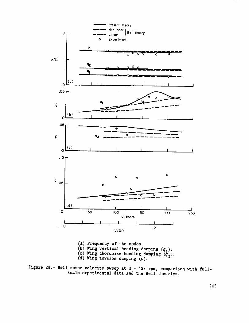
w/D,
2
I -
(a)0
'05Ic I
0
.10 -
q2
q,
"-----'- Present theory
_ Nonlinear}-- -- Linear Bell theory
o Experiment
........ nm_ml
Q ej Q O Q O
..._w w _" _) 0
I I I
I I I
O
q2 e
I I I I I
.O5
o
;Io
(d)
P
o =m" =ram =am ,ram
I I I I50 I00 150 200
V, knots
I I I I I I.5
V/9,R
I250
(a) Frequency of the modes.
(b) Wing vertical bending damping (ql).(c) Wing chordwise bending damping (q2).{d) Wing torsion damping _v).
Figure 28.- Bell rotor velocity sweep at _ = 458 rpm, comparison with full-scale experimental data and the Bell theories.
205

0
Present t heory
_ NonlineorLineor } Bell theory
Experiment
.05
(a) 185 knots I 1
I I.6 .5 .4
V/_R
.05
(b) 162 knots I I
I I I
.05 -
• 5 .4 .3V/D,R
Q
(c) 150 knots
04oo I I50O 6O0
,_, rpm
I I I5 .4 .3
V/,O, RI I I I
5OO 600 700 800I_,R, fps
(a) Wing vertical bending damping (ql) at 185 knots.
(b) Wing vertical bending damping (ql) at 162 knots.
(c) Wing vertical bending damping (ql) at 150 knots.
Figure 29.- Bell rotor rpm sweep, comparison with full-scale experimental data
and Bell theories.
206

.e
\\,,_, "_ --_ m
_ _--- x
121.. Z -.-1W _.)
II,°t
i
E
IO
Iu0o.
/ I/1
! _
_
_ C
? E
O
IOd
Iv
O
O
IO
0..i
'/u_o.
I
o.
Oi O
g
> -
OLID
o.
- OO
OO0d
O_.._"
O
o_
>_
OIf)
OO
CE
>
n._
>
l:io_I_._
_ .
°"_ _
"O _ .,-_ _O ._ "_ _IN"O _.,_
,_,.O
_-_ _.,_ _o o _ o
o _ o __ o_ o
I
o
._-I
oo
o
o
t14 M
o m
o"
o
O
o
,,--4
!
207

.O5
0
-- Present theory
Nonlinear I Bell theory.... Linear I
_ ....0..0 Experiment0
_ _ .,_. _ -C_-'-- O..._.O
ql _ _" _.,..
0
/ . -- --'_---,--_'_..__
( P _ ""0 a)150knotsj i 1 J
0
l I I I I I.9 .7 .5
V/g,R
ql
P
(b) 170 knots I I 1 I0200 300 400 500 600
,Q,, rpm
I I I 1 I I500 400 500 600 700 800
_,R, fps
t I I I I I I1.0 .8 .6 .4
V/,O.R
I.5
(a) Wing vertical bending (ql) and torsion (p) damping at 150 knots.
(b) Wing vertical bending (ql) and torsion (p) damping at 170 knots.
Figure 31.- Bell rotor on quarter-stiffness wing, rpm sweeps; comparison with
full-scale experimental data and with Bell theories.
208

I0
o .5J_
0
-- 0 0
_ theory
r_/O _ /_i • Bell nonlinear
/ / / theory
/ /- , ooo.5 1.0
alBlaa
[ I I0 .5 1.0
aB,c
_'_e,./;%n aa [ I J(a)
0 .5 I.O
aBis
aa
a_Oa
1.0
.58Bis
Theory Experiment / - _
al/_l/a= -- oc_
-a B_s/ aa ---- []
/J/ / / /no /
(b) _____ _.__ / ° I
.5V/_R
I0 1.0
(a) Correlation Detweeli Laeury and experiment.
(b) Variation with inflow ratio Y/_ (flagged symbols are for quarter-stiffnesswing at _ = 229 rpm).
Figure 32.- Bell rotor flapping due to shaft angle of attack; comparison withfull-scale experimental data and Bell theories.
209

.O5
Experiment Theory
0 ' Full stiffness wing• __Quarter stiffness wing
..... Full stiffness wing, no t_lC ' t_lS
///'/. o°
Q 0 /"_ O O
Ca)
_J
2
Full stiffness wing__ Quarter stiffness wing
_(;-I
(b)
ql
0 .5V/,GR
I I1.0
(a) Comparison with _111Lscale experimental data.
(b) Frequency of the modes.
Figure 33.- Bell rotor wing vertical bending (ql) damping, velocity sweeps onfull-stiffness and quarter-stiffness wings.
210

3 --
0
.15
.I0
.O5
B+I
_+I
P B
,8p
q2 f
,8-iql
(a)" I I I I I
_,+I
ql
0 I00
I I0 .5
ql
I I " I I J200 300 400 500 600
V, knots
I J1.0 1.5
V/,O,R
(a) Frequency of the modes.
(b) Damping ratio of the modes.
Figure 34.- Boeing rotor velocity sweep, _ = 386 rpm; predicted eigenvalues.
211

.IO
C
.15,
.IC -
05
//
//
/
\\f3-i
\ f/
\ //
\ /
\\11
/1I\
I \\\\\\\\\
/- /
//
/
i//////
0 IO0 200 30{) 400 500V, knots
J_L
1 1.5L 1.0
.50 V/_,R
60O
(a) Wing vertical bending (ql) and rotor flap (B - I) damping.
(b) Wing chordwise bending (q2) and torsion (P) damping.
Figure 35.- Boeing rotor velocity sweep, _ = 386 rpm; with and withoutand 51S rotor lag motion.
_IC
214

_
oJ
.10 -
.05 -
(b)
0
[0
,B+I
--...-____. _+1
q2
ql
we-I
(o)" I I
/3+1
fr
/3-1
ql
I I I
ql
q2
I I I I II00 200 300 400 500 600
V, knots
1.5
I I.5 1.0
V/_,R
[a) Frequency of the modes.
(b) Damping ratio of the modes.
Figure 34.- Boeing rotor velocity sweep, _ = 386 rpm; predicted eigenvalues.
211

/_+1
q2off I I
I ,I I I I I
-.05 for q I, q2
0
Velocity sweep
Nc_OO OOOoOOOOOO-- (M IO q¢ IO (D
V, knots
= ;Re X
(c) Root locus.
Figure 34.- Continued.
212

,k = -.005 + i.351 V = 250 knots ;k = -.124 + i .;)50
P
q=_B=s
;,s _,c X'_ _:,c
/_lC
= /3_s
X = -.022 + i.334 V = 400 knots k = -.034 + i.292
B=c ,.BIC
-- BIS
X = -.037 + i .343 V = 500 knots X = .004 + i .286
P
r¢;'s
/_lC
= _ls
(;o (;Ic
.Bic
C
" B_s
(d) Boeing rotor at _ = 386 rpm; variation with velocity of predicted
eigenvectors for wing vertical bending (ql) and rotor £1ap (B - 1)modes.
Figure 34.- Concluded.
213

.15 -
.I0 -
.05 -
0
.15
.I0
.05
(a)
Without _lC, _lS / _,/9-1
With _IC,_IS / '_ .I
i T
/ ',,,-
/
/ / \// \
/// \
____ ql 1 I \
I I I t \_ I
(b] I
0 600
- //
//
//
_ //
I///
I I I I "q_I00 200 300 400 500
V, knots
I I I I0 .5 1.0 1.5
V/,Q,R
(a) Wing vertical bending (ql) and rotor flap (B I) damping.
(b) Wing chordwise bending (q2) and torsion (p) damping.
Figure 35.- Boeing rotor velocity sweep, _ = 386 rpm; with and without
and _IS rotor lag motion.
_ic
214

l(C) I I
-.05 for ql, q2' p
I I I0
ImX
Ve loci ty sweep
_o(MOOo0oo00000
V, knots
Without _IC, _;IS
ReX
(C) Root locus.
Figure 35.= Concluded.
215

wing aerodynamics
0
.15
(a)
ql
Powered
wingaerody nomlcs
.10
Basic.
ered
wing aerodynamics
.O5
(b)
0
Paw
No wing aerodynamics
2OO 4OO
V, knots
t I I I
0 .5 1.0 1.5
V/D,R
I600
(a) Wing vertical bending (ql) and rotor flap (8 - I) damping.
(b) Wing chordwise bending (q2) and torsion (p) damping.
Figure 36.- Boeing rotor velocity sweep, _ = 386 rpm; comparison of basic
(autorotation and wing aerodynamics), powered, and no wing aerodynamicscases.
216

.15 -
.10
.O5
(a)
Correct collective _ Complete expressions
-- Approximate / for rotor aerodynamiccol lect ive coeff icients
.... Only CL, ' terms in rotor aerodynamiccoefficients
Powered
ql
Autorotation /
I I
//
//
//
/
//
//
//
/
Autorotation
.15 -
.10 -
.05
(b)
0
I
0
lI00
Autorototion
II
II
II
I PI
/I
Autorotation
Powered ._. q2
I I
200 300 400 500
V, knots
I I I.5 1.0 1.5
V/,Q,R
(a) Wing vertical bending (ql) and rotor flap (8 - 1) damping.(b) Wing chordwise bending (q2) and torsion (p) damping.
Figure 37.- Boeing rotor velocity sweep, a = 386 rpm; influence of the complete
expressions for the rotor aerodynamic coefficients.
217
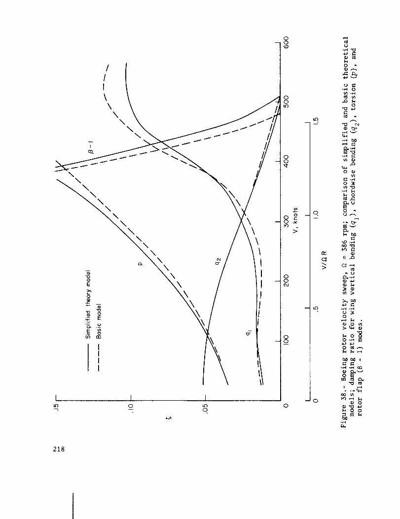
I 1 I
-- -- O
00(,,O
00L_
00
8 °
00o4
00
0
_o.
--0
r_-
>
u
0 ",
_ m
o•_ 4-J
• r"l _-J
m ID
o _m
o _
• ,...i k
o ,,
N'--'
m _
m >
o
>
.l..J .l.ao _ ..---,
• ,-I .,-I (XI
o
_ me-_ ,--_ 1.4
_ o
_ O O
p_u
218

3
I
0
.15
.I0
_ _+_
//3+I
\q2
0
ql
_ _+I
(b) I I V I I I2OO 400 6OO
,0,, rpm
I I I 1.3
I I200
.2V/Q,R
I 1 I I I400 600 800
9,R, fps
.I
(a) Frequency of the modes.
(b) Damping ratio of the modes.
Figure 39.- Boeing rotor rpm sweep, V = 50 knots.
219

_l,O,
.10 -
.05
(b) I I Vl I IO,200 400 600
,Q, rpm
II I I I n L I _ I1.2 1.0 .8 .6 .4
V/,O,R
I I I I I I I2OO 400 600 800
_,R, fps
(a) Frequency of the modes.
(b) Damping ratio of the modes.
Figure 40.- Boeing rotor rpm sweep; V = 192 knots.
220

0
o.
0
0
0
.r.I
0
.,.-4
m
.._ 0
,-q ,._
U C_
t_¢) 0
bSOI=Ln
II
0._ 4-D
e-,._
o mo
o
._
o
ok
°_
o
!
.T't
221

_I,_
3 -
2 -
.10 -
.05 -
(b)
0
I0
B+I
Ouerter stiffness wing
.... Full stiffness wing
,8
,8+1
I II00 200
v, knots
I I 1.5 1.0 1.5
V/Q,R
3OO
(a) Frequency of the modes.
(b) Damping ratio of the modes.
Figure 42.- Boeing rotor velocity sweep, quarter-stiffness wing, _ = 193 rpm.
222

_
_
0
\
q2
I I
.15 -
/_+1
q2
(b) I 71 I I II00 200 :500 400 500
Q,, rpm
I I I I I
1.0.8 .6 .4 .2V/Q,R
I I I II00 300 500 700
Q,, fps
(a) Frequency of the modes.
(b) Damping ratio of the modes.
Figure 43.- Boeing rotor rpm sweep, quarter-stiffness wing, V = 80 knots.
223

o
0
_ i_."0.ii Ii
0_D
+
W oJ
o _._
q _
q
u u _
co
o
o_
\
U
il"iII II
tre)
+
0
ttc
b-
_._
> 0
US_,P
0
+
--to)
ii ii
pr)OJ
+
"r--Ii! ii
o
o'}
<,._.
Ji..-
c_
u
_,)
rr'_
-o
_ i_
"_ I" °
I!
.,< I-,
00
o_
+
ili'0II II
_D{X)
OJ°_
"-:0
,', ,,
0
oO
I!
f,..,
00
II
C_
il
o
_-_
0
o
0
00
0
0
0
!
.M
224

Gr)
--- o
0JkJ_
0
-2
+
or...0
I
II I!
0
c_
¢oto
+
.,.<
0 LL.,n N
T___ C_
¥
o_ .c
LC)
-4-
O0 0
o_I"
U• _ ., il II _
._o\ o _o_ rO
S+
,toII
0
0 "L_']
_..nr"
)-_ngP
0
U
e_
0if)b-
+
,0dI
II It
0o0o'1
+
,qII I|
o--
"0I
II II
0')
.PI
0
"El
oU
I
4
.M
225

81c .I
.O1
I
_IC .I
.01
_I$
I
I
i m
/30 .I--
.O1
I --
ql .I -
.O1
I i IAn
P .I
i R
.O1 I.01 .I I I0
_/D,
q2 -
.01
I_. I I
.I I I0
1 1 I
(a) Vertical gust _G input.
Figure 45.- Boeing rotor in autorotation at V/_R = 0.7 (_ = 386 rpm,
V = 218 knots), magnitude of response of each degree of freedom to
input at frequency _.
226

I --
_)c .I -
_o .I-
ql .I-
P .I --
.01.01
Bis
I
_,s
I 1
_o
.I I IO
.OlI
Io
,/l,.I I
,.d.O.
I ....I I
-- N _Q. Q- + +I ! el" _
(b) Lateral gust 8G input.
Figure 45.- Continued.
227

I m u
_IC °1
.01
[ m
_lC .I
.01
I m
A
_o .J -
.01
ql .I -
.01
I -
P .I
.01.01
,AA.I I
IIO
_IS
_IS
_o
q2
/
I I I
.01 .I I I0
1 I I
T T _ _ _." ¥ ¥
(c) Longitudinal gust u G input.
Figure 45.- Continued.
228

J m
_Ic .I -
_IC .I --
_0 .I--
ql .I -
P .l --
.01.01
i I
I I0_I,Q,
,81s
_o
q2
.01
I
.I I I0
,-I,0,
- e_ _ ,"
(d) Lateral cyclic pitch @IC input.
Figure 45.- Continued.
229

_IC .I
.oi
I
_IC .I
.oi
I --
P .I
.01.01
I
.I I
(e) I
I0
_IS
_Is
q2 -
.oi
I I
.I I I0
I I I
- e_ c_. ,-I I o" _r 4- +
(e) Longitudinal cyclic pitch @
Figure 45.- Continued.
IS input.
230

/_Ic .I
.01
_IC .I -
.01
I
_o .U
.Oi I
ql .I
.01
I
I^ I
P ,I b
.01.01
I _ (f)l
.I I I0_/,0,
/_IS
_IS
_o
q2
I
.01
I I I
.I I_I,0,
II0
I I I
-- O,J _ a.I I O" O" ÷ +
(f) Collective pitch e o input.
Fi£ure 45.= Concluded.
231

I P
.01
I
_IC .I
.01
_IS
_JlS
I --
_0 .I -
.01
I --
ql .I
.01
I --
P .I
.01.01 .I I
_/_
(a) I
I0
q2
.01
i
.I I I0w/ft,
?_ J_ _r g ,L.,_ I_ O..._ "1"
_.n QI.
(a) Vertical gust _G input.
Figure 46.- Boeing rotor in Powered operation at V/_TR = 0.7 (_ = 386 rpm,
V = 218 knots), magnitude of response of each degree of freedom to input
at frequency _.
232

I --
_IC .I
.01
I --
_Ic .I -
.01
I h
_IS
_is
b
_0 .I
.01
I
ql .I
.01
I
P .I
.01.01 .I I
_/_
(b) I
I0
_0
q2
.01 .I
_/_
I I
I I0
(b) Lateral gust _G input.
Figure 46.- Continued.
233

/30 .I -
.01
tlS
l --
(C)l
I I0
p .I
.01.01 .I
_I_
q2
I
.01 ,I I I0_/,_,
__' _-_'
(c) Longitudinal gust u G input.
Figure 46.- Continued.
234

J --
_@lc .I -
_lC .I -
ql .1 -
.01.01
1 I
_lS
I I
I I.I I
L(d)J
I0
q2
D
I
.01 .I I I0o_/,0,
I I
(d) Lateral cyclic pitch @i0 input.
Figure 46.- Continued.
235

,BiG .I
.01
B,=
I
I
_IC °1
.01
_0 .I
.01 i
I -
ql .I -
.01
I n
P .I
.01.01 .I I
_/_,
(el I
I0
q|
J
F
I ,,,,
.01
I
.I 1 I0w/q,
I I I
T T =T _ "_ e. '' '_ 7
(e) Longitudinal cyclic pitch elS input.
Figure 46.- Continued.
236

BIC .I
.01
I
ql .I -
.01
I
P ,I
.01.01
A
.I I
I
! (f)l
I0
q2
l
I
J
.01 .I I_/£/,
II0
T T o: o_,-,',_" ¥ ¥
Cf) Collective pitch O0
Figure 46_- Concluded.
input.
237
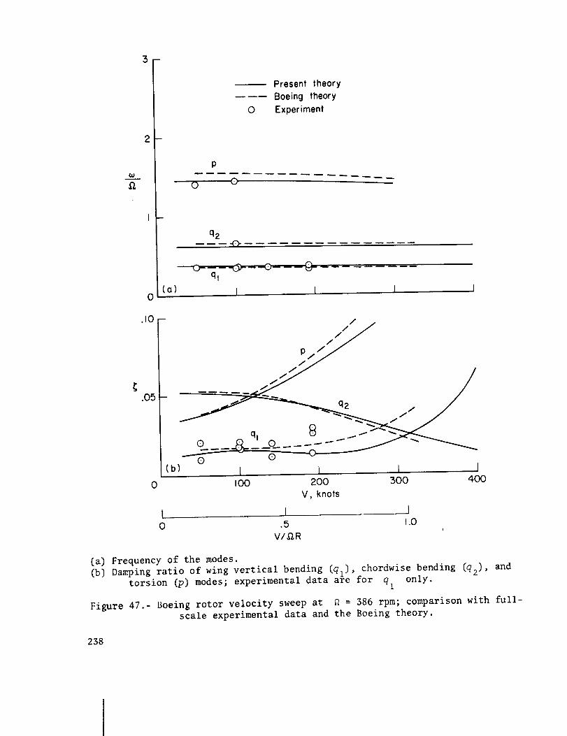
@0
0
0
Present theoryBoeing theory
Experiment
P
0 0
q2
ql
(o) I I I ]
.10 -
0
/
//
o 8 _
Q Q(b) I 1 I I
IO0 200 500 4UO
V, knots
t I J0 .5 1.0
1
V/_R
(a) Frequency of the modes.(b) Damping ratio of wing vertical bending (ql), chordwise bending (q2}, and
torsion (p) modes; experimental data are for qt only.
Figure 47.- Boeing rotor velocity sweep at £ = 386 rpm; comparison with full-scale experimental data and the Boeing theory.
238

.03 -
.02 -
.01
0
060 knotsl E .50 knotsj" xper menT
60 knots
} Present theory50 knots
Boeing theory,60 knots
0
(!) •
...--(o) ;\_i i oil,II ,
//!tI
III
.03
.O2
.01
030O
l4OO
OO 0 o //
4OO
,O,,rpm
I I
500 600
,Q,R, fps
500 600
°%° //- o ,_ //
1(b)lOOknot_ I
\_'7"
Present theory
Boeing theory
0 Experiment
C)
- 0 0\ oo °o /\ ooo o /- \.o ooo ,/_',,, / /
'_'\. 0 0 //_
- E) w
(d) 192 knots
I I I I
:300 400 500 600
Q,, rpm
I I I I I I I
700 800 400 500 600 700 800
_,R, fps
(a) Wing vertical bending damping (ql) at SO and 60 knots.
(b) Wing vertical bending damping (ql) at 100 knots.
(c) Wing vertical bending damping (ql) at 140 knots.
(d) Wing vertical bending damping (ql) at 192 knots.
Figure 48.- Boeing rotor rpm sweep, comparison with full-scale experimental
data and the Boeing theory.
239

O5
0
.O5
©
-- Present theoryBoeing theoryExperiment
.j.- o- _\ 000ql 0 _ _
- \
(o) I t I IX. I
m
(b)I I I
0 50 I00 150 200 250
\\
\\\\
qz _\
V, knots
I I I 10 .5 1.0 1.5
V/,GR
(a) Wing vertical bending damping (q,).
(b) Wing chordwise bending damping (_2).
Figure 49.- Boeing rotor on quarter-stiffness wing, velocity sweep at
= 193 rpm; comparison with full-scale experimental data and the
Boeing theory.
240

.04 --
.02
.0
0
OO O
0
0
Present theory
------ Boeing theory
0 Experiment
o\\\
0
o I
I
I
I I
\
/ \/ \
0 \
/IIIoI
o I I I jI00 200 300 400 500
Q., rpm
I 1 1 1 j200 4 O0 6 O0
•O.R, fps
Figure $0.- Boeing rotor on quarter-stiffness wing, rpm sweep at 80 knots;
comparison with full-scale experimental data and the Boeing theory.wing vertical bending (ql) damping.
_ U.S. UUV_R_VI_NT PRINTING OFFICE: 1974--7_9-i_/i_
241