dvb-t field trials around the world · 1 evaluation of a dvb-t compliant terrestrial television...
TRANSCRIPT

DVB-T Field TrialsAround The World
Prepared by the DVB Project OfficeContributions from the Validate and Motivate Partners,
Facts, Australia & the Singapore Broadcasting AuthorityGeneva, Switzerland
June 1999
INTRODUCTION
Prof. U. Reimers Chairman of the DVB Technical Module
EVALUATION OF A DVB-T COMPLIANT TERRESTRIAL TELEVISION SYSTEM
C. R. Nokes, I.R. Pullen, J.E. Salter BBC R&D, UK.
VALIDATE FIELD TRIALS OF DIGITAL TERRESTRIAL TELEVISION (DVB-T)
Chris Weck Institut für Rundfunktechnik GmbH Rundfunksystementwicklung München, Germany
(Broadcasting Systems Development)
RESULTS OF TESTS WITH DOMESTIC RECEIVER IC’S FOR DVB-T
C.R. Nokes BBC R&D, UK
MOBILE RECEPTION OF 2K AND 8K DVB-T SIGNALS
Erik Stare – Teracom AB Sweden
VALIDATE & MOTIVATE: COLLABORATIVE R&D TO SPEED UP THE LAUNCH OF DIGITALTERRESTRIAL TV
A Oliphant and P. Christ BBC R&D, UK and Deutsche Telekom Berkom, Germany
DTT COVERAGE – PREDICTIONS AND MEASUREMENT
I. R. Pullen (BBC Research and Development, Kingswood Warren)
POTENTIAL BENEFITS OF HIERARCHICAL MODES OF THE DVB-T SPECIFICATION
Chris Nokes, Justin Mitchell BBC R&D, UK
INTRODUCING MOBILE MULTIMEDIA BROADCASTING SERVICES
P. Christ and P. Pogrzeba, Deutsche Telekom Berkom GmbH Germany MOTIVATE partners
SINGLE FREQUENCY NETWORKS FOR DIGITAL VIDEO BROADCASTING
Jesús M. Fernández, J. Capdevila, R. García, S. Cabanillas, S. Mata, A. Mansilla and Jose M. FernándezEngineering R&D - RETEVISION S.A., Spain [email protected]
LAB & FIELD TESTS OF MOBILE APPLICATIONS OF DVB-T
Peter Pogrzeba Deutsche Telekom Berkom Germany [email protected] Ralf Burow DeutscheTelekom Berkom Germany [email protected] Gérard Faria IT IS France [email protected] AndrewOliphant BBC R&D United Kingdom [email protected]
AUSTRALIAN ASSESSMENT OF DTTB
Richard M Barton Facts - Australia
SINGAPORE ANNOUNCES CHOICE OF NATIONAL DIGITAL TELEVISION STANDARD
Singapore Broadcasting Authority

RESULTS OF RF MEASUREMENTS WITH DVB-T CHIP-SET AND COMPARISON WITH ATSCPERFORMANCE
A.P. Robinson and C.R. Nokes, BBC Research & Development
INTRODUCTION
DVB-T, the terrestrial system developed as one member of the family of DVB standards, hasturned from a paper specification into a system which has been introduced in certain countries ofthe world. DVB-T set-top boxes and integrated receivers have been made available in largequantities by several manufacturers. Prior to the formal introduction several companies andresearch consortia have evaluated the performance of DVB-T and have carried out field trials andpilot tests.
This booklet is a compilation of selected papers describing results of such evaluations. Thesepapers were all published between Autumn 1997 and Spring 1999. They come from differentcountries - even from Australia and Singapore - and demonstrate that DVB-T is feasible fordifferent applications. Among the most advanced developments in application scenarios for DVB-Tis the one in which DVB-T is not only used for the supply of services to stationary and portablereceivers but in which mobile receivers in buses, trains and cars are addressed. This example isan impressive proof of the fact that by evaluating the performance limits of DVB-T and by - inparallel to the evaluation - enhancing the performance of tuners, front-ends and signal processingin the receiver we are able and will continue to be able to reach a DVB-T performance which evenexceeds the impressive capabilities which we have experienced so far. There is no doubt that intwo years from now another selection of topical texts will show that what has been documentedhere is by far surpassed by what will become possible during the next 24 months.
It gives me a great pleasure to thank the partners of the two collaborative research projectsVALIDATE and MOTIVATE for the idea and their help in the preparation of this booklet. I wouldalso like to thank FACTS of Australia and the Singapore Broadcasting Authority for theircontribution.
Braunschweig, May 1999
Prof. U. Reimers Chairman of the DVB Technical Module

1
EVALUATION OF A DVB-T COMPLIANT TERRESTRIALTELEVISION SYSTEM
C. R. Nokes, I.R. Pullen, J.E. Salter BBC R&D, UK.
ABSTRACT
The BBC, in common with other UK broadcasters, intends to start digital terrestrial television services in1998. These services will be broadcast according to the DVB-T specification. BBC R&D has conducted aprogramme of laboratory tests and field trials, in preparation for the start of these services. These tests haveverified the suitability of the DVB-T specification, and determined some of the key service planningparameters.
The laboratory tests have shown that modems can be built with a small implementation margin, and that thesystem is rugged against co-channel interference and echoes. They have also determined the protectionratios for existing PAL-I services interfered by DVB-T signals. The field tests have confirmed that the resultsobtained in the laboratory can be achieved in practice, and have shown that actual coverage achieved isgenerally at least as good as computer predictions suggested.
Pullen, J.E. Salter C. R. Noke

INTRODUCTION
The BBC, in common with other UK broadcasters,intends to start digital terrestrial television servicesin 1998. These services will be broadcastaccording to the DVB-T specification, which wasapproved by ETSI (1) earlier this year.
This specification uses orthogonal frequencydivision multiplexing (OFDM) with 1705 carriers(“2K”) or 6817 carriers (“8K”). BBC R&D built thefirst DVB-T compliant modem (a 2K version)which was described by Stott (2). We have usedthis modem to conduct a programme of laboratorytests and field trials. This paper gives the resultsof these tests.
The purpose of this work was to verify the DVB-Tspecification and to determine key parametersrequired for service planning purposes. Some ofthese parameters are best measured underlaboratory conditions, and others must bemeasured in the field because of the lesspredictable conditions of a real channel.
Detailed planning is required to ensure that thenew DVB-T services will have the expectedcoverage and performance, without noticeablydegrading existing PAL-I services. To giveconfidence in the computer prediction tools, somework is presented to compare predicted andmeasured coverage in a few areas.
Results of tests with other DVB-T compliantequipment have been reported by Morello et al (3)and Weck and Schramm (4).
LABORATORY TESTS
The laboratory tests were split into two mainareas:
• Protection ratios for existing PAL-I servicesinterfered by DVB-T
• Verification of modem performance includinginteroperability tests.
The large number of possible parameters thatcould have been varied has meant that only alimited set of tests have been conducted at thetime of writing.
Protection Ratios For Existing PAL-I ServicesInterfered By DVB-T
Co-channel and adjacent channel interferencefrom a DVB-T test source was applied to alaboratory PAL-I transmission system. Out-of-band emissions –intermodulation product (IP)shoulders – from the test transmitter could bevaried. The measured IP shoulder level (seeFigure 1) could be varied over the range -35 to -50 dB or filtered with an 8 pole channel filter.
Picture impairment was assessed by a subjectivecomparison method. A reference condition wasset up by adding white Gaussian noise equivalentto Grade 3.5 according to Oliphant et al (5), to thePAL signal. The interference level was adjusted toproduce a subjectively similar impairment.
Independent assessments were made by twoobservers on three different types of PAL-Ireceiver:
• A Grade 1 measuring receiver (‘Measuring’)• A ‘top of the range’ domestic receiver
(‘NICAM’)
• An inexpensive domestic receiver (‘Portable’)
Initially three different picture sources were used.However, the variation of results was found to bevery small, so rationalisation to using only a testpattern picture source was made.
Degradation to PAL-I FM and NICAM sound wasalso measured but the results are not reportedhere as PAL-I vision was found to require thegreatest protection. No quantitative measurementof the degradation to the generally robust Teletextservice was made.
The frequency offset of the interfering DVB-Tsignal was limited to the co-channel (N) andadjacent channel (N±1) cases, with smaller
OFDMspectrum
IPshoulder
IPshoulder
level
10 MHz
Figure 1 Measurement of IP shoulder level

frequency increments over a ± 250 kHz range forthe latter. Introduction of these frequency offsetsdid not have significant benefit for protection ofPAL-I services.
PAL-I vision protection ratio as a function ofDVB-T IP shoulder level
Measurements were only made with the DVB-Tsignal in the lower adjacent channel (N-1) as thisis the most critical case. Protection ratiomeasurements were made for a variety of out-of-band emission levels from the DVB-T testtransmitter. The results are shown in Figure 2.
This shows that the upper IP shoulder encroachesinto the PAL-I channel causing in-bandinterference. With high levels of IP shoulder thisinterference dominates and the protection ratio isindependent of receiver selectivity. With lowerlevels of IP shoulder the adjacent channelinterference dominates, and so the results aremainly dependent on receiver selectivity.Therefore, much more variation of resultsbetween receivers is seen.
Overall PAL-I vision protection ratiorequirements
The results presented here are for arepresentative DVB-T interfering transmitter with-40 dB IP shoulders removed by an 8 polechannel filter. The protection ratio for pictureimpairments to grade 3.5 was measured for eachreceiver independently by two observers andaveraged. The results are given as column (M’) inTable 1. The degradation law due to DVB-Tinterference is similar in characteristic to that ofGaussian noise, so grades 3 & 4 were deduced.An allowance of +2.0 dB has been made forGrade 4 (‘continuous’-C’) and -1.5 dB for Grade 3(‘tropospheric’-T’) interference.
Interferingdigital signalin channel:
C’ M’ T’
(N-1) –4.4 -6.4 –7.9
(N) 40.2 38.2 36.7(N+1) –6.0 -8 –9.5
Table 1 Protection ratios for wanted analoguesignal in channel N
Verification Of Modem Performance
A laboratory DVB-T 2K transmission system onUHF channel 28 was used throughout these tests.Co-channel interference from a PAL-I test sourceas well as additive white Gaussian noise could beapplied at RF. In addition the RF signal could bedegraded by an RF channel multipath simulator.
The DVB-T data consisted of test data insideMPEG packets. The BBC DVB-T demodulator iscapable of checking the bit error ratio (BER) afterthe Viterbi decoder. The results are presented fordegradation to a BER of 2 x 10⁻⁴ which is theQuasi Error Free (QEF) condition at the output ofthe Reed Solomon decoder. It should be notedthat the slope of the BER curve versus impairmentlevel is impairment dependent. For someimpairments, increasing the level of theimpairment does not quickly bring about a failurecondition.
Performance with Additive White GaussianNoise (AWGN)
The noise level was increased until the QEFcondition was reached, and the noise sourceattenuator setting noted. The carrier-to-noise ratiowas also measured directly by measuring thesignal and noise sources independently with apower meter.
-10
-8
-6
-4
-2
0
2
4
6
8
10
-55 -50 -45 -40 -35 -30
IP Shoulder (dB)
Pro
tect
ion
Rat
io (d
B)
PortableMeasuringNICAM
*
* Note: Values at this level are those for the case of -40 dB shoulders removed by an 8 pole channel filter.
Figure 2 PAL-I protection ratio versus level of IPshoulder from an interfering N-1 DVB-Tsource

These results can be compared with the simulatedfigures in the DVB-T specification (1) - see Figure3. The simulated figures do not take into accountthe implementation margin associated with apractical channel equaliser. The measured resultsare for a demodulator which includes a channelequaliser. Taking this into account, thedemodulator performance is very close to thetheoretical limit.
0
5
10
15
20
25
1/2 2/3 3/4 5/6 7/8 1/2 2/3 3/4 5/6 7/8 1/2 2/3 3/4 5/6 7/8
Measured QEF
Simulated QEF from specification
16-QAMQPSK 64-QAM
Figure 3 Performance with AWGN
Performance with co-channel PAL-Iinterference
The PAL-I vision modulation used throughout was75% EBU colour bars. The FM sound carrier wasmodulated with a 1kHz tone. The NICAM soundcarrier was modulated with PRBS data. The meanpower level of this PAL-I test signal isconveniently -3.0 dB relative to the peak syncreference level.
For different modes and frequency offsets thelevel of PAL-I interference was increased until theQEF condition was achieved. The results areshown in Figure 4.
This shows that the DVB-T system is very robustagainst co-channel interference. The protectionratios observed are in line with the valuesassumed in the UK frequency planning study –see Maddocks et al (6). Note that for some of theQPSK and 16-QAM results the performance islimited by the ability of the modem to synchronisecorrectly under conditions where the power of thein-band unwanted signal is about 10dB greater
than the wanted signal. It is likely thatimprovements to the synchronisation algorithmscould improve these results still further.
-12
-10
-8
-6
-4
-2
0
2
-2500 -1500 -500 500 1500 2500
Nominal frequency offset (Hz)
64 QAM rate 2/3 16 QAM rate 1/2
QPSK rate 1/2
PAL vision carrierand a digital carrier
coincident here
Less robust
More robust
Figure 4 DVB-T carrier to co-channel PAL-Iinterference ratio for QEF
Performance in the presence of a singlemultipath echo
Figure 5 shows the result of tests conducted witha single echo – it shows that the system is robusteven for a 0 dB echo. With 64-QAM rate 2/3, andthe chosen short guard interval, the limit tooperation with a 0 dB echo is the guard intervalduration. With a very rugged code, such as QPSKrate 1/2, the limiting factor is the performance ofthe channel equaliser – and operation with delayssignificantly outside the guard interval is possible.In both cases, for very long echoes, the effect ofthe echo becomes similar to Gaussian noise, and
-20
-16
-12
-8
-4
0
0 10 20 30 40 50 60 70 80 90 100
QPSK rate 1/2 64-QAM rate 2/3
Delay (µs)
Better than QEFin this region
Figure 5 Maximum level of a single echo forQEF, with guard interval 7 µs.
so the curves asymptote to the values from Figure3.
Interoperability Tests
An important part of the testing of the BBCmodem has been to ensure that it is fullycompliant with the DVB-T standard. This has beenchecked as part of the VALIDATE project. Firstly,five different partners’ software simulations of amodulated signal were compared. All fivesimulations agreed exactly. Next, the BBC modemwas checked against this simulation – and wasfound to be identical. Finally, an interoperabilitytest was conducted with the DVB-T modem builtby Thomson Multimedia, CCETT and ITIS as partof the RACE dTTb project (the dTTb “seconddemonstrator”). In this test, it was shown that themodems worked with each other both ways round,for all modes that they operate in, and also withMPEG-2 coded audio and video. A similar testwas conducted between the BBC modem and aDVB-T modem built by DMV, with the sameresults.
The above process has confirmed not only thatthe BBC modem is fully compliant with the DVB-Tstandard, but has also helped to clarifyimplementation pitfalls that could easily be madeunless the standard is carefully applied. Thesewere documented as an Informative Annex to thespecification.
FIELD TRIALS
Transmitter Details
Signals were radiated on UHF Channel 28 fromthe Crystal Palace transmitting station in London,and on UHF Channel 59 from the Pontop Pikestation in the North East of England. Thetransmitting equipment was as previouslydescribed by Oliphant et al (7). Two importantdifferences between the two stations should benoted. First, the channel used at Pontop Pike wasupper adjacent to one of the PAL-I services fromthe same site. This was not the case at CrystalPalace. Second, at Pontop Pike a high-powercombiner was used to combine the digital andPAL-I signals, which were then radiated from the
same antenna. At Crystal Palace a separateantenna was used for the digital signal.
Field-Trials Survey Vehicle
The field trials were carried out using a van whichhad been converted into a digital broadcastingsurvey vehicle by BBC R&D. The vehicle wasequipped with a receiving antenna mounted on a10 metre pneumatic mast. The antenna could berotated through 360 degrees in the horizontalplane in order to point it in the direction of thetransmitter.
The signal from the antenna was fed to afilter/distribution amplifier box. This providedseparate feeds of the received signal for theDVB-T receiver, a field strength measuringreceiver and a spectrum analyser. Power for theequipment was provided by a petrol generatorcarried in a trailer.
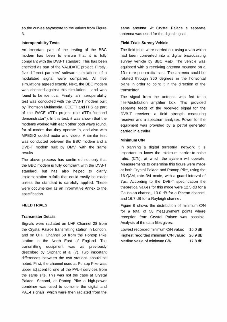
Minimum C/N
In planning a digital terrestrial network it isimportant to know the minimum carrier-to-noiseratio, (C/N), at which the system will operate.Measurements to determine this figure were madeat both Crystal Palace and Pontop Pike, using the16-QAM, rate 3/4 mode, with a guard interval of7µs. According to the DVB-T specification thetheoretical values for this mode were 12.5 dB for aGaussian channel, 13.0 dB for a Ricean channel,and 16.7 dB for a Rayleigh channel.
Figure 6 shows the distribution of minimum C/Nfor a total of 58 measurement points wherereception from Crystal Palace was possible.Analysis of the data files gives:
Lowest recorded minimum C/N value: 15.0 dBHighest recorded minimum C/N value: 26.9 dBMedian value of minimum C/N: 17.8 dB
0
5
10
15
20
14 16 18 20 22 24 26 28
C/N (dB)
Freq
uenc
y
Figure 6 Distribution of minimum C/N measuredat Crystal Palace
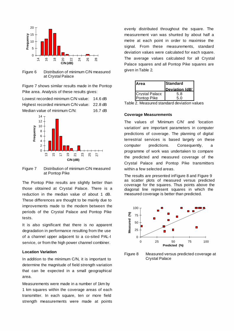
Figure 7 shows similar results made in the PontopPike area. Analysis of these results gives:
Lowest recorded minimum C/N value: 14.6 dBHighest recorded minimum C/N value: 22.8 dBMedian value of minimum C/N: 16.7 dB
02468
101214
13 15 17 19 21 23 25 27
C/N (dB)
Freq
uenc
y
Figure 7 Distribution of minimum C/N measuredat Pontop Pike
The Pontop Pike results are slightly better thanthose obtained at Crystal Palace. There is areduction in the median value of about 1 dB.These differences are thought to be mainly due toimprovements made to the modem between theperiods of the Crystal Palace and Pontop Piketests.
It is also significant that there is no apparentdegradation in performance resulting from the useof a channel upper adjacent to a co-sited PAL-Iservice, or from the high power channel combiner.
Location Variation
In addition to the minimum C/N, it is important todetermine the magnitude of field strength variationthat can be expected in a small geographicalarea.
Measurements were made in a number of 1 km by1 km squares within the coverage areas of eachtransmitter. In each square, ten or more fieldstrength measurements were made at points
evenly distributed throughout the square. Themeasurement van was shunted by about half ametre at each point in order to maximise thesignal. From these measurements, standarddeviation values were calculated for each square.The average values calculated for all CrystalPalace squares and all Pontop Pike squares aregiven in Table 2.
Area StandardDeviation (dB)
Crystal Palace 5.8Pontop Pike 5.0
Table 2. Measured standard deviation values
Coverage Measurements
The values of ‘Minimum C/N’ and ‘locationvariation’ are important parameters in computerpredictions of coverage. The planning of digitalterrestrial services is based largely on thesecomputer predictions. Consequently, aprogramme of work was undertaken to comparethe predicted and measured coverage of theCrystal Palace and Pontop Pike transmitterswithin a few selected areas.
The results are presented in Figure 8 and Figure 9as scatter plots of measured versus predictedcoverage for the squares. Thus points above thediagonal line represent squares in which themeasured coverage is better than predicted.
0
25
50
75
100
0 25 50 75 100Predicted (%)
Mea
sure
d (%
)
Figure 8 Measured versus predicted coverage atCrystal Palace

It is clear that in the majority of squares themeasured coverage is at least as good aspredicted. Though there are some squares inwhich the reverse is true, these are generally inareas where reception conditions are known to bepoor. This is often due to high levels of groundclutter, high-rise buildings etc. Such effects arenotoriously difficult to build into prediction models.In particular, five squares in the Pontop Pikesurvey gave a lower than predicted coveragefigure. These squares were, however, in aparticularly heavily built up industrial area inMiddlesbrough.
Indoor Portable Reception
Portable reception is one of the key advantages ofterrestrial broadcasting over other delivery means.In view of this, some work was undertaken withtwo basic aims:
• To measure the key parameters of buildingpenetration loss, height gain, and locationvariation required for theoretical studies.
• To assess the coverage to set-top antennas atfixed locations in the houses and how thisrelates to the measured field strength outsideat 10 metres.
A total of six residences were measured. Four ofthese were conventional houses, one was a firstfloor maisonette and one was a ground floorconversion flat. All of the buildings were ofconventional brick construction. Measurementswere made in different rooms inside the house. Ingeneral, for a normal two storey house, fourrooms were measured – upstairs and downstairson the sides nearest to and furthest from thetransmitter.
Measurements were made to determine the ratioof the field strength measured outside at 10metres to that measured inside the building. Thisoverall building loss includes both the buildingpenetration loss and height gain. The figure variedbetween about 16 and 29 dB for upstairs rooms,and 19 and 34 dB for downstairs rooms. Theaverage values were 22 dB for upstairs roomsand 29 dB for downstairs rooms.
The standard deviation of the field strengthvariation within a room varied between about 2and 4 dB.
The minimum C/N required for reception inupstairs rooms was, on average, 17 dB, virtuallyidentical to that obtained with a good directionalantenna at 10 metres height. This is clearevidence of the ruggedness of the DVB-T systemunder adverse reception conditions such as thoseencountered inside buildings. For downstairsrooms the average value was about 18 dB for aroom on the side of the house nearest to thetransmitter, and about 21 dB for a room on theopposite side. The increased C/N value requiredin ground floor rooms and rooms on the oppositeside to the transmitter probably reflects theincreased level of multipath propagation.
On the basis of these C/N values thecorresponding minimum field strength values atthe receiving antenna are 42 dB µV/m for upstairsrooms, 44 dBµV/m for a downstairs room on theside nearest to the transmitter, and 46 dB µV/mfor a downstairs room on the opposite side of thehouse.
On average a field strength of 70.5 dB µV/m at10 metres should ensure reception at 90% oflocations within an upstairs room. A field strengthof between 77 dB µV/m and 82 dB µV/m at 10metres would be required to provide similarcoverage to downstairs rooms.
CONCLUSIONS
A programme of laboratory tests and field trialshave been conducted with the BBC’s DVB-Tmodem. This work has confirmed the validity ofthe DVB-T specification and established the key
0
25
50
75
100
0 25 50 75 100Predicted (%)
Mea
sure
d (%
)
Figure 9 Measured versus predicted coverageat Pontop Pike

service planning parameters. The results supportthe values currently being used by the CEPT andin the UK frequency plan (6). Coveragemeasurements indicate that generally thecoverage is at least as good as the planning studysuggested.
REFERENCES
1. European Telecommunication Standard.1997. Digital broadcasting systems for television,sound, and data services; Framing structure,channel coding and modulation for digitalterrestrial television. ETSI specification ETS 300744, European Telecommunications StandardsInstitute, 1997.
2. Stott, J.H. The DVB terrestrial (DVB-T)specification and its implementation in a practicalmodem. International Broadcasting Convention.September, 1996 pp. 255 to 260.
3. Morello, A., Blanchietti, G., Benzi, C. andTabone, M., 1997. Performance assessment of aDVB-T television system. Proceedings of 20thInternational Television Symposium, Montreux.June 1997.
4. Weck, C. and Schramm, R., 1997 ReceivingDVB-T: Results of field trials and coverageconsiderations. Proceedings of 20th InternationalTelevision Symposium, Montreux. June 1997.
5. Oliphant, A., Taylor, K.J. and Misson N. T.,1989. The visibility of noise in System I PALcolour television. Electronics and CommunicationEngineering Journal, Vol 1, No. 3. May/June1989. pp. 139 to 148.
6. Maddocks, M.C.D., Tait, B., Laflin, N.J. andDoel, G. 1996. The plan for digital terrestrialtelevision in the UK. International BroadcastingConvention. September 1996 pp. 172 to 177.
7. Oliphant, A., Marsden, R.P., Poole, R.H.M. andTanton, N.E. 1996. The design of a network fordigital terrestrial TV trials. InternationalBroadcasting Convention. September 1996 pp.242 to 247.
ACKNOWLEDGEMENTS
This work was carried out within the ACTSVALIDATE project, which is supported by theEuropean Commission.
C. R. Nokes, I.R. Pullen, J.E. Salter - BBCR&D, UK.
Proceedings of IBC '97 pp 331-336
VALIDATE FIELD TRIALS OFDIGITAL TERRESTRIAL TELEVISION (DVB-T)
DVB-T-Feldversuche
im Europäischen ACTS-Projekts VALIDATE
Chris WeckInstitut für Rundfunktechnik GmbH Rundfunksystementwicklung München, Germany
(Broadcasting Systems Development)
ABSTRACT
Since the completion of the European specification for digital terrestrial TV broadcasting, DVB-T [1][2], moreequipment has become available and many field trials have been conducted in the framework of the ACTSproject VALIDATE at different sites throughout Europe. This paper gives an overview on these trials andhighlights some interesting results of the various test transmissions and the field work carried out so far.
Results from propagation measurements are summarised for signals from a single transmitter or fromseveral transmitters, either by using gap-fillers, which work as on-channel repeaters, or explicitly within asingle frequency network (SFN). Both outdoor and indoor reception are examined. Building penetrationlosses have been recorded and there is a brief report on the influence of a domestic gap-filler to improve theportable indoor reception within buildings.
Results on the system performance for different COFDM modes of the DVB-T system evaluated in the fieldare outlined for fixed as well as for portable reception and the possibilities for mobile reception areinvestigated, too. A few results are also available of the measured coverage probability in comparison to theservice areas as predicted by computer simulations.
ZUSAMMENFASSUNG
Seit der Festschreibung der Spezifikation für digitales terrestrisches Fernsehen, DVB-T, sind vermehrt DVB-T-Übertragungsgeräte verfügbar geworden und es wurden europaweit im Rahmen des ACTS-ProjektsVALIDATE viele Feldversuche durchgeführt. Ausgehend von einer Übersicht faßt der Vortrag die bisherigen,wichtigsten Ergebnisse der Unterarbeitsgruppe Feldversuche zusammen: Es handelt sich unter anderem umAusbreitungsmessungen mit einem DVB-T-Signal von einem einzelnen Sender oder auch von mehrerenGleichwellensendern, wobei auch Füllsender betrachtet werden, die auf der gleichen Sendefrequenz emp-fangen und abstrahlen. Es wird sowohl der Empfang innerhalb und außerhalb von Gebäuden betrachtet undeine Möglichkeit untersucht, den portablen Empfang in Räumen trotz hoher Gebäudedämpfungen zuverbessern. Die Leistungsfähigkeit des DVB-T-Übertragungssystems wurde bei gerichtetem undungerichtetem Empfang untersucht. Einige Erfahrungen liegen auch schon für den mobilen Empfang vonDVB-T vor. Die Ergebnisse werden für verschiedene Übertragungsparameter der DVB-T-Spezifikationdargestellt. Erste Aussagen über den Vergleich der geplanten mit einer gemessenen DVB-T-Versorgungsfläche bestätigen die hohe Leistungsfähigkeit des Übertragungssystems.
1 INTRODUCTION
VALIDATE stands for ‘Verification And Launch of Integrated Digital Advanced Television in Europe’. It is oneof the ACTS projects, sponsored by the European Commission in the fourth Framework Programme‘Advanced Communication Technologies and Services’. The project VALIDATE [3], led by the BBC as primecontractor, started work in late 1995 and aims to verify the European DVB-T standard for digital terrestrialtelevision broadcasting and to prepare for the launch of services. There are 19 partners in nine Europeancountries, representatives from several broadcasters including broadcasting research centres and theEuropean Broadcasting Union (EBU) as well as telecom and network operators and professional andconsumer manufacturers. A detailed list of partners can be found together with the bibliographical referencesat the end of his paper.
In VALIDATE, first computer simulations and laboratory tests and later field trials were performed in variouslaboratories and from several transmitter sites all over Europe. In two VALIDATE task forces, the meas-urement procedures for lab tests and field trials were agreed and the measurement results were exchangedand compared in order to verify the specification and to achieve reliable planning parameters for future DVB-T services.
This report gives an overview of the extensive field work and demonstrations carried out in the VALIDATEproject so far. The following list shows the sites for DVB-T field trials already existing in the project:
• United Kingdom, BBC, London area and North East of England
• France, CCETT, Rennes
• France, TDF, Metz
• Germany, Deutsche Telekom & TBerkom, Cologne and Berlin
• Germany, IRT, Munich
• Spain, Retevision, Madrid
• Italy, RAI, Torino
• Denmark, TeleDanmark
• Sweden, Teracom, Stockholm
• Ireland, RTE, Dublin
• The Netherlands, NOZEMA
Further transmitting sites and DVB-T pilot services are in preparation.
2 SCOPE OF FIELD TRIALS
The scope of field trials in VALIDATE is to confirm the extensive range of laboratory results and toinvestigate fully the overall performance of the DVB-T system for various transmission modes and variousreception conditions, where the received signal is likely to suffer a combination of propagation and receptionimpairments that would be difficult to estimate in the laboratory.
Furthermore, field trials are required to answer questions of service planning, that is to evaluate the coverageprobability for the different structures of transmitter networks and to investigate the different kinds ofdistortions of the transmission channel. Sufficient representative field-trial data has to be acquired to improvethe accuracy of the values adopted for critical planning parameters (e.g. minimum field-strength and C/N,protection ratios, etc.) used within service prediction models. Investigation of the stability / reproducibility ofmeasurements made at any given site over a period of time and under potentially different propagation and

reception conditions (including the possible effects of periodic changes in climatic or atmospheric conditions)are still going on.
3 DVB-T SPECIFICATION
In the development and definition phase of the European DVB-T specification [4], the advantages of themulticarrier modulation outweighed those of the single-carrier methods in terms of broadcastingrequirements (as it was likewise the case with EUREKA 147 DAB for digital sound broadcasting). The crucialfactor in favour of the chosen COFDM method (Coded Orthogonal Frequency Division Multiplex) [5] is theability to cope with strong echoes due to multipath propagation and the capability to set up single-frequencynetworks (SFNs), which offer network planners a higher network efficiency [6][7][8].
The specified DVB-T system offers a wide range of potential applications: conventional multi-frequency net-works (MFNs), i.e. single transmitter applications, prohibited (”taboo”) channel operation, etc. and single-fre-quency networks (SFNs). The service can be dedicated to stationary or portable reception or both usinghierarchical transmission. The network operator can select technical parameters such as the number ofOFDM carriers, the length of the guard interval (this is a cyclic continuation of the useful OFDM symbol), thedegree of error protection and the modulation method. The last two parameters in particular allow theoperator to reach an individual compromise between the number of programmes carried and theirtransmission reliability.
The transmitting system provides an MPEG-2 transport mechanism, a kind of data container whose sizedepends on the chosen transmission parameters (transmission mode). It allows for full flexibility with respectto the number of transmitted programmes, the content of any digital information or the kind of digital services(e.g. HDTV to LDTV, surround sound, data etc.).
The following transmission pa7rameters can be selected:
• BANDWIDTH: 8 MHz, 7 MHz, 6 MHz• MODULATION: 4-PSK, 16-QAM, 64-QAM• HIERARCHY: 4-PSK in 16-QAM or in 64-QAM• CARRIERS: 6817 (8K-FFT), 1705 (2K-FFT)
SPACING: 1116 Hz (8K), 4464 Hz (2K)• USEFUL SYMBOL
DURATION: 896 ?s (8K), 224 ?s (2K)• GUARD INTERVAL: 1/4, 1/8, 1/16, 1/32
DURATION: 224, 112, 56, 28, 14, 7 ?s• INNER CODE RATE: 1/2, 2/3, 3/4, 5/6, 7/8
The latter refers to the error protection of the inner convolutional code. Together with the outer error-correction code (RS 204,188) and the overhead for pilot carriers a spectrum efficiency of 0.65 to4.2 bit/Hzbandwidth can be achieved. For example in an 8 MHz TV channel, useful data rates from 4.98 to31.67 Mbit/s can be transmitted.
4 PROPAGATION MEASUREMENTS
In comparison to analogue television signals, which behave like narrow-band signals because of the singlevideo carrier, the DVB-T signal is a wide-band signal where the energy is distributed over a large number ofcarriers in the radio channel. The first issue for investigation was the received field strength at any receptionpoint and the statistics of the location variation.

Some results for signals from a single transmitter are given in Table 1. The bulk of distribution functions ofthe received field strength for different test routes was following a log-normal law. Measurements of theCCETT showed that the standard deviation of an analogue TV signal transmitted from the same tower is 0.1to 0.4 dB higher than the one of the digital signal [16].
Location Terrain Class Standard Deviation / dB
fast fading slowfading
combined
TERACOM, Stockholm, Sweden open fieldforestsuburbanurban
1.72.62.32.2
2.7
3.33.22.5
3.34.44.13.3
CCETT, Rennes, France ruralsuburbanurban
2.53.33.9
BBC, London, UK ruralurban
2.54.0
Deutsche Telekom, Berlin, D suburban 3.3
Table 1: Location variation of field strength
for various locations and receiving conditions
Location Terrain Class Margin for 50 % to 99 % coveredlocations
analogue TV digital TV
CCETT, Rennes, France ruralsuburbanurban
11.7 dB16.0 dB16.7 dB
9.7 dB12.0 dB11.8 dB
Table 2: Margin for the increase from
50 % to 99 % coverage
It is well known that, in contrast to analogue services, there is a very rapid degradation of a digitaltransmission system at the fringe of the coverage area. For DVB-T the margin in a Gaussian channelbetween the onset of impairment and the failure point is only about 1 – 2 dB, in a Rayleigh channel it can bemuch more, due to fading effects. Therefore, it is not sufficient to consider the median value of the fieldstrength for coverage considerations, but to introduce a margin from e.g. 50 % to 99% of the coveredlocations. For analogue TV systems this margin was in the order of 16 dB. Latest results from CCETT [16]given in Table 2 show that there is a distinct lower margin necessary for the digital system than for theanalogue one. This result relaxes the power requirements for DVB-T.
4.1 Single Frequency Network Gain
Conventional networks use individual radio frequencies for each transmitter (MFN: multi-frequency network)to avoid mutual interference. One programme transmitted within a network occupies therefore a set of radiofrequencies. Now, the great advantage of the DVB-T transmission system is that a large area may be

covered by transmitters working all on the same radio frequency, provided the relevant signals from varioustransmitters arrive at a reception point within the duration of the guard interval.
Such single-frequency network (SFN) has important advantages for network planning. The frequencyefficiency of large SFNs can be up to 4 times higher than for MFNs. Furthermore, the power efficiency of anSFN is better, because the coverage probability at a reception location is increased owing to the signaldiversity of the different propagation paths.
Measurements of the Deutsche Telekom in Berlin in a SFN with 3 transmitters showed that the standarddeviation of the received power is about 2.6 dB compared to 3.3 dB for the signal from a single transmitter.Especially, if the coverage probability in the middle between transmitters is considered, where thecontribution of the main signal paths is usually in the same order and rather low, there is observed a highdiversity gain in an SFN. For example, the SFN gain was found at such locations to be in the order of 4 –6 dB (considering a value of 90 % for the coverage probability). Further measurements are still necessary toachieve more statistical results.
4.2 Professional gap-filler
One additional advantage of SFNs to be mentioned is, that every gap within a coverage area can be coveredby using active deflectors working on the same single frequency, so-called professional gap-fillers. There willbe in principal no physical, but may be a financial limitation to cover an area up to 100 % with such devices.
A prototype of a professional gap-filler for application in real SFNs was developed in the framework ofVALIDATE by Mier Communicaciones, Spain. First field trials were performed in Berlin in co-operation withDeutsche Telekom, where the gap-filler received the DVB-T signal from a tower at 21 km distance. Thesignal was then retransmitted with a power of 100 W ERP to cover the city of Potsdam, which is about 26 kmaway from the main transmitter and shadowed by hills. The trial was very successful. A very high antennaisolation of up to 105 dB was achieved between receiving and transmitting antenna. Further improvement isexpected during the optimisation of the prototype.
4.3 Single Frequency Network Synchronisation
It is evident that the individual transmitters of a SFN have to transmit each single bit exactly in the samemanner and at the same time. This is a minor problem if the broadcast signal is retransmitted directly or afterfrequency transformation. But in general the MPEG transport stream may be send through different digitallinks to each transmitter and it becomes essential to synchronise the modulation procedures of all individualtransmitters.
VALIDATE investigated this problem in detail and supported the specification process for synchronisingSFNs. A synchronisation device for DVB-T modems was developed by ITIS [8] and was successfully testedby RTE and ITIS in Dublin, Ireland, in November 1997 using two transmitters. It was the first SFN operationbased on a real primary distribution network as described by the SFN-DS specification [17]. Thesynchronisation is based on a central SFN adapter inserting Mega-frame Initialisation Packets (MIP) into theMPEG2-TS with GPS time information. At each transmitter site the MPEG2-TS, e.g. from a 34 Mbps PDHlink is modulated in a synchronous mega frame according to the local GPS time.
5 INDOOR PROPAGATION MEASUREMENTS
The field-strength distribution within buildings is very important for portable receivers using very small indoorantennas or poor whip antennas. To estimate the service coverage, measurements were made at a numberof locations within office buildings and within a sample of domestic dwellings where set-top reception onportable receivers would typically be required (e.g. living room, kitchen, bedroom). The field strength wasfound to be log-normally distributed with standard deviations given in Table 3. The value of the standard

deviations in rooms in direction to the transmitter was about 0.5 – 0.6 dB higher than the value for rooms atthe opposite side of the house. For comparison, measurements of signals with lower bandwidth wereperformed, too. This was a DAB signal with 1.5 MHz bandwidth and an analogue carrier with 120 KHzbandwidth.
Location Standard Deviation
BBC, London, UK (within one room)
2.8 dB2.4 – 3.2 dB
CCETT, TDF, Rennes, France 2 dB
TERACOM, Stockholm, Sweden 3.2 dB
IRT (1.5 MHz bandwidth)*
(120 KHz bandwith)*3.5 dB5.5 dB
Table 3: Location variation within rooms
( * not DVB-T, for comparison only)
Investigations of the time variance of the signal due to moving people in the room showed a log-normaldistribution, too. The standard deviation was about 1 dB. However it must be pointed out that very deepfades corresponding to a total shadowing of the receiving antenna are not taken into account by such astandard deviation. Such fades are usually caused by somebody coming very close to the antenna and arenot to be considered as a normal condition of reception.
5.1 Building penetration loss and building loss
The indoor measurements in conjunction with outdoor measurements at the same site allow accurate valuesfor the building penetration losses to be determined for use in service planning models for portable reception.
Two different questions can be distinguished: What is the loss between outdoor and indoor reception ofDVB-T based on the same antenna height (e.g. field strength outside the window), which is here referred toas the building penetration loss, and what is the loss, compared to the traditional roof-top antenna, which ishere referred to as building loss. The results given in Table 4 indicate that the height loss is a very significantpart of the building loss, were the building penetration loss itself is in average lower than 10 dB.
Location Average Building Penetration Loss
IRT, Munich, Germany 8.5 – 9.1 dB (VHF)7.0 – 8.5 dB (UHF)
TERACOM, Stockholm, Sweden 6.4 dB (UHF)(standard deviation 3.6 dB)
Location Building Loss (incl. height loss)
BBC, London, UK 21 – 23 dB (1st floor, UHF)28 – 30 dB (ground floor, UHF)
CCETT, TDF,Rennes, France
10 – 17 dB (individual house)
Table 4: Building penetration loss and building loss
for various locations and receiving conditions

5.2 Domestic gap-fillers
As portable reception is one of the chief advantages for DVB-T compared to satellite and cable transmissionsystems. VALIDATE investigated solutions to increase the field strength in buildings by using domestic gap-fillers, which work as on-channel repeaters inside buildings. Two different prototypes, differing in size andcost, were developed by Televés, Spain. One working as broadband device and the other amplifying threeselected channels.
The first trials performed by Retevision and BBC of indoor reception of DVB-T using domestic gap-fillers vali-dated this concept and were very encouraging. Real off-air signals received by a directional roof-top antennaor derived from a MATV system were rebroadcast in domestic houses and in a very hostile laboratoryenvironment. An omnidirectional antenna or a small yagi antenna was used in the centre or in a corner of ahouse, respectively. An output of less than 250 µW from the domestic gap-filler was found to be sufficient fora set-top reception of DVB-T with 64-QAM in every room of a residential building. Detailed measurement arestill going on at the BBC and have now been started at other VALIDATE test sites.
6 SERVICE COVERAGE MEASUREMENTS
Since propagation measurements merely consider the received power they do not take into account theproperties of the DVB-T system. This means that the question whether one location is covered depends notonly on the received power, but on the fact whether the receiver is really able to provide an error-freereception of the sound and picture or not. Therefore, the individual performance of the receiver, the chosentechnical parameters like modulation and channel coding as well as the type of transmission channel have tobe considered in detail.
The determination of the service coverage at any location can be based on the picture quality itself or on realbit-error ratio measurements (BER). A BER of 2⋅10-4 after the Viterbi decoder (inner code) was adopted asone reference value corresponding to quasi error-free (QEF) operation after the outer Reed SolomonRS (204,188) decoder. The BER after Viterbi allows for more accuracy of the results than the BER after theReed-Solomon error protection, which would be available on the MPEG transport-stream level. This QEFoperation generally corresponds to a criterion based on an period of at least 30 seconds, where no picture orsound impairments occur. Concentrated errors usually are visible and audible if the signal-to-noise ratio C/Nfor 2⋅10-4 is reduced further by about 1 dB, corresponding to a BER of more than 10-3 after Viterbi decoding.
In the DVB-T specification [1] there are figures available for the required C/N for all transmission modes toachieve a BER of 2⋅10-4. These Figures are based on simulation results for three types of transmissionchannels, but without taking any implementation margin into account:
• Gaussian channeldirect sight, no multipath, laboratory condition
• Rice channel (k = 10 dB)for stationary reception using directional antennas
• Rayleigh channelfor portable reception using omnidirectional antennas
The transmission channel in the field is usually an intermediate type between a Gaussian and a Rayleighchannel. Therefore, the required C/N or the required signal power, respectively, to achieve BER 2⋅10-4 will bedifferent at different receiving locations. This fact is actually shown by the BER curves measured at differenttest locations in Munich [13]. Each of Figure to Figure 6 shows the BER behaviour after Viterbi decoding of achosen transmission mode at about 15 different receiving locations versus the receiver input power. Threemodulation modes were examined in the field:

• 64 QAM, code rate R = 2/3, guard interval GI = 1/8, 8k-FFT• 16 QAM, code rate R = 3/4, guard interval GI = 1/32, 8k-FFT• QPSK, code rate R = 1/2, guard interval GI = 1/4, 8k-FFT.
The results are given for stationary reception (directional antenna at 10 m height) as well as for portablereception (omnidirectional antenna at 1.5 m height). The continual curves of the BER show that the results inthe field are reliable and stable, which is important for the validation of the DVB-T specification.

-82 -81 -80 -79 -78 -77 -76 -75 -74 -73 -72Receiver input power / dBm
1E-006
1E-005
0.0001
0.001
0.01
0.1
Bit-
erro
r ra
tio
x x x
Figure 1: BER versus receiver input powermodulation: 64 QAM, R 2/3, GI 1/8, 8k FFTdirectional antenna height 10 m above ground
-82 -80 -78 -76 -74 -72 -70
Receiver input power / dBm
1E-006
1E-005
0.0001
0.001
0.01
0.1
Bit-
erro
r ra
tio
x x x
Figure 2: BER versus receiver input powermodulation: 64 QAM, R 2/3, GI 1/8, 8k FFTomnidirectional antenna height 1.5 m above ground
-88 -86 -84 -82 -80 -78Receiver input power / dBm
1E-007
1E-006
1E-005
0.0001
0.001
0.01
0.1
Bit-
erro
r ra
tio
x xx
Figure 3: BER versus receiver input powermodulation: 16 QAM, R 3/4, GI 1/32, 8k FFTdirectional antenna height 10 m above ground
-86 -85 -84 -83 -82 -81 -80 -79 -78 -77 -76Receiver input power / dBm
1E-007
1E-006
1E-005
0.0001
0.001
0.01
0.1B
it-er
ror
ratio
xx x
Figure 4: BER versus receiver input powermodulation: 16 QAM, R 3/4, GI 1/32, 8k FFTomnidirectional antenna height 1.5 m above ground
-95 -94 -93 -92 -91 -90 -89 -88 -87 -86 -85Receiver input power / dBm
1E-007
1E-006
1E-005
0.0001
0.001
0.01
0.1
Bit-
erro
r ra
tio
xxx
Figure 5: BER versus receiver input powermodulation: QPSK, R 1/2, GI ¼, 8k FFTdirectional antenna height 10 m above ground
-95 -94 -93 -92 -91 -90 -89 -88 -87 -86 -85Receiver input power / dBm
1E-007
1E-006
1E-005
0.0001
0.001
0.01
0.1
Bit-
erro
r ra
tio
x x x
Figure 6: BER versus receiver input powermodulation: QPSK, R 1/2, GI ¼, 8k FFTomnidirectional antenna height 1.5 m above ground

Figure 1 to Figure 6 can be used to determine the required receiver input power (abscissa) to achieve aquasi error-free reception, which is indicated in the figures by a horizontal broken line at BER of 2⋅10-4. Thisvalue is of great interest for planning DVB-T services. But for the verification of the DVB system, the mostimportant parameter is actually the required C/N value in comparison to the theoretical C/N values given inthe DVB-T specification.
In the real transmission channel C/N can be determined based on of the equivalent noise figure of thereceiver and the actual signal power received. The receiver noise figure in these tests was about 8 dBcorresponding to a noise floor of –97 dBm with an accuracy of about ±1 dB (receivers may have noisefigures as low as 5 dB). Based on this figure the actual C/N value can be estimated at each receptionlocation. For comparison, the theoretical C/N values for the three types of transmission channel are indicatedwith a cross on the horizontal broken line in the figures (from left to right: Gauss, Rice and Rayleigh channel).The C/N evaluation, which should be considered as indicative only, allows nevertheless the conclusion thatthe implementation margin of the receiver in the field is rather low: 1.5 – 3 dB in addition to the theoreticalvalue for a Gaussian or Rayleigh channel, respectively. This value was confirmed by measurements ofDeutsche Telekom in Berlin.
6.1 Comparison with service prediction
The planning of digital terrestrial services is based largely on computer predictions. Consequently, it isimportant to determine how well these predictions compare with the coverage obtained by measurementswith real DVB-T equipment.
The tests in Munich considered above showed a good accordance with the prediction, but only few results ofmeasurements were available for a statistical analysis.
More extensive surveys have been conducted by the BBC in both the London area and in the North East ofEngland to measure the percentage of coverage within a number of 1 km by 1 km squares. Only squareswith a marginal level of coverage were considered. They were selected with respect to initial results of acoverage prediction using a computer propagation model. Measurements were made at 10 to 15 randomlychosen test points within each square to determine the percentage of these points at which reception wasachieved. These results were compared with the predictions made using the methods adopted during the UKplanning study. In 80% of the squares the coverage was better than predicted. Most of the areas, where themeasured coverage was not as good as predicted, were known to suffer poor analogue reception. This wasgenerally due to tall buildings which were not considered by the propagation model. Other areas which werepredicted to be only marginally served were in fact completely covered. In conclusion, the measuredcoverage was found to be rather better than predicted.
6.2 Mobile reception of DVB-T
Even though the DVB-T standard was not developed for mobile reception there were very encouragingresults of initial field trials performed by Deutsche Telekom in Cologne. The tests in UHF channel 40(626 MHz) showed, especially if the QPSK mode, R=1/2, 2K-FFT, is chosen, no reception loss due to themovement of the receiver. The tested speed was 170 km/h. It may have been advantageous receptionconditions, because any failure of the system did occur at locations where the field strength was notsufficient at all. Tests with 16-QAM at a speed of 60 km/h were successful, too, but further investigation arerequired.
Especially, in the follow-on project of VALIDATE, which is named MOTIVATE, more tests (not only 2K-FFT)will be performed and the receiver and the channel estimation will be optimised for mobile reception of DVB-T.

7 DEMONSTRATIONS
Most of the VALIDATE trials conducted were combined with various professional and public demonstrationsof the performance of DVB-T.
Since May 1996 the BBC performed public DVB-T demonstrations in the London area and the North ofEngland using a fully DVB-T compliant 2K-FFT modem developed by them. This modem was also used todemonstrate DVB-T at IBC’96 and at DBC’96 in the Netherlands. The first public demonstration using the8K-FFT modem developed in the European Race project dTTb (digital Terrestrial Television broadcasting)took place in Munich in January 1997.
Further demonstrations in 1997 with either 2K-FFT or 8K-FFT modems were performed or supported byVALIDATE partners, respectively, in Berlin, Cologne and Munich (D), Madrid (E), ITVS’97 Montreux (CH),Sutton Coldfield (UK) and at IBC’97 Amsterdam (NL).
At the Internationale Funkausstellung Berlin (IFA’97) three UHF channels were used to transmit a total of8 TV programmes and one DVB data service. Stationary reception from two different transmitters wasdemonstrated by Deutsche Telekom. Portable reception of one programme was demonstrated by the IRT aswell as mobile reception in a bus and a car. The high reception quality of DVB-T when using a whip antennasmaller than a pencil in a very hostile environment, especially in comparison to analogue TV reception, washighly convincing.
8 CONCLUSION
The VALIDATE project has verified the very complex European specification for digital terrestrialbroadcasting DVB-T. A notable amount of field trials have been conducted so far and unambiguously provedthe results of laboratory tests and computer simulations.
Propagation measurements performed outdoor as well as indoor showed clear benefits of the broadbandDVB-T signal. The performance for stationary and portable reception in the field was as good as expected oreven better in terms of C/N. Different modulation modes and channel coding rates were tested and theresults confirmed predictions from simulation.
The field trials demonstrated the performance of DVB-T, the operation of a SFN, the concept of gap-fillersand the possibility of mobile reception. Under comparable poor receiving conditions the quality of DVB-T wasfound to be greatly superior to the analogue reception of TV.
9 ACKNOWLEDGEMENTS
The Author would like to thank all partners of the VALIDATE project for the contributions to the field workdescribed in this paper.
The support of this project by the European Commission under AC106 is acknowledged as well.Furthermore, VALIDATE has relied heavily on the work done in earlier collaborative projects including theEuropean RACE project dTTb, the Nordic HD-Divine project, and the German HDTVT project.
10 VALIDATE PARTNERS
British Broadcasting Corporation (BBC) UKRobert Bosch GmbH (Bosch) DCentre Commun d’Etudes de Télédiffusion et Télécommunications (CCETT) FDeutsche Telekom AG (Telekom) DDeutsche Thomson Brandt GmbH (DTB) D

Institut für Rundfunktechnik GmbH (IRT) DInnovations Télécommunications Image Son (ITIS) FMier Comunicaciones (MIER) ERadio Telefís Éireann (RTE) IRLRai Radiotelevisione Italiana (RAI) IRetevisión ERohde & Schwarz GmbH & Co KG (R&S) DTélédiffusion de France (TDF) FTele Danmark AS DKTelevés SA ETeracom Svensk Rundradion AB (Teracom) SThomcast FEuropean Broadcasting Union (EBU)Nederlandsche Omroep Zendermaatschappij (NOZEMA) NL
11 REFERENCES
[1] ETS 300 744: Digital broadcasting systems for television, sound and data services; framing structure,channel coding and modulation for digital terrestrial television (February 1997).
[2] Møller, L.G.: COFDM and the choice of parameters for DVB-T. (20th International Television Sympo-sium, Montreux. 1997) Record Cable/Satellite/ Terrestrial pp. 207–280.
[3] Oliphant, A.: VALIDATE - Verifying the European specification for digital terrestrial TV and preparing forthe launch of services (Proceedings of 20th International Television Symposium, Montreux 1997)Record Cable/Satellite/Terrestrial pp. 319–327.
[4] De Bot, P.G.M., Le Floch, B., Mignone, V., Schütte, H.-D.: An Overview of the Modulation and ChannelCoding Schemes Developed for Digital Terrestrial Television Broadcastion within the dTTb Project (May1994, IBC 1994)
[5] Alard, M., Lassalle, R.: Principles of Modulation and Channel Coding for Digital Broadcasting for MobileReceivers (EBU Review, No. 224, August 1987) pp. 168-190
[6] Weck, C.: Coverage aspects of digital terrestrial television broadcasting (EBU Technical Review, No.270, Winter 1996).
[7] Mignone, V. et al. (RAI): An advanced algorithm for improving DVB-T coverage in SFN (InternationalBroadcasting Convention, Amsterdam, September 1996).
[8] Faria, G. (ITIS): Single frequency network (SFN) for DVB-T and DAB (20th International TelevisionSymposium, Montreux. 1997) Record Cable/Satellite/Terrestrial pp. 654–671. ).
[9] Stott, J.H. (BBC): The DVB terrestrial (DVB-T) specification and its implementation in a practicalmodem (Proceedings of the 1996 International Broadcasting Convention, Amsterdam, September 1996,IEE Conference Publication No. 428, pp 255-260)
[10] Oliphant, A. et al. (BBC): The design of a network for digital terrestrial TV trials (International Broad-casting Convention, Amsterdam, September 1996).
[11] Morello, A., Blanchietti, G., Benzi, C., Sacco, B., and Tabone, M.: Performance assessment of a DVB-Ttelevision system. (20th International Television Symposium, Montreux 1997) RecordCable/Satellite/Terrestrial pp. 298–310.
[12] Stott, J.H.: Explaining some of the magic of COFDM. (20th International Television Symposium,Montreux. 1997) Record Cable/Satellite/Terrestrial pp. 341–350.
[13] Weck, C., Schramm, R. (IRT): Receiving DVB-T : results of field trials and coverage considerations(20th International Television Symposium, Montreux. 1997) Record Cable/Satellite/Terrestrial pp. 351–360.
[14] Cañizares, P., Torres, J.L., Martinez, J.A. (Retevision): VIDITER: Spanish experience on DTT (20thInternational Television Symposium, Montreux. 1997) Record Cable/Satellite/Terrestrial pp. 219–224.
[15] Nokes, C. et al. (BBC): Evaluation of a DVB-T compliant digital terrestrial television system (Interna-tional Broadcasting Convention, Amsterdam, September 1997).
[16] Gaudrel, R., Betend, C.: DIGITAL TV BROADCAST Field Trials on the Experimental Network ofRennes (internal VALIDATE document from CCETT, FT.CNET/DMR/DDH, November 1997).
[17] Draft EN 301 191: Digital Video Broadcasting (DVB); DVB mega-frame for Single Frequency Network(SFN) synchronisation (European Telecommunications Standards Institute, Feb. 1997). Chris Weck -
Institüt für Rundfunkteknik GmbH
Proceedings of NAB '98

RESULTS OF TESTS WITH DOMESTIC RECEIVER IC’S FORDVB-T
C.R. Nokes BBC R&D, UK
ABSTRACT
Digital terrestrial television services using the DVB-T standard will be launched later this year in the UK,followed by Sweden and perhaps other countries soon afterwards. Reception of these services will make useof domestic set-top boxes and integrated receivers using DVB-T demodulator ICs (integrated circuits). Thefirst of these ICs are now becoming available, and it is important that their performance is carefully checked,to confirm that the behaviour is close to expectations. This in turn will confirm that the planned DVB-Tservices will deliver the predicted coverage.
At the time of writing this paper, BBC R&D is testing the first two receiver ICs which have become available.The results of these tests show that working silicon is available and that the ICs generally provideperformance in excess of that assumed by the frequency planners. This will allow set-top box and receivermanufacturers to prepare their production for the launch of operational digital terrestrial television serviceslater this year.
Televisionreceiver
MPEG-2decoder
DVB-Tdemodulator
ADCRF down-converter

INTRODUCTION
BBC R&D reported at IBC ’97 results of tests onthe BBC’s prototype DVB-T digital terrestrialtelevision modem – see Nokes et al (1). During1998, several DVB-T demodulator ICs arebecoming available. These will be used in the firstDVB-T set-top boxes and television receivers thatwill be sold for the launch of operational DVB-Tservices in the UK later this year, and in Swedensoon afterwards.
It is important that the performance of these firstICs is carefully checked, to confirm that theperformance is close to expectations. This in turnwill confirm that the planned DVB-T services willdeliver the predicted coverage. At the time ofwriting, BBC R&D is testing the first two receiverICs which have become available. The results ofthese tests will be reported in this paper. Inaccordance with IBC rules, the two chip-sets areidentified as “IC A” and “IC B”. As well ascomparing the results against each other, they arecompared with the results achieved with the BBCprototype demodulator, and with the assumptionsmade for service planning purposes – seeMaddocks et al (2). It should be remembered thatboth the chip-sets tested are first generation chip-sets, and so the results may change for latergenerations.
Scope of measurements
Basic functionality of the ICs was demonstratedduring interoperability tests which have beendescribed by Oliphant and Christ (3).
In the tests described in this paper, the followingquantitative measurements have been made:
• Performance with Gaussian noise
• Performance with co-channel PAL
• Multipath performance
• Channel typical for set-top reception
• Single echo with Doppler
• Backstop noise performance
(The tests on backstop noise performance had notbeen completed at the time of publication of thispaper).
More details of the methods of measurementused, and the significance of each test, are givenalong with the results in the following sections.Unless otherwise stated, the tests used the DVB-T mode which will be used for services in the UK– 2K, 64-QAM, code rate 2/3, guard intervalfraction 1/32 (7 µs).
Error! Reference source not found.1 shows atypical DVB-T receiver block diagram. The testswhich have been performed have been confinedto assessing the performance of the DVB-Tdemodulator ICs. In principle this means the ICswhich process the signal from the output of the RFdown-converter, to the MPEG transport streamoutput. However, the test arrangement for the ICsincluded an RF down-converter (tuner), which wasa prototype domestic type, specifically designedfor DVB-T receivers; so the performance recordedis typical of the performance which would beexpected in a domestic receiver. The tests withthe BBC prototype demodulator were conductedusing a professional fixed-tuned down-converter.
The performance of the MPEG decoder ICs orother ICs necessary in a receiver has not beentested.
MEASUREMENT CRITERIA
DVB performance criteria have traditionallyalways been measured to a point described asQuasi-Error-Free (QEF). This is the point at whicherrors would occur in the decoded transportstream approximately once per hour. Given thatnot all errors are visible, and in a multi-programmestream errors may occur in a programme otherthan the one you are watching, this means a verylow visible error rate.
This very low error rate cannot be measureddirectly. So the QEF point has been defined to bemeasured before the final error corrector – i.e.after the Viterbi decoder – and QEF is defined asa bit-error ratio of 2×10⁻⁴.
An alternative performance criterion has beenused in connection with the ATSC system, whichdefines the threshold of visibility (TOV) of errors inthe decoded picture. Exactly how visible theseerrors are will depend on several factors – the

complexity of the source picture material, whetherthere is any error concealment in the MPEGdecoder, and whether the error information ispassed between the demodulation stage and theMPEG decoder. TOV is defined as a bit-error ratioof 3×10⁻⁶, on the decoded output. This wouldcorrespond to a bit-error ratio of about 3×10⁻³ afterViterbi decoding.
Performance measurements could be made forthe DVB-T system using the TOV criterion. Clearlythe results would be more relaxed for TOVcompared with QEF – the exact difference willdepend upon the DVB-T mode being used andthe nature of the impairment. For example in 64-QAM rate 2/3 it might be 1-2 dB difference forGaussian noise, but about 4 dB for co-channelinterference.
Since service planners must define coverageareas where the system is “still just working”, QEFhas been used as the performance criterion for allthe tests reported here.
RESULTS
The results of the tests are presented anddiscussed in the following sections:
Additive White Gaussian Noise (AWGN)
This is the most fundamental test of the system. Itconfirms that the system will be able to operatewith a high level of noise at the input to thedemodulator. The test is conducted at a high input
level, and artificially generated noise is added.This eases the problems of measurement andcomparison between receivers, because iteliminates variations due to receiver noise figure.Also, it eliminates other effects which can occurwith low signal levels such as self-interference –these effects tend to be more problems of thedown-converter than the demodulator ICs (andwould be tested with an input sensitivity test).
The test has been conducted for a few of thebasic modes of the DVB-T system, and the resultsare shown in Figure 10. The curve for thetheoretical values from the DVB-T specification (4)is also shown for comparison. Note that thetheoretical curve does not include any allowancefor the effect of the channel equaliser. Thisallowance could be negligible for an equaliserdesigned to have a slow temporal response.However, most demodulator designers prefer toopt for an equaliser which can track dynamicallychanging channels, at the expense of about 2 dBin the Gaussian noise performance. This 2 dBdifference can be seen between the theoreticalcurves and the measured results.
The figure assumed for frequency planning in theUK was 20 dB (for code rate 2/3) – both ICsexceed this figure.
Co-channel PAL interference
This is an important test, particularly in the contextof an interleaved frequency plan, such as will beused in the UK when services are launched laterthis year. In this plan the new services will bebroadcast alongside the existing analogueservices, and in some cases, digital coverage willbe limited by co-channel PAL signals from nearbytransmitters. It is therefore important to measurethe exact amount of co-channel PAL which can betolerated by the receiver. This is largely a functionof the demodulator IC, whereas adjacent channelprotection is mainly affected by the performanceof the tuner.
The results are presented as a co-channelprotection ratio, when the wanted signal isdegraded to QEF by the interferer only. Theprotection ratio is the power of the wanted (digital)signal minus the power of the interfering
10
12
14
16
18
20
22
24
1/2 2/3 3/4 5/6
64-QAM at different code rates
C/N
for
QE
F (d
B)
IC BIC A
BBC demodulatorTheoretical
Figure 10 Performance with AWGN for aselection of DVB-T modes

(analogue) signal, assuming decibel (dB) valuesfor the power of the signals. So a negative resultimplies that the interfering signal is stronger thanthe wanted signal – a more negative value impliesa system more able to withstand interference. Thedigital signal is measured as RMS power, but theanalogue signal is measured for peak-sync-power(the RMS power of the analogue signal during theline synchronisation pulses).
Co-channel protection ratios generally show acyclic variation – see for example Figure 4 ofNokes et al (1). Typical values for the results ofthe measurements are given in Table , along withthe figure assumed for frequency planningpurposes in the UK.
From these results it can be seen that IC Aperforms about 4 dB better than the assumptionmade for frequency planning and IC B about 4 dBworse than the planning assumption. The resultfor the BBC demodulator was about 3 dB betterthan the assumption.
Multipath performance
Two types of multipath performance measurementhave been carried out on the chip-sets – the firstwith conditions representative of static portablereception, and the second representative ofmobile reception conditions. Neither of theseconditions was specified for frequency planningpurposes, although an assumption was made that3 dB higher carrier to noise ratio would berequired for roof-top reception under multipathconditions, than under Gaussian conditions.However, the exact multipath conditions were notspecified. Both of the following tests are moredemanding tests than this requirement for roof-topreception.
Portable set-top reception test
This test makes use of a “portable” channel withsix paths – the amplitudes and delays of the pathsare the six strongest paths from Annex B of theETSI specification (4), and are given in Table 2.
Delay (µs) Relative Attenuation (dB)0 2.8
0.05 00.4 3.8
1.45 0.12.3 2.6
2.8 1.3
Table 2 Channel profile use to testportable reception
The results given in Table 3 are presented as lossof noise margin – i.e. the difference in carrier-to-
noise (C/N) ratio required for QEF with andwithout the “portable” channel. It should be notedthat in the case when the “portable” channel isapplied, the wanted carrier power (C) is increasedby 7.4 dB by the addition of the six paths.
Single echo with Doppler
In this test, a single echo was added to the mainsignal. The echo was half the power of the mainsignal, and was shifted in frequency relative to the
Device Protection ratio
IC A 0 dB
IC B 8 dB
BBC demodulator 1 dB
Frequency planningassumption
4 dB
Table 1 - Protection ratios for co-channel PAL interference
Device Maximum frequencyshift between paths
IC A 199 Hz
IC B 155 Hz
BBC demodulator 203 Hz
Table 4 Maximum frequency shift betweensignal paths for QEF, with an echo of3 dB attenuation at 6.3 µs.
Device Loss of noise margin
IC A 4.7 dB
IC B 9.2 dB
BBC demodulator 10.5 dB
Table 3 - Loss of noise margin for“portable” channel

main path. The maximum shift in frequency of theecho which can be tolerated by the system withno added noise has been recorded. It should benoted that the receiver's AFC may make thisequivalent to a shift of half the amount for eachsignal path. For example, if the maximumrecorded frequency shift for the echo path hadbeen 100 Hz, this is equivalent to a shift of -50 Hzfor the main path and +50 Hz for the echo. This isthe situation which would occur for a mobilereceiver in a single frequency network, betweentwo transmitters, with the receiver travellingtowards one transmitter at a speed of just over100 km/hr (for a transmission frequency of500 MHz).
The results are given in Error! Reference sourcenot found.. The test shows that the ICs are ableto operate successfully in dynamic channels,despite that fact that it is not thought that either ofthe ICs has been optimised for mobile reception.Also, the DVB-T mode which will be used in theUK would not be a natural choice for either mobilereception or for single frequency networks.
Backstop noise performance
BBC R&D has developed a simplified noise modelfor the DVB-T transmission chain. This is shown
in Figure . It consists of two stages – the firststage represents degradations which aredependent upon carrier level, such as the receivernoise figure. The stage has a gain G1 and anequivalent noise figure F1. The gain G1 isinversely proportional to the input power, C, tomodel ideal automatic gain control. So the outputto the second stage is at a constant level.
The noise in the second stage of the modelrepresents impairments that are independent ofcarrier level. Examples of this would be phasenoise, quantising noise, or numerical processingnoise inside the demodulator ICs. Whereas theeffects of the first stage noise can be overcome byincreasing the signal level, the second stage noiseis present at any signal level, and so is referred toas backstop noise, or noise floor.
The effects of this noise model are shown inFigure 4, which shows the C/N ratio presented tothe demodulator as a function of the input signallevel. It can be seen that as the input signal levelis raised, so a limiting value of C/N is achieved,corresponding to the backstop noise level.
Excess backstopnoise Px dBc
Noise Figure F1
Power Gain G1
Output to a‘Practical’ DemodulatorInput power C
Figure 3 Simplified noise model
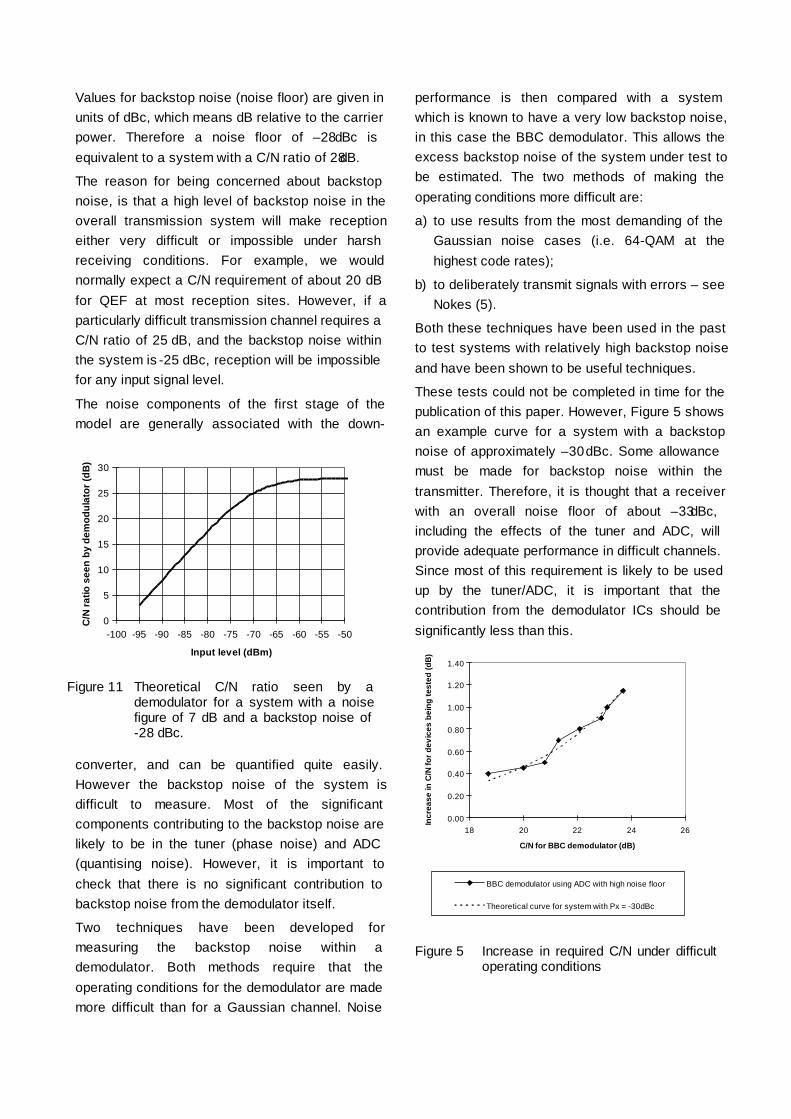
Values for backstop noise (noise floor) are given inunits of dBc, which means dB relative to the carrierpower. Therefore a noise floor of –28 dBc isequivalent to a system with a C/N ratio of 28 dB.
The reason for being concerned about backstopnoise, is that a high level of backstop noise in theoverall transmission system will make receptioneither very difficult or impossible under harshreceiving conditions. For example, we wouldnormally expect a C/N requirement of about 20 dBfor QEF at most reception sites. However, if aparticularly difficult transmission channel requires aC/N ratio of 25 dB, and the backstop noise withinthe system is -25 dBc, reception will be impossiblefor any input signal level.
The noise components of the first stage of themodel are generally associated with the down-
converter, and can be quantified quite easily.However the backstop noise of the system isdifficult to measure. Most of the significantcomponents contributing to the backstop noise arelikely to be in the tuner (phase noise) and ADC(quantising noise). However, it is important tocheck that there is no significant contribution tobackstop noise from the demodulator itself.
Two techniques have been developed formeasuring the backstop noise within ademodulator. Both methods require that theoperating conditions for the demodulator are mademore difficult than for a Gaussian channel. Noise
performance is then compared with a systemwhich is known to have a very low backstop noise,in this case the BBC demodulator. This allows theexcess backstop noise of the system under test tobe estimated. The two methods of making theoperating conditions more difficult are:
a) to use results from the most demanding of theGaussian noise cases (i.e. 64-QAM at thehighest code rates);
b) to deliberately transmit signals with errors – seeNokes (5).
Both these techniques have been used in the pastto test systems with relatively high backstop noiseand have been shown to be useful techniques.
These tests could not be completed in time for thepublication of this paper. However, Figure 5 showsan example curve for a system with a backstopnoise of approximately –30 dBc. Some allowancemust be made for backstop noise within thetransmitter. Therefore, it is thought that a receiverwith an overall noise floor of about –33 dBc,including the effects of the tuner and ADC, willprovide adequate performance in difficult channels.Since most of this requirement is likely to be usedup by the tuner/ADC, it is important that thecontribution from the demodulator ICs should besignificantly less than this.
0.00
0.20
0.40
0.60
0.80
1.00
1.20
1.40
18 20 22 24 26
C/N for BBC demodulator (dB)
Incr
ease
in C
/N fo
r de
vice
s be
ing
test
ed (d
B)
BBC demodulator using ADC with high noise floor
Theoretical curve for system with Px = -30dBc
Figure 5 Increase in required C/N under difficultoperating conditions
0
5
10
15
20
25
30
-100 -95 -90 -85 -80 -75 -70 -65 -60 -55 -50
Input level (dBm)
C/N
rat
io s
een
by d
emod
ulat
or (d
B)
Figure 11 Theoretical C/N ratio seen by ademodulator for a system with a noisefigure of 7 dB and a backstop noise of-28 dBc.
CONCLUSIONS
Some of the most important performanceparameters of the first demodulator ICs for DVB-Thave been measured and reported. Wherepossible, these parameters have been comparedwith the performance assumed in the UKfrequency planning project.
For most of the parameters tested, the ICs provideperformance in excess of that assumed by thefrequency planners. The only area of slightconcern is the protection ratio from co-channelPAL.
Overall both ICs demonstrate that working siliconis available, which will allow set top box andreceiver manufacturers to prepare their productionfor the launch of operational digital terrestrialtelevision services in the UK, Sweden.
REFERENCES
1. Nokes, C.R., Pullen, I.R. and Salter, J.E., 1997.Evaluation of a DVB-T compliant digital terrestrialtelevision system. Proceedings of the 1997International Broadcasting Convention. September1997 pp. 331 to 336.
2. Maddocks, M.C.D., Tait, B., Laflin, N.J. andDoel, G. 1996. The plan for digital terrestrialtelevision in the UK. Proceedings of the 1996International Broadcasting Convention. September1996 pp. 172 to 177.
3. Oliphant, A. and Christ, P., 1998. VALIDATEand MOTIVATE: Collaborative R&D to speed upthe launch of digital terrestrial TV. Proceedings ofthe 1998 International Broadcasting Convention.September 1998.
4. European Telecommunication Standard. 1997.Digital broadcasting systems for television, sound,and data services; Framing structure, channelcoding and modulation for digital terrestrialtelevision. ETSI specification ETS 300 744,European Telecommunications Standards Institute,1997.
5. Nokes, C.R., 1998 Apparatus and method fortesting digital modulation systems. UK patentapplication No. 98 04248.4 February 1998.
ACKNOWLEDGEMENTS
The author would like to thank his many colleagueswho contributed to the work reported in this paper.The work was carried out within the VALIDATEand MOTIVATE projects which are supported bythe Commission of the European Communitiesthrough the fourth Framework programme.
C. R. Nokes - BBC R&D, UK.
Proceedings of IBC '98 pp 294-299

MOBILE RECEPTION OF 2K AND 8K DVB-T SIGNALSErik Stare – Teracom AB Sweden
ABSTRACT
The main problems associated with mobile DVB-T reception are discussed. Fundamental limits for Dopplerand delay in mobile DVB-T reception are given. The concept of FFT leakage is introduced and an algorithmfor its reduction by receiver processing is presented, together with simulation results. Laboratorymeasurement results, performed with the Teracom DVB-T demodulator, showing Doppler performance closeto the fundamental limits are given. Network planning and receiver synchronisation aspects are discussed aswell as a comparison between 2K and 8K.
INTRODUCTION
Digital terrestrial TV (DTTV) using the DVB-Tstandard [1] is gaining more and more interest inEurope and other parts of the world. In the UKand in Sweden there are concrete plans for acommercial introduction of DTTV services in late1998, and other countries will follow soon afterthis.
Within the EU funded ACTS project VALIDATE 18different organisations have together, since Nov.1995, performed extensive work for theverification and testing of the DVB-T standard inthe context of fixed roof-top and portablereception. This work has provided a solidtechnical foundation upon which networks andreceivers are now designed for DTTV services.
During the VALIDATE field tests it was found thatalso mobile reception of DVB-T signals at veryhigh speeds is in fact possible. This has triggereda wide interest in mobile DVB-T services and anew ACTS project - MOTIVATE - has beencreated to investigate in detail the behaviour ofDVB-T in mobile channels. This paper addressessome of the main aspects of mobile DVB-Treception.
THE DVB-T STANDARD
DVB-T is a flexible standard using COFDMmodulation where the terrestrial network operatorcan choose any combination of
• No. of carriers: 6817 (8K mode) or 1705 (2Kmode)
• Guard interval ∆: TU/4, TU/8, TU/16 or TU/32,where TU is the inverse of the carrier spacing(TU = 896 µs in 8K and 224 µs in 2K)
• Constellation: 64-QAM, 16-QAM or QPSK
• Convolutional code rate R: 1/2, 2/3, 3/4, 5/6 or7/8
which results in 120 non-hierarchical modes1,suitable for a wide range of network structuresand receiving conditions, and with bit ratesranging from 4.98 Mbit/s to 31.67 Mbit/s.
In addition to the coded data the DVB-T signalcontains reference information, defined by thestandard, which can be used by the receiver fore.g. synchronisation and channel estimation. Infigure 1 below the pattern of the so calledscattered pilots is shown.
PROBLEMS TO BE OVERCOME IN MOBILEDVB-T RECEPTION
To achieve successful mobile DVB-T receptionthere are a number of problems to be overcome:
1. The receiver channel estimation has to trackthe channel variations in time and frequency.
2. The receiver has to withstand the noise-likedistortion called FFT leakage, created by thetime variant channel during the time TU of asymbol.
3. The received field strength, and consequentC/N, has to be sufficiently high at a sufficiently
1 There are also 1200 hierarchical modes in the standard

high number of locations to permit a reliablemobile service.
4. The receiver has to synchronise correctly intime and frequency in the mobile channel.
Kmin=0
TPS pilots and continual pilots between K min and Kmax are not indicated
boosted pilot
data
symbol 0
......
......
......
......
......
......
......
......
......
......
Kmax = 6 816 if 8K
Fig. 1 Frame structure of DVB-T
Tracking of channel variations in time andfrequency
As can be seen in fig.1 there are scattered pilots(hereafter only called pilots) on every symbol butonly on every third carrier. In a given symbol thereare pilots every 12th carrier. Since the value ofeach transmitted pilot is known by the receiver itcan divide the received value with the transmittedvalue and thereby obtain an estimate, Hk, of thechannel for that pilot cell2. However, equalisationof the data cells requires a corresponding channelestimate for each of them. These can be obtainedby interpolation in time and frequency betweenthe pilots.
One can view the pilot pattern as a 2-dimensionalsampling of the channel. The 2-D spectrum iscaused by the Doppler and delay spread of thechannel. Since these are independent we canassume a rectangular spectrum, which makesseparable time and frequency interpolationpossible. As long as the echo delays of thechannel are less than TU/3 (299 µs in 8K) and the
2 A cell is defined to be one carrier during one symbol
total bandwidth of the Doppler spectrum is lessthan 1/[4(TU+∆)] (between +/-112 Hz and +/-135Hz in 8K) there will be no aliasing due to the pilotsampling of the channel. The 2-dimensionalbandwidth (including spectral repetitions) that canbe spanned by the pilots is shown in fig 2 below.
The purpose of the interpolation filters is of courseto calculate an interpolated pilot value for everydata cell. In the spectrum domain this isequivalent to the removal of all spectralrepetitions.
There is also an alternative possibility: if the echodelays are less than TU/12 a Doppler spectrum aswide as 1/(TU+∆) (between +/-446 and +/-541 Hzin 8K) can be spanned by the pilots. For asacrifice of a factor 4 in maximum echo length afactor 4 in maximum Doppler frequency cantherefore be gained. In this case time interpolationis not necessary; only interpolation within asymbol is required. In fig 2 this would correspondto a 90 degree rotation of the 2-dimensionalbaseband, with a correspondent rotation of allspectral repetitions. It is easy to see that there willnot be any aliasing in this case either.
A reasonable question is whether there exists anyintermediate step, where e.g. a factor 2 in
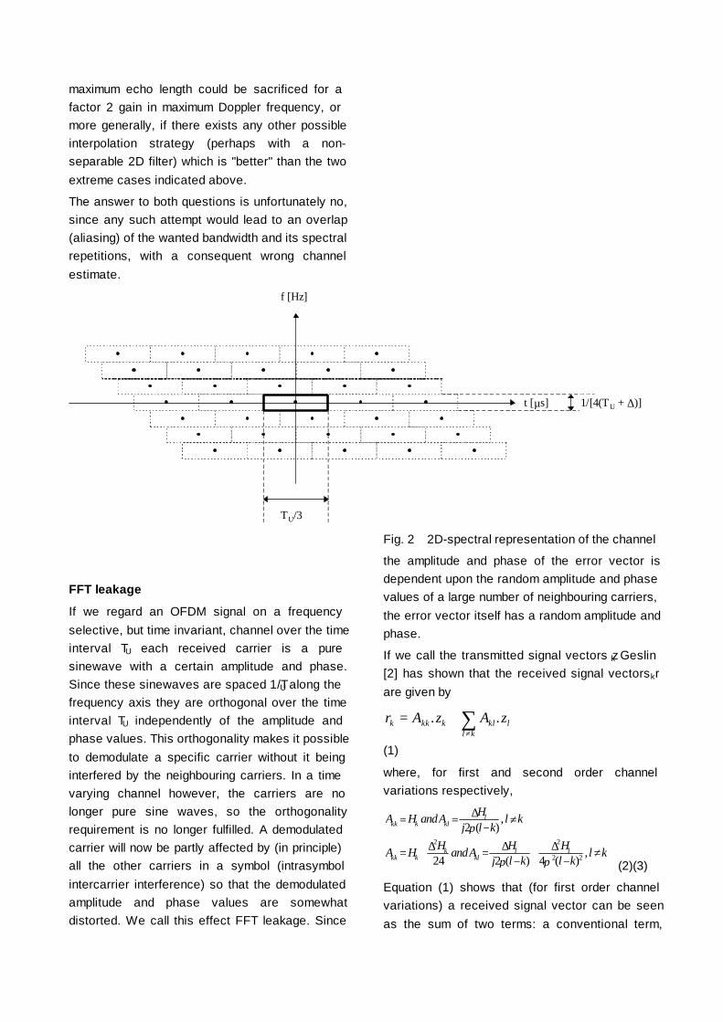
maximum echo length could be sacrificed for afactor 2 gain in maximum Doppler frequency, ormore generally, if there exists any other possibleinterpolation strategy (perhaps with a non-separable 2D filter) which is "better" than the twoextreme cases indicated above.
The answer to both questions is unfortunately no,since any such attempt would lead to an overlap(aliasing) of the wanted bandwidth and its spectralrepetitions, with a consequent wrong channelestimate.
f [Hz]
t [µs] 1/[4(TU + ∆)]
TU/3
Fig. 2 2D-spectral representation of the channel
FFT leakage
If we regard an OFDM signal on a frequencyselective, but time invariant, channel over the timeinterval TU each received carrier is a puresinewave with a certain amplitude and phase.Since these sinewaves are spaced 1/TU along thefrequency axis they are orthogonal over the timeinterval TU independently of the amplitude andphase values. This orthogonality makes it possibleto demodulate a specific carrier without it beinginterfered by the neighbouring carriers. In a timevarying channel however, the carriers are nolonger pure sine waves, so the orthogonalityrequirement is no longer fulfilled. A demodulatedcarrier will now be partly affected by (in principle)all the other carriers in a symbol (intrasymbolintercarrier interference) so that the demodulatedamplitude and phase values are somewhatdistorted. We call this effect FFT leakage. Since
the amplitude and phase of the error vector isdependent upon the random amplitude and phasevalues of a large number of neighbouring carriers,the error vector itself has a random amplitude andphase.
If we call the transmitted signal vectors zk Geslin[2] has shown that the received signal vectors rk
are given by
r A z A zk kk k kll k
l= +≠∑. .
(1)
where, for first and second order channelvariations respectively,
A H andA Hj l k
l k
A H H andA Hj l k
Hl k
l k
kk k kll
kk kk
kll l
= = − ≠
= + = − + − ≠
∆
∆ ∆ ∆2
24 2 4
2 2
2 2
π
π π
( ),
( ) ( ),
(2)(3)
Equation (1) shows that (for first order channelvariations) a received signal vector can be seenas the sum of two terms: a conventional term,
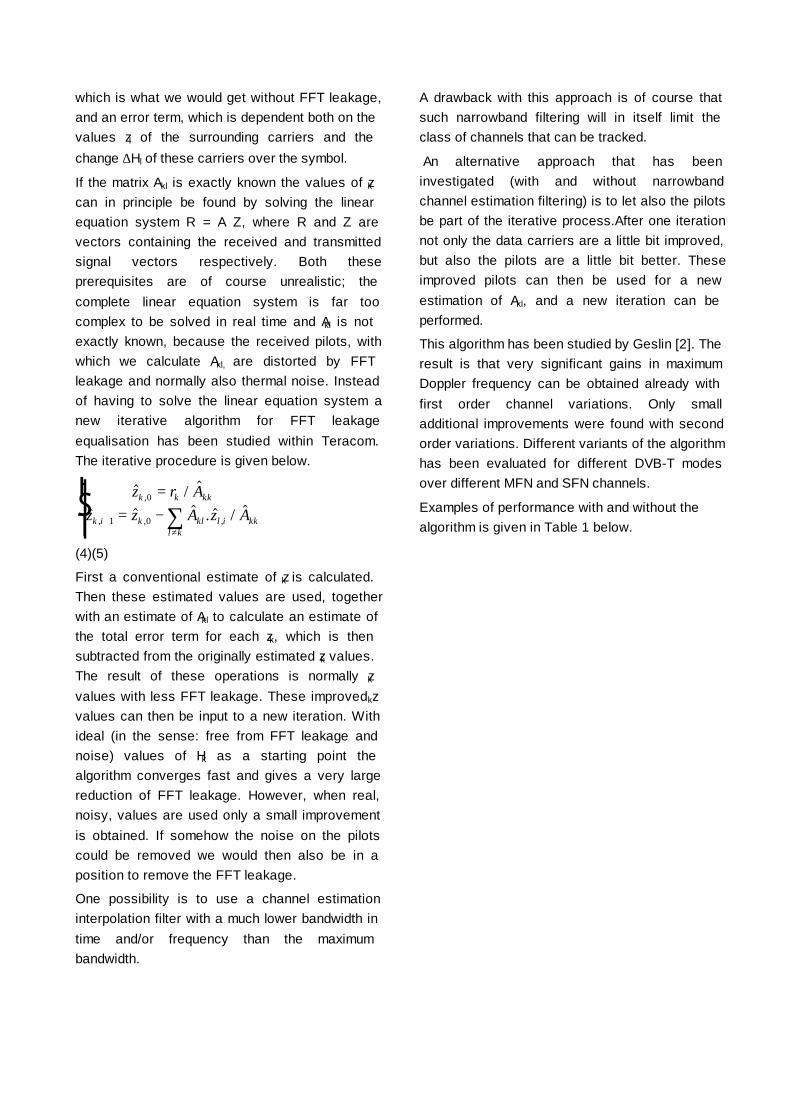
which is what we would get without FFT leakage,and an error term, which is dependent both on thevalues zl of the surrounding carriers and thechange ∆Hl of these carriers over the symbol.
If the matrix Akl is exactly known the values of zkcan in principle be found by solving the linearequation system R = A Z, where R and Z arevectors containing the received and transmittedsignal vectors respectively. Both theseprerequisites are of course unrealistic; thecomplete linear equation system is far toocomplex to be solved in real time and Akl is notexactly known, because the received pilots, withwhich we calculate Akl, are distorted by FFTleakage and normally also thermal noise. Insteadof having to solve the linear equation system anew iterative algorithm for FFT leakageequalisation has been studied within Teracom.The iterative procedure is given below.
$ / $
$ $ $ . $ / $,
, , ,
z r Az z A z A
k k kk
k i k kl l i kkl k
0
1 0
== −
RS|T| +
≠∑
(4)(5)
First a conventional estimate of zk is calculated.Then these estimated values are used, togetherwith an estimate of Akl to calculate an estimate ofthe total error term for each zk, which is thensubtracted from the originally estimated zk values.The result of these operations is normally zkvalues with less FFT leakage. These improved zk
values can then be input to a new iteration. Withideal (in the sense: free from FFT leakage andnoise) values of Hk as a starting point thealgorithm converges fast and gives a very largereduction of FFT leakage. However, when real,noisy, values are used only a small improvementis obtained. If somehow the noise on the pilotscould be removed we would then also be in aposition to remove the FFT leakage.
One possibility is to use a channel estimationinterpolation filter with a much lower bandwidth intime and/or frequency than the maximumbandwidth.
A drawback with this approach is of course thatsuch narrowband filtering will in itself limit theclass of channels that can be tracked.
An alternative approach that has beeninvestigated (with and without narrowbandchannel estimation filtering) is to let also the pilotsbe part of the iterative process.After one iterationnot only the data carriers are a little bit improved,but also the pilots are a little bit better. Theseimproved pilots can then be used for a newestimation of Akl, and a new iteration can beperformed.
This algorithm has been studied by Geslin [2]. Theresult is that very significant gains in maximumDoppler frequency can be obtained already withfirst order channel variations. Only smalladditional improvements were found with secondorder variations. Different variants of the algorithmhas been evaluated for different DVB-T modesover different MFN and SFN channels.
Examples of performance with and without thealgorithm is given in Table 1 below.

8K DVB-Tmode
Bit rate[Mbit/s]
Channel fd,max [Hz]without eq. ofFFT leakage
fd,max [Hz] witheq. of FFTleakage
vmax [km/h] at666 MHzwithout eq. ofFFT leakage
vmax [[km/h] at666 MHz witheq. of FFTleakage
16-QAMR=1/2∆/TU=1/4
9.95 Typical Urban 81.5 95.5 132 155
16-QAMR=1/2∆/TU=1/4
9.95 SFN(0,100,210)
97.5 111.5 158 181
16-QAMR=1/2∆/TU=1/8
11.06 SFN(0,50,100)
100.4 113.8 163 185
64-QAMR=1/2∆/TU=1/4
14.93 Typical Urban 49.5 70.1 80 114
64-QAMR=1/2∆/TU=1/4
14.93 SFN(0,100,210)
55.5 90.0 90 147
64-QAMR=2/3∆/TU=1/8
22.12 Rural Area 22.0 32.6 36 53
64-QAMR=2/3∆/TU=1/8
22.12 Hilly Terrain 24.3 39.8 39 64
64-QAMR=2/3∆/TU=1/8
22.12 Typical Urban 26.6 46.3 43 75
64-QAMR=2/3∆/TU=1/4
19.91 SFN(0,100,210)
31.2 62.9 51 102
Table 1 - Simulated performance gain by equalisation of FFT leakage
Performance has been evaluated for a BER of 2 x10⁻⁴ after Viterbi decoding. For a stationarychannel this corresponds to a Quasi Error Free(QEF) MPEG-2 TS after Reed Solomon (RS)decoding. This correspondence between BER afterViterbi and after RS no longer holds for DVB-T in amobile channel. Another quality criterion istherefore needed. Failing this, the traditionalcriterion has however been used in thesimulations. The channel models used are directlytaken from COST 207 [3], except the SFN modelwhich is derived from COST 207 by combiningthree Typical Urban (TU) models (each havingindependent Rayleigh fading), where the secondand third models are delayed x and y relative tothe first model. "SFN (0,y,z)" means a channelwhich consists of a sum of all paths in three COST207 TU models, where the paths in the second andthird model has been delayed y and z µs, inrelation to the standard model. The speeds are
given for the middle of the UHF band (ch.45 - 666MHz).
As can be seen the gain obtained by the algorithmis higher in SFN than in MFN channels. Oneexplanation to this is that the additional diversityintroduced by the SFN makes the field strengthvariations from symbol to symbol more even, whichis not only good from a network planning point ofview, but also from an FFT leakage point of view,since the FFT leakage varies from symbol tosymbol and is worst in connection with deep fades,since the change ∆H of the channel is then large.
Since deep fades occur more rarely in SFN thisexplains the better performance. For the sameaverage BER after Viterbi decoding the bit errors inSFN tend to be more evenly distributed than inMFN, where they tend to come in very long bursts.After RS decoding this leads naturally to a lowerBER in SFN, since the depth of the outerinterleaving is rather limited.
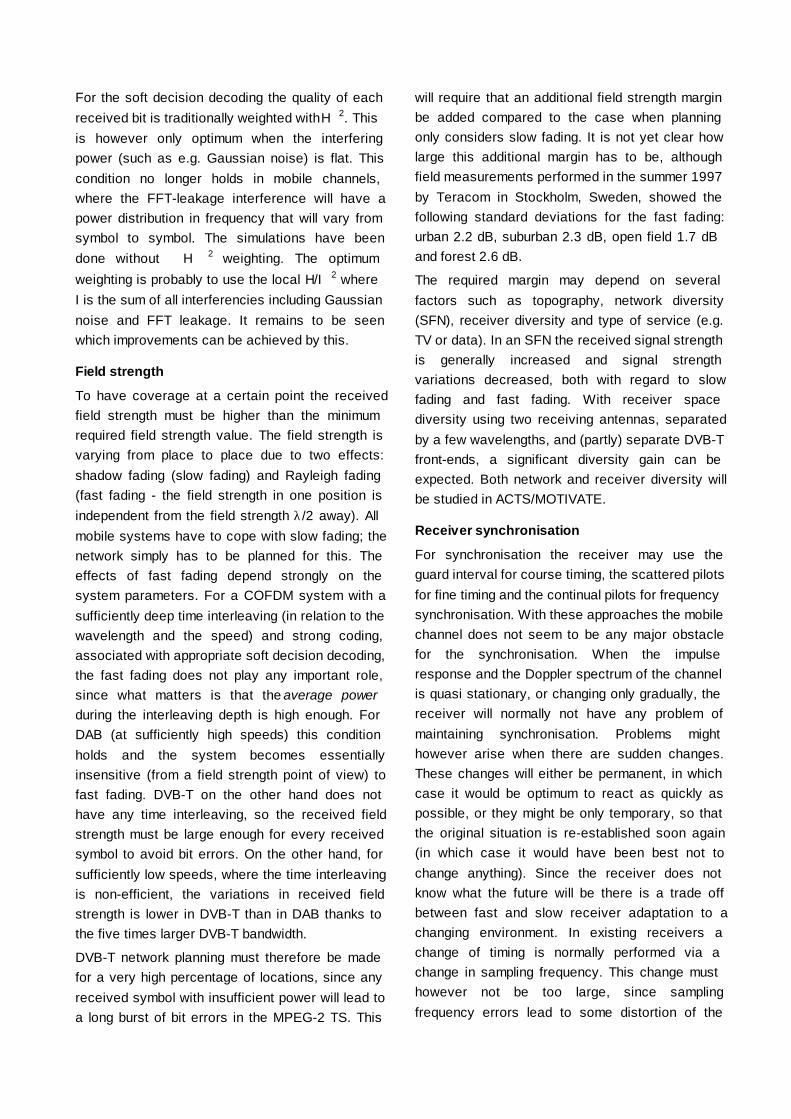
For the soft decision decoding the quality of eachreceived bit is traditionally weighted with H 2. Thisis however only optimum when the interferingpower (such as e.g. Gaussian noise) is flat. Thiscondition no longer holds in mobile channels,where the FFT-leakage interference will have apower distribution in frequency that will vary fromsymbol to symbol. The simulations have beendone without H 2 weighting. The optimumweighting is probably to use the local H/I 2 whereI is the sum of all interferencies including Gaussiannoise and FFT leakage. It remains to be seenwhich improvements can be achieved by this.
Field strength
To have coverage at a certain point the receivedfield strength must be higher than the minimumrequired field strength value. The field strength isvarying from place to place due to two effects:shadow fading (slow fading) and Rayleigh fading(fast fading - the field strength in one position isindependent from the field strength λ/2 away). Allmobile systems have to cope with slow fading; thenetwork simply has to be planned for this. Theeffects of fast fading depend strongly on thesystem parameters. For a COFDM system with asufficiently deep time interleaving (in relation to thewavelength and the speed) and strong coding,associated with appropriate soft decision decoding,the fast fading does not play any important role,since what matters is that the average powerduring the interleaving depth is high enough. ForDAB (at sufficiently high speeds) this conditionholds and the system becomes essentiallyinsensitive (from a field strength point of view) tofast fading. DVB-T on the other hand does nothave any time interleaving, so the received fieldstrength must be large enough for every receivedsymbol to avoid bit errors. On the other hand, forsufficiently low speeds, where the time interleavingis non-efficient, the variations in received fieldstrength is lower in DVB-T than in DAB thanks tothe five times larger DVB-T bandwidth.
DVB-T network planning must therefore be madefor a very high percentage of locations, since anyreceived symbol with insufficient power will lead toa long burst of bit errors in the MPEG-2 TS. This
will require that an additional field strength marginbe added compared to the case when planningonly considers slow fading. It is not yet clear howlarge this additional margin has to be, althoughfield measurements performed in the summer 1997by Teracom in Stockholm, Sweden, showed thefollowing standard deviations for the fast fading:urban 2.2 dB, suburban 2.3 dB, open field 1.7 dBand forest 2.6 dB.
The required margin may depend on severalfactors such as topography, network diversity(SFN), receiver diversity and type of service (e.g.TV or data). In an SFN the received signal strengthis generally increased and signal strengthvariations decreased, both with regard to slowfading and fast fading. With receiver spacediversity using two receiving antennas, separatedby a few wavelengths, and (partly) separate DVB-Tfront-ends, a significant diversity gain can beexpected. Both network and receiver diversity willbe studied in ACTS/MOTIVATE.
Receiver synchronisation
For synchronisation the receiver may use theguard interval for course timing, the scattered pilotsfor fine timing and the continual pilots for frequencysynchronisation. With these approaches the mobilechannel does not seem to be any major obstaclefor the synchronisation. When the impulseresponse and the Doppler spectrum of the channelis quasi stationary, or changing only gradually, thereceiver will normally not have any problem ofmaintaining synchronisation. Problems mighthowever arise when there are sudden changes.These changes will either be permanent, in whichcase it would be optimum to react as quickly aspossible, or they might be only temporary, so thatthe original situation is re-established soon again(in which case it would have been best not tochange anything). Since the receiver does notknow what the future will be there is a trade offbetween fast and slow receiver adaptation to achanging environment. In existing receivers achange of timing is normally performed via achange in sampling frequency. This change musthowever not be too large, since samplingfrequency errors lead to some distortion of the

signal, with a consequent penalty in required C/N.In principle a change of timing could be madeinstantly (at the border between any two symbols).Since a change of timing is equivalent to a phaseshift, which is proportional to the carrier number,such an instant shift in timing should only be doneif the phases of all previously received symbols,which are still in the memory, are correctedcorrespondingly.
LABORATORY MEASUREMENTS
Within the ACTS/VALIDATE project Teracom hasdeveloped a DVB-T demodulator3 optimised formobile reception. The demodulator uses channelestimation interpolation filters which are close tothe theoretical limits (e.g. 111 taps for the timefilter). No equalisation of FFT leakage is howeverperformed. A first series of measurements ofDoppler performance has been made using thisdemodulator. The measurements focused on theDVB-T mode {8K, QPSK, R=1/2, ∆/TU=1/8}resulting in a bit rate of 5.53 Mbit/s and a guardinterval of 112 µs. For this mode it was believedthat the limiting factor would be the pilot densityand not the FFT leakage. From fig. 2 it is clear thatthe fundamental Doppler limit imposed by the pilotdensity is +/-124 Hz for all 8K modes with ∆=112µs (assuming time interpolation is performed,which is necessary if echoes longer than TU/12 arepresent).
The demodulator was tested over a two path 0 dBecho channel with different delays and frequencyshifts introduced. For both a short (1.3 µs) and along (100 µs) 0 dB echo QEF decoding waspossible at a frequency shift of 238 Hz betweenthe two paths, corresponding to a Dopplerspectrum of +/- 119 Hz and a speed in the centreof the UHF band (666 MHz) of 193 km/h.
DISCUSSION
Initial studies and tests suggest that the principalobstacles for mobile DVB-T reception can be
3 The demodulator has been developed in co-operation withSINTEF Telecom and Informatics, Trondheim, Norway
removed, although sometimes with someconsequences in receiver complexity. From theDoppler performance point of view the 2K modehas an obvious advantage; in principle 2K cancope with 4 times higher Doppler frequencies andspeeds than 8K. On the other hand, from anetwork planning point of view the use of SFNsmight make coverage planning easier and reducenetwork costs, since SFN can provide significantnetwork gains both in terms of the slow and fastfading. The question whether 2K or 8K is best formobile reception is therefore not so easy toanswer.
CONCLUSIONS
The fundamental theoretical limits for mobile DVB-T reception are given by the 2-dimesional pilotsampling of the channel. When FFT leakage is notthe limiting factor (which at least seems to be thecase for QPSK R=1/2) tests with a real DVB-Tdemodulator show that performance can comeclose to these limits. Theoretical studies andsimulations also show that the FFT leakage can besignificantly reduced with receiver processing,which in principle opens the possibility for 8Kmobile reception also at higher order modulation.
REFERENCES
1. ETSI 1997, Digital Video Broadcasting (DVB);Framing structure, channel coding and modulationfor digital terrestrial television - EN 300 744 v.1.1.2.
2. Geslin, G., 1998. Equalisation of FFT-leakagein mobile DVB-T. Master Thesis inRadiocommunication from the Royal Institute ofTechnology, Stockholm, performed at TeracomAB, Stockholm Sweden.
3. COST 207, 1988. Digital land mobile radiocommunications - Final report (14 March 1984 - 13September 1988).
ACKNOWLEDGEMENTS
The author would like to thank his colleagues atthe R&D department at Teracom for theircontributions to this work.
Erik Stare - Teracom AB Sweden

Proceedings of IBC '98 pp 473-478
VALIDATE & MOTIVATE: COLLABORATIVE R&D TO SPEED UPTHE LAUNCH OF DIGITAL TERRESTRIAL TV
A Oliphant and P. Christ BBC R&D, UK and Deutsche Telekom Berkom, Germany
ABSTRACT
The VALIDATE project has verified the performance of the DVB-T specification in the laboratory and in fieldtrials. Its successful collaboration has advanced DVB-T technology to the point where services are ready tostart. Recent achievements include a multidimensional interworking demonstration, a transmitterspecification, single-frequency network synchronisation and gap-filler transmitters (on-channel repeaters).Trials have shown that mobile reception of DVB-T is possible with bitrates up to 15 Mbit/s, offering a range ofattractive new services. A new project, MOTIVATE, will develop mobile reception of DVB-T.
INTRODUCTION
The VALIDATE project started work in November1995 with the aim of verifying the DVB-Tspecification and laying the foundations for thelaunch of digital terrestrial TV services. Theseaims have been achieved and VALIDATEcompleted its work in June 1998.
Mobile reception was not a main aim of the DVB-Tspecification. However, measurements byDeutsche Telekom AG within the VALIDATEproject showed that mobile television andmultimedia services are possible using some of themore rugged modes of the Specification.
Most of the VALIDATE participants were keen toextend their collaboration to investigate this newpossibility. Deutsche Telekom AG took the lead in
forming this new project, MOTIVATE, which startedwork in May 1998, just before the end ofVALIDATE.
This paper reviews the work of VALIDATE,highlighting progress in the final year, anddescribes some of the work that will be done byMOTIVATE – starting by suggesting some possibleapplications of mobile DVB-T.
VALIDATE: PREPARING FOR LAUNCH OFSERVICES
Introduction
The VALIDATE project (TABLE 1) formed aEurope-wide ‘virtual laboratory’ to test the DVB-Tsystem and speed up its acceptance. Membersagreed the testing needed and the procedures to
TABLE 3 – Partners in VALIDATE and MOTIVATE
V*M BBC UKV M Robert Bosch DV M CCETT FV M* Deutsche Telekom Berkom DV Deutsche Thomson Brandt DV M EBUV M IRT DV M ITIS FV M Mier Comunicaciones E M Nokia SF
V - VALIDATE partner * - Coordinator
V M NOZEMA NLV Radio Telefís Éireann IRLV M RAI IV M Retevisión EV M Rohde & Schwarz DV M TDF FV Tele Danmark DKV M Televés EV M Teracom SV M Thomcast F
M - MOTIVATE partner * - Coordinator

be followed; this allowed the work to be shared outand ensured that results of tests by differentPartners could be compared within the Project andpresented together to the standards authorities.
The first task of the VALIDATE project was toverify the DVB-T specification. This verificationrequired three elements:
• checking that the specification was clear andunambiguous by demonstrating interworkingbetween simulations and then between realhardware produced by separate laboratories,
• checking that the system performed asexpected in the repeatable conditions of thelaboratory,
• checking that it met broadcasters’ expectationsin field trials.
This vital task was completed by the end of 1996,with the result that the DVB-T specification wasrapidly approved as an ETSI standard. The workwas described by Nokes et al. (1). Since thenfurther field trials of different network configurationshave been carried out in many Europeancountries: a compendium of the results has beengiven by Weck (2). These field trials have shownnot only that the DVB-T specification meetsbroadcasters’ current expectations, but haveopened the possibility of mobile reception.
The laboratory tests and field trials reported byVALIDATE formed the basis of internationalagreements on coordination of digital TVtransmitters agreed by 32 countries at Chester(UK) in July 1997(3).
VALIDATE has also carried out a wide range ofother work on distribution networks, transmitters,service planning parameters, single frequencynetworks (SFNs), and gap-fillers both forprofessional and domestic use. Much of this workhas been documented in ImplementationGuidelines, prepared for the DVB Project and nowpublished as an ETSI Technical Report (4).
These Guidelines draw attention to the technicalquestions that need to be answered in setting up aDVB-T network and offer some guidance in findinganswers to them. They give an explanation of theDVB-T specification and the basic characteristics
of transmission networks; they then covertransmitters and issues of sharing with existingservices, distribution networks, SFN operation, andnetwork planning.
Some recent successes
Interworking tests
In June 1998 VALIDATE organised a finalinterworking demonstration, bringing together awide range of DVB-T equipment from differentmanufacturers within and outside the Project.There were seven different modulators, includingfirst generation prototypes and industrial products,and nine different receivers including firstgeneration prototypes, commercial professionalreceivers and consumer chip-sets.
Sixty-one different DVB-T modes were tested;these included examples of all the possibilities andoptions offered by DVB-T specification.Interoperation of hierarchical modes wassuccessfully demonstrated for the first time.Remotely synchronised SFN operation (see below)was successfully demonstrated using modulatorsfrom different manufacturers.
The successful results of all of these tests provethe interoperability of DVB-T equipment fromdifferent manufacturers. Network operators cansafely mix equipment from different manufacturersin their networks. These results provide a soundbasis for the launch of commercial services.
TRANSMITTER PARAMETERS
Transmitter manufacturers and transmissionnetwork operators must agree on the specificationsfor the performance of transmitters, as must thenetwork operators and the service providers. Asthis is a new technology, there is no existing basisfor such specifications. VALIDATE has thereforedrawn up a transmitter performance specification.It suggests the parameters that need to bemeasured and some realistic values for them aswell as defining minimum interface specifications(not all of which are mandatory).
A useful method of specifying the overallperformance of a transmitter is the Equivalent
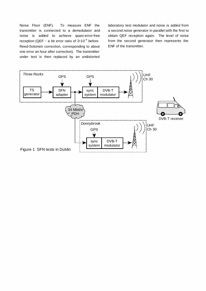
Noise Floor (ENF). To measure ENF thetransmitter is connected to a demodulator andnoise is added to achieve quasi-error-freereception (QEF − a bit error ratio of 2×10− 4 beforeReed-Solomon correction, corresponding to aboutone error an hour after correction). The transmitterunder test is then replaced by an undistorted
laboratory test modulator and noise is added froma second noise generator in parallel with the first toobtain QEF reception again. The level of noisefrom the second generator then represents theENF of the transmitter.
TSgenerator
SFNadapter
GPSThree Rocks
34 Mbit/sPDH
syncsystem
DVB-Tmodulator
UHFCh 30
syncsystem
DVB-Tmodulator
GPS
Donnybrook UHFCh 30
DVB-T receiver
GPS
Figure 1 SFN tests in Dublin

SFN Synchronisation
Two approaches are possible to the planning ofDVB-T networks: multi-frequency networks (MFNs)and single frequency networks (SFNs).
All transmitters in an SFN must be synchronised sothat their broadcasts are frequency identical andbit identical. VALIDATE partners have led thestandardisation of a method of synchronising anSFN by defining a megaframe in the MPEG-2transport stream using a megaframe identificationpacket (MIP) (5). The megaframe length has beenchosen to contain an integral number of OFDMframes, of Reed-Solomon packets, and of theenergy dispersal sequences. The MIP contains atimestamp indicating the time at which themegaframe should be broadcast, related to auniversal time and frequency reference such asthat available from the GPS satellite system. Bycomparing the timestamp with the reference at thetransmitter, all signals can be time synchronised.
To test this synchronisation technique, VALIDATEpartners RTÉ and ITIS set up, with the assistanceof TDF, a DVB-T SFN using two transmitters in theDublin area on UHF channel 30 (see Fig. 1). Thetransmission mode used for this experiment was8K, 64-QAM, R=2/3, guard interval=1/4. AnMPEG-2 Transport Stream (TS) generator, an SFNadapter, a DVB-T modulator, and a 1kW TVtransmitter operating at 50 W were set up at ThreeRock. A second DVB-T modulator and a 25 Wtransmitter were set up at Donnybrook. A 34 Mb/sPDH link was established from Three Rock toDonnybrook which fed the second DVB-Tmodulator with the MPEG-2 TS output from theSFN adapter. This complete SFN arrangementwas synchronised by using an SFN adapter (MIPinserter) and GPS receivers.
At a site near Donnybrook where the signals fromthe two transmitters were at similar levels, theprogramme was received successfully with a smallomni-directional antenna and a professional DVB-Treceiver. This field arrangement represents theworld's first SFN operation based on a real primarydistribution network according to the ETSIspecification (5).
Gap-Filler Transmitters
SFN techniques can be used on a smaller scale toimprove coverage. VALIDATE partners havebeen studying both professional gap-fillers,installed by the network operator to fill gaps in thecoverage of a main transmitter caused byshadowing from terrain or large buildings, anddomestic gap-fillers installed within a house toimprove portable reception. Obviously, the maintechnical problem of such gap-fillers is oscillationcaused by feedback of the transmitted signal to thereceiving antenna.
A professional gap-filler was demonstrated by Mierand DT Berkom in Berlin to provide coverage tothe Potsdam area that is shadowed by hills fromthe main transmitter at Alexanderplatz in the centreof Berlin (see Fig. 2). With both receiving andtransmitting antennas mounted on the sameconcrete tower an isolation of 105 dB wasobtained. The ripple on the output DVB-T signalspectrum was less than 3 dB with an output ERPof 100 W. Field trials in Potsdam showed thatportable reception was possible at all locations witha reasonable field strength.
TV-Tower BerlinAlexanderplatz
4 kW (ERP)SFN
4 kW (ERP)SFN
1 kW(ERP)
B e r l i n
4 kW (ERP)SFN
Frohna
Köpenick
SFN-T-Distanceca 30 km
Zossen
POTSDAM
Schäferberg5.5 km
100 W (ERP)Repeater
4 kW (ERP)SFN
Figure 2. The experimental network of Deutsche Telekom AG in Berlin
For the domestic gap-filler, VALIDATE partnerTelevés carried out a feasibility study that gaveencouraging conclusions, then built a prototype. As
a domestic device, the safety of such a device andits cost were important considerations.
In a first test conducted by the BBC in the Londonarea, the domestic gap-filler gave sufficient fieldstrength to provide portable reception in all roomsof a house with an output power less than 200 µW.There were no problems of stability when it wasfed from a rooftop antenna, but some care wasneeded in setting up when a receiving antennawithin the roof space of the house was used.
Five more houses and flats of different sizes anddifferent methods of construction have beenmeasured since, some of them in areas of poorreception where indoor portable reception wouldotherwise have been impossible; in all cases useof the gap-filler allowed portable reception in allrooms of the dwellings. Reception has beenproved possible even with very poor input signals(20 dB tilt across the channel and 5 dB ripple).
VALIDATE – summing up
In just under three years VALIDATE has verifiedthe DVB-T specification and has provided testresults for reliable service planning andinternational coordination. Its work has ensuredthat a range of conformant equipment is availableand has helped IC designers to design chips fordomestic receivers with confidence. DVB-Tservices are now ready to start in the UK andSweden, with long-term trials on air in severalmore European countries. This success has beenachieved thanks to the excellent teamwork of thePartners in exchanging and comparing results fromtests and trials carried out all over Europe.
MOTIVATE: DEVELOPING MOBILE SERVICES
Introduction
In some countries – such as the UK – terrestrialtelevision is still dominant. In these countries theinitial application of DVB-T will be to provide morechannels to increase choice. In other countries –such as Germany – there is a much higherpenetration of cable and satellite: only 6.8 M of the36 M German households rely on terrestrialbroadcasting. DVB-T could overcome some of the
limitations of analogue terrestrial TV but this alonewould not guarantee a successful introduction ofDVB-T services in such countries: added valueservices are needed to attract more users andincrease revenues for broadcasters and networkproviders.
Mobile reception of video, Internet and multimediadata could be an attractive feature to help thelaunch of DVB-T in countries such as Germany.Only terrestrial broadcasting could bring mobility tothe end user. A data rate up to 15 Mbit/s usingone 8 MHz UHF channel seems to be possible withthe 64-QAM mode. Mobility is one of theadvantages of the European DVB-T solutionagainst competing standards.
Mobile Services
Mobile reception of DVB-T could bring newfeatures to broadcast networks, makingapplications and services accessible and usable byanyone, anywhere, anytime, for business orindividual use. A narrowband return channel couldbe integrated using GSM. Here are someexamples of mobile services, some of which will betested in the MOTIVATE project.
Digital television for cars, buses and trains
Digital television in cars, buses and trains couldbecome the first service for mobile users. It woulduse some of the existing programmes withadditional traffic and navigation information. Anaudio description service would be needed tomake programmes safely accessible to drivers andfront-seat passengers
Mobile contribution links
RTÉ and Deutsche Telekom Berkom have testedmobile transmission of DVB-T signals forcontribution links. A low power transmitter can beinstalled in a vehicle to transmit MPEG-2 signalsfrom a vehicle – even while in motion – to a studio.Tests have been made at UHF and in the L-Band.This service might be used at sports events, suchas the Tour de France or the London Marathon, forinterviews with busy politicians, or for the reporterin the field.
Mobile Webcasting
Today, solutions for Webcasting have beendeveloped for stationary reception, mainly usingsatellite and cable based services. Webcasting isbased on an Integrated Receiver Decoder (IRD)which could combine broadcast and telephony.The return channel and interactivity is limited to thebandwidth of the telephony network. MobileDVB-T together with GSM would allow users toreceive Internet in cars, buses, on ‘watchmen’,laptops, on-the-move. GSM as a return channel forDVB-T was standardised by the DVB project.
Mobile reception of DVB-T
The analysis of mobile reception using DVB-Tstarted in early 1997. Since then, DeutscheTelekom has carried out an extensive series ofmeasurements with a DVB-T compliant modem toinvestigate the performance of the DVB-Tspecifications in a mobile environment (6).
Doppler shift, deep fading, and shadowing are thedominant factors that decrease the systemperformance in mobile environments. Thebehaviour and limits of the DVB-T specificationswere analysed through theoretical investigations,computer simulations, and laboratory tests. Fieldtrials were performed in the area of Cologne in avariety of conditions, in the 2k mode only.
For the first time, measurements and field trials ofmobile reception were carried out with higherorders of modulation, (16-QAM and 64-QAM) aswell as QPSK. Results using channel 43 with anecho of 25µs showed that QPSK and 16-QAMneed a carrier-to-noise ratio (C/N) about 6-7dBgreater than in a Gaussian channel for a speed of200 km/h; 64-QAM at 150 km/h needs C/N 10 dBgreater. In all cases code rate 1/2 must be used.
It seems that the Doppler shift, especially for theQPSK or 16-QAM rate 1/2 modes, is not thefundamental limitation of the DVB-T specifications,although it does reduce the noise margin. Otherlimitations might be the lack of time interleaving (inthe case of certain simulated channel profiles) andlong echoes, particularly in the 2k mode; the 8kmode offers longer guard intervals to avoid inter-symbol interference effects. However, both
laboratory measurements and field trials haveshown that transmission of 15 Mbit/s is possible at64-QAM. In this case the required C/N is about27 dB up to a speed of 100 km/h.
Nevertheless further investigations, especially fieldtrials, have to be made to get a clear impression ofthis problem and the necessary transmitted powerto overcome the problem of signal blocking.
The MOTIVATE project
The MOTIVATE project started work in May 1998as a successor to VALIDATE. It will investigate themobile reception of digital terrestrial TV in single-frequency and multi-frequency networks with datarates up to 15 Mbit/s. It is led by DeutscheTelekom Berkom GmbH and builds on the strongconsortium shown in TABLE 1. The project has thebacking of a number of sponsoring partners (TeleDanmark, RTÉ, DVB promotional module) whichcould make MOTIVATE the spearhead for theimplementation of mobile DVB-T services.MOTIVATE is open for cooperation withbroadcasters and network operators interested inDVB-T services.
The main objective of MOTIVATE is to providepractically-based implementation guidelines formobile DVB-T reception. To ensure that theseguidelines are soundly based, MOTIVATE willcarry out theoretical and practical work on networkstructures, service planning and receivers.
Network structures
The MOTIVATE project will investigate coverageaspects of different network configurations (MFN,SFN, gap fillers) for portable and mobile receptionto evaluate SFN network gain. Laboratorymeasurements and field trials will be carried out tooptimise the network topology by selection of theantenna polarisation, the combination of MFNs andSFNs, the use of gap-fillers, and the choice ofsuitable DVB-T modes (modulation, code rate, andguard interval).
Service planning
The planning of different configurations of DVB-Tnetworks needs parameters describing the receiverperformance for mobile reception. MOTIVATE will
specify a reference receiver and a minimal set ofperformance parameters needed to obtain a certainservice quality with a certain type of receiver.
Receivers
MOTIVATE will study, implement, test and optimiseefficient receiver algorithms for synchronisation,channel estimation and channel correctionappropriate to the mobile environment. Prototypesof mobile receivers will be tested in MFNs andSFNs, in order to evaluate the real gain of thenetwork. MOTIVATE will also contribute to thedevelopment of new and intuitive user interfaces.
Importance of MOTIVATE
MOTIVATE could have an impact on politicaldecisions on a national and European level. Thesuccessful implementation of DVB-T for stationaryreception in the UK and Sweden will help to makepolitical decisions in other European countries; thesuccessful verification of mobile DVB-T will help toovercome political constraints in other countries.
THE IMPORTANCE OF COLLABORATIVE R&D
Collaborative R&D is needed in selected areaswhere no one player can act alone, and wherecommon European specifications and standardsare necessary. This objective of the ACTSprogramme is true for the introduction of DVB-T.No single player, – network operator, broadcaster,programme provider or manufacturer – could startDVB-T in Europe in the narrow window of timeavailable: new technologies are overtaken or willwither away if they are not quickly implemented.
One of the outstanding results of the ACTSprogramme was the verification by VALIDATE ofthe DVB-T specification and the implementationguidelines derived from it. A collaborative projectof this kind involving broadcasters, networkoperators, and manufacturers is an excellentvehicle for verifying standards and ensuring acommon basis for the early start of services.
CONCLUSIONS
The work of the VALIDATE project has verified thevery flexible DVB-T specification, technically
proving the excellent behaviour of DVB-T in criticalbroadcasting situations. VALIDATE has studied alltechnical aspects of the implementation of DVB-Tnetworks and services. It has made its experienceavailable to other broadcasters in the form ofImplementation Guidelines. In particular it hasdeveloped the concept of the ‘gap-filler’ transmitterfor DVB-T and has pioneered the mobile receptionof DVB-T signals.
Though DVB-T was not specified for mobilereception, it appears to work also in mobileenvironments. Mobile reception could open upnew possibilities for digital terrestrial broadcasting,offering value-added services that could maketerrestrial broadcasting an attractive propositioneven in countries where there is substantialpenetration of cable and satellite.
The new project MOTIVATE will carry on the workof VALIDATE with a special emphasis on mobilereception. It will study the network topologies,service planning constraints, and receiver featuresneeded for mobile reception,
Collaborative research and technologicaldevelopment is needed to bring together theresources needed to launch a new technology andto ensure interoperability on a European scale.
REFERENCES
1 Nokes, C.R., Pullen, I.R., and Salter, J.E., 1997.Evaluation of a DVB-T compliant terrestrialtelevision system. Proceedings of the 1997International Broadcasting Convention, IEEConvention Publication No 447, pp. 331-336.
2 Weck, C., 1998. VALIDATE field trials of digitalterrestrial television. Proceedings of NAB 98.
3 CEPT, 1997. The Chester 1997 MultilateralCoordination Agreement relating to TechnicalCriteria, Coordination Principles and Proceduresfor the introduction of Terrestrial Digital VideoBroadcasting (DVB-T).
4. ETSI, 1997. Digital Video Broadcasting (DVB);Implementation guidelines for DVB terrestrialservices; Transmission aspects. Technical ReportTR 101 190.

5. ETSI, 1997. Digital Video Broadcasting (DVB);DVB mega-frame for Single Frequency Network(SFN) synchronisation. Technical StandardTS 101 191
6. Burow, R., Fazel, K., Hoeher, P., Klank, O.,Kussmann, H., Pogrzeba, P., Robertson, P., andRuf, M.J., 1998. On the Performance of DVB-TSystem in Mobile Environments. Proceedings ofECMAST ‘98 (Springer, Lecture Notes in ComputerScience, Vol. 1425, pp 467-480)
ACKNOWLEDGEMENTS
VALIDATE and MOTIVATE are supported by theCommission of the European Communities throughthe fourth Framework programme. The MOTIVATEcontribution to this paper is based on resultsobtained in the MINT project funded by the GermanMinistry of Education, Science, Research andTechnology as well as VALIDATE.
Andrew Oliphant - BBC R&D UK
Peter Christ - Deutsche Telekom Berkom GmbH
Proceedings of IBC '98 pp467-472
DTT COVERAGE – PREDICTIONS AND MEASUREMENTI. R. Pullen (BBC Research and Development, Kingswood Warren)
INTRODUCTION
Digital terrestrial television services began in the UK in November 1998. Unlike previous analogue services,the planning of digital television is based largely on computer coverage predictions. Although this reducesthe need for extensive coverage measurements, some field work is required to validate the predictions forboth rooftop and indoor reception. It is also important to investigate situations that may give rise to receptiondifficulties. This paper discusses the first phase of field work recently undertaken for this purpose by theBBC.
COVERAGE VS. PREDICTION
Initial checks
A helicopter measurement system was developed to measure the measure the horizontal and verticalradiation patterns of the DTT transmitting antennas. Field strength measuring equipment was installed in ahelicopter, which was flown around the antenna. During the flight, field strength was recorded on a computeralong with positional information from a differential GPS system. Subsequent analysis of the data allowedthe Horizontal Radiation Pattern (HRP) to be plotted. Also, signals were measured as the helicopterascended vertically in order to determine the Vertical Radiation Pattern (VRP). Having used this equipmentto check that the antennas were performing as intended, valid ground-based measurements could be madeto check that the actual coverage was as predicted. It is important to note that the intention is to performthese measurements only in selected areas. It is not intended to survey all DTT transmitters
Coverage measurements
Having verified the transmitting antenna characteristics, coverage measurements were made using the BBCsurvey vehicle. Figure 1 shows the configuration of test and measurement equipment in the vehicle. Signalswere received using a wideband log-periodic antenna mounted on a ten metre pneumatic mast. The antennahad a forward gain of 8 dB. The signals were fed via a tuneable band-pass filter to a distribution amplifier,which produced feeds to a measuring receiver, a spectrum analyser and a DVB-T receiver. The DVB-Treceiver was the BBC prototype receiver with a professional front end.
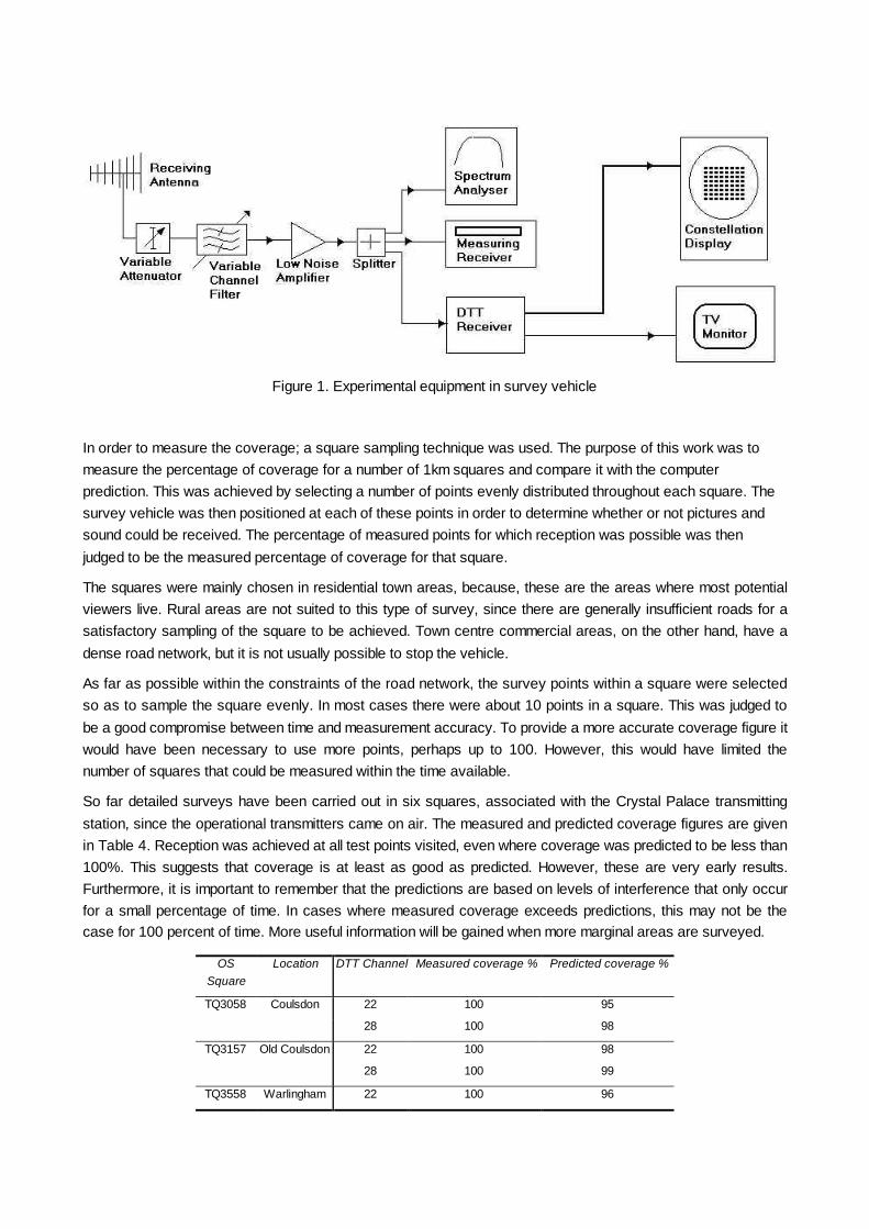
Figure 1. Experimental equipment in survey vehicle
In order to measure the coverage; a square sampling technique was used. The purpose of this work was tomeasure the percentage of coverage for a number of 1km squares and compare it with the computerprediction. This was achieved by selecting a number of points evenly distributed throughout each square. Thesurvey vehicle was then positioned at each of these points in order to determine whether or not pictures andsound could be received. The percentage of measured points for which reception was possible was thenjudged to be the measured percentage of coverage for that square.
The squares were mainly chosen in residential town areas, because, these are the areas where most potentialviewers live. Rural areas are not suited to this type of survey, since there are generally insufficient roads for asatisfactory sampling of the square to be achieved. Town centre commercial areas, on the other hand, have adense road network, but it is not usually possible to stop the vehicle.
As far as possible within the constraints of the road network, the survey points within a square were selectedso as to sample the square evenly. In most cases there were about 10 points in a square. This was judged tobe a good compromise between time and measurement accuracy. To provide a more accurate coverage figure itwould have been necessary to use more points, perhaps up to 100. However, this would have limited thenumber of squares that could be measured within the time available.
So far detailed surveys have been carried out in six squares, associated with the Crystal Palace transmittingstation, since the operational transmitters came on air. The measured and predicted coverage figures are givenin Table 4. Reception was achieved at all test points visited, even where coverage was predicted to be less than100%. This suggests that coverage is at least as good as predicted. However, these are very early results.Furthermore, it is important to remember that the predictions are based on levels of interference that only occurfor a small percentage of time. In cases where measured coverage exceeds predictions, this may not be thecase for 100 percent of time. More useful information will be gained when more marginal areas are surveyed.
OSSquare
Location DTT Channel Measured coverage % Predicted coverage %
TQ3058 Coulsdon 22 100 95
28 100 98
TQ3157 Old Coulsdon 22 100 98
28 100 99
TQ3558 Warlingham 22 100 96

28 100 94
TQ3562 Selsdon 22 100 98
28 100 98
TQ3965 West Wickam 22 100 100
25 100 100
28 100 100
29 100 98
32 100 100
34 100 98
TQ3966 West Wickam 22 100 100
25 100 100
28 100 100
29 100 98
32 100 100
34 100 100
Table 4. Measured vs. predicted coverage
RECEPTION ANOMALIES
In some areas, although the field strengths of the DTT signals were significantly greater than the receptionthreshold, reception was difficult. Possible causes of such anomalies have been investigated. These includeadjacent channel interference from analogue services, multipath propagation and man-made interference.
Adjacent Channel interference from analogue services
In order to avoid causing interference to other analogue and digital transmissions, many digital stations havebeen planned so that the radiated power is restricted in some directions. Generally, the analogue servicesfrom the same station will not be subject to these restrictions. Consequently, in these directions the ratio ofanalogue to digital field strengths will be significantly higher that the ratio of the nominal maximumtransmitter ERPs. In cases where the analogue and digital signals are on adjacent channels this may resultin reception difficulties due to adjacent channel interference from the analogue signal.
In order to investigate this situation, surveys were carried out in the coverage areas of the Hannington andCrystal Palace DTT transmitters.
At Hannington the DTT transmissions are subject to an ERP restriction to the East. It was expected that thiswould result in reception difficulties in the town of Basingstoke, to the South East of the transmitter. Three ofthe six multiplexes are at risk, since they have adjacent channel analogue services. Figure shows the resultsobtained at a sample of test points in the Basingstoke area. This diagram shows the relative locations of thetest points and the transmitter site. The approximate HRP of the transmitting antenna is also indicated. Foreach test point, figures are given for the analogue to digital power ratios for the received digital signals.
The village of Overton receives virtually the full ERP of the digital transmitter. Thus the power ratios are inagreement with the ratio of the nominal transmitter ERPs (17 dB). Consequently the digital signal can bedecoded easily as denoted by the ‘tick’ indicators in the diagram. In Basingstoke, however, the effect of theERP restriction can be seen. In the south of the town, the ratio is significantly higher than at Overton, but stillnot too high for the signals to be decoded. The further north the test point, the closer it is to the centre of theHRP null. Consequently, the more extreme are the analogue to digital power ratios. In the suburb ofChineham, in the extreme north, the analogue signal levels are all at least 40 dB greater than the digital

signals, and in one case the figure is 54 dB. The digital signal levels are sufficient to achieve reception, butthe receiver will not operate with these high levels of adjacent channel interference. This is denoted by the‘cross’ indicators. The protection ratio assumed for planning is 35 dB. When the ratio just exceeds this, thereceiver used in these tests could be made to work by careful adjustment of signal levels. However,reception could not be guaranteed. This is denoted at one of the test points by intermediate ‘question mark’indicators.
Figure 2. Reception results and analogue/digital ratios for test points in the Basingstoke area
A similar effect was noted in the coverage area of Crystal Palace. In order to avoid causing interferencesouth of the transmitter, the transmitting antenna for the four highest power multiplexes is arranged so that insome directions the maximum power is directed about 3 degrees below the horizon. Therefore the ERPradiated towards points close to the transmitter is greater than that radiated towards points further away. Thetwo lower power multiplexes are transmitted from the same antenna as the analogue services, which has anomni-directional pattern.
Figure shows the average of the received analogue to digital power ratios for the four highest powermultiplexes measured at points along a radial line centred on the transmitter site. The radial route waschosen to lie in a direction corresponding to one of the ERP restrictions. Also shown is the average analogueto digital power ratio for the two lower power omni-directional multiplexes.
At 5 km from the transmitter, the analogue signals are reduced owing to the VRP of their antenna, whereasthe high power digital multiplexes are not. Thus the analogue to digital ratio for the high power multiplexes isconsiderably smaller than the ratio of the nominal maximum ERPs (20 dB). As distance increases, however,the situation reverses and the ratio becomes greater than the ratio of the nominal maximum ERPs. In thecase of the low power multiplexes the ratio remains relatively constant. It can be seen that, beyond 10 km,the ratio for the higher power multiplexes becomes greater than that for the lower power multiplexes. The 18km point corresponds to the town of Swanley. Detailed surveys around this area revealed some locationswhere the ratio for the high power multiplexes was great enough to prevent reception. Ironically, the lowerpower multiplexes, which were not subject to the ERP restriction continued to be received.

Although these interference effects result in reception difficulties in high signal strength areas, thetransmitting antenna characteristics that cause them are incorporated into the computer predictionalgorithms, and the effects are generally well predicted.
0
5
10
15
20
25
30
35
0 5 10 15 20Distance from transmitter (km)
Rec
eive
d an
alog
ue/d
igita
l rat
io (d
B)
Average of high powermultiplexes
Average of low powermultiplexes
Figure 3. Analogue/digital ratio vs. distance from transmitter in ERP restriction
Multipath propagation (the capture system)
Reception is sometimes impaired by multipath propagation with relative delays in excess of the guardinterval. The effect of this is generally to increase the required Carrier to Noise Ratio (C/N), and hence thefield-strength threshold, for the receiver to operate. In extreme cases the receiver will not operate at anysignal levels. As with adjacent channel analogue interference, there is an increased likelihood of multipathproblems in areas where there is a restriction in the radiation pattern of the transmitting antenna. However,they are not easy to predict.
In order to investigate multipath effects, a powerful PC-based analysis tool was developed in associationwith Pioneer Digital Design Centre Ltd. The system consists of a fast Analogue to Digital Converter to digitisethe received COFDM signal and a digital memory to store a sample of the waveform. Associated softwareanalyses the captured sample to determine the amplitude and delay of any multipath echoes.
This technique was used extensively during field trials between 1996 and 1998 using an experimental pilotDTT transmitter at Crystal Palace. The transmissions had a very directional HRP such that the powerradiated to the North was 20 dB higher in level than that radiated to the South. This was found to result insevere multipath in many areas to the South of the transmitter. Figure shows three multipath profiles derivedfrom the capture system during this work, along with the associated minimum required C/N. The diagramsshow the amplitudes of delayed signals in dB relative to the direct signal, plotted against their delay times. Atthe Wallington test point, the echoes were relatively low in level. Consequently reception was possible with aC/N of 18.5 dB (about the lowest vale normally encountered). At Nork, there was a higher level echo,resulting in an increased C/N requirement of 25.3 dB. At Epsom Downs the multipath was even more severeand reception was not possible at all.
This measuring technique has continued to be used since the beginning of the service for DTT in the UK.However, although areas of multipath propagation have been found, due to less directional HRPs, no areashave yet been found where reception is prevented by multipath propagation.

Man-made Noise
In town centres, man-made noise can be a problem if the field strength does not exceed the receptionthreshold by a sufficient margin. So far this problem has been identified at one location in Basingstoke. Thislocation was near to the commercial centre of the town and suffered from low field strengths because of thetransmitter HRP.
Figure 4. Delay/amplitude plots for multipath echoes

INDOOR RECEPTION
An important aspect of terrestrial transmission is indoor portable reception. Work has been carried out todetermine the limit of coverage to indoor antennas and how it might be improved.
Measurements were made in a total of 33 residential buildings in the coverage area of the pre-operationalexperimental DTT transmissions from Crystal Palace. At each building, measurements were made of theloss of field strength associated with various rooms on different floors of the building. To do this a smallindoor antenna was moved around the room at a typical ‘set-top’ height of about one metre above floor level.The signals from the antenna were fed to a measuring receiver interfaced to a computer, which recorded themeasurements as the antenna was moved around the room. Analysis of the resulting data produced valuesfor the median and standard deviation of the field strength within the room. A reference field strength wasalso measured outside the building at a height of 10 metres using the survey vehicle. The building loss of aroom was defined as the ratio in dB of the outdoor field strength to the median value inside the room. Furthertests were carried out to determine the minimum field strength required inside the rooms for the digitalsignals to be decoded. By adding the building loss, it was possible to calculate the minimum outdoorfield-strength required at 10 metres to provide indoor coverage.
In practice, there was a considerable spread of values of building loss. A statistical approach was thereforeadopted with measured rooms grouped according to floor level – ground, first and second. The results aresummarised in Table 5. The first column gives the median value of the minimum outdoor 10 metre fieldstrength corresponding to each floor level. However, since the building loss values themselves relate to themedian field strength in a room, this value would only provide coverage to 50% of locations within the worstrooms. This level of coverage is considered to be just acceptable. Good coverage, with 90% of locationswithin a room served, requires an additional field strength equal to 1.3 times the standard deviation of thefield strength variation within the rooms (see Column 2).
Columns 3 and 4 of Table 5 give the maximum values of the 50% and 90% field strengths for each floorlevel. These represent the field strength values required to cover all measured rooms. When compared tothe minimum field strength required for outdoor reception at 10 metres (45 dB µV/m for the channel used inthe tests), it becomes clear that blanket coverage to all buildings can only be achieved in high field strengthareas close to the transmitter. However, an acceptable level of indoor reception, particularly in upstairsrooms, may be expected in a relatively large proportion of the coverage area of a transmitter.
50% of rooms All rooms
Room category 50% of locationswithin room
90% of locationswithin room
50% of locationswithin room
90% of locationswithin room
Ground Floor 74 79 86 91
First Floor 69 74 81 86
Second Floor 68 74 79 84
Table 5. Minimum field strength required at 10 metres to achieve various levels of indoor coverage
Clearly, there will be many areas where the field strength is too low for any useful level of indoor reception.In order to provide the flexibility of indoor reception in such areas, work was carried out within the ACTSVALIDATE project to determine the viability of a small domestic ‘gap-filler’. Such a device would amplify theDTT signals from an outdoor antenna and re-radiate them within the building. A prototype was developed byTeleves, one of the partners within the VALIDATE project. Although there are still a number of issues to be

resolved, initial trials were promising. An output power of less than 1 mW was found to provide goodcoverage in all houses tested.
CONCLUSIONS AND FUTURE PLANS
The roll-out of the DTT network in the UK is progressing well. Measurements in a few areas have confirmedthat the coverage is generally in line with expectations. In some areas, coverage is limited by HRPrestrictions in the transmitting antennas. This can give rise to difficulties such as multipath propagation andadjacent channel interference from analogue transmissions. In addition, at some locations the digital signalshave been found to suffer from man-made interference. Some preliminary work has been directed atquantifying these issues. As the transmitter rollout proceeds, more measurements will be required and, ifnecessary, solutions to any problems will be developed. However, it is not the intention of the BBC to surveythe coverage areas of all DTT transmitters. Indoor set-top reception of DTT services has been demonstrated.Although perfect indoor reception can only be expected very close to the transmitter, a useful level of suchreception can be expected in many more areas. Even if reception is only possible with an outdoor antenna,set-top reception could, in principle, be achieved using a domestic gap-filler device. Future work will bedirected at the issue of reception with commercial receivers using both outdoor and indoor antennas.
I.R Pullen BBC R&D UK
IEE Colloquium 'Digital Television - where is it and where is it going? 16 March 1999

POTENTIAL BENEFITS OF HIERARCHICAL MODES OF THEDVB-T SPECIFICATION
Chris Nokes, Justin Mitchell BBC R&D, UK
1 INTRODUCTION
Most people attending this IEE colloquium will be very familiar with the concept of digital terrestrial television(DTT), and hopefully will all have seen live reception of the signals at some time. However many of thosepeople will not have encountered the idea of hierarchical modulation, which is a part of the ETSI standard [1]– the definition of the RF transmission standard for DVB-T signals.
This paper will introduce the ideas behind the hierarchical modes, and show one of the ways in which theycould be used at some time in the future, or perhaps by countries still in the process of planning their DTTservices at the moment. This paper is not intended to suggest that the existing UK DTT services should bereplaced by hierarchical services, but instead it points out a potential way in which the DTT system could beused, if additional frequencies become available in the future.
2 WHAT IS HIERARCHICAL MODULATION?
The hierarchical modes of the DVB-T specification provide a means by which the MPEG-2 bit-stream can bedivided into two parts. One stream, the high priority (HP) stream, is heavily protected against noise andinterference, whereas the second, low priority (LP), stream is much less well protected. The HP stream oftencarries data at a lower bit-rate than the LP stream.
The hierarchical modulation options are most easily illustrated by reference to constellation diagrams. Figure ashows the constellation of the data carriers of the DVB-T signal in the standard mode as used in the UK (thismode is 2K, 64-QAM, code rate 2/3, guard interval fraction 1/32). The pilot carriers have been omitted forclarity. Figure b shows the constellation for one of the hierarchical
modes.
d
4d
real
imaginary
real
imaginary
(b)(a)
Figure 1Constellations of 64-QAM DVB-T signals (see text for description of circled points) a) non-hierarchical; b) hierarchical with α=4
In Figure1a it can be seen that each of the real and imaginary axes carries three bits of data, leading to eightmodulation levels on each axes, and 64 constellation points. All of the 64 constellation points are equallyspaced, and are treated equally. There is one data stream and the entire set of constellation points is used to

transmit it. So for example the data sequence ‘100111’ would cause the indicated constellation point to beused.
In Figure 1b the constellation points have been grouped. The data that modulates the HP stream is used toselect the quadrant of the transmitted point. For example if the HP bit sequence ‘10’ is to be transmitted, thetop left quadrant will be used. The LP stream, which operates at a higher bit-rate, is used to determine theexact constellation point within the quadrant. For example the LP sequence ‘0111’ would select the indicatedconstellation point. In the hierarchical case a receiver with a low signal level and hence a high level ofthermal noise would only be able to detect the quadrant and not the individual constellation points, and soonly the HP stream could be decoded. A receiver with a lower level of noise could decode all of the points,and so would be able to reproduce both HP and LP streams.
It should be noted that the hierarchical modulation options do not make any constraint on the data streamsthat are transmitted, (other than that they should be MPEG-2 transport streams). There have beensuggestions in the past for systems where hierarchical modulation was linked to hierarchical source coding.Although hierarchical source coding is not catered for in the DVB-T specification, it is possible to use asimulcast system, to provide a standard definition picture in the HP stream and a high definition (HDTV)picture in the LP stream.
2.1 Specification Options
The constellation ratio α is used to determine the spacing between the groups of constellation points. α is theratio of the spacing between the groups to the spacing between individual points within a group. So for theexample above, the ratio is 4. The permitted values of α are 1, 2 and 4. In the case of α =1, the constellationis indistinguishable from that of Figure . The description above applies to the set of cases where theconstellation is of 64-QAM form. An alternative set of options allows for a constellation of 16-QAM form.
3 WHAT CAN WE USE THE HIERARCHICAL MODES FOR?
The flexibility provided by hierarchical modulation could be used in a number of ways, and these aredescribed in the following sections.
3.1 More rugged main services
As we have seen from the previous description, hierarchical modulation provides one bit-stream that is morestrongly protected against noise and interference. This stream could be used to carry one service in amultiplex that was considered more important than the other services. There have been some discussions inAustralia about operating some of their DTT services in this way, for simulcasting HDTV. This could providea standard definition service for portable receivers and an HDTV service for fixed receivers (HDTV receiversare unlikely to be portable in any case!).
An alternative way of looking at this option would be to say that the service area coverage that is achievedfor the HP stream is higher than the coverage for the equivalent non-hierarchical mode. This point will beillustrated further shortly. Whilst this sounds as though something is being achieved for nothing, in practicethe penalty is that there is a small loss of coverage for the LP stream compared with the non-hierarchicalmode.
3.2 More bit-rate for similar coverage
If a different approach is adopted, the coverage achieved with an existing non-hierarchical mode could beroughly matched when using the hierarchical mode, but whilst carrying data at a higher overall bit-rate. Thiswould be achieved by for example converting non-hierarchical 64-QAM with a code rate of 2/3 into ahierarchical system with an HP code rate of 3/4, and an LP code rate of 2/3. This would still have broadly
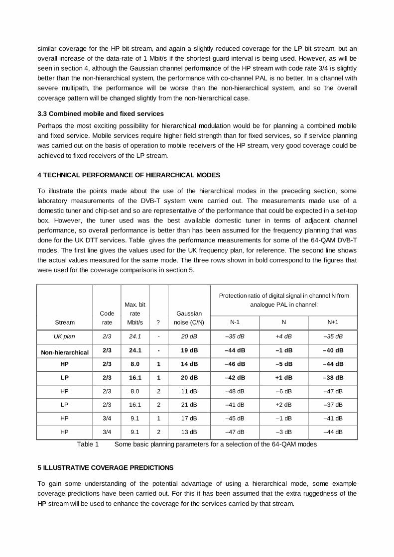
similar coverage for the HP bit-stream, and again a slightly reduced coverage for the LP bit-stream, but anoverall increase of the data-rate of 1 Mbit/s if the shortest guard interval is being used. However, as will beseen in section 4, although the Gaussian channel performance of the HP stream with code rate 3/4 is slightlybetter than the non-hierarchical system, the performance with co-channel PAL is no better. In a channel withsevere multipath, the performance will be worse than the non-hierarchical system, and so the overallcoverage pattern will be changed slightly from the non-hierarchical case.
3.3 Combined mobile and fixed services
Perhaps the most exciting possibility for hierarchical modulation would be for planning a combined mobileand fixed service. Mobile services require higher field strength than for fixed services, so if service planningwas carried out on the basis of operation to mobile receivers of the HP stream, very good coverage could beachieved to fixed receivers of the LP stream.
4 TECHNICAL PERFORMANCE OF HIERARCHICAL MODES
To illustrate the points made about the use of the hierarchical modes in the preceding section, somelaboratory measurements of the DVB-T system were carried out. The measurements made use of adomestic tuner and chip-set and so are representative of the performance that could be expected in a set-topbox. However, the tuner used was the best available domestic tuner in terms of adjacent channelperformance, so overall performance is better than has been assumed for the frequency planning that wasdone for the UK DTT services. Table gives the performance measurements for some of the 64-QAM DVB-Tmodes. The first line gives the values used for the UK frequency plan, for reference. The second line showsthe actual values measured for the same mode. The three rows shown in bold correspond to the figures thatwere used for the coverage comparisons in section 5.
Protection ratio of digital signal in channel N fromanalogue PAL in channel:
StreamCoderate
Max. bitrate
Mbit/s ?Gaussian
noise (C/N) N-1 N N+1
UK plan 2/3 24.1 - 20 dB –35 dB +4 dB –35 dB
Non-hierarchical 2/3 24.1 - 19 dB –44 dB –1 dB –40 dB
HP 2/3 8.0 1 14 dB –46 dB –5 dB –44 dB
LP 2/3 16.1 1 20 dB –42 dB +1 dB –38 dB
HP 2/3 8.0 2 11 dB –48 dB –6 dB –47 dB
LP 2/3 16.1 2 21 dB –41 dB +2 dB –37 dB
HP 3/4 9.1 1 17 dB –45 dB –1 dB –41 dB
HP 3/4 9.1 2 13 dB –47 dB –3 dB –44 dB
Table 1 Some basic planning parameters for a selection of the 64-QAM modes
5 ILLUSTRATIVE COVERAGE PREDICTIONS
To gain some understanding of the potential advantage of using a hierarchical mode, some examplecoverage predictions have been carried out. For this it has been assumed that the extra ruggedness of theHP stream will be used to enhance the coverage for the services carried by that stream.

A single frequency from a single transmitter has been chosen (channel 25 from the Crystal Palacetransmitter in south London, using the current DTT transmitter power and radiation pattern. Coveragepredictions were carried out on the basis of the measured performance figures given in section 4. Note thatthe non-hierarchical 64-QAM (which is the same mode as is used for the UK DTT service) has differentperformance parameters from the values used for the UK frequency planning. The values used for frequencyplanning are the values agreed following a number of measurements on a range of receivers. The figuresused for this example are the results from a single very good tuner. Hence the coverage predictions in themaps do not directly correspond to the actual coverage of today’s DTT service. Furthermore, since thecoverage of only a single transmitter has been calculated, the coverage cannot be taken as exactlyrepresentative of the coverage that would be obtained throughout the whole country. It does however givesome indication of the likely benefits.
Figure 2 shows the coverage that might be achieved using a non-hierarchical modulation with theperformance parameters of section 4. Figure 3 shows the coverage of the HP stream of a hierarchicaltransmission with α=1 and figure 4 shows the coverage of the LP stream. The actual population coveragefigures are shown in Table 2. It can be seen from this that the coverage for the HP stream is increased by8.4% compared to the non-hierarchical transmission, whereas the coverage of the LP stream is only reducedby 2.7%.
Figure 2 Coverage for non-hierarchical system
Figure 2 Coverage for non-hierarchical system
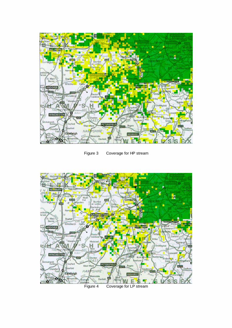
Figure 3 Coverage for HP stream
Figure 4 Coverage for LP stream

Coverage
StreamCoderate α
Population(million)
% change
Non-hierarchical 2/3 - 9.3 –
HP 2/3 1 10.1 +8.4%
LP 2/3 1 9.0 –2.7%
Table 2 Coverage predictions from Crystal Palace on channel25 for the selected modulation options
6 CONCLUSIONS
An introduction to the use of the hierarchical modulation options of the DVB-T specification has been given,explaining what they are and how they could be used. Some performance parameters for a selection of thehierarchical modes have been measured.
The performance parameters have been used to predict the coverage that could be achieved usinghierarchical modulation from the Crystal Palace transmitter. These predictions have shown that the HPstream could achieve a coverage increase of 8.4% compared to the non-hierarchical case, whilst thecoverage of the LP stream is reduced by 2.7%.
7 ACKNOWLEDGEMENTS
The authors would like to sincerely thank their colleagues without whose contributions this paper would nothave been possible: Adrian Robinson who carried out all the performance measurements, and Phil Marsdenwho performed the coverage predictions. The work was carried out within the ACTS MOTIVATE projectwhich is supported by the Commission of the European Union through the fourth Framework programme.
8 REFERENCES
European Standard. 1997. Digital Video Broadcasting (DVB); Framing structure, channel coding andmodulation for digital terrestrial television. European standard EN 300 744 V1.1.2 (1997-08). EuropeanTelecommunications Standards Institute, August 1997.
C. R. Nokes, J Mitchell - BBC R&D, UK.
IEE Colloquium Digest 99/072

INTRODUCING MOBILE MULTIMEDIA BROADCASTINGSERVICES
P. Christ and P. Pogrzeba, Deutsche Telekom Berkom GmbH Germany MOTIVATE partners
ABSTRACT
This paper presents the MOTIVATE project fundedby the European Commission and will give firstresults of laboratory measurements, field trials andsimulations of an optimised receiver in theframework of the MOTIVATE (Mobile Televisionand Innovative Receivers) project funded by theEuropean Commission. These two major streamsof innovation are expected from this project:
Specification for an optimised DVB-T receiverfor mobile reception,
Implementation guidelines for planning ofmobile DVB-T networks.
Finally, this paper should give an outlook on firstmobile services that will exploit results of theMOTIVATE project. Applications designed for thespecific needs of the car environment will beintroduced with an outlook IFA’99.
INTRODUCTION
In the UK terrestrial television will stay theprevalent distribution media. The initial applicationof DVB-T is to provide more channels to increasechoice. In other countries – such as Germany –there is a much higher penetration of cable andsatellite: only 6.8 M of the 36 M Germanhouseholds rely on terrestrial broadcasting. DVB-Tcould overcome some of the limitations ofanalogue terrestrial TV but this alone would notguarantee a successful introduction of DVB-Tservices: added value services are needed toattract more users and increase revenues forbroadcasters and network providers.
Mobile reception of video, Internet andmultimedia data could be an attractive featureto help the launch of DVB-T in Germany. Only
terrestrial broadcasting could bring mobility to theend user. A data rate up to 15 Mbit/s using one8 MHz UHF channel seems to be possible with the64QAM mode. Mobility is one of the advantages ofthe European DVB-T solution against competingstandards.
THE MOTIVATE PROJECT
In May 1998, after two years of feasibility tests ofmobile reception by Deutsche Telekom, aconsortium of 17 broadcasters, network operators,manufacturers of professional and domesticequipment and research centres launched theMOTIVATE project. It is funded by the EuropeanCommission in the ACTS (AdvancedCommunications Technologies and Services)Programme. MOTIVATE investigates the practicaland theoretical performance limits of DVB-T formobile reception. The optimisation of receiveralgorithms for channel estimation, channelcorrection and time synchronisation will lead to thenext generation of DVB-T receivers designed forthe mobile environment. MOTIVATE will prepareguidelines for broadcasters and network operatorson how to implement DVB-T networks for mobilereceivers. The promotion of mobile television willbe an essential part of the MOTIVATE project.Major Demonstrations are planned for IFA’99 andIBC’99. MOTIVATE builds on the strongconsortium shown at the bottom of this page andhas the backing of a number of sponsoringpartners (TeleDanmark, RTÉ, DVB promotionalmodule, TU-Munich, BMW and TU-Braunschweig).The collaboration with all broadcasters interestedin mobility makes MOTIVATE the spearhead inpromotion of mobile DVB-T services.

Mobile channel
The mobile channel is characterised by multipathpropagation and Doppler effect. The multipathpropagation causes different strong attenuation inthe receiving signal depending on elapse time,amplitude and phasing of the echo paths. TheDoppler effect causes a frequency shift dependingon transmission frequency f and speed of thereceiver v . The Doppler frequency is determinedby fD =v/c f cos α (c speed of light, α anglebetween receiving path and direction ofmovement).
OFDM is an effective method to combat thedistorsions of the transmitting signal caused by themultipath propagation. The received signal cantolerate echoes by insertion of a guard interval ifthe longest echoes are within this interval. In thecase of Doppler frequency an efficient channelestimation can remarkably improve theperformance of the receiver.
Mobile lab and field tests of Deutsche Telekom
Deutsche Telekom Berkom carried out extensivemeasurement series in the laboratory and in thefield to investigate the performance of DVB-Treceivers in a mobile environment. For allmeasurements a 2K-FFT signal was used.
We used for laboratory measurements a failurecriteria determined by the subjective assessmentof picture quality. A sufficient picture quality isachieved if no errors are visible in a picturesequence of 20 seconds. This method is called thesubjective failure point (SFP) method.
The artificial two paths model with Doppler shiftwas generated in a channel simulator for thelaboratory measurements. The critical case of 0 dBecho in all measurements was used.
Figure 1 shows the results of laboratorymeasurements. The C/N behaviour for differentDVB-T modulation schemes (QPSK, 16-QAM, 64-QAM with code rate 1/2 and QSPK and 16-QAMwith code rate 2/3) versus speed at an echo delayof 20 µs is shown. QPSK (CR=1/2 and 2/3) and16-QAM (CR =1/2) show no noticeable increase ofC/N values at higher speeds. However, the C/N
values of 16-QAM with CR=2/3 and 64-QAM withCR=1/2 are increasing from a speed of 100 km/h.
Three suitable modes could be identified for mobilereception of DVB-T, QPSK, 16-QAM and 64-QAMwith code rate 1/2 for each.
Thresholds of the minimum receiver input voltagefor the AWGN and the mobile channel can begiven as a result of the laboratory measurements.These thresholds are contained in Table 1 for theinvestigated modes QPSK, 16-QAM and 64-QAMwith code rate 1/2 each. Levels higher than thesethresholds guarantee error free pictures at thereceiver.
Threshold QPSK 16-QAM 64-QAM
AWGN 16 dBµV 22 dBµV 30 dBµV
Mobile 22 dBµV 29 dBµV 38 dBµV
Table 1: AWGN and Mobile thresholds
Deutsche Telekom Berkom made field trialmeasurements to study the performance of a DVB-T receiver in real mobile environments in the areaof Cologne. The ERP of the transmitter was 1 kW.The transmission of DVB-T signals performed inthe UHF channel 40 (626 MHz). The same modeswere investigated as in the laboratory tests.
The main objective of the field tests was to checkthe identified mobile thresholds in Table 1 in a realmobile environment. If the thresholds are correctthen a prediction of the expected Video Error Ratefor the route can be given on the basis of a fieldstrength prediction.
The field tests have confirmed the results obtainedfrom the laboratory tests of the DVB-T modes withthe simple 0 dB artificial echo model. Thethresholds for the examined receiver(corresponding to the constellation order)guarantee a faultless mobile video transmission.The identified mobile thresholds correspond to acoverage probability of 99 %. These thresholdscan be seen as a first basis for the planning ofservices. Further investigations are still needed.
“Mobile MOTIVATE DVB-T Lab Tests”
The “Mobile DVB-T lab tests“ were organised inNovember 1998 to compare the behaviour of state-

of-the-art receivers and to study the performancein a mobile environment. Three different channelprofiles were defined (easy, regular and difficultprofile) to perform these tests with a channelsimulator.
9 receivers have been tested which constitute alarge panel of equipment for different purposes(professional, consumer and experimentaldemodulators). The measurement results madeclear that mobile DVB-T reception is possible evenwith currently available receivers. Six suitablemodes (three for the 2k mode and three for the 8kmode) could be identified for mobile reception. Allof them have the code rate 1/2. Table 2 containsthe reachable speed on average of all receiversand the necessary C/N ratio at a speed of 100km/h of the 2k and 8k mode for the case of easyprofile.
Modulation Data rate[Mbit/s]
Averagespeed
C/N [dB]at 100 km/h
2k QPSK ½ 4.98 400 92k 16QAM ½ 9.95 250 152k 64QAM ½ 14.92 190 218k QPSK ½ 4.98 100 10*8k 16-QAM ½ 9.95 70 17*8k 64QAM ½ 14.92 50 -
Table 2: Measurement results of mobile reception inthe 2k mode (based on UHF channel 43), (* C/N at 50 km/h)
The speed limit is approximately reduced by thefactor of four in the 8k mode case. One receiverwas already optimised slightly towards mobilereception and achieved much better results indifficult reception conditions and 8k mode.
Next Generation Mobile Receiver
From this reference MOTIVATE started to optimisethe algorithms for mobile reception.
The mobile reception of DVB-T results in twoadditional components the system has to copewith. On the one hand the Doppler frequency hasto be taken into account, on the other hand thechannel transfer function is no longer a staticchannel, but a fast time variant channel. Forstationary or even portable reception it is notnecessary to provide a channel estimation which is
able to follow fast variations of the channel transferfunction.
The optimisation of channel estimation usingWiener filter algorithms and FFT leakageequalisation, the optimisation of antenna diversityin a mobile receiver provided first encouragingresults.
Further simulation work is needed in 1999 before aspecification for the next generation mobile DVB-Treceiver could be given and implementations on ahardware platform could be realised. Prototypesreceivers will be tested in MFNs and SFNs, inorder to evaluate the real gain of the network forcoverage in a mobile environment. Hierarchicalmodulation offers a real possibility to combine therobustness of QPSK modulation for mobilereception and much higher data rates of 64 QAMmodulation for stationary reception.
Network structures
The MOTIVATE project investigates coverageaspects for DVB-T services by using simulationand prediction tools and by measuring theperformance of DVB-T in both laboratory tests andfield trials. The network topology is being optimisedby the selection of the antenna polarisation, thecombination of MFNs and SFNs, the use of gap-fillers, microcell/macrocell and the choice ofsuitable DVB-T modes (modulation, code rate,guard interval).
Partners in MOTIVATE adapted existing planningsoftware for DVB-T urban networks and first mobileDVB-T measurements were performed andcompared with prediction models. One mainoutcome of the project will be the implementationguidelines for mobile DVB-T reception to set uptransmitter networks. To ensure that theseguidelines are soundly based, MOTIVATE carriesout laboratory measurements and field trials.
Hierarchical Modulation
Enhanced mobile and portable reception wasexperienced by applying the hierarchicaltransmission scheme as specified for DVB-T. Onehigh priority data stream (HP) and one low prioritystream (LP) were transmitted independently using

a QPSK modulation within a 16- or 64-QAMmodulation. This means, two bits of the encodedHP stream are used to select the quadrant of onecomplex carrier and 2 or 4 bits of the encoded LPstream are used to form the constellation pointwithin the selected quadrant. Therefore, a subsetof broadcast services transmitted in one TVchannel is routed to the HP stream and the otherpart of programmes are routed to the LP stream.
With hierarchical modulation different servicecoverage areas for the HP and the LP data streamwill exist. The main questions investigated inMOTIVATE concerning hierarchical modulationwere:
Does hierarchical modulation allow mobile orportable reception of the HP stream even if there isno reception of the LP stream ?
What is the loss in performance for the reception ofthe LP stream using hierarchical modulationcompared to the reception performance of aconventional, non-hierarchical 16- or 64-QAM ?
What is the difference in C/N performance and inthe size of the service coverage area betweenmobile or portable reception of the HP streamcompared to the stationary reception of the LPstream ?
What is the difference in C/N performance and inthe size of the service coverage area betweenmobile reception of the HP stream compared toportable reception of the LP stream ?
The results of the field trials performed inMOTIVATE showed that there is a high robustnessfor mobile or portable reception of the HP stream.Even if the constellation is totally noisy an excellentreception of the audio and video is possible. Theloss in performance for the reception of the LPstream using hierarchical modulation compared tothe reception performance of a conventional, non-hierarchical modulation in average is 1.4 db for thereceiver tested.
Mobile Services
Mobile reception of DVB-T could bring newfeatures to broadcast networks, makingapplications and services accessible and usable byanyone, anywhere, anytime, for business or
individual use. A narrowband return channel couldbe integrated using GSM. Here are someexamples of mobile services, some of them will bedemonstrated by the MOTIVATE project at IFA’99and IBC’99.
Digital television for cars, buses and trains
Digital television in luxury cars, buses and trainscould become the first service for mobile users. Itwould use some of the existing programmes withadditional traffic and navigation information. Anaudio description service would be needed tomake programmes safely accessible to drivers andfront-seat passengers.
At IFA’99 the MOTIVATE project will develop andimplement Mobile Multimedia Services into the carenvironment taking into account the specificrequirements given by the resolution, position andsize of the navigation display already implementedin cars, the peripherals such as the in-car network,antenna and other communication systems suchas GSM. MOTIVATE will customise mobileservices for the driver and co-pilot which aremainly interested in traffic, business, travel andother information. In addition the storage capacityof the receiver would allow to download andupdate a significant amount of data on-the-move.
Mobile contribution links
RTÉ and Deutsche Telekom Berkom have testedmobile transmission of DVB-T signals forcontribution links. A low power transmitter can beinstalled in a vehicle to transmit MPEG-2 signalsfrom a vehicle – even while in motion– to a studio.Tests have been made at the UHF and in theL-Band. This service might be used at sportsevents, such as the Tour de France or the LondonMarathon, for interviews with busy politicians, or forthe reporters in the field.
Mobile Internet Broadcast
Today, solutions for Internet Broadcast have beendeveloped for stationary reception, mainly usingsatellite and cable based services. InternetBroadcast is based on an Integrated ReceiverDecoder (IRD) which could combine broadcast andtelephony. The return channel and interactivity is
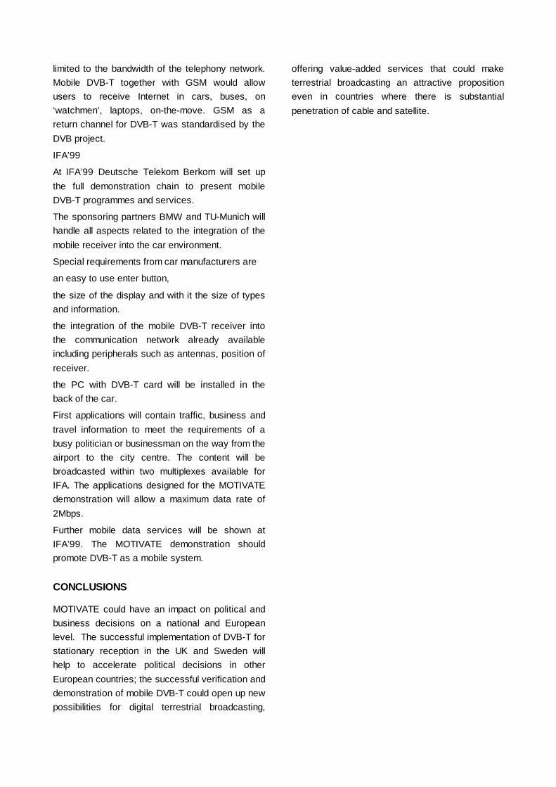
limited to the bandwidth of the telephony network.Mobile DVB-T together with GSM would allowusers to receive Internet in cars, buses, on‘watchmen’, laptops, on-the-move. GSM as areturn channel for DVB-T was standardised by theDVB project.
IFA’99
At IFA’99 Deutsche Telekom Berkom will set upthe full demonstration chain to present mobileDVB-T programmes and services.
The sponsoring partners BMW and TU-Munich willhandle all aspects related to the integration of themobile receiver into the car environment.
Special requirements from car manufacturers are
an easy to use enter button,
the size of the display and with it the size of typesand information.
the integration of the mobile DVB-T receiver intothe communication network already availableincluding peripherals such as antennas, position ofreceiver.
the PC with DVB-T card will be installed in theback of the car.
First applications will contain traffic, business andtravel information to meet the requirements of abusy politician or businessman on the way from theairport to the city centre. The content will bebroadcasted within two multiplexes available forIFA. The applications designed for the MOTIVATEdemonstration will allow a maximum data rate of2Mbps.
Further mobile data services will be shown atIFA’99. The MOTIVATE demonstration shouldpromote DVB-T as a mobile system.
CONCLUSIONS
MOTIVATE could have an impact on political andbusiness decisions on a national and Europeanlevel. The successful implementation of DVB-T forstationary reception in the UK and Sweden willhelp to accelerate political decisions in otherEuropean countries; the successful verification anddemonstration of mobile DVB-T could open up newpossibilities for digital terrestrial broadcasting,
offering value-added services that could maketerrestrial broadcasting an attractive propositioneven in countries where there is substantialpenetration of cable and satellite.
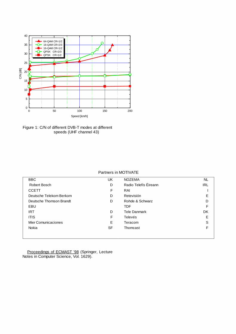
Figure 1: C/N of different DVB-T modes at differentspeeds (UHF channel 43)
Proceedings of ECMAST ’98 (Springer, LectureNotes in Computer Science, Vol. 1629).
Partners in MOTIVATE
BBC UK Robert Bosch DCCETT FDeutsche Telekom Berkom DDeutsche Thomson Brandt DEBUIRT DITIS FMier Comunicaciones ENokia SF
NOZEMA NLRadio Telefís Éireann IRLRAI IRetevisión ERohde & Schwarz DTDF FTele Danmark DKTelevés ETeracom SThomcast F
0 50 100 150 2000
5
10
15
20
25
30
35
40
64-QAM CR=1/2 16-QAM CR=2/3 16-QAM CR=1/2 QPSK CR=2/3 QPSK CR=1/2
C/N
[dB
]
Speed [km/h]

SINGLE FREQUENCY NETWORKS FOR DIGITAL VIDEOBROADCASTING
Jesús M. Fernández, J. Capdevila, R. García, S. Cabanillas, S. Mata, A. Mansilla and Jose M. FernándezEngineering R&D - RETEVISION S.A., Spain [email protected]
ABSTRACT.
This paper introduces the Terrestrial Digital Video Broadcasting DVB-T, stating its innovative aspects and itsmajor advantages for data broadcasting, particularly TV broadcasting. It also presents the experimentalDVB-T network built up by Retevisión in the framework of the Spanish VIDITER project (Terrestrial DigitalVideo) and the European ACTS VALIDATE (Verification and launch of Integrated Digital AdvancedTelevision in Europe) and ACTS MOTIVATE projects (Mobile Television and Innovative Receivers). Theexperience and some of the results of the different tests carried out by Retevisión are afterwards discussed.
WHY DIGITAL TV BROADCASTING?
Generally, the digital technology presents some major advantages in baseband efficiency, flexibility and RFperformance that make its use very attractive to broadcasters.
Effectively, when addressing to TV broadcasting, the digital signals are more robust and the spectrum use ismore efficient; more than one program may be broadcasted using the same bandwidth and having evenbetter picture quality. Moreover those digital signals are easier to process and more computer friendly.
The only issue is how long will it take to completely change the technology considering the large number ofanalogue TV receivers worldwide. Some transition period will probably be started in which both technologiescoexist (broadcasting the same TV contents in analogue and digital, often called SIMULCASTING, and someadditional only-digital contents).
WHAT IS DVB?
The Digital Video Broadcasting Project (DVB) is a marked-led initiative to standardise digital broadcastingworldwide. It is formed of 240 members from more than 35 countries, in which there are representatives ofbroadcasters, manufacturers, network operators and regulatory bodies.
The DVB was formed in September 1993 and along these years has been producing several systemspecifications that have become standard in organisms as the ETSI (European Telecommunication StandardInstitute) or CENELEC (European Committee for Electrotechnical Standardisation).
The DVB family of standards
The DVB has been producing different system specifications including satellite: DVB-S [EN 300421], cable:DVB-C [EN 300429], terrestrial: DVB-T [EN 300744], microwave: DVB-MVDS [EN 30048] and DVB-MMDS[EN 300749], community antenna: DVB-SMATV [EN 300743] and others.
The key word of the DVB standards is interoperability , all of them are part of a family of systems that makeuse of maximum commonality in order to enable the design of “synergetic” hard- and software.
The DVB transmission systems offer a “pipe” for data containers. They are transparent for SDTV (StandardDefinition TV), EDTV (Enhanced Definition TV) and HDTV (High Definition TV), for audio at all quality levelsand for all kinds of general data (multimedia data broadcasting).
All the specifications are based on the selection of the MPEG-2 (Moving Pictures Experts Group) for codingaudio and video and for the system level.

DVB-T – TERRESTRIAL DIGITAL VIDEO BROADCASTING
The DVB-T system for terrestrial broadcasting is probably the most complex DVB delivery system.
The key feature of the system is the use of COFDM (Coded Orthogonal Frequency Division Multiplexing).This is a very flexible wide-band multicarrier modulation system that uses different levels of forward errorcorrection, time and frequency interleaving and two level hierarchical channel coding.
Basically, the information to be transmitted is split into a given number (“2k” 1705 or “8k” 6817) of modulatedcarriers with individual low bit rate, so that the corresponding symbol time becomes larger than the delayspread of the channel. A guard interval (1/4, 1/8, 1/16, 1/32 of the symbol time) is inserted betweensuccessive symbols to avoid intersymbol interference and to protect against echoes.
Depending on the channel characteristics, different parameters (sub carrier modulation – QPSK, 16QAM,64QAM –, number of carriers – 2k, 8k –, code rate of inner protection, guard interval and modulationparameter - α) can be selected obtaining different operation modes . Every mode offers a trade-off betweennet bit rate and protection of the signal (against fading, echoes, etc.). Depending on the selected operationmode, 60 different net bit rates could be obtained ranging from 5 to 32 Mbps.
The selection of the COFDM modulation system presents two major advantages that make its usevery interesting to terrestrial digital video broadcasting:
Ø COFDM improves the ruggedness of the system in the presence of artificial (long distance transmitters)or natural (multiple propagation) echoes. Actually, the echoes may benefit instead of interfere the signalif they fall inside the guard interval.
Ø On the one hand, COFDM provides a considerable degree of immunity to narrow-band interferers asmaybe considered the analogue TV signals; and on the other hand it is seen by those analogue signalsas white noise, therefore not interfering or having little effect upon them.
All these characteristics enable a more efficient use of the spectrum (possible use of the so-called taboochannels, which usually are the only available ones to start new DVB transmissions); and the introduction ofSingle Frequency Networks (SFN).
Moreover, portable and mobile reception of DVB-T signals is possible. One efficient way to achieve that is byusing hierarchical transmissions, in which one of the modulated streams (so-called HP – High Prioritystream), having higher protection against errors but reducing its net bit rate, is used for portable and mobilereception; while the other one (so-called LP – Low Priority stream), having lower protection and higher bitrate, is used for fixed reception.
The ACTS MOTIVATE project, in which Retevisión participates, is currently addressing such issues,demonstrating and assessing the mobile and portable reception of DVB-T and developing algorithms andmodels for new enhanced receivers optimised for such reception conditions.
MULTIMEDIA AND INTERACTIVITY
Nowadays the importance for the broadcasters of offering new added value services, especially multimediaand interactivity, is out of question.
The number of applications is continuously growing and evolving. Among them: pay per view, NVoD, videoon demand, home shopping, home banking, Internet access, etc.
Most of those interactive services are asymmetric; the user expects a great amount of information (severalKbps or even Mbps) but request this information through a low speed return channel (few Kbps).

DVB provides network independent protocols together with a full set of network dependent return channels(e.g. PSTN – ISDN, DECT, GSM, etc.).
The advantage of DVB transmissions is that they do not distinguish between data, video or audio (it mayeven be used to broadcast data which itself incorporates audio and video as some Internet pages do).
Besides, DVB-T provides the extra advantage of joining portable and mobile reception to the previouslymentioned characteristics.
DVB data profiles
DVB foresees four ways of data broadcasting depending on the necessities:
♦ Data piping : asynchronous, non-synchronised, end to end data delivery.
♦ Data streaming : streaming oriented, end to end delivery of asynchronous, synchronous or synchroniseddata.
♦ Multiprotocol encapsulation : data services that require the transmissions of datagrams (as the ones ofTCP-IP).
♦ Data carousels: data services that require periodic transmissions of data modules.
SINGLE FREQUENCY NETWORKS
Traditionally, the analogue TV broadcasting had to face the problem of co-channel interferences byprohibiting the re-use of the same channel over considerable distances. This results in an extremelyinefficient use of the spectrum. As shown in Figure 1, in conventional 9-frequency layouts, each channel isprohibited over approximately 89% of the land area.
Fig. 1. MFN frequency planing for Conventional Analogue TV
An alternative to those Multi Frequency Networks (MFN) is to use a set of transmitters spread throughout agiven territory (a city, a region or even a country) temporally synchronised and transmitting at the samefrequency. Such configuration is called Single Frequency Network (SFN).
The advantages are enormous in terms of spectrum efficiency. Whereas in analogue MFN a single SDTVprogram was transmitted over 9 RF channels, now more than one program could be broadcasted using asingle RF channel. 9 Times less spectrum is used than in MFN! Or, 45 times more programs (assuming 5SDTV programs per channel) can be broadcasted using the same spectrum!
Moreover, taking advantage of the beneficial effect of the echoes inside the guard interval, less power wouldbe needed in locations on the verge of the coverage area of two neighbouring transmitters, signals comingfrom both would contribute to improve the overall carrier to noise ratio.
Shadowed areas can also be served by direct reamplification using a co-channel retransmitter often called“gap filler”.
A drawback of SFNs is that the flexibility of dynamically replacing the contents of a program is lost.Effectively, all the transmitters of a SFN must broadcast the same contents in the same moment in time.
A
D E FA B C A
G H I

SFN Constraints
Following the main constraints that the SFN operation introduces into the network will bebriefly assessed:
Synchronisation constraints
All the signals broadcasted by the transmitters of a SFN must be synchronised in terms of frequency, timeand bit.
The frequency synchronisation requires that a common reference oscillator shall drive all cascadedoscillators within each transmitter.
The time synchronisation requires that each transmitter shall broadcast the nth symbol at Tn ±1µs (where Tndenotes the ideal instant for the nth symbol to be transmitted).
The bit synchronisation requires that the same symbol shall be transmitted at the same time. Therefore allcarriers shall be identically modulated. Hence the same bits should modulate the same kth carrier.
In order to fulfil those requirements, DVB-T provides the MIP specification [TR101191]. By means of a SFNadapter, located at the output of the Transport Stream (TS) generation process, Megaframe IdentificationPackets (MIP) are inserted periodically into the TS. Modulators use those additional packets for the time andbit synchronisation.
The synchronisation mechanisms are based on the existence of two global external references: a frequencyreference of 10 MHz and a time reference of 1 pps (pulse per second); and example of a global systemproviding such references is the GPS (Global Positioning System).
Transmitter requirements
A complete set of specific requirements for transmitters have been identified within theframework of the ACTS VALIDATE project.
• Frequency stability . Each carrier should be transmitted in a frequency within the interval fk±(∆f/100). The
transmitter needs the external frequency reference for synchronisation in SFN (10 MHz).
• Oscillators phase noise . One of the most limiting factors found during the tests of transmitters andtransposers was the phase noise of the oscillators. In some cases transmitters which are perfectlysuitable for PAL transmissions appear to be of no use in the case of DVB-T because of phase noise.
• Output back-off. The maximum power that can be obtained by a given transmitter is limited by the non-linearity effect of the amplifiers, consequently affecting to the quality of the reception. For each kind oftransmitter used for DVB-T broadcasting there is a fixed output power value that maximises thecoverage area. Transmitting below this value, the capabilities of the equipment are not fully used, andtransmitting above, we obtain added system implementation losses, which are greater than the expectedcoverage gain. Typical back-off values are in the order of 6 dB or even more.
Professional Gap fillers requirements
Similar kinds of requirements stated for the transmitters are also applicable to professional gap-fillers ortransposers. Though, in this case, the economic point of view should be taken into account. A transposershould be much cheaper than a transmitter, and consequently the overall requirements should not be sorestrictive as for transmitters.
An additional requirement for the gap fillers is the maximum allowable gain in a given site. This gain is limitedby the feedback loop gain, which is basically determined by the input/output antenna isolation. It has been

proven in field tests that isolations above 100 dB, although difficult, can be feasible. The maximum gain ofthe transposer is then limited to the isolation value minus a security margin needed to avoid instabilityproblems that cause strong additional implementation losses and can even produce the unavailability of thesystem in the area covered by the gap-filler. A typical security margin value can be around 20 dB.
Primary distribution network aspects
The primary distribution network addresses the transport of the TV signal in whatever format to thetransmitter sites for its broadcasting.
The TV signal may be transported in digital format (i.e. using the MPEG-2 Transport Stream) or in analogueformat (i.e. modulated according the DVB-T specification).
ü Decentralised generation of the DVB-T signal
Addresses the transportation of the digital MPEG-2 Transport Stream through the primary distributionnetwork and then modulating the signal inside each transmitter site.
The primary network may use fixed terrestrial (e.g. optical fibre, radio links) or satellite links. Varioustechnologies or combination of them can be applied for such purpose (e.g. ATM, PDH, SDH, DVB-S, etc.).
Two major advantages arise from the use of this method:
Ø Flexibility: further levels of MPEG-2 multiplexing may be included, for example to provide regionalprogramme variations, although in SFN this feature is not applicable.
Ø Signal quality: after the primary distribution the carrier to noise ratio is roughly preserved.
As drawbacks several DVB-T modulators are needed (one in each transmitter site) which increase theoverall cost of the network and imply the need to synchronise them (see SFN Constraints). Another problemcould be the jitter introduced by the multiplexing and remultiplexing processes.
ü Centralised generation of the DVB-T signal
Addresses the modulation of the TV signal according the DVB-T specification at a central point andtransporting through the primary distribution network the analogue COFDM signal.
The primary network may use fixed terrestrial (e.g. radio links) or satellite links.
The major advantage of using this method is that the number of DVB-T modulators in the network isreduced, being even possible one single modulator for the entire network. Most of the synchronisationproblems of the SFN disappear, especially when using a satellite link in which not even static delays (as theones introduced by terrestrial radio links) are introduced by the network.
Notwithstanding this method looses flexibility with respect to dynamically replace programs at theremultiplexer sites. Anyway this is not affecting in the case of SFN where no remultiplexing is allowed.
Another very important problem is that generally the final signal looses quality (i.e. the C/N is degraded in theprimary distribution and this degradation can not be recovered) which translates into less coverage area.
Secondary distribution network aspects
The secondary distribution network addresses the broadcasting of the TV signal from the transmitter sites tothe final user receiver.
As previously mentioned, the DVB-T provides several operation modes to adapt the signal to the radiochannel characteristics. Every operation mode offers a trade-off between net bit rate that may be allocated tothe TV programmes and protection of the signal against echoes, noise, fadings, etc.

Mode(FFT – GI)
Distance betweenneighbour transmitters
2k–1/32 2 Km
2k–1/4 17 Km
8k–1/32 9 Km
8k–1/4 68 Km
Table 6. Maximum transmitter site’s separation depending on the operation mode for SFN (8 MHz channel)
An important issue for SFN is the use of 8k modes (i.e. 6817 sub carriers), especially for wide area SFN (seeTable 1), since this mode allow longer echoes (they have longer guard intervals) than the 2k modes.
SPANISH REGULATION
Following the Spanish Technical Regulation (issued the 16th of October 1998) on Digital TerrestrialTelevision will be briefly described:
Channel allocation
The following frequency bands are reserved for the DVB-T service:
a) 470 to 758 MHz (ch.: 21 to 56)
b) 758 to 830 MHz (ch.: 57 to 65) – Completely available from 31 October 1999.
c) 830 to 862 MHz (ch.: 66 to 69) – Completely available from 30 June 1999.
Service planning
Four SFN national coverage channels, carrying at least four services in each channel, will be set up in the830-862 MHz band.
One channel with national coverage and regional re-multiplexing (regional SFN), carrying at least fourservices, will be set up in the 758-830 MHz band. Simulcast with the analogue TV.
One SFN regional coverage channel, carrying at least four services, will be set up in the 758-830 MHz band.Simulcast with the regional analogue TV.
N channels with local coverage will be set up in the 758-830 MHz band.
The 470-758 MHz band will be used for analogue TV transmissions, MFN and local broadcasting until theanalogue switch off , the 1st of January 2013.

50 % 80 % 95 %
50 % 80 % 95 %
30-06-99 01-07-00 01-01-02 01-01-1201-11-99
Ch. 66- 69
Ch. 57- 65
Phase I
Phase II
Phase III
Phase III
Phase IV
Phase IV
Fig. 2. Phases of the establishment of Terrestrial Digital TV in Spain
Time scale
The Figure 2 shows the four phases of the coverage plan.
The coverage is thought in terms of population, not territory.
Ø Phase I: SFN national channels, 50% coverage, 12 months duration from the 30th of June 1999.
Ø Phase II: National with regional re-multiplexing channel, 50%, 8 months duration from the 31st of October1999.
Ø Phase III: all channels, 80% coverage, 18 months duration from the 30th of June 2000.
Ø Phase IV: all channels, 95% coverage, 10 years duration from the 31st December 2001.
Operational modes of DVB-T
The technical specifications of the Digital TV transmitters will follow the 8 MHz, 8k mode of the EuropeanTelecommunication standard EN 300 744.
THE RETEVISIÓN EXPERIMENTAL NETWORK
The experimental DVB-T network of Retevisión was built in the framework of the Spanish VIDITER projectand the European ACTS VALIDATE project. It consists of two transmitters; one is located in Torrespaña(Madrid) and the other in Navacerrada (separated around 50 Km). The DVB-T emitted power is 900 W and200 W respectively. The network also includes a professional gap filler (emitting 10 W) located 5 Km awayfrom the Torrespaña transmitter.
Preliminary assessment of the network was carried out from February 1996 until November of the sameyear. Afterwards the network, configured as a Multi Frequency Network (MFN), was tested until March 1997.The objective was to gather data to establish comparisons with future SFN measurements. In parallel,several laboratory tests have been performed to verify the main parameters of the DVB-T specification.
The current SFN configuration, in channel 26, was set up in March 1998. Field tests are being done sincethen obtaining very encouraging results for the near future establishment of terrestrial digital broadcastingservices in Spain.

The main DVB-T characteristics for SFN, always applied to the Spanish case (in terms of legislation,environment and reuse of existing broadcasting sites), were assessed in urban, suburban and rural areas.
In the framework of ACTS MOTIVATE project, the follow up of ACTS VALIDATE, more tests are foreseenduring 1999 to assess portable and mobile reception.
SFNADAPTER
DISTRIBUTIONNETWORK
DVB-T MODULATOR
Tx. NAVACERRADA
MPEG-2 DECODERVIDEO
MONITOR
DVB-T MODULATOR
Tx. TORRESPAÑA
POZUELOLABORATORY
INTERNET SERVER
INTERNET CLIENT
GAP-FILLER
VIDEO
VIDEO
VIDEO
VIDEO
MPEG-2
MPEG-2
MPEG-2
MPEG-2
MUX
IP Gateway
DVB-T RECEIVER
Fig. 3.Retevisión Experimental Digital Terrestrial TV network
NETWORK TOPOLOGY
Retevisión has installed a complete digital terrestrial TV chain, compliant with DVB-T, andmade up of four parts:
• Production TV studio and master control room.
• Source coding, data insertion and programme multiplex.
• Primary distribution network (so-called gathering/transport network).
• Secondary distribution network (so-called broadcast network).
The production TV studio and the master control room are both located at the Retevisión’s Laboratorypremises, in Pozuelo de Alarcón (Madrid), and their role is to feed the experimental network with aprogramme bouquet (four programmes) embedded in a Transport Stream (TS). An additional data channel isalso inserted into the TS in order to test data broadcasting services, like Internet access.
Primary distribution network
The primary distribution network has been designed to transport the signal from the Retevisión’s Lab inPozuelo up to the two transmitter sites: Torrespaña and Navacerrada.
The transport network was carrying the MPEG-2 TS from the Retevision’s Lab to Torrespaña via an opticalfibre link. From this point to the second transmitter site (Navacerrada), a digital radio link was used.
An important issue of the trials was related to the primary distribution of the signal, for that purpose, besidesthe previously mentioned methods, SDH and PDH transport of the MPEG-2 TS were both assessed.
Moreover, analogue primary distribution of the signal (decentralised generation of the DVB-T signal) wasalso addressed during the trials; a transponder of the Hispasat satellite was used to provide the transmitter

sites with the DVB-T signal already OFDM modulated. Although the results were satisfactory this optionpresented a worse performance in terms of carrier to noise ratio than the digital distribution one.
Secondary distribution network
The secondary distribution network has been designed to work either as a MFN (dual frequency) or as aSFN in channel 26. As previously mentioned, the network is made out of two transmitters and a professionalgap filler (or transposer).
With the current configuration, the generation of the DVB-T signal is not centralised, therefore at eachtransmitter site there is a modulator equipped with a GPS for the frequency, time and bit synchronisation.
The DVB-T modulators are able to reconfigure themselves using specific data sent within the MPEG-2Transport Stream, following what has been established in the MIP specification for SFN (TR 101191).
SUPPORTING LABORATORY TESTS
Hereafter some selected results of the most relevant laboratory tests carried out up to date are presented.
Reception in AWGN
Figure 4 represents the theoretical and measured implementation losses with the presenceof Additive White Gaussian Noise (AWGN) for 8K, 64 QAM modes. It can be observed thatthe actual values are always lower than 3 dB respecting the theoretical ones.
Nevertheless the measured noise factor value for the professional equipment is greater thanthe expected value, this value (9 dB) has been taken as reference for the specific coveragestudies, as recommended by the results obtained in the ACTS VALIDATE project.
1012141618202224
R=1/2 R=2/3 R=3/4 R=5/6 R=7/8
Theoretical Measured
Fig. 4. C/Nmin in AWGN
Protection ratios
The DVB-T signal presents ruggedness in front of high power PAL signals in both co-channel and adjacent channels.
The measured co-channel protection ratios (PR) against PAL signal for the mode 8K, sub-carrier modulation64 QAM, code rate 2/3, guard interval 1/4 is about -2 dB. This means that the DVB-T signal could cope in thelimit with co-channel PAL interferences if the peak sync power of the PAL signal is not more than 2 dB abovethe power of the DVB-T signal.
The PR measured values for adjacent channels (in the order of -24 dB) are more than 10 dB worst than theforeseen for commercial equipment.

With regard to interference from other DVB-T signals, the co-channel PR values are approximately the sameones as the C/Nmin measured values for AWGN channel.
Multipath propagation
The performance of DVB-T against echoes has been broadly assessed and reported previously by differentsources in the ACTS VALIDATE and MOTIVATE projects.
The implementation losses added (∆C/N) for 0 dB echoes within the guard interval were not greater than 8dB in the operation mode previously mentioned (i.e. 8k, 64QAM, 2/3, 1/4).
The feasibility of receiving DVB-T signals in typical Rayleigh channels has been also tested. This issue isespecially important in the case of portable and mobile reception.
Non-linearity effects
The behaviour of the system implementation losses due to non-linearity effects in transmitters andprofessional gap fillers has been measured in different equipment and DVB-T operation modes. Figure 5shows the typical behaviour for 2/3, 3/4 and 5/6 code rates (8k, 64QAM, 1/4 of guard interval).
012345678
0 1 2 3 4 5
back-off (dB)
loss
es (d
B)
R=2/3
R=3/4
R=5/6
Fig. 5. Non-linearity effects in DVB-T

Feedback in SFN
When using professional gap fillers in a SFN (transposers) to cover shadowed areas, it is up to the networkdesigner to select the gain of the different transposers in order to increase the coverage but avoiding thenegative effect of a high gain due to the feedback limitations.
Figure 6 shows the behaviour of the implementation losses due to positive feedbackmeasured in a typical transposer.
0
1
2
3
4
loss
es (d
B)
6 7 9 11 13 23
security margin (dB)
R=3/4 R=5/6
Fig. 6. Use of transposers in SFN
Effect of Phase Noise in Local Oscillators
Figure 7 shows the phase noise measured in the transposer local oscillator. It can be observed that thecurve (the upper one in the figure) follows what was foreseen (the lower curve in the figure that has beenissued by a signal generator). Therefore the spectral mask proposed by the ACTS VALIDATE project in ref.9 has been verified.
-4,0k -2,0k 0,0 2,0k 4,0k20
40
60
80
100
Signal generator
Frequency centered at: 877
1KHz/div, 300 Hz BW resolution
Transposer LO dBuV
Frequency
Fig. 7. Phase noise in Local Oscillators (LO)
Other measurements
Other laboratory measurements have been performed to assess the DVB-T specification in a realenvironment, some interesting aspects treated were: feasibility of distributing DVB-T signals through MATVinstallations (Master Antenna Television), technical feasibility of using domestic gap-fillers in SFN networksand an evaluation of the behaviour of the demodulators in presence of impulsive noise.

Laboratory tests of hierarchical modulation for portable and mobile reception have been recently started andwill continue during 1999.
FIELD TESTS
Hereafter some selected results of the most relevant field tests carried out up to date are presented.
The field trials were performed in the Retevisión DVB-T network settle in the area of Madrid. The networkwas configured as MFN and as SFN transmitting in channel 26 (514 MHz).
A mobile unit to obtain measurements in different areas (urban, suburban and rural) was equipped with thefollowing elements:
§ A telescopic directional antenna (10 m)
§ An omnidirectional antenna (1,5 m)
§ A GPS receiver
§ DVB-T demodulator
§ MPEG-2 decoder
§ TV set
§ BER meter
§ Field strength meter
§ Spectrum analyser
§ Laptop PC
The following operation modes were mainly considered during the trials:
§ 8k FFT, 64 QAM, 2/3 FEC, 1/4 GI
§ 8k FFT, 64 QAM, 3/4 FEC, 1/4 GI
Received spectrum
The frequency spectrum of the received DVB-T signal was measured using an ESVB and scanning it with aresolution bandwidth of 120 KHz and a step of 50 KHz.
The standard deviation (σ) of the sampled values of the spectrum within thenominal bandwidth gives an indication of the type of transmission channel.Table 2 shows the assumed classification of channels according to its σ.
Sigma Type of channel
σ ≤ 1 Gaussian
1< σ < 3 Ricean
σ ≥ 3 Rayleigh
Table 2. Types of channel
Figures 8 and 9 show the spectrum received in Ricean (typical in rural and sub-urban environments) andRayleigh channels (typical in urban areas).

510 511 512 513 514 515 516 5175
10
15
20
25
30
35
Frequency (Hz)
dBµV
Fig. 8. DVB-T Frequency spectrum in Ricean channel (σ =2.04 dB)
510 511 512 513 514 515 516 5175
10
15
20
25
30
Frequency (Hz)
dBµV
Fig. 9. DVB-T Frequency spectrum in Rayleigh channel (σ=3.48 dB)
Some areas of Madrid were presenting a strong PAL co-channel interference, however in some cases theDVB-T equipment was still able to decode and present the transmitted TV images. The received spectrum inthose points looks as shown in figure 10.
510 511 512 513 514 515 516 5178
10
12
14
16
18
20
22
24
26
Frequency (Hz)
dBµV
Fig. 10. PAL co-channel interference in the DVB-T spectrum
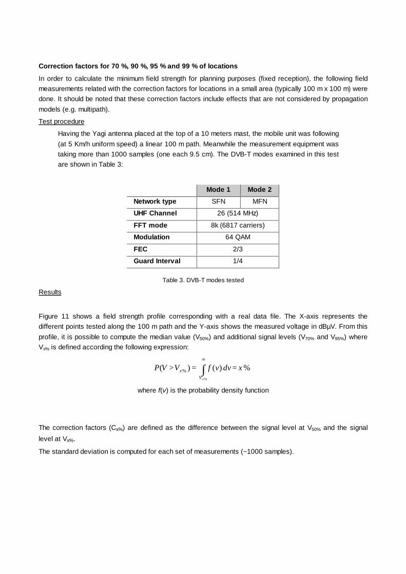
Correction factors for 70 %, 90 %, 95 % and 99 % of locations
In order to calculate the minimum field strength for planning purposes (fixed reception), the following fieldmeasurements related with the correction factors for locations in a small area (typically 100 m x 100 m) weredone. It should be noted that these correction factors include effects that are not considered by propagationmodels (e.g. multipath).
Test procedure
Having the Yagi antenna placed at the top of a 10 meters mast, the mobile unit was following(at 5 Km/h uniform speed) a linear 100 m path. Meanwhile the measurement equipment wastaking more than 1000 samples (one each 9.5 cm). The DVB-T modes examined in this testare shown in Table 3:
Mode 1 Mode 2
Network type SFN MFN
UHF Channel 26 (514 MHz)
FFT mode 8k (6817 carriers)
Modulation 64 QAM
FEC 2/3
Guard Interval 1/4
Table 3. DVB-T modes tested
Results
Figure 11 shows a field strength profile corresponding with a real data file. The X-axis represents thedifferent points tested along the 100 m path and the Y-axis shows the measured voltage in dBµV. From thisprofile, it is possible to compute the median value (V50%) and additional signal levels (V70% and V95%) whereVx% is defined according the following expression:
%)()(%
% xdvvfVVPxV
x ∫∞
==>
where f(v) is the probability density function
The correction factors (Cx%) are defined as the difference between the signal level at V50% and the signal
level at Vx%.
The standard deviation is computed for each set of measurements (~1000 samples).
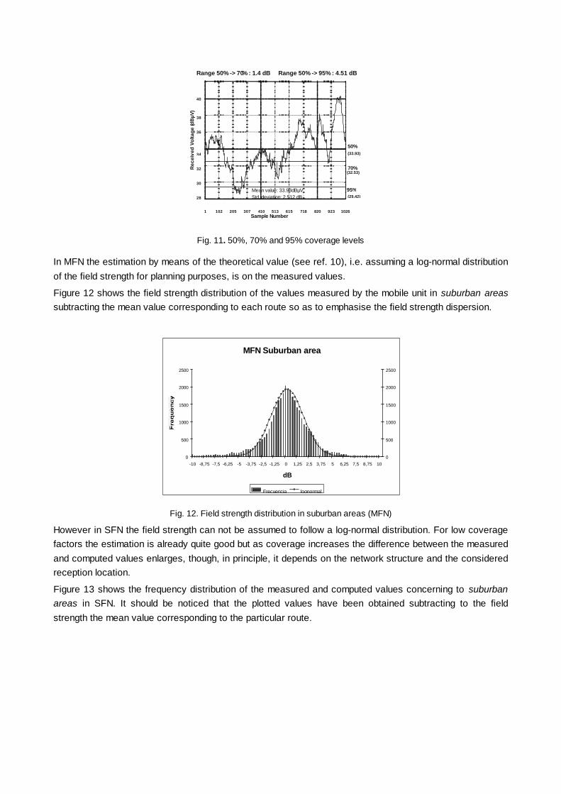
1 102 205 307 410 513 615 718 820 923 1026
28
30
32
34
36
38
40
Sample Number
Rec
eive
d Vo
ltage
(dB
µV)
Range 50% -> 70% : 1.4 dB Range 50% -> 95% : 4.51 dB
50%(33.93)
70%(32.53)
95%(29.42)
Mean value: 33.98dBµVStd. deviation: 2.512 dB
Fig. 11. 50%, 70% and 95% coverage levels
In MFN the estimation by means of the theoretical value (see ref. 10), i.e. assuming a log-normal distributionof the field strength for planning purposes, is on the measured values.
Figure 12 shows the field strength distribution of the values measured by the mobile unit in suburban areassubtracting the mean value corresponding to each route so as to emphasise the field strength dispersion.
MFN Suburban area
0
500
1000
1500
2000
2500
-10 -8,75 -7,5 -6,25 -5 -3,75 -2,5 -1,25 0 1,25 2,5 3,75 5 6,25 7,5 8,75 10
dB
0
500
1000
1500
2000
2500
Frecuencia lognormal
Fig. 12. Field strength distribution in suburban areas (MFN)
However in SFN the field strength can not be assumed to follow a log-normal distribution. For low coveragefactors the estimation is already quite good but as coverage increases the difference between the measuredand computed values enlarges, though, in principle, it depends on the network structure and the consideredreception location.
Figure 13 shows the frequency distribution of the measured and computed values concerning to suburbanareas in SFN. It should be noticed that the plotted values have been obtained subtracting to the fieldstrength the mean value corresponding to the particular route.

SFN Suburban area
0
100
200
300
400
500
600
700
800
900
1000
-10 -8,75 -7,5 -6,25 -5 -3,75 -2,5 -1,25 0 1,25 2,5 3,75 5 6,25 7,5 8,75 10
dB
0
100
200
300
400
500
600
700
800
900
1000
Frequency lognormal
Fig. 13. Field strength distribution in suburban areas (SFN)
Analogue satellite transmissions
This test was carried out to verify the feasibility of using an analogue satellite link as primary distributionnetwork for DVB-T signals.
The centralised generation of DVB-T signals and its following analogue distribution via satellite could implycertain advantages for SFN, among them:
• Possibility of using a single DVB-T modulation system for the entire network.
• Minimisation of the requirements associated with the synchronisation of the modulation process.
• Faster deployment of the broadcasting network. All transmitter sites straightforwardly covered.
But also certain important disadvantages, among them:
• Local remultiplexing not allowed. Although this is not required for SFN.
• Loss of C/N, which translates into a lower coverage area than in the digital case.
Test procedure
The transmission of the DVB-T signal was performed by means of the FM modulated system used in theanalogue television and through the Fixed Satellite Services (FSS) of Hispasat.
The DVB-T signal FM modulated by a 70 MHz IF carrier was conveyed through a 36 MHz band-pass filter inorder to bind the range frequency to the transponder’s bandwidth.
Next, this signal was shifted to the transmission frequency by means of an up-converter so as to be boostedby a travelling wave amplification system (TWT).
The signal received from the satellite was then amplified using a low noise amplifier (LNA). Afterwards it wasconverted to an intermediate frequency (IF = 70 MHz) by a down-converter whose output was connected toa noise generator in order to change the C/N ratio at the FM demodulator input. In this way it was possible tocheck the noise margin reduction that the link was introducing.
To assess the effect of the satellite, two different tests were done; the first one, called satellite loop, was asexplained above, the second, called FM loop, consisted in modulating and demodulating in FM the DVB-Tsignal without the transmission to the satellite.
The DVB-T modes tested were the following ones: 8k, 64 QAM, 1/4 GI and FEC 2/3 and 5/6.

Results
Figure 14 shows the behaviour of the link (BER vs. C/N) in the cases of FM loop and satellite loop.
It should be noticed that the satellite loop not only implies a degradation of the C/N ratio but also a change inthe slope of the behaviour in comparisons with the FM loop.
Other characteristics stated were:§ The 25 MHz frequency deviation was admitted as the optimum value to achieve the best C/N ratio
independently of the operating mode.
§ The reduction of the noise margin due to the link was approximately 3 dB for the R=2/3 mode and 8 dBfor the R=5/6 mode.
Figure 4Tests for the satellite link
BER vs. C/N for a 25 MHz. (Mode 64 QAM; BW= 36 MHz)
1,0E-08
1,0E-07
1,0E-06
1,0E-05
1,0E-04
1,0E-03
1,0E-021112131415161718192021222324252627282930
C/N (dB)
BER
R=2/3; T=1/4;satellite loop
R=5/6; T=1/4;satellite loop
R=2/3; T=1/4;FM loop
R=5/6; T=1/4; FM loop
8,5 dB 3 dB
Fig. 14. BER vs. C/N
Minimum Carrier to Noise for reception
The minimum C/N for reception was also assessed during the field tests. For that more than 300measurements were performed in portable and fixed reception with the help of the mobile unit previouslydescribed and using specially developed software. Figure 15 shows the fixed reception main screen, inwhich it is possible to visualise all the network parameters and the measurement results.
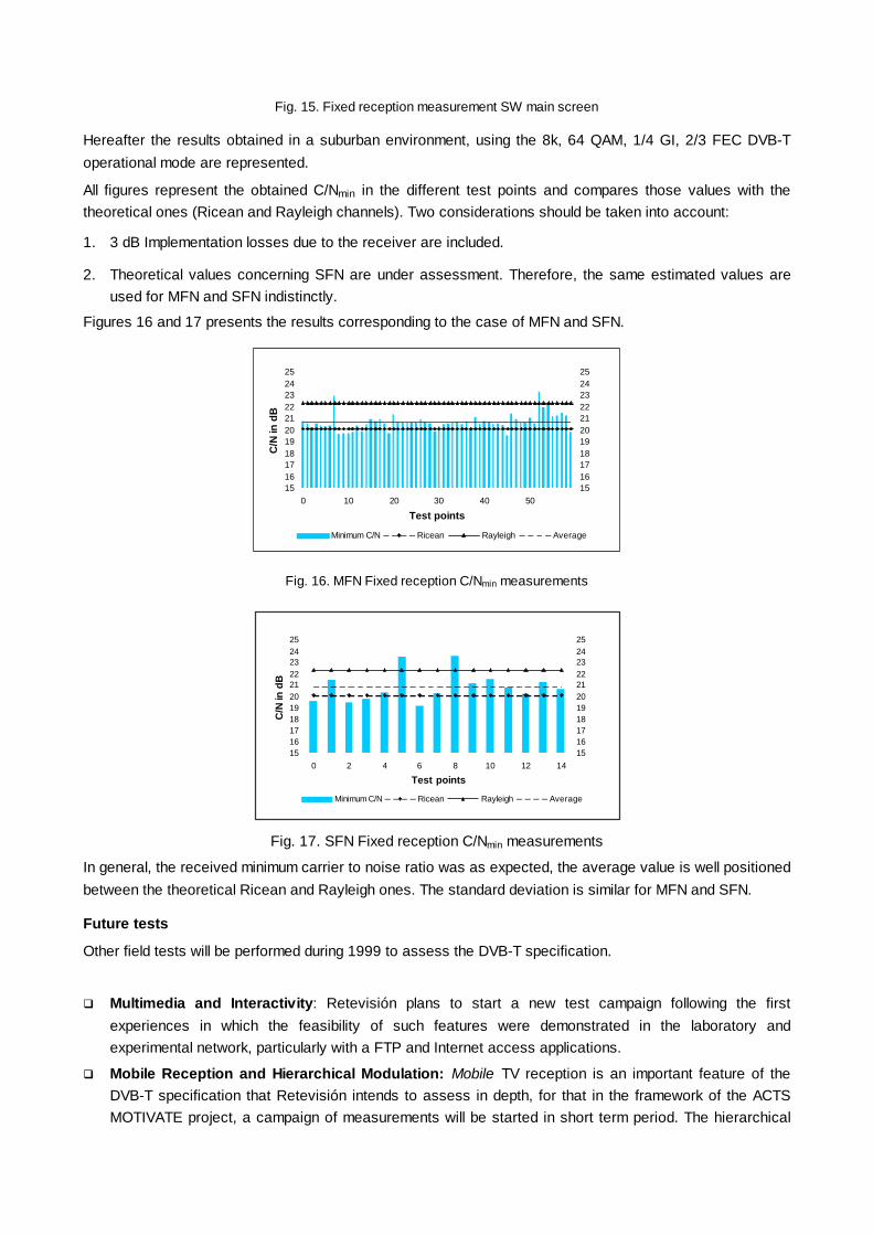
Fig. 15. Fixed reception measurement SW main screen
Hereafter the results obtained in a suburban environment, using the 8k, 64 QAM, 1/4 GI, 2/3 FEC DVB-Toperational mode are represented.
All figures represent the obtained C/Nmin in the different test points and compares those values with thetheoretical ones (Ricean and Rayleigh channels). Two considerations should be taken into account:
1. 3 dB Implementation losses due to the receiver are included.
2. Theoretical values concerning SFN are under assessment. Therefore, the same estimated values areused for MFN and SFN indistinctly.
Figures 16 and 17 presents the results corresponding to the case of MFN and SFN.
1516171819202122232425
0 10 20 30 40 50
Test points
C/N
in d
B
1516171819202122232425
Minimum C/N Ricean Rayleigh Average
Fig. 16. MFN Fixed reception C/Nmin measurements
1516171819202122232425
0 2 4 6 8 10 12 14
Test points
C/N
in d
B
1516171819202122232425
Minimum C/N Ricean Rayleigh Average
Fig. 17. SFN Fixed reception C/Nmin measurements
In general, the received minimum carrier to noise ratio was as expected, the average value is well positionedbetween the theoretical Ricean and Rayleigh ones. The standard deviation is similar for MFN and SFN.
Future tests
Other field tests will be performed during 1999 to assess the DVB-T specification.
q Multimedia and Interactivity: Retevisión plans to start a new test campaign following the firstexperiences in which the feasibility of such features were demonstrated in the laboratory andexperimental network, particularly with a FTP and Internet access applications.
q Mobile Reception and Hierarchical Modulation: Mobile TV reception is an important feature of theDVB-T specification that Retevisión intends to assess in depth, for that in the framework of the ACTSMOTIVATE project, a campaign of measurements will be started in short term period. The hierarchical

modulation tests are going to follow the laboratory tests carried out recently to assess the usefulness forportable and mobile reception of such modulation scheme in a real environment.
CONCLUSIONS
The most important issues related to the DVB-T specification and Digital Terrestrial TV service planning havebeen assessed and demonstrated in a practical case.
The Retevision experimental network has been of great importance for evaluating different aspects such asinitial coverage studies, multipath channel distortions, robustness against interferences (both of digital andanalogue signals), transmitter non-linear distortions, oscillator phase noise, etc.
Moreover, an important feature of DVB-T networks, the SFN configuration, has been successfullyimplemented, providing very encouraging results for the future Digital Terrestrial TV regular service, foreseenin Spain in the summer of 1999.
BIBLIOGRAPHY
1. ETSI, 1997. Digital Video Broadcasting (DVB); Framing structure, channel coding and modulation fordigital terrestrial television. EN 300 744
2. DVB, 1997. Specification of a Megaframe for SFN synchronisation. TS 101 191
3. ETSI, 1997. Digital Video Broadcasting (DVB); Measurement guidelines for DVB systems. ETR 290
4. VALIDATE, 1998. Implementation Guidelines to DVB-T. Del. D03 of ACTS/VALIDATE. DVB - TR 101190
5. VALIDATE, 1998. Project Final Report.
6. Cañizares, P. et al, 1996. The first Spanish experience on digital terrestrial television broadcasting.International Broadcasting Convention. IEE No. 428
7. MOTIVATE, 1998. José M. Fernández et al. DVB-T tests in Spain. First results. Retevision/007
8. MOTIVATE, 1998. A. Mansilla et al. Analogue satellite transmission of a DVB-T signal. Retevision/006
9. VALIDATE, 1997. Transmitter Performance Specification. Del D14 of ACTS/VALIDATE
10. CEPT, 1997. The Chester 1997 Multilateral Coordination Agreement relating to Technical Criteria,Coordination Principles and Procedures for the introduction of DVB-T.
Proceedings of ECMAST ’99 (Springer, Lecture Notes in Computer Science, Vol. 1629)

LAB & FIELD TESTS OF MOBILE APPLICATIONS OF DVB-TPeter Pogrzeba Deutsche Telekom Berkom Germany [email protected] Burow Deutsche Telekom Berkom [email protected]érard Faria IT IS France [email protected] Andrew Oliphant BBC R&D United [email protected]
ABSTRACT
This paper gives an overview of the performanceof DVB-T in a mobile environment. Conditions andresults of laboratory measurements and field trialsare presented. The limits of mobile DVB-Treception are explained. Conclusions are madefor the choice of suitable modes for mobileapplications, both for mobile reception byconsumers and for mobile transmission bybroadcasters for contribution links.
INTRODUCTION
The European standard for digital terrestrialtransmission (DVB-T) has been launched in theUK and Sweden and launches are planned inmany other countries worldwide.
To meet the different needs foreseen by the manypotential users, the DVB-T specification hasseveral sets of closely related modes withdifferent levels of ruggedness and differentbitrates. The close relationship between thedifferent modes means that it is easy to make onereceiver that can receive all the modes of thespecification with little added complexity. Any ofthe receiver chips on the market can beprogrammed to receive a wide range of modes ofthe DVB-T specification.
Broadcasters can trade ruggedness againstbitrate. The more rugged, lower bitrate modes willbe suitable for widespread portable reception,whereas the less rugged, higher bitrate modes willbe suitable for transmission of a multiplex of manyprogrammes (as currently used in the UK andSweden), or even HDTV, to receivers usingrooftop aerials.
When the DVB-T specification was beingprepared in 1995, mobile applications were notseen as very important. But since then inGermany, where there is already a highpenetration of cable and satellite reception, mobilereception has been identified as a unique sellingpoint for digital terrestrial TV. Work by DeutscheTelekom reported in the VALIDATE projectshowed that mobile applications of DVB-T arefeasible using the more rugged modes of thespecification.
A lot of work has been performed since then toevaluate the mobile applications of the DVB-Tstandard. This paper gives an overview of themajor results obtained.
The MOTIVATE project
The ACTS project MOTIVATE (Mobile Televisionand Innovative Receivers) started in May 1998 toinvestigate the mobile and portable reception ofDVB-T. MOTIVATE builds on the work ofVALIDATE [1], which successfully verified theDVB specification for terrestrial broadcasting.
MOTIVATE investigates the practical andtheoretical performance limits of DVB-T for mobilereception. It builds on the strong consortiumshown in Table 1. The project has the backing ofa number of sponsoring partners (TeleDanmark,RTÉ, DVB promotional module, TU-Munich andBMW, TU Braunschweig, NDS) makingMOTIVATE the spearhead for the implementationof mobile DVB-T services.

The MOTIVATE project investigates coverageaspects for DVB-T services by using simulationand prediction tools and by measuring theperformance of DVB-T in both laboratory testsand field trials. The network topology is beingoptimised by the selection of the antennapolarisation, the combination of MFNs and SFNs,the use of gap-fillers, microcell/macrocell and thechoice of suitable DVB-T modes (modulation,code rate, guard interval). Partners in MOTIVATEadapted existing planning software for DVB-Turban networks and first mobile DVB-Tmeasurements were performed and comparedwith prediction models. One main outcome of theproject will be implementation guidelines formobile DVB-T reception to set up transmitternetworks.
LABORATORY TESTS
In 1997 Deutsche Telekom carried out laboratorytests to investigate the performance of an earlycommercial DVB-T receiver in a mobileenvironment in the 2K mode. Using a two pathmodel with Doppler shift they identified threesuitable DVB-T modes: QPSK, 16-QAM and 64-QAM each with code rate 1/2.
The following thresholds of the minimum receiverinput voltage for the AWGN and the mobilechannel were measured:
Threshold QPSK 16-QAM 64-QAM
AWGN 16 dBµV 22 dBµV 30 dBµV
Mobile 22 dBµV 29 dBµV 38 dBµV
Table 2. AWGN and Mobile thresholds
In November 1998, Deutsche Telekom Berkomand ITIS organised a series of laboratory tests toevaluate the behaviour of state-of-the-artreceivers and to study the performance limits ofthe DVB-T standard in a mobile environment. Anadditional objective was to provide a test-bed thatwould allow ‘Laboratory Mobile tests’ to be donein a controlled environment.
The test methodology was based on theobservation of a Subjective Failure Point (SFP).The SFP aims to estimate the ‘limit of goodreception’, where impairments become visible onthe recovered video signal. Twelve differentDVB-T modes were used. The test evaluatedfirst, for each receiver in each tested mode that itwas capable of receiving, the level of Gaussiannoise to give the SFP. Then a channel simulatorprogrammed with one of the three COST207channel profiles described below was added,adjusted for a specific profile and a given speed(i.e. : a given Doppler characteristic), and thenoise level adjusted to give the SFP. Thedifference between the two noise levelscharacterises the loss of noise margin for thereceiver at a given speed.
Another measurement performed was to increasethe Doppler component in a given profile (withoutadded noise), to evaluate the maximum speedallowed by the receiver under test. Thisarrangement was particularly useful for comparing
Table 7. Partners in MOTIVATE
BBC UKRobert Bosch DCCETT FDeutsche Telekom Berkom * DEBUIRT DITIS FMier Comunicaciones ENokia SF
NOZEMA NLRAI IRetevisión ERohde & Schwarz DTDF FTelevés ETeracom SThomcast F* -Coordinator
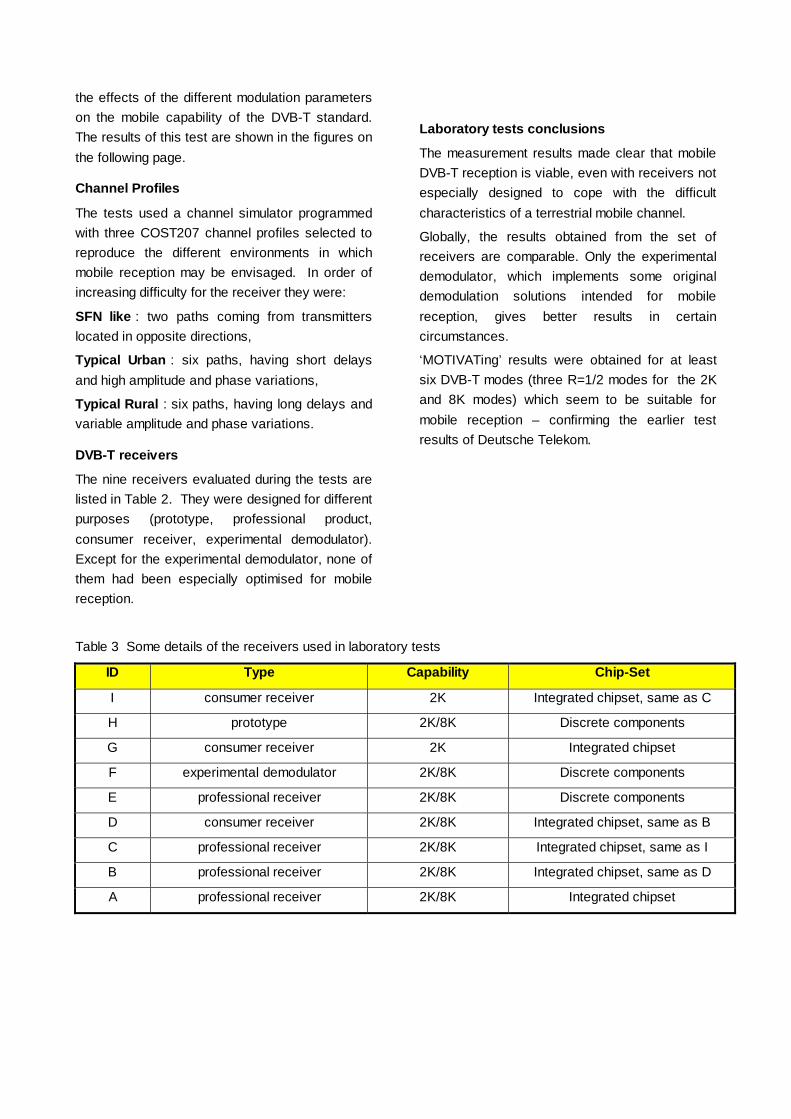
the effects of the different modulation parameterson the mobile capability of the DVB-T standard.The results of this test are shown in the figures onthe following page.
Channel Profiles
The tests used a channel simulator programmedwith three COST207 channel profiles selected toreproduce the different environments in whichmobile reception may be envisaged. In order ofincreasing difficulty for the receiver they were:
SFN like : two paths coming from transmitterslocated in opposite directions,
Typical Urban : six paths, having short delaysand high amplitude and phase variations,
Typical Rural : six paths, having long delays andvariable amplitude and phase variations.
DVB-T receivers
The nine receivers evaluated during the tests arelisted in Table 2. They were designed for differentpurposes (prototype, professional product,consumer receiver, experimental demodulator).Except for the experimental demodulator, none ofthem had been especially optimised for mobilereception.
Laboratory tests conclusions
The measurement results made clear that mobileDVB-T reception is viable, even with receivers notespecially designed to cope with the difficultcharacteristics of a terrestrial mobile channel.
Globally, the results obtained from the set ofreceivers are comparable. Only the experimentaldemodulator, which implements some originaldemodulation solutions intended for mobilereception, gives better results in certaincircumstances.
‘MOTIVATing’ results were obtained for at leastsix DVB-T modes (three R=1/2 modes for the 2Kand 8K modes) which seem to be suitable formobile reception – confirming the earlier testresults of Deutsche Telekom.
Table 3 Some details of the receivers used in laboratory tests
ID Type Capability Chip-Set
I consumer receiver 2K Integrated chipset, same as C
H prototype 2K/8K Discrete components
G consumer receiver 2K Integrated chipset
F experimental demodulator 2K/8K Discrete components
E professional receiver 2K/8K Discrete components
D consumer receiver 2K/8K Integrated chipset, same as B
C professional receiver 2K/8K Integrated chipset, same as I
B professional receiver 2K/8K Integrated chipset, same as D
A professional receiver 2K/8K Integrated chipset
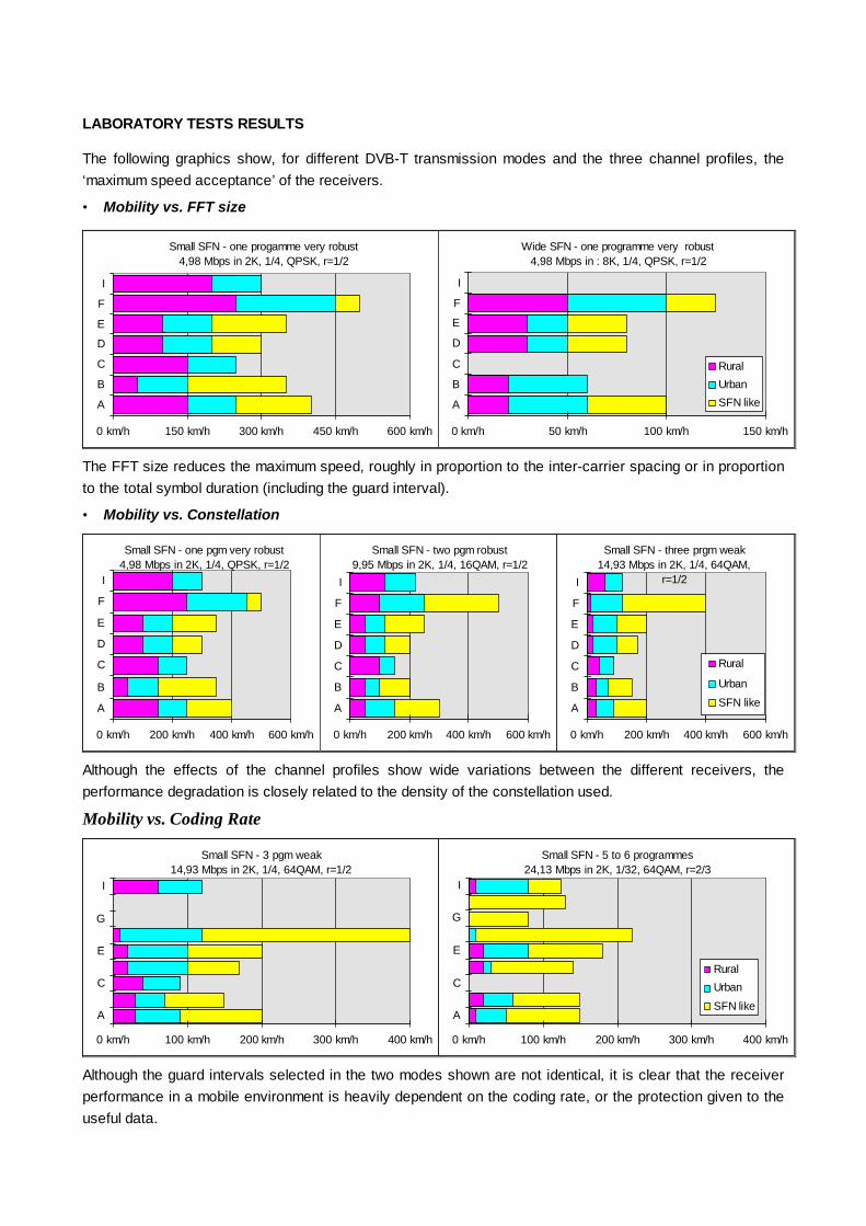
LABORATORY TESTS RESULTS
The following graphics show, for different DVB-T transmission modes and the three channel profiles, the‘maximum speed acceptance’ of the receivers.
• Mobility vs. FFT size
Small SFN - one progamme very robust4,98 Mbps in 2K, 1/4, QPSK, r=1/2
0 km/h 150 km/h 300 km/h 450 km/h 600 km/h
A
B
C
D
E
F
I
Wide SFN - one programme very robust4,98 Mbps in : 8K, 1/4, QPSK, r=1/2
0 km/h 50 km/h 100 km/h 150 km/h
A
B
C
D
E
F
I
Rural
Urban
SFN like
The FFT size reduces the maximum speed, roughly in proportion to the inter-carrier spacing or in proportionto the total symbol duration (including the guard interval).
• Mobility vs. Constellation
Small SFN - two pgm robust9,95 Mbps in 2K, 1/4, 16QAM, r=1/2
0 km/h 200 km/h 400 km/h 600 km/h
A
B
C
D
E
F
I
Small SFN - three prgm weak14,93 Mbps in 2K, 1/4, 64QAM,
r=1/2
0 km/h 200 km/h 400 km/h 600 km/h
A
B
C
D
E
F
I
Rural
Urban
SFN like
Small SFN - one pgm very robust4,98 Mbps in 2K, 1/4, QPSK, r=1/2
0 km/h 200 km/h 400 km/h 600 km/h
A
B
C
D
E
F
I
Although the effects of the channel profiles show wide variations between the different receivers, theperformance degradation is closely related to the density of the constellation used.
Mobility vs. Coding Rate
Small SFN - 3 pgm weak14,93 Mbps in 2K, 1/4, 64QAM, r=1/2
0 km/h 100 km/h 200 km/h 300 km/h 400 km/h
A
C
E
G
I
Small SFN - 5 to 6 programmes24,13 Mbps in 2K, 1/32, 64QAM, r=2/3
0 km/h 100 km/h 200 km/h 300 km/h 400 km/h
A
C
E
G
I
Rural
Urban
SFN like
Although the guard intervals selected in the two modes shown are not identical, it is clear that the receiverperformance in a mobile environment is heavily dependent on the coding rate, or the protection given to theuseful data.

FIELD TRIALS
Field trials in Cologne
In 1997 Deutsche Telekom conducted field trialsto study the performance of a DVB-T receiver inreal mobile environments in the area of Cologne.The ERP of the transmitter was 1 kW in UHFchannel 40 (626 MHz). The three DVB-T modeswith code rate ½ were used as indicated by thelaboratory tests mentioned above.
Three different routes were chosen for the fieldtests, one on the Cologne motorway and two inthe city. The received input power and asubjective parameter for the video qualitycondition (go, no-go) were stored during the trips.The measurements were performed several timesby varying the additional power attenuation (0 dB,6 dB, 12 dB) of the received DVB-T signal foreach route. Figure 1 shows an example of ameasured curve (field strength versus distance) ofthe QPSK case with 6 dB attenuation. The twovertical lines indicate errors in the received videosequence.
Figure 1. QPSK CR=1/2 with 6 dB attenuation
The main objective of the field tests was to checkthe mobile thresholds identified in Table 2 in a realmobile environment. If the thresholds are correctthen a prediction of the expected video error ratefor the route can be given on the basis of a fieldstrength prediction.
The field tests confirmed the results obtained fromthe laboratory tests of the DVB-T modes with thesimple 0 dB artificial echo model. For the receiverused, the thresholds in Table 2 guaranteefaultless mobile video reception. The identifiedmobile thresholds correspond to a coverage
probability of 99%. These thresholds can be seenas a first basis for the planning of services.
More details of the field trials in Cologne and thepreparatory laboratory tests are given in [2].
Field trials and demonstration in Amsterdam
In 1998 MOTIVATE carried out a field trial inAmsterdam in preparation for a demonstration atthe International Broadcasting Convention.
The PTT tower (65 m above ground level) nearthe RAI exhibition centre was used forbroadcasting a test signal for mobile reception onchannel 34 (578 MHz). The ERP of thetransmitter was 880 W. The test mode was 2K16QAM code rate=1/2 and guard interval=1/32.The useful bit rate in this mode is 12.06 Mbit/s,enough to transmit up to three TV programmes.The choice of guard interval 1/32 was possiblebecause the surrounding country is very flat, solong-spaced echoes were unlikely – an illustrationof how the flexibility of the DVB-T specificationcan be exploited to maximise the transmittedbitrate.
The coverage prediction was confirmed in theinvestigated area in most cases. Two parameterswere stored simultaneously as the measuring vanpassed along the streets. The first one was thereceived input power and the other one was asubjective assessment parameter for the videoquality condition (go, no-go). The reception areawas up to approximately 3.5 km from the PTTtower inside the 60 degree beam of thetransmitter. Nevertheless, there were many areasof error free reception outside the 60 degreebeam.
As a result of measurements a main road circularroute of 8 km with changing reception conditionswas identified for the demonstration. Figure 2shows the field strength along this route. Thereare very high dynamics in the field strengthbehaviour. The values are between 50 and 105dBµV/m. DVB-T reception was possible all theway round, although it was marginal at somepoints.
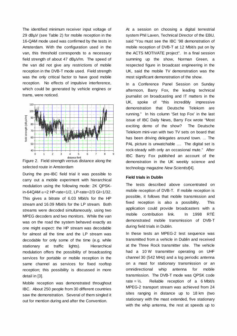
The identified minimum receiver input voltage of29 dBµV (see Table 2) for mobile reception in the16-QAM mode used was confirmed by the tests inAmsterdam. With the configuration used in thevan, this threshold corresponds to a necessaryfield strength of about 47 dBµV/m. The speed ofthe van did not give any restrictions of mobilereception in the DVB-T mode used. Field strengthwas the only critical factor to have good mobilereception. No effects of impulsive interference,which could be generated by vehicle engines ortrams, were noticed.
Figure 2. Field strength versus distance along theselected route in Amsterdam
During the pre-IBC field trial it was possible tocarry out a mobile experiment with hierarchicalmodulation using the following mode: 2K QPSK-in-64QAM α=2 HP-rate=1/2, LP-rate=2/3 GI=1/32.This gives a bitrate of 6.03 Mbit/s for the HPstream and 16.09 Mbit/s for the LP stream. Bothstreams were decoded simultaneously, using twoMPEG decoders and two monitors. While the vanwas on the road the system behaved exactly asone might expect: the HP stream was decodablefor almost all the time and the LP stream wasdecodable for only some of the time (e.g. whilestationary at traffic lights). Hierarchicalmodulation offers the possibility of broadcastingservices for portable or mobile reception in thesame channel as services for fixed rooftopreception; this possibility is discussed in moredetail in [3].
Mobile reception was demonstrated throughoutIBC. About 250 people from 30 different countriessaw the demonstration. Several of them singled itout for mention during and after the Convention.
At a session on choosing a digital terrestrialsystem Phil Laven, Technical Director of the EBU,said “You must see the IBC ’98 demonstration ofmobile reception of DVB-T at 12 Mbit/s put on bythe ACTS MOTIVATE project”. In a final sessionsumming up the show, Norman Green, arespected figure in broadcast engineering in theUK, said the mobile TV demonstration was themost significant demonstration of the show.
In a Conference Panel Session on Sundayafternoon, Barry Fox, the leading technicaljournalist on broadcasting and IT matters in theUK, spoke of “this incredibly impressivedemonstration that Deutsche Telekom arerunning.” In his column ‘Set top Fox’ in the lastissue of IBC Daily News, Barry Fox wrote “Mostexciting demo of the show? The DeutscheTelekom mini-van with two TV sets on board thathas been driving delegates around town. ... ThePAL picture is unwatchable .... The digital set isrock-steady with only an occasional mute.” AfterIBC Barry Fox published an account of thedemonstration in the UK weekly science andtechnology magazine New Scientist[4].
Field trials in Dublin
The tests described above concentrated onmobile reception of DVB-T. If mobile reception ispossible, it follows that mobile transmission andfixed reception is also a possibility. Thisapplication could provide broadcasters with amobile contribution link. In 1998 RTÉdemonstrated mobile transmission of DVB-Tduring field trials in Dublin.
In these tests an MPEG-2 test sequence wastransmitted from a vehicle in Dublin and receivedat the Three Rock transmitter site. The vehiclehad a 10 W transmitter operating on UHFchannel 30 (542 MHz) and a log periodic antennaon a mast for stationary transmission or anomnidirectional whip antenna for mobiletransmission. The DVB-T mode was QPSK coderate = ½. Reliable reception of a 6 Mbit/sMPEG-2 transport stream was achieved from 24sites ranging in distance up to 18 km (twostationary with the mast extended, five stationarywith the whip antenna, the rest at speeds up to
0 1 2 3 4 5 6 7 8 940
50
60
70
80
90
100
110
distance [km]
field
stre
ngth
[dB
µV/m
]

65 km/hr). Three additional sites gave usablesound but errored vision signals.
THE RATIONALE FOR MOBILE APPLICATIONS
The laboratory tests and field trials describedabove have shown that mobile applications ofDVB-T are feasible. But how will they beintroduced in practice?
Mobile transmission
A vehicle equipped with an interview position,camera, and DVB-T equipment could be used asa mobile TV studio. It could also be used as abase station for one or more radio cameras. Withthe vehicle stationary and a directionaltransmitting aerial on a pneumatic mast, a DVB-Tmode could be used with a high enough bitrate toallow post-processing (say about 9 Mbit/s). Withthe mast down and the vehicle in motion, a morerugged lower bitrate mode of the DVB-Tspecification could be used to give sufficientquality for news inserts – for instance to interviewa busy politician on the way to the airport.
Such professional applications can be used bybroadcasters in any country, irrespective of thestandards used for broadcasting to the public.
Mobile reception
Services for mobile reception will be only onepotential application for broadcasting spectrum.Since the available bitrate is lower for mobileservices, and the transmitted power has to behigher, a business case has to be made out forthis application. The availability of spectrum andthe broadcasting business situation are different indifferent countries, so it is likely that the balanceof services for fixed and mobile reception will alsodiffer.
In the UK, for example, terrestrial television mayremain the prevalent distribution medium. Theinitial application of DVB-T is to provide morechannels to increase the choice; mobile receptionis seen as an interesting possibility for the futureas analogue services are switched over to digital.In other countries – such as Germany – there is amuch higher penetration of cable and satellite:
only 6.8 M of the 36 M German households relyon terrestrial broadcasting. DVB-T couldovercome some of the limitations of analogueterrestrial TV but this alone would not guarantee asuccessful introduction of DVB-T services: addedvalue services are needed to attract more usersand increase revenues for broadcasters andnetwork providers. Mobile reception of video,internet and multimedia data could be anattractive feature to help the launch of DVB-T inGermany. Only terrestrial broadcasting couldbring mobility to the end user.
CONCLUSIONS
Laboratory tests and field trials have shown thatmobile applications of DVB-T are feasible usingthe code rate = ½ modes of the specification. Adata rate up to 15 Mbit/s using one 8 MHz UHFchannel is possible with the 64-QAM mode.
Mobility is one of the advantages of the EuropeanDVB-T solution against competing standards.The other is its flexibility, allowing differentapplications to suit the differing circumstances ofdifferent countries – or the business needs ofdifferent operators within a country – usingcommon receiver technology.
REFERENCES
1. Oliphant, A., and Christ, P., 1998.VALIDATE and MOTIVATE: collaborativeR&D to speed up the launch of digitalterrestrial TV. Proceedings of IBC ’98pp 467-472
2. Burow, R., Fazel, K., Hoeher, P.,Klank, O., Kussmann, H., Pogrzeba, P.,Robertson, P., and Ruf, M.J., 1998. On thePerformance of DVB-T System in MobileEnvironments. Proceedings of ECMAST’98 (Springer, Lecture Notes in ComputerScience, Vol. 1425, pp 467-480)
3. Nokes, C.R., and Mitchell, J.D., 1999.Potential benefits of hierarchical modes ofthe DVB-T specification. IEE Colloquium‘Digital television – where is it and where isit going?’, London 16 March 1999. IEEColloquium Digest 99/072. Also availablefromhttp://www.bbc.co.uk/rd/pubs/papers/pdffiles/IEEcrn-jdm160399.pdf .

4. Fox, B., 1998. TV’s easy rider. NewScientist, 26 September 1998, p. 16.
ACKNOWLEDGEMENTS
MOTIVATE is supported by the Commission ofthe European Communities through the fourthFramework programme.
THE AUTHORS
PETER POGRZEBA holds the degree of Dipl.-Ing. in information technology from the TechnicalUniversity of Chemnitz. From 1987-1994 he was aresearch assistant at the Technical University ofChemnitz working on source coding of pictures,channel coding and modulation. In 1995 he joinedthe Technology Centre of Deutsche Telekom and,since then, has been working on digitalmodulation and channel coding techniques fordigital terrestrial television transmission. He hasspecialised in the simulation of digital transmis-sion systems. Since 1997, he has worked forDeutsche Telekom Berkom GmbH. He wasinvolved in the German HDTVT project and theACTS VALIDATE project. Now he is a member ofthe MOTIVATE project.
RALF BUROW holds the degree of Dipl.-Ing. ininformation technology from the College ofTransport and Communication of Dresden. In1989 he joined Rundfunk und FersehtechnischeZentralamt and with his first experiences in digitalTV developed components for a digitaltransmission system for studios. In 1990 he joinedthe institute of Deutsche Bundespost Telekomand became expert in laboratory and field tests fordigital terrestrial transmission systems. He wasinvolved in RACE (dTTb), DTVC (EUROIMAGE),ACTS VALIDATE and the German HDTVT-project.Since 1997, he has worked for Deutsche TelekomBerkom GmbH. Now he is a member of theMOTIVATE project.
GERARD FARIA is the Director of the Researchdepartment for ITIS in Rennes, France. Hegraduated in 1978 from the Technical Universityof Paris (France).
In 1988, after more than ten years of practicalengineering experience in digital design he was
one of the founders of the ITIS company. Hehas been involved in the design of the company’sDAB and DVB product ranges and manages theITIS contribution in several EuropeanCollaborative projects (RACE, ACTS). Hisprimary responsibilities include managing the ITISresearch engineers team and driving the ITISresearch programmes oriented to digital Radioand TV broadcasting domains.
Since 1996, Gerard Faria has engaged in thestandardisation works of the EuropeanTelecommunication Standard Institute (ETSI)where he acts as a DAB network specialist. He isalso the ITIS representative in the EuropeanForums driving the DAB (Worldab) and the DVB(DVB-TM) technologies.
ANDREW OLIPHANT is a Project Manager atBBC Research & Development Department. Hejoined the BBC in 1972 after gaining a degree inElectrical Sciences from Cambridge University.During his career he has worked on teletext, videosignal processing and satellite broadcasting.From 1988 to 1994 he led two RACE projects onoptical fibre routeing systems for broadcasters.
In 1994 he joined the RACE dTTb project to leada major demonstration at the 1995 Montreux ITS.From 1995 to 1998 he led the ACTS VALIDATEproject which verified the DVB-T specification andworked towards the launch of services.
Andrew Oliphant has contributed tostandardisation in EBU, ITU, and DVB. He hasrecently moved to lead work at BBC R&D in thenew area of Metadata.
Peter Pogrzeba & Ralf Burow - DeutscheTelekom Berkom GermanyGérard Faria - IT IS FranceAndrew Oliphant - BBC R&D UKProceedings of ITS '99 Montreux

AUSTRALIAN ASSESSMENT OF DTTBRichard M Barton Facts - Australia
BACKGROUND
Australian experts have been involved throughout the development of HDTV and digital television options, fromthe debates on HDTV standards in the mid 1980’s through to the present. Particular attention has been paid tothe International Telecommunications Union (ITU-R) forums where Australian experts have consistently pressedfor a common international standard. The ITU was seen to be the main forum in which to argue for convergenceof television standards for the new technology choices, so as to avoid the need for continuing standardsconversion and consequent operational and quality difficulties.
Early work on the use of OFDM published by the IBA in the UK and in other European studies showed similarpromise to parallel work on a system to develop HDTV terrestrial broadcasting in the USA. The Australianbroadcasting experts identified a need for the ITU to provide a common forum where these disparate studiescould be drawn together in an attempt to evolve, for the first time, a world- wide common system of televisionbroadcasting. As a result of an Australian proposal to ITU-R Study Group 11, Task Group 11/3 was establishedwith the objective of preparing a common set of digital terrestrial television broadcasting (DTTB) standards.
The success of Task Group 11/3 has been well documented elsewhere. It was very successful in fostering ahigh level of convergence between the North American and European DTTB systems. In one essential area, itwas not successful. Two systems for modulation emerged, and could not be reconciled. In the US, a singlecarrier 8VSB modulation system was formally adopted. European countries confirmed their adoption of amultiple carrier Coded Orthogonal Frequency Division Multiplex modulation system (COFDM). In part, thesedifferences reflected the different market environments into which the digital technology would be implemented.In the US, there is a highly competitive localised broadcasting industry. In Europe, national broadcasters stillpredominate, and there is a tightly interference-limited international plan for all of Europe. Towards the end ofthe studies of Task Group 11/3, Japan announced that it was working on a third modulation variant which wouldoffer segmentation of the RF channel but, like DVB, basing its system on the use of OFDM modulation.
AUSTRALIAN BROADCASTING ENVIRONMENT
The Australian television industry closely parallels the US industry in its structure. Commercial networks withaffiliated stations are a dominant force, whilst the two Government-funded national networks (ABC and SBS)also draw significant audiences. On the other hand, the technology base of the industry is essentially ofEuropean origin, being built on 50 Hz PAL analogue.
Australia has a very diverse range of requirements that needed to be addressed in assessing the most suitabletechnology for the introduction of DTTB.
• Approximately half the population is concentrated in the two largest cities, Sydney and Melbourne. Thesecities have extensive urban and suburban characteristics;
• There are several other cities that have significant concentrations of urban and suburban characteristics;
• The remaining population is spread over a very large proportion of the country with many concentrations ofsmall to medium towns having suburban characteristics.

• For a very large part of the country, the population levels are relatively low but have economic importance tothe country from rural and mining activities;
In order to ensure that the Australian needs could be technically assessed for the conversion to digital televisionindustry committees actively studied the potential of DTTB through the years from 1990. The studies lead to theproduction of progressive reports addressing the issues to be examined and the findings recommending thedirection the Government should consider in legislating for the implementation of DTTB. These reports areidentified in the references.
As part of those studies, the commercial television industry body, the Federation of Australian CommercialTelevision Stations (FACTS), together with the Government’s Australian Broadcasting Authority andCommunications Laboratory, conducted extensive testing of the two available complete DTTB systems – theEuropean DVB-T (COFDM) and the USA ATSC (8 VSB). These comparative tests, both laboratory and field,were the first direct comparison of the two systems and have attracted wide interest. Detailed reports on theAustralian tests can be found in the references
In 1997, the Australian Government legislated for the introduction of digital television. In the legislation is defineda number of key requirements.
• Digital broadcasting to commence in the main capital cities by January 1, 2001
• Existing broadcasters would be “lent” an additional full TV channel for DTTB
• Commercial broadcasters must provide HDTV but may not multi-channel
• Broadcasters must provide the same program on digital and analogue
• Coverage must match the analogue coverage as soon as practical
• Broadcasters may use spare capacity for datacasting
• Datacasting services to be licensed in the broadcasting bands
CHOOSING A SYSTEM.
The Australian terrestrial broadcasting industry appointed a panel with representatives from of the main networkand regional broadcasting interests. Representation of Government was also included with participants from theDepartment of Communications and the Arts and from the Australian Broadcasting Authority. The group wasestablished for convenience by FACTS who provided the secretariat for the panel. The group was titled theFACTS DTTB Selection Panel and its basic terms of reference were to examine all the available information andrecommend a DTTB system for Australia.
In preparation for the first meeting, members submitted suggestions for the criteria that should be used inassessing the choice. The consequent list was refined and used as a guide for the final recommendation. ThePanel met four times with its final meeting taking place on June 18, 1998.
The Panel was unanimous in its view that all free-to-air television broadcasters should use a common standardto ensure commonality of equipment and minimum cost to viewers. The evaluation process that was usedassisted in clarifying the merits of each system in the context of the Australian broadcasting environment, andthe process of planning for the transition to digital television.
The evaluation of the technical comparative tests played an important part in the considerations of the Panel.While the tests showed some relative strengths and weaknesses of the two options the Panel felt that there was

insufficient information for technical assessment of some relevant criteria. In particular, this applied to translatorperformance, indoor antenna performance and carriage through Master Antenna Television systems. It wasconsidered that each of these matters would require further testing and evaluation. Preliminary arrangementswere made to obtain equipment to address each of these issues but were not progressed for comparative testingfollowing the decision to recommend DVB.
ESTABLISHING THE SELECTION CRITERIA
Starting from an initial list of some 50 possible criteria, the Panel researched, analysed and refined the list tothose criteria that were considered to have relevance for the selection. Individual elements were grouped intosets of related criteria that were then further refined by full discussion.
Elements not included in the selection
As a first step, those criteria that did not show a material differential in performance between the systems wereidentified as not being significant in making the choice. It was thought, however, that those elements still neededto be thoroughly considered in designing the overall system. For the purpose of the Australian choice, they wereassessed as providing basically the same performance for either of the systems considered. Criteria consideredto be in this category included:
• Need for co-siting
• Availability of transmission, modulation and multiplex equipment
• Compatibility with digital studio-to-transmitter links and satellite program services
• System operating costs
• Multi program/multi-channel support
• Arrangements for program associated data
• Arrangements for non-program associated data
• Stability and reliability of the technology
• System upgrade and further development capability
• Consideration of set-top boxes
• Interoperability with VCR’s
• Receiver operating system
• Electronic program guides
• Conditional access
Receiver and set-top box MP@HL capability
Interlace vs progressive scanning (receivers)
Baseband input (receivers)
Other elements which might have affected the choice but were not able to be quantified were:

Technology royalty costs
Location of receiver manufacturing.
Elements included in the selection
The following elements were identified for including in the assessment with the associated explanatory notes.
1 COVERAGE
In general, the coverage would be expected to match that achieved by PAL. It is clear that the nature of DTTB,which suffers from the “cliff effect”, will mean that the coverage will not be identical. There will be some levels oflesser performance arising from the power limits imposed by non-interference to PAL because of the expectedextensive use of channels adjacent to the existing PAL services for DTTB. The main city allocations areexpected to use the single channel gaps in Band III. On the other hand, for some aspects such as ghostinglimitations there will be areas of improved reception performance. With different characteristics between 8VSBand COFDM, the different elements need to be judged on the relative coverage potential, weighted to theaffected proportion of the audience. Eventually it can be assumed that, after cessation of PAL, coverage can beimproved by raising power levels to that needed to match the existing PAL coverage. Coverage was assessed indifferent categories; each weighted in accordance with the Panel’s assessment of importance.
• Percentage of primary coverage area population served
• Percentage of secondary coverage population served
• Set-top antennas performance
• Mobile reception capability
• Co-channel performance
• Adjacent channel performance (d-a, a-d & d-d)
• Multi-path performance
• Immunity to electrical interference
• Ability to be conveyed in MATV and cabled systems
Although as indicated above detailed comparative tests of indoor antenna performance were not able to becarried out in the time available, the relatively high proportion of viewers in urban and suburban environments(up to 30 %) meant this was an important element.
Mobile reception was seen as a future extension service rather than a prime criterion.

2 SYSTEM DESIGN ELEMENTS
This group of criteria mainly addressed the relative cost elements to broadcasters in implementing the DTTBsystem with respect to the transmission infrastructure and associated program service distribution systems.
• Combining to use common transmit antennas (PAL & DTTB)
• Ease of use and cost of implementing translators
• Common Channel Translator (CCT) capability
• Ability to use existing transmitters
Initial planning had indicated the expected use of adjacent channel PAL/DTTB operation with preference forusing a common antenna.
3 OPERATIONAL MODES SUPPORTED
This group of criteria addressed the flexibility of the systems to offer service modes that may be needed. In thisregard the Australian Government policy decision for HDTV and possibly multi-channel for nationalbroadcasters, as well as the provision for datacasting, needed to be taken into account.
• HDTV support
• Support for closed captions
• Support for multi-language audio
• Audio System
The requirements for closed captions and for HDTV were essential to meet the legislated requirements. Theother elements related to meeting perceived audience expectations.
4. OVERALL SYSTEM
• Adoption of an accepted rather than unique system for HDTV
• Performance within a 7 MHz channel
• Number of useful MBPS per 7 MHz channel
• Overall encode/decode delay
• System upgrade and further development capability
5. RECEIVER ELEMENTS
This group of criteria addresses the important aspect of availability of receivers suitable to meet the broadcastservice objectives for Australian digital television broadcasting. Australia’s relatively small market for majorconsumer products implies some need for commonality with a larger market base if costs are to be minimized.
• Receiver availability features and cost
• Receiver and set-top box MP@HL capability
• Receivers with both PAL and DTTB capability

• Receivers not specifically designed for Australia
• Receiver applications software upgrades and tools
• Receiver lock-up time
• Ability to provide automatic channel selection for Australian channeling
ASSESSMENT
In conducting its assessment the Australian DDTB Selection Panel used the results of the laboratory and fieldtrials, the available data on the characteristics of the Australian terrestrial television market and the accumulatedtheoretical knowledge built up over several years involvement in the study and development of digital television.It was necessary to take into account the government legislation requirements, particularly the need to providefor HDTV, the simulcasting of programs and the need to provide equivalent coverage to that provided by currentPAL broadcasting.
The Panel agreed not to disclose the final values derived from their numerical assessment. It considered theseto be specifically relevant to Australian broadcasting, and possibly open to misinterpretation if used out of fullcontext. Instead, it was decided that a summary of the Panel’s deliberations should be reported in order toexplain the reasons behind the final recommendation.
It was noted that the process being used was to provide guidance to the Panel for its determination of therecommendation. As such the scoring was similar to that used to score a boxing match, but it varied by applyingthe importance weighting to the final points allocated.
COVERAGE
It had been hoped that the data available from the Australian tests, supported by the field test and theoreticalperformance data from overseas tests, would allow detailed assessment of the coverage potential of the twosystems. In the time available, this proved not to be feasible. While ATSC had specific advantages in simplecarrier to noise performance and impulse noise, DVB had shown advantages in environments with significant orcomplex multipath.
It was considered that thorough analysis would require detailed quantification of such elements, with thevariations applied to detailed coverage analysis. Given the time constraints applicable, this level of analysis wasnot possible. The significant reliance on indoor antennas (up to 30% of households in some Australian markets,according to survey figures provided to FACTS) was an important factor for the Panel’s assessment.
The Panel’s assessment also had regard to the Australian approach to achievement of television coverageareas. This is based on moderate power main transmitters supported by networks of translators in the significantoutlying areas. There is an average of 10 translators for each main transmitter.
Percentage of primary coverage area population served
The Panel noted the differences between ATSC and DVB with respect to C/N. It also considered the effect ofghosting on each system. It considered that ATSC may have an advantage for the outer service area with rooftop antennas, but that the modifying effect of ghosting reduces the margin, particularly in obstructed reception

areas. For severely obstructed areas, typified by dense urban developments, the multiple ghosting may give theadvantage to COFDM.
Percentage of B coverage population served
The performance of the two systems beyond the nominal “primary” coverage area is less certain from the dataavailable. In the areas where the angle of arrival is low there are more areas with partially or fully obstructedreception. In Australia the use of masthead amplifiers is common in the outer service areas.
Given the policy direction of the Australian Government to ensure DTTB availability to all current PAL viewers,the Panel needed to address the coverage question from two aspects. The first related to the transition period,when non-interference to PAL would set a power limit on DTTB. The second related to the period aftertermination of the PAL service, when power levels could be increased to provide full coverage.
Finding 1
On balance, the Panel considered the differences with respect to coverage to fixed roof top antennas tobe marginal rather than significant and did not indicate a preference for either system.
Set-top antennas
The Panel considered this issue could be set aside during the initial assessment. It remained a substantial issue,given the high proportion of Australian viewers using set-top antennas, but further testing and analysis wasneeded before any objective differential assessment could be made. While there was satisfaction that the DVB-Tsystem performed adequately, the ATSC system was yet to be fully tested. Although the Panel considered thaton all available information COFDM would perform better it was decided that if this factor were potentiallydecisive in determining the choice the need for further testing would be addressed, even if that required a delayin the decision. However, in finalizing the assessment, it was evident that the decision would not be affected bythe results of further testing.
Finding 2
While the Panel was satisfied that COFDM would provide adequate set top antenna performance andthere was doubt if the ATSC system would perform as well, this was not demonstrable from thecomparative test carried out. The relative in door performance was not considered in the final decisionalthough it remained an important factor. There was no expectation that the ATSC system would performbetter than COFDM.
Mobile reception
Mobile reception is not expected to be a major consideration for Australian television broadcasters. However, itwas recognised that mobile broadcasting may have application for narrowcast (specific targeted audiences) andfor datacasting. The latter is specifically addressed in Australian legislation for the introduction of DTTB.Although the mobile mode had not been tested, the Panel had participated in demonstrations of QPSK mobilemode for DVB. Although ATSC advised the potential for a 2VSB mode there was no indication of the potentialbeing realised by practical development and marketing.
Finding 3
Only DVB offered a realistic mobile option.

Co-channel performance
The testing had demonstrated that DVB showed advantages in relation to interference between analogue anddigital, while ATSC had an advantage in relation to non-coherent (i.e. unrelated program material) digital todigital interference.
Interference between analogue and digital will be important during the transition, while interference from digitalto digital may be important both during and after transition.
On balance, the Panel decided not to allocate a preference.
Finding 4
The panel considered that the co-channel performance differences of the two systems largely balancedand did not provide a significant deciding factor.
Adjacent channel performance
The Panel considered that both systems provided adequate performance to meet the Australian planningrequirements.
Finding 5
Both systems have adequate performance
Multipath Performance
The Panel considered that the tests showed this element was more adequately covered by the DVB system thanATSC, particularly for dynamic ghosts and complex ghosting in low signal strength areas.
Finding 6
DVB provides a better all round performance for multipath.
Immunity to electrical interference
The test established that the ATSC system had a significantly better immunity to impulse noise thanthe DVB system. This will be a useful improvement in the VHF band and in urban environments.
Finding 7
The ATSC system is significantly more resistant to impulse noise.
Ability to be conveyed in MATV and cabled systems
The Panel considered this issue was dependent on the way MATV systems were implemented. Many MATVsystems use IF translation, while some more complex systems may use full demodulation and remodulation. Themain domestic systems are either direct amplification or IF translation.
The Panel considered this issue could be left out of the current assessment because it was still an issue that hadnot been clearly resolved. Further investigation and testing would have been needed to provide any basis forrealistic assessment.

No finding was recorded.
SYSTEM DESIGN ELEMENTS
The elements in this group mainly affect the practicality and cost of providing the infrastructure for broadcastingDTTB. For Australia, it is considered important that broadcasters are able to make maximum use of the existingtransmission sites. Broadcasters also expect to rely heavily on the use of adjacent channels, for the dualadvantage of reusing broadcaster and viewer antenna systems.
Additionally, the extensive reliance on the use of translators contributed to the weighting factors agreed by thePanel.
Combining to use common transmit antennas
The ATSC single carrier system is considered to be less tolerant to group delay errors within the channel thanthe DVB COFDM system. To some extent, this can be mitigated by using the full 7 MHz Australian channels toaccommodate a 6 MHz ATSC signal. In a normal situation, a carefully positioned dynamic feedback sensor isrequired to drive the ATSC pre-correction system. In a typical Australian environment with multiple combinedadjacent channels, appropriate positioning of the output sensing is made much more complex.
The Panel considered that this difficulty might be able to be compensated by fixed pre-correction of thecombining and common antenna equipment. However, the large temperature variations that occur in manyantenna systems with consequential changes to impedance were seen as posing a difficulty for fixed pre-correction.
It was accepted that the sensitivity of the ATSC system to group delay errors required feedback correction, andthat this would be difficult in many cases. Because of the extensive use of common infrastructure and theproposed adjacent channel working in Australia, DVB was considered to have an advantage.
Finding 8
It was considered that combining an adjacent channel DVB signal with a PAL signal would be lesscomplex than similarly combining an ATSC signal.
Ease of use and cost of implementing translators
From the limited testing related to translation and from theoretical assessment it was assessed that for the manysimple if translation examples common to the Australian environment DVB was expected to be satisfactory. Itwas considered that ATSC would need to use a remodulation processing for many translator situations. While itwas suggested that consumer grade 8VSB modulators would be developed and could be used for low costremodulating translators this was yet to be demonstrated.
It was agreed that DVB would have advantages on the basis of currently available technology.
Finding 9
The DVB system offered acceptable simple translation options while ATSC would require developmentof adequately priced remodulation equipment. For this aspect DVB was preferred.
Common channel translator capability
The use of translators in Australia will generally involve reuse of translator frequencies within a single mainservice area. In many cases the transmission content will be identical. Where there are content differences, the
separation is generally sufficient to provide adequate co-channel isolation. The co-channel advantage for ATSCis removed in such cases, and the coherent same channel capacity of DVB (SFN) becomes a useful tool forthose close spaced translators with the same program content.
Finding 10.
The DVB system was seen to offer greater flexibility to handle the variety of co-channel translatorsituations expected for the Australian environment. Particularly in the longer term when PAL is phasedout the potential of single frequency networks will be useful in optimizing spectrum efficiency.
Ability to use existing transmitters
The Panel discussed the linearity requirements of both systems and the pre correction filter requirement in theATSC system. On balance it was considered that either system could operate through suitably upgraded existingplant.
Finding 11
Both ATSC and DVB could be used with suitably upgraded existing transmitters.
OPERATIONAL MODES SUPPORTED
These criteria are considered to be important in meeting broadcasters’ and the Government’s service objectivesfor DTTB. Key objectives for the Government are for closed captioning and for HDTV. The Panel neededassurance that support would be available from DVB for HDTV, given the lack of enthusiasm for that serviceobjective in Europe. Equally, the Panel needed to be sure that selection of the ATSC system would not restrictAustralia to 60 Hz based standards.
Satisfactory assurances on the key elements were forthcoming from both parties.
HDTV support
Both DVB and ATSC had well documented standards to provide HDTV. The issues discussed included thealternatives of using 60Hz picture rates and the implications of being a pioneer in providing a 50Hz based HDTVbroadcasting. The option of using 60Hz was agreed to be impractical given the legislated requirement tosimulcast programs on DTTB and PAL. The Panel then addressed the potential availability of HDTV receivers forthe Australian market. Suitable assurance of intentions to supply the Australian market with HDTV receptioncapacity were supplied that were not constrained to the modulation system choice. Once it was agreed that thepicture rate to be used would have to be 50Hz, the issues of origination equipment did not need to be taken intoaccount.
Finding 12
The Panel agreed both systems could provide the capability for and support HDTV broadcasting. Whileeach offered advantages over the other in some of the details there was no significant overall advantage.
Support for closed captions
The need to provide closed captioning is a part of the legislated requirements. The Panel noted that closedcaptions were defined in the MPEG-2 transport stream and can consequently be supported by either DVB orATSC.

Finding 13
Both ATSC and DVB are able to fully support closed captionning.
Support for multi language audio
The Panel noted that the audio systems being developed for both systems would give enough flexibility tosupport multiple language audio channels by using additional elementary audio program streams.
Finding 14
Either Stem can support multiple language requirements.
Audio System
There are different views on the relative performance quality of AC3 and MPEG-2 5.1 channel sound systems.On balance, AC3 was seen to have advantages, particularly bearing in mind the relative market penetration.
While not directly related to the Panel’s terms of reference, the operational implications of importing programswhich have already been coded to 5.1 audio were discussed by the Panel. It was noted that consumer productsare now using chipsets for decoding the 5.1 channel sound that can interpret either audio standard. As there aredefined ways of accommodating AC3 in the MPEG-2 transport stream as well as MPEG-2 audio, it wasconsidered that this subject could be addressed in the detailing of the final Australian standard, withoutdifferentiating between the systems.
Finding 15
While the Panel tended to favour the Dolby Digital system for surround sound it was believed that itcould, if so decided, be used with either ATSC or DVB and so need not influence the modulation systemchoice.
OVERALL SYSTEM AND RECEIVER ELEMENTS
While each of the twelve individual elements in these categories were examined in some detail, the Panel wasunable to identify any specific advantages or disadvantages that would distinguish between the two systems.Considerable time was devoted to addressing the need for specific tailoring of receivers for the Australianmarket. It was recognised that this was unavoidable for either system. On some elements such as lock-up timethe Panel did not have
FINAL RECOMMENDATION
As a consequence of it deliberations the Australian DTTB Selection Panel unanimously agreed to recommendthe DVB modulation system be adopted for Australia.
SUBSEQUENT CONSIDERATIONS
With the decision on the modulation system finalized the Panel concentrated on the other crucial decisions thatwould be needed to commence work on a detailed Australian standard and to develop the associated standardsthat will be needed to implement the DTTB HDTV service in 2001.

Service Information.
In developing the full standard for Australia it was recognised that the Service Information content would becrucial to successful implementation. A project group of experts was tasked to conduct an analysis of the DVB SIstandards and the ATSC PSIP standards. There was a view that the ATSC standards still in development mayprovide advantages, particularly for the commercial network/affiliate broadcasters that are a significant part ofAustralian broadcasting.
The Project Group report provided a comparative analysis that demonstrated that the DVB SI standard meetsmore of the Australian requirements and required less adaptation than the ATSC PSIP standard at that stage ofdevelopment. Clearly the ability to cover the requirements for COFDM modulation provided a significantadvantage, but the analysis identified many other points where DVB SI was closer to meeting the Australianrequirements.
Audio
Recognizing that surround sound is an important part of a complete HDTV broadcasting system, the Panelestablished a group of experts to report on the best option for the sound system for Australia. On the basis of acareful study of the technical quality, available attributes and total broadcasting system suitability the expertgroup report clearly indicated that Dolby AC3 would provide the best total sound system to include with DTTB.
It was noted that some material required for broadcast may be received already coded with MPEG 1 stereosound. It was accepted that transcoding from MPEG 1 would compromise the quality achieved.
The Panel agreed to recommend the use of Dolby Digital for the sound system but also that MPEG1 audioshould also be a requirement. The economic implications of the decision were taken into account with thestudies providing information on the growing range of economical audio decoding integrated circuits that handleboth AC3 and MPEG audio decoding.
VIDEO HDTV PRODUCTION
Having decided that Australia would need to use a 50Hz high definition video format, the Selection Paneladdressed the need to establish the most suitable standard to use for production in Australia. The range ofcurrent 50Hz full HDTV equipment available is seen to be very limited and with the lack of interest in HDTV inEurope, the options for developing production equipment for just the Australian market were seen to berestrictive. Discussions with some of the main suppliers of camera and VTR equipment had indicated thepossibility that a modified version of the common image 1920 pixel by 1080 active line format which used a totalline count of 1125 could be made. The 50Hz version being a relatively simple adaptation of the 60Hz versionbeing developed for the USA market.
Australian experts had been working with the suppliers on a suitable modification of the ITU-R BT709 standardto include the 50 Hz 1125 line standard and the suppliers assured the broadcasters that they would be able tosupply equipment to that modified standard within the time frame needed.
Based on this advice the Selection Panel chose to recommend the use of 1920 by 1080 with a total line count of1125 lines as the preferred Australian HDTV production standard.
Richard M Barton - Facts, Australia

Singapore Announces Choice Of National Digital TelevisionStandard
Singapore Broadcasting Authority
Singapore, 25 May 1999
The Singapore Broadcasting Authority (SBA) is pleased to announce the adoption of the European DigitalVideo Broadcasting (DVB) standard as the terrestrial digital television standard (DTV) in Singapore. TheDVB standard was selected following the recommendation of the Singapore Digital Television TechnicalCommittee which was appointed by SBA in November 1997. A list of the committee members is attached asAnnex A. The Committee's Final Report is attached at Annex B. To ensure that Singapore selects the standardbest suited to its requirements, the DTV Technical Committee conducted comparative field trials of theworld's three DTV standards, namely, the American Advanced Television Systems Committee (ATSC)standard, the European DVB standard and the Japanese Integrated Services Digital Broadcasting -Terrestrial (ISDB-T) standard. The trials were successfully conducted with the considerable support of thebroadcasters, industry, and the standard agencies - the ATSC Group from the United States, the DVB groupfrom Europe, and the Digital Broadcasting Experts Group (DiBEG) from Japan - over a five-month periodfrom May to September 1998. This was the first time that all three standards were tested comprehensively inone country. Field tests of mobile reception in an MRT tunnel were also conducted between January andFebruary 1999. The Committee evaluated and compared the standards based on nine criteria:characteristics of transmitted signals including mobile reception; availability of DTV equipment; cost ofimplementation; applications; interoperability with broadcasting, IT and telecommunications networks;potential for growth; spectrum efficiency; scalability and security. The results are summarised in a DTVStandard Ranking Table, which is attached as Annex C.
ASSESSMENT OF THE DTV STANDARDS
SBA's assessment of the DTV Technical Committee's findings is that all three standards were of exceptionalquality, and each demonstrated competitive advantages over the others.
ISDB's strength is in resilience to signal distortions, making it robust under mobile conditions. ATSCperformed well in terms of its effective and efficient signal coverage and HDTV. DVB did well in all thecriteria. It led the rankings in 7 out of 9 criteria, namely availability of equipment, cost of implementation,applications, interoperability, potential for growth, scalability, and security.
SBA notes DVB's robustness in receiving signals under both fixed and mobile conditions, which is critical fora highly built-up city like Singapore. Another important criterion that favoured the DVB standard was theready availability of equipment for consumers as well as operators. In addition, DVB is readily compatiblewith cable, IT, and telecommunications infrastructure, and Singapore ONE, Singapore's nationwidebroadband network. This means that Singaporeans can expect to access a host of innovative multimediaservices through their DTV sets.
Apart from the recommendation on the national DTV standard, the DTV Technical Committee made twelveother recommendations on the implementation of DTV in Singapore. SBA generally agrees with therecommendations except for the following:
a. The DTV Committee recommends that we allow niche services such as mobile TV to adopt a differentstandard if there is such demand. SBA feels that the terrestrial standard should be common across allservices, so that the market is not segmented.

b. The DTV Committee recommends that Singapore consumers have access to DTV terrestrial, cable andsatellite, using an integrated television set or a set-top box. SBA feels that there is no need to mandatethat there should be one integrated set-top box which can access DTV terrestrial, cable and satellite. Weshould leave it to the market to decide on the various configurations and pricing of the set-top box.
c. The DTV Committee recommends that DVB be the common standard across terrestrial, cable andsatellite broadcasts. SBA has decided to defer the decision on the digital cable standard as digital cabletechnology is still evolving.
d. The DTV Committee recommends that SBA mandates a dominant electronic programme guide (EPG).SBA has decided to give broadcasters maximum flexibility in the creative development of EPGs, but willstipulate such standards as are necessary to ensure that consumers can access and navigate allservices with ease.
Mr Lim Hock Chuan, SBA's Chief Executive Officer, said, "After much deliberation, SBA decided on DVB asthe national terrestrial digital TV standard as it best meets Singapore's needs. This marks the beginning of anew and dynamic era in television broadcasting in Singapore. We hope that this decision will prompt ourlocal broadcasters, as well as equipment manufacturers, software developers, content providers and otherinterested parties, to push ahead with research and development in digital TV and multimedia services, notjust for Singapore, but also for the region and beyond."
Mr Lim added, "We plan to initially allocate a digital frequency each to our existing broadcasters, theTelevision Corporation of Singapore (TCS) and Singapore Television Twelve (STV12) to enable them toembark on DTV early. We would also like to encourage industry players interested in launching DTV servicesand applications to discuss their plans with us."
SINGAPORE NATIONAL DTV COMMITTEE
To better co-ordinate the development of DTV in Singapore, SBA will be forming an industry-led NationalDigital TV Committee to look into three broad areas of DTV implementation, namely technical, promotionaland content development. Membership will be open to all companies and organisations that support theimplementation of DTV in Singapore. Mr Lee Cheok Yew, Chief Executive Officer of the TelevisionCorporation of Singapore (TCS) and Chairman of the Association of Broadcasters, Singapore (ABS), hasbeen appointed as the Chairman of the National DTV Committee.

ANNEX A
SINGAPORE DIGITAL TV TECHNICAL COMMITTEE MEMBERS
Group A (Broadcasters & Service Providers)
Television Corporation of SingaporeSingapore Television TwelveSIM CommunicationsSingapore Cable VisionSingapore TelecommunicationsST TeleportWalt Disney Television
Group B (Regulatory/Government Bodies & Research/Tertiary Institutions)
Singapore Broadcasting AuthorityTelecommunication Authority of SingaporeHousing Development BoardNational Computer BoardEconomic Development BoardCommand Control Communications & Computer Systems Organisation (MINDEF)Ministry of EducationCentre for Wireless Communication (NUS)Centre for Signal Processing (NTU)Nanyang Technological UniversityNanyang PolytechnicSingapore Polytechnic
Group C (Suppliers from Broadcast/Computer Industry)
AvidDeutsche TelekomGeneral InstrumentHitachiIPK Broadcast SystemsJVCMicrosoftNational/PanasonicNECNeraPhilipsSamsungScientific AtlantaSharpSonyTektronicThomson Consumer ElectronicsToshiba

ANNEX B
SINGAPORE DIGITAL TELEVISION TECHNICAL COMMITTEE
FINAL REPORT
BACKGROUND
Digital technology is in the forefront of new products and services in the computer, telecommunications andbroadcasting industry. With the acceptance of digital TV standards by the ITU and supported by the industry,over the air transmission of television programmes digitally to consumer TV sets will gain wide approval.Digital opens the possibilities of more channels and better quality sound and pictures to viewers. As thesignals are in packetised bitstreams the technology enables the reception of data similar to that of Internetand related information technology services. It will create opportunities for new media products and servicesenhancing choice for the consumers and opportunities for knowledge driven industry in Singapore.
USA and UK have started commercial services in late 1998 using different systems. There are threecompeting standards in the world for digital terrestrial transmission. The three competing systems are theAmerican Advanced Television System Committee (ATSC) system, the European Digital Video Broadcasting(DVB) system and the Japanese Integrated Services Digital Broadcasting (ISDB) system. At the time of thisreport the ATSC and the DVB systems are accepted by the ITU-R Study Groups 10 & 11 Recommendationson Digital Terrestrial Television Broadcasting (DTTB) respectively for adoption as world standards. The ISDBsystem is in the process of adoption by the ITU. So far Europe, Australia and New Zealand have adoptedDVB and South Korea, Taiwan, Argentina, Canada and USA chose ATSC.
SBA in recognition of the importance of this technology has appointed a technical committee known as theSingapore Digital Television Technical Committee to conduct field trials and recommend a standard forSingapore. The Committee comprises members of the industry, government agencies and broadcasters. It ischaired by the Vice President of Engineering of the Television Corporation of Singapore.
TERMS OF REFERENCE
The terms of reference are:
(a) Need for robust reception of digital TV signals in Singapore's heavily built-up environment
(b) Need for robust reception in moving vehicles given the possibility of transmitting of programmes forviewers on the move and information related applications
(c) Compatibility with Singapore CableVision's (SCV) cable network
(d) Interoperability with Singapore ONE's broadband multimedia services
(e) Cost of implementation
(f) Availability and price of receiver sets
FIELD TRIALS
Field trials were conducted island-wide on the following dates:
ATSC: 8th June to 19th June 1998
DVB-T: 29th June to 10th July 1998
ISDB-T: 24th August to 4th September 1998
The field trials were conducted with the cooperation and support of the standard agencies and suppliers whomade possible the loan of expensive equipment free of charge. We are very pleased with the contribution of
ANNEX B
the experts from USA, Europe and Japan who facilitated this project - the first in the world to carry out testsof the three competing systems.
RESULTS
To assist the Committee, working groups for data validation, propagation and prediction, set-top boxes, andsystems were formed. A Selection Panel comprising representatives from the Singapore BroadcastingAuthority, Nanyang Technological University, Centre for Signal Processing, Television Corporation ofSingapore, Singapore Television Twelve, SIM Communications, Singapore Cable Vision, Centre for WirelessCommunication and the Housing and Development Board was set up to arrive at a recommendation to SBA.The key findings are as follows:
Characteristics of Transmitted Terrestrial Signal
(a) Robustness
Digital signals are received better as compared to analogue. For reception by fixed antennas all the threesystems can be received well when the power of the transmitters are adequate to give sufficient level at theinput of a TV set. Mobile reception is possible with both ISDB and DVB. For reception in the moving vehicles,the ISDB signal is more rugged as compared with DVB. Mobile reception using the ATSC system is notpossible.
(b) Immunity to Electrical Interference
Test results from other field trials and laboratory tests indicate that interference from impulsive noise sourceswill affect DVB and ISDB systems more than ATSC. The results of the field trial here did not indicate this asan important parameter that will adversely affect the implementation of digital TV.
(c) Resilient to Multipath Distortions
Signals that are bounced off from buildings will cause multipath distortions of the signals leading to dataerrors and no reception. DVB and ISDB signals are less susceptible to multipath distortions. Although thereare contentious issues on this, the Panel feels that the OFDM and the multi-protection system used by DVBand ISDB has the advantage. The heavily built-up nature of Singapore dictates that we give more emphasisto this factor in the decision making process.
(d) Effective and Efficient Coverage
ATSC signals have a lower reception threshold and theoretically would have better coverage for lowerpower. We think this is not significant because of the small size of Singapore and the possibility of deployinglower power transmitters using same frequency for effective coverage.
(e) Receivable using Indoor Antenna
Tests with indoor antenna were inconclusive. Nevertheless the Panel is of the view that indoor antenna willplay an important part in the reception of digital TV signals. Other broadcasters recognize this factor andefforts are being made to design special indoor antennas for the reception of digital TV. In Singapore viewersuse indoor antennas wherever possible for their second or third sets. With digital, as the signal threshold islower, we expect to see more use of this mode of reception.

ANNEX B
(f) Reception at Poor Analogue Reception Areas
It is expected that poor reception areas for the existing analogue services will receive TV better in digital.The Panel considered that DVB and ISDB would have an advantage to enlarge coverage of good receptionwith digital transmission given that the Singapore landscape gives rise to significant multipath.
(g) Adjacent Analogue/Digital Channels Performance
The Panel considered this to be important given the need to use frequencies efficiently. Given adequatefiltering and conformance with the relevant standards it is possible to use channels adjacent to analoguechannels with any of the three systems.
(h) Co-Channel Performance
This parameter was not tested as it is not likely that there will be overlapping frequencies used for digital,analogue and other services.
(i) Mobile Performance
The Panel agreed that this is important in view of interest in the industry to have this application. Taking intoaccount the field trials that were carried out with the three standard agencies and the recent field trials inMRT trains by TCS and SMRT engineers, the Panel felt that this factor has a very high weightage. It alsonoted that ATSC could not do mobile and attempts by them to consider mobile using a different techniqueare given a lower priority for consideration. It is noted that the interests in mobile applications are not high inATSC countries. Even in DVB countries, this application is not considered, except in Germany where interestis high. Singapore and Japan have indicated the possibility of starting services for moving vehicles. Betweenthe two systems (DVB and ISDB) that did well in mobile applications, ISDB was the better performer.
Availability of DTV Equipment
The Panel has to consider the wide range of equipment that is available for implementation as soon aspossible. The equipment can be classified into three broad groups comprising broadcast transmitters,encoders, multiplexes, network systems, computer systems, set top boxes and integrated televisionreceivers. Also the equipment has to be available in both multi-channel SDTV as well as HDTV formats. Thesound system has to be available in both MPEG and Dolby AC-3 format. The Panel agreed that for DVB,SDTV equipment is widely available whereas HDTV equipment is not yet available. Considering that HDTVis not the main driver for DTV in Singapore this factor was less important. ISDB equipment for commercialapplications is not available at the moment and we consider this a critical setback to the Japanese ISDBsystem.
Cost
The Panel is mindful of the costs for setting up a DTV infrastructure and costs to consumers. In the selectionof a system this would be an important factor.
Costs of digital equipment used in existing digital facilities such as graphics, post production and on-airpresentation server systems are on the downtrend because of volume and availability of integrated chipsets.The costs of DTV equipment for encoding, multiplexing and related bitstreams processing are high but areexpected to follow the same trend as the above. It is expected to cost more than $20m per standarddefinition channel to implement digital facilities in a broadcast centre. Consumer equipment is expected tocost about $500 for a set-top box and $3000 for an integrated television set for standard definition reception.Recent developments in chipsets and receiver technology indicate that receivers would be widely availablesoon. At the same time, the Economic Development Board, a member of the Singapore Digital TV Technical

ANNEX B
Committee, is encouraging the manufacturing of digital equipment in Singapore for local and overseas exportto drive cost down further.
Generally the capital costs for broadcasters would be about 50 to 100% more depending on the extent ofdigital production to support digital channels. Broadcasters will have to look at the viability and to what extentconsumers will want services. An entirely new business thinking may be necessary to fully exploit thepotential capabilities of DTV technology. It is necessary for leadership in the area of planning andimplementing multi-channel digital TV on cable, satellite and terrestrial. Data services, interactive service andnew ways of accessing programmes will have to be thought through by broadcasters. Good planning willensure the viability of the projects and benefit the consumers and Singapore society in general.
The Panel felt that there is no cost advantage between the US and European systems although it isexpected that the volume of trade will be higher in the ATSC countries than the DVB countries. The low levelof acceptance of ISDB for the moment would pose problems for costs and availability. The Panel felt that thesupport from suppliers for the ISDB system is not as high as expected.
The costs of interoperability with other systems such as SCV, Singapore ONE and telecommunicationscompanies are expected to be high initially owing to development charges. In particular we are concernedabout high charges by telecommunications companies on the fibre and ATM networks, which will beextensively used in the DTV infrastructure.
Applications
(a) Mobile TV
A study has indicated that more than three million people are on the move daily. They travel by the MRTs,buses, taxis, cars and soon the LRTs. Access to programmes for people on the move is an important factorin building the Singapore society. The Television Corporation of Singapore is keen to introduce this service.It is carrying out feasibility studies with the various transport companies to establish a viable digital TVsystem in the transportation system. This project would leverage on ideas, talent, resources, capital andmarkets that would make us the leading country in this area of technology.
The Panel concluded that the DVB and ISDB systems will work for this application.
(b) HDTV
High Definition Television for viewers means good quality pictures and sound. HDTV application is possiblein all three systems, but the two leading broadcasters TCS and STV12 are not placing priority on thisservice. However, we have studied the availability of this application in the three systems so as to providechoice to customers. Equipment for the DVB standard is expected to be available by the year 2000.
(c) SDTV
It is possible to transmit a number of standard definition digital TV programmes within a frequency bandnormally occupied by one analogue channel. This means that with this technology the number of digital TVprogrammes for over the air services will increase to about six times. The Panel felt that DVB would bestronger on this point due to the commercial availability of equipment.
(d) Interactive Multimedia Services
This is an important application for cable in view of the ADSL and Cable Modem service. Wireless over theair services is possible and development is being done to improve on the back channel using telephonereturn path, GSM and VSAT. It is expected other new emerging technologies will complement digital TVbroadcasting to enable interactive services. Broadcasters value the interactivity in the new digital pipe
ANNEX B
offered by digital television. Work is in progress for an interactive set top box that can do this for both cableand terrestrial applications. The Panel concluded that the specifications/design of the DVB and ISDBsystems are more adaptable to this application.
(e) Portable Television
There is an advantage for ISDB and DVB with the use of distributed lower power transmitters using SingleFrequency Network. Both ISDB and DVB systems enable clear reception with portable television setsregardless of location.
(f) Close Captioning
This is available in the transport bit streams of DVB and ISDB as well as ATSC.
(g) Pay-per-view/Video On Demand
This is also available with more emphasis from the DVB group.
(h) Multi-Language Transmission
This is possible as all systems have enough flexibility to transmit multiple audio channels.
(i) Conditional Access/Subscriber Management
There are capabilities for set top boxes of the three systems to provide conditional access and subscribermanagement systems.
(j) 5.1 Multi-channel Sound
The Panel studied this carefully and agreed that in view of the market penetration of Dolby sound systemsworldwide and in Singapore, a DTV system should incorporate Dolby AC-3. After lobbying the DVB agencytogether with our counterparts in Australia, DVB has agreed to our request to incorporate Dolby AC-3 in itsstandards. Singapore broadcasters will now have a choice of transmitting either MPEG or Dolby AC-3.
Interoperability
(a) Cable Network
There should be no major problem in interoperability of over the air transmission with cable networks. Thereis an advantage in the DVB system, as the satellite programmes into and out of Singapore will be mostlyusing the DVB standard. The Panel agrees that operational and quality issues could be reduced by selectionof a standard that is common to terrestrial, cable and satellite. It felt that DVB has an advantage on thispoint.
(b) Telecommunications Network
Tests carried out with Singtel indicated that transport streams can be carried by microwave systems or theATM networks using optical fibres. The field trials for the DVB system took advantage of the recentlyintroduced ATM service from Singtel. The result was positive. We did not use the ATM and fibre network forthe ISDB and ATSC trials as equipment was unavailable at the time. However we have reason to believe thetwo systems are equally capable of operating with the existing telecommunication networks, based on dataavailable from other countries.
ANNEX B
(c) MATV Systems
More than 80% of Singaporeans receive over the air signals via fixed master antenna systems. Tests carriedout indicated better reception as compared with existing analogue services. With the correct powertransmission, any of the three systems would provide a rugged signal.
(d) Satellite Reception
The DVB system has an advantage given its current deployment for satellite services in Singapore and theregion.
(e) Consumer Equipment
Existing TV sets and antennae can be used for reception of digital television. Consumers however need toinstall set top boxes. Analogue signals by broadcasters will continue to be simulcast until the penetration ofdigital receivers in the homes reach a certain level. All systems have this feature.
The Panel is concerned that the ATSC system is based on 60Hz, 6MHz channel although there is assuranceof possible adaptation to fit 50Hz, 8MHz countries.
Potential for Growth
There are immense opportunities in the areas of media production, programming, multimedia and developingof digital products and services in this new technology. All systems have potential for growth into newindustries. With regards to the development of the standards and system we felt that the DVB and ISDB usea technology that has more room for growth than the dated technology used in the ATSC system.
Spectrum Efficiency
(a) Use of Adjacent Channels
Existing analogue system does not permit the use of adjacent frequency bands for transmission. With digitalthis is possible. There is insufficient technical information to decide which is a better system. However testscarried out elsewhere indicated that there is sufficient protection of existing channels with digital signalsinterleaved. The level of interference would be protected by standards under the recognition of ITU. ForSingapore there is close coordination with neighbouring countries to resolve this.
Digital makes possible the efficient use of the broadcasting spectrum. It is possible for independent contentproviders to share the same frequency channel for digital TV services. The Panel recognised thatcoordination and proper planning would be needed to effect this.
Scalability
(a) Open Architecture
All systems advocate open concepts where hardware and software can be upgraded easily by suppliers.Broadcasters would not be concerned with proprietary standards that will lead to higher costs.
(b)Consumer Set Top Boxes
These can be made by a number of reputable suppliers. Except for the ISDB systems there aremanufacturers that can make this equipment for Singapore and possibly in Singapore. The adoption of acommon standard would ensure lower costs and accessibility. The Panel agreed that the software in thedigital consumer equipment is likely to remain stable as long as possible. Upgrading of the software wouldbe possible.

ANNEX B
RECOMMENDATIONS
The Selection Panel met five times to deliberate on a decision. At its meeting on Friday 26 February 1999the Panel unanimously agreed to recommend DVB-T for use in over-the-air broadcasting in Singapore. Theoverall evaluation and assessment have resulted in twelve recommendations to SBA. These are listedbelow:
Recommendation One
• "that Singapore adopt DVB as the Digital Television Standard of transmission."
The Selection Panel unanimously agrees to recommend DVB as the common digital television standard forthe masses in Singapore. The Panel believes that both the consumers and broadcasters in Singapore willbenefit from this standard. The Panel recognises that the specification of the DVB standard iscomprehensive and provides a new technology platform for broadcasters and manufacturers to create a hostof television, multimedia and economic activities. Besides the technical aspects, the Panel also took intoconsideration the availability of equipment, applications and consumer pricing.
The strengths and weaknesses of each of the DTV standards were established after careful evaluation of thethree standards. The Panel has considered the fact that ATSC has strong technical advantages in a numberof areas as explained above. ISDB-T is also strong in some aspects of its technology.
Although DVB has its weaknesses, its technology is selected as the chosen standard for its ability to performunder heavily built-up and high rise areas, potential for mobile applications and availability of equipment.
The Panel also proposes to SBA to leave the option open for consideration of the other systems for adoptionin other areas of applications should there be such a demand.
Recommendation Two
• "that Singapore consumers have access to DTV terrestrial, cable and satellite, using an integrated televisionset or a set-top box."
The Panel noted that there are cable set-top boxes in Singapore homes provided by SCV. It is of the viewthat in the long run the consumers' interests will be best served using only a single set-top box that canreceive DTV from the three delivery platforms (terrestrial, cable and satellite). However it is not possible fornow because of the uncertainty of standards and economics in this technology.
As such, it is proposed that there should be access to programmes from wireless delivery systems such asDTTB (Digital TV Terrestrial Broadcasting) with provision for DSR (Direct Satellite Reception) as and whenpermitted by Government, using a separate box different from SCV's. For interoperability of the two set-topboxes, the Panel is of the opinion that a common DTV standard will be useful so that consumers can receiveDTV terrestrial signals from both set-top boxes.
Recommendation Three
• "that a dominant electronic programme guide (DEPG) be adopted as soon as possible for cable andterrestrial television."
Consumers like to access content quickly and correctly when a television set is switched on. With theintroduction of digital TV, Electronic Programme Guides (EPG) are being used to facilitate navigation throughthe list of new channels. However without any form of guidelines in effect, programmes especially withnational and community interests might get hidden under complicated menus and icons.
ANNEX B
A dominant EPG (DEPG) not only will ensure that important messages are not obstructed but will also helpto accelerate the familiarisation process of using the EPG. The DEPG should preferably be a requirement forSingapore.
The Panel is also of the opinion that this dominant EPG can only be implemented with strong participation byall the major broadcasters, with the cooperation of other operators.
Recommendation Four
• "that besides the existing sound format (both stereo and Pro-Logic surround sound), it is stronglyrecommended that a 5.1 multi-channel sound format be implemented."
With growing popularity of home theatre systems in Singapore, 5.1 multi-channel sound setup will be anenjoyable enhancement to home viewers. 5.1 multi-channel sound format adds realism in the reproducedsound effect accompanying the picture. Cinemas with this feature have created acceptance and demand forhigher standard of sound in television. As such equipment like set-top boxes should be '5.1 multi-channelsound' ready. This is possible by providing an encoded audio bitstream output that is compatible withexternal multi-channel sound decoder. Viewers would enjoy these audio enhancements during DTVtransmission, as broadcasters should be ready to provide this feature.
In view of the popularity of Dolby AC-3 in films, LDs, DVDs and the availability of AC-3 processorsworldwide, the Panel feels that AC-3 sound for DTV should be incorporated in the DVB standards. We arepleased to note that DVB has agreed to amend the standards to include the transmission of Dolby AC-3sound without needing to simultaneously transmit the MPEG-2 sound. This decision would allowbroadcasters a choice of transmission of MPEG-2 or Dolby AC-3 sound in their DTV multi-channel soundtransmission.
Recommendation Five
• "that Singapore support and encourage the provision of ancillary data services to enhance theprogramming content of the DTV channels."
Within the DTV data packets there are opportunities for broadcasters to use part of the spectrum for ancillarydata. This would include information subtitling, teletext, EPGs, related information services and a host ofother digital products yet to be designed.
Recommendation Six
• that Singapore encourage the use of the DTV spectrum for independent data services such as BroadbandInternet to enable broadcasters to take advantage of the content and related services complementary to theSingapore ONE network."
One of the key advantages of digital over analogue is the capacity to provide data over the bitstreams usedby broadcasters. The specification of DTV standards allows for this. Broadcasters can use this property toprovide new services to consumers and generate new revenue streams. Services like video-on-demand,broadband Internet, interactive TV are some of the possible applications that can be offered to viewers.
With the immense amount of content on the World Wide Web, the Panel feels that DTV can take advantageof this through the Singapore ONE network to create digital content.
Recommendation Seven
• "that broadcasters work closely with the computer and the telecommunications industries to plan anddevelop common transmission and consumer interface technology."

ANNEX B
Technology is already integrating telecommunications and computers. Web TV, digital TV computer cardsand software demodulation are also closing the convergence gap.
The Panel feels that these trends indicated that the three technologies are merging and that the threeindustries should work towards cross carriage of services. The Panel suggests that one of the ways toachieve this is to establish a task force to study the issue of convergence.
Recommendation Eight
• "that Singapore establish a body to look into the implementation of a national digital televisioninfrastructure and digital broadcasting service."
The management and operation of TV frequencies will be increasingly complex with digital TV. The serviceinformation identification codes for networks, services (collectively known as SI) and so on will have to beagreed upon and managed.
In view of the use of interleaving of digital channels between analogue channels, standards of transmissionhave to be strictly adhered to. Digital is different from existing analogue systems. The service managementinformation, programming and delivery are inherently more complex. Commitment at all levels of thebroadcast industry is necessary: the Government, SBA, programme makers, multiplex operators,broadcasters, and transmission providers. Receiver manufacturers and system integrators must all worktogether for successful implementation. As such, the Panel is of the opinion that for DTV in Singapore to besuccessful, a coordinated approach by a national committee comprising TV broadcasters, SBA and relevantagencies will ensure a successful launch of DTV in Singapore. It is hoped that Singapore can serve as aworking model for countries in this region going digital in the years ahead.
Recommendation Nine
• "that if terrestrial means for the reception of TV signals are available, they could cater for technologicaldevelopments."
The Panel feels that availability of terrestrial means of television reception, such as the Master AntennaTelevision (MATV) system, would promote DVB-T and its related multimedia and mobile applications. Theywould also encourage future developments of over-the-air digital technologies and provide more deliveryoptions.
Recommendation Ten
• "that Singapore introduce legislation to authorise access to buildings for the purpose of installation andoperation of DTV transmission systems."
For good reception of DTV and spectrum efficiency there is a requirement to have low power transmitters toact as gap fillers, similar to those used for paging services. Already faced with the problem of many built-upareas in Singapore, broadcasters may face more problems, from the owners, to access the buildings.
In order to ensure the success of implementing DTV infrastructure, the Panel recommends statutoryrequirements for building owners to allow broadcasters to access the space on the rooftops.
Recommendation Eleven
• "that Singapore encourage the training and development of engineers and creative people in production,transmission and reception of digital television."
ANNEX B
It is essential that the authority initiates the training and development of engineers to design, operate andmaintain DTV systems. Also the creation of opportunities to develop digital television products will ensuresuccess in DTV in Singapore, hence enhancing our image as a broadcasting hub in this region.
Funding from the Government can be used to set up digital TV training and R&D centre. This will furtherboost the growth of the broadcast industry through a pool of trained people and development of newproducts and applications.
Recommendation Twelve
• "that Singapore set up technical performance standards for digital transmission and reception."
As Singapore emerges to become a leading broadcasting and multimedia hub for the region it is essential fortechnical standards to be established to ensure consistency and value for performance of the digital deliverysystem to consumers.
CONCLUSION
(a) The Selection Panel, after the assessment of all information and clarification from the standard agencies,recommends the DVB system for Singapore.
(b) We are pleased to report that there is worldwide interest in the Singapore DTV field trials. Weacknowledge the significant contributions of many local and overseas organisations, which activelyparticipated throughout the study. We thank ATSC, DVB and DiBEG which, together with the support oftheir manufacturers, provided invaluable information and immense support, which made the study andfield trials possible in Singapore. We also thank the local industry and broadcasters who contributedmany man-hours and resources, especially engineers from the Television Corporation of Singapore andstaff from the Nanyang Technological University.
REPORT BY:
Tay Joo ThongChairman, Singapore DTV Technical Committee/Vice President (Engineering), Television Corporation of Singapore
APPROVED BY:
Lim Chin SiangHead (Technology), Singapore Broadcasting Authority
Christopher Cheah (Dr)Member of Technical Staff, Centre for Wireless Communications
Thomas EeVice President (Engineering), Singapore Cable Vision
Ian Gosling (Dr)Associate Professor, Nanyang Technological University
Lau Hing TungVice President (Transmission Operations), Singapore Television Twelve

ANNEX B
Kelvin MaAssistant Vice President (Engineering), Television Corporation of Singapore
Roland Tan (Dr)Research Fellow, Centre for Signal Processing
Thomas TeoManager (Communications), SIM Communications
Woo Chee ChiongExecutive Electrical Engineer, Housing Development Board
Kenneth LeeSecretary, Singapore DTV Technical Committee/Engineer, Television Corporation of Singapore

ANNEX C
DTV STANDARD RANKING TABLE
The figures below reflect ranking, and are not absolute scores. A ranking of 1 indicates a better performanceunder the environment in Singapore compared to a ranking of 2 or 3.
No. Criteria ATSC DVB ISDB
1 Characteristics of Transmitted Signals
a Robustness of signal 1 3 2
Immunity to Electrical Interference
Effective Coverage
Efficiency of Transmitted Signal
Receivable using Indoor Antenna
Adjacent Channel Performance
Co-channel Performance
b Resilience to distortions 3 2 1
Resilience to multipath distortions
Mobile reception
Portable reception
c Single Frequency Network Performance 3 1 1
2 Availability of DTV Equipment
(i) SDTV 2 1 3
Production
Distribution
Post Production
Transmission
Reception
Test & Measurement
(ii) HDTV for 8 MHz environment 3 1 2
Production
Distribution
Post Production
Transmission
Reception
Test & Measurement
(iii) HDTV for 6MHz environment 1 3 2

ANNEX C
Production
Distribution
Post Production
Transmission
Reception
Test & Measurement
(iv) 5.1 Multi-Channel Sound 1 1 3
Production
Distribution
Post Production
Transmission
Reception
Test & Measurement
3 Cost of Implementation 2 1 3
Consumer
Production
Capital
Interoperability
4 Applications 2 1 2
TV Mobile/Portable TV
HDTV HDTV
5.1 Multi-Channel Sound
Closed Captioning/Subtitling
Pay-per-View TV/Video-on-Demand
Multi-Language Transmission
Conditional Access/Parental Lock
Interactive TV/Electronic Programme guide
Home Server
Internet/Email/Web Applications
5 Interoperability 2 1 3
Cable Network
Telecommunications Network
MATV Systems

ANNEX C
Present Consumer Equipment Usage
Satellite Reception
6 Potential for Growth 3 1 2
Further Development in Standard
New Industry Development
7 Spectrum Efficiency 3 2 1
Usage of 'Taboo'/Adjacent Channels
Sharing of Channel Bandwidth by Multiple ProgramsLow Protection Ratio
8 Scalability 2 1 3
Open Architecture in DTV System
Consumer Set-top Box
9 Security 2 1 3
Encryption
Open Standard
Singapore Broadcasting Authority 1999

RESULTS OF RF MEASUREMENTS WITH DVB-T CHIP-SETAND COMPARISON WITH ATSC PERFORMANCE
A.P. Robinson and C.R. Nokes, BBC Research & Development
1 INTRODUCTION
This paper presents the results of RF measurements of a current domestic DVB-T demodulator chip-set,under various channel conditions. Results were recorded for both the standard DVB measurement criterionof quasi error-free (QEF) and for the failure point (FP), allowing a comparison between these two points tobe made. These results show the excellent performance with the DVB-T system, using a domestic receiverchip-set, in both Gaussian channel conditions and in channels with severe multipath or co-channelinterference.
2 DETAILS OF THE MEASUREMENTS
Measurements have been made of the performance of a domestic DVB-T demodulator chip-set in aGaussian channel, with co-channel PAL and in a severe multipath channel (a 0 dB echo with a delay of0.8µs and 1 Hz of Doppler). The measurements are all made for the mode used for current operationalservices in the UK: 2K, 64-QAM, code rate 2/3, guard interval 7µs.
For each channel, the performance to two measurement criteria has been recorded. The first criterion is for abit-error ratio of 2×10⁻⁴ after the Viterbi decoder. At this error-ratio, there are essentially no uncorrectablepackets in the demodulated transport stream, and so this point has often been referred to as the quasi error-free (QEF) condition4. The second measurement criterion is referred to as the failure point (FP), which forthese measurements has been defined to be an average of two uncorrectable packets per ten seconds.This is simply the lowest rate it is practical to observe, requiring an observation interval of about 11/2 minutes.In the DVB-T mode used for current operational services in the UK, which has a transport data rate of 24Mbit/s, this leads to an output bit-error ratio of approximately 2×10⁻⁷ at the failure point. Hence this is still anorder of magnitude more severe than the criterion used for measurements with the ATSC system, which hasbeen defined as an error ratio of 3×10⁻⁶, the so-called threshold of visibility (TOV).
PAL co-channel measurements for protection ratios are often made with no added noise (referred to asinfinite loss of noise margin). However, these measurements were made under more realistic conditionswhere noise was added at a level of 6 dB below that for the Gaussian channel (in other words, for a 6 dBloss of noise margin). The system would tolerate approximately 2dB more interference if measured forinfinite loss of noise margin.
4 Strictly the definition of QEF is 1 uncorrectable transport packet per hour

3 RESULTS
The results of the measurements are given in the following table:
Gaussian channelC/N dB
PAL CCI channelC/I dB
C/N dB forPAL CCI channel
0dB echo channelC/N dB
0dB echo channelLONM dB
QEF FP QEF FP QEF FP QEF FP QEF FP
18.7 17.6 3.2 0.5 24.7 23.6 25.5 22.7 6.8 5.1
4 DISCUSSION
From the Gaussian channel measurements it can be seen that difference between measurements at QEFand FP is 1.1 dB. For comparison with ATSC measurements at TOV, a further allowance should be made forthe more relaxed TOV criterion. This is estimated to be a further 0.2 dB. Hence for comparison purposes, theequivalent DVB-T measurement at TOV would be 17.4 dB. This is approximately 2 dB more than ATSCreported measurements, rather than the 4 dB often claimed by ATSC.
The results with co-channel PAL confirm that excellent performance is possible with co-channel signals,without the need for specially implemented rejection filters, such as are required for ATSC.
The figures for 0 dB echo performance confirm that the expected level of performance can be achieved.ATSC often quote the relatively poor results for 0 dB echo performance measured during the Australianlaboratory tests [1]. A further important point here is that the difference between QEF and FP (approximately3 dB) is much larger for such selective channels than is the case in Gaussian channels. Appropriateallowance for this difference should be made when comparing the two systems, which in any case is onlypossible for echoes weaker than 3 dB, the maximum the ATSC system can withstand. This is showndramatically in the attached curves. Fig. 1 shows an erroneous multipath comparison curve taken from theATSC FAQ (http://www.atsc.org/pub/faq.pdf). Fig. 2 shows a corrected version of this based on the figuresgiven above, and shows that the true advantage is significantly in favour of DVB-T. It should also be notedthat this only applies for static channels – reference [1] shows that ATSC is not able to deal with conditionswhere the channel changes, such as with flutter.
5 CONCLUSIONS
The results of RF measurements with a domestic DVB-T demodulator chip-set have been presented, and ithas been shown that excellent performance has been achieved. The results compare the performance forQEF and failure point, and show that the difference is more than 1 dB in a Gaussian channel and much morestill (up to 3 dB) in a selective channel. This difference is very important when comparing DVB-T with ATSC,for which results are quoted to the so-called threshold of visibility, an even more relaxed criterion than thefailure point defined for these measurements. The results show that some of the claims made for ATSC aresomewhat erroneous.
6 REFERENCES
[1] N. Pickford, “Laboratory testing of DTTB modulation systems”, Laboratory Report 98/01, AustraliaDepartment of Communications and Arts, June 1998.
A.P. Robinson and C.R. Nokes - BBC R&D, UKDVB TM2250