duxxbak water shedding deck system installation instructions · duxxbak water shedding deck system...
TRANSCRIPT
1
DUXXBAK WATER SHEDDING DECK SYSTEM INSTALLATION INSTRUCTIONS
DuxxBak Water Shedding Deck System 3-31-15 Version 13.4
The DuxxBak Water Shedding Deck System is designed to shed water and will provide an under deck area
dry space when properly installed and maintained. Proper installation and maintenance of seals and
flashing are required to assure an effective system.

2
TABLE OF CONTENTS
Important Installation Tips 3
General Information 4
Building Codes and Construction Practices 4
Substructure Construction 4
DuxxBak Product Profiles 4
Sufficient Pitch 4
Proper Caulk and Flashing System 5
Fasteners 5
Gutter Installation 6
Special Design Concepts 6
Substructure Framing 6
Scheduling Your Deck Project 7
Installation Hints 7
The Installation of Your Deck 7
Installation Method Descriptions 9
Guide A 10
Guide B 15
Guide C 21
Stair Installation 29
Care and Maintenance 29
Warranty 29
Warranty Form 30

3
DUXXBAK WATER SHEDDING DECK SYSTEM
IMPORTANT INSTALLATION TIPS
Carefully read and use the installation instructions that are provided here.
Hybrid engineered composite decking will expand and contract as temperatures change. To minimize these effects,
attempt to install deck boards when temperatures are as close to 60 degrees as possible. For the most uniform
results on hot days, lay the boards out in the shade before installation to minimize the effects of temperature
extremes. Also avoid extreme cold temperature installation.
An unrestricted minimum pitch of 1/8” per foot in the direction of intended water flow is required. A pitch of 1/4”per
foot will provide better water shedding assurance.
A gap of at least 1/8” must be provided where the deck meets the house or other structure. A minimum gap of 3/16”
must be provided at each side of posts or other obstructions.
See the “DuxxBak Water Shedding Deck System Installation Instructions” for fastener selection recommendations to
assure a secure installation. Fastener selection does make a difference.
All fasteners must be located a minimum of 3/4” from the ends of the deck boards to avoid damage. Additionally, any
necessary face fasteners should be placed near the deck board structural septum. Avoid over penetration of the
fastener heads to assure that the fasteners will not pull through.
Adequate under deck air circulation is required. In general practice at least 24” of open space is required.
The installation of a ceiling under your deck is not recommended. If a ceiling is installed it should be constructed
using water resistant materials and must be vented to provide adequate airflow to the substructure.
Adequate drainage and/or ground run off capacity should be provided to assure that continuing wet conditions are
not present in the soil under the deck.
Avoid conditions where reflective heat buildup from “Low-E” glass may cause damage to your deck.
Installation and care instructions can also be found on our website at www.GreenBayDecking.com.
The “QR” code show on this page will direct you to the Green Bay Decking website and complete installation
instructions via your cellular telephone. An “app” is required.
Thank you for choosing the DuxxBak Water Shedding Deck System.

4
GENERAL INFORMATION
GENERAL INFORMATION All DuxxBak deck boards manufactured by Green Bay
Decking have laser engraved identification information
on the board edges. The information is repeated every 4
feet. This information includes the manufacturer’s name,
the product identification, the date and time of
production, the production line identification, and the ICC
Report Number – ESR 1369.
DuxxBak deck boards are made from a formulation of
(reclaimed) paper by-product, rice hulls (a rapidly
renewable resource), HDPE, and other high-quality
materials. Its properties differ from those of wood
products. Therefore, DuxxBak decking has different
handling and installation requirements which must be
considered during planning and installation of your deck.
Following the tips and instructions provided here will
help deliver a quality installation and assure many years
of enjoyment.
Typical woodworking tools are required. No special tools
are required.
BUILDING CODES AND
CONSTRUCTION PRACTICES Follow all local building codes and use sound construction
practices to help assure that your deck will provide many
years of enjoyment.
The installation instructions that follow have been
prepared to guide your deck to completion. Following
the necessary steps will help avoid later concerns.
Excellent deck construction books are available at your
building materials supplier or local book store.
SUBSTRUCTURE CONSTRUCTION Verify that the selected substructure lumber is sized
correctly to provide a safe and compliant finished deck.
Quality building materials should be selected to assure a
long lasting deck structure. It is recommended that the
moisture content of the substructure lumber be 19% or
less.
Assure that the joist system is properly squared and
secured with center blocking and cross bracing.
DUXXBAK PRODUCT PROFILES DuxxBak Product Profiles
DuxxBak Decking
o Description: 5/4” x 7-1/4”
o Height: 1-1/4”
o Width: 5-3/4” Coverage
o Lengths: 12’, 16’, and 20’
o Weight: Approx. 2.1 lbs./ft.
DuxxBak Decking End Cap (Right & Left)
o Height: 1-1/4”
o Width: 5-3/4”
o Weight: Approx. 0.06 lbs.
SUFFICIENT PITCH Assure that your deck has an unrestricted minimum pitch
of 1/8” or more per foot to help divert water from the
deck surface and to better assure that water will not flow
in the reverse direction. For greater assurance a pitch of
1/4” per foot is recommended. Assure that an unwanted
high point that might keep water from flowing in the
proper direction is not present in the structure. Pitch
must be parallel to the lengthwise direction of the deck
boards.

5
PROPER CAULK AND FLASHING SYSTEM Successful installation of your deck is dependent on
proper sealing and flashing at the surfaces where the
deck meets your home or other structure. Water must
be properly diverted to avoid leakage. Use the written
and illustrated instructions that follow and adhere to the
requirements of your local building code. The following
material suggestions may be beneficial.
Sealants: Use the best performing sealants available
from your supplier to form water barriers at joints.
DuPont Residential Sealant or a 100% silicone caulk
can be used.
Sealing Tape: Use the best sealing tape available
from your supplier to form a waterproofing barrier
at the point where the flashing and house wrap are
joined. DuPont Tyvek Tape can be used.
Butyl Tape: Use the best butyl tape available from
your supplier to form a waterproofing barrier at
those points where structural objects penetrate the
deck to form a waterproofing seal. A flexible wrap
such as DuPont Flex Wrap NF can be used.
FASTENERS General Notes
Avoid the use of “composite screws” and other
screws with “reverse threads” near the top end of
the screw to avoid the possibility of tearing the deck
material.
Assure that the fastener coating is conducive (ACQ
approved) to the substructure lumber if coated
fasteners are used.
DuxxBak Decking
Use #7, #8, or #9 stainless steel or coated “trim
head” screws 1-1/4” (or longer) to attach the decking
at the fastening wing. Insert fasteners at an angle of
55-60 degrees. (Please see illustration)
Use #7, #8, or #9 stainless steel or coated “trim
head” screws 2-1/4” (or longer) to attach decking at
the wall when it is necessary to insert a fastener
through the face of the deck board. It is best to
avoid this type of attachment whenever possible as it
can become a point where water can eventually
enter and find its way to the area below.
Type 316 stainless steel screws are recommended for
use near salt water.
Avoid the use of composite deck screws.
GeoDeck or TerrainDeck Perimeter Strip
Use #7, #8, or #9 stainless steel or coated “trim
head” screws 3” (or longer) to attach the perimeter
board.
Type 316 stainless steel screws are recommended for
use near salt water.
Avoid the use of composite deck screws.
GeoDeck or TerrainDeck Fascia
Use #7, #8, or #9 stainless steel or coated “trim
head” screws 1-1/2” (or longer) to attach fascia.
Type 316 stainless steel screws are recommended for
use near salt water.
Fasten according to the instructions provided with
three fasteners every 12” to assure proper
installation.
DuxxBak Decking End Cap
Use two stainless steel brad nails (5/8”, 3/4”, or 1”)
to secure the end cap to the end of the deck board.
Alternatively, small holes can be drilled and stainless
steel screws inserted.
Install the brad nails through the bottom of the deck
board and into the tabs of the end cap. A brad nail
gun will allow for an easy installation. Assure that
the end caps are properly installed with the drain
slots down to allow for effective drainage.
Type 316 stainless steel brad nails are recommended
for use near salt water.

6
GUTTER INSTALLATION As water sheds from the edge of your deck it may be
advantageous to capture and divert the water away from
the deck with a gutter system.
A seamless gutter system that is designed, fabricated,
and installed on site may provide the best solution for
proper water collection and diversion.
One of the colored gutter systems that are available at
building supply centers may coordinate well with your
home and deck.
SPECIAL DESIGN CONCEPTS Special design concepts may require that you and your
designer or builder consider how to best implement
those concepts prior to construction to avoid
installation and use concerns.
DuxxBak decking is available in 12’, 16’, and 20’
lengths. Design concepts must be considered if
conditions require longer spans to assure that water
can properly shed from the deck. Deck boards
should not be butted end to end.
“Through the deck support posts”.
Multi-level or multi-directional decking
requirements.
Transition from DuxxBak decking to GeoDeck or
TerrainDeck decking.
Hidden system to collect and divert water as it sheds
from the deck edge.
Hand rail system installation.
Build deck slope into the substructure as previously
discussed in the section titled “Sufficient Pitch.”
Remember that the deck pitch must be unrestricted.
Therefore, a highpoint at a mid-deck point could cause
water to flow in the reverse direction with the potential
to cause water damage.
The ledger board should be properly attached to the
house if the deck is to be an attached deck. The ledger
board must also be properly flashed as required by local
code.
DuxxBak decking is designed for installation on joists that
are spaced at 24” on center.
GeoDeck or TerrainDeck S4S deck boards installed on the
stairway to your deck will complement your deck.
Stringer spacing for the stairs should be no more than 12”
on center.
Structural blocking as described below is important to a
safe deck and is generally required by local building
codes.
Required blocking to maintain a stable substructure.
o Center blocking ties the joists together to
complete the framing. It will keep joists
from twisting and bowing and assist in
keeping the deck square. Blocking should
be installed every 6’ along the joists, or if
less than 12’ at the mid-span.
o Provide additional cross bracing as
necessary to assure that the substructure
will provide a strong and stable platform
for your deck.
A 1-1/2” wide strip of waterproofing butyl sealing tape
should be applied to the bottom of the deck board where
fasteners will enter after penetrating the top of a deck
board.
SUBSTRUCTURE FRAMING Plan your deck substructure to use current framing
techniques as outlined in the International Residential
Code (IRC) and your local building codes.
7
SCHEDULING YOUR DECK PROJECT UNLOADING, STORING, AND HANDLING DUXXBAK
DuxxBak decking should be stored on a dry, flat surface
with supports every 48”. Do not stack decking more than
four units (bundles) high.
The cutting and drilling of DuxxBak decking does not
produce respirable dust. However, it is always good
practice to wear a dust mask as well as safety glasses and
hearing protection when operating power saws and drills.
INSTALLATION HINTS It is best to mark, cut, and install deck boards when they
are all at roughly the same temperature.
If possible, install your decking during the coolest part of
the day. Although the ideal installation temperature is 60
degrees Fahrenheit, this is not always possible. However,
there are steps that can be taken to help reduce the
effects of expansion and contraction such as storing
boards in the shade and making final cuts after boards
have cooled.
Lay the boards out prior to installation to determine the
most pleasing effect of the deck grain.
Calculate the number of boards that will be required to
cover the deck area. Note that each full width board will
cover 5-3/4”.
Cut boards to length allowing a 1-7/16” overhang. This
will allow for the installation of a 7/16” fascia board and a
final overhang of 1”. If it is your practice to install all of
the boards and then make the final cut along a chalk line
leave the boards slightly longer.
Note: It is possible to conceal the heads of the trim head
screws for a more attractive finish. Insert the screws just
below the surface of the board. Then, use the rounded
end of a ballpeen hammer to fold the material around
the point of insertion over to cover the opening left by
the screw insertion.
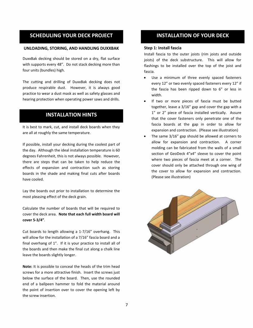
INSTALLATION OF YOUR DECK Step 1: Install fascia Install fascia to the outer joists (rim joists and outside
joists) of the deck substructure. This will allow for
flashings to be installed over the top of the joist and
fascia.
Use a minimum of three evenly spaced fasteners
every 12” or two evenly spaced fasteners every 12” if
the fascia has been ripped down to 6” or less in
width.
If two or more pieces of fascia must be butted
together, leave a 3/16” gap and cover the gap with a
1” or 2” piece of fascia installed vertically. Assure
that the cover fasteners only penetrate one of the
fascia boards at the gap in order to allow for
expansion and contraction. (Please see illustration)
The same 3/16” gap should be allowed at corners to
allow for expansion and contraction. A corner
molding can be fabricated from the walls of a small
section of GeoDeck 4”x4” sleeve to cover the point
where two pieces of fascia meet at a corner. The
cover should only be attached through one wing of
the cover to allow for expansion and contraction.
(Please see illustration)

8
INSTALLATION OF YOUR DECK (CONT.) Step 2: Install gutter apron
Cut and install coated aluminum (or other material)
gutter apron to the joist at the end of the deck where the
water will shed from the deck. (Please see illustration)
Step 3: Determine Starting Point
Determine which side of the substructure will be the
starting point for your deck. For the purpose of these
instructions the deck boards will start at that left side and
work to the right as viewed from the end of the deck
opposite of your home.
Step 4: Assure most desired appearance
Lay the deck boards out to determine how the deck will
best show its unique brushed appearance.
Step 5: Make preparations
Make any necessary preparations in the areas where the
deck will be attached to the house or other structure. It
may be necessary to remove the lower layer of siding to
allow for proper flashing.

9
DuxxBak™ Water Shedding Deck System Installation Methods
(Select Method or Combination of Methods that best fit your needs)
NOTE: Three installation guides are described in the following sections. Please review these and determine if
one of these methods or a combination of these methods will serve the requirements of your deck project.
Guide A: Seal and flash deck to house. Seal “through the deck support posts” to decking to create a
water seal. Also requires a sealant to be applied to the length of the joint of any deck boards that
intersect the “through the deck support posts”.
Guide B: Seal and flash deck to house. Modify (cut away one cavity) a GeoDeck Commercial board to
create a perimeter board that can guide the flow of water from the deck. Requires holes to be cut in
the perimeter board at the points where “through the deck support posts” will penetrate the deck. Seal
“through the deck support posts” to perimeter board or deck board as necessary and seal joints of deck
boards that will intersect any “through the deck support posts”. Also requires a sealant under the wing
of the modified perimeter strip wing.
Guide C: Seal and flash deck to house. Cut coated aluminum flashing (length of the deck plus 3/4”) to a
12” width and form one edge of the length up 3/4” and one edge of the length of the flashing down
3/4” to form a 10” wide water diverting pan. Requires holes to be cut in the pan at the points where
“through the deck support posts” will penetrate the deck. Seal “through the deck support posts” to pan
and to the decking.
10
Installation Guide A Seal and flash deck to house
Seal “through the deck support posts” to top surface of the decking
Seal the interlocking tongue and groove of boards that will intersect “through the deck support posts”
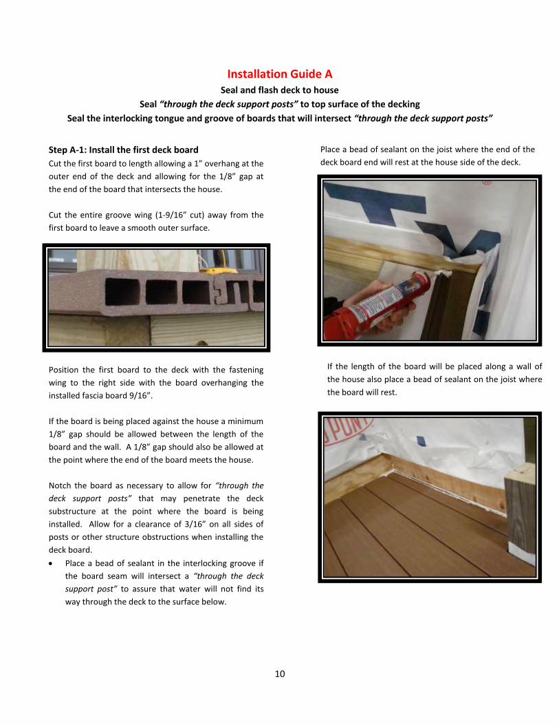
Step A-1: Install the first deck board
Cut the first board to length allowing a 1” overhang at the
outer end of the deck and allowing for the 1/8” gap at
the end of the board that intersects the house.
Cut the entire groove wing (1-9/16” cut) away from the
first board to leave a smooth outer surface.
Position the first board to the deck with the fastening
wing to the right side with the board overhanging the
installed fascia board 9/16”.
If the board is being placed against the house a minimum
1/8” gap should be allowed between the length of the
board and the wall. A 1/8” gap should also be allowed at
the point where the end of the board meets the house.
Notch the board as necessary to allow for “through the
deck support posts” that may penetrate the deck
substructure at the point where the board is being
installed. Allow for a clearance of 3/16” on all sides of
posts or other structure obstructions when installing the
deck board.
Place a bead of sealant in the interlocking groove if
the board seam will intersect a “through the deck
support post” to assure that water will not find its
way through the deck to the surface below.
Place a bead of sealant on the joist where the end of the
deck board end will rest at the house side of the deck.
If the length of the board will be placed along a wall of
the house also place a bead of sealant on the joist where
the board will rest.

11
Step A-1 Continued
Assure that the deck board is properly positioned.
Secure the deck board to the joists (a strip of
waterproofing butyl tape should be placed on the
bottom of the deck board where the fasteners will
penetrate through the top of the deck board) by
inserting one trim head screw fastener through the face
of the board at each joist with the fastener being placed
near a septum of the deck board to take advantage of the
points of strength. Assure that the screw heads are
seated just below the top surface of the board in order to
avoid pullout.
Complete the installation of the first board by inserting a
fastener through the fastening wing at each joist assuring
that the fasteners are inserted at an approximate 55
degree angle. (Please see illustration)
Step A-2: Install the second and seceding deck
boards.
Cut second and seceding boards to length allowing a 1”
overhang at the outer end of the deck and allowing for
the 1/8” gap at the end of the board that intersects the
house.
Position the second and seceding boards by installing the
groove of the board being installed over the tongue of
the previous board to lock the boards together allowing a
minimum 1/8” from the board ends to the wall.
Notch the board as necessary to allow for “through the
deck support posts” that may penetrate the deck
substructure at the point where the board is being
installed. Allow for a clearance of 3/16” on all sides of
posts or other structure obstructions when installing the
deck board.
Place a bead of sealant in the interlocking groove if
the board seam will intersect “through the deck
post” to assure that water will not find its way
through the deck to the surface below.
Place a bead of sealant on the joist where the end of the
deck board will rest at the house side of the deck.
Insert one fastener through the fastening wing at each
joist. Do not fasten through the face of the deck board.
Continue to check for square as the installation moves
along.
Step A-3: Install the final deck board.
Cut the final board to length allowing a 1” overhang at
the outer end of the deck and allowing for the 1/8” gap
at the end of the board that intersects the house.
Cut the final deck board to remove the tongue and
fastening wing (1-9/16” cut) away from the final deck
board.
If the deck width did not allow for this final board
width, it will be necessary to determine how the final
board will be sized and installed.

12
Step A-3 Continued
Position the final board to the deck with the board
overhanging the installed fascia board 9/16”.
If the deck width did not allow for this final board
width, it will be necessary to determine how the final
board will be sized and installed.
If the board is being placed against the house a minimum
1/8” gap should be allowed between the length of the
board and the wall. A 1/8” gap should also be allowed at
the point where the end of the board meets the house.
Notch the board as necessary to allow for “through the
deck support posts” that may penetrate the deck
substructure at the point where the board is being
installed. Allow for a clearance of 3/16” on all sides of
posts or other structure obstructions when installing the
deck board.
Place a bead of sealant in the interlocking groove if the
board seam will intersect a “through the deck support
post” to assure that water will not find its way through
the deck to the surface below.
Place a bead of sealant on the joist where the end of the
deck board will rest at the house side of the deck.
If the length of the board will be placed along a wall of
the house, also place a bead of sealant on the joist where
the board will rest.
Assure that the decking board is properly positioned.
Secure the deck board to the joists (a strip of
waterproofing butyl tape should be placed on the
bottom of the deck board where the fasteners will
penetrate through the top of the deck board) by
inserting two trim head screws through the face of the
board at each joist with the fastener being placed near a
septum of the deck board to take advantage of the points
of strength. Assure that the screw heads are seated just
below the top surface of the board in order to avoid
pullout.
Step A-4: Install seal and flash
Place a bead of sealant between the board ends and the
wall to retard water.
Cut and position coated aluminum (or other material)
flashing with the flashing being install behind the house
wrap material and over the decking.
Place a bead of sealant on top of the decking in the area
that will be under the flashing before the flashing is put
into its final position.

13
Step A-4 Continued
Move the flashing into position behind the house wrap
material and over the decking assuring that the sealant is
bonded to the decking and flashing.
Seal the flashing to the wall under the house wrap using a
sealing tape to assure that any moisture that penetrates
the house wrap will not find its way behind the flashing.
Turn the house wrap material down over the flashing and
seal the house wrap material to the flashing with a
sealing tape.
Install or reinstall siding if it has been removed for the
deck installation.
Install waterproofing butyl tape to the deck board (7/8”)
and deck post at all locations where a “through the deck
support post” penetrates the deck to assure that water
does not find its way through the deck to the area below.
14
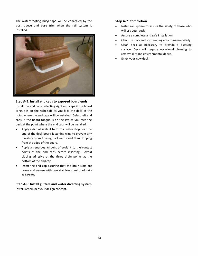
The waterproofing butyl tape will be concealed by the
post sleeve and base trim when the rail system is
installed.
Step A-5: Install end caps to exposed board ends
Install the end caps, selecting right end caps if the board
tongue is on the right side as you face the deck at the
point where the end caps will be installed. Select left end
caps, if the board tongue is on the left as you face the
deck at the point where the end caps will be installed.
Apply a dab of sealant to form a water stop near the
end of the deck board fastening wing to prevent any
moisture from flowing backwards and then dripping
from the edge of the board.
Apply a generous amount of sealant to the contact
points of the end caps before inserting. Avoid
placing adhesive at the three drain points at the
bottom of the end cap.
Insert the end cap assuring that the drain slots are
down and secure with two stainless steel brad nails
or screws.
Step A-6: Install gutters and water diverting system
Install system per your design concept.
Step A-7: Completion
Install rail system to assure the safety of those who
will use your deck.
Assure a complete and safe installation.
Clear the deck and surrounding area to assure safety.
Clean deck as necessary to provide a pleasing
surface. Deck will require occasional cleaning to
remove dirt and environmental debris.
Enjoy your new deck.

15
Installation Guide B
Seal and flash deck to house
Modify GeoDeck Commercial Board to create perimeter board
Seal “through the deck support posts” to top surface of perimeter boards and decking
Seal interlocking tongue and groove of boards that will intersect “through the deck support posts”
Provide a sealant under the wing of the perimeter board
Step B-1: Install the first deck board
Cut the first board to length allowing a 1” overhang at the
outer end of the deck and allowing for the 1/8” gap at
the end of the board that intersects the house.
Cut the entire groove wing (1-9/16” cut) away from the
first board to leave a smooth outer surface.
Cut a 1/4” wide kerf the entire length of the top surface
of the first board and 1/4” from the wall that has just
been altered.
Position the first board to the deck with the fastening
wing to the right side with the outer edge of the deck
board set in 6” from the outer surface of the fascia board.
Place a bead of sealant on the joist where the end of the
deck board will rest at the house side of the deck.
Assure that the deck board is properly positioned.
Secure the deck board to the joists (a strip of
waterproofing butyl tape should be placed on the
bottom of the deck board where the fasteners will
penetrate through the top of the deck board) by
inserting one trim head screw fastener through the face
of the board’s left top surface at each joist with the
fastener being placed near a septum of the deck board to
take advantage of the points of strength. Assure that the
screw heads are seated just below the top surface of the
board in order to avoid pullout.
Complete the installation of the first board by inserting a
fastener through the fastening wing at each joist assuring
that the fasteners are inserted at an approximate 55
degree angle. (Please see illustration)
Step B-2: Prepare and Install Left Side Perimeter
Board (From GeoDeck Commercial Board)
Cut the GeoDeck commercial board to length allowing for
a 1-1/4” overhang at the outer end of the deck and
allowing for the 1/8” gap at the end of the board that
intersects the house. Note that the perimeter strip is
1/4” longer than the deck boards.
Cut away the side wall of the commercial board that is
toward the deck leaving the radius edge at the top in
place.
Cut away the bottom wall of the commercial board at a
point that is just outside of the first interior septum. This
will create a perimeter board with four cavities.

16
Notch the board as necessary to allow for “through the
deck support posts” that may penetrate the deck
substructure at the point where the board is being
installed. Allow for a clearance of 3/16” on all sides of
the posts or other structure obstructions when installing
the deck board.
Position the prepared perimeter board over the “through
the deck support posts” and position it to the deck with
the perimeter board wing over the installed first board
allowing a 3/16” gap between the perimeter board and
the deck board.
After determining that the perimeter board will fit
properly, lift it and place a bead of sealant where the end
of the perimeter board will rest at the house side of the
deck.
Also, place a bead of sealant the length of the board on
the first deck board in a line that will be under the
perimeter board wing when the perimeter board is
positioned. The bead of sealant should be placed to
intercept water prior to the kerf cut.
Place another bead of sealant on the outer joist where
the perimeter board will rest.
Position the perimeter board and assure that it is
properly placed.
Secure the perimeter board to the joists (a strip of
waterproofing butyl tape should be placed on the
bottom of the deck board where the fasteners will
penetrate through the top of the deck board) by
inserting two trim head screw fasteners through the face
of the board at each joist with the fasteners being placed
near a septum of the perimeter board to take advantage
of the points of strength. Assure that the screw heads
are seated just below the top surface of the board in
order to avoid pullout.
Step B-3: Install the second and seceding deck
boards.
Cut second and seceding boards to length allowing a 1”
overhang at the outer end of the deck and allowing for
the 1/8” gap at the end of the board that intersects the
house.
Position the second and seceding boards by installing the
groove of the board being installed over the tongue of
the previous board to lock the boards together allowing a
minimum 1/8” from the board ends to the wall.
Notch the board as necessary to allow for “through the
deck support posts” that may penetrate the deck
substructure at the point where the board is being
installed. Allow for a clearance of 3/16” on all sides posts
or other structure obstructions when installing the deck
board.
Place a bead of sealant in the interlocking groove if the
board seam will intersect a “through the deck post” post
to assure that water will not find its way through the
deck to the surface below.
Place a bead of sealant on the joist where the end of deck
board will rest at the house side of the deck.
Insert one fastener through the fastening wing at each
joist. Do not fasten through the face of the deck board.
Continue to check for square as the installation moves
along.

17
Step B-4: Install the final deck board.
Cut the final board to length allowing a 1” overhang at
the outer end of the deck and allowing for the 1/8” gap
at the end of the board that intersects the house.
Cut away 1-5/16” of the fastening wing from the final
board leaving a 5/16” fastening lip below the board
tongue.
Cut the tongue away from the board leaving the new
5/16” lip. (Please see illustration)
Cut a 1/4” wide kerf the entire length of the top surface
of the final board and 1/4” from the wall that has just
been altered.
Position the final board to the deck with the fastening
wing to the right side.
If the deck width did not allow for this final board
width, it will be necessary to determine how the final
board will be sized and installed.
If the board is being placed against the house a minimum
1/8” gap should be allowed between the length of the
board and the wall. A 1/8” gap should also be allowed at
the point where the end of the board meets the house.
Notch the board as necessary to allow for “through the
deck support posts” that may penetrate the deck
substructure at the point where the board is being
installed. Allow for a clearance of 3/16” on all sides of
posts or other structure obstructions when installing the
deck board.
Place a bead of sealant on the joist where the end of the
deck board will rest at the house side of the deck.
If the length of the board will be placed along a wall of
the house, also place a bead of sealant on the joist where
the board will rest.
Assure that the deck board is properly positioned.
Insert one fastener through the fastening wing at each
joist. Do not fasten through the face of the deck board.
Step B-5: Prepare and Install Right Side Perimeter
Board (From GeoDeck Commercial Board)
Cut the GeoDeck commercial board to length allowing for
a 1-1/4” overhang at the outer end of the deck and
allowing for the 1/8” gap at the end of the board that
intersects the house. Note that the perimeter strip is
1/4” longer than the deck boards.
Cut away the side wall of the commercial board that is
toward the deck leaving the radius edge at the top in
place.
Cut away the bottom wall of the commercial board at a
point that is just outside of the first interior septum. This
will create a perimeter board with four cavities.

18
Step B-5 Continued
Notch the board as necessary to allow for “through the
deck support posts” that may penetrate the deck
substructure at the point where the board is being
installed. Allow for a clearance of 3/16” on all sides posts
or other structure obstructions when installing the deck
board.
Position the prepared perimeter board over the “through
the deck support posts” and position it to the deck with
the perimeter board wing over the installed first board
allowing a 3/16” gap between the perimeter board and
the deck board.
After determining that the perimeter board will fit
properly, lift it and place a bead of sealant where the end
of the perimeter board will rest at the house side of the
deck.
Also, place a bead of sealant the length of the board on
the first deck board in a line that will be under the
perimeter board wing when the perimeter board is
positioned. The bead of sealant should be placed to
intercept water prior to the kerf cut.
Place another bead of sealant on the outer joist where
the perimeter board will rest.
Position the perimeter board and assure that it is
properly placed.
Secure the perimeter board to the joists (a strip of
waterproofing butyl tape should be placed on the area
of the joists where the fasteners will penetrate through
the top of the deck board) by inserting two trim head
screw fasteners through the face of the board at each
joist with the fasteners being placed near a septum of the
perimeter board to take advantage of the points of
strength. Assure that the screw heads are seated just
below the top surface of the board in order to avoid
pullout.
Step B-6: Install seal and flash
Place a bead of sealant between the board ends and the
wall to retard water.
Cut and position coated aluminum (or other material)
flashing with the flashing being install behind the house
wrap material and over the decking.
Place a bead of sealant on top of the decking in the area
that will be under the flashing before the flashing is put
into its final position.

19
Step B-6 Continued
Move the flashing into position behind the house wrap
material and over the decking assuring that the sealant is
bonded to the decking and flashing.
Seal the flashing to the wall under the house wrap using a
sealing tape to assure that any moisture that penetrates
the house wrap will not find its way behind the flashing.
Turn the house wrap material down over the flashing and
seal the house wrap material to the flashing with a
sealing tape.
Install or reinstall siding if it has been removed for the
deck installation.
Install waterproofing butyl tape to the deck board (7/8”)
and deck post at all locations where a “through the deck
support post” penetrates the deck to assure that water
does not find its way through the deck to the area below.
20
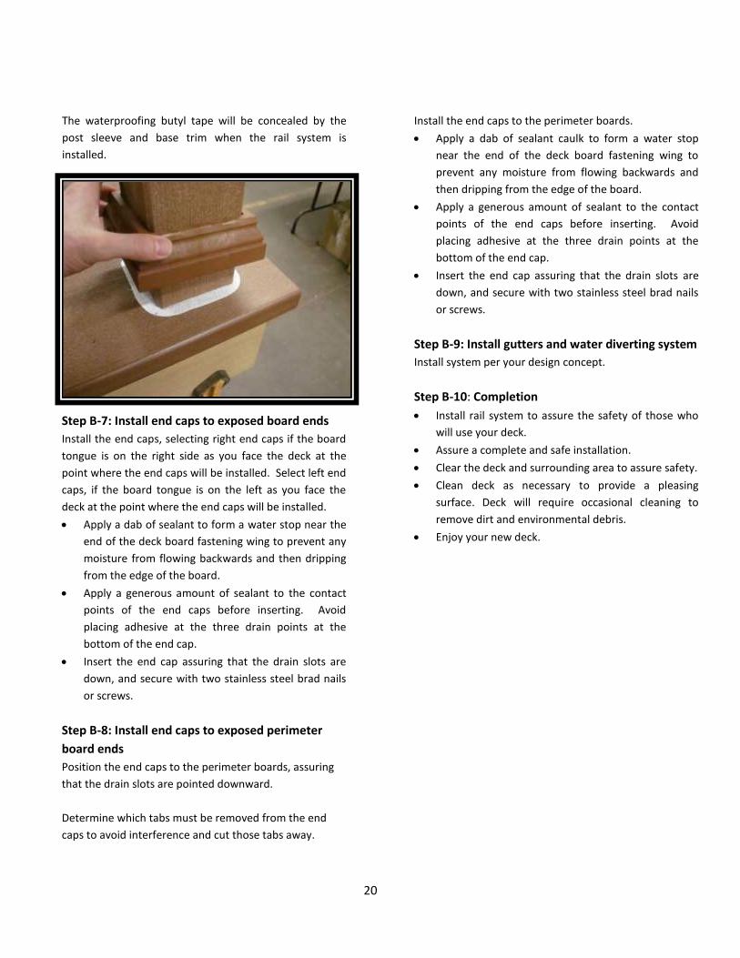
The waterproofing butyl tape will be concealed by the
post sleeve and base trim when the rail system is
installed.
Step B-7: Install end caps to exposed board ends
Install the end caps, selecting right end caps if the board
tongue is on the right side as you face the deck at the
point where the end caps will be installed. Select left end
caps, if the board tongue is on the left as you face the
deck at the point where the end caps will be installed.
Apply a dab of sealant to form a water stop near the
end of the deck board fastening wing to prevent any
moisture from flowing backwards and then dripping
from the edge of the board.
Apply a generous amount of sealant to the contact
points of the end caps before inserting. Avoid
placing adhesive at the three drain points at the
bottom of the end cap.
Insert the end cap assuring that the drain slots are
down, and secure with two stainless steel brad nails
or screws.
Step B-8: Install end caps to exposed perimeter
board ends
Position the end caps to the perimeter boards, assuring
that the drain slots are pointed downward.
Determine which tabs must be removed from the end
caps to avoid interference and cut those tabs away.
Install the end caps to the perimeter boards.
Apply a dab of sealant caulk to form a water stop
near the end of the deck board fastening wing to
prevent any moisture from flowing backwards and
then dripping from the edge of the board.
Apply a generous amount of sealant to the contact
points of the end caps before inserting. Avoid
placing adhesive at the three drain points at the
bottom of the end cap.
Insert the end cap assuring that the drain slots are
down, and secure with two stainless steel brad nails
or screws.
Step B-9: Install gutters and water diverting system
Install system per your design concept.
Step B-10: Completion
Install rail system to assure the safety of those who
will use your deck.
Assure a complete and safe installation.
Clear the deck and surrounding area to assure safety.
Clean deck as necessary to provide a pleasing
surface. Deck will require occasional cleaning to
remove dirt and environmental debris.
Enjoy your new deck.

21
Installation Guide C
Seal and flash deck to house
Provide a secondary collection pan to collect and divert water that may penetrate at openings
Seal “through the deck support posts” to the water diverting pan
Seal “through the deck support posts” to the top of the decking
Seal interlocking tongue and groove of boards that will intersect “through the deck support posts”
Step C-1: Prepare first water diverting pan
Plan, mark, and cut the first water diverting pan
Cut a 12” wide piece of coated aluminum flashing to the
length of the deck substructure plus 3/4” as the first step
in providing a water diverting pan. The additional 3/4”
will allow water to flow off of the pan and onto the
ground or into the gutter system if one is provided.
Bend one edge of the 12” wide flashing down 3/4” to
form a lip and bend the other edge of the 12” wide
flashing up 3/4” to form a lip. This will leave a 10-1/2”
wide water diverting pan.
Verify that the pan is correctly sized by placing it in
position along the left side of the deck with the
downward turned lip along the outer edge of the deck
substructure and fascia.
Layout the positions of any “through the deck support
posts” that will penetrate the deck substructure by
marking the corner points of the support posts on the
pan.
Then, layout a square within the points that is set back
from the corner points 3/4” on each side at each post
location.
Cut the square at each post location and then make a 45
degree cut to the marked corner points at each corner of
the cutout.
After each of the corner cuts is complete turn the tabs
that are formed up at a 90 degree angle to form pressure
tabs on the pan.
The installation of additional wood cross blocking under
the water diverting pans will be beneficial.
Step C-2: Install the first water diverting pan
Position the water diverting pan over the support posts
and down on to the substructure with the downward
pointing tab against the fascia and deck substructure.
22
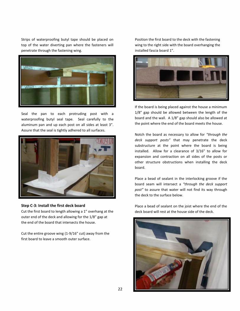
Strips of waterproofing butyl tape should be placed on
top of the water diverting pan where the fasteners will
penetrate through the fastening wing.
Seal the pan to each protruding post with a
waterproofing butyl seal tape. Seal carefully to the
aluminum pan and up each post on all sides at least 3”.
Assure that the seal is tightly adhered to all surfaces.
Step C-3: Install the first deck board
Cut the first board to length allowing a 1” overhang at the
outer end of the deck and allowing for the 1/8” gap at
the end of the board that intersects the house.
Cut the entire groove wing (1-9/16” cut) away from the
first board to leave a smooth outer surface.
Position the first board to the deck with the fastening
wing to the right side with the board overhanging the
installed fascia board 1”.
If the board is being placed against the house a minimum
1/8” gap should be allowed between the length of the
board and the wall. A 1/8” gap should also be allowed at
the point where the end of the board meets the house.
Notch the board as necessary to allow for “through the
deck support posts” that may penetrate the deck
substructure at the point where the board is being
installed. Allow for a clearance of 3/16” to allow for
expansion and contraction on all sides of the posts or
other structure obstructions when installing the deck
board.
Place a bead of sealant in the interlocking groove if the
board seam will intersect a “through the deck support
post” to assure that water will not find its way through
the deck to the surface below.
Place a bead of sealant on the joist where the end of the
deck board will rest at the house side of the deck.

23
Step C-3 Continued
If the length of the board will be placed along a wall of
the house, also place a bead of sealant on the joist where
the board will rest.
Assure that the deck board is properly positioned and
that the second deck board will fit within the pan at the
up turned lip when it is installed.
Secure the deck board to the joists (strips of
waterproofing butyl tape should be placed on top of the
water diverting pan where the fasteners will penetrate
through the top of the deck board) by inserting one trim
head screw fastener through the face of the board at
each joist with the fastener being placed near a septum
of the deck board to take advantage of the points of
strength. Assure that the screw heads are seated just
below the top surface of the board in order to avoid
pullout. (Please see illustration)
Complete the installation of the first board by inserting a
fastener through the fastening wing at each joist assuring
that the fasteners are inserted at an approximate 55
degree angle. (Please see illustration)
Step C-4: Install the second and seceding deck
boards.
Cut second and seceding boards to length allowing a 1”
overhang at the outer end of the deck and allowing for
the 1/8” gap at the end of the board that intersects the
house.
Position the second and seceding boards by installing the
groove of the board being installed over the tongue of
the previous board to lock the boards together allowing a
minimum 1/8” from the board ends to the wall. The
second deck board should fit within the pan and the third
deck board should interlock with the second as it slips
over the up turned lip of the pan.
Notch the boards as necessary to allow for “through the
deck support posts” that may penetrate the deck
substructure at the point where the board is being
installed. Allow for a clearance of 3/16” on all sides of
the posts or other structure obstructions when installing
the deck board.
Install water diverting pans for outer edge “through the
deck support posts”. Preparation is described in Step C-5
on the next page.

24
Step C-4 Continued
Position the outer edge water diverting pan over the
support post and down on to the substructure with the
upward pointing tabs being interlocked between the
joints of two deck boards on either side of the “through
the deck support post”.
Place a bead of sealant along the back edge of the water
diverting pan to form a dam that will help assure that
water will not flow backward and will not find its way to
the area below. Provide blocking under the pan to
provide support.
Seal the pan to the protruding post with a waterproofing
butyl tape. Seal carefully to the pan and up each post on
all sides at least 3”. Assure that the seal is tightly
adhered to all surfaces.
Place a bead of sealant in the interlocking groove if the
board seam will intersect a structural deck post to assure
that water will not find its way through the deck to the
surface below.
Place a bead of sealant on the joist where the end of the
deck board will rest at the house side of the deck.
Insert one fastener through the fastening wing at each
joist (strips of waterproofing butyl tape should be
placed on top of the water diverting pans as these are
encountered along the outer edge of the deck). Do not
fasten through the face of the deck board.
Continue to check for square as the installation moves
along.
Step C-5: Prepare outer edge of deck single post
water diverting pans
A small water diverting pan can be installed at each
“through the deck support post” along the outer edge of
the deck.
Cut a 12” wide piece of coated aluminum flashing to the
length of 13”.
Bend both ends of the 13” wide flashing up 3/4” to form
a 3/4” lip on both sides. This will leave an 11-1/2” wide
water diverting pan.
Layout the positions of the “through the deck support
posts” that will penetrate the deck substructure by
marking the corner points of the support posts on the
aluminum pan.
Then, layout a square within the points that is set back
from the corner points 3/4” on each side at each post
location.
Cut the square at each post location and then make a 45
degree cut to the marked corner points at each corner of
the cutout.
25
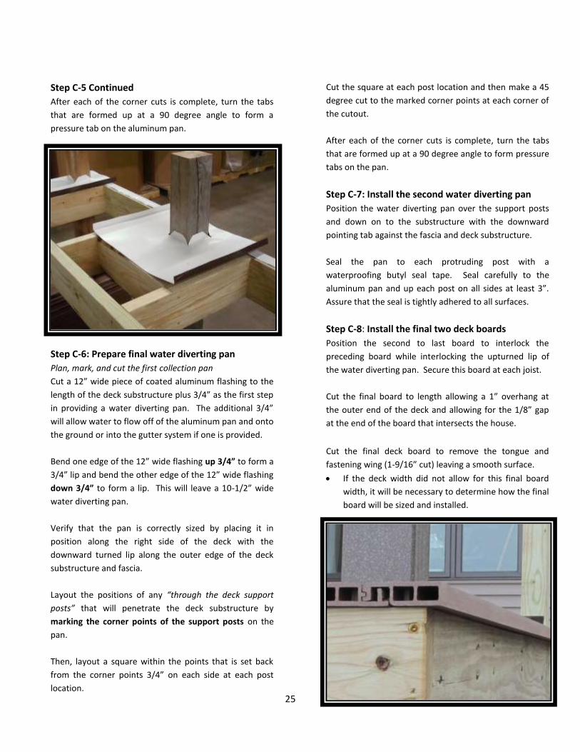
Step C-5 Continued
After each of the corner cuts is complete, turn the tabs
that are formed up at a 90 degree angle to form a
pressure tab on the aluminum pan.
Step C-6: Prepare final water diverting pan
Plan, mark, and cut the first collection pan
Cut a 12” wide piece of coated aluminum flashing to the
length of the deck substructure plus 3/4” as the first step
in providing a water diverting pan. The additional 3/4”
will allow water to flow off of the aluminum pan and onto
the ground or into the gutter system if one is provided.
Bend one edge of the 12” wide flashing up 3/4” to form a
3/4” lip and bend the other edge of the 12” wide flashing
down 3/4” to form a lip. This will leave a 10-1/2” wide
water diverting pan.
Verify that the pan is correctly sized by placing it in
position along the right side of the deck with the
downward turned lip along the outer edge of the deck
substructure and fascia.
Layout the positions of any “through the deck support
posts” that will penetrate the deck substructure by
marking the corner points of the support posts on the
pan.
Then, layout a square within the points that is set back
from the corner points 3/4” on each side at each post
location.
Cut the square at each post location and then make a 45
degree cut to the marked corner points at each corner of
the cutout.
After each of the corner cuts is complete, turn the tabs
that are formed up at a 90 degree angle to form pressure
tabs on the pan.
Step C-7: Install the second water diverting pan
Position the water diverting pan over the support posts
and down on to the substructure with the downward
pointing tab against the fascia and deck substructure.
Seal the pan to each protruding post with a
waterproofing butyl seal tape. Seal carefully to the
aluminum pan and up each post on all sides at least 3”.
Assure that the seal is tightly adhered to all surfaces.
Step C-8: Install the final two deck boards
Position the second to last board to interlock the
preceding board while interlocking the upturned lip of
the water diverting pan. Secure this board at each joist.
Cut the final board to length allowing a 1” overhang at
the outer end of the deck and allowing for the 1/8” gap
at the end of the board that intersects the house.
Cut the final deck board to remove the tongue and
fastening wing (1-9/16” cut) leaving a smooth surface.
If the deck width did not allow for this final board
width, it will be necessary to determine how the final
board will be sized and installed.

26
Step C-8 Continued
If the board is being placed against the house, a minimum
1/8” gap should be allowed between the length of the
board and the wall. A 1/8” gap should also be allowed at
the point where the end of the board meets the house.
Notch the board as necessary to allow for “through the
deck support posts” that may penetrate the deck
substructure at the point where the board is being
installed. Allow for a clearance of 3/16” on all sides of
posts or other structure obstructions when installing the
deck board.
Seal the pan to the protruding post with a waterproofing
butyl tape. Seal carefully to the pan and up each post on
all sides at least 3”. Assure that the seal is tightly
adhered to all surfaces.
Place a bead of sealant in the interlocking groove if the
board seam will intersect a “through the deck support
post” to assure that water will not find its way through
the deck to the surface below.
Place a bead of sealant on the joist where the end of the
deck board will rest at the house side of the deck.
If the length of the board will be placed along a wall of
the house also place a bead of sealant on the joist where
the board will rest.
Assure that the deck board is properly positioned.
Secure the deck board to the joists (strips of
waterproofing butyl tape should be placed on top of the
water diverting pan where the fasteners will penetrate
through the top of the deck board) by inserting two trim
head screws through the face of the board at each joist
with the fasteners being placed near a septum of the
deck board to take advantage of the points of strength.
Assure that the screw heads are seated just below the
top surface of the board in order to avoid pullout.
Step C-9: Install seal and flash
Place a bead of sealant between the board ends and the
wall to retard water.
Cut and position coated aluminum (or other material)
flashing with the flashing being install behind the house
wrap material and over the decking.
Place a bead of sealant on top of the decking in the area
that will be under the flashing before the flashing is put
into its final position.

27
Step C-9 Continued
Move the flashing into position behind the house wrap
material and over the decking assuring that the sealant is
bonded to the decking and flashing.
Seal the flashing to the wall under the house wrap using a
sealing tape to assure that any moisture that penetrates
the house wrap will not find its way behind the flashing.
Turn the house wrap material down over the flashing and
seal the house wrap material to the flashing with a
sealing tape.
Install or reinstall siding if it has been removed for the
deck installation.
Install waterproofing butyl tape to the deck board (7/8”)
and deck post at all locations where a “through the deck
support post” penetrates the deck to assure that water
does not find its way through the deck to the area below.

28
Step C-9 Continued
The waterproofing butyl tape will be concealed by the
post sleeve and base trim when the rail system is
installed.
Step C-10: Install end caps to exposed board ends
Install the end caps, selecting right end caps if the board
tongue is on the right side as you face the deck at the
point where the end caps will be installed. Select left end
caps, if the board tongue is on the left as you face the
deck at the point where the end caps will be installed.
Apply a dab of sealant to form a water stop near the
end of the deck board fastening wing to prevent any
moisture from flowing backwards and then dripping
from the edge of the board.
Apply a generous amount of sealant to the contact
points of the end caps before inserting. Avoid
placing adhesive at the three drain points at the
bottom of the end cap.
Insert the end cap assuring that the drain slots are
down and secure with two stainless steel brad nails
or screws.
Step C-11: Install gutters and water diverting
system
Install system per your design concept.
Step C-12: Completion
Install rail system to assure the safety of those who
will use your deck.
Assure a complete and safe installation.
Clear the deck and surrounding area to assure safety.
Clean deck as necessary to provide a pleasing
surface. Deck will require occasional cleaning to
remove dirt and environmental debris.
Enjoy your new deck.

29
STAIR INSTALLATION Use GeoDeck or TerrainDeck traditional S4S deck boards
for the construction of stair treads for a safe installation.
Install stairs on stringers that are installed on 12” centers.
Leave a 3/16” gap between the stair tread boards.
Install according to local codes and acceptable
construction practices.
CARE AND MAINTENANCE Occasional cleaning will help to keep your deck looking
fresh.
Regular cleaning will help to keep the brushed surface
and grooves between the deck boards free of debris. A
nylon bristle brush or broom will make the task easier.
A pressure washer with a fan tip may be carefully used to
clean your deck if it is guided along in the direction of the
grain. Always test a small area to assure that the surface
texture is not damaged. Always follow safety
precautions.
Although your DuxxBak™ Water Shedding Deck System is
durable, care should be taken to avoid scratching. If
scratches do appear it may be possible to carefully draw a
stainless steel brush across the scratches in the direction
of the grain to remove or reduce the scratches. Always
test a small area before proceeding.
Many stains can be removed with an all-purpose
household cleaner, concentrated dish soap, laundry
detergent, degreaser or deck cleaner. Fresh stains are
usually more easily removed and a nylon bristle brush will
help achieve the best results. Always test a small area
before proceeding.
Mold and mildew that may form on the surface of your
deck are environmentally generated and will not damage
your deck. These can generally be removed with cleaners
that are designed to remove mold and mildew along with
the use of a pressure washer and nylon bristle brush as
described above. Always test a small area before
proceeding.
Always make necessary repairs to maintain a safe and
enjoyable deck.
Deck surfaces can become hot during periods of hot
summer weather. It is recommended that footwear be
worn to protect against unexpected hot surfaces.
WARRANTY Your DuxxBak Water Shedding Deck System comes with a
25-year limited warranty that provides coverage against
splintering and splitting, rot and decay, and termite
damage.
Your deck will give you many years of enjoyment.
However, like all materials, DuxxBak decking will be
subject to color change when exposed to the sun’s
ultraviolet rays.
Your deck is designed to shed water and will generally
keep the under deck area dry when properly installed to
include proper seals and flashing. Seals will require
regular maintenance.
Every material expands and contracts with temperature
change, and engineered decking is no exception. Avoid
potential problems by allowing time for proper
acclimation of your decking to local temperatures prior to
installation. Expansion and contraction is not a product
defect and is not covered under the DuxxBak™ Water
Shedding Deck System warranty.
You will find our complete warranty on the next page.

30
Congratulations! As a DuxxBak Water Shedding Deck System owner, you have made a wise investment and you are protected by our twenty-five year limited warranty, which provides coverage against:
Splintering and Splitting
Rot and Decay Damage
Termite Damage
Green Bay Decking, LLC (hereinafter “Manufacturer”) warrants that its DuxxBak products are manufactured from recovered cellulose and plastic, and will not split or splinter, suffer structural damage from termites, rot, mildew, fungal decay, or mold for a period of 25 years from the time of shipment to customer when properly installed and maintained. Mildew or mold may form on the surface of your deck as a result of air pollution and environmental debris. Such surface contamination will not harm your deck and can be removed by occasional cleaning with mild household cleaners or commercial deck cleaning products using a nylon brush or a power washer equipped with a fan tipped wand. DuxxBak is designed to resist the effects of exposure to the sun and environmental elements and will provide many years of excellent service. However, like all materials, DuxxBak will be subject to color change when exposed to the sun’s ultraviolet rays.
MANUFACTURER’S LIABILITY UNDER THIS WARRANTY IS LIMITED SOLELY TO REPLACEMENT OF DEFECTIVE DUXXBAK PRODUCTS OR REFUND, WITH THE FIRST 10 YEARS NON-PRORATED AND THE FOLLOWING 15 YEARS ON A STRAIGHT-LINE DEPRECIATING BASIS, AT MANUFACTURER’S OPTION. Purchaser’s sole and exclusive remedy for any claim whatsoever, whether in contract, warranty, tort or strict liability, arising out of the use, storage or possession of DuxxBak products, including without limitation any claim that DuxxBak products failed to perform as warranted, shall be replacement with substituted DuxxBak products or completely refunded in the first 10 years, with the following 15 years based on a straight-line depreciating basis, at Manufacturer’s option. To obtain replacement or refund, the original owner must submit its claim together with this warranty certificate, the original purchase invoice indicating the date of purchase, pictures of the defective DuxxBak products, and a detailed written description to Green Bay Decking, LLC. 1518 South Broadway, Green Bay, WI 54304.
THE WARRANTY SHALL NOT APPLY TO DUXXBAK PRODUCTS THAT HAVE NOT BEEN INSTALLED IN ACCORDANCE WITH MANUFACTURER’S AND ICC GUIDELINES (ICC PENDING). “Installation Instructions” can be found at www.GreenBayDecking.com. This warranty shall not cover defects due to (i) natural disasters, including fire, smoke, water, earthquake, lightning or static electricity; (ii) causes external to the DuxxBak product such as, but not limited to, weather; (iii) the neglect, abuse, misuse (including faulty installation, repair or maintenance by other than Manufacturer), improper storage of the DuxxBak product or other failure to comply with the instructions set forth in the documentation and/or manual accompanying DuxxBak product; (iv) a modification of the DuxxBak product not provided by the Manufacturer; (v) a malfunction of any product not provided by Manufacturer with which the DuxxBak product is used or combined; (vi) use, modification or other treatment of the DuxxBak product in a manner for which it was not designed or intended; (vii) defects in articles purchased by Manufacturer and resold by it without alteration and effects in materials purchased by Manufacturer which cannot be discovered by warranty factory inspection; (viii) placement under or subjection to abnormal use conditions; (ix) normal wear and tear; or (x) expansion and contraction. This warranty does not cover product defects on installed decks that were apparent at or prior to installation.
MANUFACTURER’S WARRANTY SHALL APPLY ONLY TO DUXXBAK PRODUCTS. IN NO EVENT SHALL MANUFACTURER BE LIABLE FOR LABOR OR OTHER EXPENSES INCURRED BY THE PURCHASER, OR SPECIAL, INCIDENTAL, EXEMPLARY OR CONSEQUENTIAL DAMAGES OF ANY KIND WHATSOEVER. MANUFACTURER’S LIABILITY ARISING OUT OF THE MANUFACTURE, SALE OR SUPPLY OF THE DUXXBAK PRODUCTS OR THEIR USE, WHETHER BASED UPON WARRANTY, CONTRACT, TORT, OR OTHERWISE, SHALL NOT EXCEED THE ACTUAL PURCHASE PRICE PAID BY THE PURCHASER FOR THE DUXXBAK PRODUCTS.
Purchaser acknowledges that the DuxxBak products are not structural lumber and therefore may not be used as such. PURCHASER IS SOLELY RESPONSIBLE FOR DETERMINING THE SUITABILITY FOR USE OR APPLICATION OF ANY DUXXBAK PRODUCT, OR WHETHER DUXXBAK PRODUCTS MEET REQUIREMENTS OF APPLICABLE BUILDING CODES OR SAFETY CODES FOR SPECIFIC APPLICATIONS.
No person or entity is authorized by Manufacturer to make and Manufacturer shall not be bound by any statement of representation as to the performance of DuxxBak products other than what is contained in this warranty. This warranty shall not be amended or altered except in written instrument signed by Manufacturer and Purchaser.
THE FOREGOING WARRANTY IS EXCLUSIVE AND IN LIEU OF ANY OTHER WARRANTIES WITH RESPECT TO DUXXBAK PRODUCTS, EXPRESSED OR IMPLIED, INCLUDING WITHOUT LIMITATION, ANY IMPLIED WARRANTY OR MERCHANTABILITY, FITNESS FOR A PARTICULAR PURCHASE OR NON-INFRINGEMENT. Laws from time to time in force in certain jurisdictions may imply warranties that cannot be excluded or can only be excluded to limited extent. This warranty shall be read and construed subject to any such statutory provisions. This warranty gives you specific legal rights. You may have other rights, which vary from state to state. To activate the warranty, please fill out and send the warranty card within 30 days of purchase.
This warranty certificate was issued on . Effective January 01, 2014
25 Year Limited Warranty

31
DuxxBak Water Shedding Deck System
Product Features
Unique water shedding board requires no hidden fastener system
Outdoor furniture can be safely stored under the deck
Outdoor activities can continue during periods of rainfall
Resistance to decay and mold
Strength and durability
Less maintenance
Eco-friendly
25-year limited warranty
Easy to install
DuxxBak decking can be installed on joists that are spaced at 24”
GeoDeck and TerrainDeck S4S Stair Treads can be installed on 12” centers
For More Information
For the most up-to-date installation instructions, please visit www.GreenBayDecking.com.
Thank you for using our DuxxBak Water Shedding Decking System
Green Bay Decking, LLC
1518 South Broadway
Green Bay, WI 54304
(877) 804-0137
March 31, 2015 Version 13.4