dqs submission requirements for engineering design · dqs submission requirements for engineering...
TRANSCRIPT

DESIGN SPECIFICATIONS
SUBDIVISION & ENGINEERING STANDARDS
AUS-SPEC #1 Development Specification Series


Design Specification Contents Section Title
DQS Submission Requirements for Engineering Design
D01 Geometric Road Design (Urban and Rural)
D02 Pavement Design
D03 Structures / Bridge Design
D04 Subsurface Drainage Design
D05 Stormwater Drainage Design
D06 Site Regrading
D09 Cycleway and Shared Pathway Design
D10 Bushfire Protection
WSC.D13 Access and Off-street Parking


SUBMISSION REQUIREMENTS FOR ENGINEERING DESIGN
DQS Aug 2008 (Copyright SWR-TM/WSC) WOLLONDILLY SHIRE COUNCIL
DESIGN SPECIFICATION
DQS
SUBMISSION REQUIREMENTS
FOR ENGINEERING DESIGN


SUBMISSION REQUIREMENTS FOR ENGINEERING DESIGN
DQS Aug 2008 (Copyright SWR-TM/WSC) WOLLONDILLY SHIRE COUNCIL
Amendment Record for this Specification Part
This Specification is Council’s edition of the AUS-SPEC generic specification part and includes Council’s primary amendments.
Details are provided below outlining the clauses amended from the Council edition of this AUS-SPEC Specification Part. The clause numbering and context of each clause are preserved. New text is shown underlined and deleted text shown struck through (eg. or as 'DELETED'. New clauses are added towards the rear of the specification part as special requirements clauses. Project specific additional script is shown in the specification as italic font.
The amendment code indicated below is ‘A’ for additional script ‘M’ for modification to script and ‘O’ for omission of script. An additional code ‘P’ is included when the amendment is project specific.
Amendment Sequence No.
Key Topic addressed in amendment
Clause No. Amendment Code
Author Initials
Amendment Date
1 Drawing scales DQS.09 A IB 1/7/08
2 Design Certification Report Annexure DQS A
M IB 1/7/08
3 Design Certification Report Annexure DQS B
M IB 1/7/08


SUBMISSION REQUIREMENTS FOR ENGINEERING DESIGN
DQS Aug 2008 (Copyright SWR-TM/WSC) WOLLONDILLY SHIRE COUNCIL
DQS : SUBMISSION REQUIREMENTS FOR ENGINEERING DESIGN CONTENTS CLAUSE PAGE
DQS.01 SCOPE..............................................................................................................................................1
DQS.02 OBJECTIVES....................................................................................................................................1
DQS.03 REFERENCE AND SOURCE DOCUMENTS ..................................................................................1
DQS.04 CERTIFICATION...............................................................................................................................1
DQS.05 MINIMUM DRAFTING REQUIREMENTS ........................................................................................2
DQS.06 DESIGNER'S QUALIFICATIONS .....................................................................................................2
DQS.07 RECORDS ........................................................................................................................................2
DQS.08 AUDIT................................................................................................................................................3
DSQ.09 SUBMISSION REQUIREMENTS .....................................................................................................3
(a) Roads - (Public and Private) 4
(b) Driveways and Accessways 6
(c) Drainage – Road, Trunk and Inter-allotment Drainage 6
(d) Drainage – Property Drainage Systems 8
(e) Construction Notes 9
(f) Easements and Agreements 9
(g) Flood Studies 9
(h) Sediment & Erosion Control 10
(i) Traffic Management 11 ANNEXURES DQS-A DESIGN CERTIFICATION REPORT DQS-B CHECK LIST - ENGINEERING DESIGN PLANS

SUBMISSION REQUIREMENTS FOR ENGINEERING DESIGN
DQS Aug 2008 (Copyright SWR-TM/WSC) DQS-1 WOLLONDILLY SHIRE COUNCIL
DQS : SUBMISSION REQUIREMENTS FOR ENGINEERING DESIGN
DQS.01 SCOPE
1. This design specification sets out the minimum submission requirements of Designs required by Council for development consents.
DQS.02 OBJECTIVES
1. This specification aims to set standards and document requirements for the execution and recording of design processes in order that the infrastructure associated with any development is designed to be fit for service and where applicable, be of a standard reasonably maintainable when it is accepted by Council as a community asset.
Maintenance
2. It is also an objective that these qualities be readily demonstrable by clear records of key design processes and that data relevant to the upkeep of the assets is available to Council's management.
Records
DQS.03 REFERENCE AND SOURCE DOCUMENTS
(a) Council Specifications All Specifications for Design and Construction Council's Codes and Policies
(b) Australian Standards AS/NZS 3905.2 Guide to quality system Standards AS/NZS 9001,
AS/NZS 9002 and AS/NZS 9003 for construction. AS/NZS 3913 Quality manuals – Guide to preparation. AS/NZS ISO 8402 Quality management and quality assurance –
Vocabulary. AS/NZS ISO 9001 Quality systems – Model for quality assurance in design,
development, production, installation and servicing. AS/NZS ISO 9004.1 Quality management and quality system elements –
Guidelines.
(c) Other Section 90 (EP&A ACT) Local Government Act (1919) Subdivisions Pt XII Local Government Act (1993) Technical Publications used as Engineering Standards (AR&R) Interim Policies and Guidelines
DQS.04 CERTIFICATION
1. The Developer shall present all engineering plans to the Principal Certifying Authority for acceptance. Each set of plans shall be accompanied by a Certification Report which will be signed by the Developer's Engineer or Quantity Surveyor. The Certification Report will comprise the certificate and check lists set out in Annexure DQS-A. Approval of the plans by the Principal Certifying Authority does not relieve the developer from rectifying any errors or omissions that become evident during construction.
Certification Report
2. Certification Reports shall be required with preliminary plans and shall require resubmission with updates when final plans are submitted. Certification is not required with sketch plans or concept plans.
Certification of Preliminary Plans

SUBMISSION REQUIREMENTS FOR ENGINEERING DESIGN
WOLLONDILLY SHIRE COUNCIL DQS-2 DQS Aug 2008 (Copyright SWR-TM/WSC)
3. The Certification Report shall indicate on check lists any aspects of design which do not meet requirements or tolerances set out in Council's Design and Construction Specifications and Council Codes.
DQS.05 MINIMUM DRAFTING REQUIREMENTS
1. Design plans shall be definitive and clearly set out so as to present the design concepts in such a way that the project can be understood, specified for construction and satisfactorily built.
2. All design plans should be clearly numbered by the designer with separate sheets numbered as part of a set. All drawing sheets shall have an allocated space in the bottom right hand corner for an assigned number provided by Council (18 characters).
Plan Numbers
3. The information shown on the drawings shall be logically collected on discrete sheets to avoid illogical and onerous effort in cross referencing between sheets in order to find information. Sheets of drawings should not be overcrowded with information and should not rely on colour printing or colour wash to impart information. Drawings should be on A1 size sheets and shall be on A1 sheets if they detail any work that will be owned by Council. The drawings should be suitable for black and white copying, microfilming and photo reduction to A3 paper size without loss of clarity.
Logical Drawing Sheets
4 Council has the authority to refuse plans that do not meet minimum drafting requirements. Plans copied from other works will not be accepted.
DQS.06 DESIGNER'S QUALIFICATIONS
1. A Civil Engineer suitably experienced and qualified so as to be accepted as a member of the Institution of Engineers, Australia or a suitably experienced Registered Surveyor shall be accepted as qualified to prepare plans for roadworks, drainage works, canal works (excluding flood control structures and bridges).
Engineer Surveyor
2. A Civil Engineer qualified as detailed above shall be accepted as qualified to prepare plans for bridges, retaining walls, miscellaneous structures, buildings, pumping stations and flood control structures.
Structural Design by Engineer
3 All hydraulic and hydrological calculations shall be carried out by a person experienced in hydrologic and hydraulic design.
DQS.07 RECORDS
1. The Designer shall retain appropriate design records in a format such that they can be understood readily by design staff with no prior knowledge of the particular design.
2. Calculations which can readily be re-done need not be kept once the construction maintenance period of the project has expired.
Calculation Record Retention
3. A design file shall be maintained by the Subdivider or his/her consultant containing records of calculations, approvals and decisions, geotechnical data and other design data which could be relevant in reviewing aspects of the design or planning future maintenance responsibilities.
Design File to be kept

SUBMISSION REQUIREMENTS FOR ENGINEERING DESIGN
DQS Aug 2008 (Copyright SWR-TM/WSC) DQS-3 WOLLONDILLY SHIRE COUNCIL
DQS.08 AUDIT
1. Council shall have the right of audit of all processes and documents related to the project design. The Developer and the Developer's Consultant shall provide Council's Officers all reasonable assistance in inspecting records of designs submitted to Council for acceptance.
Assistance
2. In order to provide for such audit, access to the premises of the Developer or the Developer's Consultant will be provided to Council on a 24 hour notice basis.
Access
DSQ.09 SUBMISSION REQUIREMENTS
1 Plans for all proposed work associated with the development must be submitted to the Principal Certifying Authority for approval.
2 A typical example* of the sequence and scales of drawing sheets acceptable to Council in the compilation of a full set of subdivision plans is set out as follows.
Title, Development Consent Number, Locality Sketch, site/staging plan (1:1000) and Index of Sheets.
General Subdivision Layout Plan including lot boundaries, drainage, existing services, existing and proposed contour details, cut/fill areas and batters and a clear indication of the extent of work. (1:500)
Intersection/roundabout plans with contour details and kerb profiles. (1:200) Road Longitudinal Sections. (1:500h 1:100v) Typical Road Cross Sections showing road widths, pavement configuration,
batter slopes, kerb and gutter types. Road Cross Sections Drainage Catchment Plan (1:1000 or 1:2000) and Drainage Schedule. Drainage Long sections (1:500h 1:100v). Drainage calculations Linemarking, pavement marking and signposting plan (1:200). Specific earthworks plan if required (1:500). Erosion and Sedimentation Control Plans (1:500). Traffic Management Plan
A set of Roadworks Plans may require more than 1 sheet for each of the topics listed and may also require supplementary sheets for site specific details. Scale must be shown on all applicable drawings.
Subdivision Plan Sheets
3 Where construction of vehicular access to lots is required as part of the subdivision, details of the crossing location and internal driveway shall be shown.
4 Engineering plans in support of a construction certificate for Building work on a property must show:
Details of the lot including lot boundaries, site levels/contours, existing vegetation and natural features
All existing and proposed buildings and structures on the property All existing and proposed property accesses, internal driveways, loading
areas and carparking provisions Drainage Plans and Calculations
Property Development

SUBMISSION REQUIREMENTS FOR ENGINEERING DESIGN
WOLLONDILLY SHIRE COUNCIL DQS-4 DQS Aug 2008 (Copyright SWR-TM/WSC)
(a) Roads - (Public and Private)
1 Layout plans are to be reduced to 1:500 or any other suitable standard scale as agreed by Council and should show the following:
Boundaries of road reserves, pathways, public reserves, lots and easements (both existing and proposed) in relation to road chainages.
Road, accessway and pathway numbers or names. Existing contours, spot levels and final surface contours (maximum contour
interval 0.5 metres) to Australian Height Datum. Natural features such as cliffs, watercourses, swamps, dams, ditches. Existing constructed features including building structures, retaining walls,
fences, kerb and gutter, road pavement, pipes, pits. Limit of works. Road chainage pegs and other survey lines and sections. Schedule of symbols and notation of items e.g. kerb & gutter, pits, pipes. Kerb and Gutter alignment and concrete footpaving. Existing and proposed drainage lines and structures suitably numbered and
location chainages Details and Schedule of subsoil drainage lines. Notation regarding provision of guide posts and guard rails. Road centreline bearing and radii, kerb return and cul-de-sac kerb alignment
radii. Tangent points to curves. The location and level of all existing utility services with construction notes
relating to any necessary alterations. Pavement construction details, surfacing detail, pipe types and classes, drainage
structure and kerb types, concrete strengths, pipe bedding types. Footpath and carriageway widths. Location of any traffic calming devices eg. Entrance thresholds, roundabouts,
speed humps etc. Location of existing and proposed access to each allotment. Site regrading areas. Extent of cut and fill batters of significance. Significant vegetation. Location of bus stop construction. Kerb return numbers. Proposed service crossings. North point. Location of passing and parking bays.
Layout Plans
2 Longitudinal section of the centreline of roads shall be drawn at a scale of 1:100 Vertical, and 1:500 Horizontal or any other suitable standard scale as agreed by Council. The longitudinal section should show:
Chainages running left to right across the page. Reduced levels of existing surface. Design level of road. Design grades and lengths of vertical curves. Chainage and reduced levels for each intersection point. Chainage at intersection with other roads. The chainage and level of each crest and sag point. Position and level of culverts, drainage lines and public utility mains. Longitudinal levels should be taken at maximum 20 metre intervals and at all
intermediate changes of grade.
Longitudinal Sections

SUBMISSION REQUIREMENTS FOR ENGINEERING DESIGN
DQS Aug 2008 (Copyright SWR-TM/WSC) DQS-5 WOLLONDILLY SHIRE COUNCIL
3 Cross sections should be drawn at a scale 1:200 or any other suitable standard scale as agreed by Council at intervals not less than 10 metres and not greater than 20 metres. In addition, cross sections should be drawn at sag points, tangent points, transition points and culvert points. Cross sections should be leveled at least 10 metres beyond the property alignment to enable batters of cutting and embankments to be shown. Cross sections should show:
• Road centreline chainages below each section. • Offset chainage from the pegged centreline. • Reduced levels of existing surface. • Design levels of pavement, kerb and gutter and footpath. • The position size and level of any public utility, mains and services
affecting the work. • Existing and proposed road reserve boundaries.
A typical cross section is to be included at a scale of 1:100 or any other suitable standard scale as agreed by Council showing the following information:
• Footpath and carrageway widths • Crossfalls • Pegged Centrelines • Kerb types • Kerb lines • Boundary lines • Typical batter slopes for cut and fill • Levels and offsets relative to the centreline • Depth and type of material to be used for each layer of pavement • Type of surfacing • Sub-soil drainage.
Road Cross Sections
4 Where a proposed road makes a junction with an existing road, longitudinal and cross sections extending at least 50 metres either side of the centreline intersection point of the existing road should be submitted. The cross sections are to include sections at the tangent points and the kerb returns.
5 Where it is proposed to replace an existing table drain with kerb and gutter, plan and long-section details shall be presented upstream and downstream of the work, for at least 20 metres showing:
• Existing ground levels along the table drain • Finished ground levels of the table drain • The extent of any proposed regrading of the footway
6 A contour plan at a scale of 1:200 or any other suitable standard scale as agreed by Council should be provided showing the finished level at all intersections, cul-de-sacs bulbs and turning heads. The plans should include the following:
• Reference points corresponding with points shown on the kerb return profile
• Contours at a minimum 0.1 metre interval • Kerb return and centreline chainages • Radii of kerb returns • Tangent points identified by chainage • Location of drainage pits and other structures.
Intersection, Cul-de-sac Turning head Plans

SUBMISSION REQUIREMENTS FOR ENGINEERING DESIGN
WOLLONDILLY SHIRE COUNCIL DQS-6 DQS Aug 2008 (Copyright SWR-TM/WSC)
7 Kerb profiles should be provided for all kerb returns and cul-de-sac bulbs at a scale of 1:200 horizontal and 1:20 vertical or any other suitable standard scale as agreed by Council. Each profile should have a kerb return number corresponding with a number shown on the plan view. The profile should represent the view as looking from the road to the face of kerb. Each plan should include the following:
• Chainage: both the running chainage related to the profile together with the chainage related to the centreline.
• RL of the design top of kerb • RL of the existing top of kerb • Gradings and vertical curves • Position of gully pits • The applicable road name/number leading into the profile • An extension of a minimum of 15 metres beyond the tangent points to
ensure a smooth profile is practicable.
Kerb Return Profiles
8 A plan should be provided at a scale of 1:200 or any other suitable standard scale as agreed by Council that shows the location of all street furnishing such as:
• Linemarking, • Street, speed, warning and regulatory signs, • Guideposts, • Safety barriers • Feature walls.
Street Furnishing Plan
9 The plans should show details of all structures such as Bridges, Causeways, retaining structures, feature walls and safety barriers.
10 A pavement design report shall be approved by the Principal Certifying Authority and shall detail all considerations, assumptions, subgrade test results and calculations used to determine the pavement design.
Pavement Design Report
11 The proposed location of all subsurface drains shall be clearly indicated on the Design Drawings, including the nominal depth and width of the trench, and the location with respect to the line of the kerb/gutter or edge of pavement. Where practicable, the location of outlets and cleanouts shall also be indicated on the Drawings. Assumptions and/or calculations made in the determination of the need or otherwise for subsurface drainage in special circumstances or as a variation to the requirements of the Design Specification DS 4 SUBSURFACE DRAINAGE DESIGN shall be submitted for approval with the Design Drawings.
Sub-surface Drainage
(b) Driveways and Accessways
1 Plans for driveways and access roads for properties shall show the following:
• The layout of all driveways and carparking spaces • Dimensions of driveways and parking spaces • Existing gutter levels along the property frontage at the location of the
property entrance • Finished levels along the driveway and levels of all parking spaces • Pavement construction details.
(c) Drainage – Road, Trunk and Inter-allotment Drainage
1 Drainage design details for road, trunk and inter-allotment drainage should include a catchment plan, drainage layout plan, longitudinal section of pipes and open channels, cross sections of open channels and major overland flow paths and details of drainage structures.
Drainage Plans

SUBMISSION REQUIREMENTS FOR ENGINEERING DESIGN
DQS Aug 2008 (Copyright SWR-TM/WSC) DQS-7 WOLLONDILLY SHIRE COUNCIL
2 The catchment plans shall be drawn at scales of 1:1000 or 1:2000 or any other suitable standard scale as agreed by Council and shall show:
Contours and contour values • Direction of grading of kerb and gutter • General layout of the drainage system with pit locations • Catchment limits and Sub-catchment boundaries.
Catchment Plans
3 The drainage layout plan shall be incorporated into the road layout plans and shall show:
• Existing and proposed drainage lines (including inter-allotment drainage) identified with line numbers, pipe diameters, pipe classes and grades.
• All drainage pits and other drainage structures identified by number and located by centreline road chainage
• Limits of open channels, inlet and outlet drains • Schedule of drainage structures including type, size cover/lid description
and identification number • The location of any pubic utility services crossing influenced by the work • All significant vegetation • Overland flow paths for storms up to the 1% AEP (1 in 100 year ARI).
Drainage Layout Plans
4 The drainage system longitudinal sections shall be plotted so chainages run left to right across the sheet starting at the upstream end of the system and shall be drawn to a scale of 1:500 horizontal and 1:50 vertically or any other suitable standard scale as agreed by Council and shall show:
• Running chainages along the drainage line together with road centre line chainages where applicable
• Reduced levels to AHD of natural surface and finished surface levels • Invert levels of any existing drains • Design invert level and grade of pipelines, open drains, channels and
watercourses • Invert levels at pit inlet and outlet • Pipe diameter, type and class. • Capacity, design discharge flow and velocity • Hydraulic grade line • The accurate position and level of any proposed or existing utility
services in the vicinity of the pipeline • Drainage structures • The water level in open channels during the design storm event • The depth x velocity product in open channels.
Drainage Long sections
5 Open channel and major overflow path cross sections shall be drawn at a scale of 1:100 natural or any other suitable standard scale as agreed by Council and shall show the direction in which the cross section should be viewed. The cross sections should be at a maximum of 30 metre intervals and should detail obstructions such as fences, buildings, embankments etc that may effect flows. General survey information is to be provided for a minimum of 50 metres upstream and downstream of the work.
Cross Sections
6 Special details including non-standard pits, pit benching, open channel designs and transitions, outflow headwalls and energy dissipaters shall be provided on the design drawings at scales appropriate to the type and complexity of the detail being shown.
7 A copy of the Hydrological and Hydraulic summary sheets providing the minimum information set out in the sample summary sheets for Hydrological and Hydraulic calculations given in the appendix, shall be incorporated into the drawings.
Calculations

SUBMISSION REQUIREMENTS FOR ENGINEERING DESIGN
WOLLONDILLY SHIRE COUNCIL DQS-8 DQS Aug 2008 (Copyright SWR-TM/WSC)
8 The nine basic parameters read from Maps 1-9 in Volume 2 of ARR 1987 shall be shown in the calculations submitted to Council, except where The Bureau of Meteorology provides polynomial relationships for the catchment.
9 Where hydrological and/or hydraulic computer analysis programs are used, copies of the final data files shall be provided.
(d) Drainage – Property Drainage Systems
1 Drainage plans for property drainage systems, reduced to 1:100 scale or any other suitable standard scale as agreed by Council shall detail:
The location of all buildings, driveways and impervious surfaces The location, trunk diameter and canopy size of any significant trees that may
have roots that will be affected by the drainage system, whether they are on the subject property or not
The location of all downpipes, surface channels, kerbs, pits and pipes The size and class of all pipes and the size of all pits The invert levels of all pipes and pits Finished surface levels of all pits Finished levels of any catch drains or swales Finished levels of all paved areas, unpaved areas, building floor levels and
garage floor levels Contours at ½ metre intervals of the existing ground levels An indication of the path taken by overland flow during storm events where the
capacity of the piped drainage system is exceeded Cross section details of any swales or catch drains proposed A clear indication of the location of any easements; the location size and depth of
any Council or inter-allotment drainage pipelines; and the location of any watercourses passing through the property
Any existing buildings or hard paving on the property not being removed as a consequence of the development, and the size and location of all drainage pipes and pits associated with the existing site improvements
Details of the connection to Council’s drainage system; if disposal is to the kerb show the location and level at the point of discharge to
the kerb if connection is to a Council or inter-allotment drainage pit show location, size,
invert level and surface level of the pit along with the location and size of all pipes entering and leaving the pit
if connection is through a slope junction to a Council or inter-allotment pipeline show the location, size and level of the pipe at the connection, invert and surface levels or pits upstream and downstream of the point of connection and a 1:20 scale detail of the manner of connection
if discharge to a natural watercourse show the location and level of the top and base of the creek banks, levels along the creek bed and a 1:20 scale detail of the outlet structure.
Drainage Layout Plans
2 The layout plan or a separate catchment plan should indicate the limit and size of the catchment draining to each collection point.
3 If the property is affected by stormwater runoff from upstream properties, plans of the catchment area shall be provided. The catchment plan shall show contours and contour values, catchment boundaries, the catchment size, the anticipated runoff and a clear indication of where this runoff will enter the subject property.
Catchment Plans

SUBMISSION REQUIREMENTS FOR ENGINEERING DESIGN
DQS Aug 2008 (Copyright SWR-TM/WSC) DQS-9 WOLLONDILLY SHIRE COUNCIL
4 The following calculations are to accompany the layout plan:
calculation sheets detailing the area and surface type of the subcatchment for each collection point
calculations to show the capacity of any swale or catch drain hydraulic grade line analysis of all pipelines in excess of 225mm ø including
pipe friction coefficients and shock loss coefficients used.
Calculations
(e) Construction Notes
1 The Design Drawings shall include construction notes covering the following areas as a minimum:
construction specification to be used
the need to implement sediment and erosion controls prior to disturbing the site.
(f) Easements and Agreements
1 Where an inter-allotment drainage easement or a Council drainage easement must be created over a property outside the development site, a Deed of Agreement from all affected property owners will need to be submitted to Council prior to release of the Engineering Design Plans. Evidence is to be submitted to Council that the easement(s) has been registered with the Land Titles Office prior to issuing of the construction certificate or subdivision certificate.
2 Where it is proposed to discharge collected runoff to an existing inter-allotment drainage easement, the applicant shall submit to Council information to demonstrate that the subject property enjoys legal rights to use the inter-allotment drainage easement. This information must be received before Council releases the Engineering Design Plans.
3 Where an agreement is reached with an adjacent landowner to increase flood levels on his/her property or otherwise adversely affect his/her property, a letter signed by all the landowners outlining what they have agreed to and witnessed by an independent person shall be submitted prior to any approval of the engineering plans.
4 Where it is proposed to divert, direct or intensify the flow of stormwater into adjoining property, a "permit to discharge stormwater” shall be sought and submitted to Council prior to the approval of Engineering design plans. The above shall apply unless otherwise specified by Council.
5 Where work is proposed within an adjoining property, written consent is required from the adjoining property owner(s) outlining they will permit the applicant’s contractors to enter their property and undertake all work necessary. This letter of consent must be submitted to the Principal Certifying Authority prior to issuing of the construction certificate for the building works.
(g) Flood Studies
1 A flood study will generally be required to support any application on properties affected by flooding from watercourses and on properties affected by overland flow from a significant upstream catchment.

SUBMISSION REQUIREMENTS FOR ENGINEERING DESIGN
WOLLONDILLY SHIRE COUNCIL DQS-10 DQS Aug 2008 (Copyright SWR-TM/WSC)
2 The flood study shall include:
a survey to Australian Height Datum, of the floodway through the property, and adjoining properties where necessary, showing all physical features that may affect the path and depth of floodwaters. This shall extend sufficiently upstream and downstream to ensure all relevant hydraulic controls are contained within the survey
plans of the catchment at a scale approved by Council, indicating catchment boundaries, contours and contour values
a hydrological analysis of the upstream catchment and where necessary a hydraulic analysis of a relevant section of the piped drainage system, to determine overland flowrates through the property. Where known, flowrates will be supplied by Council
plans and calculations of the pre-developed and post-developed position, depth and velocity of the floodway through the site and on adjoining properties where relevant.
3 Where computer modelling is used for either hydrological or hydraulic analysis, copies of final computer data files shall be provided to Council for approval.
(h) Sediment & Erosion Control
1. After development consent is given an erosion and sediment control/water management plan shall be submitted to Council as part of the detailed engineering design. This plan must give all details for erosion, sediment and pollution controls. Note: This design shall be site specific and not a generalisation of erosion control philosophy. It shall also form part of the contract specifications for a contractor to comply with during construction.
2. Detailed designs shall include scaled drawings (no larger than 1:1000) and detailed specifications/diagrams which can be readily understood and applied on site by supervisory staff.
Items to be included, but not limited to, shall be:
• existing and final contours • the location of all earthworks including roads, areas of cut and fill and re-grading • location of access haulage tracks and borrow pits • location and design criteria of erosion and sediment control structures • location and description of existing vegetation • proposed vegetated buffer strips and "no access" areas • location of critical areas (vegetated buffer strips, drainage lines and structures,
water bodies, unstable slopes, flood plains and seasonally wet areas) • type and location of diversion works to direct uncontaminated run-on around
areas to be disturbed • revegetation program • procedures for maintenance of erosion and sediment control • procedures for dust control • details for staging of works
3. No site works shall commence prior to approval of the detailed engineering design. All works are to be carried out in accordance with the approved management plan. Its implementation must be supervised by personnel with appropriate qualifications and/or experience in soil conservation on construction sites.
Approval

SUBMISSION REQUIREMENTS FOR ENGINEERING DESIGN
DQS Aug 2008 (Copyright SWR-TM/WSC) DQS-11 WOLLONDILLY SHIRE COUNCIL
4. Notwithstanding the foregoing, Council may require erosion or sediment control works to be carried out additional to or instead of those works specified in the approved plan, should circumstances change during construction.
Additional Works
5. If required, examples of proposed subdivisions detailing locations of water quality structures, sediment and erosion control devices may be obtained from EPA Guidelines and Manual and used as a guide when preparing a detailed design.
Example Design
(i) Traffic Management
1 Whenever work is being undertaken in the public road reserve, a traffic management plan must be prepared and approved by Council outlining the measures that will be taken to warn, instruct and guide road users, including pedestrians and cyclists, safely around the work site with a minimum of disruption.
2 The plans shall be in accordance with requirements of the Roads and Traffic Authorities Traffic Control at Work Sites manual and must be prepared and endorsed by a person with current RTA accreditation.
3 Traffic Management Plans shall be prepared for each stage of the construction where traffic flow and safety may be affected. In certain circumstances, the Traffic Management Plan may need to be referred to the Local Traffic Committee and/or the Roads and Traffic Authority for ratification.


SUBMISSION REQUIREMENTS FOR ENGINEERING DESIGN
DQS Aug 2008 (Copyright SWR-TM/WSC) DQS-A WOLLONDILLY SHIRE COUNCIL
ANNEXURE DQS-A
WOLLONDILLY SHIRE COUNCIL DESIGN CERTIFICATION REPORT
Project Title: DA No: Consultant's Drawing No: Name of Consultant: Name and Address of Developer: I certify that the subject drawings represent a design for which the attached design check lists provide a valid record. I certify that this design has been carried out in accordance with current standards of good industry practice and in accordance with Wollondilly Shire Council's Design Specifications and specific instructions received with the exception of departures cited in the attached design check lists for Council's advice. I certify that this Design will not significantly impact on the environmental factors of the area as interpreted under Part V of the Environmental Planning and Assessment Act. I certify that this Design is in strict compliance with the development consent conditions and where a variance to the consent is found, written confirmation has been received from Council approving of the variance prior to the lodgement of Design Plans (this includes designs for staged construction). I certify that all structural elements of the Design have been designed by a competent qualified practicing Civil or Structural Engineer. Contact Phone: Design Engineer/Surveyor Date Contact Postal Address: Qualifications

SUBMISSION REQUIREMENTS FOR ENGINEERING DESIGN
DQS Aug 2008 (Copyright SWR-TM/WSC) DQS-B1 WOLLONDILLY SHIRE COUNCIL
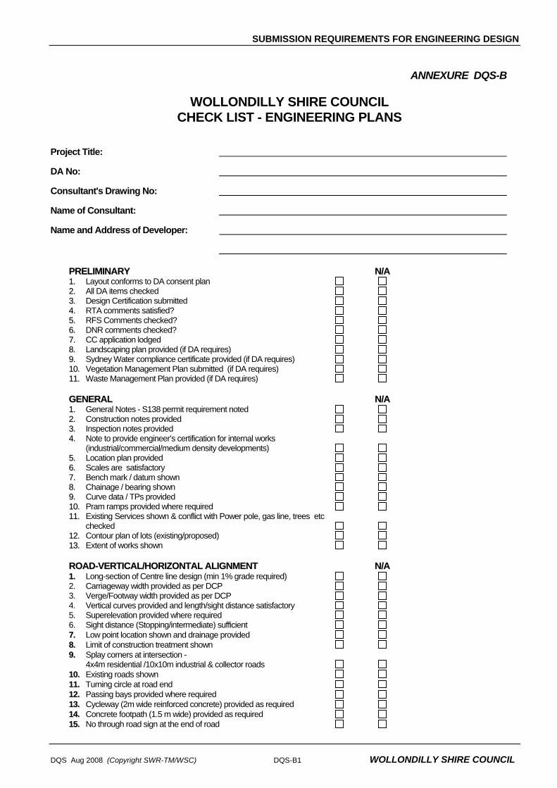
ANNEXURE DQS-B
WOLLONDILLY SHIRE COUNCIL CHECK LIST - ENGINEERING PLANS
Project Title: DA No: Consultant's Drawing No: Name of Consultant: Name and Address of Developer:
PPRREELLIIMMIINNAARRYY NN//AA 11.. Layout conforms to DA consent plan 22.. All DA items checked 33.. Design Certification submitted 44.. RTA comments satisfied? 55.. RFS Comments checked? 66.. DNR comments checked? 77.. CC application lodged 88.. Landscaping plan provided (if DA requires) 99.. Sydney Water compliance certificate provided (if DA requires) 1100.. Vegetation Management Plan submitted (if DA requires) 1111.. Waste Management Plan provided (if DA requires) GGEENNEERRAALL NN//AA 11.. General Notes - S138 permit requirement noted 22.. Construction notes provided 33.. Inspection notes provided 44.. Note to provide engineer’s certification for internal works
(industrial/commercial/medium density developments) 55.. Location plan provided 66.. Scales are satisfactory 77.. Bench mark / datum shown 88.. Chainage / bearing shown 99.. Curve data / TPs provided 1100.. Pram ramps provided where required 1111.. Existing Services shown & conflict with Power pole, gas line, trees etc
checked 1122.. Contour plan of lots (existing/proposed) 1133.. Extent of works shown RROOAADD--VVEERRTTIICCAALL//HHOORRIIZZOONNTTAALL AALLIIGGNNMMEENNTT NN//AA 11.. Long-section of Centre line design (min 1% grade required) 2. Carriageway width provided as per DCP 3. Verge/Footway width provided as per DCP 4. Vertical curves provided and length/sight distance satisfactory 5. Superelevation provided where required 6. Sight distance (Stopping/intermediate) sufficient 77.. Low point location shown and drainage provided 88.. Limit of construction treatment shown 99.. Splay corners at intersection -
4x4m residential /10x10m industrial & collector roads 1100.. Existing roads shown 1111.. Turning circle at road end 1122.. Passing bays provided where required 1133.. Cycleway (2m wide reinforced concrete) provided as required 1144.. Concrete footpath (1.5 m wide) provided as required 1155.. No through road sign at the end of road

SUBMISSION REQUIREMENTS FOR ENGINEERING DESIGN
WOLLONDILLY SHIRE COUNCIL DQS-B2 DQS Aug 2008 (Copyright SWR-TM/WSC)
RROOAADD-- CCRROOSSSS SSEECCTTIIOONNSS NN//AA 11.. Typical section provided 22.. Pavement details shown 33.. 10 mm single coat seal under 30 mm asphalt for new urban roads 44.. AC 50 mm thick around cul-de-sac and turning heads 55.. All cul-de-sac shall be kerb and guttered 66.. AC seal is required when rural road grade is more than 16.67% 77.. Kerb & gutter is required for grade >10% 88.. Traffic loadings indicated 99.. Crossfalls (footpath 4%, pavement 3%) 1100.. Batters min 1:4 fill/1:2 cut 1111.. Lot filling details shown 1122.. 1.2m turf behind footpath provided 1133.. Footpath width min 3..5 m around cul-de-sac bulb provided 1144.. Cross drawn to full extent to see impact on properties RROOAADD IINNTTEERRSSEECCTTIIOONN NN//AA 11.. Intersection treatment (AUL/AUR/BAL etc) provided 22.. Intersection turning circle plotted 33.. Widening at intersection 44.. Intersection sight distances(SISD/ESD) KKEERRBB RREETTUURRNNSS NN//AA 11.. KR profiles for all intersections provided 22.. Arc lengths shown 33.. Crossfalls/grades shown 44.. Contours plotted 55.. Lowpoints to be clear of TP by 1.5m RROOUUNNDDAABBOOUUTTSS NN//AA 11.. Inscribed circle radius 22.. Turning circles 33.. Deflection 44.. Island offsets 55.. Pavement RLs 66.. Crossfalls 77.. Linemarking 88.. Island landscaping 99.. Island drainage 1100.. Island details (structural) DDRRIIVVEEWWAAYYSS NN//AA 11.. Location satisfactory? 22.. Long Section provided when steeper grades more than 3% 33.. Vehicle crossing template used for steep grade 44.. Carriageway width, crossfall satisfactory 55.. Passing bays provided 66.. Joint details if concrete 77.. Vehicle Crossing details ( heavy duty crossing required?) 88.. Driveway drainage considered 99.. Existing driveways affected by new works? CCAARR PPAARRKKIINNGG NN//AA 11.. Clear width/depth of space 22.. Clear width of manoeuvring lane 33.. Layout acceptable from traffic safety 44.. Pavement Design/Sealing provided 55.. Vehicle turning template plotted 66.. Carparking area grade max 5%

SUBMISSION REQUIREMENTS FOR ENGINEERING DESIGN
DQS Aug 2008 (Copyright SWR-TM/WSC) DQS-B3 WOLLONDILLY SHIRE COUNCIL
SSOOIILL EERROOSSIIOONN NN//AA 11.. Notes provided 22.. Site fences shown 33.. Pits protection 44.. Turfing /grass seeding/bitumen spray on disturbed areas 55.. Stockpiles location/fence 66.. Sedimentation basin required? Show calculation 77.. No trees to be removed without Council consent 88.. Dust control measures shown on plan SSTTOORRMMWWAATTEERR DDRRAAIINNAAGGEE NN//AA 11.. Designed for recurrence interval 1:10 urban, 1:5 rural, 1:20 industrial 22.. Designed checked for 1:100 year ARI 33.. Catchment /subcatchment plan provided 44.. Calculation schedule - hydrologic/hydraulic provided 55.. Pipeline long sections provided 66.. Surface/invert levels for pipes/pits 77.. Pipe grade/size/class shown 88.. Pit schedule-type/geometry/location/lintel length/inlet capacity 99.. Curves pipelines provided on curves 1100.. Line No/Pipe size on Eng Sheets shown 1111.. Cover to pipes min 600 mm under roads 1122.. Pits to have step iron if depth>1m 1133.. 1m high handrails in pits & headwalls in public reserve 1144.. Upstream run off considered in calculation 1155.. Connection to existing pit / K&G / creek - shown on plan 1166.. Post-development flow vs predevelop for creek / existing system 1177.. Gutter Flow Width max 2m 1188.. Ponding depth at sag pits 1199.. Overland flow path shown for 1:100 ARI rainfall 2200.. V*D <0.4 m/s for overland flow path 2211.. Drainage easement width shown as per pipe size 2222.. Downstream swale drain shape and levels shown 2233.. Reverse cross fall on footpath in flow path 2244.. All channels, open drains shall be turfed 2255.. WSUD elements are detailed with supporting documents 2266.. Structural details of non-standard pits certified 2277.. Check for concentration of water onto adjoining property 2288.. Catch drains required to protect lots and roads FFLLOOOODD MMAANNAAGGEEMMEENNTT NN//AA 11.. Catchment area plan shown 22.. Height of 1%AEP flood and FFL calculated 33.. Flood extent plotted in plan 44.. Hydraulic/hydrologic calculation shown 55.. Calibration carried out 66.. Sensitivity analysis done 77.. Software model parameters checked 88.. Rainfall data correct 99.. DxV product on floodways 1100.. Emergency evacuation route provided for >1%AEP event 1111.. Flood warning signs at floodways, basins 1122.. No building/filling on floodways TTRRAAFFFFIICC CCOONNTTRROOLL DDEEVVIICCEESS NN//AA 11.. Line marking (carriagway/cycleway), RPM shown 22.. Sign (Intersection/Giveway/Speed limit) 33.. Chevron sign at T intersection provided 44.. Guide Posts shown 55.. Guard Rails provided 66.. Safety Barriers provided 77.. Stop sign is required at 4 way intersection 88.. Plans need to be referred to Traffic Committee for approval of line
marking, signposting etc.

SUBMISSION REQUIREMENTS FOR ENGINEERING DESIGN
WOLLONDILLY SHIRE COUNCIL DQS-B4 DQS Aug 2008 (Copyright SWR-TM/WSC)
TTRRAAFFFFIICC CCOONNTTRROOLL PPLLAANN NN//AA 11.. Dimensions provided on the plan 22.. Signs sufficient 33.. Follows RTA guideline 44.. Traffic Controller required 55.. Night time treatment provided 66.. Work zone defined 77.. Risk assessment done 88.. Pedestrian and business access provided at all times 99.. DTR required if speed limit of 40k is shown on plan 1100.. TCP prepared by/RTA ticket no WWOORRKK--AASS--EEXXEECCUUTTEEDD PPLLAANN NN//AA 11.. Stripped and finished levels shown 22.. Subsoil drains shown 33.. Engineer’s certification for construction provided for internal works,
bridge etc 44.. Name of new road proposed 55.. WAE levels match with design levels MMIISSCCEELLLLAANNEEOOUUSS NN//AA 11.. Structural certification for bridge, structures, retaining walls etc
provided 22.. Existing structures shown 33.. Street name signs provided 44.. Guide posts provided 55.. Existing SSMs 66.. Road Safety Audit Report Stage 3 done 77.. List of works that are to become Council’s Asset 88.. Possible adverse impacts on neighbouring properties examined 99.. Consent from adjoining owners to allow construction of batter, tail out
drain, install culvert and access for any other purpose required for the development works
CCOOMMMMEENNTTSS RREEFFEERREENNCCEE ____________________________________________________________________________________________________________________________________________ ____________________________________________________________________________________________________________________________________________ ____________________________________________________________________________________________________________________________________________ ____________________________________________________________________________________________________________________________________________ ____________________________________________________________________________________________________________________________________________ ____________________________________________________________________________________________________________________________________________ ____________________________________________________________________________________________________________________________________________ ____________________________________________________________________________________________________________________________________________ ____________________________________________________________________________________________________________________________________________ ____________________________________________________________________________________________________________________________________________ ____________________________________________________________________________________________________________________________________________ ____________________________________________________________________________________________________________________________________________ ____________________________________________________________________________________________________________________________________________ ____________________________________________________________________________________________________________________________________________

GEOMETRIC ROAD DESIGN
D1 Aug 2008 (Copyright SWR-TM/WSC) WOLLONDILLY SHIRE COUNCIL
DESIGN SPECIFICATION
D1
GEOMETRIC ROAD DESIGN
(Urban and Rural)


GEOMETRIC ROAD DESIGN
D1 Aug 2008 (Copyright SWR-TM/WSC) WOLLONDILLY SHIRE COUNCIL
Amendment Record for this Specification Part
This Specification is Council’s edition of the AUS-SPEC generic specification part and includes Council’s primary amendments.
Details are provided below outlining the clauses amended from the Council edition of this AUS-SPEC Specification Part. The clause numbering and context of each clause are preserved. New text is shown underlined and deleted text shown struck through (eg or as 'DELETED'. New clauses are added towards the rear of the specification part as special requirements clauses. Project specific additional script is shown in the specification as italic font.
The amendment code indicated below is ‘A’ for additional script ‘M’ for modification to script and ‘O’ for omission of script. An additional code ‘P’ is included when the amendment is project specific.
Amendment Sequence No.
Key Topic addressed in amendment
Clause No. Amendment Code
Author Initials
Amendment Date
1 Reference Documents D1.03 M IB 1/7/08
2 Characteristics of Urban Roads Table D1.5 M IB 1/7/08
3 Verge Widths at intersections and Turning Movements
D1.17 AO IB 1/7/08
4 Rural Design Criteria D1.22 A IB 1/7/08
5 Safe Intersection Sight Distance D1.23 M IB 1/7/08
6 Characteristics of Rural Roads Table D1.8 M IB 1/7/08
7 Standard Drawing WSCD1.1 D1.100 M IB 7/8/08
8 Standard Drawing WSCD1.2 D1.100 M IB 7/8/08
9 Standard Drawing WSCD1.3 D1.100 M IB 7/8/08
10 Standard Drawing WSCD1.17 D1.100 M IB 7/8/08
11 Standard Drawing WSCD1.25 D1.100 M IB 7/8/08
12 Salinity D1.05 A IB 7/8/08


GEOMETRIC ROAD DESIGN
D1 Aug 2008 (Copyright SWR-TM/WSC) WOLLONDILLY SHIRE COUNCIL
SPECIFICATION D1 : GEOMETRIC ROAD DESIGN (Urban and Rural)
CONTENTS
CLAUSE PAGE
GENERAL .............................................................................................................................1
D1.01 SCOPE ....................................................................................................................................................1
D1.02 AIMS ........................................................................................................................................................1
D1.03 REFERENCE AND SOURCE DOCUMENTS.........................................................................................1
D1.04 CONSULTATION ....................................................................................................................................2
D1.05 PLANNING CONCEPTS .........................................................................................................................3
D1.06 PLAN REQUIREMENTS – See DSQ......................................................................................................3
URBAN DESIGN CRITERIA .................................................................................................4
D1.07 ROAD HIERARCHY................................................................................................................................4
D1.08 ROAD NETWORK...................................................................................................................................5
D1.09 DESIGN SPEED......................................................................................................................................6
D1.10 LONGITUDINAL GRADIENT ..................................................................................................................6
D1.11 HORIZONTAL CURVES AND TANGENT LENGTHS ............................................................................7
D1.12 VERTICAL CURVES...............................................................................................................................8
D1.13 SUPERELEVATION ................................................................................................................................9
D1.14 CARRIAGEWAY WIDTH.........................................................................................................................9
D1.15 CROSSFALLS.......................................................................................................................................11
D1.16 FOOTWAY AREAS ...............................................................................................................................11
D1.17 INTERSECTIONS .................................................................................................................................12
D1.18 ROUNDABOUTS...................................................................................................................................14
D1.19 TRAFFIC CALMING..............................................................................................................................14
D1.20 PARKING...............................................................................................................................................15
D1.21 BUS ROUTES .......................................................................................................................................16
RURAL DESIGN CRITERIA ...............................................................................................16
D1.22 GENERAL..............................................................................................................................................16

GEOMETRIC ROAD DESIGN
WOLLONDILLY SHIRE COUNCIL D1 Aug 2008 (Copyright SWR-TM/WSC)
D1.23 SIGHT DISTANCES ..............................................................................................................................17
D1.24 HORIZONTAL AND VERTICAL ALIGNMENT......................................................................................20
D1.25 INTERSECTIONS .................................................................................................................................20
D1.26 PLAN TRANSITIONS............................................................................................................................21
D1.27 CARRIAGEWAYS .................................................................................................................................21
D1.28 SUPERELEVATION ..............................................................................................................................22
D1.29 SCOUR PROTECTION.........................................................................................................................22
SPECIAL REQUIREMENTS ...............................................................................................22
D1.30 CUT/FILL ROAD BATTERS..................................................................................................................22
D1.31 HALF ROAD CONSTRUCTION............................................................................................................22
D1.32 ROAD WIDENING.................................................................................................................................22
D1.33 RECONSTRUCTING AN EXISTING ROAD .........................................................................................23
D1.34 STREET FURNISHING.........................................................................................................................23
1.35 SERVICE VEHICLES ............................................................................................................................23
D1.36 PROPERTY ACCESS...........................................................................................................................24
D1.37 BOUNDARY FENCES...........................................................................................................................24
STANDARD DRAWINGS....................................................................................................24
D1.100 LIST OF DRAWINGS ...........................................................................................................................24

GEOMETRIC ROAD DESIGN
D1 Aug 2008 (Copyright SWR-TM/WSC) D1-1 WOLLONDILLY SHIRE COUNCIL
SPECIFICATION D1 : GEOMETRIC ROAD DESIGN (Urban and Rural)
GENERAL
D1.01 SCOPE
1. This section sets out the specifications developed specifically for the design of subdivision roadworks using principles of street design to ensure safety and improved amenity and to reduce pedestrian/vehicular conflicts.
2. A fundamental requirement of the design process is for designers to determine the vehicle speed which is deemed acceptable for a particular subdivision or section of road. The concept of designing to regulatory street speeds is contrary to the current principles of subdivision road design.
3. All relevant design principles must be integrated in the development of the road network. A careful balance is required between maximising amenity, safety and convenience considerations and those related to drivers’ perception of driving practice.
D1.02 AIMS
1. The provision of a road system within a subdivision is to be designed so as to achieve the following aims:
• Provide convenient and safe access to all allotments for pedestrians, vehicles and cyclists.
• Provide safe, logical and hierarchical transport linkages with existing street system.
• Provide appropriate access for buses, emergency and service vehicles.
• Provide for a quality product that minimises maintenance costs.
• Provide a convenient way for public utilities.
• Provide an opportunity for street landscaping.
• Provide convenient parking for visitors.
• Have appropriate regard for the climate, geology and topography of the area.
D1.03 REFERENCE AND SOURCE DOCUMENTS
(a) Council Specifications
All Specifications for Design and Construction.
(b) Australian Standards
AS 2890.1 Parking facilities: Off-street car parking.

GEOMETRIC ROAD DESIGN
D1-2 D1 Aug 2008 (Copyright SWR-TM/WSC)
WOLLONDILLY SHIRE COUNCIL
(c) State Authorities Roads and Traffic Authority NSW - Road Design Guide. Department of Housing – Road Manual, 1987. Department of Urban Affairs (formerly Environment) and Planning - Technical Bulletin 12
(1981), Residential Road Widths. Resource NSW – Better Practice Guide for Waste Management in Multi-Unit Dwellings
(2002)
(d) Other AUSTROADS Guide to the Geometric Design of Rural Roads. Guide Policy for the Geometric Design of Major Urban Roads. Guide to Traffic Engineering Practice: PART 5, Intersections at Grade PART 6, Roundabouts PART 10, Local Area Traffic Management PART 13, Pedestrians PART 14, Bicycles
The Institute of Municipal Engineering Australia, Qld Division - 1993: Design Guidelines for Subdivisional Streetworks.
ARRB Special Report No. 33, L E Comerford: A Review of Subdivision Road Design Criteria.
Joint Venture for More Affordable Housing – 1989: Australian Model Code for Residential Development. (AMCORD)
Stapleton, C 1984: Streets Where We Live - A Manual for the Design of Safer Residential Estates.
Stapleton, C 1988, Dept of Transport South Australia: Planning & Road Design for New Residential Subdivisions.
Brindle, R 1988, ARRB: Planning & Design of the Local Distributor.
Colman, J 1978, ARRB: Streets for Living.
Pak-Poy Kneebone - 1989: Research Study into Road Characteristics for Residential Development.
Department of Infrastructure, Planning and Natural Resources 2003 Guide: Roads and Salinity (ISBN: 0 73475377 2)
D1.04 CONSULTATION
1. Designers are encouraged to consult with the Council and other relevant authorities prior to or during the preparation of design. Designers should in addition to requirements of this Specification ascertain specific requirements of these authorities as they relate to the designs in hand.

GEOMETRIC ROAD DESIGN
D1 Aug 2008 (Copyright SWR-TM/WSC) D1-3 WOLLONDILLY SHIRE COUNCIL
D1.05 PLANNING CONCEPTS
1. In new areas (as distinct from established areas with a pre-existing road pattern) each class of route should reflect its role in the road hierarchy by its visual appearance and related physical design standards. Routes should differ in alignment and design standard according to the volume of traffic they are intended to carry, the desirable traffic speed, and other factors.
Road Hierarchy
2. The road pattern and width must be in conformity with that shown on any relevant area Development Control Plan. In areas not covered by these plans, the pattern and width(s) will be determined by Council on their merits.
3. The road network for residential developments should have clear legibility.
4. The road network should reinforce legibility by providing sufficient differentiation between the road functions.
5. Wherever possible distinct landmark features such as watercourses, mature vegetation or ridge lines should be emphasised within the structural layout so as to enhance the legibility.
Legibility
6. Whilst legibility can be enhanced by introduced physical features such as pavement and lighting details, the road network should by its inherent design and functional distinction provide the necessary legibility.
7. The number of turning movements at intersections or junctions that a visitor should be required to undertake to reach a particular address within the development should be minimised.
8. Low speeds are desirable in lightly trafficked streets to protect pedestrians and allow them to share the street with vehicles.
9. Bus routes should be within acceptable walking distance of all dwellings. Where possible, residential properties shall be within 400 metres of a bus stop.
10. Each road category must satisfy reservation and width requirements and meet all construction and design requirements.
10. Information provided by the NSW Government that indicates salinity may occur in parts of the Wollondilly Local Government Area (LGA). This salinity potential is due to inherent characteristics of the Wollondilly LGA landscape. As a result, buildings and other infrastructure in the Wollondilly LGA may be susceptible to salt damage.
The applicant must thoroughly investigate the site to determine if there are any salinity issues to be addressed. The designer shall address salinity in their design. Steps taken may include, but are not limited to:
• Minimising depth of excavation/disturbance required for roadworks; • Minimising infiltration of surface waters by providing adequate sub-soil drainage; • Provision of adequate drainage for upstream catchments; and • Use of appropriate materials in construction of roadworks.
Designers should also follow guidelines set out in Department of Infrastructure, Planning and natural Resources (2003) Guide: Roads and Salinity (ISBN: 0 73475377 2).
Salinity
D1.06 PLAN REQUIREMENTS – See DQS

GEOMETRIC ROAD DESIGN
D1-4 D1 Aug 2008 (Copyright SWR-TM/WSC)
WOLLONDILLY SHIRE COUNCIL
URBAN DESIGN CRITERIA
D1.07 ROAD HIERARCHY
1. A hierarchical road network is essential to maximise road safety, residential amenity and legibility. Each class of road in the network serves a distinct set of functions and is designed accordingly. The design should convey to motorists the predominant function of the road. A typical hierarchy is shown on Figure D1.1.
Figure D1.1 (amended)
Council Categories and Typical Road Hierarchy
2. Four distinct levels of roads are: Access Street (Accessways and Cul-de-Sacs) Local Street Collector Street Local Distributor Road.
3. Access streets (cul-de-sacs), the lowest order roads, having as their primary function residential space – amenity features which facilitate pedestrian and cycle movements, and where vehicular traffic is subservient in terms of speed and volume, to those elements of space, amenity, pedestrians and cyclists.
Access Street (Cul-de-Sac)

GEOMETRIC ROAD DESIGN
D1 Aug 2008 (Copyright SWR-TM/WSC) D1-5 WOLLONDILLY SHIRE COUNCIL
4. Local streets, the next level road, as a local residential street should provide a balance between the status of that street in terms of its access and residential amenity functions. Resident safety and amenity are dominant but to a lesser degree than access streets.
Local Street
5. Collector streets, the second highest order residential subdivision road, have a residential function but also carry higher volumes of traffic collected from lower order streets. A reasonable level of residential amenity and safety is maintained by restricting traffic volumes and speeds, however, amenity and resident safety do not have the same priority as access or local streets.
Collector Street
6. Local distributor roads, the highest order road within a residential development should have as their main function the convenient and efficient movement of traffic generated by the development. Direct access should not be provided for single dwelling allotments but access can be provided to multi-unit developments and non-residential land uses. The local distributor should where possible serve only the development and should not attract through traffic.
Local Distributor Road
D1.08 ROAD NETWORK
1. The design features of each type of road convey to the motorist its primary functions and encourage appropriate driver behaviour.
2. Traffic volumes and speeds on any road should be compatible with the residential functions of that road.
3. The maximum length of an access street should ensure its status as a residential place is retained, where the traffic, in terms of speed and volume will enable the integration of pedestrian, cycle and vehicular movements. This length will also ensure that residential convenience is not unduly impaired as a result of speed restraints.
4. The length of local distributor within a development should be minimised.
5. The distance required for motorists to travel on all streets within the development should be minimised.
6. Where access streets form part of a pedestrian or cycle network, access links should provide suitable connectivity with adjoining access streets or open space systems so as to ensure such pedestrian and cycle network are functionally efficient.
7. The road network should ensure that no road links with another road which is more than two levels higher or lower in the hierarchy. In exceptional circumstances roads may link with others that are more than two levels apart, however, no access street or local street should have access to an access-controlled arterial road.
Road Links
8. Connections between internal roads should be T-junctions or controlled by roundabouts.
9. The road layout should conform to the requirements of the external road network and satisfy the transport provisions of an outline development plan.
10. The external road network should be designed and located to provide routes which are more convenient for potential through local road network. Major roads should be provided at intervals of no more than 1.5 km and should be complete and of adequate capacity to accommodate projected movements. The internal road system should not provide through routes that are more convenient than the external road network.
External Road Network

GEOMETRIC ROAD DESIGN
D1-6 D1 Aug 2008 (Copyright SWR-TM/WSC)
WOLLONDILLY SHIRE COUNCIL
D1.09 DESIGN SPEED
1. Design speed is generally used as the basic parameter in the specification of design standards, determining the minimum design value for other elements. The NSW Roads and Traffic Authority bases its current design standards on a travel speed rather than a design speed. Travel speed identifies a speed/horizontal radius relationship. This approach is intended for roads of a minimum travel speed of 60 km/h. The maximum speed limit in NSW for built-up areas is 60 km/h and this should be used in calculating design values which depend on speed, (eg collector and distributor roads) however, in difficult topography, the design speed may be reduced. Vehicular speeds are also limited by road intersections as well as changes in horizontal and vertical alignment.
RTA Guidelines
2. Adoption of a low design speed discourages speeding, however, where vertical or horizontal curves of low design speed are located in otherwise high speed sections (tangents) the result is a potentially dangerous section of road. It should be recognised that in low standard roads, operating speeds will tend to be in excess of arbitrary speed standards. Attention should be given to ensuring that potentially hazardous features are visible to the driver and adopting traffic engineering measures which will help a driver avoid errors of judgement.
Low Speeds
3. Generally the following design speeds should be adopted: Access Street 25 km/h Local Street 40 km/h Collector Road 60 km/h Distributor Road 60/80 km/h
however the design speed adopted should always reflect the likely travel speed.
D1.10 LONGITUDINAL GRADIENT
1. A general minimum gradient of 1.0 per cent should be adopted. In very flat conditions it may be reduced to 0.5 per cent over short distances. Maximum grades are shown in Table D1.1.
Flat Terrain
Table D1.1
Access and Local
Collector Distributor
Desirable maximum percentage* 12 10 8
Absolute maximum percentage* 16 12 10
* maximum length 150 m on straight alignment.
2. Longitudinal grade through intersections should not exceed 4 per cent, the actual gradient being dependent on the type of terrain. Design of the road alignment and the grades used are interrelated. A steep grade on a side street is undesirable if vehicles have to stand waiting for traffic in the priority road. Turning circles in cul-de-sacs should have grades less than 5 per cent.

GEOMETRIC ROAD DESIGN
D1 Aug 2008 (Copyright SWR-TM/WSC) D1-7 WOLLONDILLY SHIRE COUNCIL
D1.11 HORIZONTAL CURVES AND TANGENT LENGTHS
1. The horizontal alignment of a road is normally in a series of tangents (straights) and curves. The choice of the horizontal alignment is normally determined from the design speeds for a particular street within the road hierarchy as described in Clause D1.09. Designers should ensure that, for a given design speed, the minimum radius of curvature utilised is such that drivers can safely negotiate the curve. Curves which progressively tighten produce an uncomfortable sense of disorientation and alarm. Sudden reverse curves, which drivers cannot anticipate, also have a potential to cause similar conditions.
Speed/Radius Relation
2. Where speed restriction is provided by curves in the street alignment the relationship between the radius of the curve and the desired vehicle speed is given in Table D1.2(a).
3. To determine appropriate lengths for tangents between speed restrictions, which may be curves, narrow sections or other obstructions, Table D1.2(b) is recommended.
4. Sight distance on curves is determined by formula, values of which are tabulated in RTA Road Design Guide.
Table D1.2(a) Speed/Radius Relationship
Curve Radii (m) on Road Centreline Desired Vehicle Speed
(km/h) Curvilinear Alignment (no tangents)
Isolated Curve Alignment (with tangent sections)
20 25 30 35 40 45 50 55 60
15 20 30 50 90 105 120 140 160
10 15 20 30 40 50 60 70 80
Table D1.2(b) Speed/Tangent Length Relationship
Desired Vehicle Speed in Curve
Maximum Advisable Tangent Length (m) between Curves or Restrictions Appropriate to a Selected Design Speed.
DESIGN SPEED
(km/h) 25 30 35 40 45 50 60
20 or less 40 75 100 120 140 155 180
25 45 75 100 120 140 165 30 45 80 100 120 150 35 50 80 100 135 40 55 80 120 45 60 105
NOTE: Tables D1.2(a) and D1.2(b) are derived from AMCORD.

GEOMETRIC ROAD DESIGN
D1-8 D1 Aug 2008 (Copyright SWR-TM/WSC)
WOLLONDILLY SHIRE COUNCIL
D1.12 VERTICAL CURVES
1. Vertical curves will be simple parabolas and should be used on all changes of grade exceeding 1 per cent. The desirable minimum design speed is 60 km/h. The length of the crest vertical curve for stopping sight distance should conform with RTA Road Design Guide. These standards are based on 1.5 seconds reaction time which provides a reasonable safety margin for urban conditions, where drivers’ reaction time is usually considered to be lower than in rural conditions.
2. For adequate riding comfort, lengths of sag vertical curves should conform with the RTA Road Design Guide. As residential roads are usually lit at night, the criterion for designing sag vertical curves is a vertical acceleration of 0.05 g for desirable riding comfort, and 0.10 g for minimum riding comfort. The minimum lengths for vertical curves are shown in Table D1.3.
Riding Comfort
Table D1.3
Local access (m)
Collector (m)
Distributor (m)
Minimum vertical curve 25 35 50
Absolute minimum vertical curve (to be applied at road
junctions only)
6
12
20
3. Junctions of roads should be located at a safe distance from a crest, determined by visibility from the side road. Location of a side road at a crest should only occur if there is no suitable alternative.
Side Road
4. Drainage poses a practical limit to the length of sag curves and a maximum length (in metres) of 15 times the algebraic sum of the intersecting vertical grades (expressed as a percentage) has been suggested. This is to avoid water ponding in excessively flat sections of kerb and gutter.
Sag Curves
5. The three dimensional coordination of the horizontal and vertical alignment of a road should be aimed at improved traffic safety and aesthetics. The following principles should be applied:
• The design speed of the road in both horizontal and vertical planes should be of the same order.
• Combined horizontal and vertical stopping sight distance and minimum sight distance should be considered three dimensionally.
• Sharp horizontal curves should not be introduced at or near the crest of a vertical curve. A horizontal curve should leave the vertical curve and be longer than the vertical curve.
• A short vertical curve on a long horizontal curve or a short tangent in the gradeline between sag curves may adversely affect the road’s symmetry and appearance.

GEOMETRIC ROAD DESIGN
D1 Aug 2008 (Copyright SWR-TM/WSC) D1-9 WOLLONDILLY SHIRE COUNCIL
D1.13 SUPERELEVATION
1. Superelevation, where required, shall be designed in accordance with the RTA Road Design Guide.
2. Careful consideration must be given to the effects of superelevation on road surface drainage. Additional piping may be required to ensure ponding and cross pavement flows do not occur on curves due to superelevation.
D1.14 CARRIAGEWAY WIDTH
1. The cross section of the road reserve must cater for all functions that the road is expected to fulfil, including the safe and efficient movement of all users, provision for parked vehicles, acting as a buffer from traffic nuisance for residents, the provision of public utilities and streetscaping. Table D1.5 details carriageways and footway widths and road reserve widths.
Functions
2 The carriageway width must allow vehicles to proceed safely at the operating speed intended for that level of road in the network and with only minor delays in the peak period. This must take into consideration the restrictions caused by parked vehicles where it is intended or likely that this will occur on the carriageway. Vehicles include trucks, emergency vehicles and, on some roads, buses. (Refer to Clause D1.21 for bus routes.)
Vehicles
3 The safety of pedestrians and cyclists where it is intended they use the carriageway must also be assured by providing sufficient width.
4 The carriageway width should also provide for unobstructed access to individual allotments. Motorists should be able to comfortably enter or reverse from an allotment in a single movement, taking into consideration the possibility of a vehicle being parked on the carriageway opposite the driveway.
Reversing
5 The design of the carriageway should discourage motorists from travelling above the intended speed by reflecting the functions of the road in the network. In particular the width and horizontal and vertical alignment should not be conducive to excessive speeds.
6 The verge when considered in conjunction with the horizontal alignment and permitted fence and property frontage treatments should provide appropriate sight distances, taking into account expected speeds and pedestrian and cyclist movements.
Verge
7 Stopping sight distances and junction or intersection sight distances should be based on the intended speeds for each road type. Widening may be required at intersections to allow turning and stacked vehicles to pass. Refer to the Roads and Traffic Authority Design Guide for details.

GEOMETRIC ROAD DESIGN
D1-10 D1 Aug 2008 (Copyright SWR-TM/WSC)
WOLLONDILLY SHIRE COUNCIL
Spec
ific
Park
ing
Prov
isio
ns
No
No
No
No
No
No
No
1.5
m w
ide
Conc
rete
Fo
otpa
ving
/ 2.
0 m
Cy
clep
ath
No
No
Yes
(1)
Yes
(1)
Yes
(1)
Yes
(1)
Yes
(1)
Kerb
Ty
pe
Flus
h or
R
oll
Rol
l
Rol
l
Rol
l
Stan
dard
K
& G
Stan
dard
K
&
Stan
dard
K
& G
Verg
e
Wid
th (m
) Le
ft/Ri
ght
2.5
/ 2.5
3.5
/ 3.5
3.5
/ 3.5
(2)
3.5
/ 3.5
(2)
4.0
/ 4.0
(3)
4.0
/ 4.0
(3)
4.0
/ 4.0
(3)
Carr
iage
way
w
idth
(m
)
5.0
6.0
8.0
8.0
10.0
13.0
13.0
Road
Re
serv
e W
idth
(m
10
13
15
15
18
21
21
Max
imum
Sp
eed
(2)
(kph
)
25
30
40
50
50
60
60 /
80
Max
imum
Nu
mbe
r of
Dwel
lings
7 15
30
N/A
N/A
N/A
N/A
Tabl
e D.
1.5
Char
acte
ristic
s of
Urb
an R
oads
in W
ollo
ndill
y Sh
ire C
ounc
il Ro
ad N
etw
orks
Road
Ca
tego
ry &
Ty
pe
Cat.
A Ac
cess
way
Cat.
B
Min
or
Cul
-de-
Sac
Cat.
C C
ul-d
e-Sa
c
Cat D
1 Lo
cal S
treet
Cat.
D2
Loca
l Stre
et
Cat.
E
Col
lect
or /
Bus
Rou
te
Cat.
F
Com
mer
cial /
In
dust
rial
1 N
orm
ally
requ
ired
by C
ounc
il unl
ess
alte
rnat
ive s
hare
d pa
thw
ay a
cces
s is
avai
labl
e via
an
inte
grat
ed n
etw
ork
with
in th
e de
velo
pmen
t. 2
A 2.
0m s
hare
d pa
th/ c
ycle
way
requ
ires
a ve
rge
wid
th o
f 4.5
m. I
f req
uire
d, th
is sh
all b
e pr
ovid
ed b
y in
crea
sing
the
road
rese
rve
and
may
inclu
de re
ducin
g th
e op
posit
e ve
rge
to 3
.0m
. 3
A 2.
0m s
hare
d pa
th/ c
ycle
way
requ
ires
a ve
rge
wid
th o
f 4.5
m. T
his
may
be
prov
ided
by
incr
easin
g th
e ro
ad re
serv
e or
redu
cing
the
oppo
site
verg
e to
3.5
m.

GEOMETRIC ROAD DESIGN
D1 Aug 2008 (Copyright SWR-TM/WSC) D1-11 WOLLONDILLY SHIRE COUNCIL
D1.15 CROSSFALLS
1. Desirably, roads should be crowned in the centre. Typical pavement crossfalls on straight roads are: Pavement Type Crossfall
Bituminous seal coat 3 per cent Bituminous concrete pavement 3 per cent Cement concrete pavement 3 per cent
2. There are many factors affecting levels that may force departures from these crossfalls. Differences in level between road alignments can be taken up by offsetting crown lines or adopting one way cross falls. Sustained crossfalls should not exceed 4 per cent, although up to 6 per cent may be used where unavoidable. The rate of change of crossfall should not exceed: 6 per cent per 30 m for through traffic; 8 per cent per 30 m for free flowing turning movements; or 12 per cent per 30 m for turning movements for which all vehicles are required to stop. Offset crowns should be used only in exceptional circumstances and should not be used simply to reduce earthworks or batter requirements
Offset Crown Changes
3. The crossfall on a collector or sub-arterial road should take precedence over the grade in side streets. Standard practice is to maintain the crossfall on the priority road and adjust the side road levels to suit. The crossfall in side streets should be warped quickly either to a crown or a uniform crossfall depending on the configuration of the side street. A rate of change of grade of two per cent in the kerb line of the side street relative to the centre line grading is a reasonable level.
Priority Road
D1.16 FOOTWAY AREAS
1. A suitable design for the footway will depend on utility services, the width of pathways, access to adjoining properties, likely pedestrian usage and preservation of trees. Low level paths are undesirable but may be used in exceptional circumstances where normal crossfalls are impracticable. Generally a 4% crossfall should be provided from the property boundary to the top of kerb. Crossfalls in footway paving should not exceed 4 per cent. Longitudinal grade usually parallels that of the road.
Utility Services
2. Differences in level across the road between alignments may, with Council’s approval, be accommodated by:
Options
• Cutting at the alignment on the high side
• Battering at the alignment on the low side and providing the footway at normal level and crossfall.
• A uniform crossfall across the carriageway.
• The lower footway being depressed below the gutter level.
3. The above measures can be used singularly or combined. The footway formation should extend with a 0.6m berm beyond the road alignment.
4. Where it is necessary to raise or lower the footway in front of a property, the adjoining sections of footway must be regraded to provide a smooth transition.
5. If access to adjoining properties is affected by the footway regarding, all necessary work shall be done to restore satisfactory pedestrian and vehicular access.

GEOMETRIC ROAD DESIGN
D1-12 D1 Aug 2008 (Copyright SWR-TM/WSC)
WOLLONDILLY SHIRE COUNCIL
6 If the ground level of the property is above or below the finished level of the footway then adequate measures must be taken to support the land by constructing stable earth batters or retaining structures. These are to be fully contained within the property and not encroach onto the public footway.
7 Where footway levels necessitate the retaining of an adjoining property, written permission from the affected property owner must be obtained and submitted to Council before the Engineering Plans will be approved. If the approval cannot be secured, Council will give consideration to allowing the retaining structure within the road reserve provided adequate footway width is available.
D1.17 INTERSECTIONS
1. The design of intersections or junctions should allow all movements to occur safely without undue delay. Projected traffic volumes should be used in designing all intersections or junctions on sub-arterial roads.
Traffic Volumes
2. Intersection design for the junction of subdivision roads with existing main rural, main urban and state highways should generally be designed in accordance with the publication AUSTROADS Guide to Traffic Engineering Practice, PART 5, Intersections at Grade.
Main Roads
3. Intersections with main roads, tourist roads or state highways are to be designed and constructed in accordance with the requirements of the Roads and Traffic Authority and Council.
Tourist Roads State Highways
4. Where major intersections are required to serve a development complete reconstruction of the existing road pavements will be necessary where the speed environment and irregularity of the existing road pavement may endanger the safety of traffic in the locality.
5. Intersections should be generally located in such a way that: Criteria
• The streets intersect at right angles.
• The landform allows clear sight distance on each of the approach legs of the intersection.
• The minor street intersects the convex side of the major street.
• The vertical grade lines at the intersection do not impose undue driving difficulties.
• The vertical grade lines at the intersection will allow for any direct surface drainage.
• Two side streets intersecting a major street in a right-left staggered pattern should have a minimum centre-line spacing of 40m. Left-right stagger intersections require 60-150m separation for stacking purposes. Designers are referred to the Roads and Traffic Authority Design Guide for details.
6. Adequate stopping and sight distances are to be provided for horizontal and vertical curves at all intersections.
7. Where required, appropriate provision should be made for vehicles to park safely.

GEOMETRIC ROAD DESIGN
D1 Aug 2008 (Copyright SWR-TM/WSC) D1-13 WOLLONDILLY SHIRE COUNCIL
8. In cul-de-sac streets adequate provision should be made at the end of the road for vehicle types which frequently use the streets to turn around. The likelihood of parked vehicles obstructing turns should be minimal. Refer drawing numbers W.S.C.D1.3 and W.S.C.D1. 4 of this specification for drawings of Wollondilly Shire Council’s Cul-de-sac and Accessway Head Design Layouts.
9. The drainage function of the carriageway and/or road reserve must be satisfied by the road reserve cross-section profile.
10. Verge width at intersections is the highest value of the following minima: Verge Widths
• The minimum width necessary to accommodate services, 1.5-2.0m wide footpath/ cycleway, verge parking and the desired level of landscaping.
• The minimum width necessary to satisfy acceptable noise levels.
11. All vehicle turning movements are accommodated utilising AUSTROADS Design Vehicles using AutoTURN (or similar software) or Turning Path Templates, as follows:
Turning Movements
• For turning movements involving local distributor roads, the "design prime mover & semi-trailer (19.0m)" with turning path radius 15.0m.
• For turning movements involving local streets or collector streets, but not distributor roads, the "design single unit truck/ bus (12.5m)” with turning path radius 15.0m
• For turning movements on access streets (cul-de-sac) but not involving Local Distributor roads, collector streets or local streets the “design single unit truck/ bus (12.5m)” with turning radius 15.0m.
• .For turning movements at the head of cul-de-sac streets, refer to clause D1.100 Wollondilly Shire Council’s Cul-de-sac Head Design Layout drawing numbers WSC.D1.3
• For turning movements at the head of accessways, refer to clause D1.100 Wollondilly Shire Council’s Accessway Head Design Layout drawing numbers WSC.D1.4
• For turning movements within, into and out of industrial /commercial development sites the “design single unit truck/bus (12.5m) “ with turning radius 15.0m. Turning movements within the development may be reduced to a turning radius of 12.5m with approval in special circumstances.
• For turning movements within carparks, into and out of residential development sites including medium density developments the “design car (5.0m)” with turning radius 8.0 m
12. Turning radii at intersections or driveways shall accommodate the intended movements without allowing desired speeds to be exceeded. The minimum kerb radii at intersections shall be 6.0m.
Turning Radii

GEOMETRIC ROAD DESIGN
D1-14 D1 Aug 2008 (Copyright SWR-TM/WSC)
WOLLONDILLY SHIRE COUNCIL
D1.18 ROUNDABOUTS
1. Roundabouts are to be approved by the Roads Traffic Authority via the Wollondilly Shire Council Local Traffic Committee.
2. Roundabouts should generally be designed in accordance with the requirements of the publication AUSTROADS Guide to Traffic Engineering Practice - PART 6 Roundabouts. Designs adopting alternative criteria will be considered on their merits. Roundabout design should generally comply with the following:
• Entry width to provide adequate capacity
• Adequate circulation width, compatible with the entry widths and design vehicles eg. Buses, trucks, cars.
• Central islands of diameter sufficient only to give drivers guidance on the manoeuvres expected
• Deflection of the traffic to the left on entry to promote gyratory movement
• Adequate deflection of crossing movements to ensure low traffic speeds
• A simple, clear and conspicuous layout
• Design to ensure that the speed of all vehicles approaching the intersection will be less than 50 km/h.
Approach Speed
D1.19 TRAFFIC CALMING
1. Calming devices such as thresholds, slowpoints, speed humps, chicanes and splitter islands should be designed in accordance with the requirements of the publication AUSTROADS Guide to Traffic Engineering Practice - PART 10, Local Area Traffic Management and the Reference and Source documents listed at D1.03. These devices are to be approved by the Roads Traffic Authority or the Wollondilly Shire Council Local Traffic Committee as appropriate. Devices designs should generally comply with the following:
(a) Streetscape
• reduce the linearity of the street by segmentation
• avoid continuous long straight lines (eg. kerb lines)
• enhance existing landscape character
• maximise continuity between existing and new landscape areas.
(b) Location of Devices/Changes
• devices other than at intersections should be located to be generally consistent with streetscape requirements
• existing street lighting, drainage pits, driveways, and services may decide the exact location of devices
• slowing devices are optionally located at spacings of 100-150m.

GEOMETRIC ROAD DESIGN
D1 Aug 2008 (Copyright SWR-TM/WSC) D1-15 WOLLONDILLY SHIRE COUNCIL
(c) Design Vehicles
• emergency vehicles must be able to reach all residences and properties Design Vehicles
• local streets with a 'feeding' function between arterial roads and minor local streets should be designed for a AUSTROADS Design Single Unit Truck/Bus
• where bus routes are involved, buses should be able to pass without mounting kerbs and with minimised discomfort to passengers.
• in newly developing areas where street systems are being developed in line with LATM principles, building construction traffic must be catered for.
(d) Control of Vehicle Speeds
• maximum vehicle speeds can only be reduced by deviation of the travelled path. Pavement narrowings have only minor effects on average speeds, and usually little or no effect on maximum speeds
Vehicle Speeds
• speed reduction can be achieved using devices which shift vehicle paths laterally (slow points, roundabouts, corners) or vertically (humps, platform intersections, platform pedestrian/school/bicycle crossings)
• speed reduction can be helped by creating a visual environment conducive to lower speeds. This can be achieved by 'segmenting' streets into relatively short lengths (less than 300m), using appropriate devices, streetscapes, or street alignment to create short sight lines
(e) Visibility Requirements (sight distance)
• adequate critical sight distances should be provided such that evasive action may be taken by either party in a potential conflict situation. Sight distances should relate to likely operating speeds
Visibility
• sight distance to be considered include those of and for pedestrians and cyclists, as well as for drivers
• night time visibility of street features must be adequate. Speed control devices particularly should be located near existing street lighting if practicable, and all street features/furniture should be delineated for night time operation.
(f) Critical Dimensions
Many devices will be designed for their normal use by motor cars, but with provision (such as mountable kerbs) for larger vehicles. Refer AUSTROADS Guide to Traffic Engineering Practice – PART 10, Local Area Traffic Management for typical dimensions.
D1.20 PARKING
1. The parking requirements for normal levels of activity associated with any land use should be accommodated on-site in accordance with Council’s Development Control Plan (DCP) No. 7 – Off-street Car Parking and DCP No. 32 - Residential Development. Vehicular access to the parking and loading areas provided on-site shall conform with the design requirements outlined in the WSC.D13 ACCESS AND OFFSTREET PARKING.
On-site Parking

GEOMETRIC ROAD DESIGN
D1-16 D1 Aug 2008 (Copyright SWR-TM/WSC)
WOLLONDILLY SHIRE COUNCIL
2. On single lane accessways parking spaces should be provided within the verge. Such parking should be well defined and an all-weather surface provided.
3. Parking spaces provided on the verge or carriageway should be of adequate dimensions, convenient and provide safe access.
4. Right-angled parking is provided only on accessways
D1.21 BUS ROUTES
1. Bus routes will normally be identified by Council. It is important that the road hierarchy adequately caters for buses. The main criteria in determining the location of bus routes is that no more than 5% of residents should have to walk in excess of 400 metres to catch a bus. Normally roads above the local street in the hierarchy are designed as bus routes. Bus routes shall be designed with appropriate lane widths (as outlined in Table D1.2) and set-down facilities.
Buses
Table D1.6 Bus Route Criteria
Road Carriageway Width (min.)
Stops (Spacing) Bays
Collector 13m 400 metre
Distributor 13m 400 metre Shelters*
Arterial 13m 400 metre Shelters* and Bays
* Shelters are subject to Council's requirements.
2 Barrier kerb and gutter should be used at bus stops to assist passenger movements
RURAL DESIGN CRITERIA
D1.22 GENERAL
1. In addition to the foregoing sections this section specifically applies to all those sites identified as being suited to rural subdivisions inclusive of rural home sites and hobby farm type of developments.
2. Design speed is to be generally used as the basic parameter of design standards and the determination of the minimum design value for other elements in rural subdivisions is to be based on the concept of a "speed environment" as outlined in AUSTROADS Guide to the Geometric Design of Rural Roads.
Design Speed
3. Superelevation, widening and centreline shift and their associated transitions are to comply with the RTA Road Design Guide or AUSTROADS Guide.
4. Where the table drain is likely to scour (velocity of flow > 2.0m/s or gradient >10%) a RTA Type SH or SK dish drain, or similar structure is to be constructed along the invert, or alternatively the use of kerb and gutter with suitable lead-in/ lead-out drains or pits is encouraged. Also for grades of less than 0.5%, the inverts of the drain are to be concrete lined to prevent siltation.
Table Drain

GEOMETRIC ROAD DESIGN
D1 Aug 2008 (Copyright SWR-TM/WSC) D1-17 WOLLONDILLY SHIRE COUNCIL
5. All rural subdivisions should be designed to deny direct property access to major roads.
6. All rural residential subdivisions will be required to provide kerb and gutter on both sides of roads and piped drainage will generally be required.
Kerb and Gutter
7. Kerb and gutter should be considered in cul-de sac ‘heads’ in rural areas to provide suitable treatment for stormwater discharges.
8. Cul-de-sac heads are to have an asphaltic concrete wearing course and not a spray seal in order to protect the pavement from turning vehicles. The thickness of asphaltic concrete shall be minimum 50 mm and shall be laid on a single coat bitumen seal of 10 mm aggregates.
9. Roads with longitudinal gradient more than 10% shall have kerb and gutter on both sides.
D1.23 SIGHT DISTANCES
1. Stopping sight distance shall be provided at all points on the road. The stopping sight distance is measured from an eye height of 1.15m to an object height of 0.2m, using a reaction time of 1.5 seconds. An intermediate sight distance measured from a height of 1.15m to a height of 1.15m is preferable at all times for speeds of 60 km/h and over. Tables are provided in the RTA Road Design Guide.
Stopping Distance
Intermediate Sight Distance
2. Stopping distance is the sum of the braking distance and the distance the vehicle travels during a reaction time of 1.5 seconds, and may be calculated using the following formula:
Braking Distance
d = f
VV254
42.02
+
Where d = stopping distance (m) V = speed of vehicle (km/h) f = coefficient of longitudinal friction (Source: AUSTROADS Guide to the Geometric Design of Rural Roads,)
3. Recommended sight distances (based on the RTA Road Design Guide and adjusted to include lower speeds and minimum sight distances using the above formula) are shown in Table D1.7.
4 Unless travel speeds have been reduced by Horizontal Alignment or other factors, Vertical Curves should always be designed to provide suitable sight distance when travelling at the mandatory speed limit for the road. Formal approval must be obtained from the local Traffic Committee before Council will consent to reducing the mandatory speed limit for a public road.

GEOMETRIC ROAD DESIGN
D1-18 D1 Aug 2008 (Copyright SWR-TM/WSC)
WOLLONDILLY SHIRE COUNCIL
Table D1.7(a) Stopping Sight Distance
Travel Speed km/h
Coefficient of * longitudinal friction
Stopping sight distance (m)
Intermediate sight distances
(m)
40 0.52 33 **
50 0.50 46 **
60 0.47 60 180
70 0.45 80 220
80 0.43 100 260
100 0.39 150 380
* bituminous or concrete surfaces ** not applicable at lower speeds
4. Safe intersection sight distance is applicable at all intersections associated with a development. Refer to AUSTROADS Standards Part 5 “Intersections at Grade” for details.
Safe Intersection Sight Distance
5. These figures may apply on crest vertical curves only where there are straight alignments. Adjustments should be calculated for steep grades.
Figure D1.5 Entering Sight Distance and Safe Intersection Sight Distance
Source: AUSTROADS Guide to Traffic Engineering Practice PART 5, Intersections at Grade.
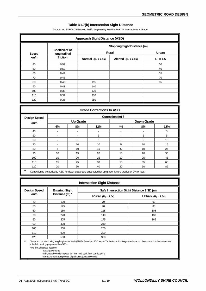
GEOMETRIC ROAD DESIGN
D1 Aug 2008 (Copyright SWR-TM/WSC) D1-19 WOLLONDILLY SHIRE COUNCIL
Table D1.7(b) Intersection Sight Distance
Source: AUSTROADS Guide to Traffic Engineering Practice PART 5, Intersections at Grade.
Approach Sight Distance (ASD)
Stopping Sight Distance (m)
Rural Urban Speed km/h
Coefficient of longitudinal
friction Normal (RT = 2.5s) Alerted (RT = 2.0s) RT = 1.5 40 0.52 30 50 0.50 40 60 0.47 55 70 0.45 70 80 0.43 115 95 90 0.41 140 100 0.39 170 110 0.37 210 120 0.35 250
Grade Corrections to ASD
Correction (m) † Up Grade Down Grade
Design Speed km/h
4% 8% 12% 4% 8% 12% 40 - - - - - 5 50 - - 5 - 5 5 60 - 5 5 - 5 10 70 - 10 10 5 10 15 80 5 10 15 5 10 25 90 10 15 20 10 20 30 100 10 20 25 10 25 45 110 15 25 30 15 35 60 120 20 30 40 20 50 85
† Correction to be added to ASD for down grade and subtracted for up grade. Ignore grades of 2% or less.
Intersection Sight Distance
Safe Intersection Sight Distance SISD (m) Design Speed km/h
Entering Sight Distance (m) * Rural (RT = 2.0s) Urban (RT = 1.5s)
40 100 70 60 50 125 90 80 60 160 115 105 70 220 140 130 80 305 175 165 90 400 210 100 500 250 110 500 290 120 500 330
* Distance computed using lengths given in Jarvis (1987). Based on ASD as per Table above. Limiting value based on the assumption that drivers are unlikely to seek gaps greater than 500m. Note that distances assume:
- Level pavements - Minor road vehicle stopped 7m (5m min) back from conflict point - Measurement along centre of path of major road vehicle.

GEOMETRIC ROAD DESIGN
D1-20 D1 Aug 2008 (Copyright SWR-TM/WSC)
WOLLONDILLY SHIRE COUNCIL
D1.24 HORIZONTAL AND VERTICAL ALIGNMENT
1. Horizontal and vertical curves are to be designed generally to the requirements of AUSTROADS - Guide to Geometric Design of Rural Roads. These requirements are essential to satisfy the safety and performance of proper road design. Roads having both horizontal and vertical curvature should be designed to conform to the terrain to achieve desirable aesthetic quality and being in harmony with the landform.
D1.25 INTERSECTIONS
1. Intersections shall be designed in accordance with the publication AUSTROADS Guide to Traffic Engineering Practice - Part 5, Intersections at Grade and Section 4 of the Roads and Traffic Authority Road Design Guide. Generally intersections with existing main and local roads will conform to the layouts shown in Figure D1.6 below. Additional requirements for left and right hand turns can be found in Section 4 of the RTA Road Design Guide. The type of intersection required will depend on existing and planned connecting roads.
Figure D1.6 Typical Rural Intersection Treatment
Source: AUSTROADS Guide to Traffic Engineering Practice PART 5, Intersections at Grade.

GEOMETRIC ROAD DESIGN
D1 Aug 2008 (Copyright SWR-TM/WSC) D1-21 WOLLONDILLY SHIRE COUNCIL
2. Adequate sight distance should be provided at intersections and junctions. The safe intersection sight distances must be provided in accordance with Section 4 of the RTA Road Design Guide.
3. An absolute minimum spacing of 40 m should be adopted for staggered junctions. The intersection angle between two roads should be 90°, and variations to this 90° angle within a tolerance of ± 20° may be permitted.
Staggered Junctions
D1.26 PLAN TRANSITIONS
1. A plan transition is the length over which widening and shift is developed from the "tangent-spiral" point to the "spiral-curve" point; ie, the length between the tangent and the curve. In urban road design it is often impracticable to use plan transitions as kerb lines are fixed in plan and any shift requires carriageway widening. Widening on horizontal curves compensates for differential tracking of front and rear wheels of vehicles; overhang of vehicles; and transition paths. Where proposed roads are curved, the adequacy of carriageway width should be considered.
Widening of Curves
2. Abrupt changes in crossfall, can cause discomfort in travel and create a visible kink in the road edge. A rate of change of road edge of no more than 0.5 per cent relative to the centre line should ensure against this. The wider the pavement the longer the transition. Superelevation transitions should be used at all changes in crossfall, not just for curves. Drainage problems can arise with superelevation transitions that may require extra gully pits and steeper gutter crossfalls. Where crossfalls change at intersections, profiles of the road edge should be drawn. Calculated points can be adjusted to present a smooth curve.
Crossfall Changes
D1.27 CARRIAGEWAYS
1 The carriageway width for new rural roads should generally be as per Table D1.8 below:
Table D1.8 CHARACTERISTICS OF RURAL ROADS IN WOLLONDILLY SHIRE COUNCIL ROAD NETWORKS
ROAD CATEGORY AND TYPE ROAD RESERVE WIDTH(m)
SEALED WIDTH(m)
UNSEALED SHOULDER WIDTH(m)
Major Roads over 1,000 AADT
(Category H road)
20 9.0 2 x 0.5
Minor Through Road up to 1,000 AADT 20 8.0 2 x 0.5
Rural Cul-de-sac servicing >15 lots(Category G2 road)
20 8.0 2 x 0.5
Rural Cul-de-sac servicing ≤ 15 lots*(Category G1 road)
20 6.0 metres
Or
Minimum 4.0 with passing
bays at intervals not greater than
100m
2 x 0.5
2 x 1.5
Rural Residential Roads Same as for Urban Residential Roads (Refer to Table D.1.5)
* Single lane treatment (4m) of minor cul-de-sacs will only be considered where site conditions are suitable. Sections of road with steep gradients or limited site distances would not be suitable for single lane treatment.
Refer to Drawing No. WSC D1.2, sheet 2 in Section D1.100 for Typical Cross Sections.

GEOMETRIC ROAD DESIGN
D1-22 D1 Aug 2008 (Copyright SWR-TM/WSC)
WOLLONDILLY SHIRE COUNCIL
D1.28 SUPERELEVATION
1. Use of maximum superelevation will be considered where the radius of the curve is approaching the minimum speed environment. Reference should be made to Section 2 of the RTA Road Design Guide for superelevation calculation.
Design Speed
D1.29 SCOUR PROTECTION
1. Scour protection of roadside drainage and table drains is required. The level of protection will depend on the nature of the soils, road gradients and volume of stormwater runoff. Protection works may involve concrete lined channels, kerb and gutter, turfing, rock pitching, grass seeding, individually or any combination of these. Geotechnical investigations should be carried out to determine the level and extent of any protection works prior to proceeding to final design stage.
2. Council will require concrete lined table drains (Roads and Traffic Authority SH or SK design) or standard kerb and gutter to be constructed where flow velocities exceed or are equal to 2m/s and/or longitudinal table drain grades exceed or are equal to 10%.
SPECIAL REQUIREMENTS
D1.30 CUT/FILL ROAD BATTERS
1. Batters shall be to a maximum slope of 1 in 2 for batters in excess of 0.6 metres high, otherwise the maximum batter gradient is 1 in 4. Fill batters shall not straddle allotment boundaries unless appropriate easements for support are created on the affected lot(s). Cut batters shall not straddle allotment boundaries unless letters are obtained for all affected property owners consenting to the proposed work on their property
2. Batters steeper than 1 in 2 may be approved subject to Geotechnical advice, otherwise the batters need to be retained
3. Stabilisation of batters by vegetation shall commence immediately following completion of bulk earthworks. Benching shall be required where any proposed free standing batter exceeds 2.5m. The minimum width of benching shall be 1.0m with a minimum slope of 1 in 100 towards the lower face. The benching shall be vegetated to prevent erosion.
D1.31 HALF ROAD CONSTRUCTION
1. Where a new road straddles a property boundary and Council has approved half width road pavement construction, construction shall include half the actual width plus 1.0 metre.
D1.32 ROAD WIDENING
1 Widening of an existing road pavement may be necessary in order to:
• ensure the public road servicing the development is of an appropriate standard,
• provide an auxiliary lane to permit safe access/egress for the development,
• provide for on-street parking or service vehicle bays.
GEOMETRIC ROAD DESIGN
D1 Aug 2008 (Copyright SWR-TM/WSC) D1-23 WOLLONDILLY SHIRE COUNCIL
2 Where road widening is required, the strength and vertical alignment of the existing road pavement must be considered. Any unsatisfactory sections of existing road pavement between the centreline and edge of road should be removed and reconstructed.
3 The new seal should extend a minimum of 150mm over the existing pavement to protect the join, however it may be necessary to extend the seal up to the road centreline to avoid irregularities in the wearing course.
D1.33 RECONSTRUCTING AN EXISTING ROAD
1 It may be necessary to reconstruct an existing public road where:
• the existing pavement is not of a suitable standard to service the traffic generated by the development,
• the additional traffic loads as a consequence of the development would significantly reduce pavement life.
• crossfalls in the existing pavement create difficulties for vehicular access/egress.
D1.34 STREET FURNISHING
1 Speed, warning and regulatory signs shall conform with AS 1743. Pavement linemarking shall meet the requirements of AS 1742.2. Street name signs shall be provided for each street in accordance with drawing WSC.D1.14 in the appendix.
Signs & Pavement Marking
2 Safety barriers should be erected where required in accordance with the Section 6 of the RTA Road Design Guide.
3 Road edge guideposts should be provided at all locations where concrete kerb and gutter is not constructed e.g half road construction, tapers, rural road and end of roads. They shall comply with RTA standards.
4 Any proposed feature walls marking the entry to a subdivision must be designed giving due regard to:
• structural adequacy • pedestrian safety and convenience • vehicle safety (sight distance) • access to services and utilities • aesthetics and visual amenity • economy (low maintenance, anti graffiti materials).
1.35 SERVICE VEHICLES
1. Measures must be included in the design of any subdivision to provide for service vehicles, such as garbage and effluent trucks. Generally, garbage and effluent trucks will not enter private properties and suitable provision must be made to service the properties from the public road. Where site conditions dictate, a sealed service bay/parking bay should be constructed in an appropriate location, approved by Council, to ensure the service vehicles do not obstruct traffic. Dimensions of the service bay/parking bay shall be 15 metres long by 3.0 metres wide with 1:4 tapers.

GEOMETRIC ROAD DESIGN
D1-24 D1 Aug 2008 (Copyright SWR-TM/WSC)
WOLLONDILLY SHIRE COUNCIL
D1.36 PROPERTY ACCESS
1 Council requires that satisfactory vehicular access can be provided for every lot taking into account the following:
• Physical constraints • Sight distances • Access, verge and allotment grading • Street design / layout • Minimum depth of cover requirements to underground services • The functional road hierarchy of the road being accessed.
2 Construction of property accesses will typically be undertaken as part of the development of that lot and not as part of the land subdivision. In situations where:
• Particularly restrictive physical constraints exist, such as limit sight distances, or
• access to a property is by way of a shared right of way,
construction of the property access will be required as part of the land subdivision.
3 For typical details of a passing bay refer to Drawing No. WSC.D1.3, contained in Section D1.100
Passing Bay
D1.37 BOUNDARY FENCES
Consideration will be given to the safety aspects of a proposed boundary fencing with respect to impact with an errant vehicle. No horizontal members shall be used in the fence if they in a location where they are capable of piercing a vehicle and cause death or injury to the occupants.
STANDARD DRAWINGS
D1.100 LIST OF DRAWINGS List of Drawings
1. DRAWING NUMBER DRAWING DESCRIPTION WSC.D1.1 Standard Cross Sections for Categories A1 to D3 Sheet 1 WSC.D1.2 Standard Cross Sections for Categories E to H Sheet 2 WSC.D1.3 Cul-de-Sac Head Design Layout Sheet 1 for Category A, B, C & Roads Standard Type A Details WSC.D1.4 Accessway Head Design Layout Sheet 2 for Category A1 & A2 Roads Standard Type B, C, D & E Details WSC.D1.12 Standard Kerb and Gutters WSC.D1.13 Standard Fender Posts and Standard Sign Plates WSC.D1.14 Standard Street Sign Details WSC.D1.24 Sign Post Locations and Sign Plate Details WSC.D1.25 Cul-de-Sac Head Design Layout Sheet 3 for Category G1 & G2 Roads Standard Type A Details


PAVEMENT DESIGN
D2 Aug 2008 (Copyright SWR-TM/WSC) WOLLONDILLY SHIRE COUNCIL
DESIGN SPECIFICATION
D2
PAVEMENT DESIGN


PAVEMENT DESIGN
D2 Aug 2008 (Copyright SWR-TM/WSC) WOLLONDILLY SHIRE COUNCIL
Amendment Record for this Specification Part
This Specification is Wollondilly Shire Council’s edition of the AUS-SPEC generic specification part and includes Wollondilly Shire Council’s primary amendments.
Details are provided below outlining the clauses amended from the Wollondilly Shire Council edition of this AUS-SPEC Specification Part. The clause numbering and context of each clause are preserved. New clauses are added towards the rear of the specification part as special requirements clauses. Project specific additional script is shown in the specification as italic font.
The amendment code indicated below is ‘A’ for additional script ‘M’ for modification to script and ‘O’ for omission of script. An additional code ‘P’ is included when the amendment is project specific.
Amendment Sequence No.
Key Topic addressed in amendment
Clause No.
Amendment Code
Author Initials
AmendmentDate
1 Minimum Pavement Thickness D2.10 M IB 1/7/08
2 Wearing Course D2.16 M IB 1/7/08
3 Permeable Pavements D2.21 A IB 1/7/08
4 Salinity D2.02 A IB 1/7/08

PAVEMENT DESIGN
D2 Aug 2008 (Copyright SWR-TM/WSC) WOLLONDILLY SHIRE COUNCIL
SPECIFICATION D2 : PAVEMENT DESIGN CONTENTS
CLAUSE PAGE
GENERAL .............................................................................................................................1
D2.01 SCOPE..............................................................................................................................................1
D2.02 OBJECTIVES....................................................................................................................................1
D2.03 REFERENCE AND SOURCE DOCUMENTS ..................................................................................2
PAVEMENT DESIGN CRITERIA ..........................................................................................2
D2.04 DESIGN VARIABLES .......................................................................................................................2
D2.05 DESIGN TRAFFIC ............................................................................................................................3
D2.06 SUBGRADE EVALUATION ..............................................................................................................3
D2.07 ENVIRONMENT................................................................................................................................4
D2.08 PAVEMENT AND SURFACING MATERIALS..................................................................................5
D2.09 CONSTRUCTION AND MAINTENANCE CONSIDERATIONS .......................................................5
PAVEMENT THICKNESS DESIGN ......................................................................................6
D2.10 PAVEMENT STRUCTURE - GENERAL...........................................................................................6
D2.11 UNBOUND GRANULAR FLEXIBLE PAVEMENTS (BITUMINOUS SURFACED) ..........................6
D2.12 FLEXIBLE PAVEMENTS CONTAINING BOUND LAYERS (BITUMINOUS SURFACED)..............6
D2.13 RIGID PAVEMENTS.........................................................................................................................7
D2.14 CONCRETE SEGMENTAL BLOCK PAVEMENTS..........................................................................7
D2.15 CLAY SEGMENTAL BLOCK PAVEMENTS.....................................................................................7
SURFACING DESIGN...........................................................................................................7
D2.16 CHOICE OF SURFACE TYPE .........................................................................................................7
D2.17 SPRAYED BITUMINOUS SEALS (FLUSH SEALS).........................................................................8
D2.18 BITUMINOUS MICROSURFACING (COLD OVERLAY) DELETED................................................8
D2.19 ASPHALTIC CONCRETE.................................................................................................................8
D2.20 SEGMENTAL PAVERS ....................................................................................................................9
D2.21 PERMEABLE PAVEMENTS.............................................................................................................9

PAVEMENT DESIGN
WOLLONDILLY SHIRE COUNCIL D2 Aug 2008 (Copyright SWR-TM/WSC)
SPECIAL REQUIREMENTS .................................................................................................9
D2.22 UNSEALED PAVEMENT..................................................................................................................9
STANDARD DRAWINGS......................................................................................................9
D2.100 LIST OF DRAWINGS.......................................................................................................................9

PAVEMENT DESIGN
D2 Aug 2008 (Copyright SWR-TM/WSC) D2-1 WOLLONDILLY SHIRE COUNCIL
SPECIFICATION D2 : PAVEMENT DESIGN
GENERAL
D2.01 SCOPE
1. The work to be executed under this Specification consists of the design of the road pavement to meet the required design life, based on the subgrade strength, traffic loading and environmental factors, and including the selection of appropriate materials for select subgrade, subbase, base and wearing surface. This design specification does not cover internal or access driveways. Pavement specifications for Internal and access driveways are outlined in WSC.D13 - ACCESS & OFFSTREET PARKING.
Design Criteria
2. The Specification contains procedures for the design of the following forms of surfaced road pavement construction:
(a) flexible pavements consisting of unbound granular materials;
(b) flexible pavements that contain one or more bound layers, including pavements containing asphalt layers other than thin asphalt wearing surfaces;
(c) rigid pavements (ie. cement concrete pavements);
(d) concrete or clay segmental block pavements.
Surfaced Pavement Types
3. Consideration to the design of unsealed (gravel) pavements will only be given for minor rural subdivisions/developments in isolated rural areas where the access to the subdivision is via an existing unsealed road.
Unsealed Pavements
D2.02 OBJECTIVES
1. The objective in the design of the road pavement is to select appropriate pavement and surfacing materials, types, layer thicknesses and configurations to ensure that the pavement performs adequately and requires minimal maintenance under the anticipated traffic loading for the design life adopted.
Pavement Performance
2. Information provided by the NSW Government that indicates salinity may occur in parts of the Wollondilly Local Government Area (LGA). This salinity potential is due to inherent characteristics of the Wollondilly LGA landscape. As a result, buildings and other infrastructure in the Wollondilly LGA may be susceptible to salt damage.
The applicant must thoroughly investigate the site to determine if there are any salinity issues to be addressed. The designer shall address salinity in their design. Steps taken may include, but are not limited to:
• Minimising depth of excavation/disturbance required for roadworks; • Minimising infiltration of surface waters by providing adequate sub-soil drainage; • Provision of adequate drainage for upstream catchments; and • Use of appropriate materials in construction of roadworks.
Designers should also follow guidelines set out in Department of Infrastructure, Planning and natural Resources (2003) Guide: Roads and Salinity (ISBN: 0 73475377 2).
Salinity

PAVEMENT DESIGN
WOLLONDILLY SHIRE COUNCIL D2-2 D2 Aug 2008 (Copyright SWR-TM/WSC)
D2.03 REFERENCE AND SOURCE DOCUMENTS
(a) Council Specifications D1 - Geometric Road Design D4 - Subsurface Drainage Design Wollondilly Shire Council Construction Specification Draft May 1990
(b) State Authorities Roads and Traffic Authority, NSW – Sprayed Sealing Guide, 1992. Department of Infrastructure, Planning and Natural Resources
Guide: Roads and Salinity (2003) (ISBN: 0 73475377 2)
(c) Other AUSTROADS - Pavement Design, A Guide to the Structural Design of Road
Pavements, 1992.
AUSTROADS - Guide to Control of Moisture in Roads.
ARRB-SR41 - Australian Road Research Board, Special Report No. 41 - A Structural Design Guide for Flexible Residential Street Pavements, 1989.
C&CAA - T33 - Cement and Concrete Association, T33 - Concrete Street and Parking Area Pavement Design, 1984.
C&CAA - T35 - Cement and Concrete Association, T35 - Interlocking Concrete Road Pavements, A Guide to Design and Construction, 1986.
C&CAA – T44 - Cement and Concrete Association, Guide to specifying Concrete Segmental pavers
C&CAA – T45 - Cement and Concrete Association, Detailing Guide.
C&CAA – T46 - Cement and Concrete Association, Design Guide to Residential Streets and Roads.
C&CAA – T51 - Cement and Concrete Association, Concrete Pavement Design for Residential Streets, 1998.
C&CAA - TN52 - Cement and Concrete Association, TN52 - Single-Lane Concrete Bus Bays, 1984.
Clay Brick and Paver Institute - Design Manual 1 - Clay Segmental Pavements, A Design
and Construction Guide for Sites Subjected to Vehicular and Pedestrian Traffic, 1989.
PAVEMENT DESIGN CRITERIA
D2.04 DESIGN VARIABLES
1. Regardless of the type of road pavement proposed, the design of the pavement shall involve consideration of the following five input variables:
(a) Design Traffic
Design Variables

PAVEMENT DESIGN
D2 Aug 2008 (Copyright SWR-TM/WSC) D2-3 WOLLONDILLY SHIRE COUNCIL
(b) Subgrade Evaluation
(c) Environment
(d) Pavement and Surfacing Materials
(e) Construction and Maintenance Considerations
D2.05 DESIGN TRAFFIC
1. The design traffic shall be calculated based on the following minimum design lives of pavement:
(a) Flexible, Unbound Granular - 25 years
(b) Flexible, Containing one or more bound layers - 25 years
(c) Rigid (Concrete) - 40 years
(d) Segmental Block - 25 years
Minimum Pavement Design Life
2. Design traffic shall be calculated in equivalent standard axles (ESAs) for the applicable design life of the pavement, taking into account present and predicted commercial traffic volumes, axle loadings and configurations, commercial traffic growth and street capacity. For new subdivisions, the design traffic shall take account of both the construction traffic associated with the subdivision development and the in-service traffic. For interlocking concrete segmental pavements, the simplification of replacing ESA's with the number of commercial vehicles exceeding 3 tonne gross contained in C& CAA – Interlocking Concrete Road Pavements is acceptable up to a design traffic of 106. Beyond this, ESAs should be calculated.
Design Traffic
3. The pavement design shall include all traffic data and/or assumptions made in the calculation of the design traffic.
Traffic Data
4. In general, reference should be made to ARRB-SR41 for the calculation of design traffic volumes up to 106 ESAs and AUSTROADS Pavement Design for design traffic volumes approaching or exceeding 106 ESAs.
Design Traffic Volumes
5. In the absence of other traffic data, the following traffic values (in ESAs) may be taken as a guide to the design traffic, but shall be subject to variation depending on the circumstances for the particular development. Street Type: Street Design ESA's Category 25 year design life Urban Residential - Minor Cul-de-sac and Accessway Category A & B 2 x 10⁴ - Cul-de-sac Category C 6 x 10⁴ - Local Street Category D 3 x 10⁵ - Collector Street Category E 1 x 10⁶ - Local Distributor Category E 2 x 10⁶ Rural Residential - Cul-de-sac Category G 2 x 10⁴ - Other 3 x 10⁵ Commercial and Industrial Category F 5 x 10⁶
Main Road, Very Heavy Industrial 1 x 10⁷
Design ESAs
D2.06 SUBGRADE EVALUATION
1. Except where a mechanistic design approach is employed using AUSTROADS Pavement Design, the measure of subgrade support shall be the California Bearing Ratio
California Bearing Ratio

PAVEMENT DESIGN
WOLLONDILLY SHIRE COUNCIL D2-4 D2 Aug 2008 (Copyright SWR-TM/WSC)
(CBR). Where a mechanistic design approach using linear elastic theory is employed for flexible pavements, the measure of subgrade support shall be in terms of the elastic parameters (modulus, Poisson's ratio).
2. The following factors must be considered in determining the design strength/stiffness of the subgrade:
(a) Sequence of earthworks construction (b) The compaction moisture content and field density specified for
construction (c) Moisture changes during service life (d) Subgrade variability (e) The presence or otherwise of weak layers below the subgrade level.
Design Considerations
3. The subgrade Design CBR adopted for the pavement design must consider the effect of moisture changes in the pavement and subgrade during the service life, and hence consideration must be given to the provision of subsurface drainage in the estimation of equilibrium in-situ CBRs, and hence in the design of the pavement structure. Warrants for the provision of subsurface drainage are given in Specification for SUBSURFACE DRAINAGE DESIGN. If subsurface drainage is not provided, then the Design CBR adopted must allow for a greater variability in subgrade moisture content during the service life of the pavement, and hence a Design Moisture Content above the Optimum Moisture Content.
Design CBR
4. The calculation of the Design CBR shall be based on a minimum of three 4 day soaked CBR laboratory samples for each subgrade area, compacted to the relative density specified for construction, and corrected to allow for the effects of subsurface drainage (or lack of), climatic zone, and soil type if appropriate (as per the guidelines in ARRB SR41) to give an estimated equilibrium in-situ CBR. The Design CBR for each subgrade area is computed by using the appropriate formulae as follows: Design CBR = Least of estimated equilibrium CBRs, for less than five (5) results Design CBR = 10th percentile of all estimated equilibrium CBRs, for five (5) or more
results = C - 1.3S Where C is the mean of all estimated equilibrium CBRs, and S is the standard deviation of all values.
Calculation of Design CBR
5. Where practicable, the Design CBR obtained from laboratory testing should be confirmed by testing performed on existing road pavements near to the job site under equivalent conditions and displaying similar subgrades. Insitu Dynamic Cone Penetrometer testing could be used to compare Design CBR values obtained as per above.
Field Confirmation
6. The pavement design shall include a summary of all laboratory and field test results and assumptions and/or calculations made in the assessment of Design CBR.
Summary of Results
D2.07 ENVIRONMENT
1. The environmental factors which significantly affect pavement performance are moisture and temperature. Both of these factors must be considered at the design stage of the pavement. Reference should be made to AUSTROADS Pavement Design, ARRB-SR41, and to NAASRA (Now AUSTROADS) - Guide to Control of Moisture in Roads.
Reference

PAVEMENT DESIGN
D2 Aug 2008 (Copyright SWR-TM/WSC) D2-5 WOLLONDILLY SHIRE COUNCIL
2. The following factors relating to moisture environment must be considered in determining the design subgrade strength/stiffness and in the choice of pavement and surfacing materials:
(a) Rainfall/evaporation pattern (b) Permeability of wearing surface (c) Depth of water table (d) Relative permeability of pavement layers (e) Whether shoulders are sealed or not (f) Pavement type (boxed or full width)
3. The effect of changes in moisture content on the strength/stiffness of the subgrade shall be taken into account by evaluating the design subgrade strength parameters (ie. CBR or modulus) at the highest moisture content likely to occur during the design life, ie the Design Moisture Content. The provision of subsurface drainage may, under certain circumstances, allow a lower Design Moisture Content, and hence generally higher Design CBR. However, extreme care is to be taken if consideration is given to lowering the design CBR value to account for the possible benefits of sub-surface drainage.
Evaluate Design CBR
4. The effect of changes in temperature environment must be considered in the design of pavements with asphalt wearing surfaces, particularly if traffic loading occurs at night when temperatures are low, thus causing a potential reduction in the fatigue life of thin asphalt surfacing. The effect of overnight changes in temperature environment should also be considered for bound or concrete layers and spray seal designs.
Temperature Change
5. The pavement design shall include all considerations for environmental factors, and any assumptions made that would reduce or increase design subgrade strength, or affect the choice of pavement and surfacing materials.
D2.08 PAVEMENT AND SURFACING MATERIALS
1. Pavement materials can be classified into essentially four categories according to their fundamental behaviour under the effects of applied loadings:
(a) Unbound granular materials, including modified granular materials (b) Bound (cemented) granular materials (c) Asphaltic Concrete (d) Cement Concrete
Pavement Classification
2. Surfacing materials can also be classified into essentially five categories or types:
(a) Sprayed bituminous seals (flush seals) (b) Asphaltic concrete and bituminous microsurfacing (cold overlay) (c) Cement Concrete (d) Concrete Segmental Pavers (e) Clay Segmental Pavers
Surfacing Classification
3. All pavement materials shall satisfy the requirements of the Wollondilly Shire Council Construction Specification.
D2.09 CONSTRUCTION AND MAINTENANCE CONSIDERATIONS
1. The type of pavement, choice of base and subbase materials, and the type of surfacing adopted should involve consideration of various construction and maintenance

PAVEMENT DESIGN
WOLLONDILLY SHIRE COUNCIL D2-6 D2 Aug 2008 (Copyright SWR-TM/WSC)
factors as follows:
(a) Extent and type of drainage
(b) Use of boxed or full width construction
(c) Available equipment of the Contractor
(d) Use of stabilisation
(e) Aesthetic, environmental and safety requirements
(f) Social considerations
(g) Construction under traffic
(h) Use of staged construction
(i) Ongoing and long-term maintenance costs
These factors are further discussed in AUSTROADS Pavement Design.
PAVEMENT THICKNESS DESIGN
D2.10 PAVEMENT STRUCTURE - GENERAL
1. The pavement thickness, including the thickness of surfacing, shall not be less than 300mm.
Minimum Pavement Thickness
2. Notwithstanding subgrade testing and subsequent pavement thickness design, the thickness of subbase and base layers shall not be less than the following:- (a) Flexible pavement: Subbase 175mm, Base 125mm (b) Rigid pavement: Subbase 100mm, Base 150mm
3. The subbase layer shall extend a minimum of 150mm behind the rear face of any kerbing and/or guttering.
Subbase Extent
4. The base and surfacing shall extend to the face of any kerbing and/or guttering. Where the top surface of the subbase layer is below the level of the underside of the kerbing and/or guttering, the base layer shall also extend a minimum of 150mm behind the rear face of the kerbing and/or guttering.
Base Extent
5. For unkerbed roads, the subbase and base layers shall extend at least to the nominated width of shoulder.
D2.11 UNBOUND GRANULAR FLEXIBLE PAVEMENTS (BITUMINOUS SURFACED)
1. Unbound granular flexible pavements with thin bituminous surfacing, including those with cement or lime modified granular materials, with design traffic up to 106 ESAs shall be designed in accordance with ARRB-SR41, using Figure 7 (95% confidence limit curves).
2. For design traffic above 106 ESAs, the design shall be in accordance with AUSTROADS Pavement Design.
D2.12 FLEXIBLE PAVEMENTS CONTAINING BOUND LAYERS (BITUMINOUS SURFACED)
1. Flexible pavements containing one or more bound layers, including cement stabilised layers or asphaltic concrete layers other than thin asphalt surfacing, shall be designed in accordance with AUSTROADS Pavement Design.

PAVEMENT DESIGN
D2 Aug 2008 (Copyright SWR-TM/WSC) D2-7 WOLLONDILLY SHIRE COUNCIL
2. As an alternative to AUSTROADS Pavement Design for design traffic up to 106 ESAs, bound layers may be assumed to be equivalent to unbound layers of the same thickness, and the pavement designed in accordance with ARRB-SR41, using Figure 7 (95% confidence limit curves).
D2.13 RIGID PAVEMENTS
1. Rigid (concrete) pavements, with design traffic up to 106 ESAs shall be designed in accordance with either C&CAA –T33 or AUSTROADS Pavement Design.
Rigid (Concrete)
2. Rigid (concrete) pavements for design traffic above 106 ESAs, the design shall be in accordance with AUSTROADS Pavement Design.
3. Single lane concrete bus bays adjacent to a flexible pavement shall be designed in accordance with C&CAA -TN52.
D2.14 CONCRETE SEGMENTAL BLOCK PAVEMENTS
1. Concrete segmental block pavements with design traffic up to 106 estimated commercial vehicles exceeding 3T gross shall be designed in accordance with C&CAA –T35.
Concrete Segmental Block
2. For design traffic above 106 estimated commercial vehicles exceeding 3T gross the design shall be in accordance with AUSTROADS Pavement Design, with the calculation of design traffic in terms of ESAs.
D2.15 CLAY SEGMENTAL BLOCK PAVEMENTS
1. Clay segmental block pavements with design traffic up to 106 ESAs shall be designed in accordance with Design Manual 1 - Clay Segmental Pavements.
Clay Segmental Block
2. For design traffic above 106 ESAs and up to 107 ESAs the design shall involve consideration of both Design Manual 1 - Clay Segmental Pavements and AUSTROADS Pavement Design, with the thicker and more conservative design of each of the two methods adopted.
3. For design traffic above 107 ESAs, the pavement shall be designed in accordance with AUSTROADS Pavement Design.
SURFACING DESIGN
D2.16 CHOICE OF SURFACE TYPE
1. Except where the pavement is designed for concrete or segmental block surfacing, the wearing surface shall be a bituminous wearing surface as follows:
Bitumen Wearing Surface
(a) Urban Residential streets - Cul-de-sac, Minor and Local Access, and streets:
- primer, plus 10mm one (1) coat flush seal, plus 40mm AC10 Asphalt for new road and new lane works, for cul-de-sac see item 4.
- primer, plus 40mm AC10 asphalt for shoulder widening work only
(b) Urban Residential streets – Collector and Distributor:
- primer, plus 10mm one coat flush seal, plus 50mm AC14 asphalt for new road and new lane works

PAVEMENT DESIGN
WOLLONDILLY SHIRE COUNCIL D2-8 D2 Aug 2008 (Copyright SWR-TM/WSC)
- primer, plus 50mm AC14 asphalt for shoulder widening work only
(c) Commercial and Industrial streets:
- primer, plus 10mm one coat flush seal, plus 50mm AC14 asphalt for new lane and new road works
- primer, plus 50mm AC14 asphalt for shoulder widening works only
(d) Sub-arterial and Arterial roads:
- primer, plus 10mm one coat flush seal, 10mm primer seal, plus 50mm AC14 asphalt for new lane and new road works
- primer, plus 50mm AC14 asphalt for shoulder widening works only
(e) Rural and Rural Residential Streets:
- primer, plus two coat flush seal 14mm / 10mm.
2. At intersection approaches and cul-de-sac turning circles on residential streets with flush seals, asphalt surfacing shall be provided within the vehicle braking and turning zones.
Braking and Turning Zones
4. Thickness of asphaltic concrete within cul-de-sac turning circle and turning heads shall be minimum 50 mm AC14 laid on a single coat seal of 10 mm aggregates.
5. Roads with longitudinal gradient more than 16.67% shall be sealed with asphaltic concrete with single coat seal of 10 mm aggregates underneath.
3. Variations to these requirements may be approved in special circumstances.
Approval
D2.17 SPRAYED BITUMINOUS SEALS (FLUSH SEALS)
1. The design of sprayed bituminous (flush) seals, including primers and primer seals, shall be in accordance with the RTA Sprayed Sealing Guide.
Seal Design
2. A 7mm or 10mm primer seals shall be indicated on the Drawings below all flush seals, and asphalt surfacing.
Primer Seal
3. Two-coat flush seals shall be double-double seals, comprising a minimum of two (2) coats binder and two (2) coats of aggregate. The preferred seal types are: 1st coat 14mm 2nd coat 10mm
Two- Coat Flush Seals
4. Single coat flush seals shall be allowable if asphaltic concrete is to be applied as the finished surface. The preferred seal type is 10mm.
Single Coat Flush Seal
D2.18 BITUMINOUS MICROSURFACING (COLD OVERLAY) DELETED
D2.19 ASPHALTIC CONCRETE
1. In light to medium trafficked residential, rural or commercial streets (design traffic up to approximately 3 x 10⁵ ESAs), the asphalt mix design shall be either a 'high-bitumen content' mix or the ARRB Gap-graded mix in accordance with ARRB-SR41 and the Wollondilly Shire Council Construction Specification.
Light to Medium Traffic
2. In medium to heavily trafficked residential, rural or commercial roads and in all industrial and classified roads, the asphalt mix design shall be a dense graded mix in accordance with the Wollondilly Shire Council Construction Specification.
Medium to Heavy Traffic
3. Asphaltic concrete surfacing shall be designed to provide a nominal compacted layer thickness of not less than 30mm on light to medium trafficked residential, rural and commercial streets, and 50mm on medium to heavily trafficked residential, rural or commercial roads and on all industrial and classified roads.
Minimum Thickness

PAVEMENT DESIGN
D2 Aug 2008 (Copyright SWR-TM/WSC) D2-9 WOLLONDILLY SHIRE COUNCIL
4. As a minimum, a 7mm or 10mm primer seal shall be indicated on the Drawings below the asphalt surfacing.
Primer Seal
5. On roundabout pavements for all classes / categories of roads, the surface shall have a minimum compacted layer thickness of 60mm AC14 SBS polymer modified Asphalt on a single 10mm primer seal. The approaches to the roundabout for a distance as determined by Council shall also have a minimum compacted layer thickness of 60mm AC14 SBS polymer modified Asphalt on a single 10mm primer seal.
Roundabouts
D2.20 SEGMENTAL PAVERS
1. Concrete segmental pavers shall be 80mm thick, shape Type A, and designed to be paved in a herringbone pattern.
Size and Shape
2. Clay segmental pavers shall be 65mm thick, Class 4, and designed to be paved in a herringbone pattern.
3. The edges of all paving shall be designed to be constrained by either kerbing and/or guttering, or by concrete edge strips
D2.21 PERMEABLE PAVEMENTS
1. Concrete permeable pavers are acceptable in private driveways and private/public car parking areas.
Edge Constraint
2. The pavement shall be designed and constructed to manufacturer’s details incorporating water sensitive urban design (WSUD) principles and shall ensure that the pavement allows infiltration of stormwater.
3. The edges of the paving shall be designed to be constrained by either kerbing and/or guttering, or by concrete edge strips.
SPECIAL REQUIREMENTS
D2.22 UNSEALED PAVEMENT
1. Consideration to the design of unsealed (gravel) pavements will only be given for minor rural subdivisions/developments in isolated rural areas where the access to the subdivision is via an existing unsealed road.
2. In permitting an unsealed road, factors that will be considered include the potential for dust from the road to adversely impact on existing dwellings or likely future dwellings and issues of erosion and maintenance.
3. Roads with a longitudinal gradient exceeding 10% must be sealed.
STANDARD DRAWINGS
D2.100 LIST OF DRAWINGS List of Drawings
1. DRAWING NUMBER DRAWING DESCRIPTION WSC.D2.2 Reinforced Concrete Accessway Jointing Details


STRUCTURES/BRIDGE DESIGN
D3 Aug 2008 (Copyright SWR-TM/WSC) WOLLONDILLY SHIRE COUNCIL
DESIGN SPECIFICATION
D3
STRUCTURES
BRIDGE DESIGN


STRUCTURES/BRIDGE DESIGN
D3 Aug 2008 (Copyright SWR-TM/WSC) WOLLONDILLY SHIRE COUNCIL
Amendment Record for this Specification Part
This Specification is Council’s edition of the AUS-SPEC generic specification part and includes Council’s primary amendments.
Details are provided below outlining the clauses amended from the Council edition of this AUS-SPEC Specification Part. The clause numbering and context of each clause are preserved. New clauses are added towards the rear of the specification part as special requirements clauses. Project specific additional script is shown in the specification as italic font. The amendment code indicated below is ‘A’ for additional script ‘M’ for modification to script and ‘O’ for omission of script. An additional code ‘P’ is included when the amendment is project specific.
Amendment Sequence No.
Key Topic addressed in amendment
Clause No.
Amendment Code
Author Initials
AmendmentDate
1 Continuous accessible path D3.06 M IB 1/7/08


STRUCTURES/BRIDGE DESIGN
D3 Aug 2008 (Copyright SWR-TM/WSC) WOLLONDILLY SHIRE COUNCIL
SPECIFICATION D3 : STRUCTURES/BRIDGE DESIGN CONTENTS
CLAUSE PAGE
GENERAL .............................................................................................................................1
D3.01 SCOPE..............................................................................................................................................1
D3.02 OBJECTIVE ......................................................................................................................................1
D3.03 BASES OF DESIGN .........................................................................................................................1
D3.04 REFERENCE AND SOURCE DOCUMENTS ..................................................................................1
D3.05 ROAD TRAFFIC BRIDGES ..............................................................................................................2
D3.06 PEDESTRIAN BRIDGES..................................................................................................................2
D3.07 STRUCTURES OTHER THAN BRIDGES, ASSOCIATED WITH ROADS ......................................3
D3.08 SMALL EARTH DAMS/DETENTION BASINS .................................................................................3
D3.09 STRUCTURES USED FOR PUBLIC SAFETY.................................................................................3
D3.10 TEMPORARY WORKS.....................................................................................................................4
STANDARD DRAWINGS......................................................................................................4
D3.100 LIST OF DRAWINGS.......................................................................................................................4


STRUCTURES/BRIDGE DESIGN
D3 Aug 2008 (Copyright SWR-TM/WSC) D3-1 WOLLONDILLY SHIRE COUNCIL
SPECIFICATION D3 : STRUCTURES/BRIDGE DESIGN
GENERAL
D3.01 SCOPE
1. This section sets out design considerations to be adopted in the design of structural engineering elements for land subdivisions. Such activities will include:
• Road traffic bridges • Pedestrian bridges • Structures other than bridges, but associated with roads (eg retaining walls) • Small earth dams, detention basins • Structures used for public safety (traffic barriers, pedestrian barriers, street
lighting) • Major sign support structures • Temporary works
Such structures may be of concrete, timber or steel constructions, but with emphasis placed on low maintenance.
D3.02 OBJECTIVE
1. The aim of design shall be the achievement of acceptable probabilities that the structure being designed will not become unfit for use during its design life, having regard to economic, physical, aesthetic and other relevant constraints.
Design Life
D3.03 BASES OF DESIGN
1. The design shall be based on scientific theories, experimental data and experience, interpreted statistically as far as possible. The safety and service performance of a structure depends also on the quality control exercised in fabrication, supervision on site, the control of unavoidable imperfections and the qualifications, experience and skill of all personnel involved. Adequate attention shall therefore be given to these factors. In addition, adequate management control and supervision by experienced engineers shall be required at all stages of design and construction to prevent the occurrence of gross errors.
Safety Quality Qualifications
2. Specifications shall be notated on the design plans with sufficient detail to ensure that the above described strategies are able to be effectively implemented at the construction stage.
D3.04 REFERENCE AND SOURCE DOCUMENTS
(a) Council Specifications D1 - Geometric Road Design D5 - Stormwater Drainage Design
(b) Australian Standards AS1170 - Minimum design loads on structures (SAA Loading Code) AS1684 - National Timber Framing Code AS3600 - Concrete structures AS3700 - Masonry in buildings (SAA Masonry Code) AS4100 - Steel structures Other relevant codes and guidelines with the above.

STRUCTURES/BRIDGE DESIGN
WOLLONDILLY SHIRE COUNCIL D3-2 D3 Aug 2008 (Copyright SWR-TM/WSC)
(c) Other AUSTROADS - Bridge Design Code Inst. of Eng. - Australian Rainfall and Runoff KD Nelson - Design and Construction of Small Earth Dams
D3.05 ROAD TRAFFIC BRIDGES
1. Structural design of bridges is a complex matter generally falling outside the scope of many small civil engineering consultancies. Council would generally prefer this work to be referred to a firm whose A.C.E.A. listing includes structural design of bridges in its claimed area of competency.
A.C.E.A. Listing
2. However, this does not preclude submissions by other qualified persons in which cases Council reserves the right to call for evidence of the qualifications and experience of the responsible designer; or to seek referral of the design calculations to an appropriate A.C.E.A. firm for checking. The latter requirement will be at the proponents cost, if directed.
Checking
3. The Austroads Bridge Design Code is the appropriate general reference for bridge proposals.
4. Council normally requires bridges to have low maintenance finishes; therefore timber and steel are not usually acceptable construction materials, unless suitable precautions are adopted. Heavy debris and bed loads may be characteristic of some streams so that large spans with slender piers are encouraged. If overtopping is permitted, handrails and guardrails are usually omitted. Flood depth indicators will be provided in such cases.
Debris
Overtopping
5. Preventive maintenance is a key issue affecting the design life of the structure. The design plans shall specify the design life of the structure together with the relevant maintenance programs to be adopted upon which the design life is based. Parameters used in the design shall also be shown on the design plans.
Design Life Maintenance
6. Unless otherwise indicated on the Development Application, bridges over small watercourses within the development shall be designed with appropriate afflux to convey the 5 year ARI storm event with certification stating that the bridge is capable of withstanding the inundation loadings for up to the 100 year ARI storm event. If in the opinion of the designer, such certification is impractical, the structure shall be designed to convey the 100 year ARI storm event without inundation.
Small Bridges
Design Storm Event
7. Where structures are designed to be inundated, the effect of the backwater gradient on upstream property shall be identified on the design plans.
8. Bridges located in roadways which are to be dedicated as public roads shall be designed to convey the stormwater event identified in the drainage design specification. Where no inundation is permitted, appropriate afflux shall be adopted together with a 500mm freeboard to the underside of the bridge deck.
Freeboard
9. Designers should enquire regarding current or likely provision for public utilities in bridges.
Public Utilities
D3.06 PEDESTRIAN BRIDGES
1. Provision for pedestrians on bridges is required in rural residential as well as urban areas. The minimum provision is a 1.5m footpath with kerb at the road traffic edge and handrail.
Pedestrians
STRUCTURES/BRIDGE DESIGN
D3 Aug 2008 (Copyright SWR-TM/WSC) D3-3 WOLLONDILLY SHIRE COUNCIL
2. Council may require the provision of separate pedestrian carriageways in other situations should the anticipated traffic warrant it. Urban bridge approaches should be lit. A continuous accessible path of travel shall be provided in the design
Accessible Path
3. Designers should enquire regarding the current and future utility services which the bridge may be required to carry. These should be concealed for aesthetic reasons. .
Carriage of Utilities
D3.07 STRUCTURES OTHER THAN BRIDGES, ASSOCIATED WITH ROADS
1. Public utility structures, retaining walls, and the like will be designed by a competent, practicing engineer, accredited in the design of such structures. The consultant shall refer to the Austroads code and any other Australian standards to execute the design.
D3.08 SMALL EARTH DAMS/DETENTION BASINS
1. Small earth dams may be designed following the guidelines in "Design and Construction of Small Earth Dams" by K D Nelson together with relevant geotechnical recommendations. The structural design of weir outlets to resist failure shall be considered in design. Refer also to the Retarding Basin and Stormwater Detention sections in the Specification for STORMWATER DRAINAGE DESIGN.
2. Childproof fencing shall be nominated where unacceptable risk exists due to the location of the dam/basin in relation to the urban nature of the area. The degree of risk is typically dependant on the grades of the land adjacent to the edge of the water and progressing into deeper water. Childproof fences will generally be required around dams and other water bodies in urban areas where the following criteria cannot be satisfied:
Approach Grade to Maximum Depth Maximum Depth (m) Greater than 1:4 0.3 1:4 to 1:15 0.8 Less than 1:15 No Maximum
Notwithstanding the above, Council may require safety fences around water bodies where, due to the nature of the landuse in the proximity of the waterbody, it is considered that there is an unacceptable risk to children.
Fencing
3. The consultant shall carry out the design with recognition of the potential risk on existing and planned infrastructure downstream, assuming the probability of dam/basin failure.
4. The consultant shall be a qualified civil or structural engineer having accreditation in the design of such structures.
Qualification
5. The consultant shall be required to certify the design and ultimately certify the work-as-executed plans for compliance with the design. All relevant details shall be shown on the design plans.
D3.09 STRUCTURES USED FOR PUBLIC SAFETY
1. Since the requirement of traffic barriers and pedestrian safety rails on bridges are different, the design engineer shall consider whether separate traffic and pedestrian barriers can be detailed to satisfy the major functional requirements.
Barriers
2. The Austroads Bridge Design Code is the recommended reference in this regard.
3. It is essential that all barriers have been fully tested and accredited for the intended use under quality assurance provisions.

STRUCTURES/BRIDGE DESIGN
WOLLONDILLY SHIRE COUNCIL D3-4 D3 Aug 2008 (Copyright SWR-TM/WSC)
4. Urban and rural residential bridge crossings shall be provided with adequate streetlighting. Such requirements will be noted accordingly on the design plans.
Lighting
D3.10 TEMPORARY WORKS
1. Structures which are proposed for the temporary support of roads, services and the like shall be designed by a qualified Engineer experienced and accredited in the design of such structures. A construction programme, indicating the sequence of events leading to the implementation and removal of the temporary structures shall be specified on the design plans.
Programme of Temporary Provisions
STANDARD DRAWINGS
D3.100 LIST OF DRAWINGS List of Drawings
1. DRAWING NUMBER DRAWING DESCRIPTION WSC.D3.1 Rock Retaining Wall


SUBSURFACE DRAINAGE DESIGN
D4 Aug 2008 (Copyright SWR-TM/WSC) WOLLONDILLY SHIRE COUNCIL
DESIGN SPECIFICATION
D4
SUBSURFACE
DRAINAGE DESIGN


SUBSURFACE DRAINAGE DESIGN
D4 Aug 2008 (Copyright SWR-TM/WSC) WOLLONDILLY SHIRE COUNCIL
Amendment Record for this Specification Part
This Specification is Council’s edition of the AUS-SPEC generic specification part and includes Council’s primary amendments.
Details are provided below outlining the clauses amended from the Council edition of this AUS-SPEC Specification Part. The clause numbering and context of each clause are preserved. New clauses are added towards the rear of the specification part as special requirements clauses. Project specific additional script is shown in the specification as italic font.
The amendment code indicated below is ‘A’ for additional script ‘M’ for modification to script and ‘O’ for omission of script. An additional code ‘P’ is included when the amendment is project specific.
Amendment Sequence No.
Key Topic addressed in amendment
Clause No. Amendment Code
Author Initials
Amendment Date
1 Subsoil drain Fig D4.1 A IB 1/7/08
2 Backfill D4.06 A IB 1/7/08
3 Salinity D4.02 A IB 1/7/08


SUBSURFACE DRAINAGE DESIGN
D4 Aug 2008 (Copyright SWR-TM/WSC) WOLLONDILLY SHIRE COUNCIL
SPECIFICATION D4 : SUBSURFACE DRAINAGE DESIGN CONTENTS
CLAUSE PAGE
GENERAL .............................................................................................................................1
D4.01 SCOPE..............................................................................................................................................1
D4.02 OBJECTIVES....................................................................................................................................1
D4.03 TERMINOLOGY................................................................................................................................1
D4.04 REFERENCE AND SOURCE DOCUMENTS ..................................................................................2
SUBSOIL AND SUB-PAVEMENT DRAINS..........................................................................2
D4.05 WARRANTS FOR USE.....................................................................................................................2
D4.06 LAY0UT, ALIGNMENT AND GRADE...............................................................................................3
FOUNDATION DRAINS ........................................................................................................4
D4.07 WARRANTS FOR USE.....................................................................................................................4
D4.08 LAYOUT, ALIGNMENT AND GRADE ..............................................................................................5
DRAINAGE MATS (BLANKETS)..........................................................................................5
D4.09 WARRANTS FOR USE.....................................................................................................................5
MATERIALS..........................................................................................................................6
D4.10 SUBSOIL AND SUB-PAVEMENT DRAIN PIPE...............................................................................6
D4.11 INTRA PAVEMENT DRAIN PIPE .....................................................................................................6
D4.12 FILTER MATERIAL...........................................................................................................................6
D4.13 GEOTEXTILE....................................................................................................................................7
STANDARD DRAWINGS......................................................................................................7
D4.100 LIST OF DRAWINGS........................................................................................................................7


SUBSURFACE DRAINAGE DESIGN
D4 Aug 2008 (Copyright SWR-TM/WSC) D4-1 WOLLONDILLY SHIRE COUNCIL
SPECIFICATION D4 : SUBSURFACE DRAINAGE DESIGN
GENERAL
D4.01 SCOPE
1. The work to be executed under this Specification consists of the design of the subsurface drainage system for the road pavement and/or subgrade.
2. This specification contains procedures for the design of subsurface drainage, including:
(a) Subsoil and Foundation Drains
(b) Sub-Pavement Drains
(c) Drainage Mats, including Type A and Type B Mats.
3. Reference guidelines for the application and design of subsurface drainage include ARRB Special Reports 35 and 41, and the AUSTROADS publication – Guide to the Control of Moisture in Roads. The full titles of these guidelines are given below.
D4.02 OBJECTIVES
1. The objective in the design of the subsurface drainage system is to control moisture content fluctuations in the pavement and/or subgrade to within the limits assumed in the pavement design.
Control Moisture Content
2. Information provided by the NSW Government that indicates salinity may occur in parts of the Wollondilly Local Government Area (LGA). This salinity potential is due to inherent characteristics of the Wollondilly LGA landscape. As a result, buildings and other infrastructure in the Wollondilly LGA may be susceptible to salt damage.
The applicant must thoroughly investigate the site to determine if there are any salinity issues to be addressed. The designer shall address salinity in their design. Steps taken may include, but are not limited to:
• Minimising depth of excavation/disturbance required for roadworks; • Minimising infiltration of surface waters by providing adequate sub-soil drainage; • Provision of adequate drainage for upstream catchments; and • Use of appropriate materials in construction of roadworks.
Designers should also follow guidelines set out in Department of Infrastructure, Planning and natural Resources (2003) Guide: Roads and Salinity (ISBN: 0 73475377 2).
Salinity
D4.03 TERMINOLOGY
1. Subsoil drains are intended for the drainage of ground water or seepage from the subgrade and/or the subbase in cuttings.
Subsoil Drains
2. Foundation drains are intended for the drainage of seepage, springs and wet areas within and adjacent to the foundations of the road formation.
Foundation Drains
3. Sub-pavement drains are intended for the drainage of the base and subbase pavement layers in flexible pavements. They may also function to drain seepage or groundwater from the subgrade.
Sub-pavement Drains

SUBSURFACE DRAINAGE DESIGN
WOLLONDILLY SHIRE COUNCIL D4-2 D4 Aug 2008 (Copyright SWR-TM/WSC)
4. Type A drainage mats are intended to ensure continuity of a sheet flow of water under fills, to collect seepage from a wet seepage area, or for protection of vegetation or habitat downstream of the road reserve where a fill would otherwise cut the flow of water.
Type A Drainage Mats
5. Type B drainage mats are constructed to intercept water which would otherwise enter pavements by capillary action or by other means on fills and to intercept and control seepage water and springs in the floors of cuttings.
Type B Drainage Mats
D4.04 REFERENCE AND SOURCE DOCUMENTS
(a) Council Specification C230 - Subsurface Drainage – General C231 - Subsoil and Foundation Drains C232 - Pavement Drains C233 - Drainage Mats
(b) Australian Standards AS2439.1 - Perforated drainage pipe and associated fittings
(c) RTA Specifications MR Form 1160 - Supply and Delivery of Seamless Tubular Filter Fabric. 3555 - Slotted Fibre Reinforced Concrete Pipe for Subsurface
Drainage
(d) Other AUSTROADS - Guide to the Control of Moisture in Roads, 1983 ARRB-SR35 - Australian Road Research Board, Special Report No. 35 –
Subsurface Drainage of Road Structures, Gerke R.J., 1987. ARRB-SR41 - Australian Road Research Board, Special Report No. 41 - A
structural Design Guide for Flexible Residential Street Pavements, Mulholland P.J., 1989..
Department of Infrastructure, Planning and Natural Resources Guide: Roads and Salinity (2003) (ISBN: 0 73475377 2)
SUBSOIL AND SUB-PAVEMENT DRAINS
D4.05 WARRANTS FOR USE
1. Subsoil drains are designed to drain groundwater or seepage from the subgrade and/or subbase in cuttings.
Subsoil Drains
2. Sub-pavement drains are designed to drain water from base and subbase pavement layers in flexible pavements, and to drain seepage or groundwater from the subgrade.
Sub-pavement Drains
3. Subsoil or sub-pavement drains shall be provided on both sides of the formation in the following locations, unless the geotechnical report indicates the absence of subsurface moisture at the time of investigation and the likelihood that changes in the subsurface moisture environment will not occur within the design life of the pavement and/or the pavement has been specifically designed to allow for likely variations in subgrade and pavement moisture contents:
Geotechnical Survey
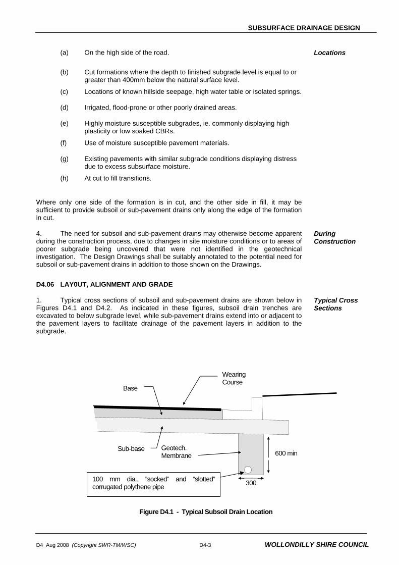
SUBSURFACE DRAINAGE DESIGN
D4 Aug 2008 (Copyright SWR-TM/WSC) D4-3 WOLLONDILLY SHIRE COUNCIL
(a) On the high side of the road. Locations
(b) Cut formations where the depth to finished subgrade level is equal to or greater than 400mm below the natural surface level.
(c) Locations of known hillside seepage, high water table or isolated springs.
(d) Irrigated, flood-prone or other poorly drained areas.
(e) Highly moisture susceptible subgrades, ie. commonly displaying high plasticity or low soaked CBRs.
(f) Use of moisture susceptible pavement materials.
(g) Existing pavements with similar subgrade conditions displaying distress due to excess subsurface moisture.
(h) At cut to fill transitions.
Where only one side of the formation is in cut, and the other side in fill, it may be sufficient to provide subsoil or sub-pavement drains only along the edge of the formation in cut.
4. The need for subsoil and sub-pavement drains may otherwise become apparent during the construction process, due to changes in site moisture conditions or to areas of poorer subgrade being uncovered that were not identified in the geotechnical investigation. The Design Drawings shall be suitably annotated to the potential need for subsoil or sub-pavement drains in addition to those shown on the Drawings.
During Construction
D4.06 LAY0UT, ALIGNMENT AND GRADE
1. Typical cross sections of subsoil and sub-pavement drains are shown below in Figures D4.1 and D4.2. As indicated in these figures, subsoil drain trenches are excavated to below subgrade level, while sub-pavement drains extend into or adjacent to the pavement layers to facilitate drainage of the pavement layers in addition to the subgrade.
Typical Cross Sections
Figure D4.1 - Typical Subsoil Drain Location
Base
Sub-base
Wearing Course
Geotech. Membrane 600 min
300100 mm dia., ”socked” and “slotted” corrugated polythene pipe

SUBSURFACE DRAINAGE DESIGN
WOLLONDILLY SHIRE COUNCIL D4-4 D4 Aug 2008 (Copyright SWR-TM/WSC)
Figure D4.2 - Typical Sub pavement Drain (in existing kerbed road)
2. In existing kerbed roads, the two acceptable alternative locations for the line of the trench are directly in front of or behind the kerbline. Pavement layers must extend to at least the line of the rear of the trench as shown in Figure D4.2.
Existing Kerbed Roads
3. In unkerbed roads, subsoil and sub-pavement drains shall be located within the shoulder, preferably at the edge of the pavement layers. .
Unkerbed Roads
4. The minimum desirable longitudinal design grade shall be 1.0 - 1.5%. For non corrugated pipes, an absolute minimum grade of 0.5% is acceptable.
Grade
5. Trench widths shall be a minimum of 300mm, with a minimum depth below finished subgrade level of 600mm in earth and 450mm in rock, and below the invert level of any service crossings.
Trench Dimensions
6. Outlets shall be spaced at maximum intervals of 150 metres. Where possible, subsoil and sub-pavement drainage pipes shall discharge into gully pits or other stormwater drainage structures. Where not possible, outlets shall be provided through fill batters.
Outlets
7. Cleanouts are to be provided in accordance with Council drawing WSC.D4.1 at the commencement of each run of drain, and at intervals not exceeding 80 metres. Cleanouts shall generally be located directly at the rear of kerb or at the edge of shoulder, as applicable.
8. Fill Material: The subsoil drainage trench shall be backfilled with average 10 mm aggregates of crushed stone or recycled concrete to the level bottom of the subbase layer.
Cleanouts
FOUNDATION DRAINS
D4.07 WARRANTS FOR USE
1. Foundation drains are designed to drain excessive ground water areas within the foundation of an embankment or the base of cutting, or to intercept water from entering these areas.
Foundation Drains
2. The need to provide foundation drains may be apparent from the results of the geotechnical survey along the proposed road formation alignment, and in this case the
Geotechnical Survey During
300
Base
Sub-base
Wearing Course
300
Alternative locations for subsoil or sub-pavement drains
in existing kerbed roads
600 min

SUBSURFACE DRAINAGE DESIGN
D4 Aug 2008 (Copyright SWR-TM/WSC) D4-5 WOLLONDILLY SHIRE COUNCIL
location shall be shown on the plans. However, more commonly, the need to provide foundation drains is determined during construction, and hence in this situation requirements and locations cannot be ascertained at the design stage.
Construction
3. Where the road formation traverses known swampy, flood-prone, or watercharged strata, the design Drawings shall be suitable annotated to the potential need for foundation drains at various locations, in addition to those shown on the Drawings.
D4.08 LAYOUT, ALIGNMENT AND GRADE
1. Typical cross-sections of foundation drains are shown below in Figure D4.3. Typical Cross Section
Figure D4.3 - Foundation Drains
2. The minimum desirable design grade shall be 1.0 - 1.5%. For non corrugated pipes an absolute minimum grade of 0.5% is acceptable.
Grade
3. Foundation drains shall be a minimum trench width of 300mm, with a variable trench depth to suit the application and ground conditions on site.
Trench Dimensions
4. Outlets shall be spaced at maximum intervals of 150 metres. Outlets
5. Where practicable, cleanouts are to be provided at the commencement of each run of foundation drain and at intervals not exceeding 80 metres. Where not practicable to provide intermediate cleanouts, outlets shall be spaced at maximum intervals of 100 metres.
Cleanouts
DRAINAGE MATS (BLANKETS)
D4.09 WARRANTS FOR USE
1. Type A drainage mats are designed where there is a need to ensure continuity of a sheet flow of water under fills, to collect surface seepage from a wet seepage area, or for protection of vegetation or habitat downstream of the road reserve where a fill would otherwise cut the flow of water. Type A drainage mats are constructed after the site has been cleared and grubbed and before commencement of embankment construction.
Type A Mats
2. Type B drainage mats are designed where there is a need to intercept water which would otherwise enter pavements by capillary action or by other means on fills and to intercept and control seepage water and springs in the floors of cuttings. Type B drainage mats shall be constructed after completion of the subgrade construction and before construction of the pavement.
Type B Mats
Seepage(spring)
Engineered Embankment
Possible Additional Drain
Existing Subgrade

SUBSURFACE DRAINAGE DESIGN
WOLLONDILLY SHIRE COUNCIL D4-6 D4 Aug 2008 (Copyright SWR-TM/WSC)
3. The need to design for the provision of drainage mats should be apparent from the result of the geotechnical survey along the proposed road formation alignment.
Geotechnical Survey
MATERIALS
D4.10 SUBSOIL AND SUB-PAVEMENT DRAIN PIPE
1. Pipes designated for subsoil, foundation and sub-pavement drains shall be 100mm ø slotted pipe.
2. Corrugated plastic pipe shall be Class 1000 conforming to the requirements of AS2439.1. Joints, couplings, elbows, tees and caps shall also comply with AS2439.1.
3. Slotted fibre reinforced cement pipe shall be designated type “100 DMR” meeting the requirements of RTA Specification No. 3555..
4. Slotted rigid UPVC pipe shall be of a type and class approved by Council.
5. All pipe shall be slotted, and fitted with seamless tubular filter fabric complying with MR Form 1160, except for cleanouts and outlets through fill batters which shall be unslotted pipe.
D4.11 INTRA PAVEMENT DRAIN PIPE
1. Pipes for use in Type B Drainage Mats shall be designated 100mm diameter slotted fibre reinforced concrete pipe, meeting the requirements of RTA Specification 3555.
2. Pipes for use in intra pavement drains where crushed rock subbase layer thicknesses are greater than 200mm shall be designated 100mm diameter slotted fibre reinforced concrete pipe, meeting the requirements of RTA Specification 3555.
3. Pipes for use in for edge drains where any part of the shoulder consists of material other than concrete, and shall be designated 100mm diameter slotted fibre reinforced concrete pipe, meeting the requirements of RTA Specification 3555.
D4.12 FILTER MATERIAL
1. The types of filter material covered by this Specification shall include:
(a) Type A filter material for use in subsoil, foundation, and sub-pavement (trench) drains and for Type B drainage mats.
(b) Type B filter material for use in subsoil, foundation and sub-pavement (trench) drains.
(c) Type C filter material comprising crushed rock for use in Type A drainage mats.
(d) Type D filter material comprising uncrushed river gravel for use in Type A drainage mats.
2. Material requirements and gradings for each type of filter material are included in the Construction Specification, SUBSURFACE DRAINAGE GENERAL.
3. The type of filter material specified to backfill the sub-surface drainage trenches (subsoil, foundation and sub-pavement drains) shall depend on the permeability of the pavement layers and/or subgrade and the expected flow rate. Generally, Type A filter

SUBSURFACE DRAINAGE DESIGN
D4 Aug 2008 (Copyright SWR-TM/WSC) D4-7 WOLLONDILLY SHIRE COUNCIL
material is used for the drainage of highly permeable subgrade or pavement layers such as crushed rock or coarse sands, while Type B filter material is used for the drainage of subgrade and pavement layers of lower permeability such as clays, silts or dense graded gravels. Further guidance to the selection of appropriate filter material is contained in ARRB Special Report 35.
D4.13 GEOTEXTILE
1. Where necessary to provide separation (ie. prevent infiltration of fines) between the filter material in the trench and the subgrade or pavement material, geotextile shall be designated to encapsulate the filter material. The geotextile shall comply with the requirements included in the Construction Specification, SUBSURFACE DRAINAGE GENERAL.
2. Geotextile shall also be designated for both Type A and Type B Drainage Mats.
STANDARD DRAWINGS
D4.100 LIST OF DRAWINGS List of Drawings
1. DRAWING NUMBER DRAWING DESCRIPTION WSC.D4.1 Subsoil Drainage Clean Outs


STORMWATER DRAINAGE DESIGN
D5 Aug 2008 (Copyright SWR-TM/WSC) WOLLONDILLY SHIRE COUNCIL
DESIGN SPECIFICATION
D5
STORMWATER
DRAINAGE DESIGN


STORMWATER DRAINAGE DESIGN
D5 Aug 2008 (Copyright SWR-TM/WSC) WOLLONDILLY SHIRE COUNCIL
Amendment Record for this Specification Part
This Specification is Council’s edition of the AUS-SPEC generic specification part and includes Council’s primary amendments.
Details are provided below outlining the clauses amended from the Council edition of this AUS-SPEC Specification Part. The clause numbering and context of each clause are preserved. New clauses are added towards the rear of the specification part as special requirements clauses. Project specific additional script is shown in the specification as italic font. The amendment code indicated below is ‘A’ for additional script ‘M’ for modification to script and ‘O’ for omission of script. An additional code ‘P’ is included when the amendment is project specific.
Amendment Sequence No.
Key Topic addressed in amendment
Clause No. Amendment Code
Author Initials
AmendmentDate
1 Water Sensitive Urban Design D5.02 A IB 1/7/08
2 Reference Documents D5.03 A IB 1/7/08
3 Percentage Impervious D5.06 A IB 1/7/08
4 DRAINS/ILASX & RAFTS Parameters & Rainfall Data D5.07 A IB 1/7/08
5 Hydraulic Calculation by Computer Models D5.08 A IB 1/7/08
6 Minor System Gutter Flow Widths, Pipe grades D5.09 M IB 1/7/08
7 Pits at intersections and access; Lintel size and Bypass Flows D5.10 MA IB 1/7/08
8 Freeboard in major systems and gutter flow depth D5.12 M IB 1/7/08
9 Freeboard major structures D5.14 MA IB 1/7/08
10 OSD requirements D5.06 AD IB 1/7/08
11 Cover to property drainage pipes D5.26 M IB 1/7/08
12 Absorption trench, charged lines D5.27 MA IB 1/7/08
13 Freeboard to overland flow path D5.29 M IB 1/7/08
14 Buildings and flow paths D5.30 A IB 1/7/08
15 Stormwater treatment requirements and riparian vegetation. D5.33 AD IB 1/7/08
16 Wetlands D5.37 D IB 1/7/08
17 Salinity D5.02 A IB 1/7/08


STORMWATER DRAINAGE DESIGN
D5 Aug 2008 (Copyright SWR-TM/WSC) WOLLONDILLY SHIRE COUNCIL
SPECIFICATION D5 : STORMWATER DRAINAGE DESIGN
CONTENTS
CLAUSE PAGE
GENERAL .............................................................................................................................1
D5.01 SCOPE..............................................................................................................................................1
D5.02 OBJECTIVES....................................................................................................................................1
D5.03 REFERENCE AND SOURCE DOCUMENTS ..................................................................................2
HYDROLOGY .......................................................................................................................3
D5.04 DESIGN RAINFALL DATA ...............................................................................................................3
D5.05 CATCHMENT AREA.........................................................................................................................4
D5.06 RATIONAL METHOD........................................................................................................................4
D5.07 OTHER HYDROLOGICAL MODELS................................................................................................5
HYDRAULICS .......................................................................................................................6
D5.08 HYDRAULIC GRADE LINE ..............................................................................................................6
D5.09 MINOR SYSTEM CRITERIA FOR STREET AND TRUNK DRAINAGE ..........................................7
D5.10 PITS ..................................................................................................................................................7
D5.11 HYDRAULIC LOSSES......................................................................................................................8
D5.12 MAJOR SYSTEM CRITERIA............................................................................................................9
D5.13 OPEN CHANNELS .........................................................................................................................10
D5.14 MAJOR STRUCTURES..................................................................................................................12
D5.15 RETARDING STRUCTURES .........................................................................................................13
STORMWATER DETENTION.............................................................................................15
D5.16 STORMWATER DETENTION ........................................................................................................15
INTERALLOTMENT DRAINAGE........................................................................................15
D5.17 INTERALLOTMENT DRAINAGE....................................................................................................15
DETAILED DESIGN............................................................................................................17

STORMWATER DRAINAGE DESIGN
WOLLONDILLY SHIRE COUNCIL D5 Aug 2008 (Copyright SWR-TM/WSC)
D5.18 CONDUITS .....................................................................................................................................17
D5.19 PIT DESIGN....................................................................................................................................17
D5.20 STORMWATER DISCHARGE........................................................................................................17
D5.21 MISCELLANEOUS..........................................................................................................................18
DOCUMENTATION.............................................................................................................18
D5.22 PLANS – See DSQ .........................................................................................................................18
D5.23 EASEMENTS AND AGREEMENTS – See DSQ............................................................................18
D5.24 SUMMARY SHEETS - See DSQ....................................................................................................18
D5.25 COMPUTER PROGRAM FILES AND PROGRAM OUTPUT - See DSQ......................................18
PROPERTY DRAINAGE.....................................................................................................18
D5.26 PROPERTY DRAINAGE SYSTEMS ..............................................................................................18
D5.27 DISPOSAL OF PROPERTY STORMWATER ................................................................................20
D5.28 BUILDING ON LOTS BURDENED BY A DRAINAGE EASEMENT...............................................23
MANAGING PROPERTY INUNDATION.............................................................................24
D5.28 GENERAL .......................................................................................................................................24
D5.29 SUBDIVISION OF LAND AFFECTED BY OVERLAND FLOW......................................................24
D5.30 BUILDINGS ON FLOOD AFFECTED LAND ..................................................................................24
D5.31 FLOOD HAZARD............................................................................................................................25
D5.32 MISCELLANEOUS FLOOD MANAGEMENT ISSUES...................................................................26
WATER QUALITY...............................................................................................................26
D5.33 GENERAL .......................................................................................................................................26
D5.36 GROSS POLLUTANT TRAPS........................................................................................................29
D5.37 WETLANDS ....................................................................................................................................29
STANDARD DRAWINGS....................................................................................................32
D5.100 LIST OF DRAWINGS......................................................................................................................32
ANNEXURES D5-A RAINFALL INTENSITY FREQUENCY DURATION TABLES

STORMWATER DRAINAGE DESIGN
D5 Aug 2008 (Copyright SWR-TM/WSC) D5-1 WOLLONDILLY SHIRE COUNCIL
SPECIFICATION D5 : STORMWATER DRAINAGE DESIGN
GENERAL
D5.01 SCOPE
1. The work to be executed under this Specification consists of the design of stormwater drainage systems for urban and rural areas.
D5.02 OBJECTIVES
1. The objectives of stormwater drainage design are as follows:
(a) To ensure that inundation of private and public buildings located in flood-prone areas occurs only on rare occasions and that, in such events, surface flow routes convey floodwaters below the prescribed velocity/depth limits.
(b) To provide convenience and safety for pedestrians and traffic in frequent stormwater flows by controlling those flows within prescribed limits.
(c) Retain within each catchment as much incident rainfall and runoff as is possible and appropriate for the planned use and the characteristics of the catchment.
(d) To ensure the ecosystem integrity of Wollondilly’s waterways is maintained and enhanced.
2. In pursuit of these objectives, the following principles shall apply:
(a) New Developments are to provide a stormwater drainage system in accordance with the "major/minor" system concept set out in Chapter 14 of Australian Rainfall & Runoff, 1987 (ARR 1987); that is, the "major" system shall provide safe, well-defined overland flow paths for rare and extreme storm runoff events while the "minor" system shall be capable of carrying and controlling flows from frequent runoff events.
Design Principles
(b) The design of the drainage system, and earthworks, for the development shall be such that the upstream drainage is not adversely affected and that the downstream drainage system is capable of carrying any increased discharges from the development. Such measures should include, but not be limited to, investigation of upgrading the existing downstream system and an investigation of providing stormwater retarding basins.
(c) The minor drainage system shall connect to a legal point of discharge acceptable to Council. The major drainage system shall be designed to ensure adjoining downstream properties will not be adversely affected as a result of the development.
(d) Water Sensitive Urban Design (WSUD) principles and stormwater treatment shall be considered in the design of the drainage system for developments as outlined in ‘Australian Runoff Quality – a Guide to Water Sensitive Urban Design’.

STORMWATER DRAINAGE DESIGN
WOLLONDILLY SHIRE COUNCIL D5-2 D5 Aug 2008 (Copyright SWR-TM/WSC)
(e) Information provided by the NSW Government that indicates salinity may occur in parts of the Wollondilly Local Government Area (LGA). This salinity potential is due to inherent characteristics of the Wollondilly LGA landscape. As a result, buildings and other infrastructure in the Wollondilly LGA may be susceptible to salt damage.
The applicant must thoroughly investigate the site to determine if there are any salinity issues to be addressed. The designer shall address salinity in their design. Steps taken may include, but are not limited to:
• Minimising depth of excavation/disturbance required for roadworks;
• Minimising infiltration of surface waters by providing adequate sub-soil drainage;
• Provision of adequate drainage for upstream catchments; and
• Use of appropriate materials in construction of roadworks.
Designers should also follow guidelines set out in Department of Infrastructure, Planning and natural Resources (2003) Guide: Roads and Salinity (ISBN: 0 73475377 2).
Salinity
D5.03 REFERENCE AND SOURCE DOCUMENTS
(a) Council Specifications
Specifications as amended:
C220 - Stormwater Drainage – General C221 - Pipe Drainage C222 - Precast Box Culverts C223 - Drainage Structures C224 - Open Drains including Kerb & Gutter
(b) Australian Standards AS 1254 - Unplasticised PVC (uPVC) pipes and fittings for stormwater
or surface water applications. AS 2032 - Code of practice for installation of uPVC pipe systems. AS 3725 - Loads on buried concrete pipes. AS 4058 - Precast concrete pipes. AS 4139 - Fibre reinforced concrete pipes and fittings.
(c) State Authorities RTA, NSW - Model Analysis to determine Hydraulic Capacities of Kerb
Inlets and Gully Pit Gratings, 1979. Department of Infrastructure, Planning and Natural Resources Guide: Roads and Salinity (2003) (ISBN: 0 73475377 2)
(d) Other AUSTROADS - Bridge Design Code. Inst. of Eng. Aust -Australian Rainfall and Runoff – A guide to flood estimation.
Aug 1987. Queensland Urban Drainage Manual, Volumes 1 & 2, 1993. Sangster, WM., Wood, HW., Smerdon, ET., and Bossy, HG. - Pressure Changes at Storm Drain Junction, Engineering
Series, Bulletin No. 41, Eng. Experiment Station, Univ. of Missouri 1958.
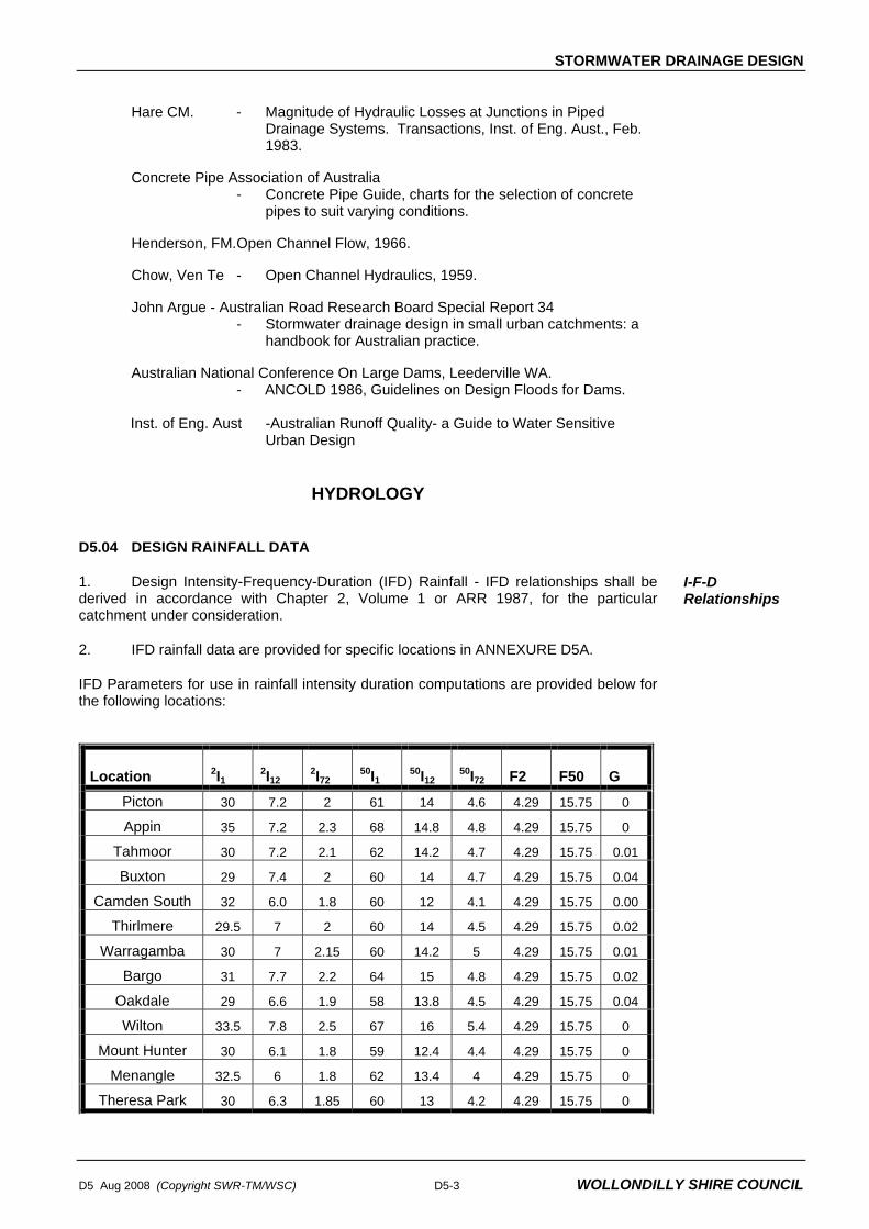
STORMWATER DRAINAGE DESIGN
D5 Aug 2008 (Copyright SWR-TM/WSC) D5-3 WOLLONDILLY SHIRE COUNCIL
Hare CM. - Magnitude of Hydraulic Losses at Junctions in Piped
Drainage Systems. Transactions, Inst. of Eng. Aust., Feb. 1983.
Concrete Pipe Association of Australia - Concrete Pipe Guide, charts for the selection of concrete
pipes to suit varying conditions. Henderson, FM. Open Channel Flow, 1966. Chow, Ven Te - Open Channel Hydraulics, 1959. John Argue - Australian Road Research Board Special Report 34 - Stormwater drainage design in small urban catchments: a
handbook for Australian practice. Australian National Conference On Large Dams, Leederville WA.
- ANCOLD 1986, Guidelines on Design Floods for Dams.
Inst. of Eng. Aust -Australian Runoff Quality- a Guide to Water Sensitive Urban Design
HYDROLOGY
D5.04 DESIGN RAINFALL DATA
1. Design Intensity-Frequency-Duration (IFD) Rainfall - IFD relationships shall be derived in accordance with Chapter 2, Volume 1 or ARR 1987, for the particular catchment under consideration.
I-F-D Relationships
2. IFD rainfall data are provided for specific locations in ANNEXURE D5A.
IFD Parameters for use in rainfall intensity duration computations are provided below for the following locations:
Location 2I1 2I12 2I72 50I1 50I12 50I72 F2 F50 G Picton 30 7.2 2 61 14 4.6 4.29 15.75 0
Appin 35 7.2 2.3 68 14.8 4.8 4.29 15.75 0
Tahmoor 30 7.2 2.1 62 14.2 4.7 4.29 15.75 0.01
Buxton 29 7.4 2 60 14 4.7 4.29 15.75 0.04
Camden South 32 6.0 1.8 60 12 4.1 4.29 15.75 0.00
Thirlmere 29.5 7 2 60 14 4.5 4.29 15.75 0.02
Warragamba 30 7 2.15 60 14.2 5 4.29 15.75 0.01
Bargo 31 7.7 2.2 64 15 4.8 4.29 15.75 0.02
Oakdale 29 6.6 1.9 58 13.8 4.5 4.29 15.75 0.04
Wilton 33.5 7.8 2.5 67 16 5.4 4.29 15.75 0
Mount Hunter 30 6.1 1.8 59 12.4 4.4 4.29 15.75 0
Menangle 32.5 6 1.8 62 13.4 4 4.29 15.75 0
Theresa Park 30 6.3 1.85 60 13 4.2 4.29 15.75 0

STORMWATER DRAINAGE DESIGN
WOLLONDILLY SHIRE COUNCIL D5-4 D5 Aug 2008 (Copyright SWR-TM/WSC)
3. Design Average Recurrence Interval (ARI) - For design under the "major/minor" concept, the design ARIs to be used are given below.
4. Recurrence interval for minor events depends on the zoning of the land being serviced by the drainage system. The minor system design ARIs are detailed below:- • 20 years for commercial/industrial area "minor" systems • 10 years for residential area "minor" systems • 5 years for rural residential and rural area "minor" systems • 1 year for parks and recreation area "minor" systems.
• 10 years for residential property and interallotment drainage “minor” systems • 20 years for commercial/industrial property drainage “minor” systems.
Average Recurrence Intervals
5. Where a development is designed in such a way that the major system flows involve surcharge across private property, then the underground system (both pipes and inlets) may need to be upsized to ensure flow across the property meets the standards outlined in section D5.29. A surcharge path shall be defined for systems even where 100 year ARI flows can be maintained within the system. Easements and Restrictions as to use are to be provided in private property over pipe systems and surcharge paths.
D5.05 CATCHMENT AREA
1. The catchment area of any point is defined by the limits from where surface runoff will make its way, either by natural or man made paths, to this point. Consideration shall be given to likely changes to individual catchment areas due to the full development of the catchment.
Catchment Definition
2. Where no detailed survey of the catchment is available, 1:4000 orthophoto maps are to be used to determine the catchments and to measure areas.
3. Catchment area land use shall be based on current available zoning information and likely future zonings, where applicable.
D5.06 RATIONAL METHOD
1. Use of the Rational Method for determining flowrates from urban catchments will be acceptable when the catchment is relatively small (approximately 10 ha). The Rational method can be used to determine runoff from rural catchments with an area of below 25km2. Rational Method calculations to determine peak flows shall be carried out in accordance with Chapter 5 and 14, AR&R 1987 and the requirements of this Specification..
2. Details of percentage impervious for various land uses are given in table D5.1 and should be used where actual information is not available.
Land Use % Impervious
Residential (10 lots/hectare) Medium Density (15 lots/hectare) Rural Residential Industrial/Commercial Road Reserve Public Recreation Area
40% 60% 30% 90% 70% 10%

STORMWATER DRAINAGE DESIGN
D5 Aug 2008 (Copyright SWR-TM/WSC) D5-5 WOLLONDILLY SHIRE COUNCIL
3. Times of Concentration - The time of concentration of a catchment is defined as the time required for storm runoff to flow from the most remote point on the catchment to the outlet of the catchment.
Times of Concentration
4. Where the flow path is through areas having different flow characteristics or includes property and roadway, then the flow time of each portion of the flow path shall be calculated separately and combined using the procedure outlined in AR&R 1987, Technical Note 3.
5. The maximum time of concentration in an urban area shall be 15 minutes unless sufficient evidence is provided to justify a greater time.
6. Flow paths to pits shall be representative of the fully developed catchment considering such things as fencing and the likely locations of buildings and shall be shown for each collection pit on the catchment area plan. Consideration shall be given to likely changes to individual flow paths due to the full development of the catchment.
7. Surface roughness co-efficients "n" shall generally be derived from information in Chapter 14 of AR&R 1987. Values applicable to specific zoning types and overland flow path types are given below:
Overland Flow Retardance
Flow across Parks 0.35 Flow across Pasture 0.35 Flow across Rural Residential land 0.30 Flow across Residential (2b) 0.11 Flow across Industrial 0.06 Flow across Commercial 0.04 Flow across Paved Areas 0.01 Flow across Asphalt Roads 0.02 Flow across Gravel Areas 0.02
D5.07 OTHER HYDROLOGICAL MODELS
1. Other hydrological models may be used as long as the requirements of AR&R 1987 are met, summaries of calculations are provided and details are given of all program input and output. A sample of a summary sheet for hydrological calculations is given in the Council publication SUBMISSION REQUIREMENTS FOR ENGINEERING DESIGN.
Alternative Models
2. Where computer analysis programs are used, copies of the final data files and results of computer run shall be provided on submission of the design to Council and with the final drawings.
3. Where hydrological analysis is carried out using DRAINS/ILSAX, following parameter values shall be adopted in the absence of calibrated data.
Parameter Value
Impervious depression 1mm
Pervious depression 5mm
Soil Type 3
AMC 3
DRAINS/ILSAX

STORMWATER DRAINAGE DESIGN
WOLLONDILLY SHIRE COUNCIL D5-6 D5 Aug 2008 (Copyright SWR-TM/WSC)
4. Where hydrologic modelling is carried out using RAFTS model, following parameter shall be used:
Initial Loss: Continuing Loss :
Impervious 10 mm Impervious 0 mm/hr
Pervious 0 mm Pervious 2.5 mm/hr
RAFTS
HYDRAULICS
D5.08 HYDRAULIC GRADE LINE
1. Hydraulic calculations shall generally be carried out in accordance with Australian Rainfall and Runoff 1987 and shall be undertaken by a qualified person experienced in hydrologic and hydraulic design. The calculations shall substantiate the hydraulic grade line adopted for design of the system and shown on the drawings. Summaries of calculations are added to the plan and details of all calculations are given including listings of all programme input and output. A sample of a summary sheet for hydraulic calculations is given in the Council's publication SUBMISSION REQUIREMENTS FOR ENGINEERING DESIGN.
Qualified Person
Calculations
2. The "major" system shall provide safe, well-defined overland flow paths for rare and extreme storm runoff events while the "minor" system shall be capable of carrying and controlling flows from frequent runoff events.
3. Downstream water surface level requirements are given below:-
(a) Known hydraulic grade line level from downstream calculations including pit losses at the starting pit in the design event.
Downstream Control
(b) Where the downstream starting point is a pit and the hydraulic grade line is unknown, a level equal to the surface level of the pit inlet in the downstream pit is to be adopted.
(c) Where the outlet is an open channel and the design storm is the minor event the top of the outlet pipe shall be the downstream control.
(d) Where the outlet is an open channel and the design storm is the major event, the downstream control shall be the greater of either the top of the outlet pipe or the 1% probability flood level.
4. The water surface in drainage pits during the minor system design storm shall be limited to 0.150m below the gutter invert for inlet pits and 0.150m below the underside of the lid for junction pits.
Water Surface Limits
5. Where the hydraulic calculations are performed by the use of computer model, electronic files of computer input data and results shall be provided to the Principal Certifying Authority for checking.
6. Where the hydraulic calculations are carried out by running computer models such as DRAINS, HECRAS, SWMM, MOUSE etc. the results from these model shall be calibrated against measured flows, depth etc. If the calibration of the model is not possible due to lack of data, outputs from the model shall be checked against output from a rational/manual method of calculation or the output from another model. Acceptance of the model output shall the consideration of the Principal Certifying Authority.

STORMWATER DRAINAGE DESIGN
D5 Aug 2008 (Copyright SWR-TM/WSC) D5-7 WOLLONDILLY SHIRE COUNCIL
D5.09 MINOR SYSTEM CRITERIA FOR STREET AND TRUNK DRAINAGE
1. The acceptable gutter flow limit is 1.0 (for a road with carriageway width 6-8m) to 2.5 (for a road with carriageway width 13m) metres maximum width for a minor system. The maximum gutter depth is 150 mm. In streets with a low level footpath the maximum flow depth shall be 75mm. Table drains should be sized to ensure table drain flows do not extend beyond the road shoulder.
Gutter Flow Widths
2. Gutter and table drain flows greater than 20 l/s will not be permitted to flow across an intersection. It will be necessary to intercept these flows with a kerb inlet pit or culvert.
3. Minimum conduit sizes are given below: • The minimum pipe size shall be 375mm diameter. • The minimum box culvert size shall be 600mm wide x 300mm high.
Conduit Sizes
4. Minimum and maximum velocity of flow in stormwater pipelines shall be 0.6m/sec and 6m/sec respectively.
Velocity Limits
5. The minimum pipe grade shall generally be 0.5%. Pipe grades less than 0.5% may be considered for pipes larger than 900 mm dia. Pipes with a grade greater than 20% will require anchor blocks at the top and bottom and at intervals not exceeding 3.0m.
Pipe Grades
D5.10 PITS
1. Inlet Pits shall be spaced so that the gutter flow width is limited in accordance with this specification and so that the inlet efficiency is not affected by adjacent inlet openings. Preference shall be given to the location of drainage pits near the centre of lots or with lintels central on lot boundaries. Location of inlet pits on kerb returns in line with normal pedestrian flow is to be avoided. The designer shall ensure that the kerb inlet pits are located clear of the tangent points on kerb returns.
Spacing
2. Other pits shall be provided
• To enable access for maintenance. • At changes in direction, grade, level or class of pipe. • At junctions.
3. The maximum recommended spacing of pits where flow widths are not critical is:
Pipe Size (mm) Spacing (m)
Less than 1200 100
1200 or larger 150
Table D5.1 Pit Spacing
4. Maximum kerb inlet lengths to side entry pits are to be a preferred maximum of 2.4m, with an absolute maximum of 3.0m where the grade is 10% or more. The designer shall minimise use of any lintel longer than 2.4 metres.
5. Inlet pits must be sufficiently large to permit the design inflow. Information on pit capacities is available in the following sources:-
• Roads and Traffic Authority’s "Model analysis to determine Hydraulic Capacities of Kerb Inlets and Gully Pit Gratings", with due allowance to inlet bypass due to grade, for on-grade pits, and recognised orifice or weir formulae for sag inlet pits.
• Pit relationships given in Chapter 14 of AR&R 1987
Inlet Capacity

STORMWATER DRAINAGE DESIGN
WOLLONDILLY SHIRE COUNCIL D5-8 D5 Aug 2008 (Copyright SWR-TM/WSC)
6. None of these pit charts include any blockage factors. The percentage of theoretical capacity allowed in relation to type of pit is given below:-
Allowance for Inlet Blockage
Condition Inlet Type Percentage of Theoretical Capacity Allowed
Sag Side entry 80%
Sag Grated 50%
Sag Combination Side inlet capacity only Grate assumed completely blocked
Sag "Letterbox" 50%
Continuous Grade Side entry 80%
Continuous Grade Grated 50%
Continuous Grade Combination 90%
Table D5.2
7. All pits shall be sized in accordance with table D5.3 to allow access for maintenance purposes.
Pit Depth (mm) Minimum pit Size (mm)
< 300
300 – 600 600-1200 1200-1500
>1500
300 x 300 450 x 450 600 x 600 900 x 600
900x900 include steel reinforcement in wall
Table D5.3
8. Pits deeper than 600mm shall have a minimum 600mm x 600mm opening. Pits deeper than 1.2 metres shall have climb irons in accordance with drawing WSC.D5.3.
9. Bypass flow at a pit shall not exceed 20% of the approach flow for the critical design rainfall.
10. Pits 3.0 metres and deeper and greater than 2.0 metres in internal dimension are to be designed by a Structural Engineer.
D5.11 HYDRAULIC LOSSES
1. Losses at junction pits, slope junctions, bends, transition structures, end pits and outlets shall be considered. Reasonable pressure change co-efficients are to be selected using Missouri Charts, Hare Charts and U.S corp of Engineers mitre bend charts.
Pit Losses
2. Allowable reduction in "KU" due to benching is given in Missouri Charts.
3. Computer program default pressure change co-efficient "KU" shall not be acceptable unless they are consistent with above charts. The chart used and relevant co-efficients for determining pit “K" values from that chart shall be noted on the hydraulic summary sheet provided for plan checking and included on the final design drawings.
STORMWATER DRAINAGE DESIGN
D5 Aug 2008 (Copyright SWR-TM/WSC) D5-9 WOLLONDILLY SHIRE COUNCIL
4. Bends may be permissible in certain circumstances and discussions with Council regarding their use is required prior to detailed design.
Bend Losses
5. Requirements for private pipes entering Council's system are in section D5.27
6. Construction of a junction without a structure should be avoided where possible. Permission to do this is required by Council prior to detailed design.
Pipe Junction Losses
7. Going from larger upstream to smaller downstream conduits is not permitted without approval of Council prior to detailed design. In going from smaller to larger pipes benching shall be provided in pits to enable a smooth flow transition.
Contraction/ Expansion Losses
8. Drainage pipe systems shall be designed as an overall system incorporating pipe and all other losses, with due regard to the upstream and downstream system and not as individual pipe lengths. Drainage pipeline systems shall generally be designed as gravity systems flowing full at design discharge, but may be pressurised with the use of appropriate pits and joints only with Council approval. Pipe friction losses and pipe sizes in relation to discharge shall be determined using the Colebrook-White formula with the acceptable roughness co-efficient being 0.6mm for concrete pipes, 0.3mm for FRC and polyethylene and 0.03 for uPVC pipes.
Pipe Friction Losses
D5.12 MAJOR SYSTEM CRITERIA
1 All drainage designs shall incorporate an assessment of major system flows. The major system provides a safe and adequate “escape route” for stormwater from rare and extreme storm events.
2 The design standard for the major system is the 1% AEP event. Consideration should be given to the potential impacts of rarer storms events. Analysis of the impact of the Probable Maximum Flood (PMF) is required in instances where the quantity of stormwater is such that catastrophic failure of the proposed system/structures may place life and limb at risk.
3 The system shall be designed to ensure drainage from upstream entering the subdivision is not obstructed or adversely affected such that flow depths on adjoining properties will be increased.
4 Roads, pathways, open space reserves and drainage reserves will generally form the flow path by which the major system flows are safely routed through a new subdivision. Using private properties as part of the major flow path should be avoided where possible. Where the major flow path is through a private property, the requirements outlined in section D5.29 shall apply.
5 Reverse crossfall shall be used where the overland flow path crosses the footway.
6 Surcharging of drainage systems which would provide for water depth above the top of kerb will not be permitted except as defined below. Surcharging of drainage system for storm frequencies greater than the design minor storm event may be permitted across the road centreline where the road pavement is below the natural surface of the adjoining private property. Flow across footpaths will only be permitted in situations specifically approved by Council.
Surcharging

STORMWATER DRAINAGE DESIGN
WOLLONDILLY SHIRE COUNCIL D5-10 D5 Aug 2008 (Copyright SWR-TM/WSC)
7. The velocity x depth product of flow across the footpath and within the road reserve shall be such that safety of children and vehicles is considered. The maximum allowable depth of water is 0.2 metres and the maximum velocity x depth product of 0.4m2/s is permitted. Where the safety of only vehicles can be affected, a maximum velocity x depth product of 0.6m2/s is permitted. In open channels and flowpaths through public and drainage reserves the above velocity x depth product criteria will be followed where possible or the design shall address the requirements for safety in relation to children by providing safe egress points from the channel or other appropriate methods.
Velocity/ Depth Criteria
8. Freeboard requirements for floor levels and levee bank levels from flood levels in open channels, roadways and stormwater surcharge paths are given below:
Generally:-
(a) A minimum freeboard of 0.5m shall be provided between the 100 year flood level and floor levels on structures and entrances to underground car parks. A higher freeboard may be required in certain circumstances.
(b) Where the road is in fill or overtopping of kerbs and flow through properties may occur a 100mm freeboard shall be provided between the ponding level of water in the road and the high point in the footpath. Driveway construction in these instances needs to consider this requirement.
Freeboard
In Surcharge Paths:-
(c) A minimum freeboard of 0.5m shall be provided between the 100 year flood level and floor levels on structures and entrances to underground car parks.
In Open Channels:-
(d) A minimum freeboard of 0.5m shall be provided between the 100 year flood level and floor levels on structures and entrances to underground car parks.
9. Flow capacities of roads should be calculated using Technical Note 4 in Chapter 14 of AR&R 1987.
Roadway Capacities
10. The major drainage system shall be designed to ensure adjoining downstream properties will not be adversely affected as a result of the development. Where it is proposed to divert, re-direct or intensify the flow of stormwater into adjoining property, a “permit to discharge stormwater” shall be sought and submitted to Council prior to the approval of Engineering design plans. The above shall apply unless otherwise specified by Council. A permit shall also be sought to carry out construction work on adjoining property and such permit also presented to Council.
11. The depth of flow in road kerb and gutter in major storm event shall not be more than 200 mm.
D5.13 OPEN CHANNELS
1. Generally, open channels will only be permitted where they form part of the trunk drainage system and shall be designed to have smooth transitions with adequate access provisions for maintenance and cleaning. Where Council permits the use of an open channel to convey flows from a development site to the receiving water body, such a channel shall comply with the requirements of this Specification.
Safety

STORMWATER DRAINAGE DESIGN
D5 Aug 2008 (Copyright SWR-TM/WSC) D5-11 WOLLONDILLY SHIRE COUNCIL
2. Design of open channels shall be generally in accordance with Chapter 14, Volume 1 of ARR 1987, and shall be designed with safety requirements as set out in Section 14.10.4 of ARR 1987 as a primary criterion. Open channels will be designed to contain the major system flow less any flow that is contained in the minor system, with an appropriate allowance for blockage of the minor system.
3. Friction losses in open channels shall be determined using Mannings "n" values given below:-
Mannings "n" Roughness Co-efficients for open channels shall generally be derived from information in Chapter 14 of AR&R 1987. Mannings "n" values applicable to specific channel types are given below:-
Concrete Pipes or Box Sections 0.011 Concrete (trowel finish) 0.014 Concrete (formed without finishing) 0.016 Sprayed Concrete (gunite) 0.018 Bitumen Seal 0.018 Bricks or pavers 0.015 Pitchers or dressed stone on mortar 0.016 Rubble Masonry or Random stone in mortar 0.028 Rock Lining or Rip-Rap 0.028 Corrugated Metal 0.027 Earth (clear) 0.022 Earth (with weeds and gravel) 0.028 Rock Cut 0.038 Short Grass 0.033 Long Grass 0.043
Channel Roughness
4. Where the product of average Velocity and maximum flow Depth for the design flow rate is greater than 0.4m2/s, the design will be required to specifically provide for the safety of persons who may enter the channel. The depth of flow in the channel should not exceed 1.2m for the 1% AEP flow.
5. Maximum side slopes on grassed lined open channels shall be 1 in 4, with a preference given to 1 in 6 side slopes, channel inverts shall generally have minimum cross slopes of 1 in 20.
Side Slopes
6. The channel shall be designed to ensure subcritical flows with the Froude Number no greater than 0.8. Measures may have to be incorporated to reduce the bed slope, such as introducing drop structures
7. Low flow provisions in open channels (man-made or altered channels) will require low flows to be contained within a pipe system or concrete lined channel section at the invert of the main channel. Subsurface drainage shall be provided in grass lined channels to prevent waterlogging of the channel bed. The width of the concrete lined channel section shall be the width of the drain invert or at least sufficiently wide enough to accommodate the full width of a tractor.
Low Flows
8. Transition in channel slopes to be designed to avoid or accommodate any hydraulic jumps due to the nature of the transition.
Hydraulic Jumps
9. Appropriate measures must be taken to protect the channel from scour. In grassed lined channels the maximum flow velocity is to be 2.5m/s. Adequate scour protection and/or energy dissipaters shall be designed at all inlets to the channel, at the channel outlet and at any point in the channel where there is a significant change in flow conditions.

STORMWATER DRAINAGE DESIGN
WOLLONDILLY SHIRE COUNCIL D5-12 D5 Aug 2008 (Copyright SWR-TM/WSC)
10. Turfing and landscaping of channels and basins should take account of possible changes to the water table and salt content. This may affect the type and species of planting; accordingly the designer may need to seek specialist advice as part of the landscape and rehabilitation design process.
11. Where a natural watercourse traverses the property, Council will generally not approve piping of the watercourse or reconstructing as a concrete or grassed lined engineered open channel. Natural watercourses have environmental benefit and their preservation is an important part of the management of the total catchment. Stream restoration or reconstruction of the stream as a ‘Natural’ channel will be acceptable. Engineered ‘Natural’ channels shall be designed with a meandering plan form, a main channel with a floodplain, a series of pools and riffle zones (rapids) and riparian and floodplain vegetation.
Engineered ‘Natural’ Watercourses
D5.14 MAJOR STRUCTURES
1. All major structures shall be designed for the 100 year ARI storm event without afflux in urban areas. Some afflux and upstream inundation may be permitted in certain rural and urban areas provided the increased upstream flooding is minimal and does not inundate private property.
Afflux
2. A minimum clearance of 0.5m between the required ARI flood level and the underside of any major structure superstructure is required to allow for passage of debris without blockage. This freeboard may need to be increased for bridges in accordance within the following table.
Freeboard
(i) Large Box Culverts and Deck used as road surface (ii) Slab, Beam, Concrete Girder or Concrete Frame Bridges across
streams where the maximum velocity is less than 3 m/s (with or without debris)
(iii) Slab, Beam, Concrete Girder or Concrete Frame Bridges across
streams where the maximum velocity is greater than 3 m/s. (iv) Plate Girder, Timber or Steel Truss Bridges across streams where
the maximum velocity is less than 3 m/s. (v) Plate Girder, Timber or Steel Truss Bridges across streams where the
maximum velocity is greater than 3 m/s.
0.5 m.
0.5m
1.0m
1.0m
1.25m
3. All bridges shall be designed for the relevant RTA/Austroad flood intensity without afflux in urban areas. The effects of the PMF shall be investigated and alterations made to the design to suit.
Bridges
4. Certified structural design shall be required on bridges and other major culvert structures and may be required on some specialised structures. Structural design shall be carried out in accordance with AUSTROADS Bridge Design Code.
5. All culverts shall be designed for 1% probability flood intensity without afflux in urban areas.
Culverts
6. Culverts (either pipe or box section) shall be designed with due regard being given to inlet and exit losses, inlet and outlet control and scour protection. Recommended design procedures are contained in Section 3 Hydraulics of Precast Concrete Conduits - Hydraulic Design Manual - by Concrete Pipe Association of Australia.

STORMWATER DRAINAGE DESIGN
D5 Aug 2008 (Copyright SWR-TM/WSC) D5-13 WOLLONDILLY SHIRE COUNCIL
7. Where culverts are used for road crossings the following design criteria shall apply:
(i) Roads and embankments shall have a minimum freeboard of 500mm above the 1% AEP (100 year ARI) top water level.
(ii) Headwalls, surface inlet pits and surcharge pits shall incorporate scour protection on the upstream and downstream ends of the culvert. Scour protection measures are to be appropriate for design conditions.
(iii) A causeway shall be provided over the culvert for extremely large flood events or for improper functioning of the culverts.
(iv) Base slabs for box culverts shall be cast-in-situ and designed by a certified practicing structural engineer.
D5.15 RETARDING STRUCTURES
1. For each ARI a range of storm events shall be run to determine the peak flood level and discharge from the retarding basin. Storm patterns shall be those given in AR&R 1987 Volume II. Sensitivity to storm pattern should be checked by reversing these storm patterns.
Critical Storm Duration
2. The critical storm duration with the retarding basin is likely to be longer than without the basin. A graph showing the range of peak flood levels in the basin and peak discharges from the basin shall be provided for the storms examined.
3. Flood Routing should be modelled by methods outlined in AR&R 1987. Routing
4. The high level outlet to any retarding basin shall have capacity to contain a minimum of the 100 year ARI flood event. Additional spillway capacity may be required due to the hazard category of the structure. The hazard category should be determined by reference to ANCOLD (1986).
High Level Outlet
5. The spillway design shall generally be in accordance with the requirements for Open Channel Design in this Specification.
6. Pipe systems shall contain the minor flow through the Retarding Basin wall. Outlet pipes shall be rubber ring jointed with lifting holes securely sealed. Pipe and culvert bedding shall be specified to minimise its permeability, and cut off walls and seepage collars installed where appropriate.
Low Flow Provision
7. The low flow pipe intake shall be protected to prevent blockages.
8. Freeboard - Minimum floor levels of dwelling shall be 0.5m above the 100 year ARI flood level in the basin.
Freeboard at Dwellings
9 Where a retention basin receives inflow from a public road or public land, the retention basin is to be wholly constructed on public land and designed to ensure no ponding of water on private lots. In a community title development, where a retention basin receives inflow from community land, the retention basin is to be wholly constructed on community land. Detention basins on private lots should not receive inflow from any other lot. Where this arrangement is impractical, private lots containing a retention basin that accepts inflow from other private properties must be burdened by an easement over the detention basin benefiting all lots draining to that basin. Any private lot with a retention/detention basin is to have a public positive covenant created on the title requiring that the property owner maintain the basin in good working order.

STORMWATER DRAINAGE DESIGN
WOLLONDILLY SHIRE COUNCIL D5-14 D5 Aug 2008 (Copyright SWR-TM/WSC)
10. Public Safety Issues – Basin design is to consider the following aspects relating to public safety.
Safety Issues
• The degree of risk is typically dependant on the grades of the land adjacent to the edge of the water and progressing into deeper water. Childproof fences will generally be required around dams and other water bodies in urban areas where the following criteria cannot be satisfied:
Approach Grade to Maximum Depth Maximum Depth (m) Greater than 1:4 0.3 1:4 to 1:15 0.8 Less than 1:15 No Maximum
Notwithstanding the above, Council may require safety fences around water bodies where, due to the nature of the landuse in the proximity of the waterbody, it is considered that there is an unacceptable risk.
• Side slopes are to be a maximum of 1 in 6 to allow easy egress. Side slopes of greater than 1 in 4 may require handrails to assist in egress.
• Water depths shall be, where possible, less than 1.5m in the 100 year ARI storm event. Where neither practical nor economic greater depths may be acceptable. In that case the provision of safety refuge mounds should be considered.
• Depth indicators should be provided indicating maximum depth in the basin.
• Protection of the low flow intake pipe shall be undertaken to reduce hazards for people trapped in the basin.
• Signage of the spillway is necessary to indicate the additional hazard.
• Basins shall be designed so that no ponding of water occurs on to private property or roads.
• No planting of trees in basin walls is allowed.
• No basin spillway is to be located directly upstream of urban areas.
• Submission of design plans to the Dam Safety Committee is required where any of these guidelines are not met or Council specifically requires such submission.
11 Other design issues – Basin design is to also consider the following:
• The minimum slope of the basin floor in a dry basin is 1%.
• Outlets are to have scour and debris control along with safety rails where applicable.
• Low flows through the detention basin shall be by means of a low flow pipeline or concrete dish or other system acceptable to Council. Where basins are integrated into open space activities such as playing fields, a low flow pipeline shall be provided. The low flow structure shall cater for two thirds of the 1 year flow, unless noted otherwise.
• Basins shall be structurally designed as small dams. A typical section through the embankment wall is to be shown on engineering plans, and include a clay core or cut-off wall.

STORMWATER DRAINAGE DESIGN
D5 Aug 2008 (Copyright SWR-TM/WSC) D5-15 WOLLONDILLY SHIRE COUNCIL
STORMWATER DETENTION
D5.16 STORMWATER DETENTION
1. Installation of Stormwater Detention is required on redevelopment sites within the Shire where under capacity drainage systems exist. A redevelopment site is defined as a site which used to have or was originally zoned to have a lower density development than is proposed.
Re-development
2. OSD system shall be acceptable in situations where there is an existing stormwater pipe system that is unable to cater for the increase in discharge due to the development, when the development will involve an increase in impervious area on the site and where it is intended to connect stormwater directly to the road kerb and gutter only and the discharge for the 1 in10 year ARI storm exceeds 25 litres per second.
3. It is also required to provide OSD to limit the post development discharge from a development site into a natural water course in order to mimic the pre development condition up to rainfall event of 2 year ARI.
4. Computation for on-site detention systems shall use a recognised computer model and include the 100%, 50%, 20%, 10%, 5%, 2%, and 1% AEP storms for all durations. The discharge (both piped and overland) from the post- developed site is not to exceed the rate of runoff from the pre-developed site for all storms.
5. Determination of storage size shall be based on 1 in 100 year ARI storm. Unless shown otherwise, calculation for a system including permanent storage for re-use, shall assume the permanent storage is full.
Storage
6. Where driveways and carparking areas form part of detention volume, depths of ponding in such areas shall not be greater than 200 mm to avoid damage to vehicles.
7. Where underground tanks are proposed for detention of stormwater, the tanks shall be designed by a suitably qualified structural engineer. Provision shall be made for maintenance of the tank by allowing easy access, specifying the maintenance schedule and also by dealing with any health and safety risks involved. Consideration shall be given to re-use of the stored water for use in landscaping, toilet, laundries etc.
8. The orifice plate is to be minimum 200mmx200mm flat stainless steel plate 3mm thick. Orifice diameter shall not be less than 25 mm.
9. The location of the Stormwater Detention System shall be shown on the Deposited Plan or included as a site plan attached to the Section 88B Instrument.
10. Prior to the issue of the Occupation Certificate or occupation of the site, the creation of a Restriction on Use of Land and Positive Covenant over the operation and maintenance of the On-Site Detention System are to be registered with the Land Titles Office. Wollondilly Shire Council shall be nominated as the body empowered with authority to release, modify or vary the restrictions.
11. On completion of construction, the works are to be certified by a suitably qualified and experienced civil engineer in conjunction with Works-AS- Executed Plans.
INTERALLOTMENT DRAINAGE
D5.17 INTERALLOTMENT DRAINAGE
1. Interallotment Drainage shall be provided for every allotment which does not

STORMWATER DRAINAGE DESIGN
WOLLONDILLY SHIRE COUNCIL D5-16 D5 Aug 2008 (Copyright SWR-TM/WSC)
drain directly to its street frontage or a natural watercourse. Interallotment drainage will generally not be necessary for rural subdivisions with a lot size greater than 5000m2.
2. Interallotment drainage shall be contained within an easement not less than 1.5m wide , and the easement shall be in favour of the upstream allotments, with Council as the Authority empowered to vary, modify or release.
3. Pipe Capacity - The interallotment drain shall be designed to accept concentrated drainage from buildings and paved areas on each allotment for flow rates having a design ARI the same as the "minor" street drainage system.
4. In lieu of more detailed analysis, the following areas of impervious surface are assumed to be contributing runoff to the interallotment drain:-
Impervious Area
Development Type % of Lot Area
Residential (2a 40 Residential (2b) 70
Industrial 80 Commercial 90
5. Pipes shall be designed to flow full at design discharge without surcharging of pits.
6. Interallotment drainage pits shall be located at all changes of direction. Pits shall be constructed of concrete, with minimum 100mm thick (if precast) or 150mm (if cast in situ) walls and floor and have minimum internal dimensions as shown in table D5.3. Pits shall have a precast heavy duty 'footpath grade' concrete lid and surround from an approved manufacturer finished flush with the surface of works. Depressed heavy duty 'footpath grade' grated inlets are acceptable.
Pits
7. Pipes - Minimum Grade – Interallotment drainage shall have a minimum longitudinal gradient of 1%.
Grade
8. Interallotment Drainage Pipe Standards – Interallotment drainage shall be constructed from rubber ring jointed pipes of either fibre reinforced concrete drainage pipe, reinforced concrete pipe, polyethylene or UPVC pipe which shall conform respectively to the requirements of AS 4139, AS 4058, AS 2566 and AS 1254. In public road and recreation reserves where vehicle loads may be encountered, reinforced or fibre reinforced concrete pipes min.class 3 or polyethylene pipes only, shall be used. The minimum pipe diameter in public areas shall be 375mm.
Pipe Type
9. Interallotment Drainage Pipe – Relationship to Sewer Mains – Where interallotment drainage and sewer mains are laid adjacent to each other they are to be spaced minimum 1.5 metres between pipe centrelines (where the pipe inverts are approximately equal).
Sewer
10. Where there is a disparity in level between inverts the spacing is to be submitted for approval.
11. Where sewer mains are in close proximity to interallotment drainage lines they are to be shown on the interallotment drainage plan.
12 Where the flow in the interallotment drainage line exceeds 25 l/s during the design “minor” storm event, direct discharge to the kerb and gutter will not be permitted. The interallotment system will need to connect to Council’s piped drainage system or to a suitable natural watercourse. See section 5.27 for details on disposal of property drainage.

STORMWATER DRAINAGE DESIGN
D5 Aug 2008 (Copyright SWR-TM/WSC) D5-17 WOLLONDILLY SHIRE COUNCIL
DETAILED DESIGN
D5.18 CONDUITS
1. Conduit and Material Standards – Conduits and materials shall be reinforced concrete or fibre reinforced concrete. Polyethylene pipelines may be acceptable for use in roads other than state or regional roads or along commercial/industrial roads. PVC pipes will not be accepted as a Council pipeline. Pipes shall conform with the test requirements of the relevant Australian Standard.
2. Pipe Bedding and Cover - Pipe Bedding and Cover for reinforced and fibre reinforced concrete pipes shall be determined from the Concrete Pipe Association "Concrete Pipe Guide" or AS 3725. For uPVC pipes, requirements shall be to AS 2032.
Bedding
3. Conduit Jointing – All concrete pipes shall have rubber ring joints.
4. Conduit Location - Drainage lines in road reserves shall generally be located under and parallel to the kerb (for detailed alignment requirements see Council SD54d – standard grated KIP). All reasonable measures should be taken to limit the extent of piping beneath the road pavement. Drainage lines in easements shall generally be centrally located within the easement.
D5.19 PIT DESIGN
1. Pits shall be designed with benching to improve hydraulic efficiency and prevent water ponding. Safety and safe access are important considerations in pit design.
D5.20 STORMWATER DISCHARGE
1. A suitable headwall shall be constructed at culvert or pipe system outlets to protect against scour unless outlet conditions dictate the use of more substantial energy dissipation arrangements.
Scour
2. At points of discharge of gutters or stormwater drainage lines or at any concentration of stormwater from one lot on to adjoining properties, either upstream or downstream, Council will require the subdivider to enter into a Deed of Agreement with the adjoining owner(s) granting permission to the discharge of stormwater drainage and the creation of any necessary easements with the cost of the easement being met by the developer.
Easements
3. Where the drainage is to discharge to an area under the control of another statutory authority eg, Public Works, the design requirements of that Statutory Authority are also to be met.
4. The minimum drainage easement width for drainage systems to be taken over by Council shall be as shown below:
Council Control
Max. Nominal Pipe
Diameter (mm) Minimum Easement
width ( m)** up to 600 2.5
900 3.0 1200 3.5 1500 4.0 1800 4.5
over1800 and box culverts As required by Council ** The overall width of the easement in Council's favour shall be such as to contain the full width of overland flow, or open channel flow in the major system design event, and any access track if

STORMWATER DRAINAGE DESIGN
WOLLONDILLY SHIRE COUNCIL D5-18 D5 Aug 2008 (Copyright SWR-TM/WSC)
required by Council.
5. Discharge to Recreation Reserves – Piped stormwater drainage discharging to recreation reserves or other Council land is to be taken to a natural water course and discharged in an approved outlet structure or alternatively taken to the nearest trunk stormwater line. Drainage lines proposed to cross either existing or proposed non-operational Council land will require specific prior Council consent in writing and, if approved, a drainage easement in Council's favour at the applicant's expense. The applicant should liase with Council's Property Department at design stage.
Council Consent
D5.21 MISCELLANEOUS
1. Subsoil drainage in Pipe Trenches – Subsoil Drainage shall be provided in pipe trenches as outlined below.
2. In cases where pipe trenches are backfilled with sand or other pervious material, a 3m length of subsoil drain shall be laid in the bottom of the trench immediately upstream from each pit or headwall. The subsoil drain shall consist of 100mm diameter corrugated PVC ag. pipe in RTA approved geotechnical stocking.
Subsoil Drain at Pits
3. The upstream end of the subsoil drain shall be suitably capped and the downstream end shall discharge through the wall of the pit or headwall, and finished flush with the inside wall.
4. Termination of Kerb and Gutter and Associated Scour Protection - Kerb and Gutter shall be extended to drainage pit or natural point of outlet. Where outlet velocity is greater than 2.5m per second or where the kerb and gutter discharge may cause scour, protection shall be provided to prevent scour and dissipate the flow.
Kerb & Gutter Termination
DOCUMENTATION
D5.22 PLANS – See DSQ
D5.23 EASEMENTS AND AGREEMENTS – See DSQ
D5.24 SUMMARY SHEETS - See DSQ
D5.25 COMPUTER PROGRAM FILES AND PROGRAM OUTPUT - See DSQ
PROPERTY DRAINAGE
D5.26 PROPERTY DRAINAGE SYSTEMS
1. Property drainage systems should have:
• Suitable sub-surface drainage to protect structures and mitigate long term surface water ponding,
Sub-Surface
• A system for collecting and conveying stormwater runoff that will prevent water entering buildings or damaging improvements on the site, minimise nuisance for people accessing buildings, prevent long term surface water ponding, prevent erosion and protect adjoining and downstream properties from any adverse stormwater impacts resulting from improvements on the property,
Piped (Minor) System
• A system of overland flow paths to provide fail-safe protection of buildings Paths for

STORMWATER DRAINAGE DESIGN
D5 Aug 2008 (Copyright SWR-TM/WSC) D5-19 WOLLONDILLY SHIRE COUNCIL
on the property and protection to adjoining downstream properties in the event of pipe blockage or storm events that generate greater runoff than the pipe capacity.
Overland Flow
2. Runoff from all new impervious surfaces (roofs and paving) on the property from storms up to the design storm listed in section D5.04 must be collected and piped to a suitable point of discharge as outlined in section D5.28.
3. Runoff from grassed and landscaped areas need only be collected and piped to Council’s system where:
• regrading or other improvements will concentrate runoff or increase the rate of flow onto adjoining properties or across a public footway, or
• long term ponding will occur that could constitute a health hazard or a significant nuisance for property users.
Runoff from Grassed Areas
4. Runoff currently entering the site from upstream properties should not be obstructed from flowing onto the site and should not be redirected so as to increase the quantity or concentration of surface runoff entering adjoining properties. Where the overland flow rates are large, the requirements outlined in section D5.29 will need to be satisfied.
Water from upstream lots
5. Where the efficiency of any existing drainage system on the property will be compromised by proposed additional site improvements, the existing system is to be suitably modified to offset any adverse impacts.
Existing Property Improvements
Pipes
6. The minimum pipe size for property drainage shall be 90mm ø where the line receives only roofwater runoff, or 100mm ø in all other cases.
Min. Pipe Sizes
7. The minimum pipe grade shall be 1% for pipes less than or equal to 225mm ø and 0.5% for large pipes.
Min. Pipe Gradients
8. The minimum pipe cover within private property shall be as follows:
Not subject to vehicle loadings 100mm In Residential Property 300mm Other than Residential Property May be subject to vehicle loading 450mm Under Driveways - Heavy Vehicles 100mm thick granular overlay then at
least 150mm of reinforced concrete - Light Vehicles 100mm thick granular overlay then at
least 100mm of concrete
Pits
9. Stormwater pits or cleaning eyes shall be installed to facilitate maintenance:
• at all junctions, changes of gradient and changes of direction, • at a maximum spacing of 30m along a length of pipe, and • directly above any reflux values, orifice plates or debris screens.
10. Inlet pits shall be installed at depressions and other locations to permit the entry of water into the stormwater pipes. Surface inlet pits or grated trench drains should be sufficiently large to accept the predict flow and positioned to ensure that for the pipe ARI:
• all runoff from roofed and paved areas is collected, • runoff does not enter garages or buildings,

STORMWATER DRAINAGE DESIGN
WOLLONDILLY SHIRE COUNCIL D5-20 D5 Aug 2008 (Copyright SWR-TM/WSC)
• long term nuisance ponding of stormwater does not occur, • pedestrian access to buildings is not affected by significant flow depths, • runoff from paved driveways and paths or concentrated runoff from
grassed or landscaped areas does not flow over the public footway or onto adjoining properties.
11. Arrestors are installed to remove contaminants such as silt and oil from the stormwater before it discharges into Council's system. Any silt arrestor shall be designed in accordance with AS 3500.3.
12. Minimum pit sizes shall be in accordance with table D5.3. All pipes must be cut flush with the wall of the pit and grouted securely in place. Continuous trench drains are to be a minimum width of 150mm.
13. PVC pits will only be permitted if they are heavy-duty PVC pits not greater than 300mm x 300mm. Brick pits should be constructed on a 150mm thick concrete bed. The walls shall be internally rendered and should have a thickness not less than 230mm for wall depths less than 1.5m. Deeper pits shall have a wall thickness in accordance with figure 4.3 in AS 3500.3, or shall be designed by a qualified structural engineer using reinforced concrete. Concrete pits shall have a minimum wall thickness of 95mm for pre-cast pits and 150mm for cast-in-situ.
14. Grates are to be galvanised steel grid type. Heavy-duty grates are to be used in areas where they may be subject to vehicle loading.
D5.27 DISPOSAL OF PROPERTY STORMWATER
1. Disposal of collected stormwater runoff from the property drainage system shall be in accordance with the following requirements.
(a) Kerb and Gutter
2. Maximum discharge to the kerb and gutter from the property drainage system during the design “minor“ storm event is 25 l/s. Only one line will be permitted within the footway from each lot.
3. Discharge of property stormwater to the kerb and gutter where the peak flow is in excess 25 l/s will be considered where there is no reasonable alternative. Approval will be at the sole discretion of Council and shall include consideration of the quantity of flow being discharged, the potential impact on gutter flows in the vicinity of the outlet and the distance to Council’s existing piped drainage system. Where approval is granted, the peak velocity of water discharging to the kerb shall not exceed 3.0m/s.
4. A single 100mm ø sewer grade PVC pipeline may be used to convey collected runoff to the kerb. Where outflow exceeds the capacity of a single 100mm ø pipe, a gavanised steel rectangular hollow section with a height no greater than 100mm shall be used. Multiple PVC pipelines across the footway will not be permitted.
5. The pipeline is to cross the footway at an angle no less than 60º. At the point of connection to the kerb, the invert of the pipe must match the invert of the kerb. The kerb is to be suitably made good at the point of connection.
6. The point of discharge to the kerb should be in front of the subject property. Where this is impractical, Council will permit the pipe to be run along the back of the kerb provided the requirements that are outlined in point 8 of this section are satisfied.
(b) Connection to Council’s Underground Drainage System
7. Requirements for private pipes entering Council's piped drainage system are given below:

STORMWATER DRAINAGE DESIGN
D5 Aug 2008 (Copyright SWR-TM/WSC) D5-21 WOLLONDILLY SHIRE COUNCIL
• All pipe inlets, including roof and subsoil pipes, shall where possible, enter the main pipe system at existing junction pits. These shall be finished off flush with and be grouted into the pit wall.
• If a junction has to be added which is larger than 225mm then a junction pit shall be built at this location in accordance with this specification. Where the new pit may be subject to vehicular traffic, it must not be able to transfer that load to the Council pipe.
• For smaller pipes, the drainage pipes may be broken into to allow interconnection with the main line. In this case, the side line shall be finished flushed with and be grouted into the main line.
8. Property drainage lines may be laid directly behind the kerb where all reasonable measures have been incorporated in the design to minimise the length of piping behind the kerb and:
• the pipe diameter does not exceed 225mm • the length of piping does not exceed 30m • the maximum depth from invert of gutter to invert of pipe does not exceed
1.2m.
Where these criteria cannot be satisfied, Council’s drainage system may need to be extended to a point in front of the subject property. In this event, the pipe is to be a minimum 375mm ø, laid within the roadway immediately in front of the kerb. A kerb inlet pit will generally be required in front of the subject property.
(c) Discharge to Open Channels or Watercourses
9. Discharge to a suitable natural watercourse or creek may be permissible subject to approval by Council. The watercourse is to be protected against scour at the point of discharge. Only a single point of discharge for the development will be permissible. In this regard an outflow apron and/or energy dissipater is to be provided.
10. Council will not approve discharging runoff into bushland or recreation reserves. The water must be piped or conveyed in a suitably designed and constructed open channel to a well defined drainage path.
(d) On-site Absorption Trench
11. Single dwelling houses on existing lots that cannot pipe runoff to the street or do not have access to a suitable interallotment drainage easement, can discharge stormwater to an onsite absorption trench provided a grassed area is available and:
• it is equal to the total plan area of all roofs and hard surfaces on the site, • it is suitably located for the purpose • the soil type is suitable for the purpose.

STORMWATER DRAINAGE DESIGN
WOLLONDILLY SHIRE COUNCIL D5-22 D5 Aug 2008 (Copyright SWR-TM/WSC)
12. Newly created lots will not be permitted to dispose to an onsite absorption trench unless they are greater than 5000m2.
13. An onsite absorption trench should be a minimum of 6.0 metres long, 0.6 metres wide and 0.6 metres deep. It should be sited parallel to the contours, as far as practicable from the property boundaries and a minimum of 3.0m from buildings. It should not be placed under any paved surface and should be at least 1.0m from pavements subject to vehicular traffic. The trench is to be principally in accordance with the figure below.
(e) Pumps and Charged Lines
14. Pumps may only be used to drain seepage and a minor amount of direct runoff from a basement carparking area. Wet wells shall be designed and constructed in accordance with section 7.3 of AS 3500.3
15. Charged line will not be permitted without provision for de-watering.
(f) Piping Against the Natural Grade
16. The drainage layout should, where possible, follow the natural fall of the land. Systems that drain against the natural grade of the land will only be permitted where the receiving drainage system has sufficient capacity to accept the additional runoff from the new catchment area.
(g) Piping through a Private Property
17. Pipes draining one property through another shall be sized to accommodate all collected runoff from the development site and shall be kept separate from the drainage system of the property through which it is passing.
18. Consideration must be given to the path taken by stormwater during extreme storm events. Where overflows could result in damage on adjoining properties, the pipes shall be designed to accommodate runoff from storms up to the 100 year ARI event.
19. Where it is necessary to convey collected stormwater runoff from one lot through another, an easement must exist on the downstream lot that confers rights to the upstream lot to drain through it. Where the easement must be created to facilitate development, it is the responsibility of the applicant to negotiate with the affected property owners to secure the necessary easement(s). If it is proposed to discharge collected runoff to an existing interallotment pipeline or to lay a new pipe within an existing interallotment easement, the applicant shall submit information from the Land Titles Office to indicate the subject property enjoys rights to use the interallotment drainage system.
Void 410mm
150mm ø PVC pipe
Geotextile FilterFabric
No fines Concrete orperforated Base Slab
ObservationRiser
Significant LandscapingStormwater Systemfrom Driveways andRoofs
Debris Screen
50mm ø subsoildrain filled withsand
Sandy Loam

STORMWATER DRAINAGE DESIGN
D5 Aug 2008 (Copyright SWR-TM/WSC) D5-23 WOLLONDILLY SHIRE COUNCIL
(h) Piping Through a Public Park
20. Council has the sole discretion to approve or refuse an application to lay property drainage lines within a public park. Issues such as damage to the park, particularly the trees, will be considered.
D5.28 BUILDING ON LOTS BURDENED BY A DRAINAGE EASEMENT
1. No buildings or structures will be permitted to encroach onto a drainage easement. This shall include eaves and balconies.
2. On-ground vehicular driveways will typically be permitted over an easement however the structural stability of the existing pipeline will need to be considered. Similar considerations will need to be made when it is proposed to reduce cover over the pipe. The driveway levels must not interfere with any overland flow function of the easement.
3. Demountable carports and other easily removable structures that do not involve usable floor space may be approved over a Council drainage easement. If approval for such a structure is granted, the owner will need to enter a “deed of charge” with Council that the property owner will remove the structure at their own expense if Council deems it necessary for the purpose of accessing the easement. Any such approval will not extinguish or limit Council’s rights under the easement. The driveway and parking space levels must not interfere with any overland flow function of the easement.
4. Masonary Walls constructed across an easement must cross at an angle of not less than 60º. The section of wall spanning the easement shall be constructed to enable its easy removal without resulting in failure of the remainder of the structure.
5. All footings for buildings and other structures shall be taken below the load-bearing zone of the existing pipeline. This shall apply even when the pipe is located on an adjoining property.
6. At any time there is an existing, unsuitable encroachment onto a drainage easement, Council will take the opportunity to have the encroachment removed if and when it is presented.
7. The exact location of a Council pipeline on the property should be confirmed. It should not be assumed that the will be located within the easement.
8. Council may consent to the relocation of an existing Council pipeline through a property. Issues that will be considered will include, but not be limited to:
• the hydraulic efficiency of the re-aligned system,
• the management of overland flows
• maintenance costs.
Should Council consent to the relocation, all associated design, construction and relocation costs shall be borne by the applicant. A Council drainage easement will need to be created over the new line of pipe and any redundant easements are to be extinguished.
9. Council will consent to releasing or extinguishing a drainage easement if it can be demonstrated to Council’s satisfaction that it is redundant to existing or future stormwater management needs. Any requests of this nature must be in writing and all costs shall be borne by the applicant.

STORMWATER DRAINAGE DESIGN
WOLLONDILLY SHIRE COUNCIL D5-24 D5 Aug 2008 (Copyright SWR-TM/WSC)
MANAGING PROPERTY INUNDATION
D5.28 GENERAL
1. Where overland flow enters the property, due consideration must be given to the effects of that flow on persons and property, with a view to ensuring there is no increase in hazard or private and public losses resulting from inundation and ensuring the development is compatible with any mitigation strategies of Council.
2. The following key design principals must be considered when developing in flood affected properties or properties inundated by overland flows:
• Any work on the property must not increase the quantity or concentration of flow through an adjoining property or otherwise aggravate stormwater overland flow characteristics on adjoining properties.
Adjoining Properties
• Site improvements must be designed to ensure there will be no significant damage caused by stormwater runoff through the property. Damages
• People, particularly children, must not placed at risk by overland flow. Any development proposal must not modify the way in which overland flow is conveyed through a property in a way that makes it hazardous, or promotes the increased use of a property (or part of a property) that has an existing stormwater inundation safety hazard.
Safety
• The proposal should not reduce the opportunity to undertake any reasonable options to redress existing overland flow problems. Existing
Problems
D5.29 SUBDIVISION OF LAND AFFECTED BY OVERLAND FLOW
1. Subdivisions should be designed to ensure that, where possible, newly created lots will be free from flooding and stormwater inundation.
2. Overland flow paths through newly created private lots may be acceptable at the discretion of Council where the following criteria is meet during the 100 year ARI storm event:
• Flow depths do not exceed 0.2m
• Flow velocities do not exceed 2.0m/s
• The peak flowrate in the overland flow path does not exceed 3.0m3/s *
• A suitable building platform, has been identified on the subdivision plans, that is a minimum of 0.5m above the water level.
• The limit of the 100 year ARI flowpath is identified on the linen plans and a restriction as to use is placed on the title of the lot preventing any alteration to the surface level or placement of any building, structure or unsuitable fence on the land effected by the flow.
NOTE * This flowrate refers to the greater of either: The 100 year ARI flow less any piped flow in the minor system, or the 100 year ARI flow less the flow from the design “minor” storm event. The figure is to include the total flow in the flowpath regardless of whether it is shared between more than one property.
D5.30 BUILDINGS ON FLOOD AFFECTED LAND
1. Due regard is to be given to the location and shape of proposed buildings on the land so as to minimise obstruction to overland flow.
Placement & Design
2. Dwellings will not be permitted to bridge over a designed flowpath due to the Building over

STORMWATER DRAINAGE DESIGN
D5 Aug 2008 (Copyright SWR-TM/WSC) D5-25 WOLLONDILLY SHIRE COUNCIL
potential for blockage. In this regard, all building footprints and filling works shall be clear of extent of 1%AEP floodway. Areas under buildings are NOT to be included when calculating impacts on adjoining properties, post developed flood depths, velocities or the like.
flowpaths
3. As buildings, fillings and structures are allowed in flood plain areas other than floodway limits of 1% flood, buildings and structures in such areas (eg. flood fringes of 1% AEP flood) are to be designed to withstand damage due to scour, debris or buoyancy forces.
4. Any openings into buildings are generally to be not less than 300 500 mm above the predicted design flood level. The floor level of lockup garages and sheds are to be at least equal with the predicted design flood level. These minimum freeboard values may be increased or reduced at the discretion of Council. Factors that will be considered in determining possible variation of freeboard are the flowrates, anticipated flow depths, potential damages in the event of inundation and the confidence in the hydrology/hydraulic prediction model. An adverse combination of factors may result in a freeboard of 500mm or greater being required.
Freeboard
5. Additions to existing buildings on properties affected by significant overland flow are to be designed using the criteria for to new buildings. Further, Council will not approve applications that involve significant capital expenditure improving an existing building that does not meet current minimum standards for overland stormwater management.
Additions & Alterations to Existing Buildings
6. The maximum depth through a designated carparking space or open carport is 180mm.
D5.31 FLOOD HAZARD
1. To satisfy restrictions pertaining to flood hazard, both depth x velocity (D.V) limits and safe water depth limits should be observed. These limits must be strictly observed when designing flowpaths on medium density residential property developments. There may be scope to relax the safety criteria standards on properties containing single residential dwellings, commercial developments and industrial developments depending on the number of children the development is likely to attract. Such relaxation of the standards are at the discretion of Council.
2. The peak depth x velocity product of stormwater runoff through areas accessible to children shall be limited to 0.4m2/s. Such areas include driveways, carparking spaces, pathways and courtyards.
Depth x VelocityProduct
3. The degree of hazard resulting from relatively deep, slow moving or still water, is dependant on the grades of the land adjacent to the waters edge, and progressing into deeper water. Acceptable water depths are outlined in the table below.
Approach Grade to Maximum Depth
Maximum Depth (m)
Greater than 1:4 1:4 to 1:15
Less than 1:15
0.3 0.8
No Maximum
4. Safety fencing necessary to restrict access to areas affected by hazardous flows shall meet the minimum standards outlined in AS1926.1-1993 “Fencing for swimming pools”. The fenced off area will not be considered as open space for the purposes of calculating minimum private open space requirements as outlined in the relevant planning instruments. Where the property is to be a strata subdivision or community title subdivision, the fenced off area of land should be nominated as common property and
Safety Fencing

STORMWATER DRAINAGE DESIGN
WOLLONDILLY SHIRE COUNCIL D5-26 D5 Aug 2008 (Copyright SWR-TM/WSC)
direct access should only be available from common property.
5. Developments with a potential to promote the increased use of a property (or part of a property) burdened by hazardous flows, may be considered inappropriate for the site depending on issues such as the extent of property affectation and the amount of usable private open space not affected by hazardous flows. This may result in some properties being considered unsuitable for medium density residential development by virtue of them being burdened by hazardous stormwater inundation during major storm events.
6. Where appropriate applications may be required to demonstrate to Council that permanent, fail-safe, maintenance-free measures are incorporated in the development to ensure the timely, orderly and safe evacuation of people in the event of a flood. Such evacuation measures are to be designed for rainfall events of more than 1 in 100 year ARI.
D5.32 MISCELLANEOUS FLOOD MANAGEMENT ISSUES
1. Boundary or internal fences should not obstruct the natural path of overland flow. All fences located within an overland flow path shall be permeable, i.e. allow water to freely pass through them. In most instances, only the lower portions of the fence will need to be permeable. Fences must be permeable to at least 100mm above the calculated top water level.
Fences
2. The coping level of any in-ground swimming pool is to be at or above the top water level of the 5 year ARI storm event. The impact of the pool structure on the flow characteristics will need to be considered.
In Ground Pools
3 Where it is proposed to collect overland flow and pipe it through the development, consideration must be given to the potential for the inlet to become blocked. Where this will result in unacceptable flows through the property, suitable measures must be taken to minimise the risk of inlet blockage.
Blockage of Inlet
WATER QUALITY
D5.33 GENERAL
1. Most developments mean a change in land use and is usually accompanied by a decline in stormwater quality. This applies to the long term as well as during the short term construction phase. The main components required to enhance stormwater quality are as follows:
(a) Buffer Zones and Filter Strips, being grassed, or similarly treated areas to facilitate the natural assimilation of water pollutants and reduce run-off.
(b) Gross Pollutant Traps (GPT) designed to intercept litter and debris to maintain visual quality in downstream waterways, and to reduce the coarse sediment load on downstream water management structures.
(c) Wet Retention Ponds are permanent sediment ponds designed to allow particulate matter to settle out. They operate under both sedimentation and macrophyte regimes. Note that a large proportion of nutrients adhere to the sediments, and therefore settle out. Other nutrients are removed by macrophytic vegetation as part of the food chain.
(d) Wetland (Nutrient) Filter to enhance the removal of fine sediment and nutrients from stormwater run-off, and are largely dependent on biochemical removal mechanisms (ie, nutrients taken up as part of the plant food chain).
(e) Vegetated Swales provide stormwater filtration during its passage to the drainage system.
Main Components

STORMWATER DRAINAGE DESIGN
D5 Aug 2008 (Copyright SWR-TM/WSC) D5-27 WOLLONDILLY SHIRE COUNCIL
2. Excess nutrients (N,P) lead to eutrophication of waterways. This can cause uncontrolled growth of algae, water weeds etc, which can deplete oxygen levels, kill resident flora and fauna, and reduce recreational appeal.
Excess Nutrients
3. It is essential to treat the "first flush" of stormwater as these initial flows from urban areas have relatively high pollutant loads. Such heavy pollution results from significant areas of impervious surfaces which do not assimilate pollutants such as dust, fertilisers, pesticides, detergents, etc to the same extent as occurs in more rural environments.
First Flush
4. In the absence of site specific data for pollutant loads and design of the treatment system, the designer shall refer to Australian standard ‘Australian Runoff Quality – a Guide to Water Sensitive Urban Design’.
5. Gross pollutants and course sediment shall be treated to a flow rate of 60L/s/ha.
Stormwater Treatment -General Requirements
6. For a development site greater than 2 ha, permanent treatment systems are to be implemented and designed for the 3 month ARI with the exception of constructed wetlands which are to be designed so that post development stormwater loads (Ryde Council 2001) meet the objectives of the Healthy Rivers Commission Inquiries.
7. The volume of runoff and hydrograph shape for existing stormwater runoff from the site up to the 2 year ARI storm event shall be maintained when the site discharges into a creek or natural water course. The flow rate and the frequency of the 2 year ARI event shall not differ from the existing runoff from the site. Details as to how this is to be achieved shall be submitted with the Engineering Plans.
8. Stormwater detention and treatment systems shall be constructed off-line of any watercourse, regardless of the order of the stream
9. Larger developments shall develop a water quality monitoring program for the site. Details of the monitoring program shall be submitted as part of the site planning requirements.
10. Unless otherwise required in the development consent, the treatment objectives in the table below, shall be met by provision of stormwater treatment measures:
Stormwater Treatment Objectives
Pollutant Description Treatment Objective
Gross Pollutants Trash, litter and vegetation larger than 5 mm
70% of the load
Coarse Sediment Contaminant particles between 0.1 mm and 5 mm
90% of the load
Fine Sediment Contaminant particles 0.1 mm or less
50% of the load
Nutrients Total phosphorus and total nitrogen
To meet water quality objectives set by the Healthy Rivers Commission Inquiries at all points in the catchment.
Hydrocarbons, motor oils, oil & grease
Whichever is greater: 1. 90% of the load; or 2. Total discharge from site of
Total Petroleum Hydrocarbons (TPH) <10 mg/L at all times.

STORMWATER DRAINAGE DESIGN
WOLLONDILLY SHIRE COUNCIL D5-28 D5 Aug 2008 (Copyright SWR-TM/WSC)
11. Riparian Vegetation Management shall conform to the following requirements: Riparian Vegetation
(a) Riparian General Requirements
12. General requirements determined by proximity to the streambank Distance from Streambank
Requirements.
0 - 20 m Riparian vegetation retained as per DNR requirements (Annand 2002, Camden Council 2002).
DNR Part 3 A Permit required for any development within 40 m of stream (Camden Council2002; Ryde Council No.41 50).
Where the development site contains riparian vegetation then construction and drainage works are to provide for rehabilitation of the vegetation (Hornsby Council 1998).
Energy dissipaters are to be provided at pipe or channel outlets (Hornsby Council 1998).
Stream rehabilitation is to be undertaken (Hornsby Council 1998) 20 - 40 m DNR Part 3 A Permit required for any development within 40 m of
stream (Camden Council 2002; Ryde Council No.41 50). Where the development site contains riparian vegetation then
construction and drainage works are to provide for rehabilitation of the vegetation (Hornsby Council 1998).
Energy dissipaters are to be provided at pipe or channel outlets (Hornsby Council 1998).
(b) Other Riparian Requirements
13. WSUD Landscaping Design and Layout Features shall be considered: Natural landforms, water bodies, topography and features retained or restored
(Donovan 2002, Lake Macquarie Council 2001, Great Lakes Council 2001, Hornsby Council 1998).
The alignment of natural watercourse is not to be altered (Camden Council 2002, Donovan et al 1999:33).
Existing native vegetation (including canopy, understorey and herb layer) is to be retained (Donovan 2002).
Habitat corridors are maintained or restored (Donovan 2002, Tweed Council 2000; Hornsby Council 2002; Lake Macquarie Council).
Planting consist of provenant indigenous species Provision is made for fauna habitat measures such as pond, wetlands, shrubs and
nest boxes (Donovan 2002). Stormwater runoff is diverted away from native vegetation to maintain nutrient
conditions, soil moisture and to discourage conditions which promote weeds (Donovan 2002).
Infiltration, detention and treatment built into the landscaping (Donovan 2002, Tweed Council 2000; Hornsby Council 2002; Lake Macquarie Council).
Sizing, operational and maintenance requirements of stormwater quality improvement measures and retention basins factored into landscape planning (Donovan 2002).
Measures should be undertaken reduce energy, water, herbicide and fertilizer use in the landscape area (Lake Macquarie Council 2001; Donovan 2002). Measures include: -
Minimising the area occupied by lawn and subsequent mowing and watering needs by using native grasses, groundcover planting, and mulched garden beds (Donovan 2002).
Plants species with similar water needs in groups (hydrozoning) (Donovan 2002). Use species that have low water demands (Donovan 2002). Use soil preparation techniques to improve soil condition, increase water retention,
and reduce evaporation (Donovan 2002). Install water efficient irrigation systems (Donovan 2002).

STORMWATER DRAINAGE DESIGN
D5 Aug 2008 (Copyright SWR-TM/WSC) D5-29 WOLLONDILLY SHIRE COUNCIL
D5.36 GROSS POLLUTANT TRAPS
1. Gross pollutant traps (GPTs) are permanent structures used to trap coarse sediments, trash, litter, and other floating materials. Usually, they are located upstream of constructed wetlands and receiving waters. They consist of an energy dissipater at the upper end, concrete sediment trap and trash rack at the lower end. Sometimes a "mini" wetland is incorporated at the downstream end.
Description
2. These traps have restricted application and each should be justified on individual merits. They have high construction costs and are generally unable to trap silt and clay sized particles other than in relatively small storm events (eg, one year ARI, critical duration storm event). Nevertheless, in some specialised situations their use might be justified, especially where a significant proportion of the bed load consists of particles coarser than 0.04mm (sandy soils) and/or where their construction/maintenance cost can be justified when compared with more conventional sediment retention basins.
Applications
3. GPTs can be defined as major or minor:
(a) major gross pollutant traps can be located on major floodways and waterways to intercept medium to high flows; and
(b) minor, enclosed gross pollutant traps can be located at heads of major floodways and/or where stormwater discharges into floodways or water bodies.
Definition
4. Design traps to intercept at least 75 per cent of sediment with a grain size of 0.04mm or greater under average annual runoff conditions. Further, ensure peak flow velocities are less than 0.3 metres per second in the 1 year ARI storm event, and taking into account any likely backwater effect from a blocked trash rack.
Sediment Interception
5. The structure should have sufficient capacity and stability to discharge the inlet flow with the trash rack fully blocked without flooding adjacent properties.
Capacity
6. Ensure GPTs are capable of gravity drainage to a dry condition for periodic cleaning and maintenance if at all possible.
Maintenance Requirement
D5.37 WETLANDS
1. Wetlands used for improvement of urban run-off quality can be either natural or artificial. They necessarily have to be shallow. Growth of emergent aquatic plants (reeds, etc) should be encouraged by using sideslopes of very low gradient (1 in 8 or less). A large percentage (greater than 25 per cent) of any permanent water should be less than 1 metre deep. The remainder of any open water should have a depth of not greater than 2 metres which will allow submerged plant growth. Figure D7.4 shows a typical wetland arrangement.
Depth and Batters
2. Where wetlands are natural, the provisions of State Environmental Planning Policy No 14 - Coastal Wetlands, should be consulted. This policy protects wetlands from clearing, construction of levees, draining and filing, but does not prevent wetlands being used for run-off control, provided safeguards and operation control ensures their continued viability.
SEPP No 14
3. Wetlands, like retention basins, operate more effectively when higher contact time between the pollutants and the biota of the wetland is provided. Thus, like retention basins, wetlands will be more efficient when used in conjunction with upstream flow retardation basins that will maintain run-off closer to pre-development levels.
Efficiency
4. A structure should be included to allow manipulation of water levels in the wetland. This will enable control of microphyte, insect populations and facilitate dredging.
Water Levels

STORMWATER DRAINAGE DESIGN
WOLLONDILLY SHIRE COUNCIL D5-30 D5 Aug 2008 (Copyright SWR-TM/WSC)
5. Where possible, small islands or shoals should be constructed in the upstream areas of the wetland to reduce water velocities, prevent short circuiting and promote aquatic plant growth.
Short Circuiting
6. The performance and life of wetlands, like wet retention basins, will suffer if they are not protected from trash and large particles. It is therefore recommended that trash racks/gross sediment/pollution traps be installed upstream of the wetland.
Wetland Protection
7. Wetlands need to be surrounded by a buffer at least 20 metres wide in order to:
(a) Restrict access to maintenance vehicles by the installation of an all weather track with a lockable device.
(b) Acts as an infiltration area for surface run-off.
(c) Provide flood protection and secondary assimilation of pollutants.
Buffer Zones
8. These areas are best planted with vegetation native to the area, but they can be used as grassed areas and an aesthetic feature.
Native Vegetation
9. In open water zones, rooted emergent macrophytes appear to be more efficient than substrate microphytes (plants that are attached to the bottom of the water but which do not emerge). This is because the emergent aquatic plants act as an oxygen pump, taking oxygen from the atmosphere into their roots and eventually into the water and so making it available for bacteria and attached algae which grow on the roots on the emergent plants. In the crushed rock zones, emergent aquatic plants are the only types of macrophytes that will grow. These plants will also act as oxygen pumps, and facilitate biological uptake of nutrients and the breakdown of organic matter by bacteria which grow on their roots.
Microphyte Types
10. A variety of plant species should be planted in artificial wetlands to achieve efficient colonisation and maximise pollutant removal. Establishment of plants should be through transplantation of seedlings during spring and early summer.
Revegetation
11. Wetlands will serve other purposes than just improving a quality of urban run-off. They will serve to attract a large range of biota and bird habitat. In areas where they have been installed, they have become an aesthetic feature. Indeed, this may present problems as surrounding communities may resist efforts by the controlling authority to de-silt the wetland.
Aesthetic Feature
12. To minimise mosquito problems, limit expanses of water with more than 50 per cent shading and ensure no sections of water become isolated from the main body.
Insect Problems
13. Islands are highly beneficial as wildlife refuges, especially for birds. Their design should consider the effects on changes in water tables.
Wildlife Refuge
14. Stock ponds with selected native fish to improve the water quality (not for sport), especially species which will control mosquito larvae and select zooplankton in preference to phytoplankton. Avoid use of fish which are bottom feeders.
Native Fish

STORMWATER DRAINAGE DESIGN
D5 Aug 2008 (Copyright SWR-TM/WSC) D5-31 WOLLONDILLY SHIRE COUNCIL
Figure D5-4 - Sediment Trap/Constructed Wetland

STORMWATER DRAINAGE DESIGN
WOLLONDILLY SHIRE COUNCIL D5-32 D5 Aug 2008 (Copyright SWR-TM/WSC)
STANDARD DRAWINGS
D5.100 LIST OF DRAWINGS List of Drawings
1. DRAWING NUMBER DRAWING DESCRIPTION WSC.D5.3 Components for Miscellaneous Pits WSC.D5.4 Precast Components for Kerb Inlet Gully Pit to WSC.D5.5 WSC.D5.5 Standard Kerb Inlet Gully Pit WSC.D5.6 Standard Junction Pit WSC.D5.7 Standard Grated Gully Pit in Concrete Accessways WSC.D5.8 Concrete Inspection Pit and Minor Drainage Details WSC.D5.9 Not Included WSC.D5.10 Standard Grated Kerb Inlet Pit WSC.D5.11 Standard Surcharge Pits WSC.D5.12 Standard Pathway Grated Pit


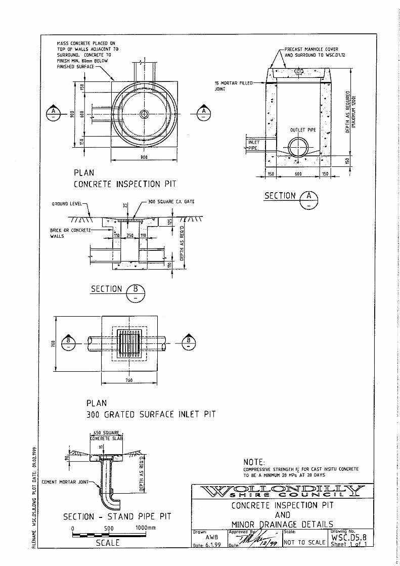


STORMWATER DRAINAGE DESIGN
D5 Aug 2008 (Copyright SWR-TM/WSC) D5A-1 WOLLONDILLY SHIRE COUNCIL
ANNEXURE D5-A WOLLONDILLY SHIRE
RAINFALL INTENSITY FREQUENCY DURATION TABLES INDEX
LOCATION PAGE
APPIN D5A - 2
BARGO D5A - 3
BELIMBLA PARK D5A - 4
BROWNLOW HILL D5A - 5
BUXTON D5A - 6
CAWDOR D5A - 7
COURIDJAH D5A - 8
DOUGLAS PARK D5A - 9
GLENMORE D5A - 10
LAKESLAND D5A - 11
MALDON D5A - 12
MENANGLE D5A - 13
MOUNT HUNTER D5A - 14
MOWBRAY PARK D5A - 15
NATTAI D5A - 16
OAKDALE D5A - 17
ORANGEVILLE D5A - 18
PHEASANTS NEST D5A - 19
PICTON D5A - 20
RAZORBACK D5A - 21
SILVERDALE D5A - 22
TAHMOOR D5A - 23
THE OAKS D5A - 24
THERESA PARK D5A - 25
THIRLMERE D5A - 26
WARRAGAMBA D5A - 27
WEROMBI D5A - 28
WILTON D5A - 29
YANDERRA D5A - 30

STORMWATER DRAINAGE DESIGN
WOLLONDILLY SHIRE COUNCIL D5A-2 D5 Aug 2008 (Copyright SWR-TM/WSC)

STORMWATER DRAINAGE DESIGN
D5 Aug 2008 (Copyright SWR-TM/WSC) D5A-3 WOLLONDILLY SHIRE COUNCIL

STORMWATER DRAINAGE DESIGN
WOLLONDILLY SHIRE COUNCIL D5A-4 D5 Aug 2008 (Copyright SWR-TM/WSC)

STORMWATER DRAINAGE DESIGN
D5 Aug 2008 (Copyright SWR-TM/WSC) D5A-5 WOLLONDILLY SHIRE COUNCIL

STORMWATER DRAINAGE DESIGN
WOLLONDILLY SHIRE COUNCIL D5A-6 D5 Aug 2008 (Copyright SWR-TM/WSC)

STORMWATER DRAINAGE DESIGN
D5 Aug 2008 (Copyright SWR-TM/WSC) D5A-7 WOLLONDILLY SHIRE COUNCIL

STORMWATER DRAINAGE DESIGN
WOLLONDILLY SHIRE COUNCIL D5A-8 D5 Aug 2008 (Copyright SWR-TM/WSC)

STORMWATER DRAINAGE DESIGN
D5 Aug 2008 (Copyright SWR-TM/WSC) D5A-9 WOLLONDILLY SHIRE COUNCIL

STORMWATER DRAINAGE DESIGN
WOLLONDILLY SHIRE COUNCIL D5A-10 D5 Aug 2008 (Copyright SWR-TM/WSC)

STORMWATER DRAINAGE DESIGN
D5 Aug 2008 (Copyright SWR-TM/WSC) D5A-11 WOLLONDILLY SHIRE COUNCIL

STORMWATER DRAINAGE DESIGN
WOLLONDILLY SHIRE COUNCIL D5A-12 D5 Aug 2008 (Copyright SWR-TM/WSC)

STORMWATER DRAINAGE DESIGN
D5 Aug 2008 (Copyright SWR-TM/WSC) D5A-13 WOLLONDILLY SHIRE COUNCIL

STORMWATER DRAINAGE DESIGN
WOLLONDILLY SHIRE COUNCIL D5A-14 D5 Aug 2008 (Copyright SWR-TM/WSC)

STORMWATER DRAINAGE DESIGN
D5 Aug 2008 (Copyright SWR-TM/WSC) D5A-15 WOLLONDILLY SHIRE COUNCIL

STORMWATER DRAINAGE DESIGN
WOLLONDILLY SHIRE COUNCIL D5A-16 D5 Aug 2008 (Copyright SWR-TM/WSC)

STORMWATER DRAINAGE DESIGN
D5 Aug 2008 (Copyright SWR-TM/WSC) D5A-17 WOLLONDILLY SHIRE COUNCIL

STORMWATER DRAINAGE DESIGN
WOLLONDILLY SHIRE COUNCIL D5A-18 D5 Aug 2008 (Copyright SWR-TM/WSC)

STORMWATER DRAINAGE DESIGN
D5 Aug 2008 (Copyright SWR-TM/WSC) D5A-19 WOLLONDILLY SHIRE COUNCIL

STORMWATER DRAINAGE DESIGN
WOLLONDILLY SHIRE COUNCIL D5A-20 D5 Aug 2008 (Copyright SWR-TM/WSC)

STORMWATER DRAINAGE DESIGN
D5 Aug 2008 (Copyright SWR-TM/WSC) D5A-21 WOLLONDILLY SHIRE COUNCIL

STORMWATER DRAINAGE DESIGN
WOLLONDILLY SHIRE COUNCIL D5A-22 D5 Aug 2008 (Copyright SWR-TM/WSC)

STORMWATER DRAINAGE DESIGN
D5 Aug 2008 (Copyright SWR-TM/WSC) D5A-23 WOLLONDILLY SHIRE COUNCIL
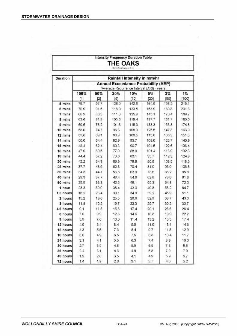
STORMWATER DRAINAGE DESIGN
WOLLONDILLY SHIRE COUNCIL D5A-24 D5 Aug 2008 (Copyright SWR-TM/WSC)

STORMWATER DRAINAGE DESIGN
D5 Aug 2008 (Copyright SWR-TM/WSC) D5A-25 WOLLONDILLY SHIRE COUNCIL

STORMWATER DRAINAGE DESIGN
WOLLONDILLY SHIRE COUNCIL D5A-26 D5 Aug 2008 (Copyright SWR-TM/WSC)

STORMWATER DRAINAGE DESIGN
D5 Aug 2008 (Copyright SWR-TM/WSC) D5A-27 WOLLONDILLY SHIRE COUNCIL

STORMWATER DRAINAGE DESIGN
WOLLONDILLY SHIRE COUNCIL D5A-28 D5 Aug 2008 (Copyright SWR-TM/WSC)

STORMWATER DRAINAGE DESIGN
D5 Aug 2008 (Copyright SWR-TM/WSC) D5A-29 WOLLONDILLY SHIRE COUNCIL

STORMWATER DRAINAGE DESIGN
WOLLONDILLY SHIRE COUNCIL D5A-30 D5 Aug 2008 (Copyright SWR-TM/WSC)

SITE REGRADING
D6 Aug 2008 (Copyright SWR-TM/WSC) WOLLONDILLY SHIRE COUNCIL
DESIGN SPECIFICATION
D6
SITE REGRADING


SITE REGRADING
D6 Aug 2008 (Copyright SWR-TM/WSC) WOLLONDILLY SHIRE COUNCIL
Amendment Record for this Specification Part
This Specification is Wollondilly Shire Council’s edition of the AUS-SPEC generic specification part and includes Wollondilly Shire Council’s primary amendments.
Details are provided below outlining the clauses amended from the Council edition of this AUS-SPEC Specification Part. The clause numbering and context of each clause are preserved. New clauses are added towards the rear of the specification part as special requirements clauses. Project specific additional script is shown in the specification as italic font.
The amendment code indicated below is ‘A’ for additional script ‘M’ for modification to script and ‘O’ for omission of script. An additional code ‘P’ is included when the amendment is project specific.
Amendment Sequence No.
Key Topic addressed in amendment
Clause No.
Amendment Code
Author Initials
AmendmentDate


SITE REGRADING
D6 Aug 2008 (Copyright SWR-TM/WSC) WOLLONDILLY SHIRE COUNCIL
SPECIFICATION D6 : SITE REGRADING CONTENTS CLAUSE PAGE
GENERAL .............................................................................................................................1
D6.01 SCOPE..............................................................................................................................................1
D6.02 OBJECTIVES....................................................................................................................................1
D6.03 REFERENCE AND SOURCE DOCUMENTS ..................................................................................1
D6.04 SITE REGRADING CONCEPT.........................................................................................................2
D6.05 SPECIAL TREATMENT OF PARTICULAR AREAS.........................................................................2
D6.06 GENERAL STANDARD OF LOT PREPARATION...........................................................................3
D6.07 STANDARD OF FILL FOR LOTS.....................................................................................................3
D6.08 TEMPORARY DIVERSION DRAINS................................................................................................4
D6.09 CONCURRENCE WITH THE ENVIRONMENTAL PROTECTION AUTHORITY (EPA) .................4
D6.10 WORK AS EXECUTED PLANS........................................................................................................4
D6.11 CARTAGE OF SOIL..........................................................................................................................5
D6.12 PERMIT TO ENTER TO DISCHARGE STORMWATER/CONSTRUCT..........................................5


SITE REGRADING
D6 Aug 2008 (Copyright SWR-TM/WSC) D6-1 WOLLONDILLY SHIRE COUNCIL
SPECIFICATION D6 : SITE REGRADING
GENERAL
D6.01 SCOPE
1. This design specification sets out requirements for the site regrading involved in land development and subdivision. Conceptual requirements are presented as necessary considerations when preparing designs for site regrading.
2. The scope of this specification assumes that the Designer is familiar with requirements cited in the various construction specifications, specifically those related to earthworks, clearing and grubbing, erosion and sedimentation. Additionally the Designer needs to make reference to the associated design specifications related to stormwater drainage design, geometric road design and erosion control and stormwater management.
Familiarity with other Specifications Required
D6.02 OBJECTIVES
1. This specification aims to assist the Designer in achieving:
• efficient and economical design
Efficient
• enhancement of the environmental character of the site whilst maintaining the natural features of the site
Environmen-tally Sound
• provision of safe conditions for construction commensurate with the proposed purpose of the development
Safe for Construction
• equality of building conditions for residential development
• a minimal impact on adjoining properties and developments. Impact on Adjoining Properties
D6.03 REFERENCE AND SOURCE DOCUMENTS
(a) Council Specifications Construction Specifications Wollondilly Shire Council Construction Specification Draft – May, 1990 Design Specifications D1 - Geometric Road Design D5 - Stormwater Drainage Design D7 - Erosion Control and Stormwater Management

SITE REGRADING
WOLLONDILLY SHIRE COUNCIL D6-2 D6 Aug 2008 (Copyright SWR-TM/WSC)
(b) Australian Standards AS 3798 - Guidelines on earthworks for commercial and residential
developments AS 2870.1 - Residential slabs and footings - Construction.
D6.04 SITE REGRADING CONCEPT
1. Areas of a site proposed for building or recreational purposes may not be suitable in their natural state for their intended function without improvement works to:
(a) Alleviate flooding of low-lying ground
(b) Fill gullies or create emergency flowpaths after underground stormwater piping has been installed
(c) Allow improved runoff from flat ground
(d) Regrade excessively steep slopes that would preclude economical construction of dwelling foundations
(e) Allow effective recreational use or give reasonable access
The Consultant shall review the natural surface contours and where necessary shall design finished surface levels that ensure the land is suitably prepared
2. Where practical, areas should be regraded to minimise the necessity for underground drainage systems with surface inlet pits, and allow surface water to flow naturally to roads or drainage reserves without excessive concentration.
Drainage
3. The Consultant shall consider the implications of site regrading in relation to the existing natural environment. Generally site regrading shall be minimised in heavily treed areas.
Natural Environment
4. Care shall be taken to provide depressions for overland flow from low points and over major drainage lines, to direct stormwater for storms up to a 100 year average recurrence interval.
Overland Flow
5. The design of site regrading areas in conjunction with the design of roadworks shall be considered with the objective of balancing cut to fill and achieving both an economical development and minimising haulage of imported fill or spoil to and from the development site. Bulk haulage should always be considered an adverse effect on adjacent development, and infrastructure.
Minimal Road Haulage
D6.05 SPECIAL TREATMENT OF PARTICULAR AREAS
1. Subject to Council approval and meeting all requirements for managing floodwaters and overland flows outlined in the Design Specification D5 STORMATER DRAINAGE, areas abutting flooding or nuisance drainage sites shall be site regraded to a minimum level of 0.5 metres above the 1% AEP Flood levels. The site shall be identified on the design plans with appropriate notation of site specific requirements.
Flooding
2. In the event that an area is known to be affected by or inundated by local stormwater flows, the Designer shall investigate the existing conditions as they relate to the proposed development and advise the Developer in the preliminary design report on all data obtained in the investigation and recommend appropriate contour adjustments. The report should normally be accompanied by sketch plans to clarify recommendations.
Inundation Areas

SITE REGRADING
D6 Aug 2008 (Copyright SWR-TM/WSC) D6-3 WOLLONDILLY SHIRE COUNCIL
3. Site constraints either natural or otherwise may be required to be identified as a burden on developed property. It is recommended that the designer take this into account when preparing the design. The property may ultimately be affected by a "restriction as to user", which may be controlled by a legal 88B Instrument placed on title to the land and/or by a Section 149 message advising prospective purchasers of any restrictions affecting the land.
Restrictions on Land Use
4. The finished surface of filled areas shall be designed to levels allowing an adequate cover depth over the pipeline (if piped) and permitting surface stormwater flow to be guided to inlet pits if depressions are retained in the finished surface contouring.
Piped Gullies or Depressions
5. The location of such features shall be clearly defined on the site regrading plans and defined by distance to corner boundaries, monuments, etc for purposes of relocation at the geotechnical testing stage for work as executed plans. A geotechnical report specifying the site specific preparation and compaction requirements will be required to be incorporated with the site regrading plan. A description of the minimum acceptable quality of the fill shall also be specified on the plans, supported by geotechnical recommendations. All documentation necessary from various authorities to support the filling of dams and watercourses shall be supplied with the design plans.
Dams and Water Courses
6. The finished level of any building area shall be designed to ensure a desirable surface grading of 1.5% (1% minimum) oriented in the direction of the drainage system designed to cater for its catchment.
Flat Ground
7. Building areas containing natural ground slopes of an excessively steep nature, ie greater than 15% shall be brought to the attention of a Geotechnical Engineer for investigation of compatibility with dwelling types proposed. Specific requirements shall be noted on the design plans.
Steep Slopes
D6.06 GENERAL STANDARD OF LOT PREPARATION
1. Special requirements will apply where necessary but generally lots are to be cleared of low scrub, fallen timber, debris, stumps, large rocks and any trees which in the opinion of Council are approaching the end of their functional life or are dangerous or will be hazardous to normal use of the development. Prior consultation with Council's Development Branch is necessary. Such requirements shall be shown on the design plan.
Clearing
2. All timber and other materials cleared from lots shall be removed from the site. All roots, loose timber, etc which may contribute to drain blockage shall be removed. Such requirements shall be shown on the design plan.
Disposal
3 Selected trees shall be preserved by approved means to prevent destruction normally caused by placement of conventional filling or other action within the tree drip zone. The relevant Council officer shall be consulted for advice and all specific requirements noted on the design plans.
Preservation of Trees
D6.07 STANDARD OF FILL FOR LOTS
1. The following notations are to be incorporated in the design plans. "Filling is to be of sound clean material, reasonable standard and free from large rock, stumps, organic matter and other debris." "Placing of filling on the prepared areas shall not commence until the authority to do so has been obtained from the Council".
2. All work shall be in accordance with AS 3798. Fill is to be placed in layers not exceeding 150mm compacted thickness. All fill is to be compacted to not less than 95% standard maximum dry density. Maximum particle size shall be 2/3 of the layer thickness.
Fill Quality

SITE REGRADING
WOLLONDILLY SHIRE COUNCIL D6-4 D6 Aug 2008 (Copyright SWR-TM/WSC)
3. Fill comprising natural sands or industrial wastes or by-products will be accepted by Council only in approved locations and will be subject to specific requirements determined by prevailing conditions.
Restricted Fill
4. It is essential that prior advice be given of intended use of such materials. It should be noted that failure to obtain Council's approval may lead to an order for removal of any material considered by Council or other relevant authorities as unsuitable or in any way unfit for filling.
Prior Approval
5. All areas where filling has been placed are to be dressed with clean arable topsoil, fertilised and sown with suitable grasses.
Top Dressing
6. Tests shall be taken on any proposed filling materials to ensure that they do not have a high dispersion potential as defined by the Emerson Crumb Dispersion Tests (AS1289 C8.1 – 1980 as amended).
Dispersion Testing
D6.08 TEMPORARY DIVERSION DRAINS
1. Where temporary drains are required to divert surface flows away from the site regrading area, the location and silt/erosion control treatment shall be clearly identified on the engineering plans. The scale of such works shall reflect the volume of water to be diverted.
The objective will be to ensure minimal soil disturbances and material loss off the site.
Control measures will include, but not be limited to:
(a) Provision of trench stops every 30m along a trench, with provision for overtopping to be directed to the kerb.
(b) Placement of "blue metal" bags along kerb and gutter at maximum 30m spacings.
(c) Placement of "blue metal" bags around downstream drainage pits.
The requirements identified in Council's current Specification for Sediment & Erosion control should be addressed for any additional requirements.
Erosion
D6.09 CONCURRENCE WITH THE ENVIRONMENTAL PROTECTION AUTHORITY (EPA)
1. The Consultant is recommended to refer to the EPA with regard to any items requiring specific consideration when preparing a site regrading plan. Such plans may need to incorporate sediment/siltation/erosion control devices with specific reference to the stage at which these are to be provided. The responsibility shall rest with the consultant/ developer to make enquiries with EPA and subsequently obtain Council approval to proposed measures.
EPA
D6.10 WORK AS EXECUTED PLANS
1. The Consultant shall annotate on the site regrading plan, the site specific detail to be shown on the Work-as-Executed plans. Such detail shall include geotechnical report certifying the works to be suitable for the intended purpose and any other certifications, testing and survey data, as required in this specification.

SITE REGRADING
D6 Aug 2008 (Copyright SWR-TM/WSC) D6-5 WOLLONDILLY SHIRE COUNCIL
D6.11 CARTAGE OF SOIL
1. The Consultant shall refer to Council for acceptable haul roads with applicable load limits. This detail shall be required to be shown on the site regrading plan. The payment of a Bond may be required by the developer/contractor where Council has some concern about the ability of a haul road to sustain the loads without undue damage or maintenance requirements.
Possible Bond Requirement
2. Unless specific application is made to Council and approval obtained, the plans will be annotated as follows:
"All topsoil shall be retained on the development site and utilised effectively to encourage appropriate revegetation."
Topsoil
D6.12 PERMIT TO ENTER TO DISCHARGE STORMWATER/CONSTRUCT
1. Where it is proposed to divert, direct or intensify the flow of stormwater into adjoining property, a "permit to discharge stormwater” shall be sought and submitted to Council prior to the approval of Engineering design plans. The above shall apply unless otherwise specified by Council. A permit shall also be sought to carry out construction work on adjoining property and such permit also presented to Council.
Permit Required


CYCLEWAY & SHARED PATHWAY DESIGN
D9 Aug 2008 (Copyright SWR-TM/WSC) WOLLONDILLY SHIRE COUNCIL
DESIGN SPECIFICATION
D9
CYCLEWAY AND
SHARED PATHWAY DESIGN


CYCLEWAY & SHARED PATHWAY DESIGN
D9 Aug 2008 (Copyright SWR-TM/WSC) WOLLONDILLY SHIRE COUNCIL
Amendment Record for this Specification Part
This Specification is Wollondilly Shire Council’s edition of the AUS-SPEC generic specification part and includes Wollondilly Shire Council’s primary amendments.
Details are provided below outlining the clauses amended from the Council edition of this AUS-SPEC Specification Part. The clause numbering and context of each clause are preserved. New clauses are added towards the rear of the specification part as special requirements clauses. Project specific additional script is shown in the specification as italic font.
The amendment code indicated below is ‘A’ for additional script ‘M’ for modification to script and ‘O’ for omission of script. An additional code ‘P’ is included when the amendment is project specific.
Amendment Sequence No.
Key Topic addressed in amendment
Clause No.
Amendment Code
Author Initials
AmendmentDate
1 Objective Statement D9.02 A IB 1/7/08
2 Minimum Design Standards D9.10 M IB 1/7/08
3 Standard Drawings D9.100 A IB 1/7/08
4 AS1428.1 2001 Added to reference Documents.
D9.03 A IB 7/8/08
5 Minimum Design Standards D9.10 M IB 7/8/08


CYCLEWAY & SHARED PATHWAY DESIGN
D9 Aug 2008 (Copyright SWR-TM/WSC) WOLLONDILLY SHIRE COUNCIL
SPECIFICATION D9 : CYCLEWAY AND SHARED PATHWAY DESIGN
CONTENTS
CLAUSE PAGE
GENERAL .............................................................................................................................1
D9.01 SCOPE..............................................................................................................................................1
D9.02 OBJECTIVES....................................................................................................................................1
D9.03 REFERENCE AND SOURCE DOCUMENTS ..................................................................................1
D9.04 CONSULTATION..............................................................................................................................2
D9.05 PLANNING CONCEPTS...................................................................................................................2
D9.06 CYCLEWAY AND PATHWAY TYPES..............................................................................................2
D9.07 PROVISIONS FOR CYCLEWAYS AND PATHWAYS AT STRUCTURES......................................3
D9.08 SIGNAGE AND PAVEMENT MARKING ..........................................................................................3
D9.09 END OF JOURNEY FACILITIES ......................................................................................................3
D9.10 MINIMUM DESIGN STANDARDS....................................................................................................4
D9.11 DOCUMENTATION ..........................................................................................................................4
SPECIAL REQUIREMENTS .................................................................................................5
D9.12 RESERVED ......................................................................................................................................5
D9.13 RESERVED ......................................................................................................................................5
D9.14 RESERVED ......................................................................................................................................5
STANDARD DRAWINGS......................................................................................................5
D9.100 LIST OF DRAWINGS.......................................................................................................................5


CYCLEWAY & SHARED PATHWAY DESIGN
D9 Aug 2008 (Copyright SWR-TM/WSC) D9-1 WOLLONDILLY SHIRE COUNCIL
SPECIFICATION D9 : CYCLEWAY AND SHARED PATHWAY DESIGN
GENERAL
D9.01 SCOPE
1. This specification sets out requirements to be used in the design of various types of cycleways and pathways.
2. All relevant design principles contained in the AUSTROADS Guide referenced below must be integrated in the design of cycleways and associated infrastructure. This specification serves as a companion document to the AUSTROADS Guide extended to incorporate basic requirements for pathways.
AUSTROADS
D9.02 OBJECTIVES
1. Wollondilly Shire is committed to an alternative transport network as a viable option for travel throughout the Shire. Provision of these services as an integrated part of all development is actively supported. Wherever possible, pathways for pedestrian and cycle transport shall be considered at the inception of a development proposal concept.
Development Integration
2. This specification aims to set standards and document requirements related to the provision of cycleways and pathways which encourage pedestrian activities and cycling for transportation and recreational purposes. Cycleways and pathways are to be safe and convenient and shall maintain a satisfactory level of service for all pathway users.
Safety
Level of Service
D9.03 REFERENCE AND SOURCE DOCUMENTS
(a) Council Specifications D1 - Geometric Road Design
(b) Australian Standards AS 1428.1 - 2001 Design for access and mobility AS 1742 - Manual of uniform traffic control devices. AS 2890.3 - Bicycle parking facilities
(c) Other CYCLE PLANNING - Wollondilly Council Precinct 3 Cycleways Study - Final Report October, 1993 AUSTROADS - Guide to Traffic Engineering Practice - PART 13
Pedestrians, PART 14 Bicycles. - Planning and Designing for Bicycles - NAASRA (now
AUSTROADS) Technical Report June 1988. Ministry of Transport, Victoria - State Bicycle Committee - Planning and Design of Bicycle Facilities,

CYCLEWAY AND SHARED PATHWAY DESIGN
WOLLONDILLY SHIRE COUNCIL D9-2 D9 Aug 2008 (Copyright SWR-TM/WSC)
D9.04 CONSULTATION
1. The Designer is encouraged to consult with Council, the Developer's Landscape Architects/Designers and relevant authorities prior to and during the preparation of cycleway and pathway design.
Landscape Designers Public Authorities
D9.05 PLANNING CONCEPTS
1. In addition to any conditions of consent, Council will provide specific requirements for cycleways and shared pathways in Council's Strategic Planning Documents The Designer will need to enquire about such documents and comply with requirements defined.
Shared Pathway Plans
2. The Designer should be familiar with cycleway geometric design requirements in terms of:
- width
- grade
- stopping sight distance
- change in grade
- horizontal curvature
- crossfall and drainage
- superelevation
- sight distance on horizontal curves
These requirements are discussed in the AUSTROADS Guide.
Geometric Design
AUSTROADS Guide
D9.06 CYCLEWAY AND PATHWAY TYPES
1. Cycleways can be provided on road and off road. The AUSTROADS Guide provides detailed descriptions, warrants, widths, pavement marking etc for the majority of these cycleways.
On Road Off Road
2. Common alternative cycleway types include: On Road Shared Parking/Bicycle Lanes Wide Kerbside Lanes Shared Traffic Lanes Exclusive Bicycle Lane Sealed Shoulder Off Road Shared Bicycle/Pedestrian Pathway Segregated Pathway Exclusive Cycleway
The AUSTROADS Guide provides advice on the suitability of pavement conditions, drainage pit grates etc for on road cycleways.
AUSTROADS Guide

CYCLEWAY & SHARED PATHWAY DESIGN
D9 Aug 2008 (Copyright SWR-TM/WSC) D9-3 WOLLONDILLY SHIRE COUNCIL
3. Common pathway types include: Exclusive Pedestrian Pathways Shared Bicycle/Pedestrian Pathways
By definition pedestrian pathways are "off road" in that pedestrian facilities routinely designed adjacent to roadways are termed footpaths and are designed to meet criteria outlined in Council's Subdivision Code and typically related to road cross section detailing.
Footpaths
4. Pathways by comparison diverge from the road alignment either within the road reserve or across land reserves. Pathways can be provided in conjunction with overland floodways or retention basins.
Land Reserves
D9.07 PROVISIONS FOR CYCLEWAYS AND PATHWAYS AT STRUCTURES
1. Designers shall consider the best way to cater for the uninterrupted movement of cyclists and pedestrians at proposed and existing structures wherever possible. Structures include bridges and underpasses over rivers, roads or railways. The AUSTROADS Guide provides information on:
- acceptable widths and clearances
- types of cycleways and pathways
- handrails
- bicycle bridges
- approach ramps
etc.
Bridges Underpasses
D9.08 SIGNAGE AND PAVEMENT MARKING
1. The Designer shall provide adequate signposting design for cycleways and shared pathways.
2. Signs and pavement marking will provide for the safe and convenient use of the facility. The signs and pavement marking will comply with AS 1742.
Signs Pavement Marking
D9.09 END OF JOURNEY FACILITIES
1. Consideration must be given to the design of adequate facilities at common destinations of bicyclists and pedestrians so as to encourage cycleway and pathway usage.
2. Such facilities could include:
- seats
- standby areas
- secure bicycle parking
- picnic facilities
Facilities
3. Bicycle parking installation design should meet appropriate criteria discussed in the AUSTROADS Guide and be fabricated to meet AS 2890.3.
Parking

CYCLEWAY AND SHARED PATHWAY DESIGN
WOLLONDILLY SHIRE COUNCIL D9-4 D9 Aug 2008 (Copyright SWR-TM/WSC)
D9.10 MINIMUM DESIGN STANDARDS
1. Notwithstanding the guidelines provided in this specification and referenced documents the following minimum standards have been determined as shown in Table D9.1.
Table D9.1 Minimum Design Standards
Cycleway Pathway Shared Pathway
Path Width 2.0m 1.5 m 2.0m (min)
Formation Width 3.0m 2.0m 3.0m
Crossfall min. (refer Note) max.
1:40 1:20
1:40 1:20
1:40 1:20
Concrete Thickness 125 mm 100 mm 125 mm
Concrete Strength M25 M25 M25
Reinforcement SL72 - 40 mm cover SL72 - 40 mm cover SL72 - 40 mm cover
Preparation Min 50 mm DGB20 or crusher dust on
compacted subgrade
Layer of sand 50 mm on Compacted
subgrade
Min 50 mm DGB20 or crusher dust on
compacted subgrade
Joints in Concrete Saw cut at max 3 metres and expansion
joint at 10 m
Saw cut at max 3 metres and expansion
joint at 10 m
Saw cut at max 3 metres and expansion
joint at 10 m
Concrete colour As advised by Council As advised by Council As advised by Council
Clearance Horiz. 2.5m 2m 2.5m
Grade max. 2% for 450m 5% for 90m 10% for 30m
NA 2% for 140m 3% for 70m 4% for 40m 5% for 30m
Note: Council has adopted a Disability Action Plan that aims to ensure all new buildings & facilities provided and major refurbishments undertaken are fully accessible. All new pathways shall be accessible pathways. Accessible pathways shall have maximum cross fall of 1:40 and maximum longitudinal gradient less than 1 in 33 or as required by Australian Standard AS1428 item 5.2 Walkways when gradient is 1 in 33 or more.
D9.11 DOCUMENTATION
1. The following listing outlines Council's minimum requirements for presentation of cycleway and/or pathway designs.
• All plans for cycleways/pathways are to be presented at the reduction ratio 1:500.
Plans
• The cycleway plan sheet may be incorporated into the road plan where clarity permits. Specific details are to be provided at reduction ratio 1:200.
• Longitudinal Sections will be required for all off-road cycleways where grades exceed 4%.
Long Sections
• Longitudinal Sections will have reduction ratios of 1:500 horizontal and 1:100 vertical.

CYCLEWAY & SHARED PATHWAY DESIGN
D9 Aug 2008 (Copyright SWR-TM/WSC) D9-5 WOLLONDILLY SHIRE COUNCIL
• Cross Sections will be presented at 1:100 reduction ratio (natural) and transition tables will be required where crossfalls vary or superelevation is provided.
Cross Sections
• A typical cross section will be detailed to indicate pavement materials and layer depths.
SPECIAL REQUIREMENTS
D9.12 RESERVED
D9.13 RESERVED
D9.14 RESERVED
STANDARD DRAWINGS
D9.100 LIST OF DRAWINGS List of Drawings
1. DRAWING NUMBER DRAWING DESCRIPTION WSC.D9.1 Typical Pavement Details for Concrete Shared Footpath/Cycleway


BUSHFIRE PROTECTION
D10 Aug 2008 (Copyright SWR-TM/WSC) WOLLONDILLY SHIRE COUNCIL
DESIGN SPECIFICATION
D10
BUSHFIRE PROTECTION


BUSHFIRE PROTECTION
D10 Aug 2008 (Copyright SWR-TM/WSC) WOLLONDILLY SHIRE COUNCIL
Amendment Record for this Specification Part
This Specification is Wollondilly Shire Council’s edition of the AUS-SPEC generic specification part and includes Wollondilly Shire Council’s primary amendments.
Details are provided below outlining the clauses amended from the Wollondilly Shire Council edition of this AUS-SPEC Specification Part. The clause numbering and context of each clause are preserved. New clauses are added towards the rear of the specification part as special requirements clauses. Project specific additional script is shown in the specification as italic font.
The amendment code indicated below is ‘A’ for additional script ‘M’ for modification to script and ‘O’ for omission of script. An additional code ‘P’ is included when the amendment is project specific.
Amendment Sequence No.
Key Topic addressed in amendment
Clause No.
Amendment Code
Author Initials
AmendmentDate


BUSHFIRE PROTECTION
D10 Aug 2008 (Copyright SWR-TM/WSC) WOLLONDILLY SHIRE COUNCIL
SPECIFICATION D10 : BUSHFIRE PROTECTION CONTENTS
CLAUSE PAGE
GENERAL .............................................................................................................................1
D10.01 SCOPE..............................................................................................................................................1
D10.02 OBJECTIVES....................................................................................................................................1
D10.03 REFERENCE AND SOURCE DOCUMENTS ..................................................................................1
DESIGN CRITERIA...............................................................................................................2
D10.04 GENERAL .........................................................................................................................................2
D10.05 FIRE PROTECTION ZONES............................................................................................................2
D10.06 FUEL REDUCED ZONE ...................................................................................................................4
D10.07 FUEL FREE ZONE ...........................................................................................................................4
D10.08 MODIFICATIONS TO FUEL REDUCED AND FUEL FREE ZONES ...............................................5
D10.09 INTERNAL ACCESS FROM SUBDIVISION ROADS.......................................................................6
D10.10 STAGING WORKS ...........................................................................................................................6
STANDARD DRAWINGS......................................................................................................7
D10.100 LIST OF DRAWINGS........................................................................................................................7


BUSHFIRE PROTECTION
D10 Aug 2008 (Copyright SWR-TM/WSC) D10.1 WOLLONDILLY SHIRE COUNCIL
SPECIFICATION D10 : BUSHFIRE PROTECTION
GENERAL
D10.01 SCOPE
1. The work to be executed under this Specification consists of the design of bushfire protection facilities to protect life and property and bring a fire to a halt.
2. The specification contains procedures for the design of fire protection facilities. Designs shall be carried out to satisfy requirements of the Council and the guidelines published by the Department of Bushfire Services, May 1991. Consultation with Council's Fire Control Officer may be required.
D10.02 OBJECTIVES
1. This specification aims to outline the requirements that will minimise bushfire hazard in developments. The requirements are particularly pertinent to rural developments but should be an integral part of urbanised development as well. The concepts proposed need to be incorporated at an early stage of development design.
Rural Development Urban Development
D10.03 REFERENCE AND SOURCE DOCUMENTS
(a) Council Specifications Wollondilly Shire Council Construction Specification.
(b) NSW Government Legislation Environment Planning and Assessment Act 1979 - Section 94
(c) NSW Government Department Publications Department of Bushfire Services (May 1991) - Planning for Bushfire Protection. A Guide for Land Use
Planners, Fire Authorities, Developer and Home Owner. Department of Land and Water Conservation (formerly Land Management) - Soil Conservation Service 1983. Guidelines for Planning,
Construction and Maintenance of Tracks. Ministry of Urban Affairs (formerly Environment) and Planning - "Planning Guidelines for Subdivisions in Bushfire Prone
Areas" 1985. NSW Department of Urban Affairs (formerly Environment) and Planning - "Circular 74: Planning in Fire Prone Areas" 1984.
(d) Other Board of Fire Commissioners - "Hazard Reduction for the Protection of Buildings in
Bushland areas" 1984.

BUSHFIRE PROTECTION
WOLLONDILLY SHIRE COUNCIL D10.2 D10 Aug 2008 (Copyright SWR-TM/WSC)
Bush Fire Council of NSW - "Everyone's Guide to Bushfire Control" 1984. - "Everyone's Guide to Bushfire Prevention in Urban
Bushland Areas" 1986. - "Everyone's Guide to Wildfire Prevention in Rural Areas"
1986. Californian Department of Forestry - "Fire Safety Guides for Residential Development in
California" 1980. Insurance Council of Australia. - "Bushfire Safety in Urban Fringe Areas." Luke, R.H. - "Before the Fires Start."
DESIGN CRITERIA
D10.04 GENERAL
1. Where a subdivision will abut unimproved timber in a bushfire prone area (as classified by Council), perimeter tracks are to be located immediately between the created allotment and the bushland within a minimum cleared width of 6m, and have a minimum formed width of 4m. Such roads shall be adequately drained to provide all weather access for fire fighting vehicles. Alternatively dedicated perimeter roads may be utilised.
Perimeter Tracks
2. The perimeter track shall be contained within a reservation or easement which borders those allotments abutting the bushfire prone area. Reservation width requirements will vary depending on slope, orientation, vegetation and/or other features but shall be not less than 20m. Such a reserve shall serve as a basis for fire protection measures to be undertaken and will not be considered as part of the public reserve dedication applicable to the subdivision.
Reservation
Width
3. Access is to be provided from the above described reservation from the local road system at regular intervals in a system of 'loops'.
Access
4. For those subdivisions receiving reticulated water, fire hydrants shall be situated at appropriate intervals or near where potential fire hazard areas exist as determined by Council.
Fire Hydrants
5. Council's Fire Control Officer shall be consulted for technical advice in relation to bushfire protection of subdivisions prior to engineering plan preparation.
Consultation
6. Fire protection zones access tracks and perimeter tracks shall be clearly indicated on the subdivision plan. Erosion control features and revegetation requirements shall also be indicated in the subdivision plan.
D10.05 FIRE PROTECTION ZONES
1. The provision of Fire Protection Zones (FPZs) can only occur as part of the development of the subdivision pattern. Each individual allotment shall have adequate space for the main building (usually a dwelling), an area of open space (front, back or side yard) and the FPZ (which may include part of the yard area and/or neighbouring properties). Figure D10.1 illustrates a typical FPZ.
Part of Development

BUSHFIRE PROTECTION
D10 Aug 2008 (Copyright SWR-TM/WSC) D10.3 WOLLONDILLY SHIRE COUNCIL
Figure D10.1 Fire Protection Zone
2. FPZs shall be required for any development fronting a bush fire hazard area, whether a single dwelling, a group of isolated dwellings or an urban subdivision. They act as a buffer zone between the development and the fuel.
Buffer Zone
3. The primary purpose of FPZs is to ensure that a progressive reduction of fuel occurs between the bush fire hazard and any combustible structures within the development.
Reduction of Fuel
4. Apart from its primary purpose the FPZ serves a number of other important purposes, dependent upon local fire fighting policy. The FPZ shall be designed to:
Other Purposes
(a) maximise the separation distance between high intensity fire and any
structure, thereby reducing the radiation and direct flame contact;
(b) provide an area where embers can fall with minimal opportunity to create further fire outbreaks;
(c) provide a safe access to a structure for fire fighters by reducing the heat level from the main fire;
(d) provide a safe retreat for fire fighters; and
(e) provide a clear control line from which to begin back burning or hazard reduction operations.
Safety requirements sometimes dictate that fires are fought from the property itself rather than along the perimeter track.
5. The FPZ incorporates up to three separate components: (a) Fuel Reduced Zone (FRZ); and
(b) Fuel Free Zone (FFZ) incorporating:
(i) a perimeter road or reserve (which incorporates an access track); and
(ii) a set-back (currently defined by minimum lot depths), which is usually part of the allotment.
Separate Components
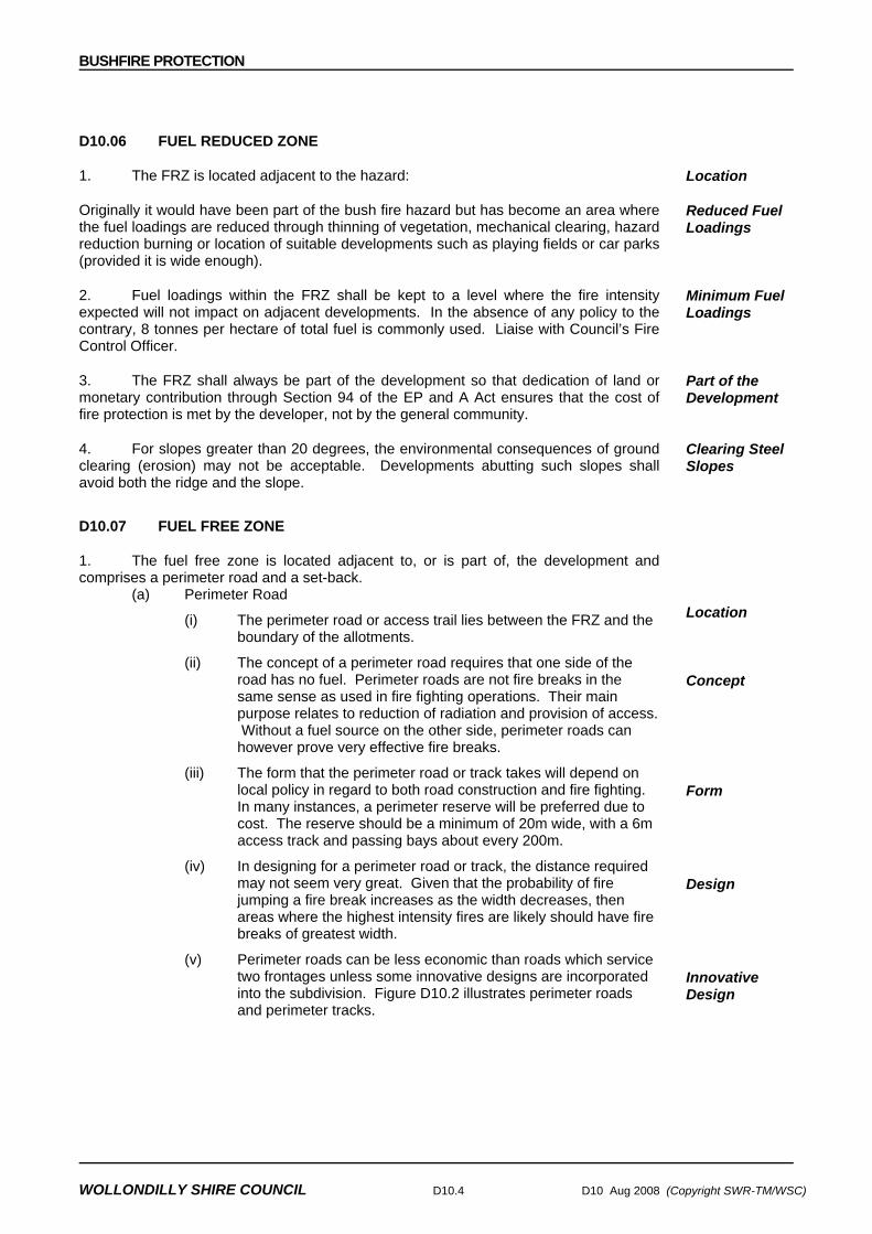
BUSHFIRE PROTECTION
WOLLONDILLY SHIRE COUNCIL D10.4 D10 Aug 2008 (Copyright SWR-TM/WSC)
D10.06 FUEL REDUCED ZONE
1. The FRZ is located adjacent to the hazard:
Originally it would have been part of the bush fire hazard but has become an area where the fuel loadings are reduced through thinning of vegetation, mechanical clearing, hazard reduction burning or location of suitable developments such as playing fields or car parks (provided it is wide enough).
Location
Reduced Fuel Loadings
2. Fuel loadings within the FRZ shall be kept to a level where the fire intensity expected will not impact on adjacent developments. In the absence of any policy to the contrary, 8 tonnes per hectare of total fuel is commonly used. Liaise with Council’s Fire Control Officer.
Minimum Fuel Loadings
3. The FRZ shall always be part of the development so that dedication of land or monetary contribution through Section 94 of the EP and A Act ensures that the cost of fire protection is met by the developer, not by the general community.
Part of the Development
4. For slopes greater than 20 degrees, the environmental consequences of ground clearing (erosion) may not be acceptable. Developments abutting such slopes shall avoid both the ridge and the slope.
Clearing Steel Slopes
D10.07 FUEL FREE ZONE
1. The fuel free zone is located adjacent to, or is part of, the development and comprises a perimeter road and a set-back.
(a) Perimeter Road
(i) The perimeter road or access trail lies between the FRZ and the boundary of the allotments.
Location
(ii) The concept of a perimeter road requires that one side of the road has no fuel. Perimeter roads are not fire breaks in the same sense as used in fire fighting operations. Their main purpose relates to reduction of radiation and provision of access. Without a fuel source on the other side, perimeter roads can however prove very effective fire breaks.
Concept
(iii) The form that the perimeter road or track takes will depend on local policy in regard to both road construction and fire fighting. In many instances, a perimeter reserve will be preferred due to cost. The reserve should be a minimum of 20m wide, with a 6m access track and passing bays about every 200m.
Form
(iv) In designing for a perimeter road or track, the distance required may not seem very great. Given that the probability of fire jumping a fire break increases as the width decreases, then areas where the highest intensity fires are likely should have fire breaks of greatest width.
Design
(v) Perimeter roads can be less economic than roads which service two frontages unless some innovative designs are incorporated into the subdivision. Figure D10.2 illustrates perimeter roads and perimeter tracks.
Innovative Design

BUSHFIRE PROTECTION
D10 Aug 2008 (Copyright SWR-TM/WSC) D10.5 WOLLONDILLY SHIRE COUNCIL
Figure D10.2 Perimeter Road Track (vi) Perimeter roads that do not require clearing or maintenance
(compared to tracks), can be cheapest in the long term. Ultimately the decision between a road or track depends on the local council's subdivision and bush fire fighting policies.
No Clearance or Maintenance
(vii) Tracks shall be constructed to Dept. of Land and Water Conservation’s Soil Conservation Service (1983) guidelines.
(b) Set-back
(i) Part of the allotment can be used as a section of the buffer by setting a minimum lot depth and rear setback. This can ensure that sufficient room (30-35m) is available to allow for erection of a dwelling that does not encroach upon the rear of the allotment.
Minimum Lot Depth
(ii) The policy previously required a minimum of 40m lot depth in order to be consistent with the average minimum lot depth in bushland residential developments. Based on the requirement to maximise the distance between hazard and structures on reasonable grounds (as developed above) and a 30m wide building envelope which includes the surrounding yard, there is no justification for a 40m minimum lot depth in some instances.
Previous Policy
D10.08 MODIFICATIONS TO FUEL REDUCED AND FUEL FREE ZONES
1. Fire authorities would generally be reluctant to agree to modifications in the width of either the FRZ or the FFZ. If modifications were to be agreed, it would be after an examination of the particular cases rather than according to any formula.
Reluctance of Fire Authorities

BUSHFIRE PROTECTION
WOLLONDILLY SHIRE COUNCIL D10.6 D10 Aug 2008 (Copyright SWR-TM/WSC)
2. Modifications would need to take account of adjacent or proposed development. Some difficulties arise where new development abuts existing development that is a fire hazard because of the nature of its usage (eg forests, parks etc). The general principle is that fire protection should be shared by both users which may require a certain level of negotiation outside the planning system.
Adjacent Development
3. Even without an extensive area of fuel outside the FRZ, intense fires can develop if the FRZ has not been hazard-reduced and if the fire begins as a line ignition from spotting embers.
4. Under adverse conditions fires moving up a slope may not be slowed by the presence of rocky outcrops and ledges, even though the continuity of the fuel bed may be broken.
D10.09 INTERNAL ACCESS FROM SUBDIVISION ROADS
1. The provision of adequate internal access is also controlled by subdivision design. Subdivision roads shall incorporate the following features:
Incorporated in Subdivision Design
(a) width, vertical clearances and any dips and crests which allow the two way movement of firefighting appliances;
(b) construction standards of roads and any bridges which allow for the carrying of fully loaded fire appliances (28 tonnes or 8 tones per axle);
(c) curves which have a minimum inner radius of 12m and are minimal in number;
(d) maximum grades which do not exceed 15% (1:7) and preferably not more than 10% (1:10);
(e) clearly signposted roads;
(f) dead end roads which do not exceed 200 metres in length;
(g) dead ends which incorporate a minimum turning circle of 12.5m; and
(h) a road network which connects regularly to any access tracks.
D10.10 STAGING WORKS
1. When considering the staging of development, planners shall provide for initial development to occur on the hazard perimeter of the development. A line of dwellings will tend to minimise the threat to the entire subdivision by limiting the hazard interface.
Initial Development on Hazard Perimeter
2. Scattered developments on the other hand, will allow a continuous network of fuel to threaten individual buildings until development is substantially underway.
Scattered Developments
3. For similar reasons, new developments should be 'tacked' onto old developments to minimise the hazard perimeter.
Minimise Hazard Perimeter
4. It is important that much of the bush fire protection is incorporated into the design of the development, rather than into individual allotments.
Incorporated in Subdivision Design

BUSHFIRE PROTECTION
D10 Aug 2008 (Copyright SWR-TM/WSC) D10.7 WOLLONDILLY SHIRE COUNCIL
STANDARD DRAWINGS
D10.100 LIST OF DRAWINGS List of Drawings
1. DRAWING NUMBER DRAWING DESCRIPTION WSC.D10.1 Fire Trail Details


ACCESS & OFFSTREET PARKING
WSC.D13 Aug 2008 (Copyright SWR-TM/WSC) WOLLONDILLY SHIRE COUNCIL
DESIGN SPECIFICATION
WSC.D13
ACCESS & OFF-STREET
PARKING

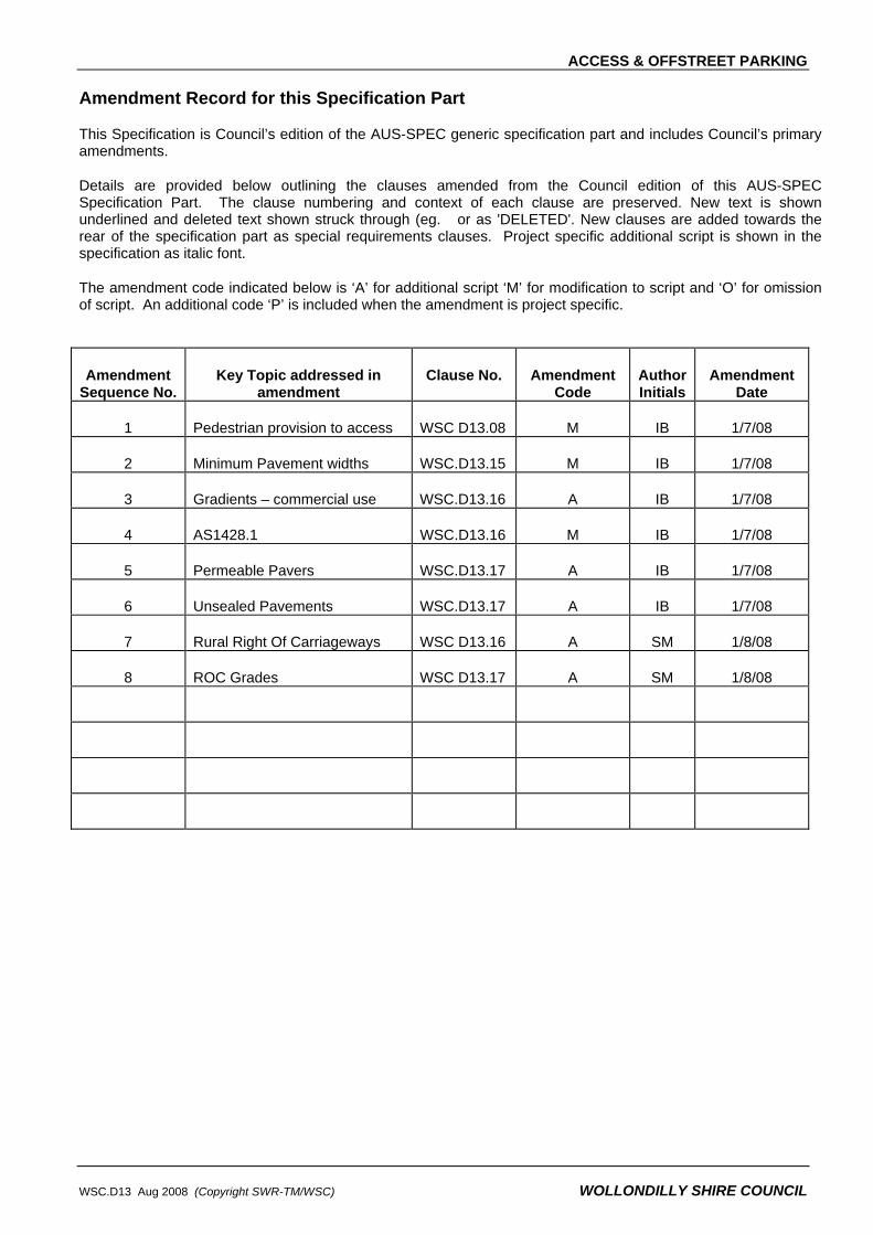
ACCESS & OFFSTREET PARKING
WSC.D13 Aug 2008 (Copyright SWR-TM/WSC) WOLLONDILLY SHIRE COUNCIL
Amendment Record for this Specification Part
This Specification is Council’s edition of the AUS-SPEC generic specification part and includes Council’s primary amendments.
Details are provided below outlining the clauses amended from the Council edition of this AUS-SPEC Specification Part. The clause numbering and context of each clause are preserved. New text is shown underlined and deleted text shown struck through (eg. or as 'DELETED'. New clauses are added towards the rear of the specification part as special requirements clauses. Project specific additional script is shown in the specification as italic font.
The amendment code indicated below is ‘A’ for additional script ‘M’ for modification to script and ‘O’ for omission of script. An additional code ‘P’ is included when the amendment is project specific.
Amendment Sequence No.
Key Topic addressed in amendment
Clause No. Amendment Code
Author Initials
Amendment Date
1 Pedestrian provision to access WSC D13.08 M IB 1/7/08
2 Minimum Pavement widths WSC.D13.15 M IB 1/7/08
3 Gradients – commercial use WSC.D13.16 A IB 1/7/08
4 AS1428.1 WSC.D13.16 M IB 1/7/08
5 Permeable Pavers WSC.D13.17 A IB 1/7/08
6 Unsealed Pavements WSC.D13.17 A IB 1/7/08
7 Rural Right Of Carriageways WSC D13.16 A SM 1/8/08
8 ROC Grades WSC D13.17 A SM 1/8/08

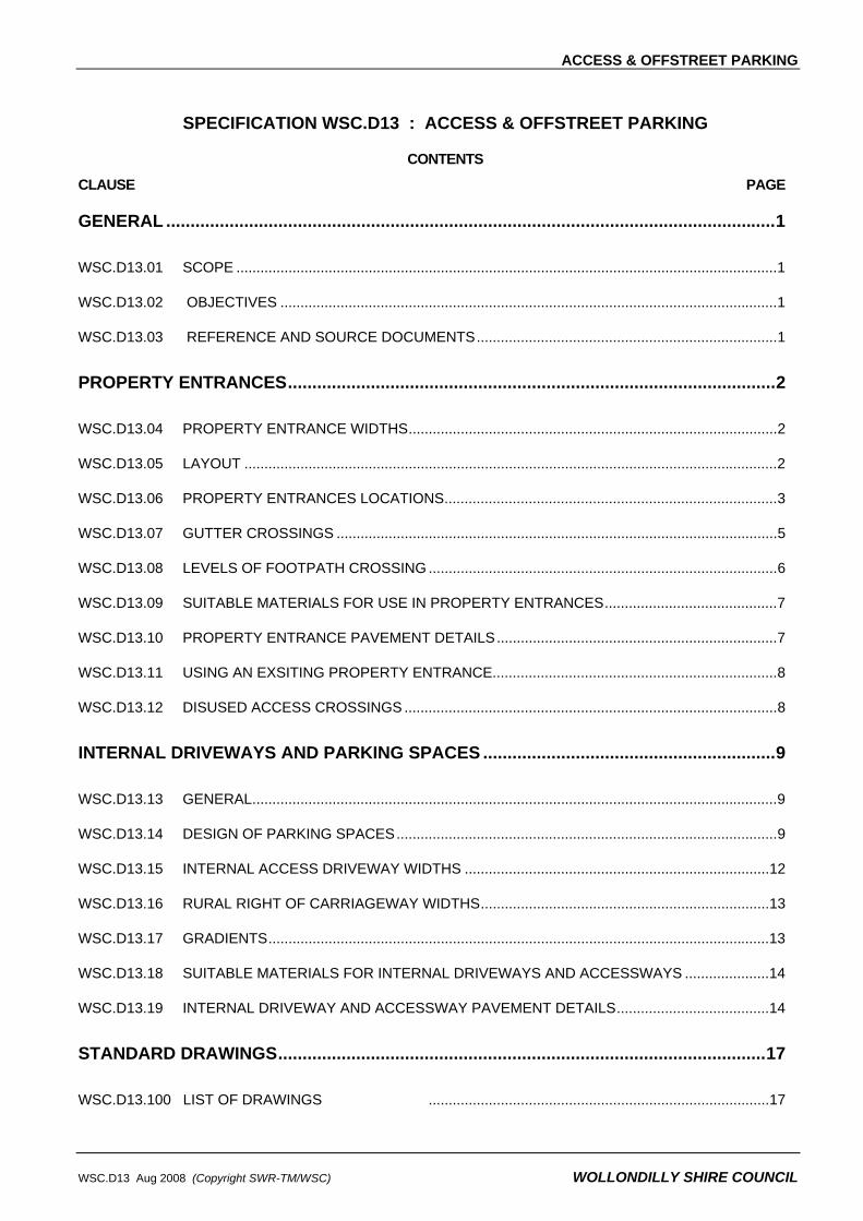
ACCESS & OFFSTREET PARKING
WSC.D13 Aug 2008 (Copyright SWR-TM/WSC) WOLLONDILLY SHIRE COUNCIL
SPECIFICATION WSC.D13 : ACCESS & OFFSTREET PARKING
CONTENTS
CLAUSE PAGE
GENERAL .............................................................................................................................1
WSC.D13.01 SCOPE .......................................................................................................................................1
WSC.D13.02 OBJECTIVES ............................................................................................................................1
WSC.D13.03 REFERENCE AND SOURCE DOCUMENTS...........................................................................1
PROPERTY ENTRANCES....................................................................................................2
WSC.D13.04 PROPERTY ENTRANCE WIDTHS............................................................................................2
WSC.D13.05 LAYOUT .....................................................................................................................................2
WSC.D13.06 PROPERTY ENTRANCES LOCATIONS...................................................................................3
WSC.D13.07 GUTTER CROSSINGS ..............................................................................................................5
WSC.D13.08 LEVELS OF FOOTPATH CROSSING .......................................................................................6
WSC.D13.09 SUITABLE MATERIALS FOR USE IN PROPERTY ENTRANCES...........................................7
WSC.D13.10 PROPERTY ENTRANCE PAVEMENT DETAILS......................................................................7
WSC.D13.11 USING AN EXSITING PROPERTY ENTRANCE.......................................................................8
WSC.D13.12 DISUSED ACCESS CROSSINGS .............................................................................................8
INTERNAL DRIVEWAYS AND PARKING SPACES ............................................................9
WSC.D13.13 GENERAL...................................................................................................................................9
WSC.D13.14 DESIGN OF PARKING SPACES...............................................................................................9
WSC.D13.15 INTERNAL ACCESS DRIVEWAY WIDTHS ............................................................................12
WSC.D13.16 RURAL RIGHT OF CARRIAGEWAY WIDTHS........................................................................13
WSC.D13.17 GRADIENTS.............................................................................................................................13
WSC.D13.18 SUITABLE MATERIALS FOR INTERNAL DRIVEWAYS AND ACCESSWAYS .....................14
WSC.D13.19 INTERNAL DRIVEWAY AND ACCESSWAY PAVEMENT DETAILS......................................14
STANDARD DRAWINGS....................................................................................................17
WSC.D13.100 LIST OF DRAWINGS .....................................................................................17


ACCESS & OFFSTREET PARKING
WSC.D13 Aug 2008 (Copyright SWR-TM/WSC) D13.1 WOLLONDILLY SHIRE COUNCIL
SPECIFICATION WSC.D13 : ACCESS & OFF-STREET PARKING
GENERAL
WSC.D13.01 SCOPE
1 This design & construction specification sets out the minimum requirements for:
• property entrances into allotments • internal driveways, and • parking spaces.
WSC.D13.02 OBJECTIVES
1 The objective is to provide for suitable vehicular access from the road to carparking and service facilities on the property.
2 The objective in designing access driveways to developments are to:
• provide safe and convenient all weather vehicle access to the development
• maintain vehicle and pedestrian safety standards • maintain traffic flow standards • protect the footway.
3 The objective of designing internal roads is that they allow for safe and convenient all weather vehicle access to and from all parking spaces and loading bays on the property. They are to be constructed of such materials and in such a manner as to perform adequately and require minimal maintenance under the anticipated traffic loading for the design life adopted.
4 Carparking spaces must be of an adequate length and width.
WSC.D13.03 REFERENCE AND SOURCE DOCUMENTS
(a) Council Specifications
DCP 7 Off-street Car Parking
(b) Australian Standards
AS 1428.1 – 1993 – General Requirements for Access – Buildings
AS 2890 – Parking Facilities
AS/NZS 3661.1- 1993 – Slip Resistance of Pedestrian Surfaces – Requirements
AS3727 – 1993 - Guide to Residential Pavements
(c) State Authorities
Roads and Traffic Authority NSW – Guide to Traffic Generating Developments
(d) Other
Austroads - Guide to Traffic Engineering Practice, Part 5 - Intersections at Grade
Austroads – Pavement Design Manual
Clay & Brick Paver Institute – Specifying and Laying Clay Pavers
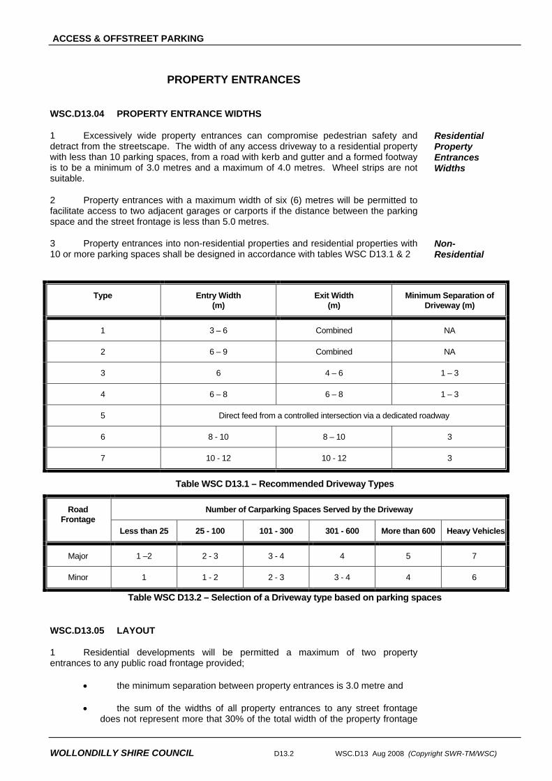
ACCESS & OFFSTREET PARKING
WOLLONDILLY SHIRE COUNCIL D13.2 WSC.D13 Aug 2008 (Copyright SWR-TM/WSC)
PROPERTY ENTRANCES
WSC.D13.04 PROPERTY ENTRANCE WIDTHS
1 Excessively wide property entrances can compromise pedestrian safety and detract from the streetscape. The width of any access driveway to a residential property with less than 10 parking spaces, from a road with kerb and gutter and a formed footway is to be a minimum of 3.0 metres and a maximum of 4.0 metres. Wheel strips are not suitable.
Residential Property Entrances Widths
2 Property entrances with a maximum width of six (6) metres will be permitted to facilitate access to two adjacent garages or carports if the distance between the parking space and the street frontage is less than 5.0 metres.
3 Property entrances into non-residential properties and residential properties with 10 or more parking spaces shall be designed in accordance with tables WSC D13.1 & 2
Non-Residential
Type Entry Width (m)
Exit Width (m)
Minimum Separation of Driveway (m)
1 3 – 6 Combined NA
2 6 – 9 Combined NA
3 6 4 – 6 1 – 3
4 6 – 8 6 – 8 1 – 3
5 Direct feed from a controlled intersection via a dedicated roadway
6 8 - 10 8 – 10 3
7 10 - 12 10 - 12 3
Table WSC D13.1 – Recommended Driveway Types
Number of Carparking Spaces Served by the Driveway Road Frontage
Less than 25 25 - 100 101 - 300 301 - 600 More than 600 Heavy Vehicles
Major 1 –2 2 - 3 3 - 4 4 5 7
Minor 1 1 - 2 2 - 3 3 - 4 4 6
Table WSC D13.2 – Selection of a Driveway type based on parking spaces
WSC.D13.05 LAYOUT
1 Residential developments will be permitted a maximum of two property entrances to any public road frontage provided;
• the minimum separation between property entrances is 3.0 metre and
• the sum of the widths of all property entrances to any street frontage does not represent more that 30% of the total width of the property frontage

ACCESS & OFFSTREET PARKING
WSC.D13 Aug 2008 (Copyright SWR-TM/WSC) D13.3 WOLLONDILLY SHIRE COUNCIL
to that street.
2 Minimum separations prevent two property entrances being used as one. Limiting property entrance widths as a percentage of street frontage allows for adequate pedestrian refuge and provides opportunity to present a more desirable streetscape.
3 Despite the 30% criteria outlined above, duplex developments may be permitted to have two property entrances where the location of the garages on the property do not permit the use of a shared crossover.
Duplexes
4 Generally all property entrances are to be constructed perpendicular to the kerbline.
Crossing Angle
5 In some instances to reduce disturbance to traffic flow along a major traffic route, an angled entrance may be permissible subject to approval by Council’s Traffic Engineer.
6 It may be necessary to provide Auxiliary Lanes and/or Right Turn Bays in order to limit disruption to traffic along high speed or high volume roads. The design of auxiliary lanes must give particular attention to pedestrian safety. Refer to Austroads publication Guide to Traffic Engineering Practice, Part 5 – Intersections at Grade for design details.
Auxiliary Lanes & Turning Bays
7 In certain circumstances, the Traffic Committee may restrict property access to left in - left out movements only. It will be necessary to erect appropriate signs and may be necessary to construct a median island within the road reserve to ensure compliance.
Left In - Left Out
8 If separate crossings are provided for entering and exiting traffic they shall be sign posted with “in” or “entrance” or “out” or “exit” as appropriate.
In-Out Sign Posts
WSC.D13.06 PROPERTY ENTRANCES LOCATIONS
1 Absolute Prohibitions:
• To a major road if reasonable access can be gained from another public road.
• Opposite or within 6m of a median opening in a major road.
Absolute Prohibitions
Desirable Restrictions
• Within 25m of a signalised intersection • Within 9m at other intersections.
These distances are measured from the face of kerb of the perpendicular street.
2 The desirable restrictions set out above will be enforced unless it is demonstrated to Council’s satisfaction that extenuating circumstances exist.
3 Property entrances should be located to ensure adequate sight distances are provided to traffic and pedestrians. Minimum traffic sight distances are outlined in the desirable sight distance (DSD) column of the table WSC D13.3.
Sight Distances
4 At the sole discretion of Council’s Traffic Engineer sight distances as low as those given in the approach sight distance (ASD) column may be approved provided no reasonable alternative exists for improving sight distances. New lots in proposed subdivision developments will not be approved if it is not possible to provide a vehicle access to that lot that will satisfy the desirable sight distance minimums of table WSC D13.3. Sight distance to pedestrians shall be met by providing clear sight lines in the areas indicated by figure D13.2 below.

ACCESS & OFFSTREET PARKING
WOLLONDILLY SHIRE COUNCIL D13.4 WSC.D13 Aug 2008 (Copyright SWR-TM/WSC)
Position of Driver
Edge of Road3.5m
No permanentsight obstruction
See Table below for Distance
See Table below for Distance
Figure D13.1 Traffic Sight Distance
Urban Roads
Approach Speed of through road (km/hr)
ASD (m) (1.5 s reaction time)
DSD (m)
50 60 70 80
45 55 70 95
80 105 130 165
Rural Roads Approach Speed of through road (km/hr)
ASD (m) (1.2 s reaction time)
DSD (m)
80 90 100
115 140 170
175 210 250
NOTE: These figures do not include cumulative specific allowance for gradients, variations in road surface, quality of street lighting and similar factors all of which, from a safety point of view, must be taken into consideration. Table WCS.D13.3
Property Boundary
Driveway
2.0
2.02.0
These areas to bekept clear ofobstructions tovisibility
Figure D13.2 Minimum Sight Lines for Pedestrian Safety
5 Consideration must be given to the potential for obstructions such as trees, earth mounds, bus shelters and the like to adversely affect sight lines.
Obstructions to Sight Lines
6 Where an existing bus shelter adversely impacts on the sight lines of vehicles using a proposed property entrance, Council may give consideration to moving the bus shelter to another location in front of the property, or constructing a new bus shelter in another location. All costs associated with such work will be borne by the applicant.
Moving a Bus Shelter
7 Access driveways shall be located clear of existing kerb inlet pits. Removing or reducing the length of a pit lintel is not acceptable.
Kerb Inlet Pits

ACCESS & OFFSTREET PARKING
WSC.D13 Aug 2008 (Copyright SWR-TM/WSC) D13.5 WOLLONDILLY SHIRE COUNCIL
8 Provided the pit is not a sag pit, Council may give consideration to moving a kerb inlet pit and lintel to another location in front of the property, in order to facilitate construction of the footway crossover. All costs associated with such work will be borne by the applicant.
Moving a Kerb Inlet Pit
WSC.D13.07 GUTTER CROSSINGS
1 Property entrances from roads with barrier kerb should have a gutter crossing (layback) constructed in the kerb line rather than returning the kerb to the property boundary. Details for gutter crossings (laybacks) are provided in the Appendix.
2 Kerb returns may be acceptable where:
• The access is to a heavily trafficked road, and the development generates a large amount of traffic, or the driveway is used by heavy vehicles, or
• The access is to a road with high traffic speeds.
Approval for the use of kerb returns shall be at the discretion of Council’s Traffic Engineer.
3 If kerb returns are permitted/required kerb ramps will need to be provided to facilitate pram and wheelchair movements. See Drawing No. WSC.D1.17 in the Appendix for details.
Kerb Ramps
4 In kerbed streets with a steep crossfall, bridge crossings over gutters may be approved for use as a last resort to prevent vehicles scraping.
5 In roads where it is necessary to cross a table drain to gain access to the property either a piped crossing or dish crossing will need to be provided depending on the depth of the table drain. See Drawing No. WSC.D1.16 in the Appendix for details.
6 Dish crossings are to be limited to locations where the gradient between the edge of the road pavement and the existing invert of the table drain does not exceed 4%. They are to be boxed below the invert level of the table drain so that the top of the dish crossing matches the existing invert level of the dish drain both on its upstream and downstream ends. A bitumen seal must be provided between the edge of the road pavement and the edge of the concrete dish crossing.
7 The location and level of the piped crossing must be approved by Council and will need to ensure:
• Rainwater will not pond in the table drain.
• The road shoulder is not narrowed or its levels modified.
• As much as possible, it is located outside the roadside clear zone. Headwalls located within the clear zone may need to be tapered for safety.
• Vehicles will not scrape when entering or leaving the property.
• There is no adverse impact on pedestrian movements along the footway.
• There is no adverse impact on existing trees, other crossings, service utilities and the like.
8 To limit the chance of blockage, the minimum size of a piped culvert is to be 375mm diameter. A larger culvert may be required to ensure adequate capacity to convey stormwater runoff. As a minimum, the capacity of the piped culvert should be
XProperty
Kerb Kerb
Gutter

ACCESS & OFFSTREET PARKING
WOLLONDILLY SHIRE COUNCIL D13.6 WSC.D13 Aug 2008 (Copyright SWR-TM/WSC)
equal to the lesser of either:
• The anticipated runoff from a 5 year ARI, or
• The existing capacity of the table drain.
9 All regrading of the table drain upstream and downstream of the piped culvert that may be necessary to ensure the suitable conveyance of rainwater runoff along the table-drain, will be carried out at the developer’s expense.
WSC.D13.08 LEVELS OF FOOTPATH CROSSING
1 The levels of the property entrance should be designed to:
• Ensure vehicle scraping does not occur
• Ensure maximum gradients are not exceeded
• Limit regrading of the footpath area
• Minimise disruption to pedestrians using the footpath area
• Preserve existing trees
• Ensure appropriate cover over existing underground utilities
• Ensure compatibility with existing or possible future plans for realignment of the road.
2 Typically, the property entrance should have a 4% gradient from the property alignment to the top of kerb. In roads where there is no kerb, the property entrance should have a 4% gradient from the property alignment to the edge of road shoulder. Where this is not practical, a design detailing the levels of the proposed property entrance should be prepared and submitted to Council for approval.
3 Where pedestrians use or are likely to use the footpath area, the levels of the access driveway must provide for pedestrians. In this regard, the section of driveway between 0.9m and 2.1m from the property alignment is to have a 4% gradient towards the kerbline. Where there is existing footpath paving the location and width of the footpath over the driveway shall match the existing. Council will give consideration to permitting the 1.2 1.5 metre wide footpath section to be located at the back of the layback in situations where levels at the property boundary are significantly above or below the level at the kerbline.
4 If the approved levels of the property entrance differ from the existing footway levels, the surrounding footway area must be regraded to satisfactorily marry with the new crossing. The minimum extent of footway which must be regraded is determined using the design constraints outlined below:
Altering Public Footway Levels
• The maximum change of grade along the footway is to be 1 in 10 with a minimum segment length of 4.0 metres;
• The maximum longitudinal grade of the footway is to be 1 in 6
5 If access to adjoining private properties is affected by the footway regrading, all work necessary shall be done within those properties to ensure satisfactory pedestrian and vehicular access is restored.
Regrading within

ACCESS & OFFSTREET PARKING
WSC.D13 Aug 2008 (Copyright SWR-TM/WSC) D13.7 WOLLONDILLY SHIRE COUNCIL
6 It will be necessary to obtain written consent from the adjoining property owner(s) that they will permit the applicant’s contractors to enter their property and undertake all work necessary to ensure vehicles and pedestrians have satisfactory access to the property following regrading of the footway. This letter of consent must be submitted to the principal certifying authority prior to issuing of the construction certificate for the building works.
Adjoining Private Properties
7 All mains, services, poles, footpath paving etc that require alteration shall be at the applicants expense and to the satisfaction of Council and the authority concerned.
8 Where the alteration of a house service is required, it is to be carried out by a suitably experienced tradesperson. Twenty-four (24) hours notice shall be given to the affected property owner before their service is affected.
Alteration of House Services
9 In the case of public utility mains, if a main must be raised, lowered or relocated, the applicant shall liase with the relevant Authority to organise the alteration and undertake all work to the satisfaction of that Authority.
Alteration of Mains
10 The applicant shall arrange with the relevant authority for the alteration of all surface fittings of all services which are affected by the new finished surface levels.
Surface Fittings
11 If the ground level of the property adjacent the footpath is above or below the finished level of the footway then adequate measures must be taken to support the land by constructing either earth batters or retaining structures. These are to be fully contained within the property and are not to encroach onto the public footway.
Retaining Private Properties
12 Where retaining of an adjoining property is necessary as a consequence of regrading the footway, written permission from the affected property owner(s) to enter their property and undertake such work must be submitted to the principal certifying authority prior to issuing of the construction certificate for the building works.
Regrading Adjoining Properties
WSC.D13.09 SUITABLE MATERIALS FOR USE IN PROPERTY ENTRANCES
1 Gutter Crossings, dish crossings and piped culvert crossings shall be constructed in accordance with the detail drawings shown in the Appendix.
2 Footpath Crossings in roads with kerb and gutter and in roads with a formed footpath area suitable for use by pedestrians are to be constructed of:
• plain concrete with a 28 day compressive strength of 25Mpa, or
• coloured or patterned concrete with a 28 day compressive strength of 25Mpa, or
• concrete pavers
3 The applicant is to be aware that any future restoration of the footway crossing carried out by Council or another service authority will be in plain concrete. The extent of restoration will be limited to the area damaged. Generally it will not extend to replacing the entire footway crossing slab.
Future Restorations
4 In roads without kerb and gutter or a formed pedestrian footway, footway crossovers may be constructed of crushed sandstone or approved road base material. Access to commercial and industrial premises and accesses that service more than one dwelling will need to be sealed. Access driveways with gradients in excess of 10% will also need to be sealed.
WSC.D13.10 PROPERTY ENTRANCE PAVEMENT DETAILS
1 Concrete slabs shall be constructed in accordance with the following thicknesses:
Thickness

ACCESS & OFFSTREET PARKING
WOLLONDILLY SHIRE COUNCIL D13.8 WSC.D13 Aug 2008 (Copyright SWR-TM/WSC)
Up to two dwellings
More than two dwellings, Commercial, Light Industrial
Major Commercial / Heavy Industrial
125mm thick, + 1 layer of F72 fabric
150mm thick + 1 layer of F72 fabric
200mm thick + 2 layers F72 fabric
2 Reinforcing shall have approximately 40mm top cover and should be supported during construction by bar chairs at 1 metre centres. The reinforcement should not be continuous through a control joint.
Reinforcement
3 A 150mm thick compacted, granular sub-base shall be provided for all commercial footway crossings. A 50mm thick compacted, granular sub-base shall be provided under all other concrete footway crossings.
Sub-Base
4 Mastic joints 5mm thick are to be provided at the property boundary and at the rear of the gutter crossing (layback). Dummy joints shall be provided at either side of the footway where applicable.
Construction Joints
5 Pavers shall be a minimum 75mm thick laid on a 100mm reinforced concrete base with a 30mm thick layer of sand between the pavers and the concrete. An edge restraint is to be provided as per plan WSC.D1.15.
Paver Slabs -Thickness
6 Concrete crossovers should usually have a broom finish unless it has a gradient steeper than 1 (vertical) to 5 (horizontal) when it should be finished with a wooden float. The finish is to be a uniform, non-slip surface. All edges are to be rounded with a 5mm edging tool.
Finish Quality
7 Any damaged, defaced or otherwise unsatisfactory section shall be removed and replaced.
Poor Finish
8 All footway crossings should have slip resistance appropriate for the pavement slopes as required by AS/NZS 3661.1. The relative level of adjacent pavers should not be greater than 5mm, and gaps between pavers or in patterned concrete slabs, no greater than 3 mm. The finish is not to constitute a hazard to pedestrians.
Pedestrians
7 Sandstone and Road base access driveways shall have a minimum thickness of 200mm. The seal shall be asphaltic concrete or a two coat 14/7 spray seal and shall smoothly match into the existing public road pavement.
WSC.D13.11 USING AN EXSITING PROPERTY ENTRANCE
1 Existing property entrance may only be used to service new property developments when:
• the existing crossing is in the correct location, at the correct level and in good condition, and
• the existing crossing is not a bridge crossing.
2 Otherwise, the crossing is to be removed and a new crossing constructed.
WSC.D13.12 DISUSED ACCESS CROSSINGS
1 Footway crossings slabs, or parts of footway crossings slabs, that become redundant are to be removed and the footway area restored. Disused gutter crossings are to be removed and the kerb reinstated.
2 Any existing unused gutter crossings and footway crossing slab will also need to

ACCESS & OFFSTREET PARKING
WSC.D13 Aug 2008 (Copyright SWR-TM/WSC) D13.9 WOLLONDILLY SHIRE COUNCIL
be removed, irrespective of the fact that it may have not become redundant as a consequence of the current application.
3 Details for kerb and gutter construction are given on plan WSC.D1.12 in the Appendix
INTERNAL DRIVEWAYS AND PARKING SPACES
WSC.D13.13 GENERAL
1 The design of all parking spaces, circulation roads and manoeuvring areas on the property must conform to the minimum requirements outlined below and the design criteria in AS 2890.1-1993 Parking Facilities, Part1 Offstreet Parking. In so far as any inconsistency exists between criteria outlined below and the Australian Standards, the criteria in this document shall apply.
WSC.D13.14 DESIGN OF PARKING SPACES
1 The depth of a parking space shall not be less than 5.5m. The width of a parking space is dependent on the width of the manoeuvring lane and will be in accordance with the following minimum standards
Clear width of space Clear width of manoeuvring lane
2.5m 2.6m 2.7m 2.8m
more than 2.8m
7.0m 6.7m 6.4m 6.1m 6.0m
Table WSC.D13.4
2 The absolute clear width of a parking space shall be 2.5m and the absolute minimum width of a manoeuvring lane shall be 6.0 metres.
3 The minimum clear width of an enclosed single vehicle garage shall be 3.0m.
4 Garage doorway shall have a minimum width of 2.5m. A wider doorway may be required if there is not sufficient manoeuvring space in front of the garage to enable a straight entry.
Garage door Width

ACCESS & OFFSTREET PARKING
WOLLONDILLY SHIRE COUNCIL D13.10 WSC.D13 Aug 2008 (Copyright SWR-TM/WSC)
Min. 1.0 m
Access Driveway
3 Where the parking is provided as an undercover space, Council may permit a reduction of the clear width of parking spaces in accordance with the diagram below if columns are setback from the front of the space.
Columns
2.6m
2.6m
2.6m
2.6m
2.6m
5.5 m
17.2 m6.2 m
Column
2.5m
2.5m
2.5m
2.6m
2.5m
5.5 m
17.2 m6.2 m
Column
0.75
Provision shall be made for the sweep of the front of the vehicle where a parking space is perpendicular to the access driveway.
Blind Aisles

ACCESS & OFFSTREET PARKING
WSC.D13 Aug 2008 (Copyright SWR-TM/WSC) D13.11 WOLLONDILLY SHIRE COUNCIL
The following Standards shall apply to angle and parallel parking:
3.9
16.8
3.68
1.84
15.4
3.91.84
3.9
One Way
45°
13.0
2.7 2.3
30°
1.3
5.2
4.8
16.5
3.0
One Way
17.2
60°
4.77 1.3
2.75
3.0
2.25
14.1
5.0
One Way
PARALLEL
One Way
2.56.1
3.1

ACCESS & OFFSTREET PARKING
WOLLONDILLY SHIRE COUNCIL D13.12 WSC.D13 Aug 2008 (Copyright SWR-TM/WSC)
WSC.D13.15 INTERNAL ACCESS DRIVEWAY WIDTHS
1 Provision must be available within the property to enable vehicles (85 percentile vehicle) to enter the designated parking space in a single turning movement and leave the space in no more than two turning movements. Turning templates are supplied in the appendix. A clearance of 300mm should be added to both sides of the turning path.
2 Provision must be made for vehicles to enter and leave the site in a forward direction. This standard does not apply to driveways from single domestic dwellings onto access, local or collector roads.
Forward Direction
3 The minimum widths for internal driveways and accessways shall be as outlined in table WSC.D13.5 below:
Development Type Minimum Pavement Width (1)
Urban and Rural Residential
Single Domestic Dwelling 3.0 m
Accessways to Multiple lots ≤ 7 dwellings > 7 dwellings
4.0 m (2)
See Category B & C Cul-de-sac requirements D1 – GEOMETRIC ROAD REQUIREMENTS
Driveways in Medium Density Developments ≤ 10 parking spaces > 10 parking spaces
4.0m (3) 5.5 m
Rural
Single Domestic Dwelling 3.0 m with min 0.5m shoulders with 15 m reservation for the road
Accessways to Multiple lots ≤ 5 dwellings > 5 & less than 15 dwellings >15 dwellings
4.0 m pavement with min. 0.5 m shoulders (4)
with 20 m reservation for the road 4.0 m pavement with min 1.5 m shoulders (4)
with 20 m reservation for the road See Category G2 Cul-de-sac requirements
D1 – GEOMETRIC ROAD REQUIREMENTS, provide minimum 20 m reservation for the road
Commercial / Industrial
All 3.0 m one way 6.0 m two way
NOTES 1 If there is a kerb or barrier higher than 150mm and closer than 300mm from the edge of the roadway, the
roadway shall be widened to provide a minimum of 300mm clearance to the obstruction. 2 Maximum length is 100m. A passing bay is required if length is greater than 80m. Greater than 100m length,
minimum width = 5.5 m. 3 Provision for vehicle passing at least every 30m by way of a passing bay that will provide a minimum
carriageway width of 5.5m for a minimum length of 7.0m 4 Provision for vehicle passing at least every 100m by way of a passing bay that will provide a minimum
carriageway width of 5.5m for a minimum length of 7.0m Table WSC D13.5

ACCESS & OFFSTREET PARKING
WSC.D13 Aug 2008 (Copyright SWR-TM/WSC) D13.13 WOLLONDILLY SHIRE COUNCIL
WSC.D13.16 RURAL RIGHT OF CARRIAGEWAY WIDTHS
1 The minimum width for ROC are:
• 15.0 metres where located adjacent to an adjoining property with separate ownership. This width is required to provide adequate space for access construction & service provision without adversely affecting the adjoining property.
• 10.0 metres where located clear of any adjoining property.
ROC Width.
WSC.D13.17 GRADIENTS
1 The desirable maximum grade for parking bays shall be:
• measured parallel with the angle of parking - 1 in 20 (5%); and
• measured at 90° to the angle of parking - 1 in 20 (5%).
Parking Space Grades
2 The minimum driveway grade shall be 1 in 200 (0.5%). Minimum Driveway Grade
3 The maximum grade for residential driveways or accessways servicing less than 5 dwellings shall be 1 in 5 (20%). The maximum grade for all other driveways shall be 1 in 6 (16.7%)
Maximum Driveway Grade
4 The maximum grade of a driveway for commercial use shall be 1 in 6 (16.67%)
5 Driveway grades on curves shall be measured along the inside edge of the carriageway.
6 Vehicle scraping may occur when changes of grade exceed 1 in 8 (12.5%). Where there is a potential for vehicle scraping, transition sections, with a minimum length of 2.0 metres, are to be provided.
Changes of Grade
7 The maximum crossfall on an internal roadway shall be 5%. Crossfalls
8 Buildings with high public usage and aged and disabled housing developments must provide pedestrian access in accordance with the requirements of AS 1428.1 – 2001
People with limited mobility
9 Rural Right of Carriageway.
• Table drains at grades greater than 10% shall be concrete lined and gutter.
• Table drains at grades lesser than 10% shall be turfed.
• Road surface on grade more than 16% shall be asphaltic concrete seal with 30mm AC10 on single coat seal of 10mm aggregates.
ROC Grades

ACCESS & OFFSTREET PARKING
WOLLONDILLY SHIRE COUNCIL D13.14 WSC.D13 Aug 2008 (Copyright SWR-TM/WSC)
WSC.D13.18 SUITABLE MATERIALS FOR INTERNAL DRIVEWAYS AND ACCESSWAYS
1 Acceptable pavement materials are listed in table WSC.D13.6 below.
Development Type Acceptable Pavement Types
Urban Residential Concrete Segmental Pavers Concrete Permeable Pavers Asphalt
Rural Residential Concrete Segmental Pavers Concrete Permeable Pavers Asphalt Flexible pavement with Spray Seal
Rural Concrete Segmental Pavers Concrete Permeable Pavers Asphalt Flexible pavement with Spray Seal Flexible pavement without Seal (1)
Commercial/Industrial Concrete Segmental Pavers Concrete Permeable Pavers Asphalt
1. See Part WCS.D13.17 – 2 below Table WSC.D13.6
2 Unsealed pavements will not be permitted. Unsealed Pavements
3 In some areas, Council may require the use of a coloured or patterned concrete driveway to provide a desired streetscape appearance.
4 In high use pedestrian areas, the use of segmental pavers is discouraged particularly where these are to become Council assets or maintenance may not be performed regularly.
Pavers Discouraged
WSC.D13.19 INTERNAL DRIVEWAY AND ACCESSWAY PAVEMENT DETAILS
1 Internal pavements for residential developments consisting of single dwellings or multiple dwellings shall be in accordance AS 3727-1993 “Guide to Residential Pavement”. Extracts from this standard are provided below. Pavements that will carry heavy vehicles or significant traffic volumes shall be designed in accordance with the AustRoads “Pavement Design” manual (AustRoads 1992) or the Clay Brick & Paver Institute publication “Specifying and Laying Clay Pavers”.
Design Manuals
(a) Concrete Pavements
2 Typical slab thickness, concrete grade, joint spacing and reinforcement should be in accordance with Table WSC.D13.7 below

ACCESS & OFFSTREET PARKING
WSC.D13 Aug 2008 (Copyright SWR-TM/WSC) D13.15 WOLLONDILLY SHIRE COUNCIL
Traffic Min Slab Thickness
Min Concrete Grade
Alternative 1 Max. Min Control Reo joint Fabric Spacing
Alternative 2 Max. Min Control Reo joint Fabric Spacing
Alternative 3 Max. Min Control Reo Joint Fabric Spacing
Light Traffic – Use by no more than two Dwellings
Medium Residential Traffic Light/Industrial Commercial
125
150
N20
N25
2 2
- -
3 4
F52
F82
6 6
F62
F82
Heavy Industrial/Commercial See AustRoads “Pavement Design” Manual
Note: Slab thickness is measured from the underside of the slab to the bottom of any top surface patterning. Table WSC.D13.7
3 Reinforcing shall have approximately 40 mm top cover and should be supported during construction by bar chairs at 1 metre centres. The reinforcement should not be continuous through a control joint. Where the slab surrounds another structure such as a drainage pit, trimming reinforcement should be used. Trimming reinforcement should be not less than one Y12 bar of minimum length 600mm.
Reinforcement
4 Control joints shall have spacings no greater than shown in the table above. They shall be constructed by formwork between concrete pours, or creating a plane of weakness to a depth of one third to one quarter of the pavement thickness. Mastic isolation joints should be provided where a pavement adjoins a building or other rigid structure such as a drainage pit.
Joints
(b) Segmental Pavements
5 Typical thickness of base-courses and required class for paver units shall be as follows:
Pavers
Traffic Compacted Base-course
Thickness Paver Class
Light Traffic - Use by no more than two Dwellings
Medium Residential Traffic
75mm
150mm
4 4
Other See reference “Specifying and Laying Clay Pavers” Table WSC.D13.8
6 The sand bedding course shall be of roughly uniform thickness and not exceed 30mm after compaction.
7 Pavers should have a nominal 3mm joint between the units. Joints should be filled with appropriate sand.
8 The entire perimeter of segmental pavements shall be provided with lateral edge restraints.

ACCESS & OFFSTREET PARKING
WOLLONDILLY SHIRE COUNCIL D13.16 WSC.D13 Aug 2008 (Copyright SWR-TM/WSC)
(c) Permeable Pavements
9 Permeable pavements comprising segmental pavers and pavement layers shall be acceptable provided they: Are designed and installed as per the manufacturer’s recommendations Allow infiltration of rainfall as per WSUD principles.
(d) Flexible Pavements
10 In rural or rural residential areas the minimum design requirements of flexible pavement driveways and accessways shall be:
Wearing Course two coat 14/10 spray seal or 30 mm AC10
Base Course 100mm DGB 20 where wearing course is AC or 100mm of 40mm crushed sandstone if not AC seal
Sub-base 100mm of 40 mm crushed sandstone
Compacted Sub grade
11 An asphaltic pavement may be constructed as full depth asphalt pavement or consist of a combination of sub-base, base course and asphalt surfacing. Typical pavement specifications shall be in accordance with table WSC.D13.9 below:
Flexible Pavements
Traffic Asphalt and Base course
Full Depth Asphalt
Light Traffic - Use by no more than two Dwellings
Medium Residential Traffic Light Industrial/Commercial
30mm AC10 125mm Base
30mm AC 10 200mm Base
100mm AC10
125mm AC 10
Other See AustRoads “Pavement Design” Manual
Table WSC.D13.9

ACCESS & OFFSTREET PARKING
WSC.D13 Aug 2008 (Copyright SWR-TM/WSC) D13.17 WOLLONDILLY SHIRE COUNCIL
STANDARD DRAWINGS
WSC.D13.100 LIST OF DRAWINGS List of Drawings
1. DRAWING NUMBER DRAWING DESCRIPTION
WSC.D1.5 Standard for Industrial Footpath Crossing WSC.D1.6 Standard for Industrial Vehicular Crossing WSC.D1.7 Standard Commercial Vehicle Crossing WSC.D1.8 150 Integral Kerb & Gutter and Vehicular Crossings for Formed K & G Construction WSC.D1.9 Vehicular Footpath Crossings for Kerb and Gutter – Cross Sections WSC.D1.10 Vehicular Footpath Crossings for Dish Crossings – Cross Sections WSC.D1.11 Vehicular Footpath Crossings for Roll Kerb and Gutter – Cross Sections WSC.D1.12 Standard Kerb and Gutters WSC.D1.15 Standard Residential Vehicular Crossing Using Pavers WSC.D1.16 Driveway Standard Rural Pipe Crossing WSC.D1.17 Standard Pram Ramp Crossing WSC.D1.18 Turning Path Template for Design Car (B99) WSC.D1.19 Service area Template for Design Car WSC.D1.20 Turning Path Template for Design Car (B85) WSC.D1.21 Turning Path Template for Heavy Rigid Vehicle WSC.D1.22 Service Area Template for Heavy Rigid Vehicle WSC.D1.23 Standard Residential Vehicular Crossing Using Concrete


