Download - SUPER GV - MRG-CZ
SUPER GV SERIES
SUPER SIZED CNC VERTICAL TURNING CENTER
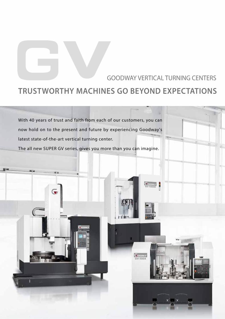
With 40 years of trust and faith from each of our customers, you can
now hold on to the present and future by experiencing Goodway's
latest state-of-the-art vertical turning center.
The all new SUPER GV series, gives you more than you can imagine.
GOODWAY VERTICAL TURNING CENTERS
TRUSTWORTHY MACHINES GO BEYOND EXPECTATIONS

2
GOODWAY VERTICAL TURNING CENTERS
Max. Turning DiameterMax. Turning Length
SUPER GVØ 2,300 ~ Ø 9,000 mm1,700 ~ 3,800 mm
Ø 1,350 ~ Ø 1,800 mm1,300 mm
GV-1
Ø 1,000 mm760 mm
660 mm
520 mm
GV-1000
Ø 820 mm
GV-780
Ø 620 mm
GV-500

SUPER SIZED CNC VERTICAL TURNING CENTER
With leading technologies and high quality components, the SUPER GV CNC vertical
turning center combines heavy-duty, high rigidity and super large machining
range advantages to provide you with large sized, asymmetric work piece turning
capabilities. The optimal reinforced structure of these series can maintain long term
precision even if the table diameter is reached up to 8,000mm. Plus, with the optional
dual ram or live tooling spindle and C-axis, all kinds of complex turning applications
can be done easily, which can meet your needs for today and tomorrow.
Super Large Turning RangeMaximum turning diameter can reach up to Ø 9,000 mm ; maximum work-piece
weight can reach up to 300,000 Kg ( GV-8000 series ).
High Rigidity StructureThe bed, column and bridge casting components are of Meehanite casting
with a symmetric structure design, which ensures optimal thermal balance and
heavy duty rigidity.
Powerful High Torque MotorsThe work piece and live tooling spindles uses a high power 2-speed heavy-
duty gear box motor to provide ample torque output for heavy duty cutting
applications.
High Effeciency Chip Removal System The standard chip wash down coolant system can flush away great amount of
chips into the coolant tank, and are sent outside from the machine through the
chip conveyor; this tremendously improves the machine's overall accuracy by
lowering thermal expansion effects to a minimum.
Turning, Milling And Grinding Multi-Tasking CapabilityThe optional live tooling spindle provides turning, milling, grinding, drilling,
and tapping capabilities, which greatly increases production efficiency while
saving equipment investment costs.
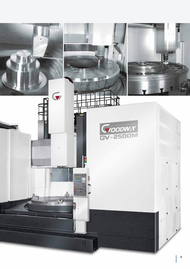
( GV-2500M model shown. )
4

HIGH RIGIDITY CONSTRUCTIONBy using Finite Element Methods ( FEM ), optimal reinforce ribbings are
directly cast into the bed and column structure. Mechanical rigidity
has been increased by more than 30% when compared to conventional
designs. The SUPER GV series is capable of performing super heavy-
duty turning and maintain long-term super high-precision accuracy.
The heavily ribbed, symmetric box-type designed bed, column and
cross beam are of Meehanite casting. This high rigidity structure can
effectively reduce thermal distortion while increasing heavy-duty cutting
capability and maintaining machining accuracy.
( Casting structure of GV-2500M series model shown. )

6
One-piece Column & Bridge Structure( GV-2000 ~ GV-2500 )
Bridge Type Structure( GV-3000 ~ GV-8000 )
The one-piece column & bridge is firmly mounted
on top of the bed, which ensures machine overall
rigidity and minimizes spindle over hang to
provide optimal machining accuracy.
The super rigid construction of the base and bed,
double column, and cross beam, can easily fulfill
heavy load and cutting requirements.
The optional high resolution close-loop
linear scale ensure optimal positioning and
repeatability accuracy.
Contact surfaces of all slides, spindles, ball
screw bearing housings, bed and column
are precis ion hand scraped to provide
maximum assembly precision, structural
rigidity, and load distribution.
Super large box way and components are of
one-piece casting; they are applied with heat
treatment and precision grinded to provide
maximum strength and accuracy.
min.

Model GV-5000 GV-6000 GV-7000 GV-8000
A 350 / 400 ( OPT. )
Model GV-2000 GV-2500 GV-3000 GV-3500 GV-4000
A 220 250 300 / 350 ( OPT. )
TOOLING SPINDLE
With the optional dual ram structure, multiple
machining applications ( such as rough turning
/ fine turning or drilling / tapping / milling ) can
be operated at the same time; one machine can
replace two vertical turning centers which saves
tool change time and increases floor space usage.
The square ram on the tooling spindle is adopted with a
closed-type design and fixed with powerful wedges. This
gives the SUPER GV series with greater structural rigidity
and machining accuracy compared to peer models with
a semi-closed type square ram structure.
Dual Simultaneous Turning Optional Single Live Tooling Spindle Optional Double Live Tooling Spindle
Semi-closed Type Square Ram
Unit : mm
Closed-type Square Ram
Increases machining efficiency Reduces Tool Change Time Reduces Tool Change Time
Dual Ram Structure
A
A
Ram Dimension
Diversed Machining Mode

17 kW
22.5 kW1200
800
400
375 700 1050 1500 rpm 0
24
16
12
8
1068
805
418 1100810
( N-m ) ( kW )900
600
300
600 1200 1800 2400 rpm 0
24
16
8
514
387
17 kW
22.5 kW
418
( N-m ) ( kW )
0
150
300
450
600
350 700 1050 1400
4
8
12
1615 kW
11 kW
( N-m ) ( kW )
rpm
493
362
291 135611620
50
100
150
200
1000 2000 3000 4000
4
8
12
1615 kW
11 kW
( N-m ) ( kW )
rpm
828
173
127
38623310
8
Torque
Torque
Torque
Torque
Output
Output
Output
Output
Low Gear
Low Gear
High Gear
High Gear
Live Tooling Spindle
GV-2500 GV-2500
( 30 min. )
( 30 min. )
( 30 min. )
( 30 min. )
( cont. )
( cont. )
( cont. )
( cont. )
Torque ( cont. )
Torque ( cont. )
Torque ( cont. )
Torque ( cont. )
Torque ( 30 min. )
Torque ( 30 min. )
Torque ( 30 min. )
Torque ( 30 min. )
The live tooling spindle uses JAPAN NN Type roller bearings to provide high rigidity, high
precision, and long life span advantages.
The high reduction ratio 2-speed gear box uses high hardness Nickel-Chromium-Molybdenum
alloy with forced oil-feed for lubrication and coolant; the gear box can maintain normal
operation and low wear even under long hours of low-speed, high-torque working conditions.
Live Tooling Spindle Output
GV-5000GV-5000
S:Standard O:Option ─:Not available
Model GV-2000 GV-2500 GV-3000 GV-3500 GV-4000 GV-5000 GV-6000 GV-7000 GV-8000
Cross Roller Bearings S S S S S ─ ─ ─ ─
Hydrostatic Bearings ─ ─ O O O S S S S
rpm
( N-m ) ( kW )
20
40
60
8075 kW
60 kW
17205
11470
42 181127
10000
20000
5000
15000
500 100 150 200rpm
( N-m ) ( kW )
0
20000
40000
60000
80000
30 45
20
40
60
8075 kW
60 KW
74140
49430
422912
10 20 40
400,000
300,000
200,000
150,000
247,900
4.6
180
135
90
45
13.3
347,000
120 kW
168 kW
0 6 12 18 rpm
( N-m ) ( kW )100,000
75,000
50,000
25,000
61,000
18.8
85,480
180
135
90
45
0
120 kW
168 kW
15 30 45 60 rpm
( N-m ) ( kW )
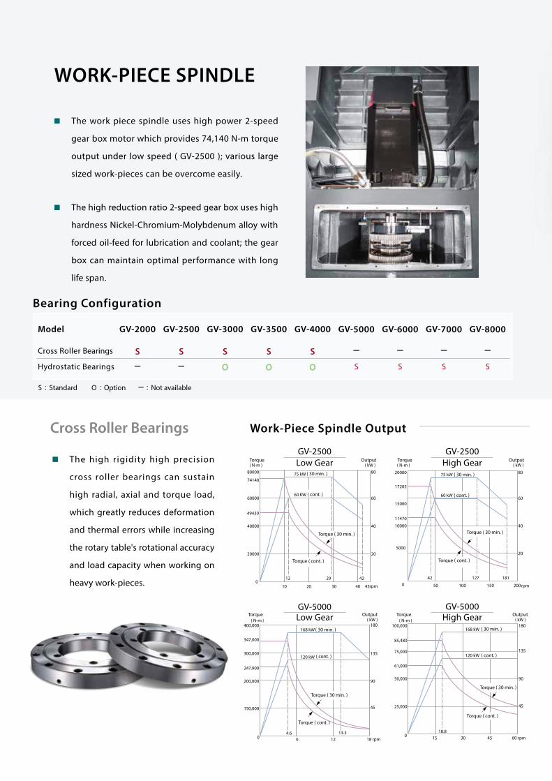
WORK-PIECE SPINDLE
Cross Roller Bearings
The work piece spindle uses high power 2-speed
gear box motor which provides 74,140 N-m torque
output under low speed ( GV-2500 ); various large
sized work-pieces can be overcome easily.
The high reduction ratio 2-speed gear box uses high
hardness Nickel-Chromium-Molybdenum alloy with
forced oil-feed for lubrication and coolant; the gear
box can maintain optimal performance with long
life span.
Bearing Configuration
Work-Piece Spindle Output
The high rigidity high precision
cross roller bearings can sustain
high radial, axial and torque load,
which greatly reduces deformation
and thermal errors while increasing
the rotary table's rotational accuracy
and load capacity when working on
heavy work-pieces.
Torque
Torque
Torque
Torque
Output
Output
Output
Output
Low Gear
Low Gear
High Gear
High Gear
GV-2500 GV-2500
( 30 min. )
( 30 min. )
( 30 min. )
( 30 min. )
( cont. )
( cont. )
( cont. )
( cont. )
Torque ( cont. )
Torque ( cont. )
Torque ( cont. )
Torque ( cont. )
Torque ( 30 min. )
Torque ( 30 min. )
Torque ( 30 min. )
Torque ( 30 min. )
GV-5000GV-5000

10
Spindle Accuracy Comparison
Hydrostatic Bearings
Grade P4 Roller Bearings
Hydrostatic Bearings
The high rigidity hydrostatic bearings provide absolute zero static friction coefficient and low
kinetic friction coefficient which can easily drive the rotary table without needing high torque
output. Plus the stick-slip effect is eliminated under low speed which provides stable and smooth
rotating movement while maintaining maximum dynamic accuracy.
The hydrostatic bearings provides great damping in vertical movement and low damping in
horizontal movement. The oil film damper provides outstanding dynamic rigidity.
Dynamic rotational accuracy
3µ
3µ
0.005 sec.
0.002 sec.
Damping effect
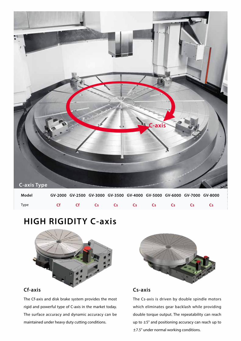
The Cf-axis and disk brake system provides the most
rigid and powerful type of C-axis in the market today.
The surface accuracy and dynamic accuracy can be
maintained under heavy duty cutting conditions.
The Cs-axis is driven by double spindle motors
which eliminates gear backlash while providing
double torque output. The repeatability can reach
up to ±5" and positioning accuracy can reach up to
±7.5" under normal working conditions.
C-axis
C-axis Type
Model GV-2000 GV-2500 GV-3000 GV-3500 GV-4000 GV-5000 GV-6000 GV-7000 GV-8000
Type Cf Cf Cs Cs Cs Cs Cs Cs Cs
HIGH RIGIDITY C-axis
Cf-axis Cs-axis
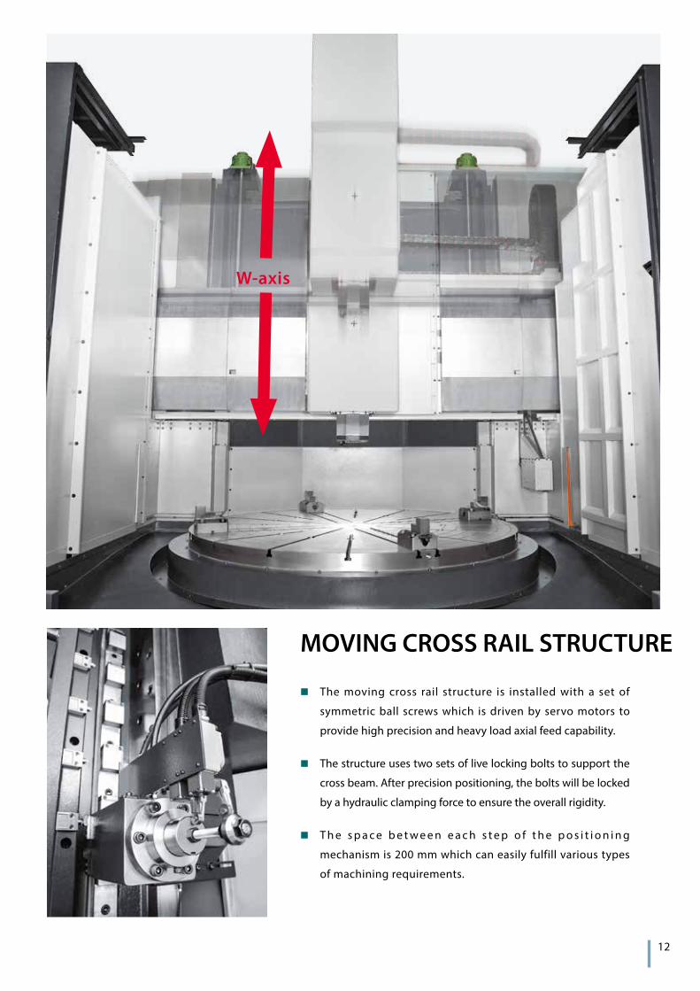
MOVING CROSS RAIL STRUCTURE
The moving cross rail structure is installed with a set of
symmetric ball screws which is driven by servo motors to
provide high precision and heavy load axial feed capability.
The structure uses two sets of live locking bolts to support the
cross beam. After precision positioning, the bolts will be locked
by a hydraulic clamping force to ensure the overall rigidity.
T h e s p a c e b e t w e e n e a c h s t e p o f t h e p o s i t i o n i n g
mechanism is 200 mm which can easily fulfill various types
of machining requirements.
W-axis
12
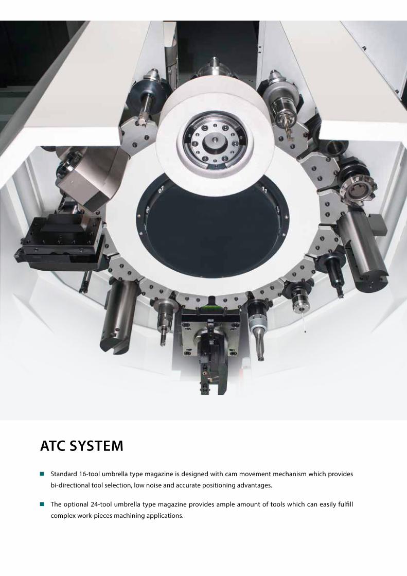
ATC SYSTEM
Standard 16-tool umbrella type magazine is designed with cam movement mechanism which provides
bi-directional tool selection, low noise and accurate positioning advantages.
The optional 24-tool umbrella type magazine provides ample amount of tools which can easily fulfill
complex work-pieces machining applications.

WORK-PIECE SPINDLEMain spindle S
Rigid tapping S
C-axis O
Disk brake for C-axis O
Lubrication system S
WORK-PIECE HOLDING4-jaw manual table S
TOOLING SPINDLEBT50 S
BT60 ( GV-3000 and above ) O
Spindle coolant O
Coolant through spindle ( CTS ) S
Milling functions O
Gear box lubrication system O
Umbrella type ATC magazine16 T S
24 T O
Chain type ATC magazine ( milling functions )
24 T C
32 T C
MEASUREMENTTool presetter O
Part presence check O
X & Z axes linear scales O
COOLANTCoolant pump 5 Kg/cm² S
High-pressure coolant system 20 Kg/cm² O
Oil skimmer O
Coolant flow switch O
Coolant level switch O
Coolant intercooler system O
Paper Tape Filter O
CHIP DISPOSALChip conveyor with auto timer O
Chip cart O
Coolant gun O
Air gun O
SAFETYFully enclosed splash guard without roof S
Fully enclosed splash guard with roof O
Door interlock ( incl. Mechanical lock ) S
Impact resistant viewing window S
Low hydraulic pressure detection switch S
Over travel ( soft limit ) S
Load monitoring function S
OTHERSTri-color operation status signal light tower S
Florescent work light S
Electrical cabinetHeat exchanger S
A/C cooling system O
Complete hydraulic system S
Advanced auto lubrication system S
Emergency maintenance electrical part package S
Operation & maintenance manuals S
SIEMENS CONTROL FUNCTIONS
SYSTEM CONFIGURATION
CNC User Memory
3M S
9M O
15M O
10.4" LCD display S
AXIS FUNCTION Separate feed for corners & chamfers S
SPINDLE FUNCTION
Oriented spindle stop S
Constant cutting speed S
Constant thread pitch cutting S
Variable thread pitch cutting S
Multiple thread cutting S
Rigid tapping S
INTERPOLATION /COUPLING
3D Circular interpolation S
Helical interpolation ( 2D+2 ) S
NURBS interpolation S
Polynomial interpolation O
Involute interpolation O
Machining on end face O
Multi-edge / Polygon turning O
HSC Look ahead block
150 S
250 O
500 O
OPERATION MODE Metric / Inch switchover ( JOG Mode ) S
CNC PROGRAMMING LANGUAGE
Global program variables S
Global / local user variables S
Macro technique S
Part programs in NCU, max 1,000 S
Workpieces on NCU, max 250 S
Part programs on CF card ( PCU50 ) S
Part programs on USB device S
Part programs on network dirve S
PROGRAMMING SUPPORT
Read / Write system variables S
Animate cycle support ( program GUIDE ) S
Animate machining step support ( Shop Turn ) S
Customer cycles dialog support S
Geometry processor for contour S
Basic Drill / Mill technology cycles S
Basic Truning technology cycles S
Free contour pocketing ( with island ) S
DXF contour conveter ( CAD Reader ) O
2D simulation ( finished part ) S
3D simulation 1 ( finished part ) O
WORK OFFSET
Number of basic frames , max 16 S
Number of settable frames ( G54~ ) 100 S
Zero / work offsets, programmable S
TOOL
Operaton with tool management S
Monitor of tool life and part count S
3D tool radius compensation S
COMMUNICATIONS
Fast Ethernet Ports S
Network drives, FTP , max 8 S
External PROFINET network S
Remote control system ( local network ) S
Remote control system ( internet ) O
SPECIAL FUNCTIONS
Auto servo turning S
Remote Diagnose via Ethernet S
SUPER GV
840D sl
STANDARD & OPTIONAL FEATURESS : Standard– : Not available
O : OptionC : Contact Goodway
14

L
L
L
W
ØD
ØD
S
S
S
S
S
Taper W L S
BT50 220 200 32
BT50 220 210 40
BT50 250 200 32
BT50 250 210 40
BT50 270 200 32
BT50 270 210 40
BT60 340 250 32
BT60 340 260 40
Taper L S D
BT50 200 25 100
BT50 300 25 100
BT60 200 25 140
BT60 300 25 140
Taper L S D
BT50 200 25 100
BT50 300 25 100
BT60 200 25 140
BT60 300 25 140
GENERAL DIMENSIONTurning Tool Holder
Unit : mm

Ø69.85
101.
83
37
Ø85Ø100
23.2
M24
Ø2574
Ø25
Ø36Ø28
Ø21
M24
DIN 69872A
Ø11.5
75°
Ø107.95
161.8
345
Ø135Ø155
28.2
M30Ø32
45°
Ø24Ø56Ø31
M30
115
Ø31
Specifications are subject to change without notice. 16
Tool Shank ( Optional )
Tapping Tool Holders
Drilling ( Collect Type ) Tool Holders
Drilling ( Side Lock ) Tool Holders
Face Milling Tool Holders
Boring Tool Holders
Taper L C D
BT50-SLA20-105 105 50 20
BT50-SLA25-105 105 55 25
BT50-SLA32-105 105 60 32
BT50-SLA40-105 105 80 40
BT50-SLA50.8-105 105 95 50.8
BT60-SLA20-105 105 50 20
BT60-SLA25-105 105 55 25
BT60-SLA32-105 105 60 32
BT60-SLA40-105 105 80 40
BT60-SLA50.8-105 105 95 50.8
Taper L D Cutter Dia.
BT50-FMA25.4-105 125 85 80
BT50-FMA31.75-105 127 85 100
BT50-FMA38.1-75 98 95 125
BT50-FMA50.8-75 99 95 150
BT60-FMA25.4-105 125 85 80
BT60-FMA31.75-105 127 85 100
BT60-FMA38.1-75 98 95 125
BT60-FMA50.8-75 99 95 150
Taper L D Tapping Range
BT50-TER16 80 28 M3-M12
BT50-TER40 117 63 M12-M35
BT60-TER16 83 28 M3-M12
BT60-TER40 126 63 M12-M35
Taper L D
BT50-BSA62-300 300 62 ~ 90
BT50-BSA72-320 320 72 ~110
BT50-BSA105-195 195 105 ~ 160
BT60-BSA62-300 300 62 ~ 90
BT60-BSA72-320 320 72 ~110
BT60-BSA105-195 195 105 ~ 160
Taper L Capacity Collet Type
BT50-ER20-100 100 1-13 ER20
BT50-ER32-100 100 2-20 ER32
BT50-ER40-100 100 3-26 ER40
BT60-ER20-100 100 1-13 ER20
BT60-ER32-100 100 2-20 ER32
BT60-ER40-100 100 3-26 ER40
Millling Tool Holder
BT50 BT60
Unit : mm
D
DC
L
L
LL
L
D
D

C
BDE
A
CC
BDEA
AB D E
Turning Tools Live Tools
90° Milling Grinding Head
X1-axis home position
X1-axis home position
X2-axis home position
X1 ATC
X2 ATC X1 ATC
ATC auto door
ATC auto doorATC auto door
ATC tool change point
ATC tool change pointATC tool change point
X1 Over centre limit
X1 Over centre limit
X2 Over centre limit
Spindle centre
RAM 1
RAM 1RAM 2
BoringBoring O.D ToolBoring
Tooling System
X-axis Travel
Single Ram ( 1R series )
Dual ram ( 2R series )
Tapping U-Drill Drilling Face millingMilling
Model A B C D E
GV-2000 2,830 705 225 1,125 1,000
GV-2500 3,080 705 225 1,375 1,000
GV-3000 3,950 500 230 1,950 1,500
GV-3500 4,450 500 230 2,200 1,750
GV-4000 4,950 500 230 2,450 2,000
GV-4500 5,450 500 230 2,700 2,250
GV-5000 6,435 740 290 3,195 2,500
GV-6000 7,435 740 290 3,695 3,000
GV-7000 8,635 740 290 4,195 3,700
GV-8000 9,735 740 290 4,695 4,300
Model A B C D E
GV-2000-2R 2,080 680 225 1,150 250
GV-2500-2R 2,330 680 225 1,400 250
GV-3000-2R 2,700 500 230 1,950 250
GV-3500-2R 2,950 500 230 2,200 250
GV-4000-2R 3,200 500 230 2,450 250
GV-4500-2R 3,450 500 230 2,700 250
GV-5000-2R 4,185 740 290 3,195 250
GV-6000-2R 4,685 740 290 3,695 250
GV-7000-2R 5,185 740 290 4,195 250
GV-8000-2R 5,685 740 290 4,695 250
Unit : mmGENERAL DIMENSION

ØBA ØC
A
ØDØEA
Model A B C D E
GV-2000-2R 1,300 1,600 360 2,300 1,000
GV-2500-2R 1,300 1,600 360 2,300 1,000
GV-3000-2R 1,400 1,700 400 2,500 1,100
GV-3500-2R 1,400 1,700 400 2,500 1,100
GV-4000-2R 1,400 1,700 400 2,500 1,100
GV-5000-2R 1,900 2,430 530 3,300 1,400
GV-6000-2R 1,900 2,430 530 3,300 1,400
GV-7000-2R 2,000 2,530 530 3,470 1,470
GV-8000-2R 2,000 2,530 530 3,470 1,470
18
ØA ØAØB ØB
ØC ØC
EE
G G
D D
D
F F
X-axis over centre travel
X1-axis over centre travel
X2-axis over centre travel
Max. turning dia.Max. turning dia.Max. swing dia.Max. swing dia.
Table diameterTable diameter
RAM 2RAM 2
RAM 1 RAM 1
Z1-a
xis
trav
el
X1-axis travel
X2-axis travelX-axis travel
Z2-a
xis
trav
el
Z-ax
is t
rave
l
W-a
xis
trav
el
W-a
xis
trav
elM
ax. h
eigh
t
Max
. hei
ght
Max
. tur
ning
leng
th
Max
. tur
ning
leng
th
Working Range
Single Ram ( 1R series ) Dual ram ( 2R series )
Specifications are subject to change without notice.
Unit : mm
機型 A B C D E*1 F*1 G*1
GV-2000 2,500 2,300 2,000 1,200 1,700 2,050 1,200
GV-2500 3,000 2,800 2,500 1,200 1,700 2,050 1,200
GV-3000 3,700 3,500 3,000 1,500 1,600 2,080 1,200
GV-3500 4,200 4,000 3,500 1,500 1,600 2,080 1,200
GV-4000 4,700 4,500 4,000 1,500 1,600 1,960 1,200
GV-4500 5,200 5,000 4,500 1,500 1,600 1,910 2,400
GV-5000 6,400 6,000 5,000 1,600 3,200 3,570 2,400
GV-6000 7,500 7,000 6,000 1,600 3,200 3,570 2,400
GV-7000 9,000 8,500 7,000 1,600 3,400 3,875 2,400
GV-8000 9,500 9,000 8,000 1,600 3,400 3,875 2,400
*1 Change upon customer's requested

Brand New Inspection Strategy for Safer and More Efficient Working ExperienceSVI Inspection
Simulation InspectionCreate Simulation Interference Inspection
General Production Process
Setting
Setting
Test-Run
Test-Run
Actual Production
Actual ProductionUtilization Rate 30 %Using 3D Simulation
Inspection
The 3D simulation inspection can greatly reduce test-run timeand improve overall utilization rate
Advanced hardware combined with intelligent software, makes your machine smarter
( Optional )
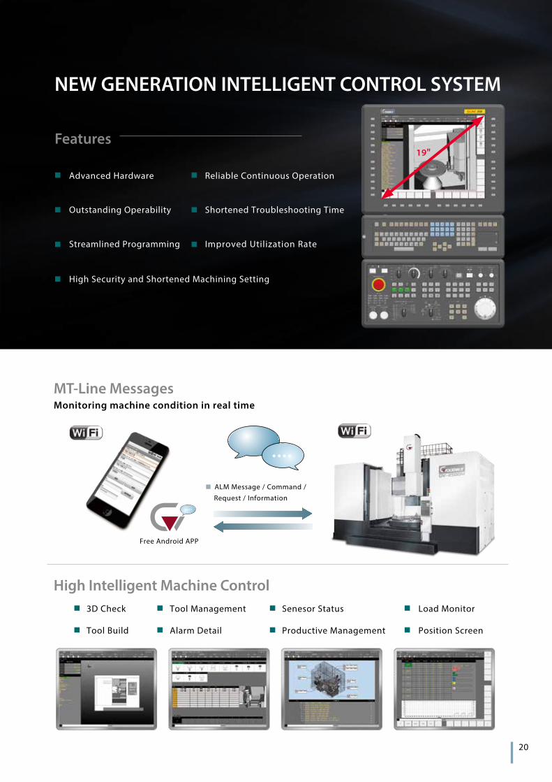
Monitoring machine condition in real timeMT-Line Messages
High Intelligent Machine Control
Features
Free Android APP
ALM Message / Command / Request / Information
3D Check Tool Management Senesor Status Load Monitor
Tool Build Alarm Detail Productive Management Position Screen
20
NEW GENERATION INTELLIGENT CONTROL SYSTEM
Advanced Hardware
Outstanding Operability
Streamlined Programming
High Security and Shortened Machining Setting
Reliable Continuous Operation
Shortened Troubleshooting Time
Improved Utilization Rate
19"

MACHINE SPECIFICATIONS
Specifications are subject to change without notice.*1 The series are designed with Cs-axis.
CAPACITY GV-2000 GV-2500 GV-3000 GV-3500Table diameter Ø 2,000 mm Ø 2,500 mm Ø 3,000 mm Ø 3,500 mm
Max. swing diameter Ø 2,500 mm Ø 3,000 mm Ø 3,700 mm Ø 4,200 mm
Max. turning diameter Ø 2,300 mm Ø 2,800 mm Ø 3,500 mm Ø 4,000 mm
Max. turning height 1,700 / 2,100 mm 1,600 / 2,400 / 3,200 mm
Max. table load 10,000 Kg 15,000 Kg 20,000 / 45,000 Kg 20,000 / 45,000 Kg
WORK-PIECE SPINDLESpindle bearing diameter Ø 912 mm Ø 1,180 mm Bear / Hydrostatic ( Opt. )
Motor output ( cont. / 30 min. ) 60 / 75 kW ( 40 / 66 kW ) x 2 [ Opt. ( 60 / 84 kW ) x 2 ]
Spindle drive system 2-step gear box
Spindle speed range 1 ~ 200 rpm 1 ~ 160 rpm 1 ~ 120 / 1 ~ 80 rpm ( Hydrostatic )
Max. spindle torque 59,700 N-m 74,140 N-m 169,700 N-m
TOOLING SPINDLE ( OPTIONAL )Motor output ( cont. / 30 min. ) 11 / 15 kW 15 / 20.5 kW ( Opt. 17 / 22.5 kW )
Spindle speed range 1 ~ 2,400 rpm
Cf-AXIS ( OPTIONAL )Cf-axis servo motor output 5.5 kW —*1
Cf-axis speed range 6 rpm —*1
Cf-axis torque output 12,600 N-m 16,200 N-m —*1
X & Z AXESMax. X-axis travel 2,830 mm 3,080 mm 3,950 mm 4,450 mm
Max. Z-axis travel 1,200 / 1,500 mm 1,500 / 1,800 mm
X / Z axes rapids 10 / 10 m/min 6 / 10 m/min
X / Z axes motor output 6 kW 8.2 kW
W-AXISMax. W-axis travel 1,200 / 1,600 mm 1,200 / 2,000 / 2,800 mm
W-axis rapids 200 mm/min 150 mm/min
ATCMagazine capacity 16 T
Spindle taper BT50 BT50 ( BT60 Opt. )
Max. tool size ( W x T x L ) 280 x 150 x 400 mm 280 x 150 x 400 mm
Max. tool weight 50 Kg 50 Kg
Max. magazine load 360 Kg 800 Kg
GENERALPositioning accuracy ±0.007 / 500 mm
Repeatability ±0.005 mm
Standard CNC control FANUC Oi -TD SIEMENS SINUMERIK 840D sl
Voltage requirement AC400/440+10%to-15%3 phase
Hydraulic capacity 130 L
Coolant tank capacity 1,000 L 1,200 L 2,500 L
Machine weight 50,000 Kg 55,000 Kg 70,000 Kg 90,000 Kg
Machine Dimensions ( H ) 6,895 mm 6,895 mm 7,600 mm 7,600 mm
Machine Dimensions ( L x W ) 7,040 x 4,610 mm 7,540 x 4,610 mm 9,500 x 8,500 mm 10,000 x 9,000 mm
22
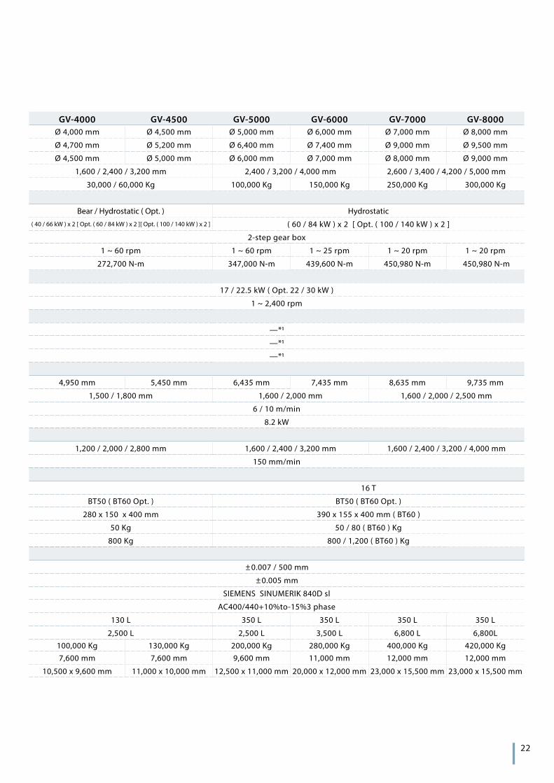
GV-4000 GV-4500 GV-5000 GV-6000 GV-7000 GV-8000Ø 4,000 mm Ø 4,500 mm Ø 5,000 mm Ø 6,000 mm Ø 7,000 mm Ø 8,000 mm
Ø 4,700 mm Ø 5,200 mm Ø 6,400 mm Ø 7,400 mm Ø 9,000 mm Ø 9,500 mm
Ø 4,500 mm Ø 5,000 mm Ø 6,000 mm Ø 7,000 mm Ø 8,000 mm Ø 9,000 mm
1,600 / 2,400 / 3,200 mm 2,400 / 3,200 / 4,000 mm 2,600 / 3,400 / 4,200 / 5,000 mm
30,000 / 60,000 Kg 100,000 Kg 150,000 Kg 250,000 Kg 300,000 Kg
Bear / Hydrostatic ( Opt. ) Hydrostatic( 40 / 66 kW ) x 2 [ Opt. ( 60 / 84 kW ) x 2 ][ Opt. ( 100 / 140 kW ) x 2 ] ( 60 / 84 kW ) x 2 [ Opt. ( 100 / 140 kW ) x 2 ]
2-step gear box
1 ~ 60 rpm 1 ~ 60 rpm 1 ~ 25 rpm 1 ~ 20 rpm 1 ~ 20 rpm
272,700 N-m 347,000 N-m 439,600 N-m 450,980 N-m 450,980 N-m
17 / 22.5 kW ( Opt. 22 / 30 kW )
1 ~ 2,400 rpm
—*1
—*1
—*1
4,950 mm 5,450 mm 6,435 mm 7,435 mm 8,635 mm 9,735 mm
1,500 / 1,800 mm 1,600 / 2,000 mm 1,600 / 2,000 / 2,500 mm
6 / 10 m/min
8.2 kW
1,200 / 2,000 / 2,800 mm 1,600 / 2,400 / 3,200 mm 1,600 / 2,400 / 3,200 / 4,000 mm
150 mm/min
16 T
BT50 ( BT60 Opt. ) BT50 ( BT60 Opt. )
280 x 150 x 400 mm 390 x 155 x 400 mm ( BT60 )
50 Kg 50 / 80 ( BT60 ) Kg
800 Kg 800 / 1,200 ( BT60 ) Kg
±0.007 / 500 mm
±0.005 mm
SIEMENS SINUMERIK 840D sl
AC400/440+10%to-15%3 phase
130 L 350 L 350 L 350 L 350 L
2,500 L 2,500 L 3,500 L 6,800 L 6,800L100,000 Kg 130,000 Kg 200,000 Kg 280,000 Kg 400,000 Kg 420,000 Kg7,600 mm 7,600 mm 9,600 mm 11,000 mm 12,000 mm 12,000 mm
10,500 x 9,600 mm 11,000 x 10,000 mm 12,500 x 11,000 mm 20,000 x 12,000 mm 23,000 x 15,500 mm 23,000 x 15,500 mm
Copyright 2015 by Goodway Machine Corp. All right reservedG-SUPER GV-EN-201502
GOODWAY MACHINE CORP.
GOODWAY MACHINE ( WUJIANG ) CO.,LTDHEADQUARTERS CENTRAL TAIWAN SCIENCE PARK BRANCH
No.13, 5Th Road,
Taichung Industrial Park,
Taichung City, 407, Taiwan, R.O.C.
E-mail : [email protected]
No. 38, Keyuan Road,
Central Taiwan Science Park.Taichung,
Taichung City, 407, Taiwan, R.O.C.
TEL : + 886-4-2463-6000
FAX : + 886-4-2463-9600
No. 4888, East Lake Taihu Avenue, Wujiang
Economic and Technological Development Zone,
Jiangsu, China
Sales Hotline : + 86-512-8286-8068
Service Hotline : + 86-512-8286-8066
FAX : + 86-512-8286-8620
E-mail : [email protected]


