NIETJOURNALoFENGINEERING&TECHNOLOGY
Winter 2011
Steady-State and DynamicPerformance of the Static Var
Compensator (SVC) Phasor Model
coNcol!)
I
0>NNNZC/)C/)
L. NavinkumarRao ' S Gairola'
'Dept. oj Electrical EnggNIET, Greater Noida 201308,u.P, [email protected]
IntroductionAbstract
A static var compensator (SVC) is used to regulatevoltage on a 500 kV,3000 MVAsystem. When systemvoltage is low the SVCgenerates reactive power (SVCcapacitive). When system voltage is high it absorbsreactive power (SVC inductive). The SVC is rated+200 Mvar capacitive and 100 Mvar inductive. TheStatic Var Compensator block is a phasor modelrepresenting the SVC static and dynamiccharacteristics at the system fundamental frequency
Index terms- Static var compensator (SVC)
'Dept. oj Electrical Engg.NIET, Greater Noida 201308, U'P; Indiasanj gairolatiiiyohoo.com
Static Var Compensators are used intransmission and distribution networks mainlyproviding dynamic voltage support in responseto system disturbances and balancing thereactive power demand of large and fluctuatingindustrial loads. A Static Var Compensator iscapable of both generating and absorbingvariable reactive power continuously asopposed to discrete values offixed and switchedshunt capacitors or reactors. Further improvedsystem steady state performance can beobtained from SVC applications. Withcontinuously variable reactive power supply, thevoltage at the SVC bus may be maintainedsmoothly over a wide range of active powertransfers or system loading conditions. Thisentails the reduction of network losses andprovision of adequate power quality to theelectric energy end-users
In recent years, with the deregulation of theelectricity market, the traditional concepts andpractices of power systems have Changed.Better utilization of the existing power system toincrease power transfer capability by installingFACTS (Flexible AC Transmission Systems)devices becomes imperative [1, 10]. Theparameter and variables ofthe transmission line,i.e. line impedance, terminal voltages, andvoltage angles can be controlled by FACTSdevices in a fast and effective way [10, 12]. Thebenefit brought about by FACTS includes
~_ •.•Iimprovement of system dynamic behavior and
r--+rV~!=r~~l1FI~~ 8 (pU»
2
pu/100MVAD ~C 00-- C ~ C <Vm (pu)
~ 500KV 3000 MVA Three-Phase BusX/R = 10 V-I Measurement SVC Selector
(Phasor Type) L- __
1~110MW
thus enhancement of system reliability. However,their main function is to control power flows [2,4].Provided that they are placed at optimallocations, FACTS devices are capable ofincreasing the system loadability too [1]. Theseaspects are playing an increasingly significantrole in the operation and control of thederegulated electricity market. Many researcheswere made on the optimal allocation of FACTSdevices [1-3]. However, the investment cost ofFACTS and their impact on bid curves of themarket participants (suppliers and consumers)in a liberalized electricity market are not whollyconsidered [8]
Z = R+jXHE~c::::::::JI------j~~
Bus . ~orFig. 1 Generic line segment with FACTSparamaters
Principle of operation
Static Var Compensators (SVC) are the mostpopular devices of FACTS. The mainfunctionality of the SVC is to regulate the voltageat a chosen bus by controlling the reactive powerinjection at the location. Maintaining the ratedvoltage levels is important for proper operationand utilization of loads. Under voltage causes
I Phasors IPowerguide
Winter 2011
deregulation in the performance of loads such asinduction motors, light bulbs, etc., whereas overvoltage causes magnetic saturation andresultant harmonic generation, as well asequipment failures due to insulation breakdown.These devices are characterised by rapidresponse, wide operational range and highreliability. SVC based on thyristors without thegate turn-off capability is considered as a shunt-connected static VAR generator orabsorber.Their output is adjusted to exchangecapacitive or inductive current. As an importantcomponent for voltage control, it is usuallyinstalled at the receiving bus. In the formulation,the SVC has been considered a shunt branchwith a compensated reactive power setting byavailable inductive and capacitivesusceptances.
III Measurement of steady-state V-Icharacteristic
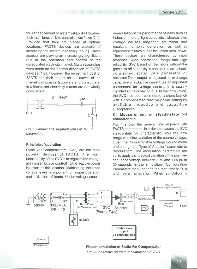
Fig. 1 shows the generic line segment withFACTS parameters. In order to measure the SVCsteady-state V-I characteristic, you will nowprogram a slow variation of the source voltage.Open the Programmable Voltage Source menuand change the "Type of Variation" parameter to"Modulation". The modulation parameters areset to apply a sinusoidal variation of the positive-sequence voltage between 0.75 and 1.25 pu in20 seconds. In the Simulation->ConfigurationParameters menu change the stop time to 20 sand restart simulation. When simulation is
BactualBcontrol (pu/100 MVA)
DScope
VactualVm (pu)
Double clickto plot
V-I characteristic
Phasor simulation of Static Var Compensator
Fig. 2 Schematic diagram for simulation of SVC
NIETJOURNALoFENGINEERING&TECHNOLOGY
completed, double click the blue block. Thetheoretical V-I characteristic is displayed (in red)together with the measured characteristic (inblue)
Simulation of dynamic performance of SVCUsing MATlAB simulink software along with itsSIMULINK and SIMPOWERSYSTEM toolboxes,this SVC is simulated. Fig. 2 shows theschematic diagram for dynamic performance ofSVC phasor model.
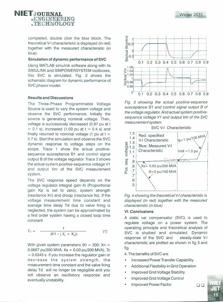
Results and DiscussionsThe Three-Phase Programmable VoltageSource is used to vary the system voltage andobserve the SVC performance. Initially thesource is generating nominal voltage. Then,voltage is successively decreased (0.97 pu at t= 0.1 s), increased (1.03 pu at t = 0.4 s) andfinally returned to nominal voltage (1 pu at t =0.7 s). Start the simulation and observe the SVCdynamic response to voltage steps on thescope. Trace 1 show the actual positive-sequence susceptance B1 and control signaloutput B of the voltage regulator. Trace 2 showsthe actual system positive-sequence voltage V1and output Vm of the SVC measurementsystem.
The SVC response speed depends on thevoltage regulator integral gain Ki (Proportionalgain Kp is set to zero), system strength(reactance Xn) and droop (reactance Xs). If thevoltage measurement time constant andaverage time delay Td due to valve firing isneglected, the system can be approximated bya first order system having a closed loop timeconstant
Tc = (1 )
With given system parameters (Ki = 300; Xn =0.0667 pu/200 MVA; Xs = 0.03 pu/200 MVA) , Tc= 0.0345 s. If you increase the regulator gain ordecrease the system strength, themeasurement time constant and the valve firingdelay Td will no longer be negligible and youwill observe an oscillatory response andeventually unstability.
Winter 2011
-_e 1 ----------j------------·t·--······-·-~.:. 1.:.------- ----I·_--t-_·_-------l -----------i------------rc :: : : .j••8o. -i--+-----i.!o;-- n-nni-- · in-- ----+nn _nmnmjco i ~
: ~ ii, i .
i-o.~~_···_···-~··t·_·-·:_::~:_::::rL:::·_·:::_::::Lr_~~:~~J=::::=:::::=:::f~::::=::::=::::t~_/_:~~1._..--_-..-~.--j
0.1 0.2 0.3 0.4 0.5 0.6 0.7 0.8 0.9
j:.:~~F~I~I~§f~~~4~.l~10.96·.. :::::::lt~<~,.; L +...........•.. · ····f..·····..·..+ ·j..· ,
! l 1 i :o 0.1 0.2 0.3 0.4 0.5 0.6 0.7 0.8 0.9
Fig. 3 showing the actual positive-sequencesusceptance 81 and control signal output 8 ofthe voltage regulator. And actual system positive-sequence voltage V1 and output Vm of the SVCmeasurement system
SVC V-I Characteristic
1.5 Red: specified I WNP-~ ~:~ V-I Characteristic ::16==='~ PI..I/~~OO
'v 1 2 Blue: Measured V-I~ . ,-+-' 1 1 Characteristic [Vref = 1.0 pu~ . :> 1 Ig .9 L--c--~--=--=--=--=--~-t~~~:::~~:::~.~=::.~1.~r~~:;..-·-':::'::::.:~.:~.o;;.:::T~--=--~--·--------(J).8 Xs= 0.03 pu/200 MVA(J)
&. .7 B=2 pu/100 MVA.7 /'.6.5
Fig. 4 showing the theoretical V-Icharacteristic isdisplayed (in red) together with the measuredcharacteristic (in blue)
VI. ConclusionsA static var compensator (SVC) is used toregulate voltage on a power system. Theoperating principle and theoretical analysis ofSVC is studied and simulated. Dynamicresponse of the SVC and steady-state V-Icharacteristic are plotted as shown in fig 3 andfig
4. The benefits of SVC are
• Increased Power Transfer Capability
• Additional Flexibility in Grid Operation
• Improved Grid Voltage Stability
• Improved Grid Voltage Control
• Improved Power Factor 0 0

ReferencesS. Gerbex, R. Cherkaoui, and A. J. Germond,"Optimal location of multitype FACTS devices in apower system by means of genetic algorithms,"IEEE Trans. Power Systems, vol, 16, pp. 537-544,August. 2001.
2 T. T. Lie, and W Deng, "Optimal flexible ACtransmission systems (FACTS) devicesallocation," Electrical Power & Energy System,vel. 19,No.2,pp. 125-134, 1997.
3 P. Paterni, S. Vitet, M. Bena and A. Yokoyama,"Optimal location of phase shifters in the Frenchnetwork by genetic algorithm," IEEE Trans. PowerSystems, vol. 14, pp. 37-42, August. 1999.
4 T. S. Chung, and Y. Z. Li, "A hybrid GA approachfor OPF with consideration of FACTS devices,"IEEE Power Engineering Review, pp. 47-57,February. 2001.
5 E. J. Oliveira, J. W M. Lima and K. C. Almeida,"Allocation of FACTS devices in hydrothermalsystem," IEEE Trans. Power Systems, vol. 15, pp.276-282, February. 2000.
6 W L. Fang, and H. W Ngan, "Optimising locationof unified power flow controllers using themethod of augmented Lagrange multipliers," lEEProc.-Gener. Transm. Distrib, vol. 146, pp. 428-434, September. 1999.
Winter 2011
7 K. S. Verma, S. N. Singh and H. O. Gupta,"Location of unified powerflow controller forcongestion management," Electric PowerSystems Research, vol. 58, pp. 89-96, 2001.
8 Lijun Cai, and Istvan Erlich, "Optimal Choice andAllocation of FACTS Devices using GeneticAlgorithms," ISAp, Intelligent Systems Applicationto Power Systems, 2003, Lemnos, Greece,August31 -September3, 2003.
9 R. D. Zimmermann, and D. Gan, "Matpower aMatlab power system simulation package,"User's Manual,", Version 2.0, Dec. 1997.
10 F. D. Galiana, K. Almeida, M. Toussaint, J. Griffin,and D. Atanackovic, "Assessment and control ofthe impact of FACTS devices on power systemperformance," IEEE Trans. Power Systems, vol,11, no. 4, Nov. 1996.
11 X. P. Wang, and L. P. Cao, Genetic Algorithms -Theory, Application and Software Realization,Xi'an Jiaotong University, Xi'an, China, 1998.
12 B. A. Renz, A. S. Mehraban, C. Schauder, E.Stacey, L. Kovalsky, L. Gyugyi, and A. Edris, "AEPunified power flow controller performance, "IEEETrans. Power Delivery, vol, 14, no. 4, Nov. 1999.
13 J.D. Finney, HA Othman, WL. Rutz, "Evaluatingtransmission congestion constraints in systemplanning", IEEE Trans. on Power Systems, vel.12, pp. 1143-1150, August 1997.
000


