download this toolbox creo an introductionan update - me program
TRANSCRIPT

This rim was created in Creo Elements/Pro 5.0 (formerly Pro/ENGINEER) rendered by Advanced Rendering Extension.
http://communities.ptc.com/community/creo/rendering/blog/tags/5.0
Prepared by Neil Smith July 2012 Edited by Scott Sleap August 2012
Rewritten by Scott Sleap March 2013

The Living Toolbox An Introduction to CREO 1
The Formula One Technology Challenge is an exciting, innovative and modern science, math and engineering action learning activity. With hundreds of schools Australia-wide already active, the F1inSchools program is ideal for all schools, being easy to integrate into a wide range of curriculum areas, or as an extra curricula activity. The competition revolves around teams designing making and racing C02 powered cars which have been machined from a balsa block using Computer Aided Drafting and Computer Aided Manufacturing techniques. This resource is based on preparing students to compete in this competition through the delivery of the NSW stage 5 Industrial Technology – Engineering syllabus. However, it could be used in a variety of stage 5, 5 & 6 syllabus including Graphics Technology, Industrial Technology, Engineering Studies, Design and technology, etc.
The Living Toolbox website has been developed in conjunction with the ME program, to provide useful resources to assist teachers to effectively introduce advanced manufacturing concepts in the classroom.
The ME program website has many resources for schools, industry and parents. It has been designed to assist participants in the program to reach the objects of the program.
Re-Engineering Foundation hold the Australian licence for the F1inScools program and their web site and accompanying supportal has a vast array of resources which support the F1inSchools Technology Challenge (REA, 2012).
The F1inSchool program is the world’s largest Science, Technology, Engineering & Mathematics (STEM) Competition. It involves over nine million students from 17,000 schools in 31 nations.
The DMO is part of the Department of Defence. In 2011-12 the Australian Government will spend more than $10 billion acquiring and sustaining military equipment and services. The DMO are major sponsors of both the F1inSchools and the ME programs.

The Living Toolbox An Introduction to CREO 2
Tutorial 1 Starting Creo Parametric and Creating a New Part
Tutorial 2
Rounds, Holes and Chamfers
Tutorial 3 Modifying Sketches and Features
Tutorial 4
Balsa Blank for F1 Car

The Living Toolbox An Introduction to CREO 3
This tutorial follows a process known the “Feature First” process, as this is the most commonly used approach.
Start the Creo parametric program by clicking on the Creo icon.
The Creo Parametric 2.0 opening screen is displayed below;
The CREO 2.0 welcome screen will open in the programs own web browser. Use the features of the browser if you wish otherwise click on the in the top right hand corner of the browser screen to close. Select FILE
NEW
The following dialog box will pop up
You should get in the habit of naming new parts. Type in a name that has meaning to you and the project you are working on, note there can NOT be any spaces. Use underscore if you wish. In the Common Name box you can type anything you want including spaces. However Name is the actual filename.

The Living Toolbox An Introduction to CREO 4
It is important you use the name box as this is the name that will appear in the model tree and will allow access whenever you wish to modify your work at a later date.
For now we will use Example1 as the name followed by your initials, good practice if you are saving work to a common hard drive.
Click OK and the following screen will appear.
NOTE: THIS AREA IS KNOWN AS THE DASHBOARD

The Living Toolbox An Introduction to CREO 5
In the MODEL menu on the Dashboard select EXTRUDE
The following screen will appear.
Note the dashboard menu has changed to EXTRUDE. The word PLACEMENT is in RED
The RED lettering is a prompt that a decision has to be made.
You are now prompted to select a PLANE to work on, for this exercise we will select the TOP plane. AS YOU MOVE YOUR MOUSE OVER EACH OF THE PLANES THEY WILL BE PRE-HIGHLIGHTED WITH A BOARDER IN GREEN. WHEN TOP HAS A GREEN BOARDER CLICK YOUR LEFT MOUSE BUTTON. Alternatively select TOP in the Model Tree

The Living Toolbox An Introduction to CREO 6
The Dashboard will change to SKETCH as shown below.
To get started we will draw a rectangle 200mm long, 150mm wide and 200mm high. In the SKETCH dashboard click on the RECTANGLE tool and then select the SKETCH VIEW button to look at the plan view.
The following view will be displayed.
Left mouse click in the center of the screen (origin of x and y) to draw a rectangle (with obviously different side lengths). Do this by clicking the left mouse button, moving the cursor up to the right, and then again clicking the left mouse button to accept. Do not be concerned about the size of the rectangle at this stage.

The Living Toolbox An Introduction to CREO 7
Click on the OK button to accept. Alternatively you can click on the middle scroll button.
The following dialogue box will appear.
Note you are still in the plan view and the EXTRUDE dashboard is now current. Simultaneously press Ctrl and “D” on your keyboard to change to the default view shown below.
Double left mouse click on the value shown for the EXTRUSION and type in 200 to make it 200mm Click on the TICK to accept.

The Living Toolbox An Introduction to CREO 8
We are now going to set the vertical and horizontal size for our rectangle. In the Model Tree left mouse click on the down arrow to display the SECTION 1 menu.
Now right mouse click on the SECTION 1 menu and then left mouse click on EDIT DEFINITION
The following screen will appear. Double left mouse click on the horizontal dimension and change it to 200. Click the middle mouse button to accept. Double left mouse click on the vertical dimension and change it to 150. Click the middle mouse button to accept.
Click OK on the dashboard to accept.
Simultaneously press Ctrl and “D” on your keyboard to center your view in the middle of the screen. This is the completed feature of a 200 x 150 x 200mm high rectangular prism Save your work. Close the CREO 2.0 program.

The Living Toolbox An Introduction to CREO 9
We will now draw another shape using the LINE tool. Open the program as in Tutorial 1 and go FILE - NEW. You should name the part as Example2 (remember no spaces in the name). Select the TOP plane with your mouse and click on the SKETCH icon from the MODEL dashboard.
Again click on the SKETCH VIEW icon view your drawing in PLAN View.
We will now use the LINE TOOL in the SKETCH dashboard to draw the following shape, we are not concerned with exact sizes, just the creation of a similar shape as to that shown below.
Draw a line by left mouse click at the start point (i.e origin of x, and y) move the next point and click again. Note that the line tool is still selected. Click on the next points until you have completed the shape. Remember to complete the object by finishing at the same point as where you started. As in Tutorial 1, click on the OK button with the green tick. Alternatively click on the middle mouse button.

The Living Toolbox An Introduction to CREO 10
Simultaneously press Ctrl and “D” on your keyboard to center your view in the middle of the screen Click on the EXTRUDE button and make the object 100mm thick. If necessary Ctrl + D again to center. Select the TICK to accept The following shape will be displayed on your screen.
We will now place ROUNDS on the top edges of the shape. From the MODEL DASHBOARD select ROUND and click.
The following Dashboard will open in the top left of the screen.
Change the size on the ROUNDS to 15 in this box We will select a chain of edges to add our rounds. HOLDING DOWN CTRL select all edges on the top face of the object. When all edges are selected click the Green tick to accept. The object will resemble the one below.

The Living Toolbox An Introduction to CREO 11
Now rotate the shape so the bottom is on the top. You can rotate an object by holding down the middle mouse button (the scroll wheel) and moving the mouse.
On the bottom edges of the object we will add a chamfer. The same procedure as placing the rounds is followed. In the MODEL DASHBOARD select CHAMFER. Select one edge and holding down Ctrl and select all other edges in a progressive manner. The chamfers will be 15mm.
Simultaneously press Ctrl and “D” on your keyboard to center your view in the middle of the screen We will now place a hole in the object, From MODEL DASHBOARD select HOLE, the following Dashboard will appear.
Note the word Placement is red and the Dashboard tells you to select a surface to place the hole. Select the top surface, by left mouse clicking.
The Living Toolbox An Introduction to CREO 12
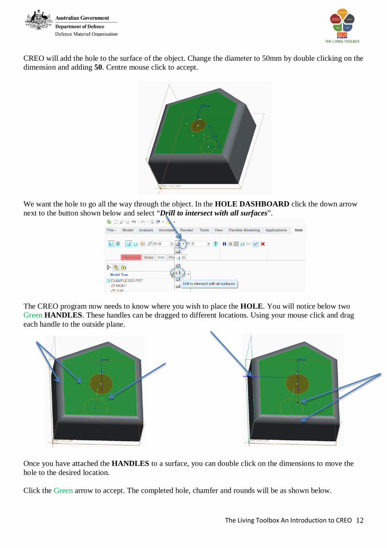
CREO will add the hole to the surface of the object. Change the diameter to 50mm by double clicking on the dimension and adding 50. Centre mouse click to accept.
We want the hole to go all the way through the object. In the HOLE DASHBOARD click the down arrow next to the button shown below and select “Drill to intersect with all surfaces”.
The CREO program now needs to know where you wish to place the HOLE. You will notice below two Green HANDLES. These handles can be dragged to different locations. Using your mouse click and drag each handle to the outside plane.
Once you have attached the HANDLES to a surface, you can double click on the dimensions to move the hole to the desired location. Click the Green arrow to accept. The completed hole, chamfer and rounds will be as shown below.

The Living Toolbox An Introduction to CREO 13
Clicking down on the middle wheel button and moving will allow you to view the 3D object. Also try rotating the middle wheel to allow you to zoom in and out of the object. Remember you can center the object on the screen by clicking Ctrl + D Below are different options that can be used for modifying a hole. Simple Hole or Threaded Hole Hole Diameter Hole Depth
Dropdown menu with options for placing the Hole
Add an additional HOLE and experiment with these options. SAVE YOUR WORK

The Living Toolbox An Introduction to CREO 14
Briefly we will look at how changes may be made to an existing completed object. There are many reasons this may be necessary including a change in a component so the object may need to change to reflect this, or a mistake in one of the sizes originally used may have been made. For this tutorial we will use example2, which you would have saved. FILE – OPEN locate example1 by default it will be saved in documents, once opened go to FILE – SAVE A COPY
For the new name use copyofexample2 remember no spaces. Examine the Model Tree
Note Extrude1 it has a grey arrow sign next to it.
Click on the grey arrow sign to reveal the following
Extrude 1 is the feature
To change the size of the original rectangle RIGHT MOUSE CLICK on SKETCH 1
Select EDIT DEFINITION
The original sketch will appear DOUBLE CLICK on the measurement and change the number, remember to press enter whenever a number is changed. Change the other measurement once completed click on the ACCEPT SKETCH TICK.
Is the original sketch from which the feature was generated.

The Living Toolbox An Introduction to CREO 15
The change the Extrude height RIGHT MOUSE CLICK on Extrude 1 Select EDIT DEFINITION
The object will turn orange, change the height of the extrusion when complete click on the green tick to accept the new extrusion.
SAVE YOUR WORK
Exit the program.

The Living Toolbox An Introduction to CREO 16
Open CREO and select FILE – NEW, name the file as BALSABLANK Click OK Select EXTRUDE from the MODEL DASHBOARD. SELECT FRONT PLANE. This is done so the blank will have the correct final appearance in space. Again click on the SKETCH VIEW icon view your drawing in PLAN View.
Draw a RECTANGLE using the CENTRE RECTANGLE tool. Located in the dropdown menu next to RECTANGLE.
Draw a RECTANGLE starting to the right of the screen and finish at the origin as shown below.
Click OK to accept. Change the EXTRUSION length to 65mm. Select EXTRUDE on both sides of the sketch plane by half by clicking on the icon below.

The Living Toolbox An Introduction to CREO 17
Click Green tick to accept EXTRUSION. Change LENGTH to 223mm and HEIGHT to 50mm. Do this by clicking on the grey arrow next to Extrude 1 and right mouse click and select EDIT DEFINITION.
The following screen will be visible.
Double click on the dimensions to change them to LENGTH to 223mm and HEIGHT to 50mm. ACCEPT SKETCH by clicking OK. This places the extrusion symmetric about the frontal plane, the reason for this will become apparent later. SAVE YOUR WORK FILE – SAVE it will save where it has been saved before click OK to accept. You may need to refit to the screen.

The Living Toolbox An Introduction to CREO 18
To insert hole in one end for the CO2 cartridge follow these instructions. In the MODEL Dashboard select HOLE Click on the end of the block where the origin is located.
Make the diameter of hole 19mm, make the depth of the hole 51mm.
To position the circle attach one green square to the top of the blank and the other to the side. Change the distance from top to centre of hole 21mm and change the distance from side to centre of hole 32.5mm
Click green tick to accept
SAVE YOUR WORK

The Living Toolbox An Introduction to CREO 19
DRAW SLOT IN BASE Select EXTRUDE from menu. Click on the end of the block
Again click on the SKETCH VIEW icon view your drawing in PLAN View.
Use the LINE tool to draw a rectangle in the location shown below
In the EXTRUDE DASHBOARD click on the REMOVE MATERIAL button and EXTRUDE to surface button. Note you may also need to select the CHANGE DEPTH DIRECTION button.
Click the Green Tick to accept

The Living Toolbox An Introduction to CREO 20
Change the size of the slot by going to the Edit Definition button in Extrude 2.
Change relevant dimensions so there is a 6mm x 6mm square.
Locate the SLOT in the correct position. Change the distance from the center to the slot at 19mm. Create a dimension between the Horizontal Center line and the edge of the square by selecting the NORMAL tool from the SKETCH DASHBOARD and drawing a line between them. Enter 3mm in the box. The SLOT is now CONSTRAINED. Click the OK button.
SAVE YOUR WORK