download bid documents
TRANSCRIPT
1
2
ASSAM POWER DISTRIBUTION COMPANY LIMITED.
OFFICE OF THE CHIEF GENERAL MANAGER (HQ),APDCL BIJULEE BHAWAN , PALTANBAZAR, GUWAHATI -781001
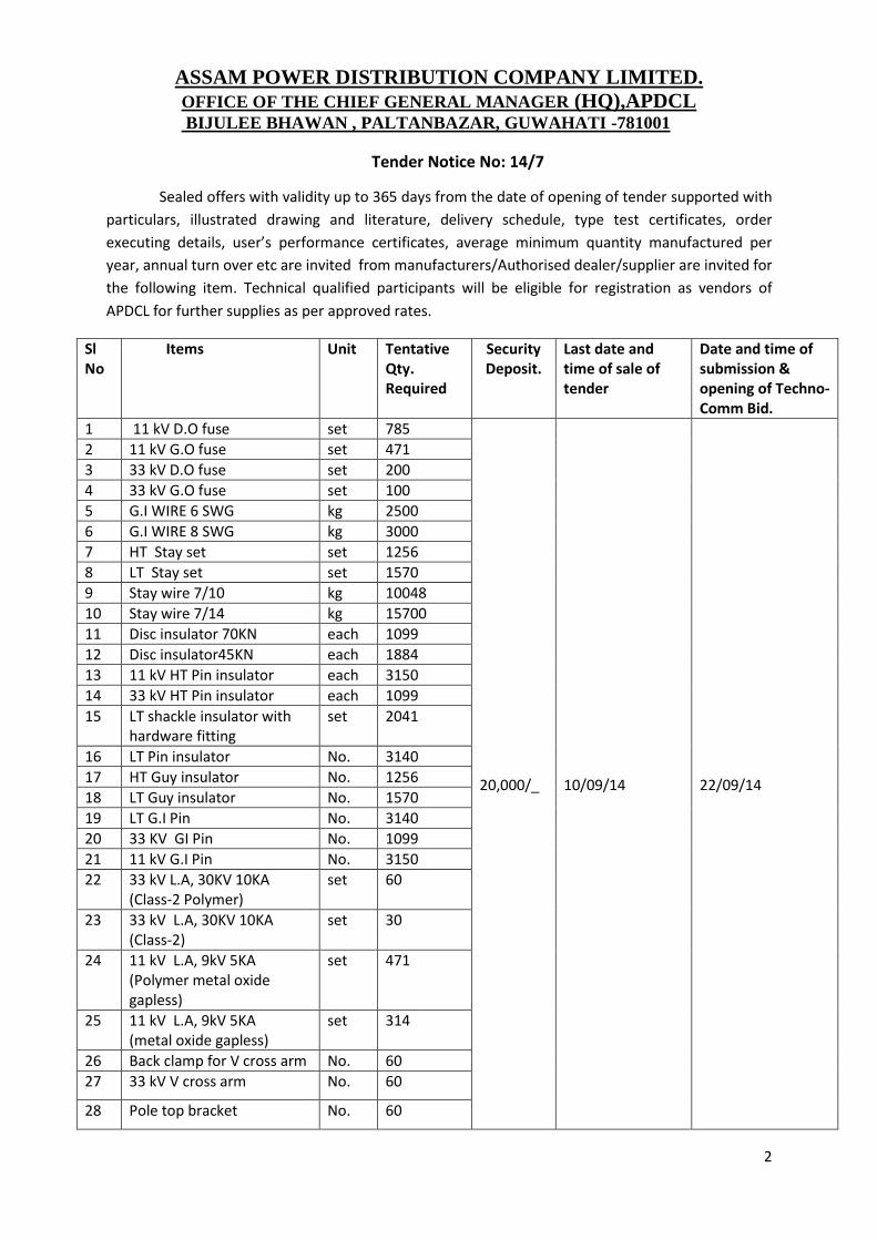
Tender Notice No: 14/7
Sealed offers with validity up to 365 days from the date of opening of tender supported with
particulars, illustrated drawing and literature, delivery schedule, type test certificates, order
executing details, user’s performance certificates, average minimum quantity manufactured per
year, annual turn over etc are invited from manufacturers/Authorised dealer/supplier are invited for
the following item. Technical qualified participants will be eligible for registration as vendors of
APDCL for further supplies as per approved rates.
Sl No
Items Unit
Tentative Qty. Required
Security Deposit.
Last date and time of sale of tender
Date and time of submission & opening of Techno-Comm Bid.
1 11 kV D.O fuse set 785 20,000/_
10/09/14
22/09/14
2 11 kV G.O fuse set 471
3 33 kV D.O fuse set 200
4 33 kV G.O fuse set 100
5 G.I WIRE 6 SWG kg 2500
6 G.I WIRE 8 SWG kg 3000
7 HT Stay set set 1256
8 LT Stay set set 1570
9 Stay wire 7/10 kg 10048
10 Stay wire 7/14 kg 15700
11 Disc insulator 70KN each 1099
12 Disc insulator45KN each 1884
13 11 kV HT Pin insulator each 3150
14 33 kV HT Pin insulator each 1099
15 LT shackle insulator with hardware fitting
set 2041
16 LT Pin insulator No. 3140
17 HT Guy insulator No. 1256
18 LT Guy insulator No. 1570
19 LT G.I Pin No. 3140
20 33 KV GI Pin No. 1099
21 11 kV G.I Pin No. 3150
22 33 kV L.A, 30KV 10KA (Class-2 Polymer)
set 60
23 33 kV L.A, 30KV 10KA (Class-2)
set 30
24 11 kV L.A, 9kV 5KA (Polymer metal oxide gapless)
set 471
25 11 kV L.A, 9kV 5KA (metal oxide gapless)
set 314
26 Back clamp for V cross arm No. 60
27 33 kV V cross arm No. 60
28 Pole top bracket No. 60

3
29 MS Channel X Arm (100x50x50x6)mm x 5000mm
No. 150
30 MS Channel cross arm (100x50x6x3200mm)
No. 350
31 MS Channel cross arm (100x50x6x2200mm)
628
32 LT angle cross arm (75x40x6x1020mm)
No. 785
A non-refundable documentation fee of Rs. 5,000/-(Rupees five thousand) only by
crossed demand draft/ Banker cheque in favour of APDCL, payable at Guwahati shall be submitted for registration and participation in the tender before the due date for opening of the tender.
The Security Deposit of Rs 20,000/- should be in the form of D.D or B.G from any nationalised bank of India, homebranches/regional offices situated within Guwahati & cover the validity period is to be pledged in favour of the APDCL, payable at Guwahati. The Security Deposit of technically qualified firms shall be retained till such period, they remain as approved vendor of APDCL. The APDCL’s General Conditions of supply & Errection and Additional Terms & Conditions are enclosed for guideline.
The under signed reserved the right to reject any/ all tenderes without assigning any reason thereof.
Chief General Manager (HQ),APDCL
Memo No. CGM(HQ)/Mat/Line Material/2014/ Dated.
Copy to: -
1. PS to CMD, APDCL, for kind appraisal of CMD. 2. The Member (T), APDCL, for kind information. 3. The CGM (D), APDCL ,UAR/CAR/LAR, for kind information. 4. The CGM( F&A) APDCL, for kind information. 5. The AGM (F&A), APDCL, O/o of the CGM(HQ) APDCL, for kind information. 6. M/s..................................................................................................................
..................................................................................................................... They are requested to submit their Bid along with terms and condition and delivery schedule within the stipulated period.
Chief General Manager (HQ),APDCL
4
ASSAM POWER DISTRIBUTION COMPANY LIMITED.
OFFICE OF THE CHIEF GENERAL MANAGER (HQ),APDCL BIJULEE BHAWAN , PALTANBAZAR, GUWAHATI -781001
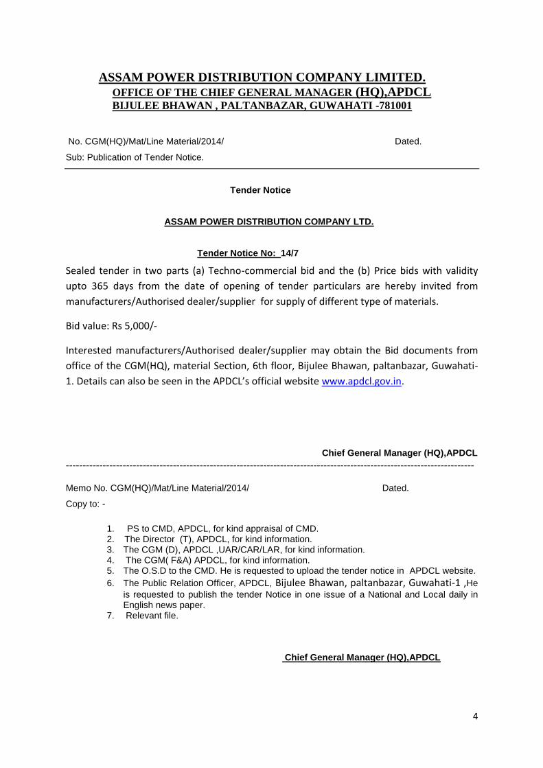
No. CGM(HQ)/Mat/Line Material/2014/ Dated.
Sub: Publication of Tender Notice.
Tender Notice
ASSAM POWER DISTRIBUTION COMPANY LTD.
Tender Notice No: 14/7
Sealed tender in two parts (a) Techno-commercial bid and the (b) Price bids with validity
upto 365 days from the date of opening of tender particulars are hereby invited from
manufacturers/Authorised dealer/supplier for supply of different type of materials.
Bid value: Rs 5,000/-
Interested manufacturers/Authorised dealer/supplier may obtain the Bid documents from
office of the CGM(HQ), material Section, 6th floor, Bijulee Bhawan, paltanbazar, Guwahati-
1. Details can also be seen in the APDCL’s official website www.apdcl.gov.in.
Chief General Manager (HQ),APDCL
--------------------------------------------------------------------------------------------------------------------------
Memo No. CGM(HQ)/Mat/Line Material/2014/ Dated.
Copy to: -
1. PS to CMD, APDCL, for kind appraisal of CMD. 2. The Director (T), APDCL, for kind information. 3. The CGM (D), APDCL ,UAR/CAR/LAR, for kind information. 4. The CGM( F&A) APDCL, for kind information. 5. The O.S.D to the CMD. He is requested to upload the tender notice in APDCL website.
6. The Public Relation Officer, APDCL, Bijulee Bhawan, paltanbazar, Guwahati-1 ,He
is requested to publish the tender Notice in one issue of a National and Local daily in English news paper.
7. Relevant file.
Chief General Manager (HQ),APDCL
5
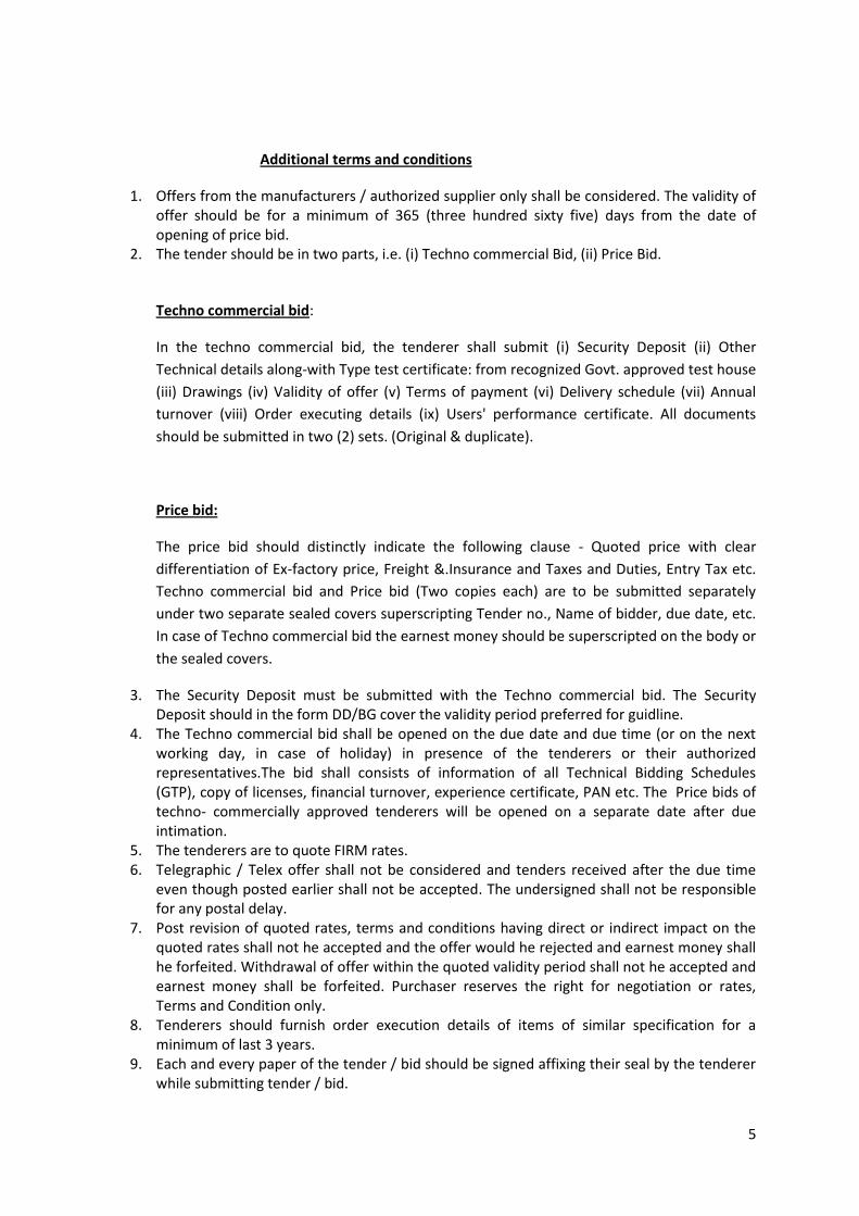
Additional terms and conditions
1. Offers from the manufacturers / authorized supplier only shall be considered. The validity of offer should be for a minimum of 365 (three hundred sixty five) days from the date of opening of price bid.
2. The tender should be in two parts, i.e. (i) Techno commercial Bid, (ii) Price Bid.
Techno commercial bid:
In the techno commercial bid, the tenderer shall submit (i) Security Deposit (ii) Other
Technical details along-with Type test certificate: from recognized Govt. approved test house
(iii) Drawings (iv) Validity of offer (v) Terms of payment (vi) Delivery schedule (vii) Annual
turnover (viii) Order executing details (ix) Users' performance certificate. All documents
should be submitted in two (2) sets. (Original & duplicate).
Price bid:
The price bid should distinctly indicate the following clause - Quoted price with clear
differentiation of Ex-factory price, Freight &.Insurance and Taxes and Duties, Entry Tax etc.
Techno commercial bid and Price bid (Two copies each) are to be submitted separately
under two separate sealed covers superscripting Tender no., Name of bidder, due date, etc.
In case of Techno commercial bid the earnest money should be superscripted on the body or
the sealed covers.
3. The Security Deposit must be submitted with the Techno commercial bid. The Security Deposit should in the form DD/BG cover the validity period preferred for guidline.
4. The Techno commercial bid shall be opened on the due date and due time (or on the next working day, in case of holiday) in presence of the tenderers or their authorized representatives.The bid shall consists of information of all Technical Bidding Schedules (GTP), copy of licenses, financial turnover, experience certificate, PAN etc. The Price bids of techno- commercially approved tenderers will be opened on a separate date after due intimation.
5. The tenderers are to quote FIRM rates. 6. Telegraphic / Telex offer shall not be considered and tenders received after the due time
even though posted earlier shall not be accepted. The undersigned shall not be responsible for any postal delay.
7. Post revision of quoted rates, terms and conditions having direct or indirect impact on the quoted rates shall not he accepted and the offer would he rejected and earnest money shall he forfeited. Withdrawal of offer within the quoted validity period shall not he accepted and earnest money shall be forfeited. Purchaser reserves the right for negotiation or rates, Terms and Condition only.
8. Tenderers should furnish order execution details of items of similar specification for a minimum of last 3 years.
9. Each and every paper of the tender / bid should be signed affixing their seal by the tenderer while submitting tender / bid.
6
10. In comparing bids and making awards, the purchaser consider such factors as compliance with specifications, relative quality and adaptability of suppliers of services, the technology and process involved in production experience, financial soundness, records or integrity in dealing ability to furnish repair and maintenance services.
11. All other terms and conditions as mentioned in the APDCL General Conditions of Supply and of supply in contravention or the above conditions will remain in force.
12. Delivery being the essence or the contract, the tenderers should preferably quote their delivery to commence within one month from the date of placing of letter of intent / order and to be compiled approximately within three months thereafter at uniform rate in a phased manner. Tenderers may be asked to re-phase delivery schedule as per requirement or APDCL.
13. The materials are required for various plan and non-plan schemes. The purchaser reserves the right to reject any / all tenders without assigning any reason thereof, the right to accept any tender or part of which is advantageous to APDCL and to award the contract to one party or Spilt up amongst the different bidders.
14. Only those bidders whose Part-I Bid i,e Techno commercial Bid (Qualification) is found acceptable shall be considered for opening of Price Bid. The date and time of opening of Part-II Bid (Price) shall be communicated to those bidders whose bids are qualified for opening.
15. The bidding documents are not transferable and cost of bidding document is not refundable under any circumstances.
Chief General Manager (HQ), APDCL

7
PRICE BID FORMAT
(To be filled by the Tenderer)
Sl No
Items Offered Qty.
Rate per free door delivery by road at our stores, inclusive of loading, unloading, forwarding, stacking freight & insurance etc. (Excise Duty and Taxes extra) (In Rs) (Words and Fingures) Guwahati | Tezpur | Jorhat | Silchar
1 11 kV D.O fuse
2 11 kV G.O fuse
3 33 kV D.O fuse
4 33 kV G.O fuse
5 G.I WIRE 6 SWG
6 G.I WIRE 8 SWG
7 HT Stay set
8 LT Stay set
9 Stay wire 7/10
10 Stay wire 7/14
11 Disc insulator 70KN
12 Disc insulator45KN
13 11 kV HT Pin insulator
14 33 kV HT Pin insulator
15 LT shackle insulator with hardware fitting
16 LT Pin insulator
17 HT Guy insulator
18 LT Guy insulator
19 LT G.I Pin
20 33 KV GI Pin
21 11 kV G.I Pin
22 33 kV L.A, 30KV 10KA (Class-2 Polymer)
23 33 kV L.A, 30KV 10KA (Class-2)
24 11 kV L.A, 9kV 5KA (Polymer metal oxide gapless)
25 11 kV L.A, 9kV 5KA (metal oxide gapless)
26 Back clamp for V cross arm
27 33 kV V cross arm

8
Break-up prices per unit. For door delivery by road should be as below:-
Destination stores:→ Guwahati Tezpur Jorhat Silchar
Ex. Factory price........Rs
Excise duty........%.....Rs
VAT..................%...Rs.
CST..................%...Rs.
Freight & Insurance
Charge..................Rs
Total..................Rs
Entry tax.......... % Rs.
Total Landed cost........Rs
Signature of Tenderer.
(With seal, Address and Contact No.)
(Separate sheet may be enclosed for different items.)
28 Pole top bracket
29 MS Channel X Arm (100x50x50x6)mm x 5000mm
30 MS Channel cross arm (100x50x6x3200mm)
31 MS Channel cross arm (100x50x6x2200mm)
32 LT angle cross arm (75x40x6x1020mm)
9
TECHNICAL
SPECIFICATION
10
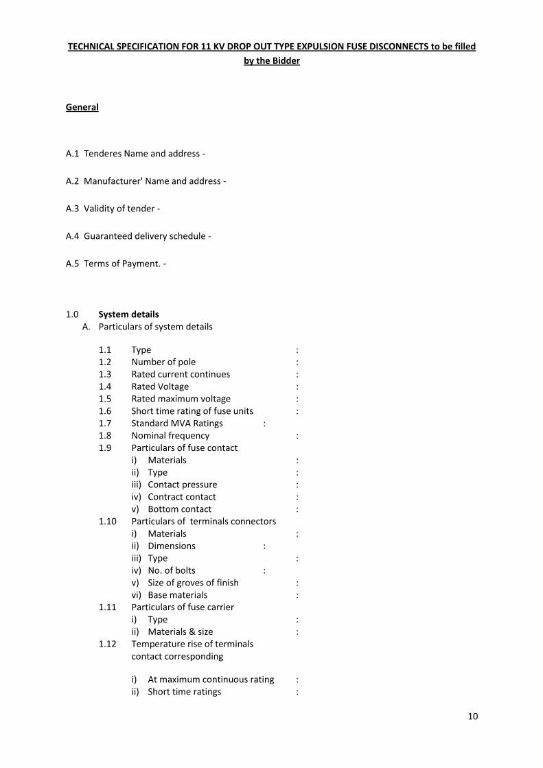
TECHNICAL SPECIFICATION FOR 11 KV DROP OUT TYPE EXPULSION FUSE DISCONNECTS to be filled
by the Bidder
General
A.1 Tenderes Name and address -
A.2 Manufacturer' Name and address -
A.3 Validity of tender -
A.4 Guaranteed delivery schedule -
A.5 Terms of Payment. -
1.0 System details A. Particulars of system details
1.1 Type : 1.2 Number of pole : 1.3 Rated current continues : 1.4 Rated Voltage : 1.5 Rated maximum voltage : 1.6 Short time rating of fuse units : 1.7 Standard MVA Ratings : 1.8 Nominal frequency : 1.9 Particulars of fuse contact
i) Materials : ii) Type : iii) Contact pressure : iv) Contract contact : v) Bottom contact :
1.10 Particulars of terminals connectors i) Materials : ii) Dimensions : iii) Type : iv) No. of bolts : v) Size of groves of finish : vi) Base materials :
1.11 Particulars of fuse carrier i) Type : ii) Materials & size :
1.12 Temperature rise of terminals contact corresponding
i) At maximum continuous rating : ii) Short time ratings :
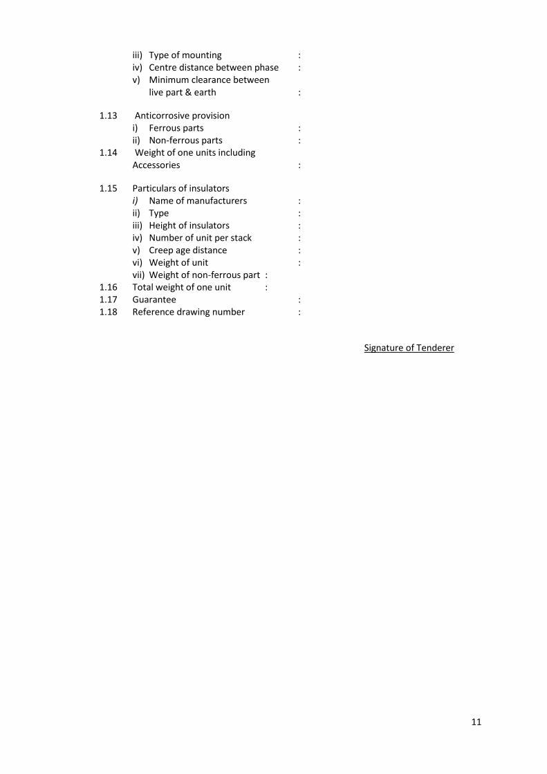
11
iii) Type of mounting : iv) Centre distance between phase : v) Minimum clearance between
live part & earth :
1.13 Anticorrosive provision i) Ferrous parts : ii) Non-ferrous parts :
1.14 Weight of one units including Accessories :
1.15 Particulars of insulators i) Name of manufacturers : ii) Type : iii) Height of insulators : iv) Number of unit per stack : v) Creep age distance : vi) Weight of unit : vii) Weight of non-ferrous part :
1.16 Total weight of one unit : 1.17 Guarantee : 1.18 Reference drawing number :
Signature of Tenderer
12
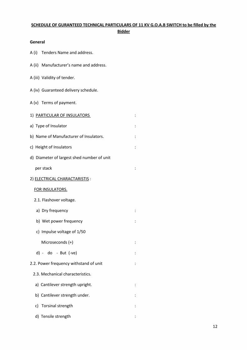
SCHEDULE OF GURANTEED TECHNICAL PARTICULARS OF 11 KV G.O.A.B SWITCH to be filled by the
Bidder
General
A (i) Tenders Name and address.
A (ii) Manufacturer’s name and address.
A (iii) Validity of tender.
A (iv) Guaranteed delivery schedule.
A (v) Terms of payment.
1) PARTICULAR OF INSULATORS :
a) Type of Insulator :
b) Name of Manufacturer of Insulators. :
c) Height of Insulators :
d) Diameter of largest shed number of unit
per stack :
2) ELECTRICAL CHARACTARISTIS :
FOR INSULATORS.
2.1. Flashover voltage.
a) Dry frequency :
b) Wet power frequency :
c) Impulse voltage of 1/50
Microseconds (+) :
d) - do - But (-ve) :
2.2. Power frequency withstand of unit :
2.3. Mechanical characteristics.
a) Cantilever strength upright. :
b) Cantilever strength under. :
c) Torsinal strength :
d) Tensile strength :

13
e) Compression strength :
2.4. General characteristics.
a) Minimum crepage distance. :
b) Weight of one unit :
2.5. Standard to which insulators conform :
NOTES: Values of insulators are given in Metric unit and for one insulator only.
Signature with seal.
14
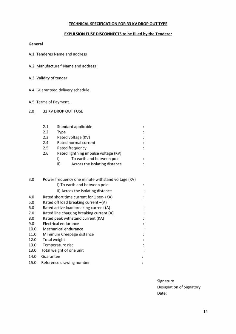
TECHNICAL SPECIFICATION FOR 33 KV DROP OUT TYPE
EXPULSION FUSE DISCONNECTS to be filled by the Tenderer
General
A.1 Tenderes Name and address
A.2 Manufacturer' Name and address
A.3 Validity of tender
A.4 Guaranteed delivery schedule
A.5 Terms of Payment.
2.0 33 KV DROP OUT FUSE
2.1 Standard applicable : 2.2 Type : 2.3 Rated voltage (KV) : 2.4 Rated normal current : 2.5 Rated frequency : 2.6 Rated lightning impulse voltage (KV)
i) To earth and between pole : ii) Across the isolating distance :
3.0 Power frequency one minute withstand voltage (KV) i) To earth and between pole :
ii) Across the isolating distance :
4.0 Rated short time current for 1 sec- (KA) : 5.0 Rated off load breaking current –(A) 6.0 Rated active load breaking current (A) : 7.0 Rated line charging breaking current (A) : 8.0 Rated peak withstand current (KA) : 9.0 Electrical endurance : 10.0 Mechanical endurance : 11.0 Minimum Creepage distance : 12.0 Total weight : 13.0 Temperature rise : 13.0 Total weight of one unit :
14.0 Guarantee :
15.0 Reference drawing number :
Signature
Designation of Signatory
Date:
15
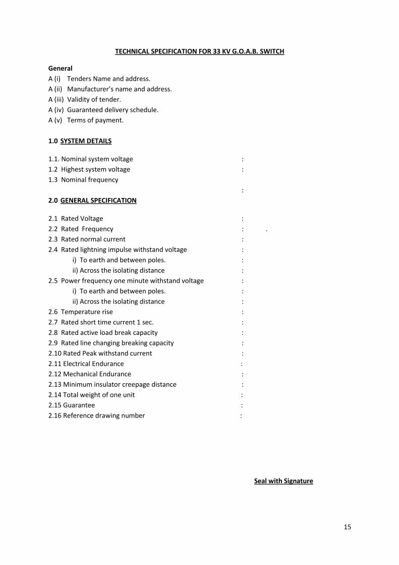
TECHNICAL SPECIFICATION FOR 33 KV G.O.A.B. SWITCH
General
A (i) Tenders Name and address.
A (ii) Manufacturer’s name and address.
A (iii) Validity of tender.
A (iv) Guaranteed delivery schedule.
A (v) Terms of payment.
1.0 SYSTEM DETAILS
1.1. Nominal system voltage :
1.2 Highest system voltage :
1.3 Nominal frequency
:
2.0 GENERAL SPECIFICATION
2.1 Rated Voltage :
2.2 Rated Frequency : .
2.3 Rated normal current :
2.4 Rated lightning impulse withstand voltage :
i) To earth and between poles. :
ii) Across the isolating distance :
2.5 Power frequency one minute withstand voltage :
i) To earth and between poles. :
ii) Across the isolating distance :
2.6 Temperature rise :
2.7 Rated short time current 1 sec. :
2.8 Rated active load break capacity :
2.9 Rated line changing breaking capacity :
2.10 Rated Peak withstand current :
2.11 Electrical Endurance :
2.12 Mechanical Endurance :
2.13 Minimum insulator creepage distance :
2.14 Total weight of one unit :
2.15 Guarantee :
2.16 Reference drawing number :
Seal with Signature

16
17
SEAL & SIGNATURE OF THE TENDERER
18

19
20
21
22
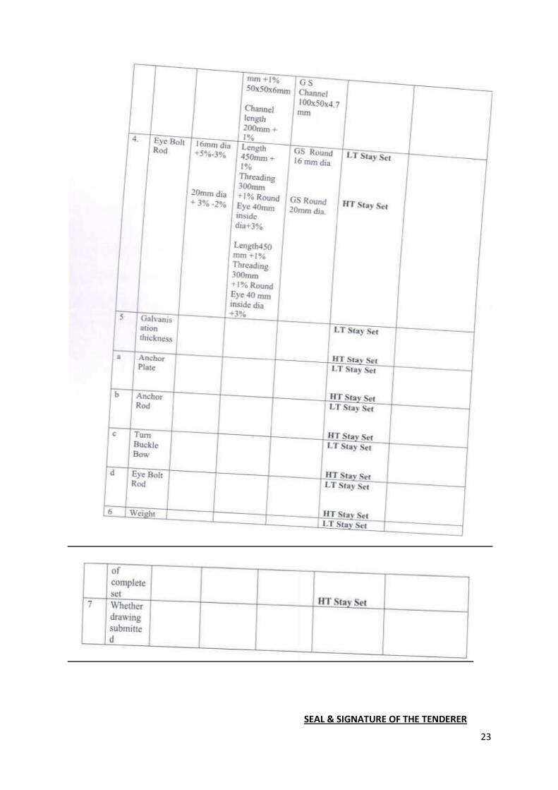
23
SEAL & SIGNATURE OF THE TENDERER
24
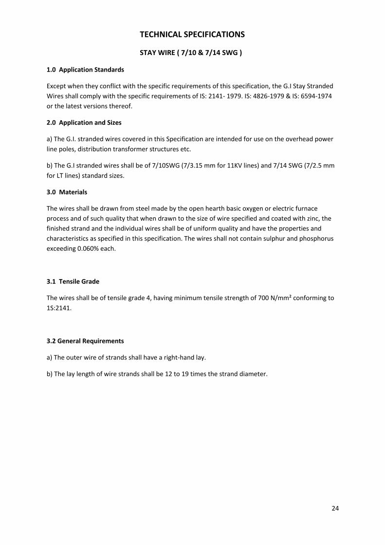
TECHNICAL SPECIFICATIONS
STAY WIRE ( 7/10 & 7/14 SWG )
1.0 Application Standards
Except when they conflict with the specific requirements of this specification, the G.I Stay Stranded
Wires shall comply with the specific requirements of IS: 2141- 1979. IS: 4826-1979 & IS: 6594-1974
or the latest versions thereof.
2.0 Application and Sizes
a) The G.I. stranded wires covered in this Specification are intended for use on the overhead power
line poles, distribution transformer structures etc.
b) The G.I stranded wires shall be of 7/10SWG (7/3.15 mm for 11KV lines) and 7/14 SWG (7/2.5 mm
for LT lines) standard sizes.
3.0 Materials
The wires shall be drawn from steel made by the open hearth basic oxygen or electric furnace
process and of such quality that when drawn to the size of wire specified and coated with zinc, the
finished strand and the individual wires shall be of uniform quality and have the properties and
characteristics as specified in this specification. The wires shall not contain sulphur and phosphorus
exceeding 0.060% each.
3.1 Tensile Grade
The wires shall be of tensile grade 4, having minimum tensile strength of 700 N/mm² conforming to
1S:2141.
3.2 General Requirements
a) The outer wire of strands shall have a right-hand lay.
b) The lay length of wire strands shall be 12 to 19 times the strand diameter.
25
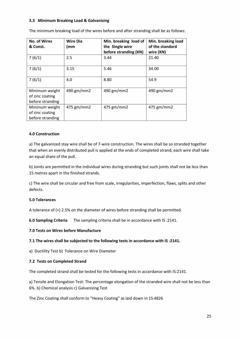
3.3 Minimum Breaking Load & Galvanising
The minimum breaking load of the wires before and after stranding shall be as follows:
No. of Wires & Const.
Wire Dia (mm
Min. breaking load of the Single wire before stranding (KN)
Min. breaking load of the standard wire (KN)
7 (6/1) 2.5
3.44 21.40
7 (6/1) 3.15
5.46 34.00
7 (6/1) 4.0
8.80 54.9
Minimum weight of zinc coating before stranding
490 gm/mm2 490 gm/mm2 490 gm/mm2
Minimum weight of zinc coating before stranding
475 gm/mm2 475 gm/mm2 475 gm/mm2
4.0 Construction
a) The galvanized stay wire shall be of 7-wire construction. The wires shall be so stranded together
that when an evenly distributed pull is applied at the ends of completed strand, each wire shall take
an equal share of the pull.
b) Joints are permitted in the individual wires during stranding but such joints shall not be less than
15 metres apart in the finished strands.
c) The wire shall be circular and free from scale, irregularities, imperfection, flaws, splits and other
defects.
5.0 Tolerances
A tolerance of (+) 2.5% on the diameter of wires before stranding shall be permitted.
6.0 Sampling Criteria The sampling criteria shall be in accordance with IS :2141.
7.0 Tests on Wires before Manufacture
7.1 The wires shall be subjected to the following tests in accordance with IS :2141.
a) Ductility Test b) Tolerance on Wire Diameter
7.2 Tests on Completed Strand
The completed strand shall be tested for the following tests in accordance with IS:2141.
a) Tensile and Elongation Test: The percentage elongation of the stranded wire shall not be less than
6%. b) Chemical analysis c) Galvanizing Test
The Zinc Coating shall conform to "Heavy Coating" as laid down in 1S:4826

26
8.0 Marking
Each coil shall carry a metallic tag, securely attached to the inner part of the coil bearing the
following information:
a) Manufacturers name or trade mark b) Lot number and coil number c) Size d) Construction e)
Tensile Designation f) Lay g) Coating h) Length i) Mass j) ISI certification mark, if any
9.0 Packing
The wires shall be supplied in 75-100 Kg. coils. The packing should be done in accordance with the
provisions of IS:6594
10.0 Other Items:
For remaining items of stay sets mentioned in the enclosed drawing, relevant applicable Indian
standards shall be applicable.
27
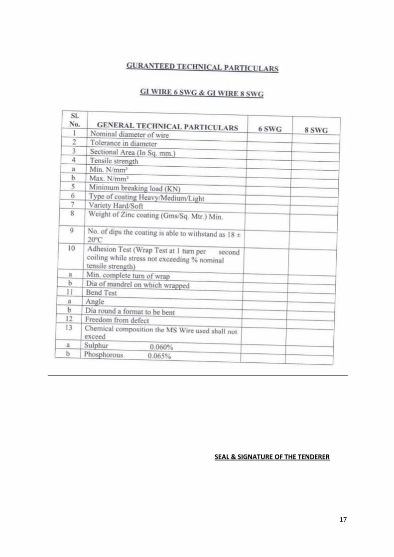
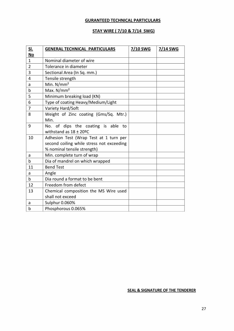
GURANTEED TECHNICAL PARTICULARS
STAY WIRE ( 7/10 & 7/14 SWG)
SEAL & SIGNATURE OF THE TENDERER
Sl. No
GENERAL TECHNICAL PARTICULARS 7/10 SWG 7/14 SWG
1 Nominal diameter of wire
2 Tolerance in diameter
3 Sectional Area (In Sq. mm.)
4 Tensile strength
a Min. N/mm²
b Max. N/mm²
5 Minimum breaking load (KN)
6 Type of coating Heavy/Medium/Light
7 Variety Hard/Soft
8 Weight of Zinc coating (Gms/Sq. Mtr.) Min.
9 No. of dips the coating is able to withstand as 18 ± 20ºC
10 Adhesion Test (Wrap Test at 1 turn per second coiling while stress not exceeding % nominal tensile strength)
a Min. complete turn of wrap
b Dia of mandrel on which wrapped
11 Bend Test
a Angle
b Dia round a format to be bent
12 Freedom from defect
13 Chemical composition the MS Wire used shall not exceed
a Sulphur 0.060%
b Phosphorous 0.065%
28
TECHNICAL SPECIFICATION FOR 11 KV 45 KN / 70 KN DISC INSULATORS
1. SCOPE:
This specification covers the manufacture, testing and works supply and delivery of 11 KV
Disc insulators. The Porcelain insulators shall conform to IS:731-1971ammended upto date.
Insulators shall be of Ball & Socket type.
2. SERVICE CONDITIONS:
The insulators to be supplied against this specification shall be suitable for satisfactory
continuous operation under the following tropical conditions.
2.1.1 Maximum ambient temperature (Degree C) … 50
2.1.2 Minimum ambient temperature (Degree C) … 3.5
2.1.3 Relative Humidity (%) … 10 to 100
2.1.4 Maximum Annual Rainfall (mm) … 1450
2.1.5. Maximum Wind pressure (kg/m.sq.) … 150
2.1.6 Maximum wind velocity (km/hour) … 45
2.1.7 Maximum altitude above mean sea level (meter) … 1000
2.1.8 Isoceraunic level (days/year) … 50
2.1.9 Seismic level (Horizontal acceleration) … 0.3 g
2.1.10 Moderately hot and humid tropical climate conductive to rust and fungus growth
3. SYSTEM PARTICULARS:
a) Nominal System Voltage 11 KV
b) Corresponding highest system Voltage 12 KV
c) Frequency 50 Hz with 3% tolerance
d) Number of phase 3
e) Neutral earthing effectively grounded.
f) Min. Impulse withstand voltage 75 KV
4. STANDARDS:
Unless otherwise specified elsewhere in the specifications insulators shall confirm to
the latest revisions of all relevant standards available at the time of placement of the order.
The standards are as listed in annexure ‘D’.
29
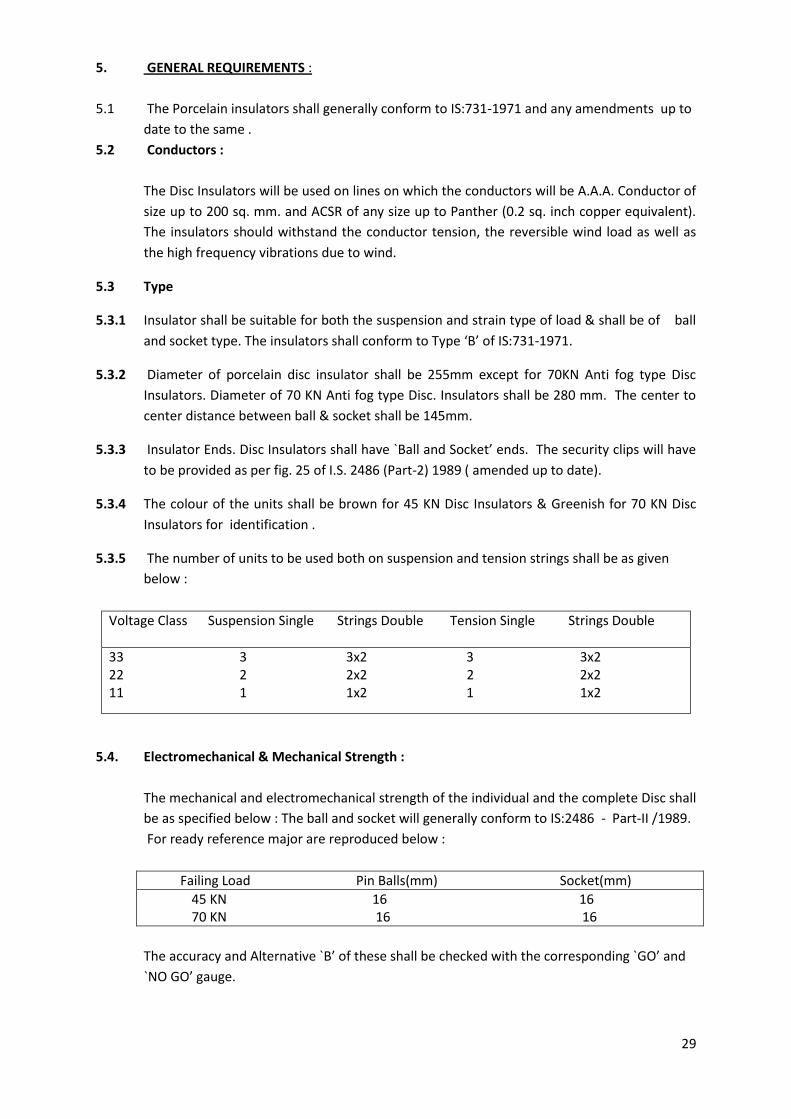
5. GENERAL REQUIREMENTS :
5.1 The Porcelain insulators shall generally conform to IS:731-1971 and any amendments up to
date to the same .
5.2 Conductors :
The Disc Insulators will be used on lines on which the conductors will be A.A.A. Conductor of
size up to 200 sq. mm. and ACSR of any size up to Panther (0.2 sq. inch copper equivalent).
The insulators should withstand the conductor tension, the reversible wind load as well as
the high frequency vibrations due to wind.
5.3 Type
5.3.1 Insulator shall be suitable for both the suspension and strain type of load & shall be of ball
and socket type. The insulators shall conform to Type ‘B’ of IS:731-1971.
5.3.2 Diameter of porcelain disc insulator shall be 255mm except for 70KN Anti fog type Disc
Insulators. Diameter of 70 KN Anti fog type Disc. Insulators shall be 280 mm. The center to
center distance between ball & socket shall be 145mm.
5.3.3 Insulator Ends. Disc Insulators shall have `Ball and Socket’ ends. The security clips will have
to be provided as per fig. 25 of I.S. 2486 (Part-2) 1989 ( amended up to date).
5.3.4 The colour of the units shall be brown for 45 KN Disc Insulators & Greenish for 70 KN Disc
Insulators for identification .
5.3.5 The number of units to be used both on suspension and tension strings shall be as given
below :
Voltage Class Suspension Single Strings Double Tension Single Strings Double
33 3 3x2 3 3x2 22 2 2x2 2 2x2 11 1 1x2 1 1x2
5.4. Electromechanical & Mechanical Strength :
The mechanical and electromechanical strength of the individual and the complete Disc shall
be as specified below : The ball and socket will generally conform to IS:2486 - Part-II /1989.
For ready reference major are reproduced below :
Failing Load Pin Balls(mm) Socket(mm)
45 KN 16 16 70 KN 16 16
The accuracy and Alternative `B’ of these shall be checked with the corresponding `GO’ and
`NO GO’ gauge.
30
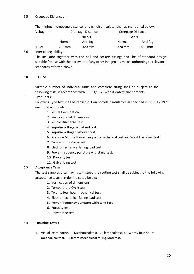
5.5 Creepage Distances :
The minimum creepage distance for each disc Insulator shall as mentioned below.
Voltage Creepage Distance Creepage Distance
45 KN 70 KN
Normal Anti fog Normal Anti fog
11 kv 230 mm 320 mm 320 mm 430 mm
5.6 Inter changeability :
The insulator together with the ball and sockets fittings shall be of standard design
suitable for use with the hardware of any other indigenous make conforming to relevant
standards referred above.
6.0 TESTS:
Suitable number of individual units and complete string shall be subject to the
following tests in accordance with IS: 731/1971 with its latest amendments.
6.1 Type Tests:
Following Type test shall be carried out on porcelain insulators as specified in IS: 731 / 1971
amended up to date.
1. Visual Examination.
2. Verification of dimensions.
3. Visible Discharge Test.
4. Impulse voltage withstand test.
5. Impulse voltage flashover test.
6. Wet one Minute Power Frequency withstand test and West Flashover test.
7. Temperature Cycle test.
8. Electromechanical failing load test.
9. Power frequency puncture withstand test.
10. Porosity test.
11. Galvanizing test.
6.3 Acceptance Tests:
The test samples after having withstood the routine test shall be subject to the following
acceptance tests in order indicated below:
1. Verification of dimensions.
2. Temperature Cycle test.
3. Twenty four hour mechanical test.
4. Electromechanical failing load test.
5. Power Frequency puncture withstand test.
6. Porosity test.
7. Galvanizing test.
6.4 Routine Tests :
1. Visual Examination. 2. Mechanical test. 3. Electrical test. 4. Twenty four hours
mechanical test. 5. Electro mechanical failing load test.
31
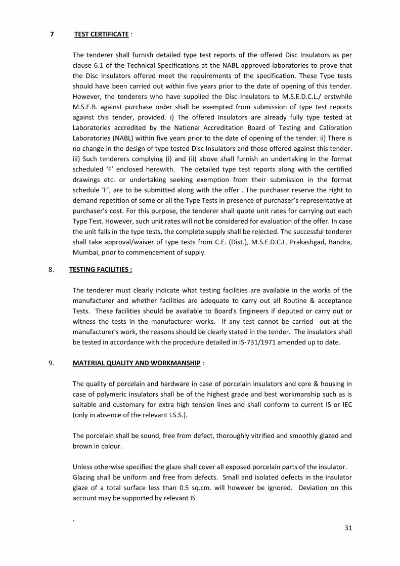
7 TEST CERTIFICATE :
The tenderer shall furnish detailed type test reports of the offered Disc Insulators as per
clause 6.1 of the Technical Specifications at the NABL approved laboratories to prove that
the Disc Insulators offered meet the requirements of the specification. These Type tests
should have been carried out within five years prior to the date of opening of this tender.
However, the tenderers who have supplied the Disc Insulators to M.S.E.D.C.L./ erstwhile
M.S.E.B. against purchase order shall be exempted from submission of type test reports
against this tender, provided. i) The offered Insulators are already fully type tested at
Laboratories accredited by the National Accreditation Board of Testing and Calibration
Laboratories (NABL) within five years prior to the date of opening of the tender. ii) There is
no change in the design of type tested Disc Insulators and those offered against this tender.
iii) Such tenderers complying (i) and (ii) above shall furnish an undertaking in the format
scheduled ‘F’ enclosed herewith. The detailed type test reports along with the certified
drawings etc. or undertaking seeking exemption from their submission in the format
schedule ‘F’, are to be submitted along with the offer . The purchaser reserve the right to
demand repetition of some or all the Type Tests in presence of purchaser’s representative at
purchaser’s cost. For this purpose, the tenderer shall quote unit rates for carrying out each
Type Test. However, such unit rates will not be considered for evaluation of the offer. In case
the unit fails in the type tests, the complete supply shall be rejected. The successful tenderer
shall take approval/waiver of type tests from C.E. (Dist.), M.S.E.D.C.L. Prakashgad, Bandra,
Mumbai, prior to commencement of supply.
8. TESTING FACILITIES :
The tenderer must clearly indicate what testing facilities are available in the works of the
manufacturer and whether facilities are adequate to carry out all Routine & acceptance
Tests. These facilities should be available to Board's Engineers if deputed or carry out or
witness the tests in the manufacturer works. If any test cannot be carried out at the
manufacturer's work, the reasons should be clearly stated in the tender. The insulators shall
be tested in accordance with the procedure detailed in IS-731/1971 amended up to date.
9. MATERIAL QUALITY AND WORKMANSHIP :
The quality of porcelain and hardware in case of porcelain insulators and core & housing in
case of polymeric insulators shall be of the highest grade and best workmanship such as is
suitable and customary for extra high tension lines and shall conform to current IS or IEC
(only in absence of the relevant I.S.S.).
The porcelain shall be sound, free from defect, thoroughly vitrified and smoothly glazed and
brown in colour.
Unless otherwise specified the glaze shall cover all exposed porcelain parts of the insulator.
Glazing shall be uniform and free from defects. Small and isolated defects in the insulator
glaze of a total surface less than 0.5 sq.cm. will however be ignored. Deviation on this
account may be supported by relevant IS
.
32
10 MECHANICAL DESIGN :
The design shall be such that stresses due to expansion and contraction in any part of
insulator shall not lead to deterioration.
Cement used in manufacture of the insulators shall not cause fracture due to expansion or
loosening due to contraction.
11 . DRAWINGS :
The tender shall be accompanied with the detailed drawings showing the dimensions of the
individual Disc, Ball & Socket, complete strings giving all the design dimensions of various
component parts. The drawing for Insulators should clearly show the method of cementing
the porcelain to the metal caps and balls. Generally it shall be as per IS.
12 . RETEST AND REJECTION :
12.1 C-2.1 Sample Procedure for testing of insulators shall be as per Appendix ‘C’ of IS- 731/1971
for Acceptance & Routine Tests. All the insulators selected at random according to col. 1 & 2
of Table 5 of IS- 731/1971 shall be subjected to dimensions and temperature cycle tests. The
insulators failing to satisfy either of requirements shall be termed as defectives. The lot shall
be considered as conforming to these requirements if the number of defectives found in the
sample is less than or equal to corresponding acceptance number given in col. 4 of Table 5.
The lot shall be rejected if the number of defectives in the same lot is greater than or equal
to the first rejection number (r 1) given in col. 5.
If the number of effectives is between the acceptance number and the first rejection
number, a second sample of the same size (see col. 3 of Table 5) shall be selected from the
lot at random and subjected to these tests. The number of defectives in the first sample and
second sample shall be combined. If the combined number of defectives is less than the
second rejection number (r2) given in col. 6 of Table 5, the lot shall be considered as
confirming to these requirements. Otherwise the lot shall be rejected without further
testing.
C-2.2 The lot which has been found as confirming to the above requirements shall
then be divided into two parts, as shown in col. 7 and 9 of Table 5. The number of insulators
to be tested for mechanical, electromechanical and porosity tests shall be in accordance
with col. 7 of Table 5. The lot shall be considered as confirming to these requirements if no
defective is found in the sample and shall be rejected if there are two or more defectives. If
there is one defective, a second sample of the same size (see col.8 of Table 5) shall be
selected at random and subjected to the tests. The lot shall be considered as confirming to
these requirements if no defective is found in the second sample; otherwise the lot shall be
rejected without further testing.
C-2.3 The lot which has been found as confirming to the above requirements of C-
2.1 shall then be tested for galvanizing test and puncture test. For this purpose, the sample
size is given in col. 9 of Table 5. The lot shall be considered as confirming to these
requirements if no defective is found in the sample and shall be rejected if two or more
defectives are found in the sample. If there is one defective, a second sample of the same
size (see col. 10 of Table 5) shall be selected at random and subjected to the tests.
33
The lot shall be considered as confirming to these requirements if no defective is found in
the second sample; otherwise the lot shall be rejected without further testing. The
lot shall be considered as conforming to the requirements of acceptance tests if conditions
in C-2.1,C-2.2 and C-2.3 are satisfied.
13 . MARKINGS :
13.1 Each insulator shall be legibly and indelibly marked to show the following :
a) Name or trade mark of the manufacturer.
b) Voltage & Type
c) Month and year of manufacturing.
d) Electromechanical strength in KN.
e) ‘MSEDCL’ marking .
13.2 The “W” clip shall be marked with/punched with the ball and socket sizes for which it
is meant e.g.16B,20 etc.
13.3 Marking on porcelain shall be printed and shall be applied before firing.
14 PACKING :
All insulators shall be packed in crates or boxes suitable for rough handling. Packing shall be
marked with the strength and KV rating.
15 GUARANTEED TECHNICAL PARTICULARS :
The tenderer shall furnish in the form attached (Schedule 'A') all the guaranteed technical
particulars.

34
Name & Signature of Bidder with seal
35
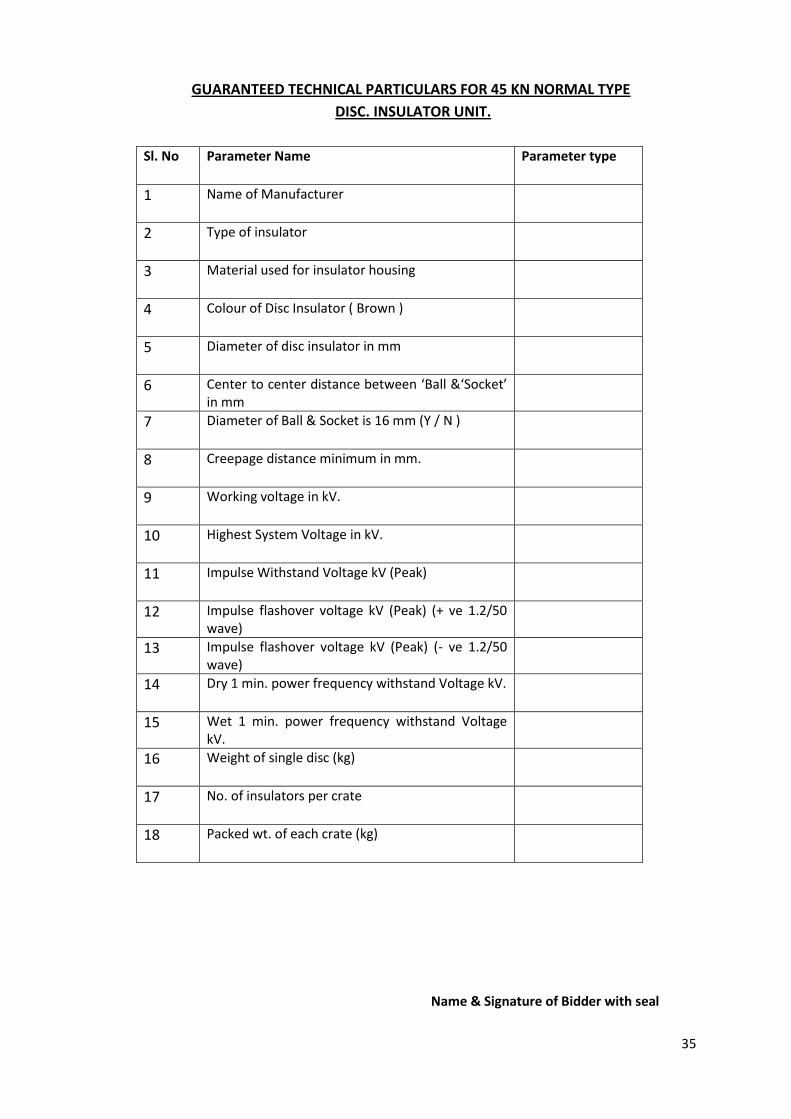
GUARANTEED TECHNICAL PARTICULARS FOR 45 KN NORMAL TYPE
DISC. INSULATOR UNIT.
Sl. No Parameter Name Parameter type
1 Name of Manufacturer
2 Type of insulator
3 Material used for insulator housing
4 Colour of Disc Insulator ( Brown )
5 Diameter of disc insulator in mm
6 Center to center distance between ‘Ball &‘Socket’ in mm
7 Diameter of Ball & Socket is 16 mm (Y / N )
8 Creepage distance minimum in mm.
9 Working voltage in kV.
10 Highest System Voltage in kV.
11 Impulse Withstand Voltage kV (Peak)
12 Impulse flashover voltage kV (Peak) (+ ve 1.2/50 wave)
13 Impulse flashover voltage kV (Peak) (- ve 1.2/50 wave)
14 Dry 1 min. power frequency withstand Voltage kV.
15 Wet 1 min. power frequency withstand Voltage kV.
16 Weight of single disc (kg)
17 No. of insulators per crate
18 Packed wt. of each crate (kg)
Name & Signature of Bidder with seal

36
GUARANTEED TECHNICAL PARTICULARS FOR 45 KN ANTI FOG TYPE
DISC. INSULATOR UNIT.
Sl. No Parameter Name Parameter type
1 Name of Manufacturer
2 Type of insulator
3 Material used for insulator housing
4 Colour of Disc Insulator ( Brown )
5 Diameter of disc insulator in mm
6 Center to center distance between ‘Ball &‘Socket’ in mm
7 Diameter of Ball & Socket is 16 mm (Y / N )
8 Creepage distance minimum in mm.
9 Working voltage in kV.
10 Highest System Voltage in kV.
11 Impulse Withstand Voltage kV (Peak)
12 Impulse flashover voltage kV (Peak) (+ ve 1.2/50 wave)
13 Impulse flashover voltage kV (Peak) (- ve 1.2/50 wave)
14 Dry 1 min. power frequency withstand Voltage kV.
15 Wet 1 min. power frequency withstand Voltage kV.
16 Weight of single disc (kg)
17 No. of insulators per crate
18 Packed wt. of each crate (kg)
Name & Signature of Bidder with seal

37
GUARANTEED TECHNICAL PARTICULARS FOR 70 KN NORMAL TYPE
DISC. INSULATOR UNIT.
Sl. No Parameter Name Parameter type
1 Name of Manufacturer
2 Type of insulator
3 Material used for insulator housing
4 Colour of Disc Insulator ( Brown )
5 Diameter of disc insulator in mm
6 Center to center distance between ‘Ball &‘Socket’ in mm
7 Diameter of Ball & Socket is 16 mm (Y / N )
8 Creepage distance minimum in mm.
9 Working voltage in kV.
10 Highest System Voltage in kV.
11 Impulse Withstand Voltage kV (Peak)
12 Impulse flashover voltage kV (Peak) (+ ve 1.2/50 wave)
13 Impulse flashover voltage kV (Peak) (- ve 1.2/50 wave)
14 Dry 1 min. power frequency withstand Voltage kV.
15 Wet 1 min. power frequency withstand Voltage kV.
16 Weight of single disc (kg)
17 No. of insulators per crate
18 Packed wt. of each crate (kg)
Name & Signature of Bidder with seal
38
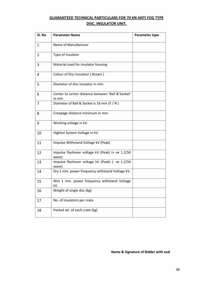
GUARANTEED TECHNICAL PARTICULARS FOR 70 KN ANTI FOG TYPE
DISC. INSULATOR UNIT.
Sl. No Parameter Name Parameter type
1 Name of Manufacturer
2 Type of insulator
3 Material used for insulator housing
4 Colour of Disc Insulator ( Brown )
5 Diameter of disc insulator in mm
6 Center to center distance between ‘Ball &‘Socket’ in mm
7 Diameter of Ball & Socket is 16 mm (Y / N )
8 Creepage distance minimum in mm.
9 Working voltage in kV.
10 Highest System Voltage in kV.
11 Impulse Withstand Voltage kV (Peak)
12 Impulse flashover voltage kV (Peak) (+ ve 1.2/50 wave)
13 Impulse flashover voltage kV (Peak) (- ve 1.2/50 wave)
14 Dry 1 min. power frequency withstand Voltage kV.
15 Wet 1 min. power frequency withstand Voltage kV.
16 Weight of single disc (kg)
17 No. of insulators per crate
18 Packed wt. of each crate (kg)
Name & Signature of Bidder with seal
39
TECHNICAL SPECIFICATION FOR 11/33 KV H.T. PIN INSULATORS
1. SCOPE:
This specification covers the manufacture, testing and works supply and delivery of 11 kV &
33 kV Pin insulators. The Insulators shall be porcelain/composite type pin insulators.
1.1 Bidder must be an indigenous manufacturer and supplier of porcelain/composite type
insulators of ratings 33 kV or above OR must have developed proven in house
technology and manufacturing process for porcelain/composite type insulators of above
rating OR possess technical collaboration/association with a manufacturer of porcelain
type insulators of ratings 33 kV or above. The bidder shall furnish necessary evidence
in support of the above along with the bid, which can be in the form of certification from
the utilities concerned, or any other documents to the satisfaction of the purchaser.
2. SERVICE CONDITIONS:
The insulators to be supplied against this specification shall be suitable for satisfactory
continuous operation under the following tropical conditions.
2.1.1 Maximum ambient temperature (Degree C) … 50
2.1.2 Minimum ambient temperature (Degree C) … 3.5
2.1.3 Relative Humidity (%) … 10 to 100
2.1.4 Maximum Annual Rainfall (mm) … 1450
2.1.5. Maximum Wind pressure (kg/m.sq.) … 150
2.1.6 Maximum wind velocity (km/hour) … 45
2.1.7 Maximum altitude above mean sea level (meter) … 1000
2.1.8 Isoceraunic level (days/year) … 50
2.1.9 Seismic level (Horizontal acceleration) … 0.3 g
2.1.10 Moderately hot and humid tropical climate
conductive to rust and fungus growth
3. SYSTEM PARTICULARS:
a) Nominal System Voltage 11 kV, 33 kV
b) Corresponding highest system Voltage 12 kV, 36 kV
c) Frequency 50 Hz with 3% tolerance
d) Number of phase ----------- 3 ------------
e) Neutral earthing effectively grounded.
f) Min. Impulse withstand voltage 75 kV, 170 kV
40
4. STANDARDS:
Unless otherwise specified elsewhere in the specifications insulators shall confirm to IS:
731/1971/ IEC: 61109 / 92-93 with the latest revisions at the time of placement of the order.
The standards are listed in Annexure ‘D’.
5.0 GENERAL TECHNICAL REQUIREMENTS:
The porcelain insulators shall generally conform to IS: 731/1971 and any amendments
up to date to the same. The insulators shall confirm to type ‘B’ of IS: 731/1971.
5.1 Conductors:
The pin insulators will be used on lines on which the conductors will be A.A.A.
Conductor size up to 200 sq.mm. and ACSR of any size up to Panther (0.2 sq. inch copper
equivalent). The insulators should withstand the conductor tension, the reversible wind
load as well as the high frequency vibrations set up to due to wind.
5.2 Design Specification:
5.2.1 The Porcelain Pin Insulators shall conform to the provisions of IS: 731-1971 or its latest
version in all respects. The pin insulators shall be suitable for the spindle detailed
below:
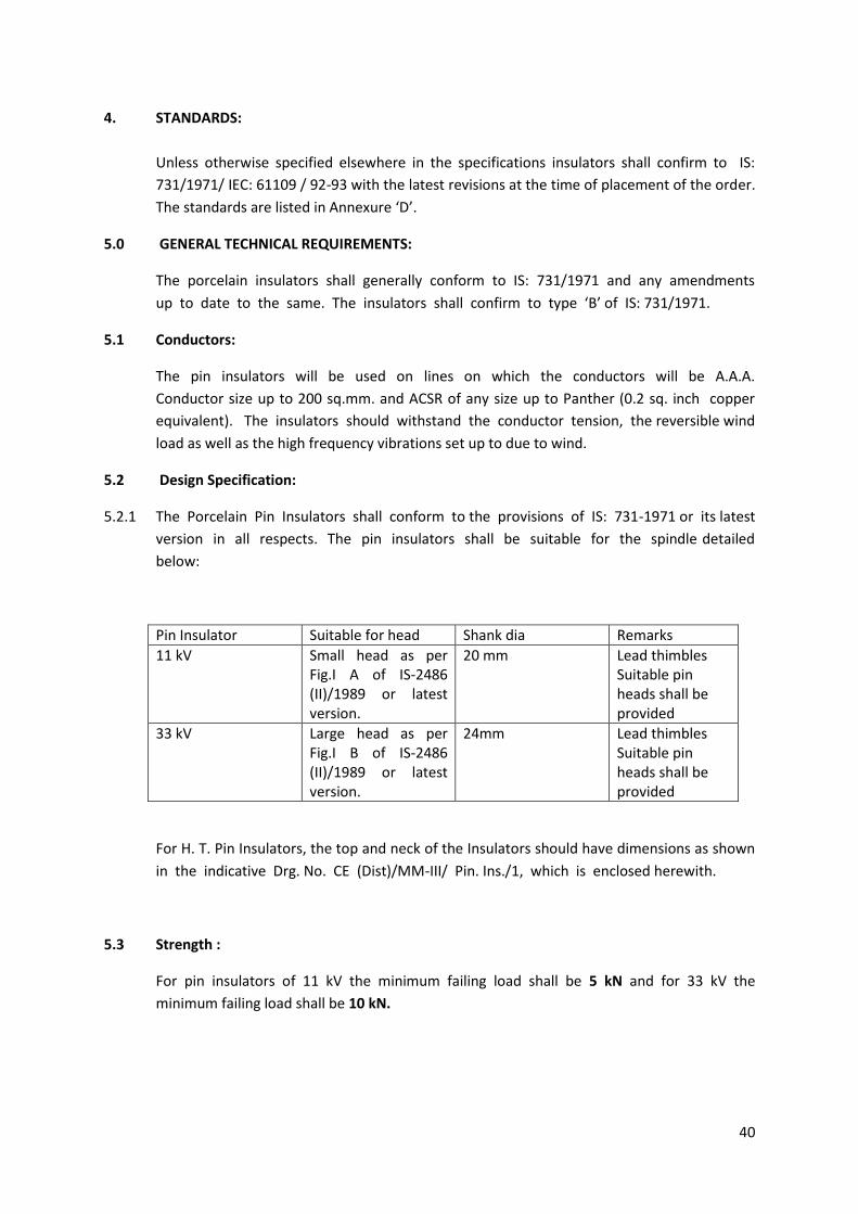
Pin Insulator Suitable for head Shank dia Remarks
11 kV Small head as per Fig.I A of IS-2486 (II)/1989 or latest version.
20 mm Lead thimbles Suitable pin heads shall be provided
33 kV Large head as per Fig.I B of IS-2486 (II)/1989 or latest version.
24mm Lead thimbles Suitable pin heads shall be provided
For H. T. Pin Insulators, the top and neck of the Insulators should have dimensions as shown
in the indicative Drg. No. CE (Dist)/MM-III/ Pin. Ins./1, which is enclosed herewith.
5.3 Strength :
For pin insulators of 11 kV the minimum failing load shall be 5 kN and for 33 kV the
minimum failing load shall be 10 kN.
41
5.4 Creepage Distance :
The minimum creepage distance shall be those given below :
-----------------------------------------------------------------------
Insulators Creepage distance
-----------------------------------------------------------------------
11 kV Pin Insulator 320 mm
33 kV Pin Insulators 840 mm
-----------------------------------------------------------------------
5.5 Material Quality and Workmanship
The quality of porcelain/composite material and hardware and all workmanship should
be of the highest grade and such as is suitable and customary for extra high tension lines
and shall conform to current IS or IEC. (Only in absence of the relevant I.S.S.).
The porcelain shall be sound, free from defect, thoroughly vitrified and smoothly
glazed and brown in colour.
Unless otherwise specified the glaze shall cover all exposed porcelain parts of the
insulator.
Glazing shall be uniform and free from defects. Small and isolated defects in the
insulator glaze of a total surface less than 0.5 sq.cm. will however be ignored.
Deviation on this account may be supported by relevant IS.
5.6 Mechanical Design:
The design shall be such that stresses due to expansion and contraction in any part of
insulator shall not lead to deterioration. Cement used in manufacture of insulator shall not
cause fracture due to expansion or loosening due to contraction.
5.7 Design and construction for composite insulators.
The composite insulator shall have a core, housing & weathershed of insulating
material and steel/aluminum hardware components for attaching it to the
support/conductor.
5.7.1 Core
It shall be a glass-fiber reinforced epoxy resin rod of high strength (FRP rod). Glass fibers and
resin shall be optimized in the FRP rod. Glass fibers shall be Boron free electrically
corrosion resistant (ECR) glass fiber orboron free E-Glass and shall exhibit both high
electrical integrity and high resistance to acid corrosion. The matrix of the FRP rod shall
be Hydrolysis resistant. The FRP rod shall be manufactured through Pultrusion process.
The FRP rod shall be void free.
42
5.7.2 Housing (Sheath)
The FRP rod shall be covered by a seamless sheath of a silicone elastometric
compound or silicone alloy compound of a thickness of 3 mm minimum.
It should protect the FRP rod against environmental influences, external pollution and
humidity. It shall be extruded or directly molded on the core and shall have chemical
bonding with the FRP rod. The strength of the bond shall be greater than the tearing
strength of the polymer. Sheath material in the bulk as well as in the sealing / bonding area
shall be free from voids.
5.7.3 Weather sheds
The composite polymer weather sheds made of silicone elastometic compound or
silicon alloy shall be firmly bonded to the sheath, vulcanized to the sheath or molded as part
of the sheath and shall be free from imperfections. The weather sheds should have silicon
content of minimum 30% by weight. The strength of the weather sheds to sheath interface
shall be greater than the tearing strength of the polymer. The interface, if any,
between sheds and sheath (housing) shall be free from voids.
5.7.4 Metal End Fitting:
End fitting transmit the mechanical load to the core. They shall be made of forged steel.
G. I. pin shall be connected to the rod by means of a controlled compression technique. G.
I. pins shall be of respective specified mechanical load and shall be hot dip galvanized after,
all fittings have been completed. The material used in fittings shall be corrosion
resistant. As the main duty of the end fittings is the transfer of mechanical loads to
the core the fittings should be properly attached to the core by a coaxial or hexagonal
compression process & should not damage the individual fibers or crack the core. The gap
between fitting and sheath shall be sealed by a flexible silicone elastomeric compound
or silicone alloy compound sealant. System of attachment of end fitting to the rod
shall provide superior sealing performance between housing, i.e. seamless sheath and
metal connection. The sealing must be moisture proof. The dimensions of end fittings
of Insulators shall be in accordance with the standard dimensions stated in IEC: 60120/IS:
2486 - Part-II /1989.
5.7.5 Corona and RI Performance
All surfaces shall be clean, smooth, without cuts, abrasions or projections. No part shall be
subjected to excessive localized pressure. The insulator and metal parts shall be so designed
and manufactured that it shall avoid local corona formation and not generate any radio
interference beyond specified limit under the operating conditions.
43
6.0 TESTS:
6.1 Testing Facilities:
The tenderer must clearly indicate what testing facilities are available in the works of the
manufacturer and whether facilities are adequate to carry out all Routine &acceptance
Tests. If any test cannot be carried out at the manufacturer's work, the reasons should be
clearly stated in the tender. The insulators shall be tested in accordance with the procedure
detailed in IS-731/1971 or IEC 61109 / 92-93 with latest amendments.
6.2 Design Tests:
For composite insulators it is essential to carry out design test as per clause 4.1 of IEC 61109
/ 92-93 with latest amendments. The design tests are intended to verify the suitability of the
design, materials and method of manufacture (technology). When a composite insulator is
submitted to the design tests, the result shall be considered valid for the whole class of
insulators, which are represented by the one tested and having the following
characteristics:
• Same materials for the core, and sheds and same manufacturing method;
• Same material of the fittings, the same design, the same method of
attachment;
• Same or greater layer thickness of the shed material over the core
(including a sheath where used);
• Same or smaller ratio of the highest system voltage to insulation length;
• Same or smaller ratio of all mechanical loads to the smallest core diameter
between fittings
• Same or greater diameter of the core.
The tested composite insulators shall be identified by a drawing giving all the
dimensions with the manufacturing tolerances.
Manufacturer should submit test reports for Design Tests as per IEC – 61109 (clause –
5) along with the bid. Additionally following tests shall be carried out or reports for the
tests shall be submitted after award of contract:
UV test: the test shall be carried out in line with clause 7.2 of ANSI C29.13.
44
6.3 Type Test :
6.3.1 The type tests mentioned below should be carried out on porcelain type of Insulator
offered by the tenderer and the test shall conform to requirements as per Table IA & as per
clause 10.1.1 of IS 731/1971 (latest version).
1. Visual Examination.
2. Verification of dimensions.
3. Visible Discharge Test
4. Impulse Voltage Withstand Test.
5 Wet Power Frequency Voltage Withstand Test
6. Temperature Cycle Test.
7. Electro-Mechanical failing load test.
8. Power frequency puncture withstand test.
9. Porosity test.
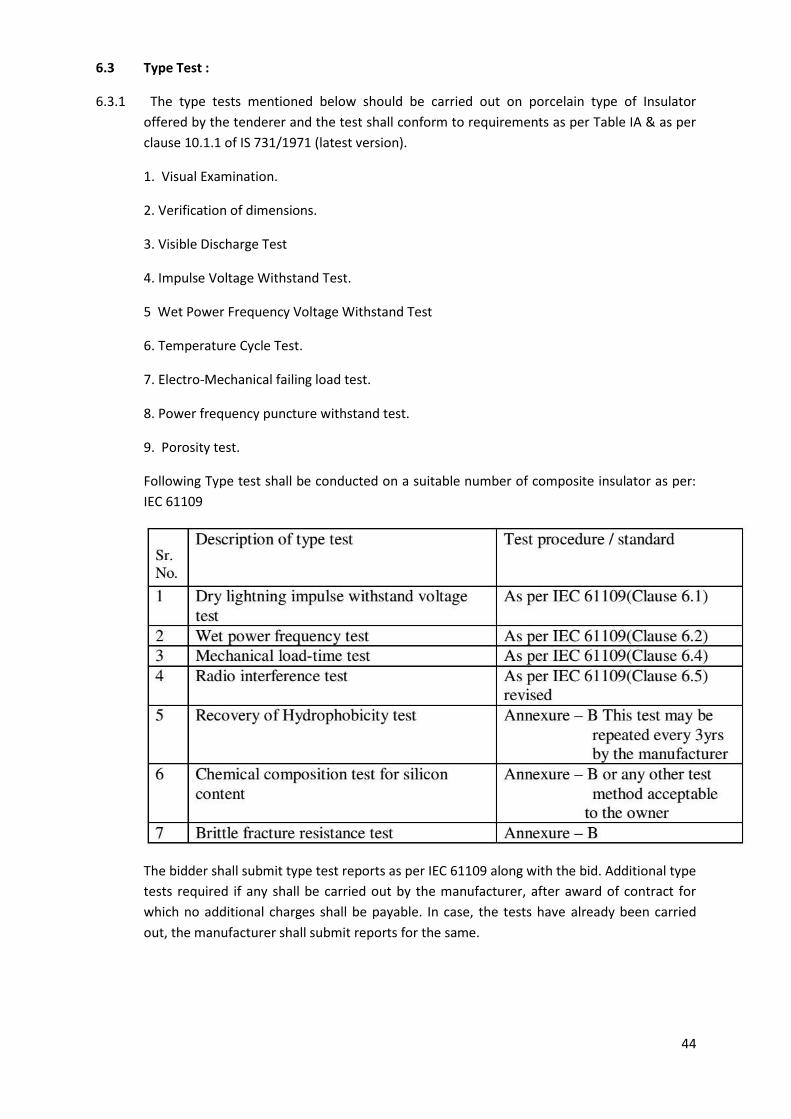
Following Type test shall be conducted on a suitable number of composite insulator as per:
IEC 61109
The bidder shall submit type test reports as per IEC 61109 along with the bid. Additional type
tests required if any shall be carried out by the manufacturer, after award of contract for
which no additional charges shall be payable. In case, the tests have already been carried
out, the manufacturer shall submit reports for the same.
45
6.3.2 Acceptance Tests
The Test samples after having withstood the routine test, porcelain type insulators
shall be subject to the following acceptance tests in order indicted below as per clause
10.1.2 of IS-731/1971
1. Verification of dimensions.
2. Temperature Cycle Test.
3. Porosity Test.
The test samples after having withstood the routine test, composite insulators shall be
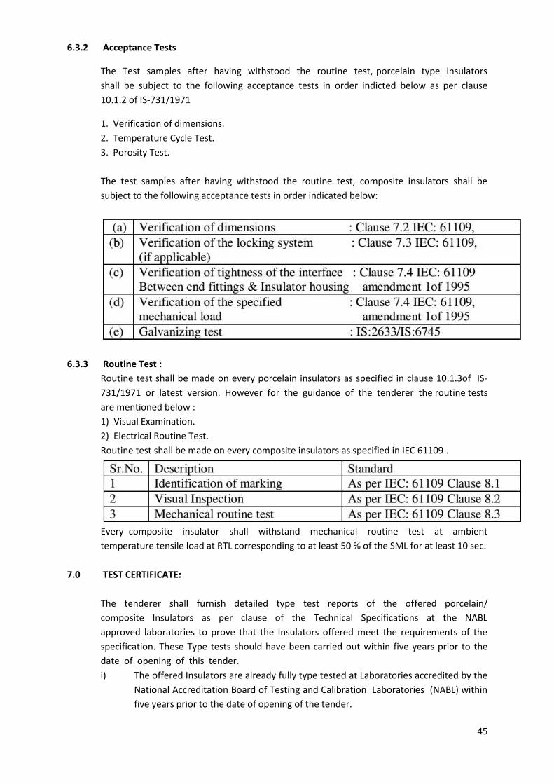
subject to the following acceptance tests in order indicated below:
6.3.3 Routine Test :
Routine test shall be made on every porcelain insulators as specified in clause 10.1.3of IS-
731/1971 or latest version. However for the guidance of the tenderer the routine tests
are mentioned below :
1) Visual Examination.
2) Electrical Routine Test.
Routine test shall be made on every composite insulators as specified in IEC 61109 .
Every composite insulator shall withstand mechanical routine test at ambient
temperature tensile load at RTL corresponding to at least 50 % of the SML for at least 10 sec.
7.0 TEST CERTIFICATE:
The tenderer shall furnish detailed type test reports of the offered porcelain/
composite Insulators as per clause of the Technical Specifications at the NABL
approved laboratories to prove that the Insulators offered meet the requirements of the
specification. These Type tests should have been carried out within five years prior to the
date of opening of this tender.
i) The offered Insulators are already fully type tested at Laboratories accredited by the
National Accreditation Board of Testing and Calibration Laboratories (NABL) within
five years prior to the date of opening of the tender.
46
ii) There is no change in the design of type-tested porcelain/composite Insulators and
those offers against this tender.
(iii) Such tenderers complying (i) and (ii) above shall furnish an undertaking in the
format scheduled ‘F’ enclosed herewith.
The detailed Type tests along with the relevant certified drawings etc. or undertaking
in the format schedule “F” seeking exemption from their submission of the type test reports
are to be submitted along with the offer.
The purchaser reserves right to demand repetition of some or all the Type Test in presence
of purchaser’s representative at purchaser’s cost. For this purpose, the tenderer shall
quote unit rates for carrying out each Type Test. However, such unit rates will not be
considered for evaluation of the offer. In case the unit fails in the Type Tests, the complete
supply shall be rejected.
8.0 DRAWINGS:
The tender shall be accompanied with the detailed drawings with dimensions for each
ratings of pin insulators i.e.11 & 33 KV. The Bidder shall furnish full description and
illustration of the material offered.8.1 The Bidder shall furnish along with the bid the outline
drawing (3 copies) of each insulator unit including a cross sectional view of the long rod
insulator unit. The drawing shall include but not be limited to the following information:
(a) Minimum Creepage distance with positive tolerance
(b) Protected creepage distance
(c) Unit mechanical and electrical characteristics
(d) Size and weight of ball and socket/tongue & clevis
(e) Weight of composite long rod units
(f) Materials
(i) Identification mark
(ii) Manufacturer’s catalogue number
9. Retest and Rejection:
9.1 C-2.1 Sample Procedure for testing of porcelain insulators shall be as per Appendix
‘C’ of IS- 731/1971 for Acceptance & Routine Tests. All the insulators selected at random
according to col. 1 & 2 of Table 5 of IS-731/1971 shall be subjected to dimensions and
temperature cycle tests. The insulators failing to satisfy either of requirements shall be
termed as defectives. The lot shall be considered as confirming to these requirements if the
number of defectives found in the sample is less than or equal to corresponding acceptance
number given in col. 4 of Table 5. The lot shall be rejected if the number of defectives in the
same lot is greater than or equal to the first rejection number (r1) given in col. 5. If
the number of defectives is between the acceptance number and the first rejection
number, a second sample of the same size (see col. 3 of Table 5) shall be selected
from the lot at random and subjected to these tests. The number of defectives in the first
sample and second sample shall be combined. If the combined number of defectives is less
than the second rejection number (r2) given in col. 6 of Table 5, the lot shall be considered
47
as confirming to these requirements. Otherwise the lot shall be rejected without
further testing.
C-2.2 The lot which has been found as confirming to the above requirements shall
then be divided into two parts, as shown in col 7 and 9 of Table 5. The number of insulators
to be tested for mechanical, electromechanical and porosity tests shall be in accordance
with col 7 of Table 5. The lot shall be considered as confirming to these
requirements if no defective is found in the sample and shall be rejected if there are
two or more defectives. If there is one defective, a second sample of the same
size(see col 8 of Table 5) shall be selected at random and subjected to the tests. The lot shall
be considered as confirming to these requirements if no defective is found in the second
sample; otherwise the lot shall be rejected without further testing.
C-2.3 The lot which has been found as confirming to the above requirements of C-
2.1 shall then be tested for galvanizing test and puncture test. For this purpose, the sample
size is given in col. 9 of Table 5. The lot shall be considered as confirming to these
requirements if no defective is found in the sample and shall be rejected if two or more
defectives are found in the sample. If there is one defective, a second sample of the
same size (see col. 10 of Table 5) shall be selected at random and subjected to the
tests. The lot shall be considered as confirming to these requirements if no defective is
found in the second sample; otherwise the lot shall be rejected without further testing.
The lot shall be considered as conforming to the requirements of acceptance tests if
conditions in C-2.1, C-2.2 and C-2.3 are satisfied.
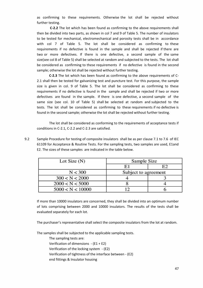
9.2 Sample Procedure for testing of composite insulators shall be as per clause 7.1 to 7.6 of IEC
61109 for Acceptance & Routine Tests. For the sampling tests, two samples are used, E1and
E2. The sizes of these samples are indicated in the table below.
If more than 10000 insulators are concerned, they shall be divided into an optimum number
of lots comprising between 2000 and 10000 insulators. The results of the tests shall be
evaluated separately for each lot.
The purchaser’s representative shall select the composite insulators from the lot at random.
The samples shall be subjected to the applicable sampling tests.
The sampling tests are:
Verification of dimensions - (E1 + E2)
Verification of the locking system - (E2)
Verification of tightness of the interface between - (E2)
end fittings & Insulator housing
48
Verification of the specified mechanical load SML - (E1)
Galvanizing test - (E2)
9.2.1 In the event of a failure of the sample to satisfy a test, the retesting procedure for
composite insulators shall be as per IEC Standard.:
10.0. Markings:
10.1.1 Each insulator shall be legibly and indelibly marked to show the following:
a) Name or trademark of the manufacturer.
b) Highest system Voltage
c) Month and year of manufacturing.
d) Min. failing load in ‘KN’.
e) Tender Reference Number
10.2 Marking on porcelain shall be printed and applied before firing.
11. Packing :
All insulators shall be packed in crates or boxes suitable for rough handling. Packing shall be
marked with the strength and KV rating.
12. Guaranteed Technical Particulars :
The tenderer shall furnish in the attached form (Schedule 'A') all the guaranteed
technical particulars.
49
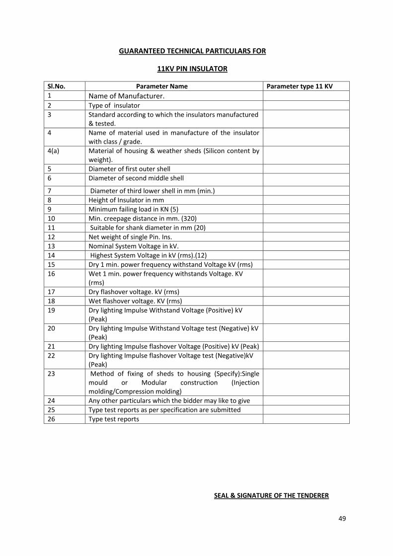
GUARANTEED TECHNICAL PARTICULARS FOR
11KV PIN INSULATOR
Sl.No. Parameter Name Parameter type 11 KV
1 Name of Manufacturer.
2 Type of insulator
3 Standard according to which the insulators manufactured & tested.
4 Name of material used in manufacture of the insulator with class / grade.
4(a) Material of housing & weather sheds (Silicon content by weight).
5 Diameter of first outer shell
6 Diameter of second middle shell
7 Diameter of third lower shell in mm (min.)
8 Height of Insulator in mm
9 Minimum failing load in KN (5)
10 Min. creepage distance in mm. (320)
11 Suitable for shank diameter in mm (20)
12 Net weight of single Pin. Ins.
13 Nominal System Voltage in kV.
14 Highest System Voltage in kV (rms).(12)
15 Dry 1 min. power frequency withstand Voltage kV (rms)
16 Wet 1 min. power frequency withstands Voltage. KV (rms)
17 Dry flashover voltage. kV (rms)
18 Wet flashover voltage. KV (rms)
19 Dry lighting Impulse Withstand Voltage (Positive) kV (Peak)
20 Dry lighting Impulse Withstand Voltage test (Negative) kV (Peak)
21 Dry lighting Impulse flashover Voltage (Positive) kV (Peak)
22 Dry lighting Impulse flashover Voltage test (Negative)kV (Peak)
23 Method of fixing of sheds to housing (Specify):Single mould or Modular construction (Injection molding/Compression molding)
24 Any other particulars which the bidder may like to give
25 Type test reports as per specification are submitted
26 Type test reports
SEAL & SIGNATURE OF THE TENDERER
50
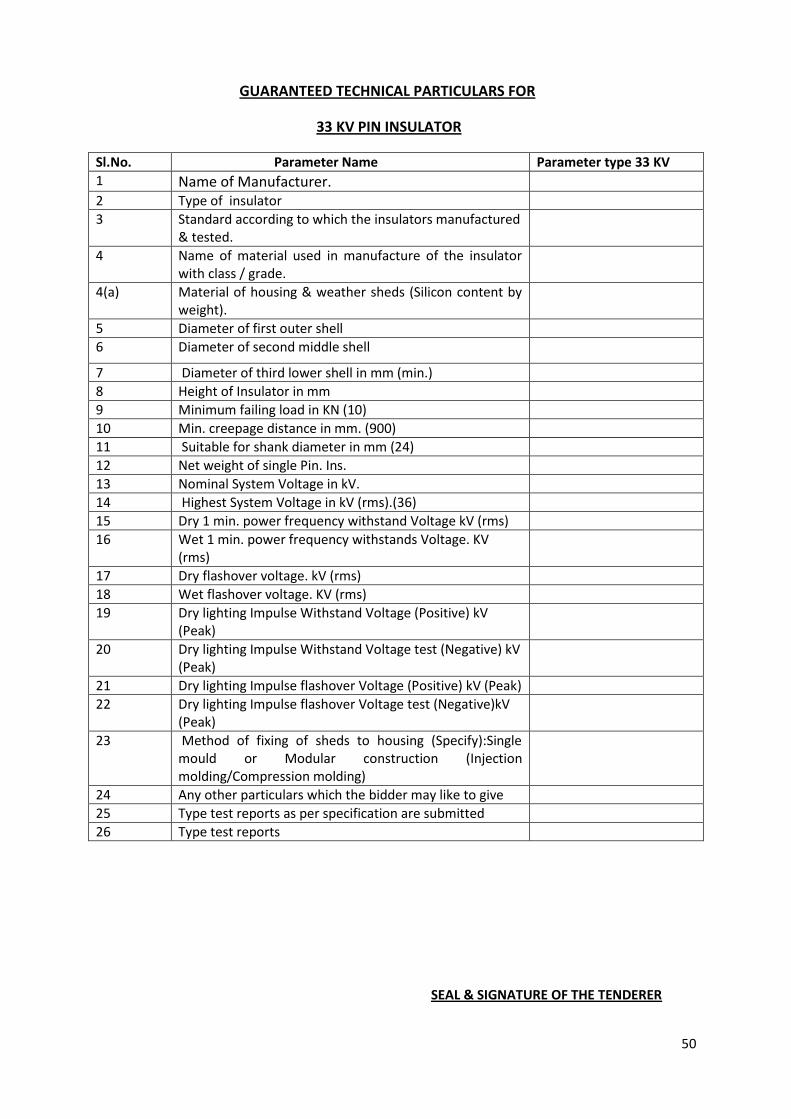
GUARANTEED TECHNICAL PARTICULARS FOR
33 KV PIN INSULATOR
Sl.No. Parameter Name Parameter type 33 KV
1 Name of Manufacturer.
2 Type of insulator
3 Standard according to which the insulators manufactured & tested.
4 Name of material used in manufacture of the insulator with class / grade.
4(a) Material of housing & weather sheds (Silicon content by weight).
5 Diameter of first outer shell
6 Diameter of second middle shell
7 Diameter of third lower shell in mm (min.)
8 Height of Insulator in mm
9 Minimum failing load in KN (10)
10 Min. creepage distance in mm. (900)
11 Suitable for shank diameter in mm (24)
12 Net weight of single Pin. Ins.
13 Nominal System Voltage in kV.
14 Highest System Voltage in kV (rms).(36)
15 Dry 1 min. power frequency withstand Voltage kV (rms)
16 Wet 1 min. power frequency withstands Voltage. KV (rms)
17 Dry flashover voltage. kV (rms)
18 Wet flashover voltage. KV (rms)
19 Dry lighting Impulse Withstand Voltage (Positive) kV (Peak)
20 Dry lighting Impulse Withstand Voltage test (Negative) kV (Peak)
21 Dry lighting Impulse flashover Voltage (Positive) kV (Peak)
22 Dry lighting Impulse flashover Voltage test (Negative)kV (Peak)
23 Method of fixing of sheds to housing (Specify):Single mould or Modular construction (Injection molding/Compression molding)
24 Any other particulars which the bidder may like to give
25 Type test reports as per specification are submitted
26 Type test reports
SEAL & SIGNATURE OF THE TENDERER
51
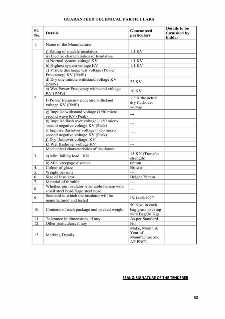
TECHNICAL SPECIFICATION FOR LT SHACKLE INSULATORS
1. SCOPE:
The specification provides for manufacture, testing before dispatch, supply and delivery
of LT Shackle Insulators as per the particulars given in "Schedule of Requirements"
attached.
2. STANDARDS:
The LT Shackle Insulators shall conform to IS:1445/1977 (the latest i thereof) and shall
be brown glazed. The tenders shall go through the above thoroughly before making their
offer. The material shall be for us moderately hot and humid tropical climate,
conducive to rust and fun growth.
3. GENERAL REQUIREMENT:
i) The porcelain shall be sound, free from defects thoroughly vitrify and smoothly
glazed.
ii) The design of Insulator should be such that, stresses due to expans or and contraction in
any part of the insulator shall not lead to deterioration.
iii) The glaze shall be Brown in colour –except for the screw threads the top portion on
which the conductor is supported during fir which may be left unglazed, all other surfaces
of the insulator shall effectively, glazed.
4. TESTS :
The Insulator shall comply with the following routine, type and accepta tests as per
IS:1445/1977 (the latest issue thereof).
4.1. Routine Test : Visual Examination
4.2 Type Test :
The firm shall submit the type test report shall be from any NABL accredit laboratory not
more than 5 years old along with offer .The following type te are to be carried out on
sample in the order mentioned bellow as per 5300/69.
a) Visual examination.
b) Verification of dimensions.
c) Dry one minute power frequency withstand test.
d) Wet one minute power frequency withstand test.
e) Temperature Cycle test.
f) Mechanical strength test
g) Porosity test.
h) Power frequency puncture withstand test
52
NOTE : The identification marks of firm provided on the insulator should be invariably mentioned in
the type test certificate.
4.3 Acceptance Tests : (to be conducted in the following order)
a) Visual examination.
b) Verification of dimensions.
c) Temperature Cycle test.
d) Mechanical strength test.
e) Porosity test (Applicable only to HT Guy Insulator Type-C).
5. MARKING:
The Insulators shall be legibly and indelibly marked as shown below.
a) Name and trade-mark of the manufacturer.
b) Month and year of manufacture and.
c) “AP PDCL” (Name of the purchaser)
Markings on porcelain shall be printed and shall be applied before firing.
6. TYPE AND DIMENSIONS:
The dimensions shall be of size 90X75 mm and construction of the LT Shackle
Insulators should be as per IS 1445/1977 and shall be brown glazed.
7. TEST AND TEST CERTIFICATES:
The test shall be carried out as per the IS before dispatch and the test certificates
shall be furnished for approval. Copies of type test certificates of identical materials for
each type with dimensional drawings shall invariably accompany the tender. The type
tests as specified in the IS should be carried out not later than 5 years from the date
of opening of bid.
8. PACKING :
This shall be done in wooden crates suitable for rough handling.
9. SAMPLES :
Two Nos. samples of LT Shackle Insulators shall invariably accompany the tender.
Tenders for which samples are not received by the stipulated date will be rejected.
10. GUARANTEED TECHNICAL PARTICULARS :
The technical particulars as specified in the IS shall be guaranteed and a statement of
guaranteed particulars shall be furnished along with the tender.
53
SEAL & SIGNATURE OF THE TENDERER

54
55

56
57
TECHNICAL SPECIFICATION OF LT PIN INSULATOR
1. SCOPE :
The specification covers the manufacture, testing at works supply and delivery of
Porcelain insulators for overhead power lines with a nominal voltage below 1000 volts.
Both LT Pin insulator (105x80)mm & (100x75)mm are covered.
2. APPLICABLE STANDARDS:
Except when they conflict with the specific requirements of this specification, the
insulators shall comply with IS : 1445/1977 or the latest version thereof.
3. GENERAL REQUIREMENTS:
The porcelain shall be sound, free from defects, thoroughly vitrified and smoothly
glazed. The design of the insulators shall be such that the stresses due to expansion
and contraction in any part of the insulator shall not lead to its deterioration. The
glaze shall be brown in color for insulators. The glaze shall cover the entire porcelain
surface parts except those areas that serve as supports during firing. The insulators
shall be suitable for use with all Aluminium Conductor or Copper conductor or ACSR
upto 100 sq.mm. The insulators should withstand the conductor tension the reversible
wind load as well as the high frequency vibrations set due to wind.
4. SYSTEM CONDITIONS:
Frequency : 50 Hz
Nominal System Voltage : 400/230 V
Maximum System Voltage LT System : 440/250 V
Minimum LT Voltage : 370 V
Power frequency one minute withstand Voltage(wet) : 10 KV
Neutral Earthing arrangement LT System : Solidly Earthed
5. TESTS:
a. Type tests:
a) Visual examination
b) Verification of dimensions
c) Temperature cycle test
d) Dry one minute power frequency withstand test
e) Wet one minute power frequency withstand test

58
f) Mechanical strength test
g) Porosity test
5.2 Acceptance test:
The insulators, after having withstood the routine test shall be subjected to the following
acceptance tests in the order given below:
a) Verification of Dimensions.
b) Temperature cycle test
c) Mechanical strength test
d) Porosity test
5.3 Routine tests:
ii) Visual examination
6. TESTING FACILITIES:
a. The Bidder must clearly indicate what testing facilities are avail able in the works
of the manufacturer and whether the facilities, are adequate to carr y out all the
routine as well as type tests. These facilities should be made available to Purchaser,s
Engineers if deputed to carry out or witness the tests. I f any tests cannot be carried
out at the manufacturer’s works, the reasons should be clearly stated in the tender.
b. The Bidder shall furnish detailed t y pe test reports of the offered LT Pin
insulator as per clause 5.1 of this specification. All the above Type Tests shall be
carried out at laboratories, which are accredited, by the National Accreditation Board
of Testing and Calibration Laboratories (NABL) of Government of India to prove that
the insulators offered meet the requirements of the specification. These Type Tests
should have been carried out within five years prior to the date of opening of this tender.
c. There offered L.T. pin insulators are already fully Type Tested at Laboratories
accredited by the National Accreditation Board of Testing and Calibration Laboratories
(NABL) within five years prior to the date of opening of the tender.
7. Drawings :
The tender shall be accompanied with the detailed drawings showing the dimensions
of the individual insulator, giving all the design dimensions of various component parts.
Generally it shall be as per IS.
8. MARKING:
a. Each insulator shall be legibly and indelibly marked to show the following:
i) Name of Purchaser- NESCO
ii)Name or trade mark of the manufacturer
59
iii) Year of manufacturer
iv) ISI certificate, mark, if any.
b. Marking on porcelain shall be applied before firing.
9. Packing :
All insulators shall be packed in crates or boxes suitable for rough handling. Packing
shall be marked with the strength and voltage rating.
SEAL & SIGNATURE OF THE TENDERER

60
NB- Every insulator should bear the marking of manufacturer’s name and ISI mark
Name & Signature of Bidder with seal
61
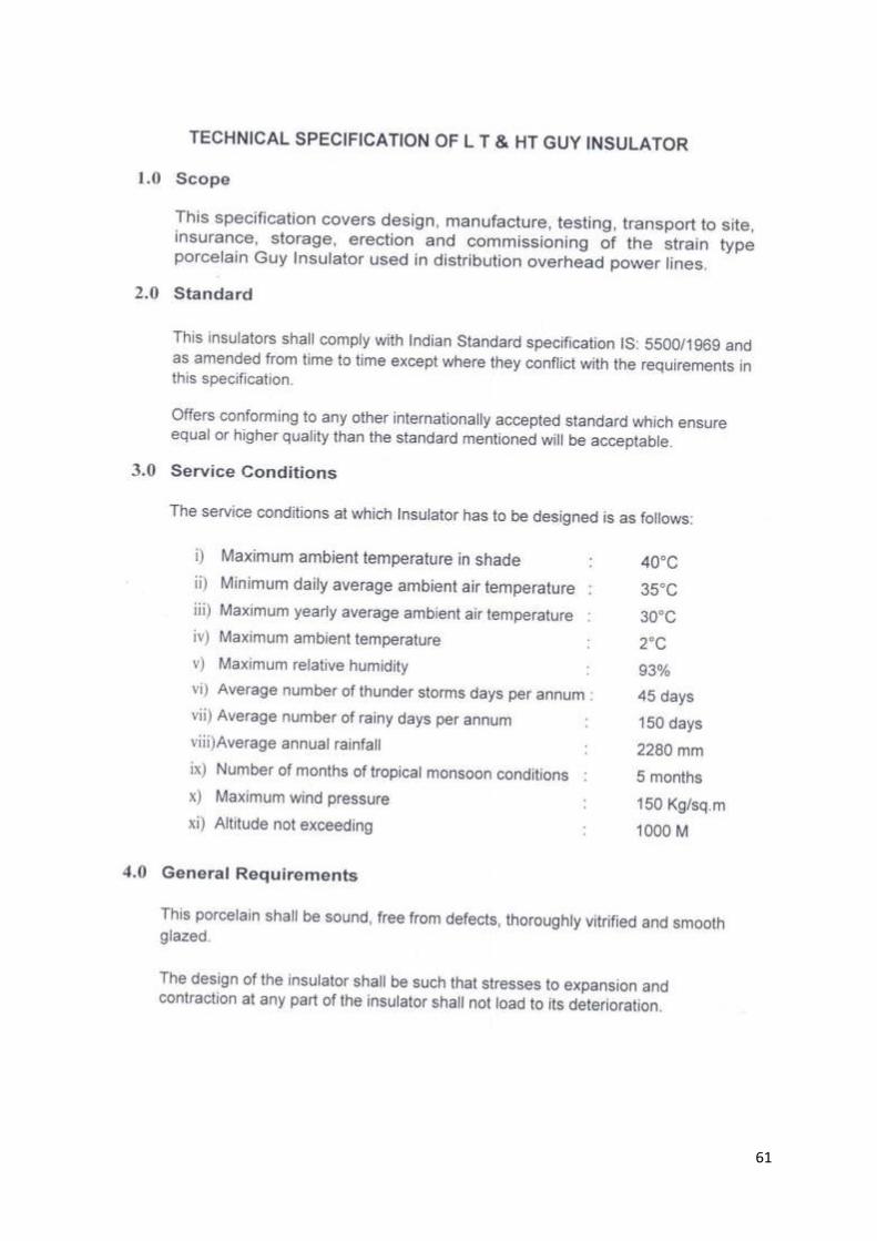
62

63
64
65
66
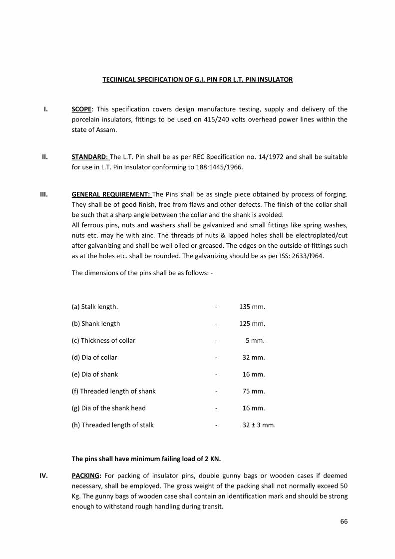
TECIINICAL SPECIFICATION OF G.I. PIN FOR L.T. PIN INSULATOR
I. SCOPE: This specification covers design manufacture testing, supply and delivery of the
porcelain insulators, fittings to be used on 415/240 volts overhead power lines within the
state of Assam.
II. STANDARD: The L.T. Pin shall be as per REC 8pecification no. 14/1972 and shall be suitable
for use in L.T. Pin Insulator conforming to 188:1445/1966.
III. GENERAL REQUIREMENT: The Pins shall be as single piece obtained by process of forging.
They shall be of good finish, free from flaws and other defects. The finish of the collar shall
be such that a sharp angle between the collar and the shank is avoided.
All ferrous pins, nuts and washers shall be galvanized and small fittings like spring washes,
nuts etc. may he with zinc. The threads of nuts & lapped holes shall be electroplated/cut
after galvanizing and shall be well oiled or greased. The edges on the outside of fittings such
as at the holes etc. shall be rounded. The galvanizing should be as per ISS: 2633/l964.
The dimensions of the pins shall be as follows: -
(a) Stalk length. - 135 mm.
(b) Shank length - 125 mm.
(c) Thickness of collar - 5 mm.
(d) Dia of collar - 32 mm.
(e) Dia of shank - 16 mm.
(f) Threaded length of shank - 75 mm.
(g) Dia of the shank head - 16 mm.
(h) Threaded length of stalk - 32 ± 3 mm.
The pins shall have minimum failing load of 2 KN.
IV. PACKING: For packing of insulator pins, double gunny bags or wooden cases if deemed
necessary, shall be employed. The gross weight of the packing shall not normally exceed 50
Kg. The gunny bags of wooden case shall contain an identification mark and should be strong
enough to withstand rough handling during transit.
67
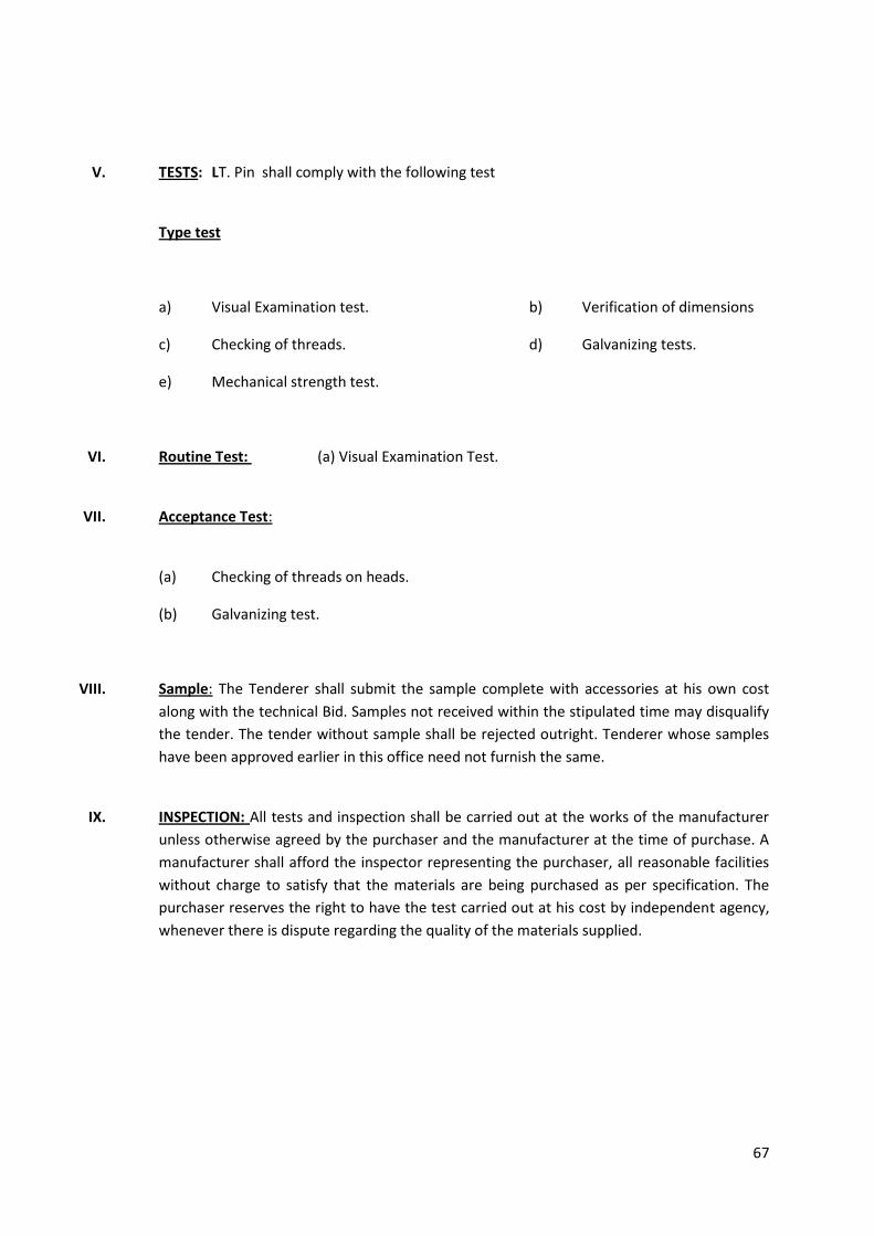
V. TESTS: LT. Pin shall comply with the following test
Type test
a) Visual Examination test. b) Verification of dimensions
c) Checking of threads. d) Galvanizing tests.
e) Mechanical strength test.
VI. Routine Test: (a) Visual Examination Test.
VII. Acceptance Test:
(a) Checking of threads on heads.
(b) Galvanizing test.
VIII. Sample: The Tenderer shall submit the sample complete with accessories at his own cost
along with the technical Bid. Samples not received within the stipulated time may disqualify
the tender. The tender without sample shall be rejected outright. Tenderer whose samples
have been approved earlier in this office need not furnish the same.
IX. INSPECTION: All tests and inspection shall be carried out at the works of the manufacturer
unless otherwise agreed by the purchaser and the manufacturer at the time of purchase. A
manufacturer shall afford the inspector representing the purchaser, all reasonable facilities
without charge to satisfy that the materials are being purchased as per specification. The
purchaser reserves the right to have the test carried out at his cost by independent agency,
whenever there is dispute regarding the quality of the materials supplied.
68
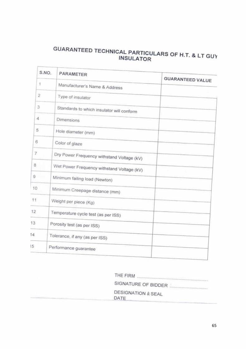
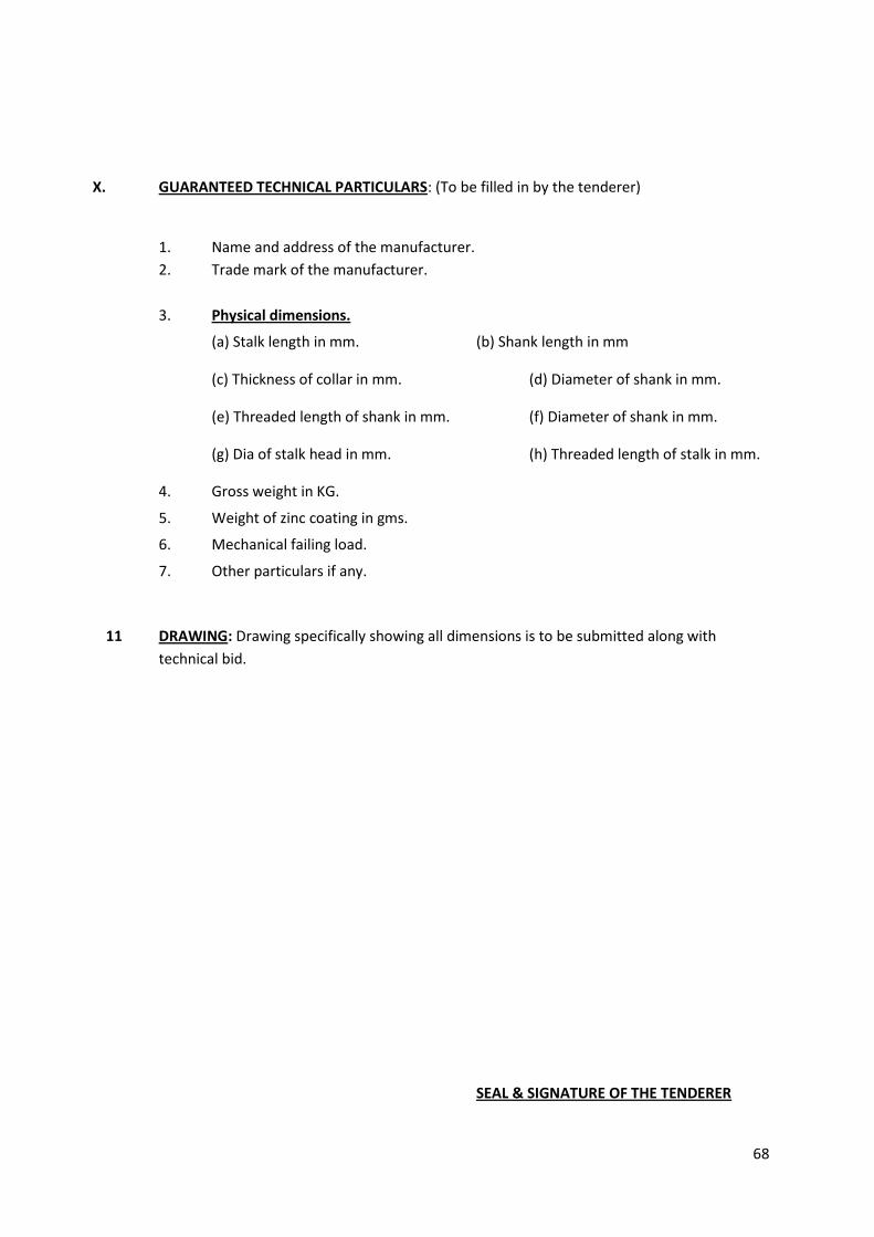
X. GUARANTEED TECHNICAL PARTICULARS: (To be filled in by the tenderer)
1. Name and address of the manufacturer.
2. Trade mark of the manufacturer.
3. Physical dimensions.
(a) Stalk length in mm. (b) Shank length in mm
(c) Thickness of collar in mm. (d) Diameter of shank in mm.
(e) Threaded length of shank in mm. (f) Diameter of shank in mm.
(g) Dia of stalk head in mm. (h) Threaded length of stalk in mm.
4. Gross weight in KG.
5. Weight of zinc coating in gms.
6. Mechanical failing load.
7. Other particulars if any.
11 DRAWING: Drawing specifically showing all dimensions is to be submitted along with
technical bid.
SEAL & SIGNATURE OF THE TENDERER
69
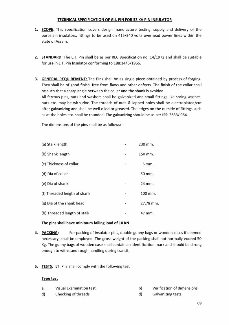
TECIINICAL SPECIFICATION OF G.I. PIN FOR 33 KV PIN INSULATOR
1. SCOPE: This specification covers design manufacture testing, supply and delivery of the
porcelain insulators, fittings to be used on 415/240 volts overhead power lines within the
state of Assam.
2. STANDARD: The L.T. Pin shall be as per REC 8pecification no. 14/1972 and shall be suitable
for use in L.T. Pin Insulator conforming to 188:1445/1966.
3. GENERAL REQUIREMENT: The Pins shall be as single piece obtained by process of forging.
They shall be of good finish, free from flaws and other defects. The finish of the collar shall
be such that a sharp angle between the collar and the shank is avoided.
All ferrous pins, nuts and washers shall be galvanized and small fittings like spring washes,
nuts etc. may he with zinc. The threads of nuts & lapped holes shall be electroplated/cut
after galvanizing and shall be well oiled or greased. The edges on the outside of fittings such
as at the holes etc. shall be rounded. The galvanizing should be as per ISS: 2633/l964.
The dimensions of the pins shall be as follows: -
(a) Stalk length. - 230 mm.
(b) Shank length - 150 mm.
(c) Thickness of collar - 6 mm.
(d) Dia of collar - 50 mm.
(e) Dia of shank - 24 mm.
(f) Threaded length of shank - 100 mm.
(g) Dia of the shank head - 27.78 mm.
(h) Threaded length of stalk - 47 mm.
The pins shall have minimum failing load of 10 KN.
4. PACKING: For packing of insulator pins, double gunny bags or wooden cases if deemed
necessary, shall be employed. The gross weight of the packing shall not normally exceed 50
Kg. The gunny bags of wooden case shall contain an identification mark and should be strong
enough to withstand rough handling during transit.
5. TESTS: LT. Pin shall comply with the following test
Type test
a. Visual Examination test. b) Verification of dimensions
d) Checking of threads. d) Galvanizing tests.
70
f) Mechanical strength test.
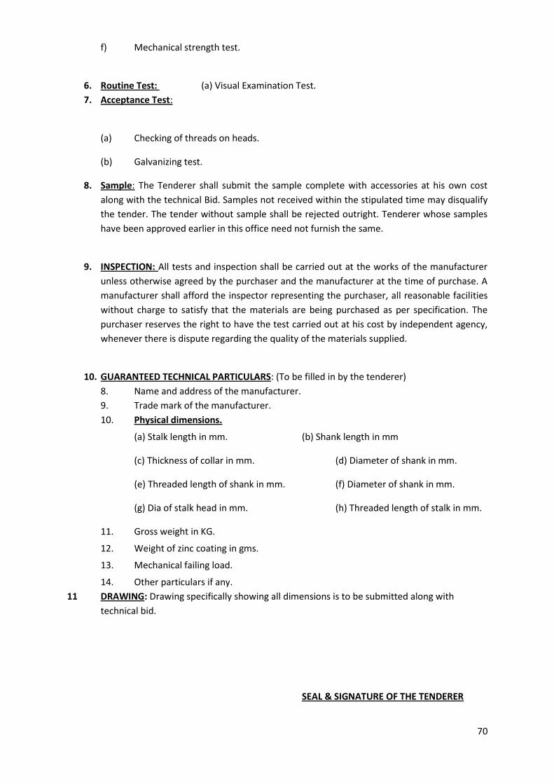
6. Routine Test: (a) Visual Examination Test.
7. Acceptance Test:
(a) Checking of threads on heads.
(b) Galvanizing test.
8. Sample: The Tenderer shall submit the sample complete with accessories at his own cost
along with the technical Bid. Samples not received within the stipulated time may disqualify
the tender. The tender without sample shall be rejected outright. Tenderer whose samples
have been approved earlier in this office need not furnish the same.
9. INSPECTION: All tests and inspection shall be carried out at the works of the manufacturer
unless otherwise agreed by the purchaser and the manufacturer at the time of purchase. A
manufacturer shall afford the inspector representing the purchaser, all reasonable facilities
without charge to satisfy that the materials are being purchased as per specification. The
purchaser reserves the right to have the test carried out at his cost by independent agency,
whenever there is dispute regarding the quality of the materials supplied.
10. GUARANTEED TECHNICAL PARTICULARS: (To be filled in by the tenderer)
8. Name and address of the manufacturer.
9. Trade mark of the manufacturer.
10. Physical dimensions.
(a) Stalk length in mm. (b) Shank length in mm
(c) Thickness of collar in mm. (d) Diameter of shank in mm.
(e) Threaded length of shank in mm. (f) Diameter of shank in mm.
(g) Dia of stalk head in mm. (h) Threaded length of stalk in mm.
11. Gross weight in KG.
12. Weight of zinc coating in gms.
13. Mechanical failing load.
14. Other particulars if any.
11 DRAWING: Drawing specifically showing all dimensions is to be submitted along with
technical bid.
SEAL & SIGNATURE OF THE TENDERER
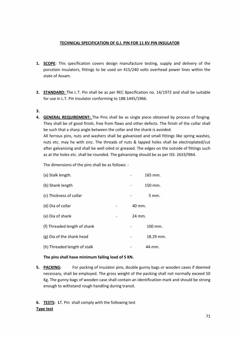
71
TECHNICAL SPECIFICATION OF G.I. PIN FOR 11 KV PIN INSULATOR
1. SCOPE: This specification covers design manufacture testing, supply and delivery of the
porcelain insulators, fittings to be used on 415/240 volts overhead power lines within the
state of Assam.
2. STANDARD: The L.T. Pin shall be as per REC 8pecification no. 14/1972 and shall be suitable
for use in L.T. Pin Insulator conforming to 188:1445/1966.
3.
4. GENERAL REQUIREMENT: The Pins shall be as single piece obtained by process of forging.
They shall be of good finish, free from flaws and other defects. The finish of the collar shall
be such that a sharp angle between the collar and the shank is avoided.
All ferrous pins, nuts and washers shall be galvanized and small fittings like spring washes,
nuts etc. may he with zinc. The threads of nuts & lapped holes shall be electroplated/cut
after galvanizing and shall be well oiled or greased. The edges on the outside of fittings such
as at the holes etc. shall be rounded. The galvanizing should be as per ISS: 2633/l964.
The dimensions of the pins shall be as follows: -
(a) Stalk length. - 165 mm.
(b) Shank length - 150 mm.
(c) Thickness of collar - 5 mm.
(d) Dia of collar - 40 mm.
(e) Dia of shank - 24 mm.
(f) Threaded length of shank - 100 mm.
(g) Dia of the shank head - 18.29 mm.
(h) Threaded length of stalk - 44 mm.
The pins shall have minimum failing load of 5 KN.
5. PACKING: For packing of insulator pins, double gunny bags or wooden cases if deemed
necessary, shall be employed. The gross weight of the packing shall not normally exceed 50
Kg. The gunny bags of wooden case shall contain an identification mark and should be strong
enough to withstand rough handling during transit.
6. TESTS: LT. Pin shall comply with the following test
Type test
72
a. Visual Examination test. b) Verification of dimensions
e) Checking of threads. d) Galvanizing tests.
g) Mechanical strength test.
7. Routine Test: (a) Visual Examination Test.
8. Acceptance Test:
(a) Checking of threads on heads.
(b) Galvanizing test.
9. Sample: The Tenderer shall submit the sample complete with accessories at his own
cost along with the technical Bid. Samples not received within the stipulated time may
disqualify the tender. The tender without sample shall be rejected outright. Tenderer whose
samples have been approved earlier in this office need not furnish the same.
10. INSPECTION: All tests and inspection shall be carried out at the works of the manufacturer
unless otherwise agreed by the purchaser and the manufacturer at the time of purchase. A
manufacturer shall afford the inspector representing the purchaser, all reasonable facilities
without charge to satisfy that the materials are being purchased as per specification. The
purchaser reserves the right to have the test carried out at his cost by independent agency,
whenever there is dispute regarding the quality of the materials supplied.
11. GUARANTEED TECHNICAL PARTICULARS: (To be filled in by the tenderer)
1 Name and address of the manufacturer.
2 Trade mark of the manufacturer.
3 Physical dimensions.
(a) Stalk length in mm. (b) Shank length in mm
(c) Thickness of collar in mm. (d) Diameter of shank in mm.
(e) Threaded length of shank in mm. (f) Diameter of shank in mm.
(g) Dia of stalk head in mm. (h) Threaded length of stalk in mm.
4 Gross weight in KG.
5 Weight of zinc coating in gms.
6 Mechanical failing load.
7 Other particulars if any.
12. DRAWING: Drawing specifically showing all dimensions is to be submitted along with
technical bid.
SEAL & SIGNATURE OF THE TENDERER
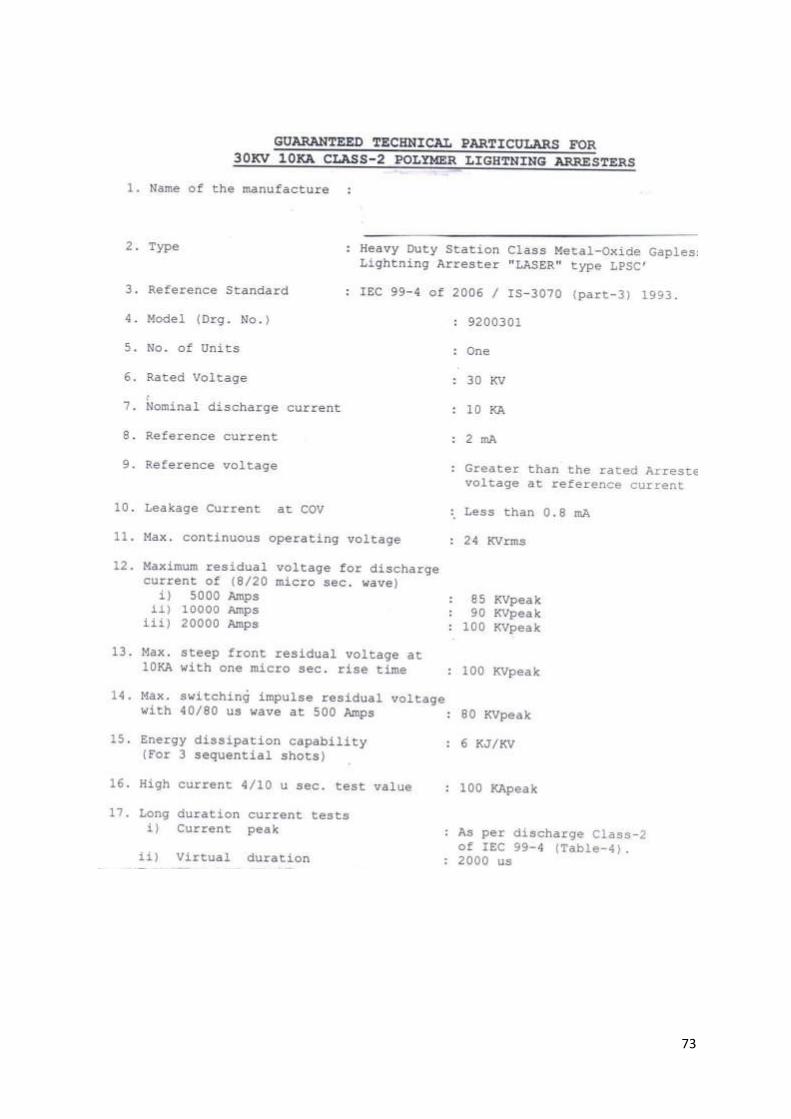
73
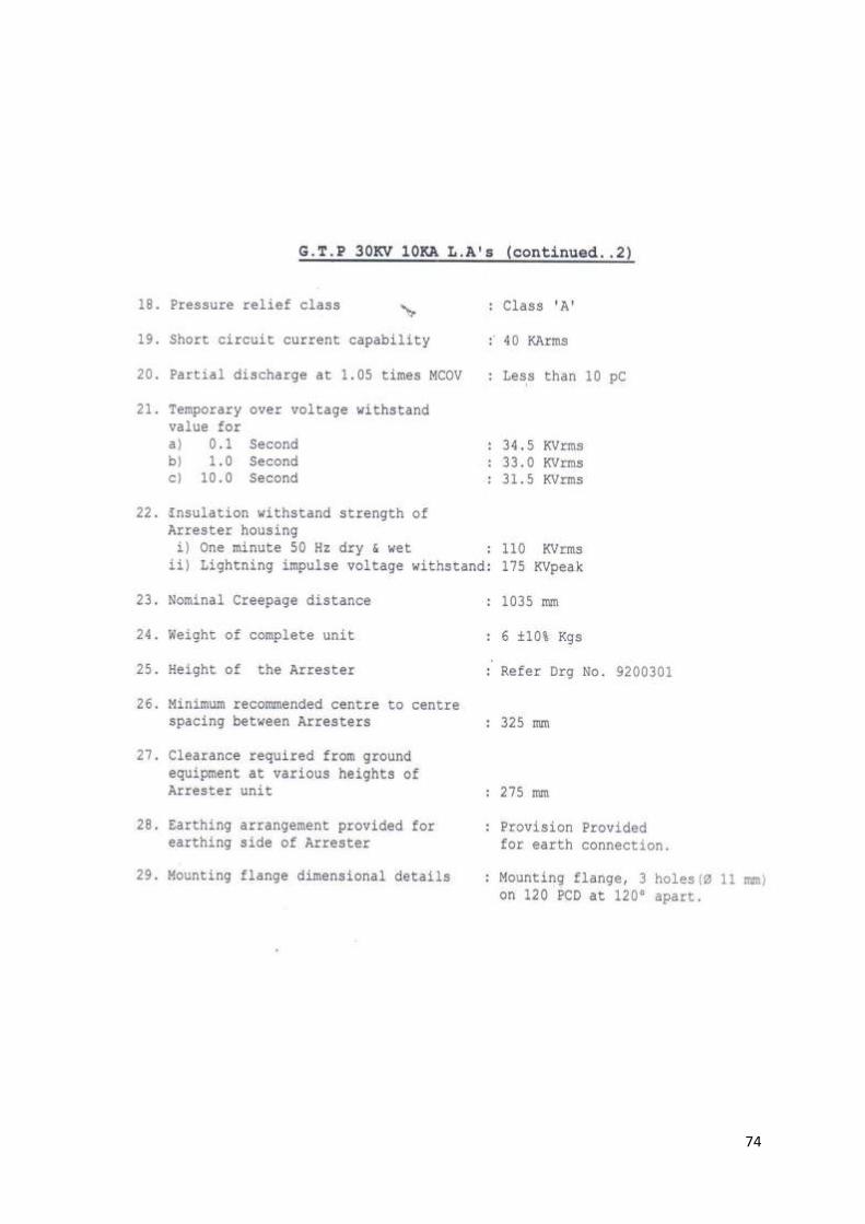
74
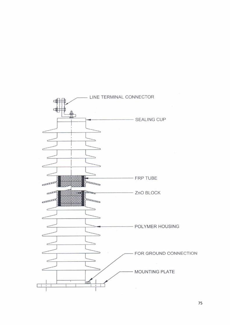
75
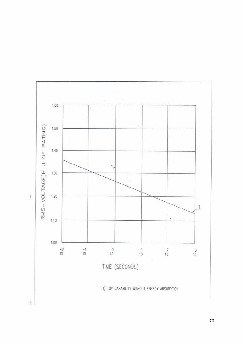
76
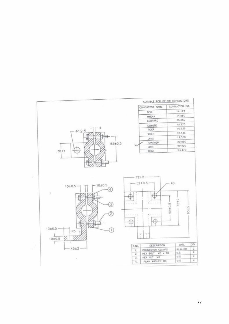
77
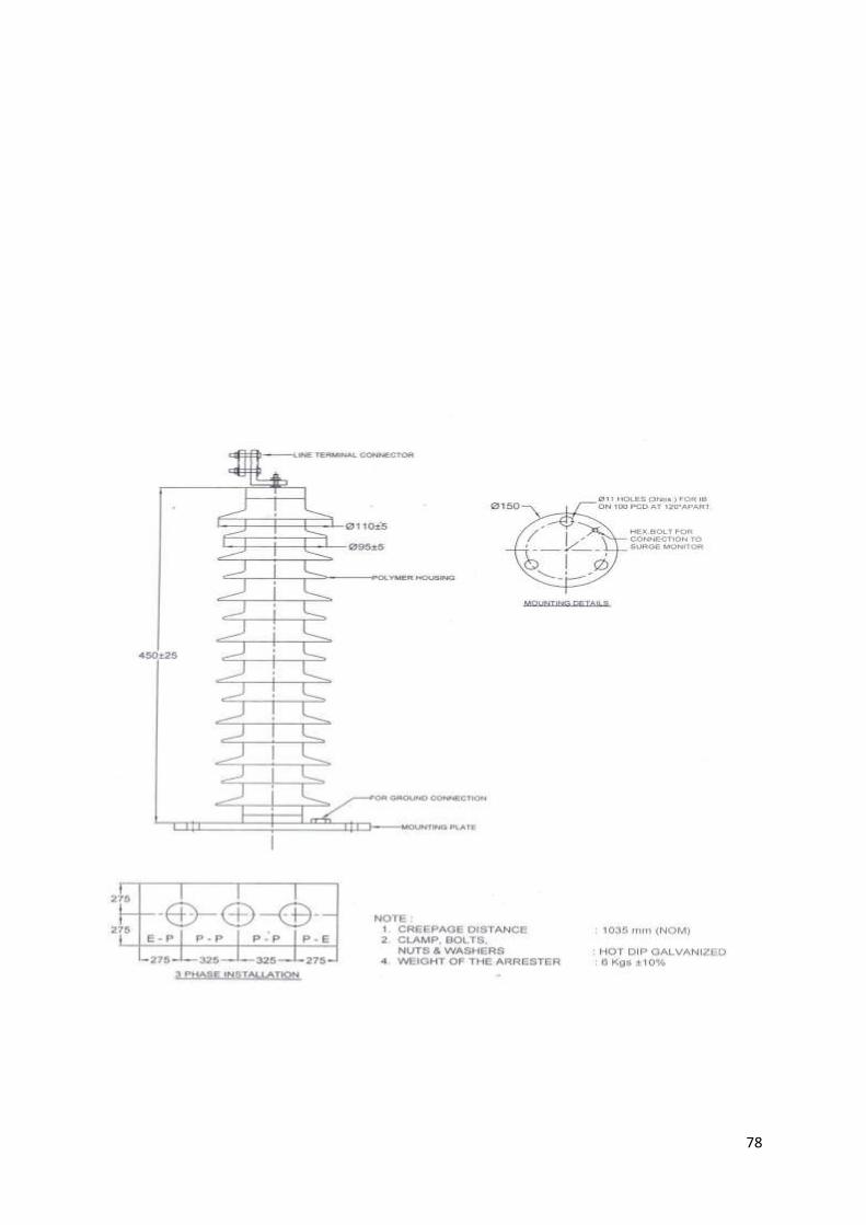
78
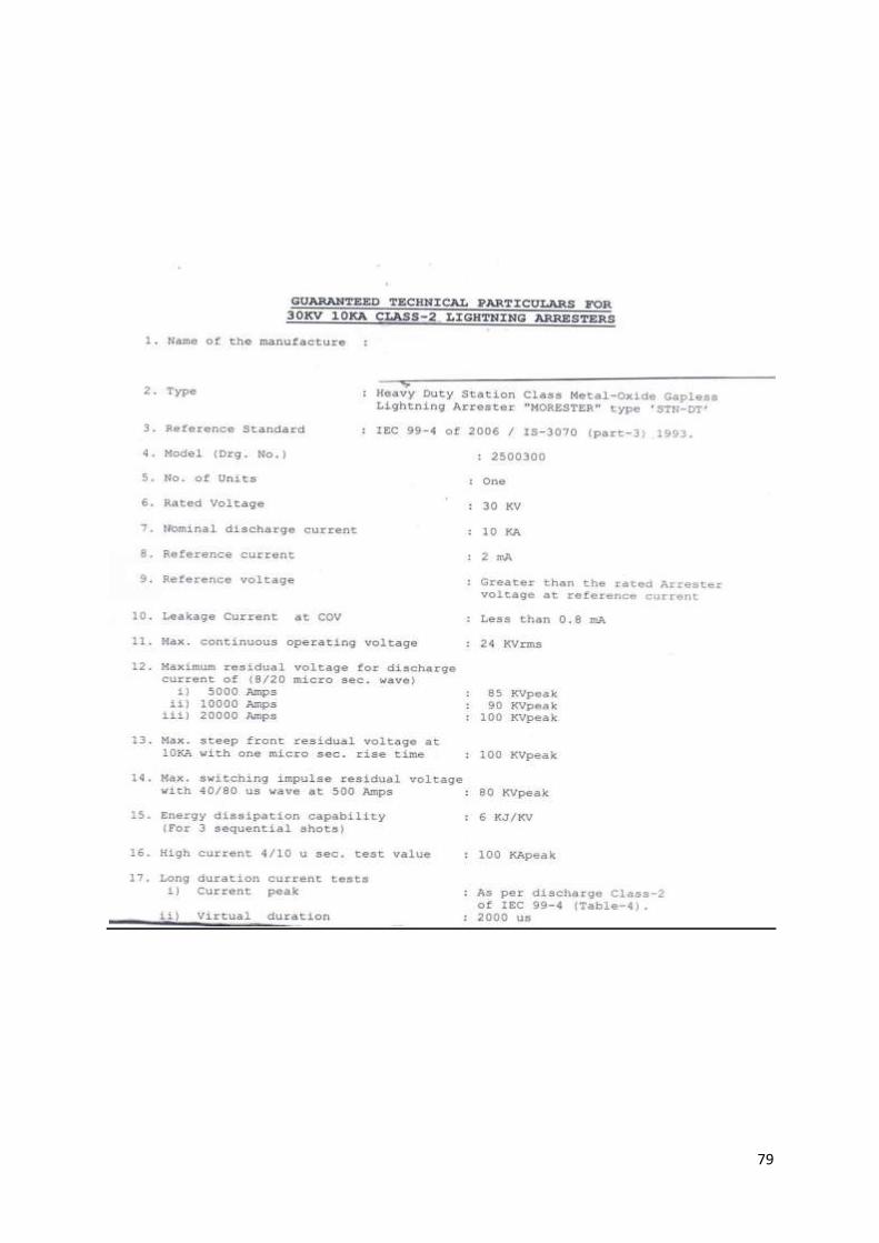
79
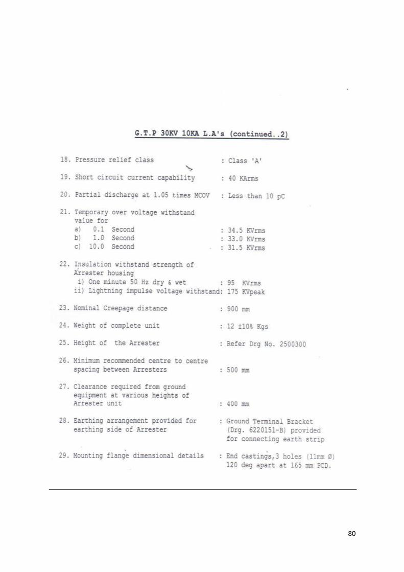
80
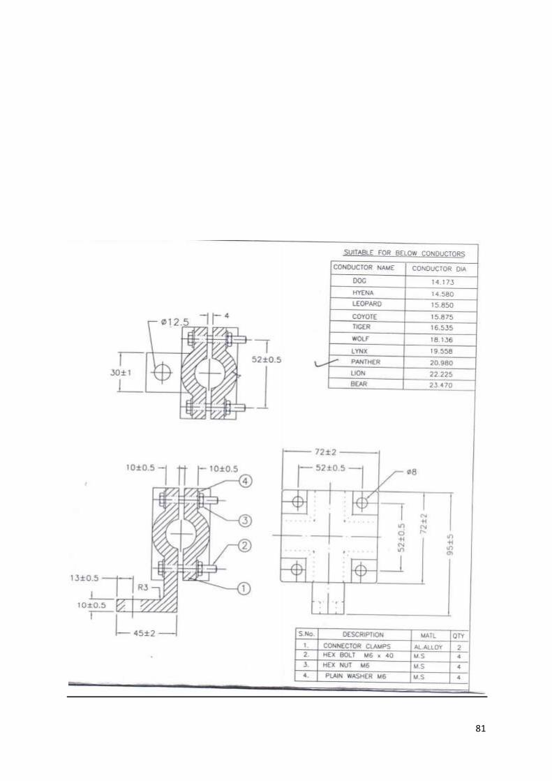
81
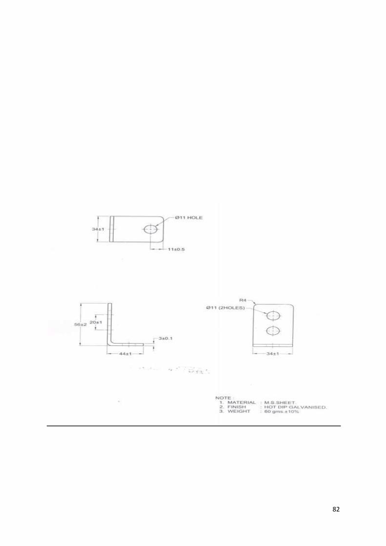
82
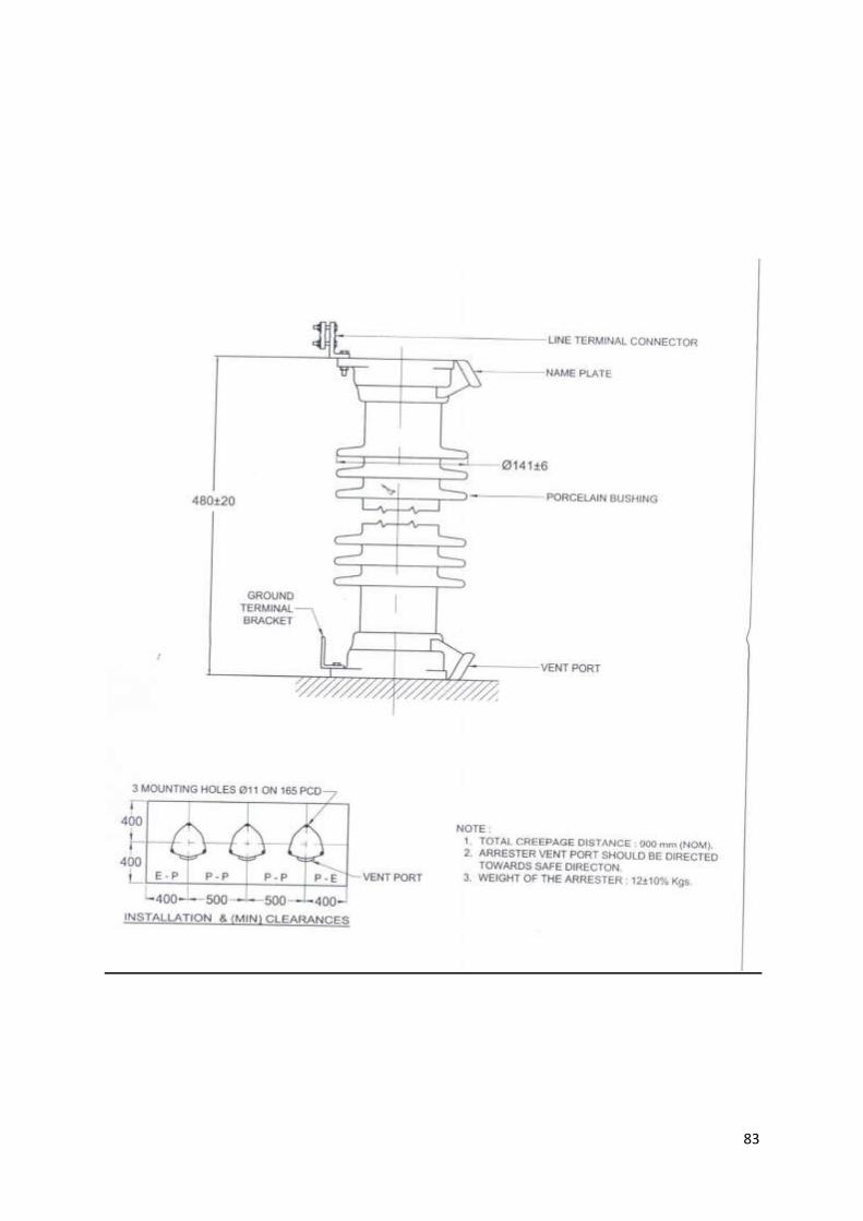
83
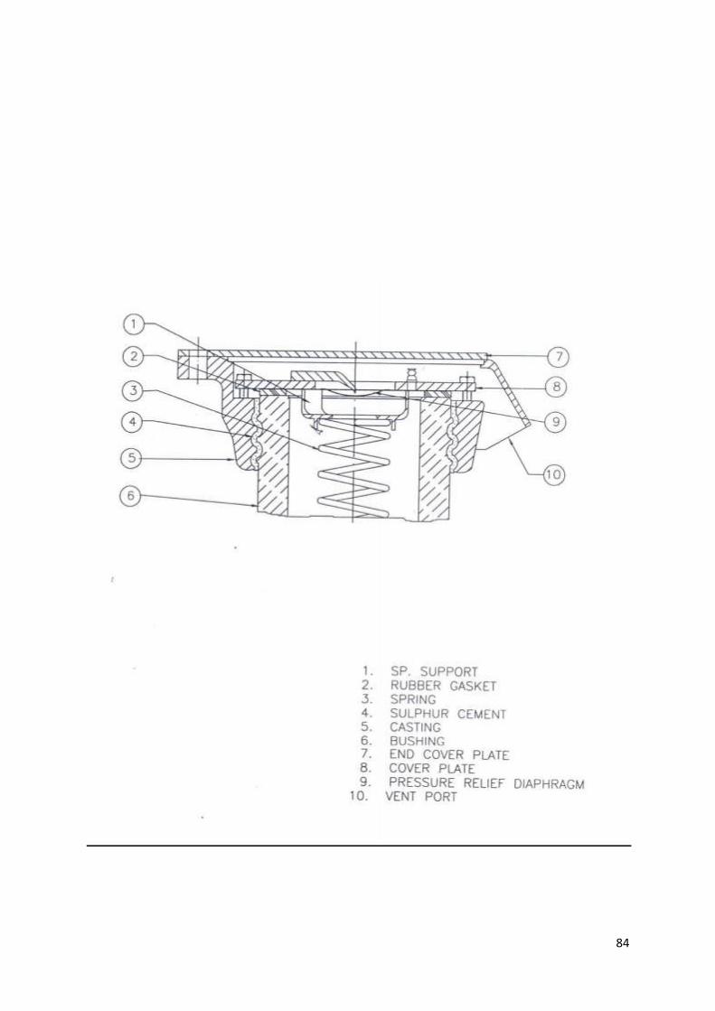
84
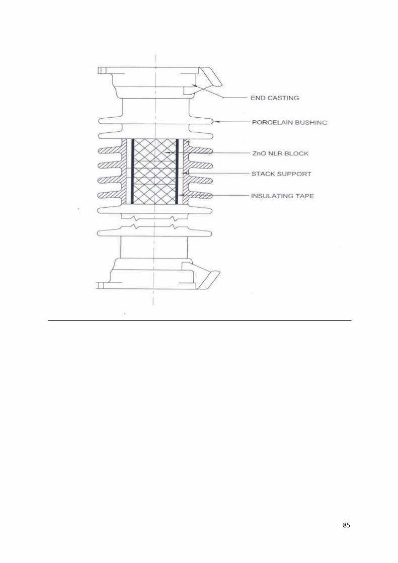
85
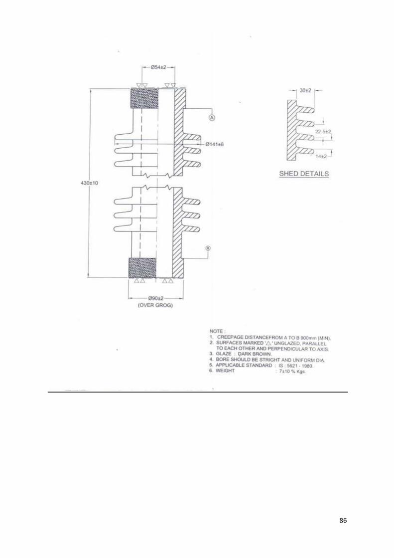
86
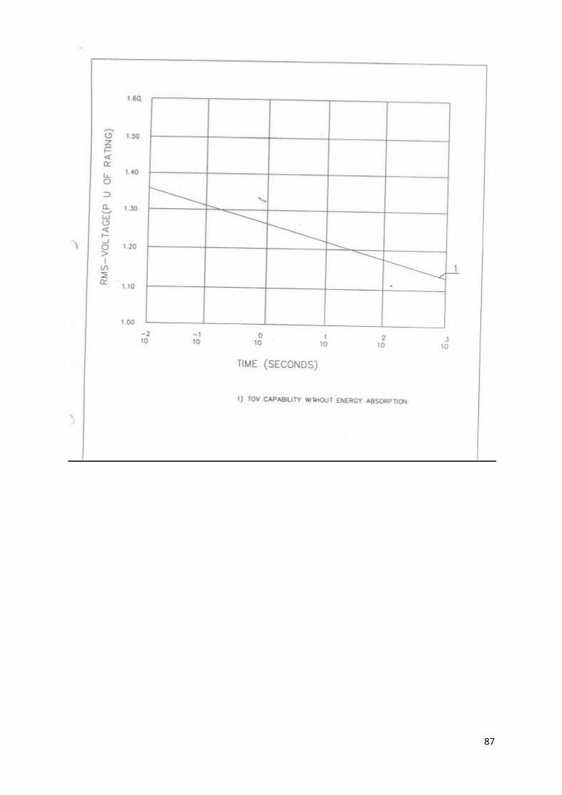
87

88
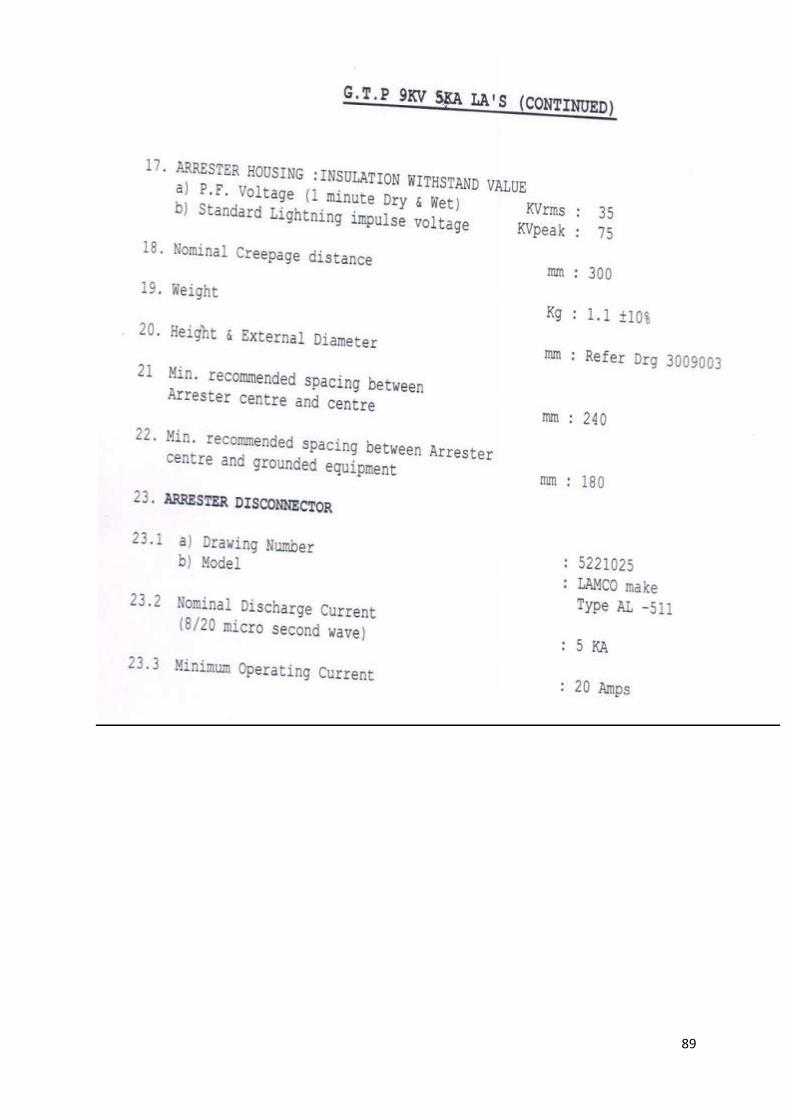
89

90
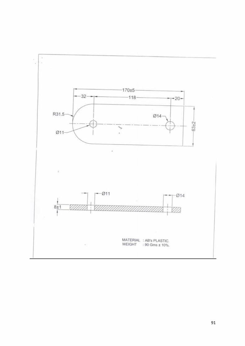
91
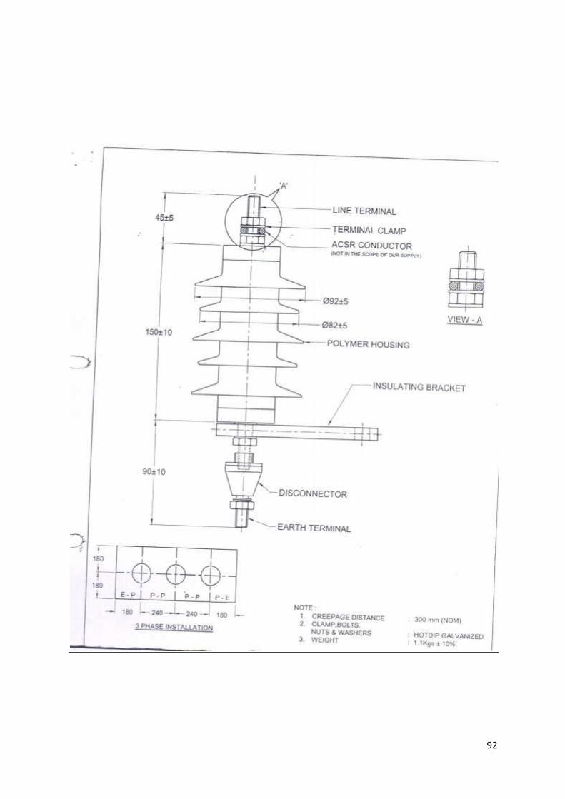
92
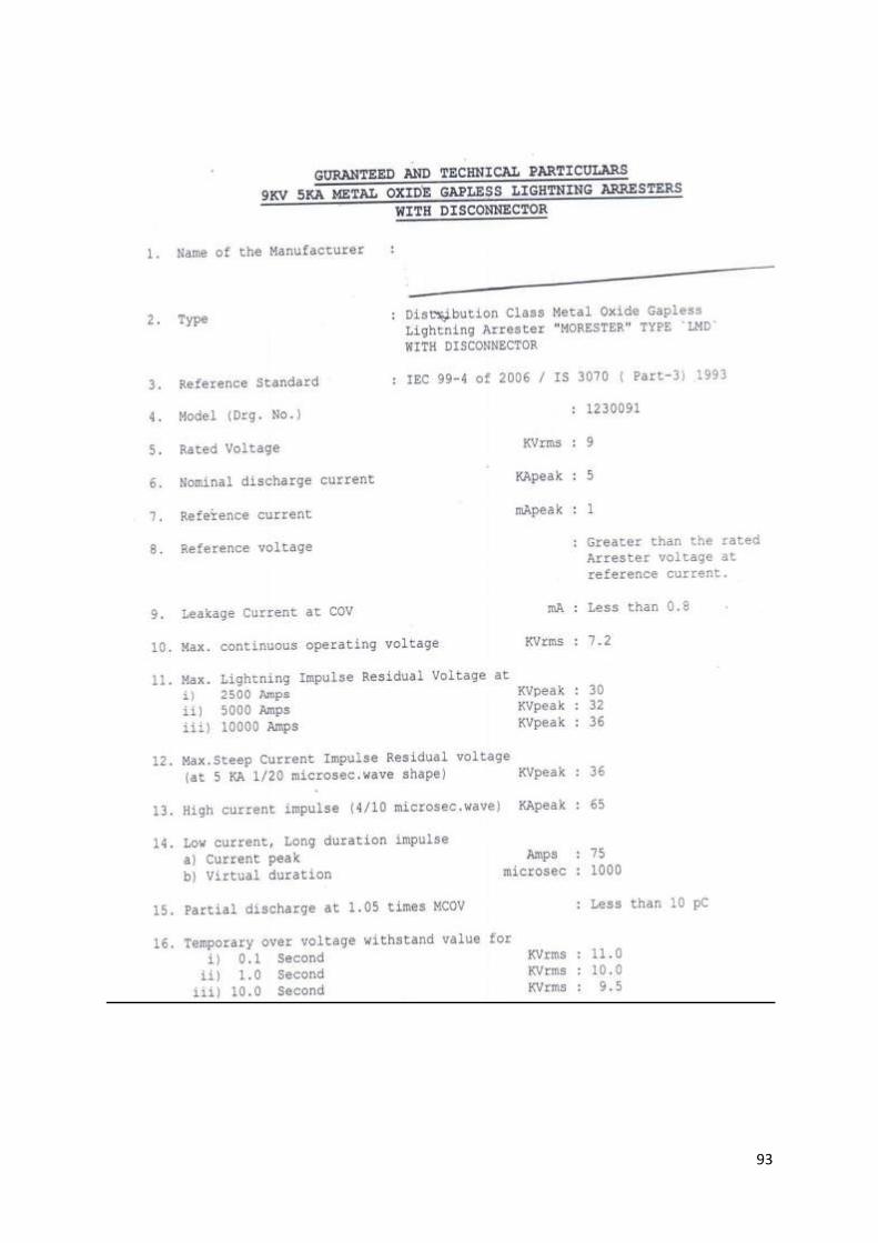
93
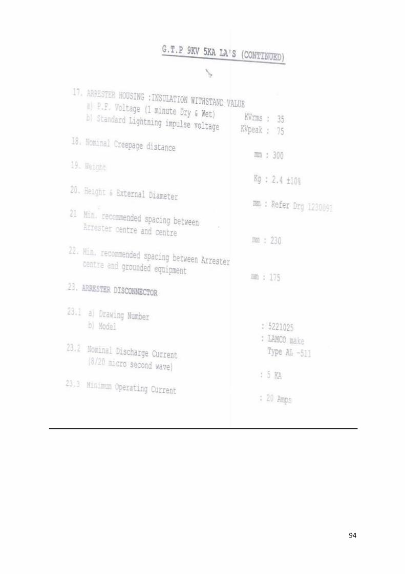
94

95
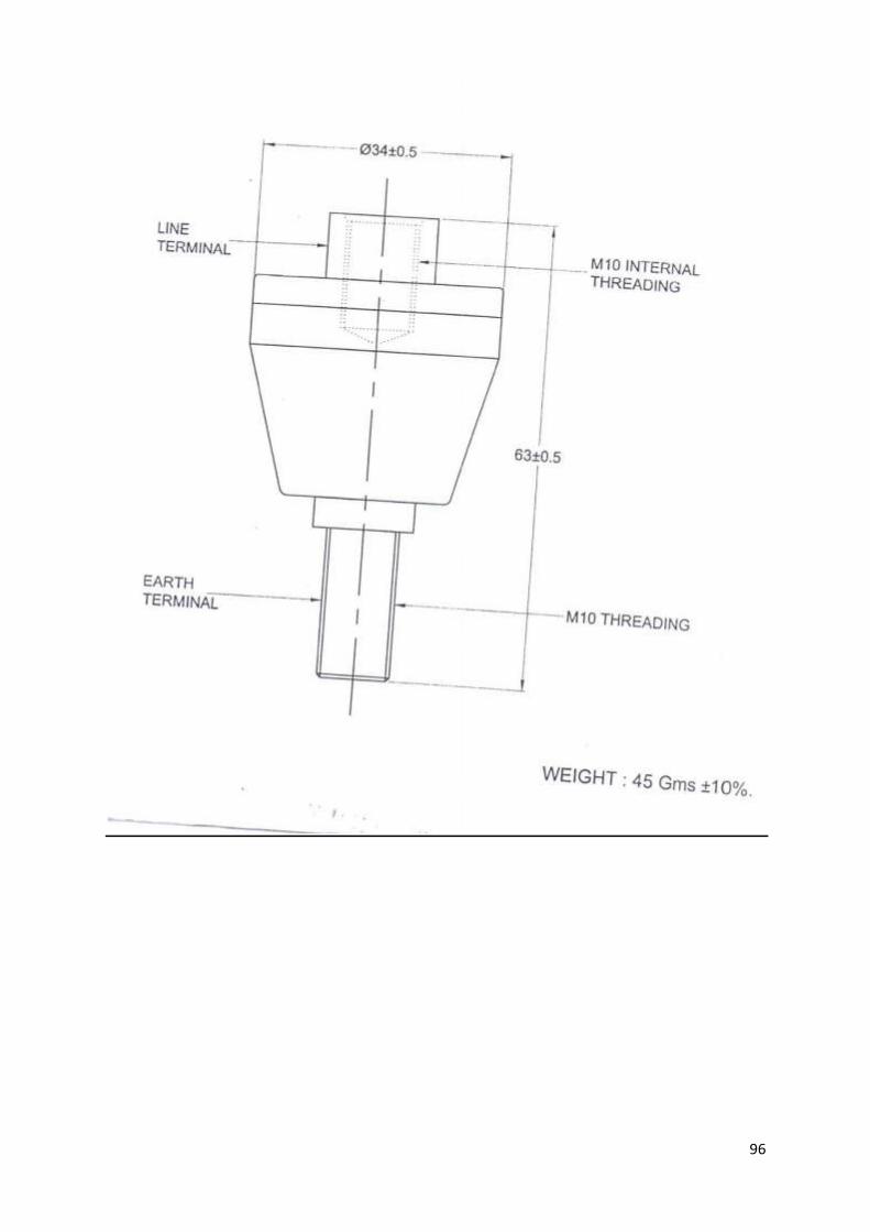
96
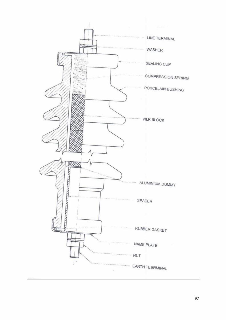
97

98
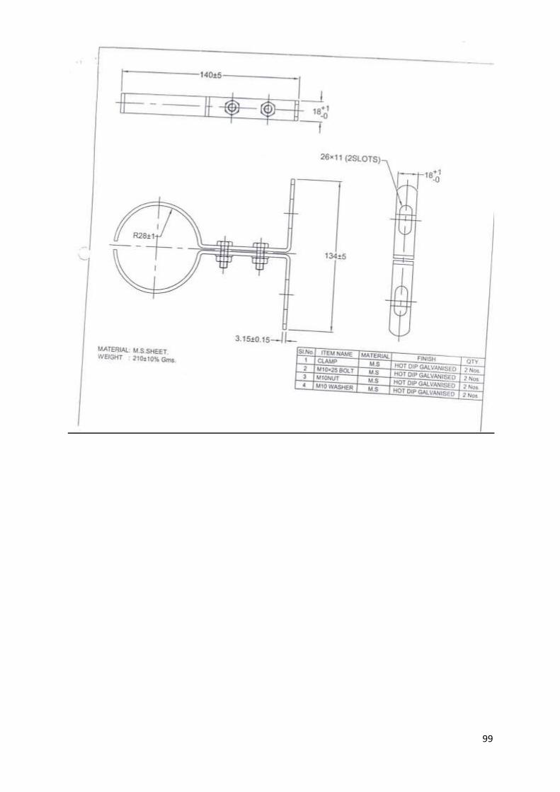
99
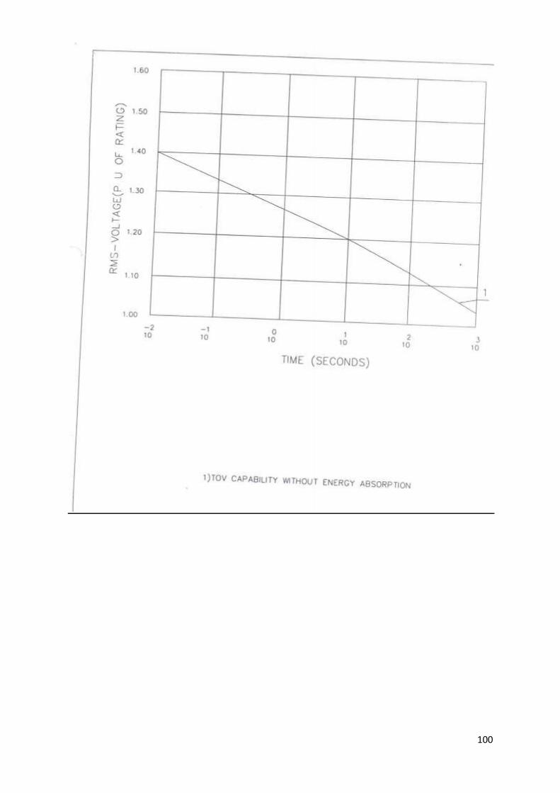
100
101
TECHNICAL SPECIFICATIONS
33 KV “V” CROSS ARM, BACK CLAMP FOR “V” CROSS ARM & POLE TOP
BRACKET
1.0 Cross arms and Pole Top Brackets for 33 kV construction at intermediate and light
angle pole shall be fabricated from grade 43A mild steel of channel section and for
heavy angle poles, end poles and section poles fabricated from grade 43A mild steel
of angle section. The grades of structural steel shall conform to IS – 226: 1975.
2.0 The ‘V’ Cross arm shall be made out of 100 x 50 x 6.4 mm MS Channel as per REC
Standard M-1. Weight of channel is 7.9 kg/mtr. The Back Clamp shall be made out of
50 x 8 MS Flat as per REC Standard & shall be suitably designed to fit PSC Pole 9 Mtr
x 300 Kg / 8 Mtr x 200 Kg. The Pole Top Bracket shall be made out of 65 x 65 x 6 mm
MS Angle & 100x 50x 6.4 M.S.Channel welded together as per REC Standard M-4,
suitably designed to fit PSC Pole 9 Mtr x 300 Kg / 8 Mtr x 200 Kg./ 11 Mtr x 300 Kg
3.0 Except where otherwise indicated all dimensions are subject to the following
tolerances:
a) dimensions up to and including 50mm:+1mm: and
b) dimensions greater than 50mm: +2%
All steel members and other parts of fabricated material as delivered shall be free of
warps, local deformation, unauthorized splices, or unauthorized bends. Bending of
flat strap shall be carried out cold. Straightening shall be carried out by pressure and
not by hammering. Straightness is of particular importance if the alignment of bolt
holes along a member is referred to its edges. Holes and other provisions for field
assembly shall be properly marked and cross referenced. Where required, either by
notations on the drawing or by the necessity of proper identification and fittings for
field assembly, the connection shall be match marked. A tolerance of not more than
1mm shall be permitted in the distance between the center lines of bolt holes. The
holes may be either drilled or punched and, unless otherwise stated, shall be not
more than 2mm greater in diameter than the bolts. When assembling the
components force may be used to bring the bolt holes together (provided neither
members nor holes are thereby distorted) but all force must be removed before the
bolt is inserted. Otherwise strain shall be deemed to be present and the structure
may be rejected even though it may be, in all other respects, in conformity with the
specification.
The back of the inner angle irons of lap joints shall be chamfered and the ends of the
members cut where necessary and such other measures taken as will ensure that all
members can be bolted together without strain or distortion. In particular, steps
shall be taken to relieve stress in cold worked steel so as to prevent the onset of
embrittlement during galvanizing.
Similar parts shall be interchangeable.
102
Shapes and plates shall be fabricated and assembled in the shop to the greatest
extent practice able. Shearing flame cutting and chipping shall be done carefully,
neatly and accurately. Holes shall be cut, drilled or punched at right angles to the
surface and shall not be made or enlarged by burning. Holes shall be clean-cut
without torn or ragged edges, and burrs resulting from drilling or reaming
operations shall be removed with the proper tool.
Shapes and plates shall be fabricated to the tolerance that will permit field erection
within tolerance, except as otherwise specified. All fabrication shall be carried out in
a neat and workmanlike manner so as to facilitate cleaning, painting, galvanizing and
inspection and to avoid areas in which water and other matter can lodge.
Contact surfaces at all connections shall befree of loose scale, dirt, burrs, oil and
other foreign materials that might prevent solid seating of the parts.
4.0 GALVANISING
For use in construction at coastal areas it shall be required for galvanizing the Cross
arms and Pole top brackets as following :
All galvanizing shall be carried out by the hot dip process, in accordance with
Specification IS 2629. However, high tensile steel nuts, bolts and spring washer shall
be electro galvanized to Service Condition 4. The zinc coating shall be mooth,
continuous and uniform. It shall be free from acid spot and shall not scale, blister or
be removable by handling or packing. There shall be no impurities in the zinc or
additives to the galvanic bath which could have a detrimental effect on the
durability of the zinc coating.
Before picking, all welding, drilling, cutting, grinding and other finishing operations
must be completed and all grease, paints, varnish, oil, welding slag and other foreign
matter completely removed. All protuberances which would affect the life of
galvanizing shall also be removed.
The weight of zinc deposited shall be in accordance with that stated in Standard IS
2629 and shall not less than 0.61kg/m² with a minimum thickness of 86 microns
for items of thickness more than 5mm, 0.46kg/m² (64 microns) for items of
thickness between 2mm and 5mm and 0.33kg/m² (47 microns) for items less than
2mm thick.
Parts shall not be galvanized if their shapes are such that the pickling solutions
cannot be removed with certainty or if galvanizing would be unsatisfactory or if their
mechanical strength would be reduced. Surfaces in contact with oil shall not be
galvanized unless they are subsequently coated with an oil resistant varnish or paint.
In the event of damage to the galvanizing the method used for repair shall be
subject to the approval of the Project Manager or that of his representative.
Repair of galvanizing on site will generally not be permitted.
The threads of all galvanized bolts and screwed rods shall be cleared of spelter by
spinning or brushing. A die shall not be used for cleaning the threads unless
103
specifically approved by the Project Manager. All nuts shall be galvanized. The
threads of nuts shall be cleaned with a tap and the threads oiled.
Partial immersion of the work shall not be permitted and the galvanizing tank must
therefore be sufficiently large to permit galvanizing to be carried out by one
immersion.
After galvanizing no drilling or welding shall be performed on the galvanized parts of
the equipment excepting that nuts may be threaded after galvanizing. To avoid the
formation of white rust galvanized materials shall be stacked during transport and
stored in such a manner as to permit adequate ventilation. Sodium dichromate
treatment shall be provided to avoid formation of white rust after hot dip
galvanization.
The galvanized steel shall be subjected to test as per IS-2633.
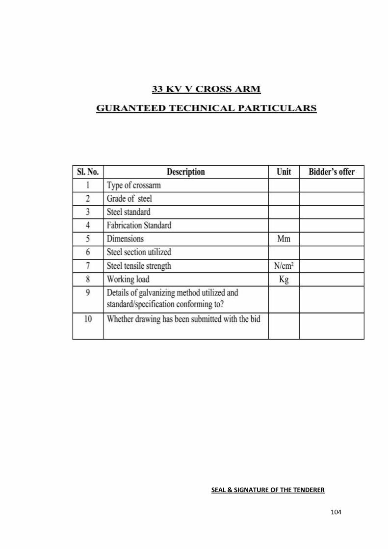
104
SEAL & SIGNATURE OF THE TENDERER
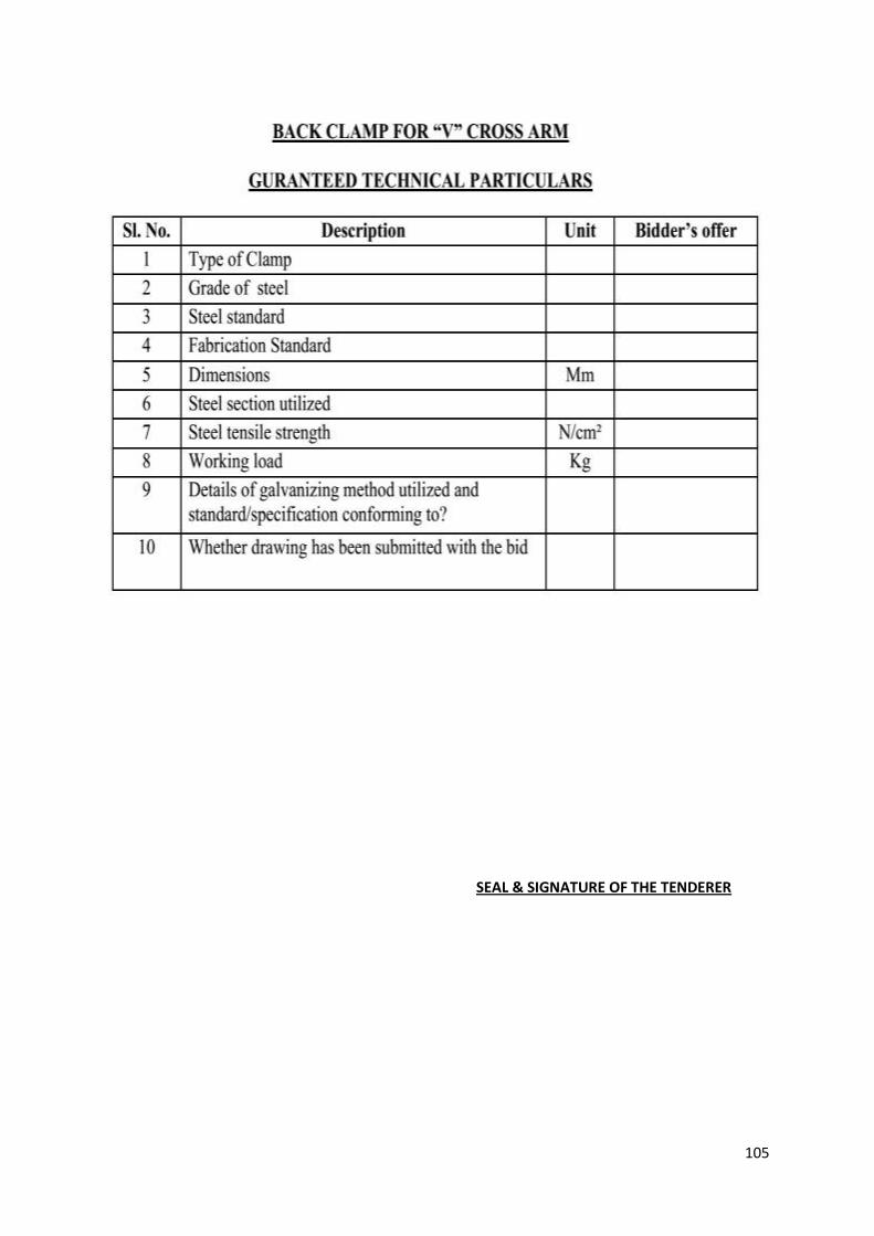
105
SEAL & SIGNATURE OF THE TENDERER
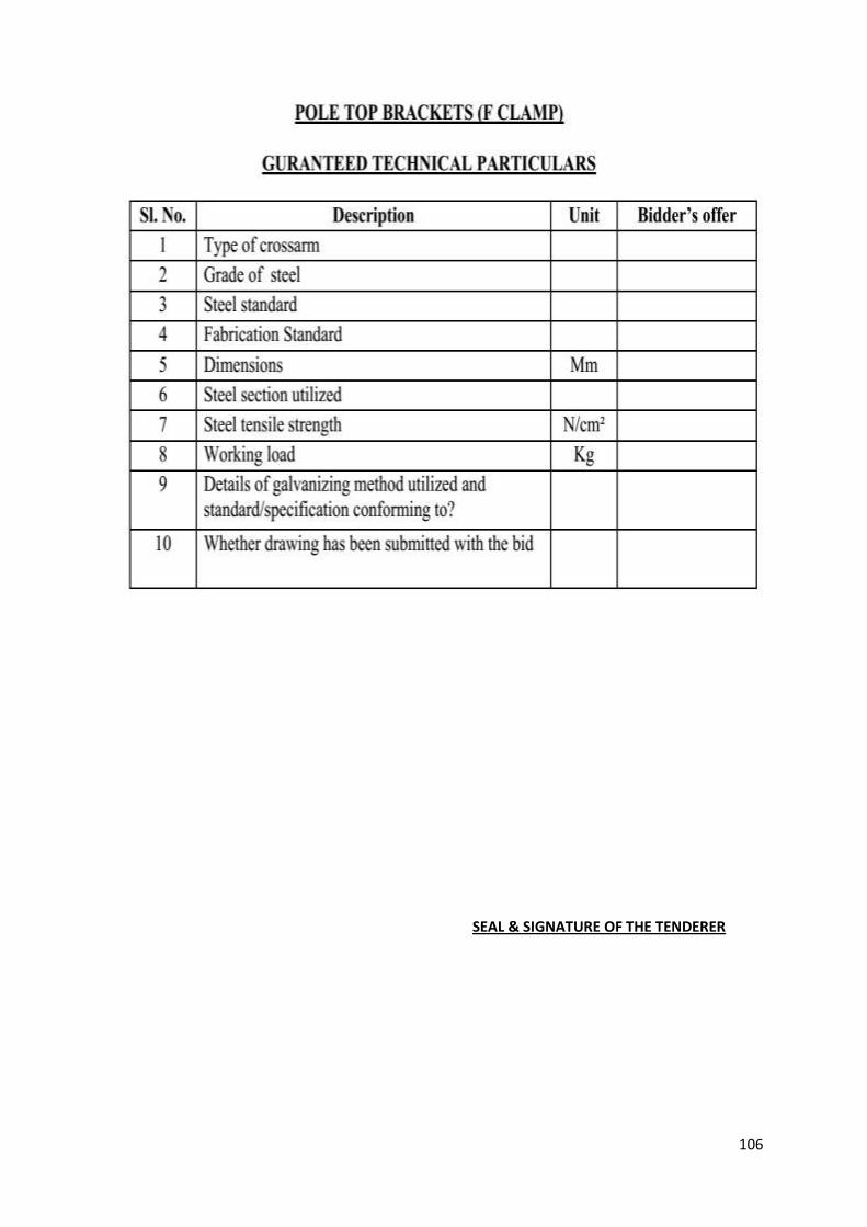
106
SEAL & SIGNATURE OF THE TENDERER

107
TECHNICAL SPECIFICATION FOR CROSS ARM
1.0 Scope
This covers manufacturing, transport to site, insurance, storage, erection and
commissioning of different types of Cross Arms suitable for 33 kV, 11 kV and L T
lines.
2.0 Climatic Conditions
The cross arms should be suitable for the climatic condition mentioned below:
a) Maximum temperature of air in shade 40°C
b) Minimum temperature of air in shade 2°C
c) Maximum temperature of air in Sun 40°C
d) Maximum Humidity 93%
e) Average number of thunderstorm days 45
f) Average numbers of dust storms per annum 10
g) Maximum rainfall/annum 3500 mm
h) Average rainfall 2280 mm
i) Wind Pressure 97.8 Kg/Sq.mm
j) Altitude above MSL 100 m to 1000 m
3.0 Standards
A. For 11 KV’ Cross-Arm
The Cross Arms shall be made out of 75 X 40 X 6 mm MS Channel and
MS Flat 50 X 6 mm
Cross Arms shall be hot dip galvanized generally conforming to IS-
2633/1972
Cross Arms should not be welded/joined at any place except as
specified.
The clamps for the Cross Arms shall be made of 50 X 6 MS Flat and
shall be hot dipped galvanized.
The clamps shall be designed to fit for the specified STP/PSC poles.
The rolling and cutting tolerance for steel products conforming to IS-226
108
shall be those specified in IS-1852/1973 or latest version.
B. Cross Arm for 33 KV Lines.
The Cross Arms shall be made out of 100 X 50x6mm MS
Channel and MS Flat 75 X 8 mm
The Cross Arm shall be hot dipped galvanized generally
conforming to the IS-2633/1972
The Clamps for the Cross Arms shall be made out of 75 X 8
mm MS Flat and shall be hot dipped galvanized conforming to
IS-2633/1972
The Clamps shall be designed to fit for STP/PSC Poles.
The rolling and cutting tolerance for steel products conforming
to IS-226 shall be those specified in IS-1852/1972 or latest
version.
C. Horizontal Type Cross Arm for 11 KV / 33 KV
It shall comprise of 100 X 50x6 mm, 3.2 M long MS Channel for
33 KV and 2.2 mt. long for 11 KV to be provided on STP/ PSCC
Poles
The rolling and cutting tolerance for steel products conforming
to IS-226 shall be those specified in IS-1852/1972 or latest
version.
The Cross Arm shall be hot dipped galvanized generally
conforming to the IS-2633/1972
The clamps for the Cross Arms shall be made of 50 X 6 MS Flat
and shall be hot dipped galvanized.
The Cross Arm should not have any welded joints.
D. Cross Arm for LT Lines
The Cross Arms shall comprise of 40 X 40 X 6 mm, 0.51 Mt.
long MS Channel to be provided on PSCC Poles.
The rolling and cutting tolerance for steel products conforming
to IS-226 shall be those specified in IS-1852/1972 or latest
version.
The Cross Arm shall be hot dipped galvanized generally
conforming to the IS-2633/1972
The Cross Arm should not have any welded joints.
The clamps shall be manufactured with MS Flat 50 X 6 mm
suitable for PSCC poles and shall be hot dipped galvanized.
E. LT MS Angle Cross Arm size 75 X 40 X 6 X 1020 mm
The Cross Arm should not have any welded joints.
All the Cross Arms shall be properly brushed to make free from
109
rust and then coated with two coatings of red oxide chromate
paint as per IS-5660/1970.
The sample Cross Arm and supplied made hereafter should
bear identification mark by way of punching or painting.
One copy of the drawing for each size of the cross arm
tendered for should be given to the purchaser.
The rolling and cutting tolerance for steel products conforming
to IS-226 shall be those specified in IS-1852/1972 or latest
version.
4.0 Marking.
The cross arm shall be marked with name of the manufacturer, year and
name of the project.
5.0 INSPECTION
Inspection may be carried out by the purchaser or third party nominee at any
stage of manufacture. The supplier shall grant free access to the purchaser's
representative or third party nominee at a reasonable time when the work is in
progress. Inspection and acceptance of any equipment under this specification
by the purchaser shall not relieve the supplier of his obligation of furnishing
equipment in accordance with the specification and shall not prevent
subsequent rejection if the equipment is found defective.
Name & Signature of Bidder with seal
110
General Conditions of
Supply & Erection of
APDCL
111
GENERAL CONDITIONS OF SUPPLY AND ERECTION
1.0 INTRODUCTION :
1.1 Assam Power Distribution Company Limited was constituted under the provisions of
Electricity Act, 2003 and is a public sector company registered under ‘Company Act,1956’. It
was formed out of Assam State Electricity Board in 2003 and was notified as the State
Electricity Distribution Utility. It is entrusted with the responsibility of promoting the co-
ordinated development of power distribution and its efficient management in the entire
state of Assam.
1.2 Assam Power Distribution Company Limited hereinafter referred to as APDCL, has its
Corporate Office at Bijulee Bhawan, Paltanbazar, Guwahati, Assam. For further information,
one may refer to APDCL’s official web site: www.laedcl.gov .in.
1.3 Assam is one of the seven states of North East India and its boundary encompasses almost
the entire valleys of Brahmaputra and Barak rivers. The state is well connected with rest of
the country by broad gauge railways and several national highways, one of which is a part of
the four lane east-west corridor. It also has important airports at Guwahati, Jorhat, Silchar,
Tezpur & Dibrugarh.
1.4 Relevant guidelines and rules connected with all departmental supply and erection works
have been laid down in this document General Conditions of Supply & Erection of Assam
Power Distribution Company Limited adopted in 2009. This document supersedes earlier
conditions of contract. It is intended that contractual clauses of this document will be
generally followed in all contractual works. Any modification of a contractual clause
considering requirement of a particular project shall be made in the NIT/ Tender document
for the specific project.
2.0 DEFINITION OF TERMS:
2.1 The following terms appearing in the General Conditions of Supply & Erection of Assam
Power Distribution Company Limited shall have the meaning herein indicated unless there is
anything repugnant in the subject or context.
2.2 “Purchaser/ Employer” shall mean the Assam Power Distribution Company Limited (in short
APDCL) and its assignees.
2.3 “Contractor/Supplier/Owner” shall mean the tenderer/ bidder whose tender/ bid has been
accepted by the “Purchaser/ Employer” and shall include the bidder’s/ tenderer’s legal
personal representatives, successors and assignees.
2.4 “Engineer” shall mean the Officer in-Charge of Project/ Work/ purchase for the supply and/
or erection contract or such other Officer or Offices as may be duly authorized and
appointed in writing by the Purchaser to act as “Engineer” for the purpose of the contract.
2.5 “Sub-Contractor” shall mean the person named in the contract for any part of the work or
any person to whom any part of the contract has been sublet with the consent in writing of
the “Purchaser/ Employer” and the legal representatives, successors and assignees of such
person.
112
2.6 “Materials” or “Works” shall mean and include plant and materials to be provided and work
to be done by the contractor under contract.
2.7 “Contract” shall mean and include the general conditions, specifications, schedules,
drawings, tender forms, bidding schedules, covering letter, schedule of prices, any special
conditions applying to the particular contract specification, amendments if any, letter of
acceptance and contract agreement to be entered into.
2.8 “Contract period” means the period from the contract commencement date to the date on
which the warranty period is over. Date of acceptance of ‘Purchase/ Work Order’ shall be
treated as the “date of commencement of contract”.
2.9 “Specification” shall mean the relevant ISS/ IEC specification with up to date amendments
and revisions and/or APDCL specification wherever applicable.
2.10 “Site” shall mean the site of the station, where proposed work is to be executed under the
contract and to which the plant and machinery are to be delivered and any other places as
may be specifically designated in the contract as forming part of the site.
2.11 “Consignee” shall mean the Executive Engineer/ Senior Manager or any other authorized
Officer performing the duty of the consignee as specified in the Order.
2.12 “Commercial use” shall mean use in the work which the contract contemplates or to which it
is to be commercially capable.
2.13 “Day” shall mean a calendar day.
2.14 “Month” shall mean a calendar month.
2.15 “Writing” shall include any manuscript, type written or printed statement properly signed.
2.16 “Persons” shall include firm, company, corporation and other body of persons whether
incorporated or not.
2.17 “Word” indicating in the singular only shall also include the plural and vice versa where the
context requires.
2.18 “Bid” will mean “Tender”
3.0 PREPARATION OF TENDER I BID:
3.1. DEFINITION OF TENDERER / BIDDER:
3.1.1. When the tenderer is a firm, the names and addresses of the partners must be indicated and
a copy of the certificate of registration with the concerned Registrar of firms should be
enclosed. 3.1.2. When the tenderer is a Company, the company registration
document along with
Memorandum of Association shall be submitted.
3.1.3. When the tenderer is an individual carrying on business in a firm’s name, the tender should
be submitted by the owner of the firm, who may describe himself as carrying on business in
the firm’s name.

113
3.1.4. When the tenderer is a Joint Venture (JV) of two or more firms as partners, one of the
partners shall be legally authorized as the lead partner for the purpose of submitting the
tender, incur liabilities; receive payments and instructions on behalf of the others. A copy of
the registered a greement, executed on Non judicial stamp paper, shall be submitted with
the tender. However, in case of a successful tender, the agreement shall be signed by all the
partners, so as to be legally binding on all the partners.
3.2. PURCHASE OF TENDER I BIDDING DOCUMENTS:
3.2.1. Tenderer may purchase the tender document by paying the requisite fee as stipulated in the
NIT. Alternatively, the tenderer may download tender document from the company’s
website: www.laedcl.gov.in and pay the above requisite fee by way of a demand draft
separately along with earnest money. Tenderer shall be responsible for any error etc., on the
downloaded tender document.
3.2.2. The General Conditions of Supply & Erection of Assam Power Distribution Company Limited
will be treated as a part of the NIT. The Contractor shall be deemed to have carefully
examined the aforesaid general conditions of supply & erection besides all specifications.
3.2.3. The tender should be complete in all respects so as to eliminate further correspondences
and clarifications. A tender which is not complete in all respects, will be liable for rejection.
However the Purchaser, in its discretion, may seek clarification from the tenderer where
necessary .The discretion of the Purchaser in this regard shall be final.
3.3. LANGUAGE AND SIGNING OF TENDER:
3.3.1. The tender, and all correspondence and documents related to the tender, exchanged
between the Tenderer and the Purchaser shall be written in English. Supporting documents
and printed literature furnished by the tenderer shall also be in English.
3.3.2. Tender shall be written in ink or typed. No tender filled in pencil or otherwise shall be
considered. The tender shall be signed by a responsible and authorized person and the
designation and authority of the signatory shall be stated in the tender. All corrections in the
proposal will have to be signed with date and seal of the tenderer. Such correction even
though signed, may make the tender liable for rejection.
3.3.3. Any printed document promoting sales may not be accepted by the Purchaser.
3.4. DOCUMENTS COMPRISING TECHNO-COMMERCIAL BID:
The particulars and supporting documents required in respect of the techno- commercial bid
should be strictly as per following sub-clauses (clauses 3.4.1 to 3.4.10). In case, any of the
details are either not furnished or inadequately furnished, the entire tender may be rejected
without informing the tenderer. A techno-commercial bid may have to be submitted under
separate sealed cover if so stipulated in the NIT. The price bid may not at all be opened for
examination in case the techno-commercial bid, which shall be opened first is not found
substantially responsive.

114
3.4.1. EARNEST MONEY OR BID SECURITY:
(a) Every tender must be accompanied with Earnest Money of value as stipulated in the NIT.
Mode of depositing the earnest money shall be clearly indicated in the NIT. Earnest money
or Bid security may be furnished in the shape of Bank Call Deposit/ Bank Draft as may be
prescribed in the NIT. Without this, the tender may be deemed to be incomplete and liable
for rejection. The earnest money shall be pledged in favour of the Officer as indicated in the
NIT.
(b) In case of unsuccessful tenderer, earnest money will be released on request from the
tenderer on a date subsequent to contract agreement with the successful tenderer.
(c) In case of successful tenderer, the earnest money will be retained until submission of the
performance security deposit referred to in clause 9.0.
(d) No interests shall be payable on such deposit
(e) The Purchaser/ Employer reserve the right to forfeit the earnest money or part thereof,
in circumstances which according to him indicate that the tenderer is not earnest in
accepting/ executing any order placed under specification.
3.4.2. GUARANTEED TECHNICAL PARTICULARS:
The GTP (Guaranteed Technical Particulars) of the materials offered along with their
complete technical description supported by drawings shall be furnished by the tenderer.
Relevant specifications like IS/ BS/ IEC etc. will be mentioned.
3.4.3. TEST REPORTS:
(a) A list showing various type tests and routine tests as required under the relevant
specifications shall be furnished by the tenderer and all such tests shall be carried out on the
materials and the components offered for supply in the event of award of contract. Against
each such test, the results of test performance shall be mentioned along with the name of
laboratories/ testing houses, where tests were so conducted. In support of the results
whether type tests or factory tests, certified copies of the test certificates shall be furnished.
In case any of the prescribed tests has not been carried out, the same shall be clearly
mentioned in this list stating the reasons for not carrying out the test. The tenderer also shall
furnish a separate list of tests which they have carried out on their products for ensuring
their better quality, but are not stipulated explicitly, in the relevant ISS or BSS specifications.
Type test reports to be acceptable, the tests have to be carried out at an NABL accredited
laboratory. Reports of Type test conducted in laboratories other than the above will be
acceptable only if witnessed by an officer from a power utility.
115
(b) Type test reports of equipment of higher capacity or voltage class than those specified
shall be acceptable for the purpose of bidding. However, in that case, the successful
tenderer shall conduct type tests on the offered equipment free of charge.
(c) Type test reports, conducted 5 years prior to the date of opening of tender, in general,
will not be accepted.
3.4.4. SPARE PARTS:
Each tenderer shall indicate the expected life in use of their products. A list of spares which
may be necessary for replacement during the maintenance of the equipment in service shall
be furnished indicating if these are of proprietary nature or of standard make available in
the market. In case these spares are of proprietary nature, their prices and the likely
quantities that may be necessary during the useful life of the equipment shall also be
mentioned.
3.4.5. BIS. CERTIFICATION:
The tenderer shall state clearly if the particular product offered by him is covered by any IS
certification mark and if so, the tenderer will furnish the particulars of the IS Specification,
the year of obtaining the certification and a copy of the certification.
3.4.6. PAST EXPERIENCE:
A Complete list of supplies/ works/ services in respect of the particular supplies / works /
services offered to various parties during the period of last 5 (five) years along with total
value of supplies shall be furnished. A separate list of supplies/ works/ services not exactly
same as the one offered but similar to it, supplied during the last five years shall also be
furnished. The tenderer shall state clearly if they had supplied similar material including the
offered product, to Assam Power Distribution Company Limited/ ASEB in the past. If so,
reference of the purchase orders, the ordering authority and the consignees shall also be
furnished.
3.4.7. SOURCES OF SUPPLIES:
3.4.7.1. The tenderer shall clearly state the names of the manufacturer, the brand name of the
product and the place/ places of its manufacture. In case, the components of the product
are obtained from ancillary manufacturers, the names and addresses of such manufacturers
also shall be furnished. It shall be mentioned clearly how the tenderer ensures quality
control over such ancillary components and if manufacturer of such components is covered
by any IS/ BS/ IEC or any other relevant specification.
3.4.7.2. The tenderer shall mention clearly whether he is a manufacturer, a sole selling agent or a
commission agent of the product.
3.4.7.3. When the tenderer is not a manufacturer, submission of manufacturer's authorization for
supply of the offered materials by the tenderer along with warranty pledged by the
manufacturer is compulsory.
3.4.7.4. Further, the manufacturing experience of the manufacturer in respect of the particular
116
product or similar product also shall be furnished, indicating chronological development of
the industry or the manufacturing unit.
3.4.7.5. The sources of receipt of the raw material whether indigenous or imported shall be clearly
mentioned against each type of such raw materials used. The methods by which quality
control of such raw materials being enforced shall be clearly described.
3.4.8. DELIVERY/ WORK SCHEDULE:
3.4.8.1. The delivery/ work schedule as stipulated in the NIT or. in the APDCL specification shall be
binding on the tenderers. In case the APDCL delivery/ work schedule is not acceptable to the
tenderer, then the tenderer may give their own delivery schedule stating clearly the reasons
for deviations whether statutory or otherwise. In any case such schedules must satisfy the
completion time specified. Acceptance of such deviations in the delivery/ completion
schedule is entirely optional to the Purchaser.
3.4.8.2. The commencement period and the quantity of each item to be supplied per month shall be
specifically mentioned.
3.4.8.3. Quantities offered ex-stock as well as with earlier delivery schedule shall be mentioned.
3.4.9. SAMPLES:
A sample shall be submitted along with the tender if asked for in the NIT and as per .its
terms. Non-submission or late submission of sample may disqualify the tender .
3.4.10. TAX CLEARANCE CERTIFICATES AND REGISTRATION:
3.4.10.1. The tender shall be accompanied with income tax and sales tax clearance certificates.
3.4.10.2The Contractor must register for VAT with the concerned department of
Government of Assam within a reasonable time after award of contract if not already
registered.
3.5. PRICE BID
3.5.1. The particulars and supporting documents in respect of the price bid should be as follows:
3.5.2. The total FOR destination price of the product offered unit wise and quantity wise both in
words and in figures shall be clearly furnished. Such FOR destination price also shall be
supported by a breakup of the price indicating separately Ex-works price, station of dispatch,
Freight and Insurance Charges. The offer may be straightway rejected if the FOR destination
price and its break up against the components as aforesaid are not furnished. The FOR
destination price will be on door delivery basis and shall be inclusive of cost of unloading of
materials at site.

117
3.5.3. The Ex-works price shall not include Sales Tax whether central or state and the same will be
indicated separately in words and in figures by the tenderer .
3.5.4. Excise duty on the finished product also shall be indicated separately if applicable. This should
be worked out both unit wise and quantity wise indicating the excise rates applicable.
3.5.5. Any other levy, entry tax, excise or otherwise on finished products and of statutory nature
also shall be indicated separately stating the reasons for claim of such levies.
3.5.6. For imported equipment:-
(a) The tenderer shall quote price for:-
i. FOB Port of shipment, inclusive of seaworthy packing.
ii. CIF Kolkata iii. Indian Agent Commission, if any.
(b) When prices quoted are for delivery FOB port of shipment, the Contractor shall agree to
arrange for the shipment and insurance of the machinery from the port of shipment to
Kolkata on behalf and to the account of the Purchaser should the Purchaser so desires. The
actual expenses incurred by the Contractor for Sea freight and insurance will be paid by the
Purchaser. The Purchaser shall provide for all incidental and statutory charges beyond the
port of shipment such as customs duty clearance, loading and unloading, Railway freight and
Octroi or terminal and other taxes.
(c) Firm FOB port of shipment shall be quoted. An alternative price CIF Kolkata shall be
quoted separately. The customs duty applicable and the category (Import Trade Control
Classification as brought up to date) under which the “applicant’s plant is assessable” shall
be stated. If firm FOB price cannot be offered, price subject to contract price adjustment
may be quoted, but a ceilings limit must be stated. Any claim for contract price adjustment
shall be supported by authentic documents which shall be to the satisfaction of the
Purchaser. Preference will be given to the firm offering FOB/ CIF price. The currency in which
payments have to be affected shall be clearly mentioned in the tender .
(d) The best delivery FOB port of shipment shall be clearly stated in the tender as it shall
have a vital bearing on the selection of the final successful tender.
(e) In either cases of goods supplied from within and outside India, the tenderer will quote
separately the freight and insurance for delivery of the goods at site.
3.5.7. Price quoted should be firm. If however a variable price is permitted as per provisions of the
NIT, the tenderer shall specifically stipulate the price variation formula by indicating the base
price and base date. Normally the price variation formula and indices as per IEEMA and
CACMAI will be accepted.
3.5.8. In case the tenderer quotes variable price as per any formula of his own/ other sources, the
tenderer will state clearly the reasons for quoting such variable price and submit the source
of the formula and indices. However, his offer may be rejected at the discretion of the
Purchaser if the Purchaser finds the quoted formula to be complex and it is difficult to
compare the outcome with other bids.
118
3.5.9. In any case, if price variation is allowed, it will be limited to a ceiling of 10% (ten percent)
upward only. However, there shall be no limit for downward price variation.
3.5.10. The rate quoted shall remain valid for a minimum period of 180 (one hundred eighty) days
from the date of opening of the tender. Any tender offering a shorter validity period than
specified in the NIT may be rejected outright. The price quoted shall remain FIRM during
the period of validity and any post revision of rate after opening of the tender will make it
liable for rejection. The Purchaser, however, reserves the right to negotiate with the
tenderer or offer lowest/ reasonable rate to any/ all of the tenderers.
3.5.11. The tenderer shall explain clearly if there is any DGS & D rate contract available for the
product offered and if on the positive, copies of such rate contract shall invariably be
furnished. For such DGS & D prices, the tenderer.should state clearly the period of validity
of the rate contract.
3.5.12. The tenderer shall mention clearly if any quantity discount or payment discount is offered.
3.5.13. The price bid shall be furnished clause wise and in the same order as above.
4.0 RIGHT TO REJECT:
4.1. The Purchaser reserves the right to reject any or all the tenders without assigning any reason
thereof and the Purchaser further reserves the right to split up the supply order in favour of
more than one contractor. The Purchaser also reserves the right to reject the lowest or any
other price without assigning any reason.
5.0 ACCEPTANCE OF THE ORDER / CONTRACT:
5.1. Acceptance of the order(s) in writing shall be conveyed by the supplier to the Purchaser/
Employer within 10 (ten) days from the date of issue of the purchase order failing which, it
will be presumed that all the terms and conditions of the purchase order are acceptable by
him in full.
5.2. Before finalization of the contract, if discussion with the successful tenderer is considered
necessary by the Engineer, the tenderer shall turn up for the same within 10 (ten) days from
the receipt of intimation by FAX / e-mail at no extra cost to the Purchaser.
5.3. Also, if it is for executing a separate agreement the successful tenderer will turn up for the
same within 10 (ten) days from the receipt of intimation at no extra cost to the Purchaser.
6.0 CONDITION OF CONTRACT: COMMERCIAL & GENERAL:
6.1. If so required by the Purchaser, a formal agreement with or without guarantee at the option
of the Purchaser shall be entered into between the Contractor and the Purchaser for the
proper fulfilment of contract. 6.2. Such contracts shall be drawn up in non-judicial stamp
paper.
6.3. The expenses of completing and standing the agreement shall be paid by the Contractor and
Purchaser shall be furnished free of charge with an executed stamped counterpart of the
agreement along with ten copies thereof.
119
6.4. After the tender has been accepted by the Purchaser, all orders or instructions to the
Contractor shall except as wherein otherwise provided, be given by the Engineer on behalf
of the Purchaser .
7.0 CONSTRUCTION OF CONTRACT:
7.1. The contract shall in all respects be constructed and operated as defined in the Indian
Contract Act 1972 and any statutory modification thereof.
8.0 EXECUTION OF AGREEMENT:
8.1. The contract agreement to be executed at Guwahati (Assam) by the parties.
9.0 PERFORMANCE SECURITY DEPOSIT:
9.1. The successful tenderer shall have to deposit through a Bank Guarantee from a nationalized
or scheduled Bank of RBI for an amount equivalent to 10% (ten percent) of the total value of
the order as performance security, immediately on acceptance of letter of intent/detailed
orders (as the case may be), duly pledged in favour of the Purchaser concerned and such
security deposits shall be valid up to 30(Thirty) days beyond the warranty period.
9.2. If the supplier fails or neglects to observe perform any of his obligations under the contract,
the Purchaser shall have the right to forfeit either in full or in part at his absolute discretion,
the security deposit furnished by the supplier.
9.3. No interest shall be payable on such deposits.
10.0 RETENTION MONEY:
10.1. In addition to above performance security deposit, 5% value of each progressive bill will be
retained by the Engineer/ Purchaser as ‘retention money’. The amount will be held by the
Purchaser till the work under the contract is completed and the completion certificate is
issued in pursuance to clause 25.0.
10.2. If the supplier fails or neglects to observe and perform any of his obligations under the
contract, the Purchaser shall have the right to forfeit either in full or in part at his absolute
discretion, the security deposit furnished by the supplier.
10.3. No interest shall be payable on such deposits.
11.0 RAW MATERIALS:
11.1. Raw materials will be arranged by the suppliers from their own quota and the Purchaser
does not have any responsibility in this regard. If, however raw materials are obtainable
against purchaser’s quota due to statutory compulsion, allotment orders in respect thereof
will be issued by the Purchaser. In case of raw materials for which supplier has own quota,
no recommendation or advice for release of raw materials shall be issued by the Purchaser.
If issue of raw materials from purchaser quota is desired by the tenderer, he must indicate
the price of the same raw material considered in the offer. In the event of actual cost of such
120
supply by the Purchaser, being lower than the price stipulated in the tender, the difference
will be recovered from the tenderer.
11.2. Where imports are unavoidable, the items shall be imported by the supplier in good time
against his import license without affecting the delivery schedule.
12.0 WARRANTY :
12.1. Each tender shall stipulate a warranty clause of products offered covering a minimum
period for rectification/free replacement thereof. The term “period of warranty” shall mean
the period of 12 (Twelve) months from the date of commissioning and successful operation
of the equipment. In any case, this period shall not be less than 18 months from the date the
materials are received in the purchaser’s store in good and acceptable conditions. During the
period of warranty, the Contractor shall rectify all defects in design, materials and
workmanship that may develop under normal use of the equipment upon written notice
from the Engineer who shall indicate in what respects the equipment is faulty .This
rectification/ free replacement must be carried i out within a reasonable period as
determined and directed by the Engineer. The cost of rectification/ free replacement will be
to the Contractor’s account.
12.2. If the Contractor fails to rectify the defects within the reasonable time, the Purchaser/
Employer may fix a date by which the Contractor would rectify the defects, failing which the
Engineer may
(a) Carry out remedial works himself or through by others, in a reasonable manner and at
the contractor’s risk and cost. The costs incurred by the Purchaser/ Employer in remedying
the defect shall be recoverable from the Contractor by the Purchaser/ Employer;
(b) Determine and certify a reasonable reduction in the contract price; or
(c) May terminate the contract in respect of such parts of the works and the Engineer shall
be entitled to recover all sums paid for such parts of the work.
13.0 DETAILS OF AUXILIARIES / MATERIALS:
13.1. Within a reasonable time from the date of acceptance of notification of award of contract,
the Contractor shall provide the Purchaser with details of all the auxiliaries/ materials being
supplied and also of others, not forming part of the Contractor’s supply but essential for the
safe and satisfactory working of the equipment/ system.
The Contractor shall send for approval on or before the date indicated by the Engineer,
outline drawings of all equipment/ materials to be furnished under the contract, together
with weights and sufficient overall dimensions to enable the design of the foundations,
structures and associated equipment to be prepared and also for transportation purpose.
14.0 CONTRACTOR.S DRAWINGS:
14.1. All working drawings shall preferably be prepared in AutoCAD 2000 software or its later
version. The Contractor shall also submit the soft copies of all working drawings.

121
14.2. Within 30 days from the date of acceptance of notification of award of contract, the
Contractor shall send to the Purchaser a preliminary list of all the drawings with their
respective identification numbers, titles and expected date of submission.
This list shall be amended or extended by the Contractor as and when necessary during the
progress of the work under the contract.
14.3. All titles, notes and inscriptions on the drawings shall be in English.
14.4. All drawings which the Contractor shall send to the Purchaser for approval shall be approved
or rejected or returned for modification within 15 days of receipt by the Purchaser. In case
of modification or rejection the Contractor shall submit the correct drawings within 15 days
from receipt of communication from the Purchaser.
Contractor shall be responsible for any delay in the contract processing and its award caused
by non conforming technical particulars furnished by the Contractor requiring query,
confirmation etc.
14.5. Upon approval by the Engineer, the drawings shall become the contract drawings and
thereafter, the Contractor shall not depart from them in anyway whatsoever except with the
written permission of the Purchaser.
14.6. FINAL AS-BUILT DRAWINGS:
In the final stages of the contract, the Contractor shall submit to the Purchaser hard copies
as well as soft copies of complete set of built up drawings.
14.7. MISTAKES/ ERRORS IN DRAWINGS:
14.7.1. The Contractor shall be responsible and liable for any change in the work due to any
discrepancies, errors, or omissions in the drawings or other particulars which have arisen
due to inaccurate information or particulars furnished by the Contractor, even though
approved by the Purchaser/Employer.
14.7.2. However, the Purchaser/ Employer shall be responsible for drawings and information
supplied by him. The Purchaser/ Employer shall compensate for any change in the work
caused due to inaccurate information supplied by him to the Contractor.
15.0 COPY RIGHT ETC.:
15.1. The Contractor shall indemnify the Purchaser against all claims, actions, suits and
proceedings for the infringement or alleged infringement of any patent, design or copyright
protected either in the country of origin or in India for the use of any equipment supplied by
the Contractor but such indemnity shall not cause any use of the equipment other than for
the purposes indicated by or reasonably to be inferred from the specification.
16.0 SUBLETTING CONTRACT:
16.1. The Contractor shall not, without the consent in writing of the Purchaser/ Employer assign
or sublet his contract, or any substantial part thereof, or interest therein or benefit or
122
advantage whatsoever, other than for raw materials or for minor details or for any part of
the work of which the Sub-contractors are named in the tender provided any such consent
shall not relieve the Contractor from any obligation, duty or responsibility under the
contract.
17.0 PACKING & MARKING:
17.1. The contract shall include provisions for secured/ protective packing of equipment so as to
avoid damage in transit, and the Contractor shall be responsible for all loss or damage
caused or occasioned by a defect in the packing.
17.2. All bright metal parts shall be thoroughly protected from rust during transit.
17.3. All materials shall be packed in suitable strong cases or crates as per standard practice,
unless otherwise specified. Large equipment such as power transformers, circuit breakers
etc. which are not packed in cases, shall have all screwed holes plugged with wood and all
machined faces shall be properly protected. Each package should be suitably marked with
APDCL marking as specified in the purchase order.
18.0 VARIATION OF QUANTITY:
18.1. Purchaser/ Employer shall have the right to increase/ decrease the ordered quantity by 20%
within 50 days of the period of completion of supply order and the same shall be supplied at
the same rates/ prices and terms and conditions stipulated in the order except in regard to
delivery schedule, which shall be mutually agreed upon in case of increase in the ordered
quantity.
19.0 CO-OPERATION WITH OTHER MANUFACTURERS:
19.1. The Contractor shall agree to co-operate with the Purchaser’s other contractors for
associated supplies and freely exchange with them such technical information as is
necessary to obtain the most efficient and economical design and to avoid unnecessary
duplication. No remuneration shall come from the Purchaser for such technical co-
operation.
20.0 INSPECTION AND TESTING:
20.1. The Purchaser/ Employer and his duly authorized representative shall have at all reasonable
time access to the Contractor’s premises or works and shall have the power to inspect and
examine the materials including raw materials used and the workmanship of the product
during manufacture. If a part of the goods is manufactured at other’s premises or works the
Contractor shall obtain for purchaser’s duly authorized representative, permission to
similarly inspect at the other premises/works.
21.0 INSPECTION AT SITE FOR ERECTION WORK:
21.1. A representative of the Purchaser shall have access to the Contractor/ Sub- Contractor’s
work at site at any time and the Contractor/ Sub-Contractor or his authorized agent shall be
present and shall provide facilities for necessary inspection.
123
22.0 TEST AT SITE FOR ERECTION WORK:
22.1. The Contractor after erection and commissioning of the equipment shall arrange testing to
prove correct workmanship as per specification. The Contractor shall give in writing the
Purchaser’s representative thirty (30) days notice of the date the equipment would be ready
for testing. The Contractor shall bear all testing cost at site of work and shall become
responsible for rectification of defects found on testing within reasonable time as decided by
the Engineer.
23.0 INSURANCE:
23.1. The Contractor shall, unless otherwise specified by the Purchaser, insure the materials
through their underwriter at their cost and shall keep it insured against any loss/ damage/
pilferage in transit, destruction or damage by fire/ flood, exposure to vagaries of weather or
through riot, civil commotion, war or rebellion, for the full value of the materials until the
materials are received at the Purchaser’s destination store.
23.2. The Contractor shall be responsible for safe arrival of the goods at destination, their
unloading and their receipt by the consignee. The Assam Power Distribution Company
Limited will discharge consignee’s responsibilities only and shall not be responsible for any
damage/ loss/ pilferage/ non-delivery by the carriers.
23.3. In case of any loss / damage / pilferage / non-delivery / short delivery by carriers etc. the
supplier shall replace free of cost the missing / damaged / lost materials within 30 (thirty)
days from the receipt of report thereof from the consignee without waiting for settlement of
their claims with their carriers/ under-writers.
Normally such reports from the consignee to the supplier shall be initiated within a period
of 30 (thirty) days from the date of receipt of each consignment by him.
23.4. If it is considered necessary that the damaged equipment either in part or in full be sent
back to the manufacturer’s works for repair, the manufacturers/ suppliers will furnish the
Bank Guarantee for the full value of equipment needing repairs and such Bank Guarantee
shall remain valid till such time the equipment are repaired and returned to the consignee in
good condition. The to and fro freight, handling and insurance charges in such cases will be
borne by the Contractor .
23.5. Unless otherwise mutually agreed upon, in case of failure by the supplier to replenish/ make
good of the loss/ damage/ short supplied quantities, within the stipulated period, the
Purchaser reserves the right to forfeit the security deposit and/ or adjust any outstanding
payment to the Contractor with APDCL or take any other appropriate action.
23.6. All materials will be dispatched against clear door delivery basis unless otherwise agreed by
the Purchaser .
24.0 TERMS OF PAYMENT:
24.1. The standard terms of payment of APDCL for supply of equipment/ materials are indicated
below:-
124
(A) 100% payment would be admissible within three (3) weeks from the date of receipt of
the materials/ equipment at site in full and good condition less deduction of retention
money and advance applicable as per clause 10.0 and 24.2 and as per terms and conditions
stipulated in the purchase order
(B) However, in special case, the following terms of payment may be agreed to at the
discretion of Purchaser .
(1) Payment of 90% (ninety percent) of the consignment value on receipt of all dispatch and
other documents by the consignee through Bank.
(2) Balance 10% (ten percent) on-receipt of the equipment/ materials at site in full and in
good condition and as per terms & conditions stipulated in the Purchase order.
(3) Payment vide clause (B)(I) & (B)(2) would be made provided the Contractor submits to
the Purchaser/ Employer a bank guarantee equivalent to 90% of the consignment value,
which will be released after the consignment is received in full and good condition.
(4) Payments as per sub-para (A), (B)(I) & (B)(2) above will be made under the following
conditions:-
(a) Advance copies of bills in duplicate and other information such as challan packing list etc.
are furnished sufficiently in advance.
(b) Any demurrage charges on account of late intimation and/or delivery of documents by
the Bank is borne by the supplier.
(c) The supplier intimates the dispatch of each and every consignment to the Purchaser and
the Consignee.
(d) All Bank charges are borne by the supplier.
(5) Payment through Bank in respect of material/ equipment dispatched by road transport
shall be allowed if required, provided the transport agency is approved by the Banking
Association and prior approval thereof is given by the Engineer .
(C) TERMS OF PAYMENTS FOR ERECTION WORK:
Payment up to 100% of erection items will be made against progressive monthly bills within
a reasonable time from the date of submission of bills less deduction of retention money
and advance applicable as per clause 10.0 and 24.2 respectively.
24.2. ADVANCE PAYMENT:
10% of the contract value as interest free advance against a Bank Guarantee for a sum
equivalent may be permitted if specifically provided in the NIT. The advance amount will be
gradually adjusted/ amortized by suitable instalments from the progressive bills. Number of
instalments will be specified in the NIT.
125
25.0 TIME FOR COMMENCEMENT AND COMPLETION:
25.1. For the purpose of determining the completion time of supply and/or erection works, the
date on which the Contractor accept the purchase/ work order in pursuance to clause 5.0
shall be taken as commencement date of the contract.
25.2. The Contractor shall attain Completion of the supply and/or works (or of a part where a
separate time for Completion of such part is specified in the NIT/ Contract), within the time
stated in the NIT / Contract.
25.3. As soon as the works, in the opinion of the Contractor, are completed as per requirements
of the specification/ contract, the Contractor shall so notify the Engineer in writing.
25.4. The Engineer shall, within fourteen (14) days after receipt of the Contractor’s notice under
Sub-Clause 25.3 either issue a Completion Certificate in the form specified by the Engineer,
stating that the supply/ works thereof have reached Completion on the date of Contractor’s
notice under Sub-Clause 25.3 or notify the Contractor in writing of any defects and/ or
deficiencies.
25.5. If the Engineer notifies the Contractor of any defects and/ or deficiencies, the Contractor
shall then correct such defects and/ or deficiencies, and shall repeat the procedure
described in Sub-Clause 25.3
25.6. If the Engineer is satisfied that the supplies/ works have reached completion, the Engineer
shall, within seven (7) days after receipt of the Contractor’s repeat notice, issue a
Completion Certificate stating that the supplies/ works have reached Completion on the
date of the Contractor’s repeat notice.
25.7. If the Engineer is not so satisfied, then he shall notify the Contractor in writing of any defects
and/or deficiencies within seven (7) days after receipt of the Contractor’s repeat notice, and
the above procedure shall be repeated.
25.8. If the Engineer fails to issue the Completion Certificate and fails to inform the Contractor of
any defects and/ or deficiencies within fourteen (14) days after receipt of the Contractor’s
notice under Sub-Clause 25.4 or within seven (7) days after receipt of the Contractor’s
repeat notice under Sub-Clause 25.6 then the supplies / works shall be deemed to have
reached completion on the date of the Contractor’s notice or repeat notice, as the case may
be.
25.9. EXTENSION OF TIME FOR COMPLETION:
Should progress be delayed because of delay in approval of drawings or any cause beyond
reasonable control of the Contractor, reasonable extension of time may be granted on the
application made by the Contractor in writing to the Purchaser but without prejudice to
other terms and conditions of the contract. It shall be the duty of the Contractor to notify to
the Purchaser the reason for delay which the Contractor considers to be beyond his control.
The decision of the Purchaser as to whether the delay was beyond the control of the
Contractor shall be final.
25.10. Price variation, if any, applicable as per purchase order shall not apply to any quantity not
delivered as per delivery schedule of the purchase order. If, however, the prices in respect of
126
delayed deliveries are found to have gone down, payment will be made at the reduced price
or penalty levied at the discretion of the Purchaser.
26.0 LIQUIDATED DAMAGE FOR DELAY IN DELIVERY / COMPLETION OF WORKS AND PENALTY:
26.1. The date of delivery/ completion of work shall be deemed to be the essence of the contract
and shall be completed not later than the date specified in the purchase order/ contract. In
case of failure to deliver the materials/ equipment in full or to complete the delivery within
the stipulated delivery period or delay in the erection work beyond completion schedule, the
Purchaser/ Employer shall be entitled to: -
(1) Recover an amount at the rate of 1% (one percent) of the Contract Price per week or
part thereof of delay, subject to maximum of 10% (ten percent) of the contract price as
liquidated damage to APDCL. However, the payment of liquidated damages shall not in any
way relieve the Contractor from any of its obligations to complete the works or from any
other obligations and liabilities of the Contractor under the Contract.
(2) Purchase the undelivered material/ equipment from elsewhere or to complete the
balance work giving notice to the supplier and to recover any extra expenditure incurred
thereby for having to purchase these materials or complete the work at a higher price, at the
risk and responsibility of the Contractor.
(3) Cancel the contract wholly or in part and to purchase materials/ equipment at the full
risk and cost of the supplier and forfeit the security deposit.
27.0 CONTRACTUAL FAILURE:
27.1. In the event of contractual failure of any respect on the part of the supplier, the Purchaser
shall be entitled to forfeit the security deposit or any deposit or any payment due to Supplier
from this or his other contracts towards the recovery of Purchaser’s claim for damages
arising out of the failure. In addition, APDCL may black-list or ban the Contractor or pending
enquiry, suspend him or take any other steps considered suitable.
28.0 REJECTION:
28.1. In the event, any of the Equipment supplied by the Contractor is found defective in
materials or workmanship or otherwise not in conformity with the requirements of the
contract specifications, the Purchaser shall either reject the equipment or request the
Contractor in writing to rectify the same. The Contractor, on receipt of such notification shall
either rectify or replace the defective equipment free of cost to the Purchaser. If the
Contractor fails to do so, the Purchaser may at his option:
(a) Replace or rectify such defective equipment and recover the extra cost so involved from
the Contractor plus 15% fifteen percent thereof, or
(b) Terminate the contract for default, or
(c) Acquire the defective equipment at a reduced price as considered equitable under the
circumstances. The provision of this article shall not prejudice the Purchaser’s right under
clause 26.0
127
29.0 DEDUCTION FROM CONTRACT PRICE:
29.1. All cost, damages or expenses which the Purchaser may have made for which, under the
contract, the Contractor is liable, may be deducted by the Purchaser from any money due or
becoming due by him to the Contractor or may be recovered by action at law or otherwise
from the Contractor.
29.2. In the event of recovery to the necessary extent becoming impossible owing to insufficiency
of the earnest money/ security deposit and withheld amounts, the balance due to the
Purchaser may at the option of the Purchaser be recovered from any money due to the
Contractor from LAEDCL under other contracts with the Contractor.
30.0 FORCE MAJEURE:
30.1. Normally, force majeure shall cover only act of God, fire, war, riots and, act of Government
etc. Any constraints other than those specified above, will not constitute a force majeure
condition. In view of other constraints beyond the control of the supplier, primarily due to
statutory compulsion, extension of delivery time may also be considered on merit of
individual case. In case of a force majeure condition, the Contractor shall notify the
Purchaser in writing such condition within 10 (ten) days from the beginning of such delay for
consideration and acceptance.
31.0 CHANGE OF NAME OF THE TENDERER:
31.1. At any stage after tendering, the Purchaser/ Employer shall deal with the Supplier/
Contractor only in the name and the address under which he submitted the tender. All the
liabilities/ responsibilities for due execution of the contract shall be that of the Supplier/
Contractor. The Purchaser may however, in his discretion deal with agents/ representatives/
distributors/ manufacturers/ associates/ principals/ sister concerns and such dealings shall
not absolve the Supplier/ Contractor from the responsibilities/ obligations/ liabilities to the
Purchaser/ Employer under the contract.
31.2. Any change/ alteration of name/ constitution/ organization of supplier shall be duly notified
to the Purchaser/ Employer and the Purchaser/ Employer reserves the right to determine
the contract, in case of any such notification.
32.0 DEATH, BANKRUPTCY ETC.:
32.1. If the Contractor becomes bankrupt or being a corporation is in the process of winding up,
amalgamation or reorganization, the Purchaser shall be at liberty to:
(a) Terminate the contract forthwith by notice in writing to the Contractor or to the
liquidator or receiver or to any person in whom the contract may become vested.
(b) Give such liquidator, receiver or other person the option of carrying out the contract
subject to his providing a guarantee for the due and faithful performance of the contract up
to an amount to be determined by the Purchaser.
32.2. In case of death of the Contractor before completion of work and supply, the Engineer or
Purchaser shall be at liberty to:
128
(a) Close up the contract and take over the completed portion of work/ supply done and
made as per specification and make final payment to the legal heir of the Contractor on
receipt of claim from such legal heir .
(b) Give the contract to the legal heir of the Contractor subject to his depositing a
performance security for the due and faithful performance of the contract. The performance
security amount shall be determined by the Purchaser/ Engineer commensurate with the
incomplete portion of the work/ supply.
The Purchaser will enter into a fresh contract with the legal heir of the Contractor on the
same terms and conditions of the earlier contract.
33.0 ARBITRATION:
33.1. If at any time, any question, disputes or differences whatsoever shall rise between the
Purchaser and the Contractor, upon or in relation to or in connection with the contract,
either party may forthwith give notice to the other in writing of the existence of such
question of dispute or difference and the same shall be referred to the adjudication of three
Arbitrators, one to be nominated by the Purchaser the other by the Contractor and the third
by the President of the International Chamber of Commerce in the case of foreign
contractors and in case of local contractors by the President of the Institution of Engineers,
India/ Retired or Sitting Judge not below the status of a retired Judge of High Court of India.
If either of the parties fail to appoint its arbitrators within 60 (sixty) days after receipt of
notice of the appointment of arbitrators then President of International Chamber of
Commerce or the President of the Institution of Engineers retired or sitting Judge of India, as
the case may be shall have the power at request of either of the parties, to appoint an
Arbitrator. A certified copy of the President of the ICC or IOE making such an appointment
shall be furnished to both parties
33.2. The arbitration shall be conducted in accordance with Rules and procedures for Arbitration
of the International Chamber of Commerce (Paris) in the case of foreign contractors as per
provisions of the Arbitration Act 1940 or any statutory modification thereof and in case of
local contractors, shall be held at Guwahati or any other place as may be decided by the
Managing Director, APDCL. The decision of the majority of Arbitrators shall be final &
binding upon the parties and the expenses of the arbitration shall be paid as may be
determined by the Arbitrator . However, any dispute arising out of this contract will first be
discussed and settled bilaterally between LAEDCL and the Contractor.
34.0 PRECAUTIONS TO BE TAKEN DURING CONSTRUCTIONS/ ERECTION:
34.1. The Contractor shall take reasonable and statutory precaution during execution of erection
and construction work so as to avoid accident and damage to equipment and injury to
workman and to prevent theft, pilferage etc.
35.0 LIABILITY FOR ACCIDENT AND DAMAGE:
35.1. The Contractor shall not claim for compensation arising out of any accident(s) or damages
done during the course of erection & commissioning work & the Contractor will be
responsible for paying compensation to the worker as per Workmen’s Compensation Act,
1923 and subsequent amendments thereof. It is further clarified that in case any payment is
129
to be made by the Contractor under the said Workmen Compensation Act, the same shall be
paid forthwith and in case of failure in making such payments the Purchaser shall make
payment and the amount so paid shall be deducted from the bills of the Contractor.
35.2. The Contractor shall adequately insure against liability to third party, in the joint names of
the Employer, the Contractor and the Sub-contractors for any loss, damage, death or bodily
injury which may occur to any physical property owned by others, the goods/ materials of
the contract or to any person which may arise out of the performance of the contract.
36.0 REGULATION OF LOCAL AUTHORITIES:
36.1. The Contractor shall abide by the regulation of local Authorities unless such regulation is
repugnant to any terms of the contract agreed upon.
36.2. All electrical contractors need to possess a valid ‘Electrical Contractor’s License’ from the
concerned Licensing Board, Government of Assam. A tenderer, who has a valid ‘Electrical
Contractor’s License’ from other states will also qualify for a bidding. However, in such cases
the tenderer will have to obtain the same or an endorsement to that extent, from the
Licensing Board of Government of Assam within a reasonable time from the date of award of
contract.
36.3. The Contractor is required to fulfil all criteria related to Labour Laws.
36.4. The Contractor will also comply with all regulations/ directives of both State & Central
Government Pollution Boards.
37.0 SUSPENSION OF BUSINESS DEALINGS WITH FIRMS/ CONTRACTORS:
37.1. The Purchaser may suspend business dealings with a Firm/ Contractor, if:
(a) The Central Bureau of Investigation or any other investing agency recommends such a
course in respect of a case under investigation; and if a prima facie case is made out that the
firm is guilty of an offence involving unethical, unlawful, fraudulent means in relation to
business dealings, which, if established, would result in business dealings with it being
banned.
(b) The Purchaser has past record of non-performance of the Firm in its previously awarded
contracts.
(c) The Purchaser has record of ban against the Firm by other Government / Public sector
utility
37.2. However, the Purchaser shall give the Firm/ Contractor a fair chance to explain the
circumstances of such previous suspensions.
38.0 BANNING OF BUSINESS DEALINGS WITH FIRMS/ CONTRACTORS:
38.1. The Purchaser may ban business dealings with a Firm/ Contractor, if:
(a) The owner (s) of the Firm/ Contractor is convicted by a court of law following
prosecution for offences involving unethical, unlawful, fraudulent means in relation to
business dealings.
130
(b) There is strong justification that the Firm has been guilty of malpractices “such as,
bribery, corruption, fraud, substitution of tenders, interpolation, mis-representation, evasion
or habitual default in payment of any Government tax" etc. .
(c) The Firm continuously refuses to return government dues without showing adequate
cause and government are reasonably satisfied that this is not due to reasonable dispute
which would attract proceeding in arbitration or court of law.
(d) The Firm is found guilty of involving in unethical practices, such as:
1. “corrupt practice” involving offering, giving, receiving or soliciting, directly or indirectly, of
anything of value to influence the action of any such official/ party in procurement process
or in contract execution.
2. “fraudulent practice” involving misrepresentation or omission of facts in order to
influence a procurement process or the execution of a contract to the detriment of the
Employer.
3. “collusive practice” involving a scheme among bidders (prior to or after bid submission)
designed to establish bid prices at artificial non-competitive levels and to deprive the
Employer of the benefits of free and open competition.
4. “coercive practice” involving harming or threatening to harm directly or indirectly,
persons or their property to influence procurement process or the execution of a contract.
38.2. The Purchaser may sanction a Firm/ Contractor or its successor, including declaring i
neligible, indefinitely or for a period of not less than 3 (three) years.
39.0 LEGAL JURISDICTION:
39.1. For any litigation arising out of the contract which cannot be resolved through mutual
agreement or through arbitration, the Guwahati High Court will have the sole jurisdiction.