bid documents for
TRANSCRIPT

Dedicated Freight Corridor Project (Western Corridor Phase- 1) Bid Documents – Vol. II Package - 5: Signal and Telecommunication, Rewari – Vadodara Section Employer’s Requirements – General Specifications
Bid Documents for
DESIGN AND CONSTRUCTION OF SIGNAL AND TELECOM WORKS FOR DOUBLE LINE RAILWAY
INVOLVING TRAIN DETECTION SYSTEM, TRAIN PROTECTION & WARNING SYSTEM, ELECTRONIC
INTERLOCKING IN STATIONS, AUTOMATIC SIGNALLING IN BLOCK SECTIONS, INTERLOCKING
OF LEVEL CROSSING GATES, DISPATCH TELEPHONE SYSTEM, FIBER OPTIC COMMUNICATION
SYSTEM, GSM(R) SYSTEM, DIGITAL ELECTRONIC EXCHANGE SYSTEM, MASTER CLOCK SYSTEM
AND VIDEO SURVEILLANCE SYSTEM FOR REWARI – MAKARPURA SECTION AND TRAIN
MONITORING AND DIAGNOSTIC SYSTEM FOR DADRI – JNPT SECTION INCLUDING TESTING AND
COMMISSIONING ON DESIGN-BUILD LUMP SUM PRICE BASIS OF WESTERN DEDICATED
FREIGHT CORRIDOR
SIGNALLING AND TELECOMMUNICATION WORKS CONTRACT
(Rewari – Makarpura of Phase 1 and part of Phase 2)
CONTRACT PACKAGE ST P-5
Issued on: April 15th, 2013
ICB No: ST P-5
VOLUME-II
EMPLOYER’S REQUIREMENTS
Section 8: General Specifications
Employer:
DEDICATED FREIGHT CORRIDOR CORPORATION OF INDIA LIMITED
(A GOVERNMENT OF INDIA ENTERPRISE)
MINISTRY OF RAILWAYS
INDIA

Dedicated Freight Corridor Project (Western Corridor Phase- 1) Bid Documents – Vol. II Package - 5: Signal and Telecommunication, Rewari – Vadodara Section Employer’s Requirements – General Specifications
BID DOCUMENTS
FOR
SIGNALLING AND TELECOMMUNICATION WORKS
Contract Package 5
for
ICB No. ST P-5: Rewari – Makarpura of Phase 1 and Part of Phase 2
SUMMARY TABLE OF CONTENTS
VOLUME I (1/2):
INVITATION FOR BIDS
SECTION 1 - INSTRUCTIONS TO BIDDERS
SECTION 2 - EVALUATION AND QUALIFICATION CRITERIA
SECTION 3 - BID FORMS
SECTION 4 - LIST OF ELIGEBLE COUNTRIES OF JAPANESE ODA LOANS
SECTION 5 - CONDITIONS OF CONTRACT
SECTION 7 – CONTRACT FORMS
Volume 1 (2/2)
SECTION 6 - FINANCIAL SUBMISSIONS
VOLUME III:
SECTION 9 – EMPLOYER’S REQUIREMENTS: PARTICULAR SPECIFICATIONS
VOLUME IV:
SECTION 10 - DATA BOOK
VOLUME V:
SECTION 11 - REFERENCE DRAWINGS
VOLUME II:
SECTION 8 – EMPLOYER’S REQUIREMENTS: GENERAL SPECIFICATIONS

Dedicated Freight Corridor Project (Western Corridor Phase- 1) Bid Documents – Vol. II Package - 5: Signal and Telecommunication, Rewari – Vadodara Section Employer’s Requirements – General Specifications
Page i of i
TABLE OF CONTENTS
Chapter Page
1. INTRODUCTION ....................................................................................................................... 1
2. DEFINITIONS AND ABBREVIATIONS ....................................................................................... 3
3. RELEVANT DOCUMENTS ........................................................................................................ 8
4. DESIGN, SUPPLY AND CONSTRUCTION PHASES ................................................................. 9
5. EMPLOYER’S OUTLINE SPECIFICATIONS, SPECIFICATIONS IN SI UNITS AND APPLICABLE
STANDARDS ...................................................................................................................................16
6. SURVEY AND SITE INVESTIGATIONS ....................................................................................17
7. PLANNING AND PROGRAMME REQUIREMENTS ..................................................................18
8. MANAGEMENT PLANS ............................................................................................................32
9. DOCUMENTS SUBMISSION AND RESPONSE PROCEDURE ................................................49
10. QUALITY ASSURANCE ..................................................................................................54
11 SAFETY, HEALTH AND ENVIRONMENT (SHE) .............................................................60
12. CLIMATIC CONDITION ...................................................................................................67
13. CONTRACTOR’S CO-ORDINATION WITH OTHERs (INTERFACE MANAGEMENT) .....71
14. CONTRACTOR’S PROJECT ORGANISATION ...............................................................82
15. SOFTWARE ....................................................................................................................83
16. MATERIALS AND EQUIPMENT ......................................................................................87
17 PACKAGING, STORAGE, SHIPPING AND DELIVERY ...................................................90
18 THE WORKS AND CARE OF THE WORKS ....................................................................93
19. DAMAGE AND INTERFERENCE ....................................................................................95
20 TEMPORARY ELECTRICITY SUPPLY..........................................................................101
21 MOCK-UPS, PROTOTYPES AND SAMPLES ................................................................105
22. SECURITY REQUIREMENTS .......................................................................................106
23. TESTING AND COMMISSIONING ................................................................................107
24 AFTERCARE SERVICES ..............................................................................................120
25. OPERATION AND MAINTENANCE DOCUMENTATION ...............................................121
26. TRAINING AND TRANSFER OF KNOWLEDGE AND SKILLS .......................................125
27 SUPPLY OF SPARE PARTS, CONSUMABLES, SPECIAL TOOLS AND TEST
EQUIPMENT ..................................................................................................................................129
28 PUBLIC RELATIONS.....................................................................................................134
APPENDIX INDEX .........................................................................................................................135
Dedicated Freight Corridor Project (Western Corridor Phase- 1) Bid Documents – Vol. II Package - 5: Signal and Telecommunication, Rewari – Vadodara Section Employer’s Requirements – General Specifications
Page 1 of 135
EMPLOYER’S REQUIREMENTS - GENERAL SPECIFICATIONS
1. INTRODUCTION
1.1 APPLICATION OF THE GENERAL SPECIFICATION (GS)
1.1.1 The provisions contained in the Particular Specifications (PS) shall prevail over the provisions
contained in this GS.
1.1.2 The provisions contained in the GS shall prevail over the provisions contained in, Indian
Standards, Japanese Standards, International Standards and similar standard documents
stated in the Contract.
1.1.3 This GS shall be read in conjunction with the other documents constituting the Contract.
1.2 GENERAL INFORMATION
1.2.1 The 1st phase of the Western Dedicated Freight Corridor consists of 931 km of double line
electrified track with 2x25 kV AC, 50 Hz overhead catenary system from Vadodara to Rewari
running along the existing Indian Railway Tracks.
Construction of the 1st phase of the Western Dedicated Freight Corridor has been planned
through eight (8) Contract Packages encompassing the following contract scopes:
CT P-1 Civil/Building/Track Works Rewari – Ajmer Section;
CT P-2 Civil/Building/Track Works Ajmer –Ikbalgarh Section;
CT P-3 Civil/Building/Track Works Ikbalgarh – Vadodara Section (excluding
bridges across river Mahi and Sabarmati);
CT P-3A Special Steel Bridges across river Mahi and Sabarmati;
EM P-4 Electrical & Mechanical, Rewari – Vadodara Section ;
ST P-5 Signal & Telecommunication, Rewari – Vadodara Section;
PE P-6 Plant and Equipment for Operation and Maintenance and
RS P-7 Rolling Stock Cum Maintenance And Depot Works.
1.2.2 Out of the total length of 931 km, the work between Ikbalgarh and Rewari in a length of 625km
has been planned under CT P-1 and CT P-2. The balance stretch of 306 km between
Ikbalgarh – Vadodara shall be carried out under Package CT P-3, except for the work of two
Special Steel Bridges across rivers Mahi and Sabarmati along with their approaches of 200m
length from abutments on both sides of the bridges, which has been planned under Package
CT P-3A.
The line is to be constructed as double line electrified track capable of operating at a maximum
train speed of 100km/h with an initial axle load of 25.0 tonnes. Formation and bridge structure
are to be provided for 32.5 tonnes axle load and track structure for 25 tonnes axle load.
Ikbalgarh – Rewari stretch is located along Palanpur – Phulera and Phulera – Rewari lines of
North Western Railway. Detour is planned at Phulera city for around 7 km length. The
proposed alignment between Ikbalgarh - Rewari is located on east side of existing IR. The
proposed alignment of DFC is passing generally parallel to the existing IR network between
Ikbalgarh and Rewari. The alignment of DFC is taking detour to avoid city congestion at
Phulera. Almost 90% of the proposed DFC alignment is passing parallel to existing IR network
Combined Package

Dedicated Freight Corridor Project (Western Corridor Phase- 1) Bid Documents – Vol. II Package - 5: Signal and Telecommunication, Rewari – Vadodara Section Employer’s Requirements – General Specifications
Page 2 of 135
and 10% of the alignment is passing through detours.
Ikbalgarh – Vadodara section of the alignment consists of two parts, viz. Ikbalgarh – Pansar
and Pansar – Vadodara (makarpura).
The alignment between Ikbalgarh and Pansar (134km approximately) is located along
Ikbalgarh – Palanpur - Jagudam - Pansar lines of North Western Railway. The Ikbalgarh –
Jagudam section of the alignment runs on Eastern side of North Western Railway whereas the
Jagudam – Pansar of the alignment runs on Western side of North Western Railway.
The alignment between Pansar and Vadodara (Makarpura) (154 km approximately) takes
detours from the existing North Western Railway tracks
Construction of two special steel bridges including their approaches of 200m length from
abutments on both sides of the bridges across river Mahi (at Chainage 161 / 740 Km in Sector
5, near Vadodara) and river Sabarmati (at Chainage 62 / 233 in Sector 7, near Ahmedabad)
on the detoured alignment between Pansar and Vadodara (Makarpura) in the Ikbalgarh –
Vadodara section has been planned to be taken up under separate package (Package CT
P-3A) and is excluded from the Scope of Work of Package 3. However the track work for the
Package CT P-3A shall be included in the Scope of Work for Package CT P-3. The
approximate length of the bridges across rivers Mahi and Sabarmati are 585m and 536m
respectively.
Work in all the sections of Phase 1 shall be executed simultaneously.
End of Chapter 1

Dedicated Freight Corridor Project (Western Corridor Phase- 1) Bid Documents – Vol. II Package - 5: Signal and Telecommunication, Rewari – Vadodara Section Employer’s Requirements – General Specifications
Page 3 of 135
2. DEFINITIONS AND ABBREVIATIONS
2.1 DEFINITIONS
2.1.1 In addition to the words and expressions defined in the General Conditions of Contract (GCC),
further following words and expressions shall have the meaning assigned to them except
where the context otherwise requires:
Access Dates: are dates that are to be achieved by other contractor(s) and which are
considered essential to the completion of the project to original planned schedule.
As-Built Drawings: means those drawings produced by the Contractor and endorsed by
it as true records of Supply/Installation of the Permanent Works and which have been
agreed with the Employer / Engineer.
Combined Services Drawings (CSD): means drawings showing the locations, layouts
and sizes of all services including those of other contractors coordinated so as to
eliminate all conflicts.
Commissioning: means the process of setting to work the complete transportation
system through a series of integrated tests that demonstrate the installation and
performance in accordance with the specified criteria.
Contractor: means the person(s) named as Contractor in the Contract Agreement and
the legal successors in title to this person(s).
Coordination Dates: are dates by which specified Coordination Event or Milestone as
described in Appendix to Bid is to be achieved. A list of activities completion of which by
given Coordination Dates is essential is included in the Appendix to Bid.
Coordination Events: are dates which are to be achieved by the contractor and which
are considered to be essential to the successful completion of the project to the original
planned schedule.
Critical Path Method Network: means a mathematically based algorithm chart set up for
scheduling a set of project activities.
Day: means calendar day unless expressly stated otherwise.
Defects Notification Period: means the period after taking over of works during which
the Contractor is responsible to remedy any defective work which becomes apparent
during the Defects Notification Period. The Defects Notification Period for this Contract
is two (2) years.
Design Package: has the meaning identified in Chapter 4 of this GS.
Design Phase: has the meaning identified in Chapter 4 of this GS.
Detailed Design: has the meaning identified in Chapter 4 of this GS.
Factory Acceptance Tests: means the tests to be performed at the Manufacturer’s
premises prior to delivery to the Site to verify compliance with the Specifications and
quality standards
Installation Tests: means the tests to be performed to verify the conformity of completion
of an installation/assembly to the design documents previously reviewed without objection
by the Engineer prior to the start of Commissioning. Installation Tests do not form part of
the Tests on Completion to be performed by the Contractor in order to achieve Employer’s
Dedicated Freight Corridor Project (Western Corridor Phase- 1) Bid Documents – Vol. II Package - 5: Signal and Telecommunication, Rewari – Vadodara Section Employer’s Requirements – General Specifications
Page 4 of 135
Taking Over of the Works or any Section however they must be successfully completed
before the Tests on Completion can commence.
Integrated Testing and Commissioning: means those tests that demonstrate the
integration of the complete transport system meeting the requirements of the Specification
in an operating environment. Integrated Testing and Commissioning form part of the
Tests on Completion to be performed by the Contractor in order to achieve Employer’s
Taking Over of the Works or any Section.
Interfacing Parties: means the Contractor’s Counterpart from any of Contract Package
P1, P2, P3, P4, P6 or P7 who has an interface requirement with the Contractor in order to
fulfil the Employer’s Requirements.
Maintenance: includes Maintenance, Consumables, Training of staff and related works.
Milestones: are dates which are to be achieved by the contractor and which are
considered to be essential to the successful completion of the project to the original
planned schedule. Liquidated Damages will be imposed at the rate given in Appendix to
Bid for the period of time that the Coordination Date requirement remains unachieved.
Other Contractors: means any party or parties having a direct contract with the
Employer for work on the project outside the scope of this Contract and shall include any
subcontractor of the Other Contractors.
Partial Acceptance Tests: means the functional tests to be performed on components
and parts of systems to meet the specified criteria. Partial Acceptance Tests form part of
the Tests on Completion to be performed under the Contract in order to achieve
Employer’s Taking Over of the Works or any Section.
Preliminary Design: has the meaning identified in Chapter 4 of this GS.
Quality Control Point: means a point in time when a notice or other document is to be
submitted to the Engineer in accordance with the Contract before the Contractor can
commence, proceed with or terminate an activity.
Quality Hold Point: means a point in time when a notice of no objection by the
Employer/Engineer required.
Railway Envelope: means the area within the Right of Way (ROW) as required for the
safe operation of the railway.
‘S’ curve: means the graphical relationship between the planned (and actual where
appropriate) quantity of completed work (or resources) and time. The curve produced is
to be illustrated on an accumulative basis where the slope of the line indicates the rate of
undertaking the work or rate of expenditure of the resources.
Schedule of Dimension: means the profile related to the designed normal coordinated
axis of the track into which no part of any structures or fixed equipment may penetrate.
Services, Electrical, Mechanical Drawings (SEM): means those drawings produced by
the Contractor showing the locations, sizes and details for openings in structural elements
for Mechanical and Electrical facilities and other related contracts.
Specialist Subcontractor: means any person so named in the Prequalification
Application as a Specialist Subcontractor for a part of the Works which requires highly
specialized inputs such as mechanized track laying, specialist design consultant etc. and
the legal successors in title to such person, but not any assignee of any such person.
Dedicated Freight Corridor Project (Western Corridor Phase- 1) Bid Documents – Vol. II Package - 5: Signal and Telecommunication, Rewari – Vadodara Section Employer’s Requirements – General Specifications
Page 5 of 135
Specification (the): means the aggregate sum of the documents and any amendments
thereto, issued to Tenderers by DFCCIL as part of the Tender process or otherwise
referred to in the Bid documents.
Specification (this): means the particular document to which the reference is made.
System Acceptance Tests: means those tests that demonstrate the performance of the
installation/equipment to the specified requirements as detailed in the PS. SATs form
part of the Tests on Completion to be performed under the Contract in order to achieve
Employer’s Taking Over of the Works or any Section.
Trial Run: means the phase after completion of the System Acceptance Tests where the
train running and operating procedures are validated through the running of the trains to
the published timetable. Trial Run form part of the Tests on Completion to be performed
under the Contract in order to achieve Employer’s Taking Over of the Works or any
Section.
Validation: means the process of confirmation by examination and provision of objective
evidence that the application produced achieves the particular requirements specified.
Verification: means the process of confirmation by examination and provision of
objective evidence that the specified requirements have been incorporated within design.
Works Specification: means the combined specifications prepared by the Contractor
which combines the Employers Design Criteria, the Employer's Outline Design, supply,
installation, testing and commissioning Specifications and those parts of the Contractor's
Technical Proposals which specify standards for Design, supply, installation, testing and
commissioning which are developed during the Design Phase.
2.2 ABBREVIATIONS
2.2.1 Common abbreviations used in the GS and in the PS shall have the following meanings:
AIP : Notice of Approval in Principle with Comments
APP : Notice of Approval
BS : British Standard
CAR : Corrective Action Request
CIF : Cost, Insurance and Freight
COTS : Commercial Off the Shelf
CPM : Critical Path Method
CV : Curriculum Vitae
DAC : Digital Axle Counter
DFC : Dedicated Freight Corridor
DD :Depot Dispatcher
DFCCIL : Dedicated Freight Corridor Corporation India Limited
DNP : Defects Notification Period
DVT : Design Verification Table
EI : Electronic Interlocking

Dedicated Freight Corridor Project (Western Corridor Phase- 1) Bid Documents – Vol. II Package - 5: Signal and Telecommunication, Rewari – Vadodara Section Employer’s Requirements – General Specifications
Page 6 of 135
E&M : Electrical & Mechanical
EMC : Electromagnetic Compatibility
EMP : Environmental Management Plan
ETI : Employer’s Training Instructors
FAI : First Article Inspection
FAT : Factory Acceptance Test(s)
FMEA : Failure Modes and Effects Analysis
FMECA : Failure Modes, Effects and Criticality Analysis
GCC : General Conditions of Contract
GS : General Specification (this document)
HV : High Voltage
IEC : International Electro-technical Commission
INP : Installation Noise Permits
ISA : Independent Safety Assessor
IP : Ingress Protection
IS : Indian Standards
ISO : International Standards Organisation
ITT : Instructions To Tenderers
ITU : International Telecommunications Union
JIS : Japanese Industrial Standards
LC : Level Crossing
LV : Low Voltage
MMI : Man-Machine Interface
MOR : Ministry of Railways
MSDAC : Multi Section Digital Axle Counter
NAP : Notice of Not Approval
OCC : Operations Control Centre
OEM : Original Equipment Manufacturer
OSR : Operational Safety Report
OSR(S) : Operational Safety Report (Software)
OHE : Over Head Equipment
PCBs : Printed Circuit Boards
PCC : Particular Conditions of Contract
PMIS : Project Management Information System
PPE : Personal Protective Equipment

Dedicated Freight Corridor Project (Western Corridor Phase- 1) Bid Documents – Vol. II Package - 5: Signal and Telecommunication, Rewari – Vadodara Section Employer’s Requirements – General Specifications
Page 7 of 135
PS : Particular Specification
PVC : Polyvinyl Chloride
QA : Quality Assurance
RAMS : Reliability, Availability, Maintainability and Safety
RDSO : Research, Design and Standardisation Organisation
RTU : Remote Terminal Unit
S&T : Signalling & Telecommunication
SAT : Systems Acceptance Test(s)
SCADA : Supervisory Control and Data Acquisition
SI : International System of Units
SIL : Safety Integrity Level
SOD : Schedule of Dimension
SQAP
: Software Quality Assurance Plan
SRR : Submission Review Request
TMS : Train Monitoring & Diagnostic System
TPWS : Train Protection & Warning System
UPS : Uninterrupted Power Supply
2.2.2 Further abbreviations may be defined within the body of the GS or PS where there is only local
applicability. Where such abbreviations exist, the Contractor shall exercise great care that the
abbreviation is not used out of context when communicating with the Employer / the Engineer.
2.2.3 Abbreviations of units of measurement used in the GS shall have the meanings as defined
under the SI units.
End of Chapter 2
Dedicated Freight Corridor Project (Western Corridor Phase- 1) Bid Documents – Vol. II Package - 5: Signal and Telecommunication, Rewari – Vadodara Section Employer’s Requirements – General Specifications
Page 8 of 135
3. RELEVANT DOCUMENTS
3.1 This General Specification shall be read in conjunction with the General Conditions of Contract
(GCC), the Particular Conditions of Contract (PCC), the Particular Specifications and the
Employer’s Drawings and any other documents referred to forming part of the Bid/Contract.
3.2 In the event of a conflict between the provisions of the following documents the order of the
precedence will be:
(i) Employer’s Requirements;
(ii) Indian and other International Standards referenced herein and
(iii) Indian and other International Standards.
3.2.1 The Contractor shall always immediately seek advice from the Employer / Engineer in the
event of any conflict between the provisions in the document.
3.3 EMPLOYER’S DRAWINGS
3.3.1 The Employer’s Drawings assist in describing the scope of the Works in general, interface
arrangements and the conceptual nature of the finished system outline.
3.3.2 The Contractor shall carefully check all Employer’s Drawings and advise the Engineer of
discrepancies, omissions, errors or ambiguities should any be found.
3.3.3 Colours having low contrast e.g. Yellow shall not be used in preparation of coloured drawings
due to its low contrast resulting in difficulty in its reading.
3.3.4 The Contractor shall note that any drawings included but marked “For information only” do not
form part of the Contract.
3.3.5 Dimensions shown in the Employer’s Drawings are indicative only.
3.3.6 Where the Employer’s Bid Documents indicate the locations of existing utilities, these are for
information and are assumed to be approximate only and it is the Contractor’s sole
responsibility to ensure that the precise nature and location of all existing utilities are
ascertained prior to undertaking any works.
3.3.7 Font size shall be such that the drawing is clearly readable.
End of Chapter 3

Dedicated Freight Corridor Project (Western Corridor Phase- 1) Bid Documents – Vol. II Package - 5: Signal and Telecommunication, Rewari – Vadodara Section Employer’s Requirements – General Specifications
Page 9 of 135
4. DESIGN, SUPPLY AND CONSTRUCTION PHASES
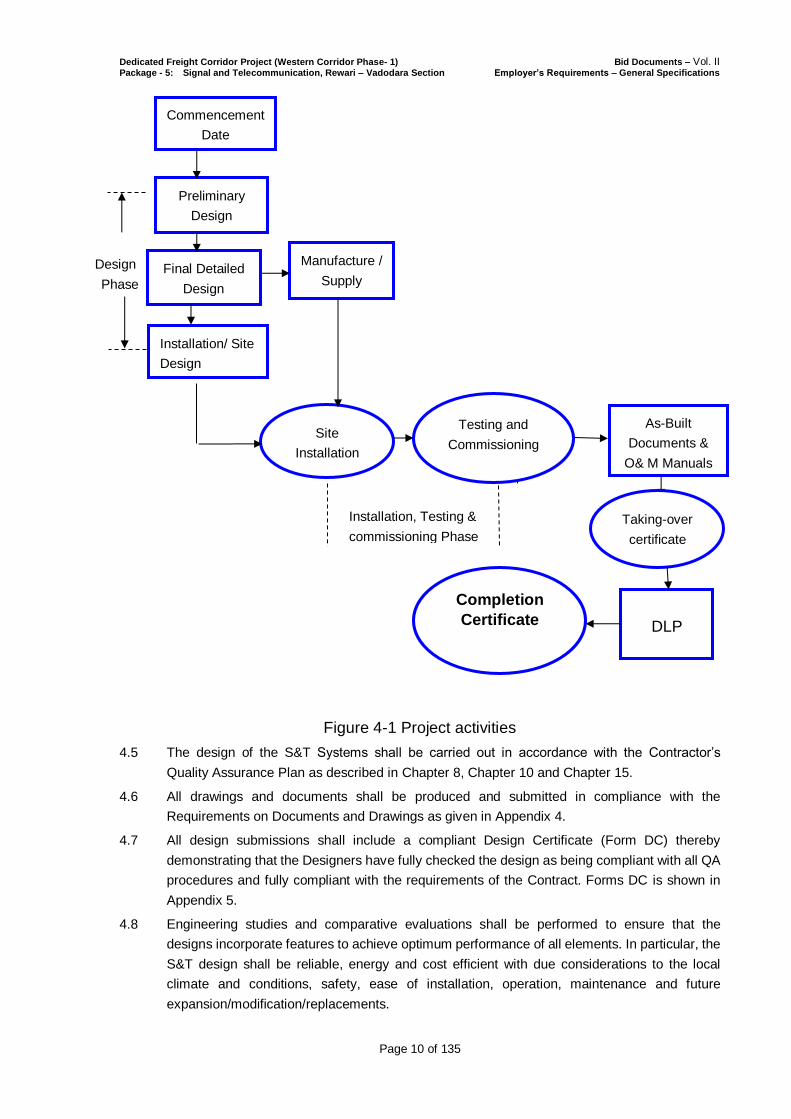
4.1 The Contractor shall execute the Works in three phases, the Design Phase, the
Manufacturing/Supply Phase and construction ie; the Installation, Testing & Commissioning
Phase.
4.1.1 The Design Phase constitutes the following three sub-phases:
(1) Preliminary Design;
(2) Detailed Design and
(3) Installation Design.
4.1.2 The manufacturing /supply phase will constitute Manufacturing by OEMs, Factory Acceptance
Tests (FAT) and delivery to the contractor’s stores in India.
4.1.3 Installation, testing and commissioning phase will constitute of the following:
(1) Equipment installation;
(2) Testing and Commissioning of all subsystems including service trials;
(3) Supply of O & M Manuals for each subsystem etc. and
(4) Submission of verified and As Built Documents.
4.2 The Contractor shall submit documents for all the above stages of design,
manufacturing/supply and Installation, testing and commissioning etc; in accordance with the
Employer’s Requirements herein, in PS and in accordance with Conditions of Contract Clause
5 to the Engineer for approval..
4.3 The Engineer will review the submissions in accordance with the Contract to be satisfied that
the submittals cover the obligations, extent and intended purpose of the design of the
Signalling and Telecommunication Systems and fully comply with the Contract.
4.4 The Design Stages and their relationship with Phases, involved activities are indicated below
in Figure 4.1
Dedicated Freight Corridor Project (Western Corridor Phase- 1) Bid Documents – Vol. II Package - 5: Signal and Telecommunication, Rewari – Vadodara Section Employer’s Requirements – General Specifications
Page 10 of 135
Figure 4-1 Project activities
4.5 The design of the S&T Systems shall be carried out in accordance with the Contractor’s
Quality Assurance Plan as described in Chapter 8, Chapter 10 and Chapter 15.
4.6 All drawings and documents shall be produced and submitted in compliance with the
Requirements on Documents and Drawings as given in Appendix 4.
4.7 All design submissions shall include a compliant Design Certificate (Form DC) thereby
demonstrating that the Designers have fully checked the design as being compliant with all QA
procedures and fully compliant with the requirements of the Contract. Forms DC is shown in
Appendix 5.
4.8 Engineering studies and comparative evaluations shall be performed to ensure that the
designs incorporate features to achieve optimum performance of all elements. In particular, the
S&T design shall be reliable, energy and cost efficient with due considerations to the local
climate and conditions, safety, ease of installation, operation, maintenance and future
expansion/modification/replacements.
Design
Installation, Testing &
commissioning Phase
DLP
As-Built
Documents &
O& M Manuals
Design
Phase
Site
Installation
Commencement
Date
Preliminary
Design
Final Detailed
Design
Installation/ Site
Design
Manufacture /
Supply
Completion
Certificate
Taking-over
certificate
Testing and
Commissioning
Dedicated Freight Corridor Project (Western Corridor Phase- 1) Bid Documents – Vol. II Package - 5: Signal and Telecommunication, Rewari – Vadodara Section Employer’s Requirements – General Specifications
Page 11 of 135
4.9 The Design shall include the Design Drawings, Works Specifications, Design Reports, Method
Statements and any other relevant contents of the Design.
4.10 The Contractor shall sub-divide all the Design into Design Packages which shall be identified
in the Design and Certification Submission Programme. The Design Packages are to relate to
the significant and clearly identifiable parts of the Design and shall address the design
requirements as described herein. The Design Packages shall facilitate the review and
understanding of the Design as a whole and shall be produced and submitted in an orderly,
sequential and progressive manner to suit the manufacture/supply, installation, testing and
commissioning sequence and the Works Programme.
4.11 Separate Design Submissions may be prepared for those major elements to be procured by
sub-contract and which sub-contracts include design. Where such work is to be procured by
the Contractor on the basis of outline design, design briefs and performance specifications,
such documents may be submitted as Detailed Design Submissions.
4.12 The Contractor shall provide to the Engineer five original full and latest editions of the
publications / Technical Standards including the Codes and Standards and other documents
that the Contractor propose to use for carrying out the Technical Designs, including other
communications between Engineer and the Contractor relevant to this Contract as part of the
Inception Report. These publications / documents shall be for the sole use of the Engineer
and, upon completion of the Contract, shall become the property of the Employer.
4.13 REQUIREMENTS DURING DESIGN PHASE:
The principal requirements of the Design Phase are the production of Preliminary Design,
Detailed Design and Installation Design.
4.13.1 Preliminary Design
(1) The Contractor shall prepare a System Requirement Specification (SRS) which includes, as a minimum, operational, functional, performance and design requirements of the proposed system.
(2) The System Requirement Specification, serving as a means of system requirement management and the Contractor’s top level design document, shall state all the requirements completely and unambiguously and how each requirement can be verified and validated.
(3) The System Requirement Specification shall include a compliance matrix that includes cross-references to the requirements stated in the PS, the System Requirement Specification and the Design Verification Table (DVT).
(4) The preliminary design stage, as a minimum, shall identify the function of each system, sub-system, equipment or other element within the overall SRS and specify the relationships and interfaces between each element of the system, including the systems of the interfacing elements of other Contractors.
(5) Equipment and interconnection specifications, with supporting calculations shall be developed at this stage. Submissions shall clarify and confirm as necessary all technical aspects of all interfaces with other elements of contractor’s overall design and of any interfaces with systems of other contractors.
(6) Ergonomic design, mock-ups/prototypes shall be developed during this phase.
(7) The Contractor, during this phase, shall submit the Preliminary Design.
Dedicated Freight Corridor Project (Western Corridor Phase- 1) Bid Documents – Vol. II Package - 5: Signal and Telecommunication, Rewari – Vadodara Section Employer’s Requirements – General Specifications
Page 12 of 135
(8) The stage at which all sub systems of Signalling and Telecommunication are fully identifed and specified.
4.13.2 Detailed Design
(1) During the preparation of the Detailed Design, the Contractor shall in particular
ensure that:
(a) all standards and regulations to be applied are complete;
(b) calculation and analysis are complete;
(c) all main and other significant elements are delineated;
(d) all protocol of tests and trials, all selection of materials and equipment are
complete;
(e) shall take full account of the effect on the S&T Systems of the proposed
methods of Installation, Testing & Commissioning and of the Temporary
Works: and
(f) complete all surveys, investigations and testing necessary to complete the
design of the S&T Systems in accordance with the Contract.
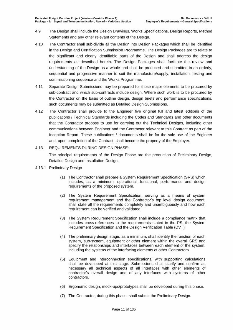
(2) The design review process is shown in the Figure 4.2.
Figure 4.2: Procedure for Design Submission and Approval
4.13.2 The Detailed Design shall be developed based on the Preliminary Design developed to the
stage at which all sub systems of Signalling and Telecommunication are fully designed and
specified.

Dedicated Freight Corridor Project (Western Corridor Phase- 1) Bid Documents – Vol. II Package - 5: Signal and Telecommunication, Rewari – Vadodara Section Employer’s Requirements – General Specifications
Page 13 of 135
4.13.3 Installation Design
4.13.3.1 The principal requirements in this design are the production, submission and consent of the
Layout Design & Method statements.
4.13.3.2 Upon approval by the Engineer in respect of a Preliminary/Detailed Design, the Contractor
shall produce the respective Installation Design which shall include, inter alia, the Equipment
Layout Drawings, System Specifications, Working Drawings and all other associated
documents necessary to supplement the design covered in the Preliminary/Detailed Design
and to comply with the Contract regarding the installation of the equipment such as detailed
Method Statement, Safety Risk Assessment etc.
4.13.3.3 Specified clearance as per SOD and designed Clearance of track side equipment (e.g.
Signals, Location Boxes etc.) in millimetres from centre line of adjacent track(s) shall be
prepared in a tabular form. Due consideration to curve allowance shall be given for equipment
located on curves.
4.13.3.4 The Preliminary/Detailed Design Drawings shall form part of the Drawings to be used for
installation purposes.
4.13.3.5 Only those drawings and documents that have been endorsed and certified and have
received consent as above shall be issued to the Site. The Installation of the Systems shall be
strictly in accordance with the relevant Design Package.
4.13.3.6 Normally documents, drawings, specifications, calculations, technical papers, material
samples, method of construction and any other matters which have been reviewed and
Approved by the Engineer shall not be changed without further submission for review by the
Engineer of the proposed changes. If the Contractor identifies the need for any change to the
design due to site conditions or other reason, then the Contractor shall produce a Design
Change Notice or Field Change Notice and submit the revised design to that effect to the
Engineer for his approval.
4.13.4 Design Plans
4.13.4.1 The design plans shall define contractor’s policy for the design of works and shall without
limitation, define:
(i) The organization of contractor’s design staff with particular reference to the design interfaces;
(ii) The specific allocation of responsibility and authority given to identified staff with particular reference to the review and verification of design specification, drawings and calculations by the contractor;
(iii) The design and performance requirements which shall be defined in terms of basic data and
design assumptions made, relevant codes, standards and regulatory requirements, safety, reliability, security and environmental requirements and commissioning requirements;
(iv) The formal design review, authorization and approval of design documentation and
(v) The independent design Verification and Validation.
4.13.5 Design Verification and Validation Plan
4.13.5.1 The design Verification and Validation plan, supplementary to design plan shall be prepared
by the Contractor in order that design Verification and validation activities are properly
directed.
4.13.5.2 The contractor shall by means of the design Verification and Validation process demonstrate

Dedicated Freight Corridor Project (Western Corridor Phase- 1) Bid Documents – Vol. II Package - 5: Signal and Telecommunication, Rewari – Vadodara Section Employer’s Requirements – General Specifications
Page 14 of 135
that all requirements within the specifications have been met. For this, the contractor shall
prepare a design verification table (DVT) demonstrating compliance. Acceptance criteria for
achieving the requirement shall be identified.
4.13.5.3 DVT shall be supplied to the Engineer for his approval and shall be monitored throughout the
design and construction of the works. Changes, if any to the DVT, must be submitted to the
Engineer for approval before implementation.
4.13.5.4 The DVT does not relieve the contractor of any other requirements of the Specification in
relation to design review, Verification, Validation, conformance or planning.
4.13.6 O&M Manuals
4.13.6.1 These manuals (to be submitted sub system wise) shall include (but not limited to) the
following:
(i) Controller’s Manual: This Manual is meant for Controllers in OCC explaining basic
operation of data entry, data recording, generation of reports etc.
(ii) ASM’s Manual: This manual is meant for ASMs explaining use of all equipment in
his charge for operation.
(iii) Service/trouble shooting Manual: This manual is meant for technical staff and will
be used to attend the various failures and trouble shoot the fault. The manual
should guide step by step to arrive at the exact fault.
(iv) Programming manual: This manual is meant for Technical staff of TMS and will be
used for programming the changes in display incorporating changes in name of
station, yard layout change, adding and deletion of new station, addition and
deletion of new controllers etc.
(v) Maintenance cum Technical manual: This manual is meant for technical staff and
shall guide step by step for carrying out the various changes required in the system.
This should also indicate how to carry out various periodical preventive
maintenance checks and backups to be taken to prevent loss of data/software. This
shall also include adjustment procedures for all field adjustable units.
4.13.6.2 Printed copies of the Operation and Maintenance Manuals (Coloured copies) of the S&T
Systems shall be submitted in sufficient numbers for keeping in Signal Equipment Rooms of all
stations, all field offices of maintenance staff, OCC and Corporate Office. Printed copies of the
Training manuals shall be submitted in sufficient numbers for supply to all trainees.
4.13.6.3 20% spare copies shall be supplied in addition.
4.13.6.4 One unbound colour copy of all documentation shall be submitted for use by the Employer for
reproduction purposes.
4.13.6.5 Soft copies of all O&M and Training manuals shall also be supplied in pdf format.
4.13.6.6 All documents, drawings, manuals and other documents shall be in English.
4.13.6.7 All manuals/ Driver software CD’s etc., whatever comes with the equipment purchased from
the vendors, should be handed over to DFCCIL.
4.13.7 VERIFIED AND AS-BUILT DOCUMENTS
4.13.7.1 The Contractor shall maintain all records necessary for the preparation of the As-Built
Documents. Within seven days of commissioning of any Signalling & telecom system, the
Contractor shall submit 3 sets of verified Preliminary and Detailed design documents.
4.13.7.2 Prior to the issue of the Taking-Over Certificate and in accordance with the Conditions of
Dedicated Freight Corridor Project (Western Corridor Phase- 1) Bid Documents – Vol. II Package - 5: Signal and Telecommunication, Rewari – Vadodara Section Employer’s Requirements – General Specifications
Page 15 of 135
Contract Clause 5, the Contractor shall prepare the As-Built Drawings and Records which,
subject to the Engineer's agreement, shall become the contents of the As-Built Documents.
4.13.7.3 The As-Built Drawings shall be a full set of the latest revisions of the Preliminary/Final
Detailed/Installation Design Drawings (updated to incorporate all Design Change Notices and
Field Change Notices) and as many Working Drawings as necessary to convey a full and true
record of the as-built condition of the Works. The As-Built Drawings shall show all changes
from the Preliminary/Final Detailed/Installation Design, all Preliminary/Final
Detailed/Installation Design deviations and all other features relevant to the future
maintenance and management of the Works and it’s facilities.
4.13.7.4 Configuration data tables shall be prepared for each individual sub-system on item by item
basis as well as on location basis.
4.13.7.5 The As-Built Drawings showing the as built details and endorsed by the Contractor and
verified, checked and approved by Engineer as true records of the commissioned Works shall
include (but not limited to) the following:
(i) Bill of quantity of equipment on location basis;
(ii) Location and connectivity of all equipment and cables;
(iii) Schematic and wiring diagrams;
(iv) Cable core plan and numbering scheme;
(v) Equipment mounting details;
(vi) Cable route drawings;
(vii) Layout in equipment racks, equipment rooms, trackside and all other equipment
rooms and
(viii) All record photographs, survey results, measurements of parameters (e.g.
of Track Circuits, UPS etc.) and all inspection records and shall be endorsed by the
Contractor as true records of the Preliminary/Final Detailed/Installation Design of
the S&T Systems.
4.13.7.6 Clearance of track side equipment (e.g. Signals, Location Boxes etc.) in millimetres from
centre line of adjacent track(s) shall be verified and painted on the relevant equipment.
4.13.7.7 The As-Built Documents shall be submitted to the Engineer, in accordance with Conditions of
Contract Clause 5, for consent.
4.14 WARRANTLY CERTIFICATES OF OEM:
4.14.1 All Original Warranty Certificates of OEMs should be registered in the name of DFCCIL. These
warranty certificates received from the OEMs should be passed on to DFCCIL.
4.14 INFRINGEMENT OF PATENT RIGHTS
The Employer shall not be responsible for infringement of patent rights arising due to similarity
in design, manufacturing process, use of similar components in design and of the Signalling
and Telecom system and any other factor not mentioned herein which may cause such a
dispute. The entire responsibility to settle such dispute/ matters shall lie with the Contractor.
End of Chapter 4

Dedicated Freight Corridor Project (Western Corridor Phase- 1) Bid Documents – Vol. II Package - 5: Signal and Telecommunication, Rewari – Vadodara Section Employer’s Requirements – General Specifications
Page 16 of 135
5. EMPLOYER’S OUTLINE SPECIFICATIONS, SPECIFICATIONS IN SI
UNITS AND APPLICABLE STANDARDS
5.1 EMPLOYER’S OUTLINE SPECIFICATIONS
5.1.1 In accordance with the provisions of these Employer's Requirements, the Particular
Specification contained in the Contract shall be considered as the minimum requirements for
the Works.
5.2 SPECIFICATIONS IN SI UNITS
5.2.1 The Contract shall utilise the SI units.
5.3 APPLICABLE STANDARDS
5.3.1 Equipment, materials and systems shall be designed, installed and tested in accordance with
the Employer’s Requirements defined in GS and PS and the latest issue of applicable
international and/or national codes and standards as listed in the GS and PS. Other similar
standards or Standards considered to be equivalent shall not apply unless these are agreed by
the Engineer and approved by the Employer. Then, the contractor shall provide at least one
copy of the document for use by the Engineer.
End of Chapter 5
Dedicated Freight Corridor Project (Western Corridor Phase- 1) Bid Documents – Vol. II Package - 5: Signal and Telecommunication, Rewari – Vadodara Section Employer’s Requirements – General Specifications
Page 17 of 135
6. SURVEY AND SITE INVESTIGATIONS
6.1 The datum used for the Contract shall be Mean Sea Level Datum of India
6.2 The Contractor shall establish the horizontal and vertical control systems at site. The vertical
control system which is represented by the height above the mean sea level shall be
established at the site based on the GTS (Great Trigonometrical Survey) Bench Mark, while
the horizontal control system which is determined by the Differential Global Positioning System
(DGPS) applying Universal Transverse Mercator (UTM) coordinate system (x, y) shall also be
established.
6.3. The Contractor shall conduct Path profile and propagation survey for the mobile radio system
part of this project and submit the requisite detailed survey report within 60 days of the Date
Commencement of the contract
6.4 The Contractor shall carry out all further site investigations necessary for the design of the
Permanent Works and to enable the determination of the methods of Installation and the
nature, extent and design of the Temporary Works.
6.5 The Contractor shall ensure that the prevailing environment on the DFC route does not have
detrimental effect on the functionality and reliability of the permanent works.
End of Chapter 6

Dedicated Freight Corridor Project (Western Corridor Phase- 1) Bid Documents – Vol. II Package - 5: Signal and Telecommunication, Rewari – Vadodara Section Employer’s Requirements – General Specifications
Page 18 of 135
7. PLANNING AND PROGRAMME REQUIREMENTS
7.1 GENERAL
7.1.1 Purpose of Programme
7.1.1.1 There are two primary purposes for the requirements of Programme (Scheduling) information
described in this document:
(i) Evaluation of Tender
(ii) To provide the Employer with sufficient information on proposed schedules and
cost to facilitate evaluation of Tenders and
(iii) Works Programme & Supporting Reports
(iv) To provide the Engineer with programme and status reports for managing,
monitoring and co-ordinating the awarded contracts during their execution within
the overall multi-contract project programme.
7.1.2 The requirements are organized in two stages. The first stage is a requirement for all
Tenderers and shall be submitted as part of Tender. The second stage is a requirement of the
Employer and describes a series of deliverables to be submitted by the Contractor to the
Engineer during the execution of the contract.
7.1.3 The Tenderer/Contractor shall programme his work at all times to meet the Coordination Dates
stated in Appendix to Bid. During the progress of the Works the Contractor shall constantly
monitor and report to the Engineer his progress against the programmes described herein.
7.1.4 Programme activities shall be discrete items of work, which when combined, produce definable
elements, components, Milestones, Stages and Sections of the Works and clearly identify the
completion obligations of the Contractor. Design programmes shall be organised by Design
Stages and Plans as described in Clause 8.5.1.
7.1.5 Coordination Dates and Milestones shall be an integral part of all programmes and all activities
and sequencing and interrelationships required to achieve each completion obligation shall be
shown. Milestones shall not impose constraints that in any way affect the programme logic and
float or limit the achievement of Coordination Dates. Milestones shall not be introduced into
any programme as constrained dates.
7.1.6 The critical path shall be clearly identified in the programme and fully described in the
accompanying programme narrative.
7.1.7 Activity descriptions shall clearly convey the nature and scope of the Works. Programmes shall
take into account the activities of precursor, concurrent, adjacent and follow on Project
Contractors as well as utility service diversions, new utilities and connections and any other
activity that may affect the progress of the Works.
7.1.8 The Contractor shall also incorporate the Engineer’s requirements for additional activities, to
further explain or subdivide complex or long duration tasks, without affecting completion dates.
7.1.9 The Tenderer/Contractor shall include in all programmes his work obligations towards shared
access, shared Site areas and other coincident or adjacent Works Areas.
7.1.10 The Works Programme and all more detailed or revised versions, shall be submitted to the
Engineer for his consent.
7.2 METHODOLOGY
7.2.1 The computerized Critical Path Method (CPM) network using the method as selected by the

Dedicated Freight Corridor Project (Western Corridor Phase- 1) Bid Documents – Vol. II Package - 5: Signal and Telecommunication, Rewari – Vadodara Section Employer’s Requirements – General Specifications
Page 19 of 135
Employer as per Clause 7.3.2 shall be used as the technique for contract management system
and in co-ordinating the multi-contract project. This technique shall also be employed by the
Tenderer in preparing their Tender submissions and by the Contractor in their
Design/Installation Stage submissions.
7.2.2 Unless otherwise agreed by the Engineer, all programmes submitted by the Contractor shall
be produced using computerized Critical Path Method (CPM) Networks developed
implementing the Precedence Diagramming Method (PDM) with Cost Loaded Charts and
Tables.
7.2.3 The Contractor shall implement and use throughout the duration of the Contract, a
computerized system (see Clause 7.3) to plan, execute, maintain and manage the planning,
design, Supply/Installation and sub-contracts in executing the CPM scheduling by PDM. The
reports, documents and data provided shall be an accurate representation of the current status
of the Works and of the work remaining to be accomplished; shall provide a sound basis for
identifying problems, deviations from the planned works and for making decisions and shall
enable timely preparation of the same for presentation to the Engineer.
7.3 PROGRAMME MANAGEMENT SOFTWARE
7.3.1 CPM programming software
CPM programming software to be used for the Tender Programme, the Works Programme and
all subsequent programmes shall be latest version of Professional Primavera Project
Management, MS Project or other equivalent software subject to the consent of the Engineer.
The Contractor shall provide three (03) copies of the agreed Scheduling software together with
all relevant instruction manuals, licensed for use in connection with the contract, to the
Engineer for use by the Engineer during the execution of the project. The Contractor shall
provide acceptable training for Engineer scheduling staff on the software being used.
7.3.2 Project Management Information System (PMIS)
7.3.2.1 The Contractor shall devise and utilize a PMIS such that all documents generated by the
Contractor can be transmitted to the Engineer by electronic means (and vice versa) and that all
documents generated by either party are electronically captured at the point of origin and can
be reproduced later, electronically and in hard copy. A similar link shall also be provided
between the Engineer Office at site and the Employer’s site office and Headquarters Office by
the Contractor. The documents shall comply with the standards as specified in Appendix-4
“Requirements on Documents and Drawings”.
7.3.2.2 The Employer is in the process of implementing an Enterprise wide IT system titled “Supply &
Installation of Integrated IT System” (to be done by other contractors). The objective of the IT
Plan is to automate core organizational business functions / process and develop a working
environment that enables higher efficiency and effectiveness, not only in internal functions but
across the entire ecosystem of the Employer including Contractors. A total of eight (8)
applications are envisaged for the Employer and the components of the proposed system
include the following elements:
a) An ERP System for covering Finance & Accounting, HR, Project Management, General
Administration to integrated management control;
b) A document Management System to ensure that all drawings / critical documents
related to the construction phase are well documented and archived;
c) A Geographical Information System that shall initially have details of every asset that is
created. It shall have the entire alignment geo-referenced. The monitoring of various
Dedicated Freight Corridor Project (Western Corridor Phase- 1) Bid Documents – Vol. II Package - 5: Signal and Telecommunication, Rewari – Vadodara Section Employer’s Requirements – General Specifications
Page 20 of 135
contracts is proposed to be done through Dashboards that will have a significant
component of GIS; and
d) An Enterprise Asset Management that has spatial co-ordinates of every asset.
The proposed IT System has been designed for facilitating preservation of important
artifacts (plans, drawings, notes, documents, reports etc.) in a secure and manageable
environment in digitized format. Appropriate triggers shall generate dashboards and
management reports every time an event causes a substantial shift in the project risk or
a deviation in processes is developed. The envisaged system would expedite decision
making, ensure better planning and co-ordination between different functions, better
data management, effective reporting, knowledge management etc. Programme
management shall provide senior management with critical information related to
various contracts, activities and funds in the form of management dashboards with
inbuilt triggers to ensure timely decision making
7.3.2.3 In view of the above, the Contractor shall be required to:
a) Upload / definition of Project Plans as per the template and using software defined by
the Employer.
b) Maintenance and updating of uploaded Project Plans in software used by the
Employer.
c) Upload of drawings / designs created by the Contractor as per the classification and on
the software platform defined by the Employer.
d) Online measurement book entry (as required) in the Project Monitoring System, in a
template defined by the Employer.
e) Asset details need to be updated in the system in the format prescribed by the
Employer.
f) Geo-referencing of the alignment.
g) Capture and upload of geo-referencing co-ordinates of the assets into GIS.
h) Upload of digitally signed invoices for payment processing.
7.3.2.4 It shall be the responsibility of the Contractor to ensure that there is interoperability between
the Contractor’s IT System and that being developed by the Employer so that the movement of
information and data across Employer’s boundaries is feasible in a seamless manner.
7.4 TENDER PROGRAMME
7.4.1 The Tenderer shall with his tender submit a fully logic linked programme that covers all
elements of the contract. The programme shall comply with all Coordination Dates identified in
Appendix to Bid.
7.4.2 The programme shall clearly indicate sequence in which the Tenderer proposes to carry out
the works and include information regarding any interfaces with external agencies that may
impact on the completion of the works. The schedule shall recognise realistic
consideration/approval durations for both Engineer and any external agency activities.
7.4.3 The programme shall be supported by information detailing major Equipment/Material to be
mobilised for the project, temporary facilities the Tenderer proposes to set up to support his
activities, details of all long lead items and information regarding the numbers, skills and
source of the labour he is proposing to deploy.
7.4.4 The Tender Programme will be used by the Engineer to refine the interfacing between the
contracts in context with the whole project.
7.4.5 The Tender Programme shall be accompanied by a Narrative that describes the Tenderer’s
Dedicated Freight Corridor Project (Western Corridor Phase- 1) Bid Documents – Vol. II Package - 5: Signal and Telecommunication, Rewari – Vadodara Section Employer’s Requirements – General Specifications
Page 21 of 135
approach to the project and lists any assumptions made during the preparation of the
programme.
7.4.6 Following the placing of the contract, the tender programme together with any negotiated
changes in Access dates, Logic or Durations shall become the successful Tenderer’s Initial
Works Programme (See Clause 7.5.2) and should be prepared accordingly.
7.5 POST CONTRACT AWARD
The Works Programme to be submitted under the Contract shall be developed from the
Tender Programme submitted and developed during the Tender period. Similarly the Design
and Certification Submission Programme shall be developed from the Outline Design and
Certification Submission Programme submitted and developed during the Tender period.
7.5.1 Mobilization Programme
7.5.1.1 The Contractor shall within seven (07) days from the award of the contract submit for the
Engineer’s consideration a mobilization schedule with details of all the work activities planned
to take place during the 1st ninety (90) days of the project.
7.5.1.2 The programme shall clearly list all activities requiring Engineer input and reflect any
agreements regarding responses in less than Forty Five (45) day response time.
7.5.1.3 The programme shall include but not be limited to mobilization of Staff, procurement of
facilities, Information required from Engineer and deliverables to be submitted.
7.5.1.4 The Mobilisation Programme shall be supported by a narrative which clearly states any
assumptions made by the contractor, any items that the Contractor identifies as being at risk
and any action required to be undertaken by the Engineer.
7.5.1.5 The duration of delay for any activity shown on the Mobilisation Programme, with the exception
of the Engineer’s Forty Five (45) day approval period, shall not exceed by more than seven
(07) days.
7.5.2 Initial Works Programme
7.5.2.1 Within twenty-eight (28) days of the Commencement Date of the Works, the Contractor shall
submit for consideration by the Engineer, his proposed initial version of the Works Programme.
The Initial Works Programme shall be based on the Tender Programme and incorporate any
changes agreed during the Contract negotiations. The programme shall reference the
mobilisation programme and provide detail of the 1st six (06) Months of the project.
7.5.2.2 Long Lead items shall be clearly identified in the Initial Works Programme.
7.5.3 Final (Detailed) Works Programme
7.5.3.1 Within 60 days after receiving consent to the Initial Works Programme the Contractor shall
submit for consideration by the Engineer the Final Works Programme.
7.5.4 Failure by the Contractor to Submit within the Specified Timescales
7.5.4.1 Should the Contractor fail to submit the initial and Final Works Programme within the
timescales nominated above, the Employer may nominate the Tender Programme as the first
issue of the Works Programme required under the Contract.
7.5.4.2 In the event that the Employer does nominate the Tender Programme as the first issue of the
Works Programme under the Contract, the Engineer may include any amendments that he
sees fit to change external constraining dates, duration of activities by parties other than the
Contractor and subdivide the Contractor’s own activities to provide additional details and links
to other activities but without altering the duration or sequencing of the activities shown on the
Dedicated Freight Corridor Project (Western Corridor Phase- 1) Bid Documents – Vol. II Package - 5: Signal and Telecommunication, Rewari – Vadodara Section Employer’s Requirements – General Specifications
Page 22 of 135
Tender Programme.
7.5.4.3 Any either initial or final Works Programme resulting from a nomination by the Employer of the
Tender Programme as amended shall be taken by the Contractor as his own work and any
responsibility for further maintenance of the Works Programme as nominated shall remain that
of the Contractor.
7.5.5 Content of Programmes
7.5.5.1 The Works Programme shall demonstrate by reference to its Sub-Programmes,
Supplementary Programmes and associated Management Plans, the sequence and duration
of activities and any restraints thereto, that the Contractor shall adopt to achieve Coordination
Dates and to fulfil all Contract obligations. The Works Programme shall become the Engineer’s
basis of administration of the time-related aspects of the Contract.
7.5.5.2 The Contractor shall provide the Engineer with substantiation for each constraint whether
target start, target finish or mandatory constraint entered by the Contractor into the Works
Programme. The number of constraints shall be kept to an absolute minimum in order that the
CPM networks developed can be freely analysed.
7.5.5.3 The Works Programme shall include activities for all the phases and stages of the Works,
clearly showing all logical interdependencies and stages in the development of the
Contractor’s design, procurement, installation, testing & commissioning of the Works. As a
minimum, it shall include:
(i) all work comprising the Permanent Works;
(ii) preparation, submission and consideration of Design Documents showing all items
where consideration by the Engineer is required;
(iii) Obtaining Cross Acceptance approval from RDSO for imported equipment, if not
already obtained;
(iv) preparation and submission for consideration of mock-ups and prototypes;
(v) procurement of all major materials and items of Contractor’s Equipment for the
Works, including the dates orders are to be placed, manufacture period, FAT and
the expected delivery date to the Site for each item, long lead items to be clearly
identified;
(vi) any software development requirements and Validation time frames;
(vii) all manufacture or prefabrication of materials or components;
(viii) all design and installation of major Temporary Works;
(ix) all activities associated with the securing of necessary permits and other statutory
approvals for the Works;
(x) access and availability dates for all Project Contractors;
(xi) all interfaces related to the Project that may affect the progress of the Works;
(xii) testing and commissioning activities which demonstrate an understanding of the
interfaces and requirements and
(xiii) Training and Knowledge/Skills Transfer.
7.5.5.4 The Works Programme shall be divided into Sub-Programmes of manageable sizes
addressing in more specific detail, the content of the Management Plans as stated in Chapter
8. The Sub-Programmes shall be as follows:
Dedicated Freight Corridor Project (Western Corridor Phase- 1) Bid Documents – Vol. II Package - 5: Signal and Telecommunication, Rewari – Vadodara Section Employer’s Requirements – General Specifications
Page 23 of 135
(i) Design and Certification Submission Programme;
(ii) Procurement Programme;
(iii) Installation Programme;
(iv) Testing and Commissioning Programme and
(v) Training and Knowledge/Skills Transfer Programme.
7.5.5.5 The submission of the full version of the Works Programme shall include the Design and
Procurement Programme, a preliminary version of the Installation Programme and the Testing
and Commissioning Programme identifying all major Design, Procurement, installation, testing
activities and associated interfaces.
7.5.5.6 The Sub-Programmes shall be further substantiated by the following supplementary
programmes:
(i) Three Month (03) Rolling Programme;
(ii) Five Week (05) Rolling Programme and
(iii) Other programme required by the Engineer.
7.5.5.7 The Contractor’s Works Programme shall comply with the following:
(i) All programmes shall be computerised Critical Path Method (CPM) networks
developed in line with Employer’s PMIS as per Clause 7.3.2 and submitted in both
hard copy and electronic data format;
(ii) All programmes shall be prepared using the specified version of CPM scheduling
software or its equivalent approved by the Employer; (See Clause 7.3.2)
(iii) Unless consent is otherwise obtained from the Engineer, all programmes shall be
accompanied by a Programme Analysis Report as described in Clause 7.17;
(iv) A standard Gregorian calendar shall be used for planning and execution of the
Works. All programme submissions shall include details of the Contractor’s
allowance for Public Holidays and non-work periods. If a Coordination Event or
Milestone falls on a Public Holiday or non-work day, it shall be effective the next
working day;
(v) The planning unit for the duration of all programme activities shall be the day. Any
activity having a duration of more than twenty eight (28) days shall be divided into
sub-activities that shall not exceed twenty eight (28) days;
(vi) CPM programme shall reflect status using remaining duration and percent
complete and
(vii) All programmes shall take into account resource requirements as appropriate or
required by the Engineer covering all stages and aspects of the Contract and shall
include, but not be limited to:
(a) major manpower for both design and installation ;
(b) number of items of Contractor’s Equipment ;
(c) number of drawings and other design deliverables and
(d) principle quantities of materials, components or parts.
7.5.5.8 All programmes constituting the Works Programme shall be organised in a logical work
breakdown structure including work stages or phases. Each activity shall be coded to indicate,
as a minimum, the work group or entity responsible for the activity, the area, facility or location

Dedicated Freight Corridor Project (Western Corridor Phase- 1) Bid Documents – Vol. II Package - 5: Signal and Telecommunication, Rewari – Vadodara Section Employer’s Requirements – General Specifications
Page 24 of 135
and the Cost Centre in which the activity is included, from information provided in the Pricing
Document. Coordination Events and Milestones shall be coded so as to be separately
identifiable. The Contractor may be required to assign additional activity codes as required by
the Engineer.
7.6 DESIGN AND CERTIFICATION SUBMISSION PROGRAMME
7.6.1 The Contractor shall, within twenty-eight (28) days of the Commencement Date of the Works,
submit a Design and Certification Submission Programme covering all proposed submissions
to the Engineer. The Design and Certification Submission Programme shall be broken down
into a submission programme for each of the Management Plans defined in Chapter 8 each of
which shall define the dates for individual submissions and these shall conform to the baseline
dates shown in the Works Programme.
7.6.2 The Design and Certification Submissions Programme shall include each submission for every
item listed in the Specification as being required to be submitted.
7.6.3 The Design and Certification Submissions Programme shall ensure that all submissions are
properly co-ordinated with the Contractor’s overall Works Programme, particularly in respect of
the following:
(i) progress of design, procurement, installation and testing work;
(ii) co-ordination with other Contractors and statutory bodies and
(iii) including due allowance for the Engineer’s consideration process to be undertaken,
including the time needed for any re-submissions.
7.6.4 The Design and Certification Submission Programme shall specifically include a milestone for
the submission by the Contractor of the Basic Design, Detailed Design, Equipment Layout
Design, O&M Manuals and Verified and As-Built Documents
7.7 DESIGN AND PROCUREMENT PROGRAMME
7.7.1 Within twenty eight (28) days of the Commencement Date of the Works, the Contractor shall
submit for consideration by the Engineer a Design and Procurement Programme that shall be
an integrated part of the overall Works Programme.
7.7.2 The Design and Procurement Programme shall show the interdependencies with other
contractors as well as between the Contractor and its sub-contractors and suppliers. This
programme shall demonstrate compliance with the requirements of the Design and
Certification Submissions Programme in Clause 7.6.
7.7.4 The Design and Procurement Programme shall include a separate breakdown, supported by
the Material Control Schedule, which shall be a complete amplification of the Contractor’s
programme and equipment list, including those items which are subject to long lead time or
component parts which are manufactured from countries outside the country of assembly and
testing.
7.7.5 The Material Control Schedule shall be automated and shall detail the following information for
each permanent major and minor equipment and significant component. The format of such a
schedule shall include but not limited to:
(i) name, description, supplier/sub-supplier details;
(ii) specification/drawing information (where appropriate);
(iii) FAT and monthly supply and
(iv) transportation process.
Dedicated Freight Corridor Project (Western Corridor Phase- 1) Bid Documents – Vol. II Package - 5: Signal and Telecommunication, Rewari – Vadodara Section Employer’s Requirements – General Specifications
Page 25 of 135
7.7.6 The Contractor shall continuously maintain this schedule and report upon the status of each
item as part of the Contractor’s regular progress reporting.
7.7.7 From this base data, the Contractor shall prepare an exception report detailing all equipment
that are in delay. This report shall be annotated with the reason for the delay and indicate what
action the Contractor is taking to recover the lost time.
7.7.8 The Contractor shall submit, as part of the Design and Supply Programme, a Factory
Acceptance Testing Programme that shall support all aspects of the Factory Acceptance
Testing Plan. This Programme shall clearly demonstrate the logic and include the topics listed
in clause 8.5.3.
7.7.9 The Factory Acceptance Testing Programme shall be fully detailed, with activities individually
identifying all tests for which a certificate will be issued and shall include activities for
preparation, submittal and consideration of the test procedures.
7.7.10 The Factory Acceptance Testing Programme shall demonstrate the logical dependencies
between the individual tests of the Works and shall also show the interfaces and dependencies
with the Contractor’s delivery programme.
7.7.11 The Factory Acceptance Testing Programme shall include details of inspection, testing and
witnessing of the Contractor’s and subcontractor’s procurement activities. As a minimum, it
shall include:
(i) First Article Inspection;
(ii) Quality Hold Points;
(iii) Quality Control Points;
(iv) Type Tests and
(v) Routine tests.
7.8 COORDINATED SUPPLY / INSTALLATION PLAN
7.8.1 The coordinated Supply/Installation Programme shall be submitted not less than three (03)
months before the proposed start of Supply/Installation activities or as directed by the
Engineer. The Supply/Installation Programme shall comply with the requirements of clause
7.5.5.
7.8.2 The Supply/Installation Programme shall include detailed activities describing all aspects of the
installation of the Works, to meet all Milestones and Coordination Events given in the Contract.
It shall be clearly linked to the Design, Supply and Installation Programme and Testing and
Commissioning Programme to form an integrated part of the Works Programme.
7.8.3 The Supply/Installation Programme shall be fully supported by the Supply and Installation
Management Plan as specified in Chapter 8.
7.8.4 The Supply/Installation Programme shall indicate the physical areas to which the Contractor
requires access, access date, duration required and the required degree of completion for civil
or architectural finishes prior to the access date.
7.8.5 The Supply/Installation Programme shall take into account the requirements for arrival at port,
delivery, storage, preservation and positioning of large items of Contractor’s Equipment and
Permanent Works and shall set out the Contractor’s proposed delivery route for such items to
the Site.
7.8.6 Installation Tests shall be clearly shown in the Installation Programme and shall include those
interface tests required to be carried out by others to establish a timetable for these tests.
Dedicated Freight Corridor Project (Western Corridor Phase- 1) Bid Documents – Vol. II Package - 5: Signal and Telecommunication, Rewari – Vadodara Section Employer’s Requirements – General Specifications
Page 26 of 135
7.8.7 Activities that may be expedited by the use of overtime, additional shifts or by any other means
shall be identified and explained.
7.8.8 In preparing the Installation Programme, the Contractor should note that the following
conditions shall apply:
(i) the Contractor shall not have exclusive access to any part of the Site except by the
specific consent of the Engineer;
(ii) the Contractor shall take note that concurrent time allocations for certain areas may
be given to more than one contractor. The Contractor shall co-ordinate the
Contractor’s work in such areas with that of Project Contractors;
(iii) the absence of a programme date or installation period for the Contractor in a
specific area shall not prejudice the right of the Engineer to establish a reasonable
programme date or installation period for that area;
(iv) the Contractor shall comply with the identified Coordination Dates. The Contractor
shall also comply with the Milestone dates identified and
(v) the Contractor shall deliver all Contractor’s Equipment and Permanent Works by
air/road and via temporary access openings unless otherwise agreed by the
Engineer.
7.9 TESTING AND COMMISSIONING PROGRAMME
7.9.1 The Testing and Commissioning Programme shall be submitted not less than three (03)
months before the start of Testing and Commissioning activities or as directed by the Engineer
and shall comply with the requirements of clause 7.5.5.
7.9.2 The Contractor shall submit the Testing and Commissioning Programme that shall fulfil all the
on-Site testing and commissioning requirements of Clause 23.4. The Testing and
Commissioning Programme shall clearly demonstrate the logic and highlight the topics listed in
the On-Site Testing and Commissioning Plan Clause 23.4.
7.9.3 The Testing and Commissioning Programme shall be fully detailed, with activities individually
identifying all tests for which a certificate will be issued and shall include activities for
preparation, submittal and consideration of the test procedures and final certification.
7.9.4 The Testing and Commissioning Programme shall demonstrate the logical dependencies
between the individual tests of the Works and shall also show the interfaces and dependencies
with all of the Project Contractors’ tests required to commission the Works and support the
Commissioning Plan.
7.10 TRAINING AND KNOWLEDGE/SKILLS TRANSFER PROGRAMME
7.10.1 The Contractor shall, within six months of the Commencement Date of the Works, submit for
consideration by the Engineer, a Training and Knowledge/Skills Transfer Programme covering
all proposed formal training courses, delivery of training equipment and accesses by the
Employer’s personnel for informal ‘hands on’ skills transfer. The Training and Knowledge/Skills
Transfer Programme shall also detail specific Knowledge/Skills Transfer features as required
by the Specification and proposed by the Contractor.
7.10.2 The Training and Knowledge/Skills Transfer Programme shall be developed to the Training
and Knowledge/Skills Transfer Plan as required under clause 8.7.4.
7.10.3 The Training and Knowledge/Skills Transfer Programme shall be sufficiently detailed that the
Employer can ensure the availability of staff for all the courses required under clause 26.1.6.
Dedicated Freight Corridor Project (Western Corridor Phase- 1) Bid Documents – Vol. II Package - 5: Signal and Telecommunication, Rewari – Vadodara Section Employer’s Requirements – General Specifications
Page 27 of 135
7.10.4 The Training and Knowledge/Skills Transfer Programme shall include the requirements of
Chapter 26, including the Training and Knowledge/Skills Transfer activities of all
sub-contractors and suppliers.
7.11 THREE MONTH ROLLING PROGRAMME
7.11.1 Within twenty eight (28) days of the Commencement Date of the Works, the Contractor shall
submit to the Engineer for consideration his initial Three Month Rolling Programme. The Initial
submission shall show in detail all activities that have commenced or are due to start within the
first three calendar month period to meet Coordination Events and Milestones and any other
dates set out in the Contract. Thereafter, the Contractor shall submit a new Three Month
Rolling Programme every month as part of the Monthly Progress Report.
7.11.2 The Three Month Rolling Programme shall after the initial submittal:
(i) provide details of all activities that are in progress, or are due to start, within the
forthcoming two month (02) period and the previous one month (01) period shall
also be shown;
(ii) be updated every month and be submitted concurrent with the Monthly Progress
Report;
(iii) highlight all required dates for transmittal or receipt of information to or from the
Engineer, sub-contractors or Project Contractors and
(iv) consist of a three month time window extracted from the Works Programme.
7.12 FIVE WEEK ROLLING PROGRAMME
7.12.1 Prior to the start of the Site mobilisation and each week during the Supply/Installation and
testing and commissioning phases, a time-scaled Five Week Rolling Programme shall be
prepared and submitted to the Engineer for consideration. The Five Week Programme shall
show in detail all activities that are in progress or due to start or finish within four weeks (04) of
its submission. The week prior to the submission date shall show activities in progress or
completed.
7.12.2 The activities shown on the Five Week Rolling Programme shall be an amplification of and
compatible with the latest version of the Three Month Rolling Programme in all respects.
7.12.3 The Five Week Rolling Programme need not be computer generated and does not require a
detailed programme analysis report. Any activity exceeding one week in duration shall be
divided into sub-activities, the duration of which shall not exceed one week.
7.13 PROGRAMME SUBMISSIONS
7.13.1 The Contractor shall submit all programmes described in this Chapter in conjunction with the
Management Plans described in Chapter 8 to the Engineer for consideration.
7.14 PROGRAMME REVIEW
7.14.1 The Engineer shall, within twenty eight (28) days of receipt of the initial submission of any
programme for consideration, either give a notice of no objection or provide specific details as
to why a notice of no objection is not given. If the Contractor is advised that the programme is
not given a notice of no objection, the Contractor shall amend the programme taking into
account the Engineer’s comments and/or requirements and resubmit the programme within
fourteen (14) days.
7.14.2 In the case of further re-submittals, the resubmission time shall also be fourteen (14) days.
7.15 WORKS PROGRAMME REVISIONS
Dedicated Freight Corridor Project (Western Corridor Phase- 1) Bid Documents – Vol. II Package - 5: Signal and Telecommunication, Rewari – Vadodara Section Employer’s Requirements – General Specifications
Page 28 of 135
7.15.1 The Contractor shall immediately notify the Engineer in writing of the need for any change in
the Works Programme, whether due to a change of intention or circumstances or for any other
reason. Where such a proposed change affects the timely completion of the Works or any
Section or Stage; the Contractor shall within fourteen (14) days of the date of notifying the
Engineer submit for the Engineer’s consideration his proposed revised Works Programme and
accompanying Programme Analysis Report. The proposed revised Works Programme shall
show the sequence of operations of any and all work related to the change and the impact of
changed work or changed conditions on the Works and Project Contractors and their works.
7.15.2 If at any time the Engineer considers the actual or anticipated progress of the work reflects a
significant deviation from the Works Programme, he may request the Contractor to submit a
proposed revised Works Programme. Upon receipt of such a request, the Contractor shall
submit within fourteen (14) days a revised Works Programme, together with an accompanying
Programme Analysis Report and Narrative Statement that shall demonstrate the means by
which the Contractor intends to eliminate the deviation.
7.16 PROGRESS MONITORING
7.16.1 The Contractor shall monitor its and its subcontractors’ performance with reference to
programmes to ensure its compliance with its obligations under the Contract. Monitoring of the
Works shall include direct, daily monitoring of the progress of the Works and the preparation of
written and computerised reports to be submitted to the Engineer. The reports shall include all
necessary supporting data to apprise the Engineer of the status of the completion of the Works
as described below.
7.16.2 The Contractor shall prepare Monthly Progress Reports covering all aspects of the execution
of the Works. Such Monthly Progress Reports shall be in writing and shall be delivered to the
Engineer by the 5th day of the month following the month of the Monthly Progress Report. The
Monthly Progress Report shall take account of work performed up to and including the last day
of the month to which the Monthly Progress Report relates.
7.16.3 The Monthly Progress Report shall include an executive summary and contain clear and
concise statements in respect of every significant aspect of the Works including, without
limitation, the requirements specified in Appendix 6 to the General Specifications.
7.16.4 The Monthly Progress Report shall contain evidence with documents supporting the progress
of the Works, as stated in the Interim Payment Certificates, to the satisfaction of the Engineer.
7.16.5 The reports, documents and data provided shall be an accurate representation of the current
status of the Works and of the work to be accomplished and shall provide the Engineer with a
sound basis for identifying problems and deviations from planned work and for making
decisions.
7.17 PROGRAMME ANALYSIS REPORT
7.17.1 The Contractor shall submit a Programme Analysis Report that shall, in narrative format,
describe the basis and assumptions used to develop all programme submissions. The
Programme Analysis Report shall be prepared in a format having been considered without
objection by the Engineer and contain as a minimum the following:
(i) cycle times and work sequences;
(ii) the deployment of Contractor’s Equipment and labour;
(iii) the installation rates used in determining duration;
(iv) the shifts assumed in determining duration;

Dedicated Freight Corridor Project (Western Corridor Phase- 1) Bid Documents – Vol. II Package - 5: Signal and Telecommunication, Rewari – Vadodara Section Employer’s Requirements – General Specifications
Page 29 of 135
(v) the breakdown of labour requirements by trades;
(vi) the schedules of quantities used in developing the programme;
(vii) interfaces with the Engineer and Project Contractors and other constraints and
(viii) any assumptions used in the programme.
7.17.2 The Programme Analysis Report shall be in sufficient detail to enable the duration, leads and
lags in the logic diagram to be reconciled and substantiated and to enable the projected levels
of labour (by trade) and staff and flows of goods, materials and equipment to be substantiated.
7.18 COORDINATION EVENT AND MILESTONE REPORT
7.18.1 The Coordination Event and Milestone Report shall be prepared in a format considered by the
Engineer and identify and state the status of :-
(i) all Coordination Events and Milestones that were planned to be achieved in the
reporting period or earlier but have not been achieved;
(ii) all Coordination Events and Milestones that have been achieved in the reporting
period;
(iii) all Coordination Events and Milestones that are planned to be achieved in the
next reporting period and
(iv) any future Coordination Events and Milestones that appear unlikely to be
achieved on time.
7.18.2 The Coordination Events and Milestone Report shall identify, for all relevant Coordination
Events and Milestones, the planned dates, the actual dates achieved and where the original
planned dates are forecast to be not achievable, the revised dates identified in the Contract, as
the same may be revised from time to time in accordance with the Contract.
7.18.3 The Coordination Events and Milestone Report shall also provide an explanation for any
deviation from the planned dates. Measures taken or required to recover programme delays
shall also be identified.
7.19 PHYSICAL PROGRESS (EARNED VALUE) REPORT
7.19.1 General
7.19.1.1 The Contractor shall prepare and submit monthly, a Physical Progress Report based on
earned value techniques. The contractor’s proposal for the Physical Progress Report and
basis for measuring progress shall be prepared in accordance with the requirements listed
below and shall be submitted within twenty eight (28) days of the Commencement Date of the
Works.
7.19.2 Selection of work activities
7.19.2.1 Earned value progress reporting requires that the Contractor’s work activities be broken
down into discrete measurable units that are time phased (0% to 100% complete) in
accordance with the Contractor’s programme and maximum limit. These discrete measurable
units shall be based on the physical deliverables and are weighted by the value of the items in
Indian Rupee(Rs) in order to summarise the activities into a planned percent complete curve.
The format for presenting the earned value progress measurement information in a Physical
Progress Report is to be considered by the Engineer.
7.19.2.2 Key work activities for reporting progress shall be determined by the Engineer in consultation
with the Contractor.
Dedicated Freight Corridor Project (Western Corridor Phase- 1) Bid Documents – Vol. II Package - 5: Signal and Telecommunication, Rewari – Vadodara Section Employer’s Requirements – General Specifications
Page 30 of 135
7.19.2.3 To the maximum extent possible, activities shall be chosen which can be measured
quantitatively rather than subjectively as the work progresses. In the event it is necessary to
use activities that can only be measured subjectively, intermediate activities or milestones
shall be identified on the programme which will establish a predetermined intermediate percent
complete for the activity at attainment of each intermediate milestone. Such milestones shall
be no more than one month apart.
7.19.3 Activity weighting
7.19.3.1 In order to summarise the key individual activities into an overall planned or actual percent
complete, activities must be weighted. Various methods for determining the appropriate
weighting can be used. The Contractor may propose an existing methodology comparable to
the intent of the earned value concept. The Engineer will assess and, if appropriate, consider
the method proposed by the Contractor. The sum of the weighting for all activities shall equal
one hundred percent (100%).
7.19.4 Revisions to Physical Progress Report
7.19.4.1 Once the weightings have been established they shall not be changed unless there is a
variation that significantly impacts on the programme and the weightings. If, after
consideration, it is decided by the Engineer to incorporate a major variation, the weightings
shall be adjusted for the impact of the variation and both the plan and actual curves revised.
The curves shall be recalculated by inserting the variation activity percent complete plan (0 to
100%) in the time frame it will occur and applying the revised weightings. This recalculation
shall be submitted to the Engineer for consideration and consideration prior to its use in the
Monthly Progress Reports. The other time-phased planned activities shall remain unchanged
during this process in order to maintain the integrity of the baseline plan.
7.19.5 Measurement of activity progress
7.19.5.1 The actual percentage of the Works completed shall be calculated on a monthly basis as
required to support the preparation of the Physical Progress Report and the Project status
reviews. The Contractor shall ensure that sufficient reliable quantitative backup documentation
exists to support these calculations for each activity within the Physical Progress Report.
7.19.5.2 Periodic detailed considerations may be made by the Engineer to assess the Contractor’s
calculations.
7.20 PROGRESS MEETINGS
7.20.1 The Employer’ Representative will chair progress meetings every month with the Contractor.
These meetings will be held at dates and times to be advised by the Engineer. Progress
meetings shall not be later than ten (10) days after the issue of the Contractor’s Monthly
Progress Report.
7.20.2 The Engineer may convene at his discretion, at any time upon reasonable notice to the
Contractor, any meeting, either on or off the Site, to discuss and address any aspect of the
Works or the Contract. The Contractor shall attend all such meetings convened by the
Engineer.
7.20.3 All meetings shall be convened in New Delhi unless directed otherwise by the Engineer.
Meetings shall be attended by senior personnel from the Contractor who shall arrive properly
briefed for all aspects of the meeting and shall be empowered to make executive decisions in
respect of the execution of the Works.
7.21 QUARTERLY REVIEW MEETINGS

Dedicated Freight Corridor Project (Western Corridor Phase- 1) Bid Documents – Vol. II Package - 5: Signal and Telecommunication, Rewari – Vadodara Section Employer’s Requirements – General Specifications
Page 31 of 135
7.21.1 The Engineer may convene Quarterly Review Meetings at approximately three monthly
intervals. The Engineer will notify the Contractor the date of such Quarterly Review Meetings
not less than twenty-eight (28) days before they are to be held.
7.21.2 Quarterly Review Meetings shall be held in order to Review the overall progress of the Works
in the context of the Project as a whole and to address and resolve any issues relevant to the
execution and progress of the Works. Such Quarterly Review Meetings will be chaired by the
Managing Director of DFCCIL or his delegate. The Contractor shall have in attendance one
senior representative of Director level from each of the companies comprising the Contractor
(together with the Managing Director of the company acting as leader or sponsor of the
Contractor if it is a joint venture, consortium or partnership whenever necessary and required
by the Engineer).
7.21.3 The Contractor shall submit names of the persons whom the Contractor proposes to attend
each Quarterly Review Meeting to the Engineer for consideration not less than seven (07)
days prior to each Quarterly Review Meeting.
End of Chapter 7
Dedicated Freight Corridor Project (Western Corridor Phase- 1) Bid Documents – Vol. II Package - 5: Signal and Telecommunication, Rewari – Vadodara Section Employer’s Requirements – General Specifications
Page 32 of 135
8. MANAGEMENT PLANS
8.1 GENERAL
8.1.1 In order to organise the various submissions required by the Engineer and to ensure the
Contractor’s understanding and compliance with the requirements of the Contract, a series of
Management Plans shall be developed. These Management Plans will serve to structure the
submittals in a manner that the Contractor can develop and prepare the submittals and the
Engineer can review and comment on a prescribed programme.
8.1.2 The Management Plans shall be configured as a family of “stand-alone” plans and associated
documents each covering one of the subjects listed below.
8.1.3 The plans and documents shall be co-ordinated with each other and shall collectively define,
describe and encompass the Contractor’s proposed methods, procedures, processes,
organisation, sequencing of activities, etc. and shall show how these combine together to
assure that the Works truly meet the requirements of the Specification in respect of the
subjects listed.
8.1.4 Unless otherwise stated in the PS, all plans and documents shall be submitted as per dates
given in table of Coordination Events and Milestones in Appendix to Bid. Further submissions
shall be made:
(i) when required in accordance with the Works Programme;
(ii) whenever the development of the Contractor’s designs or planning allows the plan to be
developed further;
(iii) in response to comments made by the Engineer in accordance with clause 9.3 & 9.4.
(iv) whenever any change occurs that invalidates the information contained in the previously
submitted and reviewed document, within fourteen (14) days of the occurrence of such
change and
(v) when requested by the Engineer from time to time.
8.2 GENERAL ORGANISATION
8.2.1 The Plans listed below shall be developed and submitted by the Contractor for the Engineer's
review:
(i) Project Management Plans
(a) Contractor’s Project Plan
(b) Interface Management Plan
(c) System Integration Management Plan
(d) Certification Management Plan
(ii) Systems Assurance Plans
(a) Quality Plans
(b) Safety Plans
(c) EMC Plan
(d) Software Quality Assurance Plan
(iii) Design Plans
(a) Design Plan
Dedicated Freight Corridor Project (Western Corridor Phase- 1) Bid Documents – Vol. II Package - 5: Signal and Telecommunication, Rewari – Vadodara Section Employer’s Requirements – General Specifications
Page 33 of 135
(b) Design Verification and Validation Plan
(iv) Supply and Installation Management Plans
(a) Procurement, Manufacture and Delivery Plan
(b) Factory Acceptance Testing Plan
(c) Construction and Installation Plan
(d) Health and Safety Documentation
(e) Environmental Qualities Management Plan
(f) Environmental Mitigation Implementation Schedule
(v) Completion Management Plans
(a) Commissioning Plan
(b) Operation and Maintenance Manuals Plan
(c) Training and Knowledge/Skills Transfer Plan
(d) Spare Parts and Consumables Management Plan
(e) Defects Liability Management Plan
(f) Maintenance Management Plan
8.3 PROJECT MANAGEMENT PLAN
The overall management of the Works shall be the Contractor’s responsibility. The
organisation of the resources for the design, supply, installation, testing and commissioning
and setting to work is to be developed into a Project Management Plan. Each Chapter of this
plan shall fully describe the Contractor’s understanding of the Works and management skills
and structure required to achieve the same.
8.3.1 Contractor’s Project Plan
8.3.1.1 The Contractor’s Project Plan shall provide a clear overview of the Contractor’s organisation,
management systems and methods to be used for the complete execution of the Works.
8.3.1.2 The Contractor’s Project Plan shall include a summary description of each and every stage of
implementation of the Works, clearly showing the principal organisational interfaces both within
the Contractor’s own organisation (including sub-contractors of every tier) and with Other
Contractors and Relevant Authorities, defining how each of these interfaces is to be managed
and controlled. An organisation chart shall be produced to illustrate the subdivision of the work
into elements for effective technical and managerial control, the reporting structure and the
interface relationship among all parties involved. Names, addresses, telephone and fax
numbers of all principal contacts shall be listed.
8.3.1.3 The Contractor’s Project Plan shall contain structured organisation charts showing the
hierarchical relationship of the Contractor’s organisation (including sub-contractors of every
tier). The organisation charts shall be produced as a “family” such that the basic chart shows
the overall organisation structure supported by subsidiary charts detailing the internal structure
of the various departments or Chapters of the overall organisation.
8.3.1.4 The Contractor’s Project Plan shall include full details of the qualifications, experience,
authority and responsibility of the personnel assigned to all key positions of the Contractor’s
organisation (including sub-contractors of every tier). As a minimum, this shall include all levels
down to senior managers and shall include the personnel responsible for each individual

Dedicated Freight Corridor Project (Western Corridor Phase- 1) Bid Documents – Vol. II Package - 5: Signal and Telecommunication, Rewari – Vadodara Section Employer’s Requirements – General Specifications
Page 34 of 135
department and functional group. A clear reference shall be given as to the location of staff
(e.g. Site resident or factory based, etc.). Names, addresses, telephone and fax numbers of all
principal contacts shall be listed.
8.3.1.5 The Contractor’s Project Plan shall define the Contractor's management structure for the
execution of the Works and for the control of the quality of the Works and shall, without
limitation, identify and set out:
(i) the procedure for audit;
(ii) the procedures for the control of receipt and issue of all Works related correspondence so
as to ensure traceability;
(iii) the procedures for filing system to be implemented to maintain the Contractor’s records
during the course of the work. The filing systems used by the Contractor and
sub-contractors of any tier shall be compatible as far as is necessary;
(iv) the procedures for the identification, production, verification, internal approval, review
(when required) by the Engineer, distribution, implementation and recording of changes to
all drawings, reports and specifications;
(v) the procedures for the evaluation, selection, engagement and monitoring of
sub-contractors / suppliers together with the means of application of quality assurance to
their work including audit and acceptance;
(vi) the procedures for the control, calibration and maintenance of inspection, testing and
measuring equipment;
(vii) the procedures for the selection, indexing, disposition and maintenance of project records
for storage in the archives. A list of items to be archived including their periods of retention
shall be submitted for review by the Engineer;
(viii) the procedures for identifying training needs and for the provision of training of all
personnel performing activities affecting quality and the procedures for the control of
non-conformity.
8.3.1.6 Particulars of agent
(i) The Contractor shall give and provide all necessary supervision during the execution of
the Works as long as the Engineer considers necessary for the proper fulfilment of the
Contractor’s obligations under the Contract.
(ii) The Contractor shall ensure that he is at all times represented on the Site by a competent
and authorised English speaking agent who shall be deemed to have been reviewed
without objection by the Engineer provided such agent is not expressly objected to by the
Engineer in writing within fourteen (14) days from the service of a notice upon the
Engineer by the Contractor of the appointment of such agent. Such agent shall be
constantly on the Site and shall give his full time to the superintendence of the Works.
(iii) The Engineer shall have the authority to withdraw his notice of no objection to the agent at
any time. If such notice of no objection is withdrawn, the Contractor shall remove the
agent from the Site forthwith and shall not thereafter employ him again on any Site of
DFCCIL in any capacity and shall forthwith replace him by another competent English
speaking agent reviewed without objection by the Engineer.
(iv) Such authorised agent shall receive on behalf of the Contractor directions and instructions
from the Engineer.

Dedicated Freight Corridor Project (Western Corridor Phase- 1) Bid Documents – Vol. II Package - 5: Signal and Telecommunication, Rewari – Vadodara Section Employer’s Requirements – General Specifications
Page 35 of 135
(v) The following particulars of the proposed agent shall be submitted to the Engineer for
review:-
(a) name, date of birth, present and permanent address, telephone No.;
(b) copy of Identity Card;
(c) details of qualifications, including copies of certificates and
(d) details of previous experience;
(e) police verification and
(f) medical examination report.
(vi) The particulars of the agent shall be submitted twenty eight (28) days before the agreed
scheduled start of that part of the Works. Except in the case of a replacement agent (as
provided for in clause 8.3.1.6 (3), in which case the said particulars shall be submitted
forthwith.
(vii) The agent shall possess relevant academic or professional qualification and have at least
ten (10) years experience in relevant engineering works. The Engineer reserves the right
to call upon the Contractor to prove such qualifications/experience to the satisfaction of
the Engineer.
8.3.2 Interface Management Plan
8.3.2.1 The Contractor shall interface and liaise with other Contractors in accordance with the
requirements of Chapter 13.
8.3.2.2 Within sixty (60) days of notification from the Engineer of the identity of each Other Contractor,
the Contractor shall develop and submit to the Engineer an Interface Management Plan that is
mutually acceptable to both the Contractor and the other Contractors. The Interface
Management Plan shall:
(i) identify the sub-systems as well as the civil works and facilities with interfacing
requirements;
(ii) define the authority and responsibility of the Contractor’s and other Contractors’ (and any
relevant sub-contractors’) staff involved in interface management and development;
(iii) identify the information to be exchanged, together with the management and technical
skills required for the associated development work, at each phase of the Contractor’s
and other Contractors’ (and any relevant sub-contractors’) project life-cycles;
(iv) include considerations of the Interface Hazard Analysis;
(v) specify the configuration and version control procedures in accordance with the
Contractor’s and other Contractors’ (and any relevant sub-contractors’) quality
management system and
(vi) address the design and certification, supply, installation, testing and commissioning
programme of the contracts to meet the Coordination Dates of each contract and highlight
any programme risks requiring management attention.
8.3.2.3 Once the Interface Management Plan has been reviewed without objection by the Engineer,
the Contractor shall execute the Works in accordance with the Interface Management Plan.
The Contractor shall advise the Engineer immediately of any difficulty in developing a mutually
acceptable Interface Management Plan.
8.3.2.4 Within ninety (90) days of notification from the Engineer of the identity of each Other
Dedicated Freight Corridor Project (Western Corridor Phase- 1) Bid Documents – Vol. II Package - 5: Signal and Telecommunication, Rewari – Vadodara Section Employer’s Requirements – General Specifications
Page 36 of 135
Contractor, the Contractor shall develop and submit to the Engineer for review a Detailed
Interface Document for each Other Contractor that is mutually acceptable to both contractors.
The Detailed Interface Document shall address in detail how the dates identified in the
Interface Management Plan shall be achieved and shall identify the data required by other
interfacing Contractors to meet the Employer’s Requirements.
8.3.2.5 The Detailed Interface Document shall specify the proposed method and schedule for verifying
the interface integrity, the individual equipment/system performance and the combined system
performance. The Detailed Interface Document shall include a programme of tests to
demonstrate the performance and integrity of the integrated systems. The Interface
Requirements described in Chapter 13 shall form the basis of the Detailed Interface
Document, but does not relieve the Contractor’s obligation to identify any new interface to
meet the Contract requirements. Any revision to the Detailed Interface Document shall be
mutually acceptable by the Contractor and Interfacing Contractors and submitted to the
Engineer for review.
8.3.2.6 The Interface Communication and Coordination Model is graphically shown in Appendix 3.
8.3.3 System Integration Management Plan
System Integration Management includes Integrated testing and commission to demonstrate
the integration of the complete transport system meeting the requirements of the specification
in an operating environment. The relevant plans shall be submitted as per clauses 8.7 and
23.4.6.
8.3.4 Certification Management Plan
8.3.4.1 All design submissions and as built documents shall include a valid “Design Certificate” (as set
out in Appendix 5) duly signed by the individual who actually does the design in case the
contractor himself is the designer. In case the contractor himself is not the designer, then the
Chief Design Engineer in the contractor’s design team and authorised representative of the
entity engaged by the contractor thereby demonstrating that:
a) Design of the Permanent Works complies with the Employer’s Requirements and
Specifications and other requirements of the Contract.
b) In house checks have been undertaken to conform the completeness, adequacy and
validity of the design as per all the quality assurance procedures.
c) All the required approvals have been obtained.
d) Design has been performed and finalised utilising the skills of professionally qualified,
competent and experienced designers and engineers.
8.3.4.2 Contractor shall fully verify the respective design outputs as a set of submissions through the
internal authorization process by signing and attaching “Design Certificate” as the covering
document.
8.3.4.3 After receiving the “Approval” or “Approval in Principle with comments” in respect of Installation
Design, all the original paper drawings in respect of Working Drawings shall be endorsed as
“Good for installation” by Chief Design Engineer before issuing it to site or submitting to the
Engineer for his endorsement.
8.3.4.4 In case the contractor contemplates any change in the design already submitted to the
Engineer for consent and /or for design and drawings for which the contractor has already
received Approval; it shall be dealt with as per the provisions of Design Review Procedure as
detailed in chapter 9.

Dedicated Freight Corridor Project (Western Corridor Phase- 1) Bid Documents – Vol. II Package - 5: Signal and Telecommunication, Rewari – Vadodara Section Employer’s Requirements – General Specifications
Page 37 of 135
8.3.4.5 ISO 9001 (Design-Build) shall be applied to the internal authorization process by being tailored
specifically for the Contract.
8.4 SYSTEMS ASSURANCE PLANS
(i) The Systems Assurance Plans shall be submitted for review to the Engineer in
Preliminary and Final forms.
(ii) Configuration management of all hardware and software shall be in accordance with ISO
10007.
(iii) The Contractor shall identify and set out the procedure for the regular review and revision
of each type of quality plan and its supplemental individual specific quality plans to ensure
their continuing suitability and effectiveness, in addition to the method to be used for
revision and issue of revised documentation.
8.4.1 Quality Plans
The Contractor shall submit for review by the Engineer quality plans in accordance with the
requirements of Clause10.2.
8.4.2 Safety Plans
8.4.2.1 Site Safety Plan
(i) The Contractor shall prepare a Site Safety Plan incorporating the requirements as
outlined in Chapter 11.
(ii) The Site Safety Plan shall form a part of the Health and Safety Documentation referred to
in Chapter 11.
8.4.2.2 System Safety Management Plan
The Contractor shall implement the Safety Management Plan. The Safety Management Plan
shall address all the factors referenced in Appendix 7 of the General Specifications.
8.4.2.3 RAMS Plan
(i) The Contractor shall implement a RAMS Plan defined in IEC 62278 for Train Control and
Signaling System to comply with the Employer’s Requirements. The RAMS Plan shall be
verified by internal audit and third certification body and be submitted for review by the
Engineer with the verification.
(ii) The Contractor shall implement a formal Reliability, Availability and Maintainability Plan
(RAM Plan) for the Telecommunication System to comply with the Employer’s
Requirements.
(iii) The Contractor’s RAMS Plan shall include Failure Modes, Effects and Criticality Analysis
and the production of a Reliability Critical Items List.
(iv) The Contractor shall submit the RAMS Plan for review by the Engineer. The first draft of
this plan shall be submitted to the Engineer for review within six (06) months of the
Commencement Date of the Works.
8.4.3 Electromagnetic Compatibility (EMC) Management Plan
8.4.3.1 The Contractor shall prepare and submit for review by the Engineer an EMC Management
Plan which shall, based upon a top-down approach, define the EMC philosophy, activities,
means of control for the design processes and EMC submissions to be supplied to
demonstrate compliance with the PS and this GS.
8.4.3.2. The EMC Management Plan shall identify a comprehensive list of specifications, standards,
Dedicated Freight Corridor Project (Western Corridor Phase- 1) Bid Documents – Vol. II Package - 5: Signal and Telecommunication, Rewari – Vadodara Section Employer’s Requirements – General Specifications
Page 38 of 135
method statements and procedures to be submitted to the Engineer for review. The EMC
Management Plan shall also include a programme that shall identify the dates for EMC
submissions.
8.4.3.3 The EMC Management Plan shall include an initial list of design documentation, test
specifications and test reports with a single paragraph description of each document to
indicate compliance with the Specification.
8.4.3.4 The EMC Management Plan shall include a definition and description of the process and
methods used for Verification and Validation that the Works will achieve the required EMC
parameters in all respects.
8.4.3.5 The Contractor shall co-ordinate the levels of interference emissions and susceptibility of all
equipment which are to be designed, manufactured, supplied and installed by the Contractor
and its sub-contractors and suppliers. The Contractor shall designate a person as point of
contact to deal with EMC matters. Details of the nominated person and any subsequent
change of the nominated person shall be subject to review by the Engineer .
8.4.3.6 The Contractor shall liaise and co-ordinate with all Other Contractors in the exchange of EMC
data and related equipment performance characteristics and advise the Engineer when any
such information is requested from any Other Contractor. A copy of all EMC related information
exchange shall be sent to the Engineer for review.
8.4.3.7 The Contractor shall comply with the following EMC requirements:
(i) The Contractor shall ensure that all electrical and electronic apparatus is designed and
constructed to operate without degradation of quality, performance or loss of function in
the electromagnetic environment of the Project including Indian Railways tracks nearby.
(ii) The Contractor shall meet the requirements of the relevant IEC Standards and/or other
standards mentioned in the PS. EMC considerations shall be incorporated in the
Contractor’s procedures for product safety and design Verification.
(iii) Detailed requirements in respect of electromagnetic compatibility characteristics are
contained in the PS.
(iv) The design shall ensure that any electromagnetic interference emissions introduced into
the environment do not exceed those detailed in the relevant IEC standards and/or the
PS. The Contractor shall ensure that the specified EMC requirements are adequate. Any
shortcomings shall be made known to the Engineer immediately and recommendations
for corrective action formulated.
(v) In respect of the design documentation, the Contractor shall demonstrate by theoretical
analysis that the design of the electrical and electronic systems is fully compliant with the
EMC requirements identified. The Contractor shall state clearly in the documentation all
the assumptions made and parameters used in the analysis.
(vi) The Contractor shall detail the methodology, verify and validate any simulation models
used in support of the analysis. The Contractor shall prepare and submit to the Engineer
for review reports of the Verification and Validation of the models.
(vii) In the circuit analysis, calculations shall be made for all component tolerance effects due
to manufacture, environment, ageing and all possible component Failure Modes. If any
component can exist in a Dormant Failure Mode, the analysis must assume that the
component has failed. The Contractor shall identify all component Failure Modes
considered and produce evidence to the Engineer for review.
Dedicated Freight Corridor Project (Western Corridor Phase- 1) Bid Documents – Vol. II Package - 5: Signal and Telecommunication, Rewari – Vadodara Section Employer’s Requirements – General Specifications
Page 39 of 135
(viii) The Contractor shall identify all components to be tested, specify the interval between
routine tests, define the test procedure and provide Verification levels and pass marks,
which must be achieved. The Contractor shall carry out proof testing of circuit
components and System Acceptance Tests in the Commissioning Plan.
(ix) The Contractor shall supply documentation showing how system safety and reliability is
ensured. It shall include Failure Modes, system failures, the effect of human intervention
and how equipment thresholds have been set in order to keep them above worst case
interference levels and how equipment tolerances and other characteristics in the
Specification have been allowed for in designing the system.
(x) The Engineer may conduct an independent EMC audit for both the system and its
component parts and shall therefore require access to all the relevant design and
production information. The Contractor shall supply sufficient documentation and analysis
in a form reviewed by the Engineer.
(xi) EMC type testing shall be carried out on all equipment identified in the design stage which
requires attention regarding EMC.
(xii) The Engineer may request at his discretion, attendance at the manufacturing factory prior
to delivery to assist in providing confidence that the EMC requirements will be met.
However, this will not give design acceptance that can only be given after successful
completion of the System Acceptance Tests.
(xiii) The Engineer may request that tests be carried out to simulate the Failure Mode of any
critical hardware/software component that is considered to have a significantly detrimental
effect.
(xiv) The Contractor shall implement corrective actions to rectify any EMC problems identified
during design, on-Site testing and when the whole system is in operational service.
(xv) The Contractor must be fully aware of the EMC requirements and any modifications to
systems and equipment carried out by the Contractor during the Defects Notification
Period shall not cause the immunity or emission levels of the installed system and
equipment to exceed such values. Detailed EMC documentation on all modifications
carried out shall be submitted to the Engineer for review. Modification work shall not
commence until the respective submission has been reviewed without objection by the
Engineer.
8.4.4 Software Quality Assurance Plan
Where software is a design deliverable, the Contractor shall submit a Software Quality
Assurance Plan in accordance with the requirements of clause 15.2.1 and Appendix 8 to this
General Specifications. The Software Quality Assurance Plan shall address all elements of the
design and development of software required as part of the Works.
8.5 DESIGN PLAN
The Design Plan shall be configured as a family of “stand-alone” plans and associated
documents each covering one of the subjects listed below.
8.5.1 Design Plan
8.5.1.1 Design shall be undertaken to ensure a smooth flow of information for review by the Engineer.
Submissions shall be strictly in accordance with the Design and Certification Submissions
Programme prepared in accordance with Clause 7.6.

Dedicated Freight Corridor Project (Western Corridor Phase- 1) Bid Documents – Vol. II Package - 5: Signal and Telecommunication, Rewari – Vadodara Section Employer’s Requirements – General Specifications
Page 40 of 135
8.5.1.2 The Contractor shall perform his designs for S&T Systems and prepare a design plan for his
design work in accordance with the design stages as described in Chapter 4.
8.5.1.3 Separate parts of the design plan shall be prepared for Contractor and sub-Contractor design
activities. The design plans shall define the Contractor's policy for the design of the Works and
shall, without limitation, define:
(i) the organisation of the Contractor's design staff with particular reference to the design
interfaces;
(ii) the specific allocations of responsibility and authority given to identified design staff with
particular reference to the review and approval of design specification, drawings and
calculations by the Contractor;
(iii) the specific methods of design necessary to identify any relevant method statements and
develop those method statements to a sufficient degree of detail review by the Engineer
and
(iv) the list of procedures and work instructions to be applied to manage and control the
quality of the design work, including without limitation:
(a) the design and performance requirements which shall be defined in terms of basic
data and design assumptions made; relevant codes, standards and regulatory
requirements; safety, reliability, security and environmental requirements and
commissioning requirements;
(b) the design methods. Software applications to be used in the design, both
proprietary and public domain, including any requirements for physical and
mathematical model testing;
(c) the preparation, checking, issue, distribution, indexing and filing of reports,
calculations, drawings and specifications together with the means for their
revisions;
(d) the formal design review and approval of design documentation and
(e) the independent design Verification and Validation.
8.5.2 Design Verification and Validation Plan
8.5.2.1 The Design Verification and Validation Plan, supplementary to the Design Plan, shall be
prepared by the Contractor in order that design Verification and Validation activities are
properly directed. The plan shall address, but not be limited to, the following:-
(i) the objectives of each Verification phase and each Validation phase;
(ii) defined input and output criteria for each development phase;
(iii) identification of types and detailed methods of test, Verification and Validation activities to
be carried out;
(iv) detailed planning of Verification and Validation activities to be carried out, including
schedules, resources and approval authorities;
(v) selection and utilisation of the test equipment and their test environmental conditions and
(vi) criteria on which the Verification or Validation is judged to be acceptable. These criteria
shall be traceable to the design and performance requirements as referred to in Clause
8.5.1.3 (4) (a).
8.5.2.2 The Contractor shall, by means of a design Verification and Validation process, demonstrate
Dedicated Freight Corridor Project (Western Corridor Phase- 1) Bid Documents – Vol. II Package - 5: Signal and Telecommunication, Rewari – Vadodara Section Employer’s Requirements – General Specifications
Page 41 of 135
that all requirements within the Specification have been met. The Contractor shall prepare a
Design Verification Table (DVT) that identifies the Contractor's proposed methodology for
demonstrating compliance.
8.5.2.3 The DVT shall be supplied to the Engineer for his review and shall be monitored throughout
the design and Manufacturing of the Works. Any changes to the DVT must be submitted to the
Engineer for review before implementation.
8.5.2.4 The DVT shall identify the proposed Verification and Validation process(es) for each
specification requirement and the acceptance criteria for achieving the requirement. The
DVT does not relieve the Contractor of any other requirements of the Specification in relation
to design review, Verification, Validation, conformance or planning.
8.5.2.5 For each item in the DVT, the Verification and Validation methods to be used shall be listed by
the Contractor. The methods used shall be reviewed by the Engineer.
8.5.2.6 Subject to review without objection by the Engineer for each application, the Verification and
Validation methods listed below are acceptable, if implemented (whether singly or in
combination):
(1) Similarity - equipment and requirement are identical to those successfully applied on other projects.
(2) Historical - requirement has been met by numerous previous design.
(3) Calculations and Drawings - for review.
(4) Design Review - either scheduled or specifically targeted.
(5) Mock-Up - actual size representation of design.
(6) Development Test - performance testing on equipment or material under development.
(7) Type Test - performance testing of the as-built component, assembly or system.
(8) Routine Test - test every component, assembly or system.
(9) First Article Inspection (FAI) - acceptances of the exact look and fit of equipment.
(10) Inspection - formal inspection of the finished item.
(11) In Service - for service demonstration requirements only.
8.5.2.7 After each Verification or Validation activity, a Verification Report shall be produced including,
as a minimum, the following:
(i) the Verification or Validation results stating whether the objectives and criteria of the
Design Verification and Validation Plan have been met and
(ii) the reasons for failure if there is a failure and proposal for remedial actions.
8.6 SUPPLY AND INSTALLATION MANAGEMENT PLAN
The Manufacturing and Installation Management Plan shall be configured as a family of
“stand-alone” plans and associated documents each covering one of the subjects listed below.
The plans shall be co-ordinated with each other and shall collectively define, describe and
encompass the Contractor’s proposed methods, procedures, processes, organisation,
sequencing of activities, etc. and shall show how these combine together to assure that the
Works truly meet the requirements of the Specification in respect of the subjects listed.

Dedicated Freight Corridor Project (Western Corridor Phase- 1) Bid Documents – Vol. II Package - 5: Signal and Telecommunication, Rewari – Vadodara Section Employer’s Requirements – General Specifications
Page 42 of 135
8.6.1 Procurement, Manufacture and Delivery Plan
8.6.1.1 The Contractor shall prepare procurement, manufacture and delivery plans in respect of all
items and goods. Separate parts of the plan shall be prepared for The Contractor or the
sub-Contractor off-Site activities. Each plan shall identify the scope of work to be applied. In
relation to such scope of work, it shall, without limitation, define:
(i) the organisation of the Contractor's staff directly responsible for the day-to-day
management of the manufacturing activity on or off the Site;
(ii) the specific allocations of responsibility and authority given to identified personnel for the
day-to-day management of the work with particular reference to the supervision,
inspection and testing of the work;
(iii) the interfacing or co-ordination required with the Contractor's other related plans;
(iv) the specific methods of manufacture to identify any relevant method statements and
develop those method statements to a degree of sufficient detail reviewed by the
Engineer and
(v) the list of procedures and work instructions to manage and control the quality of work
during procurement, manufacturing and delivery, including without limitation:
(a) the procurement of items and goods and ensuring they comply with the requirements of the
Specification, including (without limit) procurement documentation and specific Verification
arrangements for The Contractor/The Engineer inspection of material or manufactured product
prior to release for use;
(b) the manufacturing process so as to ensure compliance with the design;
(c) the manufacturing process so as to ensure clear identification and traceability of material and
manufactured parts;
(d) the inspection and testing of incoming materials, in process and final product so as to ensure
specified requirements for the material and/or manufactured product are met;
(e) the identification of the inspection and test status of all material and manufactured products
during all stages of the manufacturing process to ensure that only products that have passed
the required inspections and tests are dispatched for use and/or installation;
(f) the assessment and disposal of non-conforming material and manufactured product and
approval for reworking or rejection as scrap;
(g) the identification of preventive action so as to prevent recurrence of similar non-conformance
and
(h) the handling, storage, packaging, preservation and delivery of manufactured product.
8.6.1.2 The Contractor shall prepare and submit the inspection and testing plans to manage and
control any test and inspection activities in accordance with Clause 8.5.3;
8.6.1.3 The Contractor shall propose a structured set of inspection hold points. The hold points shall
be structured such that a formal hold point is allowed for each significant element of the
manufacturing process. At each hold point, the Engineer shall hold a formal inspection or
advise that the inspection has been waived.
8.6.1.4 Once the inspection and any required remedial actions are completed to the satisfaction of the
Engineer, the Engineer shall approve for unit shipment. The Engineer will not withhold for
shipping unreasonably, provided all pre-delivery assembly and testing has been successfully
completed.
Dedicated Freight Corridor Project (Western Corridor Phase- 1) Bid Documents – Vol. II Package - 5: Signal and Telecommunication, Rewari – Vadodara Section Employer’s Requirements – General Specifications
Page 43 of 135
8.6.1.5 Any unit delivered without the Engineer’s approval shall be rejected at the Site and all
expenses thereby incurred shall be borne by the Contractor.
8.6.2 Factory Acceptance Testing Plan
8.6.2.1 The Contractor shall prepare and submit for review by the Engineer the Contractor’s Factory
Acceptance Testing Plan detailing and explaining how the Contractor will plan, perform and
document all inspections and tests that will be conducted to verify and validate the Works
(including software) prior to delivery to the Site. The plan shall consist of a narrative description
supported by graphics, diagrams and tabulations as required.
The plan shall contain but not be limited to the following topics:
(i) the Contractor’s strategy for inspection and Factory Acceptance Tests of all constituent
parts of the Works and how this relates to the sequence of delivery;
(ii) the sequencing and interrelationships of the inspections and tests including:
(a) all Quality Hold Points and
(b) all Quality Control Points;
(iii) the type and extent of inspection and Factory Acceptance Tests to be undertaken and the
parts of the Works to be proven by that testing;
(iv) the objective of each inspection or test, what particular design and operating criteria the
test or inspection will prove and how the success of the test or inspection will be
demonstrated or measured;
(v) organisation chart and CV of key personnel in inspection and test team;
(vi) the plan for the production and submission of the inspection and test procedures to the
Engineer for review including the submission of the inspection and test reports and
records and
(vii) Type Tests, Routine Tests, First Article Inspections and any other tests constituting the
Factory Acceptance Tests.
8.6.2.2 The Contractor shall arrange for all equipment and systems manufactured for incorporation
into the Permanent Works to undergo a Factory Acceptance Test (FAT) before shipment from
the place of manufacture. Any particular requirements for inspection and testing at the place of
manufacture are prescribed in the PS.
8.6.2.3 The Contractor shall be responsible for re-inspecting and re-testing any failed inspection and
Factory Acceptance Test including regression testing on previously passed items.
8.6.2.4 Inspections and tests that are to be witnessed by the Employer or the Engineer shall be
sensibly grouped and scheduled so that as many inspections and tests as possible may be
witnessed during a single visit.
8.6.2.5 Type Tests shall be performed on all items of equipment to be installed as part of the
Permanent Works under the Contract as detailed in Clause 23.2.6. The Type testing shall be
based on the environmental conditions of the sites as described in Chapter 12 and as required
in the PS.
8.6.2.6 For all production items a First Article Inspection shall be undertaken as detailed in Clause
23.2.7. Routine production testing methods shall be detailed for review by the Engineer.
Routine testing shall ensure that all samples of a production item are within the tolerances
required for its being fully interchangeable.
8.6.2.7 The Contractor shall prepare two copies of an inspection or test report immediately after the
Dedicated Freight Corridor Project (Western Corridor Phase- 1) Bid Documents – Vol. II Package - 5: Signal and Telecommunication, Rewari – Vadodara Section Employer’s Requirements – General Specifications
Page 44 of 135
completion of each inspection or test whether or not witnessed by the Employer or the
Engineer. If the Employer or the Engineer has witnessed the inspection or test, he will
countersign the inspection or test report to indicate his review of the information and
conclusions (i.e. whether or not the equipment being inspected or tested has passed
satisfactorily) contained therein. If the Employer or the Engineer has not witnessed the
inspection or test (i.e. if a waiver has been granted, or the Employer or the Engineer has not
witnessed the inspection or test for some other reason in accordance with the Contract), the
Contractor shall forward two copies of the inspection or test report without delay to the
Engineer. The Engineer will countersign the report to indicate his review of the information and
conclusions (i.e. whether or not the equipment being inspected or tested has passed
satisfactorily) and return one copy to the Contractor. Where the results of the inspection or test
do not meet the requirements of the Specification, the Employer or the Engineer may call for a
re-inspection or re-test.
8.6.2.8 For standard equipment which is serial or bulk manufactured, manufacturer’s type test
certificates (or equivalent) may, subject to review by the Engineer, be accepted.
8.6.2.9 Test equipment and instrumentation shall be subject to approved calibration tests within a
properly controlled calibration scheme and signed calibration certificates shall be supplied to
the Engineer in duplicate. Such calibration checks shall be undertaken prior to testing and, if
required by the Engineer, shall be repeated afterwards.
8.6.2.10 Materials and equipment shall not be released for shipment until all applicable inspections
and tests including Factory Acceptance Tests have been satisfactorily completed.
8.6.3 Construction and Installation Plan
8.6.3.1 The Contractor shall prepare plans for the Construction and installation activities on and off the
site and shall ensure that these are properly related to the subsequent testing and
commissioning activity.
8.6.3.2 Separate parts of the plan shall be prepared for other contractor(s) or sub-contractor(s) off-site
activities.
8.6.3.3 Construction plan shall identify the scope of activity to be controlled. In relation to such scope
of activity, it shall, without limitation, define:
(i) the organisation of the Contractor's staff directly responsible for the day-to-day
management of the activity on or off the Site;
(ii) the specific allocations of responsibility and authority given to identified personnel for the
day-to-day management of the Works with particular reference to the supervision,
inspection and testing of the Works;
(iii) the interfacing or co-ordination required with the Contractor's other related plans;
(iv) the specific methods of Construction and installation to identify any relevant method
statements and develop those method statements to a sufficient degree of detail reviewed
by the Engineer;
(v) a detailed method statement which shall include but not be limited to:
(a) description of main operations and sub-operations;
(b) sequence of sub-operations;
(c) quantities of the work and production rates to be achieved;
(d) resources to be employed and
Dedicated Freight Corridor Project (Western Corridor Phase- 1) Bid Documents – Vol. II Package - 5: Signal and Telecommunication, Rewari – Vadodara Section Employer’s Requirements – General Specifications
Page 45 of 135
(e) quality checks to be carried out, supervision being exercised and safety
precautions to be employed;
(vi) the list of procedures and work instructions to manage and control the quality of
Construction and installation works, including without limitation:
(a) the inspection and testing activities of incoming materials, in process and final
product so as to ensure specified requirements for the material and/or product are
met;
(b) the Construction processes including Temporary Works so as to ensure
compliance with drawings and Specification. In addition, any software to be used in
the Construction, installation and commissioning process shall be identified and
details of the Verification and Validation processes for the software application shall
be given;
(c) the Construction and installation process so as to ensure clear identification and
traceability of material and manufactured product;
(d) the identification of the inspection and test status of all material and manufactured
products during all stages of the Construction and installation process to ensure
that only products that have passed the required inspections and tests are
despatched for use and/or installation;
(e) the assessment and disposition of non-conforming material and product and
approval for reworking or rejection as scrap;
(f) the identification of preventive action so as to prevent recurrence of similar
non-conformance and
(g) the handling, storage, packaging, preservation and delivery of product and
(vii) the security control of the Site and the works area for Contractor’s accommodation,
storage, car park and other works facilities, etc.
8.6.3.4 The Contractor shall prepare and submit the inspection and test plans to manage and control
any test and inspection activities in accordance with clause 10.9.
8.6.3.5 Where all or part of the Works is within the Employer’s Protection Zone, the Contractor shall
follow the guidelines issued by the Employer’s appropriate authority. The Contractor shall
submit to the Engineer for review his Construction/Installation method statement and detailed
design of any Temporary Works proposed to be erected within this zone adjacent to
Employer’s properties.
8.6.3.6 The following particulars shall be submitted to the Engineer for review within fourteen (14)
days of the Commencement Date of the Works:
(i) drawings showing the layout within the Site of the Engineer’s and Contractor’s
accommodation, Project signboards, access roads and major facilities required early in
the Contract;
(ii) drawings showing the layout and the Construction/Installation details of the Engineer’s
accommodation and
(iii) drawings showing the details to be included on Project signboards.
Details may be seen in Appendix 12.
8.6.3.7 Drawings showing the location of stores, storage areas, work areas and other major facilities
shall be submitted to the Engineer for review as early as possible, but in any case not later

Dedicated Freight Corridor Project (Western Corridor Phase- 1) Bid Documents – Vol. II Package - 5: Signal and Telecommunication, Rewari – Vadodara Section Employer’s Requirements – General Specifications
Page 46 of 135
than twenty-eight (28) days before commencement of the earliest Construction/Installation of
the facilities.
8.6.3.8 Traffic Management Substitutions.
Where the contractor is required to become involved with traffic or footpath management
activities, submission shall be made by the contractor for Engineer’s review 60 days before
implementation providing all relevant details and implications.
8.6.4 Health and Safety Documentation
8.6.4.1 The Contractor shall submit Health and Safety Documentation to fully comply with the
requirements of the Project conditions and proposed work activities in accordance with
Chapter 11.
8.6.4.2 The Contractor shall submit to the Engineer the Health and Safety Documentation for review
within twenty eight (28) days of the Commencement Date of the Works.
8.6.5 Environmental Qualities Management Plan
8.6.5.1 The Contractor shall within one hundred twelve (112) days of the Commencement date of the
Works submit an Environmental Plan based the Outline Environmental Management Plan
submitted and adapted during the Tender period. The Environmental Plan shall comprise a set
of Environmental Plans as detailed below:
(i) Contract Site Specific Environmental Plan;
(ii) Environmental Mitigation Implementation Schedule (if required) and
(iii) Traffic Management Substitutions.
8.6.5.2 Environmental Plans shall include the Contractor’s proposed means of complying with his
obligations detailed in Chapter 11 in regard to:
(i) The Site Environment as found and
(ii) System Environment as described in the Specification.
The Environmental Plan shall include as required detailed policies, procedures and applicable
regulations.
8.6.5.3 Contract Site Specific Environmental Plan
(i) The Contractor shall submit for review by the Engineer, a Contract Site Specific
Environmental Plan which will set out in detail the approach for dealing with each of the
potential environmental impacts arising from the various different Construction/Installation
activities.
(ii) The Contractor shall submit the final Site Specific Environmental Plan, for review by the
Engineer, twenty eight (28) days prior to the commencement of the earliest Construction
and installation activities.
8.6.6 Environmental Mitigation Implementation Schedule
(i) The Contractor shall submit for review an Environmental Mitigation Implementation
Schedule (EMIS) which is a plan for the provision of the mitigation measures identified in
the Site Specific Environmental Plan.
(ii) The Contractor shall submit the EMIS, for review by the Engineer in conjunction with the
Site Specific Environmental Plan, twenty eight (28) days prior to the commencement of
the earliest Construction and installation activities.
8.7 COMPLETION MANAGEMENT PLAN
Dedicated Freight Corridor Project (Western Corridor Phase- 1) Bid Documents – Vol. II Package - 5: Signal and Telecommunication, Rewari – Vadodara Section Employer’s Requirements – General Specifications
Page 47 of 135
8.7.1 General
8.7.1.1 The Contractor shall organise the services required under the Contract to bring the Works into
service under one plan. This co-ordinated approach shall allow the Engineer the ability to
review all aspects of the Works and services in an integrated manner.
8.7.1.2 The Completion Management Plan shall be configured as a family of “stand-alone” plans and
associated documents each covering one of the subjects listed below.
8.7.2 Commissioning Plan
8.7.2.1 The Contractor shall ensure the timely preparation of the Commissioning Plan in a format and
to a level of detail in accordance with Clause 23.3. The Contractor shall submit the first draft
of the Commissioning Plan to the Engineer within one hundred eighty (180) days of the
Commencement Date of the Works.
8.7.2.2 The Commissioning Plan shall consist of On-Site Testing and Commissioning Plan which shall
contain the following but not limited to:
(a) Installation Tests Schedule
The Contractor shall submit to the Engineer a comprehensive schedule of Installation
Tests as required by Clause 23.4.3 and/or the PS and in accordance with the Installation
Programme as stated in Clause 7.9. The schedule shall be submitted not later than two
months in advance of the date for the commencement of the Installation Tests.
(b) Partial Acceptance Tests Plan
The Contractor shall submit to the Engineer a comprehensive Partial Acceptance Tests
Plan including all requirements detailed in Clause 23.4.4 and/or the PS. The plan shall be
submitted not later than four months in advance of the date for the commencement of the
Partial Acceptance Tests.
(c) System Acceptance Tests Plan
The Contractor shall submit to the Engineer a comprehensive System Acceptance Tests
Plan including all requirements detailed in Clause 23.4.5 and/or the PS. The plan shall be
submitted not later than four months in advance of the date for the commencement of the
System Acceptance Tests.
(d) Integrated Testing & Commissioning Plan
The Contractor shall submit to the Engineer a comprehensive Integrated Testing &
Commissioning Plan including all requirements detailed in Clause 23.4.6 and/or the PS.
The plan shall be submitted not later than four months in advance of the date for the
commencement of the Integrated Testing & Commissioning.
8.7.3 Operation and Maintenance Manuals Plan
8.7.3.1 The Contractor shall develop an Operation and Maintenance Manual Plan to suit staged
commissioning of the system and to ensure the timely preparation of the Contractor’s
Operation and Maintenance Manuals and the ‘As-Built’ drawings in a format and to a level of
detail reviewed without objection by the Engineer and in accordance with Chapter 25.
8.7.3.2 The Contractor shall submit the Operation and Maintenance Manuals Plan by the date stated
in the PS, or, if none is given, not later than nine (9) months prior to the issue of the Taking
Over Certificate for the Works and according to staged commissioning of the proposed
systems.
8.7.4 Training and Knowledge/Skills Transfer Plan
Dedicated Freight Corridor Project (Western Corridor Phase- 1) Bid Documents – Vol. II Package - 5: Signal and Telecommunication, Rewari – Vadodara Section Employer’s Requirements – General Specifications
Page 48 of 135
8.7.4.1 The Contractor shall ensure the timely preparation of the Contractor’s Training and
Knowledge/Skills Transfer Plan in a format and to a level of detail reviewed without objection
by the Engineerand fulfilling the requirements of Chapter 26.
8.7.4.2 The Contractor shall submit the Training and Knowledge/Skills Transfer Plan no later than six
(6) months prior to the expected issue of the Taking Over Certificate for the Works and also to
suit the staged commissioning of the relevant systems.
8.7.5 Spare Parts and Consumables Management Plan
8.7.5.1 The Contractor shall submit for review by the Engineer a Spare Parts and Consumables
Management Plan to furnish an individually priced, manufacturer-recommended list of spare
parts and consumables and quantities necessary to support continuous operation of all such
equipment for an initial operating period of two (2) years after the Defects Notification Period ,
in accordance with Chapter 27.
8.7.5.2 The Contractor shall submit the Spare Parts and Consumables Management Plan not less
than six (6) months prior to the issue of the Taking Over Certificate for the Works.
8.7.6 Defects Liability Management Plan
8.7.6.1 The Contractor shall submit for review by the Engineer a Defects Liability Management Plan to
repair, replace and perform any remedial item upon the Works identified by the Engineer
during the Defects Notification Period (DNP). The first submission of this plan is required not
less than six (6) months prior to the expected issue of the Taking Over Certificate for the
Works. The Contractor shall:
(i) endeavour to complete all necessary work in a timely responsible manner;
(ii) not proceed with any remedial work without the consent of the Engineer;
(iii) submit a plan that details the methods and timing of any proposed work and
(iv) update the plan monthly, showing progress of the work and the time to completion.
8.7.7 Maintenance Management Plan
8.7.7.1 The Contractor shall prepare outline plans for the management of the maintenance function
and submit them for review by the Engineer at least six (06) months prior to the scheduled
commencement of Trial Run.
End of Chapter 8
Dedicated Freight Corridor Project (Western Corridor Phase- 1) Bid Documents – Vol. II Package - 5: Signal and Telecommunication, Rewari – Vadodara Section Employer’s Requirements – General Specifications
Page 49 of 135
9. DOCUMENTS SUBMISSION AND RESPONSE PROCEDURE
9.1 SUBMISSIONS TO THE ENGINEER
9.1.1 General requirements
9.1.1.1 Project Management Information System
To ensure efficient information management on the project the Contractor is required to
provide a Project Management Information System for formal transmittal of project
correspondence, documents and information.
9.1.1.2 The Contractor shall submit a drawing register to the Engineer in electronic copy and requisite
number of hard copies as decided by the Engineer with each submission of drawings and at an
interval agreed by the Engineer. The drawing register shall be in a format submitted for
review and agreed without objection by the Engineer and shall include each document
reference number, version, date, title and data-file name.
9.1.1.3 Specific additional requirements in respect of the numbering scheme shall be as defined in the
PS.
9.2 PROJECT DOCUMENT (Records and Reports) CONTROL
9.2.1 Project Document including reports and records are to be submitted to the Engineer and shall
be in a format agreed by the Employer. All project documents shall be signed prior to
submission by the Contractor’s agent or by a representative authorised by the Contractor.
9.2.2 Within twenty-eight (28) days of the Commencement Date of the Works, the Contractor shall
submit a Project Document Control Procedure to the Engineer for review, which shall include
but not be limited to the following:
(i) a document approval system which shall specify the level of authorities for review/
approval of all documents and material before submission to the Engineer. This will
include following levels as a minimum:
(a) Designer
(b) Reviewer
(c) Approving authority
(ii) a system of issuing documents to ensure that pertinent documents are issued to all
appropriate locations;
(iii) a document change or re-issue system to ensure that only the latest revision of a
document can be used and
(iv) a submission identification system which identifies each submission uniquely by
the following:
(a) contract number;
(b) discipline;
(c) submission number and
(d) revision indicator.
9.2.3 Project records will eventually be used by the Employer to manage, operate and maintain the
Works after the completion of the Project for future reference.
9.2.4 The Contractor shall submit the documents as required by the Engineer as Project records in
full and on time. The Engineer shall determine the adequacy of the Project record.
Dedicated Freight Corridor Project (Western Corridor Phase- 1) Bid Documents – Vol. II Package - 5: Signal and Telecommunication, Rewari – Vadodara Section Employer’s Requirements – General Specifications
Page 50 of 135
9.3 SUBMISSION AND RESPONSE PROCEDURE
9.3.1 Submission requirement
9.3.1.1 The Contractor shall include records of amendment in each submission with the following
detailed:
(i) Revision history and status of the submissions;
(ii) Description on changes for each revision;
(iii) The Contractor’s signature for authorisation of the submission indicating proper design
check has been carried out before submitting to the Engineer;
(iv) The revision status and date of preparation of the submission shall be clearly indicated at
the header of each page of the submission;
(v) The first submission shall be revision 0 and subsequent revision shall be A, then B, so
and so forth;
(vi) Each submission shall have date, name, designation & signatures of the designer,
reviewer and the approving official of the contractor and
(vii) The Contractor shall maintain records of the submission and updated record shall be
included in the Monthly Progress Report. The submission record shall include the
following details:
(a) Submission number;
(b) Submission title;
(c) Revision history;
(d) Status of Engineer’s response for each revision;
(e) Submission dates and dates of return from the Engineer for each revision and
(f) Current status.
9.3.1.2 Levels of submission
The Contractor shall adopt top-down approach and submit submissions of the following levels
in a logic sequence for the review of the Engineer:
(a) System level related submission;
(b) Equipment level related submission;
(c) Installation design related submission;
(d) Design calculations;
(e) Management plans and procedures;
(f) Approval certificates and
(g) Miscellaneous submission.
9.3.1.3 System level related submission shall show the total system including the configuration block
diagrams, operating principle, system features and functions, capacity, expandability,
interconnection within the subsystem, between subsystems and between other Contract
Package (P1, P2, P3, P4, P6 & P7).
9.3.1.4 Equipment level related submission shall show the specification on electrical, mechanical and
functionality of the equipment/materials employed for the system and the subsystems.
9.3.1.5 Installation design related submissions shall include:
(a) The installation methods and procedures for different types of installation activities;
Dedicated Freight Corridor Project (Western Corridor Phase- 1) Bid Documents – Vol. II Package - 5: Signal and Telecommunication, Rewari – Vadodara Section Employer’s Requirements – General Specifications
Page 51 of 135
(b) Drawings showing the equipment locations and positions, subsystems coverage;
(c) Schematic and wiring diagrams;
(d) Cable core plan and numbering scheme;
(e) Equipment mounting details;
(f) Configuration data, parameters and setting;
(g) Cable route drawings and
(h) Layouts in equipment racks, in equipment rooms, trackside, concourse, platform
and all other equipment locations.
9.3.1.6 Design calculations shall demonstrate the performance of the system and subsystems.
9.3.1.7 Management Plans and procedures as per details contained in Chapter 8.
9.3.1.8 The Contractor shall submit a copy of certificates from relevant parties and authorities as
required including equipment calibration certificates from manufactures and laboratories.
9.3.1.9 Any submissions not covered in sub-para above.
9.3.2 Except where specific procedures are given for certain items, all submissions shall be
submitted and reviewed according to the procedure laid down in the following clauses.
9.3.3 Each submission shall be accompanied by a brief introduction to explain which sub-system,
part or Section of the Works to which the submission refers, listing the documents enclosed
with the submission and describing in outline how all relevant requirements of the Specification
are achieved by the proposals.
9.3.4 For each stage of submittal, the Contractor shall prepare a Form DC – Design Certificate
carrying the date of submission, the submission title, the stage of submission (e.g. Preliminary
Design, Detailed Design, etc.) and the authorised signature of the Contractor’s responsible
Engineer to confirm that, in the opinion of the Contractor, the submission:
(i) complies with all relevant requirements of the Specification;
(ii) conforms to all interface requirements;
(iii) contains, or is based on auditable and proven or verified calculations or design
criteria;
(iv) has been properly reviewed by the Contractor, according to the Contractor’s QA
system, to confirm its completeness, accuracy, adequacy and validity and
(v) has taken account of all requirements for approval by statutory bodies or similar
organisations and that where required, such approvals have been granted.
(vi) contains 2 (two) properly signed copies of the Design Certificate (Form DC). (See
Appendix 5)
9.3.5 The Engineer’s response to the submission will be made within forty-five (45) days of receipt of
the submission, however, the Engineer will endeavour to respond within twenty eight (28)
days, provided that the submission is made no later than the date shown on the Design
Submissions Programme. The Engineer may extend the review period depending on the
amount of documentation accompanying the submission.
9.3.6 Throughout the design period, the Contractor shall attend monthly design review meetings with
the Engineer. At these Engineer’s review meetings, the Contractor shall present information,
drawings and other documents to the Engineer in respect of all submissions programmed to
occur during the following five week period. The Contractor’s presentations shall be in
Dedicated Freight Corridor Project (Western Corridor Phase- 1) Bid Documents – Vol. II Package - 5: Signal and Telecommunication, Rewari – Vadodara Section Employer’s Requirements – General Specifications
Page 52 of 135
sufficient depth to enable the Engineer to obtain a clear understanding of the Contractor’s
proposals and to discuss the methodology and process used in reaching the proposed design
solutions. Unless directed otherwise by the Engineer, all meetings shall be convened in New
Delhi.
9.3.7 The Contractor shall record all of the Engineer’s observations and any agreed actions resulting
from the Engineer’s review meeting and shall address each of these fully before submission of
the respective documents for formal review.
9.3.8 If, in the Engineer’s opinion, following receipt of a submission there is benefit to be gained from
a meeting with the Contractor to clarify or discuss any of the contents of the submission, he will
notify the Contractor accordingly with not less than five (05) days advance notice and the
Contractor shall attend at the time and place appointed by the Engineer.
9.3.9 No submission may be made by the Contractor in respect of the Works or any sub-system, part
or Section thereof unless a notice of no objection has been received for the previous stage of
the same Works or any sub-system, part or Section thereof.
9.4 ENGINEER’S RESPONSE
9.4.1 The Engineer will respond in one of the following three ways:
(i) “Notice of Approval”
(ii) “Notice of Not Approval” (With “A” Comments)
(iii) “Notice of Approval in Principle with Comments” (With “B” and/or “C” Comments)
9.4.2 Definition of Engineer’s response:
9.4.2.1 “Notice of Approval”: If following his review of the submission, the Engineer has not discovered
any non-compliance with the Contract; the Engineer will issue to the Contractor a formal
“Notice of Approval (APP). An APP from the Engineer irrespective of with or without comments
does not in any way imply the Engineer’s approval of the submission nor does it remove any
responsibility from the Contractor for complying with the Contract. Issue of an APP from the
Engineer entitles the Contractor to proceed to the next stage of the programmed work.
9.4.2.2 “Notice of Not Approval” : If following his review of the submission, the Engineer discovers
major non-compliance, discrepancies or omissions etc. that in his opinion are of a critical
nature, the Engineer will issue a “Notice of Not Approval”(NAP) with type “A” comments, (see
clause 9.4.3). The Contractor shall revise and reissue the submission addressing the
Engineer’s comments. Following the issue of a NAP by the Engineer, the Contractor is not
entitled to proceed to the next programmed stage for that section of the work until all of the
Engineer’s comments have been fully addressed and an APP issued.
9.4.2.3 “Notice of Approval in Principle with Comments” (With “B” and/or “C” Comments): If following
his review of the submission, the Engineer discovers discrepancies or omissions etc. that in his
opinion are not of a critical nature, the Engineer may issue a “Notice of Approval in Principle
with Comments” AIP, the comments will be of either type B or type C as defined below. The
Contractor shall respond to the comments in accordance with the requirements of clause 9.4.3.
Following the issue of an AIP by the Engineer, the Contractor is entitled to proceed to the next
stage of the programmed work subject to the inclusion of amendments necessary to address
the comments.
The Contractor shall respond to Type B and C comments and get Engineer’s agreement and
closure prior to full inclusion in the final version.

Dedicated Freight Corridor Project (Western Corridor Phase- 1) Bid Documents – Vol. II Package - 5: Signal and Telecommunication, Rewari – Vadodara Section Employer’s Requirements – General Specifications
Page 53 of 135
9.4.3 Definition of Engineer’s comments:
9.4.3.1 Type “A” Comments are of a critical nature which renders the submission non-compliant with
the Contract, the submission shall be corrected and resubmitted.
9.4.3.2 Type “B” Comments are of an intermediate nature which shall be responded, agreed and
incorporated in the Design.
9.4.3.3 Type “C” Comments are of a minor nature or may affect future submissions.
9.5 RECORDS
9.5.1 The Contractor shall establish and maintain a place for safe storage and archiving of all the
documents relating to the Works.
End of Chapter 9
Dedicated Freight Corridor Project (Western Corridor Phase- 1) Bid Documents – Vol. II Package - 5: Signal and Telecommunication, Rewari – Vadodara Section Employer’s Requirements – General Specifications
Page 54 of 135
10. QUALITY ASSURANCE
10.1 GENERAL REQUIREMENTS
10.1.1 The Contractor shall maintain and implement a Quality Management System that shall remain
in effect during the execution of the Works. The Contractor’s Quality Management System
shall be in accordance with ISO 9001 – Quality Management System - Requirements, the
latest edition of the International Standard ISO 9001 and shall submit its Quality Management
System documentation for the Engineer’s review as specified in this Chapter.
10.1.2 The Quality Management System documentation shall include, but shall not be limited to the
following:
(a) Project Quality plan including Design Quality Plan, Site Quality Plan and
manufacturing Quality Plan and
(b) Inspection and Test Plan.
10.1.3 The Contractor shall plan, perform and record all quality control activities to ensure that all
work is performed in accordance with the requirements of the Contract and is detailed in the
quality plans which are required under this Section. Such activities shall include, without
limitation, the inspections and/or tests expressly or implicitly required by the Contract.
10.1.4 Quality audits will be conducted by the Engineer to verify the Contractor’s implementation and
compliance with the quality management system as specified herein.
10.2 SUBMISSION OF THE QUALITY SYSTEM DOCUMENTATION
10.2.1 Quality system documents to be submitted shall include and embrace all activities of the
Contractor and his sub-contractors of any tier, including its suppliers, subcontractors and any
design consultants, for the execution of the works.
10.2.2 Within twenty eight (28) days of the Commencement Date of the Works, the Contractor shall
submit for review by the Engineer the Project Quality Plan including Project quality procedures
and any associated work instructions and/or Standard forms which he proposes to be used for
the contract.
10.2.3 The Contractor shall submit the separate Site and Manufacturing Quality Plan for managing
and controlling the on-site and manufacturing process for individual key items of the Works.
This quality plans shall be submitted to the Engineer for review 60 days prior to the date of
commencement of the on-site and manufacturing process covered by the plans respectively.
10.2.4 The Contractor shall submit separate inspection and test plans for managing and controlling
the inspection and testing activities covering all key elements of the works. These plans shall
be submitted for review by Engineer sixty (60) days prior to the date of commencement of the
inspection and testing activities covered by the plans.
10.2.5 The Contractor shall and/or as requested by the Engineer, continuously review and update the
quality system documents to meet the requirements and development of the works throughout
the duration of the contract. For any amendment to the quality system documents, the
Contractor shall as soon as practicable prepare and submit the proposed amendment for
review by Engineer.
10.3 CONTROLLED COPY OF QUALITY SYSTEM DOCUMENTATION
10.3.1 The Contractor shall promptly supply the Engineer with two (2) controlled copies of his quality
system documents upon such documents being reviewed without objection by Engineer. The
Contractor shall maintain such controlled documents throughout the duration of the contract. In
Dedicated Freight Corridor Project (Western Corridor Phase- 1) Bid Documents – Vol. II Package - 5: Signal and Telecommunication, Rewari – Vadodara Section Employer’s Requirements – General Specifications
Page 55 of 135
addition, the Engineer may request further copies of the quality system documents and these
documents shall reach to Engineer office within fourteen (14) days of notification.
10.4 FORMAT OF QUALITY SYSTEM
10.4.1 The quality system documents shall have a standardized format and show clearly on the
document:
(i) The document title, the document number (if any) and the page number on each
page;
(ii) The approval signatures and the date of such approval and
(iii) The revision status, with the amendments identified within the revised documents.
10.5 PROJECT QUALITY PLAN
10.5.1 The Project Quality Plan shall define the Contractor's management structure and the quality
procedure etc. for the execution of the Works and shall, without limitation, define as follows:
(i) The appointment of a Quality Manager;
(ii) The organization of the Contractor’s managerial staff with particular reference to
any member of a partnership, consortium or joint venture partners and main
sub-contractors. Organization chart shall be produced to illustrate the sub-division
of the Works into elements for effective technical and managerial control, the
reporting structure and the interface relationship between all parties involved;
(iii) The specific allocations of responsibility and authority given to managerial and
technical staff with particular reference to the design and site supervision of the
works;
(iv) The hierarchy and the structure of the overall quality system document to be
applied to the contracts and clearly indicating any particular documents to be
followed by individual key members of the Contractor if applicable;
(v) The contract specific quality procedures, works instruction and/or standard forms, if
applicable;
(vi) The full list of quality procedures, work instructions and/or standard forms, including
any contract specific documents, to be applied to manage the quality of the
contract. Specific ways shall be defined to perform the related activities and the
records to be generated as objective evidence of the activities performed or result
achieved and shall cover all the requirements of ISO 9001 and the contract
including, but not limited to, the following activities:
a) The review, approval and updating of the quality system documents to
ensure their continuing suitability and effectiveness;
b) Design control to all permanent works and/or temporary works, including
design works carried out by subcontractors and sub-consultants. The
procedures shall clearly define the review, verification / independent
checking Engineer’s certification as appropriate and validation processes of
the design;
c) Drawing management in main office and site office(s), including production,
approval, updating, maintaining, storage and distribution;
d) Project document management, including registration, updating, indexing,
filing, maintenance, storage and distribution;
Dedicated Freight Corridor Project (Western Corridor Phase- 1) Bid Documents – Vol. II Package - 5: Signal and Telecommunication, Rewari – Vadodara Section Employer’s Requirements – General Specifications
Page 56 of 135
e) Monitoring and control of subcontractors with respect to program,
submission and quality of works;
f) Monitoring of the submission and re-submission to the Engineer;
g) Monitoring of the ordering and delivery of materials, plant and equipment;
h) Quality control of the works;
i) Quality audits on the Contractor and subcontractors of any tiers and
j) Establish and maintain a record office in accordance with the contract
requirement provision.
10.6 THE DESIGN QUALITY PLAN
10.6.1 The Contractor shall prepare a Design Quality Plan for its design works. The Design Quality
Plan shall define the Contractor’s policy for the design works and shall, without limitation,
define:
(i) The organisation of the Contractor’s design staff;
(ii) The specific allocations of responsibilities and authorities given to identified design
staff or sub-contractors for particular design work;
(iii) The hierarchy of quality management system documentation for managing and
controlling design works, including design works of sub-contractors of any tier and
(iv) The list of procedures and instructions to be applied to manage and control the
quality of the design works.
10.7 SITE QUALITY PLAN
10.7.1 The Contractor shall prepare a Site Quality Plan for its Supply/Installation works. The Site
Quality Plan shall, without limitation, define:
(i) The organisation of the Contractor’s staff directly responsible for the day-to-day
management of the Supply/Installation activities on the Site;
(ii) The specific allocations of responsibilities and authorities given to identified
personnel or sub-contractors for particular Supply/Installation work;
(iii) The hierarchy of quality management system documentation for managing and
controlling Supply/Installation works, including Supply/Installation works of
sub-contractors of any tier and
(iv) The list of procedures and instructions to be applied to manage and control the
Supply/Installation works for review.
10.7.2 The Contractor shall also prepare inspection and test plans to manage and control any test
and inspection activities in accordance with clause 10.9.
10.8 THE MANUFACTURING QUALITY PLAN
10.8.1 Manufacturing Quality Plans shall define the contractor’s management structure and quality
management system for the manufacture of the key items of the works and for the items as
requested by the Engineer. Separate Manufacturing Quality Plans shall be prepared for each
item of the works.
10.8.2 The Contractor shall prepare and maintain a full list of all the Manufacturing Quality Plans
required for the contract with submission status and shall submit to the Engineer upon request.
10.8.3 Each Manufacturing Quality Plan shall define, without limitation:
(i) The scope of works and the item covered by the plan;
Dedicated Freight Corridor Project (Western Corridor Phase- 1) Bid Documents – Vol. II Package - 5: Signal and Telecommunication, Rewari – Vadodara Section Employer’s Requirements – General Specifications
Page 57 of 135
(ii) The organization of the Contractor and/or the sub-Contractor responsible for the
day to day management of the manufacture of the item;
(iii) The specific allocations of responsibility and authority given to personnel for the
day to day management of the manufacturing activities with particular reference to
the supervision, inspection & testing of works;
(iv) The specific methods of manufacture, including but not limited to the following:
a) The particulars of the material to be incorporated into the items;
b) The manufacturing process in compliance with drawings and specifications;
c) The identification or referencing requirements for traceability of the
manufactured items;
d) The identification of the inspection and test status of the materials and final
manufactured items;
e) The disposition of nonconforming materials and manufactured items and
f) The handling, storage, packaging, preservation and delivery of the
manufactured items and
g) The inspection and test plans to manage and control all inspections and
test activities.
10.9 INSPECTION AND TEST PLANS
10.9.1 Inspection and test plans shall be produced for all activities requiring test and/or inspection.
10.9.2 The Contractor shall prepare and maintain a full list of all the inspection and Test Plans
required for the contract with submission status and review status and shall submit to the
Engineer.
10.9.3 Each inspection and test plan shall define as following but without limitation:
(i) The scope of activity covered by the plan;
(ii) The sequence of work related to the activity covered by the plan;
(iii) The personnel responsible for undertaking the inspection and/or test;
(iv) The personnel responsible for certifying the inspection and/or test;
(v) The inspection and/or test method or a reference to the relevant standard of
inspection and/or test;
(vi) The frequency of the inspection and/or test;
(vii) The compliance criteria of the inspection and/or test;
(viii) The Quality Hold Point and Quality Control Points;
(ix) The documents to be used for reporting the results of the inspection and/or test and
with examples of such documents incorporated into the Inspection and Test Plan;
(x) The storage locations and filing of the records of the inspection and/or test;
(xi) Method of analysis of test data;
(xii) The procedure for correction or disposal of any work which fail the compliance
criteria;
(xiii) Example of documentation to be used for reporting the result of
inspections, tests and analysis of test data and
(xiv) Example of documentation to be used for recording the status of
Dedicated Freight Corridor Project (Western Corridor Phase- 1) Bid Documents – Vol. II Package - 5: Signal and Telecommunication, Rewari – Vadodara Section Employer’s Requirements – General Specifications
Page 58 of 135
inspections and tests.
10.10 QUALITY MANAGER
10.10.1 The Contractor shall appoint a suitably qualified and experienced full-time person as the
Quality Manager to be responsible for the task of establishing the documented quality
management system and ensuring that the quality management system is implemented and
maintained effectively.
10.10.2 The Quality Manager shall be directly responsible to the senior level of management and is
able to discharge his duties without hindrance or constraint. In addition, the Contractor shall
make available any such resources that are necessary to ensure the effective implementation
of the quality management system.
10.10.3 Within twenty eight (28) days of the Date of Commencement of the Works, the Contractor shall
submit for review by the Engineer details of qualifications, experience, authority and
responsibility of the proposed Quality Manager.
10.11 QUALITY AUDITS
10.11.1 The Contractor shall carry out quality audits on the works at quarterly intervals, or at such other
intervals as the Engineer may require to ensure the continuing suitability and effectiveness of
the quality management system. Reports of each such audit shall be submitted promptly to the
Engineer for review.
10.11.2 The Contractor shall submit for review by the Engineer details of the authority, qualifications
and experience of personnel assigned to quality audit activities before carry out quality audits.
10.11.3 The Engineer may require quality audits on the Contractor and his sub-contractors of any tier
to be carried out either by the Employer's staff or by Engineer. In such case, the Contractor
shall extend to such auditors all necessary facilities and access to the activities and records to
permit this function to be performed.
10.11.4 Upon receipt of corrective action request (CAR) or similar document issued by the Engineer as
a result of quality audits, the Contractor shall promptly investigate the matter and submit the
proposed corrective and preventive actions within fourteen (14) days to the Engineer for
review. The Contractor shall take timely corrective and preventive actions to rectify the matter
and to prevent re-occurrence. Evidence to demonstrate effective implementation of corrective
and preventive actions shall be submitted by the Contractor to the Engineer for review.
10.12 NOTIFICATION OF NON-CONFORMITIES
10.12.1 If, prior to the issue of the Taking Over Certificate for the Works or the relevant Section, the
Contractor has used or proposes to use or repair any item of the Works which does not
conform to the requirements of the Contract, he shall immediately submit to the Engineer such
proposal, supplying full particulars of the non-conformity and, if appropriate, of the proposed
means of repair.
10.12.2 If the Engineer issues non-conformity reports or similar documents to notify the Contractor of
any item of the Works which does not conform to the requirements of the contract, the
Contractor shall promptly investigate the matter and, within fourteen (14) days of notification by
the Engineer, submit to the Engineer for review the remedial measures and necessary actions
to be taken to rectify the item and to prevent re-occurrence.
10.12.3 The Contractor shall maintain and update a nonconformity register to indicate the status of all
nonconformities which are identified by the Engineer and/or the Contractor. The Contractor
shall submit the register for review upon request by the Engineer.
Dedicated Freight Corridor Project (Western Corridor Phase- 1) Bid Documents – Vol. II Package - 5: Signal and Telecommunication, Rewari – Vadodara Section Employer’s Requirements – General Specifications
Page 59 of 135
10.13 MONTHLY PROGRESS REPORT ON QUALITY MANAGEMENT SYSTEM
10.13.1 The Contractor shall continuously monitor the performance of the quality management system
and shall include in each monthly progress report:
(i) The submission status and review status of the quality system documents;
(ii) An up-to-date audit schedule and status;
(iii) An up-to-date nonconformity register providing the status of all nonconformities
identified by the Engineer or the Contractor within the reporting period and those
nonconformities not yet satisfactorily closed;
(iv) A narrative appraisal of the performance of the quality management system,
including any nonconformities, shortcomings or problem areas identified and the
corrective and preventive action taken or proposed and
(v) Any other items as requested by Engineer.
10.13.2 The Contractor shall provide and maintain at all stages of the Works a quality control register
or registers to identify the status of inspections, sampling and testing of the work and all
certificates. Such register(s) shall be updated by the Contractor to show all activities in
previous months and shall reach the Engineer’s office before seventh (7th) working day of
each month. Each register shall:
(i) List the certificates received for each batch of goods and materials incorporated in
the Works and compare this against the certification required by the Contractor and
the contractor’s quality plans;
(ii) List the inspection and testing activities undertaken by the Contractor on each
element of the Works and compare these activities against the amount of
inspection and testing required by the contract and the contractor’s quality plans;
(iii) Show the results of each report of inspection and/or test and any required analysis
of these results and compare these results against the pass/fail criteria and
(iv) Summarise any actions proposed by the Contractor to overcome any
nonconformity identified in clauses 10.12.1, 10.12.2 & 10.12.3.
The register shall be returned by the Engineer within 7 days of receipt.
10.14 QUALITY RECORDS
10.14.1 The Contractor shall ensure that all the quality records as objective evidence of the
implementation of the quality management system are properly indexed, filed, maintained,
update and stored.
End of Chapter 10

Dedicated Freight Corridor Project (Western Corridor Phase- 1) Bid Documents – Vol. II Package - 5: Signal and Telecommunication, Rewari – Vadodara Section Employer’s Requirements – General Specifications
Page 60 of 135
11 SAFETY, HEALTH AND ENVIRONMENT (SHE)
11.1 HEALTH AND SAFETY PHILOSOPHY
11.1.1 The health, safety and welfare of all personnel working on the Project, the general public and
the avoidance of damage to property are of paramount importance to the Employer. Prime
consideration shall be paid to construction activities to ensure that all operations shall be
conducted in such a manner as to eliminate the risks to persons and property. The
Contractor and his Sub-contractors of any level shall treat safety measures as the first priority
in all activities with respect to executing the Works.
11.1.2 DFCCIL’s Corporate Safety Standards, Health and Environmental Requirements, Safety
Policy, Safety Plan, Safety Procedure Rule Book are detailed in the Appendix 13 “SAFETY
HEALTH AND ENVIRONMENTAL (SHE) REQUIREMENTS” in Volume III Employer’s
Requirements. This document sets out the minimum standards to be achieved by the
Contractor but do not relieve the Contractor of his liabilities and obligations under the statutory
regulations. Where there is a discrepancy in the documents, the higher or stricter standards
shall be applied.
11.1.3 The contractor shall comply and implement all requirements of Appendix 13 Document
(Volume III Employer’s Requirements).
11.1.4 Each of the Sub-contractors shall be issued with copy of the Appendix 13 Document (Volume
III Employer’s Requirements).
11.2 ENVIRONMENT PROTECTION
11.2.1 The Contractor shall conform to the Indian Environmental Laws and codes as applicable. The
current national standards established by the Ministry of Environment and Forest, Government
of India and other government agencies for control of environmental pollutants such as air,
water, noise and visual impacts/aesthetics shall be followed for compliance during project
construction.
11.2.2 DFCCIL’s Corporate Environmental Protection Requirements are detailed in the Appendix 13
“SAFETY HEALTH AND ENVIRONMENTAL (SHE) REQUIREMENTS” in Volume III
Employer’s Requirements.. This document sets out the minimum standards to be achieved by
the Contractor but do not relieve the Contractor of his liabilities and obligations under the
statutory regulations. Where there is a discrepancy in the documents, the higher or stricter
standards shall be applied.
11.2.3 The provisions listed herein regarding Environmental Protection shall apply to and be binding
upon the Contractor for any works on the site and the persons employed by sub-Contractors.
The Contractor shall ensure that proper and adequate provisions to this end are included in all
sub-contracts placed by him.
11.2.4 The contractor and his Sub-contractor of any level shall comply fully and implement all
requirements of Appendix 13 Document in Volume III Employer’s Requirements..
11.3 SAFETY, HEALTH AND ENVIRONMENT (SHE) REQUIREMENTS - GENERAL
11.3.1 The SHE requirements contain major items with respect to environmental and social
considerations and safety and health considerations for all parties including, people affected
by the Works, Contractor’s Employees and the party involved in the Contract. Measures to the
SHE requirements shall be taken by the Contractor in accordance with the requirements
detailed in the Appendix 13 “SAFETY HEALTH AND ENVIRONMENTAL (SHE)

Dedicated Freight Corridor Project (Western Corridor Phase- 1) Bid Documents – Vol. II Package - 5: Signal and Telecommunication, Rewari – Vadodara Section Employer’s Requirements – General Specifications
Page 61 of 135
REQUIREMENTS” in Volume III Employer’s Requirements. Those are summarized below.
11.3.2 First, under the SHE requirements, the Contractor shall establish measures to carry out his
design and construction process in highest standards of international environmental practice in
compliance with all relevant Indian environmental and social laws, standards, codes and
regulations. The Contractor shall incorporate the principles of good environmental practice and
minimizing negative environmental and social impacts into the Works contained in the
Contract.
11.3.3 Second, The Contractor shall at all times be solely responsible for maintaining the health and
safety of all his employees and safety of the general public whilst exposed to construction
activities whether on or off-site. The Contractor shall at all time take all the precautions as
necessary to maintain health and safety of all his employees during working hours and during
hours in his employee’s camp. His Employee’s camp shall meet the Employer’s Requirements.
The Contractor shall also include measures with respect to HIV/AIDS prevention as described
in the Appendix 13 “SAFETY HEALTH AND ENVIRONMENTAL (SHE) REQUIREMENT” in
Volume III Employer’s Requirements.
11.4 SAFETY, HEALTH AND ENVIRONMENT (SHE) REQUIREMENTS DURING
CONSTRUCTION
11.4.1 The Contractor shall comply with all the requirements as specified in the Employer’s
Requirement - General and Appendix 13 [Safety, Health and Environment (SHE)
Requirements] in Volume III Employer’s Requirements.
11.4.2 The Contractor shall prepare and submit to the Engineer for review his proposed SHE plan
including Site Safety Plan and Programme within the period as specified in Appendix 13
[Safety Health and Environment Requirements] in Volume III Employer’s Requirements. It
shall, as a minimum, meet the requirements as specified in Appendix 13 [Safety Health and
Environment Requirements] in Volume III Employer’s Requirements. The Contractor’s SHE
Policy, SHE Plan and Site Safety Plan shall be got approved from the Engineer and other
concerned authorities before start of the Work at Site.
11.4.3 The Contractor’s Site Safety Plan shall cover the following aspects:
(1) Statement of Contractor’s Safety Policy;
(2) Senior management responsibility for safety;
(3) Appointment, duties and responsibilities of Site safety staff;
(4) Policy for identifying Hazards;
(5) Safety training;
(6) Safety equipment;
(7) Safety of the Contractor’s construction and office equipment;
(8) Safety of the workmen and staff at site;
(9) Safety procedures for sub-contractors;
(10) Disciplinary procedures;
(11) Accident reporting;
(12) First aid and emergencies;
(13) Safety promotion and awareness;
(14) Site security and
Dedicated Freight Corridor Project (Western Corridor Phase- 1) Bid Documents – Vol. II Package - 5: Signal and Telecommunication, Rewari – Vadodara Section Employer’s Requirements – General Specifications
Page 62 of 135
(15) Labour safety.
11.4.4 The Contractor’s Site Safety Plan shall also incorporate the requirement of Safety while having
interface with the running tracks of Indian Railways and complying with:
(1) Indian Railway’s rules and regulations;
(2) possessions requirng a permit to work for all works which may affect the operations of the
existing railway and
(3) requirements of safety aspects for working near the running tracks of Indian Railways as
specified.
11.4.5 Engineer reserves the right to order (in writing) the immediate removal and replacement of any
of the Contractor’s equipment or temporary works which in his opinion is unsatisfactory or not
required for the Work for its purpose and / or is in unsafe condition.
11.4.6 Contractor shall be fully responsible for safety of the Works and shall treat safety measures as
a priority in all his activities throughout the execution of the Works.
11.4.7 Contractor shall have full regard for the safety of all his personnel, sub-contractor’s personnel,
the public and all the personnel directly or indirectly associated with the Works on or in the
vicinity of the Site and the Work Areas (including without limitation to the persons to whom
access to the Site has been allowed by the Contractor), to comply with all relevant safety
regulations, including provision of safety gear and insofar as the Contractor is in occupation or
otherwise is using areas of the Site and the Work Areas, to keep the Site and the Work Areas
(so far as the same are not completed and occupied by the Employer) in an orderly state
appropriate to the avoidance of injury to all persons and shall keep the Engineer/ Employer
indemnified against all the injuries to such persons.
11.4.8 Contractor shall provide and maintain all lights, guards, fences and warning signs and
watchmen when and where necessary or required by the Engineer or by laws or by any
relevant authority for the protection of the Works and for the safety and convenience of the
public and all persons on or in the vicinity of the Site and the Work Areas.
11.4.9 When the Work would otherwise be carried out in darkness, the Contractor shall ensure that all
parts of the Site and the Work Areas where the Work is being carried out are so lighted as to
ensure the safety of all the persons on or the vicinity of the Sites, the Work Areas and of such
Work to the satisfaction of the Engineer.
11.4.10 Contractor is required to take note of all the necessary provisions in the Employer’s Safety,
Health and Environment requirements as specified in Appendix 13 [Safety Health and
Environment Requirements] in Volume III Employer’s Requirements and the Contract Price
shall be deemed to be inclusive of all the necessary costs to meet the standards and
requirements as prescribed therein. In case the Contractors fail to meet the above
requirements, the Employer may provide the necessary arrangements and recover its costs
from any bills due to the Contractor.
11.5 BREACH OF HEALTH AND SAFETY OBLIGATIONS
11.5.1 Serious or repeated breaches of the Employer’s safety documents as listed in above, statutory
regulations, or other disregard for the health and safety of any person, may be reasons for the
Engineer to exercise his authority to require the removal from the Site of any employee of the
Contractor or a sub-contractor of any level.
11.5.2 The Engineer shall have the right to order the suspension of any or all of the Contractor's
activities where the Engineer considers that to continue such activity or activities may pose a

Dedicated Freight Corridor Project (Western Corridor Phase- 1) Bid Documents – Vol. II Package - 5: Signal and Telecommunication, Rewari – Vadodara Section Employer’s Requirements – General Specifications
Page 63 of 135
hazard to the safety of persons or property. Such suspension shall continue until the
Contractor has satisfied the Engineer that satisfactory corrective action has been taken to
eliminate the hazard, the subject of the suspension.
11.6 SAFETY REQUIREMENTS FOR WORKING NEAR RUNNING TRACKS OF INDIAN
RAILWAYS
11.6.1. Operational Safety
11.6.1.1 Where the work to be executed is in proximity of the running railway track, the Contractor will
be required to observe all precautions and carryout all works that may be necessary to ensure
the safety of the running track/trains etc. without imposition of any speed restriction thereon as
may be directed by the Engineer. No claim whatsoever will be entertained for either any
inconvenience caused to the Contractor or for the re-scheduling of the operations or for any
other reasons on this account. The Contractor shall ensure that the materials are not stacked
close to the railway track, which may endanger the safety of trains and workmen.
11.6.2 Where the Schedule of Dimensions of Indian Railways for the running tracks of IR are likely to
be infringed by the Contractor, the following safety measures shall be ensured.
11.6.2.1 Measures prior to start of the Work:
(1) Contractor to provide necessary training to their supervisors and staff and shall
ensure that they know about the safety norms to be followed for working in the
premises of IR and in the vicinity of running tracks and electrified territories
(2) Inform the Engineer / Employer about :
(a) Name and address of the Contractor’s supplier / sub-contractor assigned
to execute the work;
(b) Name of the vehicle drivers / equipment operators identified for the work
and
(c) Location, duration and timings during which the SOD of IR is to be
infringed;
(3) Provide the Engineer / Employer with:
(a) copy of detailed planning of work including protection of IR track and safety
measures proposed (duly approved by the Engineer) and
(b) copy of the competency certificate of the Contractor’s Supervisor incharge
of the work (to be issued by the Engineer);
(4) Demarcate the working area at site in consultation with the Engineer / Employer;
(5) Barricade / temporary fencing along the stretch of the concentration of the work
area along the IR track, as consented by the Engineer and
(6) Provide adequate watch and ward, flagmen, lighting etc. including signage boards.
(7) Existing utilities to be identified and adequate protection measures taken for the
same as agreed by the Engineer.
11.6.2.2 Measures during execution of Work
(1) It shall be ensured that no workmen and staff is working on line / trackside unless
proper authorization is issued for those lines by the Indian Railways and/or
Engineer as per extant instructions.
(2) It shall be ensured that the moving dimensions of IR shall not be infringed. In case
of track crossing, the work is required, the same shall not be carried out without
permission from the Engineer and IR. Safety of all the existing fixed structures near

Dedicated Freight Corridor Project (Western Corridor Phase- 1) Bid Documents – Vol. II Package - 5: Signal and Telecommunication, Rewari – Vadodara Section Employer’s Requirements – General Specifications
Page 64 of 135
the vicinity of the Site shall also be ensured.
(3) No vehicles shall be plied within 6m of centre of the IR track without the specific
approval from Engineer / Employer. Individual vehicle / construction equipment
shall not be left un-attended. No vehicle shall ply from sun-set to sunrise and during
the period when the visibility is impaired, except in case of emergency and with the
consent of the Engineer.
(4) Where the construction vehicles are required to ply along the existing running
tracks of IR, the Contractor shall deploy the adequate patrolmen to prevent
tendency of the vehicle drivers to come close to the tracks and infringe.
(5) All the drivers of the road vehicles / machines plying near the running tracks of IR
shall be provided with a red flag / red lamp so that in the event of any obstruction,
they can stop the incoming train.
(6) It shall be ensured that the line of demarcation shall not be infringed by the road
vehicles / construction equipment.
(7) It shall be ensured that only eligible and competent staff shall be employed for the
work and they must wear identity card while working near running tracks of IR.
(8) For working during night, sufficient illumination shall be provided for the entire work
area for safety of the workmen and public.
(9) Temporary Engineering signals as required shall be provided.
(10) Existing engineering indicator boards shall be lit as per Permanent Way
Manual (PWM) of Indian Railways.
(11) Lookout man with red and green flags / hand signals and whistle shall be deployed
wherever required.
(12) No part of the stacked material should infringe the moving dimensions of IR.
Material shall be stacked to such a height that it does not lead to infringement of
SOD in case of accidental fall off.
(13) Any temporary arrangement shall not infringe with the moving dimensions of IR.
(14) Where the work is planned to be done within 3.5m from the centre of the IR tracks,
it shall require traffic block and all the necessary safety precautions shall be
ensured as per the requirements of Para No. 806 and 807 of PWM of Indian
Railways.
(15) First aid kit shall be readily available at the site.
(16) In case any cable / utility is found while working, the Contractor shall inform the
Engineer immediately. In case a large number of cables / utilities are found during
excavation, the work shall be carried out in the presence of representative from the
concerned owning agency of the utility / cable.
(17) It shall be ensured that the existing emergency sockets of IR are not damaged.
(18) Contractor to provide adequate communication equipment e.g. Mega-mike, Walkie
Talkie sets etc. at work site.
11.6.2.3 Additional measures required during traffic block
(1) Any work when infringing the moving dimensions of IR shall be started only after
traffic block has been imposed and IR track is protected.
(2) All the work intended to be completed during traffic block shall be completed within
the duration of the traffic block and the duration of the traffic block shall not be
exceeded.
(3) Traffic block shall be considered as cleared only when all the temporary
arrangements / machinery are cleared of the moving dimensions and the IR track is
left with proper track geometry so that IR trains can run safely.

Dedicated Freight Corridor Project (Western Corridor Phase- 1) Bid Documents – Vol. II Package - 5: Signal and Telecommunication, Rewari – Vadodara Section Employer’s Requirements – General Specifications
Page 65 of 135
11.6.2.4 Safety measures while working in OHE area
(1) While working near the OHE area, the safety guidelines as specified in para 20301,
20327, 20334, 20335, 20529, 20612, 20614, 20714, 20825, 20833, 21206 and
21207 of Volume II, Part 1 of AC Traction Manual of Indian Railways shall be
followed.
(2) No electric work close to the live OHE shall be carried out without power block and
specific approval from Engineer / Employer.
(3) A minimum distance of 2m shall be maintained between live OHE wire and any
body part of the workmen or tools or metallic support etc.
(4) No electric connection shall be tapped from OHE.
11.6.3 Excavation Affecting Existing Tracks
11.6.3.1 While doing excavation near the vicinity of the existing tracks including for bridges and other
structures, special care has to be taken to ensure that formation of the existing Railway line is
not excavated, for that matter any activity involved in construction / execution of the project
shall not endanger the safety of existing running line of Indian Railways. If excavation or any
other activity involving working and or modification and or alteration of the existing permanent
way then, before execution of such work, the Contractor shall prepare a drawing clearly
indicating such alternation / modification of the existing permanent way and the protection
measure intended to be taken by the Contractor to ensure safety of the existing running line.
The effectiveness of design of such protection measures is the sole responsibility of the
Contractor and the Contractor shall indemnify the Engineer / Employer towards the losses
incurred due to failure of such protection measure. These protection measures duly indicating
the extent of alternation / modification to the existing formation shall be incorporated in the
design and drawing submitted during preliminary design submission as per the Contract. Such
work shall not be undertaken unless and until these drawings are consented by the Engineer.
11.6.3.2 The Contractor shall indemnify the Engineer / Employer against any damage to the existing
tracks / structures / utilities etc. caused by the actions of the Contractor or his Sub-contractors
and shall make good the same, as directed by the concerned authorities, at his own cost and
shall also pay any penalty(ies) / demurrages if levied by the concerned authorities.
11.7 SAFETY REQUIREMENTS FOR ELECTRICAL WORKS
(1) The Indian Electricity Rules 1956, as amended up to date, shall be followed. The
detailed instructions on safety procedures given in I.S.S. and Indian Electricity
Rules, respective State Electricity Authorities’ regulation with up to date
amendment shall be applicable.
(2) The LT/HT distribution diagrams of sub stations shall be prominently displayed. The
substation premises, main switch rooms and D.B. enclosure shall be kept clean
whenever works are carried either inside or outside.
(3) No inflammable materials shall be stored in places other than the rooms specially
constructed for this purpose in accordance with the provisions of Indian Explosives
Act.
(4) Rubber insulating mats of suitable size and thickness should be provided in front of
the main switch boards of sub-station or any other control equipment of medium
voltage and above.
(5) Protective and safety equipment such as rubber gauntlets or gloves, earthing rods,
linemen’s belt, portable artificial respiration apparatus, safety goggles etc., shall be
provided as per the requirement of the Work.
Dedicated Freight Corridor Project (Western Corridor Phase- 1) Bid Documents – Vol. II Package - 5: Signal and Telecommunication, Rewari – Vadodara Section Employer’s Requirements – General Specifications
Page 66 of 135
(6) Necessary number of caution boards such as “Man working on line, Don’t switch on”
shall be readily available in the vicinity of electrical installation.
(7) Standard first aid boxes containing materials as prescribed by the St. John’s
Ambulance Brigade or Indian Red Cross shall be made available.
(8) Charts displaying methods of giving artificial respiration to a recipient of electrical
shock (one in English and another one in the regional language) shall be
prominently displayed at appropriate places.
(9) No work shall be undertaken on live installations, or on installation, which could be
energized unless one another person is present to immediately isolate the electric
supply in case of any accident and to render first aid, if necessary.
(10) No work on live L.T. bus bar or pedestal switch board in the sub stations should be
handled by a person below the rank of a Licensed Wireman and such a work
should preferably be done in the presence of a qualified engineer.
(11) When working on or near live installations, suitable insulated tool should be used
and special care should be taken to see that those tools accidentally do not drop on
live terminals causing shock or dead short.
(12) The electrical switch controls in distribution boards shall be clearly marked to
indicate the areas being controlled by them.
(13) Before starting any work on the existing installation, it shall be ensured that the
electric supply to that portion is cut off. Precautions, like displaying “Men at Work”
caution boards on the controlling switches, removing fuse carrier from these
switches shall be taken against accidental operation. Caution boards shall be kept
with the person working on the installation.
(14) All electrical panels & switchgear shall conform to relevant IEC standard.
(15) All external enclosures shall have degree of protection not less than IP-54.
(16) All equipment/system shall conform to relevant IEC standard on Electromagnetic
Compatibility (EMC).
(17) Cable routes of all the newly laid cables by the Contractor shall be identified with
electronic or concrete markers.
11.8 PROTECTION FOR INDIAN RAILWAY LINES
11.8.1 The Contractor shall design to install the temporary fencing / barricades for protection of the
existing Indian Railway (IR) lines where the construction activities of all Works adjacent to the
line are taking place. The fencing / barricades shall be installed as indicated in the Employer’s
Drawings and the fencing may be movable and reusable whereas it is stable enough not to
lean and infringe the structure gauge of the IR lines. The fencing pole / barricades shall be
colored to enhance visual precautionary effects. The Contractor shall develop the design of the
temporary fencing / barricades as part of the Technical Design and submit the Engineer for
consent.
End of Chapter 11

Dedicated Freight Corridor Project (Western Corridor Phase- 1) Bid Documents – Vol. II Package - 5: Signal and Telecommunication, Rewari – Vadodara Section Employer’s Requirements – General Specifications
Page 67 of 135
12. CLIMATIC CONDITION
12.1 General
12.1.1 Project Area: The Works will be carried out between Vadodara and Rewari in the states of
Gujarat, Rajasthan and Haryana. The proposed alignment will pass across the almost flat Indo
Gangetic plain and will mostly be parallel to the Delhi-Rewari-Palanpur single line section of
Indian Railways. There will be some deviations from this route to avoid stations and some
urban areas at Phulera and between Palanpur and Vadodara.
12.1.2 Hydrology: Water in rivers is observed only at the Mahi and Sabarmati Rivers throughout the
year. The other rivers have not seen water flow for several years, except when heavy rainfall
was observed. In such case, flooding has been experienced once in several years.
12.2 CLIMATE
12.2.1 The climate of the Project area is divided into four seasons i.e. Summer, Monsoon,
Post-Monsoon and winter. The climate during the four seasons in Rajasthan, where the
majority of WDFC’s alignment lies, is briefly described below:
(1) Summer, which extends from April to June, is the hottest season, with temperatures ranging from 32℃ to 46℃ in western Rajasthan. High velocity winds accompanied with dust storms occur occasionally.
(2) Monsoon season extends from July to September, temperature drops, but humidity increases, even when there is slight drop in the temperature ranging between 35℃ and 40℃. Rainfall during this period in this season records 90% of annual rainfall.
(3) Post-Monsoon period is from October to November. The average maximum temperature is between 33℃ and 38℃ and the minimum is between 18℃ and 20℃.
(4) Winter is from December to March. There is a marked variation in maximum and minimum temperatures. January is the coolest month of the year and temperature may drop to -4℃ in some cities of Rajasthan, like Churu and Mount Abu. There is slight precipitation in the north and north-eastern region of the state of Rajasthan. Light winds, predominantly from the north and north-west are observed. At this time, relative humidity ranges from 50% to 60% in the morning and 25% to 35% in the afternoon.
Annual rainfall will be between 35 and 50cm in Rajasthan State around the Ajmer area.
Climatic data, as derived from “world weather through Internet”, for some major cities is
recorded as follows:
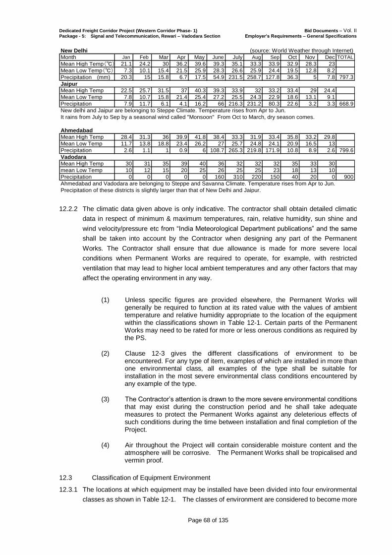
Dedicated Freight Corridor Project (Western Corridor Phase- 1) Bid Documents – Vol. II Package - 5: Signal and Telecommunication, Rewari – Vadodara Section Employer’s Requirements – General Specifications
Page 68 of 135
New Delhi (source: World Weather through Internet)
Month Jan Feb Mar Apr May June July Aug Sep Oct Nov Dec TOTAL
Mean High Temp(℃) 21.1 24.2 30 36.2 39.6 39.3 35.1 33.3 33.9 32.9 28.3 23
Mean Low Temp(℃) 7.3 10.1 15.4 21.5 25.9 28.3 26.6 25.9 24.4 19.5 12.8 8.2
Precipitation (mm) 20.3 15 15.8 6.7 17.5 54.9 231.5 258.7 127.8 36.3 5 7.8 797.3
Jaipur
Mean High Temp 22.5 25.7 31.5 37 40.3 39.3 33.9 32 33.2 33.4 29 24.4
Mean Low Temp 7.8 10.7 15.8 21.4 25.4 27.2 25.5 24.3 22.9 18.6 13.1 9.1
Precipitation 7.9 11.7 6.1 4.1 16.2 66 216.3 231.2 80.3 22.6 3.2 3.3 668.9
New delhi and Jaipur are belonging to Steppe Climate. Temperature rises from Apr to Jun.
It rains from July to Sep by a seasonal wind called "Monsoon" From Oct to March, dry season comes.
Ahmedabad
Mean High Temp 28.4 31.3 36 39.9 41.8 38.4 33.3 31.9 33.4 35.8 33.2 29.8
Mean Low Temp 11.7 13.8 18.8 23.4 26.2 27 25.7 24.8 24.1 20.9 16.5 13
Precipitation 2.6 1.1 1 0.9 6 108.7 265.3 219.8 171.9 10.8 8.9 2.6 799.6
Vadodara
Mean High Temp 30 31 35 39 40 36 32 32 32 35 33 30
mean Low Temp 10 12 15 20 25 26 25 25 23 18 13 10
Precipitation 0 0 0 0 0 160 310 220 150 40 20 0 900
Ahmedabad and Vadodara are belonging to Steppe and Savanna Climate. Temperature rises from Apr to Jun.
Precipitation of these districts is slightly larger than that of New Delhi and Jaipur.
12.2.2 The climatic data given above is only indicative. The contractor shall obtain detailed climatic
data in respect of minimum & maximum temperatures, rain, relative humidity, sun shine and
wind velocity/pressure etc from “India Meteorological Department publications” and the same
shall be taken into account by the Contractor when designing any part of the Permanent
Works. The Contractor shall ensure that due allowance is made for more severe local
conditions when Permanent Works are required to operate, for example, with restricted
ventilation that may lead to higher local ambient temperatures and any other factors that may
affect the operating environment in any way.
(1) Unless specific figures are provided elsewhere, the Permanent Works will generally be required to function at its rated value with the values of ambient temperature and relative humidity appropriate to the location of the equipment within the classifications shown in Table 12-1. Certain parts of the Permanent Works may need to be rated for more or less onerous conditions as required by the PS.
(2) Clause 12-3 gives the different classifications of environment to be encountered. For any type of item, examples of which are installed in more than one environmental class, all examples of the type shall be suitable for installation in the most severe environmental class conditions encountered by any example of the type.
(3) The Contractor’s attention is drawn to the more severe environmental conditions that may exist during the construction period and he shall take adequate measures to protect the Permanent Works against any deleterious effects of such conditions during the time between installation and final completion of the Project.
(4) Air throughout the Project will contain considerable moisture content and the atmosphere will be corrosive. The Permanent Works shall be tropicalised and vermin proof.
12.3 Classification of Equipment Environment
12.3.1 The locations at which equipment may be installed have been divided into four environmental
classes as shown in Table 12-1. The classes of environment are considered to become more
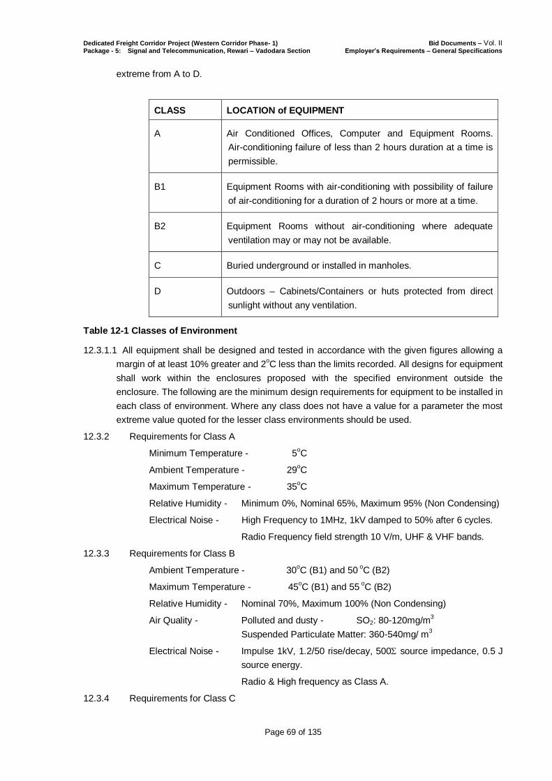
Dedicated Freight Corridor Project (Western Corridor Phase- 1) Bid Documents – Vol. II Package - 5: Signal and Telecommunication, Rewari – Vadodara Section Employer’s Requirements – General Specifications
Page 69 of 135
extreme from A to D.
CLASS LOCATION of EQUIPMENT
A Air Conditioned Offices, Computer and Equipment Rooms.
Air-conditioning failure of less than 2 hours duration at a time is
permissible.
B1 Equipment Rooms with air-conditioning with possibility of failure
of air-conditioning for a duration of 2 hours or more at a time.
B2 Equipment Rooms without air-conditioning where adequate
ventilation may or may not be available.
C Buried underground or installed in manholes.
D Outdoors – Cabinets/Containers or huts protected from direct
sunlight without any ventilation.
Table 12-1 Classes of Environment
12.3.1.1 All equipment shall be designed and tested in accordance with the given figures allowing a
margin of at least 10% greater and 2oC less than the limits recorded. All designs for equipment
shall work within the enclosures proposed with the specified environment outside the
enclosure. The following are the minimum design requirements for equipment to be installed in
each class of environment. Where any class does not have a value for a parameter the most
extreme value quoted for the lesser class environments should be used.
12.3.2 Requirements for Class A
Minimum Temperature - 5oC
Ambient Temperature - 29oC
Maximum Temperature - 35oC
Relative Humidity - Minimum 0%, Nominal 65%, Maximum 95% (Non Condensing)
Electrical Noise - High Frequency to 1MHz, 1kV damped to 50% after 6 cycles.
Radio Frequency field strength 10 V/m, UHF & VHF bands.
12.3.3 Requirements for Class B
Ambient Temperature - 30oC (B1) and 50
oC (B2)
Maximum Temperature - 45oC (B1) and 55
oC (B2)
Relative Humidity - Nominal 70%, Maximum 100% (Non Condensing)
Air Quality - Polluted and dusty - SO2: 80-120mg/m3
Suspended Particulate Matter: 360-540mg/ m3
Electrical Noise - Impulse 1kV, 1.2/50 rise/decay, 500 source impedance, 0.5 J
source energy.
Radio & High frequency as Class A.
12.3.4 Requirements for Class C
Dedicated Freight Corridor Project (Western Corridor Phase- 1) Bid Documents – Vol. II Package - 5: Signal and Telecommunication, Rewari – Vadodara Section Employer’s Requirements – General Specifications
Page 70 of 135
Ambient Temperature - 46oC
Maximum Temperature - 60oC
Electrical Noise - Impulse 5kv, otherwise as Class B.
12.3.5 Requirements for Class D
Guaranteed Temperature Range 0 oC to 55
oC
Operational Temperature Range -5o C to 60
oC
Relative Humidity - Nominal 70%, Maximum 100% (Non Condensing)
Air Quality - Polluted and dusty - SO2: 80-120mg/m3
Suspended Particulate Matter: 360-540mg/ m3
End of Chapter 12

Dedicated Freight Corridor Project (Western Corridor Phase- 1) Bid Documents – Vol. II Package - 5: Signal and Telecommunication, Rewari – Vadodara Section Employer’s Requirements – General Specifications
Page 71 of 135
13. CONTRACTOR’S CO-ORDINATION WITH OTHERs (INTERFACE
MANAGEMENT)
13.1. General
The entire construction Works of Dedicated Freight Corridor (Western Corridor, Phase 1) are
to be implemented through eight (8) Contracts as defined:
CT P-1 Civil/Building/Track Works Rewari – Ajmer Section;
CT P-2 Civil/Building/Track Works Ajmer –Ikbalgarh Section;
CT P-3 Civil/Building/Track Works Ikbalgarh – Vadodara Section;
CT P-3A Special Steel Bridges across rivers Mahi & Sabarmati;
EM P-4 Traction Power Supply and SCADA;
ST P-5 Signal & Telecommunication;
PE P-6 Plant and Equipment for operation and Maintenance; and
RS P-7 Electric Locomotive and Maintenance Depot.
The careful coordination of all technical and programming matters between the relevant
parties is a critical element in achieving a fully coordinated design and construction. This
clause describes the Contractor’s responsibilities with regard to interface management and
coordination with those who are considered to be related with the Work. The Contractor’s
responsibility for interface coordination shall include interfacing with the Other Contractors
and those who may be identified in the future such as local authorities, statutory bodies,
public utility companies including Indian Railways, private service providers, consultants or
contractors whether or not specifically mentioned in the Contract. This responsibility is not
limited to a particular number of interfacing parties and interfaces required in the Contract are
the sole responsibility of the Contractor.
13.2. General Responsibility of the Contractor
13.2.1 The Contractor shall not impede but shall afford the Other Contractors and the Interfacing
parties with all reasonable opportunities & facilities, access to the site and / or services to any
related parties in the Contract including members of the Other Contractors, Interfacing Parties
and the Engineer / Employer so as to ensure the whole project including envisaged Other
Contractor’s works as well as his Works be executed in the most efficient manner for the best
interest of the Employer as a whole.
13.2.2 The Contractor shall, in accordance with the Employer’s Requirements, coordinate and
integrate the Contractor’s own Works under the Contract with works of the Other Contractors
and Interfacing Parties. In addition, the Contractor shall take all necessary means and steps to
ensure that the Works are coordinated and integrated with the works of the Other Contractors
and Interfacing Parties, and shall comply with any directions which the Engineer may give.
Such responsibilities shall neither be mitigated nor in any way affected by virtue of similar
responsibilities being placed on Other Contractors.
13.2.3 The Contractor is responsible for the detailed co-ordination of his design, manufacturing,
installation, construction, testing and commissioning activities. The Civil and Track Works
Contractor shall take the lead in the management of the coordination process with Indian
Railways, Other Contractors and Interfacing Parties.
13.2.4 The Contractor shall carefully review pertinent information made available by the Engineer
relating to the nature and programming of the related parties’ contracts and use such
information in his planning of the Works.
13.2.5 The Contractor shall communicate, coordinate and exchange information directly with the
Other Contractors and Interfacing Parties under intimation to the Engineer. Information
Dedicated Freight Corridor Project (Western Corridor Phase- 1) Bid Documents – Vol. II Package - 5: Signal and Telecommunication, Rewari – Vadodara Section Employer’s Requirements – General Specifications
Page 72 of 135
necessary to fulfill the Contractor’s interface obligations shall be directly requested and
obtained from the Other Contractors and Interfacing Parties under intimation to the Engineer
and receipt acknowledged. Conversely, the Contractor shall provide directly to the Other
Contractors and Interfacing Parties with the information within the Contractor’s scope that is
required by them to meet their contractual obligations and proceed with their co-ordination
under intimation to the Engineer.
13.2.6 The Contractor shall ensure that the Contractor’s requirements are provided to all the related
members of the Other Contractors and the Interfacing Parties before the cut off dates as
identified in the Interface Management Plan to be developed by the Civil and Track Works
Contractor and approved by the Engineer.
13.2.7 Where the other contracts requiring interface are yet to be awarded, the Contractor shall
proceed with the coordination activities with the Engineer, until such time the related parties
including Other Contractor / Interfacing Party is engaged by the Employer.
13.2.8 The Contractor shall take all reasonable steps to ensure that the Works are coordinated and
integrated with the design, manufacture, installation, execution and testing of such other works
and shall in particular (but without limitation) to:
(a) comply with any direction which the Engineer may give for the integration of the
design of the Works with the design of any other part of the Project;
(b) consult, liaise and co-operate with those responsible for carrying out such other
works, including where necessary, in the preparation of the respective designs and
drawings, the preparation of coordinated programmes, method statements,
co-ordination drawings and specifications together with arrangements of service
priorities and zoning; and
(c) participate in Integrated Testing and Commissioning of the system with the Other
Contractors and Interfacing Parties and demonstrate to the satisfaction of the
Engineer that the Works have been designed and constructed in a manner
compatible with the works of the Other Contractors and Interfacing Parties.
13.2.9 As soon as the Other Contractors and Interfacing Parties for the project are identified, the
Contractor shall undertake design co-ordination with them, who shall be carrying out works
forming part of this project. There will be a continuous requirement of coordination between
them in respect of but not limited to design of cable trenching, structures and foundations for
overhead electrification including those on bridges, Radio Towers, Signal and Telecom Huts
and Location Boxes, interlocking of points and crossings, construction of facilities for
maintenance, other allied structures and during the installation of Signal and Telecom and
traction power systems.
13.2.10 At the end of each such co-ordination period, the Contractor and the Other Contractors and
Interfacing Parties with whose works the interface period refers, shall jointly state in writing that
their design co-ordination activities are complete and that their respective designs are
integrated and can be finalized without interference with each other’s designs or the designs
with which their designs have already been integrated. A copy of this joint written statement
shall be provided to the Engineer within 7 days of the end of the said design co-ordination
period. Unless and until copies of all relevant and necessary design co-ordination statements
have been submitted to the Engineer, the Engineer shall be entitled to suspend any review or
further review of the Contractor’s or the Other Contractor’s and Interfacing Party’s design
submissions. Such suspension shall not be grounds for any claim by the Contractor nor the
Contractor shall be entitled to receive an extension of time or additional payments.
13.2.11 During construction, the Civil and Track Works Contractor shall provide areas for staging,
storage and unloading and temporary storage within the Site for the temporary use of the
Contractors, to the reasonable extent during erection and commissioning process. Separate

Dedicated Freight Corridor Project (Western Corridor Phase- 1) Bid Documents – Vol. II Package - 5: Signal and Telecommunication, Rewari – Vadodara Section Employer’s Requirements – General Specifications
Page 73 of 135
locations shall be provided for each of the Other Contractor in some cases. Specific details
shall be coordinated and agreed during the design interface period amongst the Contractors.
13.2.12 Any other contract which depends for its execution on the Contract or upon which the Contract
is dependent for its own execution shall be identified by the Engineer as a “Interface Contract”.
The Contractor shall provide attendance on Other Contractors and Interfacing Parties (if
necessary) on meetings and correspondences in this regard in accordance with the
Employer’s Requirements and / or as instructed by the Engineer. The identity of the Other
Contractor(s) for the Interface Contract may not be known before the execution of the Contract
but this shall not be a ground for the Contractor to object to the subsequent appointment of an
Other Contractor.
13.2.13 The Contractor shall, in accordance with the requirements of the Contract and instructions of
the Engineer, coordinate his own Works with the works of Other Contractors strictly adherent
to the Coordinated Supply/ Installation Programme as detailed in clause 7.8 in Chapter on
Project Planning and Programme Requirements stated in the Employer’s Requirements,
(General Specifications) and shall afford the other contractors all reasonable opportunities for
carrying out their works.
13.2.14 The Contractor shall, while carrying out his co-ordination responsibilities, provide sufficient
information for the Engineer to decide on any disagreement between the Contractor and the
Other Contractors / Interfacing Parties as to the extent of services or information required to
pass between them.
13.2.15 If the Contractor suffers delay by reason of failure caused by any Other Contractor/ Interfacing
Parties to meet the specified installation interfacing, co-ordination, and / or completion dates
resulting in delay beyond the extent which could be reasonably foreseen by an experienced
contractor at the time when the Coordinated Supply/ Installation Programme is formulated and
consented by the Engineer , then the Engineer shall take such delay into account in
determining any extension of time to which the Contractor is entitled under the Contract.
13.2.16 If any act or omission of the Contractor whether directly or indirectly results in the delay in
execution of the works of the Other Contractor and / or Interfacing Parties associated with the
execution of the project, the matter will be settled by the Engineer under clause 3.5
[Determinations] and clause 2.5 [Employer’s Claims] of the Conditions of Contract.
13.2.17 The Civil and Track Works Contractor shall co-ordinate the access and delivery routes and
ensure that all provisions for access and delivery of the plant are co-ordinated with and
reflected in the delivery route drawings of the Other Contractors and Interfacing Parties. The
Civil and Track Works Contractor shall co-ordinate with the Other Contractors and Interfacing
Parties with regard to the details to be provided by them for the openings to be left in the
structure for their plant & equipment in accordance with Coordinated Supply/ Installation
Programme..
13.2.18 All requests for information (RFI), acknowledgement of receipt of information and any official
communication between the Contractor and the Other Contractors and Interfacing Parties shall
be made in writing with a copy to the Engineer for information.
13.2.19 The Contractor shall advise the Engineer in writing of any problems encountered in obtaining
necessary information and/or lack of cooperation from the Other Contractors. In the event that
the Engineer considers that the resolution of the interface is not proceeding satisfactorily, the
Engineer will review the matter and establish a coordinated plan directing the Contractor and
the Other Contractors / Interfacing Parties as to the required action. In such a case, the
decision of the Engineer shall be final and binding.
13.2.20 The Civil and Track Works Contractor shall conduct regular meetings with the Other
Contractors and Interfacing Parties, under intimation to the Engineer to clarify particular
aspects of the interface requirements of the Works. The party who convenes the meeting shall
Dedicated Freight Corridor Project (Western Corridor Phase- 1) Bid Documents – Vol. II Package - 5: Signal and Telecommunication, Rewari – Vadodara Section Employer’s Requirements – General Specifications
Page 74 of 135
prepare minutes recording all matters discussed and agreed at the meeting. The Contractor
shall advise the Engineer in advance the date, time and location of such meetings as he may
decide to attend.
13.2.21 The Civil and Track Works Contractor shall ensure that copies of all correspondence,
drawings, meeting minutes, programmes, etc. relating to Other Contractors / Interfacing
Parties coordination are issued to all concerned parties and the Engineer not later than two
calendar days from the date of such correspondence and meetings.
13.2.22 All interfacing Contractors shall note that the information exchange is an iterative process
requiring the exchange and up-dating of information at the earliest opportunity and shall be
carried out on a regular and progressive basis in order for the process to be completed for
each design and construction stage.
13.2.23 The Civil and Track Works Contractor shall establish an Interface Management System and
participate in the activities with the Other Contractors and Interfacing Parties. The Civil and
Track Works Contractor shall include, but not limited to, the following:
(a) provide an Interface Co-ordinator who has the responsibility, and authority with
substantial experience to resolve interface matters to the satisfaction of the Engineer,
and provide the necessary support team for the Interface Co-ordinator;
(b) respond to, confirm and make written agreements with regard to interfaces;
(c) attend interface meetings that may be arranged by the Engineer, with a
representative empowered to make agreements on interfaces. The Engineer may
arrange regular meetings to monitor the status of interfaces, and may require special
meetings as may be necessary to resolve specific issues. The Contractor may
request assistance from the Engineer to arrange meetings on particular subjects;
(d) provide the Engineer with regular status information and/or details of interfaces,
including copies of relevant correspondence and material; and
(e) provide the Engineer with access to information for the purpose of conducting audits
on interface compliance and for confirming that interface coordination is proceeding
consistently with the Employer’s Requirements.
13.2.24 Should it appear to the Engineer that the Work Programme or three month rolling programme
do not conform with the Coordinated Supply/ Installation Programme, the Contractor shall be
required to revise all such programmes so as to conform to Contractual Supply/ Installation
Programme.
13.3. Dedicated Co-ordination Team
13.3.1 The Civil and Track Works Contractor shall establish a dedicated co-ordination team led by an
Interface Co-ordinator reporting to the Contractor’s Representative. The primary function of the
team is to provide a vital link between the Contractor’s design & construction teams and the
Other Contractors / Interfacing Parties.
13.3.2 The Interface Co-ordinator shall assess the progress of the co-ordination with Other
Contractors / Interfacing Parties by establishing lines of communications as per pre-defined
co-ordination model and promote regular exchange and updating of the information so as to
maintain the Contractor’s Programme.
13.3.3 The Interface Co-ordinator, in conjunction with the Other Contractors and Interfacing parties,
shall identify necessary provisions in the Works for plant, equipment and facilities of the Other
Contractors and Interfacing Parties. These provisions shall be allowed by the Contractor in his
design of the Works.
Dedicated Freight Corridor Project (Western Corridor Phase- 1) Bid Documents – Vol. II Package - 5: Signal and Telecommunication, Rewari – Vadodara Section Employer’s Requirements – General Specifications
Page 75 of 135
13.4. Design Interface
13.4.1 General
(1) The Co-ordination Dates shown in Conditions of Contract are critical to the timely
completion of the project and the dates have been determined to create a time frame
during which design interactions with the Other Contractors and Interfacing Parties on
the project have to be completed in order for every interface activity to streamline
through the time schedule.
(2) The Civil and Track Works Contractor shall commence the design interface with the
Other Contractors / Interfacing Parties as soon as he has been notified by the
Engineer that an Interfacing Contract has been awarded by the Employer. There will
be requirement of coordination during Design Stage with respect to but not limited to
cable trenching, structures for OHE or Traction Power Supply Control Posts
including TSS, earthing and bonding, Radio Towers, Signal and Telecom Huts and
Location Boxes, interlocking of points and crossings, construction of facilities for
maintenance, other allied structures and during the installation of Signal and Telecom
and traction power systems.
(3) In the case of utility agencies and other statutory bodies, interfacing shall commence
as soon as practicable.
(4) The Contractor shall, immediately upon award of the Contract, gather all necessary
information and develop his design to a level where meaningful interaction can take
place.
13.4.2 The Civil and Track Works Contractor shall support the Other Contractors and Interfacing
Parties and the process of achieving a fully coordinated design for the Works, including
undertaking the following:
(1) providing timely information to the Civil and Track Works Contractor and when
requested by Other Contractors and Interfacing Parties;
(2) anticipating the information needs of the Other Contractors / Interfacing Parties and
transmitting such information as soon as it is available;
(3) pro-actively keeping the Other Contractors and Interfacing Parties informed of any
development of the Works and the works of the Other Contractors related to the
interfaces;
(4) advising the Other Contractors and Interfacing Parties on potential problems related to
the interfaces, together with proposed solutions likely to be acceptable to them and
which meet the needs of the Contract; and
(5) Requesting Civil and Track Works Contractor for arranging and/or attending meetings
with the Other Contractors / Interfacing Parties and/or the coordination meetings
convened by the Engineer with the Other Contractors and Interfacing Parties as
necessary to resolve interface issues. The party who convenes the meeting shall
prepare the minutes recording all the issues discussed and agreements reached.
13.4.3 While complying with the Contract requirements, the Contractor’s programme shall allow for
the timing of availability of necessary interface information from the Other Contractors and
Interfacing Parties. If necessary, the design of a particular element shall be programmed on a
“late-start” basis to allow receipt of necessary interface information. If a design activity is
programmed earlier than necessary and without sufficient interface information, this activity
shall be proceeded entirely at the Contractor’s own risk.
13.4.4 The Contractor shall allow for the fact that many of the design activities for the Other
Contractors and Interfacing Parties will be proceeding concurrently. Specific dates for the
Dedicated Freight Corridor Project (Western Corridor Phase- 1) Bid Documents – Vol. II Package - 5: Signal and Telecommunication, Rewari – Vadodara Section Employer’s Requirements – General Specifications
Page 76 of 135
delivery of the design output and other required information shall be confirmed between the
Contractor and the Other Contractors and Interfacing Parties.
13.4.5 In order to achieve a fully coordinated design, the Contractor should also note that the level of
information provided to and requested from the Other Contactors and Interfacing Parties
should be appropriate for the particular Design Stage. The Contractor shall also recognize and
allow for times when it may be necessary to modify the Contractor’s design process to
accommodate the timing of information availability from the Other Contractors and Interfacing
Parties in order to achieve a fully coordinated design. Similarly at times it will be necessary for
the Contractor to modify the Contractor’s design process to allow information needed by Other
Contractors and Interfacing Parties to be expedited for them to achieve timely completion of
the coordinated design of the Other Contractors and Interfacing Parties.
13.4.6 The Contractor’s attention is drawn to the need to undertake and develop the design in such a
way as to ensure that interface issues are resolved. Design schemes that impose unnecessary
or unreasonable construction challenges for Other Contractors will not be considered suitable
for a statement of no objection.
13.4.7 For the purpose of design coordination, the Contractor shall use the Coordination Drawings,
and other drawings as necessary.
13.4.8 In advance of each Design Stage, the Contractor shall:
(1) request in writing and obtain from the Other Contractors and Interfacing Parties,
interface information required for that Design Stage.
(2) review the interface information received and agree in writing to the Other Contractors
and Interfacing Parties that the interface information is adequate for that design stage.
13.4.9 In advance of the design stages of the Contractor and Other Interfacing Parties’ Design
Stages, the Contractor shall when requested by them:
(1) provide to the Civil and Track Works Contractors / Interfacing Parties interface
information needed for their impending design stages; and
(2) confirm in writing that the interface information suitably represents the Civil and Track
Works Contractor’s interface requirements for that Design Stage.
13.4.10 The Civil and Track Works Contractor shall submit together with each of his design
submissions a joint statement with the relevant Other Contractor / Interfacing Parties
confirming that they have jointly reviewed the drawings and documents to ensure a consistent
design that has no interference with each other’s design and that their designs are already
integrated. Unless all the relevant and necessary joint coordination statement has been
submitted to the Engineer, the Engineer will be entitled to suspend any reviews or further
review of the Contractor’s design submission. Such suspension shall not be the ground for the
Contractor to claim any extension of time or additional payment.
13.4.11 The Civil and Track Works Contractor shall ensure that the information he requires from Other
Contractors / Interfacing Parties is made known at the outset of each design interface and vice
versa so that the information can be provided in time for the Contractor and Other Contractors /
Interfacing parties to complete their design to meet their various design submission stages.
13.4.12 At the completion of each Design Stage of the Contractor, the Contractor shall:
(1) transmit those portions of the design relevant to interface to the Other Contractors and
Interfacing Parties for review and.
(2) agree in writing to the Other Contractors and Interfacing Parties on the incorporation of
applicable review comments.
Dedicated Freight Corridor Project (Western Corridor Phase- 1) Bid Documents – Vol. II Package - 5: Signal and Telecommunication, Rewari – Vadodara Section Employer’s Requirements – General Specifications
Page 77 of 135
13.4.13 At the completion of each design stage of the Other Contractors and Interfacing Parties, upon
receipt of the designs from them for review, the Civil and Track Works Contractor shall
(1) review those portions of the design relevant to interface and transmit comments to the
Other Contractors and Interfacing Parties and.
(2) agree in writing that subject to the incorporation of the applicable comments.
13.4.14 Design coordination by the Civil and Track Works Contractor shall include definition, approach
and agreement with the Other Contractors and interfacing Parties of interface areas, contract
limits, shared loads and sequence of design activities and the definition and design approach
for type, size and location of equipment, access thereto, cable routing and protection,
agreement of installation programming, preparation of Interface Documents.
13.4.15 The Contractor shall liaise with the Engineer in developing a uniform identity code system
which shall be used to uniquely identify each item of equipment and software components
provided under the Contract. Such identity codes shall be used for labeling each item of
equipment and shall also be used in design reports, drawings and operations and maintenance
manuals. This identity code system shall be generally compatible with principles to be
established by the Engineer and shall specifically be compatible with the use of the Engineer’s
defined names, mnemonics and codes for stations.
13.5. Construction Interface
13.5.1 Construction interfacing will be necessary throughout the duration of the Works commencing
from the time the Contractor mobilizes on the site to the completion of the Works. Construction
interfacing will overlap the design interface and involve all Contractors’ and Interfacing Parties’
requirements for provision of cast-in and buried items in the Civil and Track Contractor’s works
such as pipes for the Other Contractors’ and Interfacing Parties’ services, supports including
support brackets, plinths, ducts, service buildings, openings, cableways, trenches etc., that are
to be incorporated at the initial stages of the Civil and Track Contractor’s installation up to
provision of attendance during the testing and commissioning stage.
13.5.2 The Civil and Track Contractor shall coordinate with the Other Contractors / Interfacing Parties
to allow the efficient execution of the respective construction activities.
13.5.3 The Contractor shall coordinate and cooperate with Other Contractors and Interfacing Parties
on all site related matters including but not limited to site access and occupation, safety,
verification of work compatibility and survey control etc. The Civil and Track Contractor shall
advise the Other Contractors and Interfacing Parties in advance when a construction item is
ready for field inspection to verify compatibility with the Other Contractors and Interfacing
Parties’ needs and shall facilitate access to the site for the interfacing parties.
13.5.4 The Civil and Track Contractor shall ensure that there is no interference with the works of the
Other Contractors / Interfacing Parties’ and shall maintain close co-ordination with them to
ensure that his Work progresses in a smooth and orderly manner.
13.5.5 The Civil and Track Contractor shall carry out and complete the Works or any part thereof, in
such order as may be agreed by the Engineer or in such revised order as may be instructed by
the Engineer from time to time. The Civil and Track Contractor shall, be liable for and shall
indemnify the Employer against all costs, charges, expanses and the like resulting from the
failure of the Contractor to co-ordinate the Works as specified.
13.5.6 The Civil and Track Contractor shall prepare a Coordinated Construction Programme for each
segment of the Work on a works element basis covering the period of the Interfacing Contract
access. It shall fully conform to the Contractual Supply/ Installation Programme as detailed in
clause 7.8 in Chapter on Project Planning and Programme Requirements stated in the
Employer’s Requirements, (General Specifications).

Dedicated Freight Corridor Project (Western Corridor Phase- 1) Bid Documents – Vol. II Package - 5: Signal and Telecommunication, Rewari – Vadodara Section Employer’s Requirements – General Specifications
Page 78 of 135
13.5.7 The Coordinated Supply/ Installation Programme shall allow adequate time periods for all the
Contractors / Interfacing Parties to install their plant and equipment in the designated areas.
13.5.8 The Coordinated Supply/ Installation Programme shall be agreed with and signed off by the
concerned Civil and Track Contractor and Other Contractors / Interfacing Parties and then
submitted to the Engineer not later than six (6) months before the earliest access date to the
Site.
13.5.9 At or near the completion of the construction of any interface-related element of the Civil and
Track Contractor’s Work, the Civil and Track Contractor shall:
(a) advise Other Contractors and Interfacing Parties that the as-constructed
interface-related Work can be inspected and provide the necessary access to the Site
and its occupation.
(b) agree in writing to the Other Contractors and Interfacing Parties and as consented by
the Engineer on the adoption of any applicable comments on the constructed Work.
13.5.10 On advice from the Other Contractors and Interfacing Parties that an as-constructed
interface-related element is ready for inspection, the Civil and Track Contractor shall:
(a) conduct on-site inspections of the Work elements, and give comments in writing to
the Other Contractors and Interfacing Parties.
(b) agree in writing to the Other Contractors and Interfacing Parties that the
as-constructed Work meets the interface requirements.
13.5.11 Prior to applying for a Taking-Over Certificate, the Civil and Track Contractor shall obtain
written confirmation from each of applicable Other Contractors and Interfacing Parties, that the
interface elements meet the requirements of the Other Contractors and Interfacing Parties. If
any Other Contractor or Interface Party withholds such confirmation, the Engineer will decide
on further action, as requested by the Civil and Track Contractor prior to the issue of a
Taking-Over Certificate.
13.5.12 Where Contractor’s Works are identified as failing to meet the requirements of the Civil and
Track Contract and which will impact the Other Contractors’ and Interfacing Parties’ works, the
Civil and Track Contractor shall submit the proposed remedial measures to the Engineer for
review and shall copy the same to the Other Contractors and Interfacing Parties.
13.6. Preparation of Interface Documents
13.6.1 The Civil and Track Contractor shall prepare interface documents which shall be used to
completely define the Civil and Track Contractor’s interface coordination details as following
(but not limited to):
(1) Interface Matrix;
(2) Coordinated Supply/ Installation Programme as detailed in clause 7.8 in Chapter on
Project Planning and Programme Requirements stated in the Employer’s
Requirements, (General Specifications).
(3) Combined Services Drawings (CSD);
(a) Structural Electrical Mechanical (SEM) Drawings;
(b) Delivery Route Drawings (DRD);
(c) Interface Demarcation Diagrams (IDD); and
(4) Interface Management Plan (IMP).
13.6.2 These interface documents shall be submitted for review and consent to the Engineer. For all
subsequent updates, these documents shall be submitted to the Engineer for information,
Dedicated Freight Corridor Project (Western Corridor Phase- 1) Bid Documents – Vol. II Package - 5: Signal and Telecommunication, Rewari – Vadodara Section Employer’s Requirements – General Specifications
Page 79 of 135
review and comment. A summary of principal issues shall be included in each Monthly
Progress Report.
13.6.3 The Interface Matrix which describes relations between Contractor and Other Contractors and
Interfacing Parties and their rolls and responsibilities as a key document and should be
submitted to the Engineer for consideration as an overview of all subsequent interface related
documents and drawings.
13.7. Coordinated Supply/ Installation Programme
The Contractor shall prepare and submit a Coordinated Supply/ Installation Programme as
detailed in clause 7.8 in Chapter on Project Planning and Programme Requirements stated
in the Employer’s Requirements, (General Specifications) and / or as instructed by the
Engineer
13.8. Coordination drawings (CSD/SEM/DRD/IDD)
13.8.1 For the purpose of achieving a design which is fully coordinated with respect to electrical,
mechanical, architectural and railway systems elements and ensuring compatibility between
different services and adequate space requirements, the Civil and Track Contractor shall
develop and maintain service coordination drawings that specifically detail the requirements of
others in relation to the Civil and Track Contractor’s design in terms of special arrangements,
space allocation, Cable routes, Radio Tower foundation, cast in items, primary and secondary
fixings, grouting of equipment/plants, drill and fix brackets and cast-in and surface-mounted
conduit. These drawings shall also include composite cross-sections and layouts which show
the spatial requirements of all interfacing parties and identify items to be finalized, defined, or
resolved.
13.8.2 As the design progresses the service coordination drawings shall be supplemented by
Combined Services Drawings (CSD) and Structural Electrical Mechanical (SEM) drawings.
13.8.3 The CSDs and SEM drawings shall be clear and sufficiently detailed to unambiguously show
the intent of the subject services and the corresponding structure/facility allowances. While
these drawings do not have to duplicate all of the details of the construction drawings, they
shall include plans, sections and elevations as required to clearly illustrate the compatible
relationship between the different disciplines. Specifically, the drawings will include wall
elevation drawings at 1:50 scale (or larger where required) indicating all openings larger than
150mm, access panels, reinforcement zones and cast-in items.
13.8.4 The CSDs will show the intended locations, routes and spatial relationships of the individual
MEP services and railway systems installations fully coordinated with each other and the
structural work. These CSDs shall also clearly indicate that effective cable coordination has
been achieved in terms of cable location or cable trays and the trunking and cable routing.
13.8.5 The SEM drawings will show all of the structural requirements for the MEP services and the
railway systems installations including but not limited to openings, penetrations, sleeves,
plinths, lifting beams, and access panels.
13.8.6 The CSD/SEM drawings shall be used for the purpose of coordinating with the Other
Contractors and Interfacing Parties and shall be continuously updated to reflect the latest
interface coordination Copies of the CSD/SEM drawings shall be included in design submittals
to the Engineer and in-progress copies shall be provided to the Engineer on request.
13.8.7 The Civil and Track Contractor shall prepare Delivery Route Drawings (DRD) demonstrating
how and in which way the Other Contractors and Interfacing Parties may undertake and gain
access to the Civil and Track Contractor’s Works for the purpose of successful and safe
delivery and installation of equipment. These drawings shall illustrate all reasonable provisions
needed by the Other Contractors and Interfacing Parties for the successful delivery of
equipment including the provision of hard-stand and suitable access roads for heavy loads to

Dedicated Freight Corridor Project (Western Corridor Phase- 1) Bid Documents – Vol. II Package - 5: Signal and Telecommunication, Rewari – Vadodara Section Employer’s Requirements – General Specifications
Page 80 of 135
the building location for the equipment. These drawings shall also show the route to be taken
within the buildings, confirm the adequacy of doorway and corridor widths and indicate the
provision of safe lifting hooks where needed.
13.8.8 The Civil and Track Contractor shall prepare Interface Demarcation Diagrams (IDD) in
diagrammatic format for each interface showing the demarcation of scope of responsibilities
between the Civil and Track Contractor and the Other Contractors and Interfacing Parties.
13.9. Interface Management Plan (IMP)
13.9.1 The Civil and Track Contractor shall develop and submit to the Engineer within the specified
schedule, an IMP for all the interface issues that may arise during the design, construction,
testing and commissioning of the project in consultation with the Other Contractors / Interfacing
Parties and the Engineer. The Civil and Track Contractor shall prepare an Interface
Management Plan (IMP) for each segment of the Work on a works element basis covering the
period of Interfacing Contract access. The IMP shall allow adequate time periods for each of
the Other Contractor / Interfacing Party and the Civil and Track Contractor to install their plant
and equipment in the station areas.
13.9.2 The IMP shall be agreed with and signed off by each of the Other Contractors / Interfacing
Parties and then submitted to the Engineer not later than six (6) months before the earliest
Coordination Dates as defined in Conditions of Contract.
13.9.3 The IMP shall:
(1) identify all the systems and sub-systems including the civil works and facilities with
interfacing requirements;
(2) define the authority and responsibility of the Civil and Track Contractor's and the
Other Contractor’s and Interfacing Party’s (and any relevant sub-contractors') staff
involved in interface management and development;
(3) identify the information to be exchanged, together with the management and
technical skills required for the associated development of the works, at each phase
of the Civil and Track Contractor’s and the Other Contractor’s and Interfacing Party’s
(and any relevant sub-contractors’) project life-cycles;
(4) address the Works Programme of the Civil and Track Contract to meet the
Coordination Dates of the Civil and Track Contractor and the coordination dates of
the Other Contractors and Interfacing Parties and highlight any programme risks
requiring the Engineer’s attention;
(5) include considerations of the requirements of the System Safety Management;
(6) specify the configuration and version control procedures in accordance with the Civil
and Track Contractor’s and Other Contractors’ and Interfacing Parties’ (and any
relevant sub-contractors’) quality management system;
(7) address the design, supply, installation, testing and commissioning programmes of
the Civil and Track Contract to meet the coordination dates of Other Contractor’s
and Interfacing Party’s contract and highlight any programme risks requiring
management attention;
(8) indicate dates for commencement and completion of each principal activity by the
Civil and Track Contractor and those of the Other Contractor and Interfacing Party,
and delivery and installation of equipment.
13.9.4 In case of any disagreement between the Civil and Track Contractor and Other Contractors /
Interfacing Parties on the interface issues, the decision of the Engineer shall be final and
binding.

Dedicated Freight Corridor Project (Western Corridor Phase- 1) Bid Documents – Vol. II Package - 5: Signal and Telecommunication, Rewari – Vadodara Section Employer’s Requirements – General Specifications
Page 81 of 135
13.9.5 After the review of the IMP with no objections by the Engineer, all the Contractors shall strictly
execute the Works accordingly.
13.10. Employer’s / Engineer’s Input
13.10.1 The Employer/Engineer will coordinate the activities of all the Contractors with reference to
interfacing with third parties during all the phases of the Contract.
13.10.2 The Employer/Engineer, within the scope of the relevant Contract provisions, will support and
assist all the Contractors in the following fields:
(1) Interfacing state and local authorities for timely receipt of the required permits,
certificates and approvals related to the design and construction process;
(2) Interfacing state and local tax authorities for the Value Added Tax (VAT) reimbursement
arrangements;
(3) Interfacing state and local authorities for implementation of the additional land
acquisition procedures; and
(4) Any other fields of activities related to the Contract as may be required with the purpose
of facilitating all the Contractor's performance.
13.10.3 This support and assistance of the Employer/Engineer shall not release the Contractors of any
of their obligations under this Contract.
13.10.4 The Civil and Track Contractor shall coordinate with the Engineer / Employer on all matters
relating to the Works that may affect the existing Indian Railway (IR) operations. Such Works
shall be carried out as per IR rules and regulations in close coordination and under the
directions of Engineer/Employer.
13.11. Cost relating to the Interface Activities
Accepted Contract Price and Contractual Construction Programme shall be deemed to have
included the provision in respect of the obligations relating to coordination and interface
management activities. No separate payment will be made with regard to the activates as
described herein above.
End of Chapter 13
Dedicated Freight Corridor Project (Western Corridor Phase- 1) Bid Documents – Vol. II Package - 5: Signal and Telecommunication, Rewari – Vadodara Section Employer’s Requirements – General Specifications
Page 82 of 135
14. CONTRACTOR’S PROJECT ORGANISATION
14.1 The Contractor shall provide a structured organization chart (including subcontractors of every
tier) to illustrate the subdivision of the work into elements for effective technical and managerial
control, the reporting structure and the interface relationship among all parties involved.
Names, addresses, telephone and FAX numbers of all major positions shall be listed. Clear
reference shall be given to the location of each staff.
14.2 The organisation charts shall be produced as a family such that the basic chart shows the
overall organisation structure supported by subsidiary charts detailing the internal structure of
the various departments or sections of the overall organisation.
14.3 The Contractor shall have a competent, qualified and experienced team of Managers,
Engineers, Technical staff etc. so as to complete the work in a satisfactory manner as per
various requirements of the contract.
14.4 A control room with round the clock landline phones, FAX lines and Mobile telephone links with
all safety offices, works sites, site offices, batching plants, casting yards ,workshops,
fabrication yard, off site offices, Engineer’s site office, Resident Engineer’s office, testing labs
etc shall be maintained and manned round the clock. Residences of all senior project team
members shall also be linked with the control room. Vehicles for emergency use shall be on
stand-by at the control room around the clock as required.
14.5 The designations of the various project organisations team members shall be approved by the
Engineer before adoption so as to avoid any duplication of the designations with those of the
Employer or the Engineer.
End of Chapter 14
Dedicated Freight Corridor Project (Western Corridor Phase- 1) Bid Documents – Vol. II Package - 5: Signal and Telecommunication, Rewari – Vadodara Section Employer’s Requirements – General Specifications
Page 83 of 135
15. SOFTWARE
15.1 SOFTWARE SUPPORT
15.1.1 General
15.1.1.1 The Contractor shall provide full support to the Employer and Engineer for all computer
programs provided by the Contractor under the Contract.
15.1.1.2 The Contractor shall submit a software support plan at least ninety (90) days before
commencement of software installation. This plan shall require the Contractor to provide all
changes, bug fixes, updates, modifications, amendments and new versions of the program as
required by the Engineer.
15.1.1.3 The Contractor shall provide all tools, equipment, manuals and training necessary for the
Employer’s staff to maintain and re-configure all the software provided under the Contract.
15.1.1.4 The Contractor shall submit all new versions to the Engineer for review at least two (02)
weeks prior to their installation. New Versions of any program shall not result in any
non-conformance with the Specification or degrade the performance or have adverse impact
on the System. The Contractor shall:
(i) ensure that all new versions are fully tested and validated on the simulation and
development system prior to installation;
(ii) ensure that all new versions are fully tested and commissioned once installed on
the Site and
(iii) deliver to the Employer any new version, together with the updated Operation and
Maintenance Manuals.
(iv) All new version of software shall be accompanied by a release note containing the
following details:
(a) version number;
(b) modifications made to the previous version and
(c) check sum..
15.1.1.5 The Engineer shall not be obliged to use any new version and that shall not relieve the
Contractor of any of its obligations. Any effect upon the performance or operation of the
computer-controlled system that may be caused by a new version shall be brought to the
Engineer attention including updating the files to suit new version.
15.1.2 SECURITY OBLIGATIONS
Within fourteen (14) days of the installation of any software, developed or modified for this
contract, into the Permanent Works by the Contractor, the Contractor shall submit to the
Engineer for retention by the Employer, the end user, two backup copies of the software, which
shall include, without limitation:
(v) All source and executable code including all data configuration tables;
(vi) All licenses in favour of the Employer for their perpetual use by DFCCIL for the
entire life of the systems;
(vii) All design documentation relating to the software and
(viii) Any specified development tools required for maintenance of the
software, including, but not limited to, editors, compilers and linkers.
Dedicated Freight Corridor Project (Western Corridor Phase- 1) Bid Documents – Vol. II Package - 5: Signal and Telecommunication, Rewari – Vadodara Section Employer’s Requirements – General Specifications
Page 84 of 135
15.1.3 ERROR CORRECTION
15.1.3.1 When a fault is discovered within delivered software or documentation, the Contractor shall
take necessary steps to rectify errors or faults at the earliest.
15.1.3.2 The Contractor shall provide written details as to the nature of the proposed correction to the
Engineer.
15.1.3.3 The Contractor shall notify the Engineer promptly of any fixes or patches that are available to
correct or patch faults.
15.1.3.4 The Contractor shall detail any effect such fixes or patches are expected to have, upon the
applications.
15.1.4 Training
15.1.4.1 The Contractor shall provide training for the Employer’s and IR’s (as applicable) staff to
enable the Employer to make proper use of any software and its new versions.
15.2 SOFTWARE MANAGEMENT AND CONTROL
15.2.1 Prescriptive Framework
15.2.1.1 All software to be developed or modified (re-engineered software) shall follow the normative
requirements of IEC 62279 (Railway applications – Communication, signalling and processing
systems – Software for Railway Control) and IEC 62425 Railway Applications–
Communication, signalling and processing systems – Safety related electronic systems for
Signalling. The Software shall be designed, developed and tested according to the
Contractor’s Software Quality assurance Plan and as specified in the PS and the Software
Lifecycle. All signalling systems except TMS shall be to SIL 4 standard. SIL requirement for
TMS is defined in PS. The Contractor shall define within the Software Quality Assurance Plan
what techniques and measures are to be applied for software development. See Appendix 8 to
this General Specification for further requirements on the Software Quality Assurance Plan. In
addition to the requirements of the Software Quality Assurance Plan, which shall be reviewed
without objection by the Engineer, justification shall be required in respect of any highly
recommended IEC 62279 Annex A normative clauses which are proposed not to be applied to
software development and supply.
15.2.2 Software Framework
15.2.2.1 As defined in IEC 62279 and IEC 62425, all software produced or supplied for the project
shall be subject to a defined quality framework. The Contractor shall use a Quality Assurance
System which is compliant with ISO 9000 (Quality Management and Assurance) series and
others and meet the requirements as stipulated in the PS. ISO 9000-3 is considered
appropriate for Safety Integrity Level 0 or 1 software.
15.2.3 Software Management Control
15.2.3.1 The Contractor shall ensure that a full time Software Project Manager and Software Quality
Manager are appointed for software development, if software development and/or modification
are required under the Contract.
15.2.4 Status Reporting
15.2.4.1 The Contractor shall include in the Monthly Progress Report details of the status of the
software development/modifications/upgrades.
15.2.5 Auditing
15.2.5.1 The Engineer shall audit the Contractor’s implementation of Software Quality Assurance Plan

Dedicated Freight Corridor Project (Western Corridor Phase- 1) Bid Documents – Vol. II Package - 5: Signal and Telecommunication, Rewari – Vadodara Section Employer’s Requirements – General Specifications
Page 85 of 135
in line with Employer’s procedures. Further external independent audits may also be arranged
at the Engineer’s discretion.
15.2.6 Software Acceptance
15.2.6.1 Software acceptance shall be based upon the supply of software functioning in a manner
reviewed without objection by the Engineer supported by an Operational Safety Report
(Software) reviewed without objection by the Engineer. The report shall be provided by the
Contractor and submitted to the Engineer for review in the format described below. All the
documents for the design, development, testing, verification and validation as defined in ISO
9000 series and IEC 62279 shall be submitted. The Engineer’s review without objection shall
be obtained prior to Employer’s Taking Over of the Works.
15.2.6.2 The Operational Safety Report (Software) (OSR(S)) shall include, as a minimum:
(i) OSR(S) - Introduction
Shall describe the nature of the software sufficiently to ensure that the Engineer is
given a comprehensive overview of primary characteristics such as structure,
functions, criticality, volume and language.
(ii) OSR(S) - Evidence of Quality Management
Shall provide evidence to demonstrate that the software development has been
subject to acceptable quality assurance.
(iii) OSR(S) - Evidence of Safety Management
Shall provide evidence to demonstrate that the software development has been
subject to acceptable safety management.
(iv) OSR(S) - Technical Report
Shall describe how software integrity has been achieved.
(v) OSR(S) - Operation and Maintenance Report
Shall describe the software operation and maintenance characteristics.
(vi) OSR(S) - Restrictions for Use
Shall define what restrictions are applied to the use of the software.
15.2.7 Availability of Source Code and Development Tools
15.2.7.1 With the exception of “Commercial Off The Shelf” Software (COTS), the Engineer shall be
provided with access to full software documentation including source code listings and
development tool details. For COTS, the Contractor shall provide all available documentation
for the application and maintenance of that software.
15.2.8 Re-Use of Existing Software
15.2.8.1 Where existing software (defined to module level) is to be re-used without modification, the
Contractor shall provide evidence acceptable to the Engineer as to why that software is
suitable for use in the proposed application. All software developed earlier and intended to be
used for the Contract shall meet the requirements laid down in the PS.
15.2.8.2 The certified evidence of previous satisfactory use in a similar environment and application
and cross acceptance from another railway authority shall be submitted. The Engineer
reserves the right to implement an assessment of the developed software by further validation
or re-validation by an outside agency nominated by the Employer.
15.2.9 Application of “Commercial Off The Shelf” Software (COTS)

Dedicated Freight Corridor Project (Western Corridor Phase- 1) Bid Documents – Vol. II Package - 5: Signal and Telecommunication, Rewari – Vadodara Section Employer’s Requirements – General Specifications
Page 86 of 135
15.2.9.1 COTS shall not be applied to any operation software at level SIL2 and above. Where COTS
is used, the Contractor shall define within the Software Quality Assurance Plan, to the review
of the Engineer, the software support period following delivery. The software support activities
shall include but not be limited to, supply of software and supporting documentation, training
and maintenance contracts.
15.2.10 Test Software
15.2.10.1 All test software, with the exclusion of built-in test software, shall be produced in accordance
with a quality system controlled under the requirements of ISO 9000-3. Test software shall be
developed and documented using structured techniques and shall be designed to be
maintainable throughout the term of the Contract. All test software shall be documented to be
supportive of maintenance. Any test software that is to be delivered to the Employer (for long
term testing use) shall be fully documented including source code listings to allow the
Employer to maintain the software for the life of the supported system.
15.2.11 Global Positioning System Week-counter Rollover
15.2.11.1 Any equipment or software that makes use of the Global Positioning System (GPS) shall not
suffer from the GPS week-counter rollover problem, which causes the week counter to reset to
0000 every 1024 weeks.
End of Chapter 15
Dedicated Freight Corridor Project (Western Corridor Phase- 1) Bid Documents – Vol. II Package - 5: Signal and Telecommunication, Rewari – Vadodara Section Employer’s Requirements – General Specifications
Page 87 of 135
16. MATERIALS AND EQUIPMENT
16.1 MATERIALS AND EQUIPMENT PROVIDED BY THE EMPLOYER
16.1.1 No materials and equipment will be provided by the Employer.
16.2 MATERIALS
16.2.1 General
16.2.1.1 All materials and equipment appearing in RDSO’s list of approved vendors shall be procured
from such approved vendors only.
16.2.1.2 If any signalling material or equipment appearing in RDSO’s list of approved vendors is
proposed to be imported, then the same shall be got approved from RSDO as per Cross
Acceptance Procedure of RDSO.
16.2.1.3 Materials for inclusion in the Permanent Works shall be fire retardant as specified in PS and
shall be reviewed without objection by the Engineer.
16.2.1.4 Certificates of tests by manufacturers, which are submitted to the Engineer, shall relate to the
material delivered to the Site. Certified true copies of certificates may be submitted if the
original certificates cannot be obtained from the manufacturer. A letter from the supplier stating
that the certificates relate to the material delivered to the Site shall be submitted with the
certificates.
16.2.1.5 Materials, which are specified by means of trade or proprietary names, may be substituted by
materials from a different manufacturer, provided that the materials are of the same or better
quality and comply with the specified requirements and have been reviewed without objection
by the Engineer and approved by Employer.
16.2.1.6 In addition to any special provisions in the Contract for the sampling and testing of materials,
the Contractor shall submit samples or demonstrate at manufacturer’s premises as asked by
the Engineer of all materials and goods which it proposes to use or employ in or for the Works
before going in for bulk production. Such samples, if having been reviewed without objection,
shall be retained by the Engineer and shall not be returned to the Contractor or used in the
Permanent Works unless reviewed by the Engineer. No materials or goods of which samples
have been submitted shall be used in the Works unless and until the Engineer has reviewed
such samples without objection.
16.2.1.7 The Engineer may reject any materials and goods which in his opinion are inferior to the
samples previously reviewed and the Contractor shall promptly remove such materials and
goods from the Site.
16.2.1.8 If any material required for this Contract is not available in metric specifications from any
known sources, at the time the material is required for the Contract, the Engineer may, upon
application from the Contractor, give permission to the use of an equivalent material in imperial
specifications as a substitute, provided that:
(i) no statutory specification shall be altered except in accordance with relevant legal
provision, if any;
(ii) the Engineer is satisfied that the Contractor has made every reasonable effort to
obtain the material in metric specifications;
(iii) in the opinion of the Engineer, the substitute material is suitable for the Works in all
respects;
Dedicated Freight Corridor Project (Western Corridor Phase- 1) Bid Documents – Vol. II Package - 5: Signal and Telecommunication, Rewari – Vadodara Section Employer’s Requirements – General Specifications
Page 88 of 135
(iv) in the opinion of the Engineer, the substitute material complies with all the
specifications for the material substituted, allowing minor discrepancies between
the specified metric measurements and the corresponding imperial measurements
of the substitute, provided that such discrepancies can be effectively and
satisfactorily compensated for by the provision of extra quantity of the material;
(v) the Contractor shall be responsible for all extra quantities of the material required
for meeting design and specification requirements of the Works due to the use of
the substitute and
(vi) Hardwood shall not be used for Site hoardings, shoring of trenches and pits, false
work or formwork.
16.2.2 Notice of place of manufacture and/or source of supply
16.2.2.1 The Contractor shall notify the Engineer of the places of manufacture and/or the source of
supply of all goods and materials previously reviewed without objection by the Engineer to be
incorporated into the Permanent Works. The Contractor shall give reasonable notice (which
shall not in any event be less than fifty-six (56) days) to the Engineer before the start of any
manufacturing and/or the supply of goods and materials.
16.2.3 Certificates for Manufactured Goods or Materials
16.2.3.1 The Contractor shall obtain certificates for each batch of goods and materials incorporated
into the Permanent Works. Each certificate shall certify that the materials comply with the
requirements of the Contract and shall include all reports of inspections and/or tests carried out
at the place of manufacture.
16.3 EQUIPMENT
16.3.1 Identification labels
16.3.1.1 Each and every individual item of equipment forming part of the Permanent Works shall be
fitted with permanent identification labels in accordance with a system as approved by the
Engineer. In this respect, the term “individual item of equipment” refers to a complete assembly
of components and to each removable sub-module within the complete assembly.
16.3.1.2 The proposed labelling system shall be submitted for review by the Engineer at least three
(03) months before the scheduled date for the shipment of the first item of equipment to site.
16.3.1.3 The identification label shall be permanently attached in such a way that it shall not become
detached or illegible during the lifetime of the system from any cause including wear and tear,
environmental effects (such as rain, direct sunlight, etc.) or any other influence. Preference
shall be given to embossed or engraved metallic labels mechanically fastened by riveting or
similar means to the item to which they refer.
16.3.1.4 All labels shall be easily cleaned to remove dirt and debris (including grease and oil) without
disturbing the legibility properties.
16.3.1.5 All labels shall incorporate the inscription “Property of DFCCIL”.
16.4 ELECTRONIC CONTROL RACKS & CABINETS
16.4.1 Racks & Cabinets
16.4.1.1 Electronic control equipment shall be housed in nineteen (19”) racks suitably enclosed in
metal cabinets of a type acceptable to the Engineer. A sample of each type of rack or
enclosure proposed shall be submitted to the Engineer for inspection.
16.4.1.2 The equipment shall be of modular Construction to facilitate maintenance, repair and
Dedicated Freight Corridor Project (Western Corridor Phase- 1) Bid Documents – Vol. II Package - 5: Signal and Telecommunication, Rewari – Vadodara Section Employer’s Requirements – General Specifications
Page 89 of 135
replacement of parts. Standard commercial parts shall be utilised to the maximum extent
possible.
16.4.1.3 Cubicles, Equipment Racks, cable and wiring Termination Racks shall not be filled to greater
than 80% of their capacity at the completion of the works.
16.4.1.4 There shall be a minimum walkway of 1000mm between equipment racks and between
equipment racks and the walls of the rooms unless otherwise agreed by the Engineer.
16.4.1.5 The equipment shall be suitable for the environment in which it is to be used and it shall be
designed to prevent ingress of all vermin and to minimise the ingress of moisture, dust and dirt.
16.4.1.6 The cubicles shall have louvers with wire mesh for natural ventilation.
16.4.1.7 Outdoor equipment shall be sealed against the ingress of dust, moisture and vermin. A
minimum IP rating of IP65 under IEC60529 is essential.
16.4.1.8 Indoor equipment shall have a degree of protection not less than IP 54 unless specifically
stated otherwise or approved by the Engineer.
16.4.1.9 No item of equipment which is removable as part of routine maintenance procedures shall be
mounted at more than 2.0m above floor level.
16.4.2 Cables
16.4.2.1 No joints or splices shall be permitted in cables or wires except at recognised termination
points.
16.4.2.2 All multi-core control and communication cables shall allow 20% or 2 cores, whichever is the
greater, as spares unless specifically stated otherwise..
16.4.2.3 All cable cores shall be terminated including all spare conductors.
16.4.2.4 Each cable core shall be uniquely numbered and identified with a label giving details of the
circuit carried.
16.4.2.5 Terminals carrying voltages exceeding 110V shall be uniquely identified and protected
against accidental contact by persons, test equipment or other unintended physical contact.
Similarly all bus bars shall be suitably identified and protected.
End of Chapter 16
Dedicated Freight Corridor Project (Western Corridor Phase- 1) Bid Documents – Vol. II Package - 5: Signal and Telecommunication, Rewari – Vadodara Section Employer’s Requirements – General Specifications
Page 90 of 135
17 PACKAGING, STORAGE, SHIPPING AND DELIVERY
17.1 STORAGE OF EQUIPMENT AND MATERIALS
17.1.1 The Contractor shall provide and maintain acceptable storage facilities reviewed without
objection by the Engineer for the Permanent Works, equipment and materials of all kinds
intended for use in carrying out the Works or for incorporation into the Works.
17.1.2 The Contractor shall prepare, protect and store in an agreed manner all Permanent Works
equipment and materials so as to safeguard them against loss or damage from repeated
handling, from climatic influences, theft and from all other hazards arising during shipment or
storage on or off the Site.
17.1.3 Secure and covered storage shall be provided by the Contractor for all Permanent Works
equipment and materials which are other than those having been reviewed without objection
by the Engineer as suitable for open storage.
17.2 CRATING
17.2.1 The Contractor shall provide all packing, crates and markings. In doing so, it shall comply with
the following requirements:-
(i) Each case, crate or package shall be waterproof, rot-proof and insect/rodent-proof,
of robust Construction and suitable for the intended purposes. The Contractor shall,
in determining the package materials to be used, take cognisance of the climatic
conditions likely to occur during the period of transport, shipment and storage.
(ii) Each case, crate or package shall be legibly and indelibly marked in large letters
with the Site address, Contract number, "right way up", opening points and other
markings as necessary to permit materials to be readily identified and handled
during transit and when received at the Site.
(iii) Each case, crate or package shall contain a comprehensive packing list showing
the number, mark, size, weight and contents together with any relevant drawings.
A second copy of the packing list shall be enclosed in a watertight enclosure on the
outside of each case or package. Distribution of additional copies of each packing
list shall be in accordance with the Engineer's instructions.
(iv) All items heavier than 100 kg shall be marked on the outside of the case to show
the gross and net weights, the points for slinging and where the weight is bearing.
(v) Care shall be taken to prevent movement of items within cases, crates or packages
by the provision of bracing, straps and securing bolts as necessary. Bags of loose
items shall be packed in cases and shall be clearly identified by well-secured metal
labels on which the quantity and name of the part and its index or catalogue
number have been stamped.
(vi) Plug connected electronic circuit boards shall be removed from their racks, packed
and shipped separately.
(vii) All packing shall be free from sharp edges to prevent injury to persons or other
objects.
(viii) Each bulky/heavy case, crate or package shall include wedge(s) for easy
loading and unloading by mechanical handling equipment such as forklift truck.
(ix) Electronic circuit boards, integrated circuits (IC) and the like shall be well protected
by using appropriate packing, e.g. anti-static bubble bag or similar.
Dedicated Freight Corridor Project (Western Corridor Phase- 1) Bid Documents – Vol. II Package - 5: Signal and Telecommunication, Rewari – Vadodara Section Employer’s Requirements – General Specifications
Page 91 of 135
(x) Rubber products and the like shall be suitably packed to avoid damage including
but not limited to hardening, deformation and peel-off.
17.3 GENERAL PRECAUTIONS
17.3.1 Spare parts shall be tropicalised in their packing for prolonged storage in accordance with
appropriate international standards and shall be suitably and individually labelled to indicate:
(i) shelf life and date of manufacture;
(ii) type or condition(s) of storage and special handling information;
(iii) description of item and relevant part number;
(iv) serial number, if applicable;
(v) inspection/test certificate number and batch number and
(vi) Contract number, variation order number and item number.
17.3.2 Tubes, cable and conductor ends and other similar openings shall be properly sealed and
blanked off to prevent ingress of dirt or moisture. Flanged ends shall be protected by adhesive
tape or jointing material covered by a properly secured wooden plank not smaller than the
flange itself. Plain tube ends shall be closed off with bungs or plugs or suitable materials firmly
fixed in position.
17.3.3 Particular care shall be taken to prevent mechanical transport related damage or corrosion of
shafts and journals where they rest on timber or other supports which may contain moisture. At
such points, wrappings impregnated with anti-rusting composition and of sufficient strength to
resist chafing under the pressures and movements during transit shall be used.
17.3.4 Protected items shall not be removed from the manufacturer’s wrappings or packing.
17.3.5 Fragile materials shall be packed in such a way that they shall not be damaged during transit
and when they are properly unpacked for quality inspection. Glass items shall be capable of
being easily re-packed without removing the original wrappings or packing for long-term
storage within the same packing case.
17.3.6 Appropriate precautions in accordance with the Contractor’s safety regulations, the regulations
of the Employer and statutory regulations shall be taken in respect of all hazardous, toxic,
inflammable, etc. materials.
17.4 PACKAGING PROCEDURES
17.4.1 A copy of inspection/test reports shall also be supplied and packed together with individual
material. All packaging materials and procedures shall be subject to review by the Engineer.
17.4.2 All empty cases, crates or packages shall be removed from the Site by the Contractor or stored
by the Contractor in such a way that they do not interfere with the progress of the works of
Project Contractors.
17.5 SHIPPING
17.5.1 The Contractor shall notify the Engineer at least ten (10) days in advance of any expected
shipment date and give further notification of the actual shipment date and routing when such
information is subsequently established. This shall complement the inspection requirements
prior to delivery as specified herein.
17.5.2 Two copies of packing lists and quality certificates shall be attached to each case or package
to be shipped. One copy shall be placed inside the package and the second copy shall be
enclosed in a watertight enclosure on the outside of each case or package. A copy of packing
Dedicated Freight Corridor Project (Western Corridor Phase- 1) Bid Documents – Vol. II Package - 5: Signal and Telecommunication, Rewari – Vadodara Section Employer’s Requirements – General Specifications
Page 92 of 135
lists and quality certificates shall be sent to the Engineer after each package of the Works, the
equipment, spare parts and other items to be shipped have been shipped.
17.5.3 Without prejudice to any other provisions of the Contract, the Contractor shall be responsible
for all legal requirements, duties, dues, taxes and other such requirements and expenditures
required for import of the equipment, spare parts and other items to be supplied under the
Contract.
17.5.4 The Contractor shall clear the Works, the equipment, spare parts and other items to be
supplied under the Contract through Indian customs/India’s port in accordance with all
Government of India’s Enactments.
17.6 DELIVERY
17.6.1 The Contractor shall deliver the Works and all items to be supplied under the Contract to the
Site.
17.6.2 The Contractor shall unload the Works and all items to be supplied under the Contract at the
designated delivery point and make arrangements for positioning or storing them.
17.6.3 Any part of the Works or any item to be supplied under the Contract that is damaged in transit
shall not be considered as delivered until repairs (if agreed by the Engineer) or replacements
have been made and all necessary spare parts or items have been delivered to the Site to the
satisfaction of the Engineer.
17.6.4 All documents, manuals, drawings and other deliverables shall be delivered to an address in
India to be designated by the Engineer in writing.
17.6.5 The Contractor shall store and secure the Works, equipment, spare parts and other items until
the Taking over Certificate is issued by the Employer/ Engineer.
17.6.6 The Contractor shall remove temporary fittings required for shipment and re-assembly of
equipment and shall complete this prior to the equipment or parts thereof being inspected and
before they are considered delivered.
End of Chapter 17

Dedicated Freight Corridor Project (Western Corridor Phase- 1) Bid Documents – Vol. II Package - 5: Signal and Telecommunication, Rewari – Vadodara Section Employer’s Requirements – General Specifications
Page 93 of 135
18 THE WORKS AND CARE OF THE WORKS
18.1 Methods of Construction
18.1.1 The Contractor shall in any case not less than twelve (12) weeks before starting the
Construction of the Works on Site, submit to the Engineer the Construction and Installation
Plan as specified in Chapter 8.
18.2 TEMPORARY WORKS
18.2.1 Upon receiving a written application from the Contractor, the Engineer may at his absolute
discretion consent to certain Temporary Works of a minor nature being exempted from the
requirements of this Chapter. Such exemption shall not relieve the Contractor of any of his
obligations under the Contract.
18.3 NORMAL WORKING HOURS
18.3.1 Normal working hours shall be defined as the period between 0700 hours and 1900 hours on
all days excluding National Holidays. Work outside normal working hours shall not be carried
out unless reviewed without objection by the Engineer and unless the Contractor has obtained
any necessary permission or approval from Relevant Authorities.
18.3.2 The Contractor shall inform the Engineer 24 hours, or such shorter period reviewed without
objection by the Engineer, in advance of any occasion when work outside normal working
hours is proposed.
18.4 DRAWINGS AND SCHEDULES
18.4.1 Detailed manufacturing drawings for the Permanent Works will not normally be required to be
submitted to the Engineer for review but shall be available on the Contractor’s or his
sub-contractor’s premises if required. The Contractor shall also maintain at the Site a
comprehensive and up-to-date set of drawings properly indexed and catalogued, which shall
include complete sets of detailed working and installation drawings and shall permit free
access to such drawings by the Engineer at any reasonable time.
18.5 NOTIFICATION AND INSPECTION OF WORKS
18.5.1 The Works will be the subject of a formalised system of written applications for inspection.
18.5.2 The Engineer may convene any inspection at site and the Contractor shall attend the same.
18.5.3 Work that is carried out without being appropriately sanctioned by the Engineer could be
classified as defective work.
18.6 CONSTRUCTION/INSTALLATION RESTRAINTS
18.6.1 The Contractor shall design and implement Temporary Traffic Management (TTM) in
accordance with the statutory regulations.
18.6.2 The Contractor shall ensure that the design, Construction/Installation and performance of all
Temporary Works and the design and Construction/Installation of all Permanent Works shall
be such that any ground movements in and around the Site will not result in settlement and/or
subsidence of the ground that will cause damage to any buildings, structures, rail, roads,
footpaths, slopes, utilities etc.
18.6.3 The Contractor shall ensure that the method of installation of any part of the Permanent Works
(prior to dewatering and excavation) minimises settlements in the adjacent ground or buildings.
Dewatering of an excavation will not be permitted unless a closed perimeter of impermeable
wall is complete.
Dedicated Freight Corridor Project (Western Corridor Phase- 1) Bid Documents – Vol. II Package - 5: Signal and Telecommunication, Rewari – Vadodara Section Employer’s Requirements – General Specifications
Page 94 of 135
18.6.4 The Contractor’s design of dewatering methods, as far as possible, shall avoid lowering of the
water table outside the excavations. The reduction in piezometric pressure shall in no case be
greater than 2 metres in adjacent ground, unless the Contractor can clearly demonstrate that
buildings, structures, roads, footpaths and utilities within the influence of the dewatering will not
be damaged by the proposed dewatering. Pumping shall be confined within the boundaries of
the excavation and the water level within the excavation shall not be lowered by more than two
metres below the formation level.
18.7 PROTECTION FROM WATER
18.7.1 Unless otherwise reviewed by the Engineer, all work shall be carried out, as near as may be
practicable in the circumstances, in dry conditions, except where the work is required to be
carried out in or with water or other fluids.
18.7.2 The Permanent Works, including materials for use in the Permanent Works, shall, where
necessary and as near as may be practicable, be kept free of water and protected from
damage due to water. Water on the Site and water entering the Site shall be disposed of by
temporary drainage or pumping systems or by other methods capable of keeping the Works
free of water and protected from damage due to water. Traps shall be provided by the
Contractor to intercept silt and debris before water is discharged from the Site.
18.7.3 The discharge points of the temporary drainage and pumping systems shall be as those
having been reviewed without objection by the Engineer. The Contractor shall make all
arrangements with and obtain the necessary approvals and inspections from the Relevant
Authorities for discharging water to drains, watercourses etc. The relevant work shall not start
until the arrangements for disposal of the water previously reviewed without objection by the
Engineer have been implemented.
18.7.4 Measures shall be taken to prevent flotation of new and existing structures.
18.8 PROTECTION FROM WEATHER
18.8.1 Work shall not be carried out in weather conditions that may adversely affect the work unless
protection by methods reviewed without objection by the Engineer is provided.
18.8.2 The Permanent Works, including materials for the Permanent Works, shall be protected by
methods reviewed without objection by the Engineer from exposure to weather conditions
which may adversely affect the Permanent Works.
18.9 PROTECTION OF WORK
18.9.1 Finished work shall be protected by methods reviewed without objection by the Engineer from
damage that could arise from the execution of adjacent work. Work shall be carried out in such
a manner that work carried out by others, including Government departments, utility
undertakings, Relevant Authorities and Project Contractors, is not damaged.
End of Chapter 18
Dedicated Freight Corridor Project (Western Corridor Phase- 1) Bid Documents – Vol. II Package - 5: Signal and Telecommunication, Rewari – Vadodara Section Employer’s Requirements – General Specifications
Page 95 of 135
19. DAMAGE AND INTERFERENCE
19.1 DAMAGE AND INTERFERENCE
19.1.1 Work shall be carried out in such a manner that, as far as is practicable, there is no damage to
or interference with the following, other than such damage as is necessitated to enable the
execution of the Works:
(i) watercourses or drainage systems;
(ii) utilities;
(iii) structures, roads including street furniture, or other property;
(iv) public or private vehicular or pedestrian accesses;
(v) trees, graves or burial urns and
(vi) existing railways and railway systems.
19.1.1.1 The Contractor shall obtain prior approval of the concerned authority or party, if so required,
for any work near properties under their ownership or management.
19.1.1.2 The Contractor shall inform the Engineer as soon as practicable of any item, utility or thing
which is not stated in the Contract as requiring diversion, removal or relocation but which the
Contractor considers as requiring diversion, removal or relocation to enable the Works to be
executed. The Contractor shall not divert, remove or relocate any such item, utility or thing
without such diversion, removal or relocation having been reviewed without objection by the
Engineer.
19.1.2 Items which are damaged or interfered with as a result of the Works being carried out and
items which are diverted, removed or relocated to enable the Works to be carried out, shall be
reinstated to the same condition as existed before the Works started or to such condition as
may be reviewed without objection or instructed by the Engineer.
19.1.3 The Contractor shall carry out manual excavation where damage may be caused by the
operation of mechanical plant adjacent to any utilities.
19.1.4 Except with the prior approval of the Department of Fire Services (Brigade), no damage or
interference with existing fire hydrants and valves shall be caused.
19.1.5 Prior to trench excavation, the Contractor shall carry out investigations to locate utilities by
means of manually dug inspection pits. The locations and number of inspection pits required in
meeting the Contractor’s obligations to establish the location of existing utilities and
underground features shall be determined by the Contractor. The Contractor shall note that
many existing pipes/ducts/cables may not be shown in the records kept by the utility
undertakings and may only be exposed as the excavation proceeds. The trench excavation
shall be carried out manually where there are utilities adjacent to or within the excavation
works and the Contractor shall have allowed in his programme the time required for the
exposing, temporary support and diversion of these charted or uncharted utilities. Should any
pipes/ducts/cables or cover tiles be exposed, the respective utility undertaking shall be
contacted to determine if all the utilities have been located. Cover tiles and utilities shall only
be removed by the utility undertakings concerned.
19.1.6 Where the Engineer has conducted utility and ground investigation on behalf of the Employer,
the Contractor may obtain the data obtained from the investigations from the Engineer in
accordance with Clause 19.3 and subject to the condition of Clause 3.3.

Dedicated Freight Corridor Project (Western Corridor Phase- 1) Bid Documents – Vol. II Package - 5: Signal and Telecommunication, Rewari – Vadodara Section Employer’s Requirements – General Specifications
Page 96 of 135
19.2 WATERCOURSES AND DRAINAGE SYSTEMS
19.2.1 Existing watercourses and drainage systems shall be temporarily diverted as required to
enable the Works to be carried out. Particulars of the proposed diversions shall be submitted to
the Engineer for review at least fourteen (14) days before the relevant work starts. Diversions
shall be constructed to the satisfaction of the Engineer with such alignment and in such
manner that the flow is discharged adequately and effectively without causing flooding or
erosion to the adjacent area. The diversions shall be maintained while the work is being carried
out and shall be reinstated, including the removal of any obstructions to flow, as soon as
practicable after the work is complete.
19.2.2 Measures shall be taken to prevent excavated material, silt or debris from being deposited in
existing drainage systems, watercourses or the river.
19.2.3 Under no circumstances shall foul sewage flow be diverted into existing storm-water drains
and vice versa.
19.2.4 The Contractor shall adequately maintain the existing drainage and sewerage systems at all
times including removal of solids in sand traps, manholes, gullies and streambeds.
19.2.5 The Contractor shall discharge water surface run-off from the Site into storm drains via
adequately designed sand/silt removal facilities such as sand traps, silt traps and sediment
basins. Channels or sandbag barriers shall be provided on Site to properly direct the storm
water to such silt removal facilities. The Contractor shall remove all silt, which may have
accumulated in the drainage or sewerage systems whether within the Site, or not. If at any time
such provisions prove to be ineffective, the Contractor shall take such additional measures as
the Engineer deems necessary.
19.2.6 Water pumped out of the trenches under Construction shall be discharged into storm drains
after the removal of silt in silt removal facilities.
19.2.7 The Contractor shall maintain the silt removal facilities, channels and manholes and remove
the deposited silt and grit regularly, at the onset and after each rainstorm to ensure that these
facilities are functioning properly at all times.
19.2.8 No obstruction to flow is to be left in position longer than is necessary for carrying out the
Works. The Contractor shall ensure that adequate provisions are made for dealing with
increased flow of water during the wet season.
19.2.9 The Contractor shall keep interruption or disturbance to the public due to the diversion works to
a minimum.
19.2.10 If any mechanical equipment is required for the foul sewage diversion work, the Contractor
shall suggest and provide precautionary measures to mitigate against consequences of
breakdown of the equipment.
19.2.11 The Contractor shall at all times ensure that all existing stream courses and drains within and
adjacent to the Site are kept safe and free from any debris and any excavated materials arising
from the Works. The Contractor shall ensure that chemicals and concrete agitator washings
are not deposited in watercourses.
19.2.12 The Contractor shall be responsible for the Temporary Works involved in diverting or
conducting of open streams or drains intercepted by the Works and the Site, for the
maintenance of the Temporary Works and waterways as required by the Engineer and for
reinstating these to their original courses on Employer’s Taking Over of the Works, when and
where in the opinion of the Engineer such action is desirable.
Dedicated Freight Corridor Project (Western Corridor Phase- 1) Bid Documents – Vol. II Package - 5: Signal and Telecommunication, Rewari – Vadodara Section Employer’s Requirements – General Specifications
Page 97 of 135
19.2.13 The Contractor shall take all necessary precautions to prevent water entering upon or being
discharged from the Site, from entering upon the works of adjacent contractors or adjacent
properties.
19.2.14 The Contractor shall provide where necessary temporary water courses, floodwalls, flood
gates, ditches, drains, pumping or other means of maintaining the Works and the Site free of
water.
19.3 UTILITIES
19.3.1 The details of existing utilities are given by the employer for information only and the accuracy
of the details is not guaranteed. The Contractor shall make his own enquiries and shall
carefully excavate trial holes to locate accurately the utilities indicated to him by the utility
undertakings. The Contractor may use Cable Locators of adequate reliability.
19.3.2 Temporary supports and protection to utilities shall be provided by methods reviewed without
objection by the Engineer. Permanent supports and protection shall be provided if instructed
by the Engineer.
19.3.3 The Contractor shall inform the Engineer and the utility undertakings without delay of the
following:
(i) damage to utilities;
(ii) leakage of utilities;
(iii) discovery of utilities not shown on any drawings and
(iv) diversion, removal, repositioning or re-erection of utilities which is required to
enable the execution of the Works.
19.3.4 The Contractor shall take all steps necessary to enable the utility undertakings to proceed in
accordance with the programme agreed between the Contractor and the utility undertakings.
The Contractor shall maintain close liaison with the utility undertakings and shall inform the
Engineer of any delays in works by the utility undertakings.
19.3.5 The Contractor shall keep records of existing utilities encountered on the Site and a copy
provided for the Engineer. The records shall be submitted for review by the Engineer and shall
contain the following details:
(i) location of utility;
(ii) date on which utility was encountered;
(iii) nature and size of utility;
(iv) condition of utility and
(v) temporary or permanent supports provided.
19.3.6 The Contractor shall co-ordinate the activities of the utility undertakings in connection with the
diversion of utility services necessary for the execution of the Works.
19.3.7 The Contractor shall set up and manage a Utilities Liaison Group for the duration of the
Contract. The Group shall meet at a frequency as instructed by the Engineer but at least once
a month and shall discuss and resolve matters associated with utility undertakings on
programme, co-ordination and action. The Contractor shall ensure that all relevant utility
undertakings and the Engineer are represented at the meetings.
19.3.8 The Contractor shall inform the Engineer of the date, time and place of every meeting with
utility undertakings and he shall copy all correspondence and minutes of meetings to the

Dedicated Freight Corridor Project (Western Corridor Phase- 1) Bid Documents – Vol. II Package - 5: Signal and Telecommunication, Rewari – Vadodara Section Employer’s Requirements – General Specifications
Page 98 of 135
Engineer.
19.3.9 The programme for any section of work to be carried out by a utility undertaking shall be
confirmed in writing by the Contractor to the utility undertaking no more than four weeks and no
less than one week before the agreed scheduled start date for that section of Works. Such
confirmation shall be notified to the Engineer.
19.3.10 The Contractor shall monitor the progress of utility undertakings against the agreed
programmes and shall notify the Engineer of any slippage to these programmes. The agreed
programmes shall mean those programmes agreed in writing by the Contractor and the
various utility undertakings described in Clause 19.3.9.
19.3.11 In the event of any such slippage, the Contractor shall prepare and execute a plan of action
with the relevant utility undertaking to redress the slippage. Such a plan may, if necessary,
include provision of Contractor’s labour resources, materials and/or plant to the utility
undertaking.
19.3.12 The Contractor shall ensure that the peak particle velocity and amplitude of ground movement
due to temporary sheet pile driving for trench excavation or any other
Manufacturing/Construction activities, as measured by a vibrograph at all water mains within or
adjacent to the Site shall not exceed the values specified in Table 19-2 below.
Type of structure or
installation
Peak particle velocity
(mm/s)
Vibration amplitude
(mm)
Water retaining structures Water tunnels
13 0.1
Water mains Other structures and pipes
25 0.2
Table 19-2 – Peak Particle Velocity & Vibration Amplitude
19.3.13 Hand digging method shall always be employed where there are utilities adjacent to or within
the trench excavation works. Portable mechanical tools may be used but shall be restricted to
the breaking of the pavement surface. Due care shall be exercised to prevent damage to the
underground cables, water pipes, gas pipes or other utility installations.
19.3.14 Exposed utility installations shall be adequately supported and protected from accidental
damage.
19.3.15 Smoking and use of naked flames shall be prohibited if gas pipes are present, or pipes the use
of which are not identified are present.
19.4 STRUCTURES, ROADS AND OTHER PROPERTY
19.4.1 The Contractor shall immediately inform the Engineer of any damage to structures, roads or
other property that is not required for the execution of the Works.
19.4.2 The Contractor shall use every reasonable means to prevent any of the highways or bridges
connecting with, or on the routes to, the Site from being damaged by any traffic of the
Contractor or any of his sub-contractors of any tier and the Contractor shall, in particular, select
routes, choose and use vehicles and restrict and distribute loads so that the moving of
Temporary Works, Permanent Works and Contractor's Equipment from and to the Site shall be
organised as far as reasonably possible so that no unnecessary damage may be occasioned
to such highways and bridges. The Contractor shall in selecting such routes take advice from
and follow the instructions of the Department of Transport and other Relevant Authorities.
Dedicated Freight Corridor Project (Western Corridor Phase- 1) Bid Documents – Vol. II Package - 5: Signal and Telecommunication, Rewari – Vadodara Section Employer’s Requirements – General Specifications
Page 99 of 135
19.4.3 Where the nature of the Works is such as to require the use by the Contractor of water-borne
transport, the foregoing provisions of this Clause shall be construed as though "highway"
includes any river or other structure related to, on or beneath a waterway and "vehicle"
includes craft, vessels or platforms and shall be read and construed accordingly.
19.4.4 If in the course of or for the purposes of the execution of the Works or any part thereof any
highway or road or way shall have been damaged, broken or broken into then notwithstanding
anything herein contained:
19.4.4.1 If the permanent reinstatement of such highway or road or way is to be carried out by the
appropriate Relevant Authority or by some person other than the Contractor or any
sub-Contractor of any tier to him, the Contractor shall:
(i) at his own cost and independently of any requirement of or notice from the
Engineer be responsible for the temporary reinstatement of such highway, road or
way and the making good of any subsidence or shrinkage or other defect,
imperfection, settlement or fault in the temporary reinstatement of such highway,
road or way and for the execution of any necessary repair or amendment thereof
from whatever cause the necessity arises until the end of the Defects Notification
Period in respect of the part of the Permanent Works beneath or over such
highway, road or way or until the Relevant Authority or such other person as
aforesaid shall have taken possession of the highway, road or way for the purpose
of carrying out permanent reinstatement, whichever is the earlier and
(ii) indemnify and save harmless the Employer against and from any damage or injury
to the Employer or claims by third parties arising out of or in consequence of any
neglect or failure of the Contractor to comply with the foregoing obligations or any
of them and against and from all claims, demands, proceedings, damages, costs,
charges and expenses whatsoever in respect thereof or in relation thereto and
19.4.4.2 As from the end of such Defects Notification Period or the taking of possession of such
highway, road or way referred to in Clause 19.4.4.1 (1) whichever shall first happen, the
Employer shall indemnify and save harmless the Contractor against and from any damage or
injury to the Contractor arising out of or in consequence of or in connection with the said
permanent reinstatement or any defect, imperfection or failure of or in such permanent
reinstatement and against and from all claims, demands, proceedings, damages, costs,
charges and expenses whatsoever in respect thereof or in relation thereto.
19.4.5 Where the Relevant Authority or other person referred to in Clause 19.4.4 shall take
possession of the highway, road or way as aforesaid in sections or lengths, the responsibility of
the Contractor under Clause 19.4.4 shall cease in regard to any such section or length at the
time at which possession thereof is so taken. Possession should be handed over to DFCCIL
before expiry of DNP. But shall during the continuance of the said Defects Notification Period
continue to be responsible for any section or length of which possession has not been taken
and the indemnities given by the Contractor and Employer respectively under Clause 19.4.4
shall be construed and have effect accordingly.
19.5 ACCESS
Alternative access shall be provided if interference with existing public or private vehicular or
pedestrian access is necessary to enable the execution of the Works. The arrangements for
the alternative access shall be as reviewed without objection by the Engineer. The permanent
access shall be reinstated as soon as practicable after the work is complete and the alternative
Dedicated Freight Corridor Project (Western Corridor Phase- 1) Bid Documents – Vol. II Package - 5: Signal and Telecommunication, Rewari – Vadodara Section Employer’s Requirements – General Specifications
Page 100 of 135
access shall be removed as soon as practicable after it is no longer required.
19.6 TREES AND OTHER SIMILAR OBSTRUCTIONS
19.6.1 Trees which are to be retained or which are not required to be removed in order to carry out the
Works, shall be protected from damage at all times by methods reviewed without objection by
the Engineer. Materials, including excavated materials, shall not be banked around such trees
and they shall not be trimmed or cut without having been reviewed without objection by the
Engineer. Trimming or cutting of trees shall be governed by Indian Railways and Forest
Department’s regulations.
19.6.2 If any trees or other obstructions are required to be removed during the execution of the Works
which are not specifically required to be removed or otherwise catered for, the Contractor shall
draw the attention of the Engineer to them and shall not remove them without having received
a notice of no objection from the Engineer.
19.7 NOISE CONTROL ON WORKS SITE
19.7.1 All Contractor’s Noise producing Equipment shall be effectively provided with suitable noise
control measures such as silencers, mufflers, acoustics linings or shields or acoustic sheds or
screens to bring down emanating noise to levels prescribed in the relevant Noise Control
Ordinance and measured outside the nearest occupied property or to the satisfaction of the
Engineer. The Contractor shall provide details of proposed noise control measures to the
Engineer for review prior to the use of any Contractor’s Equipment on the Site.
19.7.2 Provided that the provisions of this Paragraph shall not be applicable in the case of emergency
work necessary to save life or property or for the safety of the Works or in the case of blasting
operations necessitated by urgency and reviewed by the Engineer.
19.7.3 The Contractor shall provide a sound level meter, reviewed without objection by the Engineer,
for the exclusive use of the Engineer at all times during the continuance of the Contract.
19.8 SPOIL DISPOSAL
19.8.1 The Contractor shall make his own enquiries and arrangements regarding the location and the
availability of spoil disposal areas and reclamation and shall pay all costs of complying with all
regulations and requirements of Relevant Authorities in connection with the use of such areas.
These areas are not within the control of the Employer and no claims will be entertained in
respect of non-availability of particular areas or changes in the costs of arrangements for the
use thereof.
19.8.2 The Contractor shall be responsible for all necessary liaison to ensure compliance with the
requirements of unproductive disposal of any surplus excavated rock or soft material which is
suitable for filling.
19.8.3 The Contractor shall conform to all pertinent Environmental Protection Ordinances and be
liable for any breach of such Ordinances committed by himself and/or his sub-contractors
during the disposal of surplus excavated material and water from the Site.
End of Chapter 19

Dedicated Freight Corridor Project (Western Corridor Phase- 1) Bid Documents – Vol. II Package - 5: Signal and Telecommunication, Rewari – Vadodara Section Employer’s Requirements – General Specifications
Page 101 of 135
20 TEMPORARY ELECTRICITY SUPPLY
20.1 ELECTRICITY SUPPLY FOR THE CONTRACTOR
20.1.1 Package 5 Contractor shall make his own arrangement for temporary power supply (including
temporary lighting) as required at all stations, depot, in Block Sections and OCC etc. during
Construction and Installation phase.
20.2 APPLICABILITY
20.2.1 Where the Contractor is required to provide temporary electrical supplies, or to use, extend or
expand on temporary supplies installed by others, all such activity shall be executed as a
minimum in accordance with the following Clauses.
20.3 WORK ON SITE
20.3.1 The Contractor shall nominate a representative whose name and qualifications shall be
submitted in writing to the Engineer for review not later than four (04) weeks before the
appointment and who shall be solely responsible for ensuring the safety of all temporary
electrical equipment on Site. The Contractor shall not install or operate any temporary Site
electrical systems until this representative is appointed and has commenced duties.
20.3.2 The name and contact telephone number of the representative having been reviewed without
objection by the Engineer shall be displayed at the main distribution board for the temporary
electrical supply so that he can be contacted in case of an emergency.
20.3.3 The Contractor shall submit schematic diagrams and the details of the equipment for all
temporary electrical installations along with expected load and these diagrams together with
the temporary electrical equipment shall be submitted to the Engineer for review.
20.3.4 All electrical installation work on Site shall be carried out in accordance with the requirements
laid down in BS7375 (Distribution of electricity on construction and demolition sites) and
appropriate Indian standards and the Specification. All work shall be supervised or executed
by qualified and suitably categorised electricians, who are registered as such under the Indian
Regulations.
20.4 ELECTRICAL GENERAL
20.4.1 Temporary electrical Site installations and distribution systems shall be in accordance with:-
(i) Indian Electrical Regulations;
(ii) Relevant Power Companies’ Supply Rules;
(iii) Electricity and its subsidiary Regulations;
(iv) IEC 60364-5-52 Electrical installations of buildings - Part 5 – 52: Selection and
erection of electrical equipment – Wiring systems and IEC/TS 61200-52 Electrical
installation guide - Part 52: Selection and erection of electrical equipment – Wiring
systems;
(v) Relevant Indian Regulation on Distribution of Electricity on Construction/Installation
and Building Sites;
(vi) Relevant Indian Regulation on Distribution Assemblies for Electricity Supplies for
Construction/Installation and Building Sites;
(vii) Relevant Indian and/or Japanese Regulations on Safety in the
Construction/Installation Industry and
(viii) Any other applicable national standards.
Dedicated Freight Corridor Project (Western Corridor Phase- 1) Bid Documents – Vol. II Package - 5: Signal and Telecommunication, Rewari – Vadodara Section Employer’s Requirements – General Specifications
Page 102 of 135
20.5 MATERIALS, APPLIANCES AND COMPONENTS
20.5.1 All materials, appliances and components used within the distribution system shall comply with
BS 7375, relevant Indian and Japanese Standards.
20.6 DESIGN CONSIDERATIONS
20.6.1 Distribution equipment utilised within the temporary electrical distribution system shall
incorporate the following features:-
(i) flexibility in application for repeated use;
(ii) suitability for transport and storage;
(iii) robust Manufacturing/Construction to resist moisture and damage and
(iv) safety in use.
20.6.2 All cabling shall be run at high level whenever possible and firmly secured to ensure they do
not present a hazard or obstruction to people and equipment. Cables should be run neatly.
20.6.3 The installation on Site shall allow convenient access to authorised and competent operatives
to work on the apparatus contained within.
20.7 MAINS VOLTAGE
20.7.1 The Site mains voltage shall be as the Electricity Companies’ Utility supplies, 415V, 3-phase,
50 Hz 4 wire system.
20.7.2 Single-phase voltage shall be as the Electricity Companies' Utility supplies, 230V, 50 Hz
supply.
20.8 TYPES OF DISTRIBUTION SUPPLY
20.8.1 The following voltages shall be adhered to for typical applications throughout the distribution
systems:
(i) fixed plant - 415V, 3-phase, 50 Hz;
(ii) movable plant fed by trailing cable - 415V, 3-phase, 50 Hz;
(iii) installations in Site buildings - 230V, single-phase, 50 Hz;
(iv) fixed flood lighting - 230V, single-phase, 50 Hz;
(v) portable and hand held tools - 230V, single-phase, 50 Hz;
(vi) Site lighting (other than flood lighting) - 230V, single-phase, 50 Hz and
(vii) portable hand-lamps (general use) - 230V, single-phase, 50 Hz.
20.8.2 When the low voltage supply is energised via the other party's transformer, any power utilised
from that source shall be either 415V, 3-phase, 50 Hz or / 230V, single-phase, 50 Hz as
appropriate. The Contractor shall carry out any conversion that may be necessary to enable
him to use power from that source.
20.9 PROTECTION OF CIRCUITS
20.9.1 Protection shall be provided for all main and sub-circuits against excess current, residual
current and earth faults. The protective devices shall be capable of interrupting (without
damage to any equipment or the mains or sub-circuits) any short circuit current that may occur.
20.9.2 Distinction between functioning of circuit breakers and fuses shall be in accordance with BS
7375 and appropriate Indian Standards.
20.10 EARTHING
20.10.1 Earthing and bonding shall be provided for all electrical installations and equipment to prevent
Dedicated Freight Corridor Project (Western Corridor Phase- 1) Bid Documents – Vol. II Package - 5: Signal and Telecommunication, Rewari – Vadodara Section Employer’s Requirements – General Specifications
Page 103 of 135
the possibility of dangerous voltage rises and to ensure that supply is disconnected by installed
circuit protection in case of any short-circuit, overload, earth fault etc.
20.10.2 Earthing systems shall conform to the following standards:-
(i) IEC 60364-5-52 Electrical installations of buildings - Part 5 – 52: Selection and
erection of electrical equipment – Wiring systems and IEC/TS 61200-52 Electrical
installation guide - Part 52: Selection and erection of electrical equipment – Wiring
systems;
(ii) IEC62128-1 Railway applications - Fixed installations - Part 1: Protective provisions
relating to electrical safety and earthing and
(iii) any other appropriate Indian Standard.
20.11 PLUGS, SOCKET OUTLETS AND COUPLERS
20.11.1 Low voltage plugs, sockets and couplers shall be colour coded and constructed in accordance
with appropriate Indian Standards. High voltage couplers and 'T' connections shall be in
accordance with appropriate Indian Standards.
20.12 CABLES
20.12.1 Cables shall be selected after full consideration of the conditions to which they will be exposed
and the duties for which they are required. Supply cables up to 3.3KV shall be in accordance
with relevant Indian Standards and/or JIS. The cable armouring shall be used as the earth
return in conditions where the cable is continuously extended and not subject to continuous
movement after installation.
20.12.2 For supplies to mobile or transportable equipment where operation of the equipment subjects
the cable to flexing, the cable shall conform to one of the following standards appropriate to the
duties imposed on it:
(i) Appropriate Indian Standards and/or JIS on insulated cables for electric power
and lighting and
(ii) Appropriate Indian Standards and/or JIS flexible cords and cables.
20.12.3 Where low voltage cables are to be used, reference shall be made to Appropriate Indian
Standards and/or JIS. Appropriate Indian Standards and/or JIS for armoured PVC insulated
cables shall also be referred to particularly for underground cables.
20.12.4 All cables which have a voltage to earth exceeding 110 V (except for supplies from welding
transformers to welding electrodes) shall be of a type having a metal sheath and/or armour
which shall be continuous and effectively earthed. In the case of flexible or trailing cables, such
earthed metal sheath and/or armour shall be in addition to the earth core in the cable and shall
not be used as the sole earth conductor.
20.12.5 For resistance to the effects of sunlight, overall non-metallic covering of cables shall be black
in colour.
20.12.6 All cables that are likely to be frequently moved in normal use shall be flexible cables.
20.12.7 Flexible cables shall be in accordance with appropriate Indian Standards and/or JIS.
20.12.8 Taped joints shall not be used in cables.
20.13 LIGHTING INSTALLATION
20.13.1 Lighting circuits shall be run separate from other sub-circuits and shall be in accordance with
appropriate Indian Standards and/or JIS.
Dedicated Freight Corridor Project (Western Corridor Phase- 1) Bid Documents – Vol. II Package - 5: Signal and Telecommunication, Rewari – Vadodara Section Employer’s Requirements – General Specifications
Page 104 of 135
20.13.2 Luminaries shall have a degree of protection not less than IP 54. In particularly bad
environments where the luminaries are exposed to excesses of dust and water, a degree of
protection to IP 65 shall be employed.
20.13.3 Where the Engineer requires for special site visits, the Contractor shall upgrade the lighting
level to a minimum of 200 lux by localised lighting in all areas.
20.13.4 Use of wire guards or other such devices shall provide mechanical protection of luminaries
against damage by impact whenever risk of damage occurs.
20.13.5 Luminaries by the side of IR track shall be so located and provided with suitable shades so that
these do not interfere with the visibility of IR signals.
20.14 ELECTRICAL MOTORS
20.14.1 Totally enclosed fan cooled motors to appropriate Indian Standards and/or JIS shall be used.
20.14.2 Motor control and protection circuits shall be as stipulated in Indian Standards and/or JIS.
Emergency stops for machinery shall be provided.
20.15 INSPECTION AND TESTING
20.15.1 Electrical installations on Site shall be inspected and tested by the Contractor in accordance
with the requirements of the IEC 60364-5-52 Electrical installations of buildings - Part 5 – 52:
Selection and erection of electrical equipment – Wiring systems and IEC/TS 61200-52
Electrical installation guide - Part 52: Selection and erection of electrical equipment – Wiring
systems and inspection/test report submitted to the Engineer for review.
20.16 IDENTIFICATION
20.16.1 Identification labels of a type reviewed without objection by the Engineer shall be affixed to all
electrical switches, circuit breakers and motors to specify their purpose.
20.17 MAINTENANCE
20.17.1 Strict maintenance and regular checks of control apparatus and wiring distribution systems
shall be carried out by an electrician (duly qualified to carry out the said checks) to ensure safe
and efficient operation of the systems. The Contractor shall submit for review by the Engineer
details of his maintenance schedule and maintenance works record.
20.18 MAINTENANCE RECORD
20.18.1 All portable electrical appliances shall be permanently numbered (scarf tag labels or similar)
and a record kept of the date of issue, date of the last inspection carried out and the
recommended inspection period.
End of Chapter 20
Dedicated Freight Corridor Project (Western Corridor Phase- 1) Bid Documents – Vol. II Package - 5: Signal and Telecommunication, Rewari – Vadodara Section Employer’s Requirements – General Specifications
Page 105 of 135
21 MOCK-UPS, PROTOTYPES AND SAMPLES
21.1 REQUIREMENTS
21.1.1 The Contractor shall produce mock-ups, prototypes and samples as specified in the PS.
21.1.2 Samples may be subject to testing and investigation by the Employer and shall in no way be
incorporated into the Permanent Works.
21.1.3 Samples shall become the property of the Employer.
21.2 PURPOSE
21.2.1 The mock-ups, samples and prototypes shall demonstrate the proposed design and/or design
options. Any mock-ups shall increase in levels of detail and finish as the design progresses.
21.2.2 Mock-ups and prototypes may generally be produced initially with “dummy” equipment items
unless otherwise specified, so long as there is sufficient detail to evaluate the operability
and/or maintainability aspects of the proposed layout.
21.2.3 The mock-ups and prototypes shall be constructed at the Contractor's/ Manufacturer’s
premises as appropriate unless otherwise specified in the PS.
21.3 REVIEW
21.3.1 The Engineer will conduct formal review(s) as considered necessary.
21.3.2 The complete and agreed mock-ups and prototypes shall be suitable for transportation to and
display in New Delhi for final review by the Engineer and the Employer.
21.3.3 The Contractor shall transport and set up such mock-ups and prototypes at a nominated site.
The Contractor shall incorporate the Engineer's review comments, if any, into the mock-ups
and prototypes prior to the next scheduled review by the Engineer and the Employer.
End of Chapter 21

Dedicated Freight Corridor Project (Western Corridor Phase- 1) Bid Documents – Vol. II Package - 5: Signal and Telecommunication, Rewari – Vadodara Section Employer’s Requirements – General Specifications
Page 106 of 135
22. SECURITY REQUIREMENTS
22.1 GENERAL REQUIREMENTS
22.1.1 The Contractor shall propose a temporary Key System in order to provide the appropriate
security access control with due consideration of security and the convenience of S&T system
operation and maintenance activities.
22.2 KEY ARRANGEMENT CONCEPT
22.2.1 All outdoor equipment shall be provided with padlocks or in-built locks and sufficient keys
supplied for use by operations & maintenance personnel as per relevant RDSO specification of
individual equipment.
22.2.2 Suitable anti-theft arrangement shall be provided on outdoor equipment.
22.2.3 Signal Equipment Room, Telecom Equipment Room, UPS(S&T) Room, Auto Location Huts
and Telecom Huts shall be provided with Door Opening alarm which shall be displayed in OCC
and nearest station.
End of Chapter 22
Dedicated Freight Corridor Project (Western Corridor Phase- 1) Bid Documents – Vol. II Package - 5: Signal and Telecommunication, Rewari – Vadodara Section Employer’s Requirements – General Specifications
Page 107 of 135
23. TESTING AND COMMISSIONING
23.1 GENERAL
23.1.1 Testing and Commissioning shall comply with all the requirements of the Conditions of
Contract supplemented, amplified, modified or superseded as applicable by this Specification
and the PS.
23.1.2 The Contractor shall perform all testing and commissioning activities to satisfactorily
demonstrate the performance of the Works within the framework of the Completion
Management Plan.
23.1.3 The Contractor’s activities shall include but are not limited to the following:
(i) provision of all labour and experienced supervisors to perform all inspections and
tests required to demonstrate the performance of the Works;
(ii) preparation of that portion of the Commissioning Plan that applies to the Works to a
level of detail acceptable to the Engineer;
(iii) performance of all duties and responsibilities, as specified in the Commissioning
Plan;
(iv) participation in the Commissioning Team that shall develop, review and implement
the Commissioning Plan. As a participant of the Commissioning Team, the
Contractor shall provide personnel and technical support to the Employer and the
Engineer in the Commissioning of the Project;
(v) performance of the testing and commissioning for all systems forming part of the
Works in a manner which is fully co-ordinated with other Contractors, the Employer
and the Engineer;
(vi) provision of all required testing and special equipment and materials including
consumables required to support the testing and commissioning pre-operations
activities and
(vii) removal and appropriate disposal of any toxic or other spoils (e.g. cable drums,
cable pieces, cable insulations generated during wiring, empty packing cases, used
filters, oils and fluids) created as a result of the Contractor’s
Construction/Installation, testing and commissioning activities.
23.1.4 The Contractor shall provide full access for the Employer and Engineer to witness any test or
inspection.
23.1.5 The Employer and the Engineer will bear their own costs for attendance at witnessed
inspections or tests (other than re-tests) scheduled in accordance with the agreed Works
Programme and subject to notice in accordance with the Specification.
23.1.6 The documents covered in this chapter shall contain full details on relevant topic and shall be
submitted at least three (3) months before proposed start of relevant activity of testing and
commissioning.
23.2 MANUFACTURING TEST PLAN
23.2.1 The Manufacturing Test Plan is the Contractor’s plan for carrying out the necessary
procedures to ensure that the items presented for acceptance by the Employer and the
Engineer are in compliance with the requirements of the Specification.
23.2.2 During the process of procurement and manufacture of the system components the Contractor
Dedicated Freight Corridor Project (Western Corridor Phase- 1) Bid Documents – Vol. II Package - 5: Signal and Telecommunication, Rewari – Vadodara Section Employer’s Requirements – General Specifications
Page 108 of 135
shall undertake such testing and inspection as is required by the Manufacturing Quality Plan
referred in Clause10.8.
23.2.3 The Employer and the Engineer will normally associate in the following tests:
(i) Type Tests;
(ii) First Article Inspection and
(iii) Factory Acceptance Tests.
23.2.4 Before shipment of any items to Site, the Contractor shall present the items for the first stage of
Acceptance according to the Commissioning Plan as detailed in Clause 23.3.
23.2.5 Inspection
23.2.5.1 The Contractor shall be wholly responsible for all inward inspection of items to be
incorporated into the system as a whole.
23.2.6 Type Tests
23.2.6.1 Type tests will not be required in those cases where the Contractor can produce certified
evidence to the satisfaction of the Engineer that the required type tests have been performed
successfully on identical equipment or equipment which is, for practical test purposes, similar
and produced in the factory where the equipment offered is to be manufactured.
23.2.6.2 Evidence to this effect submitted during the Tender period shall be resubmitted, this and any
further submissions for waiver of Type Testing shall be submitted for review by the Engineer
no later than two months before the scheduled date for shipment of the item to site.
23.2.6.3 Unless specified to the contrary in RDSO or any other specifications, equipment type testing
shall consist of performing the tests listed below on at least one sample of the design:
(i) Mechanical Tests - Based on the function to be performed as laid down in the PS;
(ii) Environmental Tests - Based on the class of environment into which the item is to
be installed;
(iii) Functional Tests - To comply with the requirements of the PS;
(iv) Electrical Tests - (where appropriate) To demonstrate compliance with electrical
characteristics under conditions of interference and power supply disruption and
(v) Fatigue (Soak) Tests - To demonstrate the reliability or longevity of the item.
23.2.6.4 Where only some of the required type tests have been carried out, the Engineer may agree to
selected type tests being carried out individually rather than as part of a sequence.
23.2.6.5 The Contractor shall conduct the tests in accordance with the reviewed test procedures and
shall enter the results in the result sheets. Full use shall be made during the tests of operator
manuals and other documentation provided by the Contractor, to provide a series of tests of
their accuracy.
23.2.6.6 Various requirements for typical Type Tests are included in Appendix 9 to this General
Specification.
23.2.6.7 For each test, the Engineer will determine whether the item under test has passed or failed.
In general, the test will be considered to have failed if either:
(i) The result of the test is not in accordance with the expected result
described in the test procedure, or
(ii) The result of the test is in accordance with the expected result described in the test
procedure, but some other unexpected or unexplained event occurred which the

Dedicated Freight Corridor Project (Western Corridor Phase- 1) Bid Documents – Vol. II Package - 5: Signal and Telecommunication, Rewari – Vadodara Section Employer’s Requirements – General Specifications
Page 109 of 135
Engineer considers to be a fault.
23.2.6.8 If during Type Tests, any failure occurs or the equipment design is changed, it shall be
reported to the Engineer who may, at his discretion, require repetition of the previous tests at
the Contractor's cost.
23.2.7 First Article Inspection
23.2.7.1 First Article Inspection (FAI) shall be performed jointly by the Employer or the Engineer and
the Contractor on all major equipment items or sub-systems identified by the Engineer.
23.2.7.2 Equipment shall be shipped from the point of manufacture only after a FAI has been
completed or the requirement waived in writing by the Engineer.
23.2.7.3 The Contractor shall provide a minimum of fifteen (15) working days notice to the Engineer
before any FAI. Other than the FAI, the Contractor shall give the Engineer notice of all
Quality Control Points and Quality Hold Points involving inspections and/or tests by the
Contractor in accordance with Clause 23.8.1.
23.2.7.4 At least 15 days prior to each FAI, the latest drawings, inspection and test procedures,
specifications and quality documentation required for adequate inspection of the equipment
under inspection shall be submitted to the Engineer. The drawings shall be complete to the
lowest level replaceable unit.
23.2.7.5 The Contractor shall ensure that he and his subcontractors are prepared for all FAIs. The
Contractor shall not schedule more than one FAI on the same day without prior notice of No
Objection by the Engineer.
23.2.7.6 The FAI shall evaluate component and system maintainability. The FAI shall enable the
Employer and the Engineer and the Contractor to jointly establish the quality of workmanship
for the balance of like components.
23.2.7.7 The FAI shall not be conducted until the design drawings of the equipment have been
reviewed. If drawings with outstanding comments are used, the Engineer’s comments shall be
satisfied at the FAI and represented by the inspected equipment.
23.2.7.8 FAI shall be performed on a component built using reviewed without objection production
processes, tooling and manpower. All test fixtures, programs and instruments used in FAI shall
be those to be used in the routine production testing of subsequent identical items.
23.2.7.9 The Contractor shall be responsible for the cost and scheduling, to the Employer and the
Engineer's convenience, of any repeat testing of items which fail FAI.
23.2.8 Factory Acceptance Test
23.2.8.1 Before shipment all manufactured items or systems and software shall undergo Factory
Acceptance Test in accordance with the requirements of the PS.
23.3 COMMISSIONING PLAN
23.3.1 The Commissioning Plan is the Employer and the Engineer’s tool for managing and
co-ordinating the Testing, Commissioning, Training and Trial Run activities. The
Commissioning Plan will be divided into the following sub-plans:
(i) Factory Acceptance Testing Plan (see Clause 8.5.3 and the PS) and
(ii) On-Site Testing and Commissioning Plan.
23.3.2 Testing and Commissioning Phases
23.3.2.1 Testing and Commissioning activities shall be undertaken in the following phases:
Dedicated Freight Corridor Project (Western Corridor Phase- 1) Bid Documents – Vol. II Package - 5: Signal and Telecommunication, Rewari – Vadodara Section Employer’s Requirements – General Specifications
Page 110 of 135
(i) Factory Acceptance Test (which requirements are specified in Clause 8.5.3);
(ii) Installation Tests;
(iii) Partial Acceptance Tests;
(iv) System Acceptance Tests;
(v) Integration Testing & Commissioning and
(vi) Trial Run.
23.3.2.2 Items (iii), (iv), (v) and (vi) constitute the Tests on Completion referred to in the Conditions of
Contract.
23.4 ON-SITE TESTING AND COMMISSIONING PLAN
23.4.1 The Contractor shall prepare and submit for review by the Engineer the Contractor’s On-Site
Testing and Commissioning Plan detailing and explaining how the Contractor will plan, perform
and document all tests and inspections that will be conducted to verify and validate the Works
on Site. The On-Site Testing and Commissioning Plan shall consist of a narrative description
supported by graphics, diagrams and tabulations as required.
23.4.2 The On-Site Testing and Commissioning Plan shall contain, but not be limited to, the following
topics:
(i) the Contractor’s strategy for testing and commissioning all constituent parts of the
Works and how this relates to the sequence of Construction and installation;
(ii) the sequencing and interrelationships of the inspections and tests including:
(a) all Quality Hold Points and
(b) all Quality Control Points;
(iii) the interdependency and interaction with other Contractors and their
commissioning programme;
(iv) the type and extent of testing and commissioning to be undertaken and the parts of
the Works to be proven by that testing;
(v) the objective of each test, what particular design and operating criteria the test or
inspection will prove and how the success of the test will be demonstrated or
measured;
(vi) the organization chart and CV of key personnel in testing and commissioning team;
(vii) the plan for the production and submission of the testing and commissioning
procedures to the Engineer for review including the submission of the testing and
commissioning reports and records and
(viii) the On-Site Testing and Commissioning Plan shall be organised and
submitted in the stages described in clauses 23.3.2, 23.4.3 & 23.4.7.
23.4.3 Installation Tests
23.4.3.1 The Installation Tests phase is defined as being the final stage of assembly/installation
before the start of commissioning itself. The Installation Tests are to be performed by the
Contractor under the Contract and may be witnessed by the Employer or the Engineer.
During this phase, the Contractor shall perform static testing of components and/or systems in
preparation for Partial Acceptance Testing.
23.4.3.2 The particular requirements for Installation Tests are prescribed in the PS. Where
performance across interfaces to other Contractors or to other parties is required to be verified,
Dedicated Freight Corridor Project (Western Corridor Phase- 1) Bid Documents – Vol. II Package - 5: Signal and Telecommunication, Rewari – Vadodara Section Employer’s Requirements – General Specifications
Page 111 of 135
the Contractor shall liaise with the interfacing party to co-ordinate the test procedures and
programme in the manner prescribed in Clause 8.3.2.
23.4.3.3 The Contractor shall prepare three copies of a test report immediately after the completion of
each test whether or not witnessed by the Employer or the Engineer. If the Employer or the
Engineer has witnessed the test, he will countersign the report to indicate his agreement to the
information and conclusions (i.e. whether or not the equipment being tested has passed
satisfactorily) contained therein. If the Employer or the Engineer has not witnessed the test (i.e.
if a written waiver has been granted), the Contractor shall forward three (03) copies of the test
report without delay to the Engineer.
23.4.3.4 The Engineer will countersign the report to indicate his agreement to the information and
conclusions (i.e. whether or not the equipment being tested has passed satisfactorily) and
return one copy to the Contractor. Where the results of the test do not meet the requirements
of the Specification, the Employer or the Engineer may call for a re-test.
23.4.3.5 Test equipment and instrumentation shall be subject to calibration test within a properly
controlled calibration scheme and signed calibration certificates shall be supplied to the
Engineer in duplicate. Such calibration checks shall be undertaken prior to testing and, if
required by the Employer or the Engineer, shall be repeated afterwards.
23.4.3.6 The Contractor shall submit to the Engineer a comprehensive schedule of tests as required to
meet Functional requirements given in the PS giving full details and procedures for each test to
be carried out under the Contract and including the pass / fail criteria (i.e. the standards or
limits to be achieved).
23.4.4 Partial Acceptance Tests
23.4.4.1 Partial Acceptance Tests are defined as the performance of functional tests of sections,
areas, or stages of a system. The Partial Acceptance Tests are part of the Tests on
Completion to be performed by the Contractor under the Contract in order to achieve
Employer’s Taking Over of the Works. During this phase, a power source shall be introduced
to enable functional testing to be performed. On satisfactory completion of the Partial
Acceptance Tests, the tested items will be considered available for Systems Acceptance
Testing.
23.4.4.2 The Contractor shall submit to the Engineer a comprehensive Partial Acceptance Tests Plan
including all requirements detailed in the PS. The plan shall be submitted on a logical
section-by-section basis, describing the testing and commissioning strategies and processes
clearly showing how these serve to provide the full verification of the systems and equipment.
23.4.4.3 The Partial Acceptance Tests Plan shall identify a comprehensive list of specifications,
standards, method statements, procedures, pass/fail criteria, sample records, resources to be
made available, drawings and records to be submitted to the Engineer and a programme
showing the dates for testing and for submission of each test procedure.
23.4.4.4 Test procedures shall be carefully planned to ensure that the work can be executed in the
time available. If the available time is restricted, this planning shall include contingency plans
to be implemented if testing proceeds slower than anticipated or if defects are discovered that
necessitate rectification and subsequent repeat testing, etc.
23.4.4.5 If any working equipment is relocated or altered by the Contractor during the execution of the
Works, thorough re-testing shall be performed to verify that the equipment remains fully
functional and operates safely according to its specification. The testing to be performed shall

Dedicated Freight Corridor Project (Western Corridor Phase- 1) Bid Documents – Vol. II Package - 5: Signal and Telecommunication, Rewari – Vadodara Section Employer’s Requirements – General Specifications
Page 112 of 135
be no less rigorous than the procedures used for the original testing and commissioning of the
equipment.
23.4.4.6 The Contractor shall submit to the Engineer by the date laid down in the PS (or if none is
given, no later than three (3) months before the commencement of the commissioning work
whichever is earlier), three (03) copies of its proposed Partial Acceptance Tests record forms.
The forms shall be appropriately sub-divided to make provision for the various parts of the
systems and equipment covered by the Contract and shall cover all tests (mechanical,
electrical or otherwise), positive identification of equipment, assemblies and sub-assemblies
by serial number, drawing and specification reference numbers (and issue reference) and any
other data to be certified by the Employer or the Engineer during the course of commissioning.
23.4.4.7 The Contractor shall during the execution of the Works prepare such reports and records of
design, manufacture, installation, erection and testing as may be required in order that any
relevant licences or approvals (including any statutory approvals) may be issued or granted.
Such records shall be adequate to enable the system or its respective part to be commissioned
and to meet the requirements of the licensing authority or statutory body.
23.4.4.8 Immediately following the successful Partial Acceptance Testing of the system or any
constituent part, the Contractor shall complete the appropriate Partial Acceptance Tests
records in the agreed format and submit three (03) signed copies to the Engineer.
23.4.4.9 The Contractor shall include a complete schedule of all Partial Acceptance Tests record
forms and their current status within the Monthly Progress Report.
23.4.5 System Acceptance Tests
23.4.5.1 System Acceptance Tests are defined as the tests undertaken to demonstrate that the Works
in its entirety is capable of functioning in accordance with the specified requirements in the
Contract in all respects. The System Acceptance Tests are part of the Tests on Completion to
be performed by the Contractor under the Contract in order to achieve Employer’s Taking Over
of the Works. The System Acceptance Tests may commence before remote operations
capability (if any) is fully functional, however, the system must be satisfactorily tested remotely
(if specified to have such capability) before the System Acceptance Tests can be considered to
be completed. On satisfactory completion of the System Acceptance Tests, the tested items
will be considered available for Integrated Testing & Commissioning.
23.4.5.2 The Contractor shall submit to the Engineer a comprehensive System Acceptance Tests Plan
including all requirements detailed in the PS. The plan shall be submitted on a section by
section basis to demonstrate how the System Acceptance Tests are to be carried out. The
plan shall describe the System Acceptance Tests completion strategy and process.
23.4.5.3 System Acceptance Tests shall comprise comprehensive testing of the assembled
installation to ensure that it operates in accordance with the requirements of the PS.
23.4.5.4 The tests shall include, but not be limited to, the following:
(i) tests of all functional and performance requirements for the system and
(ii) tests of behaviour under failure conditions, e.g. changeover to redundant hardware;
initiation of re-configuration functions or reverse modes of operation and recovery
of the equipment and system from failure.
23.4.5.5 The System Acceptance Test Plan shall identify a comprehensive list of specifications,
standards, method statements, procedures, pass / fail criteria, sample records, resources to be
made available, drawings and records to be submitted to the Engineer and programme

Dedicated Freight Corridor Project (Western Corridor Phase- 1) Bid Documents – Vol. II Package - 5: Signal and Telecommunication, Rewari – Vadodara Section Employer’s Requirements – General Specifications
Page 113 of 135
showing the dates for testing and for submission of each test procedure.
23.4.5.6 Test procedures shall be carefully planned to ensure that the work can be executed in the
time available. If the available time is restricted, this planning shall include contingency plans
to be implemented if testing proceeds slower than anticipated or if defects are discovered that
necessitate rectification and subsequent repeat testing, etc.
23.4.5.7 Immediately following the successful acceptance testing of the system, the Contractor shall
complete the appropriate commissioning records in the agreed format and submit 3 signed
copies to the Engineer.
23.4.5.8 The Contractor shall include a complete schedule of all System Acceptance Test records and
their current status within the Monthly Progress Report.
23.4.6 Integrated Testing & Commissioning
23.4.6.1 Integrated Testing & Commissioning are defined as the final tests to be undertaken before
the commencement of Trial Run. The Integrated Testing & Commissioning are part of the
Tests on Completion to be performed by the Contractor under the Contract in order to achieve
Employer’s Taking Over of the Works. The Integrated Testing & Commissioning shall
demonstrate the full compatibility between all interfacing systems. On satisfactory completion
of the Integrated Testing & Commissioning, the tested items will be considered available for
Trial Run.
23.4.6.2 The Contractor shall submit to the Engineer a comprehensive Integrated Testing &
Commissioning Plan including all requirements detailed in the PS. The plan shall be submitted
on a logical section-by-section basis, using a “top-down” approach describing the testing and
commissioning strategies and processes clearly showing how these serve to provide the full
verification of the systems and equipment in context of the complete railway system.
23.4.6.3 The Contractor shall co-ordinate with the Employer and the Engineer and with all interfacing
parties to ensure that the proposed test programme and schedule truly demonstrate that the
full specified performance requirements are achieved.
23.4.6.4 The tests shall include, but shall not be limited to the following:-
(i) test of all functional and performance requirements for the system;
(ii) test to demonstrate compliance with all interface specifications and
(iii) test of behaviour under failure conditions (e.g. changeover to redundant hardware,
initiation of re-configuration functions or reversionary modes of operation, recovery
of systems and equipment from failure, demonstrations of planned emergency
procedures, etc.).
23.4.6.5 The Integrated Testing & Commissioning Plan shall identify a comprehensive list of
specifications, standards, method statements, procedures, pass/fail criteria, sample records,
resources to be made available, drawings and records to be submitted to the Engineer and a
programme showing the dates for testing and for submission of each test procedure.
23.4.6.6 Test procedures shall be carefully planned to ensure that the work can be executed in the
time available. If the available time is restricted, this planning shall include contingency plans
to be implemented if testing proceeds slower than anticipated or if defects are discovered that
necessitate rectification and subsequent repeat testing, etc.
23.4.6.7 Immediately following the successful Integrated Testing & Commissioning of the system or
any constituent part, the Contractor shall complete the appropriate commissioning records in

Dedicated Freight Corridor Project (Western Corridor Phase- 1) Bid Documents – Vol. II Package - 5: Signal and Telecommunication, Rewari – Vadodara Section Employer’s Requirements – General Specifications
Page 114 of 135
the agreed format and submit three (03) signed copies to the Engineer.
23.4.6.8 The Contractor shall include a complete schedule of all Integrated Testing & Commissioning
records and their current status within the Monthly Progress Report.
23.4.7 Trial Run
23.4.7.1 Trial Run is defined as the final test of the fixed equipment, the rolling stock and the
operational procedures including the final elements of the Tests on Completion to demonstrate
that the system in its entirety can operate satisfactorily. The Trial Run is performed by the
Employer with attendance by the Contractor under the Contract in order to achieve Employer’s
Taking Over of the Works. During this phase, the system will be run to the published timetable.
This phase also allows for Validation of the training procedures in a real time environment.
23.4.7.2 The Commissioning Team in conjunction with the Employer will develop the Trial Run plan.
Operating Department or any other team of the Employer will serve to organise and
co-ordinate all on-Site activities.
23.4.7.3 The tests to be undertaken during the Trial Run shall include particular requirements of PS.
23.4.7.4 The Contractor shall provide special and general attendance to the Employer and the
Engineer during the Trial Run period.
23.4.7.5 The Contractor shall co-operate with the Employer and the Engineer and with all interfacing
parties to ensure that the proposed Trial Run programme and schedule truly demonstrates that
the full, specified performance requirements and operating parameters are achieved.
23.4.7.6 The Contractor shall review and comment on the Engineer’s Trial Run Plan and shall identify
specifications, standards, method statements, procedures, pass / fail criteria and convey to the
Engineer for inclusion in the Plan.
23.4.7.7 The Contractor shall not interfere with the Trial Run tests and Validations in any manner.
Any need for remedial works required to be performed by the Contractor shall be co-ordinated
with the Employer and the Engineer in advance.
23.4.7.8 Immediately following the successful tests of the system or any constituent part during Trial
Run, the Contractor shall complete the appropriate commissioning records in the agreed
format, submit three (03) signed copies to the Engineer and may then apply for the
Taking-Over Certificate in accordance with the requirements of the Conditions of Contract.
23.4.7.9 The Contractor shall include a complete schedule of all Trial Run records and their current
status within the Monthly Progress Report.
23.5 ACTIVITY OF THE EMPLOYER AND THE ENGINEER
23.5.1 The Employer and the Engineer will establish a Commissioning Team and a Site Co-ordination
Team at appropriate stages of the Project. These teams will comprise representatives of all
interested parties including not more than two representatives of the Contractor, subject to
review by the Employer and the Engineer. In accordance with the Commissioning Plan, the
Commissioning Team shall advise and plan to co-ordinate the activities of the Contractor to
ensure that the Employer’s requirements are met.
23.5.2 The Contractor shall participate in the activities of the Commissioning Team and Site
Co-ordination Team in addition to its own testing and commissioning or as directed by the
Employer or the Engineer.
23.6 RECORDS AND REPORTS
23.6.1 The Contractor shall submit to the Engineer for review not less than six (6) months before

Dedicated Freight Corridor Project (Western Corridor Phase- 1) Bid Documents – Vol. II Package - 5: Signal and Telecommunication, Rewari – Vadodara Section Employer’s Requirements – General Specifications
Page 115 of 135
commissioning activities commence his proposed format for the commissioning records. The
records shall be appropriately sub-divided to make provision for the various parts of the
Permanent Works covered by the Contract.
23.6.2 The format of the records shall cover all mechanical and electrical tests, provide positive
identification by serial number for assemblies and sub-assemblies of the Permanent Works
and show modifications to Employer’s Drawings and diagrams or "As Built" data to be certified
by the Employer or the Engineer in the course of installation, testing and commissioning of
the Works.
23.6.3 The Contractor shall, during the execution of the Works, prepare such reports and records of
design, manufacture, installation and testing as may be required in order that a sanction may
be issued or statutory requirements may be met or approval given. Such reports or records
shall be adequate to enable each part of the Permanent Works to be commissioned and to
meet the requirements of the sanctioning authority or any standing statutory regulations and
shall be reviewed by the Employer and the Engineer.
23.6.4 The Contractor shall arrange reports of each inspection and/or test. Such reports shall show
the results of all the inspections and/or tests carried out and shall certify that the work has been
inspected and/or tested in accordance with the requirements of the Contract and that the work
complies with the requirements of the Contract.
23.6.5 Any analysis of the results required to confirm that the work complies with the requirements of
the Contract shall be compiled and reported to the Engineer in accordance with Chapter 9.
23.6.6 A representative of the Contractor who has been allocated the required authority under the
relevant quality plans shall sign each report of inspection and/or test.
23.6.6.1 Each report of inspection and/or test shall include the appropriate details of:-
(i) the description of the item or goods subjected to the test or inspection;
(ii) if applicable, the batch from which the samples were taken for test, the size and
description of samples and the method of sampling;
(iii) the place of testing;
(iv) the date and time of tests;
(v) the environmental conditions;
(vi) the technical personnel supervising or carrying out the test or inspection;
(vii) the properties tested or inspected;
(viii) the method of testing or inspection;
(ix) all relevant checklists and work sheets used during the inspection and/or test,
including the readings and measurements taken during the tests;
(x) Details of measuring instruments used including its Serial No. and validity of
calibration and
(xi) the test results, including any calculations and graphs.
23.6.7 After Commissioning of a part of the Works, the Contractor shall complete each commissioning
record in the agreed format and shall forward copies of the record to the Engineer for review.
23.6.8 The Contractor shall submit within its Monthly Progress Report a complete schedule of his
commissioning records showing actual completion dates, target completion dates and status.
23.6.9 Timing for Reports of Inspection and/or Test

Dedicated Freight Corridor Project (Western Corridor Phase- 1) Bid Documents – Vol. II Package - 5: Signal and Telecommunication, Rewari – Vadodara Section Employer’s Requirements – General Specifications
Page 116 of 135
The Contractor shall ensure that a signed copy of each report of inspection and test is filed in
his filing system within three (03) working days of the date of inspection and test.
23.6.10 Quality Control Register
The Contractor shall provide and maintain at all stages of the work a quality control register or
registers to identify the status of inspections, sampling and testing of the work and all
certificates in accordance with Quality Control Register identified in Clause 10.13.2.
23.6.11 Summaries of Inspection and/or Test
The Contractor shall submit to the Engineer for his information summaries based on each
quality control register showing the type and amount of certification received and the
inspection and/or testing undertaken on each element of the Works. Such summaries shall
reach the Engineer’s office before the seventh (7th) working day of the month. The summaries
shall identify and demonstrate the compliance of such certification, inspection and/or testing
with the requirements of the Contract and shall identify any item which does not conform to the
requirements of the Contract.
23.7 TEST EQUIPMENT AND FACILITIES
23.7.1 The Contractor shall provide all equipment and services required for testing, including, but not
limited to:
(i) Laboratory test instruments;
(ii) Special test equipment, emulators, simulators and test software, to permit full
testing of System functions and performance;
(iii) Any other items of the System, specified elsewhere as being part of the
Contractor's supply, even if not part of the Subsystem under test and
(iv) Consumables.
23.7.2 All test instruments shall be subject to routine inspection, testing and calibration by the
Contractor.
23.7.3 Details of all test instruments shall be submitted for review by the Engineer and, if required by
the Employer. These shall be calibrated at the expense of the Contractor by an independent
standards laboratory.
23.7.4 The Contractor shall ensure that all inspection and test equipment is calibrated in accordance
with the specified standards or, if such standards are not applicable to certain test and
inspection equipment, with systems and programmes of calibration which have been reviewed
without objection by the Engineer.
23.7.5 All test equipment must be capable of operating from the mains supply (230V AC 50Hz) or on
its own internal battery.
23.7.6 All test software shall be subject to formal quality assurance requirements stipulated in the
Specification.
23.7.7 The Contractor shall ensure that documented evidence of instrument calibration is maintained
and made available to the Employer or the Engineer on request.
23.8 Witnessing by the Employer and the Engineer.
23.8.1 Notice for Trial, Inspection and/or Test to the Engineer.
23.8.1.1 In relation to all Quality Control Points and Quality Hold Points or any other point if decided by
the Engineer involving inspection and/or testing by the Contractor, the Contractor shall give the
Dedicated Freight Corridor Project (Western Corridor Phase- 1) Bid Documents – Vol. II Package - 5: Signal and Telecommunication, Rewari – Vadodara Section Employer’s Requirements – General Specifications
Page 117 of 135
Engineer notice of when the relevant work will be inspected and/or tested using the form in
Appendix 10 to this General Specifications. A reasonable period of notice shall be given by the
Contractor provided that:
(i) in the case of on-Site work, such notice shall be given not less than seventy-two
(72) hours of normal working time before the work is to be inspected and/or tested
and
(ii) in the case of work carried out off-Site, such notice shall be given not less than five
(05) days before the work is to be inspected and/or tested.
23.8.1.2 In relation to all inspection and/or testing notified by the Contractor, the Employer and the
Engineer may select to witness such inspections and/or tests but the Contractor may proceed
with the inspections and/or tests without presence of the Engineer if the Engineer decides not
to attend the said inspection and / or test.
23.8.1.3 If the Contractor is in any doubt whether inspection and/or testing by the Engineer is required
as a Quality Hold Point, the Contractor shall request that the Engineer clarifies his
requirements prior to submitting the relevant inspection and testing plan for review and in any
event not later than twenty eight (28) days.
23.8.2 Timing for Inspection and/or Test by the Employer and the Engineer
23.8.2.1 The Contractor shall allow the Employer and the Engineer a reasonable time to carry out any
inspection and/or testing and to assess the result of any inspection and/or test before
proceeding with the Works.
23.8.2.2 Unless the Engineer’s prior review without objection has been obtained, all inspections
and/or tests to be carried out or witnessed by the Employer and the Engineer shall be carried
out between 0800 and 1800 hours.
23.8.3 Failure to Notify the Engineer
The Employer or the Engineer may reject the test and test results in question and require the
test to be repeated in the event of any failure by the Contractor to notify the Engineer in
accordance with Clause 23.8.1.1.
23.9 FAILURES
23.9.1 The Contractor shall correct all faults found during testing and shall arrange for the relevant
tests to be repeated. The relevant tests shall only be repeated when the fault has been
remedied and the equipment demonstrated to function correctly.
23.9.2 Where remedial measures involve significant modifications that might, in the Engineer's
opinion, affect the validity of earlier tests, the Contractor shall repeat the earlier tests and
obtain results satisfactory to the Employer and the Engineer before repeating the test in which
the fault was first identified.
23.9.3 The Employer or the Engineer shall have the right to order the repeat or abandonment of any
test in the event that results demonstrate that the equipment is significantly non-compliant with
the Contract.
23.9.4 The Employer or the Engineer shall have the right to suspend any test in the event that errors
or failures have become unacceptable. The Employer or the Engineer shall also have the right
to suspend any test if a fault was detected by the Contractor but not reported to the Engineer
within 24 hours of the detection. In this event, the suspension shall remain in effect until
reporting has been brought up to date to the satisfaction of the Employer and the Engineer.

Dedicated Freight Corridor Project (Western Corridor Phase- 1) Bid Documents – Vol. II Package - 5: Signal and Telecommunication, Rewari – Vadodara Section Employer’s Requirements – General Specifications
Page 118 of 135
23.10 REPEAT TESTS
23.10.1 The Contractor shall correct and re-test every fault detected during the tests.
23.10.2 If the test results in a failure of the item under test, the provisions of Conditions of Contract
clause 7.5 shall apply.
23.11 FAULT CATEGORIES
23.11.1 The Engineer will allocate a category to each fault, which shall determine the future conduct of
tests. Test categories shall be as defined in Table 23-1
Category Description
0 An item recorded as a fault during testing and subsequently considered as being a normal acceptable occurrence. Testing may continue.
1 Minor fault. An event not affecting the functionality being tested in that session. Testing may continue.
2 Repeat fault not affecting the functionality being tested in the session. Testing may continue at the discretion of the Engineer.
3 Repeat fault affecting the functionality being tested in the session. The fault must be rectified before retest of the affected test session or sessions. Testing may proceed on other sessions if permitted by the Engineer.
4 Major fault affecting the functionality being tested in the session. The fault must be rectified before recommencing testing.
5 Non repetitive fault affecting functionality being tested in the session. The action taken will depend on the severity of the fault. Discussion is needed to establish the most appropriate course of action.
6 Documentation error or deficiency. The error will usually be amended during the test and the test will continue. The documentation shall be corrected before the tests are considered complete.
7 Deficiency in the ability of the test or test equipment to demonstrate the functionality being tested in the session. Discussion is needed to establish the most appropriate action.
8 Other fault not covered above, but requiring explanation and, in some cases, correction.
Table 23-1 Fault Categories
23.12 FAULT LOG
23.12.1 The Contractor shall maintain a fault log throughout each series of tests. Every fault detected
during the tests will be entered in the log, together with the actions taken to clear and re-test
the fault.
23.12.2 The fault log will be retained as part of the permanent quality assurance record for the system
and be subject to regular inspection by the Engineer.
23.13 HARDWARE FAILURE REPORTS
23.13.1 For each hardware failure that occurs at any stage of testing, the Contractor shall investigate
the failure and prepare a report on its cause(s) and design implications, if any, resulting from
such failure. The report shall clearly show:
(i) the observed symptoms;
(ii) the most likely cause of the failure;
(iii) the fault category (from Table 23-1);
(iv) an analysis of any stress that may have been caused to other components of the
Dedicated Freight Corridor Project (Western Corridor Phase- 1) Bid Documents – Vol. II Package - 5: Signal and Telecommunication, Rewari – Vadodara Section Employer’s Requirements – General Specifications
Page 119 of 135
equipment being tested as a result of the failure;
(v) whether the failure is a result of any component operating outside its design range;
(vi) whether any design changes should be made to avoid further failures and
(vii) All such reports will be retained as part of the permanent quality assurance record
for the system, which shall be subject to inspection by the Engineer.
23.14 SOFTWARE FAILURE REPORTS
23.14.1 For each software failure that occurs, once the software has been reviewed without objection
for inclusion into the system and is subject to configuration control, the Contractor shall
generate a software failure report.
23.14.2 All such reports will be retained as part of the permanent quality assurance record for the
system, which shall be subject to inspection by the Engineer.
23.14.3 The report shall clearly show:
(i) the observed symptoms;
(ii) the likely cause;
(iii) the fault category (from Table 23.1) and
(iv) the operator input.
23.14.4 The report shall also clearly show the following information which shall be entered when the
failure has been investigated:
(i) the actual cause of the failure;
(ii) the corrective action taken and
(iii) all software modules affected.
End of Chapter 23

Dedicated Freight Corridor Project (Western Corridor Phase- 1) Bid Documents – Vol. II Package - 5: Signal and Telecommunication, Rewari – Vadodara Section Employer’s Requirements – General Specifications
Page 120 of 135
24 AFTERCARE SERVICES
24.1 The Employer is keen on the aftercare services by the Contractor, such as periodical checking
of working condition of machines and equipment, advice on the maintenance system, ad-hoc
consultation on troubleshooting, guarantee of supply of spare parts, consumable parts, etc.,
after completion of the Defect Notification Period.
24.2 The Tenderer is requested to submit a proposal on the aftercare works in the technical
proposal of the tender documents with proposed terms of payment and effective period for the
respective items of the proposed aftercare works.
24.3 The proposal on the aftercare shall be incorporated into the technical evaluation of the tender
process.
End of Chapter 24
Dedicated Freight Corridor Project (Western Corridor Phase- 1) Bid Documents – Vol. II Package - 5: Signal and Telecommunication, Rewari – Vadodara Section Employer’s Requirements – General Specifications
Page 121 of 135
25. OPERATION AND MAINTENANCE DOCUMENTATION
25.1 GENERAL
25.1.1 The Contractor shall supply Operation and Maintenance documentation in respect of the
Signalling and Telecommunications system supplied, installed, commissioned and modified
subsequently under the Contract Package 5 in accordance with the requirements of the
following clauses, except where expressly specified otherwise in the Contract.
25.1.2 All Operation and Maintenance Manuals produced by the Contractor shall conform to the
requirements of the Employer. The Contractor shall take approval of the Employer for the
requisite format.
25.1.3 The Contractor shall supply all documentation, including Operation and Maintenance Manuals
and “as-built” drawings, necessary for operating, maintaining, repairing and modifying the
systems and equipment supplied, installed or modified under the Contract.
25.1.4 The Contractor may use manufacturer’s data and handbooks for individual items of S&T
equipment that are a sub-component of the overall system, including printed circuit boards,
provided they meet the requirements of the Specification and are integrated by the Contractor
into the description of his equipment. All such documentation shall be contained in similar
binders.
25.1.5 Where a sub-assembly item is of such a nature that local repairs in India cannot be made and
it is necessary to be returned to the manufacturer as a unit for overhaul, the specific
information concerning its repair and breakdown into component parts shall be provided.
25.1.6 Except where otherwise stated, the Contractor shall submit bound colour copies of all
documentation in sufficient numbers for keeping in Equipment Rooms of all stations, all field
offices of maintenance staff, OCC and Corporate Office.
(i) 20% spare copies shall be supplied in addition.
(ii) One unbound colour copy of all documentation shall be submitted for use by the
Employer for reproduction purposes.
(iii) One soft copy in pdf format shall be supplied in addition.
25.1.7 All documentation shall be written in concise and simple English and Hindi. The content shall
be sufficient to provide adequate guidance on all features of the design which impact on the
operation, maintenance and repair of the railway systems.
25.1.8 The Contractor shall fully co-ordinate and cross-reference interfaces and areas associated
with interconnecting equipment and systems within the Contract. The Operation and
Maintenance Manuals shall fully describe the overall operation of all systems.
25.1.9 The Operation and Maintenance Manuals shall contain no irrelevant or ambiguous information
and shall relate specifically to this Contract. The Operation and Maintenance Manuals shall be
prepared in a user-friendly manner that permit finding complete sets of information and
instructions for a given system or component quickly.
25.2 CONTENT STRUCTURE
The Contractor shall arrange all documentation in accordance with the following guidelines for
all Operation and Maintenance Manuals:
(i) The first Section shall be an overview of the functions provided by the systems.
(ii) All functions shall be described and all operator input clearly defined.

Dedicated Freight Corridor Project (Western Corridor Phase- 1) Bid Documents – Vol. II Package - 5: Signal and Telecommunication, Rewari – Vadodara Section Employer’s Requirements – General Specifications
Page 122 of 135
(iii) All system operating sequences shall be explained.
(iv) All indications and alarms shall be described together with the appropriate operator
response.
(v) Descriptions of indications and operator inputs shall be accompanied by pictures or
screen shots of the control interface.
(vi) Lengthy technical descriptions of the systems in sections on operator input shall be
avoided and if required shall be segregated into an appendix for reference.
(vii) Relevant system block diagrams, drawings, flow charts etc. shall be provided
where this assists understanding of the text and the significance of the equipment
alarms and status indications.
(viii) Paper size shall be A4 with folded A3 or A5 with folded A4.
25.3 OPERATION MANUALS
25.3.1 The Operation Manuals shall provide detailed instructions for the operation of all types of
railway core systems provided under Contract Package 5. These manuals shall be produced
with due regard to the qualification of personnel who shall be required to refer to them. These
documents will be issued as controlled documents and should therefore, be collated and
numbered in proper order corresponding to the contents and index pages. Nomenclature of
equipment, diagrams and figure numbers or units shall be consistent throughout the text. In
order to comprehend the text, diagrams, drawings, sketches and actual photographs shall be
added where necessary. All manufacturers’ literature identification codes or stamp markings
shall be omitted. Precautions and warnings regarding the safety of life and equipment shall be
included where applicable.
25.3.2 Contents of Operation Manuals
The operation manuals for the use of train operating and system maintenance staff shall
contain followings, but not be limited to:
(i) Safety regulations for operation including train operation;
(ii) Instructions of operation for all categories of train operating/train controlling staff in
stations, depots, level crossing gates, OCC etc.;
(iii) Explanation of the system out line, structure of the system indicating relation of
each subsystem and/or equipment, faculty of system/subsystem/equipment;
(iv) List of equipment and parts with identification codes and illustration indicating
structure and
25.4 MAINTENANCE MANUALS
25.4.1 The Maintenance Manuals shall provide detailed instructions for the maintenance of all types
of railway systems. These manuals shall be produced with due regard to the qualification of
personnel who shall be required to refer to them. These documents will be issued as controlled
documents and should therefore, be collated and numbered in proper order corresponding to
the contents and index pages. Nomenclature of equipment, diagrams and figure numbers or
units shall be consistent throughout the text. In order to comprehend the text, circuit diagrams,
drawings, sketches and actual photographs shall be added where necessary. All
manufacturers’ literature identification codes or stamp markings shall be omitted. Precautions
and warnings regarding the safety of life and equipment shall be included where applicable.
Manuals shall be clearly identified as being:
Dedicated Freight Corridor Project (Western Corridor Phase- 1) Bid Documents – Vol. II Package - 5: Signal and Telecommunication, Rewari – Vadodara Section Employer’s Requirements – General Specifications
Page 123 of 135
(i) First line scheduled maintenance;
(ii) First line recovery/corrective maintenance;
(iii) Second line maintenance and
(iv) Software maintenance.
25.4.2 Contents of Maintenance Manuals
The maintenance manuals for the use of system maintenance staff shall contain followings, but
not be limited to:
(1) Guide to failure detection and
(2) Instructions of periodical cleaning, checking and adjustment.
(3) Contact number and address with E-mail ID of contractor and system supplier for use in
emergency.
25.4.3 Kinds of Maintenance Manuals
The Contractor shall prepare maintenance manuals for DFCCIL’s Railway Systems as given
below, but not limited to:
(i) Safety regulations for maintenance work;
(ii) Inspection and maintenance schedules;
(iii) Inspection and repair standard and/or criteria;
(iv) Inspection and repair method;
(v) Operation manuals for inspection equipment, instrument, tester and tool;
(vi) Data management system for logging asset status, inspection and repair record
and
(vii) Quality assurance system data base for tracing maintenance history.
25.5 AS-BUILT DOCUMENTATION
25.5.1 The as-built documentation shall describe the system as installed and provide sufficient
information for the O&M staff maintainers and other users to execute their responsibilities. All
documentation shall be submitted for review by the Engineer and shall include (but not limited
to):
(a) Operation and Maintenance Manuals;
(b) Configuration Data Tables and
(c) As-built drawings.
25.5.2 The configuration data table shall be prepared for each individual subsystem and on an
item-by-item basis as well as on location basis.
25.5.3 The as-built drawings shall show the as-built details of the works and the Information contained
on the drawings shall include but not be limited to:
(i) arrangement drawings for all sub-systems and individual items of equipment;
(ii) installation and fixing drawings for all sub-systems and individual items of
equipment;
(iii) interface drawings for all sub-systems and individual items of equipment;
(iv) schematic drawings for all systems;
(v) sizes, material and finish of all fixtures;

Dedicated Freight Corridor Project (Western Corridor Phase- 1) Bid Documents – Vol. II Package - 5: Signal and Telecommunication, Rewari – Vadodara Section Employer’s Requirements – General Specifications
Page 124 of 135
(vi) manufacturer's code, drawing and reference numbers;
(vii) wiring diagrams to appropriate Standards including internal wiring of sealed unit
items along with IC and Electronic component details. No symbolic depiction of
components to be given in circuit details;
(viii) setting dimensions and tolerances and
(ix) bill of materials.
25.5.4 Where instructed by the Engineer, drawings shall be supplied with bilingual (English & Hindi)
title and other details.
25.5.5 The Employer shall have the right to reproduce any part or whole of any operation and
maintenance manual as he wishes for his O and M requirements.
. End of Chapter 25
Dedicated Freight Corridor Project (Western Corridor Phase- 1) Bid Documents – Vol. II Package - 5: Signal and Telecommunication, Rewari – Vadodara Section Employer’s Requirements – General Specifications
Page 125 of 135
26. TRAINING AND TRANSFER OF KNOWLEDGE AND SKILLS
26.1 TRAINING REQUIREMENTS
26.1.1 The Contractor shall provide comprehensive training to the DFCCIL staff to enable all of the
systems provided under Contract Package 5 to be operated and maintained in the designed
manner safely and efficiently so as to achieve the maximum reliability and economy and to
meet the requirements of the Employer’s programme. The Contractor shall provide suitably
qualified and competent instructors for this task.
26.1.2 Persons to be trained shall be employees of DFCCIL and/or IR. The Contractor shall
coordinate with the Engineer and agree on the prerequisites for system maintenance training
and the level of competence of trainees that shall be reached through training.
26.1.3 The Contractor shall provide personnel proficient in the English language for the training of
DFCCIL and/or IR staff in the operation and maintenance of all railway systems. All training
materials shall be in English.
26.1.4 The Contractor shall submit to the Engineer for review the range of staff for which training is
recommended and a Training and Knowledge/Skills Transfer Plan to be proposed to DFCCIL
in accordance with Clause 8.7.4.
26.1.5 The recommendation shall include details of training necessary and appropriate to achieve the
training objectives.
In addition the Contractor shall make a training plan for DFCCIL and/or IR staff as necessary
for the Trial Run. This training shall be completed before commencement of the Trial Run.
26.1.6 The Contractor shall be aware that DFCCIL and/or IR require skills development of
maintenance staff performing O & M infrastructure in the long term to comprise three skill
levels:
(i) Expert – High degree of knowledge of the systems and maintenance process can
provide advice and directions to junior staff;
(ii) Maintainer – Skilled in the performance of maintenance, can work with minimum
supervision and
(iii) Semi-skilled position – Supporting Maintainers and Experts, an entry level or
apprentice position.
26.1.7 The training plan shall include training of train operating staff including ASMs, controllers,
drivers, etc.
26.1.8 The Training Plan shall provide a structured training programme to educate and train the
personnel of DFCCIL and/or IR in all aspects of the system operation and maintenance and
shall include, but not be limited to, the following:
(i) schedule of training courses;
(ii) objective, syllabus, format, class size and duration of each training course;
(iii) list of training materials and documentation to be included with the training course;
(iv) method of pre- and post- testing to be utilised;
(v) qualifications and experience level necessary for the trainees;
(vi) instructor’s qualifications and
(vii) course evaluation methods.
Dedicated Freight Corridor Project (Western Corridor Phase- 1) Bid Documents – Vol. II Package - 5: Signal and Telecommunication, Rewari – Vadodara Section Employer’s Requirements – General Specifications
Page 126 of 135
26.1.9 Courses offered shall be suitable for maintenance staff classified below as distinct from
engineering design staff:
(i) first line and second line maintenance staff undertaking recovery/corrective and
routine/scheduled maintenance;
(ii) third line (high skill level) maintenance staff specialised in workshop repair and
overhaul of equipment and
(iii) technical support staff specialising in fault analysis and investigation techniques
associated with the particular type of equipment.
26.1.10 Training shall, as a minimum, impart the following techniques to DFCCIL and/or IR staff of the
appropriate grades:
(i) all planned maintenance and overhaul of the railway systems supplied, installed or
modified under the Contract;
(ii) fault finding and rectification techniques for the systems and equipment supplied,
installed or modified under the Contract. These shall be developed from the
Contractor’s previous experience with similar equipment and also from the fault
tree analysis and other analyses carried out as part of the reliability engineering
studies undertaken by the Contractor;
(iii) normal and degraded modes of operation of the railway systems including
equipment supplied, installed or modified under the Contract;
(iv) all rules, regulations, practices and procedures necessary for the safe and efficient
operation of the railway systems supplied, installed or modified under the Contract
and
(v) all contingency plans necessary to recover speedily and safely from any mishaps
or emergencies that may arise with the railway systems supplied, installed or
modified under the Contract.
26.1.11 The Contractor shall provide all training material, including presentations, mock-ups, models,
tables, chairs, white boards and so on. If available, the Contractor may use training rooms of
DFCCIL.
26.1.12 The Contractor shall train DFCCIL and/or IR staff to operate and maintain systems for
achieving competency certificate from the competent authority.
26.2 TRAINING METHOD
26.2.1 Training shall consist of classroom (theory) training, computer based interactive multi-media
training, simulator or training facility and practical (hands on) training.
26.2.2 The training shall take place in Western DFC, unless there are prohibitive reason(s) and shall
be related to the Works that are to be or are being installed on the Project.
26.2.3 The training in Western DFC shall be supplemented, where appropriate, by training at the
Contractor’s own premises and the premises of the major sub-contractors during the
manufacturing and factory testing phases of the Works. Maximum use shall be made of the
opportunities presented during equipment testing phases of the Contract to demonstrate and
practise fault finding and diagnostic techniques.
26.2.4. To meet this need, the Contractor shall supply competent trainers/instructors to carry out
training to a high degree of proficiency in areas where the Contractor has the specialised
knowledge.

Dedicated Freight Corridor Project (Western Corridor Phase- 1) Bid Documents – Vol. II Package - 5: Signal and Telecommunication, Rewari – Vadodara Section Employer’s Requirements – General Specifications
Page 127 of 135
26.2.5 In order to ensure that satisfactory standards are met, the Employer’s relevant
Operations/Maintenance Department in liaison with the Training Department will monitor all
training.
26.2.6 During the Defects Notification Period, when the Contractor is responsible for fault finding and
repair, he shall provide practical hands on training to DFCCIL and/or IR’s maintenance staff to
facilitate the successful handover of this maintenance function.
26.2.7 Where applicable, DFCCIL and/or IR will pay all of his staff’s salaries, travelling, subsistence
and other related allowances.
26.3 O&M INSTRUCTOR TRAINING
26.3.1 The Contractor shall provide training courses and training materials to train DFCCIL and/or
IR’s Training Instructors to a level of competence to allow DFCCIL and/or IR’s Training
Instructors to subsequently train DFCCIL and/or IR’s staff in all aspects of operation and
maintenance of the railway systems supplied, installed or modified in the Contract.
26.3.2 For Maintenance Instructors, this shall include specific training in the use of maintenance
documentation, all faultfinding guides and any special gauges, instrumentation or test
equipment required in any maintenance or fault finding and analysis.
26.3.3 For Operations Instructors, this shall include training in the operation of the equipment and the
various systems/sub systems under both normal and fault conditions.
26.4 TRAINING PLANT & EQUIPMENT
26.4.1 With the prior approval of the Engineer, the Contractor may use the Works being erected,
tested or commissioned for the training of DFCCIL and/or IR’s staff. In general, the Contractor
shall not use Contract Spare parts and Consumables for this purpose.
26.4.2 Training course notes shall be entirely compatible and, where appropriate, cross-referenced to
the manuals supplied by the Contractor as part of the Operation and Maintenance
documentation.
26.4.3 The Contractor shall provide such written or printed matter, functional equipment, samples,
models, cutaway equipment, slides, films and other instructional materials as may be
necessary for training. Such equipment and material shall remain the property of the Employer
and shall be sufficient both for the persons trained by the Contractor and for those to be
subsequently trained by DFCCIL and/or IR’s Training Instructors.
26.4.4 The Contractor shall provide an instructor’s guide for each training course. The guide shall
include the course agenda, objectives, list of resources and facilities required, detailed lesson
plans, presentation notes, discussion guides, training aids and job aids, test papers, criteria
and methodology for testing and assessment and all other things that will enable DFCCIL
and/or IR’s Training Instructors to carry out repeat or refresher courses in the future.
26.4.5 All training course notes and instructor’s guides shall be submitted to the Engineerfor review
six (06) months prior to the commencement of the first training session of the course.
26.4.6 All training course notes and instructor’s guides shall be in a form that allows for easy
reproduction.
26.4.7 All training course notes and instructor’s guides shall be in a standard format as set out by the
DFCCIL and/or IR.
26.5 TESTING AND ASSESSMENT
26.5.1 The Contractor shall develop examination and certification procedures for trainees to verify

Dedicated Freight Corridor Project (Western Corridor Phase- 1) Bid Documents – Vol. II Package - 5: Signal and Telecommunication, Rewari – Vadodara Section Employer’s Requirements – General Specifications
Page 128 of 135
their proficiency in the subjects trained. Examination and certification procedures shall be
submitted to the Engineer for approval. These procedures shall include tests from time to time
during the training period to ensure the subjects are mastered. Tests shall include but not
limited to vocational aptitude test for drivers and DFCCIL and/or IR staff. At the end of the
formal training period, trainees shall be certified by the Contractor. Training sessions, tests and
certification processes may be witnessed by the Engineer and DFCCIL and/or IR.
26.6 TRAINING RECORDS
The Contractor shall, at the completion of each training course:
(i) provide the Engineer with a consolidated training record listing the training course
title, date of training, name of all trainees, training result and other relevant
information and
(ii) issue an appropriate certificate to each trainee who has successfully completed the
course.
26.7 KNOWLEDGE/SKILLS TRANSFER
26.7.1 Knowledge/Skills Transfer shall be essential and shall include system installation,
maintenance, software customisation and training of DFCCIL and/or IR’s personnel.
26.8 TRANSFER OF TECHNOLOGY
26.8.1 For Signalling systems, the transfer of technology for imported signalling equipment shall be
done as per Cross Acceptance Provisions of Ministry of Railways, India.
End of Chapter 26
Dedicated Freight Corridor Project (Western Corridor Phase- 1) Bid Documents – Vol. II Package - 5: Signal and Telecommunication, Rewari – Vadodara Section Employer’s Requirements – General Specifications
Page 129 of 135
27 SUPPLY OF SPARE PARTS, CONSUMABLES, SPECIAL TOOLS,
DIAGNOSTIC EQUIPMENT AND TEST EQUIPMENT
27.1 DETAILS OF SUPPLY
27.1.1 The Contractor shall provide spare parts, consumables, tools and test equipment for the
maintenance of all railway systems provided under Contract Package 5, in accordance with the
provisions of this Chapter, as part of the Works:
(i) Spare parts including (but not limited to) sub-assemblies and those to be supplied
by its subcontractors of any tier ("Spare Parts and Consumables");
(ii) Special Tools, Diagnostic Equipment, jigs, fixtures and gauges and test and
maintenance equipment, including those to be supplied by its subcontractors of any
tier (Special Tools, Diagnostic Equipment and Test Equipment);
(iii) Quantity of tools and test equipment shall be sufficient for distribution to all
maintenance staff and
(iv) 20% spare quantity of tools and test equipment shall be supplied in addition to
quantity as per item iii above.
27.1.2 The Spare Parts and Consumables to be supplied by the Contractor shall consist of:
(i) Contract Spares and Consumables (as hereinafter defined);
(ii) Commissioning Spares and Consumables (as hereinafter defined) and
(iii) Defects Liability Spares and Consumables (as hereinafter defined).
27.1.3 The Contractor shall recommend contract spare parts and consumables including quantities
for the maintenance of S&T systems. The spare parts and consumables may be kept at
material stores in designated location.
27.1.4 The Contractor shall submit with the Tender an indicative list of recommended spare parts and
consumables. Spare parts and consumables shall be identified.
27.1.5 The recommended list of spare parts and consumables shall be updated for the review by the
Engineer at the time of completion of the Detailed Design and again at the time of Equipment
Installation Design with the identity of parts by source, OEM part number and individual price.
A final update with the same details shall be made one year before completion of the works.
Spare parts and consumables shall be delivered to DFCCIL not later than six (06) months
before the date set out for stage commissioning of the system.
27.1.6 The information supplied in respect of each spare part, consumables or special tool shall
include, but not be limited to, the following:
(i) Core data - main assembly/equipment
(a) manufacturer/brand name
(b) manufacturer's type/model number
(c) manufacturer order number
(d) parts description - a full description of the Spare Part, including a note as to
whether it is a sealed unit or whether it is an assembly or sub-assembly
which can be broken-down into component parts
(e) the manufacturer's part number (if different from the ordering number)
(f) the sub-contractor's ordering part number/reference, if applicable
Dedicated Freight Corridor Project (Western Corridor Phase- 1) Bid Documents – Vol. II Package - 5: Signal and Telecommunication, Rewari – Vadodara Section Employer’s Requirements – General Specifications
Page 130 of 135
(g) rating
(h) serial number, if applicable
(i) total number of the assembly/equipment supplied under the contract
(j) recommended quantity
(k) unit of measurement
(l) total number of the said Part supplied under the Contract
(ii) Primary data
(a) parts catalogue number/cross reference (illustrated parts catalogues to be
submitted together with the contract spares schedules to the Engineer)
(b) drawing number
(iii) Secondary data
(a) lead times stating whether for ex-stock or for product manufactured upon
receipt of order.
(b) delivery schedule(s).
(c) supplementary information:
-special handling instruction, e.g. for fragile materials, hazardous
substances, radioactive materials, etc.
-storage requirements, e.g. overall dimensions including special packing (if
any) for bulky materials, materials with limited shelf life, climate-controlled
conditions, etc.
-statutory requirements, e.g. licences, test certificates, etc.
-interchangeability information
- tailor-made product for the Contract or a standard bought-in product
- the source of the Spare Part or Special Tool and Test Equipment, including
the manufacturer’s name, phone number, FAX No., E-mail ID and address
together with that of his agent in India and local sources
- supplementary sheets to be used for detailed information that is important
to the Employer's future procurement.
27.2 MANUFACTURE AND DELIVERY OF SPARE PARTS AND CONSUMABLES
27.2.1 The Spare Parts and Consumables to be supplied under the Contract shall be manufactured at
the same time as the Permanent Works. All Spare Parts and Consumables shall be
manufactured, works tested and inspected in accordance with the relevant quality system,
suitably packed and labelled in accordance with Chapter 17 and delivered to the Employer by
the Contractor. Before the Spare Parts and Consumables are delivered to the Employer, the
Contractor shall submit to the Engineer a shipment advice notifying details such as date of
dispatch, date of arrival, vessel name, etc. as well as a packing list to indicate the contract
number, variation order number, the lot size, quantity and weight. The Spare Parts and
Consumables shall be consigned to the Employer and delivered in accordance with The
Engineer's instructions to a programme which shall ensure that sufficient Spare Parts and
Consumables are delivered to facilitate normal routine maintenance of the Permanent Works
by the Employer at all stages of completion.
27.2.2 Spare Parts and Consumables shall be fully interchangeable with their corresponding part.

Dedicated Freight Corridor Project (Western Corridor Phase- 1) Bid Documents – Vol. II Package - 5: Signal and Telecommunication, Rewari – Vadodara Section Employer’s Requirements – General Specifications
Page 131 of 135
All Spare Parts and Consumables shall be configured to the latest revision during the Defects
Notification Period. For Spare Parts and Consumables such as electronic components, lamps,
fuses and high-use items, the Contractor shall ensure that a minimum of two alternative
sources of supply are available.
27.2.3 An adequate supply of Spare Parts and Consumables shall be available throughout the design
life of the Works, from the date of the Employer’s Taking Over of the Works. The Contractor
undertakes to notify the Employer at least two (02) years prior to permanently deleting any item
used in the Works from general availability.
27.2.4 For any Spare Parts and Consumables that the Contractor is unable to supply throughout the
design life of the Works, or where the Contractor ceases availability support of that item before
the end of such design life or if the Contractor ceases trading, the Contractor undertakes to
transfer the relevant intellectual property rights, design rights and technology to the Employer
and the Employer shall have the full right to manufacturing drawings, schedules, software and
any other information needed to manufacture the relevant item. Such rights shall give the
Employer complete freedom to manufacture the item in India or anywhere else world-wide.
The Contractor shall also undertake to notify the Employer at least two (02) years in advance
of the intended cessation of spares availability of any item.
27.2.5 If any Spare Part or Consumable is rendered obsolete by a design change or material change
during the design life of the Works supplied under the Contract, the Contractor shall design a
replacement item to match the identical mechanical and electrical interfaces as the original
item.
27.2.6 If, as a result of changes in technology, any Spare Part or Consumable is not completely
interchangeable with the original item, or the performance of any Spare Part or Consumable is
different from the original item, then the Contractor shall purchase the same from the
Employer, at a price agreed between the parties, such quantities of the obsolete Spare Part or
Consumable as the Employer may possess.
27.3 CONTRACT SPARES AND CONSUMABLES
27.3.1 The quantities of recommended Spare Parts and Consumables to be supplied by the
Contractor to the Employer shall be included in the Spares Management Plan as described in
Clause 8.7.5.
27.3.2 Notwithstanding the quantities defined in the Spares Management Plan, the quantities of
Spare Parts and Consumables shall be sufficient for the full operation of the Permanent Works
for the first two (02) years following the expiry of the Defects Notification Period for the Works
("Contract Spares and Consumables').
27.3.3 The Contractor shall submit the contract spares/consumables schedules for the Contract
Spares and Consumables in hard copies (including the illustrated parts catalogues) as well as
soft copies to the Engineer for review.
27.3.4 All spares and consumables quantities shall be rounded up to the nearest deliverable unit e.g.
cable shall be delivered in complete drums, liquids in complete sealed containers, small parts
in complete packs.
27.4 COMMISSIONING SPARES AND CONSUMABLES
27.4.1 In addition to the Contract Spares and Consumables, the Contractor shall keep on the Site
throughout the installation, erection and commissioning periods, sufficient stocks of Spare
Parts and Consumables to enable immediate replacement of any item in the Permanent Works

Dedicated Freight Corridor Project (Western Corridor Phase- 1) Bid Documents – Vol. II Package - 5: Signal and Telecommunication, Rewari – Vadodara Section Employer’s Requirements – General Specifications
Page 132 of 135
found to be defective or in any way in non-conformance with the Specification during the
installation, erection and commissioning period ("Commissioning Spares and Consumables").
27.4.2 The Contractor shall supply and deliver the Commissioning Spares and Consumables on or
before the commencement of any Partial Acceptance Tests (PAT) or as defined in the PS.
27.4.3 The Contractor shall submit to the Engineer for review a list of all Commissioning Spares and
Consumables that shall be made available during the installation, erection and commissioning
period.
27.4.4 The Contractor shall ordinarily not be entitled to use any of the Contract Spares and
Consumables to replace any item in the Permanent Works during the installation, erection and
commissioning periods.
27.5 Defects Notification Period Spares
27.5.1 In addition to the Contract Spares and Consumables, the Contractor shall keep sufficient
stocks of Spare Parts and Consumables in off-site locations at Headquarter. Of
Sectional/Junior Engineers throughout the Defects Notification Periods to enable rapid
replacement of any item in the Permanent Works found to require replacement as part of the
Contractor's obligations during the Defects Notification Periods ('Defects Notification Spares
and Consumables").
27.5.2 The Contractor shall supply and deliver the Defects Liability Spares and Consumables on or
before the commencement of the Trial Run.
27.5.3 The Contractor shall submit to the Engineer for review a list of all Defects Liability Spares and
Consumables that shall be maintained by the Contractor during the Defects Notification
Periods.
27.5.4 The Contractor shall not be entitled to use any of the Contract Spares and Consumables to
replace any item in the Permanent Works during the Defects Notification Periods. In case any
item out of Contract Spares and Consumables has to be used due to non availability of
concerned item with the contractor, then contractor will ensure supply of new item in lieu at the
earliest.
27.6 SPECIAL TOOLS, DIAGNOSTIC EQUIPMENT AND TEST EQUIPMENT
27.6.1 The Contractor shall supply all tools, Special Tools, Diagnostic Equipment, laptops with
necessary software and test equipment for all maintenance needs for all railway systems
provided under Contract Package 5. In addition, 20% shall be supplied as spare. Tools,
Special Tools, Diagnostic Equipment and test equipment shall be provided for scheduled and
unscheduled maintenance, including inspections, servicing, preventive maintenance,
corrective maintenance, overhaul and testing.
27.6.2 All Tools, Special Tools, Diagnostic Equipment and Test Equipment shall be supplied along
with suitable carrying case. Samples of individual type of carrying case and its contents shall
be got agreed by the Engineer.
27.6.3 The Tools, Special Tools, Diagnostic Equipment and Test Equipment (together with the
relevant calibration certificates) required to carry out all the functions described in the
Operation and Maintenance Manual or as required by the PS shall be suitably packed and
identified in accordance with Chapter 17, consigned to the Employer by the Contractor and
delivered to the Employer in accordance with the Engineer's instructions not later than six(6)
months before the date scheduled for stage commissioning. The extent of supply shall include
protective carrying cases as may be appropriate for the storage and use of each item.

Dedicated Freight Corridor Project (Western Corridor Phase- 1) Bid Documents – Vol. II Package - 5: Signal and Telecommunication, Rewari – Vadodara Section Employer’s Requirements – General Specifications
Page 133 of 135
27.6.4 All Special Tools, Diagnostic Equipment and Test Equipment shall be supplied with Operation
and Maintenance Manuals, complete diagrams, schematics, assembly and connection
drawings, calibration instructions and circuit diagrams/descriptions for maintenance.
27.6.5 Where the Contractor has used the Special Tools, Diagnostic Equipment and Test Equipment
for installation and commissioning of the Permanent Works, he shall refurbish and re-calibrate
each item to the satisfaction of the Engineer prior to handover to the Employer, accompanied
by the Certificate of Calibration traceable to a recognised International or National standard.
27.6.6 Where any item of Special Tools, Diagnostic Equipment and Test Equipment is provided by
the Contractor, it shall be accompanied by drawings, manuals and full operating instructions to
enable them to be used by suitably skilled (but not necessarily specially trained) personnel in a
non-hazardous manner and to achieve the desired result in terms of accuracy and quality.
27.6.7 The Contractor shall provide the means and instructions which describe the requirements of
each item of Special Tools, Diagnostic Equipment and Test Equipment that are critical to their
proper methods of use and which enable the Employer's staff using the Special Tools,
Diagnostic Equipment and Test Equipment to achieve the proper performance and operation.
Such means and instructions shall include, but not be limited to, any routine checking or
re-calibration needs for the Special Tool and Test Equipment itself.
27.7 CODING AND TAGGING OF SPARE PARTS, SPECIAL TOOLS, DIAGNOSTIC
EQUIPMENT AND TEST EQUIPMENT
27.7.1 All Spare Parts, Consumables, Special Tools, Diagnostic Equipment and Test Equipment to be
delivered to the Employer shall each carry a metal tag suitably marked, bar-coded and
numbered, which should be able to sustain harsh environments..
27.7.2 The numbers on the tags shall correspond with those on the coding system developed by the
Contractor for all components, parts and equipment's. See also Clause 16.3.1.
End of Chapter 27

Dedicated Freight Corridor Project (Western Corridor Phase- 1) Bid Documents – Vol. II Package - 5: Signal and Telecommunication, Rewari – Vadodara Section Employer’s Requirements – General Specifications
Page 134 of 135
28 PUBLIC RELATIONS
28.1 The Contractor shall prepare and submit Public Relations (PR) Plan to the Engineer. The
Contractor shall also carryout PR activities and public consultation works with the instruction
and guidance of the Engineer. Further details of the Publicity and Public Relations are
described in Appendix 11 to the Employer’s Requirements.
End of Chapter 28

Dedicated Freight Corridor Project (Western Corridor Phase- 1) Bid Documents – Vol. II Package - 5: Signal and Telecommunication, Rewari – Vadodara Section Employer’s Requirements – General Specifications
Page 135 of 135
EMPLOYER'S REQUIREMENTS
APPENDIX INDEX
APPENDIX 1 PROJECT CALENDAR ............................................................................................. 1
APPENDIX 2 DFC RAILWAY ENVELOPE HANDOVER AND ACCESS .......................................... 1
APPENDIX 3 INTERFACE COMMUNICATION AND COORDINATION MODEL ............................ 1
APPENDIX 4 REQUIREMENTS ON DOCUMENTS AND DRAWINGS ............................................ 1
APPENDIX 5 FORM DC – DESIGN CERTIFICATE ........................................................................ 1
APPENDIX 6 MONTHLY PROGRESS REPORT ............................................................................ 1
APPENDIX 7 SYSTEM SAFETY MANAGEMENT ........................................................................... 1
APPENDIX 8 SOFTWARE QUALITY ASSURANCE PLAN ............................................................. 1
APPENDIX 9 TYPICAL TYPE TEST REQUIREMENTS .................................................................. 1
APPENDIX 10 REQUEST FOR INSPECTION OF WORKS FORM ................................................. 1
APPENDIX 11 PUBLICITY AND PUBLIC RELATIONS ................................................................... 1
APPENDIX 12: TEMPORARY WORKS ............................................................................................. 1
Dedicated Freight Corridor Project (Western Corridor Phase- 1) Bid Documents – Vol. II Package - 5: Signal and Telecommunication, Rewari – Vadodara Section Employer’s Requirements – General Specifications
Appendix 1 Page 1 of 1
EMPLOYER'S REQUIREMENTS
APPENDIX 1 PROJECT CALENDAR
1. The project weeks shall be commenced on a Monday. A day shall be deemed to
commence at 0001 hour on the morning of the day in question. Where reference is
made to the completion of an activity or milestone by a particular week, this shall mean
by midnight on the Sunday of that week.
2. A 7-day week calendar shall be adopted for various (Works) programme schedules for
scheduling purposes.
3. Basic Work Unit shall be “days” for scheduling purposes.
4. The presentation shall be in ‘Week”’ units for project purposes.
∗ End of Appendix 1 ∗
Dedicated Freight Corridor Project (Western Corridor Phase- 1) Bid Documents – Vol. II Package - 5: Signal and Telecommunication, Rewari – Vadodara Section Employer’s Requirements – General Specifications
Appendix 2 Page 1 of 2
EMPLOYER'S REQUIREMENTS
APPENDIX 2 DFC RAILWAY ENVELOPE HANDOVER AND ACCESS
1. DFC Railway Envelope Handover
1.1 The Railway Envelope is defined in the Employer's Requirements - General.
1.2 The conditions for handover of the Railway Envelope are as follows:
(1) The Contractor shall hand over the Railway Envelope to the Employer on the
Co-ordination Date as defined in the Conditions of the Contract. From this date any
access to the Railway Envelope by the Contractor shall be in accordance with any
procedures, requirements and conditions laid down by the Employer as defined under
Clause 1.3 of this Appendix.
(2) At the time of handover, the Contractor shall have executed all necessary works on the
structure and all other work within the Railway Envelope, the installation of all equipment
and fixings defined under Clauses 2.1 and 2.2 of this Appendix and shall ensure that the
Envelope is complete, secure, safe for the operation of trains and has the Employer's
and Engineer’s approval for effective handover.
1.3 The conditions for access to the DFC Railway Envelope after handover are as follows:
(1) Access to the Railway Envelope after handover will be controlled by the Employer and
priority will be given to the testing and trial running of rolling stock and other operating
components associated with the railway. Access will be given to the Contractor and to
Other Contractors by the Employer for inspecting, maintaining, adjusting and repairing,
by prior arrangement and for limited periods.
(2) At the time of handover, the Contractor shall provide the Employer with the name of
twenty-four (24) hour contact person who shall be individual incharge of liaison with the
Employer. The Contractor shall give two weeks notice of his desired track possessions
and this appointed liaison officer shall attend, when requested, the appropriate meetings
where track possession allocations will be made by the Employer. It may be necessary
for the Contractor's work to be carried out intermittently or at night if suitable
possessions cannot be given during its preferred hours. During all such operations the
Contractor will be fully responsible for safety of men, equipment and Works.
(3) The conditions for access to the Railway Envelope on the Work Site after issue of
Taking Over Certificate on completion will be administered by the Employer.
(4) Prior to the substantial completion of the Works the Contractor will be given extended
possessions of the Railway Envelope for the purposes of final adjustment, tightening,
touching up or cleaning up prior to the final inspection of the Works. Such possessions
shall be agreed with the Employer in accordance with the procedure set out under
Clause 1.3 (2) of this Appendix.
2. Railway Equipment
2.1 Non-structural items
2.2.1 Maintenance platforms within the Railway Envelope and any flooring, screens, handrails and
exit doors forming the boundaries of the Railway Envelope required in terms of the Contract
shall be supplied and installed by the Contractor before the handover of the Railway Envelope
to the Employer.

Dedicated Freight Corridor Project (Western Corridor Phase- 1) Bid Documents – Vol. II Package - 5: Signal and Telecommunication, Rewari – Vadodara Section Employer’s Requirements – General Specifications
Appendix 2 Page 2 of 2
2.2 Electrical and Mechanical Equipment Fixings
(1) The Contractor shall be responsible for all co-ordination with the Employer and for
determining his detailed requirements for equipment fixing provisions in accordance with
the requirements of the Contractor's Works Programme.
(2) No additional holes in or welding to structural members beyond those shown on the
Working Drawings, nor changes to hole or weld locations or sizes, shall be permitted
without specific approval of the Engineer.
2.3 Electrical and Mechanical Equipment
2.3.1 Unless expressly specified in the Contract, all railway electrical and mechanical equipment and
services within the Railway Envelope, including MV & HV power supplies, traction power
equipment, emergency lighting and LV will be supplied and installed by the Other Contractors.
∗ End of Appendix 2 ∗
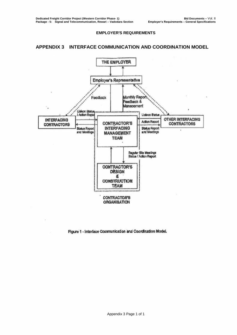
Dedicated Freight Corridor Project (Western Corridor Phase- 1) Bid Documents – Vol. II Package - 5: Signal and Telecommunication, Rewari – Vadodara Section Employer’s Requirements – General Specifications
Appendix 3 Page 1 of 1
EMPLOYER'S REQUIREMENTS
APPENDIX 3 INTERFACE COMMUNICATION AND COORDINATION MODEL
2.1.1
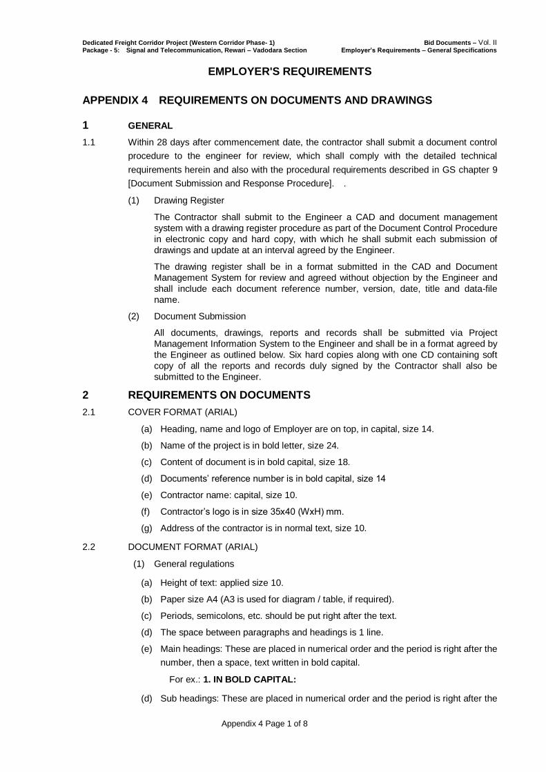
Dedicated Freight Corridor Project (Western Corridor Phase- 1) Bid Documents – Vol. II Package - 5: Signal and Telecommunication, Rewari – Vadodara Section Employer’s Requirements – General Specifications
Appendix 4 Page 1 of 8
EMPLOYER'S REQUIREMENTS
APPENDIX 4 REQUIREMENTS ON DOCUMENTS AND DRAWINGS
1 GENERAL
1.1 Within 28 days after commencement date, the contractor shall submit a document control
procedure to the engineer for review, which shall comply with the detailed technical
requirements herein and also with the procedural requirements described in GS chapter 9
[Document Submission and Response Procedure]. .
(1) Drawing Register
The Contractor shall submit to the Engineer a CAD and document management
system with a drawing register procedure as part of the Document Control Procedure
in electronic copy and hard copy, with which he shall submit each submission of
drawings and update at an interval agreed by the Engineer.
The drawing register shall be in a format submitted in the CAD and Document
Management System for review and agreed without objection by the Engineer and
shall include each document reference number, version, date, title and data-file
name.
(2) Document Submission
All documents, drawings, reports and records shall be submitted via Project
Management Information System to the Engineer and shall be in a format agreed by
the Engineer as outlined below. Six hard copies along with one CD containing soft
copy of all the reports and records duly signed by the Contractor shall also be
submitted to the Engineer.
2 REQUIREMENTS ON DOCUMENTS
2.1 COVER FORMAT (ARIAL)
(a) Heading, name and logo of Employer are on top, in capital, size 14.
(b) Name of the project is in bold letter, size 24.
(c) Content of document is in bold capital, size 18.
(d) Documents’ reference number is in bold capital, size 14
(e) Contractor name: capital, size 10.
(f) Contractor’s logo is in size 35x40 (WxH) mm.
(g) Address of the contractor is in normal text, size 10.
2.2 DOCUMENT FORMAT (ARIAL)
(1) General regulations
(a) Height of text: applied size 10.
(b) Paper size A4 (A3 is used for diagram / table, if required).
(c) Periods, semicolons, etc. should be put right after the text.
(d) The space between paragraphs and headings is 1 line.
(e) Main headings: These are placed in numerical order and the period is right after the
number, then a space, text written in bold capital.
For ex.: 1. IN BOLD CAPITAL:
(d) Sub headings: These are placed in numerical order and the period is right after the

Dedicated Freight Corridor Project (Western Corridor Phase- 1) Bid Documents – Vol. II Package - 5: Signal and Telecommunication, Rewari – Vadodara Section Employer’s Requirements – General Specifications
Appendix 4 Page 2 of 8
number, then a space, text written in bold normal.
For ex.: 1.1 In bold normal:
(2) Note
(a) Notes of tables should be included in the table; in case if these are not able to be
included, the same should be noted clearly that these are notes for which table.
(b) Notes are usually in italic text.
(3) Contents of the documents
(a) Following the Indian regulations, standards of technical process on survey, design,
experiment, etc.
The above sizes are indicative and define proportional sizes only. Actual sizes can
be increased / decreased proportionally as per availability of space.
2.3 DOCUMENT NUMBERING SYSTEM
2.3.1 The Contractor shall prepare the document numbering system as specified in Clause 9.2
Project Document Control.
2.4 UNITS
2.4.1 The Contract shall utilize the SI system of units.
3 REQUIREMENTS ON DRAWINGS
3.1 GENERAL
(1) The Contractor shall adopt a title block placed on bottom right corner and similar for
all drawings prepared under the Contract.
(2) Each drawing shall be uniquely referenced by a drawing number and shall define
both the current status and revision number of the drawing.
(3) The current status of each design drawing shall be clearly defined by the use of a
single letter code as follows:
PD - Preliminary Report Drawing
DD - Detailed Design Drawing
ID - Installation Design Drawing
BD - As-Built Document
3.2 DRAWING NUMBERING SYSTEM
(1) The drawing number shall comprise nine (9) letters/digits plus a revision letter in the
following format:
Drawing No. Revision
n / xx / xx / nnnn x
(A) (B) (C) (D) (E)
(Note: This format permits the use of a full 10 - character computer reference,
combining the Drawing No. and Revision.)
(2) (A) - A single digit (from 1 to 8) denoting the Contract Package Number of project e.g.
1 - CT P-1 Civil/Building/Track Works Rewari – Ajmer Section;
2 - CT P-2 Civil/Building/Track Works Ajmer –Ikbalgarh Section;
3 - CT P-3 Civil/Building/Track Works Ikbalgarh – Vadodara Section
(excluding bridges across river Mahi and Sabarmati);

Dedicated Freight Corridor Project (Western Corridor Phase- 1) Bid Documents – Vol. II Package - 5: Signal and Telecommunication, Rewari – Vadodara Section Employer’s Requirements – General Specifications
Appendix 4 Page 3 of 8
4 - CT P-3A Special Steel Bridges across river Mahi and Sabarmati;
5 - EM P-4 Electrical and Mechanical with Control System and Substation;
6 - ST P-5 Signal & Telecommunication System;
7 - PE P-6 Plant and Equipment for operation and Maintenance and
8 - RS P-7 Electric Locomotive and Maintenance Depot.
(3) (B) - A two (2) alphabet code denoting the subjected area e.g.
AL Alignment Layout
EL Electric Loco Maintenance Depot
YL Yard Layout
IB Important Bridge
MB Major Bridge
NB Minor Bridge
OB ROB
UB RUB
PS Pedestrian Subway
LC Level Crossing
JS Junction Stations
CS Crossing Stations
SB Station Building
DP Maintenance Depots
IM IMD
OC Operation Control Cener
RB Residential Buildings
TW Temporary Works
BA Borrow Areas
ER Equipment Room
BL Block Section
CL Crew Lobby
(4) (C) - A two (2) alphabet code denoting the type of S&T sub-system e.g.
TE Telephone System
CK Clock System
FO Fibre Optic Transmission System
RA Radio System
TV CCTV System
BS Battery Backup System
US Uninterrupted Power Supply System
TP TPWS
IL Interlocking
TM TMS
Dedicated Freight Corridor Project (Western Corridor Phase- 1) Bid Documents – Vol. II Package - 5: Signal and Telecommunication, Rewari – Vadodara Section Employer’s Requirements – General Specifications
Appendix 4 Page 4 of 8
In case of any other drawings, the drawing numbering system shall be submitted by the
Contractor to the Engineer for his consent.
(5) (D) - A unique four (4) digit number (from 0001 to 9999), determined by the
Contractor, identifying each drawing.
(6) (E) - A single alphabet (A to Z except I and O) denoting the sequence of revision to
the drawing. The first drawing issue will carry a revision letter “A”.
3.3 DRAWING SIZE
3.3.1 The drawings produced by the Contractor for submission to the Engineer / Employer shall
generally be to ISO A1 and A3 size unless otherwise instructed by the Engineer. These
shall display the title block containing the information / details as specified herein and shall
be got approved from the Engineer in advance.
4 CAD STANDARDS
4.1 INTRODUCTION
4.1.1 The main objectives of the CAD standards are as follows:
(1) To ensure that the CAD data files produced for project are coordinated and
referenced in a consistent manner.
(2) To provide the information and procedures necessary for a CAD user from one
discipline or external organization to access (and use as background reference),
information from a CAD data file prepared by another discipline or external
organization.
(3) To standardize the information contained within CAD data files which may be
common to more than one discipline such as drawing borders, title boxes, grid lines
etc.
(4) To establish procedures necessary for the management of CAD data files.
(5) To ensure all the contractors use ‘Model Space’ and ‘Paper Space’ in the production
of their CAD files’.
4.2 CAD DATA CREATION, CONTENT & PRESENTATION
4.2.1 A consistent method of CAD data creation, together with content and presentation is
essential. The method of CAD “Model Space” and “Paper Space” creation shall be as
follows:
(1) Model Space Files
(a) Typically CAD “Model Space” files shall be required for general
arrangement and location plans and will consist of a series of other “Model
Space” referenced CAD files covering the total design extents at a defined
building level (the number of referenced files shall be kept to an absolute
minimum). Data contained within a CAD “Model Space” files shall be drawn at full
size (1:1) and located at the correct global position and orientation on the Project
Grid / or defined reference points.
(b) Each CAD “Model Space” file will relate to an individual discipline.
Drawing border / text, match / section lines or detailed notation shall NOT be
included within a CAD “Model Space” file. Dimensions shall be included within a
CAD “Model Space” but located on a dedicated layer. Elevations, Long Sections
and Cross Sections shall also be presented in CAD “Model Space” as defined
above, but do not need to be positioned and orientated on the Project Grid.
(2) Paper Space CAD Files
(a) “Paper Space” CAD files shall be utilised to aid the process of plotting
“Paper” drawings and shall be primarily a window of the CAD “Model Space” file.
A“Paper Space” CAD file shall typically contain drawing borders, text, match or

Dedicated Freight Corridor Project (Western Corridor Phase- 1) Bid Documents – Vol. II Package - 5: Signal and Telecommunication, Rewari – Vadodara Section Employer’s Requirements – General Specifications
Appendix 4 Page 5 of 8
section lines & detailed notation. Once these files are initially set up and
positioned the majority of “Paper Drawing” plots at various approved scales are
efficiently and consistently generated by displaying different combinations of
element layers and symbology contained within the “Paper Space” file and the
referenced “Model Space” files.
(b) The purpose shall be to ensure that total coordination is achieved
between the CAD “Model Space” file and the “Paper Drawing” output during the
revision cycle of the design and production process. Duplicated data in “Model
and Paper Space” files shall not be acceptable unless an automatic update link
exists between the two data sets. “Paper Space” files shall not typically be
required as part of the CAD Media Receipt from contractors, unless specifically
requested.
4.3 CAD QUALITY CONTROL CHECKS
(1) Random CAD Quality Control Audits will be carried out by the Engineer on all CAD
media received and transmitted.
(2) These checks DO NOT verify the technical content of the CAD data received or
transmitted (as this is the responsibility of the originating organization), however
compliance with CAD and drafting standards shall be checked.
(3) In addition, the Contractor who transmit and receive CAD data from the Project shall
have CAD quality control procedures in place. A typical quality control procedure
shall contain CAD data quality checking routines coupled with standards for CAD
data transmittal and archiving.
4.4 REVISIONS
(1) All Construction Industry symbols produced as CAD Cells shall typically conform to
Indian regulation.
(2) The following example text indicates the current CAD file revision, i.e. ‘Revision [A]’.
This shall be allocated to a defined layer on all CAD “Model Space” files, in text of a
size that will be readable when the CAD “Model Space” file is fitted to the screen,
with all levels on.
4.5 BLOCK LIBRARIES, BLOCKS, & BLOCK NAMES
(1) All Construction Industry symbols produced as CAD Cells shall typically conform to
Indian regulation.
(2) All Blocks created shall be Primitive (i.e. NOT Complex) and shall be placed
Absolute (i.e. NOT Relative).
(3) The Contractor's specific block libraries shall be transmitted to the Engineer together
with an associated block library list containing the filename (max. 6 characters) and
block description. The Contractor shall ensure that the library is regularly updated
and circulated to all other users, together with the associated library listing.
(4) All Blocks of a common type, symbols or details shall initially be created within a
CAD “Model Space File” specifically utilized for that purpose. These files shall be
made available to the Engineer / Employer as required.
(5) All Blocks created shall typically be 2D unless 3D is specifically requested. In both
instances they shall have an origin at a logical point located within the extents of
each Block’s masked area or volume.
4.6 CAD DIMENSIONING
4.6.1 Automatic CAD Dimensioning shall be used at all times. Any dimensional change must
involve the necessary revision to the model space file. If the CAD Quality Control Checks
find that the revisions have not been correctly carried out, the rejection of the entire CAD
submission will result.

Dedicated Freight Corridor Project (Western Corridor Phase- 1) Bid Documents – Vol. II Package - 5: Signal and Telecommunication, Rewari – Vadodara Section Employer’s Requirements – General Specifications
Appendix 4 Page 6 of 8
4.7 CAD LAYERING
4.7.1 All CAD elements shall be placed on the layers allocated for each different discipline. The
layer naming convention to be adopted by the Contractor shall be submitted for acceptance
and inclusion within these standards.
4.8 GLOBAL ORIGIN, LOCATION AND ORIENTATION ON THE ALIGNMENT DRAWING
4.8.1 Location or Plan information in “Model Space” files shall coincide with the correct location
and orientation on the Project grid for each specific contract.
4.8.2 Location plans shall have at least three setting out points shown on each CAD “Model
Space” file. Each setting out point shall be indicated by a simple cross-hair together with
related Eastings and Northings co-ordinates. The Contractor shall establish the setting out
coordinates for his respective Works, which will then be used by the Other Contractors.
4.9 LINE THICKNESS AND COLOR
4.9.1 To facilitate the consistent plotting by the Contractor and other users, the colour codes, line
shape, line thickness / pen sizes etc. for different applications of the works / work elements
shall be assigned by the Contractor and submitted to the Engineer for his consent.
4.10 MASTER LIST OF DOCUMENTS FOR APPROVAL
4.10.1 The Contractor shall furnish the Engineer a master list of the technical documents for
approval, which he proposes to prepare and submit under the Contract, within 42 days from
the Commencement Date. The master list shall include the drawing number, title and the
Contractor's target date for the first submission of each document for approval.
4.10.2 The master list of documents to be submitted shall be subject to the Engineer's approval.
4.10.3 The master list shall be used to monitor submission and approval of each drawing.
4.11 CAD UTILIZATION OF 2D & 3D FILES
4.11.1 Although the project standard shall be 2D CAD files, certain disciplines and contractors
may use 3D CAD files for specific applications or where the isolated use of 3D aids the
design and visualisation process (i.e. Architecture, Survey and Public Utilities). In these
specific instances 3D CAD data will only be transmitted if all other users can use this data.
If this is not the case, a 3D to 2D translation shall be processed by the creator prior to issue.
4.12 CAD FILE NUMBERING
4.12.1 Contractor’s CAD File Numbering shall be as described in clause 2.2.
4.12.2 Employer’s CAD File Numbering : This will follow the numbering system as specified above
except that the status of the drawing shall be with the letter "E".
4.13 CAD FILE NAMING CONVENTION – GENERAL
4.13.1 CAD “Model Space” files shall be named in accordance with general drawing conventions.
5 SUBMISSION, RECEIPT AND TRANSMITTAL OF DOCUMENTS AND
DRAWINGS
5.1 SUBMISSION OF THE DOCUMENTS AND DRAWINGS
5.1.1 Unless and otherwise instructed by the Engineer, when the Contractor submit any documents and drawings to the Engineer for his check/ review/ approval/ consent/ issue of “Notice of No Objection” as well as in respect of “Good for Construction Drawings” and “As Built Documents”, the Contractor shall prepare six (6) sets of hard copies (controlled copies) with one (1) set of CDs of submitting documents and CAD data of submitting drawings.
5.1.2 Signalling Circuit books

Dedicated Freight Corridor Project (Western Corridor Phase- 1) Bid Documents – Vol. II Package - 5: Signal and Telecommunication, Rewari – Vadodara Section Employer’s Requirements – General Specifications
Appendix 4 Page 7 of 8
a) Signaling Circuit books shall be bound in loose leaf form so that pages are easily replaceable. One or more books per interlocking area shall be provided depending on the number of plans required. One book shall be provided per equipment location giving information relevant to that location. Through circuits
shall appear in both Station Interlocking and automatic signalling circuit books.
b) Plans for Automatic Signalling Sections shall be made up into circuit books
comprised of A3 size drawings.
c) Circuit books shall have a comprehensive index which shows all plan numbers.
d) The Designer shall produce a list showing all plan numbers and current revision status in plan number order. The Drawing Management System will allocate a
series of plan numbers for any new plans required by the Designer.
e) Circuit books shall be of manageable size and weight with a maximum thickness of 25 mm. Beyond this size, books shall be split into logically ordered volumes as approved by the Engineer.
f) Book binders shall not form an injury hazard to users. They shall slide easily and not be damaged or damage other books when books are stacked for storage.
5.2 DATA TRANSFER MEDIA AND FORMAT
5.2.1 When data is received & transmittal between the Engineer / Employer and the Contractor, the media shall be as follows:
(1) Data Exchange Format
(a) Document including tables and figures: PDF (.pdf)
(b) Drawings: Autocad (Latest version)
(2) Operating System – Windows 7 or 8 (3) Data Transfer Media : 12cm Compact Disc (650 MB) or preferably DVD (4) All CDs or DVDs shall be labeled on the data shield with:
(a) Name of Employer / Contractor
(b) Project Title
(c) Drawing Filenames
(5) The Contractor shall ensure the supplied media is free from virus.
5.3 CAD MEDIA RECEIPT & TRANSMITTAL
(1) CAD Media Transmittal (from the Contractor to the Engineer) – this will consist of the following:
(a) CAD Digital Media shall typically contain CAD “Model Space” and “Paper Space” files;
(b) CAD data sheet;
(c) CAD issue/ revision sheet and
(d) CAD Quality Checklist confirming compliance.
(2) The above CAD media will be collectively known as “CAD Media Transmittal Set”. The CAD data file transmittal format required by the Engineer from all contractors shall be in AutoCAD (version 2011)

Dedicated Freight Corridor Project (Western Corridor Phase- 1) Bid Documents – Vol. II Package - 5: Signal and Telecommunication, Rewari – Vadodara Section Employer’s Requirements – General Specifications
Appendix 4 Page 8 of 8
(3) All CAD media received from contractors will be retained by the Engineer as an audit trail / archive of a specific contractor’s design evolution.
(4) CAD Media Receipt (from the Engineer to the Contractor)
(a) CAD media should normally be as obtained from the respective Other Contractors and Interfacing parties , but should the Engineer issue CAD media it will consist of the following:
i. CAD Digital Media typically contain only CAD “Model Space” files.
ii. CAD data sheet.
iii. CAD issue / revision sheet
(b) Each CAD transmittal disk will be labelled with proper disk label as approved by the Engineer. Any CAD data transmitted without this label is assumed to be provisional information not to have been quality checked and therefore not formally issued.
∗ End of Appendix 4 ∗

Dedicated Freight Corridor Project (Western Corridor Phase- 1) Bid Documents – Vol. II Package - 5: Signal and Telecommunication, Rewari – Vadodara Section Employer’s Requirements – General Specifications
Appendix 5 Page 1 of 2
EMPLOYER'S REQUIREMENTS
APPENDIX 5 FORM DC – DESIGN CERTIFICATE
FORM DC - Page 1 of 2
This design certificate refers to submission no. ..……… Which comprises: ………
Design package no. ....
Design stage : preliminary design / detailed design / construction/installation design / as-built
document/ in respect of :
[description of the Works to which the submission refers]
The contents of this submission are listed in Section A.
Documents for which a Notice of No Objection has previously been issued and which are of relevance
to this Submission are listed in Section B.
DESIGNER’S STATEMENT
We certify that the design of the Works, as shown and described in the drawings and documents listed
in Section A,
(a) has been designed by us and complies with the Employer's Requirements and all other
requirements of the Contract;
(b) has been properly reviewed and confirmed as a complete, accurate, adequate and of valid
design through an in-house design and QA check
(c) includes all necessary and required approvals (e.g. from Local Authorities or agencies etc)
relating to the design and copies of such approvals are annexed in Section C;
(d) all effects of the design comprising the submission on, or from, the design of adjacent or other
parts of the Works and Interfacing Contracts have been fully taken into account in the design.
(e) Where required, ISA’s certificate is attached.
Signed by ‘Authorised Representative’ (for Designer)
Name Date
Position/Designation

Dedicated Freight Corridor Project (Western Corridor Phase- 1) Bid Documents – Vol. II Package - 5: Signal and Telecommunication, Rewari – Vadodara Section Employer’s Requirements – General Specifications
Appendix 5 Page 2 of 2
FORM DC - Page 2 of 2
CONTRACTORS CERTIFICATION
This Certifies that all design has been performed utilising the skill and care to be expected of a
professionally qualified and competent designer, experienced in work of similar nature and scope. This
further certifies that all works relating to the preparation, review, checking and certification of design
has been verified by us.
Signed by ‘Authorised Representative’, (for Contractor)
Name Date
Position/Designation
Section A
Submission no. .... comprises the following :
Drawings : (Title, drawing number and revision)
Documents : (Title, reference number and revision)
Others :
Section B
Documents for which a Notice of No Objection has previously been issued and which are of relevance
to this Submission :
Document : (Title, reference number and revision)
submitted with Submission No…..
(Contractor to provide sufficient details to uniquely identify the relevant document)
Section C
[Contractor to attach copies of necessary and required approvals]
End of Appendix 5
Dedicated Freight Corridor Project (Western Corridor Phase- 1) Bid Documents – Vol. II Package - 5: Signal and Telecommunication, Rewari – Vadodara Section Employer’s Requirements – General Specifications
Appendix 6 Page 1 of 4
EMPLOYER'S REQUIREMENTS
APPENDIX 6 MONTHLY PROGRESS REPORT
1. GENERAL
(1) The Contractor shall submit to the Engineer, a Monthly Progress Report as
required per clause 7.16 of GS. This Report shall be submitted to the Engineer by
the fifth day of the month following the month the Monthly Progress Report pertains
and shall account for all work actually performed up to and including the last day of
the Month of the Monthly Progress Report. The report shall continue until the
contractor has completed all work which is known to be outstanding at the
completion date stated in the Taking Over certificate for the work. It shall be
submitted in a format to which the Engineer shall have given his consent and shall
contain sections/sub-sections for, but not be limited to, the topics listed in clauses
below.
2. EXECUTIVE SUMMARY
(1) The contractor shall provide an executive summary highlighting the major
achievements made during the reporting period, the activities planned for the next
month and any issues that are affecting or may affect future project progress
explaining corrective action to be taken. These items are to be dealt with fully in the
body of the report.
3. FINANCIAL STATUS
(1) A report on the status of the Contractor’s claims and potential claim – variations /
potential variations. List of variations, notices given under conditions of contract
clauses CC 2.5 (Employer’s claims) and CC 20.1 (contractor’s claim) shall be
included.
4. DESIGN STATUS
(1) A report detailing the design and design co-ordination progress made during the
reporting period together with a progress copy of the Design submission
Programme. (list of all design submittals verses deliverable schedule showing
current status to be appended.)
5. PHYSICAL PROGRESS
(1) It shall describe the status of work performed, significant accomplishments,
including critical items and problem areas, corrective actions taken or planned and
other pertinent activities and shall, in particular, address interface issues, problems
and resolutions. (See clause 7.18 of GS)
(2) It shall include a simplified representation of progress measured in percentage
terms compared with percentage planned as derived from the Works Programme.
(3) Physical progress shall include the following activities:
(a) Equipment / Software installation and erection;
(b) Test and Commissioning activity;
Dedicated Freight Corridor Project (Western Corridor Phase- 1) Bid Documents – Vol. II Package - 5: Signal and Telecommunication, Rewari – Vadodara Section Employer’s Requirements – General Specifications
Appendix 6 Page 2 of 4
(c) System integration tests;
(d) Completion of remedial works;
(e) Progress photographs;
(f) Contractor’s resources (details of all staff and sub-contractors engaged on the works) and
(g) Software development.
6. PROGRAMME UPDATE (FOR ENTIRE PROJECT)
Programme updating shall include:
(1) The monthly Programme Update which shall be prepared by recording actual
activity completion dates and percentage of activities completed up to the
twenty-fifth (25th ) of the month together with estimates of remaining duration and
expected activity completion based on current progress. The Programme Update
shall be accompanied by an Activity Report and a Narrative Statement. The
Narrative Statement shall explain the basis of the Contractor’s submittal:
(a) Early Work and Baseline Submittals – explains determination of activity
duration and describes the Contractor’s approach for meeting required
Coordination Dates as specified in the Contract.
(b) Updated Detail Programme Submittals – state in narrative the Works actually
completed and reflected along Critical Path in terms of days ahead or behind
allowable dates. Specific requirements of narrative are:
(i) If the Updated Detailed Work Programme indicates an actual or
potential delay to Contract Completion date or Coordination Dates,
identify causes of delays and provide explanation of Work affected
and proposed corrective action to meet Coordination Dates or
mitigate potential delays. Identify deviation from previous month’s
critical path.
(ii) Identify by activity number and description, activities in progress and
activities scheduled to be completed.
(iii) Discuss Variation Order Work Items, if any linking Engineer’s
instructions for such variations.
(2) The Programme Status which shall:
(i) show Works Programme status up to and including the current report period,
display Cumulative progress to date and a forecast of remaining work and
(ii) be presented as a bar-chart size A3 or A4 and as a time-related logic
network diagram on an A1 media, including activity listings.
(3) The Activity Variance Analysis which shall analyse activities planned to start prior to
or during the report period but not started at the end of the report period as well as
activities started and/or completed in advance of the Works Programme. (See
clause 7.19 of GS).
(4) The progress of other programmes including Operation manuals, Maintenance
manuals, Training manuals, As-built drawings, Spares/ Special Tools/ Diagnostic
Equipment/test equipment, Training, Employer’s Taking Over of Works (part or
Dedicated Freight Corridor Project (Western Corridor Phase- 1) Bid Documents – Vol. II Package - 5: Signal and Telecommunication, Rewari – Vadodara Section Employer’s Requirements – General Specifications
Appendix 6 Page 3 of 4
whole of Works), Maintenance issues, Defects Liability.
(5) The Progress on any other programmes as required by the Engineer.
7. MILESTONES AND COORDINATION EVENTS STATUS
(1) A report on the status of all milestones and Coordination Events due to have been
achieved during the month and forecasts of achievement of any missed milestones
and Coordination Events and those due in the next month.
8. THREE MONTH ROLLING PROGRAMME
(1) The monthly issue of the Three Month Rolling Programme.
9. PLANNING AND CO-ORDINATION
(1) A summary of all planning/co-ordination activities during the month and details of
outstanding actions.
(2) A schedule of all submissions and consents/approvals obtained/outstanding.
10. PROCUREMENT REPORT
(1) A summary of all significant procurement activities during the month, including
action taken to overcome problems.
(2) A report listing major items of plant and materials which will be incorporated into the
Works. The items shall be segregated by type and the report should show as a
minimum the following activities:
(a) purchase Order Date - Scheduled/Actual;
(b) manufacturer/Supplier and Origin;
(c) letter of Credit Issued date;
(d) manufacturer/Supplier Ship Date - Scheduled/Actual;
(e) method of Shipment and
(f) arrival Date at nominated site of DFCCIL- Scheduled/Actual.
11. PRODUCTION AND TESTING
(1) A review of all production and manufacturing activities during the month.
(2) Summaries of all production and manufacturing outputs during the month together
with forecasts for the next month.
(3) Review of all testing activities (both at site or at the manufacture's premises) during
the month.
12. SAFETY
(1) A review of all safety aspects during the month including reports on all accidents
and actions proposed to prevent further occurrence.
13. ENVIRONMENTAL
(1) A review of all the environmental issues during the past month to include all
monitoring reports, mitigation measures undertaken and activities to control
environmental impacts.
14. QUALITY ASSURANCE
(1) A review of all quality assurance issues during the past month including all audits
undertaken (internal and external) with a schedule detailing the status of

Dedicated Freight Corridor Project (Western Corridor Phase- 1) Bid Documents – Vol. II Package - 5: Signal and Telecommunication, Rewari – Vadodara Section Employer’s Requirements – General Specifications
Appendix 6 Page 4 of 4
outstanding actions.
14. COPIES
(1) The contractor shall submit 1 unbound original and 6 (six) bound hard copies of all
monthly progress reports and accompanying documents plus one copy in
electronic format.
* End of Appendix 6 *

Dedicated Freight Corridor Project (Western Corridor Phase- 1) Bid Documents – Vol. II Package - 5: Signal and Telecommunication, Rewari – Vadodara Section Employer’s Requirements – General Specifications
Appendix 7 Page 1 of 3
EMPLOYER'S REQUIREMENTS
APPENDIX 7 SYSTEM SAFETY MANAGEMENT
1. SAFETY ASSURANCE PROGRAMME PLAN
1.1 The Contractor shall within 30 days of Notice to Proceed, submit his proposed Safety
Assurance Programme Plan to the Employer for approval.
1.2 The Safety Assurance Programme Plan shall cover design, manufacture, testing, integrated
testing and commissioning to ensure safe routing, spacing, movement and control of trains and
meet the requirements as stipulated in the PS.
1.3 The Safety Assurance Programme Plan shall also address reliability, maintainability and
availability of the system. This shall ensure the system has a high degree of reliability and
minimise down time during routine and failure repair. The Safety Assurance Programme Plan
shall describe procedures required to perform the specific tasks necessary to achieve safety,
reliability and maintainability requirements. These procedures shall be incorporated within
the Contractor’s Quality Assurance System and shall be subject to review by the Engineer.
1.4 The Safety Assurance Programme Plan shall include an EMC/EMI Control Plan that shall
evaluate the requirements for electro-magnetic compatibility and interference, in this
specification for all appropriate elements of the system and ensure they are met. Proximity of
Signalling and Telecom systems of DFCCIL to the Indian Railways 25 KV AC electrified lines
shall also be taken into account.
2. HAZARD ANALYSIS
2.1 The Contractor shall take the lead role in the interface Hazard Analysis for trackside
equipment, to which the system is interfaced, provided by other contractors.
2.2 The Contractor shall produce the Hazard Analysis Schedule for the complete system including
all interfacing systems.
2.3 The Contractor shall, as part of the safety analysis, prepare analyses to identify Hazards and
ensure their satisfactory resolution. The following analyses shall be prepared and submitted
by the Contractor for the Engineer approval:
(i) Preliminary hazard analysis;
(ii) Interface hazard analysis;
(iii) Subsystem hazard analysis;
(iv) Operating hazard analysis including maintenance;
(v) Fault tree analysis and
(vi) Failure modes effects and criticality analysis (FMECA).
2.4 The Contractor shall compile a list of critical and catastrophic items identified as a result of
hazard analysis, FMECA or by other means.
2.5 All hazard resolution by procedural control shall be cross-referenced from the Critical and
Catastrophic Items List to the appropriate manuals.
2.6 The qualitative measures of hazard severity are defined as follows:

Dedicated Freight Corridor Project (Western Corridor Phase- 1) Bid Documents – Vol. II Package - 5: Signal and Telecommunication, Rewari – Vadodara Section Employer’s Requirements – General Specifications
Appendix 7 Page 2 of 3
(i) Hazard Category I – Catastrophic: Operating conditions such that personnel errors,
environment, design deficiencies, subsystem or component failure or procedural
deficiencies may cause death or system loss. The safety target shall be based on
internationally accepted standards.
(ii) Hazard Category II – Critical: Operating conditions such that personnel errors,
environment, design deficiencies, subsystem or component failure or procedural
deficiencies may cause severe injury to personnel, severe occupational illness or
major system damage.
(iii) The safety target for the occurrence of all Category II hazards summed together
shall again be based on internationally accepted standards.
(iv) Hazard Category III – Marginal: Operating conditions such that personnel errors,
environment, design deficiencies, subsystem or component failure or procedural
deficiencies, may cause minor injury to personnel, minor occupational illness or
minor system damage.
(v) Hazard Category IV – Negligible: Operating conditions such that personnel errors,
environment, design deficiencies, subsystem or component failure or procedural
deficiencies will not result in injury to personnel occupational illness or damage to
the system.
(vi) The Contractor shall submit a Schedule for Hazard Analysis Submissions within 30
days of Notice to Proceed. The Preliminary Hazard Analysis shall be submitted
within 6 months of Notice to Proceed. This draft shall include a comprehensive
assessment of potential equipment failure modes during normal operating and
overload conditions and assess the performance of the equipment for a range of
hazard conditions. The final draft shall be submitted by the completion date of
final design.
2.7 The Contractor shall prepare a Fire Safety Design Report for the Engineer approval. This shall
be submitted within 2 months after Notice to Proceed and revised and updated for the
completion of the preliminary and final design stages. Materials used in the Permanent
Works of the system shall conform to Indian or Japanese fire safety requirements or the latest
edition of other equivalent international standards, subject to the approval of the Engineer.
Note: Whichever Standard is selected for meeting the Fire Safety Criteria, then that
standard shall be declared and its requirements shall be met consistently throughout the
contract/work.
3 RESULTS
3.1 Source of all failure rates employed shall be indicated in the Hazard Analyses and shall be as
far as possible independently established by recognised standards authorities.
3.2 All hazard analyses submitted to the Employer are to be standardised by the Contractor such
that format and forms employed by all sub-contractors are the same.
3.3 The following targets shall be employed for the Fault Tree Analysis
(i) No single point failure shall lead to unsafe situation.
No combination of undetected failure and double point failures shall result in unsafe situation.
No combination of undetected failure and single point failure shall result in unsafe situation.

Dedicated Freight Corridor Project (Western Corridor Phase- 1) Bid Documents – Vol. II Package - 5: Signal and Telecommunication, Rewari – Vadodara Section Employer’s Requirements – General Specifications
Appendix 7 Page 3 of 3
3.4 The procedures for Operation, Maintenance, Training and the Contractor’s Quality Assurance
manuals shall incorporate resolution of hazards identified from this hazard analysis. Proper
cross-referencing to the hazards and resolution measures shall be provided in all these
aforementioned documents.
End of Appendix 7

Dedicated Freight Corridor Project (Western Corridor Phase- 1) Bid Documents – Vol. II Package - 5: Signal and Telecommunication, Rewari – Vadodara Section Employer’s Requirements – General Specifications
Appendix 8 Page 1 of 12
EMPLOYER'S REQUIREMENTS
APPENDIX 8 SOFTWARE QUALITY ASSURANCE PLAN
1. GENERAL
1.1 This Section defines the management and control requirements which the Employer will
impose on software.
1.2 Where the software is to be supplied by an organisation other than the Contractor, the
Contractor shall pass on all requirements in their entirety and without modification. The
Contractor shall, however, remain responsible for the execution of the Works.
2. DEFINITIONS
2.1 Software
2.1.1 The term “software” used within the scope of this Appendix shall cover software and firmware.
The following definitions shall be applicable to all software products to be delivered under the
scope of the Contract.
2.2 Workpackage
2.2.1 A “workpackage” is defined as a group of software and/or firmware items which fulfil defined
requirements and which shall be validated and tested as one logical unit.
2.2.2 The assurance and deliverable requirements for each workpackage are characterised by its
Safety Integrity Level as defined in the Contract.
2.3 Supplier
2.3.1 The “supplier” of a workpackage is defined as the organisation responsible for supplying or
developing that workpackage to fulfil Contract requirements.
2.4 Safety Integrity Level
2.4.1 “Safety Integrity Level” is a classification assigned to a workpackage to indicate the sensitivity
of a possible fault within that workpackage to its impact on people or service with respect to
safety, customer service, environmental obligations and revenue. Safety Integrity Levels will
be assigned in relation to the requirements of IEC62279. (Railway Application Software for
Railway Control and Protection Systems).
2.4.2 The Safety Integrity Levels of all workpackages are defined in the Contract.
2.5 Intellectual Property Rights
2.5.1 The intellectual property rights of all software including source code listings produced for the
Contract shall be vested in the Contractor or his suppliers.
2.6 Software Lifecycle
2.6.1 The Contractor shall confirm in the software quality plan compliance with the software
development lifecycle phases, as detailed in IEC62279 by Safety Integrity Level.
3. SOFTWARE QUALITY ASSURANCE REQUIREMENT
3.1 Software Quality Assurance Requirements
3.1.1 Clauses 3.2 to 3.9 are general process and product quality assurance requirements. The
Contractor shall comply with those applicable to specific Safety Integrity Level for individual
workpackage.
3.2 ISO 9000-3 Compliance

Dedicated Freight Corridor Project (Western Corridor Phase- 1) Bid Documents – Vol. II Package - 5: Signal and Telecommunication, Rewari – Vadodara Section Employer’s Requirements – General Specifications
Appendix 8 Page 2 of 12
3.2.1 To ensure the quality of the software development process, the Contractor shall comply with
the requirements of the BS EN ISO 9000-3:1997 “Guidelines for the Application of ISO 9001 to
Development, Supply and Maintenance of Software”. ISO 9000-3 is considered appropriate for
Safety Integrity Level (SIL) 0 or 1 Software. The Contractor shall further comply with the
requirement of the SEI-CMM-SW and shall state to what level the workpackage is being
developed. The level shall be submitted for review by the Employer.
3.3 Configuration Management
3.3.1 To control change during the software development lifecycle, the Contractor shall define and
implement effective software configuration management procedures. These procedures shall
be defined in the configuration management plan. The Contractor shall refer to Clauses 8.1
to 8.9 for specific requirements.
3.3.2 The Contractor shall use an automated and integrated software package to perform
configuration management functions.
3.4 Software Development Programme
3.4.1 The Contractor shall create and maintain a software development programme for the Contract.
This programme shall be linked to the Contractor’s Design, Procurement and Manufacture
Programme and shall:
(a) define the schedule of the whole software development effort;
(b) define activities for each phase of the software development lifecycle at individual
workpackage level;
(c) highlight software related Milestones;
(d) define internal software audit schedule and
(f) define the critical path of software development of the Contract.
3.5 Dependability Requirements
3.5.1 For all workpackages, the Contractor shall perform the following, in accordance with the
requirements of IEC62279 and submit the results for review by the Employer:
(a) software hazard analysis;
(b) interface hazard analysis;
(c) software fault tree analysis;
(d) software effects analysis;
(e) common cause failure analysis and
(d) specify procedures for graceful degradation of the system.
3.5.2 For all workpackages the Contractor shall perform of the following, in accordance with the
requirements of IEC62279 and submit the results for review by the Employer:
(a) fagan inspection;
(b) structured walkthrough;
(c) formulate an appropriate software reliability growth model and
(d) use only development tools which have been certified by appropriate certification bodies.
3.6 Software Metrics
3.6.1 For all workpackages software metrics shall be used throughout the entire software
development lifecycle to plan, manage and improve the process and to control and predict the
Dedicated Freight Corridor Project (Western Corridor Phase- 1) Bid Documents – Vol. II Package - 5: Signal and Telecommunication, Rewari – Vadodara Section Employer’s Requirements – General Specifications
Appendix 8 Page 3 of 12
quality of software products.
3.6.2 The following metrics shall be collected at each individual software development phase:
(a) Software requirements analysis & design phases;
(i) requirement/design document pages;
(ii) defects found via requirements/design review, inspection, or use in subsequent development stages;
(iii) function size and
(iv) number of calls from individual module.
(b) Software module coding phase
(i) Complexity;
(ii) lines of code;
(iii) comment ratio and
(iv) volume.
(c) Software test, Commissioning, Defects Notification Period
(i) discrepancy break/fix ratio;
(ii) computer resource utilization rate;
(iii) discrepancy open duration;
(iv) defect density over time;
(v) defect type distribution;
(vi) maintenance staff utilization;
(vii) percentage of modules changed per release;
(viii) test case completion rate;
(ix) percentage of paths tested and
(x) percentage of decision nodes and branches tested.
(d) all phases
(i) effort spent in person-months and
(ii) requirements stability.
3.6.3 The Contractor shall define in the software quality plan metrics to be collected at individual
software development phases and establish goals to be achieved. The goals shall be
reviewed without objection by the Engineer.
3.6.4 The Contractor shall use collected measures to track progress, adjust the process to correct
out-of-bound conditions and to evaluate impacts of these adjustments.
3.6.5 Metrics measurements shall be recorded for audit review and shall be made available to the
Engineer upon request. Analysis results shall be given in the software verification and
validation report. Any potential adverse impact on the software development programme
and/or requirements shall be communicated to the Engineer.
3.6.6 Automated tools shall be used to facilitate the metrics measurement process.
Dedicated Freight Corridor Project (Western Corridor Phase- 1) Bid Documents – Vol. II Package - 5: Signal and Telecommunication, Rewari – Vadodara Section Employer’s Requirements – General Specifications
Appendix 8 Page 4 of 12
3.7 VERIFICATION AND VALIDATION
3.7.1 The Contractor shall develop a software verification and validation plan for the verification of all
development phase outputs at the end of each phase and for the validation of the software
system before delivery for site acceptance test. Such plan shall cover all software delivered for
the Works, including those provided by subcontractors.
3.7.2 Verification and validation shall be carried out in accordance with IEC62279 and the assigned
Safety Integrity Level.
3.8 INTERNAL SOFTWARE AUDIT
3.8.1 The Contractor shall conduct internal software quality audits throughout the software
development lifecycle of the Contract. These audits shall cover all software supplier(s) for the
Contract.
3.8.2 An internal audit schedule shall be defined in the software development programme of the
Contract.
3.9 SOFTWARE AUIDTS BY THE ENGINEER
3.9.1 The Engineer will conduct software audits on all software supplier(s) of the Contract whenever
appropriate. Seven (7) days of advance notice will be given to the Contractor.
3.9.2 The Contractor and his supplier(s) shall make relevant personnel available for interview and
provide all necessary supporting material for auditing.
4. DELIVERABLE REQUIREMENTS
4.1 General
4.1.1 Clauses 4.2 to 4.5 are general deliverable requirements. The Contractor shall submit those
applicable to specific Safety Integrity Level, dependability level and/or development level for
individual workpackages.
4.2 Software License & Program Listing
4.2.1 The Contractor shall deliver all the software licenses in original.
4.2.2 All software licenses shall be valid for ever.
4.3 Software Safety Plan
4.3.1 The Contractor shall submit a software safety plan in accordance with the requirements of the
Major Capital Works Safety Management System and IEC62279.
4.4 Software Reliability Plan
4.4.1 The Contractor shall submit a software reliability plan in accordance with the requirements of
IEC62279.
4.5 Submissions for Review
4.5.1 At software inception the Contractor shall submit for review by the Employer the following
documents:
(a) Software Quality Plan;
(b) Software Requirement Specification;
(c) Software Safety Plan;
(d) Software Verification & Programme Plan;
(e) Software Development Plan and Programme;
(d) Software Reliability Plan and

Dedicated Freight Corridor Project (Western Corridor Phase- 1) Bid Documents – Vol. II Package - 5: Signal and Telecommunication, Rewari – Vadodara Section Employer’s Requirements – General Specifications
Appendix 8 Page 5 of 12
(f) Configuration Plan.
4.5.2 During the Works, the Contractor shall submit for review by the Employer the following
documents:
(a) Software (module & integration) Test Plan;
(b) Software (module & integration) Test Results;
(c) Software Design Specifications;
(d) Audit results;
(e) Software review meeting minutes;
(f) System Test Plan;
(g) System Test Results and
(h) Metric reports.
4.5.3 At the time of software handover, the Contractor shall submit for review by the Employer the
following documents:
(a) Software Verification & Validation Report;
(b) Software Operational Safety;
(c) Software Availability Report and
(d) Deliverables in accordance with Clause 4.5.
4.5.4 Other deliverable as required is IEC62279, dependent upon Safety Integrity Level, shall be
forwarded for review by the Employer at a time commensurate with the requirements of
IEC62279
4.6 Post Acceptance Documents
4.6.1 The Contractor shall submit post-acceptance documentation in accordance with Clauses 12.1
to 12.6.
5. SOFTWARE PROJECT MANAGEMENT
5.1 General
5.1.1 The Contractor shall conduct software project management in accordance with Clauses 5.2 to
5.7.
5.2 Supplier Management
5.2.1 The Contractor shall be responsible for managing the performance of all software supplier(s)
and the quality of their work. The Contractor shall be responsible for the validation of all
subcontracted work.
5.2.2 The Contractor shall ensure that his software supplier(s) conform to the software quality plan,
configuration management plan and software development programme as soon as they have
been reviewed without objection by the Employer.
5.2.3 The organizational and working relationships between the Contractor and all the suppliers
shall be described in the software quality plan.
5.3 Key Personnel
5.3.1 If any key member of the software team becomes unavailable, the Contractor shall submit his
notice, together with qualified replacement for review by the Employer. The replacements shall
start working on the Works at least one month before the departure of the original member.
5.4 Software Milestones

Dedicated Freight Corridor Project (Western Corridor Phase- 1) Bid Documents – Vol. II Package - 5: Signal and Telecommunication, Rewari – Vadodara Section Employer’s Requirements – General Specifications
Appendix 8 Page 6 of 12
5.4.1 Achievement of having received a notice of no objection status of the submissions detailed in
Clause 4.6 will be included in payment Milestones set out in the Interim Payment Schedule.
5.5 Software Review Meetings
5.5.1 The Contractor shall present the result of software requirements analysis at the Employer’s
site office prior to the submission of the software requirements specifications.
5.6 Baseline of Requirements / Design Document
5.6.1 The Contractor shall baseline the software requirements specification and the software design
specifications as a formal procedure upon receipt of a notice of no objection from the Engineer
on corresponding document.
5.6.2 Any necessary functional and/or technical changes to these documents after baseline shall be
submitted for review by the Engineer.
5.7 Completion Test and Commissioning Support
5.7.1 During site completion test and commissioning, the Contractor and his software supplier(s)
shall provide technical staff at the test or commissioning Site to support defect analysis,
software configuration control over change requests and proper distribution and installation of
software changes.
5.7.1 The Contractor shall ensure that software defects shall be rectified, tested, validated,
configured and delivered to the test or commissioning Site in accordance with the programme
having been reviewed without objection by the Engineer.
6. SPECIFIC DOCUMENTATION REQUIREMENTS
6.1 GENERAL
The Contractor shall produce software related documents in accordance with the following
general requirements, or otherwise reviewed without objection by the Employer. The software
quality plan, the software configuration management plan and the software verification and
validation plan shall be prepared using the provided table of contents.
6.2 SOFTWARE QUALITY PLAN REQUIREMENT
6.2.1 The software quality plan shall define the controls and methods necessary to ensure that the
quality processes appropriate for the development are selected by the Contractor and
reviewed without objection by the Engineer.
6.2.2 The software quality plan shall define the responsibilities and authorities of the key personnel
responsible for the development, testing and integration of the software.
6.2.3 The software quality plan shall identify the software work packages to be produced and the
development level that has been assigned, including justification.
6.2.4 The software quality plan shall define a software lifecycle, or lifecycles, to be used for the
development, testing and supply of software.7.5 The software quality plan shall map the
phases of the defined software lifecycle(s) against the phases of the lifecycle.
6.2.6 The software quality plan shall list all contractual deliverables.
6.2.7 The software quality plan shall specify the guidelines, standards, Codes of Practice,
methodologies, languages and tools to be applied at each lifecycle phase.
6.2.8 The software quality plan shall make reference to the Contractor's quality control and quality
assurance procedures, including the procedures for configuration management (see Clauses
6.3.1 to 6.3.9 that will apply to the Contract.

Dedicated Freight Corridor Project (Western Corridor Phase- 1) Bid Documents – Vol. II Package - 5: Signal and Telecommunication, Rewari – Vadodara Section Employer’s Requirements – General Specifications
Appendix 8 Page 7 of 12
6.2.9 The software quality plan shall state the review points. This statement shall clearly differentiate
between internal activities and those which involve the Engineer.
6.2.10 The software quality plan shall specify or make reference to the procedures to be adopted to
ensure the security of the software.
6.2.11 The software quality plan shall contain the content in Table 1 below.
Table 1 - FORMAT FOR SOFTWARE QUALITY PLAN
SOFTWARE QUALITY PLAN
1. Purpose
2. Reference Documents
3. Management
3.1 Organization
3.2 Tasks
3.3 Responsibilities
4. Deliverables
4.1 Purpose
4.2 List of Software Workpackage and Development Level
4.3 Submission Requirements
5. Software Development Lifecycle
5.1 Mapping to the Engineer’s Standard
5.2 Input and Output Document far Each Phase
6. Standards, Practices, Conventions and Metrics
6.1 Assurance and Control of Compliance
6.2 Reference standards
(a) Design Standards
(b) Coding Standards
(c) Testing Standards
(d) Review and Audit Standards
7. Reviews and Audits
8. Test and Integration
9. Problem Reporting and Corrective Action
10. Tools. Techniques and Methodologies
11. Software Supplier Control
12. Records Collection, Maintenance and Retention
13. Training
6.3. SOFTWARE CONFIGURATION MANAGEMENT PLAN REQUIREMENTS
6.3.1 The software configuration management plan shall define the controls and methods for
identifying, organizing and controlling modifications to the software. The configuration
Dedicated Freight Corridor Project (Western Corridor Phase- 1) Bid Documents – Vol. II Package - 5: Signal and Telecommunication, Rewari – Vadodara Section Employer’s Requirements – General Specifications
Appendix 8 Page 8 of 12
management plan shall be submitted for review by the Engineer.
6.3.2 The software configuration management plan shall define configuration identification to enable
the unique identification, content and build state to be determined for each software product,
program and module. The software product, program and module will form the configured
items held under configuration control. The configuration control process shall identify the
current and historic status of each configured item.
6.3.3 The software configuration management plan shall define a change control process to allow for
software and documentation changes to be made whilst ensuring the functionality of the
system is in a known and visible state. The change control process shall allow changes to be
made from the development phase through Site acceptance test, commissioning and Defects
Notification Periods.
6.3.4 The software configuration management plan shall define problem reporting by which
problems with software or documentation are identified and the appropriate action is taken,
tracked and verified.
6.3.5 The software configuration management plan shall define the media control process to be
taken to ensure that software source code, databases and documentation have adequate
archive. Such provisions shall allow the retrieval and regeneration of all software and
documentation. Media control also covers the cataloguing of and access to, the physical media
on which source code, documentation and other relevant material is stored.
6.3.6 The software configuration management plan shall define the configuration audits, reviews and
status accounting processes.
6.3.7 The software configuration management plan shall define how to perform configuration
management and control on interfaces with other parties, such as the Project Contractors and
his suppliers.
6.3.8 The software configuration management plan shall describe the use of automated
configuration management tools to assist with the configuration management process.
6.3.9 The software configuration management plan shall contain the content in Table 2 below.
Table 2 - FORMAT FOR SOFTWARE CONFIGURATION MANAGEMENT PLAN
THE SOFTWARE CONFIGURATION MANAGEMENT PLAN
1. Introduction
2. Software Configuration Management
2.1 Organization
2.2 Software Configuration Management Responsibilities
2.3 Applicable Policies, Directives and Procedures
3. Software Configuration Management Activities
3.1 Configuration Identification
(a) Identifying Configuration Items
(b) Naming Configuration Items
(c) Acquiring Configuration Items Purpose
3.2 Change Control
(a) Requesting Changes
Dedicated Freight Corridor Project (Western Corridor Phase- 1) Bid Documents – Vol. II Package - 5: Signal and Telecommunication, Rewari – Vadodara Section Employer’s Requirements – General Specifications
Appendix 8 Page 9 of 12
(b) Evaluating Changes
(c) Approving or Disapproving Changes
(d) Implementing Changes
3.3 Problem Reporting
3.4 Media Control
3.5 Configuration Status Accounting
3.6 Configuration Audits and Reviews
3.7 Interface Control
3.8 Subcontractor/Vendor Control
4. Software Configuration Management Schedules
5. Software Configuration Management Resources
6. Software Configuration Management Plan Maintenance
6.4 SOFTWARE VERIFICATION & VALIDATION PLAN REQUIREMENTS
6.4.1 The software verification and validation plan (SVVP) shall specify the timing, controls and
methods necessary for the verification and validation processes having been reviewed without
objection by the Engineer.
6.4.2 The SVVP shall define the organization, schedule, resources, responsibilities, tools,
techniques and methodologies for software verification and validation.
6.4.3 The SVVP shall define how traceability of all levels of requirement, design and testing are
maintained and verified. Traceability is required for the purpose of relating a software item,
through all levels of software design, to the Contract requirements. The use of automated
tools is preferred.
6.4.4 For software verification, the SVVP shall define, for each phase of the software development
lifecycle:
(a) the software items subject to verification;
(b) the required verification tasks and
(c) the input/output relationship of the software items involved in the verification.
6.4.5 For software validation, the SVVP shall include:
(a) the software products subject to validation;
(b) the required validation tasks;
(c) the mechanism for handling problems and non-conformances detected by the validation effort
and
(d) the mechanism for collecting and reporting metrics in the software verification and validation
reports.
6.4.6 The SVVP shall address the procedures and timing for forwarding software verification and
validation reports for review by the Engineer.
6.4.7 The SVVP shall address the verification of:
(a) the supplier’s capability in fulfilling contractual requirements;
(b) the processes selected for the project are adequate, implemented, being executed as planned
and compliant with the Contract;

Dedicated Freight Corridor Project (Western Corridor Phase- 1) Bid Documents – Vol. II Package - 5: Signal and Telecommunication, Rewari – Vadodara Section Employer’s Requirements – General Specifications
Appendix 8 Page 10 of 12
(c) the system/software requirements to be consistent, feasible and testable;
(d) both internal and external interfaces to be complete and correct and
(e) all documentation to be adequate, complete and consistent and timely preparation and
submission of documents.
6.4.8 The software verification and validation plan shall contain the content in Table 3.
Table 3 - FORMAT FOR SOFTWARE VERIFICATION AND VALIDATION PLAN
SOFTWARE VERIFICATION AND VALIDATION PLAN
1. Purpose
2. Reference Documents
3. Definitions
4. Verification and Validation Overview
4.1 Organization
4.2 Master Schedule
4.3 Resources Summary
4.4 Responsibilities
4.5 Tools, Techniques and Methodologies
4.6 Traceability of Requirement, Design and Test
5. Lifecycle Verification
5.1 Software Items Subject to Verification
5.2 Verification tasks
5.3 Input and Output Relationship of Software Items
6. Lifecycle Validation
6.1 Software items Subject to Validation
6.2 Validation Tasks
6.3 Handling Problems and Non-conformances
6.4 Collection and Reporting of Metrics
7. Software Verification and Validation
7.1 Procedure
7.2 Timing
8. Other Verification Process
8.1 Supplier Capability Verification
8.2 Process Verification
8.3 Requirement Verification
8.4 Interface Verification
8.5 Documentation Verification
6.5 SOFTWARE TEST PLAN REQUIREMENTS
6.5.1 The software test plan shall define the philosophy, objectives and schedule of the test activities
to be performed. These requirements apply to all levels of testing and test plan

Dedicated Freight Corridor Project (Western Corridor Phase- 1) Bid Documents – Vol. II Package - 5: Signal and Telecommunication, Rewari – Vadodara Section Employer’s Requirements – General Specifications
Appendix 8 Page 11 of 12
6.5.2 The software test plan shall define the roles, responsibilities, independency and authorities of
the key personnel responsible for the testing of the software.
6.5.3 The software test plan shall identify the software item to be tested with a description of the
features to be tested and features not to be tested.
6.5.4 The software test plan shall describe the approach and method for testing, including how
pass/fail criteria are defined; what are the suspension criteria and what are the resumption
requirements.
6.5.5 The software test plan shall define what are the test deliverables and submission schedule for
each level of testing.
6.5.6 The software test plan shall detail the tasks required for the testing. This shall include the
environmental, staffing and training needs for testing.
6.5.7 The software test plan shall define the schedule of testing and discuss the risks (e.g.
programme slip, uncontrollable external factor, supplier’s staffing and experience, etc.)
involved and the contingencies planned.
6.6 SOFTWARE TEST SPECIFICATION REQUIREMENTS
6.6.1 The software test specification shall detail the test cases to be performed. This requirement
applies to all levels of testing and test specification.
6.6.2 Each test case shall be defined by:
(a) test item identification which includes:
(i) a unique identifier;
(ii) reference to the relevant requirement item;
(iii) reference to the relevant design item and
(iv) reference to the post-acceptance documentation.
(b) specific hardware and software needs;
(c) specific constraints and limitations;
(d) special procedure requirements;
(e) inter-case dependencies;
(f) input specification required to execute the test and output specification and pass/fail criteria.
6.7 POST ACCEPTANCE DOCUMENTATION REQUIREMENTS
6.7.1 The post-acceptance documentation shall comprise individual package of operation manual
and software maintenance manual.
6.7.2 The operation manual shall include a general description of the facilities available to each
operator who will communicate with the system, including those operators who will only
receive outputs from the system or be affected in some other way by the system. All controls,
screen and printout formats and keyboard layouts shall be fully described.
6.7.3 The software maintenance manual shall fully describe how to maintain and rebuild the
software after a change to the source code. The manual should also describe how system
configuration changes can be made, for example changing parameter data or adding
peripheral equipment.
6.7.4 The list of documentation supplied shall be submitted for review by the Engineer. Any
deviations from the list shall also be submitted for review by the Engineer.

Dedicated Freight Corridor Project (Western Corridor Phase- 1) Bid Documents – Vol. II Package - 5: Signal and Telecommunication, Rewari – Vadodara Section Employer’s Requirements – General Specifications
Appendix 8 Page 12 of 12
6.7.5 The software maintenance manual shall describe the procedure for backup and restoration of
the system and procedure to reinstall the software.
6.7.6 All post-acceptance documentation shall be submitted in English.
6.7.7 In addition to submission of hard copies as per Appendix 4, all post-acceptance documentation
shall be available to the Engineer in multimedia format CD-ROM with document browser and
hypertext links. This applies to software product purchased from third party as well unless the
multimedia format is not available from the original equipment manufacturer (OEM) of the
software.
End of Appendix 8
Dedicated Freight Corridor Project (Western Corridor Phase- 1) Bid Documents – Vol. II Package - 5: Signal and Telecommunication, Rewari – Vadodara Section Employer’s Requirements – General Specifications
Appendix 9 Page 1 of 8
EMPLOYER'S REQUIREMENTS
APPENDIX 9 TYPICAL TYPE TEST REQUIREMENTS
TESTS ON ELECTRONIC AND ELECTRICAL EQUIPMENT
1. GENERAL
1.1 The initial visual inspection shall be carried out to ensure that the equipment is of sound
construction and, so far as can be ascertained, meets the requirements of the Specification.
1.2 Specific Type Test requirements given in individual equipment specifications and SPN 144 of
RDSO for signalling equipment shall as a minimum be followed.
1.3 Initial Performance Test
1.3.1 The initial performance tests shall consist of a comprehensive series of measurements of the
characteristics of the equipment to demonstrate that its performance is in accordance with its
functional requirements, including detailed requirements of the Specification.
1.3.2 This test shall normally be performed at maximum ambient temperature +5°C while supplied at
its normal voltage and frequency, if relevant.
1.3.3 This test shall extend to demonstrating compliance with any limitation on self-generated
vibration or interference as stated in the Specification.
1.4 Modes of Testing
1.4.1 Electrical tests will generally be applied to the 'external terminals' of the item of equipment to
be tested which are normally used to interface the subject equipment to other equipment or
external circuits, e.g. power supply terminals, signal input/output terminals, frame (safety)
earth terminals, etc. Tests may be applied in Common Mode and/or Series Mode, as
described below.
1.4.2 Common mode tests generally involve testing circuits with respect to the equipment's frame
earth. All accessible metal parts (intended to be connected to earth) are to be connected to
the frame earth.
1.4.3 All the terminals of the circuit to be tested shall be connected together, where practicable. All
terminals of circuits not involved in the test shall preferably be connected to earth.
1.4.4 For example, a common mode test on the AC power supply circuit of an item of equipment
would involve connecting all the supply circuit terminals together (e.g. phase (s) and neutral)
and applying the test between those connected terminals and the equipment's frame earth
terminal. The terminals of all other circuits, e.g. signal input/output terminals, shall preferably
be connected to earth.
1.4.5 Series mode tests generally involve testing circuit connections with respect to each other.
1.4.6 Where an item of equipment to be tested has a large number of identical interfaces circuits
series mode testing may be restricted to a representative sample of those interfaces, the
proportion being to the agreement of the Engineer.
1.4.7 The test is applied between terminals (other than the earth terminal) either associated with the
same circuit (e.g. between power supply terminals) or associated with different circuits (e.g.
between input signal terminals and output signal terminals). All terminals of circuits not
involved in the test shall preferably be connected to earth.
For example, a series mode test on an RTU’s analog input circuit would involve applying the
Dedicated Freight Corridor Project (Western Corridor Phase- 1) Bid Documents – Vol. II Package - 5: Signal and Telecommunication, Rewari – Vadodara Section Employer’s Requirements – General Specifications
Appendix 9 Page 2 of 8
test between the positive and negative analogue signal input terminals, preferably with all other
terminals connected to earth.
1.4.8 For each item of equipment to be tested, there may be many combinations of terminals to
which series mode testing could be applied. Not all combinations may be relevant or subject
to the conditions against which a particular test is to be performed. However, the Contractor
shall test all combinations unless specifically agreed otherwise by the Engineer.
2. MECHANICAL TESTS
2.1 Drop Test
(1) The drop test is intended to be carried out on units and sub-assemblies that are portable.
It is not intended that it be carried out on complete racks of equipment.
(2) Casings or dust covers, which have to be removed for servicing, shall be removed after
subjecting equipment to this test to inspect for damage. The test is designed to reveal
any weakness of assembly and to ensure that the component mountings are of adequate
strength. It is not designed to check whether doors or windows made of glass will
fracture and to this end meters, glass windows, etc., may be removed.
(3) The equipment shall not be deemed to have failed the drop test if externally accessible
components such as control knobs or connectors are damaged. The Engineer however
reserves the right to ask for some form of guard, to prevent such damage, to be fitted at
the Contractor's cost.
(4) Test conditions shall be in accordance with IEC 60068-2-31. Information required for
paragraph 4.2 of that standard:
(a) Visual inspection and function test to specification.
(b) Assembled ready for installation.
(c) Connection cables removed, casings or covers in place.
(d) Not applicable.
(e) All.
(f) 25mm, 6 times.
(g) 25mm, 6 times.
(5) Visual inspection and function test to specification.
(6) Topple (or push over) test is not required.
2.2 Vibration Test
(1) The vibration test is designed to reveal any parts or components of the equipment that
may be prone to any resonance severe enough to cause possible damage or
malfunctioning.
(2) The test shall be in accordance with IEC 60068-2-6. Information required for Chapter 12
of that standard:
(a) Measuring Points: If four or less fixing points are used for the specimen, these shall
also be used as checkpoints. If more than four fixing points are used then those
nearest the corners shall be used as checkpoints. The checkpoints shall be located
as close as possible to the fixing points.
(b) Transverse Motion: Any transverse motion in excess of that specified in the standard
clause 4.1.2 shall be noted and recorded in the test results.
Dedicated Freight Corridor Project (Western Corridor Phase- 1) Bid Documents – Vol. II Package - 5: Signal and Telecommunication, Rewari – Vadodara Section Employer’s Requirements – General Specifications
Appendix 9 Page 3 of 8
(c) Distortion: As defined in clause 3 in excess of the limits in clause 4.1.3 of the above
standard shall be noted as defined in clause 4.1.3 paragraph 4 of the same standard.
(d) Derivation of Control Signal Single point.
(e) Tolerances at check points shall be as clause 4.1.4.2 of the above standard. Where
these cannot be achieved, the actual values shall be recorded.
(f) Monitoring of Specimen(s): The equipment shall be rigidly mounted in a jig so
designed as to transmit the input vibration with minimum modification.
(3) Equipment intended for use with vibration isolators shall normally be tested with its
isolator. When this is not possible, the equipment shall be rigidly secured to the vibrator
and the input vibration levels modified to include transmissibility of the isolators.
(4) Equipment under test is to be mounted in its normal operational attitude.
(5) Frequency Range: See Section 6, Paragraph 5.5 (Equipment Requirements).
(6) Vibration Amplitude: See Section 6, Paragraph 5.5 (Equipment Requirements).
(7) Special crossover frequency: See Section 6, Paragraph 5.5 (Equipment Requirements).
(8) Type and duration of endurance:
(a) Endurance by sweeping 6 hours, i.e. 2 hours per axis
(b) Endurance at critical frequencies (as defined in the standard clause 8.1): 1 minute at
each frequency providing not more than four such frequencies exist per axis.
(9) Pre-conditioning: None.
(10) Initial measurements Functional test to the appropriate test procedure.
(11) Axes of vibration: Three mutually perpendicular axes in turn.
(12) Force Limitation: Not required.
(13) Test stages to be performed in the sequence below:
(a) Vibration response investigation.
(b) Endurance at fixed frequencies derived from vibration response investigation.
(c) Endurance by sweeping.
(14) The equipment functionality shall be verified throughout the sweep test to the appropriate
test procedure.
(15) Action to be taken after vibration response investigation. If less than four critical
frequencies are found in each axis, then endurance testing for the prescribed duration
shall be performed at each frequency.
(16) Final response test not required.
(17) Predetermined frequencies shall be derived from the vibration response investigation.
(18) Conditioning at the resonance frequencies of the specimen on its isolators (where fitted)
shall be included.
(19) Final measurements Functional test to the appropriate test procedure.
(20) Any resonance liable to affect the performance or reliability of the equipment shall be
reduced to an acceptable level by suitable modifications and the complete test repeated.
3. ENVIRONMENTAL TESTS
3.1 Dry Heat Test

Dedicated Freight Corridor Project (Western Corridor Phase- 1) Bid Documents – Vol. II Package - 5: Signal and Telecommunication, Rewari – Vadodara Section Employer’s Requirements – General Specifications
Appendix 9 Page 4 of 8
(1) The dry heat test shall be carried out on each complete piece of equipment or assembly,
with all doors and covers being in place and closed as in normal operation.
(2) Test conditions shall be in accordance with IEC 60068-2-2. Information required for
paragraph 44 of that standard:
(a) Laboratory ambient.
(b) Visual inspection.
(c) Assembled and mounted in rack, enclosure or cabinet ready for operation or
installation.
(d) On.
(e) Maximum class temperature (see Section 6, Section 5.2, Equipment Requirements)
for 16 hours.
(f) At maximum class temperature after 16 hours, switch on and function test to
specification.
(g) Recovery at laboratory ambient.
(h) Visual inspection and function test to specification.
(i) None.
3.2 Low Temperature Test (in case applicable for WDFC corridor route ambient temperature
range)
(1) The low temperature test shall be carried out on each complete piece of equipment or
assembly, with all doors and covers being in place and closed as in normal operation.
(2) Test conditions shall be in accordance with IEC 60068-2-1. Information required for
paragraph 33 of that standard:
(a) Laboratory ambient.
(b) Visual inspection and function test to specification.
(c) Assembled and mounted in rack, enclosure or cabinet ready for operation or
installation.
(d) Off.
(e) Minimum class temperature (see Chapter 6, Paragraph 5.2, Equipment
Requirements) for 16 hours.
(f) At minimum class temperature after 16 hours, switch on and function test to
specification.
(g) Recovery at laboratory ambient.
(h) Visual inspection and function test to specification.
(i) None.
3.3 Change of Temperature Test
(1) If both Dry Heat and Low Temperature Tests are required (as decided by the Engineer)
they may be replaced by a single test in accordance with IEC 60068-2-14.
(2) Information required for paragraph 2.9 of that standard:
(a) Assembled and mounted in rack, enclosure or cabinet ready for operation or
installation.
(b) Minimum class temperature.
Dedicated Freight Corridor Project (Western Corridor Phase- 1) Bid Documents – Vol. II Package - 5: Signal and Telecommunication, Rewari – Vadodara Section Employer’s Requirements – General Specifications
Appendix 9 Page 5 of 8
(c) Maximum class temperature.
(d) Per Minute.
(e) One.
(f) Visual inspection.
(g) On.
(h) Hours.
(i) None.
(j) Recovery at laboratory ambient.
(h) Visual inspection and function test to specification.
3.4 Damp Heat Test
(1) The damp heat test shall be carried out on each complete piece of equipment or
assembly, with all doors and covers being in place and closed as in normal operation.
(2) Test conditions shall be in accordance with IEC 60068-2-30. Information required for
paragraph 10 of that standard:
(a) Maximum class temperature, two cycles.
(b) Visual inspection and function test to specification.
(c) Switched on, ready to use.
(d) None.
(e) Variant 2.
(f) At maximum class temperature after 12 hours, function test to Specification. At 6
hours after the temperature starts to fall a further function test to specification.
Tests to be repeated during second cycle.
(g) Laboratory ambient conditions.
(h) None.
(i) Visual inspection and function test to specification within 4 hours.
3.5 Driving Rain Test
(1) The test conditions shall be in accordance with IEC 60068-2-18 Method Rb 2.2.
(2) Information required for paragraph 5.3.8 of that standard:
(a) Minutes/m2 for a minimum of 15 minutes.
(b) No preconditioning of seals.
(c) Visual inspection and function test to specification.
(d) Table V1: a = 60°. B = 60°C. duration = 10 minutes.
(e) Table V2: diameter = 0.40mm. water flow = 0.10 + 0.005 dm3/min. supply pressure
= 80 kpa.
(3) Equipment functioning throughout the test to be verified by testing.
(4) Any ingress of water shall be reported to the Engineer, the equipment shall be visually
inspected and function tested to Specification.
3.6 Dust ingress Test
(1) The test conditions shall be in accordance with IEC 60529.
(2) Test severity shall be based on IP rating of the equipment under test.

Dedicated Freight Corridor Project (Western Corridor Phase- 1) Bid Documents – Vol. II Package - 5: Signal and Telecommunication, Rewari – Vadodara Section Employer’s Requirements – General Specifications
Appendix 9 Page 6 of 8
4. ELECTRICAL TESTS
4.1 Supply Variations
4.1.1 Measurements of equipment performance and maximum VA consumption shall be made, for
supply voltage and frequency variations in all possible combinations of upper limit, normal and
lower limit as detailed in the Specification. Throughout these tests, the equipment shall
function in accordance with the Specification.
4.2 Supply Interruptions
(1) The supply input to the equipment under test shall be interrupted for periods of 10 ms.
(2) The tests shall be performed ten times at random for AC supplies and three times at
random for DC supplies.
(3) The equipment shall be capable of withstanding these interruptions of supply input without
damage, interruption or resetting by the operator and shall continue to function and
operate correctly in accordance with the Specification.
4.3 High Frequency Disturbance Test
(1) The High Frequency Disturbance test is required to determine whether an item of
equipment will continue to operate correctly when specified high frequency transients,
representative of practical system conditions, are applied to the fully operating equipment.
(2) The test to be applied is based on IEC 60255-3, Appendix E.
(3) This test shall be performed for all equipment required to operate in environments subject
to Electrical Interference Class 2 or 3 (refer to Table 8-3) and shall be applied to the AC
power supply terminals of that equipment.
(4) Waveform: a damped oscillatory wave with the envelope decaying to 50% of peak value
at the end of three to six cycles.
(5) Frequency: 1 MHz tolerance + 10%.
(6) Source impedance: 200 ohm tolerance + 10%.
(7) Repetition rate: the test wave is applied to the equipment under test at a repetition rate of
400 per second.
(8) Duration of test: 2 s tolerance + 10% 0% (see Sub-clause E5.2.7 of IEC 60253-4,
Appendix E).
(9) Standard value of test voltage: Refer to Table 8-3.
(10) Test voltage tolerance: +0 -10%.
(11) The test voltage levels are the voltages at the output of the test circuit before the
equipment to be tested is connected to the test circuit terminals.
(12) The test leads shall not be longer than 2 m.
(13) The disturbance test shall be applied to the AC supply terminals of the equipment under
test in series mode (refer to Sub clause 2.1.3).
(14) The tests shall be carried out with the equipment operating under nominal supply
conditions.
(15) The equipment shall function in accordance with the Specification throughout the test.
4.4 Radio Frequency Interference
(1) Portable radio communication transmitters are a common source of radio frequency

Dedicated Freight Corridor Project (Western Corridor Phase- 1) Bid Documents – Vol. II Package - 5: Signal and Telecommunication, Rewari – Vadodara Section Employer’s Requirements – General Specifications
Appendix 9 Page 7 of 8
interference when they are operated in close proximity to equipment. A field strength of
10 V/m shall be assumed to be present in the VHF and UHF bands.
(2) These field strengths are approximately those expected at a distance of 35 cm from a 5
watt hand portable radiotelephone. These fields can induce currents of the order of 100
mA into cables, screens and metalwork.
(3) Other possible sources are low level radiation from adjacent equipment including
fluorescent lamps and signals from powerful but more distant radio, television and radar
transmitters.
(4) The test to be applied is based on IEC 61000-4-3 over a frequency range of 27 MHz to
500 MHz. The Severity Level (Chapter 5) to be applied shall be as follows:
(5) The Contractor shall state to what field strength the equipment is immune and include as
an option the cost of testing to 10 V/m. The equipment functionality and performance
shall not be degraded during or after the RFI test.
(6) With regard to RTUs and tele-protection equipment, the command outputs shall be
immune to mal-operation with the cubicle doors open when the equipment is subjected to
the radiated field strengths mentioned above.
4.5 Electrical Stress Impulse Voltage Withstand
(1) The Impulse Voltage Withstand test is designed to demonstrate that the equipment has
been correctly designed to withstand, without damage, the electrical stresses to which it
might be subjected in practice.
(2) The test to be applied is based upon IEC 60255-3, Appendix E.
(3) This test shall be performed for all equipment required to operate in environments subject
to Electrical Interference Class 2 or 3 (refer to Table 8-3) and shall be applied as follows:
(a) To all AC power supply input and output terminals of all equipment.
(b) To all signal input/output, communication interface and DC power supply terminals of
RTU and tele-protection equipment.
(c) For the withstand test, the impulse voltage is a periodic transient voltage without
appreciable oscillations (see IEC 60060, High-voltage Test Techniques).
(4) Impulse waveform: This shall be the standard 1.2/50 impulse specified in IEC 60060 and
having the following tolerances:
(a) Voltage rise time: + 30%.
(b) Voltage falls time: + 20%.
(c) Source impedance: 500 ohm tolerance + 10%.
(d) Source energy: 0.5 J tolerance + 10%.
(e) Standard value of test voltage: Refer to Table 3.
(f) Test voltage tolerance: +0 -10%.
(5) The test voltage levels are the voltages at the output of the test circuit before the
equipment to be tested is connected to the test circuit terminals.
(6) The test leads shall not be longer than 2m.
(7) Three positive and three negative impulses shall be applied at intervals of not less than
5s. Both common mode and series mode tests shall be performed (refer to Sub-clause
2.1.3).
Dedicated Freight Corridor Project (Western Corridor Phase- 1) Bid Documents – Vol. II Package - 5: Signal and Telecommunication, Rewari – Vadodara Section Employer’s Requirements – General Specifications
Appendix 9 Page 8 of 8
(8) After the above tests, the equipment shall be visually inspected and function tested to
check compliance with the Specification.
4.6 Insulation Resistance (Across Isolating Barrier) Test
(1) Where a barrier is used to provide isolation from external circuits, its insulation resistance
shall be measured.
(2) If the barrier is required to withstand high voltage stresses, then it shall be stressed at the
specified voltage to demonstrate its withstand capability and a further insulation
resistance test shall be made to ascertain that it has not been significantly degraded as a
result of the stress being applied.
(3) The insulation of all circuits that include contacts of switches, relays or contractors for
isolation functions shall be tested for insulation resistance, R1. R1 shall not be less than
20 megohm when measured at 500 V dc.
(4) For switches, relays and contractors, 500 V is to be applied between:
(a) The opposite ends of each circuit with contacts in open position.
(b) Both ends of each circuit to earth with contacts in closed position.
(c) For circuits intended for connection to 100 V ac or dc and above, 2 kV RMS shall be
applied for one minute and this shall be followed by a further test for insulation
resistance, R2.
(5) Stress to be applied between:
(a) The individual circuits of this type.
(b) Each circuit of this type and all other circuits including earth. These other circuits can
be strapped together electrically for the purpose of this test.
(6) Final insulation resistance shall be such that either:
(a) R2 > 20 mega ohm, or
(b) R2/R1 > 0.7.
(7) For circuits intended to provide isolation against large differences in earth potential, the
barrier shall, after the initial resistance measurement, be stressed to the design voltage
and this shall be followed by a further insulation resistance test.
End of Appendix 9

Dedicated Freight Corridor Project (Western Corridor Phase- 1) Bid Documents – Vol. II Package - 5: Signal and Telecommunication, Rewari – Vadodara Section Employer’s Requirements – General Specifications
Appendix 10 Page 1 of 1
EMPLOYER'S REQUIREMENTS
APPENDIX 10 REQUEST FOR INSPECTION OF WORKS FORM
WESTERN DEDICATED FREIGHT CORRIDOR CORPORATION OF INDIA LTD.
CONTRACTOR
REQUEST FOR INSPECTION OF WORKS
To the Engineer Date
* Location ) Will be ready for your inspection
) on
* Description of Works ) at prior to
)
) on At Hrs
* Labour and plant to be used
Signed for Contractor. Received by
for Engineer
Date
Time
Filled in by Engineer Mr Please arrange inspection
Mr Please check setting out
Signed
Filled in by Inspector * The above work was inspected and permission was given to proceed with next
operation.
by Mr On At hrs
* The above work was inspected and permission was not given to proceed with next
operation.
* The following remedial works were required
* Contractor informed verbally to Mr
by Mr On At hrs
* Remedial works inspected and permission given to proceed with next
operation on At hrs
as supervised
by
Signed
Date Time
Verbal or written permission by the Engineer or his staff shall in no way relieve the Contractor of his responsibilities
under the Contract.
Attachments if any
* To be completed as applicable.
End of Appendix 10

Dedicated Freight Corridor Project (Western Corridor Phase- 1) Bid Documents – Vol. II Package - 5: Signal and Telecommunication, Rewari – Vadodara Section Employer’s Requirements – General Specifications
Appendix 11 Page 1 of 3
EMPLOYER'S REQUIREMENTS
APPENDIX 11 PUBLICITY AND PUBLIC RELATIONS
1. General
The responsibilities of the Contractor or his sub-contractors of any tier with the specific written
approval of the Engineer / Employer shall without limitation include:
(1) Inform and explain to the public on the background, the need and the development of
the project;
(2) Promote the project to the public and the parties concerned with a positive message;
(3) Raise the community’s awareness on the needs of the modernized heavy load railway
transportations system for the nation’s future development;
(4) Highlight how the project improves the environment and transport condition of the
people and brings about the benefits to the people;
(5) Ensure adequate transparency of the project to the public and key stakeholders;
(6) Gain support and minimize objections from the community and the parties concerned;
(7) Establish a sense of partnership among the Government and stakeholder groups in the
development of the project;
(8) Provide proper responses to comments, criticism and complaints during the construction
stage;
(9) Resolve issues and crises arising during the course of construction;
(10) Communicate with the concerned parties and to show them the team is keen to prevent
and/or mitigate any nuisance due to the construction of the Project at the earliest
possible time;
(11) Prepare and supply all necessary drawings, photomontages, documents, consultation
papers, presentations, display materials for public consultations and
(12) Provide assistance and information to facilitate all PR activities as instructed by the
Project Quality Plan and / or as required by the Employer / Engineer.
2. Public Consultation
The Contractor shall carry out with the guidance of the Engineer, but not be limited to, the
following public consultation works:
(1) The Contractor shall inform and consult the relevant Government departments
concerning the project, local residents, property management offices, shops, schools
and sensitive receivers at least three months prior to the commencement of construction
works;
(2) The Contractor (or the specialized subcontractor if hired) shall organize and participate
in Commissions and Public Hearing with relevant authorities concerning the civil,
ecological and archeological issues.
(3) The Contractor shall gain support, ease concerns and minimize objections from the
public affected by the construction works during the public consultation;
(4) The Contractor shall address public concerns and feedbacks as far as possible to
minimize disturbance to the public during construction at the Contractor’s own
expenses;
The Contractor shall ensure proper communications to the public by establishing an effective
Dedicated Freight Corridor Project (Western Corridor Phase- 1) Bid Documents – Vol. II Package - 5: Signal and Telecommunication, Rewari – Vadodara Section Employer’s Requirements – General Specifications
Appendix 11 Page 2 of 3
communication channel. The communications shall be open and transparent in the form of an
interactive two-way system. Stakeholders and parties concerned shall be updated regularly on
the progress of Works and development of the projects in particular during construction stage
on matter relating to ground movement, vibration and special traffic arrangement, etc. by an
easily accessible system. Queries, feedbacks and comments from the stake holders and
parties concerned shall be considered and handled properly in an effective manner. An
effective communication system of on-site notices, website and hotlines shall be set up.
3. Public Relations Tools
The Contractor shall provide and make use of, but not be limited to, the following Public
Relations (PR) tools in carrying out his PR duties:
3.1 Newsletter
The Contractor shall design and produce newsletters with the guidance of the Engineer at
three months interval throughout the construction period and distribute to concerned
Government departments, Employer, related competent agencies, NGOs or individual
members of the public, local authorities and people in the affected areas, etc. The newsletters
shall be published in both English and Hindi providing in depth descriptions of the project and
the latest development and construction progress of the project. The highlight shall be on the
benefits of the project, milestone events of the construction activities and mitigation measures
taken to minimize the impact to the public. Ways of communication channels shall also be
published in the newsletters such as the phone numbers of the enquiry hotline and the email
address for enquires, etc.
3.2 On-site Notice
The Contractor shall post on-site notices with the guidance of the Engineer with clear
description of the Works and indication of anticipated completion date together with the
enquiry hotline and internet website information. Advance notices shall be given in carrying out
the Works with great impact on local residents. The design of this notice should be well
considered to keep the good landscape.
3.3 Hotline
The Contractor shall set up a 24-hour hotline with the guidance of the Engineer to provide
enquiry services to the public and the Contractor should ensure queries and enquiries
regarding the project are taken seriously and dealt with swiftly. Whenever complaint is
received, response shall be made within 7 calendar days. If a longer processing time is
needed, an interim reply shall be served to the complainant within 7 calendar days.
3.4 Construction Site Tour
The Contractor shall cooperate for having periodical tours for construction sites to the public
during the construction period. The main target audiences are ordinary families and students.
Site visitors become resources for advertising and promoting the benefit of the project. The
tour should be planned with the instruction of the Engineer.
3.5 Public Relations Plan
The Contactor shall produce a Public Relations (PR) Plan. The PR Plan shall include the
methodology specific ways and actions to be carried out for proper informing and consulting
the public and promotion of the project. The PR Plan shall also include the methodology,
specific ways and actions to handle reactions from the public, in particular issues relating to
congestion, pollution, vibration, ground movement, noise and nuisance (during construction
stage), etc. The PR Plan shall give proposals and details on effective liaising, consulting,
informing, meeting, contacting, clarifying with the public and gaining their support and
understanding on the importance and benefits of the project and the mitigation measures to
reduce the impacts which may generate during the construction stage of the project. The
Contractor shall update quarterly and submit the PR Plan including a summary of PR events
Dedicated Freight Corridor Project (Western Corridor Phase- 1) Bid Documents – Vol. II Package - 5: Signal and Telecommunication, Rewari – Vadodara Section Employer’s Requirements – General Specifications
Appendix 11 Page 3 of 3
conducted and complaints/ queries handled in the past quarter and PR events to be conducted
and complaints/ queries envisaged in future throughout the Contract Period.
4. Publicity
The Contractor shall not publish or otherwise circulate alone or in conjunction with any other
person, any articles, photographs or other materials relating to the Contract, the Site, the
Works, the project or any part thereof, nor impart to the press, or any radio or television
network any information relating thereto, nor allow any representative of the media access to
the Site, Contractor’s Works Areas, or off-Site place of manufacture, or storage except with the
permission, in writing, of the Employer / Engineer. The Contractor shall ensure that his
sub-contractors of any tier shall also be bound by a like obligation and shall, if so required by
the Employer / Engineer, enforce the same at his own expense. The provisions of this
Sub-Clause shall not exempt the Contractor from complying with any statutory provision in
regard to the taking and publication of photographs.
5. Coordination with Other Contractors
The Contractor shall, subject to the instruction of the Engineer, coordinate with the Other
Contractors, including but not be limited to Employer, related competent agencies in the
implementation of PR activities.
End of Appendix 11

Dedicated Freight Corridor Project (Western Corridor Phase- 1) Bid Documents – Vol. II Package - 5: Signal and Telecommunication, Rewari – Vadodara Section Employer’s Requirements – General Specifications
Appendix 12 Page 1 of 12
EMPLOYER'S REQUIREMENTS
APPENDIX 12: TEMPORARY WORKS
1. Scope of Work
1.1 All necessary Temporary Works adequate for the realization of the Works such as
Temporary Facilities and Temporary Utility Services shall be provided and maintained by
the Contractor for his own use, for his sub-contractors, the Engineer and the Employer
unless otherwise authorized by the Engineer.
1.2 The Temporary Facilities including, but not limited to, offices, warehouses and material
stock areas as well as the Temporary Utility Services including, but not limited to, power,
lighting, water and communication shall be provided, equipped, and maintained in good
conditions until the issue of Taking-Over Certificate.
1.3 The Contractor shall ensure that the Temporary Facilities and Services do not interfere with
the Permanent Works or prevent the installation, commissioning and testing of the
Permanent Works and works and services of Other Contractors. Where necessary the
Contractor shall divert or relocate the temporary facilities / services in the course of the
works at his own cost. The Contractor shall locate his Temporary Facilities within the land
earmarked for the purpose upon consent of the Engineer.
1.4 All the requirements and provisions as specified in Appendix 13 [SHE Requirements] of the
specifications (Volume III of the Bid Documents) shall be complied with.
2. Submittals
2.1 Technical Design Submission
The contractor shall submit the Temporary Works Drawings and the Temporary Works
Design Report which detail adequate scale, location and all arrangements of the Temporary
Works to the Engineer for review within 84 days after the Commencement Date.
The Temporary Works to be carried out shall be consistent with the plan submitted by the
Contractor with his technical proposal in his Bid together with any subsequent
developments and / or changes subsequently agreed to by the Employer / Engineer. The
Temporary Works shall include but not limited to the following:
(1) Employees' camp:
Detailed drawings at scale 1:500 showing the camp layout, buildings, roads, recreation
areas, all public utilities, etc., and drawings at scale 1:50 showing typical building
construction details with specifications.
(2) Offices, parking areas, warehouses, storage areas, and medical care services:
Drawings and specifications for the establishments and facilities with appropriate details
and First Aid Station as detailed in Appendix 13 [SHE Requirements] of the specifications
(Volume III of the Bid Documents).
(3) Water supply, sewerage, sewage treatment and disposal, power supply and illumination,
communication services (basically mobile phones and land phones), and fire fighting
services
(a) Detailed design for industrial and potable water supply to the camps and
working areas as well as sewerage systems, sewage treatment and disposal
system based upon estimated number of users in compliance with the
SHE requirements given in Appendix 13 [SHE Requirements] of the
specifications (Volume III of the Bid Documents).
(b) Detailed layout drawings for electrical installations and distribution system at
the Site and Work Areas, showing power sources, voltages, outlets, and
routing of power lines

Dedicated Freight Corridor Project (Western Corridor Phase- 1) Bid Documents – Vol. II Package - 5: Signal and Telecommunication, Rewari – Vadodara Section Employer’s Requirements – General Specifications
Appendix 12 Page 2 of 12
(4) Security and safety arrangements
All arrangements shall comply with the relevant provisions prepared in this Employer’s
Requirements
(5) Layout and drawings for offices for the Employer's and the Engineer's staff.
(6) Project sign boards and diversion boards
(7) Barricades and other temporary walls and alike with pertinent design considerations &
drawings containing details such as height, material, colour scheme, Logo, anchoring
mechanism etc. complying the requirements specified in Appendix 13 [SHE
Requirements] of the specifications (Volume III of the Bid Documents).
3. Temporary Facilities for the Contractor’s Use
3.1 Contractor’s Site Offices, Warehouses, Material Yards
The Contractor shall provide and equip, for his own and his subcontractors' use, main and
secondary offices, warehouses and materials stock areas all of which shall be constructed
and furnished for use within 140 days after the Commencement Date and maintained in
good conditions until the issue of Taking-Over Certificate.
3.2 Land for temporary facilities for Contractor’s Use:
The approximate area of land available for Temporary Works has been marked on the
Reference Drawings. The Contractor shall be allowed to use this land for carrying out his
Temporary Works. Any land required in excess of that marked on the plans enclosed shall
have to be arranged by the Contractor using his own resources and at his own cost under
due intimation to the Engineer.
3.3 Communication Systems
The Communication System to be applied to the project shall be basically the Mobile Phone
Base Communication System. The Contractor shall establish the Mobile Phone Base
Communication System Plan solely dependent on ready-to-use mobile phones for internal
and external communication and submit the plan to the Engineer for consent.
The Contractor shall ensure that his Communication System is available for communication
with the Engineer and Employer within 28 days after Commencement Date and shall
maintain the same until completion of the Defect Notification Period.
3.4 Employee’s Camp
(1) The Contractor shall provide adequate camping facilities for the use of his employees / staff
and those of his sub-contractors. Camping facilities shall have adequate sanitary facilities
including sewage disposal system, medical service, drainage, fire control and all utility
services (potable water, power etc.) and shall comply with statutory requirements.
(2) Contractor’s Employee’s Camp shall be located at the land available within the ROW at
each Station identified for the Temporary Works and indicated on the Reference Drawings.
If any additional area is required by the Contractor for the purpose, the same shall have to
be arranged by the Contractor at his own cost
(3) No camp construction shall commence until the Contractor's drawings and specifications
have been consented by the Engineer.
(4) Camp facilities shall be provided to meet the requirements of the maximum anticipated
work load and labor force. These facilities shall be available and fully operational within 140
days after the Commencement Date and maintained in good conditions until the issue of
Taking-Over Certificate unless otherwise authorized by the Engineer.
(5) The Contractor’s Camp shall comply with the applicable laws, Codes and Standards.
(6) The Contractor shall be responsible for keeping the camp, and the buildings within it, in
good hygienic conditions. The standards and regulations presently in force in India with
regard to personnel treatment, sanitary conditions, and fire and accident prevention shall be
duly taken into account.
Dedicated Freight Corridor Project (Western Corridor Phase- 1) Bid Documents – Vol. II Package - 5: Signal and Telecommunication, Rewari – Vadodara Section Employer’s Requirements – General Specifications
Appendix 12 Page 3 of 12
3.5 First Aid Stations
(1) The Contractor shall comply with the applicable laws and health standards presently in
force in India. His contractual obligations to this end are stipulated in Clause 6.7 [Health and
Safety] of the Conditions of Contract. In the event of an epidemic breaking out, the
Contractor shall carry out and comply with all orders, arrangements or regulations which
may be issued by the Government or local authorities.
(2) The Contractor shall construct, equip, and maintain the First Aid Station at adequate
locations on the Site and at the every camp each.
(3) These facilities shall be fully equipped and staffed as per the applicable regulations in force.
These facilities shall be available and fully operational within 140 days after the
Commencement Date and maintained in good conditions until the issue of Taking-Over
Certificate unless otherwise authorized by the Engineer.
(4) Medical services in the First Aid Stations shall be under the direction of a licensed doctor
and nurses on the same working hours as the Works throughout the duration of the
construction.
(5) Standing arrangements shall have to be made with the nearest general hospital for
providing treatment in case of emergencies and serious cases
(6) All the other requirements as specified in Appendix 13 [SHE Requirements] of the
specifications (Volume III of the Bid Documents) shall be complied with.
3.6 The Contractor shall summarise the design of all his Temporary Facilities in the Temporary
Works Design Report and Drawings as described in para 2.1 above.
4. Temporary Utility Services for the Contractor’s Use
4.1 Power Supply and Illumination
(1) The electric power supplies for the Temporary Facilities including but not limited to
Contractor’s camps, offices, Site, Work Areas and other facilities as described herein shall
be arranged by the Contractor at his own cost.
(2) The Contractor shall install, operate and maintain its own electrical distribution systems for
the power supply for his Temporary Facilities including Site, Work Areas.
(3) The Contractor shall also furnish, install and keep operational the diesel power generating
facilities of such capacity what he considers necessary to prevent the interruption of the
Works.
(4) The Contractor shall ensure adequate illumination for all his operations at the Site and at
the camp. According to National Building Code of India (2005) the minimum intensities for
illumination in general shall be as follows:
Area or Operation Luminous
Intensi
ty
(a) General construction areas, outdoor concrete
placement, active storage areas, loading,
platforms, refueling, and field maintenance
areas
20 Lux
(b) Indoor construction areas 150 Lux
(c) General construction plant and shops, e.g. batching
plants, mechanical and electrical, equipment
rooms, carpentry shops, active storerooms,
100 Lux

Dedicated Freight Corridor Project (Western Corridor Phase- 1) Bid Documents – Vol. II Package - 5: Signal and Telecommunication, Rewari – Vadodara Section Employer’s Requirements – General Specifications
Appendix 12 Page 4 of 12
barracks or living quarters, lockers or dressing
rooms, mess halls, and indoor toilets
(d) First aid stations, infirmaries, and offices
300 Lux
(e) General interiors warehouses, corridors, hallways and
exitways
100 Lux
(f) Welding 150 Lux
4.2 Water Supply
(1) The Contractor shall design, install, operate and maintain water supply systems including pumps, piping system, valves, storage tanks etc, at the Site with respect to:
(a) Potable water supply system:
For supply to all the Temporary Facilities including but not limited to Contractor’s camps,
offices, Site, Work Areas and other facilities for human consumption and use
4.3 Sanitation and Sewerage
(1) All Sites, offices, workshops, laboratory, camp and other buildings etc. shall be provided with sanitation and sewage handling & disposal system complying with the statutory requirements and applicable laws, Codes & Standards.
(2) If required, portable chemical toilets shall be provided and maintained by the Contractor for the use of all personnel at all work locations,
(3) All the requirements of Appendix 13 [SHE Requirements] of the specifications (Volume III of the Bid Documents) shall also be complied with.
4.4 Waste and Garbage Disposal
(1) The Site and the Work Areas shall be kept clean and free of refuse at all times.
(2) The Contractor shall collect waste material and garbage from Site, camp, offices, yards and workshops on a daily basis and dispose off the same in the approved area and as per the guidelines prescribed by the local authorities. No waste of any kind shall be deposited in any watercourses.
(3) All the requirements of Appendix 13 [SHE Requirements] of the specifications (Volume III of the Bid Documents) shall also be complied with.
4.5 Fencing and Site Security and Safety
(1) The Contractor shall be responsible for the security and safety of the Site. Accordingly the Contractor's offices, workshops and storage compounds, campsites, all construction areas, storage areas shall be adequately fenced, gated, lighted and guarded round the clock. Fire fighting equipment shall be provided in accordance with the applicable Codes and requirements of local authorities.
(2) All the requirements as detailed in Appendix 13 [SHE Requirements] of the specifications (Volume III of the Bid Documents) shall be complied with.

Dedicated Freight Corridor Project (Western Corridor Phase- 1) Bid Documents – Vol. II Package - 5: Signal and Telecommunication, Rewari – Vadodara Section Employer’s Requirements – General Specifications
Appendix 12 Page 5 of 12
(3) The Contractor shall be responsible for any losses occurring within the Site premises.
4.6 The Contractor shall install, furnish all these facilities within 140 days after the Commencement Date and maintained in good conditions until the issue of Taking-Over Certificate
4.7 Inspection by the Employer or Engineer
The Employer and the Engineer have the right at any time to inspect any part of the
Contractor's Temporary Facilities and to require immediate rectification to comply with the
specified requirements.
4.8 Final Clean-Up
(1) Upon the Completion of Works, or when any of the plants and facilities have completed its functions, the Contractor shall dismantle and demobilize the temporary facilities and remove all refuse, debris, objectionable material, and fill, grade and dress all the areas to its original condition as it was before commencement of the Work.
(2) No demobilization or removal of temporary facilities and equipment shall be made without prior consent of the Engineer.
5. Temporary Facilities for the Use by Employer and Engineer
5.1 Site Office and Huts
5.1.1 Requirements
The Contractor shall design, construct, equip and furnish the site offices and huts for the
Employer's and Engineer's use at the time specified below. The Contractor shall also
maintain the site offices and the huts in good conditions and provide services including, but
not limited to maintenance of the office equipment and furniture, repairing and mending,
cleaning, consumable replenishment in respect of toiletries, cartridges for the plotter and
colour laser writers, first aid box, batteries / battery cells, drinking water etc. Design of all
the Site Offices and Huts shall be submitted to the Engineer for review prior to
commencement of the construction of those facilities. Details of the Engineer’s site office
including huts are described in the following paragraphs.
All furniture, furnishings, fittings & fixture and equipment etc. shall be of the configuration,
make and quality as consented by the Engineer.
Unless otherwise stated herein below, all the site office and huts including all furniture,
furnishings, fittings & fixture and equipment etc. as provided by the Contractor for the use of
Engineer / Employer shall be the property of the Employer after issue of Taking-over
Certificate.
(1) Main Site Office
Within 224 days after the Commencement Date, unless otherwise authorized by the
Engineer, the Engineer’s main Site offices at three locations (one for Rewari – Ajmer
Section,one for Ajmer – Ikbalgarh Section and one for Makarpura - Iqbalgarh section) shall
be constructed in the same Junction Stations or Crossing Stations as the Contractor
constructs his main offices and fully furnished as described in the following clauses, and
maintained in good conditions until the issue of Taking-Over Certificate unless otherwise
authorized by the Engineer.
(2) Secondary Site offices and Site Huts
Within 56 days after the Commencement Date the Site Huts and Secondary Site offices
shall be prepared for use at locations as detailed below and maintained in good conditions
until the issue of Taking-Over Certificate unless otherwise authorized by the Engineer.

Dedicated Freight Corridor Project (Western Corridor Phase- 1) Bid Documents – Vol. II Package - 5: Signal and Telecommunication, Rewari – Vadodara Section Employer’s Requirements – General Specifications
Appendix 12 Page 6 of 12
5.1.2 Main Site Offices
(1) The area surrounding the office shall be well drained and provided with concreted pavements, walkways and parking areas for the vehicles.
(2) The main office buildings shall be of sound design and of the material as approved by the Engineer, complying with national building codes. The office shall be weatherproof, lined inside with plywood, and painted internally and externally. Floors shall be tiled and floor to ceiling height shall be as consented by the Engineer. Each room having an internal wall shall have at least one screened window. The office building shall have two external lockable doors with screened storm doors. Electricity supply and receptacles shall be provided in various locations appropriate to the usage of the rooms. Rooms shall be well lighted, appropriate HVAC systems with temperature control and other necessary building services as described in the National Building Code of India.
(3) Each of the main site offices shall be furnished as referred to the following parameters and the design shall be submitted to the Engineer for review.
S.N. Room No. and Designation No. of Rooms Min Area
(m2) Min. Tot. Area
(
m2
)
Chief Resident Engineer (CRE)
1 40 40
Dy CRE 1 20 20
Senior Engineers 1 60 60
Jr. Engrs./Surveyors 1 60 60
Secretaries + server 1 20 20
Inspectors 1 40 40
Conference Room 1 30 30
Administration Office 1 30 30
Filling Room 1 20 20
Store 1 20 20
Drivers 1 10 10
Lobby/Display 1 15 15
Kitchenette 1 15 15
Washrooms 2 20 40
Printing Room 1 20 20
Corridors 1 20 20
Total Area (Minimum) for each Main Site Office
460
(4) Plumbing fixtures shall be standard types made out of porcelain or stainless steel and all pipe work and fittings shall be polyvinyl chloride (PVC). All works, materials and fixtures shall comply with the national plumbing code, sanitary engineering standards, and other applicable regulations.

Dedicated Freight Corridor Project (Western Corridor Phase- 1) Bid Documents – Vol. II Package - 5: Signal and Telecommunication, Rewari – Vadodara Section Employer’s Requirements – General Specifications
Appendix 12 Page 7 of 12
(5) The equipment and furniture to be provided are listed in Table 12-1 at the end of this Appendix and shall be of make / brand, model, type, size, capacity as approved by the Engineer / Employer.
5.1.3 Secondary Site Offices
(1) The Secondary site office one each at Rewari and Vadodara stations shall be constructed in the same conditions and specifications except dimensions of the buildings as described those of the main site office above.
(2) Every Secondary site office shall be furnished as referred to the following parameters and the design shall be submitted to the Engineer for review.
S.N. Room No. and Designation No. of Rooms Min Area
(m2) Min. Tot. Area
(
m2
)
Senior Engineer 1 20 20
Jr. Engrs./Inspectors 1 40 40
Conference Room 1 20 20
General Office 1 15 15
Kitchenette 1 10 10
Washroom 1 10 10
Total Area (Minimum) for each Secondary Site Office
115
The furniture, furnishings, fittings & fixture and equipment etc. to be provided are listed in Table 12-2 at the end of this Appendix and shall be of make / brand, model, type, size, capacity as approved by the Engineer / Employer.
5.1.4 Site Huts
(1) The Site Huts at Junction Stations and Crossing Stations of all the three Sections (viz. Rewari – Ajmer Section, Ajmer – Ikbalgarh Section and Makarpura – Iqbalgarh section), except at stations of main and secondary site offices, shall be constructed in the same conditions and specifications except dimensions of the buildings as described those of the main site office above.
(2) Every site hut shall be furnished as referred to the following parameters and the design shall be submitted to the Engineer for review.
Room No. and Designation No. of Min. Area Min. Tot. Area
Rooms (m2) (m2)
----------------------------------------------------------------------------------------------------------
1. Engineers and Inspectors 1 25 25
2. Conference Room 1 15 15
4. Kitchenette 1 5 5
5. Washrooms 1 5 5
---------------------------------------------------------------------------------------------------------------
Dedicated Freight Corridor Project (Western Corridor Phase- 1) Bid Documents – Vol. II Package - 5: Signal and Telecommunication, Rewari – Vadodara Section Employer’s Requirements – General Specifications
Appendix 12 Page 8 of 12
Total Area (Minimum) 50
The furniture, furnishings, fittings & fixture and equipment etc. to be provided are listed in Table 12-2 at the end of this Appendix and shall be of make / brand, model, type, size, capacity as approved by the Engineer / Employer.
6. Temporary Utility Services for the Use by Employer and Engineer
The following temporary utility services shall be provided by the Contractor for the use by the
Employer / Engineer until issue of Taking Over Certificate unless otherwise directed by the
Engineer.
6.1 Electricity and Water Supply
Power and potable water supply systems for the Employer and Engineer’s site offices ( Main
Site Offices and Site Huts) shall be installed and made operational within the specified
period of construction as mentioned above in respect of the respective site offices. The
Contractor shall maintain and provide continuous and adequate supplies unless otherwise
authorized by the Engineer.
6.2 Sanitation and Sewerage
(a) Sanitation and Sewerage systems for the Employer and Engineer’s site offices shall
be installed and made operational within the specified period of construction as
mentioned above in respect of the respective site offices.
(b) The Contractor shall provide a properly designed and constructed septic tank as
consented by the Engineer for the disposal of domestic sewage from each building in
the Engineer's site offices / huts.
(c) Each septic tank shall be regularly emptied, maintained and serviced by the
Contractor to ensure proper functioning.
6.3 Office Cleaning, Waste and Garbage Disposal
(a) The Contractor shall provide personnel and perform daily cleaning of all rooms in the
Employer and Engineer's site offices and huts.
(b) The Contractor shall collect and dispose of, in a location and manner consented by
the Engineer, all domestic waste and garbage from the Employer’s and Engineer's
site offices and huts on daily basis. Collection times shall be arranged for the
convenience of the Employer and Engineer.
6.4 Fire Fighting Equipment: Firefighting equipment shall be provided in all the site offices and site huts of the Engineer in accordance with the recommendations of the Local Fire Brigade Station.
6.5 Office Security The services of a full time round the clock office security shall be provided for all the site offices and site huts of the Engineer.
6.6 Use of Contractor's First Aid Stations The Contractor's emergency medical care and first aid services shall be made available, for use by the Employer's and Engineer's site staff and their families living at the Site or the Work Areas, free of charge,

Dedicated Freight Corridor Project (Western Corridor Phase- 1) Bid Documents – Vol. II Package - 5: Signal and Telecommunication, Rewari – Vadodara Section Employer’s Requirements – General Specifications
Appendix 12 Page 9 of 12
TABLE 12-1
FIXTURES AND FURNISHINGS FOR EACH OF THE ENGINEER'S MAIN SITE
OFFICE
Fixture/Furnishing Number of items to be furnished
Executive desk (lockable) with drawer and chair 3
Desk (lockable) with drawer and swivel chair with armrests 20
Secretarial desk (lockable) with drawer and chair 2
Reception desk (lockable) with drawer and chair 1
Side Table 3
Visitors chairs 30
Plan table, adjustable with lamp & stool 2
Conference Table 1 with 15 Chairs
Sofa set 2
Plan rack with holders As required
Plan Chest (A1 size) 1
Drawing Hangers As required
Drawing Cabinets 4
Filing cabinet (4 drawer-lockable) 6
Steel cabinet (lockable) 6 ft. high with internal shelves 6
Office safe (combination lock) 1
Book cabinet (glass fronted) 6
Heavy Duty paper shredder 1
Wall shelving (set) 6
Window curtains (set) As required
Telephone unit with EPBX system 30 (number of phone sets)
Internet Connection 30(number of outlets)
Fire extinguisher As an applicable code stipulates
Waste paper can 30
Color LaserWriter (FAX/Copier) 2
Plotter 1
Display boards (wall type) 3
Fully automatic camera with date and time recording
facility downloadable to a PC 1
Multi-functional Movie projector (with screen) 1
First aid box 2
Refrigerator 1
Coffee percolator 1
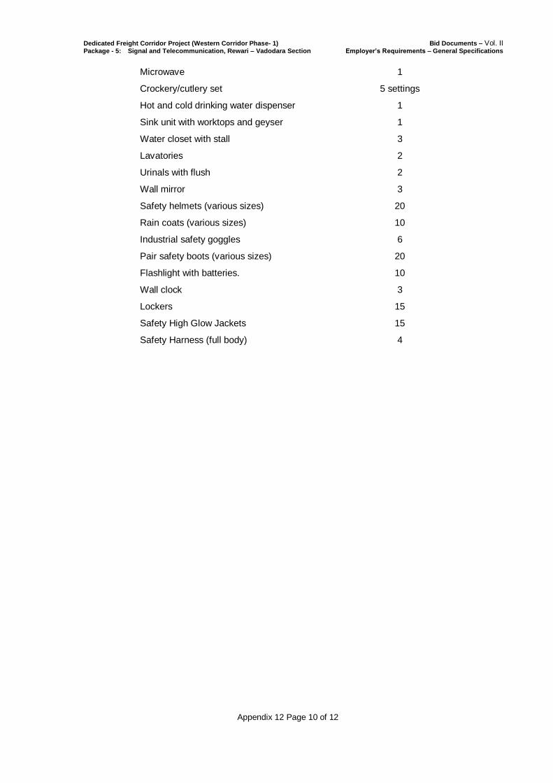
Dedicated Freight Corridor Project (Western Corridor Phase- 1) Bid Documents – Vol. II Package - 5: Signal and Telecommunication, Rewari – Vadodara Section Employer’s Requirements – General Specifications
Appendix 12 Page 10 of 12
Microwave 1
Crockery/cutlery set 5 settings
Hot and cold drinking water dispenser 1
Sink unit with worktops and geyser 1
Water closet with stall 3
Lavatories 2
Urinals with flush 2
Wall mirror 3
Safety helmets (various sizes) 20
Rain coats (various sizes) 10
Industrial safety goggles 6
Pair safety boots (various sizes) 20
Flashlight with batteries. 10
Wall clock 3
Lockers 15
Safety High Glow Jackets 15
Safety Harness (full body) 4
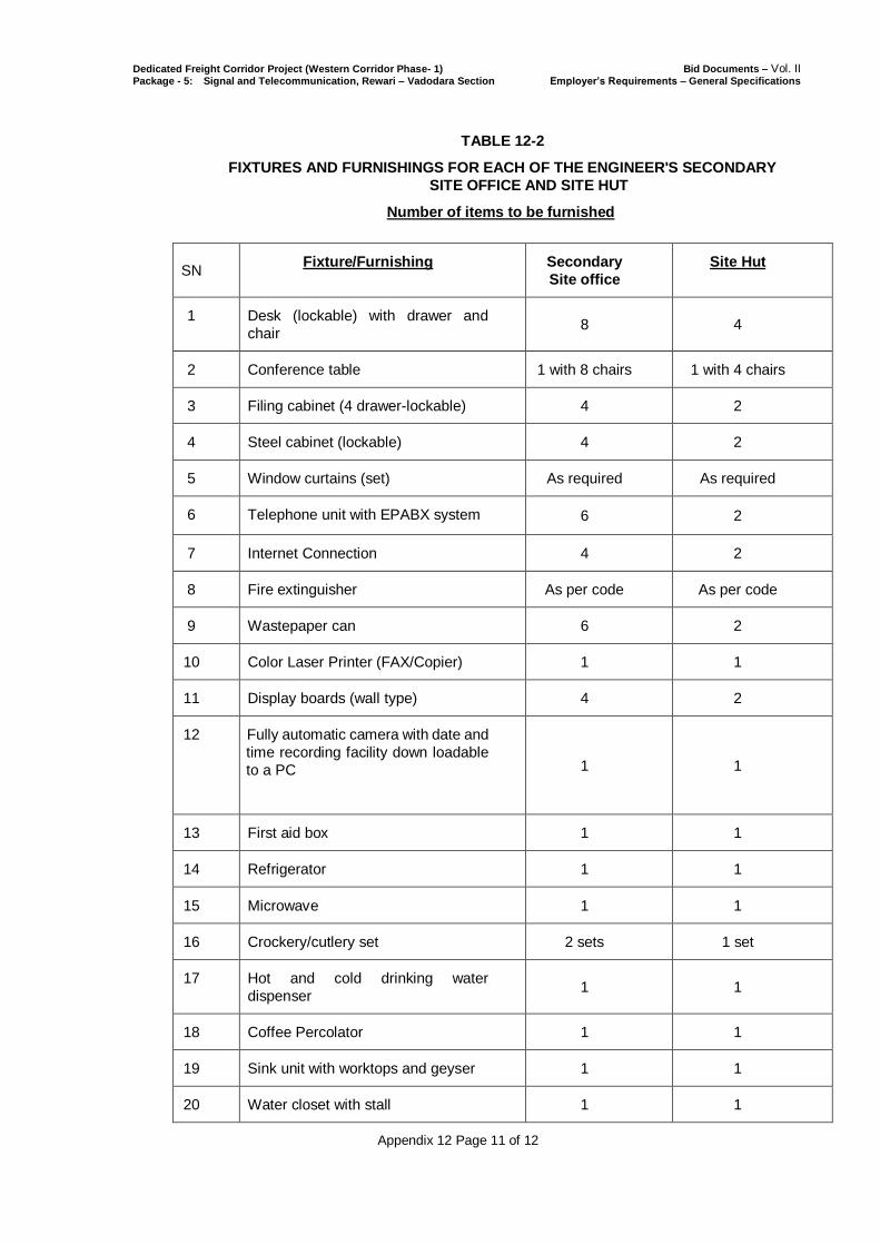
Dedicated Freight Corridor Project (Western Corridor Phase- 1) Bid Documents – Vol. II Package - 5: Signal and Telecommunication, Rewari – Vadodara Section Employer’s Requirements – General Specifications
Appendix 12 Page 11 of 12
TABLE 12-2
FIXTURES AND FURNISHINGS FOR EACH OF THE ENGINEER'S SECONDARY
SITE OFFICE AND SITE HUT
Number of items to be furnished
SN Fixture/Furnishing Secondary
Site office
Site Hut
1 Desk (lockable) with drawer and
chair 8 4
2 Conference table 1 with 8 chairs 1 with 4 chairs
3 Filing cabinet (4 drawer-lockable) 4 2
4 Steel cabinet (lockable) 4 2
5 Window curtains (set) As required As required
6 Telephone unit with EPABX system 2 (number of phone sets) 6 2
7 Internet Connection 4 2
8 Fire extinguisher As per code As per code
9 Wastepaper can 6 2
10 Color Laser Printer (FAX/Copier) 1 1
11 Display boards (wall type) 4 2
12 Fully automatic camera with date and
time recording facility down loadable
to a PC
1 1
13 First aid box 1 1
14 Refrigerator 1 1
15 Microwave 1 1
16 Crockery/cutlery set 2 sets 1 set
17 Hot and cold drinking water
dispenser 1 1
18 Coffee Percolator 1 1
19 Sink unit with worktops and geyser 1 1
20 Water closet with stall 1 1
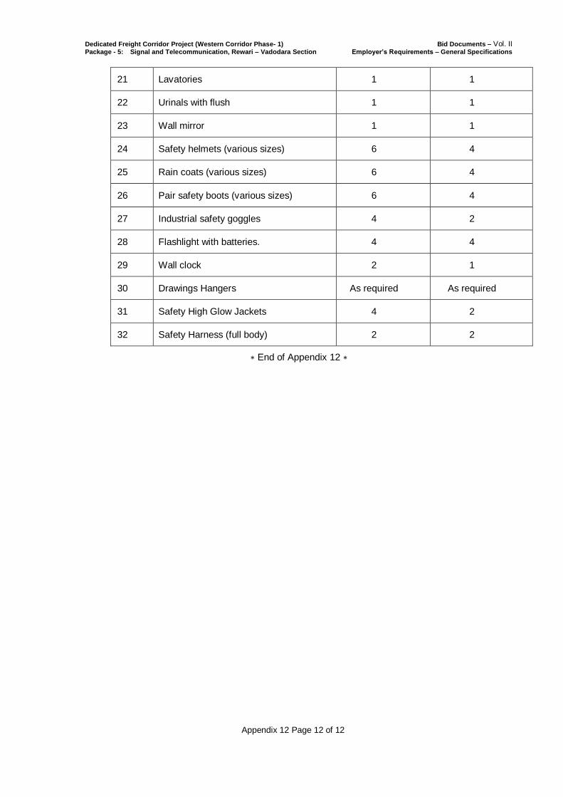
Dedicated Freight Corridor Project (Western Corridor Phase- 1) Bid Documents – Vol. II Package - 5: Signal and Telecommunication, Rewari – Vadodara Section Employer’s Requirements – General Specifications
Appendix 12 Page 12 of 12
21 Lavatories 1 1
22 Urinals with flush 1 1
23 Wall mirror 1 1
24 Safety helmets (various sizes) 6 4
25 Rain coats (various sizes) 6 4
26 Pair safety boots (various sizes) 6 4
27 Industrial safety goggles 4 2
28 Flashlight with batteries. 4 4
29 Wall clock 2 1
30 Drawings Hangers As required As required
31 Safety High Glow Jackets 4 2
32 Safety Harness (full body) 2 2
∗ End of Appendix 12 ∗