dolphin 3dcam help · dolphin 3dcam help 3 / 92 introduction dolphin 3dcam dolphin 3dcam is a cam...
TRANSCRIPT

Copyright © <2018> by <Dolphin Cadcam Systems Ltd>. V1.020216 All Rights Reserved.
Dolphin 3DCAM Help
Dolphin 3DCAM Help
2 / 92
Table of Contents Introduction .................................................................................................................................. 3
Getting Started............................................................................................................................. 4
The Ribbon Toolbar ................................................................................................................ 5
File ............................................................................................................................................ 6
Geom ........................................................................................................................................ 9
Solids...................................................................................................................................... 24
View ........................................................................................................................................ 25
Milling .................................................................................................................................... 26
Screen Layout ......................................................................................................................... 69
Creating and using Sketches ............................................................................................ 70
Program Tree Objects .......................................................................................................... 74
Imported File ...................................................................................................................... 74
Program Number ............................................................................................................... 76
Tools ....................................................................................................................................... 77
Patterns ................................................................................................................................ 80
Surfaces ................................................................................................................................ 82
Operations ........................................................................................................................... 84
Main Graphics Area ............................................................................................................... 85
System Options ...................................................................................................................... 88
Properties ................................................................................................................................. 89
Messages .................................................................................................................................. 92

Dolphin 3DCAM Help
3 / 92
Introduction
DOLPHIN 3DCAM
Dolphin 3DCAM is a CAM (Computer Aided Manufacturing) system designed to create programs (G Code) for your CNC Milling machines and Machining Centres. It is designed to import solid models of the following file formats, IGES, STP (STEP) and STL and then create 2D & 3D toolpaths on those models. It can also import DXF files and produce toolpaths for them. The output generated by 3DCAM can be tailored to suit your particular machine tool and controller, normally this is in the form of G Codes but can be any format required such as Heidenhain or Anilam conversational format.

Dolphin 3DCAM Help
4 / 92
Getting Started
Getting Started
Below is the main 3DCAM screen. The screen is split into various areas, they are.... The Ribbon toolbars control all functions within the software. To display different Ribbons (topics) - please click on the appropriate ribbon item - such as File, Geom, Solids etc.
Main Graphics Area Objects Tree System Options Properties Messages

Dolphin 3DCAM Help
5 / 92
The Ribbon Toolbar
The Ribbon toolbars control all of the functions and options within 3DCAM
To change ribbons, click on the appropriate menu item File Geom Solids View Milling

Dolphin 3DCAM Help
6 / 92
File
This is the File Ribbon Toolbar, it is split into 3 sections, File, Print and Edit - the options are listed below
THE FILE SECTION File New - this will create a new, empty workspace. If you haven't Saved your project you will see this dialogue box where you can save or discard any operations.
File Open - This will allow you to Open an existing 3DCAM project, you will be shown the File Open dialogue box where you can choose the project you wish to Open or browse to a different folder to choose your project. Clicking on the Down Arrow - will show the Recent File list. This will list the last 12 files you worked on. Files created by 3DCAM will have the extension .d3d for instance MYFIRSTPART.d3d If you need to contact our technical support department with questions concerning a part you are working on, they will need to have the .d3d file you are working on as well as the original geometry file that you imported. Please attach these files to any emails you send.
The File Open dialogue box

Dolphin 3DCAM Help
7 / 92
File Import - Use this option to import a geometry file that you can add machining operations onto. The Import Dialogue box will be shown. The file types that can be imported are: IGES files - 3D Solid and Surface models, STEP (STP) 3D Solid and Surface models, STL - 3D models made up of 3D triangles, DXF - 2D geometry files.
File Save - This option will save the current project under the name previously given with Save As... if a name has not been assigned to the project, the File > Save As dialogue box will be displayed. If a filename has been given, the current status of the project will be saved. Restore Defaults - This will restore all system defaults, such as units, snap options etc to their factory settings. Please note; this action cannot be "undone" About - Will display the version and build number of the software any copyright notices.
THE PRINT SECTION Print - This option will print the contents of the graphics window to your printer, the print dialogue box will be shown that allows you to select the printer to use

Dolphin 3DCAM Help
8 / 92
Page Setup - This option will you set the size and orientation of the paper to use for printing
Print Preview - Will show the view to be printed.
THE EDIT SECTION Cut - This command will Cut (Delete) the current selection from the Objects Tree view Copy - This command will Copy the current selection from the Objects Tree view to the Clipboard so that it can be used again Paste - This command will Paste (Add) the current contents of the Clipboard into the Objects Tree view

Dolphin 3DCAM Help
9 / 92
Undo - Will undo the previous operation, this could be changing a machining operation, moving the model, modifying a Sketch etc. Redo - Will reverse the actions of the preceding Undo operation. Select - This option will allow you to select items in the Main Graphics area
Geom
This is the Geometry Ribbon Toolbar, it is split into 6 sections, Sketches, Circles, Other Drawing, Text, Transformations & Snapping- the options are listed below
Sketches Circles Other Drawing Text Transformations Snapping

Dolphin 3DCAM Help
10 / 92
Sketches
Sketches
When using any of these options, please ensure that your current Graphics Plane view is what you require, eg XY, YZ or XZ. Use the View toolbar to set your required View.
Lines Selecting this option will you to draw a single line or a series of connected lines or arcs.
The Message box will display the current option, use the down arrow to change options. Use the mouse to position the cursor in the graphics area to draw the lines/arcs. End points can be entered by clicking the X, Y or Z inputs.
Rectangles This will draw Rectangles and create them as Sketches that can used for the Profile or Pocket machining commands Use the Messages box to set a corner radius if required.
Dolphin 3DCAM Help
11 / 92
Use the mouse to position the cursor in the graphics area to draw the. The opposing corners of the Rectangle can entered by clicking the X, Y or Z inputs.
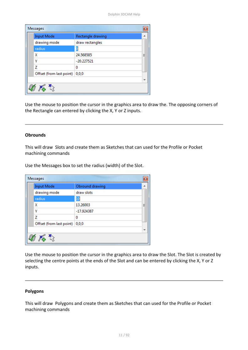
Obrounds This will draw Slots and create them as Sketches that can used for the Profile or Pocket machining commands Use the Messages box to set the radius (width) of the Slot.
Use the mouse to position the cursor in the graphics area to draw the Slot. The Slot is created by selecting the centre points at the ends of the Slot and can be entered by clicking the X, Y or Z inputs.
Polygons This will draw Polygons and create them as Sketches that can used for the Profile or Pocket machining commands

Dolphin 3DCAM Help
12 / 92
Use the Messages box to set the number of sides, and also whether the Polygon should be created by using an excribed or inscribed mode.
Use the mouse to position the cursor in the graphics area to draw the Polygon. The Polygon is created by selecting the centre point and the radius of the circle, the Polygon can be entered by clicking the X, Y or Z inputs.
Gear This will produce an Involute gear form that can be used to create a Sketch for the Profile and Pocketing commands. Use the Properties window to enter the parameters for the Gear

Dolphin 3DCAM Help
13 / 92
It is only possible to produce gears when the module is known, if you need to produce gears given the diametral pitch etc. Use this table or consult an expert.
To create a Sketch from a Gear, right click the Gear entry in the Object Tree window and choose either of the Make options.

Dolphin 3DCAM Help
14 / 92
NOTE - if you modify the Gear parameters, the Sketch that was created from it will not be updated, you will need to create a new Sketch using the above method.
Circles
Circles
Circles can drawn by the following methods. 3 points on the circumference 2 points on the circumference which measured across the diameter Centre point and radius Centre point with radius entered. To choose any of the methods, select the option from the Messages dialogue box

Dolphin 3DCAM Help
15 / 92
To use Centre point with radius entered method, use the Radius input window
Ellipses
An ellipse is created by indicating the centre point, minor axis and major axis.
Draw the ellipse and then use the Properties box to adjust the parameters.

Dolphin 3DCAM Help
16 / 92
Other Drawing
Other Drawing
Infinite Line A line is created by indicating 2 points which the line will be drawn through.
Selecting the Line will display the Properties box where the start and end points can be modified.
Dolphin 3DCAM Help
17 / 92
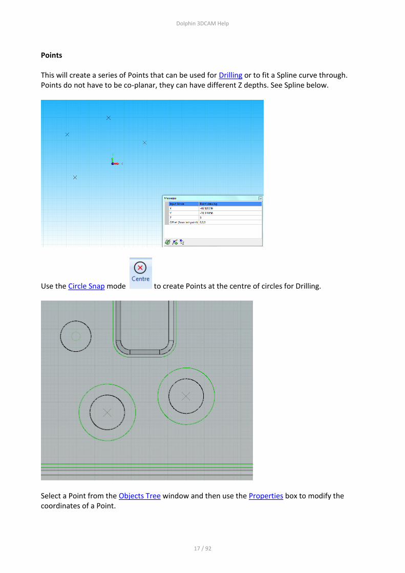
Points This will create a series of Points that can be used for Drilling or to fit a Spline curve through. Points do not have to be co-planar, they can have different Z depths. See Spline below.
Use the Circle Snap mode to create Points at the centre of circles for Drilling.
Select a Point from the Objects Tree window and then use the Properties box to modify the coordinates of a Point.
Dolphin 3DCAM Help
18 / 92
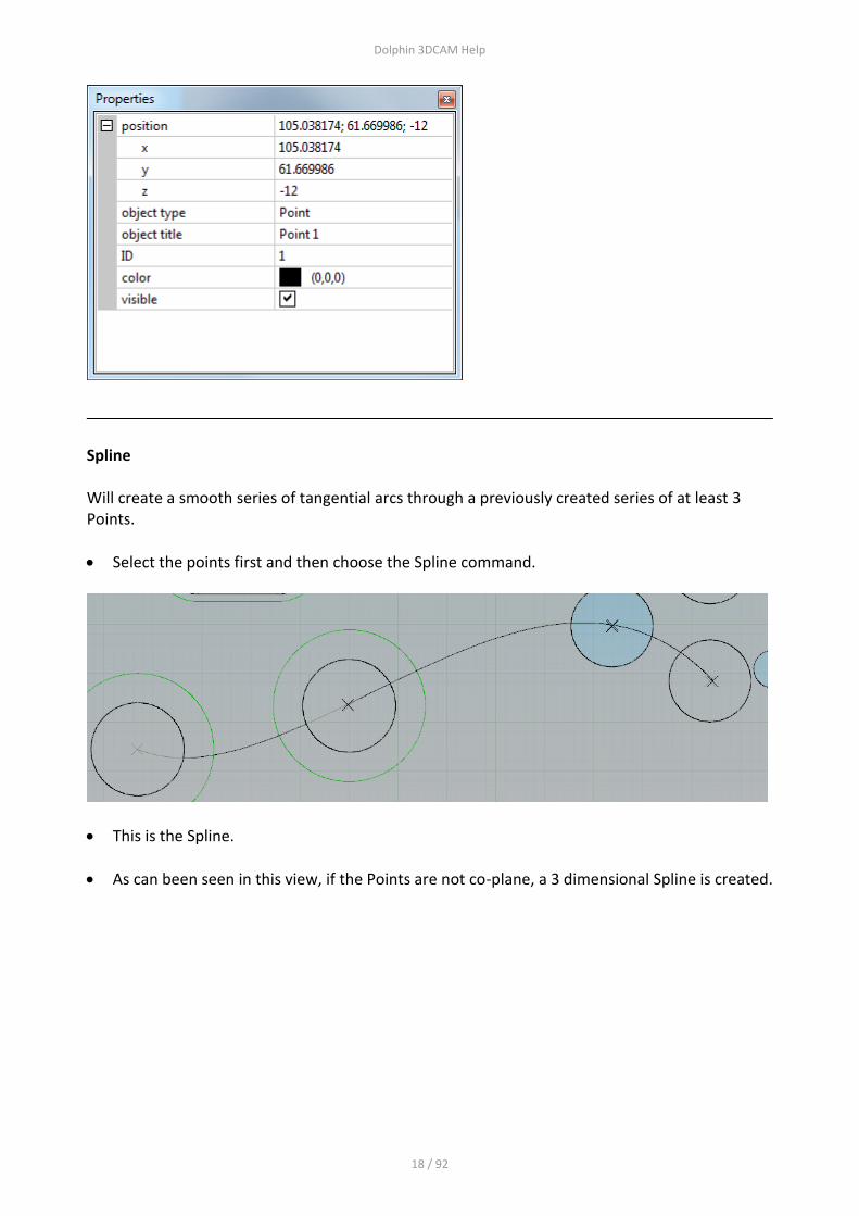
Spline Will create a smooth series of tangential arcs through a previously created series of at least 3 Points.
Select the points first and then choose the Spline command.
This is the Spline.
As can been seen in this view, if the Points are not co-plane, a 3 dimensional Spline is created.

Dolphin 3DCAM Help
19 / 92
Text
Text
Dolphin 3DCAM Help
20 / 92
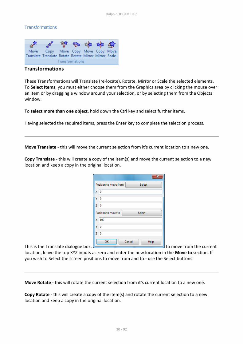
Transformations
Transformations
These Transformations will Translate (re-locate), Rotate, Mirror or Scale the selected elements. To Select Items, you must either choose them from the Graphics area by clicking the mouse over an item or by dragging a window around your selection, or by selecting them from the Objects window. To select more than one object, hold down the Ctrl key and select further items. Having selected the required items, press the Enter key to complete the selection process.
Move Translate - this will move the current selection from it's current location to a new one. Copy Translate - this will create a copy of the item(s) and move the current selection to a new location and keep a copy in the original location.
This is the Translate dialogue box. to move from the current location, leave the top XYZ inputs as zero and enter the new location in the Move to section. If you wish to Select the screen positions to move from and to - use the Select buttons.
Move Rotate - this will rotate the current selection from it's current location to a new one. Copy Rotate - this will create a copy of the item(s) and rotate the current selection to a new location and keep a copy in the original location.

Dolphin 3DCAM Help
21 / 92
This is the Rotate dialogue box. to Rotate about the current location, leave the top XYZ inputs as zero. Choose the axes about which to rotate, XY, XZ or YZ. Note how the Triad graphic changes to show the axes chosen, enter the new angle in the Angle window. If you wish to select an arbitrary line about to rotate, click on the Other radio button, the following dialogue will be shown that allows you to specify a different rotational plane.

Dolphin 3DCAM Help
22 / 92
Move Mirror - this will mirror image the current selection from it's current location to a new one. Copy Mirror - this will create a copy of the item(s) and mirror the current selection to a new location and keep a copy in the original location.
This is the Mirror dialogue box. to move from the current location, leave the top XYZ inputs as zero and enter the new location in the Move to section. If you wish to Select the screen positions to move from and to - use the Select buttons.
Move Scale 1. Select the object you want to Scale (see section on Selecting Objects) 2. Look at the Messages box for this entry
and select the centre position to scale about
3. You will see this dialogue box. Enter the required scale factor, use an integer such as 3, 5, 10 to enlarge the scale and decimail such as 0.1 or 0.25 to reduce the scale.
4. The newly scaled elements will be shown in the graphics area, if you have used a very large
scaling factor you may need to zoom out of the graphics window to see the objects.

Dolphin 3DCAM Help
23 / 92
Snapping
Snapping
Snap modes are used to control how a newly created piece of Geometry or Dimension will "snap" or lock onto an existing item. Clicking these icons will either switch on or off the appropriate snap mode. Multiple snap modes can be in force at any time.
Endof - this is the end point of a Line or Arc
Inters - this is the Intersection between 2 items
Centre - this is the centre of an arc or circle
Midpoint - this can the mid point of a line or arc
Grid - this will snap to a Grid position, use the down arrow to set the Grid size
Dolphin 3DCAM Help
24 / 92
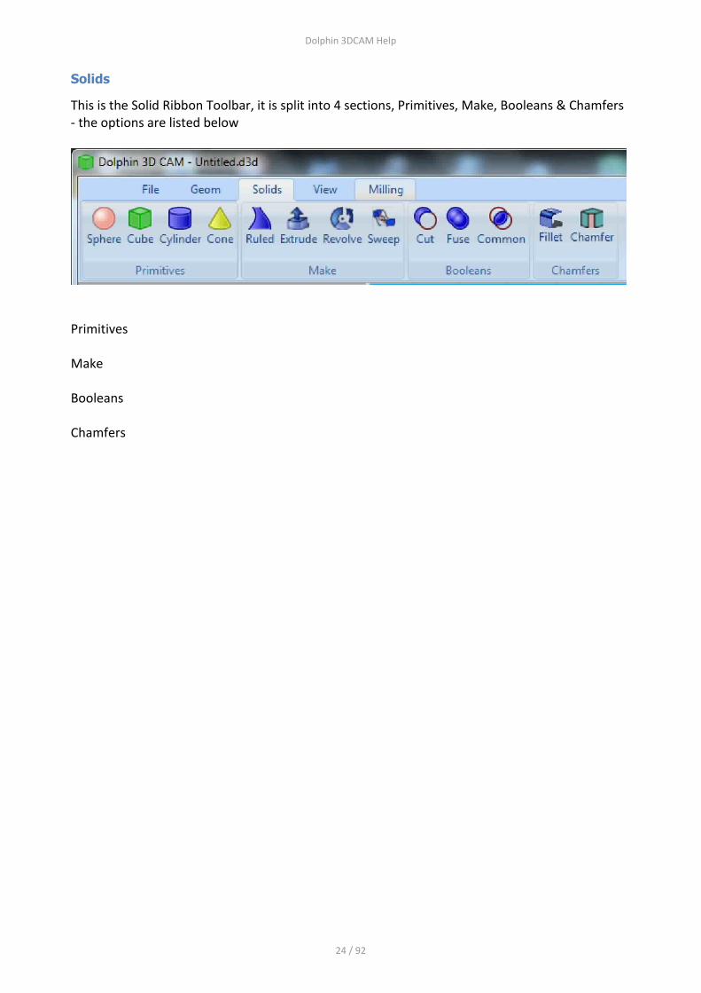
Solids
This is the Solid Ribbon Toolbar, it is split into 4 sections, Primitives, Make, Booleans & Chamfers - the options are listed below
Primitives Make Booleans Chamfers

Dolphin 3DCAM Help
25 / 92
View
This is the View Ribbon Toolbar, it is split into 5 sections, Magnify, General Specific Views, View Dragging and Windows - the options are listed below
Magnify
Mag Extents - this will Magnify the model to it's maximum and reset the view to the nearest standard view XY, XZ or YZ. Mag No Rotation - this will Magnify the model to it's maximum and leave the view rotation as is.
General View Back - will return the to it's previous state after you have used the mouse wheel to zoom and/or pan the view FullScreen - this will display just the model with no toolbars or other windows displayed. Use the Esc key to return to the normal view mode Redraw - this will re-paint the screen
Specific Views
Choosing any of these options will rotate the model to that view
View Dragging
If you don't have mouse with a centre wheel or you are using a laptop with just a touch pad, then use these icons to control the mouse's left hand button actions.
Windows
Using these options will hide or display the chosen window
Dolphin 3DCAM Help
26 / 92
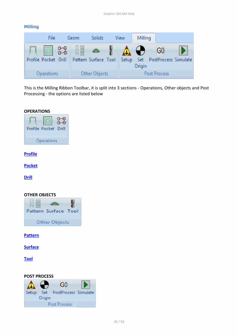
Milling
This is the Milling Ribbon Toolbar, it is split into 3 sections - Operations, Other objects and Post Processing - the options are listed below OPERATIONS
Profile Pocket Drill OTHER OBJECTS
Pattern Surface Tool POST PROCESS
Dolphin 3DCAM Help
27 / 92
Setup Set Origin Post Process Simulate
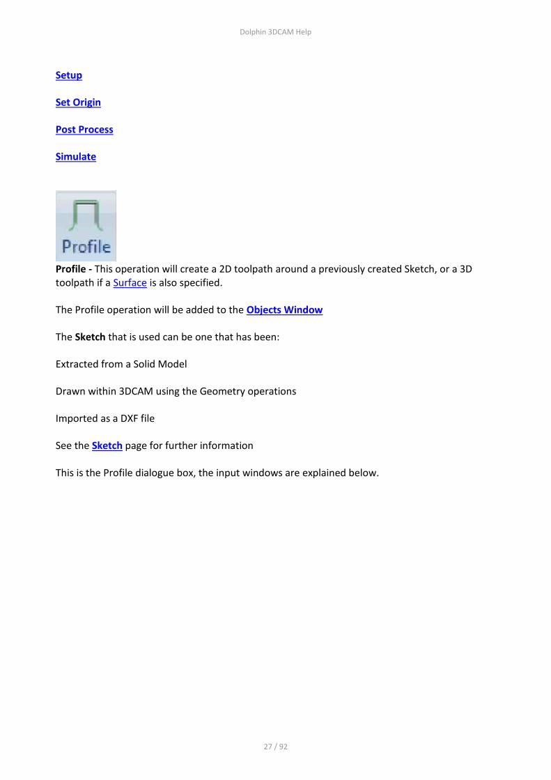
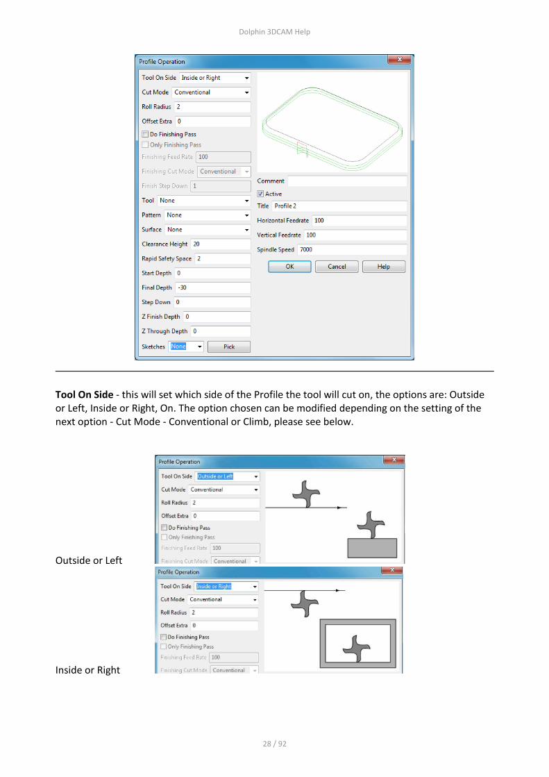
Profile - This operation will create a 2D toolpath around a previously created Sketch, or a 3D toolpath if a Surface is also specified. The Profile operation will be added to the Objects Window The Sketch that is used can be one that has been: Extracted from a Solid Model Drawn within 3DCAM using the Geometry operations Imported as a DXF file See the Sketch page for further information This is the Profile dialogue box, the input windows are explained below.
Dolphin 3DCAM Help
28 / 92
Tool On Side - this will set which side of the Profile the tool will cut on, the options are: Outside or Left, Inside or Right, On. The option chosen can be modified depending on the setting of the next option - Cut Mode - Conventional or Climb, please see below.
Outside or Left
Inside or Right

Dolphin 3DCAM Help
29 / 92
On
Cut Mode
Conventional
Climb
Roll Radius
This option will set the value of the radius that is applied as the tool approaches and runs off the Profile. This does not apply if the Tool On Side option is set to On If not required, the radius should be set to zero.
Offset Extra

Dolphin 3DCAM Help
30 / 92
This option will add an allowance to either; Outside / Left or Inside / Right. If you have chosen On to the option Tool On Side, this value will be ignored. Having set this value you have the following further options available
Do Finishing Pass - this will produce 2 toolpaths in the XY plane, the first will be offset from the Profile by the Offset Extra value, the second will be the actual Profile itself. Only Finishing Pass - this will produce a single XY toolpath offset by the amount specified Finishing Feed rate - this will set the XY feedrate to be used on the finishing pass, as opposed the Horizontal feedrate set. Finishing Cut Mode - This can be Conventional or Climb - please see Cut Mode above for more details Finishing Step Down - The Step Down that has been set specified further down in this dialogue box can be overridden here. It might be that you have a Step Down set to 1mm on a total depth of 10mm - producing 10 cuts in the Z axis, but on the Finishing pass you need just a single cut of 10mm - in this case enter 10 here.
Tool - This will select the tool for this operation, use the Down Arrow to select a tool from those previously defined. Use the Tool icon from the main Milling ribbon to define new tools

Dolphin 3DCAM Help
31 / 92
Pattern - This will use a previously created Pattern - use the Pattern icon from the Milling ribbon to create a new Pattern to machine multiple instances of this operation
Surface - Using this option will force the toolpath to be controlled by the shape of the Surface. If you use just a 2D Sketch without specifying a Surface you will create a 2D toolpath. Using a Surface will "drape" the 2D Sketch over the Surface creating a 3D toolpath
Clearance Plane
Clearance Plane - This is a Z value that must be clear of all obstructions and fixtures. It is the plane used to Rapid from one XY feature or position to the next XY position. This is an absolute value measured from Z zero - please see diagram above.

Dolphin 3DCAM Help
32 / 92
Feed Change Plane
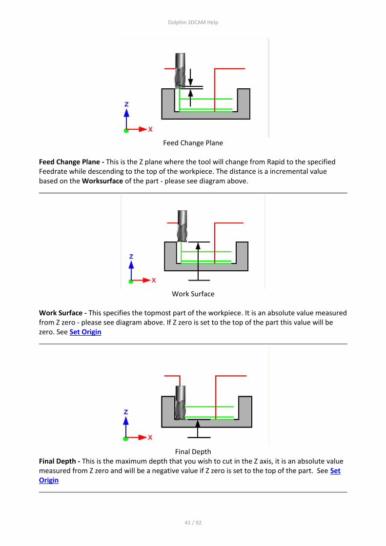
Feed Change Plane - This is the Z plane where the tool will change from Rapid to the specified Feedrate while descending to the top of the workpiece. The distance is a incremental value based on the Worksurface of the part - please see diagram above.
Work Surface
Work Surface - This specifies the topmost part of the workpiece. It is an absolute value measured from Z zero - please see diagram above. If Z zero is set to the top of the part this value will be zero. See Set Origin
Final Depth

Dolphin 3DCAM Help
33 / 92
Final Depth - This is the maximum depth that you wish to cut in the Z axis, it is an absolute value measured from Z zero and will be a negative value if Z zero is set to the top of the part. See Set Origin
Step Down
Step Down - This controls the Z distance of each pass in the Z axis. The size entered is the maximum amount of each cut per pass. This value maybe adjusted (reduced) if the value entered is not divisible into the total depth of cut. If you don't need to use this feature set the value to zero.
Z Finish Depth
Z Finish Depth - This value is used to create an extra finishing pass, it will be machined with the current tool and with all the current feedrates in force. It will also be used after any passes created by use of the Step Down value entered above.

Dolphin 3DCAM Help
34 / 92
Z Through Depth
Z Though Depth - This will create an extra pass in the Z axis which will added after the last cut set by the Final Depth. The Z Finish Depth will be applied to this dimension, not the Final Depth.
Choosing a Sketch
Sketch - The Profile command must be based on a previously created Sketch. You can choose a Sketch from the pull down list or select a Sketch from the Objects Tree window. Please also see the page on creating Sketches
Setting the Spindle Speed and Feedrates

Dolphin 3DCAM Help
35 / 92
Comment - This will output a comment to the G code file to allow you to identify different parts of the program Active - Selecting this box will make the current operation active, it will be calculated and will produce G codes Title - This will appear in the Objects Tree window to identify this operation Though Tool Coolant - Will switch on the appropriate command within the Post processor and output the required G or M code Horizontal Feedrate - This will apply to all XY feed moves Vertical Feedrate - This will control the feedrate in the Z axis when the tool is plunging into the workpiece. Spindle Speed - This will set the spindle RPM speed for the current tool, it will output the required instructions to the post processor to switch on the spindle ( normally a M6 command) and set the spindle RPM, typically an " S " word - S1234 for instance
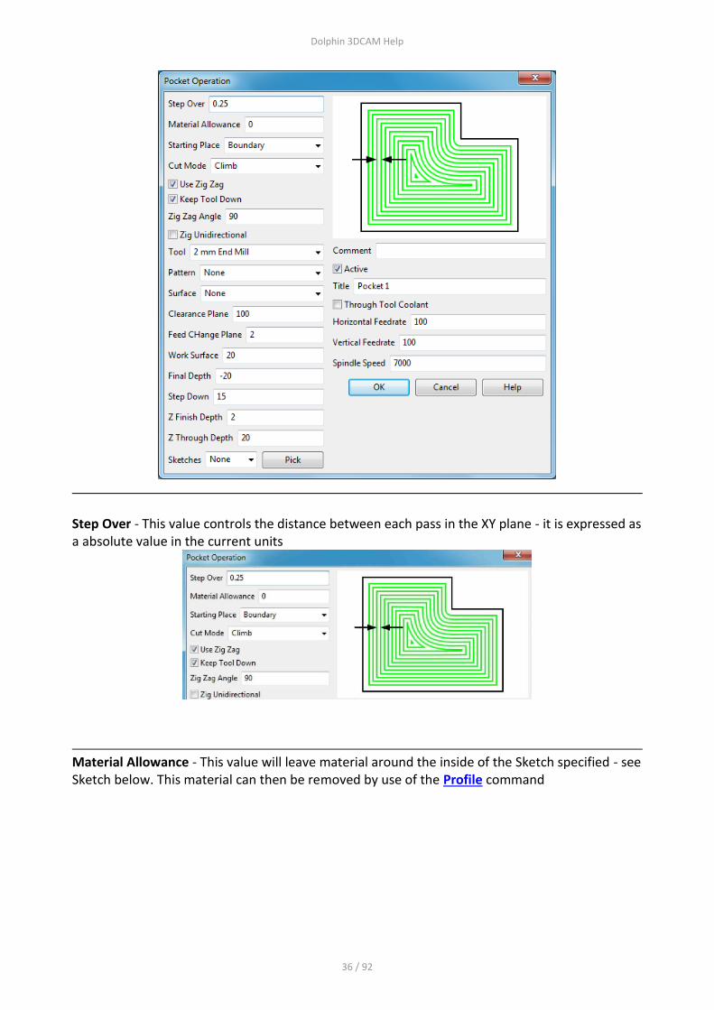
Pocket - This operation will create a 2D Area Clearance toolpath around a previously created Sketch, or a 3D toolpath if a Surface is also specified The Pocket operation will be added to the Objects Window The Sketch that is used can be one that has been: Extracted from a Solid Model Drawn within 3DCAM using the Geometry operations Imported as a DXF file See the Sketch page for further information This is the Pocket dialogue box, the input windows are explained below.
Dolphin 3DCAM Help
36 / 92
Step Over - This value controls the distance between each pass in the XY plane - it is expressed as a absolute value in the current units
Material Allowance - This value will leave material around the inside of the Sketch specified - see Sketch below. This material can then be removed by use of the Profile command

Dolphin 3DCAM Help
37 / 92
Starting place - Use the pull down arrow to choose either Boundary or Centre for the start of machining
Cut Mode - Use the pull down arrow to select either Climb or Conventional machining. In most cases Climb milling is preferred.
Dolphin 3DCAM Help
38 / 92
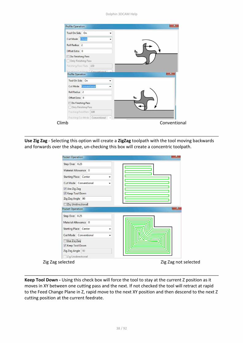
Climb Conventional
Use Zig Zag - Selecting this option will create a ZigZag toolpath with the tool moving backwards and forwards over the shape, un-checking this box will create a concentric toolpath.
Zig Zag selected Zig Zag not selected
Keep Tool Down - Using this check box will force the tool to stay at the current Z position as it moves in XY between one cutting pass and the next. If not checked the tool will retract at rapid to the Feed Change Plane in Z, rapid move to the next XY position and then descend to the next Z cutting position at the current feedrate.

Dolphin 3DCAM Help
39 / 92
Zig Zag Angle - Use this to set the angle of the Zig Zag toolpath. The angle is measured from zero (3.0 o'clock) and can be positive or negative. If the Zig Zag option is not selected, this input window will not be active.
Zig Zag Unidirectional - Checking this box will force machining to cut in single direction set by the Zig Zag angle. The tool will retract at rapid to the Feed Change Plane in Z, rapid move to the next XY position and then descend to the next Z cutting position at the current feedrate.
Tool - This will select the tool for this operation, use the Down Arrow to select a tool from those previously defined. Use the Tool icon from the main Milling ribbon to define new tools

Dolphin 3DCAM Help
40 / 92
Pattern - This will use a previously created Pattern - use the Pattern icon from the Milling ribbon to create a new Pattern to machine multiple instances of this operation
Surface - Using this option will force the toolpath to be controlled by the shape of the Surface. If you use just a 2D Sketch without specifying a Surface you will create a 2D toolpath. Using a Surface will "drape" the 2D Sketch over the Surface creating a 3D toolpath
Clearance Plane
Clearance Plane - This is a Z value that must be clear of all obstructions and fixtures. It is the plane used to Rapid from one XY feature or position to the next XY position. This is an absolute value measured from Z zero - please see diagram above.
Dolphin 3DCAM Help
41 / 92
Feed Change Plane
Feed Change Plane - This is the Z plane where the tool will change from Rapid to the specified Feedrate while descending to the top of the workpiece. The distance is a incremental value based on the Worksurface of the part - please see diagram above.
Work Surface
Work Surface - This specifies the topmost part of the workpiece. It is an absolute value measured from Z zero - please see diagram above. If Z zero is set to the top of the part this value will be zero. See Set Origin
Final Depth
Final Depth - This is the maximum depth that you wish to cut in the Z axis, it is an absolute value measured from Z zero and will be a negative value if Z zero is set to the top of the part. See Set Origin

Dolphin 3DCAM Help
42 / 92
Step Down
Step Down - This controls the Z distance of each pass in the Z axis. The size entered is the maximum amount of each cut per pass. This value maybe adjusted (reduced) if the value entered is not divisible into the total depth of cut. If you don't need to use this feature set the value to zero.
Z Finish Depth
Z Finish Depth - This value is used to create an extra finishing pass, it will be machined with the current tool and with all the current feedrates in force. It will also be used after any passes created by use of the Step Down value entered above.
Z Through Depth
Z Though Depth - This will create an extra pass in the Z axis which will added after the last cut set by the Final Depth. The Z Finish Depth will be applied to this dimension, not the Final Depth.

Dolphin 3DCAM Help
43 / 92
Choosing a Sketch
Sketch - The Profile command must be based on a previously created Sketch. You can choose a Sketch from the pull down list or select a Sketch from the Objects Tree window. Please also see the page on creating Sketches
Setting the Spindle Speed and Feedrates
Comment - This will output a comment to the G code file to allow you to identify different parts of the program Active - Selecting this box will make the current operation active, it will be calculated and will produce G codes Title - This will appear in the Objects Tree window to identify this operation Though Tool Coolant - Will switch on the appropriate command within the Post processor and output the required G or M code Horizontal Feedrate - This will apply to all XY feed moves Vertical Feedrate - This will control the feedrate in the Z axis when the tool is plunging into the workpiece. Spindle Speed - This will set the spindle RPM speed for the current tool, it will output the required instructions to the post processor to switch on the spindle ( normally a M6 command) and set the spindle RPM, typically an " S " word - S1234 for instance

Dolphin 3DCAM Help
44 / 92
Drill
DRILL This command will drill holes at previously created XY locations using a Drill type tool. This is the Drill dialogue box.
The available cycles are:- Drill - Feed to depth, retract at rapid. - Can be used with tools defined as either MILL or DRILL. The normal drill cycle moves the tool in XY to the drill position the tool then sinks at rapid feedrate to the Feed Change Plane. It then sinks at feedrate to the programmed depth of the hole and then retracts at rapid feedrate to either the Feed Change Plane or the Clearance Plane depending upon which option is chosen. Optionally you can program a Dwell at the bottom of the cycle. Deep Drill - Drill hole in a series of pecks, retracting tool completely between each peck. This cycle is normally used when drilling deep holes and is intended to provide swarf clearance as the drilling progresses. The tool is sunk in a series of pecks, the peck depth being calculated by PartMaster by dividing the total depth by the number of pecks, retracting completely clear of the job after each peck. The deep drill cycle moves the tool in XY to the drill position the tool then sinks at rapid feedrate to the Feed Change Plane. It then sinks at feedrate to the first peck depth. It then retracts at rapid feedrate to the Feed Change Plane before sinking at feedrate to the next peck depth Optionally the feed down to the next peck can be made at Rapid speed, in which case it will switch back to feedrate a short distance before the previous peck depth is reached. After it has reached the final depth it then retracts at rapid feedrate to either the Feed Change Plane or the Clearance Plane depending upon which option is chosen.
Dolphin 3DCAM Help
45 / 92
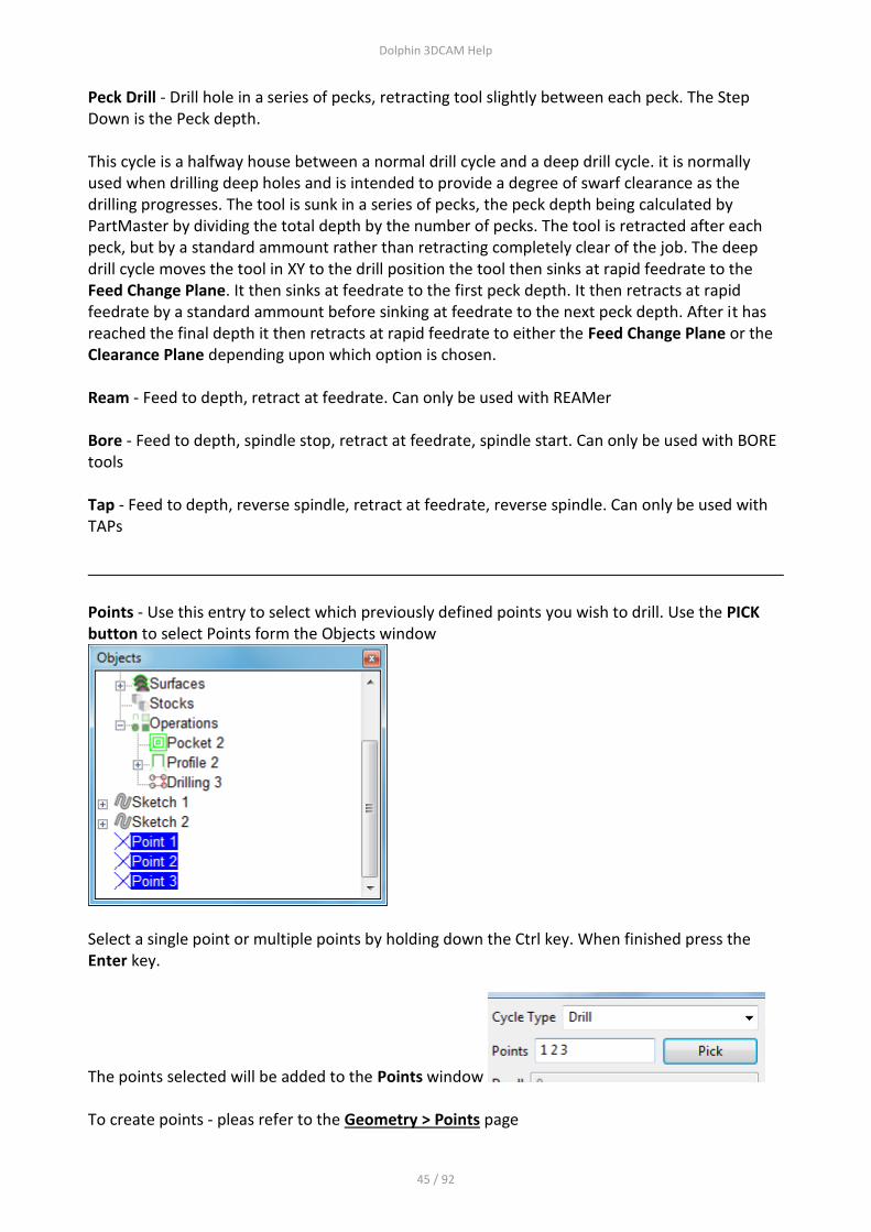
Peck Drill - Drill hole in a series of pecks, retracting tool slightly between each peck. The Step Down is the Peck depth. This cycle is a halfway house between a normal drill cycle and a deep drill cycle. it is normally used when drilling deep holes and is intended to provide a degree of swarf clearance as the drilling progresses. The tool is sunk in a series of pecks, the peck depth being calculated by PartMaster by dividing the total depth by the number of pecks. The tool is retracted after each peck, but by a standard ammount rather than retracting completely clear of the job. The deep drill cycle moves the tool in XY to the drill position the tool then sinks at rapid feedrate to the Feed Change Plane. It then sinks at feedrate to the first peck depth. It then retracts at rapid feedrate by a standard ammount before sinking at feedrate to the next peck depth. After it has reached the final depth it then retracts at rapid feedrate to either the Feed Change Plane or the Clearance Plane depending upon which option is chosen. Ream - Feed to depth, retract at feedrate. Can only be used with REAMer Bore - Feed to depth, spindle stop, retract at feedrate, spindle start. Can only be used with BORE tools Tap - Feed to depth, reverse spindle, retract at feedrate, reverse spindle. Can only be used with TAPs
Points - Use this entry to select which previously defined points you wish to drill. Use the PICK button to select Points form the Objects window
Select a single point or multiple points by holding down the Ctrl key. When finished press the Enter key.
The points selected will be added to the Points window To create points - pleas refer to the Geometry > Points page
Dolphin 3DCAM Help
46 / 92
Dwell -
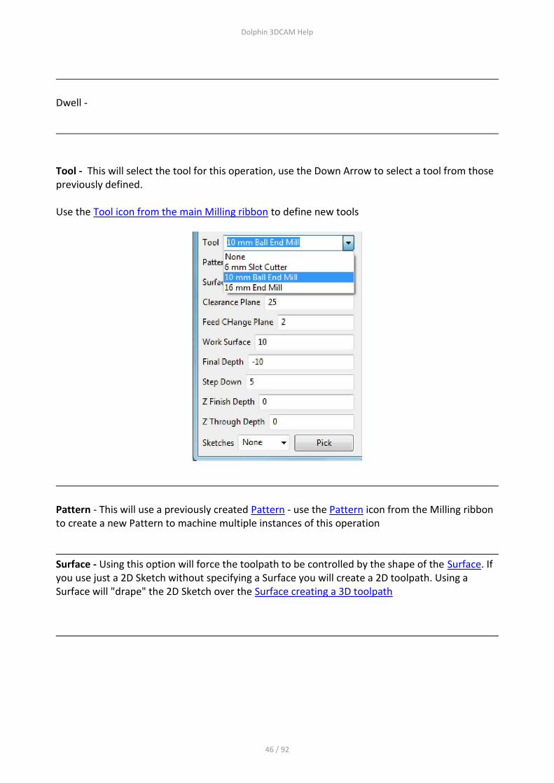
Tool - This will select the tool for this operation, use the Down Arrow to select a tool from those previously defined. Use the Tool icon from the main Milling ribbon to define new tools
Pattern - This will use a previously created Pattern - use the Pattern icon from the Milling ribbon to create a new Pattern to machine multiple instances of this operation
Surface - Using this option will force the toolpath to be controlled by the shape of the Surface. If you use just a 2D Sketch without specifying a Surface you will create a 2D toolpath. Using a Surface will "drape" the 2D Sketch over the Surface creating a 3D toolpath

Dolphin 3DCAM Help
47 / 92
Clearance Plane
Clearance Plane - This is a Z value that must be clear of all obstructions and fixtures. It is the plane used to Rapid from one XY feature or position to the next XY position. This is an absolute value measured from Z zero - please see diagram above.
Feed Change Plane
Feed Change Plane - This is the Z plane where the tool will change from Rapid to the specified Feedrate while descending to the top of the workpiece. The distance is a incremental value based on the Worksurface of the part - please see diagram above.
Work Surface

Dolphin 3DCAM Help
48 / 92
Work Surface - This specifies the topmost part of the workpiece. It is an absolute value measured from Z zero - please see diagram above. If Z zero is set to the top of the part this value will be zero. See Set Origin
Final Depth
Final Depth - This is the maximum depth that you wish to cut in the Z axis, it is an absolute value measured from Z zero and will be a negative value if Z zero is set to the top of the part. See Set Origin
Step Down
Step Down - This controls the Z Peck distance. This option is only available if the current cycle is Deep Drill or Peck Drill.

Dolphin 3DCAM Help
49 / 92
Setting the Spindle Speed and Feedrate
Comment - This will output a comment to the G code file to allow you to identify different parts of the program Active - Selecting this box will make the current operation active, it will be calculated and will produce G codes Title - This will appear in the Objects Tree window to identify this operation Though Tool Coolant - Will switch on the appropriate command within the Post processor and output the required M code Vertical Feedrate - This will control the feedrate in the Z axis when the tool is plunging into the workpiece. Spindle Speed - This will set the spindle RPM speed for the current tool, it will output the required instructions to the post processor to switch on the spindle ( normally a M6 command) and set the spindle RPM, typically an " S " word - S1234 for instance
Pattern
Pattern A Pattern will setup up repeat machining on subsequent machining operations, to activate the Pattern, you must specify the Pattern number in the Profile or Pocket machining operations This is the Pattern Dialogue box

Dolphin 3DCAM Help
50 / 92
Number of Copies A This is the number of machining instances, in the above example there are 3 instances separated by 50 mm in the X axis X Shift A This is the amount each instance will be separated from the others in the X axis Y Shift A This is the amount each instance will be separated from the others in the Y axis For the Pattern command to work correctly, you must specify a distance in either or both the X/Y Shift boxes In this example the Y Shift has also been specified, the graphics show the results
Number of copies B This is the number of machining instances to be combined with Number of Copies A X Shift B This is the amount each instance will be separated from the others in the X axis

Dolphin 3DCAM Help
51 / 92
Y Shift B This is the amount each instance will be separated from the others in the Y axis For the Pattern command to work correctly, you must specify a distance in either or both the X/Y Shift boxes In this example the Number of Copies B has also been specified, the graphics show the results
Surface
Surface This command will create a Surface from an existing solid model, the surface can then be used in the Profile and Pocket commands to create a 3D toolpath

Dolphin 3DCAM Help
52 / 92
If you are working with a single solid model then you only need to create the surface once, the default name for the surface will be Surface 1, but you can set the number in the first input window. If you are working on multiple models you will need to select the model using the Pick button. Tolerance - This will set the accuracy of the surface being created from the model. The value entered here will depend on your current units MM or INCH. Setting this value to a smaller number will create a more accurate surface but will increase the time taken to calculate the toolpath and the size of the output file (G code) will be considerable larger. Use the largest value you can to give you the accuracy you need. You will need to experiment with this.
Material Allowance - Setting this value will produce a surface that is offset from the original model
Same for each Pattern Position - Checking this box will use this surface for each instance of machining if you have setup a Pattern to produce multiple toolpaths.

Dolphin 3DCAM Help
53 / 92
Created with the Personal Edition of HelpNDoc: Produce Kindle eBooks easily
Tool
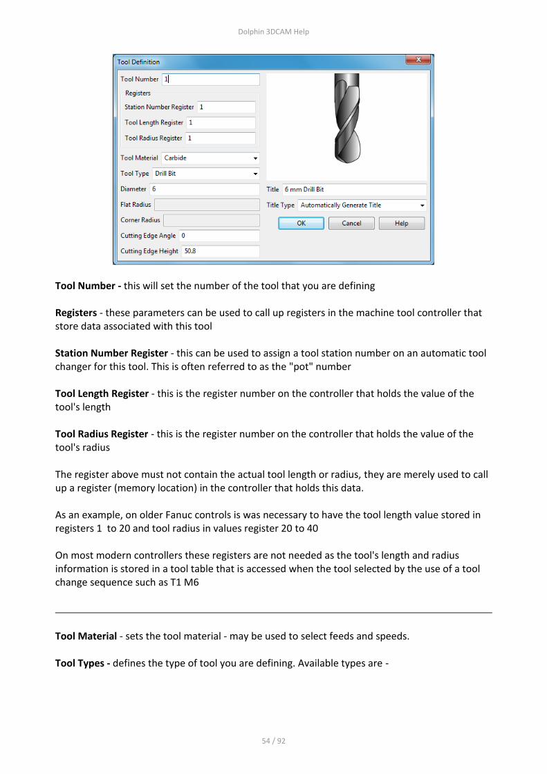
Tool This option will allow you to define tools that can be used in the current program and also saved into a toolfile for use in any program. Please also see the Tool entry in the Program Objects tree on the main screen. This is the Tool dialogue box that is displayed.
Dolphin 3DCAM Help
54 / 92
Tool Number - this will set the number of the tool that you are defining Registers - these parameters can be used to call up registers in the machine tool controller that store data associated with this tool Station Number Register - this can be used to assign a tool station number on an automatic tool changer for this tool. This is often referred to as the "pot" number Tool Length Register - this is the register number on the controller that holds the value of the tool's length Tool Radius Register - this is the register number on the controller that holds the value of the tool's radius The register above must not contain the actual tool length or radius, they are merely used to call up a register (memory location) in the controller that holds this data. As an example, on older Fanuc controls is was necessary to have the tool length value stored in registers 1 to 20 and tool radius in values register 20 to 40 On most modern controllers these registers are not needed as the tool's length and radius information is stored in a tool table that is accessed when the tool selected by the use of a tool change sequence such as T1 M6
Tool Material - sets the tool material - may be used to select feeds and speeds. Tool Types - defines the type of tool you are defining. Available types are -

Dolphin 3DCAM Help
55 / 92
Drill bit - parameters
Diameter
Cutting Edge Angle
Cutter Edge Height
Center Drill Bit - parameters

Dolphin 3DCAM Help
56 / 92
Diameter
Cutting Edge Angle
Cutter Edge Height
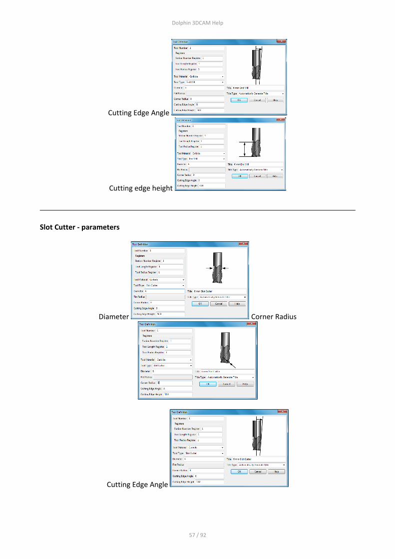
End Mill - parameters
Diameter Corner Radius
Dolphin 3DCAM Help
57 / 92
Cutting Edge Angle
Cutting edge height
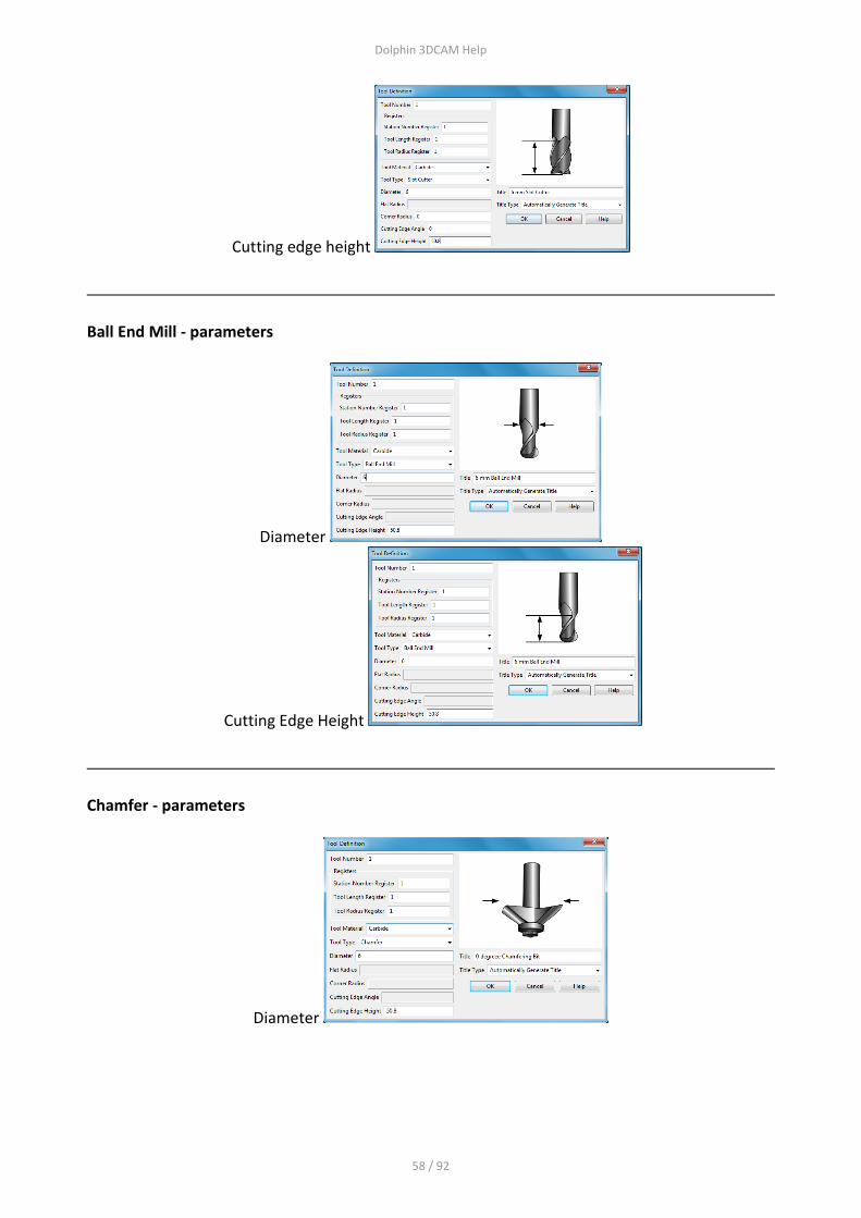
Slot Cutter - parameters
Diameter Corner Radius
Cutting Edge Angle
Dolphin 3DCAM Help
58 / 92
Cutting edge height
Ball End Mill - parameters
Diameter
Cutting Edge Height
Chamfer - parameters
Diameter

Dolphin 3DCAM Help
59 / 92
Cutting Edge Height
Engraving Bit - parameters ------ still to come
Title and Title Type
Setting the Title type to "automatic" will create an entry based on the diameter and tool type. Setting the Title type to "leave manual" will allow you to enter your own Tool Title.

Dolphin 3DCAM Help
60 / 92
Setup
Setup This section deals with the Tool Change position and default Post Processor to be used, the dialogue is shown here.
Tool Change Position Enter the required Tool change position in X, Y and Z. These are absolute coordinates relative to the XYZ datum position of this part. Post Processor This window will show the default folder where all post processors are stored, unless you have specifically placed the post processors into a different folder, leave this as the default which is C:\ProgramData\DolphinCadCam\PartMaster\PostProcessors. Use the Browse button to choose a different folder if you have stored posts in a different folder. The second window choose the post processor you actually want to use, choose the correct post processor for your machine tool / controller. NC Program file name This window shows you the name of the output file created by the post processor, the name will be the same as that which you have used to create the program. File extension

Dolphin 3DCAM Help
61 / 92
3DCAM uses a different file extensions for the various files that are created when a part program is made. The default for the post processed file (normally a G code file ) is "tap" - the file created will be a simple text file. It may be that you need to change the file extension for various reasons, if so, enter the new file extension here, for example txt. Output in inches Use this check box if you wish to output a Metric program in INCH units. If your current units are set to INCH you don't need to check this box as the output will be in INCHs Utility Program and Debug These facilities are supplied for advanced users only, for more information please contact your software supplier.
Dolphin 3DCAM Help
62 / 92
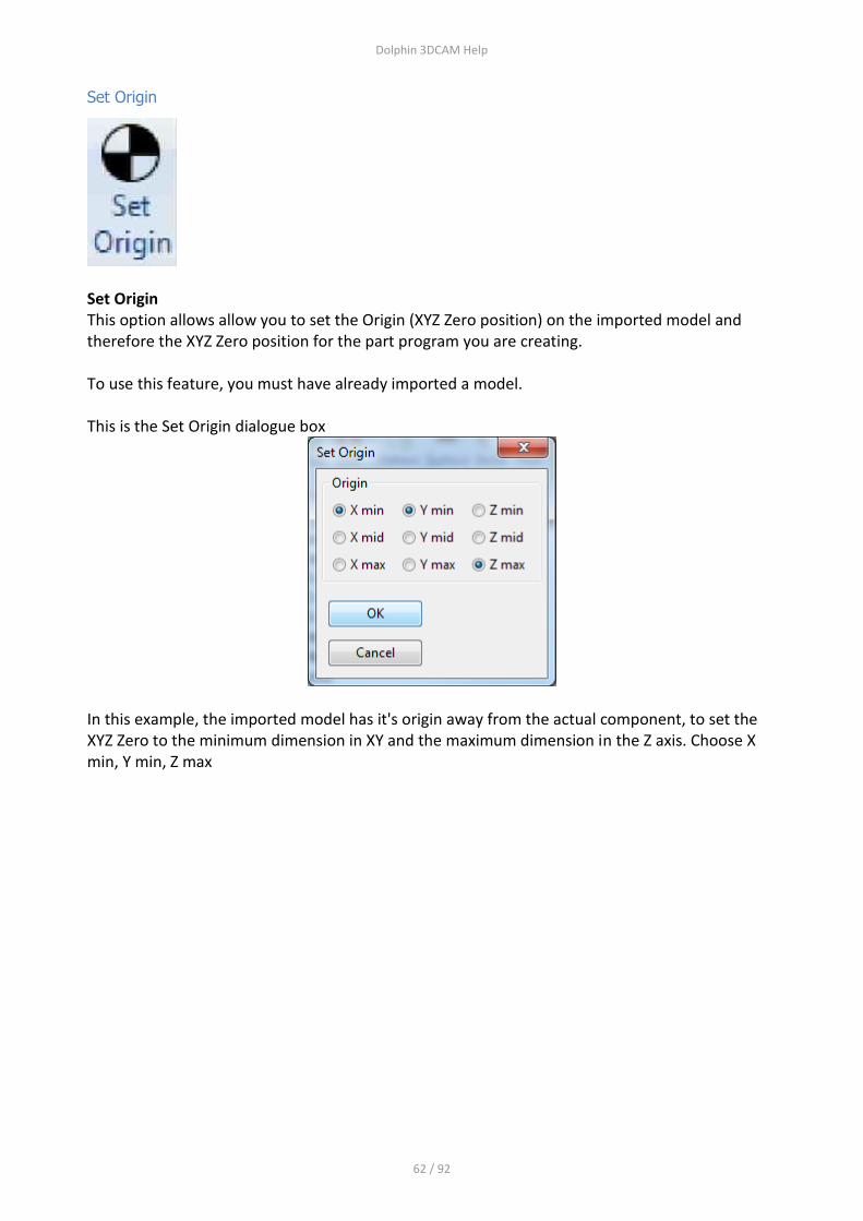
Set Origin
Set Origin This option allows allow you to set the Origin (XYZ Zero position) on the imported model and therefore the XYZ Zero position for the part program you are creating. To use this feature, you must have already imported a model. This is the Set Origin dialogue box
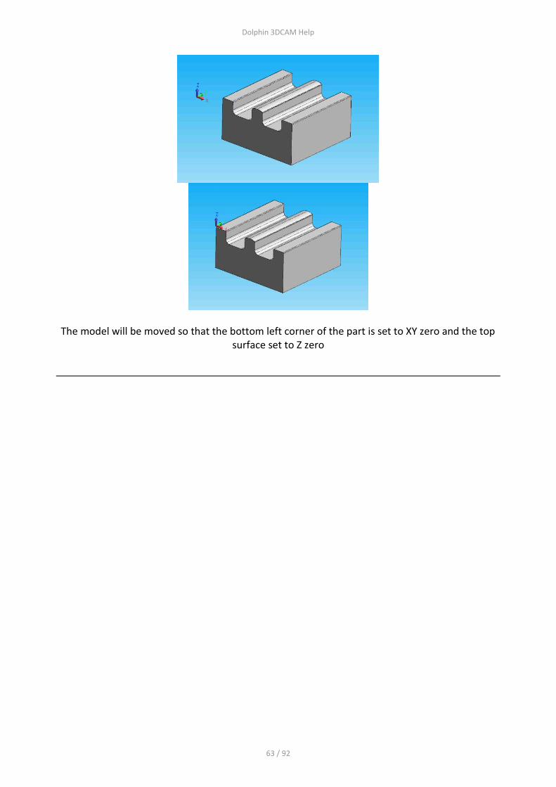
In this example, the imported model has it's origin away from the actual component, to set the XYZ Zero to the minimum dimension in XY and the maximum dimension in the Z axis. Choose X min, Y min, Z max
Dolphin 3DCAM Help
63 / 92
The model will be moved so that the bottom left corner of the part is set to XY zero and the top surface set to Z zero
Dolphin 3DCAM Help
64 / 92
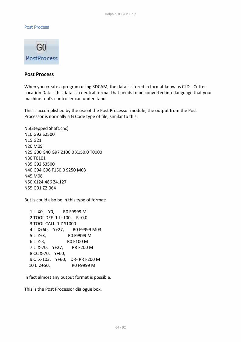
Post Process
Post Process
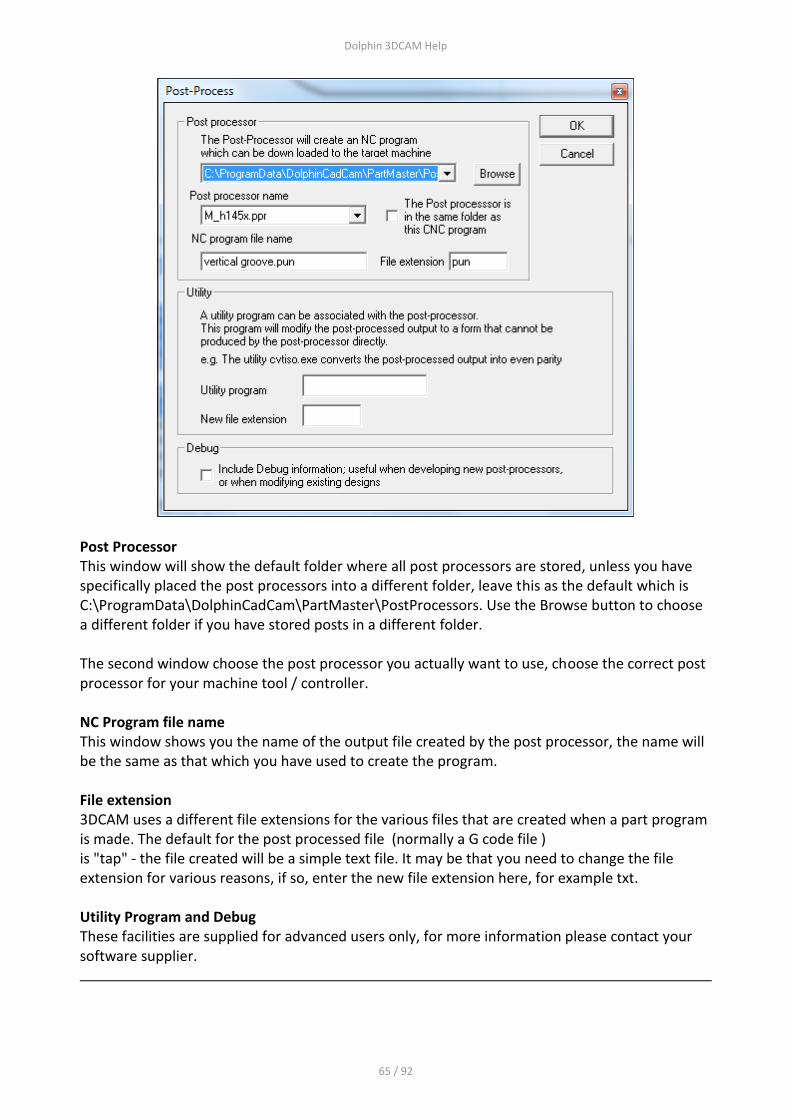
When you create a program using 3DCAM, the data is stored in format know as CLD - Cutter Location Data - this data is a neutral format that needs to be converted into language that your machine tool's controller can understand. This is accomplished by the use of the Post Processor module, the output from the Post Processor is normally a G Code type of file, similar to this: N5(Stepped Shaft.cnc) N10 G92 S2500 N15 G21 N20 M09 N25 G00 G40 G97 Z100.0 X150.0 T0000 N30 T0101 N35 G92 S3500 N40 G94 G96 F150.0 S250 M03 N45 M08 N50 X124.486 Z4.127 N55 G01 Z2.064 But is could also be in this type of format: 1 L X0, Y0, R0 F9999 M 2 TOOL DEF 1 L+100, R+0,0 3 TOOL CALL 1 Z S1000 4 L X+60, Y+27, R0 F9999 M03 5 L Z+3, R0 F9999 M 6 L Z-3, R0 F100 M 7 L X-70, Y+27, RR F200 M 8 CC X-70, Y+60, 9 C X-103, Y+60, DR- RR F200 M 10 L Z+50, R0 F9999 M In fact almost any output format is possible. This is the Post Processor dialogue box.
Dolphin 3DCAM Help
65 / 92
Post Processor This window will show the default folder where all post processors are stored, unless you have specifically placed the post processors into a different folder, leave this as the default which is C:\ProgramData\DolphinCadCam\PartMaster\PostProcessors. Use the Browse button to choose a different folder if you have stored posts in a different folder. The second window choose the post processor you actually want to use, choose the correct post processor for your machine tool / controller. NC Program file name This window shows you the name of the output file created by the post processor, the name will be the same as that which you have used to create the program. File extension 3DCAM uses a different file extensions for the various files that are created when a part program is made. The default for the post processed file (normally a G code file ) is "tap" - the file created will be a simple text file. It may be that you need to change the file extension for various reasons, if so, enter the new file extension here, for example txt. Utility Program and Debug These facilities are supplied for advanced users only, for more information please contact your software supplier.

Dolphin 3DCAM Help
66 / 92
Simulate
Simulate
This will run the Machine Tool Simulation module
This is the Simulate dialogue box
The available options are: SM_Vertical MIll - a standard 3 axis machining centre. SM_4AXHorizontal Mill - a horizontal mill SM_GantryMill - a vertical Gantry style mill Arc tolerance This is used as a coarseness factor when converting arcs into lines, setting this to a very small value will give more accurate results but will result in greatly increased processing times, for most applications you can leave the default unchanged.
Dolphin 3DCAM Help
67 / 92
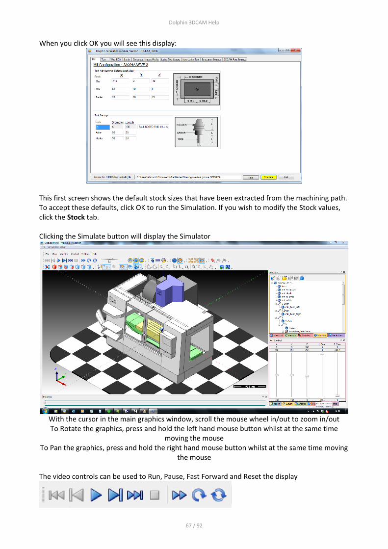
When you click OK you will see this display:
This first screen shows the default stock sizes that have been extracted from the machining path. To accept these defaults, click OK to run the Simulation. If you wish to modify the Stock values, click the Stock tab. Clicking the Simulate button will display the Simulator
With the cursor in the main graphics window, scroll the mouse wheel in/out to zoom in/out To Rotate the graphics, press and hold the left hand mouse button whilst at the same time
moving the mouse To Pan the graphics, press and hold the right hand mouse button whilst at the same time moving
the mouse
The video controls can be used to Run, Pause, Fast Forward and Reset the display

Dolphin 3DCAM Help
68 / 92
The Focus controls can be used to set the display's Focus The 3 options are 1 = Focus on the Stock with the tool stationary 2 = Focus on the Stock with the tool moving 3= Focus on the entire machine tool
For more help about the Machine Tool Simulator, click the Help button

Dolphin 3DCAM Help
69 / 92
Screen Layout
Screen Layout
Below is the main 3DCAM screen. The screen is split into various areas, they are The Ribbon toolbars control all functions within the software. To display different Ribbons (topics) - please click on the appropriate ribbon item - such as File, Geom, Solids etc.
Main Graphics Area Objects Tree System Options Properties Messages
Dolphin 3DCAM Help
70 / 92
Creating and using Sketches
Creating and using Sketches
1) Extracting a Sketch from a model 2) Importing a DXF file 3) Using the Geometry construction options
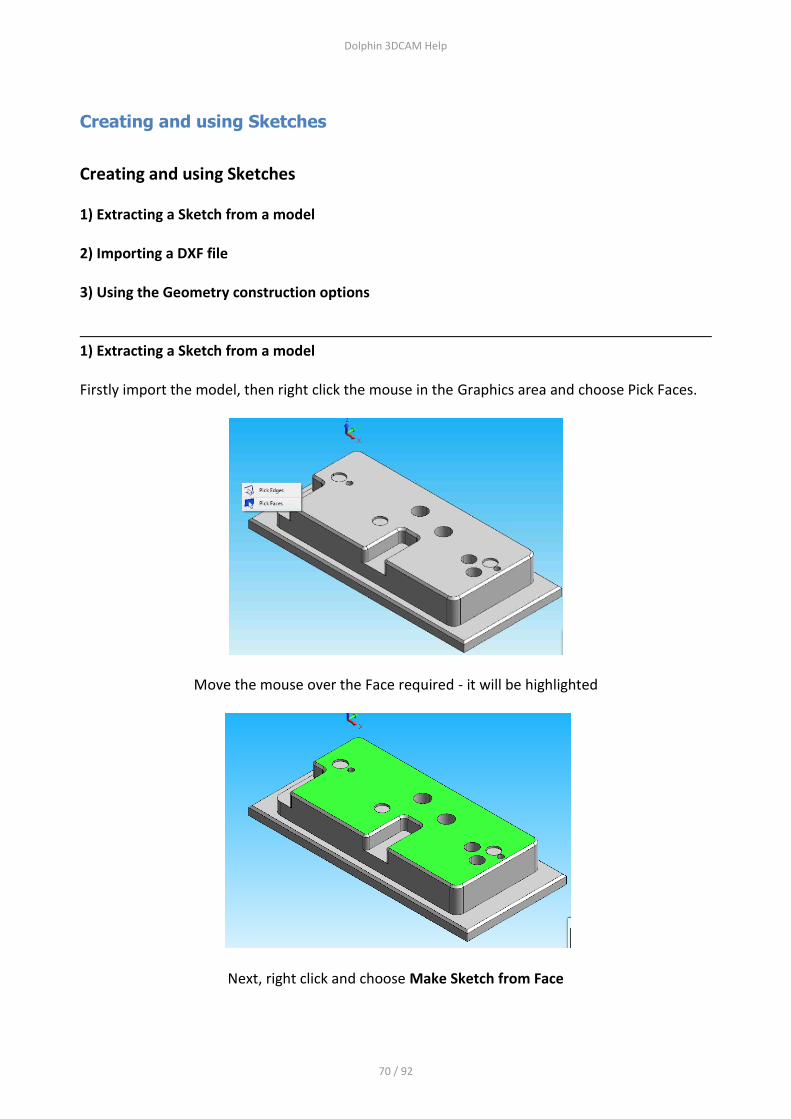
1) Extracting a Sketch from a model Firstly import the model, then right click the mouse in the Graphics area and choose Pick Faces.
Move the mouse over the Face required - it will be highlighted
Next, right click and choose Make Sketch from Face

Dolphin 3DCAM Help
71 / 92
A new Sketch entry will appear in the Objects Tree
This Sketch will have more than shape, the outside shape and circles. Right click the on the Sketch and choose "Split Sketch"
This will create a number of Sketches that can be used in Profile and Pocket operations.
Dolphin 3DCAM Help
72 / 92
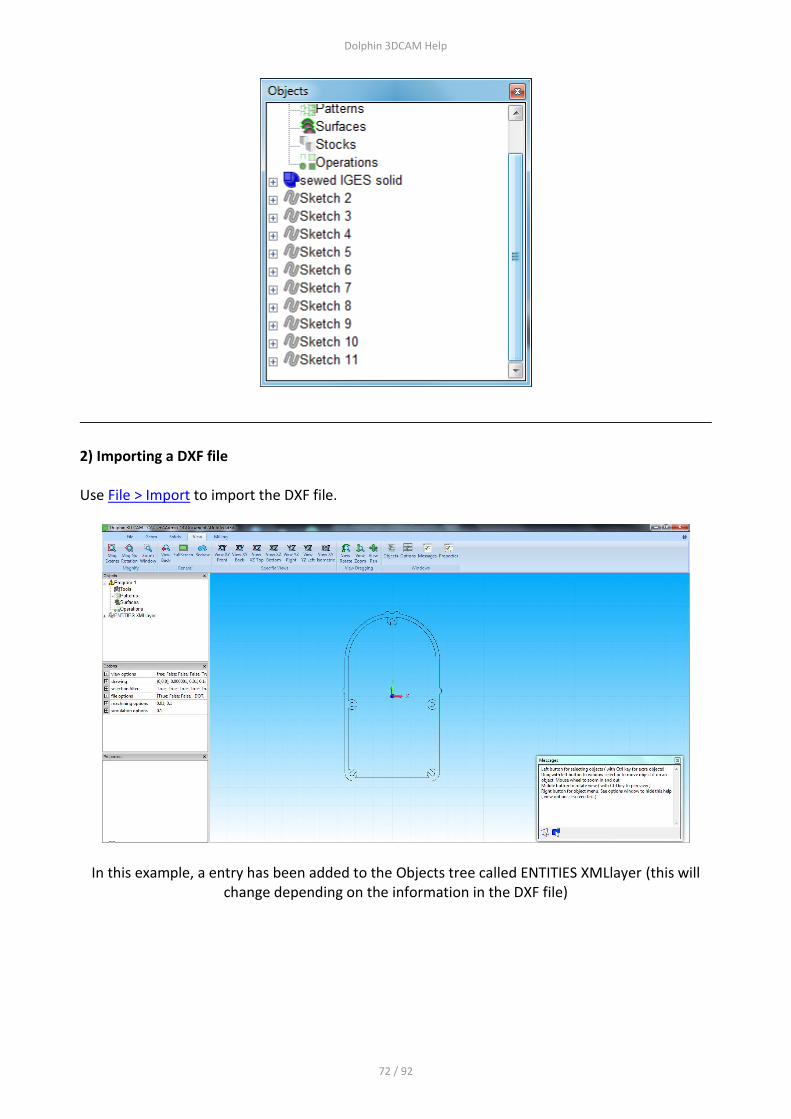
2) Importing a DXF file Use File > Import to import the DXF file.
In this example, a entry has been added to the Objects tree called ENTITIES XMLlayer (this will change depending on the information in the DXF file)
Dolphin 3DCAM Help
73 / 92
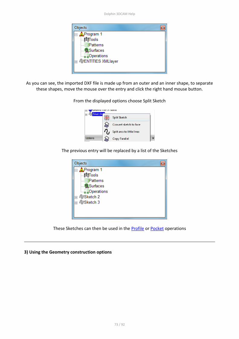
As you can see, the imported DXF file is made up from an outer and an inner shape, to separate these shapes, move the mouse over the entry and click the right hand mouse button.
From the displayed options choose Split Sketch
The previous entry will be replaced by a list of the Sketches
These Sketches can then be used in the Profile or Pocket operations
3) Using the Geometry construction options

Dolphin 3DCAM Help
74 / 92
Program Tree Objects
Program Objects Tree
This window will display the Objects that may form part of the current job. An Object can be a solid model, a tool, a milling operation or sketch for example.
Objects can be Expanded or Collapsed using the + or - buttons next to each entry, only shown if there are further entries/parameters available.
Imported File
The type of imported file - IGES, STEP or STL
Dolphin 3DCAM Help
75 / 92
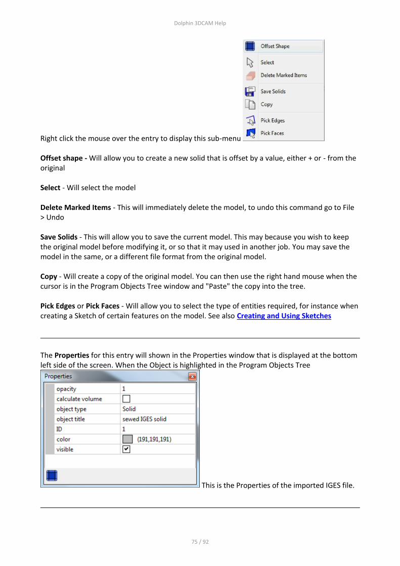
Right click the mouse over the entry to display this sub-menu Offset shape - Will allow you to create a new solid that is offset by a value, either + or - from the original Select - Will select the model Delete Marked Items - This will immediately delete the model, to undo this command go to File > Undo Save Solids - This will allow you to save the current model. This may because you wish to keep the original model before modifying it, or so that it may used in another job. You may save the model in the same, or a different file format from the original model. Copy - Will create a copy of the original model. You can then use the right hand mouse when the cursor is in the Program Objects Tree window and "Paste" the copy into the tree. Pick Edges or Pick Faces - Will allow you to select the type of entities required, for instance when creating a Sketch of certain features on the model. See also Creating and Using Sketches
The Properties for this entry will shown in the Properties window that is displayed at the bottom left side of the screen. When the Object is highlighted in the Program Objects Tree
This is the Properties of the imported IGES file.

Dolphin 3DCAM Help
76 / 92
Opacity - This controls the view of the model, 1 = fully solid, 0 = invisible. Setting this to 0.5 would give this transparent view of the model.
Calculate Volume - Will give the volume and centre of gravity of the model Object type - Will show the type of file imported, sewed IGES solid, STEP soild or STL object ID - is simply there to identify this model - you may import more than 1 model
Colour - This can used to set the colour of the model, click the entry
to see the colour selector
Program Number
The Program number - default = 1

Dolphin 3DCAM Help
77 / 92
To change any of the parameters, click the entry Path Control Mode - Options are: Undefined = Not set Exact Path Mode Exact Stop Mode Best Possible Speed Visible - uncheck to disable view of all toolpaths
Tools
Tools
This will show the tools available. Click the + button to expand the tree and view the tools. See also the Tool option on the Milling toolbar Clicking on an individual tool will show the tool in the graphics window.
The Tool Properties window will show these options

Dolphin 3DCAM Help
78 / 92
Right click when the mouse is over the Tools entry to see this sub-menu of options.
Save As Default - This will save all the currently defined into the default tool table that is loaded automatically when a new job is started. Restore Default Tools - Will replace all current tools with those in the default tool table. Import Tool Table - Will allow you to open a previously exported (saved) tool table. Export Tool Table - This will allow you to save all the currently defined tools into a new tool table, you may have any number of tool tables. For instance you may a different tool table for each machine tool type you have.
The next section will allow you to define a new tool, See also the Tool option on the Milling toolbar for more details about how to define a tool
Copy, Pick Edges and Pick Faces - not functional in this context

Dolphin 3DCAM Help
79 / 92
Clicking on an individual tool will show the tool in the
graphics window
Right click over the tool to show these options Select - Will show the tool in the graphics window Edit - Will display the dialogue box that was used to create the tool originally so that you may edit the contents. This is also possible by using the Tool Properties window that is displayed at the bottom left on the main screen. See The User Interface
Delete Marked Items - this will delete the current tool entry. To undo this go to File > Undo

Dolphin 3DCAM Help
80 / 92
Copy - will place a copy of the entry on the clipboard, you can then right click and Paste the tool to create a new tool.
Pick Edges and Pick Faces - not functional in this context
Patterns
Patterns
This will show any previously created Patters using the Pattern command found in the Milling Toolbar This is the entry from the Pattern command
Pattern A Pattern will setup up repeat machining on subsequent machining operations, to activate the Pattern, you must specify the Pattern number in the Profile or Pocket machining operations This is the Pattern Dialogue box
Number of Copies A This is the number of machining instances, in the above example there are 3 instances separated by 50 mm in the X axis X Shift A This is the amount each instance will be separated from the others in the X axis Y Shift A

Dolphin 3DCAM Help
81 / 92
This is the amount each instance will be separated from the others in the Y axis For the Pattern command to work correctly, you must specify a distance in either or both the X/Y Shift boxes In this example the Y Shift has also been specified, the graphics show the results
Number of copies B This is the number of machining instances to be combined with Number of Copies A X Shift B This is the amount each instance will be separated from the others in the X axis Y Shift B This is the amount each instance will be separated from the others in the Y axis For the Pattern command to work correctly, you must specify a distance in either or both the X/Y Shift boxes In this example the Number of Copies B has also been specified, the graphics show the results

Dolphin 3DCAM Help
82 / 92
Surfaces
Surfaces
This will show any previously created Surfaces using the Surface command found in the Milling Toolbar This is the entry from the Surface command
Surface This command will create a Surface from an existing solid model, the surface can then be used in the Profile and Pocket commands to create a 3D toolpath
If you are working with a single solid model then you only need to create the surface once, the default name for the surface will be Surface 1, but you can set the number in the first input window. If you are working on multiple models you will need to select the model using the Pick button. Tolerance - This will set the accuracy of the surface being created from the model. The value entered here will depend on your current units MM or INCH. Setting this value to a smaller number will create a more accurate surface but will the time taken to calculate the toolpath and the size of the output file (G code) will considerable larger. Use the largest value you can to give you the accuracy you need. You will need to experiment with this.

Dolphin 3DCAM Help
83 / 92
Material Allowance - Setting this value will produce a surface that is offset from the original model
Same for each Pattern Position - Checking this box will use this surface for each instance of machining if you have setup a Pattern to produce multiple toolpaths.

Dolphin 3DCAM Help
84 / 92
Operations
Operations
This sections deals with the actual machining operations. Machining Operations are created by choosing the appropriate option from the Milling Toolbar The Operations are:- Profile - for creating 2D or 3D Profiling Toolpaths around an existing Sketch. Pocket - for creating a 2D or 3D Pocketing Toolpaths on an existing Sketch or Sketches. Drill - for creating drilling operations on a previously created series of point positions that represent the centre point of the dilling operation.
Right click the mouse over the Operations item to reveal this sub-menu
Only the first 2 options have any function in this context.

Dolphin 3DCAM Help
85 / 92
Main Graphics Area
Main Graphics Area
This area of the screen will display the imported model, sketches and toolpaths, as shown here.
To manipulate the view use:- Mouse Wheel rotated forward and backward to zoom in/out of the view Press Mouse Wheel down and move mouse to Rotate the view Press Mouse Wheel + Ctrl key and move mouse to Pan the view To Select an item use the Left button. To select multiple items hold down the Ctrl key and click the items.
Selecting Objects To select on object such as a model, sketch or other object, move the mouse over the object. The object under the cursor will be highlighted (see System Options > View Options > highlight items under cursor) Having selected an object, the item will be also be shown in the Objects Tree. To view a Context Sensitive Menu - click the right hand mouse button, depending on what object you have selected the menu will display the options relevant to that object.

Dolphin 3DCAM Help
86 / 92
Selecting a model and right clicking will display this menu, choose the option or sub option required. If you delete the model by mistake, go to File > Undo
Pick Edges - will allow you create a Sketch from edge elements, hold down the Ctrl key to select multiple egdes. When you have selected all the required edges, right click the mouse again and choose Make to Sketch. A new sketch object will be shown in the Objects Tree window Pick Face - will allow you select a face, select the face and then right click again and choose Make Sketch from Face - this will create a Sketch from the Face that can be used in the Profile or Pocket operations
Selecting a Sketch and right clicking will display this menu along with the various sub options available

Dolphin 3DCAM Help
87 / 92
Split Sketch - will convert the sketch into lines and arcs. Convert Sketch to Face - will convert the sketch into a Face that can be extruded for instance Split arcs to little lines - will convert arcs to line vectors Copy Parallel - will create a new Sketch that is Offset from the original, either smaller or larger using this dialogue box
New Profile Operation - will create a new machining operation based on the selected Sketch New Pocket Operation - will create a new machining operation based on the selected Sketch
Re-selecting objects - if you have used the option Pick Edges or Pick Faces and wish to cancel this filter and be able to pick any object, right click the mouse in an empty area of the graphics
window. This box will be displayed Choose Pick Anything to remove the previously used selection filter.

Dolphin 3DCAM Help
88 / 92
System Options
System Options
This window will show settings and parameters. To set the system units use View Options > Units
Use this option to choose the units each time you start 3DCAM.

Dolphin 3DCAM Help
89 / 92
Properties
Properties
This window will the display the Properties of an object chosen from the Objects Tree Window. To modify or edit the Properties of an Object double click the entry in the Objects Tree Window, or use the Properties window where you can click on an individual entry and change it's parameters.
Imported solid - - It's Properties -
Click here for details
Program Number -
It's Properties - Click here for details

Dolphin 3DCAM Help
90 / 92
Tools -
It's Properties - Click here for details
Patterns -
It's Properties - Click here for details
Dolphin 3DCAM Help
91 / 92
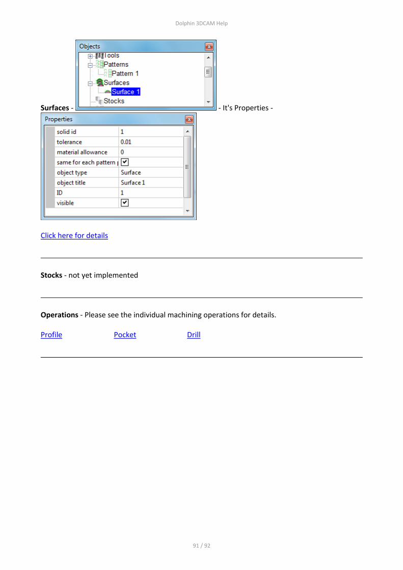
Surfaces - - It's Properties -
Click here for details
Stocks - not yet implemented
Operations - Please see the individual machining operations for details. Profile Pocket Drill

Dolphin 3DCAM Help
92 / 92
Messages
Messages
This area will display the context sensitive help message when performing a particular operation.
The information box can be resized by moving the mouse over any corner, click and drag to a new size. The box can also be re-positioned by click and drag on the top part of the box The Icons shown in the above example are for picking Edges or Faces from a model.
This message box will appear when using the Rectangle draw mode from the Geometry toolbar
The 3 Icons are 1 = Accept selection. 2 = Snap to near point. 3 = Snap to cursor