z-stack end device power consumption measurement
TRANSCRIPT
1SWRA625B–August 2018–Revised February 2020Submit Documentation Feedback
Copyright © 2018–2020, Texas Instruments Incorporated
Z-Stack End Device Power Consumption Measurement With theSimpleLink™ Wireless MCU Family
Application ReportSWRA625B–August 2018–Revised February 2020
Z-Stack End Device Power Consumption MeasurementWith the SimpleLink™ Wireless MCU Family
Sean McClain
ABSTRACTThis application report describes the power performance and how to set up power consumptionmeasurements for the SimpleLink CC1352P and CC2652R devices running Z-Stack 3.3. Light and Switchapplications from the SimpleLink CC13X2/CC26X2SDK v3.10 (downloaded from [5] and it described in[6]). This document uses the Zigbee 3.0 profile.
Contents1 Introduction ................................................................................................................... 22 Abbreviations and Acronyms ............................................................................................... 33 System Overview ............................................................................................................ 44 Measurement Setup ......................................................................................................... 55 Measurements .............................................................................................................. 126 Application to a Practical Use Case ..................................................................................... 187 Batteryless Green Power Device ........................................................................................ 208 Summary .................................................................................................................... 219 References .................................................................................................................. 21
List of Figures
1 LAUNCHXL-CC26X2R1 and LAUNCHXL-CC1352P-2 LaunchPad Hardware Setup ............................. 42 Measurement Setup Overview ............................................................................................ 53 ZED Measurement Setup................................................................................................... 54 Erase Flash Option ......................................................................................................... 75 Setting Compile Options for the ZED Node ............................................................................. 86 Setting up Poll Rate ........................................................................................................ 97 Setting Custom Default Channel .......................................................................................... 98 Setting TX Power Level for GPDs ....................................................................................... 119 ZED Current Consumption Measurement in Sleep Mode ........................................................... 1210 ZED Current Consumption for One Polling Operation (5 dBm) ...................................................... 1311 ZED Current Consumption Measurement for One On/Off Toggle Operation (5 dBm)............................ 1312 GPD Current Consumption Measurement in Sleep Mode ............................................................ 1413 GPD Current Consumption Measurement for Sending GPDF With 3 Duplicates (5 dBm)....................... 1514 ZED EnergyTrace Measurement Profile ................................................................................ 1615 ZED EnergyTrace Current Measurement ............................................................................... 1616 ZED EnergyTrace Energy Measurement ............................................................................... 1717 Message Sequence: End Device Switch Sends Toggle Command to a Coordinator Light ..................... 1818 LAUNCHXL-CC26x2R1 LaunchPad Connected to TIDA-00690 Reference Design PCB........................ 20
List of Tables
1 Abbreviations and Acronyms............................................................................................... 32 Current Consumption of SimpleLink CC1352P/CC2652R for ZED Typical Use Cases .......................... 14
Introduction www.ti.com
2 SWRA625B–August 2018–Revised February 2020Submit Documentation Feedback
Copyright © 2018–2020, Texas Instruments Incorporated
Z-Stack End Device Power Consumption Measurement With theSimpleLink™ Wireless MCU Family
3 Current Consumption of SimpleLink CC1352P/CC2652R for GPD Typical Use Cases .......................... 15
TrademarksSimpleLink, Texas Instruments, Code Composer Studio, EnergyTrace are trademarks of TexasInstruments.Arm, Cortex are registered trademarks of Arm Limited (or its subsidiaries) in the US and/or elsewhere.IAR Embedded Workbench is a trademark of IAR Systems AB.All other trademarks are the property of their respective owners.
1 IntroductionThe CC2652R device from Texas Instruments™ is the ideal System-on-Chip for high-performance Zigbeeapplications, addressing many product specifications from a low-power standpoint. The CC2652Rcombines a powerful 48 MHz Arm® Cortex®-M4F CPU with up to 80KB of RAM and 352KB of on-chipflash. With a dedicated Radio Controller handling low-level RF protocol commands stored in ROM, it canhandle complex network stacks ensuring ultra-low power and great flexibility.
In the world of IoT, battery life is tremendously valued by customers, cutting down on bill of materials andbattery replacement costs, while enabling easy maintenance and product convenience. Therefore, currentconsumption of devices inside a connected network must have their current consumption tightly controlled.The CC2652R is designed with the lowest power performance in sleep mode, active mode, and duringsensor and data processing.
When range is an important consideration for an application, Texas Instruments offers the CC1352Pdevice, which contains a +20-dBm integrated high-power amplifier with a best-in-class efficiency for longrange applications. The CC1352P is a multiprotocol Sub-1 and 2.4-GHz with the same powerful system,offering the ability for a high-performance, long range Zigbee device.
This application report references examples from Z-Stack 3.3.1, which is based on the Zigbee 3.0 profile.Included in Z-Stack 3.3.1 are Green Power examples that allow for powerful, battery-less Zigbee products,by taking advantage of common energy harvesting techniques. In Zigbee 3.0, every device with routingcapability is required to use Green Power Basic Proxy functionality, which mandates all routing devices toforward all Green Power Data Frames (GPDF), making it much easier to have Green Power Devices(GPD) inside the Zigbee network. For more details about GPD usage, see the Green Power DeviceApplication Overview section in the Z-Stack User's Guide [6]. Z-Stack comes packaged as part of theSimpleLink CC13X2/CC26X2 SDK, which is designed for simplified development within one environmentusing industry standard APIs, TI Drivers, and TI RTOS to provide a robust foundation for applicationdevelopment. The version used in this report's test cases is v3.10.
The measurement setup in this application report consists of a Zigbee End Device (ZED) and a ZigbeeCoordinator (ZC). The ZED can also be connected to a Zigbee Router (ZR) instead of a ZC. The ZEDpolls its parent periodically for data and in between polls, the ZED will go to sleep (using Standby Mode)to save power. For measuring Green Power, the setup consists of a GPD and a ZC application acting asthe Green Power Sink (GPS).
Section 3 describes which hardware and software was used for the measurement setup, and is describedin Section 4. The obtained results are shown and discussed in Section 5.
For similar measurements on the CC2538, see [8].
Note that there are many factors that influence the overall power consumption and that the resultspresented in this document should only be regarded as indicative for what is possible to achieve insystems with similar hardware.
For detailed information about the CC1352P and CC2652R, see the CC1352P product page [1] or theCC2652R product page [2]. More details regarding usage, examples, and API's on Z-Stack 3.3.0 can befound in the Z-Stack User's Guide [6].
www.ti.com Abbreviations and Acronyms
3SWRA625B–August 2018–Revised February 2020Submit Documentation Feedback
Copyright © 2018–2020, Texas Instruments Incorporated
Z-Stack End Device Power Consumption Measurement With theSimpleLink™ Wireless MCU Family
2 Abbreviations and Acronyms
Table 1. Abbreviations and Acronyms
ACK AcknowledgmentAPS Application Support Sub-LayerEW Embedded WorkbenchGPD Green Power DeviceGPDF Green Power Data FrameGPP Green Power ProxyGPS Green Power SinkI Current (Ampere, A)mA Milliampere (10-3 A)MAC Medium Access ControlPHY Physical LayerRAM Random Access MemoryRX ReceiveTX TransmitμA Microampere (10-6 A)V Voltage (Volt)ZC ZigBee CoordinatorZED ZigBee End DeviceZR ZigBee Router
System Overview www.ti.com
4 SWRA625B–August 2018–Revised February 2020Submit Documentation Feedback
Copyright © 2018–2020, Texas Instruments Incorporated
Z-Stack End Device Power Consumption Measurement With theSimpleLink™ Wireless MCU Family
3 System OverviewThis section describes the hardware and software used for the measurement setup described inSection 4.
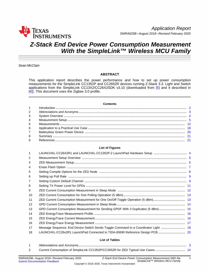
3.1 Hardware:LAUNCHXL-CC1352P-2, LAUNCHXL-CC26X2R1Figure 1 shows the hardware used in this application report: one LAUNCHXL-CC1352P-2 [4], twoLAUNCHXL-CC26X2R1s [3], and micro-USB cables.
Figure 1. LAUNCHXL-CC26X2R1 and LAUNCHXL-CC1352P-2 LaunchPad Hardware Setup
Additionally, a Keysight N6705B DC Power Analyzer was used for the power measurements. The detailedmeasurement setup is shown in Section 4.
3.2 Software: Z-StackThe following subsections describe the software that was used to perform the measurements.
3.2.1 Z-Stack Development EnvironmentThe measurement setup shown in Section 4 is based on the Z-Stack 3.3.1 Light Sink, Switch, and GPDSwitch examples, which come as part of the SimpleLink CC13X2/CC26X2 Software Development Kit [5]described in [6].
In order to be able to compile the application and load onto the devices, the correct version of CodeComposer Studio™ or IAR Embedded Workbench™ for ARM (mentioned in the Release Notes documentinside the SimpleLink CC13X2/26X2 SDK install directory) must be installed, which can be obtained athttp://www.ti.com/tool/CCSTUDIO or http://www.iar.com/downloads, respectively.
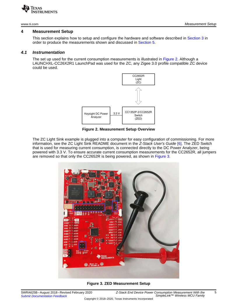
Keysight DC Power
Analyzer
CC1352P-2/CC2652R
Switch
(ZED)
3.3 V
CC2652R
Light
(ZC)
www.ti.com Measurement Setup
5SWRA625B–August 2018–Revised February 2020Submit Documentation Feedback
Copyright © 2018–2020, Texas Instruments Incorporated
Z-Stack End Device Power Consumption Measurement With theSimpleLink™ Wireless MCU Family
4 Measurement SetupThis section explains how to setup and configure the hardware and software described in Section 3 inorder to produce the measurements shown and discussed in Section 5.
4.1 InstrumentationThe set up used for the current consumption measurements is illustrated in Figure 2. Although aLAUNCHXL-CC26X2R1 LaunchPad was used for the ZC, any Zigee 3.0 profile compatible ZC devicecould be used.
Figure 2. Measurement Setup Overview
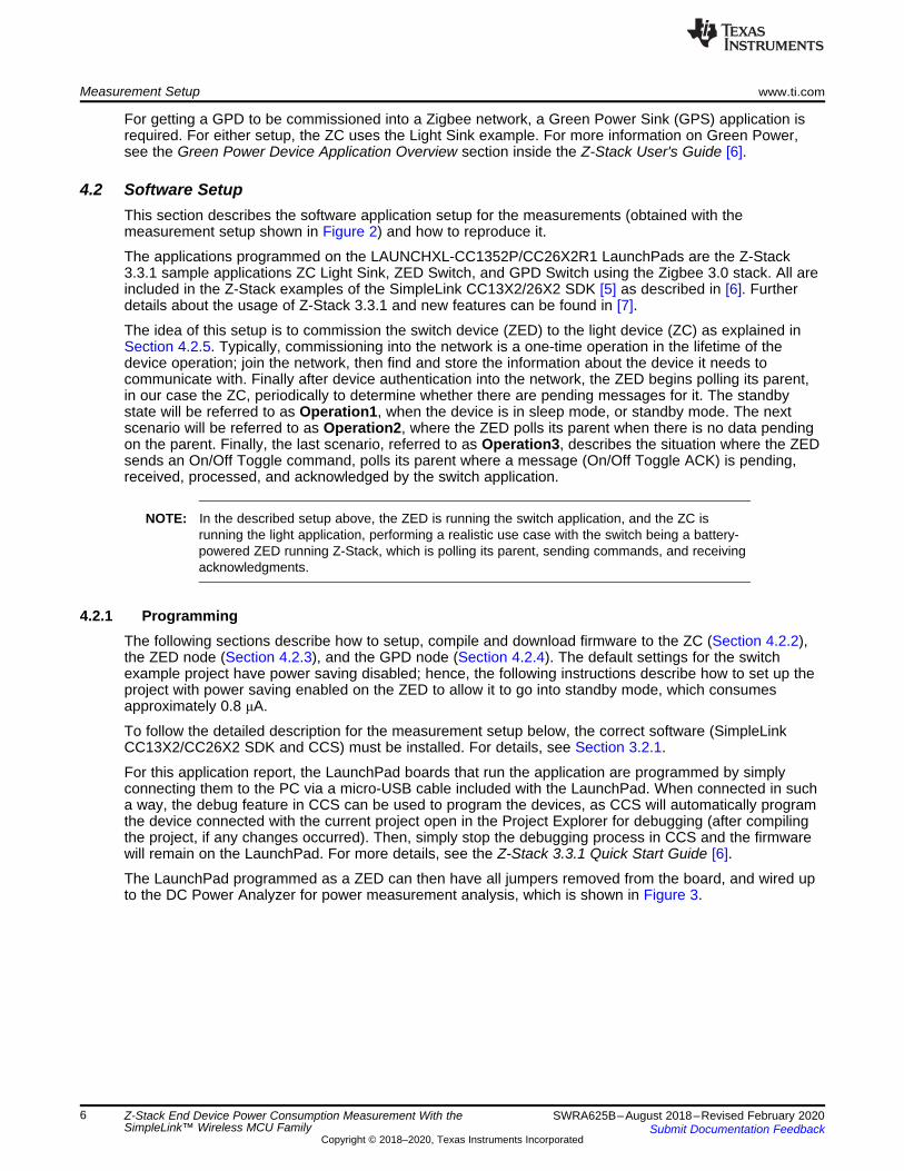
The ZC Light Sink example is plugged into a computer for easy configuration of commissioning. For moreinformation, see the ZC Light Sink README document in the Z-Stack User's Guide [6]. The ZED Switchthat is used for measuring current consumption, is connected directly to the DC Power Analyzer, beingpowered with 3.3 V. To ensure accurate current consumption measurements for the CC2652R, all jumpersare removed so that only the CC2652R is being powered, as shown in Figure 3.
Figure 3. ZED Measurement Setup
Measurement Setup www.ti.com
6 SWRA625B–August 2018–Revised February 2020Submit Documentation Feedback
Copyright © 2018–2020, Texas Instruments Incorporated
Z-Stack End Device Power Consumption Measurement With theSimpleLink™ Wireless MCU Family
For getting a GPD to be commissioned into a Zigbee network, a Green Power Sink (GPS) application isrequired. For either setup, the ZC uses the Light Sink example. For more information on Green Power,see the Green Power Device Application Overview section inside the Z-Stack User's Guide [6].
4.2 Software SetupThis section describes the software application setup for the measurements (obtained with themeasurement setup shown in Figure 2) and how to reproduce it.
The applications programmed on the LAUNCHXL-CC1352P/CC26X2R1 LaunchPads are the Z-Stack3.3.1 sample applications ZC Light Sink, ZED Switch, and GPD Switch using the Zigbee 3.0 stack. All areincluded in the Z-Stack examples of the SimpleLink CC13X2/26X2 SDK [5] as described in [6]. Furtherdetails about the usage of Z-Stack 3.3.1 and new features can be found in [7].
The idea of this setup is to commission the switch device (ZED) to the light device (ZC) as explained inSection 4.2.5. Typically, commissioning into the network is a one-time operation in the lifetime of thedevice operation; join the network, then find and store the information about the device it needs tocommunicate with. Finally after device authentication into the network, the ZED begins polling its parent,in our case the ZC, periodically to determine whether there are pending messages for it. The standbystate will be referred to as Operation1, when the device is in sleep mode, or standby mode. The nextscenario will be referred to as Operation2, where the ZED polls its parent when there is no data pendingon the parent. Finally, the last scenario, referred to as Operation3, describes the situation where the ZEDsends an On/Off Toggle command, polls its parent where a message (On/Off Toggle ACK) is pending,received, processed, and acknowledged by the switch application.
NOTE: In the described setup above, the ZED is running the switch application, and the ZC isrunning the light application, performing a realistic use case with the switch being a battery-powered ZED running Z-Stack, which is polling its parent, sending commands, and receivingacknowledgments.
4.2.1 ProgrammingThe following sections describe how to setup, compile and download firmware to the ZC (Section 4.2.2),the ZED node (Section 4.2.3), and the GPD node (Section 4.2.4). The default settings for the switchexample project have power saving disabled; hence, the following instructions describe how to set up theproject with power saving enabled on the ZED to allow it to go into standby mode, which consumesapproximately 0.8 μA.
To follow the detailed description for the measurement setup below, the correct software (SimpleLinkCC13X2/CC26X2 SDK and CCS) must be installed. For details, see Section 3.2.1.
For this application report, the LaunchPad boards that run the application are programmed by simplyconnecting them to the PC via a micro-USB cable included with the LaunchPad. When connected in sucha way, the debug feature in CCS can be used to program the devices, as CCS will automatically programthe device connected with the current project open in the Project Explorer for debugging (after compilingthe project, if any changes occurred). Then, simply stop the debugging process in CCS and the firmwarewill remain on the LaunchPad. For more details, see the Z-Stack 3.3.1 Quick Start Guide [6].
The LaunchPad programmed as a ZED can then have all jumpers removed from the board, and wired upto the DC Power Analyzer for power measurement analysis, which is shown in Figure 3.
www.ti.com Measurement Setup
7SWRA625B–August 2018–Revised February 2020Submit Documentation Feedback
Copyright © 2018–2020, Texas Instruments Incorporated
Z-Stack End Device Power Consumption Measurement With theSimpleLink™ Wireless MCU Family
4.2.2 ZC NodeOpen the workspace file zc_light_sink_CC26X2R1_LAUNCHXL_tirtos_ccs.projectspec with the correctversion of CCS. The project file is found in the following folder after installing the SimpleLinkCC13X2/CC26X2 SDK [5]:
C:\ti\simplelink_cc13x2_26x2_sdk_<version>\examples\rtos\<LaunchPad>\zstack\zc_light_sink\tirtos\ccs
NOTE: When performing measurements on a GPD, a GPS application must be in the network. Theeasiest way to accommodate this is by using the ZC Light Sink project described.
With Zigbee 3.0, Base Device Behavior was introduced to allow for common network commissioning, suchas automatic Finding & Binding mode, for a simplified commissioning process in Zigbee devices. InSection 4.2.5, it is explained how to start commissioning devices into a Zigbee network. To enableconvenient features, such as storing storing and restoring the binding information after a device reset,ensure that the NV_RESTORE predefine symbol is defined in the project, which is defined by default inthe projectspec. For more information about the NV_RESTORE compile option, see the Z-Stack Overviewin the Z-Stack User's Guide [6].
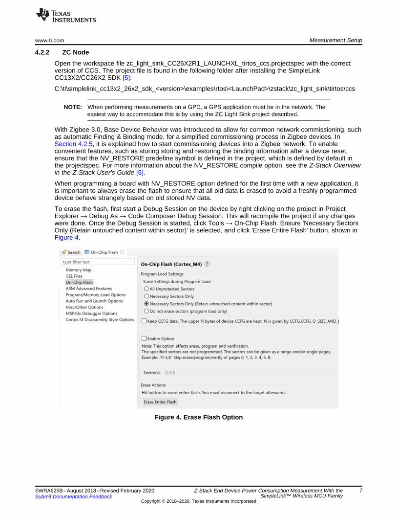
When programming a board with NV_RESTORE option defined for the first time with a new application, itis important to always erase the flash to ensure that all old data is erased to avoid a freshly programmeddevice behave strangely based on old stored NV data.
To erase the flash, first start a Debug Session on the device by right clicking on the project in ProjectExplorer → Debug As → Code Composer Debug Session. This will recompile the project if any changeswere done. Once the Debug Session is started, click Tools → On-Chip Flash. Ensure 'Necessary SectorsOnly (Retain untouched content within sector)' is selected, and click 'Erase Entire Flash' button, shown inFigure 4.
Figure 4. Erase Flash Option
Measurement Setup www.ti.com
8 SWRA625B–August 2018–Revised February 2020Submit Documentation Feedback
Copyright © 2018–2020, Texas Instruments Incorporated
Z-Stack End Device Power Consumption Measurement With theSimpleLink™ Wireless MCU Family
4.2.3 ZED NodeOpen the workspace file zed_sw_CC26X2R1_LAUNCHXL_tirtos_ccs.projectspec with the correct versionof CCS. The project file is found in the following folder after installing the SimpleLink CC13X2/CC26X2SDK 3.10.00 [5]:
C:\ti\simplelink_cc13x2_26x2_sdk_<version>\examples\rtos\<LaunchPad>\zstack\zed_sw\tirtos\ccs
The power saving features (implemented in the Z-Stack for ZEDs) is not enabled by default, as it wouldhinder the debugging within the development phase. In order to enable these features for themeasurement setup, the correct compile options must be set as well as adding several lines of code in theapplication files described below. For all details about the power saving functionalities, see the PowerManagement section in the Z-Stack User's Guide [6].
As already mentioned in the ZC Node setup, it is also important to ensure the NV_RESTORE predefinesymbol is defined.
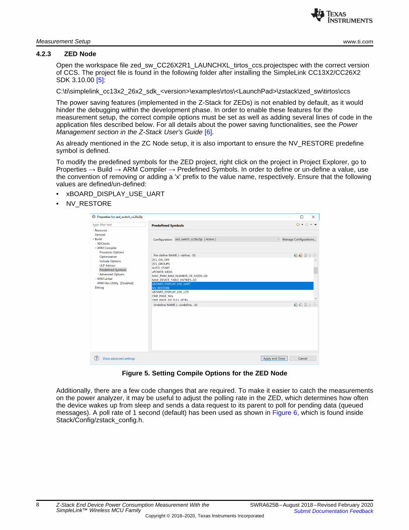
To modify the predefined symbols for the ZED project, right click on the project in Project Explorer, go toProperties → Build → ARM Compiler → Predefined Symbols. In order to define or un-define a value, usethe convention of removing or adding a 'x' prefix to the value name, respectively. Ensure that the followingvalues are defined/un-defined:• xBOARD_DISPLAY_USE_UART• NV_RESTORE
Figure 5. Setting Compile Options for the ZED Node
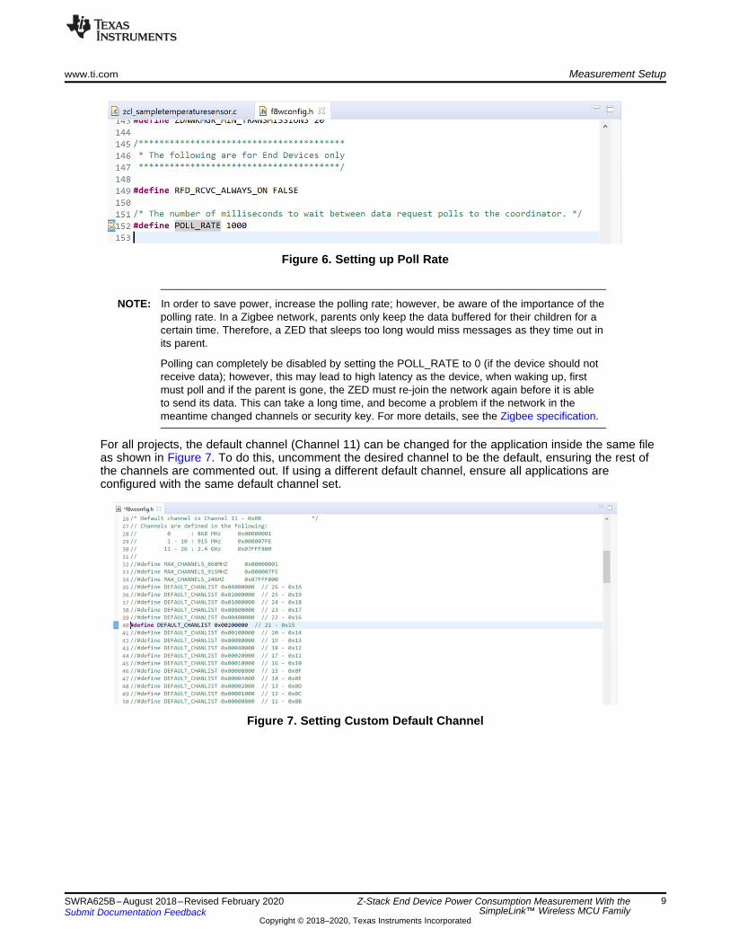
Additionally, there are a few code changes that are required. To make it easier to catch the measurementson the power analyzer, it may be useful to adjust the polling rate in the ZED, which determines how oftenthe device wakes up from sleep and sends a data request to its parent to poll for pending data (queuedmessages). A poll rate of 1 second (default) has been used as shown in Figure 6, which is found insideStack/Config/zstack_config.h.
www.ti.com Measurement Setup
9SWRA625B–August 2018–Revised February 2020Submit Documentation Feedback
Copyright © 2018–2020, Texas Instruments Incorporated
Z-Stack End Device Power Consumption Measurement With theSimpleLink™ Wireless MCU Family
Figure 6. Setting up Poll Rate
NOTE: In order to save power, increase the polling rate; however, be aware of the importance of thepolling rate. In a Zigbee network, parents only keep the data buffered for their children for acertain time. Therefore, a ZED that sleeps too long would miss messages as they time out inits parent.
Polling can completely be disabled by setting the POLL_RATE to 0 (if the device should notreceive data); however, this may lead to high latency as the device, when waking up, firstmust poll and if the parent is gone, the ZED must re-join the network again before it is ableto send its data. This can take a long time, and become a problem if the network in themeantime changed channels or security key. For more details, see the Zigbee specification.
For all projects, the default channel (Channel 11) can be changed for the application inside the same fileas shown in Figure 7. To do this, uncomment the desired channel to be the default, ensuring the rest ofthe channels are commented out. If using a different default channel, ensure all applications areconfigured with the same default channel set.
Figure 7. Setting Custom Default Channel
Measurement Setup www.ti.com
10 SWRA625B–August 2018–Revised February 2020Submit Documentation Feedback
Copyright © 2018–2020, Texas Instruments Incorporated
Z-Stack End Device Power Consumption Measurement With theSimpleLink™ Wireless MCU Family
The next change is adding the functionality to change the TX power level when sending data packets. Bydefault, the TX packets are sent out at 5 dBm power. To change the TX power level to a different value fora ZED, modify the function zclSampleSw_Init() inside the file Application/zcl_samplesw.c, adding thefollowing lines:...//Setup ZDO callbacksSetupZStackCallbacks();
// Setup power levelzstack_sysSetTxPowerReq_t powerReq;zstack_sysSetTxPowerRsp_t powerRsp;powerReq.requestedTxPower = 0; // 0 dBm
Zstackapi_sysSetTxPowerReq(appServiceTaskId, &powerReq, &powerRsp);...
The powerReq.requestedTxPower is where the power level can be set in dBm. The maximum power levelsupported for a regular CC1352R/CC2652R device in IEEE 802.15.4 mode is 5 dBm. The CC1352Pdevice includes an integrated Power Amplifier that can support up to 20 dBm. For 10 and 20 dBm powermeasurements taken in Section 5, a LAUNCHXL-CC1352P-2 is used. It can also be noted that this abovecode change can be used for any example project, and only requires changing the appServiceTaskId tothe appropriate application's entity variable name.
Also remember to erase the flash when programming as shown in Figure 4 for the ZED.
To save current consumption even further on the LAUNCHXL-CC1352P-2, Boost Mode can be disabled,which is enabled in the TX power tables by default when the PA is enabled. Boost Mode increases theVDDR from 1.7 V to 1.95 V in order to increase the output power from the power amplifier further. Thismode enables the CC1352P device to output at the full 20 dBm in 802.15.4 IEEE mode, whereas, withoutBoost Mode, the device will output 17 dBm with the maximum TX power level setting.
Boost Mode is enabled from inside the TX power tables. The TX power tables can be modified in the filefound inside the following directory:
C:\ti\simplelink_cc13x2_26x2_sdk_<version>\source\ti\ti154stack\common\boards\mac_user_config_cc13x2r1_rftable.h
The list txPowerTable_ieee_CC1352P1 defines all available TX power levels available to be used whenthe PA is enabled. The RF_TxPowerTable_HIGH_PA_ENTRY define has the following structure:RF_TxPowerTable_HIGH_PA_ENTRY(bias, ibboost, boost, coefficient, ldotrim)
To disable boost mode, set the boost value to 0 inside the TX power table for the desired TX power levelentry. In this application report, the TX power entries for 10 and 20 dBm were modified to disable BoostMode, as the CC2652R does not have Boost Mode enabled. For more information on Boost Mode, seethe CC1352P Data Sheet [7].
As the final step, simply right click on the project in Project Explorer → Debug As → Code ComposerDebug Session. This builds the project if any changes were done from the last time the project was built,and programs the LaunchPad connected with the ZED switch project.
Stop the debugger by pressing the red Terminate button (Ctrl+F2) and follow the instructions inSection 4.2.5 to establish a Zigbee network with the switch bound to the light, before disconnecting theZED from the computer. Finally connect it to the DC Power Analyzer as shown in Figure 3.
www.ti.com Measurement Setup
11SWRA625B–August 2018–Revised February 2020Submit Documentation Feedback
Copyright © 2018–2020, Texas Instruments Incorporated
Z-Stack End Device Power Consumption Measurement With theSimpleLink™ Wireless MCU Family
4.2.4 GPD NodeOpen the workspace file gpd_sw_cc26x2lp.projectspec with the correct version of CCS. The project file isfound in the following folder after installing the SimpleLink CC13X2/CC26X2 SDK 3.1.00 [5]:
C:\ti\simplelink_cc13x2_26x2_sdk_2_40_00_81\examples\rtos\CC26X2R1_LAUNCHXL\zstack\gpd_switch\tirtos\ccs
A GPD device is different from the three logical Zigbee devices defined in Zigbee PRO: Coordinator,Router, and End Device. They have a strict energy budget and can only be commissioned into a Zigbeenetwork through a Green Power Sink (GPS) or a Green Power Proxy (GPP). Similarly to a ZED, the GPDdoes not have some power saving features enabled by default, as it would hinder debugging during thedevelopment phase. To enable these features, we must set the correct predefined symbols as well as addseveral lines of code in the application files described below. As a GPD has very limited power, it uses astripped down version of Z-Stack compared to a ZED. For detailed information on GPDs, see the GreenPower Device Application Overview section in the Z-Stack User's Guide [6].
GPD devices send specific types of data packets, called Green Power Data Frames (GPDF), which areconverted by a GPP into Green Power Notifications. As the GPD does not receive ACKs, duplicateGPDFs are typically sent out, where the number of duplicates to send is configured by the predefinesymbol GPDF_FRAME_DUPLICATES. The default is 3 duplicates, however, the more duplicates sent out,the more power is consumed. Power measurements taken in Section 5 test both sending 3 duplicates aswell as testing with no duplicates sent out.
For modifying the predefined symbols on the device for the GPD projects, see Section 4.2.3. The onlyadditional predefine symbol that needs to be modified is the GPDF_FRAME_DUPLICATES, to the desirednumber of duplicate GPDFs to be sent.
As the GPD is not part of the Zigbee network the same way as a regular ZED is, no polling is done anddoes not require any polling configuration.
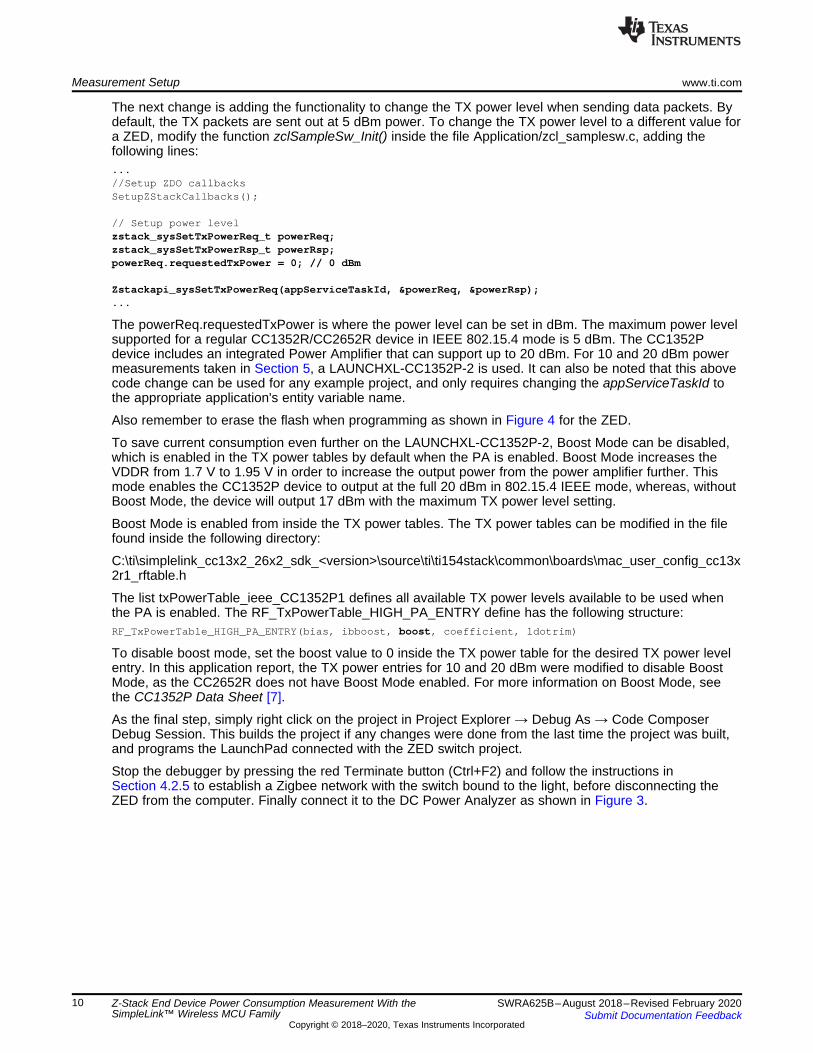
The next change is changing the TX power level when sending a GPDF. For a GPD project, the TX powerlevel is changed in a different way compared to a ZED. Inside the file Application/gpd_sw.c, near the top,is the CONFIG_TRANSMIT_POWER define. This can be modified to any supported TX power level indBm, as shown in Figure 8.
Figure 8. Setting TX Power Level for GPDs
4.2.5 CommissioningAfter following the above steps, the ZC is connected to the computer and the ZED is connected andpowered on with the DC Power Analyzer. To easily verify the commissioning process for both the ZC andZED, it is recommended to use a packet sniffer to observe the OTA packets. For more information onsetting up a packet sniffer, see the Packet Sniffer section inside the Z-Stack User's Guide [6].
In the first step, the Zigbee network must be formed with the ZC. To form the network, press button 1(BTN-1), which automatically starts the BDB commissioning process, allowing other devices to join thenewly formed network.
As soon as the network is formed, press BTN-1 on the ZED in order to start the ZED's commissioningprocess, which starts Steering Mode. When both are on the same network, the commissioning processwill then execute Finding and Binding Mode, which sets both devices into Identify mode. The switchcreates a bind, binding itself to the light. For more details, see the Running the Example Applicationssection in the Z-Stack User's Guide [6] or refer to the SimpleLink CC13X2/CC26X2 SDK's SimpleLinkAcademy [10].
Measurements www.ti.com
12 SWRA625B–August 2018–Revised February 2020Submit Documentation Feedback
Copyright © 2018–2020, Texas Instruments Incorporated
Z-Stack End Device Power Consumption Measurement With theSimpleLink™ Wireless MCU Family
To verify if the switch is correctly bound to the light, press button 2 (BTN-2) on the switch. The ZED switchsends out an On/Off Toggle command to the ZC light, which should turn on the light's LED (DIO6).
At this stage, both the ZED and ZC can be turned off and back on at any time, as both were compiled withNV_RESTORE set, and therefore have the NV items retained. When turned back on, the network will beable to restore itself (the ZED performs a re-join to the ZC).
5 MeasurementsThe SimpleLink CC1352P and CC2652R devices are designed with a relentless attention for powerconsumption in all phases of the device. This section shows and explains the results that were obtainedwith the setup detailed in the previous sections. In the measurement setup, the TX packets are sent out at0, 5,10, and 20 dBm power.These tests were performed under normal operating conditions around 22°C,running at 3.3 V. Since the CC2652R has a maximum TX power of 5 dBm, a CC1352P device was usedfor measuring 10 and 20 dBm power levels. CC1352P includes an integrated Power Amplifier, which isable to output at a maximum of 20 dBm.
NOTE: Keep in mind that the results shown in this application report are indicative. You have toperform your own measurements on your own hardware to know its real power consumption.
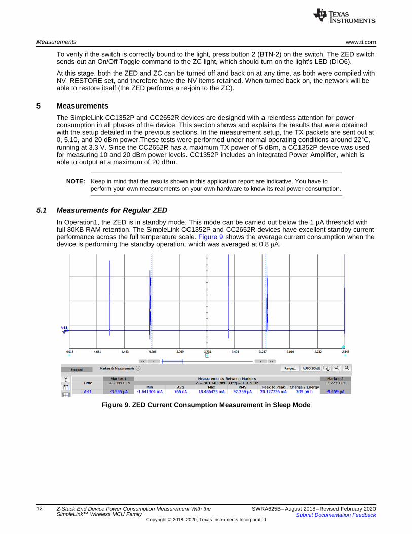
5.1 Measurements for Regular ZEDIn Operation1, the ZED is in standby mode. This mode can be carried out below the 1 µA threshold withfull 80KB RAM retention. The SimpleLink CC1352P and CC2652R devices have excellent standby currentperformance across the full temperature scale. Figure 9 shows the average current consumption when thedevice is performing the standby operation, which was averaged at 0.8 μA.
Figure 9. ZED Current Consumption Measurement in Sleep Mode
www.ti.com Measurements
13SWRA625B–August 2018–Revised February 2020Submit Documentation Feedback
Copyright © 2018–2020, Texas Instruments Incorporated
Z-Stack End Device Power Consumption Measurement With theSimpleLink™ Wireless MCU Family
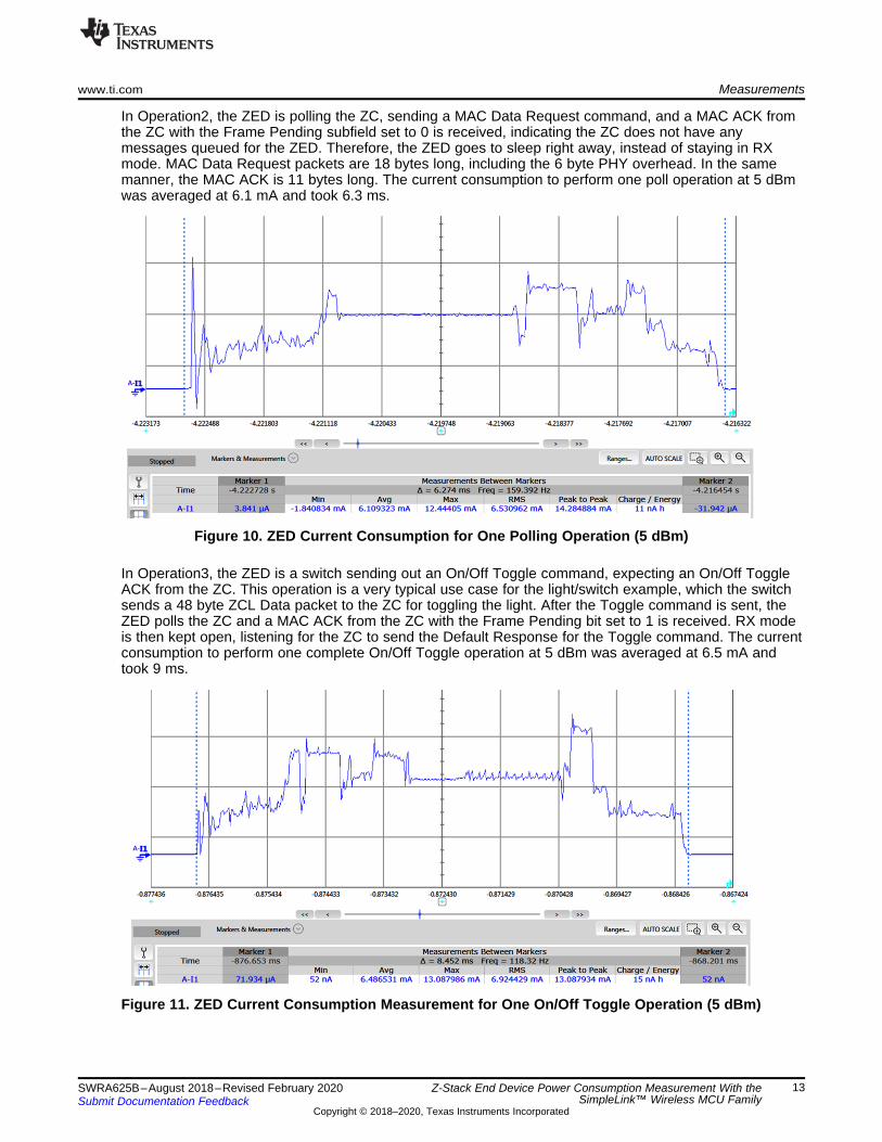
In Operation2, the ZED is polling the ZC, sending a MAC Data Request command, and a MAC ACK fromthe ZC with the Frame Pending subfield set to 0 is received, indicating the ZC does not have anymessages queued for the ZED. Therefore, the ZED goes to sleep right away, instead of staying in RXmode. MAC Data Request packets are 18 bytes long, including the 6 byte PHY overhead. In the samemanner, the MAC ACK is 11 bytes long. The current consumption to perform one poll operation at 5 dBmwas averaged at 6.1 mA and took 6.3 ms.
Figure 10. ZED Current Consumption for One Polling Operation (5 dBm)
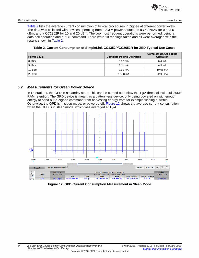
In Operation3, the ZED is a switch sending out an On/Off Toggle command, expecting an On/Off ToggleACK from the ZC. This operation is a very typical use case for the light/switch example, which the switchsends a 48 byte ZCL Data packet to the ZC for toggling the light. After the Toggle command is sent, theZED polls the ZC and a MAC ACK from the ZC with the Frame Pending bit set to 1 is received. RX modeis then kept open, listening for the ZC to send the Default Response for the Toggle command. The currentconsumption to perform one complete On/Off Toggle operation at 5 dBm was averaged at 6.5 mA andtook 9 ms.
Figure 11. ZED Current Consumption Measurement for One On/Off Toggle Operation (5 dBm)
Measurements www.ti.com
14 SWRA625B–August 2018–Revised February 2020Submit Documentation Feedback
Copyright © 2018–2020, Texas Instruments Incorporated
Z-Stack End Device Power Consumption Measurement With theSimpleLink™ Wireless MCU Family
Table 2 lists the average current consumption of typical procedures in Zigbee at different power levels.The data was collected with devices operating from a 3.3 V power source, on a CC2652R for 0 and 5dBm, and a CC1352P for 10 and 20 dBm. The two most frequent operations were performed, being adata poll operation and a ZCL command. There were 10 readings taken and all were averaged with theresults shown in Table 2.
Table 2. Current Consumption of SimpleLink CC1352P/CC2652R for ZED Typical Use Cases
Power Level Complete Polling OperationComplete On/Off Toggle
Operation0 dBm 5.82 mA 6.4 mA5 dBm 6.11 mA 6.5 mA10 dBm 7.91 mA 10.05 mA20 dBm 13.38 mA 22.93 mA
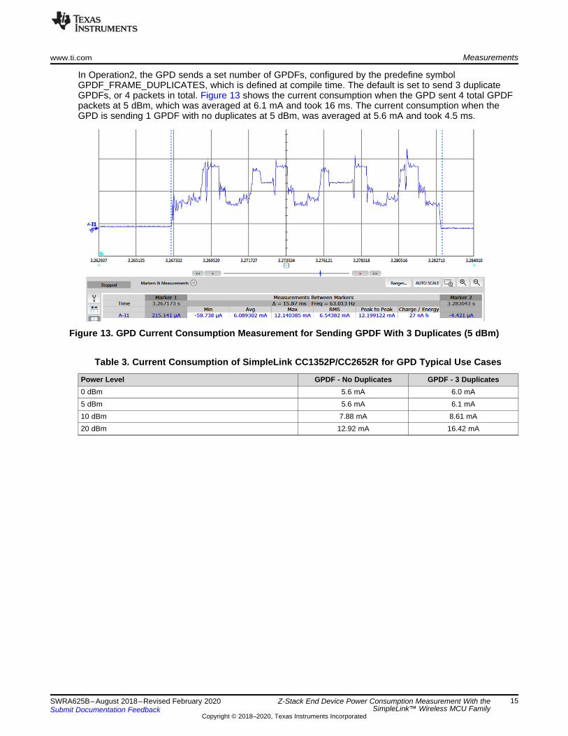
5.2 Measurements for Green Power DeviceIn Operation1, the GPD in a standby state. This can be carried out below the 1 μA threshold with full 80KBRAM retention. The GPD device is meant as a battery-less device, only being powered on with enoughenergy to send out a Zigbee command from harvesting energy from for example flipping a switch.Otherwise, the GPD is in sleep mode, or powered off. Figure 12 shows the average current consumptionwhen the GPD is in sleep mode, which was averaged at 1 μA.
Figure 12. GPD Current Consumption Measurement in Sleep Mode
www.ti.com Measurements
15SWRA625B–August 2018–Revised February 2020Submit Documentation Feedback
Copyright © 2018–2020, Texas Instruments Incorporated
Z-Stack End Device Power Consumption Measurement With theSimpleLink™ Wireless MCU Family
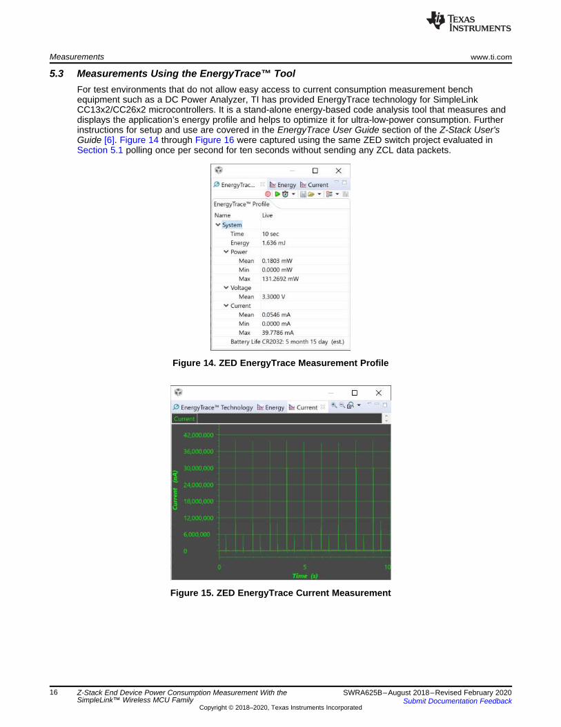
In Operation2, the GPD sends a set number of GPDFs, configured by the predefine symbolGPDF_FRAME_DUPLICATES, which is defined at compile time. The default is set to send 3 duplicateGPDFs, or 4 packets in total. Figure 13 shows the current consumption when the GPD sent 4 total GPDFpackets at 5 dBm, which was averaged at 6.1 mA and took 16 ms. The current consumption when theGPD is sending 1 GPDF with no duplicates at 5 dBm, was averaged at 5.6 mA and took 4.5 ms.
Figure 13. GPD Current Consumption Measurement for Sending GPDF With 3 Duplicates (5 dBm)
Table 3. Current Consumption of SimpleLink CC1352P/CC2652R for GPD Typical Use Cases
Power Level GPDF - No Duplicates GPDF - 3 Duplicates0 dBm 5.6 mA 6.0 mA5 dBm 5.6 mA 6.1 mA10 dBm 7.88 mA 8.61 mA20 dBm 12.92 mA 16.42 mA
Measurements www.ti.com
16 SWRA625B–August 2018–Revised February 2020Submit Documentation Feedback
Copyright © 2018–2020, Texas Instruments Incorporated
Z-Stack End Device Power Consumption Measurement With theSimpleLink™ Wireless MCU Family
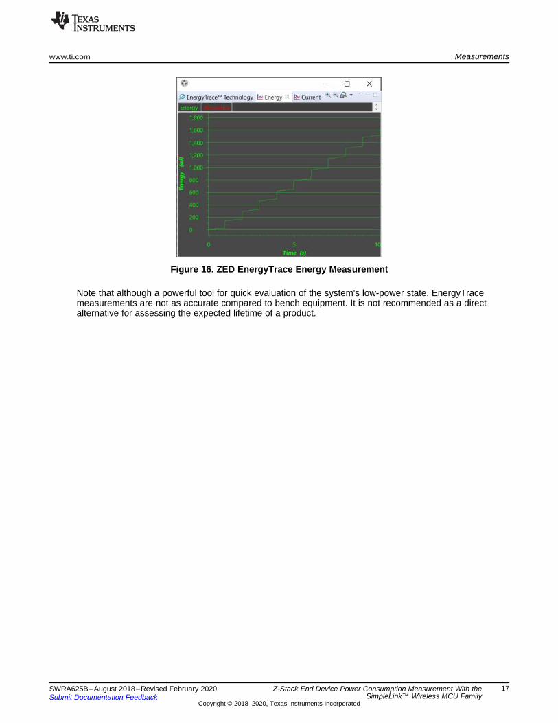
5.3 Measurements Using the EnergyTrace™ ToolFor test environments that do not allow easy access to current consumption measurement benchequipment such as a DC Power Analyzer, TI has provided EnergyTrace technology for SimpleLinkCC13x2/CC26x2 microcontrollers. It is a stand-alone energy-based code analysis tool that measures anddisplays the application’s energy profile and helps to optimize it for ultra-low-power consumption. Furtherinstructions for setup and use are covered in the EnergyTrace User Guide section of the Z-Stack User'sGuide [6]. Figure 14 through Figure 16 were captured using the same ZED switch project evaluated inSection 5.1 polling once per second for ten seconds without sending any ZCL data packets.
Figure 14. ZED EnergyTrace Measurement Profile
Figure 15. ZED EnergyTrace Current Measurement
www.ti.com Measurements
17SWRA625B–August 2018–Revised February 2020Submit Documentation Feedback
Copyright © 2018–2020, Texas Instruments Incorporated
Z-Stack End Device Power Consumption Measurement With theSimpleLink™ Wireless MCU Family
Figure 16. ZED EnergyTrace Energy Measurement
Note that although a powerful tool for quick evaluation of the system's low-power state, EnergyTracemeasurements are not as accurate compared to bench equipment. It is not recommended as a directalternative for assessing the expected lifetime of a product.
Application to a Practical Use Case www.ti.com
18 SWRA625B–August 2018–Revised February 2020Submit Documentation Feedback
Copyright © 2018–2020, Texas Instruments Incorporated
Z-Stack End Device Power Consumption Measurement With theSimpleLink™ Wireless MCU Family
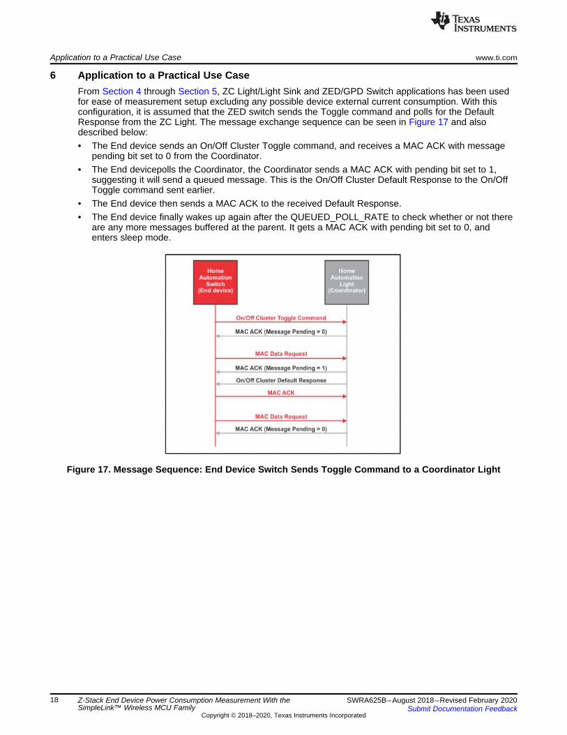
6 Application to a Practical Use CaseFrom Section 4 through Section 5, ZC Light/Light Sink and ZED/GPD Switch applications has been usedfor ease of measurement setup excluding any possible device external current consumption. With thisconfiguration, it is assumed that the ZED switch sends the Toggle command and polls for the DefaultResponse from the ZC Light. The message exchange sequence can be seen in Figure 17 and alsodescribed below:• The End device sends an On/Off Cluster Toggle command, and receives a MAC ACK with message
pending bit set to 0 from the Coordinator.• The End devicepolls the Coordinator, the Coordinator sends a MAC ACK with pending bit set to 1,
suggesting it will send a queued message. This is the On/Off Cluster Default Response to the On/OffToggle command sent earlier.
• The End device then sends a MAC ACK to the received Default Response.• The End device finally wakes up again after the QUEUED_POLL_RATE to check whether or not there
are any more messages buffered at the parent. It gets a MAC ACK with pending bit set to 0, andenters sleep mode.
Figure 17. Message Sequence: End Device Switch Sends Toggle Command to a Coordinator Light
www.ti.com Application to a Practical Use Case
19SWRA625B–August 2018–Revised February 2020Submit Documentation Feedback
Copyright © 2018–2020, Texas Instruments Incorporated
Z-Stack End Device Power Consumption Measurement With theSimpleLink™ Wireless MCU Family
6.1 Estimation for Usage ScenarioIn this section, you can estimate per-day current consumption amounts based on daily usage scenariosand calculate the battery life for each scenario. It is assumed that 1 CR2032 coin cell battery whosecapacity is 235 mAh is used, and that the TX power level used is the default 5 dBm.
For ease of calculation, defined here is the constant CCSLEEP, per-day charge consumption in sleep mode.Since the switch is supposed to sleep most of time and the time period where it is awake is relativelynegligible, assume the switch is consuming sleep mode current all the time. CCSLEEP is calculated asshown in Equation 1.
(1)
Consider the following two example usage scenarios to present how to estimate per-day chargeconsumption in various actual usages.
6.1.1 Usage Scenario 1In Scenario 1, assume the switch polls the light every 5 seconds and toggles the light 20 times a day.Assuming there is no communication failure, this scenario has (60 x 60 x 24 / 5 – 20) = 17260 times ofOperation2, 20 times of Operation3, and 20 additional times of Operation2. Therefore, the total per-daycharge consumption CCTOTAL is calculated as shown in Equation 2.
(2)
And, the battery life can be calculated as shown in Equation 3.
(3)
6.2 Usage Scenario 2In Scenario 2, assume the switch polls the light every second and toggles the light 10 times a day.Assuming there is no communication failure, this scenario has (60 x 60 x 24 / 1 – 10) = 86390 times ofOperation2, 10 times of Operation3, and 10 additional times of Operation2. Therefore, the total per-daycharge consumption CCTOTAL is calculated as shown in Equation 4.
(4)
And, the battery life can be calculated as shown in Equation 5.
(5)
Batteryless Green Power Device www.ti.com
20 SWRA625B–August 2018–Revised February 2020Submit Documentation Feedback
Copyright © 2018–2020, Texas Instruments Incorporated
Z-Stack End Device Power Consumption Measurement With theSimpleLink™ Wireless MCU Family
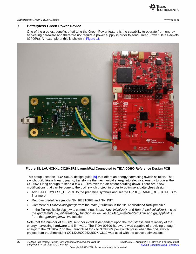
7 Batteryless Green Power DeviceOne of the greatest benefits of utilizing the Green Power feature is the capability to operate from energyharvesting hardware and therefore not require a power supply in order to send Green Power Data Packets(GPDPs). An example of this is shown in Figure 18.
Figure 18. LAUNCHXL-CC26x2R1 LaunchPad Connected to TIDA-00690 Reference Design PCB
This setup uses the TIDA-00690 design guide [9] that offers an energy harvesting switch solution. Theswitch, build like a linear dynamo, transforms the mechanical energy into electrical energy to power theCC2652R long enough to send a few GPDPs over-the-air before shutting down. There are a fewmodifications that can be done to the gpd_switch project in order to optimize a batteryless design:• Add BATTERYLESS_DEVICE to the predefine symbols and set the GPDF_FRAME_DUPLICATES to
3 or more• Remove predefine symbols NV_RESTORE and NV_INIT• Comment out VIMSConfigure(); from the main(); function in the file Application/StartUp/main.c• In the file Application/gp_sw.c, comment out Board_Key_initialize(); and Board_Led_initialize(); inside
the gpdSampleSw_initialization(); function as well as ApiMac_mlmeSetReqUint8 and gp_appNvInitfrom the gpdSampleSw_Init function
Note that the number of GPDPs sent per event is dependent upon the robustness and reliability of theenergy harvesting hardware and firmware. The TIDA-00690 hardware was capable of providing enoughenergy to the CC2652R on the LaunchPad for 2 to 3 GPDPs per switch press when the gpd_switchproject from the SimpleLink CC13X2/CC26X2SDK v3.10 was used with the above optimizations.
www.ti.com Summary
21SWRA625B–August 2018–Revised February 2020Submit Documentation Feedback
Copyright © 2018–2020, Texas Instruments Incorporated
Z-Stack End Device Power Consumption Measurement With theSimpleLink™ Wireless MCU Family
8 SummaryThis application report has gone through the basics of performing current consumption measurementsusing the CC1352P/CC2652R with Z-Stack 3.3.1 from the SimpleLink CC13X2/CC26X2 SDK. The currentreported consumptions were measured in different use cases and applied to practical usage scenarios.
With this information, you should be able to create your own current measurement setup. All of thecalculation and estimation formulas are provided to allow you to calculate the current daily consumptionsbased on different scenarios so that they can estimate battery life.
9 References1. CC1352P Product Page: http://www.ti.com/product/CC1352P2. CC2652R Product Page: http://www.ti.com/product/CC2652R3. LAUNCHXL-CC1352P LaunchPad Development Kit: http://www.ti.com/tool/LAUNCHXL-CC1352P4. LAUNCHXL-CC26X2R1 LaunchPad Development Kit: http://www.ti.com/tool/LAUNCHXL-CC26X2R15. SimpleLink CC13X2/CC26x2 SDK: http://www.ti.com/tool/SIMPLELINK-CC13X2-26X2-SDK6. Z-Stack 3.3.1 User's Guide (Look under Z-Stack documents from the SimpleLink CC13X2/CC26X2
SDK in http://dev.ti.com/tirex)7. Texas Instruments: What’s New in Zigbee 3.08. Texas Instruments: Power Consumption Measurements and Optimization for CC2538 End Device With
Z-Stack9. Texas Instruments: Energy Harvesting for Wireless Switch—Power Reference Design Design Guide10. Zigbee SimpleLink Academy (Look under the Zigbee folder from the SimpleLink CC13X2/CC26X2
SDK in http://dev.ti.com/tirex)11. Texas Instruments: CC1352P SimpleLink™ High-Performance Dual-Band Wireless MCU With
Integrated Power Amplifier Data Sheet12. Texas Instruments Packet Sniffer: http://www.ti.com/tool/packet-sniffer13. Texas Instruments: Use of Low-Power Thread and Zigbee With the SimpleLink Wireless MCU Family14. ZigBee Alliance
Revision History www.ti.com
22 SWRA625B–August 2018–Revised February 2020Submit Documentation Feedback
Copyright © 2018–2020, Texas Instruments Incorporated
Revision History
Revision HistoryNOTE: Page numbers for previous revisions may differ from page numbers in the current version.
Changes from A Revision (Janaury 2019) to B Revision ............................................................................................... Page
• The version was changed throughout the document. ................................................................................ 1• Updates were made in Section 1........................................................................................................ 2• Updates were made in Section 4.2.2. .................................................................................................. 7• Updates were made in Section 4.2.3. .................................................................................................. 8• Updates were made in Section 4.2.4.................................................................................................. 11• Added new Section 5.3.................................................................................................................. 16

IMPORTANT NOTICE AND DISCLAIMER
TI PROVIDES TECHNICAL AND RELIABILITY DATA (INCLUDING DATASHEETS), DESIGN RESOURCES (INCLUDING REFERENCE DESIGNS), APPLICATION OR OTHER DESIGN ADVICE, WEB TOOLS, SAFETY INFORMATION, AND OTHER RESOURCES “AS IS” AND WITH ALL FAULTS, AND DISCLAIMS ALL WARRANTIES, EXPRESS AND IMPLIED, INCLUDING WITHOUT LIMITATION ANY IMPLIED WARRANTIES OF MERCHANTABILITY, FITNESS FOR A PARTICULAR PURPOSE OR NON-INFRINGEMENT OF THIRD PARTY INTELLECTUAL PROPERTY RIGHTS.These resources are intended for skilled developers designing with TI products. You are solely responsible for (1) selecting the appropriate TI products for your application, (2) designing, validating and testing your application, and (3) ensuring your application meets applicable standards, and any other safety, security, or other requirements. These resources are subject to change without notice. TI grants you permission to use these resources only for development of an application that uses the TI products described in the resource. Other reproduction and display of these resources is prohibited. No license is granted to any other TI intellectual property right or to any third party intellectual property right. TI disclaims responsibility for, and you will fully indemnify TI and its representatives against, any claims, damages, costs, losses, and liabilities arising out of your use of these resources.TI’s products are provided subject to TI’s Terms of Sale (www.ti.com/legal/termsofsale.html) or other applicable terms available either on ti.com or provided in conjunction with such TI products. TI’s provision of these resources does not expand or otherwise alter TI’s applicable warranties or warranty disclaimers for TI products.
Mailing Address: Texas Instruments, Post Office Box 655303, Dallas, Texas 75265Copyright © 2020, Texas Instruments Incorporated