machine-to-machine communication with long-term evolution with reduced device energy consumption
TRANSCRIPT
TRANSACTIONS ON EMERGING TELECOMMUNICATIONS TECHNOLOGIESTrans. Emerging Tel. Tech. 2013; 24:413–426
Published online 18 April 2013 in Wiley Online Library (wileyonlinelibrary.com). DOI: 10.1002/ett.2643
SPECIAL ISSUE - M2M
Machine-to-machine communication with long-termevolution with reduced device energy consumptionTuomas Tirronen1*, Anna Larmo1, Joachim Sachs2, Bengt Lindoff3 and Niclas Wiberg4
1 Oy L M Ericsson AB, Jorvas, Finland2 Telefonaktiebolaget LM Ericsson, 16480, Stockholm, Sweden3 Telefonaktiebolaget LM Ericsson, 22363, Lund, Sweden4 Telefonaktiebolaget LM Ericsson, 58112, Linköping, Sweden
ABSTRACT
We present a method to reduce the device battery consumption to efficiently support battery-operated machine-to-machine(M2M) communication in 3GPP long-term evolution. The long-term evolution discontinuous reception (DRX) is a keymechanism in reducing the device energy consumption, and we discuss how the traffic behaviour of machines in the Internetof things scenarios differs from the typical cellular user of today, for whom the current DRX mechanism is optimised for.We list typical transactions in M2M scenarios and discuss how the DRX operation is affected. We continue by introducinga power consumption model for M2M devices. Our assumption is that the device transmits small amounts of data in theuplink with deterministic intervals. The model takes into account the energy consumption in the active and the nonactiveperiods of the communication, which alternate depending on the DRX configuration. We use the model with differentparameter settings referring to potential future M2M devices and identify the parameters, which contribute most to thedevice energy consumption. The results indicate that making the current maximum DRX cycle length longer will lead tosignificant gains in the energy consumption of M2M devices compared with what is possible today. Our key contributionsinclude the discussion of the DRX mechanism in the Internet of things scenarios and the realistic assumptions for thepotential of trading the responsiveness of a device for energy consumption gain with very long DRX cycles. Copyright© 2013 John Wiley & Sons, Ltd.
*Correspondence
T. Tirronen, Oy LM Ericsson AB, 02420 Jorvas, Finland.E-mail: [email protected]
Received 12 October 2012; Revised 11 February 2013; Accepted 5 March 2013
1. INTRODUCTION
Machine-to-machine (M2M) communications means con-necting possibly tens of billions of different devices toeach other using data communication technologies. That is,M2M typically refers to situations, where machines com-municate to machines. The Internet of things (IoT) is aclosely related term commonly used to refer to a visionof an Internet where also objects, that is, things, besidehumans, are equipped with some intelligence and are con-nected and communicating. Sometimes these communicat-ing things are referred to as smart objects as in [1]. Lately,the meaning of the term M2M* has also widened to mean
*Note that 3GPP typically uses term machine-type communications
(MTC) instead of M2M. We will use the term M2M throughout
this work.
machines or things that are connected and communicatethrough the Internet.
Wireless networks will be a key technology enablingthis vision [2]. Cellular networks are already used todayfor some applications in the M2M field, such as auto-matic meter reading of water or power consumption inhouseholds. Although the modern cellular technologies aredesigned for efficient transmission of speech as well as datatraffic, there is potential and need for further optimisingthe networks and procedures to be able to support highernumber of devices and devices with constrained capabili-ties. Making current technologies more energy-efficient isa crucial step in making the visions of billions of connecteddevices come true.
One important requirement for an M2M device is itslow energy consumption. Typical scenarios include manysmall devices, such as sensors, operating on battery power
Copyright © 2013 John Wiley & Sons, Ltd. 413

T. Tirronen et al.
in possibly remote locations. The lifetime of such devicescould be tied to the lifetime of the battery, if replace-ment or recharging the batteries would be impossible ortoo costly.
Discontinuous reception (DRX) is a technique wherethe radio receiver of a device or user equipment (UE) isallowed to be switched off during times where there is noallocated transmission towards the said device. In this situ-ation, it would be wasteful from an energy point of view tohave the receiver circuitry using power as there would beno information to be received. On the other hand, the DRXcycle length limits the responsiveness of a device towardstriggers from the network, as there are no means to reach adevice whose receiver is turned off.
This work is an extension to our earlier work pre-sented in [3]. Our main purpose is to present the implica-tions of M2M traffic in device power consumption throughDRX and identify the key factors affecting the modempower consumption. We will also show the advantage oflong DRX cycles in M2M scenarios in terms of lowerenergy consumption and what kind of gains are realisticallyachievable compared with the currently allowed settings.In 3GPP long-term evolution (LTE) [4], the current max-imum DRX or paging cycle length is 2.56 s [5]; a valuechosen to best suit human-to-human communications. Ourintent is to present evidence that longer DRX cycles thancurrently possible in the 3GPP specifications are vital formaking cellular technologies a viable platform for M2Mconnectivity. We do not consider the reduced responsive-ness caused by long DRX cycles to be a serious limitationfor most M2M use cases, where the services are oftendelay-tolerant and communications are typically initiatedby the device in the uplink. The extended DRX cycles areintended for devices, which would be in a ‘sleeping’ statefor most of their lifetime, but still need to be reached bythe network from time to time, for example, for softwareupdate purposes.
We study the gain in LTE M2M device power consump-tion achievable by extending the DRX cycle length usinga simple power consumption model. The model consid-ers a device transmitting small data with fixed time inter-vals. We take into account the energy consumption of fourdifferent periods: active, nonactive, transmission and syn-chronisation. Transmission period models the actual uplinkdata transmission, active period refers to receiving data orlistening for paging messages from the network. Nonac-tive period models the DRX, or sleeping, period of thedevice. Synchronisation period refers to the period neededto obtain proper synchronisation to the air interface beforetransmitting or receiving information. The examples weuse assume power consumption figures for an optimisedM2M device, where we have made realistic estimationsfor the actual power consumption values for the four mod-elled periods. Intuitively, lengthening the DRX cycles willgive lower average energy consumption. Our model willserve as a tool to get insight on what is the magnitude ofrealistically achievable gains.
Modelling DRX cycles and the trade-off between energyconsumption and different timers involved have been pre-viously studied in several papers. The studies differ in whatkind of power model is used and what are the traffic char-acteristics and use scenarios. Also, the model details andmethodologies differ from each other. We summarise someof the previous work later.
Energy and power saving of 3GPP technologies havebeen studied, for example, in [6–8] and [9]. In some ofthese studies, a similar type of power model, which wepropose, is used in simulations, with periods for deepsleep, sleep and active mode for reception. We use simi-lar set of states in this work and provide our own assess-ments of power consumption values of potential futureM2M devices. Also, we will focus only in the M2M sce-nario, with extended DRX cycle lengths, a topic which theprevious work has not considered.
A typical way to address the effect of DRX cycle lengthswith different types of traffic, such as bursty or streamingtraffic is to model the DRX cycles as Markov processes,such as in [10] and [11]. DRX inactivity timer in WCDMAis studied in [12]. A recent work in [13] provides similarapproach we have used by dividing the period into differ-ent independent parts and analysing the parts separately.Their research further takes into account buffering of thearriving traffic, and they calculate the resulting delay usingM/G/1 queueing model. They provide a detailed model ofthe current LTE DRX mechanism and calculate a powersaving factor based on the times the UE spends in sleepingand active states. Our work differs from this as we focuson M2M traffic and possible future extended DRX cyclesfrom machine-type device point of view. We also discussthe actual power consumption of an LTE modem in addi-tion to just the length of the sleeping and active states andprovide some insight into the expected power consumptionvalues of a future M2M device.
A recent study [14] is claimed by its authors to bethe first empirically verified power consumption modelfor LTE systems. This model uses different set of statesfor energy consumption that we consider: promotion, datatransfer, tail and idle. The model is verified to be accurate;however, one drawback is that the verification is carriedout using traces from 3G and Wifi traffic and not real LTEtraffic. The difference to our work is again the consideredscenario: We consider optimised M2M devices and trafficand not typical smartphone traffic of today’s networks.
Topics related to M2M communications and specificwireless technologies have recently started to be morecommon in the literature. One of the first general frame-work proposals for M2M and LTE can be found in [15].The work addresses primarily radio resource allocationand consequently is not directly related to our power con-sumption assessments. In [16], the authors introduce waysto reduce energy consumption of M2M LTE devices, forexample, they propose a new state for LTE idle mode forreducing unnecessary procedures for M2M devices. Theyalso discuss decreased number of paging occasions as one
414 Trans. Emerging Tel. Tech. 24:413–426 (2013) © 2013 John Wiley & Sons, Ltd.DOI: 10.1002/ett

T. Tirronen et al.
way to reduce the energy consumption; however, they donot directly consider longer DRX cycles as we do.
Despite the number of papers addressing either detailedDRX operation or M2M issues, there is a lack of jointdiscussion of LTE DRX mechanism and how it affectsthe power consumption of M2M devices. Accordingly, asstated already, our main contribution compared with earlierwork is to present discussion and results combining theseaspects. Further, we propose a general model for studyingrealistically achievable energy consumption gains whentrading the responsiveness of a device by extending theDRX cycle length.
The rest of the paper is organised as follows. In the nextsection, we present what kind of traffic models are includedin the IoT visions for M2M and their impact on the deviceenergy consumption. We further elaborate the energy con-sumption aspects in Section 3 where we explain the LTEdiscontinuous reception mechanism in detail with discus-sion on LTE modem power consumption. In Section 4, wedescribe the model for the power consumption and dis-cuss the set of parameters used. Exemplary results usingthe model are presented in Section 5. We present some dis-cussion of the obtained results in Section 6 and concludethe work in Section 7.
2. INTERNET OF THINGS ANDMACHINE-TO-MACHINECOMMUNICATIONS
2.1. Traffic patterns in Internet of things
The current and future envisioned traffic behaviour inM2M scenarios is different from the assumptions used tooptimise the currently deployed 3G and 4G cellular net-works. Specifically, LTE networks originally targeted twomain types of applications: VoIP with periodic packets andmobile Internet applications with some form of chattinessimplying bursty traffic.
For IoT, typical connected devices are sensors andactuators. The traffic patterns anticipated for these devicesare formed from the following components. In uplink,
(1) Repeated sensor readings or status indications.These readings typically fit into one data packet.
(2) In rare cases, bulk read-outs consist of a fewsuccessive packets.
In downlink,
(1) Control commands occurring as individual mes-sages, which typically fit into a single packet, or atmost a few successive ones.
(2) Occasional large data transfer events (e.g. firmwareupdates), composing of several successive packets.
Internet Engineering Task Force has specified protocolsfor the constrained use cases envisioned for battery-operated (and other) machine-type devices. Typical trans-actions are based on Constrained Application Protocol(CoAP) over UDP. CoAP is an application layer protocoland can be seen as a lightweight version of HTTP. Typicaltransactions include:
(1) Sensor configuration and/or actuator control.� A sensor is configured with a reporting rule
in downlink. This could be followed by anacknowledgement using CoAP.
� Typical rules are short and they consist of oneor only a few messages.
� There may be delay requirements or alterna-tively the configuration messages are delay-tolerant.
(2) Solicited sensor read-out.� Sensor receives a CoAP request and provides a
CoAP response with the sensor reading.� Typical uplink and downlink messages fit into
a single packet.� There may be delay requirements or alterna-
tively the configuration messages are delay-tolerant.
(3) Unsolicited sensor read-out.� Sensor provides event or timer triggered sensor
reading.� Typically a single uplink message.� May be followed by a CoAP acknowledge-
ment.� There may be delay requirements or alterna-
tively the configuration messages are delay-tolerant.
2.2. Device characteristics
For battery-operated devices, it is reasonable to assume thatthe only few packets are transmitted or received during onetransaction. Data heavy applications, such as remote videosurveillance, better suit devices with constant power supplyas the actual radio transmissions consume lot of energy.
The devices may be mobile or static. Mobile scenariosinclude, for example, sensors used in the transportationindustry, such as sensors for cargo or vehicle tracking.Static devices can be seen as staying in one location ormoving very slowly and/or rarely. From cellular networkpoint of view, static devices do not make handovers fromone serving base station to another, or have very rarehandover events. With mobile devices, the handovers canbe frequent, and this increases the energy consumptionbecause of the required signaling traffic regardless ofthe actual application layer transactions. In reality, staticdevices located near cell edges might need to undergo fre-quent handovers because of low received signal strengthand changing radio environment. This problem is notaddressed in this work and could be solved, for example,
Trans. Emerging Tel. Tech. 24:413–426 (2013) © 2013 John Wiley & Sons, Ltd.DOI: 10.1002/ett
415

T. Tirronen et al.
Figure 1. Radio resource connection (RRC)_IDLE to radioresource connection (RRC)_CONNECTED mode signaling in
long-term evolution.
by identifying devices in problematic locations and havingrelaxed rules for mobility related procedures.
From the LTE radio resource point of view, theUE can be in two different states: RRC_IDLE andRRC_CONNECTED. In connected state, the radio bearersand security context have been established and communi-cation is possible in both uplink and downlink. In idle state,the UE cannot directly send uplink data; the device needsto perform random access and move to connected modebefore actual data can be transmitted. In idle state, thenetwork may page the UE, which needs to listen to the pag-ing information periodically. Similarly, in connected state,the UE needs to listen to the downlink control channel peri-odically as determined by the DRX settings, see Section 3for details.
The required signaling from RRC_IDLE to RRC_CONNECTED state transition is depicted in Figure 1. Thepicture includes processing times given for the device aspresented in [17]. Only the relevant signaling betweenthe device and the eNodeB (basically, the base station) isshown. Our model presented in Section 4 will not take thissignaling explicitly into account, but the parameters canbe tuned to implicitly account for the extra power con-sumption. We will briefly compare scenarios where thedevice is in RRC_IDLE versus RRC_CONNECTED laterin Section 5.5.
From the previous discussion, we pick the followingcharacteristics for our assumed low energy IoT device; thedevice sends little data, is static (i.e. no handovers) andstays in the connected mode to avoid as much signalingas possible. We will use these assumptions in the modeldetailed in Section 4.
2.3. Tail energy consumption
In [14], the authors claim that one major reason for theinefficiency of LTE compared with 3GPP 3G and Wifi is
high tail energy consumption. This means the energy thatthe UE consumes after listening to transmissions from thebase station and before transitioning back to RRC_IDLEstate, where the UE needs to basically only listen tonetwork paging messages. However, this is not an inherentbehaviour required for mobile devices. In our M2M model,we assume that the device can switch off most of its cir-cuitry immediately after transmission and active periods asdiscussed in Section 3.3. Further, as described previously,we assume that the device stays in RRC_CONNECTED, orsimilar, state. The model parameters can be tuned to modellonger periods of transitioning if so required.
For a typical interactive session, it is highly desirableto keep the connection active for some time when thereis no traffic, to improve the responsiveness and reducethe signaling. Doing so results in the higher tail energyconsumption as discussed in [14]. For the network, itis then necessary to distinguish between M2M servicesand interactive services, and to treat them differently.This could potentially be carried out in different ways,for example,
(1) Special signaling during the radio resource connec-tion (RRC) set-up procedure.
(2) Device classes include the information of maximumbit rates, M2M capabilities and so on. This infor-mation could be directly asked for by the eNodeBor retrieved from the core network if the UE hasnetwork context with this information.
(3) The M2M service profile is configured with thesubscription and stored in the core network.
(4) eNodeB uses machine learning techniques todeduce the presence of M2M communications.
(5) eNodeB performs traffic pattern or deep packetinspection to detect the M2M communication status.
3. DISCONTINUOUS RECEPTION
3.1. Basic operation
Discontinuous reception in LTE is used to decrease thetotal power consumption of the terminal by allowing itto turn receiver circuitry momentarily off. An overviewdescription of DRX can be found, for example, in [18, 19].
In LTE, a form of DRX may be used both in the idle(RRC_IDLE) and in the connected (RRC_CONNECTED)state. The idle state DRX is called paging and is a simplemechanism based on the configured DRX cycle length[20], compared with connected state, where the DRXmechanism is more complex. In the next paragraphs, wedetail the operation of the connected state DRX for LTE.
Without DRX configured, an LTE terminal wouldhave to listen to the physical downlink control channel(PDCCH) every subframe, that is, in LTE, every milli-second without the opportunity to save energy by turningthe parts of its circuitry off. The PDCCH includes infor-mation on uplink grants and downlink assignments sothe terminal would know when it should transmit or
416 Trans. Emerging Tel. Tech. 24:413–426 (2013) © 2013 John Wiley & Sons, Ltd.DOI: 10.1002/ett
T. Tirronen et al.
receive data. As packet data traffic is typically bursty, thisbehaviour will result in wasted resources; the UE will listento PDCCH every subframe although in many cases thiswould not be necessary, as there are no data to send orto receive.
When DRX is configured, the terminal needs to listento the control channel only occasionally. A key parameterin DRX is the DRX cycle length, which determines thecycle for the possible sleeping periods for the terminal. Theactive time when the terminal needs to listen to PDCCH isdefined by various timers such as
(1) On duration timer, which determines how manyconsecutive subframes the terminal needs to listento PDCCH at the beginning of every DRX cycle,
(2) Inactivity timer, started after the PDCCH indicatesa new uplink or downlink transmission, tells howmany consecutive subframes the terminal needs tolisten and
(3) Retransmission timer, used for waking up to receivepossible hybrid-ARQ (HARQ) retransmissions atpredefined times when a downlink transmission hasnot yet been successfully decoded.
In addition, active time includes time when the terminalhas sent a scheduling request and it is pending, or whenan uplink grant for a pending HARQ retransmission canoccur. Apart from the basic DRX cycle, an optional shortcycle timer may be used to have the device to wake up morefrequently after transmission or reception activity. Moredetails can be found in the medium access control proto-col specification for LTE [21]. The different timer valuesmay be optimised when the characteristics of the trafficare known. DRX parameters may be configured when traf-fic characteristics of the terminal change to obtain the bestperformance in both traffic and power consumption sense.Furthermore, the device may be put to sleep when in activetime with a medium access control level command, if nofurther transmission to or from the device are expected.
DRX provides an opportunity for the UE to turn itsreceiver circuitry off or go into low power mode when-ever the device is not in DRX active time. Extendingthe DRX basic cycle length will result in longer down-link delay, or reduced responsiveness, of the terminal; theeNodeB cannot reach the UE during the sleep period of thecycles, because scheduling in the eNodeB towards the UEis limited to those subframes where the device listens toPDCCH during the on duration period.
To account for bursty traffic patterns better, a terminalis typically kept in active state, listening to PDCCH, fora while after it has transmitted or received data. Thisis controlled via the inactivity timer, which is always(re)started upon new uplink or downlink transmission indi-cation. LTE HARQ mechanism is accounted for by usingthe retransmission timer. Optionally, the device may followa DRX short cycle for a while after recent uplink or down-link activity to respond faster to possible communicationfollowing the recent transmission/reception.
We expect networks to configure DRX parametersaccording to the expected traffic type for the device. As theM2M traffic model considered here is very simple, onlyoccasional single uplink transmissions, it may be assumedthat the wake time of the device outside the actual trans-mission will be minimised by using only short values forthe inactivity timer and likely no short cycle. The addi-tional timers may be implicitly taken into account usingother model parameters, see Section 4.
For uplink, the DRX cycle length does not affect theresponsiveness or latency, as the device may initiate uplinktransmission at will by sending a scheduling request(synchronisation or random access might be requiredbefore). For downlink, the mean latency would be onaverage half the time of the DRX cycle length, as DRXdetermines the time instants during which the eNodeB canreach the device.
In conclusion, there is a trade-off between the DRXcycle length and the terminal responsiveness in the down-link. On the one hand, longer cycles would result in energysavings; on the other hand, the device responsiveness willdeteriorate.
3.2. Internet of things and DRX
Uplink transmissions may be initiated at any time; thus, theDRX operation is only relevant for downlink data transmis-sions. In between the three discussed transaction types inSection 2, the main parameter affecting the DRX operationis then the DRX cycle length. Also, the unsolicited read-out transaction is not relevant as the device can initiate therandom access procedure when it needs to send the data, orsuch occasions could even be pre-scheduled.
If we assume only little data per one periodical trans-action, there is no incentive to configure the optional shortDRX cycle, which might be used to sleep in between trans-mission periods during a long transaction, such as a chattyInternet application. Moreover, long inactivity timer is notrequired as the transactions are assumed to consist of atmost couple of packets.
Further, the possible delay requirements of the applica-tions impose restrictions on the DRX parameters. If thedevice needs to be reachable within a certain period, theDRX cycle length cannot exceed the length of this period.However, if the transaction is delay-tolerant, then the DRXcycle can be configured to give best possible battery life-time, that is, the cycle may be very long. In the lattercase, the network will buffer the incoming packets duringlong DRX.
3.3. Discontinuous reception frommodem perspective
A high level model structure of an LTE modem consists ofthree main parts:
Trans. Emerging Tel. Tech. 24:413–426 (2013) © 2013 John Wiley & Sons, Ltd.DOI: 10.1002/ett
417

T. Tirronen et al.
Figure 2. Schematic diagram of how different parts of an LTE modem could be turned off when discontinuous reception (DRX) isconfigured. Depending on the DRX cycle length, different parts could be turned off. For DRX cycle lengths over around 100 ms,
we assume only the absolutely necessary parts, such as a coarse clock, are on.
� Radio, including duplexer, power amplifier, analogreception (RX) and transmission (TX) parts andanalog-to-digital and digital-to-analog converters.Radio part includes also a crystal oscillator drivingthe phase-locked loop used for time and frequencysynchronisation of the transceiver.
� Digital baseband (BB), including coding and decod-ing parts.
� Low power clock, with low accuracy, which main-tains coarse synchronisation to the network. This isthe clock used in RRC_IDLE and DRX modes, andthe power consumption can be very low comparedwith the accurate clock in the radio part.
In a typical battery-driven modem design, the aim isto have as low power consumption as possible. This isachieved by turning off suitable parts when so possible.Figure 2 shows a schematic picture on how this works.The numbers are related to current LTE modems. In futureM2M devices, it is expected that less BB processing poweris needed; therefore, one can expect that the BB part of thepower consumption will be smaller for such devices.
In the figure, 100% power consumption refers to rela-tively low downlink rate and low transmitter output power(values over 100% are possible to achieve for high TXoutput power and/or high downlink data rate). Once themodem is not transmitting, the analog TX is turned off.The switch on/off time is in the order of 10–100 �s, andtherefore, the transmitter could almost be switched on oroff on LTE OFDM† symbol basis. From the figure, we canthen see that in ‘RX only’ modes, the power consumptionis still around or over 50% of the typical total. Hence, RXonly modes without DRX configured cannot be seen as apower saving state. The switch on/off time for RX parts areroughly the same as for the TX part, around 10–100 �s.
†Orthogonal frequency-division multiplexing, the method used in LTE
to encode data on multiple subcarriers.
Furthermore, turning off and then on the RX, will put thephase-locked loops in different phase states, and therefore,a new network synchronisation might be needed, in termsof updated channel estimation. Hence, depending on appli-cation or use case, 0–1 ms of synchronisation symbols isneeded to obtain network synchronisation. The RX is onlyturned off if the time until next reception is in the orderof 1 ms.
After turning off the RX parts as well, the powerconsumption is in the range of 30% (entire basebandprocessing still enabled). However, doing neither transmis-sion nor reception, large parts of the BB can be disabled tosome extent. Exactly when, and what, can be disabled inthe BB chip is very implementation dependent, but a rea-sonable goal is to turn off as much as possible as fast aspossible. When the DRX cycle is known to be well above10 ms, one typically disables the crystal oscillator, and relythe timing on the coarse low power clock. That togetherwith disabling of power supply to memories and so on,one reach a ‘deep sleep’ state with a power consumptionin the range of fractions of percent (say, 0.5% in today’ssmartphones and much smaller in future M2M devices) ofthe power consumption in active state. Because the coarseclock is inaccurate, there might be need for 1–100 ms ofnetwork synchronisation prior to reception, once wakingup next time. The length of this required synchronisationperiod depends on the magnitude of the time and frequencydrift of the accurate clock during the sleeping state.
4. ENERGY CONSUMPTION MODELFOR DRX CYCLES
4.1. Scenario description
Our energy consumption model considers an M2M device,which sends little data periodically with data reportingperiod t as outlined in Section 2.2. Thus, compared withsmartphone-type traffic, in our scenario, the data amounts
418 Trans. Emerging Tel. Tech. 24:413–426 (2013) © 2013 John Wiley & Sons, Ltd.DOI: 10.1002/ett
T. Tirronen et al.
are much smaller and the transmission intervals infre-quent. The device has low mobility or is static, that is,handovers are not performed. An example of a devicefulfilling the previous characteristics would be a staticsensor or a battery-powered utility meter sending reportson measurements.
Our basic assumption is that the device can initiate datatransmission immediately after a synchronisation period, atany point in time, that is, we assume the device has radiobearers and security context established and they are keptmaintained. In LTE terms, this corresponds to the devicebeing in RRC_CONNECTED state, see, for example, [18].If the devices changed to RRC_IDLE state between datatransmissions, the data transmission would be accompa-nied by an additional radio bearer establishment procedure,which would result in increased energy consumption forevery transmission instance.
4.2. Model description
To study the trade-off between the gains in energyconsumption and device responsiveness, we define fourdifferent phases based on the previous discussion ofthe LTE DRX mechanism, the modem perspective andpossible transaction types. The four states presented laterquantify the power consumption of an M2M device realis-tically enough.
The four phases or periods are as follows:
(1) Active period consisting of receiving data andrelated procedures (Pact; tact).
(2) Nonactive, or sleeping, period, where the devicedoes not listen to any radio channels and tries toconserve energy (Psleep, tDRX).
(3) Transmission period, where the device sends data(Ptx; ttx).
(4) Sync period before active and transmission periods(Pclock; tsync).
In addition, in our energy consumption model, we will takeinto account a base power consumption, Pbase, which isalways consumed independent from the transmission state.
We do not explicitly model possible erroneous trans-missions or retransmissions. In the case of retransmis-sions, the total energy consumption would grow, and thefigures of energy consumption gains in Section 5 wouldbe lower. However, if the radio channel conditions areknown, average values of expected power consumption dueto retransmission can be incorporated into the calculationslater. We briefly discuss how retransmissions would affectthe results in Section 6.
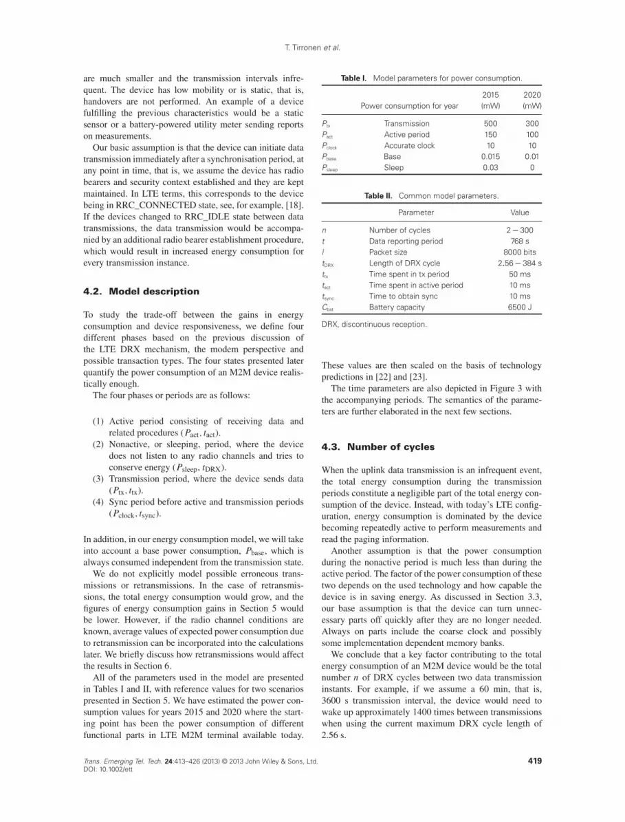
All of the parameters used in the model are presentedin Tables I and II, with reference values for two scenariospresented in Section 5. We have estimated the power con-sumption values for years 2015 and 2020 where the start-ing point has been the power consumption of differentfunctional parts in LTE M2M terminal available today.
Table I. Model parameters for power consumption.
2015 2020Power consumption for year (mW) (mW)
Ptx Transmission 500 300Pact Active period 150 100Pclock Accurate clock 10 10Pbase Base 0.015 0.01Psleep Sleep 0.03 0
Table II. Common model parameters.
Parameter Value
n Number of cycles 2� 300t Data reporting period 768 sl Packet size 8000 bitstDRX Length of DRX cycle 2:56� 384 sttx Time spent in tx period 50 mstact Time spent in active period 10 mstsync Time to obtain sync 10 msCbat Battery capacity 6500 J
DRX, discontinuous reception.
These values are then scaled on the basis of technologypredictions in [22] and [23].
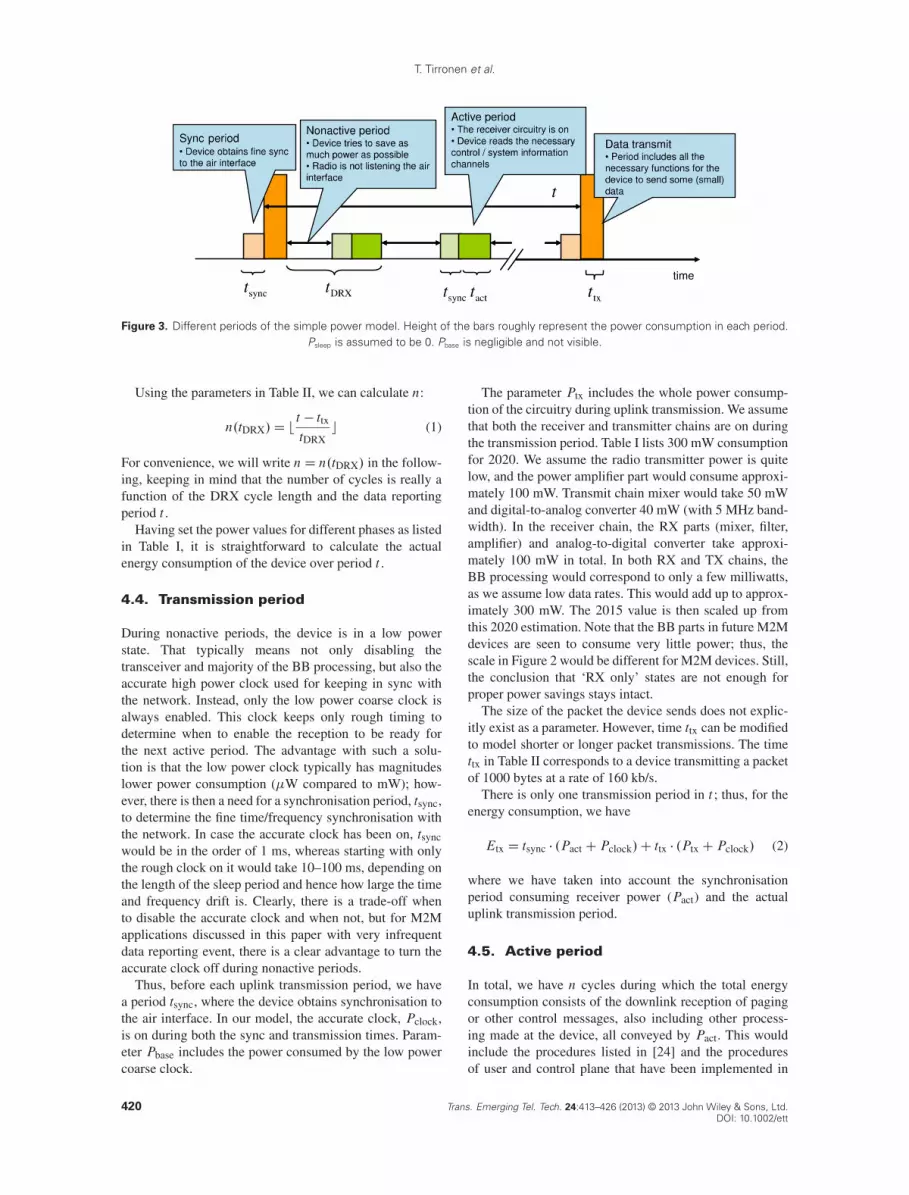
The time parameters are also depicted in Figure 3 withthe accompanying periods. The semantics of the parame-ters are further elaborated in the next few sections.
4.3. Number of cycles
When the uplink data transmission is an infrequent event,the total energy consumption during the transmissionperiods constitute a negligible part of the total energy con-sumption of the device. Instead, with today’s LTE config-uration, energy consumption is dominated by the devicebecoming repeatedly active to perform measurements andread the paging information.
Another assumption is that the power consumptionduring the nonactive period is much less than during theactive period. The factor of the power consumption of thesetwo depends on the used technology and how capable thedevice is in saving energy. As discussed in Section 3.3,our base assumption is that the device can turn unnec-essary parts off quickly after they are no longer needed.Always on parts include the coarse clock and possiblysome implementation dependent memory banks.
We conclude that a key factor contributing to the totalenergy consumption of an M2M device would be the totalnumber n of DRX cycles between two data transmissioninstants. For example, if we assume a 60 min, that is,3600 s transmission interval, the device would need towake up approximately 1400 times between transmissionswhen using the current maximum DRX cycle length of2.56 s.
Trans. Emerging Tel. Tech. 24:413–426 (2013) © 2013 John Wiley & Sons, Ltd.DOI: 10.1002/ett
419
T. Tirronen et al.
Figure 3. Different periods of the simple power model. Height of the bars roughly represent the power consumption in each period.Psleep is assumed to be 0. Pbase is negligible and not visible.
Using the parameters in Table II, we can calculate n:
n.tDRX/D bt � ttx
tDRXc (1)
For convenience, we will write nD n.tDRX/ in the follow-ing, keeping in mind that the number of cycles is really afunction of the DRX cycle length and the data reportingperiod t .
Having set the power values for different phases as listedin Table I, it is straightforward to calculate the actualenergy consumption of the device over period t .
4.4. Transmission period
During nonactive periods, the device is in a low powerstate. That typically means not only disabling thetransceiver and majority of the BB processing, but also theaccurate high power clock used for keeping in sync withthe network. Instead, only the low power coarse clock isalways enabled. This clock keeps only rough timing todetermine when to enable the reception to be ready forthe next active period. The advantage with such a solu-tion is that the low power clock typically has magnitudeslower power consumption (�W compared to mW); how-ever, there is then a need for a synchronisation period, tsync,to determine the fine time/frequency synchronisation withthe network. In case the accurate clock has been on, tsyncwould be in the order of 1 ms, whereas starting with onlythe rough clock on it would take 10–100 ms, depending onthe length of the sleep period and hence how large the timeand frequency drift is. Clearly, there is a trade-off whento disable the accurate clock and when not, but for M2Mapplications discussed in this paper with very infrequentdata reporting event, there is a clear advantage to turn theaccurate clock off during nonactive periods.
Thus, before each uplink transmission period, we havea period tsync, where the device obtains synchronisation tothe air interface. In our model, the accurate clock, Pclock,is on during both the sync and transmission times. Param-eter Pbase includes the power consumed by the low powercoarse clock.
The parameter Ptx includes the whole power consump-tion of the circuitry during uplink transmission. We assumethat both the receiver and transmitter chains are on duringthe transmission period. Table I lists 300 mW consumptionfor 2020. We assume the radio transmitter power is quitelow, and the power amplifier part would consume approxi-mately 100 mW. Transmit chain mixer would take 50 mWand digital-to-analog converter 40 mW (with 5 MHz band-width). In the receiver chain, the RX parts (mixer, filter,amplifier) and analog-to-digital converter take approxi-mately 100 mW in total. In both RX and TX chains, theBB processing would correspond to only a few milliwatts,as we assume low data rates. This would add up to approx-imately 300 mW. The 2015 value is then scaled up fromthis 2020 estimation. Note that the BB parts in future M2Mdevices are seen to consume very little power; thus, thescale in Figure 2 would be different for M2M devices. Still,the conclusion that ‘RX only’ states are not enough forproper power savings stays intact.
The size of the packet the device sends does not explic-itly exist as a parameter. However, time ttx can be modifiedto model shorter or longer packet transmissions. The timettx in Table II corresponds to a device transmitting a packetof 1000 bytes at a rate of 160 kb/s.
There is only one transmission period in t ; thus, for theenergy consumption, we have
Etx D tsync � .PactCPclock/C ttx � .PtxCPclock/ (2)
where we have taken into account the synchronisationperiod consuming receiver power (Pact) and the actualuplink transmission period.
4.5. Active period
In total, we have n cycles during which the total energyconsumption consists of the downlink reception of pagingor other control messages, also including other process-ing made at the device, all conveyed by Pact. This wouldinclude the procedures listed in [24] and the proceduresof user and control plane that have been implemented in
420 Trans. Emerging Tel. Tech. 24:413–426 (2013) © 2013 John Wiley & Sons, Ltd.DOI: 10.1002/ett

T. Tirronen et al.
the device. The transmitter chain is turned off during thisperiod; thus, the total power consumption in 2020 wouldbe approximately 100 mW. It is worth noting that Pact, thepower consumed by the receiver circuitry, would be a func-tion of the downlink bit rate; faster bit rates result in higherenergy consumption. We assume that the received bit rateis low and constant, and eNodeB takes this into accountwhen scheduling the transmissions.
The active period length includes the on duration andinactivity timers in LTE DRX, see Section 3. There is noneed to configure longer inactivity timers with the trafficmodel we assume. If longer timers are required, they can bemodelled by increasing the length of tact correspondingly.
Over time t with n cycles in total (if n > 1), we arrive atenergy consumption
Eact D n � .tactC tsync/ � .PactCPclock/ (3)
4.6. Nonactive period
The power consumption of the device in nonactive periodsin our model is Psleep. We consider this value to be negli-gible if the device has been optimised for the use scenarioswe have described. Total nonactive time is everythingbetween the data reporting period t and total active timeand we arrive at
Esleep D .t � ttx � n � .tsyncC tact// �Psleep (4)
4.7. Total energy consumption oversending interval
In total, taking into account the cycles of active and non-active periods, we can write an expression for the energyconsumption of the device over time t :
E�t DEtx CEactCEsleep CEbase
D tsync � .PactCPclock/C ttx � .PtxCPclock/
C n � .tactC tsync/ � .PactCPclock/
C .t � ttx � n � .tsyncC tact// �Psleep CPbase � t
(5)
Here, we have additionally taken into account the basepower consumption, Ebase D Pbase � t , over the whole timeperiod t .
For some M2M scenarios, we will assume thatPsleep D 0 in Section 5. Note that the power consumptionparameters do not explicitly include the base consumption,Pbase. That is, even if Psleep D 0, some parts are still onduring the nonactive period contributing to the total energyconsumption with Pbase.
We will also study the average power consumption:
Pavg DE�t
t(6)
where we have divided the total energy consumption overone period with the time giving us average energy con-sumption per time unit. We see that
n
tD
t � ttx
t � tDRXD
1
tDRXwhen t !1
(we left the floor function deliberately out at this point);thus, (6) converges
limt!1
Pavg DtactC tsync
tDRX� .PactCPclock/
C
�1�
tsyncC tact
tDRX
��Psleep CPbase (7)
If we further let tDRX grow as well, that is, set tDRX D t ,there are no active periods remaining in-between datatransmission, and we would eventually have
limt ; tDRX!1
Pavg D limt ; tDRX!1
E�t
tD Psleep CPbase (8)
4.8. Battery lifetime
Many use cases for M2M consider devices, which operateon battery power; thus, the lifetime of the energy source isoften a key question when planning the operation of M2Mcommunications system. Let us denote Cbat as the batterycapacity in joules. Then, the battery lifetime tbat is
tbat DCbat
E�tt (9)
where t is the data reporting period of the device and E�tthe energy consumption during one such period as givenin (5).
5. SCENARIOS AND RESULTS
5.1. M2M scenarios
The energy consumption and other model parameters forthe studied M2M scenarios are listed in Tables I and II.Figures 4 and 5 depict the two scenarios.
We have chosen to model two different scenarios rep-resenting almost similar future M2M devices, which havebeen optimised for low energy operation. The power con-sumption values of 2020 are envisioned to be lower by alinear factor compared with those of 2015. We have furtherdifferentiated the two cases by having nonzero Psleep forthe device in 2015. This difference is introduced to high-light the potential benefits of aggressive optimisations indevice platforms tailored specifically for battery-operatedM2M applications. Intuitively, parameters Psleep and Pbasehave high contribution to the total energy consumption, asthey are used to model the parts, which consume energyeven when the device is in the sleeping state.
Trans. Emerging Tel. Tech. 24:413–426 (2013) © 2013 John Wiley & Sons, Ltd.DOI: 10.1002/ett
421
T. Tirronen et al.
0 50 100 150 200 250 300 350 4000
5
10
15
20
25
DRX cycle length (s)
Bat
tery
life
time
fact
orEnergy consumption
0
0.2
0.4
0.6
0.8
1
Ene
rgy
cons
umpt
ion
(rel
ativ
e)
Battery lifetimeEnergy consumption
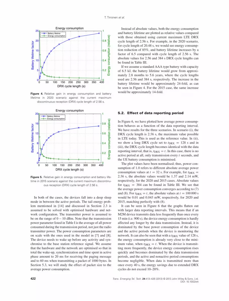
Figure 4. Relative gain in energy consumption and batterylifetime in 2020 scenario against the current maximum
discontinuous reception (DRX) cycle length of 2.56 s.
0 50 100 150 200 250 300 350 4000
4
8
12
16
20
DRX cycle length (s)
Bat
tery
life
time
fact
or
Energy consumption
0
0.2
0.4
0.6
0.8
1
Ene
rgy
cons
umpt
ion
(rel
ativ
e)
Battery lifetimeEnergy consumption
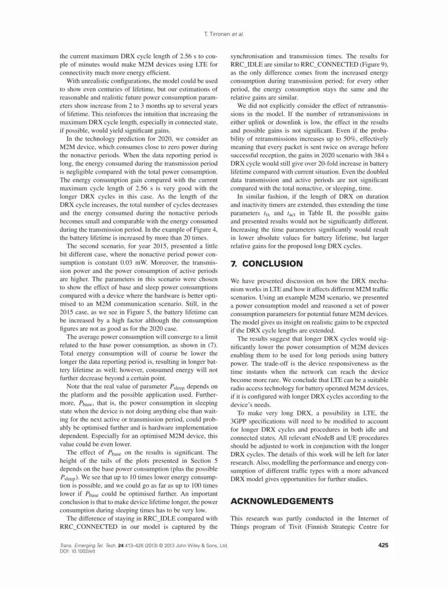
Figure 5. Relative gain in energy consumption and battery life-time in 2015 scenario against the current maximum discontinu-
ous reception (DRX) cycle length of 2.56 s.
In both of the cases, the devices fall into a deep sleepmode in between the active periods. The tail energy prob-lem mentioned in [14] and discussed in Section 2.3 isassumed to be solved with optimised hardware and net-work configuration. The transmitter power is assumed tobe on the range of 0� 10 dBm. Note that the transmissionpower parameter listed in Table I is the average of all powerconsumed during the transmission period, not just the radiotransmitter power. The power consumption parameters areon scale with the ones used in the model in [7] and [8].The device needs to wake up before any activity and syn-chronise to the base station reference signal. We assumethat the hardware and the network are optimised so that intotal the wake-up, synchronization and time spent in activephase amount to 20 ms for receiving the paging messageand to 60 ms when transmitting a packet of 1000 bytes. InSection 5.3, we will study the effect of packet size to theaverage power consumption.
Instead of absolute values, both the energy consumptionand battery lifetime are plotted as relative values comparedwith those obtained using current maximum LTE DRXcycle length of 2.56 s. For example, in the 2020 scenario,for cycle length of 20.48 s, we would see energy consump-tion reduction of 85%, and battery lifetime increases by afactor of 6.5 compared with cycle length of 2.56 s. Theabsolute values for 2.56 and 384 s DRX cycle lengths canbe found in Table III.
If we assume a standard AAA type battery with capacityof 6.5 kJ, the battery lifetime would grow from approxi-mately 2.8 months to 5.6 years, where the cycle lengthsused are 2.56 and 384 s, respectively. The increase in thebattery lifetime would be approximately 24-fold, as canbe seen in Figure 4. For the 2015 case, the same increasewould be approximately 14-fold.
5.2. Effect of data reporting period
In Figure 6, we have plotted how average power consump-tion behaves as a function of the data reporting interval.We have results for the three scenarios. In scenario (i), theDRX cycle length is 2:56 s, the maximum value possiblein LTE today. This is used as the reference value. In (ii),we show a long DRX cycle set to tDRX D 128 s and in(iii), the DRX cycle length becomes identical with the datareporting interval, that is, tDRX D t . In this case, there is noactive period at all, only transmission every t seconds, andthe UE battery consumption is minimised.
The plot values have been normalised; thus, power con-sumption of 1:0 refers to different absolute average powerconsumption values at t D 32 s. For example, for tDRX D
2:56 s, the absolute values would be 1:37 and 2:14 mW,respectively, for the 2020 and 2015 cases. Absolute valuesfor tDRX D 384 can be found in Table III. We see thatthe average power consumption converges according to (7)and (8). For tDRX D t , the absolute values at t D 100 000 swould be 0:01 and 0:045 mW, respectively, for 2020 and2015, matching perfectly with (8).
It can be seen in Figure 6 that the graphs flatten outwith larger data reporting intervals. This means that if anM2M device transmits data less frequently than once every15 min (i.e. 900 s), the device energy consumption is hardlyaffected any longer by the data transmission. Instead, it isdominated by the base power consumption of the deviceand the active periods when the device is monitoring thenetwork. It can also be seen that with a tDRX value of 128 s,the energy consumption is already very close to the mini-mum value, when tDRX D t . When the device is transmit-ting more frequently, the device energy consumption risesquickly and becomes dominated by the data transmissionperiods, and the active and nonactive period consumptionsbecome negligible. When data is transmitted more thanonce every 40 s, the energy savings due to extended DRXcycles do not exceed 10–20%.
422 Trans. Emerging Tel. Tech. 24:413–426 (2013) © 2013 John Wiley & Sons, Ltd.DOI: 10.1002/ett

T. Tirronen et al.
Table III. Absolute energy and power consumption and battery lifetime values from the different figures for DRX cycle length of 2.56and 384 s. The values are calculated over the data sending interval t D 768 s unless otherwise indicated.
2.56 s cycle 384 s cycle Improvement (%)
Figure 4 Energy cons. 684 mJ 28.2 mJ 99.96(2020 Energy consumption) Battery life 2.8 months 67.2 months 2300
Figure 5 Energy cons. 1022 mJ 68.1 mJ 93.3(2015 Energy consumption) Battery life 1.9 months 28.3 months 1389
Figure 6 2020b 1.37 mW 0.53 mWa 61.3(Avg. power consumption comparison) 2015b 2.14 mW 0.89 mWa 58.4
Figure 7 200 bytes 0.87 mW 0.021 mW 97.6(Effect of packet sizes) 10 000 bytes 1.07 mW 0.219 mW 79.5
Figure 8 0.001 mW 2.8 months 88.5 months 3060(Effect of Pbase/ 0.1 mW 2.6 months 19.7 months 658
Figure 9 ‘Ideal DRX ’ 691 mJ 35.7 mJ 94.8(Idle mode power consumption) ‘No DRX’ 694 mJ 38.5 mJ 94.5
DRX, discontinuous reception.aThe absolute values for the power consumption comparison on the second column are for tDRX D t.bThe absolute values for the power consumption comparison are for t D 32 s.
101 102 103 104 105 1060
0.1
0.2
0.3
0.4
0.5
0.6
0.7
0.8
0.9
1Power consumption with different reporting intervals
Reporting interval t (s)
Pow
er c
onsu
mpt
ion
(rel
ativ
e)
2020, t = 2.56
2015, t = 2.56
2020, t = 128
2015, t = 128
2020, t = t
2015, t = t
Figure 6. Effect of lengthening the data reporting period onpower consumption. 1.0 consumption refers to case whent D 32 s, the absolute values are different for all cases. Thelowest two lines (red) correspond to 2020 case, whereas themiddle two lines (blue) represent the 2015 case. For the topmostlines, where the discontinuous reception (DRX) cycle length isthe current maximum of 2.56 s, 2015 case converges to the
lower relative power consumption than the 2020 case.
5.3. Effect of packet size
Effect of the packet size on the average power consumptionwith different DRX cycle lengths is plotted in Figure 7. Thelines in the plot correspond to different DRX cycle lengthsas indicated in the figure. The relation between ttx and thepacket size l is assumed to be linear where the rate is fixedto 160 kbit/s , that is, ttx D l=160 000. All of the lineshave factor of one at packet size of 200 bytes. Absolute
0 1000 2000 3000 4000 5000 6000 7000 8000 9000 100001
2
3
4
5
6
7
8
9
10
11
Packet size (bytes)
Pow
er c
onsu
mpt
ion
(fac
tor)
Effect of packet sizes on power consumption
2.56 s
5.12 s
10.24 s
20.48 s
384 s
192 s
96 s
76.8 s
64 s
32 s
51.2 s
256 s
128 s
Figure 7. Effect of different packet sizes. The topmost line corre-sponds to discontinuous reception (DRX) cycle of 384 s and thelowest to DRX cycle of 2.56 s. The lines in between correspond
to DRX cycle lengths used as data points in Figure 4.
consumption values over t for the largest and smallestcases can be found in Table III.
We see that larger packets have considerable effect onthe average power consumption with the longer cyclelength. For short DRX cycles, the energy consumed dur-ing the active times dominates, and the packet size has nosignificant effect.
5.4. Effect of base power consumption
Effect of the coarse clock power (Pbase) consumptionon the average power consumption with different DRXcycles lengths is plotted in Figure 8. This illustrates the
Trans. Emerging Tel. Tech. 24:413–426 (2013) © 2013 John Wiley & Sons, Ltd.DOI: 10.1002/ett
423

T. Tirronen et al.
0 50 100 150 200 250 300 350 4000
5
10
15
20
25
30
35
DRX cycle length (s)
Bat
tery
life
time
fact
or
Effect of base power consumption on battery lifetime
0.05
0.1
0.01
0.005
Pbase
= 0.001
Figure 8. Effect of different Pbase values.
importance of the power consumption of the parts, whichare supposed to be always on; it is worth to optimisethe base power consumption as much as possible whenconsidering battery-operated M2M devices.
5.5. Idle mode versus connected mode
Although the basis of this work is to assume that the devicestays in connected mode during the whole time, the samemodel could be applied to idle mode and paging cycles aswell. The current maximum paging cycle for LTE whenin RRC_IDLE state is the same, 2.56 s, as for the maxi-mum DRX cycle in RRC_CONNECTED. Both DRX andpaging cycle maximums should be used for maximum flex-ibility to allow trade-offs between energy consumption anddevice responsiveness.
Figure 1 depicts the signaling needed to establish radiobearers and security context for the device to be able tosend data. We see that the device has four transmissionand three reception events with accompanying processingtimes before the actual uplink data transmission is possible.In total, the whole signaling would take on average 80 msas presented in [17].
We can additionally assume ‘ideal DRX’ during theperiods where the device is not processing or sending data,that is, the device is in sleep mode during eNodeB or corenetwork processing times. We will approximate the timeand power consumption of this signaling as follows.
� The device has total processing and reception time ofapproximately 50 ms, where the power consumptionis PactCPclock.
� For transmission, the device needs approximatelyadditional 5 ms, where the power consumption isPtxCPclock.
We compare this scheme to ‘no DRX’ where the devicedoes not have DRX enabled during the signaling for state
0
5
10
15
20
25
DRX cycle length (s)
Bat
tery
life
time
fact
or
Energy consumption
0 50 100 150 200 250 300 350 4000
0.2
0.4
0.6
0.8
1
Ene
rgy
cons
umpt
ion
(rel
ativ
e)
Battery connected modeBattery idle mode, ideal DRXBattery idle mode, no DRXEnergy cons. connected modeEnergy cons. idle mode, ideal DRXEnergy cons, idle mode, no DRX
Figure 9. 2020 scenario where the device stays in RRC_IDLEbetween transmissions. Ideal discontinuous reception (DRX)refers to settings where the device can sleep during theIDLE-CONNECTED transition whenever it does not receive ortransmit. No DRX refers to case where during the transitionno DRX is used at all. For other periods, DRX works as the
model describes.
transition. For this case, we assume total time of 75 ms forreception and synchronisation.
To compare this case with our previous results, where weassume the device stays in RRC_CONNECTED all time,we need to modify (2) accordingly by increasing the ttx by5 and tsync by 50 or 75 ms. Note that we do not increasetsync for the other periods, just for the transmission period.We further assume that the device goes immediately backto RRC_IDLE after the transmission has been carried out,cf. the discussion in Section 2.3.
Figure 9 shows the relative gains for 2020 scenario.The solid lines show the original 2020 results forRRC_CONNECTED (Figure 4). Absolute values can beagain seen from Table III. Realistically, the RRC_IDLEperformance could be between the two DRX schemes ofno DRX and optimal DRX if there are possibilities tosleep during the state transition procedure. We see theperformance is slightly worse than when staying in theRRC_CONNECTED for the whole time. This favours ourassumption of staying in the connected mode. In addi-tion to increased signaling seen by the device, there arenetwork-side implications for the state transitions. How-ever, we do not see these affecting the power and energyconsumption of the M2M device itself.
6. DISCUSSION
It is clear from the results presented in the previous sectionthat lengthening the maximum possible DRX cycle lengthprovides the possibility to trade the responsiveness ofM2M devices to significantly lower energy consumptionand ultimately longer battery lifetime. Even multiplying
424 Trans. Emerging Tel. Tech. 24:413–426 (2013) © 2013 John Wiley & Sons, Ltd.DOI: 10.1002/ett
T. Tirronen et al.
the current maximum DRX cycle length of 2.56 s to cou-ple of minutes would make M2M devices using LTE forconnectivity much more energy efficient.
With unrealistic configurations, the model could be usedto show even centuries of lifetime, but our estimations ofreasonable and realistic future power consumption param-eters show increase from 2 to 3 months up to several yearsof lifetime. This reinforces the intuition that increasing themaximum DRX cycle length, especially in connected state,if possible, would yield significant gains.
In the technology prediction for 2020, we consider anM2M device, which consumes close to zero power duringthe nonactive periods. When the data reporting period islong, the energy consumed during the transmission periodis negligible compared with the total power consumption.The energy consumption gain compared with the currentmaximum cycle length of 2.56 s is very good with thelonger DRX cycles in this case. As the length of theDRX cycle increases, the total number of cycles decreasesand the energy consumed during the nonactive periodsbecomes small and comparable with the energy consumedduring the transmission period. In the example of Figure 4,the battery lifetime is increased by more than 20 times.
The second scenario, for year 2015, presented a littlebit different case, where the nonactive period power con-sumption is constant 0.03 mW. Moreover, the transmis-sion power and the power consumption of active periodsare higher. The parameters in this scenario were chosento show the effect of base and sleep power consumptionscompared with a device where the hardware is better opti-mised to an M2M communication scenario. Still, in the2015 case, as we see in Figure 5, the battery lifetime canbe increased by a high factor although the consumptionfigures are not as good as for the 2020 case.
The average power consumption will converge to a limitrelated to the base power consumption, as shown in (7).Total energy consumption will of course be lower thelonger the data reporting period is, resulting in longer bat-tery lifetime as well; however, consumed energy will notfurther decrease beyond a certain point.
Note that the real value of parameter Psleep depends onthe platform and the possible application used. Further-more, Pbase, that is, the power consumption in sleepingstate when the device is not doing anything else than wait-ing for the next active or transmission period, could prob-ably be optimised further and is hardware implementationdependent. Especially for an optimised M2M device, thisvalue could be even lower.
The effect of Pbase on the results is significant. Theheight of the tails of the plots presented in Section 5depends on the base power consumption (plus the possiblePsleep). We see that up to 10 times lower energy consump-tion is possible, and we could go as far as up to 100 timeslower if Pbase could be optimised further. An importantconclusion is that to make device lifetime longer, the powerconsumption during sleeping times has to be very low.
The difference of staying in RRC_IDLE compared withRRC_CONNECTED in our model is captured by the
synchronisation and transmission times. The results forRRC_IDLE are similar to RRC_CONNECTED (Figure 9),as the only difference comes from the increased energyconsumption during transmission period; for every otherperiod, the energy consumption stays the same and therelative gains are similar.
We did not explicitly consider the effect of retransmis-sions in the model. If the number of retransmissions ineither uplink or downlink is low, the effect in the resultsand possible gains is not significant. Even if the proba-bility of retransmissions increases up to 50%, effectivelymeaning that every packet is sent twice on average beforesuccessful reception, the gains in 2020 scenario with 384 sDRX cycle would still give over 20-fold increase in batterylifetime compared with current situation. Even the doubleddata transmission and active periods are not significantcompared with the total nonactive, or sleeping, time.
In similar fashion, if the length of DRX on durationand inactivity timers are extended, thus extending the timeparameters ttx and tact in Table II, the possible gainsand presented results would not be significantly different.Increasing the time parameters significantly would resultin lower absolute values for battery lifetime, but largerrelative gains for the proposed long DRX cycles.
7. CONCLUSION
We have presented discussion on how the DRX mecha-nism works in LTE and how it affects different M2M trafficscenarios. Using an example M2M scenario, we presenteda power consumption model and reasoned a set of powerconsumption parameters for potential future M2M devices.The model gives us insight on realistic gains to be expectedif the DRX cycle lengths are extended.
The results suggest that longer DRX cycles would sig-nificantly lower the power consumption of M2M devicesenabling them to be used for long periods using batterypower. The trade-off is the device responsiveness as thetime instants when the network can reach the devicebecome more rare. We conclude that LTE can be a suitableradio access technology for battery operated M2M devices,if it is configured with longer DRX cycles according to thedevice’s needs.
To make very long DRX, a possibility in LTE, the3GPP specifications will need to be modified to accountfor longer DRX cycles and procedures in both idle andconnected states. All relevant eNodeB and UE proceduresshould be adjusted to work in conjunction with the longerDRX cycles. The details of this work will be left for laterresearch. Also, modelling the performance and energy con-sumption of different traffic types with a more advancedDRX model gives opportunities for further studies.
ACKNOWLEDGEMENTS
This research was partly conducted in the Internet ofThings program of Tivit (Finnish Strategic Centre for
Trans. Emerging Tel. Tech. 24:413–426 (2013) © 2013 John Wiley & Sons, Ltd.DOI: 10.1002/ett
425

T. Tirronen et al.
Science, Technology and Innovation in the field of ICT),funded by Tekes.
REFERENCES
1. Jean-Philippe Vasseur AD. Interconnecting SmartObjects with IP: The Next Internet. Morgan Kaufmann:Burlington, MA, USA, 2010.
2. OECD. Machine-to-machine communications: connect-ing billions of devices. OECD Digital Economy Papers192, OECD publishing, 2012. http://dx.doi.org/10.1787/5k9gsh2gp043-en. [Accessed 5 April 2013].
3. Tirronen T, Larmo A, Sachs J, Lindoff B, Wiberg N.Reducing energy consumption of LTE devices formachine-to-machine communication, In GlobecomWorkshops (GC Wkshps), 2012 IEEE, Anaheim,CA, USA; 1650-1656, DOI: 10.1109/GLOCOMW.2012.6477833. 3-7 Dec. 2012.
4. Dahlman E, Parkvall S, Sköld J. 4G LTE / LTE-Advanced for Mobile Broadband. Academic Press:Kidlington, Oxford, UK, 2011.
5. 3GPP. Radio resource control RRC protocol specifi-cation. TS 36.331, 3rd Generation Partnership Project(3GPP), March 2012.
6. Yeh JH, Chen JC, Lee CC. Comparative analysis ofenergy-saving techniques in 3GPP and 3GPP2 systems.IEEE Transactions of Vehicular Technology 2009; 58(1):432–448. DOI: 10.1109/TVT.2008.923687.
7. Kolding T, Wigard J, Dalsgaard L. Balancing powersaving and single user experience with discontinu-ous reception in LTE, In IEEE International Sym-posium on Wireless Communication Systems, 2008.ISWCS ’08, Reykjavik, Iceland, 2008; 713–717, DOI:10.1109/ISWCS.2008.4726149.
8. Wigard J, Kolding T, Dalsgaard L, Coletti C. On the userperformance of LTE UE power savings schemes withdiscontinuous reception in LTE, In IEEE InternationalConference on Communications Workshops, 2009. ICCWorkshops 2009, Dresden, Germany, 2009; 1–5, DOI:10.1109/ICCW.2009.5208042.
9. Fowler S. Study on power saving based on radioframe in LTE wireless communication system usingDRX, In IEEE Globecom Workshops, 2011, Houston,TX, USA, 2011; 1062–1066, DOI: 10.1109/GLO-COMW.2011.6162340.
10. Zhou L, Xu H, Tian H, Gao Y, Du L, Chen L.Performance analysis of power saving mechanismwith adjustable DRX cycles in 3GPP LTE, In IEEE68th Vehicular Technology Conference, 2008. VTC2008-Fall, Calgary, BC, Canada, 2008; 1–5, DOI:10.1109/VETECF.2008.312.
11. Yang SR, Lin YB. Modeling UMTS discontinuousreception mechanism. IEEE Transactions on Wireless
Communications 2005; 4(1): 312–319. DOI: 10.1109/TWC.2004.840259.
12. Lee CC, Yeh JH, Chen JC. Impact of inactiv-ity timer on energy consumption in WCDMA andcdma2000, In Wireless Telecommunications Sympo-sium, 2004, Pomona, CA, USA, 2004; 15–24, DOI:10.1109/WTS.2004.1319545.
13. Jin S, Qiao D. Numerical analysis of the power saving in3GPP LTE advanced wireless networks. IEEE Transac-tions on Vehicular Technology 2012; 61(4): 1779–1785.DOI: 10.1109/TVT.2012.2187690.
14. Huang J, Qian F, Gerber A, Mao ZM, Sen S, SpatscheckO. A close examination of performance and power char-acteristics of 4G LTE networks, In The Tenth Interna-tional Conference on Mobile Systems, Applications andServices (Mobisys 2012), Low Wood Bay, Lake District,UK, 2012; 225–238, DOI: 10.1145/2307636.2307658.
15. Zheng K, Hu F, Wang W, Xiang W, Dohler M. Radioresource allocation in LTE-advanced cellular networkswith M2M communications. IEEE CommunicationsMagazine 2012; 50(7): 184–192.
16. Chao H, Yu C, Jinsong W. Power saving for machineto machine communications in cellular networks, InGlobecom Workshops 2011, Houston, TX, USA, 2011;389–393, DOI: 10.1109/GLOCOMW.2011.6162477.
17. 3GPP. Feasibility study for further advancements forE-UTRA (LTE-Advanced) (Release 10). TS 36.912,3rd Generation Partnership Project (3GPP), September2004.
18. 3GPP. E-UTRA overall description. TS 36.300,3rd Generation Partnership Project (3GPP), March2012.
19. Bontu CS, Nortel EI. DRX mechanism for power sav-ing in LTE. IEEE Communications Magazine 2009;47(6): 48–55. DOI: 10.1109/MCOM.2009.5116800.
20. 3GPP. User equipment (UE) procedures in idle mode.TS 36.304, 3rd Generation Partnership Project (3GPP),September 2012.
21. 3GPP. Medium access control (MAC) protocol speci-fication. TS 36.321, 3rd Generation Partnership Project(3GPP), March 2012.
22. ITRS. System drivers, 2009 edition. Technical Report,International Technology Roadmap for Semiconduc-tors (ITRS), 2009. http://www.itrs.net/Links/2009ITRS/2009Chapters_2009Tables/2009_SysDrivers.pdf[Accessed 10 February 2012].
23. ITRS. System drivers, 2011 edition. Technical Report,International Technology Roadmap for Semiconduc-tors (ITRS), 2011. http://www.itrs.net/Links/2011ITRS/2011Chapters/2011SysDrivers.pdf [Accessed 10 Febru-ary 2012].
24. 3GPP. LTE physical layer general description. TS36.201, 3rd Generation Partnership Project (3GPP),March 2012.
426 Trans. Emerging Tel. Tech. 24:413–426 (2013) © 2013 John Wiley & Sons, Ltd.DOI: 10.1002/ett