wood processor model wp820, wp830
TRANSCRIPT

WOOD PROCESSORMODEL WP820, WP830
OPERATOR'S MANUAL

WALLENSTEINWOOD PROCESSOR
WARRANTY
Thisproductiswarrantedtobefreeofdefectsinmaterialsandworkmanshipundernormaluseandservice,foraperiodofoneyearfromthedateofpurchase,whenoperatedandmaintainedinaccord-ancewiththeOperatingandMaintenanceInstructionssuppliedwiththisunit.Thiswarrantydoesnotcovermisuseornegligence.
Undernocircumstanceswillthemanufacturerbeliableforanyconsequentialdamageorexpenseof any kind, including loss of profits. The manufacturer is under no circumstances liable for tractor damage ofanykind.Themanufacturerisnotliableforthemaintenanceoftheproduct.
Thiswarrantyisextendedonlytotheoriginalpurchaser.WarrantyisvoidifrepairsareattemptedbyanyoneotherthananAuthorizedServiceCentre.
If a difficulty develops with the product, you should contact your nearest Authorized Repair Centre, ordistributer.Onlytheselocationsareauthorizedtomakerepairstotheproductoraffectthereplacementofdefectiveparts,whichwillbedoneatnochargewithinareasonabletimeafterthereceiptoftheproduct.Unitorpartsshouldbereturnedat thecustomer'sexpenseto thenearest repair locationorAuthorizedServiceCentre.Damagein-transitisnotcoveredbywarranty.Includeoriginalpurchasereceiptwithanyclaim (keeping a copy for your files).
Thedistributer'sliabilityunderwarrantyislimitedtorepairoftheproductand/orreplacementofpartsandisgiventothepurchaserinlieuofallotherremediesincludingincidentalandconsequentialcharges.There are no warranties, expressed or implied other than those specified herein. For the nearest Authorized Service Centre call the manufacturer. For Robin engine service, contact your local Subaru dealer or go to www.subaruequip.ca.
EMBManufacturingInc.4144BoomerLineSt.Clements,ONN0B2M0Canada
Phone:519-699-9283Fax: 519-699-4146
WARRANTY VOID IF NOT REGISTERED

WALLENSTEINWOOD PROCESSOR
WARRANTY REGISTRATION FORM & INSPECTION REPORT
Date Dealer’s Rep. Signature
DateOwner'sSignature
TheaboveequipmentandOperator’sManualhavebeenreceivedbymeandIhavebeenthoroughlyinstructedastocare,adjustments,safeoperationandapplicablewarrantypolicy.
WHITE
EMB MFG., INC
YELLOW
DEALER
PINK
CUSTOMER
WARRANTY REGISTRATION (please print)This form must be filled out by the dealer and signed by both the dealer and the customer at the time of deliv-ery.
Customer’sName DealerName
Address Address
City,State/Province,Code City,State/Province,Code
Phone Number ( ) Phone Number ( )
ContactName
Model
SerialNumber DeliveryDate
IhavethoroughlyinstructedthebuyerontheabovedescribedequipmentwhichreviewincludedtheOp-erator’sManualcontent,equipmentcare,adjustments,safeoperationandapplicablewarrantypolicy.
DEALER INSPECTION REPORT
SAFETY____ SafetyChainonHitch
____ AllDecalsInstalled____ Guards and Shields Installed and Secured____ Review Operating and Safety Instructions
____ CheckConditionofCable____ Fasteners Tight____ LubricateMachine____ CheckforHydraulicLeaks____ Check that Cylinder Extends Freely____ Retainers Installed Through Drawbar Pin orBallMechanism____ CheckTirePressure____ Check Engine Fluid Levels____ Check Hydraulic Reservoir Level

SERIAL NUMBER LOCATIONAlwaysgiveyourdealertheserialnumberofyourWallensteinWoodProcessorwhenorderingpartsorrequestingserviceorotherinformation.
Theserialnumberplateislocatedwhereindicated.Pleasemarkthenumberinthespaceprovidedforeasyreference.
SERIAL NUMBER LOCATION
Wood Processor Serial Number _____________________________________
Model Number ____________________________________________________
Location (Typical)

TABLE OF CONTENTS
SECTION DESCRIPTION PAGE 1 Introduction......................................................... 1 2 Safety................................................................... 2 2.1 General Safety..................................................... 3 2.2 Equipment Safety Guidelines.............................. 4 2.3 SafetyTraining..................................................... 5 2.4 SafetySigns......................................................... 5 2.5 Preparation.......................................................... 6 2.6 MaintenanceSafety............................................. 6 2.7 OperatingSafety.................................................. 7 2.8 HydraulicSafety................................................... 8 2.9 StorageSafety..................................................... 8 2.10 TransportSafety.................................................. 8 2.11 Refuelling Safety.................................................. 9 2.12 BatterySafety...................................................... 9 2.13 TireSafety............................................................ 9 2.14 Gas Motor Safety............................................... 10 2.15 Employee Sign-Off Form................................... 11 3 SafetySignLocations........................................ 12 4 Operation........................................................... 14 4.1 TotheNewOperatororOwner.......................... 14 4.2 MachineComponents........................................ 15 4.3 MachineBreak-In............................................... 16 4.4 Pre-OperationChecklist..................................... 16 4.5 Controls............................................................. 17 4.6 Attaching/Unhooking.......................................... 23 4.7 MachineSetUp................................................. 25 4.8 Field Operation.................................................. 30 4.9 Transporting....................................................... 44 4.10 Storage.............................................................. 45 5 ServiceandMaintenance.................................. 46 5.1 Service............................................................... 46 5.1.1 Fluids and Lubricants......................................... 46 5.1.2 Greasing............................................................ 46 5.1.3 ServicingIntervals............................................. 47 5.1.4 Service Record.................................................. 50 5.2 Maintenance...................................................... 51 5.2.1 CleaningAirCleaner.......................................... 51 5.2.2 ChangingEngineOil.......................................... 52 5.2.3 Changing Hydraulic Oil Filter & Oil.................... 53 6 Troubleshooting................................................. 54 7 Specifications..................................................... 55 7.1 Mechanical......................................................... 55 7.2 BoltTorque......................................................... 56 8 Index.................................................................. 57

�
� INTRODUCTIONCongratulations on your choice of a Wallenstein Wood Processor to compliment your operation. This equip-ment has been designed and manufactured to meet the needs of a discerning timber or woodlot industry.
Safe, efficient and trouble free operation of your Wallenstein Wood Processor requires that you and anyone else who will be using or maintaining the Wood Processor, read and understand the Safety, Operation, Maintenance and Trouble Shooting information contained within the Operator's Manual.
This manual covers the Wallenstein Wood Processor Model WP820 & WP830. Use the Table of Contents or Index as a guide to locate required information.
Keep this manual handy for frequent reference and to pass on to new operators or owners. Call your Wal-lenstein dealer or the Distributer if you need assistance, information or additional copies of the manuals.
OPERATOR ORIENTATION - The directions left, right, front and rear, as mentioned throughout this manual, are determined when standing at the control panel. The hitch is the front of the machine and the control panel is on the left side.
�
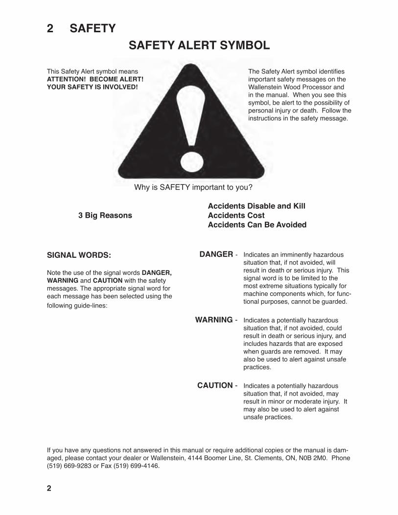
� SAFETYSAFETY ALERT SYMBOL
Why is SAFETY important to you?
The Safety Alert symbol identifies important safety messages on the Wallenstein Wood Processor and in the manual. When you see this symbol, be alert to the possibility of personal injury or death. Follow the instructions in the safety message.
This Safety Alert symbol means ATTENTION! BECOME ALERT! YOUR SAFETY IS INVOLVED!
Accidents Disable and Kill Accidents Cost Accidents Can Be Avoided
3 Big Reasons
If you have any questions not answered in this manual or require additional copies or the manual is dam-aged, please contact your dealer or Wallenstein, 4144 Boomer Line, St. Clements, ON, N0B 2M0. Phone (519) 669-9283 or Fax (519) 699-4146.
DANGER - Indicates an imminently hazardous situation that, if not avoided, will result in death or serious injury. This signal word is to be limited to the most extreme situations typically for machine components which, for func-tional purposes, cannot be guarded.
WARNING - Indicates a potentially hazardous situation that, if not avoided, could result in death or serious injury, and includes hazards that are exposed when guards are removed. It may also be used to alert against unsafe practices.
CAUTION - Indicates a potentially hazardous situation that, if not avoided, may result in minor or moderate injury. It may also be used to alert against unsafe practices.
SIGNAL WORDS:
Note the use of the signal words DANGER, WARNING and CAUTION with the safety messages. The appropriate signal word for each message has been selected using thefollowing guide-lines:
3
SAFETYYOU are responsible for the SAFE operation and maintenance of your Wallenstein Wood Proces-sor. YOU must ensure that you and anyone else who is going to use, maintain or work around the Wood Processor be familiar with the using and maintenance procedures and related SAFETY information contained in this manual. This manual will take you step-by-step through your working day and alerts you to all good safety practices that should be used while using the Wood Processor.
Remember, YOU are the key to safety. Good safety practices not only protect you but also the people around you. Make these practices a work-ing part of your safety program. Be certain that EVERYONE using this equipment is familiar with the recommended using and maintenance proce-dures and follows all the safety precautions. Most accidents can be prevented. Do not risk injury or death by ignoring good safety practices.
• Wood Processor owners must give operating instructions to operators or employees before allowing them to operate the machine, and at least annually thereafter.
• The most important safety device on this equipment is a SAFE operator. It is the op-erator’s responsibility to read and understand ALL Safety and Operating instructions in the manual and to follow these. Most accidents can be avoided.
• A person who has not read and understood all using and safety instructions is not qualified to use the machine. An untrained operator exposes himself and bystanders to possible serious injury or death.
• Do not modify the equipment in any way. Unauthorized modification may impair the function and/or safety and could affect the life of the equipment.
• Think SAFETY! Work SAFELY!
1. Read and understand the Op-erator’s Manual and all safety signs before using, maintain-ing, adjusting or cleaning the Wood Processor.
�.� GENERAL SAFETY
2. Have a first-aid kit available for use should the need arise and know how to use it.
3. Have a fire extinguisher available for use should the need arise and know how to use it.
4. Do not allow riders.
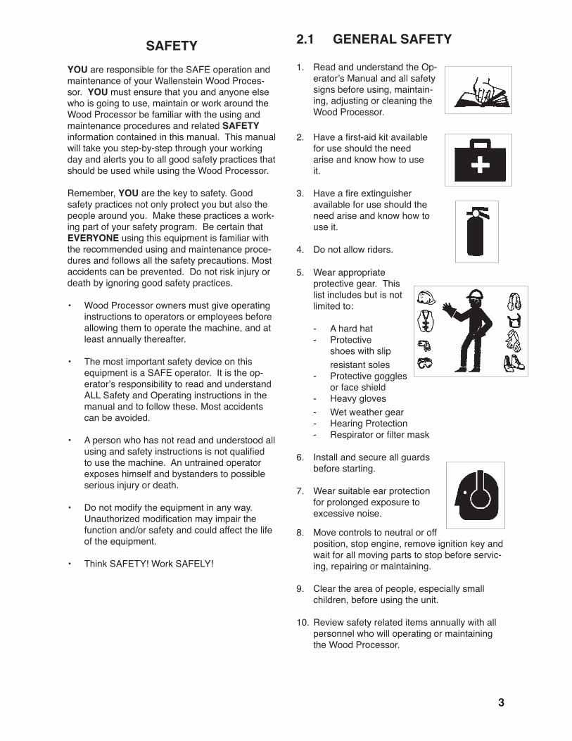
5. Wear appropriate protective gear. This list includes but is not limited to:
- A hard hat - Protective shoes with slip resistant soles - Protective goggles
or face shield - Heavy gloves - Wet weather gear - Hearing Protection - Respirator or filter mask
6. Install and secure all guards before starting.
7. Wear suitable ear protection for prolonged exposure to excessive noise.
8. Move controls to neutral or off position, stop engine, remove ignition key and wait for all moving parts to stop before servic-ing, repairing or maintaining.
9. Clear the area of people, especially small children, before using the unit.
10. Review safety related items annually with all personnel who will operating or maintaining the Wood Processor.

�
�.� EQUIPMENT SAFETY GUIDELINES
1. Safety of the operator and bystanders is one of the main concerns in designing and de-veloping equipment. However, every year many accidents occur which could have been avoided by a few seconds of thought and a more careful approach to handling equipment. You, the operator, can avoid many accidents by observing the following precautions in this section. To avoid personal injury or death, study the following precautions and insist those working with you, or for you to follow them.
2. In order to provide a better view, certain photographs or illustrations in this manual may show an assembly with a safety shield removed. However, equipment should never be used in this condition. Keep all shields in place. If shield removal becomes necessary for repairs, replace the shield prior to use.
3. Replace any safety sign or instruction sign that is not readable or is missing. Location of such safety signs is indicated in this manual.
4. Never use alcoholic beverages or drugs which can hinder alertness or coordination while us-ing this equipment. Consult your doctor about using this machine while taking prescription medications.
5. Under no circumstances should young children be allowed to work with this equipment. Do not allow persons to use or assemble this unit until they have read this manual and have developed a thorough understanding of the safety precautions and of how it works. Review the safety instructions with all users annually.
6. This equipment is dangerous to children and persons unfamiliar with its operation. The operator should be a responsible, properly trained and physically able person familiar with machinery and trained in this equipment's operations. If the elderly are assisting with work, their physical limitations need to be recognized and accommodated.
7. Never exceed the limits of a piece of machin-ery. If its ability to do a job, or to do so safely, is in question - DON'T TRY IT.
8. Do not modify the equipment in any way. Un-authorized modification may result in serious injury or death and may impair the function and life of the equipment.
9. In addition to the design and configuration of this implement, including Safety Signs and Safety Equipment, hazard control and ac-cident prevention are dependent upon the awareness, concern, prudence, and proper training of personnel involved in the operation, transport, maintenance, and storage of the machine. Refer also to Safety Messages and operation instruction in each of the appropri-ate sections of the engine and machine manu-als. Pay close attention to the Safety Signs affixed to the engine and the machine.

�
�.3 SAFETY TRAINING
1. Safety is a primary concern in the design and manufacture of our products. Unfortunately, our efforts to provide safe equipment can be wiped out by a single careless act of an operator or bystander.
2. In addition to the design and configuration of equipment, hazard control and accident pre-vention are dependent upon the awareness, concern, prudence and proper training of personnel involved in the operation, transport, maintenance and storage of this equipment.
3. It has been said, "The best safety feature is an informed, careful opera-tor." We ask you to be that kind of an operator. It is the operator's responsibility to read and under-stand ALL Safety and Using instructions in the manual and to follow these. Accidents can be avoided.
4. Working with unfamiliar equipment can lead to careless injuries. Read this manual before assembly or using, to acquaint yourself with the machine. If this machine is used by any person other than yourself, or is loaned or rented, it is the machine owner's responsibility to make certain that the operator, prior to using:
a. Reads and understands the operator's manuals.
b. Is instructed in safe and proper use.
5. Know your controls and how to stop engine and machine quickly in an emergency. Read
this manual and the one provided with engine.
6. Train all new personnel and review instruc-tions frequently with existing workers. Be certain only a properly trained and physically able person will use the machinery. A person who has not read and understood all using and safety instructions is not qualified to use the machine. An untrained operator exposes himself and bystanders to possible serious in-jury or death. If the elderly are assisting with the work, their physical limitations need to be recognized and accommodated.
�.� SAFETY SIGNS
1. Keep safety signs clean and legible at all times.
2. Replace safety signs that are missing or have become illegible.
3. Replaced parts that displayed a safety sign should also display the current sign.
4. Safety signs displayed in Section 3 each have a part number in the lower right hand corner. Use this part number when ordering replace-ment parts.
5. Safety signs are available from your author-ized Distributor or Dealer Parts Department or the factory.
How to Install Safety Signs:
• Be sure that the installation area is clean and dry.
• Be sure temperature is above 50°F (10°C).
• Determine exact position before you remove the backing paper.
• Remove the smallest portion of the split back-ing paper.
• Align the sign over the specified area and carefully press the small portion with the ex-posed sticky backing in place.
• Slowly peel back the remaining paper and carefully smooth the remaining portion of the sign in place.
• Small air pockets can be pierced with a pin and smoothed out using the piece of sign backing paper.
�
�.� PREPARATION
1. Never use the machine until you have read and completely understand this manual, the engine Operator's Manual and each of the Safety Messages found on the safety signs on the engine and machine.
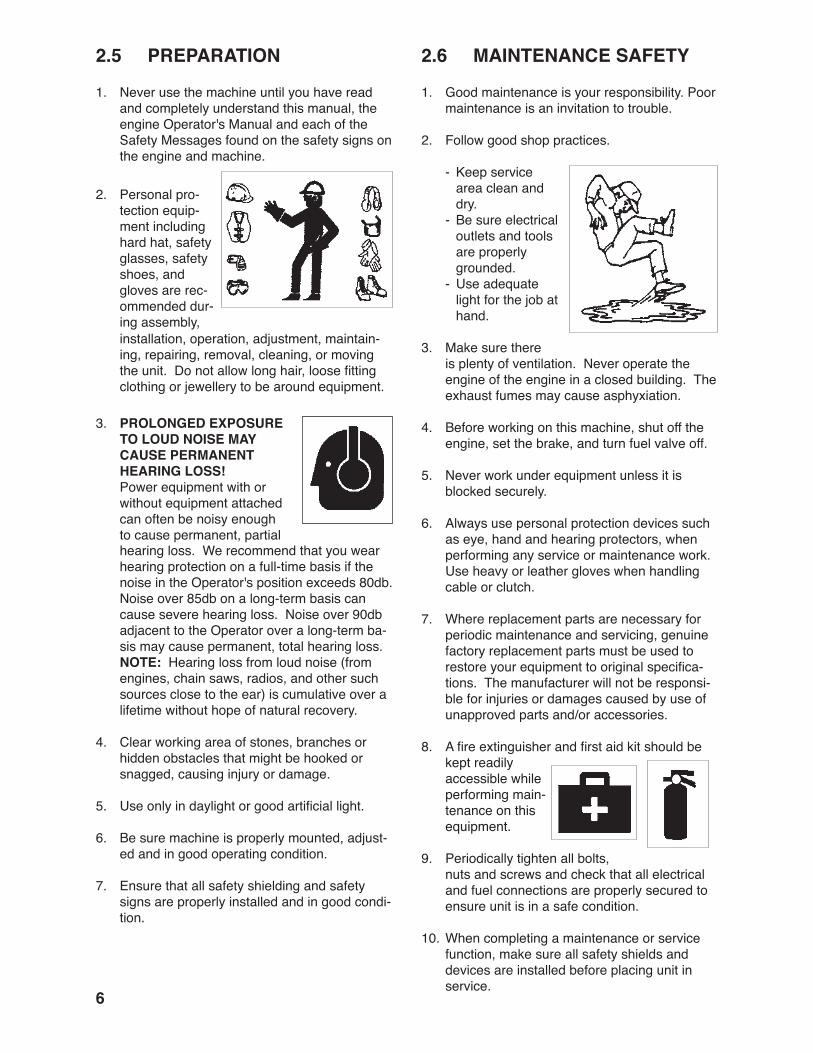
2. Personal pro-tection equip-ment including hard hat, safety glasses, safety shoes, and gloves are rec-ommended dur-ing assembly, installation, operation, adjustment, maintain-ing, repairing, removal, cleaning, or moving the unit. Do not allow long hair, loose fitting clothing or jewellery to be around equipment.
3. PROLONGED EXPOSURE TO LOUD NOISE MAY CAUSE PERMANENT HEARING LOSS!
Power equipment with or without equipment attached can often be noisy enough to cause permanent, partial hearing loss. We recommend that you wear hearing protection on a full-time basis if the noise in the Operator's position exceeds 80db. Noise over 85db on a long-term basis can cause severe hearing loss. Noise over 90db adjacent to the Operator over a long-term ba-sis may cause permanent, total hearing loss. NOTE: Hearing loss from loud noise (from engines, chain saws, radios, and other such sources close to the ear) is cumulative over a lifetime without hope of natural recovery.
4. Clear working area of stones, branches or hidden obstacles that might be hooked or snagged, causing injury or damage.
5. Use only in daylight or good artificial light.
6. Be sure machine is properly mounted, adjust-ed and in good operating condition.
7. Ensure that all safety shielding and safety signs are properly installed and in good condi-tion.
�.� MAINTENANCE SAFETY
1. Good maintenance is your responsibility. Poor maintenance is an invitation to trouble.
2. Follow good shop practices.
- Keep service area clean and dry.
- Be sure electrical outlets and tools are properly grounded.
- Use adequate light for the job at hand.
3. Make sure there is plenty of ventilation. Never operate the engine of the engine in a closed building. The exhaust fumes may cause asphyxiation.
4. Before working on this machine, shut off the engine, set the brake, and turn fuel valve off.
5. Never work under equipment unless it is blocked securely.
6. Always use personal protection devices such as eye, hand and hearing protectors, when performing any service or maintenance work. Use heavy or leather gloves when handling cable or clutch.
7. Where replacement parts are necessary for periodic maintenance and servicing, genuine factory replacement parts must be used to restore your equipment to original specifica-tions. The manufacturer will not be responsi-ble for injuries or damages caused by use of unapproved parts and/or accessories.
8. A fire extinguisher and first aid kit should be kept readily accessible while performing main-tenance on this equipment.
9. Periodically tighten all bolts, nuts and screws and check that all electrical and fuel connections are properly secured to ensure unit is in a safe condition.
10. When completing a maintenance or service function, make sure all safety shields and devices are installed before placing unit in service.
�
�.� OPERATING SAFETY1. Please remember it is important that you read
and heed the safety signs on the Wood Proc-essor. Clean or replace all safety signs if they cannot be clearly read and understood. They are there for your safety, as well as the safety of others. The safe use of this machine is strictly up to you, the operator.
2. All things with moving parts are potentially hazardous. There is no substitute for a cau-tious, safe-minded operator who recognizes potential hazards and follows reasonable safety practices. The manufacturer has designed this Wood Processor to be used with all its safety equipment properly attached, to minimize the chance of accidents. Study this manual to make sure you have all safety equipment attached.
3. Close and secure all guards, deflectors and shields before starting and operating.
4. Read and understand operator's manual before starting. Review safety instructions annually.
5. Personal protection equipment including hearing protection, hard hat, safety glasses, safety shoes, and gloves are recommended during assembly, installation, operation, adjustment, maintaining, repairing, removal, or moving. Do not allow long hair, loose-fitting clothing, or jewellery to be around moving parts.
6. Do not allow anyone within 20 ft (6 m) of ma-chine or logs during operation. Wood chips can be ejected and injure others. Keep children away.
7. Move controls to neutral or off position, stop engine, remove ignition key and wait for all moving parts to stop before servicing, repairing or maintaining.
8. Do not try to process more than one log at a time. The extra log can be ejected and cause injury.
9. Keep your fingers and hands away from cracks in the log that can open while splitting.
10. Always load logs by holding onto the sides, not the top and bottom.
11. Do not load the processor while the wedge is in motion.
12. Do not try to split logs across the grain. Some kinds can burst or splinter and fly out of the machine causing injury.
13. For unevenly cut logs, always place the wide end down and the most square end against the splitting wedge.
14. Never stand directly in line with cable while pull-ing.
15. Check cable condition before using winch. Ca-ble may break during operation if it is corroded, knotted, has broken strands or sharp kinks. Replace cable if damaged.
16. Do not touch cable during operation.
17. Never use alcoholic beverages or drugs which can hinder alertness or coordination while operat-ing this equipment. Consult your doctor about operating this machine while taking prescription medications.
18. Operate only on level ground and lower winch blade when winching.
19. Do not exceed winching angle of more than + 25°.
20. Always winch up a slope.
21. Do not winch across a slope.
22. Do not operate on hillsides or when working area is cluttered, wet, muddy or icy to prevent slipping and tripping.
23. Keep working area clean and free of debris to pre-vent tripping. Operate only on level ground.
24. Stop engine when leaving unattended.
25. Do not exceed a safe travel speed when trans-porting.
26. Read the chain saw operator's manual and fol-low all safety instructions.

�
�.� HYDRAULIC SAFETY1. Make sure that all the components in the hy-
draulic system are kept in good condition and are clean.
2. Before applying pressure to the system, make sure all components are tight, and that lines, hoses and couplings are not damaged.
3. Do not attempt any makeshift repairs to the hydraulic lines, fittings or hoses by using tapes, clamps or cements. The hydraulic sys-tem operates under extremely high pressure. Such repairs will fail suddenly and create a hazardous and unsafe condition.
4. Wear proper hand and eye protection when searching for a high pressure hy-draulic leak. Use a piece of wood or cardboard as a backstop instead of hands to isolate and identify a leak.
5. If injured by a concentrated high-pressure stream of hydraulic fluid, seek medical atten-tion immediately. Serious infection or toxic reaction can develop from hydraulic fluid piercing the skin surface.
6. Relieve pressure on hydraulic system before maintaining or working on system.
�.9 STORAGE SAFETY1. Store the unit in an area away from human
activity.
2. Do not let children to play on or around the stored machine.
3. Store the unit in a dry, level area. Support the frame with planks if required.
�.�0 TRANSPORT SAFETY
1. Comply with state and local laws governing safety and transporting of machinery on public roads.
2. Check that all the lights, reflectors and other lighting requirements are installed and in good working condition.
3. Do not exceed a safe travel speed. Slow down for rough terrain and cornering.
4. Be sure the Wood Processor is hitched posi-tively to the tow unit with retainers installed through the drawbar pin or hitch jaw mecha-nism.
5. Do not drink and drive.
6. Be a safe and courteous driver. Always yield to oncoming traffic in all situations, including narrow bridges, intersections, etc. Watch for traffic when operating near or crossing road-ways.
7. Never allow riders on the machine.

9
�.�� REFUELING SAFETY
1. Handle fuel with care. It is highly flammable.
2. Allow engine to cool for 5 minutes before refu-elling. Clean up spilled fuel before restarting engine.
3. Do not refuel the machine while smoking or when near open flame or sparks.
4. Fill fuel tank outdoors.
5. Prevent fires by keeping machine clean of ac-cumulated trash, grease and debris.
�.�� BATTERY SAFETY1. Keep all sparks and flames away from batter-
ies, as gas given off by electrolyte is explo-sive.
2. Avoid contact with battery electrolyte: wash off an spilled electrolyte immediately.
3. Wear safety glasses when working near bat-teries.
4. Do not tip batteries more than 45°, to avoid electrolyte loss.
5. To avoid injury from spark or short circuit, dis-connect battery ground cable before servicing any part of the electrical system.
�.�3 TIRE SAFETY1. Failure to follow proper procedures when
mounting a tire on a wheel or rim can produce an explosion which may result in serious injury or death.
2. Do not attempt to mount a tire unless you have the proper equipment and experience to do the job.
3. Have a qualified tire dealer or repair service perform required tire maintenance.
4. When replacing worn tires, make sure they meet the original tire specifications. Never indersize.

�0
�.�� GAS MOTOR SAFETY
BEFORE STARTING ENGINE, READAND UNDERSTAND THE OPERATING AND MAINTENANCE INSTRUCTIONSTHAT CAME WITH YOUR ENGINE.
WARNING: DO NOT
1. DO NOT run engine in an enclosed area. Ex-haust gases contain carbon monoxide, an odour-less and deadly poison.
2. DO NOT place hands or feet near moving or rotating parts.
3. DO NOT store, spill, or use gasoline near an open flame, or devices such as a stove, furnace, or water heater which use a pilot light or devices which can create a spark.
4. DO NOT refuel indoors where area is not well ventilated. Outdoor refuelling is preferred.
5. DO NOT refuel while engine is running. Allow engine to cool for 5 minutes before refuelling. Store fuel in approved safety containers.
6. DO NOT remove fuel tank cap while engine is running.
7. DO NOT operate engine if gasoline is spilled. Move machine away from the spill and avoid creating any ignition until gasoline has evapo-rated.
8. DO NOT smoke while filling fuel tank.
9. DO NOT choke carburetor to stop engine. When-ever possible, gradually reduce engine speed before stopping.
10. DO NOT run engine above rated speeds. This may result in injury.
11. DO NOT tamper with governor springs, gover-nor links or other parts which may increase the governed speed.
12. DO NOT tamper with the engine speed selected by the original equipment manufacturer.
13. DO NOT check for spark with spark plug or spark plug wire removed.
14. DO NOT crank engine with spark plug removed. If engine is flooded, crank until engine starts.
15. DO NOT strike flywheel with a hard object or metal tool as this may cause flywheel to shatter in operation. Use proper tools to service engine.
16. DO NOT operate engine without a muffler. Inspect periodically and replace, if necessary. If engine is equipped with a muffler deflector, inspect pe-riodically and replace, if necessary with correct deflector.
17. DO NOT operate engine with an accumulation of grass, leaves, dirt or other combustible materials in the muffler area.
18. DO NOT use this engine on any forest covered, brush covered, or grass covered unimproved land unless a spark arrester is installed on the muffler. The arrester must be maintained in effective work-ing order by the operator. In the state of California the above is required by law (Section 4442 of the California Public Resources Code). Other states may have similar laws. Federal laws apply on federal land.
19. DO NOT touch hot muffler, cylinder or fins be-cause contact may cause burns.
20. DO NOT run engine with air cleaner or air cleaner cover removed.
WARNING: DO
1. ALWAYS DO remove the wire from the spark plug when servicing the engine or equipment to pre-vent accidental starting. Disconnect the negative wire from the battery terminal if equipped wit a 12 volt starting system.
2. DO keep cylinder fins and governor parts free of grass and other debris which can affect engine speed.
3. DO examine muffler periodically to be sure it is functioning effectively. A worn or leaking muffler should be repaired or replaced as necessary.
4. DO use fresh gasoline. Stale fuel can gum car-buretor and cause leakage.
5. DO check fuel lines and fittings frequently for cracks or leaks. Replace if necessary.

��
�.�� SIGN-OFF FORMWallenstein follows the general Safety Standards specified by the American Society of Agricultural and Biological Engineers (ASABE) and the Occupational Safety and Health Administration (OSHA). Anyone who will be using and/or maintaining the Wood Processor must read and clearly understand ALL Safety, Usage and Maintenance information presented in this manual.
Do not use or allow anyone else to use this Wood Processor until such information has been reviewed. An-nually review this information before the season start-up.
Make these periodic reviews of SAFETY and OPERATION a standard practice for all of your equipment. We feel that an untrained operator is unqualified to use this machine.
A sign-off sheet is provided for your record keeping to show that all personnel who will be working with the equipment have read and understand the information in the Operator’s Manual and have been instructed in the operation of the equipment.
EMPLOYEES SIGNATURE EMPLOYERS SIGNATURE
SIGN-OFF FORM
DATE

��
REMEMBER - If safety signs have been damaged, removed, become illegible or parts replaced without safety signs, new signs must be applied. New safety signs are available from your authorized dealer.
3 SAFETY SIGN LOCATIONS The types of safety signs and locations on the equipment are shown in the illustrations that follow. Good safety requires that you familiarize yourself with the various safety signs, the type of warning and the area, or particular function related to that area, that requires your SAFETY AWARENESS.
• Think SAFETY! Work SAFELY!
A
B
Z94040

�3
REMEMBER - If safety signs have been damaged, removed, become illegible or parts replaced without safety signs, new signs must be applied. New safety signs are available from your authorized dealer.
The types of safety signs and locations on the equipment are shown in the illustrations that follow. Good safety requires that you familiarize yourself with the various safety signs, the type of warning and the area, or particular function related to that area, that requires your SAFETY AWARENESS.• Think SAFETY! Work SAFELY!
C D
Z9�00�
B
D
AC
��
� OPERATION
The Wallenstein Wood Processors are designed to connect to and pull logs to the machine, position for cutting with a chain saw and split the resulting log. The operator should be familiar with the machine prior to starting.
It is the responsibility of the owner or operator to read this manual and to train all other opera-tors before they start working with the machine. Follow all safety instructions exactly. Safety is everyone's business. By following recommend-ed procedures, a safe working environment is provided for the operator, bystanders and the area around the worksite. Untrained operators are not qualified to use the machine.
Follow all safety instructions exactly. Safety is everyone's business. By following recommend-ed procedures, a safe working environment is provided for the operator, bystanders and the area around the worksite. Untrained operators are not qualified to operate the machine.
Many features incorporated into this machine are the result of suggestions made by customers like you. Read this manual carefully to learn how to use the winch, chain saw and wood splitter safely and how to set it to provide maximum operating efficiency. By following the using instructions in conjunction with a good maintenance program, your Wood Processor will provide many years of trouble-free service.
�.� TO THE NEW OPERATOR OR OWNER
OPERATING SAFETY• Read Operator's Manual before using. Review
safety instructions annually.
• Move controls to neutral or off position, stop engine, remove ignition key and wait for all moving parts to stop before servicing, repairing or maintaining.
• Do not allow anyone within 20 ft. (6m) of ma-chine or logs during operation. Keep children away.
• Wear appropriate safety gear including but not limited to face shield, hearing protection, hard hat, heavy gloves and steel toed shoes with slip-resistant soles.
• Check cable condition before using winch. Cable may break during operation if cable is corroded, knotted, has broken strands or sharp kinks. Replace cable if damaged.
• Do not touch cable while winch is in opera-tion.
• Operate only on level ground.
• Do not exceed winching angle of more than 25°.
• Always winch up a slope.
• Do not winch across a slope.
• Do not operate on hillsides or when the working area is cluttered, wet, muddy or icy to prevent slipping or tripping.
• Never stand directly in line with cable while pulling.
• Do not operate machine unless standing behind protective screen.
• Do not place hands or feet between log and wedge/splitter or base.
• Keep all hydraulic components in good work-ing order.
• Use care when starting and using chain saw. Read chain saw operator's manual and follow all safety instructions. Keep others away.
• Stop engine when leaving machine unat-tended.
��
�.� MACHINE COMPONENTSThe Wallenstein Wood Processor consists of a winch mounted in a frame to pull or winch logs into the log chute and then position them at the sawing location. A lever on the left-hand side of the frame engages the winch motor to pull in the cable. The engaging lever is spring-loaded and will return to its OFF position when the lever is released. The lever on the top locks and unlocks the winch drum which allows the cable to be pulled out - freewheel. Use the left lever on the control panel to engage the hydraulic motor that drives the winch to pull or move the log.
The operator uses his own chain saw to cut the log to the desired length. When the log is cut, the piece rolls into the splitting chamber where the cylinder pushes it through the splitting wedge. Guides and markers on the cutting and splitting chambers show the operator the status of those areas.
Fig. � PRINCIPLE COMPONENTS
A Winch FrameB WinchC HookD CableE Winch LockF StandsG Cutting Chamber MarkerH Splitting Chamber MarkerJ Safety ScreenK Splitting CylinderL Splitting WedgeM Wood Dicharge ChuteN Engine
Power to drive the machine is provided through the gas engine and hydraulic pump.
A safety screen is mounted on the top of the frame for protection against flying chips.
AB
CD
A
E
K
J
J
L M
N
H
H
F
F
B
F
G

��
�.3 MACHINE BREAK-INAlthough there are no operational restrictions on the Wood Processor when used for the first time, it is recommended that the following mechanical items be checked:
A. After operating for � to � hours:
1. Check all nuts, bolts and other fasteners. Tighten to their specified torque.
2. Check hydraulic system for leaks. Tighten all leaking fittings and replace any leaking components.
3. Check machine fluid levels: Fuel, engine oil, and hydraulic oil reservoir. Top up as required.
4. Check condition of winch.
5. Check the condition of the cable. Replace if kinked, frayed or if it has any broken strands.
6. Check for entangled material. Remove all entangled material before resuming work.
7. Lubricate all grease fittings.
B. After operating for �0 hours:
1. Repeat steps 1 through 7 listed above. (Section A)
2. Change engine oil.
3. Go to the normal servicing and mainte-nance schedule as defined in the Mainte-nance Section.
�.� PRE-OPERATION CHECKLIST
Efficient and safe operation of the Wallenstein Wood Processor requires that each operator reads and understands the using procedures and all related safety precautions outlined in this section. A pre-operation checklist is provided for the operator. It is important for both the personal safety and maintaining good mechanical condition that this checklist is followed.
Before operating the Wood Processor and each time thereafter, the following areas should be checked off:
1. Lubricate the machine per the schedule out-line in the Maintenance Section.
2. Check for entangled material. Remove any twine, wire or other material that has become entangled.
3. Check the condition of the cable. Replace if kinked, frayed or if it has any broken strands
4. Check the wedge and block. Be sure they are not damaged or broken and are not badly worn. Repair or replace as required.
5. Check for hydraulic leaks. Tighten fittings or replace components to stop leaks.
6. Check engine and machine fluid levels. Top up as required.
7. Check that all bearings turn freely. Replace any that are rough or seized.
8. Make sure that all guards and shields are in place, secured and functioning as designed.
9. Check the condition of the winch. It must be in good condition to operate properly.
��
Fig. � CONTROLS
�.� CONTROLSBefore starting to work, all operators should famil-iarize themselves with the location and function of controls.
�. Gas Engine (Electric Start): Read the engine manufacturers operator's
manual before starting for more detailed in-structions.
a. Ignition Switch: This key operated switch controls the
electric power to the engine.
OFF Turn key fully counter-clockwise to stop the electrical system power and turn the engine off.
RUN Turn clockwise on detent to the run position. This is the position where the engine will continue to run.
START Turn fully clockwise to the last spring-loaded detent position to engage the starter solenoid and start the engine. Release the key when the engine starts and it will return to the RUN position.
b. Choke: This push/pull knob controls the position
of the choke. Pull the knob out to close the choke for starting when the engine is cold. Push the knob in to open the choke as the engine warms. Always push the knob fully in when operating the machine.
c. Throttle: This lever controls the engine RPM. Turn
the lever clockwise to increase engine speed and counter-clockwise to de-crease.
d. Fuel Shut-Off Valve: This valve controls the flow of fuel to the
engine. Turn the valve at right angles to the fuel line to turn the fuel off and parallel to turn the fuel on.
ab cd

��
�. Gas Engine (Manual Start): Read the engine manufacturers operator's
manual before starting for more detailed in-structions.
a. Ignition Switch: This switch controls the electrical power
to the engine electrical system. Turn the switch counter-clockwise to turn OFF. Turn clockwise to the first position to turn ON.
b. Choke: This push/pull knob controls the position
of the choke. Pull the knob out to close the choke for starting when the engine is cold. Push the knob in to open the choke as the engine warms. Always push the knob fully in when operating the machine.
c. Throttle: This lever controls the engine RPM. Turn
the lever clockwise to increase engine speed and counter-clockwise to de-crease.
d. Fuel Shut-Off Valve: This valve controls the flow of fuel to the
engine. Turn the valve at right angles to the fuel line to turn the fuel off and parallel to turn the fuel on.
e. Starting Rope: This retracting rope and T bar is used to
turn the engine over for starting. Grasp the T bar firmly and pull the rope sharply to start the engine. Close the choke if the engine is cold.
Fig. 3 MANUAL START
c
e
b
d
�9
Fig. � WINCH CONTROL
Engaged
Released
3. Winch Control: This 3-position valve controls the flow of oil
to the hydraulic motor powering the cable retracting winch. Move the lever down and hold to start the winch and retract the cable. Release the lever to stop the cable. Move the lever up to allow the cable to freewheel or unwind, however the winch lock must also be released before the cable can be pulled out.
4. Winch Lock: This two-position lever controls the lock on
the winch drive system. Pull the lever to the right to lock the winch in its driving configu-ration. Push it to the left and the winch will be released and can free-wheel. The cable can then be pulled out to attach to a log.
Left - Freewheeling
Right - Locked
Fig. � WINCH LOCK
�0
In Detent
Left in Neutral
Right in Neutral
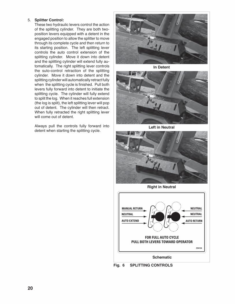
Fig. � SPLITTING CONTROLS
5. Splitter Control: These two hydraulic levers control the action
of the splitting cylinder. They are both two-position levers equipped with a detent in the engaged position to allow the splitter to move through its complete cycle and then return to its starting position. The left splitting lever controls the auto control extension of the splitting cylinder. Move it down into detent and the splitting cylinder will extend fully au-tomatically. The right splitting lever controls the suto-control retraction of the splitting cylinder. Move it down into detent and the splitting cylinder will automatically retract fully when the splitting cycle is finished. Pull both levers fully forward into detent to initiate the splitting cycle. The cylinder will fully extend to split the log. When it reaches full extension (the log is split), the left splitting lever will pop out of detent. The cylinder will then retract. When fully retracted the right splitting lever will come out of detent.
Always pull the controls fully forward into detent when starting the splitting cycle.
Schematic
��
Long Length
Short Length
Short Log
Fig. � LOG LENGTH
Manual
Hydraulic
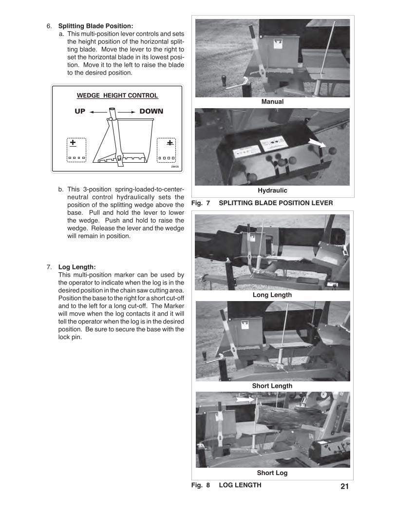
Fig. � SPLITTING BLADE POSITION LEVER
6. Splitting Blade Position: a. This multi-position lever controls and sets
the height position of the horizontal split-ting blade. Move the lever to the right to set the horizontal blade in its lowest posi-tion. Move it to the left to raise the blade to the desired position.
b. This 3-position spring-loaded-to-center-neutral control hydraulically sets the position of the splitting wedge above the base. Pull and hold the lever to lower the wedge. Push and hold to raise the wedge. Release the lever and the wedge will remain in position.
7. Log Length: This multi-position marker can be used by
the operator to indicate when the log is in the desired position in the chain saw cutting area. Position the base to the right for a short cut-off and to the left for a long cut-off. The Marker will move when the log contacts it and it will tell the operator when the log is in the desired position. Be sure to secure the base with the lock pin.

��
Retracted
Extended
Large Angle
Fig. 9 LOG CHUTE POSITION
8. Log Chute Position: This multi-position sliding bracket controls
the angle of the split log chute. Retract it for a small angle. Extend it for a larger angle. Set appropriate for operating conditions and allows the height to be set for conveyors or trailers.

�3
�.� ATTACHING AND UNHOOKINGThe Wood Processor should always be located on a level, dry area that is free of debris and other foreign objects. When attaching the machine to a tow unit, follow this procedure:
1. Clear the area of bystanders, especially small children.
2. Make sure there is enough room and clear-ance to safely back up to the machine.
3. Slowly back the tow vehicle until the jaws on the hitch and the ball are aligned.
4. Raise the hitch and place the jaws over the ball.
5. Flip the latch to lock the jaws around the ball.
6. Install the retainer through the latch.
Fig. �0 ALIGNED
Fig. �� JAWS
Fig. �� JAWS

��
7. Attach the safety chain securely to the tow unit to prevent unexpected separation. Cross the chains under the hitch when attaching.
8. Connect the wiring harness for the lights.
9. Raise and stow the hitch jack.
10. Reverse the above procedure when unhook-ing.
Fig. �3 SAFETY CHAIN
Fig. �� WIRING HARNESS
Fig. �� JACK
��
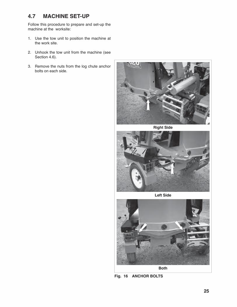
�.� MACHINE SET-UPFollow this procedure to prepare and set-up the machine at the worksite:
1. Use the tow unit to position the machine at the work site.
2. Unhook the tow unit from the machine (see Section 4.6).
3. Remove the nuts from the log chute anchor bolts on each side.
Right Side
Left Side
Both
Fig. �� ANCHOR BOLTS
��
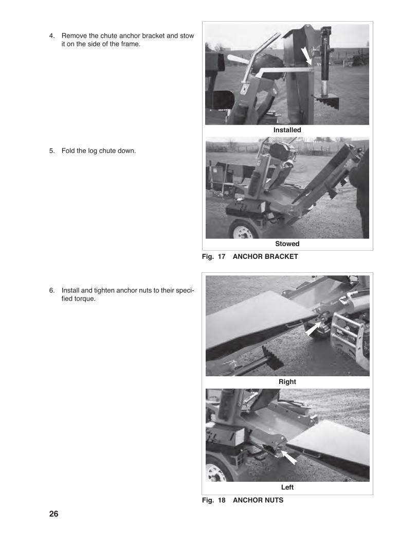
Installed
Fig. �� ANCHOR BRACKET
Stowed
Fig. �� ANCHOR NUTS
Right
Left
4. Remove the chute anchor bracket and stow it on the side of the frame.
5. Fold the log chute down.
6. Install and tighten anchor nuts to their speci-fied torque.

��
Stored
Fig. �9 JACKS
Turned
Fig. �0 JACKS EXTENDED
Right
Left
7. Unpin the log chute support jacks and turn them to the down position.
8. Install anchor pins.
9. Extend the jacks to support the log chute.
��
Folding
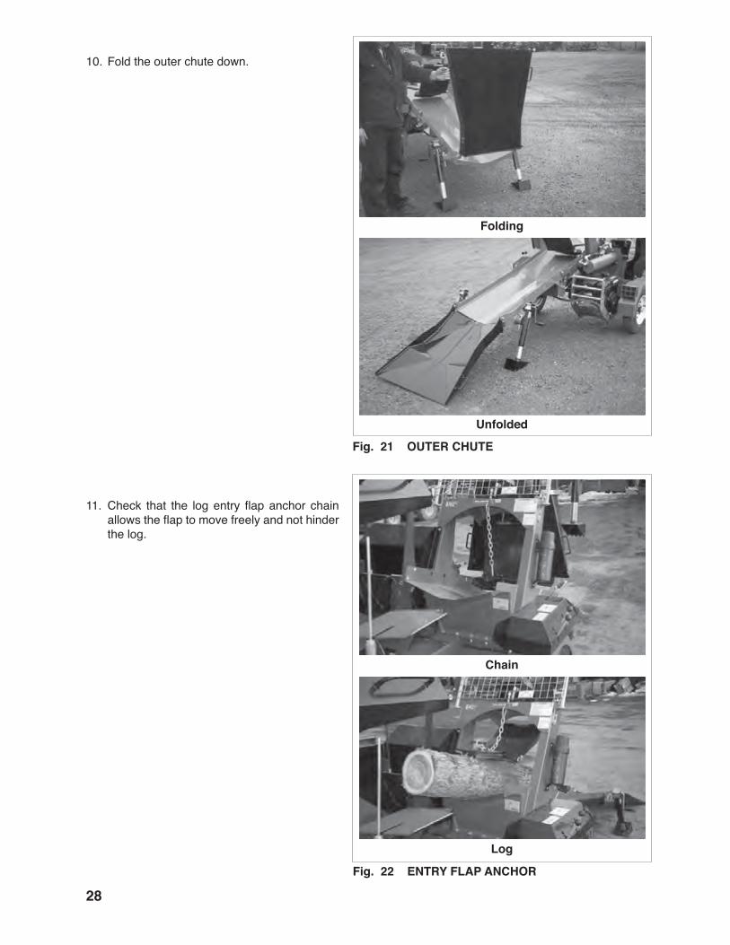
Fig. �� OUTER CHUTE
Unfolded
Fig. �� ENTRY FLAP ANCHOR
Chain
Log
10. Fold the outer chute down.
11. Check that the log entry flap anchor chain allows the flap to move freely and not hinder the log.
�9
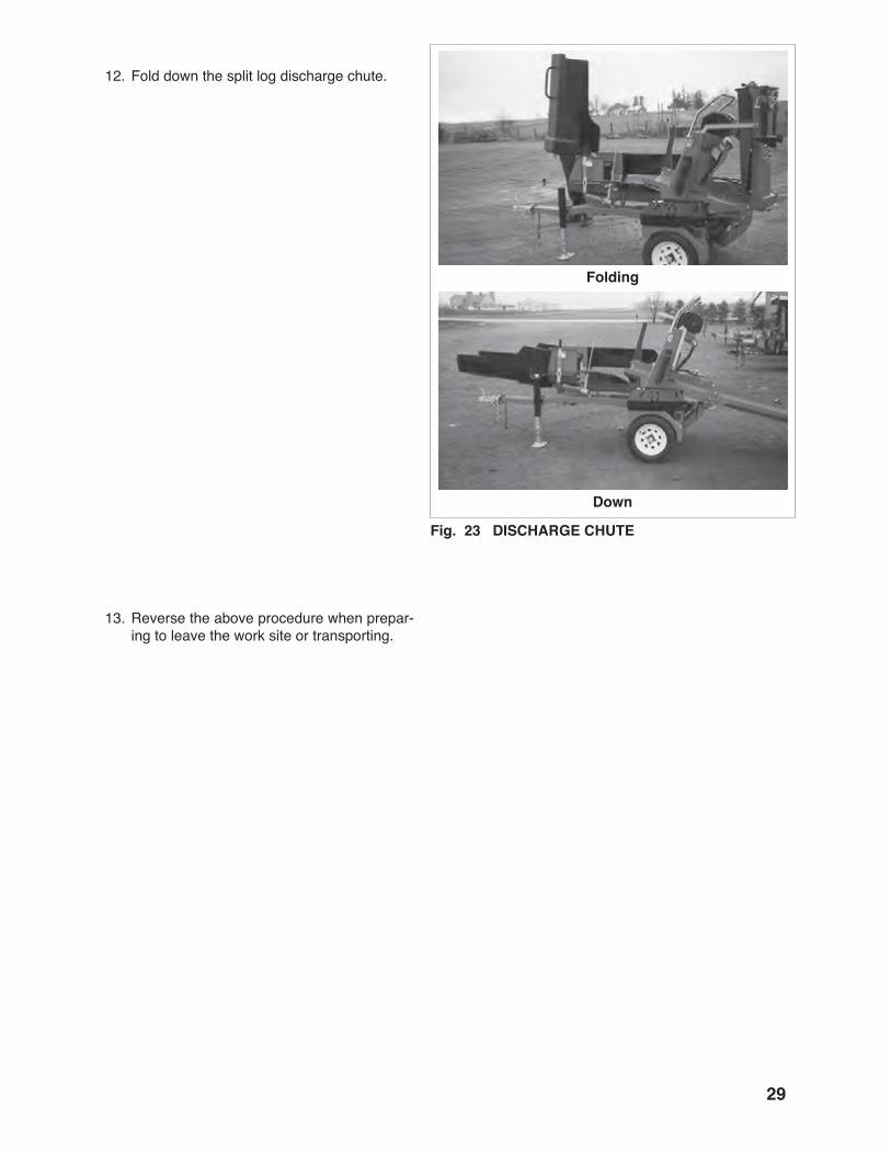
Fig. �3 DISCHARGE CHUTE
Folding
Down
12. Fold down the split log discharge chute.
13. Reverse the above procedure when prepar-ing to leave the work site or transporting.

30
�.� FIELD OPERATION
Although the Wood Processor is easy to use, each operator should review this section to familiar-ize himself with the detailed safety and operating procedures. When using this machine, follow this procedure:
1. Clear the area of bystanders, especially small children.
2. Review and follow the Pre-Operation Checklist (see Section 4.4).
3. Attach the machine to the tow unit (see Section 4.6).
4. Drive to the working area and position the ma-chine.
5. Unhook the tow unit and set up the machine (see section 4.7).
OPERATING SAFETY• Read Operator's Manual before using. Review
safety instructions annually.
• Move controls to neutral or off position, stop engine, remove ignition key and wait for all moving parts to stop before servicing, repairing or maintaining.
• Do not allow anyone within 20 ft. (6m) of ma-chine or logs during operation. Keep children away.
• Wear appropriate safety gear including but not limited to face shield, hearing protection, hard hat, heavy gloves and steel toed shoes with slip-resistant soles.
• Check cable condition before using winch. Cable may break during operation if cable is corroded, knotted, has broken strands or sharp kinks. Replace cable if damaged.
• Do not touch cable while winch is in opera-tion.
• Operate only on level ground.
• Do not exceed winching angle of more than 25°.
• Always winch up a slope.
• Do not winch across a slope.
• Do not operate on hillsides or when the working area is cluttered, wet, muddy or icy to prevent slipping or tripping.
• Never stand directly in line with cable while pulling.
• Do not operate machine unless standing behind protective screen.
• Do not place hands or feet between log and wedge/splitter or base.
• Keep all hydraulic components in good work-ing order.
• Use care when starting and using chain saw. Read chain saw operator's manual and follow all safety instructions. Keep others away.
• Stop engine when leaving machine unat-tended.

3�
Fig. �� TRAINING
6. Training: Each operator must be trained in the proper
operating procedures prior to being allowed to operate the machine.
a. Review control location, function and movement directions.
b. Move the unit to a large open area to al-low the operator to become familiar with control function and machine response.
c. When a new operator is familiar and comfortable with the machine, they can proceed with the work. Do not allow untrained operators to use the machine. They can endanger themselves and others or damage property and the ma-chine.
7. Job Site: It is the responsibility of the operator to be
thoroughly familiar with the work site prior to starting. Prevent the chance or possibility of problems or accidents by not being in the situ-ation to start with. Some items the operators should check include but are not limited to:
a. Close or cramped work space. Be sure there is sufficient space and clearance for the machine to winch-in the log during operation.
b. Organize the working area to minimize the winching and wood removal distanc-es. The shorter the distances, the faster the work will be finished.
Fig. �� JOB SITE
3�
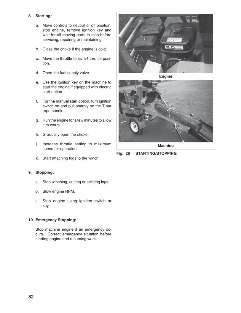
�. Starting: a. Move controls to neutral or off position,
stop engine, remove ignition key and wait for all moving parts to stop before servicing, repairing or maintaining.
b. Close the choke if the engine is cold.
c. Move the throttle to its 1/4 throttle posi-tion.
d. Open the fuel supply valve.
e. Use the ignition key on the machine to start the engine if equipped with electric start option.
f. For the manual start option, turn ignition switch on and pull sharply on the T-bar rope handle.
g. Run the engine for a few minutes to allow it to warm.
h. Gradually open the choke.
j. Increase throttle setting to maximum speed for operation.
k. Start attaching logs to the winch.
9. Stopping:
a. Stop winching, cutting or splitting logs.
b. Slow engine RPM.
c. Stop engine using ignition switch or key.
�0. Emergency Stopping: Stop machine engine if an emergency oc-
curs. Correct emergency situation before starting engine and resuming work.
Fig. �� STARTING/STOPPING
Engine
Machine
33
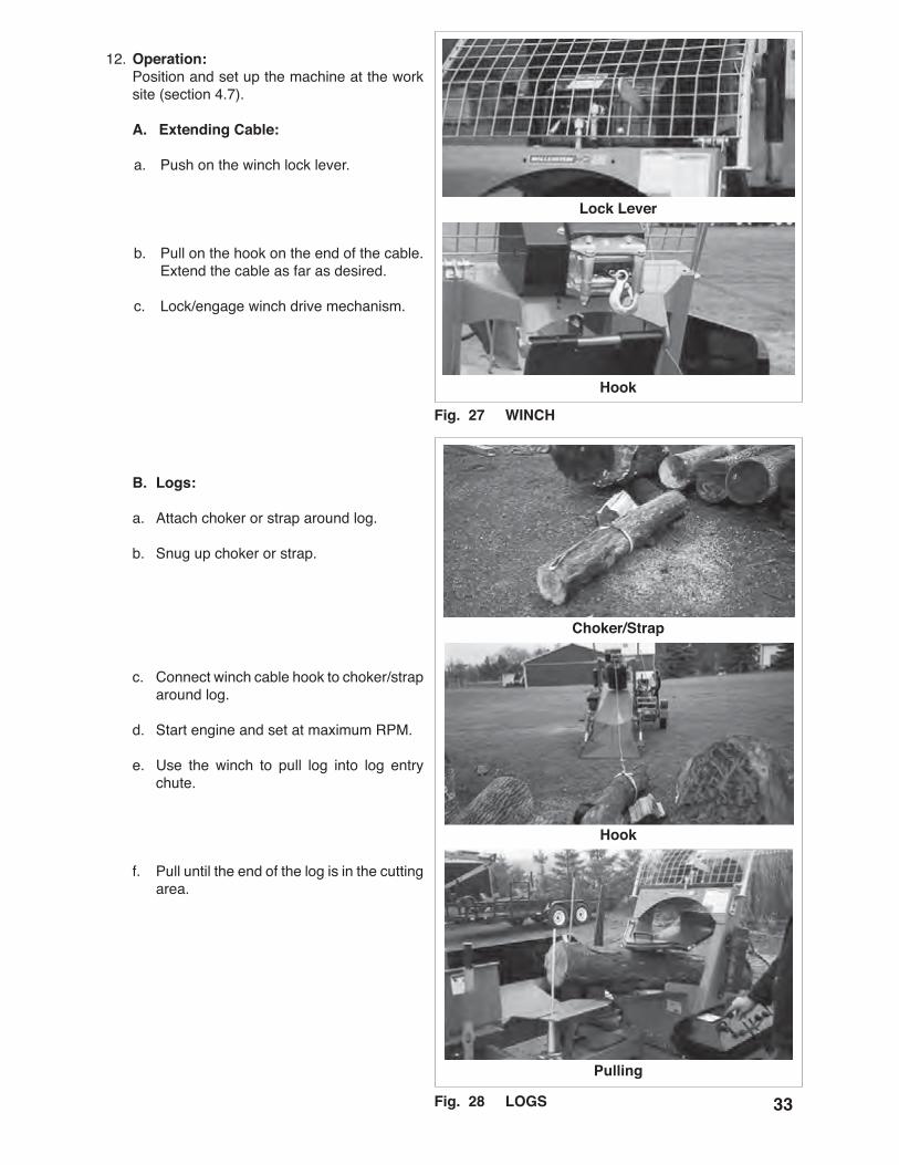
12. Operation: Position and set up the machine at the work
site (section 4.7).
A. Extending Cable:
a. Push on the winch lock lever.
b. Pull on the hook on the end of the cable. Extend the cable as far as desired.
c. Lock/engage winch drive mechanism.
B. Logs:
a. Attach choker or strap around log.
b. Snug up choker or strap.
c. Connect winch cable hook to choker/strap around log.
d. Start engine and set at maximum RPM.
e. Use the winch to pull log into log entry chute.
f. Pull until the end of the log is in the cutting area.
Fig. �� WINCH
Lock Lever
Hook
Choker/Strap
Hook
Pulling
Fig. �� LOGS

3�
C. Second log:
If the log is short, it is recommended that another log be used to move the first one into the cutting area. When working with a second log, follow this procedure:
a. Release the cable and hook.
b. Pull the cable and hook out.
c. Attach the choker to the next log.
d. Engage the winch drive lock.
e. Retract the cable and pull the second log into the log chute.
f. Retract until second log moves the first log into the cutting area.
Winch Lock
Fig. �9 SECOND LOG
Choker
Second Log
Log Chute

3�
g. Move the second log as required to slide the first log through the cutting area.
h. Move the choker down the log to at-tach further away.
j. Pull the logs into the cutting area as required.
k. Last log: Move log using the log peavey in-
serted into holes at side of chute. Slide log into the cutting chamber.
l. Repeat until log is completely cut up.
New Choker Position
Pulling
Last Log
Fig. 30 MOVING SECOND LOG
Short Log
Peavey
3�
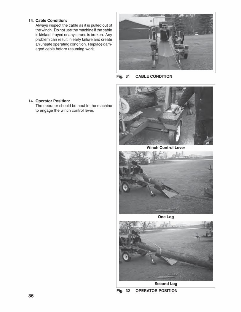
13. Cable Condition: Always inspect the cable as it is pulled out of
the winch. Do not use the machine if the cable is kinked, frayed or any strand is broken. Any problem can result in early failure and create an unsafe operating condition. Replace dam-aged cable before resuming work.
14. Operator Position: The operator should be next to the machine
to engage the winch control lever.
Fig. 3� CABLE CONDITION
Winch Control Lever
One Log
Second LogFig. 3� OPERATOR POSITION
3�
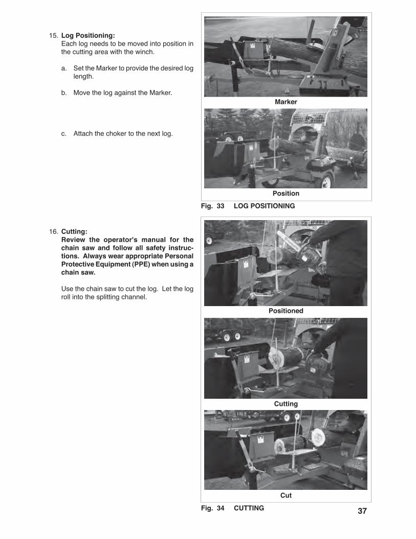
15. Log Positioning: Each log needs to be moved into position in
the cutting area with the winch.
a. Set the Marker to provide the desired log length.
b. Move the log against the Marker.
c. Attach the choker to the next log.
16. Cutting: Review the operator's manual for the
chain saw and follow all safety instruc-tions. Always wear appropriate Personal Protective Equipment (PPE) when using a chain saw.
Use the chain saw to cut the log. Let the log roll into the splitting channel.
Marker
Position
Fig. 33 LOG POSITIONING
Positioned
Cutting
Cut
Fig. 3� CUTTING
3�
Splitting Chamber
Extending
Splitting
Split
Controls
Fig. 3� SPLITTING
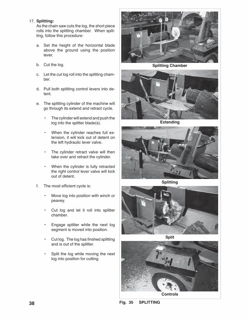
17. Splitting: As the chain saw cuts the log, the short piece
rolls into the splitting chamber. When split-ting, follow this procedure:
a. Set the height of the horizontal blade above the ground using the position lever.
b. Cut the log.
c. Let the cut log roll into the splitting cham-ber.
d. Pull both splitting control levers into de-tent.
e. The splitting cylinder of the machine will go through its extend and retract cycle.
• The cylinder will extend and push the log into the splitter blade(s).
• When the cylinder reaches full ex-tension, it will kick out of detent on the left hydraulic lever valve.
• The cylinder retract valve will then take over and retract the cylinder.
• When the cylinder is fully retracted the right control lever valve will kick out of detent.
f. The most efficient cycle is:
• Move log into position with winch or peavey.
• Cut log and let it roll into splitter chamber.
• Engage splitter while the next log segment is moved into position.
• Cut log. The log has finshed splitting and is out of the splitter.
• Split the log while moving the next log into position for cutting.

39
Log
Split
Height
Fig. 3� WOOD DISCHARGE
18. Wood Discharge: The split pieces of log will be pushed out of
the discharge as each additional log moves through the machine. Set the discharge at the appropriate position for making a pile or moving into a vehicle.
19. Safety Screen: Each machine is equipped with a safety
screen that protects the operator from flying chips, twigs and branches when winching. Always keep it in good condition when operat-ing.
Fig. 3� SAFETY SCREEN
�0
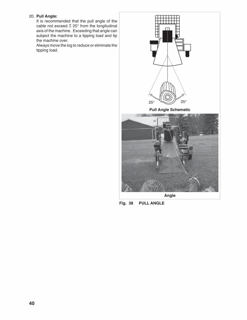
20. Pull Angle: It is recommended that the pull angle of the
cable not exceed + 25° from the longitudinal axis of the machine. Exceeding that angle can subject the machine to a tipping load and tip the machine over.
Always move the log to reduce or eliminate the tipping load.
Pull Angle Schematic
Fig. 3� PULL ANGLE
Angle
��
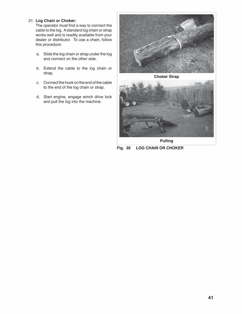
21. Log Chain or Choker: The operator must find a way to connect the
cable to the log. A standard log chain or strap works well and is readily available from your dealer or distributor. To use a chain, follow this procedure:
a. Slide the log chain or strap under the log and connect on the other side.
b. Extend the cable to the log chain or strap.
c. Connect the hook on the end of the cable to the end of the log chain or strap.
d. Start engine, engage winch drive lock and pull the log into the machine.
Choker Strap
Fig. 39 LOG CHAIN OR CHOKERPulling

��
22. Operating Hints:
a. Use a second log to move a short log through the cutting area.
b. Attach the choker to the front or rear of the log as appropriate.
c. Use the Marker on the back of the cutting area as a guide in positioning the log for cutting.
Fig. �0 SECOND LOG
Fig. �� Marker
Front
Rear
�3
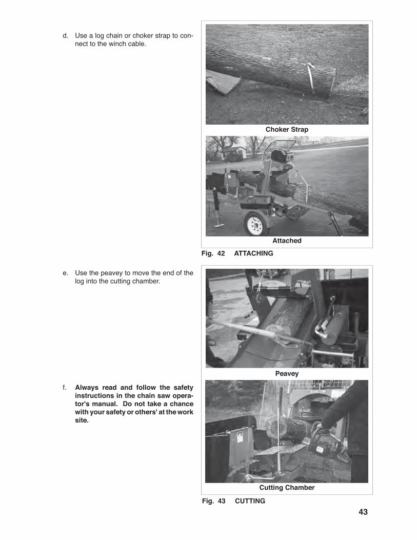
d. Use a log chain or choker strap to con-nect to the winch cable.
e. Use the peavey to move the end of the log into the cutting chamber.
f. Always read and follow the safety instructions in the chain saw opera-tor's manual. Do not take a chance with your safety or others' at the work site.
Fig. �� ATTACHING
Choker Strap
Attached
Fig. �3 CUTTING
Peavey
Cutting Chamber
��
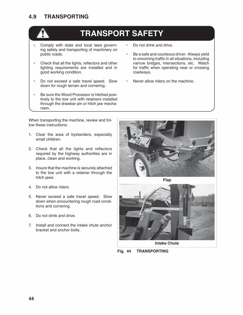
TRANSPORT SAFETY•. Comply with state and local laws govern-
ing safety and transporting of machinery on public roads.
• Check that all the lights, reflectors and other lighting requirements are installed and in good working condition.
• Do not exceed a safe travel speed. Slow down for rough terrain and cornering.
• Be sure the Wood Processor is hitched posi-tively to the tow unit with retainers installed through the drawbar pin or hitch jaw mecha-nism.
• Do not drink and drive.
• Be a safe and courteous driver. Always yield to oncoming traffic in all situations, including narrow bridges, intersections, etc. Watch for traffic when operating near or crossing roadways.
• Never allow riders on the machine.
Fig. �� TRANSPORTING
When transporting the machine, review and fol-low these instructions:
1. Clear the area of bystanders, especially small children.
2. Check that all the lights and reflectors required by the highway authorities are in place, clean and working.
3. Insure that the machine is securely attached to the tow unit with a retainer through the hitch jaws.
4. Do not allow riders.
5. Never exceed a safe travel speed. Slow down when encountering rough road condi-tions and cornering.
6. Do not drink and drive.
7. Install and connect the intake chute anchor bracket and anchor bolts.
�.9 TRANSPORTING
Flap
Intake Chute
��
OPERATING SAFETY• Store the unit in an area away from human
activity.
• Do not permit children to play on or around the stored machine.
• Store the unit in a dry, level area. Support the frame with planks if required.
�.�0 STORAGE
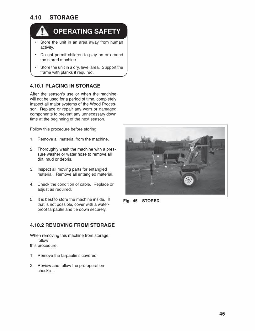
After the season's use or when the machine will not be used for a period of time, completely inspect all major systems of the Wood Proces-sor. Replace or repair any worn or damaged components to prevent any unnecessary down time at the beginning of the next season.
Follow this procedure before storing:
1. Remove all material from the machine.
2. Thoroughly wash the machine with a pres-sure washer or water hose to remove all dirt, mud or debris.
3. Inspect all moving parts for entangled material. Remove all entangled material.
4. Check the condition of cable. Replace or adjust as required.
5. It is best to store the machine inside. If that is not possible, cover with a water-proof tarpaulin and tie down securely.
�.�0.� REMOVING FROM STORAGE
When removing this machine from storage, follow
this procedure:
1. Remove the tarpaulin if covered.
2. Review and follow the pre-operation checklist.
�.�0.� PLACING IN STORAGE
Fig. �� STORED

��
MAINTENANCE SAFETY
• Good maintenance is your responsibility. Poor maintenance is an invitation to trouble.
• Follow good shop practices.
- Keep service area clean and dry. - Be sure electrical outlets and tools are properly grounded. - Use adequate light for the job at hand.
• Make sure there is plenty of ventilation. Never operate the engine of the engine in a closed building. The exhaust fumes may cause as-phyxiation.
• Before working on this machine, shut off the engine, set the brake, and turn fuel valve off.
• Never work under equipment unless it is blocked securely.
• Always use personal protection devices such as eye, hand and hearing protectors, when performing any service or main-tenance work. Use heavy gloves when handling sharp components.
• Where replacement parts are necessary for periodic maintenance and servicing, genuine factory replacement parts must be used to restore your equipment to original specifications. The manufacturer will not be responsible for injuries or damages caused by use of unapproved parts and/or acces-sories.
• A fire extinguisher and first aid kit should be kept readily accessible while performing maintenance on this equipment.
• Periodically tighten all bolts, nuts and screws and check that all electrical and fuel connections are properly secured to ensure unit is in a safe condition.
• When completing a maintenance or service function, make sure all safety shields and de-vices are installed before placing unit in serv-ice.
� SERVICE AND MAINTENANCE�.� SERVICE�.�.� FLUIDS AND LUBRICANTS
1. Grease: Use an SAE multipurpose high temperature
grease with extreme pressure (EP) perform-ance. Also acceptable is an SAE multipur-pose lithium base grease.
2. Engine Oil: Use an SAE 10W30 or 10W40 multi-viscosity
oil meeting the American Petroleum Institute (API) classification of SF, SG, SH or SJ for normal operating conditions. Do not mix oil types with different viscosities. Check engine operator's manual.
9.0 hp 1.0 L (1.1 US Quarts) 14.0 hp 1.5 L (1.6 US Quarts)
3. Engine Gasoline: Use a standard automotive super unleaded
gasoline for all operating conditions.
Fuel tank capacity:
9.0 hp 6.1 L (1.6 US Gal.) 14.0 hp 8.0 L (2.2 US Gal.)
4. Storing Lubricants: Your machine can operate at top efficiency
only if clean lubricants are used. Use clean containers to handle all lubricants. Store them in an area protected from dust, moisture and other contaminants.
�.�.� GREASING
Use the Maintenance Checklist provided to keep a record of all scheduled maintenance.
1. Use a hand-held grease gun for all greasing.
2. Wipe grease fitting with a clean cloth before greasing, to avoid injecting dirt and grit.
3. Replace and repair broken fittings immedi-ately.
4. If fittings will not take grease, remove and clean thoroughly. Also clean lubricant pas-sageway. Replace fittings if necessary.
��
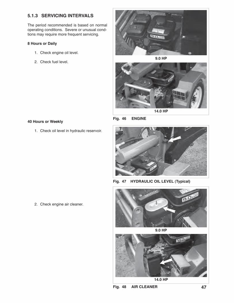
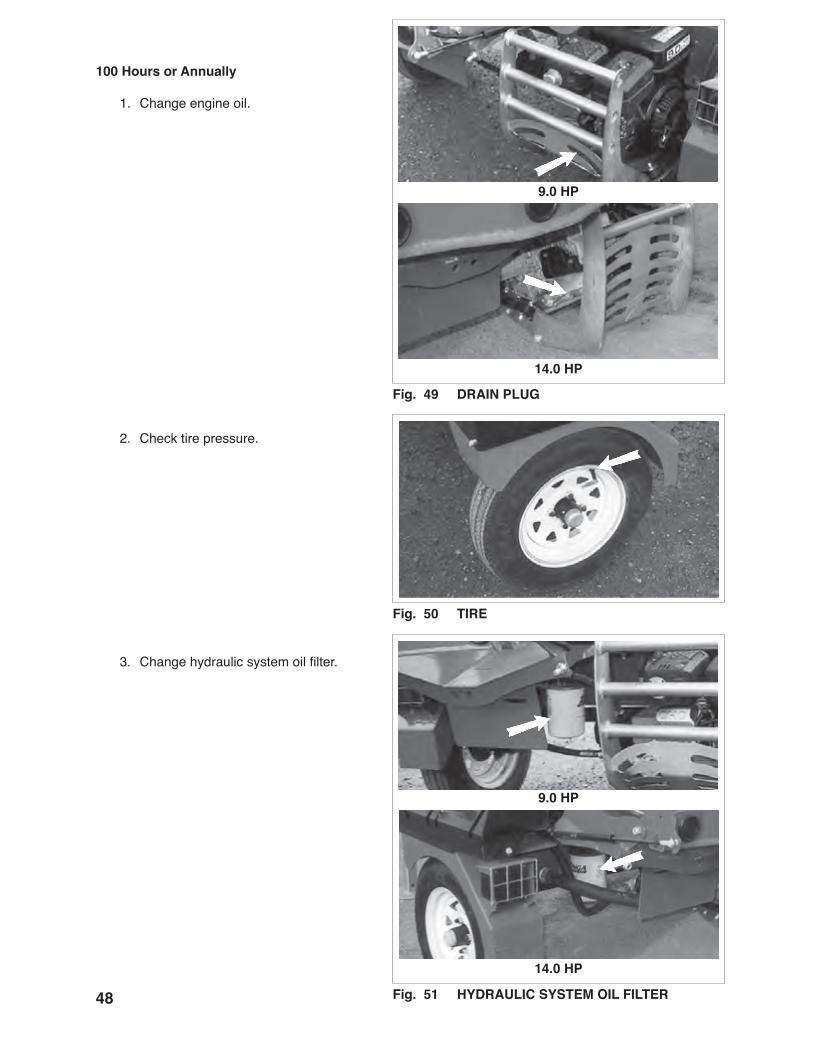
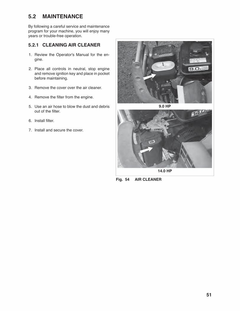
�.�.3 SERVICING INTERVALS
The period recommended is based on normal operating conditions. Severe or unusual cond-tions may require more frequent servicing.
� Hours or Daily
1. Check engine oil level.
2. Check fuel level.
�0 Hours or Weekly
1. Check oil level in hydraulic reservoir.
2. Check engine air cleaner.
Fig. �� ENGINE
Fig. �� HYDRAULIC OIL LEVEL (Typical)
Fig. �� AIR CLEANER
��.0 HP
9.0 HP
��.0 HP
9.0 HP
��
�00 Hours or Annually
1. Change engine oil.
2. Check tire pressure.
3. Change hydraulic system oil filter.
Fig. �9 DRAIN PLUG
Fig. �0 TIRE
Fig. �� HYDRAULIC SYSTEM OIL FILTER
��.0 HP
9.0 HP
��.0 HP
9.0 HP

�9
4. Replace engine air cleaner.
5. Clean machine.
Fig. �� AIR CLEANER
Fig. �3 MACHINE
��.0 HP
9.0 HP

�0
�.�.� SERVICE RECORD
See Lubrication and Maintenance sections for details of service. Copy this page to continue record.
ACTION CODE G GREASE CL CLEAN R REPLACE CK CHECK CH CHANGE
HOURS
SERVICED BY MAINTENANCE
� Hours or Daily CK Engine Oil Level CK Fuel Level
�0 Hours or Weekly CK Hydraulic Oil Level CK Engine Air Cleaner
Annually CH Engine Oil CK Tire Pressure CH Hydraulic Oil Filter R Engine Air Cleaner CL Machine
��
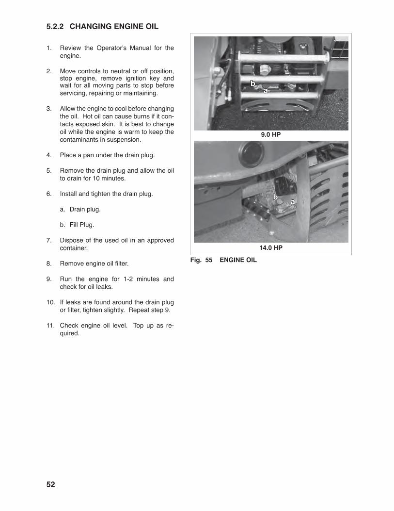
�.� MAINTENANCEBy following a careful service and maintenance program for your machine, you will enjoy many years or trouble-free operation.
�.�.� CLEANING AIR CLEANER
1. Review the Operator's Manual for the en-gine.
2. Place all controls in neutral, stop engine and remove ignition key and place in pocket before maintaining.
3. Remove the cover over the air cleaner.
4. Remove the filter from the engine.
5. Use an air hose to blow the dust and debris out of the filter.
6. Install filter.
7. Install and secure the cover.
Fig. �� AIR CLEANER
��.0 HP
9.0 HP
��
�.�.� CHANGING ENGINE OIL
1. Review the Operator's Manual for the engine.
2. Move controls to neutral or off position, stop engine, remove ignition key and wait for all moving parts to stop before servicing, repairing or maintaining.
3. Allow the engine to cool before changing the oil. Hot oil can cause burns if it con-tacts exposed skin. It is best to change oil while the engine is warm to keep the contaminants in suspension.
4. Place a pan under the drain plug.
5. Remove the drain plug and allow the oil to drain for 10 minutes.
6. Install and tighten the drain plug.
a. Drain plug.
b. Fill Plug.
7. Dispose of the used oil in an approved container.
8. Remove engine oil filter.
9. Run the engine for 1-2 minutes and check for oil leaks.
10. If leaks are found around the drain plug or filter, tighten slightly. Repeat step 9.
11. Check engine oil level. Top up as re-quired.
Fig. �� ENGINE OIL
ab
��.0 HP
9.0 HP
ab

�3
�.�.3 HYDRAULIC SYSTEM OIL FILTER & OIL CHANGE
1. Review the Operator's Manual for the Wood Processor.
2. Move controls to neutral or off position, stop engine, remove ignition key and wait for all moving parts to stop before servic-ing, repairing or maintaining.
3. Allow the machine to cool before changing the oil. Hot oil can cause burns if it con-tacts exposed skin. It is best to change oil while the machine is warm to keep the con-taminants in suspension.
4. Place a pan under the filter head.
5. Remove bottom hose and strainer to drain oil.
6. Remove hydraulic oil filter.
7. Apply a light coat of oil to the O ring and install the replacement filter. Snug up by hand and then tighten 1/2 turn.
8. Install and secure bottom hose and strain-er.
9. Fill the reservoir with the specified oil.
10. Run the machine for 1-2 minutes while op-erating cylinder and check filter head for oil leaks.
11. If leaks are found around the filter, tighten slightly. Repeat step 8.
12. Check hydraulic reservoir oil level. Top up as required.
13. Dispose of the spilled oil in an approved container.
Fig. �� HYDRAULIC SYSTEM FILTER
9.0 HP
��.0 HP

��
PROBLEM CAUSE SOLUTION
Cylinder does not move. No pressurized oil. Hydraulic oil filter plugged. Change filter.
Wood jammed around wedge. Remove wood.
Cylinder jumps. Wedge frame jamming. Do not split logs with large knots.
Winch does not move. Cable jammed. Pull cable out and guide cable when retracting.
Winch drive locked. Release winch lock.
� TROUBLE SHOOTINGThe Wallenstein Wood Processor uses a hydraulically powered winch to pull logs up a chute into a cutting area. When the chain saw cuts the log, the short piece rolls into the splitting chamber where a hydraulic cylinder pushed it through the splitting wedge. It is a simple and reliable system that requires minimal maintenance.
In the following section, we have listed many of the problems, causes and solutions to the problems that you may encounter.
If you encounter a problem that is difficult to solve, even after having read through this trouble shooting sec-tion, please call your local distributor or dealer. Before you call, please have this Operator's Manual from your unit and serial number ready.

��
� SPECIFICATIONS
�.� MECHANICAL
SPECIFICATIONS SUBJECT TO CHANGE WITHOUT NOTICE
�� HP Subaru Engine 9 HP Subaru Engine 22 GPM, 2 Stage 16 GPM, 2 Stage 4.5"/24" Cylinder Diameter/Stroke 4.5"/24" Cylinder Diameter/Stroke Auto Cycle Valving Auto Cycle Valving 7 Second Full Stroke 11 Second Full Stroke Splitting Cycle Time Splitting Cycle Time 25 Ton Splitting Force 25 Ton Splitting Force 24" Max. Split Length 24" Max. Split Length 22" Max. Log Diameter 22" Max. Log Diameter Adjustable 4-Way Adjustable 4-Way Wedge Configuraton Wedge Configuraton Torflex® Suspension Torflex® Suspension 5.30 x 12 Tire Size 5.30 x 12 Tire Size 2" Ball Coupler & Highway Lights 2" Ball Coupler & Highway Lights Weight 1855 lbs. Weight 1825 lbs (LxWxH) 120" x 62" x 72" (LxWxH) 120" x 62" x 72" Hydraulic, Valve Operated Winch Hydraulic, Valve Operated Winch 50' Winch Cable Length 50' Winch Cable Length 1550 lbs. Winch Pulling Force 1550 lbs. Winch Pulling Force 44" Max. Discharge Chute Height 44" Max. Discharge Chute Height
��
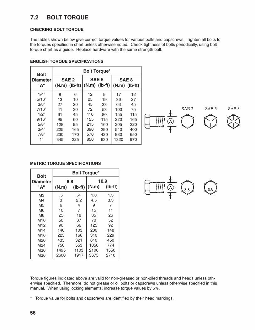
�.� BOLT TORQUE
CHECKING BOLT TORQUE
The tables shown below give correct torque values for various bolts and capscrews. Tighten all bolts to the torques specified in chart unless otherwise noted. Check tightness of bolts periodically, using bolt torque chart as a guide. Replace hardware with the same strength bolt.
ENGLISH TORQUE SPECIFICATIONS
METRIC TORQUE SPECIFICATIONS
SAE �(N.m) (lb-ft)
Bolt Torque*Bolt
Diameter"A"
SAE �(N.m) (lb-ft)
SAE �(N.m) (lb-ft)
1/4"5/16"3/8"7/16"1/2"9/16"5/8"3/4"7/8"1"
81327416195128225230345
6102030456095165170225
12254572110155215390570850
919335380115160290420630
1736631001552203055408801320
12274575115165220400650970
�.�(N.m) (lb-ft)
Bolt Torque*Bolt
Diameter"A"
�0.9(N.m) (lb-ft)
M3M4M5M6M8M10M12M14M16M20M24M30M36
.5361025509014022543575014952600
.42.24718376610316632155311031917
1.84.59153570125200310610105021003675
1.33.371126529214822945077415502710
Torque figures indicated above are valid for non-greased or non-oiled threads and heads unless oth-erwise specified. Therefore, do not grease or oil bolts or capscrews unless otherwise specified in this manual. When using locking elements, increase torque values by 5%.
* Torque value for bolts and capscrews are identified by their head markings.

��
� INDEX
PAGE PAGES
Safety ..............................................................2 Battery Safety .............................................9 Equipment Safety Guidelines .....................4 Gas Motor Safety......................................10 General Safety ...........................................3 Maintenance Safety ....................................6 Operating Safety.........................................7 Preparation .................................................6 Refueling Safety .........................................9 Safety Signs ...............................................5 Safety Training............................................5 Sign-Off Form ...........................................11 Storage Safety ............................................8 Tire Safety ..................................................9 Transport Safety .........................................8Safety Sign Locations ....................................12Specifications ................................................55 Bolt Torque ...............................................56 Mechanical ...............................................55
T
Trouble Shooting ...........................................54
I
Index ..............................................................57Introduction ......................................................1
O
Operation .......................................................14 Attaching/Unhooking.................................23 Controls ....................................................17 Field Operation .........................................30 Machine Break-In .....................................16 Machine Components...............................15 Machine Set Up ........................................25 Pre-Operation Checklist ...........................16 Storage .....................................................45 To the New Operator or Owner .................14 Transporting..............................................44

WALLENSTEIN
4144 BOOMER LINEST. CLEMENTS, ONN0B 2M0 CANADAPH: (519) 699-9283FAX: (519) 699-4146
PRINTED IN CANADAAPRIL 2010 PART NUMBER: Z97040