smart as a cryptographic processor
TRANSCRIPT
Kettering University Kettering University
Digital Commons @ Kettering University Digital Commons @ Kettering University
Electrical & Computer Engineering Presentations And Conference Materials
Electrical & Computer Engineering
5-2016
SMaRT as a Cryptographic Processor SMaRT as a Cryptographic Processor
Saroja Kanchi
Nozar Tabrizi
Cody Hayden
Follow this and additional works at: https://digitalcommons.kettering.edu/
electricalcomp_eng_conference
Part of the Electrical and Computer Engineering Commons
Jan Zizka et al. (Eds) : CCSEIT, AIAP, DMDB, MoWiN, CoSIT, CRIS, SIGL, ICBB, CNSA-2016
pp. 01–11, 2016. © CS & IT-CSCP 2016 DOI : 10.5121/csit.2016.60601
SMART AS A CRYPTOGRAPHIC PROCESSOR
Saroja Kanchi1, Nozar Tabrizi
2 and Cody Hayden
3
1Department of Computer Science, Kettering University, Flint, USA
[email protected] 2Department of Electrical and Computer Engineering, Flint, USA
[email protected] 3Department of Computer Science, Kettering University, Flint, USA
ABSTRACT
SMaRT is a 16-bit 2.5-address RISC-type single-cycle processor, which was recently designed
and successfully mapped into a FPGA chip in our ECE department. In this paper, we use
SMaRT to run the well-known encryption algorithm, Data Encryption Standard. For
information security purposes, encryption is a must in today’s sophisticated and ever-increasing
computer communications such as ATM machines and SIM cards. For comparison and
evaluation purposes, we also map the same algorithm on the HC12, a same-size but CISC-type
off-the-shelf microcontroller, Our results show that compared to HC12, SMaRT code is only
14% longer in terms of the static number of instructions but about 10 times faster in terms of the
number of clock cycles, and 7% smaller in terms of code size. Our results also show that 2.5-
address instructions, a SMaRT selling point, amount to 45% of the whole R-type instructions
resulting in significant improvement in static number of instructions hence code size as well as
performance. Additionally, we see that the SMaRT short-branch range is sufficiently wide in
90% of cases in the SMaRT code. Our results also reveal that the SMaRT novel concept of
locality of reference in using the MSBs of the registers in non-subroutine branch instructions
stays valid with a remarkable hit rate of 95%!
KEYWORDS
CISC and RISC comparison; Communication Security; Cryptography; Data Encryption
Standard; Microprocessors; SMaRT
1. INTRODUCTION
Sixteen-bit microcontrollers are widely used in a variety of embedded systems such as power
tools, medical instruments, toys, office products, automotive industry, remote controls and
appliances [1]. Texas Instruments manufactures the popular family of MSP430 [2]. Microchip
produces the well-known PIC24 MCUs and dsPIC® DSCs [3] . The S12XE family of automotive
and industrial microcontrollers, as another example of 16-bit modern processors, is manufactured
by NXP. For the list of 16-bit microcontrollers from NXP see [4].
In addition to industry, sixteen-bit microcomputers are commonly used in academia as well.
There are numerous textbooks such as [5][6][7] based on 16-bit microcontrollers on the market.
2 Computer Science & Information Technology (CS & IT)
Additionally, 16-bit microcontroller-based education/training boards such as HCS12-based
Dragon12Plus [8], and the PIC24-based Explorer 16 [9] are popular in academia.
Sixteen-bit microprocessors are not only a research topic [10][11][12][13], they are also used by
researchers as a research tool. Tang et al use the Microchip PIC18F4520 to design an embedded
controller for a portable fuel cell [14]. A 16-bit dsPIC is used in [15] for motion control of a
mobile robot.
SMaRT is a Small Machine for Research and Teaching, which was recently designed and
mapped into an Altera Cyclone II FPGA chip in our ECE department as reported in [16]. It is a
16-bit RISC-type single-cycle architecture with 16-bit long instructions. Unlike some 16-bit
processors, SMaRT instruction-memory address-bus is 16 bits wide as well. This results in a
better code density. Featuring the novel 2.5-address instructions, SMaRT can avoid data loss that
inherently exists in 2-address machines. Additionally and as elaborated in [16], SMaRT’s short
branch instructions take advantage of the temporal locality of reference in accessing the upper or
lower halves of the CPU’s 16x16 orthogonal register file. This enables SMaRT to extend the
range of the short branch instructions by a factor of 4. SMaRT is reviewed in Section 2.
In this paper we use SMaRT as a cryptographic processor. The advent of world-wide
communication over the network makes cryptography essential to provide data transmission with
security. Data encryption has been used for a long time. Security requirements may vary
depending on the type of application and performance standards in terms of level of privacy,
time, and power consumption leading to various encryption algorithms.
One of the most popular cryptographic algorithms is the Data Encryption Standard (DES) that
converts plaintext to cipher text. The DES algorithm was standardized in 1977 by NIST. DES is
the best symmetric cipher and is used in ATM machines and SIM cards. DES was replaced with
Advanced Encryption Standard (AES) in 2000. It will be years before Advanced Encryption
Standard (AES) can replace DES usage [17].
DES is based on a sequence of confusion and diffusion steps. The confusion step obscures the
relationship between plaintext and cipher text and diffusion step ensures that a small change in
plaintext causes significant changes in the cipher text. In this paper we map DES to the SMaRT
processor.
An FPGA implementation of DES using pipelining, logic replication and register retiming is
presented in [18]. A single-chip implementation of an iterative DES algorithm on a FPGA
platform using 224 combinational logic blocks (CLBs) and 54 input/output blocks (IOBs) is
presented in [19]. Patterson [20] presented a FPGA implementation of DES using Java API bit
stream support for computing the key schedule entirely using software resulting in a throughput
of 10 Gigabits per second. Another FPGA-based implementation of DES is presented in [21]. In
this non-software-based design a 16-stage pipelined architecture is used to get the fastest DES
implementation on a FPGA. In [22], Kaps et al use loop unrolling as well as pipelining to
enhance their FPGA-based DES performance. An implementation of the DES algorithm using
hardware loops and their variations can be seen in [23]. Standaert F.-X. et al present another
FPGA-based implementation for DES and triple DES in [24]. They show that modern FPGAs
provide sufficient resources to implement masked DES, hence improve security against power
analysis attacks.

Computer Science & Information Technology (CS & IT) 3
The rest of the paper is organized as follows: Overviews of SMaRT and Data Encryption
Standard Algorithm (DES) are presented in Section 2. In Section 3 we map the above algorithm
on SMaRT. We discuss our results in Section 4. Section 5 is the conclusion.
2. OVERVIEW
In this section, we first look at the SMaRT and then review the data encryption standard
algorithm.
2.1. SMaRT
SMaRT has a 16x16 register file: R0 through R15. There are four different instruction formats in
this machine, namely R, LSI, B and BL, as shown in Figure 1. Each SMaRT instruction is 16 bits
wide (same as the data-bus width) with an exception of baleq and balne, which are 2 words long.
Each one-word instruction and two-word instruction executes in one cycle and two cycles,
respectively. The OpCode is always 3 bits wide and occupies bits 12 through 14 of each
instruction.
Figure 1. SMaRT instruction formats
The R-type instructions share the same OpCode; the Function field (bits 0 through 3)
distinguishes between two such instructions. See Figure 1.
An R-type instruction may function as a 2-address or 2.5-address instruction based on the value
of cdr bit, the MSB of the instruction. In a 2.5-address instruction, the operation result is stored in
the register located right after the first operand register ruling out the data loss that exists in 2-
address instructions. For example, while register R2 is overwritten hence lost in the following 2-
address instruction
sub R2, R6
none of the source registers will be overwritten in the following 2.5-address instruction:
sub R2+, R6
Note that in the first instruction, R2 becomes R6 – R2; however, in the second instruction R3
becomes R6 – R2.
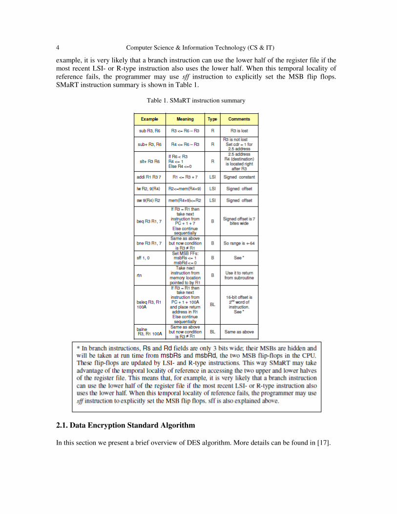
In branch instructions, Rs and Rd fields are only 3 bits wide; their MSBs are hidden and will be
taken at run time from msbRs and msbRd, two flip-flops in the CPU. These flip-flops are updated
by LSI- and R-type instructions. This way SMaRT may take advantage of the temporal locality of
reference in accessing the two upper and lower halves of the register file. This means that, for
4 Computer Science & Information Technology (CS & IT)
example, it is very likely that a branch instruction can use the lower half of the register file if the
most recent LSI- or R-type instruction also uses the lower half. When this temporal locality of
reference fails, the programmer may use sff instruction to explicitly set the MSB flip flops.
SMaRT instruction summary is shown in Table 1.
Table 1. SMaRT instruction summary
2.1. Data Encryption Standard Algorithm
In this section we present a brief overview of DES algorithm. More details can be found in [17].
Computer Science & Information Technology (CS & IT) 5
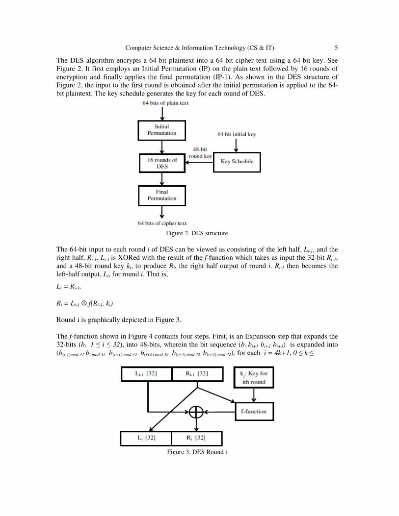
The DES algorithm encrypts a 64-bit plaintext into a 64-bit cipher text using a 64-bit key. See
Figure 2. It first employs an Initial Permutation (IP) on the plain text followed by 16 rounds of
encryption and finally applies the final permutation (IP-1). As shown in the DES structure of
Figure 2, the input to the first round is obtained after the initial permutation is applied to the 64-
bit plaintext. The key schedule generates the key for each round of DES.
Figure 2. DES structure
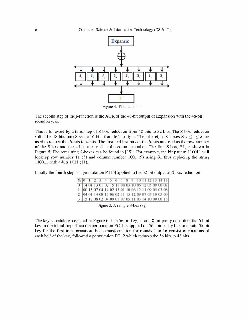
The 64-bit input to each round i of DES can be viewed as consisting of the left half, Li-1, and the
right half, Ri-1. Li-1 is XORed with the result of the f-function which takes as input the 32-bit Ri-1,
and a 48-bit round key ki, to produce Ri, the right half output of round i. Ri-1 then becomes the
left-half output, Li, for round i. That is,
Li = Ri-1,
Ri = Li-1 ⊕ f(Ri-1, ki)
Round i is graphically depicted in Figure 3.
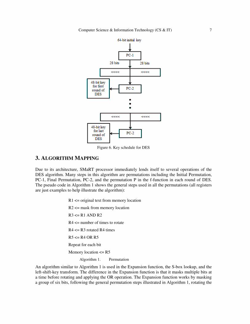
The f-function shown in Figure 4 contains four steps. First, is an Expansion step that expands the
32-bits (bi 1 ≤ i ≤ 32), into 48-bits, wherein the bit sequence (bi bi+1 bi+2 bi+3) is expanded into
(b(i-1)mod 32 bi mod 32 b(i+1) mod 32 b(i+2) mod 32 b(i+3) mod 32 b(i+4) mod 32), for each i = 4k+1, 0 ≤ k ≤
Figure 3. DES Round i
6 Computer Science & Information Technology (CS & IT)
Figure 4. The f-function
The second step of the f-function is the XOR of the 48-bit output of Expansion with the 48-bit
round key, ki.
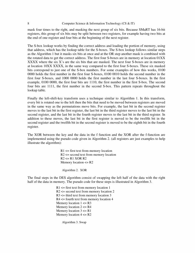
This is followed by a third step of S-box reduction from 48-bits to 32-bits. The S-box reduction
splits the 48 bits into 8 sets of 6-bits from left to right. Then the eight S-boxes Si,1 ≤ i ≤ 8 are
used to reduce the 6-bits to 4-bits. The first and last bits of the 6-bits are used as the row number
of the S-box and the 4-bits are used as the column number. The first S-box, S1, is shown in
Figure 5. The remaining S-boxes can be found in [15]. For example, the bit pattern 110011 will
look up row number 11 (3) and column number 1001 (9) using S1 thus replacing the string
110011 with 4-bits 1011 (11).
Finally the fourth step is a permutation P [15] applied to the 32-bit output of S-box reduction.
Figure 5. A sample S-box (S1)
The key schedule is depicted in Figure 6. The 56-bit key, k, and 8-bit parity constitute the 64-bit
key in the initial step. Then the permutation PC-1 is applied on 56 non-parity bits to obtain 56-bit
key for the first transformation. Each transformation for rounds 1 to 16 consist of rotations of
each half of the key, followed a permutation PC- 2 which reduces the 56 bits to 48 bits.
Computer Science & Information Technology (CS & IT) 7
Figure 6. Key schedule for DES
3. ALGORITHM MAPPING
Due to its architecture, SMaRT processor immediately lends itself to several operations of the
DES algorithm. Many steps in this algorithm are permutations including the Initial Permutation,
PC-1, Final Permutation, PC-2, and the permutation P in the f-function in each round of DES.
The pseudo code in Algorithm 1 shows the general steps used in all the permutations (all registers
are just examples to help illustrate the algorithm):
R1 <= original text from memory location
R2 <= mask from memory location
R3 <= R1 AND R2
R4 <= number of times to rotate
R4 <= R3 rotated R4 times
R5 <= R4 OR R5
Repeat for each bit
Memory location <= R5
Algorithm 1. Permutation
An algorithm similar to Algorithm 1 is used in the Expansion function, the S-box lookup, and the
left-shift-key transform. The difference in the Expansion function is that it masks multiple bits at
a time before rotating and applying the OR operation. The Expansion function works by masking
a group of six bits, following the general permutation steps illustrated in Algorithm 1, rotating the
8 Computer Science & Information Technology (CS & IT)
mask four times to the right, and masking the next group of six bits. Because SMaRT has 16-bit
registers, this group of six bits may be split between two registers, for example having two bits at
the end of one register and four bits at the beginning of the next register.
The S-box lookup works by finding the correct address and loading the portion of memory, using
that address, which has the lookup table for the S-boxes. The S-box lookup follows similar steps
as the Algorithm 1 but it masks six bits at once and at the OR step another mask is combined with
the rotated data to get the correct address. The first four S-boxes are in memory at location 01XX
XXXX where the six X’s are the six bits that are masked. The next four S-boxes are in memory
at location 10XX XXXX, in the same way compared to the first four S-boxes. These six masked
bits correspond to just one of the S-box numbers. For some examples of how this works, 0100
0000 holds the first number in the first four S-boxes, 0100 0010 holds the second number in the
first four S-boxes, and 1000 0000 holds the first number in the last four S-boxes. In the first
example, 0100 0000, the first four bits are 1110, the first number in the first S-box. The second
four bits are 1111, the first number in the second S-box. This pattern repeats throughout the
lookup table.
Finally the left-shift-key transform uses a technique similar to Algorithm 1. In this transform,
every bit is rotated one to the left then the bits that need to be moved between registers are moved
in the same way as the permutations move bits. For example, the last bit in the second register
moves to the last bit in the first register, the last bit in the third register moves to the last bit in the
second register, and the last bit in the fourth register moves to the last bit in the third register. In
addition to these moves, the last bit in the first register is moved to be the twelfth bit in the
second register and the twelfth bit in the second register is moved to be the eighth bit in the fourth
register.
The XOR between the key and the data in the f function and the XOR after the f-function are
implemented using the pseudo code given in Algorithm 2. (all registers are just examples to help
illustrate the algorithm):
R1 <= first text from memory location
R2 <= second text from memory location
R2 <= R1 XOR R2
Memory location <= R2
Algorithm 2. XOR
The final steps in the DES algorithm consist of swapping the left half of the data with the right
half of the data in memory. The pseudo code for these steps is illustrated in Algorithm 3.
R1 <= first text from memory location 1
R2 <= second text from memory location 2
R3 <= third text from memory location 3
R4 <= fourth text from memory location 4
Memory location 1 <= R3
Memory location 2 <= R4
Memory location 3 <= R1
Memory location 4 <= R2
Algorithm 3. Swap
Computer Science & Information Technology (CS & IT) 9
4. RESULTS
Our studies in this research showed how remarkably SMaRT’s features might help improve a
SMaRT-based embedded system. We manually mapped the well-known Data Encryption
Standard Algorithm on SMaRT. We also mapped the same algorithm on the HC12, an off-the-
shelf microcontroller, but using a C compiler [25]. Our results showed that compared to the
HC12, SMaRT code is only 14% longer in terms of the static number of instructions but some 10
times faster in terms of the number of clock cycles, and 7% smaller in terms of code size. 14%
increase in the static code size is a very reasonable price for such a remarkable improvement. The
significant difference between the numbers of clock cycles of the two processors is in part due to
their architectural difference: SMaRT is a single-cycle RISC machine while HC12 is a CISC one
with multi-cycle instructions. We then looked at the selling points of SMaRT and noticed some
encouraging results: 278 R-type instructions out of 535, i.e. over 50%, are in the 2.5-address
mode. Considering the total number of SMaRT instructions, this means that some 24% of the
whole code takes advantage of this feature. We should have used some 278 more instructions if
SMaRT had not had this novel feature. Our results also showed a hit-rate of 95% when the MSBs
of the registers in non-subroutine branch instructions are taken from the most recently used LSI
or R-type instruction. We also noticed that 11 SMaRT branch instructions out of 13 non-
subroutine-call branches (in total) are short. In terms of dynamic number of branch instructions,
this means that in 90% of times the SMaRT short branch instruction has a sufficient range.
5. CONCLUSION
In this paper we used SMaRT as a cryptographic processor. We mapped the Data Encryption
Standard on SMaRT and showed that SMaRT’s 2.5-address instructions comprise over 50% of
the whole R-type instructions. This demonstrates how useful SMaRT’s 2.5-address mode is. We
also showed that for the register fields of SMaRT’s non-subroutine branch instructions 3 bits are
usually sufficient; the fourth bits are correctly taken from two flip-flops in the CPU at run time.
These flip-flops are updated by LSI- and R-type instructions. We also showed that SMaRT’s
short branch instructions range is usually sufficient to reach the jump addresses. We additionally
mapped DES on HC12 using the C language, and noticed that although SMaRT code is only 14%
longer in terms of the static number of instructions, number of clock cycles for SMaRT is much
lower than what HC12 needs.
REFERENCES [1] https://www.futureelectronics.com/en/Microcontrollers/16-bit-microcontroller.aspx
FUTURE ELECTRONICS 16bit Microcontrollers
[2] http://www.ti.com/lit/ug/slau144j/slau144j.pdf MSP430x2xx Family User's Guide
[3] http://ww1.microchip.com/downloads/en/DeviceDoc/70157F.pdf
Microchip 16-bit MCU and DSC Programmer’s Reference Manual
[4] http://www.nxp.com/products/microcontrollers-and-processors/more-processors/NXP 8/16 bit MCUs
[5] Cady Fredrick M. Software and Hardware Engineering: Assembly and C Programming for the
Freescale HCS12 Microcontroller, 2nd Edition. ISBN: 0195308263
[6] Reese Robert B. et al. Microcontrollers: From Assembly Language to C Using the PIC24 Family, 2nd
Edition. ISBN: 1305076559
10 Computer Science & Information Technology (CS & IT)
[7] Almy Tom. Designing with Microcontrollers -- The 68HCS12. ISBN: 1463738501
[8] http://www.evbplus.com/download_hcs12/dragon12_plus_usb_9s12_manual.pdf
Dragon12-Plus-USB Trainer for Freescale HCS12 microcontroller family; User’s Manual for Rev. G
board Revision 1.10
[9] http://ww1.microchip.com/downloads/en/DeviceDoc/Explorer%2016%20User%20Guide%
2051589a.pdf Microchip Explorer 16 Development Board User’s Guide
[10] Gheorghe, A.-S. et al. 2010. Savage16 - 16-bit RISC architecture general purpose microprocessor,
Intl Semiconductor Conf., CAS, Oct 2010, pp 521-524, Sinaia
[11] Morales-Velazquez et al. 2012. FPGA embedded single-cycle 16-bit microprocessor and tools, IEEE
Intl Conf. on Reconfigurable Computing and FPGAs, pp 1-6, Cancun
[12] Muslim, S.M.S. et al. 2007. Design of an Algorithmic State Machine Controlled, Field Programmable
Gate Array Based 16-bit Microprocessor, Intl Symposium on Integrated Circuits, ISIC '07, Sep. 2007,
pp 434-436 Singapore
[13] Sakthikumaran S. et al. 2011. 16-Bit RISC Processor Design for Convolution Application. Intl Conf.
on Recent Trends in Information Technology, ICRTIT, pp.394-397, Chennai
[14] Tang Tzu-Chiang et al. 2013. Embedded controller design for portable fuel cell, 9th Intl Conf. on
Information, Communications and Signal Processing, ICICS 2013, pp 1-3, Tainan
[15] Suwannakom, A. 2014. Adaptive control performance of a mobile robot using hybrid of SLAM and
fuzzy logic control in indoor environment, Intl Electrical Engineering Congress, March 2014, pp 1-4,
Chonburi
[16] Tabrizi, N. 2016. SMaRT: Small Machine for Research and Teaching, International Journal of
Electronics and Electrical Engineering (in press).
[17] Paar et al. 2010. Understanding Cryptography. Springer Publications
[18] Raed Bani-Hani1et al. 2014. “High-Throughput and Area-Efficient FPGA Implementations of Data
Encryption Standard (DES)”, Circuits and Systems, 2014, 5, 45-56.
[19] Wong K. et al. 1998. A Single-Chip FPGA Implementation of the Data Encryption Standard (DES)
Algorithm, IEEE Global Telecommunications Conference on the Bridge to Global Integration, 8-12
November, 1998, Sydney, 827-832.
[20] Patterson C. 2000. High Performance DES Encryption in Virtex FPGAs using JBits. Proceedings of
the 2000 IEEE Symposium on Field-Programmable Custom Computing Machines, Napa Valley, 17-
19 April 2000, 113-121.
[21] McLoone M. et al. 2000. High-performance FPGA Implementation of DES. IEEE Workshop on
Signal Processing Systems, Lafayette, 11-13 October 2000, 374-383.
[22] Kaps J.-P. et al. 1998. Fast DES Implementations for FPGAs and Its Application to a Universal Key-
Search Machine. Selected Areas in Cryptography, Lecture Notes in Computer Science, 1556, 234-247
[23] Trimberger S. et al. 2000. A 12 Gbps DES Encryptor/Decryptor Core in an FPGA. Proceedings of the
2nd International Workshop on Cryptographic Hardware and Embedded Systems, Worcester, 17-18
August 2000, 156-163.

Computer Science & Information Technology (CS & IT) 11
[24] Standaert F.-X., Rouvroy, G. and Quisquater, J.-J. (2006) FPGA Implementations of the DES and
Triple-Des Masked Against Power Analysis Attacks. International Conference on Field
Programmable Logic and Applications, 28-30 August 2006, Madrid, 1-4.
[25] ANSI-C/cC++ Compiler for HC12 V-5.0.41 Build 10203, Jul 23, 2010