wetting by liquid sodium and fracture path analysis of sodium
TRANSCRIPT
HAL Id: hal-02162257https://hal.archives-ouvertes.fr/hal-02162257
Submitted on 21 Jun 2019
HAL is a multi-disciplinary open accessarchive for the deposit and dissemination of sci-entific research documents, whether they are pub-lished or not. The documents may come fromteaching and research institutions in France orabroad, or from public or private research centers.
L’archive ouverte pluridisciplinaire HAL, estdestinée au dépôt et à la diffusion de documentsscientifiques de niveau recherche, publiés ou non,émanant des établissements d’enseignement et derecherche français ou étrangers, des laboratoirespublics ou privés.
Wetting by liquid sodium and fracture path analysis ofsodium induced embrittlement of 304L stainless steel
Bassem Barkia, Thierry Auger, Jean Louis Courouau, Julie Bourgon
To cite this version:Bassem Barkia, Thierry Auger, Jean Louis Courouau, Julie Bourgon. Wetting by liquid sodium andfracture path analysis of sodium induced embrittlement of 304L stainless steel. Journal of MaterialsResearch, Cambridge University Press (CUP), 2018, 33 (2), pp.121-129. �10.1557/jmr.2017.435�. �hal-02162257�
Wetting by liquid sodium and fracture path analysis of sodiuminduced embrittlement of 304L stainless steel
Bassem BarkiaLaboratoire de Mécanique des Sols, Structures et Matériaux, CentraleSupélec, UMR CNRS 8579, Université Paris-Saclay, Chatenay-Malabry 92295, France
Thierry Augera)
Laboratoire de Mécanique des Sols, Structures et Matériaux, CentraleSupélec, UMR CNRS 8579, Université Paris-Saclay, Chatenay-Malabry 92295, France; and Laboratoire PIMM, ENSAM–CNRS–CNAM, UMR CNRS 8006,Paris 75013, France
Jean-Louis CourouauDen-Service de La Corrosion et du Comportement des Matériaux dans Leur Environnement (SCCME), CEA-Saclay, Université Paris-Saclay, Gif-sur-Yvette F-91191, France
Julie BourgonInstitut de Chimie et des Matériaux Paris-Est, UMR 7182, CNRS/UPEC, Thiais 94320, France
The wettability of the 304L steel is an important parameter in Liquid Metal Embrittlement studies.Empirically, it is found to be greatly enhanced by pre-exposure to oxygenated liquid sodium.The corrosion interface formed during exposure to sodium has been analyzed at the nanoscale bytransmission electron microscopy using the focused ion beam sampling. A thin layer of sodiumchromite (NaxCrO2 with x # 1) is detected at the interface validating wetting on an oxidemechanism for the enhanced wetting after pre-exposure. Fracture micromechanisms and the crackpath of liquid sodium-embrittled austenitic steel 304L at 573 K have been investigated down tothe nanoscale. High-resolution orientation mapping analyses immediately below the fracturesurface show that abundant martensitic transformations (c ! a) and twinning occur duringdeformation of austenite. The preferential crack path is intergranular along the newly formed c/cinterfaces. It is concluded that these transformations play a major role in the fracture process.
I. INTRODUCTION
Liquid Metal Embrittlement (LME) is a special type ofenvironmental effect where an otherwise ductile materialhas a brittle fracture mode when mechanically testedwhile in contact with a liquid metal. LME of austeniticsteels by liquid sodium (Na) is of relevance for sodium-cooled nuclear power plants or solar thermal power plantsusing intermediate heat transfer sodium loops. It istherefore a subject of importance related to the structuralsafety of such structures and it is highly desirable toassess the potential sensitivity to LME. The recentoutcome of LME research shows that to obtain a correctsensitivity assessment, great care must be taken to defineproper testing conditions that take into account thephysico-chemistry of the solid–liquid interface1 andensure good surface’s wettability.2 By correct assess-ment, one implies reproducible results in mechanicalproperties as well as a quantification of the maximum
possible mechanical degradation. Nonobservance of theseconditions, particularly the requirement of prewetting,potentially leads to a spread in the degree of measuredembrittlement and at the extreme wrong null-results. Therequirement of good wetting is crucial in particular toenable the supply of liquid at the crack tip during crackpropagation (provided that the systems have a brittlecrack initiation).The earlier analysis of the interaction of austenitic
steels with sodium3 indicated that a high content ofdissolved oxygen favors the formation of a NaCrO2 scalein replacement of the passive chromium oxide thatnatively forms in air. These exposure conditions wereobserved to trigger a transition from nonwetting of liquidsodium on the steel’s surface to total wetting by liquidsodium of the corroded layer.4 Consequently, in a priorwork of ours,5 pre-exposure to oxygenated sodium at thelevel of 200 lg/g was used to promote wetting of the304L steel by sodium. Alkali liquid metals such assodium are particularly demanding in terms of experi-mental facilities due to their strong reactivity withdi-oxygen and water vapor. The corrosion behaviordepends largely upon the content of dissolved impurities(oxygen, hydrogen, nitrogen, or carbon). Therefore,
Contributing Editor: Jürgen Eckerta)Address all correspondence to this author.
a facility with a controlled impurity level allowinghandling of sodium in satisfactory conditions was usedthat simplifies all operations required for preparation ofthe testing and handling of the liquid metal.6
In addition, specific operating procedure and purifica-tion step were developed to ensure efficient control of thedissolved oxygen in the liquid sodium to a definite level.The issue of contamination during handling is particu-larly acute with alkali metals and requires glove boxeswith a content of water and oxygen controlled to remaincontinuously below a level of 1 wppm. A similar facilityfor mechanical testing has been developed in parallelwith transfer under cover gas ability.5 While handlingand manipulations require high purity, it can be beneficialto re-introduce oxygen at a controlled level in sodiumprocesses. Indeed, by applying pre-exposure in oxygen-ated sodium at a controlled level, a drastic change in thewettability of the 304L steel by sodium was observed asexpected by prior know-how.4 The formation of NaCrO2,supposedly responsible for the observed wettabilitychange, was only inferred from the thermodynamicalanalysis of our pre-exposure conditions (X-ray diffractionanalysis did not convincingly detect this oxide even witha small angle configuration). We report here a dedicatedanalysis of the interface evolution particularly by trans-mission electron microscopy (TEM) on the focused ionbeam (FIB)-extracted lamella. One of the aims of thisstudy is to provide firm ground for the pre-exposurewetting on an oxide scenario that was proposed earlier.5
The pre-exposure conditions for the wetting transitionwere also the conditions in which a reproducible onset ofbrittle cracking of 304L steel was observed when testedin contact with liquid sodium at a low strain rate in thetemperature range 573–673 K.5 This case of liquidsodium embrittlement of austenitic stainless steelspresents a challenge to fracture analysis due to thecomplexity of the observed fracture surfaces. Somecracks observed on the fracture surface are clearlyintergranular, but the vast majority of the fracture surfacedoes not seem to have a clear interpretation in terms ofthe crack path relative to the microstructure. The fracturemode is conventionally qualified as the standardizedquasi-cleavage mode. The current level of understandingprevents correlating the topographies of the fracturesurface as observed by the standard scanning electronmicroscopy (SEM) surface analysis with microstructuralfeatures. A better knowledge of the fracture path wouldallow a major step forward to pin point the rightmodeling scheme to tackle this type of environmentalfracture. Therefore, to improve the knowledge of thisLME fracture type, we characterized the potentialrelationship between the fracture surface as observed inSEM and the underlying microstructure. Therefore, in thesecond part of this work, we report a nanoscale TEManalysis on the FIB lamellae extracted from selected areas
of the fracture surface that allows us to give a clearinterpretation of this otherwise ambiguous LME fracturemode. The implications of this work will be discussedfurther.
II. MATERIALS AND EXPERIMENTALPROCEDURE
A. Materials
The chemical composition of the 304L austeniticstainless steel used in this study is listed in Table I.The as-received material was in the annealed andquenched metallurgical state. The reported yield stresswas 377 MPa, the ultimate tensile strength was 596 MPa,and the Vickers hardness was 170 HV. The steel isprimarily in the austenitic state with 1.8% of d-ferrite(measurement carried out by ferritoscope). The initialmicrostructure was analyzed using optical microscopy byelectrolytic etching (10% oxalic acid solution) and TEMon a Jeol 1200-EX operated at 120 kV. The mean grainsize was estimated to be of the order of 30 lm. TEManalysis of the as-received material indicates a lowdensity of initial dislocations with evidences of stackingfaults as expected from a low stacking fault energy steellike the 304L austenitic steel. No initial subgrainsstructures were found. The sodium used throughout thisstudy is high-purity sodium (.99.95%—ER grade) pro-vided by the Métaux Spéciaux company (Plombière StMarcel, France). Before testing, the sodium was meltedand the free level was skimmed off to remove sodiumoxides present in excess. A holding step at a temperatureof 378 K was then done for ;300 h, analog to a de-cantation step, followed by the skimming off any residualoxides present at the free level. Then, a last purificationstep was achieved at high temperature (;903 K during75 h) with a large surface zirconium foil (150 � 300 �0.125 mm—Neyco, Vanves, France) to gather any re-sidual oxygen. This foil was removed after the purifica-tion step. Oxygen was then assessed to be lower than 1wppm. This was indeed checked with 316L(N) speci-mens whose oxidation kinetics is known in our con-ditions. The perfect mirror appearance of the free levelqualitatively confirmed this assessment. The resultingtotal metallic impurity level is less than 10 lg/g (the mainimpurities are Cl, Fe, and K). The 200 lg/g oxygencondition was obtained by adding, after the zirconiumpurification step, the required amount of sodium oxideto the liquid metal (Na2O—Alfa Aesar, Haverhill,Massachusetts). After the corrosion test, an additional
TABLE I. Composition of the as-received 304L austenitic steel.
Element C Cr Co Mn P Ni Si S Fe
wt% 0.015 18.6 0.10 1.48 0.023 9.0 0.42 0.001 Balance
high-temperature Zr foil purification step is repeated tomeasure the oxygen content at the end of the test bymeasuring the weight gain. It was found close to theinitial one (200 lg/g).
B. Experimental procedure
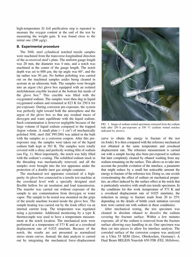
The 304L steel cylindrical notched tensile sampleswere machined from the transverse-longitudinal directionof the as-received steel’s plate. The uniform gauge lengthwas 20 mm, the diameter was 4 mm, and a notch wasmachined at the center of the gauge length. The notchdepth was set to 600 lm, the tip angle was 60°, and thetip radius was 50 lm. No further polishing was carriedout on the machined samples asides being cleaned inacetone in an ultrasonic bath. The samples were broughtinto an argon (Ar) glove box equipped with an isolatedmolybdenum crucible located at the bottom but inside ofthe glove box.6 This crucible was filled with theoxygenated sodium. The samples were then dug in liquidoxygenated sodium and remained at 823 K for 250 h forpre-exposure. During corrosion pre-exposure, the systemwas perfectly tight toward both the atmosphere and theargon of the glove box so that any residual traces ofdioxygen and water equilibrate with the liquid sodium.Such contamination is however negligible because of thelarge volume of liquid sodium compared to the trappedArgon volume. A small plate (;1 cm2) of mechanicallypolished 304L steel (SiC P#1200) was added in the bathwith the samples as a corrosion coupon. After this pre-exposure step, the samples were taken out of the liquidsodium bath kept at 383 K. The samples were totallycovered with a shiny and perfectly wetting film of sodium(see Fig. 1). Most importantly, the notch was fully filledwith the sodium’s coating. The solidified sodium stuck inthe threading was mechanically removed, and all thesamples were brought into the test apparatus under theprotection of a double inert gas airtight container.
The mechanical test apparatus consisted of a high-purity Ar glove box connected to a tensile test machine atthe crosshead level with a specially designed steelflexible bellow for air insulation and load transmission.The transfer was carried out without exposure of thesample to any contamination from dioxygen or watervapor. The sample to be tested was mounted on the gripsof the tensile machine located inside the glove box. Thesample heating was carried out by the Joule effect via aninternal current loop. The temperature was regulatedusing a pyrometer. Additional monitoring by a type Kthermocouple was used to have a temperature measure-ment at the notch location. The mechanical tests wereperformed at a temperature of 573 K and at a crossheaddisplacement rate of 0.025 mm/min. Because of thenotch, the results are not presented as normalizedstress–strain curves. Instead, the data analysis is carriedout by integrating the mechanical force–displacement
curve to obtain the energy to fracture of the test(in Joule). It is then compared with the reference mechanicaltest obtained at the same temperature and crossheaddisplacement rate. The reference measurement is carriedout with a sample having also been pre-exposed to sodiumbut later completely cleaned by ethanol washing from anysodium remaining on the surface. This allows us to take intoaccount the possible evolution of the interface, a parameterthat might reduce by a small but noticeable amount theenergy to fracture of the reference test. Doing so, one avoidsoverestimating the effect of sodium on mechanical proper-ties, an effect induced by the surface effect at the notch thatis particularly sensitive with small-size tensile specimens. Inthe conditions for this work (temperature of 573 K anda crosshead displacement rate of 0.025 mm/min), thereduction in energy to fracture reads from 20 to 25%depending on the details of brittle crack initiation (severaltests were carried out with sodium in these conditions).
After mechanical testing, the test specimen wascleaned in absolute ethanol to dissolve the sodiumcovering the fracture surface. Within a few minutesexposure, all of the sodium is removed from the fracturesurface allowing easy handling in air. One specimen wasthen cut into pieces to allow for interface analysis. Thecorroded surface of the corrosion coupon was analyzedon a Ultra 55 SEM (Zeiss, Oberkochen, Germany). ADual Beam HELIOS Nanolab 650 FIB (FEI, Hillsboro,
FIG. 1. Image of sodium wetted specimens extracted from the sodiumbath after 250 h pre-exposure at 550 °C (sodium wetted notchesindicated by arrows).
Oregon) was used to extract TEM lamella using the liftout technique. One TEM foil was extracted, perpen-dicular to the surface, at a location that was not affectedby the plastic deformation near or at the notch (someplace along the gauge length but away from the notch).The other ones were extracted from the fracture surfaceat places representative of the morphology of thefracture surface. First a protective platinum (Pt) layer(of typically 2 lm thickness) was deposited on thesurface to protect it from damage during subsequention beam sectioning. Two trenches are then milled onboth sides of the protected area using a focused Ga1
ion source operated at 30 kV. A U-cut was then made,and the sample was lifted out and attached on a TEMgrid by a Pt deposit. A molybdenum grid instead ofa copper one was chosen for the lift out devoted toEDX analysis to allow an easier deconvolution of theNa Ka X-ray line (copper has an Lb line at 949.8 eVwhile Ga has a La line at 1097.9 eV surrounding theNa Ka line at 1041 eV). A low Gallium ion current of80 pA was used for the final thinning of the lamella toreduce surface artifacts. The TEM lamella was ana-lyzed at 200 kV in an Tecnai F20 TEM (FEI, Hillsboro,Oregon) equipped with an EDX detector. A chemicalmapping was carried out on the TEM lamella andtreated after background subtraction with a deconvolu-tion algorithm for the sodium Ka X-ray line (EDAXTEAM software, Draper, Utah). The compositionprofiles of the corroded layers have been assessedsemi-quantitatively by Glow Discharge—Optical Elec-tron Spectroscopy (GD-OES) using the Horiba Jobin-Yvon (Kyoto, Japan) GD-Profiler 2 in the radio-frequency mode (30 W & 800 Pa). The emissionresponses from the excited sputtered elements (O, Fe,Cr, Ni, Mo, C, Si, Mn, etc.) were detected usinga polychromator with a focal length of 500 mm, whilea monochromator was used to determine the sodiumconcentration. Reference alloys were used to calibratethe measurements.
To characterize the crack path, two TEM foils weresampled from the brittle fracture surface area of the 304Lsteel. One lift out was carried out at a location with stepridges on the fracture surface and the other one at a locationwhere an arrested crack was likely to be captured in the foil(see Sec. III.B for further details on the experimentalprocedure). These areas represented typical morphologiesof the quasi-cleavage fracture surface. The crystallographicorientations of the interesting zones in the FIB lamellaswere then investigated by a TECNAI F20 (FEI, Hillsboro,Oregon) operating at 200 kV and equipped with theprecession automated crystal orientation mapping(ACOM-TEM) using the Astar package.7 Two phases (c.c. and c.f.c.) were allowed in the automated indexing due tothe possibility of martensitic transformation of the 304Laustenitic steel. A phase map was built whenever necessary.
III. RESULTS
A. Pre-exposure
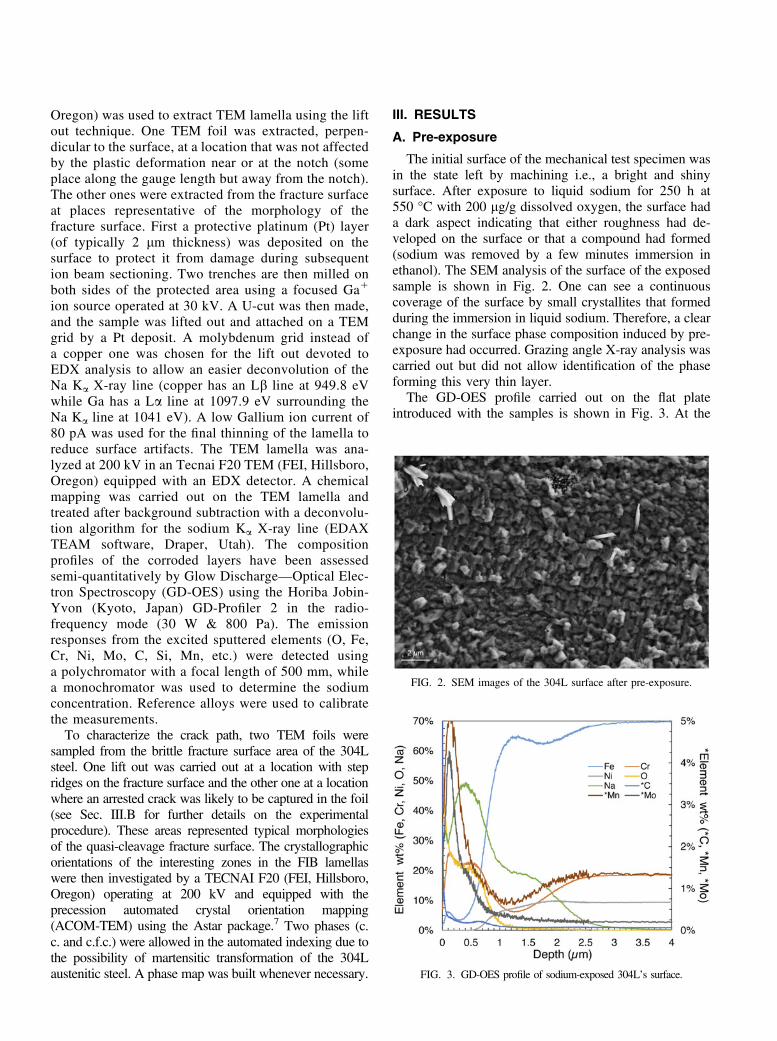
The initial surface of the mechanical test specimen wasin the state left by machining i.e., a bright and shinysurface. After exposure to liquid sodium for 250 h at550 °C with 200 lg/g dissolved oxygen, the surface hada dark aspect indicating that either roughness had de-veloped on the surface or that a compound had formed(sodium was removed by a few minutes immersion inethanol). The SEM analysis of the surface of the exposedsample is shown in Fig. 2. One can see a continuouscoverage of the surface by small crystallites that formedduring the immersion in liquid sodium. Therefore, a clearchange in the surface phase composition induced by pre-exposure had occurred. Grazing angle X-ray analysis wascarried out but did not allow identification of the phaseforming this very thin layer.
The GD-OES profile carried out on the flat plateintroduced with the samples is shown in Fig. 3. At the
FIG. 2. SEM images of the 304L surface after pre-exposure.
FIG. 3. GD-OES profile of sodium-exposed 304L’s surface.
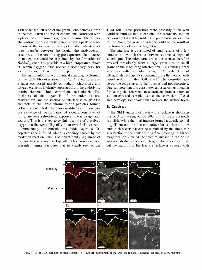
surface (at the left side of the graph), one notices a dropin the steel’s iron and nickel constituents correlated witha plateau in chromium, oxygen, and sodium. Other minorelements (carbon and molybdenum) have a peak concen-tration at the extreme surface potentially indicative ofmass transfer between the liquid, the molybdenumcrucible, and the steel during pre-exposure. The increasein manganese could be explained by the formation ofNaMnO2 since it is possible at a high temperature above80 wppm oxygen.3 One notices a secondary peak forsodium between 1 and 1.5 lm depth.
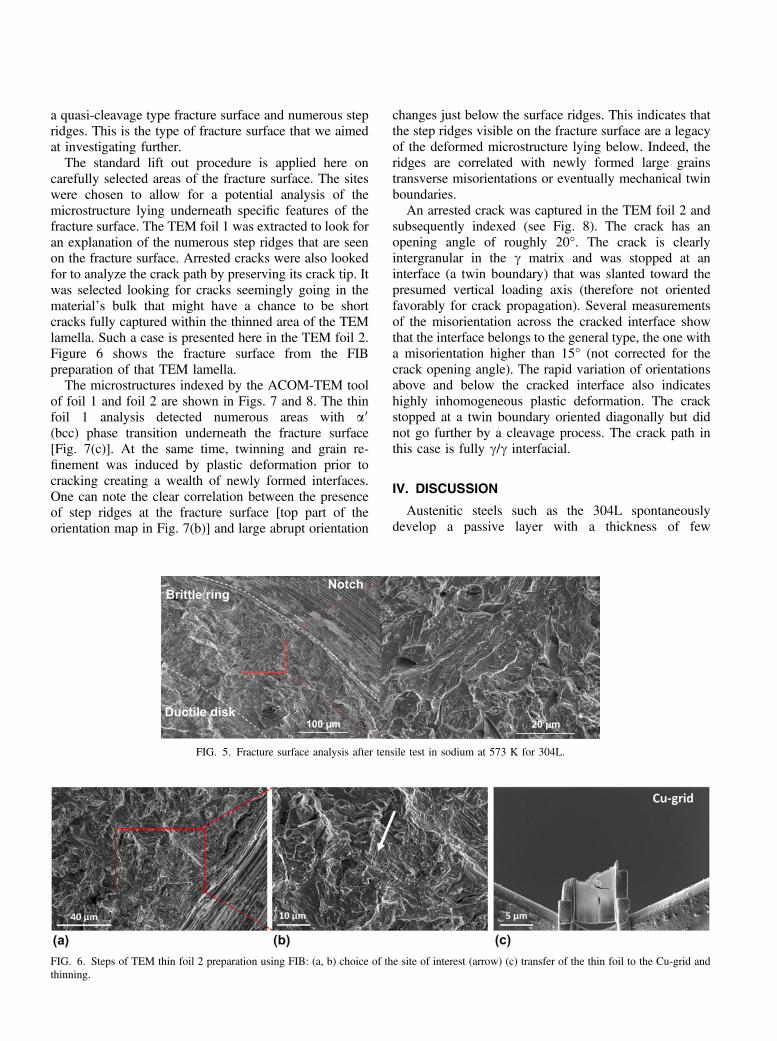
The nanoscale-resolved chemical mapping performedon the TEM lift out is shown in Fig. 4. It indicates thata layer composed mainly of sodium, chromium, andoxygen elements is clearly separated from the underlyingmatrix elements (iron, chromium, and nickel). Thethickness of that layer is of the order of onehundred nm, and the steel/oxide interface is rough. Onecan note as well that chromium-rich particles formedbelow the outer NaCrO2. This constitutes an unambigu-ous evidence of the formation of a continuous layer ofthis phase over a short-term exposure time in oxygenatedsodium. This is the key to explain the role of dissolvedoxygen on the wettability of sodium over 304L’s steel.
Immediately, underneath this oxide layer, a Cr-depleted zone is found which is certainly caused by theoxidation reaction. The TEM bright field (BF) image ofthe interface is shown in Fig. 4(f). This corrosion zonepresents intergranular pores that are clearly seen on the
TEM foil. These porosities were probably filled withliquid sodium so that it explains the secondary sodiumpeak on the GD-OES profile. The preferential dissolutionof iron along the grain boundaries could be the result ofthe formation of soluble Na4FeO3.
The interface is constituted of small grains of a fewhundred nm with holes in between at over a depth ofseveral lm. The microstructure at the surface thereforeevolved remarkably from a large grain size to smallgrains in the machining-affected area. This finding bearssimilitude with the early finding of Moberly et al. ofintergranular precipitates forming during the contact withliquid sodium in the 304L steel.8 The corroded areabelow the oxide layer is then porous and not protective.One can note that this constitutes a posteriori justificationfor taking the reference measurement from a batch ofsodium-exposed samples since the corrosion-affectedarea develops some voids that weaken the surface layer.
B. Crack path
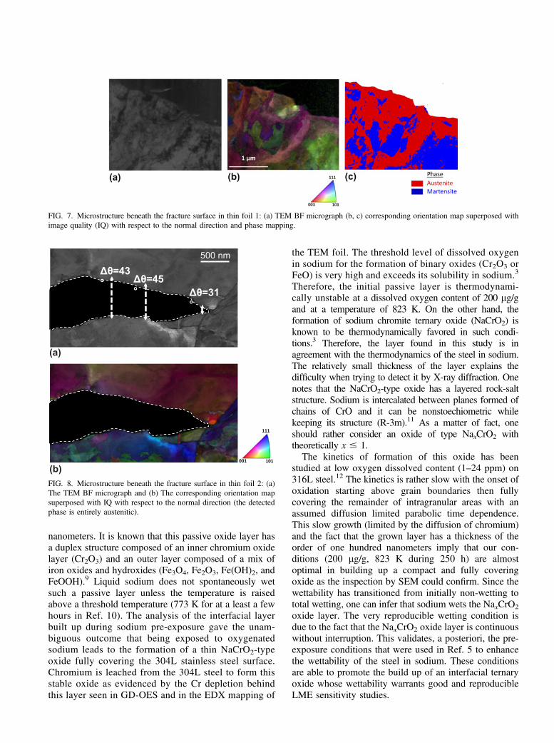
The SEM analysis of the fracture surface is shown inFig. 5. A brittle ring of 200–300 lm starting at the notchis visible, while the final fracture formed a ductile centralring. Therefore, the fracture surface has a mixed brittle/ductile character that can be explained by the strain rateacceleration at the center during final cracking. A highermagnification view of the fracture surface in the brittlearea reveals that some clear intergranular cracks occurred,but the majority of the fracture surface is covered with
FIG. 4. (a–e) EDX mapping of main elements (f) TEM BF micrograph of the area (the rectangle indicates the area of EDX mapping).
a quasi-cleavage type fracture surface and numerous stepridges. This is the type of fracture surface that we aimedat investigating further.
The standard lift out procedure is applied here oncarefully selected areas of the fracture surface. The siteswere chosen to allow for a potential analysis of themicrostructure lying underneath specific features of thefracture surface. The TEM foil 1 was extracted to look foran explanation of the numerous step ridges that are seenon the fracture surface. Arrested cracks were also lookedfor to analyze the crack path by preserving its crack tip. Itwas selected looking for cracks seemingly going in thematerial’s bulk that might have a chance to be shortcracks fully captured within the thinned area of the TEMlamella. Such a case is presented here in the TEM foil 2.Figure 6 shows the fracture surface from the FIBpreparation of that TEM lamella.
The microstructures indexed by the ACOM-TEM toolof foil 1 and foil 2 are shown in Figs. 7 and 8. The thinfoil 1 analysis detected numerous areas with a9(bcc) phase transition underneath the fracture surface[Fig. 7(c)]. At the same time, twinning and grain re-finement was induced by plastic deformation prior tocracking creating a wealth of newly formed interfaces.One can note the clear correlation between the presenceof step ridges at the fracture surface [top part of theorientation map in Fig. 7(b)] and large abrupt orientation
changes just below the surface ridges. This indicates thatthe step ridges visible on the fracture surface are a legacyof the deformed microstructure lying below. Indeed, theridges are correlated with newly formed large grainstransverse misorientations or eventually mechanical twinboundaries.
An arrested crack was captured in the TEM foil 2 andsubsequently indexed (see Fig. 8). The crack has anopening angle of roughly 20°. The crack is clearlyintergranular in the c matrix and was stopped at aninterface (a twin boundary) that was slanted toward thepresumed vertical loading axis (therefore not orientedfavorably for crack propagation). Several measurementsof the misorientation across the cracked interface showthat the interface belongs to the general type, the one witha misorientation higher than 15° (not corrected for thecrack opening angle). The rapid variation of orientationsabove and below the cracked interface also indicateshighly inhomogeneous plastic deformation. The crackstopped at a twin boundary oriented diagonally but didnot go further by a cleavage process. The crack path inthis case is fully c/c interfacial.
IV. DISCUSSION
Austenitic steels such as the 304L spontaneouslydevelop a passive layer with a thickness of few
FIG. 5. Fracture surface analysis after tensile test in sodium at 573 K for 304L.
FIG. 6. Steps of TEM thin foil 2 preparation using FIB: (a, b) choice of the site of interest (arrow) (c) transfer of the thin foil to the Cu-grid andthinning.
nanometers. It is known that this passive oxide layer hasa duplex structure composed of an inner chromium oxidelayer (Cr2O3) and an outer layer composed of a mix ofiron oxides and hydroxides (Fe3O4, Fe2O3, Fe(OH)2, andFeOOH).9 Liquid sodium does not spontaneously wetsuch a passive layer unless the temperature is raisedabove a threshold temperature (773 K for at a least a fewhours in Ref. 10). The analysis of the interfacial layerbuilt up during sodium pre-exposure gave the unam-biguous outcome that being exposed to oxygenatedsodium leads to the formation of a thin NaCrO2-typeoxide fully covering the 304L stainless steel surface.Chromium is leached from the 304L steel to form thisstable oxide as evidenced by the Cr depletion behindthis layer seen in GD-OES and in the EDX mapping of
the TEM foil. The threshold level of dissolved oxygenin sodium for the formation of binary oxides (Cr2O3 orFeO) is very high and exceeds its solubility in sodium.3
Therefore, the initial passive layer is thermodynami-cally unstable at a dissolved oxygen content of 200 lg/gand at a temperature of 823 K. On the other hand, theformation of sodium chromite ternary oxide (NaCrO2) isknown to be thermodynamically favored in such condi-tions.3 Therefore, the layer found in this study is inagreement with the thermodynamics of the steel in sodium.The relatively small thickness of the layer explains thedifficulty when trying to detect it by X-ray diffraction. Onenotes that the NaCrO2-type oxide has a layered rock-saltstructure. Sodium is intercalated between planes formed ofchains of CrO and it can be nonstoechiometric whilekeeping its structure (R-3m).11 As a matter of fact, oneshould rather consider an oxide of type NaxCrO2 withtheoretically x # 1.
The kinetics of formation of this oxide has beenstudied at low oxygen dissolved content (1–24 ppm) on316L steel.12 The kinetics is rather slow with the onset ofoxidation starting above grain boundaries then fullycovering the remainder of intragranular areas with anassumed diffusion limited parabolic time dependence.This slow growth (limited by the diffusion of chromium)and the fact that the grown layer has a thickness of theorder of one hundred nanometers imply that our con-ditions (200 lg/g, 823 K during 250 h) are almostoptimal in building up a compact and fully coveringoxide as the inspection by SEM could confirm. Since thewettability has transitioned from initially non-wetting tototal wetting, one can infer that sodium wets the NaxCrO2
oxide layer. The very reproducible wetting condition isdue to the fact that the NaxCrO2 oxide layer is continuouswithout interruption. This validates, a posteriori, the pre-exposure conditions that were used in Ref. 5 to enhancethe wettability of the steel in sodium. These conditionsare able to promote the build up of an interfacial ternaryoxide whose wettability warrants good and reproducibleLME sensitivity studies.
FIG. 7. Microstructure beneath the fracture surface in thin foil 1: (a) TEM BF micrograph (b, c) corresponding orientation map superposed withimage quality (IQ) with respect to the normal direction and phase mapping.
FIG. 8. Microstructure beneath the fracture surface in thin foil 2: (a)The TEM BF micrograph and (b) The corresponding orientation mapsuperposed with IQ with respect to the normal direction (the detectedphase is entirely austenitic).
One can elaborate on why sodium totally wetsNaxCrO2 while the initial 304L passive oxide is notwetted. Because there is an interfacial phase formation,this wetting transition should belong to the reactivewetting category (liquid metal/oxide reactive wetting).However, the observed transition to a nearly perfectwetting indicates larger improvement than usuallyreported in reactive wetting. This possibly could implythat the sodium bonding of this new phase is bondedmetallically rather than iono-covalently as categorized byEustathopoulos.13 It remains to be clarified at this pointsuch that wettability studies of different oxides by liquidsodium would be necessary.
Early on, it was shown that the 304L steel interactedwith sodium by the formation of an intergranular phase.8
Here, it is found that the first few microns of the corrodedlayer develop some porosity and Cr-rich precipitates (seeBF TEM image in Fig. 4). This might also be aningredient favoring early crack initiation. Within a wettedcrack, the capillary flow of sodium induced by goodwetting is then the key to supply liquid sodium at thecrack tip at the earliest stage of LME in a self-maintainedprocess. Once started, a crack is filled and will remainfilled as it propagates.
The pre-exposure conditions of this study imply thatthe sodium that fills the notch of the test specimen isoxygenated at some level (but not necessarily as much asthe initial oxygen content if some oxygen was consumedby corrosion in the course of the crack propagation). Theeffect of dissolved oxygen on the fatigue crack growthrate has been studied between 1 ppm up to 40 ppm withthe 304L austenitic steel.14 In the conditions of that study(high test frequency and the lowest temperature startingat 700 K), it was concluded that the dissolved oxygenlevel did not affect the crack growth rate. In anotherstudy, the oxygen influence on crack growth underconstant load was studied with the 304L austenitic steel.It was also shown that while varying the oxygen contentof sodium from 0.7 to 14 ppm, the intergranular crackgrowth had only a slight increase and so was deemedlargely independent upon the dissolved oxygen concen-tration.15 It is therefore anticipated that the oxygenatedcondition is no more detrimental than ultrapure sodium.
The brittle fracture mode evidenced by 304L in contactwith oxygenated sodium above 573 K, albeit with limitedmechanical degradation (20–25% reduction of the energyto fracture), has possibly important implications. It there-fore deserves some close attention. The fracture surfacehas the typical appearance of the quasi-cleavage brittlefracture with a few intergranular cracking spots. Theknowledge of the crack path relative to the microstructure,or at least its categorization in terms of intergranular orintragranular, is decisive for the subsequent understandingand modeling of LME. The crack path was analyzed intypical areas of the fracture surface where the fracture
mode is not seemingly intergranular. The fracture surfaceof this LME case has numerous areas with regular stepridges and buried cracks. Two TEM foils were extracted toanalyze the microstructure below regular step ridges and ata location with a microcrack going inside the material.Two main conclusions can be drawn from the analysis thatwas carried out via the ACOM-TEM technique.
Firstly, the 304L steel microstructure is heavily de-formed with a large amount of a9 phase transformedmaterial. Twinning at the microscale is also observedright below the fracture surface. These processes createda microstructural refinement with a large increase in thedensity of sub-grain boundaries. The step ridges structureis correlated with a large underlying orientation change(subgrains or twin boundaries) and is the trace of theinterplay of twinning or phase transform and fracture.
Secondly, the arrested crack of foil 2 shows a typicalcase of c/c interfacial fracture. The underlying micro-structure is extremely complex with numerous twins andsubgrain boundaries. The fracture surface in the analyzedarea was typical of the quasi-cleavage-like fracture area.We can infer that a large part of the crack propagationproceeds as an interfacial fracture.
There are several possibilities to analyze the interplaybetween fracture and twinning or a9 (bcc) phase trans-form. Under stress, interface formation via twinning orphase transformation may simply be an independentresponse over brittle cracking. Another possibility is thatthe crack may nucleate twins or trigger phase change dueto the high stress triaxiality near the crack tip. The thirdpossibility is that these newly formed interfaces mayprovide a preferred path for the growth of cracks.
In studies of the ductile fracture of the 304LN stainlesssteel, a clear correlation between deformation inducedmartensite and the nucleation of microvoids has beenfound.16 In a detailed study of the deformation at roomtemperature, examples of shear-band intersection, shear-band grain boundary intersection or grain boundary triplepoint have been found as nucleation sites.16 Therefore,the location of a9 (bcc) phase transform or twinning canbe found inhomogeneously but everywhere in the micro-structure beyond some threshold strain level so that theinterface nucleation process takes place at relatively lowdeformation levels. LME occurs clearly at a later stage ofplastic deformation in our case such that a large quantityof interfaces must already be present so that one maythink of twinning or phase change as an independentprocess relative to brittle cracking. It means that it islikely not while twinning that cracking takes place.
We infer that the crack propagation was likely toproceed in a discontinuous manner associated with crackpropagation along twinned and c (fcc) to a9 (bcc)boundaries induced by phase transform. The step ridgesof the fracture surface in particular are leftovers of thisprocess. This is similar to the association of twinning and
fracture in bcc metals where twin-matrix interfaces arefound to be the preferred propagation path.17 Thespecificity of LME is that here sodium induces crackpropagation along newly formed interfaces.
These characterizations document further the LME caseof 304L in contact with sodium as being due to theembrittlement of plastically generated interfaces. We high-light the similarity of these findings with the demonstrationof the importance of subgrain defect structures in un-derstanding hydrogen embrittlement of steels.18 Additionalinsight calls for in situ investigation of the propagation ofa crack induced by liquid sodium. This would providefurther indications into the details of the intertwining ofphase transform and cracking in austenitic steel’s LME.
V. CONCLUSION
The LME case of the 304L austenitic steel has beenanalyzed down to the nanoscale in two crucial points. Thefirst one is the wettability and the role of pre-exposure inoxygenated sodium. The second one is related to thecorrelation of the crack path with the deformed micro-structure. The main findings are the followings:
(1) The wettability is enhanced due to the formation ofa NaxCrO2 (x # 1) layer in direct contact with liquidsodium. The oxygenated sodium pre-exposure conditionsthat were used allow for the in situ buildup of this oxideand validate the wetting of an oxide scenario that wasinferred from the thermodynamical analysis in Ref. 5.
(2) A quasi-cleavage-like fracture surface with stepridges is to be understood as a product of microstructuralchanges (phase transform and grain refinement) inducedby prior plastic deformation. The step ridges are themarkers of discontinuous crack propagation intertwinedwith phase transform. This strongly hints at the quasi-cleavage being essentially an interfacial cracking in thecase of LME of austenitic steels.
(3) The crack path was characterized on arrested cracks.It is found fully interfacial. The crack path is found tofollow the newly formed interfaces created by plasticdeformation prior to cracking that are embrittled by sodium.
We highlight the need to characterize fracture surfaceswith the underlying material’s microstructure whenassessing the fracture mode of unstable steels like the304L austenitic steel.
ACKNOWLEDGMENTS
Financial support for this work by the CEA-Generation4/Structural material project is acknowledged. Exposureof the specimen to liquid sodium was carried out in theCorrona-1 test bench with the help of V. Lorentz(CEA Saclay). The FIB work was carried out usingthe equipment of the MATMECA consortiumpartially funded by the ANR under contract number
ANR-10-EQUIPEX-37. M. Tabarant (CEA Saclay) isthanked for performing the GD-OES analysis.
REFERENCES
1. C. Fazio, ed. Handbook on Lead-Bismuth Eutectic Alloy and LeadProperties, Materials Compatibility, Thermal-Hydraulics andTechnologies, 2015 ed. (OECD-NEA, Issy-les-Moulineaux,France, 2015).
2. S. Hémery, T. Auger, J.L. Courouau, and F. Balbaud-Célérier:Effect of oxygen on liquid sodium embrittlement of T91 martens-itic steel. Corros. Sci. 76, 441 (2013).
3. N.P. Bhat and H.U. Borgstedt: Corrosion behavior of structuralmaterials in sodium influenced by formation of ternary oxides.Mater. Corros. 39, 115 (1988).
4. B. Longson and J. Prescott: Some experiments on the wetting ofstainless steel, nickel and iron in liquid sodium. In Liquid AlkaliMetals: Proceedings of an International Conference Organized bythe British Nuclear Energy Society (Edited by the British NuclearEnergy Society, London, published by Thomas Telfard Limited,Nottingham University, U.K. 1973); pp. 171–176.
5. S. Hémery, T. Auger, J.L. Courouau, and F. Balbaud-Célérier:Liquid metal embrittlement of an austenitic stainless steel in liquidsodium. Corros. Sci. 83, 1 (2014).
6. J.L. Courouau, F. Balbaud-Célérier, V. Lorentz, and T. Dufrenoy:Corrosion by liquid sodium of materials for sodium fast reactors:The CORRONa testing device. In International Congresson Advances in Nuclear Power Plants 2011 (Edited by the SociétéFrançaise d’Energie Nucléaire, Paris, France, 2011); p. 11152 (avail-able at https://inis.iaea.org/search/search.aspx?orig_q=RN:44092769).
7. E.F. Rauch, M. Véron, J. Portillo, D. Bultreys, Y. Maniette, andS. Nicolopoulos: Automatic crystal orientation and phase mappingin TEM by precession diffraction. Microsc. Anal. 22, S5 (2008).
8. J.W. Moberly, M. Barlow, M.C. Garrison, and P.J. Planting:Electron microscope observations of liquid sodium interactionwith 304 stainless steel. J. Nucl. Mater. 29, 223 (1969).
9. G. Lorang, M. da Cunha Belo, A.M.P. Simões, andM.G.S. Ferreira: Chemical composition of passive films on AISI304 stainless steel. J. Electrochem. Soc. 141, 3347 (1994).
10. E.N. Hodkin and M.G. Nicholas: The Wetting of CladdingMaterials and Other Materials and Alloys by Sodium;AERE–R7406, May, 1976.
11. J.J. Braconnier, C. Delmas, and P. Hagenmuller: Etude pardésintercalation électrochimique des systèmes NaxCrO2 etNaxNiO2. Mater. Res. Bull. 17, 993 (1982).
12. I.W. Cavell and M.G. Nicholas: Some observations concernedwith the formation of sodium chromite on AISI 316 exposed tooxygenated sodium. J. Nucl. Mater. 95, 129 (1980).
13. N. Eustathopoulos and B. Drevet: Interfacial bonding, wettabilityand reactivity in metal/oxide systems. J. Phys. III 4, 1865 (1994).
14. L.A. James and R.L. Knecht: Fatigue-crack propagation behaviorof type 304 stainless steel in a liquid sodium environment. Metall.Trans. A 6, 109 (1975).
15. H. Abe and S. Shimoyashiki: Time dependent crack growth oftype 304 stainless steel in elevated temperature sodium. Eng.Fract. Mech. 26, 657 (1987).
16. A. Das and S. Tarafder: Experimental investigation on martensitictransformation and fracture morphologies of austenitic stainlesssteel. Int. J. Plast. 25, 2222 (2009).
17. C.N. Reid: The association of twinning and fracture in bcc metals.Metall. Trans. A 12, 371 (1981).
18. M.L. Martin, J.A. Fenske, G.S. Liu, P. Sofronis, andI.M. Robertson: On the formation and nature of quasi-cleavagefracture surfaces in hydrogen embrittled steels. Acta Mater. 59,1601 (2011).