web-based control and robotics education .pdf
TRANSCRIPT
123
Spyros G. TzafestasEditor
Intelligent Systems, Control and
Automation: Science and Engineering
Web-Based Control and Robotics Education

Web-Based Control and Robotics Education
International Series on
INTELLIGENT SYSTEMS, CONTROL AND AUTOMATION:SCIENCE AND ENGINEERING
VOLUME 38
Editor
Professor S. G. Tzafestas, National Technical University of Athens, Greece
Editorial Advisory BoardProfessor P. Antsaklis, University of Notre Dame, IN, U.S.A.Professor P. Borne, Ecole Centrale de Lille, FranceProfessor D. G. Caldwell, University of Salford, U.K.Professor C. S. Chen, University of Akron, Ohio, U.S.A.Professor T. Fukuda, Nagoya University, JapanProfessor F. Harashima, University of Tokyo, JapanProfessor S. Monaco, University La Sapienza, Rome, ItalyProfessor G. Schmidt, Technical University of Munich, GermanyProfessor N. K. Sinha, McMaster University, Hamilton, Ontario, CanadaProfessor D. Tabak, George Mason University, Fairfax, Virginia, U.S.A.Professor K. Valavanis, University of Denver, U.S.A.Professor S. G. Tzafestas, National Technical University of Athens, Greece
For other titles published in this series, go to www.springer.com/series/6259

Spyros G. TzafestasEditor
Web-Based Control and Robotics Education

ISBN 978-90-481-2504-3 e-ISBN 978-90-481-2505-0DOI 10.1007/978-90-481-2505-0Springer Dordrecht Heidelberg London New York
Library of Congress Control Number: 2009926290
© Springer Science + Business Media B.V. 2009No part of this work may be reproduced, stored in a retrieval system, or transmitted in any form or by any means, electronic, mechanical, photocopying, microfilming, recording or otherwise, without written permission from the Publisher, with the exception of any material supplied specifically for the purpose of being entered and executed on a computer system, for exclusive use by the purchaser of the work.
Printed on acid-free paper
Springer is part of Springer Science+Business Media (www.springer.com)
EditorSpyros G. TzafestasSchool of Electrical and Computer EngineeringNational Technical University of [email protected]

The Web is a tremendous platform for innovation, but we face a number of challenges to making it more useful, in particular to people in underserved communities.One of the things I always remain concerned about is that the medium remains neutral.
Sir Tim Berners - LeeDirector, World Wide Web Consortium (W
3C)
Co-Director, Web Science Research Initiative (WSRI)
Founder, World Wide Web Foundation
The free flow of information is of paramount importance to communities in a democracy and maintaining the World Wide Web free is critical for the future of that free flow.
Alberto IbargüenPresident and CEO, John S.
and James L. Knight Foundation

vii
Preface
For the things we have to learn before we can do them, we learn by doing them.
Aristotle
Teaching should be such that what is offered is perceived as a valuable gift and not as a hard duty.
Albert Einstein
The second most important job in the world, second only to being a good parent, is being a good teacher.
S.G. Ellis
The fast technological changes and the resulting shifts of market conditions require the development and use of educational methodologies and opportunities with moderate economic demands. Currently, there is an increasing number of educa-tional institutes that respond to this challenge through the creation and adoption of distance education programs in which the teachers and students are separated by physical distance. It has been verified in many cases that, with the proper methods and tools, teaching and learning at a distance can be as effective as traditional face-to-face instruction.
Today, distance education is primarily performed through the Internet, which is the biggest and most powerful computer network of the World, and the World Wide Web (WWW), which is an effective front-end to the Internet and allows the Internet users to uniformly access a large repertory of resources (text, data, images, sound, video, etc.) available on the Internet.
The World Wide Web Foundation (www.webfoundation.org), recently estab-lished, aims “to advance One Web that is free and open, to expand the Web’s capa-bility and robustness, and to extend the Web’s benefit to all people on the planet”. This will be done by funding research, technology, and social development pro-grams around the world. Academia, governments, NGOs, and other stakeholders will be brought together to synergetically cooperate and develop health care, nutri-tion, education, and other critical services.
For teachers and instructors the WWW offers an ideal novel way for distance teaching and learning, creation of classroom pages, and a suitable medium for

viii Preface
developing remote virtual laboratories and remotely controlling physical plants and experiments. New and emerging web services and web tools are expected to offer unique opportunities, in the near future, for extending this technology to new levels and broader repertories of information sharing.
This book provides a collection of contributions on a wide range of topics, meth-odologies and tools that fall within the domain of Internet/Web-based teaching of control and robotics analysis, design, and laboratory experiments. These contribu-tions contain both review/tutorial material and fresh/hot results developed by the research and educational groups of the contributors. The majority of them place the emphasis on the development of virtual and/or remote physical labs and their effec-tive utilization in the educational process.
I am indebted to the contributors for their enthusiastic support in this project and their experience offered to the book, and to Springer’s Scientific Editor, Dr. Nathalie Jacobs, for her care and help throughout the book production.
Athens, December 2008 Spyros G. Tzafestas

ix
Preface ............................................................................................................... vii
Contributors ..................................................................................................... xi
Outline of the Book .......................................................................................... xv
Acronyms .......................................................................................................... xxi
1 Teaching Control and Robotics Using the Web ..................................... 1 Spyros G. Tzafestas
2 Control System Design and Analysis Education via the Web .............. 39 Harry H. Cheng, Bo Chen, and David Ko
3 Web Based Control Teaching .................................................................. 61 Suzana Uran and Riko Šafarič
4 Web-Based Control Education in Matlab .............................................. 83 Katarína Žáková
5 Object-Oriented Modelling of Virtual- Laboratories for Control Education .............................................................................. 103
Carla Martin-Villalba, Alfonso Urquia, and Sebastian Dormido
6 A Matlab-Based Remote Lab for Control and Robotics Education ........................................................................... 127
Marco Casini, Domenico Prattichizzo, and Antonio Vicino
7 Implementation of a Remote Laboratory Accessible Through the Web ..................................................................................... 153
Giuseppe Carnevali and Giorgio Buttazzo
Contents

x Contents
8 Teaching of Robot Control with Remote Experiments ......................... 171 Andreja Rojko and Darko Hercog
9 Web-Based Laboratory on Robotics: Remote vs. Virtual Training in Programming Manipulators .............. 195
Costas S. Tzafestas
10 Design and Educational Issues within the UJI Robotics Telelaboratory: A User Interface Approach .......................... 227Raul Wirz, Raul Marín, and Pedro J. Sanz
11 Web-Based Industrial Robot Teleoperation: An Application .............. 249Gianni Ferretti, Gianantonio Magnani, and Paolo Rocco
12 Teleworkbench: A Teleoperated Platform for Experiments in Multi-robotics ................................................................ 267Andry Tanoto, Ulrich Rückert, and Ulf Witkowski
13 Web-Based Control of Mobile Manipulation Platforms via Sensor Fusion.................................................................... 297Ayssam Elkady and Tarek Sobh
14 Web Based Automated Inspection and Quality Management ............. 313S. Manian Ramkumar and Immanuel A. Edinbarough
Biographies ....................................................................................................... 333
Index .................................................................................................................. 343

xi
The only source of knowledge is experience.Albert Einstein
The importance of information is directly proportional to its improbability.
Jeremia Eugene Pournelle
Who dares to teach must never cease to learn.John Cotton Dana
Buttazzo, Giorgio Scuola Superiore Sant’ Anna, Via Moruzzi, 1, 56124 Pisa, Italy [email protected], http://feanor.sssup.it/~giorgio/
Carnevali, Giuseppe Research and Development Unit, O.C.E.M. S.p.A., Via 2, Agosto 1980, n.11, 40016 San Giorgio di Piano, Bologna, Italy, [email protected]
Casini, Marco Dipartimento di Ingegneria dell’ Informazione, Università di Siena, Via Roma 56, 53100 Siena, Italy, [email protected], http://www.dii.unisi.it/casini
Chen, Bo Department of Mechanical Engineering - Engineering Mechanics and Department of Electrical and Computer Engineering, Michican Technological University, 815 R.L. Smith Building, 1400 Townsend Drive, Houghton, MI 49931, USA, [email protected], http://www.imes.mtu.edu
Cheng, Harry H. Department of Mechanical and Aeronautical Engineering, University of California, One Shields Avenue, Davis, CA 95616, [email protected], http://iel.ucdavis.edu/people/cheng.html
Dormido, Sebastian Departamento de Informática y Automática (DIA), Escuela Técnica Superior de Ingeniería Informática (ETSI), Universidad Nacional de Educacion a Distancia (UNED), Juan del Rosal 16, 28040 Madrid, Spain,[email protected]
Edinbarough, Immanuel A. Department of Applied Technology, University of Texas at Brownsville, Texas Southmost College, Brownsville, Texas 78521, USA, [email protected]
Contributors

xii
Elkady, Ayssam Department of Computer Science and Engineering, University of Bridgeport, Bridgeport, CT 06604, USA, [email protected], [email protected], http://www1bpt.bridgeport.edu/~aelkady/
Ferretti, Gianni Dipartimento di Elettronica e Informazione, Politecnico di Milano, Piazza Leonardo da Vinci 32, 20133 Milano, Italy, [email protected],http://home.dei.polimi.it/ferretti/indice.htm
Hercog, Darko Institute of Robotics, Faculty of Electrical Engineering and Computer Science, University of Maribor, Smetanova 17, 2000 Maribor, Slovenia, [email protected]
Ko, David Department of Mechanical and Aeronautical Engineering, University of California, One Shields Avenue, Davis, CA95616, USA, [email protected]
Magnani, Gianantonio Dipartimento di Elettronica e Informazione, Politecnico di Milano, Piazza Leonardo da Vinci 32, 20133 Milano, Italy,[email protected], http://www.dei.polimi.it/people/magnani
Marin, Raul Department of Computer Science and Engineering, University of Jaume I, Avd Vte. Sos Baynat s/n, 12071 Castellon, Spain,[email protected], http://rmarin.act.uji.es
Martin-Villalba, Carla Departamento de Informática y Automática (DIA), Escuela Técnica Superior de Ingeniería Informática (ETSI), Universidad Nacional de Educacion a Distancia (UNED), Juan del Rosal 16, 28040 Madrid, Spain,[email protected], http://www.euclides.dia.uned.es/carlam
Prattichizzo, Domenico Dipartimento di Ingegneria dell’ Informazione, Università di Siena, Via Roma 56, 53100 Siena, Italy, [email protected],http://www.dii.unisi.it/prattichizzo
Ramkumar, S. Manian Center for Electronics Manufacturing and Assembly, Rochester Institute of Technology, Bldg.78-Room 1518, 78 Lomb Memorial Drive, Rochester, NY 14623, USA, [email protected], http://www.rit.edu/CAST/CEMA
Rocco, Paolo Dipartimento di Elettronica e Informazione, Politecnico di Milano, Piazza Leonardo da Vinci 32, 20133 Milano, Italy, [email protected],http://www.dei.polimi.it/people/rocco
Rojko, Andreja Institute of Robotics, Faculty of Electrical Engineering and Computer Science, University of Maribor, Smetanova 17, 2000 Maribor, Slovenia
Rückert, Ulrich System and Circuit Technology, Heinz Nixdorf Institute, University of Paderborn, Fuerstenallee 11, 33102 Paderborn, Germany,[email protected]
Šafarič, Riko Institute of Robotics, Faculty of Electrical Engineering and Computer Science, University of Maribor, Smetanova 17, 2000 Maribor, Slovenia, [email protected]
Contributors

xiii
Sanz, Pedro J Department of Computer Science and Engineering, University of Jaume I, Avd Vte. Sos Baynat s/n, 12071 Castellon, Spain, [email protected], [email protected], http://www3.uji.es/~sanzp
Sobh, Tarek Graduate Studies and Research & School of Engineering, University of Bridgeport, 221 University Avenue, Bridgeport, CT06604, [email protected], http://www.bridgeport.edu/~sobh
Tanoto, Andry System and Circuit Technology, Heinz Nixdorf Institute, University of Paderborn, Fuerstenallee 11, 33102 Paderborn, Germany,[email protected]
Tzafestas, Costas S. Division of Signals, Control and Robotics, School of Electrical and Computer Engineering, National Technical University of Athens, Zographou, Athens, GR 15773, Greece,[email protected], http://users.softlab.ece.ntua.gr/~ktzaf/
Tzafestas, Spyros G. School of Electrical and Computer Engineering & Institute of Communication and Computer Systems, National Technical University of Athens, Zographou, Athens, GR 15773, Greece,[email protected], http://users.softlab.ece.ntua.gr/~sgt/
Uran, Suzana Institute of Robotics, Faculty of Electrical Engineering and Computer Science, University of Maribor, Smetanova 17, 2000 Maribor, Slovenia, [email protected]
Urquia, Alfonso Departamento de Informática y Automática (DIA), Escuela Técnica Superior de Ingeniería Informática (ETSI), Universidad Nacional de Educacion a Distancia (UNED), Juan del Rosal 16, 28040 Madrid, Spain,[email protected], http://www.euclides.dia.uned.es/aurquia
Vicino, Antonio Dipartimento di Ingegneria dell’ Informazione, Università di Siena, Via Roma 56, 53100 Siena, Italy, [email protected], http://www.dii.unisi.it/~vicino
Wirz, Raul Department of Computer Science and Engineering, University of Jaume I, Avd Vte Sos Baynat s/n, 12071 Castellon, Spain,[email protected]
Witkowski, Ulf System and Circuit Technology, Heinz Nixdorf Institute, University of Paderborn, Fuerstenallee 11, 33102 Paderborn, Germany,[email protected]
Žaková, Katarína Institute of Control and Industrial Informatics, Faculty of Electrical Engineering and Information Technology, Slovak University of Technology, Ilkovičova 3, SK-81219 Bratislava, Slovakia, [email protected]
Contributors
xv
The whole is more than the sum of its parts.Aristotle
Our expectations for a technology rise with its advancement.Henry Petrovski
If the Internet turns out not to be the future of computing, we’re toast.But if it is, we’re golden.
Larry Ellison
The book contains 14 timely contributed chapters that cover a wide range of con-cepts, techniques, technologies, tools and implementations of Web-based control and robotics educational environments. In overall, the material of these chapters reflect very well the current efforts and tendencies in the design, implementation and practical use of Web-based virtual labs and telelabs.
A brief outline of these chapters is as follows.
Chapter 1, by S. Tzafestas, which is actually the introductory chapter of the book, starts by providing a review of the principal Web-based control and robotics educa-tional platforms, namely e-course environments, Web-based virtual labs, and Web-based remote labs. Then, the classical field of telerobotics that has a variety of applications, including the Web-based remote labs and the single-or-multiple user robotic web camera systems, is discussed. Special focus is given to the issues of random or varying time delays in the data transmission over the Internet, discussing the Quality of Service (QoS) model of communication networks and the dynamic modeling and estimation of the Internet delay. The general characteristics of Web-based virtual labs and remote labs (architectures, protocols, human-computer inter-faces, system modeling requirements, etc.) are examined. Finally, a set of examples drawn from the literature are given to clarify many of the concepts and issues con-sidered in the chapter. An appendix reviews the definitions and uses of the typical general purpose software environments and languages employed for developing Web-based educational platforms and virtual/remote labs.
Outline of the Book

xvi Outline of the Book
Chapter 2, by Cheng, Chen and Ko, describes the design, implementation, and educational use of a Web-based interactive control design and analysis system (WCDAS) based on the Ch Control Systems Toolkit, which is available on the Internet. The main design idea of the system is to use the World Wide Web as a communication infrastructure to allow multiple users to access the Ch Control System Toolkit and other computational tools. A Web browser provides an environ-ment for accepting user inputs and transmitting information to the Web server. A Web server supports the execution of a computation engine-control toolkit, and interfaces with the clients. WCDAS covers many classical and modern techniques for control systems design and analysis. Most functions in the system support both continuous-time and discrete-time linear time-invariant systems modeled in state space, transfer functions, or zero-pole-gain representations. Users can select a design and analysis method, and specify the system model type, the system type, and the system parameters in the Web browser. The user inputs are transferred to the Web server for numerical computation, and the computation results, including values and images, are sent back to the Web browser for display. The system is available for use through the Web without any software installation, system con-figuration, or programming. WCDAS is open architecture and open source. It can be extended to solve many problems in design and analysis of control systems. As an example, a Web-based controller design module is developed based on WCDAS. With this design module, the synthesis and analysis of a control system can be merged, and the effect of the modification in the parameters can be observed imme-diately on the Web. Both WCDAS and the Web-based controller design tool have been used in the undergraduate course “Automatic Control of Engineering Systems” of the University of California, Davis. The student survey and evaluation of the Web-based control tool is very positive.
Chapter 3, by Uran and Šafarič, presents the teaching of the control theory at the Faculty of Electrical Engineering and Computer Science, University of Maribor, for the Mechatronics study program. The main challenge described is the important modernization of the educational process through the new web based and remote rapid prototyping teaching methods. Several techniques of modern control theory teaching are presented, namely: (i) Web-based virtual laboratory, using MATLAB Web server, which has been used by professors for lecture demonstrations and stu-dent homework, (ii) more advanced DSP-based remote rapid prototyping labora-tory based on an in-house developed DSP-2 learning module, which is sufficiently robust for massive use in an everyday educational process, where the student can gain valuable control theory hands-on experiences.
Chapter 4, by Zăková, is devoted to the exploitation of Matlab in Web based control applications. Various approaches are explained. First, the attention is focused to possibilities that are incorporated directly in the Matlab environment. Starting with the Matlab Web Server, which is no more supported by the Math Works Inc., the chapter continues with the Matlab Builder for Java and the Matlab Builder for.NET, which are available in the last versions of Matlab. Besides these standard approaches, some other alternative ways for using the capabilities of Matlab for the

xviiOutline of the Book
web-based control are introduced. The communication can be done via Dynamic Data Exchange (DDE) conversation, Component Object Mode (COM) objects, TCP/IP, and share file. Several possibilities for communicating directly with the Java programming language, which is very often used for building Web applica-tions, are also discussed.
Chapter 5, by Martin-Villalba, Urquia and Dormido, provides a review of the state-of-the-art in object-oriented modelling of virtual-labs for control education. The presentation emphasizes the main advantage of this methodology, i.e. the reduction in the modelling effort. The combined use of different languages and tools is addressed, namely: Modelica/Dymola, Sysquake, Easy Java Simulations (Ejs), and Matlab/Simulink. In particular, three approaches to virtual-lab imple-mentation are discussed. The Modelica language is used in all of them for describ-ing the model, and Dymola is used for translating the model into executable code. For the first approach, the user-to-model interactive interface (i.e., the virtual-lab view) is built using Sysquake. The next approach consists in implementing the virtual-lab view with Ejs, and using Matlab/Simulink as an interface between the model and the view of the virtual-lab. Finally, a procedure for describing the com-plete virtual-lab using the Modelica language and Dymola is outlined. These three approaches are illustrated by discussing the development of three complex virtual-labs for control education. These virtual-labs show the operation of an industrial boiler, a double-pipe heat exchanger, and the thermodynamic behaviour of a solar house. In conclusion, the methodology and tools, presented in the chapter, support the description of complex virtual-labs, facilitating the modelling task.
Chapter 6, by Casini, Prattichizzo and Vicino, presents a remote control and robot-ics education laboratory, called Automatic Control Telelab(ACT), which has been developed at the University of Siena (Italy). This telelab allows the users to run experiments, change control parameters, and analyze and evaluate the results remotely. The student can also design personal controllers, using Matlab/Simulink, and test them on the real plant via a user friendly interface. Further, the student can besides control experiments, carry out remote system identification experiments, using selected or designed input signals, in both a deterministic and a stochastic context. Using ACT, groups of students can compete to develop the best controller for a given remote plant, on the basis of predefined control system performance specifications. The controllers’ performance is automatically scored, ranked, and reported to the students for their learning process. ACT was recently enriched with robot basic and advanced experiments. The resulting system is called Robotics and Automatic Control Telelab(RACT). ACT and RACT are available on the Web.
Chapter 7, by Carnevali and Buttazo, describes the implementation of a remote laboratory environment which is used in the real-time systems course at the University of Pavia, and is accessible through the Web. The presentation starts with some examples of virtual control engineering laboratories, and then proceeds to the illustration of the characteristics and capabilities of a generic interface for a PID controller embedded in a feedback system. Next, the details of the software

xviii
architecture of the proposed remote virtual laboratory, which is organized in three layers, are presented. This architecture offers increased flexibility and modularity by allowing the assignment of the system responsibility to the different layers, and the decoupling of the different components. As a result, the users are free to change, improve or modify the graphics without affecting the server layer. The principal characteristic of this virtual remote lab is that a specific hard real-time kernel, called Shark, is used. This kernel is suitable for modular real-time systems develop-ment, and can verify the sensitivity of task time constraints, such as periods and deadlines, on the control performance.
Chapter 8, by Rojko and Hercog, describes a robot motion control course with increased flexibility for both the teacher and the learner, by introducing available course documentation and remote experiments on the web. Both elements together enable the learner to perform autonomous and time-space independent execution of the course. The course is built around two case studies which give insight to most of the problems of robot motion control. The process from the modelling of the plant, performing simulations and designing several motion controllers, to the tun-ing of controllers’ parameters by remote experiments for both case studies is out-lined. After the implementation of the course, the students’ opinion was obtained and evaluated. It was found that students think positively about the introduction of remote experiments, although they find them most useful when combined with on-site lab experiments.
Chapter 9, by C. Tzafestas, describes research related to the development and evaluation of a web-based laboratory platform, designed to support distance train-ing in the field of robotics. One of the research directions is to explore the adapta-tion of concepts and techniques inspired by related work in the field of telerobotics and virtual reality, and to assess their integration in such e-laboratory settings. The chapter presents the results of a pilot study, providing a comparative evaluation for three training modes: real (hands-on), remote, and virtual. The results obtained reveal certain differences between the three modes, giving some insight regarding the “training dimensions” that seem to be mostly affected by the absence of physi-cal (or realistic virtual) presence at the laboratory. Nevertheless, statistical analysis indicates that, despite these apparent differences, such e-laboratory modules can be integrated quite efficiently in practical scenarios, creating virtual training environ-ments that can provide adequate learning elements, as related particularly to mid- and high-level skill acquisition.
Chapter 10, by Wirz, Marin and Sanz, presents and discusses a number of interest-ing conclusions drawn from the recent efforts at the University Jaume - I (UJI), Spain, in teaching robotics using different tele-laboratories developed by the UJI research group concerned. Initially, the work was aimed to utilize some advanced facilities, including virtual and augmented reality and voice recognition, for user task specification and visually-guided robot performance. However, an important limitation for the students was that they needed to face some requirements, such as downloading a client program (including 3D libraries), having previous skills about
Outline of the Book

xix
Java programming, as well as other very specific programming requirements. The initial Telelaboratory contained only educational robots (instead of industrial ones), but currently new components and an industrial robot were added thus improving the usability, feasibility, reliability and robustness of this Tele-laboratory, and enabling new educational possibilities through a friendlier user interface. The chap-ter describes in detail the main aspects related to the hardware and software employed, the user interaction capabilities implemented, and to the teaching/learn-ing experiences gained.
Chapter 11, by Ferretti, Magnani and Rocco, presents a Web-based industrial robot teleoperation system consisting of the industrial robot COMAU SMART 3-S, the robot controller COMAU C3G-9000, a PC-server connected to the robot con-troller, via a serial RS-232 link, and to the Internet, and three web cams with proper communications. The shared autonomy control concept is employed to implement a tele-sensor programming subsystem, called TeleSMART, using standard Internet-oriented low cost commercial hardware and software components. The PC server involves two principal components, i.e.: the image server and the telerobot server. The chapter describes in sufficient detail the system architecture, the teleprogram-ming and supervisory control issues, the remote operator teleoperation interface, and the functions implemented. The proposed system is suitable for advantageous use in robotics education for students trained in robotic programming, and in continuing education of industrial robotic technicians.
Chapter 12, by Tanoto, Rückert and Witkowski, presents a teleoperated platform, called the Teleworkbench, which facilitates the tasks of performing experiments with single or multi minirobots. This system provides a typical environment where robot algorithms and programs can be tested, validated, and benchmarked using real robots. The special features of the Teleworkbench are the following: (i) down-loading user-defined programs to particular robots, (ii) robot tracking for more than 30 robots simultaneously, (iii) live video of the experiment, and (iv) a visualization tool for the analysis and evaluation of the experiments. The system is available to remote areas over the Web, thus broadening the possibilities of applications. The chapter describes the system in detail, including its architecture, its components, the two robotic platforms used in the Teleworkbench and some application sce-narios, and discusses some challenges for further work.
Chapter 13, by Elkady and Sobh, presents a system that allows remote users to directly control a mobile robotic manipulator. The users can interact with remote environments while receiving visual and sensory feedback (provided by the sen-sors) via the World Wide Web. In order to reduce the uncertainty in localization, sensor fusion is used for creating efficient and effective user interfaces to facilitate teleoperation by enhancing the quality of information which is provided to the teleoperator. The chapter investigates a number of sensory-guided control strategies that are used in the authors’ work on the fusion of sensor data. A quick look on the previous similar work is made, and the design specifications for the data acquisition and the sensors (sonar, infrared) are fully discussed. The mobile manipulator
Outline of the Book

xx
platform, where the navigation, obstacle avoidance and control algorithms are applied is called RISCbot, and is actually a wheelchair base. The overall teleoper-ated system has three separate modules, namely the sensors’ module, the display module, and the communication link module.
Chapter 14, by Ramkumar and Edinbarough, deals with the technologies that make manufacturing automation inspection and quality control a reality using the Web. The chapter shows how an automated inspection (AI) and quality manage-ment (QM) system works over the Web, and gives a review of the related literature. Then, the system architecture for the Web-based AI and QM system is presented, and the sensor and instrumentation subsystems (digital/analog sensors, discrete metrology instrumentation, vision systems, coordinate measuring machines) are outlined, also discussing their integration. Next, the issues of integrating the inter-face and control system hardware (PLCs, DAS, HMIs), including the supervisory system hardware, are investigated, and the integration of the enterprise/manage-ment information system is addressed. The chapter provides an example of imple-menting the overall AI-QM system, and concludes with the system safety issue, and the educational benefits of web-based AI-QM systems in automated manufacturing training processes.
Teaching control and robotics theory and experiments over the Internet/WWW is receiving increasing popularity and many important results are now available. Taken together, the chapters of this book help the reader to obtain a global and sufficiently deep view of the problems, techniques, tools and implementations developed over the years, including both “stand-alone” systems and “generic” systems with high degrees of reusability and sharing, such as WCDAS, ACT, etc. The field is currently expanding, and so the book can be a basis for new developments in Web-based learn-ing and experimentation in control and robotics analysis and design.
Outline of the Book

xxi
Acronyms
ACT Automatic Control TelelabAI Artificial Intelligence/Automated InspectionAMS Access Management SystemAPF Artificial Potential FieldAPI Application Programming InterfaceAR Auto RegressiveARIMA Auto Regressive Integrated Moving AverageARMA Auto Regressive Moving AverageARX Auto Regressive eXogenousASP Active Server PagesATS Active Trasc SuspensionAWT Abstract Windowing Toolkit
CAB Cyclical Asynchronous BufferCAN Control Area NetworkCBS Constant Bandwidth ServerCCD Charge - Coupled DeviceCCST Ch Control Systems ToolkitCGI Common Gateway InterfaceCIP Common Industrial ProtocolCMM Coordinated Measuring MachineCMRP Circulant Modulated Rate ProcessCNC Computer Numerical ControlCOM Common Object ModelCORBA Common Object Request Broker ArchitectureCS Collaboration ServerCSS Cascading Style Sheets (extension to HTML)CTF Component Technology File
DAC Data AcquisitionDAE Differential – Algebraic EquationDAIR Distributed Architecture for Internet RobotDAS Data Acquisition SystemsDCL Distributed Control Laboratory

xxii Acronyms
DDE Dynamic Data ExchangeDOE Design of ExperimentDOF Degree of FreedomDSP Digital Signal ProcessorDT Data TransmissionDYMOLA Dynamic Modeling Language
EDF Earliest Deadline FirstEJS Easy Java SimulationsEQM E-Quality for ManufacturingERPS Enterprise Resource Planning SystemES Experimentation ServerESA European Space Agency
FEC Forward Error CorrectionFPGA Field Programmable Gate
GUI Graphical User InterfaceHCI Human Computer InterfaceHNI Heinz Nixdorf InstituteHTML HyperText Markup LanguageHTTP HyperText Transfer Protocol
IP Internet Protocol
JAVA EE Java Enterprise EditionJAVA ME Java Micro EditionJAVA SE Java Standard EditionJDBC Java Data Base ConnectivityJDK Java Development KitJIT Just-in-TimeJNI Java Native InterfaceJPEG Joint Photographic Experts GroupJ STAT COM Java Statistical ComputingJVM Java Virtual Machine
LabVIEW Laboratory Virtual Instrumentation Engineering WorkbenchLAN Local Area NetworkLLM Lab-based Learning ModelLME Linear Matrix EquationLMS Learning Management SystemLTI Linear Time InvariantLVDT Linear Variable Differential Transformer
MA Moving AverageMATLAB Matrix LaboratoryMCR Matlab Component RuntimeMEMS Micro-Electro-Mechanical SystemMES Manufacturing Execution System

xxiiiAcronyms
MIMO Multiple-Input Multiple-OutputMLNA Modified Local Navigation AlgorithmMOMR Multiple Operator Multiple RobotMOSR Multiple Operator Single RobotMSE Mean Square ErrorMWS Matlab Web Server
NCS Networked Control SystemNI National Instruments
OLF Online Laboratory FrameworkOPC Object linking and embedding for Process Control
P Proportional (Control)PD Proportional plus DerivativePDL Programming Data LanguagePHP Hypertext Pre ProcessorPIC Programmable Interrupt ControllerPID Proportional plus Integral plus DerivativePLC Programmable Logic ControllerPNG Portable Network GraphicsPWM Pulse Width Modulation
QM Quality ManagementQoS Quality of Service
RACT Robotics and Automatic Control TelelabRAPI Real-Time Application Programming InterfaceRCP Real Control ProtocolRECOLAB Remote Control LaboratoryRISC Robotics Intelligent Systems and Control LabRISCBOT RISC RobotRLO Reusable Learning ObjectRMMS Remote Machine Monitoring SystemRPC Remote Programming ControlRSVP Resource Reservation ProtocolRTCA Real Time Control ApplicationRTW Real Time Workshop (of Matlab)
SCADA Supervisory Control and Data AcquisitionSCARA Selective Compliance and Robotic AssemblySCF Shared Communication FileSDL Safety Design LayerSISO Single – Input Single – OutputSLAM Simultaneous Localization and Map BuildingSMS Short Message ServiceSNRP Simple Network Robot ProtocolSOAP Simple Object Access ProtocolSOMR Single Operator Multiple Robot

xxiv Acronyms
SOSR Single Operator Single RobotSQL Structure Query LanguageSTC Self Tuning ControllerSVG Scalable Vector Graphics (XML Format)
TCP Transfer Control ProtocolTCP/IP Transfer Control Protocol/Internet ProtocolTeleSMART Tele-sensor Programming of SMART RobotTF Transfer Function
UDP Universal Datagram ProtocolURL Uniform Resource Locator
VCL Virtual Control LaboratoryVFF Virtual Force FieldVFH Vector Field HistogramVI Virtual InstrumentVR Virtual RealityVRML Virtual Reality Mark-up (Modeling) Language
WCDAS Web-Based Control Design and Analysis System
XML Extensible Mark up Language
Chapter 1Teaching Control and Robotics Using the Web
Spyros G. Tzafestas
1.1 Introduction
Web-based control and robotics distance education is a growing field of engineering education with a substantial amount of educational material and many teaching tools and platforms already available. Many educational institutes are adopting distance education programs in most of their courses including those which must be followed by hands-on experimentation. In distance education programs the traditional face-to-face teacher communication and interaction are replaced by technological tools (i.e., voice, video, data print, multimedia). Through a number of studies it was demonstrated that with the proper care (selection of method, technology, student/teacher interaction means, etc.), teaching and studying at a distance can be equally successful as traditional face-to-face instruction.
Today, distance education is mainly implemented using the Internet and the World Wide Web (WWW). The WWW is an exciting innovative front-end to the Internet. The Internet is the biggest and most powerful computer network of the World. It is still growing at a good rate, although the growth rate differs from area to area over the World. It is not expected that the World rate will increase again substantially until broadband is further developed and its price reduced. The Internet usage and population statistics around the World are recorded by the Internet World Stats (http://www.internetworldstats.com/stats.htm) and compiled by the e-consultancy company (http://www.e-consultancy.com). E-consultancy.com is a leading online publisher of best practice Internet marketing reports, research, and guides. Useful and accurate information about networks throughout the World is provided in (http://www.internettrafficreport.com), the web site of the Internet Traffic Report (ITR).
Web-based training (WBT) is defined as any skill or knowledge transfer through the WWW as the distribution channel. In [1], the state-of the-art of WBT is provided, including its growth and the industry trends. The factors that drive Web-based training today, the Web’s inherent strengths, Web-based learning models,
S.G. Tzafestas (ed.), Web-Based Control and Robotics Education, 1Intelligent Systems, Control and Automation: Science and Engineering 38,DOI 10.1007/978-90-481-2505-0_1, © Springer Science + Business Media B.V. 2009
S.G. TzafestasSchool of Electrical and Computer Engineering & Institute of Communication and Computer Systems, National Technical University of Athens, Zographou, Athens, GR 15773, Greecee-mail: [email protected]; http://users.softlab.ece.ntua.gr/~sgt/
2 S.G. Tzafestas
virtual learning spaces, content development, critical design elements, instruction design, and sorting out WBT, are deeply considered in this study. It is remarked that today there is actually a shift from “use” of software to “workspace competencies” (e.g., instead of teaching the “Word and Excel”, the topic “Creating Year-end Reports” is taught so that the learner is getting the skills to “use” of software as a by-product of learning what he/she really needs to learn). The Web reduces the capital barriers for distributed learning and so it is a promising breakthrough. In [2], a thorough classification of WBT is provided on the basis of several characteristics, such as purpose types, learning skills, learner’s role, methods, interactions, etc.). In [3, 4], a study of the characteristics of Websites as teaching and learning environments, is made. This study is based on a taxonomy of Web-based learning environments (using 100 variables in four dimensions) that was applied to 436 Websites con-cerning science, mathematics and technology. The overall conclusion of this study is summarized as “one step ahead for the technology, two steps back for the pedagogy.” The University of Idaho, College of Engineering Outreach, Moscow, has produced a set of 13 Guides for distance education (DE) that cover all issues from the definition of DE (Guide 1), to differences of DE from standard education and the need of DE, up to producing a convenient glossary of DE terminology (Guide 13) [5].
In the area of control and robotic engineering education we have today available the important results of several efforts toward the development of interactive web-based platforms that provide e-course material with on-line theoretical and laboratory exercises, course management, virtual classes etc., as well as virtual (simulation) laboratories and Web-based remote physical laboratories. Actually these Web-based platforms can be categorized as follows:
• E-coursematerialande-classroomenvironments• Virtuallaboratories• Remote(physical)laboratories• Combinationoftheabove
Our purpose in this chapter is to provide an introductory overview of the above platforms, some of which are extensively presented by their creators in this book, together with a presentation of the architectures that these platforms have followed, and the technological tools that are currently available for actual implementation.
The chapter is organized as follows. Section 1.2 gives a review of Web-based control and robotics educational platforms, namely e-course environments, Web-based virtual labs, and Web-based remote labs. Section 1.3 is concerned with Telerobotics, an old field with many applications that include the Web-based remote labs, and the single-or multiple-user robotic web camera systems. Particular attention is given to the problems arised from the existence of varying or random delays in the data transmission over the Internet. In this framework, the Quality of Service (QoS) model of communication networks is outlined, and the dynamic modeling and estimation of the Internet delay is treated. Section 1.4 provides the general characteristics of Web-based virtual labs (simulators) including architec-tural, communication-protocol, human–computer interface, and system modeling characteristics (requirements). The corresponding issues of the Web-based remote

1 Teaching Control and Robotics Using the Web 3
labs are discussed in Section 1.5, including the procedure that must be followed for a student (client, user) to get an appointment for work in an experiment available at the remote lab. In Section 1.6, five examples are given that clarify many of the concepts and techniques discussed in Sections 1.2–1.5. Section 1.7 includes some concluding remarks, and the Appendix (Section 1.8) provides the definitions and uses of the most common general purpose software environments and languages available for developing Web-based educational platforms and virtual/remote labs.
1.2 Review of the Web-Based Control and Robotics Educational Platforms
1.2.1 E-Course/E-Classroom Environments
Today, in many Universities world-wide, especially those intended to offer open-education and confer distance-education degrees, e-courses and e-classroom (or virtual classroom) environments, operated through the Web, have been developed [6–12]. For example, the interactive educational support environment presented in [6] offers course material, course management, and online exercises. At the University of Drexel (Applied Engineering Technology Program), a laboratory curriculum integrated with Internet robotics and automation was developed and implemented with the cooperation of the Yamaha Robotics Company [7]. The remotely located students can program, control, and monitor the robotic functions via the WWW using the Windows-based graphical user interface. Details on the lab development for teaching the remote control of robots and PLCs, and on how to effectively offer Web-based robotics and automation education are provided. In [8], the web-based robotics and mechatronics educational framework developed at the University of Maribor is presented. This includes e-course material produced by hypertext and supported by multimedia. The students have to prepare the protocols of the lab exercises in electronic form. Special attention was paid to the availability of the educa-tional material from various browsers and operating systems. In [9] several examples of effective combination of Internet and multimedia components in the electrical engineering courses offered at Ryerson Polytechnic University are given, with particular focus on the control courses. The e-course available on the Internet is complemented with Quick Time movies of several laboratory set ups and experiments, such as an inverted pendulum, a flexible robotic joint, a 3 d.o.f. helicopter simulator, and two different servo-positioning systems. The control concepts that are supported by multimedia include: (i) pole-zero location effects on system response, (ii) convolution, (iii) PID and lead-lag controller design, (iv) effects of sampling, and (v) filter design via truncated Fourier series expansion. A new approach to student assessment is applied following the guidelines provided in [10]. In [11] the so-called multiact approach is described, via which innovative teaching environments in control and robotics, with improved efficiency and cost efficiency, can be built. This approach mixes different instructional and constructional activities. The constructional activities
4 S.G. Tzafestas
are distinguished in “off-campus” and “on-campus” activities, and the instructional activities include on-line class, PC-based direct control, remote labs, and movement skills. Through a balance between instructional and constructional activities, the students can have an active role and enhance substantially their creative part in the education process. The multiact approach provides a good potential tool for developing new courses or updating existing ones offered by the traditional way. In [11] a successful application is demonstrated where a teaching environment was developed for the indoor mobile robotics field. In Germany the Fern University of Hagen became a fully distance teaching University, where all courses and educational services can be accessed and used via electronic communication and multimedia [12]. The web-based educational environment developed is actually an example of “Virtual University”. A major role in this approach is played by several “virtual laboratories”, particularly for engineering fields like the control and robotics field. Many other German Universities make beneficial use of this general-purpose educational platform developed at the University of Hagen [12].
The common feature in all the above efforts is that they try to place the emphasis of the engineering courses not only on the provision of a solid theoretical background, but also on the extension of the theory to practice (e.g., on the understanding and treatment of real system properties such as uncertainty and nonlinearities). To this end, the majority of the available e-courses/classes for control, robotics and other engineering fields, incorporate virtual and/or remote physical labs implemented using either widely available technology tools and software tools, or tools developed by particular groups (e.g., Modelica, Ch. Control System Toolkit, etc.) as we will see in many places of this book.
1.2.2 Web-Based Virtual Laboratories
Two general review studies of Web-based Virtual labs and Remote (physical) labs available for the control and robotics field can be found in [13, 14]. The Web-based virtuals labs are platforms where the students (clients) have continuous access to a simulation model on a remote station, very often accompanied by animation and multimedia facilities. These “virtual labs” are sometimes referred to as “web-based simulators” [15]. Most Web-based simulators use MATLAB/Simulink, LabVIEW and JAVA as the computational aid. Two early virtual control labs were presented in [16, 17], where the simulator was based on MATLAB, and accessed from the Web browser available on the student (remote) station via a MATLAB plug-in. Additional plug-ins are required for displaying the MATLAB plots on the windows of the browser and rendering the simulation results via VRML (Virtual Reality Modeling Language) [18]. In [16] the virtual lab provides simulation models for three experi-mental systems, namely a “ball and beam system”, a “tank’s level control system”, and a “gyropendulum system”. Similarly, in [17], simulators are included for an “automated highway system” and a “magnetically levitated vehicle”.
In [19], a virtual laboratory environment is presented which enables a remote student to interact with a real-time operating system for performing a control
1 Teaching Control and Robotics Using the Web 5
experiment with a “ball balancing” device. This system, which is actually a hybrid virtual/remote lab, was developed to support the real-time systems course at the University of Pavia, and uses a special hard real-time kernel, called Shark [20]. Three other hybrid virtual/remote physical labs are presented in [15, 21, 22]. In [15], the design issues a web-based simulator (virtual lab) for remote control experiments are studied. This simulator enables multiple geographically separated users to carry-out experiments collaboratively as a team with a real plant. An example of successful application of the web simulator to a “catalytic reactor” process is provided. In [21], a hybrid virtual/remote control lab (called recolab) is described, which is based on MATLAB/Simulink and allows the student to implement and execute physical process controllers via the Internet. A client-server communication structure using HTTP/HTML protocol was adopted together with the Common Gateway Interface(CGI) for interfacing the control applications of the MATLAB web server with the user. The remote system under control is a d.c. motor. The control functions implemented remotely are: identification, position PID control, and velocity PID control. Prior to using the designed controllers, the student simulates and tests them via Simulink. After the successful test, the student embeds them to the real system (d.c. motor). In [22], a MATLAB Web server-based virtual lab is presented, for learning control design methods, along with a remote control lab for an RC-oscillator experiment. In the RC oscillator experiment, interactivity between the controller parameters (using Root Locus and Bode plots) with the real experiment has been implemented for achieving full visualization of the controller design. In [23], a lab-based learning model (LLM) is proposed which employs the RLO(reusable learning object) concept for developing reusable and interoperable web-based laboratory courses. The advantages of LLM include the possibility of sharing resources among labs and Universities, the creation of e-learning based labs among different departments for cross – disciplinary learning experience, and the offer of an environment where many people, whether commercially or from academic institutions, can contribute and develop lab learning objects that could be used or re-used by Learning Management Systems (LMS). The learner can carry out experiments using real apparatus from anywhere at any time.
1.2.3 Web-Based Remote Laboratories
The Web-based remote labs are physical laboratories/experiments that can be accessed remotely by the students via the Internet. Remote labs are typically supported by multimedia technology (video, audiostream). After authentized log-in, the students can run the selected experiment, modify the controller parameters (or its type), monitor the results, and download desired data. Today there are many virtual/remote labs available on the Web and documented in the literature, including some of those presented in this book (e.g., The Automatic Control Telelab(ACT) [24], the Web-Based Control System Design and Analysis [25], and those of [26–30]). Here, a brief review of some additional remote labs, which obviously do not exhaust the vast amount of existing web-based control and robotics labs that have been
6 S.G. Tzafestas
described in the literature, is provided. In [31], a Java-based control telelaboratory is described which was designed so as to secure a minimum access time of a remote client (student) that manipulates the laboratory apparatus. The time delay due to the Internet was faced using a Web-embedded Server (WES). The multi-user capability was achieved using PHP-based dynamic pages implemented via an APACHE server in the local control system. In [32], a robotic lab experiment is presented, where the robot is controlled by a joystick via a CORBA event channel combined with the Simplex system that supports safe and reliable online upgrading of software components despite of possible errors in new models. This is a useful feature needed when embedding new control technologies into running systems. The Simplex replacement manager is accessed via a CORBA interface. The user requests the compilation of a new controller code communicating with the Simplex communication manager, and, if the compilation is successful, he/she requests the insertion of the controller into the Simplex system for execution and evaluation. In [33], a collaborative virtual platform for a remotely – operated laboratory is presented. Collaborative virtual platforms enable multiple users, distributed in distant places and connected via a network, to cooperate and develop skills as a team. Only standard Web browsers (and not any additional software) are needed be the users. This tele-operated lab was designed using a client-server architecture (like other tele-labs) which is implemented using Java. The first experiment which was controlled is the position/velocity control of a wheel driven omnidirectional robotic vehicle. Other experiments embedded later in this tele-lab platform are: (i) testing and programming of a Simatic S7 PLC controller (Siemens), and (ii) control of an inverted pendulum gantry crane teleoperated system [34]. In [35], the devel-opment of a remote-access control platform is presented, which again allows users to carry out control experiments over the Internet. The platform involves an internal distributed system, and an application linked by a DAC (data acquisition) interface card. A client-server structure is again employed with components: a Web server, a video server, and a LabVIEW controller server. A d.c. motor example is provided to validate the high performance of the system. In [36, 37], two systems are presented that integrate the Web features with wireless technology [38]. The system of [36] permits distant students access remotely in real time an automation laboratory. It is based on a synergy of Web services from logmein.com [39, 40] with the IEEE 802.11 g wireless network [38], which allows remote programming of the PLC that controls the automation laboratory, while providing visual feedback with the help of wireless Web Cameras. Log Me In Pro possesses special features such as remote access control, secure file access/transfer, file sharing, and multilayered security that make it a suitable tool for the design of remote control labs. The system of [37] is based on a new timing scheme that uses clock-driven sensing and actuation with event driven control, and offers a number of advantages over other methods. It was implemented using standard PCs and the IEEE 802.11b wireless network. The control environment used is the MATLAB/Simulink combined with the Windows 2000 operating system. A precise timing for the control application was achieved. This system was applied to the stabilization, using linear quadratic control, of a rotating base pendulum system over a wide range of sampling periods and network conditions.

1 Teaching Control and Robotics Using the Web 7
1.3 Web Telerobotics and Internet Delay
1.3.1 General Issues
The first “master-slave” teleoperator was designed and built at Argonne National Laboratory [41]. Teleoperation systems are used to perform unstructured and hazardous tasks (space tasks, nuclear reactor tasks, deep-sea exploration tasks, military tasks, exploration tasks on Mars, medical operations, etc.). A comprehensive survey of teleoperation and telerobotics is provided in [42]. In [43] the use and importance of virtual reality in telerobotics is examined. A teleoperation system consists of two distant systems that are coupled such that both send and receive commands from each other (bilateral teleoperator). The master sends to the slave, position and/or velocity commands, and the slave, typically sends to the master a force command. Using the force feedback information, the master gets the feeling of the conditions existing to the slave and so the operator can perform the manipulations with small errors (which prevent the slave from exerting unnecessarily large forces on the environment). Web-based teleoperation uses the WWW as the communication channel, which introduces time varying or random communication delays.
In online Web-based experimentation and teleoperation applications, including the educational remote lab applications, the time delay between the master controller and the slave robot can have many undesired effects such as destabilization, and loss of synchronization and transparency [44–46]. Therefore, control scientists and engineers have devoted a lot of effort to compensate and overcome the effects of the communication/Internet delay. An early technique was developed in [45], where a new communication architecture based on scattering theory was proposed. This technique was further studied in [46], where the wave variable technique was introduced for the teleoperation. In [47], the time-varying nature of the delay was studied, and a predictor (time-forward) observer was developed for supervisory control over the Internet. In [48], a Kalman filter-based predictor was presented for predicting the wave variables and compensating the time delays. In [49] an adaptive motion/force controller for unilateral and bilateral teleoperation was employed. In [50], the transparency in teleoperation was studied, along with the stability. Transparency is the major desirable performance characteristic in all teleoperation projects. A teleoperation system is said to possess complete transparency if the slave reproduces accurately the master’s commands, the master feels correctly the slave forces, and the human operator experiences the same interaction forces as the slave does. Many other works exist toward minimizing the delay effects, including H¥ robust control theory [51], sliding mode control theory [52], and neural estimation/control theory [53, 54]. Well known “web robots” have been developed and are since long time available on the Web, e.g., the Mercury project telerobot [55], the Telegarden project robot [56], the Western Australia Univer-sity’s tele robot [57], and the Netrolab project robot [58, 59]. In [55–57] a web robotic camera identifies the robot position and terrain, and transmits them to the user via the WWW.

8 S.G. Tzafestas
The topic of controlling the Web robotic cameras has received a particular attention by the robotic workers. Very important in this area is the research described in [60–67]. In [60], an automated camera is positioned during teleoperation using the theory of “visual acts” in order to provide the operator with the required task information in a timely way. In [61], reconfigurable hardware and embedded software (namely, secure Virtual Private Network with 3DES encryption and Internet Camera Server with JPEG compression) are used for the design of the webcam system. The webcam system designed in [62] is suitable for surveillance applications. Other applications of webcams include teleconferencing, industrial robot testing, etc. [68, 69]. In [63, 64], the multi-user robot camera control problem (for videoconferencing) is treated using multiple cameras, i.e. panoramic cameras and a pan-tilt-zoom camera. The users control the pan-tilt-zoom camera on the basis of the panoramic view. This system needs the illumination to be continuously good as it happens in a videoconferencing environment. According to Goldberg [65, 66], multiple cameras are good but not necessary in cases dynamic information is not required. The panoramic image can be produced by the same pan-tilt-zoom camera, and so a saving in bandwidth requirements is obtained. In [65–67] a system, called ShareCam, consisting of a robotic pan-tilt-and zoom camera and two servers that communicate with users via the Internet is presented (Fig. 1.1).
The system is described in [65] (interface, architecture, implementation), and the algorithms are presented in [66, 67]. Actually, the ShareCam problem is to find a camera frame that maximizes a measure of user satisfaction. The system input
Canon VC-C3Robot Cam
RS232
NTSCVideo Server
User station 1
User station 2
User station 3
Share Cam Server
User station n
Fig. 1.1 Structure of the ShareCam multi-user system

1 Teaching Control and Robotics Using the Web 9
is the set of the camera frames requested from the n users, and the output is the optimum camera frame that maximizes user satisfaction. ShareCam belongs to the class of “multiple operator single robot” (MOSR) systems according to the taxonomy provided in [70], which classifies the teleoperation systems as:
• SOSR: Single Operator Single Robot• SOMR: Single Operator Multiple Robot• MOMR: Multiple Operator Multiple Robot• MOSR: Multiple Operator Single Robot
Conventional control techniques for robotic cameras restrict the control to one user at a time, and so users have to wait in a queue for their turn to control and operate the camera. The algorithms proposed in [66, 67] eliminate the necessity of a queue and enable multiple users to share control of the camera concurrently. These algorithms use rectangle – related problems of computational geometry that involve range searching and rectangle intersection. The frame vector is c = [x, y ,z], where (x, y) is the center point of the input rectangle (which corresponds to the pan and tilt), and z = size (c) determines the rectangle’s size to be used for controlling the zoom. Given requests from n users, the system determines a single global frame c* which best satisfies the set of n requests. User satisfaction is a “generalized intersection of maximum” (GIOM) function.
The two algorithms proposed in [66, 67] are:
• A lattice based approximation algorithm• A distributed algorithm
In the lattice algorithm, the relationship between solution quality and computational speed is expressed as follows: “For a desired approximation bound e, the approximately optimal frame can be found in O(n/e3) time”. The branch and bound (BnB)-like implementation reduces the constant factor of the algorithm by more than 70%.
In the distributed algorithm, each of the n clients (users), actually his/her computer connected to the server, share in the computation, and so the overall computation time is reduced. Here, each user searches a coarse lattice with proper offsets. The previous algorithm is divided into client and server components, by dividing the lattice L into n sublattices L
i, i = 1, 2,…,n, where L
i is searched by
the user i. As a result: “Each client finds its solution in O(1/e3) time”. If one client fails to submit his/her result, the approximation bound increases a little. Clearly, the above algorithms of this single frame selection (SFS) approach prefer speed to accuracy.
1.3.2 The Quality of Service Model of Communication Networks
The performance of a communication network is characterized by the following Quality of Service(QoS) model (Fig. 1.2), which involves four parameters [71, 81]:

10 S.G. Tzafestas
• Timedelay• Jitter• Bandwidth• Packageloss
Time delay: Time delay is defined to be the average time needed for a packet to be transmitted from the source (sender) to the receiver. The delay presented by the Internet involves the following components: the waiting time (delay) in the queue, the delay due to the processing time in the switches, and the propagation delay in the links. The performance (transparency, stability) of the network is improved if all of the above delay components are reduced as much as possible. To reduce the effects of the delay in the queue and the processing time delay, a tradeoff with the propagation delay must be accepted. Thus, QoS improvement can, in general, be obtained if the propagation delay is minimized.
Jitter: Jitter represents requests the fluctuations of the packet to packet travel time, caused by the random queue delay in the network components. Suppose that the jitter J presents a maximum value of variation in the end-to-end delay time T
ee =T + J. If this maximum jitter in the teleoperation system is smaller than
half width of the strobe impulse of the D/A converter, then no effect appears on the signal. However, it is noted that in practice is typically greater than that. The jitter introduces high frequency disturbances that possibly may cause system destabilization.
Bandwidth: The bandwidth of a link determines the data transmission rate over that link. The bandwidth needed in a teleoperation system depends on the desired resolution, on the sampling period (rate) of position and force signals, and on the protocol overhead. Teleoperation is actually sensitive on bandwidth. To successfully transmit position and force/haptic data, the communication links must have sufficient bandwidth, and the protocol overhead should be as small as possible. The protocol overhead in UDP(Universal Datagram Protocol) is much smaller than that of TCP(Transport Control Protocol), and also in UDP a consistent sampling rate with smaller fluctuations can be assured. Thus in teleoperation applications UDP is preferable.
Bandwidth (W)Package loss (P)
HumanService
Interface
Tele-Operator
Time delay (T)Jitter (J)
Fig. 1.2 Structure of bilateral web-based teleoperation system with QoS

1 Teaching Control and Robotics Using the Web 11
Packet loss: If a network is loaded in excess of its capacity, then packet loss occurs, i.e., some devices of the network drop packets. The packet drop level depends on the network load and the type of the queue employed in the network. Redundancy in transmitted packets, such as in the forward error correction (FEC) method, compensates for lost packets. Again UDP is preferred with regard to packet loss.
The end-to-end packet delay dynamics has received great attention in the litera-ture, since its understanding helps in the design of efficient congestion control mechanisms. The works documented in the literature can be divided in two categories, namely:
• End-to-endandpacketdelay[72–74]• End-to-endpathcharacteristics[75, 76]
For example, in [72] the end-to-end packet delay and packet loss in the Internet was investigated via small UDP probe packets. In [73] the correlation between the actual packet delay and the packet loss was studied. In [74], the delay dynamics of the Internet was examined using measurements in about 20,000 TCP data transfers. In [75], the end-to-end path properties were estimated, and in [76] the loss and delay characteristics of a transmission link were discussed using end-to-end multicast measurement. According to [71], in voice applications the jitter can be removed by prefacing each chunk with a sequence number, a time stamp, and delaying playout. The effect of jitter in teleoperation systems can be faced via the use of reconstruction filters [46]. All the above works were concerned with the statistical features of end-to-end packet delays and/or path characteristics, and not with the delay dynamics that helps to design proper controllers for the delay compensation. This topic will be discussed in the next section.
1.3.3 Internet Delay Modeling and Estimation
Within the framework of the control engineering approach to the modeling and estimation of the Internet delay(s), the delay is included in the control loop. A pure time delay T
d has a nonrational transfer function of the form:
( ) ( ) −=/ dsTy s x s e
where ( ) ( )=y s y tL denotes the Laplace transform of the signal ( ),y t and ω= +s a j
is the complex frequency variable. The two classical techniques for treating the time delay are: (i) use of rational approximations of exp(-sT
d) (Pade approximations),
and (ii) minimize the effect of the delay using Smith’s predictor [77]. A comprehensive survey of recent networked control systems(NCS) methodologies that handle efficiently the network delay effect can be found in [78]. Some works about the network traffic black-box modeling are provided in [79–84]. In [79], a fast algo-rithm for constructing a “Circulant Modulated Rate Process” (CMRP) for traffic

12 S.G. Tzafestas
modeling is presented, and in [80] CMRP and ARMA (Autoregressive Moving Average) techniques are combined to model the traffic. In [81], the ARX (Autoregressive exogenous) model is used for the delay dynamics, and the relevant parameters are estimated to study the communication system behavior. The results indicate a periodic pattern of the Internet delay. In [82], an analytical approach is employed to study and control the Internet congestion and delay.
Here we will provide an outline of the scattering/wave variable teleoperation technique [45, 46, 83], and the ARIMA modeling/identification technique [84].
1.3.3.1 The scattering/wave variables technique
The scattering transformation as applied to a tele-operation system is depicted in Fig. 1.3.
The velocity and force feedback variables are transformed by the scattering transformation to the wave variables u and v, i.e.:
( ) ( )1 1,
2 2s sd s m m mu ax F u ax F
a a= + = +& &
( ) ( )1 1,
2 2s sd s m m mv ax F v ax F
a a= − = −& & (1)
where:&mx = master velocity, &sx = slave velocity, hF = operator torque
mF = force reflected back to the master from the slave robot
sF = force information sent from the slave to the master&sdx = slave velocity after the scattering transformation
It is assumed that the communication delay T is constant.Then:
( ) ( ) ( ) ( )= − = −,s m m su t u t T v t v t T (2)
A system is said to be passive (i.e., it does not produce energy) if and only if
( ) ( ) ( ) ( ) ( )τ τ τ τ τ= ≥ −∫ ∫ 0t t
Tin stored stored
o o
P d d E t Ex y (3)
MASTER
Fh Fm Vm VS FS Fe
um uS
SLAVES.T. S.T.
Delay
e-sT
e-sTxm xm xS xS
Fig. 1.3 Scattering transformation (S.T.) in a tele-operated system

1 Teaching Control and Robotics Using the Web 13
where ( ) ( ) ( )= TinP t t tx y is the power that enters in the system, x(t) is the input
vector, y(t) is the output vector, ( )storedE t is the energy stored at time t, and
( )0storedE is the initial stored energy in the system.In our case the input power at the communication block at time t is equal to:
( ) ( ) ( ) ( ) ( )= −& &in md m sd sP t x t F t x t F t (4)
Therefore, the total energy stored in the communication block during the signal transmission between master and slave, under the assumption of zero initial energy, is given by:
( ) ( ) ( ) ( ) ( ) ( )
( ) ( ) ( ) ( ) ( ) ( )
( ) ( ) ( ) ( )
0 0
0
1
2
10
2
t t
in md m sd s
tT T Tm m m m s s
tT Tm m s s
t T
E t P d x F x F d
d
t
t−
= = −
= − +
= + ≥
∫ ∫
∫
∫
u u v v v v
u u v v
& &τ τ τ τ τ τ
τ τ τ τ τ τ
τ τ τ τ
(5)
This inequality implies that if the wave variable representation is used, the time delay does not produce energy. Therefore, stability is assured for the time-delayed teleoperation independently of the magnitude of the delay T.
1.3.3.2 The ARIMA Internet Delay Estimation Technique
Queuing theory can be used for estimating and predicting the time delay under the assumption that the distributions of traffic inter-arrival and inter-departure time at the communication links are known, which however is not the case for the Internet. But even if the distribution is known, the computation time grows prohibitively with the network size. For this reason, control and communication scientists are using the time series approach which is easier to develop and less complex to use. It is noted that the time series approach has been widely used long time ago in all engineering and system applications areas; control, power, management, economics, etc. A time series is a collection of observations obtained sequentially in time. Therefore, the end-to-end Internet delay and the round-trip time, when measured at equally spaced time intervals, are typical time series data. It is important to remark here that the model fitting process on a time series does not need any assumption about the observed system.
The alternative time series models available for use are the following:
• MA: Moving Average• AR: AutoRegressive• ARX: AutoRegressive eXogenous• ARMA: Auto-Regressive Moving Average

14 S.G. Tzafestas
• ARMAX: Auto-Regressive Moving Average eXogenous• ARIMA: Auto-Regressive Integrated Moving Average
These models, with the exception of the ARIMA model, are suitable for stationary time series. However, most time series data of the Internet delay are nonstationary. A simple way to make them applicable to the Internet end-to-end packet delay problem is to use the delay variation instead of the delay itself, as it was done for example in [81], where the ARX model was used. In general, a time series can be made stationary by differencing as many times as necessary. This is exactly the idea used by Box and Jenkins [85] for the development of the ARIMA technique. It is remarked that to each of the above models and to ARIMA there corresponds a state-space model (although not uniquely). Therefore one can combine time series methodology, and control theory to compensate the Internet delay effects.The ARIMA model: Let d be the degree of differencing needed to get a stationary and invertible time series. Then, the original time series (process) is said to be “integrated of order d” (symbolically y(k) ~ I(d )).
An ARIMAX process of order ( ), , , ,dn d m m r is defined as:
( )( ) ( ) ( ) ( ) ( ) ( )λ− − − −− = − +1 1 1 11d
n m d rA q q y k B q u k n C q e k (6)
where u(k) is the exogenous input, y(k) is the output, e(k) is the disturbance (noise), −1q is the backward unit shift operator ( ) ( )− = −pq y k y k p , and:
( )( )( )
− − −
− − −
− − −
= + + +
= + + +
= + + +
L
L
L
1 11
1 10 1
1 11
1
1
nn n
mm m
rr r
A q a q a q
B q b b q b q
C q c q c q
(7)
with nd being the delay from the input to the output, and λ being the noise standard
deviation.If > 0d , then the model is clearly nonstationary, because the AR operator
( )( )− −−1 11d
nA q q has d roots on the unit circle. If d = 0, we get as special case an
ARMAX model ( ), , ,dn n m r , which is equivalent to an ARIMAX ( ), , , ,dn o n m r model:
( ) ( ) ( ) ( ) ( ) ( )λ− − −= − +1 1 1n m d rA q y k B q u k n C q e k (8)
An obvious question for the ARIMAX technique is “how does the order d affect prediction?.” A basic feature of the prediction for stationary models is that it tends toward the mean of the series as the prediction (lead) time l increases. Consider the ARMA (n, r) process:
( ) ( ) ( ) ( )− −=1 1n rA q y k C q e k (9)

1 Teaching Control and Robotics Using the Web 15
where {y(k)} is a stationary time series. The process y(k) has the following infinite MA representation:
( ) ( )∞
=
= −∑0
jj
y k f e k j (10)
where { fj} are constant parameters, with =0 1f . The optimal predictor l steps
ahead is given by:
( ) ( ) ( )∞
+=
+ = + = − ∑ ll l0
}ˆ { T jj
y T T E y T y f e T j (11)
where( ) ( )= − …{ { , 1 }} ,Ty y T y T . The mean square error (MSE) of the predictor is
now given by:
( ) −=
+ = ∑l
ll 2 2
1
ˆj
j
MSE y T T f s (12)
where s 2 is the variance of the noise l e(k).
The MSE of the predictor in the ARIMA model is given by the same formula (12) with the proper computation of the parameters f
i. It is remarked that, since the
MSE in (12) tends to increase quickly as the prediction time l increases, the above models (ARIMA, etc.) are applicable to short-term prediction. Indeed, in Internet applications the routing process, the competing traffic, the available bandwidth and so on, are strongly dynamic, and the prediction time must not be too long. On the other hand, the end-to-end packet delays over the Internet possess a seasonal perio-dicity (e.g., the delay in the early hours and the late hours of the day is high, and much smaller in between during the day). If this periodicity of the time series is known (e.g., periodicity every s observations), then it may be used to simplify the methodology as shown in [84, 85].
1.4 General Characteristics of Web-Based Virtual Laboratories
1.4.1 General Architecture of VLabs
As we already pointed out, Virtual labs (simulators) provide some learning advan-tages, and the combination of dynamic simulation with the Web features make a widespread and powerful teaching mix for control, robotics, and other engineering fields with laboratory requirements. Of course, developing web-based dynamic simulators presents some challenges in software, interfacing, and networking. Among the primary features of the web virtual lab environment we mention the time delay, the unpredictable network performance, the conflict of control, and the uncertainty

16 S.G. Tzafestas
about the users, i.e. those who will work offline and those who will be connected online. In general, a Web-based Virtual lab contains a Web server, a computer for the teacher (where the plant simulator may also be hosted) and the students’ remote stations, as shown in Fig. 1.4 [15, 21, 22].
The web server runs the server application(s), the teacher’s computer enables the tutor to monitor and evaluate the performance of the students, and sometimes incorporates the plant simulator software to save the server from excessive work load. Therefore the teacher’s station may also act as interface front-end to the plant simulation model. The web server sends data and control commands to the student stations and the process model via HTTP/TCP or other proper connection. A possible configuration layout of the virtual web-based lab has the form depicted in Fig. 1.5. At the server/teacher station site, Java applets or MATLAB can be used to implement the display and control functions for the teacher and the students. The student’s browser downloads the Java applets from the web server and runs them on the student’s own station, once the student loads the interface to his/her station. There is no need of any extra software to be installed at the teacher/students stations.
The server station implements and controls the communication between the teacher/students and the plant simulator via proper sockets. This architecture allows a collaborative operation of the students who can operate the same simulator concurrently as a team. Of course, the students have to remain online during the cooperative session.
Web Server
Teacher station
Student station 1
Student station 2HTML
Student station n
Fig. 1.4 General architecture of a virtual web-based lab

1 Teaching Control and Robotics Using the Web 17
1.4.2 Communication Characteristics
One of the basic communication issues in web-based virtual labs and remote physical labs is the protocol adopted. Protocols allow data to be taken apart for faster trans-mission, which are transmitted and reassembled at the destination in the correct order. Other issues include the bandwidth and the time delays which were discussed in a previous section. Here we will discuss the communication protocols. The server of the virtual lab passes the messages from the teacher station to the student station and vice versa using a particular protocol. Three protocols most often used in web-based virtual labs and telelabs are the following:
• CGI:Common Gateway Interface• TCP/IP:Transport Control Protocol/Internet Protocol• UDP/IP:Universal Datagram Protocol/Internet Protocol
CGI: This is a frequently used protocol in server-client communications. It runs on the web server, and sends and receives features and parameters from the user’s browser. The web users use their browsers to be linked to the server, watch the web page, send CGI requests to the server, and get the server’s response. Due to the “per session” operation, CGI is not appropriate for team-wise collaborative operation on the virtual or remote lab.
TCP/IP: This is a connection oriented protocol and has inside a “sliding window” to keep changing its size in accordance to the bandwidth available for the connection, to allow for the data to go through fairly. A TCP connection (in contrast to CGI and UDP), established by a user with a server, remains in place until the user closes the connection.
WebBrowser
HTTP /TCP
WWW / HTML
HTTP /TCP
HTTP /TCP
HTTP /TCP
WebBrowser
WebBrowser
WebServer
Program JavaApplet
JavaApplet
JavaApplet
PlantModel
Server(Local)
Site
Teacher(Remote)
Site
Student(Remote)
Site 1
Student(Remote)
Site n
Fig. 1.5 A typical layout of the web-based virtual lab

18 S.G. Tzafestas
UDP/IP: This is connectionless and unreliable protocol. It has no congestion and flow control mechanisms, and supports fast communication, since it introduces less communication overhead. UDP cannot assure the delivery of the data in the right order. TCP is a little slower protocol, but secures that the data delivered will be correct and in the right order. TCP/IP is not suitable for real-time transmission, but UDP/IP is ideal. However, TCP is a good protocol for implementing web-based virtual laboratories (simulators).
A good combination of TCP and UDP, that possesses a nice mixture of the features of both of them, was proposed in [86]. Normally, a network system involves two layers, i.e. the control application layer and the network layer. In the network architecture proposed in [86] three additional layers were added which are based on UDP.
These layers are (see Fig. 1.6):
• RCP:Real Control Protocol• RAPI:Real-Time Application Programming Interface• SDL:Safety Design Layer
RCP aims to provide simple and more predictable means to handle reliability and time issues. RAPI uses RCP to provide the required application interface for the control function, and SDL assures secure communication for real-time data. The Resource Reservation Protocol(RSVP) helps the applications to reserve bandwidth and allows them to get sufficient “Quality of Service” (QoS) for their data flow [87]. This end-to-end network architecture, with the new combined TCP/UDP protocol, replaces the complicated TCP protocol with a simple framework based on UDP, and can be used in web-based virtual reality/remote labs, and other teleopera-tion applications, more directly, more flexibly, and more efficiently.
Client Application Server Application
RAPI
Safety Design
TCP
UDP
RSVPRCP
RAPI
Safety Design
TCP
UDP
RSVPRCP
WWW
End systemNetwork QoS End system
Fig. 1.6 The TCP/UDP combined end-to-end Internet-based transmission architecture

1 Teaching Control and Robotics Using the Web 19
1.4.3 Human–Computer Interface Characteristics
Human–computer interface (HCI) design is crucial for the success of virtual and remote web-based labs. The interface available at the student station must enable him/her to understand very quickly the functioning of the simulation model (or of the real experiment in remote labs) so as to provide the proper commands or initiate the proper problem-solving procedures. A fundamental requirement of the design should be to minimize the irrelevant information in the interface, in order to avoid any fuzziness or attraction of the attention of the student to unimportant information. Multimedia technologies and virtual reality can enhance further the capabilities of the human-computer interface. Of course, no specific interface software and no special type of computer are typically available in the Internet environment. Therefore, the users (students, teachers, etc.) have to do their work using computer screen, keyboard, mouse, and speaker.
For the design and implementation of HCI in computer-assisted automated systems, there is a plythora of methods, tools and software/hardware available [88, 89]. As a general rule the interface functions should include: dialoguing functions, operation functions, monitoring functions, and evaluation/assessment func-tions. In virtual labs or remote physical labs supported by simulators the Matlab or LabView interface facilities can be used, complemented by proper Java applets, or other appropriate special simulation environments (such as Modelica, Ch Control Systems Toolkit, etc.) (See Appendix, Section 1.8). Here, we discuss briefly the following two interface functions: system operation and system monitoring.
Operation of controlled system: Here, all elements concerning the controllers used and their influence on the operation of the system under control must be included. For example, windows should be provided for: (a) PID Controller, (b) other controllers, (c) control performance analysis, etc. These windows should allow the user to modify the controller and process parameters according to his/her requirements each time.
System monitoring: Here, the historical evolution of the system’s data should be displayed (e.g., data concerning the system’s performance, the faults occurred, the faults restored, etc.). Also video and audio is typically required for warning purposes (alarms, etc.), so that the student can interfere quickly in the proper way. Finally, graphical representations of the controlled system components should be provided, in order for the student to be able to know the current states of the key plant variables and any other information required about the operating units of the plant. These graphical representations must be included in the student’s home page. Other monitoring displays should be accessed from the home page.
1.4.4 System Modeling
Virtual labs contain two principal components, namely a model and a view. The model is the mathematical (and logical) model of the controlled system’s dynamics, and the view is the human–computer (model) interface. The purpose of the view is to

20 S.G. Tzafestas
provide a visual representation of the simulated behavior of the model and to enable the user to interact with the model during simulation. The changes of the values of model variables are automatically displayed by view, and conversely the interaction of the user and view modifies automatically the values of the respective model variables. The web-based model requirements are substantially different from those of the standard process simulators, which are primarily concerned with the enhance-ment of control and optimization. The basic characteristics that a web-based model (simulator) must have, in order to be usable online, are the following:
• Themodelmustcovertheentirerangeofthesystemoperationmodes(startup,normal operation, faulty operation, shutdown).
• Themodelmustcoverthelogicalanddiscrete–eventoperationalactionsandprocedures (e.g., on and off actions, etc.).
• The model must include the main equipment failures, to allow the user toperform the relevant special recovery experiments.
• The model must not require excessive computation efforts, and should avoiditerative computation as far as possible.
For extensive discussions of the above modeling issues the reader is referred to [90–92].
1.5 General Characteristics of Web-Based Remote Laboratories
1.5.1 General Requirements of Remote Labs
We recall again that web-based remote labs are physical laboratories/experiments that can be accessed by the users via Internet. The WWW is actually the commu-nication structure of the lab, and the Web browser is used as the user (student) interface. The basic general characteristics (requirements) of remote labs are the following [32–34]:
• Thecontrollersareimplementedonacomputer.Thecontrollercanbeuploadedto the plant/experiment computer [93] or to the student (user) computer [94].
• Theremoteuser(student)shouldfeelthathe/sheisactuallyperformingarealexperiment (video and audio streams are needed for this to be achieved).
• Theserverstoresalltheprocessdataforidentificationandcontrollerdesignand/or evaluation. Students can download the data at their computer for extra use and processing.
• Thesystemisequippedwithproperschedulingprocedurestoassurethatonlyonestudent (or student team) receives access to the remote physical lab/experiment each time.
• Thesystemiscapable toanalyzeallcommandsgiven to thecontrolledplant/experiment so that any dangerous controller settings are recognized and restored.

1 Teaching Control and Robotics Using the Web 21
(It is remarked that plant instabilities may occur if the student is allowed to set the controller parameters without any attendance or limitation).
• The communication is of the synchronous type if the tele-operated plant/experiment is provided to a team of students (i.e., use of telephone, teleconfer-encing, chat, etc.).
• Thesystemcanoptionallyofferacollaborativeenvironment tobring togetherstudents who are in different geographical places but are connected via Internet. A procedure should be available that enables a student to send information to other students about the interactions made in the shared environment. All students must have the same data/information of what is happening in real time. Details about collaborative environments can be found in [95, 96].
• Thesystemmustmaintainarecordofallcommunicationsbetweenthestudentand the experiment, so that the evaluation of the student’s work can be done.
1.5.2 General Architecture of Remote Labs
In general, a Web-based remote lab contains an access management system (AMS), a collaboration server (CS), and the experimentation server (ES) as shown in Fig. 1.7 [82–84]. These components can be implemented using any proper combination of available technological tools (Matlab, LabView, VRML, JAVA, etc.). Here we will work on the basis that Java and Java applets are used throughout.
In the above architecture the client/server scheme is assumed, which is imple-mented in Java. The students can use any station equipped with a Web browser and a Java run time environment that eliminates the heterogeneity problem, and the students do not have any restriction in selecting their resources. In general, the students are not prepared to install specific software to perform their experiment.
Experimentation Server
Collaboration Server
ExperimentHTML
Student station n
Student station 2
Student station 1
SQL DB
Access ManagementSystem
Fig. 1.7 General architecture of a web-based remote lab (experiment)
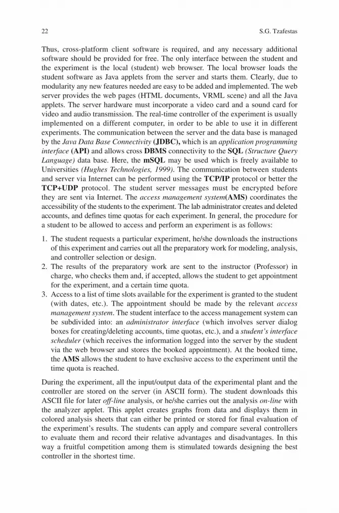
22 S.G. Tzafestas
Thus, cross-platform client software is required, and any necessary additional software should be provided for free. The only interface between the student and the experiment is the local (student) web browser. The local browser loads the student software as Java applets from the server and starts them. Clearly, due to modularity any new features needed are easy to be added and implemented. The web server provides the web pages (HTML documents, VRML scene) and all the Java applets. The server hardware must incorporate a video card and a sound card for video and audio transmission. The real-time controller of the experiment is usually implemented on a different computer, in order to be able to use it in different experiments. The communication between the server and the data base is managed by the Java Data Base Connectivity (JDBC), which is an application programming interface (API) and allows cross DBMS connectivity to the SQL (Structure Query Language) data base. Here, the mSQL may be used which is freely available to Universities (Hughes Technologies, 1999). The communication between students and server via Internet can be performed using the TCP/IP protocol or better the TCP+UDP protocol. The student server messages must be encrypted before they are sent via Internet. The access management system(AMS) coordinates the accessibility of the students to the experiment. The lab administrator creates and deleted accounts, and defines time quotas for each experiment. In general, the procedure for a student to be allowed to access and perform an experiment is as follows:
1. The student requests a particular experiment, he/she downloads the instructions of this experiment and carries out all the preparatory work for modeling, analysis, and controller selection or design.
2. The results of the preparatory work are sent to the instructor (Professor) in charge, who checks them and, if accepted, allows the student to get appointment for the experiment, and a certain time quota.
3. Access to a list of time slots available for the experiment is granted to the student (with dates, etc.). The appointment should be made by the relevant access management system. The student interface to the access management system can be subdivided into: an administrator interface (which involves server dialog boxes for creating/deleting accounts, time quotas, etc.), and a student’s interface scheduler (which receives the information logged into the server by the student via the web browser and stores the booked appointment). At the booked time, the AMS allows the student to have exclusive access to the experiment until the time quota is reached.
During the experiment, all the input/output data of the experimental plant and the controller are stored on the server (in ASCII form). The student downloads this ASCII file for later off-line analysis, or he/she carries out the analysis on-line with the analyzer applet. This applet creates graphs from data and displays them in colored analysis sheets that can either be printed or stored for final evaluation of the experiment’s results. The students can apply and compare several controllers to evaluate them and record their relative advantages and disadvantages. In this way a fruitful competition among them is stimulated towards designing the best controller in the shortest time.

1 Teaching Control and Robotics Using the Web 23
1.6 Some Examples
In this section five examples are provided to support many of the concepts, tools, and methods considered in this chapter. The first two of them deal with internet delay (modeling, estimation, effect on teleoperation stability), and the next three examples present particular remote virtual/physical labs based on different software platforms.
1.6.1 Example 1: Internet Delay Estimation
The ARX model:
( ) ( ) ( ) ( ) ( )− −= − +1 1n m dA q y k B q u k n e k
was applied in [81] both with simulated and real measured data. Two cases were considered: (a) each host sends UDP packets, and (b) each host sends both UDP and TCP packets. Here, u(k)is the packet inter-departure time, and y(k) is the end-to-end packet delay variation. For the computations, input-output data of 100 packets were used. Table 1.1 shows the ARX parameters and their standard deviations found for UDP when ( ) ( )=, , 6,6,1dn m n . The respective results for UDP + TCP are shown in Table 1.2. Comparing the model output ( )y k q , where q are the parameters of the
ARX model ( ) ( )=, , 20,20,1dn m n , it follows that they almost coincide. The slight
difference is due to that the end-to-end packet delay variation is distributed by some
other unknown traffic not included in the model output ( )y k .The model for the UDP + TCP case showed visibly better performance compared
to the pure UDP case.
Table 1.1 ARX parameters and their standard deviations (UDP case)a
6a
5a
4a
3a
2a
1
0.231 0.053 0.136 0.282 0.248 0.261 Coefficients0.013 0.108 0.111 0.114 0.115 0.112 Std. dev.
b6
b5
b4
b3
b2
b1
0.019 0.011 0.008 0.0007 0.021 0.004 Coefficients0.013 0.015 0.016 0.016 0.015 0.016 Std. dev.
Table 1.2 ARX parameters and their standard deviations (UDP + TCP case)
a6
a5
a4
a3
a2
a1
−0.11 −0.029 −0.052 0.018 0.129 0.107 Coefficients0.103 0.107 0.107 0.108 0.106 0.105 Std. dev.
b6
b5
b4
b3
b2
b1
−0.03 0.028 −0.012 0.007 −0.026 0.008 Coefficients0.02 0.024 0.025 0.026 0.025 0.027 Std. dev.

24 S.G. Tzafestas
1.6.2 Example 2: Effect of Time Delay on Teleoperation
A set of simulations were carried out in [83] to study models of communication with and without delay in a simple teleoperation system represented with wave variables (Section 1.3.3). The teleoperation system considered consists of the master controller (a 1-d.o.f. joystick) and the slave robot (a 1-d.o.f. slider). Both the master and the slave subsystems were modeled using the Simmechanics blocks of Matlab/Simulink. The case with no delay corresponds to the situation in which the two subsystems are coupled perfectly. The delay case was firstly simulated without the wave variable technique for time delays of 0.1, 0.2 and 0.5 s. The results in this case show the effect of the delay in the stability of teleoperation. Finally, the system was simulated for the same time delay values using the wave variable technique to verify the improvement of the stability theoretically expected. It was really verified that without the wave variable technique the slave steady-state motion was oscillating without any damping. When the wave variable technique was introduced, the slave motion was dampened and converged to a point just above the set point value of 50 in.. Of course, although the wave variable technique has improved the stability performance of the teleoperation system, the speed of manipulation was shown to be decreased. It was also verified that an increase of the time delay resulted in an increase of the slave slider settling time.
1.6.3 Example 3: The Wheel-Driven Robot Lab of the University of Hagen
The multi-user Java-based remote lab concept of the University of Hagen was firstly implemented on a mechanism wheeled vehicle. A brief discussion of how the students can use this remote lab follows [33, 34]. This vehicle is ommidirectional and can provide any desired motion along x and y axes, and rotation about the z axis. The vehicle is equipped with electronic drives, and the input to the quadrature – axis servo controller is provided by resolver feedback. The vehicle has also available on-board a computer which provides several controller algorithms for fine-tuning and evaluation by the students during the experiment [33]. The student is connected to the server with a Web browser. The browser loads the experiment’s Web page which includes a Java applet to receive the live video and audiostream, and another applet to control the experiment. When the Web page loading is completed, the applet starts. After successful log-in (each student has a log-in name and password), the applet opens a TCP/IP connection to the access control module of the server. When the total time allocated to the student for the current experiment is exhausted, the server disconnects the student from the experiment. The communication between the student and the server is implemented in the form of telegrams via the open TCP/IP connection. During the experiment the student has access to the input-output data ASCII file for either on-line use or for downloading and subsequent analysis. The organization of the student/server communication structure is as shown in Fig. 1.8.
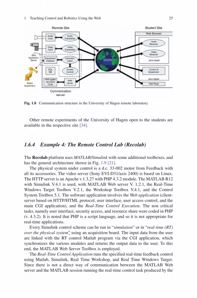
1 Teaching Control and Robotics Using the Web 25
Other remote experiments of the University of Hagen open to the students are available in the respective site [34].
1.6.4 Example 4: The Remote Control Lab (Recolab)
The Recolab platform uses MATLAB/Simulink with some additional toolboxes, and has the general architecture shown in Fig. 1.9 [21].
The physical system under control is a d.c. 33-002 motor from Feedback with all its accessories. The video server (Sony EVI-D31/axis 2400) is based on Linux. The HTTP server is an Apache v.1.3.27 with PHP 4.3.2 module. The MATLAB R12 with Simulink V.4.1 is used, with MATLAB Web server V. 1.2.1, the Real-Time Windows Target Toolbox V.2.1, the Workshop Toolbox V.4.1, and the Control System Toolbox 5.1. The software application involves the Web application (client-server based on HTTP/HTML protocol, user interface, user access control, and the main CGI application), and the Real-Time Control Execution. The non critical tasks, namely user interface, security access, and resource share were coded in PHP (v. 4.3.2). It is noted that PHP is a script language, and so it is not appropriate for real-time applications.
Every Simulink control scheme can be run in “simulation” or in “real-time (RT) over the physical system” using an acquisition board. The input data from the user are linked with the RT control Matlab program via the CGI application, which synchronizes the various modules and returns the output data to the user. To this end, the MATLAB Web Server Toolbox is employed.
The Real-Time Control Application runs the specified real-time feedback control using Matlab, Simulink, Real Time Workshop, and Real Time Windows Target. Since there is not a direct way of communication between the MATLAB Web server and the MATLAB session running the real-time control task produced by the
Fig. 1.8 Communication structure in the University of Hagen remote laboratory

26 S.G. Tzafestas
Real-Time Workshop and Real-Time Window Target toolboxes, a PHP-coded CGI starts the Matlab real-time task with the parameters requested by the student, and synchronizes its execution via a file-based semaphore mechanism.
The purpose of the experiment is to perform several control actions in the local (student) site with the physical system (d.c. motor) in the remote site. The control experiments include the following: system identification, design of a PID position controller, and design of a PID velocity controller. Initially, the student runs a simu-lation of the designed controllers on his/her station, and sends the data of the designed controllers to the remote area for application to the physical system only if the simulation shows that they are correct.
1.6.5 Example 5: The Distributed Control Lab (DCL)
The Distributed Control Lab. (DCL) was developed at the Operating Systems and Middleware (OSM) Group of Hasso-Platner-Institute of the University of Potsdam [97, 98]. It realized a remotely controlled test-bed for interconnected middleware-based components and embedded mobile systems, thus providing an open infrastructure carrying-out control and robotics experiments over the Internet, from a variety of client equipment. The management architecture of DCL involves user authentication,
Real-TimeWorkshop
DAC
VideoServer
Student
Student Site
Remote Site
WebServer
Matlab(m-file)
Real-TimeWindowsTarget
Simulink
DiskFile
MatlabFile
MatlabWeb
Server
WebBrowserHTTP
PhysicalExperiment
(Motor)
DataAcquisition
Fig. 1.9 General architecture of Recolab
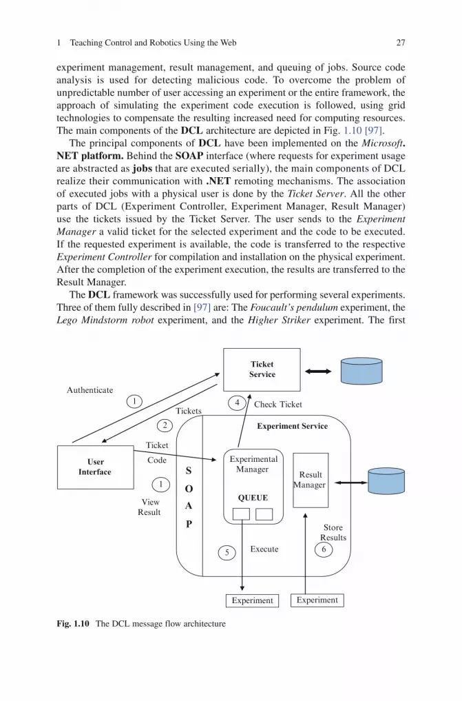
1 Teaching Control and Robotics Using the Web 27
experiment management, result management, and queuing of jobs. Source code analysis is used for detecting malicious code. To overcome the problem of unpredictable number of user accessing an experiment or the entire framework, the approach of simulating the experiment code execution is followed, using grid technologies to compensate the resulting increased need for computing resources. The main components of the DCL architecture are depicted in Fig. 1.10 [97].
The principal components of DCL have been implemented on the Microsoft.NET platform. Behind the SOAP interface (where requests for experiment usage are abstracted as jobs that are executed serially), the main components of DCL realize their communication with .NET remoting mechanisms. The association of executed jobs with a physical user is done by the Ticket Server. All the other parts of DCL (Experiment Controller, Experiment Manager, Result Manager) use the tickets issued by the Ticket Server. The user sends to the Experiment Manager a valid ticket for the selected experiment and the code to be executed. If the requested experiment is available, the code is transferred to the respective Experiment Controller for compilation and installation on the physical experiment. After the completion of the experiment execution, the results are transferred to the Result Manager.
The DCL framework was successfully used for performing several experiments. Three of them fully described in [97] are: The Foucault’s pendulum experiment, the Lego Mindstorm robot experiment, and the Higher Striker experiment. The first
UserInterface S
OA
P
ExperimentalManager
QUEUE
ResultManager
Experiment Service
TicketService
Experiment Experiment
1 4
2
5 6
ViewResult
1
Ticket
Code
Check Ticket
Execute
StoreResults
Authenticate
Tickets
Fig. 1.10 The DCL message flow architecture

28 S.G. Tzafestas
experiment consists of a pendulum with an iron ball swinging over an electromagnet, and the goal of the experiment is to switch on/off the magnet at the right time instants in order to keep the pendulum swinging. The user can be trained on the use of various controllers (e.g., for minimum energy consumption operation or for maximum acceleration within a given period, etc.). In the second experiment, the user can write C-type programs in order to carry out control studies within a predefined operation area.
Finally, in the third experiment, the user can write control programs to accelerate an iron cylinder in a tube of glass, using six electromagnets placed along the tube. This experiment is a difficult real-time control experiment, because the physics (and mathematical equations) behind the movement of the cylinder are very com-plicated. The Higher Striker experiment is used to support the course on “embedded system development” at the Hasso – Plattner – Institute of the Potsdam University.
1.7 Concluding Remarks
Currently, distance education in all of its modes (e-courses, e-classes, virtual labs, remote physical labs) is primarily implemented via the Internet/WWW. Although many Web-based virtual and physical telelabs are available for open use in the WWW, the majority of them represent “stand-alone” systems and platforms without any interoperability and reusability features. Therefore, a challenging area in the Web-based control and robotics education field is that of producing new software environments with maximum degrees of interoperability, reusability and sharing. The most popular general purpose software platforms for creating Web-based control and robotics course materials and remote labs are the Matlab(Math Works), the LabView(National Instruments) environments, and the C/C++ and Java languages.
1.8 Appendix: Software Environments for Developing Web-Based Educational Platforms
For completeness and the convenience of the novice reader, this Appendix provides a minimum amount of information on the software environments and tools available for use in the design and running of Web-based control and robotics educational platforms. Prior to this, a short presentation of Web 2.0 which was recently introduced in the Internet field is made.
1.8.1 Web 2.0
The term Web 2.0 appeared for the first time in the “2004 Web 2.0 Conference” and refers to the new attitude in employing the WWW so as to stimulate and help improving the user creativity and information sharing, and, particularly, in strengthening the

1 Teaching Control and Robotics Using the Web 29
cooperation among developers and users. The concept of Web 2.0 does not include any upgrade of the technical features of the Web, but it rather guides to a new version of the WWW which changes the ways software developers and end-users employ the Web [99] (http://en.wikipedia.org/wiki/Web_2). According to the definition provided in [100]: “Web 2.0 is the business revolution in the computer industry caused by the move to the Internet as platform, and an attempt to understand the rules for success on that new platform”. The term and concept of Web 2.0 has been questioned by many scientists and has produced a strong debate among the Internet experts [101, 102]. The use of Web 2.0 in e-learning is discussed in [103], along with a discussion of the pedagogical theories that support the exploitation of Web 2.0 for creating personalized and collaborative learning environments via a socio – technical approach. The new skills that are enabled by Web 2.0 will unavoidably influence the capabilities offered by Web-based virtual and remote control and robotics labs.
1.8.2 Matlab
The Matlab (Matrix laboratory) of the MathWorks Company (founded in 1984) is a numerical computation environment and computer language used widely all over the World in education of mathematics, science, and engineering. Matlab is constructed around the Matlab language (sometimes called M-code or simply M). Today, the tool called Matlab Builder is provided to deploy Matlab functions as library files which can be used with the .NET or Java application building environ-ment. The computer to which the application has to be installed needs the Matlab Component Runtime(MCR) software tool, which is freely available with library files generated by the Matlab computer [104–106].
Educational material for computations in mathematics, physics, and engineering fields is provided in the sites of many Universities (e.g., Rice University, University of Michigan, University of New Hampshire, University of Berkeley, University of San Diego, etc.). In particular the Carnegie Mellon University offers control tutorials with Matlab, a Virtual Control Lab (VCLab) using Netscape plugins and Java applets with Matlab/Simulink to perform control experiments over the Web, and the Control Systems Tutorials where a collection of controller design tutorials in Matlab Notebook form is provided for free use. Other topics, for which plenty of tutorials, examples and exercises are provided, include: digital signal processing, image processing, fuzzy controls, vibration analysis, an robotics (see [107]). Detailed infor-mation and links to all of these University sites are given collectively in [108].
1.8.3 LabVIEW
The LabVIEW (Laboratory Virtual Instrumentation Engineering Workbench) is a development environment for a visual programming language developed by NI (National Instruments). LabVIEW is typically used for data acquisition, instrument

30 S.G. Tzafestas
control, and industrial automation on a variety of platforms including Microsoft Windows, and several versions of UNIX, Linux, and MacOS [109]. The programming language used in LabVIEW is called G, and is a data flow programming language. The execution sequence of the LabVIEW graphical syntax is as well defined as with any textually coded language (C, Visual BASIC, etc.). LabVIEW embeds into the development cycle, the construction of user interfaces (called “front panels”). LabVIEW programs and subroutines are called virtual instruments(VIs), each one of which has three elements (block diagram, front panel, connector panel). The front panel exhibits controls and indicators that allow a user to input data into or extract data from a running VI. In addition, the front panel can also act as a programming interface. A benefit of LabVIEW over other development environments is the extensive support for accessing instrumentation hardware [110, 111].
1.8.4 VRML
VRML (Virtual Reality Markup Language) is a standard text file format for repre-senting 3-dimensional (3D) interactive vector graphics, designed particularly for use in the WWW [112]. In VRML one can specify vertices and edges for a 3D polygon along with the surface color, UV mapped textures, brightness, transparency, and so on. URLs can be associated with graphical components. Thus, when the user clicks a particular graphical component, a Web page or a new VRML file can be brought by a Web browser from the Internet. The user can trigger via external events (e.g., timers) animations, sounds, lighting, etc., or interact with them. The addition of a program code (written in Java or Java Script, etc.) to a VRML file can be done via a special Script Node. VRML, now reengineered as X3D, is extensively used in education and research, where an open specification is most preferred. VRML is also widely used as a file format for interchange of 3D models, particularly from CAD systems [113, 114].
1.8.5 Java
The Java programming language was released in 1995 by Sun Microsystems. Today, most of the Java technologies are offered as free and open source software according to the General Public License of GNU [115]. Java Standard Edition platform is licensed by Sun Microsystems for Linux, Solaris and Microsoft Windows. Java follows the object oriented programming approach, and is “platform inde-pendent”, i.e. programs written in the Java language can run on any supported hardware-operating system platform [116]. This is done by compiling the Java code to byte code (i.e. half way), which is then run or any Java virtual machine (JVM) regardless of computer architecture. JVM is a program written in native code on

1 Teaching Control and Robotics Using the Web 31
the host hardware which interprets and executes generic Java bytecode. The syntax of Java is basically derived from C and C++ but possesses a simpler object model and less low-level means. A Java program is executed by saving the code as a file and first compiled into bytecode via a Java compiler, the result being a “class” file. This class file is then launched. An applet of Java is a program which is embodied in other applications, usually in a Web page viewed on a Web browser [117]. An applet is placed in an HTML document. An Abstract Windowing Toolkit (AWT) component enable the applet to display a GUI and react to user events. Applets can be embedded using the applet tag or the object tag element [118]. The functionality of a Web server can be extended using the Java Servlet facility. Servlet provides responses (e.g., HTML pages) to requests (e.g., HTTP requests) from users. The Java platform is equipped with a Swing application, i.e. GUI library that creates respective windows. The software needed to run an application installed on the Java platform is the Java Runtime Environment (JRE). A JRE is usually run in software packages and Web browser plugins. Java offers libraries which are the compiled byte codes of source code developed by the JRE for supporting the development of Java applications. Java is available in three different platforms that accommodate different sets of APIs (Java Micro Edition(ME), Java Standard Edition (SE) and Java Enterprise Edition (EE)). Java ME is suitable for platforms with limited resources, Java SE is used in workstation environments, and Java EE is appropriate for large enterprise or the Internet environment. Sun offers rich tutorials for developers who want to use the Java programming language to create applications [119, 120].
1.8.6 HTML and HTTP
The Internet development started in 1989 at CERN as a result of the efforts to link textual information on several computers, created by different scientists. The result of this work is the concept of “hypertext” which allows information to be linked not in a linear hierarchical way but in a web-like structure. Information nodes can be linked to other nodes in multiple ways, allowing users to dynamically criss-cross the information web using pieces in the most convenient order. The outcome of the CERN project was the WWW front-end to the Internet. Later, the CERN product was pushed further at Illinois University developing the first Web browser: “Mosaic”. Now, we have available many other popular Web browsers, namely Netscape, Microsoft’s Internet Explore and Mozilla. A Web browser facilitates the access of information residing on another remote computer. The documents that are to be viewed by a browser are formatted using HTML (Hyper Text Markup Language). HTML is a markup language (not a programming language) used to construct the WWW.HTML uses a fixed set of markup tags (codes) embedded in the text, i.e. it can be thought of as a “presentation language”. But, to make pages interactive, programming code can be embedded in a HTML page (e.g., Java Script is typically interspread in Web (HTML) pages). To access a Web document, one must type-in the address (URL: Uniform Resource Locator) of the home page in his/her Web

32 S.G. Tzafestas
browser. Web browsers communicate with Web servers through the TCP/IP protocol. The browser sends to the server HTTP requests. The server replies with HTML pages and possibly with Java applets.
HTTP (Hyper Text Transfer Protocol) is the standard application – level protocol employed for transporting files on the WWW.HTTP works in conjunction with the TCP/IP protocol. The basic operation of HTTP is to realize a connection with the Web server and return Web pages to the user’s browser. HTTP is also used to download server files to the user’s browser or to other applications that request these files via HTTP. The TCP connection between the server and the user is main-tained during the files’ transfer. The connection is closed when the server completes the transfer of the requested file to the user.
1.8.7 PHP Hypertext Preprocessor
PHP (Hypertext PreProcessor) has taken its original name from Personal Home Page (Rasmus Lerdorf) [121], and is a general-purpose scripting language appro-priate for developing dynamic Web pages. On August 7, 2008 the PHP development has released the PHP 4.4.9 which is the last PHP 4.4 release [122]. PHP can run on a Web server with PHP code as input and Web pages as output. It is offered free of charge and can be installed on most web servers, platforms, and operating systems, (Mac OSX, Linux, Windows). It can work with many relational data base systems. If one wants to save considerable bandwidth, and develop locally, he/she can use a web server such as an Apache and install a data base such as MySQL. The PHP manual provides the proper installation instructions, and the PHP tutorial shows the basics of PHP [123]. PHP-enabled web pages can be created, edited, and handled in the same way as HTML pages.
1.8.8 CORBA
CORBA (Common Object Request Broker Architecture) is an open vendor-independent architecture and infrastructure produced and offered by OMG [124]. Through the standard IIOP protocol, a CORBA-based program from any vendor (on almost any computer, operating system, programming language, and network) can interoperate with any other CORBA-based program. CORBA is a middleware suitable for servers that have to handle reliably large number of users at high hit rates. CORBA takes successful care of issues like load balancing, resource control, and fault tolerance on the server side. CORBA2 and CORBA3 represent complete releases of the entire CORBA specification [125].

1 Teaching Control and Robotics Using the Web 33
References
1. G. Gallego, WBT: State – of – the art in web-based training, http://www.gracespace.com/weblearn/state.htm#critical.
2. M. M. Driscoll, Defining internet and web-based training, Journal of Performance and Instruction, Vol. 36, No. 4, pp. 5–9, 1997,http://home.vicnet.net.au/~carlrw/net2000/ten_things_we_know.html.
3. D. Mioduser, R. Nachmias, U. Lahav, A. Oren, Web-based learning environments: Current pedalogical and technological state, Journal of Research on Computing in Education, Vol. 33, No. 1, pp. 55–76, 2000, http://muse.tau.ac.il/publications/wble-54.html.
4. D. Mioduser, R. Nachmias, A. Oren, O. Lahav, Web-based learning environments (WBLE): Current state and emerging trends, Proceedings of World Conference on Educational Multimedia, Hypermedia and Telecommunications (EDMEDIA ‘98), pp. 753–758, 1998.
5. University of Idaho, Distance Education at a Glance (Guides 1 through 13), College of Engineering Outreach, Moscow, October 1995, http://www.uidaho.edu/eo.
6. G. J. C. Cpinga, M. H. G. Verhaegen, M. J. J. M. van de Ven, Toward a web-based study support environment for teaching automatic control, IEEE Control Systems Magazine, Vol. 20, pp. 8–19, Aug. 2000, http://lcewww.et.tudelft.ne/~babuska/Gerald.html.
7. Drexel University, Laboratory development for robotics and automation education using Internet based technology, 2006, http://www.drexel.edu/goodwin/faculty/ASEENSFCon06_final.pdf.
8. M. Terbuc, S. Uran, A. Rojko, K. Jezernik, Web based education of robotics and mechatronics at the University of Maribor, Proceedings of the Conference on Advances in Internet Technologies and Applications (CAITA 2004), Purdue, USA, July 8–11, 2004.
9. M. S. Zywno, D. C. Kennedy, Integrating the internet, multimedia components, and hands-on experimentation into problem-based control education, Proceedings of the 30th ASEE/IEEE Frontiers in Education Conference, Kansas City, MO, Oct. 2000.
10. D. J. Hagreaves, Student learning and assessment are inextricably linked, European Journal of Engineering Education, Vol. 4, No. 22, pp. 401–410, 1997.
11. A. Khamis, F. Rodriguez, M. Salichs, Multiact approach for building web-based educational environments: Mobile robotics course as a case study, Proceedings of 11th Mediterranean Conference on Control and Automation (MED ‘03), Rhodes, Greece, June 18-20, 2003.
12. I. Masar, A. Bischoff, M. Gerke, Remote experimentation in distance education for control engineers, Proceedings of 5th International Conference on Virtual University, Bratislava, Slovakia, Dec. 16-17, 2004.
13. S. E. Poindexter, B. S. Heck, Using the Web in your courses: What can you do? what should you do?, IEEE Control Systems Magazine, Vol. 19, No. 1, pp. 83–92, 1999.
14. S. G. Tzafestas, Teaching control engineering over the internet: A rapidly growing approach with future, In: S. Pennachio (ed.), Recent Advances in Control Systems, Robotics and Automation (3rd edition), Internationalsar.org, 2009.
15. S. H. Yang, J. L. Alty, Development of a distributed simulator for control experiments through the internet, Future Generation Computer Systems, Vol. 18, pp. 595–611, 2002.
16. C. Schmidt, The virtual lab VCLAB for education on the Web, Proceedings of the 17th American Control Conference, Philadelphia, PA, pp. 1314-1318, 1998.
17. K. M. Lee, W. Daley, T. McKlin, An interactive learning tool for dynamic systems and control, Proceedings of the International Mechanical Engineering Congress & Exposition, Anaheim, CA, pp. 71-76, 1998.
18. VRML Archives.http://web3d.org/x3d/vrml/index/html.19. G. Carnevali, G. Buttazo, A virtual laboratory environment for real time experiments, Proceedings
of the 5th IFAC International Symposium on Intelligent Components and Instruments for Control Applications (SICICA ‘03), Aveiro, Portugal, pp. 39-44, July 9-11, 2003.

34 S.G. Tzafestas
20. P. Gai, L. Abeni, M. Giorgi, G. Buttazo, A new Kernel approach for modular real-time system development, Proceedings of the 13th IEEE Euromicro Conference on Real Time Systems, Delft, The Netherlands, 2001.
21. R. Puerto, L. M. Limenez, O. Reinoso, C. Fernandez, R. Neco, Remote control laboratory using Matlab and Simulink: Application to a dc motor model, Proceedings of the Second IFAC Workshop on Internet Based Control Education (IBCE 2004), Grenoble, France, Sept. 5-7, 2004.
22. S. Uran, D. Hercog, K. Jezernik, MATLAB Web server and web-based control design learning, Proceedings of the 3rd IEEE Annual Conference on Industrial Electronics (IECON ‘2006), pp. 5420–5425, 2006.
23. B. Duan, K.-V. Ling, H. Mir, M. Hosseini, R. Kheng, G. Leng, An online laboratory framework for control engineering courses, International Journal of Engineering Education, Vol. 21, No. 6, pp. 1068–1075, 2005.
24. M. Casini, D. Prattichizzo, A. Vicino, The automatic control telelab: A web-based technology for distance learning, IEEE Control Systems Magazine, Vol. 24, No. 3, pp. 36–44, June 2004, http://dii.unisi.it.
25. Q. Yu, B. Chen, H. H. Cheng, Web-based control system design and analysis: Design, implemen-tation, and salient features, IEEE Control Systems Magazine, Vol. 24, No. 3, pp. 45–47, June 2004, http://softintegration.com/webservices/control.
26. C. Martin, A. Urquia, S. Dormido, Implementation of interactive virtual laboratories for control education using modelica, Proceedings of European Control Conference 2007 (ECC ‘07), Kos, Greece, pp. 2679-2686, July 2007.
27. R. Safaric, M. Truntic, D. Hercog, G. Pacnic, Control and robotics remote laboratory for engi-neering education, International Journal of Online Engineering (iJOE), www.i-joe-org.
28. A. Tanoto, U. Witkowski, U. Ruckert, Teleworkbench: A teleoperated platform for multi-robot experiments, Proceedings of AMiRE 2005, Fukui University, Japan, Sept. 21–22, 2005.
29. C. S. Tzafestas, N. Palaiologou, M. Alifragis, Virtual and remote robotics laboratory, IEEE Transactions on Education, Vol. 49, No. 3, pp. 360–369, 2006.
30. M. Sedlak, K. Zakova, Remote experiments in Matlab, Proceedings.of European Control Conference (ECC ‘07), Kos, Greece, pp. 2707-2713, July, 2007.
31. M. Chaabene, K. Mkaouar, M. Ouali, A web-based interactive real laboratory for process engineering education, Journal of Computer Science, Vol. 3, No. 7, pp. 540–547, 2007.
32. J. Schwarz, A. Polze, K. Wehner, L. Sha, Remote lab: A reliable tele-laboratory environment, Proceedings of International Conference on Internet Computing (IC ‘2000), Las Vegas, NV, pp. 55–61, June 26-29, 2000.
33. H. Hoyer, A. Jochheim, C. Rohrig, A. Bischoff, A multiuser virtual-reality environment for a tele-operated laboratory, IEEE Transactions on Education, Vol. 47, pp. 121–126, Feb. 2004.
34. Real Systems in Virtual Lab. Access to the remote web-based experiments of theFern Universitat in Hagen (Department of Electrical Engineering), http://rsv1.fernuni-hagen.de/sps/sprail.
35. K. Yeung, J. Huang, Development of a remote-access laboratory: A dc motor control experi-ment, Computers in Industry, Vol. 52, No. 3, pp. 305–311, 2003, http://www.acae.cuhk.edu/ohk/~accl/ibc/.
36. J. Z. Zhang, A. K. Ball, M. Clare, W. Extine, Design of a real-time remote-access engineering laboratory using integrated Web service and wireless technology for distance learners, World Transactions on Engineering Technology and Education, Vol. 4, No. 2, pp. 231–234, 2005.
37. N. J. Ploplys, P. A. Kawka, A. G. Alleyne, Closed-loop control over wireless networks, IEEE Control Systems Magazine, Vol. 24, No. 3, pp. 58–71, 2004.
38. H. Ye, G. Walsh, L. Bushnell, Wireless local area networks in the manufacturing industry, Proceedings of 2000 American Control Conference, Chicago, IL, pp. 2236-2367, June 2000.
39. Marton, Log Me In in a corporate environment, White Paper 3am Labs., 2004, http://secure.logmein.com/wp_lmi_corporate.pdf .
40. Marton, Log Me In security: An in-depth look, White Paper 3am Labs, 2004, http://secure.logmein.com/wp_lmi_security.pdf.

1 Teaching Control and Robotics Using the Web 35
41. R. Goertz, R. Thompson, Electronically controlled manipulator, Nucleonics, Vol. 12, No. 11, pp. 46–47, 1954.
42. T. B. Sheridan, Telerobotics, Automation and Human Supervisory Control, MIT Press, Cambridge, MA, 1992.
43. S. G. Tzafestas, C. S. Tzafestas, Virtual reality in telerobotics: An overview and two case studies, Proceedings of the 4th International Conference on Software for Electrical Engineering Analysis and Design (Electrosoft ‘99), Seville, Spain, May 17–19, 1999.
44. T. Mirfakhrai, S. Payandeh, A delay prediction approach for teleoperation over the internet, Proceedings of IEEE International Conference on Robotics and Automaion (ICRA ‘02), May 11–15, 2002.
45. R. J. Anderson, M. W. Spong, Bilateral control of teleoperators with time delay, IEEE Transactions on Automatic Control, Vol. AC-34, No. 5, pp. 494–501, May 1989.
46. G. Niemeyer, J. Slotine, Towards force reflecting teleoperation over the internet, Proceedings International Conference on Robotics and Automation (ICRA ‘98), Leuven, Belgium, pp. 1909–1915, 1998.
47. K. Brady, T. J. Tarn, Internet-based remote teleopetation, Proceedings of IEEE International Conference on Robotics and Automation, pp. 65-70, 1998.
48. S. Munir, W. J. Book, Internet-based teleoperation using wave variable with prediction, Procedings of IEEE/ASME Trans on Mechatronics, Vol. 7, pp. 124–133, 2002.
49. W. H. Zhu, S. E. Salcudean, Stability guaranteed teleoperation: An adaptive motion/force control approach, IEEE Transactions on Automatic Control, Vol. AC-45, No. 11, pp. 1951–1969, 2000.
50. D. A. Lawrence, Stability and transparency in bilateral teleoperation, IEEE Transactions on Robotics and Automation, Vol. 9, No. 5, pp. 625–637, 1993.
51. A. Sano, H. Fujimwra, M. Tanaka, Gain scheduled compensation for time delay of bilateral teleoperation systems, Proceedings of the IEEE International Conference on Robotics and Automation, Leuven, Belgium, pp. 1916–1923, 1998.
52. S. G. Tzafestas, P. A. Prokopiou, Compensation of teleoperator modeling uncertainties with sliding-mode controller, Robotics and Computer-Integrated Manufacturing, Vol. 13, No. 1, pp. 9–20, 1997.
53. P. A. Prokopiou, S. G. Tzafestas, W. S. Harwin, A novel scheme for human-friendly and time delays robust neuropredictive teleoperation, Journal of Intelligent and Robotic Systems, Vol. 25, No. 4, pp. 311–340, 1999.
54. P. A. Prokopiou, C. S. Tzafestas, E. S. Tzafestas, S. G. Tzafestas, Neural network robust-adaptive telemanipulator control: Comparison with sliding-mode control, System Analysis Modelling Simulation, Vol. 33, pp. 259–294, 1998.
55. K. Goldberg, M. Maschna, S. Gentner, N. Rothenberg, C. Sutter, J. Wiegley, Desktop teleop-eration via the WWW, Proceedings of the IEEE International Conference on Robotics and Automation, pp. 654–659, 1995.
56. http://telegarden.aec.at .57. http://telerobot.mech.uwa.edu.au .58. http://netrolab.cs.rdg.ac.uk.59. G. T. Mc Kee, A virtual robotics laboratory for research, Proceedings of SPIE, Vol. 25, No.
89, pp. 162–171, 1995.60. B. G. Brooks, G. T. McKee, The visual acts model for automated camera placement during
teleoperation, Proceedings of the IEEE International Conference on Robotics and Automation (ICRA 2001), Korea, 2001.
61. J.-Y. Mignolet, S. Vernalde M. Engels, A low-power reconfigurable appliance camera, Revue High Frequency Electronique Telecommunications, Vol. 4, No. 4, pp. 4–11, 2000.
62. T. Kaga, S. Nojima, E. Nanma, M. Tamura, H. Nakagane, Internet camera system, Matsushita Technical Journal, Vol. 44, No. 5, pp. 66–73, 1998.
63. D. Kimber, Q. Liu, J. Foote, L. Wilcox, Capturing and presenting share multi-resolution video, Proceedings of SPIE (ITCOM 2002), Vol. 48-62, pp. 261-271, Boston, MA, July 2002.

36 S.G. Tzafestas
64. Q. Liu, D. Kimber, L. Wilcox, M. Cooper, J. Foote, J. Boreczky, Managing a camera system to serve different video requests, Proceedings of IEEE International Conference on Multimedia and Expo (ICME ‘2002), Lausanne, Switzerland, Vol. 2, pp. 13–16, Aug. 2002.
65. D. Song, K. Y. Goldberg, ShareCam Part I: Interface, system architecture, and implementation of a collaboratively controlled robotic webcam, Proceedings of IEEE/RSJ International Conference on Intelligent Robots (IROS ‘03), Nov. 2003, http://www.tele-actor.net/sharecam/.
66. D. Song, A. Pashkevich, K. Goldberg, Share Cam Part II: Approximate and distributed algo-rithms for a collaborative controlled robotic webcam, Proceedings of IEEE/RSJ International Conference on Intelligent Robots (IROS ‘03), Nov. 2003.
67. D. Song, K. Y. Goldberg, Approximate algorithms for collaboratively controlled robotic camera, IEEE Transactions on Robotics, Vol. 23, No. 5, pp. 1061–2007, Oct. 2007.
68. M. Perry, D. Agarwal, Remote control for video-conferencing, Proceedings of the International conference of the Information Resources Management Association., Anchorage, AK, USA, 2000.
69. D. Schmidt, B. Maule, I. Roth, Performance teletests for industrial robots by internet, Proceedings of 1st IFAC Conference on Telematics Applications in Automation and Robotics (TA 2001), Weingraten, Germany, 2001.
70. N. Chong, T. Kotoku, K. Ohba, K. Komoriya, N. Matsuhira, K. Tanie, Remote coordinated controls in multiple telerobot cooperation, Proceedings of the IEEE International Conference on Robotics and Automation (ICRA ‘2000), Vol. 4, pp. 3138–3143, Apr. 2000.
71. K. Kurose and K. Ross, Computer Networking, Addison-Wesley, Reading, MA, 2001.72. J. C. Bolot, Characterizing end-to-end packet delay and loss in the internet, Journal of High-Speed
Networks, Vol. 2, pp. 305–323, 1993.73. S. B. Moon, J. Kurose, P. Skelly, D. Towsley, Correlation of packet delay and loss in the
internet, Technical Report, Computer Science Department, University of Massachusetts, USA, Jan. 1998.
74. V. Paxson, End-to-end packet dynamics, Proceedings of ACM (SIGCOMM ‘97), pp. 139–152, Sept. 1997.
75. M. Allman, V. Paxson, On Estimating end-to-end path properties, Proceedings of the ACM (SIGCOMM ‘99), Aug. 1999.
76. Adams et al., The use of end-to-end multicast measurements for characterizing internal network behavior, IEEE Communications, Vol. 38, pp. 152–159, 2000.
77. J. Huang, Neurocontrol and telerobotic systems with time delays, Ch.8: in: F. L. Lewis, J. Campos, R. Selmic, Neuro-Fuzzy Control of Industrial Systems with Actuator Nonlinearities, SIAM, Philadelphia, PA, 2002.
78. Y. Tipsuwan, M.-Y. Chow, Control methodologies in networked control systems, Control Engineering Practice, Vol. 11, No. 10, pp. 1099–1111, 2003.
79. H. Che, S.-Q. Li, Fast algorithms for measurement-based traffic modeling, IEEE Journal on Selected Areas in Communications, Vol. 16, No. 5, pp. 612–625, June 1998.
80. L. A. Kulkarni, S.-Q. Li, Measurement-based traffic modeling: Capturing important statistics, Journal Stochastic Modeling, Vol. 14, No. 5, pp. 1113–1150, 1998.
81. E. Kamrani, H. R. Momeni, A. R. Sharafat, Modeling internet delay dynamics for teleoperation, Proceedings of the 2005 IEEE Conference on Control Applications, Toronto, Canada, pp. 1528-1533, Aug. 2005.
82. S. H. Low, F. Paganini, J. Wang, S. Adlakha, J. C. Doyle, Internet congestion control: An analytical perspective, IEEE Control Systems Magazine, Vol. 7, pp. 28–43, Feb. 2002.
83. M. I. Can Dede, S. Tosunoglu, D. W. Repperger, Effects of time delay on force feedback teleoperation systems, Proceedings 12th Mediterranean Conference on Control and Automation (MED ‘04), Kusadasi, Aydin, Turkey, June 2004.
84. M. Yang, X. Rong Li, Predicting end-to-end delay of the internet using time-series analysis, University of New Orleans (Technical Report), Lake front, Nov. 2003.
85. G. E. Box, G. M. Jenkins, Time Series Analysis: Forecasting and Control, Holden-Day, San Francisco, CA, 1976.
1 Teaching Control and Robotics Using the Web 37
86. H.-Y. Li, Y.-H. Ke, A novel network transmission architecture for internet-based process control systems, Proceedings of the IEEE (IECON ‘98), 31 Aug. – 4 Sept., pp. 0–3-xxix, 1998.
87. R. Braden, Resource reservation protocol-version 1 functional specification, IETF: RSVP Working Group, Draft-ietf-rsvp-spec-14, Nov. 1996.
88. S. G. Tzafestas, E. S. Tzafestas, Human-machine interaction in intelligent robotic systems: A unifying consideration with implementation examples, Journal of Intelligence and Robotic Systems, Vol. 32, No. 2, pp. 119–141, 2001.
89. M. G. Helander, T. K. Landauer, P. V. Prabhu (eds.), Handbook of Human-Computer Interaction, North-Holland, Amsterdam, 1997.
90. S. G. Tzafestas, Knowledge-Based System Diagnosis, Supervision and Control, Plenum, London, 1989.
91. S. G. Tzafestas (Guest Editor), Special issue on systems modelling, analysis and design, System Analysis Modelling Simulation, Vol. 38, No. 2, 2000.
92. S. G. Tzafestas (ed.), Applied Control: Current Trends and Modern Methodologies, Marcel Dekker, New York, 1993.
93. Y. Piguet, D. Gillet, Java-based remote experimentation for control algorithms prototyping, Proceedings of 1999 American Control Conference, San Diego, CA, Vol. 2, pp. 1465-1469, 1999.
94. J.W. Overstreet, A. Tzes, An internet-based real-time control engineering laboratory, IEEE Control System Magazine, Vol. 19, pp. 19–34, 1999.
95. S. Shirmohammadi, J. C. Oliveira, N. Georganas, Applet-based telecollaboration: A network centric approach, IEEE Multimedia, Vol. 5, pp. 64–73, Apr.-June 1998.
96. J. C. Oliveira, S. Shirmohammadi, N. Georganas, Distributed virtual environment standards: A performance evaluation, Proceedngs of the 3rd IEEE/ACM International Workshop on Distributed Interactive Simulation & Real Time Applications, pp. 14-21, Oct. 1999.
97. B. Rasche, P. Rabe, A. P. Troeger, Distributed Control Lab, http://www.dcl.hpi.uni-potsdam.de/research/papers/virtuallab_2004_rasche_rube_polze.pdf > & < http://www.dcl.hpi.uni-pots-dam.de/research/dcl/.
98. A. Rasche, P. Troeger, M. Driska, A. Polze, Foucault’s pendulum in the distributed control lab, Proceedings of the 9th IEEE International Workshop on Object – Oriented Real-Time Dependable Systems, pp. 289-296, Oct. 1-3, 2003.
99. T. O’Reilly, What is Web 2.0 (30 Sept. 2005), http://www.oreillynet.com/pub/a/oreilly/tim/news/2005/9/3/what-is-web-20.html.
100. T. O’Reilly, Web 2.0 compact definition: Trying again (10 Dec. 2006), http://radar.oreilly.com/archives/200/12/web_20_compact.html.
101. T. Berners-Lee, Developer Works Interviews (28 July 2006), http://www.ibm.com/develop-erworks/podcast/dwi/cm-int082206txt.html.
102. D. Best, Web 2.0: Next big thing or next big internet bubble?, Lecture Web Information Systems, Eindhoven Technical University, 2006.
103. M. Sigala, Integrating Web 2.0 in e-learning environments: A socio-technical approach, International Journal of Knowledge and Learning, Vol. 3, No. 6, pp. 628–648, 2007.
104. F. S. Quarteroni, Scientific Computing with Matlab and Octave, Springer, Berlin, 2006.105. http://www.mathworks.com/products/matlab.106. http://www.matlabtutorials.com.107. P. Corke, A robotics toolbox for Matlab, IEEE Robotics and Automation Magazine, Vol. 3,
No. 1, pp. 24–32, Mar. 1996, http://www.ict.csiro.au/downloads/robotics/. 108. http://www.ee.ucr.edu/EEsystems/docs/Matlab .109. J. Travis, J. Kring, LabVIEW for Everyone: Graphical Programming Made Easy and Fun
(3rd edition), Prentice-Hall, Upper Saddle River, NJ, July 2006.110. LabVIEW Pricing and Products, http://ni.com/labview/.111. LabVIEW Student Edition, http://ni.com/labviewse/.112. VRML Archives, http://www.web3d.org/x3d/vrml/index/html.

38 S.G. Tzafestas
113. VRML and X3D Description, http://xml.coverpages.org/vrml-X3D.html > , < http://web3d.org/x3d/specifications/vrml/.
114. Extensible 3D: XML Meets VRML, http://www.xml.com/pub/a/2003/08/06/x3d.html115. JAVA ONE: Sun – The bulk of Java is open sourced, http://open.itworld.com/4915/070508opsjava/
page_1.html.116. The Java Language Environment, http://java.sun.com/docs/white/langenv/.117. Java Applets, http://java.sun.com/javase/6/docs/api/java/Applet.html.118. Java Applet Tag, http://java.sun.com/docs/books/tutorial/deployment/applet/applettag.html.119. Java Tutorials, http://java.sun.com/docs/books/tutorial.120. J. Gosling, B. Joy, G. Steele, G. Braha, The Java Language Specification (3rd edition), Addison-
Wesley, Reading, MA 2005, http://java.sun.com/docs/books/vmspec/2nd-edition/html/VMSpec TOC.doc.html.
121. PHP.Net History, http://php.net/history.122. http://php.net.123. http://gr.php.net/tut.php.124. http://omg.org.125. http://omg.org/gettingstarted/corba faq.htm.
Chapter 2Control System Design and Analysis Education via the Web
Harry H. Cheng, Bo Chen, and David Ko
2.1 Introduction
Advances in mathematics and computing technology have greatly expanded the range of control systems and engineering problems that can be solved [1]. As methodologies become more computational intensive, the desire for development of innovative teaching and learning software has increased. To meet the demand, software packages such as the MATLAB Control Systems Toolbox [2] and Mathematica’s Control System Professional [3] have been developed and made commercially available for the purpose of computer aided control system design and analysis.
Web based computing has proven to be an efficient and reliable method of performing complex tasks in recent times. Web based applications allow users to use applications that may not reside on their own computers. These tools also serve as a promising technology that could greatly improve the teaching and student learning of control systems by allowing students to quickly and easily try out different control systems from a simple web interface without needing to install or run special software [4, 5]. Web based computing in the field of automatic control systems and education have also undergone rapid development in recent years. Many virtual and remote laboratories have been developed on a variety of backends and web interfaces, utilizing technologies such as Java applets, databases, and webcams to record physical experimentation apparatuses [68].
An embeddable C/C++ interpreter known as Ch has been developed by Cheng [9]. The Ch language is a superset of C and fully supports all C99 constructs, including complex numbers, variable length arrays, and IEEE floatingpoint arithmetic and typegeneric mathematical functions. Ch also supports C++ classes for objectoriented programming. In addition, Ch has builtin 2D and 3D plotting capabilities, as well as support for computational arrays for matrix computation and linear system analysis.
H.H. Cheng (), B. Chen, and D. Ko Department of Mechanical and Aeronautical Engineering, University of California, One Shields Avenue, Davis, CA 95616, [email protected], http://iel.ucdavis.edu/people/cheng.html
S.G. Tzafestas (ed.), Web-Based Control and Robotics Education, 39Intelligent Systems, Control and Automation: Science and Engineering 38,DOI 10.1007/9789048125050_2, © Springer Science + Business Media B.V. 2009
40 H.H. Cheng et al.
Utilizing the unique feature set found in Ch, a number of toolkits have been developed in Ch. This chapter will introduce the Ch Control System Toolkit (CCST) [10, 11] in conjunction with the Ch CGI Toolkit [12] and the Webbased Control System Design and Analysis System (WCDAS) [1315] for teaching automatic control systems. These packages offer web capabilities that are hard or inconvenient to develop under the previously mentioned MATLAB and Mathematica packages. In addition, the packages to be discussed will allow a user to design and implement their own webbased interface for control systems engineering. This aspect is fundamentally different from a virtual laboratory, where the user does not necessarily have any design input for the web page or program flow. The advantages provided by these packages will be discussed in detail in the remainder of the chapter. Example usage of sample WCDAS application will also be presented to design a simple controller via root locus. Example development of the web based software will also be presented.
2.2 Ch Control Systems Toolkit
The Ch Control Systems Toolkit (CCST) [10, 11] is an objectoriented module developed in the Ch computing environment [16]. The module provides a class with member functions for the modeling, analysis, and design of linear, timeinvariant (LTI) control systems. All commonly used functions are provided including functions for timedomain response, frequencydomain response, system analysis, system design, model conversion, and system conversion. These functions may be applied to a number of continuous and discrete LTI systems which may be modeled in singleinput singleoutput (SISO) systems, multiinput multioutput (MIMO) systems, statespace equations, transfer functions, or zeropolegain representations. The major features of the CCST are listed below.
• C/C++Compatible• Objectoriented• Embeddable• Web-based• Modelbuilding• Continuous/discretesystemsconversions• Systeminterconnectingandreduction• Timedomainanalysis• Frequencydomainanalysis• Rootlocusdesign• Controllabilityandobservability• State-spacedesign• Optimalcontrolsystemdesignandequationsolvers• Plottingutilities
Traditionally, control systems simulation and modeling code is written using mathematical environments such as MATLAB or Mathematica, but these applications

2 Control System Design and Analysis Education via the Web 41
are not designed to directly support actual usable realtime control. Although most of these environments provide translators to convert the control code into a language usable for realtime control, such as C [17], the reproduction of program code is usuallyinefficientanderrorprone.Furthermore,thegeneratedCcodemaynotbewell organized or intended for human reading. Since CCST is written in C/C++ , it is more convenient to interface with existing C/C + + code in either source code or binaries. This eliminates bugs caused by code translation and enables users to do the modeling, analysis, design, and realtime system control all in one language. Furthermore,alargenumberofC/C++librariessuchasgraphicaluserinterfacein X11/Motif, Windows, GTK, 3D graphics in OpenGL, computer vision in OpenCV, data acquisition in NIDAQ and motion control in NIMotion are readily available for application development. By developing the CCST package in Ch, it is possible to integrate it with any number of these packages, including the Ch CGI package [12]toenablewebbasedcontrolsystemsdesignandanalysis.Furthermore,the CCST package is open source, allowing a user to study and modify its behavior.
2.2.1 Design and Implementation
The Ch Control System Toolkit implements all of its functionality in C++ . A linear time invariant (LTI) system is modeled as an instance of a C++ class called CControl, provided by the CCST. The CControl class supports various control system model types, including transfer functions, zeropolegain, and state space. The class provides a variety of public member functions to perform various tasks. These tasks range from setting model attributes to generate complex response curves. A partial list of provided member functions is provided in Table 2.1 and comparedwithequivalentMATLABfunctions.Furthermore,byimplementingthepackage as a C++ class, the controls toolkit may be used as a base class or embedded in other C/C++ applications. Also, by implementing control systems models as C++ classes, all member functions are encapsulated in their own namespace. This helps to reduce namespace clashes as well as simplify the syntax of the package user’s program.
The Ch Control System Toolkit also takes advantage of C++ polymorphism. Several member functions of the CControl class have multiple declarations which allow them to be called with different numbers of arguments, depending on how the user wants to use the function. This increases the ease of coding and increases the code readability.
The Ch Control System Toolkit also internally uses another class called CPlot to handle graphical plotting. The robust and featurerich CPlot class handles all of CControl’s two and three dimensional plotting. It allows plots to be displayed on the screen, or saved to disk in a variety of different formats including PNG, LaTeX, and EPS. A CPlot instance is easily customized by the user by using its public member functions. Once it is configured, it may be passed to CControl’s plotting functions, at which point the plot is generated with the user’s specifications.
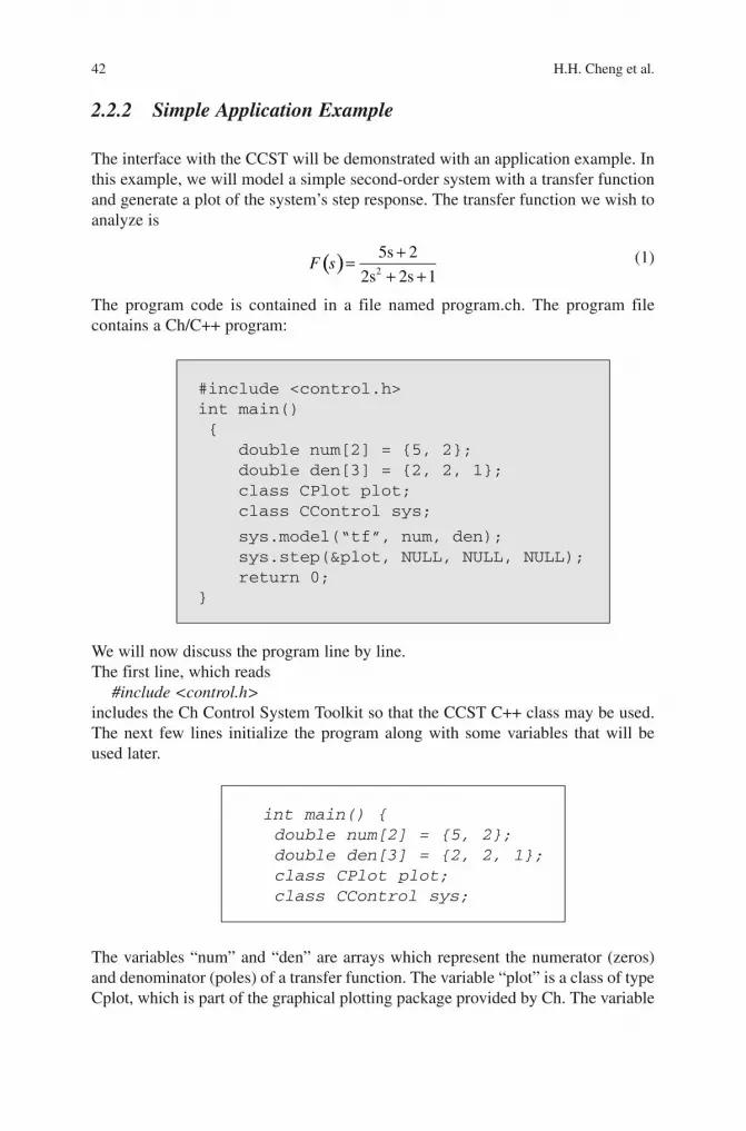
42 H.H. Cheng et al.
2.2.2 Simple Application Example
The interface with the CCST will be demonstrated with an application example. In this example, we will model a simple secondorder system with a transfer function and generate a plot of the system’s step response. The transfer function we wish to analyze is
( ) 2
5s 2
2s 2s 1F s
+=
+ + (1)
The program code is contained in a file named program.ch. The program file contains a Ch/C++ program:
We will now discuss the program line by line.The first line, which reads
#include <control.h>includes the Ch Control System Toolkit so that the CCST C++ class may be used. The next few lines initialize the program along with some variables that will be used later.
The variables “num” and “den” are arrays which represent the numerator (zeros) and denominator (poles) of a transfer function. The variable “plot” is a class of type Cplot, which is part of the graphical plotting package provided by Ch. The variable
#include <control.h>int main() {
double num[2] = {5, 2};double den[3] = {2, 2, 1};class CPlot plot;class CControl sys;
sys.model(“tf”, num, den);sys.step(&plot, NULL, NULL, NULL);return 0;
}
int main() { double num[2] = {5, 2}; double den[3] = {2, 2, 1}; class CPlot plot; class CControl sys;
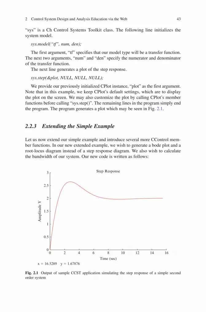
2 Control System Design and Analysis Education via the Web 43
“sys” is a Ch Control Systems Toolkit class. The following line initializes the system model.
sys.model(“tf”, num, den);
The first argument, “tf” specifies that our model type will be a transfer function. The next two arguments, “num” and “den” specify the numerator and denominator of the transfer function.
The next line generates a plot of the step response.
sys.step(&plot, NULL, NULL, NULL);
We provide our previously initialized CPlot instance, “plot” as the first argument. Note that in this example, we keep CPlot’s default settings, which are to display the plot on the screen. We may also customize the plot by calling CPlot’s member functions before calling “sys.step()”. The remaining lines in the program simply end theprogram.TheprogramgeneratesaplotwhichmaybeseeninFig.2.1.
2.2.3 Extending the Simple Example
Let us now extend our simple example and introduce several more CControl member functions. In our new extended example, we wish to generate a bode plot and a rootlocus diagram instead of a step response diagram. We also wish to calculate the bandwidth of our system. Our new code is written as follows:
8
Time (sec)
Am
plitud
e Y
x = 16.5289 y = 1.67876
Step Response
64200
0.5
1
1.5
2
2.5
3
10 12 14 16
Fig. 2.1 Output of sample CCST application simulating the step response of a simple second order system

44 H.H. Cheng et al.
The “bode” member function generates a Bode plot of our second order system so that we may study its frequency response. The “bandwidth” function calculates the −3 dB bandwidth of the system. Finally, the “rlocus” member functiondisplays a root locus plot of the system. When we run the example, we are shown theBodeplot,asseeninFig.2.2andtherootlocusplot,showninFig.2.3. The bandwidth of the system is also printed stating that the bandwidth is 1.787520 radians per second.
–60
–90–80–70–60–50–40–30–20–10
010
0.1
Mag
nitu
de(d
B)
1 10
Bode Diagram
Frequency(rad/sec)
100 1000
0.1 1
x = 12.8528 y = 150.746
Pha
se(d
egre
e)
10 100 1000
–50–40–30–20–10
010
Fig. 2.2 Bode plot of sample second order system
#include <control.h>int main() {double num[2] = {5, 2};double den[3] = {2, 2, 1};class CPlot bodeplot;class CPlot rlocusplot;class CControl sys;sys.model(“tf”, num, den);sys.bode(&bodeplot, NULL, NULL, NULL);printf(“System Bandwidth: %f rad/sec\n”, sys.bandwidth());sys.rlocus(&rlocusplot, NULL, NULL);return 0;
}

2 Control System Design and Analysis Education via the Web 45
These examples demonstrate some of the features which are commonly used in control systems analysis. These simple functions may be used to quickly determine the time and frequency response of a particular system, as well as its range of stability. Note that this example only uses a small subset of all the available member functions provided, as shown in Table 2.1.
Table 2.1 Partial list of Ch Control Toolkit member functions and their MATLAB equivalents
MATLAB Control Toolbox Ch Control Toolkit
fb = bandwidth (sys) fb = sys.bandwidth()bodemag(sys,{wmin, wmax}) sys.bodemag(plot, NULL, NULL, wmin, wmax)bode(sys,{wmin, wmax}) sys.bode(plot, NULL, NULL, NULL, wmin, wmax)sysd = c2d(sys, Ts, method) sysd = sys.c2d(Ts, method)sysc = d2c(sysd, method) sysc = sysd.d2c(method)impulse(sys, tf) sys.impulse(plot, NULL, NULL, NULL, tf)[k, s, e] = lqr(a, b, q, r, n) sys.model(“ss”, a, b, NULL, NULL)
sys.lqr(k, s, e, q, r, n)nichols(sys,{wmin, wmax}) sys.nichols(plot, NULL, NULL, NULL, wmin, wmax)nyquist(sys, w) sys.nyquist(plot, NULL, NULL, NULL, w)ob = obsv(sys) sys.obsv(ob)
0
Real Axisx = –0.985473 y = 0.511702
Root Locus0.6
0.4
0.2
0
–0.2
–0.4
–0.6–1.6 –1.4
Imag
Axi
s
–1.2 –1 –0.8 –0.6 –0.4
Fig. 2.3 RootlocusdiagramfromCCSTapplicationexample

46 H.H. Cheng et al.
2.3 Web Based Control Design and Analysis
A web based control system design web page [14, 15] is provided at [13]. The web site uses the CCST package in conjunction with the CGI package to create an intuitive interface that may be accessed with any web browser. The website uses standard HTML forms for data input. The site may be used to perform a variety of different utilities. The full list of functionality may be viewed on the web at [13], also shown in Figs. 2.4 and 2.5. The list is organized in a hierarchal manner by system type. Upon selecting a desired system type and output type, the user is taken through a series of pages where they may input system and simulation parameters.
A Web server supports the execution of a computation engine, control toolkit, and interfaces with the clients. By developing a controls toolkit on the web, any person with an internet connection and web browser may perform analysis and simulation on a variety of different control systems, even if their own computer may lack the necessary memory or CPU resources to perform the computations. This provides students with a great opportunity to learn control theories and prototype
Fig. 2.4 Partial listing of major features offered by the Ch Control System taken from the web based Ch Control Package website

2 Control System Design and Analysis Education via the Web 47
control systems on the Web. The web interface is designed to be relatively easy and intuitive to use. Users can select a design and analysis method and specify the system model type, system type, and system parameters within the web browser. User inputs are validated and informative error messages are displayed if inputs are not valid. The data is then transmitted to the Web server for numerical computation and the simulation results are sent back to the web client through CGI using the Ch CGI package. A unique feature of the Web control system is its ability to design, analyze, and verify control strategies over the internet without software installation, system configuration, or programming. Since computations are performed purely on the server, the computational time is not hindered by the connection speed between the server and client. Users can focus on the control systems problems and obtain the results interactively. Furthermore, the Webcontrols site provides an example for each function to illustrate its usage. With the provided examples and simple user interface, users can gain experience in control systems design and analysis.
In the following subsection, we will present the same simple example with the second order step response as detailed in the previous section, but we will use the web interface.
Fig. 2.5 RemainderofmajorfeaturesoftheChwebbasedControlPackage

48 H.H. Cheng et al.
2.3.1 Web Control Application Example
The same example presented in the previous section using the CCST package will now be presented using the webbased control application at [13] for comparison. Uponclickingthe“StepResponse”linkatthebeginningoftheintroductorypageshowninFig.2.4,weareshownthewebpageshowninFig.2.6 Note that the opening page includes a sample system with two coefficients in the numerator and three coefficients in the denominator which happens to coincide with the system we wish to simulate. Thus, we may simply enter our system parameters and click on the buttonlabeled“RunExample.”
Upon submitting this information, we are presented with the step response of the system,showninFig.2.7 Note that the plot displayed in this figure is the same as showninFig.2.1 from our previous example.
Fig. 2.6 Opening web page for plotting the step response of a transfer function

2 Control System Design and Analysis Education via the Web 49
2.4 Customized Design and Implementation of Web-Based Control Systems
Custom control system analysis websites may be designed and implemented with great ease. By utilizing both the CCST and the CGI Ch packages, fully interactive control system analysis websites may be fabricated to suit specific applications. The robust and fully featured Ch CGI package is used to simplify the handling of CGI requests and responses. This helps keep the user’s code to a minimum number of lines and greatly increases the code’s readability. Once the website is designed, written, and published, it may be accessed from the web with any web browser.
Fig. 2.7 Step response result from web based second order system calculation. Upon submitting our system parameters, the website calculates and generates an image of the step response of the system and displays it. Note that this step response image is identical to the one calculated by the CCST on a local machine

50 H.H. Cheng et al.
This section will first introduce a custom web application designed to facilitate compensator design via root locus. The website is built to be user interactive, guiding the user through each step of the design process. The user must simply follow the instructions on each page and specify the system parameters and interpret the figures provided by the web application.
This section will then present the source code for a selected step during this interactive process. The source code will be discussed in detail illustrating the design and implementation of the web based control system.
2.4.1 Root Locus Web Application Example
Forourexample,wehavedesignedandimplementedawebsitetofacilitatecompensator design via root locus. In our example, we will be presented with a plant for which a Lag compensator needs to be implemented. We will use our custom web site for the design process and will arrive at a suitable controller for our plant.
Note that the website may be viewed and all source code may be downloaded at http://iel.ucdavis.edu/course/control/compensate/.
2.4.1.1 Problem Description
Considerthefollowingmass-spring-dampersystem(Fig.2.8):Given that the mass in 1 kg, the spring constant is 20 N/m, and the damping
coefficient is 30 Ns/m, implement a compensator to achieve following specifications. The overshoot must not exceed 30% and the steady state error must be less than or equal to 0.01 for a step input.
2.4.1.2 Problem Solution
Performing a simple free body analysis, we arrive at the following transfer function for the system.
( ) 2
1Xs
F ms bs k=
+ + (2)
Fig. 2.8 Simple mass/spring/damper system

2 Control System Design and Analysis Education via the Web 51
After arriving at this transfer function, we may use our custom design web based design tool to design a compensator for this system. Upon visiting the web site, wearepresentedwiththewelcomepage.Forourexample,wewishtodesignalagcompensator.AfterselectingtheappropriateradiobuttonasshowninFig.2.9, we are presented with the next screen.
Since we were able to derive a transfer function previously, we will select the “Transferfunction”optionforthisstep,showninFig.2.10.
UponbeingpresentedwiththepageshowninFig.2.11, we notice that the dimensions of the sample plant given to us do not match our derived plant. Thus, we must redefinethedimensionoftheplanttomatchourown(Fig.2.12).
InFig.2.13, we are presented with the root locus of the uncompensated system. Using this image, we may begin to design our compensator. From our previousspecifications, we set our percent overshoot to be 30% and our steady state error to be 0.01. We now place the pole for our compensator at −0.01 on the real axis.
Upon entering our data, we are presented with the results of our compensator. The resultsaredisplayedasaseriesoffiguresandparameterizeddata.First, theuncompensatedrootlocusandstepresponsearedisplayed,asshowninFig.2.14.
Fig. 2.9 Web based compensator design welcoming page. This page may be viewed at http://iel.ucdavis.edu/course/control/compensate/

Fig. 2.10 Lag compensator design page
Fig. 2.11 Plant specification page
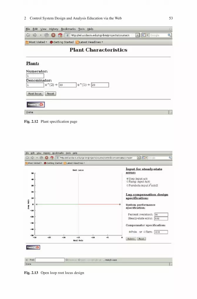
2 Control System Design and Analysis Education via the Web 53
Fig. 2.12 Plant specification page
Fig. 2.13 Open loop root locus design

54 H.H. Cheng et al.
Next, we are given data regarding the compensated system as shown in Fig.2.15. The data contains information about the compensator parameters, such as the location of the compensator poles and zeros, as well as some results about the time response of the compensated system.
Fig. 2.14 Uncompensated plant input response
Fig. 2.15 Characteristics of the compensated system
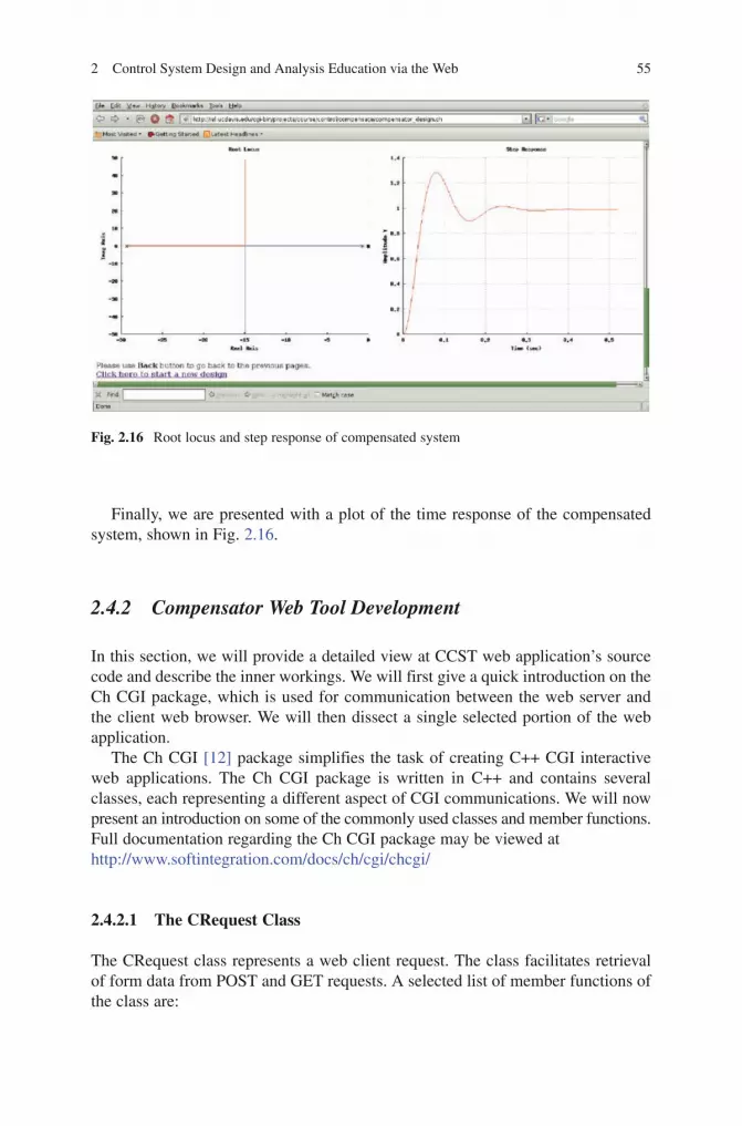
2 Control System Design and Analysis Education via the Web 55
Finally,wearepresentedwithaplotofthetimeresponseofthecompensatedsystem,showninFig.2.16.
2.4.2 Compensator Web Tool Development
In this section, we will provide a detailed view at CCST web application’s source code and describe the inner workings. We will first give a quick introduction on the Ch CGI package, which is used for communication between the web server and the client web browser. We will then dissect a single selected portion of the web application.
The Ch CGI [12] package simplifies the task of creating C++ CGI interactive web applications. The Ch CGI package is written in C++ and contains several classes, each representing a different aspect of CGI communications. We will now present an introduction on some of the commonly used classes and member functions. FulldocumentationregardingtheChCGIpackagemaybeviewedathttp://www.softintegration.com/docs/ch/cgi/chcgi/
2.4.2.1 The CRequest Class
TheCRequestclassrepresentsawebclientrequest.Theclassfacilitatesretrievalof form data from POST and GET requests. A selected list of member functions of the class are:
Fig. 2.16 Rootlocusandstepresponseofcompensatedsystem

56 H.H. Cheng et al.
• GetForms():Thismemberfunctionisusedtoretrieveallvaluesofaspecifiedname which were obtained from a POST or GET method.
• GetFormNameValue(): This function is used to obtain name/value pairs thatwere read from a POST or GET method.
2.4.2.2 The CResponse Class
TheCResponseclassrepresentsaresponsethatistobesentbacktotheclientfollowing a request. In this manner, the response may be dynamically generated depending on the contents of the request. Some commonly used member functions are:
• Begin():ThisfunctionisusedtobeginaCGIresponse.• End():ThisfunctionisusedtoendaCGIresponse.• Redirect():Thisfunctionredirectstheclient’sbrowsertoanotherURL.• SetContentType():Thisfunctionisusedtosetthecontenttypeoftheresponse.
2.4.2.3 Source Code Example
Let us now provide a detailed explanation of the execution of the first several pages of our web based control design website. Upon visiting the website, we are presented with the file “index.html”. Examining the source code of this file, let us focus on lines 35–41, which read:
Program 1: Excerpt from “index.html”, the Web Based Compensator Design welcome page.
This is the code responsible for handling the initial selection of the type of compensator to be designed. Note that the form action is “compensator_design.ch”. The program “compensator_design.ch” is the main program that will drive the rest of the interactive web application.
Also note the code used to create the two radio buttons to select the type of controller to design. Depending on which of the radio buttons is selected, the
<form method=”post” action=”compensator_design.ch” ><h3> <u> Compensation type: </u> </h3><input type=”radio” name=”CompType” value=”Lag”>Lag compensation < br ><input type=”radio” name=”CompType” checked value=”Lead”>Lead compensation <br><br><input type = submit value=”Continue”>
</form>

2 Control System Design and Analysis Education via the Web 57
browser will send either the value “Lag” or “Lead” to the CGI script. Now let us take an excerpt from the main program, ‘compensator_design.ch’.Program 2: Excerpt from “compensator_design.ch”.
In the opening lines of the program, several variables are declared. Note the variables “name” and “value” of type “chstrarray”. This data type is defined by the Ch CGI package and is simply an array of strings. These variables will be used to hold the names and values retrieved from the request using the POST or GET methods.
The next line, which reads
num = Request.getFormNameValue(name, value);
obtains the names and values from the previous request. Following this, theprogram sets the content type of the page and begins the response with the following lines.
Response.setContentType(contenttype);Response.begin();
The program then prints a rudimentary html header. The next output is dependent on what the user had selected from the previous page. The following lines divert the program flow depending on the user’s previous choices.
int main(){int num, i;chstrarray name, value;
num = Request.getFormNameValue(name, value);Response.setContentType(contenttype);Response.begin();
printf(“<head> \n”);printf(“<title>%s</title>\n”,title);printf(“<style>#eqn{position:relative;top:8px;}printf(</style></head>\n”);
if(strcmp(value[0], “Lag”) = = 0){LagPage();
}else if(strcmp(value[0], “Lead”) = = 0){LeadPage();
}

58 H.H. Cheng et al.
If the program was called from the welcoming page, “index.html”, then we expect the name to be “CompType”, and the value to be either “Lag” or “Lead”, depending on the user’s selection. In our example, we selected to create a lag controller, so the function “LagPage()” is called, which displays a customized page for lag controller design for the user.
Using these simple methods, a fully featured and user interactive web page may be created. By combining the functionality of the Ch Control System Toolkit with the Ch CGI package, a custom controller design web page may be quickly developed and used.
2.5 Conclusion
The Ch Control System and Ch CGI toolkits have been discussed. These toolkits give the Ch programming environment a unique feature set over other mathematically rich environments such as MATLAB or Mathematica to allow webbased control system design and analysis websites to be conveniently designed and implemented. Furthermore,theobject-orienteddesignoftheaforementionedChtoolkitsallowsthem to be extended by the user.
Many applications and source code examples were presented to demonstrate the design and implementation process of using and creating a controlsystem analysis enabled website. With these tools, customized web sites with control system analysis tools may be designed and built.
References
1. Bencomo, S.D., Control Learning: Present and Future.AnnualReviews inControl, 2004.28(1): pp. 115–136.
2. MATLAB Control System Toolbox: http://www.mathworks.com/products/control/ 3. Mathematica’s Control System Professional: http://www.wolfram.com/products/applications/
control/index.html
if(strcmp(value[0], “Lag”) = = 0){LagPage();}else if(strcmp(value[0], “Lead”) = = 0){LeadPage();}

2 Control System Design and Analysis Education via the Web 59
4. Casini, M., D. Prattichizzo, and A. Vicino, The Automatic Control Telelab: A User-friendly Interface for Distance Learning. IEEE Transactions on Education, 2003. 46(2): pp. 252–257.
5. Chan, C.C., R. Kwan, and S.F. Chan, Learning control systems on the web, Proc. of the International Conference on Computers in Education, Auckland, New Zealand. December 2002. pp. 3–5.
6. Wu, Min, JinHua She, GuiXiu Zeng and Y. Ohyama. Internet-based teaching and experi-ment system for control engineering course. Industrial Electronics, IEEE Transactions on June 2008. 55(6): pp. 2386–2396.
7.Leva, A. and F. Donida, Multifunctional Remote Laboratory for Education in Automatic Control: The CrAutoLab Experience. IEEE Transactions on Industrial Electronics, June 2008. 55(6): pp. 2376–2385.
8. Hu,Wenshan,Guo-PingLiu,D.ReesandYuliangQiao.Design and implementation of web-based control laboratory for test rigs in geographically diverse locations. Industrial Electronics, IEEE Transactions on June 2008. 55(6). pp. 2343–2354.
9. Cheng, H.H., Ch: A C/C + + Interpreter for Script Computing. C/C + + User’s Journal, January 2006. 24(1): pp. 6–12.
10. Ch Control System Toolkit: http://www.softintegration.com/products/toolkit/control/11. Zhu, Y., B. Chen, and H.H. Cheng, An Object-Based Software Package for Interactive Control
System Design and Analysis. ASME Journal of Computing and Information Science in Engineering, 2003. 3(4): pp. 366–371.
12. Ch CGI Toolkit: http://www.softintegration.com/products/toolkit/cgi/13. Web-Based Control System Design and Analysis: http://www.softintegration.com/webservices/
control/14. Yu, Q., B. Chen, and H.H. Cheng, Web-Based Control System Design and Analysis. IEEE
Control Systems Magazine, 2004. 24(3): pp. 45–57.15. Chen, B., Y.C. Chou, and H.H. Cheng, Teaching Automatic Control of Engineering Systems
Using Open Source Ch Control System Toolkit and Web-Based Design and Analysis System. In ASME Dynamic Systems and Control Conference. 2008. Ann Arbor, MI, USA.
16. Ch – an Embeddable C/C + + Interpreter: http://www.softintegration.com17. Hanselman, D. and B. Littlefield, Mastering Matlab 6 – A Comprehensive Tutorial and
Reference.2001,Prentice-Hall,UpperSadleRiver,NJ,USA.

BookID 175907_ChapID 3_Proof# 1 - <Date>
Chapter 3Web Based Control Teaching
Suzana Uran and Riko Šafarič
3.1 Introduction
Control education is an essential part of university curriculum for Electrical Engineering, Mechanical Engineering, Mechatronics, and also for other studies for instance, Chemical Engineering. A need for control appeared early in the history. Mechanical control was first implemented in clocks. In the time of industrial revolution control expanded even more because steam machines needed control in order not to explode. For this purpose James Watt invented centrifugal regulator. Since the Second World War control theory has developed. And a shift from mechanical to electronic and computer-based controllers took place. Therefore, topics covered by an introductory undergraduate Control theory course, is well established. A typical introductory undergraduate control course covers [1, 2]:
• Input-output and state space description of single-input single-output (SISO)control systems
• DevelopmentofblockdiagramsforSISOcontrolsystems• QuantitativeandqualitativeanalysesofSISOcontrolsystems• Frequencydomaincontroldesigntechniques(Bodeplot,Nyquistplot)• TheRoot-Locusdesignmethod• Statespacecontrollerdesign
Today, especially in the learning of control basics, the emphasis is not on what to teach but on how to support active learning and using of high efficiency computer tools. Computer-aided control design and control implementation are desirable, because they improve the efficiency of control learning and industrial control practice. In addition new technologies, like Internet, offer new learning possibilities. Internet(Web)supportsdistancelearningandlearningatanytimebyenablingfast
S.UranandR.Šafarič ()InstituteofRobotics,FacultyofElectricalEngineeringandComputerScience, University of Maribor, Smetanova 17, 2000 Maribor, Slovenia, [email protected]
S.G.Tzafestas(ed.),Web-Based Control and Robotics Education, 61Intelligent Systems, Control and Automation: Science and Engineering 38,DOI10.1007/978-90-481-2505-0_3,©SpringerScience+BusinessMediaB.V.2009

62 S.UranandR.Šafarič
BookID 175907_ChapID 3_Proof# 1 - <Date> BookID 175907_ChapID 3_Proof# 1 - <Date>
delivery of the learning material between the teacher and students as well as access tolaboratoryexperiments24haday.
3.2 Motivation for Web Based Control Teaching
TwotypesofWebbasedlaboratoriesexist:virtualandremote.Virtuallaboratoriesare based on computer visualisation and simulations, while remote laboratories enable operating of real devices constituting the control experiment.
“Learningthroughdoing”(hands-onlearning)isaleadingideamotivatingthedesign of virtual and remote laboratories. The idea of hands-on learning is not a new idea in engineering education. But it is still a theme in engineering education, today. Psychological studies have shown that, in general, people remember only about10%ofwhattheyread,but90%ofwhattheyactually“tryandrealize”.Thisresult motivates professors and instructors who teach engineering courses to deliver not only good lectures, but also hands-on experiments and proper course projects tosupportacompletelearningexperience.Virtualandremotelaboratoriesenablecosts effective hands-on experimenting tailored to the actual needs of the course.
In addition, virtual and remote laboratories are desirable due to multiple other reasons. Goals of a virtual laboratory might also be the visualization of certain special phenomena or hard-to-grasp concepts, an illustration of course material and the important relationships within it, the elimination of math representations, as stated in [3–6].Themotivationforsuchgoalscomesfromtheneedsofthecourse(tovisualiseinvisible, lack of student mathematical background, etc.). Additional goals of avirtual and remote laboratory might be a support of computer aided control design and implementation and elimination of a gap between theory and practice.
Many reasons exist as to why computer-aided control design and implementation are desirable in industrial practice, and in the learning of control design. First, the nature of the control design process is cyclic. To design a control system in industrial practice one must iterate through modeling, design, simulation, testing and imple-mentationasmanytimesasrequired.Today’smarketcompetitionresultsinademandfor greater and greater efficiency. This demand for greater efficiency in the field of control practice is reflected in a need to perform control design and implementation asquicklyaspossible.Sincemanycontroldesignmethodsaregraphical,thecontroldesign process could be speeded-up by using computers with suitable software to plot graphs instead of plotting them by hand. Computers are also used to perform simulations to validate a control plant model and a designed control for the plant. In addition, rapid control prototyping computer software tools are used to speed up the testing and implementation of control in industrial practice. For all the afore-mentioned reasons computer-aided control design and implementation is a must in any successful control education of students. Actually, the need for computer-aided control design and implementation was realized long ago by teaching communities at Universities around the world. Therefore, laboratory practice in control has been adapted to teach students computer-aided control design and implementation using, forinstance,MATLAB.MATLABwas,andstillis,oneofthesoftwaretoolsused

3 Web Based Control Teaching 63
BookID 175907_ChapID 3_Proof# 1 - <Date>
at Universities all over the world to support the learning of computer-aided control design and implementation. However lectures, theoretical exercises, and examinations incontrolhaveremainedrootedindrawing(sketching)differentplotsbyhand,whileMATLABwasjustanadditionalaid(see[1, 2]).Why?
Multiple reasons exist as to why lectures, theoretical exercises, and examina-tionswerenotsupportedbyMATLAB:
• AstudentstartingtostudyautomaticcontrolisusuallyabeginnerinMATLAB,inasensea“doublebeginner”.
• Additional costs appear when introducing computer-aided learning of controldesignandimplementation(computersandsoftwareneedtobebought).
• Time isneeded tomakea shift inhuman thinking, togainmoreexperiencewithcomputer-aidedteaching/learningandtodevelopInternetandWeb-basedtechnologies.
MATLABisahighprogramminglanguagewithgoodgraphicsandhelp,aimedatbeing user-friendly and easy to program. Unfortunately, teaching practice has shownthatstudentsneedtimetoadopttheMATLABdefinitionofpolynomialsasa form of polynomial coefficients vectors. A permanent source of student confusion is whether the polynomial coefficients should be defined in descending or ascending powers of s. Students are also confused if one or more powers in the polynomial aremissing.Inaddition,roundandsquarebrackets,commas,andsemicolonsmustbe used in the proper way. The MATLAB syntax is strict; nothing incorrect isallowed. All special visualization effects have to be programmed. Every teacher introducingMATLABtosupportlecturesmustfacetheriskthatstudentswillnotsee “the wood for the trees” in any control lecture given because of MATLAB.Therefore,oneiswisetoavoida“doublebeginner”situation.References[3–6] and [7–9] show that building a virtual laboratory with an intuitive man-machine user interface ispossible todecoupleMATLABprogramminganddemandingmathe-matical representations from the control knowledge. Such a virtual laboratory could, atthesametime,support“Whatif?”questionsandhands-onexperimentation.Therefore,the virtual laboratory is welcomed in supporting lectures.
In learning control, a typical example of a plot drawn by hand is a Bode diagram. In [10] the authors argue that students must learn to draw Bode diagrams using piecewise-linear asymptotic approximations by hand to understand fully how the locations of poles and zeros affect the shape of the Bode diagram. This argument exists even though programs, such as MATLAB, can accurately create a Bodediagram for a given transfer function. A similar statement is given in [1]. The authors of [10] also state that teachers are faced with a problem that drawing semi-logarithmic graphsbyhandisinaccurate,whetheronablackboard(chalkboard),whiteboard,oran overhead transparency. An alternative to hand-drawn graphs are paper handouts with worked examples. Unfortunately, such paper handouts are good for accuracy reasons,butarenotusefulforansweringastudent’s“Whatif?”question.Therefore,in [10]theauthorsproposeanaid–aspecialgraphicaltool(GUI)todrawpiecewise-linearasymptoticapproximationsofBodediagramsusingMATLABandacomputer.Consequently,virtuallaboratoriesforcomputer-aidedlearningofcontroldesignusingBode diagrams, piecewise linear or accurate, are welcomed.
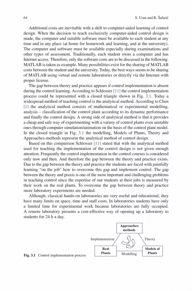
64 S.UranandR.Šafarič
BookID 175907_ChapID 3_Proof# 1 - <Date> BookID 175907_ChapID 3_Proof# 1 - <Date>
Additional costs are inevitable with a shift to computer-aided learning of control design. When the decision to teach exclusively computer-aided control design is made, the computer and suitable software must be available to each student at any timeandinanyplace(athomeforhomeworkandlearning,andattheuniversity).The computer and software must be available especially during examinations and other types of assessment. Traditionally, each student owns a computer and has Internet access. Therefore, only the software costs are to be discussed in the following. MATLABistakenasexample.ManypossibilitiesexistforthesharingofMATLABcosts between the student and the university. Today, the best ways seems to be sharing ofMATLABusingvirtualandremotelaboratoriesordirectlyviatheInternetwithproper license.
The gap between theory and practice appears if control implementation is absent during the control learning. According to Schlosser [11] the control implementation process could be represented with a closed triangle shown in Fig. 3.1. Today a widespread method of teaching control is the analytical method. According to Chen [1] the analytical method consists of mathematical or experimental modelling, analysis – classification of the control plant according to its dynamic performance and finally the control design. A strong side of analytical method is that it provides a cheap and safe way of experimenting with a variety of control plants even unstable onesthroughcomputersimulation/animationonthebasisofthecontrolplantmodel.In the closed triangle in Fig. 3.1 the modelling, Models of Plants, Theory and Approaches-methods represent the analytical method of control design.
Based on this comparison Schlosser [11] stated that with the analytical method used for teaching the implementation of the control design is not given enough attention.Frequentlythecontrolimplementationinthecontrolcoursesisconsideredonly now and then. And therefore the gap between the theory and practice exists. Due to the gap between the theory and practice the students are faced with painfully learning“onthejob”howtoovercomethisgapandimplementcontrol.Thegapbetween the theory and praxis is one of the most important and challenging problems in teaching control since the expertise of our students at their jobs is measured by their work on the real plants. To overcome the gap between theory and practice more laboratory experiments are needed.
Although, classical hands-on laboratories are very useful and educational, they have many limits on space, time and staff costs. In laboratories students have only a limited time for experimental work because laboratories are fully occupied. A remote laboratory presents a cost-effective way of opening up a laboratory to studentsfor24haday.
Modelling
Approaches-methods
Models ofPlants
RealPlants
TheoryImplementation
Fig. 3.1 Control implementation process
3 Web Based Control Teaching 65
BookID 175907_ChapID 3_Proof# 1 - <Date>
3.3 Virtual Control Design Laboratory
SeveralvirtuallaboratorieshavebeenbuiltbasedonMATLABcoveringavarietyof topics [3–5] and [7]. In addition these virtual laboratories, others incorporating or devoted to control basic topics are presented in [6–10]. In [6–9] the control topicscovermodelling,systemrepresentationswith timeresponsesor frequencyresponses, the relationship between open- and closed-loop systems, and Bode plot loop-shaping to design a controller. The virtual laboratories in [6] and [10] are implementedinMATLABusingMATLABgraphicaluserinterfaces(GUIs).In[8] and [9] virtual laboratories with control experiments published on the Web and implementedusingApplets are presented.Very interesting topicswithproblemsencounteredinBodeplotteaching/learningarediscussedin[10]. According to the references it could be stated that computerization and information technologies affect learning methods considerably.
In the following two virtual laboratories with the goal of supporting computer-aided control design are represented. To achieve intuitive man-machine communication and goals for which virtual laboratory was designed the environment of virtual laboratory is relatively structured. What parameters could be changed within which range and what could be observed or designed in a particular experiment is defined bythestructureofthevirtualexperiment/laboratory.Althoughstructuredenviron-ments are desirable at the start of learning control and computer-aided control design theydon’tgivestudentspossibilitytocreatetheirownexperimentsaftergoalsofthe structured environment are mastered. Engineering education, however, must ensure that youngengineerspossess the ability to addnewvalue; todesign andconductexperiments;toanalyseandinterpretdata;todesignasystem,component,orprocess;andtomeet thedesiredneeds[12]. Problems students would have to solve in their professional career are not likely to fit into one of the structured experiments the students have learned at school. Therefore, a permanent need in engineering education exist for less structured and more creative environments where students can build experiments of their own, and practice design, data analyses, and interpretation. A two-step strategy for learning of control design is proposed.
The two-step control design learning strategy consists of:
• 1. Step: learning control design using a structuredenvironmentof“Websisotool”virtual laboratory
• 2. Step: learning control design using an unstructuredenvironmentofMATLABusing M-file script
Two virtual laboratories for control design were built to support the two-step strat-egy.Thefirstvirtuallaboratory,called“Websisotool”,isastandardMATLABWebServer(MWS)applicationwithastructuredenvironment.ThesecondWeb-basedvirtual laboratoryiscalled“M-fileapplication”.M-fileapplicationisanunstruc-tured batch-mode programming environment, similar to MATLAB that enablesstudents towrite theirownM-code forMATLABand tocreateanddesign theirown MATLAB experiments. The term unstructured environment (experiment) is
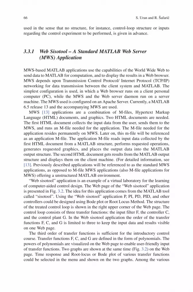
66 S.UranandR.Šafarič
BookID 175907_ChapID 3_Proof# 1 - <Date> BookID 175907_ChapID 3_Proof# 1 - <Date>
used in the sense that no structure, for instance, control-loop structure or inputs regarding the control experiment to be performed, is given in advance.
3.3.1 Web Sisotool – A Standard MATLAB Web Server (MWS) Application
MWS-basedMATLABapplicationsusethecapabilitiesoftheWorldWideWebtosenddatatoMATLABforcomputation,andtodisplaytheresultsinaWebbrowser.MWS depends upon Transmission Control Protocol/ Internet Protocol (TCP/IP)networking for data transmission between the client system and MATLAB. Thesimplest configuration is used, in which a Web browser runs on a client personal computer (PC), while the MWS and the Web server daemon run on a servermachine.TheMWSusedisconfiguredonanApacheServer.Currently,aMATLAB6.5 release 13 and the accompanying MWS are used.
MWS [13] applications are a combination of M-files, Hypertext Markup Language(HTML)documents,andgraphics.TwoHTMLdocumentsareneeded.ThefirstHTMLdocumentcollectstheinputdatafromtheuser,sendsthemtotheMWS, and runs an M-file needed for the application. The M-file needed for the applicationresidespermanentlyonMWS.Lateron,thism-filewillbereferencedas an application M-file. The application M-file reads input data collected by the firstHTMLdocumentfromaMATLABstructure,performsrequestedoperations,generates requested graphics, and places the output data into the MATLABoutputstructure.ThesecondHTMLdocumentgetsresultsfromtheMATLABoutputstructureanddisplaysthemontheclientmachine.(Fordetailedinformation,see[13]. Previously described applications will be referenced to as the standard MWS applications,asopposedtoM-fileMWSapplications(alsoM-fileapplicationsforMWS)offeringaunstructuredMATLABenvironment.
“Websisotool”applicationisanexampleofavirtuallaboratoryforthelearningofcomputer-aidedcontroldesign.TheWebpageofthe“Websisotool”applicationis presented in Fig. 3.2.TheideaforthisapplicationcomesfromtheMATLABtoolcalled“sisotool”.Usingthe“Websisotool”applicationP,PI,PD,PID,andothercontrollerscouldbedesignedusingBodeplotorRootLocusMethod.Thestructureof the treated control loop is shown in the right upper corner of the Web page. The control loop consists of three transfer functions: the input filter F, the controller C, and the control plant G. In the Web sisotool application the order of the transfer functions F, C, and G is limited to three to keep the input data and results visible on one Web page.
The third order of transfer functions is sufficient for the introductory control course. Transfer functions F, C, and G are defined in the form of polynomials. The powers of polynomials are visualized on the Web page to enable user-friendly input oftransferfunctions.Twographsareshownatthesametime(Fig.3.2)ontheWebpage. Time response and Root-locus or Bode plot of various transfer functionscould be selected in the menu and shown on the two graphs. Among the various

3 Web Based Control Teaching 67
BookID 175907_ChapID 3_Proof# 1 - <Date>
transferfunctionsthatcouldbeselectedfortimeresponse,Root-locusorBodeplotare transfer functions F, C, G, open-loop transfer function C*G, and a closed-loop transfer function with and without F.
“Web sisotool” supports visualization of Bode plot design parameters (phasemarginandcrossoverfrequency)andreadingoftheactualvaluesoftheamplitudeandphasevaluesoftheBodeplotatagivenfrequency.Anyvariationoftheparameterson the Web page results in a new updated figure on the screen. Therefore, control-loop or control-plant behaviour could be interactively explored. Controller design and tuning for various types of plants and controllers could also be performed. By observing closed-control-loop time response and Bode plot with visualized phase margin and crossover frequency, students could grasp the relationship betweentime-response and Bode plot design parameters.
Strict limits on those experiments that could be performed are imposed by the structureof“Websisotool”.Theselimitsarethegivenstructureofthecontrolloop,the order of a control plant, and a controller. Only input step response can beobserved;multipleBodeplotsor timeresponsescannotbeobservedat thesametime, etc. Therefore, creativity in a structured environment is considered to be low, and a virtual laboratory with unstructured environment is needed in addition.
Fig. 3.2 Web sisotool application

68 S.UranandR.Šafarič
BookID 175907_ChapID 3_Proof# 1 - <Date> BookID 175907_ChapID 3_Proof# 1 - <Date>
3.3.2 M-file Application
According to the two-step strategy for computer-aided control design learning, proposed, a virtual laboratory with an unstructured environment is needed in addi-tiontothevirtuallaboratorywithastructuredenvironment.MATLABinaremoteclient configuration could be used for this purpose. In this case, one license key is neededperoneactiveuserbecauseof the interpretativenatureof theMATLABdevelopment environment. Another option is to use MWS to implement an unstruc-turedMATLABenvironmentthatwouldrunMATLABM-scriptprogramsinthebatch processing mode, while M-script programs would be developed in some other environment. In the latter case multiple active users could be effectively served with only one Web server license key. Therefore, an MWS-based option is an interesting consideration because of lower costs.
ThefollowingconsidersavirtuallaboratorybasedonMWSrunningMATLABM-scriptsinthebatchprocessingmode.AnunstructuredMATLABprogrammingenvironmentwasimplementedusingavirtuallaboratory,called“M-fileapplication”.“M-file application” was built having in mind a student beginner in MATLAB.Therefore, themainobjectiveof thevirtual laboratory is thatMATLABMcodewritten for the virtual laboratory could be without any changes successfully executed withMATLABrunninglocallyonthepersonalcomputer(PC).Viceversaisnotalways possible because of limitations imposed on the M-file application. To comply withMATLABWebServerlicenserestrictions,limitationsthatencompassthesizeoftheuserM-file(2kbytes)andtheprocessingtimeoftheuserM-file(maximum1min)wereimposedontheM-fileapplication.InadditionM-fileapplicationsupportsonly one figure per M-file and tf class of transfer functions. Because of its limitations M-file application is only suitable for learning experiments, since the M-files might only be of the size of the demonstration programs.
TheM-fileMWSapplicationallowsstudents(users)towritetheirownM-filesand send them to MWS for execution. Students obtain the results over the Web. To use the M-file application, students need only an Internet browser and any of the textfileeditors,forexample,theNotepad.
TheconceptofanunstructuredMATLABenvironmentimplementationproposedin the paper is to build one standard MWS application that would serve for the uploadingandexecutionofusers’M-filesonMWS.ThesizeoftheuserM-filesfile that could be uploaded is limited to 2k bytes. All user data should be defined inside theuserM-file.NoinputofuserdataisavailablethroughtheWebpage.Aconstraintof one figure per user M-file for M-file application is accepted. Temporarily, only theobjecttf(transferfunction)issupportedbytheM-fileMWSapplication.
Hypertext Preprocessor programming language (PHP) and a multithreaded,multi-user Structured Query Language (MySQL) database were chosen for theimplementation of the M-file application. PHP [14] is an open source server-side language used to create dynamic Web pages. The PHP programming language was chosenbecausePHPcouldbemixedwiththeHTML.
ForthestandardMWSapplication,twoHTMLfilesareneededandtheapplicationM-file.IntheM-fileapplication,thefirstHTMLfileisreplacedwithtwoPHPfiles.

3 Web Based Control Teaching 69
BookID 175907_ChapID 3_Proof# 1 - <Date>
The task of the first PHP file is to upload the necessary user M-files. Up to three user M-files can be uploaded to the MWS at the same time, if needed. The second PHP file serves as a reservation for the user directory on MWS, for the saving of uploaded user M-files to the user directory, for sending a user directory name and a name of user M-file to be executed as application data, and for running the applicationM-fileonMWS.ReservationforuserdirectoriesisbasedontheuserTCP/IPaddressandonMySQLdatabase.OnlyoneusercanaccessMySQLdata-baseatthesametime;therefore,twouserscannotreservethesameuserdirectory.After theuserhasreservedtheuserdirectory,alluser’sM-filesaresavedon theuser directory. The application M-file is a function that runs users M-files and saves results to the application directory. At the end of application M-file, the second HTMLfileiscalled,andtheresultsaresent tothesecondHTMLfile.InM-fileapplication,thesecondHTMLfilenotifiestheuserthattheMATLABhasfinishedthe execution and calls the third PHP file. The third PHP file releases the reserved user directory, deletes all user M-files, and displays the results in the browser.
Figures 3.3–3.5 show the whole M-file application as seen by the user, in the case of a very simple task of plotting a step response of a transfer function. In Fig. 3.3, asimplecodeforthecalculationofstepresponse,writteninthetexteditorNotepad,is shown. Figure 3.4 presents the Web page for the uploading of M-files.
Figure 3.5 shows the Web page with numerical and graphical results for the uploaded user M-file. The graphical results are represented in the form of a figure. All the variables used in the user M-file can be selected from the selection menu to be displayed.
For M-file MWS application, the use of Internet Explorer, as a browser, is recom-mended but not necessary. A good aspect of the proposed solution is that using the InternetExplorer,theMATLABM-codesyntaxerrorsarereportedtotheuser.Notallproblemsaresolvedwiththeproposedsolution.OneoftheproblemsremainingrepresentstheinteractiveactionoftheMATLABenvironment.IntheuserM-fileto be executed by MWS, every command must end with a semicolon, otherwise the browser reports error, and the M-file execution is terminated.
The M-file application is supported by an introduction to MATLAB andMATLAB command reference in Slovene. In an M-file application environmentstudents recreate one or two experiments previously performed in Web sisotool.
Fig. 3.3 M-file for a step response

70 S.UranandR.Šafarič
BookID 175907_ChapID 3_Proof# 1 - <Date> BookID 175907_ChapID 3_Proof# 1 - <Date>
Afterwards students could be asked to show their creativeness by creating and designing an experiment that was impossible to perform using Web sisotool, for example checking load step response or showing a family of time responses in one figure or designing a state space controller, etc.
Reference[15] presents a solution, called the Extension of MWS, similar to the M-file application. The Extension of MWS automatically creates a standard MWS application for each uploaded user M-file. The user M-files, uploaded as a text fromtheWeborasatextfile,arestoredinaMySQLdatabaseandpre-processed.Theoutputresultscouldbegraphical(oneormorefigures)ornumerical.Theinputof user data for Extension of MWS is foreseen over the Web browser. The user input and output variables have to be an element of sinput and soutput structure, respectively,toberecognizedasinput/outputvariablesbytheautomaticalgorithmoftheExtensionofMWS.Consequently,theExtensionofMWS[15] is unsuitable for students starting to learnMATLAB inwhich all the names of variables areallowed except reserved words. In [15] no report is found about user M-file syn-tactic error(s) handling, and no report about whether multiple M-files could beuploaded and run. Another drawback of the Extension of MWS is that a considerable amount of code has to be generated for each uploaded user M-file that may result in memory troubles.
Fig. 3.4 M-fileuploadtoMATLABWebserver
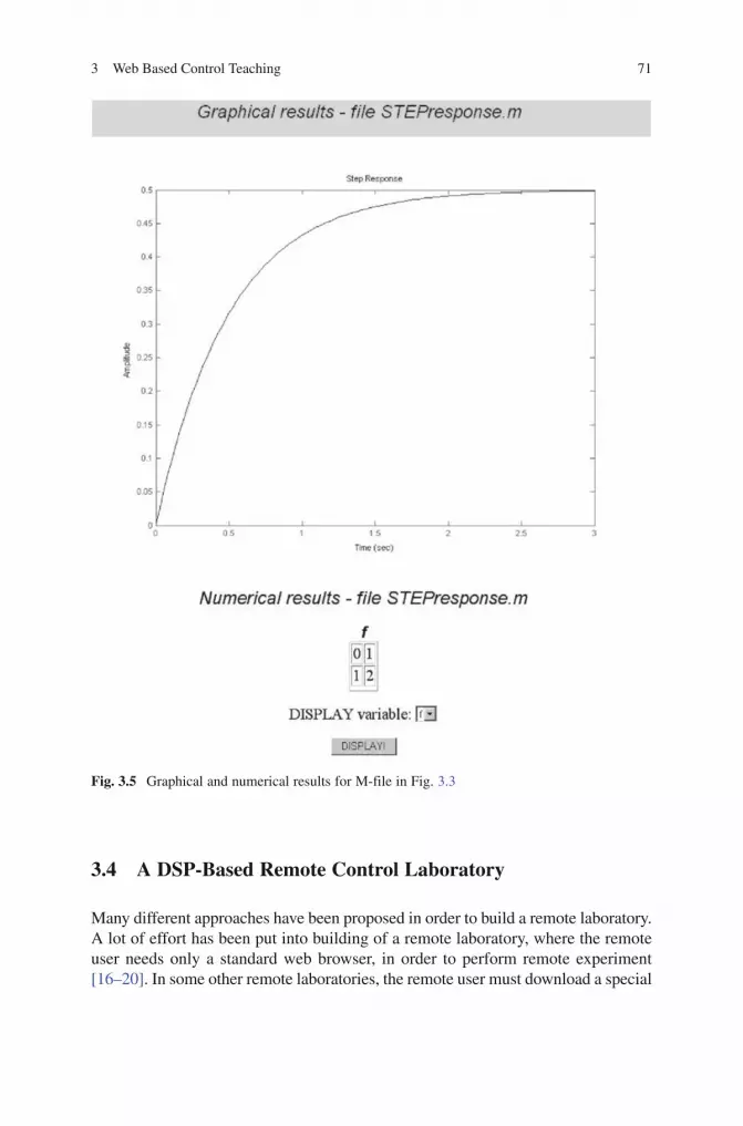
3 Web Based Control Teaching 71
BookID 175907_ChapID 3_Proof# 1 - <Date>
3.4 A DSP-Based Remote Control Laboratory
Many different approaches have been proposed in order to build a remote laboratory. A lot of effort has been put into building of a remote laboratory, where the remote user needs only a standard web browser, in order to perform remote experiment [16–20]. In some other remote laboratories, the remote user must download a special
Fig. 3.5 Graphical and numerical results for M-file in Fig. 3.3

72 S.UranandR.Šafarič
BookID 175907_ChapID 3_Proof# 1 - <Date> BookID 175907_ChapID 3_Proof# 1 - <Date>
program enabling remote control [21, 22]. In the majority of the cited remote control experiments the remote experiments are structured with regard to control. Usually, remote users can run the experiment with a collection of predefined controller types and adjust the controller parameters from a set of predefined para-meters. In remote laboratory for a two degree of freedom helicopter [16], the remote user can select between four different predefined controller types. Safety reasons(possibilityofinstabilityandconsequentdamagesofthecontrolplant)ofinteractively performed experiments demand a structured experiment. In cases of relatively slow control plants, when interactive remote experiments are not feasible, batch processing of remote experiments is implemented. An Automatic Control Telelab (ACT) [17] is an example of remote laboratory using batch processing which enables a relatively unstructured remote experiments. Using ACT, the remote userscandesigntheirowncontrollerusingMATLAB/Simulinkenvironment,onalocal PC and, after successful simulation, upload it to the ACT server and verify it on the real process.
3.4.1 A DSP-Based Remote Control Laboratory
DSP-basedRemoteControlLaboratoryisbasedonDSP2learningmodul,softwarepackages MATLAB/Simulink from Mathworks, Inc. and LabVIEW from theNationalInstrumentsCompany.DSP2learningmoduleisversatile,lightandsmall,handy and easy to use learning system developed at the Faculty of Electrical EngineeringandComputerScience,UniversityofMaribor(Fig.3.6).
The DSP2 learning module hardware consists of signal processor TI TMS320C32-60 and Xilinx FPGA which implements on board peripheral interfaces:
• Threefastanalog+/−2Vinputs(12bits,2.6us),eightMUXanaloginputs(12bits),oneinputforincrementalencoder,onedigitalinput
• Oneanalogbipolaroutput+/−4V(12bits)or twoanalogunipolaroutputs0–4V(12bits),onePWMoutput,threedigitaloutputs
• RS232duplexcommunicationport
Simulink,Real-TimeWorkshop(RTW)andTexasInstrumentsCodeComposerareused for simulation, control algorithm development and rapid executable code genera-tion. “DSP2 Library for Simulink”, also developed at the Faculty of ElectricalEngineering and Computer Science, University of Maribor, incorporates device driver’sblocksforallavailableI/Oportsdescribedabove.TogetherwithSimulinkandRTW“DSP2LibraryforSimulink”formsaveryefficientRapidControlPrototyping(RCP)tool[23].WhentheSimulinkblockschemeonthehostPCisbuilttheMatlab/RealTimeWorkshopbuildsCcodewhichisthentranslatedbyCodecomposerintoabinary code for DSP2 processor. Finally the binary code is downloaded from the hostPContheDSP2learningmoduleovertheRS232port.LabVIEWservesasthe user front for on-the-fly data visualisation, parameter tuning and remote operation.

3 Web Based Control Teaching 73
BookID 175907_ChapID 3_Proof# 1 - <Date>
A variety of control plants could be connected to DSP2 learning module, among them are first order systems, second order systems, buck converter, DC motor and student built plants.
Figure 3.7 shows a structure of the DSP-based remote laboratory. Besides multiple DSP2 learning modules (one per experiment) the DSP-based remote
DSP2 system
Exchangeable Control Plant
Fig. 3.6 DSP2 learning module
Fig. 3.7 Structure of the DSP-based remote laboratory
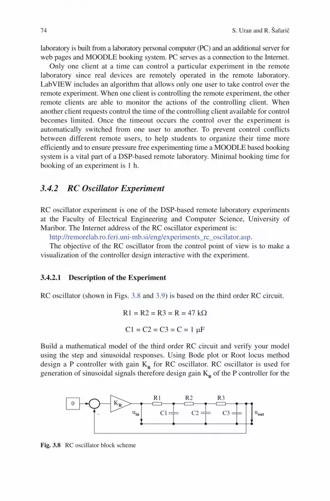
74 S.UranandR.Šafarič
BookID 175907_ChapID 3_Proof# 1 - <Date> BookID 175907_ChapID 3_Proof# 1 - <Date>
laboratoryisbuiltfromalaboratorypersonalcomputer(PC)andanadditionalserverforwebpagesandMOODLEbookingsystem.PCservesasaconnectiontotheInternet.
Only one client at a time can control a particular experiment in the remotelaboratory since real devices are remotely operated in the remote laboratory. LabVIEWincludesanalgorithmthatallowsonlyoneusertotakecontrolovertheremote experiment. When one client is controlling the remote experiment, the other remote clients are able to monitor the actions of the controlling client. When anotherclientrequestscontrolthetimeofthecontrollingclientavailableforcontrolbecomes limited. Once the timeout occurs the control over the experiment isautomatically switched from one user to another. To prevent control conflicts between different remote users, to help students to organize their time more efficientlyandtoensurepressurefreeexperimentingtimeaMOODLEbasedbookingsystem is a vital part of a DSP-based remote laboratory. Minimal booking time for booking of an experiment is 1 h.
3.4.2 RC Oscillator Experiment
RCoscillatorexperimentisoneoftheDSP-basedremotelaboratoryexperimentsat the Faculty of Electrical Engineering and Computer Science, University of Maribor.TheInternetaddressoftheRCoscillatorexperimentis:
http://remorelab.ro.feri.uni-mb.si/eng/experiments_rc_oscilator.asp.TheobjectiveoftheRCoscillatorfromthecontrolpointofviewistomakea
visualization of the controller design interactive with the experiment.
3.4.2.1 Description of the Experiment
RCoscillator(showninFigs.3.8 and 3.9)isbasedonthethirdorderRCcircuit.
R1=R2=R3=R=47kW
C1=C2=C3=C=1mF
Buildamathematicalmodelof the thirdorderRCcircuitandverifyyourmodelusing the step and sinusoidal responses. Using Bode plot or Root locus methoddesign a P controller with gain KR forRCoscillator.RCoscillator is used forgeneration of sinusoidal signals therefore design gain KR of the P controller for the
R1 R2
C1 C3
R3
C2
KRuin uout
0
–
Fig. 3.8 RCoscillatorblockscheme

3 Web Based Control Teaching 75
BookID 175907_ChapID 3_Proof# 1 - <Date>
marginofstability.Verifyyourdesignbytheexperiment.ObserveresponsesofRCoscillator before and after the margin of stability.
For the RC circuit students derive a third order transfer function given withequation(1).
TheMatlab/SimulinkschemeimplementedfortheRCoscillatorexperimentisshown in Fig. 3.10.Theopen-loopcontrolofRCcircuitandfeedbackcontrolofRCcircuitarecombinedinoneSimulinkblockscheme.
Switch S1 is used to select between the open-loop or feedback control. When open-loop control is selected switch S2 is used to select the step or the sinusoidal responseoftheRCcircuit.
Fig. 3.9 RCcircuitonbreadboardandwithDSP2 learning module
EditParameters
UpdateParameters
Build
0 KR
ICS1
S2
Switch
Switch1
Switch2
Saturation
Ground
GND
ADDA - RC circuit
ADDA analog input 2
AO AI1 R R R
Terminator
C
DSP-2 TTUout1
DSP-2 TTUout2
DSP-2 TTUref
Gain1
Ks
DSP-2 TTUin
DSP-2 ADDAAI 2
CC
Gain
+–
BODEdiag
ROOTloc
Fig. 3.10 Matlab/SimulinkblockschemeforRCoscillator

76 S.UranandR.Šafarič
BookID 175907_ChapID 3_Proof# 1 - <Date> BookID 175907_ChapID 3_Proof# 1 - <Date>
3 3 2 2
( )( )
( )
1
( * ) . 5*( * ) . 6*( * ). 1
outRC
in
U sF s
U s
R C s R C s R C s
= =
=+ + +
AnexampleoftheRCcircuit(openloop)stepresponseisshowninFig.3.11.Another switch takes action when feedback control is selected. This switch
selects between the IC input and feedback with gain KRforinputintotheRCcircuit.Thecapacitorsof theRCcircuits are charging to thevalue ICwhen IC input isselected. The RC oscillator response is observed on the right side of the screenwhen feedback with gain KRisselected.OnlinetuningofthegainKR results in the interactive change of the RC oscillator response. Due to delays appearing inInternet connections delays appear also between the variation of the gain KR and theinteractiveviewoftheRCoscillatorresponse.
TheRCoscillatorBodeplotorRootLocuscouldbeinteractivelyobservedontheleftsideofthescreeninadditiontotheRCoscillatorstepresponseontherightsideofthescreen.AselectionbetweentheBodeplotandRootLocusdesignisdoneby the button left above the design diagrams.
An example of Bode plot design selected is shown in Fig. 3.12.
Fig. 3.11 RCcircuitstepresponse

3 Web Based Control Teaching 77
BookID 175907_ChapID 3_Proof# 1 - <Date>
AnexampleofRootLocusmethoddesignselectedisshowninFig.3.13.ThePcontrollergainKRcanbesetsmallinordertogetpositivephasemargin
orhighinordertogetnegativephasemargin(instability).ThestepresponseoftheRCoscillatorcouldbeobservedintheinstabilityregionanddeviationofRCoscillator response from linear-expected behaviour could be observed. Students are asked to find the cause for observed deviation. In Fig. 3.10, the cause – saturation at the output of the controller is explicitly pointed out.
RCexperimentisstaticfromthepointofvisualobservationthereforethereisnoneed for video picture or voice transmission over the Internet.
3.4.3 DC Motor Speed Control Experiment
3.4.3.1 Experiment Description
DesignPIspeedcontrollerforacurrentcontrolledDCmotor(Escap28D2R-219P)shown in Figs. 3.14 and 3.15. Use Bode plot to design the PI controller according to the method of symmetrical optimum and assure ϕ =margin 55o .Verifyyourdesignwith simulations and experiment!
Fig. 3.12 Bodeplotdesignwithinteractivestepresponseplot(KR=5)
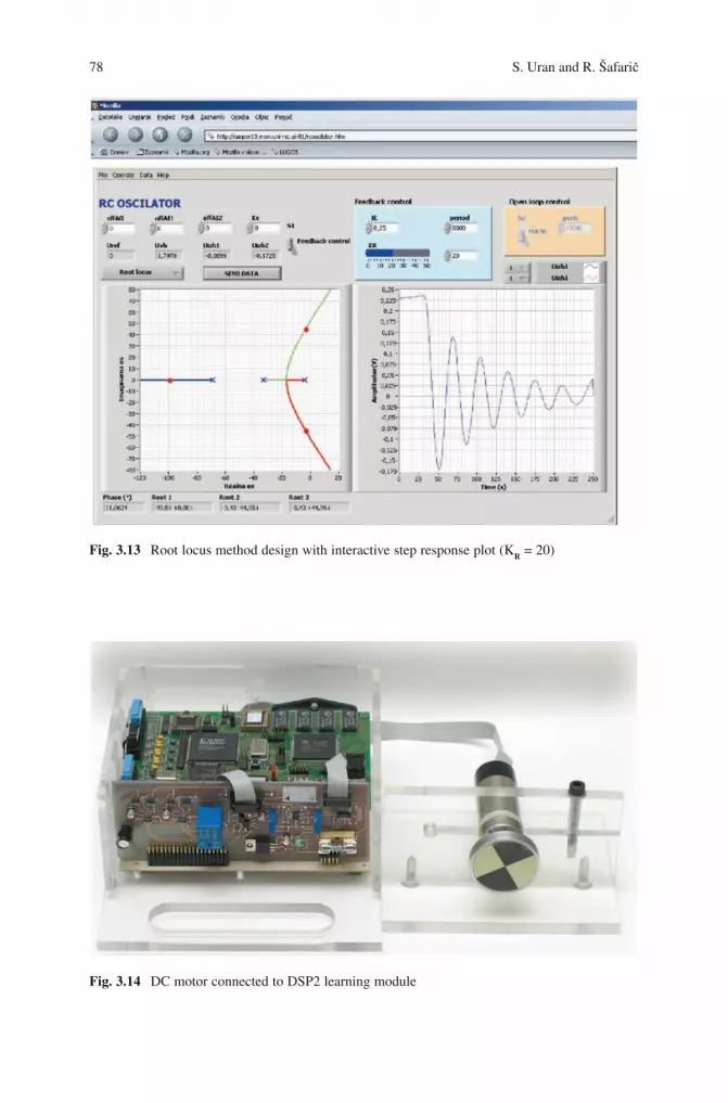
78 S.UranandR.Šafarič
BookID 175907_ChapID 3_Proof# 1 - <Date> BookID 175907_ChapID 3_Proof# 1 - <Date>
Fig. 3.13 Rootlocusmethoddesignwithinteractivestepresponseplot(KR=20)
Fig. 3.14 DC motor connected to DSP2 learning module

3 Web Based Control Teaching 79
BookID 175907_ChapID 3_Proof# 1 - <Date>
DCmotorspeedcontrolexperimentisabitmoreclassicallydesignedthenRCoscillator experiment. No control design is interactively visualized with the DCmotor speed controlled time response. But special safety precautions have been built into the experiment design due to the remote operation of the DC motor.
Open loopandclosed loopcontrolofcurrentcontrolledDCmotor ispossible(Figs. 3.16–3.18). Small offset in the reference signal when no speed control is implemented results in rise of motor speed to maximal value – where it remains. Such situation is not desirable for a longer period of time due to DC motor wear. Sincestudentoperatesmotorremotelyhe/shedoesnothearthesoundofmotorrota-tions. Unfortunately, visual information on motor rotation is not enough informative for detection of motor maximal rotational speed. Therefore the DC motor rotating
Fig. 3.15 DCmotor(livevideopicture)intheremotelaboratory
wmR
–
KM
KT, TTKR, TW
Md
wm1/JC
JC = Jm + JL
Fig. 3.16 DC motor speed control loop for current controlled motor

80 S.UranandR.Šafarič
BookID 175907_ChapID 3_Proof# 1 - <Date> BookID 175907_ChapID 3_Proof# 1 - <Date>
Fig. 3.18 OperationalpanelofDCmotorspeedcontrolremoteexperiment
PulseGenerator1
++
+–
offV
DSPConstant
Velocitycontroller
GainCCDCmotor
DSP-2 TTWmREF
DSP-2 FTIoff
DSP-2 FTenable
DSP-2 TTIa
DSP-2 TTwm
DSP-2 TTwmf
DSP-2 TTfi
DSP-2 TTIaREFCfak
CfakIaREF Ia
wm
wmf
fiIoff
enable
Gain1
Fig. 3.17 Matlab/SimulinkblockschemeforDCmotorspeedcontrol

3 Web Based Control Teaching 81
BookID 175907_ChapID 3_Proof# 1 - <Date>
withmaximalspeedisautomaticallyturnedoffafter2min.Nointerventionoflabo-ratory staff is needed to turn the motor on again. The student turns the motor on simplywithclickingonabuttonontheLabVIEWfrontpanelforDCmotorspeedcontrol experiment.
3.5 Conclusion
The chapter presents the teaching of the control theory at the Faculty of electrical engineering and computer science, University of Maribor for Mechatronics study program. The main challenge of the chapter is to present the modernization of the educational process trough the new web based and remote rapid prototyping teaching techniques. Several techniques of modern control theory teaching were presented:Web-basedvirtuallaboratorybasedonMATLABWebserverwhichhasbeenusedbyprofessorsforlecturedemonstrations(Websisotool)andstudenthomework(M-fileapplication)andmoreadvancedDSP-basedremoterapidprototypinglaboratory(RCoscillatorexperimentandDC-motorexperiment)basedoninhousedevelopedDSP-2learning module, which is enough robust for massive use in an every day educational process, where student can gain valuable control theory hands-on experiences.
Three teaching techniques were adopted in presented application orientedcontrol theory course. First, the hands-on experiments were included in the course, mostly on the level of Web based virtual laboratory, but also practical demonstrations were made with the help of the DSP-based remote control laboratory experiments by lecturer. Second, at the laboratory sessions of the control course the students used predominantly WEB based virtual laboratory for designing the controller parametersandappliedthemontherealcontrolplants,likeRC-oscillatorandDC-motor.The third, to improve the student learning at home, the remote laboratory experiments were used by the students.
References
1. C. T. Chen, “Analog and Digital Control System Design: Transfer-Function, State-Space, and AlgebraicMethods”,SaundersCollegePublishing,NewYork,1993.
2.R.C.Dorf andR.H.Bishop,ModernControlSystems, 11th ed.,PearsonEducation Inc.,PearsonPrenticeHall,UpperSaddleRiver,NJ,2008.
3.B.Wittenmark,H.Haglund,andM.Johansson,“DynamicPicturesandInteractiveLearning”,IEEE Control Systems, vol. 18, pp. 26–32, June 1998.
4. B.L.SturmandJ.D.Gibson,“SignalsandSystemsUsingMATLAB:AnIntegratedSuiteofApplications forExploringandTeachingMediaSignalProcessing”,Proceedings of the 35th ASEE/IEEE Frontiers in Education Conference.pp.F2E-21–F2E-25,October2005,Indianapolis,USA, Indiana.
5.M.deMagistris, “AMATLAB-BasedVirtualLaboratory forTeaching IntroductoryQuasi-StationaryElectromagnetics”,IEEE Transactions on Education,vol.48,pp.81–88,February2005.

82 S.UranandR.Šafarič
BookID 175907_ChapID 3_Proof# 1 - <Date>
6. M. Johansson, M. Gäfvert and K. J. Aström, “Interactive Tools for Education in Automatic Control”,IEEE Control Systems,vol.18,pp.33–40,June1998.
7.J.Sanchesetal.,“EasyJavaSimulations:AnOpen-SourceTooltoDevelopInteractiveVirtualLaboratories Using MATLAB/Simulink”, International Journal of Engineering Education, vol. 21, no. 5, pp. 798–813, September 2005.
8.S.G.CrutchfieldandW.J.Rugh,“InteractiveLearningforSignals,Systems,andControl”,IEEE Control Systems,vol.18,pp.88–91,August1998.[Online]Virtuallaboratoryavailableat:http://www.jhu.edu/~signals
9. J. S. Lee and D. R. Yang, Chemical Engineering Education Using Internet, 8th APCChECongress,pp.1033–1036,1999.[Online]Virtuallab–AppletSeriesV,VIavailableat:http://wwwchbe.gatech.edu/lee/che4400/javamodule.html
10.E. Cheever and Y. Li, “A Tool for Construction of Bode diagrams from Piecewise LinearAsymptoticApproximations”,International Journal of Engineering Education, vol. 21, no. 2, pp.335–340,March2005.
11.A.Schlosseretal.,“RapidControlPrototypinginderLehre”,Automatisierungstechnik, vol. 52,no.2,pp.75–80,2004.
12. S. D. Creighton et al., “A Comprehensive System for Student and Program Assessment: LessonsLearned”,International Journal of Engineering Education, vol. 17, no. 1, pp. 81–88, January 2001.
13. TheMathWorksInc.,MATLABWebServer,productdocument,January2001.14. M. Zandstra, “Naucite se PHP v 24 urah (Authorised translation from the English language
edition,entitledSAMSTeachYourselfPHPin24Hours)”,ZalozbaPasadena,Ljubljana,2004.15.M. Sysel and I. Pomykacz, “Extension of MATLAB Web Server”, Proceedings of 35th
IASTED International Conference. Advances in Computer Science and Technology,pp.70–74,November2004,St.Thomas,USVirginIslands.
16.C.C.Ko,B.M.Chen,J.P.Chen,J.Zhang,andK.C.Tan,“AWeb-BasedLaboratoryonControl of a Two-Degrees-of-Freedom Helicopter”, International Journal of Engineering Education, vol. 21, no. 6, pp. 1017–1030, 2005.
17.M.Casinietal.,“TheAutomaticControlTelelab”,IEEE Control Systems Magazine,vol.24,No.3,pp.36–44,2004.
18.J. Sanches, S. Dormido, R. Pastor, and F. Morilla, “A Java/Matlab-Based Environment forRemoteControlSystemLaboratories:IllustratedwithanInvertedPendulum”,IEEE Transactions on Education,vol.47,no.3,pp.321–329,2004.
19.A. R. S. Castellanos, L. Hernandez, I. Santana, and E. Rubio, “Platform for DistanceDevelopment of Complex Automatic Control Strategies Using MATLAB”, International Journal of Engineering Education, vol. 21, no. 5, pp. 790–797, 2005.
20.B. Duan, K. V. Ling, H. Mir, M. Hosseini, and R. K. L. Gay, “An Online LaboratoryFrameworkforControlEngineeringCourses”,International Journal of Engineering Eduction, vol. 21, no. 6, pp. 1068–1075, 2005.
21.J. Henry and C. Knight, “Modern Engineering Laboratories at Distance”, International Journal of Engineering Education,vol.19,no.3,pp.403–408,2003.
22.T. Kikuchi, S. Fukuda, A. Fukuzaki, K. Nagaoka, K. Tanaka, T. Kenjo, and D. A. Harris,“DVTS-Based Remote Laboratory Across the Pacific over the Gigabit Network”, IEEE Transactions on Education,vol.47,no.1,pp.26–32,2004.
23.D. Hercog and K. Jezernik, “Rapid Control Prototyping Using MATLAB/Simulink and aDSP-BasedMotorController”,International Journal of Engineering Education, vol. 21, no. 4,pp.596–605,2005.
BookID 175907_ChapID 4_Proof# 1 - <Date>
Chapter 4Web-Based Control Education in Matlab
Katarína Žáková
4.1 Introduction
The aim of this chapter is to point out how Matlab can be exploited in Internet-based control education. As it is known, Matlab is the mathematical software package that was originally developed for computations with matrices. Later, its functionality was completed with Simulink and a number of various toolboxes. Simulink was designed for simulation of dynamical systems. Its graphical interface enables easy manipulation with blocks that form basic dynamical components of a system. In spite of a great number of these predefined blocks the interested user is given by a possibility to create his/her own elements or to group blocks together. Matlab toolboxes are developed for many areas, e.g. symbolic computation, statistics, finances, identification, virtual reality, control, etc. Control education has to cover many topics that lead to the robust implementation of controllers in practice. Starting from system identification, continuing to analysis, controller design and verification via simulation, and ending with implementation on real plants. All these steps can be realized using Matlab, too.
Matlab was primarily oriented to computations that were carried out on a local computer without interaction with any additional equipment. Later, its expansion was also addressed to the development of toolboxes that enabled interaction with other software, applications or even real devices.
Successful running of a local application in Matlab represents only the first step on the way to Internet-based control of Matlab applications. Actually, such applica-tions can be divided into two groups: virtual experiments and remote experiments. Both have their pro-and-con. Matlab computations, simulations, animations belong to virtual experiments. Their advantage consists in the fact that the user can make his/her own decisions, but he/she can also make errors. The process of interactive learning through testing, evaluation, decision-making, and error correction creates
K. ŽakováInstitute of Control and Industrial Informatics, Faculty of Electrical Engineering and Information Technology, Slovak University of Technology, Ilkovičova 3, SK-81219 Bratislava, Slovakia, e-mail: [email protected]
S.G. Tzafestas (ed.), Web-Based Control and Robotics Education, 83Intelligent Systems, Control and Automation: Science and Engineering 38,DOI 10.1007/978-90-481-2505-0_4, © Springer Science + Business Media B.V. 2009
84 K. Žáková
BookID 175907_ChapID 04_Proof# 1 - <Date> BookID 175907_ChapID 04_Proof# 1 - <Date>
a much stronger learning environment than passive instructions. By real experiments the user realizes that the control algorithm designed for the simulated simplified mathematical model may not work properly. It is necessary to take into account the presence of noise, possible delays and unmodelled dynamics. In the case where real experiments are available via the Internet one can talk about remote experiments or remote laboratory, respectively.
Actually, there exist two basic approaches to remote control. In the first one the control signal is computed on the client side and, after all computations are done, the computed control variable is transferred to the plant via Internet using agreed protocols. In this case the remote user has the entire control process under his/her own control. In the second approach the total control is kept on the server side where the plant is controlled locally. The remote user has only limited possibilities to modify the running experiment, e.g. setting control parameters, selecting or uploading a control algorithm and starting the experiment. It is not possible to tune the experiment on the fly. Both approaches can be applied for virtual experiments, too. The development of Internet based control applications can be done in various ways. It is possible to create a completely new application where one has to take care about all steps of the development of a client-server application including the building of a mathematical mechanism needed for simulation execution. Another possibility is to use the support of already developed software that can serve as a simulation engine of virtual or remote experiment. For this purpose one can utilize standard software which is wide-spread at universities worldwide such as Matlab, LabView, SciLab, etc. This is exactly the way followed in this chapter, whereby our attention will be oriented to the Matlab environment.
4.2 Standard Solutions
Following the expansion of Web applications, The MathWorks, Inc. also started to support the networking functionality. It developed several solutions in the form of additional toolboxes. These may be considered as standard solutions that can provide maximal compatibility between the Matlab environment and the created application.
4.2.1 The Matlab Web Server
The Matlab Web Server was the first standard Matlab environment that enabled one to deploy Matlab capabilities over Internet. The MathWorks Company, Inc. sup-ported this solution for several Matlab releases: from version 5.3 (R11, 1999) to version 7.2 (R2006a, 2006). The server was able to accept data sent from a user web browser via HTML form, to process them and to return numerical or graphical results back to the web browser.
Matlab Web Server required for its operating TCP/IP networking software and a standard Web (HTTP) server capable of running Common Gateway Interface (CGI) programs. The HTTP server created a service interface between the web page and

4 Web-Based Control Education in Matlab 85
BookID 175907_ChapID 04_Proof# 1 - <Date>
Matlab Web Server (Fig. 4.1). It was common that Web server and Matlab Web Server were installed on the same hardware.
The Matlab Web Server enabled the creation of Matlab applications and their placement on the web. It was sufficient to prepare three files – input html form, Matlab m-file for processing of data from the form, and template of the output web page where the results were visualized. In this way programmers could easily use the capabilities of the World Wide Web to send data to Matlab for computation and to display results in a Web browser. Users of the application did not need to know the Matlab environment, they only filled the prepared form with suitable parameters and after sending it for processing, they received back the expected response.
From the technical point of view after the editing of parameters was completed, the client sent data to the HTTP demon, which loaded the Matlab Web server (matweb file) through the Common Gateway Interface (CGI) [1]. The Matlab Web server was connected to the Matlab server by means of internal protocol. The Matlab server loaded the requested M-file (stored locally in the folders of the server) into a separated copy of Matlab. Finally, the file was executed and results were sent back to the user. However, in spite of the fact that the idea of the Matlab Web Server was very good and really very simple, it is no more supported.
4.2.2 Web Applications and Matlab Builders Products
Starting with Matlab version 7.3 (R2006b, 2006), The MathWorks, Inc. introduced a new concept of applications available via the Web. It developed two builders that allow application developers to create algorithms in Matlab and then incorporate them into enterprise applications based on Java or .NET technologies. The royalty-free builders eliminate the process of recoding an algorithm created in Matlab into Java or a .NET language. These Matlab deployment tools enable to share Matlab applications with users who do not use and do not know how to use Matlab. It is possible to share Matlab programs including GUIs and figure windows.
The Matlab Builder for Java converts Matlab algorithms into standard Java classes that can be called from any Java application. The Matlab Builder for .NET converts algorithms into standard .NET or Common Object Model (COM) compo-
TCP / IP
MatlabWeb Server
HTTPServer
ClientApplication
Server
Web Browser
Fig. 4.1 Interaction with Matlab Web server

86 K. Žáková
BookID 175907_ChapID 04_Proof# 1 - <Date> BookID 175907_ChapID 04_Proof# 1 - <Date>
nents. With both builders, one can leverage the language, technical functions, and visualization tools in Matlab to prototype and develop specific algorithms, which can then be distributed to users without Matlab as components of desktop or Web applications. It is not necessary to have a complete Matlab installation on the server. The functionality of the created web application can be ensured by the Matlab kernel, i.e. the Matlab Component Runtime (MCR). The MCR installer is provided as a separate file with both Matlab builders. The only requirement is that the version of MCR installed on the server has to correspond to the version of Matlab where the Matlab component is developed.
4.2.2.1 The Matlab Builder for JAVA
The advantage of Matlab Builder for Java consists in the fact that it automatically gener-ates Java classes from Matlab functions (Fig. 4.2). Later they can be used with Java applications for desktop or Web environment. This development requires the installation of an additional tool – Java Development Kit (JDK) – which is a basic tool for develop-ment of Java applications. Java components can be deployed to the Web as servlets.
The overall design of a web application using the Matlab Builder for Java can be divided into three steps (Fig. 4.3).
Firstly, one has to prepare the kernel of the Web application. Usually, it is a servlet. Servlets are objects that are created on the basis of Java technology and they are used for generating dynamical Web pages, and for various activities on the server side. They can read data from a user (entered via HTML form or Java applet, etc.), they can prepare and format results, set parameters of HTML response, send response to the client, etc. Servlets are platform independent. This fact enables to use the most suitable combination of an available operating system, server, and tools.
To accept servlets the programmer has to design a client application. The data from the user are usually collected by means of HTML form. It is a simple and reliable way, and therefore it is often used as an interface between servlet and user. The output from servlet is sent back to the user using a dynamically generated web page. In the case of Java technology a JSP Web page is very often used.
m-fileJava Components *.class
Component *.ctf*.jar Component
for Java Application
Fig. 4.2 Building a process with the Matlab builder for Java
Designof Java Servlet
Design of Client Application(Input & Output Web Page)
Implementation of Applicationto Java Web Server
Fig. 4.3 Development of a Web application using Matlab builder for Java

4 Web-Based Control Education in Matlab 87
BookID 175907_ChapID 04_Proof# 1 - <Date>
The implementation of a prepared Web application relates with the Java Web server. Probably the most common servers, that also have a direct support of servlets, are the Sun Java System Web Server and the Apache Tomcat Server.
The next task is to prepare the Matlab file (m-file) that has to be compiled to the Java component. It contains user defined commands for all computation, simulation and visualization processes that should be accomplished in Matlab. It is to note that it is not necessary to have the whole Matlab code in one file. The code can be dis-tributed in several files according to the needs of the application.
The procedure of compilation is sketched in Fig. 4.4.The Matlab Compiler compiles Matlab m-files and all corresponding features to
the Java component needed for the final web application. The important part of compilation is the creation of Component Technology File (CTF) archive. It con-tains all necessary Matlab functions associated in the concrete Java component. The compilation of m-files to Java components is done using the external JDK functionality (command javac) that generates output files with extension .class. Finally, all generated files (.class and.ctf) are packed to Java archive (e.g., Example.jar as in Fig. 4.4) which is the keystone for the external application. This file is copied to the folder with final web application files. During the compilation, still one additional file (javabuilder.jar) is automatically generated and it also has to be copied to the same folder. It is the fundamental file for communication between an external Java application and MCR or Matlab respectively.
The compilation can also be done using the graphical environment that can be run by the command deploytool. This graphical tool allows one to select the type and the name of the project, to choose m-files and other complementary files, to set names of classes, and the entire distributive package.
Example1.m Example2.m
mcc -W Example1.m Example2.m
Compilation of m-code to Java
ExampleComponent.javaExampleComponentRemote.java
ExampleMCRFactory.java
Analysis of Matlab Code
Java Compiler
ExampleComponent.classExampleComponentRemote.class
ExampleMCRFactory.class
Encryption and Compressionof Matlab Functions
Example.ctf
Java Package
Example.jar
Fig. 4.4 Matlab builder for Java: compilation procedure

88 K. Žáková
BookID 175907_ChapID 04_Proof# 1 - <Date> BookID 175907_ChapID 04_Proof# 1 - <Date>
The generated files (Example.jar, javabuilder.jar) have to be imported at the beginning of Java servlet source code:
After that, it is possible to introduce individual code of the servlet that communicates with Matlab by means of defined input and output variables. At the end, the output result is sent to Java Server Pages web page. The Java Server Pages enable the preparation of dynamically generated web pages on the basis of results from the servlet. Similarly to all other web pages, their structure consists of the header and body part whereby the <head> tag content can look as follows:
import Example.*;import com. mathworks. toolbox. javabuilder. * ;
<head><%@ taglib uri=”/WEB-INF/webfigures.tld” prefix=”wf” %><%@ page contentType=”text/html; charset=iso-8859-2” language=”java” %><table width=”763” border=0 cellpadding=0 cellspacing=2 style=”width:100%;height:100%”> <tr> <td> <wf:web-figure name=”picture” scope=”session” root=”WebFigures” width=”100%” height=”100%”/> </td> </tr></table></head>
Its main part is formed by directives whereby the programmer can distinguish three types of directives:
• Page–importsclasses,defineswebpagecontenttype,enablesorforbidssessioncreation;
• Include–enablestoincludetheexternalfiletothewebpage;• Taglib–definesusertags.
Actually, the last directive enables one to include to the code new tags that are used for communication with Matlab. The first attribute “uri” specifies the file with user defined tags, and the second attribute defines the name of the namespace within which they can be used. In the illustrated example the “taglib” directive refers to the Matlab predefined tag file which is used for the creation of the graphical servlet output.
Results (e.g., some graphical dependence) can be visualized by means of a pic-ture to be displayed in the web application of the remote user. For this purpose one can use the Matlab predefined function webfigure where the input argument is the handler of the given figure. The function creates the Java object and pregenerates

4 Web-Based Control Education in Matlab 89
BookID 175907_ChapID 04_Proof# 1 - <Date>
images in different resolutions that are available to the client via the webfigure component included in the web page from the Java server page. The webfigure component is AJAX thin client that provides delivery of figures to the browser.
Actually, the generated picture is a set of static pictures. Despite the fact that Matlab offers some additional functionality which enables the user to rotate or zoom the picture on the web page, the picture quality can be changed only in small predefined set of reso-lutions depending on image zoom. Therefore, these features can be used only in a limited range. Integration of SVG graphics could offer a better comfort to the user.
4.2.2.2 The Matlab Builder for .NET
The Matlab Builder for .NET automatically generates independent .NET or COM components from Matlab algorithms (Fig. 4.5).
Generated .NET components integrate with any .NET language, including C#, VB.NET or ASP.NET. Similarly, COM components can be integrated with COM-compliant technologies, including Microsoft Excel, Visual Basic or ASP. Both .NET and COM components can be deployed to the Web via Active Server Pages (ASP/ASP.NET).
Design of .NET application by means of Matlab Builder for .NET is very similar to the previous design via Matlab Builder for Java. Again it is necessary to prepare an m-file that is converted mostly to classes in C# language. The main difference consists in the fact that now the programmer can choose the compiler for building standalone Matlab applications. He or she can use either the internal Matlab com-piler or an arbitrary external compiler that enables to compile programs on the basis of C/C++ language (e.g., Borland C++ , Microsoft Visual C++ , etc.). The process of compilation is illustrated in Fig. 4.6.
The Component Technology File archive again comprises of all Matlab func-tions that could be associated during the use of .NET component. The process of compilation generates, besides the CTF file, a dynamic-link library (.dll file) that is a shared library under the Windows operating system and has also to be imported into the created application.
Similarly to the building of Java components, the compilation can also be done via the graphical environment that can be started by the command deploytool.
In comparison to Java technology, it has to be taken into account that .NET technology is oriented only for a Windows platform and that the programmer has not such a big choice of free development tools as in the case of Java technology.
m-file.NET Components *.dll
Component *.ctf
Fig. 4.5 Building a process with the Matlab builder for .NET

90 K. Žáková
BookID 175907_ChapID 04_Proof# 1 - <Date> BookID 175907_ChapID 04_Proof# 1 - <Date>
4.2.3 Matlab Compiler and CGI Scripts
Both the Matlab Builder for Java and Matlab Builder for .NET were built as an extension of the Matlab Compiler. They both can be used for the development of Web applications. However, what about the Matlab Compiler by itself?
The Matlab Compiler converts m-files, mex-files and other Matlab codes to independently running programs or libraries that do not need Matlab for their func-tioning. They need only the Component Technology File (CTF) and the Matlab Component Runtime (MCR). The CTF file is specific to each operating system platform and contains the Matlab functions and data that define the application or library.
The Matlab Compiler enables the creation of native applications written in C or C + + language. This allows one to create CGI scripts (executable standalone applications) that can be called by Web server. CGI scripts generate HTML code and write it to standard output (stdout). The implementation of CGI scripts on the server requires setting them as executable files. It has to be done for files generated by Matlab Compiler, too.
4.3 Alternative Solutions
This section is devoted to solutions that can offer alternatives to the solution offered directly by The MathWorks, Inc.
Matlab enables one to call and use external programs. They can be written in several languages, e.g. C, C++ , Fortran or Java. As we will see later, the support for Java is included in the Matlab engine directly. Programs written in other languages have to be compiled together with Matlab contemporarily. The use of external application, pro-grams and routines brings several advantages. They are usually executed faster, they enable us to exploit external graphical user interfaces written, say, in Java, and finally they enable us to exchange information with existing software and libraries.
Example1.m Example2.m
mcc -m Example1.m Example2.m
Compilation of m-code to C/C++
Example1_main.csExample1_mcc_component_data.cs
Analysis of Matlab Code
C/C++ Compiler
Example.dll
Encryption and Compressionof Matlab Functions
Example.ctf
Fig. 4.6 Matlab builder for .NET: compilation procedure

4 Web-Based Control Education in Matlab 91
BookID 175907_ChapID 04_Proof# 1 - <Date>
The Matlab can use several external interfaces: native MEX files, Java, COM, DDE or external libraries – *.dll for Windows or *.so for Solaris, Unix and Linux operating systems. Some of these interfaces can also be used to build applications that can be shared over the Internet.
4.3.1 Matlab Dynamic Data Exchange (DDE)
The Dynamic Data Exchange (DDE) was one of the first methods supporting communication in Windows. It is a technology developed by Microsoft Corporation that allows communication and data exchange among various Windows applications. DDE doesn’t need to be installed separately; it is a part of the Windows operating system. Matlab contains functions enabling full duplex approach of Windows applications to Matlab. These functions use Dynamic Data Exchange.
DDE allows sending and receiving messages in the so-called “conversations” between applications. The communication starts after establishing the DDE conver-sation, whereby the application that initiates a communication is called a client, and the application answering to the client is a server. We can talk about the client/server application. The client has to identify two DDE parameters that are defined by the server, i.e., the name of the application that should answer to the client prompt – service name, and the subject of communication – topic. When the server receives a request for opening the conversation channel, it verifies the topic and, if verified, it allows the client connection. The combination of two obligatory param-eters uniquely identifies the conversation.
In general, Matlab can act both as a client and as a server, although the second possibility may be more frequent. A client application can access Matlab as a DDE server in two ways, depending on the client application. If we wish use an application that provides functions or macros to conduct DDE conversations, the simplest way is to use these functions or macros. If we wish to create our own application, we can use the Matlab Engine Library or DDE directly [26].
In case that Matlab is considered as a client application, it is possible to use func-tions from the Matlab DDE client module to establish and maintain conversations. Using these functions one can initiate a DDE conversation, request data from the DDE server application, send data from Matlab to the DDE server application, etc.
Considering web based education, it must be noted that the DDE communication can usually run only locally. However, the local communication with Matlab, successfully realized, enables one to step forward and to try to implement TCP/IP protocol in order to use Matlab remotely. In this case the DDE client is trans-formed to TCP/IP server that can be approached by remote clients via Internet. The structure of such a connection is shown in Fig. 4.7.
The realization of this solution is highly time-demanding, since it requires to program a TCP/IP server and also a client application. The client implementation is very often done in the Java environment, because of its platform independence. The advantage is that this development enables full optimalization of system tools and functions that are needed for communication.

92 K. Žáková
BookID 175907_ChapID 04_Proof# 1 - <Date> BookID 175907_ChapID 04_Proof# 1 - <Date>
Finally, it must be remarked that the support for DDE conversation is no more available in Matlab. It exists there, it can be used, but The Mathworks, Inc. turns its attention to other types of external interfaces.
4.3.2 The Component Object Model
The Component Object Model (COM) is a software architecture developed by Microsoft to build component-based applications that can be called up and executed in a Windows environment. This means that Matlab environment can support the COM communication only on the Microsoft Windows platform.
COM is used by developers to create re-usable software components, link com-ponents together to build applications, and take advantage of “Windows” services [27]. Using the COM technology, a program can call the object whenever it needs its services. As already mentioned in [25], standard applications, such as word processor and spreadsheets, can be written to expose their internal functions as COM objects, allowing them to be “automated”, instead of manually selected from a menu. For example, a small script could be written to extract data from a database, put it into a spreadsheet, summarize and chart it, all without manual intervention. A similar functionality is also supported by Matlab [28].
A COM object can be implemented in any language. Generally, a client access-ing a COM object does not have direct access to the actual data contained in the object. The COM object is only accessible through the set of interfaces that the object exports. In this way the user can approach most of the object parameters. The only interface that Matlab supports is called IDespatch. Except of the interface, the programmers need to know what approach methods can use. The simplest one is the already mentioned Automation method, also supported by Matlab.
The interface enables communication between a COM client and a COM server. A COM client is a program that makes use of COM objects. COM objects that expose functionality for use are called COM servers. Matlab can act both as a client and as a server. Considering Matlab as a COM client, a user can use two techniques for developing programs in Matlab, i.e., it is possible to include COM components in the Matlab application or one can access existing applications containing objects via Automation. It is noted that Matlab software on Microsoft Windows operating
TCP / IP
DDE Server
ClientApplication
Matlab
Web Browser
Proxy
Fig. 4.7 Client/server communication via DDE

4 Web-Based Control Education in Matlab 93
BookID 175907_ChapID 04_Proof# 1 - <Date>
systems also supports COM Automation server capabilities. Any Windows program that can be configured as an Automation controller can control Matlab.
As already mentioned a COM object can be written in any language. It has to be only capable of understanding and implementing its binary defined data types and interfaces. In addition, Matlab COM builder (and perhaps Matlab Compiler) trans-forms Matlab applications to COM objects, too. In this way Matlab code and appli-cations can be compiled as independent COM objects.
To develop an application via Internet one can use a structure such as that shown in Fig. 4.8.
The application is initialized by the user who runs from the web browser the script placed on the web server. The script creates a COM client and sends to it the application name to open. The Matlab application cannot be opened before the COM object is created. Matlab has always to be initialized by a created COM client because later they cannot be assigned each to other.
Using the server operating system, the COM client executes Matlab in the Automation mode, i.e. it creates the COM server object that waits for next instruc-tions. A COM client addresses the COM server and sends to it parameters and commands for computation or simulation handling. Usually, the user receives all the results after all computations and simulations are done.
As script languages one can use, PHP or Python. However, PHP is weak in handling serialized objects and classes. Moreover, the PHP language is not suitable for initializing a COM object in such a way that would enable one to work with a multithread application. To overcome these problems, Python is a better solution. It enables one to handle COM objects automatically via the imported modules. Sessions are able to save one or more instances of a Matlab COM object. In case where, for some reason, Matlab request fails, it is possible to return to the object and use it once again. The communication problem between COM objects and multithread applications is solved by the function pythoncom.CoInitialize() from PyWin32 extension. It can be used as interface to almost any COM program. In addition, Python has several user-friendly libraries that can com-municate with Matlab. However, the main advantage consists in saving COM objects in Python sessions. There is no need to open a new Matlab environment for each request. When a user sends the first request to Matlab, it is sufficient to start one persistent Matlab session which is opened till the user accomplishes all experiments. To illustrate this fact better, let’s imagine a simulation process taking one hour of time. Using the application written in PHP scripting language, the
TCP / IPClient
Application
Matlab Web Browser
iDespatchinterface
COM Server
Apache Web Server
COM Client
PHP, Python, ..
Fig. 4.8 Communication with Matlab via COM objects

94 K. Žáková
BookID 175907_ChapID 04_Proof# 1 - <Date> BookID 175907_ChapID 04_Proof# 1 - <Date>
user can set and start the simulation but then he/she has to wait until the simulation stops, and cannot do anything else. Using Python the user can run additional computations in Matlab or change the parameters of the simulation process during its running.
4.3.3 Matlab and Java
Web applications are very often based on the Java programming language. Since in the control area they may cooperate with Matlab, it is good to know what communication tools are available for this purpose. Standard external interfaces, such as DDE and COM objects mentioned in previous sections, can also be used to communicate with Java. However, these solutions are available only under the Windows operating system.
In the following we distinguish two typical situations: calling Java from Matlab and calling Matlab from Java. As we will see, they mostly cannot be solved together.
4.3.3.1 Calling Java from Matlab
The communication between Matlab and Java was considerably simplified after Matlab 6 was released. This version of Matlab includes a Java Virtual Machine (JVM) which allows access to Java objects. However, Matlab is only fully sup-ported on the JVM that it ships with [26]. Under a different version of the JVM some components may not work properly. In spite of that, it was a step further since the JVM software allows the use of the Matlab interpreter with Java com-mands. In this way the user can construct Java objects in Matlab, call Java methods using either Java or Matlab syntax, pass data between Matlab variables and Java objects, access Java API class packages that support I/O and networking, etc. [26]. The advantage is that the user can also call native (built-in) as well as external java classes directly with the Matlab prompt. Java classes do not need to be compiled explicitly for Matlab and no gateway function is needed in the Java class.
4.3.3.2 Calling Matlab from Java
Through the Java Virtual machine in Matlab, The MathWorks, Inc. allows one to call and use Java objects from Matlab, but not to call Matlab commands from Java. Despite this fact it can be more useful. Regarding various computations, Matlab can do whatever Java can. However, in case of some heavy numerical processing Java cannot compete with Matlab, since Matlab was designed exactly for this. In the case where the Java application must call Matlab, it can be done only in some indi-rect way. There exist several possibilities.

4 Web-Based Control Education in Matlab 95
BookID 175907_ChapID 04_Proof# 1 - <Date>
Java Matlab Interface
Firstly, one can use Java Matlab Interface from The MathWorks, Inc. where the file jmi.jar is included to Java code to support such functionality. This approach is con-sidered, for example, in [4] or [21] and [5]. The MatlabControl object developed by Kamin Whitehouse [21] allows a user to create calls into Matlab from Java. However, this object must be used and run within the same JVM that Matlab is running. The work refers to that of Bowen Hui [5], which sets up a MatlabServer. The MatlabServer allows remote calls, but everything must be string based, and it uses a basic socket server with no well defined protocol.
JMatLink
A second possibility to realize calls from Java to Matlab is to use third-party Java-Matlab interfaces. The most widely known is probably the product JMatLink from Stefan Müller [12]. This dll library is programmed in the C language that using the ActiveX tool approaches data and services of Matlab. The library is implemented in the class of Java language that has the same name (JMatLink .class). If Java is used for the development of a client application, one has available all methods of the mentioned class. JMatLink uses a multi-threading approach to improve performance and handle multiple Matlab sessions on time (Fig. 4.9).
Java Runtime Class
This approach is described in [8] and uses the Java Runtime class to start a new Matlab process. Platform-independent communication is achieved through acquiring Matlab’s standard input and output streams. Matlab can be started directly from a Java class, either on the same machine, or, under Unix-based systems, even on another machine. The communication was tested in Matlab version 6.5, but, as the author states, it will most likely work with future versions of Matlab.
There are mentioned two disadvantages. First, the transfer of data is character- and stream-based, and therefore inefficient, especially for larger amounts of data (high latency, low transfer rates compared to direct memory access). Secondly, parsing of the Matlab output stream has to be done manually.
TCP / IPClient
ApplicationSimulink
MatlabWeb Browser
JMatLink
Fig. 4.9 Communication via the JMatLink library

96 K. Žáková
BookID 175907_ChapID 04_Proof# 1 - <Date> BookID 175907_ChapID 04_Proof# 1 - <Date>
JNI Wrapper for Matlab’s C Engine
This procedure was also described in [8]. With Java’s Native Interface (JNI), one can write a wrapper class for Mathworks’ C Engine library. This implementation is a little bit cumbersome, since building a Java application that contains native libraries is more difficult than a pure Java application. On the other hand, this approach makes The Matlab C Engine library functions accessible.
Similarly, as in the previous case, Matlab can be started directly from a Java class, either on the same machine, or, under Unix-based systems, even on another machine. Likewise, the data transfer is also character- and stream based, therefore inefficient especially for larger amounts of data (high latency, low transfer rates compared to direct memory access). Moreover, this solution is platform-depend-ent, and, according to the author, in most cases it is not expected to work with future versions of Matlab (after version 6.5) without small adjustments and re-compilation.
As mentioned in [8], with the last two strategies the data is transferred via character streams. This is not very fast, but there is no other way to follow. In most applications, however, the amount of input and output data can be kept rather small, since communication is usually required only at the beginning and at the end of a computation.
JMatlab/Link
JMatlab/Link [9] is an add-on to the Open Source framework JstatCom (JAVA Statistical Computing), originally designed for time series analysis, that can also be used for statistical computing in general. JMatlab/Link can be used to call dlls that have been generated with the Matlab Compiler directly from Java. This allows one to integrate Matlab features into Java applications and thus combine the strengths of both. In this case, direct calls to compiled system dlls are possible without the need to write a dedicated JNI wrapper. To compile Matlab dlls, Matlab version 7, Matlab Compiler version 4, and Microsoft Visual C++ compiler are required. The Matlab generated dlls can only be run with the same version of Matlab or with the MCR under which they have been generated.
Using JMatlab/Link together with the generated dlls allows full control over Matlab execution, especially stopping a running computation any time. It reports all Matlab output and errors to a logging handler. Even if a Matlab computation results in a fatal error, the Java application will remain stable and can safely invoke another computation based on Matlab. Use of JMatlab/Link allows a single instal-lation procedure of applications, without the need to install the Matlab Component Runtime in a separate step. The disadvantage is that currently JMatlab/Link runs only on Windows.

4 Web-Based Control Education in Matlab 97
BookID 175907_ChapID 04_Proof# 1 - <Date>
4.3.4 Communication via File
This type of communication is by its nature very simple. It is based on the fact that both Matlab and programming languages used for the design of web application are able to work with files, i.e. they can for example write numerical values and strings into files and they can also read from the files.
The communication functions on the basis of a shared file (see Fig. 4.10). Web pages with the control based application and Matlab software can be installed on the same web server. The user enters his/her own simulation parameters and commands in the form that can be filled in via the web browser. After their submission they are written into the file placed on the server where Matlab is installed. The content of the file is read by Matlab functions. After the variables are saved in the Matlab workspace, they can be used for computation or simulation. Finally, results have to be sent to the client. This can be done via the file, too.
It is noted that if this approach is used for simulation or even for the control of a real plant, where the parameters can also be changed on the fly, Matlab has to read the file in regular time instants.
Using the Real Time Workshop, the big advantage of the method consists in the fact that the block scheme prepared in Simulink is attached to the real plant perma-nently, and, therefore, visualization via the Virtual Reality toolbox can also be used. However, this method has also a drawback. Real-time Workshop (RTW) does not support I/O functions with files. Therefore this solution is suitable only for simulations without RTW.
4.3.5 Communication via TCP/IP
As it is known, TCP/IP is the communication protocol for communication among computers connected to the Internet. It also specifies how data should be transmit-ted over the Internet. TCP/IP uses the client/server model of communication in which a computer user (a client) requests and receives a service (such as sending a Web page) by another computer (a server) in the network [29].
TCP / IPClient
Application
Simulink
Matlab
Web Browser
File
Web Server
Fig. 4.10 Communication with Matlab via file

98 K. Žáková
BookID 175907_ChapID 04_Proof# 1 - <Date> BookID 175907_ChapID 04_Proof# 1 - <Date>
4.3.5.1 The MathWorks Instrument Control Toolbox
TCP/IP connectivity is also included in The MathWorks Instrument Control Toolbox [26]. Except of others, this toolbox provides the networking functionality that enables one to create a client application in Matlab in order to communicate with one or more server applications built in programming languages other than Matlab. It must be emphasized that the TCP/IP object created using the MATLAB Instrument Control Toolbox can only act as a client and not as a server. Despite this fact, the Instrument Control Toolbox enables Matlab to control, configure, and transfer data with instrumentation. In addition, this toolbox provides blocks to Simulink, too. Using these blocks one can exchange data between an instrument and the Simulink model over the Internet via TCP/IP.
4.3.5.2 The TCP/UDP/IP Toolbox
Although, the TCP/IP communication is presently supported by the MathWorks directly there are also some other possibilities for making this functionality live. One of them is to use TCP/UDP/IP Toolbox 2.0.6 – the product of Peter Rydesäter [15]. Despite the fact that it was developed some years ago (in the year 2001), it still has good references.
This toolbox can be used to set up TCP/IP connections or send/receive UDP/IP packets in MATLAB. It can transmit data over the Intranet/Internet between MATLAB processes or other applications. It is possible to act as a server and/or a client and transmit text strings, arrays of any data type, files or MATLAB variables [15]. As it can be seen from the following example of remote TCP/IP connection, the work with this toolbox is really very easy.
con = pnet(‘tcpconnect’,’remote-server.xxx.com’,1677);pnet(con,’printf’,’Hello world!\n’);pnet(con,’close’);
4.3.5.3 The S-function Block
The communication between Matlab and a remote user is realized in two channels. First of all the client has to control the activity in Matlab (at least by entering his/her own parameters and initializing the computation or simulation), and then the result has to be sent back from Matlab to the remote user.
Suppose that one has to build a web application that should cooperate with Simulink (Matlab graphical simulation environment) and that the first channel (the transfer of data and commands from the client to Matlab/Simulink) is already solved. The task is to find the solution for the channel to the client. It means to ensure the transfer of simu-lated or measured signals to the user that can visualize results in the web browser (e.g., using Java applet). This situation can also be solved using TCP/IP communication.

BookID 175907_ChapID 04_Proof# 1 - <Date>
4 Web-Based Control Education in Matlab 99
Since the application cooperates with Simulink, one can use the block S-function. This block can be written in any compatible language, e.g., C, C++ , Ada, Fortran, Matlab, etc. S-functions can be compiled as MEX files and dynamically linked to Matlab whenever required. S-functions use special syntax that enables interactions with Simulink and its ODE. The structure of S-function allows creating continuous, discrete, and also hybrid functions.
For the S-function can be realized in two ways. It can be used either as a TCP/IP client or a TCP/IP server. In both cases it is useful to write it in C language and to compile it into a dll library, since then it can be used without problems for real time experiments, too.
For S-function representing a TCP/IP client the implementation is more complicated. Usually, it is necessary to create an additional application (e.g., Java application) that consists of two TCP/IP servers (Fig. 4.11). The TCP/IP client in S-function is connected to one of these servers and the client in the web application available to the remote user is connected to the second server. In the created supplementary application TCP/IP servers only move data between themselves and in this they send data to the user.
The second solution is simpler because the TCP/IP server realized in Matlab S-function can directly be connected to the TCP/IP client on the user side (Fig. 4.12).
The disadvantage of S-functions lies on the fact that, if we want to use them in combination with the Real-Time Workshop, we cannot use any Windows API func-tions, or any I/O functions for communication with files and many other functions that could cooperate with timers.
4.4 Client Applications
The previous sections were dedicated mostly to the server part of Web applications and to the communication between a server and a client. However, the realization of the client side also requires considering various aspects of its design. It is required to adjust
TCP / IPS-functionTCP / IP Client
ClientApplication
Matlab / Simulink Web Browser
TCP / IPTCP / IPserver
Proxy Server
TCP / IPserver
Fig. 4.11 Communication via TCP/IP using the S-function as a client
TCP / IPS-functionTCP / IP Server
ClientApplication
Matlab / Simulink Web Browser
Fig. 4.12 Communication via TCP/IP using the S-function as a server

100 K. Žáková
BookID 175907_ChapID 04_Proof# 1 - <Date> BookID 175907_ChapID 04_Proof# 1 - <Date>
requests of users, programmers and possible technical limits of the application. It is convenient if the chosen tool is suitable for animation, i.e. if it can guarantee smooth animations. It should enable simple Internet communication e.g., using sockets. Finally, the requirement is to create a multi-platform application. The platform independence is important because the application is presented to users via Internet. These requirements can be fulfilled by several solutions. Let’s introduce at least three of them.
Probably, the one mostly used is a Java applet. It is a program written in the Java language that can be included in an HTML page. Java enables a comfortable network programming, and the communication is very simple. A little bit more difficult may be to create a smooth animation without a blinking. This problem can be solved, but it is uselessly tricky and complex.
The next possibility is to combine JavaScript and CSS. In this case the graphical layout of the HTML web site is ensured by the Cascading Style Sheets that can be dynamically changed by JavaScript. Such preparation of the client is very simple and natural. As in the previous case, a possible animation is not very smooth, and the communication with the server is relatively complicated. However, a very promising SVG format can also be used for the preparation of web applications. This vector format can be applied for the presentation of graphics and animations, as well. Thanks to its XML structure it can be easily modified, zoomed, animated, etc. The SVG figure allows data downloading from the server dynamically, and it offers the possibility to enhance velocity, flexibility and interactivity of the generated graphics, e.g., signalize status of data, or update current data in time.
The third possibility is a Macromedia Flash animation. This software enables one to create nice animations that are independent of the platform. In addition, the use of ActionScript offers a simple control of applications and Internet communication on the basis of XML sockets.
4.5 Conclusions
Matlab is usually used for computations that are accomplished on the computer locally. However, the increased expansion of Internet together with the growing sup-port of online education raised the question of how to exploit the capabilities of Matlab for these purposes, too. In such a case, one installation of Matlab placed on a remote server could be used for several clients, whereby the client can be represented by a person or an application. Our attention was dedicated to Matlab since, thanks to its toolboxes, it facilitates access to experiments and belongs to widespread applications in the control education.
The introduction of virtual and remote laboratories [2, 3, 6, 7, 10, 11, 13–20, 22–24] enhances remarkably the student motivation and also develops various other skills in the signal measurement, signal processing, and the entire control education. Virtual and remote experiments help to enhance the interactivity of education. They can be available 24 hours per day and 7 days in a week, and, therefore, they are very suitable for distance education.

BookID 175907_ChapID 04_Proof# 1 - <Date>
4 Web-Based Control Education in Matlab 101
Sometimes, universities are said to be too theoretical. On the other hand, industry demands professionals with good practical skills. Web based labs try to overcome this paradox and to help students become qualified professionals.
Acknowledgments The author thanks M. Sedlák, D. Antal, P. Píš, M. Kohút, M. Repcík and P. Riecan for their help and useful discussions.
References
1. T. Bhabhrawala, “Web-Based Teleoperated Virtual Laboratories (Web Labs)”, University at Buffalo Educational Technology Center, January 2005, http://mechatronics.eng.buffalo.edu/education/WebLabs/index.html
2. P. Bisták, “Remote Control of Thermal Plant Using Easy Java Simulation”, International Conference on Interactive Computer Aided Learning ICL ‘06, Villach, Austria, 2006.
3. P. Bisták, K. Žáková, “Organising Tele-Experiments for Control Education”, 11th Mediterranean Conference on Control and Automation, Rhodes, Greece, June 2003.
4. S. Caton, “Controlling Matlab from Java”, 2005-2008, http://beryl.cs.cf.ac.uk/Web/Guides/Java%20Control%20of%20Matlab/1.php
5. B. Hui, “Calling Matlab from Java”, http://www.cs.utoronto.ca/~bowen/code/code.html#matjav
6. F. Jakab, V. Andoga, L. Kapova, M. Nagy, “Virtual Laboratory: Component Based Architecture Implementation Experience”, Electronic computer and informatics, Košice-Herľany, Slovakia, September 2006.
7. P. Karagiannis, I. Markelis, K. Paparrizos, N. Samaras, A. Sifaleras, “E-learning technologies: employing Matlab web server to facilitate the education of mathematical programming”, International Journal of Mathematical Education in Science and Technology, Vol. 37, No. 7/15, pp. 765–782, October 2006.
8. Klimke, “How to Access Matlab from Java”, Berichte aus dem Institut fľr Angewandte Analysis und Numerische Simulation, Universität Stuttgart, Preprint 2003/005.
9. M. Krätzig, “JMatlab/Link User Guide”, JStatCom Engineering, www.jstatcom.com, 2007.10. J. Liguš, J. Ligušová, I. Zolotová, “Distributed Remote Laboratories in Automation
Education”, 16th EAEEIE Annual Conference on Innovation in Education for Electrical and Information Engineering, Lappeenranta, Finland, June 2005.
11. F. Michau, S. Gentil, M. Barrault, “Expected benefits of web-based learning for engineering education: examples in control engineering”, European Journal of Engineering Education, Vol. 26, No. 2, pp. 151–168, June 1, 2001.
12. S. Müller, H. Waller, “Efficient Integration of Real-time Hardware and Web Based Services Into MATLAB”, 11th European Simulation Symposium, Erlangen, Germany, October 1999, http://jmatlink.sourceforge.net
13. P. Píš, K. Žáková, “Remote Control of the Beam and Ball Model”, Process Control 2005, ľtrbské Pleso, Slovakia, pp.201.1-201.6, June 2005.
14. M. Repcik, K. Žáková, “Remote Control of Inverted Pendulum”, International Conference on Remote Engineering & Virtual Instrumentation, Porto, Portugal, June 23-27, 2007.
15. P. Rydesäter, “TCP/UDP/IP Toolbox 2.0.6”, March 2001, http://www.mathworks.com/matla-bcentral/fileexchange/345
16. F. Schauer, M. Ožvoldová, F. Lustig, “Real remote physics experiments across internet – inherent part of integrated e-learning”, International Journal of Online Engineering. Vol. 4, No 2, pp. 52–55, 2008.
17. Chr. Schmid, “Virtual Laboratory for Engineering Education”, ICDE, Austria, 1999. 18 . Chr. Schmid, “Internet – basiertes Lernen”, Automatisierungstechnik, Vol. 51, No. 11, pp.
485–493, 2003.
102 K. Žáková
BookID 175907_ChapID 04_Proof# 1 - <Date>
19. M. Sedlák, K. Žáková, “Remote Experiments in Matlab”, European Control Conference, Kos, Greece, pp. 2707–2713, July 2007.
20. M. Šimunek, P. Bisták, M. Huba, “Virtual Laboratory for Control of Real Systems”, International Conference ICETA, Košice, Slovakia, Septemper 2005.
21. K. Whitehouse, “Calling Matlab from Java”, 2002, http://www.cs.virginia.edu/~whitehouse/matlab/JavaMatlab.html
22. K. Žáková, M. Huba, V. Zemánek, M. Kabát, “Experiments in Control Education”, IFAC Symposium on Advances in Control Education, Gold Coast, Australia, December 2000.
23. K. Žáková, M. Sedlák, “Remote control of experiments via Matlab”, International Journal of Online Engineering, Vol. 2, No. 3, 2006.
24. K. Žáková, M. Sedlák, “Web-Based Control Education in Matlab”, Remote Engineering & Virtual Instrumentation: International Conference REV, Düsseldorf, Germany, June 2008.
25. http://www.answers.com26. http://www.mathworks.com27. http://www.microsoft.com28. http://www.pcmag.com29. http://whatis.techtarget.com/

BookID 157964_ChapID <CID>_Proof# 1 - 12/5/2009
Chapter 5Object-Oriented Modelling of Virtual-Laboratories for Control Education
Carla Martin-Villalba, Alfonso Urquia, and Sebastian Dormido
5.1 Introduction
Virtual-laboratories (virtual-labs, in short) provide a flexible and user-friendly method useful for defining the experiments to be performed on a mathematical model. Virtual-lab users are allowed to design and perform their own simulation experiments. As a result, they become active players in their own learning process, which motivates them to further learning. Virtual-labs can be used to explain basic concepts, to provide new perspectives of a problem, and to illustrate analysis and design topics.
Virtual-labs are typically composed of: (1) the simulation of the mathematical model describing the relevant properties of the system under study; (2) the interac-tive user-to-model interface, named the virtual-lab view; and (3) a narrative that provides information about the system under study and the virtual-lab use.
Depending on whether or not the virtual-lab user is allowed to interact with the model during the simulation run, the following two types of interactivity can be distinguished:
• Runtime interactivity. Users can change the value of the model inputs, parame-ters and state variables during the simulation run, immediately perceiving how these changes affect the model behaviour. An arbitrary number of actions can be made on the model at any time during the simulation run. For example, this type of interactivity is supported by virtual-labs intended to emulate the real-time response of the plant, allowing the user to make real-time decisions.
• Batch interactivity. The user’s action triggers the start of the simulation, which is run to completion. During the simulation run, the user is not allowed to inter-act with the model. Once the simulation run is finished, the results are displayed and a new user’s action on the model is allowed. This type of interactivity is useful in applications whose goal is to obtain the simulated response of the model for a specific time-period, and use it to automatically compute linear
C. Martin-Villalba (), A. Urquia, and S. Dormido Departamento de Informática y Automática, Escuela Técnica Superior de Ingeniería Informática, Universidad Nacional de Educacion a Distancia (UNED), Juan del Rosal 16, 28040 Madrid, Spain,
[email protected], http://www.euclides.dia.uned.es/carlamv
S.G. Tzafestas (ed.), Web-Based Control and Robotics Education, 103Intelligent Systems, Control and Automation: Science and Engineering 38,DOI 10.1007/978-90-481-2505-0_5, © Springer Science + Business Media B.V. 2009

104 C. Martin-Villalba et al.
BookID 175907_ChapID 05_Proof# 1 - 12/5/2009 BookID 175907_ChapID 05_Proof# 1 - 12/5/2009
approximations to the system and their frequency-domain characteristics, to perform automatic synthesis of controllers, etc.
There exist several software tools specifically intended for the implementation of virtual-labs. These tools: (1) provide their own procedures to define the narrative, the model and the view of the virtual-lab; (2) guide the virtual-lab programmer in these tasks; and (3) automatically generate the virtual-lab executable code. Two of them are Sysquake and Easy Java Simulations (Ejs).
Sysquake [1–3] is a Matlab-like environment with strong support for interactive graphics. It is aimed for developing virtual-labs with batch interactivity. A Sysquake application typically contains several interactive graphics, which can be displayed simultaneously. These graphics contain elements that can be manipulated using the mouse. While one of these elements is being manipulated, the other graphics are automatically updated to reflect this change. The content represented by each graphic, and its dependence with respect to the content of the other graphics, is programmed using LME (an interpreter for numerical computation which is mostly compatible with Matlab). Sysquake can be extended by plug-ins and libraries of functions written in LME. Several virtual-labs for control education have been developed using Sysquake [4–7].
Ejs [8, 9] is an open-source, Java-based software tool intended to implement virtual-labs supporting runtime interactivity. It can be freely downloaded from [10]. Ejs guides the user in the process of creating the narrative, the model and the view of the virtual-lab. It generates automatically: (1) the interactive simulation, as a Java application; and (2) HTML pages containing the narrative and the interactive simu-lation as a Java applet. Then, the user can run the virtual-lab and/or publish it on the Internet. Ejs allows the user to include new Java classes. Some virtual-labs implemented with Ejs can be found in [11–14].
A strong point of these two tools is that they allow easy definition of the virtual-lab view. Ejs provides a complete set of interactive graphic elements which are ready to be used, in a simple drag-and-drop way, to compose the view. Additionally, it facilitates the integration of multimedia elements such as video and sound. Sysquake supports built-in functions to include in the view different types of interactive plots and interactive graphic elements (i.e., radio-buttons, sliders, dialog boxes, etc.).
However, the model definition capabilities and the numerical solvers provided by these tools are not the state-of-the-art. The model has to be defined in terms of explicit state models and the computational causality of the model must be explic-itly set. These restrictions do not facilitate the model reuse and they strongly condi-tion the modelling task, which requires a considerable effort [15]. For instance, dummy dynamics need to be introduced in the model to avoid the establishment of systems of simultaneous equations. The model programmer has to manipulate the model to transform its equations to the form of ordinary differential equations. As a consequence, the modelling and simulation capabilities supported by these tools are not the best possible ones for describing large models.
The physical modelling paradigm [15], supported by the object-oriented model-ling languages, is an attractive alternative. Object-oriented modelling languages support a declarative description of the model, based on equations instead of assignment statements. The computational causality is not included in the model
5 Object-Oriented Modelling of Virtual-Laboratories for Control Education 105
BookID 175907_ChapID 05_Proof# 1 - 12/5/2009
description. Therefore, the model description is valid for more than one data-flow context. The modelling knowledge is represented as differential, algebraic equa-tions (DAE) and discrete-time equations that may change when triggered by events (i.e., hybrid-DAE models) [16, 17]. Some object-oriented modelling languages are ASCEND [18], EcosimPro Language [19], gPROMS [20], Modelica [21-24] and VHDL-AMS [25].
Modelica is a free modelling language intended to serve as a standard format for model representation, supporting the exchange between tools and users of models arising in different engineering fields. The use of the Modelica language reduces considerably the modelling effort and allows better reuse of the models. Currently, a number of free and commercial component libraries in different domains are available [22], including electrical, mechanical, thermo-fluid and physical-chemi-cal. Modelica is well suited for describing the type of multi-domain and multi-formalism models used in automatic control.
The Modelica language is supported by several simulation environments [22], including the state-of-the-art simulation environment Dymola [26], which auto-matically carries out the manipulations required to transform the Modelica model into highly-efficient C code.
Virtual-lab implementation using the Modelica language is an active research topic [27-30]. Three different approaches to virtual-lab implementation proposed in [28-30] are discussed in this chapter. Modelica is used in all of them for describing the model and Dymola is used for translating the Modelica model into executable code. The virtual-lab view is developed using different tools: (1) Sysquake; (2) Ejs and Matlab/Simulink; and (3) the VirtualLabBuilder Modelica library [30].
The first approach, which combines the use of Modelica/Dymola and Sysquake, is intended for developing virtual-labs with batch interactivity. It is discussed in Section 5.2. The other two approaches, discussed in Section 5.3, are intended for developing virtual-labs with runtime interactivity. These three approaches to virtual-lab implementation are illustrated by discussing the design and implementation of three virtual-labs for control education: (1) operation and control of a double-pipe heat exchanger, in Section 5.4; (2) cvontrol of an industrial boiler, in Section 5.5; and (3) thermodynamic behaviour of a solar house, in Section 5.6. The VirtualLabBuilder Modelica library, the Modelica/Dymola-to-Sysquake interface and the files required to execute these three virtual-labs can be freely downloaded from [31].
5.2 Implementation of Virtual-Labs with Batch Interactivity
Virtual-labs supporting batch interactivity can be implemented by combining the use of Modelica/Dymola and Sysquake. The virtual-lab model is described using Modelica language and translated into executable code using Dymola. The virtual-lab view is implemented using Sysquake.
This approach allows taking advantage of the best features of each tool: Modelica capability for physical modelling, Dymola capability for simulating hybrid-DAE models, and Sysquake capability for building interactive user inter-faces composed of graphical elements (i.e., sliders, menus, Nichols diagrams, time

106 C. Martin-Villalba et al.
BookID 175907_ChapID 05_Proof# 1 - 12/5/2009 BookID 175907_ChapID 05_Proof# 1 - 12/5/2009
and frequency plots, etc.), whose properties can be linked to the model variables and synthesizing control systems and analyzing linear time-invariant systems.
In order to facilitate the combined use of Sysquake and Modelica/Dymola, a Sysquake-to-Dymosim interface has been implemented [29, 30]. Dymosim is the executable file generated by Dymola in order to perform the initial value computations and to simulate the model [26]. The above mentioned interface consists of a set of functions written in LME and gathered in a library named sysquakeDymosimInter-face, which can be freely downloaded from [31].
These LME functions synchronize the execution of the Dymosim file and the Sysquake application. In particular, they allow performing the following tasks: (1) to set the experiment description; (2) to simulate and to linearize the Modelica model; and (3) to save the result of a model simulation or linearization to the Sysquake workspace, which then can be used by Sysquake applications. The dou-ble-pipe heat-exchanger virtual-lab discussed in Section 5.4 illustrates the imple-mentation of a virtual-lab using Modelica/Dymola and Sysquake.
5.3 Implementation of Virtual-Labs with Runtime Interactivity
The following two methods for implementing virtual-labs with runtime interactivity are discussed in this section:
1. Implementing virtual-labs by combining the use of Ejs, Matlab/Simulink and Modelica/Dymola. The virtual-lab model is described using Modelica and Matlab/Simulink, and the virtual-lab view is implemented using Ejs. The model-view communication is carried out through the Matlab/Simulink workspace. This approach is discussed in Section 5.3.1.
2. Describing virtual-labs using only the Modelica language. The virtual-lab model is described using Modelica. The virtual-lab view is composed using the VirtualLabBuilder Modelica library, which contains Modelica models imple-menting graphic interactive elements, such as containers, animated geometric shapes and interactive controls. These models allow the virtual-lab developer to compose the view, and to link the visual properties of the virtual-lab view with the model variables. The components of the library contain the code required to perform the bidirectional communication between the view and the model. This approach is discussed in Section 5.3.2.
In both cases, the virtual-lab model is described using the Modelica language. The systematic methodology proposed in [30] needs to be applied for adapting the Modelica model into a description suitable for runtime interactive simulation. To this end, the Modelica model is modified so that all interactive quantities are defined as state variables taking advantage of the Modelica tools for controlling the state selection [32]. In particular, interactive parameters and user-controlled variables are defined as constant state-variables (i.e., with zero time-derivative).
Modelica supports performing instantaneous changes in the value of the model state variables. This state re-initialization is performed using the when clause and the

5 Object-Oriented Modelling of Virtual-Laboratories for Control Education 107
BookID 175907_ChapID 05_Proof# 1 - 12/5/2009
reinit built-in operator of Modelica. Therefore, the changes in the value of the interactive quantities are implemented by re-initializing their values. The code required to implement the user’s changes in the value of the interactive quanti-ties is pre-defined in some components of the VirtualLabBuilder Modelica library. Therefore, this code does not need to be included in the virtual-lab model description when the virtual-lab is implemented using VirtualLabBuilder, but it has to be included when it is implemented using Ejs, Matlab/Simulink and Modelica/Dymola.
Additional modifications in the Modelica model have to be made when the virtual-lab is implemented by combining the use of Ejs, Matlab/Simulink and Modelica/Dymola. The Modelica model needs to be embedded within a Simulink block of the DymolaBlock type [26]. Therefore, the causality of the Modelica model interface (i.e., the inputs and outputs of the Modelica model) needs to be explicitly set.
5.3.1 Virtual-Lab Implementation by Combining the Use of Ejs, Matlab/Simulink and Modelica
Virtual-labs with runtime interactivity can be implemented combining the use of Modelica/Dymola, Matlab/Simulink and Ejs. This approach allows taking advantage of Ejs capability for building interactive user interfaces, Modelica capability for physical modelling, Dymola capability for simulating hybrid-DAE models, and Matlab/Simulink capabilities for modelling of automatic control systems and for model analysis.
The bi-directional communication between the model (implemented using Modelica/Dymola and Matlab/Simulink) and the view (implemented using Ejs) is accomplished by using the following two interfaces: the Ejs-to-Matlab/Simulink interface and the Matlab/Simulink-to-Modelica/Dymola interface.
The Ejs-to-Matlab/Simulink interface is provided in Ejs [13]. This feature allows the combined use of both tools for virtual-lab implementation: the description of the model using Matlab/Simulink, and the description of the narrative and the view using Ejs. The data exchange between the virtual-lab view (composed using Ejs) and the model (i.e., the Simulink block diagram) is accomplished through the Matlab work-space. The properties of the Ejs’ view elements are linked to variables of the Matlab workspace, which can be written and read from the Simulink block diagram.
On the other hand, the Matlab/Simulink-to-Modelica/Dymola interface is a Simulink’s block called DymolaBlock which has been implemented by the Dynasim Company [26]. This block is an interface to the C-code generated by Dymola for the Modelica model. This C-code contains the numerical algorithms required to simulate the Modelica model, which is formulated in terms of differential-algebraic equations (DAE) and discrete-time equations.
Dymola allows automatically embedding the Modelica model inside the DymolaBlock block, which can be connected, in the Simulink’s workspace window, to other Simulink blocks and also to other DymolaBlock blocks. Simulink synchro-nizes the numerical solution of the complete model, performing the numerical integration of the DymolaBlock blocks together with the other blocks.

108 C. Martin-Villalba et al.
BookID 175907_ChapID 05_Proof# 1 - 12/5/2009 BookID 175907_ChapID 05_Proof# 1 - 12/5/2009
As it was discussed previously, the systematic methodology proposed in [29, 30] needs to be applied in order to adapt the Modelica model to a description suitable for interactive simulation. To this end, the interactive quantities have to be defined as state variables and the code required to implement the user’s changes (i.e., when clauses and reinit functions) has to be included in the Modelica model. Additionally, the computational causality of the Modelica model interface needs to be explicitly set, in order to embed a Modelica model inside a DymolaBlock block [26]. The input variables to the DymolaBlock block are calculated from other Simulink blocks, while the output variables are calculated from the Modelica model.
During the simulation run, there is a bi-directional flow of information between the model and the view. The communication is as follows (see Fig. 5.1). On each communication interval [30]:
• Themodelsimulationsendstotheviewthedatarequiredtorefreshtheview.Thevector O[:] includes the value of the output variables that Ejs uses to refresh the view.
• Theviewsendstothemodelsimulationthenewvalueofthevariablesmodifieddue to the user’s interactive action. The Istate[:], Iparam[:] and Ivar[:] variables contain, respectively, the new values of the state variables, the interactive param-eters and the user-controlled variables. The CKstate, CKparam and CKvar variables are used for triggering the re-initialization events.
The industrial boiler virtual-lab, discussed in Section 5.5, illustrates the implementation of a virtual-lab using this methodology.
5.3.2 Virtual-Lab Implementation using VirtualLabBuilder
The VirtualLabBuilder Modelica library [28, 30] facilitates the development of virtual-labs with runtime interactivity using only the Modelica language. It allows performing an object-oriented description of the virtual-lab view, which facilitates
Iparam [:]Ivar[:]
CKparamCKvarCKstate
Istate [:]O[:]
Virtual-lab model (Simulink)
Virtual-lab view (Ejs)
Modelica model adapted for interactivesimulation, translated using Dymola andembedded within a DymolaBlock block
Fig. 5.1 Information flow between the virtual-lab model and view for a virtual-lab implemented by combining the use of Ejs, Matlab/Simulink and Modelica/Dymola
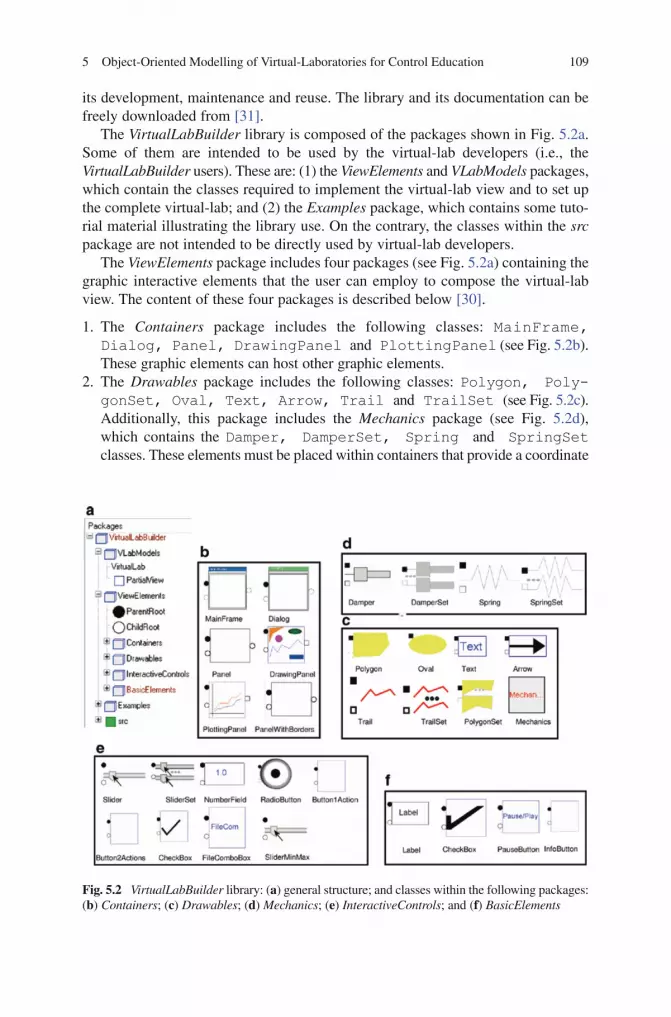
5 Object-Oriented Modelling of Virtual-Laboratories for Control Education 109
BookID 175907_ChapID 05_Proof# 1 - 12/5/2009
its development, maintenance and reuse. The library and its documentation can be freely downloaded from [31].
The VirtualLabBuilder library is composed of the packages shown in Fig. 5.2a. Some of them are intended to be used by the virtual-lab developers (i.e., the VirtualLabBuilder users). These are: (1) the ViewElements and VLabModels packages, which contain the classes required to implement the virtual-lab view and to set up the complete virtual-lab; and (2) the Examples package, which contains some tuto-rial material illustrating the library use. On the contrary, the classes within the src package are not intended to be directly used by virtual-lab developers.
The ViewElements package includes four packages (see Fig. 5.2a) containing the graphic interactive elements that the user can employ to compose the virtual-lab view. The content of these four packages is described below [30].
1. The Containers package includes the following classes: MainFrame, Dialog, Panel, DrawingPanel and PlottingPanel (see Fig. 5.2b). These graphic elements can host other graphic elements.
2. The Drawables package includes the following classes: Polygon, PolygonSet, Oval, Text, Arrow, Trail and TrailSet (see Fig. 5.2c). Additionally, this package includes the Mechanics package (see Fig. 5.2d), which contains the Damper, DamperSet, Spring and SpringSet classes. These elements must be placed within containers that provide a coordinate
Fig. 5.2 VirtualLabBuilder library: (a) general structure; and classes within the following packages: (b) Containers; (c) Drawables; (d) Mechanics; (e) InteractiveControls; and (f) BasicElements

110 C. Martin-Villalba et al.
BookID 175907_ChapID 05_Proof# 1 - 12/5/2009 BookID 175907_ChapID 05_Proof# 1 - 12/5/2009
system. They can be used to build an animated schematic representation of the system. The variables setting the geometric properties of these elements (posi-tion, size, etc.) can be linked to model variables.
3. The InteractiveControls package includes the following classes: Slider, SliderSet, NumberField, RadioButton, Button1Action and Button2Actions (see Fig. 5.2e). The model interactive quantities can be linked to the variables defining the state of the interactive control elements. This allows the user to change the value of these model variables during the simulation run.
4. The BasicElements package includes the following classes: Label, CheckBox, PauseButton and InfoButton (see Fig. 5.2f). These classes can be included inside a window or a panel. The PauseButton class creates a button that allows the user to pause and resume the simulation. The InfoButton class creates a button that allows the user to show and hide windows containing the virtual-lab documentation in HTML format.
The graphic elements included in the Drawables and the InteractiveControls packages implement the information flow between the model and the view of the virtual-lab. The simulated value of the model variables modifies the properties of the drawable elements (i.e., the information flows from the model to the view). The user’s interactive action on the interactive controls modifies the value of the model variables (i.e., the information is transmitted from the view to the model). Further details of the graphic elements can be found in the library documentation. The VirtualLabBuilder library can be extended in order to include more interactive graphic elements, as it is explained in [30].
The virtual-lab definition includes the description of the narrative, the model, the view, and the bidirectional flow of information between the model and the view. The steps to define the virtual-lab are outlined below.
Step 1. Description of the Virtual-Lab Model. The Modelica model has to be adapted to suit interactive simulation applying the systematic methodology proposed in [28, 30]. As it has been discussed previously, this methodology is based on defining all interactive quantities as state variables.
Step 2. Description of the Virtual-Lab View. The Modelica class describing the view must be a subclass of the PartialView class. This class contains the code required to perform the communication between the model and the view. This code is valid for any model and view descriptions, and the virtual-lab designer only needs to set the length of the model-to-view communication interval.
The graphic components have to be connected by the virtual-lab programmer. The “root” graphic component (i.e., the container component which hosts the rest of the components), named root, is pre-defined in the PartialView class. The connec-tions among the graphic components determine their layout in the virtual-lab view. Dymola allows defining in a drag-and-drop way the instantiation of the required VirtualLabBuilder library components and connecting them using the mouse.
Step 3. Virtual-Lab Set Up. The Modelica description of the virtual-lab has to be an instance of the VirtualLab class. This class contains two parameterized

5 Object-Oriented Modelling of Virtual-Laboratories for Control Education 111
BookID 175907_ChapID 05_Proof# 1 - 12/5/2009
generic classes: the class of the virtual-lab model and the class of the view. In addition, the virtual-lab designer has to specify, by writing the required equations, how the variables of the model and the view classes are connected.
Step 4. Translation to Executable Code and Launch. The virtual-lab description has to be translated using Dymola, generating an executable that can be run by the user. As a part of the model initialization (i.e., the calculations performed to find the initial value of the model variables), the initial sections of the interactive graphic objects and of the PartialView class are executed. These initial sections contain calls to Modelica functions, which encapsulate calls to external C-functions that are Java-code generators.
Therefore, the Java code of the virtual-lab view is automatically generated, compiled and packed into a single jar-file during the model initialization. Also, the communication procedure between the model and the view is set up. This commu-nication is based on client-server architecture: the C-program generated by Dymola is the server and the Java program (which is automatically generated during the model initialization) is the client.
Once the jar-file has been created, it is automatically executed. As a result, the initial layout of the virtual-lab view is displayed and the client-server communication is established. Then, the model simulation starts. During the simulation run, there is a bi-directional flow of information between the model and the view. The model simulation (i.e., the server) sends to the view (i.e., the client) the data required to refresh the view. And the view sends to the model simulation the new value of the variables modified due to the user’s interactive action.
5.4 Case Study I: Control of a Double-Pipe Heat Exchanger
This virtual-lab with batch interactivity illustrates the application to a double-pipe heat exchanger of some linearization and control techniques. This process is handled as a Single Input Single Output process. The water flow and the gas outlet temperature are, respectively, the process input and output. This virtual-lab is aimed to help the students to: (1) understand the behaviour of the plant non-linear models; (2) apply some linearization techniques; (3) analyze the plant linearized model using zero-pole, Bode and Nyquist diagrams; and (4) synthesize the PID, lead and lag compensators required to control the process.
5.4.1 Virtual-Lab Model
The JARA Modelica library has been used to compose the model of a double-pipe heat exchanger. JARA was originally written in the Dymola language [33, 34]. Later on, it was translated into the Modelica language. JARA contains models of some fundamental physical-chemical principles, including: (1) mass, energy and

112 C. Martin-Villalba et al.
BookID 175907_ChapID 05_Proof# 1 - 12/5/2009 BookID 175907_ChapID 05_Proof# 1 - 12/5/2009
momentum balances applied to ideal mixtures of semi-perfect gases and homoge-neous liquid mixtures; (2) mass transport due to pressure and concentration gradi-ents; (3) heat transport by conduction and convection; (4) chemical reactions; and (5) liquid-vapour phase change. JARA’s main application is the modelling of physical-chemical processes in the context of automatic control. The JARA Modelica library can be freely downloaded from [31].
The JARA model of the heat exchanger (see Fig. 5.3a) is based on the model described in [35]. A mixture of carbon dioxide and sulphur dioxide is cooled by
b Pulse
period=100
PID
limPID Plant
c Pulse
period=100
FeedbackController
uMax=0.1
b(S)
a(S)
Limiter Plant
c...c... c...
c...
c... c...
CVg1 CVg2 CVg3 CVg4 CVg5 CVg6 CVg7 CVg8 CVg9 CVg10
CVl1 CVl2 CVl3 CVl4 CVl5 CVl6 CVl7 CVl8 CVl9 CVl10
CVs1 CVs2 CVs3 CVs4 CVs5 CVs6 CVs7 CVs8 CVs9
rg1rt1
rg2 rg3 rg4 rg5 rg6 rg7 rg8 rg9
r11 r12 r13 r14 r15 r16 r17 r18 r19
rt2 rt3 rt4 rt5 rt6 rt7 rt8
a
Fig. 5.3 Diagram of the heat-exchanger Modelica model: (a) open-loop plant; (b) plant controlled using a PID; and (c) plant controlled using a compensator

5 Object-Oriented Modelling of Virtual-Laboratories for Control Education 113
BookID 175907_ChapID 05_Proof# 1 - 12/5/2009
water in a double-pipe heat exchanger of length L. The thermal dynamic of the gas mixture, the water and the wall of the inner pipe are considered in the model. The inner heat-exchanger pipe is made of copper with a constant thermal conductivity, and the exterior of the steel pipe shell is supposed to be very well insulated.
The following heat flows have been modelled by using the thermal resistor models included in the JARA library (see Fig. 5.3a): (1) the convective heat-flow between the gas mixture and the inner wall of the inner pipe (resistors r
gi, with i =
1...9), (2) the convective heat-flow between the wall of the inner pipe and the water (resistors r
li, with i = 1...9); and (3) the conduction heat-flow along the wall of the
inner pipe (resistors rti, with i = 1...8). The convective heat-transfer on the pipe and
the shell are calculated from the Dittus-Boelter correlation [35].In order to study the dependence of the temperature on the axial coordinate, the heat
exchanger has been divided into N = 10 elements. The length of the elements located at
the pipe end, ( )−2 1
L
N, is the half of the length of the inner elements. It is assumed
that the temperature of the gas mixture contained within an element is uniform along the element’s volume. The same assumption has been made related to the tem-perature of the water and the wall of the inner pipe. The gas, the liquid and the inner-pipe control volumes have been labelled in Fig. 5.3a as CV
gi (i = 1...10), CV
li
(i = 1...10) and CVsi (i = 1...9), respectively. The gas and liquid flows among the
elements are modelled by connecting JARA’s pump models to the elements. Two modes of operation are allowed: co-current flow and counter-current flow.
The diagrams of the Modelica model describing the closed-loop system control-led by a PID and a compensator are shown, respectively, in Fig. 5.3b and c. The PID model used to control the plant (see Fig. 5.3b) is included in the standard Modelica library. It has been designed according to the model described in [36]. This model has limited output, anti-windup compensation and set-point weightings.
5.4.2 Composing the Virtual-Lab
A Sysquake application has been developed in order to implement the virtual-lab view and to control the execution of the three Dymosim files: the Dymosim file that simulates the open-loop plant, and the two Dymosim files that simulate the plant controlled using a PID and a compensator, respectively.
The features of this Sysquake application, that constitutes the virtual-lab core, include the application to the heat-exchanger model of several identification techniques and the design of control strategies (using the linear models previ-ously obtained by applying the identification techniques). The challenge is to control the gas outlet temperature by manipulating the water flow. In addition, the virtual-lab view contains an info icon that displays the virtual-lab docu-mentation (see Fig. 5.4).
The virtual-lab supports the automatic calculation of the plant linearized model. This calculation is performed as follows (see Fig. 5.4a). Firstly, the change in the

114 C. Martin-Villalba et al.
BookID 175907_ChapID 05_Proof# 1 - 12/5/2009 BookID 175907_ChapID 05_Proof# 1 - 12/5/2009
value of the gas exit temperature, in response to a step in the water flow, is calculated simulating the heat exchanger model. Then, a transfer function (TF) is fitted to this response. During this identification procedure, the virtual-lab user is allowed to:
1. Change the parameter values and the input variable values of the heat exchanger model, the simulation communication interval and the total simulation time.
2. Choose among different identification methods, including “first order TF with delay”, “second order TF with delay” and “parametric identification”.
Fig. 5.4 View of the double-pipe heat exchanger virtual-lab: (a) plant linearization; and (b) controller synthesis
5 Object-Oriented Modelling of Virtual-Laboratories for Control Education 115
BookID 175907_ChapID 05_Proof# 1 - 12/5/2009
3. Modify the obtained TF.4. Analyze the obtained TF by means of Bode and zero-pole diagrams, and robust-
ness margins.5. Start the simulation run.6. Export the calculated TF to another Sysquake application.
In addition, the virtual-lab automates the controller synthesis and analysis. The virtual-lab supports the following user’s operations (see Fig. 5.4b):
1. To import the TF previously identified.2. To analyze the TF characteristics using Nyquist, Nichols and Bode diagrams.3. To choose the type of controller among the following options: PID, lead and lag
compensators.4. To synthesize the controller (i.e., to set the value of the PID’s parameters).5. To specify the error and the phase margin of the system controlled by the lead
or lag compensators.6. To simulate the closed-loop linear and non-linear models.
An example of usage of the heat-exchanger virtual-lab will be described below. The operation conditions of the heat exchanger are shown in Fig. 5.4a. A change in the value of the water-flow from 0 to 10–4 kg/s has been applied at time 150 s to the heat exchanger. A TF has been fitted to the change in the value of the gas outlet temperature in response to the step change in the water-flow. A first-order identifi-cation method, that uses the times to reach 28.3% and 63.2% response, has been applied. The following TF has been obtained:
2
24064.1 10240
33.3 15.17 0.43
s
s s
−+ +
A PID to control the plant has been synthesized using the TF previously com-puted in the design process. The evolution of the gas outlet temperature tracking the set-point is shown in Fig. 5.4b.
5.5 Case Study II: Control of an Industrial Boiler
This virtual-lab has been designed to illustrate the dynamic behaviour of an industrial boiler operating under two different control strategies: manual and decentralized PID. It is a Multiple Input Multiple Output system: the inputs are the pump throughput and the heater power, and the outputs are the water level inside the boiler and the vapour output flow.
This virtual-lab with runtime interactivity has been implemented by combining the use of Ejs, Matlab/Simulink and Modelica/Dymola. The physical model of the industrial boiler has been composed using the JARA Modelica library, whose models have been adapted for runtime interactive simulation (i.e., the interactive quantities have been defined as state variables).
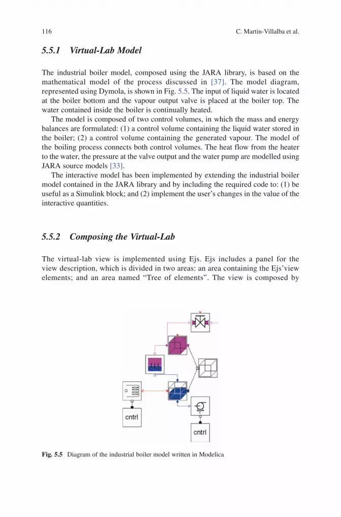
116 C. Martin-Villalba et al.
BookID 175907_ChapID 05_Proof# 1 - 12/5/2009 BookID 175907_ChapID 05_Proof# 1 - 12/5/2009
5.5.1 Virtual-Lab Model
The industrial boiler model, composed using the JARA library, is based on the mathematical model of the process discussed in [37]. The model diagram, represented using Dymola, is shown in Fig. 5.5. The input of liquid water is located at the boiler bottom and the vapour output valve is placed at the boiler top. The water contained inside the boiler is continually heated.
The model is composed of two control volumes, in which the mass and energy balances are formulated: (1) a control volume containing the liquid water stored in the boiler; (2) a control volume containing the generated vapour. The model of the boiling process connects both control volumes. The heat flow from the heater to the water, the pressure at the valve output and the water pump are modelled using JARA source models [33].
The interactive model has been implemented by extending the industrial boiler model contained in the JARA library and by including the required code to: (1) be useful as a Simulink block; and (2) implement the user’s changes in the value of the interactive quantities.
5.5.2 Composing the Virtual-Lab
The virtual-lab view is implemented using Ejs. Ejs includes a panel for the view description, which is divided in two areas: an area containing the Ejs’view elements; and an area named “Tree of elements”. The view is composed by
Fig. 5.5 Diagram of the industrial boiler model written in Modelica

5 Object-Oriented Modelling of Virtual-Laboratories for Control Education 117
BookID 175907_ChapID 05_Proof# 1 - 12/5/2009
instantiating and connecting with the mouse the “view elements” in this area. The Modelica model is embedded into the Simulink model. The communica-tion between the Simulink model and the Ejs view is performed through the Matlab workspace.
The Ejs view of the boiler virtual-lab is shown in Fig. 5.6. The user can interactively choose between two control strategies: manual and decentralized PID. The control system has been modelled using Modelica: a PID is used to control the water level and another PID is used to control the vapour flow. Alternatively, the control system could be implemented as Simulink blocks connected to the DymolaBlock blocks. The manipulated variables are the pump water-flow and the heater heat-flow respectively. The parameters of these PID controllers can be changed interactively. In addition, the value of the model state-variables (mass and temperature of the water and the vapour), parameters (inner volume of boiler), and input variables (temperature of the input water, valve opening and output pressure) can be changed interactively during the simulation run.
The dynamic response of the industrial boiler to a step change in the set-point of the vapour output flow from 8 mol/s to 9.2 mol/s is shown in the right window of Fig. 5.6. This change has been interactively performed by the virtual-lab user at the simulated time 201.8 s. The boiler is operating in automatic mode.
Fig. 5.6 View of the industrial boiler virtual-lab

118 C. Martin-Villalba et al.
BookID 175907_ChapID 05_Proof# 1 - 12/5/2009 BookID 175907_ChapID 05_Proof# 1 - 12/5/2009
5.6 Case Study III: Solar House
The implementation of a virtual-lab intended to illustrate the thermodynamics of a solar house is discussed. This virtual-lab allows the user to: (1) change the thermo-dynamic properties of the floor, the outer and inner walls, and the roof; (2) turn on and off the air-conditioning system, which is placed in the living room; and (3) set the parameters of the air-conditioning control system (i.e., the set-points for the minimum and maximum values of the temperature).
The virtual-lab view contains the floor plan of the house. The room colours change depending on the temperature inside the room. The heat flow through the outer walls is represented by arrows. Also, the virtual-lab view contains plots of some selected quantities.
5.6.1 Virtual-Lab Model
This solar house model is included within the Bondlib Modelica library [38]. The model describes the thermodynamic behaviour of an experimental house located near the airport in Tucson (Arizona) with a passive solar-heating system. The house has four rooms: two bedrooms, a living room and a solarium that collects heat during the winter and releases it during the summer. The living room has an air-conditioning unit.
The four rooms are composed using models that describe the outer and inner walls, the roofs, the windows and the slabs. The bond graph technique is used to model the physical laws of heat transfer between the basic components of the house, regarding conduction, convection and radiation. A detailed description of the model can be found in [39, 40]. In order to adapt the model to suit interactive simulation [30], the interactive parameters and the input variables have been re-defined as constant state-variables (i.e., with zero time-derivative).
5.6.2 Composing the Virtual-Lab
The Modelica description of the virtual-lab view has been developed modularly, by extending and connecting the required graphic components of the Virtual-LabBuilder library. Modelica classes have been developed to describe the view associated to an outer wall (ExWallView), an inner wall (InWallView), a roof (RoofView) and a floor (SlabView). These classes are described below [30].
• ThediagramoftheExWallView Modelica class is shown in Fig. 5.7a and the graphic interface generated is shown in Fig. 5.7b. The ExWallView class contains instances of some graphic elements contained in the VirtualLabBuilder library (i.e., Dialog, DrawingPanel, Panel, Polygon, Text and

5 Object-Oriented Modelling of Virtual-Laboratories for Control Education 119
BookID 175907_ChapID 05_Proof# 1 - 12/5/2009
Slider). The connection among these elements determines the layout of the graphic interface. The graphic interface consists of a window that con-tains a set of sliders at the bottom and at the top (see Fig. 5.7b). These sliders allow the user to modify the temperature and the thermodynamic properties of the wall, including the specific thermal conductivity of the dry wall, the thickness of the conduction layer, the specific heat capacity, the density, the thickness of the outer wall, and the absorption coefficient. The centre of the window contains a graphical representation of the wall model, which is composed of three conducting layers.
• TheInWallView class contains sliders that allow the user to change the tempera-ture and the thermodynamic properties of the wall (i.e., specific thermal conduc-tivity of the dry wall, thickness of the conduction layer, specific heat capacity, density and thickness).
• TheRoofView class contains sliders that allow the user to change the thermody-namic properties (i.e., specific thermal conductivity, thickness, specific heat capacity and density) of the three conducting layers that compose the roof.
• TheSlabView class contains sliders that allow the user to change the floor thermodynamic properties (i.e., specific thermal conductivity, thickness of the floor, specific heat capacity, density and thickness of the conduction layer).
The Modelica classes describing the view associated to the house (HouseView), the living room (LivingRoomView) and the two bedrooms (BedRoom1View and BedRoom2View) have been composed using VirtualLabBuilder. The diagram of the BedRoom1View class is shown in Fig. 5.8a, and the generated graphic
Fig. 5.7 ExWallView class: (a) Modelica diagram; and (b) generated view

120 C. Martin-Villalba et al.
BookID 175907_ChapID 05_Proof# 1 - 12/5/2009 BookID 175907_ChapID 05_Proof# 1 - 12/5/2009
interface is shown in Fig. 5.8b. This model contains instances of the SlabView, RoofView,ExWallView and InWallView classes. The view consists of a window with four checkboxes and the floor plan of the room (see Fig. 5.8b). The checkboxes allow the user to show and hide the windows associated to each build-ing component of the room (outer and inner walls, floor and roof).
The diagram of the HouseView class is shown in Fig. 5.9a, and the generated graphic interface is shown in Fig. 5.9b. The view consists of a window that has a set of checkboxes and two buttons at the bottom and a diagram of the house floor plan in the centre (see Fig. 5.9b). The checkboxes allow the user to show and hide the windows associated to the bedrooms 1 and 2, and to the living room. The two buttons allows the user to: (1) pause and resume the simulation; and (2) to show the virtual-lab documentation (see Fig. 5.10). As it was mentioned before, each room of the floor plan has a colour, which changes from blue to red as a function of the room temperature. The arrows shown in the floor plan represent the heat flow through the outer walls (see Fig. 5.9b). The width and orientation of the arrows depend on the magnitude and the direction of the heat flow, respectively.The Modelica description of the complete view (i.e., class View) is shown in Fig. 5.11. This model extends the PartialView class, which contains: a) one pre-defined graphic element: root; and b) the code required to perform the communi-cation between the model and the view. The View class contains instances of
Fig. 5.8 BedRoom1View class: (a) Modelica diagram; and (b) generated view

5 Object-Oriented Modelling of Virtual-Laboratories for Control Education 121
BookID 175907_ChapID 05_Proof# 1 - 12/5/2009
Fig. 5.9 HouseView class: (a) Modelica diagram; and (b) generated view
Fig. 5.10 Documentation of the solar house virtual-lab
BedRoom1View, BedRoom2View and LivingRoomView classes. It also contains instances of the VirtualLabBuilder library components describing plots. These plots are used to display the time evolution of the heat flow and the tempera-ture in the rooms of the house.

122 C. Martin-Villalba et al.
BookID 175907_ChapID 05_Proof# 1 - 12/5/2009 BookID 175907_ChapID 05_Proof# 1 - 12/5/2009
The Modelica description of the virtual-lab has to be an instance of the VirtualLab class. This class contains two parameterized generic classes: the classes of the virtual-lab model and view. In addition, the virtual-lab programmer has to include in this class the equations that link the variables of the model and the view classes.
The Modelica model of the virtual-lab is translated into executable code using Dymola and is then executed. Then, the jar-file containing the Java code of the virtual-lab view is automatically generated and executed.
The dynamic response of the solar house when the air-conditioning system is turned off is shown in Fig. 5.12. This change has been interactively performed by the virtual-lab user at the simulated time 100 h. The following six plots are shown in Fig. 5.12: (1) the heat-flow rate in bedroom 2; (2) the heat-flow rate of the air-conditioning system; (3) the living-room temperature and the set-point value for the minimum and maximum temperatures; (4) the bedroom-1 temperature; (5) the bedroom-2 temperature; and (6) the ambient temperature.
5.7 Conclusions
The implementation of virtual-labs based on large mathematical models has been dis-cussed. Three different approaches, combining different tools, have been presented. The Modelica language has been used in all of them for describing the virtual-lab model and Dymola has been used for translating the model into executable code. The interac-tive user interface (i.e., the virtual-lab view) has been implemented using Sysquake, Ejs
Fig. 5.11 Modelica model diagram of the complete virtual-lab view

5 Object-Oriented Modelling of Virtual-Laboratories for Control Education 123
BookID 175907_ChapID 05_Proof# 1 - 12/5/2009
and Matlab/Simulink, and the VirtualLabBuilder Modelica library, respectively. The first approach allows designing virtual-labs with batch interactivity. The two others facilitate the implementation of virtual-labs with runtime interactivity.
This software combination allows taking advantage of the best features of each tool. The use of the Modelica language reduces considerably the modelling effort, facilitating the model reuse. Additionally, there exist several commercial and free Modelica libraries that can be used to compose the virtual-lab model. Dymola is a state-of-the-art modelling environment, which generates highly efficient C-code from the Modelica models. Ejs and Sysquake are two software tools specifically intended to develop virtual-labs, whose strong point is the programming of the virtual-lab view. VirtualLabBuilder is a free Modelica library that facilitates the implementation of virtual-labs with elaborate user interfaces using only Modelica.
The methods presented for virtual-lab implementation have been illustrated by means of three case studies: the heat exchanger, the industrial boiler and the solar house virtual-labs.
References
1. Calerga: Sysquake user manual. http://www.calerga.com/doc/SQ4_main.htm (2008). Accessed 24 July 2008
2. Y Piguet: Multimodel Synthesis of a Robust Polynomial Controller. Ph.D. dissertation, Swiss Federal Institute of Technology (EPFL), Lausanne, Switzerland (1997)
3. Y Piguet, U Holmberg, R Longchamp: Instantaneous Performance Visualization for Graphical Control Design Methods. In Proceedings of the 14th IFAC World Congress, Beijing, China (1999)
4. JM Diaz, S Dormido, J Aranda: Interactive computer-aided control design using quantitative feedback theory: the problem of vertical movement stabilization on a high-speed ferry. Int. J. Contr. 78(11), 813–825 (2005)
Fig. 5.12 Dynamic response of some selected quantities

124 C. Martin-Villalba et al.
BookID 175907_ChapID 05_Proof# 1 - 12/5/2009 BookID 175907_ChapID 05_Proof# 1 - 12/5/2009
5. JM Diaz, S Dormido, J Aranda: An interactive software tool for learning robust control design using quantitative feedback theory methodology. Int. J. Eng. Educ. 23, 1011–1023 (2007)
6. M Dimmler, Y Piguet: Intuitive Design of Complex Real-Time Control Systems. In Proceedings of the 11th IEEE International Workshop on Rapid System Prototyping, pp. 52–57 (2000)
7. Y Piguet, R Longchamp: Interactive Applications in a Mandatory Control Course. In Proceedings of the 7th IFAC Advanced Control Education (2006)
8. F Esquembre: Creación de Simulaciones Interactivas en Java. Aplicación a la Enseñanza de la Física. Prentice-Hall, Englewood Cliffs, NJ (2004)
9. F Esquembre: Easy Java Simulations: a software tool to create scientific simulations in Java. Comput. Phys. Commun. 156, 109–204 (2004)
10. Ejs web-site: http://fem.um.es/Ejs/ (2008). Accessed 24 July 200811. R Dormido, H Vargas, N Duro, J Sanchez, S Dormido Canto, G Farias, F Esquembre, S
Dormido: Development of a Web-based control laboratory for automation technicians: the three-tank system. IEEE T. Educ. 51(1), 35–44 (2008)
12. AM Hernandez, MA Mañanas, R Costa-Castelló: Learning respiratory system function in BME studies by means of a virtual laboratory: respilab. IEEE T. Educ. 51(1), 24–34 (2008)
13. J Sanchez, F Esquembre, C Martin-Villalba, S Dormido, S Dormido-Canto, R Dormido-Canto, R Pastor, A Urquia: Easy Java Simulations: an open-source tool to develop interactive virtual laboratories using Matlab/Simulink. Int. J. Eng. Educ. 21(5), 798–813 (2005)
14. J Sanchez, S Dormido, F Esquembre: The learning of control concepts using interactive tools. Comput. Appl. Eng. Educ. 13(1), 84–98 (2005)
15. KJ Astrom, H Elmqvist, SE Mattsson: Evolution of Continuous-Time Modeling and Simulation. In Proceedings of the 12th European Simulation Multiconference, Manchester, UK, pp. 9–18 (1998)
16. FE Cellier: Continuous System Modeling. Springer, New York (1991) 17. FE Cellier, E Kofman: Continuous System Simulation. Springer, London (2006) 18. P Piela, T Epperly, K Westerberg, A Westerberg: ASCEND: An object-oriented computer
environment for modeling and analysis: the modeling language. Comput. Chem. Eng. 15(1), 53–72 (1991)
19. Empresarios Agrupados: EcosimPro Web. http://www.ecosimpro.com/index.php (2008). Accessed 27 July 2008
20. P Barton, C Pantelides: Modeling of combined discrete/continuous processes. AIChE J. 40, 966–979 (1994)
21. H Elmqvist, SE Mattsson, M Otter: Modelica-The New Object-Oriented Modeling Language. In Proceedings of the 12th European Simulation Multiconference (ESM ‘98). SCS, The Society for Computer Simulation, Manchester, UK (1998)
22. Modelica Association web-site: http://www.modelica.org (2008). Accessed 27 July 200823. P Fritzson: Principles of Object-Oriented Modeling and Simulation with Modelica 2.1. Wiley-
IEEE Press, Piscataway, NJ, (2004)24. M Tiller: Introduction to Physical Modeling with Modelica. Kluwer, Dordrecht (2001)25. IEEE: Standard VHDL Analog and Mixed-Signal Extensions. Technical Report IEEE 1076.1
(1997)26. Dynasim AB: Dymola. User’s Manual. Version 5.3a. Dynasim AB, Lund, Sweden (2004)27. V Engelson: Tools for Design, Interactive Simulation, and Visualization of Object-Oriented
Models in Scientific Computing. Ph.D. dissertation, Department of Computer and Information Science, Linkoping University, Sweden (2000)
28. C Martin-Villalba, A Urquia, S Dormido: An approach to virtual-lab implementation using Modelica. Math. Comp. Model. Dyn. 14(4), 341–360 (2008)
29. C Martin-Villalba, A Urquia, S Dormido: Object-oriented modelling of virtual-labs for educa-tion in chemical process control. Comput. Chem. Eng. doi: 10.1016/j.compchemeng. 2008.05.011, 32(12), 3176–3186 (2008)
30. C Martin-Villalba: Object-Oriented Modelling of Virtual-Laboratories for Control Education. Ph.D. dissertation, Department of Informática y Automática, Universidad Nacional de Educación a Distancia (UNED), Madrid, Spain (2007)
5 Object-Oriented Modelling of Virtual-Laboratories for Control Education 125
BookID 175907_ChapID 05_Proof# 1 - 12/5/2009
31. Some Free Modelling & Simulation Resources Developed at Department of Informática y Automática, UNED: http://www.euclides.dia.uned.es Accessed 24 July 2008
32. M Otter, H Olsson: New Features in Modelica 2.0. In Proceedings of the 2nd International Modelica Conference, Oberpfaffenhofen, Germany, pp. 7.1–7.12 (2002)
33. A Urquia: Modelado Orientado a Objetos y Simulación de Sistemas Híbridos en el ámbito del Control de Procesos Químicos. Ph.D. dissertation, Department of Informática y Automática, Universidad Nacional de Educación a Distancia (UNED), Madrid, Spain (2000)
34. A Urquia, S Dormido: Object-oriented design of reusable model libraries of hybrid dynamic systems. Part two: A case study. Math. Comp. Model. Dyn. 9(1), 91–118 (2003)
35. MB Cutlip, M Shacham: Problem Solving in Chemical Engineering with Numerical Methods. Prentice-Hall, Upper Saddle River, NJ (1999)
36. KJ Aström, T Hagglund: PID Controllers: Theory, Design and Tuning. ISA Press, NC (1995)
37. WF Ramirez: Computational Methods for Process Simulation. Butterworths, Boston, MA, USA (1989)
38. FE Cellier, A Nebot: The Modelica Bond-Graph Library. In Proceedings of the 4th International Modelica Conference, pp. 57–65 (2005)
39. M Weiner: Bond Graph Model of a Passive Solar Heating System. M.S. thesis, Department of Electrical & Computer Engineering, University of Arizona, USA (1992)
40. M Weiner, FE Cellier: Modeling and Simulation of a Solar Energy System by Use of Bond Graphs. In Proceedings of the 1st SCS Internatinal Conference on Bond Graph Modeling, pp. 301–306 (1993)
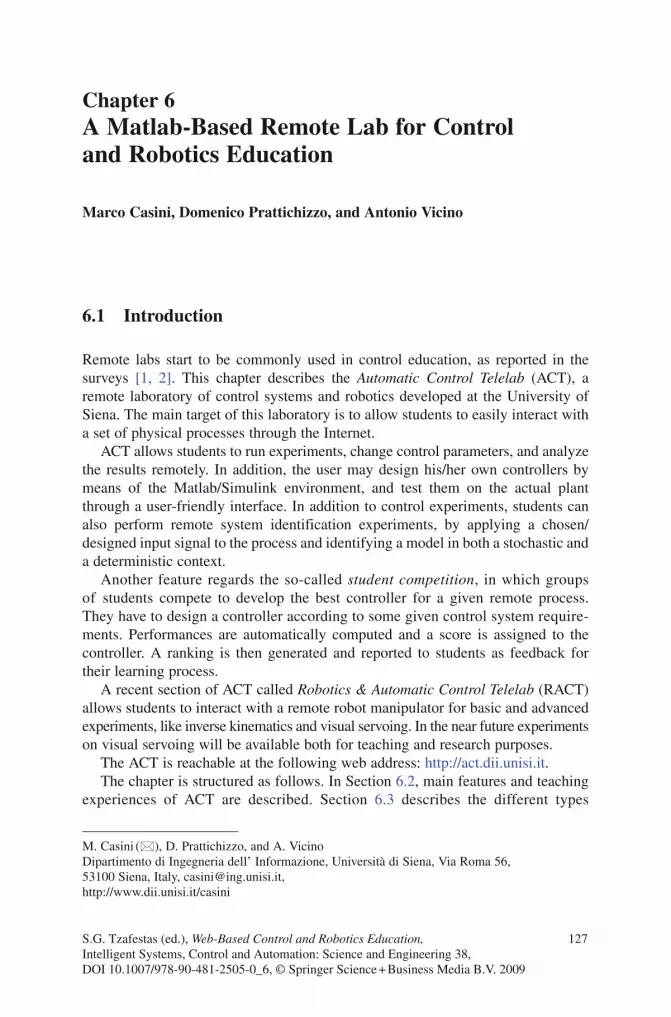
BookID 175907_ChapID 6_Proof# 1 - 11/4/2009
Chapter 6A Matlab-Based Remote Lab for Control and Robotics Education
Marco Casini, Domenico Prattichizzo, and Antonio Vicino
6.1 Introduction
Remote labs start to be commonly used in control education, as reported in the surveys [1, 2]. This chapter describes the Automatic Control Telelab (ACT), a remote laboratory of control systems and robotics developed at the University of Siena. The main target of this laboratory is to allow students to easily interact with a set of physical processes through the Internet.
ACT allows students to run experiments, change control parameters, and analyze the results remotely. In addition, the user may design his/her own controllers by means of the Matlab/Simulink environment, and test them on the actual plant through a user-friendly interface. In addition to control experiments, students can also perform remote system identification experiments, by applying a chosen/designed input signal to the process and identifying a model in both a stochastic and a deterministic context.
Another feature regards the so-called student competition, in which groups of students compete to develop the best controller for a given remote process. They have to design a controller according to some given control system require-ments. Performances are automatically computed and a score is assigned to the controller. A ranking is then generated and reported to students as feedback for their learning process.
A recent section of ACT called Robotics & Automatic Control Telelab (RACT) allows students to interact with a remote robot manipulator for basic and advanced experiments, like inverse kinematics and visual servoing. In the near future experiments on visual servoing will be available both for teaching and research purposes.
The ACT is reachable at the following web address: http://act.dii.unisi.it.The chapter is structured as follows. In Section 6.2, main features and teaching
experiences of ACT are described. Section 6.3 describes the different types
M. Casini (), D. Prattichizzo, and A. Vicino Dipartimento di Ingegneria dell’ Informazione, Università di Siena, Via Roma 56, 53100 Siena, Italy, [email protected], http://www.dii.unisi.it/casini
S.G. Tzafestas (ed.), Web-Based Control and Robotics Education, 127Intelligent Systems, Control and Automation: Science and Engineering 38,DOI 10.1007/978-90-481-2505-0_6, © Springer Science + Business Media B.V. 2009

128 M. Casini et al.
BookID 175907_ChapID 6_Proof# 1 - 11/4/2009 BookID 175907_ChapID 6_Proof# 1 - 11/4/2009
of experiments which can be performed remotely, while Section 6.4 deals with the lab architecture. In Section 6.5, the robotic experiments provided by RACT are described in details and some conclusions and future developments are reported in Section 6.6.
6.2 The Automatic Control Telelab
The Automatic Control Telelab (ACT) is a remote laboratory developed at the Dipartimento di Ingegneria dell’Informazione of the University of Siena [3, 4]. The main goal of the lab is to allow students to put in practice their theoretical knowledge of control theory without restrictions due to laboratory opening time and process availability. In fact, the ACT is accessible 24 h a day from any computer connected to the Internet by means of any common Internet browser. In addition to control systems experiences, ACT provides also robotics experiments through the section referred to as Robotics & Automatic Control Telelab which is described in details in Section 6.4.
The Automatic Control Telelab is continuously upgraded with new software versions and experiments. At the present stage, the remote processes available for online experiments are as follows (Fig. 6.1).
• DC motor. This process involves the control of the shaft angle or the rotation speed. Both experiments are Single-Input-Single-Output (SISO).
• Water tank. Through this process users can perform level or flow SISO experiments. In spite of its simplicity, dynamics of the tank is nonlinear.
• Magnetic levitation system. This process provides two different kind of experiments. Depending on the user choice, it is possible to perform SISO stable (repulsive) or unstable (attractive) experiments.
• Helicopter simulator. The process consists in a two degree-of-freedom helicopter simulator which is a MIMO system showing nonlinear and unstable dynamics.
6.2.1 ACT Features
The main features of ACT are described below.
• Easy-to-use interface. Simplicity is essential for designing an effective user interface. The ACT is based on intuitive and simple HTML pages and Java applets, which are fully supported by the latest versions of browsers. Help pages are provided for detailed information.
• Simulink-based interface for controller design. The Simulink-based interface is used to design controllers driving the real process. Only a basic knowledge of Matlab/Simulink environment is required. At the end of the experiment, the user can download a file in the Matlab workspace format (.mat), where all data of the experiment are stored for offline analysis.
• Predefined and user-defined controller types. Each experiment of the remote lab can be controlled using a predefined or a user-defined controller. In the first

6 A Matlab-Based Remote Lab for Control and Robotics Education 129
BookID 175907_ChapID 6_Proof# 1 - 11/4/2009
case, a student selects a control law from a given list, and then assigns the value of typical parameters. For example, a student can select a PID controller to run the experiment, and choose the values of proportional, integral, and derivative coefficients. Alternatively, the user can design her/his own controller to drive the experiment, by means of the Simulink graphical interface, and send it to the ACT server. A Simulink user-defined template is available to help the remote user in this phase.
• Predefined and user-defined reference types. The remote user can choose reference signals from a given list, or create new references by building a Simulink subsystem. It is possible to change the system reference while an experiment is running. The user does not have to start a new experiment to verify the response of the system to different input signals.
• Controller parameter change. While an experiment is running, the ACT provides a mechanism that allows the user to change controller parameters online, like, e.g., the coefficients of the PID controller. Working over the Internet, parameters are updated when packets reach the ACT server. The resulting time lags depend
Fig. 6.1 The Automatic Control Telelab’s online experiments

130 M. Casini et al.
BookID 175907_ChapID 6_Proof# 1 - 11/4/2009 BookID 175907_ChapID 6_Proof# 1 - 11/4/2009
on the distance, the type of Internet connection, and the network congestion. These delays do not affect the system stability and performance since the control loop run on a PC directly connected to the process (see Section 6.4). The only consequence of these time lags is a delay between the user parameter change request and its execution on the remote server. Tunable parameters may also be included in the user-defined controller by naming the parameter variables according to a simple syntax.
• Lab presence. For effective distance learning, it is important to get a sense of presence in the laboratory even if the user is not there. Live video and online data plots are provided making it possible for students to view the real process while the experiment is in progress.
• Resource management. As with other remote labs, the experiment hardware is controllable by one user at a time. To prevent process monopolization, a fixed amount of time is assigned to each experiment session. After that time the user is automatically disconnected, and the process is available for the next user. The web page provides a list of available experiments (Fig. 6.1) indicating which processes are idle, as well as the maximum delay time for busy experiments.
• System safety. Regarding system safety, hardware and software actuator saturation is enforced to prevent users from performing dangerous operations. A check on the maximum input reference is also performed. Moreover, an instability detection system has been implemented in software to stop the experiment when the system becomes unstable.
• Simplicity of adding new processes. The software and hardware architectures of the ACT have been designed to simplify the connection of new processes to the remote laboratory. In fact, ACT server uses only a live CD and a USB pendrive to work (see Section 6.4 for more details), and only a Simulink model and a text file have to be created to add a new experiment to the ACT.
6.2.2 Teaching Experiences
The Automatic Control Telelab has been used in control systems courses at the University of Siena since 1999. Tasks are assigned to students (usually divided into groups), varying from controller synthesis, system identification and robotics experiments. After having analyzed the problem, students may perform their task at any time and from any computer connected to the Internet.
An important step toward the educational objectives of the ACT has been realized by the student competition component (see Section 6.4.3), which is designed to encourage groups of students to compare their user-designed controllers with those of other students. In the student competition, performance indexes are automatically computed, and the results are stored and ranked.
Students’ feedback are mostly positive, especially since students are able to apply many theoretical notions resulting in a deeper knowledge and an increased interest in control systems and robotics topics.
Due to its free usage, in addition to the University of Siena, some other institutions around the world is using the ACT in their courses. Moreover, the ACT server has

6 A Matlab-Based Remote Lab for Control and Robotics Education 131
BookID 175907_ChapID 6_Proof# 1 - 11/4/2009
been installed in the Department of Aeronautics and Astronautics at MIT to allow remote experiments on three degree-of-freedom helicopter simulators [5].
6.3 ACT Experiments Description
From the home page of the ACT, it is possible to access general information pages, such as the laboratory user guide, and the list of available experiments. In the following, a description of the various kinds of experiments provided by ACT is reported.
6.3.1 Control Experiment
After choosing which experiment to run, the Control Type Interface appears as shown in Fig. 6.2. Through this interface, the user completes a personal-data form to provide statistics about users, and chooses a controller. Possible choices are a predefined controller or a customized one. For predefined controllers, the structure is
Fig. 6.2 The Control Type Interface. The user can choose a predefined or a custom controller for use during the experiment

132 M. Casini et al.
BookID 175907_ChapID 6_Proof# 1 - 11/4/2009 BookID 175907_ChapID 6_Proof# 1 - 11/4/2009
given and the user can modify some controller parameters, for the customized one the user is required to design the complete controller scheme through a Simulink model.
6.3.1.1 Designing User-Defined Controllers
To simplify the controller design, the user can download a Simulink template model that contains two subsystems, one for the controller (ACT_Controller), and one for the reference input (ACT_Reference), see Fig. 6.3.
The reference, output, and command signals are available in the ACT_Controller subsystem, as shown in Fig. 6.4. The user can simply define the controller structure joining signals by means of suitable blocks. Such blocks are provided by any avail-able Simulink toolbox. Moreover, it is possible to set constant and gain blocks as variable parameters that can be modified online while the experiment is in progress. This feature is obtained by using the prefix “ACT_TP_” (ACT Tuning Parameter) to name the variables as described in the bottom window of the Simulink template in Fig. 6.4.
The ACT_Reference subsystem of the template file is used to build new references that can enter the system during the experiment. A set of reference signals is available by default, such as constant and ramp signals or sinusoidal and square waves. The user can remove some of these blocks or add new ones, see Fig. 6.5.
Once the user-defined controller has been built, the controller model is uploaded to the ACT server through the send controller button and compiled. If the Simulink model does not contain errors and compilation is successful it is possible to run the experiment.
6.3.1.2 Running the Experiments
Once the user-defined controller has been uploaded or a predefined controller is chosen, the Experiment Interface is displayed, as shown in Fig. 6.6, whereby it
Fig. 6.3 The Simulink template model. This model helps the user design a controller and choose the reference signals to be applied during the experiment

6 A Matlab-Based Remote Lab for Control and Robotics Education 133
BookID 175907_ChapID 6_Proof# 1 - 11/4/2009
Fig. 6.4 The ACT_Controller Simulink subsystem. Designing a controller involves connecting the reference, output, and command signals with suitable blocks
Fig. 6.5 Through these blocks the user can include new reference signals for use during the experiment

134 M. Casini et al.
BookID 175907_ChapID 6_Proof# 1 - 11/4/2009 BookID 175907_ChapID 6_Proof# 1 - 11/4/2009
is possible to run the remote experiment through the start experiment button. When the experiment is in progress, the user can look at the signals of interest in a window displaying the control input, the reference input, and the output along with their numerical values as shown in Fig. 6.6 regarding the DC motor process.
A live video window is provided to see what is occurring in the remote lab. The video window is an important feature because the user can look at the real process while it is running, obtaining a sense of presence in the laboratory.
Fig. 6.6 The Experiment Interface. With this interface, it is possible to open windows that allow one to change controller parameters and reference signals, as well as view data plots and online video of the experiment

6 A Matlab-Based Remote Lab for Control and Robotics Education 135
BookID 175907_ChapID 6_Proof# 1 - 11/4/2009
During the experiment it is possible to change references online, as well as some controller parameters. When the user stops the experiment, it is possible to download a file in Matlab format (.mat) where signals have been saved. This file can be used to perform offline analysis, such as evaluation of the maximum overshoot and settling time, as shown in the time plot in Fig. 6.7.
6.3.2 Remote System Identification
The aim of the remote system identification facility is to find a suitable model which approximates the real plant. From the experiment page, the user can choose the Identification Experiment option so that the Identification Interface appears as shown in Fig. 6.8 (here reference is made to the DC motor).
From this interface the input to the process (i.e. the DC motor voltage) can be selected among a set of predefined inputs (e.g. white noise, pseudo random binary sequences, sinusoidal and square waves, etc.) or can be designed, according to the user requirements, by using the Simulink environment. In this case, it is only necessary to download a Simulink template model and change the blocks inside the ACT_INPUT subsystem in a similar way to that discussed in Section 6.4.1.1 for user-defined controllers.
After the selection of the input signal, the Identification Experiment Interface appears. It is now possible to start the experiment: the user can see the development
00
0.5
1
1.5
2
2.5
3
5 10 15 20 25 30 35 40 45 50
Fig. 6.7 A time plot of an experiment. The red line represents the reference signal, while the black line is the real output

136 M. Casini et al.
BookID 175907_ChapID 6_Proof# 1 - 11/4/2009 BookID 175907_ChapID 6_Proof# 1 - 11/4/2009
Fig. 6.8 The Identification Interface
of input/output signal and observe the experiment through a webcam (see Fig. 6.9). It is also possible to modify online the applied input signal.
At the end of the experiment the Identification Panel is displayed (Fig. 6.10). Through this interface, it is possible to perform several operations to compute the identified model. The ACT allows to identify models in both a statistic and a deterministic setting. Regarding the statistic framework, it is possible to choose among ARX, ARMAX, and OE model classes [6], while in the set-membership context ARX models are considered.
In the left side of this interface (Fig. 6.10) the time plot as well as the periodogram of the input/output signals are shown. At the bottom, it is possible to download the Matlab workspace file containing the experiment signals, in order to perform offline analysis. The actual identification interface is on the right. It allows the user to choose the desired model structure and the order of its polynomials. Moreover, it is possible to choose to remove mean and trend as well as to choose which data are used for identification and which for validation purposes. Once all options are set, it is possible to identify the system by pressing the Run Identification Algorithm button.
At the end of the identification procedure, results are shown in the Identification Result Interface, reported in Fig. 6.11 (the figure regards the least-squares identification of
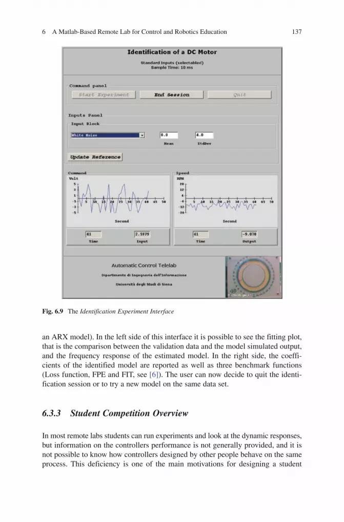
6 A Matlab-Based Remote Lab for Control and Robotics Education 137
BookID 175907_ChapID 6_Proof# 1 - 11/4/2009
Fig. 6.9 The Identification Experiment Interface
an ARX model). In the left side of this interface it is possible to see the fitting plot, that is the comparison between the validation data and the model simulated output, and the frequency response of the estimated model. In the right side, the coeffi-cients of the identified model are reported as well as three benchmark functions (Loss function, FPE and FIT, see [6]). The user can now decide to quit the identi-fication session or to try a new model on the same data set.
6.3.3 Student Competition Overview
In most remote labs students can run experiments and look at the dynamic responses, but information on the controllers performance is not generally provided, and it is not possible to know how controllers designed by other people behave on the same process. This deficiency is one of the main motivations for designing a student

BookID 175907_ChapID 6_Proof# 1 - 11/4/2009 BookID 175907_ChapID 6_Proof# 1 - 11/4/2009
Fig. 6.10 The Identification Panel
Fig. 6.11 The Identification Result Interface

6 A Matlab-Based Remote Lab for Control and Robotics Education 139
BookID 175907_ChapID 6_Proof# 1 - 11/4/2009
competition feature for the ACT. Through this tool, students are aware of the performance requirements that their controllers must satisfy. Moreover, a ranking of the best controllers as well as the time plots of related experiments are provided.
Features of the ACT competition system are described below.
• Remote exercises. In addition to controller synthesis exercises, this tool challenges students to design a controller that must satisfy performance requirements, and allows them to test their controller on a remote real process. At the end of the experiment, the performance measures are automatically computed and shown to the user; if such measures fulfill the requirements, the exercise is completed. An overall measure, usually a weighted sum of the previous measures, is then computed, and the controller is included in the ranking list.
• Controller comparison. The competition ranking is provided to the students. During the final competition lesson, students who have designed the best controllers are invited to discuss their projects, while the instructor explains why some control strategies or parameter choice work better than others.
• Many benchmarks on the same process. It is possible to provide more than one competition benchmark on the same process, thus increasing the number of remote exercises available for students. New benchmarks can be easily added for implementation due to the software architecture of the ACT competition system.
6.3.3.1 A Competition Session Description
In this section, we describe a competition session for the helicopter simulator process. The competition refers to the control of the azimuth angle only. The requirements for a step reference input are as follows:
• The5%settlingtimemustbelessthan7s.• Thetimeresponseovershootmustbelessthan10%.
To compete, students register by filling a form, and then receive a username and password. The phases of a competition session are summarized below:
• Studythephysicalmodeloftheprocessandlinearizeitaroundanoperatingpoint.• Analyze the linear model through frequency domain plots and root locus
techniques to determine appropriate bounds for the controller gains.• Synthesize a controller that achieves the given performance specifications by
using lead-lag or PID controllers.• BuildaSimulinkmodelofthecontroller.• Simulatethecontroller.• Testthecontrollerontheremoteprocess.• Analyzethesystemresponseand,ifnotsatisfactory,adjustthecontrollerstructure
or parameters and try again.
To design the controller, students must download a Simulink template file and connect the signals describing the reference, output, and command signals with suitable

140 M. Casini et al.
BookID 175907_ChapID 6_Proof# 1 - 11/4/2009 BookID 175907_ChapID 6_Proof# 1 - 11/4/2009
Simulink blocks. Since the output signal is the sensor reading, students must insert a block that models the sensor characteristic.
A special graphical interface allows students to describe the structure of their controllers, such as PID, and set the sample time of the experiment. In addition, the user must specify the file containing the controller and, if needed, the Matlab workspace file (.mat) containing the data for their controller. These files are uploaded to the server, compiled, and, if no error occurs, executed on the real remote process. A second graphical interface (Fig. 6.12) allows the user to start the experiment and observe its behavior through plots and live video windows. At the end of the experiment, the performance measures are automatically computed and displayed. It is now possible to download a Matlab workspace file containing the full dynamics of the experiment and to view the time plots (Fig. 6.13).
Since different controllers can satisfy the performance specifications, an overall score is computed to generate a ranking, see Fig. 6.14. This overall score is obtained as a weighted sum of the performance measures. If a controller does not satisfy the performance specifications, an overall score is not computed.
It is possible for each user to view a controller report with information on ranking and other data, such as the controller description, the nickname of the user, and the user’s institution.
Fig. 6.12 The interface showing the running experiment. Through this interface, it is possible to start and stop the experiment, as well as view data plots and online video

6 A Matlab-Based Remote Lab for Control and Robotics Education 141
BookID 175907_ChapID 6_Proof# 1 - 11/4/2009
100
80
60
40
20
0
–20
–40
–60
–80
–1000 5 10 15 20
Time (s)
Ref
eren
ce /
Out
put (
deg)
25 30 35 40 45
Fig. 6.13 Time plots of the experiment
Fig. 6.14 Controller ranking. At the end of the experiment, performance measures are automati-cally computed, and the controller is included in the ranking list

142 M. Casini et al.
BookID 175907_ChapID 6_Proof# 1 - 11/4/2009 BookID 175907_ChapID 6_Proof# 1 - 11/4/2009
6.4 The ACT Architecture
A remote lab is conceptually divided in two parts: one is devoted to the connection and the control of the physical processes (server side), whereas the other is related to the communication with the user (client side).
Users firstly connect to a general server, which provides the home page and other descriptive pages, as well as the Control Type Interface. Such pages are HTML pages generated by PHP. All data regarding the experiments, user access, and controllers are stored in a MySQL database. Once chosen the experiment to execute, the user is reconnected to the computer devoted to the process, and it is possible to perform the experiment by a Java applet (Experiment Interface), which guarantees the maximum portability across various platforms. Through this connection it is possible to change the references and the controller parameters online, and to send the experimental data over the Internet. A webcam is used to send streaming video to the remote user.
A sketch of the connections between client and servers is reported in Fig. 6.15.Hereafter, the process servers will be taken into account. The main issue to
connect physical processes to the remote lab is to equip the PCs devoted to the processes with special hardware and software, such as, for instance, data acquisition boards (DAQs) and their drivers.
In the ACT, a bootable (live) CD along with a USB pendrive is used on the server side [7]. A bootable CD is a CD-ROM which contains an operating system along with other software, which can be run directly from the CD drive on system startup, without installing into permanent memory.
Using a bootable CD in a remote lab requires that all the software (and the O.S.) needed by the server, must be stored on the CD. If a lab has many processes and
main server
processesprocessservers
remote users
Fig. 6.15 The client-server connections

6 A Matlab-Based Remote Lab for Control and Robotics Education 143
BookID 175907_ChapID 6_Proof# 1 - 11/4/2009
experiments available remotely, it is likely that the software installed on any server connected to a physical process is almost the same.
The ACT architecture allows one to store all the software common to any server in a unique live CD, while the files specific to a single process are saved on a USB pendrive. This allows one to use the same live CD for any server con-nected to any process.
The main motivations for using a bootable CD are summarized as follows.
• Process update. Adding a new process to a remote lab is a task which requires two main steps. The first is devoted to the physical process, and regards hardware: connecting all hardware devices along with safety mechanisms. The second regards software installation and configuration. For the reasons previously explained, the time needed by the software installation can be greatly reduced by using a bootable CD (which contains all the needed software) along with some configuration files stored in a USB pendrive.
• Software update. In addition to increasing the number of available processes, improvements on a remote lab can regard the development of new functionalities, fixing bugs, performance improvements, etc. In this case, it is only sufficient to remaster the CD with the new software version and reboot the servers from CD. The updated version of the lab may then work on every process with a minimal effort.
• Failures restoring time. In a remote lab it is not uncommon that some software and/or hardware failures occur in some servers/processes. Regarding process failures (e.g., component breakdowns), it is of course impossible to find a standard way to repair them, since they strongly depend on the specific process. However, other kinds of hardware failures concerning the PC connected to the process can be avoided or easily and quickly fixed by using a bootable CD. For example, in the case of a hard disk failure, the process usually goes offline until a new hard disk is found, and all the software needed by the server is reinstalled and properly reconfigured. Since the number of software applications usually required from a remote lab is in general quite large, this operation can take much time. Instead, by using a bootable CD it is possible to connect processes to PCs with no hard disks, preventing from such kinds of problems. Moreover, failures of other PC components can also be easily solved; in fact, it is only needed to temporarily replace the broken PC with any other (containing a data acquisition board) and booting it from CD. Since the software in the CD does not need to read/write the hard disk, the original content of the hard disk is preserved. So, it is possible to use this PC without any problem until a new PC is ready to replace it.
In case of software failures, it is just needed to reboot the system to have the server fully operating. Moreover, the reboot procedure is not dangerous since the working data is written in memory (ram-disk) and not on permanent devices.
• Increased reliability. The reliability of a remote lab is increased by using a live CD for several reasons. The lack of a hard disk obviously prevents from certain problems, like, e.g., mechanical failures. One more reason for improved reliability is that the software installation is correct and all needed applications have been installed with the proper version. Finally, since the CD is a read-only storage device, it is free from viruses corruptions or other hacker attacks.
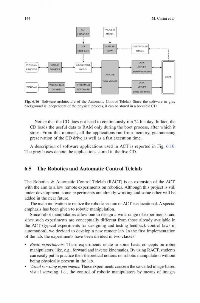
144 M. Casini et al.
BookID 175907_ChapID 6_Proof# 1 - 11/4/2009 BookID 175907_ChapID 6_Proof# 1 - 11/4/2009
Notice that the CD does not need to continuously run 24 h a day. In fact, the CD loads the useful data to RAM only during the boot process, after which it stops. From this moment, all the applications run from memory, guaranteeing preservation of the CD drive as well as a fast execution time.
A description of software applications used in ACT is reported in Fig. 6.16. The gray boxes denote the applications stored in the live CD.
6.5 The Robotics and Automatic Control Telelab
The Robotics & Automatic Control Telelab (RACT) is an extension of the ACT, with the aim to allow remote experiments on robotics. Although this project is still under development, some experiments are already working and some other will be added in the near future.
The main motivation to realize the robotic section of ACT is educational. A special emphasis has been given to robotic manipulation.
Since robot manipulators allow one to design a wide range of experiments, and since such experiments are conceptually different from those already available in the ACT (typical experiments for designing and testing feedback control laws in automation), we decided to develop a new remote lab. In the first implementation of the lab, the experiments have been divided in two classes:
• Basic experiments. These experiments relate to some basic concepts on robot manipulators, like, e.g., forward and inverse kinematics. By using RACT, students can easily put in practice their theoretical notions on robotic manipulation without being physically present in the lab.
• Visual servoing experiments. These experiments concern the so-called image-based visual servoing, i.e., the control of robotic manipulators by means of images
Fig. 6.16 Software architecture of the Automatic Control Telelab. Since the software in gray background is independent of the physical process, it can be stored in a bootable CD

6 A Matlab-Based Remote Lab for Control and Robotics Education 145
BookID 175907_ChapID 6_Proof# 1 - 11/4/2009
taken by one (or more) cameras, see e.g., [8]. This framework allows one to design a wide range of experiments, ranging from easy to very difficult ones. The former are designed for educational purposes, while the latter should be used in research contexts to test advanced visual servoing algorithms.
6.5.1 General Architecture
The robot used is a KUKA KR3, an anthropomorphic manipulator with six degrees-of-freedom (Fig. 6.17).
Like the ACT, also the RACT server is based on the Matlab environment, allowing a powerful and user-friendly interaction with the robot.
Students will be requested to design some Matlab functions to perform the given experiment, and to test it through a graphical user interface. The robot communicates with the server through the TCP/IP protocol. The communication between Matlab and the robot is provided by some special Matlab functions, while to allow the interaction with the user, the Apache web server with PHP extensions (see [9]) has been installed on the server.
On the client side, users may connect to the remote lab through web pages, where they can find all the useful information about the available experiments. Once an experiment is chosen, they need to upload a file containing the designed Matlab function, after that they can interact with the robot through a Java applet. The communication between the applet and the server is made through the TCP protocol. Notice that, as previously stated for ACT, timing aspects are not critical since the controller resides in the server side.
It is worthwhile to notice that Matlab just runs on the server side, and it is not needed on the client. In fact, the client application is only required to send a control function written in Matlab code, which simply consists in a text file. However, the presence of Matlab on the client machine should help users to debug and test their functions before sending them to the server. Moreover, Matlab can be a useful tool for offline analyzing the experiment data. In fact, once a working session is finished, users may download a file containing all the data regarding the experiments.
Fig. 6.17 The KUKA KR3 manipulator

146 M. Casini et al.
BookID 175907_ChapID 6_Proof# 1 - 11/4/2009 BookID 175907_ChapID 6_Proof# 1 - 11/4/2009
To prevent that a user could monopolize the robot, for each working session, a maximum number of experiments has been fixed, after that the user is automatically disconnected. In addition, a time-out has been also implemented for the same reason. The state of the robot (ready or busy) is shown by an appropriate notice.
Like other remote labs, safety aspects have been taken into account. To this purpose, to prevent damages to people or to itself, the robot has been placed in an off-limit site and suitable hardware security systems allows it to move inside a safe region. A sketch of hardware/software architecture is reported in Fig. 6.18.
6.5.2 Experiments description
In this section, a description of the available experiments as well as those to be added in the near future is reported.
6.5.2.1 Inverse Kinematics Experiment
A first experiment regards the inverse kinematics topic, i.e., evaluating robot joint angles in order to reach a given position and orientation of the end-effector. Students are asked to design a function in Matlab to perform this task. Of course, all the useful data regarding the geometry of the manipulator (e.g., links length and coordinate system orientation) are available to students on the web page describing the experiment.
The Matlab function designed by students must take as inputs the six coordinates associated to the target position and orientation of the end-effector. All the coordinates are referred to a given reference system. As output, this function must return the six angles in the Denavit-Hartenberg representation, see [10]. So, the function declaration looks like the following:
function [d1, d2, d3, d4, d5, d6] = IK(x, y, z, x, y, z);
Fig. 6.18 The Robotics & Automatic Control Telelab architecture
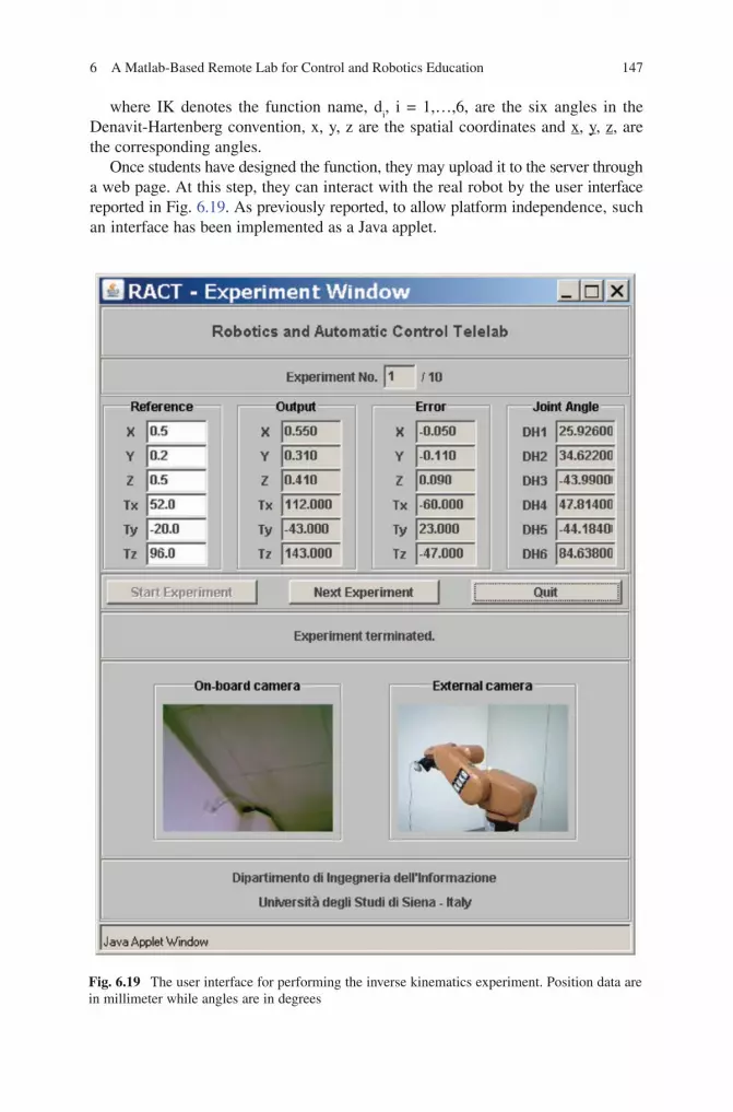
6 A Matlab-Based Remote Lab for Control and Robotics Education 147
BookID 175907_ChapID 6_Proof# 1 - 11/4/2009
where IK denotes the function name, di, i = 1,…,6, are the six angles in the
Denavit-Hartenberg convention, x, y, z are the spatial coordinates and x, y, z, are the corresponding angles.
Once students have designed the function, they may upload it to the server through a web page. At this step, they can interact with the real robot by the user interface reported in Fig. 6.19. As previously reported, to allow platform independence, such an interface has been implemented as a Java applet.
Fig. 6.19 The user interface for performing the inverse kinematics experiment. Position data are in millimeter while angles are in degrees
148 M. Casini et al.
BookID 175907_ChapID 6_Proof# 1 - 11/4/2009 BookID 175907_ChapID 6_Proof# 1 - 11/4/2009
To increase the sense of presence in the lab, two cameras have been provided. The former (on-board camera) is placed on the end-effector of the manipulator, while the latter (external camera) is located outside the robot workspace to take a panoramic view. In the next subsection, it will be shown how the on-board camera will be used to perform visual servoing experiments.
Users are asked to fill in the reference fields, i.e., the target position of the robot, and to start the experiment. The joint angles are computed by the designed function, and the corresponding fields are automatically filled. At this point, the kukatbx_movejt function let the joint angles assume the computed values. After moving, the kukatbx_where function returns the position and orientation of the end-effector computed by the robot internal routines. Such values are then written in the output fields, and the positioning error, i.e., the difference between output and reference, is computed.
6.5.2.2 Visual Servoing Experiment
This experiment deals with the control of the robot based on images acquired by a camera. In particular, the task consists in moving the robot from a known initial position to a final (target) one. The only information available about the target position is a picture taken by the camera placed on the end-effector. Thus, the objective is to move the robot in a position such that the current image is close to the target one.
In general, finding an algorithm to solve this kind of problem is a complex task, especially when the robot has several degrees-of-freedom and works in an unknown environment. Since the main purpose of this project is of educational nature, to simplify the experiment, the robot has been placed in front of a white panel with a black triangle as image. Moreover, the on-board camera has been located orthogonally to the panel and the robot is allowed to move maintaining such a camera orientation. Since the end-effector orientation is given, it is possible to reach a given position using only translations, thus reducing the complexity of the experiment.
Students are asked to design a control function which takes as input the current and the target images and returns the vector denoting the relative robot motion along the three axes:
function [mx, m
y, m
z] = VS(current_img, target_img);
where VS is the function name and mx, m
y, m
z denote the relative motions along
each direction. This function can be designed by students assuming to know the camera calibration data or not. Of course, in the last case, the function design will result more involved. Note that the usage of Matlab allows students to design their functions starting from a large number of routines already provided in Matlab toolboxes, like, e.g., the Image Processing Toolbox or the Robotics Toolbox (see [11]), allowing the design of powerful algorithms.
Once uploaded the designed function, users can interact with the robot by means of the interface reported in Fig. 6.20. Here, students can set the starting and target position of the robot by filling the appropriate fields. These reference positions

6 A Matlab-Based Remote Lab for Control and Robotics Education 149
BookID 175907_ChapID 6_Proof# 1 - 11/4/2009
can also be set randomly within a prescribed range. Three camera windows are provided. The first two windows show images taken by the on-board camera in the current and target position, respectively. The third one contains the picture taken by the external camera.
Periodically, the x, y, z coordinates of the current position are reported along with four graphic charts representing the positioning errors along the three axes and
Fig. 6.20 The user interface for performing the visual servoing experiment. Data are in millimeter

150 M. Casini et al.
BookID 175907_ChapID 6_Proof# 1 - 11/4/2009 BookID 175907_ChapID 6_Proof# 1 - 11/4/2009
the euclidean distance between the current and the target position. The objective is therefore to reduce such an error in the smallest time.
It is worthwhile to note that, although the target coordinates are reported in the interface (and eventually set by the user), they are unknown to the designed visual servoing function, which takes as input just the current and target image.
6.5.2.3 Future Developments
Since RACT is still under development, it is not yet available 24 h a day. In addition to let it fully available, in the following some actions which could be taken in future development of RACT are reported.
• Otherthaninversekinematics,aneasierexperimentregardingforwardkinematicswill be provided. In this case, given the six angles in the Denavit-Hartenberg convention, students will be asked to design a function which computes the corresponding end-effector position.
• Inadditiontotranslation,rotationsalongtheaxisorthogonaltotheimageplanewill be provided. To provide more complex experiments, rotations along the three axes will be taken into account.
• Placingseveralpanelsintherobotworkspace,itwillbepossibletosetupvariousexperiments, depending on the features reported on each panel. For example, they may contain a black triangle (as in Section 6.6.2.2), some lines, colored features, etc. In this way, it will be possible to perform a high number of visual servoing experiments involving minor changes.
6.6 Conclusions
In this chapter, the Automatic Control Telelab has been described. Through this remote lab it is possible to perform control and robotics experiments on remote processes. Such a tool is particularly useful for education, allowing students to do their task without time and space restrictions.
The ACT architecture, based on a bootable CD, allows to easily increase the number of available experiments, in addition to guaranteeing much reliability and efficiency.
Further work will be devoted to the design of research-oriented experiments on visual servoing and the introduction of more complex physical processes with the aim of attracting the interest of a wider community of advanced students in robotics and control.
The ACT home page is: http://act.dii.unisi.it.
Acknowledgments This work has been partially supported by funds of Ministero dell’Università e della Ricerca and EC FP7.
6 A Matlab-Based Remote Lab for Control and Robotics Education 151
BookID 175907_ChapID 6_Proof# 1 - 11/4/2009
References
1. S.E. Poindexter, B.S. Heck (1999) Using the web in your courses: what can you do? what should you do?. IEEE Contr Syst Mag 19(1): 83–92.
2. S. Dormido (2004) Control learning: present and future. Annu Rev Contr 28(1): 115–136. 3. M. Casini, D. Prattichizzo, A. Vicino (2003) The automatic control telelab: a user-friendly
interface for distance learning. IEEE Trans Educ 46(2): 252–257. 4. M. Casini, D. Prattichizzo, A. Vicino (2004) The automatic control telelab: a web-based
technology for distance learning. IEEE Contr Syst Mag 24(3): 36–44. 5. M. Ishutkina, E. Feron, M. Casini, A. Vicino (2004) An internet based laboratory for control
of a safety critical system. In Proceedings of IEEE International Conference on Systems, Man and Cybernetics, Vol. 3, pp. 2707–2712.
6. L. Ljung (1999) System identification: theory for the user, 2nd edition. Prentice-Hall, Upper Saddle River, NJ.
7. M. Casini, D. Prattichizzo, A. Vicino (2007) Operating remote laboratories through a bootable device. IEEE Trans Ind Electron 54(6): 3134–3140.
8. S. Hutchinson, G.D. Hager, P.I. Corke (1996) A tutorial on visual servo control. IEEE Trans Robot Autom 12(5): 651–670.
9. The Apache Software Foundation (2008) Apache HTT P server project. http://httpd.apache.org/. Accessed 30 September 2008.
10. M.W. Spong, S. Hutchinson, M. Vidyasagar (2006) Robot modeling and control. Wiley,New York.
11. P.I. Corke (1996) A robotics toolbox for Matlab. IEEE Robot Autom Mag 3(1): 24–32.
BookID 175907_ChapID 7_Proof# 1 - 11/4/2009
Chapter 7Implementation of a Remote Laboratory Accessible Through the Web
Giuseppe Carnevali and Giorgio Buttazzo
7.1 Introduction
In spite of the big crisis of the years 2000, Internet has continued to grow. The broadband has reached more and more people all around the world and the used technology are always more dynamic and user friendly. The worldwide distribution of the Net joined with the simplicity of information sharing has created new economical and social models in several fields. The methodology of learning, which is a primary form of information and knowledge sharing, was also significantly involved in such a process, evolving in what the E-learning paradigm. At the beginning, E-learning enabled users to share E-books, web pages with exercises and have simple chats with the teachers. Then, videoconferences and virtual desktops were introduced to improve the learning experience of the students. Today, the Internet can also be exploited to conduct actual experiments on physical devices available in remote locations. This approach is twofold. From one hand, students can access remote physical devices from anywhere and at any time, conduct longer experiments and compare different approaches among various laboratories. On the other side, scientists and technicians can collaborate from different locations by running joint experiments from their own office on large and expensive equipment, reducing travel costs and allowing observation of results to other people in real time.
Distance learning also introduces other advantages with respect to traditional models. In fact, it has fewer requirements in terms of space, time, money and travels. These aspects are more important in scientific and technical fields where it is necessary to perform practical laboratories activities to complete the course of study and improve the theoretical knowledge with direct experience.
Giving students a complete and instructive laboratory experience is a hard challenge for the E-learning field. Two solutions are typically adopted. The more straightforward one consists of using a simulated environment accessed through
G. Carnevali () and G. Buttazzo Research and Development Unit, O.C.E.M. S.p.A., Via 2, Agosto 1980, n.11, 40016 San Giorgio di Piano, Bologna, Italy, [email protected]
S.G. Tzafestas (ed.), Web-Based Control and Robotics Education, 153Intelligent Systems, Control and Automation: Science and Engineering 38,DOI 10.1007/978-90-481-2505-0_7, © Springer Science + Business Media B.V. 2009

154 G. Carnevali and G. Buttazzo
BookID 175907_ChapID 7_Proof# 1 - 11/4/2009 BookID 175907_ChapID 7_Proof# 1 - 11/4/2009
specific software tools [1–5]. This means that all the experiments are performed in a synthetic environment, where physical processes are defined and simulated using mathematical models. The main advantage of this solution is that it is simple to implement, but the knowledge acquired by the students depend on several factors, such as the model used in the simulation, the types of imposed constraints, and the functionality of the tool. The main disadvantage of this approach is that several details may be neglected, taking the students away from practical problems.
The other solution, which is more sophisticated, consists of implementing a remote control and monitoring system that interacts with physical devices. This solution is more difficult and more expensive to implement, but provides a better laboratory experience, because it allows the students to interact with real devices and face with the actual behaviour of the system, including non-linear phenomena and noisy data.
Another advantage of this solution is that students are protected against unexpected and dangerous behaviours of the devices and, at the same time, sophisticated devices are more protected against inappropriate usages. In fact, a suitable user interface can disable dangerous operations, or bring the system in a safe state under critical conditions that might cause any damage.
Different kind of experiments can be implemented using a virtual laboratory approach. For example, a user could acquire data from expensive devices, such as infrared cameras, stereo visual systems, 3D laser scanners, or mobile cameras, in order to test specific algorithms on real data. Control experiments can also be carried out on robotic devices, by changing input set points and control parameters.
7.2 Examples of Existing Virtual Labs
There are already several virtual laboratories on the web, mainly developed in university research labs, which propose specific control experiments on robot devices.
For example, the control group at the University of Siena developed a virtual environment, The Automatic Control Telelab, with a set of three experiments, including a position controller for a dc motor, a water level controller, and a levitation control system [6]. Figure 7.1 illustrates a screenshot of the initial window related to the magnetic levitation system. The Automatic Control Telelab allows a user to execute remote control experiments using three operational modes: Predefined Controller, User-defined Controller, and Student Competition Experiment. In the first mode, the student can select one among different predefined controllers, like a simple PID controller, and change its parameters. In the second mode, the student can submit a Simulink personal controller, whereas in the third mode a user-defined controller is submitted and evaluated against certain performance specifications. Controllers are then compared and ranked.
The real-time group at the University of Illinois at Urbana Champagne, developed an inverted pendulum that can be remotely controlled by sending its own control algorithm, and its performance can be evaluated in terms of angular errors on the balancing pole [7]. The environment, illustrated in Fig. 7.2, allows the user to send

17 Implementation of a Remote Laboratory Accessible Through the Web 155
BookID 175907_ChapID 7_Proof# 1 - 11/4/2009
its own controller and a fault tolerant technique protects the system from possible mistakes in the control algorithm and malicious attacks, by switching the user controller to a safe backup controller when critical conditions are detected.
At the University of Pisa, the control group of the Centro “E. Piaggio” developed a remote laboratory named “Breaking the Lab’s Walls: The Tele-Lab” [8]. The environ-ment provides a number of devices on which the user can conduct control experiments: an anthropomorphic robot, a simple DC motors, a magnetic levitator and an interactive environment intended to allow fair and thorough comparison of different techniques to solve a basic problem in nonholomic motion planning.
Figure 7.3 illustrates the interface for the DC motor experiment. The environment allows the user to modify parameters like set points, controller type and sampling time. By clicking on another button the user can start a teleconference application that visualizes the scene under control. At the end of a control session, it is possible to get numerical and graphical data of the experiment.
Fig. 7.1 The virtual laboratory developed at the University of Siena
Fig. 7.2 The virtual laboratory developed at the University of Illinois
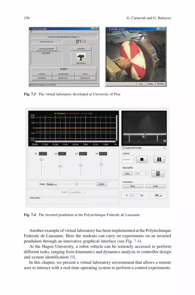
156 G. Carnevali and G. Buttazzo
BookID 175907_ChapID 7_Proof# 1 - 11/4/2009 BookID 175907_ChapID 7_Proof# 1 - 11/4/2009
Another example of virtual laboratory has been implemented at the Polytechnique Federale de Lausanne. Here the students can carry on experiments on an inverted pendulum through an innovative graphical interface (see Fig. 7.4).
At the Hagen University, a robot vehicle can be remotely accessed to perform different tasks, ranging from kinematics and dynamics analysis to controller design and system identification [9].
In this chapter, we present a virtual laboratory environment that allows a remote user to interact with a real-time operating system to perform a control experiments.
Fig. 7.3 The virtual laboratory developed at University of Pisa
Fig. 7.4 The inverted pendulum at the Polytechnique Federale de Lausanne
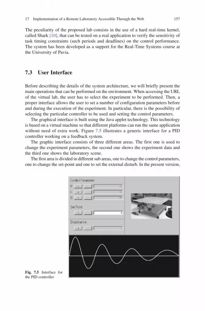
17 Implementation of a Remote Laboratory Accessible Through the Web 157
BookID 175907_ChapID 7_Proof# 1 - 11/4/2009
The peculiarity of the proposed lab consists in the use of a hard real-time kernel, called Shark [10], that can be tested on a real application to verify the sensitivity of task timing constraints (such periods and deadlines) on the control performance. The system has been developed as a support for the Real-Time Systems course at the University of Pavia.
7.3 User Interface
Before describing the details of the system architecture, we will briefly present the main operations that can be performed on the environment. When accessing the URL of the virtual lab, the user has to select the experiment to be performed. Then, a proper interface allows the user to set a number of configuration parameters before and during the execution of the experiment. In particular, there is the possibility of selecting the particular controller to be used and setting the control parameters.
The graphical interface is built using the Java applet technology. This technology is based on a virtual machine so that different platforms can run the same application without need of extra work. Figure 7.5 illustrates a generic interface for a PID controller working on a feedback system.
The graphic interface consists of three different areas. The first one is used to change the experiment parameters, the second one shows the experiment data and the third one shows the laboratory scene.
The first area is divided in different sub areas, one to change the control parameters, one to change the set-point and one to set the external disturb. In the present version,
Fig. 7.5 Interface for the PID controller

158 G. Carnevali and G. Buttazzo
BookID 175907_ChapID 7_Proof# 1 - 11/4/2009 BookID 175907_ChapID 7_Proof# 1 - 11/4/2009
control parameters consist of controller’s proportional, derivative and integral gains. Any parameter can be modified either by entering a numerical value in a field or by incrementing/decrementing its value through a pair of buttons.
The second area is located at the bottom of the experiment window and shows the graphical evolution of a selected system variable.
Finally, the third area on the upper-right corner of the window is used to display the images acquired from a web cam located near the physical device. Such a feature allows the user to monitor in real time the actual evolution of the system, thus catching all the aspects of the experiments that cannot be understood from the analytical representation, but can only be provided by a direct observation.
The interface also handles the case in which the system is busy, because is being used by another user, and the case in which the experiment exceeds a maximum duration. This is done to avoid occupying the lab for a long time so allowing several students to run their own experiments. Before the timeout, the user receives an informative message from the system. Then, at the occurrence of the timeout, the experiment is terminated and the user is disconnected to make the lab available to another user.
7.4 Software Architecture
The software architecture proposed for our environment is based on two main concepts: the laboratories and the experiments. A laboratory is a container for the experiments that can be added or removed from it. A laboratory has to maintain a list and a brief description of all its experiments and has to route the users to the correct experiment.
The experiment is the abstraction of the trial that a student can perform on a physical device. His main tasks are to handle the physical resources and to communicate with the remote clients.
In the next sections we present the main characteristics of the software architecture. We first consider the simplest case in which we have a laboratory with a single experiment. Then, we present the software architecture from a more abstract point of view and we will describe a more complex environment where a laboratory has to handle more experiments.
7.4.1 Basic Details
The software architecture of the virtual lab is organized into three layers. This approach increases flexibility and modularity, since it allows sharing the responsi-bility of the system among the different layers and allows decoupling between different components.
Thanks to this solution, the clients do not know about the business logics on the servers and are free to change, improve or modify the graphics without affecting

17 Implementation of a Remote Laboratory Accessible Through the Web 159
BookID 175907_ChapID 7_Proof# 1 - 11/4/2009
the server layer. In addition, the real-time system (layer 3) is completely decoupled from the server (layer 2), which is essential to guarantee the timing behavior of the control application. In this way, the real-time system runs in a well known environment and is not affected by the unpredictable behavior of internet latencies introduced by the TCP/IP communication protocol.
The three layer architecture of the system is depicted in Fig. 7.6. The Browser contains the applets and the spirals represent the servers waiting for or handling connections.
The interaction between layers works as follows. When the browser gets connected with the Web Server through the internet, it asks for permission to begin the experiment and the Cam and Java/Shark servers starts the communication. The Cam server starts sending the images captured from the web cam to the Video Applet on the client and the Java/Shark server starts sending experimental data from the Shark real-time kernel to the Experiment Applet. The communication continues until the experiment is ended by the user or until a timeout notification is raised by the system. An appropriate message is displayed when the experiment cannot be initiated.
The purpose of the first layer is to handle the user graphical interface, as also done in [11]. This layer consists of a browser that contains two applets: a Video Applet and an Experiment Applet. The Video Applet receives the images from the Cam server and displays them. The Experiment Applet handles the parameters set or changed by the user and sends them to the Java/Shark server. Moreover, it receives the experimental data from the Java/Shark server and displays them in real time. These two applets have been integrated in the same frame, as can be seen in Fig. 7.5, but for the sake of clarity we consider them separately.
The second layer consists of three different servers: a web server that answers the requests coming from the client; a servlet (based on the module for handling servlets in the web server), which sends the images from the webcam to the client; and a Java/Shark server, which manages the communication between the client and the Shark real-time kernel.
Fig. 7.6 Three layer architecture of the system

160 G. Carnevali and G. Buttazzo
BookID 175907_ChapID 7_Proof# 1 - 11/4/2009 BookID 175907_ChapID 7_Proof# 1 - 11/4/2009
This layer is responsible for connecting the user to the laboratory via web. To achieve this goal, we needed a stable, reliable, responsive and, possibly free, web server. After evaluating different solutions, we selected the Apache web server. Besides meeting all our needs, this server is open source and includes a very useful module, called Tomcat. Tomcat is a servlet container and provides a pure Java HTTP web server environment for Java code to run. Tomcat allows the possibility to build customized servers and it has been used to push the images acquired from web cam to the clients.
The Java/Shark server is the most important component of the architecture. His main goal is to handle the communication between the clients and the under-lying real-time subsystem. Among the different tasks, it handles the user access logic to the experiment, checks the experiment timeout and manages all the service communications. A scheme of the threads involved in the Java/Shark server is illustrated in Fig. 7.7.
In Fig. 7.7 the spirals represent the threads that compose the server, the little windows named Lab GUI and Error GUI represent the Graphical User Interfaces shown to the users, and the Tower PC on the right represents the computer running the Shark real-time kernel handling the control application.
This server is a modular component that has two main blocks: the Receiver and the Access Lab thread. The Receiver thread is a daemon that listens to a socket for incoming requests. The Access Lab is the heart of the system and handles all the experiment access requests. It knows the experiment status, knows whether the experiment is free or busy, and notifies the users with appropriate messages. If the experiment is free, it starts two threads, one for enabling the communication between the client and the real-time system, and one for enabling the communi-cation between the real-time system and the client. For the sake of simplicity, only the Accept thread is shown in Fig. 7.7. If the lab is busy, the Access Lab starts the Reject thread that warns the user and closes the communications.
As shown in Fig. 7.7, the communication between the real-time system and the Accept thread is done through the UDP protocol, which is more suitable for implementing control applications with real-time constraints.
Finally, we have the web cam server that enables the students to see the experiment scene in real-time. Different solutions have been considered to implement such a
Fig. 7.7 Threads involved in the Java/Shark server

17 Implementation of a Remote Laboratory Accessible Through the Web 161
BookID 175907_ChapID 7_Proof# 1 - 11/4/2009
functionality, keeping in mind that our objective was to minimize the bandwidth while keeping good speed and image quality. The implemented solution is called server push and represents a good compromise between a streaming solution, where there is a continuous flow of images, and the snap-shot solution, where the client, from time to time, look for new images. According to this method, the server periodically sends, with a configurable period, the image acquired from the web cam. Selecting a suitable push period, it is possible to reach a good tread off between bandwidth consumption and video speed.
The third layer consists of the real-time controller, whose purpose is to run the actual experiment on the physical device. Its main function is to set the initialization parameters sent by the user, run the control application, and send periodically to the user the output data produced by the system.
For this layer, we decided to adopt the Shark real-time operating system, which supports either hard and soft real-time applications and has a modular component-based interface for the specification of scheduling algorithms and resource management protocols [12].
The network communication protocol is a crucial aspect for achieving a predictable behavior in a real-time system, due to high variability of packet delays in the underlying network. The Shark kernel supports the UPD/IP stack protocol. The low-level driver has been implemented to meet real-time system requirements avoiding unpredictable delays during dispatching and receiving of network packets. The goal has been reached solving two main problems: the interrupt handling and the mutual exclusion on the network card. The first problem has been solved handling the network card interrupt with a soft aperiodic task, whereas the second problem has been solved using a priority inheritance protocol to access shared resources [13].
Shark implements may different device drivers that enable the application to interact with a lot of physical devices. For our experiments, the serial port commu-nication driver and the National Instruments 6025E board driver have been used.
7.4.2 Advanced Details
In this section we present how the system works when a laboratory contains more than one experiment.
Different solutions have been considered. In a first instance we thought to exploit a hybrid solution using a standard web server that allows remote users to connect to the laboratory adopting a technology, like CORBA or RMI, to handle the system back-end. The advantage of this solution is that it would hide low-level details and would simplify the development of the network services. On the other hand, this solution is not optimal to transmit data streaming and introduces a certain complexity to the system. In the last years web technology became more dynamic, thus we preferred to use a solution completely based on the web. It is illustrated in Fig. 7.8.
On the right we have the remote PC clients and the Internet cloud. In the middle, the big rectangle and the staked rectangles represent web pages. The cylinder represents the classical database and the physical devices are illustrated on the right.

162 G. Carnevali and G. Buttazzo
BookID 175907_ChapID 7_Proof# 1 - 11/4/2009 BookID 175907_ChapID 7_Proof# 1 - 11/4/2009
A remote PC connects to the laboratory through the main web page, labelled Laboratory. This page lists and describes all the available experiments and the user can choose the desired experiment. When an experiment is selected, the user is redirected to the web page of the experiment, named Experiment in Fig. 7.8. Here the Java/Shark server is started and the interaction between system and client is the same as described in the previous section.
Before a laboratory is set, it is necessary to start a configuration session where any experiment is described and registered with it. The start-up operations are handled by a script, which reads the configuration database and checks the availability of all the components of the system. Then, the main page is dynamically generated.
The system also defines a privileged user, called configurator user, who can modify the configuration on the fly through a protected web page and, for example, can put some experiments off line and some others on line for maintenance purposes.
This architecture is scalable and it is possible to make a hierarchical structure where a server is used as a high level gateway that routes the user towards the selected remote laboratory, which can implement many different experiments. In this way it is possible to have many remote laboratories geographically located in different places. It is also possible to use a more sophisticated and dynamic technology introduced by web 2.0, but this last idea has not been tested yet.
7.5 Hardware Architecture
The Hardware architecture reflects the software organization and consists of three different layers. In this section we illustrate the main characteristics of the hardware components, focusing on the structure of the connections and on the relations that occur among physical components.
Fig. 7.8 Advance software architecture overview
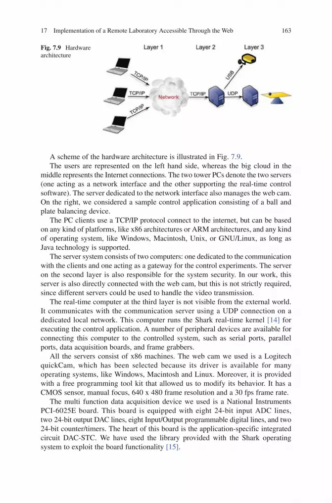
17 Implementation of a Remote Laboratory Accessible Through the Web 163
BookID 175907_ChapID 7_Proof# 1 - 11/4/2009
A scheme of the hardware architecture is illustrated in Fig. 7.9.The users are represented on the left hand side, whereas the big cloud in the
middle represents the Internet connections. The two tower PCs denote the two servers (one acting as a network interface and the other supporting the real-time control software). The server dedicated to the network interface also manages the web cam. On the right, we considered a sample control application consisting of a ball and plate balancing device.
The PC clients use a TCP/IP protocol connect to the internet, but can be based on any kind of platforms, like x86 architectures or ARM architectures, and any kind of operating system, like Windows, Macintosh, Unix, or GNU/Linux, as long as Java technology is supported.
The server system consists of two computers: one dedicated to the communication with the clients and one acting as a gateway for the control experiments. The server on the second layer is also responsible for the system security. In our work, this server is also directly connected with the web cam, but this is not strictly required, since different servers could be used to handle the video transmission.
The real-time computer at the third layer is not visible from the external world. It communicates with the communication server using a UDP connection on a dedicated local network. This computer runs the Shark real-time kernel [14] for executing the control application. A number of peripheral devices are available for connecting this computer to the controlled system, such as serial ports, parallel ports, data acquisition boards, and frame grabbers.
All the servers consist of x86 machines. The web cam we used is a Logitech quickCam, which has been selected because its driver is available for many operating systems, like Windows, Macintosh and Linux. Moreover, it is provided with a free programming tool kit that allowed us to modify its behavior. It has a CMOS sensor, manual focus, 640 x 480 frame resolution and a 30 fps frame rate.
The multi function data acquisition device we used is a National Instruments PCI-6025E board. This board is equipped with eight 24-bit input ADC lines, two 24-bit output DAC lines, eight Input/Output programmable digital lines, and two 24-bit counter/timers. The heart of this board is the application-specific integrated circuit DAC-STC. We have used the library provided with the Shark operating system to exploit the board functionality [15].
Fig. 7.9 Hardware architecture

164 G. Carnevali and G. Buttazzo
BookID 175907_ChapID 7_Proof# 1 - 11/4/2009 BookID 175907_ChapID 7_Proof# 1 - 11/4/2009
7.6 Experiments
The virtual environment presented in this chapter allows the implementation of two basic components: the laboratories and the experiments. A laboratory is a container for experiments, whereas an experiment is a specific procedure for using a physical device available in the laboratory.
In order to test our system, we implemented a laboratory that contains two experiments: a controller for a ball balancing device and a position controller for a web cam.
7.6.1 Ball Balancing Device Experiment
The specific experiment we decided to develop is a real-time controller for a ball balancing device. This system consists of a two-degrees-of freedom rotating plate that has to be controlled to keep a ball in a desired position. A picture of the system is illustrated in Fig. 7.10.
Fig. 7.10 The ball and plate balancing device

17 Implementation of a Remote Laboratory Accessible Through the Web 165
BookID 175907_ChapID 7_Proof# 1 - 11/4/2009
The graphical interface on the client allows the user to modify the parameters of a PID controller. In addition, it is possible to visualize the system through a web cam and follow the temporal evolution of the error in a graphic diagram (see Fig. 7.5). Finally, the user can also introduce a disturbance on the plate to verify the stability of the system and to measure the response times required to bring the error below a certain desired value.
The rotating plate is made of a squared plexiglass surface with a small fence of the borders that prevents the ball to fall out during motion. The plate is free to rotate around two degrees of freedom by means of a spherical joint attached at its centre (from below). The joint is then fixed on a rigid shaft attached on an aluminium base that supports the whole structure.
The motion of the plate is transmitted by two servomotors connected by two staffs to its external border. The servomotors are driven by PWM signals generated by a Programmable Interrupt Controller (PIC 16F876), which receives position commands from a PC through an RS232 serial port. The position of the ball is detected by a CCD camera, whose images are acquired by the PC using a frame grabber.
To achieve a correct behaviour of the system, all sensing, control and actuation activities need to be executed within precise timing constrains. The control application is developed in C under the Shark real-time operating system, which is able to handle periodic and aperiodic activities with explicit timing constraints with a highly predictable behaviour. The most important feature of Shark is that it can be easily configured to run different scheduling algorithms and resource management protocols, that can be selected among several existing modules available in the kernel. Its modular design also allows replacing certain classes of algorithms without modifying the application.
The application consists of six periodic tasks, three are hard real-time tasks and the remaining three are soft real-time tasks. We have used the Cyclical Asynchronous Buffer technique (CAB) [16] to share some data that can be concurrently accessed by the tasks and we have used the semaphores technique for other mutually exclusive resources.
The Cyclical Asynchronous Buffers (CAB) are useful to handle the communication among periodic tasks with different periods. A CAB provides a one-to-many communication channel and in each instant it contains the most recent message. The message is not consumed by the receiver and is updated only when overwritten by the producer. In this way many clients can read the same message simultaneously. On the other hand, an internal buffer mechanism prevents the producer from being blocked until it has finished to write the new message.
The task control scheme used for the application is illustrated in Fig. 7.11.In Fig. 7.11, the spirals represent the tasks composing the real time application
under Shark, and the folders, in the middle of the figure, represent the shared resources. The figure also illustrates the camera, the ball balancing device and the servomotors for moving it.
The tasks named Get_Frame, Get_Position and Move_Motors are hard periodic tasks scheduled according to the Earliest Deadline First (EDF) [17] scheduling algorithm.. The other tasks, namely Draw_frame, Msg_Receiver and Msg_Sender,

166 G. Carnevali and G. Buttazzo
BookID 175907_ChapID 7_Proof# 1 - 11/4/2009 BookID 175907_ChapID 7_Proof# 1 - 11/4/2009
are soft periodic tasks that are scheduled using the Constant Bandwidth Server (CBS) [18]. The Shark operating system also allows changing the scheduling algorithms and the tasks parameters during the initialization process of the real time application. In this way it is possible to test the behaviour of the control application with different algorithms and/or timing constraints.
Figure 7.11 illustrates how the different tasks interact to control the ball balancing plate. Get_Frame is a hard periodic task used to interact with the camera: it opens the communication with the frame grabber, gets the image and closes the communication; then, it puts the image in a Cyclic Asynchronous Buffer.
The Draw_frame is a soft periodic task. It gets the image from the CAB and calculates statistical information on the running tasks. All data are printed on the screen of the computer hosting the real-time application. This information is only used for debugging purpose and is not accessible to the remote users.
Get_Position is a hard periodic task. It analyses the image produced by the camera and computes the position of the ball on the plate. To speed up the computation, the ball is identified by a simple thresholding operation and its position is derived by computing the first order momentum. Velocity is also estimated from the difference with the previous values. After the computation, this information is stored in the Ball Position shared buffer.
Move_Motors is a hard periodic task. A PID control algorithm is implemented in this task and the information stored in the Ball Position and the PID parameters buffer are used by the control algorithm to calculate the new position of the two servo motors that move the ball balancing plate. This information and the ball position are subsequently stored in the System Status shared buffer.
Msg_Receiver is a soft periodic task. It opens a UDP connection and periodically reads the incoming messages from the network. The received messages are parsed, formatted, and finally put in the PID parameters buffer.
Fig. 7.11 Tasks control scheme

17 Implementation of a Remote Laboratory Accessible Through the Web 167
BookID 175907_ChapID 7_Proof# 1 - 11/4/2009
Msg_Sender is a soft periodic task. It opens a UDP connection and periodically reads the data stored in the System Status buffer. Then parses and formats these data and send them through the network to the upper levels.
7.6.2 Rotating Web Cam Experiment
The second experiment we developed is a real-time controller for a rotating web cam that moves according to user commands to monitor the environment. The system consists of a servo motor attached to a web cam that has to be controlled to get the required angular position to reach the desired view. A picture of the system is illustrated in Fig. 7.12.
The graphical interface on the client is very similar to the one presented in the previous experiment and allows the user to modify the set point parameters of a PID controller (see Fig. 7.5). The acquired images are displayed on the screen and the data showing the difference between the starting angular position and the actual position are tracked. In this experiment, the error command is disabled and, unlike the previous experiment, the set point command is enabled.
The motion of the servomotor is transmitted to the web cam throughout an aluminium structure. Figure 7.12 illustrates the structure holding the servomotor and the web cam.
The servomotor is an Hitachi HS-805BB controlled by a PWM (Pulse With Modulation) signal generated by the multi function data acquisition device of the PCI-6025E board. To protect the data acquisition device from extra currents, an electronic circuit has been developed to connect the servomotor to the board.
Fig. 7.12 Controlled cam structure

168 G. Carnevali and G. Buttazzo
BookID 175907_ChapID 7_Proof# 1 - 11/4/2009 BookID 175907_ChapID 7_Proof# 1 - 11/4/2009
The control application is developed under the Shark operating systems and consists of three periodic tasks, as shown in Fig. 7.13. The figure illustrates how the different tasks interact to achieve the goal. We have used the semaphores technique to access mutually exclusive resources.
Move_Motors is a hard real-time periodic task scheduled using the Earliest Deadline First scheduling algorithm. It implements a PID controller and uses the information stored in the PID parameters buffer to calculate the new position of the motor, which is then stored in the System Status buffer.
Msg_Receiver and Msg_Sender are soft real-time periodic tasks scheduled using the Constant Bandwidth Server. They work as the equivalent tasks described in the previous experiment. Both tasks open a UDP connection, but Msg_Receiver receives the messages from the user to modify the experiment set point, whereas Msg_Sender sends the experiment status to the upper levels for monitoring purposes.
7.7 Conclusions
In this chapter we described our experience in the development of a virtual laboratory environment aimed at the interaction with a real-time system for running control experiments. The real-time experiments we have implemented consists in controlling a two-degrees-of-freedom plate balancing device for keeping a ball in a desired position and in controlling a rotating web cam to monitor a remote environment.
The results achieved in this work allow remote users to connect through the Internet to run real-time experiments available in the virtual laboratory and interact with the system using a simple and intuitive graphical interface.
The peculiarity of the proposed environment is to remotely interact with a real-time kernel to verify how the timing constraints defined on the application tasks affect the performance of the control system.
Fig. 7.13 Web cam controller

17 Implementation of a Remote Laboratory Accessible Through the Web 169
BookID 175907_ChapID 7_Proof# 1 - 11/4/2009
As a future work, we plan to include the possibility for the client to send not only the parameters of the controller, but the entire control algorithm. In this case, the system must be designed to be tolerant to malicious attacks or software errors in the controller, by switching to a safe backup algorithm when critical conditions are detected.
References
1. SHsu, B Alhalabi (2000) A Java-Based Remote Laboratory for Distance Education. http://www.ineer.org/Events/ICEE2000/Proceedings/papers/MD2-1.pdf. Accessed 16 Aug 2008.
2. A Alhalabi, M K Hamza, S Hsu, N Romance (1998) Virtual Labs VS Remote Labs: Between Myth Reality. http://www.cse.fau.edu/~bassem/CADET/FLHEC1998-Deerfield.pdf. Accessed 16 Aug 2008.
3. B Alhalabi, D Marcovitz, K Hamza, S Hsu (2000) Remote Labs: An Innovative Leap in Engineering Distance Education. http://www.cse.fau.edu/~bassem/Publications/Pub-35-C-ACE2000-Australia.pdf. Accessed 16 Aug 2008.
4. K Hamza, B Alhalabi, M Marcovitz (2000) Remote Labs!. http://polaris.cse.fau.edu/~bassem/CADET/AACE2000-SanDiego.pdf. Accessed 16 Aug 2008.
5. A Cervin, D Henriksson, B Lincoln, J Eker, K E Årzén (2003) How Does Control Timing Affect Performance? IEEE Control Systems Magazine, 23(3): 16–30, June.
6. M Casini, D Pratichizzo, A Vicino (2002) Automatic Control Telelab: un Laboratorio Remoto per l’Ingegneria dei Controlli. BIAS Automazione e Strumentazione, 4: 142–145.
7. J Schwarz, A Polze, K Wehner, L Sha (2000) Remote Lab: A Reliable Tele-Laboratory Environment. International Conference on Internet Computing, pp. 55–62.
8. A Bicchi, A Coppelli, F Quarto, L Rizzo, F Turchi, A Balestrino (2001) Breaking the Lab’s Walls: Tele-Laboratories at the University of Pisa. In Proceedings of IEEE International Conference on Robotics and Automation, Seoul, Korea, pp. 1903–1908.
9. C Rohrig, A Jochheim (1999) The Virtual Lab for Controlling Real Experiments via Internet. In Computer Aided Control System Design. IEEE Computer Society, Washington, DC, USA.
10. P Gai, L Abeni, M Giorgi, G Buttazzo (2001) A New Kernel Approach for Modular Real-Time Systems Development. In ECRTS ‘01: Proceedings of the 13th Euromicro Conference on Real-Time Systems. IEEE Computer Society, Washington, DC, USA.
11. D Sadoski, S Commella-Dorda (2003) Three Tier Software Architectures. http://www.sei.cmu.edu/str/descriptions/threetier_body.html. Accessed 16 Aug 2008.
12. P Gai, L Abeni, M Giorgi, G Buttazzo (2001) A New Kernel Approach for Modular Real-Time Systems Development. IEEE Proceedings of the 13th Euromicro Conference on Real-Time Systems, Delft, The Netherlands, June.
13. P Gai, G Buttazzo, L Palopoli, L Albeni, G Lipari, G Lamastra, A Casile, M Giorgi (1998) S.Ha.R.K. User Manual Volume II.
14. C Salzmann (2005) eMersion. http://lawww.epfl.ch/page13172.html. Accessed 16 Aug 2008.15. T Facchinetti (2000) Realizzazione di un sistea robotico per il tiro a volo di bersagli mobili.
Master’s thesis, Università degli Studi di Pavia.16. G Buttazzo (1997) Hard Real-Time Computing Systems: Predictable Scheduling Algorithms
and Applications. Kluwer, Boston, MA.17. C L Liu, J W Layland (1973) Scheduling Algorithms for Multiprogramming in a Hard-Real-Time
Environment. Journal of the ACM, 20(1): 46–61.18. L Abeni, G Buttazzo (2004) Resource Reservation in Dynamic Real-Time Systems, Real-Time
Systems, 27(2): 123–167.

BookID 175907_ChapID 8_Proof# 1 - 14/4/2009
Chapter 8Teaching of Robot Control with Remote Experiments
Andreja Rojko and Darko Hercog
8.1 Introduction
Nowadays, remote experiments are becoming a widely used tool for improving the quality of the engineering educational process. Although, classical hands-on labo-ratories are very useful, they have many limitations regarding space, time, and staff costs. They are usually fully occupied, and students have to conclude their research within the time allotted for experimental work. The problems with traditional laboratory work can be avoided by using remote experiments and remote labora-tories. In remote experimentation, students operate with the real system, although they are not physically present in the lab. The remote users can conduct their experi-ments by accessing the lab when they most need it and from a remote’s location which is more comfortable to them. Remote laboratories are mainly used within the academic field to enhance classroom lectures, share research equipment, and sup-plement the learning process. In addition, remote labs efficiently solve the problems that occur at the course schedule planning, particularly when educating part time students, participants of the programs of life-long learning, students from abroad or when working with large groups of learners.
In the field of automatic control, a variety of different remote experiments and remote laboratories has been developed [1–17]. These remote experiments include different objects under control, like DC motor [1–10], inverted pendulum [1, 2, 13–16], magnetic levitation [1, 2], coupled tanks [1, 2, 12, 16, 17], helicopter [1, 2, 11, 12, 17], ball and beam [2] and others. In the majority of existing solutions, remote users can execute experiments, change predefined controller parameters, observe results in text or graphical view and download the experimental results. Some remote labs also include additional functionalities, like testing of custom designed controller [1, 2] and the booking system [9].
A. Rojko and D. Hercog () Institute of Robotics, Faculty of Electrical Engineering and Computer Science, University of Maribor, Smetanova 17, 2000 Maribor, Slovenia, [email protected]
S.G. Tzafestas (ed.), Web-Based Control and Robotics Education, 171Intelligent Systems, Control and Automation: Science and Engineering 38,DOI 10.1007/978-90-481-2505-0_8, © Springer Science + Business Media B.V. 2009

172 A. Rojko and D. Hercog
BookID 175907_ChapID 8_Proof# 1 - 14/4/2009 BookID 175907_ChapID 8_Proof# 1 - 14/4/2009
The robot control course presented here is based on remote experiments developed primarily for the students of Electrical Engineering, Mechanical Engineering and Mechatronics, although it can also be taken by students of Physics/Mathematics and students of other engineering and natural science fields who have sufficient preliminary knowledge of mechanics, control theory, modelling and simulations, mathematics and physics.
The design of the course deals with two basic groups of challenges; (i) educational challenges, and (ii) technical challenges. Educational challenges deal with the problem of how to design a course that will present the subject matter in a clear and interesting manner in the form of e-materials supported by suitable remote experiments. Even of greater educational challenge, is how to encourage the students’ active engagement in the learning process and enhance their interest, although the whole course is an online course and there are only occasional contacts between lecturer and learner. Most technical challenges arise from the problem of preparing reliable remote experiments of good quality. It is expected that the experiments are available all the time and that they cover most of the course’s topics. Since the course described here is a robot control course, the experimental setups are mechanical. This puts additional requirements to the design of remote experiments and experimental devices, since security measures to prevent mechanical damage have also to be taken. Mechanical parts must be robust, constructed in the way, that the errors in the control algorithm and consequent controller’s instability do not cause any mechanical damage. Also wear and tear of the mechanical part should not be too excessive, so the replacements of the components of the mechanism are not too frequently required. In the chapter, both educational and technical solutions employed in the course are described.
The chapter is organized as follows. Section 8.2 presents the educational strategy and structure of the course. In Section 8.3 the remote laboratory and the technical solutions for establishing remote experiments are described. The first part of the course, which concerns the control of one degree of freedom mechanism with nonlinear dynamics, is described in Section 8.4. Section 8.5 describes the second part of the course, where the topic is the motion control of robots with nonlinear dynamic. Remote experiments are performed on a SCARA type robot. In Section 8.6, student responses as well as lecturer’s observations about the course are given. The last section gives some conclusions.
8.2 Educational Strategy
The course is built according to the following educational objectives:
• Modellingofthemechatronicsdeviceincludingrobotswithnonlineardynamics• Designandapplicationoflinearmotioncontrollers(cascadecurrentcontroller,
velocity controller, position controller, PD controller) to the motion control of the nonlinear device
• Designandapplicationofthemodelbasednonlinearmotioncontroller(computedtorque position controller) to the motion control of the nonlinear device
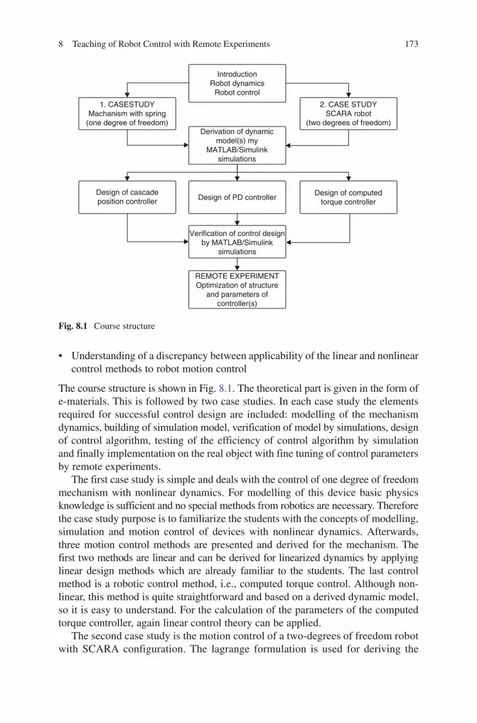
8 Teaching of Robot Control with Remote Experiments 173
BookID 175907_ChapID 8_Proof# 1 - 14/4/2009
• Understandingofadiscrepancybetweenapplicabilityofthelinearandnonlinearcontrol methods to robot motion control
The course structure is shown in Fig. 8.1. The theoretical part is given in the form of e-materials. This is followed by two case studies. In each case study the elements required for successful control design are included: modelling of the mechanism dynamics, building of simulation model, verification of model by simulations, design of control algorithm, testing of the efficiency of control algorithm by simulation and finally implementation on the real object with fine tuning of control parameters by remote experiments.
The first case study is simple and deals with the control of one degree of freedom mechanism with nonlinear dynamics. For modelling of this device basic physics knowledge is sufficient and no special methods from robotics are necessary. Therefore the case study purpose is to familiarize the students with the concepts of modelling, simulation and motion control of devices with nonlinear dynamics. Afterwards, three motion control methods are presented and derived for the mechanism. The first two methods are linear and can be derived for linearized dynamics by applying linear design methods which are already familiar to the students. The last control method is a robotic control method, i.e., computed torque control. Although non-linear, this method is quite straightforward and based on a derived dynamic model, so it is easy to understand. For the calculation of the parameters of the computed torque controller, again linear control theory can be applied.
The second case study is the motion control of a two-degrees of freedom robot with SCARA configuration. The lagrange formulation is used for deriving the
1. CASESTUDYMachanism with spring
(one degree of freedom)
Design of cascadeposition controller Design of PD controller
2. CASE STUDYSCARA robot
(two degrees of freedom)Derivation of dynamic
model(s) myMATLAB/Simulink
simulations
Verification of control designby MATLAB/Simulink
simulations
REMOTE EXPERIMENTOptimization of structure
and parameters ofcontroller(s)
Design of computedtorque controller
IntroductionRobot dynamics
Robot control
Fig. 8.1 Course structure

174 A. Rojko and D. Hercog
BookID 175907_ChapID 8_Proof# 1 - 14/4/2009 BookID 175907_ChapID 8_Proof# 1 - 14/4/2009
dynamic model. Since the students are already familiar with the concepts of modelling and simulation from first case study, extending this concept to more degrees of freedom causes no problems. Again the dynamic model is verified by simulations which are followed by derivation of three robot motion control algorithms. The problem of coupling effects between robot joints, and that of the computational complexity of control algorithms is also considered.
The last phase of both case studies and remote experiments deals with the comparison and evaluation of the results. The students should understand the discrepancy between linear and nonlinear control methods, get insight into some practical problems of robot motion control as coupling effects, tuning of controller parameters, computational complexity, signal noise, and others.
A special educational strategy was developed for local students. Locally the course is implemented as a part of the regular course in robot control for the students of mechatronics and automation. The students must first attend lectures. Next, for laboratory work, two options are available. The students with weak knowledge are advised to attend conventional laboratory sessions, while better students can, according to their wish, also proceed with the remote execution of the laboratory exercises. At the conventional laboratory sessions the course is executed under the supervision of the tutor and the experiments are done locally in the laboratory. The students work in groups of two to three. At the end of the laboratory sessions they are aimed to execute also remote experiments, so that each student gets an opportunity to work autonomously and update the lab report with his individual results. At the same time they have the opportunity to refine knowledge and again repeat the tasks which they did not manage or did not fully understand. Remote exercises are very well accepted from students’ side and as such an additional motivation factor for learning of the subject matter.
8.3 The DSP-Based Remote Control Laboratory
The remote control laboratory, developed at University of Maribor, is based on in-house developed control hardware and two commercially available software packages. MATLAB/Simulink is used for control algorithm development while the LabVIEW for the user front end and remote control.
Fig. 8.2 DSP-2 learning module (left) and DSP-2 robotic controller (right)

8 Teaching of Robot Control with Remote Experiments 175
BookID 175907_ChapID 8_Proof# 1 - 14/4/2009
In the remote laboratory, two types of control hardware are used: (1) DSP-2 learning module [18] and (2) DSP-2 robotic controller [19] (Fig. 8.2). Both DSP-2 control systems are based on a DSP-2 controller [20], which include TI TMS320C32 floating point processor, Xilinx FPGA, A/D and D/A converters, a three-phase pulse width modulator (PWM), an optically isolated digital I/O, interface for the incremental encoder, RAM, FLASH ROM and CAN controller. The DSP-2 control systems can be used in different control applications and can be easily programmed using block oriented programming language MATLAB/Simulink [18, 21].
The structure of the remote laboratory is shown in Fig. 8.3. This remote laboratory, available at [22], is composed of DSP-2 control systems and laboratory server. DSP-2 control systems are connected to the lab server which is, in turn, connected to the Internet. The control systems implement a control algorithm and through the analogue and digital I/O signals, drive the real process. At the same time, LabVIEW virtual instrument (VI) for individual experiments and the LabVIEW server are run on the lab server for the purpose of enabling remote control. Individual VI performs data exchange between the DSP-2 control system and the lab PC, while the LabVIEW server enables remote operation of this VI. Virtual instruments for individual experiment are published on the Web using a LabVIEW built-in Web Publishing Tool [23]. When a remote viewer enters an appropriate URL address, the LabVIEW front panel appears in the Web browser. Once the user has been granted control, the GUI controls become active and running the LabVIEW application is like running the application from the local environment.
The remote experiments, course materials and booking table are accessible at the remote lab home page [22], Fig. 8.4. Remote users have to create their user account and then they can enter the Web page with materials, description of remote experiments and booking table. On the Web page they can also download two programs necessary for execution of the remote experiments. The first program is the LabVIEW Run-time Engine, and the second is the Webcam client required for transfer of live picture of experiment.
To execute the experiments, the students have to reserve a time slot in the booking system on the web page. When the reservation is valid, the user front end appears
Fig. 8.3 Structure of the remote laboratory
Interface
Remoteuser
Internet DSP- 2controlsystem
Objectunder
control
Analogand
digitalI/O

176 A. Rojko and D. Hercog
BookID 175907_ChapID 8_Proof# 1 - 14/4/2009 BookID 175907_ChapID 8_Proof# 1 - 14/4/2009
on the Web browser and the student can overtake the control of the experiment. In the user friendly interface, the remote user can change predefined system parameters and observe the system response in textual, graphical or video format.
8.4 Control of a Mechanism with Spring
The first experimental device is a “mechanism with spring”, one degree of freedom mechanism with nonlinear dynamics, shown in Fig. 8.5. The mechanism is driven by a high quality direct drive motor with an incremental encoder for measuring of actual position. The motor shaft is covered with silicon material and drives an acrylic glass disc and a stainless steel disc with attached spring. The friction between the motor’s shaft and disc can be set to different levels, so that slippage can be avoided. The ratio of the disc and motor shaft’s radius defines the gear ratio of N = 13.4. The cylinder is fastened to the bearing, while on the other side of the bearing the spring is attached. The spring can be attached in few different positions; therefore springs with
Fig. 8.4 Web page and booking system

8 Teaching of Robot Control with Remote Experiments 177
BookID 175907_ChapID 8_Proof# 1 - 14/4/2009
different lengths can be used. The whole mechanism is fastened on an acrylic glass housing. Together with the DSP-2 control system the experimental mechanism forms the mechanical experimental setup that is table size, easily portable, quite robust and requires no special maintenance. Since the motion of the mechanism is not restricted, this mechanism is especially suitable for remote experiments.
8.4.1 Dynamic Model of the Mechanism with Spring
The dynamic model of the experimental mechanism is highly nonlinear, which makes it a perfect object for teaching of control, especially robot control. The dynamic model can be derived by using only physics knowledge; therefore it is also appropriate for a study in modelling of mechanical devices. The torque T that must be compensated by the motor depends on the sum of mechanism’s inertias J and spring torque T
s.
There is also influence of gravity because of the aluminium part on the back of the mechanism. However, since the mass of this part is small, the gravitation effect will be neglected. Therefore the inverse dynamic model can be written in the following form:
T = Jq + Ts + q (8.1)
The inertia can be calculated according to the dimensions and masses of the mecha-nism’s parts. The spring torque must be described as a function of dimensions of mechanism’s parts and measured angle q.
The inertias of four parts should be considered: inertia of acrylic glass disc Jc,
inertia of stainless steel disc Js, inertia of aluminium part at which spring is attached
Ja and inertia of ingot that is attached to the bearing J
p. At the calculation of inertias
of both discs, the equation for inertia of the cylinder can be applied. This equation can be found in most mechanical engineering handbooks. The inertia of acrylic glass disc J
c with mass m
c and radius r
c is:
Fig. 8.5 The mechanism with spring
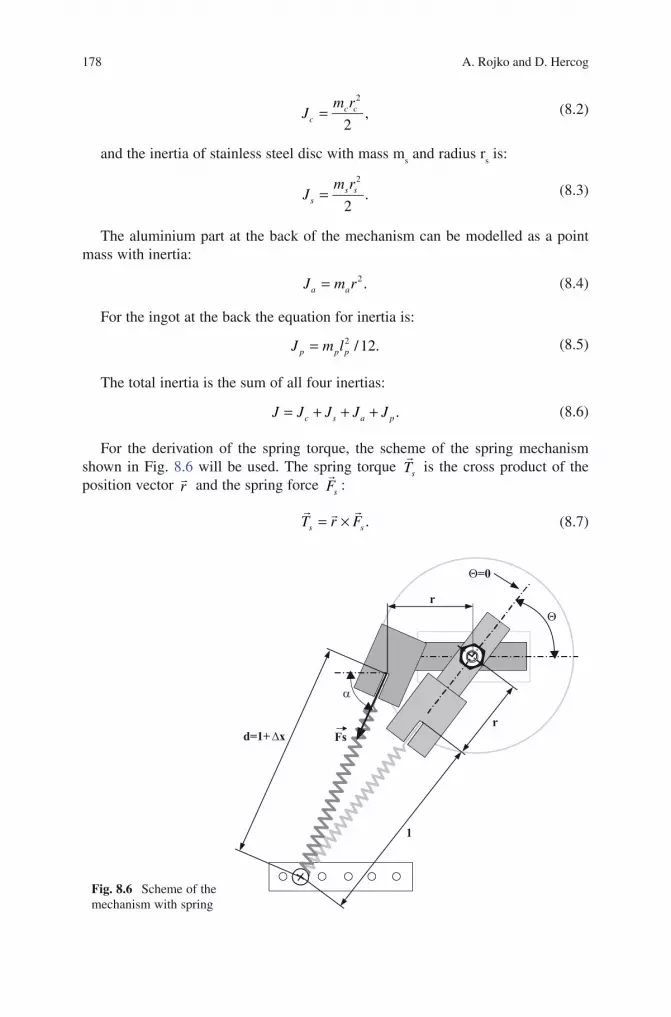
178 A. Rojko and D. Hercog
BookID 175907_ChapID 8_Proof# 1 - 14/4/2009 BookID 175907_ChapID 8_Proof# 1 - 14/4/2009
2
,2
= c cc
m rJ (8.2)
and the inertia of stainless steel disc with mass ms and radius r
s is:
2
.2
= s ss
m rJ (8.3)
The aluminium part at the back of the mechanism can be modelled as a point mass with inertia:
2 .=a aJ m r (8.4)
For the ingot at the back the equation for inertia is:
= 2 / 12.p p pJ m l (8.5)
The total inertia is the sum of all four inertias:
.c s a pJ J J J J= + + + (8.6)
For the derivation of the spring torque, the scheme of the spring mechanism shown in Fig. 8.6 will be used. The spring torque
sTr
is the cross product of the position vector r
r and the spring force sF
r:
.s sT r F= ×r rr
(8.7)
1
d=1+Dxr
r
Q=0
Q
a
Fs
Fig. 8.6 Scheme of the mechanism with spring

8 Teaching of Robot Control with Remote Experiments 179
BookID 175907_ChapID 8_Proof# 1 - 14/4/2009
To calculate the absolute value of the spring torque, the cross product must be replaced by the sinus of the angle between position vector r
r and force sF
r:
( ) ( ).s s sT rF sin rF sinp a a= − = − (8.8)
The spring force sFr
is the product of the spring extension D x and the coefficient of elasticity k (Hook’s law):
.sF k x= ∆ (8.9)
The angle a from Eq. (8.8) and extension of spring D x from Eq. (8.9) must be expressed as the functions of two known dimensions r, l and measured angle q.
In Fig. 8.6 one can see that the two sides of the triangle, and the angle q between them are known. The first unknown value is the angle a or even better sin (a), which is directly required in equation Eq. (8.8). Also, the spring extension D x has to be calculated. It cannot be calculated directly but only from the third side of the triangle, that is the length d of the extended spring. By using the Law of Cosines, the following expression for the length of the extended spring, d, can be written:
( ) ( ) ( )22 2 .d r r l r r l cos q= + + − + (8.10)
The spring extension can be calculated as:
.x d l∆ = − (8.11)
Further, sin (a) can be calculated from the Law of Sines as:
( ) ( ) ( ).l rsin sin
da q
+= − (8.12)
With this, all elements of the dynamic model Eq. (8.1) are known. The complete model is:
( ) ( )( )¨+r .aT J k x sinq q a q= ∆ (8.13)
where the total inertia J is given by Eqs. (8.2–8.6).Usually in the model, friction torque should also be included. Here, the friction
is mostly composed from rolling friction caused by the contact between the motor shaft covered with a little flexible silicon material and Acrylic glass disc. For a good friction model, measuring of the parameters would be required, which is a time consuming procedure and hard to accomplish by remote experiments. Therefore no friction is included in the dynamic model.
The MATLAB/Simulink simulation model based on the dynamic model Eq. (8.13) is shown in Fig. 8.7. This model can be verified by simulations.

180 A. Rojko and D. Hercog
BookID 175907_ChapID 8_Proof# 1 - 14/4/2009 BookID 175907_ChapID 8_Proof# 1 - 14/4/2009
A first test is usually made by setting the system into a stable equilibrium point which means zero initial position, zero initial velocity and zero control torque input. In this case the system should stay at standstill. If this is not the case, then the model of the mechanism is not correct. A second test is the calculation of system responses when the initial position is an unstable equilibrium point. In this case the spring is fully extended, but the torque acting to the mechanism’s shaft is zero. For the unstable equilibrium position the expected result is that the system stays at the standstill for some time, but later the numerical errors at the calculation cause a change of position, and therefore initiate the movement of the mechanism. A third test is to observe the motion trajectory of the mechanism when the initial condition is not an equilibrium condition. Because the friction is not included in the model, a trajectory of periodic type is expected. When the simulations are successfully completed and therefore the model is proven to be correct, the derived dynamic model can be implemented for the control design purposes, calculation of the proper controller’s parameters or for the model based controllers directly as part of the control algorithm.
8.4.2 Control Design for the Mechanism with Spring
8.4.2.1 Cascade Control
Cascade motion control is usually implemented in the industrial controllers. It is composed from three controller connected in series, as shown in Fig. 8.8. The current controller should assure that the actual current is very close to the reference current, while the other two controller blocks compensate the dynamic effects caused by all torques acting upon the mechanism.
The current controller is usually a PI controller, as it is also the case in industrial controllers. The velocity controller is usually of PI or sometimes PID type. The position controller can be a P, PI or PID controller. Some producers of industrial controllers include also a feedforward signal in their algorithm. Such a
r*k
2*r*(r+l) cos
sin
Motiontrajectory
sqrt
1s
xo
1s
xo
Initial angularvelocity
omega _0
Initial angle
theta_0
Drivingtorque
l+r
l
1/Inertia
1/JAngularvelocity
Position (angle)
d
Extension of spring (delta_x)
Extension of spring (delta_x)
sin (theta)sin (alfa)
Springtorque
Angularacceleration
r^2+(r+l)^2
Fig. 8.7 Simulation scheme for the mechanism with spring

8 Teaching of Robot Control with Remote Experiments 181
BookID 175907_ChapID 8_Proof# 1 - 14/4/2009
controller is linear and therefore the best results are achieved in cases of mechanisms with linear dynamics or when gears with high gear ratio are used.
In the case of cascade control of the mechanism with spring, suitable controller parameters can be calculated by using linear control theory and a linearized model or simply via a trial-and-error method by performing simulations in MATLAB/Simulink. After that, fine tuning of parameters should be done by experiments.
8.4.2.2 PD Control
PD control with position and velocity feedback loops is used very frequently in robotics. This is also a linear controller, but, contrary to the cascade controller, information about the reference velocity must also be applied to calculate the reference current signal. Therefore, it can be applied in tasks where the velocity errors should not be too high. The control law is given by:
· · .aT KP e KV e= + & (8.14)
Here kp is the position gain and kv the velocity gain. The position error e is defined as the discrepancy between the reference position q
ref and the measured position q :
,refe q q= − (8.15)
and the velocity error is:
e. = q
.ref
–q.. (8.16)
The control scheme for a one degree of freedom mechanism is shown in Fig. 8.9. The controller is suitable for the motion control of the mechanisms with linear dynamics. In case this controller is implemented for control of the mechanisms with nonlinear dynamics, like the mechanism with spring, higher path following and positioning errors are to be expected. Also the problem of motor saturation is quite common, since the controller gains must be set to sufficiently high values in order to achieve
Fig. 8.8 Cascade controller
PIvelocity
controller
Actuator Load
Actual current
Actual velocity
Referencevelocity
Referencecurrent
Actual position
Pposition
controllerReference
position
PIcurrent
controller
REF

182 A. Rojko and D. Hercog
BookID 175907_ChapID 8_Proof# 1 - 14/4/2009 BookID 175907_ChapID 8_Proof# 1 - 14/4/2009
lower position and velocity errors. The main advantage of the method is its simplicity. Therefore it is used very often. The method works well also for systems with nonlinear dynamics in cases where gears with high gear ratio are employed. This is so because high gear ratio lowers the effect of the mechanism dynamics to the motors.
Also, here the controller parameters for the mechanism with spring can be calculated according to the control theory for linearized dynamic models or by simulations through a trial and error procedure. The fine tuning of parameters must be done experimentally.
8.4.2.3 Computed Torque Control
Computed torque control is a robotic nonlinear control method which is therefore efficient in the motion control of mechanisms with nonlinear dynamics. This method is based on a dynamic model, and so a very accurate inverse dynamic model of the mechanism must be available. An inverse dynamic model of the mechanism is included in the control algorithm and it is used to cancel the effects of gravity, inertia, Coriollis and centrifugal forces. The efficiency of the method depends on how close the applied dynamic model is to the real dynamics. In the case where the model is accurate, the computed torque control linearizes and decouples the system (if it has more degrees of freedom), therefore it provides accurate tracking of the desired path. The drawback of the method is the high computational requirements, because the whole dynamic model must be calculated at each sampling time. Also, when the model of the mechanism has parameters that are varying, as the payload varies, the method cannot be applied. However, in the case of the mechatronics device presented here the computed torque controller yields better results, because it can be achieved with the cascade and PD controllers just described, which are both linear.
The computed torque control law is:
( )·¨ , .cT J H qqq= +% % (8.17)
Fig. 8.9 PD controller
REF
Actuator Load+
+
+
-Referencevelocity
Positiongain
Actual current
Actual velocity
KP
Referenceposition
Currentcontroller
KV+
-
+
-
Actual position
Velocityerror
Velocitygain
Positionerror

8 Teaching of Robot Control with Remote Experiments 183
BookID 175907_ChapID 8_Proof# 1 - 14/4/2009
Here, J~ is the estimated inertia, H
~ (q·, q) are the other estimated dynamic influences,
usually without friction estimation, and q c is the calculated acceleration:
¨ ¨= + +&· · .cref KV e KP eq q (8.18)
Here, kp is the position gain and kv is the velocity gain. The controller scheme for one degree of freedom is shown in Fig. 8.10.
If the parameters and the structure of the estimated dynamic model applied in the control law Eq. (8.17) are close to the real ones, then this control linearizes and decouples the system, and so the error dynamics equation is linear:
1· · .de KV e KP e w J T−+ + = =&& & (8.19)
Here, kp represents disturbance torques which are torques that cannot be described analytically, because they appear randomly and/or are unknown. The characteristic equation for Eq. (8.19) is:
( ) · · .det I A e KV e KP el − = + +&& & (8.20)
It can be seen that the control is stable for positive gains kp and kv. After Laplace transformation, the error equation can be compared to the general equation of the second-order system:
( ) 2 2 2· 2 .c n ns s KV s KP s D sw w= + + = + +∆ (8.21)
It follows that the position gain KP depends on the natural frequency oω as:
2,nKP w= (8.22)
and the velocity gain KV as:
Fig. 8.10 Computed torque controller
REF +
-Referencevelocity
Actual current
KP
Referenceposition
KV+
-
+
-
Referencetorque
Reference acceleration Inversedynamic
model
1Km
Calculatedacceleration
Referencecurrent
Torquecurrent
Actuator Load
Currentcontroller
Actual velocity
Actual position

184 A. Rojko and D. Hercog
BookID 175907_ChapID 8_Proof# 1 - 14/4/2009 BookID 175907_ChapID 8_Proof# 1 - 14/4/2009
2 .nKV Dw= (8.23)
Overshoots must be avoided in most mechanical systems. Therefore critical damp-ing D = 1 is a common choice. For critical damping, the following two equations that can be useful for parameter tuning can be written:
,n KPw = (8.24)
2 .vK KP= (8.25)
The natural frequency nω determines the speed of response. For faster responses, higher values are chosen. However, the upper limit of the natural frequency is limited by many factors. Since the mechanical systems are never totally stiff, the natural frequency must be chosen sufficiently low so that it does not induce resonance. Further, by using high values for the natural frequency, the calculated controller torques may be higher like those that can be provided by motors (motor saturation problem).
For the implementation of computed torque control on mechanism with spring, the dynamic model Eq. (8.13) can be used. By including the friction model with meas-ured parameters, the efficiency of control can be further improved. The controller parameters can be found only by experiments, since the simulation of computed torque gives no information about the controller efficiency. This is so because the real model is not known and the estimated model is already used in the control.
8.4.3 Remote Experiments Using the Mechanism with Spring
Remote experiments with the mechanism with spring include the implementation of all three control methods described: i.e., cascade controller, PD controller, and computed torque controller.
For each control, a special executable MATLAB/Simulink file is built. Remote students do not see the executable model when performing remote experiments, but only a specially created user front end, as shown in Fig. 8.11, which enables switch-ing between controllers, tuning of the parameters and observing the measured and calculated data. It is also possible to observe live picture of an experiment through a web camera (Fig. 8.12).
The reference trajectory in the experiment is fixed and remains the same for all controllers. It is a cyclic reference trajectory calculated by using sin2 velocity profile, where the mechanism makes two full turns in each direction in one cycle. The desired end position of the mechanism q
ref_end is 4p rad, the maximum angular velocity &qref_end
is 10 rad/s, and the maximum anguvlar acceleration &&
ref_endq is 50 rad/s2.In the user front end, the actual and reference positions of the mechanism, its
position error and reference, and its actual current are shown in graphical form. Some other signals, such as the reference and actual velocity, and the reference acceleration, are shown in numerical form.

BookID 175907_ChapID 8_Proof# 1 - 14/4/2009
Fig. 8.11 User front end for remote control of the mechanism with spring
Fig. 8.12 Webcam live picture of the experi-ment

186 A. Rojko and D. Hercog
BookID 175907_ChapID 8_Proof# 1 - 14/4/2009 BookID 175907_ChapID 8_Proof# 1 - 14/4/2009
The students are first working with the cascade controller. By using online tun-ing of the controller’s parameters they have to find the parameters of the PI velocity controller and the P position controller that result in a stable motion with the lowest tracking error. Similar is also the procedure in the PD case, where the optimal val-ues for the position and velocity gain should be found. The computed torque control method allows online tuning of the position and velocity gains, as well as some changes in the controller’s structure. For example, it is possible to turn on or off the compensation of spring torque and friction. In this way the student can see how important is the compensation of these two dynamic effects for good efficiency of the computed torque controller.
After finishing the experiments, the students have to write a report with their results, where all methods are compared, evaluated and commented.
8.5 Control of the SCARA Robot
The second experimental device is a two degrees of freedom robot of SCARA type (Fig. 8.13). The robot is without wrist, and so the motion is limited only to the X-Y plane. As actuators, two ESCAP 28D11 direct current motors mounted on the robot base are used. The advantage of this construction is that the moving masses, and therefore the inertias, are lower, so that higher accelerations can be achieved. For transfer of the motion to the robot joints, belt transmission combined with gear trains is applied. The gear ratio is the same for both joints, i.e., N = 105/28. Each of the motors is equipped with an incremental encoder for measuring the shaft velocity and the direction of rotation, as well as its position. Other components of the system are two current controllers which in this case are analogue. For robot control, a special robotic version of DSP-2 control system, that can drive mechanisms with more than one degrees of freedom, was applied.
8.5.1 The Dynamic Model of the SCARA Robot
To derive the dynamic model, the Lagrange notation is applied. The model is derived for an ideal planar elbow manipulator with two revolute joints as shown in Fig. 8.14.
The dynamic model for the two degrees of freedom robot has the following known form:
1 11 12 1 1
2 21 22 2 2
T J J q C
T J J q C
= +
&&
&& (8.26)

8 Teaching of Robot Control with Remote Experiments 187
BookID 175907_ChapID 8_Proof# 1 - 14/4/2009
Here, iT is the sum of all torques acting on the i-th robot joint, iq&& is the acceleration of the i-th robot joint, iiJ is the inertia of the i-th joint, while ijJ and ijJ are cou-pling inertias. iC are torques caused by Coriollis and centrifugal forces. The ele-ments of equation Eq. (8.26) are:
Fig. 8.13 The SCARA robot
Fig. 8.14 Scheme for the dynamic model derivation of the SCARA robot
y
x
m1
m2
mb
q1
q2
I 1
I 2
l 1T
l 2Tl b

188 A. Rojko and D. Hercog
BookID 175907_ChapID 8_Proof# 1 - 14/4/2009 BookID 175907_ChapID 8_Proof# 1 - 14/4/2009
( )( ) ( )( )
= + + + +
+ + + + + + +
2 2 2 211 1 1 1 2 1 2 1 2 2
221 2 1 2 2 1 2
2 cos
2 cos ,
T m T T
b b b zz zz
J m l m l m l l l l q
m l l l l l l q J J
(8.27)
( )
( ) ( )( ) + = = + + + + +
22 2 1 2 2
12 21 2
2 1 2 2 2
cos2 ,
cos
T T
b b b zz
m l l l qJ J
m l l l l l q J (8.28)
( )= + + +2 222 2 2 2 2 ,T b b zzJ m l m l l J (8.29)
( )( )( )( )
= − − +
+ − − +
& &
&
1 2 1 2 2 1 2 2 1 2
22 1 2 2 1 2 2 2
2 sin 2 sin
2 sin 2 sin ,
T b b
T b b
C m l l q m l l l q q q
m l l q m l l l q q
(8.30)
( )( )= + + &22 1 2 2 1 2 2 1 .T b bm l l sinq m l l l sinq q2C (8.31)
Here, iq and iq& (i = 1,2) are the positions, respectively the velocities of the i-th joint, im is the mass of the i-th joint, mm is the mass of bearing and gear in the second joint, bm is the load mass, il is the length of the i-th joint,
iTl is the distance from the previous joint to the centre of mass of the i-th joint, and zziJ is the moment of inertia for the i-th link calculated for the centre of mass of the i-th link.
From Eqs. (8.27–8.31) it can be seen that the robot dynamics is nonlinear and that the robot joints are coupled. Therefore, the dynamic influences caused by one joint affect the other joint’s motion. This makes the mechanism suitable for testing the efficiency of robot motion control methods.
Based on the inverse dynamic model Eqs. (8.27–8.31) a direct dynamic model of the robot can also be calculated, which is required for building the MATLAB/Simulink simulation scheme. As in the case of the mechanism with spring, simulations can be used to verify the dynamic model. The procedure of verification consists in observing the responses of the system with zero torque input and zero initial veloc-ity, where the system should stay at standstill. Applying non-zero motor torque only at one joint should cause motion of the other joint, and vice versa.
8.5.2 Control Design for the SCARA Robot
8.5.2.1 Cascade Control
Although cascade control is almost never used for controlling robots, it was imple-mented here for comparison with the other two methods. The same controller structure as that for the mechanism with spring was used (Fig. 8.8). But here two

8 Teaching of Robot Control with Remote Experiments 189
BookID 175907_ChapID 8_Proof# 1 - 14/4/2009
controllers are required; one for each robot joint. Since PI current controllers are suitable for robots when realized as analogue controllers, only the position controller P and the velocity controller PI were programmed.
The controller parameters can be calculated by using linear control theory and a linearized model, or by simulation with a trial and error procedure. However, for good efficiency in real-time control, fine parameter tuning via experiments is also required.
Of course this control does not really bring good results. The reason is that the robot dynamics is nonlinear and coupled, whereas the controller is linear and totally decoupled since there is an independent controller for each joint. Because no velocity reference signal is used in the control algorithm, this controller is less applicable when high position and velocity accuracy are required.
8.5.2.2 PD Control
The PD robot controller with velocity and position feedback loop (Fig. 8.9), is given by:
, , .i p i i v i iT K e K e= + & (8.32)
where the position error of the i-th joint is:
, ,i ref i ie q q= − (8.33)
and its velocity error is:
· ·, .i ref i ie q q= −& (8.34)
Since a velocity reference signal is included, a little lower velocity errors can be expected as in the case of cascade controller. However, for practical use in robot control, good results are expected only when controlling robots with high gear ratios. Again MATLAB/Simulink simulations can be performed in order to find proper controller parameters that can be the starting point for fine experimental parameter tuning.
8.5.2.3 Computed Torque Control
The computed torque control law for a two degrees of freedom robot is given by:
1 11 12 1 1
2 21 22 2 2
c
c
T J J q C
T J J q C
= +
%% % &&
%% % && (8.35)
where ijJ% are estimated inertias, iC% are estimated effects of Coriollis and cen-trifugal forces, and
ciq&& is calculated inertia:

190 A. Rojko and D. Hercog
BookID 175907_ChapID 8_Proof# 1 - 14/4/2009 BookID 175907_ChapID 8_Proof# 1 - 14/4/2009
¨ ¨, , , .c
i ref i v i i p i iK e K eq q= + +& (8.36)
If the discrepancy between real and estimated parameters is small, this control decouples and linearizes the controlled system. In this case the error equation for each joint is:
( )∆ = + + = + +2 2 2, , , , ,2 .c i v i p i i n i n is s K s K s D sw w (8.37)
Here, the choice of position and velocity gains determines the response of the sys-tem as described in the case of the mechanism with spring. When the derived dynamic model and its parameters are correct, this control is expected to yield the best results for all the described controllers.
8.5.3 Remote Experiments with the SCARA Robot
The remote experiments with the SCARA robot also include an implementation of all three control methods: cascade controller, PD controller, and computed torque controller. Again, as reference trajectory a cyclic motion calculated with sin2 velocity profile is implemented.
The user front end, shown in Fig. 8.15, allows switching between the three con-trol methods, tuning of position and velocity gains for PD and computed torque control, and tuning of the parameters of the position and velocity controller in the case of cascade control. The user can also choose the option where only one joint is in motion. In this case, the second joint operates with the controller held at zero position. However, coupling effects also induce motion of the joint at a standstill. The extent of the motion induced by the coupling depends on the efficiency of the controller applied in each case.
The measured results, the actual and reference positions for both joints, the posi-tion error for both joints, and the reference currents for both joints (i.e., the signals of the analogue current controllers) are all shown in graphical form.
If the controller parameters are not chosen optimally, the position of the robot can drift with time because the robot has only incremental encoders. This problem can be solved by running an initialization procedure (“Reset” position option in the user interface) that brings the robot back to the real zero initial position. This pro-cedure can be executed at any time between remote experiments, and it is also executed automatically at the beginning the of experiments.
8.6 Students’ Feedback
To evaluate the remote course, a small group of 18 local students were asked to follow the course and fill in an anonymous questionnaire. The questions were mostly given in order to examine their attitude toward courses with remote

8 Teaching of Robot Control with Remote Experiments 191
BookID 175907_ChapID 8_Proof# 1 - 14/4/2009
experiments, while the comments about the course content and possible techni-cal problems, at the execution of the experiments, were examined separately during the course.
It was found that all students have at home equipment appropriate for remote experiments, including fast web connection and personal computer.
The results of the questionnaire show that 94% of the students have the opinion that distance courses with remote experiments constitute a very good supplement of the local lectures and local, conventionally executed, laboratory exercises. However, only 22% think that remote experiments can be used to completely replace local laboratory exercise. Furthermore, 94% of the students think that remote experiments are suitable to strengthen and complete already existing knowledge, while 72% of them think that such experiments are also suitable for acquiring completely new knowledge.
39% of the students executed the remote course for the first time. Since these students were at their final year of study, this shows that remote courses in the engineering field are still quite rare.
Surprising were the answers to the question if the students prefer remote experi-ments over conventional laboratory experiments. 61% of the students replied that they prefer local laboratory work, despite the fact that the remote experiments offer time and space independency at the execution of the experiments. 33% of the students
Fig. 8.15 User front end for remote control of SCARA robot

192 A. Rojko and D. Hercog
BookID 175907_ChapID 8_Proof# 1 - 14/4/2009 BookID 175907_ChapID 8_Proof# 1 - 14/4/2009
were neutral to this question, while only 7% of the students prefer remote experiments over the local experiments.
A very important result from the questionnaire is the fact that 78% of the students think that they obtained more knowledge at the execution of conventional laboratory experiments in comparison to the remote experiments. This is justified, since laboratory work (opposite to the remote experiments) provides also experience on how to prepare the equipment and handle the measuring devices. In addition, at the laboratory exercises there is usually a Lab. Assistant present who answers to students’ questions immediately as they appear, and help them to solve any actual problems.
From the viewpoint of the lecturer it was very clear that the remote course with remote experiments motivated more strongly the students who had to work with more dedication in comparison to the case where conventional lab exercises were performed. Consequently, the knowledge level has been improved, and more stu-dents became interested to continue their work in this area by taking diploma work in the subject.
Also, because the remote version of the course was available, it was easier to handle the organizational problems that usually occur when the students miss obligatory laboratory exercises.
8.7 Conclusions
With the robot control course presented here it was shown how new educational possibilities, like remote experiments, can be applied in practice at the teaching process of highly demanding topics (such as robot control), which, besides theory, also require experimental work performed on mechanical devices. The course is offered with complete on line documentation that enables the students, with different knowledge levels and from different engineering fields, to carry out individual work. The remote experiments are supported by a user-friendly “booking system”. A continuous improvement of the course, including technical solutions of the remote lab and course documentation, is based on the feedback information pro-vided by the students. A complete course, especially remote experiments with an efficient “booking” system, is particularly beneficial in the case of a large number of students and a limited quantity of the available experimental equipment. Students’ and teachers’ feedback shows that this approach is very welcomed and can be used as part of a regular educational process, in order to enhance the students interest, improve their knowledge, and also to offer a new, more flexible and user friendly, pedagogical approach.
Acknowledgments This work has been partially carried out within the project “E-learning Distance Interactive Practical Education (EDIPE)”. The project was supported by the European Community within the framework of Leonardo da Vinci II programme (project No CZ/06/B/F/PP-168022). The opinions expressed by the authors do not necessarily reflect the position of the European Community, nor does it involve any responsibility on its part.
8 Teaching of Robot Control with Remote Experiments 193
BookID 175907_ChapID 8_Proof# 1 - 14/4/2009
This work has also been partially pursued within the project “Innovative Remote Laboratory in the E-training of Mechatronics (MerLab)”. The project was supported by the European Community within the framework of Leonardo da Vinci programme.
References
1. M. Casini, D. Prattichizzo, and A. Vicino, “The automatic control telelab - A web-based technology for distance learning,”IEEE Control Syst. Mag., vol. 24, no. 3, pp. 36–44, 2004.
2. M. Basso and G. Bagni, “ARTIST: A real-time interactive Simulink-based telelab,” in Proceedings of the 2004 IEEE International Symposium on Computer Aided Control Systems Design (CACSD’04), 2004, pp. 196–201.
3. A. R. S. Castellanos, L. Hernandez, I. Santana, and E. Rubio, “Platform for distance develop-ment of complex automatic control strategies using MATLAB,” Int. J. Eng. Educ., vol. 21, no. 5, pp. 790–797, 2005.
4. K. Yeung and J. Huang, “Development of a remote-access laboratory: A dc motor control experiment,” Comput. Ind., vol. 52, no. 3, pp. 305–311, 2003.
5. D. Gillet, F. Geoffroy, K. Zeramdini, A. V. Nguyen, Y. Rekik, and Y. Piguet, “The cockpit: An effective metaphor for web-based experimentation in engineering education,” Int. J. Eng. Educ., vol. 19, no. 3, pp. 389–397, 2003.
6. T. Kikuchi, S. Fukuda, A. Fukuzaki, K. Nagaoka, K. Tanaka, T. Kenjo, and D. A. Harris, “DVTS-based remote laboratory across the Pacific over the gigabit network,” IEEE Trans. Educ., vol. 47, no. 1, pp. 26–32, 2004.
7. T. Kikuchi, T. Kenjo, and S. Fukuda, “Remote laboratory for a brushless DC motor,” IEEE Trans. Educ., vol. 44, no. 2, pp. 207–219, 2001.
8. R. Pastor, C. Martin, J. Sanchez, and S. Dormido, “Development of an XML-based lab for remote control experiments on a servo motor,” Int. J. Electr. Eng., vol. 42, no. 2, pp. 173–184, 2005.
9. D. Hercog, B. Gergic, S. Uran, and K. Jezernik, “A DSP-based remote control laboratory,” IEEE Trans. Ind. Electron., vol. 54, no. 6, pp. 3057–3068, 2007.
10. C. Salzmann, D. Gillet, and P. Huguenin, “Introduction to real-time control using LabVIEWTM with an application to distance learning,” Int. J. Eng. Educ., vol. 16, no. 3, pp. 255–272, 2000.
11. C. C. Ko, B. M. Chen, J. P. Chen, J. Zhang, and K. C. Tan, “A web-based laboratory on control of a two-degrees-of-freedom helicopter,” Int. J. Eng. Educ., vol. 21, no. 6, pp. 1017–1030, 2005.
12. C. C. Ko, B. M. Chen, C. Jianping, Y. Zhuang, and K. Chen Tan, “Development of a web-based laboratory for control experiments on a coupled tank apparatus,” IEEE Trans. Educ., vol. 44, no. 1, pp. 76–86, 2001.
13. M. R. Quintas, A. M. Lopes, C. Moreira da Silva, P. Abreu, and D. Sá, “Remote web operation of an inverted pendulum,” in Proceedings of the International Symposium on Remote Engineering and Virtual Instrumentation, 2007, pp. 1–5.
14. G. Hovland, “Evaluation of an online inverted pendulum control experiment,” IEEE Trans. Educ., vol. 51, no. 1, pp. 114–122, 2008.
15. J. B. Dabney, J. McCune, and F. H. Ghorbel, “Web-based control of the rice SPENDULAP,” Int. J. Eng. Educ., vol. 19, no. 3, pp. 478–486, 2003.
16. B. Duan, K. V. Ling, H. Mir, M. Hosseini, and R. K. L. Gay, “An online laboratory framework for control engineering courses,” Int. J. Eng. Educ., vol. 21, no. 6, pp. 1068–1075, 2005.
17. M. L. Corradini, G. Ippoliti, T. Leo, and S. Longhi, “An Internet based laboratory for control education,” in Proceedings of the 40th IEEE Conference on Decision and Control, 2001, pp. 2833–2838.
194 A. Rojko and D. Hercog
BookID 175907_ChapID 8_Proof# 1 - 14/4/2009
18. D. Hercog and K. Jezernik, “Rapid control prototyping using MATLAB/Simulink and a DSP-based motor controller,” Int. J. Eng. Educ., vol. 21, no. 4, pp. 596–605, 2005.
19. M. Čurkovič and D. Hercog, DSP-2 Robotic Controller User’s Manual. Maribor, Slovenia: Inst. Robot., Fac. Electr. Eng. and Comput. Sci., Univ. Maribor, 2006. [Online]. Available: http://www.ro.feri.uni-mb.si/projekti/dsp2
20. M. Čurkovič, DSP-2 User’s Manual. Maribor, Slovenia: Inst. Robot., Fac. Electr. Eng. and Comput. Sci., Univ. Maribor, 2001. [Online]. Available: http://www.ro.feri.uni-mb.si/projekti/dsp2
21. D. Hercog, DSP-2 Library for Simulink User’s Manual. Maribor, Slovenia: Inst. Robot., Fac. Electr. Eng. and Comput. Sci., Univ. Maribor, 2006. [Online]. Available: http://www.ro.feri.uni-mb.si/projekti/dsp2
22. DSP-Based Remote Control Laboratory. [Online]. Available: http://remotelab.ro.feri.uni-mb.si 23. National Instruments, LabVIEW User Manual. Austin, TX: National Instruments, 2006.

BookID 175907_ChapID 9_Proof# 1 - <Date>
Chapter 9Web-Based Laboratory on Robotics: Remote vs. Virtual Training in Programming Manipulators
Costas S. Tzafestas
9.1 Introduction
It is widely accepted that, in all engineering education disciplines, well-designed practical training scenarios in realistic experimental laboratory set-ups are needed to complete students’ education. Hands-on laboratory experimentation is, indeed, essen-tial to enhance and complete classroom lectures and theoretical teaching. Illustrating analytical techniques, assimilating theoretical concepts, introducing students to pro-fessional practice and to the uncertainties involved in real experiments, as well as developing skills including teamwork in technical environments, are some of the reasons that make laboratory classes pedagogically indispensable in engineering cur-ricula. Quite often, though, access to expensive and complex laboratory equipment imposes inevitably many constraints, both in terms of time and space limitations. Remote and/or virtual laboratories could provide some solutions to these constraints, offering different alternatives to overcome such limitations by giving students access to laboratory infrastructure in ways that would otherwise be impossible to consider.
The rapid development of many distance learning platforms and applications in recent years constitutes undoubtedly one of the most characteristic examples of the potential that is offered by new information and communication technologies, and particularly by the continuous evolution of those technologies related to the Internet and the World Wide Web. Teaching from a distance in a synchronous or asynchronous e-learning mode is now a usual practice. The development of such applications is often based on some type of teleconferencing (video/audio streaming) platform, with an MCU (multi-point conferencing unit) at the core of the system, enhanced by many software features, such as application sharing or other functionalities forming “virtual classroom” web-spaces. We can, thus, say that nowadays attending and participating in classroom lectures or seminars remotely is a technologically feasible goal, as related technologies are mature enough, and many application platforms have already been established as a standard.
S.G. Tzafestas (ed.), Web-Based Control and Robotics Education, 195Intelligent Systems, Control and Automation: Science and Engineering 38,DOI 10.1007/978-90-481-2505-0_9, © Springer Science + Business Media B.V. 2009
C.S. TzafestasDivision of Signals, Control and Robotics, School of Electrical and Computer Engineering, National Technical University of Athens, Zographou, Athens, GR 15773, Greecee-mail: [email protected]; http://users.softlab.ece.ntua.gr/~ktzaf/

196 C.S. Tzafestas
BookID 175907_ChapID 9_Proof# 1 - <Date> BookID 175907_ChapID 9_Proof# 1 - <Date>
However, although synchronous and asynchronous distance learning platforms form now a common place, remote “e-laboratory” systems are still under development and investigation, and are currently far from offering any standard solution in engi-neering education. The development of systems that can offer such kind of practical laboratory-training courses from a distance has been in constant progress for more than a decade now. However, these efforts have been mostly sporadic or isolated, and the related technological components are just now beginning to assemble into integrated platforms, with however no standardized or global solution available yet. One of the difficulties here is of course related to the fact that such remote and/or virtual “e-laboratory” applications involve interfacing through the network of many different physical devices and diverse experimental equipment needed to complete a real physical experiment. These devices must be remotely operated through the network, and this may call for a variety of different technological solutions depending on the type of the equipment and the real physical experiment involved. It must be noted here that, although sophisticated software packages exist that in many cases can provide realistic simulation environments, experience shows that hands-on experi-mentation with real physical systems is in practice irreplaceable and is necessary to adequately convey basic engineering concepts and skills.
A lot of research is, thus, still needed in the direction of developing efficient e-laboratory platforms, not only to improve technologies but also especially to assess the efficacy of various available teaching and training modalities, in terms of learning transfer performance, and to consequently formulate appropriate guidelines for the efficient design of such applications. In this context, this chapter describes the develop-ment and pilot evaluation of a web-based laboratory platform, designed to support distance education in the field of robotics. The system is designed to support student training in realistic scenarios of robot manipulator programming. A “Virtual Pendant” panel is incorporated, providing an interface to teach students how to program a robot manipulator using the functions of the manual Teach Pendant device of the robot. From a technological perspective, the research work described is directed towards the adaptation of concepts and techniques inspired by related work in the field of telerobotics and virtual reality, and their integration in such e-laboratory settings. This chapter focuses particularly on the educational impact of such systems, the goal being to assess the performance of such e-laboratory scenarios in terms of the efficacy of the training provided to students.
In this direction, the results of a pilot experimental study are presented, provid-ing a comparative evaluation for three training modes: real, remote, and virtual training on robot programming. The experiments were conducted according to an evaluation protocol specially designed for the considered target training task, using scoring charts to obtain quantitative performance measures and assess the performance of the student groups participating in the course. Training, as a dynamic process, is approached according to a typical three-dimensional model, and performance scores are accordingly assessed in these dimensions (namely: low-level versus mid and high-level skills and understanding). The obtained results reveal certain differ-ences between the three groups, particularly as related to the low-level skill training score, giving some insight about the training ‘dimensions’ that are expected to be

9 Web-Based Laboratory on Robotics 197
BookID 175907_ChapID 9_Proof# 1 - <Date>
mostly affected by the absence of physical (or realistic virtual) presence in a real hands-on experimentation. Statistical analysis indicates, however, that, despite these apparent differences, such e-laboratory modules can be integrated quite effectively in practical scenarios, creating virtual training environments that can provide adequate learning elements, as related particularly to mid and high-level skill acquisition. Further work and large-scale studies are still needed, though, in order to explore the extent to which such a general conclusion is valid in different training settings, and to form the basis of a more theoretical evaluation for a comprehensive understanding of the pedagogical differences between real, virtual, and remote learning/training methodologies and experiences.
The Chapter is organized as follows. In Section 9.2 a brief literature survey is presented, identifying the current state-of-the-art regarding the design and development of remote laboratory platforms. Section 9.3 highlights the research motivation and background, and sets the objectives (both technological and educational) of this work. Section 9.4, then, describes the design and development of the virtual and remote robot laboratory platform, while Section 9.5 describes the pilot study conducted, to evaluate performance comparatively for different training modes, and presents the experimental results obtained. Conclusions and future research trends are finally discussed in the Section 9.6.
9.2 Remote Labs: Literature Survey
In recent years, a number of “remote laboratory” projects have been initiated on a national or international basis, aiming to teach fundamental concepts in different engineering fields through the remote operation and control of specific experimental facilities. A typical example was the research project ReLAX (remote laboratory experimentation trial), funded by the European Commission within the IST framework. The goal of this project was to study the feasibility of making remote experimentation available as a component in distance learning, both from a technological point of view and from an economic perspective [1]. A continuation of this effort was the eMersion project aiming to study the deployment of innovative pedagogical scenarios and flexible learning resources for completing virtual or remote experi-ments via Internet [2]. A case study of the implementation of such remote experi-mentation scenarios in an automatic control course is presented in [3], where useful hints concerning best practices in deploying sustainable flexible education scenarios, from academic and pedagogical perspectives, are also given.
Similar activities towards the development of virtual and remote laboratory systems are also carried out by many other academic institutions, covering various engineering fields ranging from electronics [4] and control [5, 6], to a larger variety of mechanical and chemical engineering experimental set-ups [7]. Experience acquired from this work and from other similar initiatives [8, 9] reveals the difficulties and the challenges associated with the introduction and deployment of distance laboratory modules. From a technical point of view, such a goal requires adaptation of existing equipment, which must often be performed in a task-specific way. Each

198 C.S. Tzafestas
BookID 175907_ChapID 9_Proof# 1 - <Date> BookID 175907_ChapID 9_Proof# 1 - <Date>
laboratory setup, and often each associated learning scenario, may call for a different type of operation and control, which raises considerable challenges when performed remotely.
From a didactical perspective, substantial effort is still needed for assessing the effectiveness of these learning modalities compared to traditional means of “hands-on” laboratory training. Some initial attempts to evaluate, in pedagogical terms, remote and virtual laboratory platforms are reported in [10] and [11]. In [10], a methodological evaluation approach is presented for a distributed Internet-assisted laboratory experiment. More results, however, are to be reported in the future in the frames of ongoing international collaboration projects. In [11], a methodology is described that was used, in the frames of a research project, for the evaluation of Web-based remote experimentation and student training environments. This evaluation was based on a usability engineering approach, preferred to a didactical approach that was left as an option for the future.
More recent research efforts attempt to approach such dimensions and to evaluate comparatively different training modes, in terms of the learning outcomes measured through systematic (quantitative) methodologies [12, 13]. Lindsay and Good in [12] study whether a remote access modality may, in fact, enhance certain learning out-comes, and report statistically significant differences in the learning outcomes of the students, their perceptions of the laboratory class, and the ways in which they engage the learning experience. In [13], the results of a pilot study are presented evaluating three different training modes (on-site, remote and virtual), reporting differences identified with respect to the students’ skill acquisition process in specific training dimensions. Undoubtedly, a lot of research is still needed, in order to be able to draw general conclusions about the relative impact of different technical elements and training modes, in the learning process within a virtual and remote laboratory.
9.3 Research Motivation and Objectives
Keeping in mind the various initiatives towards the development of remote laboratory modules worldwide, some of which are cited above, our research work within the Intelligent Robotics and Automation lab of our Department has been oriented towards two principal goal directions. Firstly, from a technological point of view, the goal is to design and develop platforms that incorporate a variety of learning elements, integrating different interactive operation modalities that support both virtual and remote experimentation scenarios, with the learning objectives emphasizing particu-larly on the operation, programming, and control of complex mechatronic devices, such as robot manipulators. Secondly, from an educational perspective, our research focuses on the design of appropriate training scenarios and on the experimental analysis and comparative evaluation of different training modes and technical/learning elements, including virtual simulation and remote control panels.
At this point, the use of the terms virtual and remote should be clarified, in describing different dimensions of what can be more generally termed e-laboratory
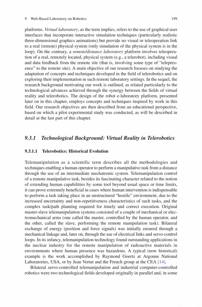
9 Web-Based Laboratory on Robotics 199
BookID 175907_ChapID 9_Proof# 1 - <Date>
platforms. Virtual laboratory, as the term implies, refers to the use of graphical user interfaces that incorporate interactive simulation techniques (particularly realistic three-dimensional graphics animations) but provide no visual or teleoperation link to a real (remote) physical system (only simulation of the physical system is in the loop). On the contrary, a remote/distance laboratory platform involves teleopera-tion of a real, remotely located, physical system (e.g., a telerobot), including visual and data feedback from the remote site (that is, involving some type of “telepres-ence” to the remote site). A main objective of our research focuses on studying the adaptation of concepts and techniques developed in the field of telerobotics and on exploring their implementation in such remote laboratory settings. In the sequel, the research background motivating our work is outlined, as related particularly to the technological advances achieved through the synergy between the fields of virtual reality and telerobotics. The design of the robot e-laboratory platform, presented later on in this chapter, employs concepts and techniques inspired by work in this field. Our research objectives are then described from an educational perspective, based on which a pilot experimental study was conducted, as will be described in detail at the last part of this chapter.
9.3.1 Technological Background: Virtual Reality in Telerobotics
9.3.1.1 Telerobotics: Historical Evolution
Telemanipulation as a scientific term describes all the methodologies and techniques enabling a human operator to perform a manipulative task from a distance through the use of an intermediate mechatronic system. Telemanipulation control of a remote manipulative task, besides its fascinating character related to the notion of extending human capabilities by some tool beyond usual space or time limits, it can prove extremely beneficial in cases where human intervention is indispensable to perform a task taking place in an unstructured “hostile” environment, due to the increased uncertainty and non-repetitiveness characteristics of such tasks, and the complex task/path planning required for timely and correct execution. Original master-slave telemanipulation systems consisted of a couple of mechanical or elec-tromechanical arms (one called the master, controlled by the human operator, and the other, called the slave, performing the remote manipulation task). Bilateral exchange of energy (position and force signals) was initially ensured through a mechanical linkage and, later on, through the use of electrical links and servo-control loops. In its infancy, telemanipulation technology found outstanding applications in the nuclear industry for the remote manipulation of radioactive materials in environments where human presence was hazardous. A typical (now historical) example is the work accomplished by Raymond Goertz at Argonne National Laboratories, USA, or by Jean Vertut and the French group at the CEA [14].
Bilateral servo-controlled telemanipulation and industrial computer-controlled robotics were two technological fields developed originally in parallel and, in some

200 C.S. Tzafestas
BookID 175907_ChapID 9_Proof# 1 - <Date> BookID 175907_ChapID 9_Proof# 1 - <Date>
extent, independently. The awareness that both these fields can benefit from devel-opment accomplished in each other has led to the fusion of these technologies and the creation of what is generally described under the term of telerobotics. Robotics was initially concerned with the development of industrial manufacturing systems performing programmable, repetitive operations in an autonomous sensor-based manner, while telemanipulation was focusing on a different class of tasks, which should clearly rely on the predominant presence of a human operator in the control loop. Telerobotics, which globally describes the fusion of these general technologi-cal fields, is a very challenging and promising research field, which aims at exploit-ing in a full extent both human operator skills and machine intelligence capabilities within a human-robot interaction and cooperation context.
The integration of some mobility characteristics on a remote manipulation system, has extended the workspace and, generally, the functionality of these systems in terms of space and task limitations, and has led to the creation of new application domains covered under the more broad term of teleoperation. Such application domains include the development of mobile telemanipulator vehicles for space operations (e.g. Mars Rovers), with typical examples being the mobile robotic systems developed by NASA for future Mars exploration missions. All these systems belong to the general field of intervention and service robotics, which focuses on the devel-opment of integrated mobile robot platforms with embedded manipulation and sensing modules, operating under direct remote control, or semi-autonomously under high-level human supervision. This general field also comprises systems that aim to assist humans when performing delicate operations, requiring increased precision, which is the case of the research performed in the field of medical robotics, dexterous telemanipulation and telesurgery.
One of the main problems that usually needs to be tackled in a general teleoperation system is the presence of time delays in the bilateral communication loop. This problem is mainly due to the distance separating the master from the slave site, but may also be due to the processing time required for coding and data transmission. Such delays may be constant (e.g. in the case of direct ISDN link), but may also be varying in an unpredictable manner due to the load of the network servers (which is the case of the Internet), causing additional difficulties in coping with the problem. For instance, time delay for transcontinental teleoperation when a satellite link is used may exceed 1 s, while when teleoperating a rover on the moon, round-trip time delay approaches 3 s. The human operator is in such cases obliged to apply a “move-and-wait” strategy, that is, to make small moves while waiting for the images (and in general, the sensory feedback) to be updated. As a consequence, communication time delays cause certain degradation of the teleoperation system’s performance; but what is even more critical, their presence may jeopardize safe operation and cause dangerous instabilities especially when force-feedback is involved in a long-distance bilateral telemanipulation system.
Degradation of sensory feedback may also be due not only to the presence of time delays and limited bandwidth, but also to noise and other sort of disturbances in the communication channel. Problems related to the quality of sensory feedback may also derive from the nature of the task itself, for instance when a slave robot operates

9 Web-Based Laboratory on Robotics 201
BookID 175907_ChapID 9_Proof# 1 - <Date>
in low visibility conditions (e.g. video feedback from an underwater remotely operated vehicle, which may, in some cases, be completely useless or extremely difficult to interpret). In all these cases, when sensory feedback is deteriorated, due to time-delays, noise or other sources of signal degradation, some task-specific methodology or advanced remote control strategy has to be followed to assist the human operator to perform the task goals, and ensure safe and efficient operation of the system.
A class of techniques trying to cope with the problem of communication time-delay is based on the use of predictive displays. Graphical predictors, supplying visual cues (estimations) on the evolution of the teleoperation task, are the most commonly used. Bejczy et al. (1990), for instance, in [15] had proposed the use of a wire-frame graphical model of the slave robot, overlaid on the usual video feedback provided to the human operator. This combination of both synthetic and real images (i.e. the display of a graphical model, directly following the movements of the human operator and showing what the state of the robot will be before the actual delayed video images arrive from the slave site) greatly facilitates the task of the human operator. This approach of graphical predictive displays has been greatly adopted since, and has also been extended not only to cope with problems related to the presence of time delays in the bilateral control loop, but also to perform visual feedback enhancement and to assist the human operator in quickly assessing a situation and performing teleoperation tasks.
9.3.1.2 Telerobotics and Virtual Reality: Synergy
The integration of more advanced virtual reality (VR) techniques in teleoperation systems can be partly seen as a generalization of the concept of predictive displays described above, where the term display may now refer not only to the visual dis-play of simple graphical cues, but also to other forms of sensory feedback such as haptic or auditive display. Virtual Reality is in fact a multidisciplinary scientific/technological field, where the aim is to enable a more natural and intuitive human-computer interaction based on the use of multimodal/multisensory interfaces. This human-machine interface technology involving various perceptuo-motor modali-ties of the human being (not only vision, but also haptic interaction and auditive feedback) can provide a technological solution of excellence for the human-robot interaction and communication systems constituting the field of telerobotics. Virtual environment simulations of teleoperation systems can indeed be used as predictive models performing the role of a mediator between the human operator and the remote (slave) robotic system. This means, in other words, that the human operator could be provided with realistic three-dimensional graphical images of the remote operation site, while being able to interact with these images and to perform the desired teleoperation task in a natural and intuitive way (that is, for instance, by feeling the reaction forces during the execution of this virtual task model); and all that, before the actual (delayed or deteriorated) real sensory-feedback signals arrive from the remote slave site. In fact, this interaction between the human operator and the virtual environment (that is, the virtual task performed by the human operator)

202 C.S. Tzafestas
BookID 175907_ChapID 9_Proof# 1 - <Date> BookID 175907_ChapID 9_Proof# 1 - <Date>
can be used to generate the appropriate command signals that have to be sent to the slave robotic site, and guide the on-line execution of the real teleoperation task. The use of such an intermediate virtual representation of a teleoperation task is reported in [16], where a multi-robot long-distance teleoperation experiment is described.
VR-based models of teleoperation tasks can also be used in off-line teleprogram-ming schemes, in which case the master and slave control loops are completely decoupled. The human operator performs a virtual task in a simulated manner, within a 3D graphic environment representing the slave site. This virtual task is analysed and the appropriate sequence of robot commands is extracted and recorded. The sequence of command signals is then previewed and evaluated by the human operator before its subsequent transmission to the slave robotic system, where real task execution will take place. Communication time delay is generally not a problem in this approach. However, this is not applicable for all kind of teleoperation tasks, for instance when fine telemanipulation of a dextrous robotic mechanism is required, since programming such complex tasks in the form of simple sensor-based opera-tions is very difficult. The key issue in teleprogramming schemes is the type of commands that will constitute the robot programs, which must make use in full extent of any autonomy features supported by the slave robotic system in the form of reactive sensor-based behaviours or elementary task operations. Such approaches are especially applied in super-long-distance teleoperation systems, for instance when guiding the operation of a rover on the surface of a distant planet such as Mars. Of course, the same idea of semi-autonomous teleoperation control can also be applied in an on-line direct teleoperation scheme, where more high-level command primitives can be sent in real-time to the remote robot, instead of the traditional, continuous force-position-speed signals (see, for instance, [17] and [18]).
VR technology and its applications in different scientific fields have known a rapid development during the last decade. We can now say with confidence that VR has the potential to become a key technology for the design of modern man-machine interfaces, as is the case of teleoperation systems. It can provide the tools and techniques to establish a multimodal, natural and intuitive human-machine interaction, increasing the feel of telepresence for the human operator, which con-stitutes the ultimate goal of any teleoperation/telerobotic system. Of course, many challenging problems have to be tackled and appropriate (generalized or task-spe-cific) solutions must be proposed, taking into consideration not only ergonomic issues and human factors, but also more technical problems such as image calibra-tion, coping with discrepancies and modelling uncertainties, as well as control issues and stability of human-machine active interfaces.
The use of VR techniques in telerobotics can be seen as an evolution of general computer-aided teleoperation schemes, developed to facilitate the task of the human operator and provide assistance in one of the following ways:
• Byperformingthefunctionsofan information provider, that is, by enhancing the sensory feedback provided to the human operator and helping to better perceive the state of the remote task execution. Typical examples are the graphical predictive displays, described above, or some form of artificial haptic (kinesthetic and/or tactile) feedback.

9 Web-Based Laboratory on Robotics 203
BookID 175907_ChapID 9_Proof# 1 - <Date>
• By performing some form of decision support function, that is, by providing suggestions or indications concerning the most suitable action plan and assisting the human operator at the decision making process.
• Byinterpretingtheactionsofthehumanoperatorandperformingafunctionofsubstitution or cooperation, to provide active assistance for the on-line control of a teleoperation task. This is the case of an active intervention of the master computer, with typical examples being a system undertaking the control of some degrees of freedom (DOF), or ensuring that the commands issued by the human operator satisfy some constraints related to safety issues.
All these features (i.e. providing perception, decision or action assistance to the human operator) concern functions performed by the system within the master control station, and are generally described by the term computer-aided teleopera-tion. Similarly, some form of computational intelligence can be embedded to the slave control system, which is for instance the case of a slave robot supporting some kind of autonomous sensor-based behaviours. In this case, we refer to a shared-control (or shared-autonomy control) mode of operation, with the slave robot exe-cuting a set of elementary (or more complex) operations in a completely autonomous mode. The commands issued by the master control station (that is, by the human operator) are described in a high level of abstraction and include some form of implicit task representations. In an even higher level, one could then think of a telerobotic system where the human operator is in charge of simply supervising the remote task execution, with active intervention only in extreme error recovery situ-ations. All these paradigms are generally grouped under the term supervisory tele-operation, described in [19]. A schematic representation of the evolution of these teleoperation paradigms is illustrated in Fig. 9.1. The interaction and merging of machine intelligence features with human operator capacities and skills is the key
Human Operator Control / Teleoperation
Robo
t Aut
onom
y
MechanicalTeleoperators
Robotics
Evolution of
teleoperation systems
Servo-ControlledMaster-Slave
Computer-AidedTeleoperation
Shared-AutonomyTeleoperation
SupervisoryControl
Intelligent /Autonomous
Robots
Intellige
nt
Teler
obot
ics
Fig. 9.1 Evolution of teleoperation systems towards intelligent telerobotics

204 C.S. Tzafestas
BookID 175907_ChapID 9_Proof# 1 - <Date> BookID 175907_ChapID 9_Proof# 1 - <Date>
issue that will lead to the creation of more advanced telerobotic systems, capable to perform more complex task such as those required in the field of intervention and service robotics. It is certainly one of the most challenging tasks for the designers of modern teleoperation systems, to find the “optimum line” between robot auton-omy and human operator control, in order to exploit in a full extent the potential of such human/machine interaction and cooperation systems.
9.3.1.3 Web-Based Telerobots
The first telerobotic systems were remotely operated through dedicated fast network connections, and their use was exclusively reserved to trained specialists. The integration of teleoperation technology with new rapidly evolving media/network technologies, especially the Internet and the World Wide Web technologies, promises to open the door to a much wider audience, by creating and wide spreading new application domains. Controlling a real distant device over the Internet and performing a physical process in a remote location (as opposed to simple information processing) will extend the scope of telework applications, most probably having a significant impact in many aspects of both social and eco-nomic life. This section presents a brief survey of such web-based telerobotic systems. Situating the current state-of-the-art for this promising and challenging research area is of particularly interest within the scope of the work presented in this chapter.
By web robots we mean robotic devices that are accessible from any computer connected on the Internet. Remote control of these systems via the Internet is possible from any site using a standard web browser incorporating the human operator control interface. Even though many robots exist, by now, that are avail-able for teleoperation on the web, the development of such systems is still more or less in its infancy, consisting mainly of “playing” with a distant robot over the Internet, issuing simple motion commands to perform elementary tasks. A typical example is the Australia’s telerobot, developed at the University of Western Australia. It consists of a six-axis robot manipulator, remotely controlled with one fixed observing camera. The initial prototype system, originally demon-strated in 1994, required users to type in spatial coordinates to specify relative arm movements. Since then, various user interfaces have been developed and tested [20], which more recently embed Java technology to enable the human operator either to choose from a pre-specified set of target positions or to click on the image and issue robot motion commands relative to the position of a cursor. Another very good example of a robotic manipulator being controlled over the Web is the PumaPaint system [21], which was on-line from June 1998 until March 2000. It consisted of a Puma 760 robot controlled over the Internet using a Java compatible web browser. The task performed by the robot was painting on an easel, reproducing in real the paintings created by the user on a virtual canvas, which was incorporated in the user interface running a Java applet. The system
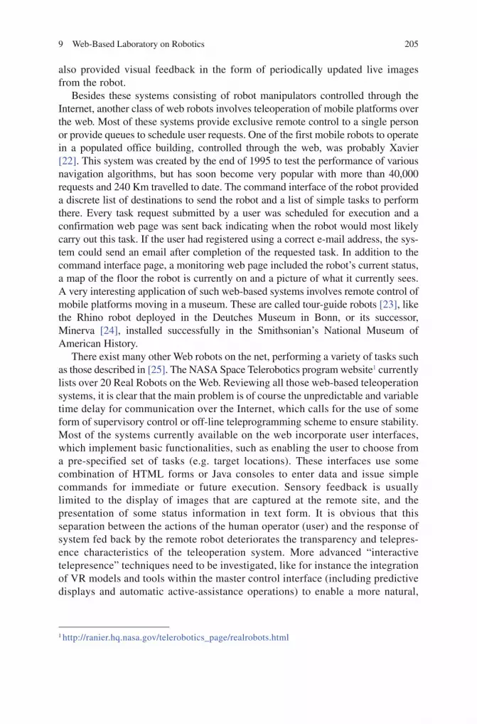
9 Web-Based Laboratory on Robotics 205
BookID 175907_ChapID 9_Proof# 1 - <Date>
also provided visual feedback in the form of periodically updated live images from the robot.
Besides these systems consisting of robot manipulators controlled through the Internet, another class of web robots involves teleoperation of mobile platforms over the web. Most of these systems provide exclusive remote control to a single person or provide queues to schedule user requests. One of the first mobile robots to operate in a populated office building, controlled through the web, was probably Xavier [22]. This system was created by the end of 1995 to test the performance of various navigation algorithms, but has soon become very popular with more than 40,000 requests and 240 Km travelled to date. The command interface of the robot provided a discrete list of destinations to send the robot and a list of simple tasks to perform there. Every task request submitted by a user was scheduled for execution and a confirmation web page was sent back indicating when the robot would most likely carry out this task. If the user had registered using a correct e-mail address, the sys-tem could send an email after completion of the requested task. In addition to the command interface page, a monitoring web page included the robot’s current status, a map of the floor the robot is currently on and a picture of what it currently sees. A very interesting application of such web-based systems involves remote control of mobile platforms moving in a museum. These are called tour-guide robots [23], like the Rhino robot deployed in the Deutches Museum in Bonn, or its successor, Minerva [24], installed successfully in the Smithsonian’s National Museum of American History.
There exist many other Web robots on the net, performing a variety of tasks such as those described in [25]. The NASA Space Telerobotics program website1 currently lists over 20 Real Robots on the Web. Reviewing all those web-based teleoperation systems, it is clear that the main problem is of course the unpredictable and variable time delay for communication over the Internet, which calls for the use of some form of supervisory control or off-line teleprogramming scheme to ensure stability. Most of the systems currently available on the web incorporate user interfaces, which implement basic functionalities, such as enabling the user to choose from a pre-specified set of tasks (e.g. target locations). These interfaces use some combination of HTML forms or Java consoles to enter data and issue simple commands for immediate or future execution. Sensory feedback is usually limited to the display of images that are captured at the remote site, and the presentation of some status information in text form. It is obvious that this separation between the actions of the human operator (user) and the response of system fed back by the remote robot deteriorates the transparency and telepres-ence characteristics of the teleoperation system. More advanced “interactive telepresence” techniques need to be investigated, like for instance the integration of VR models and tools within the master control interface (including predictive displays and automatic active-assistance operations) to enable a more natural,
1 http://ranier.hq.nasa.gov/telerobotics_page/realrobots.html

206 C.S. Tzafestas
BookID 175907_ChapID 9_Proof# 1 - <Date> BookID 175907_ChapID 9_Proof# 1 - <Date>
intuitive and direct, real-time interaction between the user and the web-based teleoperation system.
9.3.2 Technological and Educational Research Objectives
As described in the previous paragraph, robot teleoperation technologies have been constantly advancing and evolving for more than 2 decades now [14, 19]. Particularly with the advent of new communication and networking technologies and the development of novel human-machine interactive simulation media, particularly virtual reality systems [26], research in the field of telerobotics has shown considerable progress, with new concepts proposed and demonstrated with success, such as “predictive displays” [15], “shared-autonomy” teleoperation control [17], or the “hidden-robot” concept [16].
VR technologies, in particular, can be used in various ways to enhance robot teleoperation systems, as already stated in the previous paragraph. VR can be seen as constituting, in fact, a pool of advanced multimodal human/machine interaction technologies; such technologies can thus be employed at a “mediator” level between the human-operator and the remotely controlled robotic system. The per-formance of any telerobotic system can be measured in terms of two, often contra-dictory, indicators:
(a) Transparency, that is, the fidelity with which the human operator can perceive the remote robot environment, and the easiness by which he/she can perform the remote task via the telerobot and
(b) Stability, particularly in the presence of large time delays in the bilateral com-munication and control loop that can jeopardize smoothness of operation, especially when force-reflecting bilateral telemanipulation is involved
Substantial application scenarios of VR technologies are found in the field of education. If these technologies are combined with teleoperation concepts and tools, they can lead to the development of very efficient remote and virtual laboratory platforms, aiming to enable distance training in a number of engineering disciplines. In this context, our objectives from a technological perspective are oriented towards enhancing virtual and augmented reality based teleoperation techniques and integrating such modules in advanced multimodal human-machine interfaces, with a particular emphasis in e-laboratory environments. One such application is described in [13], presenting a platform that aims to enable student training in robot manipulation and control technologies from any remote location via Internet. The rest of this chapter describes the design and development of a recently enhanced version of this platform that integrates various user interaction modalities, including VR-based simulation and teleoperation/teleprogramming control panels.
Integrating such user interaction elements in a distance-training environment can enhance the realism and, potentially, the efficacy of the learning process.

9 Web-Based Laboratory on Robotics 207
BookID 175907_ChapID 9_Proof# 1 - <Date>
Evaluating these aspects comparatively for different interaction modalities and learning elements constitutes, from an educational perspective, a major research objective. The pilot study presented in detail in this chapter aims to evaluate such aspects in the specific case of the robotics e-laboratory platform. The work follows a systematic approach: (i) to identify the learning objectives, (ii) to design respective training scenarios, and (iii) to set up specific protocols to measure objectively the learning outcome and, consequently, the relative performance of the various mod-ules of the e-laboratory platform.
In particular, teaching robot manipulation principles, as is the case in the robotics laboratory paradigm considered in this work, involves the familiarization with a variety of mechanical and control engineering concepts and skills, such as task- versus joint-space control of serial kinematic chains, programming and executing motion sequences to perform a desired manipulation task, etc. The goal then is to evaluate to which extent a combination of remote and/or virtual laboratory sce-narios can be efficiently implemented in practice and used by students to obtain practical training as a supplement to theoretical courses. A literature review shows that the majority of the research results in this direction are restricted either in a qualitative type evaluation or in a “usability-oriented” approach. On the contrary, the objectives of the experimental part of the work presented in the following sec-tions of this chapter puts the emphasis on the didactical/educational aspect of the system, assessing the learning outcome in terms of the efficacy of the training provided to students. This assessment can be performed comparatively for differ-ent training modes, to shed light on the relative efficacy of various learning elements, such as virtual and/or remote control, interactive visualization modes, information feedback schemes, etc. Quantitative performance measures can be obtained through the use of specially designed scoring charts for each considered target training task.
The keyword here is training, which is often approached and modelled as a three-dimensional dynamic process, namely, that of building awareness, knowledge, and skills [27, 28]. In line with these models, the goal of the case study presented at the last part of this chapter, is to assess performance in these three dimensions, comparatively for two different e-laboratory modes: (a) a remote laboratory version, providing direct visual, teleoperation, and teleprogramming link with a real, remotely located, robot manipulator (but with a simplistic two-dimensional (2-D) graphical user interface), and (b) a virtual laboratory interface, incorporating realistic, virtual (3-D graphical) animations of the robot and programming tasks (but with no visual and teleop-eration link with a real remote robot). These e-laboratory modalities, which are described more in detail in Section 9.4, are assessed in comparison to a classical “hands-on” training and experimentation on the real robot (onsite laboratory training), forming a total of three student groups participating in the controlled experiments, as will be described in Section 9.5, where the com-parative experimental results obtained for these student groups will be pre-sented and analysed.

208 C.S. Tzafestas
BookID 175907_ChapID 9_Proof# 1 - <Date> BookID 175907_ChapID 9_Proof# 1 - <Date>
9.4 Design of a Virtual and Remote Robot Laboratory Platform
The first step in designing an efficient virtual laboratory platform is to specify the educational objectives that are addressed by the system and the training tasks that are to be implemented. A subsequent step could then be to integrate various learning elements and to explore the individual performance and the impact of different teaching/training modes. This section describes the design and development of an e-laboratory platform that supports both virtual and remote training scenarios in the field of robotics. The emphasis in the design of such a system should be on creating training scenarios that enable students to acquire skills and assimilate concepts, in ways that resemble as closely as possible real hands-on experimenta-tion with a real robot. The work presented in the sequel focuses particularly on teaching robot manipulator programming skills, using some of the functionalities and programming modalities provided by a real robotic system. In the considered training scenarios, students are offered the opportunity to learn how to program a real robotic system without having one at the proximity, but in a way that realisti-cally emulates how actual robot programming operations and procedures are performed in real practice. This process is more clearly explained in the follow-ing paragraphs.
9.4.1 E-Training Scenarios in Robot Manipulator Programming
A few attempts are reported in the literature, aiming to develop virtual and remote (Web-based) laboratory systems in the particular field of robotics education. Most of these research efforts cover the field of mobile robotics (mobile robot telelaboratories, e.g. [29]) as a means to enhance the teaching of basic sensing and intelligent control principles, and very few address problems in the field of robotic manipulation. One of these is described in [30], presenting a platform that includes, among other virtual (simulated) experiments, the control of a simple 2-dof robotic arm. This research was based on a Java applet performing kinematic simulation of the robot arm motion (with 2D only graphical animation). Simple motion commands can be issued at the joint space and can be used to convey basic principles of robot motion characteristics. The system illustrates basic Web-based virtual laboratory concepts, but only in simulation (with no remote real robot in the loop). On the contrary, [31] presents a Java-based interface that sup-ports the functionality both to simulate and to teleoperate a robot manipulator. This system can be used to practice movement commands of a simulated and/or remote robot manipulator and can, supposedly, convey in a more efficient way the same basic concepts of robot motion control. A more recent effort is described in [32], where a more elaborate multimedia interface is presented, to remotely con-trol a robot arm over the Web.
From a literature survey of this field, it can thus be deduced that the spectrum of functionalities provided by existing virtual and/or remote robotic laboratory platforms

9 Web-Based Laboratory on Robotics 209
BookID 175907_ChapID 9_Proof# 1 - <Date>
covers basically the following: (1) simulating and animating (in 2D or 3D) the motion of simple robot arms; (2) practicing movement commands, which are usu-ally issued either as desired end-effector’s Cartesian position in x-y coordinates, or directly as reference angular displacements in the joint space; and eventually (3) submitting these commands for execution by a remotely located real robot. Such functionalities can indeed demonstrate and teach students the basic principles of robot manipulation and control. However, programming a real robot arm to perform an industrial manipulation task (e.g., a pick-and-place task in an assembly sequence) is usually more complicated. The human operator is often obliged to program the task directly using the robot’s own programming language (usually some script-like interpreter language, such as VAL, V+, etc.); more often, however, an on-line robot programming scheme is employed, for instance, using the robot’s Teach Pendant tool to teach (record) the intermediate configurations that will constitute the com-plete robot motion sequence.
Taking into account all these considerations, and keeping in mind the main research objectives, as already highlighted in previous paragraphs, an important educational objective in the frames of a robotics laboratory module would be to emphasize on learning concepts and practicing skills related to robot manipulator programming. The work presented hereafter is directed towards the design and development of a platform that can remotely train students how to program a robot manipulator arm, but in realistic scenarios, that is, by using tools and applying techniques in ways that resemble as closely as possible the operations and proce-dures involved in the programming of a real robot. In other words, the developed platform should be designed in such a way that the training scenarios practiced by the students emulate how a complete robot manipulation program is actually cre-ated and issued in a real-world task scenario.
In this context, the work focuses particularly on two specific training scenarios considered for the first pilot application:
1. The first scenario is focused on the task of programming a robot manipulation pick-and-place operation using the functionality of the Manual Teach Pendant on-line programming tool of the robot.
2. For the second scenario we consider direct programming of robotic manipula-tion tasks through direct editing of scripts using the programming language of the robot (in our case, the robot manipulator arm available for the laboratory course supports the well-known V+ robot operating system).
To implement the above training scenarios, a graphical and functional emulator of the robot’s Teach Pendant was integrated in the virtual robot laboratory graphical user interface. The system is designed to enable students to create, edit and execute robot programs (i.e. complete motion sequences, such as a pick-and-place task) in exactly the same way as if they were using the real-robot’s pendant tool. The pro-grams can be viewed and edited by the student in simulation (with 2D and/or 3D animation features), and can also be sent for execution by a real robot manipulator (located in the premises of our robotics and automation laboratory). For the second training scenario, an “e-console” module was additionally integrated in the user

210 C.S. Tzafestas
BookID 175907_ChapID 9_Proof# 1 - <Date> BookID 175907_ChapID 9_Proof# 1 - <Date>
interface, providing local compilation of V+ robot programming scripts. This ena-bles students to learn how to directly edit a robot program in its own operating system, and control robot manipulation tasks in this direct coding way. The follow-ing paragraph presents the overall architecture of the e-laboratory platform and describes the graphical user interface design as well as the specific user interaction and learning components developed to support these training modes.
9.4.2 Platform architecture and Web-Based Graphical User Interface
The virtual robotic laboratory platform is developed based on Java technologies. The graphical user interface (GUI), in its more recent version, integrates the follow-ing panels (see Fig. 9.2):
1. 2D graphical representation (top-view and side view) panels, visualizing both actual (remote feedback or simulated) and commanded (by the human operator) kinematic configurations of the robot manipulator
2. A virtual robot panel implemented using Java3D, providing 3-D visualization of both the commanded (preview animation) and the current robot configuration
3. A real-time video streaming panel, which is based on RTP and implemented using JMF, showing (when on-line) the real remote manipulator in motion
2D GraphicalRepresentation Panels
Real Robot VideoStreaming Panel
Robot waypoints actual
(remote) robot position
control modes
Control / CommandEditing Panel
commandedrobot position
Status Panel
Feedback Panel
Virtual Robot Panelcommandedrobot position
actual (remote) robot position
control modes
Fig. 9.2 Graphical User Interface of the virtual and remote robotic laboratory

9 Web-Based Laboratory on Robotics 211
BookID 175907_ChapID 9_Proof# 1 - <Date>
4. A control/command editing panel, where the user (student) can view the real values of the robot’s joint angular displacements, select control modes (described more in detail in the sequel) and edit commanded robot motion waypoints
5. Status and feedback panels providing real-time textual information on the cur-rent robot state
6. Additionally, the GUI integrates: (a) an interactive panel providing an exact emulation of the robot’s Teach Pendant, called Virtual Pendant, and (b) an e-console for direct editing and compiling of robot manipulator programs, using the V+ operating system (these modes of operation are described more in detail in the following paragraphs)
The remote laboratory platform is based on a client-server architecture, providing the human operator with support of the following three telerobotic control modes: (i) direct teleoperation control, (ii) indirect control, for robot teleprogramming via the command/editing panel, and (iii) manual control, that is, robot manipulator programming using the Virtual Pendant functionalities. These control modes are inspired from the telerobotics field, and particularly from work proposing various “shared-autonomy” and “supervisory” remote control approaches. In direct teleop-eration, every command issued by the user locally (i.e. within the GUI master control site), is immediately transferred for execution to the remote (slave) robot. At the same time two types of feedback displays are active: (a) a predictive display (both in the 2D and 3D graphical panel) immediately visualizing the commanded robot motion according to the human operator issued commands, and (b) a real robot feedback display (also both in 2D and 3D animation), showing where the robot actually is (that is, visualizing the current remote robot configuration, in real-time through continuous data feedback from the remote site).
As opposed to direct teleoperation, in the indirect “teleprogramming” control mode, the commands are generated off-line, queued in a list and submitted to the robot in a subsequent time frame, when the human operator decides to do so. The idea is offering the possibility to create a complete robot program off-line, test its validity and optimality, before actually sending the command sequences for execu-tion by the real robot. Based on the functionality of this indirect teleprogramming mode (robot command editing routines, waypoints list creation etc.), we have developed a third “manual-control” mode, which implements exactly the Virtual Pendant robot-programming scheme. According to our distance training goals out-lined in the previous paragraph, the Virtual Pendant panel supports all the main functions of the real robot’s pendant tool, and enables the student to learn and prac-tice robot-programming routines locally. The user can create a robot program, add, edit or delete intermediate robot positions, as happens with the real robot’s pro-gramming interface, and subsequently either “preview” the robot program visually on the 2D graphical representation panels of the interface, where an animation of the predicted robot motion is displayed, or “send” the program for remote execution on the real robot, and see the results of the actual manipulator motion on the video streaming panel (as well as on the 2D graphical panels that provide continuous position feedback to the user).

212 C.S. Tzafestas
BookID 175907_ChapID 9_Proof# 1 - <Date> BookID 175907_ChapID 9_Proof# 1 - <Date>
The graphical user interface can run as an applet in any standard web browser, enabling users to connect via Internet (or LAN). Figure 9.3 shows the overall archi-tecture of the remote robotic laboratory platform. The system supports multiple connected users (terminal TE-1 to TE-n), through the implementation of a specific protocol using TCP/IP sockets for communication and real-time data exchange with the “robot server”. Each client (student) can connect to the robot server either as an “observer”, or as an “administrator”, in which case (after entering the correct password) actual control of the real robot is obtained. Robot observers have access (through continuous data-feedback) to the current status and motion of the remote robot, while local (simulated) robot programming can also be performed. The robot administrator (only one logged-on at a time) has additional rights to send motion commands or complete motion sequences (robot program) to the remote robot manipulator for real execution. The robot server communicates with the Adept robot controller via an RS232 serial link, using an application specific protocol for real-time data exchange. In addition to the above, a separate “video server” accepts calls from any remote location, establishing a direct video link that is based on RTP for real-time video streaming. The robot used in the experiments is a SCARA-type AdeptOne-MV manipulator, equipped with a pneumatic parallel-jaw gripper.
9.4.3 Robot Programming Modes: Virtual Pendant and e-Console
Based on the robot control modes described above, the platform supports two basic training scenarios, where the user edits, validates and executes a robot manipulation
TE-1
AdeptOne Robot Adept MV-8 Controller
Video Camera
… INT
ER
NE
T
TE-2
TE-n
…
RobotServer
RS
-232
Ser
ial P
ort
TC
P/IP
Soc
kets
RT
P
Str
eam
ing
Fra
me
Gra
bberVideo
Server
RS
-232
Fig. 9.3 Remote laboratory platform: overall architecture

9 Web-Based Laboratory on Robotics 213
BookID 175907_ChapID 9_Proof# 1 - <Date>
program using: (a) the functionality of the manual Tech Pendant of the robot, and (b) direct V+ scripting through an e-console panel. The implementation of these programming modes within the robot laboratory platform is described in the sequel.
9.4.3.1 The Virtual Pendant Emulator
The GUI of the virtual and remote laboratory platform, described in this chapter, integrates a control panel emulating the operation of the robot’s manual teach pen-dant tool, called virtual pendant panel. The implementation of the virtual pendant panel is based on a real high-resolution image of the real robot’s teach pendant tool (Fig. 9.4). This choice is made, in order to enhance the realism of the user interface and, potentially, achieve better learning outcomes.
This interactive control panel comprises active (“clickable”/“hot”) areas (virtual buttons) and simulated LED indicators, to provide an exact emulation of all the main buttons and functions of the robot’s manual pendant. The system enables students to learn and practice robot-programming routines, that is, to create and
emulatedmessagepanel
emulatedLEDindicators
currentactivebuttons
Fig. 9.4 An instance of the virtual pendant implementation

214 C.S. Tzafestas
BookID 175907_ChapID 9_Proof# 1 - <Date> BookID 175907_ChapID 9_Proof# 1 - <Date>
execute robot programs (complete motion sequences, such as a pick-and-place task) in exactly the same way as if they were using the real-robot’s manual pendant tool. The user can add, edit, or delete intermediate robot positions, as happens with the real robot’s programming interface. He/she can then either “preview” (in simu-lation) the robot program visually on the 2-D graphical representation panels of the interface, where an animation of the predicted robot motion is displayed, or “send” the program for remote execution on a real robot to see the results of the actual manipulator motion on the video streaming panel (and on the 2-D graphical panels that provide continuous position feedback to the user).
9.4.3.2 E-console: V+ Robot Programming User Interface
The implementation of the e-console application is also based on Java technologies and integrates the following Java GUI components (see Fig. 9.5):
• Aninputtextfieldforthemonitor commands provided by the user• Anoutputtextfielddisplayingthehistory of the last issued V+ command• Astatus bar indicating the current operating status of the application• Anoutputtextfieldreportingthecurrent joints’ angles or end-effector coordi-
nates including gripper state• Themain input text field,whichemulates theembedded editor of the V+ real
time operating system (V+ command editor)• TheCompile and the Submit button and• TheGet Joint Attributes button, which polls through the graphical representa-
tion of the robot, the current joints angles or end-effector coordinates
The graphical user interface emulates the V+ computer-based control system and programming language, designed specifically for the Adept Technology Industrial robots. At the current stage of the e-console platform development, a set of monitor and robot motion commands have been implemented. As in the real V+ control
Fig. 9.5 The e-console implementation emulating the V+ robot programming environment
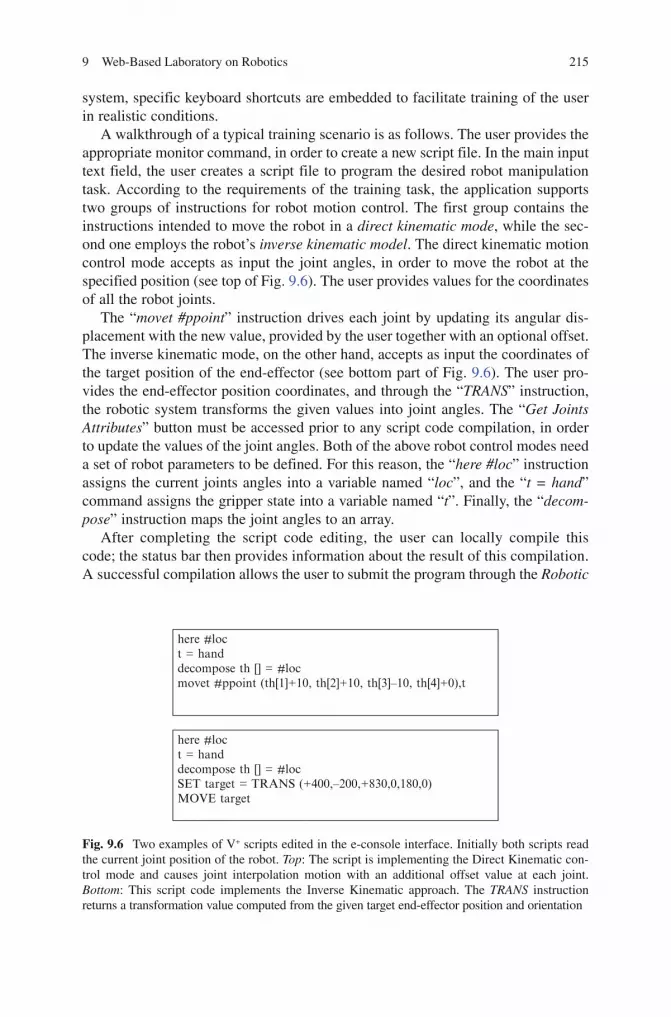
9 Web-Based Laboratory on Robotics 215
BookID 175907_ChapID 9_Proof# 1 - <Date>
system, specific keyboard shortcuts are embedded to facilitate training of the user in realistic conditions.
A walkthrough of a typical training scenario is as follows. The user provides the appropriate monitor command, in order to create a new script file. In the main input text field, the user creates a script file to program the desired robot manipulation task. According to the requirements of the training task, the application supports two groups of instructions for robot motion control. The first group contains the instructions intended to move the robot in a direct kinematic mode, while the sec-ond one employs the robot’s inverse kinematic model. The direct kinematic motion control mode accepts as input the joint angles, in order to move the robot at the specified position (see top of Fig. 9.6). The user provides values for the coordinates of all the robot joints.
The “movet #ppoint” instruction drives each joint by updating its angular dis-placement with the new value, provided by the user together with an optional offset. The inverse kinematic mode, on the other hand, accepts as input the coordinates of the target position of the end-effector (see bottom part of Fig. 9.6). The user pro-vides the end-effector position coordinates, and through the “TRANS” instruction, the robotic system transforms the given values into joint angles. The “Get Joints Attributes” button must be accessed prior to any script code compilation, in order to update the values of the joint angles. Both of the above robot control modes need a set of robot parameters to be defined. For this reason, the “here #loc” instruction assigns the current joints angles into a variable named “loc”, and the “t = hand” command assigns the gripper state into a variable named “t”. Finally, the “decom-pose” instruction maps the joint angles to an array.
After completing the script code editing, the user can locally compile this code; the status bar then provides information about the result of this compilation. A successful compilation allows the user to submit the program through the Robotic
here #loct = handdecompose th [] = #locmovet #ppoint (th[1]+10, th[2]+10, th[3]–10, th[4]+0),t
here #loct = handdecompose th [] = #locSET target = TRANS (+400,–200,+830,0,180,0)MOVE target
Fig. 9.6 Two examples of V+ scripts edited in the e-console interface. Initially both scripts read the current joint position of the robot. Top: The script is implementing the Direct Kinematic con-trol mode and causes joint interpolation motion with an additional offset value at each joint. Bottom: This script code implements the Inverse Kinematic approach. The TRANS instruction returns a transformation value computed from the given target end-effector position and orientation

216 C.S. Tzafestas
BookID 175907_ChapID 9_Proof# 1 - <Date> BookID 175907_ChapID 9_Proof# 1 - <Date>
e-Laboratory Platform for virtual preview (2D/3D graphics representation), in case a simulation mode is selected, or to the real robot for actual execution, in case of actual teleoperation with a real robot in the loop. Multiple “move” commands are supported at the current version, in order for the student to accomplish a simple robotic manipulation task, such as a pick & place task. It is important to point out here that this e-console robot script editing mode is integrated within the indirect robot control mode of the Robotic e-Laboratory Platform, thus providing additional support for off-line editing of the intermediate control points, before the sequence of “move” instructions is actually submitted to the robot. The student is thus able to access dynamically the joints and the end-effector coordinates during the program-ming process, by means of the virtual pendant or through graphical interaction, which provides augmented capabilities than real programming on the robot site.
9.5 Pilot Study: Research Methodology and Results
A pilot study was conducted to assess the performance of the e-laboratory platform. This study was focused particularly on evaluating the relative impact of different training modes on the learning outcome, namely virtual versus remote training modes, in comparison with traditional hands-on experimentation. This section describes the methodology employed, including the experimental protocol used to conduct the study, and presents the research results obtained. Further analysis of these results leads to interesting remarks and conclusions, which are discussed towards the end of this section.
9.5.1 Experimental Protocol
The students participating in this laboratory class were all in the fourth year of their Electrical and Computer Engineering degree, following an introductory course on robotic manipulation analysis and control. The students were randomly divided into three groups: (I) Group-I (real) was trained the “traditional way” on the real robot, (II) experimental Group-II (remote) was trained on a reduced version of the remote laboratory platform, with remote connection to the real robot but without the virtual 3D animation panel, and (III) experimental Group-III (virtual) was trained on the virtual robot laboratory (but with no visual and teleoperation link with a real remote robot). Each group comprised six teams of three to five students each (total number of teams 18). Each team of students was trained separately in different laboratory time slots (approximately 1 h 30 min per each). The total number of the sample of this pilot study was 60 (N) students.
All three groups of students had the same training phases and were exposed to exactly the same educational material during each experimental session. The only difference among groups was the training mode used to practice the robot programming

9 Web-Based Laboratory on Robotics 217
BookID 175907_ChapID 9_Proof# 1 - <Date>
procedures learned: (I) directly on the real robotic system (group-I real, i.e. with physical presence on the real-robot site), (II) using the remote laboratory platform (group-II remote, i.e., telepresence), or (III) using the virtual robot interface (group-III, virtual presence).
Each training session lasted approximately one hour and a half, with the tutor (always physically present) explaining all key issues to the students. Tutorial and educational support material was provided to the students describing: (1) the robot used in the experiment (its mechanical and kinematic characteristics, and its control and programming features) and (2) the exact procedure and steps needed to pro-gram a robot manipulation task using the manual pendant. By the end of each ses-sion, students of all three groups completed their training by performing a specific evaluation test on the real robot (final assessment test). During this final test, a robot-programming task was assigned to the students (a pick-and-place operation using the robot’s teach pendant). This final assessment test was performed on the real robot for all the three student groups (meaning that group-II and group-III students had to move from a remote location, in a separate building, to the real robot laboratory site to perform the final tests). The test was subdivided into distinct time phases to facilitate tracking the performance of the students and identifying errors committed and difficulties encountered.
To help the trainer (examiner) assess students’ performance during the final test, a specially designed scoring chart was used. It was organized into a sequence of: (1) rows, tracking the distinct time-phases, sub-tasks, and manual operations involved in the final assessment task and (2) columns, corresponding to the differ-ent categories of skills (respectively, errors) monitored by the trainer during the test. In line with the educational research objectives of this work, the errors committed by the trainees were classified according to three main categories: low-level technical skills, mid-level skills, and higher-level understanding. The method used to grade students’ performance consistently was to assign a pre-determined “penalty mark” for each specific error committed. Errors could, for instance, range from simply pressing the wrong button (or forgetting which button performs a specific function and referring to the manual, in which case a penalty mark of two points was added to the “low-level” category score) to higher-level mistakes or misconceptions, expressed by an incapacity to create and implement a correct plan or sequence of actions for programming a robot subtask (five points added to the “higher-level” category; in case tutor intervention was asked, an extra five points were added to the score in the respective category). Moreover, teamwork and collaboration between students was qualitatively monitored, while total time needed to complete each phase of the test was also recorded.
All these scoring items (indicating the frequency of the different types of mis-takes) were coded in real-time on the scoring chart by the tutor monitoring the experiment, and were subsequently decoded to compute the final values for the dif-ferent scores. For each final assessment test, a total score was computed giving a global measure of performance for the respective team of students, while individual categories scores give an idea of the type of difficulties encountered by the students, with respect to the three main dimensions used to model the dynamic process

218 C.S. Tzafestas
BookID 175907_ChapID 9_Proof# 1 - <Date> BookID 175907_ChapID 9_Proof# 1 - <Date>
of training (often referred to as the triad of training). In the following paragraph, the results of this pilot study are presented and analysed.
9.5.2 Experimental Results
As mentioned in the previous paragraph, in this pilot study the learning outcome was evaluated by assessing the performance of the students in the final test on the real robot. The tutor (examiner) noted down on the scoring chart the errors committed by the students, according to the procedure and the marking categories defined above. This categorization constitutes a first qualitative approach to this experiment. Based on the scoring chart and the associated “penalty marks”, a quantitative analysis followed by means of specific statistical techniques; for this reason, SPSS® 12.0 was used to obtain statistical analysis results.
More specifically, a t-test of independent groups was followed to find out whether statistically significant differences exist among the Means of the various test scores: (1) low, (2) mid/high (accumulated together), (3) time, and (4) total score, for the three student groups (I, II, and III). Group is the independent variable, and score values are the dependent variables. The criterion that was set for the statistical significance was p < 0.05. In the following tables, the scores correspond to penalty marks, meaning that higher score values indicate worse performance of the student; scores correspond to absolute penalty marks since transforming the penalty scores into relevant percentiles was not considered necessary.
Table 9.1 shows means and standard deviations of the final assessment test scores for group-I (real), group-II (remote) and group-III (virtual). The mean values and standard deviations of these scores for all three groups are also illustrated as a bar graph in Fig. 9.7. A review of means shows that some apparent differences exist among groups for the different score categories. In the “low” category, representing errors committed related to low-level technical skills, group I (real) students made very few mistakes compared to students of group II (remote).
By explanation, students forming the “real” group were trained the traditional way on-site, in physical contact with the real robot manipulator system, as opposed to group-II students who were trained remotely using an initial and reduced (no 3D panel)
Table 9.1 Means and standard deviations of the final assess-ment test scores for the three groups
Low Mid/high Time Total
Group-I Mean 2.42 4.42 12.28 19.14Group-I STD 1.39 2.14 2.49 4.37
Group-II Mean 4.60 4.80 15.60 25.0Group-II STD 2.88 3.03 3.78 9.43
Group-III Mean 2.16 2.83 13.83 18.83Group-III STD 1.60 2.04 3.71 6.11
I: Real, II: Remote, and III: Virtual.
t, .1
t, .2
t, .3t, .4
t, .5t, .6
t, .7t, .8
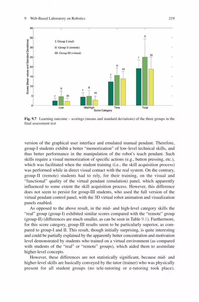
9 Web-Based Laboratory on Robotics 219
BookID 175907_ChapID 9_Proof# 1 - <Date>
version of the graphical user interface and emulated manual pendant. Therefore, group-I students exhibit a better “memorization” of low-level technical skills, and thus better performance in the manipulation of the robot’s teach pendant. Such skills require a visual memorization of specific actions (e.g., button pressing, etc.), which was facilitated when the student training (i.e., the skill acquisition process) was performed while in direct visual contact with the real system. On the contrary, group-II (remote) students had to rely, for their training, on the visual and “functional” quality of the virtual pendant (emulation) panel, which apparently influenced to some extent the skill acquisition process. However, this difference does not seem to persist for group-III students, who used the full version of the virtual pendant control panel, with the 3D virtual robot animation and visualization panels enabled.
As opposed to the above result, in the mid- and high-level category skills the “real” group (group-I) exhibited similar scores compared with the “remote” group (group-II) (differences are much smaller, as can be seen in Table 9.1). Furthermore, for this score category, group-III results seem to be particularly superior, as com-pared to group-I and II. This result, though initially surprising, is quite interesting and could be partially explained by the apparently better concentration and motivation level demonstrated by students who trained on a virtual environment (as compared with students of the “real” or “remote” groups), which aided them to assimilate higher-level concepts.
However, these differences are not statistically significant, because mid- and higher-level skills are basically conveyed by the tutor (trainer) who was physically present for all student groups (no tele-tutoring or e-tutoring took place).
Fig. 9.7 Learning outcome – scorings (means and standard deviations) of the three groups in the final assessment test

220 C.S. Tzafestas
BookID 175907_ChapID 9_Proof# 1 - <Date> BookID 175907_ChapID 9_Proof# 1 - <Date>
Indeed, according to the T-test results shown in Table 9.2, no statistical signifi-cance was found between the three groups for the “low”, “mid/high”, and “total” scores of the final assessment test. This means, in fact, that the performance of all three student-groups is comparable in terms of the scores obtained in the final assessment test. In other words, all student teams from the three groups performed equally well in statistical terms, with no statistically significant deviations observed that can be attributed to the different training modality for each group. This result leads to the conclusion that an e-laboratory platform, comprising vari-ous remote and virtual control modules and learning elements, such as the ones developed and implemented in this pilot study, can be integrated effectively in the practical training of students.
9.5.3 Analysis of Experimental Results – Discussion
Analysing more in detail the results presented in the previous paragraph, and the differences observed among groups, one could add some comments to the general conclusion drawn above.
1. The differences among the “low” score values for the three groups, particularly the observed performance degradation for the “remote” student group (group-II), although not statistically significant (p = 0.055, comparatively for groups II vs. I and II vs. III) provides an idea about the training “dimension” that is mostly affected by the lack of physical presence and direct contact with the real experi-mental system, particularly observing that this performance degradation does not persist for the “mid/high” score values.
2. The score value that seems to be affected the most is time: group-I (real) exhibits the best performance (mean value 12.28 (minutes)), while both group II (remote) and III (virtual) show degradation in performance (mean values 15.60 and 13.83, respectively); however, only the difference between groups I and II is statistically significant (p = 0.048).
3. Regarding the overall performance as reflected in the total score, groups I and III have practically identical results, while group-II shows again a performance degradation, which is still not statistically significant (p = 0.088).
An interesting conclusion can thus be drawn in relation to the comparative assess-ment between groups II and III, that is, remote/telepresence vs. virtual presence,
Table 9.2 T-test results (p values), comparing final assessment scores for the three groups (statistical significance, p < 0.05)
Low Mid/high Time Total
Group I vs. Group II 0.055 0.404 0.048 0.088Group I vs. Group III 0.38 0.099 0.195 0.46Groups II vs. Group III 0.055 0.116 0.228 0.111
9 Web-Based Laboratory on Robotics 221
BookID 175907_ChapID 9_Proof# 1 - <Date>
with an apparent benefit towards the latter, in terms of training performance. In other words, it seems that a realistic virtual environment, even with a complete absence of real (visual etc.) feedback, can provide adequate learning elements, particularly as related to mid- and high- level skills, compensating for the lack of direct physical presence on the real experimental site. This provision seems to be valid for the specific experimental scenario investigated in this pilot study (labora-tory training course on robotic manipulation). However, a large-scale study is still needed to investigate these issues more profoundly.
Indeed, if more elaborated statistical analysis techniques are followed, such as one-way ANOVA or multiple comparisons tests (such as the Bonferroni test) no statistical significance is found among groups in all score categories (including also “low” score and total time values). Nevertheless, certain tendencies are clearly identified, as discussed above, indicating that larger-sample studies are needed before more general conclusions can be drawn with certainty (though it seems that these findings do constitute useful indications about the relative performance of the considered training modalities). Such a larger-scale study remains in the future-work plans and can constitute the basis of a more theoretical evaluation to highlight the pedagogical differences between distinct real, virtual and remote learning meth-ods and experiences.
9.6 Conclusion – Future Research Directions
This chapter presented ongoing research work on telelaboratory systems, espe-cially in engineering (control and robotics) disciplines. In particular, the design and experimental evaluation of a virtual and remote robot laboratory platform is described, aiming to teach students how to program a robot manipulator in realistic task scenarios. The experimental platform presented is web-enabled, implemented based on Java technologies. The graphical user interface incorporates, among other features, a “Virtual Pendant” panel providing an exact emulation of the real robot’s Teach Pendant functions, and an “e-console” panel, for direct scripting of robot programs using the command set of the real robot’s programming language (in this case, the V+ robot operating system). The learning aim is to offer students the possibility to learn how to program a real robot without having one at proximity, in scenarios that closely resemble the real robot programming operations and procedures.
The chapter starts with a brief literature survey, describing the current state-of-the-art in the general field of remote and virtual laboratory platforms, identifying some important priorities related to the design and evaluation of such systems. The research motivations and objectives (both technological and educational) are then outlined, defining the context of the work presented in this chapter. From a techno-logical perspective, the general scope of this research work can be described as an effort: (i) to explore ways to achieve an efficient synergy between advanced human-machine interaction technologies (particularly based on virtual reality methods
222 C.S. Tzafestas
BookID 175907_ChapID 9_Proof# 1 - <Date> BookID 175907_ChapID 9_Proof# 1 - <Date>
and, in this case study non-immersive, tools) with concepts and techniques devel-oped in the evolving field of intelligent telerobotics; (ii) to adapt and implement efficiently such multimedia technologies in engineering education scenarios, like the considered e-laboratory applications. From a pedagogical perspective, the goal is to assess the performance of such e-laboratory systems, in terms of the “quality” of training provided to students. This evaluation has to be performed comparatively for various training modalities, in order to shed light on the pedagogical relations between different learning experiences, and on the relative importance of various “learning elements” integrated in the system.
A pilot study was conducted to evaluate experimentally the performance of the developed telelaboratory system, in terms of remotely training students to program robot manipulation tasks. Three student groups participated in the experiments: (i) group-I (real) trained the traditional way on the real robot; (ii) group-II (remote) trained using the remote laboratory platform, providing direct visual, teleoperation, and teleprogramming link with a real, remotely located, robot manipulator (but with a simplistic 2D graphical user interface); and (iii) group-III (virtual) trained on the virtual robotic laboratory interface, incorporat-ing realistic, virtual (3D graphical) animations of the robot and programming tasks (but with no visual and teleoperation link to a real remote robot). In the evaluation approach that was followed, emphasis was put on the didactical aspects of the system, based on a specially designed experimental protocol that combines both qualitative and quantitative metrics. The goal was to assess the effectiveness of these new media compared with traditional hands-on laboratory training scenarios. Training was approached according to a typical three-dimensional model (i.e., building awareness, knowledge, and skills), and performance scores are accordingly assessed in these dimensions (namely, low-level skills vs. mid- and high-level skills and understanding).
Performing a statistical analysis of the obtained experimental results reveals that all student groups performed equally well (in statistical terms), with no statistically significant deviations observed that could be attributed to the different training modality of each group. Nevertheless, a closer look on the experimental results reveals some apparent differences, particularly for the “low” score (i.e., low-level skill acquisition). More specifically, a performance degradation is observed for the “remote” student group (group-II), which, though not statisti-cally significant, gives some clear insightful indication about the training “dimension” that seems to be mostly affected by the lack of physical presence (or realistic virtual presence). This finding is strengthened by this observed per-formance in which the degradation tendency does not persist for the “mid/high” score values.
An interesting conclusion can also be drawn in relation to the comparative assessment between groups II (remote) and III (virtual), with the obtained results being particularly (and probably surprisingly) in favour of the “virtual” group. In other words, one finds that a realistic virtual environment, even with a complete absence of real (visual etc.) feedback from the considered experimental system, can

9 Web-Based Laboratory on Robotics 223
BookID 175907_ChapID 9_Proof# 1 - <Date>
provide adequate learning elements, particularly as related to mid- and high-level skills, compensating for the lack of direct physical presence on the real experimental site. This finding seems to be valid for the specific experimental scenario that is investigated in this pilot study; however, a large-scale study is still needed to investigate these issues more profoundly.
A general conclusion can, thus, be summarized in the following statement: the presented robot e-laboratory platform created a virtual training environment that provided adequate learning elements, as related particularly to mid- and high-level skill transfer, compensating for the lack of direct physical presence on the real robot site. Despite the fact that we certainly do not assert that these initial results lead to a general conclusion about what one should definitely expect in a completely different didactical context (as this would require a larger-scale sample and experi-mental procedure, which remains one of the key future work priorities), we do believe however that these results are helpful and insightful, indicating that such remote laboratory platforms can indeed be implemented quite efficiently and effec-tively. It should be noted at this point that there is also need for a more comprehen-sive evaluation between real, virtual and remote laboratory teaching, to contribute towards a more profound understanding of the theoretical pedagogical basis for different laboratory experiences and training modes.
Having explored, to some extent, important factors related to the efficacy of such virtual and remote laboratory systems, another key issue to be emphasized in the future concerns their long-term deployment and the associated benefits that can result from such implementations. We refer more specifically to the concept of “lab facilities sharing” between academic and educational institutions (and not so much to other “flexible education” models). Our aim is to explore ways for a more efficient exploitation of existing laboratory infrastructure to the practical training of students through the implementation of remote laboratory platforms. The benefits from providing the means to obtain remote access to experimental infrastructure existing in various distant laboratory facilities can become signifi-cant both from a socio-economic point of view, as well as from an educational perspective. This is directly related to the quality and the equity of practical train-ing possibilities offered to all students. In this context, a more thorough experi-mental evaluation study has to be conducted in the future, regarding the feasibility of these goals and the acceptability of such new technologies by students in their education and training practice.
Acknowledgments The work was partially supported by the Greek General Secretariat for Research and Technology, and the European Commission in an international Greek-German bilat-eral cooperation research framework. The author would like to thank Dr. S.C.A. Thomopoulos (Research Director, Institute of Informatics and Telecommunications, NCSR “Demokritos”) and Mrs. Athanassia-Elena Exarchou (IS Integrated Product Information K-DOE-5, VW Group, Wolfsburg) for the cooperation. A. Kroys and R. Kunicke, graduate students at the Faculty of Computer Science of the Otto-von-Guericke University, Magdeburg, had helped in developing the first version of the graphical user interface. Special thanks go to Mr. M. Alifragis and A. Mantelos, Ph.D. students at the School of ECE/NTUA, for their valuable help in conducting the experiments of the pilot study, and for their continuing research work in the field.

224 C.S. Tzafestas
BookID 175907_ChapID 9_Proof# 1 - <Date> BookID 175907_ChapID 9_Proof# 1 - <Date>
References
1. B. A. Foss, K. E. Malvig, and T. I. Eikaas, Remote Experimentation - New Content in Distance Learning, in Proceedings of International Conference in Engineering Education (ICEE’ 2001), Oslo, Norway, August 6-10, 2001.
2. D. Gillet and G. Fakas, eMersion: A New Paradigm for Web-Based Training in Mechanical Engineering Education, in Proceedings of International Conference on Engineering Education (ICEE’ 2001), Oslo, Norway, August 6-10, 2001. [online web server of “eMersion” Project available at: http://emersion.epfl.ch/]
3. D. Gillet, Towards Flexible Learning in Engineering Education, in Innovations-2003: World Innovations in Engineering Education and Research, W. Aung et al. (Eds.), International Network for Engineering Education and Research (iNEER), New York: Begell House Publishers, pp. 95–102, July 2003.
4. T. A. Fjeldly, J. O. Strandman, and R. Berntzen, LAB-on-WEB: A Comprehensive Electronic Device Laboratory on a Chip Accessible via Internet, in Proceedings of International Conference on Engineering Education (ICEE’ 2002), Manchester, UK, August 2002.
5. J. B. Dabney, F. H. Ghorbel, and J. McCune, Web-Based Control of the Rice SPENDULAP, International Journal of Engineering Education, Special Issue on Distance Controlled Laboratories and Learning Systems, vol. 19, no. 3, pp. 478–486, 2003.
6. J. Sanchez, S. Dormido, R. Pastor, and F. Morilla, A Java/Matlab-Based Environment for Remote Control System Laboratories: Illustrated with an Inverted Pendulum, IEEE Transactions on Education, vol. 47, no. 3, pp. 321–329, 2004.
7. J. Henry and C. Knight, Modern Engineering Laboratories at a Distance, International Journal of Engineering Education, Special Issue on Distance Controlled Laboratories and Learning Systems, vol. 19, no. 3, pp. 403–408, 2003.
8. A. Böhne, N. Faltin, and B. Wagner, Self-Directed Learning and Tutorial Assistance in a Remote Laboratory, in Proceedings of the Interactive Computer Aided Learning Conference (ICL’ 2002), Villach, Austria, September 25-27, 2002.
9. M. Saad, H. Saliah-Hassane, H. Hassan, Z. El-Guetioui and M. Cheriet, A Synchronous Remote Accessing Control Laboratory on the Internet, in Engineering Education and Research-2001: A Chronicle of Worldwide Innovations, W. Aung et al. (Eds.), 2002 iNEER Special Volume, New York: Begell House Publishers, 2002.
10. L. Hesselink, D. Rizal, E. Bjornson, S. Paik, R. Batra, P. B. Catrysse, D. Savage, and A. Wong, Stanford CyberLab: Internet Assisted Laboratories, International Journal of Distance Education Technologies, vol. 1, no. 1, pp. 21–39, 2003. [online research group web page available at: http://kaos.stanford.edu/]
11. S. Sire, A. V. Nguyen, and D. Gillet, Evaluation of a Web-Based Training Environment for Hands-on Experimentation, in Proceedings of International Conference on Engineering Education (ICEE’ 2003), Valencia, Spain, July 22-26, 2003.
12. E. D. Lindsay and M. C. Good, Effects of Laboratory Access Modes Upon Learning Outcomes, IEEE Transactions on Education, vol. 48, pp. 619–631, 2005.
13. C.S. Tzafestas, N. Palaiologou, M. Alifragis, Virtual and Remote Robotic Laboratory: Comparative Experimental Evaluation, IEEE Transactions on Education, vol. 49, no. 3, p. 360–369, August 2006.
14. J. Vertut and P. Coiffet, Teleoperation and Robotics: Evolution and Development (Robot Technology; Volumes 3a-3b), Springer, Paris, 1984.
15. A. K. Bejczy, W. S. Kim, and S. Venema, The Phantom Robot: Predictive Displays for Teleoperation with Time Delay, in Proceedings of the 1990 IEEE International Conference on Robotics and Automation (ICRA’ 90), Cincinnati, OH, USA, pp. 546-551, May 13-18, 1990.
16. A. Kheddar, C. Tzafestas, P. Coiffet, T. Kotoku, and K. Tanie, Multi-Robot Teleoperation Using Direct Human Hand Actions, International Journal of Advanced Robotics, vol. 11, no. 8, pp. 799–825, 1997.

9 Web-Based Laboratory on Robotics 225
BookID 175907_ChapID 9_Proof# 1 - <Date>
17. G. Hirzinger, B. Brunner, J. Dietrich and J. Heindl, Sensor-Based Space Robotics - ROTEX and Its Telerobotic Features, IEEE Transactions on Robotics and Automation, vol. 9, no. 5, pp. 649–663, 1993.
18. E. Freund and J. Rossmann, Projective Virtual Reality: Bridging the Gap Between Virtual Reality and Robotics, IEEE Transactions on Robotics and Automation, vol. 15, no. 3, pp. 411–422, June 1999.
19. T. B. Sheridan, Telerobotics, Automation and Human Supervisory Control, MIT, Cambridge, MA, 1992.
20. K. Taylor and B. Dalton, Internet Robots: A New Robotics Nich, IEEE Robotics and Automation Magazine, 7(1), (special issue: Robots on the Web), March 2000.
21. M. R. Stein, Interactive Internet Artistry. Painting on the World Wide Web with the PumaPaint Project, IEEE Robotics and Automation Magazine, 7(2), June 2000.
22. R. Simmons, Lessons Learned from Xavier, IEEE Robotics and Automation Magazine, 7(2), 2000.
23. S. Thrun, MINERVA: A Second-Generation Museum Tour-Guide Robot, in Proceedings of 1999 IEEE International Conference on Robotics and Automation (ICRA’ 99), 1999.
24. D. Schulz, Web Interfaces for Mobile Robots in Public Places, IEEE Robotics and Automation Magazine, vol.7, no.1, pp.48–56, March 2000.
25. K. Goldberg, Introduction: The Unique Phenomenon of a Distance, in: The Robot in the Garden. Telerobotics and Telepistemology in the Age of the Internet, K. Goldberg (ed.), MIT, 2000, The MIT Press, Cambridge, MA.
26. G. Burdea and P. Coiffet, Virtual Reality Technology - 2nd Edition, Wiley-IEEE, New York, 2003.
27. P. B. Pedersen, Hidden Messages in Culture-Centered Counseling: A Triad Training Model, Sage, Beverly Hills, CA, 2000.
28. G. J. Hofstede, P. B. Pedersen, and G. Hofstede, Exploring Culture: Excercises, Stories and Synthetic Cultures, Intercultural Press, Yarmouth, ME, 2002.
29. E. Guimaraes, A. Maffeis, J. Pereira, B. Russo, E. Cardozo, M. Bergerman, and M. F. Magalhaes, REAL: A Virtual Laboratory for Mobile Robot Experiments, IEEE Transactions on Education, vol. 46, no. 1, pp. 37–42, February 2003.
30. M. Karweit, Enhanced Learning Through Virtual Laboratory, in Proceedings of the 2002 ASEE Annual Conference and Exposition, Montreal, CA, June 16-19, 2002.
31. F. A. Candelas, S. T. Puente, F. Torres, F. G. Ortiz, P. Gil, and J. Pomares, A Virtual Laboratory for Teaching Robotics, International Journal of Engineering Education, Special Issue on Distance Controlled Laboratories and Learning Systems, vol. 19, no. 3, pp. 363–370, 2003.
32. R. Marín, P. J. Sanz, P. Nebot and R. Wirz, A Multimodal Interface to Control a Robot Arm via the Web: A Case Study on Remote Programming, IEEE Transactions on Industrial Electronics, vol. 52, no. 6, pp. 1506–1520, December 2005.

BookID 175907_ChapID 10_Proof# 1 - 15/4/2009
Chapter 10Design and Educational Issues within the UJI Robotics Telelaboratory: A User Interface Approach
Raul Wirz, Raul Marín, and Pedro J. Sanz
10.1 Introduction
10.1.1 The Aim of the System
Since its foundation in 1991, University Jaume-I (UJI, hereinafter) in Spain, has been working on research and educational aspects of the robotics field. Thus, trying to improve the teaching-learning excellence in this context, a Telelaboratory [1] was designed for enabling students hands-on in different aspects of robotics. These experiments tried to cover a wide range of activities, such as robotic control using visual-servoing techniques [2, 3], and grasping determination algorithms.
For this first telelaboratory, an educational robot arm provided with calibrated cameras and sensors was made accessible to the students via Internet. They were able to teleoperate the robot using a simple Java3D applet and launch simple robotic tasks using a set of text commands. These commands were recorded into a file and used by the teacher to evaluate the skills of the student. The telelaboratory had the possibility of programming the robot using both, an off-line 3D simulation and a real robot. After that, we realized that the telelaboratory could be improved by offering the students the possibility to program their robotic tasks using a more advanced language like Java, C, or even Matlab. To do so, the telelaboratory network architecture was modified accordingly [2]. This second version of the telelaboratory was in fact very successful with undergraduate students, because they were able to program sophisticated control algorithms such us visual servoing manipulation. Moreover, this second version of the Telelaboratory enabled students to program multi-robot algorithms, in a concurrent manner. For that, a Java library was provided, which was used by the students to perform their laboratory sessions. This second version of the telelaboratory was very focused on the user interfaces, which provided
R. Wirz, R. Marín, and P.J. Sanz() Department of Computer Science and Engineering, University of Jaume I, Avd Vte. Sos Baynat s/n, 12071 Castellon, Spain, [email protected], [email protected], http://www3.uji.es/~sanzp
S.G. Tzafestas (ed.), Web-Based Control and Robotics Education, 227Intelligent Systems, Control and Automation: Science and Engineering 38,DOI 10.1007/978-90-481-2505-0_10, © Springer Science + Business Media B.V. 2009

228 R. Wirz et al.
BookID 175907_ChapID 10_Proof# 1 - 15/4/2009 BookID 175907_ChapID 10_Proof# 1 - 15/4/2009
a simple way to teleoperate and programming remotely a manipulator, providing facilities like grasping determination, augmented reality and speech recognition.
We realized the educational robots have some advantages (e.g. accessibility and security) and as well some limitations. In fact, master students felt more motivated when using a real industrial platform. This means the students can program remotely a robotic scenario in a very similar way to that used in industrial manufacturing processes. This motivated the design of the UJI Manufacturing Cell [3], which provided very interesting challenges like real-time reconfigurable vision for grasping (i.e. FPGAs), and a simpler a fast protocol for distributed sensors and actuators in an IP wired network (i.e. SNRP-Simple Network Robot Protocol). This work provided a web-based user interface very friendly for students. In particular, students program their algorithms via a Java library or Matlab, and they are able to send commands to the devices just by sending a properly formatted HTTP command. In this third telelaboratory we focused on the network facilities, such as protocols and networking architecture, following the initiatives of the IEEE TC on Networked Robotics.
10.1.2 A Brief Account of the State of the Art
Networked Robotics is an emerging research area for creating intelligent robotic architectures that integrate embedded systems, sensors and actuator networks [4]. Simplicity is maybe the most important challenge of the network robotics architecture, due to the fact that it must be possible for a very broad range of devices to be part of it. In the scientific literature several studies can be found that propose different ways and architectures for organizing task-oriented applications of multiple network robots [5, 6]. Some of these architectures are focused on Internet software frame-works (e.g. Web Services) and have been extended from previous studies in single-robot telerobotics [7]. Other studies focus on the Internet network protocols themselves and study internet transport protocols that enable real-time control and teleoperation of network robots over IP. In fact, as explained in [8, 9], solutions can be found to cope with the problems associated with the Internet in order to control networked robots: time-arying transmission delay, and non-guaranteed bandwidth.
In summary, the three telelaboratories together form a system that enables students to learn robotic concepts using the facilities summarized in Fig. 10.1. In particular, students can perform web-based control using the real robot, sensors, and cameras, or by using in some cases a robot simulation provided with a 3D predictive interface. Moreover, some experiments about robot programming and learning computer vision techniques can also be explored by students.
10.2 System Description – The Architecture
The initial educational telelaboratory was based on Java, Corba and JNI technology, but some limitations were detected such as the necessity, from the students’ side, for good programming skills in Java (it was necessary for them to have a Java compiler
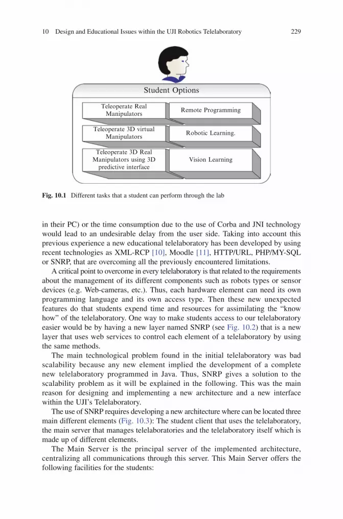
10 Design and Educational Issues within the UJI Robotics Telelaboratory 229
BookID 175907_ChapID 10_Proof# 1 - 15/4/2009
in their PC) or the time consumption due to the use of Corba and JNI technology would lead to an undesirable delay from the user side. Taking into account this previous experience a new educational telelaboratory has been developed by using recent technologies as XML-RCP [10], Moodle [11], HTTP/URL, PHP/MY-SQL or SNRP, that are overcoming all the previously encountered limitations.
A critical point to overcome in every telelaboratory is that related to the requirements about the management of its different components such as robots types or sensor devices (e.g. Web-cameras, etc.). Thus, each hardware element can need its own programming language and its own access type. Then these new unexpected features do that students expend time and resources for assimilating the “know how” of the telelaboratory. One way to make students access to our telelaboratory easier would be by having a new layer named SNRP (see Fig. 10.2) that is a new layer that uses web services to control each element of a telelaboratory by using the same methods.
The main technological problem found in the initial telelaboratory was bad scalability because any new element implied the development of a complete new telelaboratory programmed in Java. Thus, SNRP gives a solution to the scalability problem as it will be explained in the following. This was the main reason for designing and implementing a new architecture and a new interface within the UJI’s Telelaboratory.
The use of SNRP requires developing a new architecture where can be located three main different elements (Fig. 10.3): The student client that uses the telelaboratory, the main server that manages telelaboratories and the telelaboratory itself which is made up of different elements.
The Main Server is the principal server of the implemented architecture, centralizing all communications through this server. This Main Server offers the following facilities for the students:
Student Options
Teleoperate RealManipulators
Remote Programming
Robotic Learning.Teleoperate 3D virtual
Manipulators
Teleoperate 3D RealManipulators using 3D
predictive interfaceVision Learning
Fig. 10.1 Different tasks that a student can perform through the lab
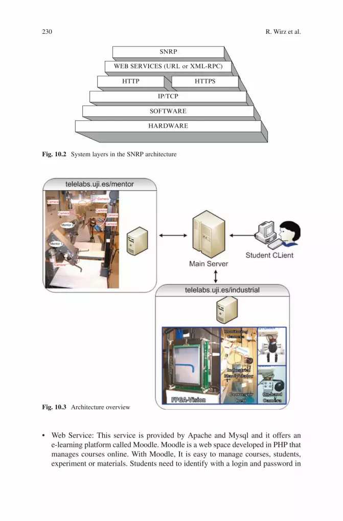
230 R. Wirz et al.
BookID 175907_ChapID 10_Proof# 1 - 15/4/2009 BookID 175907_ChapID 10_Proof# 1 - 15/4/2009
SNRP
HTTP HTTPS
IP/TCP
SOFTWARE
WEB SERVICES (URL or XML-RPC)
HARDWARE
Fig. 10.2 System layers in the SNRP architecture
Camera
Camera
Mentor 2
Mentor 1
Camera
Camera
Camera
Camera
Camera
Fig. 10.3 Architecture overview
• WebService:This service isprovidedbyApacheandMysql and itoffers ane-learning platform called Moodle. Moodle is a web space developed in PHP that manages courses online. With Moodle, It is easy to manage courses, students, experiment or materials. Students need to identify with a login and password in

10 Design and Educational Issues within the UJI Robotics Telelaboratory 231
BookID 175907_ChapID 10_Proof# 1 - 15/4/2009
Moodle and this identification allows students to access the experimental resources. Each student has a unique identification code so that the system can monitor what the student is doing. Without the correct identification, the student can’t get access to the telelaboratories because all communications go through the main server and students need to log in. The telelaboratory security is provided by the telelaboratory server.
• DNSService:Studentsdon’t need toknowwhat IPhas a specific robotof atelelaboratory or what port uses the robot to establish a communication. For that reason the students use domain names such as “telelabs.uji.es/ educational/ mentor” when they are referring to the Mentor Education Telelaboratory or “telelabs.uji.es/ educational/ mentor/ mentor1” for selecting the “Mentor 1” robot, for example.
• Bridgeservice:Eachtelelaboratorycanbesituatedinadifferentplacesoeachtelelaboratory has a unique internet address. It is easy to assimilate a single domain name but if a great number of telelaboratories were available the things could became unsuitable. Hence, this service redirects the communication between the student and the telelaboratory in a transparent manner using only one domain address.
• Log service: This service saves all communication and information that arebeing processed through the main server, so that errors in communication are detected and students’ use of the system is monitored.
As it has been explained before, a telelaboratory is made up of different elements with their own features or characteristics. Each element has specific software that is installed into the hardware element or needs to be installed in an external computer. With this architecture, the telelaboratory has a central computer where all the telelaboratory software is installed or other software can be accessed. For example (Fig. 10.4), the educational telelaboratory has two Mentor robots, six cameras that are controlled by a camera server and a central telelaboratory server where the software controlling the Mentor robots has been installed. In particular, if the software element has its own server, such as the camera server, the Central Telelaboratory server redirects the request from the Main server to this specific server.
The central telelaboratory server also has the following services:
• Security service: Users unconnected to the project could try to communicatewith the telelaboratory and misuse or damage it. It is for that reason that the central telelaboratory server only accepts communication with the main server and only with previously identified students.
• Resourceservice:Informationofwhatresourcesareavailableandwhatresourcesare not is sent to the main server so that students know what resources they can use. When a student selects an experiment that uses specific resources, those resources are isolated by the central telelaboratory server and labeled as unavailable.
• SNRPservice:EachtelelaboratoryelementhasaSNRPfacilityfortranslatingthe SNRP method to code able to be executed or translating a piece of code to SNRP. For instance, the Mentor robot is controlled by using methods in C language, so the software which controls the Mentor robot has a library that translates SNRP to C or vice versa and that library can be easily integrated in the software that controls the Mentor robot.

232 R. Wirz et al.
BookID 175907_ChapID 10_Proof# 1 - 15/4/2009 BookID 175907_ChapID 10_Proof# 1 - 15/4/2009
The Student client is the last element of the architecture but it is the most important one for the student. The student will use the client to communicate with the telelab-oratory. When a telelaboratory is designed, it is important to determine which method the user will employ to access the telelaboratory and how the user will manage it. From an educational point of view, it is convenient to implement a friendly interface guaranteeing an intuitive access for each student, so that no specific previous technical knowledge is necessary. Thus, initially the telelaboratory provides three different kind of access depending on the students’ level skills (i.e. in programming languages) and two different technologies for each one (see Fig. 10.5). The intention has been that students could control the telelaboratory by using only the XML-RPC standard or also the URL.
10.2.1 Implementation Details
When we are talking about HTTP technologies, we are referring to the technologies that use HTTP in the application layer of the OSI model. Thus, the student can use two different ways to send SNRP commands: Using the URL as REST [12], and using XML. The XML specifications that are chosen is the XML-RPC because its technology for remote procedure calling (RPC) has been implemented in various programming languages and it is easy to use. In the following we will see some details about each one of these two implemented possibilities.
Fig. 10.4 Telelaboratory architecture overview

10 Design and Educational Issues within the UJI Robotics Telelaboratory 233
BookID 175907_ChapID 10_Proof# 1 - 15/4/2009
The simplest manner for accessing the different elements of a telelaboratory will be using a simple URL in a HTTP request. The domain of the URL is provided for the telelaboratory and the user must provide the SNRP method. This technology of access is similar at REST but the difference is that the technology here implemented accepts verbs and it permits the representation of methods meanwhile by using REST the verbs are not acceptable and only states are represented. It is noticeable, that in the telelaboratories context, it is easier that students learn verbs as “GetImage” to get a camera image or “moveToPosition” to move a robot than learn states such as “ImageDownloaded” or “NewPosition”.
For example, if the student wants to move an industrial robot (e.g. Motoman, in our case) to the position (4,12,10) using the telelaboratory, students will use the following URL in their Web navigators:
http://telelabs.uji.es/industrial/motoman/moveToPosition 4 12 10
Where “http://telelabs.uji.es” is the telelaboratory domain, “industrial” specifies that it is the Industrial Telelaboratory and “motoman” that is the specific telelaboratory element that the student wants to control.
When the web server in the main server receives the HTTP request, it will run the SNRP method and it will respond with the corresponding result. The response is a simple web page without any type of design that only contains the result of the operation.
On the other hand, XML-RPC is a XML specification to process remote procedure calls and uses HTTP to be transported. In other words, when students send a SNRP method to the telelaboratory, the SNRP method will be sent in XML format using the method HTTP POST. The XML format is defined using the XML-RCP specification. The advantage of XML-RPC is that the use of XML-RPC is similar to employing methods in language programming so it is easy to assimilate for students. Students can easily use XML-RPC specification because this is implemented in a great number of programming languages.
Student Client
Main Server
Central TelelaboratoryServer
ACCESS
WebExplorer
URL
XML-RPC
ProgrammingLanguage
JavaInterface
TECHNOLOGY
Fig. 10.5 A flow chart showing different communication possibilities provided through the main server
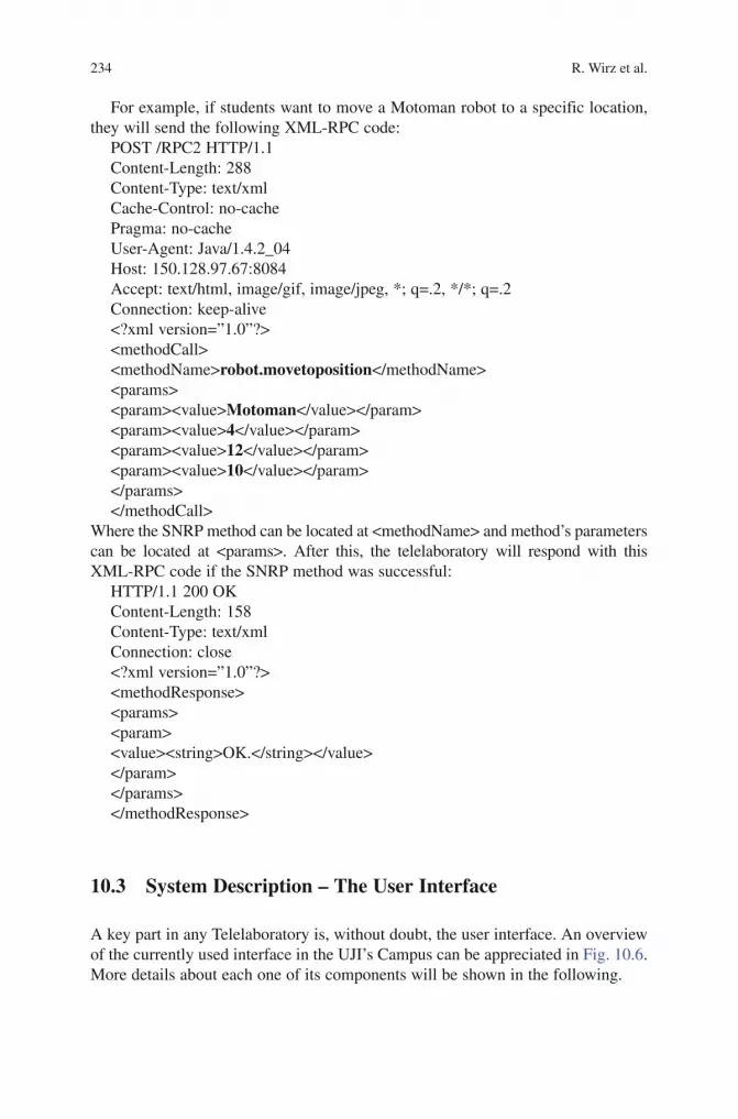
234 R. Wirz et al.
BookID 175907_ChapID 10_Proof# 1 - 15/4/2009 BookID 175907_ChapID 10_Proof# 1 - 15/4/2009
For example, if students want to move a Motoman robot to a specific location, they will send the following XML-RPC code:
POST /RPC2 HTTP/1.1Content-Length: 288Content-Type: text/xmlCache-Control: no-cachePragma: no-cacheUser-Agent: Java/1.4.2_04Host: 150.128.97.67:8084Accept: text/html, image/gif, image/jpeg, *; q=.2, */*; q=.2Connection: keep-alive<?xml version=”1.0”?><methodCall><methodName>robot.movetoposition</methodName><params><param><value>Motoman</value></param><param><value>4</value></param><param><value>12</value></param><param><value>10</value></param></params></methodCall>
Where the SNRP method can be located at <methodName> and method’s parameters can be located at <params>. After this, the telelaboratory will respond with this XML-RPC code if the SNRP method was successful:
HTTP/1.1 200 OKContent-Length: 158Content-Type: text/xmlConnection: close<?xml version=”1.0”?><methodResponse><params><param><value><string>OK.</string></value></param></params></methodResponse>
10.3 System Description – The User Interface
A key part in any Telelaboratory is, without doubt, the user interface. An overview of the currently used interface in the UJI’s Campus can be appreciated in Fig. 10.6. More details about each one of its components will be shown in the following.

10 Design and Educational Issues within the UJI Robotics Telelaboratory 235
BookID 175907_ChapID 10_Proof# 1 - 15/4/2009
Students can use telelaboratories in three easy ways and each way has its own peculiarities. Thus, these three possibilities are: By using a web explorer, by means of a programming language or utilizing a specific Interface developed in Java.
10.3.1 Using a Web Navigator
The main advantage of these access methods is that students only need a simple web navigator as Internet Explorer or Firefox to access the telelaboratory. This access method provides the student with two modalities: Using a JavaScript web page or using the URL.
The URL modality offers a web page where they have a list of possible SNRP methods that run with the telelaboratory selected. The student only needs to select the methods and a new web page will open with results of that method. The problem of this modality is that it is more difficult to control because for each method executed, a new window webpage arises so it becomes an uncomfortable interface even though very simple to use.
Fig. 10.6 The UJI Telelaboratory in a working day and two screens (centre) provided by the system as visual interfaces

236 R. Wirz et al.
BookID 175907_ChapID 10_Proof# 1 - 15/4/2009 BookID 175907_ChapID 10_Proof# 1 - 15/4/2009
The other modality provides a JavaScript webpage to control the telelaboratory using a web navigator through XML-RPC technology. Thus, the webpage is divided into two different fields (see Fig. 10.7):
• The left fieldof thewebpage (Fig 10.7 on the left) is the screen area where students select the SNRP method that they want to use from an available list of methods and after this action, the general SNRP method goes up into a textbox where students can modify the general parameters to specific ones. For instance, if a student selects the SNRP order “MoveToPosition” in the list, the general method movetoposition(“X”, “Y”, “Z”) arises in a textbox where the student can change “X”, “Y” and “Z” parameters for numbers representing the new axis values that the end-effector of the robot must reach. Finally, the student sends the method in XML-RPC standard to check the result of this method in the same webpage.
• Therightfieldofthewebpage(Fig 10.7 on the right) is the screen where students visualize an image from a webcam (i.e. Telelaboratory camera). This area is refreshed automatically and the student can adjust its processing time.
10.3.2 By Means of a Programming Language
Students can program the telelaboratory using any programming language that accepts XML-RPC (e.g. Perl, Python, Java, Frontier, Delphi, Microsoft.NET, etc.) or that is able to use URL (e.g. Matlab).
Fig. 10.7 XML-RPC Webpage designed

10 Design and Educational Issues within the UJI Robotics Telelaboratory 237
BookID 175907_ChapID 10_Proof# 1 - 15/4/2009
In order to provide students and researchers with the possibility of programming the Telelaboratory in a simple and reliable manner, a Java Library named “Experiments”, managing all SNRP implementation details, is available. This library already includes templates that are examples of simple experiments that manage the remote robots and the cameras (see Fig. 10.8).
10.3.3 Through the Java Interface
Another interface is provided for controlling the robot with better performance. The interface is implemented in Java (i.e. Sun technology) and it is loaded using Java Web Start. Thus, students only need to choose the experiment type that they want to execute with the Java technology and the application starts in a new java application. This application has different windows and each application window represents a module which students can situate in the window they want in the screen. A module also represents a telelaboratory characteristic.
It is difficult to find two similar telelaboratories in Internet because each telelab-oratory has its own properties and constraints. Also, when students want to control a telelaboratory, they have different experiments available and each of one has its own specifications. So, each telelaboratory or each experiment needs to use a specific characteristic or some particular parameters. The module is a software representation of this characteristic or parameters where students must work. For instance, a telelabo-ratory characteristic would be each webcam that it is activated in a specific experiment. So, the application tries to implement each feature or characteristic of the telelaboratory in a window that it is named “Module”. Modules can communicate among themselves by using the SNRP language and the following have been already implemented:
Fig. 10.8 Organization of the library of experiments

238 R. Wirz et al.
BookID 175907_ChapID 10_Proof# 1 - 15/4/2009 BookID 175907_ChapID 10_Proof# 1 - 15/4/2009
• Directkinematicsmodule:Therobotcanbecontrolledusingdirectkinematicswith this module. Each joint is represented with a side bar and the side bar is limited by the maximum value and the minimum value of the joint.
• Inversekinematicsmodule:Therobotcanbecontrolledusinginversekinematicswith this module. Each axis is represented with a side bar and the side bar is limited by the workspace of the robot.
• Cameramodule:Foreachcamerainthetelelaboratory,awindowwiththecameraimage can be displayed. The user can save images from the camera and can also control a pan tilt camera.
• Ordermodule:TherobotcanbecontrolledusingdirectSNRPorderswiththismodule. The user can directly write the order or can choose the order from a list.
• Informative module: In this module the information and the objective of theexperiment are displayed in the window. Other information can be displayed in this window such as the clock.
• Connectionmodule:Thismoduleisloadedwhentheuserwantstocontrolarealrobot directly. This module establishes a communication with the real robot and it is the responsible for sending orders and receiving the feedback.
• Simulationmodule:Thewindowofthismodulerepresentsa3Drobotsimulation.The simulation is made using the Denavit–Hartenberg parameters.
In Fig. 10.9 can be observed an example of one experiment using the java Interface. In this experiment students learn to identify “X”, “Y” and “Z” axis using these
Fig. 10.9 Example of a Java interface screen

10 Design and Educational Issues within the UJI Robotics Telelaboratory 239
BookID 175907_ChapID 10_Proof# 1 - 15/4/2009
modules: Inverse Kinematics Slides Module, SNRP Methods module, Mentor 3D robot simulator and the informative module.
10.4 A New Network Protocol: SNRP
The SNRP protocol is an application level protocol that it is continually in develop-ment to offer a good performance. This completes the presentation of the software architecture for the SNRP framework. The SNRP protocol itself, which allows SNRP experiments, holders, naming services and robots to communicate with each other will now be introduced. Further information can be located in [13]. The first objective is to enable the devices to be accessed through the Internet, so that they should be able to manage the IP protocol. In order to make the SNRP simple to use and implement, it uses the HTTP protocol as a basis, which gives it even more interoperability and flexibility. However, for this kind of situation the HTTP does not provide the following features: (1) Event Notification, and (2) Support for structured information. These two characteristics are very important for designing the SNRP framework in the industrial robotics area. To accomplish this, the SNRP protocol has been adapted with the model of REST, which permits the implementation of state-oriented applications and a simple scenario to design event notification and structured information features.
10.4.1 The SNRP Description
Each telelaboratory element has developed a SNRP server and each SNRP server is controlled by a telelaboratory SNRP central server. This server controls services holders and experiments. In Fig. 10.10 we can see the software architecture flow-chart of the SNRP framework providing the following modules:
1. SNTELP: Every robot/device in the SNRP framework would provide a SNRP_Robot network interface, which allows any client (e.g. user experiment) using a service provided (e.g. “motoman.service.moveToPosition(x, y, z)”. Examples of these interfaces are “SNRPCamera” or “SNRPMentor”.
2. SNRPRobotsGroup: A SNRP robot can be the union of several SNRP robots (e.g. a Mobile manipulator is the union of a mobile robot, a robot arm, and a set of sensors). Moreover, the SNRP module for the arm can be the union of two modules, one for the gripper and other one for the arm itself. Thus, SNRPRobotsGroup allows new services to be defined for the various networks robots that work together as if they were a single robot.
3. SNRPNamingService: A SNRP network robot can register itself with a naming service in order to select a name (e.g. telelabs.uji.es/industrial/motoman) and informing other peers of which IP and port is attending on.
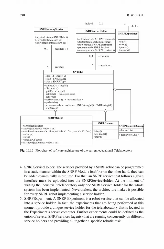
240 R. Wirz et al.
BookID 175907_ChapID 10_Proof# 1 - 15/4/2009 BookID 175907_ChapID 10_Proof# 1 - 15/4/2009
4. SNRPServiceHolder: The services provided by a SNRP robot can be programmed in a static manner within the SNRP Module itself, or on the other hand, they can be added dynamically in runtime. For that, an SNRP service that follows a given interface must be uploaded into the SNRPServiceHolder. At the moment of writing the industrial telelaboratory only one SNRPServiceHolder for the whole system has been implemented. Nevertheless, the architecture makes it possible for every SNRP robot implementing a service holder.
5. SNRPExperiment: A SNRP Experiment is a robot service that can be allocated into a service holder. In fact, the experiments that are being performed at this moment provide a unique service holder for the telelaboratory that is located in the Experiment’s server computer. Further experiments could be defined as the union of several SNRP services (agents) that are running concurrently on different service holders and providing all together a specific robotic task.
+register(entrada SNRPRobot)+getPort(entrada snrp_id)+getAddress(entrada snrp_id)
SNRPNamingServiceSNRPServiceHolder
SNRPExperiment
–holded
–registers
–contains
–iscontained
–registers To0..1
0..1
SNTELP
SNRPMentor
SNRPCameraSNRPElementsGroup
–devicesList
+getDevicesList()+stop()+getlmage()+start()
+waitObjectlnField()+takeObject(entrada object : int)+movePosition(entrada X : float, entrada Y : float, entrada Z : float)+unGrasp()+grasp()+recognizeObjects()+classifyObject(entrada object : int)
–snrp_id : string(idl)–state : SNRPState–type : SNRPType
+connect() : string(idl)+disconnect()+getld() : string(idl)+getState() : <sin especificar>+getType()+getServicesList() : <sin especificar>+getDetails()+service(entrada serviceName : SNRPstring(idl)) : SNRPstring(idl)+waitOrder()
**
–holds
+start()+stop()+pause()+resume()
+upload(entrada SNRPExperiment)+start(entrada SNRPExperiment)+stop(entrada SNRPExperiment)+pause(entrada SNRPService)+resume(entrada SNRPExperiment)
*0..1
Fig. 10.10 Flowchart of software architecture of the current educational Telelaboratory

10 Design and Educational Issues within the UJI Robotics Telelaboratory 241
BookID 175907_ChapID 10_Proof# 1 - 15/4/2009
The SNRP protocol itself, which allows SNRP experiments, holders, naming services and robots to communicate with each other will be introduced in the following.
10.4.2 Example of a SNRP Library
This SNRP Library has been developed to manage the Mentor robots. The Mentor SNRP library inherits from the Telelaboratory SNRP library (SNTLP). An example of provided instructions is the following:
• Connect: The user connects to the robot and reserves this resource until theprocess is concluded.
• WaitObjectInField:Robotwaitsuntilanobjectisdroppedonthework-area.• TakeObject:Robotpicksuptheobjectthatwewant.• RegisterToEvent:Robotwaitsuntilaspecificeventhasbeenactivatedinanother
robot.• MoveToPosition:Robotismovedtoaspecificposition.• Ungrasp:Robotdropstheobjectthathasbeengrasped.• RecogniseObject:Robotrecognizestheobjectusingstatisticalmethodsandan
already existing database.• ClassifyObject:Robotdropstheobjectinthesameareaasothersimilarobject.• Disconnect:Userdisconnectstherobot.
10.5 Teaching Experiences with the Tele-Laboratory
In previous sections a lot of details about design and implementation issues of the Telelaboratory have been presented, but little attention has been paid in showing its utility for those students starting to learn different aspects about robotics.
Nowadays, all students become familiar with the use of internet and they are downloading music, watching online videos, sending messages or exploring web pages all the time. This is the main reason why using a web navigator is the easiest way of connection for any student, as it was previously described in Section 3.
At this point, it is noticeable that the e-learning platform used by the Telelaboratory is Moodle, free software developed in PHP and MySQL, which helps to present a friendly educational environment through Internet.
Specifically, Moodle helps with some important aspects: the courses management and distribution and also with security. Thus, in order to access the telelaboratory web pages, students need to start by logging in Moodle.
After a successful login, the student can select the particular education telelaboratory, selecting the requested experiment and subsequently obtain the access available for that experiment. Finally, the student can perform the experiment.
242 R. Wirz et al.
BookID 175907_ChapID 10_Proof# 1 - 15/4/2009 BookID 175907_ChapID 10_Proof# 1 - 15/4/2009
Thus, within the educational telelaboratory web pages, different experiments, ordered in increasing difficult degree, can be chosen to learn different aspects about robotics meanwhile students became familiar with the different ways of access to the telelaboratory.
In order to highlight the possibilities of teaching robotics with the telelaboratory a real teaching-learning experience is presented in the following. In this case some experiences were developed working with a group of 14 postgraduate engineering students, without previous skills on robotics. This group was divided in seven groups of two people each one to provide a better functionality. One of the main underlying questions was to test if with the new architecture through the telelaboratory it would be easier to learn central aspects about the manner in which a robot can be guided to execute simple actions. Before the lab, students had received some theoretical lessons about robotics but no experience at all with a real robot was carried out yet. After the lab experience, it was confirmed that students assimilate well the new concepts related with some control techniques gaining experience in guiding real robot actions. Hence, in the following some details will be presented about the experiments divided in two main parts: basic and advanced ones.
10.5.1 Basic Experiments
10.5.1.1 SNRP and XML-RPC Experiment
With this experiment, the educational objective is to take a first contact with the new telelaboratory and with the SNRP methods while they are trying to establish robot control using XML-RPC by means of this kind of network protocol. Students assimilate the SNRP methods through a web navigator and using the JavaScript web pages that offer an easy manner of using the XML-RPC technology (see Fig 10.6).
The experiment developed in order to motivate students has been grasping an object by using different SNRP methods each time (i.e. move the robot using the direct kinematics or by using the inverse kinematics) and experimenting with different coordinates (i.e. camera coordinates or robot coordinates). The difficulty of such an experiment has been to show why it is so important to distinguish between camera and robot coordinates and when it is more suitable to select one or the other. Students can supervise their executed actions over the robot scenario “on live” by using a webcam (see Fig. 10.11, on the left).
10.5.1.2 HTTP Experiment
The educational objective of this experiment is to learn the telelaboratory architecture and to prepare the student to realize advanced experiments. For that experiment they will use a web navigator for sending SNRP methods using the URL technology. The architecture is explained with a text and students need to paint the architecture

10 Design and Educational Issues within the UJI Robotics Telelaboratory 243
BookID 175907_ChapID 10_Proof# 1 - 15/4/2009
with the help of the URL technology using all SNRP methods. Also, students must try a list of proposed SNRP methods to see what are able to do each one of them. For example, if they select to send from the available list the following SNRP method:
http://telelabs.uji.es/educational/motoman/moveToPosition 4 9 10They will know that the telelaboratory has a robot available, named Motoman that it belongs to the educational telelaboratory and that the end-effector of this manipulator is moved to position 4 9 10. Or when they select “GetImage” from the available methods list and send the following SNRP method:
http://telelabs.uji.es/educational/camera1/getImageThey will become aware that the educational telelaboratory also has a camera and the camera image will be received.
10.5.2 Advanced Experiments
10.5.2.1 Java Interface Experiment
The following experiment is to show the functionalities of the Java Interface. The student selects the experiment and Java Web starts launching the Java Interface. Students perform a visual control of an educational robot (i.e. Mentor) using the different interface modules. If the robot is available they can control the real robot, in any other case, they can use the virtual robot representation. The context of the experiment is the same used when SNRP and XML-RPC was presented, namely grasping an object. But now students are using a visual interface to control the robot
Fig. 10.11 Web to supervise the experiment

244 R. Wirz et al.
BookID 175907_ChapID 10_Proof# 1 - 15/4/2009 BookID 175907_ChapID 10_Proof# 1 - 15/4/2009
where they can exercise control by using direct or inverse kinematics, apart from the available SNRP methods.
10.5.2.2 Programming Language Experiment
After students learnt the functionality of SNRP methods and the telelaboratory architecture, the last experiment is focused on the robot control by using a program-ming language as Java, C or Matlab. This experiment has been divided into two parts from the educational point of view. Thus, the objective of the first part has been to know how to control more than one telelaboratory element simultaneously by using a programming language to perform a specific task. And, the educational objective of the second part has been to familiarize students with computer vision based control algorithms (i.e. Visual Servoing techniques). In this last case, the experiment can only be performed with the real robot, because a 3D simulator for this situation is unavailable, and the technologies that students can use are XML-RPC or URL.
For the first part, the experiment consists of using the camera information which provides geometrical information for each object in the image to transform the left image on Fig. 10.12 into the right image on the same figure. The solution is to know how to obtain the area and the centroid of each object and to move the robot in camera coordinates.
For the second part, a successful Visual Servoing algorithm is necessary to complete this experiment. The objective is to grasp an object with the robot using the camera information. The starting point for students, with this computer vision based control technique, named visual servoing, is a direct explanation by using the flowchart depicted in Fig 10.13.
Thus, after a general comprehension of this technique, the student must be ready to generate a Visual Servoing algorithm code with the help of a Java template provided by the teacher (see Fig. 10.14).
Students have a list of SNRP methods where they need to select the correct ones to fill the code. The correct SNRP methods for that experiment are the following:
Fig. 10.12 Initial and final state of the experiment

10 Design and Educational Issues within the UJI Robotics Telelaboratory 245
BookID 175907_ChapID 10_Proof# 1 - 15/4/2009
• GetImage(1);//Acameraimageisobtained• ColorSegmentacion(imageIcon, frame); //Binarization, segmentation of an
image and returns a centroid value.• ExistError(FinalPoint,GraspPoint,Error);//Differencebetweenthefinalpoint
and the grasp point.• ControlLaw(Error);//Givethecorrectdirectiondependontheerror.• MoveRobotDirection(GraspPoint,Direction);//Movetherobot• TakeObject(GraspPointOld);//Graspanobject.
e
Segmentation
POSE DETERMINATION IMAGE PROCESSING
Binarization Camera Image
Control Law “Move to PositionX Y Z ”+
-
Fig. 10.13 Image used to explain the visual servoing algorithm
imageIcon = evs1._______________;
image2Icon = __________________________
imageJLabel.setIcon(image2Icon);
imageJLabel.repaint();
while (_________________________) {
if (GraspChanged) { //is the grasp position changed?
Direction =____________________________
_________________________________
GraspChanged = false;
GraspPointOld = GraspPoint;
}
imageIcon = evs1.___________________________
image2Icon = ________________________________
imageJLabel.setIcon(image2Icon);
imageJLabel.repaint();
}
_______________________________
evs1.disconnect();
}
Fig. 10.14 Visual servoing template

246 R. Wirz et al.
BookID 175907_ChapID 10_Proof# 1 - 15/4/2009 BookID 175907_ChapID 10_Proof# 1 - 15/4/2009
When the code is completed and it is also correct, students perform a visual servoing algorithm using the information that provides the camera to move the educational robot.
10.6 Conclusions and Work in Progress
The main goal of the work here presented has been put together the suitable software and network architecture within the robotics context, providing simultaneously the following properties: (1) Simple, (2) Open, (3) Flexible, (4) Dynamic, (5) Robust, (6) Scalable, (7) Efficient, (8) Secure, and (9) Platform independent:
1. Simple: Students only need to learn SNRP methods to control all telelaboratories elements and don’t need to install any specific software because they use a web navigator.
2. Open: Any new element can be included in the telelaboratory. Only the system’s administrator must take care of this update. Thus, only the administrator has a SNRP library available, with the responsibility to update this library including the new element.
3. Flexible: Web-based control means that students can be connected any time and anywhere. Furthermore, students can choose what element they want to control.
4. Dynamic: Students can use other standard tools such as Matlab or similar to realize advanced control algorithms by using XML-RPC or URL.
5. Robust: Telelaboratories are independent of each other. The telelaboratories are controlled by a single central server but if any of them is shutting down the rest is not affected.
6. Scalable: New telelaboratory elements or new telelaboratories can be added to the system. It is only required to implement a SNRP layer.
7. Efficient: Students don’t need to expend time learning the features of each telelaboratory. They only need to learn the SNRP protocol.
8. Secure: Moodle provides the system with some security of the user’s identity and because students don’t have direct access to the telelaboratory (i.e. commands go through the Main Server), the system can check commands and save them in log files.
9. Platform independent: Students only need a platform that accepts the use of sockets or a web explorer.
Finally, to underline what has been achieved recently we would make the following comments. The two initial ones from a technological point of view, and the final from an educational perspective:

10 Design and Educational Issues within the UJI Robotics Telelaboratory 247
BookID 175907_ChapID 10_Proof# 1 - 15/4/2009
• Different aspects of the user interface currently require our attention, as newfunctionalities of the available Java interface, or a better GUI (i.e. Graphical User Interface) design.
• Anewpackofsoftwareisbeinggeneratedtoprovidenewtelelaboratorieswithan easy transformation into the SNRP architecture. Also, the architecture imple-mentation has being recently improved.
• Thankstothefeedbackobtainedwhiledifferentgroupsofstudentswereinter-acting with the lab, the experiments have being improved a lot. Moreover, new experiments have being currently designed to help in teaching new robotics techniques such as the learning by demonstration paradigm, etc.
References
1. R. Marin, P. J. Sanz, and A. P. del Pobil. The UJI Online Robot: An Education and Training Experience. Autonomous Robots, 15(3), 283–297, 2003.
2. R. Wirz, R. Marin, and P. J. Sanz. Remote programming over multiple heterogeneous robots: A case study on distributed multirobot architecture. Industrial Robot: An International Journal. 33(6), 431–442, 2006.
3. R. Marin, G. Leon, R. Wirz, J. Sales, J. M. Claver, and P. J. Sanz. “Remote control within the UJI Robotics Manufacturing Cell using FPGA-based vision”. European Control Conference, 2007.
4. G. T. McKee, D. I. Baker, and P. S. Schenker. “Network robotics: Dynamic reconfigurable architectures”, Proceedings SPIE Intelligent Robots and Computer Vision XXII: Algorithms, Techniques and Active Vision (2004)
5. G. T. McKee, D. I. Baker, and P. S. Schenker: “Robot Spaces, Module Networks and Distributed Robot Architectures”, Proceedings of the IROS 2004 Workshop on Networked Robotics:issues, architectures and applications, Sendai, Japan (2004).
6. R. Marín and P. Sanz. Grasping determination experiments within the UJI robotics telelab, Journal of Robotic Systems, Internet and Online Robots for Telemanipulation Special Issue (Part 2), 22(4), 203–216, 2005.
7. B. K. Kim et al., “Web Services Based Robot Control Platform for Ubiquitous Methods” In Proceedings of the IEEE International Conference on Robotics and Automation (ICRA). Barcelona, Spain, April 2005.
8. D. Lee and M. W. Spong, “Bilateral Teleoperation of Multiple Cooperative Robots over Delayed Communication Networks: Theory” In Proceedings of the IEEE International Conference on Robotics and Automation (ICRA). Barcelona, Spain, April 2005.
9. P. X. Liu, M. Q. H. Meng, and S. X. Yang. Data communications for internet robots, Autonomous Robots, 15, 213–223, 2003.
10. http://www.xml-rpc.com 11. http://moodle.org 12. R. Thomas Fielding. Architectural Styles and the Design of Network-based Software
Architectures, Ph.D. thesis, University of California, Irvine, CA, 2000. 13. R. Wirz, R. Marin, J. Fernandez, and P. J. Sanz, Remote programming of multirobot systems
within the UPC-UJI telelaboratories: System architecture and agent-based multirobot control. International Journal of Intelligent Control and Systems. 13(2), 120–127, June 2008.

BookID 175907_ChapID 11_Proof# 1 - 15/4/2009
Chapter 11Web-Based Industrial Robot Teleoperation: An Application
Gianni Ferretti, Gianantonio Magnani, and Paolo Rocco
11.1 Introduction
Since 1994, when the Mercury Project gave birth to the first Internet robot [1], Internet based telerobotics has been studied by a large number of researchers around the world [2−8], attracted by the ubiquity and ever increasing opportunities offered by the Internet. Telerobotics has been studied and experienced for years, mainly for space, subsea, and nuclear applications [9, 10].
A major difficulty with telerobotics is related to communication delays, in particular if control loops have to be closed through the remote operator. The difficulties related to communication delays are especially severe in Internet based teleoperation, since delays may not only be large but also variable and unpredictable (an UDP-based protocol has been proposed in [11−13] to face this problem). Most of the literature on telerobotics actually deals with this problem [9, 11−17]. For example, the effects of Internet latencies and bandwidth were evaluated in [18], with reference to remotely programmed visual servoing experiments. Under this constraint, direct control strategies [19−21], where the remote operator closes feedback loops either on robot position or on eteroceptive sensor measures are not allowed. Therefore robot autonomy should be exploited as far as possible.
For example, in the first teleoperation experiment [22, 23] with a space robot (Rotex) on board the Columbus shuttle, teleoperated both by astronauts and from ground, a tele-sensor-programming concept, named shared autonomy (control), was used. Sensory feedbacks were used to close fast control loops locally (onboard), whose setpoints were computed autonomously based on teleoperator gross motion commands, referred to as elemental moves. Basic feedback to the remote operator (telepresence) was provided only via the visual system, i.e., stereo TV images for the astronaut, and predictive 3D computer generated images for the ground operator, in addition to the delayed TV images.
Shared autonomy seems the most suitable and perhaps the only feasible approach with a commercial, off-the-shelf, industrial controller. In fact, the only way to interact
G. Ferretti, () G. Magnani, and P. RoccoDipartimento di Elettronica e Informazione, Politecnico di Milano, Piazza Leonardo da Vinci 32, 20133 Milano, [email protected]; http://home.dei.polimi.it/ferretti/indice.htm
S.G. Tzafestas (ed.), Web-Based Control and Robotics Education, 249Intelligent Systems, Control and Automation: Science and Engineering 38,DOI 10.1007/978-90-481-2505-0_11, © Springer Science + Business Media B.V. 2009

250 G. Ferretti et al.
BookID 175907_ChapID 11_Proof# 1 - 15/4/2009 BookID 175907_ChapID 11_Proof# 1 - 15/4/2009
with such a controller is through the programming language (command) interpreter. The user is allowed, on one side, to send proper commands to the command interpreter and, on the other, to get information on the robot state, needed to provide telepresence to the remote operator.
With the aim of improving robot autonomy, thus trying to overcome problems related to unreliable connections and variable delays, a new approach has been also recently proposed in [24, 25]: the Distributed Architecture for Internet Robot (DAIR). The DAIR architecture aims at implementing a generic distributed computing infra-structure, by utilizing networked information and computation resources, and it is based on behavior and mission as the basic decision units. Rather than sending motion instruc-tions to robots and receiving the feedback from Internet, as in the traditional robotic teleoperation, a closed loop behavior is transferred to the robot, so that most of the computation task is performed locally by the robot instead of by a remote closed loop within unreliable connections. Moreover, in the DAIR architecture, the robot is given the ability to autonomously find from Internet the sensors needed to perform the task.
An event-based distributed controller has been also adopted in [26], with reference to a cooperative teleoperation of a mobile robot and a robot arm with a multifingered hand, with real-time force feedback from multiple sites, where each robot is controlled independently, using a different event to synchronize its own actions with inputs from its operator. Thus, to overcome the instability caused by time delays the controller employs a nontime parameter to synchronize robots and operators.
The use of predictive displays, based on augmented and virtual reality techniques, in order to cope with Internet latency and delay effects has been also proposed in [27], with reference to an Internet-based telelaboratory, allowing users to remotely control and program two educational robots. Remarkably, the telelaboratory has been also endowed with a very detailed remote programming environment (including voice commands), based on a well structured Java library, with an automatic object recognition feature, in order to construct a complete 3-D model of the experiment scenario, and with an autonomous grasping execution capability.
The tele-sensor-programming concept (TeleSMART) presented in this paper is based on the shared autonomy concept. The systematic formulation of an automation and robotic system pursued by European Space Agency – ESTEC [28] is followed, which defines a catalog of activities hierarchically broken down into actions, tasks, and missions. To increase safety during teleoperations, shared control is integrated with safety oriented supervisory control functions, which arrest robot motion in case the end-effector position gets out the borders of a virtual workspace, and allows the remote operator to arrest motion if an unsafe condition is perceived.
TeleSMART is implemented on the industrial robot COMAU Smart 3S using only typical Internet oriented low cost commercial components, both from the hardware and software points of view. This approach, which ensures the highest portability and independence from the configuration of the client platform, was also followed in [1] in the Mercury Project. Related to the Mercury Project, TeleSMART can be viewed as a feasibility study, for industrial and educational applications.
It also shows some points in common with the work recently reported in [29] in particular regarding the software architecture, the user interface and the use of an industrial robot. On the other hand, in [29], three different protocols, namely TCP,

11 Web-Based Industrial Robot Teleoperation: An Application 251
BookID 175907_ChapID 11_Proof# 1 - 15/4/2009
RTP and UDP, are used for communicating high-level commands, visual feedback data and real-time motion control data respectively and no autonomy is implemented. Moreover, the main focus in [29] is on the teaching of robotics and, in this respect, the remote programming system has been evaluated by comparison of the performance of a local and a remote student group.
The paper is organized as follows. In Section 2 the overall telerobotic system archi-tecture is described. In Section 3 the teleprogramming and supervisory control concepts and functions implemented are discussed. Section 4 gives details on the overall soft-ware architecture and Section 5 illustrates the remote operator teleoperation interface.
11.2 System Architecture
The architecture of the robotic teleoperation system (shown in Fig. 11.1) consists of the following components:
• AnindustrialrobotCOMAUSMART3-S• ArobotcontrollerCOMAUC3G-9000• APCoperatingasaserver,connectedtotherobotcontrollerviaaserialRS-232
link and to the Internet• Threewebcamswithdedicatedcommunications
Fig. 11.1 Robotic teleoperation system
C3G9000
Camera
RobotWorkspaceSMART 3S
ImageServer
RobotServer
Web Server PC
Internet
Remote

252 G. Ferretti et al.
BookID 175907_ChapID 11_Proof# 1 - 15/4/2009 BookID 175907_ChapID 11_Proof# 1 - 15/4/2009
11.2.1 The Robot SMART 3-S
The SMART 3-S (Fig. 11.2) is an industrial robot with six rotational degrees of freedom, mainly used for arc welding, manipulation, painting and water jet processing. It carries a payload up to 6 kg and is characterized by a repeatability of 0.1 mm. The end effector is a pneumatic gripper, made up by two opposing parallel fingers. The gripper is controlled through an electric valve and is endowed with two proximity sensors, in order to monitor the states of the grasp operation: open gripper, closed gripper and grasped object, respectively. Electric valve and proximity sensors are directly interfaced to the I/O controller module and processed with a simple routine written in PDL2, the standard programming language of the controller.
11.2.2 The C3G 9000 Controller
The COMAU C3G 9000 can control up to 32 axes. It is endowed with an operator control panel and a programming terminal (teach pendant). Differently from other works [30], the controller has been used in its standard mode, to comply as much as possible with the industrial practice and with low cost and portability requirements. Thus, a link with an external PC has been realized through a serial port RS-232, available on the frontal panel, and the communication protocol is implemented in the programming language PDL2.
The PDL2 interpreter is a powerful multitasking environment, where tasks written in the native PDL2 language can be concurrently executed. Typically a task consists of robot motion and end effector commands, but handling of digital and analog I/Os,
Fig. 11.2 Robot SMART 3-S (VRML model)

11 Web-Based Industrial Robot Teleoperation: An Application 253
BookID 175907_ChapID 11_Proof# 1 - 15/4/2009
programming interfaces and peripherals is also supported, as well as the definition of complex data structures and events servicing.
A full-duplex software communication has been implemented: the main PDL2 task waits for motion commands to be executed, while another (lower priority) task sends to the PC server, at a given (nearly constant) frequency, the robot position data.
11.2.3 The PC Server
A standard PC has been used as a server, in charge of running four different tasks:
• Thewebserver,hostingtheappletsusedbytheremoteoperatortointeractwiththe robot
• The image server, managing the three web cams and transferring the videoimages to the client
• Therobotserver,managingtherobot–clientinteraction• TheJavaVirtualMachine(JVM),runningtherobotservercode(theJVMcould
be avoided if the code is compiled, however the portability would be lost)
The functional architecture of the PC server is shown in Fig. 11.3 where two main components can be singled out: the image server and the telerobot server.
C3G com.manager
C3G-9000controller
Web cams Imagemanager
Imagefiles
Telerobot server
PC server
PC client
Communication manager
client com.manager
Supervisor
Errormonitor
Recovery
Action/Taskmanager
Actionfiles
Fig. 11.3 PC server functional architecture

254 G. Ferretti et al.
BookID 175907_ChapID 11_Proof# 1 - 15/4/2009 BookID 175907_ChapID 11_Proof# 1 - 15/4/2009
The image server is in charge of showing in a separate window of the browser the video streaming, independently from the telerobotics application. Of course, a fast Internet connection is required to send the video images.
The telerobot server, in turn, is made up by two main components: the commu-nication manager, establishing the link between the client and the C3G-9000 controller, and the supervisor, whose functions are described in Section 11.3.2.
The communications between the server and the client (one client at a time) takes place in two distinct phases, based on two different standard Internet protocols:
• Ina firstphase thecommunication isbasedon theHTTPprotocol: theclientconnects through a browser to the web server of the PC server and downloads the applets implementing the user interface and the motion commands.
• InthesecondphasetheappletsareinterpretedbytheJVMofthebrowser,imple-menting the communication with the robot server through the TCP/IP protocol.
11.2.4 The Web Cams
The three web cams are arranged in the following configuration (Fig. 11.9): a web cam shoots the whole scene from the top, so as to give an overview of the workcell, while two other web cams are arranged orthogonally, so as to locate a position in space by merging the two viewpoints.
Some problems have been encountered when using low-cost web cams as pointing devices. In fact, their wide-angle lens, distort images. This drawback, together with the low resolution obtained, makes it difficult to precisely locate points in space from web cam images.
11.3 Teleprogramming and Supervisory Control Functions
The telerobotic system presented in this paper combines basic teleprogramming, shared control, and supervisory control functions, which can be implemented by interfacing the PDL2 interpreter. Basic teleprogramming functions are actuated by a remote virtual teach-pendant, which allows the remote operator to execute, from the Internet client, the main functions a local operator can execute with the robot programming terminal (teach pendant).
The virtual teach-pendant supports point-to-point joint space motion, Cartesian space motion, referred to both base and tool frames, and closing/opening the gripper. During a teleoperation session with the virtual teach-pendant, video streams from the three webcams, as well as joint and Cartesian robot positions, are fed back to the operator. Relative (with respect to current position) motion commands, both in joint and Cartesian space, are easily given from the virtual teach-pendant.
An obvious safety issue however emerges, as the operator must care to avoid unexpected impacts of the arm against the environment. To this aim, programming of linear gross motion is supported by a 3D cursor, to be moved over two webcam images (XZ and YZ planes, Fig. 11.8) and within a predefined prismatic working volume.

11 Web-Based Industrial Robot Teleoperation: An Application 255
BookID 175907_ChapID 11_Proof# 1 - 15/4/2009
Also relative motion command destination (end-effector position) can be checked with respect to the working volume borders. The interface for basic teleprogramming is discussed in details in Section 11.5. Safety of operations is increased also by auto-matic and manual supervisory functions, which are described later on.
11.3.1 Shared Autonomy Control
Shared autonomy means that position control loops are closed locally in the robot controller, so that the robot can execute autonomously commands sent by the remote operator. Feedbacks from the robot sensors and video images, delayed by communications times, are sent to the operator, possibly combined with predictive computer simulation, for supervision purposes.
According to ESTEC approach to shared autonomy, the robot activities are decomposed into a three-layer hierarchy:
• Missions• Actions• Tasks
The very top level, robotic missions, represents the highest level of activities for which a robot system is responsible (e.g. “SERVICE a life science experiment”, “REPAIR a satellite”). Each mission can be decomposed into tasks, defined as the highest level of activity performed on a single subject (e.g., “OPEN a door”, “INSTALL a sample in a processing furnace”, “POLISH a surface”, “WELD aseam”). Finally, each task can be decomposed into actions (e.g., “GRIP a sample container”, “DISPLACE a tool to a position”, “MOVE the container to the freezer”, “INSERT the container in the port”, “SLIDE a drawer”, “RUB along a path on a surface”, “FOLLOW a seam”, “TRACK a part on a conveyor”). Each action is realized with a particular control concept (e.g., free continuous path control for MOVE, or impedance control for INSERT and SLIDE) such that there are well-defined criteria for identifying actions within a task. The ESTEC Control Development Methodology [28] offers a “catalog” of frequently occurring tasks and actions.
Under shared autonomy control, the operator can send the robot controller mission, task, and action level commands. The robot executes commands autonomously, unless the operator intervenes to stop the sequence or to modify it.
This is also the approach followed in the TeleSmart project, even though the mission level is not considered. A small number of actions and tasks, useful to teleoperate the SMART 3S, and suitable to be coded in PDL2, have been defined and implemented, up to now. Only actions requiring just position control can be currently implemented in PDL2, since C3G 9000 is not endowed with interfaces to eteroceptive (e.g. force, vision) sensors. More recent and powerful robots would permit the implementation of a longer list of actions. Currently, the following actions are supported:
• MOVELINEAR.• DISPLACE:therobotmovesanobjecttoacertainlocationdefinedwithrespect
to its own reference frame.

256 G. Ferretti et al.
BookID 175907_ChapID 11_Proof# 1 - 15/4/2009 BookID 175907_ChapID 11_Proof# 1 - 15/4/2009
• APPROACH:theend-effectormovestowardsanobjectalongoneormoretoolframe axes and close to contact.
• RETRACT:theoppositeofAPPROACH,butitcanincludecontact–noncontacttransition.
Sequences of such actions can be grouped to perform complex robotic tasks (executable tasks). Executable tasks may be defined by directly entering the Cartesian coordinates of the end effector or through a visual user interface, are stored in the PC-Server and can be easily recalled and executed by remote operators. In executable tasks all action parameters (e.g., the destination of a MOVE LINEAR) are fixed, namely they specify precise positions in the robot workspace.
Specific sequences of actions are also grouped to form parametric tasks, namely tasks whose parameters are assigned by the operator before execution. Currently three parametric tasks are defined: PICK, PLACE and PICK&PLACE. PICK is defined as the following sequence of actions: DISPLACE position,APPROACHdistance, OPEN GRIPPER, RETRACT distance. PLACE is defined in a similar way, and PICK&PLACE is the composition of PICK and PLACE.
11.3.2 Supervisory Control Functions
Manual supervisory control functions of which the operator (human supervisor) is incharge,areactuatedthroughtheSTOPbuttonandtheHALTbutton.Whenpushed,the latter halts the execution of a robot task but only at the end of the current command, while the STOP button commands the arrest of any robot activity immediately.Typically,theHALTbuttonisusedduringsharedcontroloperations,to allow the intervention of the operator at the end of an action, while the STOP one is used for safety purposes in emergency conditions.
Automatic supervisory functions are executed by special software in the PC-server. Alternatively, they could be implemented in PDL2 and executed by the robot controller, if the computation power suffices. The following automatic supervisory functions are implemented:
• Monitoringofrobotend-effectorpositionwithrespecttobordersofapredefinedprismatic working space borders. If the end-effector Cartesian position fed back from C3G controller during robot motion gets out the border of the working space, robot motion is stopped.
• MonitoringofconnectionswithbothPC-ClientandC3G.Iftheconnectionwiththe Client is lost, a new one is awaited, while if the connection with the robot controller is lost, the client is informed.
• Taskexecutioncoordination.Thependingactionissent toC3Gforexecutiononly once the end of the action under execution is acknowledged.
At present a recovery function is also implemented, which just brings the robot to the center point of the working volume.

11 Web-Based Industrial Robot Teleoperation: An Application 257
BookID 175907_ChapID 11_Proof# 1 - 15/4/2009
11.3.3 Off-Line VRML Trajectory Simulation
During operation under shared control, the 3D robot predictive simulation is very effective [23, 24, 27] to enhance telepresence. To implement predictive simulation without communication delays, the same trajectory interpolation algorithm must be executed synchronously in the C3G and in the PC-Client. While it is difficult but somehow feasible to synchronize algorithm execution, it is almost impossible to get control software specifications from a robot manufacturer. For this reason, at the moment this function is not implemented.
However,PDL2issuitableforoff-linesimulationofrobottrajectory.Providedthat motor drives are off, i.e., the robot arm is braked and cannot move, the trajectory generation algorithm can be executed in simulation mode, and its output (joint motion setpoints) is available to PDL2. When off-line simulation is selected, the PC-Server gets the timely setpoints to animate a 3D Virtual Reality Modeling Language (VRML) [31, 32] model of the arm, under a Cortona VRML browser (Fig. 11.4).
Fig. 11.4 VRML model of the robot

258 G. Ferretti et al.
BookID 175907_ChapID 11_Proof# 1 - 15/4/2009 BookID 175907_ChapID 11_Proof# 1 - 15/4/2009
A dynamic simulation model is currently being developed, based on an accurate dynamic model of the robot arm, including friction and joint flexibility.
11.4 Software Architecture
Three main software environments make up the software architecture of the application, shown in Fig. 11.5: the C3G-9000 software, the PC-Server software and the PC-Client software.
11.4.1 C3G-9000 Software
Three main processes run in parallel on the C3G-9000 controller: Telerob2, Tlrob and Update. Multitasking processing is here essential in order to monitor and to promptly stop motion in case of emergency. To this aim a full-duplex communication between PC-Server and C3G-9000 has been implemented.
Telerobot client
Telerobot server
UserInterface
WebServer
File taskServer
Telerob2 Tlrob Update
ImageServer
PC Client
TCP/IP
PC Server
C3G-9000
Robot Smart 3S Web Cams
Fig. 11.5 Software architecture

11 Web-Based Industrial Robot Teleoperation: An Application 259
BookID 175907_ChapID 11_Proof# 1 - 15/4/2009
The main process is Telerob2, which acts as a server, accepting queries from the PC-Server and activating the other two processes (or directly stopping motion in case of emergency). Tlrob interprets and executes motion commands, while Update, which is activated at the initialization of Telerob2, writes on the serial port of the controller timely samples of the actual position of the robot (with the lowest priority).
The three processes communicate among themselves and with the C3G-9000 controller serial port through shared variables. A semaphore rules the access to the serial port: only Telerob2 may read from the serial port, while all the three processes may write on it. The process Tlrob ends after the execution of each motion command, received from the PC-Server in the form of a character string.
11.4.2 PC-Server Software
A main Java class of the server essentially rules the communication between the C3G-9000 controller and the client, in particular it performs the following tasks:
• Implementation of a serial interface (SerialPortEventListener) with the robot controller
• Instantiation of the internal classes implementing the communication andsupervision tasks
• Implementationofagraphicalinterfacemonitoringtheteleoperationsession
The class Server sets up the communication channels with the robot controller through the serial port and with the PC-Client through a TCP socket. A UDP socket is also used to send the current joint positions to another applet, implementing a VRML model of the robot, which runs independently.When a client demands a connection, the class instantiates a new object of the class Receive, which rules the communication between controller and client, and acti-vates the objects relative to the supervision tasks.
These objects are in turn instances of three main classes: Thread_supervisor, Thread_timeout and Thread_stop. The class Thread_supervisor checks the crossing of the borders of the workspace, first stopping the motion when this occurs and then moving the robot in the reset configuration. This thread has the greatest priority. The class Thread_timeout checks the expiration of a time interval of 30 s, allotted to the controller to perform the motion command. After this interval the thread interrupts the teleoperation and advises the remote user. The class Thread_stop implements the management (editing, saving, deleting and execution) of the files describing complex tasks. Storing the task files on the PC-Server speeds up the execution of tasks and allows sharing of task files among several remote users.
The image server is independent from the other processes and interacts directly with the remote client, by sending the video of the task in execution.

260 G. Ferretti et al.
BookID 175907_ChapID 11_Proof# 1 - 15/4/2009 BookID 175907_ChapID 11_Proof# 1 - 15/4/2009
11.4.3 PC-Client Software
As already mentioned, the software on the PC-Client, whose functional architecture is shown in Fig. 11.6, is made up by applets, downloaded from the PC-Server through a browser (the operation is protected by a password, no mechanisms for brokering control [5] are considered for the moment), and is in charge of running four main tasks: communication with the telerobot server; communication with the image server; management of the VRML robot model; implementation of the graphical user interface.
The remote user interface, in particular, is described in more detail in the next section.
11.5 Teleoperation User Interface
The main window of the user interface is shown in Fig. 11.7, together with the emergency stop button, which is always active.
The window is made up by panels:
• Consolle: this panel shows the commands sent to the server and the replies received.• Robot Position1: : this panel updates the current robot position, both in joint and
in Cartesian space.
Telerobot clientTelerobotserver
Imageserver
Videomanager
BrowserVRML
HALT
PC server
User interface
PC lient
Communication manager
Actions
Tasks
Fig. 11.6 PC client functional architecture
1 “Informazioni mondo reale robot”.

11 Web-Based Industrial Robot Teleoperation: An Application 261
BookID 175907_ChapID 11_Proof# 1 - 15/4/2009
• Command panel2: : apart from simple buttons used to reset the robot position in a given configuration and to open and close the gripper, this panel contains buttons to start the programming, the recording, the execution, the retrieval and the assembly of previously programmed tasks, and the button to launch the virtual teach pendant (the slider sets the operation speed as a fraction of the maximum speed). The teach pendant supports basic programming: single joint motion, single Cartesian linear or rotational axes motion (Fig. 11.8).
• Interactive Image Panel: This panel shows the images provided by the three web cams (Fig. 11.9). Moreover, the robot can be commanded to move to a given point in the operational space, selected (in Cam X-Z and Cam Y-Z) by positioning with the mouse three intersecting orthogonal lines. The coordinates of the gripper frame are shown in the panel under the image (see Fig. 11.6), in terms of the position of the frame origin and the value of the third Euler angle (in this mode the first two Euler angles are set to 0° and 180°). The Euler angle can be easily changed using a slider.
Fig. 11.7 Main interface window
2 “Pannello comandi”.

262 G. Ferretti et al.
BookID 175907_ChapID 11_Proof# 1 - 15/4/2009 BookID 175907_ChapID 11_Proof# 1 - 15/4/2009
Fig. 11.9 Web cam images
Fig. 11.8 Virtual teach pendant
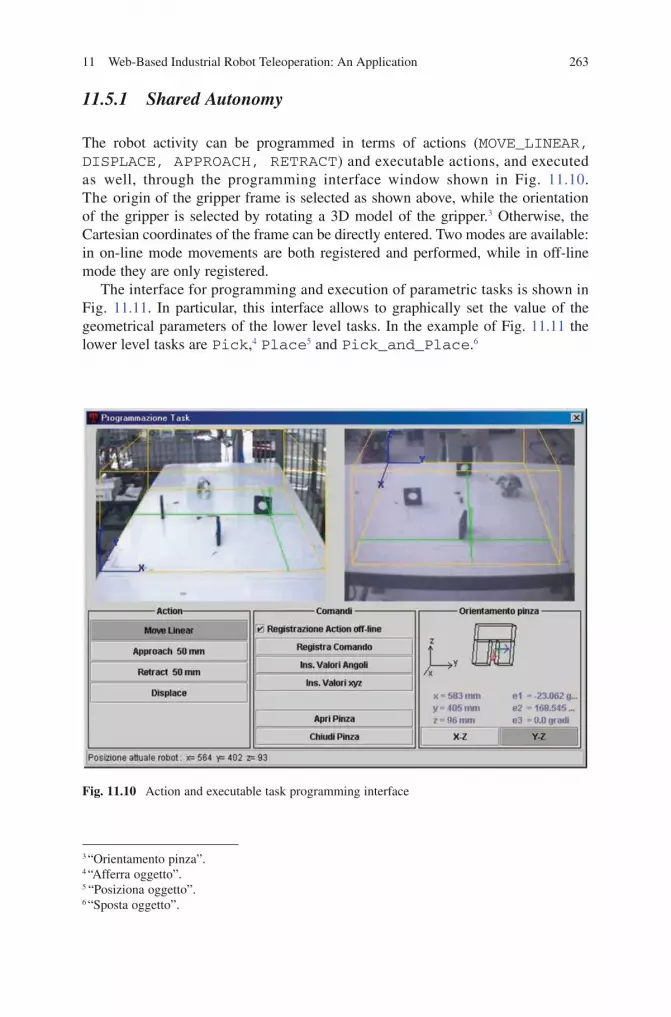
11 Web-Based Industrial Robot Teleoperation: An Application 263
BookID 175907_ChapID 11_Proof# 1 - 15/4/2009
Fig. 11.10 Action and executable task programming interface
3 “Orientamento pinza”.4 “Afferra oggetto”.5 “Posiziona oggetto”.6 “Sposta oggetto”.
11.5.1 Shared Autonomy
The robot activity can be programmed in terms of actions (MOVE_LINEAR, DISPLACE, APPROACH, RETRACT) and executable actions, and executed as well, through the programming interface window shown in Fig. 11.10. The origin of the gripper frame is selected as shown above, while the orientation of the gripper is selected by rotating a 3D model of the gripper.3 Otherwise, the Cartesian coordinates of the frame can be directly entered. Two modes are available: in on-line mode movements are both registered and performed, while in off-line mode they are only registered.
The interface for programming and execution of parametric tasks is shown in Fig. 11.11. In particular, this interface allows to graphically set the value of the geometrical parameters of the lower level tasks. In the example of Fig. 11.11 the lower level tasks are Pick,4 Place5 and Pick_and_Place.6

264 G. Ferretti et al.
BookID 175907_ChapID 11_Proof# 1 - 15/4/2009 BookID 175907_ChapID 11_Proof# 1 - 15/4/2009
11.6 Conclusions
A tele-sensor-programming concept of an industrial robot has been presented, which combines basic programming, shared autonomy control, and supervisory control functions. Shared autonomy is a suitable and feasible approach with a commercial, off-the-shelf, industrial controller, which accepts only high level operator commands, and circumvents the difficulties related to the communication delay by exploiting robot autonomous capabilities. The shared autonomy concept is the more effective the higher the degree of robot autonomy is, i.e. when the robot system is able to perform a larger variety of actions and (parametric) tasks. It should therefore be very attractive for state-of-the-art and future industrial robots, suitable to operate withexternalsensors,likeforceandvisionsensors.Hardwareandsoftwareimple-mentation of the system is entirely based on Internet oriented, low cost, commercial components, which guarantee high portability and independence from the client hardware and software platform.
An important field where use of the teleoperated system would be advantageous is education, both for students taking robotic programs and for continuing education of technicians in industry.
Future research should consider solutions to improve telepresence with predictive simulation, which is very important for shared autonomy under large communication delay. This is not a simple task, however, because of the variable and unpredictable
Fig. 11.11 Parametric task programming interface
11 Web-Based Industrial Robot Teleoperation: An Application 265
BookID 175907_ChapID 11_Proof# 1 - 15/4/2009
delay and the difficulties in emulating the trajectory generation algorithms of the actual controller. A second research direction aims at increasing the robot autonomy, namely at extending the list of actions the robot can execute, in order to fully exploit advantages of the shared autonomy teleoperation concept. This is however a major step, since it entails expanding the robot controller capabilities.
References
1. G. Goldberg, S. Gentner, C. Sutter, and J. Wiegley. “The Mercury project: a feasibility study for internet robots,” IEEE Robotics and Automation Magazine, vol. 7, no. 1, 2000, pp. 35–40.
2. O. Michel, P. Saucy, and F. Mondada. “KhepOnTheWeb: an experimental demonstrator in telerobotics and virtual reality,” 3rd Annual Conference on Virtual Systems and Multimedia VSMM’97, Sep. 10–12, 1997, Geneva, Switzerland, pp. 90–98.
3. P. Fiorini and R. Oboe. “Internet-based telerobotics: problems and approaches,” 8th International Conference on Advanced Robotics ICAR’97, July 7-9, 1997, Monterey, CA, USA, pp. 765–770.
4. P. Saucy and F. Mondada. “KhepOnTheWeb: open access to a mobile robot on the internet”, IEEE Robotics and Automation Magazine, vol. 7, no.1, 2000, pp. 41–47.
5. D. Schulz, W. Burgard, D. Fox, S. Thrun, and A. B. Cremers. “Web interfaces for mobile robots in public places”, IEEE Robotics and Automation Magazine, vol. 7, no. 1, 2000, pp. 27–34.
6. K. Taylor and B. Dalton. “Internet robots: a new niche,” IEEE Robotics and Automation Magazine, vol. 7, no. 1, 2000, pp. 27–34.
7. K. Brady and T. J. Tarn. “Internet-based teleoperation”, 2001 IEEE International Conference on Robotics and Automation ICRA01, May 21–26, 2001, Seoul, pp. 644–649.
8. G. T. McKee, “The development of internet-based laboratory environments for teaching robotics and artificial intelligence”, 2002 IEEE International Conference on Robotics and Automation ICRA02, May 2002, Washington, DC, pp. 2695–2700.
9. T. B. Sheridan, “Space teleoperation through time delay: review and prognosis,” IEEE Transactions on Robotics and Automation, vol. 9, no. 5, Oct. 1993, pp. 592–606.
10. G. Niemeyer and J. J. Slotine. “Stable adaptive teleoperation,” IEEE Journal of Oceanic Engineering, vol. 16, no. 1, Jan. 1991, pp. 152–162.
11. X.P.Liu,M.Q.-H.Meng,X.Ye,andJ.Gu.“AnUDP-basedprotocolforinternetrobots,”4th World Congress on Intelligent Control and Automation, June 10–14, 2002, Shanghai, P. R. China, pp. 59–65.
12.X.P.Liu,M.Q.-H.Meng,J.Gu,S.X.Yang,andC.Hu.“Controlanddatatransmissionfor internet robots,” 2003 IEEE International Conference on Robotics and Automation, Sep. 14–19, 2003, Taipei, Taiwan, pp. 1659–1664.
13. X.P.Liu,M.Q.-H.Meng,P.R.Liu,andS.X.Yang.“Anend-to-endtransmissionarchitecturefor the remote control of robots over IP networks,” IEEE Transactions on Mechatronics, vol. 10, no. 5, Oct. 2005, pp. 560–570.
14. J. E. Lloyd, J. S. Beis, D. K. Pai, and D. G. Lowe, “Model-based telerobotics with vision,” 1997 IEEE International Conference on Robotics and Automation ICRA’97, Apr. 20–25, 1997, Albuquerque, New Mexico, pp. 1297–1304.
15. A. Sano, H. Fujimoto, and T. Takai, “Network-based force-reflecting teleoperation,” 2000 IEEE International Conference on Robotics and Automation ICRA’00, Apr. 24–28, 2000, San Francisco, CA, USA, pp. 3126–3131.
16. I.Elhajj,N.Xi, andY.H.Liu,“Real-timecontrolof the internetbased teleoperationwithforce reflection,” 2000 IEEE International Conference on Robotics and Automation ICRA’00, Apr. 24–28, 2000, San Francisco, CA, USA, Apr. 2000, pp. 3284–3289.
17. G. Niemeyer and J. J. Slotine, “Toward force-reflecting teleoperation over the internet,” 1998 IEEE International Conference on Robotics and Automation ICRA’98, May 16–28, 1998, Leuven, Belgium, pp. 1909 –1915.
266 G. Ferretti et al.
BookID 175907_ChapID 11_Proof# 1 - 15/4/2009
18. R. Wirz and R. Marín. “Remote programming of an internet tele-lab for learning visual servoing techniques: a case study,” 2004 IEEE International Conference on Systems, Man and Cybernetics, Oct.10–13,2004,TheHague,Netherlands,pp.4414–4419.
19. R. Oboe and P. Fiorini. “Design and control environment for Internet-based telerobotics,” International Journal of Robotics Research, vol. 17, no. 4, Apr. 1998, pp. 433–449.
20. W. Zhu and S. E. Salcudean. “Stability guaranteed teleoperation: an adaptive motion/force control approach,” IEEE Transactions on Automatic Control, vol. 45, no. 11, Nov. 2000, pp. 1951–1969.
21. S. Munir and J. W. Book. “Internet based teleoperation using wave variables with prediction,” 2001 IEEE/ASME International Conference on Advanced Intelligent Mechatronics Proceedings AIM’01, July 8–12, 2001, Como, pp. 43–50.
22. G.Hirzinger,B.Brunner,J.Dietrich,andJ.Heindl.“ROTEX-thefirstremotelycontrolledrobot in space,” 1994 IEEE International Conference on Robotics and Automation ICRA’94, May 8–13 1994, San Diego, CA, USA, pp. 2604–2611.
23. G.Hirzinger,K.Landzettel,andC.Fagerer.“Teleroboticswithlargetimedelays-theROTEXexperience,” IEEE/RSJ/GI International Conference on Intelligent Robots and Systems, Part 1 (of 3), Sep. 12–16, 1994, Munich, Ger, pp. 571–578.
24. X.Houand J.Su. “Adistributed architecture for internet robot,”2004 IEEE International Conference on Robotics and Automation ICRA’04, Apr. 18–22, 2004, Barcelona, Spain, pp. 3357–3362.
25. X.HouandJ.Su.“Newapproachestointernetbasedintelligentroboticsystem,”2004 IEEE International Conference on Robotics and Automation ICRA’04, Apr. 18–22, 2004, Barcelona, Spain, pp. 3363–3368.
26. W.Lo,Y.Liu,I.H.Elhajj,N.Xi,Y.Wang,andT.Fukuda,“Cooperativeteleoperationofamultirobot system with force reflection via Internet,” IEEE/ASME Transactions on Mechatronics, vol. 9, no. 4, Dec. 2004, pp. 661–670.
27. R. Marín, Sanz, P. J. Sanz, P. Nebot, and R. Wirz T.. “A multimodal interface to control a robot arm via the web: a case study on remote programming,” IEEE Transactions on Industrial Electronics, vol. 52, no. 6, Dec. 2005, pp. 1506–1520.
28. G. Ferretti, G. Magnani, P. Putz, and P. Rocco. “The structured design of an industrial robot controller,” Control Engineering Practice, vol. 4, no. 2, Feb. 1996, pp. 239–249.
29. Z. Doulgeri, and T. Matiakis. “A web telerobotic system to teach industrial robot path planning and control”, IEEE Transactions on Education, vol. 49, no. 2, May 2006, pp. 263–269.
30. R. J. Anderson and M. W. Spong. “Bilateral Control of teleoperators with time delay,” IEEE Transactions on Automatic Control, vol. 34, no. 5, 1989, pp. 494–501.
31. ISO/IEC 14772 Part 1. “The Virtual Reality Modeling Language (VRML),” International Organization for Standardization and International Electrotechnical Commission, 1997.
32. ISO/IEC 14772 Part 2. “The External Authoring Interface (EAI),” International Organization for Standardization and International Electrotechnical Commission, 1997.
BookID 175907_ChapID 12_Proof# 1 - 15/4/2009
Chapter 12Teleworkbench: A Teleoperated Platform for Experiments in Multi-robotics
Andry Tanoto, Ulrich Rückert, and Ulf Witkowski
12.1 Introduction
Robot development is a highly complex and interdisciplinary process. It comprises several phases: design, implementation, as well as test and validation to name some of them. In test and validation, simulation is commonly used. However, experiments with real robots still have a very important role since simulations cannot accurately model the real environment and, as a result, produce inconclusive results [1]. Performing robotic experiments, however, is considerably tedious. It is a repetitive process consisting of several steps: setup, execution, data logging, monitoring, and analysis. Moreover, it also requires a lot of resources especially in the case of experiments in multi-robotics.
We have designed a system that can ease the tasks of performing experiments with single or multi minirobots, called the Teleworkbench [2]. The aim of the system is to provide a standard environment in which algorithms and programs can be tested and validated using real robots. As they run in a standardized environment, benchmarking in robotics can be achieved. Also there are several reasons to choose minirobots: the small-size, low-complexity, and low-cost to name a few. Moreover, it is easy to scale up developed solutions for minirobots to larger platforms or to scale them down to micro-mechanical systems (MEMS).
The Teleworkbench has some unique features: downloading user-defined programs to specific robots, robot tracking for more than thirty robots simultaneously, live video of the experiment, and a visualization tool for analyzing the experiments. With this system, we expect more efficient resource utilization (robots, robot modules, experiment fields, etc.); it can reduce idle periods of resources by adaptively allocating resources depending on the need. This system is also connected to the Internet to open its service to people in remote areas. As its access is broadening, there are more application possibilities for the Teleworkbench.
Recently, robots have been more commonly used in education to stimulate students’ interest in science and technology. In this regard, the Teleworkbench can have an
A. Tanoto (), U. Rückert, and U. WitkowskiSystem and Circuit Technology, Heinz Nixdorf Institute, University of Paderborn, Fuerstenallee 11, 33102 Paderborn, Germany [email protected]
S.G. Tzafestas (ed.), Web-Based Control and Robotics Education, 267Intelligent Systems, Control and Automation: Science and Engineering 38,DOI 10.1007/978-90-481-2505-0_12, © Springer Science + Business Media B.V. 2009

268 A. Tanoto et al.
BookID 175907_ChapID 12_Proof# 1 - 15/4/2009 BookID 175907_ChapID 12_Proof# 1 - 15/4/2009
important role in providing schoolchildren or students access to robots. As the robots are centralized and shared, it is not necessary to provide each student with one robot, which is economically not feasible yet. They can instead use robots anytime they need whenever the resources are available. As it is operable via the Internet, the distance will not be a problem for them to perform the experiment remotely. With the real-time infor-mation (video, robot position, exchanged communication, etc.) streamed over the Internet, users can have a high degree of interactivity with the robot. The system is also offering remote programming or also called teleprogramming by providing an API (application programming interface). There are also other applications related to educa-tion the Teleworkbench can provide, which will be further explored in this chapter.
Till now, there have been many efforts to make robots more affordable by developing cheap robots. However it is obvious that there is a correlation between robots’ features and their price. Robots that support high programmability and expandability are significantly more expensive than the ones without these features. At the same time we also notice the demands for such robots for research and education which, due to their price, are not always affordable for wide use.
This chapter is organized as follow. The first section presents our motivation of developing the Teleworkbench. In the next section, we describe the system in detail; we present an overview of its architecture and each of its main components. We describe in Section 1.3 two robotic platforms that we are using on the Teleworkbench. Section 1.4 presents some application scenarios in which the Teleworkbench can be advantageous, continued by some application scenarios using this system that have been done so far in our institute. Afterward, we will discuss some challenges that we are facing and some future work for dealing with those challenges. Finally, we conclude this chapter in a short summary.
12.2 The Teleworkbench System
The block diagram of the Teleworkbench system is shown in Fig. 12.1. The system con-sists of one partitionable field, five web cameras, a Bluetooth-based robot communication system, one Teleworkbench server, five video processing servers, and one webserver
The physical dimension of the field is 2 x 2 m, partitionable into a maximum of four fields with the size of 1 x 1 m. In each field, there is at least one recharging station for minirobots [3]. Each field will be monitored by one web camera and there is one additional web camera assigned to monitor the whole big field. Each camera is connected to one video processing server.
We have developed a wireless communication system using Bluetooth technology [4]. In this implementation, considering our small-size platform, we use Bluetooth of class 2 that has a communication range of 10 m and a maximum power output of 2.5 mW.
The main features of the Teleworkbench are:
• Experiment setup and execution. Local and remote users can setup and execute experiments involving many minirobots with various extension modules.
• Parallel experiment execution, up to four experiments simultaneously.

12 Teleworkbench: A Teleoperated Platform for Experiments in Multi-robotics 269
BookID 175907_ChapID 12_Proof# 1 - 15/4/2009
• Program-download to robot. Local and remote users are able to download their own programs to robots.
• Robot tracking system. The robot tracking system tracks robots captured by the webcam and extract robots’ position relative to the field.
• Wireless robot communication. The Teleworkbench uses Bluetooth technology for communication channel among robots as well as between robots and the Teleworkbench Server.
• Live-video of the experiment. During experiments, users can watch in real-time the progress of the experiment through the live-streamed-video of the experiment taken by webcams.
• Events and messages logger. All events and exchanged messages are recorded and accessible.
• Post-experiment analysis tool. An interactive MPEG4-video can be generated to show some important information recorded during the experiment, that can be used for analyzing the experiment. Moreover, since all information is stored in one file, it provides comfort in exchanging and presenting research result.
• Interoperability. The Teleworkbench system is designed to allow communica-tion with other programs/systems. The communication can be implemented by using socket communication and a text-based communication protocol. Du et al. in [5] show an example of the interoperability by using web service technology for robot teleoperation.
• Internet connectivity. The Teleworkbench is connected to the Internet, which allows easy access for remote users located on every part of the world.
Next, the main components of the system will be described in more detail.
Fig. 12.1 The diagram of the Teleworkbench system depicting its main components and the interconnection among them
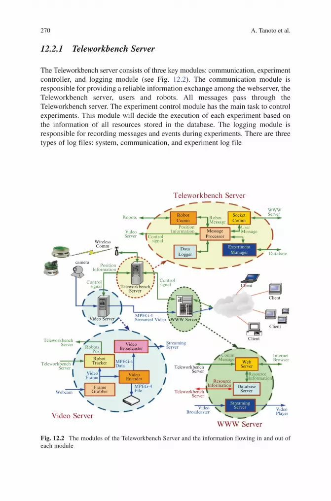
270 A. Tanoto et al.
BookID 175907_ChapID 12_Proof# 1 - 15/4/2009 BookID 175907_ChapID 12_Proof# 1 - 15/4/2009
12.2.1 Teleworkbench Server
The Teleworkbench server consists of three key modules: communication, experiment controller, and logging module (see Fig. 12.2). The communication module is responsible for providing a reliable information exchange among the webserver, the Teleworkbench server, users and robots. All messages pass through the Teleworkbench server. The experiment control module has the main task to control experiments. This module will decide the execution of each experiment based on the information of all resources stored in the database. The logging module is responsible for recording messages and events during experiments. There are three types of log files: system, communication, and experiment log file
Teleworkbench Server
Video ServerWWW Server
RobotComm
Robots
VideoServer
WirelessComm
camera
Controlsignal
Video Server
Controlsignal
MPEG-4Streamed Video
PositionInformation
TeleworkbenchServer
WWW Server
StreamingServer
VideoBroadcaster
VideoBroadcaster
VideoPlayer
StreamingServer
InternetBrowser
DatabaseServer
VideoEncoder
RobotsPos
RobotTracker
TeleworkbenchServer
TeleworkbenchServer
ResourceInformation
ResourceInformation
WebServer
Client
Client
Client
Client
CommMessage
TeleworkbenchServer
TeleworkbenchServer
Webcam
MPEG-4Data
MPEG-4File
FrameGrabber
VideoFrame
Controlsignal
RobotMessage
UserMessage
WWWServer
Database
PositionInformation Message
Processor
DataLogger
SocketComm
ExperimentManager
Fig. 12.2 The modules of the Teleworkbench Server and the information flowing in and out of each module

12 Teleworkbench: A Teleoperated Platform for Experiments in Multi-robotics 271
BookID 175907_ChapID 12_Proof# 1 - 15/4/2009
12.2.2 Video Server
The main modules of video server are frame grabber, robot tracker, video encoder, and video broadcaster (see Fig. 12.2. left-bottom). The robot tracker module works by processing the video captured by the web camera. The output of this module is the position, orientation, and ID number of the robots. For robot identification and tracking, color-coded markers are put on top of the robots (see Fig. 12.3). This method enables the robot tracker to identify up to 36 robots. At the same time, the video encoder encodes the grabbed frame into video stream. Consecutively, the video stream is saved as a video file and transmitted to the video streaming server by the video broadcaster.
12.2.3 WWW Server
There are three modules located in the WWW Server: the Web Server, the Video Streaming Server, and the database. The Web Server provides the web-based user interface written in PHP (a recursive acronym of PHP: Hypertext Preprocessor) scripting language, which enables communication between the user and the Teleworkbench server (see Fig. 12.2). The Video Streaming Server is responsible for streaming the video to the client (see Fig. 12.4). The advantage of streaming a video is that users can watch the video without having to wait until the entire video data is downloaded. The database serves as the resource information storage. The recorded information is important for determining the execution of experiments.
12.2.4 Teleworkbench Post-experiment Analysis Tool
Robot software development is a tedious task. It is a repetitive design process consisting of program generation (writing and compiling the code), simulation,
A box for givingorientationinformation
Color Coding
IDColor I
Color R G B Value Color R G B ValueColor II
91011
36
37
38
BlueBlueBlue
Red
Red
Red
000
1
1
1
000
0
0
0
111
0
0
0
888
32
32
32
BlueGreenCyan
Red
Megenta
Yellow
000
1
1
1
011
0
0
1
101
0
1
0
123
4
5
6
The first colorrepresenting threemost significant bits
The second colorrepresenting threeleast significant bits
Fig. 12.3 An example of a marker for robot identification and positioning. The table on the right shows the color coding

272 A. Tanoto et al.
BookID 175907_ChapID 12_Proof# 1 - 15/4/2009 BookID 175907_ChapID 12_Proof# 1 - 15/4/2009
and experiment validation using real robots. For experiment validation, we see the importance of having a tool for analyzing the result of experiments using real robots that can help robot programmers to understand the behavior of the robots (Fig. 12.5)
The developed post-experiment analysis tool is able to support robot programmers in analyzing experiments by visualizing occurred events and exchanged messages. This tool is based on the MPEG-4 standard [6]. It visualizes computer-generated objects on top of the video of the experiment. The tool consists of two main parts: the visualization generator and the MPEG-4-based video.
12.2.4.1 Visualization Generator
The block diagram of the visualization generator is shown in Fig. 12.5a. At the input, it takes some information from other components of the Teleworkbench: the position log file, the communication log file, and the video taken by the webcam. At the output, the process generates an interactive video which can be used as a user interface and visualization.
Embedded videoshowing the live-video
Menu for interacting withthe Teleworkbench and
robots.
Setup & executeexperiments
Direct interaction with theTeleworkbench & robots.
Watch the live-video fromthe webcams
Browse the archives ofexperiment results
Browse thedocumentation of the
system.
For administration only
Fig. 12.4 A snapshot of web-based user interface embedded with live-video used for remotely monitoring the robot over the Internet

12 Teleworkbench: A Teleoperated Platform for Experiments in Multi-robotics 273
BookID 175907_ChapID 12_Proof# 1 - 15/4/2009
The visualization generator is basically composed of a data extractor, scene generator, and MPEG-4 scene encoder (Fig. 12.5b). In the following paragraphs, a short description of each component will be presented
Data Extractor
Data extractor processes the data to provide information needed by the scene generator. The input data are video from the webcam, as well as the position and communication log files. The video and position log file are generated by the Robot Tracker, and the communication log file is provided by the Data Logger.
MessageLogger
Data Extractor
Visualization BuilderVisualization Builder
Scene Generator
MPEG4 SceneEncoder
MPEG4 File
MPEG4Player
RobotTracker
PositionVideo
Communication
CommunicationPosition
Position,Orienation,
Communication,Sensor, etc
SceneryInformation
Video
a
Fig. 12.5 The visualization generation process and a snapshot of the generated visualization in a form of MPEG-4 video. (a) The process flow of the visualization generator. (b) An example of the MPEG-4 video used as a user interface for experiment analysis
The robot marker, which is clickable to select the robot for further detailed information
The visualization of the linear camera data showing the ball.
The visualization of the infra-red sensor. The bigger, the closer it is to the object.
Video player menu, the same as the common video players.
b
The visualization menu, to de-/activate a certain information from the display.
The area to display more detail information of the selected robot.
The slider, to move to a particular time of the video.
A line representing the robot path.

274 A. Tanoto et al.
BookID 175907_ChapID 12_Proof# 1 - 15/4/2009 BookID 175907_ChapID 12_Proof# 1 - 15/4/2009
The position log file provides two types of important information for the data extractor. The first one is the frame information consisting of frame numbers and time stamps. This information is required to synchronize the computer generated objects with the input video data. The second information is the position and orientation of the robots. This information is required for drawing the visualization objects at the right position and orientation.
The communication log file contains some information which is transmitted/received by the robots. As a result, its contents vary depending on how the robots are programmed. In general, robot programmers can define as many types of information as possible. Accordingly the information will be visualized by this tool. In the current version, the tool visualizes few types of information, e.g. infra-red sensors, linear camera, robots’ states, and other communicated messages. The last type includes all messages which do not belong to any of the first three types of information. To differentiate one type of information from the others, some specific characters are used as tags, each of which represents a different type of information.
Scene Generator
The scene generator generates a scene description which is required by the MPEG-4 scene encoder for creating a computer-generated animation overlaying the input video data. The scene description is based on XMT-A, which is one of the Extensible Markup Language (XML)-based formats supported by the MPEG-4 standard.
The scene description contains the information of all objects to be visualized and how they change, in term of position, orientation, shape, size, etc. For example, it describes how the objects representing the robots should move as well as how the graphs representing the internal states of the robots change from time to time. Moreover, it also describes how these objects should react to users action. As an example, a click on an object may cause some other objects to be hidden.
MPEG-4 Scene Encoder
MPEG-4 scene encoder generates an MPEG-4 file based on the scenery information written in XMT-A format. The heart of this component is the open source software called MP4BOX, a command-line MPEG-4 scene encoder of the GPAC project [7]. The output from MP4Box is a video file in MP4 format. There are two reasons for using this software. First, it supports many types of multimedia data, e.g. MPEG-4 video and audio, JPEG and PNG images, AVI, etc., which means we can easily combine many kinds of multimedia data into one file. Second, it is an open source software. For more details on the GPAC project in general and the MP4BOX in particular, interested readers are referred to the aforementioned reference.

12 Teleworkbench: A Teleoperated Platform for Experiments in Multi-robotics 275
BookID 175907_ChapID 12_Proof# 1 - 15/4/2009
12.2.4.2 Interactive Video as User Interface
A snapshot of the video as a user interface is shown in Fig. 12.4. The part in the middle is the video taken by a webcam located above the experiment field. In the same part, some computer-generated objects will be superimposed onto the video near the corresponding robot. These objects represent information such as robots’ body, communication messages, robots’ path, battery level, internal states, and robots’ camera data, etc.
In the area on the right side, there are two sub-areas, the first sub-area above is the menu area at which users can select the information they want to see at any time. The second one below is the detail-information area in which users can have a more detailed visualization of the selected information.
12.2.5 Teleworkbench Application Programming Interface (API)
There are two roles of the Teleworkbench: the experiment manager and the telerobotic platform. In the first role, it allows users to setup and execute experiments using one or many robots. During experiment setup, users can define robot programs for each robot. Later, when all parameters of the experiment are completely set and the resources are available, it will execute the experiment automatically. In the latter role, the Teleworkbench allows remote users to control robots through the Internet. It is this functionality that we want to extend so that a program running on a different machine can also control the robot.
Inside the Teleworkbench Server, there is a module for processing and redirecting the incoming messages. There are three possible sources of messages: robots, other modules, and other external systems (see Fig. 12.6a). To enable communication with external systems, the Teleworkbench acts as a server which is listening to a port and waiting for any incoming message. At the moment, the server is developed to accept only messages sent using TCP/IP
Figure 12.6b shows the architecture of the API and its connection to the Tele workbench. We use a layered architecture to provide flexibility in implementing and maintaining the API. Each layer represents a different abstraction level. The lowest layer, the Socket Communication Layer, is responsible for exchanging messages from layers above it to the Teleworkbench Server. The top layer is assigned for complex robot behavior functions. By structuring the API in layers, users can flexibly select the layer they think is most appropriate for their application. It often occurs that different users have different algorithms for similar tasks, such as path planning, obstacle avoidance, etc. The differences are commonly in the high abstraction level, most likely above the Robot Specific Layer. Thus, the layers below are still reusable and users can better concentrate on implementing their own algorithm. Another advantage of using layer architecture is that changes in one specific layer will not force changes in the others, so long the interface is kept consistent.

276 A. Tanoto et al.
BookID 175907_ChapID 12_Proof# 1 - 15/4/2009 BookID 175907_ChapID 12_Proof# 1 - 15/4/2009
Fig. 12.6 The Teleworkbench API. (a) Three possible message sources. The message processor will process and redirect the message according to the Teleworkbench Communication Protocol. (b) The layered architecture of the Teleworkbench API
12.2.6 Teleworkbench Graphical User Interface (GUI)
To support remote operation and monitoring, we have developed a graphical user interface (GUI) using Java technology. The GUI is designed to provide some levels of interactivity with the Teleworkbench System as well as with the robots on the field. Low level interaction can be performed either through clicking the navigation button or pressing some keys on the keyboard or typing commands in the command field box. High level interaction can, for an example, be done by clicking the robots to determine the target of the command followed by clicking any point on the field or by giving a high-level command in the command field box. A snapshot of the GUI is shown in Fig. 12.7

12 Teleworkbench: A Teleoperated Platform for Experiments in Multi-robotics 277
BookID 175907_ChapID 12_Proof# 1 - 15/4/2009
12.3 Robot Platform
We currently use two types of minirobots as the robotic platform for the Teleworkbench: Khepera II from K-Team and BeBot from Heinz Nixdorf Institute (HNI). There are several reasons that minirobots are preferable. Minirobots are well suited for multi-robot experiments. They need relatively few resources, in terms of space, cost, and power. For example, experiments using minirobots will require much less space than the ones using big robots. As an illustration, for Khepera II minirobot, a field of size 2 x 2 m is more or less equal to a field of size 11.6 x 11.6 m for robot Pioneer3-DX (44 x 38 x 22 cm). Moreover, the acquisition and maintenance of such robots are financially less demanding than their counterparts. Another driving factor of using minirobots is that they can provide the possibility to easily scale-up or scale-down the developed solutions to other platforms, e.g. to bigger platforms, such as larger robots and automobiles, or to smaller platforms, such as Micro-Electro-Mechanical Systems (MEMS). Thus, they can be a suitable test bed for research in many diverse areas. Furthermore, due to their low cost, they can be a suitable tool for education and entertainment (edutainment as we call these two terms) by providing an option for learning science in an entertaining way. Additionally, they can stimulate robotic research by providing access to robot hardware to more researchers.
GUI in JavaApplet
shown in anInternetBrowser
Robot withID
Robot path
One of thefields where
the robotsrun
Menu area showingoptions and additionalinformation
Tabs to select the kind of interaction or information to display
Communicationdelay between GUI and TeleworkbenchServer
Fig. 12.7 A Snapshot of the Teleworkbench GUI used for remotely controlling a robot over the Internet

278 A. Tanoto et al.
BookID 175907_ChapID 12_Proof# 1 - 15/4/2009 BookID 175907_ChapID 12_Proof# 1 - 15/4/2009
We should note here that although minirobots are currently the supported robotic platform, the idea of the Teleworkbench is applicable for any type of robot. The most relevant issue here is the ratio of the size of robot and the field. Thus, it is possible, for instance, to use big robots, such as Pionner3-DX, as the robotic platform and a basketball field as the experiment field. The following subsection shortly presents the two types of robot that are currently used in our group.
12.3.1 Khepera Minirobot
Khepera II [8] is the successor of the older version of miniature mobile robot Khepera. It is designed with functionality similar to larger robots used in research and education. There are some advantages of Khepera II, some of which are: compact, easy to use, decent microprocessor, many sensors and actuator extensions (see Fig. 12.8a showing the Khepera II with some extension modules). Moreover, it is widely used for real-world testing to support developing algorithms, namely trajectory planning, obstacle avoidance, pre-processing of sensory information, and hypotheses on behavior processing
12.3.2 BeBot – HNI Minirobot
BeBot is a new minirobot platform developed by HNI [9]. The robot has a base area of about 9 x 9 cm with a height of about 7 cm (see Fig. 12.8b). It has chain drives with DC motors and incremental encoders which enable it to operate on rough surface. For processing a PXA270 microprocessor at 520 MHz running Linux and a Spartan3E 1200 FPGA for reconfigurable computing are integrated. The robot is equipped with 64 MByte SDRAM and 64 MB Flash RAM. For communication, Bluetooth and Zigbee are integrated by default, while WLAN can be connected via a USB slot. Integrated connectors include USB, RS232, IC, SPI, and MMC/SD Card. The sensors of the robot include 12 infrared-sensors with a range of up to 10 cm and a color camera with a resolution of 640 x 480 pixels. Moreover, the robot has a display, a speaker and a microphone for user interaction.
12.4 Application Scenarios in Research and Education
We have been using the Teleworkbench for our research and education activities in our institute for about 6 years. In research, several cooperative activities in robotics with other universities or other working groups have been going on for a while. In education, we are offering some courses related to robotics, i.e. Autonomous System Engineering and Embedded Systems, in which students may have to use the

12 Teleworkbench: A Teleoperated Platform for Experiments in Multi-robotics 279
BookID 175907_ChapID 12_Proof# 1 - 15/4/2009
Teleworkbench for their assignments. Moreover, there are also possibilities for students to use this system for their intermediate or final projects.
The Teleworkbench has a wide range of applications (see Fig. 12.9). Users can use it for robot remote control and monitoring as well as online/offline analysis.
Fig. 12.8 Two types of robot platform currently used on the Teleworkbench (a) Mini-robot Khepera II with some extension modules (from left clock-wise): ASIC with associative memory, a gripper and a linear camera module, Bluetooth module, VGA camera module, and infra-red communication module. (b) BeBot minirobot developed by the Heinz Nixdorf Institute has more computational power than Khepera II

280 A. Tanoto et al.
BookID 175907_ChapID 12_Proof# 1 - 15/4/2009 BookID 175907_ChapID 12_Proof# 1 - 15/4/2009
Additionally, its API allows remote programs to communicate and control the Teleworkbench as well as the robots. In the following sub-section, we will see some application scenarios together with some examples of the Teleworkbench in assisting us in research and education activities.
12.4.1 From Local to Remote Experiment
The original idea of the project was that local users can setup and execute experiments remotely. During experiment setup, they can define the number of robots and the extension modules needed for the experiments. Moreover, they can also define the program for each robot. This means that users can compile the program for the robot and then upload it to the web server. When the experiment is about to start, the Teleworkbench Server will download the program from the web server to the robot.
As the Internet infrastructure becomes commonplace and faster, we see it feasible to make the Teleworkbench accessible to geographically dispersed users. In this way, we can offer flexibility to users, either students or researchers, for doing experiments. As it is remotely accessible, they do not need to come to the site to perform the experiment. As it can determine the execution of the experiments automatically, users can setup many experiments at the same time and get the results afterward. Additionally, we can also offer services to local schools to help them giving the schoolchildren hands-on experience with robots.
Camera
Bluetooth
WWW Server
TeleworkbenchSystem
Java Program Matlab Script C/C++ Program
TWB API
Internet
Online/Offline AnalysisLive VideoRobot Remote Control
Fig. 12.9 The Teleworkbench application scenarios. It supports interoperability with other systems connected via the Internet

12 Teleworkbench: A Teleoperated Platform for Experiments in Multi-robotics 281
BookID 175907_ChapID 12_Proof# 1 - 15/4/2009
In the following paragraphs, we present two scenarios in which remote users can use the Teleworkbench.
12.4.1.1 Web Service Interfaces for Mobile Autonomous Robots
As web service can ensure interconnectivity and interoperability, we think that it can enhance the operation of mobile autonomous robots. Autonomous mobile robots have the ability to perceive and physically interact with the real world. By equipping mobile autonomous robots with web service interfaces, a standardized, interoperable way for world-wide access to the robots could be provided. Moreover, web service can enable the mobile robots to be accessible by virtually any client, regardless of location, programming language, or platform.
In this project, we adopt two approaches. The first solution uses an intermediate server to provide the web service interface. This server processes the SOAP 1 messages received from the user, translates them into commands suitable for the robot and sends them to the robot over the wireless Bluetooth connection. This approach is suitable for cases where robots do not have their own web service interface integrated. The second solution uses a gSOAP engine [11] ported to the Khepera platform. In this method, the robot runs a complete web service and all web service-related processing is performed on the robot while the intermediate server merely forwards incoming connections from the internet to the robot. Thus the robot becomes a fully self-contained web service and is independent from intermediate specialized servers. Figure 12.10 shows the implementation of the second approach. The role of the Teleworkbench Server is to forward the message from the intermediary server to the robot via Bluetooth.
12.4.1.2 Robot Tele-Programming
Robot tele-programming is an activity to develop a program locally and then to download it to remote robots. Tele-programming is desirable when we want to control the robot at the low level. Normally users write the code on their PC, compile the code, and then transfer the compiled code to the microcontroller on the robot. Whenever there is a need to modify the behavior of the robot, the aforementioned steps are repeated.
The Teleworkbench provides a convenient way to perform tele-programming. Users can write several versions of the robot program and set up several experiments to test each of the versions. The experiment execution will be done automatically by the Teleworkbench by taking into consideration the available resources, such as the field, robots and their modules. Snapshots in Fig. 12.11 show how experiments can be set up and how their results can be acquired
1 SOAP used to stand for Simple Object Access Protocol. However, starting from SOAP version 1.2 standards [10], this acronym is no longer used because it was considered misleading.

282 A. Tanoto et al.
BookID 175907_ChapID 12_Proof# 1 - 15/4/2009 BookID 175907_ChapID 12_Proof# 1 - 15/4/2009
12.4.2 Batch, Interactive, and Sensor Experiments
Harward et al. [12] group experiments into three classes: batched experiment, inter-active experiment, and sensor experiment. In batched experiments, users specify the course of the experiments before they begin. In interactive experiments, users can monitor as well as interact with some aspects of the experiments during runt-ime. In sensor experiments, users only monitor or analyze real-time data streams without influencing the course of the experiments.
From the definition above and also from the previous sections, it is obvious that the Teleworkbench is able to provide to users those three types of experiments. Users can setup experiments: how long the experiments last, how many robots are involved, which robot modules to use, which programs to download to the robot, where the
Fig. 12.10 The web service implementation using the Teleworkbench (a) The system architecture of the second approach. (b) A snapshot of the user interface with embedded real-time video
Rem
ote U
ser Interface
Teleworkbench
a
ServerCamera
Khepera Robot with gSOAP Engine
ExtensionModule
IntermediaryServer
Video Stream
Intern
et
SOAP Messages
SOAP Messages
RS232 over Bluetooth
VideoStream
Visual Data
Live-Video streamedby the Teleworkbench
Steuerungsseite Khepera mit gSOAPb
Input fromUser
Color ID of the robot tobe controlled
Target position andorientation (x,y,alpha)
Transmit the message
Robot which willreceive the message
The experiment fieldof size 1m x 1m

12 Teleworkbench: A Teleoperated Platform for Experiments in Multi-robotics 283
BookID 175907_ChapID 12_Proof# 1 - 15/4/2009
robots will start, etc (see Fig. 12.11). In this mode, users can setup as many experiments as possible and the Teleworkbench will then execute each of the experiments whenever the resources are available. Moreover, through the user interface, either the web-based as well as the graphical one, users can interact with some aspects of the experiment, e.g. monitor as well as observe the robot, directly control the robots, or terminate
Fig. 12.11 Setup and execute experiments through the web-based user interface (a) A list of experiments already set-up. (b) Detail information of an experiment with links to result of the experiment execution
Sub-menu for experiment setup
a
Owners of the experiment
The number of robots used
The duration in (hh:mm) The description
The status of the experiment
Link to detail information
Sub-menu forexperiment archive
General Information of theExperiment
b
Information of the robotsused in the experiment
The data (e.g. robotprogram) used in the
experiment
The status of theexperiment execution
The result of theexperiment ready for
download

284 A. Tanoto et al.
BookID 175907_ChapID 12_Proof# 1 - 15/4/2009 BookID 175907_ChapID 12_Proof# 1 - 15/4/2009
the experiment. It is also possible to use the Teleworkbench to run an experiment for demonstration purpose. e.g. to show students some practical implementation of some particular algorithms running on real robots.
In this mode, users, in this case the students, only watch and observe some information about the robots that are streamed and displayed to help them to understand the algorithms being implemented.
12.4.3 From Simulator to Real-Robots
Robot software development process in general consists of several stages: coding, simulation, and testing with real robots (see Fig. 12.12). Although simulation is important in the early stage of the development, testing with real robots is still compulsory. However, testing with real robots is a tedious task and takes a lot of resources.
Thus, it is common practice to firstly perform simulation intensively and proceed to testing with real robots after the simulation results are convincing. Depending on the simulator used, the transition from simulation to testing with real robots can be either seamless or tedious. The issue here is that the simulators and the robots use different types of programming languages and libraries. Some simu-lators support seamless transition, some do not. The first type of simulators requires users to write the program only once and they will take care of generating the native code for a specific robot, if it is supported. The latter cannot provide such function-ality, thus users have to rewrite their code for a specific robot platform.
The Teleworkbench has been developed with an aim of assisting users in performing experiment with real robots. Moreover, its design enables it to support several types of experiments for testing and validation purpose, as described in earlier sections. The development of its application programming interface (API) adds more features to the list. With the API, users can develop and test robot
Fig. 12.12 The role of the Teleworkbench in robot software development process. The GUI implements the first three layers: Socket Communication Layer, Teleworkbench Communication Protocol Layer, and Robot Specific Layer

12 Teleworkbench: A Teleoperated Platform for Experiments in Multi-robotics 285
BookID 175907_ChapID 12_Proof# 1 - 15/4/2009
programs easily without being concerned with porting their code to any particular robot platform. As it provides several abstraction levels, users are free to take any level they think most suitable for their application and integrate it into their code.
Another advantage of this API is that the Teleworkbench becomes more transparent to users. It means that users will have similar experience in robot programming whether they do it via the Teleworkbench or directly on the robots. Furthermore, this API is intended to provide interoperability with other types of systems. As an example, the developed graphical user inter-face uses the Java version of the API for communication with the Teleworkbench.2 Another example is the off-board robot programming. Such a program can be written in any common programming language for a personal computer (PC). Depending on the abstraction levels chosen, the API eases the task of developing such a program. In Fig. 12.13, a program written in C controls a Khepera II minirobot on the Teleworkbench. This program runs on a PC about ten meters away from the Teleworkbench. Through the live-video, users can monitor the experiment during runtime, and accordingly terminate the experiment if required. On the robot, a small program is running to enable users to control it at low-level (e.g. to command the wheels to spin at a particular speed) or at high-level (e.g. to command the robot to go to a certain position).
As simple as it looks, we are aware that robot programming is a complex task.
Moreover, it involves real-time multi-threaded programming. As a result, the pro-posed API may not work properly in some specific settings, e.g. when hard real-time is required. In this case, there is a possibility of combining the developed API with teleprogramming. This way, the hard real-time part, e.g. obstacle avoidance and
The integrateddevelopmentenvironment
(IDE) used towrite the codefor controlling
the robot
Messagesoutput by the
program
The live video to observehow the experimentgoes
The robot with color ID on top
Fig. 12.13 An example of an off-board program running on a PC. The program controls the robot to go to four target points and to avoid obstacle in between
2 The GUI implements the first three layers: Socket Communication Layer, Teleworkbench Communication Protocol Layer, and Robot Specific Layer.
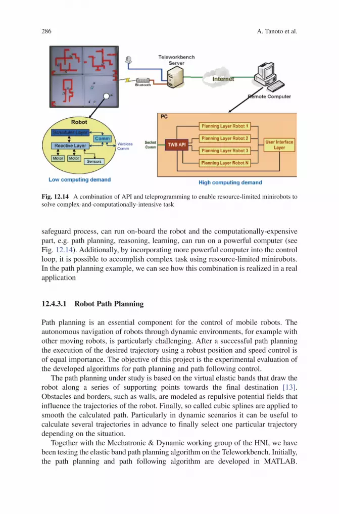
286 A. Tanoto et al.
BookID 175907_ChapID 12_Proof# 1 - 15/4/2009 BookID 175907_ChapID 12_Proof# 1 - 15/4/2009
safeguard process, can run on-board the robot and the computationally-expensive part, e.g. path planning, reasoning, learning, can run on a powerful computer (see Fig. 12.14). Additionally, by incorporating more powerful computer into the control loop, it is possible to accomplish complex task using resource-limited minirobots. In the path planning example, we can see how this combination is realized in a real application
12.4.3.1 Robot Path Planning
Path planning is an essential component for the control of mobile robots. The autonomous navigation of robots through dynamic environments, for example with other moving robots, is particularly challenging. After a successful path planning the execution of the desired trajectory using a robust position and speed control is of equal importance. The objective of this project is the experimental evaluation of the developed algorithms for path planning and path following control.
The path planning under study is based on the virtual elastic bands that draw the robot along a series of supporting points towards the final destination [13]. Obstacles and borders, such as walls, are modeled as repulsive potential fields that influence the trajectories of the robot. Finally, so called cubic splines are applied to smooth the calculated path. Particularly in dynamic scenarios it can be useful to calculate several trajectories in advance to finally select one particular trajectory depending on the situation.
Together with the Mechatronic & Dynamic working group of the HNI, we have been testing the elastic band path planning algorithm on the Teleworkbench. Initially, the path planning and path following algorithm are developed in MATLAB.
Fig. 12.14 A combination of API and teleprogramming to enable resource-limited minirobots to solve complex-and-computationally-intensive task

12 Teleworkbench: A Teleoperated Platform for Experiments in Multi-robotics 287
BookID 175907_ChapID 12_Proof# 1 - 15/4/2009
To enable communication with the Teleworkbench, a simple socket communication library is written Java, which is callable inside MATLAB. The picture at the top of Fig. 12.15 shows one experiment using three robots. Two of them are used as a static and a dynamic obstacle. However, the fact that this MATLAB implementa-tion is not fast enough leads to the effort of porting the program to C/C++. Subsequently, BeBot is used to replace Khepera II. Additionally, the path following algorithm is ported to run on-board the robot. In this way, only the path planning runs off-board the robot due to its resource-intensive computation. The Teleworkbench API is used to enable communication between the path planning and the robot. One example of the experiment is shown in the picture at the bottom of Fig. 12.15. In this setting, two robots are used to demonstrate an overtaking maneuver scenario
12.4.4 Robotic Experiment Analysis
The Teleworkbench is originally designed for providing a standardized environment for executing and analyzing robotic experiments. The pose information of the robot extracted from the video data is useful not only during runtime but also during analysis. Together with the logged messages and the recorded video, they can provide useful information of the behavior as well as the performance of the robots.
Fig. 12.15 The result of path planning experiments. The picture at the top shows robot path planning using Khepera II. The path planning and path following algorithm are written in Matlab and run on a PC. The path follower controls the robot via the Teleworkbench. Another robot is used to simulate a moving object to test the reliability of the algorithm. The picture at the bottom shows the robot path planning experiment using BeBot minirobot. The path planning algorithm runs on a PC and communicates with the robot via the Teleworkbench. The path following algorithm runs on board the robot
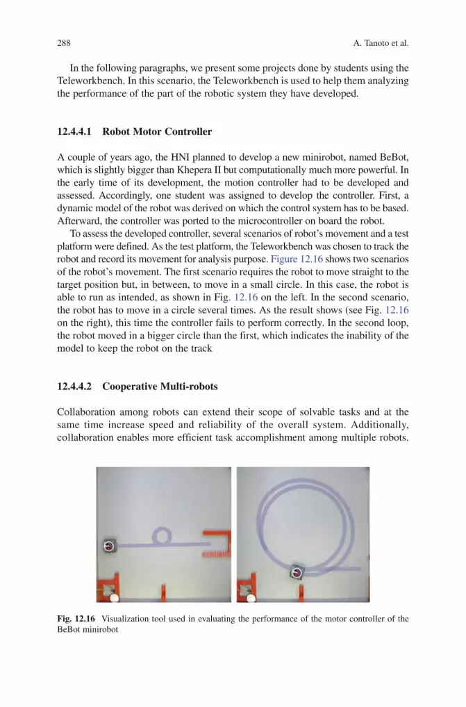
288 A. Tanoto et al.
BookID 175907_ChapID 12_Proof# 1 - 15/4/2009 BookID 175907_ChapID 12_Proof# 1 - 15/4/2009
In the following paragraphs, we present some projects done by students using the Teleworkbench. In this scenario, the Teleworkbench is used to help them analyzing the performance of the part of the robotic system they have developed.
12.4.4.1 Robot Motor Controller
A couple of years ago, the HNI planned to develop a new minirobot, named BeBot, which is slightly bigger than Khepera II but computationally much more powerful. In the early time of its development, the motion controller had to be developed and assessed. Accordingly, one student was assigned to develop the controller. First, a dynamic model of the robot was derived on which the control system has to be based. Afterward, the controller was ported to the microcontroller on board the robot.
To assess the developed controller, several scenarios of robot’s movement and a test platform were defined. As the test platform, the Teleworkbench was chosen to track the robot and record its movement for analysis purpose. Figure 12.16 shows two scenarios of the robot’s movement. The first scenario requires the robot to move straight to the target position but, in between, to move in a small circle. In this case, the robot is able to run as intended, as shown in Fig. 12.16 on the left. In the second scenario, the robot has to move in a circle several times. As the result shows (see Fig. 12.16 on the right), this time the controller fails to perform correctly. In the second loop, the robot moved in a bigger circle than the first, which indicates the inability of the model to keep the robot on the track
12.4.4.2 Cooperative Multi-robots
Collaboration among robots can extend their scope of solvable tasks and at the same time increase speed and reliability of the overall system. Additionally, collaboration enables more efficient task accomplishment among multiple robots.
Fig. 12.16 Visualization tool used in evaluating the performance of the motor controller of the BeBot minirobot

12 Teleworkbench: A Teleoperated Platform for Experiments in Multi-robotics 289
BookID 175907_ChapID 12_Proof# 1 - 15/4/2009
By exchanging information about their positions, their current task, etc., global information of the current situation can be obtained, which in turn can help them to achieve an optimum solution.
In a cooperative multi-robot system, each robot needs the ability to mutually offer each other services in an open, heterogeneous network and they must be able to efficiently discover and use those services. Only this feature will allow them to cooperate flexibly and dynamically to solve tasks. Thus, service discovery allows a constant, task-oriented self-configuration of the overall system to achieve required goals. One solution for service discovery in networks of mobile robot systems has been developed by our working group. Its capability has been demonstrated and tested through simulation as well as a working implementation on real robots.
A small example scenario is devised to demonstrate this approach. The demon-stration uses four Khepera robots equipped with wireless communication modules. Three types of robots are used: robots equipped with additional camera modules, a transport robot equipped with an additional gripper module, and a patrol robot with no additional extension modules except for the communication module.
In the implementation on real robots, the Teleworkbench is used as the infra-structure for a cooperative multi-robot system. It can provide a communication channel among robots; it has the functionality to send messages from one robot to another or to broadcast messages to all robots on the field. Hence, it can reduce the effort during the implementation. Additionally, the Teleworkbench is also used as the tool for analysis. As software for multi-robot systems is typically distributed, multi-threaded, and real-time, it is very laborious and complex to match the data received from the robots (such as sensor values, actuator commands, internal states, or communication data) with observable external parameters extracted from the recollection or recorded on video like position, orientation, speed, and other robot actions. With the analysis tool presented earlier, users can debug multi-robot systems through the produced video which can serve also as the user interface. The result of the experiment can be presented in a single, interactive interface where users can go forward or backward to situations and selectively activate information (see Fig. 12.17). In this way, users can quickly grasp a situation, whereas the possibility of selectively activating information helps them in analyzing interesting events in depth
12.4.4.3 Swarm Robots
In research, models have been developed to simulate the behavior of human crowds in panic and escape situations [14]. The findings gained from such simulations help engineers design escape routes for areas where mass panic situations may occur. When performing such simulations, researchers usually have a global view and are interested in total system behavior. In these simulations people are often modeled as particles. The resulting speed of a particle is calculated independent of the desired direction as well as attractive and repulsive forces of other particles and static obstacles like walls. The particles often have global knowledge to make their decisions and are able to sense and move omni-directionally.

290 A. Tanoto et al.
BookID 175907_ChapID 12_Proof# 1 - 15/4/2009 BookID 175907_ChapID 12_Proof# 1 - 15/4/2009
Inspired by the idea of escape simulations for large crowds, we aimed to develop evacuation strategies for multi-robot systems. Evacuation strategies for robot systems may become necessary when an area must be vacated quickly through a limited number of exits or when a large number of robots have to board a transport robot. However, in difference to the particle-based simulation models above, the individual robots generally do not have global knowledge and cannot sense and move omni-directionally.
A group of students were assigned the task of implementing the evacuation strategy with real robots. Two approaches were adopted: egoistic and cooperative strategy. In the egoistic case each robots simply tries to reach the exit as quickly as possible using a few simple, robust policies and relying only on local sensing. Other robots are merely considered as obstacles. When a robot detects an obstacle, it tries to circumnavigate it. In the second approach, nearby robots cooperate to avoid collisions and congestion. To support coordination and information exchange,
Fig. 12.17 The visualization tool is used to show the behavior as well as the messages exchanged in a service discovery experiment using four robots. In this example, one camera robot (#9) is assigned to cluster all cylinders in the operational area. As it has no means of transporting found cylinders, the camera robot calls the transport robot (#11) for help. In another part of the operational area, the patrol robot (#33) monitors an enclosure. Upon detection of a potentially relevant feature, e.g. a damage, it calls a more sophisticated robot to assess the situation, in this case the camera robot (#14)
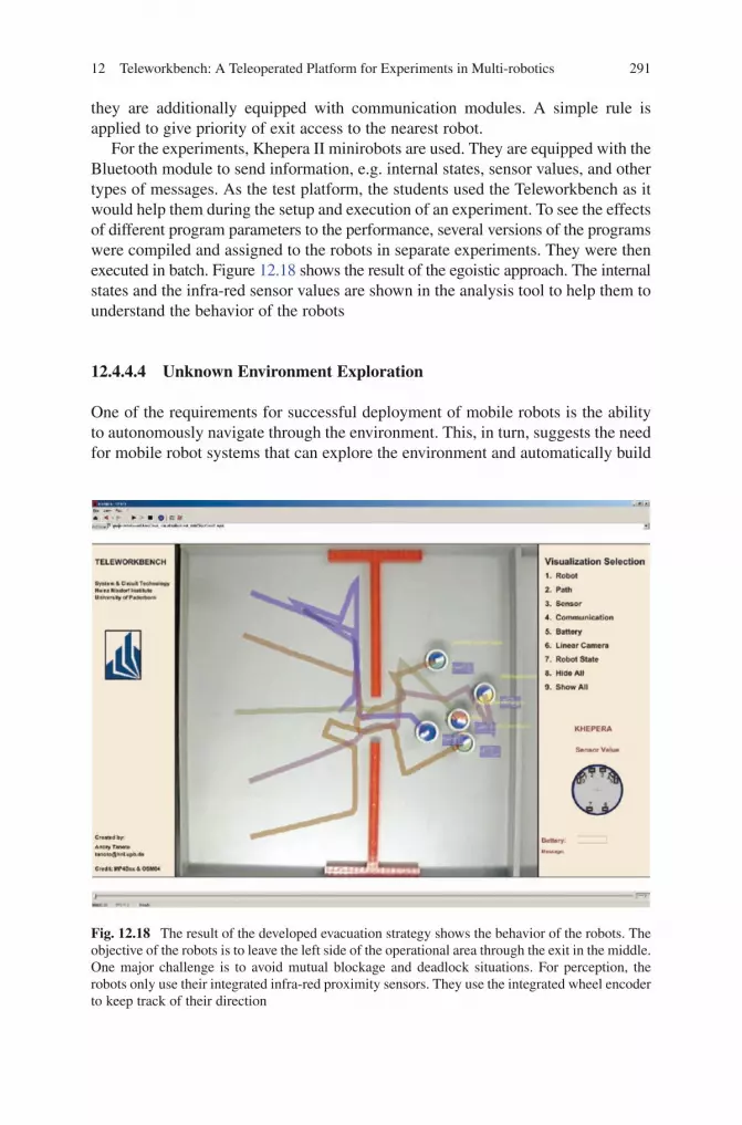
12 Teleworkbench: A Teleoperated Platform for Experiments in Multi-robotics 291
BookID 175907_ChapID 12_Proof# 1 - 15/4/2009
they are additionally equipped with communication modules. A simple rule is applied to give priority of exit access to the nearest robot.
For the experiments, Khepera II minirobots are used. They are equipped with the Bluetooth module to send information, e.g. internal states, sensor values, and other types of messages. As the test platform, the students used the Teleworkbench as it would help them during the setup and execution of an experiment. To see the effects of different program parameters to the performance, several versions of the programs were compiled and assigned to the robots in separate experiments. They were then executed in batch. Figure 12.18 shows the result of the egoistic approach. The internal states and the infra-red sensor values are shown in the analysis tool to help them to understand the behavior of the robots
12.4.4.4 Unknown Environment Exploration
One of the requirements for successful deployment of mobile robots is the ability to autonomously navigate through the environment. This, in turn, suggests the need for mobile robot systems that can explore the environment and automatically build
Fig. 12.18 The result of the developed evacuation strategy shows the behavior of the robots. The objective of the robots is to leave the left side of the operational area through the exit in the middle. One major challenge is to avoid mutual blockage and deadlock situations. For perception, the robots only use their integrated infra-red proximity sensors. They use the integrated wheel encoder to keep track of their direction
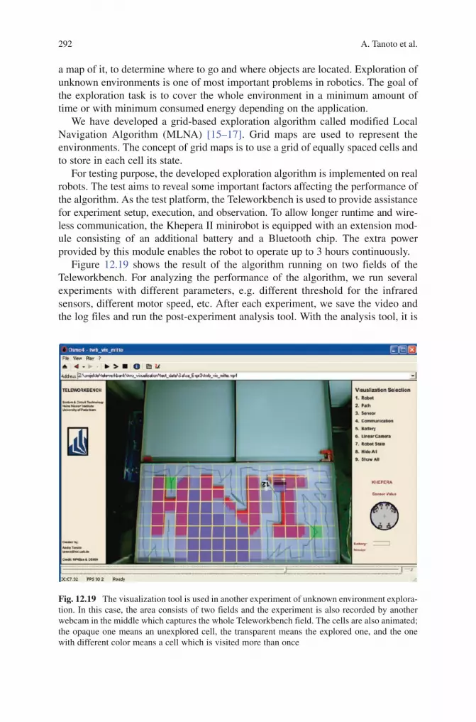
292 A. Tanoto et al.
BookID 175907_ChapID 12_Proof# 1 - 15/4/2009 BookID 175907_ChapID 12_Proof# 1 - 15/4/2009
a map of it, to determine where to go and where objects are located. Exploration of unknown environments is one of most important problems in robotics. The goal of the exploration task is to cover the whole environment in a minimum amount of time or with minimum consumed energy depending on the application.
We have developed a grid-based exploration algorithm called modified Local Navigation Algorithm (MLNA) [15–17]. Grid maps are used to represent the environments. The concept of grid maps is to use a grid of equally spaced cells and to store in each cell its state.
For testing purpose, the developed exploration algorithm is implemented on real robots. The test aims to reveal some important factors affecting the performance of the algorithm. As the test platform, the Teleworkbench is used to provide assistance for experiment setup, execution, and observation. To allow longer runtime and wire-less communication, the Khepera II minirobot is equipped with an extension mod-ule consisting of an additional battery and a Bluetooth chip. The extra power provided by this module enables the robot to operate up to 3 hours continuously.
Figure 12.19 shows the result of the algorithm running on two fields of the Teleworkbench. For analyzing the performance of the algorithm, we run several experiments with different parameters, e.g. different threshold for the infrared sensors, different motor speed, etc. After each experiment, we save the video and the log files and run the post-experiment analysis tool. With the analysis tool, it is
Fig. 12.19 The visualization tool is used in another experiment of unknown environment explora-tion. In this case, the area consists of two fields and the experiment is also recorded by another webcam in the middle which captures the whole Teleworkbench field. The cells are also animated; the opaque one means an unexplored cell, the transparent means the explored one, and the one with different color means a cell which is visited more than once
12 Teleworkbench: A Teleoperated Platform for Experiments in Multi-robotics 293
BookID 175907_ChapID 12_Proof# 1 - 15/4/2009
possible to visualize what the robot perceives of the environment, which is helpful for debugging the program.
12.5 Challenges for a Teleoperated Robotic Laboratory in Research and Education
To date, there are several similar attempts to use the Internet for education using mobile robots. One example is the work of Messom and Craig [18]. In their work, they designed a web based workbench for performing experiments with PID controllers of real mobile robots. To prevent bandwidth overload, this system sends as feedback only the position information of the robots instead of images or video data. On the client side, this information is rebuilt to resemble the original environment. Another example is the web-based telerobotic system for research and education at Essex by Yu et al. [19], which allows remote users to control and/or to program mobile robots to explore the laboratory. To do so, the system sends continuous 24-bit JPEG images to users as feedback. To program a robot, a user has to submit a text-based script, based on the Colbert language, containing commands for the robot. After the program is uploaded, a Colbert evaluator is executed to analyze the script.
Despite promising results in this area, we see, based on our analysis on the current system, that there are several challenges to make such a laboratory more advantageous. The first challenge is related to the interoperability with robotic simulators. While experiments with real robots are ideal and can bring more satisfaction to students, it, however, consumes time and resources. Moreover, it is hard to debug. Thus, we see the necessity of using a robotic simulator. Even though we know that codes that run perfectly in the simulator will not always run in real robots, but a seamless integration of robot simulator and the remote laboratory might reduce the development time and effort. Furthermore, by proportionally allocating the load between simulator and real robots, we can have higher efficiency and utilization of robots.
The second challenge is concerning the need of analysis tools to assess the behavior of the robots during experiments. When a program runs on a robot, it is difficult to see what is actually going on inside the robot because we can only see the behavior from an outsider’s perspective. As a result, we might wonder why a program behaves inconsistently from time to time. Thus, we somehow need a tool to see the internal state of the robots during runtime. So far, we have partially achieved this objective through our post-experiment analysis tool using video that is based on MPEG-4 standard [20].
The third one is sufficient feedback and interactivity. Without enough feedback, students will find it difficult to interact with robots, and without good interaction, they will easily get bored. Moreover, if the experiment requires situation assessment from them, e.g. telerobotics with supervised control, it may be very hard to do it properly. Thus, we need to transfer the remote environment where the real experiment runs to the students as much as possible. One way to achieve this is by using video. Even though transferring video data is bandwidth consuming, but as fast internet
294 A. Tanoto et al.
BookID 175907_ChapID 12_Proof# 1 - 15/4/2009 BookID 175907_ChapID 12_Proof# 1 - 15/4/2009
connections are becoming more commonplace, we deem it feasible to implement a remotely-accessible robotic laboratory.
In tele-programming, we are facing other challenges related to safety and usability. When users develop their own programs which can be executed on the robots, the robots are totally under their control because they have direct access to low-level control, such as motors or sensors, etc. There may exist users who will develop malicious programs for the robots which may create threats to the environment. Unintentional bugs in the program can also create similar problems. To ensure safety in robot tele-programming, we face the question of how to effectively install the safety policy to the code without interfering the robot behavior in normal situation. The next question is how to enable code-reusability for simulation and experiment using real robots. From user’s point of view, the code-reusability is highly desirable; they do not need to write different code for both simulation and experiment. Currently, there are several projects providing this feature for some robot types: Microsoft Robotic Studio [21], Player-Stage [22], and Pyro [23] to name a few. However, they are not developed for robot tele-programming. At the time being, we are exploring possibilities of supporting safety and usability in robot tele-programming by using some of the aforementioned tools.
12.6 Summary and Future Work
We have presented a teleoperated platform for robotic experiment, which is called the Teleworkbench. Some aspects of this system have been discussed in details: its components and system architecture, its features and advantages, as well as some possible application scenarios. We have also presented some challenges for improving the system. In the following paragraph, we note some important points for future works.
To date, the Teleworkbench has been successfully implemented and used in some research and education activities, as shown in the previous sections. Mainly, they are done locally in our institute. In near future, we want to promote the Teleworkbench to some local high schools, to offer their pupils a chance to get hands-on experiences with robots. In the past, we had some cooperative activities with some high-schools to work in some small research projects. From our experience, we see the opportunity to promote the idea of teleoperated platform for robotic experiment to schoolchildren. In spite of the trend of decreasing robot cost, robots are still not yet affordable for them. Thus, providing access to robots regardless of users’ geographical location may answer this problem.
Despite its versatility and capabilities, we notice that there is still room for improvement. As mentioned earlier, we identified some challenges that we have to face to advance the use of the Teleworkbench. With this in mind, we are planning to develop a bigger system which can offer larger space and better usability. Larger space enables us to perform experiments with physically bigger robots or with more robots. Better usability can be gained by providing a well-defined interface so that

12 Teleworkbench: A Teleoperated Platform for Experiments in Multi-robotics 295
BookID 175907_ChapID 12_Proof# 1 - 15/4/2009
interoperability between robot simulators and the Teleworkbench can be obtained. Hence, users can go through the software development process seamlessly, without the hassle of porting their programs in these two stages. Moreover, a better environment reconstruction/visualization at the users’ side is deemed important to provide ease in interaction with the robots. Last but not least, we see that the Teleworkbench is not the ultimate testing and validation tool. Instead, we consider it as a bridge to the implementation in real environment. Aligned with this idea, a plan has been developed in our group to add a new feature to the Teleworkbench that can support for upscaling. Hence, users would be able to easily port their program from the Teleworkbench to a bigger platform, e.g. a bigger environment with bigger robots.
References
1. F. Mondada, E. Franzi, and P. Ienne, “Mobile Robot Miniaturization: A Tool for Investigation in Control Algorithms,” in Experimental Robotics III, Proceedings of the 3rd International Symposium on Experimental Robotics, Kyoto, Japan, 1993. Springer, London, 1993.
2. A. Tanoto, U. Witkowski, and U. Rückert, “Teleworkbench: A Teleoperated Platform for Multi-Robot Experiments,” in Proceedings of the 3rd International Symposium on Autonomous Minirobots for Research and Edutainment (AMiRE 2005). Awara-Spa, Fukui, Japan. Springer, September 20–22, 2005, pp. 49–54.
3. U. Witkowski, M. Bandyk, and U. Rückert, “Long-Running Experiments Using the Minirobot Khepera with Automatic Charging Station,” in Proceedings of the 2nd International Conference on Autonomous Minirobots for Research and Edutainment AMiRE03, Brisbane, Australia, February 2003, pp. 249–252.
4. M. Grosseschallau, U. Witkowski, and U. Rückert, “Low-cost Bluetooth Communication for the Autonomous Mobile Minirobot Khepera,” in IEEE International Conference on Robotics and Automation - ICRA05, Barcelona, Spain, April 18-22, 2005, pp. 4205–4210.
5. J. L. Du, U. Witkowski, and U. Rückert, “Teleoperation of a Mobile Autonomous Robot using Web Services,” in Proceedings of the 3rd International Symposium on Autonomous Minirobots for Research and Edutainment (AMiRE 2005), Fukui, Japan, September 20–22, 2005.
6. R. Koenen, “Overview of the MPEG-4 Standard.” [Online]. Available: http://www.chiariglione.org/mpeg/standards/mpeg-4/mpeg-4.htm
7. GPAC, “GPAC Project on Advanced Content.” [Online]. Available: http://gpac.sourceforge.net/index.php
8. K-Team, “Robot Khepera II.” [Online]. Available: http://www.k-team.com 9. T. Kaulmann, U. Witkowski, T. Chinapirom, and U. Rückert, “Universal Mini-Robot with
Microprocessor and Reconfigurable Hardware,” in Proceedings of the FIRA RoboWorld Conference 2006 (Dortmund, Germany, June 2006), 2006, pp. 137–142.
10. W3C, “SOAP Version 1.2 Part 1: Messaging Framework,” April 2007, second Edition. [Online]. Available: http://www.w3.org/TR/soap12-part1/
11. R. A. van Engelen and K. Gallivan, “The gSOAP Toolkit for Web Services and Peer-to-Peer Computing Networks,” in Proceedings of the 2nd IEEE International Symposium on Cluster Computing and the Grid (CCGrid2002), May 21-24, 2002, Berlin, Germany, 2002, pp. 128–135. [Online]. Available: http://gsoap2.sourceforge.net/
12. V. Harward, J. del Alamo, S. Lerman, P. Bailey, J. Carpenter, K. DeLong, C. Felknor, J. Hardison, B. Harrison, I. Jabbour, P. Long, T. Mao, L. Naamani, J. Northridge, M. Schulz, D. Talavera, C. Varadharajan, S. Wang, K. Yehia, R. Zbib, and D. Zych, “The iLab Shared Architecture: A Web Services Infrastructure to Build Communities of Internet Accessible Laboratories,” Proceedings of the IEEE, vol. 96, no. 6, pp. 931–950, June 2008.

296 A. Tanoto et al.
BookID 175907_ChapID 12_Proof# 1 - 15/4/2009
13. T. Hesse, T. Sattel, J. L. Du, and U. Witkowski, “Application of Auto-motive Motion Planning Algorithms on Non-Holonomic Mobile Minirobots,” in Proceedings of the 4th International Symposium on Autonomous Minirobots for Research and Edutainment AMIRE, Buenos Aires, Argentina, October 2–5,2007.
14. D. Helbing, I. Farkas, and T. Vicsek, “Simulating Dynamical Features of Escape Panic,” Nature, vol. 407, no. 6803, pp. 487–490, September 2000.
15. S. Amin, A. Tanoto, U. Wit-kowski, U. Rückert, and M. S. Abdel-Wahaab, “Environment Exploration Using Mini-Robot Khepera,” in Proceedings of Autonomous Mini Robots for Research and Education (AMiRE 2007), 2007.
16. S. Amin, A. Tanoto, U. Witkowski, U. Rückert, and M. S. Abdel-Wahab, “Effect of Global position Information in Unknown World Exploration - A Case Study Using the Teleworkbench,” in Proceedings of the 5th International Conference on Computational Intelligence, Robotics and Autonomous System (CIRAS 2008), 19-21 June, Linz, Austria, 2008.
17. S. Amin, A. Tanoto, U. Witkowski, U. Rückert, and S. Abdel-Wahab, “Modified Local Navigation Strategy for Unknown Environment Exploration,” in Proceedings of the 5th International Conference on Informatics in Control, Automation and Robotics 2008, Funchal, Madeira, Portugal, 2008.
18. C. Messom and R. Craig, “Web Based Laboratory for Controlling Real Robot Systems,” in Proceedings of the Biannual conference of the Distance Education Association of New Zealand, DEANZ 2002, Wellington, New Zealand, 2002.
19. L. Yu, P. Tsui, Q. Zhou, and H. Hu, “A Web-based Telerobotic System for Research and Education at Essex,” in IEEE/ASME International Conference on Advanced Intelligent Mechatronics 2001, 2001.
20. A. Tanoto, J. L. Du, U. Witkowski, and U. Rückert, “Teleworkbench: An Analysis Tool for Multi-Robotic Experiments,” in Proceedings of IFIP BICC, 2006.
21. Microsoft, “Microsoft Robotic Studio,” 2006. [Online]. Available: http://msdn.microsoft.com/robotics/
22. B. P. Gerkey, R. T. Vaughan, K. Sty, A. Howard, M. J. Mataric, and G. S. Sukhatme., “Most Valuable Player: A Robot Device Server for Distributed Control,” in Proceedings of the IEEE/RSJ International Conference on Intelligent Ro-bots and Systems (IROS), Wailea, Hawaii, October 2001, p. 12261231.
23. D. Blank, D. Kumar, L. Meeden, and H. A. Yanco, “Pyro: An Integrated Environment for Robotics Education,” in National Conference on Artificial Intelligence (AAAI-05), July 2005.

BookID 175907_ChapID 13_Proof# 1 - 12/07/2009
13.1 Introduction
The World Wide Web (WWW) eliminates traditional communication problems such as long distance and time constraints. Furthermore, the WWW provides us with an unprecedented comprehensive environment for distributing information over a large network so that people living in distant locates can share their ideas and work together. In this article, we focus on web-based tele-operated mobile platformcontrol. In teleoperation tasks, remote users can control a remote mobile manipulation platform to extend human sensory and control ranges. The tele-operation tasks are potentially useful in dangerous and unpredictable environments such as at a construction site, space, underwater, service environments, and in nuclear power stations.
A mobile manipulator is a manipulator mounted on a mobile platform with no support from the ground. A mobile manipulator offers a dual advantage of mobility offered by the platform and dexterity offered by the manipulator. For instance, the mobile platform extends the workspace of the manipulator. We are developing and constructing a mobile manipulation platform called RISCbot. The prototype of the RISCbot is shown in Fig. 13.1.
Sensor fusion has been an active area of research in the field of computer vision and mobile robotics. Sensor fusion can be defined as a method for conveniently combining and integrating data derived from sensory information provided by various and disparate sensors, in order to obtain the best estimate for a dynamic system’s states and produce a more reliable description of the environment than any sensor individually. Sensor fusion algorithms are useful in low-cost mobile robot applications, where acceptable performance and reliability are desired, given a limited set of inexpensive sensors such as ultrasonic and infrared sensors. Depending on the modalities of the sensors, sensor fusion can be categorized into two classes (as described in Yilmaz [1]), sensor fusion using complimentary sensors and sensor
Chapter 13Web-Based Control of Mobile Manipulation Platforms via Sensor Fusion
Ayssam Elkady and Tarek Sobh
A. Elkady () and T. SobhDepartment of Computer Science and Engineering, University of Bridgeport, Bridgeport, CT 06604, [email protected]; [email protected]; http://www1bpt.bridgeport.edu/~aelkady/
S.G. Tzafestas (ed.), Web-Based Control and Robotics Education, 297Intelligent Systems, Control and Automation: Science and Engineering 38,DOI 10.1007/978-90-481-2505-0_13, © Springer Science + Business Media B.V. 2009

298 A. Elkady and T. Sobh
BookID 175907_ChapID 13_Proof# 1 - 12/07/2009 BookID 175907_ChapID 13_Proof# 1 - 12/07/2009
fusion using competing sensors. Complementary sensors consist of sensors with different modalities, such as a combination of a laser sensor and a digital camera. In contrast to complementary sensors, competing sensors are composed of sensors suit which have the same modality, such as two digital cameras which provide photographic images of the same building from two different viewpoints.
Sensor fusion has some critical problems such as the synchronization of sensors. Different sensors have different resolutions and frame rates so the sensors need to be synchronized before their results can be merged by fusing the data from multiple sensors and presenting the result in a way that enables the tele-operator to perceive the current situation quickly. Sensor fusion is used to reduce the workload for the operator to enable him or her to concentrate on only the task itself.
Sensor fusion is commonly used to reduce uncertainty in localization, obstacle avoidance, and map building. Furthermore, sensor fusion may be used to improve tele-operation by creating user interfaces which efficiently facilitate understanding of remote environments and improve situational awareness.
In this article, we discuss sensor fusion for teleoperation, describe our mobile manipulation platform, and present our results.
13.2 Prior Work
Goldberg, Mascha et al. [2] designed a teleoperated robot manipulator via the WWW. Their project consisted of an industrial robot arm fitted with a CCD camera and a pneumatic system. They placed a sandbox filled with buried artifacts in the robot workspace. The WWW users can remotely move the camera to view desired locations or direct a short burst of compressed air into the sand to view the newly cleared region.
In [3], Safaric et al. designed a teleoperated system providing remote users with internet access to a laboratory robotic system and presented a real experiment which enables students to control a six DOF teleoperated robotic manipulator. Furthermore, they developed a virtual reality environment which improves the
Fig. 13.1 A prototype of the RISCbot

29913 Web-Based Control of Mobile Manipulation Platforms via Sensor Fusion
BookID 175907_ChapID 13_Proof# 1 - 12/07/2009
visualization of the manipulator hardware and associated workspace. In addition, they implemented a simulator to provide realistic collision detection between the virtual robot and its associated workspace.
Xavier [4] can accept commands to travel to different offices within a building, broadcasting camera images as it travels. Minerva [5] is an interactive autonomous robot that moves daily through crowds at the Smithsonian’s National Museum of American History. Rhino [6] has been deployed as a tour guide robot at Deutsches Museum in Bonn, Germany.
In [7], a mobile autonomous robot called RISCBOT was designed at the RISC lab of the University of Bridgeport. RISCBOT localizes itself and successfully fulfills WWW user requests and navigates to various rooms.
13.3 Design Specifications
13.3.1 Data Acquisition
In our project, we used a data acquisition module called Data Translation DT9814 which is a low cost USB data acquisition module that offers 24 analog input chan-nels, 2 analog outputs channels, and one 32-bit counter timer to accommodate most applications. Furthermore, it provides a resolution of 12 bits for both the analog input and analog output subsystems, and input throughput up to 50 kHz. The Analog signal range is from −10 to 10 V. This module also provides the following features (as described in DT9814 user’s manual [8]):
One 32-bit counter/timer channel.•Internal and external A/D clock sources.•Internal and external A/D trigger sources.•No external power supply required.•It supports a 32-location channel-gain list. You can cycle through the channel-gain •list using continuous scan mode or triggered scan mode.It can be connected directly to the USB ports of a computer.•
13.3.2 Sensors
There are various sensor types used for measuring distances to the nearest obstacle around the robot for navigation purposes such as ultrasonic and infrared sensors. The sensors can be classified as proprioceptive/exteroceptive and passive/active [9]. Proprioceptive sensors measure values internal to the robot such as motor speed, wheel load, and battery voltage. Exteroceptive sensors acquire information from the robot environment such as distance measurements.
Passive sensors measure ambient environmental energy entering the sensor; such as temperature sensors, and microphones. Active sensors emit energy into the environment, then measure the environmental reaction.

300 A. Elkady and T. Sobh
BookID 175907_ChapID 13_Proof# 1 - 12/07/2009 BookID 175907_ChapID 13_Proof# 1 - 12/07/2009
There are two important concepts to understand when analyzing any sensor; sensitivity and range. A sensing device reacts to varying levels of some physical stimulus by outputting a characteristic voltage (or current, frequency, etc.). Sensitivity is a measure of the degree to which the output signal changes as the measured quantity changes. Let’s call the sensor output r and the measured physical quantity z. The sensitivity S can be computed from Eq. (13.1).
∆ ∆=
r zS
r z (13.1)
Where Dz is a small change in the measured quantity and Dr is related to a small change in the sensor response.
13.3.2.1 Sonar Sensor
A sonar sensor measures the time of flight of a sonar pulse to travel to the object in font of this sensor and the time to be received again. Given the speed of the sound, one can compute the distance to the object.
The distance d to the nearest object within the sonar cone can be computed from Eq. (13.2). Where t is the elapsed time between the emission of the sonar signal and the reception of its echo and C is the speed of the sonar signal in the medium (the speed of the sound (m/s) in dry air is given approximately by Eq. (13.3) where T
C
is the Celsius temperature)
=2
Ctd (13.2)
≈ + ×331.4 0.6 CC T (13.3)
There are some uncertainties associated with readings from sonar sensors. The uncertainties are due to:
The exact position of the detected object is unknown because the computed •distance d in Eq. (13.2) could be anywhere within the sonar cone.Specular reflections problem occurs when the sonar beam hits a smooth surface •at a shallow angle and is therefore not reflected back to the robot.Crosstalk can occur when an array of sonar sensors is used.•
We used the LV-MaxSonar®-EZ0TM ultrasonic sensors. As described in (LV-MaxSonar®-EZ0TM Data Sheet [10]), they can detect objects from 0 to 254 in. (6.45 m) and provides sonar range information from 6-in. out to 254-in. with 1-in. resolution. Objects from 0 to 6-in. range as 6-in. They are low cost sonar ranger actually consisting of two parts: an emitter, which produces a 42 kHz sound wave; and a detector, which detects 42 kHz sound waves and sends an electrical signal back to the microcontroller. Readings can occur up to every 50 ms, (20-Hz rate)

30113 Web-Based Control of Mobile Manipulation Platforms via Sensor Fusion
BookID 175907_ChapID 13_Proof# 1 - 12/07/2009
and designed for indoor environments. The advantage of using ultrasonic sensors is that they can detect obstacles with high confidence especially when the object is well defined (i.e., located perpendicular to the sonar axis and has good ultrasonic reflectivity).
As described in (LV-MaxSonar®-EZ0TM Data Sheet [10]), the sample results for measured beam patterns are shown in Fig. 13.2 on a 12-in. grid. The detection pattern is shown for;
[(A)] 0.25-in. diameter dowel, note the narrow beam for close small objects.•[(B)] 1-in. diameter dowel.•[(C)] 3.25-in. diameter rod, note the long controlled detection pattern.•[(D)] 11-in. wide board moved left to right with the board parallel to the front •sensor face and the sensor stationary. This shows the sensor’s range capability.
13.3.2.2 Infrared Proximity Sensor
Infrared sensors operate by emitting an infrared light, and detecting any reflection off surfaces in front of the robot. If the reflected infrared is detected, it means that an object is detected. On the other hand, if the reflected infrared signal is absent, It does not mean that there is no object in front of the infrared sensor because certain darkly colored objects are invisible to infrared signal. Therefore, infrared sensors are not absolutely safe to use alone in obstacle avoidance applications.
We have used an infrared proximity sensor – Sharp GP20A21YK. As described in (SparkFun Electronics website [11]), this sensor has an analog output that varies from 3.1 V at 10 cm to 0.4 V at 80 cm as shown in Fig. 13.3. The analog sensor
Fig. 13.2 Beam characteristics
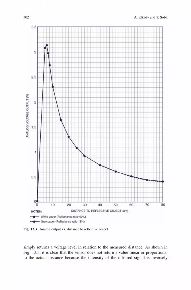
302 A. Elkady and T. Sobh
BookID 175907_ChapID 13_Proof# 1 - 12/07/2009 BookID 175907_ChapID 13_Proof# 1 - 12/07/2009
simply returns a voltage level in relation to the measured distance. As shown in Fig. 13.3, it is clear that the sensor does not return a value linear or proportional to the actual distance because the intensity of the infrared signal is inversely
Fig. 13.3 Analog output vs. distance to reflective object

30313 Web-Based Control of Mobile Manipulation Platforms via Sensor Fusion
BookID 175907_ChapID 13_Proof# 1 - 12/07/2009
probational to the square of the distance. Therefore, the infrared signal falls rapidly as the distance increases.
13.3.3 Jazzy 1122 Wheelchair
As described in (Jazzy 1122 the owner’s manual [12]), the jazzy wheelchair has two main assemblies: the seat and the power base as described in Fig. 13.4. Typically, the seating assembly includes the armrests, seatback, and controller. The power base assembly includes two drive wheels, two anti-tip wheels, two rear caster wheels, and a body shroud. In our project, we remove the armrests and seatback as shown in Fig. 13.5. The specifications of the Jazzy 1122 wheelchair are described in Table 13.1. The jazzy 1122 wheelchair also provides the following features: (as described in [12])
1. Active-Trac Suspension: The wheelchair is equipped with Active-Trac Suspension (ATS) to be able to traverse different types of terrain and obstacles while maintaining smooth operation. With ATS, the front anti-tip wheels work in conjunction with the motor suspension to maneuver over obstacles. As the front anti-tip wheels come in contact with an obstacle, the front anti-tip wheel assembly is drawn upward. At the same time, the motors are forced downward. This allows the motors to push the wheelchair over an obstacle.
2. Rear Suspension: The wheelchair is equipped with a rear suspension system to work in conjunction with the ATS and is designed to maintain a smooth ride when driving over rough terrain and up and down curbs.
SEATBACK
SEAT ASSEMBLY
POWER BASE ASSEMLY
REARCASTER WHEEL
DRIVE WHEEL
ARMRESTS
CONTROLLER(REMOTE PLUS SHOWN)
BODY SHROUD
FOOTRIGGING(FOOT PLATFORMSHOWN)
ANTI-TIP WHEELS
Fig. 13.4 The Jazzy 1122

304
t.1
t.2
t.3t.4t.5t.6t.7t.8t.9
t.10t.11t.12
A. Elkady and T. Sobh
BookID 175907_ChapID 13_Proof# 1 - 12/07/2009 BookID 175907_ChapID 13_Proof# 1 - 12/07/2009
13.4 Applications
13.4.1 Manipulability
Studying the performance characteristics of the robot such as dexterity, manipulability, and accuracy is very important to the design and analysis of a robot manipulator. The manipulability is the ability to move in arbitrary directions while the accuracy is a measure of how close the manipulator can return to a previously taught point. The manipulability index is considered as a quantitative and performance measure of the ability for realizing some tasks. This measure should be taken into consideration in the design phase of a serial robot and also in the design of control algorithms.
In (Mohammed et al. [13]), we presented a new method for measuring the manipu-lability index, then justify this concept by visualizing the bands of this index resulting
Table 13.1 Specifications of the Jazzy 1122 wheelchair
Suspension ATS and rear suspension
Drive wheels 14 in., pneumatic, center-mountedCaster wheels 8 in., solid, rear-articulatingAnti-tip wheels 6 in., solid, front-mountedMaximum speed Up to 6 mphBrakes “Intelligent braking,” electronic regenerative, disc park brakeDrive train Two motor, mid-wheelBatteries Two 12-V, Group 24 batteriesComponent weights Base: 129 lb.
Seat: 40 lb. (standard seat).Batteries: 53.5 lb.
Fig. 13.5 The RISCbot base

30513 Web-Based Control of Mobile Manipulation Platforms via Sensor Fusion
BookID 175907_ChapID 13_Proof# 1 - 12/07/2009
from our experiments implemented on different manipulators such as the Puma 560 manipulator, a six DOF manipulator and the Mitsubishi Movemaster manipulator.
In fixed-base serial manipulators, manipulability depends on link lengths, joint types, joint motion limits and the structure of the manipulator. In mobile manipulators, the manipulability depends on the kinematics, geometric design, the payload, mass and mass distribution of the mobile platform. Thus, the manipulability measure in mobile manipulators is very complicated due to the coupling between the kinematic parameters and the dynamics effect. Furthermore, we used the proposed method for measuring the manipulability index in serial manipulators to generalize the standard definition of the manipulability index in the case of mobile manipulators
13.4.2 Navigation and Obstacle Avoidance
A prerequisite task for the autonomous mobile robot is the ability to detect and avoid obstacles given real-time sensor readings. Obstacle avoidance is a crucial issue in robot’s navigation. Given partial knowledge about its environment and a goal position or a series of positions, navigation encompasses the ability of the robot to act based on its knowledge and sensor values so as to reach its goal positions as efficiently and as reliably as possible.
The obstacle may be defined as any object that appears along the mobile robot’s. The techniques used in the detection of obstacles may vary according to the nature of the obstacle. The resulting robot motion is a function of both the robot’s sensor readings and its goal position. The obstacle avoidance applications focus on changing the robot’s tra-jectory as informed by sensors during robot motion. The obstacle avoidance algorithms that are commonly used can be summarized as the following: (as described in [9]).
• The bug algorithm: The basic idea is to follow the easiest common sense approach of moving directly towards the goal, unless an obstacle is found. If an obstacle is found, the obstacle is contoured until motion to goal is again possible. In [9], two approaches are described; Bug1 and Bug2. In Bug1 Algorithm, the robot fully circles the object first, and then departs from the point with the shortest distance toward the goal. This approach is very inefficient but it guarantees that the robot will reach any reachable goal. In Bug2, the robot will fellow the object’s contour but it will depart immediately when it is able to move directly toward the goal.
• Tangent Bug: As described in [14], tangent bug algorithm is a variation of the bug algorithm. The robot can move more efficiently toward the goal also go along shortcuts when contouring obstacles and switch back to goal seeking earlier. In many simple environments, tangent bug approaches globally optimal paths.
• Artificial Potential Fields: The artificial potential fields (APF) is proposed by Khatib in [15]. The robot is considered as a moving particle in a potential field generated by the goal and by the obstacles that are presented in the environment. In APF method, the robot immersed in the potential filed is subject to the action of a force that drives it to the goal. This approach uses repulsive potential fields around the obstacles (and forbidden regions) to force the robot away

306 A. Elkady and T. Sobh
BookID 175907_ChapID 13_Proof# 1 - 12/07/2009 BookID 175907_ChapID 13_Proof# 1 - 12/07/2009
and an attractive potential field around goal to attract the robot. A potential field can be viewed as an energy field and so its gradient, at each point, is a force. Consequently, the robot experiences a generalized force equal to the negative of the total potential gradient. This force drives the robot towards its goal while keeping it away from the obstacles (it is the action of a repulsive force that is the gradient of the repulsive potential generated by the obstacles). However, there is a major problem with the APF approach because the local minima can trap the robot before reaching its goal. One of the powerful techniques for avoidance of local minima is the simulated annealing approach which has been applied to local and global path planning as described in [16].
• Vector Field Histogram: Borenstein and Koren developed the vector field histo-gram (VFH) [17]. Borenstein and Ulrich extended the VFH algorithm to yield VFH* [18] and VFH+ [19]. As described in [9], the instantaneous behavior of the mobile robot in the Bug algorithms is a function of only its most recent sensor readings which may lead to undesirable problems in cases where the robot’s instantaneous sensor readings do not provide enough information for robust obstacle avoidance. The VFH algorithm is computationally efficient, very robust and insensitive to misreading. The VFH algorithm allows continuous and fast motion of the mobile robot without stopping for obstacles. The VFH algorithm [17] permits the detection of unknown obstacles and avoids collisions while simultaneously steering the mobile robot toward the target. This algorithm uses a two-dimensional cartesian histogram grid to represent a local map of the environ-ment around the robot which is updated continuously with the sampled data from range sensors. In contrast, the VFH algorithm generates a polar histogram to represent the relation between the angle at which the obstacle was found and the probability that there really is an obstacle in that direction based on the occupancy grid’s cell values. From this histogram a steering direction is calculated. The polar histogram is the most significant distinction between the virtual force field (VFF) and the VFH method as it allows a spatial interpretation (called polar obstacle density) of the robot’s instantaneous environment. In the VFH+ algorithm [19], the basic robot kinematics limitations were used to compute the robot possible trajec-tories using arcs or straight lines. The VFH* algorithm [18] proposes look-ahead verification. The method investigates each possible direction provided by the VFH+ approach, checking their consequences concerning the robot future posi-tions. The experimental results of [18] shows that this look-ahead verification can successfully deal with problematic situations that the original VFH and VFH+ can not handle and the resulting trajectory is fast and smooth.
13.4.3 Path Planning and Map Building
Given a map and a goal location, path planning involves identifying a trajectory that will bring the robot from the initial location to reach the goal location. During the execution, the robot must react to unforeseen events such as the obsta-
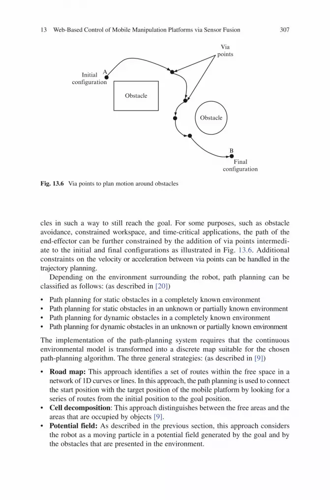
30713 Web-Based Control of Mobile Manipulation Platforms via Sensor Fusion
BookID 175907_ChapID 13_Proof# 1 - 12/07/2009
cles in such a way to still reach the goal. For some purposes, such as obstacle avoidance, constrained workspace, and time-critical applications, the path of the end-effector can be further constrained by the addition of via points intermedi-ate to the initial and final configurations as illustrated in Fig. 13.6. Additional constraints on the velocity or acceleration between via points can be handled in the trajectory planning.
Depending on the environment surrounding the robot, path planning can be classified as follows: (as described in [20])
Path planning for static obstacles in a completely known environment•Path planning for static obstacles in an unknown or partially known environment•Path planning for dynamic obstacles in a completely known environment•Path planning for dynamic obstacles in an unknown or partially known environment•
The implementation of the path-planning system requires that the continuous environmental model is transformed into a discrete map suitable for the chosen path-planning algorithm. The three general strategies: (as described in [9])
• Road map: This approach identifies a set of routes within the free space in a network of 1D curves or lines. In this approach, the path planning is used to connect the start position with the target position of the mobile platform by looking for a series of routes from the initial position to the goal position.
• Cell decomposition: This approach distinguishes between the free areas and the areas that are occupied by objects [9].
• Potential field: As described in the previous section, this approach considers the robot as a moving particle in a potential field generated by the goal and by the obstacles that are presented in the environment.
Obstacle
Obstacle
Initialconfiguration
Finalconfiguration
Viapoints
A
B
Fig. 13.6 Via points to plan motion around obstacles

308 A. Elkady and T. Sobh
BookID 175907_ChapID 13_Proof# 1 - 12/07/2009 BookID 175907_ChapID 13_Proof# 1 - 12/07/2009
In the navigation problem, the requirement is to know the positions of the mobile robot and a map of the environment (or an estimated map). The related problem is when both the position of the mobile robot and the map are not known. In this scenario, The robot starts in an unknown location in an unknown environment and proceeds to gradually build the map of the existing environment. In this case, the position of the robot and the map estimation are highly correlated. This problem is known as Simultaneous Localization and Map Building (SLAM) [21, 22]. SLAM is the process of concurrently building a feature based map of the environment and using this map to get an estimation of the location of the mobile platform. In [23], the recent Radio Frequency Identification (RFID) was used to improve the localization of mobile robots. This research studied the problem of localizing RFID tags with a mobile robot that is equipped with a pair of RFID antennas. Furthermore, a probabilistic measurement model for RFID readers was presented in order to accurately localize RFID tags in the environment.
13.5 Implementation and Results
We are developing and constructing the mobile manipulation platform called RISCbot (the prototype of the RISCbot is shown in Fig. 13.1). The RISCbot mobile manipulator has been designed to support our research in algorithms and control for autonomous mobile manipulator. The objective is to build a hardware platform with redundant kinematic degrees of freedom, a comprehensive sensor suite, and significant end-effector capabilities for manipulation. The RISCbot platform differs from any related robotic platforms because its mobile platform is a wheelchair base. Thus, the RISCbot has the advantages of the wheelchair such as high payload, high speed motor package (the top speed of the wheelchair is 6 mph), Active-Trac and rear caster suspension for outstanding outdoor performance, and adjustable front anti-tips to meet terrain challenges.
In order to use the wheelchair as a mobile platform, a reverse engineering process has been used to understand the communication between the joystick of the wheelchair and the motor controller. This process was done by intercepting the continuous stream of voltages generated by the joystick after opening the joystick module and reading the signals within joystick wires that are sent the signals to the wheelchair controller.
We used different types of sensors so that the RISCbot can perceive its environment with better accuracy. Our robot hosts an array of 13 LV-MaxSonar®-EZ0TM ultrasonic sensors. The sensors are suitable for obstacle avoidance applications but their wide beams are unable to distinguish features within the beam angle, making sonars a poor choice of sensor for fine feature extraction within indoor environments. This resolution problem is magnified for objects further away from the robot (i.e., objects appearing at the wide end of the beam). Lastly, our robot is also equipped with an array of 11 Sharp GP20A21YK infrared proximity sensors above the sonar ring. The sonar and infrared sensors were mounted together so that their beams are

30913 Web-Based Control of Mobile Manipulation Platforms via Sensor Fusion
BookID 175907_ChapID 13_Proof# 1 - 12/07/2009
oriented in the same direction. The configuration of sonar and infrared sensors is shown in Fig. 13.7. These sensors allow the RISCbot to obtain a set of observations to provide these observations to the controller and higher decision making mechanisms. The controller acts upon this set of observations to cause the robot to turn in the correct direction. The Integration of these modules together constitutes an intelligent mobile robot.
A main drawback of the infrared sensors is that they can only accurately mea-sure obstacle distances within a range of 0.1-0.8 m. Another drawback of these sensors is that they are susceptible to inaccuracies due to outdoor light interference as well as an obstacle’s color or reflectivity characteristics which can be seriously affected by windows and metallic surfaces.
Note that since our sonar and infrared sensors are in fixed positions, our experiments concentrated on performing data fusion on data obtained from a particular fixed height in the environment.
In this project, sonar and infrared sensors are used together in a complementary fashion, where the advantages of one compensate for the disadvantages of the other.
As shown in Fig. 13.8, the RISCbot software which is written in Visual C# and runs on a laptop reads the values of all sensors at a rate of 10 Hz gathered in the data acquisition The RISCbot software maps the sensory inputs to a series of actions which is used to achieve the required task. Based on the used algorithm, the RISCbot software responses to the sensor data by generating stream of voltages corresponding to the joystick signals to the wheelchair controller. These voltages control the direction and the speed of the wheelchair to cause the RISCbot to turn in the desired direction.
Figure 13.9 shows an experimental result for the RISCbot navigation in a real hallway environment. In this figure, the rectangles in the map are the positions of the RISCbot and the black regions are the obstacles exiting in the environment.
Fig. 13.7 A closeup view of the sonar and infrared
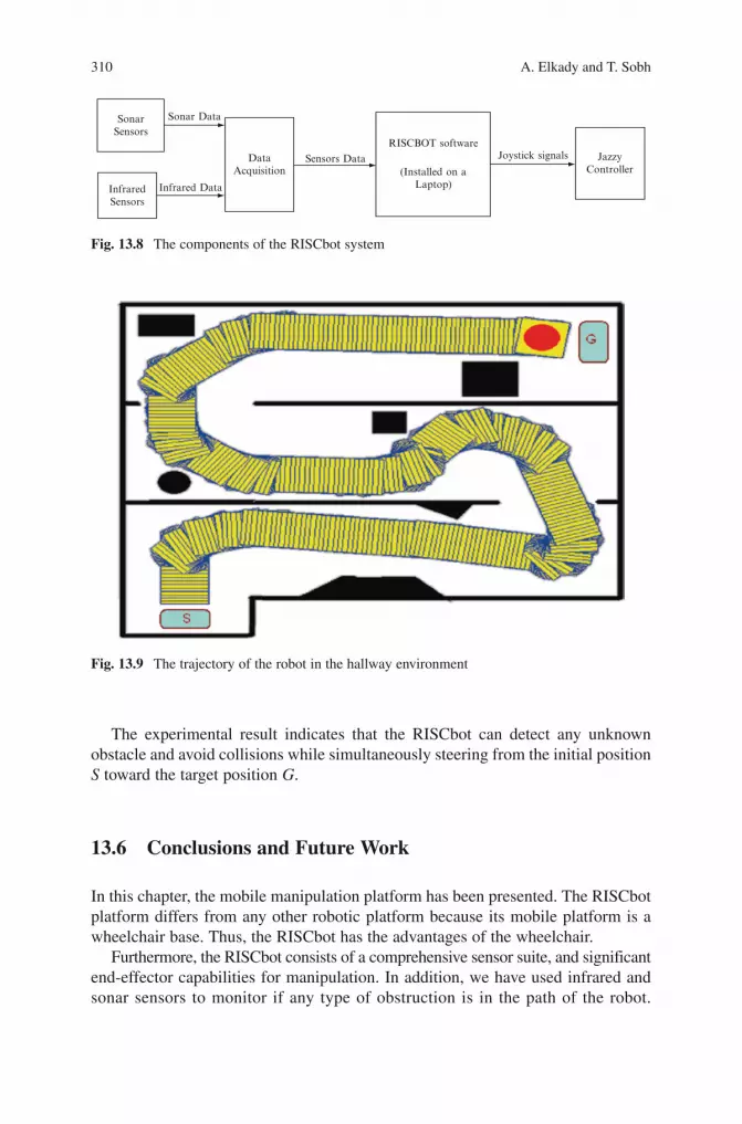
310 A. Elkady and T. Sobh
BookID 175907_ChapID 13_Proof# 1 - 12/07/2009 BookID 175907_ChapID 13_Proof# 1 - 12/07/2009
The experimental result indicates that the RISCbot can detect any unknown obstacle and avoid collisions while simultaneously steering from the initial position S toward the target position G.
13.6 Conclusions and Future Work
In this chapter, the mobile manipulation platform has been presented. The RISCbot platform differs from any other robotic platform because its mobile platform is a wheelchair base. Thus, the RISCbot has the advantages of the wheelchair.
Furthermore, the RISCbot consists of a comprehensive sensor suite, and significant end-effector capabilities for manipulation. In addition, we have used infrared and sonar sensors to monitor if any type of obstruction is in the path of the robot.
Fig. 13.9 The trajectory of the robot in the hallway environment
SonarSensors
InfraredSensors
Infrared Data
DataAcquisition
Sonar Data
Sensors Data
RISCBOT softwareJoystick signals Jazzy
Controller(Installed on aLaptop)
Fig. 13.8 The components of the RISCbot system

31113 Web-Based Control of Mobile Manipulation Platforms via Sensor Fusion
BookID 175907_ChapID 13_Proof# 1 - 12/07/2009
The results of an experiment for the RISCbot navigation and path planning modules in a real hallway environment has been illustrated. This research aspires to find online real-time collision-free trajectories for mobile manipulation platforms in an unknown static or dynamic environment containing some obstacles, between a start and a goal configurations.
Path planning for mobile robots is one of the key issues in robotics research that helps a mobile robot find a collision-free path from the beginning to the target position in the presence of obstacles. Furthermore, it deals with the uncertainties in sensor data.
The objective for this project is to implement a Web-Based tele-operated mobile manipulator via Sensor Fusion. There are great benefits in using a tele-operated mobile manipulator in dangerous, inaccessible and toxic environments. In teleoperation, a human operator controls the RISCbot from a distance. The teleoperator has some type of display and control mechanisms, and the RISCbot has sensors, an end-effector, and mobility. The teleoperator cannot look at what the remote is doing directly, in most cases, because the robot is physically remote. Therefore, in our project we have three different modules. The first module contains the sensors which gather all the information about the remote environment. The second is the display technology to provide the operator with the chance to see the sensor data. The last module is the communication link between the operator and the RISCbot.
In our anticipated future work, there will be an ongoing effort for the development of multiple mobile manipulation systems and platforms which interact with each other to perform more complex tasks exhibiting intelligent behaviors utilizing the proposed manipulability measure.
References
1. Yilmaz A (2007) Sensor fusion in computer vision. Urban Remote Sensing Joint Event. 2. Goldberg K, Mascha M, Gentner S, Rothenberg N, Sutter C, Wiegley J (1995) Desktop
teleoperation via the World Wide Web. IEEE International Conference on Robotics and Automation. Volume 1, Issue, 21-27 May 1995, pp. 654–659.
3. Safaric R, Jezernik K, Calkin DW, Parkin RM (1999) Telerobot control via Internet. Proceedings of the IEEE International Symposium on Industrial Electronics, Volume 1, pp. 298–303.
4. Simmons R, Fernandez J, Goodwin R, Koenig S, O’Sullivan J (1999) Xavier: An autonomous mobile robot on the web. Robotics and Automation Magazine.
5. Thrun S, Bennewitz M, Burgard W, Cremers A, Dellaert F, Fox D, Hahnel D, Rosenberg CR, Roy N, Schulte J, Schulz D (1999) MINERVA: A second-generation museum tour-guide robot. In Proceedings: IEEE International Conference on Robotics and Automation (ICRA ‘99), Detroit, MI, USA.
6. Burgard W, Cremers AB, Fox D, Hahnel D, Lakemeyer G, Schulz D, Steiner W, Thrun S (1998). The interactive museum tour-guide robot. American Association for Artificial Intelligence (AAAI-98), Madison, WI, USA.
7. Sanyal R, Patel S, Sobh T (2006) RISCBOT: A www enabled mobile surveillance and identification robot. Journal of Intelligent and Robotic Systems, vol. 45, no. 1, January 2006, pp. 15–30(16).
8. DT9814 User’s Manual, www.datatranslation.com, Ninth Edition, July, 2007.

312 A. Elkady and T. Sobh
BookID 175907_ChapID 13_Proof# 1 - 12/07/2009
9. Siegwart R, Nourbakhsh IR (2004) Introduction to autonomous mobile robots. Intelligent Robotics and Autonomous Agents Series. The MIT Press, Cambridge, MA, USA. ISBN 0-262-19502-X.
10. LV-MaxSonar®-EZ0TM Data Sheet, www.maxbotix.com, Copyright 2005-2007.11. SparkFun Electronics (www.sparkfun.com), Accessed 24 June 2008.12. Jazzy 1122 the Owner’s Manual (2006) www.pridemobility.com, Pride Mobility Products Corp.13. Mohammed M, ElKady A, Sobh T (2007) New concept in optimizing manipulability index of
serial manipulators, using SVD method. International Conference on Industrial Electronics, Technology and Automation (IETA 07).
14. Kamon I, Rivlin E, Rimon E (1996) A new range-sensor based globally convergent navigation algorithm for mobile robots. In Proceedings of the IEEE International Conference on Robotics and Automation, Minneapolis, MN, USA.
15. Khatib O (1986) Real-time obstacle avoidance for manipulators and mobile robots. International Journal of Robotics Research, vol. 5, no. 1, pp. 90–98.
16. Park MG, Jeon JH, Lee MC (2001) Obstacle avoidance for mobile robots using artificial potential field approach with simulated annealing. Industrial Electronics, 2001 (ISIE 2001). IEEE International Symposium on Volume 3, Issue, 2001, pp. 1530-1535.
17. Borenstein J, Koren Y (1991) The Vector Field Histogram - Fast obstacle avoidance for mobile robots. IEEE Journal of Robotics and Automation, vol. 7, pp. 278–288.
18. Ulrich I, Borenstein J (2000) VFH*: Local obstacle avoidance with look-ahead verification. In Proceedings of the IEEE International Conference on Robotics and Automation, San Francisco, CA, USA.
19. Ulrich I, Borenstein J (1998) VFH+: Reliable obstacle avoidance for fast mobile robots. In Proceedings of the International Conference on Robotics and Automation (ICRA’98), Leuven, Belgium.
20. Hui-zhong Z, Shu-xin DU, Tie-jun WU (2006) On-line real-time path planning of mobile robots in dynamic uncertain environment. Journal of Zhejiang University SCIENCE.
21. Dissanayake MWMG, Newman P, Clark S, Durrant-Whyte HF, Csorba M (2001) A solution to the simultaneous localization and map building (SLAM) problem. IEEE Transactions on Robotics and Automation, Volume 17, Issue 3, June 2001, pp. 229–241.
22. Guivant JE, Nebot EM (2001) Optimization of the simultaneous localization and map-building algorithm for real-time implementation. IEEE Transactions on Robotics and Automation, Volume 17, Issue 3, June 2001, pp. 242–257.
23. Hähnel D, Burgard W, Fox D, Fishkin K, Philipose M (2004) Mapping and localization with RFID technology. In Proceedings of the IEEE International Conference on Robotics and Automation (ICRA 2004).

BookID 175907_ChapID 14_Proof# 1 - 15/4/2009
Chapter 14Web Based Automated Inspection and Quality Management
S. Manian Ramkumar and Immanuel A. Edinbarough
14.1 Introduction
Quality management (QM), which includes quality monitoring, data analysis and data reporting, requires continuous inspection of product quality, process quality and equipment/tool condition. Product quality monitoring inspects the products after they have been manufactured or assembled. This does not provide a real-time indication of the process that is making the product. Hence, it becomes more of a non-value added task to separate the good from the bad. On the other hand, process quality or equipment/tool condition monitoring provides value-added real-time feedback of the drift in the process. This information will be useful for adaptive control of the process and equipment, to produce good parts and assemblies. With the advent of the web, and its use to control various aspects of manufacturing and assembly, real-time web-based Automatic Inspection (AI) and QM have become very attractive and viable. Web-based AI and QM will enable effective real-time integration of shop-floor dynamics into the Manufacturing Execution Systems (MES) and the Enterprise Resource Planning Systems (ERPS). This will provide effective monitoring and adaptive control of the manufacturing enterprise and its supply chain.
MES applications improve production performance and product optimization, while ERPS applications help a manufacturing enterprise manage product planning, parts purchasing, inventory maintenance, supplier interaction, customer service, and order tracking. Real-time data collection for MES and ERPS can be successfully achieved by hierarchical integration of sensors, control equipment, computers, database systems, network architecture and human-machine interfaces within the manufacturing enterprise and its supply chain (Fig. 14.1).
Continuous flow of meaningful real-time data, between all levels, is essential within the hierarchical structure. Data exchange is dependent on the quality and adaptability of the system hardware and software. Real-time data from the manufacturing enterprise
S.M. Ramkumar () and I.A. EdinbaroughCenter for Electronics Manufacturing and Assembly, Rochester Institute of Technology, Bldg.78-Room 1518, 78 Lomb Memorial Drive, Rochester, NY 14623, [email protected]; http://www.rit.edu/CAST/CEMA
S.G. Tzafestas (ed.), Web-Based Control and Robotics Education, 313Intelligent Systems, Control and Automation: Science and Engineering 38,DOI 10.1007/978-90-481-2505-0_14, © Springer Science + Business Media B.V. 2009

314 S.M. Ramkumar and I.A. Edinbarough
BookID 175907_ChapID 14_Proof# 1 - 15/4/2009 BookID 175907_ChapID 14_Proof# 1 - 15/4/2009
is obtained from quality monitoring, sensing and tracking of various activities. Automated real-time quality monitoring requires metrology hardware and its integration into the system. In addition, a common database is also essential for successful shop-floor inte-gration and data sharing with MES and ERPS.
This chapter provides details pertaining to the hardware integration and programming requirements for real-time quality monitoring within a manufac-turing system and web-based AI and QM. Section 14.2 will describe briefly the AI and QM system and its operation. Section 14.3 presents a summary of systems reported in relevant literature. Section 14.4 presents the system architecture to implement a web-based AI and QM system. Section 14.5 describes the metrology hardware. Sections 14.6–14.9 discuss in detail hardware integration, control system integration, supervisory system integration, and the enterprise/management information system integration respectively. Section 14.10 discusses briefly the overall automated system architecture. Section 14.11 presents a cursory view of system safety requirements for remote operation. Section 14.12 presents the educational impact perceived by the authors. Overall, the reader will be provided with sufficient technical insight, to be able to implement an AI and QM system within their academic laboratory or the manufacturing enterprise.
Automated Inspection&
Meterology Instrumentation
Quality Monitoring, Control&
Data AcquisitionHuman Machine Interface
Data Storage Servers MES ERPS
Scheduling
Production Planning Product OptimizationProduction Control
Inventory ManagementParts Purchasing
Incoming Inspection
Order Tracking
EtherNet
Device LevelNetwork
Control LevelNetwork
SPC & DOE INFORMATIONSHARING
Fig. 14.1 AI and QM integration with MES and ERPS

14 Web Based Automated Inspection and Quality Management 315
BookID 175907_ChapID 14_Proof# 1 - 15/4/2009
14.2 Web-Based AI and QM System – How It Works?
Quality management systems make use of real-time data from the manufacturing enterprise to perform a variety of functions including quality monitoring, quality control, system diagnostics, adaptive control and statistical analysis for decision making. A web-based approach to AI and QM provides remote accessibility to quality data and the ability to perform the aforementioned functions remotely. This approach also provides remote access to equipment for control of product and process quality.
Web-based approach to AI and QM starts with sensors, vision systems and metrology instrumentation collecting relevant data from the shop floor in real-time. This data is recorded by Programmable Logic Controllers (PLCs) or Data Acquisition Systems (DASs), which execute application specific programs. PLCs and DASs are typically distributed throughout the manufacturing enterprise and each system monitors islands of automation within the enterprise. The islands of automa-tion can also be in different parts of the same facility or different geographical loca-tions of the corporation. The PLCs and DASs have the ability to communicate over various proprietary and common networks, including the Ethernet to share data and information.
The distribution of many control PLCs and DASs within the manufacturing enterprise necessitates the need for a supervisory control that tracks all of these systems and receives data to be stored in a common database. The supervisory control can be accomplished either using advanced PLC control hardware such as the ControlLogix™ system from Rockwell Automation, or using computer systems.
A standardized mechanism referred to as Object Linking and Embedding for Process Control (OPC) provides the means for communicating with numerous data sources including databases and devices on the factory floor. An OPC server executing on the supervisory controller collects the data from the PLCs or DASs that receive the quality information from the field sensors. The data collected in the database is made available to management information systems at the enterprise level to accomplish the various quality management functions.
The enterprise level systems act as OPC clients. The OPC data requests can be initiated in any high level language including C, C++, Visual Basic, Java, XML, etc. for web-based control. The advent of the internet and powerful web-based programming languages, and common data storage and retrieval mechanisms has enhanced the ability of the end user at the enterprise level to remotely collect data and control manufacturing systems using the web.
14.3 Literature Review
A review of published literature reveals that one of the earliest laboratory implemen-tations of automated inspection and quality control was developed by the authors of this chapter [1, 2, 3]. The authors had utilized a Linear Variable Differential Transformer (LVDT) connected to a National Instruments (NI) external DAS to automatically inspect the length of the machined work piece. The authors had implemented a four level
316 S.M. Ramkumar and I.A. Edinbarough
BookID 175907_ChapID 14_Proof# 1 - 15/4/2009 BookID 175907_ChapID 14_Proof# 1 - 15/4/2009
hierarchical architecture consisting of the robot inputs and outputs and sensors at the lowest level, an external DAS constituting the control level, a control computer providing web access to the manufacturing cell and the inspection data, at the supervisory level, and a remote computer on the web providing the web-based cell management at the enterprise level. The authors had elaborated on the use of LabView Virtual Instrumentation (VI) for cell control and AppletView VIs for transfer of data between the supervisory level and the enterprise management level, through the web. The authors have also developed systems utilizing smart distributed sensing and actuation and Opto 22 based cell control, using Visual Basic programming, Common Gateway Interface (CGI) scripting and Hypertext Markup Language (HTML) scripting for web-based data acquisition and control.
Another published work by Kwon et al. from Drexel University, USA, is termed as E-Quality for Manufacturing (EQM) [4, 5]. In this work, the authors discuss an approach that embeds real-time quality control within a manufacturing system, using web-based technologies and advanced sensor technologies. The authors of this work have developed a web-based manufacturing system consisting of networked sensors, web-controllable robots and machine vision systems, a Computer Numerical Control (CNC) mill, network server and other sensors and actuators. Most of the hardware used by the authors has been web enabled for direct communication with each individual piece of hardware, through the use of Transmission Control Protocol/Internet Protocol (TCP/IP). The authors have indicated the use of Visual Basic code for cell control and interface development, and the use of Winsock and ActiveX control components for communications with the enterprise level components, using TCP/IP.
Yang et al. from Loughborough University in the UK describe a laboratory implementation of an internet-based process control system [6, 7]. The web-based system described by these authors consist of a process, data acquisition instrument, a web server, a web camera, and several web clients including mobile clients, which enable wireless communications with the internet. The data acquisition instrument communicates through the serial interface (RS232) with the web server, which uses LabView VIs for system control and also serves as the video server to interact with the web camera. The authors have used the web-based system as a test bed for investigat-ing the effect of the internet time delays, concurrent user access and communication techniques between multiple users. The authors have discussed details pertaining to the design issues arising when developing web-based systems, including requirement specification, architecture design, user interface design, internet time delays, virtual supervision and parameter control, concurrent user access and system safety checking.
A research publication by Renton et al. of McMaster Manufacturing Research Institute in Ontario, Canada, elaborates on the development of an internet-based manufacturing process optimization and machine monitoring system [8]. The authors have implemented a Remote Machine Monitoring System (RMMS) using different CNC machines, process sensors and Coordinate Measuring Machines (CMMs) for remote process monitoring and product quality measurements and prototype builds by clients. Through this system, the remote clients are provided the ability to change process parameters on the CNC equipment, control the process output, measure the process quality and monitor production for acceptance.

14 Web Based Automated Inspection and Quality Management 317
BookID 175907_ChapID 14_Proof# 1 - 15/4/2009
Although many more publications exist that describe web-based automation, cell control, etc. [9–19], the authors included in this section [1–8] were identified as prime candidates who had discussed one or more aspects of web-based quality management. The following sections provide details pertaining to the generic system architecture, the hardware elements and their integration to develop a web-based AI and QM system.
14.4 System Architecture for AI and QM
The system architecture for the web-based AI and QM discussed in this chapter is based on the client-server communication model. It consists of four levels of integration, starting with the shop floor level and ending with the enterprise level. At each level of integration, the authors have attempted to identify applicable hardware, software, networking, and communication modes for data transfer and data sharing. The use of many open network architectures is emphasized, in order to enable the integration of hardware from many different vendors.
The hierarchical levels of the architecture (Fig. 14.2) consist of: (1) Metrology Hardware (field sensors), (2) Control System, (3) Supervisory System and (4) Enterprise/Management Information System. These levels of integration represent
MetrologyHardware
Integration
Control SystemIntegration
SupervisoryControl
PLC/DataAcquisitionSystem
Level 1
Level 2
Supervisory SystemIntegration
Enterprise/ ManagementInformation System Integration
Level 3
Level 4
Proprietary PLC Network/ControlNet™/EtherNet
EtherNet
Fig. 14.2 System Architecture for web-based AI and QM

318 S.M. Ramkumar and I.A. Edinbarough
BookID 175907_ChapID 14_Proof# 1 - 15/4/2009 BookID 175907_ChapID 14_Proof# 1 - 15/4/2009
sensors, metrology instruments, PLCs, computer based DASs, communication networks, supervisory controllers or computers, human-machine interfaces, data base servers, web servers and various programs to provide the web-based services. The key to the success of this architecture is the ability of the database servers to support communication channels for real-time data collection, storage and access, through the OPC control applications. This enables live data exchanges between the quality system generating the data on the manufacturing floor and the enterprise/management information system. The web server will host web services and support remote accesses to the network. The web server will also compile dynamic web data in line with different data requests received from clients and will enable interaction.
14.5 Metrology Hardware – Sensors and Instrumentation
Real-time inspection, quality monitoring and timely feedback for process control allows for in-process correction and adaptive control of the processes. This is becoming critical with tighter tolerance requirements for products and the need for inspection technologies to keep pace with the manufacturing flow, Just-in-Time (JIT) delivery schedules and reduced work in process requirements. The metrology industry has responded to these requirements with advanced part-inspection technology that enable automated, programmable, inspection to high levels of accuracy and repeatability [20].
The metrology hardware includes a variety of sensors and sensing systems that are used to measure product quality, process variations and equipment or tool deviations. They can be broadly classified into discrete digital or analog sensors, discrete instrumentation, vision sensors, vision systems and Coordinated Measurement Machines (CMMs), discussed briefly in the following sections.
14.5.1 Discrete Digital and Analog Sensors
Discrete digital sensors typically provide Go/No Go sensing or Presence/Absence sensing. These can be accomplished by using proximity sensors, limit switches, photo electric sensors, color sensors, ultrasonic sensors, etc. The output from these sensors is either a 1 or a 0. The applications range from simple presence or absence sensing of features to fluid level sensing and color sensing for identification. These sensors can be interfaced to digital input modules of PLCs or DASs. The modules are designed to interface with alternating current or direct current sensors, which operate over a range of voltages, and are available as current sinking or sourcing devices.
Discrete analog sensing provides continuous signals from the field devices that need to be converted to digital format, using an Analog to Digital converter. Specific sensors include ones that measure displacement, velocity, acceleration, pressure, load, force, strain, etc. These sensors can be interfaced to analog input modules of

14 Web Based Automated Inspection and Quality Management 319
BookID 175907_ChapID 14_Proof# 1 - 15/4/2009
the PLCs or DASs. The physical parameter sensed by the transducer of the analog sensor is converted into a current or voltage (analog signal), 0–10 mA, 0–4 V, etc. The information gathered by the analog sensor represents the “present value” of the process variable and is compared to the “set point” for Proportional-Integral-and-Derivative (PID) control of the process.
14.5.2 Discrete Metrology Instrumentation
Discrete metrology instrumentation includes micrometers, calipers, height gages, depth gages, thickness gages, linear scales, etc. This instrumentation differs from the discrete analog sensors, in that they do not provide continuous signal but a specific value pertaining to the feature or quality parameter that is being measured. These instruments traditionally were analog dial readouts, which have changed to electronic digital readouts and now are also capable of outputting the measured values in ASCII format, through wired or wireless means, to external readers. This level of electronics integration into instrumentations has been possible due to the continued miniaturization and advances in microprocessor technology. With proper integration to PLCs and DASs, these instrumentations can provide the quality measurements that can be stored inside the data table of the PLC or DAS, for further access by an OPC server. These measurement data will support a variety of quality functions such as SPC charting, process capability (Cp and Cpk) analysis, Design of Experiment (DOE) analysis, etc.
14.5.3 Vision Systems and Vision Sensors
Apart from discrete sensors and instrumentations, machine vision systems and vision sensors are used to accomplish a variety of inspection tasks. These systems and sensors provide advanced inspection and analysis options, due to the higher level of intelligence built into their hardware and software.
A Machine Vision System can be described as the integration of image acquisition hardware, computers, and imaging software into high-speed, complex manufacturing systems. The machine vision system if implemented effectively can collect data, use historical information to provide context, and generate process knowledge for automated characterization and control of product quality within the manufacturing process.
A typical machine vision system shown in Fig. 14.3 consists of the following components:
1. Camera with image sensor for acquiring images2. Lenses or optics to focus the desired field of view onto the image sensor3. Suitable light sources to illuminate the scene (LED banks, fluorescent lamps,
halogen lamps, fiber optic bundles, strobe lighting, etc.)

320 S.M. Ramkumar and I.A. Edinbarough
BookID 175907_ChapID 14_Proof# 1 - 15/4/2009 BookID 175907_ChapID 14_Proof# 1 - 15/4/2009
4. A frame grabber for digitizing the captured images5. An image processor6. An algorithm to process the images and detect relevant features7. Communication hardware to provide digital Input (I)/Output (O) connections, or
other communication links such as Ethernet or serial communication (RS232)8. Sensors for part detection to trigger image acquisition and processing
The function of the machine vision system starts with the proper illumination of the scene. The optics within the camera, which determines the magnification and field-of-view for the image, transfers the illuminated scene onto the image sensor. The image sensor consists of a 2D array of picture elements (pixels). The field of view and the number of pixels along the X and Y dimensions of the image sensor determines the resolution of the system. The image incident on the sensor is captured by the frame grabber for digitization. Digitization is the conversion of the image into a two dimensional array of numbers, which corresponds to the intensity of the incident light (0-255) on the pixels. Zero represents black, 255 represents white and the values in between represent gray scale or different colors. The digitized image is then stored in the memory and processed by the machine vision software. Image processing involves reducing the noise in the image and binarization. Binarization is the process of converting a gray scale or color image into a pure black (0) and white (1) image. Once the image is binarized, the software will be able to count, measure, identify objects, identify defects or identify features and indicate Pass or Fail using digital output signals.
Frame Grabber& Image Processor
View Station
Camera
Image Analysis&
Decision Making
Digital I /O
USB, RS232 orEthernet
EtherNet
PLC/DAS
Fig. 14.3 Vision System
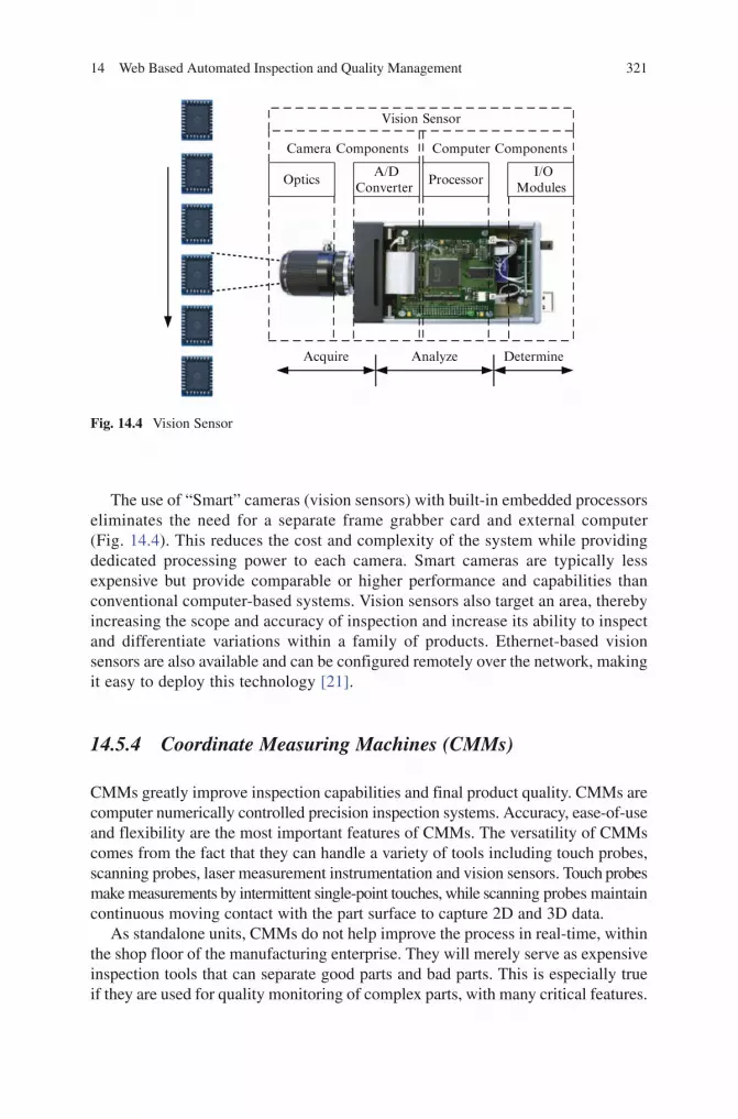
14 Web Based Automated Inspection and Quality Management 321
BookID 175907_ChapID 14_Proof# 1 - 15/4/2009
The use of “Smart” cameras (vision sensors) with built-in embedded processors eliminates the need for a separate frame grabber card and external computer (Fig. 14.4). This reduces the cost and complexity of the system while providing dedicated processing power to each camera. Smart cameras are typically less expensive but provide comparable or higher performance and capabilities than conventional computer-based systems. Vision sensors also target an area, thereby increasing the scope and accuracy of inspection and increase its ability to inspect and differentiate variations within a family of products. Ethernet-based vision sensors are also available and can be configured remotely over the network, making it easy to deploy this technology [21].
14.5.4 Coordinate Measuring Machines (CMMs)
CMMs greatly improve inspection capabilities and final product quality. CMMs are computer numerically controlled precision inspection systems. Accuracy, ease-of-use and flexibility are the most important features of CMMs. The versatility of CMMs comes from the fact that they can handle a variety of tools including touch probes, scanning probes, laser measurement instrumentation and vision sensors. Touch probes make measurements by intermittent single-point touches, while scanning probes maintain continuous moving contact with the part surface to capture 2D and 3D data.
As standalone units, CMMs do not help improve the process in real-time, within the shop floor of the manufacturing enterprise. They will merely serve as expensive inspection tools that can separate good parts and bad parts. This is especially true if they are used for quality monitoring of complex parts, with many critical features.
Camera Components Computer Components
Acquire Analyze Determine
OpticsA/D
Converter Processor
I/OModules
Vision Sensor
Fig. 14.4 Vision Sensor

322 S.M. Ramkumar and I.A. Edinbarough
BookID 175907_ChapID 14_Proof# 1 - 15/4/2009 BookID 175907_ChapID 14_Proof# 1 - 15/4/2009
In such instances, CMMs with high speed scanning will greatly increase inspection throughput and improve integration into the manufacturing flow. Integrating the CMMs to provide real-time feedback is essential for effective process monitoring and control.
14.6 Metrology Hardware Integration
14.6.1 Discrete Digital and Analog Sensor Integration
The various sensory hardware elements, discussed in section 14.5, are stand-alone units without any application specific intelligence. These sensors are hard wired individually to the digital and analog modules of the PLC and DAS (Fig. 14.5). The digital and analog signals from these sensors are stored in memory for further processing and data sharing. The intelligence required to use these sensors effectively, in a quality monitoring environment, is provided by writing application specific programs for the PLCs or DAS. The application specific programs are executed continuously within these controllers and they monitor the sensors during every scan cycle of the program. The key requirement is collecting the quality data from the sensors in the field and storing or updating the information in appropriate memory locations within the data table area of the PLCs and DASs. The user program or logic that monitors the sensor inputs takes appropriate action based
PLC
Sensors
DAS(Opto22)
DAS(NI)
Digital and Analog Input Wiring
RS232, USB,or EtherNet,
Proprietary PLCNetwork or EtherNet
SupervisoryController
Fig. 14.5 Discrete sensor integration
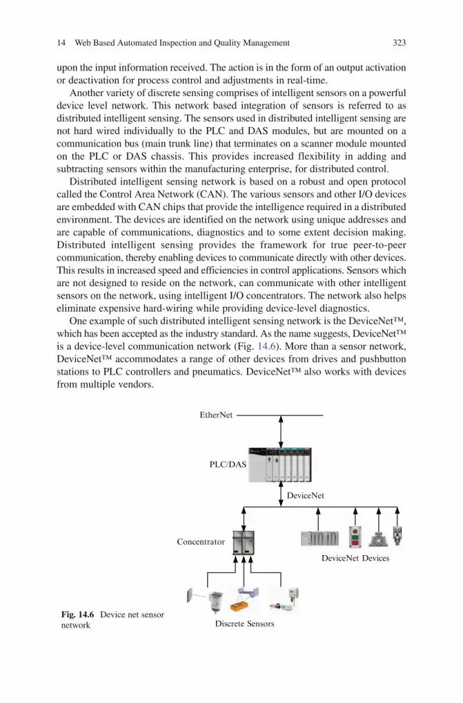
14 Web Based Automated Inspection and Quality Management 323
BookID 175907_ChapID 14_Proof# 1 - 15/4/2009
upon the input information received. The action is in the form of an output activation or deactivation for process control and adjustments in real-time.
Another variety of discrete sensing comprises of intelligent sensors on a powerful device level network. This network based integration of sensors is referred to as distributed intelligent sensing. The sensors used in distributed intelligent sensing are not hard wired individually to the PLC and DAS modules, but are mounted on a communication bus (main trunk line) that terminates on a scanner module mounted on the PLC or DAS chassis. This provides increased flexibility in adding and subtracting sensors within the manufacturing enterprise, for distributed control.
Distributed intelligent sensing network is based on a robust and open protocol called the Control Area Network (CAN). The various sensors and other I/O devices are embedded with CAN chips that provide the intelligence required in a distributed environment. The devices are identified on the network using unique addresses and are capable of communications, diagnostics and to some extent decision making. Distributed intelligent sensing provides the framework for true peer-to-peer communication, thereby enabling devices to communicate directly with other devices. This results in increased speed and efficiencies in control applications. Sensors which are not designed to reside on the network, can communicate with other intelligent sensors on the network, using intelligent I/O concentrators. The network also helps eliminate expensive hard-wiring while providing device-level diagnostics.
One example of such distributed intelligent sensing network is the DeviceNet™, which has been accepted as the industry standard. As the name suggests, DeviceNet™ is a device-level communication network (Fig. 14.6). More than a sensor network, DeviceNet™ accommodates a range of other devices from drives and pushbutton stations to PLC controllers and pneumatics. DeviceNet™ also works with devices from multiple vendors.
DeviceNet
EtherNet
PLC/DAS
DeviceNet Devices
Discrete Sensors
Concentrator
Fig. 14.6 Device net sensor network

324 S.M. Ramkumar and I.A. Edinbarough
BookID 175907_ChapID 14_Proof# 1 - 15/4/2009 BookID 175907_ChapID 14_Proof# 1 - 15/4/2009
MultiplexerUSB®USB Cable
orUSB®RS232 Cable
RS232–SerialCommunication
EtherNet
ComputerController
PLC/Data AcquisitionSystem
RS232–SerialCommunication
SupervisoryController
Fig. 14.7 Discrete instrumentation integration
14.6.2 Discrete Metrology Instrumentation Integration
Discrete metrology instrumentation such as micrometers, calipers, scales, tensile testers, hardness testers, etc., are fitted with appropriate electronic hardware, to provide ASCII data output to a computer, PLC or DAS through either the RS232 serial communication interface or the USB interface (Fig. 14.7). The manufacturer of this type of metrology instrumentation typically provides cables for data transfer and custom software to receive data into a computer. Interface hardware is also available from third party vendors to receive the data through RS232 serial interface or the USB interface and integrate the instrument with the Ethernet. Direct access to such instrumentation over the Ethernet is not desirable because of security reasons. Multiple metrology instruments can be interfaced to a single computer, using a serial RS232 interface multiplexer (Fig. 14.7). These hardware interfaces typically allow the data to be written into an Excel spread sheet or other databases within the host computer. If the option is not available then it would require third party software routines to receive the data and write it to the spreadsheet or database.
When interfacing the instrumentation with the serial communication port of the PLC or DAS, it is important to configure the communication parameters such as the baud rate, parity, stop bits, data bits, and handshaking protocol and data termination characters. Also, in the application specific program, appropriate commands for

14 Web Based Automated Inspection and Quality Management 325
BookID 175907_ChapID 14_Proof# 1 - 15/4/2009
reading ASCII data from the serial communication buffer and storing the data as strings need to be used to record incoming quality information.
14.6.3 Vision System and Vision Sensor Integration
A vision system, as indicated in section 14.5.3, has a dedicated computer that per-forms the entire image processing function and is capable of producing data per-taining to the product’s quality characteristic. With dedicated software residing on the vision system computer, the data can be written to a common database that will be accessible from a supervisory computer. This requires the vision system computer to serve as an OPC server, providing the connectivity to the next level of the architec-ture and the access to the quality data requested by the OPC client applications (MES or ERPS Clients). The vision system control software vendor should supply the source code or methodology for OPC connectivity that determines the data that is accessible, the data names and the physical access to the data.
The vision system hardware is also capable of interfacing with PLCs or DASs, for digital I/O signal interface. This enables the PLC or the DAS to trigger the vision system to carry out the inspection routine. Once the input signal is received from the controller, the vision system initiates the inspection process and sends an output signal to the controller upon completion.
Similar to the vision system, vision sensors can communicate through digital I/O for triggering the inspection process and through serial or Ethernet interface, to a dedicated computer for data sharing. With vendor supported programming environments or instruction sets, the vision sensors can also be configured to share data with OPC servers and clients.
14.6.4 CMM Integration
CMMs are computer numerical control metrology equipment. They are typically integrated with a computer based control system. Dedicated software will control the X, Y and Z-axis movement of the 2D and 3D inspection probes and scanners. In order to retrieve the data, the CMM should have the ability to record the inspection data into a database or spreadsheet and provide access to the database through the Ethernet or serial communication (Fig. 14.8).
Specific requirements of the dedicated CMM software include: real-time data acquisition, on-line statistical analysis, integrated networking, and quality information sharing (OPC Connectivity). Users should be able to acquire and analyze data in real-time to maximize production and minimize defects. The dedicated software should also have the ability to serve in a client/server environment, to provide the performance needed in a distributed processing environment. The software should also provide a

326 S.M. Ramkumar and I.A. Edinbarough
BookID 175907_ChapID 14_Proof# 1 - 15/4/2009 BookID 175907_ChapID 14_Proof# 1 - 15/4/2009
safe and organized multi-user relational database warehousing system, making quality data available for viewing and analysis at every level of the hierarchy.
14.7 Control System Integration
This hierarchical level is responsible for data acquisition from the various discrete sensors, discrete digital signals provided by CMMs and measurements from discrete instrumentation or CMM. Apart from data acquisition; this level is also responsible for controlling the manufacturing cells in its entirety, within the manufacturing enterprise. This integration level involves the use of PLCs such as the ones from Rockwell Automation, Siemens, Omron, Keyence, etc., and other dedicated internal or external DAS such as the ones from National Instruments (NI), Opto 22, etc. Based upon the experience of the authors with Rockwell Automation, NI and Opto 22, only those systems are discussed in this section. These control systems also provide serial communication interface (RS232), for basic communication with instrumentation and for receiving ASCII data.
This level also supports the Human-Machine Interfaces (HMI) required for the operators, technicians and engineers to interact with the manufacturing and quality systems. HMI allows for data input, data monitoring, data interpretation and messaging. HMI can also be part of other higher levels of the integration hierarchy.
RS232Datalink
Digital I/O
CMM
EtherNet
CMMController
Communication Link(Inspection Data)
PLC orDAS
SupervisoryController
Fig. 14.8 CMM Integration into the system

14 Web Based Automated Inspection and Quality Management 327
BookID 175907_ChapID 14_Proof# 1 - 15/4/2009
14.7.1 PLC Based Control
PLCs have I/O modules that interface with field devices and communicate with the processor module, through the backplane of a chassis. PLCs execute dedicated programs developed by the user for acquiring the field input data, taking logical decisions and controlling the outputs. These dedicated programs reside in the user memory area of the PLC system. The sensor data acquired by the PLC is stored in the memory accessible through OPC servers. The PLCs can be programmed using a combination of ladder logic programs, sequential function charts, function block diagrams and structured text methods. Several distributed independent PLC systems can be integrated using proprietary networks such as DH485, DH+, Modbus®, Profibus®, etc. or the more common Ethernet and ControlNet™ to share data with the next level of the hierarchy (the supervisory level).
14.7.2 Opto 22 Based Control
The DAS from Opto 22 uses optical isolator modules, which communicate with the brain, through the backplane of a module rack. This links the information available from the field devices to the control program residing in the brain. A dedicated program written using vendor provided software or high level language interfaces the inspection system to the control hardware. This control program makes use of custom routines and control objects provided by Opto 22 to develop the command strings necessary to read and write data. Special modules from Opto 22 also provide integration to the supervisory level using Ethernet or proprietary networks such as DH485, DH+, Modbus®, Profibus®, etc. With special configuration routines provided by the vendor, the I/O of the Opto 22 modules can be recognized within the memory of other PLCs or DASs over the Ethernet. This provides the flexibility to customize the automation islands with different control systems and still access I/Os and data from a supervisory system.
14.7.3 NI – LabView Based Control
The internal or external DAS from NI range from compact DAS controlled through the USB port of a computer to Compact FieldPoint systems similar to PLCs. A dedicated control computer runs the LabVIEW software, which is a flexible instrumentation and analysis software. The program (Virtual Instrument – VI), is developed using a graphical programming language (LabVIEW). The executable elements of VIs execute only when all the required input data is received. In other words, data flows out of the executable element only after the code is finished executing. LabVIEW also has an extensive library of virtual instruments and functions for connectivity to common control systems such as PLCs. Special hardware
328 S.M. Ramkumar and I.A. Edinbarough
BookID 175907_ChapID 14_Proof# 1 - 15/4/2009 BookID 175907_ChapID 14_Proof# 1 - 15/4/2009
from NI also provide integration to the supervisory level using Ethernet ports and other PLC networks.
14.8 Supervisory System Integration
The Supervisory level integration primarily requires a common medium for data interchange between the various controls systems (PLCs and DAS), a common medium for data storage and sharing, HMI, SCADA systems, etc. Two networks accepted as industry standard, that provide the most options for supervisory level integration are the ContolNet™ and Ethernet, discussed briefly in the following sections.
14.8.1 ControlNet™
ControlNet™ is a real-time, supervisory control-layer network that takes full advantage of the producer/consumer model to allow multiple controllers to control inputs and outputs. This supervisory network provides significant advantages when compared to other network types, as they allow more than one master controller on the network. ControlNet™ also provides high-speed transport of both time-critical I/O data and messaging data, upload/download of programming and configuration data, and peer-to-peer messaging [22]. The producer/consumer model allows data to be collected directly from devices without the need for complicated programming and allows devices to send and receive data independently.
14.8.2 Ethernet
EtherNet is the most developed, proven and complete industrial Ethernet network solution available for manufacturing automation. This network uses the Common Industrial Protocol (CIP), which encompasses a comprehensive set of messages and services for a variety of manufacturing automation applications. CIP provides users with unified communication architecture throughout the manufacturing enterprise. This network provides users with the tools to deploy standard Ethernet technology for manufacturing applications while enabling Internet and enterprise level connectivity, providing data anytime, anywhere [22].
14.9 Enterprise/Management Information System Integration
The primary requirement for enterprise or management level integration is the creation, maintenance and access to a common manufacturing database for information sharing. OPC was designed specifically to enable such information sharing and link Windows based applications with process control hardware and software applications.

14 Web Based Automated Inspection and Quality Management 329
BookID 175907_ChapID 14_Proof# 1 - 15/4/2009
OPC facilitates interoperability between process control and manufacturing automation applications. OPC servers provide a method for many different off the shelf tools such as SCADA packages, databases, spreadsheets, etc., at the supervisory level, to access data from a control system, such as a PLC or DAS. Enterprise or management information system clients at the enterprise level, can access data contained in the databases of the OPC servers using custom applications, which provide OPC interfaces.
OPC’s architecture can be implemented using Java, Microsoft.NET, C, C++, Visual Basic, or other web programming languages, eliminating the need to use Microsoft Windows based platforms and applications. This unified architecture provides OPC interfaces with XML and other web based services, to deliver quality information to higher level MES and ERPS on the web, a key enabler for web-based automation and management [23].
14.10 Overall System Integration – An Example
Three networks that have become the most prominent in an automated manufactur-ing environment include the DeviceNet at the device level, the ControlNet at the controls level and the Ethernet at the supervisory and enterprise level. This section outlines a typical control architecture using Rockwell Automation components as examples.
The distributed intelligent sensors and actuators reside on the DeviceNet throughout the factory floor and communicate with a PLC controller through the DeviceNet scanner module, mounted on its chassis. Also, on the DeviceNet net-work a computer running the DeviceNet Manager Software continuously moni-tors the DeviceNet network for the availability and proper functioning of all the sensors and actuators. If a sensor or actuator goes offline on the network, the shop floor personnel will be alerted using a Panelview terminal located on the DeviceNet network. At the control system level, the PLC controller serves as the main control PLC. The PLC system provides the link between the ControlNet and the DeviceNet and is programmed using ladder logic, function block diagram, sequential function charting or structured text or a combination of these program-ming languages. The programming software (RSLogix) in conjunction with the communication software (RSLinx) provides the OPC server capability to collect real-time data from the PLC controllers. The communication software also com-municates with the ControlLogix gateway controller, at the supervisory control level, that links the ControlNet with the Ethernet. This provides the OPC clients on the Ethernet, access to information within the ControlLogix gateway controller.
This example shows the integration of various hardware elements at different levels of the hierarchy and data sharing between them. The system can also include additional hardware elements that may be available within the factory floor from previous installations that can be added to these three networks, by using special purpose modules on their chassis.

330 S.M. Ramkumar and I.A. Edinbarough
BookID 175907_ChapID 14_Proof# 1 - 15/4/2009 BookID 175907_ChapID 14_Proof# 1 - 15/4/2009
14.11 System Safety
Implementing a web based process control system introduces many new challenges and safety concerns such as web related traffic delays, uncertainty about who the users are and concurrent user access situations. These are important considerations in the development of web-based systems, which makes the design of these systems different from dedicated computer-based process control systems. Yang and Xue [6] identify that many new web tools and distributed computing methods need to be developed to address issues involving the accessabilty and security of web-based systems. Data security measures such as the prevention of unauthorized access using firewall, user authentication, data encryption, and adoption of technically sound counter measures are to be considered.
The following are considered by the authors to be important data security and system safety issues that needs to be addressed for the succesful implementaion of a web-based AI and QM sytem.
1. Hacker attacks2. Unauthorized access3. Wiretapping and wireless transmission interference4. System failures caused by viruses5. Denial of service due to network and server overload
14.12 Educational Impact
Web-based training and development is known to have provided positive and negative experiences to the user. According to the authors, implementing a web-based AI and QM system for automated manufacturing and training is perceived to have the following benefits and issues.
Benefits:
1. Real time data collection on the product and processes and its subsequent integration with MES and ERPS will help the industry improve their product quality and manufacturing efficiency.
2. Greater data sharing and data availability for control and monitoring will enhance automated system performance.
3. Allows academic or industrial partnerships, on-site or across the globe with their counterparts, for collaborative engineering and agile manufacturing.
4. Remote monitoring and optimization of product design and processes based on inspection and quality feedback.
5. Cost effective and ease of course delivery and training.6. Possible full scale experimentation through simulation, before production or
installation.7. Eliminates duplication of effort.

14 Web Based Automated Inspection and Quality Management 331
BookID 175907_ChapID 14_Proof# 1 - 15/4/2009
8. Sharing of learning materials and other resources using hyperlinks and cross-references.
Issues:
Even though the above benefits are impressive, the implementation of web based AI & QM requires a thorough understanding of the following issues:
1. Increased dropout rate attributed to problems with technology and poorly designed training modules and limited instructional methods.
2. Development of platform-independent, universal programming languages for the control and operation of various devices available in the system.
3. Internet time delay due to heavy traffic may lead to delayed response for corrective actions.
4. Equipment operational safety and security concerns.
14.13 Conclusion
In general, the authors have observed that teaching web based manufacturing automation principles and processes have been well received. However, the main challenge is the internet connection dependence of the remote users. The requirement for high speed internet access creates a technological boundary with international cooperation especially in developing countries. Another issue is the rapid development of wireless connectivity for web-based industrial automation. This trend calls for higher skill set requirements for faculty engaging ever increasing student interest in this technology.
Collaboration between academia and industry is vital to help the small and medium scale industries move away from their conventional data collection methods, to a web-based methodology for implementing a comprehensive management informa-tion system. Also, the employers do not find time to design and schedule formal training for their employees and increasingly prefer the web based training methods to satisfy their training and product and process optimization requirements.
Therefore, there is a continuous demand for developing and implementing advanced technologies, that address the above mentioned issues and fully reap the benefits of this emerging web based Automated Inspection and Quality Management Technology.
References
1. Ramkumar, S. M., & Edinbarough, I. A. (1998). Computer Based Manufacturing Cell Control Using Intelligent Sensing System. Minneapolis, MN: Proceedings of the International Conference on Agile Manufacturing.
2. Edinbarough, I. A., & Ramkumar, S. M. (2001). A Feasibility Study for the Implementation of Non-Site Based Hands-On Curriculum for Engineering Technology. Proceedings of the 2001 American Society for Engineering Education Annual Conference and Exposition.
332 S.M. Ramkumar and I.A. Edinbarough
BookID 175907_ChapID 14_Proof# 1 - 15/4/2009
3. Edinbarough, I. A., Ramkumar, S. M., & Soundararajan, K. (2002). A Web-Based Approach to Automated Inspection and Quality Control of Manufactured Parts. Proceedings of the 2002 American Society for Engineering Education Annual Conference and Exposition.
4. Kwon, Y., & Chiou, R. (2007). Quality Control in Network-Based Production Environments. SPIE.
5. Kwon, Y., Rauniar, S., Chiou, R., & Sosa, H. (2006). Remote Control of Quality Using Ethernet Vision and Web-Enabled Robotic System. Concurrent Engineering: Research and Applications, 14 (1), 35–42.
6. Yang, S. H., Chen, X., & Alty, J. L. (2003). Design Issues and Implementation of Internet-Based Process Control. Control Engineering Practice, 11, 709–720.
7. Yang, S. H., Tan, L. S., & Chen, X. (2002). Requirements Specification and Architecture Design for Internet-Based Control Systems. Proceedings of the 26th Annual International Computer Software and Applications Conference. IEEE.
8. Renton, P., Bender, P., Veldhuis, S., Renton, D., Elbestawi, M. A., Teltz, R., et al. (2002). Internet-Based Manufacturing Process Optimization and Monitoring System. IEEE, 2, 1113–1118.
9. Anton, D., Bragos, R., & Riu, P. J. (2004). Remotely Accessible Laboratory for Instrumentation and Sensors. IMTC 2004 – Instrumentation and Measurement Technology Conference (pp. 1272–1276). Como, Italy: IEEE.
10. Ruusunen, M., & Paavola, M. (2002). Quality Monitoring and Fault Detection in an Automated Manufacturing System – A Soft Computing Approach. University of Oulu, Department of Process and Environmental Engineering. Finland: Control Engineering Laboratory.
11. Yeung, K., & Huang, J. (2001). Development of the Internet Based Control Experiment. Proceedings of the 40th IEEE Conference on Decision and Control (pp. 2809–2814). Orlando, FL: IEEE.
12. Furuya, M., Kato, H., & Sekozawa, T. (2000). Secure Web-Based Monitoring and Control System. IEEE, 4, 2443–2448.
13. Bellmunt, O. G., Miracle, D. M., Arellano, S. G., Sumper, A., & Andreu, A. S. (2006). A Distance PLC Programming Course Employing a Remote Laboratory Based on a Flexible Manufacturing Cell. IEEE Transactions on Education, 49 (2), 278–284.
14. Wang, L., Orban, P., Cunningham, A., & Lang, S. (2004). Remote Real-Time CNC Machining for Web-Based Manufacturing. Robotics and Computer-Integrated Manufacturing, 20, 563–571.
15. Warnier, E., Yliniemi, L., & Joensuu, P. (2003). Web Based Monitoring and Control of Industrial Processes. Report A No. 22, University of Oulu, Control Engineering Laboratory.
16. Kumar, D. K., Karunammorthy, L., Roth, H., & Mirnalinee, T. T. (2005). Computers in Manufacturing: Towards Successful Implementation of Integrated Automation System. Technovation, 25, 477–488.
17. Lacroix, E., & St-Denis, R. (2003). Web Technologies in Support of Virtual Manufacturing Environments. IEEE, 2, 43–49.
18. Lal, S. P., & Onwubolu, G. C. (2007). Three Tiered Web-Based Manufacturing System – Part 1: System Development. Robotics and Computer-Integrated Manufacturing, 23, 138–151.
19. Lee, J. (2003). E-Manufactruing – Fundamental, Tools, and Transformation. Robotics and Computer-Integrated Manufacturing, 19, 501–507.
20. Zayia, D. (2004, May). Probing Technology Moves Ahead. Manufacturing Engineering, 132 (5).21. Waurzyniak, P. (2005, January). Vision Sensors for Gaging. Manufacturing Engineering, 134 (1).22. ODVA:ControlNet. (n.d.). Retrieved November 15, 2008, from ODVA: http://www.odva.org23. The OPC Foundation – Dedicated to Interoperability in Automation. (n.d.). Retrieved
November 15, 2008, from OPC Foundation: http://www.opcfoundation.org/

BookID 175907_ChapID BM_Proof# 1 - <Date>
Biographies
Editor
Spyros G. Tzafestas, an NTUA emeritus Professor since 2006, received the following degrees: B.Sc. in Physics, P.G. Diploma in Electronics (Athens University, 1963, 1964); D.I.C. and M.Sc. in Control (Imperial College, London University, 1966); Ph.D. (1969) and D.Sc. (1978) in Systems and Control (Southampton University). He is recipient of D.Sc. Eng. (Honoris Causa), Intl. Univ. Foundation (1987), Dr.-Ing. E.h., T.U. Munich (1997) and Docteur Honoris Causa, E.C. Lille (2003). From 1969 to 1973 he was a research leader at the Nuclear Research Center “Demokritos” (Athens), from 1973 to 1984 he was pro-fessor of systems and control engineering at Patras University, Greece, and from 1985 to 2006 he was professor of robotics and control at the National Technical University of Athens (NTUA), Greece. He has published 30 research books and over 700 technical papers. He is the founding editor of the Journal of Intelligent and Robotic Systems, associate editor of 15 journals, and editor of the Springer book series on Intelligent Systems, Control and Automation: Science and Engineering. His research interests include intelligent systems, robotics, CIM, con-trol, fault diagnosis, and computational intelligence. He is a Life Fellow of IEEE, a Fellow of IEE (now IET), a member of ASME and the New York Academy of Sciences, and has received many awards over the years for his achievements. His experience includes the organization of several conferences in intelligent systems, robotics and control, and the leadership of several European R&D projects in Information Technology, Control, and Automation.
Contributors
Giorgio Buttazzo is Full Professor of Computer Engineering at the Scuola Superiore Sant’Anna of Pisa. His main research interests include real-time operat-ing systems, dynamic scheduling algorithms, quality of service control, multimedia
333

334 Biographies
BookID 175907_ChapID BM_Proof# 1 - <Date> BookID 175907_ChapID BM_Proof# 1 - <Date>
systems, advanced robotics applications, and neural networks. He graduated in Electronic Engineering from the University of Pisa in 1985, received a Master in Computer Science at the University of Pennsylvania in 1987, and a Ph.D. in Computer Engineering at the Scuola Superiore Sant’Anna of Pisa in 1991. Dr. Buttazzo has been Program Chair and General Chair of major international conferences on real-time systems. He has authored six books on real-time systems and over 200 papers in the field of real-time systems, robotics, and neural networks. He is a Senior Member of IEEE.
Giuseppe Carnevali is a Computer Engineer at the Research and Development Unit of the OCEM SpA. He is involved in the development of new technologies and flexible programming architectures for the new generation of lighting systems for airports, railways, and laboratories. He graduated in Computer Engineering at the University of Pavia in 2002. From 2002 to 2003, he worked at the Robotics Lab of the University of Pavia for developing a web-based remotely accessible laboratory. His main research interests include telecontrol, real-time systems, distributed sys-tems, and computer graphics.
Marco Casini was born in Siena, Italy, in 1973. He received the Laurea degree in information engineering and the Ph.D. in Control Systems from the University of Siena, Siena, Italy, in 1999 and 2003, respectively. In 2005, he joined the Dipartimento di Ingegneria dell’Informazione of the University of Siena, where he is currently an Assistant Professor. In the summer 2001 he was a visiting researcher at the Laboratory for Information and Decision Systems (LIDS) of the Massachusetts Institute of Technology (MIT), Cambridge, MA. He is the author of several publi-cations in international journals and conference proceedings. His research interests include set-membership system identification and modeling, remote laboratories of automatic control and modeling of environmental systems.
Bo Chen is an Assistant Professor in the Department of Mechanical Engineering – Engineering Mechanics and the Department of Electrical & Computer Engineering at Michigan Technological University. As a joint Professor, she conducts interdis-ciplinary researches in the areas of pattern recognition, mobile agent and multi-agent systems, real-time and embedded control, mechatronics, sensor networks, and intelligent transportation systems. Dr. Chen has published over 30 refereed journal and conference papers. She received the best paper award in computational methods and software at the 2008 IEEE/ASME International Conference on Mechatronic and Embedded Systems and Applications. Dr. Chen has been very active in the ASME and IEEE societies and served as Symposium Chair or Session Chair for several international conferences.
Harry H. Cheng is a professor of the Department of Mechanical and Aeronautical Engineering, Graduate Group in Computer Science, and Graduate Group in Electrical and Computer Engineering at the University of California, Davis. He is also the Director of the Integration Engineering Laboratory at UC Davis. Before joining the faculty at UC Davis in 1992, he worked as a Senior Engineer on robotic automation systems in the Research and Development Division at United Parcel

Biographies 335
BookID 175907_ChapID BM_Proof# 1 - <Date>
Service from 1989 to 1992. He is the Chief Architect of an embeddable C/C++ interpreter Ch for script computing. He is the founder of SoftIntegration, Inc. He received the M.S. degree in Mathematics in 1986 and the Ph.D. degree in Mechanical Engineering in 1989 from the University of Illinois at Chicago. Dr. Cheng has published over 130 papers in refereed journals and conference pro-ceedings. He is a Fellow of ASME and a Senior Member of IEEE.
Sebastian Dormido received his Physics degree from Universidad Complutense de Madrid (1968) and his Ph.D. from Country Vasc University (1971). In 1981, he was appointed Full Professor of Control Engineering at the Universidad Nacional de Educacion a Distancia (UNED), Faculty of Sciences. He has been President of CEA-IFAC from 2002 until 2006. He has coordinated more than 30 research projects, has supervised more than 25 Ph.D. Dissertations and has co-authored more than 130 journal papers.
Immanuel Edinbarough is a Professor in the Department of Applied Engineering Technology at the University of Texas, Brownsville. He has a successful track record spanning over 25 years in the service oriented and challenging fields of academia, industry and military. He is a hands-on manufacturing expert who has worked in several areas of engineering, manufacturing, and technical management including research, design, and production of mechanical, electronic, and electro-mechanical systems. A recognized trainer and resource person in the fields of CAD/CAM/CIM, Robotics and Automation, Machine vision, ISO 9000 and Lean Six Sigma. He has published several papers, in these areas, in various national and international conferences and journals. He has won several teaching awards includ-ing the recent academic excellence award, NISOD 2008, from the University of Texas at Austin.
Ayssam Yehia Elkady received the B.Sc. in Engineering degree with honors in Computer Science and Automatic Control from the Faculty of Engineering, Alexandria University, Egypt in 2002, M.S. degree in engineering mathematics from the Faculty of Engineering, Alexandria University, Egypt in 2006, and M.S. degree in Computer Science from the School of Engineering, University of Bridgeport, Connecticut in 2008. He is currently a fulltime Ph.D. student of Computer Science and Engineering at the University of Bridgeport. He won Best Poster Competition at the ASEE zone 1 conference, March 2008. His background is in the fields of robotics, AI, control theory, neural networks, and fuzzy control.
Gianni Ferretti was born in Cremona (Italy) in 1962. He received the ‘Laurea’ degree in Electronics Engineering in 1987 from the Politecnico di Milano. From 1990 to 1998 he was Assistant Professor at the Department of Electronics and Computer Science of the Politecnico di Milano, and in 1994 he was a visiting researcher at the Laboratoire d’Automatique de Grenoble. From 1998 to 2005 he was Associate Professor at the Politecnico di Milano where he is currently Full Professor in Systems and Control. He is the Director of the Cremona campus of the Politecnico di Milano, and he teaches Automatic Control to aerospace and informa-tion engineering students and Simulation Techniques and Tools. His principal

336 Biographies
BookID 175907_ChapID BM_Proof# 1 - <Date> BookID 175907_ChapID BM_Proof# 1 - <Date>
research interests are in control of servomechanisms, modelling and simulation of mechatronic systems, force/position control of robots, modelling and simulation of automotive systems. He is coauthor of more than 100 papers, most of which were published in international journals or presented in international conferences, and he was involved in many research projects with industries and institutions.
Darko Hercog has graduated in electrical engineering in the year 2001 from the Faculty of Electrical Engineering and Computer Science, University of Maribor. For his B.A. thesis, he received the Vratislav Bedjanič Award for the best diploma work (in Slovenia) in the field of control and robotics. Since the year 2002, he has been employed at the Institute of Automation as Assistant-Researcher in the Laboratory for electrical measurements. His field of expertise includes the embed-ded systems, real-time systems, rapid control prototyping systems, virtual instru-mentation and remote laboratories. He is an IEEE Member, author of many journal articles, and reviewer for journals and conferences. He is also active at the promo-tion of engineering study and introduction of modern teaching methods in the education process.
David Ko graduated from the University of California at Davis with a BS degree in Mechanical Engineering and Material Science with a minor in Computer Science in 2006. He is currently pursuing his Ph.D. in the Department of Mechanical and Aeronautical Engineering at the University of California at Davis. His research interests include robotics and mobile agent systems.
GianAntonio Magnani received the Master of Science in Electronic Engineering from the Politecnico di Milano, Italy, in 1978. From 1978 to mid 1984 he worked with the Automatica Research Center of the Italian Electricity Board (ENEL), where he participated in research on modeling, simulation and control of electric power plants. From 1986 to 1992 he was with Fiar Spa, Robotics and Artificial Intelligence Division and with Tecnospazio, a Fiar and Comau (Fiat Group) joint company, where he was in charge of research and development units and led several projects for industrial and space robotics applications. He is presently the Director of the Dipartimento di Elettronica e Informazione of the Politecnico di Milano. He teaches Control System Technologies and Engineering and Industrial Robotics, and he is in charge of research projects awarded by industrial companies and research agencies. His current research interests include robot position and force control, servomechanisms and mechatronics. He is a Senior Member of IEEE and currently serves as an Associate Editor for Mechatronics and Control Engineering Practice.
Raul Marin received a B.Sc. degree in computer science and engineering (1996) and a Ph.D. in Engineering (2002) by the Jaume I University of Castellon (Spain). In 1996 he worked in the Multimedia department of BYG Systems Ltd, Nottingham (UK), as a software developer. In 1997, he joined Lucent Technologies (Bell Labs Innovations) and worked as researcher, software developer and software architect at the Switching and Access Division. In 1999 he began to teach and research as professor at the Jaume I University. Presently, he is working as researcher at the Department of Computer Science of the Jaume-I University (Spain) and teaches

Biographies 337
BookID 175907_ChapID BM_Proof# 1 - <Date>
Computer Networking and Distributed Systems in the same university. His research interests lie mainly in the field of Multirobot Distributed Systems, High-Performance FPGA-based Vision, Internet Telerobotics, Network Protocols, Human-Computer Interfaces, and Tele-Education. He is author or co-author of many research publications in these subjects.
Carla Martin-Villalba was graduated in Electronic Engineering in 2001 at the University Complutense of Madrid (UCM) and received her Ph.D. in Computer Science from the Universidad Nacional de Educación a Distancia (UNED, Spain) in 2007. She is currently Assistant Professor at the Departamento de Informática y Automática of UNED University in Madrid, Spain.
Domenico Prattichizzo has received the M.S. degree in Electronics Engineering and the Ph.D. degree in Robotics and Automation from the University of Pisa in 1991 and 1995, respectively. Since 2002 is an Associate Professor of Robotics at the University of Siena. In 1994, he was a Visiting Scientist at the MIT AI Lab. He served as Co-chair of the IEEE International Workshop on “Control Problems in Robotics and Automation” 2002, co-chair of the IEEE ICRA workshop on “Multi-point Interaction in Robotics and Virtual Reality” 2004, and Vice-chair for Special Issues of the IEEE Technical Committee on Haptics (since 2006). He is Co-editor of two books by STAR, Springer Tracks in Advanced Robotics, Springer (2003, 2005). Since 2007 he is Associate Editor in Chief of the IEEE Transactions on Haptics. From 2003 to 2007, he was Associate Editor of the IEEE Transactions on Robotics and IEEE Transactions on Control Systems Technologies. He served as a member of the Editorial Board of many Conferences on Control and Robotics. His research interests are in haptics, grasping, visual servoing and geometric control. Dr Prattichizzo is the author of more than 150 papers in the area of robotics and automatic control.
Manian Ramkumar is a Professor in the Manufacturing and Mechanical Engineering Technology and Packaging Science Department at the Rochester Institute of Technology (RIT). He is also the Director for the Center for Electronics Manufacturing and Assembly (CEMA) and the Graduate Program Chair for the Masters Degree program in Manufacturing and Mechanical Systems Integration. He specializes in Manufacturing Automation and Surface Mount Electronics Packaging and teaches courses related to Controls for Automation, Computer Integrated Manufacturing (CIM), Robotics, Computer Numerical Control (CNC), and Electronics Packaging. He was instrumental in developing the CIM and the Electronics Packaging laboratories at RIT and a completely web based laboratory course on Controls for Automation. This course was recently recognized for its innovative use of web technologies to provide online laboratory experience for distance education. The laboratories developed by Dr. Ramkumar are equipped with industry scale equipment, to support hands-on training and applied research projects for industry and are recognized as foremost of its kind in any academic institution. Dr. Ramkumar has presented technical papers at SMTA, APEX, IMAPS, ASME, ECTC and IEEE conferences and has many journal publications

338 Biographies
BookID 175907_ChapID BM_Proof# 1 - <Date> BookID 175907_ChapID BM_Proof# 1 - <Date>
to his credit. He is also a recognized industry trainer for Automation, Surface Mount Technology (SMT) and Advanced Electronics Packaging courses.
Paolo Rocco was born in Busto Arsizio (Italy) in 1966. He received the “Laurea” degree cum laude in Electronic Engineering and the Doctorate degree in Computer Science and Automation in 1991 and 1995, respectively, both from the Politecnico di Milano, Italy. In 1995 he was a visiting scholar at the School of Mechanical Engineering of Georgia Tech, Atlanta, USA. Since 1996 he has been with the Department of Electronics and Computer Science of the Politecnico di Milano, where he is currently Full Professor in Systems and Control, teaching courses in Automatic Control and Industrial Robotics. He has been in charge of several research projects both with industrial partners and public bodies. His research inter-ests include industrial robotics, motion control, and mechatronics in general. He is the author or co-author of about 100 papers, most of which have been published in international journals or presented in international conferences. Dr. Rocco has served as an Associate Editor for the IEEE Transactions on Robotics (2004–2008), and currently he serves as an Associate Editor for the Conference Editorial Board of the IEEE Robotics and Automation Society.
Andreja Rojko received B.Sc. (1997) and Ph.D. (2002) degrees in electrical engi-neering from the Faculty of Electrical Engineering and Computer Science, University of Maribor, Slovenia. While working toward the Ph.D. degree, she was a National Science Junior Researcher. She is currently at the Institute of Robotics, University of Maribor, Slovenia where she works as a Research Assistant since 2001. Since 2008 she is an Assistant Professor for Automation and Robotics. Her research interests include modern education methods, remote experiments, lifelong and distance learning as well as motion control in robotics and mechatronics, soft computing systems, real-time control systems and mobile robots. Her other activi-ties include working on several bilateral and international projects concerning e-learning and other modern education methods. She is an IEEE Member and IEEE Education Society member, and also reviewer for journals and conferences, mem-ber of program committees for conferences, and active at the promotion of engi-neering study.
Ulrich Rueckert received the diploma degree (M.Sc.), with honours in computer science, and a Dr.-Ing. degree (Ph.D.), with honours in electrical engineering, both from the University of Dortmund, Germany, in 1984 and 1989, respectively. He joined the Department of Electronic Components, University of Dortmund, in 1985, where he developed the first VLSI implementations of artificial neural net-works in Europe. Since 1995, he is a Full Professor of electrical engineering at the University of Paderborn. As a member of the Heinz Nixdorf Institute, he is head of the research group “System and Circuit Technology”. The group is working on innovative circuit design and development of microelectronic systems for massive-parallel and resource-efficient information processing. His main research interests are distributed intelligent systems, neural information processing and reconfigura-ble computing architectures. He is a member of the managing board of the Heinz

Biographies 339
BookID 175907_ChapID BM_Proof# 1 - <Date>
Nixdorf Institute, and Adjunct Professor at the Faculty of Information Technology, Queensland University of Technology, Brisbane, Australia. He is a chair member of AMiRE (Autonomous Minirobots for Research and Edutainment) Symposium.
Riko Šafarič was born in 1961. He received the B.Sc. degree in 1985, the M.Sc. degree in 1989, and the Ph.D. in 1994 in Electrical Engineering from the University of Maribor, Slovenia. He was researcher in industry for 3 years after he had received his B.Sc. degree. He became a researcher and later an assistant at the Faculty of Electrical Engineering and Computer Science, University of Maribor after he had received the M.Sc. degree. He has been holding the position of a full professor of Robotics since 2006. He is the head of the Lab for cognitive systems in mechatronics. His research interests are mainly in the field of robotics: adaptive control of direct-drive robot mechanisms, neural-network control, sliding-mode control, telerobotics via internet, collision detection in virtual reality world, mechatronics design, etc.
Pedro J. Sanz is an Associate Professor of Computer Science and Artificial Intelligence at Jaume-I University (Spain). He holds a B.Sc. in Physics from the University of Valencia (1985, Spain), M.Sc. in Engineering (CAD/CAM) from the Technical University of Valencia (1989, Spain), and a Ph.D. in Computer Engineering by the Jaume I University of Castellon (1996, Spain). Since 1990 he is active in R&D within several projects on Advanced Robotics and Multimodal Interfaces. He is author or co-author of a broad range of research publications, and a member of several scientific societies such as IEEE, IAPR, or ECCAI, among others. He has served as a program committee member of several outstanding inter-national conferences on Robotics, and as an Associate editor of IEEE Transactions on Systems, Man and Cybernetics (C), since 2005, and IEEE Robotics and Automation Magazine, since 2008. His current research interests include Multisensory based Dexterous Manipulation, Telerobotics, and Human-Robot Interaction.
Tarek M. Sobh received the B.Sc. in Engineering degree with honors in Computer Science and Automatic Control from the Faculty of Engineering, Alexandria University, Egypt in 1988, and M.S. and Ph.D. degrees in Computer and Information Science from the School of Engineering, University of Pennsylvania in 1989 and 1991, respectively. He is currently the Vice President for Graduate Studies and Research, and Dean of the School of Engineering at the University of Bridgeport, Connecticut; the Founding Director of the Interdisciplinary Robotics, Intelligent Sensing, and Control (RISC) laboratory; and a Professor of Computer Engineering, Computer Science, Electrical Engineering and Mechanical Engineering. His cur-rent research interests include reverse engineering and industrial inspection, CAD/CAM and active sensing under uncertainty, robots and electromechanical systems prototyping, sensor-based distributed control schemes, unifying tolerances across sensing, design, and manufacturing, hybrid and discrete event control, modelling, and applications, and mobile robotic manipulation. He has published over 200 journal and conference papers, and book chapters in those and other areas. Dr. Sobh

340 Biographies
BookID 175907_ChapID BM_Proof# 1 - <Date> BookID 175907_ChapID BM_Proof# 1 - <Date>
is a member or senior member of several professional organizations including; ACM, IEEE, IEEE Computer Society, IEEE Robotics and Automation Society, IEEE Computer Society Technical Committee on Pattern Analysis and Machine Intelligence (PAMI), and many others.
Andry Tanoto holds a BEng. degree in Aeronautical Engineering from Bandung Institute of Technology, Indonesia in 1997. In 2004 he received his M.Sc. degree in Electronic Systems and Engineering Management from the University of Applied Sciences South Westphalia, Germany, and Bolton Institute, UK. He is currently pursuing his doctoral degree at the Heinz Nixdorf Institut, University of Paderborn, where he has been involved in the Teleworkbench and EU GUARDIANS project. He is also a member of FaceBots project during his summer internship at the Interactive Robot and Media Laboratory, UAE, in 2008. His research interests are in the areas of internet mobile-robotics, human robot interaction, and image/video processing.
Costas S. Tzafestas holds an Electrical and Computer Engineering Degree (1993) from the National Technical University of Athens, as well as D.E.A. (1994) and Ph.D. Degrees in Robotics (1998) from the Université Pierre et Marie Curie (Paris 6), France. He is currently a Lecturer on Robotics at the School of Electrical and Computer Engineering of the National Technical University of Athens. He has previ-ously been a Research Fellow at the Institute of Informatics and Telecommunications of the National Center for Scientific Research “Demokritos”, Greece. His research interests include haptics, human-robot interaction, virtual reality, and robot vision techniques, particularly with applications in the field of telerobotics, where he has published several archival journal and conference papers. He is a member of the IEEE and of the Greek Technical Chamber. Dr. C. Tzafestas serves as a member of the Editorial Board for the Journal of Intelligent and Robotic Systems.
Suzana Uran received the B.Sc., M.Sc., and Ph.D. degrees in Electrical Engineering in 1985, 1989 and 1998, respectively, from the University of Maribor. Since 1985 she has been with the Institute of robotics, Faculty of Electrical Engineering and Computer Science, University of Maribor, where she is currently an Assistant Professor. Her research activities include mechatronic systems design, control, robot force/position control, and web-based education in control and robotics.
Alfonso Urquia received an M.S. degree in Physics in 1992 from the Universidad Complutense de Madrid, and a Ph.D. in Physics in 2000 from the Universidad Nacional de Educación a Distancia (UNED). His work experience includes 6 years as an R&D Engineer at AT&T Microelectrónica España, Lucent Technologies - Bell Labs and Agere Systems. Since 2002, he has been working as an Associate Professor at the Department Informática y Automática, UNED.
Antonio Vicino was born in 1954. He received the Laurea in Electrical Engineering from the Politecnico di Torino, Torino, Italy, in 1978. From 1979 to 1982 he held several Fellowships at the Dipartimento di Automatica e Informatica of the Politecnico di Torino. He was Assistant Professor of Automatic Control from 1983
Biographies 341
BookID 175907_ChapID BM_Proof# 1 - <Date>
to 1987 at the same Department. From 1987 to 1990 he was Associate Professor of Control Systems at the Universita’ di Firenze. In 1990 he joined the Dipartimento di Ingegneria Elettrica, Universita’ di L’Aquila, as Professor of Control Systems. Since 1993 he is with the Universita’ di Siena, where he founded the Dipartimento di Ingegneria dell’Informazione and served as Head of the Department from 1996 to 1999. From 1999 to 2005 he was Dean of the Engineering Faculty. In 2000 he founded the Center for Complex Systems Studies (CSC) of the University of Siena, where he presently possesses the position of Director. He has served as Associate Editor for the IEEE Transactions on Automatic Control from 1992 to 1996, and for the IEEE Transactions on Circuits and Systems II from 2006 to 2007. Presently he serves as an Associate Editor for Automatica, and Associate Editor at Large for the IEEE Transactions on Automatic Control. He is a Fellow of the IEEE and of the IFAC. He is the author of more than 230 technical publications, co-editor of two books on ‘Robustness in Identification and Control’, Guest Editor of the Special Issue ‘Robustness in Identification and Control’ of the International Journal of Robust and Nonlinear Control, and of the Special Issue ‘System Identification’ of the IEEE Transactions on Automatic Control. He has worked on stability analysis of nonlinear systems, and on time series analysis and prediction. Presently, his main research interests include robust control of uncertain systems, robust identification and filtering, mobile robotics, and applied system modelling.
Raul Wirz received a M.Sc. in Computer Science from the Jaume I Univesity of Castellón in 2005. Currently, he has a research grant from the Spanish Ministry of Science and Education for pursuing his Ph.D. at the Intelligence Robotics Laboratory at the Jaume I University. His current research interests are in Network Robotic Systems, Internet Tele-Operation, and Network Protocols for remote control, Tele-Manipulation, High Performance Computer Vision, and e-learning platforms. He is the author of several publications in journals and conferences in these fields.
Ulf Witkowski is an assistant professor at the Heinz Nixdorf Institute, University of Paderborn. He received the Dr.-Ing. degree from the University of Paderborn, Germany in 2003. He is head of the Cognitronics research group that is part of the group “System and Circuit Technology” at the Heinz Nixdorf Institute. His research interests are among cognitive systems, mini-robotics, cooperative behaviour strate-gies including smart networking in mobile ad-hoc networks, and efficient microe-lectronic realizations of neural networks in analog, digital and mixed mode circuitry. He has managed and worked on several projects (university and industry). Dr. Witkowski is a member of the scientific exchange groups Computational Intelligence (VDE-GMA) and Microelectronics for neural networks (ITG).
Katarína Žáková (Assoc. Prof., M.Sc., Ph.D.) graduated in Technical Cybernetics from the Slovak University of Technology in Bratislava in 1991, gained her Ph.D. in Automation and Control in 2003. She is associated professor at the Slovak University of Technology in Bratislava since 2008. Her current research activities are concentrated on computer aided control design; Internet based interactive edu-cation, and e-learning.

BookID 175907_ChapID BM_Proof# 1 - <Date>
Index
AActive sensors, 299Artificial potential fields (APF), 305, 306Automated inspection (AI), 313–331Automatic Control Telelab (ACT), 72, 127,
145, 146, 154architecture, 142–144, 150experiments, 131–141features, 128–130reference subsystem, 132
Auto-regressive integrated moving average (ARIMA) model(ing), 12, 14, 15
BBall balancing device, 5, 164–167BeBot–HNI minirobot, 278Bode plot, 43, 44, 65–67, 74, 76, 77Boiler virtual-lab, 108, 117Bond graph, 118Bridge service, 231
CCascade control, 180–181, 184, 186,
188–190Cell decomposition, 307C3G 9000 Controller, 252–254
software, 258–259Ch Control Systems Toolkit (CCST), 40–45Common Object Request Broker Architecture
(CORBA), 6, 32, 161, 228, 229Communication characteristics, 17–18Communication via file, 97Communication via TCP/IP, 97–99Compensator web tool, 55–58 Component Object Model (COM), 92–94Computed torque control, 173, 182–184, 186,
189–190
Control application, 6, 18, 25, 48–49, 159–161, 163, 165, 166, 168
Control education, 61, 62, 83–101, 103–123, 127
Control implementation process, 64Control system integration, 314, 326–328
Lab View-based control, 327–328Opto22 based control, 327 PLC-based control, 327
Control type interface, 131, 142Cooperative multi-robot(s), 288–289Coordinate measuring machine (CMM), 316,
318, 321–322, 325–326Crosstalk, 300Customized design, 49–58Cyclical Asynchronous Buffer (CAB), 165, 166
DData acquisition, 6, 29, 41, 142, 163, 167, 299,
309, 315, 316, 325, 326DC motor speed control, 77–81Dexterity, 297, 304Distance education (DE), 1–3, 28, 100, 196Distributed control lab (DCL), 26–28DSP-based remote control lab, 71–81,
174–176Dymola, 105–108, 110, 111, 115, 116,
122, 123Dymolablock, 107, 108, 117Dymosim, 106, 113
EEasy Java Simulation (Ejs), 104E-console, 209, 211–216, 221E-course/e-classroom, 3–4Enterprise resource planning system (ERPS),
313, 314, 329, 330
343
344 Index
BookID 175907_ChapID BM_Proof# 1 - <Date> BookID 175907_ChapID BM_Proof# 1 - <Date>
E-training scenarios, 208–210Experimental protocol, 216–218, 222Experiment interface, 132, 134, 135, 137Exteroceptive sensors, 299
HHands-on lab training, 198, 207, 222Heat exchanger virtual lab, 106, 114, 115HTTP/HTML, 5, 25Human-computer interface (HCI), 2, 19Human-machine interface (HMI), 201, 206,
313, 318, 326, 328Hybrid DAE model, 105, 107Hypertext Preprocessor (PHP), 6, 25, 32, 68,
69, 93, 142, 145, 229, 230, 241, 271
IInformation provider, 202Infrared sensor, 278, 292, 297, 299, 301,
308, 309Interactive video, 272, 275Interactivity, 103–108, 123
batch, 103, 105–106runtime, 103, 106–111
Interface, 127–129, 157–158, 210–212, 214–216, 227–247, 260–264, 275–277, 281
Ejs-to-Matlab/Simulink, 107Modelica/Dymola-to-Matlab/Simulink, 107Sysquake-to-Dymosim, 106
Internet delay, 2, 7–15, 23
JJava, 30–31, 86–89, 94–97, 237–239, 243–244
architecture, 228–234teaching experiences, 241–246
Java interface, 237–239, 243–244, 247Java/Shark server, 159, 160, 162Jitter, 10, 11
KKhepera minirobot, 278
LLabView, 4, 6, 19, 28–30, 72, 74, 81, 84, 174,
175, 316, 327–328Lag compensator, 50–52, 111, 115Learning through doing, 62Localization, 298, 308Log service, 231
MManagement information system (MIS)
integration, 314, 317, 318, 328–329Manipulability, 304–305, 311Manufacturing execution system (MES), 313,
314, 329, 330Map building, 298, 306–308Matlab, 29, 66–67, 83–101, 107–108,
127–150builder for Java, 86–89builder for .NET, 89–90compiler script, 90dynamic data exchange (DDE), 91–92and Java, 94web server, 84–85web server application, 66–67
Mechanism with spring, 176–186, 188, 190Metrology hardware, 314, 317–326
discrete sensors, 318–319instrumentation, 318–322integration, 322–326sensors, 318–322
M-file application, 65, 68–71, 81MIS integration. See Management information
system (MIS) integrationMobile
autonomous robot, 281manipulation platform(s), 297–311robotic manipulator, 204, 298
Modelica, 105–108, 110–113, 115–123Modelica library, 105–108, 111–113, 115,
118, 123JARA, 111, 112, 115VirtualLabBuilder, 108–111
NNavigation, 205, 276, 286, 292, 299, 305–306,
308, 309, 311
OObstacle avoidance, 275, 278, 285, 298, 301,
305–308
PPassive sensors, 299Path planning, 199, 275, 286–287, 306–308, 311PD control, 172, 181–182, 184, 189, 190PHP. See Hypertext preprocessorPotential field, 286, 305–307Predictive display, 201, 202, 205, 206, 211, 250Proprioceptive sensors, 299

Index 345
BookID 175907_ChapID BM_Proof# 1 - <Date>
QQuality management (QM), 313–331Quality of service (QoS), 2, 9–11, 18
RRC oscillator, 5, 74–77, 79, 81
bode plot, 5, 74, 76, 77DC motor speed control,root locus, 5, 74, 76–78
Real-time multi-threaded programming, 285Remote control lab (RECOLAB), 5, 6, 25–26,
71–81, 174–176Remote experiment, 71, 72, 74, 80, 83, 84,
100, 131, 134, 144, 171–193, 197, 198, 280–282
Remote system identification, 127, 135–137
RISCBOT, 297–299, 304, 308–311 Robotics and Automatic Control Telelab
(RACT), 127, 128, 144–150Robot manipulation, 206, 207, 209, 210, 212,
215, 217, 222Robot motor controller, 288Robot path planning, 286, 287Robot platform, 200, 277–279, 284, 285Robot smart 3-S, 252Robot teleprogramming, 211Root locus, 5, 40, 43–45, 50–55, 61, 66, 67,
74, 76–78, 139Rotating web cam, 167–168
SSCARA robot control, 186–190Scattering/wave variable, 12–13Scene generator, 273, 274Second-order system, 42–44, 49, 73, 183Sensor fusion, 297–311ShareCam, 8, 9Shared autonomy control, 203, 255–256, 264Simulink-based interface for ACT, 128SNRP protocol, 239, 241, 246Solar house virtual lab, 121, 123Sonar, 300–301, 308–310Supervisory control, 7, 205, 250, 251,
254–258, 264, 315, 318, 328, 329Supervisory system integration, 314, 328Swarm robots, 289–291Sysquake, 104–106, 113, 115, 122, 123System layers, 230System modeling, 2, 19–20System safety, 130, 314, 316, 330
TTelelaboratory, 6, 221, 222, 227–247, 250Teleoperation experiment, 202, 249Teleoperation user interface, 260–264Teleprogramming, 202, 205–207, 211, 222,
251, 254–258, 268, 285, 286Telerobotics, 2, 196, 199–203, 205, 206, 211,
222, 228, 249, 254, 293Tele-sensor programming of SMART robot
(TeleSMART), 250, 255Teleworkbench system, 268–277
analysis tool, 271–275application programming interface,
275–276graphical user interface, 276–277server, 268–271, 275, 280, 281
Transparency, 7, 10, 30, 63, 205, 206
UUltrasonic sensor, 300, 301, 308, 318User-defined controller, 128, 130, 132,
135, 154User interface, 3, 25, 30, 41, 47, 63, 65,
90, 105, 107, 122, 123, 128, 145, 147, 149, 154, 157–158, 160, 190, 199, 204, 205, 207, 209–216, 219, 221, 222, 227–247, 250, 254, 256, 260–264, 271–273, 275–277, 282, 283, 289, 298, 316
VVector field histogram (VFH), 306Video server, 6, 25, 212, 271, 316Virtual classroom webspace, 195Virtual control lab (VCL), 4, 29Virtual lab, 2, 4–5, 15–20, 28, 40,
2, 63, 65–68, 81, 103–123, 154–158, 168, 195, 198, 199, 206–208, 221
hardware architecture, 162–163software architecture, 158–162
Virtual pendant emulator, 213–214Virtual reality (VR), 7, 18, 19, 83, 97, 196,
199–206, 221, 250, 257, 298based on teleoperation models, 202
Virtual training environment, 197, 223Vision systems/sensors, 319–321Visualization generator, 272–274Visualization of Bode plot, 67Visual servoing, 127, 144, 145, 148–150, 227,
244–246, 249

346 Index
BookID 175907_ChapID BM_Proof# 1 - <Date>
WWeb-based AI/QM, 313–315, 317, 330
system architecture, 317Web-based graphical user interface,
210–212Web-based remote laboratory, 153–169Web-based telerobotics, 7–15 Web-based training (WBT), 1, 330Web-based virtual laboratory, 65, 81
Web cams, 251, 253, 254, 261Web server, 5, 6, 16, 17, 22, 25, 31, 32, 46, 47,
55, 65–68, 70, 81, 84–85, 87, 90, 93, 97, 145, 159–161, 233, 253, 254, 271, 280, 316, 318
Web service, 6, 229, 230, 269, 281, 282, 318
Web sisotool, 65–67, 69, 70, 81Wheelchair, 303, 304, 308–310