vortex-induced-vibration of jack-ups with cylindrical legs in
TRANSCRIPT

Page 1 of 49
Vortex-Induced-Vibration of Jack-ups with Cylindrical Legs in Multiple Modes 1
Sudheesh Ramadasan, 2
Marine Technology, Newcastle University in Singapore, 537 Clementi Road #06-01, SIT@NP Building, 3
Singapore 599493 4
Longbin Tao∗, 5
Department of Naval Architecture, Ocean & Marine Engineering, University of Strathclyde, Glasgow G4 6
0LZ, United Kingdom 7
Arun Kr Dev, 8
Marine Technology, Newcastle University in Singapore, 537 Clementi Road #06-01, SIT@NP Building, 9
Singapore 599493 10
Abstract 11
A simple mathematical model was developed based on the single-degree-of-freedom analogy and 12
principle of conservation of energy evaluating various modes of Vortex-Induced-Vibration (VIV) of a 13
jack-up with cylindrical legs in steady flow. Mass ratio, damping ratio and mode factor were found to be 14
the important parameters controlling the inline and cross flow VIV and radius of gyration for the yaw 15
VIV. Criteria for the initiation of the three VIV modes were developed for the cases of a single 2D 16
cylinder, four rigidly coupled 2D cylinders in rectangular configuration and a jack-up experiencing 17
∗ Corresponding author. Tel: +44 (0)141 548 3315; Email: [email protected]

Page 2 of 49
uniform flow. The model tests demonstrated that the jack-up with cylindrical legs experienced cross flow 1
and yaw VIV in uniform flows, with amplitude ratios greater than 0.1D. Further, there was considerable 2
overlap of the lock-in ranges and coupling at higher current speeds of the aforementioned modes making 3
the jack-up practically redundant throughout the operating currents. The analysis of the mean inline 4
responses of the model revealed drag amplification due to the VIV. The test results validated the developed 5
VIV model, VIV criteria and the importance of mass ratio in suppressing VIV. The mathematical method 6
will enable practising engineers to consider the effect of VIV in jack-up designs. 7
Keywords, Jack-up, Vortex-induced-vibration (VIV), VIV criteria, VIV suppression 8
1. Introduction 9
Flow around circular cylinders is one of the extensively researched subjects in fluid mechanics. Alternate 10
shedding of vortices about the cylinders due to flow separation can cause Vortex-Induced-Vibration 11
(VIV), which can eventually lead to structural yield and fatigue failures. Comprehensive reviews on VIV 12
can be found in Sarpkaya and Isaacson (1981), Blevins (2001), Sarpkaya (2004), Williamson and 13
Govardhan (2004) and Sumer and Fredsøe (2006). 14
VIV in water is characterised by low mass ratio, added mass and significant fluid damping. King et al. 15
(1973) investigated the nature of VIV in water by means of an exhaustive test programme using model 16
piles and observed VIV along both inline and cross flow directions. Khalak and Williamson (1997a) 17
conducted experiments with an elastically mounted rigid cylinder in water and found an upper branch of 18
VIV with large vibration amplitudes owing to very low mass ratio and damping. It was observed that 19
oscillation frequency kept increasing above the natural frequency throughout the excitation regime and 20
considerable lift and drag amplification during lock-in vibrations. Khalak and Williamson (1997b) 21
presented the results of tests performed to separately determine the effect of mass ratio and damping ratio. 22

Page 3 of 49
It was reported that the overall range of excitation as well as the shape of the response curve is determined 1
by the mass ratio while the level of response is characterised by the mass damping parameter. Govardhan 2
and Williamson (2004) found that the vibration frequency during lock-in is primarily dependent on mass 3
ratio and vibration frequency can reach remarkably large values when mass ratio is in the order of unity. 4
The authors proposed an expression for the lower branch vibration frequency and confirmed the existence 5
of a critical mass ratio below which the structure will vibrate till infinite flow speed in the upper branch. 6
This revealed that the added mass of cylinders during large amplitude cross flow vibration is negative. 7
Blevins and Coughran (2009) conducted tests on VIV of an elastically supported cylinder in water and 8
observed that the lock-in range increased with a decrease in mass ratio and for light cylinders, the vibration 9
frequency increased up to 50% above cylinder’s natural frequency. Vandiver (2012) proposed an 10
alternative damping parameter (C*) to overcome the limitation of mass damping parameter and argued 11
that the alternative might be used to characterise VIV at all reduced velocities in the lock-in range and 12
multiplied with the amplitude ratio to calculate the lift coefficient. It was also noted that inline cylinder 13
vibrates at twice the shedding frequency. 14
Multi-cylinder structures are extensively used in marine and offshore industries, typical concepts being 15
jacket platforms, semi-submersibles, riser bundles and jack-up platforms. Figure 1 displays a typical jack-16
up with cylindrical legs performing soil investigation. Floating multi-cylinder structures like semi-17
submersibles and TLPs are found to experience Vortex Induced Motion (VIM), a low frequency 18
equivalent of VIV. The mass ratio of unity and low slenderness ratio of the cylinders can be regarded as 19
the main difference of VIM with jack-up undergoing VIV. However, as previous studies are limited for 20
the VIV of a jack-up, the available literature on VIM and VIV of rigidly coupled multiple cylinders can 21
be used effectively to draw relevant insights on the former. A comprehensive review of the research 22
developments on VIM was presented by Fujarra et al. (2012). Gonçalves et al. (2011b) conducted 23
experimental studies on VIM with a scaled model of the semi-submersible and found that inline, cross 24

Page 4 of 49
flow and yaw motions were experienced. It was also observed lock-in for both the cross flow and yaw 1
motions and the later was named as vortex-induced-yaw motion (VIY). It was further stated that VIY 2
occurred when vortex shedding frequency about the columns approached the natural frequency of yaw of 3
the semi-submersible. Liang et al. (2017) carried out a comprehensive numerical study complimented by 4
experimental measurements on the VIM of a deep draft semi-submersibles to examine the characteristics 5
of vortex shedding processes and their interactions due to multiple cylindrical columns. Gonçalves et al. 6
(2018) conducted experiments on deep draft semi-submersibles models to investigate the effects of the 7
column shape and the surface roughness. It was found that the circular column experienced higher VIM 8
amplitudes in both transverse and yaw motions and confirmed the existence of lock-in ranges for both 9
modes. It was also observed dynamic amplification of drag, lift and yaw moment coefficients during lock-10
in. Gonçalves et al. (2011a) conducted VIV experiments with cantilevered bar and pivoted pendulum of 11
low mass and aspect ratios, and compared the results with the published literature on VIM to establish 12
similarity between VIM and VIV. It was observed similarity in trends and values between both the 13
phenomena and that higher aspect ratios experienced higher amplitudes due to enhanced vortex 14
correlation. 15
16
Page 5 of 49
Figure 1. Jack-up with cylindrical legs (Ms Cybermarine Technologies Pte. Ltd.) 1
The spacing between the cylinders is a significant parameter for multi-cylinder VIV as the cylinders are 2
strongly influenced by wake and proximity interference effects. The flow around the downstream 3
cylinders is highly influenced by the wake of the upstream cylinders. Sumner (2010) has presented an 4
exhaustive review of the literature on the flow around two identical circular cylinders in a steady flow, 5
covering the three main configurations namely tandem, side by side and staggered. Bearman (2011) has 6
reviewed the recent research on the VIV of isolated circular cylinders and circular cylinders in tandem 7
arrangement. Zdravkovich (1985) conducted extensive wind tunnel experiments with two identical 8
cylinders in tandem, side by side and staggered arrangements covering the proximity interference, wake 9
interference and no interference regions as depicted in Figure 2. Based on the experimental study, 10
Zdravkovich (1985) concluded that the coupling between cylinders disappeared when the transverse pitch 11
ratio was above 4, and the wake interference gradually diminished when the longitudinal pitch ratio was 12
greater than 7. Wang et al. (2013) conducted an experimental study of flow around four circular cylinders 13
in a square configuration and reconfirmed that depending on the pitch ratio, the inline flow can be broadly 14
classified as shielding regime, shear layer reattachment regime and vortex impinging regime. It was 15
observed that for transverse spacing ratios above 4, the four cylinder array could be regarded as two 16
isolated parallel rows of two cylinders in tandem. It was further revealed that for large pitch ratios (P/D > 17
5), the vortex shedding from all four cylinders is fully synchronised with constant frequency and definite 18
phase relationships. Assi et al. (2010) studied the wake induced vibration (WIV) response of a downstream 19
cylinder for various longitudinal pitch ratios and found that the downstream cylinder experienced 20
vibrations with increasing amplitudes at higher reduced velocities for the pitch ratios less than 8. For pitch 21
ratios greater than 8, however, the WIV was seen progressively reduced, and the response amplitude peak 22
corresponded to that of VIV resonance. 23

Page 6 of 49
1
Figure 2. Cylinder interference regions (Zdravkovich, 1985) 2
Jiang (2012) numerically studied flow induced transverse vibrations of two tandem cylinders between two 3
parallel walls and effect of pitch ratios ranging from 1.1 to 10. It was found that the cylinders decouple 4
and behave as two isolated cylinders for larger pitch ratios above 8. Han et al. (2015) numerically 5
investigated the flow induced vibration of four uncoupled identical circular cylinders in a square 6
arrangement subjected to uniform flow. Dual resonance or cylinder synchronised vibrations were 7
identified along both inline and cross flow directions during lock-in for a pitch ratio of 5. Zhao and Cheng 8
(2012) performed numerical simulation of VIV of four rigidly coupled square cylinders in a square 9
configuration with a pitch ratio of 3. It was reported that there were two modes of vortex shedding, 10
symmetrical and synchronised. In the symmetrical mode, cylinders on either side were found to shed 11
vortices symmetrically about the longitudinal centre line. The synchronised mode was found to cause 12
aggressive lock-in vibrations due to the synchronisation of vortex shedding about all the four cylinders. 13
Self-elevating platforms or jack-ups with cylindrical legs are usually deployed in shallow and intermediate 14
waters. Cylindrical legs, typically having diameters from 0.50m to 4.00 m can potentially lead to large 15
resonant vibration and lock-in in lateral and yaw directions of the jack-ups when the vortex shedding 16

Page 7 of 49
frequency approaches the unit’s natural frequency. Such VIV can amplify the mean drag acting on the 1
legs, resulting in high static and cyclic stresses and eventually lead to yield and fatigue damages. Nicholls-2
Lee et al. (2013) pointed out the instability of the jack-ups in high tidal currents and associated VIV 3
causing large topside motions leading to abortion of operations. Thake (2005) described the VIV 4
experienced by jack-ups working in deep and fast currents and further stated the lack of established design 5
guidelines to address this issue and the need for developing new methods. The potential modes of VIV of 6
the jack-up are illustrated in Figure 3. 7
a) b) c)
Figure 3. Jack-up VIV modes, a) inline (surge), b) cross flow (sway), c) yaw (torsional)
The harmonic model was used to develop criteria (Barltrop and Adams, 1991; Blevins, 2001) for the 8
occurrence of VIV. It was found that various modes of VIV can be suppressed by increasing reduced 9
damping or mass damping parameter above certain threshold values. King et al. (1973) conducted 10
experiments on model piles in water and developed stability criteria for the occurrence of VIV; stability 11
parameters 1.2 and 17 for inline and cross flow mode respectively. Sakai et al. (2002) conducted 12
experimental study on cantilever cylinders with various reduced damping and confirmed the criteria of 13
reduced damping of 1.2 in the inline direction. Vickery and Watkins (1964) derived the dependence of 14
response amplitude on reduced damping by considering the energy balance between excitation and 15

Page 8 of 49
damping at resonance, and presented conditions of similarity between model and prototype for VIV 1
experiments. 2
There are limited model test results on jack-ups available in the published literature, and almost none of 3
them pertains to jack-up VIV. Bennett Jr and Patel (1989) tested the scaled down model of a jack-up with 4
truss legs to understand the dynamics in regular waves and confirmed that the behaviour was similar to a 5
classical SDOF (single-degree-of-freedom) system. Johnson and Patel (1992) and Grundlehner (1997) 6
presented the tests carried out with the free and restrained jack-up model in the elevated condition to 7
measure and verify the dynamic response. The results of the fixed and free tests were compared, and the 8
dynamic amplification factor was obtained. Cammaert et al. (2014) carried out model tests of an arctic 9
jack-up with cylindrical legs to verify the ice loads and leg sheltering factor. Journee et al. (1988) had 10
carried out experiments with simplified jack-up models with cylindrical legs and investigated the 11
hydrodynamic and structural nonlinearities in the fluid-structure interaction. 12
The main objectives of the paper are to understand the VIV of the jack-up with multi-cylindrical legs by 13
means of model tests and to develop simple mathematical models to evaluate the various VIV modes. A 14
set of criteria are then proposed for predicting the occurrence of the various VIV modes of jack-ups. The 15
significance of such a simplified mathematical approach is to enable practising engineers to account for 16
the effect of the VIV in the design stage of jack-ups. The comprehensive experimental results presented 17
in this paper will also serve as a benchmark for the future research of jack-up VIV. 18

Page 9 of 49
2. Theoretical Evaluation 1
2.1. 2D Circular Cylinders VIV in Steady Flow 2
2.1.1. Inline/ Surge VIV of a Single Cylinder 3
The inline resonant response amplitude, 𝑥𝑥𝑂𝑂 of a lightly damped linear mass spring SDOF cylinder under 4
dynamic excitations can be expressed as (Ramadasan et al., 2018), 5
𝑥𝑥𝑂𝑂 = 𝐹𝐹𝑑𝑑𝐶𝐶𝜔𝜔𝑁𝑁
(1) 6
where 𝐹𝐹𝑑𝑑, 𝐶𝐶 and 𝜔𝜔𝑁𝑁 represent the amplitude of the excitation force, damping coefficient and natural 7
angular frequency respectively. The product 𝐶𝐶𝜔𝜔𝑁𝑁 is the dynamic damping stiffness and controls the 8
resonance amplitude. The oscillatory drag excitation (Fd) can be expressed as, 9
𝐹𝐹𝑑𝑑 = 12𝜌𝜌𝐶𝐶𝑑𝑑𝐷𝐷𝑈𝑈2𝐿𝐿 (2) 10
where 𝜌𝜌, 𝐶𝐶𝑑𝑑, 𝐷𝐷,𝑈𝑈 and 𝐿𝐿 denote the density of the fluid, oscillatory drag coefficient, diameter of the 11
cylinder, flow velocity and length of the cylinder respectively. 12
The flow velocity can be expressed in terms of the Strouhal relationship as, 13
𝑈𝑈 = 𝑓𝑓𝑣𝑣𝐷𝐷𝑆𝑆𝑆𝑆
= 𝜔𝜔𝑣𝑣𝐷𝐷2𝜋𝜋𝑆𝑆𝑆𝑆
(3) 14
where 𝑓𝑓𝑣𝑣, 𝜔𝜔𝑣𝑣 and 𝑆𝑆𝑆𝑆 represent the vortex shedding frequency, vortex shedding angular frequency and 15
Strouhal number respectively. 16
The damping coefficient can be expressed in terms of a damping ratio (𝜁𝜁) as, 17
𝜁𝜁 = 𝐶𝐶2 √𝑀𝑀𝑀𝑀
(4) 18

Page 10 of 49
where 𝑀𝑀 and 𝐾𝐾 represent the mass and inline stiffness respectively of the cylinder. 1
During inline resonance or lock-in, 2
𝜔𝜔𝑉𝑉 = 𝜔𝜔𝑁𝑁2
= 12�𝑀𝑀𝑀𝑀
(5) 3
Defining mass ratio (𝑚𝑚∗) of a cylinder as the ratio of mass over displaced mass, 4
𝑚𝑚∗ = 𝑀𝑀𝜌𝜌𝜋𝜋4𝐷𝐷
2𝐿𝐿 (6) 5
Substituting Equations (2) to (6) in (1), the amplitude ratio of the inline VIV response can be derived as, 6
𝑥𝑥𝑂𝑂𝐷𝐷
= 𝐶𝐶𝑑𝑑16𝜋𝜋3𝑆𝑆𝑆𝑆2 𝜁𝜁𝑚𝑚∗
(7) 7
It can be seen from Equation (7) that the inline response amplitude ratio of a cylinder undergoing inline 8
VIV in a steady flow is inversely proportional to the product of mass and damping ratios. The Reynolds 9
number (Re) dependence of the inline VIV is also visible from the presence of Strouhal number and drag 10
coefficient in the above expression. 11
A criterion for the occurrence of the inline VIV can be derived by considering 1% amplitude ratio 12
(Barltrop and Adams, 1991). 13
𝜁𝜁𝑚𝑚∗ ≤ 25 𝐶𝐶𝑑𝑑4𝜋𝜋3𝑆𝑆𝑆𝑆2
(8) 14
Considering a Strouhal number of 0.20 and a maximum stationary cylinder oscillatory drag coefficient of 15
0.10 (Sumer and Fredsøe, 2006) for the practical Re range, the criterion for the inline VIV can be derived 16
as 17
𝜁𝜁𝑚𝑚∗ ≤ 0.50 (9) 18

Page 11 of 49
2.1.2. Cross flow/Sway VIV of a Single Cylinder 1
During cross flow resonance or lock-in, 2
𝜔𝜔𝑉𝑉 = 𝜔𝜔𝑁𝑁 = �𝑀𝑀𝑀𝑀
(10) 3
Like inline response, the amplitude ratio of the cross flow VIV response (𝑦𝑦𝑂𝑂) of a 2D cylinder in a steady 4
flow can be derived as. 5
𝑦𝑦𝑂𝑂𝐷𝐷
= 𝐶𝐶𝐿𝐿4𝜋𝜋3𝑆𝑆𝑆𝑆2 𝜁𝜁𝑚𝑚∗
(11) 6
where 𝑪𝑪𝑳𝑳 represents the lift coefficient of the cylinder. The equation also shows the inverse proportionality 7
to the product of mass and damping ratios and the Reynolds number dependence of the cross flow VIV. 8
Similar to inline VIV, the criterion for the occurrence of the cross flow VIV can also be derived by 9
considering a 1% amplitude ratio (Barltrop and Adams, 1991). 10
𝜁𝜁𝑚𝑚∗ ≤ 25𝐶𝐶𝐿𝐿𝜋𝜋3𝑆𝑆𝑆𝑆2
(12) 11
Considering a Strouhal number of 0.20 and a maximum stationary cylinder lift coefficient of 0.85 for the 12
practical Re range, the cross flow VIV criterion can be derived as, 13
𝜁𝜁𝑚𝑚∗ ≤ 17.20 (13) 14
15

Page 12 of 49
2.1.3. Yaw VIV of a system of four 2D cylinders in rectangular configuration under inline excitation 1
2
Figure 4. Yaw due to inline excitation 3
Like the single cylinder VIV, the amplitude of yaw VIV response (∅𝑂𝑂) of a system of four 2D cylinders 4
in a steady flow under inline or drag excitation can be expressed as, 5
∅𝑂𝑂 = 𝑀𝑀∅𝑂𝑂𝐶𝐶∅ 𝜔𝜔𝑁𝑁
(14) 6
where 𝑀𝑀∅𝑂𝑂 and 𝐶𝐶∅ represent the amplitude of yaw excitation moment and yaw damping coefficient 7
respectively. 8
The yaw excitation due to oscillatory drag, considering the vortex synchronisation between cylinders as 9
shown in Figure 4 can be, 10
𝑀𝑀∅𝑂𝑂 = 2 × 12𝜌𝜌 𝐶𝐶𝑑𝑑𝐷𝐷𝑈𝑈2𝐿𝐿 × 𝑏𝑏 (15) 11
where 𝑏𝑏 represents the cross flow or transverse cylinder spacing. 12
During resonance/lock-in under inline excitation, 13

Page 13 of 49
𝜔𝜔𝑉𝑉 = 𝜔𝜔𝑁𝑁2
= 12�𝑀𝑀∅
𝐼𝐼 (16) 1
where 𝐾𝐾∅ and 𝐼𝐼 represent the yaw stiffness and yaw moment of inertia respectively. 2
Considering the Strouhal relationship, mass ratio, damping ratio and defining the yaw radius of gyration 3
(𝒓𝒓∅), the amplitude ratio of yaw VIV resonant response can be derived as, 4
∅𝑂𝑂𝐷𝐷
= 𝐶𝐶𝑑𝑑 𝑏𝑏 32 𝜋𝜋3𝑆𝑆𝑆𝑆2𝜁𝜁 𝑚𝑚∗ 𝑟𝑟∅
2 (17) 5
Equation (17) shows the inverse proportionality of the yaw response to the product of mass and damping 6
ratios and the Reynolds number dependence of the yaw VIV. The proportionality with the leg transverse 7
spacing and inverse proportionality with the square of yaw radius of gyration are also captured. 8
Similar to inline and cross flow VIV, considering a 1 % amplitude ratio to represent VIV occurrence, 9
𝑟𝑟∅∅𝑂𝑂𝐷𝐷
≤ 1 100
(18) 10
The criterion for the occurrence of yaw VIV under drag excitation can be derived as, 11
𝜁𝜁𝑚𝑚∗ ≤ 25 𝐶𝐶𝑑𝑑 𝑏𝑏 8 𝜋𝜋3𝑆𝑆𝑆𝑆2 𝑟𝑟∅
(19) 12
Considering a Strouhal number of 0.20 and a maximum stationary cylinder oscillatory drag coefficient of 13
0.10 for the practical Re range, the criterion becomes, 14
𝜁𝜁𝑚𝑚∗ 𝑟𝑟∅ ≤ 0.25 𝑏𝑏 (20) 15
16

Page 14 of 49
2.1.4. Yaw VIV of a system of four 2D cylinders in rectangular configuration under cross flow excitation. 1
2
Figure 5. Yaw due to cross flow excitation 3
The yaw excitation due to lift, considering the vortex synchronisation between cylinders as shown in 4
Figure 5 can be expressed as, 5
𝑀𝑀∅𝑂𝑂 = 2 × 12𝜌𝜌𝐶𝐶𝐿𝐿𝐷𝐷𝑈𝑈2𝐿𝐿 × 𝑎𝑎 (21) 6
where 𝑎𝑎 is the inline or longitudinal cylinder spacing. 7
During resonance/lock-in under lift excitation, 8
𝜔𝜔𝑉𝑉 = 𝜔𝜔𝑁𝑁 = �𝑀𝑀∅ 𝐼𝐼
(22) 9
Similar to yaw due to drag excitation, the amplitude ratio of the yaw VIV resonant response due to lift 10
excitation can be derived as, 11
∅𝑂𝑂𝐷𝐷
= 𝐶𝐶𝐿𝐿 𝑎𝑎 8 𝜋𝜋3𝑆𝑆𝑆𝑆2𝜁𝜁𝑚𝑚∗ 𝑟𝑟∅
2 (23) 12

Page 15 of 49
Equation (23) presents the inverse proportionality of the response with the product of cylinder mass ratio, 1
damping ratios and the square of the yaw radius of gyration. Re dependence and linear proportionality 2
with the longitudinal leg spacing are also reflected. 3
Similarly, the criterion for the occurrence of yaw VIV under lift excitation can be derived as, 4
𝜁𝜁𝑚𝑚∗ ≤ 25 𝐶𝐶𝐿𝐿𝑎𝑎2 𝜋𝜋3𝑆𝑆𝑆𝑆2 𝑟𝑟∅
(24) 5
Considering a Strouhal number of 0.20 and a maximum stationary cylinder lift coefficient of 0.85 for the 6
practical Re range, the criterion becomes, 7
𝜁𝜁𝑚𝑚∗ 𝑟𝑟∅ ≤ 8.60 𝑎𝑎 (25) 8
9

Page 16 of 49
2.2. VIV of Jack-up with Cylindrical Legs in Steady Flow 1
Figure 6 illustrates the SDOF idealisation of jack-up and the typical leg mode shape. The jack-up is 2
idealised as an elevated concentrated mass in way of the hull leg interface with the legs providing flexural 3
stiffness against lateral deflection. 4
a) b) 5
Figure 6. Jack-up structural idealisation, a) SDOF (PANEL OC-7, 2008), b) leg mode shape 6
The mode shape or deflected profile of the leg of an independent leg type jack-up unit undergoing resonant 7
vibration can be idealized as a generalised sinusoidal wave. For example, for inline vibration, 8
𝑥𝑥𝑜𝑜(𝑧𝑧) = � 𝑋𝑋𝐿𝐿𝐴𝐴 𝑠𝑠𝑠𝑠𝑠𝑠(𝑘𝑘𝐿𝐿𝐿𝐿+𝐵𝐵)+ 𝐸𝐸
� [𝐴𝐴 𝑠𝑠𝑠𝑠𝑠𝑠(𝑘𝑘𝐿𝐿𝑧𝑧 + 𝐵𝐵) + 𝐸𝐸] (26) 9
where 𝑋𝑋𝐿𝐿, 𝑘𝑘𝐿𝐿 represent the inline response in way of the hull interface and mode shape of the leg 10
respectively, A, B and E are constants depending on boundary conditions and z represents the elevation 11

Page 17 of 49
with respect to leg bottom with positive direction pointing upwards; at leg bottom, z = 0 and at hull 1
interface, z = L. 2
The effective mass per leg (𝑀𝑀𝑒𝑒𝐿𝐿) of the equivalent single-degree-of-freedom (SDOF) system of a Jack-up 3
idealised at the hull leg interface level can be expressed based on the energy principle (Barltrop and 4
Adams, 1991) as, 5
𝑀𝑀𝑒𝑒𝐿𝐿 = ∫ 𝑚𝑚(𝑧𝑧) �𝐴𝐴 𝑠𝑠𝑠𝑠𝑠𝑠(𝑘𝑘𝐿𝐿𝑧𝑧+𝐵𝐵)+ 𝐸𝐸𝐴𝐴𝑠𝑠𝑠𝑠𝑠𝑠(𝑘𝑘𝐿𝐿𝐿𝐿+𝐵𝐵)+ 𝐸𝐸
�2𝐿𝐿
0 𝑑𝑑𝑧𝑧 (27) 6
where 𝑚𝑚 represents the mass distribution along the leg. 7
As evident from the Equation (27), the contributions from the individual mass components, hull, leg, 8
entrapped mass, added mass depend on the leg mode shape and their respective locations along the leg. 9
2.2.1. Inline and Cross flow VIV 10
The effective excitation force per leg (𝐹𝐹𝑒𝑒𝐿𝐿) of the SDOF system of the jack-up can be expressed based on 11
energy principle (Barltrop and Adams, 1991) as, 12
𝐹𝐹𝑒𝑒𝐿𝐿 = ∫ 𝑓𝑓𝑂𝑂(𝑧𝑧) 𝐴𝐴𝑠𝑠𝑠𝑠𝑠𝑠(𝑘𝑘𝐿𝐿𝑧𝑧+𝐵𝐵)+ 𝐸𝐸𝐴𝐴 𝑠𝑠𝑠𝑠𝑠𝑠(𝑘𝑘𝐿𝐿𝐿𝐿+𝐵𝐵)+ 𝐸𝐸
𝑑𝑑′0 𝑑𝑑𝑧𝑧 (28) 13
where 𝑓𝑓𝑂𝑂 represents the distribution of the oscillatory excitation force along the leg. 14
2.2.1.1. Inline / Surge VIV in Uniform Current 15
The resonant inline response (𝑋𝑋𝐿𝐿) of the SDOF can be expressed similar to Equation (1) and considering 16
the similarity, parallelism and vortex synchronisation of the legs, 17
𝑋𝑋𝐿𝐿 = 𝐹𝐹𝑒𝑒𝐿𝐿𝐶𝐶𝑒𝑒𝐿𝐿𝜔𝜔𝑁𝑁
(29) 18

Page 18 of 49
where 𝐶𝐶𝑒𝑒𝐿𝐿 represents the effective damping coefficient per leg. 1
The simplest inline VIV model for a jack-up can be developed by considering the oscillatory drag 2
excitation as, 3
𝑓𝑓𝑂𝑂𝑥𝑥 = 12𝜌𝜌 𝐶𝐶𝑑𝑑𝐷𝐷𝑈𝑈2 (30) 4
where 𝑓𝑓𝑂𝑂𝑥𝑥 represents the distribution of the oscillatory drag force amplitude along the leg. 5
Defining the oscillatory drag force as 𝐹𝐹𝑑𝑑 = 𝑓𝑓𝑂𝑂𝑥𝑥 𝑑𝑑′, Equation (29) can be simplified as, 6
𝑋𝑋𝐿𝐿 = 𝐹𝐹𝑑𝑑𝐶𝐶𝑒𝑒𝐿𝐿 𝜔𝜔𝑁𝑁
� 1𝑑𝑑′[𝐴𝐴𝑠𝑠𝑠𝑠𝑠𝑠(𝑘𝑘𝐿𝐿𝐿𝐿+𝐵𝐵)+𝐸𝐸]�∫ [𝐴𝐴 𝑠𝑠𝑠𝑠𝑠𝑠(𝑘𝑘𝐿𝐿𝑧𝑧 + 𝐵𝐵) + 𝐸𝐸]𝑑𝑑′
0 𝑑𝑑𝑧𝑧 (31) 7
where 𝑋𝑋𝐿𝐿 and 𝑑𝑑′ represent the inline response of the leg in way of hull interface and the effective water 8
depth considering leg penetration in the soil respectively. 9
Considering the Strouhal relationship, resonance/lock-in under inline excitation, 10
𝑋𝑋𝐿𝐿𝐷𝐷
= C𝑑𝑑16𝜋𝜋3𝑆𝑆𝑆𝑆2𝜁𝜁𝑚𝑚∗ �
1𝑑𝑑′[𝐴𝐴𝑠𝑠𝑠𝑠𝑠𝑠(𝑘𝑘𝐿𝐿𝐿𝐿+𝐵𝐵)+𝐸𝐸]�∫ [𝐴𝐴 𝑠𝑠𝑠𝑠𝑠𝑠(𝑘𝑘𝐿𝐿𝑧𝑧 + 𝐵𝐵) + 𝐸𝐸]𝑑𝑑′
0 𝑑𝑑𝑧𝑧 (32) 11
Equation (32) shows clearly the inverse proportionality with the mass damping parameter (product of 12
mass ratio and damping ratio), the effect of leg mode shape and the Re dependence of the inline VIV. 13
Considering the 1 % amplitude ratio, the criterion for the occurrence of inline VIV of a jack-up can be 14
derived as, 15
𝜁𝜁𝑚𝑚∗ ≤ 25 𝐶𝐶𝑑𝑑4 𝜋𝜋3𝑆𝑆𝑆𝑆2
� 1𝑑𝑑′[𝐴𝐴𝑠𝑠𝑠𝑠𝑠𝑠(𝑘𝑘𝐿𝐿𝐿𝐿+𝐵𝐵)+𝐸𝐸]�∫ [𝐴𝐴 𝑠𝑠𝑠𝑠𝑠𝑠(𝑘𝑘𝐿𝐿𝑧𝑧 + 𝐵𝐵) + 𝐸𝐸]𝑑𝑑′
0 𝑑𝑑𝑧𝑧 (33) 16
Considering a Strouhal number of 0.20 and a maximum stationary cylinder oscillatory drag coefficient of 17
0.10 for the practical Re range, the criterion becomes 18

Page 19 of 49
𝜁𝜁𝑚𝑚∗ � 𝑑𝑑′[𝐴𝐴 𝑠𝑠𝑠𝑠𝑠𝑠(𝑘𝑘𝐿𝐿𝐿𝐿+𝐵𝐵)+𝐸𝐸]
∫ [𝐴𝐴𝑠𝑠𝑠𝑠𝑠𝑠(𝑘𝑘𝐿𝐿𝑧𝑧+𝐵𝐵)+𝐸𝐸]𝑑𝑑′0 𝑑𝑑𝑧𝑧
� ≤ 0.50 (34) 1
The expression inside parenthesis can be defined as the mode factor (MF). The product of MF with mass 2
damping parameter can be the effective (or modified) mass damping parameter for a jack-up. Thus the 3
criterion becomes, 4
𝜁𝜁𝑚𝑚∗𝑀𝑀𝐹𝐹 ≤ 0.50 (35) 5
2.2.1.2. Cross flow / Sway VIV in Uniform Current 6
Like inline response, the cross flow response can also be derived considering Strouhal relationship and 7
lock-in conditions as, 8
𝑌𝑌𝐿𝐿𝐷𝐷
= 𝐶𝐶𝐿𝐿4𝜋𝜋3𝑆𝑆𝑆𝑆2𝜁𝜁 𝑚𝑚∗ �
1𝑑𝑑′[𝐴𝐴𝑠𝑠𝑠𝑠𝑠𝑠(𝑘𝑘𝐿𝐿𝐿𝐿+𝐵𝐵)+𝐸𝐸]�∫ [𝐴𝐴 𝑠𝑠𝑠𝑠𝑠𝑠(𝑘𝑘𝐿𝐿𝑧𝑧 + 𝐵𝐵) + 𝐸𝐸]𝑑𝑑′
0 𝑑𝑑𝑧𝑧 (36) 9
where 𝑌𝑌𝐿𝐿 represents the cross flow response of the leg in way of hull interface. 10
It can be observed that the inverse proportionality with mass damping parameter, the effect of leg mode 11
shape and the Re dependence are applicable also for cross flow VIV. 12
Considering a 1 % amplitude ratio, the criterion for the occurrence of cross flow jack-up VIV is, 13
𝜁𝜁 𝑚𝑚∗ ≤ 25 𝐶𝐶𝐿𝐿𝜋𝜋3𝑆𝑆𝑆𝑆2
� 1𝑑𝑑′[𝐴𝐴 𝑠𝑠𝑠𝑠𝑠𝑠(𝑘𝑘𝐿𝐿𝐿𝐿+𝐵𝐵)+ 𝐸𝐸]�∫ [𝐴𝐴 𝑠𝑠𝑠𝑠𝑠𝑠(𝑘𝑘𝐿𝐿𝑧𝑧 + 𝐵𝐵) + 𝐸𝐸]𝑑𝑑′
0 𝑑𝑑𝑧𝑧 (37) 14
Considering a Strouhal number of 0.20 and a maximum stationary cylinder lift coefficient of 0.85 for the 15
practical Re range, the criterion becomes, 16
𝜁𝜁𝑚𝑚∗𝑀𝑀𝐹𝐹 ≤ 17.20 (38) 17
18

Page 20 of 49
2.2.2. Yaw VIV 1
The total effective yaw excitation moment per leg (𝑀𝑀𝑒𝑒∅𝐿𝐿) of the equivalent SDOF system of a Jack-up is, 2
𝑀𝑀𝑒𝑒∅𝐿𝐿 = ∫ 𝑚𝑚∅(𝑧𝑧) �𝐴𝐴 𝑠𝑠𝑠𝑠𝑠𝑠(𝑘𝑘𝐿𝐿𝑧𝑧+𝐵𝐵)+𝐸𝐸𝐴𝐴𝑠𝑠𝑠𝑠𝑠𝑠(𝑘𝑘𝐿𝐿𝐿𝐿+𝐵𝐵)+𝐸𝐸
�𝑑𝑑′
0 𝑑𝑑𝑧𝑧 (39) 3
where 𝑚𝑚∅ represents the distribution of the yaw excitation moment along the leg. 4
The total yaw excitation on the jack-up (𝑀𝑀𝑒𝑒∅) can be expressed as, 5
𝑀𝑀𝑒𝑒∅ = 4 𝑀𝑀𝑒𝑒∅𝐿𝐿 (40) 6
The yaw resonant response of the SDOF (∅𝑳𝑳) can be expressed similar to Equation (14) and considering 7
the similarity and vortex synchronisation of the legs. 8
∅𝐿𝐿 = 𝑀𝑀𝑒𝑒∅𝐶𝐶𝑒𝑒∅ 𝜔𝜔𝑁𝑁
(41) 9
where 𝐶𝐶𝑒𝑒∅ represents the effective yaw damping coefficient of the jack-up SDOF. 10
2.2.2.1. Yaw VIV due to inline excitation in Uniform Current 11
The yaw excitation per unit leg length can be expressed as, 12
𝑚𝑚∅(𝑧𝑧) = 𝑓𝑓𝑂𝑂𝑥𝑥(𝑧𝑧) 𝑏𝑏2 (42) 13
where 𝑏𝑏 represents the cross flow or transverse spacing of legs. 14
Considering Strouhal relationship and lock-in condition, Equation (42) can be further simplified as, 15
∅𝐿𝐿𝐷𝐷
= 𝐶𝐶𝑑𝑑 𝑏𝑏 32𝜋𝜋3𝑆𝑆𝑆𝑆2𝜁𝜁 𝑚𝑚∗ 𝑟𝑟∅
2 �1
𝑑𝑑′[𝐴𝐴 𝑠𝑠𝑠𝑠𝑠𝑠(𝑘𝑘𝐿𝐿𝐿𝐿+𝐵𝐵)+ 𝐸𝐸]�∫ [𝐴𝐴 𝑠𝑠𝑠𝑠𝑠𝑠(𝑘𝑘𝐿𝐿𝑧𝑧 + 𝐵𝐵) + 𝐸𝐸]𝑑𝑑′0 (43) 16

Page 21 of 49
Equation (43) shows the inverse proportionality of the yaw response with the product of cylinder mass 1
ratio, damping ratio and the square of the yaw radius of gyration, the effect of mode shape, Re dependence 2
and linear proportionality with the transverse leg spacing. 3
Considering a 1 % amplitude ratio, the criterion for the occurrence of yaw VIV of a Jack-up under drag 4
excitation can be derived as, 5
𝜁𝜁𝑚𝑚∗𝑟𝑟∅2 ≤ 25 𝐶𝐶𝑑𝑑 𝑏𝑏√𝑎𝑎2+𝑏𝑏2
16 𝜋𝜋3𝑆𝑆𝑆𝑆2 � 1𝑑𝑑′[𝐴𝐴𝑠𝑠𝑠𝑠𝑠𝑠(𝑘𝑘𝐿𝐿𝐿𝐿+𝐵𝐵)+ 𝐸𝐸]�∫ [𝐴𝐴 𝑠𝑠𝑠𝑠𝑠𝑠(𝑘𝑘𝐿𝐿𝑧𝑧 + 𝐵𝐵) + 𝐸𝐸]𝑑𝑑′
0 𝑑𝑑𝑧𝑧 (44) 6
Considering a Strouhal number of 0.20 and a maximum stationary cylinder oscillatory drag coefficient of 7
0.10 for the practical Re range, the criterion becomes, 8
𝜁𝜁𝑚𝑚∗𝑀𝑀𝐹𝐹 𝑟𝑟∅2 ≤ 0.13 𝑏𝑏 √𝑎𝑎2 + 𝑏𝑏2 (45) 9
The expression on the left-hand side (LHS) of Equation (45) is the product of the effective mass damping 10
parameter and the square of the yaw radius of gyration which can be termed as the effective inertia 11
parameter. 12
2.2.2.2. Yaw VIV due to cross flow excitation in Uniform Current 13
The yaw excitation per leg is, 14
𝑚𝑚∅(𝑧𝑧) = 𝑓𝑓𝑂𝑂𝑦𝑦(𝑧𝑧) 𝑎𝑎2 (46) 15
where 𝑓𝑓𝑂𝑂𝑦𝑦 and 𝑎𝑎 represent the distribution of the oscillatory lift force amplitude along the leg and cross 16
flow or transverse spacing of legs respectively. 17
Like yaw due to drag excitation, the amplitude ratio of the yaw VIV resonant response due to lift excitation 18
can be derived as, 19

Page 22 of 49
∅𝐿𝐿𝐷𝐷
= 𝐶𝐶𝐿𝐿 𝑎𝑎 8 𝜋𝜋3𝑆𝑆𝑆𝑆2 𝜁𝜁 𝑚𝑚∗ 𝑟𝑟∅
2 �1
𝑑𝑑′[𝐴𝐴𝑠𝑠𝑠𝑠𝑠𝑠(𝑘𝑘𝐿𝐿𝐿𝐿+𝐵𝐵)+ 𝐸𝐸]�∫ [𝐴𝐴 𝑠𝑠𝑠𝑠𝑠𝑠(𝑘𝑘𝐿𝐿𝑧𝑧 + 𝐵𝐵) + 𝐸𝐸]𝑑𝑑′0 𝑑𝑑𝑧𝑧 (47) 1
Equation (47) shows the inverse proportionality of the yaw response with the product of cylinder mass 2
ratio, damping ratio and the square of the yaw radius of gyration, the effect of mode shape, Re dependence 3
and linear proportionality with the longitudinal leg spacing. 4
Considering a 1 % amplitude ratio to represent VIV suppression, the criterion for Yaw VIV of a Jack-up 5
under lift excitation can be expressed as, 6
𝜁𝜁𝑚𝑚∗ 𝑟𝑟∅2 ≤ 25 𝐶𝐶𝐿𝐿 𝑎𝑎 √𝑎𝑎2+𝑏𝑏2
4 𝜋𝜋3𝑆𝑆𝑆𝑆2 � 1𝑑𝑑′[𝐴𝐴𝑠𝑠𝑠𝑠𝑠𝑠(𝑘𝑘𝐿𝐿𝐿𝐿+𝐵𝐵)+ 𝐸𝐸]�∫ [𝐴𝐴 𝑠𝑠𝑠𝑠𝑠𝑠(𝑘𝑘𝐿𝐿𝑧𝑧 + 𝐵𝐵) + 𝐸𝐸]𝑑𝑑′
0 𝑑𝑑𝑧𝑧 (48) 7
Considering a Strouhal number of 0.20 and a maximum stationary cylinder lift coefficient of 0.85 for the 8
practical Re range, the criterion becomes, 9
𝜁𝜁𝑚𝑚∗𝑀𝑀𝐹𝐹 𝑟𝑟∅2 ≤ 4.30 𝑎𝑎 √𝑎𝑎2 + 𝑏𝑏2 (49) 10
11

Page 23 of 49
3. Physical Experiments 1
3.1. Jack-up Model 2
A jack-up model with a scale of 1: 28 was constructed to suit the tank dimensions. The model material 3
was selected as PVC as per Cauchy scaling to satisfy the law of similitude for structural deflections. The 4
leg footings were provided with ball joints to simulate the typical pinned boundary conditions. The 5
intended elevated load was achieved by means of lead ballast plates mounted on the model deck. The 6
elevated mass was free to vibrate in all 6 degrees of freedom (DOF) under the leg excitation. Figure 7 7
illustrates the jack-up model and the principal properties of the model are displayed in Table 1. 8
9
Figure 7. Jack-up model 10
11

Page 24 of 49
Table 1. Model properties 1
Particulars Prototype Model Length (m) 20.00 0.71 Breadth (m) 16.00 0.57 Longitudinal Leg spacing (m) 16.00 0.57 Transverse Leg Spacing (m) 12.00 0.43 Elevated Load (kg) 400,000 17.94 Leg cantilever length (m) 27.35 0.97 Leg Diameter (m) 0.94 0.034 Leg Material Mild Steel PVC Hull Material Mild Steel Plastic Water Depth (m) 20.00 0.78 Wave Height (m) 2.00 0.07 Current (knots) 4.00 0.75
2
3.2. Experimental Setup 3
The experiment was conducted in the wind wave current (WWC) tank at the Hydrodynamic Laboratory 4
of the School of Marine Science and Technology, Newcastle University. The WWC tank has a length of 5
11.00 m, a width of 1.80 m and can accommodate a maximum water depth of 1.00 m, maximum wave 6
height of 0.12 m and a maximum current of 1.00 m/s. The model was fixed to the tank bottom, positioned 7
at the measuring section of the WWC tank and was exposed to currents with various speeds. The model 8
was mounted on a turntable base which can be rotated to simulate various headings. The model responses 9
were measured by means of 2 Qualisys motion tracking cameras installed on either side of the model. The 10
experimental setup is illustrated in Figure 8. 11
The tank blockage is 3.78%, and the distance of the model leg from the nearest side wall is around 20 12
times its diameter. This ensures insignificant flow blockage and boundary effects on the test results 13
(Chakrabarti, 2005). The scale effect due to the difference in model and prototype Reynolds numbers is 14
expected to be minimal due to the free vibrations of the legs, as even small vibrations tend to synchronise 15

Page 25 of 49
vortex shedding and separation points (DNV.GL, 2017). Moreover, the Reynold’s number influence 1
experienced by a smooth stationary cylinder in an incoming laminar flow is not significantly felt in real 2
flows with substantial incoming turbulence, as verified with full scale submarine pipelines and piles 3
experiencing aggressive cross flow VIV even in critical and supercritical regimes (Raven et al., 1985; 4
Sainsbury and King, 1971). The full scale conditions around a jack-up leg are usually influenced by a 5
reasonable surface roughness due to the presence of marine growth (PANEL OC-7, 2008). The high 6
turbulence intensity of around 13% generated by the inlet grid ensures a turbulent boundary layer during 7
test conditions in the subcritical flow regime, similar to the realistic prototype conditions (Chakrabarti, 8
2005). 9
10
Figure 8. Experimental setup 11

Page 26 of 49
3.3. Test Procedure 1
The tests involved mass tests, stiffness tests, free decay test and response tests. Mass tests yielded the 2
mass, inertia and centre of gravity (COG) details of the model. Stiffness tests verified the stiffness of the 3
model, the effect of ball joint friction on the model stiffness and associated nonlinearities. Natural 4
frequencies, damping properties and the dynamic nonlinearities of the models were established with the 5
free decays tests. Response tests were carried out to evaluate the modes, amplitudes and frequencies of 6
the VIV responses experienced by the model. It is noted that response tests were carried out both in 7
uniform current and wind to verify the effect of mass ratio and to validate the criteria developed. In order 8
to capture all the operational envelope of a jack-up, response tests were conducted for three water depths 9
and three elevated loads. The effect of the VIV on the mean drag force acting on the model was also 10
established with the response tests. The details of the test cases are presented in Table 2. 11
Table 2. Test Matrix 12
Test Case Description Hull Mass
(kg) Fluid Medium Water
Depth (m) Effective Water
Depth (m) NVL, Dry No Variable Load 10.65 Air - - VL, Dry Full Variable Load 18.05 Air - - VL, 500WD Full Variable Load 18.05 Water 0.50 0.39 VL, 700WD Full Variable Load 18.05 Water 0.70 0.59 NVL, 890WD No Variable Load 10.65 Water 0.89 0.78 RVL, 890WD Reduced Variable Load 14.08 Water 0.89 0.78 VL, 890WD Full Variable Load 18.05 Water 0.89 0.78
13

Page 27 of 49
4. Results and Discussion 1
4.1. Stiffness Tests 2
Figure 9a) illustrates the sway stiffness test setup and 9b) demonstrates the variation of sway stiffness 3
with the deflection for the test case NVL, 890WD. It is observed that the ball joint friction was influencing 4
the rotational fixity of the leg footing. Leg bottom behaved as a fixed footing for very small initial 5
deflections and for reasonably large deflections as pinned footing. The model stiffness was also found to 6
reduce during unloading cycle due to the reversal of ball joint friction. The mentioned behaviours are 7
illustrated in the stiffness variations in Figure 9b), which also demonstrates the corresponding dynamic 8
sway stiffnesses for the port (P) and starboard (S) sides, derived from the free decay tests. It can be 9
observed that the dynamic stiffness is less dependent on the deflection and nearly corresponds to that of 10
pinned footing. The surge and sway stiffnesses were found to be identical as expected due to the symmetric 11
configuration. Yaw stiffness tests also exhibited footing fixity at very small deflections similar to the surge 12
and sway results. 13
4.2. Free Decay Tests 14
Free decay tests were carried out with the model in air as well as in still water. The tests were intended to 15
establish the natural frequency, added mass, damping and the nonlinearities of the system. As the model 16
was found to exhibit softening nonlinearity at large deflections due to the ball joint friction or support 17
rotational stiffness, the free decay time series was truncated to remove large amplitudes, and Fast Fourier 18
Transform (FFT) analysis was carried out to establish the natural frequencies. The added mass of the legs 19
was calculated from the differences in the natural frequencies of the model in air and water. The variation 20
of the damping factor with the natural frequencies was calculated from the successive amplitude decays, 21
and the trend was used to calculate the damping ratio corresponding to the initial natural frequency. 22

Page 28 of 49
a) b) Figure 9. a) Sway stiffness test setup b) Sway stiffness variation with deflection for NVL, 890WD
Figure 10 illustrates the results of the sway free decay test of the model for the test case, NVL, 890WD. 1
Figure 10)a, 10)b and 10)c displays the result of FFT of the truncated histogram, the variation of the 2
natural frequency with sway deflections and the variation of the damping ratio with the natural frequency. 3
It was found that the damping of the model increases with reducing the natural frequency or increasing 4
vibration amplitudes. However, it is worth noting that the damping ratios obtained from the tests were 5
found to exhibit considerable scatter owing to the ball joint friction which influenced the results as dry 6
friction or coulomb damping. 7
8
0
200
400
600
800
1000
1200
1400
1600
1800
2000
0.00 2.00 4.00 6.00 8.00 10.00sw
ay st
iffne
ss (N
/m)
sway deflection (mm)
Loading UnloadingDynamic_S Dynamic_P

Page 29 of 49
a) b)
c) Figure 10. a) FFT of sway free decay test; NVL, 890WD b) Sway natural frequency variation with displacement; NVL, 890WD c) Variation of sway damping ratio with sway frequency; NVL, 890WD.
Tables 3 and 4 summarise the results of sway and yaw free decay tests respectively. From free decay tests, 1
the added mass coefficient of the legs in still water was found to be around 1, approaching the theoretical 2
0.00
0.10
0.20
0.30
0.40
0.50
0.60
0.70
0.80
0.00 1.00 2.00 3.00 4.00 5.00
Ampl
itude
(mm
)
Frequency (Hz)
0.0
1.0
2.0
3.0
4.0
5.0
6.0
7.0
8.0
9.0
0.0 2.0 4.0 6.0 8.0 10.0
Sway
freq
uenc
y (H
z)Sway displacement (mm)
starboard port
-0.02
0.00
0.02
0.04
0.06
0.08
0.10
0.12
6.5 7.0 7.5 8.0 8.5
% d
ampi
ng
Sway frequency (Hz)
starboard portLinear (starboard) Linear (port)

Page 30 of 49
value. The corresponding mode shape was found to be that of pinned footing. This showed that for the 1
practical vibration amplitudes, the model legs were vibrating with a mode shape near to that of pinned 2
footing and the effect of the ball joint friction was negligible. It was also revealed that the damping of the 3
system had increased in still water due to the additional fluid damping. 4
Table 3. Model natural frequency, added mass and damping from sway free decay tests 5
Sway
Test Case
Damping
Ratio
Natural Frequency
(Hz) Natural
Period (s) Added
Mass (kg) Leg Added Mass
Coefficient
Fluid Damping (Ns/m)
Fluid damping
ratio NVL, Dry 0.036 1.37 0.73 0.00 - 0.00 0.00 VL, Dry 0.031 1.03 0.97 0.00 - 0.00 0.00 VL, 500WD 0.041 1.00 1.00 0.12 0.71 2.09 0.01 VL, 700WD 0.035 0.98 1.02 0.56 1.06 1.00 0.00 NVL, 890WD 0.040 1.22 0.82 1.46 1.35 1.15 0.01 RVL, 890WD 0.044 1.08 0.93 1.40 1.29 2.87 0.01 VL, 890WD 0.038 0.95 1.05 1.19 1.10 1.97 0.01
Table 4. Model natural frequency, added mass and damping from yaw free decay tests 6
Yaw
Test Case Damping
Ratio
Natural Frequency
(Hz) Natural
Period (s)
Added Mass Inertia (kgm2)
Leg Added Mass
Coefficient
Fluid Damping
(Nms/rad)
Fluid damping
ratio NVL, Dry 0.037 2.05 0.49 0.00 - 0.00 0.00 VL, Dry 0.040 1.91 0.52 0.00 - 0.00 0.00 VL, 500WD 0.041 1.86 0.54 0.02 1.00 0.04 0.00 VL, 700WD 0.042 1.78 0.56 0.07 1.00 0.10 0.00 NVL, 890WD 0.038 1.81 0.55 0.13 0.88 0.11 0.00 RVL, 890WD 0.043 1.74 0.58 0.14 0.95 0.21 0.01 VL, 890WD 0.043 1.72 0.58 0.12 0.82 0.15 0.01
Table 5 displays the mass ratio, mode factor, effective mass damping parameter and effective inertia 7
damping parameter of the model for the respective test cases. It can be inferred from the VIV criteria in 8
Equations (35), (38), (45) and (49) that model will not experience any of the VIV modes in wind, owing 9
to high effective mass and inertial damping parameters in the air. Further, the model is expected to 10
experience cross flow VIV and yaw VIV due to cross flow excitation during all the test cases in water. By 11

Page 31 of 49
comparing the effective mass damping and inertia damping parameters, it is expected that the responses 1
increase with increasing water depth and will be highest for the lightest test case, ‘NVL, 890WD’. 2
On verifying against the VIV criteria in Equations (35), it can be noted that the model is expected to 3
experience inline VIV only for the lightest two test cases, ‘RVL, 890WD’ and ‘NVL, 890WD’ at 0.89m 4
water depth. Similarly, verification against Equation (45) reveals that the model is expected to experience 5
yaw VIV due to inline excitation for all the three test cases at 890m water depth. However, it can be 6
deciphered that the Re corresponding to the inline VIV and yaw VIV due to inline excitation for the test 7
cases in water is around 3000 to 5000, and the corresponding stationary cylinder oscillatory drag 8
coefficient is 0.06 (Barltrop and Adams, 1991) that is considerably less than the upper limit value of 0.10 9
considered in Equation (35) and (45). On proportionally correcting the right hand side (RHS) of the 10
equations and verifying against Table 5, it can be observed that the model will not be vulnerable to inline 11
VIV and yaw VIV due to inline excitation in any of the test cases. 12
4.3. Response Tests 13
Response tests were carried out by exposing the model to incremental current from the zero heading (0 14
degree angle of attack). Three drafts and three loading conditions were considered for the tests to cover 15
the realistic operation scenarios and the practical ranges of the mass ratio and the mass damping parameter. 16
The responses of the hull along the 6 DOF were measured and recorded as individual time series. The 17
inline, transverse and yaw time series were post processed, and the root-mean-square (rms) amplitudes 18
and vibration frequencies were calculated for various current speeds. The results of the response tests are 19
also summarised in Table 5. 20

Page 32 of 49
Table 5. Response test results, a) cross flow/sway b) yaw 1
a) Sway Case m* MF ζ m*ζ MF Vry yO, rms/D yO, max/D VL, Dry 6719.10 1.571 0.031 328 4.80 0.00 0.00 VL, 500WD 13.65 3.274 0.041 1.82 4.80 0.02 0.03 VL, 700WD 9.38 2.276 0.035 0.75 4.92 0.04 0.06 VL, 890WD 7.38 1.812 0.038 0.51 5.05 0.06 0.10 RVL, 890WD 5.96 1.812 0.044 0.47 4.82 0.07 0.11 NVL, 890WD 4.73 1.812 0.040 0.34 4.84 0.08 0.13
b) Yaw
Case m* MF ζ rφ (m) m*ζ MF rφ
2
(m2) Vrφ RφφO, rms/D RφφO, max/D VL, Dry 6719.10 1.571 0.040 0.215 19.2911 4.96 0.00 0.00 VL, 500WD 13.65 3.274 0.041 0.218 0.0863 4.96 0.02 0.04 VL, 700WD 9.38 2.276 0.042 0.224 0.0447 5.40 0.04 0.08 VL, 890WD 7.38 1.812 0.043 0.233 0.0310 5.15 0.07 0.13 RVL, 890WD 5.96 1.812 0.043 0.252 0.0293 5.54 0.06 0.12 NVL, 890WD 4.73 1.812 0.038 0.275 0.0245 5.32 0.06 0.11
4.3.1. Inline and Cross flow VIV 2
Figure 11 and 12 show the variation of the normalised inline and cross flow rms amplitude responses 3
respectively, plotted with respect to the corresponding reduced velocities. It is observed that the model 4
does not exhibit inline VIV response for any of the test cases as predicted and evident in Figure 11. This 5
validated the mathematical model, inline VIV criteria, and the effect of high inherent mass ratios of the 6
jack-ups. These results demonstrated the significance of the effective mass damping parameter in 7
suppressing VIV. 8

Page 33 of 49
1
Figure 11. Inline amplitude response with corresponding reduced velocity (U/fNxD) 2
3
Figure 12. Cross flow amplitude response with corresponding reduced velocity (U/fNyD) 4
Figure 12 evidently shows that the model was highly vulnerable to cross flow VIV with large lock-in 5
regimes. The response amplitudes (rms) were found to be around 0.08D, and the maximum response 6
amplitude was observed to be as high as 0.13D. The sway lock-in regime was found to extend between 7
0.000
0.005
0.010
0.015
0.020
0.025
0 1 2 3 4 5 6 7 8 9 1 0 1 1 1 2 1 3
x O/D
Vrx
NVL, 890WD RVL, 890WD VL, 890WD VL, 500WDVL, 700WD VL, Dry NVL, Dry
0.00
0.01
0.02
0.03
0.04
0.05
0.06
0.07
0.08
0.09
0 1 2 3 4 5 6 7 8 9 1 0 1 1 1 2 1 3
y O/D
Vry
VL, Dry VL, 500WD VL, 700WD NVL, Dry
VL, 890WD RVL, 890WD NVL, 890WD

Page 34 of 49
reduced velocities of 3 to 8. Further, the response amplitude and lock-in range were found to increase with 1
the increase in water depth and reduction in elevated load, with the lightest test case exhibiting the largest 2
cross flow response amplitude and lock-in regime. 3
However, it is noted that the model does not exhibit any cross flow VIV during the response tests in wind. 4
This validated the cross flow VIV criterion, the mathematical model and revealed the significance of the 5
mass ratios in containing the VIV of the jack-ups. It was observed that the increase in mass ratio reduces 6
the amplitude response and the lock-in range. The normalised cross flow rms response amplitude ratios 7
fitted reasonably well in a straight line when plotted against the inverse of the effective mass damping 8
parameter as shown in Figure 13. This further demonstrated the significance of the effective mass damping 9
parameter in controlling the cross flow VIV response. Thus, the effective or modified mass damping 10
parameter can be considered as the universal parameter for the comparison of cross flow VIV across 11
various mode shapes and water depths. 12
13
Figure 13. Cross flow amplitude response with the inverse of modified mass damping parameter. 14
0.00
0.01
0.02
0.03
0.04
0.05
0.06
0.07
0.08
0.09
0.10
0.00 0.50 1.00 1.50 2.00 2.50 3.00
y O,rm
s/D
1/(m*ζ MF)
Page 35 of 49
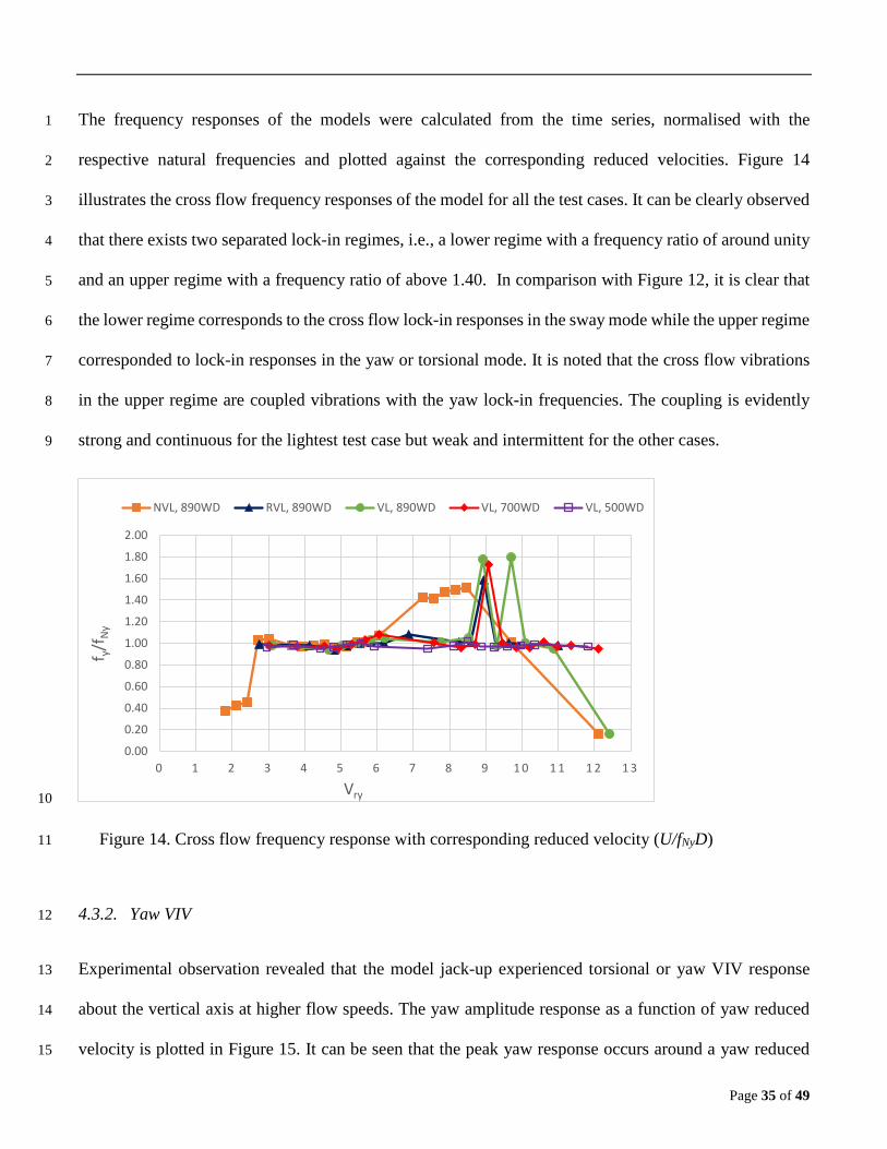
The frequency responses of the models were calculated from the time series, normalised with the 1
respective natural frequencies and plotted against the corresponding reduced velocities. Figure 14 2
illustrates the cross flow frequency responses of the model for all the test cases. It can be clearly observed 3
that there exists two separated lock-in regimes, i.e., a lower regime with a frequency ratio of around unity 4
and an upper regime with a frequency ratio of above 1.40. In comparison with Figure 12, it is clear that 5
the lower regime corresponds to the cross flow lock-in responses in the sway mode while the upper regime 6
corresponded to lock-in responses in the yaw or torsional mode. It is noted that the cross flow vibrations 7
in the upper regime are coupled vibrations with the yaw lock-in frequencies. The coupling is evidently 8
strong and continuous for the lightest test case but weak and intermittent for the other cases. 9
10
Figure 14. Cross flow frequency response with corresponding reduced velocity (U/fNyD) 11
4.3.2. Yaw VIV 12
Experimental observation revealed that the model jack-up experienced torsional or yaw VIV response 13
about the vertical axis at higher flow speeds. The yaw amplitude response as a function of yaw reduced 14
velocity is plotted in Figure 15. It can be seen that the peak yaw response occurs around a yaw reduced 15
0.00
0.20
0.40
0.60
0.80
1.00
1.20
1.40
1.60
1.80
2.00
0 1 2 3 4 5 6 7 8 9 1 0 1 1 1 2 1 3
f y/f N
y
Vry
NVL, 890WD RVL, 890WD VL, 890WD VL, 700WD VL, 500WD

Page 36 of 49
velocity of 5, which demonstrates that the yaw VIV is due to cross flow lift excitation. The rms response 1
amplitudes are found to be around 0.07D, and the maximum response amplitude is around 0.13D. The 2
lock-in regime is found to extend between the yaw reduced velocities of 3 to 7. Yaw VIV due to inline 3
excitation was not observed in any of the test cases as anticipated, validating the respective yaw VIV 4
criterion and the mathematical model. 5
6
Figure 15. Yaw amplitude response with corresponding reduced velocity (U/fNφD) 7
The response amplitude and lock-in range are found to increase generally with an increase in water depth. 8
However, amplitude and lock-in range do not increase with the reduction in elevated load, with the 9
response amplitudes displaying saturation in the lighter test cases. This behaviour may be attributed to the 10
increase in yaw radius of gyration of the model with decreasing elevated load, increase in the range of 11
overlapping sway vibrations and enhanced frequency coupling of sway with yaw vibrations with the 12
reduction in mass ratio. Hence further experiments are necessary with model experiencing pure yaw 13
vibrations and restrained along the cross flow direction. 14
0.00
0.01
0.02
0.03
0.04
0.05
0.06
0.07
0 1 2 3 4 5 6 7
R φφ ο
/D
Vrφ
NVL, 890WD RVL, 890WD VL, 890WD VL, 700WDVL, 500WD VL, Dry NVL, Dry

Page 37 of 49
It is noted that the model did not exhibit any yaw VIV either, as anticipated during the response tests in 1
wind demonstrating the validity of the mathematical model and the significance of the mass ratios in 2
containing the VIV of the jack-ups. It was observed that the increase in mass ratio reduces the amplitude 3
response and the lock-in range except for the test cases at maximum water depth. The response amplitude 4
ratio fitted reasonably well in a straight line except for the lighter test cases, when plotted against the 5
inverse of the effective inertia damping parameter as illustrated in Figure 16. Effective inertia damping 6
parameter is the product of mass damping parameter, mode factor and square of yaw radius of gyration, 7
which can be considered as the universal parameter determining the yaw VIV response. 8
The yaw frequency responses of the model normalised with the corresponding natural frequencies and 9
plotted against the yaw reduced velocities are displayed in Figure 17. Similar to cross flow frequency 10
response, the yaw frequency response of the model also revealed two separated lock-in regimes, a lower 11
regime with a frequency ratio below 0.70 and an upper regime with a frequency ratio of around 1. In 12
comparison with Figure 14 and Figure 15, it can be seen that the lower regime corresponds to the coupled 13
yaw vibrations in cross flow sway lock-in regime and the upper regime represents lock-in responses in the 14
yaw mode. 15
16
0.00
0.01
0.02
0.03
0.04
0.05
0.06
0.07
0.08
0.0 10.0 20.0 30.0 40.0 50.0
R φφ o
,rms
/D
1/(m*ζ MF rφ2)

Page 38 of 49
Figure 16. Yaw amplitude response with the inverse of effective inertia damping parameter 1
2
Figure 17. Yaw frequency response with corresponding reduced velocity (U/fNφD) 3
4.3.3. Combined Response 4
The combined cross flow amplitude response of the leg derived from the corresponding cross flow and 5
yaw responses is plotted in Figure 18. It is found that the range of the yaw response overlaps with that of 6
the cross flow response particularly for low mass ratios, causing a combined lock-in range throughout the 7
operating current speeds. The combined vibrations experienced higher response amplitudes than the 8
individual values, especially for low mass ratios. Further the combined lock-in range is seen extending 9
almost throughout the operating current range (0.10 m/s to 0.40 m/s) making the jack-up practically 10
redundant. 11
0.00
0.20
0.40
0.60
0.80
1.00
1.20
1 2 3 4 5 6 7
f φ/f
Nφ
Vrφ
NVL, 890WD RVL, 890WD VL, 890WD VL, 700WD VL, 500WD

Page 39 of 49
1
Figure 18. Leg cross flow combined amplitude response due to sway and yaw with current 2
4.3.4. Mean Response 3
The mean or steady inline responses were also measured as a function of current speeds, and the 4
normalised results were plotted in Figure 19. It can be observed that the mean inline response 5
approximately follows a quadratic variation with the flow speeds and hence can be considered as a good 6
representation of the drag force acting on the jack-up. The lightest operating condition (NVL, 890WD) at 7
the maximum water depth exhibited the highest mean inline response despite having a greater stiffness 8
due to lesser P delta effect. It is evident that the jack-up VIV increases the mean inline responses at all 9
practical speed ranges, clearly indicating an amplification of the mean drag acting on the legs. On the 10
other hand, the mean cross flow and yaw responses were found to be insignificant throughout the tested 11
current speeds. 12
0.00
0.02
0.04
0.06
0.08
0.10
0.12
0 . 0 0 0 . 0 5 0 . 1 0 0 . 1 5 0 . 2 0 0 . 2 5 0 . 3 0 0 . 3 5 0 . 4 0 0 . 4 5
y*rm
s/D
U (m/s)
NVL, 890WD RVL, 890WD VL, 890WD VL, 700WD VL, 500WD

Page 40 of 49
1
Figure 19. Inline mean response of the model with current 2
4.4. Recommendations 3
Based on the test results, it is recommended that the mass ratio of the jack-ups shall be as high as 4
possible to minimise any potential VIV occurrence. Since the combined lock-in range of both the modes 5
extends over almost all the practical current speeds, VIV and mean drag amplification can have a 6
considerable effect on the yield and fatigue strength of the structure. Hence, necessary modifications to 7
the present classification rules or guidelines are warranted to adequately account for the effect of VIV in 8
the design of jack-ups. 9
5. Conclusions 10
A simple mathematical model was developed based on the single-degree-of-freedom analogy and the 11
principle of conservation of energy, which can be used to evaluate various modes of VIV of a jack-up 12
with cylindrical legs in steady flow. Mass ratio, damping ratio and mode factor were found to be the 13
0.00
0.05
0.10
0.15
0.20
0.25
0 . 0 0 0 . 0 5 0 . 1 0 0 . 1 5 0 . 2 0 0 . 2 5 0 . 3 0 0 . 3 5 0 . 4 0 0 . 4 5
X̅/D
U (m/s)
NVL, 890WD RVL, 890WD VL, 890WD VL, 700WDVL, 500WD VL, Dry NVL, Dry

Page 41 of 49
important parameters controlling the inline and cross flow VIV of jack-ups. The radius of gyration was 1
found to be an additional important parameter influencing yaw VIV. Criteria for the occurrence of inline, 2
cross flow and yaw VIV were developed for the cases of a single 2D cylinder, four 2D cylinders in 3
rectangular configuration and a complete jack-up with cylindrical legs in steady uniform flow. 4
The model tests demonstrated that the jack-up experienced both cross flow and yaw lock-in vibrations due 5
to lift excitation, with maximum amplitude ratios in excess of 0.1D. The jack-up was found not to 6
experience inline and yaw VIV due to oscillatory drag excitation. Experiments conducted in wind revealed 7
that the jack-up was not experiencing any of the VIV modes and lock-in vibrations. The observed 8
behaviours validated the newly developed VIV model, criteria and the importance of various parameters. 9
From the test results, it can be inferred that the jack-ups were highly vulnerable to cross flow VIV with 10
large lock-in ranges in light operating conditions at high water depths. Further, the lock-in range of the 11
cross flow VIV was found to overlap with the lock-in range of yaw VIV, particularly in light operating 12
conditions making the unit almost redundant throughout the operating current ranges. The cross flow and 13
yaw VIV were also observed to couple at higher current speeds causing very high combined leg amplitude 14
response. From the mean inline displacements, it was also revealed that both the cross flow and yaw VIV 15
increases the mean drag force acting on the jack-up. 16
The mathematical approach presented will enable practising engineers to effectively consider the effect 17
of VIV in jack-up designs. The test results also underline the significance of yaw or torsional VIV in the 18
case of rigidly coupled multi-cylinder structures. 19

Page 42 of 49
6. Acknowledgement 1
This work was carried out by using the facilities at the School of Marine Sciences and Technology, 2
Newcastle University, UK and was supported by M/s Cybermarine Technologies Pte Ltd, Singapore. The 3
authors gratefully acknowledge the unconditional support provided by both Newcastle University and 4
Cybermarine Technologies. 5

Page 43 of 49
7. Nomenclature 1
a = longitudinal or inline spacing of cylinders/legs 2
b = transverse or cross flow spacing of cylinders/legs 3
CL = lift coefficient 4
C = damping coefficient 5
Cd = oscillatory drag coefficient 6
𝐶𝐶∅ = yaw damping coefficient 7
CeL = effective SDOF damping coefficient per leg 8
𝐶𝐶𝑒𝑒∅ = effective SDOF yaw damping coefficient 9
D = diameter of the cylinder 10
d’ = effective water depth considering penetration 11
fNx = surge natural frequency 12
fNy = sway natural frequency 13
fNφ = yaw natural frequency 14
fv = vortex shedding frequency of the cylinder 15
fO (z) = oscillatory excitation force distribution along leg 16
fOx (z) = oscillatory drag force distribution along leg 17
fOy (z) = oscillatory lift force distribution along leg 18
Fd = oscillatory drag force 19
FeL = effective SDOF force excitation per leg 20
I = yaw inertia 21
kL = structural wave number/mode shape of the leg 22
K = stiffness of a linear mass spring cylinder 23
𝐾𝐾∅ = yaw stiffness 24

Page 44 of 49
L = length, effective leg length (from leg bottom to hull interface) 1
M = leg mass distribution 2
m* = mass ratio (mass per displaced mass) of the cylinder. 3
M = mass of a linear mass springs cylinder 4
MeL = effective SDOF mass per leg at the hull interface level 5
𝑀𝑀∅𝑂𝑂 = Amplitude of oscillatory yaw moment 6
𝑀𝑀𝑒𝑒∅𝐿𝐿 = effective SDOF yaw excitation per leg 7
𝑀𝑀𝑒𝑒∅ = effective SDOF yaw excitation 8
MF = Mode Factor 9
𝑚𝑚∅(𝑧𝑧) = oscillatory yaw moment distribution along leg 10
m (z) = mass distribution along leg 11
Re = Reynolds Number 12
𝑟𝑟∅ = yaw radius of gyration 13
𝑅𝑅∅ = radial distance of the leg from yaw centre 14
St = Strouhal number 15
U = 2D steady flow or uniform current velocity 16
Vrx = surge reduced velocity 17
Vry = sway reduced velocity 18
Vrφ = yaw reduced velocity 19
xo = amplitude of inline VIV response 20
xo(z) = inline VIV response amplitude variation along leg 21
XL = inline VIV response of leg in way of the hull interface 22
yo = amplitude of cross flow VIV response 23
YL = cross flow VIV response of leg in way of the hull interface 24

Page 45 of 49
z = elevation w.r.t to the seabed, positive upwards; at the seabed 1
∅𝑂𝑂 = amplitude of yaw response 2
∅𝐿𝐿 = yaw VIV response in way of the hull interface 3
ρ = density of the fluid 4
𝜔𝜔𝑁𝑁 = natural angular frequency 5
𝜔𝜔𝑉𝑉 = vortex sheding angular frequency 6
𝜁𝜁 = damping ratio 7

Page 46 of 49
8. References 1
Assi, G.R.S., Bearman, P.W., Meneghini, J.R., 2010. On the wake-induced vibration of tandem circular 2 cylinders: the vortex interaction excitation mechanism. Journal of Fluid Mechanics 661, 365-401. 3 Barltrop, N.D.P., Adams, A.J., 1991. Dynamics of Fixed Marine Structures (Third Edition). Butterworth-4 Heinemann. 5 Bearman, P.W., 2011. Circular cylinder wakes and vortex-induced vibrations. Journal of Fluids and 6 Structures 27 (5–6), 648-658. 7 Bennett Jr, W.T., Patel, R.K., 1989. Jack-up behavior in elevated condition: model test and computer 8 simulation. SNAME, NJ. 9 Blevins, R.D., 2001. Flow-Induced Vibration, Reprint ed. Krieger Publishing Company, Florida. 10 Blevins, R.D., Burton, T.E., 1976. Fluid Forces Induced by Vortex Shedding. Journal of Fluids 11 Engineering 98 (1), 19-24. 12 Blevins, R.D., Coughran, C.S., 2009. Experimental investigation of vortex-induced vibration in one and 13 two dimensions with variable mass, damping, and Reynolds number. Journal of Fluids Engineering, 14 Transactions of the ASME 131 (10), 1012021-1012027. 15 Cammaert, A.B., Hoving, J.S., Vermeulen, R., 2014. Experimental program for ice loads on an artic jack-16 up structure, HYDRALAB IV User Meeting, Lisbon, Portugal. 17 Chakrabarti, S., 2005. Physical Modelling of Offshore Structures, Handbook of Offshore Engineering, 18 Volumes 1-2. Elsevier. 19 DNV.GL, 2017. DNVGL-RP-C205, Recommended Practice, Environmental Conditions and 20 Environmental Loads. DNV GL AS, Oslo. 21 Fujarra, A.L.C., Rosetti, G.F., de Wilde, J., Gonçalves, R.T., 2012. State-of-Art on Vortex-Induced 22 Motion: A Comprehensive Survey After More Than One Decade of Experimental Investigation. (44915), 23 561-582. 24 Gonçalves, R.T., Freire, C.s.M., Rosetti, G.F., Franzini, G.R., Fujarra, A.L.C., Meneghini, J.R., 2011a. 25 Experimental Comparisons to Assure the Similarity Between VIM (Vortex-Induced Motion) and VIV 26 (Vortex-Induced Vibration) Phenomena. (44397), 11-22. 27 Gonçalves, R.T., Fujarra, A.L.C., Rosetti, G.F., Kogishi, A.M., Koop, A., 2018. Experimental study of 28 the column shape and the roughness effects on the vortex-induced motions of deep-draft semi-submersible 29 platforms. Ocean Engineering 149, 127-141. 30 Gonçalves, R.T., Rosetti, G.F., Fujarra, A.L.C., Nishimoto, K., Oliveira, A.C., 2011b. Experimental Study 31 on Vortex-Induced Motions (VIM) of a Large-Volume Semi-Submersible Platform. (44397), 1-9. 32 Govardhan, R., Williamson, C.H.K., 2004. Critical mass in vortex-induced vibration of a cylinder. 33 European Journal of Mechanics - B/Fluids 23 (1), 17-27. 34 Grundlehner, G.J., 1997. Systematic model tests on a harsh environment jack-up in elevated condition. 35 Marine Structures 10 (2–4), 159-180. 36 Han, Z., Zhou, D., He, T., Tu, J., Li, C., Kwok, K.C.S., Fang, C., 2015. Flow-induced vibrations of four 37 circular cylinders with square arrangement at low Reynolds numbers. Ocean Engineering 96, 21-33. 38 Iwan, W.D., Blevins, R.D., 1974. A Model for Vortex Induced Oscillation of Structures. Journal of 39 Applied Mechanics 41 (3), 581-586. 40 Jiang, R., 2012. FLOW-INDUCED VIBRATIONS OF TWO TANDEM CYLINDERS IN A CHANNEL. 41 Thermal Science 16 (5), 1377-1381. 42 Johnson, T.L., Patel, R.K., 1992. The use of small scale physical models and numerical models for jack-43 up design, Recent Developments in Jack Up Platforms. Blackwell Scienific Publications, Oxford. 44 Journee, J., Massie, W., Boon, B., Onnink, R., 1988. Model experiments on jack-up platform 45 hydrodynamics. TU Delft. 46

Page 47 of 49
Khalak, A., Williamson, C.H.K., 1997a. FLUID FORCES AND DYNAMICS OF A HYDROELASTIC 1 STRUCTURE WITH VERY LOW MASS AND DAMPING. Journal of Fluids and Structures 11 (8), 2 973-982. 3 Khalak, A., Williamson, C.H.K., 1997b. Investigation of relative effects of mass and damping in vortex-4 induced vibration of a circular cylinder. Journal of Wind Engineering and Industrial Aerodynamics 69–5 71 (0), 341-350. 6 King, R., Prosser, M.J., Johns, D.J., 1973. On vortex excitation of model piles in water. Journal of Sound 7 and Vibration 29 (2), 169-188,IN161-IN162. 8 Liang, Y., Tao, L., Liu, M., Xiao, L., 2017. Experimental and Numerical Study on Vortex-Induced-9 Motions of a Dee-Draft Semi-Submersible Concept. Applied Ocean Research 67, 169-187. 10 Nicholls-Lee, R., Hindley, S., Parkinson, R., 2013. Development of an economic and efficient installation 11 vessel for tidal stream energy converter arrays, International Conference on Offshore Mechanics and 12 Arctic Engineering - OMAE. ASME, Nantes, France, p. 9. 13 PANEL OC-7, S.A.O.J.-U.R., 2008. Guidelines for Site Specific Assessment of Mobile Jack-Up Units, 14 Technical and Research Bulletin. SNAME, p. 366. 15 Ramadasan, S., Tao, L., Dev, A., 2018. Antinode Fairings: An Optimum Solution for Reduction of Vortex 16 Induced Vibration, Offshore Technology Conference Asia. Offshore Technology Conference, Kuala 17 Lumpur, Malaysia. 18 Raven, P.W.J., Stuart, R.J., Bray, J.A., Littlejohns, P.S., 1985. Full-Scale Dynamic Testing of Submarine 19 Pipeline Spans, Offshore Technology Conference. Offshore Technology Conference, Houston, Texas, p. 20 10. 21 Sainsbury, R.N., King, D., 1971. THE FLOW INDUCED OSCILLATION OF MARINE STRUCTURES. 22 Proceedings of the Institution of Civil Engineers 49 (3), 269-302. 23 Sakai, T., Morishita, M., Iwata, K., Kitamura, S., 2002. Experimental Study on the Avoidance and 24 Suppression Criteria for the Vortex-Induced Vibration of a Cantilever Cylinder. Journal of Pressure Vessel 25 Technology 124 (2), 187-195. 26 Sarpkaya, T., 2004. A critical review of the intrinsic nature of vortex-induced vibrations. Journal of Fluids 27 and Structures 19 (4), 389-447. 28 Sarpkaya, T., Isaacson, M., 1981. Mechanics of wave forces on offshore structures. Van Nostrand 29 Reinhold Co. 30 Skop, R.A., Griffin, O.M., 1973. A model for the vortex-excited resonant response of bluff cylinders. 31 Journal of Sound and Vibration 27 (2), 225-233. 32 Sumer, B.M., Fredsøe, J., 2006. Hydrodynamics around Cylindrical Structures (Revised Edition). World 33 Scientific. 34 Sumner, D., 2010. Two circular cylinders in cross-flow: A review. Journal of Fluids and Structures 26 (6), 35 849-899. 36 Thake, J., 2005. Development, Installation and Testing of a Large-Scale Tidal Current Turbine 37 Department of Trade and Industry, UK, p. 74. 38 Vandiver, J.K., 2012. Damping Parameters for flow-induced vibration. Journal of Fluids and Structures 39 35, 105-119. 40 Vickery, B.J., Watkins, R.D., 1964. FLOW-INDUCED VIBRATIONS OF CYLINDRICAL 41 STRUCTURES A2 - SILVESTER, RICHARD, Hydraulics and Fluid Mechanics. Pergamon, pp. 213-42 241. 43 Wang, X.K., Gong, K., Liu, H., Zhang, J.X., Tan, S.K., 2013. Flow around four cylinders arranged in a 44 square configuration. Journal of Fluids and Structures 43 (0), 179-199. 45 Williamson, C.H.K., Govardhan, R., 2004. VORTEX-INDUCED VIBRATIONS. Annual Review of 46 Fluid Mechanics 36 (1), 413-455. 47 Zdravkovich, M.M., 1985. Flow induced oscillations of two interfering circular cylinders. Journal of 48

Page 48 of 49
Sound and Vibration 101 (4), 511-521. 1 Zhao, M., Cheng, L., 2012. Numerical simulation of vortex-induced vibration of four circular cylinders in 2 a square configuration. Journal of Fluids and Structures 31 (0), 125-140. 3 4

Page 49 of 49
9. List of Tables 1
Table 1. Model properties ......................................................................................................................... 24 2
Table 2. Test Matrix .................................................................................................................................. 26 3
Table 3. Model natural frequency, added mass and damping from sway free decay tests ....................... 30 4
Table 4. Model natural frequency, added mass and damping from yaw free decay tests ........................ 30 5
Table 5. Response test results, a) cross flow/sway b) yaw ....................................................................... 32 6
10. List of Figures 7
Figure 1. Jack-up with cylindrical legs (Ms Cybermarine Technologies Pte. Ltd.) ................................... 5 8
Figure 2. Cylinder interference regions (Zdravkovich, 1985) .................................................................... 6 9
Figure 3. Jack-up VIV modes, a) inline (surge), b) cross flow (sway), c) yaw (torsional) ........................ 7 10
Figure 4. Yaw due to inline excitation ...................................................................................................... 12 11
Figure 5. Yaw due to cross flow excitation .............................................................................................. 14 12
Figure 6. Jack-up structural idealisation, a) SDOF (PANEL OC-7, 2008), b) leg mode shape ............... 16 13
Figure 7. Jack-up model ............................................................................................................................ 23 14
Figure 8. Experimental setup .................................................................................................................... 25 15
Figure 9. a) Sway stiffness test setup b) Sway stiffness variation with deflection for NVL, 890WD ..... 28 16
Figure 10. a) FFT of sway free decay test; NVL, 890WD b) Sway natural frequency variation with 17
displacement; NVL, 890WD c) Variation of sway damping ratio with sway frequency; NVL, 890WD. 29 18
Figure 11. Inline amplitude response with corresponding reduced velocity (U/fNxD) .............................. 33 19
Figure 12. Cross flow amplitude response with corresponding reduced velocity (U/fNyD) ..................... 33 20
Figure 13. Cross flow amplitude response with the inverse of modified mass damping parameter. ....... 34 21
Figure 14. Cross flow frequency response with corresponding reduced velocity (U/fNyD) ..................... 35 22
Figure 15. Yaw amplitude response with corresponding reduced velocity (U/fNφD) ............................... 36 23
Figure 16. Yaw amplitude response with the inverse of effective inertia damping parameter ................ 38 24
Figure 17. Yaw frequency response with corresponding reduced velocity (U/fNφD) ............................... 38 25
Figure 18. Leg cross flow combined amplitude response due to sway and yaw with current .................. 39 26
Figure 19. Inline mean response of the model with current ..................................................................... 40 27
28