veritas™ 5250 appliance hardware installation guide
TRANSCRIPT

Veritas™ 5250 ApplianceHardware Installation Guide
Veritas 5250 Appliance Hardware Installation GuideLast updated: 2022-01-13
Document version: Revision 1.1
Legal NoticeCopyright © 2022 Veritas Technologies LLC. All rights reserved.
Veritas, the Veritas Logo, and NetBackup are trademarks or registered trademarks of VeritasTechnologies LLC or its affiliates in the U.S. and other countries. Other names may betrademarks of their respective owners.
This product may contain third-party software for which Veritas is required to provide attributionto the third party (“Third-party Programs”). Some of the Third-party Programs are availableunder open source or free software licenses. The License Agreement accompanying theSoftware does not alter any rights or obligations you may have under those open source orfree software licenses. Refer to the Third-party Legal Notices document accompanying thisVeritas product or available at:
https://www.veritas.com/about/legal/license-agreements
The product described in this document is distributed under licenses restricting its use, copying,distribution, and decompilation/reverse engineering. No part of this document may bereproduced in any form by any means without prior written authorization of Veritas TechnologiesLLC and its licensors, if any.
THE DOCUMENTATION IS PROVIDED "AS IS" AND ALL EXPRESS OR IMPLIEDCONDITIONS, REPRESENTATIONS AND WARRANTIES, INCLUDING ANY IMPLIEDWARRANTY OF MERCHANTABILITY, FITNESS FOR A PARTICULAR PURPOSE ORNON-INFRINGEMENT, ARE DISCLAIMED, EXCEPT TO THE EXTENT THAT SUCHDISCLAIMERS ARE HELD TO BE LEGALLY INVALID. VERITAS TECHNOLOGIES LLCSHALL NOT BE LIABLE FOR INCIDENTAL OR CONSEQUENTIAL DAMAGES INCONNECTION WITH THE FURNISHING, PERFORMANCE, OR USE OF THISDOCUMENTATION. THE INFORMATION CONTAINED IN THIS DOCUMENTATION ISSUBJECT TO CHANGE WITHOUT NOTICE.
The Licensed Software and Documentation are deemed to be commercial computer softwareas defined in FAR 12.212 and subject to restricted rights as defined in FAR Section 52.227-19"Commercial Computer Software - Restricted Rights" and DFARS 227.7202, et seq."Commercial Computer Software and Commercial Computer Software Documentation," asapplicable, and any successor regulations, whether delivered by Veritas as on premises orhosted services. Any use, modification, reproduction release, performance, display or disclosureof the Licensed Software and Documentation by the U.S. Government shall be solely inaccordance with the terms of this Agreement.
Veritas Technologies LLC2625 Augustine DriveSanta Clara, CA 95054
http://www.veritas.com
Technical SupportTechnical Support maintains support centers globally. All support services will be deliveredin accordance with your support agreement and the then-current enterprise technical supportpolicies. For information about our support offerings and how to contact Technical Support,visit our website:
https://www.veritas.com/support
You can manage your Veritas account information at the following URL:
https://my.veritas.com
If you have questions regarding an existing support agreement, please email the supportagreement administration team for your region as follows:
[email protected] (except Japan)
DocumentationMake sure that you have the current version of the documentation. Each document displaysthe date of the last update on page 2. The latest documentation is available on the Veritaswebsite:
https://www.veritas.com/content/support/en_US/dpp.Appliances.html
Documentation feedbackYour feedback is important to us. Suggest improvements or report errors or omissions to thedocumentation. Include the document title, document version, chapter title, and section titleof the text on which you are reporting. Send feedback to:
You can also see documentation information or ask a question on the Veritas community site:
http://www.veritas.com/community/
Veritas Services and Operations Readiness Tools (SORT)Veritas Services and Operations Readiness Tools (SORT) is a website that provides informationand tools to automate and simplify certain time-consuming administrative tasks. Dependingon the product, SORT helps you prepare for installations and upgrades, identify risks in yourdatacenters, and improve operational efficiency. To see what services and tools SORT providesfor your product, see the data sheet:
https://sort.veritas.com/data/support/SORT_Data_Sheet.pdf
Chapter 1 Hardware overview ............................................................. 7
About the appliance and the storage shelves ....................................... 7Appliance disk drives ...................................................................... 8About the 5250 Appliance control panel .............................................. 9
About the System Status LED states .......................................... 11About the Power button LED states ............................................ 14
Appliance rear panel ..................................................................... 15Storage shelf disk drives ................................................................ 16Storage shelf control panel ............................................................. 17Storage shelf rear panel ................................................................. 18Cables ....................................................................................... 18About IPMI configuration ................................................................ 19Product documentation .................................................................. 20
Chapter 2 Preinstallation requirements .......................................... 21
Customer-provided environment and supplies .................................... 21Appliance shipping container contents .............................................. 22Storage shelf shipping container contents .......................................... 23Best practices for rack installation .................................................... 23Determining rack locations ............................................................. 24Storage shelf rack requirements ...................................................... 26Heat dissipation ........................................................................... 27Verifying SAS-3 cable length ........................................................... 27Prerequisites for IPMI configuration .................................................. 28
Chapter 3 Installation procedures ..................................................... 29
Installing the storage shelf rack rails ................................................. 29Installing the storage shelf into a rack ............................................... 31Attaching the storage shelf bezel ..................................................... 32Installing the appliance rack rails ..................................................... 33Installing the appliance into a rack ................................................... 37Understanding appliance and storage shelf connections ....................... 38Connecting an appliance to one storage shelf .................................... 41Connecting an appliance to more than one storage shelf ...................... 42
Contents
Connecting the network cables ........................................................ 54Connecting the power cords ........................................................... 55Turning on the hardware and verifying operation ................................. 56Configuring the IPMI port from the NetBackup Appliance Shell Menu
........................................................................................... 65Configuring the Veritas Remote Management Interface from a Flex
Appliance ............................................................................. 70Accessing and using the Veritas Remote Management interface ............ 74
Appendix A Adding one or more storage shelves to anoperating appliance that does not have anystorage shelves ............................................................ 77
Overview ................................................................................... 77Preparing the appliance ................................................................. 79Removing the appliance cover ........................................................ 80Installing the Expansion Storage Kit components ................................ 81Replacing the appliance cover ........................................................ 87Connecting the storage shelves to the appliance ................................. 88
Connecting one storage shelf to an appliance .............................. 88Connecting two storage shelves to an appliance ........................... 91Connecting three storage shelves to an appliance ......................... 96Connecting four storage shelves to an appliance ......................... 103Connecting the fifth storage shelf to an appliance ........................ 111Connecting the sixth storage shelf to an appliance ....................... 119
Appendix B Adding storage shelves to an operating appliancethat has at least one storage shelf attached.......................................................................................... 128
Overview .................................................................................. 128Moving the MSDP partition from a base disk to an expansion disk for
optimum performance ............................................................ 129Additional storage shelf scenarios .................................................. 138Installing storage shelves to an appliance that has at least one storage
shelf ................................................................................... 139Recabling to connect additional shelves .......................................... 139
Connecting additional shelves to an appliance that already hasone operating shelf ......................................................... 141
Connecting additional shelves to an appliance that already hastwo operating shelves ...................................................... 144
Connecting a storage shelf to an appliance that already has threeoperating shelves ........................................................... 147
5Contents
Appendix C Configuring the disk space for new NetBackupExpansion Storage Shelves ................................... 150
Adding the disk space of additional storage shelves from the NetBackupAppliance Shell Menu ............................................................ 150
Adding the disk space of additional storage shelves from the NetBackupAppliance Web Console ......................................................... 152
Appendix D Configuring the disk space for new FlexExpansion Storage Shelves ................................... 154
Adding the disk space of an Expansion Storage Shelf from the FlexAppliance Console ................................................................ 154
Index .................................................................................................................. 156
6Contents
Hardware overviewThis chapter includes the following topics:
■ About the appliance and the storage shelves
■ Appliance disk drives
■ About the 5250 Appliance control panel
■ Appliance rear panel
■ Storage shelf disk drives
■ Storage shelf control panel
■ Storage shelf rear panel
■ Cables
■ About IPMI configuration
■ Product documentation
About the appliance and the storage shelvesThe Veritas 5250 Appliance is a hardware and software storage system that canscale to 429.4TiB of available backup capacity. It consists of a Veritas 5250Appliance and up to six optional Veritas 2U12 65.5TiB/72TB storage shelves.
1Chapter
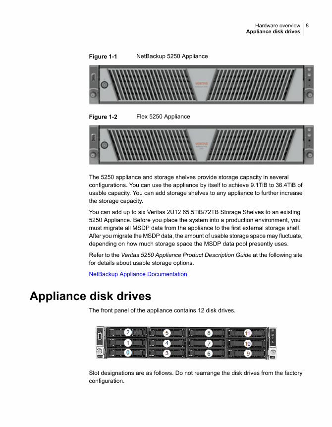
Figure 1-1 NetBackup 5250 Appliance
Figure 1-2 Flex 5250 Appliance
The 5250 appliance and storage shelves provide storage capacity in severalconfigurations. You can use the appliance by itself to achieve 9.1TiB to 36.4TiB ofusable capacity. You can add storage shelves to any appliance to further increasethe storage capacity.
You can add up to six Veritas 2U12 65.5TiB/72TB Storage Shelves to an existing5250 Appliance. Before you place the system into a production environment, youmust migrate all MSDP data from the appliance to the first external storage shelf.After you migrate the MSDP data, the amount of usable storage space may fluctuate,depending on how much storage space the MSDP data pool presently uses.
Refer to the Veritas 5250 Appliance Product Description Guide at the following sitefor details about usable storage options.
NetBackup Appliance Documentation
Appliance disk drivesThe front panel of the appliance contains 12 disk drives.
Slot designations are as follows. Do not rearrange the disk drives from the factoryconfiguration.
8Hardware overviewAppliance disk drives
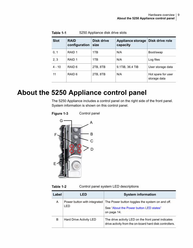
Table 1-1 5250 Appliance disk drive slots
Disk drive roleAppliance storagecapacity
Disk drivesize
RAIDconfiguration
Slot
Boot/swapN/A1TBRAID 10, 1
Log filesN/A1TBRAID 12, 3
User storage data9.1TiB, 36.4 TiB2TB, 8TBRAID 64 - 10
Hot spare for userstorage data
N/A2TB, 8TBRAID 611
About the 5250 Appliance control panelThe 5250 Appliance includes a control panel on the right side of the front panel.System information is shown on this control panel.
Figure 1-3 Control panel
A
B
C
G
F
D
E
Table 1-2 Control panel system LED descriptions
System informationLEDLabel
The Power button toggles the system on and off.
See “About the Power button LED states”on page 14.
Power button with integratedLED
A
The drive activity LED on the front panel indicatesdrive activity from the on-board hard disk controllers.
Hard Drive Activity LEDB
9Hardware overviewAbout the 5250 Appliance control panel
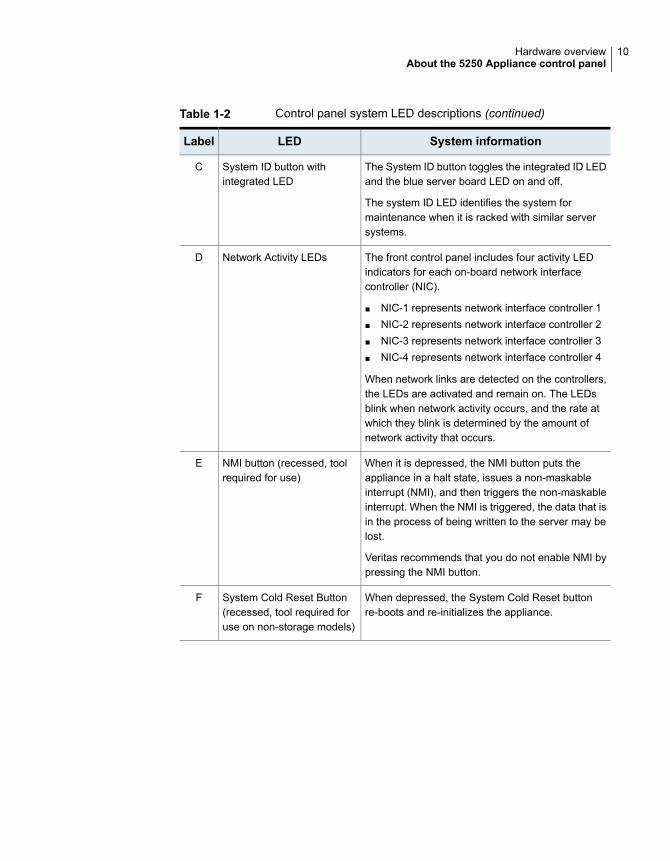
Table 1-2 Control panel system LED descriptions (continued)
System informationLEDLabel
The System ID button toggles the integrated ID LEDand the blue server board LED on and off.
The system ID LED identifies the system formaintenance when it is racked with similar serversystems.
System ID button withintegrated LED
C
The front control panel includes four activity LEDindicators for each on-board network interfacecontroller (NIC).
■ NIC-1 represents network interface controller 1■ NIC-2 represents network interface controller 2■ NIC-3 represents network interface controller 3■ NIC-4 represents network interface controller 4
When network links are detected on the controllers,the LEDs are activated and remain on. The LEDsblink when network activity occurs, and the rate atwhich they blink is determined by the amount ofnetwork activity that occurs.
Network Activity LEDsD
When it is depressed, the NMI button puts theappliance in a halt state, issues a non-maskableinterrupt (NMI), and then triggers the non-maskableinterrupt. When the NMI is triggered, the data that isin the process of being written to the server may belost.
Veritas recommends that you do not enable NMI bypressing the NMI button.
NMI button (recessed, toolrequired for use)
E
When depressed, the System Cold Reset buttonre-boots and re-initializes the appliance.
System Cold Reset Button(recessed, tool required foruse on non-storage models)
F
10Hardware overviewAbout the 5250 Appliance control panel
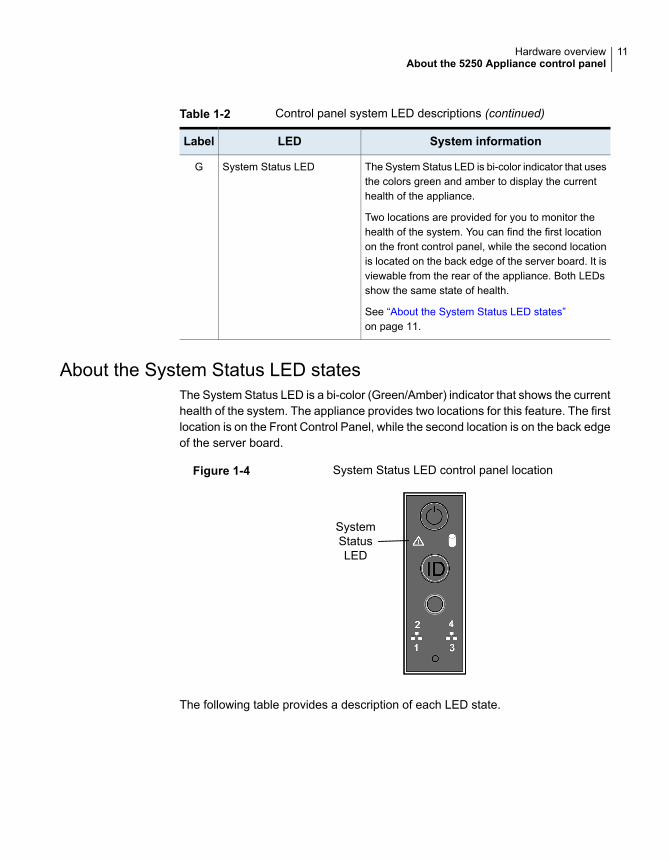
Table 1-2 Control panel system LED descriptions (continued)
System informationLEDLabel
The System Status LED is bi-color indicator that usesthe colors green and amber to display the currenthealth of the appliance.
Two locations are provided for you to monitor thehealth of the system. You can find the first locationon the front control panel, while the second locationis located on the back edge of the server board. It isviewable from the rear of the appliance. Both LEDsshow the same state of health.
See “About the System Status LED states”on page 11.
System Status LEDG
About the System Status LED statesThe System Status LED is a bi-color (Green/Amber) indicator that shows the currenthealth of the system. The appliance provides two locations for this feature. The firstlocation is on the Front Control Panel, while the second location is on the back edgeof the server board.
Figure 1-4 System Status LED control panel location
SystemStatusLED
The following table provides a description of each LED state.
11Hardware overviewAbout the 5250 Appliance control panel
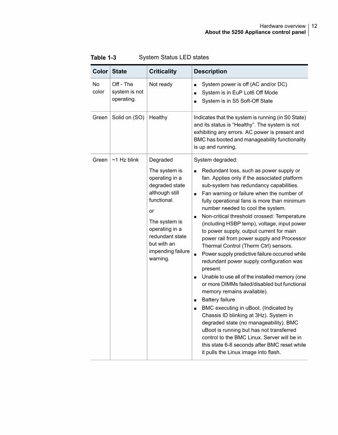
Table 1-3 System Status LED states
DescriptionCriticalityStateColor
■ System power is off (AC and/or DC)■ System is in EuP Lot6 Off Mode■ System is in S5 Soft-Off State
Not readyOff - Thesystem is notoperating.
Nocolor
Indicates that the system is running (in S0 State)and its status is “Healthy”. The system is notexhibiting any errors. AC power is present andBMC has booted and manageability functionalityis up and running.
HealthySolid on (SO)Green
System degraded:
■ Redundant loss, such as power supply orfan. Applies only if the associated platformsub-system has redundancy capabilities.
■ Fan warning or failure when the number offully operational fans is more than minimumnumber needed to cool the system.
■ Non-critical threshold crossed: Temperature(including HSBP temp), voltage, input powerto power supply, output current for mainpower rail from power supply and ProcessorThermal Control (Therm Ctrl) sensors.
■ Power supply predictive failure occurred whileredundant power supply configuration waspresent.
■ Unable to use all of the installed memory (oneor more DIMMs failed/disabled but functionalmemory remains available).
■ Battery failure■ BMC executing in uBoot. (Indicated by
Chassis ID blinking at 3Hz). System indegraded state (no manageability). BMCuBoot is running but has not transferredcontrol to the BMC Linux. Server will be inthis state 6-8 seconds after BMC reset whileit pulls the Linux image into flash.
Degraded
The system isoperating in adegraded statealthough stillfunctional.
or
The system isoperating in aredundant statebut with animpending failurewarning.
~1 Hz blinkGreen
12Hardware overviewAbout the 5250 Appliance control panel
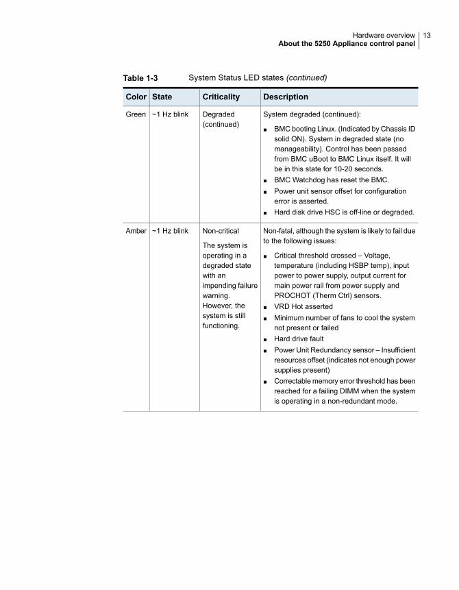
Table 1-3 System Status LED states (continued)
DescriptionCriticalityStateColor
System degraded (continued):
■ BMC booting Linux. (Indicated by Chassis IDsolid ON). System in degraded state (nomanageability). Control has been passedfrom BMC uBoot to BMC Linux itself. It willbe in this state for 10-20 seconds.
■ BMC Watchdog has reset the BMC.■ Power unit sensor offset for configuration
error is asserted.■ Hard disk drive HSC is off-line or degraded.
Degraded(continued)
~1 Hz blinkGreen
Non-fatal, although the system is likely to fail dueto the following issues:
■ Critical threshold crossed – Voltage,temperature (including HSBP temp), inputpower to power supply, output current formain power rail from power supply andPROCHOT (Therm Ctrl) sensors.
■ VRD Hot asserted■ Minimum number of fans to cool the system
not present or failed■ Hard drive fault■ Power Unit Redundancy sensor – Insufficient
resources offset (indicates not enough powersupplies present)
■ Correctable memory error threshold has beenreached for a failing DIMM when the systemis operating in a non-redundant mode.
Non-critical
The system isoperating in adegraded statewith animpending failurewarning.However, thesystem is stillfunctioning.
~1 Hz blinkAmber
13Hardware overviewAbout the 5250 Appliance control panel
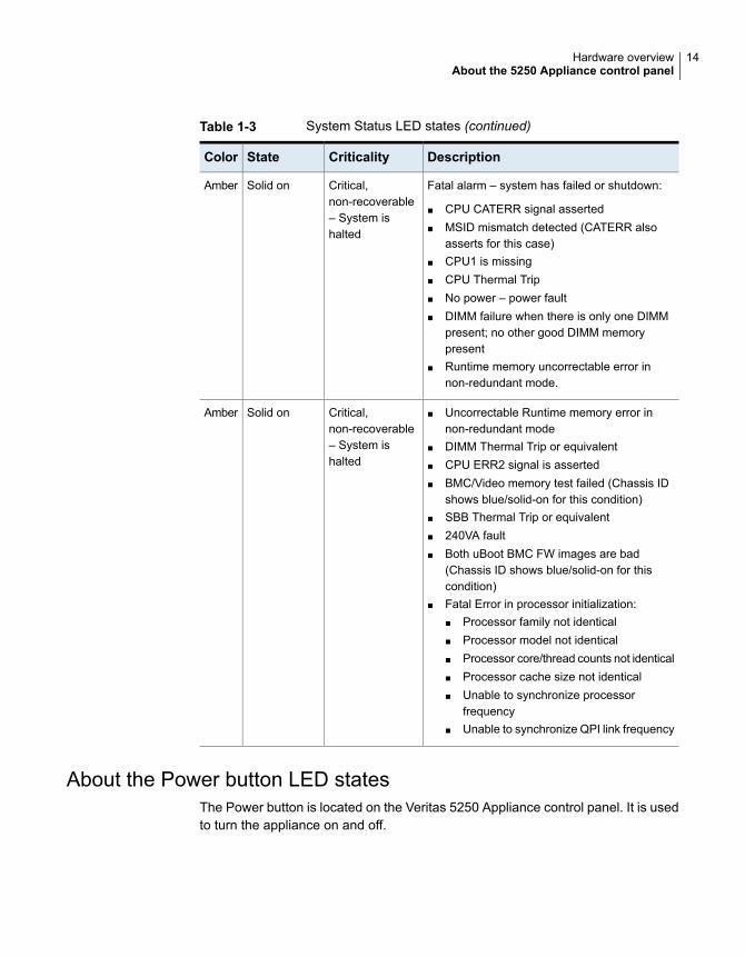
Table 1-3 System Status LED states (continued)
DescriptionCriticalityStateColor
Fatal alarm – system has failed or shutdown:
■ CPU CATERR signal asserted■ MSID mismatch detected (CATERR also
asserts for this case)■ CPU1 is missing■ CPU Thermal Trip■ No power – power fault■ DIMM failure when there is only one DIMM
present; no other good DIMM memorypresent
■ Runtime memory uncorrectable error innon-redundant mode.
Critical,non-recoverable– System ishalted
Solid onAmber
■ Uncorrectable Runtime memory error innon-redundant mode
■ DIMM Thermal Trip or equivalent■ CPU ERR2 signal is asserted■ BMC/Video memory test failed (Chassis ID
shows blue/solid-on for this condition)■ SBB Thermal Trip or equivalent■ 240VA fault■ Both uBoot BMC FW images are bad
(Chassis ID shows blue/solid-on for thiscondition)
■ Fatal Error in processor initialization:■ Processor family not identical■ Processor model not identical■ Processor core/thread counts not identical■ Processor cache size not identical■ Unable to synchronize processor
frequency■ Unable to synchronize QPI link frequency
Critical,non-recoverable– System ishalted
Solid onAmber
About the Power button LED statesThe Power button is located on the Veritas 5250 Appliance control panel. It is usedto turn the appliance on and off.
14Hardware overviewAbout the 5250 Appliance control panel
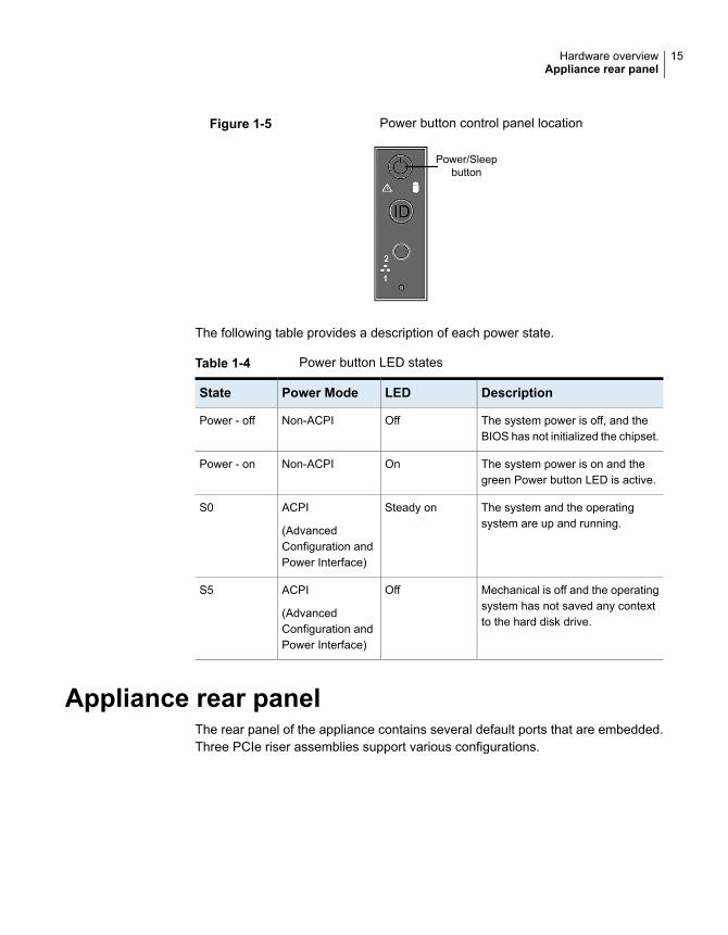
Figure 1-5 Power button control panel location
Power/Sleepbutton
The following table provides a description of each power state.
Table 1-4 Power button LED states
DescriptionLEDPower ModeState
The system power is off, and theBIOS has not initialized the chipset.
OffNon-ACPIPower - off
The system power is on and thegreen Power button LED is active.
OnNon-ACPIPower - on
The system and the operatingsystem are up and running.
Steady onACPI
(AdvancedConfiguration andPower Interface)
S0
Mechanical is off and the operatingsystem has not saved any contextto the hard disk drive.
OffACPI
(AdvancedConfiguration andPower Interface)
S5
Appliance rear panelThe rear panel of the appliance contains several default ports that are embedded.Three PCIe riser assemblies support various configurations.
15Hardware overviewAppliance rear panel
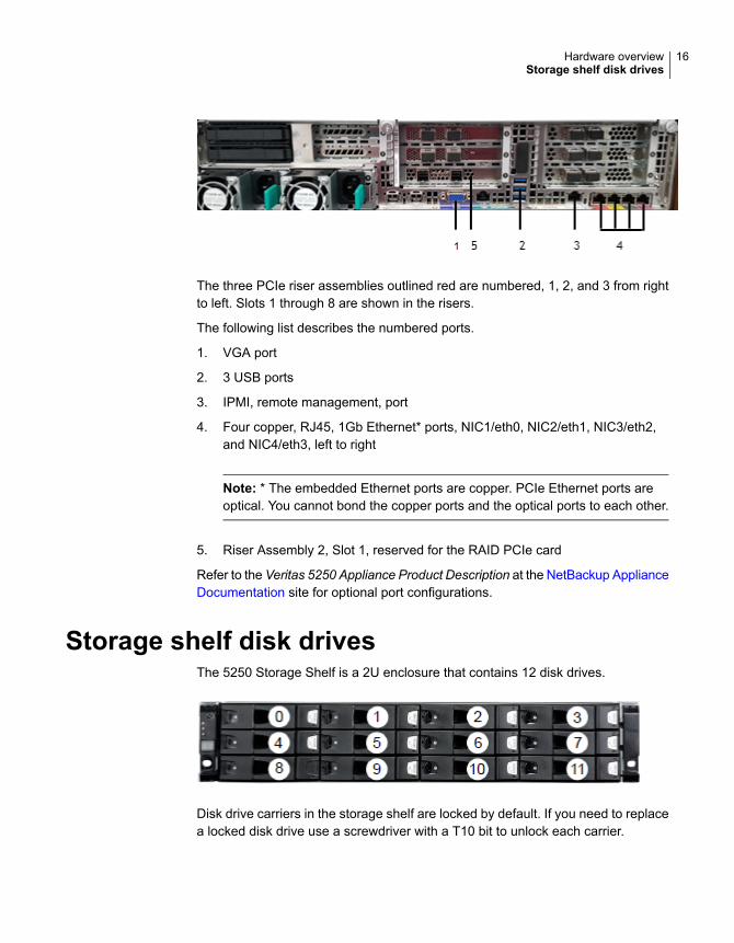
The three PCIe riser assemblies outlined red are numbered, 1, 2, and 3 from rightto left. Slots 1 through 8 are shown in the risers.
The following list describes the numbered ports.
1. VGA port
2. 3 USB ports
3. IPMI, remote management, port
4. Four copper, RJ45, 1Gb Ethernet* ports, NIC1/eth0, NIC2/eth1, NIC3/eth2,and NIC4/eth3, left to right
Note: * The embedded Ethernet ports are copper. PCIe Ethernet ports areoptical. You cannot bond the copper ports and the optical ports to each other.
5. Riser Assembly 2, Slot 1, reserved for the RAID PCIe card
Refer to the Veritas 5250 Appliance Product Description at the NetBackup ApplianceDocumentation site for optional port configurations.
Storage shelf disk drivesThe 5250 Storage Shelf is a 2U enclosure that contains 12 disk drives.
Disk drive carriers in the storage shelf are locked by default. If you need to replacea locked disk drive use a screwdriver with a T10 bit to unlock each carrier.
16Hardware overviewStorage shelf disk drives
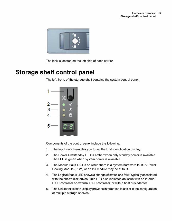
The lock is located on the left side of each carrier.
Storage shelf control panelThe left, front, of the storage shelf contains the system control panel.
Components of the control panel include the following.
1. The Input switch enables you to set the Unit Identification display.
2. The Power On/Standby LED is amber when only standby power is available.The LED is green when system power is available.
3. The Module Fault LED is on when there is a system hardware fault. A PowerCooling Module (PCM) or an I/O module may be at fault.
4. The Logical Status LED shows a change of status or a fault, typically associatedwith the shelf's disk drives. This LED also indicates an issue with an internalRAID controller or external RAID controller, or with a host bus adapter.
5. The Unit Identification Display provides information to assist in the configurationof multiple storage shelves.
17Hardware overviewStorage shelf control panel
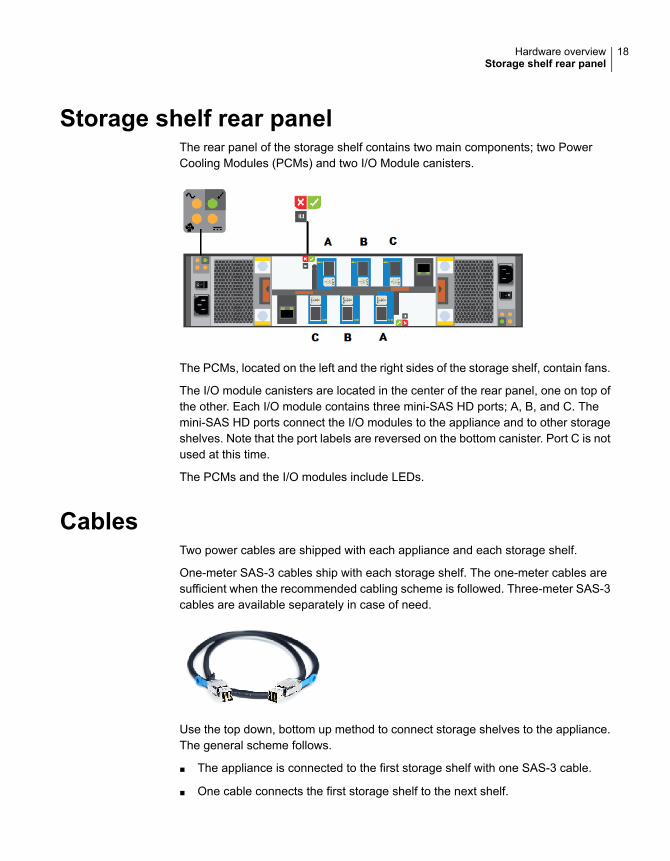
Storage shelf rear panelThe rear panel of the storage shelf contains two main components; two PowerCooling Modules (PCMs) and two I/O Module canisters.
The PCMs, located on the left and the right sides of the storage shelf, contain fans.
The I/O module canisters are located in the center of the rear panel, one on top ofthe other. Each I/O module contains three mini-SAS HD ports; A, B, and C. Themini-SAS HD ports connect the I/O modules to the appliance and to other storageshelves. Note that the port labels are reversed on the bottom canister. Port C is notused at this time.
The PCMs and the I/O modules include LEDs.
CablesTwo power cables are shipped with each appliance and each storage shelf.
One-meter SAS-3 cables ship with each storage shelf. The one-meter cables aresufficient when the recommended cabling scheme is followed. Three-meter SAS-3cables are available separately in case of need.
Use the top down, bottom up method to connect storage shelves to the appliance.The general scheme follows.
■ The appliance is connected to the first storage shelf with one SAS-3 cable.
■ One cable connects the first storage shelf to the next shelf.
18Hardware overviewStorage shelf rear panel
■ Subsequent storage shelves are connected until the last storage shelf isconnected.
■ The last storage shelf is connected to the appliance with one cable.
■ The last storage shelf is also connected to the next, highest, storage shelf.
■ The storage shelves are connected until the shelf closest to the appliance isconnected.
See “Connecting the network cables” on page 54.
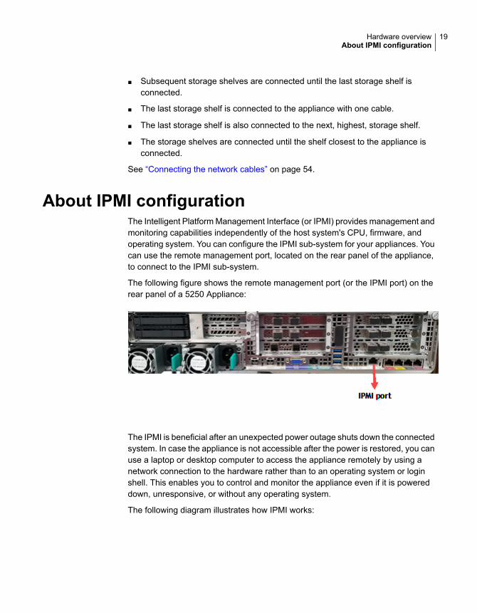
About IPMI configurationThe Intelligent Platform Management Interface (or IPMI) provides management andmonitoring capabilities independently of the host system's CPU, firmware, andoperating system. You can configure the IPMI sub-system for your appliances. Youcan use the remote management port, located on the rear panel of the appliance,to connect to the IPMI sub-system.
The following figure shows the remote management port (or the IPMI port) on therear panel of a 5250 Appliance:
The IPMI is beneficial after an unexpected power outage shuts down the connectedsystem. In case the appliance is not accessible after the power is restored, you canuse a laptop or desktop computer to access the appliance remotely by using anetwork connection to the hardware rather than to an operating system or loginshell. This enables you to control and monitor the appliance even if it is powereddown, unresponsive, or without any operating system.
The following diagram illustrates how IPMI works:
19Hardware overviewAbout IPMI configuration
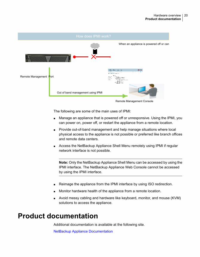
How does IPMI work?
When an appliance is powered off or cannot be accessed using the network interface
Remote Management Port
Out of band management using IPMI
Remote Management Console
The following are some of the main uses of IPMI:
■ Manage an appliance that is powered off or unresponsive. Using the IPMI, youcan power on, power off, or restart the appliance from a remote location.
■ Provide out-of-band management and help manage situations where localphysical access to the appliance is not possible or preferred like branch officesand remote data centers.
■ Access the NetBackup Appliance Shell Menu remotely using IPMI if regularnetwork interface is not possible.
Note: Only the NetBackup Appliance Shell Menu can be accessed by using theIPMI interface. The NetBackup Appliance Web Console cannot be accessedby using the IPMI interface.
■ Reimage the appliance from the IPMI interface by using ISO redirection.
■ Monitor hardware health of the appliance from a remote location.
■ Avoid messy cabling and hardware like keyboard, monitor, and mouse (KVM)solutions to access the appliance.
Product documentationAdditional documentation is available at the following site.
NetBackup Appliance Documentation
20Hardware overviewProduct documentation
Preinstallationrequirements
This chapter includes the following topics:
■ Customer-provided environment and supplies
■ Appliance shipping container contents
■ Storage shelf shipping container contents
■ Best practices for rack installation
■ Determining rack locations
■ Storage shelf rack requirements
■ Heat dissipation
■ Verifying SAS-3 cable length
■ Prerequisites for IPMI configuration
Customer-provided environment and suppliesFor best ventilation, the rack cabinet:
■ Should be at least 100 cm (4 feet) from walls
■ Should have at least 100 cm (4 feet) from other cabinets on the front and backof the appliance and the storage shelves
Data centers with two-foot spaces in the front and in the back of the appliances areacceptable with proper cooling and ventilation.
Refer to the following section for more details.
2Chapter
See “Heat dissipation” on page 27.
The following describes the necessary personnel and equipment that are neededat the installation site:
■ At least two people or a mechanical lift to move the appliance and the storageshelves.
■ Cables to connect the appliance to your corporate network.
■ A USB-keyboard and a monitor to connect to the appliance.
■ A 19-inch rack with dual Power Distribution Units (PDUs) with 120VAC or220VAC power supplies for the compute node.
■ A magnetic Philips-head screw driver to install the storage shelf rails into therack.
■ A screwdriver with a 2mm Hex bit to secure the bezels to the front of eachstorage shelf drawer.
■ A 19-inch rack with dual Power Distribution Units (PDUs) with 220VAC powerinput for the storage shelves.
See “Best practices for rack installation” on page 23.
Appliance shipping container contentsThe appliance and each storage shelf are shipped in separate containers. Eachcontainer includes other boxes and contents. The disk drives are installed into theappliance and the storage shelf at the factory.
The following items ship within the appliance box.
■ Open Me First container, containing:
■ Deployment plan that provides basic information, and links to detailedinformation
■ Cable straps
■ Quick Installation card
■ Cable connections poster
■ Envelope containing the following:
■ Warranty and license information
■ Accessory box containing rack rails
■ Two power cables
■ Two screws
22Preinstallation requirementsAppliance shipping container contents
■ Bezel
Storage shelf shipping container contentsThe appliance and each storage shelf are shipped in separate containers. Eachcontainer includes other boxes and contents.
The disk drives are installed into the appliance and the storage shelf at the factory.
The following items ship within the storage shelf box.
■ Open Me First container, containing
■ Deployment plan that provides basic information and links to detailedinformation
■ Quick Installation card
■ Cable connections poster
■ Rack rails
■ Two SAS-3 cables
■ Two power cords
■ Bezel
Best practices for rack installationPrepare for the hardware installation by following these recommendations.
■ The appliance requires two RUs of space. Install the appliance in the space thatis directly above the storage shelves.
■ Two people should install the rails; one person at the back of the rack and oneat the front.
■ Two people should lift and place the appliance into the mounted rails.
■ The storage shelves are heavier than the appliance and should be installed asclose to the bottom of the rack as possible.
■ Always install the heavier storage shelves at the bottom of the rack. Bestpractices recommend that you install hardware at the bottom of a rack first. Thenwork your way up the rack.
■ Determine device order and cabling limits.
23Preinstallation requirementsStorage shelf shipping container contents
■ Be aware of the depth of the guide rails and the devices. Ensure that the distancebetween cabinet posts accommodates the rails, devices, cables, and extendingears.
■ Physically hold a SAS-3 cable between the intended locations for the applianceand the last storage shelf. Visually confirm that the cable is long enough.
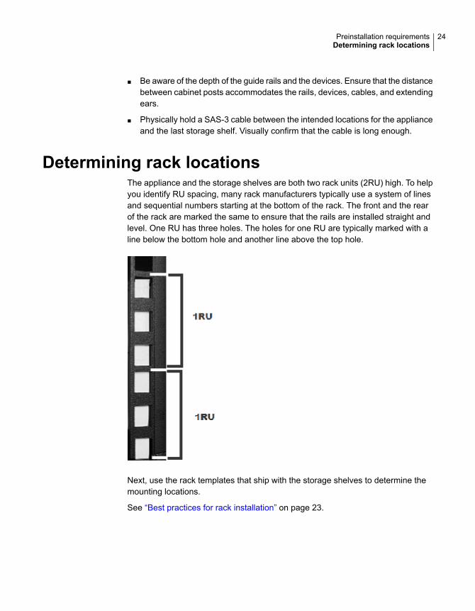
Determining rack locationsThe appliance and the storage shelves are both two rack units (2RU) high. To helpyou identify RU spacing, many rack manufacturers typically use a system of linesand sequential numbers starting at the bottom of the rack. The front and the rearof the rack are marked the same to ensure that the rails are installed straight andlevel. One RU has three holes. The holes for one RU are typically marked with aline below the bottom hole and another line above the top hole.
Next, use the rack templates that ship with the storage shelves to determine themounting locations.
See “Best practices for rack installation” on page 23.
24Preinstallation requirementsDetermining rack locations
To determine rack locations for the storage shelves
1 A storage shelf is 2RU high. Multiply the number 2 by the number of shelvesthat you plan to install.
An appliance and six storage shelves require a total of 14 RUs.
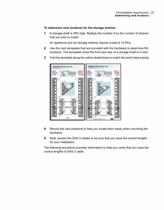
2 Use the rack templates that are provided with the hardware to determine RUlocations. The templates show the front and rear of a storage shelf in a rack.
3 Fold the template along the yellow dotted lines to match the rack holes exactly.
4 Record the rack positions to help you locate them easily when mounting thehardware.
5 Next, assess the SAS-3 cables to be sure that you have the correct lengthsfor your installation.
The following procedure provides information to help you verify that you have thecorrect lengths of SAS-3 cable.
25Preinstallation requirementsDetermining rack locations
To determine SAS-3 cable requirements
1 Note that each rack unit (RU) is 44.50 mm (1.752 inches) in height. The 5250Appliance and the 5250 Storage Shelf are both 2RU high.
2 Each SAS-3 cable is 1 meter (3.28 feet) long. The 1-meter cable is long enoughto connect an appliance to the fourth storage shelf, assuming that therecommended configuration is used.
Verify that your cables are long enough to connect all of the devices.
Longer SAS-3 cables are supported with the 2U12 Storage Shelf if needed forthe configuration and are provided by the customer.
Storage shelf rack requirementsFor best ventilation, the rack cabinet:
■ Should be at least 100 cm (4 feet) from walls.
■ Should have at least 100 cm (4 feet) from other cabinets on the front and backof the appliance and the storage shelves.
■ Data centers with two-foot spaces in the front and in the back of the appliancesare acceptable with proper cooling and ventilation
■ There must be a minimum depth of 76 cm (30 in.) between the front of the rackand the rear of the rack.
■ Storage shelves should be installed lower in the rack than the appliance.
The following list describes the necessary personnel and equipment that customersmust supply at the installation site:
■ At least two people or a mechanical lift to move the appliance and the storageshelves.
■ Two people to install the rails; one person at the back of the rack and one atthe front
■ Two people to lift and place the storage shelf into the mounted rails
■ Cables to connect the appliance to your corporate network.
■ A USB-keyboard and a monitor to connect to the appliance.
■ A 19-inch rack with dual Power Distribution Units (PDUs) with 220VAC powersupplies.
26Preinstallation requirementsStorage shelf rack requirements
Heat dissipationAir flows from the front of each unit and exits from the rear of each unit. You caninstall the optional bezel without disruption to the airflow.
For best ventilation, the rack cabinet should:
■ Be at least 100 cm (4 feet) from walls.
■ Be at least 100 cm (4 feet) from other cabinets on the front and back of theappliance and the storage shelves.
Note:Data centers with two-foot spaces in the front and in the back of the appliancesare acceptable with proper cooling and ventilation.
Veritas provides the following requirements to ensure sufficient cooling.
■ Veritas requires that you install the system in a National EngineeringManufacturer's Association (NEMA)-certified or equivalent rack.
■ A minimum of 3 inches (7.6 cm) of space must be between the front of anappliance and the cabinet door or other air block.
■ A minimum of 6 inches (15.2 cm) of space must be between the rear of anappliance and the cabinet rear or other air block.
■ A minimum of 1 inch (2.5 cm) of space must be between the front of a storageshelf and the cabinet door or other air block.
■ A minimum of 2 inches (5.0 cm) of space must be between the rear of a storageshelf and the cabinet rear or other air block.
Refer to the Veritas 5250 Appliance Product Description Guide for specificationsabout temperature and cooling.
NetBackup Appliance documentation
Verifying SAS-3 cable lengthBefore you install and connect the hardware, be sure to verify that you have thecorrect length of the SAS-3 cables for your setup.
Each rack unit (RU) is 44.50 mm (1.752 inches) in height. The 5250 Appliance andthe 5250 Storage Shelf are both 2RU high.
Each SAS-3 cable is 1 meter (3.28 feet) long. The 1-meter cable is long enough toconnect an appliance to the fourth storage shelf when the recommendedconfiguration is used.
27Preinstallation requirementsHeat dissipation
Longer SAS-3 cables are supported with the 2U12 Storage Shelf if needed for theconfiguration.
Prerequisites for IPMI configurationVerify the following configuration prerequisites:
■ The remote management port auto-negotiates its link speed to 1 Gbps.
Note: If the IPMI port is connected to a managed switch port, it is recommendedthat you configure the switch port to auto-negotiation
■ If a firewall exists between the appliance and the remote devices that managean appliance (like a laptop computer), open the following ports:
SOL SSH66
HTTP80
SNMP162
HTTPS443
Floppy/USB media623
Secured Floppy/USB media627
CD5120
Secured CD5124
KVM5900
Secured KVM5902
Note: If you have a private internal network, remember to configure the settingsaccordingly in your network address translation (NAT).
■ The remote management port must be configured as a DHCP or static address.
28Preinstallation requirementsPrerequisites for IPMI configuration
Installation proceduresThis chapter includes the following topics:
■ Installing the storage shelf rack rails
■ Installing the storage shelf into a rack
■ Attaching the storage shelf bezel
■ Installing the appliance rack rails
■ Installing the appliance into a rack
■ Understanding appliance and storage shelf connections
■ Connecting an appliance to one storage shelf
■ Connecting an appliance to more than one storage shelf
■ Connecting the network cables
■ Connecting the power cords
■ Turning on the hardware and verifying operation
■ Configuring the IPMI port from the NetBackup Appliance Shell Menu
■ Configuring the Veritas Remote Management Interface from a Flex Appliance
■ Accessing and using the Veritas Remote Management interface
Installing the storage shelf rack railsUse the following procedure to install the storage shelf rack rails. Ensure that thebest practises for installing the rack rails are followed.
See “Storage shelf rack requirements” on page 26.
3Chapter
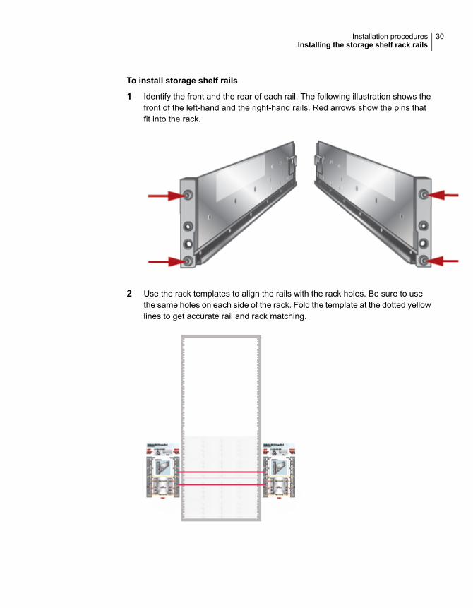
To install storage shelf rails
1 Identify the front and the rear of each rail. The following illustration shows thefront of the left-hand and the right-hand rails. Red arrows show the pins thatfit into the rack.
2 Use the rack templates to align the rails with the rack holes. Be sure to usethe same holes on each side of the rack. Fold the template at the dotted yellowlines to get accurate rail and rack matching.
30Installation proceduresInstalling the storage shelf rack rails
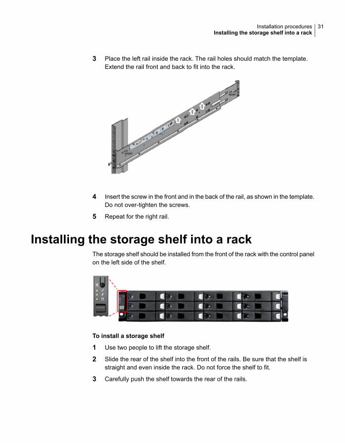
3 Place the left rail inside the rack. The rail holes should match the template.Extend the rail front and back to fit into the rack.
4 Insert the screw in the front and in the back of the rail, as shown in the template.Do not over-tighten the screws.
5 Repeat for the right rail.
Installing the storage shelf into a rackThe storage shelf should be installed from the front of the rack with the control panelon the left side of the shelf.
To install a storage shelf
1 Use two people to lift the storage shelf.
2 Slide the rear of the shelf into the front of the rails. Be sure that the shelf isstraight and even inside the rack. Do not force the shelf to fit.
3 Carefully push the shelf towards the rear of the rails.
31Installation proceduresInstalling the storage shelf into a rack
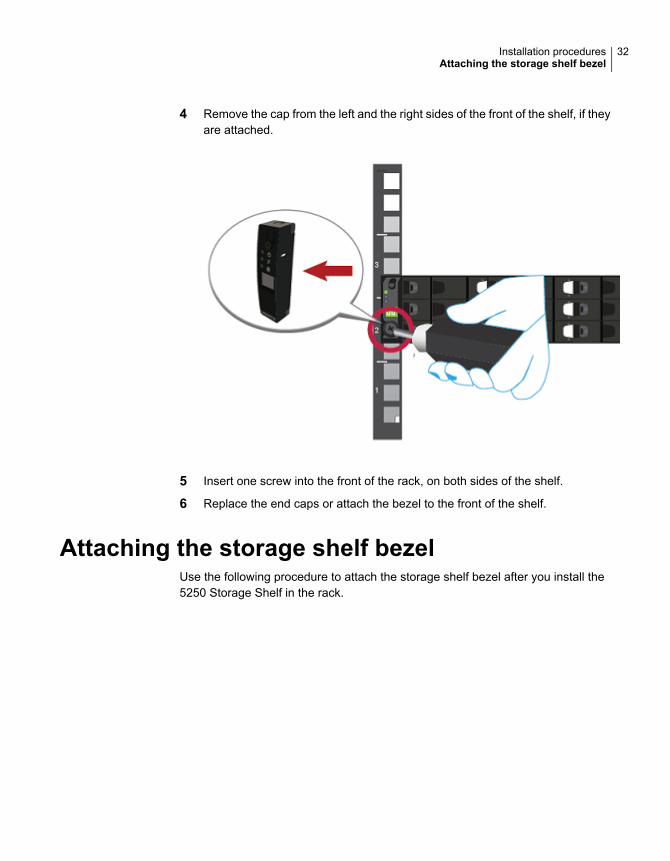
4 Remove the cap from the left and the right sides of the front of the shelf, if theyare attached.
5 Insert one screw into the front of the rack, on both sides of the shelf.
6 Replace the end caps or attach the bezel to the front of the shelf.
Attaching the storage shelf bezelUse the following procedure to attach the storage shelf bezel after you install the5250 Storage Shelf in the rack.
32Installation proceduresAttaching the storage shelf bezel
To attach the storage shelf bezel
1 Remove the bezel from its packaging.
Note: Ensure the end caps that cover the storage shelf control panel on theleft and the blank panel on the right are not installed. The bezel cannot beattached if the end caps are installed on the panels.
2 With the front of the storage shelf bezel facing you, place the bezel over thefront panel of the storage shelf.
The bezel should cover the left control panel assembly and the right panelassembly.
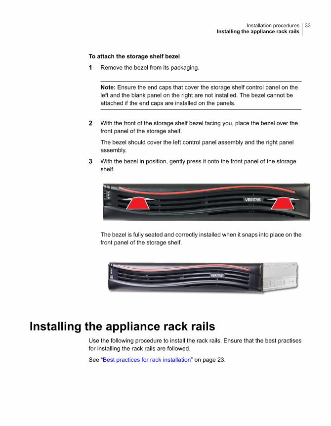
3 With the bezel in position, gently press it onto the front panel of the storageshelf.
The bezel is fully seated and correctly installed when it snaps into place on thefront panel of the storage shelf.
Installing the appliance rack railsUse the following procedure to install the rack rails. Ensure that the best practisesfor installing the rack rails are followed.
See “Best practices for rack installation” on page 23.
33Installation proceduresInstalling the appliance rack rails
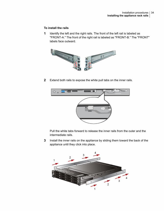
To install the rails
1 Identify the left and the right rails. The front of the left rail is labeled as"FRONT-A." The front of the right rail is labeled as "FRONT-B." The "FRONT"labels face outward.
2 Extend both rails to expose the white pull tabs on the inner rails.
Pull the white tabs forward to release the inner rails from the outer and theintermediate rails.
3 Install the inner rails on the appliance by sliding them toward the back of theappliance until they click into place.
34Installation proceduresInstalling the appliance rack rails
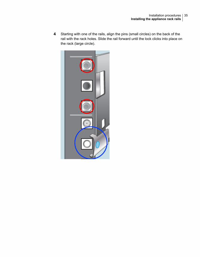
4 Starting with one of the rails, align the pins (small circles) on the back of therail with the rack holes. Slide the rail forward until the lock clicks into place onthe rack (large circle).
35Installation proceduresInstalling the appliance rack rails
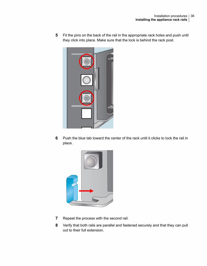
5 Fit the pins on the back of the rail in the appropriate rack holes and push untilthey click into place. Make sure that the lock is behind the rack post.
6 Push the blue tab toward the center of the rack until it clicks to lock the rail inplace.
7 Repeat the process with the second rail.
8 Verify that both rails are parallel and fastened securely and that they can pullout to their full extension.
36Installation proceduresInstalling the appliance rack rails
Installing the appliance into a rackAfter the storage shelves and the appliance rails have been installed, you can installthe appliance into the rack.
To install the appliance into the rack
1 Verify that the rails are securely attached.
■ Verify that the outer rail is securely attached to the rack.
■ Verify that the inner rail is securely attached to the appliance.
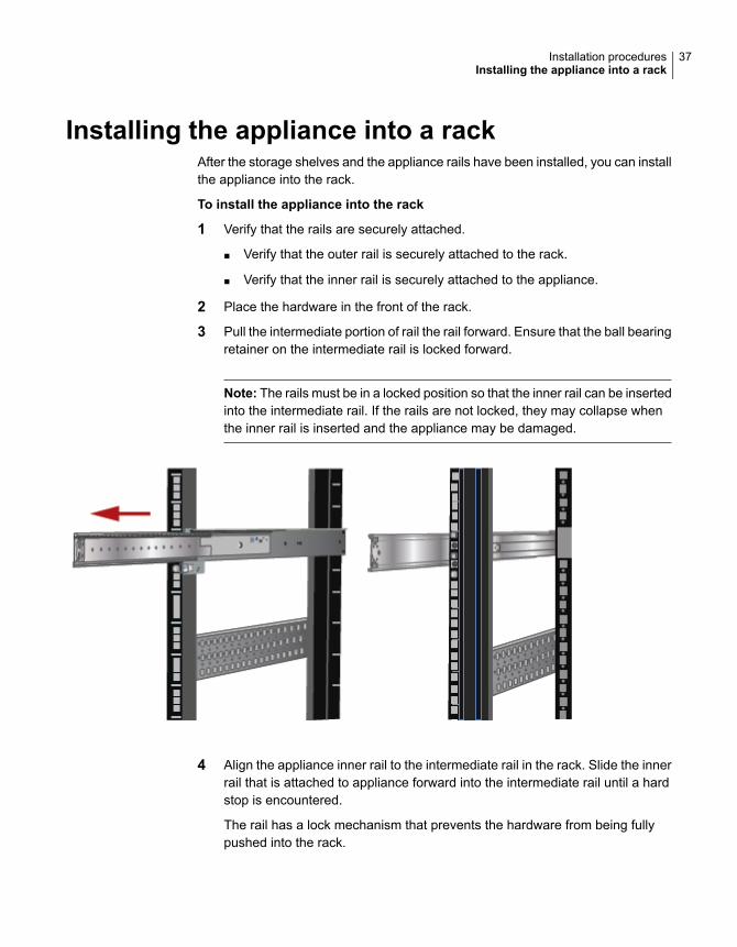
2 Place the hardware in the front of the rack.
3 Pull the intermediate portion of rail the rail forward. Ensure that the ball bearingretainer on the intermediate rail is locked forward.
Note: The rails must be in a locked position so that the inner rail can be insertedinto the intermediate rail. If the rails are not locked, they may collapse whenthe inner rail is inserted and the appliance may be damaged.
4 Align the appliance inner rail to the intermediate rail in the rack. Slide the innerrail that is attached to appliance forward into the intermediate rail until a hardstop is encountered.
The rail has a lock mechanism that prevents the hardware from being fullypushed into the rack.
37Installation proceduresInstalling the appliance into a rack
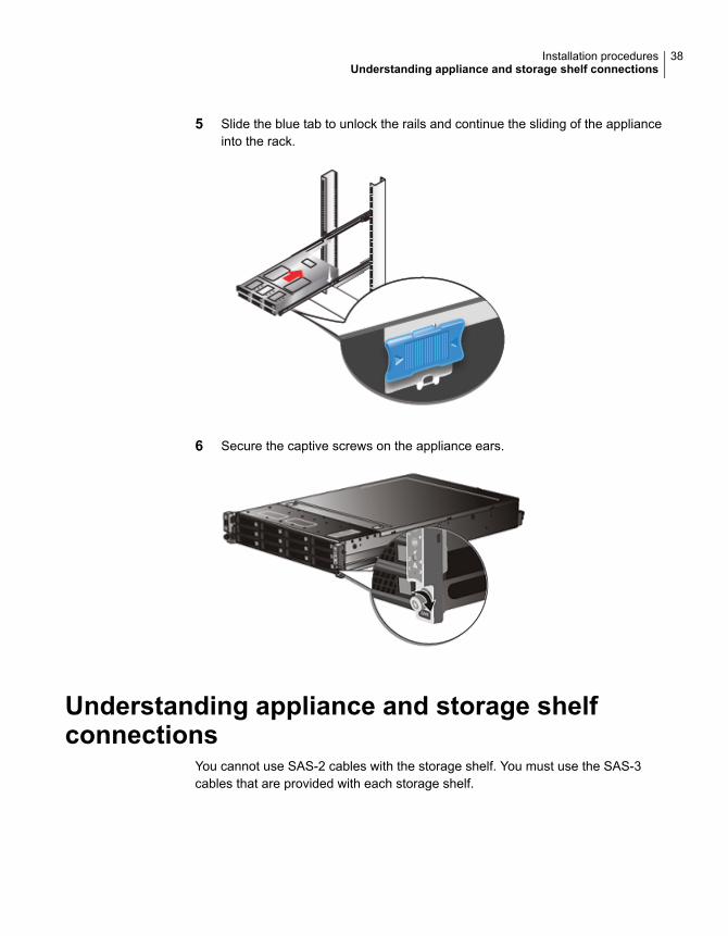
5 Slide the blue tab to unlock the rails and continue the sliding of the applianceinto the rack.
6 Secure the captive screws on the appliance ears.
Understanding appliance and storage shelfconnections
You cannot use SAS-2 cables with the storage shelf. You must use the SAS-3cables that are provided with each storage shelf.
38Installation proceduresUnderstanding appliance and storage shelf connections
Note: The cables in the illustrations in the following sections are shown in differentcolors for demonstration purposes only. The actual cables are black.
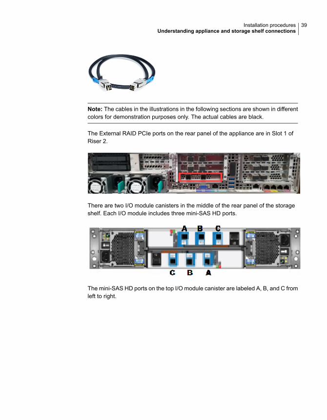
The External RAID PCIe ports on the rear panel of the appliance are in Slot 1 ofRiser 2.
There are two I/O module canisters in the middle of the rear panel of the storageshelf. Each I/O module includes three mini-SAS HD ports.
The mini-SAS HD ports on the top I/O module canister are labeled A, B, and C fromleft to right.
39Installation proceduresUnderstanding appliance and storage shelf connections
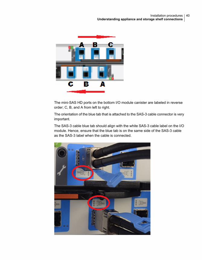
The mini-SAS HD ports on the bottom I/O module canister are labeled in reverseorder; C, B, and A from left to right.
The orientation of the blue tab that is attached to the SAS-3 cable connector is veryimportant.
The SAS-3 cable blue tab should align with the white SAS-3 cable label on the I/Omodule. Hence, ensure that the blue tab is on the same side of the SAS-3 cableas the SAS-3 label when the cable is connected.
40Installation proceduresUnderstanding appliance and storage shelf connections
The steps in the following sections assume that the appliance and one or morestorage shelves are shipped together and installed at the same time.
Refer to the following sections as needed.
See “Connecting an appliance to one storage shelf” on page 41.
See “Connecting an appliance to more than one storage shelf” on page 42.
Connecting an appliance to one storage shelfThe steps in this section assume that the appliance and the storage shelf areshipped together and installed at the same time.
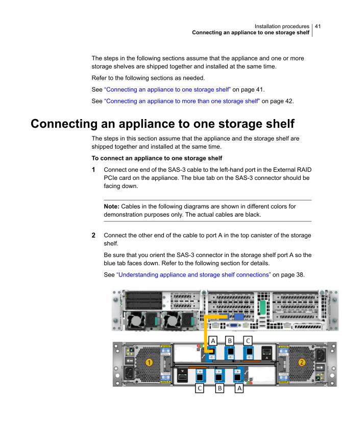
To connect an appliance to one storage shelf
1 Connect one end of the SAS-3 cable to the left-hand port in the External RAIDPCIe card on the appliance. The blue tab on the SAS-3 connector should befacing down.
Note: Cables in the following diagrams are shown in different colors fordemonstration purposes only. The actual cables are black.
2 Connect the other end of the cable to port A in the top canister of the storageshelf.
Be sure that you orient the SAS-3 connector in the storage shelf port A so theblue tab faces down. Refer to the following section for details.
See “Understanding appliance and storage shelf connections” on page 38.
41Installation proceduresConnecting an appliance to one storage shelf
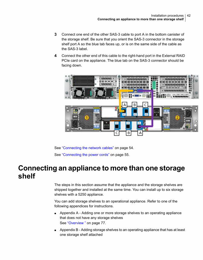
3 Connect one end of the other SAS-3 cable to port A in the bottom canister ofthe storage shelf. Be sure that you orient the SAS-3 connector in the storageshelf port A so the blue tab faces up, or is on the same side of the cable asthe SAS-3 label.
4 Connect the other end of this cable to the right-hand port in the External RAIDPCIe card on the appliance. The blue tab on the SAS-3 connector should befacing down.
See “Connecting the network cables” on page 54.
See “Connecting the power cords” on page 55.
Connecting an appliance tomore than one storageshelf
The steps in this section assume that the appliance and the storage shelves areshipped together and installed at the same time. You can install up to six storageshelves with a 5250 appliance.
You can add storage shelves to an operational appliance. Refer to one of thefollowing appendices for instructions.
■ Appendix A - Adding one or more storage shelves to an operating appliancethat does not have any storage shelvesSee “Overview ” on page 77.
■ Appendix B - Adding storage shelves to an operating appliance that has at leastone storage shelf attached
42Installation proceduresConnecting an appliance to more than one storage shelf
See “Overview” on page 128.See “Moving the MSDP partition from a base disk to an expansion disk foroptimum performance” on page 129.
To connect an appliance to storage shelves
Note: This section provides detailed instructions to connect four storage shelvesto an appliance. Instructions for connecting six shelves are provided wherenecessary.
43Installation proceduresConnecting an appliance to more than one storage shelf
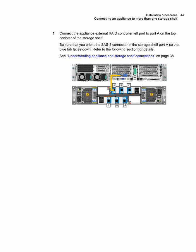
1 Connect the appliance external RAID controller left port to port A on the topcanister of the storage shelf.
Be sure that you orient the SAS-3 connector in the storage shelf port A so theblue tab faces down. Refer to the following section for details.
See “Understanding appliance and storage shelf connections” on page 38.
44Installation proceduresConnecting an appliance to more than one storage shelf
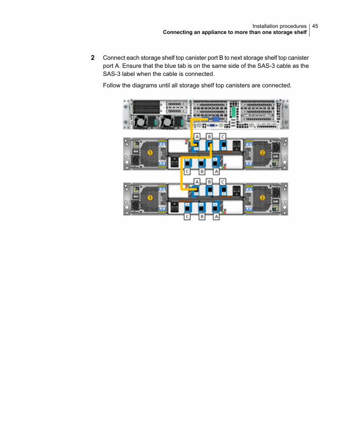
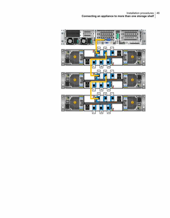
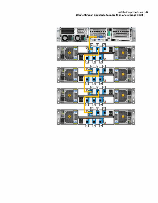
2 Connect each storage shelf top canister port B to next storage shelf top canisterport A. Ensure that the blue tab is on the same side of the SAS-3 cable as theSAS-3 label when the cable is connected.
Follow the diagrams until all storage shelf top canisters are connected.
45Installation proceduresConnecting an appliance to more than one storage shelf
46Installation proceduresConnecting an appliance to more than one storage shelf
47Installation proceduresConnecting an appliance to more than one storage shelf
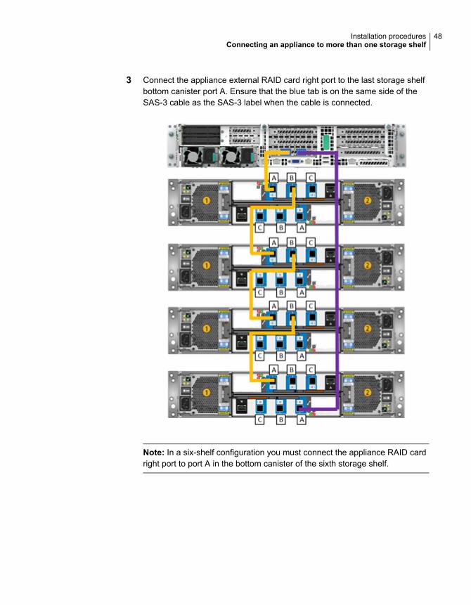
3 Connect the appliance external RAID card right port to the last storage shelfbottom canister port A. Ensure that the blue tab is on the same side of theSAS-3 cable as the SAS-3 label when the cable is connected.
Note: In a six-shelf configuration you must connect the appliance RAID cardright port to port A in the bottom canister of the sixth storage shelf.
48Installation proceduresConnecting an appliance to more than one storage shelf
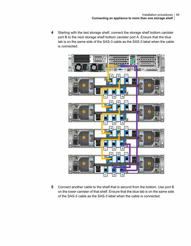
4 Starting with the last storage shelf, connect the storage shelf bottom canisterport B to the next storage shelf bottom canister port A. Ensure that the bluetab is on the same side of the SAS-3 cable as the SAS-3 label when the cableis connected.
5 Connect another cable to the shelf that is second from the bottom. Use port Bon the lower canister of that shelf. Ensure that the blue tab is on the same sideof the SAS-3 cable as the SAS-3 label when the cable is connected.
49Installation proceduresConnecting an appliance to more than one storage shelf
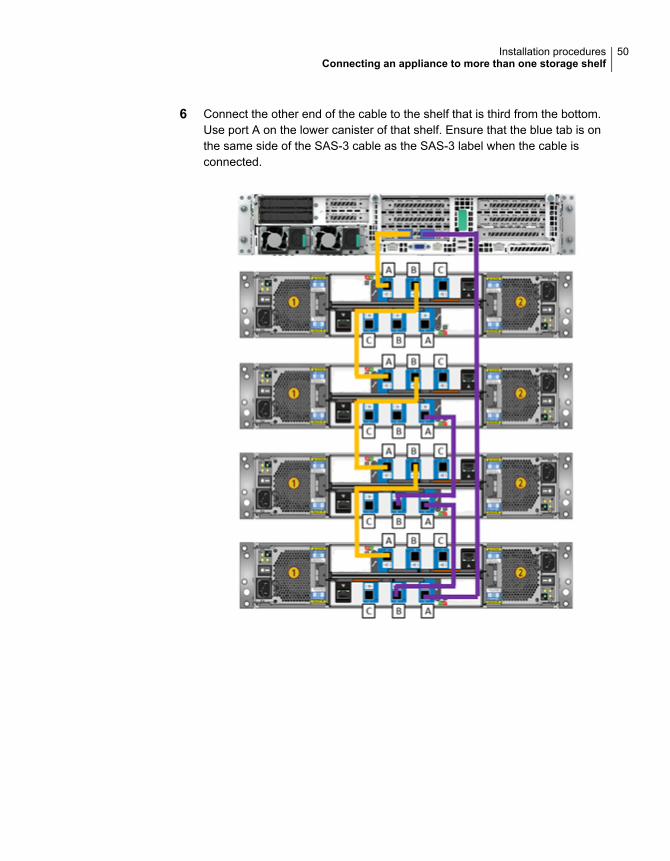
6 Connect the other end of the cable to the shelf that is third from the bottom.Use port A on the lower canister of that shelf. Ensure that the blue tab is onthe same side of the SAS-3 cable as the SAS-3 label when the cable isconnected.
50Installation proceduresConnecting an appliance to more than one storage shelf
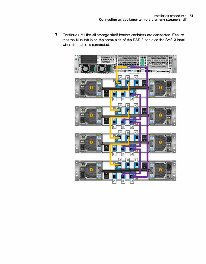
7 Continue until the all storage shelf bottom canisters are connected. Ensurethat the blue tab is on the same side of the SAS-3 cable as the SAS-3 labelwhen the cable is connected.
51Installation proceduresConnecting an appliance to more than one storage shelf

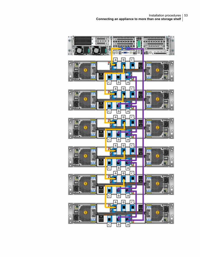
8 In a six-shelf configuration verify that all cables are installed as shown.
52Installation proceduresConnecting an appliance to more than one storage shelf
53Installation proceduresConnecting an appliance to more than one storage shelf
See “Connecting the network cables” on page 54.
See “Connecting the power cords” on page 55.
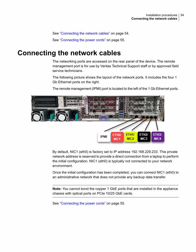
Connecting the network cablesThe networking ports are accessed on the rear panel of the device. The remotemanagement port is for use by Veritas Technical Support staff or by approved fieldservice technicians.
The following picture shows the layout of the network ports. It includes the four 1Gb Ethernet ports on the right.
The remote management (IPMI) port is located to the left of the 1 Gb Ethernet ports.
By default, NIC1 (eth0) is factory set to IP address 192.168.229.233. This privatenetwork address is reserved to provide a direct connection from a laptop to performthe initial configuration. NIC1 (eth0) is typically not connected to your networkenvironment.
Once the initial configuration has been completed, you can connect NIC1 (eth0) toan administrative network that does not provide any backup data transfer.
Note: You cannot bond the copper 1 GbE ports that are installed in the appliancechassis with optical ports on PCIe 10/25 GbE cards.
See “Connecting the power cords” on page 55.
54Installation proceduresConnecting the network cables
Connecting the power cordsEach appliance and each storage shelf contains two AC power supplies. To ensurepower redundancy, connect the power supplies on each component to separateAC power sources.
Caution: Do not turn on the power to any components while connecting the powercords. The components must be turned on in a specific sequence to ensure correctcommunication.
To connect the power cables
1 Verify that the AC power supply input for the appliance and for the storageshelf is within one of these ranges.
■ 100 - 127 VAC at 50/60 Hz
■ 200 - 240 VAC at 50/60 Hz
2 For each device, obtain two power cords that are appropriate for your regionand equipment.
55Installation proceduresConnecting the power cords
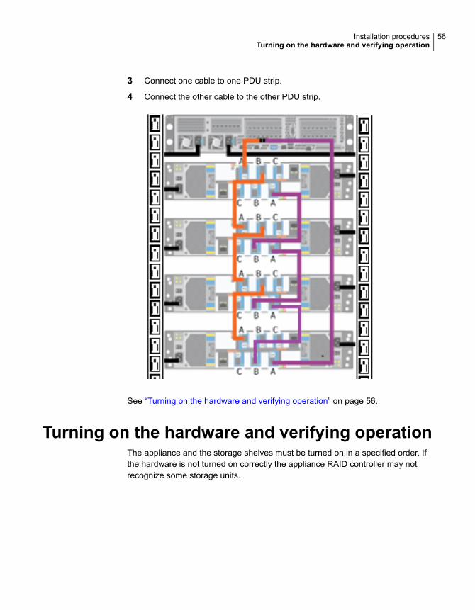
3 Connect one cable to one PDU strip.
4 Connect the other cable to the other PDU strip.
See “Turning on the hardware and verifying operation” on page 56.
Turning on the hardware and verifying operationThe appliance and the storage shelves must be turned on in a specified order. Ifthe hardware is not turned on correctly the appliance RAID controller may notrecognize some storage units.
56Installation proceduresTurning on the hardware and verifying operation
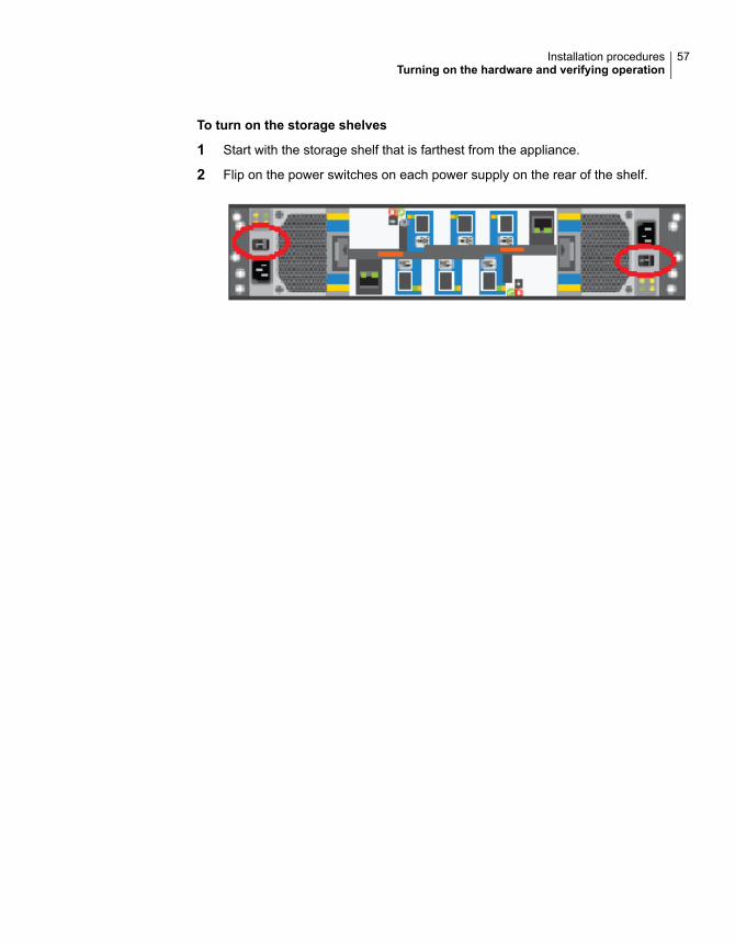
To turn on the storage shelves
1 Start with the storage shelf that is farthest from the appliance.
2 Flip on the power switches on each power supply on the rear of the shelf.
57Installation proceduresTurning on the hardware and verifying operation
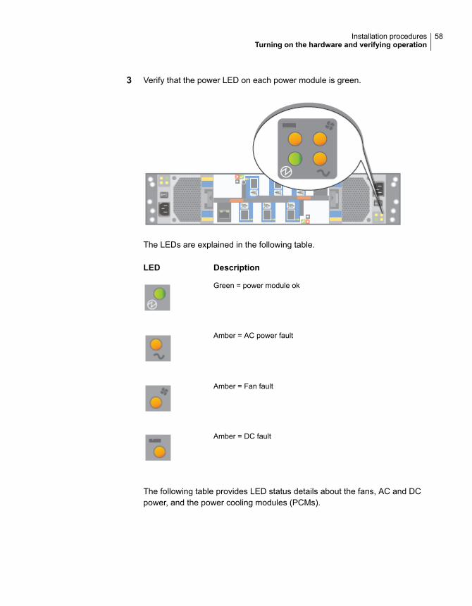
3 Verify that the power LED on each power module is green.
The LEDs are explained in the following table.
DescriptionLED
Green = power module ok
Amber = AC power fault
Amber = Fan fault
Amber = DC fault
The following table provides LED status details about the fans, AC and DCpower, and the power cooling modules (PCMs).
58Installation proceduresTurning on the hardware and verifying operation
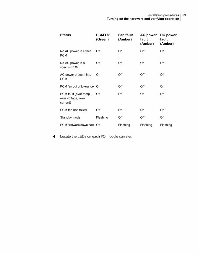
DC powerfault(Amber)
AC powerfault(Amber)
Fan fault(Amber)
PCM Ok(Green)
Status
OffOffOffOffNo AC power in eitherPCM
OnOnOffOffNo AC power in aspecific PCM
OffOffOffOnAC power present in aPCM
OnOffOffOnPCM fan out of tolerance
OnOnOnOffPCM fault (over temp.,over voltage, overcurrent)
OnOnOnOffPCM fan has failed
OffOffOffFlashingStandby mode
FlashingFlashingFlashingOffPCM firmware download
4 Locate the LEDs on each I/O module canister.
59Installation proceduresTurning on the hardware and verifying operation
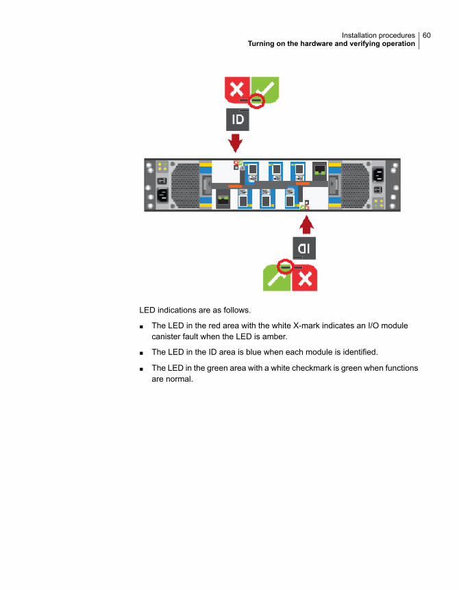
LED indications are as follows.
■ The LED in the red area with the white X-mark indicates an I/O modulecanister fault when the LED is amber.
■ The LED in the ID area is blue when each module is identified.
■ The LED in the green area with a white checkmark is green when functionsare normal.
60Installation proceduresTurning on the hardware and verifying operation
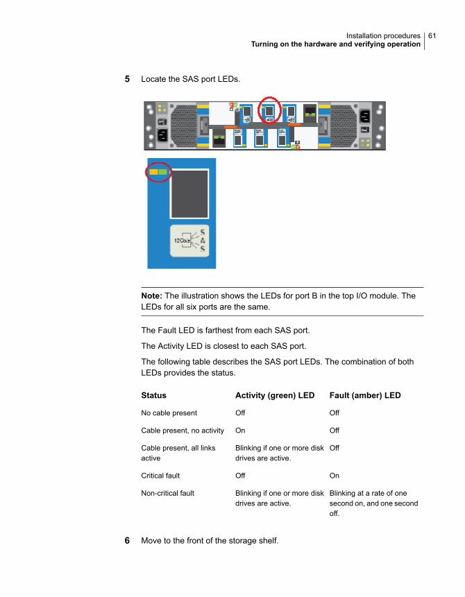
5 Locate the SAS port LEDs.
Note: The illustration shows the LEDs for port B in the top I/O module. TheLEDs for all six ports are the same.
The Fault LED is farthest from each SAS port.
The Activity LED is closest to each SAS port.
The following table describes the SAS port LEDs. The combination of bothLEDs provides the status.
Fault (amber) LEDActivity (green) LEDStatus
OffOffNo cable present
OffOnCable present, no activity
OffBlinking if one or more diskdrives are active.
Cable present, all linksactive
OnOffCritical fault
Blinking at a rate of onesecond on, and one secondoff.
Blinking if one or more diskdrives are active.
Non-critical fault
6 Move to the front of the storage shelf.
61Installation proceduresTurning on the hardware and verifying operation
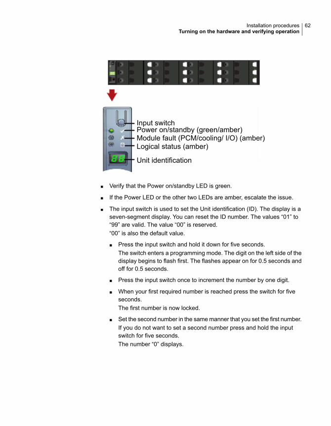
Input switchPower on/standby (green/amber)Module fault (PCM/cooling/ I/O) (amber)Logical status (amber)
Unit identification
■ Verify that the Power on/standby LED is green.
■ If the Power LED or the other two LEDs are amber, escalate the issue.
■ The input switch is used to set the Unit identification (ID). The display is aseven-segment display. You can reset the ID number. The values “01” to“99” are valid. The value “00” is reserved.“00” is also the default value.
■ Press the input switch and hold it down for five seconds.The switch enters a programming mode. The digit on the left side of thedisplay begins to flash first. The flashes appear on for 0.5 seconds andoff for 0.5 seconds.
■ Press the input switch once to increment the number by one digit.
■ When your first required number is reached press the switch for fiveseconds.The first number is now locked.
■ Set the second number in the same manner that you set the first number.If you do not want to set a second number press and hold the inputswitch for five seconds.The number “0” displays.
62Installation proceduresTurning on the hardware and verifying operation
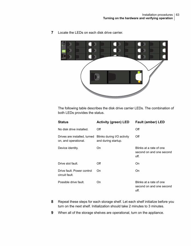
7 Locate the LEDs on each disk drive carrier.
The following table describes the disk drive carrier LEDs. The combination ofboth LEDs provides the status.
Fault (amber) LEDActivity (green) LEDStatus
OffOffNo disk drive installed.
OffBlinks during I/O activityand during startup.
Drives are installed, turnedon, and operational.
Blinks at a rate of onesecond on and one secondoff.
OnDevice identity.
OnOffDrive slot fault.
OnOnDrive fault. Power controlcircuit fault.
Blinks at a rate of onesecond on and one secondoff.
OnPossible drive fault.
8 Repeat these steps for each storage shelf. Let each shelf initialize before youturn on the next shelf. Initialization should take 2 minutes to 3 minutes.
9 When all of the storage shelves are operational, turn on the appliance.
63Installation proceduresTurning on the hardware and verifying operation
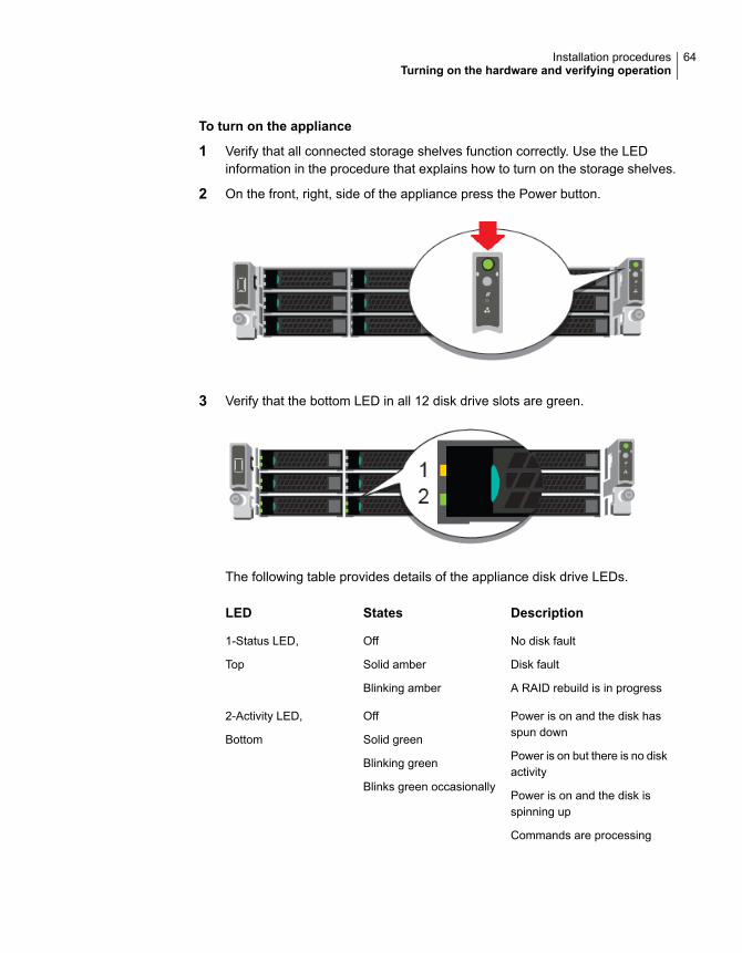
To turn on the appliance
1 Verify that all connected storage shelves function correctly. Use the LEDinformation in the procedure that explains how to turn on the storage shelves.
2 On the front, right, side of the appliance press the Power button.
3 Verify that the bottom LED in all 12 disk drive slots are green.
The following table provides details of the appliance disk drive LEDs.
DescriptionStatesLED
No disk fault
Disk fault
A RAID rebuild is in progress
Off
Solid amber
Blinking amber
1-Status LED,
Top
Power is on and the disk hasspun down
Power is on but there is no diskactivity
Power is on and the disk isspinning up
Commands are processing
Off
Solid green
Blinking green
Blinks green occasionally
2-Activity LED,
Bottom
64Installation proceduresTurning on the hardware and verifying operation
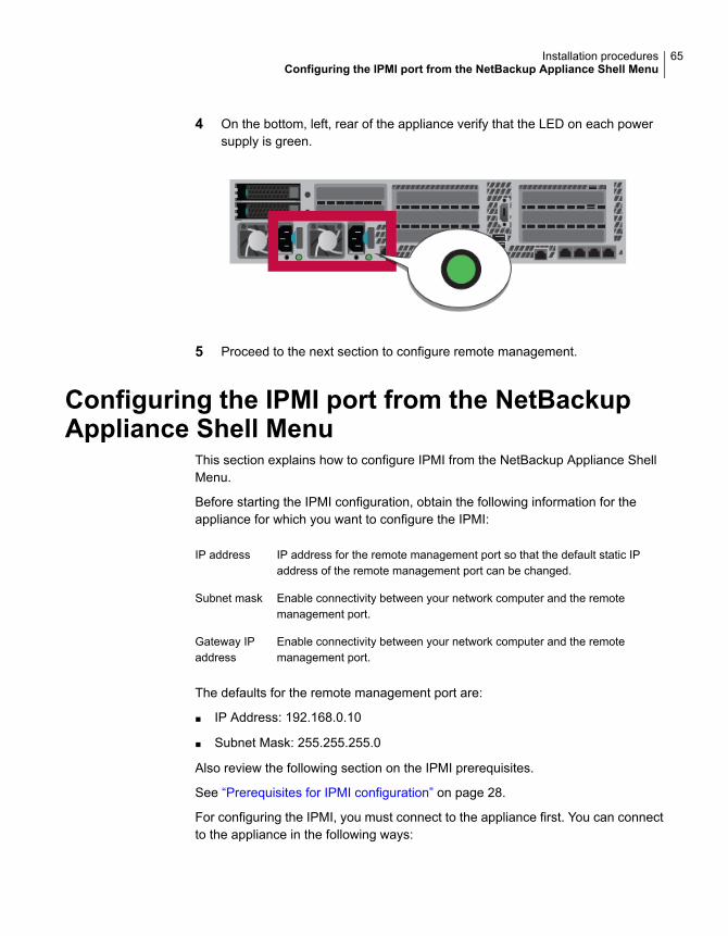
4 On the bottom, left, rear of the appliance verify that the LED on each powersupply is green.
5 Proceed to the next section to configure remote management.
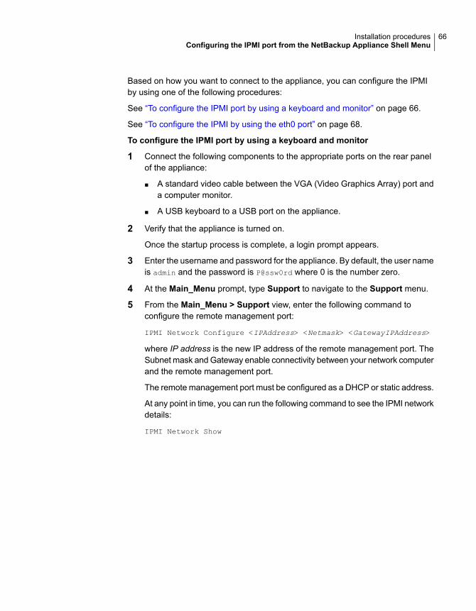
Configuring the IPMI port from the NetBackupAppliance Shell Menu
This section explains how to configure IPMI from the NetBackup Appliance ShellMenu.
Before starting the IPMI configuration, obtain the following information for theappliance for which you want to configure the IPMI:
IP address for the remote management port so that the default static IPaddress of the remote management port can be changed.
IP address
Enable connectivity between your network computer and the remotemanagement port.
Subnet mask
Enable connectivity between your network computer and the remotemanagement port.
Gateway IPaddress
The defaults for the remote management port are:
■ IP Address: 192.168.0.10
■ Subnet Mask: 255.255.255.0
Also review the following section on the IPMI prerequisites.
See “Prerequisites for IPMI configuration” on page 28.
For configuring the IPMI, you must connect to the appliance first. You can connectto the appliance in the following ways:
65Installation proceduresConfiguring the IPMI port from the NetBackup Appliance Shell Menu
Based on how you want to connect to the appliance, you can configure the IPMIby using one of the following procedures:
See “To configure the IPMI port by using a keyboard and monitor” on page 66.
See “To configure the IPMI by using the eth0 port” on page 68.
To configure the IPMI port by using a keyboard and monitor
1 Connect the following components to the appropriate ports on the rear panelof the appliance:
■ A standard video cable between the VGA (Video Graphics Array) port anda computer monitor.
■ A USB keyboard to a USB port on the appliance.
2 Verify that the appliance is turned on.
Once the startup process is complete, a login prompt appears.
3 Enter the username and password for the appliance. By default, the user nameis admin and the password is P@ssw0rd where 0 is the number zero.
4 At the Main_Menu prompt, type Support to navigate to the Support menu.
5 From the Main_Menu > Support view, enter the following command toconfigure the remote management port:
IPMI Network Configure <IPAddress> <Netmask> <GatewayIPAddress>
where IP address is the new IP address of the remote management port. TheSubnet mask and Gateway enable connectivity between your network computerand the remote management port.
The remote management port must be configured as a DHCP or static address.
At any point in time, you can run the following command to see the IPMI networkdetails:
IPMI Network Show
66Installation proceduresConfiguring the IPMI port from the NetBackup Appliance Shell Menu
6 Enter the following command if you want to add a new user to access the IPMIsub-system. Note that this is an optional step.
IPMI User Add <User_Name>
At the New Password prompt, enter a password for the user.
The default user name is sysadmin. The default password is P@ssw0rd,where 0 is the number zero.
At any point in time, you can run the following command to view the users whocan access the IPMI:
IPMI User List
7 Type Return to return to the Main_Menu prompt.
8 Use a Cat5 or a Cat6 cable to connect the remote management port to thenetwork.
9 Make sure you can reach the Veritas Remote Management Console over thenetwork by using the new address in a web browser.
10 The appliance is ready for initial configuration. See the NetBackup ApplianceInitial Configuration Guide for the appropriate platform for information aboutinitial configuration requirements and procedures.
Note:Once the initial configuration has been completed, you can connect NIC1(eth0) to an administrative network that does not provide any backup datatransfer.
67Installation proceduresConfiguring the IPMI port from the NetBackup Appliance Shell Menu
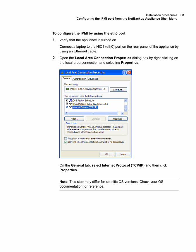
To configure the IPMI by using the eth0 port
1 Verify that the appliance is turned on.
Connect a laptop to the NIC1 (eth0) port on the rear panel of the appliance byusing an Ethernet cable.
2 Open the Local Area Connection Properties dialog box by right-clicking onthe local area connection and selecting Properties.
On the General tab, select Internet Protocol (TCP/IP) and then clickProperties.
Note: This step may differ for specific OS versions. Check your OSdocumentation for reference.
68Installation proceduresConfiguring the IPMI port from the NetBackup Appliance Shell Menu
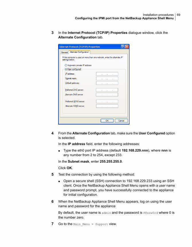
3 In the Internet Protocol (TCP/IP) Properties dialogue window, click theAlternate Configuration tab.
4 From theAlternate Configuration tab, make sure theUser Configured optionis selected.
In the IP address field, enter the following addresses:
■ Type the eth0 port IP address (default 192.168.229.nnn), where nnn isany number from 2 to 254, except 233.
In the Subnet mask, enter 255.255.255.0.
Click OK.
5 Test the connection by using the following method:
■ Open a secure shell (SSH) connection to 192.168.229.233 using an SSHclient. Once the NetBackup Appliance Shell Menu opens with a user nameand password prompt, you have successfully connected to the appliancefor initial configuration.
6 When the NetBackup Appliance Shell Menu appears, log on using the username and password for the appliance
By default, the user name is admin and the password is P@ssw0rd where 0 isthe number zero.
7 Go to the Main_Menu > Support view.
69Installation proceduresConfiguring the IPMI port from the NetBackup Appliance Shell Menu
8 Enter the following command to configure the IPMI port:
IPMI Network Configure <IPAddress> <Netmask> <GatewayIPAddress>
Where IP address is the new IP address for the IPMI port. The Subnet maskand Gateway enable connectivity between your network computer and theIPMI port.
The IPMI port must be configured as a DHCP or static address.
At any point in time, you can run the following command to see the IPMI networkdetails:
IPMI Network Show
9 Type Exit and press Enter to log out of the NetBackup Appliance Shell Menu.
10 Use a Cat5 or a Cat6 cable to connect the remote management port to thenetwork.
11 Make sure you can reach the Veritas Remote Management Console over thenetwork by using the new address in a web browser.
12 The appliance is ready for initial configuration. See the NetBackup ApplianceInitial Configuration Guide for the appropriate platform for information aboutinitial configuration requirements and procedures.
Note:Once the initial configuration has been completed, you can connect NIC1(eth0) to an administrative network that does not provide any backup datatransfer.
Configuring the Veritas Remote ManagementInterface from a Flex Appliance
Veritas Flex Appliance release does not support configuring the IPMI port throughthe Flex Appliance Shell.
To configure the dedicated Veritas Remote Management Interface (IPMI) LANsettings in the BIOS
1 Connect a standard video cable between the VGA (Video Graphics Array) portand the computer monitor
2 Connect a keyboard to a USB port at the rear of the Flex 5250 appliance.
3 Ensure that the power cords are connected to a power supply and press thepower switch on the front panel.
70Installation proceduresConfiguring the Veritas Remote Management Interface from a Flex Appliance
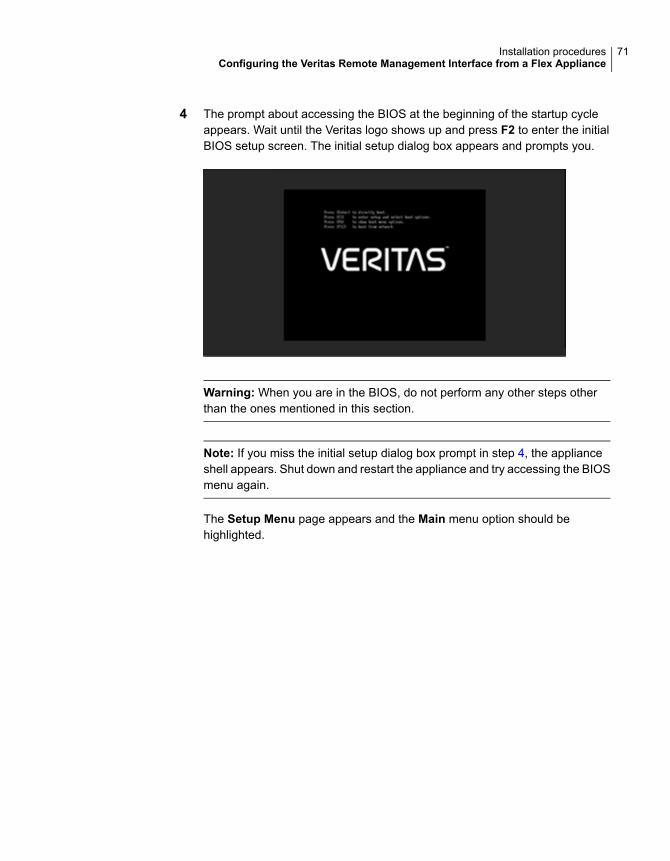
4 The prompt about accessing the BIOS at the beginning of the startup cycleappears. Wait until the Veritas logo shows up and press F2 to enter the initialBIOS setup screen. The initial setup dialog box appears and prompts you.
Warning: When you are in the BIOS, do not perform any other steps otherthan the ones mentioned in this section.
Note: If you miss the initial setup dialog box prompt in step 4, the applianceshell appears. Shut down and restart the appliance and try accessing the BIOSmenu again.
The Setup Menu page appears and the Main menu option should behighlighted.
71Installation proceduresConfiguring the Veritas Remote Management Interface from a Flex Appliance
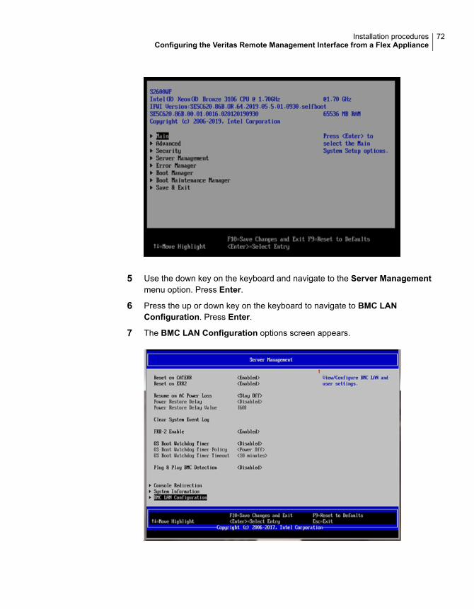
5 Use the down key on the keyboard and navigate to the Server Managementmenu option. Press Enter.
6 Press the up or down key on the keyboard to navigate to BMC LANConfiguration. Press Enter.
7 The BMC LAN Configuration options screen appears.
72Installation proceduresConfiguring the Veritas Remote Management Interface from a Flex Appliance
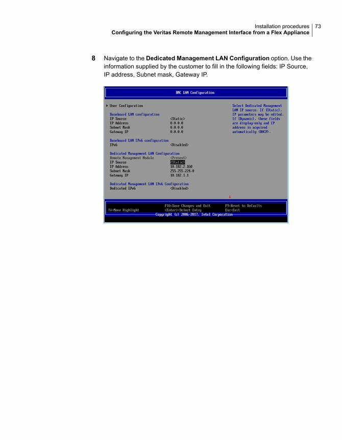
8 Navigate to the Dedicated Management LAN Configuration option. Use theinformation supplied by the customer to fill in the following fields: IP Source,IP address, Subnet mask, Gateway IP.
73Installation proceduresConfiguring the Veritas Remote Management Interface from a Flex Appliance
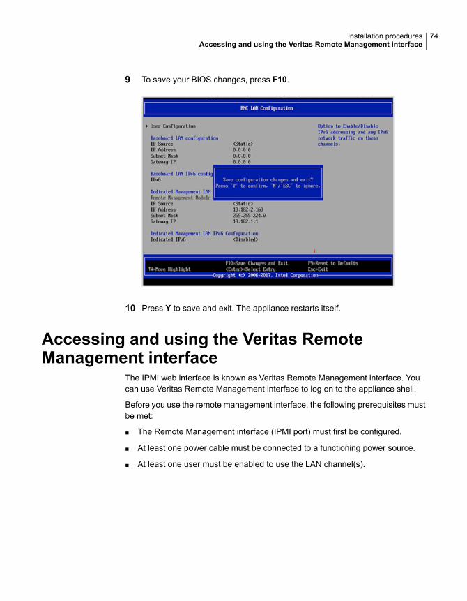
9 To save your BIOS changes, press F10.
10 Press Y to save and exit. The appliance restarts itself.
Accessing and using the Veritas RemoteManagement interface
The IPMI web interface is known as Veritas Remote Management interface. Youcan use Veritas Remote Management interface to log on to the appliance shell.
Before you use the remote management interface, the following prerequisites mustbe met:
■ The Remote Management interface (IPMI port) must first be configured.
■ At least one power cable must be connected to a functioning power source.
■ At least one user must be enabled to use the LAN channel(s).
74Installation proceduresAccessing and using the Veritas Remote Management interface
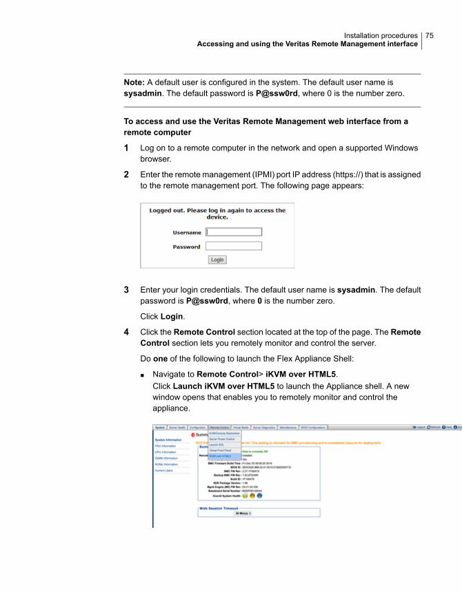
Note: A default user is configured in the system. The default user name issysadmin. The default password is P@ssw0rd, where 0 is the number zero.
To access and use the Veritas Remote Management web interface from aremote computer
1 Log on to a remote computer in the network and open a supported Windowsbrowser.
2 Enter the remote management (IPMI) port IP address (https://) that is assignedto the remote management port. The following page appears:
3 Enter your login credentials. The default user name is sysadmin. The defaultpassword is P@ssw0rd, where 0 is the number zero.
Click Login.
4 Click the Remote Control section located at the top of the page. The RemoteControl section lets you remotely monitor and control the server.
Do one of the following to launch the Flex Appliance Shell:
■ Navigate to Remote Control> iKVM over HTML5.Click Launch iKVM over HTML5 to launch the Appliance shell. A newwindow opens that enables you to remotely monitor and control theappliance.
75Installation proceduresAccessing and using the Veritas Remote Management interface
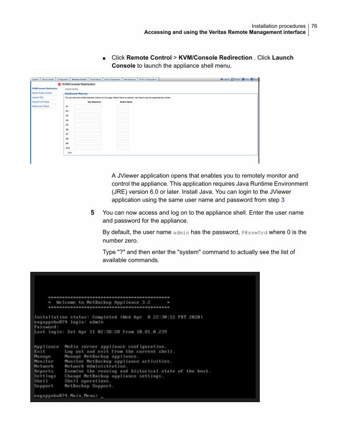
■ Click Remote Control > KVM/Console Redirection . Click LaunchConsole to launch the appliance shell menu.
A JViewer application opens that enables you to remotely monitor andcontrol the appliance. This application requires Java Runtime Environment(JRE) version 6.0 or later. Install Java. You can login to the JViewerapplication using the same user name and password from step 3
5 You can now access and log on to the appliance shell. Enter the user nameand password for the appliance.
By default, the user name admin has the password, P@ssw0rd where 0 is thenumber zero.
Type "?" and then enter the "system" command to actually see the list ofavailable commands.
76Installation proceduresAccessing and using the Veritas Remote Management interface
Adding one or morestorage shelves to anoperating appliance thatdoes not have any storageshelves
This appendix includes the following topics:
■ Overview
■ Preparing the appliance
■ Removing the appliance cover
■ Installing the Expansion Storage Kit components
■ Replacing the appliance cover
■ Connecting the storage shelves to the appliance
OverviewSeveral procedures are involved in the process of adding one or more storageshelves to an existing appliance that does not have any storage shelves. Newcomponents inside the chassis are required as described in this appendix.
An appliance that does not have storage shelves needs additional components tosupport the external storage shelves.
AAppendix
The 5250 Expansion Storage Kit contains the following required hardwarecomponents:
■ Eight, 32Gb, Dual in-line memory modules (DIMMs)
The procedures in this appendix explains the tasks which are required to beperformed to add one or more storage shelve.
These tasks must be performed in the order that is provided.
■ Preparing the applianceSee “Preparing the appliance” on page 79.
■ Removing the appliance coverSee “Removing the appliance cover” on page 80.
■ Installing the Expansion Storage Kit components into the applianceSee “Installing the Expansion Storage Kit components” on page 81.
■ Replacing the appliance coverSee “Replacing the appliance cover” on page 87.
■ Installing the storage shelves rack railsSee “Installing the storage shelf rack rails” on page 29.
■ Installing one or more storage shelves into a rackSee “Installing the storage shelf into a rack” on page 31.
■ Installing the appliance into the rackSee “Installing the appliance into a rack” on page 37.
■ Understanding appliance and storage shelf connectionsSee “Understanding appliance and storage shelf connections” on page 38.
■ Connecting the appliance to the storage shelvesSee “Connecting the storage shelves to the appliance” on page 88.
■ Connecting the network cablesSee “Connecting the network cables” on page 54.
■ Connecting the power cordsSee “Connecting the power cords” on page 55.
■ Turning on the appliance and verifying operationSee “Turning on the hardware and verifying operation” on page 56.
78Adding one or more storage shelves to an operating appliance that does not have any storage shelvesOverview
Preparing the applianceBest practices recommend removing the appliance from the rack to access theinside of the chassis. Alternatively you can either pull out the appliance on its rails.Be sure that the appliance and rack are stable.
Turn off the appliance properly and disconnect it from AC power sources. A softshutdown informs the appliance operating system to stop and close all activeprocesses. After the operating system stops all of the processes, the applianceturns itself off.
Warning: Never turn off the appliance by using the power button on the controlpanel. Using the power button to turn off the appliance can cause data loss orcorruption.
To perform a soft shutdown of the appliance
1 Log on to the NetBackup Appliance Shell Menu.
2 Enter Support > Shutdown.
3 Verify that the appliance is completely turned off. All LEDs are off. Fans arenot running.
4 Remove the power cords that connect the appliance to the rack PowerDistribution Units (PDUs).
The following procedure explains the process of removing the appliance from therack.
To remove the appliance from the rack
1 Verify that the appliance is off and that the power cords have been disconnectedfrom the power sources.
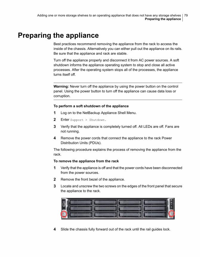
2 Remove the front bezel of the appliance.
3 Locate and unscrew the two screws on the edges of the front panel that securethe appliance to the rack.
4 Slide the chassis fully forward out of the rack until the rail guides lock.
79Adding one or more storage shelves to an operating appliance that does not have any storage shelvesPreparing the appliance
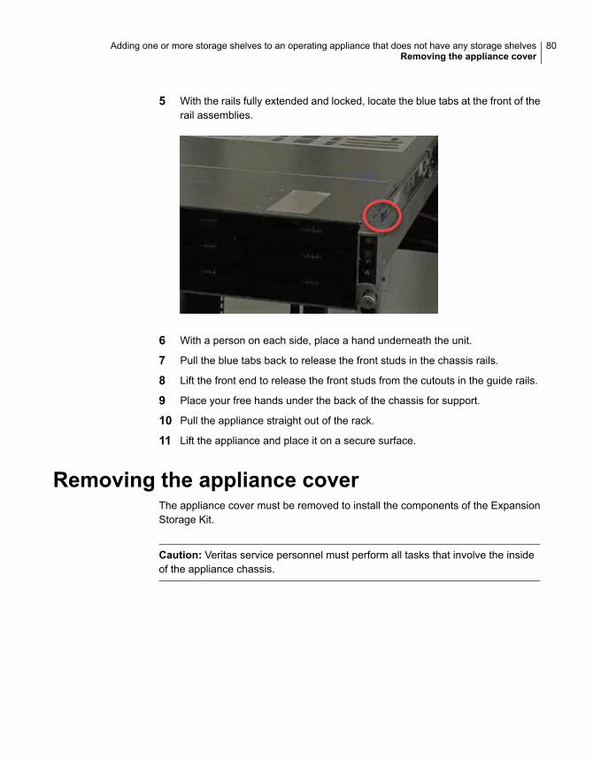
5 With the rails fully extended and locked, locate the blue tabs at the front of therail assemblies.
6 With a person on each side, place a hand underneath the unit.
7 Pull the blue tabs back to release the front studs in the chassis rails.
8 Lift the front end to release the front studs from the cutouts in the guide rails.
9 Place your free hands under the back of the chassis for support.
10 Pull the appliance straight out of the rack.
11 Lift the appliance and place it on a secure surface.
Removing the appliance coverThe appliance cover must be removed to install the components of the ExpansionStorage Kit.
Caution: Veritas service personnel must perform all tasks that involve the insideof the appliance chassis.
80Adding one or more storage shelves to an operating appliance that does not have any storage shelvesRemoving the appliance cover
To remove the cover
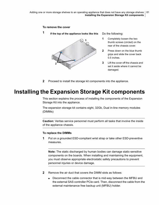
1 If the top of the appliance looks like this Do the following:
1 Completely loosen the twothumb screws (circled) on therear of the chassis cover.
2 Press down on the blue thumbgrips and slide the cover back0.5 inches.
3 Lift the cover off the chassis andset it aside where it cannot bedamaged.
2 Proceed to install the storage kit components into the appliance.
Installing the Expansion Storage Kit componentsThis section explains the process of installing the components of the ExpansionStorage Kit into the appliance.
The expansion storage kit contains eight, 32Gb, Dual in-line memory modules(DIMMs)
Caution: Veritas service personnel must perform all tasks that involve the insideof the appliance chassis.
To replace the DIMMs
1 Put on a grounded ESD-compliant wrist strap or take other ESD-preventivemeasures.
Note: The static discharged by human bodies can damage static-sensitivecomponents on the boards. When installing and maintaining the equipment,you must observe appropriate electrostatic safety precautions to preventpersonnel injuries or device damage.
2 Remove the air duct that covers the DIMM slots as follows:
■ Disconnect the cable connector that is mid-way between the MFBU andthe external SAS controller PCIe card. Then, disconnect the cable from theexternal maintenance free backup unit (MFBU) holder.
81Adding one or more storage shelves to an operating appliance that does not have any storage shelvesInstalling the Expansion Storage Kit components
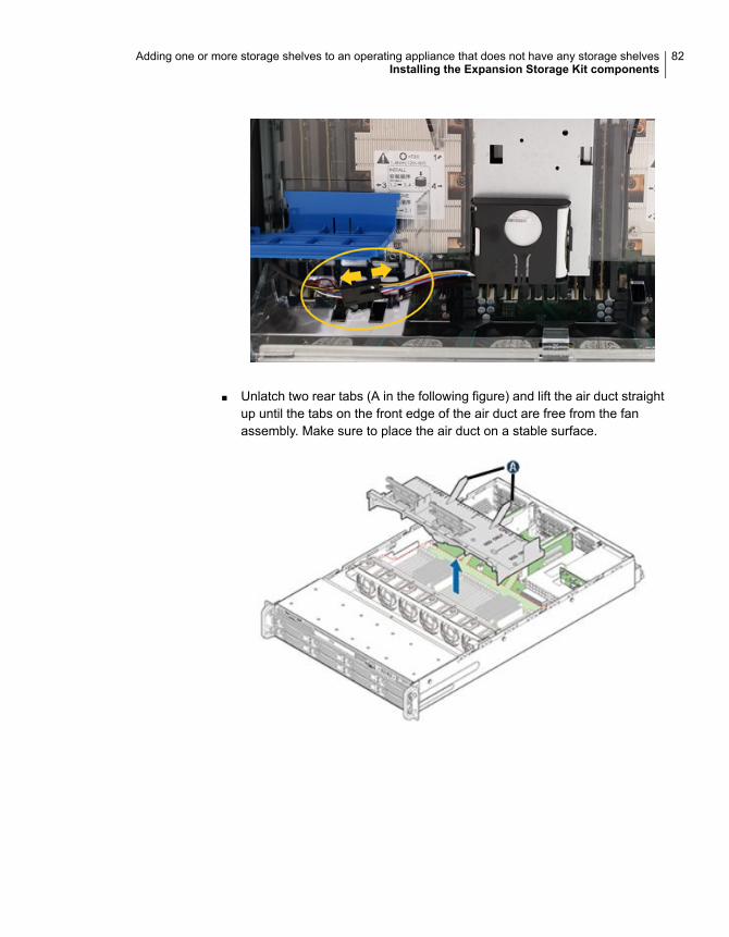
■ Unlatch two rear tabs (A in the following figure) and lift the air duct straightup until the tabs on the front edge of the air duct are free from the fanassembly. Make sure to place the air duct on a stable surface.
82Adding one or more storage shelves to an operating appliance that does not have any storage shelvesInstalling the Expansion Storage Kit components
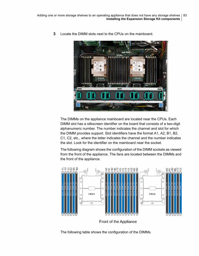
3 Locate the DIMM slots next to the CPUs on the mainboard.
The DIMMs on the appliance mainboard are located near the CPUs. EachDIMM slot has a silkscreen identifier on the board that consists of a two-digitalphanumeric number. The number indicates the channel and slot for whichthe DIMM provides support. Slot identifiers have the format A1, A2, B1, B2,C1, C2, etc., where the letter indicates the channel and the number indicatesthe slot. Look for the identifier on the mainboard near the socket.
The following diagram shows the configuration of the DIMM sockets as viewedfrom the front of the appliance. The fans are located between the DIMMs andthe front of the appliance.
The following table shows the configuration of the DIMMs.
83Adding one or more storage shelves to an operating appliance that does not have any storage shelvesInstalling the Expansion Storage Kit components
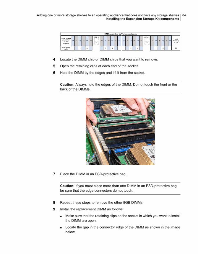
4 Locate the DIMM chip or DIMM chips that you want to remove.
5 Open the retaining clips at each end of the socket.
6 Hold the DIMM by the edges and lift it from the socket.
Caution: Always hold the edges of the DIMM. Do not touch the front or theback of the DIMMs.
7 Place the DIMM in an ESD-protective bag.
Caution: If you must place more than one DIMM in an ESD-protective bag,be sure that the edge connectors do not touch.
8 Repeat these steps to remove the other 8GB DIMMs.
9 Install the replacement DIMM as follows:
■ Make sure that the retaining clips on the socket in which you want to installthe DIMM are open.
■ Locate the gap in the connector edge of the DIMM as shown in the imagebelow.
84Adding one or more storage shelves to an operating appliance that does not have any storage shelvesInstalling the Expansion Storage Kit components
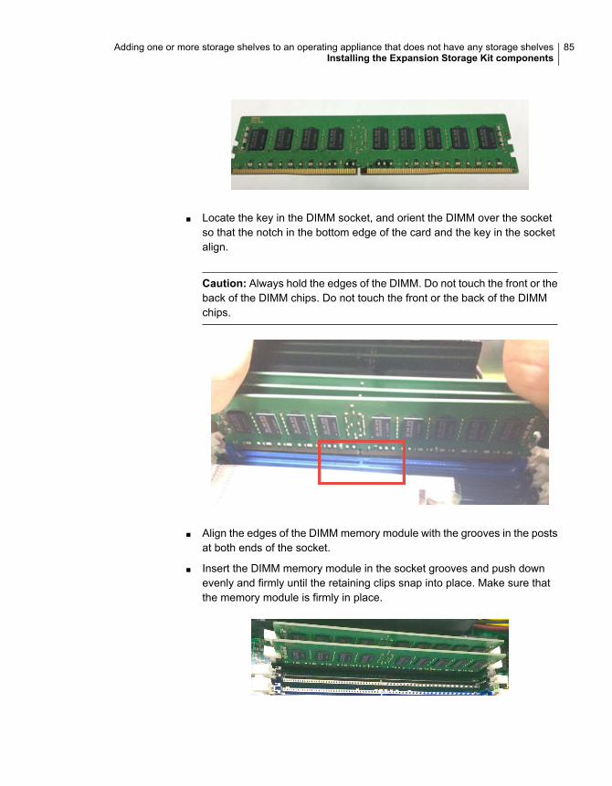
■ Locate the key in the DIMM socket, and orient the DIMM over the socketso that the notch in the bottom edge of the card and the key in the socketalign.
Caution: Always hold the edges of the DIMM. Do not touch the front or theback of the DIMM chips. Do not touch the front or the back of the DIMMchips.
■ Align the edges of the DIMM memory module with the grooves in the postsat both ends of the socket.
■ Insert the DIMM memory module in the socket grooves and push downevenly and firmly until the retaining clips snap into place. Make sure thatthe memory module is firmly in place.
85Adding one or more storage shelves to an operating appliance that does not have any storage shelvesInstalling the Expansion Storage Kit components
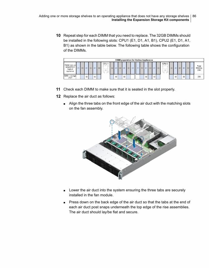
10 Repeat step for each DIMM that you need to replace. The 32GB DIMMs shouldbe installed in the following slots: CPU1 (E1, D1, A1, B1), CPU2 (E1, D1, A1,B1) as shown in the table below. The following table shows the configurationof the DIMMs.
11 Check each DIMM to make sure that it is seated in the slot properly.
12 Replace the air duct as follows:
■ Align the three tabs on the front edge of the air duct with the matching slotson the fan assembly.
■ Lower the air duct into the system ensuring the three tabs are securelyinstalled in the fan module.
■ Press down on the back edge of the air duct so that the tabs at the end ofeach air duct post snaps underneath the top edge of the rise assemblies.The air duct should lay/be flat and secure.
86Adding one or more storage shelves to an operating appliance that does not have any storage shelvesInstalling the Expansion Storage Kit components
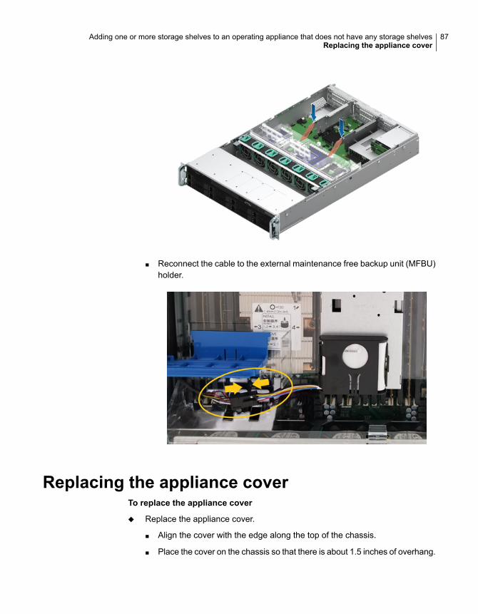
■ Reconnect the cable to the external maintenance free backup unit (MFBU)holder.
Replacing the appliance coverTo replace the appliance cover
◆ Replace the appliance cover.
■ Align the cover with the edge along the top of the chassis.
■ Place the cover on the chassis so that there is about 1.5 inches of overhang.
87Adding one or more storage shelves to an operating appliance that does not have any storage shelvesReplacing the appliance cover
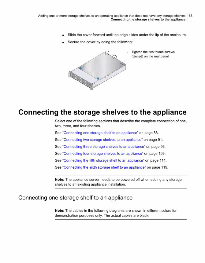
■ Slide the cover forward until the edge slides under the lip of the enclosure.
■ Secure the cover by doing the following:
■ Tighten the two thumb screws(circled) on the rear panel.
Connecting the storage shelves to the applianceSelect one of the following sections that describe the complete connection of one,two, three, and four shelves.
See “Connecting one storage shelf to an appliance” on page 88.
See “Connecting two storage shelves to an appliance” on page 91.
See “Connecting three storage shelves to an appliance” on page 96.
See “Connecting four storage shelves to an appliance” on page 103.
See “Connecting the fifth storage shelf to an appliance” on page 111.
See “Connecting the sixth storage shelf to an appliance” on page 119.
Note: The appliance server needs to be powered off when adding any storageshelves to an existing appliance installation.
Connecting one storage shelf to an appliance
Note: The cables in the following diagrams are shown in different colors fordemonstration purposes only. The actual cables are black.
88Adding one or more storage shelves to an operating appliance that does not have any storage shelvesConnecting the storage shelves to the appliance

Note: The SAS-3 cable blue tab should align with the white SAS-3 cable label onthe I/O module.
89Adding one or more storage shelves to an operating appliance that does not have any storage shelvesConnecting the storage shelves to the appliance
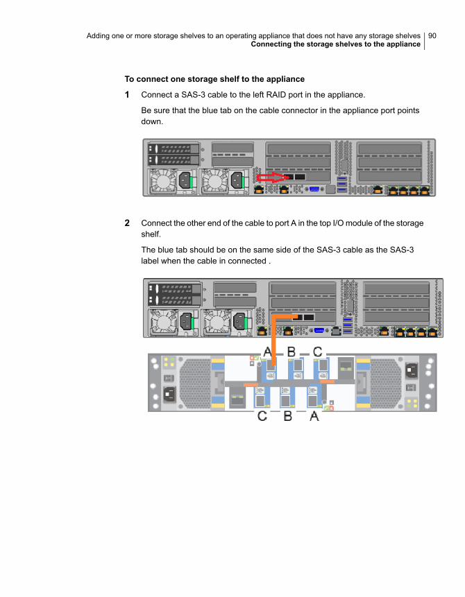
To connect one storage shelf to the appliance
1 Connect a SAS-3 cable to the left RAID port in the appliance.
Be sure that the blue tab on the cable connector in the appliance port pointsdown.
2 Connect the other end of the cable to port A in the top I/O module of the storageshelf.
The blue tab should be on the same side of the SAS-3 cable as the SAS-3label when the cable in connected .
90Adding one or more storage shelves to an operating appliance that does not have any storage shelvesConnecting the storage shelves to the appliance
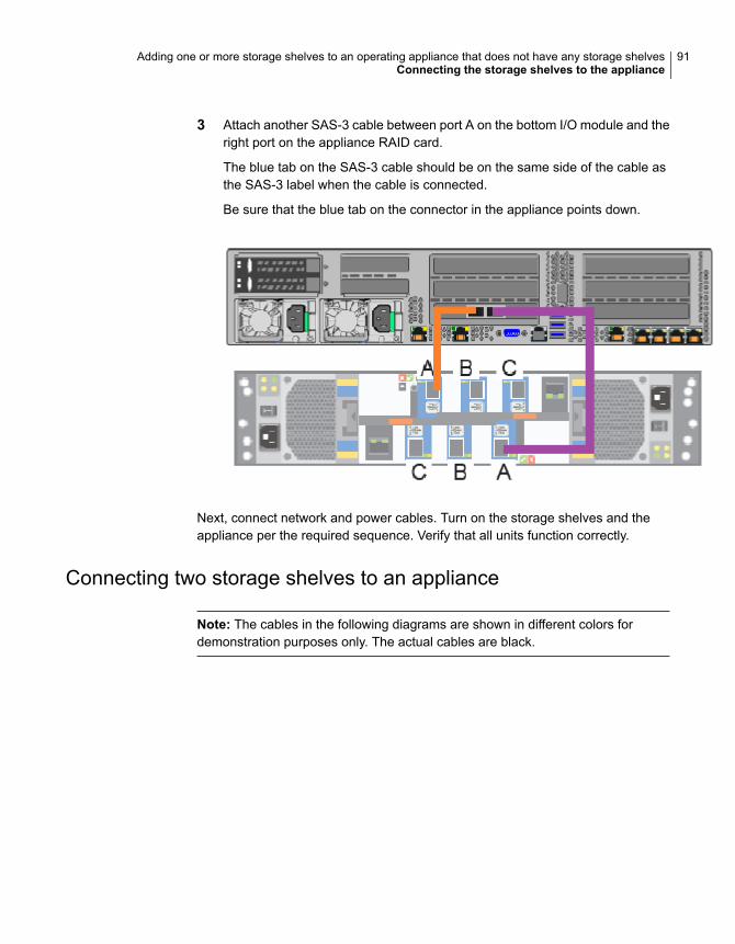
3 Attach another SAS-3 cable between port A on the bottom I/O module and theright port on the appliance RAID card.
The blue tab on the SAS-3 cable should be on the same side of the cable asthe SAS-3 label when the cable is connected.
Be sure that the blue tab on the connector in the appliance points down.
Next, connect network and power cables. Turn on the storage shelves and theappliance per the required sequence. Verify that all units function correctly.
Connecting two storage shelves to an appliance
Note: The cables in the following diagrams are shown in different colors fordemonstration purposes only. The actual cables are black.
91Adding one or more storage shelves to an operating appliance that does not have any storage shelvesConnecting the storage shelves to the appliance

Note: The SAS-3 cable blue tab should align with the white SAS-3 cable label onthe I/O module.
92Adding one or more storage shelves to an operating appliance that does not have any storage shelvesConnecting the storage shelves to the appliance
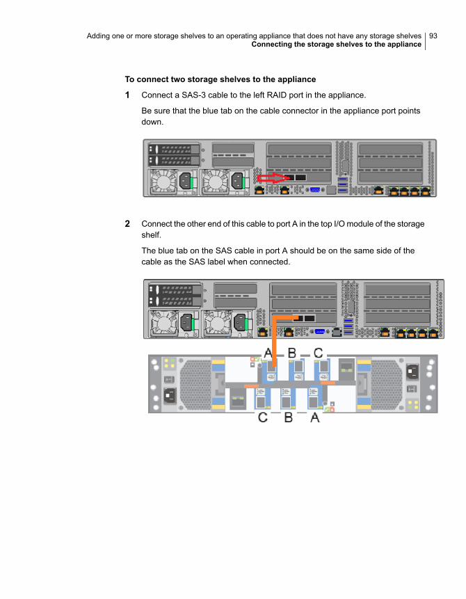
To connect two storage shelves to the appliance
1 Connect a SAS-3 cable to the left RAID port in the appliance.
Be sure that the blue tab on the cable connector in the appliance port pointsdown.
2 Connect the other end of this cable to port A in the top I/O module of the storageshelf.
The blue tab on the SAS cable in port A should be on the same side of thecable as the SAS label when connected.
93Adding one or more storage shelves to an operating appliance that does not have any storage shelvesConnecting the storage shelves to the appliance
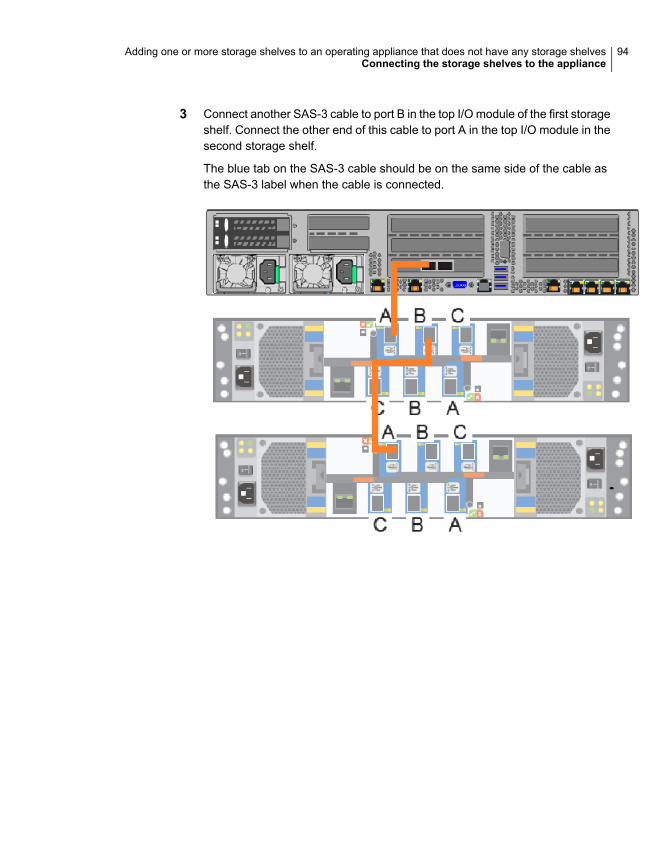
3 Connect another SAS-3 cable to port B in the top I/O module of the first storageshelf. Connect the other end of this cable to port A in the top I/O module in thesecond storage shelf.
The blue tab on the SAS-3 cable should be on the same side of the cable asthe SAS-3 label when the cable is connected.
94Adding one or more storage shelves to an operating appliance that does not have any storage shelvesConnecting the storage shelves to the appliance
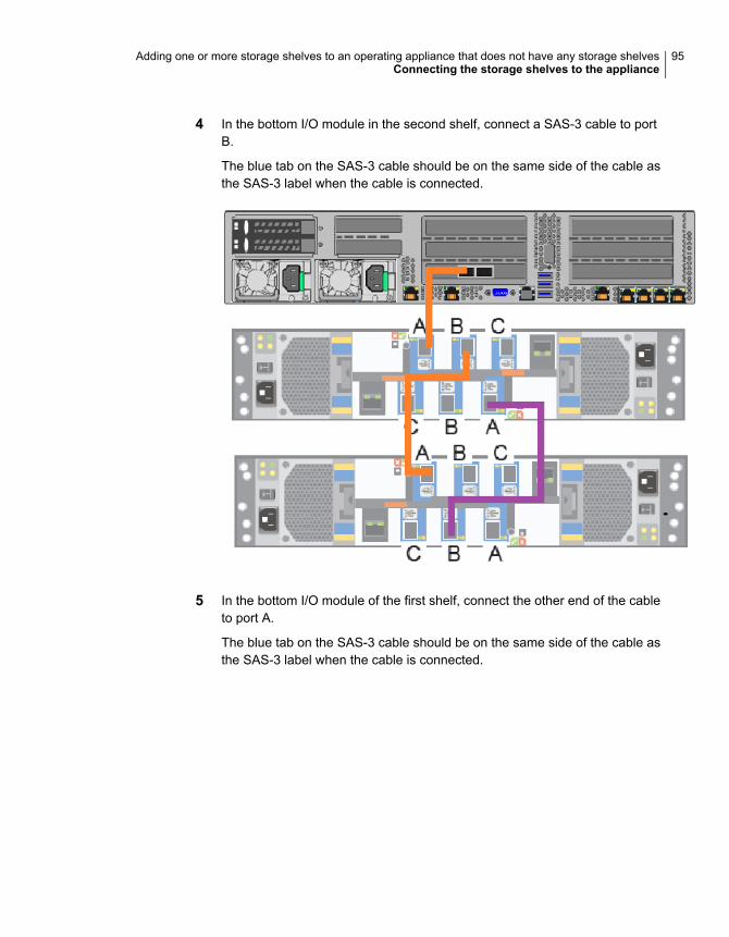
4 In the bottom I/O module in the second shelf, connect a SAS-3 cable to portB.
The blue tab on the SAS-3 cable should be on the same side of the cable asthe SAS-3 label when the cable is connected.
5 In the bottom I/O module of the first shelf, connect the other end of the cableto port A.
The blue tab on the SAS-3 cable should be on the same side of the cable asthe SAS-3 label when the cable is connected.
95Adding one or more storage shelves to an operating appliance that does not have any storage shelvesConnecting the storage shelves to the appliance
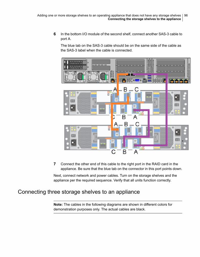
6 In the bottom I/O module of the second shelf, connect another SAS-3 cable toport A.
The blue tab on the SAS-3 cable should be on the same side of the cable asthe SAS-3 label when the cable is connected.
7 Connect the other end of this cable to the right port in the RAID card in theappliance. Be sure that the blue tab on the connector in this port points down.
Next, connect network and power cables. Turn on the storage shelves and theappliance per the required sequence. Verify that all units function correctly.
Connecting three storage shelves to an appliance
Note: The cables in the following diagrams are shown in different colors fordemonstration purposes only. The actual cables are black.
96Adding one or more storage shelves to an operating appliance that does not have any storage shelvesConnecting the storage shelves to the appliance
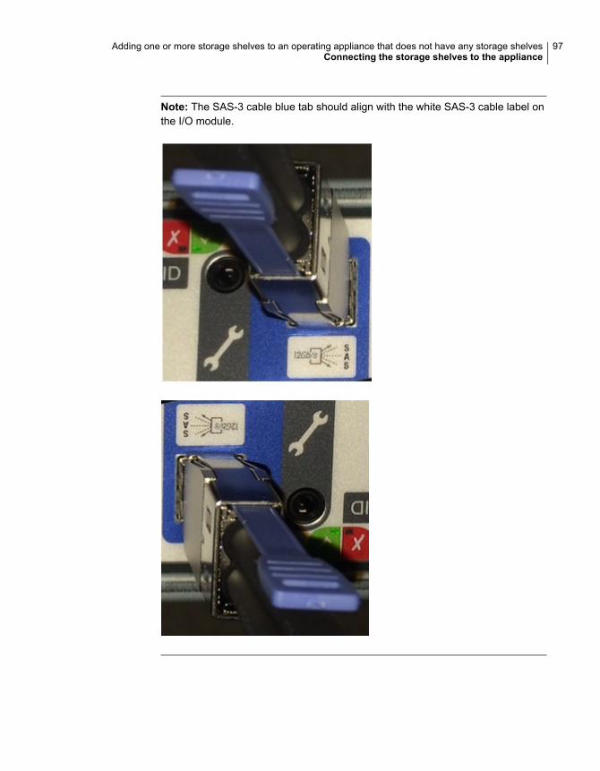
Note: The SAS-3 cable blue tab should align with the white SAS-3 cable label onthe I/O module.
97Adding one or more storage shelves to an operating appliance that does not have any storage shelvesConnecting the storage shelves to the appliance
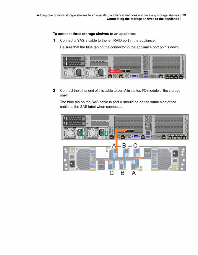
To connect three storage shelves to an appliance
1 Connect a SAS-3 cable to the left RAID port in the appliance.
Be sure that the blue tab on the connector in the appliance port points down.
2 Connect the other end of this cable to port A in the top I/O module of the storageshelf.
The blue tab on the SAS cable in port A should be on the same side of thecable as the SAS label when connected.
98Adding one or more storage shelves to an operating appliance that does not have any storage shelvesConnecting the storage shelves to the appliance

3 Connect another SAS-3 cable to port B in the top I/O module of the first storageshelf. Connect the other end of the cable to port A in the top I/O module in thesecond storage shelf.
The blue tab on the SAS-3 cable should be on the same side of the cable asthe SAS-3 label when the cable is connected.
99Adding one or more storage shelves to an operating appliance that does not have any storage shelvesConnecting the storage shelves to the appliance
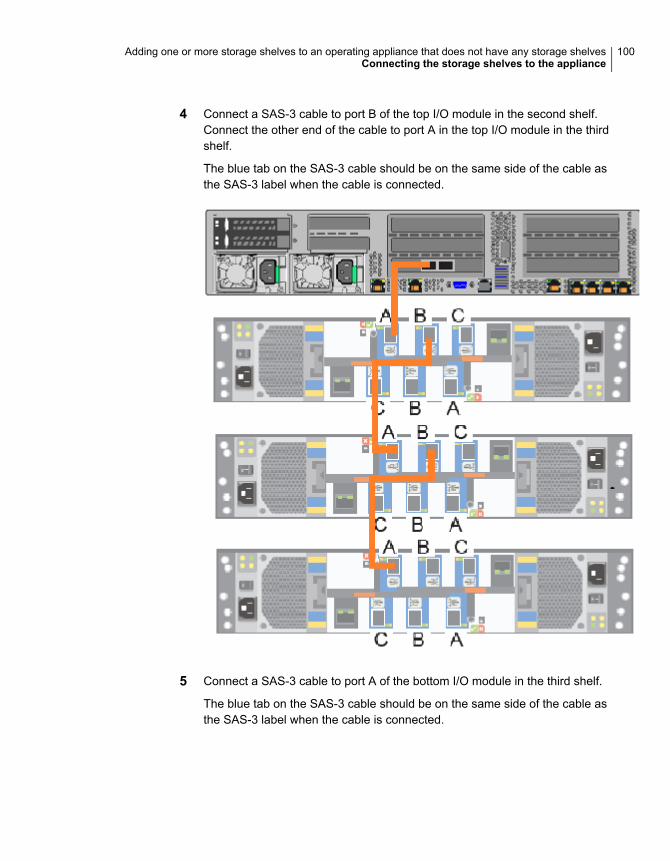
4 Connect a SAS-3 cable to port B of the top I/O module in the second shelf.Connect the other end of the cable to port A in the top I/O module in the thirdshelf.
The blue tab on the SAS-3 cable should be on the same side of the cable asthe SAS-3 label when the cable is connected.
5 Connect a SAS-3 cable to port A of the bottom I/O module in the third shelf.
The blue tab on the SAS-3 cable should be on the same side of the cable asthe SAS-3 label when the cable is connected.
100Adding one or more storage shelves to an operating appliance that does not have any storage shelvesConnecting the storage shelves to the appliance
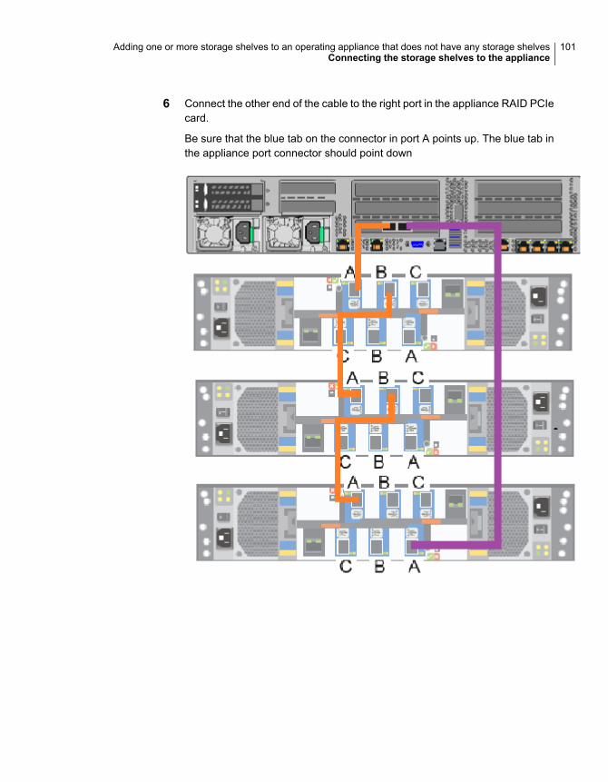
6 Connect the other end of the cable to the right port in the appliance RAID PCIecard.
Be sure that the blue tab on the connector in port A points up. The blue tab inthe appliance port connector should point down
101Adding one or more storage shelves to an operating appliance that does not have any storage shelvesConnecting the storage shelves to the appliance
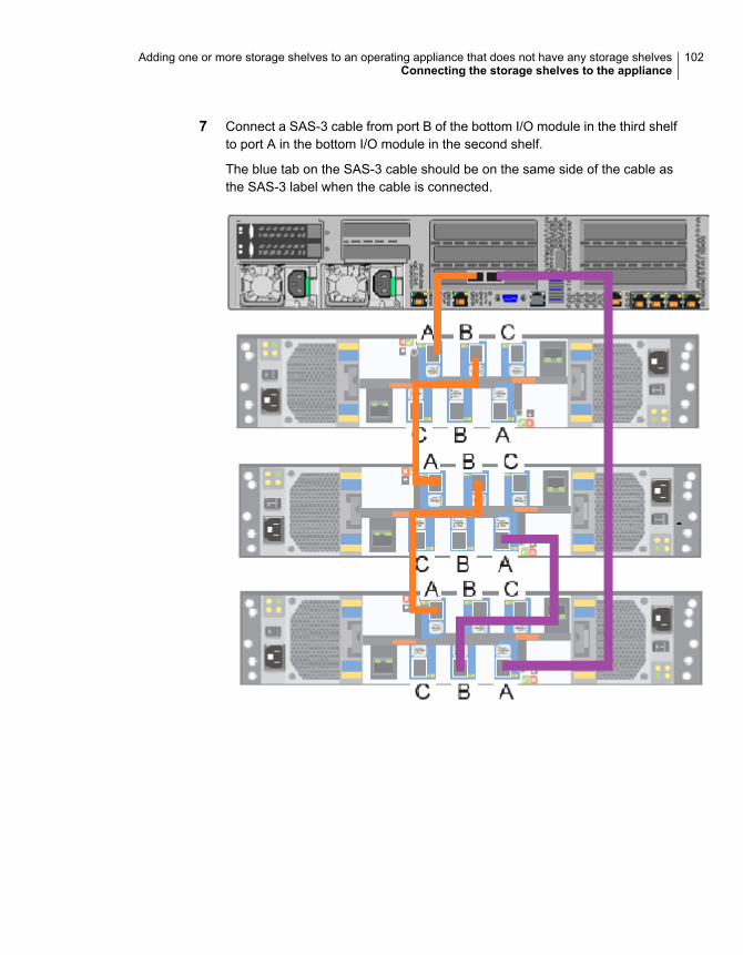
7 Connect a SAS-3 cable from port B of the bottom I/O module in the third shelfto port A in the bottom I/O module in the second shelf.
The blue tab on the SAS-3 cable should be on the same side of the cable asthe SAS-3 label when the cable is connected.
102Adding one or more storage shelves to an operating appliance that does not have any storage shelvesConnecting the storage shelves to the appliance
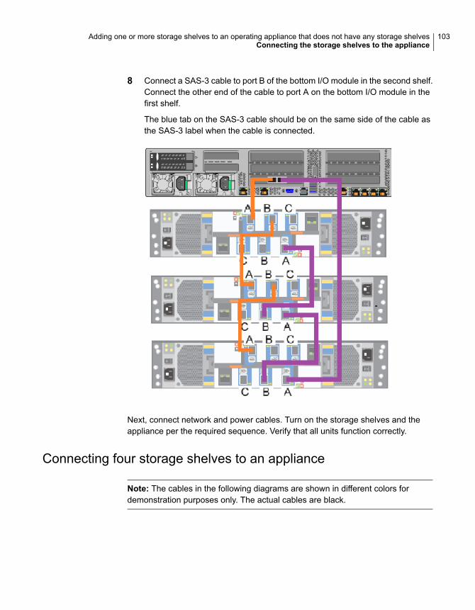
8 Connect a SAS-3 cable to port B of the bottom I/O module in the second shelf.Connect the other end of the cable to port A on the bottom I/O module in thefirst shelf.
The blue tab on the SAS-3 cable should be on the same side of the cable asthe SAS-3 label when the cable is connected.
Next, connect network and power cables. Turn on the storage shelves and theappliance per the required sequence. Verify that all units function correctly.
Connecting four storage shelves to an appliance
Note: The cables in the following diagrams are shown in different colors fordemonstration purposes only. The actual cables are black.
103Adding one or more storage shelves to an operating appliance that does not have any storage shelvesConnecting the storage shelves to the appliance

Note: The SAS-3 cable blue tab should align with the white SAS-3 cable label onthe I/O module.
104Adding one or more storage shelves to an operating appliance that does not have any storage shelvesConnecting the storage shelves to the appliance
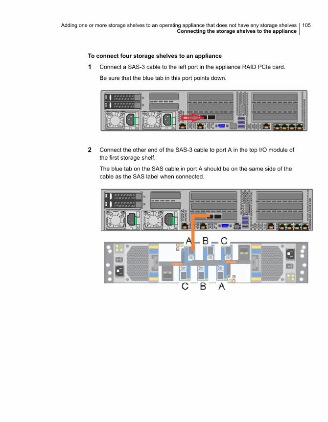
To connect four storage shelves to an appliance
1 Connect a SAS-3 cable to the left port in the appliance RAID PCIe card.
Be sure that the blue tab in this port points down.
2 Connect the other end of the SAS-3 cable to port A in the top I/O module ofthe first storage shelf.
The blue tab on the SAS cable in port A should be on the same side of thecable as the SAS label when connected.
105Adding one or more storage shelves to an operating appliance that does not have any storage shelvesConnecting the storage shelves to the appliance
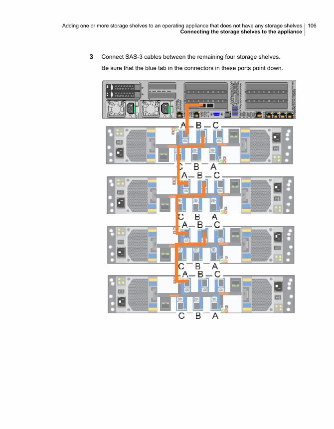
3 Connect SAS-3 cables between the remaining four storage shelves.
Be sure that the blue tab in the connectors in these ports point down.
106Adding one or more storage shelves to an operating appliance that does not have any storage shelvesConnecting the storage shelves to the appliance
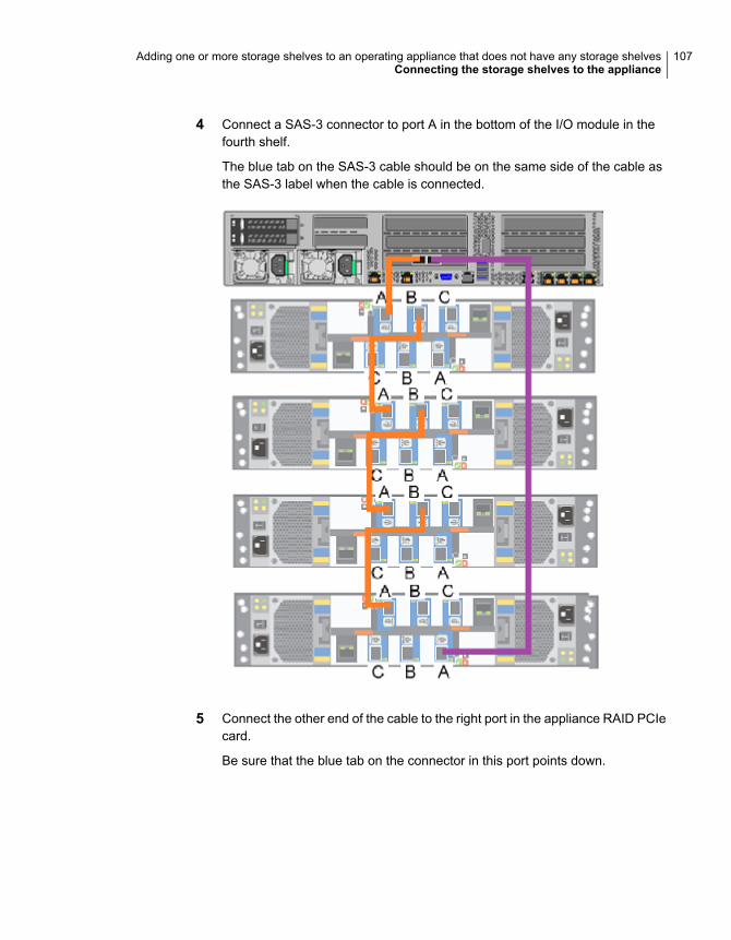
4 Connect a SAS-3 connector to port A in the bottom of the I/O module in thefourth shelf.
The blue tab on the SAS-3 cable should be on the same side of the cable asthe SAS-3 label when the cable is connected.
5 Connect the other end of the cable to the right port in the appliance RAID PCIecard.
Be sure that the blue tab on the connector in this port points down.
107Adding one or more storage shelves to an operating appliance that does not have any storage shelvesConnecting the storage shelves to the appliance
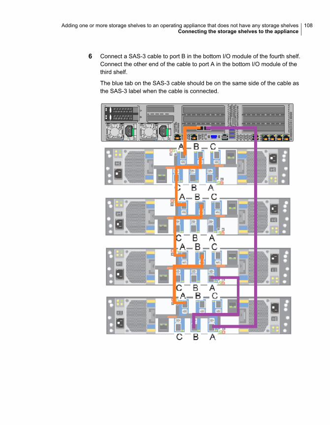
6 Connect a SAS-3 cable to port B in the bottom I/O module of the fourth shelf.Connect the other end of the cable to port A in the bottom I/O module of thethird shelf.
The blue tab on the SAS-3 cable should be on the same side of the cable asthe SAS-3 label when the cable is connected.
108Adding one or more storage shelves to an operating appliance that does not have any storage shelvesConnecting the storage shelves to the appliance
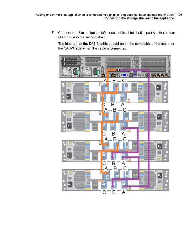
7 Connect port B in the bottom I/O module of the third shelf to port A in the bottomI/O module in the second shelf.
The blue tab on the SAS-3 cable should be on the same side of the cable asthe SAS-3 label when the cable is connected.
109Adding one or more storage shelves to an operating appliance that does not have any storage shelvesConnecting the storage shelves to the appliance
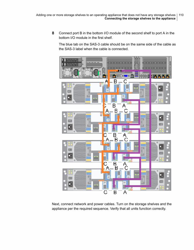
8 Connect port B in the bottom I/O module of the second shelf to port A in thebottom I/O module in the first shelf.
The blue tab on the SAS-3 cable should be on the same side of the cable asthe SAS-3 label when the cable is connected.
Next, connect network and power cables. Turn on the storage shelves and theappliance per the required sequence. Verify that all units function correctly.
110Adding one or more storage shelves to an operating appliance that does not have any storage shelvesConnecting the storage shelves to the appliance

Connecting the fifth storage shelf to an appliance
Note: The cables in the following diagrams are shown in different colors fordemonstration purposes only. The actual cables are black.
111Adding one or more storage shelves to an operating appliance that does not have any storage shelvesConnecting the storage shelves to the appliance

To connect the fifth storage shelves to an appliance
112Adding one or more storage shelves to an operating appliance that does not have any storage shelvesConnecting the storage shelves to the appliance
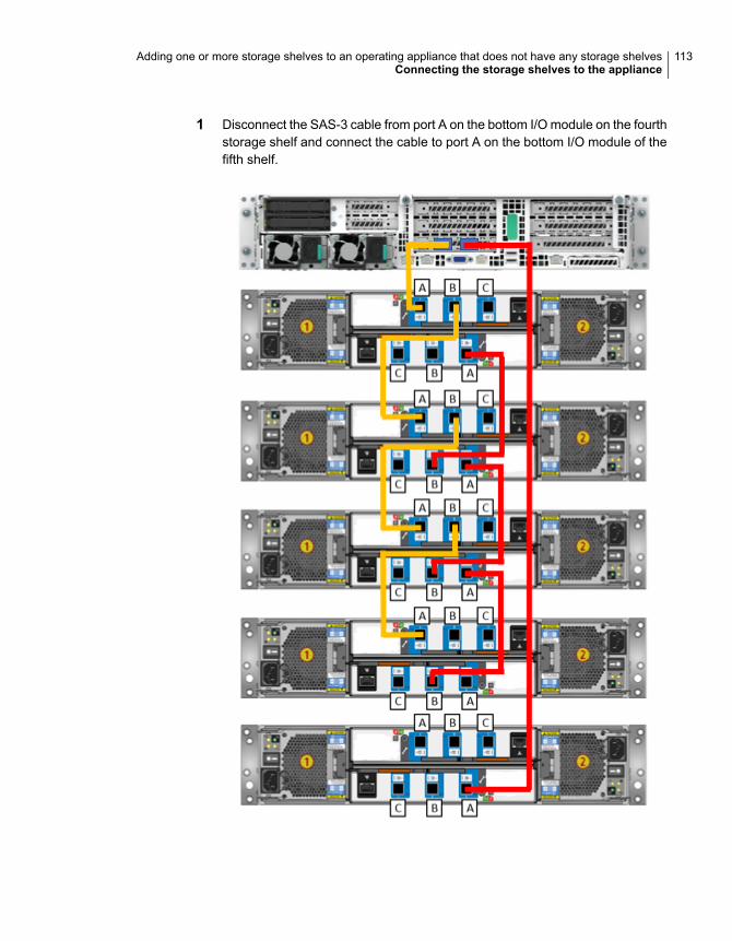
1 Disconnect the SAS-3 cable from port A on the bottom I/O module on the fourthstorage shelf and connect the cable to port A on the bottom I/O module of thefifth shelf.
113Adding one or more storage shelves to an operating appliance that does not have any storage shelvesConnecting the storage shelves to the appliance

The blue tab on the SAS cable in port A should be on the same side of thecable as the SAS label when connected.
114Adding one or more storage shelves to an operating appliance that does not have any storage shelvesConnecting the storage shelves to the appliance
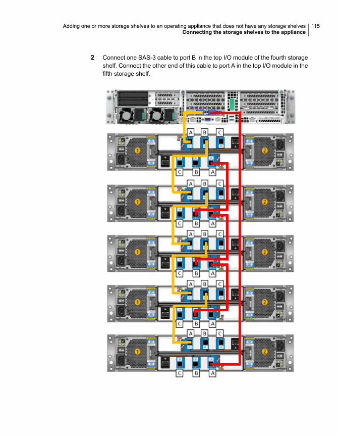
2 Connect one SAS-3 cable to port B in the top I/O module of the fourth storageshelf. Connect the other end of this cable to port A in the top I/O module in thefifth storage shelf.
115Adding one or more storage shelves to an operating appliance that does not have any storage shelvesConnecting the storage shelves to the appliance

The blue tab on the SAS cable in port A and port B should be on the sameside of the cable as the SAS label when connected.
116Adding one or more storage shelves to an operating appliance that does not have any storage shelvesConnecting the storage shelves to the appliance
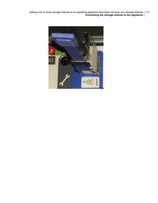
117Adding one or more storage shelves to an operating appliance that does not have any storage shelvesConnecting the storage shelves to the appliance
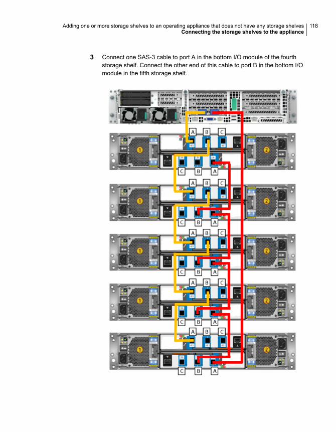
3 Connect one SAS-3 cable to port A in the bottom I/O module of the fourthstorage shelf. Connect the other end of this cable to port B in the bottom I/Omodule in the fifth storage shelf.
118Adding one or more storage shelves to an operating appliance that does not have any storage shelvesConnecting the storage shelves to the appliance
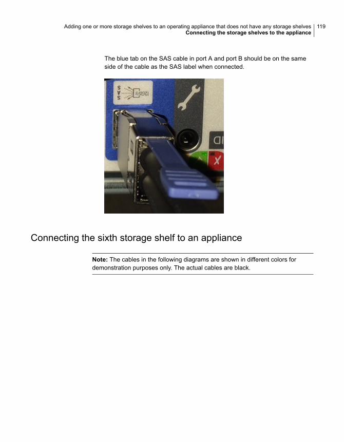
The blue tab on the SAS cable in port A and port B should be on the sameside of the cable as the SAS label when connected.
Connecting the sixth storage shelf to an appliance
Note: The cables in the following diagrams are shown in different colors fordemonstration purposes only. The actual cables are black.
119Adding one or more storage shelves to an operating appliance that does not have any storage shelvesConnecting the storage shelves to the appliance

To connect the sixth storage shelves to an appliance
120Adding one or more storage shelves to an operating appliance that does not have any storage shelvesConnecting the storage shelves to the appliance

1 Disconnect the SAS-3 cable from port A on the bottom I/O module on the fifthstorage shelf and connect the cable to port A on the bottom I/O module of thesixth shelf.
121Adding one or more storage shelves to an operating appliance that does not have any storage shelvesConnecting the storage shelves to the appliance
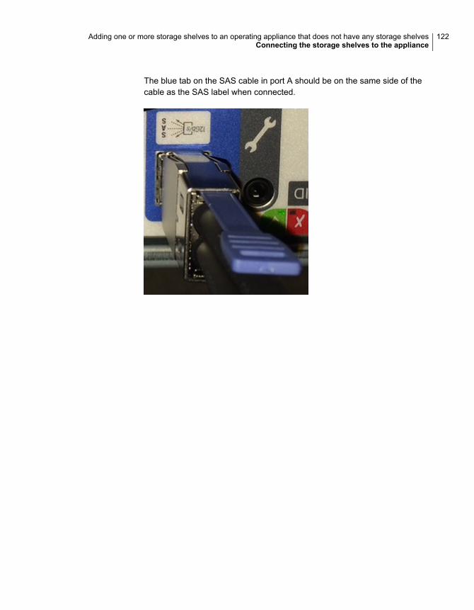
The blue tab on the SAS cable in port A should be on the same side of thecable as the SAS label when connected.
122Adding one or more storage shelves to an operating appliance that does not have any storage shelvesConnecting the storage shelves to the appliance

2 Connect one SAS-3 cable to port B in the top I/O module of the fifth storageshelf. Connect the other end of this cable to port A in the top I/O module in thesixth storage shelf.
123Adding one or more storage shelves to an operating appliance that does not have any storage shelvesConnecting the storage shelves to the appliance
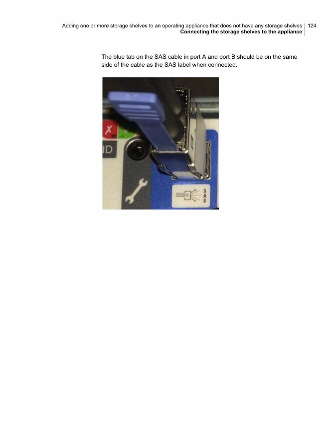
The blue tab on the SAS cable in port A and port B should be on the sameside of the cable as the SAS label when connected.
124Adding one or more storage shelves to an operating appliance that does not have any storage shelvesConnecting the storage shelves to the appliance

3 Connect one SAS-3 cable to port A in the bottom I/O module of the fifth storageshelf. Connect the other end of this cable to port B in the bottom I/O modulein the sixth storage shelf.
125Adding one or more storage shelves to an operating appliance that does not have any storage shelvesConnecting the storage shelves to the appliance
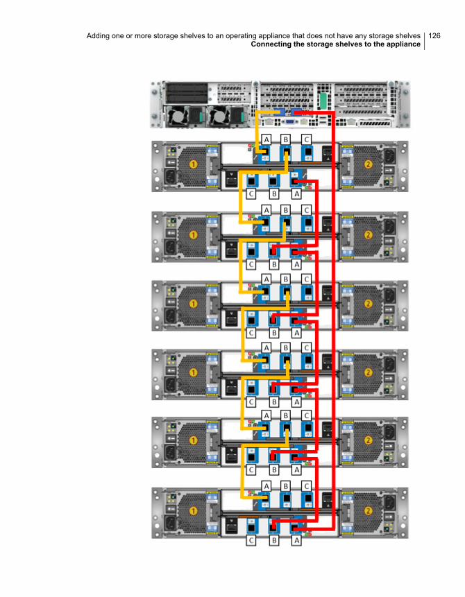
126Adding one or more storage shelves to an operating appliance that does not have any storage shelvesConnecting the storage shelves to the appliance
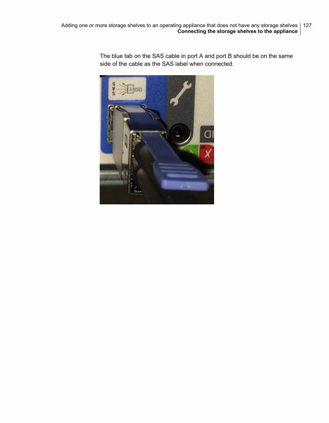
The blue tab on the SAS cable in port A and port B should be on the sameside of the cable as the SAS label when connected.
127Adding one or more storage shelves to an operating appliance that does not have any storage shelvesConnecting the storage shelves to the appliance
Adding storage shelves toan operating appliancethat has at least onestorage shelf attached
This appendix includes the following topics:
■ Overview
■ Moving the MSDP partition from a base disk to an expansion disk for optimumperformance
■ Additional storage shelf scenarios
■ Installing storage shelves to an appliance that has at least one storage shelf
■ Recabling to connect additional shelves
OverviewThe 5250 Appliance operates with up to six external storage shelves. If yourappliance has at least one storage shelf that is connected and running properly youcan add more shelves for a total of six shelves.
Existing 5250 Appliances with internal storage capacities of 9.1TiB and 36.4TiBsupport up to six Veritas 2U12 65.5TiB/72TB Storage Shelves.
Before you place the system into a production environment, you must migrate allMSDP data from the appliance to the first external storage shelf. After you migrate
BAppendix
the MSDP data, the amount of usable storage space may fluctuate, depending onhow much storage space the MSDP data pool presently uses.
See “Moving the MSDP partition from a base disk to an expansion disk for optimumperformance” on page 129.
Spanning MSDP data across a 5250 Appliance and a storage shelf is notrecommended.
More information about Migration Utilities is available in the NetBackup ApplianceAdministrator's Guide at the following site.
NetBackup Appliance Documentation
Moving the MSDP partition from a base disk to anexpansion disk for optimum performance
The following procedures explain how to move the MSDP partition from a base diskto an expansion disk. The base disk resides on the appliance base unit. Theexpansion disk resides on a storage shelf that is attached to the appliance.
Consider the following scenarios:
■ Scenario 1 - The MSDP and AdvancedDisk partitions are configured on thebase disk. The expansion units are physically attached to the appliance buthave not been added yet.
■ Scenario 2 - The MSDP partition exists on the base disk. The expansion unitsare configured and partitions exist on them.
Select the scenario that applies to you and follow the appropriate procedure outlinedbelow.
129Adding storage shelves to an operating appliance that has at least one storage shelf attachedMoving the MSDP partition from a base disk to an expansion disk for optimum performance
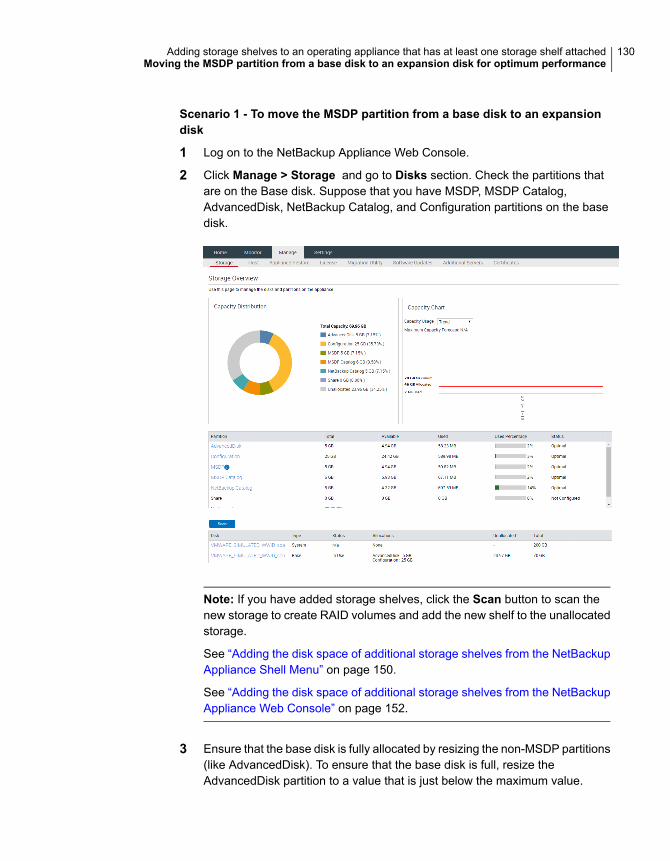
Scenario 1 - To move the MSDP partition from a base disk to an expansiondisk
1 Log on to the NetBackup Appliance Web Console.
2 Click Manage > Storage and go to Disks section. Check the partitions thatare on the Base disk. Suppose that you have MSDP, MSDP Catalog,AdvancedDisk, NetBackup Catalog, and Configuration partitions on the basedisk.
Note: If you have added storage shelves, click the Scan button to scan thenew storage to create RAID volumes and add the new shelf to the unallocatedstorage.
See “Adding the disk space of additional storage shelves from the NetBackupAppliance Shell Menu” on page 150.
See “Adding the disk space of additional storage shelves from the NetBackupAppliance Web Console” on page 152.
3 Ensure that the base disk is fully allocated by resizing the non-MSDP partitions(like AdvancedDisk). To ensure that the base disk is full, resize theAdvancedDisk partition to a value that is just below the maximum value.
130Adding storage shelves to an operating appliance that has at least one storage shelf attachedMoving the MSDP partition from a base disk to an expansion disk for optimum performance
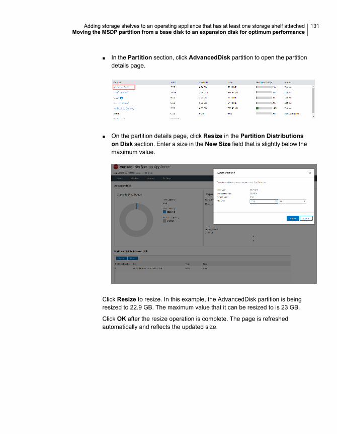
■ In the Partition section, click AdvancedDisk partition to open the partitiondetails page.
■ On the partition details page, click Resize in the Partition Distributionson Disk section. Enter a size in the New Size field that is slightly below themaximum value.
Click Resize to resize. In this example, the AdvancedDisk partition is beingresized to 22.9 GB. The maximum value that it can be resized to is 23 GB.
Click OK after the resize operation is complete. The page is refreshedautomatically and reflects the updated size.
131Adding storage shelves to an operating appliance that has at least one storage shelf attachedMoving the MSDP partition from a base disk to an expansion disk for optimum performance
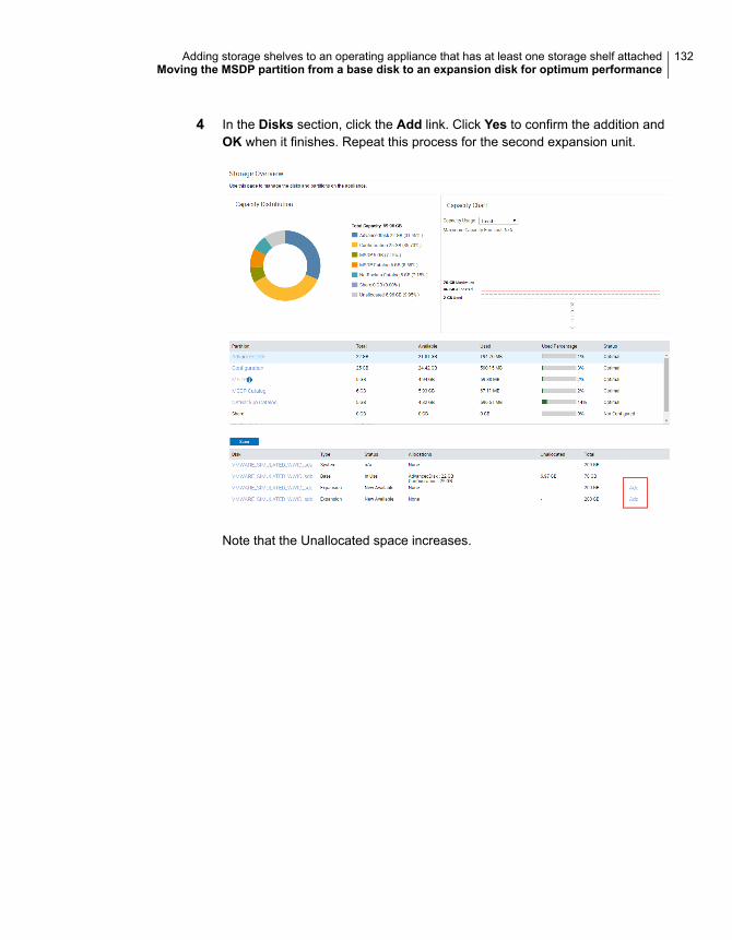
4 In the Disks section, click the Add link. Click Yes to confirm the addition andOK when it finishes. Repeat this process for the second expansion unit.
Note that the Unallocated space increases.
132Adding storage shelves to an operating appliance that has at least one storage shelf attachedMoving the MSDP partition from a base disk to an expansion disk for optimum performance
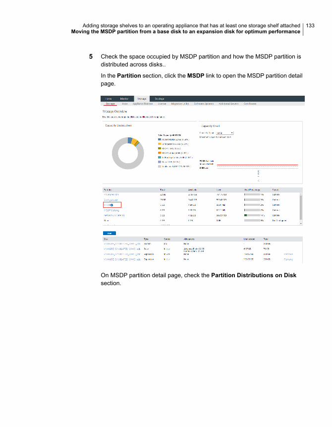
5 Check the space occupied by MSDP partition and how the MSDP partition isdistributed across disks..
In the Partition section, click the MSDP link to open the MSDP partition detailpage.
On MSDP partition detail page, check the Partition Distributions on Disksection.
133Adding storage shelves to an operating appliance that has at least one storage shelf attachedMoving the MSDP partition from a base disk to an expansion disk for optimum performance
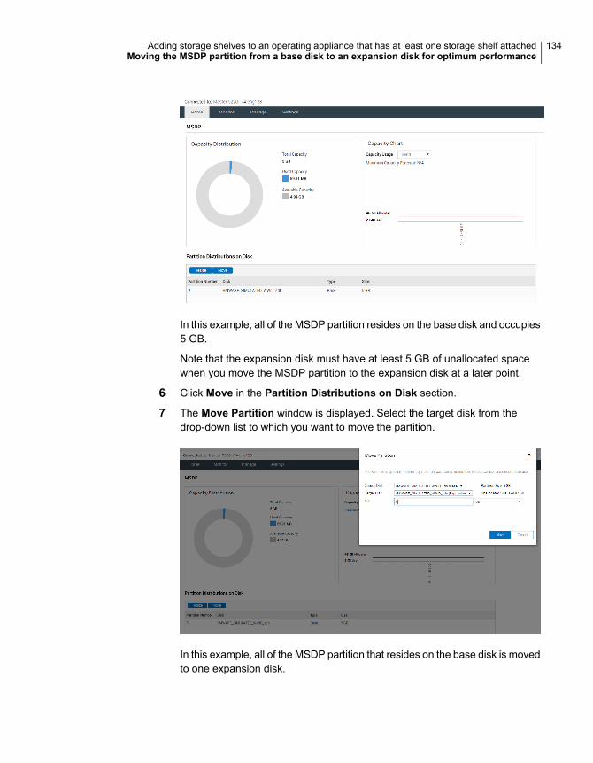
In this example, all of the MSDP partition resides on the base disk and occupies5 GB.
Note that the expansion disk must have at least 5 GB of unallocated spacewhen you move the MSDP partition to the expansion disk at a later point.
6 Click Move in the Partition Distributions on Disk section.
7 The Move Partition window is displayed. Select the target disk from thedrop-down list to which you want to move the partition.
In this example, all of the MSDP partition that resides on the base disk is movedto one expansion disk.
134Adding storage shelves to an operating appliance that has at least one storage shelf attachedMoving the MSDP partition from a base disk to an expansion disk for optimum performance
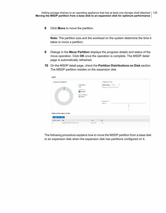
8 Click Move to move the partition.
Note: The partition size and the workload on the system determine the time ittakes to move a partition.
9 Dialogs in the Move Partition displays the progress details and status of themove operation. Click OK once the operation is complete. The MSDP detailpage is automatically refreshed.
10 On the MSDP detail page, check the Partition Distributions on Disk section.The MSDP partition resides on the expansion disk.
The following procedure explains how to move the MSDP partition from a base diskto an expansion disk when the expansion disk has partitions configured on it.
135Adding storage shelves to an operating appliance that has at least one storage shelf attachedMoving the MSDP partition from a base disk to an expansion disk for optimum performance
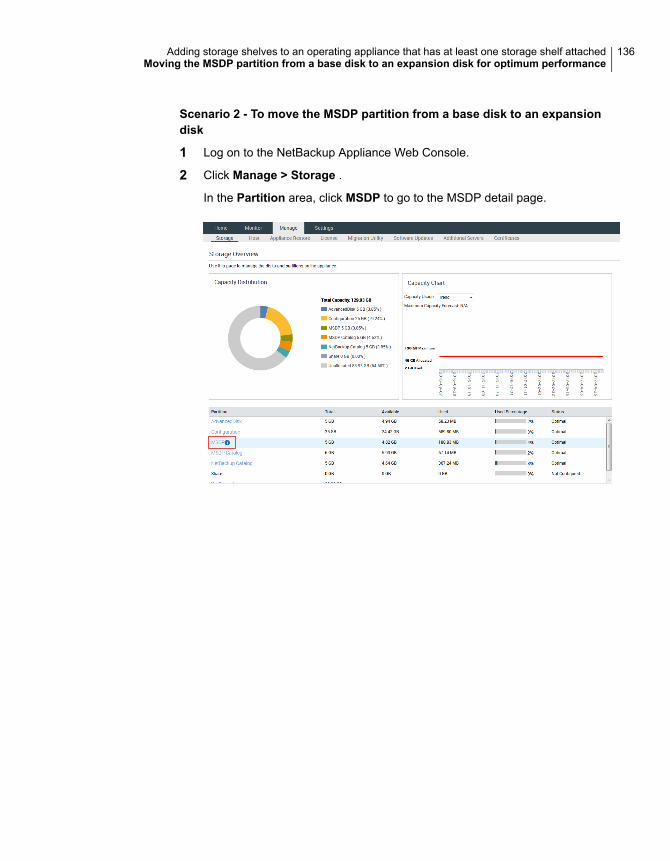
Scenario 2 - To move the MSDP partition from a base disk to an expansiondisk
1 Log on to the NetBackup Appliance Web Console.
2 Click Manage > Storage .
In the Partition area, click MSDP to go to the MSDP detail page.
136Adding storage shelves to an operating appliance that has at least one storage shelf attachedMoving the MSDP partition from a base disk to an expansion disk for optimum performance
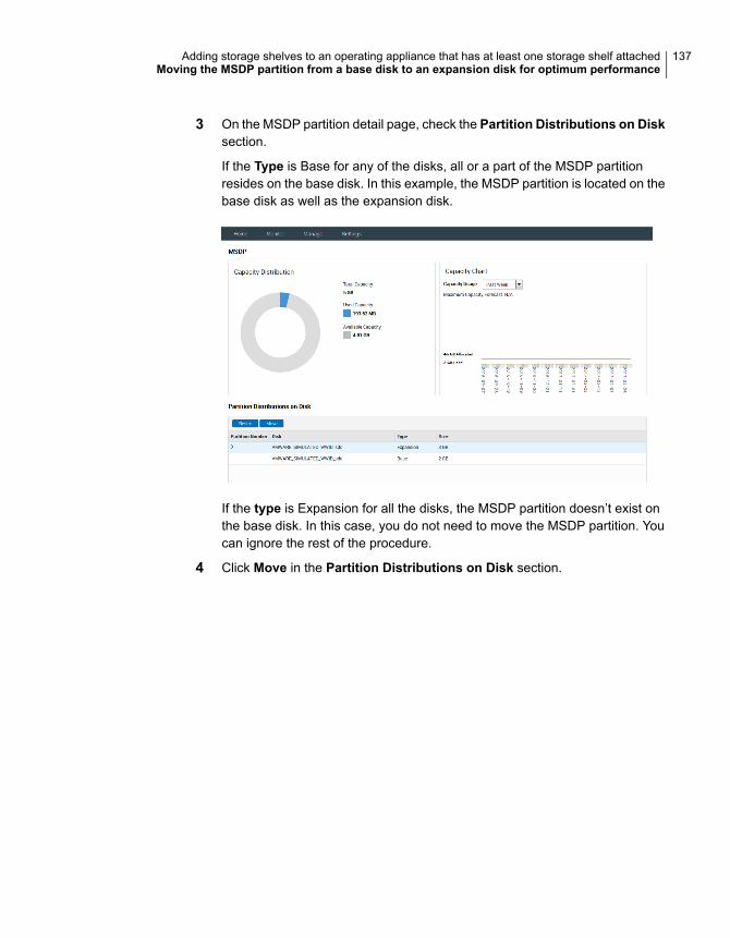
3 On the MSDP partition detail page, check the Partition Distributions on Disksection.
If the Type is Base for any of the disks, all or a part of the MSDP partitionresides on the base disk. In this example, the MSDP partition is located on thebase disk as well as the expansion disk.
If the type is Expansion for all the disks, the MSDP partition doesn’t exist onthe base disk. In this case, you do not need to move the MSDP partition. Youcan ignore the rest of the procedure.
4 Click Move in the Partition Distributions on Disk section.
137Adding storage shelves to an operating appliance that has at least one storage shelf attachedMoving the MSDP partition from a base disk to an expansion disk for optimum performance
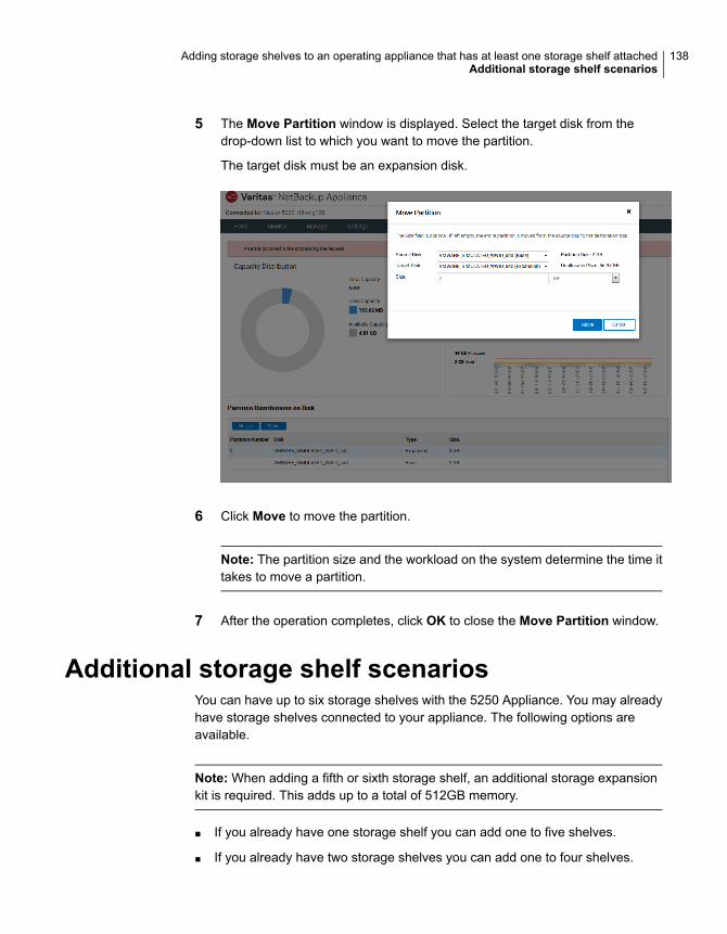
5 The Move Partition window is displayed. Select the target disk from thedrop-down list to which you want to move the partition.
The target disk must be an expansion disk.
6 Click Move to move the partition.
Note: The partition size and the workload on the system determine the time ittakes to move a partition.
7 After the operation completes, click OK to close the Move Partition window.
Additional storage shelf scenariosYou can have up to six storage shelves with the 5250 Appliance. You may alreadyhave storage shelves connected to your appliance. The following options areavailable.
Note: When adding a fifth or sixth storage shelf, an additional storage expansionkit is required. This adds up to a total of 512GB memory.
■ If you already have one storage shelf you can add one to five shelves.
■ If you already have two storage shelves you can add one to four shelves.
138Adding storage shelves to an operating appliance that has at least one storage shelf attachedAdditional storage shelf scenarios
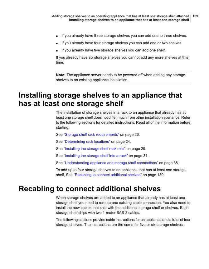
■ If you already have three storage shelves you can add one to three shelves.
■ If you already have four storage shelves you can add one or two shelves.
■ If you already have five storage shelves you can add one shelf.
If you already have six storage shelves you cannot add any more shelves at thistime.
Note: The appliance server needs to be powered off when adding any storageshelves to an existing appliance installation.
Installing storage shelves to an appliance thathas at least one storage shelf
The installation of storage shelves in a rack to an appliance that already has atleast one storage shelf does not differ much from other installation scenarios. Referto the following sections for detailed instructions. Read all of the information beforestarting.
See “Storage shelf rack requirements” on page 26.
See “Determining rack locations” on page 24.
See “Installing the storage shelf rack rails” on page 29.
See “Installing the storage shelf into a rack” on page 31.
See “Understanding appliance and storage shelf connections” on page 38.
To add up to four storage shelves to an appliance that has at least one storageshelf, See “Recabling to connect additional shelves” on page 139.
Recabling to connect additional shelvesWhen storage shelves are added to an appliance that already has at least onestorage shelf you need to reroute one existing cable connection. You also need toinstall the new cables that ship with the additional storage shelf or shelves. Eachstorage shelf ships with two 1-meter SAS-3 cables.
The following sections provide cable instructions for an appliance and a total of fourstorage shelves. The instructions are the same for five or six storage shelves.
139Adding storage shelves to an operating appliance that has at least one storage shelf attachedInstalling storage shelves to an appliance that has at least one storage shelf
Note: The cables in the following diagrams are shown in different colors fordemonstration purposes only. The actual cables are black.
A green box outlines the storage shelves that are added to the existing devices.
See “Connecting additional shelves to an appliance that already has one operatingshelf” on page 141.
See “Connecting additional shelves to an appliance that already has two operatingshelves” on page 144.
See “Connecting a storage shelf to an appliance that already has three operatingshelves” on page 147.
Refer to one of the following sections to add the additional disk space.
See “Adding the disk space of additional storage shelves from the NetBackupAppliance Shell Menu” on page 150.
See “Adding the disk space of additional storage shelves from the NetBackupAppliance Web Console” on page 152.
140Adding storage shelves to an operating appliance that has at least one storage shelf attachedRecabling to connect additional shelves
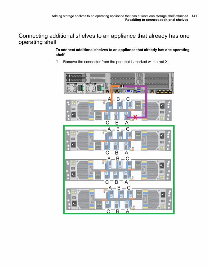
Connecting additional shelves to an appliance that already has oneoperating shelf
To connect additional shelves to an appliance that already has one operatingshelf
1 Remove the connector from the port that is marked with a red X.
141Adding storage shelves to an operating appliance that has at least one storage shelf attachedRecabling to connect additional shelves
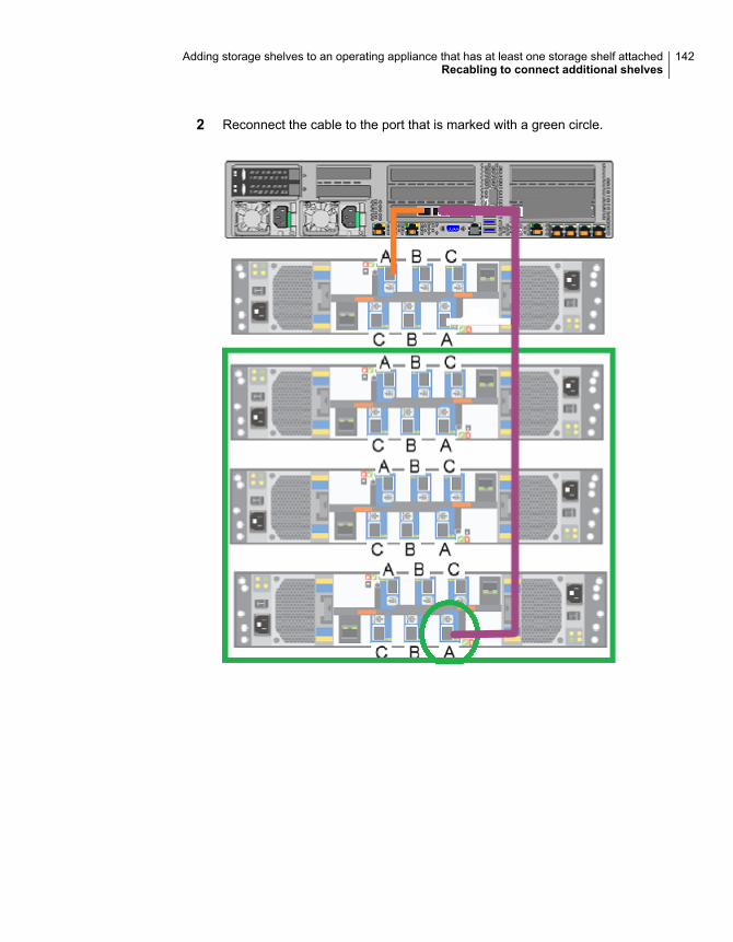
2 Reconnect the cable to the port that is marked with a green circle.
142Adding storage shelves to an operating appliance that has at least one storage shelf attachedRecabling to connect additional shelves
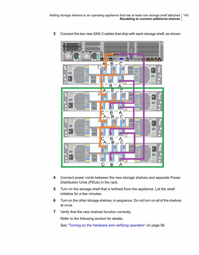
3 Connect the two new SAS-3 cables that ship with each storage shelf, as shown.
4 Connect power cords between the new storage shelves and separate PowerDistribution Units (PDUs) in the rack.
5 Turn on the storage shelf that is farthest from the appliance. Let the shelfinitialize for a few minutes.
6 Turn on the other storage shelves, in sequence. Do not turn on all of the shelvesat once.
7 Verify that the new shelves function correctly.
Refer to the following section for details.
See “Turning on the hardware and verifying operation” on page 56.
143Adding storage shelves to an operating appliance that has at least one storage shelf attachedRecabling to connect additional shelves
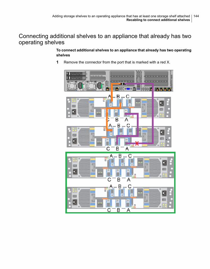
Connecting additional shelves to an appliance that already has twooperating shelves
To connect additional shelves to an appliance that already has two operatingshelves
1 Remove the connector from the port that is marked with a red X.
144Adding storage shelves to an operating appliance that has at least one storage shelf attachedRecabling to connect additional shelves
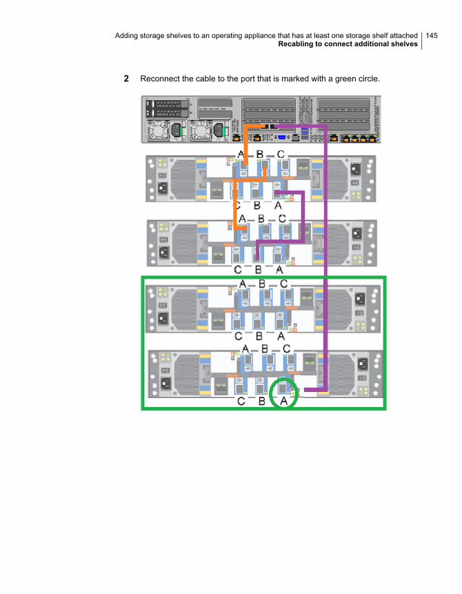
2 Reconnect the cable to the port that is marked with a green circle.
145Adding storage shelves to an operating appliance that has at least one storage shelf attachedRecabling to connect additional shelves
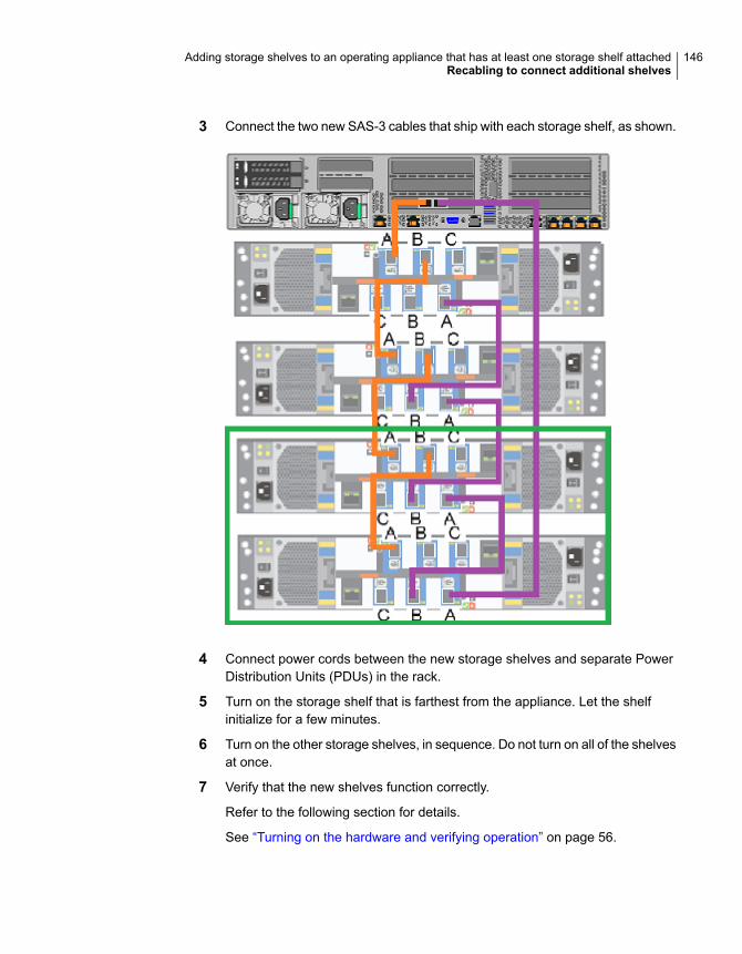
3 Connect the two new SAS-3 cables that ship with each storage shelf, as shown.
4 Connect power cords between the new storage shelves and separate PowerDistribution Units (PDUs) in the rack.
5 Turn on the storage shelf that is farthest from the appliance. Let the shelfinitialize for a few minutes.
6 Turn on the other storage shelves, in sequence. Do not turn on all of the shelvesat once.
7 Verify that the new shelves function correctly.
Refer to the following section for details.
See “Turning on the hardware and verifying operation” on page 56.
146Adding storage shelves to an operating appliance that has at least one storage shelf attachedRecabling to connect additional shelves
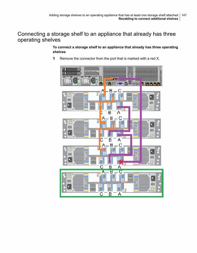
Connecting a storage shelf to an appliance that already has threeoperating shelves
To connect a storage shelf to an appliance that already has three operatingshelves
1 Remove the connector from the port that is marked with a red X.
147Adding storage shelves to an operating appliance that has at least one storage shelf attachedRecabling to connect additional shelves
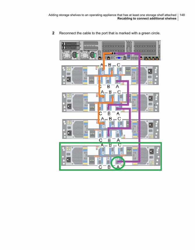
2 Reconnect the cable to the port that is marked with a green circle.
148Adding storage shelves to an operating appliance that has at least one storage shelf attachedRecabling to connect additional shelves
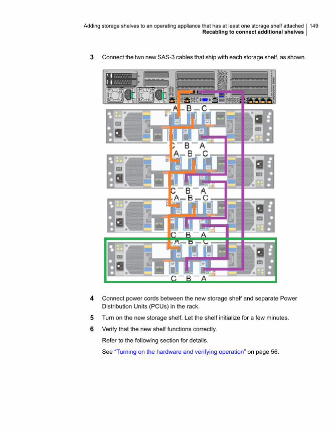
3 Connect the two new SAS-3 cables that ship with each storage shelf, as shown.
4 Connect power cords between the new storage shelf and separate PowerDistribution Units (PCUs) in the rack.
5 Turn on the new storage shelf. Let the shelf initialize for a few minutes.
6 Verify that the new shelf functions correctly.
Refer to the following section for details.
See “Turning on the hardware and verifying operation” on page 56.
149Adding storage shelves to an operating appliance that has at least one storage shelf attachedRecabling to connect additional shelves

Configuring the disk spacefor new NetBackupExpansion StorageShelves
This appendix includes the following topics:
■ Adding the disk space of additional storage shelves from the NetBackupAppliance Shell Menu
■ Adding the disk space of additional storage shelves from the NetBackupAppliance Web Console
Adding the disk space of additional storageshelves from theNetBackupApplianceShell Menu
The following procedure describes how to add new storage shelf disk space to aNetBackup appliance using the NetBackup Appliance Shell Menu.
CAppendix
To add new storage shelf disk space to a NetBackup appliance using theNetBackup Appliance Shell Menu
1 Use PuTTY to start an SSH session to access the NetBackup Appliance ShellMenu.
Note: You can also connect a laptop, keyboard and monitor, or KVM to theappliance to access the NetBackup Appliance Shell Menu.
2 Log on to the NetBackup Appliance Shell Menu. The Main_Menu promptappears.
3 Go to the Monitor view as follows:
Type Monitor and press Enter.
4 Type Hardware ShowHealth and press Enter. Verify that the new storagedevices appear. If the new storage devices do not appear, check the cableconnections and make sure that the power is on.
5 At the prompt, type return to return to the Main menu.
6 Perform a scan as follows:
■ At the Main_Menu prompt, enter Manage and press Enter.
■ Enter Storage and press Enter.
■ Enter Scan and press Enter.
The scan takes a couple of minutes to complete.
7 Navigate to the Storage view.
From the Storage menu, enter Add and press Enter. It displays the disks thatare in a New Available state and can be added. Copy a disk ID that isdisplayed.
8 At the prompt, enter add < disk ID > and press Enter. < disk ID > is the diskID that you copied. Repeat step 7 and 8 to add each disk ID that is displayed.
9 View the available storage space as follows:
■ Navigate to the Storage menu.
■ At the prompt, enter Show Disk and press Enter. The status of the newlyadded disks is displayed as In Use and space in the Unallocated columnis the disk space available for the new disk.
151Configuring the disk space for new NetBackup Expansion Storage ShelvesAdding the disk space of additional storage shelves from the NetBackup Appliance Shell Menu

Adding the disk space of additional storageshelves from the NetBackup Appliance WebConsole
The following procedure describes how to add new storage shelf disk space to aNetBackup appliance using the NetBackup Appliance Web Console.
To add new storage shelf disk space to a NetBackup appliance using theNetBackup Appliance Web Console
1 Launch the NetBackup Appliance Web Console and verify that the new storagedevices appear on the Monitor > Hardware page. If the new storage devicesdo not appear, check the cable connections and make sure that the power ison.
2 Click Manage > Storage.
3 Select the Disks tab.
4 Click the Click here to scan for new disks option.
5 In the Do you want to scan for new disk? dialog box, click OK to start thescan.
6 When the scan is complete, click OK to refresh the Disk tab.
In the Disk column, a new ID should appear for the new storage shelf units.The new entries should have the following attributes:
■ Type = Expansion.
■ Status = New Available
7 In the Status column, next to New Available, click Add to activate the storagein the RAID.
8 In the Confirmation dialog box, click Yes to start a scan.
When the process completes, the following message should appear:
Storage operation completed. Succeeded.
9 Click OK to refresh the system.
After the system refreshes, the Disks tab should show the following attributesfor the new storage shelf units:
■ Type = Expansion
■ Status = In Use
■ Unallocated = n TB
152Configuring the disk space for new NetBackup Expansion Storage ShelvesAdding the disk space of additional storage shelves from the NetBackup Appliance Web Console

Where n is the usable volume or disk space available in the new storageshelf.
153Configuring the disk space for new NetBackup Expansion Storage ShelvesAdding the disk space of additional storage shelves from the NetBackup Appliance Web Console
Configuring the disk spacefor new Flex ExpansionStorage Shelves
This appendix includes the following topics:
■ Adding the disk space of an Expansion Storage Shelf from the Flex ApplianceConsole
Adding the disk space of an Expansion StorageShelf from the Flex Appliance Console
Follow the steps in this section to add storage disk space to an appliance afterphysically adding one or more Expansion Shelves.
Note: When you configure additional disk space, any current backup operationsare stopped until the process is complete. Veritas recommends that you do notstart any backup operations before starting this procedure.
To configure additional disk space
1 Turn on the new shelf or shelves.
2 Sign in to the Flex Appliance Console.
3 Go to the System topology page.
DAppendix
4 Click on Add storage.
5 A confirmation window appears. Click Yes.
You can monitor the progress from the Activity Monitor.
Note: In a multi-node appliance, two tasks are shown in the Activity Monitor.
A task to add new storage displays for the first node, and a task to scan newstorage displays for the second node. The task for the second node runs afterthe first node's tasks are complete.
155Configuring the disk space for new Flex Expansion Storage ShelvesAdding the disk space of an Expansion Storage Shelf from the Flex Appliance Console
Aabout
appliance 7customer-provided environment 21network cables 54SAS-3 cables 18
add disk space of additional storage shelffrom NetBackup Appliance Shell Menu 150from NetBackup Appliance Web Console 152
adding storage shelvesoverview 77, 128
additional storage shelfconnecting 141, 144, 147
airflow 27Appliance
control panel 9system Status LED indicator 11
applianceabout 7cables 18cabling
more than one storage shelf 42network ports 54one storage shelf 41power cords 55six storage shelves 52
connectingmore than one storage shelf 42one storage shelf 41
connecting four storage shelves 103connecting one storage shelf 88connecting storage shelf 88connecting the fifth storage shelf 111connecting the sixth storage shelf 119connecting three storage shelves 96connecting two storage shelves 91connections 38control panel
Power button LED states 14system status LED location 11
disk drive slots 8
appliance (continued)disk drives 8eth0/NIC1 IP address 54ethernet ports, bonding 54installing into a rack 37power button LED 15rack locations 24rack rail installation 33RAID ports 39rails
blue latch 38extending intermediate section 37
rear panel 15–16remote management port IP address 65removing the cover 80, 87replacing DIMMs 81shipping container contents 22soft shutdown 79storage shelf addition scenarios 138storage shelf installation 139turning on the hardware 56
Bbest practices
heat dissipation 27internal chassis access 79rack installation 23
Ccabling
scheme 18six storage shelves 52verifying SAS-3 length 27
configureIPMI 65
Control panelAppliance
system LED descriptions 9appliance
power button LED states 14
Index
control panelstorage shelf 17
Ddisk drives
about 8documentation 20
Hheat dissipation 27
Iinstalling
appliance into a rack 37appliance rack rails 33expansion storage kit 81storage shelf into a rack 31storage shelf rack rails 29
IP addresseth0/NIC1 port 54remote management port 65
IPMI configuration 65about 19with laptop 68
LLED descriptions
appliancesystem status 11
MMSDP
migrating data from an appliance to a storageshelf 128
spanning 129
OOpen Me First container
appliance 22storage shelf 23
Ppower button LED
appliance 15descriptions 15
Power button LED statesappliance
control panel 14
Rrack cabinet requirements 21rear panel
appliance 15storage shelf 18
recablingstorage shelf connections 139
SSAS-3 cables
blue tab orientation 40description 38using 27
Status LED indicatorappliance control panel 11
storage shelfbezel installation 32connecting 88connections 38control panel 17disk drive
lock 17slots 16
installing into a rack 31rails 30rear panel 18recabling 139SAS-3 ports
blue tab orientation 40location 39
shipping container contents 23six shelf cabling 52
storage shelf bezelstorage shelf rack rail
installation 29system status
applianceLED descriptions 11
system status LED locationappliance
control panel 11
157Index

VVeritas Remote Management Interface
configuration 70Veritas Remote Management interface
accessing 74
158Index