verification of the performance accuracy of a real-time skin-dose tracking system for interventional...
TRANSCRIPT
Verification of the performance accuracy of a real-time skin-dosetracking system for interventional fluoroscopic procedures
Daniel R. Bednarek*, Jeffery Barbarits, Vijay K. Rana, Srikanta P. Nagaraja, Madhur S.Josan, and Stephen RudinUniversity at Buffalo (State University of New York), Toshiba Stroke Research Center, 3435 MainSt., Buffalo, NY USA 14214
AbstractA tracking system has been developed to provide real-time feedback of skin dose and dose rateduring interventional fluoroscopic procedures. The dose tracking system (DTS) calculates theradiation dose rate to the patient’s skin using the exposure technique parameters and exposuregeometry obtained from the x-ray imaging system digital network (Toshiba Infinix) and presentsthe cumulative results in a color mapping on a 3D graphic of the patient. We performed a numberof tests to verify the accuracy of the dose representation of this system. These tests includedcomparison of system–calculated dose-rate values with ionization-chamber (6 cc PTW) measuredvalues with change in kVp, beam filter, field size, source-to-skin distance and beam angulation. Tosimulate a cardiac catheterization procedure, the ionization chamber was also placed at variouspositions on an Alderson Rando torso phantom and the dose agreement compared for a range ofprojection angles with the heart at isocenter. To assess the accuracy of the dose distributionrepresentation, Gafchromic film (XR-RV3, ISP) was exposed with the beam at different locations.The DTS and film distributions were compared and excellent visual agreement was obtainedwithin the cm-sized surface elements used for the patient graphic. The dose (rate) values agreedwithin about 10% for the range of variables tested. Correction factors could be applied to obtaineven closer agreement since the variable values are known in real-time. The DTS provides skin-dose values and dose mapping with sufficient accuracy for use in monitoring diagnostic andinterventional x-ray procedures.
Keywordsskin dose; dosimetry; radiation safety; cardiac fluoroscopic procedures; fluoroscopic dose; dosetracking; real-time dosimetry; fluoroscopic interventional procedures
1. INTRODUCTIONInterventional fluoroscopic procedures involve both stochastic and deterministic radiationrisk to the patient. The deterministic effect of concern for most procedures is damage to theskin since this is the organ receiving the highest radiation dose, being at the entrance surfaceof the patient. There have been numerous reports of patient injury which has includederythema, epilation, telangiactasia and necrosis.1-4 These effects are considered to have athreshold below which the effect is not seen and above which the severity of the effectincreases. Currently there is no commercially available method for assessing the risk ofthese effects during the procedure since there is no method to provide a real-time
© 2011 SPIE*Corresponding author: [email protected]; phone: (716) 898-4193 .
NIH Public AccessAuthor ManuscriptProc Soc Photo Opt Instrum Eng. Author manuscript; available in PMC 2011 June 30.
Published in final edited form as:Proc Soc Photo Opt Instrum Eng. 2011 February 13; 7961(796127): . doi:10.1117/12.877677.
NIH
-PA Author Manuscript
NIH
-PA Author Manuscript
NIH
-PA Author Manuscript
determination of the skin dose distribution. Surrogates for skin dose estimation include dose-area-product (DAP) measurement, reference-point or cumulative dose determination andfluoroscopic exposure-time logging. None of these are sufficient for risk estimation. DAPdoes not provide an indication of the dose concentration on the skin, while cumulative dosedoes not account for changes in beam location or source to skin distance, and exposure timehas been shown to provide only very poor correlation to patient exposure.5-7
We have been developing a system to provide real-time graphic feedback to theinterventionalist of the dose distribution to the patient’s skin.8,9 Such real-time feedback isimportant for the proper management of patient radiation risk. This paper reports on thecurrent status of this system and on measurements made to verify its performance accuracy.Currently the system is installed in a cardiac catheterization suite and verification will focuson that application.
2. MATERIALS AND METHODS2.1 Dose Tracking System
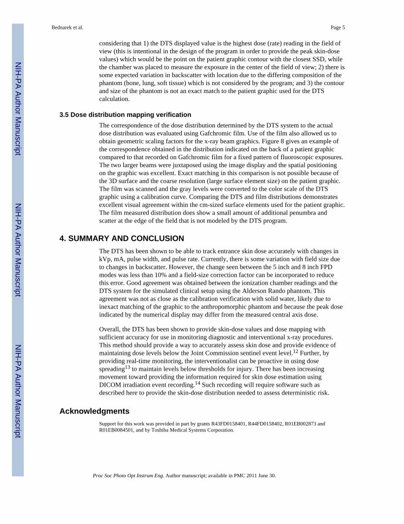
The dose tracking system (DTS) provides a graphic display showing the skin dosedistribution and the skin dose rate in real time during fluoroscopic interventional procedures.The display gives a color-coded representation of the cumulative skin dose distribution on apatient graphic as well as the real-time peak skin dose rate and cumulative skin dose valuesat the current beam projection. Figure 1 gives an example of a screen capture of the displayobtained at the end of a cardiac catheterization procedure. This display is intended to bepresented in the procedure room as well as in the control room for immediate real-timefeedback to the physician and technologist.
Before the procedure begins, the patient graphic is selected from a library of models10 toobtain the closest match to the patient and its position on the table can be adjusted tocorrespond to the actual patient position if it differs from the default. The projection of thex-ray beam onto the patient is determined by a 3D graphic modeling of the imaging systemand patient using OpenGL. The size of the beam and its projection onto the patient isobtained from the collimator position and the position of the patient relative to the x-raytube. All geometric information relating to the position and orientation of the system gantry,collimator and patient table is obtained from a CAN bus which runs between thecomponents of the Toshiba Infinix C-Arm imaging system which has a Varian PaxScan2020 flat panel detector (FPD).
The DTS skin dose rate values are calculated from the product of the mA, pulse width, pulserate and mGy per mAs. The mGy per mAs value is read from a data file that contains thisvalue as a function of kVp for each of the three beam filters. The pulse width, mA and kVpare obtained from the CAN bus, while the pulse rate is currently not provided on the bus soit is given the default value for the protocol selected, but can be changed manually by theoperator if the pulse rate is changed during the procedure. Cumulative dose is calculated bymeasuring the exposure time in intervals, multiplying it by the dose-rate value and summingthe result. The results are summed for each element of the patient graphic that is intersectedby the incident x-ray beam with individual inverse-square correction to that element. Thepatient graphic surface is modeled by tessellation into triangles and the cumulative valuesare assigned to each of the vertices.
2.2 System calibrationThe mGy per mAs data file is determined by measurement with a PTW Unidos dosimeterand a calibrated PTW model TN34069 6 cc ionization chamber (PTW-Freiburg GmbH,Freiburg, Germany) which is placed on the tabletop under a 20 cm thick block of water
Bednarek et al. Page 2
Proc Soc Photo Opt Instrum Eng. Author manuscript; available in PMC 2011 June 30.
NIH
-PA Author Manuscript
NIH
-PA Author Manuscript
NIH
-PA Author Manuscript
equivalent plastic as shown in Figure 2. The R/min reading was measured in fluoroscopicmode with manual setting of mA, pulse width and kVp. The measured R/min value wasmultiplied by 9.2 to convert to skin dose in mGy. The value includes table attenuation andpatient backscatter for the 7 inch mode at a position 15 cm on the tube-side of isocenter asappropriate for cardiac catheterization procedures. Separate calibrations were obtained foreach of the 3 beam filters (F1 - 0.2 mm Cu, F2 - 0.3 mm Cu, F3 - 1.8 mm Al). A calibrationset was also obtained for cine (DA) mode. Manual settings were not possible to generate thecine measurements as a function of kVp so the kVp was changed by changing the phantomattenuation by varying its thickness and by adding Cu sheets to obtain the higher kVpvalues.
This calibration is meant to provide the actual dose to the skin since this is the quantity thatdetermines the deterministic risk. DAP readings and reference dose readings normallyprovide the air kerma without backscatter or table attenuation11 and thus do not provide anindication of skin dose even when scaled by beam area or source-to-skin distance (SSD).
2.3 Verification testsWe performed a number of tests to verify the accuracy of the dose representation of thissystem. These tests included comparison of system–calculated dose-rate values withionization-chamber (6 cc PTW) measured values with change in kVp, beam filter, field size,source-to-skin distance and beam angulation.
To verify the accuracy of the DTS in a simulated clinical setup, measurements of theentrance skin dose were made by placing the 6 cc PTW ionization chamber at variouslocations on the surface of the Alderson Rando anthropomorphic torso phantom as shown inFigure 3. The phantom was placed on the patient table with the heart at the isocenter of theToshiba Infinix c-arm. A patient graphic was chosen from those available for the DTS thatwas the closest match in size to the phantom. The 7-inch mode was used for the FPD and theToshiba system was operated in automatic technique selection mode. After the chamber waspositioned and attached on the phantom, the C-arm gantry was rotated to the appropriateCRA/CAU and LAO//ROA angle to view the chamber and the heart at the center of the fieldof view. Imaging was performed in fluoroscopic and cine (DA at 30 frames per s) modesand the exposure rate was measured with a PTW electrometer. This value was multiplied bythe exposure to dose conversion factor for soft tissue (9.2 mGy/R) to obtain the skin doserate in mGy/min and was compared to the dose rate indicated on the DTS display. This wasdone for a range of projection angles normally used for a cardiac procedure.
To assess the geometric accuracy of the dose distribution representation, Gafchromic® film(XR-RV3, International Specialty Products Corporation, Advanced Materials Group,Wayne, NJ) was exposed with the beam at different locations and the beam sizes andpositioning was compared to the scaled DTS graphic representation. The film was read witha Canon MF5750 Scanner and a calibration curve was generated by exposing strips todifferent known exposures while placed on the tabletop with full solid-water backscatter.
3. RESULTS AND DISCUSSION3.1 Calibration verification
To verify that the system is able to accurately calculate the dose values, the 6 cc PTWionization chamber was placed on the tabletop under a 20 cm block of water-equivalentplastic, with the table 15 cm tube-side of isocenter. Dose rate values were read from theDTS display with the system in ion chamber mode (i.e., giving the tabletop dose rate). Thetube kilovoltage was manually varied in fluoroscopic mode from 50 to 120 kVp for all threebeam filters and the measured dose-rate value was compared to that of the DTS display. The
Bednarek et al. Page 3
Proc Soc Photo Opt Instrum Eng. Author manuscript; available in PMC 2011 June 30.
NIH
-PA Author Manuscript
NIH
-PA Author Manuscript
NIH
-PA Author Manuscript
results in Figure 4 show the agreement between the DTS calculated reading and the PTWmeasured value to be within 1% over most of the kVp range for all filters. Excellent linearityof dose rate reading was also demonstrated with variation in mA, pulse width and pulse rateas these are multiplicative factors in the program.
3.2 Variation with modeTo determine the accuracy of the DTS as the FPD magnification mode is changed, the PTWionization chamber was placed on the tabletop at 15 cm tube-side of isocenter under 20 cmof water-equivalent plastic and fluoroscopy was performed for the 5, 6, 7 and 8 inch modes.The collimated beam size was set to correspond to the selected mode. Figure 5 shows theratio of PTW dose rate reading to the DTS reading as a function of kVp for each FPD magmode and each beam filter. Since the DTS calculated value uses a calibration file measuredfor the 7-inch mag mode, the values for the 8″ mode are greater than 1 and those for the 5and 6 inch modes are less than 1 due to differences in backscatter. It is seen that these ratiosvary only a small amount as a function of kVp and filter for the same mag mode. Morevariation is seen between mag modes due to changes in backscatter with field size. As seenin Figure 5, the change from the 5″ to the 8″ modes was about 10% and mode specificcalibration files are being implemented to reduce this difference using mode and collimatorinformation available on the CAN bus.
3.3 Variation with angleThe variation of patient table attenuation with projection angle is a potential source of error.This variation was measured by placing the PTW ionization chamber at the FPD before 3mm of Cu to reduce backscatter to the chamber and rotating the gantry so that the angle oftransmission through the table was varied. Transmission measurements were made usingfixed fluoroscopic techniques over RAO/LAO and CRA/CAU angles every 10 degrees.Figure 6 shows the reduction of transmission with angle for all projections at 80 kVp usingfilter 2. This reduction is simply the result of increased path length through the table, whichvaries as the inverse cosine of the incident angle. A fit was made to this data assumingexponential attenuation through the table and the calculated change of thickness with angleto obtain a value for the product of linear attenuation coefficient (μ) and thickness (T). Thetransmission curve obtained using this fitted μT value is shown as the “calculated” curve inthe figure. This μT value is used as an angular correction in the DTS program using thecompound angle derived from the RAO/LAO and CRA/CAU values. The form of the curveused for the fit assumes a simple exponential with no table beam hardening.
3.4 Anthropomorphic phantom verificationThe accuracy of the DTS displayed dose/dose-rate values for a simulated procedure wasevaluated by placing the ionization chamber on the surface of the Alderson phantom andcomparing its reading with the DTS calculated values. Exposures were made over a range ofRAO/LAO and CRA/CAU angles with the heart at isocenter and the chamber in the centerof the beam. Readings were taken of both the rate and integrated dose over various intervalsof exposure time using both fluoroscopy and cine radiography. Figure 7 shows the combinedresults taken on two different days. Plotted are the ratios of dose-rate values and integrateddose values of the DTS system to the values measured by the PTW chamber (DTS/PTW).The projection angles shown here range from 54° RAO to 36° LAO and 30° CRA to 38°CAU; values at a given LAO/RAO angle shown in the graph may have been measured atdifferent CRA/CAU angles.
Over the angles shown, the ratio of rate readings varied from 0.92 to 1.11 for the fluoro andfrom 0.89 to 1.05 for the cine measurements and the ratio of integrated dose readings variedfrom 0.93 to 1.11 for the fluoro and from .92 to 1.08 for the cine. This is good agreement
Bednarek et al. Page 4
Proc Soc Photo Opt Instrum Eng. Author manuscript; available in PMC 2011 June 30.
NIH
-PA Author Manuscript
NIH
-PA Author Manuscript
NIH
-PA Author Manuscript
considering that 1) the DTS displayed value is the highest dose (rate) reading in the field ofview (this is intentional in the design of the program in order to provide the peak skin-dosevalues) which would be the point on the patient graphic contour with the closest SSD, whilethe chamber was placed to measure the exposure in the center of the field of view; 2) there issome expected variation in backscatter with location due to the differing composition of thephantom (bone, lung, soft tissue) which is not considered by the program; and 3) the contourand size of the phantom is not an exact match to the patient graphic used for the DTScalculation.
3.5 Dose distribution mapping verificationThe correspondence of the dose distribution determined by the DTS system to the actualdose distribution was evaluated using Gafchromic film. Use of the film also allowed us toobtain geometric scaling factors for the x-ray beam graphics. Figure 8 gives an example ofthe correspondence obtained in the distribution indicated on the back of a patient graphiccompared to that recorded on Gafchromic film for a fixed pattern of fluoroscopic exposures.The two larger beams were juxtaposed using the image display and the spatial positioningon the graphic was excellent. Exact matching in this comparison is not possible because ofthe 3D surface and the coarse resolution (large surface element size) on the patient graphic.The film was scanned and the gray levels were converted to the color scale of the DTSgraphic using a calibration curve. Comparing the DTS and film distributions demonstratesexcellent visual agreement within the cm-sized surface elements used for the patient graphic.The film measured distribution does show a small amount of additional penumbra andscatter at the edge of the field that is not modeled by the DTS program.
4. SUMMARY AND CONCLUSIONThe DTS has been shown to be able to track entrance skin dose accurately with changes inkVp, mA, pulse width, and pulse rate. Currently, there is some variation with field size dueto changes in backscatter. However, the change seen between the 5 inch and 8 inch FPDmodes was less than 10% and a field-size correction factor can be incorporated to reducethis error. Good agreement was obtained between the ionization chamber readings and theDTS system for the simulated clinical setup using the Alderson Rando phantom. Thisagreement was not as close as the calibration verification with solid water, likely due toinexact matching of the graphic to the anthropomorphic phantom and because the peak doseindicated by the numerical display may differ from the measured central axis dose.
Overall, the DTS has been shown to provide skin-dose values and dose mapping withsufficient accuracy for use in monitoring diagnostic and interventional x-ray procedures.This method should provide a way to accurately assess skin dose and provide evidence ofmaintaining dose levels below the Joint Commission sentinel event level.12 Further, byproviding real-time monitoring, the interventionalist can be proactive in using dosespreading13 to maintain levels below thresholds for injury. There has been increasingmovement toward providing the information required for skin dose estimation usingDICOM irradiation event recording.14 Such recording will require software such asdescribed here to provide the skin-dose distribution needed to assess deterministic risk.
AcknowledgmentsSupport for this work was provided in part by grants R43FD0158401, R44FD0158402, R01EB002873 andR01EB0084501, and by Toshiba Medical Systems Corporation.
Bednarek et al. Page 5
Proc Soc Photo Opt Instrum Eng. Author manuscript; available in PMC 2011 June 30.
NIH
-PA Author Manuscript
NIH
-PA Author Manuscript
NIH
-PA Author Manuscript
REFERENCES[1]. Wagner LK, Eifel PJ, Geise RA. Potential biological effects following high x-ray dose
interventional procedures. J. Vasc. Interv. Radiol. 1994; 5:71–84. [PubMed: 8136601][2]. Shope T. Radiation induced skin injuries from fluoroscopy. Radiol. 1996; 197(Supplement):449.[3]. Wagner LK, McNeese MD, Marx MV, Siegel EL. Severe skin reactions from interventional
fluoroscopy: Case report and review of the literature. Radiol. 1999; 213:773–776.[4]. Koenig TR, Wolff D, Mettler FA, Wagner LK. Skin injuries from fluoroscopically guided
procedures: part 1, characteristics of radiation injury. Am. J. Roentgenol. 2001; 177:13–20.[PubMed: 11418390]
[5]. McParland BJ. Entrance skin dose estimates derived from dose-area product measurements ininterventional radiological procedures. Br. J. Radiol. 1998; 71:1288–1295. [PubMed: 10319003]
[6]. Fletcher DW, Miller DL, Balter S, Taylor MA. Comparison of four techniques to estimateradiation dose to skin during angiographic and interventional radiology procedures. J. Vasc.Interv. Radiol. 2002; 13:391–397. [PubMed: 11932370]
[7]. Dohatcu A, Bednarek DR, Rudin S. Analysis of dose-related data logged for fluoroscopic cardiacinterventional procedures. Med. Phys. 2006; 33:2210.
[8]. Dinu P, Bednarek DR, Wobschall D, Peterson R, Ionita C, Rudin S, Zeng M, Chugh K, HoffmannKR. X-ray beam tracking system for a fluoroscopic C-arm unit. Med. Phys. 2003; 30(6):1424.
[9]. Chugh K, Dinu P, Bednarek DR, Wobschall D, Rudin S, Hoffmann KR, Peterson R, Zeng M. Acomputer-graphic display for real-time operator feedback during interventional x-ray procedures.Proc of SPIE. 2004; 5367:464.
[10]. SAE International. Civilian American and European Surface Anthropometry Resource Project-CAESAR®. http://www.sae.org/standardsdev/tsb/cooperative/caesar.htm
[11]. Bednarek DR, Rudin S. Comparison of two dose-area-product ionization chambers with differentconductive surface coating for over-table and under-table tube configurations. Health Phys. 2000;78:316–321. [PubMed: 10688455]
[12]. Joint Commission. Aurora, IL: 2006. Sentinel Event Policy and Procedures.http://www.jointcommission.org
[13]. Rudin S, Bednarek DR. Comparison of filter material and design for use in ROI angiography.Proc. SPIE. 1993; 1896:354–364.
[14]. Balter S. Capturing patient doses from fluoroscopically based diagnostic and interventionalsystems. Health Phys. 2008; 95:535–540. [PubMed: 18849686]
Bednarek et al. Page 6
Proc Soc Photo Opt Instrum Eng. Author manuscript; available in PMC 2011 June 30.
NIH
-PA Author Manuscript
NIH
-PA Author Manuscript
NIH
-PA Author Manuscript
Figure 1.DTS display at end of a cardiac procedure showing the color-coded mapping of skin doseover the back of the patient. The current virtual intersection of the x-ray beam with thepatient is outlined by the lightened rectangle near the center. The current (or last exposure)peak dose rate and the peak cumulative skin dose in the current beam intersection aredisplayed in the bar graphs. The numerical tabulated data indicate the conditions of the lastexposure.
Bednarek et al. Page 7
Proc Soc Photo Opt Instrum Eng. Author manuscript; available in PMC 2011 June 30.
NIH
-PA Author Manuscript
NIH
-PA Author Manuscript
NIH
-PA Author Manuscript
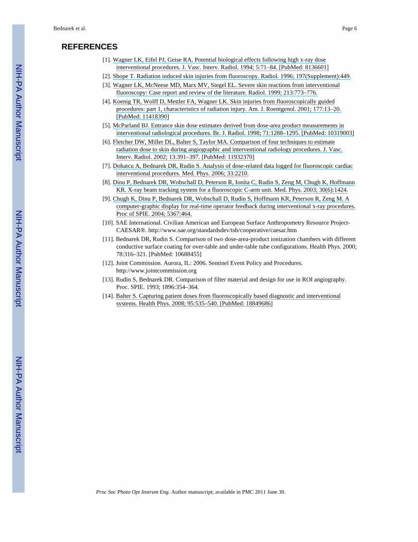
Figure 2.Setup for determination of the calibration file. The ionization chamber is placed on thetabletop under the solid water phantom 15 cm from isocenter to measure entrance skin dose.
Bednarek et al. Page 8
Proc Soc Photo Opt Instrum Eng. Author manuscript; available in PMC 2011 June 30.
NIH
-PA Author Manuscript
NIH
-PA Author Manuscript
NIH
-PA Author Manuscript
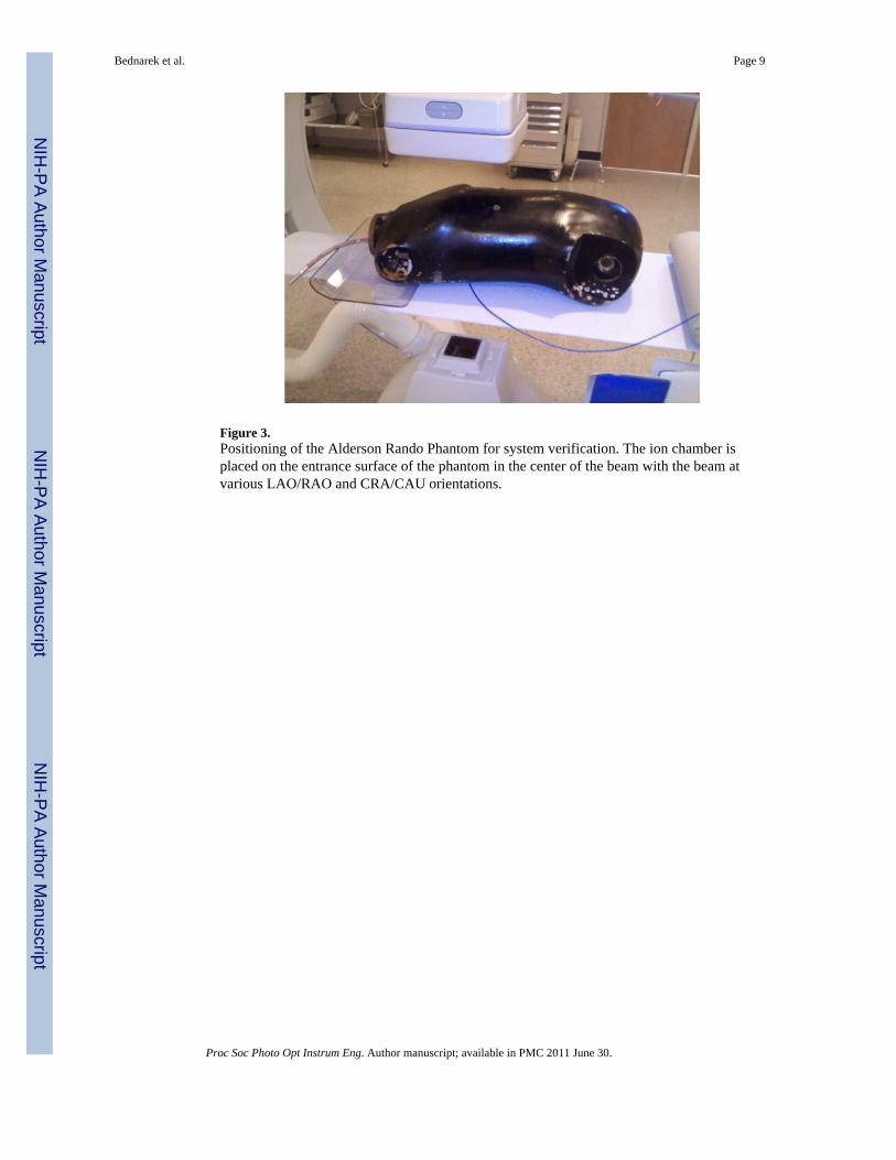
Figure 3.Positioning of the Alderson Rando Phantom for system verification. The ion chamber isplaced on the entrance surface of the phantom in the center of the beam with the beam atvarious LAO/RAO and CRA/CAU orientations.
Bednarek et al. Page 9
Proc Soc Photo Opt Instrum Eng. Author manuscript; available in PMC 2011 June 30.
NIH
-PA Author Manuscript
NIH
-PA Author Manuscript
NIH
-PA Author Manuscript
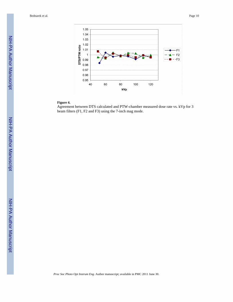
Figure 4.Agreement between DTS calculated and PTW-chamber measured dose rate vs. kVp for 3beam filters (F1, F2 and F3) using the 7-inch mag mode.
Bednarek et al. Page 10
Proc Soc Photo Opt Instrum Eng. Author manuscript; available in PMC 2011 June 30.
NIH
-PA Author Manuscript
NIH
-PA Author Manuscript
NIH
-PA Author Manuscript
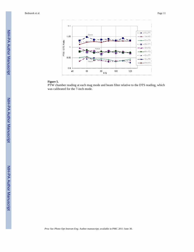
Figure 5.PTW chamber reading at each mag mode and beam filter relative to the DTS reading, whichwas calibrated for the 7-inch mode.
Bednarek et al. Page 11
Proc Soc Photo Opt Instrum Eng. Author manuscript; available in PMC 2011 June 30.
NIH
-PA Author Manuscript
NIH
-PA Author Manuscript
NIH
-PA Author Manuscript
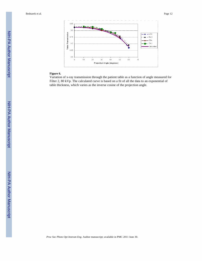
Figure 6.Variation of x-ray transmission through the patient table as a function of angle measured forFilter 2, 80 kVp. The calculated curve is based on a fit of all the data to an exponential oftable thickness, which varies as the inverse cosine of the projection angle.
Bednarek et al. Page 12
Proc Soc Photo Opt Instrum Eng. Author manuscript; available in PMC 2011 June 30.
NIH
-PA Author Manuscript
NIH
-PA Author Manuscript
NIH
-PA Author Manuscript
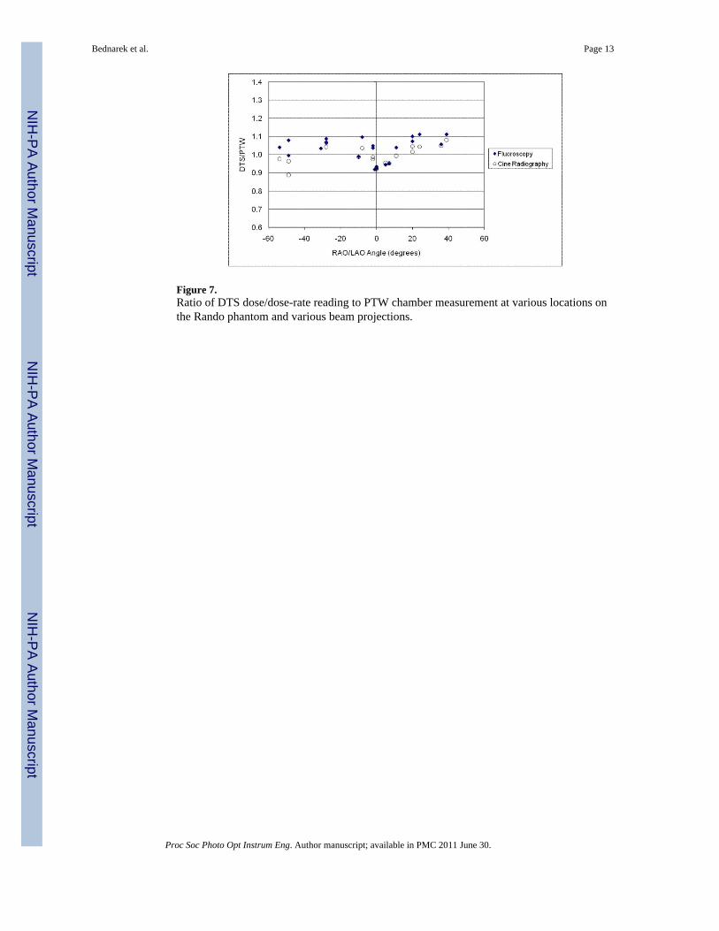
Figure 7.Ratio of DTS dose/dose-rate reading to PTW chamber measurement at various locations onthe Rando phantom and various beam projections.
Bednarek et al. Page 13
Proc Soc Photo Opt Instrum Eng. Author manuscript; available in PMC 2011 June 30.
NIH
-PA Author Manuscript
NIH
-PA Author Manuscript
NIH
-PA Author Manuscript
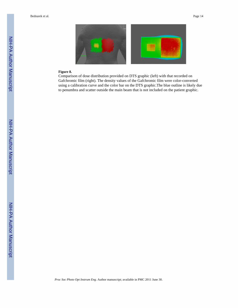
Figure 8.Comparison of dose distribution provided on DTS graphic (left) with that recorded onGafchromic film (right). The density values of the Gafchromic film were color-convertedusing a calibration curve and the color bar on the DTS graphic.The blue outline is likely dueto penumbra and scatter outside the main beam that is not included on the patient graphic.
Bednarek et al. Page 14
Proc Soc Photo Opt Instrum Eng. Author manuscript; available in PMC 2011 June 30.
NIH
-PA Author Manuscript
NIH
-PA Author Manuscript
NIH
-PA Author Manuscript