vegadis 81 - intrinsic safety "i"
TRANSCRIPT

Document ID: 41919
Safety instructionsVEGADIS 81Intrinsic safety "i"
2 VEGADIS 81
41919-EN-200907
Contents1 Area of applicability ................................................................................................................. 3
2 Importantspecificationinthetypecode ............................................................................... 3
3 Differentignitionprotectiontypes ......................................................................................... 4
4 General information ................................................................................................................. 4
5 Application area ....................................................................................................................... 5
6 Specificconditionsofuse("X"identification) ..................................................................... 5
7 Importantinformationformountingandmaintenance ........................................................ 5
8 Safeoperatingmode ............................................................................................................... 6
9 Potentialequalization/Grounding .......................................................................................... 7
10 Electrostaticcharging(ESD) .................................................................................................. 7
11 Instructionsforzone0applications ...................................................................................... 7
12 Electricaldata........................................................................................................................... 8
13 Thermaldata ............................................................................................................................ 8
Supplementary documentation:
• Operating Instructions VEGADIS 81• Certificate of Conformity IECEx PTB 06.0048X (Document ID: 41920)• SIL Safety Manual (Document ID: 50224)
Editing status: 2018-08-27

3VEGADIS 81
4191
9-EN
-200
907
1 Area of applicabilityThese safety instructions apply to the VEGADIS 81 of type series:
• VEGADIS DIS81(*).IC*******• VEGADIS DIS81(*).IO*******• VEGADIS DIS81(*).IH*******
According to Certificate of Conformity IECEx PTB 06.0048X (certificate number on the type label) and for all instruments with safety instruction 41919.The classification as well as the respective standards are stated in the Certificate of Conformity:
• IEC 60079-0: 2017• IEC 60079-11: 2011• IEC 60079-26: 2014
Type of protection marking:
• Ex ia IIC T6 … T1 Ga• Ex ia IIC T6 … T1 Gb
2 ImportantspecificationinthetypecodeVEGADISDIS81(*).abcdefghiPosition Feature Description
a Scope I Worldwide
b Approval
C IEC Ex ia IIC T6 … T1 Ga, Gb
O IEC Ex ia IIC T6 … T1 Ga, Gb + Ship approval (DNV GL, BV, RM-ROS)
H IEC Ex ia IIC T6 Ga, GborIEC Ex tb IIIC T75°C Db IP66
c Electronics I Digital (I2C communication)
d Housing K Plastic
A Aluminium
V Stainless steel (precision casting)
H Special colour, Aluminium
e Protection rating I IP66/IP67; NEMA 4X
N IP66/IP68 (0.2 bar); NEMA 6P
f Cable entry / Connection D M20 x 1.5 / Blind plug
N ½ NPT / Blind plug
M M20 x 1.5 / Cable gland PA black (ø5-9 mm), standard
J ½ NPT / Cable gland PA black (ø5-9 mm)
* further cable glands, blind plugs, cable leadthroughs, plug connec-tors, Conduit system
4 VEGADIS 81
41919-EN-200907
Position Feature Description
g Display and adjustment module PLICSCOM
X without
A mounted
F without; lid with inspection window
K mounted; with Bluetooth, magnetic pen operation
h Mounting type
A for wall mounting with Aluminium or stainless steel housing
C for carrier rail and wall mounting with plastic housing
D for carrier rail with Aluminium or stainless steel housing
E for tube mounting (29 … 60 mm) incl. mounting material
i CertificatesX No
M Yes
In the following, all above mentioned versions are called VEGADIS 81. If parts of these safety instructions refer only to certain versions, then these will be mentioned explicitly with their type code.
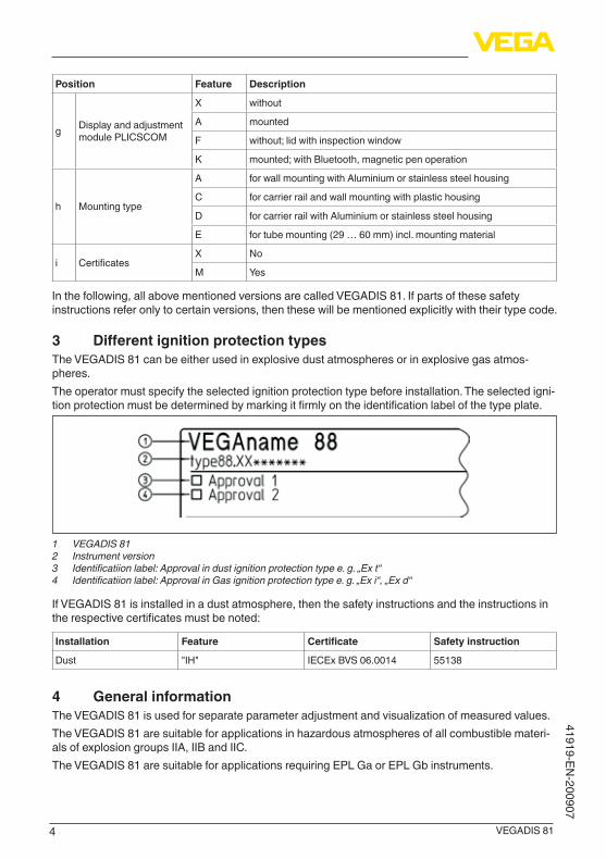
3 DifferentignitionprotectiontypesThe VEGADIS 81 can be either used in explosive dust atmospheres or in explosive gas atmos-pheres. The operator must specify the selected ignition protection type before installation. The selected igni-tion protection must be determined by marking it firmly on the identification label of the type plate.
1 VEGADIS 81 2 Instrument version3 Identificatiionlabel:Approvalindustignitionprotectiontypee.g.„Ext“4 Identificatiionlabel:ApprovalinGasignitionprotectiontypee.g.„Exi“,„Exd“
If VEGADIS 81 is installed in a dust atmosphere, then the safety instructions and the instructions in the respective certificates must be noted:
Installation Feature Certificate Safetyinstruction
Dust "IH" IECEx BVS 06.0014 55138
4 General informationThe VEGADIS 81 is used for separate parameter adjustment and visualization of measured values. The VEGADIS 81 are suitable for applications in hazardous atmospheres of all combustible materi-als of explosion groups IIA, IIB and IIC. The VEGADIS 81 are suitable for applications requiring EPL Ga or EPL Gb instruments.
5VEGADIS 81
4191
9-EN
-200
907
5 Application areaEPLGainstrumentThe VEGADIS 81 with the mechanical fixing element are installed in hazardous areas of zone 0 requiring EPL Ga instruments.
EPLGbinstrumentThe VEGADIS 81 with the mechanical fixing element are installed in hazardous areas of zone 1 requiring EPL Gb instruments.
6 Specificconditionsofuse("X"identification)The following overview is listing all special properties of VEGADIS 81, which make a labelling with the symbol "X" behind the certificate number necessary.
Electrostaticcharging(ESD)You can find the details in chapter " Electrostaticcharging(ESD)" of these safety instructions.
AmbienttemperatureYou can find the details in chapter " Thermaldata" of these safety instructions.
ImpactandfrictionsparksThe VEGADIS 81 in light metal versions (e.g. aluminium, titanium, zircon) must be mounted in such a way that sparks from impact and friction between light metals and steel (except stainless steel, if the presence of rust particles can be excluded) cannot occur.
Non-grounded,metallicpartsThe resistance between aluminium housing to metal measuring point identification plate is > 109 Ohm.The capacitance of the metal measuring point identification plate was measured as follows:
Measurementloopidentificationlabel Capacitance
45 x 23 mm (standard) 21 pF
100 x 30 mm 52 pF
73 x 47 mm 61 pF
7 ImportantinformationformountingandmaintenanceGeneralinstructionsThe following requirements must be fulfilled for mounting, electrical installation, setup and mainte-nance of the instrument:
• The staff must be qualified according the respective tasks• The staff must be trained in explosion protection• The staff must be familiar with the respectively valid regulations, e.g. planning and installation
acc. to IEC 60079-14• Make sure when working on the instrument (mounting, installation, maintenance) that there is no
explosive atmosphere present, the supply circuits should be voltage-free, if possible.• The instrument has to be mounted according to the manufacturer specifications, the Certificate
of Conformity and the valid regulations and standards• Modifications on the instrument can influence the explosion protection and hence the safety,
therefore repairs are not permitted to be conducted by the end user• Modifications must only be carried out by employees authorized by VEGA company• Use only approved spare parts

6 VEGADIS 81
41919-EN-200907
• Components for installation and connection not included in the approval documents are only permitted if these correspond technically to the latest standard mentioned on the cover sheet. They must be suitable for the application conditions and have a separate certificate. The special conditions of the components must be noted and if necessary, the components must be inte-grated in the type test. This applies also to the components already mentioned in the technical description.
• Vessel installations and probable flow must be taken into account
MountingKeep in mind for instrument mounting
• Mechanical damage on the instrument must be avoided• Mechanical friction must be avoided• Close the housing lid (s) up to the stop before starting operating, to ensure the IP protection rat-
ing specified on the type label
MaintenanceTo ensure the functionality of the device, periodic visual inspection is recommended for:
• Secure mounting• No mechanical damages or corrosion• Worn or otherwise damaged cables• No loose connections of the line connections, equipotential bonding connections• Correct and clearly marked cable connections
Intrinsicsafety"i"• Valid regulations for connection of intrinsically safe circuits, e.g. proof of intrinsic safety accord-
ing to IEC/EN 60079-14 must be observed• The instrument is only suitable for connection to certified, intrinsically safe instruments• When connecting a circuit with protection level Ex ib, the device, the sensor meas. system of the
device must no more be used in hazardous areas of zone 0.• When connecting an intrinsically safe instruments with classification mark Ex ia to a circuit with
protection level Ex ib, then the classification mark of the instrument changes to Ex ib. After the use as instrument with Ex ib power supply, the instrument must no more be used in circuits with protection level Ex ia
• When connecting an intrinsically safe instrument to an non-intrinsically safe circuit, the instru-ment must be no longer used in intrinsically safe circuits
• With surface temperatures > 70 °C, the cables must be suitable for the higher application condi-tions
8 SafeoperatingmodeGeneraloperatingconditions• Do not operate the instrument outside the electrical, thermal and mechanical specifications of
the manufacturer• Use the instrument only in media against which the wetted parts are sufficiently resistant• Note the relation between process temperature on the sensor/antenna and the permissible
ambient temperature on the electronics housing. For permissible temperatures, see the respec-tive temperature tables. See chapter " Thermaldata".
• If necessary, a suitable overvoltage arrester can be connected in front of the VEGADIS 81• For assessment and reduction of the explosion risk, valid standards such as for example ISO/
EN 1127-1 must be taken into account
7VEGADIS 81
4191
9-EN
-200
907
9 Potentialequalization/Grounding• Integrate the instruments into the local potential equalisation, e.g. via the internal or external
earth terminal• The potential equalization terminal must be secured against loosening and twisting• If grounding of the cable screening is necessary, this must be carried out acc. to the valid stand-
ards and regulations, e.g. acc. to IEC/EN 60079-14• The intrinsically safe input and the intrinsically safe output circuits are ground-free. The voltage
resistance against ground is min. 500 Veff.• The supply and signal circuit zwischen dem VEGADIS 81 und dem Sensor should be set up
without grounding
10 Electrostaticcharging(ESD)In case of instrument versions with electrostatically chargeable plastic parts, the danger of electro-static charging and discharging must be taken into account!The following parts can charge and discharge:
• Lacquered housing version or alternative special lacquering• Plastic housing, plastic housing parts• Metal housing with inspection window• Plastic process fittings• Plastic-coated process fittings and/or plastic-coated sensors• Connection cable for separate versions• Type label• Isolated metallic labels (measuring point identification plate)
Take note in case of danger of electrostatic charges:
• Avoid friction on the surfaces• Do not dry clean the surfaces
The instruments must be mounted/installed in such a way that the following can be ruled out:
• electrostatic charges during operation, maintenance and cleaning.• process-related electrostatic charges, e.g. by measuring media flowing past
The warning label indicates danger:
WARNING - POTENTIAL ELECTROSTATICCHARGING HAZARD - SEE INSTRUCTIONS
11 Instructionsforzone0applicationsIn hazardous areas, the instrument should only be operated under atmospheric conditions:
• Temperature: -20 … +60 °C.• Pressure: 80 … 110 kPa (0.8 … 1.1 bar)• Air with normal oxygen content, normally 21 %
If no explosive mixtures or additional application conditions are certified resp. supplementary measures such as e.g. according to EN 1127-1 taken, then the instruments can be also operated according to the manufacturer specification outside atmospheric conditions.If there is a risk of dangerous potential differences inside zone 0, then suitable measures for circuits in zone 0 must be taken, e.g. according to the requirements of IEC/EN 60079-14.
8 VEGADIS 81
41919-EN-200907
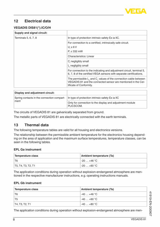
12 ElectricaldataVEGADISDIS81(*).IC/O/HSupplyandsignalcircuit:
Terminals 5, 6, 7, 8 In type of protection intrinsic safety Ex ia IIC.
For connection to a certified, intrinsically safe circuit.Ui ≤ 6 VPi ≤ 332 mW
Characteristics: Linear
Ci negligibly smallLi negligibly small
For connection to the indicating and adjustment circuit, terminal 5, 6, 7, 8 of the certified VEGA sensors with separate certifications.
The permissible Lo and Co values of the connection cable between VEGADIS 81 and the connected sensor are mentioned in the Cer-tificate of Conformity.
Displayandadjustmentcircuit:
Spring contacts in the connection compart-ment
In type of protection intrinsic safety Ex ia IIC
Only for connection to the display and adjustment module PLICSCOM.
The circuits of VEGADIS 81 are galvanically separated from ground. The metallic parts of VEGADIS 81 are electrically connected with the earth terminals.
13 ThermaldataThe following temperature tables are valid for all housing and electronics versions.The relationship between the permissible ambient temperature for the electronics housing depend-ing on the area of application and the maximum surface temperatures, temperature classes, can be seen in the following tables.
EPLGainstrument
Temperatureclass Ambienttemperature(Ta)
T6 -20 … +46 °C
T5, T4, T3, T2, T1 -20 … +60 °C
The application conditions during operation without explosion-endangered atmosphere are men-tioned in the respective manufacturer instructions, e.g. operating instructions manuals.
EPLGbinstrument
Temperatureclass Ambienttemperature(Ta)
T6 -40 … +46 °C
T5 -40 … +60 °C
T4, T3, T2, T1 -40 … +80 °C
The application conditions during operation without explosion-endangered atmosphere are men-

9VEGADIS 81
4191
9-EN
-200
907
tioned in the respective manufacturer instructions, e.g. operating instructions manuals.

10
Notes
VEGADIS 81
41919-EN-200907
11
Notes
VEGADIS 81
4191
9-EN
-200
907

Printing date:
VEGA Grieshaber KGAm Hohenstein 11377761 SchiltachGermany
4191
9-EN
-200
907
All statements concerning scope of delivery, application, practical use and operat-ing conditions of the sensors and processing systems correspond to the information available at the time of printing.Subject to change without prior notice
© VEGA Grieshaber KG, Schiltach/Germany 2020
Phone +49 7836 50-0Fax +49 7836 50-201E-mail: [email protected]