unusual kinetic inhibitor effects on gas hydrate formation
TRANSCRIPT

Chemical Engineering Science 61 (2006) 1368–1376www.elsevier.com/locate/ces
Unusual kinetic inhibitor effects on gas hydrate formation
Ju Dong Lee, Peter Englezos∗
Department of Chemical and Biological Engineering, University of British Columbia, 2216 Main Mall, Vancouver, British Columbia, Canada V6T 1Z4
Received 4 July 2005; received in revised form 20 July 2005; accepted 4 August 2005Available online 10 October 2005
Abstract
Gas hydrate formation experiments were conducted with a methane–ethane mixture at 273.7 or 273.9 K and 5100 kPa and using waterdroplets or water contained in cylindrical glass columns. The effect of kinetic inhibitors and the water/solid interface on the inductiontime for hydrate crystallization and on the hydrate growth and decomposition characteristics was studied. It was found that inhibitors GHI101 and Luvicap EG delayed the onset of hydrate nucleation. While this inhibition effects has been reported previously some unusualbehaviour was observed and reported for the first time. In particular, the water droplet containing GHI 101 or Luvicap EG was found tocollapse prior to nucleation and spread out on the Teflon surface. Subsequently, hydrate was formed as a layer on the surface. Catastrophicgrowth and spreading of the hydrate crystals was also observed during hydrate formation in the glass columns in the presence of thekinetic inhibitor. Finally, when polyethylene oxide (PEO) was added into the kinetic inhibitor solution the memory effect on the inductiontime decreased dramatically.� 2005 Elsevier Ltd. All rights reserved.
Keywords: Gas hydrates; Kinetic inhibitors; Water droplets; Morphology
1. Introduction
It is well known that gas hydrates may block hydro-carbon transportation lines. Therefore, various mitigationstrategies have evolved which are classified either as ther-modynamic or kinetic inhibition methods (Sloan, 1998).Thermodynamic methods use methanol and glycol (10–50%of the water phase), but are costly in offshore developmentsand onshore processing facilities (Dholabhai et al., 1992;Lovell and Pakulski, 2003). Kinetic inhibition methods arebased on the injection of polymer-based chemicals at lowdosages in the water phase (Fu, 2002; Huo et al., 2001; Kohet al., 2002). Kinetic inhibitors do not prevent the formationof hydrates but either delay their onset or modify them toreduce the agglomeration tendency (Englezos, 1996; Sloan,1998). It is noted that in an analogous fashion antifreezeglycoproteins in the blood of Antarctic fish enable them toexist below 0 ◦C (Zeng et al., 2003; Marshall et al., 2004).
∗ Corresponding author. Tel: +1 604 822 6184; fax: +1 604 822 6003.E-mail address: [email protected] (P. Englezos).
0009-2509/$ - see front matter � 2005 Elsevier Ltd. All rights reserved.doi:10.1016/j.ces.2005.08.009
Gas hydrate formation is a complex multiphase crys-tallization process (Davidson, 1973; Englezos, 1993; Rip-meester, 2000; Koh, 2002; Sloan, 2003a,b). As such it isdifficult to observe experimentally and various approacheshave been followed to monitor hydrate formation and de-composition at different levels of detail (Sloan, 2003a,b).Morphology studies involve observations of hydrate forma-tion at fluid/fluid interfaces and offer valuable informationon the mechanistic aspects of crystal nucleation, growth,and decomposition (Maini and Bishnoi, 1981; Sugaya andMori, 1996; Ohmura et al., 1999; Unchida et al., 1999, 2000;Servio and Englezos, 2003a,b; Ohmura et al., 2004, 2005;Lee and Englezos, 2005a).
These studies complement traditional gas uptake mea-surements (Englezos et al., 1987), structural investigations(Ripmeester, 2000; Udachin et al., 2002; Sloan, 2003a; Koh,2002) and molecular simulations (Tse and Klug, 2002).Thus, it would be of interest to employ morphological ob-servations in hydrate systems in the presence of kineticinhibitors. One such study has been reported by Sakaguchiet al. (2003). In particular, the effect of two kinetic inhibitors

J.D. Lee, P. Englezos / Chemical Engineering Science 61 (2006) 1368–1376 1369
Fig. 1. Apparatus.
poly(N-vinylpyrrolidone) and poly(N-vinylcaprolactam) onstructure II hydrates was studied with a model system in-volving HCFC-141b (CH3CCl2F) hydrate. It is noted thatthe kinetic inhibitor effects are usually studied in stirred ves-sels or flow loops (bulk systems).
In this work, we present the results from methane–ethanehydrate formation on water droplets containing kinetic in-hibitors and in water enclosed in narrow cylindrical glasscolumns. A noteworthy property of the CH4–C2H6 systemis that although CH4 and C2H6 are known to form structureI hydrate, the binary gas mixture forms structure II hydrateat certain compositions (Subramanian et al., 2000a,b). Ki-netic inhibitor effects on gas hydrate formation of naturalgas components in water in such systems have not been re-ported previously.
2. Experimental
Two types of gas hydrate formation experiments wereconducted. In one arrangement, hydrate formation on threewater droplets was observed. The second arrangement in-volved hydrate formation in water contained in narrow glasscolumns. The hydrate forming gas was a mixture with 89.4%CH4 and the balance was C2H6.
A detailed description of the apparatus shown in Fig. 1 andthe procedure is given elsewhere (Lee and Englezos, 2005a).Briefly, it consists of a crystallizer with a magnetic bar whichrotates vertically to agitate the gas phase. The crystallizeris immersed in a cooling bath that contains a 50–50 wt%mixture of water and ethylene glycol. The hydrate crystalsare monitored using a Nikon SMZ 2000 microscope fittedwith digital camera. The procedure involves wiping the in-ternal surface of crystallizer with a cotton cloth to removemoisture followed by injection of water droplets contain-ing kinetic inhibitor on the Teflon surface of the crystallizer.
Table 1Kinetic inhibitors
Product Supplier
GHI 101 ISP technologies(Wayne, NJ, US)
Luvicap EG BASF corporation(Charlotte, NC, US)
PVP ALFA AESAR(Ward Hill, MA, USA)
NEL-411-31 ISP technologies
Table 1 presents the kinetic inhibitors used. Hydrate-forminggas was then added and withdrawn from the crystallizer inorder to remove any residual air. When the temperature be-came stable the hydrate forming gas was fed and the mag-netic stirring was started. This is time zero for the measure-ment of the induction time for hydrate formation.
Three cylindrical glass containers with a 6 mm diameterand 33 mm height containing 0.2 cm3 of water or aqueous in-hibitor solution were placed in the crystallizer. Experimentsinvolved the formation of hydrates three times at 5100 kPaand 273.7 K. Following first or second formation the hydratecrystals were decomposed at 1 atm. However, the decompo-sition of hydrates formed for the third time was carried outat 1000 kPa instead of 1 atm. The water from the decom-posed hydrates was kept at the decomposition pressure forone hour and was used for the subsequent hydrate formation.
Experiments were also carried out in two other cylindricalglass columns with a height of 40 mm and diameters equalto 3.5 and 10 mm. The amount of water added is given inTable 5. The procedure was similar to the one followed forthe previous glass columns. The decomposition pressure was1000 kPa. It is noted that the equilibrium hydrate formationpressure at 273.9 K is 1634 kPa.
3. Results and discussion
The experimental conditions and measured inductiontimes for hydrate formation on water droplets are given inTable 2. As seen, the addition of a small amount (0.5 wt%)of inhibitors GHI 101 and Luvicap EG delayed the onset ofnucleation. Inhibitor GHI 101 was the strongest. The induc-tion time was much longer when water and small amount ofGHI 101 was used. On the other hand PVP and NEL-411-31 did not delay the nucleation. PVP is known to be a weakkinetic inhibitor. For example it exhibited a small effect inmethane hydrate formation experiments (Lee and Englezos,2005b). It is also seen that 2-butoxyethanol by itself is nota kinetic inhibitor. However, this chemical is known to en-hance the performance of kinetic inhibitors (Cohen et al.,1998a,b). In experiment 5 a small amount of polyethyleneoxide (PEO) was also included but the induction time wassame as that with GHI 101 alone. It was recently found thatPEO has a synergistic effect with this kinetic inhibitor (Lee

1370 J.D. Lee, P. Englezos / Chemical Engineering Science 61 (2006) 1368–1376
Table 2Experimental conditions and results from hydrate formation on water droplets
Exp. no Droplet andsize (mm)
Inhibitor solution T (K) P (kPa) Inductiontime (min)
Comment
1 A (5) Water 273.9 5100 191B (5) 0.5 wt% of GHI 101 252 Droplet collapsedC (5) 0.5 wt% of PVP 191
2 A (5) Water 273.9 5100 84B (5) 0.5 wt% of GHI 101 320 Droplet collapsedC (5) 0.5 wt% of PVP 84
3 A (5) Water 273.9 5100 57B (5) 0.5 wt% of GHI 101 265 Droplet collapsedC (5) 0.75 wt% of 2-butoxyethanol 57
4 A (7) 0.5 wt% of GHI 101 273.9 5100 >720 Droplet was placed ona stainless steel sur-face. Droplet gradu-ally evaporated
B (5) 0.5 wt% of GHI 101 567 Droplet collapsedC (5) 0.5 wt% of Luvicap EG 406 Droplet collapsed
5 A (5) Water 273.9 5100 317B (5) 0.5 wt% of NEL-411-31 317C (5) 0.5 wt% of GHI 101 371 Droplet collapsedD (5) 0.5 wt% of GHI 101 0.0025 wt% of PEO 371 Droplet collapsed
and Englezos, 2005b). This synergistic effect was observedin the glass column experiments as will be seen later.
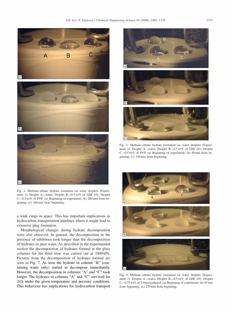
Figs. 2 to 5 show pictures of the droplets at differentstages during hydrate formation. The observations revealedan unusual behaviour that has not been previously reported.In all the experiments containing GHI 101 or Luvicap EG,the water droplet collapsed just prior to nucleation. The waterfrom the droplet then spread on the teflon surface and hydrateformed on the thin water layers. It is not clear what is theorigin of the observed phenomenon. Teflon is a hydrophobicsurface and this is why the water droplet arrangement ispossible. Obviously, the droplets containing kinetic inhibitorundergo some kind of change just prior to nucleation. Theybecome oleophilic and are able to wet the Teflon surface.The observed phenomena deserve further studies because itmight be possible to establish a link between the oleophilictendency and kinetic inhibitor capacity.
Experimental conditions on hydrate formation in the three(33 × 6) glass columns together with results are given inTable 3. These results show a remarkable effect that PEO hasduring the second and third nucleation. Hydrate formationin pure water has a very strong “memory effect” as expected(Uchida et al., 2000). The presence of a kinetic inhibitorreduces the memory to some extent. However, when PEO isincluded in the kinetic inhibitor solution the memory effectweakens dramatically. Table 4 shows the ratio of inductiontimes with inhibitor over that with water (tGHI 101/tw) andthe ratio of the induction time with inhibitor and PEO overthat with water (tGHI 101+PEO/tw) for the three nucleations.As seen the effect of PEO is more striking for the thirdnucleation. It is not known why such a small amount of
PEO would have such an effect. Perhaps this water solublepolymer when added to a kinetic inhibitor solution disruptsany “residual hydrate structures”.
The results in Table 3 also show that GHI 101 showed aninhibition effect (longer induction time) on the hydrate for-mation. Moreover, the induction time was much longer whensmall amount (0.0025 wt%) of polyethylene oxide (PEO)was added in the kinetic inhibitor solution (synergistic ef-fect). This synergistic effect was recently discussed (Lee andEnglezos, 2005b). It is noted that each column offers an in-dependent hydrate formation environment in the sense thatwhat happens in one column is not likely to affect the otherones. On the other hand, the droplets are situated next toeach other and it is possible that there is some sort of inter-action which might lead to simultaneous nucleation. Perhapsthis explains why the synergistic effect was not observed inthe droplet experiments.
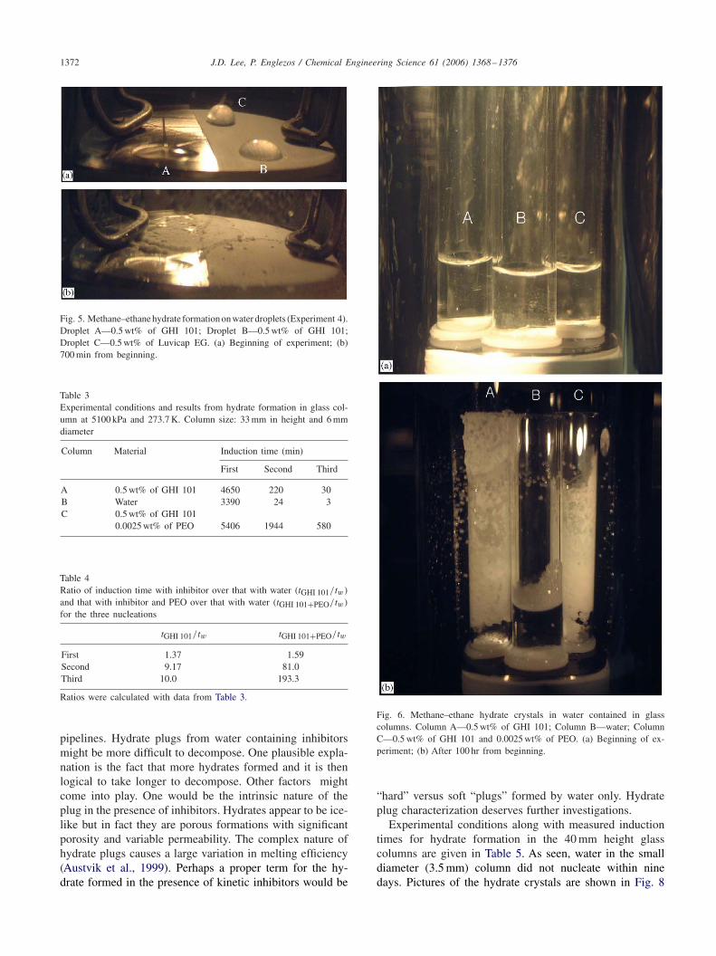
The morphological behaviour of the system is very inter-esting as seen in Fig. 6. During hydrate formation in watercontaining GHI 101 or GHI 101 + PEO system (columnsA and C) hydrate crystals grew upward along the wall ofglass column. Moreover, it appeared that all of the water re-maining at the bottom of the column converted to hydratecrystals. On the other hand, the column containing pure wa-ter (column B) showed different behaviour. Hydrate crystalsformed on the gas/liquid interface while only small amountof hydrate crystals was attached on the glass surface. Thus,the columns containing inhibitor exhibited delayed nucle-ation but once hydrate forms the growth has a “catastrophic”character in the sense that water appears to have been con-sumed entirely and the mass of hydrate crystals extends over
J.D. Lee, P. Englezos / Chemical Engineering Science 61 (2006) 1368–1376 1371
Fig. 2. Methane–ethane hydrate formation on water droplets (Experi-ment 1). Droplet A—water; Droplet B—0.5 wt% of GHI 101; DropletC—0.5 wt% of PVP. (a) Beginning of experiment; (b) 200 min from be-ginning; (c) 260 min from beginning.
a wide range in space. This has important implications inhydrocarbon transportation pipelines where it might lead toextensive plug formation.
Morphological changes during hydrate decompositionwere also observed. In general, the decomposition in thepresence of inhibitors took longer than the decompositionof hydrates in pure water. As described in the experimentalsection the decomposition of hydrates formed in the glasscolumns for the third time was carried out at 1000 kPa.Pictures from the decomposition of hydrates formed areseen in Fig. 7. As seen the hydrate in column “B” (con-taining water only) started to decompose immediately.However, the decomposition in columns “A” and “C” tooklonger. The hydrates in columns “A” and “C” survived for24 h under the given temperature and pressure conditions.This behaviour has implications for hydrocarbon transport
Fig. 3. Methane–ethane hydrate formation on water droplets (Experi-ment 2). Droplet A—water; Droplet B—0.5 wt% of GHI 101; DropletC—0.5 wt% of PVP. (a) Beginning of experiment; (b) 90 min from be-ginning; (c) 330 min from beginning.
Fig. 4. Methane–ethane hydrate formation on water droplets (Experi-ment 3). Droplet A—water; Droplet B—0.5 wt% of GHI 101; DropletC—0.75 wt% of 2-butoxyethanol. (a) Beginning of experiment; (b) 65 minfrom beginning; (c) 270 min from beginning.
1372 J.D. Lee, P. Englezos / Chemical Engineering Science 61 (2006) 1368–1376
Fig. 5. Methane–ethane hydrate formation on water droplets (Experiment 4).Droplet A—0.5 wt% of GHI 101; Droplet B—0.5 wt% of GHI 101;Droplet C—0.5 wt% of Luvicap EG. (a) Beginning of experiment; (b)700 min from beginning.
Table 3Experimental conditions and results from hydrate formation in glass col-umn at 5100 kPa and 273.7 K. Column size: 33 mm in height and 6 mmdiameter
Column Material Induction time (min)
First Second Third
A 0.5 wt% of GHI 101 4650 220 30B Water 3390 24 3C 0.5 wt% of GHI 101
0.0025 wt% of PEO 5406 1944 580
Table 4Ratio of induction time with inhibitor over that with water (tGHI 101/tw)
and that with inhibitor and PEO over that with water (tGHI 101+PEO/tw)
for the three nucleations
tGHI 101/tw tGHI 101+PEO/tw
First 1.37 1.59Second 9.17 81.0Third 10.0 193.3
Ratios were calculated with data from Table 3.
pipelines. Hydrate plugs from water containing inhibitorsmight be more difficult to decompose. One plausible expla-nation is the fact that more hydrates formed and it is thenlogical to take longer to decompose. Other factors mightcome into play. One would be the intrinsic nature of theplug in the presence of inhibitors. Hydrates appear to be ice-like but in fact they are porous formations with significantporosity and variable permeability. The complex nature ofhydrate plugs causes a large variation in melting efficiency(Austvik et al., 1999). Perhaps a proper term for the hy-drate formed in the presence of kinetic inhibitors would be
Fig. 6. Methane–ethane hydrate crystals in water contained in glasscolumns. Column A—0.5 wt% of GHI 101; Column B—water; ColumnC—0.5 wt% of GHI 101 and 0.0025 wt% of PEO. (a) Beginning of ex-periment; (b) After 100 hr from beginning.
“hard” versus soft “plugs” formed by water only. Hydrateplug characterization deserves further investigations.
Experimental conditions along with measured inductiontimes for hydrate formation in the 40 mm height glasscolumns are given in Table 5. As seen, water in the smalldiameter (3.5 mm) column did not nucleate within ninedays. Pictures of the hydrate crystals are shown in Fig. 8

J.D. Lee, P. Englezos / Chemical Engineering Science 61 (2006) 1368–1376 1373
Fig. 7. Methane–ethane hydrate decomposition at 1000 kPa and 273.7 K. Column A—0.5 wt% of GHI 101; Column B—water; Column C—0.5 wt% ofGHI 101 and 0.0025 wt% of PEO. The hydrates in columns A and C survived for 24 h. (a) Beginning of decomposition; (b) 30 min from beginning; (c)24 h from beginning; (d) 24 h from beginning (side view).
Table 5Experimental conditions and results from hydrate formation in glass columns at 5100 kPa and 273.9 K
Exp. no Column size H × D (mm) Injected water (cm3) Induction time P and T
First Second Third
1 40 × 3.5 0.1 > 9 days — — 5100 kPa40 × 3.5 0.1 > 9 days — — 273.9 K40 × 3.5 0.1 > 9 days — —
2 40 × 10 0.5 627 min 2 min 8 min 5100 kPa
40 × 10 0.5 627 min 2 min 8 min 273.9 K
(Exp. no. 2). It was observed that the nucleation occurredat the same time. The first induction time was 627 min, sec-ond induction time was 2 min and third induction time was8 min in this experiment. The time taken for second andthird nucleation was small in comparison with the first one.
This is due to the fact that the induction time required ina system is reduced because of the memory effect (Uchidaet al., 2000).
The fact that hydrate formation in the presence of a ki-netic inhibitor exhibits a drastically different morphological

1374 J.D. Lee, P. Englezos / Chemical Engineering Science 61 (2006) 1368–1376
Fig. 8. Methane–ethane hydrate crystals in water contained in glass columns (Exp. no. 2). (a) Beginning of experiment; (b) 24 h after first nucleation;(c) 24 h after second nucleation; (d) 24 h after third nucleation.
behaviour (collapse of the water droplet; spreading over theentire glass column) points to an additional effect of the ki-netic inhibitor beyond the well-known delay in nucleation.It is noteworthy that in gas uptake measurements in a semi-batch vessel kinetic inhibitors were found to delay the nucle-ation but did not affect the growth phase (Lee and Englezos,2005b). The current observations with the droplets point toa possible hydrophobic to oleophilic transformation that thewater droplet undergoes. A future study should be directedtowards the impact of the chemistry of the inhibitors on wa-ter droplet/surface interactions perhaps through contact an-gle and surface tension measurements. On the other hand itis possible that the hydrates formed in the presence of the
inhibitors are so porous that capillary action transports waterupwards. This water then encounters the gas phase and thushydrate formation is facilitated. These phenomena are notexpected to appear in hydrate experiments in a semi-batchvessel because mixing of the vessel contents and a baffle ar-rangement maintains a suspension of hydrate particles for aperiod of time following nucleation and before the onset ofagglomeration (Englezos, 1996; Lee and Englezos, 2005b;Lee et al., 2005). However, plug characterization should alsobe carried out along with the study of water droplet/surfaceinteractions.
Finally, it should be noted that while two kinetic inhibitors(GHI 101 and Luvicap EG) were found to exhibit a strong

J.D. Lee, P. Englezos / Chemical Engineering Science 61 (2006) 1368–1376 1375
inhibition effect (delayed nucleation) at the same time theyslowed hydrate decomposition. In other words, inhibitorswork both ways and exhibit unusual behaviour too.
4. Conclusions
Gas hydrate formation experiments were conducted witha methane–ethane mixture at 273.7 or 273.9 K and 5100 kPaon water droplets or in water contained in cylindrical glasscolumns. It was found that GHI 101 and Luvicap EG showedan inhibition effect (longer induction time) on the hydrateformation. Some unusual behaviour was also observed. First,the water droplet containing GHI 101 or Luvicap EG wasfound to collapse and spread on the Teflon surface prior tohydrate nucleation. It is possible that the droplet undergoesa hydrophobic to oleophilic transformation in the presenceof the kinetic inhibitor. When water was placed in narrowcylindrical glass columns, hydrate crystals formed from thesystem containing GHI 101 grew upwards along the wall ofthe column. In general, when kinetic inhibitors were presentnucleation was delayed but once hydrate formation starteda “catastrophic” growth stage was followed. Moreover, hy-drates from water containing inhibitors took longer to de-compose. Finally, when a small amount (0.0025 wt%) ofpolyethylene oxide was added into the kinetic inhibitor so-lution the memory effect was dramatically reduced.
Acknowledgements
The financial support from the Natural Sciences andEngineering Research Council of Canada (NSERC).
References
Austvik, T., Li, X., Gjertsen, L.H., 1999. Hydrate plug properties.Formation and removal of plugs. In: Holder, G.D., Bishnoi, P.R. (Eds.),Annals New York Academy of Sciences, vol. 912. pp. 294–303.
Cohen, J.M., Wolf, P.F., Young, W.D., 1998a. Enhanced hydrate inhibitors:powerful synergism with glycol ethers. Energy and Fuels 12, 216–218.
Cohen, J.M., Wolf, P.F., Young, W.D., 1998b. Methods for preventing orretarding the formation of gas hydrates. US patent 5,723,524.
Davidson, D.W., 1973. Gas hydrates. In: Frank, F. (Ed.), Water: AComprehensive Treatise, vol. 2. Plenum Press, New York, pp. 115–234 (Chapter 3).
Dholabhai, P.D., Kalogerakis, N., Bishnoi, P.R., 1992. Inhibition of gashydrate deposition in offshore pipelines: effect of methanol. Preprintof Paper # CIM 92–83, Annual Meeting of the Petroleum Society ofCIM, Calgary, Alberta, June 7–10.
Englezos, P., 1993. Clathrate hydrates. Industrial and EngineeringChemistry Research 1251–1274.
Englezos, P., 1996. Nucleation and growth of gas hydrate crystals inrelation to “kinetic inhibition”. Revue de l’Institut Français du Pétrole51, 789–795.
Englezos, P., Kalogerakis, N.E., Dholabhai, P.D., Bishnoi, P.R., 1987.Kinetics of formation of methane and ethane gas hydrates. ChemicalEngineering Science 42, 2647–2658.
Fu, B., 2002. The development of advanced kinetic hydrate inhibitors.In: Balson, T., Craddock, H.A., Dunlop, J., Frampton, H., Payne, G.,
Reid, P. (Eds.), Chemistry in the Oil Industry VII. Royal Society ofChemistry, ACS, Cambridge, UK, pp. 264–276.
Huo, Z., Lamar, M., Sannigrahi, B., Knauss, D.M., Sloan, E.D., 2001.Hydrate plug prevention by anti-agglomeration. Chemical EngineeringScience 56, 4979–4991.
Koh, C.A., 2002. Towards a fundamental understanding of natural gashydrates. Chemical Society Reviews 31, 157–167.
Koh, C.A., Westacott, R.E., Zhang, W., Hirachand, K., Creek, J.L., Soper,A.K., 2002. Mechanisms of gas hydrate formation and inhibition. FluidPhase Equilibria 194–197, 143–151.
Lee, J.D., Englezos, P., 2005a. Methane–ethane and methane–propanehydrate formation and decomposition on water droplets. ChemicalEngineering Science 60, 4203–4212.
Lee, J.D., Englezos, P., 2005b. Enhancement of the performance ofgas hydrate kinetic inhibitors with polyethylene oxide. ChemicalEngineering Science 60, 5323–5330.
Lee, J.D., Susilo, R., Englezos, P., 2005. Kinetics of structure H gashydrates. Energy and Fuels 19, 1008–1015.
Lovell, D., Pakulski, M., 2003. Two low-dosage hydrate inhibitors. Journalof Petroleum Technology 55 (4), 65–68.
Maini, B.B., Bishnoi, P.R., 1981. Experimental investigation of hydrateformation behaviour of a natural gas bubble in a simulated deep seaenvironment. Chemical Engineering Science 36, 183–189.
Marshall, C.B., Fletcher, G.L., Davies, P.L., 2004. Hyperactive antifreezeprotein in a fish. Nature 429, 153.
Ohmura, R., Shigetomi, T., Mori, Y.H., 1999. Formation, growth anddissociation of clathrate hydrate crystals in liquid water in contact witha hydrophobic hydrate-forming liquid. Journal of Crystal Growth 196,164–173.
Ohmura, R., Shimada, W., Uchida, T., Mori, Y.H., Takeya, S., Nagao, J.,Minagawa, H., Ebinuma, T., Narita, H., 2004. Clathrate hydrate crystalgrowth in liquid water saturated with a hydrate-forming substance:variations in crystal morphology. Philosophical Magazine 84 (1), 1–16.
Ohmura, R., Matsuda, S., Uchida, T., Ebinuma, T., Narita, H., 2005.Clathrate hydrate crystal growth in liquid water saturated with a guestsubstance: observations in a methane + water system. Crystal Growthand Design 5 (3), 953–957.
Ripmeester, J.A., 2000. Hydrate research-from correlations to aknowledge-based discipline. In: Holder, G.D., Bishnoi, P.R. (Eds.),The Importance of Structure, vol. 912. Annals New York Academy ofSciences, pp. 1–16.
Sakaguchi, H., Ohmura, R., Mori, Y., 2003. Effects of kinetic inhibitorson the formation and growth of hydrate crystals at a liquid–liquidinterface. Journal of Crystal Growth 247, 631–641.
Servio, P., Englezos, P., 2003a. Morphology of methane and carbon dioxidehydrates formed from water droplets. A.I.Ch.E. Journal 49, 269–276.
Servio, P., Englezos, P., 2003b. Morphology study of structure H hydrateformation from water droplets. Crystal Growth and Design 3, 61–66.
Sloan, E.D., 1998. Clathrate Hydrates of Natural Gases. second ed. MarcelDekker, New York.
Sloan, E.D., 2003a. Clathrate hydrate measurements: microscopic,mesoscopic, and macroscopic. Journal of Chemical Thermodynamics35, 41–53.
Sloan, E.D., 2003b. Fundamental principles and applications of naturalgas hydrates. Nature 426, 353–359.
Subramanian, S., Ballard, A.L., Kini, R.A., Dec, S.F., Sloan, E.D., 2000a.Evidence of structure II hydrate formation from methane + ethanemixtures. Chemical Engineering Science 55, 1981–1999.
Subramanian, S., Ballard, A.L., Kini, R.A., Dec, S.F., Sloan, E.D., 2000b.Structural transitions in methane + ethane gas hydrates-part I: uppertransition point and applications. Chemical Engineering Science 55,5763–5771.
Sugaya, M., Mori, Y.H., 1996. Behavior of clathrate hydrate formationat the boundary of liquid water and a fluorocarbon in liquid or vaporstate. Chemical Engineering Science 51, 3505–3517.
Tse, J.S., Klug, D.D., 2002. Formation and decomposition mechanismsfor clathrate hydrates. Journal of Supramolecular Chemistry 2,467–472.

1376 J.D. Lee, P. Englezos / Chemical Engineering Science 61 (2006) 1368–1376
Uchida, T., Ebinuma, T., Kawabata, J., Narita, H., 1999. Microscopicobservations of formation processes of clathrate–hydrate films at aninterface between water and carbon dioxide. Journal of Crystal Growth204, 348–356.
Uchida, T., Ebinuma, T., Narita, H., 2000. Observations of CO2-hydratedecomposition and reformation processes. Journal of Crystal Growth217, 189–200.
Udachin, K.A., Ratcliffe, C.I., Ripmeester, J.A., 2002. Single crystaldiffraction studies of structure I, II and H hydrates: structure, cageoccupancy and composition. Journal of Supramolecular Chemistry 2,405–408.
Zeng, H., Wilson, L.D., Walker, V.K., Ripmeester, J.A., 2003.The inhibition of tetrahydrofuran clathrate–hydrate formation withantifreeze protein. Canadian Journal of Physics 81, 17–24.