untitled - heritage nsw
TRANSCRIPT


· '"

, If
~
, r
I
"' C'i
HE.~\""t' A" ~ <5«(0 ~C . DOC¥\. '+
HER TAGE COUNCIL 0 N.S.W.
SECOND NATIONAL CONFERENCE ON ENGINEERING HERITAGE
"The Value of Engineering Heritage."
MELBOURNE 20 - 22 MAY 1985 PREPRINTS OF PAPERS
Organised by: The National Panel on Engineering Heritage of The Institution of Eng ineers, Austra lia. In Association with -The National Trust of Australia (Victoria) and the Museum of Victoria

ISBN 085825 2163
ORGANISING COMMITTEE
J.J . FERGUSON G.D. HAYES
K.G . McINNES R.B. SANDIE
A.W. WINNETT
Published by The Institution of Engineers. Australia . 11 National CircUit Barton. A,C,T. 2600 - February 1985 Responsibility for the content of these papers rests upon the authors and not The Institution of Engineers, Australia, Data presented and conclusions developed by the authors are for information only and are not intended for use without independent substantiating investigation on the part of the potential user. Printed by Paragon Printers Pty , Ltd , Fyshwick, A.C.T, - February 1985

PREFACE
The conference theme "The Value of Engineering Heritage" has been chosen to draw the attention of the profession to our engineering and industrial heritage and the need for greater awareness and clearer policies towards it. The conference aims to demonstrate to engineers how an appreciation of the history of our industrial and engineering developments is of value to them and the profession, particularly with respect to -
undergraduate, public and continuing education the use of hindsight in the development of new technology the identification, securing, recording or preservation of significant objects, historical works or sites
the social and economic impact of .technology and our engineering heritage an understanding of the life and work of past and present engineers of outstanding merit
This conference has been organised by the Engineering Heritage Sub-Committee of the Victoria Division, on behalf of the National Panel on Engineering Heritage and it has been organised in conjunction with the National Trust of Australia IVic), and the Museum of Victoria, as part of Victoria's 150th anniversary celebrations. The engineering profession in Australia has a responsibility for ensuring that the history of Australian engineering and technological innovation and achievements both in Australia and overseas are recog
Inised. The Institution has decided as a national body to be more active in pursuing these objectives as part of its contribution to Australia's Bicentenial celebrations. If this conference, and these papers can create more interest in the history of engineering and technology, and, if it can encourage the engineering profession in Australia to look beyond its contemporary practice for inspiration, innovation and achievement, then this conference will have achieved its objectives.
Ken G. Mcinnes Chairman Engineering Heritage Sub-Committee Victoria Division

PAPERS
Economical Preservation of Places of Engineering Heritage .. . . P.J.Butcher
Engineering Heritage with Reference to Mining ........................ .
The Royal Engineers in Colonial Tasmania ......... • .........................
... C.J. Davey 4
P.H. MacFle 9
.. A.R. Haas 16 Nineteeth Century Engineering Societies
The Education of Australian Engineers who Achieved Eminence before 1940 .... J .M. Ferguson 21
History in the Civil Engineering Curriculum at the University of Canterbury ....... G. Mullenger 25
Engineering Education and the Heritage of Knowledge ......................... D.F. Radcliffe 31
Lessons from the Past for Engineering Students ..................................... P.Milner 35
Development and Operation of a Technological Museum at
Sovereign Hill. Ballarat. .................................... P.L. McCarthy and H.C. Conder 41
Treatment of Artefacts - Conservation or Destruction . . . . . . . .. P.J. Kentish 48
Development of the Melbourne Engineerium . . . . . . . . D.S.F. Atkinson 52
The First Sydney/ Brisbane Steamship Service ......................... . ....... R. L. Whitmore 57
Construction of the Fitzroy Dock. Cockatoo Island . . . . .. . ... .............. . ..... E. Balint 63
Victoria 's Engineering Heritage First Hundred Years 1842· 1942 . .... . ...... C.G. T. Weickhardt 69
Telford. Stephenson and Brunei - Pilots of the Future ........................ P.S. Staughton 74
Engineering Considerations in an Historical Argument
- the Ridley·Bull Stripper" Controversy .......... . .. . ....................... L.J . Jones 79
Monier and Anti-Monier: Early Reinforced Concrete in Australia ..................... M. Lewis 85
The First Australian Aeroplane and Engine: The Work of L.J .R. Jones ................ E.D. Daw 91
History of a History: The Woomera Story ......................................... J.M.R. Frost 96
Early Automatic Telephony in Australia ............................ .
Mr. Watt's Stupendous Steam Engine .. .
.J.F. Moynihan 100
. .. L.M. Crossley 107

Second National Conference on Engineering Heritage, ~lelbourne, 20-22 ~lay 1985
Economical Preservation of Places of Engineering Heritage
P.J . BUTCHER
Director. Rooney and Bye (Aus!.) Ply. Ltd. Sydney
SU~IMARY A method is presen ted whereby places of Engineering Heri tage can be preserved economically . This would enable the preservation and promotion of public understanding of Australian Engineering Heritage through the cr eation of commercially operated tourist attractions.
1 INTRODUCTION
Many studies have been carried out on places of interest and of places of Engineering Significance. For such places to be economically viable and financially self supporting, one method of operation is to develope that place as a tourist attraction. However, as a tourist attraction it must compete for the tourist dollar, without sacrificing its Engineering Heri tage. As a result of promotion and use of the place, management is able to promote a better W1derstanding of our Engineering Heritage through the creation of recreational and educational facilities at the site.
2 EVALUATION OF PLACES OF ENGINEERING SIGNIFICANCE
2.1 Conservation Plan
Every place of Engineering Heri tage requires the appropriate conservation process. The tenn process is taken from the Burra Charter, meaning the type of conservation W1dertaken.
In preparing a conservation plan first analyse the documentary evidence of reports, groW1d photos, maps, plans, surveys, oral information and publicised material as well as the physical evidence of the fabric of the place. Prepare a statement of significance stating precisely why the place is Significant.
Secondly prepare a conservation policy. summary of the conservation approach and proposed for the building or site.
This is a the use
The implementation of the policy will be the guideline for its future development. The policy should ensure that our Australian Engineering Heritage is preserved and allow for future res toration and reconstruction. The place may be suited for adaption and compatible uses, which could sustain a financially viable development.
2 . 2 Market Potential
The success of a tourist attraction is dependent upon its proximity to a large residential or tourist population. If there is no large population base, it must rely on tourists from adjoining population areas, therefore the closer the attraction is to other tourist nodes, the higher will be the "market penetration rate".
The market potential can be divided into three main
segments: The Resident and Regional Segment The Domestic Tourist Market The In ternational Touris t ~larket
Each have their own growth rate potential and visitor penetration rates.
2.3 Financial Assessment
From the assessed market penetration rates, projected attendance levels and admission charges, the commercial viability of the complex can be assessed. The capital requirements, revenue and operating cost profile for the complex, needs to be developed.
2.4 Constraints and Benefits
The constraints to development, such as location, access, capital costs, physical features of the site and alternate competing attractions must be analysed and included in the overall assessment of the prOject. The benefits should include the preservation of Engineering Heri tage in a form tha t it will promote public interest. The tourist at traction should educate the touris t and at the same time provide a means of recreation.
3 WALKA WATERWORKS
3.1 History and Description
The conservation of the Walka Waterworks can be used to illustrate the above concepts.
The I~aterworks are situated 1. 5 kilometres north of ~lai tland in New South Wales. The site of 64.2 7 ha is comprised of the old machinery buildings, filter tanks and a storage reservoir with a stated capacity of 782 megalitres.
Construction began in 1880 and it supplied water to Newcastle and surroW1ding districts from 1887 to 1940. It was put on standby after the completion of the Chiches ter Dam north of DWlgOg and in 1945 the last steam trials were conducted. In 1949 the machinery was removed and sold for scrap. The N.S.W. Electricity Commission used the pumping station site as a power station from 1953 to 1978 and the buildings have since been maintained by the HW1ter District Water Board.
3.2 Planning Study
In 1983 a planning study was carried out to determ-

ine the most approp riate use of the site .
3.2.1 Analysis of existing buildings
The site had been thoroughly researched by M's N. Malnic . The research covered the documentary evidence including an oral description by John McLeod the resident engineer of the l ast s t eam trials of the machinery, conducted in 1945. The existing structures are the two storey brick building that housed the beam engines, boiler rooms and chimney stack. Adjacent to these are the fi lter beds, settling tanks, water intake structure, clear water tank, reservoir and the stone faced dam wall.
TIlese structures are in a good state of repair although 'no machinery has been l eft .
3.2.2 Heritage
TIle total site is one of cuI tural significance in terms of identifying its arch'aeology and the more obvious Engineering Heritage items on the site consisting of the items listed in pa'ragraph 3.2.1. There are also the remains of the Chief Engineer ' s Cottage and workmen's cottages .
3. 3 Tourist Demand Analysis
3 . 3.1 ~Iarket potential
In order to predict the market demand, the market was segmented into categories described below. The potential market and estimated probable penetration rates for eacll market segment was estimated to arrive at the projected range of attendance levels.
3. 3.2 Resident market
The site is located near the centre of population of the main urban areas of Cessnock, Singleton, ~laitland and Newcastle .
Wi thin a radius of 0 to 50 kilometres live 407 350 people, within 0 to 100 kilometres live 641 790 people.
3.3.3 Tourist and regional demand
TIle Hunter Region, with an es timated population in 1981 of 455 400 is second only to Sydney as the State ' s most populous region. The region is the third most popular tourist destination in N.S.W ., after Sydney and the North Coast with an estimated 2 600 000 visitors in 1980/81. The regional population is projected to rise to 556 000 by the year 2001.
lhis project will attract visitors from surrounding regions. TIle following table shows the total number of people in each segment.
TABLE I
~1ARKET SEc;r.IENTS AND POPULATION
Dis tance from ~lai tland
o - 50 km 50 - 100 km
100 - 160 km
3. 3.4 Age structure
Population
407 350 234 440
3 100 000
The age structure is an important consideration in the pl anning of recreational developments, as di fferent facilities tend to attract different age groups .
2
Of the total regional population of 455 400, 34% were aged between 0 too 19 years , 30% between 20 to 39 years and 36% between 40 to 75+ years .
3.3 . 5 Domestic tourist monitor
This monitor records the visits to various regions and anal yses the reasons for these V1S1tS. This gives a very good indication of the tourist potential of the region. Of the t otal visits to the Hunter Region, 55% were for pl easure/ho liday, 27% for visiting friends or relatives, 1.5% for educational or school excursions and the remainder for business and other reasons.
3.4 Demand Characteristics
Analysis and projection of visitation levels are generally best based on visitor attendance by geographically defined market segments .
Analysis of outdoor museums and historic site attractions by Economic Research Unit has indicated a definite relationship between distance of visi tor's place of residence from an attraction and their propensity to visit the attraction , called the "market penetration rate".
The available markets are those people residing in large residential populations within 150 to 160 kilometres from the attraction. This is also the overseas experience.
Potential markets do not guarrultee attendance levels or financial viabi Ii ty, however , they ident i fy the market associated with the development.
TABLE II
MARKET SEc;r.1ENT PENETRATION RATES
Market Segmen t Kilometres
o - 50 km 51 - 100 km
101 - 160 km
Suggested Achievable Penetration Rates %
15% - 25% 10% - 20% 10% - 15 ~;
3.4.1 Projected visitor attendance
TIle Waterworks site has a large residential population within 50 kilometres together with a large potential tourist population situated within 100 kilometres of the site .
The pro~ ected visitor attendance for the short term and long term has been estimated using conservative figures of market penetration.
TABLE II I
ASSU~1ED WALKA WATERWORKS ~1ARKET POTENTIAL
~larket Segmen t ~larket Penetra-Kilometres Population tion Rates %
0 - 50 km 407 350 7.5% - 15% 50 - 100 km 234 440 5% - 10%
100 - 160 km 3 100 000 0.5% - 5%
Exis ting visi tor attendances for museums and outdoor attractions are given to compare with the anticipated visitor attendance for Walka. These figures are from a report by W.D. Scott and Co. P/L 1980:
Lachlan Vintage Village at Forbes 47 000 p. a. Norman Lindsay Gallery & Museum at Springwood 26 960 p.a.

Timbertown at \~auchope 143 000 p . a.
3. 4 . 2 El ements of successful attraction
From the various studies t hat have been conducted, a number of points emerge that can be identified as criteria for success. W.O . Scott identified :
location near major population centres or major tourist resorts the need for entrepreneurial backing to develop a theme with wide appeal and market it successfully t o continually develop theme parks in order to gain repeat patronage.
3. 5 Financial Feasibility
This analysis covers the estimated revenue and expenditure in operating the attraction for various stages .
Stage 1 has the initial high capital works costs, whilst Stages 2 and 3 at tractions should be on a franchise or lease agreement, where the operator would pay on a percentage of gross turnover of the attract ion.
The financial viability will depend on :
a) Manpower The general ratio of one staff member per 5 000 to 6 000 visitors is considered to be an acceptable average
b) Complementary Attractions These attractions should account for 20% to 35% of total revenue
c) Promotion Promotion is essential for this development . It should be integrated with other surrounding attractions and form part of a cluster within the region .
3.5 . 1 Revenue
Visitor expenditure can be estimated at $4 . 50 to $6.50 per visitor in 1980 terms. This includes admission charges , books, leases and concessions.
3. 5.2 Expenditure and running costs
The expenditure will vary from site to site with the capital expenditure on access roads, parking areas, provision of water, sewer, and power being
3
l arge cost i t ems early in t he project life . Sufficient funds must be available to create a favourab l e tourist impression when the site is opened.
The main running costs wi l l be staff, maintenance, cleaning, administration expenses, insurance and promotion at approximately $0.30 per visitor.
3.6 Constraints and Benefit s
The major internal constraints to development of the Waterworks relate to the heritage items , unique physical features of the land form, water quality and the existing flora and fauna.
The benefits of the development are the conservation of our Engineering Heritage . The technical knowledge as portrayed by the Waterworks are to be preserved and disp l ayed, together with t he his t or y of other technology, particularly t hose related to water uses and the use of steam power. The development calls for the retention and restoration of all existing buildings and structures.
The lagoon will pr ovide a major attraction in the summer months for passive water recreational act ivities such as sai l ing, wind surfing and canoeing.
Some of t he tanks could be converted to shallow wading pools for children, providing a background for engineering education, without abusing the existing structure .
4 CONCLUSION
Many places of engineering significance, with the correct conservation policy and through preservation, restoration , reconstruction and adaption may be commercially viable tourist attractions . This would then ensure that our Engineering Ileritage is not lost and these places could be part of our educational and recreational public facilities .
5 REFERENCES
SURRA CHARTER. The Australia ICO~~S Charter for the Conservation of Places of Cultural S1gn1ficance
ECONOMIC RESEARCH UNIT (1976). Study of Man-Made Tourist Attractions .
W.O. SCOTT & CO. PTY . LTD . (1980) . Market Intel l igence Report No .1 for t he Department of Industr1al Development and Decentralisation , N.S.W. Government
Second National Conference on Engineering Heritage, Me l bourne, 20-22 May 1985
Engineering Heritage with Reference to Mining C.J. DAVEY
Senior Lecturer. Royal Melbourne Institute of Technology
SUMMARY The conflict that is arising between government heritage legislation and mining engineering is explained. The nature of engineering heritage is explored with reference to mining traditions to show that present heritage legislation often is actually destroying real heritage . It is also often poor historical method and results in a failure to properly interpret relics. It is argued that engineers should be involved in the assessment and management of relics associated with their heritage.
INTRODUCTION
Something called II heritage" has become important in recent government legislation such as the Australian Heritage Commission Act 1975, and will, it seems be a continuing factor in government decision making in regard to both public and private development . This trend reflects a number of international conventions and recommendations some of which Australia is a signatory to. Government decisions relating to land use and planning are therefore going to be increasingly influenced by the philosophies embodied in the "heritage" legislation of the Federal. and State governments.
Inspite of this trend it is significant that involvement in industrial history as a public activity is being left largely to public servants and retired people and not those inVOlved in the ongoing practice of engineering. The contributions in a recent conference of the Victorian National Estate Committee, entitled "No future without a Past", reflected this situation. While this lack of involvement may be partly due to the time constraints of people such pS practising engineers, there may be more fundamental reasons.
One reason for the general failure of engineers to be inVOlved in the history of their profession is, I believe, a failure on their part to perceive it as relevant or important. Prof Whitmore speaks of " the essential link between past and present" and when speaking about engineering heritage, identifies engineers' biographies, documentation and structures as the essential elements of that heritage (Whitmore, 1982) . Because these elements so often remain uninterpreted and unappreciated, they fail to excite engineers or anyone else for that matter . There is almost an irresolvable situation because without the participation of engineers, the interpretation of relics is hardly possible but without such a presentation of the significance of surviving engineering reliCS, general professional engineering involvement is unlikely.
A further reason is a basic mistrust by engineers of government moves to curb development and present day engineering projects on the pretext of the existence of something regarded as significant in engineering heritage terms . The re l ationship between "heritage" p r eservation and development is an area which has not been exp lored properly but is essential to r esolve if practising engineers are to rel ate to what is ca l led their heritage .
4
A recent discussion paper in Victoria, " l\. Future for the Past" stated that "The misconception that conservation and development are irreconcilable will have to be broken down, and opposition from some parts of the community to heritage conservation countered" (National Estate Committee I 1984) . This can hardly give engineers comfort particularly as the paper does not discuss what may be meant by this statement. Another recent failure in this regard is the otherwise excellent paper "value and meaning in cultural "resources" by Lipe (1984). In fact most discussions on the value of cultural heritage and its relationship to development fail because there is no genuine attempt to grapple with the true nature of heritage. Nowhere is that more evident than in mining engineering.
2 MINING HERITAGE CONFLICT
Between 1850 and 1900 Victoria was a major gold mining area . It ceased to be so when other places such as Kalgoorlie and South Africa became more financially attractive and Victoria was left without the resources to continue development and overcome the technical problems of mining. Those resources exist today elsewhere in Australia, and are only being half-heartedly applied to Victoria because the State Government is denying access to many of Victoria ' s known goldfieLds and most prospective areas.
Entire old gold mining areas in the Alpine area, the goldfields of Chiltern, Steiglitz, Warrandyte, Kinglake , Harrietville and Mallacoota and portions of many others, have all come under the control of the National Parks Service who manage under the guidance of the National Park Advisory Council. This Council has representatives from groups such as the Conservation Council of Victoria and people with an interest in conservation but no one with any commitment to mining . Although legally pOSSible , the Victorian government will not allow prospecting and mining on these goldfields.
Recent recommendations of the Land Conservation Council of Victoria delineated land as Historic Areas on the basis of the existing evidence of past mining . These areas have been given to the National parks Service to manage under t he prima ry recommendations t hat t h e a r eas be used to: -(a) provide opportunities for recreation and
education a ssociated wi t h the enjoyment and unders t anding of t heir h i story ,

(b) protect the historic integrity of the locality , and, in particular, specific sites that contain relics of equipment, construction works, and artefacts associated with gold and tin mining and early settlement (LCC, 19B3) .
Exploration and mining are allowed in the area where they do not conflict with the primary recommendations. For all practical purposes this is a ban on mining as what is meant by the "historic integrityll of the area will certainly be disturbed if mining is commenced .
The Cox Eldorado Dredge is the last of its kind left in Victoria. It ceased work in 1956 when the gold bearing material the dredge was mining sunk below the reach of the dredge's buckets and since then it has sat idle . The companies attempts to move the dredge have been thwarted by a Historic Iluilding Preservation Order placed on it. Recently the dredge sank through lack of maintenance.
Maldon, a gold mining town in north central Victoria is being recommended as a historic town for preservation where mining should be prohibited particularly in the vicinity of sites of major historical, environmental or educational interest (Jacob Lewis Vines, 1977). This includes most of the important goldmining areas about the town. Walhalla another historic goldmining town is proposed to be "preserved" not only without mining, but without people .
The stated assumption underlying all these projects is that people will be better able to understand their history, by stopping mining on the goldfields . But will they and what sort of understanding will the deserted landscapes produce?
This situation has developed because of the emphasis of most legislation to date has been retention of places which are seen to be culturally significant . According to the Burra Charter adopted by Australia ICOMOS, that means sites, areas, buildings or other works, groups of buildings or other works together with pertinent contents and surroundings which have aesthetiC, historic, scientific or social value for past, present or future generations (Australia ICOMOS, 19B2). The thrust of the charter is toward the conservation of architectural places, many of which occupy our cities and towns. There is no doubt that the character of urban environments is largely determined by the buildings they possess and that that character should provide security and habitability (Chamberlain, 1979). Buildings, bridges and roads are part of everyone's experience and can be appreciated to some extent by all. Because of their very nature the conservation of such structures can often be accommodated in development plans by adoption, adaptation or relocation of the new structures. The issue in these instances is whether or not the additional cost is warranted.
Industrial sites are not wi thin everyone's experience and can not be so easily treated. Mining sites are particularly awkward because they are located on the existence of a natural resource . Every miner knows the truth of the old Cornish adage which refers to orebodies "where she be r there she be". Ore is where it is found and the miner has to cope with all the difficulties 'that that may entail which nowdays are not just natural inconveniences, but the decisions of planners made before the discovery of the orebody. Where gold is concerned, orebodies will often be found in c l ose proximity to previous mining enterprises , so tha t exploration and development may inVOl ve the same land, shafts and drives as t he earlier operations .
5
If the aim is to preserve essential to appreciate actually is . Only then will hope of success and the development have any chance
mining heritage, it is what mining heritage preservation have any
apparent conflict with of resolution.
3 MINING RELICS AND THE LANDSCAPE
The most impressive historic mining landscape in Australia is to be found north of Creswick in central Victoria . The south- easterly view from Clove Hill is along the line of the Berry Lead, the richest deep lead ever mined in Australia and indeed the world. The sinuous line of the lead and its branches is easily detected by the massive white dumps which fill the landscape. The millions of tonnes of quartz, mullock and slum which was all brought to the surface from the underground leads up shafts in one tonne hand trucks, is a testimony to the most rigorous industry.
But for all their impressiveness, these dumps tell us nothing of the people who worked the mines , they say very little about the technology that was used by them and they present a false impression of what the area would have been like during the 1660's when mining was at its peak . There they sit, silent as a graveyard on a forgotten battlefield. They simply present the visitor with questions about their existence; why are they there, who put them there and how did they do it? For the answers one has to look elsewhere.
Photographs of these mines during the 1680's give some impression of the surface workings of the mines. From these it is possible to imagine some of the activity; the hissing of steam, the motion of the pumping gear, the ring of bells from the brace, and the rumbling of the ore trucks and the rakes in the puddling machines. But this appreciation of mining atmosphere is not possible without familiarity with the equipment pictured and it still does not provide an understanding of the impetus for such work .
Written records of the era give de s criptions of the methods used by the miners . Drawings of the equipment exist and give an indication of the sophistication of the whole operation . With careful research it is possible to piece together the lives of some of the mining people of last century. The most tangible cultural evidence of Victoria's mining heritage are the collections of relics and models in our museums particularly those of the Museum of Victoria. Victoria's museum and libraries inspite of comparatively poor funding, offer by far the best resource for understanding the technical origins and development of mining in Victoria during last century. But the models, statistics and drawings can beg the same questions as the relics .
An understanding of the personal histories of miners and the technical details of mining can give only an indication of the traditions of the people who owned mines and worked in them . The traditions which brought the mines into existence and by which they were operated are still to be seen in much of the mining industry . These traditions are our heritage and without appreciating them, the existence of the massive dumps north of Creswick can never be understood.
4 MINING TRADITIONS
It is evident from the mining industry, both past and present, that miners are people of vision and incurable optimism . These qualities drove the miners

of the last century into the impenetrable bush of Tasmania, the snows of Kiandra, the tropics of the Palmer River and the deserts of the Northern Territory and Western Australia. Isolation and deprivation were endured repeatedly for the hope of gold. Today mining companies spend millions of dollars on exploration seeking deposits which they have very little chance of finding .
Deep lead mining in Victoria was in water - logged gravels and the mining method was hazardous and labour intensive and ceased to be employed when most deep lead mines closed shortly before World War I . The deep leads of Creswick lie beneath basalt . Drilling thfough the basalt cap CQuld detect the wash dirt but before gold could be proved to exist in payable quantities, expensive shafts had to be sunk and mining begun (Canavan, 1982) . Ultimately success could only be guaged by mining because although comparatively rich, the amount of gold per unit volume of wash dirt was highly variable. Mining with all the attendant expenses had to be begun largely on hope.
Persistence of miners is evidenced by the repeated sinking of shafts in search of gold . In the deep leads the constant enemy was water. The Berry No 1 for example had to pump water from their shaft for a number of years before the wash dirt was dry enough to mine (Davey, 1983) . Following the disaster at the New Australasian in 1883, laws were introduced which required mines to be dewatered and when they ceased mining their pumping operation had to be carried on by neighbouring mines . Today mining companies display perSistence by embarking on projects with more than 10 years lead time.
Innovation has always been common in mining . Mines are often in isolated circumstances and problems which may never have been faced by others must be solved with facilities immediately to hand. So new ideas are tried. The industry has always attracted people from varied backgrounds so that methods and systems common in other fields are often used. Deep lead mining had its share of innovation. The system of blocking out and mining was developed from the Ballarat field, and during the 1880's the Berry leads saw the use of shields and compressed air for shaft sinking in the water-logged ground. By 1901 freezing was being used to assist shaft sinking at the nearby Ascot Deep Lead Company and the Berry Consuls Extended used electricity for lighting in 1902 (McGeorge, 1966) .
Independence and freedom are features of miners . This was commented upon by the 1854-5 Royal Commission into the GOldfields which carefully accounted for it when making its recommendations (Victoria, 1855). Part of this freedom is the right to mine what is discovered and when that right is removed, so is the incentive for exploration . The tribute system and the Miners ' Right are two provisions which recognise the individuality of miners. One of the aims of the Prospectors ' and Miners' Association of Victoria is "to ensure the rights, privileges, and heritage of all persons to fossick, prospect, explore and mine . .. are maintained."
Some traditions are not so evident today. European miners were often religous people no doubt as a result of their community and the dangers they faced. This characteristic seems to have waned as it has in the rest of society. The capacity for exte nded hours of hard phYSical work has likewise diminished although the digger ' s concept of the "Aussie battler" is still alive in some sections of Austra lian society.
6
5 PRESERVING MINING HERITAGE
The link between present day miners and those of our past is not only one of interest, it is one of commonality . The approach to life and work have a similar basis. While today some attitudes have been modified to cope with the changed values of society, the essential principles of prospecting and mining remain the same. The minerg heritage therefore is not to be found in the relics but in the traditions of the mining industry which are illustrateded by historical records and kept alive by working mines, miners and their associations.
The qualities of vision , optimism, persistence, innovation, independance and freedom are part of our heritage and essential elements in our society. But much of the legislation related to heritage would effectively outlaw mining, thus destroying one expression of these qualities . In fact one recent assessment of the international small-scale mining industry said of Australian governments that they had "begrudged their heritage" by abandoning the industry (Wels, 1983) .
To some extent the Historical Area concept of the Government of Victoria can be viewed by miners as being similar to the shepherding claim owners of the past, who had no intention of working their ground, but held it in the hope that rich finds on neighbouring claims would enable the claim to be sold at a profit. But it is worse than that. The anti-mining policy of land controlling bodies such as the National Parks Service means that the land has been permanently withdrawn from mining inspite of their paternalistic banter about preserving heritage . The fact is that much of the heritage legislation and planning which is being applied in victoria is incompatable with the heritage which is supposedly being preserved . Nowhere is this more clear than in mining and naturally engineers for whom heritage is a living experience, do not want to be involved with what is in effect a destruction of it.
The situation is well expressed by Raymond Polin, professor of History at the Sorbonne: "Everbody tries to influence his own history, the history of his group, the history of his time. And if certain men are incapable of any positive action, they try to insert their passivity into the history of their group, so that its history will be their own history" (Polin, 1976) .
In this very succinct statement Polin describes the situation where people of action find themselves controlled by passive people, intent on curbing history making activity and by taking responsibility for historic reliCS, are seen to possess history. This is precisely what is happening in the matter of heritage legislation in Victoria . At the "No Future without a Past" conference it was proposed by Miles Lewis that items of heritage should be assessed in respect of preservation by experts in the historical field and their assessment should be final (Lewis, 1981) •
But the passivity of historians, conservationists and archaeologists can not ru1e society if it is to survive . Many urban Australians have sadly lost sight of the fact that their way of life is dependent on industry and where the mining industry is concerned that relies on the preservation of its traditions of activity and freedom.
It is good to record our past and preserve what best illustrates the traditions and activities of the past and the ~raditions that we have inherited. But

if preserving and recording the past becomes the controlling factor in society it is clear that nothing has been learned from the history which is being recorded. The intention by such groups as the Land Conservation Council of Victoria that people will appreciate their history from static relics and landforms is illogical and false. In fact even the historical process itself is being abused in such an event .
6 THE HISTORICAL PROCESS
History in a Simple form may be past events and these can be commemorated by monuments. But recorded events are perceived happenings and that perception varies from person to person and age to age. History then is not what is written about but what is written and that is a perception of events of a person or group of people at a particular time. Past events must be perceived to some extent at least in the light of present experience and in this sense History involves a form of self understanding and self interpretation. It is dynamic and relative not static and absolute; it is an open sys tem not an entity, a process and not a product.
What miners inherit from the past is part of the historical process, dynamic in character and it must be seen to retain that character if it is to be relevant to mining relics and present day society. Un interpreted events and relics may be a fascination to people with good imaginations J but as such they can only be an interesting diversion. Relics, other than those associated with specific events) must be interpreted in the light of living traditions if they are to have meaning. The same living traditions which give significance to relics are indispensable to the way all people of action perceive themselves and their actions.
The preservation of real historical significance of a site or city is therefore denied if action is forbidden. Where mining is concerned an operating mine is a far better demonstration of our heritage than a few rusty relics because it embodies many of the traditions or the principles of action, which were once associated with the relics. The significance and value of the relics are more obvious to people who -appreCiate the living traditions of an ongoing industry.
7 ENGINEERS AND PRESERVATION
It has been demonstated by Harold Burstyn that when dealing with technology, general historians do not often understand technical details and cannot therefore appreciate the full significance of events and present a plausible history (Burstyn, 1979). He goes on to say that inventions in a vacuum are not convincing as they generally occur in a historical continuum . To account for both technical detail and in socio-industrial traditions it is necessary for professional engineers to be inVOlved in the interpretation and assessment of relics if they are to be presented realistically and convincingly.
The protection of relics needs to be handled carefully if people of action are not going to be disinherited and money wasted. The preservation) recycling or demolition of sites, buildings and relics therefore should not occur only on the basis of the historians' , expert· assessment) but also on the assessment of the proposed development in the light of the traditions and requirements of the community . People of action , that is people involved in the ongoing industry who make history and bear our heritage must be part of the assessment process if it is to have reliability and reality. Such
7
people shOUld also be included in the management of sites and relics that are intended to relate to our heritage.
The issue for society and government policy makers is whether or not our engineering and in particular our mining heritage is of value to people tOday. If attempts to preserve it inVOlve a ban on present-day activity, it is in fact not heritage which is being preserved but a memory and probably a false one at that. Mines, their dumps and associated relics then become memorials to part of our history which we do not understand and with which we do not want to be associated. The consequences for our following s uch a path are far reaching would be turning its back on enterprise) vision) self-sufficiency and hard work .
society of because it ingenuity,
If engineering heritage is worth preserving, Australian governments are going to have to change many of their poliCies . The present concentration on land control in favour of the protection, preservation and presentation of many historic documents and relics which are often housed in poorly funded museums, demonstates a lack of genuine commitment to our heritage. This lack of commitment is also evident in their failure to include the bearers of heritage in heritage policy making. Legislation under the title of heritage has often become little more than an avenue of power for the anti-development and anti- mining sentiments of society's passive people. In this environment engineers must own their heritage with pride and understanding and without sentimentality.
8 REFERENCES
AUSTRALIA ICOMOS. (1981). The Burra Charter: c harter for the conservation of places of cultural significance.
BURSTYN, H.L. (1979). What can the History of Technology Contribute? Bugliarello, G. & Doner, D.B . (eds). The History and Philosophy of Technology . Urbana, University of Illinois Press, 57-79 .
CANAVAN, F. (1982). Some Thoughts Concerning Gold. Aust I.M.M., Annual Conf. Froe., Melbourne, 97-105.
CHAMBERLAIN, E . R. (1979). Preserving the Past. Dent, London.
DAVEY, C . J. (1983). Bergbau in fossilen Goldseifen im australis chen Victoria. Der Anschnitt, 35, 95-103 .
JACOB LEWIS VINES. Study.
( 1 977 ) • ::!M!!ac!l~d:::o:!.n~~C~o::.!n!:s~e:.r!:.v!.a!!..!:tc!i~o:!!n
LCC (LAND CONSERVATION COUNCIL) . Recommendations , Alpine Area Special Melbourne.
( 1983) . Final Investigation .
LEWIS, M. (1981) . Conservation of the European environment in Victoria. Victoria National Estate Committee) No future without the past. Ministry for Conservation, Victoria.
LIPE, W. O. (1984). Value and Meaning of Cultural Resources. H. Cleere (ed). Approaches to Archaeological Heritage. C.U . P., Cambridge, 1 11.
McGEORGE, J . H. W. Melbourne.
(1966). Buried Rivers of Gold.
POLIN, R. (1978) . Farewell to the Philosophy of History . Y. Yovel (ed). Philosophy of History and ~. Reidel, Jerusalem , 201 218 .

WHITMORE, R. L. (1982) . The Nature of the Engineering Heritage. I . E. Aust ., The Protection of the Engineering Heritage. National Conference Publication 82/2, Brisbane, 1- 3 .
VICTORIA NATIONAL ESTATE COMMITTEE . (1984). A Future for the Past . Ministry for Planning and Environment, Victoria.
8
VICTORIA. (1855) . Commission of Enquiry into the Goldfields 1854-5 .
WELS , T . A. (1983). Small - scale mining the forgotten partner. Trans . of Inst . Min. [Ioletall . J
Sec . A, 19-27.

Second National Conference on Engineering Heritage, Melbourne, 20-22 ~lay 1985
The Royal Engineers in Colonial Tasmania P.H. MacFIE
Port Arthur Conservation Project, National Parks and Wildlife Service, Tasmania
SUN~IARY The Royal Engineers implemented changing British and colonial res~onses to the housing, treat~ent and punishment of convicts. Conflicts arose over this policy, the Royal Engineers considering many decisions wasteful. The housing of the military and the erection of defence fortifications were also under their jurisdiction. Many examples of these survive in Tasmania .
The Royal Engi neers and Ordnance served in Tasmania from 1835 to the early 1870's. The extent of the involvewent of the Royal Engineers in colonial construction has been overlooked until recently. This has been due to lack of understanding of the workings of British colonial administration. The removal of military records following the withdra~lal of regi ments in the 1860's to 1870's, the restructuring of government departDents in the post Imperial period (coupled with a haste to forget) has also obscured the function of colonial era de9artments, Jim Kerr's Design for Convicts is the first detailed study of the Royal EngIneers involve~ent in construction in the Austral ian penal colonies. (1)
The arrival of the Royal Engineers in Van Diemen's Land follol-Ied difficulties experienced with the Civil Engineering Department, headed by John Lee Archer and foll owed a recommendation by Nel'l South Ha 1 es' Governor Bourke. The previ ous ins i s tence on private contractors had resulted in building delays and costs such as those experienced with the 1833 Launceston Female "House of Correction". (2 )
The Royal Engineers assumed responsibil ity for convict and military buildings, fortifications and hospitals. From Archer's Civil Engineering Department, were inherited the Hobart and Launceston tlale Prisoners 8arracks and Female Factories (Port Arthur and other penal stations), Military Barracks at Hobart (Anglesea Barracks; extant) and Launceston, plus those at New Norfolk and other inland settlements . Responsibility for hospitals also included provision for the invalid and insane. In addition, as prison chapels became part of British prison reform policy, the Royal Engineers were responsible for their construction, as were guard houses, military cells and gaols, gunpowder magazines and the maintenance of a convict marine.
The stay of the Royal Engi neers in Tasmani a, (then Van Diemen's Land), was characterised by a lack of co-operation between the Royal Engineers and the Convict Department. Kerr refers to the "continuous endeavours of the Convict Engineers and Commissariat Departments to thwart and circumvent each other" . (3) Confl i ct exi s ted also between the C.R.E. - Ordnance Officers and the Lieutenant Governor and also between the Commandant of Port Arthur, the largest penal settlement in the island, plus other Convict Department officials.
9
Disputes over status, ranks and priority - including a rigid insistence on protocol by C.R.E. 's and Ordnance - were coupled with delays, jealousies and ineptitude of senior officials and at least one Lieutenant Governor (Hilmot). The Home Govern~ent urged greater econor.1Y, ~Ihil e exporti ng an increasing number of prisoners to be housed, clothed and employed - but at the same time, demanding ever-greater economy. The Royal Engi~rs as the British Government auditors, planners, designers and engineers were in a cleft stick, with suggestions amended or rejected - and also themselves re jecting direction from Lieutenant Governors, Not surpri si ngly, Latrobe reported in 1847 that C.R.E. Victor and his department were disheartened by the constant change of ~lan and frequent abandonment of works, so much so that the C.R.E. viewed the whole duty imposed upon him with distrust, if not disgust. (4) Victor, Hamilton, Twiss, Hadden, Delves-Broughton and Chesney - all experienced delay and all initiated challenges.
The C.R.E. 's conflict with Lieutenant Governor and convict authorities arose because of the pragmatic approach of the Royal Engineers. The classification of prisoners hindered work, if, for example, all the most skilled "mechanics" (or tradesmen) were in the one gang - or under sentence for a trivial breach of rules. The convict officials insisted on punishment for its own sake; consequently projects were delayed. Prison officers such as the Port Arthur Commandant Charles O'Hara Booth, sal. buildings as a means to imposing discipline, even in their construction.
Ordnance despi te the annoyance and orders in tri plicate, supplied the tools, glass, hinges, paint, etc. without which the Convict Department could not function.
Confl ict between the Commanding Royal Engineer and the Lieutenant Governor of Van Diemen's Land began shortly after the arrival of Captain Roger Kelsall, Royal Engineer. The first Royal Engineer in Australia, Kelsall arrived in Hobart TOIm per brig "Layton", on lOth December 1B35, only one day before George Barney, the first Royal Engineer appointed to Nel. South Hales, reached Sydney, (5) Kelsall succeeded the civil engineer - architect, John Lee Archer. In charge of Ordnance was storekeeper, Robert Douglas and Robert Howe, Clerk of (·Jorks. (6)

Within six F.lonths, of arrival, Kelsall had completed a tour of inspection of Van Diemen's Land and compiled a detailed description of all gaols, military barracks, stores and hospitals, in the colony for which Ordnance was responsible. These were situated in the centres of population and areas where land was being converted to farming and ranged from Hobart to Launceston, through the midlands towns of Ross and Campbelltown, and extended to George Town, \'Jestbury in the North, plus New Norfolk, Richmond and the penal station of Port Arthur, Poi nt Puer, Eagl ehawk Neck and the Coal Mi nes on Tasman Peninsula in the South of the island. (7)
Conflicts between Royal Engineers and their superiors were also over the authority and independency of the Ordnance branch, and the Royal Engineer himself. In 1836, clashes occurred between Kelsall and the new Lieutenant Governor, John Franklin, a naval captain. This first dispute typified F.lany of the disagreements between the C.R.E. and the colony's appointed head. Kelsall assumed that, being responsible for all aspects of convict and military buildings, and stores, the convicts and the produce of their labour were also under the control of the Royal Engineers.
Ke lsall requested that not only should he be able "to drawn upon the produce of the labour of the prisoners" but he al so requested that "instructions be given to the prinCipal Superintendent of Convicts to furnish mechanics and labourers when required, by the Royal Engineers Department at any of the stations in the command". Kelsall believed that the Home Government, of which he was a representative, should have "a priority claim to such labour which can be advantageously employed in the reduction of the Ordnance estimates". (8)
Without giving notice to Franklin, Kelsall wrote to the Master General and the Honorable Board of Ordnance, arguing for the autonomy of the Royal Engineer and Ordnance. (9) The C.R.E. 's decision to circumvent Franklin's authority was in response to the Lieutenant Governor's refusal to give priority claim to the convict labour from Port Arthur. In addition, Kelsall had demanded that the Commandant of Port Arthur, Captain Charles O'Hara Booth, "be instructed to that effect". In reply, Colonial Secretary Montague, stated that although priority claim to Port Arthur's produce would be given, Kel sall 's preferential demand for mechanics and labourers was unacceptable.
Protesting to the Honorable Board of Ordnance, Kelsall complained of the "interference" of the Commandant at Port Arthur and requested the Board to remove the difficulty". While the C.R . E. saw the penal station in pragmatic terms, providi ng hardware for H.M. Government building programme, Commandant Booth saw Port Arthur, - as Kel sall himself noted -as a place for the discipline of convicts. (10)
Kelsall bel ieved that Booth, not having experience of building techniques, etc., should leave "the works and Establishment under the charge of the Ordnance Officers". (11) The C.R.E. made a barely concealed criticism of Booth for "extravagant expenditure" of stores at Port Arthur, which the Ordnance were prevented from checking. Kelsall decried the unnecessary intervention of the officer (i. e. Booth), who "cannot be supposed to be capable of conducting professional works, which consist of buildings, repairs, shipwright works, shoemakers, establishment, timber, etc. for convict and colonial purposes. Coal mines, rail roads, many of which are ~n) necessary except to gi ve convi cts employment".
10
Booth was obviously stung by Kelsall's comments, but the C.R.E. ' s written apology (signed by Kelsall and Storekeeper Douglas), concedes only that the Commandant was a "zealous officer", while insisting still on their paramount responsibilities and duties as Ordnance Officers.
Despite the eventual rebuff to Kelsall from the Home Office, which insisted that Kelsall and the officers of Ordnance be responsible to the Lieutenant Governor, the central role given to Royal Engineers gave them unadmitted power . The authority to draft and approve plans and provide hardware, etc . for the convict department made them de facto controllers of the Department. Kelsall and Booth played a delicate game of out-manoeuvering one another, each blaming the other for delays in the planning and erection of s ites on Tasman Peninsula .
The ForeF.lan of Works employed by the Royal Engineers for on-site construction were, apart from the Ordnance Foreman, civilians as were other office staff in Hobart and Launceston . (13) The posi tion of Foreman of I,orks at Port Arthur thus created a special problem; ~ was he to be able, as an appointee of the Royal Engineers to circumvent the Commandant? Franklin refused to allow the Port Arthur Foreman of I,orks, Hi 11 i am Carte, to become part of Ordnance, insisting that the Commandant -("He and he only") - was responsible for "the conduct of every person and for the progress of every work". (14) The hard swearing William Carte , was "al ready charged with .... i nspecti ng every work at Tasman Peninsula". In addition, Carte held a dual role as Superi n tenden t of Conv i cts a t Port Arthur, both positions held from 1833 to 1848.
Frankl in, thoroughly offended by Kelsall's cavalier treatment, was probably only too willing to defend the independence of his friend, O'Hara Booth. (The two shared a mutual respect, as evidenced in Booth's Journal). The Ordnance Officers in turn resented the authority of Franklin over their departmental work in connection with the convict service - Franklin being disdainfully referred to as "a naval officer". (15)
Despite the apparent independent status of Carte as Foreman of Works and Superintendent of Convicts at Port Arthur, Commandant Booth and the Lieutenant Governor relied on Kelsall for drafting plans and elevation of structures on Port Arthur and the Tasman Peninsula and for providing iron-ware, paint, leather, etc. for the working of the penal station. In 1839, Carte was appointed Acting Foreman of Works on the Ordnance, Franklin's former decision thus being reversed, and the reality of the pivotal role of Ordnance formally recognised. (16)
Conflict over rank and relative status of officers requires an understanding not only of the personalities, but the military traditions of the period. In regimental precedence, the Royal Engi neers were second only to the Royal Artillery, while Booth's regiment was the 21st or Royal Scots Fusi1iers . Booth's journal also refers to Kelsall upon his first visit to Port Arthur in 1836 as "acting rather strangely", in not accepting Booth's hospitality. In 1837, the C.R.E. was promoted to Major. Booth referred to him as "01 d Ke1 sall", although only 10 years his senior. (17)
From 1837 to 1840, Kelsall was involved with expanding buildings at Port Puer penal settlement near Port Arthur, for an increasing number of boy convicts . Kelsall's 1840 plan, amended by Booth was approved by Frankl in". (18)

For this and other building works, Ordnance supplied nails, hinges, locks, glass, plus linseed turpentine, paint ochre and whiting. (19)
During the early 1840's, the structure of the Ordnance Department in Van Diemen's Land was firmly established, with two sections headed by the Commanding Royal Engineer, the Ordnance Storekeeper and his deputy . Three branches of the Royal Engineers existed, its headquarters being at Macquarie Point, Hobart Town, with out-stations at Launceston, New Norfolk and in 1844, Norfolk Island. The Store and Cash Branch were located at the New Wharf, and the Barrack Branch at Anglesea Barracks, Hobart. (20) A temporary civilian workforce headed by acting foreman of works and overseers of (convict) blacksmiths, carpenters, and sail-makers, and clerks. (21)
In 1839, suggestions for the construction of the granary at Port Arthur came from the Commissariat Officer, Roberts; the idea of a corn mill and granary appealed to franklin and Booth. Receiving "a communication from the Royal Engineer concerning the erection of a water-mill", Foreman of \lorks, Carte, travelled to "Hobart Town per whale boat". (22) Consequently, C.R.E. Kelsall \~as asked to prepare a drawi ng for dam and s ite \~ith two sets of water-driven mill stones, and also a treadmill. (23) Conflict over the appropriateness of a treadmill provide a perfect example of the clash of roles and expectations of R.E. Kelsall and the penal station com'11andant Booth. Kelsall was opposed to the treadmill on practical grounds as an unnecessary expense, while Booth thought the addition essential, as it provided "a description of labour at times much required on the settlement". (24) The plan for the treadmill was eventually forwarded, and included provision for working a "circular saw for cutting timber".
Booth used a delaying tactic on the mill to try to force the completion of the new buildings at Point Puer, and the erection of a new military barrack -also designed by the Royal Engineers. The military at Port Arthur, like the convicts at this time, were 1 iving in rough timber huts and barracks. (25) The delay on the mill was conveniently blamed on the C.R.E.! The mill was finally approved and work begun in early 1842, near the end of Kelsall's tour of duty when the work was supervised by Alexander Clarke, civilian engineer and mill-wright recommended by Kelsall. Clarke and Victor, the second C.R.E., worked closely on the construction of the mill and granary, with Clarke consulting Victor on aspects of the mill's construction, including whether the wheel should be over, or undershot, the former being chosen. (26)
Booth was prepared to initiate construction at Port Arthur without the final approval of the C.R.E. Lack of plans for a proposed building, he noted "will not a1 together prevent our proceeding with the building in its present stage". Booth apparently took advantage of the 1842 change-over in C.R.E . from Kelsall to Victor, to construct a two storeyed parsonage. The new C.R.E. found his comments - requested by the Lieutenant Governor -were unnecessary, "the buil di ng bei ng already constructed". (27) .
The Royal Engineers had also been responsible in 1840, for inspection of the steam-driven enginepump provided by Alexander Clarke for draining water from the Coal Mines, Tasman Peninsula. Situated on the North-I~estern tip of the Peninsula, these deposits were extensively mined by convict
11
labour in the worst form of punishment available on the Peninsula. The ~oya1 Engineer Overseer of Blacksmiths, Mr. Robinson, gave the technical approval to the 10 h.p. steam engine, imported from Scotland and valued at :i.600. (28)
Fortifications were one area of responsibility where the Royal Engineers appear to have been unchallenged. In 1839, Kelsall advised the British Home Office of the defence requirements of the Derwent and Tamar Rivers . The plans drawn show an intricate series of intersecting firing lines on the headlands on either side of Sullivans Cove, Hobart - Mu1grave Battery on Battery Point and Fort Arthur (later the Queens Battery) on the northern headland Macquarie Point - (now the site of the Cenotaph). (29) Across the river a battery proposed for Kangaroo Point t,eoretica11y g~ve Hobart Town cover. (The Kangaroo Point Battery was finally buil t in the late 1880's). Kelsall's recommendations for an enlarged battery in Battery Point, resulted in the construction of the 10-gun Prince of Hales Battery in 1840 - 43. (30) This was above the earlier Mu1grave battery. The eleven-gun Queens Battery was commenced in 1842 and in 1855 renamed the Prince Albert Battery. In 1854, Lieutenant Governor Denison, Royal Engineer, had a smaller two-gun battery constructed in Hobart below Franklin Square in line with Davey Street, and next to the 01 d Government House. (31)
Hospitals, "principally intended for convicts in government service", ~Iere another responsibil ity of the Royal Engineers. (32) Prior to the 1840's, hospi ta 1 s \~ere either huts in county areas, or dilapidated timber structures in the larger centres of Hobart, Launceston and New Norfol k. Following a typhoid epidemic in 1840, a board of enquiry which included Kelsall, recommended the establishment of a new building. This I"las commenced in 1842 and completed in August 1843.
Poor diet, plus the effects of heavy work and prison isolation resulted in an increasing number of invalid and insane patients which had to be housed. The Royal Engineers were responsible for such buildings. In 1836 - 38 Kelsall's department provided additional accommodation at the New Norfolk Asylum and Lunatic Hospital. (Extant) (33). Here worked the largest party attached to the Royal Engineers outside Hobart and Launceston.
At Port Arthur, a two-storeyed sandstone hospital for 100 patients was erected in 1842. Even before completion, Frankl in bel ieved the hospital too large for the sette1ement. (34)
Changes in England to the treatment of prisoners in the late 1830's had far reaching effects in Van Diemen's Land, both for the Royal Engineers and for the prisoners. These coupled with the end of transportation to Ne\~ South "ales in 1840, resulted in three ne\~ methods of housing convicts - the Pentonville or "model" prison and the Parkhurst or juvenile prison, plus the probation system. The Royal Engineers, first under Kelsall and then his successors Victor, Hamilton and Twiss had to cope with these new forms of ins tituti ona 1 i sed puni shMent with their cells, bars and isolation wards. There were aspects of penal control not experienced in the colony until then, except for hardened and insane inmates.
The response to the arrival in Van Diemen ' s Land of large numbers of convicts was the creation of the probationary system, an expedient method of handling prisoners 'en masse ' . Convicts were

housed and worked in gangs according to their class, while on probation - hence probation stations. These ~Iere situated on the frontiers of white settlement in Tasmania, often in inhospitable terrain, where gangs were expected to clear and farm 1 and.
Probation stations, and their related hiring stations dotted the island. They were spread from Southport in Southern Tasmania to Jerusalem 1841 (now Colebrook) beyond Richmond, to Rocky Hills and Fingall (1841) (East Coast) and ~larlborough and others in the central highlands to Deloraine and Mersey in the North-\·Iest. (35) On Tasman Peninsula, stations were built at Impression Bay, (now Premaydena), Saltwater Ri ver and the Cascades -(now Koonya) - these last three being the most complete extant evidence of the probationary system. At these stations were erected not only the convict housing referred to by Kerr, but also the hospitals, military barracks and cells for supervising soliders. They were necessary to protect the surrounding settlers from escapees from the chaotic probationary gangs, as the convict population increased by 40% in four years and ex-convicts failed to find work in the worsening depression. (36) At Deloraine, a barrack was required "for the protection of neighbouring settlers, so long as that place is retained as a probation station". (37) t1ilitary cells \~ere also needed to protect locals from rowdy and sometimes viole"t soldiers.
The decentralised Probation stations stretched the colonies resources to the limit, while the British Home Office pressed for tighter financial control. Before departing in November 1842, Kelsall had been involved in supervising the early stages of the probationary system. In November 1841, he designed a "House of Correction for 400 female convicts" .
C.R . E. Victor explained the delay in providing drawings for a hospital at Port Cygnet on the Huon River (site of a probation station) being due to an estimate being prepared for "a range of separate cells at the Prisoners Barracks, Hobart Town". (38)
Meanwhile, the new trends from the United Kingdom began to take effect, as Franklin and there his successor \,ilmot were urged - in a contradictory demand - to isolate prisoners at penal stations. Kelsall designed the separate apartments on Maria Island on this principle. HO\~ever, his plans were discarded in favour of those designed by the British prison reformers. The call to isolate prisoners was re-inforced by reports that the "namel ess crime" - homosexual i ty - was practi sed where male (and female) convicts were grouped in dormitory sleeping quarters.
The Van Diemen's Land convict department had been altered to encourage implementation of the new prison system then in vogue in the United Kingdom. At the centre of this new approach was Captain J. Jebb, Royal Engineer, designer of the trial or model prison at Pentonville . The Royal Engineers in Tasmania were increasingly expected to adopt the plans, aims and deSigns of Cap . Jebb and the Inspector of Prisons. This system of absolute isolation was designed to tame the most mutinous spirit. The implementation of these new prison systems was left to the second C.R.E. In 1842 Kelsall advertised his "pO\~erful grey horse" of 16 hands for sale, from his home in Fitzroy Place, and returned to England. (39) (Kelsall retired from the Royal Engineers and returned to farm in Victoria, and is buried at the Eastern Cemetery, Geelong - the first
12
Australian and possibly the only Royal Engineer from Tasmania buried in the country. Does his headstone still exist?) Kelsall's successor, J.C. Victor, Brigade Major, was senior to his Lieutenant Governor Franklin and undoubtedly, more competent than Franklin's bumbling successor, Eardley Wilmot. (40) Inevitably, Victor clashed with his superiors. From September 1844, Victor had the help of three other Royal Engineers - Captain John Twiss, who proceeded to take charge at Launceston, and Lieutenant W. C. Hadden and Captain R.G. Hamilton, who became C.R.E. Norfolk Island, when this outpost came under the jurisdiction of the island colony, Twiss was absent in \,estern Australia and South Australia for part of 184E, advising on fortifications. (41)
The island colony's public works expanded as settlers alienated more and more land. Consequently, C.R.E. Victor was directed by Franklin to ~lOrk with IJ.P. Kay, architect and director of public works, in a newly organised public service department. (42) Victor objected to this directive, insisting on a distinction between civil and military service, apparently unable to accept that the island had a growing free enterprise economy, particularly in the north.
The C.R.E. inherited the new administrative control of convicts in Van Diemen's Land, headed by the administrator of the Convict Department - Comptroller General Hampton. C.G. Hampton and his friend James Boyd, an ex-Pentonville instructor and fu ture Port Arthur cOmr.landant, vlere both enthus i astic advocates of the effects of isolation and supervision made possible by the model ~rison at Pentonville. Boyd and Hampton advocated their versions of prison design based the claim, "upon the Pentonville plan", "even vlhen the differences ~Iere more marked than the similarities". (43) The Royal Engineers were expected to respond to both the soul-less idealism of the model prison and the herding of prisoners under the probationary system.
Victor, unable to control or check the use of Ordnance stores at the scattered probation stations, refused to supply them. He also expressed his displeasure behind Franklin's back and was, like Kelsall, reprimanded. (44) The lessening role of the Royal Engineer in the Convict Depot resulted in the sacking of six acting Foremen of \lorks. (45) Victor's duties \~ere now "confined to the construction of such new buildings as may have been authorised at Hobart Town and Launceston, the maintaining and repair of existing permanent convict buildings and the convict marine, etc. (46)
Although not in direct control of probation stations, the Royal Engineers had in fact expanded responsibilities. In 1845 these included the Female Prison Hulk "Anson", moored in the Derwent River north of Hobart, the New Norfolk Lunatic Asylum (extant), and the Queen Orphanage, New Town (extant), the latter having recently been handed over from colonial service.
In 1845, Victor drafted plans for a new boys prison at Safety Cove, Port Arthur, replaCing the poorlysited Point Puer. These were based on the Parkhurst model-prison for juvenile offenders in England, as suggested by Mitchell and Horne the Point Puer Superintendents . (47) Part of buildings on this site remain. The C.R.E. was in 1846 asked to prepare plans for 50 apartments and exercise yards as at Pentonville, and which are fully detailed in ~lajor Jebb's published plans. (48) By October 1847 Victor had fOri-larded the plans. The prison finally "open" in D~ce:nber 1849, alt~ough not with-

out conflict, this time over the use of a chapel. Hampton felt this aspect of religious indoctrination with isolated prisoners essential to a "rigid system of discipl ine". (49) On the grounds of economy, Victor was not convinced. The model prison still stands at Port Arthur.
During Victor's period, the Royal Engineers built a permanent residence on the site of the timber yard at the mouth of the Hobart Rivulet. The twostoreyed neo- Gothic building was erected 1847-8 (extant and to be restored) . Of strategic significance, the Royal Engineers Yard and buildings dating from John Lee Archer's time, originally faced across the port toward Anglesea Barracks. Thus the military held the headland and high vantage points around Sullivan ' s Cove, Hobart Town.
The arrival of a new Governor, Denison, who had been a Captain in the Royal Engineers, again resulted in a conflict with C. R.E. Victor. Denison although Governor, was in the invidious position of being lower in rank to the new Lieutenant Colonel Victor. (50) Denison (who had worked on the Rideau Canal, Canada), recommended the construction of Franklin Wharf, Hobart. Victor criticised the project as uneconomical, communicating his views to the Board of Ordnance, England, only to be severly reprimanded by Early Grey. (51) Before leaving in December 1848 , Victor supervi sed the construction of a gunpowder magazine on the Domain, Hobart, for use by the mil itary and merchants. He also was responsible for the military gaol, five courts, and a wing of the barracks, all at Anglesea Barracks. (52)
The demands on the Royal Engineers - Ordnance were graphically outlined in 1847. Storekeeper Douglas complained of understaffing, and the impossibility of "supplying wants of 20,000 male and female prisoners, in clothing, bedding, barracks and hospitals, utensils and likewise implements, tools and other stores .... required ... . of labour works in Van Diemen's Land and Norfol k Island, with a view of carrying out the new system of convict discipline". (i.e. the probationary system).
The number of persons to be requisitioned had grown from 500 troops and 4,000 convicts in 1837, to 3,000 troops and 20,000 convicts in 1847. (53).
What became of an elderly R.E.?
Victor had shown little sympathy for an elderly engineer, Lieutenant Simmons, believing employing a person not fully capable "vicious in principle". (54 )
That the other staff were not in Van Diemen's Land is evidenced by other correspondence. Storekeeper Douglas complained of the high cost of living, describing the island as "this penal station".(55)
The first Clerk of Works, Howe, had been ordered home for acquiring "habits which materially impair his efficiency". (56)
Captain Twiss, the new C.R.E. following Victor's departure in 1848, also conflicted with Lieutenant Governor Denison. With Twiss as C.R.E. and Denison Royal Engineer as Lieutenant Governor, there were two initiators of engineering works. Denison had brought two subalterns of his own corps to Van Diemen's Land. Lieutenant Chas. Stanley (private secretary) and Lieutenant Andrew Clarke, on duty as a Royal Engi neer. Twi ss concerned himself with the convict and military sections, while
13
Denison involved himself in wharf construction, swamp-drainage, fortifications, dams and irrigation. He also helped form the Royal Society, and to it contributed papers on horticulture, wet and dry docks, public health and sewerage. He supervised the improvement of the midland highway into a first class turn-pike . Bridges were built at various sites in the colony, included at Dunrobin on the Derwent, with the aim of opening new country to the west. (57).
Denison also encouraged coal mining, a non-sectarian education and ordered the building of a twinhulled steam ferry for the trans-Derwent Run. This craft, the "Kangaroo", built of Tasman Peninsula timber, ran from 1855 to 1926.
Denison bore the brunt of criticism during the anti -transportation agitation and attracted criticism for his support of its continuation. His rather brutal view of the purposes of penal servitude contrasted with the reformatory nature approach then current and possibly explain his apparent willingness to leave prison design to Twiss. That Denison was out of touch with current prison reform is shown ina 1 etter to Jebb, Royal Engi neer, Inspector of Prisons, United Kingdom. Denison disagreed with Jebb's reformist ideas, based on separation and silence and instead, bel ieved in "real and efficient punishment". (58)
Boyd's appointment to Port Arthur in 1848, signified the most dramatic change in the administration of the penal settlement, as a "professional" prison - manager assumed control from the solider commandants.
The prevalance of "abnormal practices" amongst male convicts results in the demand for separate sleeping compartments for convicts . Twiss was responsible for re-designing prison accommodation, as required by Hampton and Boyd, at the Hobart Prisoners Barracks, Maria Island and Port Arthur. The 1 i ttl e-used mi 11 and granary were converted to a large-scale penitentiary, with separate apartments, the ruins of which survive at Port Arthur. By the time of conversation in 1854-7, Boyd was Civil Commandant at Port Arthur .
Denison meanwhile initiated the arrival of a party of fifteen Royal Sappers and Miners led by John Hawkins, R.E. This party, previously engaged in the Ordnance survey of Great Britain, carried out land and trigarometrical surveying throughout the island. Hawkins, unlike his Royal Engineer peers, "cheerfully undertook any duty .... conduci ve to the publ ic benefi t". The mil itary surveyors however, aroused the ire of the Legislative Council, who believed their presence stopped the employment of civil surveyors. (59).
Captain Twiss continued the tradition of insubordination to the Lieutenant Governor, by refusing to allow Akers, R.E., to be paid by Ordnance for surveying a line of road between Hamilton and New Norfolk, Twiss again relayed his feelings to the Inspector General of Fortifications. Once moved, the Van Diemen's Land C.R.E. was reminded that he was to "furnish every assistance ..... toward Colonial Services". (60)
Following the gold discoveries in Victoria, the transportation of convicts ceased in 1853. These events coincided with the departure of Twiss in March 1853 and the return of Captian Hamilton as C.R.E., while Akers and Lochner were still present. In 1854, Akers commanded a section of howitzers

which with infantry, went to the victorian goldfields, follOl~ing the Eureka Outbreak. (See Footnote). Denison's resignation in 1855 coincided with the naf!ling of "Tasmania"; a year later, Hamilton was the only R9yal Engineer stationed in the island. (61)
The role of the Royal Engineer I~as not over. The convict and ex-convict population had aged, so that accommodation was needed for the geriatric and insane. A scandal involving C.R.E. Hamilton erupted in 1856, when he and Boyd, the Port Arthur Civil Commandant, and May, Superintendent of the Hobart Penitentiary, were found to have used prison labour at Port Arthur to procure sandstone for erectin~ houses in their joint names.
From 1860 to 1871, when the British regiment departed, there 1·las a winding down of the Royal Engineer's involvement with convict responsibilities. Instead they becaf!le involved in self-defence and fortifications both before and after the military exodus.
C.R.E. IJ.E. Delves-Broughton continued the tradition of conflict with the civil head of the colony - by nOl·1 the Govern;nent and Governor. The C. R. E. refused to hand over possession of buildings to the colonial government, until ordered to. DelvesBroughton leaked this and other matters to the press. Hi s successor, F. R. Chesney was appoi nted Commander of th~ Southern-Volunteer Division in 1863, as a local militia was f!lounted to replace the British imperial regiments. He was anxious about an outbreak of the decrepid inf!lates of Port Arthur, urging better defences there. (62)
The C. R.E. at the time of the 1871 withdra.lal regiments I~as Brevet ~lajor Harren, who supervised construction of the Alexandra Battery at One Tree Point, Sandy Bay, in 1870 - 71. (63)
. ~s Tasmani a tri ed to respond to the f!lany mil i tary "scares" - usually Russian - of the 1 ate 19th Century, advi ce I~as sought on Hobart's harbour defences. The enef!lY, it was assumed, would helpfully always attack the strongest positions. Submarine cable - mining of the Derwent River and construction of the extant Kangaroo Bluff Battery in IBB5 \~ere carried out. (64) This follo~led the formation of a Tasmanian Engineer Corps in 18B3. The Royal Engineer who assisted the establishr:lent of this and other Tasf!lanian units, found the parsimo~of the local government equal to that of the British government. In both matters, the Royal Engi neers were, as agents of governments, putti n9 into effect policies of the day.
An assessment of role of the Royal Engineers needs to be set against the wider expectations and demands which the British government placed on them, during the Imperial period. The ~oyal Engineers actions must also be seen as an outcome of British attitudes to the treatment of prisoners - (and thereby British society), the provision of defences - (and therefore British foreign ?olicy) and the provision of health and welfare. (\~hich in turn, reflects the prevailing explanations for poverty, I~here the sufferer was blamed, rather than society.)
As convict numbers grew, especially follo~Jing the cessation of transportation to New South Hales in 1840, the def!lands on the Royal Engineer and Ordnance f!lultiplied. The Royal Engineers implemented pol i ci es whi ch were i ncreas i ngl y unpopul ar with the non-convict population, many aspects of \Ihi ch the Iloya 1 Engi neers cons i dered uneconof!li c and wasteful. Their chief responsibility \Vas as they
14
believed, to protect the British mil itary chest from wasteful expenditure. A conflict of interest existed between the colonies' moves toward free enterprise, and self-government, and the Royal Engineers, who viewed the penal system as a militaryoperation . Frustration ~Ias felt at their inabil ity to control the convict work force, mechanics and their products. Their supervision had been given to other "lesser" corps prior to the arrival of the Royal Engineers in 1835.
The belated introduction i~ 1850 of convicts in IJestern Austral ia had no such confl ict. There the Royal Engineers were given the task of building and reforming convicts. The lessons of Van Diemen's Land had apprently been le3rnt. (65) Other lessons had not. The Royal Engineers' later involvement in fortifications anticipated the bastion mental ity common, until the fall of Singapore in I~orld Har II. Buildings inherited by the Tasmanian government fomed the basis of social \Ielfare pol icy in the State. The New ~!orfol k Mental Health Complex still includes part of that desioned by the Royal Engineers. Anglesea Barracks, st,11 houses Australian Military regiments. Footnote . . .... .
Charles S. Akers, \Vater colourist, sketcher and Royal Engineer, kept an illustrated journal held by the Dixon Library, Sydney.
He was discontented with his stay in Van Diemen's Land,"because it is too quiet a country and with too little excitement in it, to satisfy me - but I am ordered there" . He compl ai ned that, "our duty here is almost solely that of building and keeping in repair, barracks for convicts". He hO~lever, enjoyed the social life and married the daughter of the Commanding Officer, Col. H. Despard.
Reference: Joan Kerr (Editor), Dictionary of Australian Artists. Vol. 1 A - H, University of Sydney, 1984 .
REFERENCES
1. Kerr, J.S. (Design for Convicts, Sydney, 1984 2. ibid, P. 9~,
3. ibid, P. 136 4. Latrobe Report, P. 44 5. NOI7, Rl. 1547, Piece 2747 6. HO 44, Reel 932, P. 130 7. \~O 0,4, Rl. 188 8. \10 55, Reel 1l08, 1l.5 . 36 9. CSO 5(92(2069 P. 144 - 242 10. ibid 1 "ibid" 11. op cit ibid 1 "ibid" 12. op cit ibid 1 "ibid" 13. HO 55, Reel 1110 14. CSO 1(14(325 15. CSO Vol. 43, P.p. 329 - 55 - 9.5.38 16. HO 44, 993 17. O'Hara Booth, Heard, D. (ed.), The Journal of
Charles O'Hara booth, Hobart, 1981. 18. E.C. 4/7. ~lin. No. 79 19. CSO 5(174(4142 20. McNichol, R.R. Ubique: The Royal Australian
Engineers, 1835-1902, Canberra, 1977, P. 29 21. 140 55, Reel 1110 22. CSO 48(3, 27(8(39 23. Brand, I. Penal Peninsula, Hobart, 1978, P.47 24. CSO 5(204(5011 - 29.5.40 25. CSO 22(57(764 - 20.5.4 26. Clarke Letterbook, Royal Society Archives,
University of Tasmania 27. CSO 22(48(249 - 19.12.42 28. CSO 5(207(5127 - 1.8.40

29. WO 44 Reel 932 30. WO 55 Reel 1109 - 30.6.45 31. Dollery, LM. "Defenses of the Derwent",
Tasmanian Historical Research Associ ati on, Vol. 14, No.4, April 1967, P. 154
32. Brown, J. Poverty is Not a Crime, Hobart, 1972, P. 18
33. WO 44/188 34. CSO 22/57/704 - 21.3.42 35. Kerr, op.cit, P. 132 36. Shaw, A.J.L., Convicts & The Colonies,
London, 1966, P. 306 37. WO 55, Rl. 1110 - 28.8.46 38. Mi sc. 62/17 39. Hobart Town Courier 24/6/42, Pl . , C1 40. Shaw, op.cit. P. 296 41. McNichol, op.cit. P. 104 42. Australian Dictionary of 8iography, Vol . 2
P. 555 43. Kerr, op.cit. P. 160 44. McNichol, op.cit. P. 24 45. WO 55/Rl. 1109 - 1.11.44
15
46 . ibid, 8.9 . 44 47 . Kerr, op.cit. P. 142 48 . M.M. 62/21/115, 7.7.49 49 . ibid 50 . A.D.B . op . cit. P. 555 51. WO 55/55 Reel 1110 - 2.3.48 52 . ibid 53 . \~O 55, Reel 1109 - 11 .6.45 54. WO 44, Reel 934/19 - 22 .4.47 55. WO 55, Reel 1110 - 10.1.46 56 . WO 44, Reel 934 - 190 57. MacFie, "Denison: A 8iographical Profile"
Institution of Engineers, Aust. (Tas.) 1982. 58. Denison, W. Varieties of Vice-Regal Life,
London, 1878, P. 267 59 . McNichol, op.cit, P. 30 60 . ibid, P. 29 61. ibid, ~. 33 62. GO 47/1/-18.3.63 63. McNichol, P. 104 64. Dollery, op.cit, P. 161 65. McNichol, op . cit, P. 104 - 5.

Second Na t ional Conference on Engineering Her i t age , ~ Ie l bourne, 20-22 May 1985
Nineteenth Century Engineering Societies
A.R. HAAS
Head Department of Electrical Technology, Royal Melbourne Institute of Technology
SUMMARY Duri ng the l 850s, sever al attempts were made in Vict oria, and i n one instance i n South Austral ia, t o es t ablish socie t ies having some connect ion wit h engineer i ng, but these early efforts were not successful . Against this many engineers maintained a re l at ionshi p with the Royal Society of Victoria in t he decades after the l850s , Several of these ear l y societies had a membership which i ncluded architects, sur veyors and engineers. After the establishment of t he Engineering Association of New South Wales in 1870, and the Victorian Institute of Engineers in 1883 a proliferation of engineering societies began to take pl ace, and by the Great War some Australian stat es had several societies. All of the engineering societies formed in Australia followed the British mode l in that they were independent of state control . In 1919 most of these bodies amalgamated to form the Institution of Engineers, Australia.
1. THE BRITISH HERITAGE
Britain at the beginning of the Nineteenth Century, was the leading industrialized nation in the world . This had largely come about due to the lai ssezfair approach to economics adopted in Britain, which allowed the rapid application of technological advances to proceed with minimal government interference . In contrast to this the major European states of France, Germany and Austria had followed a path of state intervention. This resulted in the state in those countries becoming involved in the education of engineers at a much earlier period than occurred in Britain. For example, the Corps des Ingenieurs was founded in 1716 to develop an extensive road network throughout France . To train these engineers, the Ecole des Pont s et Chausses was founded in 1747, and taking its place alongside existing military and naval schools provided France with a body of well educated engineers. In this way the European states were able to control entry to the engineering profes sion . In contrast to this the learned societies which emerged in Britain were invariably independent of any form of state control, in keeping with the laissez-fai re approach to economic matters. Thus when Thomas Telford assumed the office of President of the Institution of Civil Engineers in 1820, he stressed the importance of the Institution remaining independent. He said, 'in other countries, (alluding to France and Germany) similar establishments are instituted by the government and their members and proceedings are under their control,.l As the state did not control entry to the engineering profession in Britain, in time this role fell to the engineering societies, although it was to be well into the Twentieth Century before this was effective. This is not to say that the British engineering societies had no connection '<ith the state. Invariably all societies of any consequence sought a Royal Charter. not as a mark of subservience to the state, but rather to gain recognition.
After the initial British settlement in 1788, the Australian colonies established in the following decades adopted many practices from 'the old country' . Most of the early engineers who practiced in Australia, came from Britain and many held memberships in British engineering societies. The ear ly engineering societies which emerged in Aust -
ralia after the end of the 1840s genera l ly drew on earlie, developments in Britain, and those societies which were established did so with9ut any involvement with the colonial governments of the day.
Another aspect of the British heritage was the practice of some form of apprenticeship, not only at the trade, but also the professional level. This method of training had evolved over the centuries, but began to breakdown in Britain during the Industrial Revolution. ~lany tasks previously performed by tradesmen were mechanized or were subdivided so that workmen could be kept at aspects of a task which maximized production and subsequently profits. Engineering was less effected by the decline in apprenticeship than other industries, due to the one off nature of many tasks, and as a result tradesmen continued to serve apprenticeships in the workshop, and engineers served their articles as pupils in the office. Those who served articles often had a good general education by contemporary standards, perhaps studying at a private grammar school until fifteen years of age, and gaining some understanding of geometry, algebra, trigonooetry and languages . As a substantial premium was required for young men serving articles, they tended to come from families with means . In contrast to this, those apprentices who entered the workshop often had received little elementary education, and usually came from poorer families. Nevertheless tradesmen having a flair for organization and innovation also rose to become respected engineers. The barrier of formal qualifications was not to emerge to any extent until well into the Twentieth Century.
The foundation of mechanics institutes, compulsory elementary education, technical colleges and schools of mines in Australia was also a reflection of British practice, and all first appeared in Australia within a few years of such initiatives being introduced into Britain.
16
2. THE RELATIONSHIP BEn~EEN ARCHITECTURE. ENGINEERING AND SURVEYING
Until late in the Nineteenth Century the distinction between engineers, sur veyors and architects was not clear cut and many individuals trained and practiced or moved between two or all three of what today are quite separ ate professions.

To cite a few examples of this situation . Augustus Alt , who arrived with the First Fleet in 1788, had the title Surveyor of the Territory of New South Wales, not only carried out a considerable number of surveys, but also became involved in2the design of bridges, roads and public buildings. William Weaver who practiced as an engineer and architect in New South Wales during the 1850s, had trained as an engineer and architect in Britain' 3 He also had considerable experience in surveying. William Wardell who was appointed Government Architect for the Colony of Victoria in 1859, had orig!nally trained as an engineer-surveyor in England.
As settlement expanded in Australia, many surveyors extended their work to include road construction, bridge work ~nd similar tasks associated with civil engineering . The relationship between architecture engineering and surveying was to be reflected in several early Australian societies having a connection with engineering. However by the end of the Nineteenth Century, in the face of technological change, these professions had clearly separated. Indeed by the turn of the century, engineering itself was beginning to separate into new disciplines as a consequence of increasingly complex scientific discoveries.
3. EARLY AUSTRALIAN ENGINEERING SOCIETIES
During the early years of settlement the penal nature of colonial life resulted in much engineering work being carried out under the direction of military officers. Most construction took place in the coastal cities that developed, and generally did not extend far from these centres. The rapid expansion of the wool industry in the years after 1830, whilst opening up much new country, did little to stimulate the need for capital works and resultant professional skills, for it was economic to move wool by dray to the coastal cities without the need for roads and bridges.
The discovery of gold in New South Wales and Victoria during the earl y 1850s compl etely changed this picture, particularly in the case of Victoria which underwent a period of rapid growth. The population of Victoria reflected this and increased from 77300 in 1851 to reach 460000 in 1861 . This in turn stimulated the growth of cities, roads, waterworks, railways, a telegraph network, etc. and manufacturing; changes which demanded engineering skills not previously required to any extent . For the first time numbers of engineers appeared in Australia, even if they had only come in response to the lure of gold.
Perhaps stimulated by the foundatiog of the Victorian Architects Association in 1851, an attempt was made in Melbourne around 1854 to f ound the Victorian Institution of Civil Engineers. The objects of the Institution were,
That an Institution of Civil Engineers be estab lished in Melbourne for the general advancement of mechanical science, and more particularly for promoting the acquisition of that species of knowledge which constit~tes the profession of civil engineer.
The first attempt to establish an engineering society in Australia, was not a success. The Institution did not develop, and does not seem to have progressed much beyond publishing its Bye Laws and ReguLations . It appears to have simply disappeared from view. Even the Melbourne directories and newspapers of the time did not mention the Institution.
17
Another attempt to establish an organization having a connection with engineering took place in 1857. It was proposed that an Institute of Mining and ~lechanical Engineers and Surveyors of Victoria, be established, but this title was quickly discarded in favour of the Mining Institute of Victoria. It appears that the driving force behind the Institute was a certain J. Brache, a civil and mining engineer. First Chai rman of the Institute was Count John Dembinski. The Institute had as its main objective the promotion of mining science in Victoria. Full membership of the Institute was limited to civil, mining and mechanical engineers, mining surveyors , metallurgists, assayers J geologists and mineralogists, but associate members could be anybody from 'respectableSand intel ligent miners' to goldfields magistrates. The Institute set up two groups subject to its control. The first was a Copps des Mines , the function of which appears to have been to establish a panel of mining experts . In 1858 of the nine Copps members, six were engineers . The second group was a Department of Political Science. Membership of this group was to be drawn from poli ticians and political economists . This curious organization met regularly for several years, and prior to its demise in the early 1860s, publishe§ a single volume of Transactions on mining matters. In 1859, the Institute had sufficient standing in colonial society to be requested by Sir Henry Barkly, the Victorian Governor to cooperate with the Royal Society of Victoria in the preparation of information related to the resources of Victoria, 18r transmission to the Society of Arts, London.
The connection between architecture, engineering and surveying was reflected in the formation of the Geelong Society oflirchitects, Civil Engineers and Surveyors in lS58, as was the foundation of the South Australian Associatio~20f Architects, Engin-eers and Surveyors in 1858. However within a few years these bodies had also faded.
The failure of these early societies might be attributed in part to the small number of individuals actually engaged in professional practice. The 1857 Victorian Census revealed that only 328 persons were working as architects, civil engineers, draftsmen, surY3yors, etc. out of a total population of 410766. Nevertheless, the fact that these bodies even appeared, gives a clear indication that some individuals found the need to meet their fellows to discuss professional matters in much the same way that many of them would have been accustomed to do in Britain.
Another factor which acted against the successful formation of an engineering society in Victoria during this period was the foundation of what became the Royal Society of Victoria. This body had its roots in the foundation of the Victorian Institute for the Advancement of Science and the Philosophical Society of Victoria, both bodies commencing their activities in 1854 . The Institute had as its objective,
bringing together persons whose attention was devoted to scientific observations and particularly to those branches of investigation that were calculated to bear directly on thel~dvancement of the Colony of Victoria.
Obviously engineering came within the scope of this objective. Both of these bodies amalgamated in 1855 to form the Philosophical Institute of Victoria, and gaining a Royal Charter became the Royal Society of Victoria in 1860, continuing under that name to the present. That the existence of the Royal Society retarded

moves towards the formation of a successful engineering society in Victoria, can be appreciated by perusal of the journals of the Royal Society and its predecessors. In the period up until the end of the Nineteenth Century, many papers concerned with engineering were read before the Society along with those on botany, geology, physics, mathematics etc. For the period 1885 - 1900, Professor William C. Kernot, Dean of the Faculty of Engineering at the University of Melbourne, was President of the Royal Society of Victoria. However by the 1880s, an engineering society had been established in Victoria, and after this time the participation of engineers in the affairs of the Royal Society declined.
An echo of earlier times was the formation of the Ballarat Institute of Architects, Civil Engineers and Surveyors in 1870. Like the other societies established ig Victoria in the 1850s it only lasted a few years. As Charles Todd was to reflect, when giving the inaugural address to the South Australian Electrical Society in 1887,
many a society has been started with a loud flourish of trumpets, and with the best possible intentions, but the new born zeal of its mem~5rs proved evanescent and died away.
4. LATER ENGINEERING SOCIETIES
The initial if somewhat short lived vigor of engineering societies in Victoria during the l850s, was not paralleled in New South Wales. However in 1870 the Engineering Association of New South Wales was formed. This was the first engineering society in Australia to last any length of time, unlike the transient nature of the earlier Victorian and South Australian bodies . The decision to form the Engineering Association may have been stimulated by the foundation of what became the Royal Institute of Architects of New South Wales in 1~10' This body initially covered civil engineers, and this may have been the reason why many of the original members of the Engineering Association had a connection with mechanical rather than ci vii engineering. The Engineering Association had as its objects,
to hold Monthly Meetings, at which papers will be read on General Engineering and Manufacturing subjects, and discussion held thereon; also to watch the progress of Mechanical Arts in other countries, keeping in view their adaptation to the wants of this Colony; and for general diffussion 018mechanical knowledge among Its members.
The qualification for membership was that members be 'persons engaged in general an~9mechanical engineering in any of its branches.' The EngIneering Association met regularly to discuss technical matters and hear papers delivered. It published a journal which normally contained the proceedings of meetings and papers delivered, on a yearly basis. The Engineering Association took considerable inter est in technical education with many references being made in its journal regarding the conduct of classes at Sydney Technical College. The offerings of the University of Sydney were also mentioned from time to time. The difficulties of apprentices2bp were ever before the Engineering Association. The successful establIshment of the EngIneering Association may have been influenced by the fact that although the Royal Society of New South Wales had existed in one form or another from 1821, it did not have any substantial involvement with
18
engineering . Later however, in 1891, the Royal Society of New South Wales formed an Engineering Section, and many papers were read on engineering matters before this body unti~11908 when the Engineering Section was disbanded.
The Victorian Institute of Engineers, was established along similar lines to the Engineering Association of New South Wales during 1883 . In Queensland, the Mechanical Engineers Association began during 1887, and apart from a brief recess in 1893 during the financial crisis it developed to become the Queensland Institute of Engineers in 1900, at which time it extended its membership to include civil engineers, who were followed by members of the Queensland Electrical Association in 1911 when 22at body amalgamated with the ~ueensland Institute.
In the l 890s, a proliferation of engineering societies in Australia began to take place . The Melbourne University Engineering Society was founded in 1889, to be followed by the Sydney University Engineering Society in 1895. The Australasian Institute of Mining Engineers whose membership included geologists, metallurgists and chemists, began at Broken Hill, NSW during 1893. The Electrical Association of Australia, began in NSW during 1891 as the Electric Club of New South Wales and in Victoria in 1906, forming a federation in 1914. In Newcastle, the Northern Engineering Institute was formed in 1891 h~~ing members from engineering and architecture. This body went into recess during the 1890s, but was reformed in 1908. An Institute of Local Government Engineers of Australasia was established in 1909, and during the early part of the Twentieth Century engineering institutes were founded.in2~outh Australia, Tasmania and Western AustralIa.
Gradually the nature of these societies was changing. With the wider availability of university and technical college courses, increasing numbers of members had received some form of technical education, above that associated with a trade apprenticeship. Nevertheless it could be said that by and large these bodies were not organizations for professional engineers as the term is understood today. Many of those who joined these engineering societies had no formal qualifications. Writers of the period often considered that there existed only trade and professional levels of engineering. A simple way to view this situation could be that all those working above the trade level were considered to be professional, regardless of qualifications held. Thus the professional group of the time included both qualified and unqualified engineers and draftsmen.
Another type of engineering society which emerged in Australia during the l870s and 80s, was devoted to the study of some aspect of engineering knowledge, but restricted membership to employees of a particular organization. The first of these bodies was the Telegraph Electrical Society, Melbourne which was founded in 1874 for the 'promotion of knowledge of elec2Sicity, especially as connected with telegraphy ' . This body restricted membership to employees of the Victorian Post and Telegraph Department. The Victorian Railways Electrical Society, established in 1886 for the 'advancement of i 26 members in Electrical and Telegraphic Science', only accepted as members persons employed by the Victorian Railways. The South Australian Electrical Society, formed in 1887 was also 'established for the advancement of its members in Electrical and Telegraphic Science', was only open to emploY27s of the South Australian Telegraph De-partment. The early enthusiasm which lead to the

establishment of these organizations waned quickly, and after a few years of life all had disappeared. However each of them held regular meetings and pub~~shed a journal which contained technical papers.
It is possible that other organizations similar to those cited also existed . These bodies could be considered self improvement societies for what today might be regarded as technicians, and fulfilled an important educative role when the provision of technical education was limited. Some of the functions of these early bodies were revived in 1908, with the establishment of the Postal Electrical Society, bY2gmployees of the Post Master Generals Department.
5. THE INSTITUTION OF ENGINEERS, AUSTRALIA
As has been mentioned previously, in the period prior to the Great War, the Australian engineering societies had proliferated, and some states had several bodies concerned with some aspect of engineering knowledge. This of course was a reflection of earlier developments in Britain, where the engineering profession had fragmented into diSCipline based societies. In Australia this trend was complicated by the separate development of what became the states.
By the turn of the century compulsory elementary education was almost universal in most parts of Australia, and with the wider availability of technical college and university courses, it was becoming increasingly common for the members of these societies to have at least attempted a course of study, although course completion was not widespread until after the Great War. IH th the Australian engineering societies in such fragmented state they were unable to tackle the question of engineering education to any extent. However the question of education became increasingly pressing. Whereas in earlier times much engineering work undertaken was of a concrete nature, technological change created demands for engineers trained to solve abstract problems in a scientific manner.
In the years after Federation in 1901, moves towards a united Australian engineering society began to take place. Around 1910, steps were taken to explore the possibility of some form of co-operation between the various engineering societies in Australia. Apparently the Great3~ar precipitated a quickening of these discussions, and the stage was set for the formation of a national engineering body . Thus in 1918, twelve engineering societies, (including state branches of some societies)with a total of 2552 members were considering amalgamation (see Appendix)31, and in 1919 these efforts were largely successful with the foundation of the Institution of Engineers, Australia. Only the31ustral-asian Institute of Mining, and Me~3llurgy the Victorian Institute of Engineers and the Victor-ian Branch of the Institute of Local Government Engineers of Australasia decided not to j~!n, although the Victorian Branch did so in 1926 . Whilst not all societies had joined the majority had done so, and as a result the difficulties of a fragmented engineering profession in Australia have by and large been avoided.
The Institution of Engineers, Australia differed from the earlier engineering societies with its clear emphasis on professionalism, which eventually restricted entr y to those who qualified by way of its examination or held a qualification recognized by the Institution. Increasingly it was able to influence educational bodies on the engineering courses offered, and as a result control ent r y to the pr ofession . Yet the Institution was only poss-
19
ible due to the efforts of the foundation societies in reaching the stage where a national body was feasible. The emergence of the Institution then, was linked by a chain of endeavour exhibited by those engineering societies which had existed in Australia back to the l850s.
REFERENCES
1. ARMYTAGE, 1'1., A Social History of Engineering, Faber and Faber, London, 1961, p.121.
2. SELFE, N., 'Annual Address to the Engineering Section', Journal and Proceedings Royal Society of NSW, Vol. 34, 1900, pp.1 - 4.
3. MAGUIRE, R., ' Introducing William Weaver : Architect and Engineer', Heritage Australia, Vol.3, No . 1, 1984, p.46 - 48.
4. FREELAND, J., The Making of a Profession, Angus and Robertson, Sydney, 1971, p.44.
5. SEAVER, T. , 'Engineering Aspects of Local Government', ~1inutes of Proceedings Engineering Association of NSW, Vol. 6, 1891, p.63.
6 . FREELAND, op. cit., p.21.
7. VICTORIAN INSTITUTION OF CIVIL ENGINEERS, Proposed Bye-Laws and Regulations, The Institution, Melbourne, 1854, p.l. (Victorian Pamphlets, Vol. 2, State Library of Victoria.)
8. MINING INSTITUTE OF VICTORIA, Rules and ByeLaws, The Institute, Melbourne, 1858, p.2. (Minerals Pamphlets, Vol. 1, State Library of Victoria. )
9 . Transactions Mining Institute of Victoria, Vol. 1, 1859.
10. BARKLY, H., Governor of Victoria to the DUKE OF NEWCASTLE, Colonial Secretary, 19 April 1860. (~lanuscript collection, Mitchell Library, Sydney.)
11. FREELAND, op. cit., p. 24.
12. Ibid . , p. 93.
13. P.P. (Victoria), Vol. 2, 1857-58, Census of Victoria, p.12.
14. 'Preface', Transactions Victorian Institute for the Advancement of Science, 1854-55 Session.
15. FREELAND, op . cit., p. 32.
16 . TODD, C., 'Inaugural Address to the South Australian Electrical Society ' , ~ourna1 South Australian Electrical Society, Vol.1, 1887,p.3
17 . FREELAND, op. cit., p. 54 .
18. ENGINEERING ASSOCIATION OF NStI, 'Original Set of Rules (1870) of the Engineering Association of New South Wales ' , Minutes of Proceedings Engineering Association of NSW, Vol. 35 , 1920, p . 27 .
~ 9. Ibid.
20 . See the following items in Minutes of Proceedings Engineering Association of NSIV: CRUIKSHANK, IV., 'Address by the President', Vol. 3, 1888, p . 5.

NELSO~, A., ' Address by the President', Vol. 4, 1889, p . 3, KIDD, H. , 'Presidentia l Address', Vol. 16, 1901, p. 19, SINCLAIR, R., 'Address by the President', Vol. 23, 1907, p . 26, TURNER, J, 'The Technical College in Relation to the Apprentice;, Vol . 23, 1908, pp. 126-158, BARRACLOUGH, S., 'The \"Iar: Australia and the Engineer;, Vol. 30, 1915, pp. 221 - 228 .
21. See Journal and Proceedings Royal Society of NSII, 1891 - 1908.
22. SHAW, ~1., ' The History and Development of Engineering Industry in Queensland', Proceedings Koya1 Society of Queens l and, Vol. 67, 1955, p. 18.
23 . ORTHERN E GINEERING INSTITUTE OF NSW, 'Rules of the Northern Engineering Institute of New South \Vales ' , Proceedings Northern Engineering Institute of NSW, Vol. 1, 1891, p.13.
24. Most of the foregoing paragraph was extracted from, ' Historical Account of the Formation of the Institution of Engineers, Australia' J Transactions Institution of Engineers, Austral~ Vol. 1, 1920, pp . 28 - 47.
25. Transactions Telegraph Electrical Society, ~;elbourne, Vol. 1, No.1, October 1874, p. 2 . , Mcl,WiON, B., 'The Early History of tile Telegraph Electrical Society, ,'lelbourne', Telecommunications Journal of Australia, Vol. 2, No.2, February 1939, pp . 166 - 170.
26 . VICTORIAN RAILWAYS ELECTRICAL SOCIETY, 'Rules of the Victorian Railways Electrical Society', Victorian Electrical and Telegraphic Journal, Vol. 1, 1886, p.3.
27. SOUTH AUSTRALIAN ELECTRICAL SOCIETY, 'Rules of the South Australian Electrical Society', Journal South Australian Electrical Society, Vol.l, No. 1, ~lay 1887, Supplement.
28. The journals published were: Transactions Telegraph Electrical Society, Melbourne (1874 -1881), Victorian Electrical and Telegraph Journal (1886 - 1891), Journal South Australian Electrical Society (1887 - 1888).
29 . McMAHON, op. cit., p . 170.
30. CORBETT, A. , The History of the Institution of Engineers, Australia 1919 - 1969, Angus and Robertson, Sydney, 1973, pp. 16 - 23. HARRICKS, D., ' Presidential Address', ~linutes
of Proceedings Engineering Association of NS\·I, Vol. 33, 1918, p. 259.
31 . HARRICKS, op. cit.
32. The Australasian Institute of Mining Engineers changed its name to the Australasian Institute of Mining and Metallurgy in 1919 and continues to the pres en t.
33. The Victorian Institute of Engineers ceased during the 1940s.
34. tlhen the Victorian Branch of the Institute of Local Government Engineers of Australasia amalgamated with the Institution of Engineers, Australia in 1926 it was known as the Institution of Municipal Engineers of Victoria.
APPENDIX
AUSTRALIAN ENGINEERING SOCIETIES CONSIDERING AMALGAMATION IN 1918
Society
Australasian Institute of Mining Engineers Electrical Association of Australia Engineering Association of New South Hales Institute of Local Government Engineers of Australasia Melbourne University Engineering Society Northern Engineering Institute of New South Wales Queensland Institute of Engineers South Australian Institute of Engineers Sydney University Engineering Society Tasmanian Engineering Institute Victorian Institute of Engineers Western Australian Institution of Engineers
20
Founded
1893 1891 1870 1909 1889 1891 1900 1913 1895 1918 1883 1909
Total
Membership
600 483 271 300 175 194
99 121 200
50 202 194
2552

Second National Conference on Engineering Heritage, Melbourne , 20-22 ~lay 1985
The Education of Australian Engineers who Achieved Eminence Before 1940
J.M. FERGUSON Formerly Head of Department of Mechanical Engineering. Gordon Institute of Technology, Geelong
SUMMARY There is one common denominator in the careers of engineers who were born in the nineteenth century and who made valuable contributions to the development of Australia : they all were exposed to the work situation at an ear l y age . Cl ose examination shows that those who became eminent did study mathematics and basic science by various means. Biographical studies can provide motivation and inspiration for st udents and indicate the value of continuing education for practising engineers . If those who are responsible for the development of engineering courses have studied the careers of great engineers of the past, they would be able to act with informed judgement and achieve a balance of theoretical knowledge, practical experience and management ski ll s .
INTRODUCTION
Engineers who became eminent in the nineteenth century almost invariab l y were exposed to the work situation in early teenage . Thi s probab l y gave them a fee l ing for their particular industry and a basis for their excellent judgement in middle and late life . Some people felt it was all important to put a thirteen year old to work in the foundry, the workshop , the survey camp or perhaps in the drawing office .
The introduction of engineering courses was met with derision from many of the so ca lled lise If-made practical men" . However a study of biography shows that t hose who became em inent did in fac t study mathematics and fundamenta l e ngineering science by various means . Their studies were not confined to one branch of engineering but covered a wide range of engineering . In addition to study, they were curious about what they observed, and persisted with investigations until their curiosity was salisfied . They made it their business to work in as many departments as possible and to try their hand at as many operations as possible, in order to gain experience in a wide ra nge of engineering practice. They participated in continuing education throughout their careers by further reading, by learned society activities , by publishing papers and checking the calcu l ations of other authors' work and by making overseas trips to observe the l atesl developments . In addition t hey had to l earn how to manage both money and men so that they could grasp the financial, political and human relations realit i es of t heir operations .
When a n engi neering project has achieved excellence , it can be t hought of as being mounted on a tripod so that a ll the world can see a nd admire it; if any one of the legs fail, it wil l crash down . The three legs represent :-
(i) Mathematics and fundamental engineering science ;
(11) Trade ski lls; and
(iii) Management of money, me n, materia l s , and sa l es .
The publication "Guide Lines on Education for the Engineer ing I ndustry" is designed to cross-brace
21
and strengt hen both the theory l eg and the trade leg of the tripod .
The following sections list the various methods used to acquire knowledge , with biographical examples to illustrate the achievements of well known engineers .
2 LEARNING ON TilE JOB
There is s uch a wide variation of in- service training that it is best considered in categories .
2 . 1 Foundry and Workshop
Men with trade skills, many of whom served ap prenticeships, made notable contrib utions to the development of Australia . They include the foundrymen and fabricators who mostly contracted to make up other people's designs ; and also the inventors and makers of early agricultural machines . To survive in business they had to apply good managemenl and scientific principles. H. V. McKay's company is a good example . McKay combined several invenLions into one machine , he made good decisions in the se l ection of sites for his operations , and his manufacture and after sa l es service was efficient . When sales fel l, he explo red more distant markets and exported to South America .
Successful compa nies estab li shed laboralories and research and deve l opme nt sections. Grad ua ll y professional engineers were e mpL oyed to design special purpose machines . Today computer aided design and manufacture is a ppl ied .
2 . 2 Ap prenticeship
Some men became engineers by serving an apprenticeship under an established engineering master . C. Y. O'Connor (b . 1843) is a notable example (Tauman ,1978) . He served under the chief engineer of the Limerick Waterford Railway in Ireland. Before coming to Western Australia he was in cha rge of a ll public works in New Zealand - roads, rail ways , harbours and buildings . In W. A. he was Confronted with public controve r sy over which of three ways to develop t he Fremant l e harbour - hi s so lutio n ha s proved to be the correc t one . Anot her ac hievement was to develop the railways to the extent of making them profitable instead of lOSing money . Hi s main fame came from the Coolgardie Water Scheme

for which he was responsible, and which was considered as an engineering wonder of the world at the time (Ferguson, 1981 and Palmer, 1905) .
The road bridge over the Leigh River at Shelford (c . 1874) is a fine example of early Victorian engineering (Alsop, 1974). C. A. C. Wilson (b . 1827) was the engineer. He was indentured to an engineering firm in London before coming to Victoria . He surveyed the Geelong to Melbourne railway line and while working for the Central Roads Soard he assisted in building the wrought iron box girder bridge over the Sarwon River at Geelong (c . 1859). He built 108 bridges in 22 years - 13 of them being concrete . ~e attributed his success to his training under the Board's engineer - Charles Rowland. In turn Wilson passed on his knowledge to his son .
These facts indicate the importance of engineers in any era, being responsible for the education and training of their subordinates.
2.3 Night School
Attending night school at Mechanics Institutes and Colleges was another method of gaining theoretical knowledge .
James Harrison (b . 1816) studied Mathematics, Science and English at night school while he was serving his apprenticeship as a printer . After he settled in Geelong he invented the refrigeration cycle . With its applications to food preservation, human comfort and many industrial uses, this invention must rank with James Watt's steam engine in importance (Lang, 1982) .
2 . 4 Private Tutors
University graduates in Mathematics and Science were able to pass on skills and knowledge to people who did not have the opportunity to study at a university . Both O'Connor and Lalor probably increased their understanding of mathematics and and physical science by studying privately under graduates of Trinity College, Dublin .
2.5 Private Study
Some remarkable people learned their basic theory by private study . Sir Charles Todd (b. 1826) gained employment as an assistant and calculator at the Greenwich Observatory when he turned 15 . Seven years later he was appointed Assistant Astronomer at the Cambridge Observatory . Later, he took charge of the Galvanic Department of the Royal Observatory . During these three periods of employment he learned enough mathematics and science to become not only an astronomer , but also a meteorologist and electrical engineer . His M. A. from Cambridge was an honorary degree awarded late in life. In 1855 he came to South Australia . His major achievements were the building of telegraph lines from Adelaide to Darwin, and to Melbourne and Sydney. In S.A. he established 510 meteorological stations all served by telegraph. He also worked on electric lighting projects and he experimented with sub- marine cables .
G. D. Delprat (b. 1857) was another engineer who studied privately during his apprenticeship with the contractor who built the Tay River Bridge at Dundee (Mawson, 1958) . In 1873 when he would have been only 16, he left Scotland and worked as an assistant to a professor of Physics at Amsterdam . He was apparently able to sit in on tutorials. One day the professor set his students a problem which none of them could solve . He was surprised to find that Delprat had solved it, so he asked him to write the solution on the blackboard , and to read it out to
22
the class . Delprat refused . Later the professor asked him why . Delprat explained that he was too embarrassed to read it because he did not know how to pronounce "those little squiggly symbols" -referring to the Greek letters . The professor was astonished to discover that Delprat had made such remarkable progress by private study . Delprat worked for a while in the laboratory of a diamond cutting factory. Then he was a mine manager and mining consultant in many countries. When on leave, or during his travels, he would visit as many plants or mines as he could . He read journals in several languages and he would pick up any mistake and then correspond with the author .
In 1898 he came to Broken Hill as S. H. P . manager . While there he developed and successfully applied the floatation process - a very important contribution to technological progress.
He recommended to the Board of S. H. P . that the company should phase out the Broken Hill mine and develop an integrated steel works at Newcastle using iron ore from Iron Knob. He travelled overseas to observe developments , and engaged David Baker - a steel expert from the U. S . A. Delprat's skill with human relations , and his honesty, enabled him to have a good record in industrial relations . The establishment of the Newcastle steel works was a notable success .
This was in contrast to the steel works at Lithgow, where Rutherford and Sandford were too enthusiastic with the romantic notion of establishing a great Australian iron and steel works (Hughes, 1962) . They had not grasped the financial realities of the industry . Units of plant were too small, ore reserves were over-estimated, and no one was sent overseas to note the latest developments. When the Hoskins brothers took over the works they had to cope with both financial and severe industrial relations problems. Eventually Hoskins phased out the production there and transferred the operation to Port Kembla .
George Chaffey (b . 1848) was another great engineer who studied privately (Alexander, 1928) . His father built and operated steam ships on the Great Lakes in America . George left school at an early age and learned his engineering by reading text books and talking to the men in his father'S workshops . In his 20's he designed and built 20 steam ships . He invented a new design of propel lor which enabled his ships to travel at unusually high speed, yet with economical fuel consumption .
When 32 years old, George Chaffey and his brothers estab l ished the irrigation colony called "Ontario", some 100 km inland from Los Angeles . The colony comprised a town and irrigated farms which were served by a water storage in nearby mountains, a hydro-electric power station (the first in Western America), and an agricultural college . He called the wide main street of the town "Euclid Avenue", showing his interest in mathematics.
George ChafEey came to Mildura to establish an irrigation colony there . He designed a pumping station to lifl 650 tlmin of water from the Murray River to a high point from where it could be reticulated in channels . The pumping plant consisted of a triple expansion steam engine - up- to-date technology in 1887. The crankshaft extended from each end of the engine to take a direct coup l ed centrifugal pump and a pulley each end. Two other pumps were driven by flat belts from the pulleys, so in all the engine drove four pumps at 160 r . p . m. The impellors were just over 1 m. in diameter . Experts in several countries said that Chaffey was

making a grave mistake, and Tangyes of Birmingham, who built the pumps, refused to take any responsibility for their performance . The use of centrifugal pumps was revolutionary, but soon became normal practice for similar work. The whole plant worked perfectly for many years . George Chaffey went back to America and irrigated the Colorado Desert in Southern California.
3 LEARNING BY COURSE WORK
3 . 1 Military Engineers
There were numerous military engineers who were in charge of government departments particularly in the 1850's and '60's. They all entered the Royal Academy at Woolwich at about 15 years of age and graduated as Lieutenants at about 20. They would have studied mathematics and engineering science in addition to their military training.
3 . 2 British Engineering Schools
It is of interest to note that Peter La l or (b . 1827) probably qualified as a Civil Engineer at SL . Patrick ' s Carlow Lay College (Blake, 1979) . This Irish college was affiliated with the University of London from 1793 to 1882 . Lalor worked on t he Geelong to Me l bourne railway , before he went to Ballarat to mine gold and become involved in the Eureka uprising. In May 1856 the Hon. Peter Lalor, C.E . , M. L. C. was appointed "Inspector of Works" for the railways in Victoria .
3 .3 Australian Engineering Schools
The University of Melbourne introduced a certificate course to be taken after completing an arts course . W. C. Kernot (b . 1845) graduated B.A. in 1864 and M.A. plus Cert . of Civil Engineering in 1866 . He went on LO gain broad experience, but not withouL some frustration . In 1865 he went to the Mines Department where they did not know how to employ a graduate, and he felt his qualification was useless . In 1866 he worked on Melbourne's water supply and was alarmed to find that his seniors were not conscious of the physical laws governing the performance of water supply systems . From 1870 to 1875 he worked with the railways where his superior never missed an opportunity to state that univerSity training was useless . After leaving the railways he worked on a wide range of projects:- structures, a steerable torpedo, telephone and telegraphic services, flood control and electricity gen~ration . In 1883 he became the first Professor of Engineering aL the University of Melbourne . He continued to work on a wide range of problems including the balancing of locomotives . He made t hree overseas trips during his career .
In t he l ate 1880's he conducted a lengt hy campaign against anti-academic attit udes in the Institution of Civi l Engineers and in the Public Service . Apprentices in the foundry, in the work shop , in survey camps and in the drawing office were expected to study text books at night. This was rarely done, and if it was done, three out of four would be incapable of mastering engineering theory without a competent teacher . Kernot went on to conclude that" theory and experience are of equal importance . "Theory without experience is like a foundation without a super-structure . Experience without theory is the super-structure without the foundation - the former is useless, the latter is dangerous" . (East , 1984)
Sir John Monash and Dr. Bradfield were early graduates of Australian universities . Both were born in Australia and their careers extended into
23
the 1930's . They were both involved in work at "grass roots" leve 1 when they were young, and they both worked in all branches of engineering . As time passed, more and more people graduated, more engineering schools were established and course work became the accepted way to enter the profession.
4 CONCLUS IONS
The achievements of eminent engineers over the past 150 years were not just matters of chance . Those who achieved eminence had two things in common; they all studied maLhemaLics and science by some means of other; and they a 11 had "grass roots" practical experience at an early age .
Academics who design courses could benefit from historical study . There are two opposing factors . On one hand historical studies do indicate the value of people being exposed to the work situation at an early age . On the other hand the pressure on year 12 students is so great that they must devote themselves wholly to their studies .
One compromise would be to take two years Lo do the year 12 work and add courses in engineering drawing and workshop practice . This would make the students employable . In the second year, extra work would be done, beyond year 12 level, on fundamental science topics that are important to engineers:e . g. statics and dynamics - the basis for both machine and structural theory . They could then do their degree courses and gain practical experience at the same time . There are obvious advantages in co-operative (e.g . sandwich) courses. The equivalent of one semester on management and financial studies would be advantageous (Arndt, 1981). The undergraduate course should be a general course, not specialising in anyone branch of engineering at the expense of other branches . SpeCialisation can follow with post-graduate studies, and continuing education.
Students can be inspired and motivated by historical studies . Biographies of great engineers can be used as resource material in courses which develop skills in writing, speaking and using libraries . Historic structures and machines can be investigated as part of design and practical work . Historical studies can provide worthwhile final year projects and post graduate theses.
Historical studies remind practlslng engineers of the importance of continuing education, learned society activities, private study, short courses on specialised subjects, courses run by Lhe vendors of new technology, and overseas study tours .
A study of engineering heritage can therefore be a valuab l e resource which wil l enable engineers to maintain and enhance the Australian tradition of excellence .
5 REFERENCES
Adam Smith, P. (1980) . Romance of Victorian Railways . Rigby .
Alexander, J . A. (1928). The Life of Gaorge Chaffey . MacMillan .
Alsop, P. F. B. (1974) . The ShelEord The Investigator Magazine nf Geelong Society, Vol. 9 No . 4, p. 117.
Bridge . Historical
Arndt , G. (1981) . ~ed "Acadustrialism" in Tertiary Engineering Courses . Gen . Engg . Trans . I . E. Aust . Vol . GE5 No . 2, pp. 64-96 .

Australian Dictionary of Biography 1966-1983 . Vols . 1-9. N.U . P .
Bate, W. A. (1978). Lucky City . M. U. P.
Blake, L. (1979) . Peter Lalor. Neptune Press .
Cyclopedia of Victoria, 1903-1905. Melb . Cyclopedia Co .
East, L. R. (1984) . Personal correspondence .
Ferguson, J. M. (1981). The Development of Stee l Pipe ManufacLure in Australia: 1885-1900 . Gen . Engg. Trans . I : E. Aust ., Vol. G. E.5, No . 2, pp . 115-119.
Harrigan (1962). Victorian Railways to 1962 . Vic. Rail.
Hughes, H. (1962). Australian Iron and Steel Industry . A. N. U. Press .
24
Institution of Engineers, Australia (1983). Guidelines on Education for the Engineering Industry.
Lang, W. R. (1982) . James Harrison - Pioneering Genius . Neptune Press .
Linge, G. J . R. (1979) . Industrial Awakening. A. N. U. Press.
Mawson, P. (1958) . A Vision of Steel. Griffin Press .
Palmer, C. S . R. (1905) . Coolgardie Water Suppl y . Proc . I.C . E.
Serle, G. (1982). John Monash : a Biography . M. U. P.
Tauman, M. (1978) . c. Y. O'Connor the Chief . W.A. Uni. Press .
100 Famous Australian Lives (1969) . Paul Hamlyn.

Second National Conference on Engineering Heritage, ~lelbourne, 20-22 May 1985
History in the Civil Engineering Curriculum at the University of Canterbury
G. MULLENGER
Senior Lecturer, Department of Civil Engineering, University of Canterbu ry, New Zea land
SUtn~RY The History of Civil Engineering course for final year civil engineering students at the University of Canterbury is described . It is explained that lectures are arranged to complement project work done by the students and to coordinate with visiting speakers . Lecture topics, and sources for significant amounts of lecture material, are given . The role of a history course in an engineering curriculum, and therefore the intention in presenting the course, is explored .
The History of Civil Engineering as a topic was first introduced into the final year course for civil engineering students at the University of Canterbury by Professor H.J. Hopkins in 1969 when the course was reorganised to offer the students the choice of eight from a selection of about 16 topics . ~ly teaching of the subject began in 1979 following the retirement of Prof . Hopkins.
Each final year topic corresponds to about l~ hours of lecture time a week and additional laboratory or other activity time. The HCE course for example consists of 31 lectures and six afternoon sessions featuring a site visit or a lecture from a visitor with specialist knowledge in some field. The course therefore ranks as a full academic partner alongside the more traditional offerings in structural mechanics , fluid mechanics, engineering design, etc ., and students who choose to take it do so in the face of the attractions of these. Numbers taking the subject since 1979 have varied between 11 and 30. (In the latter case five of the top six academic students for that year had elected to take HCE.) Meanwhile total numbers of students graduating from the final year class have varied between 70 and 90 . During the year students work at three projects , each worth 15 percent of the total course mark, and sit a three hour written final exam for the remaining 55 percent.
For the first project, teams of two students are given about six weeks in which to assemble a record of an interesting old structure. The records have included notes in the categories typically asked for in engineering heritage record forms. Results have been naturally variable; depending on what the students could unearth in the course of six weeks from sources such as National Archives , libraries, museums, government departments (central and local) , engineers, and informed private individuals. (One enterprising group had an interesting response to an advertisement they put in a local newspaper . ) With their own notes, calculations and drawings , and correspondence etc. gleaned from various sources, some students have produced reports running to 90 pages . Since the initiation of this work three years ago (following, may I acknowledge very clearly, my attendance at the previous conference on engineering heritage at Brisbane) the emphasis has moved away from a written historical record derived from literature search and toward the preparation of a set of drawings ; because this involves skills that engineering students are in the process of learning, and which are indigenous to engineering. The
25
projects have therefore become directed more towards artefacts for which no drawings exist , or are available . Examples of work are shown in Figures I - 6.
The order in which lecture topics are presented is largely governed by the three projects and the timing of the lectures from the visitors. Consequently , the year begins with a set of lectures which relate to the Objects likely to be encountered in the first project, and are as follows:
1 - industrial archaeology 2 - New Zealand engineering history -
2/3 lectures 3 - traditional engineering knowledge and
practice at mid eighteenth century 4 - wrought iron 5 - the Britannia Bridge 6 - steel 7 - the Chicago style of tall buildings
During this project, the students are taken on a tour of the strengthening of the Christchurch Arts Centre and Christ's College , guided by the engineer responsible for this work . In addition they spend one afternoon considering architectural drawing practice , and have an afternoon lecture on New Zealand ' s Industrial Heritage from r·lr. G. G. Thornton who has written a book with that title.
The second project, for which about six weeks ' time is also allowed, is a study of the morphology of disasters. This is purely a literature research project , principal sources being the reports of commissions of enquiry . Following the largely narrative accounts resulting from more loosely written instructions of three or four years ago , the instructions for this project have been made more specifically technical :
- briefly describe the failure event in technical terms (befitting an engineer)
- prepare a chart summary of the organisational hierarchy, showing relationships of responsibility between the parties, and append notes as necessary
- identify built-in weaknesses (and strengths) in the project management
- assess their contribution to the failure of the project
Between two and three lectures (8 , 9) are devoted to introducing this project. F1rst the general

features of management of a major civil engineering project are discussed and the roles of various parties identified. Next , sets of parameters which govern the success or failure of a project are presented. These are principally the parameters Pugsley (1973) and Blockley (1980) have applied to the analysis of disasters. Thus a background is erected against which the organisation under study is analysed, and built-in organisational difficulties indentified and evaluated. Finally , five failures are presented in outline and each student chooses one of them to study. They are ,
Tay Bridge
Quebec Bridge
Kings St . Bridge
Kairnai Tunnel (New Zealand)
Westgate Bridge
In the year of the largest class the Ronan Point and Ferrybridge disasters were added to the list to widen the choice . Emphasis is place on conciseness, technical accuracy and technical relevance in reports in this project. Students are encouraged to support judgemental comments with evidence and to consider the problem of avoiding libellous remarks .
One of the most satisfying aspects of teaching the course is the support provided by colleagues . The Head of Department, Professor R. Park, has himself written two serious articles which are used intensively . One is a chapter on the development of reinforced concrete in a book published in tribute to Pugsley on the occasion of his 80th birthday. The other is a comprehensive account of the development of present seismic code regulations in New Zealand, delivered as an annual address to the New Zealand Concrete Society. Other members of the faculty very generously give lectures on topics they have researched particularly . In 1984, in preparation for them there was a lecture on
10 - the development of the concept of Cauchy stress
Following that, guest lectures were given on:
11 hydraulics and fluid mechanics (2 lecture~
12 - the catenary contest
13 - slope stability
14 - Karl Terzaghi
Other lectures have been given in previous years.
The third project , an essay on the engineering contribution of a famous person (engineer, architect, mathematician, artist , .. . ) is also a book research and is given little introduction beyond a simple list of names for whom the University libraries have suitable reference material, usually a book on the life of ... • Students generally get from this the feeling of dedication , determination and energy exhibited by famous builders , particularly in overcoming difficulties in their struggles with the forces of nature. In o rder to limit the size of the written work in this project, and to allow them to experience examination conditions, the students are asked to present themselves at the assigned time and write unaided for one hour on their topic.
A highlight just after the middle of the year has been the set of afternoon l ectures given by,
Professor H.J . Hopkins: The development of
26
arches and vaults .
Professor H.J. Simpson (School of Fine Arts), Roots of modern architecture/The Crystal Palace/Gothic architecture .
Professor P.G. Lowe (Dept . of Civil Engineerin~ University of Auckland): Engineering text books and engineering education. (Prof. Lowe is a dedicated collector and has a comprehensive library of old engineering texts, all the more remarkable for being in New Zealand . )
The sequence of lectures which is used to prepare for these visitors consists of:
15 - Greek science
16 - Roman engineering
17 - Gothic architecture
18 - the Renaissance
19 - the effect of structure on architecture
20 - the beginnings of technical education in the Engli sh Renaissance
21 - technical education in Europe
22 - technical education in Britain
The project on disasters (which is returned to the students at about this point in the course) is concluded with a lecture:
23 - remedial work following various failures
Some earlier themes are continued and others introduced in a final set of lectures ,
24 - the London County Council (General Powers) Act, 1909, and the Steel Structures Research Committee, 1929-1936
25 - structural steel design regulations since 1936
26 - reinforced concrete construction and code developments
27 - limit states design and the direction of present code developments
28 - a structural mechanics topic (column , beam)
29 - public health in Eighteenth Century London and the Royal commission of 1899-1916
30 - development of codes for seismic design
The final examination is set as a fourth project. About ten topics (with exclusions of the form: 'prepare topic SA OR 5B') are presented to the class in August following-the completion of the third project. Students are asked to prepare two of the topics for a final three hour examination . On average the answers are about 1700 words in length for each of the two essays .
since the students are judged on their written work and drawings the usual literacy and technical proficiency criteria for these are applied. In additio~ in the language of their written work the students are asked to be technically correct and reflect understanding of technology at a level appropriate for first year engineers. They should not make statements without supporting evidence. They should be able to develop a coherent line of explanation, and show appreciation of the main line of development of whatever technology they are discussing, not being drawn off to give undue weight to insignifkant developments. As far as possible they should in

their writing show identification with their subject and avoid using the language of their sources.
A number of sources have been consulted for the preparation of lectures . As a general comment it can be remarked that in order of merit original papers are the most fruitful sources (often supplemented by lengthy discussion, in the case of articles in the Proc. I .C.E . for example), followed by articles in journals on the history of technology or science, monographs on specific topics, and general histories of engineering . Two major history of technology journals of note are the History of Technology series of occasional publications and the Transactions of the Newcomen Society. In addition, useful information is found in industrial archaeology journals and in sporadic articles on history topics in engineering journals. To date the following sources have provided significant material for the lectures:
l. I.E.A. Engineering Heritage Record Form
2. Furkert, F.W. (1953) Early N.Z. Engineers,
Wellington, Reed. Lloyd-Pritchard, M. (1970) An Economic History of
N.Z. to 1939, Auckland, Collins. Noonan, R.J. (1975) By Design, Wellington, N.Z.
Govt. Printer. O'Regan, R. (1980) Te Ara Tika, Wellington, Crown
Leasehold Association.
3. Smeaton, J. (1837) Reports of the late John Smeaton,
2d. ed., London, U. Taylor. Cresy, E. (1861) Encyclopaedia of Civil Engineering,
London, Longman Green. Ruddock, T. (1979) Arch Builders and their Bridges,
Cambridge, c.u.P. Heyman, J. (1982) The Masonry Arch, Chichester,
E. Horwood.
4. Rhead, R.L. (1941) Metallurgy, London, Longman Green. Gale, W.K.V. (1964) Wrought Iron - A Valediction,
Trans. Newc. Soc., vol. 36, pp 1-12. Sutherland, R.J.M. (1964) The Introduction of
Structural Wrought Iron, Trans. Newc. Soc., vol. 36, pp 67-84.
Gale, W.K.V. (1967) The British Iron and Steel Industry, Newton Abbot, David and Charles.
5. Cresy, Encyclopaedia of Civil Engineering. Rosenberg, N. and Vincenti, W.G. (1978) The
Britannia Bridge, Cambridge Mass., MIT Press.
6. Gale, The British Iron and Steel Industry.
7. Shankland, E.C. (1897) Steel Skeleton Construction
in Chicago, Proc. I.C.E., vol. 128, pp 1-27. Condit, C.W. (1968) American Building, Chicago,
U. of Chicago Press.
8. We arne , S.H. (1973) Principles of Engineering
Organisation, London, E. Arnold. Pugsley, A. (1973) The Prediction of Proneness to
Structural Accidents, The Struct. Engr., vol. 51, pp 195-196.
Smith, D.W. (1976) Bridge Failures, Proc. I.C.E., Pt . 1, vol. 60, pp 367-382.
Sibley, P . G. and Walker, A.C. (1978) Structural Accidents and their Causes, Proc. I.C.E., Pt.l, vol. 62, pp 191-208.
Blockley, D.I. (1980) The Nature of Structural Design and Safety, Chichester, E. Horwood.
27
9. Reports of commissions of Enquiry into:
10.
Tay Bridge Quebec Bridge Kings Bridge Kaimai Tunnel West Gate Bridge
Truesdell, C. (1968) Essays in the History of Mechanics, Berlin, Springer.
12 . Truesdell, C. (1960) The Rational Mechanics, in
13.
L. Euleri Opera Omnia, ed. Speiser, A. et al., vol. 10/11, series 2.
Heyman, J. (1972) Coulomb's Memoir on Statics, Cambridge, C.U.P.
14. Terzaghi, K. (1960) From Theory to Practice in
Soil Mechanics, N.Y., Wiley.
15. Archimedes (1963) Works, N.Y., Dover.
16. Vitruvius Pollio (1960) Vitruvius: The Ten Books
on Architecture, N.Y., Dover. Chevallier, R. (1976) Roman Roads, London, Batsford.
17. Villard de Honnecourt (1959) The Sketchbook of
Villard de Honnecourt, Bloomington, Indiana Univ.
Mark, R. (1972) The Structural Analysis of Gothic Cathedrals, Sci. Am., vol. 227, no. 5, pp 90-99.
Mark, R. (1982) Experiments in Gothic Architecture, Cambridge, Mass., MIT Press.
18. Gille, B. (1966) The Renaissance Engineers, London,
Lund Humphries. Truesdell, Essays in the History of Mechanics.
19. Torroja M, E. (1958) Philosophy of Structures,
Berkeley, U. of Calif. Press. Collins, P. (1965) Changing Ideals in Modern
Architecture, London, Faber. Kepes, G. ed. (1965) Structure in Art and Science,
London, Studio Vista. Nervi, P.L. (1966) Aesthetics and Technology in
Building, Cambridge, Mass., Harvard U. Press.
20. Bacon, F. (1859) The Works of Francis Bacon,
popular edition , Boston, Houghton Ilifflin. Stimson, D. (1949) Scientists and Amateurs: A
History of the Royal Society, London, Sigma. Ward, J. (1967) The Lives of the Professors of
Gresham College, N.Y., Johnson Reprint.
2l. Booker, P.J. (1962) Gaspard Monge, Trans. Newc. Soc.,
vol. 34, pp 15-36. Emmerson, G.S. (1975) Engineering Education, Newton
Abbot, David and Charles.
22. Tudsberry, J.H.T. (1918) Record of the Origin
and Progress of the Institution, London, I.C.E. Pendred, L. St. L. (1947) British Engineerin~
Societies, London, Longman Green. Kronick, D.A. (1961) A History of Scientific and
Technical Periodicals, N.Y., Scarecrow Press. Emmerson, Engineering Education.
23. Inglis, W. (1888) The Construction of the Tay Viaduct,
Dundee, Proc . I.C.E., vol. 94, pp 99-115.
Burren, \'.H . and Day , H.B. (1968) Kings Bridge, Melbourne , Restoration Works , J . I . E . A. , vol.40, pp 279- 286 .
Department of the Environment (1971) Gt . Britain Committee of Enquiry into the Design and Erection of Steel Box Girder Bridges , London , HMSO.
Wolfram , H. G. and Toakley , A. R. (1974) Design Modifications to West Gate Bridge, I.E . A. Civil Eng . Trans. , vol . 16, no. 2, pp 143-150 .
24. D.S.I . R. (1931) First Report of the Steel Structures
Research Commdttee , London, HMSO. - Second (1934) - Final (1936)
25 . Codes of Practice: BS 449, AISC (1959) (1965) (196~,
NZSS 1900, AS 1250 , NZS 3404 .
26 . Newlon, H. ed (1976) A Selection of Historic
~erican Papers on Concrete, Detroit, A.C.l . Park , R. (1983) Concrete Structures , in Engineering
Structures, ed. Bulson, P.S. et al., Bristol, U. of Bristol Press. ---
27 . Adams , P.F. (1979) Limit States Design in structural
Steel, Willowdale, Ont. , Can. lnst. Steel Constr.
28 . Ayrton, W.E . and Perry, J . (1886) On Struts , The
Engineer, vol. 62, pp 464-465. Godfrey, G.B. (1962) The Allowable Stresses in
Axially-Loaded Steel Struts, The Struct. Engr., Vol . 40, pp 97-112.
Timoshenko , S . (1953) History of the Strength of Materials , N.Y., McGraw-Hill .
29 . Bazalguette, J.W. (1865) The Main Drainage of
London, Proc. I.C.E., vol . 24, pp 280-314. Royal Commission on the Treating and Dispensing of
Sewage (1899-1916) Reports, Papers of the House of Commons, 1900-1949 ,
Binnie , G.M . (19Bl) Early Victorian Water Engineers, London, Telford.
30. N.Z. Building Regulations Committee (1931) Report,
A.J.H . R., H-21. Park, R. (1981) Review of Code Developments for
Earthquake Resistant Design of Concrete Structures in N . Z . , Bull. of N.Z. Nat . Soc . for Earthq. Engng., vol . 14, no. 4, pp 177-208.
AS a general text for students taking the course Professor Hopkins' book, A Span of Bridges , is recommended; and is purchased by a majority of the students.
Upon reflection it is clear that history should be only a small part of an engineering education, alongside the mass of scientific and technical data that students today are asked to assimilat e . We recognise that Smeaton took a classical path in his education when in 1755, with note book and diary, he toured the Low Countries observing harbours, bridges, canals , mills and etc. on the way. There is a clear line of association back to the note book of Villard de Honnecourt. In his time the education of engineers, in their earlier manifestation as masons, was entirely based upon a study of the subject as handed down by practising masters . From about Srneaton ' s time, however , the education of engineers in France was being changed. It was being formalised to encompass new scientific approaches to traditional problems such as bridge building , and new problems such as the design of canal locks. Since then the encroachment of
scientific attitudes into engineering education has continued, to the point where the historical approach has in the main been completely ousted .
It seems, however, that the study of history in the ordinary sense addresses a fundamentally human need, which is a wish to feel associated with a background of past experience. The reason need not be specific. In a restricted sense all engineers are natural historians. Faced with any particular problem there never has been an engineer who was not interested in an earlier solution to that problem or one like it; whether it succeeded or failed being equally revealing to him . It also happens that in a large proportion of their activities engineers perform on the basis of their personal experience . So that, for example, certain solutions having been satisfactory are then repeated, and may even become the basis for a "style" . Some of the more notable engineers have developed clear personal styles:
28
Maillart, for example , in bridge engineering . This is a very observable example , but each of us has peculiarities in the way in which we perform much smaller everyday engineering tasks, and there is a large component of experience involved in this .
I am arguing, therefore, for the place of History in an engineering syllabus as a conscious effort to broaden the student ' s background as a basis on which he can develop his own approach to his work. He can for example observe the degree of commitment that some engineers have been required to give , the importance of attention to details, the importance and difficulty of maintaining communication lines between parties on a large project and the benefits that can accrue from being willing to acknowledge new technology, even against popular opinion. In a more immediate context, study of recent history can arm him for meaningful dialogue with older engineers he will work under in the first years of his career.
The division between history and science is fundamental. In science the result of progress is to reduce the content of many particularisations down to a refined body of theory that is as general as possible. In history progress is measured in the opposite way . The topics of history are particular events; and the more accretions of particular knowledge that can be found about an event the more it is felt to be understood. In fact it would only be completely understood if every aspect of it were known - which suggests an infinitude of knowledge impossible to achieve . This division also separates the areas of usefulness to engineering education of the two approaches. Scientific analysis is needed for the broad design, but the built object in the real world will embody some details that defy analy·· sis and yet are crucial. These are clearly the proper subject matter for a historical study.
To end on a lighter note consider the Christchurch based chemical and process engineer whose design for a series of successful steam boilers arose from ca~eful research into earlier solutions to heat transfer problems which had fallen into the background and been forgotten in contemporary practice. That he wa s acting within the mainstream of technological development is made clear by the following remark about the Japanese company Matsushita , which trades under the name UNa tional " :
"Their concept of research and development is to analyse competing products and figure out how to do it better."
(from: Pascale , R.T. and Athos , A. G. (1981) The Art of Japanese Management, N.Y., Simon and Schu~ter . )

I I
! I , I
II I
I-
il "
~~-
~
E1.,€&:!oQTlCJN
KAtWARA SUS~Ns/a.v 8RICIGE J/(lR(lN(l1 RIV£R
----
~ .
"
1 i ~!
"
IAWgSffY " CAN1U6UIlY ~ Y- Btl6NabVtIS ~
"\ ' . "" ,
ELEW'4'TJitCW
-j l _ .,
rOWER
J/(lRt.IN(l1 RIV&R
Figures 1 & 2 Suspension bridge over the Hurunui River at Ethelton , 100 kIn north of Christchurch
29
DETAIL 8
OETAIL [;

t _-1--. I ,
--
Figure 3 Ground floor plan of the Canterbury Museum , Christchurch
•
l Figure 6 Helmores Lane Bridge over the Avon River
in Hagley Park, Christchurch
30
L
I
1UlPt . ... ..
~~~~Y - _ ... -,
~~ ~ _0_ ..
........ ~ . - ---- - - ,.j . ::: - ..... ,.
:.:L
Figures 4 & 5 Water wheel at the Orton Bradley Estate on the southern shore of Lyttelton Harbour

Second National Conference on Engineering Heritage, Melbourne, 20-22 May 1985
Engineering Education and the Heritage of Knowledge D.F.RADCLIFFE
Lecturer, Department of Mechanical Engineering, University of Adelaide
SUMMARY: Our engineering heritage extends beyond physical artifacts, and includes engineering knowledge and ideas. While these reside in the minds of experts or in libraries, the problem is one of making this heritage available, particularly to undergraduates. Given the rapidly expanding knowledge base it is important that engineering education retains a historical perspective on new developments. Classic failures such as the Liberty ships, the early Comets t and the Tacoma Narrows bridge have provided a leavening, particularly to design courses, 1n the past. However the impact of these case studies in fal1m-t" is diminishing. This is, in part, a reflection of the trend to more rationalist, mathematically based subjects in engineering curricula. Developments in knowledge engineering offer a new perspective on empirical k.nowledge. This offshoot of artificial intelligence provides a non- algorithmic means of extracting, organizing and computerizing the knowledge base of an "expert". As educational institutions be c ome more computer based, expert systems provide a timely method of incorporating past and present engineering expertise into curricula.
INTRODUCTION
Engineering heritage is usually perceived in terms of physical artifacts, how thesll! were created and the lives of the engineers responsible for them (Whitmore, 1982].Accordingly these facets of engineering heritage have received most attention to date. However underlying every engineering artifact is 8 rich heritage of engineering knowledge and ideas. Although physical artifacts embody this knowledge, it remains implicit. The real legacy of many of the great engineers 1s found in the concepts and guiding principles which they introduced, as much 8S in the artifacts per se they created.
Engineering knowledge is inherited through a mixture of formal education and industrial experience. Originally both of these processes centred on the IImsster-apprenticeU relationship. Over time, however, this approach has evolved into more institutional structures. The rapid expansion of the knowledge base and the corresponding increase in knowledge obsolescence has been a major factor in this evolution. Information technology seems destined to accelerate this process further (Farrar. 1984 J • There is always the danger that knowledge at the core of our engineering heri tage will be lost in the haste to embrace the latest advances.
In the midst of this information technology revolution, knowledge-based or expert systems stand out as offering a contemporary method of encapulating and transmittIng our heritage of engineering ideas and knowledge (Gero, 1983, Michie, 1982).. It is therefore timely to review traditional techniques used in engineering education for storing and passing on engineering knowledge. Specific examples in the paper are drawn primarly from the civil and mechanical fields although the principles involved have a wider applicability.
2 ENGINEERING KNOWLEDGE
Engineers are variously de8cribed as problem
31
solvers, innovators or c reators but above all, as doers. Each of these a c tivities involve knowledge in some form being processed intelligently. The concepts of knowledge and intelligence cannot be defined succinctly, although it is possible to list some of the attributes of each.
2.1 Attributes
Engineering knowledge can take many forms; it is not restricted simply to factual data such as the properties of materials, types and characteristic s of current technology, Engineers rely upon
cost information and 90 on. a myriad of physi c al and
mathematical models to provide causal relationships between input stimulii and responses in respec t of materials, components and systems. These two forms of knowledge can be broadly c lassified as the science of engineering.
Engineers also use heuristiC procedures, rules of thumb, intuition, experience or know how, good engineering practice and so on; what is usually classified as the art of engineering. Although the ascendary of the engineering sciences has dominated developments in the profession over the past 100 to 150 years, the art of engineering retains a vital place in engineering knowledge.
The attributes of intelligence include the capacity to identify the relationships between things and the capacity to deal with novel situations effiCiently. The art of engineering therefore contains elements of both knowledge and intelligence. (A distinction is drawn here between intelligence and some special cognitive abilities such as memory.)
2.2 Dissemination
The science of engineering is stored as the written word; in periodicals, textbooks, codes of practice I standards, handbooks I design manuals and the like . Dissemination of this knowledge is enhanced by personal advocacy. Person to person contact facili tstes the transft'!r of knowledge and related skills. Formal education has evolved around this premise. As the knowledge base expands. primary

sources such as original papers in periodicals are refe r red to at a dec reasjng rate. De r ivative summaries in handbooks or textbooks become the principal source of information. This filtering process is a function of the state and direction of the tec hnology in a parti c ular field at the ti me. td~as often r~main dormant only to bE" rediscove r ed many years later when the tec hno log ical, economi.c and social clima lps are right.
In contrast. the experiential knowledge base associated with the art of engineering resides in the mind of the engineer, usually at a subconscious level. It is transmitted to others i.ndirectly through th~ actions of the engineer. Such knowledge is seldom E'xpressed explicitly o r recorded in a formal manner.
Many design procedures dichotomy of engineering practi ce , standards and amalgam of empirical
straddle the art/science knowledge. Most codes of design manuals contain 8n
and theoretically based knowledge. Indeed the evolut ion of design techniques in given fields deserves more provide an historical perspective on the engineering practice.
study to state of
There are numerable histories of science whi ch emphasiz.e the evolution of ideas and how we have arrived at our present understand i ng of the natural world. However hlstories of technology are usually just that. Little time is given to discussion of the dissemination of ideas and knowledge into engineering practice or to the interplay between theor y and practice. One notable exception is "History of strength of materials tl by Timoshencko (1953).
2.3 Preservation
The rate of generation of non scientific and technological knowledge continues to accelerate. The "half life'l of applicable knowledge diminishes correspondingl y. The net result is an "ignorance explosion'l (Lukasiewicz, 1972) in which the individual knows proportionally less and less of all the available knowledge in a particular field. These concurrent processes place increasing pressure on the infrastructures for storing and disseminating knowledge. Compared with that of engineering artifacts or personal documents of famous engineers, the preservation of factual engineering knowledge has provided little cause for concern to date. Nevertheless given the finite resources available an increasing amount of "out of date" material will be put at risk in the foreseeable future.
Empirical knowledge associated with the art of engineering is, by its very nature, most vulnerable . For one it is rarely written down or recorded in an explicit form. Even in design guides, codes etc . experiential knowledge is often embedded in formulae leaVing no possibility for learning or developing any real understanding from this knowledge. Secondly, the very fact that the art of engineering relies upon past experience renders much of it obsolete when changes in the technology occur. Radford et al. (1984) cite the example of the rule Iispan over two plus one" used to size roof joists. While this works well for timber joists it cannot be applied to other structural materials or elements, such as steel beams or concrete floors. So experience from one area cannot be translated to another . A further complication occurs in this csse because the rule assumes imperial dimensions, i.e. Bpan in feet and depth of joist i n inches. However Radford and co-workers go on to show how new rules
32
of thumb can bf" created by examining the solution space for the newer materials and methods of design. This process draws together both the art and the science of engineering in design .
3 ENGINEERING EDUCATION
EnginE'ering education forms a vital link in the process of knowledge inheritance. As well as directly transferring knowledge. formal education establishes the foundation upon whi c h future learning occurs. It plays a vital part in orienting futurE' engineer~ to the valu~ of past expprience.
3.1 Trends
The formal facet of engineering education is dominated by factual information and algorithmi c analysis procedures. or at least this is the perception of students. Th~re has been a fundamental shift of emphasis from the art to the s cien ce in engineerjng education in Australia over the past 30 or 40 years (Lloyd , 1968). Undergraduate curricula have undergone a radical transformation mathemati ca llydisplacing the oriented ones. changes.
over that period, with based engineering science subjects
more des c riptive and technologi cal The following exampl~s typify these
Strength of materials has evolved trom a mixture of empiricism, simple mathemati cal analySiS and rules of thumb to the mathematical exactitudes of solid mechanics and ultimately continuum mechanics, a blend of solid mechanics and fluid mechani cs having a common mathematical base. In the process much of the experimental evidence relating to the performance of real mater ia ls and structures has been displaced by the mathematical rigour of the analysis of the physical models of materials and structures. less likely
Under these ci r cumstances students are to develop an intuitive feel for the
behaviour of real materials and structures.
Engineering draWing, descriptive geometry and graphical techniques respresent an ares of fundamental engineering knowledge which over a couple of decades, was either excised from, or conSiderably reduced in engineering courses, particularly in the U.S.A. (Emmerson, 1973). The irony was that these "out moded" subjects, displaced in part by the emergence of the digital computer, became within a further decade or so, the basis for the computer graphics revolution . Rather than totally eliminating the need for an appreciation of graphics, computer aided design (CAD) has arguably heightened this need. Some of the manual skills involved in engineering drawing have been replaced by the manual skills needed to operate a CAD workstation: however, the underlying ability of the engineer to think in 30 is as important as ever it was.
3 . 2 Learning by failure
Enginee rs not only live with their mistakes, they learn by them. It is eaSily forgotten that each new layer of knowledge is underpinned by past experience . Too often new knowledge is seen as simply displacing the old. Failures in engineering are usually the result of going beyond the limits of knowledge and experience (Whyte, 197~). The recording and analysis of such failures provides a valuable learning experience for practicing engineers and a leavening in the formal engineering education process. Failure in the Liberty ships, the early Comet aircraft and the Tacoma Narrows

bridge are known to a generation (or more) of engineers who were born after these events occured. The collapse of the King St . and Westgate bridges have provided loca l examples for students. ThPosE" "classic" failures have traditionally been compleme nted by anec dotal stories drawn from the experience of staff members. This is particularly true in design courses . However undergraduates (and others) tend to disregard information published more than 10 or 15 years ago as being out of date and largely irrelevant. Although there is nothing new in this attitude, the c urrent emphasis on the new technology has accentuated the problem. There are, of course, more recent examples of major structural failures, <e.g. the Alexander Kiellard oil rig collapse). However students are much more attracted to the clear cut rationality of mathematically-based topics . The des c riptive aspect of failure analysis does not fit neatly into suc h a frame work. The net effect is that the impact of this most important vehic l e for developing an historical perspective on knowledge development is diminishing. That the broader lessons of past failu re s remain relevant, even though the details of the particular technology become obsolete, is often not fully appreciated.
3.3 Historical perspective
It is crucial that engineering education maintains a historical perspective on developments in engineering practice. The importance of this perspective increases as the pace of expansion in the knowledge base increases. The upsurge in interest in our engineering heritage is a reflection of this. However this should not become the sole mechanism for gaining an appreciation of the future based upon an awareness of the past. Heri tage or industrial archaeology type projects are valuable for particular students, however more pervasive methods need to be tried. Methods need to be developed that will draw together the new and the old, the art and the science to facilitate a more balanced view of current engineering practice. Developments in expert systems seem to offer such an
opportunity. ~
4. EXPERT SYSTEM~ Expert systems attempt to replicate the ability of an expert in a given field to solve new and unseen problems, without necessarily replicating the method by which th~ expert arrives at the solution. This emerging class of computer programs are built around the inherent strength of compu ters, symbolic manipulation. Expert systems allow knowledge (numeric and otherwise) and the relationships which exist between elements of knowledge to be declared. Both analysis and syntheSiS problems can be handled. (Michie, 1982).
4.1 Fundamentals
Expert systems can be formulated in a number of ways each related to the format for representing the knowledge. The most Widely used are the " ru l e -based tl systems (Buchanan and Duda, 1983). There are three major components in such systems;
(a) the data base whi ch contains facts or assertions. (b) the rule base in the general form ".!.! A occurs then B is the logical result U and (c) a rule interpreter or inference engine that controls the sequence in which the rule set is applied. The inference engine can be common to a range of expert system whereas the facts and the rule base are problem specific.
33
Al though pxperl syRtems can be programmed tn computt"r languages familiar to most engjneers~ e .g. Fortran, Pascal and Basic, it is more efficient to use languages stJch as Lisp developed for artificial inte l 1 if,en ce researc h or logi c programming languages su c. h as Prolog. Ei ther way the reprpserltation of the knowledge needs to be flexib l e enough t o allow for e x tpnsions during program development. Simpl iei ty iR also important . The knowl~clge shoulrl be a ccessible, i.p. the usC"'r should he a hlp t o qlJ~stion the system as to why a part i c ular conclusion was reached. tn this way knowlpdgp Clln be transfprred to the user. It is a180 pOAsible in some systems fot' "new" knowledg e to be rreateo.
4.2 Appli ca tions
Expert systems have been employed 1n such divprse areas as medi c al diagnc)sis, evaluation of potential mineral deposit sites and the interpretation of mas s-spec trum data. Engineering applications include the design of c.onfigurations for computers to suit c ustomer specification, VLSI deSign, advising users of a structural design package as to the most appropriate analySiS for particular structures and (Simmons I 1984).
in maintenance troubleshooting
The form of expert systems is evolving from relativel y small demonstration programs t o viable commercial software. In the area of engineering design "intelligent aides" are be i ng de ve loped that can extend the memory and expertise of the designer as well as reduc ing some of the r ou tine drudgery . This should extend the scope and the productivity of the deSigner.
One offshoot of this approach is the in t elligen t tutor for use i n education. Prototype compute r ass is ted instruction systems of this type are already being developed (Simmons, 1984). By t his means a student can "inherit" past experience in a struc tured format. The avajlability of knowledge 1s increased, particlilarly experiential knowledge, and its a ccess made easier .
4.3 Knowledge acquisition
The acquisition and va lidation of knowledge remain the cen tral issues 1n expert system development. After all an expert system is only as good as the expertise it c ontains. There are problems of extracting knowledge. Since experiential knowledge 1s seldom expressed explicitly during the normal course of events, how is it to be gathered and communi cated to the expert system? Such knowledge is often incomplete, inconsistent or it involves judgements and uncertainties. Experts can disagree. The difficulties of establishing a system and val idat i ng it are cons iderable. Nevertheless successful systems have been constructed based upon fewer than 100 rules. Some systems however extend to over 1000 rules.
Much of the literature on expert systems relates to techniques of system implementation. There is a danger that this emphasis will overshadow the considerable task of assembling a knowledge base for a particular area of expertise.
5. KNOWLEDGE INHERITANCE
Engineering is in general an evolutionary rather than a revolutionary process. New designs are usually extensions of existing designs . Progress

mor~ often than not occurs through a sequence of modest improvements rather than by quantum leaps. Even apparently radi ca l c hanges in design, technique or te c hnology are sustained by an underlying process of steady development, testing of ideas and refining of methods. The present conce rn with high rates of technological c hange do not invalidale thiR assertion . Engine~ring is inherently a conservative activity.
Knowledge. both s CIentifi c and experiential and related skills provid~ a source of continuity to the profession. However this is not always recognised. Engineering schools have a r esponsiblity to ensure that young engineers not only receive a grounding in state of the art engineering and its underlying knowledge base. but that they also develop a broader perspective on engineering developments. Creater interest needs to be shown t o the interplay between available knowledge and the practice of engineering.
The application of hindsight through anecdotal stories and case bE" sufficient to say that these
studies of classic failures may not achievE" this goal. This is not to techniques should be abandoned.
Rather, complementary methods need to be devised. For example it is possible to write student exercises that revolve around compar ison of c ontemporary theory wi th past and present design codes and procedure or historical experiments, th~reby giving the student an inSight into the evolution of suc h codes in the light of prevailing theory and experience. However at present this proces s is complicated by the often diverse locations of the information. Reviews of the origins and evolution of the major design codes used in Australia would provide many insights into the transfer of knowledge into the prac ti ce of engineering in this country and provide a valuable teaching aid .
Many codes and design manuals contain knowledge drawn from the art of engineering, rules of thumb and the like. Dissemination of this type of knowledge containing as it does conditional f
jUdgemental and occasionally contradictory information has always proved difficult. Because it 16 not always rationally and scientifically based, academics have tended to feel ill at ease with it. Much of this type of information has been displaced by the mathematical rigour of engineering science subjects. However the emergence of expert systems and knowledge engineeri ng has made rules of thumb. heuristics and 90 on academically respectable at lasl.
F;ngineering education will inevitably become more and more computer based. Developments in knowledge engineering offer a timely stimulus for the acquistion and incorporation of this often disregarded facet of the engineering knowledge base into undergraduate courses. Provided the primary mot ivation is the knowledge base and not the elegance of the computer implementation, expert systems could provide a powerful method of storing and disseminating past and present knowledge. This should provide a stimulus for undertaking the type of historical rev iew of design methods outlined above. Being computer based, expert systems will doubtless have good student appeal. Here lurks the ever present danger of computer infallibility.
34
6. CONCLUSIONS
Knowledge is at the core of engineering and those involved in engineering education have an obligation to increase, preserve and disseminate thi9 knowledge. There has b~en a tendency. however, to favour mathemati ca lly based knowledge at the expense of experiential knowledg~. At the same time insufficient attention has been paid to the role of knowledge transfer in the developement of engineering. Knowledge engineering and expert systems could radi cally alter this situation by providing an appropriate means of collating and presenting empirical engineering knowledge, past and present. These developments provide a useful adjunt to the documentation and preservation of engineering artifacts, in maintaining our engineering heritage. Although the dimension of the task is enormous, the opportunities are undeniable.
7. REFERENCES
Emmerson, C.S. social history.
(1973) Engineering education: a David and Charles, Newton Abbot.
Farrar, D.J. (1984). The evolution of th~
engineering profession under the impact of information technology European Journal of Engineering Education, Vol. 9, pp 107-122.
Gero, J. S. (1983). Knowledge engineering - future uses of computers in engineering. Conference on Computers and Engineering. Sydney. pp 159-162.
Lloyd, B.E. (1968) . The education of professional engineers in Australia. The Association of Professional Engineers, Australia. 3rd Edition.
Lukasiewicz. J. (1972). The ignorance explosion : a contribution to the study of conf rontat ion of man wi th the complexi ty of science-based society and environment. Trans. New York Academy of Sciences Vol.34 (Sec 2), pp 373-391.
Michie, D. (Ed)
expert systems . York.
(1982). Introductory readings in Cordon and Breach Science Pub •• New
Radford, A.D., Hung. P. and Gero J.S. (1984). New rules of thumb for computer-aided structural design: acquiring knowledge for expert systems CAD84, Butterworths, CUildford, pp 558-566.
Simmons, H.K. (1984). Artificial intelligence for engineering deSign. Computer Aided EngnR J. Vol I,
pp 75-83
Timoshenko, materials.
s • p • ( 1 953 ) • :..:H",i.::S,.:t"'0'7r..Jy:......::o",f_",s.::t.:.r.::e",n:.cs"t"h=-.::o.:.f Mc Graw Hill, New York.
Whitmore, R.L. (1982). The nature of the engineering heritage. Conf. on the Protection of the Engineering Heritage, Brisbane, pp 1-3.
Whyte, R.R. (1975). Engineering progress through trouble. I. Mech. E., London.

Second National Conference on Engineering Heritage, Melbourne, 20-22 May 1985
Lessons from the Past for Engineering Students P. MI LNER
Senior Lecturer, University of Melbourne
S~1ARY The educational objectives and some of the more recent experiences which final year mechanical and industrial engineering students at the University of Melbourne have gained from field work in the history of technology are discussed.
INTRODUCTION
Engineering is the application of scientific and other knowledge which requires both skill and experience for its successful accomplishment . It has long been recognized (e.g . Rankine, 1875; lEA, 1971) that the study of both the underlying scientific principles and their application is necessary in any course of professional engineering education. The need to include engineering applications material has usually been satisfied by introducing students to engineering design: commencing with the design of simple machine elements and progressing on to the design of engineering systems with an emphasis upon design rules, design methodologies and techniques for engineering problem solving (e.g. Lewis, 1977; Samuel, 1984; Milner, 1984 . 3) . This supposes that students already have an adequate understanding of engineering hardware, that the transition from science to its application can be readily achieved and that what students experience in design courses is sufficiently representative of engineering practice. But there is now some evidence to suggest that what may have been a satisfactory arrangement is so no longer. Firstly, in the sciences attention is being more and more devoted to the inner representation of phenomena. There has been a shift in emphasis from the study of engineering systems to the corresponding processes; from engines, turbines and boilers to processes of heat and mass transfer; from fluid machinery to boundary layers and from rotating and other machinery to the various configurations of stress and flow. As the result students often display an erroneous, superficial, or overly-narrow understanding of engineering hardware (Milner, 1977). They have difficulty describing how things work (Samuel, 1984), they display neither confidence nor ability in applying theory to practice, they fail to grasp the technical possibilities of scientific principles and they cannot always be blamed for this . Furthermore, engineering problem solving tends to be a rather restricted conceptual exercise. It is restricted because problems are presented in isolation and devoid of information on the social, economic, political and even technical environment in which they would otherwise appear. This may have been stripped away in the interests of assessment, because such data are not readily available or, if included, would make the whole exercise more artificial than it presently is. At the same time practical limitations, time and material resources and perhaps nowhere more so than now (lEA, 1983), usually do not permit students to construct practical operating engineering systems, as distinct from mechanical toys, and to test them under realistic service
35
conditions. So they do not perceive some of the difficulties associated with the construction, operation and maintenance of their designed systems in the real world.
In 1977, in response to the changes then perceived in the structure and content of its engineering courses, and to the difficulties being experienced by students (Milner, 1974; Milner/Pengilley, 1976), the Department of Mechanical and Industrial Engineering at the University of Melbourne began to offer a final year option subject in the history of technology for students in engineering and other faculties. This has entailed some 60 hours of formal contact divided more or less equally between lectures and field/assignment work. The rationale, style, content and scope of this subject has already been discussed elsewhere (Milner, 1982.2, 1983.1-3) as well as the methodology especially developed for field work (Milner, 1980.2, 1981 .2, 1982.3, 1984.1). A major feature of the subject has been its field work; in which students have gone out and recorded significant industrial sites (Allen et aI, 1983; Anderson et aI, 1984.1-2; Brown et aI, 1982.1-2; Chen et aI, 1982; Clark et aI, 1984; Dransfield et aI, 1984; Fullinfaw/Stone, 1980; Jarrett et aI, 1983; Wearne, 1982), have subsequently studied the history of 'particular types of machinery (Dalley, 1977; Dawson/Hinz, 1979; Grant/ Mercer/Pretty, 1984; Kent, 1983; Morley, 1983; Saflekos, 1981) or of particular engineering firms/ industrial organizations (Clark, 1984; Fitzpatrick, 1977; Hayes, 1978; Lench/O'Brien, 1981 . 1-2; Robinson, 1978; Sanders/Steel, 1981; Silverson, 1980; Weir/Thomson, 1981) and analyzed specific engineering artefacts/machine elements (Allen/Hannaford, 1983; Anderson/Burns, 1984; Dransfield, 1984; Houghton/James, 1983; Hunter, 1982; Jarrett/Kee, 1983; Kaleski, 1984; McFarlane, 1984; Morley/Wearne, 1983, Salden, 1982) . This has resulted in the preparation of an increasing number of classification reports for the National Trust (Milner, 1982 .4-7; 1983.5, 1984.5-6,8) and of several submissions to government calling for the preservation of significant elements of the State ' s engineering heritage (Milner, 1981.1, 1982 .8, 1983.4,7, 1984 . 7; Milner/ Pengilley, 1979) . But whilst partiCipation in conservation activities provides many students with a personal motivation for doing the subject, the cultivation of this response is by no means the most important educational objective to be achieved . These are, in rough order of importance:
I . to gain some perspective on the engineering pro-

fession,
2. to temper theory with practice,
3. to gain some familiarity with full-scale machinery,
4. to study realistic examples of engineering problem solving, and
5. to develop skills associated with the recording and analysis of engineering artefacts.
It is proposed to discuss here how some of these objectives bave been achieved and the response of students to some of the related assignment work.
2 COMPARATIVE TECHNOLOGY
The design of even the simplest of machine elements , usually set as introductory exercises in engineering design courses, presents students with a number of decisions for which there can be no appeal to some scientific theory: the determination, for instance, of a factor of safety , or the selection of a suitable material and surface finisb. Some of these considerations can be ignored in the first instance although this does not usually apply to factors of safety. In the Levell design course at the University of Melbourne students are provided with a rational hut not entirely satisfactory means for calculating factors of safety (Lewis, 1977, 5-6):
Fd = FOl1l2l3s1s2s3s4s5 where Fd factor of safety
FO factor depending upon the consequence of failure factor depending upon uncertainty in the magnitude of the applied load factor depending upon uncertainty in the rate of application of the load factor depending upon uncertainty in the sharing of the load between members factor depending upon variations in material properties factor depending upon the introduction of defects during manufacturing factor depending upon the effects of the physical environment factor depending upon . the effects of stress concentration factor depending upon the reliability of the mathematical model employed
Of these factors, s4 and, to a certain extent depen
ding upon circumstances, other factors can be given a quantitative value based on experiments, although it is usual to regard them as subjective for which these guidelines may apply :
1.4 (very serious) S FO $ 1 .0 (not serious)
1.6 (poor) S ll,13 , sl,s2,s3,s5 S 1 . 1 (very good)
1.2 (light shock) S 12 S 3 . 0 (heavy shock)
Without taking the stress concentration factor into account this gives a possible range for Fd of:
70.46 S Fd S 2 .1 3
so it is not surprising, even given the usual amount of collaboration evident in a design tutorial class that students will compute factors of safety varying for a given situation from 2.5 to 6.0. Whilst this is considerably less than what is possible, the disparity is sufficient, in a practical situation, to make one design quite uneconomic relative to another . The primary cause is undoubtedly uncertainty resulting from a lack of experience in judging the appropriate value of the factor to be employed . Students can be told what is a more acceptable final
36
result and may even be shown how such a result is obtained . But this is a much less satisfactory way for students to learn than by finding out for themselves. This suggests, perhaps, that, as a preliminary exercise , students should analyze some already existing machine element and determine the factors of safety involved. But quite apart from the fact that this can so easily become yet another exercise on paper, so that students are unable to visualize the consequences of their design decisions and gain no sense of right proportions, there is a failure to recognize that many of these design parameters change with time. The situation is not a static, but a dynamic, one and just as it is important to know wbat is currently the right value an indication of the present trend is equally so.
What has become evident from the data collected during field work is that machinery designed and installed many years ago was often more generously proportioned than the modern counterparts. This may be due to any number of different reasons: grea t er perceived uncertainties in the design situation resulting in larger factors of safety , lower working stresses, more conservative design rules and different economic relativities in manufacturing processes. This suggests that students may gain a useful perspective on these and other aspects of the engineering profession if, having recorded some artefact in tbe field, they were to design some relatively simple part of it according to the rules for design relevant to the period of its construction, to design it according to current design rules and then to try and explain the differences both in the magnitudes of the various design variables, working stresses and factors of safety and in the two sets of design rules themselves. For a number of years now students have been given the opportunity to do an assignment of this kind and in that time analyses have been made of :
1. a turbine shaft extension installed in 1877 at the Barwon paper mill (Anderson/Burns, 1984),
2 . a bevel gear pair installed at the same time and in the same mill (Kaleski, 1984),
3. a spur gear pair installed at a battery on Morning Star Creek between 1875 and 1880 (McFarlane, 1984),
4 . an intermediate shaft on a stamp battery designed in 1888 (Dransfield, 1984), and
5. an unfired pressure vessel installed at a mine in 1907 (Jarrett/Kee, 1983).
McFarlane, for instance, discovered:
1. that factors of safety are now lower than they were a hundred years ago (2.3 versus 6.7),
2. that working stresses are now higher,
3. that there is now greater insistence upon surface finish,
4. that gear design has become more complicated : it now involves 15 more design variables, 11 more design equations and it has resulted in a tighter specification not only for the gear teetb but for the gear blank as well , and
5 . that design rules for gears bave been practically unchanged for considerable periods of time . But between about 1930 and 1940 there were rapid changes to allow for: design for wear as peripberal velocities increased, the effects of temperature on material properties, higher working stresses and the differing areas of contact between meshing teeth.
Students, generally, have been surprised by the lack of standards and codes of practice at the

beginning of the period they have been investigating, by how long it has taken for matters which are now commonplace to be introduced, by how much had been left to the discretion of the individual designer, and by factors of safety based on ultimate strength; forgetting that a hundred years ago the most common constructional materials were cast iron and timber. As the result of this there has been a greater appreciation of the discretionary element in existing design rules and of where changes may be made in the future.
3 THE STATE AS A LABORATORY 1 . THEORY AND PRACTICE
Familiarity with engineering systems, representative of what the student might expect to find in practice, is now a minor and almost incidental objective to be achieved by time spent in engineering laboratories. Increasingly, therefore, students enter the later years of their courses unable to identify the basic components of some of the engineering systems on which they may have earlier performed experiments (e.g. an internal combustion engine) and even less ready to describe, in appropriate scientific terminology, their operation. This also applies to even simpler engineering components with which they may have a greater, though usually superficial, familiarity (e.g. a tap or valve). Too much theory and not enough "science in practice" is damaging for both. For either theory will he learned in isolation and forgotten where it cannot be applied, or outworn rules and explanations will persist in practice because they are not subjected to proper scrutiny. So inefficiencies continue and opportunities for improvement are lost. Design, for instance, remains anchored in the sureties of the past and that, as students can now discover for themselves, results in waste on the one hand and failure on the other .
If the traditional components of an engineering course are unable to remedy this then some alternative bridge has to be established between theory and practice. In a developed economy this can be achieved by regarding what is outside the educational institution as a vast laboratory requiring little more than the cost of transport to bring it into use. Visits to operational engineering systems rarely give students the opportunity to gain anything other than a superficial understanding; whilst vacational employment often comes too late, is limited in scope and only rarely, and usually incidentally, satisfies educational objectives. An alternative is to examine engineering systems which are no longer operational on the understanding that whilst the form may have changed the underlying engineering principles will be the same. These systems may be components of our engineering heritage or they may become so as the result of attention directed to them . Usually these components/systems are simpler or less complicated in construction; they may be found stripped down to essentials or completely dismantled and therefore awaiting inspection. There are, for instance, any number of Cornish boilers around the State which it is possible to crawl inside to see how water circulation and heat transfer have been achieved, and to examine the problems of sludging and corrosion. A wide variety of engines : hot air engines, steam engines, and various kinds of internal combustion engines, all in various stages of disassembly, makes it possible to show how the several heat engine cycles are realized in practice, the types of ignition systems which have been developed, and the details of machine element construction: bearings, shafts, cams, keys and couplings, for instance. There are also Pelton wheels and water turbines, air compressors, fans, centrif-
37
ugal and reciprocating pumps, heat exchangers, agricultural and electrical machinery, and various kinds of ingenious mechanisms such as toggles, quick-return mechanisms and double four bar chains as may be found on concentrating tables, all of which may become the subject of detailed study based upon field recording (e.g. Grant/Mercer/ Pretty, 1984; Houghton/James, 1983; Kent, 1983; Salden, 1982). At the same time the opportunity can be taken to extend the range of machinery and machine elements normally considered within the course as, for example, in the analysis of a Pelton wheel driven single drum winch which incorporates some epicyclic gearing (Allen/Hannaford, 1983; Morley/Wearne, 1983) .
4 THE STATE AS A LABORATORY 2 . ENGINEERING PROBLEM SOLVING
Students often develop a very simplistic attitude to engineering problem solving chiefly because of the nature of the problems they are asked to solve and the environment in which they are required to do this. Overwhelmingly, these problems are to develop an understanding of the relevant scientific principles rather than their application in practical circumstances (Milner/Pengilley, 1972, A6/1). They are old problems with known solutions rather than novel problems; problems with tidy, closedform solutions rather than open-ended ones with only approximate, multiple, or temporary solutions. They are well formulated problems that have been abstracted out of their original socio-economic circumstances (Milner, 1978; 1984.3) and therefore lacking the complexity and unexpectedness of real problems. Simplified problems are obviously essential to give students confidence for tackling more complicated, more demanding and, hopefully, more realistic problems later in their courses. This is assuming greater importance now that The Institution expects the inclusion of professional responsibility material related to the social effects of engineering decisions (lEA, 1971); for this requires a discussion of social, economic, political and other factors not only in the implementation of solutions to engineering problems but in their formulation as well.
The case study approach to engineering design has been employed for a number of years (e.g. Krick, 1969; Fuchs/Steidel, 1973), although the emphaSis has usually been upon modern operational engineering systems where the elements/stages of the design process can be illustrated without the introduction of too much "extraneous ll material. But there may be advantages in extending the time frame backwards to consider also historic/non-operational engineering systems . TIle myths that explain and maintain a currently operational system can be stripped away so that the system and the myths can be studied independently and more objectively . In several instances where systems have fallen into disuse, have been dismantled or demolished, so that there may be very few material remains, quite substantial records survive from which case studies may be constructed . For instance,
1. the log books for the Melbourne and Metropolitan Board of Works pumping station have survived even though the plant was decommissioned in 1965. These books, particularly the earliest ones, provide an almost minute by minute account of the troubled operation of the four Thompson pumping engines installed there in 1897 and withdrawn in two stages, in 1922 and 1937/8 respectively,
2 . at the Barwon paper ~ill, where paper was made between 1878 and 1922, the buildings have survived although the machinery has long since been

scrapped. Yet over 40 architectural and engineering drawings have survived. One d~tes from 1876 and shows the general arrangement of the machine room as designed for the mill owners. There are over 100 old photographs, several of which were taken in 1880. There are also newspaper accounts, labour contracts, samples of paper, and illustrations of machinery which all make it possible to investigate the problems faced by the mill ' s first engineer, Andrew Millar (Milner, 1982.1), and
3. in 1895 the United Brothers Gold Mining Company erected a model quartz treatment plant at Sunnyside, Victoria. It operated in a disappointing fashion,for a number of years before being sold and removed so that the site is now no more than a series of overgrown terraces cut in a hillside. For this installation mining records, correspondence, an engineering drawing of the battery buildings, newspaper accounts, photographs and illustrations have survived.
In this last case the analysis of these records throws an interesting light on the nature of compromise . Had the company installed the battery alongside the entrance to their main working level the distance over which the stone had to be hauled would have been very short. But here there was not enough water for the size of plant contemplated. DoWn in the main creek below the mine there was plenty of water but the stone would have had to be hauled over a very considerable distance . So they did what any engineer might have done when faced with conflicting requirements. They compromised; placing the battery half-way down the slope on the banks of a tributary of the main creek and getting the worst of both positions. For in summer when stone could easily be hauled along the tramway the battery ran short of water, whereas in winter, when there was plenty of water, the battery had to stop for lack of stone as the tramway was blocked by ice and snow . Consequently, the company only paid regular dividends when they shut the battery down completely and began cyaniding their extensive tailings dumps.
Compromise is so integral a part of engineering design (Lewis, 1977; Samuel, 1984) that students need to have this method of dealing with conflict critically examined . In this case, it seems that rather than seeking a compromise, the company would have been better rewarded had they reviewed the many decisions already made in connection with the potential ore reserves, the grade of stone and the proposed method of working the mine . In this they would have had the experience of several other companies with batteries in the area to guide them had they so chosen.
Not all historic engineering installations are likely to provide suitable case material, despite the wealth of documentary and other evidence that may exist about them. Nevertheless, because the essential nature of engineering problems has hardly changed, even though the form of their solution may have changed quite dramatically, the use of historical material in this way appears to offer students a way of understanding the social, economic and political setting within which all engineering problems must be solved; and certainly it appears to be a more cost-effective way than some recent case studies which have involved observation of the process of solving some particular engineering problem .
38
5 CONCLUSIONS AND RECOMl{ENDATIONS
The study of our engineering heritage in an analytical fashion can be an economical and effective way for engineering students to gain some perspective on their chosen profession, to see how scientific theory can be applied in practice, to gain some familiarity with the types of engineering systems they may later have to design and manage, and to study the cultural environment of engineering problem solving. The experience gained within the Department suggests that all engineering courses, but chiefly those in mechanical and probably civil engineering, would benefit from a proper study of suitably selected components of our engineering heritage, either as a separate subject or as a substantial component of another in one or other of the later years . For as is well known, those who ignore the lessons of history are prone to repeat its mistakes .
6 REFERENCES
ALLEN, G.H . , DOERY, A.J., HANNAFORD, T.J., HOUGHTON, K.J . , JAMES, A.P., JARRETT, I.F., KEE, P.K . and WEARNE, J. (1983). A study of machinery sites in the Aberfeldy area. Department of Mechanical and Industrial Engineering (DOMIE), Univ . Melb., No. 83/3.2, May/June, 116pp .
ALLEN, G.H. and HANNAFORD, T.J. (1983) . An assessment of a Pelton wheel driven single drum winch. DOHlE, Univ. Melb . , No . 83/2.4, June, 10pp.
ANDERSON, J.C . and BURNS, C.A. (1984). A comparative study of the design of the turbine shaft extension at the Barwon paper mill, Fyansford. DOMIE, Univ. Melb., No. 84/3.3, August, 35pp . ---
ANDERSON, J.C . , BURNS, C.A., CLARK, N.J., DRANSFIELD, J.S., FAGAN, A.J., GRANT, R. A. , KALESKI, A. R., McFARLANE, D.C., MERCER, C.M., NELMS, C., NEWMAN, P., PRETTY, S.W. and SCHMIDT, G. (1984). A study of machinery sites in the Aberfeldy area . DOHIE, Univ. Melb., No. 84/2.1, May, 75pp .
ANDERSON, J.C., BURNS, C.A., KALESKI, A. R. and PRETTY, S.W. (1984). The recording of mill water races on the Barwon River at Fyansford. DOMIE, Univ . Helb., No. 84/1.1, March, 23pp . ---
BROWN, P., DUSTING, J . N., FYFFE, R.A . , SALDEN, M.C. SIMITIAN, G.R. and WHITMORE, M.G . (1982). The Duke of Cornwall mine, Fryerstown. DOMIE, Univ. Melb., No. 82/1.2, August, 28pp. ---
BROWN, P., DUSTING, J . N. and HUNTER, W.S. (1982). The Fyansford paper mill water race survey . DOHIE, Univ. Melb., No. 82/1.1, March, 10pp.
CHEN, C.S., KENT, D.A., HANN, R.G. and RACE, P.R. (1982). A study of machinery sites in the Mount Wills area . DOHIE, Univ . Melb., No. 83/3.1, May, 46pp . --
CLARK, N.J. (1984). Joseph Bosisto - the founder of the eucalyptus oil industry. DOMlE, Univ . Melb . , No. 84/3.10c, August, 29pp. --
CLARK, N.J., GRANT, R.A., McFARLANE, D.C. and MERCER, C.M. (1984). The recording of mill water races on the Barwon River at Fyansford . DOMlE, Univ. Melb . , No . 84/1.2, April, 19pp. ---
DALLEY, J. (1977). The development of the thrashing machine. Department of Mechanical Engineering (DME), Univ. Melb., No. 77/3, October, 63pp.
DAWSON, D. J . and HINZ, E. (1979) . A Tangye oil engine at Glen Valley. DME, Univ . Melb., No. 79/3.1, June, 21pp.
DRANSFIELD, J.S. (1984). A comparative study of the design of shafting for the Hopeful battery, Hount

Wills . DOMIE, Univ. Melb., No. 84/3 .4, August, 57p.
DRANSFIELD, J.S . , FAGAN, A. J . and SCMIDT, G. (1984) . The recording of mill water races on the Barwon River at Fyansford. DOMIE, Univ. Melb . , No . 84/1 .3, April, 9pp . --
FITZPATRICK, I. (1977). An aspect of the history of technology: The Fyansford Paper Mills. DME, Univ. Melb., No . 77/1, September, 40pp.
FUCHS, H.O. and STEIDEL , R. F. (1973) . 10 cases in engineering design . London: Longman
FULLINFAW, V. and STONE, P . (1980). Hydraulic lifts in Melbourne . DME, Univ. Melb., No. 80/3.1, October, 46pp .
GRANT, R.A., MERCER , C.M. and PRETTY, S.W. (1984). A comparative study of some concentrating table shaker mechanisms. DOl{[E, Univ. Melb., No. 84/3.8, August, 163pp. ---
HAYES, G.D . (1978). The history of glass technology in Melbourne between 1866 and 1900. DME, Univ. Melb . , No . 78/2, September, 69pp. --
HOUGHTON, K.J. and JAMES, A. P. (1983) . Card concentrating table shaker mechanism . DOMIE, Univ . Melb., No. 83/2.6, June, 21pp .
HUNTER, W.S. (1982). The Fyansford water race - a backwater profile . DOMIE, Univ. Melb., No . 82/4 . 1, September, lapp. ---
lEA. (1971). Basic requirements for a professional engineering course . Journal, I . E.Aust., 43, March, 22-23.
lEA. (1983) . Engineering education in crisis. The Institution of Engineers, Australia.
JARRETT, I.F., CHEN, C.S. and KEE, P . K. (1983). Water race survey . DOMIE, Univ. Melb . , No. 83/1,1, April, 15pp.
JARRETT, I . F . and KEE, P .K. (1983). Unfired pressure vessel design . DOMIE, Univ. Melb., No. 83/2.5, June, 16pp.
KALESKI, A. R. (1984). A comparative study of the design of a bevel gear pair at the Barwon paper mill Fyansford . DOMIE, Univ . Melb . , No. 84/3 . 2, August, 18pp. --
KENT, D.A. (1983). A comparative study of Some concentrating table shaker mechanisms . DOMIE, Univ. Melb., No. 83/4 . 1, September, 27pp . ---
KRICK, E.V . (1969) . An introduction to engineering and engineering design . New York: Wiley.
LENCH, P. and O'BRIEN, N.G. (1981). George Munro of Ballarat West: 1866 - 1935 . DME, Univ. Melb., No . 81/3 .3, September, 27pp .
LENCH, P . and O' BRIEN, N.G . (1981) . David Munro and Co. DME, Univ. Melb., No. 81/3.4, September, 17pp .
LEWIS, W.P . (1977). Fundamentals of engineering design. Faculty of Engineering, Univ. Melb .
McFARLANE, D.C. (1984) . A comparative study of the design of a spur gear pair for a battery on Morning Star Creek. DOMIE, Univ. Melb., No . 84/3.17, August, 48pp .---
MILNER, P. (1974) . On the planning of an undergraduate course in mechanical engineering. DME, Univ . Melb. No. TR-74/4, July, 77pp.
MILNER, P. (1977). Knowledge of hardware amongst third year Mechanical Engineering students. DME, Univ. Melb., No. TR-78/2, September, 8pp.
MILNER, P. (1978). On strategies for engineering problem evolution. Proc . , Sixth Natl. Conf., Inst. Indus. Engrs ., Aust . ; Hobart, September .
39
MILNER, P. (1980). An assessment of machinery at Fairfield Vineyard. DME, Univ. Melb., No. TR-80/2, June, 18pp . --
MILNER, P . (1980). On recording engineering relics. DME, Univ . Melb . , No. TR-80/3, August, 50pp .
MILNER, P. (1981). A classification of artefacts on the Mount Wills gold and tin fields. DME, Univ. Melb . , No. TR-81/1, April, 21pp . -
MILNER, P. (1981). On the recording of industrial artefacts. DME, Univ . Melb . , No . TA-81/2, October, 180pp .
MILNER, P . (1982). The Barwon paper mill. A case of a mill in the wrong position. DOMIE, Univ. Melb., No. TR-82/1, January, 45pp .--
MILNER, P . (1982). On the recording of industrial artefacts. Proc . , Conf . Engng. Heritage, I . E. Aust. May, 5pp .
MILNER, P . (1982) . On the recording of our engineering heritage . DOMIE, Univ . Melb . , No. TA-82/2, May, 64pp .
MILNER, P . (1982) . A Pelton wheel driven single drum winch. DOMIE, Univ. Melb., No . TC-82/1, July, 9pp . --
MILNER, P . (1982). The United Brothers Gold Mining Company. DOMIE, Univ . Melb . , No. TC-82/2, August, 13PP:--
MILNER, P. (1982). The Yellow Girl air receiver. DOMIE, Univ. Melb., No. TC-82/4, September, 5pp .
MILNER, P. (1982) . The Mount Alfred battery site. DOMIE, Univ. Melb., No . TC-82/5, September, 4pp .
MILNER, P. (1982). Historic mining sites in the Mount Wills area. DOMIE, Univ. Melb., No. TR-82/4, November, 47pp.
MILNER, P . (1983). The significance of history in engineering. DOMIE, Uoiv . Melb., No. TL-83/1, March, 38pp.
MILNER, P . (1983) . On the study of heritage in the education of engineers . Proc., Engng. Conf., Newcastle . I.E. Aust . , April, 7pp.
MILNER, P . (1983). Our mechanical engineering heritage and its relevance in engineering education . DOMIE, Univ. Melb., No. TA-83/2, April, 230pp.
MILNER, P . (1983) . On a proposed historic area at Mount Wills. DOMIE, Univ. Melb . , No. TR-83/2, July, 40pp. ---
MILNER, P. (1983) . The Barwon paper mill, Fyansford. DOMIE, Univ. Melb., No . TC-83/1, September, 29pp. --
MILNER, P. (1983) . The Barwon paper mill, Fyansford . DOMIE, Univ. Melb . , No . TN-83/4, November, 36pp. --
MILNER, P. (1983) . On Planning Department proposals for the township of Glen Wills. DOMIE, Univ. Melb . , No. TN-83/5, November, I1pp. -----
MILNER, P . (1984) . On the methodology of field work . DOMIE, Univ. Melb., No. TL-84/2, March, 102pp.
MILNER, P . (1984). The Barwon paper mill at Fyansford. A case study in historical engineering analysis. DOMIE, Univ. Melb., No . TL-84/4, March, 65pp .
MILNER, P. (1984) . Industrial problem solving. DOMIE, Univ. Melb., No. TL-84/6, June, 449pp.
MILNER, P. (1984) . On mining in the Aberfeldy, Toombon and Donnelley's Creek areas. DOMIE, Univ . Melb., No. TN-84/1, Aug"st, 24pp. ---
MILNER, P. (1984). The Barwon paper mill, Fyansford. DOMIE, Univ. Melb . , No. TR- 84/5, September,

61pp .
MILNER, P . (1984) . A record of the Barwon paper mill, Fyansford. DOMIE, Univ. Helb., No. TR-84/6, October, 427pp . -----
MILNER, P. (1984) . A comparison of the Spotswood pumping station with similar installations in Britain. DOHIE, Univ . Helb., No. TN-84/4, October, 14pp . --
MILNER, P. (1984). Source materials for industrial activity at the Barwon paper mill, Fyansford . 1. Drawings. DOMIE, Univ . Helb . , No . TR-84/5, November, 54pp.
MILNER, P. and PENGILLEY, C. J . (1972). Technology and technical education in Australia - an introduction. DME, Univ . Helb., No. STS-l, January, 56p .
MILNER, P . and PENGILLEY, C.J. (1976) . On a philosophy and a framework for the education of professional engineers. Proc . , Conf. Engng . Educ., Helb., I.E. Aust . , October.
MILNER, P. and PENGILLEY, C.J . (1979). Glen Valley. DME, Univ . Helb., No. TR-79/1, October, 255pp .
HORLEY, W. (1983). The development of the hydraulic turbine in the nineteenth and twentieth centuries with particular reference to Australian installations . DOHIE, Univ. Helb . , No . 83/34.1, September, 39pp.
HORLEY, W. and WEARNE, J . (1983). An assessment of a Pelton wheel driven single drum winch. DOMIE,
40
Univ . Helb . , No. 84/2.4, June , Ilpp.
RANKINE, W. J.HcQ . (1875) in: Education scientific and technical. Royal Commission on Scientific Instruction and the Advancement of Science. Report, British Parliamentary Papers, p21 .
ROBINSON, R. (1983) . Electric lighting in Helbourne: 1880-1900. DME, Univ. Helb., October, 35pp .
SAFLEKOS, S .A. (1981). Victorian grain harvester patents: 1843-1884 . DME, Univ. Helb., No. 81/4.1, September, 24pp.
SALDEN, H. C. (1982) . An investigation into the Barwon paper mill paper machine . DOHIE, Univ. Helb . , No. 82 /4.1, September , 24pp.
SAMUEL , A. E. (1984). Educational objectives in engineering design courses. Instructional Science, 13 , 243-273.
SANDERS, B.H. and STEEL, J .D. (1981). Hodifications to the Spotswood pumping station: 1895-1965 . DME, Univ. Helb . , No . 81/4.2, September, 33pp.
SILVERSON, A.J . (1980). Pioneer engineering firms of Victoria: 1840-1900. DME, Univ . Helb., October, 8pp . and card index.
WEARNE, J. (1982) . The windmill at Windmill Farm, Green Hill . DOHIE, Univ. Helb., No. 82/4 . 7, October, 48pp.
WEIR, S.R . and THOHSON, B.A . (1981). G. Weymouth Pty . Ltd., electrical engineers of Richmond, Victoria. DME, Univ. Helb., No. 81/2.4 , April, 41pp.

Second National Conference on Engineering Heritage, Melbourne, 20-22 May 1985
Development and Operation of a Technological Museum at Sovereign Hill, Ballarat
P.L. McCARTHY Senior Lecturer, Ballarat College of Advanced Education
and
H.C. CONDER
Steam Operations Supervisor, Sovereign Hill Historical Park. Ballarat
SUMMARY Experiences in at Sovereign Hill are planning to ensure that
planning and operating the Mining Museum and associated displays related. Live-steam operations in particular require careful exhibits survive for the benefit of future generations.
INTRODUCTION
Aspects of our eng i neer i ng her i tage are preserved and displayed at Sovereig n Hill, Ballarat, with particular empha s i s on gold-mining technology . The Mining Museum is a complete reconstruction on an original mining site , and has developed in parallel with the Go ldmining Township and the Red Hill Gully Diggings at Sovereign Hill. The Go ld Museum, a more formal museum in a modern building, is sited nearby.
Sovereign Hill is operated by the Ballarat Historical Park Association, a non-profit community-based orga ni sation registered under the Victorian Companies Act . The philosophy and guidelines for development are laid down by an Honorary Board elected by the members, and are implemented through a professional staff. Membership of the Association is open to all .
Since the park opened to the public in 1970 it has been an outstand i ng success, and in 1983-84 it was visited by over 430 , 000 peop I e. I n that year an average 300 school chi Idren visited the complex on every schoo I day throughout the year, on organised school excursions . Wei I over 5 mi Ili on visitors have passed through si nce 1970, so it i s reasonable to say that many Austra Ii ans have formed their op ini ons of 19th Century living cond iti ons and technology as a result of what i s dep icted at Soverei gn Hi I I .
In addition to its imp ortance in preserving and displaying our heritage, Sovere ign Hill i s of co mmer cial s ignificance to the Ballarat area. With a full-time staff of over 150, and an annua I expend-iture of $4.2 million (1983-84), the compl ex i s a major l ocal indu stry. The flow-on benefits to l oca l businesses are estimated at $10-15 mi I I ion per annum .
2 THE MINING MUSEUM
The Mining Museum at Sovereign Hill consists of the surface installations and und e rground workings associated with a Ballarat quartz mine of the period 1880 - 1916 . A quartz mine was a mine wh i ch worked quartz reefs contai n i ng
41
gold . Hard-rock mining methods were used and the quartz ore was c ru shed ina stamp mill, or battery, to liberate fine particles of gold for amalgamation with mercury .
The Mining Museum is divided into surface and underground areas, of which the surface bu i I dings and structures ca n be exam i ned at the visitor ' s leisure. The underground area is accessible only as a guided tour, which takes about 45 minutes to complete.
The weatherboard bu i I dings on the surface include the boiler house, c hangehouse, engine house, mine blacksmith's shop, and battery house. The engine house contains the winding engine, air compressor and pumping engine, and the battery. house contains the changehouse and the mine office comp l ete the scene . Mining museum staff also have responsbility for engineering plant in other businesses in the Townsh i p area . A tota I of 7 steam engi nes are fu II y restored and operationa l, with much anci Ilary plant.
3 MU SEU M PHILOSOPHY
Sovereign Hi I I mu seum or th eme on the Ballarat
is a "I iving history" park which portrays life
Go ldfi e lds. It has stan-dards of conservation , research and inter-pretation whi ch are simi lar to those of the more formal, government-funded museums. The Mining Mu se um area wa s the fir st to be given attent i on when Sovere ign Hill was developed in the late 1960 ' s. At the time, the Board sa w mining as the ce ntral theme for the complex, and were aware of two Ballarat traditions; the big quartz mines whi ch survived into the second decade of th i s century, and the sma ll- sca l e alluvial mining of 1850's. There wer e sti I I many vigorous people in Ballarat who remembered the big mines, and even more wh o had been involved in the sma ll-scale mining revival of the 1930's . It seemed natural at the time to deve I op these two areas as d i sp lays for the coming generations.
Today , nearly 20 years after these decisions were made, it is more difficult to reconci Ie the Diggings area of 1851-54 to the adjacent township of

1854-61, and to the quartz mine of a much I ater era. Much research and p I ann i ng by a professiona l staff has led to definitions of the time period represented in each area, and of the materials which should be used to present each area to the visiting publ ic.
For many reasons the severa I areas had to develop as they did. The diggings was the original Ballarat, world - famous after 1851 for the richness of its surface gold. The Red Hi II Gully Diggings is of that period , with no hint of the subsequent I arger-sca I e developments, or the oi I-engines and Ford Model T ' s of the 1930 ' s revival. The township i s late 1850 ' s, with one or two facades and bus i nesses of 186 1 , the year the rai Iway came and completed the trans formation of Ballarat from a mining camp into an industrial city . No large-scale mining exhib i ts show the technology of the 1860's and 1870's because the equipment of that era has not survived, or is not ava i I ab Ie . The comp I ete quartz-mining plant of 1880-1916 was co I I ected some years ago when most items were commonly available and even stocked by mining equipment suppliers . It would be nearly impossible to build the Mining Museum again in the 1980's .
Given that three distinct periods are be i ng represented at Sovere i gn Hi I I, no reduction in standards of historical accuracy is permitted when a display is planned for one of the areas . In recognizing the interpretive problems and in trying to minimise its impact, we do much better than most outdoor museums and theme parks where there is usua I I Y no attempt to def i ne the era being depicted, or to separate objects and displays from different periods . At Sovereign Hill a picket fence sepa rates the mine area from the township, and a coach road runs between the township and diggings.
4 DISPLAY RESEARCH AND DESIGN
Profess i ona I I Y qua Ii f i ed staf fare employed in the curatorial and research departments . However engineering re -search, by its speci a I i sed nature, Is heavi Iy dependant on voluntary assistance. The elected Board of Sovereign Hi I I Includes four professional engineers who give their time for this purpose in varying degrees .
As an examp Ie of the research process, consider the "Bunlnyong Company" display now being developed . As a result of a change of ph I I osophy is the underground museum, a I arge chamber wh i ch had been excavated some years ago for a formal museum-sty led i sp I ay became ava i I ab Ie for redevelopment . Constraints on the new d I sp I ay were that it had to dep i ct an activity which took place underground in Ballarat and district some time before the 1916 cut-of f date for the museum . It obviously could not duplicate any of the existing displays .
42
The literature was searched , particularly old Geological Survey reports and recent historical publications . Mention was found of an underground rope - hau lage and pumping chamber at the Buninyong Company's alluvial mine in 1864. Curato-rial staff found a I ithograph in the museum arch i ves wh i ch showed the chamber and machinery in sufficient detail for an engineering sketch to be prepared. Prel iminary costs and an artists impression of the display were considered by the Mini ng Committee , and a recommendation made to the Board that the project be supported and funding sought. This process involved:
a) A decision that alternatives uses of the chamber were l ess attractive .
b) A decision that additional time could be provided within the guided tour of the mining museum for the equipment to be demonstrated .
c) A decision that alluvial (Deep Lead) mining should be depicted in the underground mining museum, which had previously been restricted exclusively to quartz mining.
The detailed planning, including engineering drawings, will proceed with a combination of voluntary work and paid consultancy.
5 PROJECT COST ESTIMATION
The 0 I d adage "reckon it out then doub Ie it" has some place in historical reconstruction, especially when major components have to be procured or fabricated. Restoration of an existing machine such as a steam engine can be costed out carefu I I Y after i nspecti ng the state of wear of components and determining which parts are missing. This cannot be done without a partial dismantling which includes, for this example, removal of cylinder heads and bearing brasses. Normal casting and engineering costs will apply for new components. The cost of pattern mak i ng can be important for comp I ex one off parts ; it i s cheaper to track down duplicate originals held by collectors or other museums and borrow the parts if possible as patterns .
Non essential work (from a functional point of view) can be surprisingly expen-sive . This includes such things as paint -ing and lining (pin-striping), brass-bound wood I agg i ng of cy Ii nders, dummy flanges on steam pipes , and false brick work on concrete foundations.
Economies can be achieved by ski lied appl ication of old methods . Hardwood bearings were commonly used in outback locations last century, and in Red Gum and Grey Box such bearings have given excellent service at Sovereign Hi II as low cost subst i tutes for expens i ve casttings . For success, such bearings must be wei I-lubricated.
Measures such as of I arge - d i ameter hand - fitting of can save outs I de
the machining In place bear i ng journa I s, and
badly worn I'brasses," costs but may i ncrease

the i nterna I I abour component . Where staff are involved in museum operations and capital works , the temptation is strong to hide some restoration costs as "operations ", particularly when an over -r un on an estimate is developing. Whi Ie this doesn ' t add to an organisations over a I I costs , it does distort the accounting records and makes the esti mation of the next project difficult, probably leading to another under-estimate .
As an example of the estimation of a major re-creation project, co nsider the estimates for the "Beam Pump " project made in 1982, which are I isted below . <The stages referred to are the actual sequence of construction) .
ITEM
Engine and crankshaft foundations Purchase of steam engine Pit excavation and retaining wal Is Timber for beam and rods Assembly Underground drains and plumbing Contingencies
Stage 1 subtotal
Restoration of steam engine Steam plumbing Restoration of gears and bearings Manufacture castings Contingencies
Stage 2 subtotal
Bui Iding alte rations Shafting and crank Construct flume Rising main in shaft Construct plunger pump Contingencies
Stage 3 subtotal
Grand Total
A statement was included in the proposal outlining the difficulty of estimating such a project . Almost every component might be obtainable as a donation , or at scrap price, or might be very expens i ve to reproduce as a casti ng or a fabr i cation . The Beam Pump project proceeded fo ll owing receipt of a gr ant from the Buck land Fou ndation to cover stage 1 construction cost est imates .
At the time the estimate was made, no components for the project were on hand. I t was suspected that "Bob " components in particular , might be obta i nab Ie, but that a su i tab I e eng i ne wou I d be found read i I y . I n the event , most of the requ ired bob castings were obtained as a donation shortly after the project was announced . The steam engine was purchased from a dealer fol lowing national advertising (including a letter in "Engineers Austra II a " ) and the wr it i ng of dozens of I etters over more than a year . A spur gear was obta i ned at scrap pri ce from a wrecked mi n i ng shove I, but a match i ng pin i on gear was sought for many months and purchased at the "spar e part" price .
Obta in i ng the bob cas t i ngs was a wi ndfa I I, but created a new pr oblem . The castings were fo r a bob near I y daub I e t he size of the one wh i ch
43
ESTIMATE 1982 DOLLARS
3000 2000 5000 2500 5000 1000 4000
22500
6000 1000 1000 5000 4000
17000
2000 1000 3000 2000 5000 2500
15500
55000
ACTUAL 1 984 DOLLARS
54000
15000
17000
86000
had been estimated , and the cost of excavating and lin i ng the bob- p it in b I uestone masonry was well in excess of budget . A decision was made to proceed , accepting the inevitable overrun in th i s area . The rna i n beam of the bob is a 10m length of 300 x 450 mm oregon , which was not obta i nab lei n imported timber . The prob I em was so I ved by fin d i ng an oregon pine tree in Victor i a of a s ize permitt ing the piece to be cut fr om it . Considerable care was t hen required in cu r ing and treat i ng the piece after it arr i ved on site freshly cut .
Seven-inch plumber blocks proved almost impossible to obta in, desp ite a search of Victor i an scrapyards . They were eventually found in a Queensland sugar mi II . Sovereign Hi II is fortunate in having many friends throughout Australia, and without their help many projects could not be attempted .
To contrast these successes, consider a lapsed project of some years ago . The proposa I was to build a 10 m diameter waterwheel and have it drive a smal I quartz-crushing battery . Essential to the project was a cast waterwheel hub and the cast ring gear wh i ch bo I ts to the per i phery of the wheel . These had been located at an abandoned
mi ne s ite and app I i cat i on was made through the relevant government department for their r emova l . Th i s was refused , and instead the equ i pment went to a "tourist attraction " where it I ies in pieces today . Such prob I ems cannot be foreseen at the budgeting stage .
6 OPERAT ING COSTS
Operat i ng costs must be cons i de red for each new project . These inc I ude the cost of power wh i ch may be firewood for the boiler, the cost of staff ing the exhibit , usually wi th a qualified eng inedr i ver , and the cost of ma i ntenance . For many mach i nes the ma i ntenance costs inc I udes a major rep I acement in 10 or 15 years, such as r ep lac i ng the mortar boxes ina stamp mi 11 . Such costs must be acknow ledged by the management before the project is app r oved . Wh er e operat ions are external ly funded or subs idi sed , provision for major rep I acement shou I d be bu i It into accoun t s . For oper ation of the Sover eign Hi l I battery , for example , the fol lowing costs are assumed :
Labour Fi rewood Chemica ls Water Grease & 0 i I Electr icity Stone Ta iii ngs remova I Repair fund
TOTAL
$135 . 00 $ 25 .00 $ 1.50 $ 0 . 70 $ 1. 70 $ 0 . 50 $ 25 .00 $ 3 .00 $ 5 .50
$197 . 90
This cost app l ies to some 2- 3 tonnes of stone crushed da i I y, a I though a greater throughput is possible with a modest increase in cost . It is evident that any custom mi II ing of ore for prospector s must be charged at a rea list i c I eve I . The dec i s i on to part-subs i d i se the c I i ent ' s costs because of the publ ic ity value or t he extended hours of demonstration to vi s itor s , can then be an informed one made by management.
7 FINANCE
Sovereign Hi II has been self-funding since its inception. Nevertheless , the rate of new develop ment has been helped from time to time by Government grants and private donations for specific projects . The members of the board , the members of the various committees and the Friends of Sovereign Hi II all give their ser v ices voluntar i Iy. AI I profits from operations are directed back into cap ital development .
There Is strong evidence that museums can not ach i eve commerc i a I success wh i le ma i nta i n i ng an adequate standard of hi stor i ca I accuracy and conservation . Other privately-run ventures which asp i re to be like Sovere i gn Hi I I have stopped developing soon after open ing in order to preserve a cash f low, and often su f fer from I ack of even basic maintenance of exhibits . That Sovereign Hi I I has ga i ned cred i b iii ty as a museum has been poss i b I e because of a high standard of bus i ness management and market i ng expert i se . An exam i nation of past accounts shows that there has been no surp I us of funds generated wh i ch wou I d have provided a satisfactory return on investment for a commerc ial operator . Considering that this is the most successful outdoor museum in Austral ia, the message is clear: no private operator or Gove rnme nt body should contemplate developing a technologica l museum on any bas is
44
other than non-profit . Any surplus of income over expenditure must be earmarked for development , conservation and research .
8 CONSERVATION OF EXHIBITS
Once given respons i b iii ty for an object , a museum has the fol lowing options:
place . i) Store it for future research in a safe
i i ) iii) iv)
Store , whi Ie researching and publishing . Mount a static display . Inc lude it in an activated display.
Whi Ie in storage , a s team e ngine should have a I I pack i ngs removed t o prevent the acce I erated pitt i ng of s hafts wh i ch occurs beneath the packings. Engines and other machines should be turned over and lubri cated on a week ly basis .
I n the case of steam-dr i ven mach i nes, act i vated displays may be achieved by using concealed electr ic drives , or by operating the engine on compressed air or steam . Each approach has its advantages and disadvantages .
To use an electric drive , the engine must be stripped and the piston and va lve assembly removed. These can be stored for future r esearch or restor ation . I f the budget permits , it is best to make up new piston rods and eccentr i c rods so that the originals can be protected from the heavy wear wh i ch wi I I occur . We I I - I ubr i cated g I and pack i ngs are requ i red and proper, regu I ar lubr ication of packings is almost impossible to ach ieve.
An examp le of a s ituation where an electr ic drive was required is provided by the Furniture Factory at Sovere i gn Hi I I . The bu i I ding was des i gned as a I eased bus i ness, and the Min i ng Museum team had to design th e bui Idin g ' s interna l layout with steam eng ine and drives to lathes . An early decis ion was made to place the steam engine within the bu i I ding . Some ev i dence was ava i I ab I e for engines being situated within working areas in Ba I I arat , poss i b I e because of the coo I to mil d climate . A suitable engine would be of the 1850's as th i s bu i I ding is the on I y steam- powered p I ant within the township ar ea , defined as 1851 - 61 , and is not part of the Mining Museum . The engine should also be relatively small and be attractive .
A su i tab I e eng i ne was located by advert i sement in Eastern Victori a , at a private museum which was be i ng so I d up. The eng i ne was in poor con dition , and was in fact situated by the roadside as a signpost for the museum . I t was dec i ded to operate the factory by concealed e lectri c drive because:
a ) the furniture factory was locat ed at some distance (150 m) from the boiler house .
b) no eng i ne dr i ver wou I d be ava i I ab I e in the leased business.
c) the i nsta I led bo i I er was app r oach i ng the I imit of its steam ing capacity . The restorat i on and i nsta I I at i on of the eng i ne cost $5000 in 1979 . A 50 mm dr i ve shaft ran the I ength of the bu i I ding, and two I athes were driven through fast and loose pulleys to lay shafts, with 4- step pulleys for varying speed range.
Compr essed ai r is oft en used to drive steam engines for d i sp I ay, bu t there is a high risk of damage due to poor lubricati on of rubbing surf aces . Part i cu I ar I y at risk are th e cy I i nder bore and

va I ve faces. If compressed - a i r must be used, a proper airline lubricator must be instal led as c lose as pass i b I e to the va I ve chest, and a good compressed-a i r I ubr i cat i ng a i I used . Even then, the air velocity through the engine is usually too low, and the oil mist drops out in the bottom of the cyl inder . Tests at Sovereign Hi II, involvi ng str i pp i ng an eng i ne for exam i nat i on after running on air, showed that a steam line lubricator is quite unsuitable in this appl ication.
Displays of machinery can be in the formal museum setting I ike "glass-case" exhibits, or they can be ina s imu I ated work i ng env ironment . D i sp I ay in the original location is the most desirable destiny for an old machine, but in most cases it is impossible because the industry continues to operate on the site, or the site is being redeve loped . There wi I I a I ways be a need for "I iving history" museums to house significant machines .
Mechanical wear is an inevitable result of operating machines. 19th Century equipment is usually of massive construction and designed for a very long wear I ife, so that the problem is not as serious as it might be for modern machines . Also, the original design usually included provision for taking up considerable play in bearings, gears ~nd linkages due to wear. Th i s prov i sian was necessary due to the uncerta in qua I i ty of I ubr i cants, and the pass i b iii ty of unsk i I led operators having charge of equipment .
The result today is that with modern lubricants and careful operators, whi Ie running under light loads for on I y a few hours per day, a mach i ne may have a life expectancy of many centur i es. Des i gns often incorporated rep I aceab I e wear surfaces which can be renewed without comprising the hi~torical integrity of the exhibit .
Low-speed steam eng i nes are best at 50-60 r . p . m. This speed is sufficient for most operations and avoi ds the high stresses and high wear rates which might cause premature component fai lure. Some difficulty may result with governors designed for a higher speed . Th is can be so I ved by changing the belt pulley size on a flyball governor or instal I ing softer springs in the more advanced types . Large engines which are I ightly loaded present a special hazard in the event of a runaway due to the loss of a governor belt. Flywheel speeds increase rapidly in such an event and self-destruction could be reached in a few seconds . A orifice plate fitted in the steam del ivery I ine wi II I imit the open - throttle speed of the engine . The engine should also be loaded wherever possible with some real istic task. This not on I y reduces acce I erat i on ina runaway but gives better sea ling on a D-va I ve. Eng i nes seen in some museums and steam ra I lies deve I op a va I ve rattle because there is inadequate pressure in the steam chest to ho I d the va I ve face firm I y against its seat.
9 RESTORATION TECHNIQUES
Some of the techniques used at Sovereign Hi II may be of interest to other museums, so a br i ef discuss i on is warranted. Most cast parts can be welded with modern methods, so repairs are pass i b Ie. Rep I i cas of cast i ngs can be made by fabricating from mi Id steel plate with plenty of fi I ler-welding and grinding . Casting features can be added with auto body fi I ler, prior to painting.
45
Shot-blasting and bead-blasting are useful timesavers for clean i ng sma I I er components . Har dfacing and metal-spraying can be used to bui Id up worn surfaces , such as air compressor poppetvalves .
Foundations must be designed wi th regard to static and dynamic loadings and the qual ity of footing material. Old engineering books give safety factors wh i ch app I y to stat i c loads to cope with dynamics at the low speeds invo l ved. Foundations are simplest in reinforced concrete, with PVC drainpipe provided as bolt tubes. A bolt may be set in the vertical PVC pipe with a large washer beh i nd the bol t-head. Bend in the bo It gives the requ i red freedom of movement at the top of the pipe. Alternatively, bolt ends may be boxed to the outside of the foundation so that nuts and washers may be fitted to the bottom of the bo I tatter the fou ndat ion is camp I eted. The use at epoxy res i n has proved sat is factory for t i xing I arge-d i ameter bo I ts i ntc ho I es wh i ch were dril led into reinforced concrete with a rockdr i I I .
Lubr i cat i ng a i I was f i I tered and reused unt i I recent times. At low temperatures th ismay be quite acceptable but fi Itered oi I at Sovereign Hi I I is not used in any original equipment, because its qual ity cannot be verified.
10 REGULATIONS AND PUBLIC SAFETY
Sovere i gn Hi I I dea I s wi th many Government departments in its planning and day-to-day operations. Local Government planning approval is required for any new development, with Labour and Industry approva I for i ndustr i a I act i v i ties and amusement structures. The Mining Museum operates under the Mines Act and Regulations, with some input from Department of Labour and Industry.
A Mining Committee meets monthly to plan and monitor developments in the mining area, and reports to the Board of Sovereign Hi I I. For at least a decade the District Inspector of Mines has been a member of the comm i ttee, wh i ch a I so inc! udes severa I Profess iona I Eng i neers from the I aca I commun i ty. A Hea I th and Safety Committee, of Safety and Medical professionals and operations staff, meets independently.
A prime concern of both committees is safety; avo i ding acc i dents to vis i tor sand staf f . Th i s must be achieved around machinery without seriously reducing visibi I ity, or compromising the historical presentation . As much of the exhibit as possible must be visible to the publ ic, and viewing should be from as many angles a5 possible .
The pub I i c must be kept c I ear, at greater than arms reach, from al I moving or hot parts. Barr i ers and spac i ng must be des i gned to prevent deliberate attempts at self-injury . As an example, the authors instal led an unlagged steam pipe some 3.5 m above ground, we I lout of reach of non - athletes, and then had to deal with a visitor with burnt hands who had taken a runn i ng leap to sw i ng on the pipe . Need I ess to say, the pipe was lagged the fol lowing day. An older generation was fami I iar with open belt drives and their hazards; today I s vis i tors are a I most un i versa I I Y ignorant of the peri Is which surround them in a 19th Century p I ant. Steam exhausts must be well out of reach, as people insist on plunging hands into the escap i ng steam to test its temperature. Sovereign Hi I I has had success with

barriers made of timber, and avoided the need to use modern materials I ike weld-mesh or perspex . Th i s contr i butes to the atmosphere ach i eved throughout the museum .
Visibi I ity must be given attention - it is no good restoring and operating equipment which is poorly illuminated or obscured . Illumination is best and most economically achieved at Sovereign Hil I through the use of skylights and clerestory wi ndows . The period depicted is l argely before the advent of electricity.
Public viewing platforms work best when elevated above the 'working floor of the plant. As little as 500 mm elevation can make it possible to see over adjacent mach ines and across the room .
When large numbers of visitors are handled , accesses and viewing areas must be connected on the one-way "sausage mach i ne" pr i nc i pie . View i ng areas shou I d be wi de enough , say 2 m, for two rows of spectators at a ra iii ng to be passed by through traffic behind them .
The most d iff i cu I t dec i s ions ar i se when a reguI at i ng body requ i res a mac i ne to be mod i f i ed to su it modern regu I at ions . Somet i mes there is no alternative . The Cornish flue boi ler at Sovere i gn Hi I lis fitted with an e I ectr i c low- water alarm and a locked safety valve . Permission was granted for the old lever-arm safety valve to be retained in paral lei with the modern one, and the a I arm ish i dden in the I agg i ng . A modern water - treatment un i tis concealed behind panel I ing in the boi ler house . At the time of each annual inspection, cast pressure vessels such as valve bodies are crack tested. The riveted bo i I er seams are x-rayed per i od i ca I I Y .
Less success has been achieved with the main winding engine, which was imported from Scotland in 1904 . The eng i ne has been restored to its original condition and safe operation has been demonstrated . However, modern regulations require a "dead-man" fac iii ty so that the brakes are app lied in the event of any mechan i ca I fa i lure or loss of power . To i ncoporate such a fac iii ty wou I d requ ire a sign i f i cant change in the mech an i sm of the eng i ne, comprom is i ng its i ntegr i ty as a museum object . As there is no intention of using the winding engine to hoist people up the shaft, it is hoped that this impasse can be reso I ved with mi nor changes to the mode of operation.
11 INTERPRETATION
People want to stop and talk to operators . In an ideal world, every visitor could have an extended chat or a persona I i sed gu i ded tour. When the area is no i sy or when the demand i ng work is being undertaken , no contact is possible . A compromi se shou I d be sought somewhere between the extremes. For example, every publ ic area emp I oyee ' s product i v i ty must be assumed to be I ess than it wou I d be ina pr i vate area, due to the need for commun i cat i ng with the pub I i c (often ca I led " i nterpret i ng the exh I b i t " ) . A gregarious emp loyee wi II do less than ha l f the work normally possible, whi Ie a reserved nature I eads to high producti v i ty . The museum is there ultimately to please the publ ic, so the problem must be accepted, and a certain I eve I of inter pretat i on chosen and costed into the operat i on. The enforcement of th i s I eve I is the respons i b iii ty of super v i sors who need
46
some measure of an empoyees ' productivity to decide whether the I eve lis be i ng ach i eved . Poss i b I e measures include manufacturing output, restoration rate, machine avai labi I ity (breakdown rate) and vis i tor sat i sfact i on as measured by comments or surveys. The concept of "I i v i ng history" is at odds with the use of interpreti ve signs, which intrude into the field of views and exude a "museum presence." In operat i ng areas the staff may be too few or too far away to ass i st the visitor ' s understanding of activities . In some areas the no i se i s too great to perm i t con versat i on . Freely ava i lable brochures tend to be discarded after reading, and create a litter problem .
The solution to these problems has not been deter mined . Some outdoor museums offer a "gu i ded tour" soundtrack on a cassette recorder which can be hired. Some offer a "theme lounge" adjacent to each operational area, where visitors may explore the subjects in greater detai I after view i ng the act i vi ties. At Sovere i gn Hi I I , the great number of the visitors (up to 7000 per day) make some proposa lsi mpract i ca I . The eng i neer i ng areas are the ones of greatest concern . Most people can comprehend the purpose and function of 19th Century shops , homes, horse- drawn vehicles and social activities . They cannot be expected to comprehend two-stage intercooled air compressor, a tandem-compound steam engine or a reciprocating bob pump with Cornish pitwork .
It is the author's opinion that a working compromise can be achieved by the simple label I ing of exhibits, and the avai labi I ity of high qual ity publ ications describing the h i storical development and function of each engineering component or process . Publ ications must be well illustrated and must be so I d near where the exh i bits operate, perhaps ina "theme lounge" env ironment. Such publications would make a useful contribution to the awareness of our engineering heritage . The problem of interpretation is still under consideration at Sovereign Hi I I and is by no means resolved.
12 STAFFING
Staff operating boi lers and steam engines must be qual ified to do so, and must be particularly aware of the pub I i c risk . To operate on a seven day basis requires a minimum of three engine drivers if hoi idays and sick leave are to be covered . When s i mu I taneous work i ng of more than one d i splay area is required , this number rises. I t a I so rises if operat i ng staf f are a I so the ski I led staff who are depended upon for restoration and construction of new exhibits .
At Sovereign Hi I I , three engine driver/boi ler attendants are current I y emp loyed on a rotat i ng roster . One of these was tra i ned on the job and a second has improved his qualifications there. A fourth is intra i n i ng and soon to sit his exams . This number of staff is proving inadequate as new d i sp I ays are deve loped and as projects requ i re construct ion expert i se . The resu I t is that annual leave entitlements bui Id up wh i Ie the staff cannot be freed to take their l eave. Th i sis a resu I t of the enthus i asm of the staff rather than the intention of managment . The necessary ski lis are in short supply and consider able on-the- job training is required, so that this situation is not easily remedied .
Development and maintenance of the underground

museum also cal Is for special ski I Is, and a minimum of two experienced miners are employed for the purpose . These men must be versati Ie, and wi II ing to assist with surface construction and restoration whi Ie underground activity is suspended .
13 CONCLUSION
The Sovereign Hi II operation is an examp Ie of a successfu I technological museum . The authors consider that its success is due to a high standard of research and presen tation, made possible by a sound level of
47
funding generated by careful commercial management . Such conditions can only be met in Austral ia by a non-profit organisation with cons i derab I e vo I untary ass i stance, and with professional staff in management. Careful cost control and engineering supervision are prerequisites to success.
14 ACKNOWLEDGEMENTS
The authors wish to thank the Ballarat Historica l Park Association for permission to publ ish this paper.

Second National Conference on Engineering Heritage, ~1elbourne, 20-22 May 1985
Treatment of Artefacts - Conservation or Destruction P.J KENTISH
Metallurgist, The Australian Mineral Development Laboratories, Adelaide
1 INTRODUCTION
Hany artefacts in archaeological sites and on display are not only of historical interest but have the potential to reveal much about the manufacturing and artistic trends of earlier ti~es. Artefacts, particularly those of a ferrous nature, which are exposed to the elements for extended periods of time shO\~ signs of varying degrees of deterioration. This is particularly true for arti cl es recovered fror.l sea lIater whi ch can suffer from extensive cher,li cal and/or r,lechanical degradation. Since artefacts fro~ these sites tend to exhibit the greater degree of dar.1age greater care and different conservation techniques are required compared to land based artefacts. Consequently this paper has a bias tOl~ards the treatment of r,larine artefacts.
The natural reaction of r,lany people IIho find articles of interest is to retrieve these for private displays with little or no concern for conservation. Consequently it is not unusual to find these artefacts spalling, flaking and even disintegrating with time. It should be stressed that it is not only individuals who are guilty of a lack of appreciation for subsequent conservation. However governr,lents, companies, ar.lateur groups and individuals are becoming more aware of the need for conservation.
To recover artefacts requires more than merely ~icking them up, if it is desired to retain their surface features and physical characteristics for future generations. On site conservation, storage and laboratory conservation are all important and the procedures used for the more common materials are outlined below.
2 ON SITE COi'ISERVATIOI'j
Whilst completely immersed in a fresh water or marine site for an extended period of time an artefact is generally in a relatively stable environment. The same is not necessarily true for some land base sites and areas of changing environment such as vlith partially buried or immersed structures. However once this environment is disturbed an increased rate of corrosion lIill often occur. Consequently on-site conservation and laborator~' conservation facilities should be available when the artefacts are recovered. When re~oving an artefact from its site, especially a water site it is important that it be handled in a r,lanner that will cause the least damage. Leaving the concretions intact protects the underlying metal from excessive chemical deterioration due to changing environments and provides protection against mechanical da~age.
48
Some materials are more prone to irrever:;ible damage after recovery and it is necessary for the on-site archaeologist, conservator to distinguish between different groups of materials. This generally requires experience in the field, particularly in the behaviour of different materials in different environments. A simple magnet \'Ii 11 distinguish the majority of ferrous alloys from the common non-ferrous ~etals and alloys. If any doubt exists the artefact should be kept viet until it arrives at the conservation laboratory. Suggested on-site conservation procedures for sor,le selected ~aterials are listed below
2.1 Ferrous Artefacts
As mentioned earlier the retention of the concretions on the surface is important. It is also important to prevent the concreted artefact from drying out particularly if it has been in a marine or salty environment. If the artefact is allowed to dry out then the harmful chlorides will concentrate and oxygen will be freely available for accelerated corrosive attack. Ferrous artefacts, particularly those where the concretions have been removed or extensively damaged should be placed in an alkaline solution with a pH of 10-13. A suitable solution would be 2% sodium hydroxide in water. Sea water would be suitable if fresh water was in limited supply. In this environment con-tinued corrosion would be negligible.
Since moisture is required for continued corrosion, dehydration can be used as a storage method. This would necessitate the removal of the concretions which \'Iould harbour moisture and then placing the artefact in a sealed container with an adequate amount of dried dessicant, such as silica gel, which changes colour as it becomes saturated with moisture. Regular inspections are required to ensure that the dessicant is in a suitable condition. This method is not recommended for small concreted fragile articles since the removal of the concretions may result in extensive mechanical damage.
2.2 Copper and its Alloys
Copper and copper alloys do not generally corrode rapidly in most naturally occurring environments. However if they are electrically connected to a less active metal and/or subjected to erosive conditions corrosion can be accelerated. Reco-vered copper based artefacts can be stored dry for short periods of time. If prolonged storage is necessary prior to conservation then the artefact should be either immersed in inhibited fresh water or kept completely dry by sealing the artefact in conta i ners vii th a dess i cant.

2.3 Silver Artefacts
No special storage conditions are generally required for silver artefacts and they can be stored dry. They should, however be handled with great care so that any mechanical damage to the corrosion products, and therefore surface features, be avoided.
2.4 lead and lead Alloys
As with silver, lead artefacts can generally be stored dry in an unpolluted atmosphere.
2.5 Ceramics
Ceramics and similar artefacts should not be all-owed to dry out. Instead they should be stored in water containing a fungicide such as panacide. This is esrecia11~ true if they are from a marine environment in which case they should be stored in sea water.
2. 5 ~'ooden Artefacts
Waterlogged wood is generally prone to cracking if it is allOl/ed to dry out in air. Consequently such wood is stored in water containing a bactericide until controlled drying can be performed.
3 CONSERVATION TECHNIQUES
No conservation procedures should be used until a thorough examination has been performed. For example it has been known for concreted copper base artefacts from a fresh water site to have been mistaken for corroded iron and were consequently cleaned in inhibited acid along with iron artic1eL The result was a copper coating on the surface of these iron artefacts. Therefore concretions and generally corrosion products should be gently removed before a final decision is made as to the procedures to be adopted.
During conservation a complete record should be kept of details of procedures used. A short description of some procedures used to conserve artefacts is shown below.
3.1 Ferrous Artefacts
Of the common metallic materials iron tends to be the most susceptible to corrosion in marine, fresh water and land sites. The type of conservation technique employed is generally determined by the environment from which the artefact has been removed. I f the envi ronment is such that a hi gh chloride level exists, such as in a marine or a high salt environment, then these chlorides should be reduced to a low concentration. Procedures which have been used have included one or more of grit blasting, protective coatings, thermal decomposition, alkali sulphite reduction, acid pickling, washing in caustic soda and electrolysis. Each method has its advantages and limitations and the selection of the method should take into account the nature and condition of the artefact, its final display requirements and the funds available.
For artefacts with a high associated chloride level and sufficient solid metal remaining, the most appropriate method v/Ou1d be electrolysis possibly followed by grit blasting (providing no surface features are to be retained) and then an application of a suitable paint system depending on preparation and the display site (Kentish, Dillon 1982). A suitable method for artefacts with a low associated salt content would be simple
49
washing in inhibited acid follol/ed by an inhibited fresh water l'lash and the 2'~p1ication of a protective coating system. As with artefacts from a marine type environment the need for specific surface preparation and the choice of a coating system are inter-related. However the nature of the artefact itself will greatly determine the type of preparation and coating.
3. 2 Copper and its Alloys
The conservation of copper' based artefacts generally depends on the presence of bronze disease which occurs in the presence of chlorides and humid conditions (A~iOEl, 1979). Bronze disease can be treated by inr.lersion for lengthy periods of time in 2% sodium bicarbonate and 2% sodium carbonate solutions, preferably with distilled water . This procedure will requi re several sol uti on changes.
If an artefact is not suffering from bronze disease then the corrosion products can be removed by soaking in a 10% citric acid, 2% thiourea solution followed by thorough washing. Before usina this acid clean consideration should be given to the presence of any protective greenbrown patina Ilith respect to its value as an antique.
The protecti ve pati nas vlhi ch fonn on copper based alloys do not nonila 11 y necess itate the app1 i cati on of a protective coating. However if a clean metal surface is to be retained a clear acrylic lacquer should be applied. This is only suitable for indoor display and storage of artefacts.
3.3 Silver Artefacts
The corros i on products ~Ihi ch form on silver artefacts may include silver sulphide, silver chloride and possibly copper corrosion products. Silver can become brittle after extended periods in a marine environment and consequently artefacts should be handled with care. A successful method for treating extensively corroded si1ver,especia11y from a marine environment was developed by Ian Macleod and Neil North (Macleod, North 1979). This includes acid removal of concretions and foreign corrosion products, washing, reduction of silver corrosion products to metallic silver followed by further washing and brushing.
3.4 lead and lead Alloys
lead artefacts generally only require cleaning which can be performed by immersing in 10% hydrochloric acid followed by thorough cleaning and drying. Care is required in storing lead as vapour from organic acids IIhich is cOITolon1y found inwood cabi nets may damage 1 ead.
3.5 Ceramics
The major damage experi enced I'li th cerami cs, apart from mechanical damage, is incorrect treatment. If acids are used to remove concretions, fragile and iron containing glazes could be damaged. Another form of permanent damage can result from storing ceramics dry if they have been in a salty environment. These salts lIou1d crystallise on drying and damage the body and glazes of the ceramic. The safest method of removing the concretions is by gentle mechanical means, particularly when they are \~et. The salts should be removed by a seri es of vlashes starti ng with an initial chloride level similar to the level in the envi ronment from whi ch the cerami c was removed . The chloride level of the wash water should

gradually be reduced to low levels (Olive and Pearson) .
3.6 Wood
The major problem associated with the recovery of waterlogged wood is the subsequent cracking during the drying operation. Numerous different techniques have been used (Grathen 1982). These have included air drying, freeze drying, acetonerosin treatment, silica deposition (TEOS) and bulking with polyethylene glycol (PEG).
Many variables affect the treatment procedures. The type of wood and the extent to which it has degraded has a major influence on the success of the conservation operation. Each method has its advantages and disadvantages. A method which has proved successful is the dehydrating of wood by replacing the water with PEG commencing at a low concentration with gradual increases. Elevated treatment temperatures (60°C) accelerates the treatment and control s the growth of fungus .
Cri ed wood has been sati sfactorily conso1 idated using polyvinyl butyra1 resins preferably by va. c~ur.1 impregnation or by brushing (Barclay 1981) .
4 CASE STUDIES
4.1 Cannon Ball - Lack of On-Site Conservation
When cast iron corrodes it forms a graphitised layer ~Ihich generally retains the original surface and dimensions of the artefact. This graphitised layer is very weak and is easily broken. If such artefacts are removed from a water site the surface layers readily spall and break away from the core. Fi gure 1 shOl~s a cannon ball where the graphitised layer has spa11ed after being allowed to dry out after recovery from a mari ne site.
4.2 Anchor - Lack of any Conservation
Figure 2 shows an anchor at A~1DEL after initial electrolysis treatment. This anchor had been on display, after recovery, for an extended period of time. Since no conservation had been performed subsequent corrosion was extensive and during electrolysis the corrosion ~roducts fell off the anchor in relatively thick sheets. A second anchor from the same wreck did not suffer as badly since it was cleaned and painted prior to the original display of the anchor.
4.3 Cast Iron - Incorrect Electrolysis
During electrolytic treatment of ferrous artefacts hydrogen can be evo1 ved from the artefact. If the applied voltage is too high the hydrogen can result in exfoliation of the fragile graphitised layer as is shown in Figure 3.
4.4 Water Fountain - Poor Material Selection During Conservation
During the life of a fountain a copper plate had been inserted behind the taps and in contact with the cast iron body. Figure 4 shows that the presence of this copper plate had accelerated the corrosion of the cast iron due to direct metal contact in a moist environment.
4.0 Glass House - Inadequate Maintenance
Conservation of an artefact is rarely ever completed as it should always include regular inspecti~ and maintenance. ~o protec~ive coating system is
50
perfect and they all have a finite 1 ife. However it is common that the maintenance is neglected and everri:ually a major restoration job is required. Thi s gl ass house shows such an examp1 e where the paint film has long since failed. (Figure 5).
5 CONCLUSIONS
Objects have survived, some in relatively good condition for long periods of time . The recovery of artefacts without adequate conservation faci 1 iti es or I"li thout sui ·~ab 1 e know1 edge of conservation may result in the rapid deterioration of the artefact. Depending on the type of material this increased deterioration may commence immediately the artefact is disturbed. The conservation of an artefact should commence at the time of recovery and it is an on-going process during display and storage.
The common procedures used on site and in the laboratory to treat various artefacts have been briefly outlined. However it should be remembered that all methods have their advantages and limitations. The conservator should be aware of any possible shortcomings in the chosen procedure and therefore should regularly inspect the artefact for outbreaks of corrosion.
6 REFERENCES
AMDEL Progress Report (1979). Restoration Techniques - Progress Report No.3 - Bronze Disease .
BARCLAY, R. (1981). Wood Consolidation of an Eighteenth Century English Fire Engine. Studies in Conservation 25 (1981) pp 133-139.
GRATHEN, D.W. (1982). A Practical Comparative Study of Several Treatments for Waterlogged Wood. Studies in Conservation 27(3} August 1982 p 124.
WHISH, P.J., DILLOI~, B.1. (1982) . Conservation, Preservation and Presentation of Iron and Steel Artefacts. Conference on the Protection of the Engineering Heritage, Brisbane.
~IACLEOD, 1.0., and NORTH, N.A. (1979). Conservation of Corroded Silver. Studies in Conservation 24 (1979), pp 165-170.
OLIVE, J., and PEARSON, C. The Conservation of Ceramics from Marine Archaeological Sources. Department of ~lateria1 Conservation and Restoration, Fremant1e Museum, W.A.
Figure 1 Cast iron cannon ball showing spalling of the graphitised corrosion layer

Fi sure 2 l'rought iroll anchor. During electrolysis the corrosion products, as a consequence of roo Qriginal conservation,fell off the anchor
Figure 3 A length of cast iron where the fragile graphitised layer has partially exfolia ted
51
Figure 4 Section of a water fountain showing accelerated attack of the cast iron due to contact with a copper plate
Figure 5 Section of a glass house showing the ourbreak of corrosion

Second Nationa l Conference on Engineering Heritage , Melbourne , 20-2 2 May 1985
Development of the Melbourne Engineerium D.S.F. ATKINSON
Melbourne Steam Traction Engine Club Ltd.
SUMMARY The Melbourne Steam Traction Engine Club plans to establish a museum - The Melbourne Engineerium for the display of working examples of historic steam plant , internal combustion engines and associated equipment .
The museum will have a strong engineering orientation and there will be a logical historical progression to reflect signi ficant developments in design and manufactu r e .
Installation of t he engines and provision of services to enable them to be operated readily will necessitate a more sophisticated design than found in conventional museums .
Two sites in the Dandenong Valley Metropolitan Par k are being discussed with the Melbourne and Metropolitan Board of Works . The large r s i te is pr eferred by the club as it will enable greater flexibility , engines could be displayed by type in separate bui ldings and ploughing and similar demonstrations could be conduc t ed regular ly .
INTRODUCTION
The Melbourne Steam Traction Engine Cl ub Ltd . has been in existence fo r 21 year s and its overall objective is t he pr eser vation and demonstration of steam and oil engines of histo r ic i nterest . I n recent yea r s the need fo r pe rmanent f acilities i n which to display both club and member owned exhibits has become pressing. Agr eement in pr inciple has been reached with the Melbourne and Metropolitan Board of Works fo r a permanent s i te within t he Dandenong Valley Metropolitan Park . One of the sites with substantially different areas is likely to be made available to the Club and the two different museum designs which have been developed will be discussed .
The part of our engineering heritage which the Club will preserve and demonstrate and the mahner in which the oper ating exhibits wil l be displayed in the museum to be called the Melbourne Engineerium will be described.
2 HISTORY OF THE CLUB
The Melbourne Steam Traction Engine Club was formed in 1963 by a small group of people , some of whom owned steam rollers and traction engines , which had become commercially redundant .
Membership grew steadily and much steam equipment was acquired by members in the next few years .
The club was fortunate enough to secure the use of a paddock at Wantirna in 1968 and conducted its first public rally there in November , followed by another the following March. This latter event has continued on the Labor Day weekend ever since.
The first rally saw the introduction of early internal combustion or "oil engines" and this activity has accelerated in recent years .
The club became inCorporated in 1976 which gives
52
the members protect ion in a numbe r of ways and allows t he club to be officially recognised . The cl ub seeks to fos t er interest in the preservation of examples of steam plant , inter nal combustion engines and associated equipment , the maintenance of historical data and the presentation of operati ng machine ry during publ i c exhibitions . At the disc r etion of the Committee , club owned engines are available for members to restore and or maintain and display as app ropriate .
The club subscribes to a large numbe r of journals and these are made available from its library .
Working parties are regularly held to upgrade and maintain existing facilities . A monthly Newsletter is produced on cl ub owned equipment, and contribution to any part regarding editorial and production of the Newsletter is always welcome .
The " romance of steam" has almost un i versal appeal but as indicated more than this is captured within the club . All members have a particular appreciation for past power engineering . Not only ar e they concerned about preservation of equipment and records , they also want , as far as is practical to present dynamic exhibits which are both appealing and educational .
The club provides engineering fellowship and an opportunity for people from all backgr ounds to be involved in a broad spectrum of related activities . Much of the equipment collected reflects a remarkably efficient use of limited materials and an elegance of design . Also , the club ' s collection of historical engines reveals substantial innovation as well as some quite original development. Involvement with the historical engines and plant found within the club develops an appreciation of past engineering skills . In turn, the club intends through the construction of the museum which will house working exhibits to bring a part of our engineering heritage alive and consequently to inform and educate .

3 THE CURRENT SITUATION
At present the club leases an area of some 4 .5 hectares . Temporary club meeting and stor age rooms together with a larger museum building which houses the stationary steam engines have ueen constructed . The museum is at present adequate for the display of the various stationary steam engines in a manner where they will not deteriorate and where they can be operated by steam , virtually on demand . The club now has a large number of additional stationary engines and mobile plant for which there is no suitable storage and it must therefore be stored outside, and in the long term this is unsatisfactory .
Virtually the entire site , including the museum area is flood prone and this precludes further development . In fact during the winter months much of the area is inaccessible and as there is really no working space undercover , restoration work at the site is virtually limited to the summertime . The net result is that most of the exhibits can only be displayed over the three days of the annual rally in March .
Whenever possible, the Club accepts invitations to display select items of equipment at appropriate venues.
4 SIGNIFICANT EXHIBITS OWNED BY THE CLUB
The club owns sufficient items of engineering significance to establish a museum in its own right and these will be complemented and extended by additional items owned by club members . Some of the more significant of these , because of important engineering design or rarity , are listed below .
Buffalo 3-point ating . world .
Springfield quick- reversing hot ashphalt roller , steam powered restored and operBelieved one of only two existing in the Made in USA WT 12 ton .
Ronaldson Bros. & Tippett 3 H. P. single cylinder ho r izontal Hot Bulb engine. Made in Victoria. Restored and operating .
Buchanan & Brock compound tug engine marine type. Made in Melbourne . Restored and operating .
Marshall Compound Instructional horizontal steam engine. One of 2 built and only one existing . Restored and operating .
Robinson wooden beam overhead workshop gantry crane, manufactured in Melbourne , hand operated in good order , not erected.
John Fowler Ploughing Engine steam powered . Restored and operating . WT 27 ton .
Kelly & Lewis Bulldog agricultural tractor manufactured at Springvale . Restored and operating .
McDonald Diesel road roller , single cylinder manufactured at Richmond. Restored and operating .
Crossley single cylinder horizontal engine, convertible to distillate , petrol or gas fuel as required. Instructional engine restored and operating. WT 5 ton .
Johnston No . 4 portable steam engine . Made in Melbourne . Only one existing , under restoration 90% complete .
53
The following items have been lent to the Club in perpetuity :
Linde, 30 ton , horizontal ammonia compressor with nominally 6m , rope driven flywheel , complete but dismantled.
Willans open crank ' A' frame air blast injection diesel generating set, complete but dismantled.
5 MUSEUM OBJECTIVES
The museum ' s objectives were defined some years ago as a comprehensive long term future plan was seen as critical. The Engineerium is an apt single word title for the museum which unlike conventional ones or those of the pioneer , community or vintage transport type will feature only working examples of power en~ineerin~ and related engineering principles . The objectives for the museum should ensure that it will not duplicate any other in Victoria and recommended ' museum ethics and practice ' (McDonald et aI, 1982) will be observed .
It is appropriate to place the Club ' s objectives for its museum in context . Basically it is expected to complement the relevant sections of the Museum Victoria by display or a more extensive and comprehensive range of generally larger operating exhibits . The museum will not be based on a historical site but rather very close to the demographic centre of Melbourne and therefore should be accessible to a large population. Education about the engineering principles embodied in the exhibits is considered most important and it is intended to cater for both specific interest groups and the general public .
The museum will incorporate the following
5 . 1 Activities
i Heat engines of all types and allied equipment as applied to commercial , industrial and local agricultural activities . (As a general rule , engine power will be less than 100 b.h . p. (75kw)) .
ii Self propelled road construction and agricultural prime movers.
iii Period workshop .
iv Maintenance of related documents .
5.2 Excluded Activities
Railway over 24" gauge, horse-harness , tramways , vintage cars and fire engines for example . Any societies representing these interests would of course be invited to rallies or other special events but there would be no allowance for permanent display of such exhibits in the museum .
5 .3 Historical Time Period
Australian and Victorian built exhibits will be given emphasis . The time period will be to within 30 years of the present and will move forward so next year it will be for equipment built up to 1955 .
5 .4 Exhibits
All restored equipment will have safety fences to protect the public and w111 be on permanent display - even if not operating . Owners or custodians can operate mobile equipment when they wish and such

equipment must be displayed on special days such as rallies .
5.5 Opening Times
Initially, the museum will be open one weekend per month and within two years of completion of the complex it will be open daily .
6 MUSEUM DESIGN
At this stage , the club has developed two alternative museum designs to suit the different sites . If the larger area is effectively to be permanently under. the club ' s management then exhibits will be housed ·in a number of separate buildings as shown in Figure 1. Alternatively if the club has a smaller area only then all exhibits will be displayed within a single building as shown in Figure 2 .
Either alternative is considered to be satisfactory but the Club does have a preference for control of the larger are? as this would permit
more variety of permanent exhibits
flexibility Lo develop earth moving and steam ploughing displays
greater separation of different groups of eXhibits
storage of some " non display" equipment
There are of course advantages for the alternative in that the Club would not have to maintain such a large area , museum building construction costs would be lower and overall site management probably easier.
It is considered that the style of building construction will be very dependent on available funds. Ideally , building architecture will have a period flavour about it but in the case of the single large building it is thought that only modern construction methods will be economical . Interior finish of the display areas including arrangement of pipework and ductwork for example will be of an industrial standard in terms of design and finish .
With either museum design, a miniature railway will be a feature basically as an attraction to the general public and in view of the MMBW ' s longer term planning, the railway could provide intrapark transport. If the larger site is developed then it is hoped to incorporate a display of the internationally significant MMBW designed soft earth tunnel boring equipment, e . g. "moles".
6 . 1 Engineering Design for Presentation of Operating Exhibits
Unlike , in the majority of technical museums, it is planned to operate the engines as they would have been used originally . This represents a contrast to traditional static display or even having engines turned over by means of a small electric motor. A number of challenging design problems will have to be overcome to ensure ready, reliable operation of the equipment .
In the case of all stationary engines weighing over 500kg which are not mounted on wheeled subframes it will be necessary to provide suitable foundations. T~e Willans Diesel engine for example should be mounted on a block containing at
54
least 14 cubic metres of concrete .
Steam engines must not only be supplied with steam but manifolding to ventilate the exhaust steam and trains to remove the condensate will be necessary. Some experimentation will be needed but at this stage it is considered , in light of experience to date , that floor drains which are enclosed as far ~ practical and force ventilated will efficiently remove both steam and condensate .
Ventilation will be necessary for the exhaust from the numerous stationary internal combustion engines and for mobile equipment (of all types) on start up before moving outside .
Many of he early oil engines were quiet by modern standards and it is considered quite inappropriate to silence the internal combustion engines any more than originally . Therefore it is planned to isolate the in ernal combustion engines accoustically from the other exhibits . This will not be difficult if the engines are housed in a separate building but otherwise if there is one large building then the internal combustion engine " house" will have to be surrounded by walls and ceilings with a high transmission loss . In either case , increaSing room absorption to reduce reverberant noise will be investigated .
6.2 Display of Engineering Exhibits
A rigorous and accurate presentation of exhibits is considered fundamental and together with the manner in which groups are conducted through the museum will cater for all requirements .
A library of texts related to the exhibits has been established and will continue to be expanded. Brochures and other printed material will be prepared so that the exhibits can be understood in terms of their historical relevance to engineering development and current technology .
Also, the role the equipment in Victorian material and economic development and the social implications will be discussed. A theatrette will be used to complement the physical exhibits .
The nature and engineering emphasis of the displays will be common to either museum design . Overall, there will be an historical development from early stationary steam engines and boilers through to internal combustion engines and selected plant built within thirty years of the present. Consequently engines and equipment will generally be grouped according to type and will be displayed as follows
6 .2.1 Stationary Steam Engines
The steam engine was of course the first fossil fuel fired source of mechanical power . A comprehensive collection of reciprocating engines will enable display of the engineering design developments from the crude open single cylinder through to the fully enclosed multicylindered expansion engine . The steam engine provides the opporunity for a study of mechanisms especially through valve gear actuation.
Various types of boilers will be utilised illustrating developments in heat transfer , metallurgy and pressure vessel design . Fuels will include WOOd, coal, oil, reclaimed oil and possibly gas. Total boiler capacity will only permit the demonstration of small steam turbines . It is expected

that as at present the boilers will be available for potential operators to gain experience with the most basic to ultimately , fully automatic design.
6 .2 .2 Internal Combustion (I .C. ) Engines
The I .C. engines provide many examples of progressive engineering refinement together with the application of what were quite original principles . In the earliest oil engines, there was a very obvious relationship to the then basic mechanical design of steam engines . This was soon surpassed with improved alloys, lubrication and ignition «hieh enabled the design of more compact enclosed higher speed engines . It will be possible to demonstrate working examples of all types of ignition systems from the early hot bulb through to various types of magnetos and spark plug systems . Compression ignition engines of various types including a very rare air blast injection diesel engine «ill be operated .
As appropriate , engines will run on a range of fuels including petrol, kerosene, diesel oil, vegetable oils, reclaimed oil and possibly various types of gas . Demonstration will show that these engines had virtually instantaneous starting in comparison with steam engines and boilers . Noise generation was, and still can be a problem, with internal combustion engines as discussed above and building design will be such as to prevent transmission to adjacent areas .
6 .2.3 Electricity Generation
Various steam and I.C. generating sets of up to nominally 100kW capacity will be operated, ideally in a separate power house . This will provide an opportunity to study the performance of the different sets under load . Development of both D.C. generator and A.C . alternator designs of progressively higher voltage and associated switch gear and instrumentat ion will be displayed .
6.2.4 Mobile Equipment
The mobile equipment will feature engineering developments essentially in the areas of heavy road transport and agriculture . In the case of (three pOint) road rollers, the Club ' s extensive collection will show very little difference in fundamental design from the turn of the century until recent times. For ploughing however only
1·lith the advent of the I .C. powered tractor was it possible in Australia to apply mechanised direct traction to the plough and replace the cable system as powered by the Club ' s steam ploughing engine .
It is a policy that all of the mobile equipment will be demonstrated in motion which should set the museum apart from almost any other. There will be the opportunity to study transmission development and even at the most basic level there will be many examples of wheel development in heavy transport . For example, vehicles will include those with solid wooden wheels , fabricated all ste~l wheels , cast wheels with solid rubber tyres and the more conventional steel wheels fitted with pneumatic tyres .
6.2.5 Period Workshop
A workshop Hill be tain the equipment tain the exhibits.
established basically to connecessary to restore and main
As far as is practical the
55
workshop machinery will be of the same period of the exhibits. This will enable an appreciation of past maintenance techniques and machine tool developments.
6.2.6 Refrigeration Equipment
A very significant development occurred in 1879 with the first successful shipment of frozen meat from Australia to Great Britain (C . Singer et all . The successful export industry which developed was largely dependent on the application of the ammonia based refrigeration plant. The Club is very fortunate in having an extensive number of reciprocating ammonia compressors which will be integrated into a refrigeration system and small cool store. Various forms of design for rotating power transmission Hill be demonstrated, the most dramatic, and now almost completely redundant being the rope drive to the 6m diameter flywheel of the Linde single cylinder reciprocating compressor .
6 .2 .7 Models
The club is fortunate in either owning or having access to an extensive number of exhibits but certain items which would reflect significant relevant engineering developments no longer exist or are unobtainable. It is planned to use scale working models of engines and equipment to demonstrate or diaply these developments .
CONCLUSION
One of the two sites in the Dandenong Valley Metropolitan Park, may be available to the Melbourne Steam Traction Engine Club Ltd.
The larger is preferred as the Club will have greater flexibility, in organising the museum, engines could be displayed by type in separate buildings and ploughing and similar demonstrations could be conducted . A single large museum building on a smaller site would be successful but greater engineering design would be necessary for foundations and the provision of services to the engines to enable successful operation. It is considered that in either case , if the exhibits are selected and displayed in accordance with standard museum practice then this will satisfy the needs of groups with a specific interest as well as the general public .
ACKNOWLEDGEMENT
The sUbstantial contribution of Mr. David Simpson , Architect in the preparation of the plans for the museum designs is gratefully acknowledged.
REFERENCES
f1cDONALD , P . et al (1982). Museum Ethics and Practice. Interim Document, Museum Association of Australia Incorporated.
SINGER , Vol. 4, No.5
C. et al (1958). A History of Technology, pp 45-49, Oxforo at the Clarendon Pr~ss.

I
I \
I ~~ I
I I ~
~ I ~--::--!h ~~ - §4-+--k-!+¥-
I I
I-':~ ==.-. 1 I I I I
HAlN ARENA
Figure I Plan of Museum Facilities - Large Site
_0-~, --'
Figure 2 - Floor Plan for Main Museum Building - Small Site
56
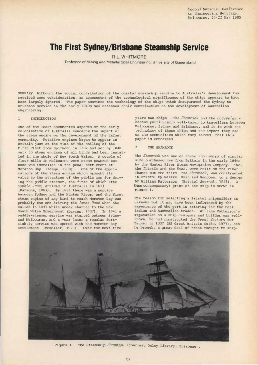
Second National Conference on Engineering Heritage, Melbourne, 20-2 2 ~lay 1985
The First Sydney/Brisbane Steamship Service R.L. WHITMORE
Professor of Mining and Metallurgical Engineering, University of Queensland
SUMMARY Although the social contribution of the coastal steamship service to Australia ' s development has received some consideration, an assessment of the technological significance of the ships appears to have been largely ignored. The paper examines the technology of the ships which inaugurated the Sydney to Brisbane service in the early l840s and assesses their contribution to the development of Australian engineering.
1 INTRODUCTION
One of the least documented aspects of the early colonisation of Australia concerns the impact of the steam engine on the development of the infant community . Rotative engines began to appear in Britain just at the time of the sailing of the First Fleet from Spithead in 1787 and yet by 1840 only 36 steam engines of all kinds had been installed in the whole of New South Wales . A couple of flour mills in Melbourne were steam powered but none was installed in the penal settlement at Moreton Bay (Linge, 1979). one of the applications of the steam engine which brought its value to the attention of the public was for driving the paddle steamer, the first of which (the Sophia Jane ) arrived in Australia in 1831 (Parsons, 1967). By 1834 there was a service between Sydney and the Hunter River, and the first steam engine of any kind to reach Moreton Bay was probably the one driving the James Watt when she called in 1837 while under charter to the New South Wales Government (Davies, 1937). In 1841 a paddle-steamer service was started between Sydney and Melbourne , and a year later a regular fortnightly service was opened with the Moreton 8ay settlement (McKellar, 1977). Over the next five
years two ships - the Shamrock and the Sovepeign -became particularly well- known to travellers between Melbourne, Sydney and Brisbane, and it is with the technology of these ships and the impact they had on the communities which they served, that this paper is concerned.
2 THE SHAMROCK
The Shamrock was one of three iron ships of simi lar size purchased new from Britain in the early l840s by the Hunter River Steam Navigation Company. Two , the This tle and the Rose , were built on the Rive r Thames but the third, the Shamrock , was constructed in Bristol by Messrs Bush and Beddoes, to a design by William Patterson (Bristol Journal , 1841). A (ocn contemporary) print of the ship is shown in Po; gure 1.
1.h e reason for selecting a Bristol shipbuilder is unknown but it may have been influenced by the experience of the port in catering for the East Indian and Australian trades. William Patterson' s reputation as a ship designer and builder was wellknown; he had constructed the Gpeat Wes tePn for Brunei in 1837 (SS Great Britain Guide, 1977), and he brought a great deal of fresh thought to ship-
Figure 1. The Steamship Shampock (courtesy Oxley Library , Brisbane).
57

building in Bristol where he had his yard. Brunel harnessed him to a team designing the much larger Gpeat Bpitain and when a small iron boat , the Rai nbow , visited Bristol in 1838 , Brunel was sufficiently intrigued to arrange for Patterson to join her for a voyage to Antwerp. The report was so favourable that Brunel decided to build the GPeat Bri tain in iron instead of wood, and Patterson immediately began to design other ships in this material , one of the first being the shamrock. However , he did not have the facilities to build it in his own yard (Farr, 1971) and he was heavily involved in supervising the construction of the Gpeat Bpitain so that the task was given to 8ush and Beddoes who, up to that time , had been chiefly known as engine builders.
Unfortunately, all plans or contemporary drawings of the Shampock have been lost but it is known from the builder's certificate that the hull measured 44.9 m in length, with a beam of 5.9 m and a depth of 3. 6 m. The central 13 .7 m contained the engine room and she had 3 watertight comjJalLments. Following sailing- ship practice and like
t 5·9m ~El 0
L I
I Steerage I
Crew Hold
I Passengers
I I
all ships of the period she was flush decked,and she carried a quarter deck with sham quarter galleries terminating in a square stern. At her prow was a female figurehead, while the three masts were schooner- rigged.
In the engine room the two cylinders of the sidelever engine had equal diameters and strokes of 1.07 m, and were supplied with low-pressure steam at 60 kPa from a square, iron boiler which operated on sea water. Waste stearn was exhausted to a simple jet condenser , giving the engine an output of 75 kw which drove the 5.6 m diameter paddle wheels at up to 21 rpm through shafts coupled directly to the engine crankshaft (Votes and Proceedings,1854). TWo bunkers accessible to the engine room but filled from on deck each held 13 tonnes of coal, and a further 60 tonnes could be stored in the hold but it was difficult to recover when the ship was at sea, the usual policy being to carry additional supplies on deck adjacent to the funnel where it was protected from the heat of the flue by the steam chest (Votes and Proceedings, 1852).
44· 9m
~ C3 [QJ , 2 _ _ _ ___ ..J ____
B • -8 I I
7 . 6 5 , I
Saloon Engine Room Officers
Passengers
...---------- 47-2m ~ I
I
5~1 L .-1---=.l------ - ------;
I Crew I Passengers & Cabin Crew
o
SCALE
I 5
I I 10m
Figure 2. Tentative layout of Shampock and comparison with Boeing 767 - 200.
1. Ladies cabin 4. Captain 7 . Saloon 2. Private cabin 5. Store 8. Engine 3. Officers 6. Pantry 9 . Boiler
58

Aft of the engine room were the saloon and cabins. steerage accommodation being located forward. Berths were provided for 34 cabin or saloon passengers with 45 in steerage; cargo was carried in the hold or on deck where there were pens for 8 horses~ A lifeboat, a cutter and a small dingy could provide accommodation in an emergency for almost one half of the total complement of the ship. Figure 2 indicates the kind of general arrangement which might have been expected; it is based on written accounts of the ship and detailed plans of the Wi Zberfnrce which was a contemporary of the Shamrock and similar in general dimensions. The plans were kindly provided by the British National Maritime Museum , Greenwich .
The gross (or builder's) tonnage was 322 , but the steam (or registered) tonnage was 200 and this was used for entering and clearing her at the CUstom House in Sydney. The total complement was calculated on the gross tonnage, and for voyages of less than 21 days she was permitted to carry one person for every two registered tons : this gave an official capacity of 160 persons (including the crew) but it was frequently exceeded (Votes and Proceedings , 1852).
After Shamrock was completed in March 1841 she ran some trials in the Bristol Channel where she was greatly admired for her speed and comfort. She sailed for Sydney later in the year under the command of Captain George Gilmore (Bristol Journal, 1841), and made her first trip to Moreton Bay in January 1842 carrying 78 passengers and numbers of horses , bulls, cows and rams as additional deck cargo (Sydney Morning Herald, 1842a). A few days later the return journey to Sydney was made in 49 hours (Sydney Morning Herald, l842b).
3 THE SOVEREIGN
As with Shamrock, there are no plans or contemporary drawings of the Soverei gn but by a fortunate chance full details of her engines and boilers are available.
:. .,;:.. ... " - .,~
Between 1814 and 1828 steamboats were introduced in large numbers on the River Thames to serve the towns which were rapidly developing between London and the open sea (Rowland,1970). In 1830 the London and Margate Steam Packet Company which operated one of the services ordered a new addition from Elias Evans of Rotherhithe , and the directors named it Wi l liam t he Fourth (Banbury, 1971). The wooden hull was 34 . 9 m in length according to the shipts register, with a beam of 4 ~ 9 m, a depth of 3.2 m and a draught of only 1.1 m, making it particularly suitable for river work (Boulton & Watt, 1830). The side-lever engine possessed cylinders 0.78 m in internal diameter with a stroke of 0.69 m; it developed 37 . 5 kw and contained a number of unusual design features including geared drives from the crankshaft to the paddle- wheel shafts. The engine and the square-section iron boiler were built at Boulton & Watt ' s Soho Foundry and a plan and cross- section of the engine room, together with other details, survive in the company's archives held by the City of Birmingham Reference Library (Figures 3 and 4 respectively).
In 1837 Wil l iam the Fourth was re- registered in London with Thomas Street and Joseph Grose as her new owners and she was immediately prepared for the voyage to Australia (Parsons, 1967). Despite her diminutive size and shallow draught she completed the journey safely. arriving in Sydney in January 1838 where she was acclaimed as a "splendid vessel" (Sydney Morning Herald, 1838). At the time there was already a locally-constructed steam boat operating out of Sydney under the name of the Wi lliam t he Fourth and the new arrival was therefore renamed King WiZli am the. Fourth in order to avoid confusion . Grose put her to work on the east coast of Australia where she was the first ste am vessel to enter the Clarence River (Parsons, 1967) . Her active life was cut short after 18 months, however, by striking Coal Island at the entrance to Newcastle Harbour and becoming a total loss, although there were fortunately no casualties. By a stroke of good fortune the "boilers went out on the off side"
. .~ , • II ~ .. ~r.--~...-.-..:.DT"---"Diii==:::;.iiit--
• . ..... ,41-.:--....... 0< I t;l _ J __ - ___ -...J'-"-~
• ' . . .~=:. ~-------, ... " .. .
~ .... - . -.-. ... ,: ...... p~~
SCALE o 2m
Figure 3. Section of Engine Room of William t he Fourt h
59

and were recovered , together with the engines (Sydney Morning Herald, 1839) .
At the time of the accident , Joseph Grose was having a boat constructed at pyrmont by Chowne and Thompson for coastal service and the design was hurriedly adjusted to accept the boilers and engines of the ill-fated King William the Fourth. The new ship was shorter, wider and heavier than the King WilZiam , and carried two masts and a schooner rig_ The hull dimensions are given variously as between 33.8 m (McKellar, 1977) and 37.2 m (Hocking, 1969) in length, with a beam of 5.4 m and a depth of 2.9 m. The draught was increased to 1.7 m giving a gross tonnage of 214 and a steam tonnage of 119. The large hull and small engines gave her a maximum speed of only 8 knots, and she normally carried a crew of 23, divided between the various offices as shown in Table 1 (Sydney Morning Herald, 1847).
The Sovereign was registered in Sydney in 1841 and Grose put her on a regular service to Morpeth on the Hunter River (Sydney Morning Herald, 1841). In 1842 the Hunter River Steam Navigation Company purchased her and she was set to work on the Sydney to Brisbane run (Sydney Morning Herald, l842c), where she replaced the Shamrock which was transferred to the newly-established Sydney to Melbourne run. The Sovereign maintained a fortnightly service until 1847 when she foundered with a heavy loss of life while attempting to leave Moreton Bay in a severe storm . The disaster was attributed to the failure of the engines; a contemporary account explains that ..... the frames of both engines were broken close under the p'lummer boxes, which were turned upside down.". This suggests that a racking motion of the paddle-wheel shafts fractured the five supporting webs of the cast-iron entablature on which the plummer boxes were mounted (see figure 3). The plummer boxes then jammed and rotated on the pa~dle-wheel shafts, jamming the whole engine or forcing the pinions apart and disconnecting the paddle wheels from the engine.
"':--'-;~ . ''':'' -- :.: "
F ...
SCALE "'=====::::1 o 2m
TABLE 1
Crew of 5.5. Sovereign
Position Number
Captain 1 Officers 2 Engineers 2 Firemen 3 Seamen 6 Stewards 5 Stewardess 1 Cooks 2 Boy 1
Total 23
4 DISCUSSION
Before discussing the impact which the steamships made on the inhabitants of Brisbane and Melbourne it is necessary to appreciate their size and performance. The Shamrock represented the most recent technology of the time and in Table II and Figure 2 its dimensions and operational characteristics are compared with those of a modern, interstate passenger aircraft which today performs the same function of providing a regular service between the major Australian coastal cities. The hull and the fuselage are similar in size. and their passenger carrying capacities are comparable but there the similarity ends. Whereas the aircraft makes the journey between Sydney and Brisbane in about 50 minutes, the ship took 50 hours. The space provided for each passenger or crew member to eat, sleep. work and exercise during the journey was extremely cramped; it was not unusual for one half of the steerage passengers to have no berth at all. while there were frequent complaints of the saloon . cabins and deck space being filled with evil-smelling cargo such as animals or raw wool. Nevertheless these crowded. expensive, little boats were gratefully accepted by the public because they provided a regular service. and their steam technology was a continuing source o f c uriosity to the travellers.
, ... ..
-~,
Fiqure 4: Cross-Section of Engine Room of WiZliam the Fourth
60

TABLE II
Comparison between Coastal Paddle Steamer and Interstate Aircraft
year of construc-ticn
Length Width Height Manufacturer ' s or
Builder ' s weight Number of crew Max. number of
passengers Time of travel
Brisbane/Sydney Approx.weight of
fuel consumed passenger fare,
Brisbane/Sydney Passenger fare as
proportion of average weekly wage.
s . s .Shamrock Ansett Boeing 767 - 200
1841 1983
44. 9m (hull) 47. 2m (fuselage) 5.9m(hu11) 5. Om (fuselage) 3.6m(hu11) 5. 3m (fuselage)
327 tonnes 74.5 tonnes
30 9
130 201
50 hours 50 minutes
25 tonnes 7 tonnes
}4-!8 $117-$218
1.6-3.2 0.3-0.6
It could hardly have been otherwise because the central third of the hull was given over entirely to machinery which emitted a continuous stream of noise, heat, smell,smoke and steam. The engine casing was made as small as possible in order to conserve space and was surmounted by a skylight. The crankshaf~at deck-level,was supported on a heavy cast-iron frame, the entablature, which in turn rested on cast-iron frames from the engine bedplate (Figures 3 and 4) . The seals between the cylinders and the pistons were made by lengths of tallow-impregnated rope (Australian, 1841); lubrication was by tallow, both inside and outside the cylinders, supplemented by sea water on the larger bearings. Shafts were built up out of separate forgings , the webs being keyed onto the journals and the crankpin being either bolted or collared into position between the webs (Guthrie, 1971). The engine room was completely decked over except for the skylight and the great, iron side-levers seesawed up and down in perpetual heat and gloom, their trunnion bearings adding their grunts to the cacophony of clicks and clanks from the air, bilge, feed and brine pumps cluttered round the baseplate. None of the machinery was fenced . or guarded by handrails, and lighting was by a hurricane lamp; each duty watchkeeper carried out his duties by the light of a duck lamp consisting of a coffee-pot shaped vessel filled with oil, with a wick in the spout emitting a smoky, reddish glare. Boilers were large, stayed, iron boxes, rectangular in shape so that they would be fitted in the space below deck set aside for machinery. Maintenance went by default and they soon either scaled up or the bottom plating eroded away under the action of the sea water with which they were fed. Considering the levels of perfection to which the armourer and the silversmith had raised metal working in Europe or the U.S.A. in the 18th century, the technology was crude and cumbersome but it fitted the needs of the new country and made a major contribution to the social and technical development of the coastal fringe of the sub-continent.
61
The steamers drove Sydney into the age of technology , engines had to be repaired, boilers manufactured and hulls built. Eleven ships had been completed by the end of 1840, and in boats such as the Sovepeign they provided evidence to settlers along the whole coast of what had been achieved. As early as 1837 J. Russell was building 45 kw marine engines locally at pyrmont and by 1840 cylinders up to 1.1 m in diameter could be bored locally. Stationary steam engines were installed on land but they were smaller than their marine counterparts and provided a total power output of only 300 kw in 1840, which was less than the total power generated by the paddle steamers operating out of Sydney. Melbourne lagged a few years behind Sydney in developing the technology . while the Moreton Bay settlement had to wait a further decade before its first steam engine was installed (Linge, 1979).
Nevertheless the steam boats created a small but regular market for coal at the ports of call and led to the opening of local pits (Whitmore, 1981). There was also a stimulus to the construction of small river boats and steamers. A nucleus of marine and mechanical engineers was established which supplemented the supply of civil engineers trained in Britain who opted to remain in Australia after discharge from the army. When the demand for steam power began its rapid rise in the l850s there was , therefore, a nucleus of local engineering to accept the influx of mechanical expertise which arrived from overseas. In view of the importance of the coastal steamers to Australia's history it is unfortunate that not a single example has survived, nor are there any plans of their design or details of the construction techniques employed.
5 REFERENCES
AUSTRALIAN (1841). 19th March. BANBURY, P. (1971). Shipbuilders of the Thames and Medway. Newton Abbot, David & Charles.
80ULTON & WATT (1830). Portfolio 1252, main catalogue .
BRISTOL JOURNAL (1841). Felix Farley ' s , 24th May.
DAVIES, A.G. (1937). Pioneer Ships in Queensland Waters. Journ. Hist . Soc.of Q'land. Vol.3,pp5- 26 .
FARR , G. (1971). Bristol Shipbuilding in the 'Nineteenth Century . Bristol, Historical Association of Britain.
GUTHRIE, J.A. (1971). A History of Marine Engineering . London, Hutchinson Educational.
HOCKING , C. (1969) . Dictionary of Disasters at Sea during the Age of Steam, 1824-1962. London, Lloyds Register.
LINGE , G.J.R. (1979). Industrial Awakening . Canberra, ANU Press.
McKELLAR, N.L. (1977). From Derby round to Burketown . St . Lucia, U of Q Press.
MORETON BAY COURIER (1847). 17th March.
PARSONS , R.H. (1967). Paddle Steamers of Australasia . Adelaide, Parsons (privately).

ROWLAND , K.T.( 1970). steam at Sea. Newton Abbot , David & Charles .
S.S. GREAT 8RITAIN GUIDE (1977). London , Macmillan.
SYDNEY MORNING HERALD (1838) . 5th February.
SYDNEY MORNING HERALD (1839). 5th July
SYDNEY MORNING HERALD (1841) . 11th November
SYDNEY MORNING HERALD (1842a). 22nd January
62
SY'DNEY MORNING HERALD (1842b). 4th February
SYDNEY MORNING HERALD (1842c), 2nd November
SYDNEY MORNING HERALD (1847). 27th March
VOTES & PROCEEDINGS (1852 ) Legislat ive Council of N.S.W. Vol . 2, pp.10ll - 1039.
VOTES & PROCEEDINGS (1854) Legislative Council of N.S .W. Vol. 2 , pp.821- 828.
WHITMORE, R.L. (1981). Coa l in Queensland . St. Lucia, U of Q Press.

Second National Conference on Engineering Heritage. ~Ielbourne. 20- 22 May 1985
Construction of the Fitzroy Dock, Cockatoo Island E. BALINT
Emeritus Professor, University of New South Wales
SUMMARY Fitzroy Dock was the first large-scale engineering project attempted in New South \iales. It was built entirely by prisoners detained on Cockatoo Island. to the design of Gother Kerr Mann, a 'military engineer', who also managed the construction and supervised the dock's operation.
1 HISTDRICAL BACKGROUND
1.1 Political Climate in the 1840s
The devastating drought that lasted from 1837 till 1841 was one of the low points in the fortunes of the fl edg 1 i ng co 1 ony of New South Ua 1 es. By then, the harsh rule of early colonial governors was somewhat eased by the establishment of a Legislative Council. In 1823 the Council consisted of just five to seven members appointed by the Governor and that Council lias not able to initiate or reject legislation.
liith the years, the Council acquired popular representation and its power increased: by 1842 twothirds of its 36 members were elected by admittedly a somewhat privileged electorate. The process of 1 iberal isation ~/as on its way, reinforced by the stand taken by free settlers such as lIilliam Charles Wentworth but it was also aided by the sympathetic attitude of two governors: Sir Richard Bourke (1831-38) and Sir George Gipps (1838-46). To the colonists' good fortune, these able and conscientious men were at the helm of government at the time of the drought crisis - probably Australia has had no abler governors than Bourke and Gipps.
1.2 The Engineer Establishment
The 1841 census showed a population, including the Port Phillip District, of 130,000 souls of I'/hom some 25,000 were convicts. Only a few were engineers and this limited the construction of public works such as roads, bridges or water supplies. Governor Bourke, himself an engineer, requested for a competent civil engineer to be sent out from Britain and an officer of the Royal Engineer Corps was ordered to take up the post. Captain George Barney arrived in Sydney in IB35, took charge of the Engineer Department and took over as Commanding Royal Engineer.
The Department (previously headed by Ambrose Hallen, Surveyor General) was responsible for military and convict buildings, whilst the Colonial P,rchitect was in charge of all Government (public) buildings (Barlow, 1971'). Thomas 11itchell, the Surveyor General, with the reputable David Lennox, continued to build roads and bridges.
In 1836 Governor Bourke appointed Barney Colonial Engineer, a new title that ~/as meant to lift him to a status equal to that of Colonial Architect. Alas, the title was short-lived: on Barney's departure at the end of 1843 Governor Gipps did not confer it on
63
Lieut. Col. James Gordon. Barney's successor as Commanding Royal Engineer. Thus the seat allocated to the Colonial Engineer in the re-constituted Legislative Council also remained vacant.
Horse still, in November 1843 the Council voted to cancel all engineering expenditure for the next year since the Colony was still suffering the aftermath of the drought. The Council also abolished the Engineer's Department and ordered that office, stores and books be handed over to the Colonial Architect's Department (Reynolds, 1972).
For the next twelve years, the Architect looked after construction and maintenance of roads, bridges and wharves in the colony whilst Col. Gordon retained command over military construction. An intriguing system of engineering tas ks and responsibilities! The division between 'military' and 'civil' engineering remained well into the 1850s (see Table I)
1,3 Early History of Cockatoo Island
Barney had achieved much in his short term (1835-43) in Sydney with the building of wharves, fortifications, barracks and the completion of the city water supply. In 1839 prisoners, under his supervi sion, cut fifteen bottle-shaped grain receptacles ('silos') out of the rock on Cockatoo Island .
For 45 years after settlement, Cockatoo Island had remained dormant. In 1833, Governor Bourke caused the erection of the first permanent buildings for prisoners stationed there, ruins of some of whi ch are still standing.
In 1841 a barracks building with berths for 344 was completed and the island was constituted as one of the colony's penal establishments, to hold prisoners under colonial sentence as well as transported convicts.
Such was the lead-up to the next move, ostensibly by the Legislative Council but possibly inspired by Governor Gipps. On 31st October, 1845, the Council adopted an Address to the Governor asking him 'to represent to Her Majesty's Government the advantages, l'lhich would accrue to this Colony and to the Empire at large, were a Dry Dock to be constructed at Sydney for ~len of I·Jar.' Hhen transmitting the address to the British Go\ernment, Gipps added : 'Cockatoo Island is the place in Sydney Harbour, which I consider best adapted for a Naval Establ ishment ... ' (HRA vol XXIV, p 611).* * HRA stands for Historical Records of Australia .

TABLE I
ENGINEERING RESPONSIBILITIES IN NEH SOUTH HALES 1835-57
YEAR 1830 35 1840 4,5 18,50 5,5 18,60
Colonial Governor Sir Richard Sir George Gipps Sir Charles Fitzroy Sir William Bourke Denison
-1831-38 --1838-46 1846-55 --1855-61--
Colonia l Architect Mortimer Lewis E T B1acket 1835-49 - 1849-54-
responsibl e for publi c bui1dings-- --pub1i c buildings, roads-& bridges
Engineer Department George Ba rney Dept of - - 1836-43 abo1 ished i n 1844 Lands
responsible for military & convict & vJorks b 1 dgs, roads and *- 1857-
bridges
Colonial Engineer George Barney title abandoned -1836-43-- in 1843
Cor.manding Royal George Barney James Gordon Engineer 1835-43 -- 1844-56 responsible for as for Engineer Dept military construction
* The first 'responsible government' was formed in New South Wales in June, 1856
It could well be that in his choice of the island, the Governor considered the useful employment of hundreds of prisoners held there . Other factors in its favour were that the island was a mere 2~ miles (3.6 km) from Sydney wharves and that it was surrou nded by deep water with plenty of room off its shores to manoeuvre boats into a dock. See Figures 1 and 2.
2 PLANNI NG FOR THE DOCK
2 . 1 Government Actions
Whilst Governors were virtual rulers of the colonial administration, they had little discretion in fiscal matters . The reply to Governor Gipps' letter by the
Figure 1 1854 map of Cockatoo Island drawn by Jas v~ Thomas Esq, Resident Engineer
A Fitzroy Dock B Pumping Station G Barracks of 1841 H Kitchen & Guard House of 1833
64
then Home Secretary , Hilliam G1 ads tone (future L i bera1 Prime Minister of Britain) in June, 1846 was based on advice from the Admiralty: 'while their Lordships approved of the work itself as well as the locality .. . they were not prepared to recommend that the expense ... shou1d be borne by t he Bri ti sh Treas ury '. (HRA vol XXVI, p 50)
Another two years had to pass before the Admiralty relented. In a despatch dated June 1848 it was s tated that 'in the event of the Local Government consenting to the construction of the Dock in the form and according to the dimensions pointed out in the accompanying sketch, and provided the work can be executed at a reasonable cost, their Lordships will be prepared ... for a fair contribution' (HRA vol XXVI, P 458).
COCKATOO (Bl tDCUJ ISlAND
Figure 2 1892 map of the Island drawn by J F Campbell in 1932
C & D Barracks of 1841 F Ruins of kitchen etc of 1833 G Power House N Silos of 1839 (Barney) V Horkshops

But during those two years Gother Kerr Mann had prepared a design and estimate for the Dock. In June, 1847, Governor Fitzroy transmitted these plans to the Legislative Council, asking it 'to report upon the expediency of undertaking the execution of this work upon the scale proposed ' . A Select Committee of Council recommended within three months in favour of construction on Cockatoo Island, with an extension of the water-line breadth and the depth of water at the sill (Votes & Procs of LC 1847 vol 2, pp 393-414).*
Subsequently, in November, 1847 the Governor ordered Col. Gordon to con~ence work on the Dock. A month later the Legislative Council voted £ 500 for each of the next two years to finance construction . The Admiralty's plans had not reached Sydney until July, 1848 - by this time surveys and investigations had been completed! Now it was up to Mann to comply with the Admiralty's design standards and it appears that he managed to conform.
At the time when the Select Committee was formed in June, 1847, the Council received a petition 'from certain inhabitants of Sydney against the employment of Convict Labour in the construction of a Dry Dock on Cockatoo Island ' . This could have been a reaction to the inhuman treatment of the prisoners on the Island.
2.2 Planning: Feasibility
The moment of conception for the project lingered on for two years: from October, 1845 when the Legislative Council adopted an address to Governor Gipps, to the order to commence work by Governor Fitzroy, in October, 1847. The time was spent on enquiries of maritime and engineering nature. * LC denotes the Legislative Council of New South
IJales.
Ships had hitherto been serviced by Captain Mosmarls shipyard in Mosman Bay and by slipways in Careening Cove (off Kirribilli) and Darling Harbour. 'Careening' meant to give the floating vessel a list to each side in succession, to obtain access to the bottom for scraping. This was considered a dangerous practice because of a risk of capsize. 'Heaving down' involved a similar operation on land - here, supports were provided to avoid damage to the hull.
Dry docks could be operated efficiently at places of large rise and fall in the tide, enabling boats to enter at high tide. The falling tide then drained the dock without need for pumping. This is the case on the Merseyside: the Liverpool docks operate practically without pumping. At Cockatoo Island, rise and fall of tides is only 1.2m to 1.8~ and it was realised that pumping machinery will be required.
In order to establish feasibility of the project, the 1847 Select Committee took evidence on maritime and technical questions. The shoals of the Sow and Pigs inside the Heads appeared to limit the size of vessel that could navigate up the Harbour and reach the proposed dock. A witness expressed preference for using a dock, compared to delays and expenses involved in heaving down a ship. Economic advantages that could accrue to Sydney were pointed out by others: 'French vessels of war, as well as commercial vessels, would come here'.
Gordon and Mann were examined on the nature of the rock on site (with a view to sell ing the excavated material), on the type of buildings and the water supply on the island, and on the supply of labour. To the question: Do you think convicts would do as much work as free men?, Mann replied: No; but I think, even with the additional expense of
--fiTZROY DOCK COCKATOO ISLAND--PLAN-SHrWINC AMOUNT 0' I:NlAftCfNI:HT
-IU:QUlfU:O "0111 DOCIeIHeArI'''T CL ..... SHII' 0,. W"JII _
J.. • •••••• r • -
- PLAN-
---CftOs. SICT~N AT ALTAfIIS- -CIiliOS' SlCTION AT I:NTftANC[ _
Figure 3 Fitzroy Dock after 1870 extensions and showing planned further enlargement
From L C Journal 1873-74 vol 23 Pt 1. p 738
65

indulgences (small extra rations of tea and sugar), a considerable saving would be effected.
In the years to come, he had reason to regret that statement.
Mann's cost estimate was £ 4,626 with convict labour, or £ 10,377 with free labour. It covered the cost of labour, tools and ~achinery but did not include rations and clothing for the convicts since they had to be maintained in any case at the cost of the Colony. A superintending engineer and assistants were required and it was anticipated that their salaries would be covered by the sale of rock, valued at £ 1,000.
Strangely, members of the Select Committee omitted to ask how long construction will take? Six years later, J1ann had to face another searching enquiry by a Commi ttee of the Legi s 1 ati ve Council, wi th members pressing him 'to state anything like an approximate period when this Dock will be ready to receive a vessel' (Votes & Procs, L C 1853).
2.3 Design
Fro~ Mann's replies to questions by members of the 1847 Select Committee it transpires that he was educated as a Civil Engineer (passed an examination) and that he was employed by Gordon in preparing the estimate for the Dock. He had consulted various works on the subject, he said, and, considering the capabilities of the harbour, came to the conclusion that the best or most profitable size for the Dock was as he has drawn it - Figure 3.
Indications are that he conceived the design on his own, possibly with some assistance from Gordon. His later mentor and adviser, Sir William Denison, designer of \~oolwich Dock in England, did not arrive in Hobart as Lieut. Governor of Tasmania until January, 1848, and it is unl i kely that he had seen Mann's design until late in 1849.
It is probable that Mann arrived at the shape of the Dock by analysing the form of contemporary vessels. A major parameter was the depth of water over the sill of the Dock and Mann based this dimension on the depth of passage at the Sow & Pigs: 24 ft (7.3m). The original 17 ft (5.2m) design depth over the sill at high water allowed for the passage of a
ship of 1,800 tons, the prototype being a paddle\·Iheeler steam frigate.
The Dock had been enlarged several times: plans were modified before construction started and then during construction, and twice later when extensions were carried out. Table II lists these dimensions; for comparison, some of the Waterview Dock (Balmain, NSW) and Alfred Dock {Williamstown, Vic} deminsions are also listed.
Mann perceived the difference between tidal conditions here and at Home and altered the cross section shown on Admiralty plans by narrowing it below low water line. This reduced the quantity of water remaining to be pumped out when a vessel was docked. Another concern was the level of keel blocks: the floor level Vias dropped 2 ft (.6m) below the entrance sill to allow placing of keel blocks. This facilitated work on the bottom of ships.
The design concept involved excavating the Dock out of the rock. Denison wrote that 'to cut the Dock out of the solid sandstone seems ... to be very feasible' (G K Mann Papers vol 1, p 313). A major concern was, however, stone quality. Mann allowed for blasting away a considerable volume of the cliff occupying the site but the permeability of the rock in situ and its suitability for lining had not been tested. On the surface the sandstone was mixed with a layer of clay and when that was removed to some .5m above high water line, a close-grained sandstone rock was encountered. Denison was led to believe that a stratum of shale occupied the bottom level of the Dock and that both bottom and sides of the Dock would require to be lined with stone.
For the floor, Denison suggested that the stones should be cut to a mould with a thickness of 3 ft (.91m) and laid in an inverted arch of a radius (in a vertical plane) of some 70 ft (21m) . His sketch showed how the shale behind the altars (series of steps running along the side of the Dock) should be replaced by rubble masonry and the stones for the altars laid against this backing. The stone floor was to be carried under the altar stones and to extend back to the depth of the rubble backing; the lowest altar stone to be let into the stones of the floor and each successive upper altar stone to be rebated into the stone below. The sill courses had
TABLE II
DIMENSIONS OF FITZqOY DOCK AND OTHER CONTEMPORARY DOCKS IN AUSTRALIA
Dock Year Length Length Breadth Entrance Depth over along along in middle width sill
top altar keel floor (mean) OHW in m in m in m in m in m
Fi tzroy Dock 1846 81 69 23 16.5 5.2 original plans
Fi tzroy Dock 1857 86 79 26 17.7 6.2 as built
Fi tzroy Dock 1870 122 116 26 17.7 6.2 first extension
Fi tzroy Dock 1880 146 142 26 17.7 6.2 second extension (present dimensions)
Alfred Dock 1864 142 137 30 25 8.2 Williamstown, Vic
Watervi ew Dock 1854 105 23 5.8 Balmain NSH
66

to be deep, also laid as an inverted arch and carried under the floor lining.
It is essential, Denison wrote, that all the masonry \"Iork be well jointed with a watertight mortar. Cement sets too rapidly and once the joint is broken, it is of no further use. He recomw.ended a mortar composed of good hydraulic lime and pozzolana, or cOlTlTlon lime mixed ~Iith clay and 'rebounced' .
Des i gn of the caisson or floating gate caused a problem for r1ann who stated at the 1847 Select COlTlTlittee hearing that he had not seen a detailed plan of an iron plate caisson. The shape of the caisson was determined for conditions of stability when floating free, and for sufficient buoyancy to rise for undocking a vessel.
In housing the caisson, ~Iann initially allowed for a groove. 'I n order to make the entrance suitable for a caisson, it is necessary to deviate from the form shown in the (admiralty's) sketch' wrote ~Iann to the Colonial Secretary . 'By it, the piers are represented as perpendicular'. Mann has insisted on a batter of 4 ft (1.22m) in the height of the piers; thus the caisson ~Iould float free after rising 10 ft (3.05m) and leave a draft of about 11 ft (3.25m), twice the draft required for safe free floating (G K Mann Papers, 14th July, 1B49).
Instead of a groove in the sill and piers, Denison proposed a step (rebate) all around. This way the caisson would float if it was drained of a small amount of water.
According to Denison, structural design conditions were: when water pressure is on one side only, it is resisted by the sheathing and framing, and transmitted through the keel and stem of the caisson to the dock itself. Also, the water contained in the caisson for buoyancy and manouevring exerts internal pressure and this must be met by cross ties and braces (G K Mann Papers 1845-69, Vol 1).
r1ann designed the contours of the caisson and indicated valves, sluices and pumps. The detail design, all in galvanised wrought iron, was carried out by fabricating contractors Rennie & Ilaterman, of Blackwall, London - see Figure 4.
3 CONSTRUCTION
In 1848, Mann was delegated to the Dock project but he was unhappy with his position. Denison wrote: 'I am slad to see that the authorities in N S Iiales propose to put you on a more respectable footing than heretofore' (G K Mann Correspondence 1845-69). By 1853 the matter was resolved: a Parliamentary COlTlTlittee addressed him as 'Ci vil Engi neer of the Dry Dock at Cockatoo Island'.
By then he was well known in the Colony through the spectacular blasting of the high cliffs overlying the Dock site. Mann used the technique known as mine firing: a gallery was cut into the cliff and charges were placed in two places, with the entrance and the connecting galleries well tamped - see Figure 5. The gunpOl.der charQ3s (in pounds) were calculated by Mann to be (LLRj /30, where (LLR), the least line of resistance, was 34 ft (10.4m) and 25 ft (7.6m) for the two charges respectively.
Mann constructed an electric firing machine, geared to attain simultaneous firing of the two charges -see Figure 5.
By July, 1853 1 ~ million cu ft (42,600 m3) of rock had been jxcavated, including 580,000 cu ft (16,200 m ) to form the Dock itself. Removal of SO,OOO cu ft (2,200 m3) still remained but this could have been difficult since it included the underwater ~Iork at the entrance to the Dock. Mann used a quantity of Bickford's fuse for blasting under water and a diving bell to remove the stone.
In the meantime stones for the inverted arch lining ~Iere being prepared and Mann built a traversing crane to lay them speedily. rlann now admitted that progress would be faster if free stonemasons and quarrymen were employed - but these I.oul d not work on the Island because of an antipathy to working by the side of prisoners!
Hann also had his hands full with receivinc and assembling the prefabricated caisson; with - the erection of a boiler and pump house, and installation of workshop equipment.
In 1855, Iii 11 iam Denison was appointed Governor of Ne~1 South Wales. Together wi th Mann, he had been a
Figure 4 Mann's design for the Caisson
67

" . , "---,- - -"
\
Figure 5 Hann's areat blast - Tap:
sketch of the arrangement for the
Centre: Bottom:
elevation of cliff plan of gallery & charges the firing mechanism
drivina farce behind the establishment of railways in the-Colony. The private railways company was taken over by the Colony in 1855 and ilann served as Commissioner of Railways ~Qr the next two years.
Responsible government came in June 1856 and i~ October 1857 a new Department of Land and PubllC I'Jorks ~/as establ ished. In ·the Publ ic I:orks Branch, one of the Departr,lents lias Civil Engineering, Dry Docks and Cockatoo Island, with G K Mann as Engineer-in-Chief. Fittingly, the first vessel docked weeks after in the ne\~ Fitzroy Dock - see Figure 6.
The ~roject ~~s far from finished and in the coming years, work continued on several extensions, fo 11 oVled by i ncreas i ng tht scope and capaci ty of the equ i pment.
As early as 1865 Mann was advocating 'the construction of an additional dock of sufflclent capac ity for any future requirements' (Journal of L C, 1865-6). This came to be reallsed twenty years later in the building of Sutherland Dock on the Island - see Figure 2.
Mann retired in 1870 at the age of 62, Vlhen the Penal Establishment on the Island VIas abolished. A few months later he offered to undertake the management of Fitzroy Dock but was curtly informed that his 'proposition cannot be entertained' (G K Mann Papers).
68
Figure 6 Royal Navy ship in Fitzroy Dock, c1866.
4 CCNCLIIS ION
Fitzroy Dock is nO~1 a working unit of the Cockatoo Dockyard Pty Ltd. The Islard is a veritable treasury of engineering heritage and much of it is worthy of recordinc and preservation . Over the years there have been changes: the old boiler and pU8p house is now part of the workshop complex and the orioinal caisson has been replaced by a steel structure that uses compressed air to speed up the discharge of water.
Since the last war, a few docks were closed down and operators and workers have di spersed. It Vloul d be an urgent task to track down documents and to record traditions of Australian dock building and operation.
5 ACKNOULEDGEMENTS
The author is indebted to the Mitchell Librarian, State Librarv of t·leVl South I'lales, for permission to us e and photograph material in the Library's archives, and to the General Manager, Cockatoo Dockyard Pty Ltd for arranging an inspection of archival material on the Island.
6 REFERENCES
BARLO", M.L. (1971). Lt .Col. George Barney, Royal Engineer. B Arch Thesis, University of New South \·Jales.
HISTCRICAL RECORDS OF AUSTRALIA . Series I. Governors' Despatches to and from England . Published by: The Library COMmittee of the Commonwealth Parliament. 1925.
LEGISLATIVE COUNCIL OF NEil SOUTH HALES (L C). Journal. Votes and Proceedings. Government Printer.
MANN, G.K. PapE'rs and Correspondence. Includes Fiaures 1 to 6 inclusive, reproduced by courtesy of the tl,itche11 Library, State Library of NSI~.
REYNOLDS, P. (1972). The Evolution of the Government Architect's Branch. Ph D TheSis, Faculty of Architecture, University of New South Iiales.

Second National Conference on Engineering Heritage, Melbourne, 20-22 May 1985
Victoria's Engineering Heritage First Hundred Years 1842 - 1942 C.G.T. WEICKHARDT
Formerly Chief Draftsman, ICI Australia Limited Ammunition Factory
1. INTRODUCTION
It is the aim of this paper to set out the achievements of the pioneer engineers of Victoria and to show how their 'mrk displayed their resourcefulness , powers of innovation and invention . Without their work , the resources of the State would not have been developed to the degree they have today. It is timely to recall the words of L . Sprague de Camp ( ' The Ancient Engineers ' ) , ' Civilisation, as we know it today, owes its existence to the engineers .'
It will be appreciated that Victorian engineers faced many handicaps; the remoteness from sources of raw materials , such as wrought iron , pig iron, coke and other materials, as well as machine tool and hand tool supplies, would have been frustrating in extreme and would have forced them to imprOvise in many ways. They began their activities at a time when engineering development in England and Europe was beginning to gather pace. In England, the work of the Darby's, father and son , in the late eighteenth century, in developing the use of coke as fuel in blast furnaces , had borne fruit by making larger quantities of cast iron available to engine builders . Larger s team engines resulted; in addi tion, machine tool builders were quick to take advantage of this development and were able to build larger and more massive machine tools. By 1825, the horizontal steam engine began to replace the beam engine, and by the middle 1830 ' s, machine tool development began to gather momentum .
It was in this scene, then, that Victoria's first engineering firm, Langlands & Fulton, had its genesis in 1842 ( 1). Their first machine tool was a treadle operated lathe ; this, together with blacksmithing equipment, enabled them to cope with their early work in the form of bullock drays, wool presses, agricultural machinery and iron work for buildings . In addition, they had an iron foundry and a brass foundry . The partnership was dissolved in 1846.
2. THE MINING INDUSTRY. In 1851 gold was dis -covered near Ballarat and it galvanised the engineering industry into feverish activity. Langlands , Fulton, and others became closely involved with supplying machinery to the mining fields . Some engineers were tempted into trying their luck on the goldfields , but many were unsuccessful and re turned to engineering. Others, however, saw a more profitable future in supplying machinery to the miners , and in many instances , started operations in proximity to the mining fields . Thus it was that Ballarat, Bendigo and Castlemaine became centres of engineering activity .
In Ballarat the firm of Richard Carter & Company became one of the outstanding firms in the district
69
2) . Established in 1655 , they became well known for their mining machinery . The Victoria Foundry, Soho Foundry, and Cornish & Bruce were also early in the field. At a later period , Lonie Dingle , Cowleys Eureka Iron Works, and the Union Foundry became well known . Some of these firms not only supplied local and interstate orders , but overseas customers as well . Indicative of the size of the machines supplied were horizontal steam engines up to 26 i nch (660mm) bore and 60 inch (l524mm) stroke.
In Bendigo Joel Horwood started in 1856, Victoria Foundry in 1858 and A. Roberts & Sons in 1861 . Sane of Roberts machinery has been ~reserved at the Central Deborah mine. Another company was that of T . Horsfield who developed a rock drill that was used locally and interstate, and was exported overseas in large numbers.
In Castlemaine, several engineering firms were established, the major one being Thompson & Company. ( 3) . The two brothers David and James Thompson, started the engineering works in 1875 . As well as building steam engines, boilers, stamp batteries etc, they became well known for their sand and gravel pumps for hydraulic sluicing. In 1935 they supplied a large dredge to Cock's Eldorado Gold Dredging N. L. in Wangaratta, Victoria . This was followed a few years later by a larger dredge for Harrietville (Tronoh) Limited, Ovens Valley , Victoria . About 5000 tons (5080 tonne) in weight, it was one of the two larges t mining dredges in the world.
Charles Ruwolt, who started at Wangaratta , Victoria, in 1903, began building dredges in 1908 ( 4) . He moved his works to Melbourne in 1911 and continued dredge construction ; many of these were shipped to Malaya and some were still operating in 1970. The last dredge was built in 1921. The firm remained active in the mining machinery field and built ball and tube mills, rock crushers Wilfley pumps as well as other equipment. They opened their steel foundry in 1914 and in 1929 they designed, built and erected an electric steel melting furnace .
Another Melbourne firm that was prominent in the mining machinery field was Hughes, Pye & Rigby starting in 1880. (The name was changed later to Austral Otis Elevator & Engineering Co.)( 5). Engines, boilers, stamp batteries, ball mills, Wilfley ore concentrators and tables were some of their output.
At a later date- in l899-the firm of Geo. W. Kelly & Lewis ( 6) was formed and early in the 1900 ' s they built many steam winding engines for gold mines . Pumps for de - watering mines and air compr essors were supplied, as well as oth ':r equipment. The firm held the manufacturing rights for the Corliss Steam engine and built many of them . This type of equipment - and that mentioned previous ly - required high standards
of craftmanship. A project that illustrated the enterprising spirit of the firm was its association with Mr. A. de Bavay, a noted research chemist, who developed the flotation process for the recovery of zinc. The firm w~s given the order for the plant which was installed at Broken Hill, N.S.I" and operated successfully .
3. RAILWAYS & TP~AYS. The great influx of migrants and merchandise into Victoria after the discovery of gold necessitated the construction of a railway line from Port Melbourne (Sandridge) to the city area in 1854. This was followed afterwards by the Brighton and St. Kilda lines; in the years that followed,.railways began to spread across the State. Initially rolling stock was imported but local engineering firms soon began to take an interest in building locoootives and rolling stock. In 1870, the Ballarat firm of Richard Carter & Company was formed into a ~ublic company and the name was changed to Phoenix Foundry Company . They became almost totally involved in locomotive building and at times turned out one a week . As the bulk of their raw materials came from overseas, the forward ordering and organisation of supplies impl1e5 an organisation of outstanding ability . In addition, interchangeability of components necessitated high standards of workmanship . In all, they built 351 locomotives for the Victorian Railways; it was an epoch making episode in Victorian engineering history .
The South Melbourne firm of Robison Brothers & Co. Pty. Ltd. built 25 locomotives for the Victorian Railways in the 1890 ' s ( 7) and David !lunro & Company built 25 tank locomotives in 1891. In 1913, the Victorian Railways placed an order with Thompson & Company, Castlemaine for 40 ' Dd' c lass locomotives and 20 more some time later . In 1924, the Commonwealth Government placed an order with Thompsons for 14 locomotives. Thompsons first supplied the Victorian Railways with points and crossings in 1879 and continued to do so over the years . In 1957 they built a new machine shop to deal with this phase of their work.
During World War I, the supply of steel tyres for railway and tramway wheels was cut off and it posed a serious threat to communications and transport . At the request of the Commonwealth Government, Thompson ' s designed and built a 500 ton (508 tonne) forging press to manufacture these items. At a later date, a 1000 ton (1016 tonne) press was built .
A number of steel bridges were required by the railways and local engineering firms demonstrated their ability to fabricate and erect them . Enoch Chambers, David Munro & Company, Campbell, Sloss & McCann, Mephan Ferguson, Johnson & Son Tyne Foundry, Rob ison Brothers, Campbell & Sloss and Humble & Nicholson of Geelong were among those who partiCipated in this field.
The safe working of railways depends largely on Signalling and interlocking of points . In 1880, the firm of McKenzie & Holland of Worcester, England, opened a branch in Melbourne and a short time later began the manufacture of signalling and interlocking equipment . They became well known throughout Australia and New Zealand . Early in the present century, it was realised that steam traction would be unable to cope with the growing volume of traffic on the Melbourne suburban railway system. Electrification of the system was started in 1913. Automatic signalling with all it implies was a new field for McKenzie & Holland, but with the experience of the parent company in England and other railways, they successfully mastered the problems involved .
70
Melbourne's cable tram system, one of the largest in the world, called on the expertise of several local engineering firms during its construction. Contracts were let in 1885 for the supply of equipoent and construction of the system . Rails, and steel cables had to be imported; some of the steam engines and rolling stock were imported in the early stages, but much of the equipment was built in Victoria . The steam engines for driving the cables were twin cylinder horizontal engines 20 inches (508mm) bore by 40 inches (1016mm) stroke and were 500 horsepower (373kW). Hughes, Pye & Rigby built thirteen of them and the firm of Ilright & Edwards built two . Boilers were supplied by Forman & Company, Campb 11, Sloss & McCann, Langlands Foundry Company and Johnson & Sons Tyne Foundry . Thousands of steel yokes or frames to form the cable tunnels were required; they were made from l1ght steel rails bent to shape. Wright & Edwards supplied some 80 ,000; Johnson & Sons Tyne Foundry supplied several thousand .
4. IIATER SUPPLY, IRRIGATION & SEWERAGE. As the population of 11elbourne and the provincial centres of Victoria increased, it became evident that an assure d supply of pure water was imperative . In 1853, the Victorian State Parliament passed an Act cons t1 tuting a Board of Commissioners of ~.J'ater
Supply & Sewerage. This resulted in the construction of the Yan Yean reservoir for Melbourne ' s water supply and the r e ticulation of water to the city and suburbs. Geelong, Ballarat, Bendigo and other towns followed suit at a later date. These projects involved civil e ngineers in the design of catchoents and reservoirs, together with the reticulation of water . Large quantities of cast iron and wrought iron pipes, together with the attendant fittings , valves, stop cocks and meters were required . Some of the companies involved were Langlands Foundry Company, Fulton Foundry Company, Mephan Ferguson, Davies Shephard, John Danks & Sons and others.
The firm of Hephan Ferguson became well known for their spiral rive tted pipes for water supply. Ferguson developed and built the machinery for forming and rivetting the pipes . The firm also became well known for the lock bar pipes which they developed. They were used on the Kalgoorlie gold fields water supply in the e arly part of the present century. The pipes we re 30 inches (762mm) in diameter and in 28 foot (8.53m) lengths; 11ephan Ferguson supplied 30,000 lengths, G. & C. Hoskins supplying an equal number.
As well as domestic water supplies, large scale catchments and distribution systems for irrigation purposes were built in the 19th century . The Goulburn Scheme "as started in 1887, followed by the Cali ban scheme, the Laanecoorie Basin and the Werribee scheme . The Chaffey brothers achieved fame in their initiation of the irrigation system in the Mallee area . Thompson & Co. of Castlemaine supplied many boilers and quick revolution steam engines coupled to centrifugal pumps for irrigation purposes.
Melbourne's sewerage scheme began in the late 1890's and as well as being a major civil engineering project, it provided a considerable amount of work for local engineers and foundries . Austral Otis Engineering Company, South ~Ielbourne, supplied large quantities of cast iron pipes, as well as a large steam pumping engine; in 1909 they supplied two more. Thompson & Co . Castlemaine built four pumping engines for the project towards the end of the 19th century. Mephan Ferguson supplied several large steel pipes as well as the Clark tunnelling shields used in excavating the underground tunnels .

5. GAS AND ELECTRICITY. In England, coal gas was used for street lighting in 1814 and Victorian engineers were not slow in taking advantage of these developments. In the early 1850 ' s, a gas plant was erected at the western end of Melbourne, somewhere near Collins Street. A new gas plant was built on the Yarra Bank in West Melbourne in 1856 and in 1857 the main City area streets were lit by gas . By 1858 a gas main was laid along Chapel Street, Prahran,as far as the Prahran Town Hall, followed two years later by a main along St. Kilda Road, Commercial Rd. and High St . By 1861 gas street lighting was in use in Chapel Street and Greville Street, Prahran. Ballarat and Bendigo soon followed Melbourne ' s example with a gas works in Ballarat in 1857 and one in Bendigo in 1859 .
It is noteworthy that the Metropolitan Gas Company availed itself of electric arc welding early in its use in Australia . In 1922 arc welding was used to strengthen a 200 foot (60 . 96m) diameter gas holder at the West Melbourne Gas Works. Shortly afterwards a 163 foot (49.68m) diameter gas holder at the Fitzroy Gas Works was completely fabricated by electric arc welding. It contained 760 tons (772 tonnes) of steel and was believed to be, at that time, the largest all-welded structur e in the world. ( 8)
In 1880, the Victoria Electric Lighting Company had its inception and supplied electricity to a part of the city. This was taken over in 1881 by the Aust ralian Electric Company. The Melbourne Centennial Exhibition of 1888 saw electric lighting used on a large scale; Austral Otis Engineering supplied three steam engines, similar to those used for the cable tram system, for driving the dynamos. In 1894 the M.elbourne City Council power station was built, and a few years later the Melbourne Electric Supply Company built its power s ta tion in Richmond .
In 1921 the State Electricity Commission of Victoria started with the turning of the first sod at Yallourn. It was created to exploit the brown coal deposits of South Gippsland and to bring electric power to all parts of the State, as well as making Victoria independent of outside sources of coal. Local engineering firms played a major part in the design and construction of massive power station buildings, transmission line towers (Johns & Way good Limited supplied over 400 towers for the first transmission line from Yallourn to Melbourne) and other aspects of the project. In the field of power production, Thompson & Company, Castlemaine, in 1920 commenced the manufacture of steam turbines, condensing and feed heating plants for power stations allover Australia. In 1927, they had under construction six 25 , 000kW turbines with condensers for Bunnerong power station in New South Wales . They were built to the design of the Metropolitan-Vickers Electrical Company Ltd . , England , who supplied the rotating portions of the turbines . Thompsons also supplied the circulating water pumps for the condensers . The firm also supplied condensers and water circulating pumps for 125,000kW generating sets at Yal10urn . In addition, water turbine casings for the Sugarloaf-Rubicon Hydro-electric scheme were built.
6. SHIPPING . The growth of trade with Victor-ia from overseas and interstate made ship repair facilities necessary early in the his tory of the State. Ship building was also undertaken . One of the first firms to tackl e this work was Forman & Company in South Melbourne , who started in 1854; the dredge ' John Nimmo ' was built by them . Campbell, Sloss & McCann built the ' ss Lady Loch ' in 1886; originally built for the Victorian Department of
71
Trade & Customs, it was used later for ser~c~ng lighthouses . Johnson & Sons Tyne Foundry built barges, small craft , gold dredges for New Zealand and did ship repair work. Buchanan & Brock (originally Buchanan & Nodrum) built steamers for the Gippsland Lakes, tugs, launches and other craft, as well as ship repairs. Australian Forge & Engineering Company, Williamstown built the pilot steamer ' Victoria ' Local engineers supplied machinery for the River Murray paddle steamers; \,right & Edwards, Fulton Foundry Company and David Munro & Company were among those so engaged.
Mention must also be made of one of the most outstanding mechanical engineering inventions of the twentieth century . This was the Michell thrust block; devised initially for marine propeller shafts . It was the invention of Mr . A. G. M. Michell, a Melbourne engineer; it was patented in 1905 and was adopted by the British Admiralty and by ship builders generally. It solved a problem that was holding up development of large ships .
7 . BUILDING & HOUSING. In the early years of Victoria's history, basalt deposits at shallow depths in various areas provided suitable building material . Other rock deposits were also exploited . Similarly, various clay deposits, particularly in the Northcote and Brunswick areas, were used for bricks and tiles. The demand for brick and tile making machinery was met, amongst others, by firms such as W. Anderson & Sons, Hachar & Teale, Langlands Foundry Company and John \'elch.
The increasing height of multi- storey buildings required steel framing and Peter Johns' Melbourne Iron Works was one of the first to provide rivet ted steel girders and columns in the 1880's for this purpose. At a later period, Austral Otis Engineering, Edward Campbell & Son, and A. Challingsworth shared in supplying the demand .
The increasing height of office and other buildings necessitated the use of lifts , and once again Peter Johns took a leading part in this field . From supplying hydraulic goods lifts to warehouses, he began constructing passenger lifts for offices, hotels and public buildings. Shortly afterwards, Austral Otis Elevator & Engineering Company entered the field, together with the Australian Way good Elevator Company . Johns & Waygood installed their first electric lift in Greens Buildings, Swanston Street, Helbourne in 1907.
8. PASTORAL INDUSTRIES. The production of wheat and other cereals began early in the his tory of Victoria; by 1851 there were 52000 acres (21044 hectares) of land under cultivation . Despite this, considerable quantities of wheat and flour had to be imported. The demand for agricultural implements was met by many local engineering firms; in Melbourne Langlands Foundry Company, Fulton Foundry Company, David Munro, Hugh Lennon, Mitchell & Co., T. Robinson, were amongst those who met the demand . Some engineers saw advantages in being in close proximity to the wheat growing areas, hence Ballarat became a centre for many firms in this field. George Munro, D. B. Macaw, Dingle Laverick, Kelly & Preston, and John Tynan were some of those who produced implements of all types. Hany firms made a feature of interchangeability of parts on their machines, thus helping to solve the repair problem.
The operation of winnowing in wheat harvesting was loathed by wheat growers, and it took the ingenuity and perseverance of H. V. McKay to solve the problem. He took out patents in 1885 and began operations in

Ballarat, moving later to Melbourne . His machines were built to a standard specification and interchangeability of parts was guaranteed .
In parts of Victoria, traction engines and tractors had difficulty in working in wet soil and sandy soil. These were overcome by the invention of a special type of road wheel . Developed by Frank Botrill, an inventor and bIacksraith, i -t came aEter the development of the caterpillar tread and a patent was taken out for it in 1907. A tractor and waggon with these patent wheels was built by A. H. McDonald & Company, Richmond, in collaboration with Austral Otis Engineering Company . McDonalds also supplied tractors w~th Bottrill wheels for us e on the construction of the Trans-Continental Railway. Another unique invention was a four wheel drive steam traction engine; conceived by Thomas Quinlivan, a farmer living near Coghills Creek, Victoria, it was designed by Mr . G. F. Wightman, Works Manager of Cowleys Eureka Iron Works, Ballarat, and built by them. Nothing like it had ever been built before; it was patented in 1908.
The production of wool required the use of wool scouring and associated machines, wool presses, and other equipment. Hall Brothers, Clifton Hill, Victoria made a specialty of wool scouring machines. Wool presses were built by many firms from the earl iest days; Humble & Nicholson of Geelong, built over one thousand, many being shipped to South America. Peter Johns began building hydraulic wool presses prior to 1880. The introduction of the sheep shearing machine in 1888 eliminated a good deal of labor in the sheep shearing industry. It was the invention of Wolseley wbo came to Australia from Ireland; Herbert Austin, who had served an apprenticeship with Langlands Foundry Company, collaborated with Wolseley in the production of the machine. Production was carried out at the works of R. P. Park, South Melbourne.
9. FOOD PRODUCTION. Flour mills were built in various parts of the State, to cope with the demands of increasing population. A number of local engineering firms supplied mill machinery, pre-eminent being Robert Bodington , and Schumachers Mill Furnishing Works. Both these firms supplied a full range of flour milling, grain and seed machinery. Meat works were established fairly early in Victoria together with tanneries. One company that became well known for its products in this field was that of J. T. Stamp; Stamp was associated with Walter Powell for some years in the manufacture of abbotoir machinery. Dairy products feature largely in the State 's primary industries, but the preservation of meat and dairy products was not satisfactorily solved until the advent of refrigeration. A Geelong inventor, J. Harrison, developed an ether-compress ion refrigeration process that was used in a Bendigo brewery in the 1850' s. Robison Brothers fitted two ships , the 'Protos ' and the 'Europa' with refrigeration equipment in 1880 and 1881; they took cargoes of frozen meat to England. Humble & Nicholson, Geelong commenced building refrigeration and ice making plants early in the 1880 ' s. Lowther & Jarvis, The Atlas Company of Engineers, and R. Werner & Company were other firms that became well known in the refrigeration field.
Preserved meat exports began about 1868; the Melbourne Meat Preserving Company was the most success ful in this field, and by about 1880 were employing a large number of tinsmiths to make the thousands of containers required . This demand for containers led to the manufacture of press tools, sheet metal working machinery, power presses and the like. Such
work demanded precision engineering methods and the firm of W. G. Goetz & Sons Ltd. became one of the leaders in the field.
10. INTERNAL COMBUSTION ENGINES . The first gas engine built in Victoria was produced by G. Scott & Sons in 1884 . It seems apparent that Victorian engineers kept themselves well informed of developments in England and Europe; Lenoir in France developed the first internal combustion engine in 1860 and Otto developed the four cycle pe trol engine in 1876. It was not long before Victorian engineering firms launched into the production of internal combustion engines, mostly small ones for farm use . John Buncle in Melbourne, Jelbart Brothers and Ronaldson Brothers & Tippett, both in Ballarat, Geo . W. Kelly & Lewis, A. H. McDonald & Co., H. V. Hampton, and E. Coulson were some of those that were busy in this field . McDonalds started production of small petrol engines in 1904; Geo. W. Kelly & Lewis began building similar engines in batches of fifty in 1910. Quantity production required interchangeability of parts, thus necessitating jigs and fixtures, as well as precision measuring methods and equipment. All this led to engineers : honing and refining their skills, paving the way at a later date for automobile and aircraft manufacture.
11. WARTIME PRODUCTION. It has been said that no country can afford to go to war without having a well-organised and efficient secondary industry. In this regard, Australia was well served by the well established engineering firms that had grown up in less than one hundred years. During World War I, the Commonwealth Government called on selected local engineering firms to assist in the war effort, one of them being Geo. W. Kelly & Lewis . They had an order for shell cases, which required special lathes for their production; none were available so the firm designed and built their own . Three months after commencing work, twelve were delivered. The firm als 0 built three air - craft engines for the Aus tralian Flying Corps; they were 80 horsepower (60 kW) and modelled on a Renault prototype. Johns & Waygood also produced several thousand shell cases. It was mentioned earlier that Thompson & Company, Castlemaine, were called on to design and build a 500 ton (508 tonne) forging press for the production of steel tyres for railway and tramway rolling stock . They also built marine engines during the war.
72
The outbreak of World War II was not unforeseen, and some time ahead of the catastrophe, the Commonwealth Government made plans to ensure that local engineering firms were fully organised to cope with the burdens that would be laid on them. Many firms built special annexes to deal with the requirements of the Defence Department and in many cases undertook work that was completely foreign to them . Only a few examples can be quoted. Charles Ruwolt (now Vickers-Ruwolt) built a special annex for the manufacture of 3" (76.2 mm) trench mortar bombs, and at a later date, undertook the manufacture of 25 pounder gun howitzers. Nine months after the receipt of the order, the first gun was submitted to the Army Inspection for proof tests. This was an extraordinary feat in view of the fact that the firm had had no previous experience of ordnance manufacture, and that they had to design and build some machine tools for special machining operations . In addition to these contracts , the firm also supplied tank attack guns, 200 horsepower (149kW) Diesel engines, and other items. Kelly & Lewis had a wide ranging program of steam generating se t s for the Navy, air pumps and fans for sloops and cor-

vettes, portable pumps , barges , sections steel telegraph poles and radio masts . Johns & ~aygood ~ade 10 pound (4 .53kg) and 20 pound (9.07 kg) mortor bombs , 20 pound (9 . 07 kg) aerial bombs, made and assembled torpedo parts . steel structures of all kinds, as well as machine tools for defence factories . Thompson & Co . , Castlemaine, built marine engines circulating pumps, supplied massive forgings to other companies, ~rine propellers , tank attack guns and many other items. This is to say nothing of the achievements in the automobile and air-craft manufacturing industries . In fact, it is only a small picture of all that went on during those years.
12. CONCLUSION . The economic values of our engineering heritage are many. TI1e potentialities of the pastoral and agricultural indus tries were made possible by the supply of suitable equipment . Gold production laid the foundation of the State's wealth in its early years . Dairy products, meat products, and fruits were kept fresh in cool stores supplied with equipment furnished by Victorian engineers . The exploitation of the brown coal resources of southern Gippsland brought electric power to all parts of the State .
Many social values accrued from our engineering heritage. The provision of fresh water and the installation of sewage treatment plants brought about a great improvement in public health. The coming of gas and electricity brought a marked icprovement in living and social conditions; streets were made safer at night, cooling and household he ating were improved and pollution was reduced . The installation of machinery in factories and farms eliminated much drudgery, arduous and laborious work , as well as eliminating many hazardous tasks . It made a reduction of working hours possible, with increased leisure. The installation of telephones and telegraphs was a great boon enabling as it did, instant communication in City, rural and interstate areas . Roads, railways and tramways improved social life by quicker, easier and safer travel.
It is perhaps appropriate to conclude with the sentiments expressed by the late Ifr. E. P. Lewis,
73
for~er Chairman of Kelly & Lewis Limited . In a foreword to the company book ' Fifty Years of Engineering ' published in 1949, he said,
"In recent times the tides of political and economic thought seem to have set against enterprise. The appreciation of its benefits has been overshadowed by a too close preoccupation with its deficiencies . But while this world needs the virtues of courage, vision and honest workmanship, enterprise will always have its part to play."
13 . REFERENCES .
1. Weickhardt, C.G.T . (1983) Langlands Foundry COmpany Journal Royal Historical Soc. of Vic. Vol . 54 No. 3 Sept. pp 47 - 49
2. Weickhardt, C.G.T . (1984) Phoenix Foundry Company Journal Royal Historical Soc. of Vic . Vol . 55 No.3 Sept. pp 46- 50
3 . Weickhardt, C.G . T . (1982) Thompson & Company , Castlemaine Unp ub lis hed .
4 . Weickhardt, C.G.T. (1978) Vickers Ruwolt Ltd. Unpublis hed .
5 . \,eickhardt, C.G .T . (1980) Austral-Otis Engineering Company Ltd. Unpublished
6 . Kelly & Lewis Ltd . (1949) Fifty Years of Engineering 1899-1949 Kelly & Lewis
7 . Weickhardt, C.G.T. (1984) Robison Brothers & Co . Pty . Ltd. Journal Royal Historical Soc. of Vic. Vol. 55 No . 1 March pp 31 - 35
8. Masterton, C.A. (1961) The Development of Electric Welding Journal Inst . of Eng . Aust. Vol.33 No.6 June

Second National Conference on Engineering Heritage , ~Ie Ibourne, 20- 22 ~lay 1985
Telford, Stephenson and Brunei - Pilots of the Future P.S. STAUGHTON
Architect, Warrandyte. Victoria
1 INTRODUCTION
Thomas Telford , Robert Stephenson and Isambard Kingdom Brunel were intellectual giant s of their times - the latter decades of the eighteenth century and the first half of the nineteenth. These were ~en of inspiration , imagination and invention , each with a see~ngly endless capacity for mental and physical endurance , who charted the courses of their lives with i nquiry I precision , determination and an innate sense of beauty as they strode confidently into the future to create a bountiful heritage of "im'nense and glorious works of fine intelligence ".
They built superbly in the old materials of stone and brick and they embraced with int ense enthusiasm the new materials and processes of the new age -the Age of the Industrial Revolution . Abraham DarbY at Coalbrookdale on the Severn in Shropshire used coke in place of charcoal for the smelting of iron which led to the production of cast iron in great quantities , unrestricted by the old difficulties of supplying sufficient suitable charcoal . A hitherto unknown architect from Shrewsbury , Thomas Farnolls Pritchard , designed the first cast iron bridge in the world . Cast at Coalbrookdale , the components were assembled and the bridge with a span of 30 m and a rise of 15 m was complete across the Severn in 1779 where it stands to this day at Ironbridge.
This achievement is one of the most significant, far reaching and influential attainments in the history of man as an engineer and builder and its lessons were not lost on the brilliant minds so closely to follow its example and see its implications for the future.
Wrought iron was known to the ancient Egyptians and Assyrians who made great use of it and it is mentioned in the Book of Genesis. It is surprising to see that cast iron was made as comparatively recently as the sixth century A. D. in China. Until the advent of the Coalbrookdale cast iron bridge, iron, either wrought or cast, had never been conceived as a material for engineering works in its own right . Ironbridge was the great new dawn which was to lead to the development of the science of metallurgy, controlled systems for the testing of materials and the monitoring of production methods. Telford , Stephenson and BruneI were pioneers in this work and one of their most valuable lessons for us was their use of small scale prototypes which provided the essential information allowing their great structures to follow more surely. Henry Bessemer with his converter and others made possible the mass production of steel. The Forth Bridge 1883- 89, designed by Fowler a nd Baker was the first large steel structure to be built and we owe much to these two remarkable engineers for their frontier work on the effects of
74
wind pressure on structures.
Our century has produced gr~at steel wire cabl e suspension bridges, like J . B. Strauss ' s Golden Gate , San Francisco , 1933-37. Wire cabl e was first used in a large structure by J.A. Roebling for his superb Brooklyn Suspension Bridge in New York , 1869-83 , and the principles he established for the spinning of wire cables are used today - a fascinating development from the wrought iron link c hains in the bridges of Telford and BruneI .
In our century , Fritz Leonhardt of Germany has built his elegant fan and harp cable stayed bridges, which rank with the world's engineering masterpieces .
2 THOMAS TELFORD (1757-1834)
Thomas Telford was born on August 9th 1757 in a small cottage at Glendinning in the Parish of Westerkirk , Eskdale, Dumfries - the son of an 'unblameable shepherd '. He started out in life as a stonemason, with the aim of becoming an architect . In fact, during his early years in London he worked as a mason on Somerset House where he was introduced to Sir William Chambers and Robert Adam, two very distinguished architec t s indeed. He went on to design the Commissioner ' s House at Portsmouth Dockyard before moving up to Shrewsbury in 1787 to make improvements to the Castle there and to design the new prison among other works . He later built two fine churches , St. Mary , Bridgnorth and the innovative little octagonal church of St. Michael, in nearby Madeley. It was about this time that Telford was appointed Engineer and Building Surveyor to the town of Shrewsbury and the quite extensive district around about. His first task was to build a number of bridges over the Severn to replace those destroyed or extensively damaged by severe recent flooding. It was most fortuitious that he should have come to the Severn Valley, the cradle of civil engineering, just at this time . From now on, civil engineering became his career, but he never abandoned the tenets of form, line and proportion acquired during his studies of architecture - his roads , canals , bridges and aqueducts always set so harmoniously and at times in striking contrast with the diverse landscapes in which he moved , were all works of considerable beauty.
The Iron Bridge at Coalbrookdale clearly impressed Telford profoundly and this set him thinking about structura l uses for cast iron. In 1793 he was appointed to design a scheme for connecting the Mersey , Dee and Severn to be known as the Ellesmere Canal System . Telford wished to reduce the flights of locks wherever possible to speed up the traffic and this presented him with the greatest challenge of the proj ect - how to convey the Canal across the

wide and deep valley of the River Dee at Pont Cysylltau near Llangollen , in North Wal es .
Now just at this time , Telford was appointed engineer to another Canal, the Shrewsbury Canal which connected the town of Shrewsbury with t he col l ieries near the Wrekin at a place called Ketley where a large ironworks had been established. The Canal had to cross t he small River Tern near the vil l age of Longdon and this is the way Te l ford described his idea "1 have just recommended an Iron Aqueduct , . . . it is approved and wil l be executed under my direction upon a principle entire l y new and which I am endeavouring to establish with regard to the application of iron. "
What Telford did was to build an aqueduct entirely of cast iron components. The trough members whilst rectangular in cross-section were fan shaped in side elevation giving the action and appearance of a flat arch . Those sections were bolted together along their flanges and sealed at the joints to make the whole assembly watertight. This continuous aqueduct trough some 55 m long and supported on cast iron columns and struts, all made at Ketley , was the first iron aqueduct in the world. Though small in scale, it was a great technological achievement . The tremendous importance of this model aqueduct was that it gave Telford the opportunity to demonstrate the soundness and practicality of his idea shortly to burgeon forth in his mighty work at Pont Cysylltau .
This majestic aqueduct is a continuous cast iron trough some 300 m in length made up of fan shaped channel sections based upon the Longdon system. The trough extends over nineteen spans , each supported by cast iron arches between tall stone piers . Telford designed these piers to be cellular from a height of 20 m upwards , thereby establishing an important new structural principle . It combined strength with comparative lightness in the masonry, it demanded excellence of workmanship and it reduced quite substantially the load upon the foundations .
The Pont Cysylltau Aqueduct was opened in 1805, to the astonishment of the people and the acclamation of the engineering world . To see canal barges being towed 40 m above the River Dee was beyond belief to the Welsh , this "Stream in the Sky" as they called it and Sir Walter Scott pronounced it the most impressive work of art he had ever seen .
Telford built his first cast iron bridge in 1796 at Buildwas on the Severn, not far from Ironbridge. The span of the arch was 40 m with a rise of only 7.5 m which very effectively resisted the thrust of the banks . This bridge, of greater span than Iron Bridge used less than half the quantity of cast iron .
Telford built a great number of cast iron bridges throughout his life. His most ambitious design was, unfortunately , never built. This was his proposal for a new London Bridge in 1801 , a magnificent design spanning the Thames in one 180 m cast iron arch. It seems incredible to us that the project was abandoned on one count only - the difficulties created by the neighbouring wharf owners over the approaches to the bridge - the great chance of formal arcades l ining the river in the vicinity of St. Paul ' s lost , if not forever , at least until the advent of an age of enlightened design .
Telford built a large number of beautiful stone bridges as well, in connection with his road and canal schemes , many of these in Scotland . It is scarcely an exaggeration to say that almost solely
75
throug~ h i s efforts , the econocy of the Highl ands was restored - the e ngineer by his considerable talents and practical skills seen as the ' redeemer of an entire SOCiety, once in apalling poverty , now start ing to revive and establish once more.
Te l ford ' s achievements in wrought i ron a r e no less important than his works in cast iron , i ndeed they are perhaps even more remar kabl e and astonishing. His great est work in wrought i r on is the supremely beautiful Menai Suspension Bridge , of 1826 , conveying his London to Holyhead Road over the navigable Menai Straits linking the mainland of Wales with the Island of Anglesey .
This bri dge, the longest suspension bridge of its time , has a clear span of 174 m with a clearance of 30 m between high water and the underside of the deck - a stringent requirement of the Admiralty . The two main piers , each with t wo archways to allow the passage of traffic , rise to a height of 16 m above t he roadway deck as pyr amidal towers to support the chains. The deck is approached by three great masonry arches on the mainland side and four on the Anglesey side. The stone used in the suspension towers and the approaches is a tough grey limestone , from the quarries of Penman , at the eastern end of Anglesey. The deck , 9 m wide , was supported originally by sixteen chains made up of composite links each consisting of thirty- six bars of iron.
Telford approached the design and b uilding of this bridge , a pilot structure for which there was no precedent in scale with the greatest caution and has given the succeeding generations of engineers much invaluable information and guidance . For example , every wrought iron link of each of the chains was given a tensile test on a machine specially designed for the purpose by Telford and installed in William Hazledine ' s Coleham ironworks at Shrewsbury. From protracted experiments , Telford was able to show that his bridge would in fact have the ample safety margin of 100 per cent. Corrosion of structural metals was a particular concern of his , as it is for us today . To protect the links from the very serious corrosive effect of saltwater and the salty atmosphere of the Menai , they were heated , quenched in a bath of linseed oil and then dried in a stove which gave them a protective varnish.
Telford never trusted theory alone , but checked every move he contemplated by practical experiment wherever possible. In spite of the thorough Coleham tests , the first length of chain to be assembled was suspended across a nearby valley on Anglesey and given rigorous tensile testing. He also was able to determine the power necessary to raise the chains to t heir appointed position on the bridge itself. Furthermore, he built a one- quarter size model of one of the chains and suspended it to enable his calculated lengths of the vertical suspension rods to be checked against actual meas urement . It is especially interesting to note that a steel master link or pattern was made to allow the greatest possible accuracy in the manufacture of the chains and in the boring of the links. Our word for the process is ' jig drilling '.
The progressive raising of al l the sixteen chains from the raft on the water into their positions on the towers , the linking up with the landward anchored chains and the ancillary tasks proceeded smoothly over several days, with efficiency improving as the men worked into a routine. That the entire difficult and risky operation was completed without hitch or mishap was owing , in large measure ,

to Telford ' s superb planning , rigorous testing , well chosen assistants and to his abiding concern for the safety of every man on the works .
In the middle of the night, on January 30th , 1826 the first coach crossed the Menai and the greatest suspension bridge in the world was opened without ceremony in the manner Telford saw fit.
Only a week after the opening on the night of February 7th, 1826, a ferocious gale blew down the Menai Straits, striking the bridge broadside . It induced a very pronounced movement in the structure, so much so that the coachmen refused to cross. Twenty-four of the roadway bars along with six suspension rods were broken. Twelve days later an even more violent storm at night broke twenty more suspension rods and bent another fifty . Great concern was expressed at the waving motion in the road\",ay deck , which was described as alarming. Clearly modifications had to be made. Stronger suspension rods were installed, bracing chains were added to steady the main chains and the deck was strengthened with heavier members. Notwithstanding these measures which appeared to have overcome the problems of movement in the bridge during bad gales, Telford with all his extreme care and concern, was gravely worried, so much so that he stated his belief that no future suspension bridge should exceed the span of the Menai Bridge. As we shall see , I.B . BruneI was soon to refute the assertion vehemently . In fact the bridge stood at the threshold of the science of aerodynamics.
The Menai Bridge , after the initial problems were overcome, served splendidly down the years. In 1940 it was modified , with the deck and chains renewed, yet it retains its original elegance of line.
The poet Southey referred to Telford as "The Colossus of Roads". He was also called "Pontifex Maxirnus", the supreme bridge builder. He gave us the basic form of the building contract we use to this day. He was a Fellow of the Royal Society and the first President of the Institution of Civil Engineers . Born in ,the Parish of Westerkirk 1757 , buried in the nave of Westminster Abbey, 1834.
"And I will make all my mountains a way , and my highways shall be exhalted" - Isaiah 49:11
3 ROBERT STEPHENSON (1803-1859)
Robert Stephenson was born in 1803, son of George Stephenson, "the Father of Railways" as many called him , with little exaggeration. Robert Stephenson , unlike his father , had a formal education and distinguished himself early as a mechanical engineer. His great success with their "Rocket" at the Rainhill trials of 1829 established his reputation and the practicality of locomotive hauled railways .
In this paper we are concerned with Robert Stephenson, the celebrated civil engineer. Of his many great works, two stand out particularly, making him a pilot of the future - the Britannia and Conway Tubular Bridges.
In 1845, he was appointed Engineer-in- Chief to the Chester & Holyhead Railway. His task was to build the line and it is fascinating to see that like Telford , he too had to find a way of crossing the river estuary at Conway Castle and , of far greater ~ment, meet the challenge of the Menai Straits. As these were railway bridges, suspension systems with light , untrussed decks were dismissed at the outset as totally unsuitable . Robert Stephenson was emphatic about this and wrote at length on the
76
subject . It is curious to recall that at one point his father was seriously proposing to use a lane of Telford ' s bridge to carry the railway over the Menai Straits!! The failure of Captain Brown 's suspension railway bridge over the Tees at Stockton was a stark lesson.
For the Menai , Stephenson selected the crossing point for his bridge to align with the Britannia Rock, a natural rock outcrop almost in the middle of the Straits , about a mile south of Telford ' s bridge . His first proposal was for two equal cast iron arch spans each extending from its shore abutment to the central pier on the Rock. This scheme was discarded on two counts - the centering needed to construct the arches would interfere with navigation for a lengthy period and the Admiralty requirement of 30 m clearance would set the abutments so high above natural grade that the railway approaches would become prohibitively costly . His next thought for the spans was a new concept of suspension where the chains might support a form of deep trussed girder either in wood or wrought iron. His next step was to consider solid wrought iron sides and bottom made up of riveted plates, a trough in effect open to the sky , with the railway track at the bottom of the trough which would be supported by suspension chains.
Now just at this critical stage a mishap occurred during a broadside launching of an iron steamship at Blackwa11 on the Thames. She had jammed , quite undamaged , supported clear at two points only, at her forepeak and her sternpost. Stephenson went down expressly to have a look at her and there set before him he saw his solution to the Britannia Bridge. The vessel, her decks closed in , was in reality a long tube , supported only at the ends. He returned , put a roof on his trough and created a rectangular tube of considerable strength. The great idea was born .
Now the time for exhaustive testing had come . Stephenson believed that the strength of the tube could be such that suspension chains would not be needed. He approached two men , both experts in their field - William Fairbairn the famous engineer and shipbuilder, once an associate of his father , and Professor Eaton Hodgkinson , F . R.S ., a prize mathematician and an authority on iron beams. The two reports were submitted to Stephenson. Hodgkinson considered the chains were essential, Fairbairn dismissed the need for them. "Provided the parts are well proportioned and the plates properly riveted", he stated "you may strip off the chains and have it (the bridge) as a useful Monument of the enterprise and energy of the age in which it was constructed. " Wi th characteristic caution, Robert Stephenson studied the reports exhaustively and finally decided against chains . Fairbairn and Hodgkinson worked as a close team with Stephenson on the Britannia and Conway Tubular Bridges. The basis of their work was a series of tests to destruction on large wrought iron models of the tubes set up in Fairbairn's shipyard . Progressive improvements were made after each test and the results of those tests led to the final design of the actual tubes. Cellular construction was adopted for the roof and floor of the tubes. Individual plates with stiffening "T" section ribs formed the sides .
The Britannia Bridge was designed symmetrically about the tall central pier on Britannia Rock . There were two parallel tubes each conveying a railway track. The span from the central tower to each of the intermediate towers on either side of it was 138 m and from the intermediate towers to the portal

abutments 69 m. The tubes tapered slightly from the Britannia tower where the overall cross- section measured 9 m in height by 4 . 5 m in width. The total length of each tube from portal to portal was 454 m.
It is important to appreciate that the four sections of each tube were joined together within the towers to form one continuous tube , rigidly fixed in the central Britannia tower, but free to move over roller bearings in the intermediate towers and abutments to provide for expansion and contraction. The brilliant subtlety of this system devised by Robert Stephenson is often missed . In fact the end spans were jacked down thereby actually prestressing the tubes , an astonishing innovation for 1850, revived only comparatively recently. This continuity of the tubes and the prestressing measures greatly increased the strength of the bridge , thereby allowing it to cope easily with the heavy trains of today .
The tubular bridge at Conway though small in comparison with the Britannia Bridge provided Stephenson with the ideal opportunity for a full scale model test before he started to float the great Britannia tubes on their pontoons at the Menai. Again we see the inestimable value in having a small scale prototype to gather information and experience for the immense work to follow . The Conway bridge carried two tracks in simply supported parallel tubes of 120 m span between the portals which in this instance were decorated with rO~ldels and battlements in keeping with Conway Castle a device used by Telford earlier in the towers of his adjacent suspension bridge. It must have been a memorable occasion to have seen Stephenson and BruneI standing together on one of the Conway tubes as it was floated into position.
In spite of all the tests and careful preparations, unforeseen problems occurred at the Menai - a hydraulic press burst , a capstan fouled at a critical time and the timber staging supporting one of the tubes during assembly gave under the weight and had to be strengthed and the camber in the tube restored. There was heroic drama in the floating and raising of the Britannia tubes.
Finally , all difficulties overcome , the great bridge was completed in 1850 , one of the most astonishing achievements in the world for its time and a pilot for the future.
It is sad irony to recall how fragile the greatest structures of man can .be. A few years ago young boys were smoking out ferrets , it is said , around one of the abutments. A spark from their fires flew up and lodged it seems beneath the light timber roof over the tubes which was impregnated with bitumen as a protection against the weather. In an instant the Britannia Bridge was alight from shore to shore, the once mighty tubes now sagging limp and dangerously, damaged beyond feasible restoration; one of the greatest and most innovative pieces of our Engineering Heritage was now lost forever.
In Victoria, at Shelford between Teesdale and Rokewood a small but most elegant wrought iron tubular girder road bridge of three spans crosses the River Leigh . It was designed by the engineer Charles Wilson in 1873-74.
4 . ISAMBARO KINGDOM BRUNEL (1806-1859)
Isambard Kingdom Brunel , son of the distinguished engineer Sir Marc BruneI , famous for his Thames Tunnel, has been most aptly described as the Leonardo of the nineteenth century - the universal
77
man. He was a rnan of vaulting intellect and unbounded imagination. In his iron steamship 'Great Britain ' he proved the practicality of the screw propeller for driving ships across the oceans and his 'Great Eastern', the largest ship in the world for many years to come, laid the first successful telegraph cable across the Atlantic.
Many of BruneI ' s finest achievements in Civil Engineering are to be found on his superb broad gauge Great Western Railway - the Wharncliffe viaduct ; the Maidenhead Bridge with its wide span and very low rise brick arches; Box Tunnel and the prodigious difficulties encountered in boring it; the fan shaped timber viaducts in Cornwall and at the very end of his astonishingly productive life his greatest railway work of all, the Royal Albert Bridge at Saltash carrying the railway over the Tamar Estuary into Cornwall.
The Royal Albert Bridge has two great lens shaped trusses of wrought iron construction , each with a span of 140 m supported at the middle of the Estuary on a composite cast iron pier , itself consisting of four octagonal cast iron columns. The trusses are supported at the shore ends by tall masonry piers. The deck is 30 m above high water , the familiar Admiralty requirement. The approaches to the bridge are carried above the land on either side on short span wrought iron plate girders, supported on slender masonry piers. At first the bridge was to take two railway tracks , but severe economies meant that this had to be reduced to a single line .
Of particular interest to us is the method of founding the central pier and the composition of the truss system .
Brunel had a most thoroughgoing survey made of the geology of the bed of the Estuary and from the information derived, he was able to construct a model section. The survey was done by using a wrought iron cylinder, 26 m long and 2 m in diameter which was slung between two hulks and lowered vertically down to the river bed . Brunel took 175 borings at 35 different places in the vicinity of the centre of the Estuary. Finally he sunk the cylinder to bed rock, pumped out the water and excavated the mud from inside the cylinder and built a trial masonry pier founded upon the rock up to the level of the river bed , before withdrawing the cylinder.
Now in possession of essential information, BruneI proceeded to construct the great masonry column to support the central pier. This column , 10.7 min diameter, rises 29 m from bed rock to its upper surface above high water level from which the cast iron pier is supported. BruneI decided that a wrought iron cylinder of 10.7 m diameter was to be sunk by means of compressed air with its base or cutting edge inclined to suit the slope of the rock .
About 6 m up from the cutting edge, a wrought iron dome was placed to form the roof of the working chamber from which a 3 m diameter shaft, open at both ends, reached to the surface. An innovation was the construction of an annular space 1.2 m wide inside the chamber. The idea was to pump air into the annular space only clearing the water from it so that the men could make a type of coffer dam at the bottom of the cylinder without having to use air pressure over its whole area. The cylinder was built on the river bank, f loated on the tide by pontoons and lowered into position . Work proceeded steadily with some difficulties such as unexpected inrushes of water through fissures in the rock. The pumps coped, however , and by the end of 1856 ,

the masonry cylinder and central pier it supported were complete , ready to receive the trusses . The Saltash caisson was a pilot work of the greatest consequence in civil engineering.
The trusses are a combination of beam , arch and chain , the beam being the railway deck , the arch the curved tube of elliptical section over the top and the chain below restraining the outward thrust of the tube. The arch, chain and beam are connected by vertical hangers . Each truss was prefabricated on the Devon shore and the complete assembly f ully tested by Brunel before being floated out and raised into its final position .
The floating operation was meticulously organised with Brunel himself directing operations for the first tube. This great bridge was completed in what may be described as a heroic operation without mishap .
The Chepstow railway bridge , completed a little earlier by BruneI used the same truss system. Though much smaller in scale, it served as a prototype for the great work at Saltash.
It is of some interest to recall that BruneI was retained by the victorian Rai l ways to inspect and certify engineering components before they were shipped to Melbourne.
As a young ~an, BruneI submitted his superb design for the Avon Bridge Competition . The site chosen is most spectacular , high above t~e Avon Gorge at Clifton, near Bristol. His conception was a single suspended span of 280 m sweeping across the sky, high above the gorge . The judge, Thomas Telford , recalling his experience at the Menai , rejected the design outright . Brunel was adamant , for he had included an opposing curve of restraining chains to steady the deck . The young , brilliant Brunel was the next generation , embracing with wisdom, the experience of the past and illuminating with inspiration the way into the future .
5 CONCLUSION
Telford , Stephenson and Brunel , pilots through their mighty works and enormous contribution to the knowledge and benefit of mankind , left a Heritage which has inspired the generations of engineers who have followed them. The bridges of Strauss , Steinmann and Leonhardt , some of the finest achievements of our century , reflect the essential value of that Heritage.
The present and future will produce an ever widening range of new material s with structural and mechanical engineering possibilities . It behoves us to heed the philosophies , procedures and approaches of the great engi neers of the past and to learn from the Heritage that they have left us so that we might the more confident l y and steadfastly advance into the future set before us .
Menai Suspension Bridge , Telford , 1826 .
r l . I· I · llnr> I J! >~
Royal Albert Bridge , Saltash , Brunel , 1859.
.r ,
Clifton Suspension Bridge, 1864 Final form , Memorial to BruneI .
6 REFERENCES
RICKMAN , J. (1838). Life of Thomas Telford .
ROLT , L.T.C. (1958). Thomas Telford.
DEMPSEY. Dempsey ' s Practical Railway Engineer.
ROLT , L.T . C. (1960). George and Robert Stephenson.
ROLT , L.T . C. (1957). Isambard Kingdom Brunel.
BECKETT, D. BruneI ' s Britain .
STAUGHTON , P . S . The Essential Past, Essay . of Iron and the Great Engineers.
The Age
Bri tannia Tubular Bridge , Robert Stephenson, 1850.
78

Second National Conference on Engineering Heritage, Melbourne, 20-22 May 1985
Engineering Considerations in an Historical Argument The Ridley-Bull "Stripper" Controversy
LJ. JONES
Senior Lecturer, Mechanical Engineering, University of Melbourne
SUMMARY For more than 140 years an argument has continued, off and on (and sometimes aClimoniously) over the invention of the South Australian wheat "stripper". Some, such as G.L. Sutton (1937) , have claimed that the real inventor was a farmer, John Wrathall Bull (1804?-1886), and that Bull's idea was stolen and then commercially exploited by the Hindmarsh flour-miller John Ridley (1806-1887). Indeed, following Sutton, most modern Australian agricultural and general historians have accepted this view without question2, and incorporated it into their own works. Ridley and his supporters, however, always staunchly denied the charge ("hich was originally laid by J.W. Bull in 1845), insisting that IUdley himself was the sole and unaided inventor.
It will be shown that certain purely engineerin~ considerations can significantly assist in settling this matter; these have not been taken into account previously. Further, these engineering factors, taken to):!ether with some additional historical evidence recently brought forward, now enable us to see that Ridley was unjustly accused, and that in fact he is fully entitled to the credit for the "stripper's invention as well as for its introduction.
1 INTRODUCTORY REMARKS
During 1843 the colony of South Australia faced a serious, and also to an extent unexpected, agricultural crisis. Following on from some very rapid expansion in its infant wheat-growing industry over the preceding two years, a situation had arisen where a bumper crop was expected in the summer at year's end, but which would be far too large for the total local work-force to gather in.
In the previous harvest season (1842-43) a wheat crop of just under 14,000 acres had taxed to the limit the maximum harvest effort which the colony could then muster. Every able-bodied man was recruited, and even the Government offices were closed (by order of Governor Grey) to release as many men as possible. Indeed the Governor himself reportedly rolled up h~s sl7eves and took his turn wi th the reaping hook. Sallors from slups 1n the harbour deserted their vessels in order to take advantage of the high wages on offer for harvest work, and some 150 soldiers from New South Wales also joined in. These soldiers . incidentally, had been sent to help out at the request of Governor Grey, who had forseen the difficulty . Later, in a letter to a friend in England, the Governor wryly remarked concerning them :
' ... at the pruning hook, in getting in that harvest, they were of vast assistance, and not 4 often have soldiers been more nobly occupied ... '
However in 1843, and with only a slight increase in the colonial population, some 23,000 acres were sown to wheat - that is, an increase of almost twothirds over the year before. By mid-year it was plain to all that at the coming harvest the labour situation would be very serious indeed. In fact, unless something could be done quickly, a considerable part of the crop was certain to be lost, remain in):! in the paddocks to rot for want of harvest hands to bring it in.
2 RESPONSE TO THE CRISIS, AND THE INTRODUCTION OF THE "STRIPPER"
As a result of the general public unease, in August
79
or September of 1843 a group call1ng itself the "Corn Exchange Committee" came together in Adelaide. This was a loose association of prominent local men - some of them farmers - who were in the habit of meeting socially at Payne's 'Auction Mart Tavern' in the town. Their self-imposed task was to encourage those settlers possessing inventive talent to produce a mechanical "reaping machine" in time (hopefully!) to help with the harvest . s In late-Septemoer 1843 a "reaping machine" design competition was held in Adelaide, under the auspices of the Co~nittee, but of the seventeen or so entries only one is seen in hindsight to have possessed originality and real promise.
Mr. J.W. Bull, a farmer of the Mount Barker district, suomitted a model machine featuring what we would now call a "comb-and-beaters" mechanism for threshing the grain directly from the ears of the standing crop . This was examined by the Committee'S judging panel on the evening of 19 September 1843, but unfortunately they saw no particular merit in it and put it aside. A dispirited Bull afterwards left the model on public display in the office of an Adelaide corn merchant, in the hope that someone with more means than his 01<0 might be interested to make up such a machine for testing.
However in the meantime John Ridley, a pioneer flour miller of Hindmarsh, had quietly been constructing a full-sized machine of his o"n desi~ in the workshops attached to his mill. He was not an entrant in the Committee'S competition, but he did advise the Committee ' S judges (on 21 September) of his activities . On that occasion he told the panel and others assembled that the construction of his machine already was well underway; they would all be welcome, he said, to watch the field trials as soon as it was ready.
As is now well documented,6 John Ridley's machine had its first public demonstration, before a large crowd of onlookers, at ~ayville on 14 November 1843, and this was an extraordinary success. Subsequently

it helped in bringing in that season's problem harvest, and then went on to become the dominant graingathering machine in South Australia for the remainder of the century. It has become known simply as the "stripper" .
3
v ••
Figure 1 The origlnal Ridley machine, as sketched by 'N .R. F. ' (From M. Collisson, South Australia in 1844-45 (1845).)
CONTROVERSY OVER PRIORITY OF INVENTION: THE FACTS OF THE MATTER
For a time Ridley enjoyed undisputed public recognition as the inventor of the "stripper", and he received congratulations from all sides . He was awarded a prize by the South Australian Agricultural and Horticultural Society, received high praise from the Governor and other officials, was presented with a sum of money raised by public subscription,7 and was even the recipient of a congratulatory citation from Queen Victoria and Prince Albert. For more than sixteen months after the Wayville event there was no suggestion anywhere of the credit belonging to anyone but John Ridley - notwithstanding the fact that the "stripper's" principle was markedly similar (if not identical) to that in the model displayed previously by J .W. Bull.
revolution in [the local] rural economy 'which was then occurring. Thus began a controversy which, as stated at the outset, has been unpleasant and very long-running. Indeed it has continued to the present day. Over the years some have publicly
supported Bull's position, and others Ridley's, "ith the balance of opinion in recent times (following Sutton) in favour of Bull.
As a preliminary to a reassessment of the situation, perhaps a recapitulation of the facts as they are known could be helpful. In chronological order, as far as possible, they are as fo 11o"s:-
(i) By mid-1843 it was recognised that the area of "heat which had been planted in South Australia was too great for the colony's labour force to gather in at the end-of-year harvest.
(ii) During September of that year the "Corn Exchange Committee" mounted a public "reaping machine" design competition, hoping to uncover a suitable design to be made in time to help with the harvest .
liii) Among the entries received was J . W. Bull's model, featuring the "comb-and-beaters" principle. This was shown to the judging panel on 19 September, and afterwards was placed on public display in Adelaide.
(iv) On 20 September 1843 John Ridley met the Committee, and announced that already he was well advanced with the construction of a machine of his own.
(v) Newspaper reports9 indicate that Ridley'S machine was completed, and also tested privately near Hindmarsh, by not later than the last week of October in 1843.
(vi) During these private test sessions difficulty was experienced with the (wooden) comb; it warped, and as "ell the tooth-shape was found to be unsuitable. Two of Ridley ' s workmen (j ohn Dunn and John Dawkins) then dcvised and fitted a new (iron) comb, which cured the trouble. lO
(vii) On 3 November 1843 Samuel Marshall (a "mechanic" of Adelaide) became the first in the colony to complete and actuallv test a harvest machinc. This was a "cutting style" machine; unfortunately it proved a failure.
(viii) On 14 November 1843 John Ridley publicly demonstrated his machine at Wayville, near Adelaide,
and it performed both impressively and flawlessly. 11 (Note, however, that it operated on the "comb-and-beaters" principle, which was featured in Bull ' s model displayed some eight weeks previously.).
(ix) This machine, together with a second on the same pattern hurriedly constructed by Ridley at lIindmarsh, made an important contribution at the 1843-44 harvest. Subsequently Ridley was "idely congratulated, while there was no protest from anyone (including Bull) as Ridley received the credit for the machine'S invention as well as for its successful introduction.
John Ridley (1806-1887) J.W. Bull (1804?-1886)
(x) On 15 March 1845 (and after a total silence of sixteen months) J.W. Bull, in a letter to the Adelaide press,12 laid claim to the invention of the "stripper's" principle of operation and, through that, to the credit for having initiated an agric-
80

ultural revolution. Ridley ignored the letter totally.
(xi) Irritated by the lack of a response3
Bull published a further letter on 5 April 1845. 1 In this he challenged Ridley directly either to confirm or deny his (Bull's) right to the invention. Ridley ignored this letter as well, and thereafter nothing more was heard from Bull for thirty years.
(xii) Early in 1853 Ridley returned to England to live in retirement. Prior to his departure from South Australia several official functions were arranged to mark his invention of the "stripper" and his other contributions to the colony's progress. Nothing was said by Bull or by any of his supporters.
(xiii) On 27 February 1861, at a function in London arranged by a group of former South Australian colonists, Ridley was presented with a handsome silver candelabrum as an expression of thanks for the creation of the "stripper' .14 Again there was no following protest, either in Britain or South Australia.
(xiv) In December 1875, after a thirty years silence, J. W. Bull wrote to the press reasserting his claim to the "stripping" principle. 15 He did so, he said, in the interests of leaving ' ... a legacy of honour ... ' to his children and grandchildren. A spate of press correspondence followed, with strong support offered to both sides.
(xv) Late in February 1876 Bull published two further letters,16 th1S tlme hinting more strongly than before that Ridley had dishonestly appropriated his "comb-and-beaters" principle.
(xvi) uurlnT 1880 Bull persuaded three reputable Adelaide men 7 to review his collected evidence and make a judgement upon it. Their findings favoured Bull (but can now be seen to be illogically based).
(xvii) In June of 1880 Bull formally petitioned the South Australian Government for recognition of himself as the true inventor of the "stripper", and also for an appropriate reward.
(xviii) In September 1882 the Parliament voted a limited acceptance of Bull's claim, and awarded him £250 ' ... for services in improving agricultural machinery ... ' However Ridley remained the Parliament's choice as the actual inventor of the South Australian "stripper" .18
(xix) In January 1886, following yet another published letter from Bull and further press debate, John Ridley broke a silence of more than forty years and wrote to the Adelaide vress himself. 19 In this letter he stated categor1cally that, apart from a ' . .. notice of a Roman invention ... ' in an old encyclopaedia,20 ' ... from no other source whatever did I receive the least help or suggestion . . . '
(xx) After further letters 1n the press from Bull and others (which generally were inconclusive), on 4 Jun~ 1886 Bull wrote to the press for the last time. 1 (He was now very ill and dying.). However this time Bull made a quite new allegation - viz., that in 1843 Ridley initially began the construction of a "cutting style" machine, but upon seeing Bull's model at once consigned it to the ' . .. waste heap
, After that, Bull said, Ridley commenced a new machine based on the "comb-and-beaters" pr1nciple (i. e., the Wayville machine).
(xxi) J.W. Bull died in September 1886, and Ridley also in November 1887. A biography of Ridley written by his daughter Annie (and not unexpectedly
81
favouring his side of the dispute) was published some years later, in 1904. 22
(xxii) In September 1937 Dr. G.L. Sutton published an influential article reviewing the controversy.23 His principal conclusion was that J. W. Bull was the rightful claimant to the invention of the "stripper" and that Ridley dishonestly deprived him of the credit for it .
(xxiii) Subsequently virtually all prominent Australian agricultural and general historians have (somewhat uncrjtically) accepted this view, and reproduced it 1n their own works.
4 ENGINEERING CONSIDERATIONS - WHAT DO THEY INDICATE TO US?
As is noted briefly above (item (xx)), at the end of his life J .W. Bull asserted that at first Ridley set out to make a "cutting style" machine, but abandoned it when he saw Bull's model soon after 19 September 1843. After that, said Bull, Ridley sent for Samuel ~larshall to build a new machine based on a quite different principle - the same, in fact, as that embodied in the model. Bull then went on to claim that John Wilkinson, one of Ridley ' s "engineers" at Hindmarsh at the time, had later verified the scrapping of that first design by Ridley .
Of course the truth or falsity of this accusation by Bull is central to the whole dispute. If it is true, then Ridley "as not the inventor of the "stripper". If it is false, then the question remai ns an open one, but perhaps with a slight bias in Ridley's favour.
As far as is kno"n there exists no written record by or on beha] f of John Wilkinson to show that such an earlier "cutting" machine ever existed, let alone that it "as scrapped to make way for a new approach. Neither is there anything concerning such a machine from John Ounn or indeed from any of Ridley's workmen - all of whom "ere (with Wilkinson) directly involved, and were thus in a position to know. Indeed at least three positive statements to the contrary were afterwards published by John Dunn; we shall consider these more closely a little later .
But flrst let us scrutinise carefully the known facts , and consider some of the engineering implications. From the newspaper reports we know that John Ridley's ultimately successful machine was finished, and also privately tested, by the last week of OctOber 1843. We know in addition that a replacement comb was made and fitted, and the machine then retested, between that time and the public demonstration at Wayville on 14 November. Thus, if we are to accept Bull's claim that Ridley began making this machine (abandoning an earlier one) after he saw the model around 19 September, then we must also accept that the total construction time for the Wayville machine must have been not more than six weeks at the very most.
We also know that, following the Wayville triumph, Ridley at once set in train the construction of a s econd machine. There is evidence to show that this was finished by l~ January 1844. 24 In this new construction program, according to John Dunn (who was Ridley's foreman at Hindmarsh at the time), ' . . . all hands who could use a tool were set to work to build No.2 .. . , 25 Thus we see that, with an enhanced "ork-force employed, machine No.2 required exactly eight-and-a-half weeks for its construction alone - that is, at least two-and-a-half weeks more than for machine No.1 (if we accept Bull's scenario).

On purely technical grounds we can say that such a state of affairs seems more than a 11ttle unlikely. All engineers know that the number of man-hours required to produce a prototype almost always is significantly greater than for any subsequent copies - not less . The rate at which unfamiliar components can be made and assembled (at the prototype stage) of course is slower than for known components in a previously proven arrangement. Unexpected difficulties encountered with the very first unit usually can be avoided in subsequent ones, and manufacturing and assembly procedures can also be streamlined to save time and effort.
Thus it would seem that the building of Ridley's Wayville machine must have been begun wel l before BlIll 's model was made public. Indeed it must have been begun not later than the beginning of September, and possibly (probably?) much earlier . From this it follows that Ridley almost certainly told the truth when he stated to the "Corn Exchange Committee" on 20 September 1843 that the construction of his own machine already had reached quite an advanced stage .
5 PREVIOUSLY UNCONSIDERED TESTIMONY FROM JOI-IN DUNN
Curiously, all of those who previously have concerned themselves seriously with the Ridley-Bull controversy (such as J. W. Bull himself, Miss Annie Ridley, Dr. G.L. Sutton, and perhaps also Stephen Parsons and G. II. Pitt26) appear to have overlooked a body of very important evidence, which nevertheless is and always has been readily accessable. This is contained in a series of articles and letters published by John Dunn during 1886 and 1887, embodying his recollections of early South Australia. As has been mentioned already, Dunn was Ridley'S foreman at lIindmarsh over the entire period of the "stripperls" conception, construction, and introduction.
For much of his life Dunn lived in the Mount Barker district, in the hills to the east of Adelaide. It is not altogether surprising, therefore, that he chose to publish these writings in his local newspaper, the Mount Barker Courier. It appears, however, that this was an historical source never examined by the investigators mentioned.
Uunn in fact had much to say about the "stripper", and also about Ridley and Bull - with both of whom, incidentally, he seems to have been on very good terms. In all instances Dunn was adamant that Ridley did not steal Bull's "comb-and-beaters" idea, and that Bull was totally wrong to accuse Ridley of it as he did. For example in a long letter by Dunn published in mid-181l6~7 there are no less than three direct statements on this matter. They are as follows:-
' ... the idea of the Ridley reaper was obtained by the person from whom it took its name, from a sketch in an old book .. . '
(By the way, the book in question was J.C. Loudon's Encyclopedia of AgriCUlture, and the sketch was of the ancient Roman "vallus".). 28
' . . . Visitors came every hour of the day during this time [from mid-November 1843 to midJanuary 1844, while machine No.2 was under construction], and I never heard a word directly or indirectly that anybody except Ridley was the first inventor ... '
, . .. I was 0 ften in town then. ~Ir _ Bull had started a restaurant, .. here I often called . . . for the sake of a chat It .. as at these meetings, and during these talks, that
82
~lr . Bull would try to impress on JllY mind that it was he who invented the mach i ne .. , I used to tell him then, as I do no .. , that I had no reason to doubt that Mr. Ridley was the first to conceive t he idea of striking t he head off the grain . .. '
Elsewhere in the same letter Dunn also commented directly on the source of the principle employed by Ridley in the original "stripper" :
' ... It was sometime in the early part of 1843, I think, that Mr. Ridley conceived the idea of striking the heads i nstead of cutting them off, and explained his original notions to me and others in the I<orkshops . . . '
From this it is plain I<hy Dunn refused to agree with Bu l l during those talks in the latter ' s restaurant. lie could not agree because he possessed first-hand kno .. ledge of the true situation - viz., that Ridley had himself invented the "stripping" principle, quite independently, and long before Bull made the same idea public through the display of his model.
6 SOME QUESTIONS AND ANSWERS
Inevitably, in a restricted article such as this, much detail and nuance pertaining to the events and to the participants must be omitted. For instance, a discussion of the backgrounds and characteristics of the protagonists certainly would be illuminating, as would also some of the testimony offered by others havin2 some kind of connection .. ith the central events. Z9 Nevertheless the foregoing already has suggested some points to consider, and this might help us to arrive at appropriate conclusions. For instance:
Was Ridley fully committed to the "comb-andbeaters" principle when he began building his first machine? Or did he, as charged by Bull, begin .. ith a "cutting" approach and change his mind later?
Dr. G.L . Sutton (ref. item (xxii) earlier) .. as of the opinion that Ridley did change to a "comb-andbeaters" design after scrapping a partly-completed "cutting style" machine. lIis supporting evidence and argument, however, is quite unsatisfactory; they simply do not support such a conclusion. In addition, it seems most unlikely that the existence of an earlier "cutt1ng" machine would have been deliberately suppressed by men of other .. ise good reputation, such as John Dunn, John Wilkinson, and John Dawkins. (All three, of course, were at Bindmarsh throughout Ridley ' s project.). Indeed the total absence of references to this alleged earlier machine (other than by Bull himself) suggests that it was never more than a figment of Bull's imagination.
2 Was there sufficient time for Ridley to build the Wayville machine after viewing Bull's model? Or alternatively, could he have converted a part-finished "cutting" machine to the new principle?
As has already been demonstrated, the answer to the first question is 'No ' . Ho .. ever it probably was possible for a conversion to have been carried4Jut in the eight weeks between 19 September and 14 November 1843. All we can say about this is that so far there is no acceptable evidence to sho .. that it was done, and indeed there is strong evidence to the contrary . In short, a "cutting" machine could have been so modified, but on the evidence it----almost certainly was not!
3 Did Bull in any .. ay establish the practicability of his proposed ne .. harvesting method?

Clearly he did not . In fact Bull never attempted to move beyond the first model stage . Also, as he told the panel, Bull never envisaged such a machine doing more than just roughly harvesting the grain. But as professional engineers know, it is not possible simply to scale up a model (even a working model, as in Bull's case) to full size and obtain a practical machine . John Dunn ,was aware of it, though, as he indicated when he wrote in 1886:
' . . . Many pictures look well on paper, and models also which stand upon a table and are turned by the finger, which are useless in
. ,30 practlce ...
4 Is prior publication of the bare principle sufficient in itself to establish Bull's right to the invention of the "stripper"?
Cer tainly Bull was the first (by about eight weeks) to "announce" the "comb-and-beaters" principle- via his model. However entirely independent invention by separate individuals in fact has been reasonably common over the centuries, both in science and technology. (Cf . for instance Newton-Liebniz and the integral calculus, or again Richard TrevithickOliver Evans and the so-called "Cornish" steam boiler.) . In such circumstances it seems unrealistic to nominate one over the other as the inventor; instead it is preferable to speak of co-inventors or joint inventors. It would hardly be right, therefore, to regard the appearance of Bull's model as the deciding factor in this priority dispute.
5 If, as he claimed, Ridley devised his machine independently of outside influences, where are his developmental sketches and/or his working drawings?
It is a fact that no sketches, drawings, or even rough notes of John Ridley's indicating the line of development of his ideas for a "stripper" have ever been found . However this too was adequately accounted for by John Dunn in 1886, when he wrote:
' .. . He [Ridley] was a very poor draftsman. His drawing-board was his shop-door, and his pencil a piece of chalk ... ,31
That is, Ridley saw no particular need to prepare formal drawings, or to preserve any original rough sketches. He used simple chalked diagrams on a wall or door to convey the broad outline to the workmen . After that it was up to John Dunn and his colleagues in the workshop to translate these (supplemented no doubt by verbal instructions from time to time) into suitable components.
7 CONCLUSIONS: RESOLUTION OF THE CONTROVERSY
Taken together, the engineering considerations (i.e., those relating to possible/probable times required for construction), and the unequivocal testimony of Ridley ' S foreman, John Dunn, establish fairly clearly that John Ridley did not purloin J.W. Bull's discovery. Neither, it appears, did Ridley abandon a partly-finished "cutting" machine when Bull ' s model was made public in late-September 1843. Indeed it has never been satisfactorily shown that Ridley at any time attempted to make a machine of that type.
Ridley ~n fact had no need to steal Bull's idea, since he himself had accomplished the self-same inventive feat - quite independently, and long before the appearance of the model. Bull's strenuous and prolonged efforts to prove that he had been robbed of his invention were therefore doomed to failure from the beginning. The accusation
83
against Ridley was untrue, and thus could never be proved .
That being so, the sole legitimate ground for J.W. Bull's claim to the invention was his priority (which is unquestioned) in actually announcing the "comb-and-beaters" principle to the public. After displaying his model, Bull then made no contribution whatever towards the production of a working "stripper", or for that matter to its development or improvement afterwards. (As a consequence of the latter, the South Australian Parliament's award to Bull in 1882 for ' ... services in improving agricul-tural machinery ... ' is seen to have been entirely inappropriate. Bull at no time made any contribution of that kind.). The fact is that, had Bull delayed showing his model by only a few weeks, his name probably would never have arisen subsequently in connection with the machine at all.
Ridley on the other hand went far beyond the mere conception of a novel harvesting principle. He also constructed and introduced a working machine, proved its efficiency in the field, and (though this has not been discussed) he afterwards led the way in the commercial manufacture of machines for the local wheat industry.
It is now clear that Bull and Ridley, contemporaneously and independently, each invented the "stripping" principle. But if (as seems fair) we count them as joint inventors in this sense, it must be understood that only the principle is at issue. The credit for producing a practical working machine belongs solely and completely to Ridley. His contribution overall is thus seen to have been far greater than that of J.W. Bull - if indeed Bull's activities really influenced the outcome at all. It is appropriate, therefore, that this unique and important machine is now commonly known as the "Ridley stripper".
8 NOTES
(1) See G.L. Sutton, 'The invention of the stripper', Journ. Dep't Agric. of Western Australia, 2nd series, Vol.14, No.3 (Sept. 1937), pp.193-247.
(2) Examples are the agricultural historisns A.R. Callaghan and A.J . Millington, E. Dunsdorfs, and P.L. Wheelhouse, and the eminent general historian C. Manning H. Clark.
(3) See Annie E. Ridley, A Backward Glance (1904), p.93.
l4) J. Milne, Romance of a Pro-Consul (1899), p.64.
(5) By this time reasonably successful(?) machines had been developed both in Britain and America. However none were yet being manufactured and sold commercially.
(6) G.L. Sutton (note 1); also L.J. Jones, ' John Ridley and the South Australian "Stripper" ' , History of Technology, Vol.5 (1980), pp . 55-101, and elsewhere.
l7) Afterwards, however, Ridley returned the gift by buying books for a fledgling local public library.
(8) Adelaide Observer (15 March 1845), p.7.
(9) Adelaide Observer (28 October 1843), p . 5, and (4 November 1843), D.5; also South Australian Register (1 November 1843), p . 2, and Southern
Australian (7 November 1843), p.2 .
(10) See John Dunn's letter in the Mount Barker Courier (11 June 1886), pp . 2-3, and also (with slight changes) in the South Australian Rej(ister (19 June 1886), p.7.
(11) Ref . note 6.
(12) Ref. note 8.
(13) Adelaide Observer l5 April 1845), p.5.
(14) See L.J. Jones, 'John Ridley'S candelabrum', The Connoisseur, Vol.209, No.840 (February 1982), pp.146-7.
(15) South Australian Register (27 December 1875), p . 6.
(16) South Australian Register (23 February 1876), p .6, and (29 February 1876), p.6.
(17) These were Messrs. T.F . Monteith (the then Mayor of Glenelg), H. Evans la partner in a firm of land and commission agents), and J. Harvey (a farmer and ~lember of Parliament).
was turned out of hand yesterday
(25) South Australian Register (19 June 1886), p.7 .
(26) Mr. Parsons was an enthusiastic amateur historian in South Australia around the 1920s, and Mr. Pitt for many years was the Chief Archivist at the State Library in Adelaide.
(27) Ref. note 10.
(28) For further information on the "vall us" , see L.J. Jones, 'The early history of mechanical harvesting ' , History of Technology, Vo1.4 (1979), especially pp.107-112.
(29) For full details, see my Ph.D. thesis, John Ridley and the Early Progress of South AUStralia, University of ~lelbourne, 1979.
(30) Mount Barker Courier (11 June 1886), pp.2-3 .
(31) Ibid .
9 REFERENCES
BULL, J.W. l2nd ed., 1884). Early Experiences of Life in South Australia. Adelaide, E.S. Wigg and
(18) See South Australian Parliamentary Debates Son. (5 September 1882), co1 . 844.
(19) His letter was published in the South Australian Register (6 May 1886), p.7, and again in the Adelaide Observer (8 May 1886). p.11.
(20) This was J.C. Loudon's Enclclooedia of Agric-ulture.
(21) South Australian Register (4 June 1886), p.3.
(22) See note 3.
(23) See note 1.
(24) In the Adelaide Observer (13 January 1844), p.S, it was reported that •... machine No.2
84
DUNN, J. (11 June 1886). ' Honour to whom honour is due', Mount Barker Courier (S.A.), pp.2-3.
JONES, L.J. (1979). John Rid1el and the Early Progress of South Australia. Ph.D. thesis, University of Melbourne.
PARSONS, S. (4 May 1933). ' What John Ridley did for South Australia ' , Adelaide Chronicle, p.2.
RIDLEY, A.E. (1904). A Backward Glance. London, James Clarke and Co.
SUTTON, G.L. (September 1937) . 'The invention of the stripper', Journal of the Dep't of Agriculture of Western Australia, 2nd series, Vo1.14, No.3, pp . 193-247 .

Second National Conference on Engineering Heritage. Melbourne. 20-22 ~fay 1985
Monier and Anti-Monier: Early Reinforced Concrete in Australia
M. LEWI S Department of Architecture and Building, University of Melbourne
SUMMARY The Monier system of reinforced concrete was the nominant one in Australia from 1895 to 1914, but it was not alone . Evidence is found of the use of the Wunsch, Me1an, Kahn/Truscon, Turner and Considere systems, and surviving examples are discussen.
1. I NTRODUCTI ON
The Moni er system, as developed hy the patents of Wayss and Rauschinger, was introducen to New South Wales in 1895-6 by Carter Gummow and Co. with W.J. Baltzer. It was brought to Victoria ann South Australia in 1897-8 by the engineers Monash and Anderson, and then hy Monash's Rei nforced Concrete and Monier Pipe Construction Co . Pty . Ltd. Opposition to the virtual monopoly of the Monier system was led by George Taylor, editor of Building magazine, ann it appears to have been principally in an attempt to circumvent the Monier patents that a lternat i ve rei nforcement systems (most 1y i nferi or to or parasitic upon the Monier system) were adopted by local engineers. By 1909 Taylor was denounci ng the purported Moni er patent ri ghts as a bluff, and they were soon being ignored. Once the Great War was over 1 itt 1 e was heard of any of these systems, but standard reinforcing design derived principally from the Hennebique ann Monier systems.
2. AUSTRALIAN AND OVERSEAS USE OF REINFORCED CONCRETE
The two decades 1895 to 1914 were remarkable in Australia for innovative concrete engineering, and while advances in reinforced concrete design theory and a rapid expansion in the use of the material were international phenomena, the Australian situation neserves attention for specific reasons. Although no s i gnifi cant theoreti ca 1 developments were actually conceived in this country, many European and Ameri can advances were adopted with surprising speed, largely because of the competition between the Monier System and its rivals. Some of the structures which resulted were, if not the fi rst of thei r types, at 1 east amongst the earliest in the world: certainly some were outstanding as being the largest.
Internationally, the development of reinforced concrete had occurred principally upon the cont i nent of Europe, and seconda ri 1y in the Uni ted States, the first significant patents being the French ones ' of Coi gnet in 1855 and Moni er in 1867. From about 1870 there were a number of empirical innovations, especially in the form and the p1 aci ng of rei nforcement, and from the 1 ate 1880s a number of systems of calculation were deve loped. The fi rst of these was that of the Germans, Professor J. Bauschinger of the Munich
65
Polytechnic, who published papers on the Monier system in 1885, and G. A. Wayss, who had purchased the Moni er ri ghts in Germany, and pub1 i shen experimental findings in 1887 . (Jones, 1913, 6-9; Co 11 i ns , 1959, 60-1.) The mos t promi nent French system was that of Francois Hennebique, who became a contracting engineer on an international scale. His system was distinguished by the intronuction of stirrups and of cranked-up reinforcing bars to resist shear, but was not markedly different in principle from the Monier system. Hennebique tenden, more than other engineers of his nay, to exploit the material to produce frame constructions, and to express this frame visibly in the elevations of his buildings: in detail he tended to use haunched beams, and chamfered edges to both beams and columns.
To single out these prominent systems is to ignore the enormous number of competing ones, some of which one would hardly recognise as reinforced concrete from today's viewpoint. Cottancin's system was effectively reinforced brickwork more than it was reinforced concrete. Joseph Me1an's system, for bridges, used relatively heavyweight bars arounn the arch, apparently taking compression, though embedded in a complete mass of concrete. Even in Australia there were some relatively primitive essays in the direction of reinforcing. Mass concrete had been used from at least the 1890s, especially for rural and more or less primitive structures but these were based on hydraulic lime or, in at least one Australian instance, so-called Roman cement. ('Craig1ee', Sunbury, Victoria.) Portland cement and various patent materials might be used for special purposes, such as urns for parapets, and such components were sometimes reinforced by having an i ron rod up the cent re. Accordi ng to one account Kilmi nster and Co. of Sydney used rei nforcement in the manufacture of cement fireplaces, (BEMJ, 1902, 158; Building, December 1907, 33) ana-a more serious claim can he made for Angus McLean's patent of 1873, which was for an ornamental column resemb1 i ng the standard cast i ron type used for shop and house verandahs, but made of a tube of ga1vanised iron with a wrought iron core and cement and sand packed between the two. (Mayes, 1908,33.) These were soon exported from Victoria to the adjoining colonies, and even overseas.
Local Portland cement manufacture was begun in

Tasmania by the Maria Island Company, which was formed in 1887, and was able to show specimens at the Melbourne Exhibition of 1888. In 1890 Portland cement began to be made in New South Wales by the Cull en Bull en Lime and Cement Company (' Kangaroo' brand) and Victoria David Mitchell ('Emu' brand) ann the Aust ra 1 i an Portland Cement Company at Geelong . In 1891 Goodlet ~ Smith began manufacture in New South Wales (re-equipping with new plant in 1893), amd in 1892 two compani es began manufacture in South Australia, Shearing's Portland Cement Co. Ltd . , and the South Australian Portland Cement Co . (McKay, 1977, 2-B; ABCN, 1890.) Already the largest concrete dam inthe world, the Beetaloo Dam, had been built in South Australia in 1888,(Const: Rev., 1977,15 . ) and the way was now opened up for a series of major engineering structures, first in mass concrete, and then in reinforced concrete .
Joseph Melan's system for building bridges was extremely successful 1n the United States, beginning with the Franklin Bridge at Forest Park, St. Louis, of 1898, (Condit, 1Q61, 249) hut I am able to identify only one example in Australia, and that only on the grounds of appearance: this was a small bridge at Mansfield, Victoria, which apparently no longer survives. (Building, December 1907, 37.) The rather more logical system of the Hungarian Robert Wunsch, however, was used here even before the Mel an system in Ameri ca. Wunsch used a system of i ron or steel members, not only following the arch, as in the Melan method, but running horizontally at the top, and connected with wrought iron angles to make complete frames in the vertical plane. In 1895-6 a bridge of this sort was built at Lamington, near Maryborough in Queensland, over the Mary River. The designing engineer was Alfred Brady and he used Vignoles pattern railway 1 i ne for the pri nci pal rei nforci ng memhers: the bridge was regarded as the most notahle example of the system outside Europe, and consisted of eleven spans of 24.2 metres each. (Brady, n.d.) Until 1904 these spans were exceeded only by the single span of 25.36 metres of the Emperor Rridge at Sarajevo in 80snia (now Yugoslavia), though whether the Emperor Bridge itself pre-dated the Lamington Bridge, I am unable to establish. (Ruel ~ Hill, 1906,242-4.)
3. THE MONIER SYSTEM IN AUSTRALIA
The Wunsch system is st ill not rei nforced concrete in the modern sense of a system in which the concrete takes only compression, and the steel is disposed accurately to take the tension and the shear, and, in some cases, a proportion of the compression as well. Of the two principal European systems which conformed to this definition, the Hennebique is not known to have come to Australia in any distinct and recognisable form, but the Moni er di d. By 1895 W.J. Baltzer, an engi neer with the New South Wales Public Works Department, had become aware of the system and worked on it in conjunction with the civil engineers and construction contractors Carter Gummow ~ Co., who acquired the Australian rights to the Moni~r patents. They were contracted to buil d two test arches, and then the major sewage aqueduct at Forest Lodge, Sydney, in 1896; (Constr. Rev., 1977, 12-14,20) not long afterwards, 1t would seem, they huilt an overhead bridge on the deviation of the Southern Railway between Hilltop and Colo Vale. (IlEMJ, 1898, 42) Ba 1 tzer 1 eft the government employ to join Carter Gummow ~ Co., and in 1897 the Melbourne engineer J.T.N. Anderson, of Monash and Anderson, met F.M. Gummow and secured the Victorian agency for the Monier system. (Serle, 1982, 131)
86
Anderson's partner, John Monash, went to Sydney in March 1898 and was thoroughly coached in Monier Construction . The fi rst Victo r ian works were the Anderson Street, Fyans ford and Creswi ck bri dges, designed by Anderson in 1897-8 and carried out under Gummow's close supervision, but the partners rapidly mastered the field, and in 1905 the Reinforced Concrete and Monier Pipe Construction Co. Pty Ltd. was estab 1 i shed under John Monash, with the financial backing of the builder and cement manufacturer, David Mitchell. (Serle, 1982, 134-5, 154-5) In 1906 Monash established the South Australian Reinforced Concrete Co . Ltd., (Serle, 1982, 164) and its early works included the Hindmarsh rai lway bridge at Victor Harbour, of 1907 (the fi rst rei nforced concrete rai lway bri dge in Australia), (Building, January 1908) and in 1908 a wharf at Port Adelaide and some commercial buildings. (Serle, 1982, 164) .
Monash broke into the field of conventional city building by constructing a building to house the head quarters of his financial backer, David Mitchell, as well as his own company . (Building, October 1907, 58; Building, December 1907, 59.) Here, for the first and last time, he was able not only to construct the typical Monier frame, now with octagonal columns and no haunches, but to carry this through to the facade and fi 11 it only with windows and non-structural spandrels. This is not rema rkab 1 e in the 1 i ght of Hennebi que's Tourcoi ng Mi 11 of 1895, whi ch seems to be the source, though Hennebique's edge beam with a panel in the face has been expanded into somethi ng more 1 ike a spandrel, and more crudely at that. Monash's building was also preceded by Frederick Ransome's patent of 1902, (which exploited the structural advantages of continuing the floor slab a 1 ittle way past the faces of the external columns, and of integrating it with spandrels above and below), (Ranham, 1983, 384- 5) and buildings by Ransome 1 i ke the United Shoe Machi nery Co., Beverly, Massachusetts,(Buel " Hill, 1906, 190-1; Reid, 1907, 479; Banham, 1983, 383, 385) the second stage of Pacifi c Coast Borax at Bayonne, New Jersey, both of 1903, (Reid, 1907, 275, 473, 479; Banham, 19B3, 385-7) and the Kelly ~ Jones Machine Shop, Greensburg, Pennsylvania, of 1903-4. The Oliver Lane building is, however, remarkable in the local context, for it seems to have slipped under the guard of the authorities late in 1905: for at 1 east the next yea r or two they di sa 11 owed such structures and required external walls of a thi ckness appropri ate to load-beari ng masonry, whether they were load-bearing or not.
The next city building in Melbourne with a Monier frame may have been commissioned in 1904, though it took a considerable battle with the Building Surveyor's Department of the Melbourne City Council before it was able to be built in 1905-6. (Serle, 1982, 154) Here the exterior, by the architects Tunbri dge and Tunbri dge, was, above the rusti cated ground floor, a fai rly austere treatment in face brick to which a limited amount of classical elaboration was applied: the north flank, of sheer brick punctured extensively with rectangular openings at different heights, is distinctly interesting, if largely fortuitous . The interior concrete probably shows the hand of Monash more than that of the architects, for the system is in essence much 1 i ke that he used el sewhere: primary beams join the columns continuously with an angled fi 11 et - here not so much a haunch of the beam as a flare of the column. This is very ITlJch as in the archetypal Hennebique system, and here, too, both the primary and the secondary beams (here four per bay, but 1 ater usua lly three) have chamfered

arrises. The unusual element here is a doubling up of primary beams with arches between them, reflecting the corridor arrangement of most floors. (Building, December 1907, 42).
Although there were no more exposed or expressed frames for the present, there were other innovations by Monash, such as the construction of sawtooth roofs in rei nforced concrete at the Central Telephone Exchange, 447-457 Lonsdale Street, Melbourne, of about 1907-9, (Monier file 741) and at the woolstores of the Australian Mortgage Land ~ Finance Co., Ltd., lloyd Street, Kensington, about 1907-8. (Monier file 605). It does not seem that Sydney was more advanced than Melbourne, at least so far as the exposed frame is concerned. A promi nent hui 1 di ng, Cha 11 is House in Ma rt in Pl ace, of about 1907, had concrete fl oors, but steel gi rders and stanchions, am1 was encased in conventional masonry. (Building, September 1907, 21-2) A six-storey factory in Castlereagh Street, by Charles Slatyer, was of reinforced concrete fi reproof const ructi on throughout, but encased in bri ck and with a stone front. (8uil di ng, September 1907, 16) In Adelaide, however, the first reinforced concrete building in Adelaide was put up in King William Street for William Kither in 1907. It stands today as 29-31 King William Street, its original curtain wall obscured behind a modern facade, and most of its interior construction concealed by remodelling. It is six storeys high and on an 11.2 metre frontage: conventional masonry walls would have had to be 590 mm thick as opposed to 186 mm in concrete, so that, as Monash pointed out, the internal width was 10.830 as opposed to 10.020 metres. (8uilding, September 1907, 11; 8uilding, January 1908, 59).
Monash's building in Oliver Lane seems to have had an effect, for in October 1907, at about the time it was being completed, H.E. Morton, the Melbourne building surveyor, proposed revised regulations for what was referred to as 'curtain wall' construction (different from the more specifiC sense in which thi s term was later used). The essence was that neither the internal nor the external walls were load-bearing, the load being carried through a frame of either reinforced concrete or steel. (Building, October 1907, 58) One other building in Whl ch Monash was able to express the qual it i es of his material was a private house at Beaumaris, beyond the reach of the city building surveyor, and for another enthusiast, his friend and colleague George Higgins. It was built in 1912 and is thought to have been the fi rst rei nforced concrete house in Victoria: (Serle, 19B2, 179) its nature is expressed in flat decks and low pitched roofs with integral gutters, square water spouts, and panelled walls and eaves. It compares favourably enough with Thomas Edison's monolithic houses in the United States, of 1906-9 whi ch had been reported locally. (Collins, 1959, pls.27A,27B; Building, January 1908, 43).
4. THE KAHN/TRUSCON SYSTEM
8y and large it was not the Monier system but its opposition which produced the most interesting concrete arctlitecture. A hint of rivalry comes wi th a report in 1902 that George Taylor of Sydney had invented a new system of reinforcing concrete. It was in fact an impractical enough concept involving reinforcement with parallel frameworks of bars in a vertical plane, but the Significance of the publicity is its reference to other systems such as those of Cottancin, Hennebique, Milan (sic), Ransome and Bonna - upon all of whi ch it purported to be an improvement -
87
but the absence of any reference at all to Monier. (BEMJ, 1902, 158) Taylor was to become an increasingly influential proponent of reinforced concrete in Australia, but an opponent of the virtual Monier monopoly.
The only overseas systems to offer a di rect challenge to Monier were expanded metal and the Kahn Patent Trussed Bar, both marketed by Elliott, Maclean !Io Co . of Sydney and, in due course, Reid Brothers and Russell Proprietary Limited of Melbourne, W. ~ T. Rhodes of Adelaide, Paul Gray Ltd. of Brisbane, and W.H. Kidston Co. of Perth (these perhaps being suh-agents of Elliott Maclean). (Buildin~, October 1907, 14) Expanded metal had been lnvented by the American J.T. Golding in 1883, but conceived originally only as lathing for plaster. (Jones, 19B, 8; Hocl, 1913, 169).
A more complicated version of the expansion prinCiple was 'Rib Metal', marketed in the United States by the Trussed Concrete Steel Co. (Hoo 1 , 1913, 170) Rib metal may have been the invention of the archi tect Al bert Kahn, for he was the orginator of the Kahn Bar in 1902 and, with his brothers, was joint proprietor of the Trussed Concrete Company. The bar was a roll ed sect ion with projecting flanges along each side, which were slit so as to form strips which could be bent upwards to act as shear rei nforcement and, if requi red, to wrap around any top bars. The American company formed an association with the English firm of Holland & Hannen to set up an English Truscon Company, beginning operations in 1907. (Truscon, 1957, 5,7) Presumably it was this company Whl ch 1 i censed the vari ous Austral i an agenci es, though Ell i ott McLean !Io Co. seem to have published a booklet, Expanded Steel, at an earlier date. This work was sald to have been for some time the only information on reinforced concrete construction available to local practitioners. How much these patent products were used locally is not clear, but they seem to have been more in demand for special components than for complete reinforced concrete framed buildings. (8uilding, September 1907, 16).
In 1907, however, two major concrete structures were reinforced with expanded metal. The South Melbourne Gasworks was designed by the engineer of the Metropolitan Gas Company, P.C. Holmes Hunt, on a giant raft measuring 73 X 9.3 metres, on which were diaphragm walls, then a secondary raft, 150 mm thick, the space between being filled with building waste. (8uilding, January 1908, 53) At about the same time, or slightly earlier in 1907, the Fertilizer House of Borthwick's meat works at Brooklyn, near Melbourne, was constructed with wa 11 s as we 11 as fl oors of concrete rei nforced with expanded metal. The building was designed by the architect and engineer C.A. D'Ebro, and the rather unlikely use of expanded metal as the reinforcement of walls probably reflects the difficulties facing engineers when the local Monier company claimed the exclusive rights to more suitable systems. The unusual thinness of the walls in this case was counteracted by the provision of full height buttresses, tapering as they rose. (Building, November 1907, 31) Stylistically this was analagous with a recent English house, C.F.A. Voysey's 'Perrycroft' of 1893.
The original Borthwick building does not survive today, but there remai ns another, the Sheep and Lamb Oress i ng Floor, apparently bui lt by the same engi neer-architect about a year 1 ater. Here the attempt to make expanded metal rei nforced wall s has

heen abandoned: there are steel stanchi ons, with concrete only as infill panels hetween, and there are al so steel gi rders and knee hraces, but they support a remarkahle concrete structure for the upper floor, conSisting of two parallel slabs, each of 150 mm and more , at varying distances, up to ahout 1.5 metres, and diaphragm walls running vertically between them at intervals . The structure is confused by the changes of level, by the integral casting-in of drains to remove blood and waste from the slaughtering floor, by the cutting of holes through the diagphragm walls, and the superimposition of multiple layers of concrete on the top surface. Nevertheless the intention can be inferred, . especially bearing in mind the contemporary South Melbourne Gasworks raft reinforced on the same system . The Rorthwicks building is conceived as a sort of hollow slab, or the slab equivalent of a box girder, though the dimensions are such that it can hardly have been effective in this mode.
These hu i 1 di ngs were based on the expanded metal marketed by Ell i ot Macl ean ... Co., but thei r other product, the Kahn bar, was to present the major challenge to the Monier monopoly. The domed reading room of the Melbourne Public Library, the story of which was first told by David Saunders in 1959, (Saunders, 1959) was designed on the aSSUmption that it would be built by Monier, and certainly John Monash gave advice to N.G. Peebles, of the architects, Bates, Peebles and Smart, and to the trustees. (Serle, 1982, 166) His preliminary drawi ngs, dated May 190R, have only recently been discovered. (hy John Thomas, of Kew) Rut it was now that local bui 1 di ng contractors fought hack, ably supported by the journal Ruilding and its editor, George Taylor who, as we have seen, was an early advocate of rei nforced concrete and an early promoter of systems other than Monier. In February of 1908 Ruilding reported that the Master Builders Association had discussed the increasing use of prime costing in both government and private work, ann contractors like J.W. Swanson had spoken strongly against it. (Iluilding, February 1908, 15) Their main target seems to have been the library dome, which, with a span of 34. R metres, was to be the largest in the world. Taylor's comment was that 'The utilisation of reinforced concrete construction is certainly not beyond the intelligence of the Australian builder'. (Building, February 190R, 66) Ily June Taylor was becoml ng more emphatic, using a four-tiered heading 'The Combi ne System: Its Grave Danger in Bui 1 di ng Construction: How it has worked in America: A warning to Australia'. (Building, June 190R, 37).
The campai gn was successful. On 17 February 1909 a deputation from the Master Builders Association met the trustees of the library, who agreed to open the reinforcen concrete work to competition. (Building, March 1909, 44) New specifications were drawn up, fresh tenders were called, and that of J.W . and D .A. Swanson for 66,914 pounds was accepted. (Armstrong II Boys, 1932,10) The new reading room when completed was a magni fi cent space, but stylistically unadventurous: its most dramatic feature was the great area of glazing within the dome, and today all this has been covered over . Be low thi s grand space at ground fl oor 1 eve 1 was a much less pretentious area for the newspaper room, and a basement below that. In the newspaper room the nature of the concrete work is more clearly apparent than above. It is octagonal like the reading room, hut is a single volume without the annulus of spaces around the outside. In the ceiling is a grid of beams supporting the slab above and carried on a central column, from which
88
the pr incipal beams radiate, and subsidiary columns placed below the inner wall of the annulus ove rhead . The co l umns are octagonal and ang l e out at the top into octagonal cone heads whi ch meet rather unsatisfactorily with the grid of beams, but were to he used more approp r iately in another Melbourne building very shortly . The lib r ary took possession early in October 1913 and the new building was formally opened on 19 November . (Armstrong ... Boys, 1932, 21 - 2) Swansons, the bu il ders, had hrought in the English Truscon company as cont ract i ng engi neers for the reinforcing work, and this was the first major local use of the Kahn bar . (Constr . Rev . , 1977, 23) A comparison of the bUilding with the recently discovered Monash drawings shows clearly that the detailed form of the building , including the shape of the Columns and the disposition of the beams is that originally conceived by Peebles and Monash .
5. THE TURNER SYSTEM
While the library was building, changes had been taking place . Taylor had continued his campaign, announcing, when the Monier company tried to assert its control over certain patents, that Monash was bluffing. (Building, May 1909, 23-4) Monash did not accept the challenge to go to 1 aw, and from 1910 reinforced concrete construction was effectively open to all. (Serle, 19112, 166) Two structures of particular interest were built during the period of transition. In March of 1909 it was announced that the engineer Henry Crawford was building Melbourne's first complete concrete building in Drewery Lane, off Swanston Street. This claim seems to ignore the Monier building in Oliver Lane, hut the general point was well made that such bui 1 di ngs were i nhi bited by the ambi guity of the regulations, and that even in this case the walls had to be made much thicker than structurally necessary, and the pillars and floors stuffed with metal. The designer had been presented with a choice of waiting for the adoption of newly proposed regulations which would no longer require reinforced concrete walls to be as thick as loadbearing masonry, but which would also severely reduce the building height permissible in such a narrow street as Drewery Lane, and he had chosen to proceed under the existing constraints. (Building, March 1909, 45)
Crawford's building was for Sniders ... Abrahams, manufacturing tohacconists, and was to house nine hundred cigarette makers. It was at first planned to have a standard beam and slab structure, but after construction had begun it was decided to change to the flat plate or 'mushroom' system of the American C. A.P . Turner, allegedly because of the savi ng in the cost of formwork for the beams. Although the construction was in some respect heavier than necessary hecause of the requi rements of the building regulations, the slab was less than 200 mm thick for a span more than 5.7 metres, or nearly 8 metres on the diagonal. (Building, June 1910, 23, 57-60, 62) Where the columns in the original American system were cylindrical, with a head at the top that flared outwards in a curve, with a rather fussy band at top and bottom, (Condit, 1961, 169) the columns of the Melbourne building were octagonal, with simple octagonal cones for the heads. Thi s was the same as the shape used in the lower level of the Public Library, and was probably copied from it.
Turner's first structure of this type, the LindekeWarner Buil di ng at St. Paul Mi nnesota, dates from 1908-9, and I am unable to find that it survives, so that the Sniders II Abrahams building, begun

before the Lindeke-Warner building was finished, may be the oldest existing building of the type. It also pre-c1ates the rather simi lar system of the Swiss engineer Robert Maillart, which is supposed to have been developed in 1908-10, but was used only in 1912 for the Federal Grain Storehouse at Altdorf, Switzerland. Maillart ' s flared head is more elegant than either Tu rner' s or Crawford's, though more expens i ve than Tu rner' S to form. The substantial difference is that Turner has reinforcement running in four c1irections across the column head, thus decreasing the effective depth of the slab where they overlap, so that any benefit from the diagonal reinforcement is lost. Maillart, by contrast, confines himself to the usual two directions, hut spaces the rods more closely over the column, and better approximates the real structural requirements. (Bill, 1969, 154,158-9) A further refinement on the Turner system, which was to become quite widespreac1 in Australia, was to lay a grid of hollow terra cotta lumber blocks in the slab, the overall thickness of which was greater, but the amount of solid concrete less: this made it effectively into a sort of waffle slab except over and near the column heads, where the whole depth of solic1 concrete was retained, a much more efficient disposition of material. This version, the Innes Bell system, was used for a number of garages in the Sydney area, anc1 for other buildings until at least the Second World War.
6. THE CONSIOERE SYSTEM
Undoubtedly the most extraordi nary of all the Australian examples is the Denys Lascelles Wool Store at Geelong . It was designed in about 1909 by the Sydney engineer E.G. Stone, who had previously taken out various patents for improvements in rei nforced concrete, none of whi ch are known to have been significant. At Geelong he used a distinctive system of reinforcing which is undoubtedly that of the French engineer Armand Considere. Considere had been chief engineer with the Ponts et Chaussees in France (Collins, 1959, 79) but resignec1 to exploit his system, known in English as 'hooped concrete '. He established himself in the firm of Considere, Pelnarc1 II Lodier of 103 and 128 Boulevard de Montparnasse, Paris, anc1 took out patents including German no.149,944 of 1902, (Colby, 1909, 123) and United States no.752,523 of 1904. (Ransome" Saurbrey, 1910, 46-7) Before 1906 he had estab 1 i shed a London agency in the name of the Considere Construction Company at 3 Victoria Street, Westminster. (Marsh" Dunn, 1906, 42,563; Collins, 1959) Following repeated independent tests, Considere's system was recognised in the regulations of France, Germany and Austria. (Adams II Matthews, 1911, 259).
The Considere system was distinguished by its use of spi ra lly wound rei nforcement - hence the name 'hooped concrete' - a development of the ideas of Lee" Hodgson (Collins, 1959, 54) and of Cottancin. (Collins, 195Q, B3, 116; Marsh" Dunn, 1906, 42) Considere, however, used a single helical rod or wire rather than a mesh, substantiated his system by an extensive programme of experi mentat ion, some of it apparently in conjunction with Hennebique, (Marsh II Dunn, 1906; 177-243, 277, 318; Buel II Hill, 1906, 80-84; Twelvetrees, 1907, 2R9-195 k.; Ball, 1913, 20,49,69; Martin, 1912, 22-3,91-107; Brooks, 1911, 109 ff.) and developed a method of calculation. (Marsh II f)unn, 1906, 342,390) The system was illustrated in an Engl ish text of 1910, (Rings, 1910, 135) and described in another of 1913 as follows :
Reams and Slabs. -This system is well-nigh devold of fanciful methods of shaping and
89
arranging the reinforcement, and is claimed to rest entirely on a scientific basis. In the case of minor beams, the tensional rei nforcement takes the form of round bars, some of which are horizontal throughout, and others are bent up at the ends . Where a compression member is required, a spiral coil of round steel is inserted near the top surface. Occasionally beams are additionally reinforcerl against shear by means of thin steel roc1s, which are lapped round the tension anc1 compression bars . In addition to the above, Considere sometimes inserts an extra rei nforcement (a spi ral coi 1 of round steel laid nearly horizontal) in that part of the concrete which is in compression near the supports of a continuous beam. The slab rei nforcements between the beams consi st of round bars bent up over the supports at each end, there being, in addition, round bars whi ch cross the other rei nforcements at ri ght angles . In large gi rders and trusses, as employed in bri dge construct i on, the tensi on members are reinforcec1 in the manner already c1escribed, whilst the comp ression members are reinforced with longitudinal bars and spiral coil s.
Columns .- Columns are generally circular, octagonal, or square in cross section, and the vertical reinforcements are straight round bars from 4 in. to 6 in. apart, whilst the transverse reinforcements consist of round rods in the form of coi 1 s wound spirally round the vertical reinforcements, the ends of the coils being bent inwards. Piles. - Considere has devoted much attention to the construction of reinforcec1 concrete piles on scientific principles. His general form of pi 1 e is octagonal, with 1 ongitudi na 1 reinforcing roc1s, generally numbering about eight, inside a continuous spiral winding of round steel rods, the pitch of the spi ral bei ng ahout 2 in. at the mi ddl e and c1iminishing to about 11J2 in. at both head and foot. The head is of cyl i ndri cal shape and for about 4 in. is bound with steel coi 1 s closely pitched, this reinforcing the head to such an extent that it will not fracture under the c1riving shock, even though a cap or dolly is not used. (Jones, 1913, 217).
The Consi dere system was fi rst used in the United States in 1903-4 by the Ameri can rei nforced concrete pioneer E.L. Ransome, for the Kelly ... Jones machi ne Shop, Greensburg, Pennsyl vani a, (Ransome" Saurbrey, 1910, 13; Collins, 1959, 63; Buel II Hill, lQ06, 190,192,213; Reid, 1907, 472-3) similarly in extensions to the Pacific Coast Borax Factory, (Reid, 1907. 275,473,474) and the United Shoe Machinery Company building, Beverley, Massachusetts, (Buel ... Hill, 1906, 190,191; Reid, 1907, 474) all referred to above . In England the system was used for Gordon and Gunter's Royal I nsu rance Bu il di ng in Lomba rd St reet, London, of 1910, (Jones, 1913, 358-60) almost contemporary with the Ilennys Lascelles Austin stores. Whether the system was used in Australia other than at the Geelong building is not known, except that Stone also employed it in one other structure at Geelong. It would not appear that he had used it in the concrete house he built at Iandra, New South Wales, in 1910, as this has the appearance of mass concrete construction. (Building, March 1910, 73-75) Overseas, the system was again used for Leonard Stokes's Roman Cathol i c Cathedral at Georgetown, Demerara, of 1914, (Collins, 1959,85) but it is not clear whether it survived as a

distinct system after the Great War. The Dennys Lascelles Austin builrting has never, so far as is known, been previously identified as heing built on the Considere system. However, a contemporary report refers to the casting of the concrete in wooden boxes,
in the centre of which are long steel rods spirally wound with stout wire. These contrivances confuse (sic, for confine) the rei nforcement. ••• (News of the Week, 14 April 1910, 18).
Later a photograph was publ ished showing the reinforcing cage which, although the columns were cast square in section, had the vertical rods disposed octagonally and wound with the characteristic spiral hooping. (News of the Week, 2 November 1911, 16) In the roof trusses the top chord and verticals are actually cast octagonal in section, and similar reinforcing has been exposed by spall i ng. It does not, however, appear that the helical reinforcing is so great as Considere would have advocated, for in some exampl es the di ameter of the coil equalled that of the longitudinal rods. It is, nonetheless, too substantial to be regarded merely as a continuous ligature.
The Dennys Lascelles Austin building has a roof structure over the main area of six reinforced concrete girders tied together in pairs like three parallel bridges.
Thei r form was hased closely upon bridges built by Considere in France, which tends to support the thesis that the reinforcing system is also his. The overall design of the structure, which was by far the largest reinforced concrete roof span in the world, is itslef fascinating, but not the subject of the present paper. Stone followed it with another structure on the Considere system, the almost equally remarkable sewerage aqueduct over the Barwon River at Geelong, of 1914-15: this, however, was based upon Fowl er and Baker's Forth Bridge, Scotlanr!.
7. CONCLUSION
The Moni er monopoly was under challenge especi ally from 1909 onwards, and the challenge succeeded, for nothi ng was heard of these patent ri ghts once the Great War was over. But the Moni er system prevailed. The only one of its rivals which persister! in a recognisable form was that of Turner, which was adapted into the Innes-Bell system of flat plate flooring, incorporating hollow terra cotta hlocks. While the Monier system has not survived in name, it is the one to which modern reinforced concrete design most closely approximates.
8. ABCN
REFERENCES (1890) Australian News, Melbourne.
Builder and Contractor's
ADAMS, H. and MATHEWS, E.R. (1911). Reinforced Concrete Construction, London, Longmans.
ARMSTRONG, LL.T. and BOYS, R.D. (1932). The Book of the Public Library, Museums and Natlonal Gallery of Victoria, 1906-1931. Melbourne, Trustees of the Publlc Llbrary, Museum and National Gallery of Victoria.
BALL, J.D.W. (1913). Reinforced Concrete Railway Structures. London, Constable.
BANHAM, R. (19fl3). Ransome at Bayonne. J. Soc. .:,;A.;.-rc~h.:..;i,-,tc::e..::c.::.tu::.;r...::a:..:l_H,,-i:..:s:..:t..::o.:...rl.:..;' a",n=s, XLI I, 4, pp.382-387.
BEMJ 1898, 1902). -- Journal (and
RILL, M. (1969). Robert Maillart: Bridges and
90
Constructions, New York, Praeger.
BRADY, A.B. (n.d.) Low-Level Concrete Bridge over the Mary River, Maryborough, Old. Min. & Proc. Inst. Civ. Eng., CXLI, pp.246-257.
BROOKS, J.P. (1911) Reinforced Concrete Mechanics and Elementary DeSigns. New York, McGraw Hi 1 , •
BUEL, A.W. and HILL, C.S. Concrete Construction. Constable.
(1906). Reinforced 2nd ed., London,
Ruilding (1907 ff.). Sydney (monthly pagination).
COLBY, A. L. Europe.
(1909). Rei nforced Concrete South Bethlehem, Penna, pro pub.
in
CONOIT, C.W. (1961). American Building Art: the Twentieth Century. New York, Oxford D.p.
Constr. Rev. (1977). Constructional Review, 1,4, Sydney.
HOOL, G.A. (1918). Concrete Engineers Handbook. New York, McGraw Hlll.
JONES, B. (1913). Cassell's Reinforced Concrete. London, Cassell.
McKAY, P. (1977). The Cement Industry in Australia. Typescript report for the Cement and Concrete Association, Sydney.
MARSH, C.F., and DUNN, W. (1908). Reinforced Concrete. London, Constable.
MARTIN, N. (1912). The Properties and Design of Reinforced Concrete. London, Constable.
MAYES, C.E. (1908). Australian Builders and Contractors' Price Book. Sydney, E.W. Cole.
Monier Company files, Melbourne University Archives, nos. 605,741.
News of the Week (1910,1911). paglnatlon).
Geelong (weekly
RANSOME, E.L. and SAURBREY, A. (1910). Reinforced Concrete Buildings. New York, McGraw Hlll.
REID, H.A. (1907) Concrete and Rei nforced Concrete Construction. New York, Clark.
RINGS, F. (1910. Rei nforced Concrete Theory and Practice, London, Batsford.
SAUNDERS, D.A.L. (1959). The Rei nforced Concrete Dome of the Melbourne Public Library, 1911. Architectural Science Review, II, 1, Sydney, pp.39-46.
SERLE, G. (1982). John Monash. Melbourne, Me 1 bou rne U. P •
Truscon (1957) Truscon: the first Fifty Years. London, Truscon.
TWELVETREES, W.N. (1907 approx.). Concrete-Stee 1. A Treat i se on the Theory and Pracb ce of Rei nforced Concrete Constructi on. London, Whlttaker.

Second National Conference on Engineering Heritage, Helbourne, 20-22 May 1985
The First Australian Aeroplane and Engine: The Work of L.J.R. Jones
E.D. DAW Senior Lecturer in Government, University of New South Wales, Duntroon, ACT
SUWiARY This paper examines the early work of L,J.R. Jones, who was an outstanding figure in the field of aeronautical engineering in Australia in its formative years. Prior to World War I he had designed and constructed three aircraft and their engines, achieving flight in a steam-powered machine in June 1911. His designs were highly innovative and were carried into effect in his own workshop . He was the first Australian to become airborne in a machine in which both airframe and engine were of his own design and construction. He was generally ahead of his contemporaries in carrying his work into effect. Neither historians nor engineers have given him adequate recognition.
1, INTRODUCTION
Leslie John Roberts Jones was born at Bathurst, New South Wales, on 4 June 1886, the younger son of William Henry Jones and his wife Rosina, nee Dumbrell. His father was a picture frame maker and carpenter, and from him Jones gained valuable experience in woodwork , He was educated at St . Stanislaus College, Bathurst.
He developed an interest in aeronautics from an early age, and later claimed that this proved to be so detrimental to his schooling that his father forbad him to continue his enquiries until he had reached 21 years of age. He constructed primitive models, including ones made with feathers and cork which were launched from an upstairs window, in order to test their behaviour during descent . Other, hopefully more advanced, models were made from wire and calico ,
The only real thing "of an aerial nature" that came to Bathurst during his childhood was a hot air balloon. He was taken to see it by his elder brother William, but in later years did not remember much about it "except that there was a big bag, and a trench with a fire in it and a man who was throwing something onto it with a cup, probably kerosene",l
His family subsequently moved to the inner Sydney suburb of Glebe, where he was apprenticed in engineering to Edge and Edge Ltd, a firm of electrical instrument repairers. He worked subsequently as an electrical instrument repairer for the New South Wales Railways, and for the Sydney Morning Herald newspaper where he remained for a year and a half. He also gained some experience in marine engineering with the Union Steamship Company. At the age . of about 18, he developed an interest in the science of x-rays, working in the field designing and building his own basic x-ray machine which was advanced for its time.
2. EARLY RESEARCH
In 1907, while he had a position as an x-ray operator in a Sydney hospital, and with "a fair amount of time to myself to think", Jones again turned his attention to flight and the design of flying machines. After reading an article on early exper-
91
iroents by the Wright brothers, he built a model of their glider using light sticks and tissue paper , Spurred on by his brother's disbelief in anything to do with flying, the model was launched, "The result was what we should have expected and my brother was satisfied he was right, but I wanted to know why",2 During this period he had attendeci a number of lectures by Lawrence Hargrave, and read what little information was then available to him in the developing field of aeronautics,
Initially, Jones gave his attention to the development of an aircraft engine which would develop sufficient power for flight with the least possible weight. He contemplated a turbine driven by gas pressure obtained by chemical action, but he later observed that "it would have been too dangerous and it had to be dropped" . He then began early design work for a petrol internal combustion engine with four cylinders placed crossways running as a four cylinder double acting engine. However, there were too many mechanical problems to be overcome if the engine was not to be too heavy. Jones later stated that his previous experience of the internal combustion engine in notor cars, motor cycles and motor launches had left him with no particular love for that form of power. Accordingly, he turned his attention to the development of a steam turbine engine.
3, FIRST DESIGNS
At this stage his brother joined him in his work. William Jones was a commercial photographer by trade and consequently he recorded in great detail several years of the work and experiment which followed. These photographs survive today, are of high quality and constitute an excellent example of the imaginative recording of history as it was made.
The following account of the design and construction of the first engines and aircraft by Jones and his brother is drawn in part from a hitherto unpublished record by Jones of their work in the period 1907 to 1911. The result was later described by one his contemporaries as "the first Australian aeroplane and engine"3 although it was not the first to fly. Jones was, however, the first to commence construction of both, and his achievement is enhanced by the fact that he developed them to the stage of actual flight within a few years.

For the engine, a turbine of the De Laval type was designed and construction commenced at the rear of their Glebe home. Two rotors and casings were constructed at the same time . The turbine shaft was of small diameter, and the bearings were spaced well apart. This allowed the rotor to deflect slightly. The bearings were ball bearings, the inner race forming a cone that was free to spin on the shaft as another bearing . This was intended to remove all risk of seizure. The centre disc of the rotor was made of aluminium alloy, the blades were steel, the shroud ring was made of steel shrunk on over the blades. The rotor is reported to have been machined with negligible eccentricity and near perfect balance . The casing was made of aluminium and the four jets were bronze . This turbine turned over at about 30,000 revolutions per minute with steam pressure of 600 lbs per square inch.
The turbine having been constructed, it then became necessary to develop a steam generator that would produce the amount of steam required . As before there was no worthwhile technical information available to them on this subject , so they set about obtaining information as best they could.
A start was made with three coils of copper tubes, one within the other. These were heated with a large kerosene burner. With this generator they Here able to get the turbine running, and so begin to determine the loading and hence the size of the generator that would be necessary.
In the light of this experience, they then constructed a larger generator with three units each of three coils of copper tube, similar to the first one . There was no water level in these generators; the water was forced in with a pump and and was flashed straight into steam . They had continuous trouble with this equipment, the worst being the burning out of the copper coils .
Having got the turbine and the generator running some time in 1909, a realistic load was needed for the next step, and this could only be obtained by the use of airscrews together with suitable reduction gear .
They decided that the best way to do this was to work out the design for th~ proposed aircraft using such information as they had been able to collect. In particular, Jones and his brother relied on Sir Hiram Haxim's book Artificial and Natural Flight, for there was little else they could find at the time . Having obtained this rudimentary and rather limited information, they then set out to take their work to the next stage by designing and constructing a complete aeroplane. This took shape in 1909 and 1910 in the narrow backyard of their terrace home in Hereford Street, Glebe. Photographs show the aircraft at various stages of its construction, increasingly encroaching on the airspace of their neighbours who displayed continuing tolerance and occasional interest.
The airframe itself was evidently the simplest part of the whole construction. Work had commenced on the framework of the fuselage in 1908 . It was a structure of triangular cross-section made of oregon wood and wire bracing and initially featured an outrigger to carry two propellers, one on either side. A simple undercarriage consisting of two bicycle wheels and a rear skid was fitted. The wings were of two-span construction drilled to reduce weight, and had reinforcing spacer blocks. The covering was calico starched for tightness and
92
fitness , and was fitted by his sister and aunts .
Illustration 1: Jones' first aircraft when completed .
The principal dimensions of this first aircraft in its initial version were:
Overall length 33 ft; span 30 ft.
Mainplanes area 168 sq . ft.
Mainplanes span each plane 14 ft.
Mainplanes chord 6 ft. Mainplanes camber 3.5 ins point of max. camber 24 ins behind leading edge.
Ailerons 2 each 4 ft; span 2 ft; chord area 8 ft; control by wheel on elevator lever.
Tail plane area 30 sq. ft; span 10 ft; chord 3 ft; incidence adjustable in flight .
Elevator area 17.5 sq . ft; span 7 ft; chord 2.5 ft; extended on outrigger in front of machine control by lever.
Rudder area 8 sq. ft control by pedals
Propellers (2) diameter 6 ft; pitch 12 ft; revs per minute 500.
This was followed by the less straightforward turbine and generator, which went through several phases of development before the whole machine was put to a practical test . In order to reduce the revolution speed of the turbine from 30,000 per minute to 500 per minute, chains were used in preference to gears. Radiators were then constructed out of tubes formed from brass with light brass headers, mounted in the slipstream of the two propellers . However, during testing early in 1910 one of the chains snapped causing the engine to race. The shroud ring burst and smashed its way through the casing, damaging the equipment, nearby property, and to a lesser extent, the inventor himself .
Consequently, a second turbine was constructed, using instead a worm reduction arrangement with two shafts to drive the propellers, thus reducing the revolution rate to 2,000 per minute, with further reductions being possible if necessary . However, Jones and his brother were not happy about the safety of this engine unde. load . They therefore used its components in the construction of an internal combustion engine which they had initially

rejected. The two cyl inder engine wh i ch they built ran well enough , but suffered from continual overheating. liAs our bus i ness was to make a machine fly and not play around with engines, this threw us back to where we started."
Thei r next attempt at powering their flying machine took the form of a seven cylinder rotary engine on the principle of the Gnome engine . A design was worked out , drawings made , and construction started - all in their own premises . The design called for the use of steel cylinders with aluminium alloy cooling vanes, with other parts machined from solid iron and steel in their own workshop. They did all their own castings using a brick furnace in the backyar d . They experienced considerable difficulty in casting the aluminium vanes on to the steel sleeves of the cylinders . Eventually the engine was completed and installed in the airframe, which was modified to use a single propeller 8 feet in diameter and with a pitch of 4 fee t 6 inches . During testing the master rod failed under the load , and the engine failed to develop what Jones considered would be adequate power. "By this time we had had enough of hard work and expense , we had an air craft on Our hands and a scrap heap full of parts of experimental engines ".
There were various other experiments with the engine - the aircraft was nearly ready and they were anxious to have an engine to power it . Consequently Jones reverted to the use of a steam engine in his efforts to build an aircraft that would fly. A highly superheated three-cylinder steam engine was built using the appropriate parts from their earlier efforts. The necessary heat was provided by kerosene fed from a tank under the pilot's seat. The engine drove a propeller 8 feet in diameter, and "when tried out looked like giving useful results" . With this encouragement, and more from a storm which damaged the airframe, the aircraft itself was modified. In effect , the first aircraft had been so "strained and knocked about by the testing of the various engines and exposure to the weather", that a second aircraft was constructed. The triangular fuselage section was abandoned in favour of a rectangular section devoid of covering, and the forward elevator which was evident in early photographs was removed . It was a mid-wing monoplane, constructed of oregon timber as spruce was virtually unobtainable . In place of the two propellers on outriggers, a single propeller was mounted in the centre to drive the aircraft .
During the course of Jones ' work, in September 1909, the Australian Government announced a competition for the production of an aeroplane suitable for military purposes . A prize of five thousand pounds was offered to any natural born Australian or naturalised British subject with not less than two years residence in Australia. The competition is a separate story in itself. It attracted an amazing range of entrants, all claiming to have resolved the initially impossible set of conditions which the government laid down . One of the condUions was that the whole aircraft, including engines and propellors, should as far as possible be constructed in Australia by Austral-1a05 . 4 Jones ' machine was one of the more serious entrants,S but like every other entrant, he failed to meet such requirements as the ability to hover in a stationary position. The competition ultimately lapsed. Jones continued with his work, anG narrowly missed being the first person to leave the ground in an aeroplane constructed in Aust-
93
ralia and powered by an Australian-built engine . Histor y has cast aside detail and accorded this honour to Joh n R. Duigan , on 16 July 19 10. 6
4. ACHIEVENENT OF FLIGHT
By early 1911, the year in which Australia crossed the aviation threshhold, the time had come for Jones to put all this experimentation to the test . Arrangements were made for the use of a field at "Eden Glassie" , the property of Herman Holl ier at Emu Plains well to the west of Sydney. The complete aircraft was dismantled and carried by horse and cart from Glebe to Emu Plains. The journey commenced in the dark on 19 May 1911, and was completed about twenty- four hours later . Jones noted that only one motor vehicle was seen during the whole journey . For the residents of Penrith and Emu Pl ains , the passage of this strange vehicle through their towns was rare entertainment indeed. It marked, as the Nepean Times noted in lengthy and partly conjectural account , the advent of the aeroplane to the district, and rapidly became the main topic of conversation . By Sunday , 21 .Nay 1911 , "in the presence of only a few local residents . .. matters had so far progressed that a trial was given of the engine , which proved to work most satisfactorily" . The paper ' s enthusiastic reporter went on to remark on the number of rumours which took hold of local residents "as to when the machine would be given its first trial flight . It was definitely stated (by people who did not know, of course) that it was to fly on Tuesday afternoon, and naturally a large crowd of people drove over from Penrith - press representatives, as well as others - to witness the spectacle. The rumour, however, proved to be altogether without foundation, for on arrival there Mr Jones was found to be quietly proceeding with the work of putting his machine together" . 7 Jones did his utmost to discourage the inquisitive onlookers, and he and his brother proceeded to set up camp in the field with their machine. They were aided by their sister, who stayed in a nearby house . According to a letter written by Jones shortly afterwards, his aircraft attracted favourable comment at this time by McDonald and Coles, the two mechanics who were accompanying J.J. Hammond on his tour of Australia in 1911 on behalf of the British Aeroplane Company (later Bristol) in an attempt to sell Boxkite aircraft to the Australian government for military use . 8
Illustration 2: Steam-powered aircraft ready for flight, 4 June 1911.

Jones and his brother first had to learn to spend some time in getting the use and feel of the controls. In short, they had to discover the sensation of flight for themselves before they could bestow it on their creation. After much testing of the assembled aircraft and engine, Jones' machine finally made its first successful steam-powered flight on 4 June 1911 at Eden Glassie. In his own words, "in spite of everything we got the dear old thing to where it would lift off the ground for us under its own steam and fly short distances".9 Unfortunately, after a number of flights, Jones had one of his many adverse encounters with the weather and the aircraft was d~maged beyond repair.
In an effort to apply the lessons they had learnt, Jones and his brother then constructed their third aircraft, a much lighter machine. Initially, it too was fitted with a steam engine, but it was overturned and damaged before the machine could be completed for testing because the engine had not been adequately secured to the airframe. 10 It was replaced by a more conventional Pannard car engine. Contemporary photographs show that this aircraft was spare and light in the extreme, and exhibited significant "wing warp". The fuselage was a simple three-cornered frame of wood and wire with a cruciform tail for both horizontal and vertical control, with a light undercarriage. It was without ailerons. This machine was too weak to remain airborne for long but was successful at the experimental level, adding to the lessons that had been learnt from his first machine. However, it too was damaged beyond repair by a storm in the early part of 1912.
In February 1912, Jones responded to the Commonwealth Government I s advertisement for "two competent mechanists and aviators" to be appointed to the Department of Defence. In his application, Jones set out his experiences with his aircraft over the previous five years, adding that he had had (presumably due to his brother's activities) "a little experience in the use of the Camera, should this at any time be required ... ".11 Although his application was not successful - the appointments going instead to Eric Harrison and H. A. Petre - it is an important document, being a contemporary, detaile~and illustrated account of his activities in the design and construction of aircraft in the years up to 1912.
Following these first three aircraft, Jones proceeded to put his newly acquired knowledge and experience into the construction of a fourth aircraft, commencing this project almost immediately. In 1913, he began construction of a fivecylinder rotary engine. It was of the conventional Gnome Monosoupap type, "the latest thing in Aero engines at the time". The crankcase was of aluminium alloy, the castings being made "by one of those old time tradesmen who knew his job" . Mos t of the engine parts, including the cylinders were of steel. It was tested initially on a static frame, and started without hesitation at the first attempt. Its basic specifications included a weight of 139 lbs, a petrol tank of 12 gallon capacity, and a propel lor 7 feet in diameter. After modifications, the engine was put aside and work commenced on the airframe.
"Just as we were getting interested, my brother joined up and went overseas on military service ... Being with the shipping, I was tied up by the Navy (sic) for the time being, so I got on with the job". His fathe r assisted with the project. Construction of the airframe was under way in 1915 at
94
the family ' s new home at Ryde, New South Wales, where housing development was still relatively sparce, thus allowing adequate open ground for testing. The aircraft was built as a biplane to Jones' own design, with a wing section chosen from drawings in a contemporary aeronautical journal. For the first time, Jones used elementary stress analysis rather than trial and error in his design work. The airframe employed ash wood for the spars, the longerons, and the struts. The undercarriage initially featured two skids, but these were replaced with more conventional-looking Vstruts and wheels as construction continued. In the wings, bracing wires were added to correct instability in the overhang of the upper wings. The forward part of the fuselage was covered with plywood and linen, which was also used to cover the wings. The rear part of the fuselage was left uncovered. The firewall and cowls of the engine were of aluminium. The upper wing had a span of 33 ft, the lower wing a span of 24 ft. The overall length of the aircraft was 25 ft, and it had an empty weight of 598 lbs with a flying weight of approximately 778 lbs. 12
Initial flight testing commenced on 2 April 1916, when the aircraft became airborne at the first attempt, reaching a height of eight to ten feet in a straight run . Over the next few months, testing continued, although no attempts were made at flying circuits. The flight tests were hindered by unreliable engine performance, and by the inevitable spectators and reporters who were only too willing to offer advice.
On 16 October 1916, Jones enlisted for war service, and his fourth attempt at building an aircraft and engine to his own design was necessarily abandoned. The engine was greased and crated, and the aircraft was left in a shed at West Ryde. After the war, when the Jones family moved to a new house, this aircraft was discarded and eventually destroyed .
5. CONCLUSION
Jones subsequently observed that in their efforts to build and fly Australia's first locally designed aeroplane and engine, "we had learnt a lot relative to aircraft. We had learnt a lot about aircraft propellers, having built all our own, having built them up with laminations and carved them out of solid . .. We had also learnt a lot about engineering that I know as an engineer I could not have learnt in any other way. It made me learn to know how ... 1113
Speaking twenty years later, while Jones was still active in aircraft design and construction, one of his contemporaries described him as the leading figure in the application of scientific principles to aircraft amongst Australia's first group of experimental pioneers of flight in the years before the first World War. It seems clear that he was the first to begin the construction of an aeroplane and engine in Australia, and that while the progress of his designs may have been at times uneven, he was ahead of most of his contemporaries in carrying his work into effect. That he was able to successfully fly by mid-1911, a steam-powered aeroplane of his own design and construction for both airframe and engine, speaks for itself in assessing his early work .
6 . REFERENCES
1. Notes by L. J.R . Jones, in private possession.

2. Notes by L. J.R. Jones in private possession.
3. Leech, T.D . J. (1931) in Aircraft, Melbourne, I May, p . 13 .
4 . Daily Telegraph, Sydney, 2 September 1909.
5. Secretary, Department of Defence to W. H. Jones, 10 June 1910 (letter in private possession).
6. Gibson, Ron J. (1972) , "Australian Aviation : The First Hundred Years", Journal of the Royal Australian Historical Society Vol . S8, Part 3, September, pp.167-168. Gibson does not adequately recognize Jones' contribution and achievement .
7. Nepean Times, Penrith, 27 May 1911.
8 . Jones to Secretary , Department of Defence,
95
27 Pebruary and 4 March 1912, MP 1849/8/132, Australian Archives, Melbourne.
9. Ibid; and notes by Jones in private possession.
10 . Jones to Secretary, Department of Defence, 27 February and 4 March 1912, MP 1849/8/132.
11 . Jones to Secretary, Department of Defence, 27 February and 4 March 1912, MP 1849/8/132.
12. Herald, Melbourne, 14 September 1916; and notes by L.J.R . Jones in private possession.
13. Leech, T. D. J . (1931), "The Birth of Australian Aviation", Aircraft, 1 May, pp . 12-13; Leech, T.D .J., and Rennie, E. J.C . (1937), "Aeronautical Engineering Training and Research in Australia - I " , Journal I.E . Aust . , Vol.9, No . 6, June p . 247 .

Second National Conference on Engineering Heritage, ~le lbourne, 20- 22 May 1985
History of a History: The Woomera Story J . M. R. FROST
Experimental Officer, Defence Science and Technology Organisation, Department of Defence. Adelaide
SUMMARY The paper discusses the changing approach made to writing for publication a history of a major enlerprise : the UK/Australian "Joint Projecl" agreement (1946-80), which established and operated the rocket range and township of Woomera and ils base at Salisbury S. A. Lessons are drawn that might be useful in olher organisations contemplating histories of large-scale engineering enterprises, intended for outside distribution . The main advice is that while historical writing is to be commended it should not be entered into lightly . It needs to be properly planned at the outset, and the importance of expertise recognised. The use of a professional writer is recommended.
INTRODUCTION
The "Joinl Project" agreement was first negotiated belween UK and Australia in 1946, soon after World War 11 ended, and its main aim was to set up and operate a range in Australia for testing the ne>l gUIded weapons being developed by the UK, weapons that had been used with such devastating effect by the Germans in the closing stages of the war. Wilhin a few years several small ranges and a new town of Woomera had been created in the north of South Australia . A disused munitions factory at Salisbury had been converted into a support base and was rapidly becoming a centre for defence research and development. 8y the sixties, which were the peak years of Joint Project activity, the Woomera range was of world standard, stretching to the Indian Ocean and equipped with extensive electronic and optical tracking systems, communications and control equipment. It was an essential element in the developmenl of guided weapons such as Thunderbird and Sea Dart and in the late sixties was used for tesLing the multinational "EUROPA" satellite launching vehicle and for launching the "WRESAT" and "81ack Arrow" satellites. The Project was nol only a major engineering achievement . It had a considerable economic impacl in Soulh Australia up to the mid sixties, as a major employer and as a significant user of the building and construction industries . There was also a social impact, particularly on lhe residents of the isolated on-industry lown of Woomera . The Project continued through the sevenlies, but at a lower ebb because of declining UK inlerest in the Range. It finally terminated on 30 June 1980, by which time lhe remaining Auslralian staff had been redeployed to other defence work.
It is now almost ten years since a history of this Projecl was first proposed, and the approach has changed several times. In this paper five main phases have been identified, some of them split into shorler periods as shown in Table 1 .
2 FIRST PHASE OF WORK DATA GATHERING
GENESIS AND PRELIMINARY
It was in Dctober 1975, just after UK and Australia had negotiated an agreement to run dOl;n the Joj nl Project and to terminate it in 1980, lhat Mr A. Sharpe a senior executive of the Department of Defence in Canberra proposed that a history of the whole enterprise be written . He considered the
96
task important enough to warrant the full Lime attention of one person . The then Director of Weapons Research Establishment Salisbury, Dr M.W. Woods, supported the proposal but saw t he main difficulty as finding a suitable person, who would have to be keen, lo have a flair for writing , to be prepared to wade lhrough an immense volume of re cords, to have a long background with the Project and to have enough lime to spare. Nobody could be found to fit this well-nigh unattainable combination, and consequenUy it was decided to limit the work in the first phase to preliminary data gathering.
At that time there were staff with long experience in Project work awaiting redeployment to olher work, following the severe contraction in Woomera trials. One of them was given the preliminary data gathering but he found it a monumental task for one man . A progress review some twelve months later reported that notes had been made on a large mass of publications, files and minutes of meetings . The notes were in great detail, as little thought had yel been given to the content of the history. The report considered that another twelve months would be needed on data gathering, and that the notes should then be reduced "to a coherent form suitable for editing and embellishment by a more professional wri ter" . In the face of this disappointing report the work was terminaled and the officer transferred to another waiting task: he was not used again on the history . His efforts were useful in later phases in that he had identified many sources, which were then collected. They were found much more amenable than the prodigious handwritten notes he had taken, intended for his own use later .
3 SECOND PHASE : THE COMMITTEE
The Superintendent of the Joint Project component at Salisbury revived the proposal to write a history in August 1978, following a period of sixteen months in which it had lain fallow. He canvassed his middle managers for ideas on why it should be attempted at all, for whom it should be written and the suggested style, format and content. After considering responses, lhe Superintendent decided on the following as the main lines for this second phase:
(a) the purpose of the task would be to prepare a historical record of the Joint Project, bul >lith no attempt to be comprehensive;

(b) the history should be written in an interesting style, designed to appeal mainly to those already interested in the subject rather than to the general public ;
(c) funds would not be available to employ a professional author, nor to use staff working fulltime on the history, which "must be largely a cooperative venture, depending on those willing to contribute and able to devote part of their working (or leisure) time to the task" .
A part-time committee of five was set up in November 1976 to coordinate and progress the work, to edit contributions as they came forward and later to arrange publication, which at that stage was to be done internally . Composed as it was of five people busy with higher priority tasks, the committee did not meet very often, and during the tI.elve months of its existence it could do little more than organise an appeal for voluntary contributors and outline for the first time the proposed contents and format of the history .
4 THIRD PHASE: THE FULL-TIME TEAM
Faced once again with disappointing progress, the Superintendent decided to cut losses and replace the committee with a small full-time team to take over the coordinating, progressing and editing role . Because of the rundown, staff with a long background in the Project were again available; two wereselected and they started in November 1979 . One of the first actions of the new full-time team was to assist the Superintendent to revise the contents, to assess the response to the appeal for voluntary contributions and to draw up a plan for drafting the history. The selected volunteers were invited to research and draft contributions on specified topics. The team then turned its attention to gathering more data . Some contributions started to arrive at this stage, mainly from UK sources (a retired Ministry of Defence officer W. T. S. Pearson had agreed to lead the UK share in this history).
I joined the team in early 1981 on the retirement of the Superintendent, and have led the team and managed the task since then . Before retiring the Superintendent recognised that the work could no longer be carried on without official recognition and funds, and he initiated action to plan the task and seek funds . As part of my task management T attempted a routine assessment of progress and likely completion dates, by setting up a simple model based on assumed writing rates for the various stages of research, drafting, editing and vetting for each chapter . This model proved to be quite unrealistic as there had been little experience to draw on in assessing these rates . The attempt was soon abandoned, as it was taking more time than it was worth and diverting effort from the real work of writing the history .
What did emerge was that the team could not rely on voluntary contributions , which with some notable exceptions were simply not forthcoming despite routine reminders . No real pressure could be applied as the volunteers had not been officially tasked, and so their work for the history was very low priority. Another problem was that the contributions that we did have needed much more than the hoped-for minimal editing for consistency . Additional research and extensive editing, even rewriting, would be mandatory if t he story told were to be interesting and reasonably coherent. This is not to deny the value of written contributions, all of which were very welcome.
97
It was discovered that oral contribuLions are much easier to come by than written. Very few fail to respond to an invitation to reminisce into the microphone of a tape recorder in a discussion with one or two team members, and much valuable material has been collected this way including frank, lively comments that would not emerge from a written contribution. Unfortunately there are dra.ibacks. Interviews have to be prearranged, and are rarely practicable for interstate people . The material has to be tediously transcribed and is often difficult to use, as most interviewees appear much more verbose in a verbatim transcript of an interview than they would in a studied written communication. Many hours of effort are needed to arrange, carry out, transcribe and edit each interview, and some might yield only a sentence or two in the final manuscript. Nevertheless, the interview method has been found irreplaceable and some interviews invaluable.
Clear ly the function of the team I.ould have to change. We would now have to shoulder most of the research and drafting, extensively edit and rewrite as well. The next question that arose was how long it would then take to finish the manuscript . The team had by now been at work for two years and had done considerable work in planning the structure and approach, gathering and sorting documents and other data, consulting Press references and compiling information folders. Nevertheless, there was still very little publishable material available: little more than the first chapter. Further, the other team member was due to retire shortly , and in any case neither of us claimed to have the flair for writing prose that the average reader would want to go on reading and this was the most critical outstanding part of the whole task.
It was at this stage that I was asked to re-examine the old proposal to use a professional writer under contract. After estimating costs and timescales for various op ions, I concluded that adding such a writer Lo Lhe team would not only give a superior end product, but would save both time and money. It was really the only way to finish the task in an acceptable timescale. My recommendation was approved and in November 1982 the writer post was advertised in the Saturday book review sections of the Age, Australian and Adelaide Advertiser. There was a very good response, but with the generous help of an unpaid consultant the 25 applications were short-listed for interview. The interview panel included an historian and a I.ell-known Adelaide author, who gave expert advice on the likely writing style, speed and historical research ability of inLerviewees . The person selected, Dr Peter Morton, had a relevant academic background (PhD in English) and considerable experience in scientific journalism, which should give an idea of the blend of qualifications sought.
5 FOURTH PHASE: CONTRACT WRITER AND TEAM
An 18 month contract with Dr Morton was signed in April 1983 . The contract adopLed a format suggested by the Australian Government Publishing Service (AGPS1, but some of the clauses had been left open for negotiation . Two of these were the period and remuneration : the approach had been to ask frontrunning applicants to nominate a period, rather than to impose one that might turn out to be impossible. Later it was found necessary to extend the contract by ten months . As the writer was to be paid for writing and did not have to rely on returns from future royalties, copyright was assigned to the Commonwealth.

In this fourth and current phase of the task, in which the writer and the Departmental team are closely integrated, it was soon evident that the approach adopted was the right one, after three unsuccessful tries in the previous phases. The writer was quickly immersed in research and drafting, and in the first ten months work the 15,000 words of publishable material already drafted grew to 140,000.
6 FIFTH AND FINAL PHASE : PUBLICATION
As the history will be an official Commonwealth publication, this phase will be in the hands of the AGPS . Action will be necessary in due course to programme and fund the publication, which is expected to be complete in September 1986.
7 CONCLUSIONS
In my view both right and wrong turnings were made at various stages in writing this history, such as the following:
(a) The initial decision to write the history was a good one, and so were later decisions to proceed despite setbacks. I firmly believe that the final history will be well worthwhile . Apart from its value to future historians and its interest to those involved in Woomera or Salisbury activities, one should remember that the Joint Project s pent many millions of Australian and British taxpayers' money during its life time, and should be prepared to account for itself.
(b) Much of the work done in the first phase was wasted, because no real attention had been given to the content of the history, because the work was carried out in something of a vacuum with no wide canvassing of inputs outside senior management circles, and because the officer concerned was not used again after his work was abruptly terminated. The next 16 months were lost, perhaps unavoidably, because of inaction.
(e) The second phase began well with efforts to correct former mistakes, by examining the purpose and content of the history, by canvassing middle management for ideas, and later by widely publicising the whole proposal among those likely to be able to contribute. However, one wrong turning was to rely on a part-time committee to organise the writing task, given the inevitable competition from other higher priority tasks. This was later corrected by replacing the committee by a full-time team dedicated to the history.
(d) While it was a very good idea to invite voluntary contributions and to cast a wide net for them, the mistake was made in the second phase, and carried over into the third, of relying almost entirely on these voluntary contributions, and of assuming that they would be forthcoming quickly and be suitable for publication with a minimum of editing . Inevitably the early estimates of timescale proved hopelessly unrealistic as a result .
(e) Another error made in the second phase was failure to seek funds for the task, without which it tended to be regarded as low priority work that could not compete with recognised priority tasks .
( f ) Undoubtedly the biggest mistake made in the second phase, and carried over into the third, was to exclude the possibility of using a professional writer. It was not until this was recognised and corrected that the task was at last placed on a proper footing. Arranging the contract and selecting a writer diverted significant effort away from
98
writing draft material for 16 months but it was effort well spent .
8 ADVICE TO OTHERS
The following words of advice are offered in the hope that they might be useful guidance for other organisations contemplating writing histories of large-scale engineering enterprises, histories that are intended not just for internal consumption or for technical readers, but for the general public as well.
8 .1 The Decision to Write a History
It is assumed that a subject for a possible history has emerged . The first question to decide is whether it should be attempted, and this in turn will depend on the answers to other deceptively simple questions, such as those suggested below.
(a) Why do we want to write it? There are all sorts of sound reasons why engineering heritage should be recorded in the form of a historical account, but they should be considered, agreed and recorded, perhaps weighted or qualified .
(b) For whom is it to be written? The answers should flow from (a) . Thus if the history is being written to influence public attitudes or as an accounting to the public, then its content and style must appeal to the layman. If intended as a historical record, then it will need to be adequately researched and referenced and to deal with significant matters and not just entertaining trivia. Of course the his tory may well aim at both the layman and the historian .
(c) What is to be written? Is there a clear concept of what the final product should be like? Are those in charge of the project agreed on this? Consider not just the content, length, illustrations and so on, but the approach . Is it to be scholarly, entertaining, factual or a blend? Is it to pass judgement on past decisions and if so will the writer be free to state views contrary to the official "line" of the organisation? The censorship issue should be faced squarely .
(d) Can we write it? Are there adequate records to use as source material? Are there knowledgeable people still around whose memories can be drawn on to produce a lively account? Are sufficient funds likely to be available? Most importantly, who is to write it? This last question is explored in detail below.
Given that there are sound reasons for writing the history, that it can be written and so on, one must now decide whether it is really worth undertaking, remembering that it will inevitably take longer, cost more and need more determination than when first assessed . If the history is unlikely to become a firm commitment, strong enough to survive reasonable future setbacks, then it is better not attempted .
8 . 2 Specifying and Planning the Task
Assuming the proposed history has survived its first hurdle, the next step should be to define and plan the task. This is no different in principle from doing it for an engineering task of comparable magnitude, and thus should include the purpose and aims of the task, the proposed method, resources needed, cost and timescale estimates and the management plan .

8.3 Who is to Write the History?
This question should be given special attention, because a wrong decision could wreck the entire task, perhaps after considerable effort has been put into it . Avoid getting heavily involved in research before the writer is at work . There is no reason why sources of information should not be gathered at the outset, but "research" without the writer's guidance can easily become an end in itself, wasting time in seeking the wrong data while giving an illusion of progress.
Beware of the fable that any competent engineer or administrator,experienced in writing technical or other papers and submissions, can write lively and readable narrative likely to appeal to an intelligent layman unused to technical jargon or "officialese". A few such people can write really well, even brilliantly : Nevil Shute was an aeronautical engineer who became a masterly storyteller . But the chances are against it . Remember that you will need an individual who is not only skilled in writing but is also self- motivated, used to working alone, and who has the discipline to carry through the task thoroughly and diligently. Unless you are very lucky or your ambitions are modest, you will have to look for such a writer outside your own organisation .
The ability to produce TO ORDER accurate yet appealing manuscript from indifferent materials, such as voluminous files and dry technical literature, is a rare skill . Like any such skill it needs basic ability, education and experience, and it has a price. Decide what quality of job you want done, seek expert advice from those who know the writing profession, and set your budget accordingly . As a guide, you are unlikely to be paying less than you would for a skilled and experienced engineer .
An argument of Len used is that only someone inside the organisation, who has lived with Lhe venture to be recorded, can possibly wriLe the hisLory . Certainly such people are invaluable in the research phase and in contributing written drafts or oral rem1n1scences . But using an outsider has advantages on other points. He/ she is more likely to see the wood rather than the trees, more likely to make disinterested unemotional historical judgements, less likely to be over-influenced by the rules and traditional views that every organisation generates.
Do not, of course, go to the other extreme of engaging an outside writer and Lhen leaving him to do all the work, including ferretting out documents, finding people Lo interview, even managing the Lask. An outsider will need considerable management support and direct help with research, preferably full time, to make best use of his talents .
Selecting the writer is very important . Seek expert advice at all stages . Advertise widely, taking care to outline the history proposal and the part to be played by the writer (best done by preparing notes to be sent to enquirers rather than attempting to cover it all in a short advertisement ) . Decide what attributes you are looking for in the writer, and make sure you have somebody on the interview panel competent to judge such attributes in interviewees . Make sure t he conLract covers all the
99
viLal matters, e . g . what is expected of t he wri er, period, payment, access, facilities to be provided, break clauses etc. Many of these will have to be negotiated before signing, perhaps before making the final selection . Do not simply select the lowest price or even the shortest timescale - demonstrated writing ability should be paramount .
8 .4 Other Advice
Consider the use of I.ord processing facilities . Repeated editing and rewriting is inevitable, and a flexible system will come into its own. Nowadays many writers prefer to compose and edit on the keyboard.
Like any task you will need to set deadlines and to measure progress from time to time , but do not be too ambitious, as writing by its nature proceeds in fits and starts, and does not lend itself to complex PERT charting. Probably the only quantity that means much is how many publishable words have been drafted .
TABLE I
PHASES IN \~RIT ING THE "WOOMERA HISTORY"
Phase Main Actions Duration (months)
1 . Proposal made, considered by senior 6 management.
. PRELIMINARY DATA GATHERING by one 12 man full-time . Terminated after review.
. Interval 16
2 .Approach reconsidered & widely 3 discussed.
. COMMI TTEE set up (parL-time ) . 12 Contents, format and approach outlined . Appeal for voluntary contributors.
3 .fULL-TIME TEAM replaced committee . 25 Contents revised, contributions invited . Data gathering & research some contribut10ns in .
. Use of professional writer examined 10 & recommended . Research, drafting etc. conLinued at slow pace.
.Letting of writing contract appro- 6 ved. Advertising, short-listing, interviews . Writer selected, con-tract Lerms negotiated .
4 .CONTRACT WRITER sLarted (18 months 28* term) . Research & drafting proceeds . Review after 10 mo . , contract exten-ded to 28 months .
5 .PUBLICATION (AGPS) . 12*
Total duration (10.8 yr ) 130'
" esLimaLed

Second National Confer ence on Engi neer ing Her i t age , Me l bourne , 20 - 22 May 1985
Early Automatic Telephony in Australia J .F. MOYNIHAN
Supervising Engineer. Te lecom Australia. Western Australia
SUMMARY The paper discusses the initial installation of automatic telephone exchanges in Australian capital city networks in the 1910s and 1920s with particular discussion of prob1e~s associated ~/ith the Perth installation. Rural Automatic Exchange development in the 1920s and 1930s is briefly outlined.
INTRODUCTION
A fair proportion of engineering heritage matters deal with activity of which some sort of physical evidence remains, eg bridges . With cOlllllunication engineering and allied fields such as electronics the working life of plant is relatively brief due to technological changes. Also as the plant is easily disposed of, few artefacts remain. Thus it is necessary to seek out the engineering heritage of cOlllllunications from written records, photographs and the li ke. This paper is a case study assembled in that manner.
In this age of automation it is difficult to believe that automatic telephony was not readily received as it emerged. The paper examines the reasons for this, especially as these reasons affected the Australian scene.
Automatic telephone working was first patented in the USA in 1879 but it was some years before a workable system emerged and even th i s was limited by practical considerati ons.
After examination and consideration of both automatic and manual systems available world-wide , Australia opted for manual equipment in 1906. It was to take a second overseas trip by the Postmaster-Genera1's Department's Chief Electrical Engineer John Hesketh in 1912 before automatic working began to be accepted in Australia. Even then troubles experienced with the Perth installation cast a brief cloud over the system's future. Subsequently World War 1 slowed up introducti on of automatic telephone working to all Australian capital cities.
Rural Automatic Exchanges were introduced to Australia late i n the 1920s, but their spread throughout the nation was slowed by the depression.
2 EARLY AUTOMATIC TELEPHONE SYSTEMS
Bel l i nvented the telephone in 1876 and only three years later Connolly and McTighe were granted a USA patent for an automatic system. This and a number of other early systems, described in references 1-4, were not practical.
The first viable automatic system was patented by Almon B Strowger in 1891 and the first exchange of his type was cOlllllissioned at La Porte, Indianna late in 18925• This system used five wires from the exchange to each subsc r iber. The
100
Strowger company's Alexander Keith together with John and Charles Erickson introduced an i~proved bi-motiona1 selector in 1895 and the rotary finger-~/hee1 dial in 1896. Other improvements took place and, by 1900, there were only two wires from exchange to subscriber; however a third wire connected to ground at the subscriber's premises was necessary to complete a call from an automatic telephone instrument -this lias the so-called three wire working. In some, if not all systems, each instrument required a local transmitter battery.
Presumably there was some interest in Australia in the activity of the 1890s described above, but the writer has not researched that era.
3 AUSTRALIA : 1901-1910
The first mention of automatic telephony in an Australian publication seen by this writer is in the Melbourne Herald of June 1903. It was stated that the fi rm 0l'CIa rke, Pad1 ey and Coy of Melbourne had brought to the notice of the Postmaster-General an automatic telephone system for which they supplied a catalogue. Apparatus was not available for a practical t est6•
At the formation of the federal Postmaster-General 's (PMG ) Department in 1901 there was initi all y no Engineering Department at the Ne1bourne Headquarters. Late in 1904 John Hesketh, Electrical Engineer for the PMG Department , Queensland, went on an overseas tour to study recent developments in the telephone art, including automati c working . Hesketh, an Englishman, had been brought to Australia by Queensland's Colonial Post Office as their Electrical Engineer in 1896 . He was previously an Electrical Engineer with the Corporation of B1 ackpoo1 .
On his return i n 1905 He sketh reported , inter al i a , on automatic t el ephony ; it was , he sai d, the most di f fic ul t probl em t o sol ve on his tou r, ie, automatic versus manual systems. The greater majority of installations he saw were of the then modern common-battery (CB) manual switchboard . Also the automatic system would not, among other things, work party lines or private branch exchanges. Hesketh's report opted for the CB system but concluded that the PMG Department should not lose interest in automatic working altogether. 7
John Hesketh was appointed to the PMG

Department's Headquarters Administration as the first Chief Electrical Engineer in February 1906. At that time a decision had to be taken as to what type of apparatus would be installed in new exchanges planned for Sydney, Melbourne and Hobart. PMG Austin Chapman decided on CB on Hesketh's adviceB. Subsequently, Australia's first CB exchange was opened at Hobart in 1907.
Alexander Graham Bell visited Melbourne in 1910 and gave evidence to a Royal Commission investigating the Postal Service. Bell's opinion was that the CB system was "the most perfect system at present existing". He described automatic working as "still in the experimental stage" and seemed to be in favour of it being made "more practical "9. Bell was a1 so very critical of the poor quality service being given in Australia by the single wire earth return subscribers' circuits. Only eight percent of lines in the nation were metallic (two wire) at 1901, by 1910 this had risen to fifty percent.
In discussing the state of telephone switching on the world scene as it was in 1910, Chapuis says: "In switching, manual telephony held undisputed sway in 1910, except among a few dissidents who were still regarded as exaggeratedly progressive. Manual telephony had reached a high degree of perfection, especially in the United States ...••.• Indeed automatic exchanges were the exception to the rule and, in the United States, were operated by the independants (non-Bell companies). In Europe a few were put into service ••••.••• "1
Chapuis then goes on to say that despite the doubts of most telephone authorities, automatic exchanges were proving that they worked properly and that the public was adapting to the new, albeit more complex method of operation.
4 AUTOMATIC TELEPHONY EMERGES IN AUSTRALIA
Obviously the PMG Department had been thinking of automatic telephone exchanges in 1910 as, in January 1911, tenders were called for a switchboard at Gee10ng which allowed for alternative tenders for manual or automatic equipment. The gazetta1 said that tenders would be accepted for either a branching mUltiple magneto lamp-signalling switchboard, or an automatic, or semi-automatic switchboard "together wi th all associ ated appa ratus and subscribers' instruments".
In March 1911, the Sydney Morning Herald announced that a representatlve of the Automatic Telephone Company would soon arrive from America with an automatic plant capable of dealing with 100 subscribers; PMG Josiah Thomas was hopeful it would be installed in the Sydney GPO to allow automatic working to be given a practical and thorough test. The equipment was installed, at the company's expense, in Sydney's GPO and its operation was demonstrated to Prime Minister Andrew Fisher early in April. The exchange was brought into use on 4 May 1911, more or less as a PABX, there being at that time 29 GPO extensions and 2 lines 'each way connected to the City Exchange. The plant was eventually purchased for £500 in 191310
Obviously the Sydney GPO plant had the desired effect as the tender of Automatic Telephones (Australasia) Limited [AT(A)] of Sydney of £14,293 was accepted in October 1911 for "supply and delivery, and installation in working order
101
of an automatic switchboard, together with all associated apparatus at the Post Office, Gee10ng"1l. [AT(A) were the Australian agent for the Strowger company, which by 1911 was known as the Automatic Electric Company of Chicago (AEC)].
Unfortunately, no official records or drawings dealing with Gee10ng have survived in Australia, or with the manufacturer in America. The BOO line installation was placed in service on 6 July 191212. The first automatic exchange in England had been opened at Epsom only two months before, on 14 May 1912; 500 lines were installed. Both the Epsom and Gee10ng installations were of the Strowger type, using equipment manufactured by AEC. The Epsom installation's workings are described in detail, including circuit diagrams, at reference 13, it may therefore be assumed that much of this description is applicable to Geelong and other early installations in Australia. A general description of the Strowger system written in Australia at that time is at reference 14.
There had been a number of automatic exchanges opened in Canada prior to 191215 • Hence Australia was the third country in the then British Empire to have automatic telephone working.
The Gee10ng installation seems to have worked reasonably well after commissioning, but late in 1913 there were claims that "the service has deteri orated" • Edward Howson, Assi stant Engi neer Telephone Equipment, Victoria, visited Gee10ng, examined the exchange and also discussed the matter with twenty-six important subscribers. He concluded that the claim did not have any foundation in fact; however Howson reported that a fair number of wrong numbers were called and that the calling device (dial) was capable of improvement16 •
5 HESKETH'S SECOND OVERSEAS TOUR
A conference of PMG Electrical Engineers from all states met at Melbourne in July 1911. Automatic telephony was on the agenda and they visited Sydney to examine the GPO installation. In a subsequent minute to the Secretary of the Department, a document signed by all the State representatives recommended that a special study be conducted on the system, including an overseas trip by the Chief Electrical Engineer and two others17 • The Secretary's reaction at that time is not known; however, when tenders were subsequently received for the Perth exchange, as discussed below, Hesketh went overseas to make enquiries about the relative merits of various automatic systems.
Hesketh travelled abroad, alone, from 12 February to 14 July 1912. On his return he wrote a report favouring automatic telephony. He pointed out that many advances had been made in the Strowger system since his previous trip in 1904; some of these were (a) use of a common battery instead of the local battery system, (b) use of two wire instead of the three wire system (two wire working was introduced in 1909), (c) adoption of party line working, (d) use of the Keith line switch (plunger unise1ector) instead of the costly, individual bi-mctional selector for each subscriber's ~ine (the Keith switch had emerged about 1905). 1

6 THE PERTH SWITCHBOARD TENDERS
In 1910 Perth's city exchange was an overloaded Western Electric magneto multiple installation, its beginning dating back to 1892. Tenders were called in October 1910 for "the supply and delivery of one Common Batter~ Switchboard for the Perth Central Exchange". 1 Five tenders were received, four for CB manual equipment and one for automatic eQuipment20. The tenders for CB were in the range ilO,500-i12,240 whereas that for automatic [from AT(A)] was for i23,500.
Hesketh considered the tenders and in June 1911 wrote a report saying in effect that automatic equipment should be considered for Perth and that fresh tenders be called for automatic or semi-automatic equipment. His recommendation was accepted and an appropriate notice appeared in the Gazette in July 191121.
Tenders were lodged at Perth and sent to Melbourne. It appears that the highest tender for automatic equipment, including supply of telephone instruments, was i35,400 - which included il020 to install the automatic exchange equipment. No further details of the second lot of tenders have survived as, in February 1912, the Deputy Postmaster-General Perth had all tender papers returned to him with instructions to return deposits to tenderers. The reason given was that, as the Postmaster-General had agreed to the Chief Electrical Engineer visiting Europe and America to enquire into automatic telephony, the matter was to stand over until his return. In making his submission to go abroad, Hesketh had made the point that, while Perth was the only exchange then under consideration, "several exchanges in Sydney and elsewhere require new equipment ••• (and that) the Oepartment's offi cers should be put into possession of all available information on which to decide whether the (automatic) system could be app 1 i ed ••.. ".
A week before Hesketh ' s return tenders were again called for Perth switchboards. It appears that the Minister was impatient in this matter, hence his not waiting for Hesketh's advice as to speCifications. Tenders were invited for CB manual, or semi-automatic, or fully automatic boards. 22
The offers received, arranged in order of annual costs, were:
Annual Cost Installed Cost Western Electric Coy -) i5,062 i28,355 full automatic )
Western Electric Coy - i5,569 i22,955 semi-automatic
Siemens Bros - full i5,805 i35,l09 automatic
Automatic Electric Coy-) i5,924 i36,193 full automati c )
Wes tern El ectri c COy - ) i6,250 i12,369 manual CB )
Hesketh wrote in favour of accepting a Quote for automatic. He went on to point out that the Minister had directed that no order be placed on the Western Electric Coy "until certain Questions of an important nature are settled". He al so said that acceptance of Siemens' Quote would
102
make it "necessary to obtain a sati sfactory indemnity as to patents". The offers were referred to the Minster via the Secretary on 30 January 1913. On 10 February 1913, PMG Charles Fraser endorsed the file: "Accept tender of Automati c El ectri c Company". (In fact the tender had been lodged by AT(A) on behalf of AEC).
Hesketh finally had his way in regard to specifications, his recommendation that the tender of AT(A) be accepted subject to various conditions was accepted. These conditions, in fact variations and additions to the tender specification, cover five pages. Extant official papers make no mention of the size of the installation, however, a newspaper article gave this as 4000 lines of equipment. In addition to the exchange equipment, the final contract price of i42,612 lOs included extra for the supply of 3350 wall telephones, 750 table telephones and 40 party line telephones, plus 100 public telephone coin cOllectors 23• Party line telephone bells were mechanically tuned to respond to one of the four frequencies 16, 33, 50 or 66 Hz.
John Hesketh
7 OTHER EARLY TENDERS
In March 1912, tenders were called for either automatic or CB switchboards at Newtown, Balmain and Glebe in NSW. This was followed by tenders being invited for a CB installation at Brighton, Vi ctori a, two months 1 ater. In October 1912, it was announced that alternative tenders for automatic or semi-automatic equipment ~or Brighton would "receive consideration" 4.
Acceptance of tenders for automatic installations at Newtown, Balmain and Glebe does not appear to have been gazetted. Telecom in Sydney has it noted (without reference to source) that the tender of AT(A) was accepted and contracts signed on 3 February 1913, prices being Newtown i15,090, Balmain i8,195 and Glebe i12,975. The same firm secured the contract for an automatic inssallation at Brighton for i15,950 17s 10d2 • Thus these other four early Australian automatic exchanges were also of the Strowger type.

8 TROUBLE AT PERTH
The five installations mentioned in the previous two sections were all commissioned within a short space of time. The PMG's Annual Report for 1913/1914 lists the followlng Zti .
Exchange Newtown Brighton Balmain Glebe Perth
Commi s s i oned 6.6.1914
11.6.1914 11.7.1914 22.8.1914 26.9.1914
Subscri bers 1060 1160
610 950
3200
It appears that all the early installations, except Perth, worked reasonably well-given the fact that the system was entirely new to both subscribers and those in the PMG Department associated with such work, thus requiring a settling down period after commissioning. The Perth installation was by far the largest then in service in Australia, also it was the only one in a central city business area and from the start there was trouble. Much of the early problem was due to two causes; firstly, subscribers having no knowledge of how to operate an automatic telephone instrument and, secondly, insufficient exchange equipment had been installed to carry the traffic offered by subscribers (although the contractors had been supplied with information on traffic through the manual switchboards). There were also other matters as discussed below.
There were the inevitable letters to the editor. A week a fter cutover one correspondent wrote " ... In common with the rest of the people of this state, we business men have already to contend with three separate and distinct blights - the Scaddan Ministry, the war and a bad season; it is too much to expect that we shall remain silent when this burden is increased by what seems to be a most aggravating and unworkable telephone system'. A month later another correspondent suggested that on Guy Fawkes Day (November 5) Perth's schoolboys be allowed to collect all automatic phones to make a bonfire. 27
The poor performance of the Central Exchange Perth was aired in Parliament. This resulted in Perth subscribers being rebated one half of their rental charges for the first two week's operation of the new exchange. 28
Hesketh had been present at the Perth cutover in 1914. He returned in February 1915 for two weeks and subs~~uently prepared a report on his findings • He was critical of the maintenance and operation of equipment dealing with calls to and from the other (all manual) exchanges in the Perth metropolitan network; PBX operators tied up equipment and caused congestion; insufficient rotary connectors (PBX final selectors) had been supplied; there were insufficient junction lines to Fremantle, furthermore, construction of the open wire junctions to Fremant1e was fault prone; it appears that insulation of some other junctions in the network was sub-standard; there was doubt about procedures to ensure proper issue and maintenance of telephone instruments, especially dials which were fault prone; trained switchroom staff were sometimes put on other duties to the detriment of switching equipment; routine tests on equipment were not carried out to schedule; fault analysis was off-handed; although line construction in the city itself was good (having been undergrounded in the years prior to cutover) some outlying areas were not up to standard, this situation was causing various
103
troubles; engineers and traffic officers had not met formally since May 1914; a scheme to observe subscribers' lines was to be provided.
The contractor's engineer, Harry S Janes, was still being held in Perth, also the Department still held the deposit (lodged with the tender) of £1090 plus £1150 as a portion of the contract payment.
Before he left Perth, Hesketh was interviewed by the press and gave the opinion that the service was as good as any manual system. He also went out of his way to make it clear that the under-trunking was the contractor's fault - it being written into the contract that sufficient apparatus to carry offered traffic be supplied. The press in its report did not seem entirely convinced in regard to the automatic service vis-a-vis manual 30.
Soon after Hesketh departed, the Deputy Postmaster-General, Perth, proposed to the Secretary that the contractor should be responsible "for the expense to which the Department has been put through their admitted failure to provide sufficient equipment"31. Soon after, the contractor tendered an account for £1087 12s 9d for the extra equipment supplied in order to carry offered traffiC, the main item being 200 secondary line switches and 130 selectors. Discussion on the whole matter dragged on for some months, with Hesketh arguing that not all the problems and expense had been caused by the contractor. Finally, in August 1915, a legal agreement was drawn up and signed in Perth; the company agreed to withdraw the claim for extra equipment and the PMG Department paid all outstanding monies except £350 which was held to cover some miscellaneous items in need of attention. Harry Janes then left Perth and proceeded to work on the Burwood installation in Sydney.
9 ACCEPTANCE OF AUTOMATIC WORKING
In September 1915, a Parliamentary Committee on Public Works was formed to hear submissions on the provision of automatic exchanges at City North, Sydney, Malvern and Collingwood. By that time, automatic exchanges were already working in NSW at Mosman, Ashfield, Burwood and Homebush. (It was to be July 1919 before Victoria's second metropolitan automatic exchange was commissioned at Mal vern).
In giving evidence Hesketh admitted to "the unfortunate experience at the beginning of the Perth system". He was, however, wholly in favour of automatic working and his evidence and the evidence of others swayed the Committee who in its final report of October 1915 said: "The Committee is satisfied from personal observation, from the evidence of the expert engineers of the Postmaster-General 's Department, and from the testimony of commercial men who use the automatic telephones to a considerable extent, that the system is highly efficient and a distinct improvement on the manually operated system. It has, therefore, no hesitation in recommending that the automatic system be adopted in cases where the establishment of a new exchange of a sufficient size is in cortemplation, or where manually operated boards of a sufficient size have outlived their period of usefulness and have to be replaced'32.
From that time, automatic telephony was accepted

in Australia although its spread, slowed by two world wars and a depression, was more gradual than would have been envisaged in 1915.
10 AUTOMATIC IN OTHER STATES
For the sake of completeness, the introduction of automatic working in those Australian states not already mentioned is discussed in this section.
The first automatic equipment in South Australia was, in fact, a semi-automatic installation. Under this system the subscriber lifted off the handset or earpiece and was automatically trunked to a telephonist. If the call was to another subscribe~ in. the same exchange, the telephonist entered the required digits by means of a keysender and withdrew. The method of completing calls to or from other exchanges depended on the type of terminating equipment.
The Port Adelaide semi-auto was cutover in August 1916. The equipment was manufactured by Siemens Bros and, generally speaking, worked on a similar principle to Strowger equipment, ie using relays, uniselectors and bi-motional switches. Two other semi-auto installations were completed in 1919 -Unley and Norwood. These were both Western Electric (WE) installations, working on a different principle from those already discussed. The WE system used various units that were power driven by a continuously rotating shaft. A brief description of both the Siemens and WE systems and also the Strowger system is at reference 33. A highly detailed description of these three (and other) systems is at reference 34.
The first exchange using full automatic working came to the Adelaide network with the cutover of the new Port Adelaide Strowger (or step-by-step as it had become known) exchange on 3 April 1926.
In original planning for early automatic exchanges in Australia a number of exchanges in the Brisbane network had been under consideration. However World War I and other matters intervened and it was July 1925 before Queensland's first automatic exchange cutover at South Brisbane. This was the Siemens 16 system, which was step-by-step equipment.
Hobart's Central automatic exchange, also step-by-step, was placed in service in October 1929.
In regard to the Territories, Canberra's automatic exchange was cutover in March 1927 while Darwin's first installation - prefabricated in a portable building at Sydney - was commissioned in January 1958. This supplemented a manual exchange. All Darwin subscribers were cutover to a new automatic exchange in a permanent building during December 1959/ January 1960.
11 INTRODUCTION OF THE ROTARY UNISELECTOR
John Hesketh, who must be considered as the father of automatic telephony in Australia, died aged 49 in 1917. Hesketh's successor was Frederick Golding from NSW. Golding made his mark in the history of Australian automatic telephony, but with unusual results.
In 1922, Golding was charged under the Public Service Act on eight counts. One of these was that he had arranged, without proper authority,
104
for AT(A) to substitute the superior 25 point AEC rotary uniselectors for Keith line switches, as secondary finders, in equipment to be supplied to City North, Sydney in 1920, the extra cost being i1933.
A number of witnesses were examined before it became clear that an AT(A) company engineer in Australia had cabled Chicago to make the change, after some months of unsuccessfully encouraging PMG engineers to place a formal order. Golding's part, it seems, was associated with authorisation of payment of the extra i1933 at a later date. This particular charge was found to be 'not proven'; other charges, strange by today's standards, were found to be 'proven' and Golding was demoted. This is not the place to discuss the case, but the assertion by Golding's advocate, Stanley Lewis KC, that his ~lient had been "treated like a dog", seems apt3 •
12 RURAL AUTOMATIC EXCHANGES
Previous sections have dealt with metropolitan type, ie, large exchanges, each capable of expansion to nominally 10,000 lines. It is fitting to make brief mention of automatic working in the country.
Rural Automatic Exchanges (renamed Small Country Automatic Exchanges in 1964) are self contained unit type installations serving, in their early days, about 100 subscribers maximum.
Nelder claims that the first RAX in Victoria was built by the PMG Department and installed at Barep in 192536. It is possible that other exchanges in Victoria and perhaps other states were similarly served, ie by local design and manufacture, but this writer has not pursued that aspect and the remainder of this section deals with units purchased from commercial manufacturers.
The Annual Report of the PMG's Department for 1926/27 says that the first two RAXs were at Sutherland, NSW and Springvale, Victoria, being cutover on 1 December 1926 and 7 May 1927 respectively.31 In 1947, a list of RAXs installed to that time, together with cutover dates was assembled by PMG Headquarters. 38 For the four states not already mentioned the first RAX cutovers listed were-Goodna (Qld) 20 May 1935; Willunga (SA) 10 January 1935; Brunswick Junction (WA) 17 July 1935 and Ross (TAS) 21 September 1935.
These dates illustrate that while less than ten RAXs had been installed in Victoria and New South Wales in the 1920s, the effect of the depression was to delay initial installations in other states. No technical details of early RAXs have survived but most, if not all, probably would have worked on the step-by-step principle.
13 CONCLUSION
Australia was fortunate with the introduction of automatic telephony in that John Hesketh was a man of vision and talent. He was instrumental in allaying the concern of both laymen and his fellow engineers, concern also felt in places other than Australia, at the introduction of a then suspect system. Engineers today can look back over the many decades of automatic working to see the solid foundation laid by Hesketh.

14 ACKNOWLEDGEMENTS
The author is grateful to Messrs M Gooley and K Work (Adelaide) for information on early South Australian installations. Mr J Lightfoot and other members of the Queensland Postal-Telecommunications Historical Society supplied information on John Hesketh's early days in Australia and also on Brisbane automatic installations. Staff of the State Reference Library of Western Australia were most helpful with newspapers and Commonwealth Government publications .
The author is especially grateful to Mr S R E Warner, Manager, Central Registry, Telecom Headquarters Melbourne , for his help over the years with early files of the PMG's Department.
The permission of the Chief General Manager, Telecom Australia , to publ i sh this paper is acknowledged .
15
1.
2.
3.
4.
5.
6.
7.
8.
9.
10.
11.
REFERENCES
Chapuis R J, 100 Years of Telephone Switching (1878-1978), Part 1. Manual and £lectromechan1cal SW1tch1n~. North-Holland, New York 19 2.
Kingsbury J E, The Teleehone & Telephone Exchanges , Their !nvent10n and Development. Longmans-Green, London 191 5.
Lawson R A, History of Automatic Telephony. Post Office Electrical Enrineer's Journal (PO££J) vol 5, 1912/1 3 pp 92-207.
Hill R B, Early Work on Dial Telephone Systems, Bell Laboratories Record. January 1953 pp22-29 (Conta1ns a list of US Patents for Automatic Telephone Exchange equipment issued during the years 1879-1900).
Hi ll R B, The Early Years of the Strowger System, ibid. March 1953 pp95-103.
Herald (Melbourne) 16.6.1903 p2 , 17.6.1903 ~
Reports by Mr John Hesketh ... on (1) Matters !nvest1gated By H1m Dur1ng His Recent Tour of Affier1ca and Europe (2) The Message Rate (Measured Serv1ce) or Toll s)stem of Charg1n~ for Telephone Serv1ce ( ) Further Repor on the Automat1c Teleehone Exchange System. Commonwealth Parl1amentary Papers, General (CPP), 1905 session , vol 2, pp1461-1485.
~rgus (Melbourne) 20. 2.1906 p7: See al so ommonwealth Parliamentary Debates (CPO)
22.8. 1906, vol 33, p3240.
Royal Commissi on on Postal Services . CPP, 191 0 seSS1 0n vol s 4 and 5; see Bel' 's evidence vol 5, particularly pp2417, 2418.
History of the Telephone Service in New South Wales, Sect10n 13. Telecom Public Relations Section, Sydney, n d.
Geelong switchboard: Tenders call ed, Commonwealth Gazette eCG) 28.1.1911 p89; contract 1 et CG 7. 1 O. 1911 p2020.
105
12.
13.
14.
15.
16.
17.
18.
19.
20.
21.
22.
23.
24.
25.
26.
27.
28.
29.
30.
31.
32.
Articles on the Geelong installation appear in the Melbourne A6gui as follows : 15.8.1911 p4; 2.11 . 1911 p; .4. 1912 p6; 25.4.1912 p9; 8. 7.1912 p11; 9.7.1912 p6; 22 . 7.1912 p15; 1.8.1912 plO.
Bailey W J, The Strowger Automatic Exchange at Epsom, POEEJ vol 5 1912/13 pp 121-192. --
Baer F L, Automatic Telephony, Proceedings of the Electrical Association of New South Wales, 1912713 pp 125-139.
Collins R A Voice From Afar, The Hi story of Telecommun1cat10ns 1n Canada. McGraw H1ll-Ryerson, Ontario 1977: Also, correspondence with Bell Canada, 1983.
Re~ort on the worki~ of the Automatic Te ephone Exchange elong. CPP , 1914 seSS10n, vol I, pp337-340.
Australian Archives (AA) accession MP341, file 22/1324 'Telegraph Systems -Multiplex - Synchronism' (The pape rs on automatic telephony were obvi ously misfiled).
Hesketh's report is in PMGs Annual Report 191 2/13 pp 35-38. See a 1 so 1911 /12 Annual Report p23.
CG 15.10.1910 p1639.
Details re all tenders for Perth Switchboards in the peri od 191 0-191 3 are f rom AA acc MP33 fi le 16/558 ' Perth Switchboards' .
CG 22.7.1911 p170D.
CG 6.7.1912 p1227.
CG 8.11.1913 p3024.
Newtown, Balmain, Glebe CG 30. 3.191 2 p442- 444 ; Brighton CG 18~.1912 pl008, 5.10.1912 p2243. -
CG 9.5.1914 p840.
PMGs Annual Report for 191 3/1914 p37 (It was common for these reports to l i st matters outside their nominal date range) .
'unworkable telephone system' West Australian 5.10.1914 p5; bonfiresuggest10n Daily News (Perth) 5. 11.1914 p5.
CPO 11 . 11.1914, vol 75 p452: See also rut Austral ian 30.11. 1914 p6.
AA acc MP33 file 15/568 'Perth Automatic Switchboards, Report of CEE' .
West Austral ian 10.3.1915 p8
AA acc MP33 file 15/1835 'Perth Swi tchboards' •
Report of Parl iamentary Committee on Publ1C Works Relat1ng to Prov1s10n of Automat1c Exchanges at Sydney, Malvern and Coll1ngwood. CPP 1914-1917 seSS10ns , vol 4, pp 533-587.

33.
34.
35.
Becher E, Automatic Telephony, Proceedin9s of the Electrical Association of AustralIa 1916717 pp67-115.
Aitken W, Automatic Telephone Slstems. 3 vols, Ernest Benn, london 192 • 1923, 1924.
The Golding enquiry, held at Melbourne in the period 9-21 October 1922, was reported in various newspapers: See also AA ACT series CRS A428, item G22-478, transcript of the Golding enquiry: See also CG 9.11.1922 p1969, Golding demotion.--
106
36.
37.
38.
Nelder R R, History of Small Country Automatic Exchanges in Victoria. Telecommunication Journal of Australia, vol 20, no 3, 1970 pp274-271.
PMGs Annual Report for 1926/27 p14, see under "Hours of Attendance at Exchanges ".
Telecom Headquarters, Melbourne, file 293/7/27 : See also AA acc MP341 file 32/8673 "Telephone Matters - Rural Exchanges" .

Mr. Watt's Stupendous Steam Engine L.M. CROSSLEY
Chief of Research. Publications and Productions. Power House Museum, Sydney
SUMMARY An account of the origins and history of a 1785 Boulton and Watt rotative beam engine in the Museum ' s collection , is presented . Plans for its restoration and display are outlined , and its mechanical , economic and social significance are discussed .
INTRODUCTION
In a recent bulletin of the International Council of Museums (ICOM) , one writer described Museums as places where each object kills every other , and all of them together annihilate the visitor . This is yet one more variation on the long held perception of museums as cemeteries of dead objects .
The Power House Museum , to open in Sydney in 1988 , is making a full frontal attack on this tradition . It will be a place of vibrancy , exciteClent and involment providing entertainment as well as education for visitors of all ages . The project I will describe epitomises this s~irit, for its aim is not just the preservation but the revitalisation of an outstanding example of Australia ' s, and indeed the world ' s , engineering heritage . I refer to the 1785 Boulton and Watt rotative beam engine in the Museum ' s collectio~ which is being restored to steaming condition for its bicentenary this year, and which will be the star performer in an exhibition featuring a dozen working steam engines in the Power House Museum in 1988 . 'fhe engine has been called the world ' s most significant mechanical antiquity by one authority (Minns , 1980) - and even the Mona Lisa of Technology ! Certainly , it is the oldest steam engine of any kind in Australia , and the oldest rotative engine in the world . In addition its mechanical features and its industrial economic and social significance give it an intrinsic interest fal' beyond the mere fact of its survival , although that is a fascinating story in itself .
2 PRESERVATION OF THE ENGINE
2 . 1 Aqu isition bJ tile Museum
The Museum ' s role in the preservation of the engine began almost 100 years ago , in 1887 . As is so often the case , it was the result of coincidence and Circumstance , rather than rational planning .
The precursor of the Power House Museum , itself a branch of the Museum of Applied Arts and Sciences , was established in 1880 . Called then the Technological , Industrial and Sanitary Museum , its found ing was a direct result of the sucess of the 1879 Sydney International Exhibition . Most of the fledgling Museum ' s collection was inherited from the Exhibition , but sadly this and its buildings too were destroyed in the Garden Palace fire in 1882 . But it was this catastrophe which spurr ed t he undaunted Trustees to begin again from scratch , and indirectly , br ought the engine to Australia .
107
In 1887, one of the Trustees , Professor Archibald Liversidge , then Professor of Chemistry at Sydney University , travelled to England with , amongst other tasks , a commission to acquire new material for the Museum . At this point , coincidence played a strong hand . Firstly , Liversidge had previously taught at the Royal School of Science in London and so had many local contacts . Secondly , his visit coincided with the final retirement of the venerable Boulton and Watt engine that had driven Whitbread ' s Finsbury brewery for 102 years . It was to be replaced by a modern high pressure compound engine and again by coincidence , the engineer in charge was an ex- student of Liversidge . With his help , Liversidge suceeded in persuading Whitbread ' s to donate the engine to the Sydney Museum , on condition that Liversidge would "use (his) influence to have it erected , exhibited and kept in good order in the Museum ." (Liversidge correspondence , 1887) .
In addition the Museum was to pay the cost of packing and freight to Sydney - a total sum of 1 171 . 4. 6d. Interestingly , the flywheel had to be cut in two to fit into the Ship ' s hold and the entire engine occupied 45 crates weighing almost 35 tons , which arrived on the wool clipper "Patriarch" on 6 June , 1888 (MAAS archives , 1888) .
However , Liversidge ' s success in obtaining the engine (which even then 'was an acknowledged rarity) caused the Trustees considerable problems as there was nowhere to put it . No resources to replace the Garden Palace premises were forth coming from the government , despite repeated requests , until the building in Harris Street , Ultimo was completed in 1893 (Willis , 1982) . Consequently , the engine remained in storage on the wharf until 1896 , when a building to 'house both the Watt engine and the No.1 . locomotive was erected behind the main museum building . However , the engine itself was not fully erected by 1902 . When it was actually completed is not documented , but in 1930 an electric motor was installed so that the engine could be seen in motion (MAAS archives , 1895- 1930) .
2 . 2 Restoration Programme
Whether any plans were ever made to steam the engine is unclear - certainly no ~rovision for a boiler appears to have been made. But the battle to house it safely had been won , and for 50 years the engine could be seen in operation of a kind . However , it was not very accessible to the public , and all too few visitors even knew of its existence . Now the

Power House project has finally given the Museum the opportunity to do the engi ne full justice , and to display it in a fashion which , I am sure , would delight the original donors .
Again , chance has played a part . The site of the hard won engine house is being redeveloped by Sydney Technical College , forcing the Museum to dismantle the engine entirely - for the second time in its life - and move it to another site . This has not only provided the opportunity to make detailed engineering drawings of every component , but to completely overhaul the working parts , carry out non dastructive materials testing, and to reerect the engine for steaming trials well in advance of its final debut in the Power House Museum .
Based on the decision to steam the engine regularly on display , conservation guidelines were established which call for replacement of components likely to be subject to heavy wear in running . (MAAS Conservation Report , 1982) . After much debate it was decided to sleeve the main cylinder with an inner lining and install a new piston with modern lubrication system to prevent wear on the original components . In addition , replica steam valves have been installed , and new dash pots fabricated as the originals were for some reason removed . The air pump was found to be badly worn and pitted from corrosion . As it could not be operated effectively in this condition it was decided to skim the cylinder and fit a slightly larger diameter sealing ring to the piston , using a 70/30 nylon/cotton material instead of the original hemp rope seal. The condenser was also found t o have internal pitting and corrosion , and has been abrasive blasted and treated with a high temperature waterproof surface coating . The brittle cast iron condenser tank has been fitted with an inner stainless steal lining to ensure its watertightness . The main moving parts are in good condition and apart from replacement of bearings require little treatment . It was decided not to re- weld the flywheel boss , as its current state is regarded as part of the engines life history . All original parts replaced in restoration have been retained , and will be displayed with the engine .
When the restoration programme is completed in June 1985, the engine will be in full working order once more and ready to steam on , no longer turning the wheels of industry but rather delighting and instructing generations of Museum visitors , for at least another 200 years !
2 . 3 Display Programme
The display programme will have two phases . first of all , on Sunday 21 July , 1985 a celebration of the 200th anniversary of the engine ' s first steaming (Law, Boulton and Watt collection , 1785) will take place at its current site , the Museum ' s storage facility at Castle Hill outside Sydney . This will be open to the public , and weekend steamings will be held until the engine is once again dismantled for the move to the Power House Museum .
This will be the engine ' s final resting place , and a great deal of thought and discussion has gone into the plans for its display . The engine will be set in a replica of the brick engine house - a converted stable - at the Whitbread brewery where it was first erected . One side of the engine house will be cut away so that visitors can view the entire engine at once (which has never been possible before since it stands 10 metres high) and at the same time appreciate its original context . A detached staircase and a two level viewing platform will give access
lOB
to the beam and parallel motion on the higher level , and the value gear below .
Built into the rear side of the engine house will be a display on the "life and times" of the engine . This will cover its own working history , and material on the Boulton and Watt partnership , and the intellectual and industrial climate of Birmingham, especially as represented by the Lunar Society of which both were members . An aud i ovisual will demonstrate how the engine works , and trace the evolution of steam power from Savery and Newcomen , through Watt , to high pressure engines and turbines . These will be displayed in the main Power exhibition , to which the Boulton and Watt engine will form an introduction .
The display I'ill maximise the visual impact of the engine itself - ste~.ling away at 10 revolutions a minute , I'ith the six tonne beam swinging majestically to and fro , the five metre flywheel spinning steadily at the urging of the sun and planet gear , and the parallel motion linking beam end to piston rod describing its hypnotic curves, it will be an awe inspiring kinetic sculpture . At the same time the display will enable visitors to appreciate the engines historical context and its mechanical feat ures as well . Since the engine will be steaming for about 5 hours a day , the attendant I'ill also provide a live interpretation , enhancing visitors ' experience of the reality of the engine ' s working enviroment .
3 MECHANICAL HISTORY Of THE ENGINE
3 .1 Original Configuration
Unlike art objects, mechanical antiquities which survive a century or more are very rarely in their original form , and this engine is no execption . As ordered by Samuel Whitbread, and as originally drawn by Watt in June , 1784 , the engine had a 24 inch cylinder I'ith a 6 foot stroke , running at about 10 revolutions a minute in a single acting cycle . Steam pressure at about 5 psi was supplied by a rivet ted copper haystack boiler . The piston drove a trussed wooden beam to which it was attached by chains; while a wooden connecting rod drove the flywheel and shaft via a sun and planet gearing .
Interestingly , on these first June 1784 plans, a parallel motion linkage is drawn in pencil , and in a set drawn in November the same year, replaces the chains entirely. Watt patented this device in August , 1784 , and this was the first engine built to incorporate it from the outset , though an existing engine was modified earlier .
As far as can be determined , the engine was built to the November plans , which also incorporated a modified wooden beam , laminated rather than trussed , and a cast iron connecting rod .
The plans in the Whitbread port folio in the Boulton and Watt collection also show how the engine was fitted into the stable at Whitbreads , and how it was coupled to the Malt crusning IJill , its primary function . This was previously driven by four horses fron a 27 foot di1ueter horizontal wheel, a i; tached to the shaft <ir1vin<; the '"1iU sto"es. '. ~e nill .• as in a building adjoining the stable , and by means of two vertical spur wheels and a horizontal shaft across a passage way, the engine was connected to
, i: :,e toothed outer rim of the horse wheel. The diameters of the various gears were ,calculated to
, drive the mill shaft at about the same speed as the horses .

3 . 2 Modifications
In 1795 , after 10 year s successful operation , Whitbread decided the engi ne needed more power so that it could undertake additional functions in the brewery bes i des driving the malt mill . To achieve this , the engine was made double acting and Boulton and Watt supplied a new cylinder, piston and steam chests and valves . One source (Cauper , Liversidge papers , 1887) suggests that the «ooden beam was replaced with a cast iron one at this time . There is no documentary evidence of this ; however a new cast iron beam was ordered in 1830 (Foundry Order Book , Boulton and Watt Collection) . Since it seems unlikely that such a robust component would have worn out or failed , it is probable that th;s was the first cast iron beam fitted - certainly it is the one currently in the engine .
In 1814 a third , 25 inch cylinder was substituted , requlrlng replacement of valve chests . In addition , the engine went through several air pumps, condensors and smaller working parts , so that the deterioration found in the current components appears to have oeen a comr,Jon place problem . The sun and planet gears or i ginally had wooden teeth which \;ere a frequent cause of breakdOlm . These gears have brass teeth , but when they were replaced is not known .
Overall , these modifications have been made to increase the engine's power and improve its performance and reliability, as >lell as being due to wear and tear . In a strict sense the only original components are probably the flywheel (though cut in half), the sun and planet gears (though not the teeth) , the connecting rod and the parallel motion . However, the engine as it now stands , in circa 1830 configuration, represents the evolution of a working machine, and although not entirely "original" , in its components, it is the direct descendant of the original 1785 engine.
3.3 The Engine as a Catalogue of Watt's Inventions
Because the engine was built during the period of Watt's greatest inventive activity , it has the added significance of representing a catologue of his major patents . As originally built, the engine incorporated the separate condenser (1769) , the sun and planet gear (1781) and the parallel motion (1784) . A major modification encompassed the double acting engine (1782) while the centrifugal governor (1788) Has added whilst the engine was in service .
As it stood by 1795 , the engine encapsulated all the basic principles of stationary steam power which were to remain unchanged for the next half century . In this regard , as well as in its own individual history , the engine is a living model of the early evolution of steam technology (Fairey , 1827) .
4 ROTATIVE ENGINES AND THE INDUSTRIAL REVOLUTION
4.1 Receprocating versus Rotative Engines
The first steam engines of major economic significance were the Newcomen types which came into use for pumping Hater from mines from the 1720 ' s onHards (Musson and Robinson , 1959) . These were reciprocating engines , and the first engines built by Boulton and Watt were also of this type and for this purpose . But the applications of reciproca-
109
ting engines were lirolited . All the machinery of the burgeoning textile industry , and most other manufacturing processes, Has driven by water Hheels . Matthew Boulton , a Birmingham industrialist, Has one of the first to see the potential for rotative steam engines as universal industrial prime movers; and his partnership with James Watt enabled him to help fulfil it .
4. 2 The Boulton and Watt Partnership
The success of Boulton and Watt as engine builders derived as much from the entrepreneurial flair of Boulton as from the engineering genius of Watt . Boulton ' s first coup was to obtain an Act of Parliament giving the partnership the exclusive privilege to manufacture condensing engines for 25 years from 1775 . In this period the firm produced over 500 engines , or one every 2- 3 >leeks. This was an impressive organisational feat , given the primitive machine shop and foundry facilities available; not to mention transport difficulties as well , since much work was subcontracted . The completion of the Soho foundry in Birmingham in 1796 brought most operations to a single site and placed the firm in a dominant position even when the Parliamentary privilege ceased in 1800 (Tann , 1981) .
By then , over half the firm ' s out put was rotative engines - a clear fulfillment of Boulton ' s prediction in 1773 that " the industrial owners of Birmingham and London will become steam- mill mad " (Dickinson , 1968). It was at his urging that in 1782 Watt developed his rotative engine , using initially the sun and planet gearing rather than the simpler crank mechanism to convert reciprocating to rotative motion. This was forced upon him because a patent had already been taken out by a rival for the use of the crank in steam engines (Muirhead, 1859) . When this patent was disallowed, Watt engines used the crank , and «ith their superior efficiency , workmanship and reliability soon led the field .
One of Boulton ' s most important contributions to the firm ' s success was his marketing strategy . He picked key figures in various indus tries to become a vital link in introducing his engines to their colleagues; men like Arkwright in the cotton industries , Wedgwood in pottery and Whitbread amongst the brewers (Tann, 1978) .
4. 3 Samuel Whitbread and the Brewing Industry
In many ways Whitbread was the most important of Boulton ' s targets , because the early rotative engines were best suited to a fairly robust application like mill grinding . One apprehensive prospective cotton mill customer wrote to Boulton and Watt in 1786 , saying that he had heard .that their rotative enQ;ines were " very llable to go the contrary way in setting on or stopping the engine , which is very hur.tful to the machinery of the :nill". In addition , early models without governors were liable to run irregularly , which could be equally hurtful to delicate spinning frames. So for a long time , steam engines were only used in cotton mills to pump Hater back up to the header pond of water \;heels, which ran more steadily, and alHays the right way. Arkwright , for example , did not buy his first rotative engine until 1792 , by which time it had been tamed in less demanding applications like brewing, and flour milling.
Brewing was an ideal proving ground for this new technology for other reasons . With the rapid urbanisation of Great Britain in the late 18th century, a large concentrated r.Jarket for beer was generated .

At the same tir.Je , a nell kind of beer was developed called porter "hich was very strongly hopped and highly fermentert , giving it excellent keeping qual ities . Both these factors encouraged brewers to expand their capacity , "hich in turn led to greater mechanisation and generated economies of scale and higher profits . Brewing became highly capitalised and highly competitive; an ideal market for relatively expensive but in the long term, cost- effective machinery . Whitbread himself was already a leading brewer by the 1780 ' s and anxious to stay ahead of his rivals . He "as thus an ideal target for Boulton ' s marketing strategy , for no sooner had Whitbread ' s engine been installed , than his competitors were clamouring to follow suit . By 1796, Boulton and Watt had sold eleven similar engines to London brewers , who almost always asked specifically for an engine identical to Mr Whitbread ' s. The Whitbread engine was therefore a significant catalyst in the diffusion of rotative steam power in the brewing industry , and this in turn was a catalyst in its wider adoption in other industries. As the third rotative engine built by Boulton and Watt, it stands at the watershed of the industrial revolution; the application of steam as a universal industrial prime mover .
5 CONCLUSIONS
Although the acquisition by the Museum of the 1785 Boulton and Watt engine from Whitbread ' s brewery may have owed much to fortunate circumstance , the value of the engine is now inestimable . The rest oration and display programme will ensure that it remains at the height of its power for many years to come . At the same time , it will demonstrate to millions of visitors not only the engineering achievements of James Watt , but also the intricacies of the relationship of steam power in general, and this engine in particular , with the industrial revolution form which our present economy and lifestyle are derived .
6 ACKNOWLEDGEMENTS
Much of the primary source material on which this paper is based is in the Boulton and Watt Collection , Birmingham Reference Library. The author would like to thank the Senior Archivist and his staff for their tireless assistance in lo~atin~ relevant materi(ll.
110
7 REFERENCES
BOULTON AND WATT COLLECTION , unpublished papers , Birmingham Reference Library , Birmin~ham , U. K.
DICKINSON , H. W. and JENKINS , R. (1927 , reprinted 1981) . James Watt and the Steam Engine . London, Hartington .
FAIREY , J . (1827) . A Treatise on the Steam Engine . London .
LIVERSIDGE CORRESPONDENCE , (1887 -1 896). University of Sydney Archives , unpublished
MINNS , J . (1980) . A report on the Transport and Engineering collections of the Sydney Museum of Applied Arts and Sciences . Unpublished
MUIRHEAD , J . P. (1859) Life of James Watt with selections form his correspondence . London
MUSEUM OF APPLIED ARTS AND SCIENCES ARCHIVES , (1888 - 1930) , unpublished .
MUSEUM OF APPLIED ARTS AND SCIENCES . (1982) . Conservation report on object #18432 , Boulton and Watt beam engine . Unpublished
MUSSON , A. E. and ROBINSON , E. (1959) . The early growth of steam power . Econ . Hist. Rev. , pp 418-439 ·
TANN, J . (1978) . Marketing methods in the steam engine market : the case of Boulton and Watt. J . Econ . Hist , pp 38- 51 .
TANN, J . (1981) . The selected papers of Boulton and Watt , Volume I , The engine partnership . (1775-1825 . Cambridge , MIT Press .
WILLIS , J . L. (1982) From Palace to Power House : A hundred years of the Museum of Applied Arts and Science . Unpublished .

ECONOMICAL PRESERVATION OF PLACES OF ENGINEERING HERITAGE
KEYWORDS: Engineering heritage; preservation; tourist attractions.
ABSTRACT: A method is presented whereby placed of engineering heritage can be preserved economically. This would enable the preservation and promotion of public understanding of Australian Engineering Heritage through the creation of commercially operated tourist attractions.
REFERENCE: BUTCHER, P.J. (1985). Economical Preservation of Places of Engineering Heritage. Second National Conference on Engineering Heritage, Melbourne, 20-22 May 1985 . The Institution of Engineers, Australia. Preprints of Papers. pp. 1-3. (The Institution of Engineers, Australia, National Conference Publication No. 85/3).
ENGINEERING HERITAGE WITH REFERENCE TO MINING
KEYWORDS: Engineering heritage; mining heritage; relics; relic preservation, heritage legislation.
ABSTRACT: The banning of m~n~ng on sites containing historic m~n~ng relics is creating conflict between government heritage legislation and mining engineering. The nature of engineering heritage is illustrated by mining traditions and shows that present heritage legislation is often actually destroying true heritage. It is also often poor historical method and results in a failure to properly interpret relics. Because they understand their heritage engineers should be inVOlved in the assessment and management of relics associated with that heritage.
REFERENCE: DAVEY, C.J. (1985) Engineering Heritage with Reference to Mining. Second National Conference on Engineering Heritage, Melbourne, 20-22 May 1985. The Institution of Engineers, Australia, Preprints of Papers. pp. 4-8. (The Institution of Engineers, Australia, National Conference Publication No.85/3) .
THE ROYAL ENGINEERS IN COLONIAL TASMANIA
KE~~ORDS: Van Diemen's Land; convicts accommodation; prisons; military; fortifications; conflicts; paupers; insane.
ABSTRACT: The Royal Engineers and Ordnance supervised construction, supplied hardware and kept account of convict and military structures, including hospitals and prisons in Tasmania, from 1836-1871. Fortifications were also their responsibility. The treatment of prisoners underwent considerable change during the period. With accompanying military accommouation, these buildings were distributed throughout the island. The Royal Engineers conflicted with civil authorities including lieutenant governors. This resulted from differing views between the R.E . 's and prison administrators over the employment and housing of convicts. The pragmatic approach of the R.E. 's believed convict policy \~asteful and expressed their views to the Board of Ordnance, London. Conflict occurred between the R.E. 's and other "lesser" ranks and regiment. Housing an aging ex-convict prisoner, pauper and insane population also required their planning and repair skills. The buildings inherited by the Tasmanian Government formed the basis of social welfare policy, some being in use today. Increased anxiety over foreign intrusion caused the R.E.'s to design harbour fortifications and defences for the new colonial volunteer force .
REFERENCE: MACFIE, P. (1985). The Royal Engineers in Colonial Tasmania. Second National Conference on Engineering Heritage, Melbourne, 20-22 May, 1985. The Institution of Engineers, Australia. Preprints of Papers. pp. 9-15. (The Institution of Engineers, Australia, National Conference Publication No. 85/3).

NINETEENTH CENTURY AUSTRALIAN ENGINEERING SOCIETIES
KEYWORDS: Engineering societies origin, Australian engineering societies, engin eering history .
ABSTRACT : During the 1850s, several attempts were made in Victoria, and in one instance in South Australia, to establish societies having a connection with eng-ineering, but these early efforts were not successful . Against this many engineers maintained a relationship with the Royal Society of Victoria in the decades after the 1850s. Several of these early societies had a membership which included architects, surveyors and engineers. After the establishment of the Engineering Association of New South Wales in 1870, and the Victorian Institute of Engineers in 1883 a proliferation of engineering societies began to take place, and by the Great War some Australian states had several societies. All of the engineering societies formed in Australia followed the British model in that they were independent of state control. In 1919 most of these bodies amalgamated to form the Institution of Engineers, Australia.
REFERENCE: Societies. May 1985 . pp. 16-20. Publication
I~S, A. R. (1985) . Nineteenth Century Australian Engineering Second National Conference on Engineering Heritage, Melbourne , 20-22 The Institution of Engineers, Australia. Preprints of Papers.
(The Institution of Engineers, Australia, National Conference No. 85/3).
TIlE EDUCATION OF AUSTRALIAN ENGINEERS WHO ACHIEVED EMINENCE BEFORE 1940
KE~~ORDS: Education of engineers; history; biographies
ABSTRACT: Most nineteenth century engineers did not have the opportunity to attend a structured coruse at a university or college. However, it is noted that those who achieved eminence did study mathematics and basic engineering science by various means, and they practised continuing education throughout their careers. There are a number of common factors in their personal development which are discussed. They developed business skills and were able to grasp the financial realities of their engineering activities. They did not confine themselves to one specialised branch of engineering but kept themselves informed, interested and they were active over the total field of engineering. They were exposed to the work situation at an early age and this could account for their feeling for their industry (the art of engineering), their sound engineering judgement in later life, and their good record in industrial relations.
REFERENCE : FERGUSON, J.M. (1985) . The Education of Australian Engineers who Achieved Eminence before 1940 . Second National Conference on Engineering Heritage, Melbourne, 20-22 May 1985. The Institution of Engineers, Australia . Preprints of Papers . pp. 21-24 . (The Institution of Engineers, Australia, National Conference Publication No . 85/3).

HISTORY IN 1~ CIVIL ENGINEERING CURRICULUM AT THE UNIVERSITY OF CN1TERBURY
KEnIORDS: Civil engineering; engineering education; history; uni versi ties.
ABSTRACT: The History of Civil Engineering course for final year civil engineering students at the University of Canterbury is described. It is explained that lectures are arranged to complement project work done by the students and to coordinate with visiting speakers. Lecture topics, and sources for significant amounts of lecture material, are given . The role of a history course in an engineering curriculum , and therefore the intention in presenting the course, are explored.
REFERENCE: MULLENGER, G. (1985) History in the Civil Engineering Curriculum at the University of Canterbury. Second National Conference on Engineering Heritage, Melbourne, 20-22 May,1985. The Institution of Engineers, Australia. Preprints of Papers . pp. 25- 30. (The Institution of Engineers, Australia, National Conference Publication No. 85/3).
ENGINEERING EDUCATION AND THE HERITAGE OF KNOWLEDGE
KEYWORDS: Engineering education; knowledge; heritage; expert systems.
ABSTRACT: Engineers not only live with their mistakes, they learn by them. It is easily forgotten that each new layer of knowledge is underpinned by past experience. At this time of the rapidly expanding knowledge base it is important that engineering education retains a historical perspective on new developments. The trend towards scientifically based curricula has created an imbalance between the art and science of engineering in undergraduate courses. As a result, the use of hindsight through anecdotal methods is becoming less effective. However, developments in computer based expert systems provide a contemporary focus for the acquisition and dissemination of experiental knowledge. This provides a stimulus for further study of our rich heritage of engineering knowledge.
REFERENCE: RADCLIFFE, D.F. (1985). Engineering Education and the Heritage of Knowledge. Second National Conference on Engineering Heritage, Melbourne, 20-22 May, 1985. The Institution of Engineers, Australia. Preprints of Papers.pp. 31-34. (The Institution of Engineers, Australia, National Conference Publication No .85/3).
LESSONS FROM THE PAST FOR ENGINEERING STUDENTS
KEYWORDS: Design; engineering education; history of technology, problem solving; professional perspectives; trends in engineering variables.
ABSTRACT: In traditional engineering courses students have difficulty in applying theory in practice, they lack an understanding of engineering hardware, and they have very little sense of perspective. Some aspects of the field work in a final year option subject in the history of technology offered within the Departillent of Mechanical and Industrial Engineering at the University of Melbourne are described in which these deficiencies are addressed by an analytical approach to elements of our engineering heritage.
REFERENCE: MILNER, P. (1985) Lessons from the past for engineering students. Second National Conference on Engineering Heritage, Uelbourne, 20-22 May 1985. The Institution of Engineers, Australia . Preprints of Papers. pp . 35-40. (The Institution of Engineers, Australia, National Conference Publication No.85/3).

DEVELOPMENT AND OPERATION OF A TECHNOLOGICAL MUSEUM AT SOVEREIGN HILL,BALLARAT
KEYWORDS: Mining; Museum; St eam Engine; Sovereign Hill
ABSTRACT: TIl e Mining Museum at Sovereign Hil l , Bal larat is an examp l e of a successful techno l ogical museum which is playing its part in preserving the engineering heritage . Aspects of planning and management of the Museum are presented to assist other organisations attempting to preserve and display 19th century machinery.
REFERENCE: McCARTHY, P.L. and CONDER, H.C . (1985). Development and Operation of a Technological Museum at Sovereign Hill, Ballarat. Second National Conference on Engineering Heritage, Melbourne, 20-22 May 1985 . The Institution of Engineers, Australia . Preprints of Papers. pp . 41-47 . (The Institution of Engineers, Australia, National Conference Publication No . 85/3) .
TREATMENT OF ARTEFACTS - CONSERVATION OR DESTRUCTION
KEYWORDS : Artefacts; conservation;
ABSTRACT: Many artefacts in archaeological sites and on display are not only of historical interest but have the potential to reveal much about the manufacturing and artistic trends of earlier times. To recover artefacts requires more than merely picking them up, if it is desired to retain their surface features and physical characteristics for future generations . On-site conservation, storage and laboratory conservation are all important and the procedures used for the more common materials are outlined in this paper.
REFERENCE: KENTISH, P.J. (1985). Treatment of Artefacts - Conservation or Destruction . Second National Conference on Engineering Heritage, Melbourne, 20-22 May 1985. The Institution of Engineers, Australia. Preprints of Papers. pp. 48-51 . (The Institution of Engineers, Australia, National Conference Publication No. 85/3) .
DEVELOPMENT OF THE MELBOURNE ENGINEERIUM
KEYWORDS: Museum design; display; operation of historical steam and oil engines; Engineerium.
ABSTRACT: The Melbourne Steam Traction Engine Club Ltd . plans to establish a Museum to be called The Melbourne Engineerium. It will contain operating historical oil and steam engines and associated equipment. Exhibits will be selected and displayed in accordance with standard museum practice and with appropriate printed descriptive material, this should meet the requirements of groups with a specific engineering interest or the general public. Operation and display of the engines within the museum building will require substantial engineering design especially in the provision of services .
REFERENCE: ATKINSON, D.S . F. (1985). Development of the Melbourne Engineerium. Second National Conference on Engineering Heritage, Melbourne, 20-22 May 1985. The Institution of Engineers, Australia. Preprints of Papers. pp. 52-56. (The Institution of Engineers, Australia, National Conference Publication No. 85/3).

THE FIRST SYDNEY/BRISBANE STEAMSHIP SERVICE
KEYWORDS: Steamship service; steamers;
ABSTRACT: Although the social contribution of the coastal stemship service to Australia's development has received some consideration, an assessment of the technological significance of the ships appears to have been largely ignored. The paper examines the technology of the ships which inaugurated the Sydney to Brisbane service in the early l840s and assesses their contribution to the development of Australian engineering.
REFERENCE: ln1ITMORE, R.L. (1985). The First Sydney/Brisbane Steamship Service . Second National Conference on Engineering Heritage, Melbourne, 20-22 Hay 1985. The Institution of Engineers, Australia. Preprints of Papers. pp.57-62. (The Institution of Engineers, Australia, National Conference Publication No.85/3).
CONSTRUCTION OF THE FITZROY DOCK, COCKATOO ISLAND
KEYWORDS: blasting; caissons; drydocks; drydock equipment; engineering history; marine engineerinq; masonry; shipyards
ABSTRACT: For the past 128 years, Fitzroy Dock stood as a solid workin£ unit in the shipyard of Cockatoo Island, Sydney. It was built by convicts detained in a penal establishment on the Island. A young engineer, Gother Kerr Mann designed the Dock with advice from William Denison, then Lieut Governor of Van Diemen's Land. Mann also Danaged and closely supervised construction of the Dock. The Dock and the Island at large contain valuable items of engineering heritage but other dockyards in Australia, working and defunct, are also worthy of attention for recording and conservation.
REFERENCE: BALINT, E. (1985) Construction of the Fitzroy Dock, Cockatoo Island. Second National Conference on Engineering Heritage, Melbourne, 20-22 May 1985. The Institution of Engineers, Australia, Preprints of Papers. pp.63-68. (The Institution of Engineers, Australia, National Conference Publication No.85/3).
VICTORIA'S ENGINEERING HERITAGE FIRST HUNDRED YEARS 1842-1942
KEYWO~DS: Engineering heritage; Victorian engineers; state development
ABSTRJ\CT Starting with limited resources, at a time when engineering technology was still in its early phases, Victorian engineers displayed enterprise and initiative in developing the State's potentialities. This paper describes their work in equipping the gold mines, the construction of railway rolling stock, the construction of agricultural implements, development of water supplies, among other aspects of the engineering industry. Many of the firms concerned are mentioned and their activities detailed.
REFERENCE: WE ICKHARDT, C.G.T. (1985). Victoria's Engineering Heritage First Hundred Years 1842-1942. Second National Conference on Engineering Heritage, Melbourne, 20- 22 May 1985. The Institution of Engineers, Australia. Preprints of Papers. pp. 69-73. (The Institution of Engineers, Australia, National Conference Publication No. 85/3).

TELFORD, STEPHENSON AND BRUNEL - PILOTS OF THE FUTURE
KEYWORDS: Telford; Robert Stephenson, 1. K. BruneI; Major Works; Small Scale; Precursors; Innovations.
ABSTRACT: Thomas Telford, Robert Stephenson and Isambard Kingdom BruneI, giants of civil engineering in the nineteenth century were, between them, responsible for a remarkable number of inventions and innovations in the uses of new materials and structural systems shown by their great works such as the Menai Suspension Bridge, the Pont Cysylltau Aqueduct, The Britannia Tubular Bridge, the Great Western Railway and the Royal Albert Bridge joining Devon and Cornwall by railway. Their use of small scale precursors, the Longdon Aqueduct, the Conway Tubular Bridge and the Chepstow Railway Bridge, provided much valuable information for the building of their great masterpieces. The opportunity of using the experience gained in this way has in important message for us today.
REFERENCE: STAUGHTON, P.S. (1985). Telford, Stephenson and BruneI - Pilots of the Future. Second National Conference on Engineering Heritage, Melbourne, 20-22 May 1985. The Institution of Engineers, Australia. Preprints of Papers. pp. 74-78. (The Institution of Engineers, Australia, National Conference Publication No. 85/3).
ENGINEERING CONSIDERATIONS IN AN HISTORICAL ARGUMENT - THE RIDLEY-BULL "STRIPPER" CONTROVERSY
KEYWORDS: South Australia; harvesting; "stripper"; invention; controversy; engineering factors; new evidence .
ABSTRACT: A unique and subsequently important machine for harvesting wheat was introduced in South Australia in November 1843; the machine is now commonly known as the South Australian (or Ridley) "stripper". However, over the following 140 years an argument has continued, sometimes acrimoniously, over I"ho is its rightful inventor. Some say that the credit belongs to a Mount Barker farmer, John Wrathall Bull, but that his idea was stolen and exploited by the Hindmarsh flour-miller, John Ridley. But others insist that Ridley, who certainly was responsible for introducing the machine and for proving its effectiveness, was also the true inventor. By an appeal to purely engineering considerations, and also by reassessing the available historical evidence (some of which was apparently overlooked previously), a resolution of the controversy is arrived at.
REFERENCE: JONES, L.J. (1985). Engineering Considerations in an Historical Argument - the Ridley-Bull "Stripper" Controversy. Second National Conference on Engineering Heritage, Melbourne, 20-22 May 1985. The Institution of Engineers, Australia. Preprints of Papers. pp. 79-84. (The Institution of Engineers, Australia, National Conference Publication No. 85/3).
MONIER AND ANTI-MONIER: EARLY REINFORCED CONCRETE IN AUSTRALIA
KE~VORDS: The Monier System; reinforced concrete
ABSTRACT: The Monier system of reinforced concrete was the dominant one in Australia from 1895 to 1914, but it was not alone. Evidence is found of the use of the Wunsch, Melan, Kahn/Truscon, Turner and Considere systems, and surviving examples are discussed.
REFERENCE: LEWIS, M. (1985). Monier and Anti-Monier: Early Reinforced Concrete in Australia. Second National Conference on Engineering Heritage, Melbourne, 20-22 May 1985. The Institution of Engineers, Australia. Preprints of Papers. pp. 85-90. (The Institution of Engineers, Australia, National Conference Publication No. 85/3).

THE FIRST AUSTRALIAN AEROPLANE AND ENGINE: THE WORK OF L.J.R.JONES
KE~vORDS: Aeronautical engineering; gas pressure; internal combustion; steam turbine; aluminium; airscriew; ariframe; mainplanes; elevator; reduction; rotary engine; superheated; monoplane; biplane; wing warp.
ABSTRACT: This paper describes the early work of L.J.R. Jones, a pioneer of aeronautical engineering in Australia. A skilled engineer, he developed an interest in aviation in its formative years, and proceeded to design and construct three aircraft over the period 1907-1914. The first served as a platform for testing his early ideas for both airframe and engine. The second achieved flight in June 1911, powered by a steam engine after other modes of power had been tried and discarded. The third, a much lighter machine was not developed to any great extent. In 1913, Jones commenced construction of a biplane to his own design. This was his fourth aircraft, and achieved flight in April 1916. However the project was discontinued when he enlisted for I"ar service. Amongst Australia's first group of experimental pioneers of flight, Jones was one of the leading figures in the application of scientific principles. He was the first to successfully fly an aeroplane of his own design and construction for both airframe and engine.
REFERENCE: DAW, E.D. (1985). The First Australian Aeroplane and Engine: The Work of L.J.R. Jones. Second National Conference on Engineering Heritage, Melbourne, 20-22 May 1985. The Institution of Engineers, Australia, Preprints of Papers. pp. 91-95. (The Institution of Engineers, Australia, National Conference Publication No. 85/3).
HISTORY OF A HISTORY : THE WOOMERA STORY
KEYWORDS: Historigraphy; history; joint project; missile ranges; rockets; Woomera; writing.
ABSTRACT: The paper discusses the changing approach made to writing for publication a history of a majol" enterprise: the UK/Australian "Joint Project" agreement (1946-80), which established and operated the rocket range and township of Woomera and its base at Salisbury S.A. Lessons are drawn that might be useful in other organisations contemplating histories of large-scale engineering enterprises intended for outside distribution. The main advice is that while historical writing is to be commended it should not be . entered into lightly. It needs to be properly planned at the outset, and the importance of expertise recognised. The use of a professional writer is recommended.
REFERENCE: FROST, J.M.R. (1985). History of a History: The Woomera Story. Second National Conference on Engineering Heritage, Melbourne, 20-22 May 1985. The Institution of Engineers, Australia. Preprints of Papers. pp. 96-99. (The Institution of Engineers, Australia, National Conference Publication No.85/3).

EARLY AUTOMATIC TELEPHONY IN AUSTRALIA
KEYWORDS: Telephony; automati c telephony ; telecommunications.
ABSTRACT: Although automati c telephone systems became viable in the 1890s, it was 1912 before Australia ' s first publi c automatic telephone exchange was commi ss ioned. The reasons for this lag are examined and the first automatic t elephone exchange installa t ion fo r each capi tal city is considered to varying degrees . The f i rs t Perth install ation i s examined in detail, as it caused not abl e troubl e in its early days of servi ce. Emergence of the smaller Rural Automat ic Exc han ge in the 1920s and 1930s is br iefly considered.
REF ERE NCE : MOY NIHAN, J . F. (1985). Early Automatic Telephony in Australia . Second National Conference on Engineering Heritage, ~'1elbourne, 20-22 May 1985. The Institution of Engineers , Austral i a . Preprints of Papers. pp . 100-106 . (The Institution of Engineers, Australia, National Conference Publication No. 85/ 3).
HR . WATT'S STUPENDOUS STEAM ENGINE
KEYWORDS: s team power; Wat t; Boulton; Museum; beam engine; Whi tbread; conservation.
ABSTRACT: The 1785 Boulton and Watt rotative beam engine originally installed at Whitebread's London brewery, is now in the collection of the Power House Museum, Sydney, Australia . It will be restored to steaming condition for display in 1988 . It illustrates the engineering achievements of James Watt, and the significance of steam power in the industrial revolution.
REfERENCE : CROSSLEY, L.M . (1985) . Mr. Watt's Stupendous Steam Engine . Second Nati~na.l-.f.onference on Engineering Heri tage, Melbourne, 20- 22 May 1985. The Institut ion of Engineers, Australia . Preprints of Papers . pp . 107-1 10. (The Institution of Engineers, Australia, National Conference Pub l ication No.85/3).

Author Index
. ATKINSON, D.S.F. ~52 KENTlSH, P.l. 48
BALINT, E. 63 LEWIS, M. 85 BUTCHER, P.l. 1
McCARTHY, P.L. 41
CONDER, H.C. 41 CROSSLEY, L.M. 107 MacFIE, P.H. 9
MILNER, P. 35 DAVEY, C.l. 4 MOYNIHAN, l.F. 100 DAW, E.D. 91 MULLENGER, G 25
RADCLIFFE, D.F. 31 FERGUSON, l.M. 21 FROST, l.M.R. 96
ST AUGHTON, P.S. 74
HAAS, A.R. 16
WEICK HARDT, C.G.T. 69 JONES, LJ. 79 WHITMORE, R.L. 57