transport for nsw tfnsw
TRANSCRIPT

~''k --NSW GOVERNMENT
Transport for NSW
Sydney Growth Trains Project (ISD-16-5312)
Exhibit 1 - Scope and Performance Requirements
Date of Issue
Document Number:
Status
08 NOVEMBER 2016
4959474 22
FINAL
COMMERCIAL IN CONFIDENCE
TfNSW

4''1i I Transport ~ forNSW
Sydney Growth Trains Project (150-16-5312)
Exhibit 1 - Scope and Performance Requirements
Table of Contents 1. Introduction ..... .. ... ......... .... ........... ............. ..... ..... ........ .... .. .... .... ...... .... .... ... ...... ......... ....... .. .... ... .... ... 4
1.1. Preamble .... .......... ... ... .... ...... .. ................ ... ....... ..... .. ......... .. .. .. ... ... .. ........ .. .. .... ..... .... ... ...... ....... 4
1.2. Interpretation ....... ... ... ... ........... ...... ....... .... .......... .. ...... ....... .. ......... ....... .. .... ... ...... .. ....... .......... ... 4
1.3. Scope .. ... ........ .. ......... ..... .. .............. .. ...... ..... ...... .. .... ... ... .. ....... ... .............. ... ...... ..... ..... .... .... .... .. 5
2. Management Requirements .......................................... ... ... ... ....... ..... .. ........ ...... ... .......................... 7
2.1. Project Management .. ........... .... ......... ....... ..... ... ..... ....... ..... ....... .... .. ........... ....................... ...... 7
2.2. Authorisation and Accreditation Plan ............ .. .. .. ....... ... ........ ... ... ... .. ........ .. ............ .... .... ..... .. 13
2.3. Safety Assurance Reports ............... .. ...... .. .. ..... .... ........ ..... .. ....... ..... .. .... ...... ... .. ...... ... ...... .... .. 15
2.4. Stakeholder Management Plan .............. .. .... ....... ... .... ....... .. .. .. ........... .... ....... ... ........ ..... .. ... ... 17
2.5. Quality Management ............................ .. ...... ..... ... ... ... ............ ...... .. ...................... ..... ............ 17
2.6. Risk Management ......... ... ... ... .. ..... ....... .. .......... .......... ..... ..... ... ....... .. .. ...... ................ ... .... ... .... 18
2.7. Configuration Management ....... .... .. ....... .. .... ....... .. ...... .. .... ... ... .... .. ........... .. ....... ... ... ... ........... 20
2.8. Work Health and Safety Management ... ............... .... ... .......... ... .... .... .. .. .. ....... .. ..... ...... ... ..... .. 21
2.9. Incident and Security Management.. .................................................... ............. ... .. ... ... .. .. .. .. . 23
2.10. Competency Management ........... ... ...................... .... ................. ...... ...................... ..... ..... .... . 25
2.11 . Systems Engineering Management ....................... ...... ............... ... ... .. ..... .. ... .. ..... ..... .. ..... .... . 26
2.12. Reliability, Availabil ity and Maintainability .... .. ....... .. ... .... .. ... ........... .. ...... .. ......... ... ......... .... .... 30
2.1 3. System Safety Assurance ......... .. .......... .. ....... .. ..................... .. ... ..... ...... .............. ... ............... 31
2.14. Electromagnetic Compatibility ................... ........ ........ ..... .... ... ..... .... ............... ..... .... .... ... .... ... . 32
2.15. Manufacturing and Procurement ........ ... .. .. ......... ...... .................. ... ... .................... ... ..... ..... .... 33
2.16. Verification Management... ... ........................ .. .... .................. ..... ....................... ...... ........ ..... .. 34
2.17. Operational Readiness ......................... ....... ... .. .... ...... ...... .. ................. ......... .. ....... .. .... .. ... ..... 38
2.18. Asset Management. ... .... ... .......... .................... ....................... .... ........... .... .. ..................... ... ... 41
2.19. Vandalism and Graffiti ....... ......... .... ..... ..... .. ............ ... ........... ..... ...... .......... ... ............... .......... 46
2.20. Environment and Sustainability Management.. ...... ... ... ..... ..... .............. ... ...... .... .. .. ... ...... ..... .. 47
2.21. ICT Management ....... ...... ... ..... .. .. ......... ..... .... .. .. ........................ ........ .... ... ... ........... ..... .......... 47
3. Design Development Requirements ..... .. ... ........ .... ... ...... ......... ................... .. .. ..... .... ........... .... ....... 50
3.1 . Process Overview ... ...... ... ........ ..... .. ....... ... .. ..... ............. ......... .. ............... ..... .... ...................... 50
3.2. Design Stages ...... .. .... .. ... .. .. ... ............ ... .... ... .......... ..... ......... ......... ..... .. .. ... ....... .... .. ... ...... ...... 50
3.3. System Definition Review ....... .................. ...... .. .. .. ................. ....................... .... ... .... .... .. ........ 51
3.4. Preliminary Design Review ... ............ .. .. .. ... .. ............ .. .... .... ... ... ... ....... ...... .................... ..... ... .. 52
3.5. Detailed Design Review ............. .. ............... .. .. .. .... .................... ..... .... .. ... ............. .. ... ............ 52
3.6. Test Readiness Review ...... .. .... ...... ..... ...... .......... .... ........ ......... ..... .. ...... ... ............ .. ..... .......... 53
4959474_22
©TfNSW 2016
TfNSW
Final V06.0
Page 2 of 70

~Ii / Transport ~ forNSW
Sydney Growth Trains Project (ISD-16-5312)
Exhibit 1 - Scope and Performance Requ irements
3.7. System Verification Review ....... ...... .............. ... .. ............ .. .. .. ......... .... .... ........... .... .. .. ....... .... .. 54
3.8. Technical Packages ................................................................................... ........................... 55
3.9. Technical Reports ............... .... .... ................. ...................................... ........ ................. .. ... ...... 56
4. Governance .... .. ... .......... .. ... ...... .... ..... ... ... ... ...... ... ......... ..... .... ... ... .... ........................ ....... ..... .......... 58
4.1. Monthly Contract Review Meetings and reporting ......... ..... ................... .... .............. ... ... ... .. .. . 58
4.2. Senior Control Group ... ...... ...... ... ............ .. ..... .. .... .. ....... ..... ...... ... ... .... ..... .... ............ ......... ...... 58
4.3. Annual Performance Review .. .... .... .. ........ ... ... .. .......... ..... .. .. ...... ................. .... ...... ................. 60
4.4. Contract Review Meeting Agenda ...... ......... ...... ... ... ... ..... ...... ....... .. .. .. ... ...... ...... ..... .... ...... ... .. 61
4.5. Annual Performance Review Criteria ......... ......................... .... ............. ...... ... ..... ... ...... ... .. .. ... 63
5. Reporting Requirements .............. ... ...... .............. ..... ...... .......... .... ... ... .. ....... ... ...... ..... ... .................. 65
5.1. Scope ..... ...... ............ ... ..... ...................... .. ....... .............. ... ........ .... .. ....... ............ ..................... 65
5.2. Delivery Phase Progress Report ... .... ... ..... ... .. .... .... .. ..... ..... ... .... ............ ... ..... .. .... .. ... ........... .. 65
5.3. TLS Phase Performance Report .... .. ...... ... ... ........... .. ... .... .... ............ .... ..... ... .......... ............... 67
5.4. Annual Performance Review Report ..... ........................ .................. .... .... ..... ... .......... ...... .... .. 70
4959474_22 © TfNSW 2016
Final V06.0 Page 3 of 70
TfNSW

4''1i / Transport ti~ forNSW
Sydney Growth Trains Project (ISD-16-5312)
Exhibit 1 - Scope and Performance Requirements
1 . Introduction
1.1. Preamble
(a)
(b)
This document is the Scope and Performance Requirements (SPR) comprising Exhibit 1 to the Delivery Deed and the TLS Deed. It should be read in conjunction with all other parts of the Delivery Deed and the TLS Deed.
Defined terms, abbreviations and acronyms in the requirement text have been capitalised and are defined in either the Project Agreements or Appendix 14 Technical Glossary.
1.2. Interpretation
(a)
(b)
(c)
(d)
(e)
(f)
If there is an inconsistency, ambiguity or discrepancy that exists within this document or between this document and other documents then clause 1.9 of the Delivery Deed or clause 1.9 of the TLS Deed will apply.
Unless the context otherwise provides, these requirements are to be to be interpreted in accordance with the principles of AS/NZS ISO/IEC 15288 outlined below:
(i)
(ii)
(iii)
requirements of this specification are marked by the use of the verb "must";
recommendations of this specification are marked by the use of the verb "should"; and
permissions are marked by the use of the verb "may".
This document contains "requirements", which are specified in this column. Each requirement has an allocated "requirement identification number", which is located in the column to the right of the relevant "requirement". Requirement identification numbers are allocated to both complete requirements and parts of requirements (e.g. a list). Where a requirement includes a list of uniquely identified parts, then the full requirement will not be satisfied until all the parts of the requirement are satisfied.
Unless the context requires otherwise, a reference to "Appendix" (or "appendix") or "Appendices" (or "appendices") in this SPR is a reference to an Appendix or the Appendices attached to this SPR, and a reference to this SPR includes all Appendices to it.
Unless the context requires otherwise, a reference to "Section" (or "section") in this SPR is a reference to that section in this SPR.
Unless the context requires otherwise, a reference to "Annexure" (or "annexure") in this SPR is a reference to an Annexure attached to this SPR.
4959474_22 ©TfNSW 2016
TfNSW
INFORMATION
INFORMATION
INFORMATION
INFORMATION
INFORMATION
INFORMATION
INFORMATION
INFORMATION
INFORMATION
INFORMATION
INFORMATION
Final V06.0 Page 4 of 70

~tJi I Transport ~ forNSW
Sydney Growth Trains Project (ISD-16-5312)
Exhibit 1 - Scope and Performance Requirements
1.3. Scope
(a)
(b)
(c)
(d)
(e)
(f)
(g)
This document specifies performance, management, submission and reporting requirements for the Project Activities.
The purpose of the SPR is to enable delivery of the TfNSW objectives defined in the Project Agreements through definition of the performance requirements for the Project Activities.
The SPR includes the following Appendices and Annexures which the Supplier must comply with in the performance of the Project Activities:
(i)
(ii)
(iii)
(iv)
(v)
(vi)
(vii)
(viii)
(ix)
(x)
(xi)
(xii)
(xiii)
(xiv)
(xv)
Appendix 01 - Standards and Guidelines;
Appendix 02 - Rolling Stock Specification;
Appendix 03 - ICT Shore Side Specification;
Appendix 04 - Maintenance Facility Site;
Appendix 05 - Through Life Support Specification;
Appendix 06 - Running time and energy performance requirements;
Appendix 07 - Schedule of Deliverables;
Appendix 08 - Authorised Engineering Organisation services;
Appendix 09 - Environment and sustainability;
Appendix 10 - Initial interface protocols;
Appendix 11 - Initial Project Plans;
Appendix 12 - Design Books;
Appendix 13 - not used;
Appendix 14 - Technical Glossary; and
Annexure A - Notices of Concession.
Appendix 12 of this SPR contains the Design Books prepared by the Supplier for the delivery and maintenance of the Assets.
The Design Books (being the Supplier's Set Design Book, the Through Life Support Description and the ICT Shore Description) must address all the requirements in this SPR and the relevant Appendices and Annexures.
The Supplier must design the Sets and the ICT Shore Systems and deliver through life support of the Assets in accordance with the relevant specification and the relevant Design Book.
Where there is an inconsistency, ambiguity or discrepancy in or between the constituent parts of the SPR, the part or provision which prescribes or requires the highest standard of performance or the more onerous obligation on the Supplier must take precedence.
4959474_22 ©TfNSW 2016
INFORMATION
INFORMATION
RSD-SPR-0001
RSD-SPR-0002
RSD-SPR-0003
RSD-SPR-0004
RSD-SPR-0005
RSD-SPR-0006
RSD-SPR-0007
RSD-SPR-0008
RSD-SPR-0009
RSD-SPR-0010
RSD-SPR-0011
RSD-SPR-0012
RSD-SPR-0013
RSD-SPR-0014
RSD-SPR-0015
RSD-SPR-2001
RSD-SPR-0016
RSD-SPR-0017
RSD-SPR-0018
RSD-SPR-0019
Final V06.0 Page 5 of 70
TfNSW

~'1; I Transport ~ forNSW
Sydney Growth Trains Project (ISD-16-5312)
Exhibit 1 - Scope and Performance Requirements
(h)
(i)
Annexure A of this SPR contains the Notices of Concession, either granted or rejected , in which the Supplier or TfNSW in respect of the project has sought concession against a standard or requirement.
Notwithstanding section 1.3(g) of this SPR, where a concession has been granted, the concession as described in the Notices of Concession will be given precedence over the relevant requirement in the SPR or in an appendix to the SPR.
4959474_22 ©TfNSW 2016
TfNSW
INFORMATION
INFORMATION
Final V06.0 Page 6 of 70

~tJ.i I Transport ~fil't for NSW
Sydney Growth Trains Project (ISD-16-5312)
Exhibit 1 - Scope and Performance Requirements
2. Management Requirements
(a)
(b)
(c)
(d)
(e)
(f)
The Supplier must develop, submit for Review, implement and maintain Project Plans for all of the Project Activities.
The Supplier must avoid duplicated content between Project Plans.
Each Project Plan must describe how that Project Plan integrates with :
(i)
(ii)
the other Project Plans; and
relevant Significant Contractor project plans.
When developing the Initial Project Plans, the Supplier must not depart from the commitments set out in the Initial Project Plans.
The Supplier must develop, submit for Review, and implement Project Plans as soon as necessary to carry out the Project Activities, and in any case no later than the timeframes specified in Appendix 07.
The Supplier must nominate any additional applicable regulations, standards, procedures and codes of practices required to undertake the Project Activities.
2.1. Project Management
(a)
(b)
(c)
(d)
(e)
2.1.1.
(a)
The Supplier must comply with the project process and the organisational project-enabling process requirements of AS/NZS ISO/IEC 15288.
The Supplier must comply with the requirements and guidance of AS 4292.
The Supplier must establish a project team and supporting organisation to undertake all Project Activities.
The Supplier must provide the necessary training for all Personnel undertaking any of the Project Activities.
The Supplier must develop, implement and maintain management systems in accordance with AS/NZS ISO 9001 .
Project Management Plan
The Supplier must develop, submit for Review, implement and maintain a Project Management Plan that describes, as a minimum:
(i)
(ii)
(iii)
how the Supplier will comply with the project management requirements of AS/NZS ISO/IEC 15288 sections 6.3.1 to 6.3.3;
how the Supplier will comply with the human resource management process requirements of AS/NZS ISO/IEC 15288 section 6.2.4;
how the Supplier will comply with the requirements of AS/NZS ISO 9001;
4959474_22 ©TfNSW 2016
RSD-SPR-0020
RSD-SPR-0021
RSD-SPR-0022
RSD-SPR-0023
RSD-SPR-0024
RSD-SPR-0025
RSD-SPR-0026
RSD-SPR-0027
RSD-SPR-0028
RSD-SPR-0029
RSD-SPR-0030
RSD-SPR-0031
RSD-SPR-0032
RSD-SPR-0033
RSD-SPR-0034
RSD-SPR-0035
RSD-SPR-0036
Final V06.0 Page 7 of 70
TfNSW
~" I Transport ~~ forNSW
Sydney Growth Trains Project (150-16-5312)
Exhibit 1 - Scope and Performance Requirements
(b)
(iv)
(v)
(vi)
(vii)
(viii)
(ix)
(x)
(xi)
(xii)
(xiii)
(xiv)
how the Supplier will comply with the relevant requirements of the Project Agreements relating to project management;
how the Supplier will comply with the Delivery Program requirements in section 2.1 .2;
how the Supplier will comply with the information management requirements in section 2.1 .3;
the qualifications, experience and authorities for each project management role ;
the processes required for the management of the Project Activities;
the governance arrangements for all Project Activities, including:
(A) risk management; and
(B) system safety;
the structure of the Project Plans and how all the Project Plans relate to each other (by way of a document tree) ;
the development and implementation of each Project Plan , including the period of currency for each Project Plan ;
how and when the Supplier will baseline or re-baseline the Delivery Program;
how the requirements of Schedule 10 of the Delivery Deed (Acceptance Criteria) will be achieved; and
the business continuity arrangements for implementation during Force Majeure Events or incidents that affect, or have the potential to affect, the performance of the Project Activities, including:
(A) the management of critical information and communication systems, including restoration and protection of data;
(B) the management of critical business processes including rail safety, work health and safety, operational performance, financial and accounting, human resources and payroll , information and communications technology and procurement; and
(C) the obligations of the Subcontractors in meeting the requirements of the business continuity arrangements of this section 2.1.1 (xiv).
The Project Management Plan must describe, for all Project Activities, the timing and methodology to demonstrate how competency will be managed, including:
(i) how the Supplier will comply with the requirements of the Rail Safety National Law;
4959474_22 ©TfNSW 2016
TfNSW
RSD-SPR-0037
RSD-SPR-0038
RSD-SPR-0039
RSD-SPR-0040
RSD-SPR-0041
RSD-SPR-0042
RSD-SPR-0043
RSD-SPR-0044
RSD-SPR-0045
RSD-SPR-0046
RSD-SPR-0047
RSD-SPR-0048
RSD-SPR-0049
RSD-SPR-0050
RSD-SPR-0051
RSD-SPR-0052
RSD-SPR-0053
RSD-SPR-0054
Final V06.0 Page 8 of 70

~tli / Transport ~ forNSW
Sydney Growth Trains Project (ISD-16-5312)
Exhibit 1 - Scope and Performance Requirements
(c)
(d)
(ii)
(iii)
(iv)
(v)
(vi)
(vii)
how the Supplier will comply with the requirements of AS 4292 ;
how the Supplier will comply with the relevant requirements of the Project Agreements;
qualifications, experience and authorities of each competency management role ;
recruitment, including identification, selection and induction of Supplier's Personnel ;
identifying the competence requirements for tasks undertaken; and
training needs analysis, including ongoing assessment and development of Supplier's Personnel.
The Project Management Plan must include an organisation chart that sets out the following:
(i)
(ii)
the name of the Supplier's Representative; and
the hierarchy of the Supplier's Personnel responsible for management and supervision of the Project Activities, including name, role, safety accountabilities , work location and employer.
The Project Management Plan must include the processes for managing the Transition Out process describing how the Suppl ier will :
(i)
(ii)
(ii i)
(iv)
(v)
comply with the project closing requirements of AS/NZS ISO/IEC 15288;
comply with the requirements of the TLS Deed and, in particular, the Transition Out process set out in clause 45 of the TLS Deed;
manage all legal arrangements pertinent to the Assets which will require transfer from the Supplier to TfNSW or authorised nominees, including:
(A) contracts;
(B) interfaces;
(C) agreements;
(D) warranties and guarantees;
(E) intellectual property rights ; and
(F) supply and procurement arrangements.
manage all configuration change, safety, environment, and quality actions to be closed out by the Supplier before the Maintenance End Date;
manage the Project Activities being undertaken during the Transition Out period , including full details of:
(A) scope;
4959474_22 © TfNSW 2016
RSD-SPR-0055
RSD-SPR-0056
RSD-SPR-0057
RSD-SPR-0058
RSD-SPR-0059
RSD-SPR-0060
RSD-SPR-0061
RSD-SPR-0062
RSD-SPR-0063
RSD-SPR-0064
RSD-SPR-0065
RSD-SPR-0066
RSD-SPR-0067
RSD-SPR-0068
RSD-SPR-0069
RSD-SPR-0070
RSD-SPR-0071
RSD-SPR-0072
RSD-SPR-0073
RSD-SPR-0074
RSD-SPR-0075
RSD-SPR-0076
Final V06.0 Page 9 of 70
TfNSW

~~ I Transport ~~ forNSW
Sydney Growth Trains Project (150-16-5312)
Exhibit 1 - Scope and Performance Requirements
2.1.2.
(a)
(b)
(c)
(d)
(e)
(vi)
(vii)
(viii)
(8) planned dates of work; and
(C) options for handling the works during the Transition Out period;
ensure all Assets are at the Target Condition by the End Date;
manage the transition of the Assets from the Supplier to TfNSW and/or any authorised nominee, including:
(A) notifying the location and condition of each Asset;
(8) provision of training;
(C) provision of Spares and Consumables; and
(D) provision of Tools; and
include a program detailing the timescales, and sequencing of actions needed to Transition Out by the End Date.
Delivery Program
The Supplier must develop, submit for Review, implement, and maintain a Delivery Program in TfNSW's Primavera planning environment database:
(i)
(ii)
(iii)
(iv)
using Primavera P6 Professional Release 8.1 or later in .XER format;
that meets the Delivery Schedule in Schedule 9 of the Delivery Deed;
that meets the Delivery Program reporting requirements of section 5.2 of this SPR; and
that schedules all of the Project Activities for delivery.
The Supplier must ensure that each update to the Delivery Program is archived within TfNSW's Primavera planning environment database.
TfNSW will provide the Supplier with TfNSW's Primavera planning environment database free-of-charge for up to five users.
The Delivery Program must be structured such that the following can be separated from the overall program and distributed as stand-alone outputs:
(i) Set delivery program;
(ii) ICT Shore Systems delivery program ;
(iii) Verification Program ; and
(iv) operational readiness program .
The Delivery Program must include:
4959474_22 ©TfNSW 2016
TfNSW
RSD-SPR-0077
RSD-SPR-0078
RSD-SPR-0079
RSD-SPR-0080
RSD-SPR-0081
RSD-SPR-0082
RSD-SPR-0083
RSD-SPR-0084
RSD-SPR-0085
RSD-SPR-0086
RSD-SPR-0087
RSD-SPR-0088
RSD-SPR-0089
RSD-SPR-0090
RSD-SPR-0091
RSD-SPR-0092
RSD-SPR-0093
RSD-SPR-0094
RSD-SPR-0095
RSD-SPR-0096
RSD-SPR-0097
RSD-SPR-0098
Final V06.0 Page 10 of 70

t\'1.i I Transport ~ forNSW
(i)
(ii)
(iii)
(iv)
(v)
(vi)
(vii)
(viii)
(ix)
(x)
(xi)
4959474_22 © TfNSW 2016
Sydney Growth Trains Project (ISD-16-5312)
Exhibit 1 - Scope and Performance Requirements
all key dates, milestones, stages and section of works (key dates and milestones must be an integral part of the delivery program);
an executive summary of key dates and milestones not exceeding three A3 pages;
the work breakdown structure for all Project Activities and Deliverables;
all Project Activities that require the involvement of TfNSW or a NSW Rail Entity;
the timing for all inputs required from TfNSW or a NSW Rail Entity;
activities and milestones associated with :
(A) the supply of all Deliverables, including those in Appendix 07;
(B) the supply of all Assets, including ICT Shore Systems;
(C) the award of all Significant Contracts;
(D) all Delivery Milestones;
(E) all Reviews of all Deliverables;
(F) all external engagements with Stakeholders, including User Groups;
(G) all Approvals;
(H) Supplier hold points and witness points;
(I) the Verification Program ;
(J) Provisional Acceptance of each Set;
(K) MF Completion of the MF Works;
(L) Final Acceptance of each Set;
(M) Fleet Acceptance; and
(N) operational readiness.
all critical path activities and any contingencies;
predecessor and successor relationships for each activity and milestone;
calendars identifying the working and non-working times ;
all time leads and lags, resources and other constraints; and
the resource profile, including all Supplier's Personnel.
RSD-SPR-0099
RSD-SPR-0100
RSD-SPR-0101
RSD-SPR-0102
RSD-SPR-0103
RSD-SPR-0104
RSD-SPR-0105
RSD-SPR-0106
RSD-SPR-0107
RSD-SPR-0108
RSD-SPR-0109
RSD-SPR-01 10
RSD-SPR-0111
RSD-SPR-0112
RSD-SPR-0113
RSD-SPR-0114
RSD-SPR-0115
RSD-SPR-0116
RSD-SPR-01 17
RSD-SPR-0118
RSD-SPR-0119
RSD-SPR-0120
RSD-SPR-0121
RSD-SPR-0122
RSD-SPR-01 23
Final V06.0 Page 11 of 70
TfNSW

.. Ii I Transport ~ forNSW
Sydney Growth Trains Project (ISD-16-5312)
Exhibit 1 - Scope and Performance Requirements
(f)
(g)
(h)
(i)
(j)
(k)
(I)
(m)
(n)
2.1.3.
(a)
(b)
(c)
The Delivery Program must include the required Network Access Rights including Train Runs and track occupation and Operator requirements including notice periods for on track Verification Activities and reliability demonstration running .
The Delivery Program must enable TfNSW to plan its own activities.
The Delivery Program must report earned value in accordance with AS 4817.
The Supplier must obtain TfNSW's written approval before rebaselining the Delivery Program .
The Delivery Program must be submitted to the TfNSW Representative in P6 XER and PDF electronic formats.
The Delivery Program must be capable of being printed as a Gantt chart on A3 sized paper with a minimum font size of 6.
The initial Delivery Program must be consistent with the Dates for Provisional Acceptance of Sets set out in the Delivery Schedule.
The Supplier must:
(i)
(ii)
(iii)
(iv)
(v)
not depart, without reasonable cause, from the most recent Confirmed Delivery Program;
update the Delivery Program in accordance with section 5 of this SPR;
ensure that each update of the Delivery Program contains the details required by this section 2.1.2 and any other details which TfNSW's Representative reasonably directs;
ensure that each update of the Delivery Program makes allowance for the Project Plans and Technical Documents to be submitted for Review in a manner and at a rate which will give the Reviewing Party a reasonable opportunity to review the submitted Project Plans or Technical Documents within the Review Period; and
give TfNSW's Representative copies of each update of the Delivery Program for Review.
Nothing in the Delivery Program will bind TfNSW or otherwise affect the time for the performance of TfNSW's obligations under the Project Agreements.
Information Management
The Supplier must comply with the information management process requirements of AS/NZS ISO/IEC 15288 section 6.3.6.
The Supplier must comply with the information security requirements of AS ISO/IEC 27001 .
The Supplier must upload and make available on the PDCS all submissions, information, data and records relating to the Project Activities, including:
4959474_22
©TfNSW 2016
TfNSW
RSD-SPR-0124
RSD-SPR-0125
RSD-SPR-0126
RSD-SPR-0127
RSD-SPR-0128
RSD-SPR-0129
RSD-SPR-0130
RSD-SPR-0131
RSD-SPR-0132
RSD-SPR-0133
RSD-SPR-0134
RSD-SPR-0135
RSD-SPR-0136
RSD-SPR-0137
RSD-SPR-0138
RSD-SPR-0139
RSD-SPR-0140
Final V06.0 Page 12 of 70

~'1i / Transport ~~ forNSW
Sydney Growth Trains Project (ISD-16-5312)
Exhibit 1 - Scope and Performance Requirements
(d)
(e)
(f)
(i)
(ii)
(iii)
(iv)
(v)
(vi)
(vii)
(viii)
(ix)
(x)
(xi)
Delivery Phase Progress Report;
TLS Phase Performance Report;
Delivery Program;
Technical Documents;
Project Plans;
Technical Packages;
a project risk register;
a project hazard log;
register of Submitted Documents as per paragraph 6.2 of Schedule 7 of the Delivery Deed and the TLS Deed (Review Procedures);
correspondence, including:
(A) copies of Notices given in accordance with the Project Agreements;
(B) copies of notices given to an Authority; and
(C) copies of notices and approvals received from an Authority;
Safety Management System documentation including:
(A) incident reporting and corrective action; and
(B) audit and review records.
All information and data uploaded onto the PDCS must be in both industry standard interchange format and the native file format.
The Supplier must arrange PDCS training for its Personnel with TfNSW's Representative.
Submission of, access to and any use of information and data on and via the PDCS must comply with the requirements of TfNSW standard 7TP-ST-140.
2.2. Authorisation and Accreditation Plan
(a) The Supplier must develop, submit for Review, implement and maintain an Authorisation and Accreditation Plan that describes, as a minimum:
(i)
(ii)
(iii)
how the Supplier will comply with the AEO requirements of the ASA during each phase of the Project Activities;
how the Supplier will comply with the requirements for Accreditation;
how the Supplier will comply with the 'Major Projects Guidelines' published by ONRSR;
4959474_22 ©TfNSW 2016
RSD-SPR-0141
RSD-SPR-0142
RSD-SPR-0143
RSD-SPR-0144
RSD-SPR-0145
RSD-SPR-0146
RSD-SPR-0147
RSD-SPR-0148
RSD-SPR-0149
RSD-SPR-0150
RSD-SPR-0151
RSD-SPR-0152
RSD-SPR-0153
RSD-SPR-0154
RSD-SPR-0155
RSD-SPR-0156
RSD-SPR-0157
RSD-SPR-0158
RSD-SPR-0159
RSD-SPR-0160
RSD-SPR-0161
RSD-SPR-0162
RSD-SPR-0163
Final V06.0 Page 13 of 70
TfNSW
"" I Transport ~ forNSW
Sydney Growth Trains Project (ISD-16-5312)
Exhibit 1 - Scope and Performance Requirements
(b)
(c)
(iv)
(v)
(vi)
how the Supplier will comply with other requirements of the Project Agreements, relating to authorisations and Accreditation, including reporting requirements;
the qualifications, experience and authorities for each authorisation and Accreditation management role; and
how the Supplier will meet the obligations of clause 6 of the Delivery Deed in respect of Accreditation Variations.
The Authorisation and Accreditation Plan must include a Safety Accreditation Strategy that describes, as a minimum:
(i)
(ii)
(iii)
(iv)
(v)
(vi)
how the Supplier will obtain and maintain Accreditation for all railway operations applicable to the Project Activities;
the Supplier entity or entities that will hold Accreditation ;
the proposed staging and timing for the Supplier obtaining Accreditation;
the extent and potential source of any documentation, information, records and any other assistance the Supplier will require in connection with its Accreditation ;
the specific Safety Interface Agreements that will be implemented during the performance of the Project Activities to comply with the Rail Safety National Law; and
the strategy and timing for liaison with ONRSR and other necessary stakeholders.
The Authorisation and Accreditation Plan must include an AEO authorisation strategy that describes, as a minimum:
(i)
(ii)
(iii)
(iv)
(v)
(vi)
when and how authorisation from the ASA for each of the engineering services will be obtained;
how the integration between individual AEO's providing the engineering services required by the Project Agreements will be managed;
the specific entities (including Supplier and Subcontractors) that will be accountable for using their systems and processes to produce and assure the required engineering services defined in Appendix 08;
once authorisation is attained, the details of any conditions or actions associated with the AEO authorisation;
how the engineering services will be assured in terms of engineering, quality, competency, configuration and systems engineering management, including the integration of processes across all AEOs and overseas entities;
how the Supplier will ensure that all Subcontractors are competent to perform the activities subcontracted to them and how the output of Subcontractors will be assured by an AEO;
4959474_22 ©TfNSW 2016
TfNSW
RSD-SPR-0164
RSD-SPR-0165
RSD-SPR-0166
RSD-SPR-0167
RSD-SPR-0168
RSD-SPR-0169
RSD-SPR-0170
RSD-SPR-0171
RSD-SPR-0172
RSD-SPR-0173
RSD-SPR-0174
RSD-SPR-0175
RSD-SPR-0176
RSD-SPR-0177
RSD-SPR-0178
RSD-SPR-0179
RSD-SPR-0180
Final V06.0 Page 14 of 70

~" I Transport ~ forNSW
Sydney Growth Trains Project (ISD-16-5312)
Exhibit 1 - Scope and Performance Requirements
(vii)
(viii)
(ix)
(x)
how the required authorisation will be maintained during each phase of the Project Activities;
how the authorised party will provide effective oversight of all Project Activities undertaken in jurisdictions not subject to the Rail Safety National Law;
how the Supplier will ensure that the output of all Subcontractors will be assured by an authorised representative of the Supplier, who has appropriate technical authority; and
the strategy and timing for liaison with the ASA.
2.3. Safety Assurance Reports
(a)
(b)
(c)
(d)
(e)
(f)
(g)
(h)
The Supplier must develop, submit for Review, implement and maintain for the Delivery Phase Activities, the following Safety Assurance Reports to support the Operator's Accreditation and Safety Assurance requirements:
(i)
(ii)
(iii)
(iv)
Set Design Safety Assurance Report;
Set Construction Safety Assurance Report;
Set Dynamic Testing Safety Assurance Report; and
Set Safety Assurance Report.
The Supplier must develop and maintain a TLS Phase Safety Assurance Report to support the Operator's Accreditation and Safety Assurance requirements.
All Safety Assurance Reports must meet the requirements for a "Safety Case" as described in EN50126.
Each Safety Assurance Report must include a safety argument presented using Goal Structuring Notation in accordance with the 'GSN Community Standard'.
Each Safety Assurance Report must be signed by an authorised person of the Supplier certifying that they have exercised due diligence in relation to that Safety Assurance Report.
The Set Design Safety Assurance Report must demonstrate that the design of the Set is for rolling stock that is safe SF Al RP.
The Set Construction Safety Assurance Report must demonstrate that the Set can be manufactured in compliance with the design.
The Set Dynamic Testing Safety Assurance Report must demonstrate that the Set is adequately safe to commence on track testing and the scheduled testing is adequately safe to perform . These arguments should include demonstration that:
(i)
(ii)
the Set design is for a train that is adequately safe to conduct testing;
the Sets have been manufactured in compliance with the design;
4959474_22 ©TfNSW 2016
RSD-SPR-0181
RSD-SPR-0182
RSD-SPR-0183
RSD-SPR-0184
RSD-SPR-0185
RSD-SPR-0186
RSD-SPR-0187
RSD-SPR-0188
RSD-SPR-0189
RSD-SPR-0190
RSD-SPR-0191
RSD-SPR-0192
RSD-SPR-0193
RSD-SPR-0194
RSD-SPR-0195
RSD-SPR-0196
RSD-SPR-0197
RSD-SPR-0198
Final V06.0 Page 15 of 70
TfNSW
~" I Transport ~ forNSW
Sydney Growth Trains Project (ISD-16-5312)
Exhibit 1 - Scope and Performance Requirements
(i)
(j)
(iii)
(iv)
(v)
(vi)
(vii)
(viii)
(ix)
(x)
(xi)
(xii)
(xiii)
(xiv)
there are effective arrangements in place to maintain the safety of the Sets for the duration of the dynamic testing activities;
individual Set non-conformances are identified and managed to ensure an adequate level of safety;
all requirements have either been verified , or else nonverification has been determined to be acceptable in a dynamic testing context;
vehicle failures/defects identified during testing will be adequately addressed SFAIRP;
adequate testing has been conducted in a static environment to ensure the Set is safe to conduct dynamic testing;
risks identified with the conduct of the tests have been identified, assessed, and mitigated SFAIRP;
risks associated with test locations have been identified, assessed and mitigated SFAIRP;
interface risks have been identified, assessed and mitigated SF Al RP;
the proposed tests have been developed through appropriate process to ensure that they have addressed risk SFAIRP;
lessons are learned to incrementally reduce risk;
the personnel participating in test activities are competent to perform their assigned functions; and
the dynamic testing activities will be performed by parties accredited in accordance with the Rail Safety National Law.
The Set Safety Assurance Report must demonstrate that:
(i)
(ii)
effective governance arrangements have been put in place to ensure that all Assets are operated safely;
the Sets are safe to operate because:
(A) the Sets have been tested to demonstrate compliance with the safety requirements;
(B) operational testing has demonstrated that the Sets are safe and fit to operate on the Network; and
(C) the interfaces between the Sets and the Network are safe.
The TLS Phase Safety Assurance Report must demonstrate that there are effective arrangements in place to maintain the safety of the Sets.
4959474_22 ©TfNSW 2016
TfN - Vl~
RSD-SPR-0199
RSD-SPR-0200
RSD-SPR-0201
RSD-SPR-0202
RSD-SPR-0203
RSD-SPR-0204
RSD-SPR-0205
RSD-SPR-0206
RSD-SPR-0207
RSD-SPR-0208
RSD-SPR-0209
RSD-SPR-0210
RSD-SPR-0211
RSD-SPR-0212
RSD-SPR-0213
RSD-SPR-0214
RSD-SPR-0215
RSD-SPR-0216
RSD-SPR-0217
Final V06.0
Page 16 of 70

"~ I Transport ~ forNSW
Sydney Growth Trains Project (ISD-16-5312)
Exhibit 1 - Scope and Performance Requirements
2.4. Stakeholder Management Plan
(a) The Supplier must develop, submit for Review, implement and maintain a Stakeholder Management Plan that describes, as a minimum:
(i)
(ii)
(iii)
(iv)
(v)
(vi)
(vii)
(viii)
(ix)
an identification and engagement strategy of all project stakeholders;
all roles, groups and organisations with an interest in or may be impacted by any Project Activities including TfNSW, the Operator, the Supplier, emergency services, local authorities, community groups and utility companies;
how each stakeholder will be impacted by the Project Activities;
how the Supplier will update the requirements following consultation with stakeholders;
how the Supplier will engage stakeholders in the Design Development Process;
how mock ups and prototypes will be used during the Design Development Process and the stakeholders to be engaged in these activities;
the role of stakeholders in the Verification Activities;
the strategy and timing for liaison with the ONRSR; and
how the Supplier will comply with the User Group consultation requirements of this SPR.
2.5. Quality Management
(a)
(b)
2.5.1.
(a)
The Supplier must comply with the quality management process (section 6.2.5) and measurement process requirements (section 6.3.7) of AS/NZS ISO/IEC 15288.
The Supplier must comply with the requirements and guidance of AS/NZS ISO 9001 .
Quality Plan
The Supplier must develop, submit for Review, implement and maintain a Quality Plan that describes, as a minimum :
(i)
(ii)
(iii)
(iv)
(v)
how the Supplier will comply with the quality management requirements of AS/NZS ISO 9001;
the qualifications, experience and authorities for each quality management role ;
the processes for the quality management of Deliverables;
Supplier hold points and witness points;
the quality records used to control and assure the Project Activities;
4959474_22 ©TfNSW 2016
RSD-SPR-0218
RSD-SPR-0219
RSD-SPR-0220
RSD-SPR-0221
RSD-SPR-0222
RSD-SPR-0223
RSD-SPR-0224
RSD-SPR-0225
RSD-SPR-0226
RSD-SPR-0227
RSD-SPR-0228
RSD-SPR-0229
RSD-SPR-0230
RSD-SPR-0231
RSD-SPR-0232
RSD-SPR-0233
RSD-SPR-0234
RSD-SPR-0235
Final V06.0 Page 17 of 70
TfNSVtl

~'1.i I Transport ~ forNSW
Sydney Growth Trains Project (150-16-5312)
Exhibit 1 - Scope and Performance Requirements
(vi)
(vii)
how inspection, witnessing, monitoring, recording and reporting will be undertaken; and
an audit schedule.
2.6. Risk Management
(a)
(b)
2.6.1.
(a)
(b)
2.6.2.
(a)
The Supplier must comply with:
(i)
(ii)
(iii)
(iv)
the project risk management requirements of TfNSW Transport Enterprise Risk Management Standard 30-ST-164, including the risk matrix;
the risk management process requirements of AS/NZS ISO/IEC 15288 section 6.3.4;
the principles and guidelines of AS/NZS/IS031000 , including Annex A (Attributes of Enhanced Risk Management); and
the relevant risk assessment techniques of ISO/IEC 31010.
The Supplier must ensure that any hazards that are to be transferred to other entities, including the Operator, are assessed and reported in accordance with the risk assessment criteria and risk matrix of the respective entities.
Risk Management Plan
The Supplier must develop, submit for Review, implement and maintain a Risk Management Plan that describes, as a minimum:
(i)
(ii)
(iii)
(iv)
(v)
how the Supplier will comply with the principles and guidelines of AS/NZS/ISO 31000, including Annex A (attributes of enhanced risk management);
how the Supplier will comply with the risk assessment techniques of ISO/IEC 31010;
the qualifications, experience and authorities for each risk management role;
how the Supplier will identify sources and types of risks including those related to section 2.6.2(b); and
how the Supplier will comply with the risk management reporting requirements of section 5.
The Risk Management Plan must describe the processes and timing for review and update of the project risk register required in accordance with section 2.6.2.
Project Risk Register
The Supplier must develop, submit for Review, implement and maintain a project risk register that evidences the:
(i) identification of all risks as per section 5.4.2 of AS/NZS/ISO 31000;
4959474_22 ©TfNSW 2016
TfNSW
RSD-SPR-0236
RSD-SPR-0237
RSD-SPR-0238
RSD-SPR-0239
RSD-SPR-0240
RSD-SPR-0241
RSD-SPR-0242
RSD-SPR-0243
RSD-SPR-0244
RSD-SPR-0245
RSD-SPR-0246
RSD-SPR-0247
RSD-SPR-0248
RSD-SPR-0249
RSD-SPR-0250
RSD-SPR-0251
RSD-SPR-0252
Final V06.0 Page 18 of 70

~'1.i I Transport ~fil't for NSW
Sydney Growth Trains Project (150-16-5312)
Exhibit 1 - Scope and Performance Requirements
(b)
(c)
(ii)
(iii)
(iv)
(v)
(vi)
analysis of all risks as per section 5.4.3 of AS/NZS/ISO 31000;
evaluation of all risks as per section 5.4.4 of AS/NZS/ISO 31000;
treatment of all risks as per section 5.5 of AS/NZS/ISO 31000;
traceability of treatment activities to evidence that treatments have been implemented, including:
(A) for residual risks, traceability to evidence that the ongoing ownership of control activities has been allocated to, and accepted by, the individual or organisation responsible for the ongoing maintenance of the control activity; and
(B) for potential control measures rejected by the Supplier, traceability to evidence that demonstrates that the potential control measures were not reasonably practicable; and
traceability to evidence that the risk has been communicated to, and accepted by, the risk owner.
The project risk register must, as a minimum, include risks relating to the following:
(i)
(ii)
(iii)
(iv)
(v)
(vi)
(vii)
(viii)
(ix)
(x)
(xi)
(xii)
(xiii)
(xiv)
(xv)
safety;
compliance;
technical;
Delivery Schedule;
financial;
Environment and sustainability;
interface;
operations;
maintenance;
security;
reputation;
stakeholder relationships;
industrial relations;
Subcontractors; and
Approvals, Authorisation and Accreditation.
The project risk register may exclude safety risks if the project hazard log is managed separately from the project risk register.
4959474_22 ©TfNSW 2016
RSD-SPR-0253
RSD-SPR-0254
RSD-SPR-0255
RSD-SPR-0256
RSD-SPR-0257
RSD-SPR-0258
RSD-SPR-0259
RSD-SPR-0260
RSD-SPR-0261
RSD-SPR-0262
RSD-SPR-0263
RSD-SPR-0264
RSD-SPR-0265
RSD-SPR-0266
RSD-SPR-0267
RSD-SPR-0268
RSD-SPR-0269
RSD-SPR-0270
RSD-SPR-0271
RSD-SPR-0272
RSD-SPR-0273
RSD-SPR-0274
RSD-SPR-0275
RSD-SPR-0276
Final V06.0
Page 19 of 70
TfNSW

(iti I Transport ~ forNSW
Sydney Growth Trains Project (ISD-16-5312)
Exhibit 1 - Scope and Performance Requirements
(d) Where controls for safety risks recommended in the technical standards referenced by this SPR are neither mandated for nor precluded from implementation by the Project Agreements, the Supplier must consider them as potential hazard controls during safety management activities, and must implement the control measures if it reduces risk and is reasonably practicable . Evidence of this consideration must be documented in the project risk register.
2. 7. Configuration Management
(a)
(b)
(c)
(d)
(e)
2.7.1.
(a)
The Supplier must comply with the configuration management process requirements of section 6.3.5 of AS/NZS ISO/IEC 15288.
The Supplier must comply with T MU AM 04001 PL TfNSW Configuration Management Plan.
The Supplier must comply with the guidelines of AS ISO 10007.
The Supplier must not implement any configuration change that degrades the standard of Assets or Deliverables, including with regards to safety, reliability, availability, maintainability, sustainability, compliance, performance, aesthetics, customer amenity or crew amenity.
All proposed configuration changes to the Project Rail Assets must be subject to the Review Procedures.
Configuration Management Plan
The Supplier must develop, submit for Review, implement and maintain a Configuration Management Plan that describes, as a minimum:
(i)
(ii)
(iii)
(iv)
(v)
(vi)
(vii)
how the Supplier will comply with the guidelines of AS ISO 10007;
how the Supplier will comply with the relevant requirements of the Project Agreements relating to configuration management;
how the Supplier will align with T MU AM 04001 PL TfNSW Configuration Management Plan, including assurance gateways;
qualifications, experience and authorities for each configuration management role ;
how the Supplier will assess the impacts of configuration changes, including any impact assessment templates to be used;
how the Supplier will categorise and prioritise configuration changes, including the required timeframes for implementation;
how the Supplier will assure the configuration status of each Asset being offered for acceptance with respect to the relevant configuration baseline;
4959474_22 ©TfNSW 2016
TfNSW
RSD-SPR-0277
RSD-SPR-0278
RSD-SPR-0279
RSD-SPR-0280
RSD-SPR-0281
RSD-SPR-0282
RSD-SPR-0283
RSD-SPR-0284
RSD-SPR-0285
RSD-SPR-0286
RSD-SPR-0287
RSD-SPR-0288
RSD-SPR-0289
RSD-SPR-0290
Final V06.0 Page 20 of 70
4''1i I Transport ~ forNSW
Sydney Growth Trains Project (150-16-5312)
Exhibit 1 - Scope and Performance Requirements
(b)
2.8.
2.8.1.
(a)
(b)
(c)
(d)
(e)
(viii)
(ix)
(x)
(xi)
how the Supplier will determine what configuration audits are required ;
how the Supplier will manage non-conforming configuration ;
how the Supplier will comply with the configuration management reporting requirements; and
identification of all items to be deposited into escrow in accordance with paragraph 3 of Schedule 3 of the Delivery Deed and Schedule 3 of the TLS Deed (Intellectual Property).
The Configuration Management Plan must comply with the structure and content of AS ISO 10007 Annex A.
Work Health and Safety Management
Safety Management System
The Supplier must develop, implement and maintain a Safety Management System for each phase of the Project Activities.
The Safety Management System must comply with the requirements of:
(i)
(ii)
(iii)
WHS Law;
Rail Safety National Law; and
AS/NZS 4801, OH SAS 18001 or an equivalent standard.
The Supplier must comply with the requirements and guidance of AS 4292.1 and AS 4292.3.
The Supplier must provide all reasonable assistance requested by TfNSW and any NSW Rail Entities to enable compliance with their obligations under the WHS Law.
The Safety Management System must:
(i)
(ii)
set out in adequate detail the procedures the Supplier will implement to manage the Project Activities from a WHS perspective for those Project Activities occurring :
(A) within the Commonwealth of Australia; and
(B) outside of the Commonwealth of Australia;
describe how the Supplier proposes to ensure that the Project Activities occurring within the Commonwealth of Australia are performed consistently with the WHS Law and any other Mandatory Requirement for those Project Activities; and
4959474_22 ©TfNSW 2016
RSD-SPR-0291
RSD-SPR-0292
RSD-SPR-0293
RSD-SPR-0294
RSD-SPR-0295
RSD-SPR-0296
RSD-SPR-0297
RSD-SPR-0298
RSD-SPR-0299
RSD-SPR-0300
RSD-SPR-0301
RSD-SPR-0302
RSD-SPR-0303
RSD-SPR-0304
RSD-SPR-0305
RSD-SPR-0306
RSD-SPR-0307
Final V06.0 Page 21 of 70
TfNSW

~" I Transport ~ forNSW
Sydney Growth Trains Project (ISD-16-5312)
Exhibit 1 - Scope and Performance Requirements
(f)
(g)
(h)
2.8.2.
(a)
(iii) describe how the Supplier proposes to ensure that the Project Activities occurring outside of the Commonwealth of Australia are performed consistently with all applicable laws and legal requirements in those jurisdictions in which the Project Activities are being performed outside of the Commonwealth of Australia.
The Safety Management System must otherwise be in accordance with the NSW Government Work Health and Safety Management Systems and Auditing Guidelines (Edition 5, September 2013).
Without limiting any duties or obligations under the Rail Safety National Law, the Supplier must, upon receipt of a written request by TfNSW, make available all records relating to WHS and the Supplier's implementation of the Safety Management System within and outside of the Commonwealth of Australia and provide TfNSW or any third party appointed by TfNSW with access and copies of all records relating to the Supplier's:
(i)
(ii)
(iii)
WHS compliance;
WHS management systems; and
breaches of any laws relating to WHS within and outside of the Commonwealth of Australia.
The Supplier must demonstrate the implementation of a positive safety culture through the Project Plans and by implementing programs to support a positive safety culture for all of the Project Activities.
Safety Management Plan
The Supplier must develop, submit for Review, implement and maintain a Safety Management Plan that describes, as a minimum:
(i)
(ii)
(iii)
(iv)
(v)
(vi)
(vii)
how the Supplier will comply with the safety requirements of the WHS Law;
how the Supplier will comply with the safety requirements of the Rail Safety National Law;
how the Supplier will comply with the safety requirements of the Rail Safety National Regulations;
how the Supplier will comply with AS/NZS 4801, OHSAS 18001 or an equivalent standard;
how the Supplier will comply with the occupational health and safety requirements and guidance of AS 4292.1 and AS 4292 .3;
how the Supplier will comply with the relevant safety management requirements of the Project Agreements;
how the Supplier will set out in adequate detail the procedures the Supplier will implement to manage the Project Activities from a WHS perspective at each Maintenance Location;
4959474_22 ©TfNSW 2016
TfNSW
RSD-SPR-0308
RSD-SPR-0309
RSD-SPR-0310
RSD-SPR-0311
RSD-SPR-0312
RSD-SPR-0313
RSD-SPR-0314
RSD-SPR-0315
RSD-SPR-0316
RSD-SPR-0317
RSD-SPR-0318
RSD-SPR-0319
RSD-SPR-0320
RSD-SPR-0321
RSD-SPR-0322
Final V06.0 Page 22 of 70

4'~ I Transport ~ forNSW
Sydney Growth Trains Project (ISD-16-5312)
Exhibit 1 - Scope and Performance Requirements
(b)
(c)
(d)
(e)
(viii)
(ix)
(x)
(xi)
(xii)
(xiii)
(xiv)
how the Supplier proposes to ensure that the Project Activities at each Maintenance Location are performed consistently with the WHS Law and any other Mandatory Requirement;
the qualifications, experience and authorities for each work health and safety management role;
how safety accountabilities are defined, communicated, transferred and accepted by individuals;
how the Safety Management System will be developed and maintained;
how safety is managed effectively within the Supplier's organisation structure and how occupational health and safety issues are escalated;
how the Supplier will comply with the safety management reporting requirements; and
how the accident and incident requirements of the Project Agreements will be managed.
The Supplier must prepare the Safety Management Plan as a condition precedent to the grant of:
(i)
(ii)
each Out Depot licence pursuant to paragraph 1.5 of Schedule 9 of the TLS Deed; and
undertaking any activities on the Network.
Without limiting clause 8 of the Delivery Deed or clause 9 of the TLS Deed, the Supplier must:
(i)
(ii)
(iii)
continue to correct any defects in or omissions from the Safety Management Plan (whether identified by TfNSW's Representative or the Supplier);
regularly and at least no less than annually, review and, as necessary, revise the Safety Management Plan in accordance with the WHS Law; and
and submit an amended draft of its Safety Management Plan to TfNSW's Representative, after which clauses 8.3 and 8.5 of the Delivery Deed and 9.3 and 9.5 of the TLS Deed will reapply (to the extent applicable).
The Supplier must document and maintain detailed records of inspections or audits undertaken as part of the Safety Management Plan .
The Supplier must ensure that the Supplier's Personnel, carry out the Project Activities in accordance with, and otherwise implement, the latest Safety Management Plan.
2.9. Incident and Security Management
(a) The Supplier must manage security preparedness and incident response capability throughout all of the Project Activities.
4959474_22 ©TfNSW 2016
RSD-SPR-0323
RSD-SPR-0324
RSD-SPR-0325
RSD-SPR-0326
RSD-SPR-0327
RSD-SPR-0328
RSD-SPR-0329
RSD-SPR-0330
RSD-SPR-0331
RSD-SPR-0332
RSD-SPR-0333
RSD-SPR-0334
RSD-SPR-0335
RSD-SPR-0336
RSD-SPR-0337
RSD-SPR-0338
RSD-SPR-0339
Final V06.0 Page 23 of 70
TfNSW
(it) I Transport ~ forNSW
Sydney Growth Trains Project (ISD-16-5312)
Exhibit 1 - Scope and Performance Requirements
(b)
2.9.1.
(a)
The Supplier must have a business continuity strategy that complies with the guidelines of AS/NZS 5050.
Incident and Security Management Plan
The Supplier must develop, submit for Review, implement and maintain an Incident and Security Management Plan that describes, as a minimum:
(i)
(ii)
(iii)
(iv)
(v)
(vi)
(vii)
(viii)
(ix)
(x)
how the Supplier will comply with the security and incident management requirements of the Rail Safety National Law;
how the Supplier will comply with the security and incident management requirements of the Rail Safety National Regulations;
how the Supplier will comply with the Australian Government NCTC National Counter-Terrorism Plan as published by the Australia-New Zealand National Counter-Terrorism Committee;
how the Supplier will comply with the State Emergency and Rescue Management Act 1989 (NSW);
how the Supplier will comply with the NSW Emergency Management Plan;
the qualifications, experience and authorities for each incident and security management role;
how the Supplier will integrate with the Australian Government National Terrorism Public Alert System levels at the Maintenance Facility Site, including:
(A) security measures and arrangements for each of the levels; and
(B) procedures to communicate and respond to changes in each of the levels ;
incident preparedness identification and management measures including:
(A) policies and procedures to be used by Supplier's Personnel;
(B) equipment type and location;
(C) signage; and
(D) evaluating, testing and auditing of preparedness;
procedures for notifying TfNSW and relevant Authorities, including the police, of an incident, including a security breach or terrorist attack;
how the Supplier will manage accidents and incidents; and
4959474_22 ©TfNSW 2016
TfNSW
RSD-SPR-0340
RSD-SPR-0341
RSD-SPR-0342
RSD-SPR-0343
RSD-SPR-0344
RSD-SPR-0345
RSD-SPR-0346
RSD-SPR-0347
RSD-SPR-0348
RSD-SPR-0349
RSD-SPR-0350
RSD-SPR-0351
RSD-SPR-0352
RSD-SPR-0353
RSD-SPR-0354
RSD-SPR-0355
RSD-SPR-0356
RSD-SPR-0357
Final V06.0 Page 24 of 70

~ti I Transport ~ forNSW
Sydney Growth Trains Project (ISD-16-5312)
Exhibit 1 - Scope and Performance Requirements
(b)
2.10.
(a)
(b)
(c)
(d)
(e)
(f)
(xi) the incident and security management framework and protocols for the Maintenance Facility Site, including how Interface Contractors, Subcontractors, staff and visitors to the Maintenance Facility Site will be managed.
The Incident and Security Management Plan must also describe as applicable to the Sets:
(i)
(ii)
how authorisation will be managed to enable access by the Supplier's Personnel, TfNSW Personnel, and the Operator's Personnel to restricted items, including:
(A) Set CCTV data (local and remote access);
(B) Set event recorder data (local and remote access); and
(C) the AMS juridical recorder unit; and
the processes used to ensure the security and authenticity of any data retrieved and/or retained from the Assets to enable chain-of-custody of evidence to be demonstrated.
Competency Management
The Supplier must comply with the competency requirements of the Rail Safety National Law.
The Supplier must comply with the competency requirements and guidance of AS/NZS ISO 9001 .
The Supplier must comply with the competency requirements and guidance of AS 4292.1 and AS 4292.3.
The Supplier must comply with the competency requirements of AS ISO 55001 .
The Supplier must comply with the requirements of ASA TS 10503: 2013 AEO Guide to Engineering Competence Management.
The Supplier must develop, submit for Review, implement and maintain a Training Management Plan that describes, as a minimum:
(i)
(ii)
to the extent that the Delivery Phase Activities include works in NSW, how the Supplier will satisfy its obligations as a contractor under the Training Management Guidelines, including by ensuring that it has a 20% Project Training Target calculated in accordance with the Training Management Guidelines;
during the TLS Phase:
(A) how the Supplier will ensure that at least 10% of the Supplier's Personnel are apprentices and trainees;
(B) how longer-term management of training will be managed;
4959474_22 ©TfNSW 2016
RSD-SPR-0358
RSD-SPR-0359
RSD-SPR-0360
RSD-SPR-0361
RSD-SPR-0362
RSD-SPR-0363
RSD-SPR-0364
RSD-SPR-0365
RSD-SPR-0366
RSD-SPR-0367
RSD-SPR-0368
RSD-SPR-0369
RSD-SPR-0370
RSD-SPR-0371
RSD-SPR-0372
RSD-SPR-0373
RSD-SPR-0374
Final V06.0 Page 25 of 70
TfNSW

~tli I Transport ti~\Y for NSW
Sydney Growth Trains Project (ISD-16-5312)
Exhibit 1 - Scope and Performance Requirements
(g)
2.11.
(a)
(b)
2.11.1.
(a)
(iii)
(iv)
(v)
how the Supplier will cooperate with and assist TfNSW with any reviews undertaken by TfNSW of the Supplier's compliance with training requirements;
how the Supplier will maintain records evidencing the Supplier's compliance with training requirements and make the records available to TfNSW;
how the respective target training rates will be achieved during the Delivery Phase and TLS Phase.
The Supplier must maintain all records pertaining to all personnel engaged in the Project Activities in its competency management system including:
(i)
(ii)
(iii)
(iv)
(v)
(vi)
the recruitment, including identification, selection and induction of staff;
the identification of competency requirements for tasks undertaken;
risk based training needs analysis, including ongoing assessment and development of staff;
the necessary training for all staff engaged in Project Activities;
how the Supplier will ensure that all Subcontractors are competent to perform the activities subcontracted to them ; and
the qualifications, accountabilities and management role.
experience, responsibilities, authorities of each competency
Systems Engineering Management
The Supplier must comply with the technical process requirements of AS/NZS ISO/IEC 15288.
The Supplier must comply with T MU AM 06006 ST Systems Engineering Standard.
Systems Engineering Management Plan
The Supplier must develop, submit for Review, implement and maintain a Systems Engineering Management Plan that describes, as a minimum:
(i)
(ii)
(iii)
how the Supplier will comply with the technical process requirements of AS/NZS ISO/IEC 15288, including justification for any tailoring;
how the Supplier will comply with T MU AM 06006 ST;
how the Supplier will comply with the technical and software development processes of AS/NZS ISO/IEC 12207;
4959474_22 © TfNSW 2016
TfNSW
RSD-SPR-0375
RSD-SPR-0376
RSD-SPR-0377
RSD-SPR-0378
RSD-SPR-0379
RSD-SPR-0380
RSD-SPR-0381
RSD-SPR-0382
RSD-SPR-0383
RSD-SPR-0384
RSD-SPR-0385
RSD-SPR-0386
RSD-SPR-0387
RSD-SPR-0388
RSD-SPR-0389
RSD-SPR-0390
Final V06.0 Page 26 of 70

~Ii I Transport ~~ forNSW
Sydney Growth Trains Project (150-16-5312)
Exhibit 1 - Scope and Performance Requirements
(b)
(iv)
(v)
(vi)
(vii)
(viii)
(ix)
(x)
(xi)
(xii)
(xiii)
(xiv)
the qualifications, experience and authorities for each engineering management role;
how the Supplier will ensure that all Assets are fit for purpose;
how compliance to the Disability Standards for Accessible Public Transport (DSAPT) will be achieved through design and how operational activities to achieve compliance will be minimised;
the scope and objectives of the track detection systems compatibility analysis study and the track detection systems compatibility case in accordance with EN 50238-1;
how the Minimum Operating Standards for Available Sets will be used in the Set design to optimise mission reliability;
how the Supplier will manage the system integration activities, including identification of all key system interfaces for each Asset;
how the Supplier will apply AS/NZS ISO 9001 to software in accordance with the guidelines of AS/NZS ISO/IEC 90003;
how the Supplier will integrate AS/NZS ISO/IEC 15288 with other referenced lifecycle standards such as AS/NZS ISO/IEC 12207 for software and EN 50126-1 for RAMS;
how the Supplier will address requirements management activities in DOORS® including:
(A) the process for allocating functional and nonfunctional requirements to Technical Packages;
(B) the process for integrating and coordinating requirements management activities between the Supplier and its Subcontractors, including the use of any tools and templates;
(C) the process for managing requirements that are contained within the Design Books and referenced standards; and
(D) the processes for identifying and resolving requirements quality issues.
how the Supplier will produce the deliverables described in Appendix 07; and
how the Supplier will comply with the technical submission requirements of section 3.
Without prejudice to any other requirements of this SPR in relation to the Systems Engineering Management Plan, if the Supplier is required to, or wishes to, vary the Systems Engineering Management Plan it must:
4959474_22 ©TfNSW 2016
RSD-SPR-0391
RSD-SPR-0392
RSD-SPR-0393
RSD-SPR-0394
RSD-SPR-0395
RSD-SPR-0396
RSD-SPR-0397
RSD-SPR-0398
RSD-SPR-0399
RSD-SPR-0400
RSD-SPR-0401
RSD-SPR-0402
RSD-SPR-0403
RSD-SPR-0404
RSD-SPR-0405
RSD-SPR-0406
Final V06.0 Page 27 of 70
TfNSW

....
4't.1 Transport ~ forNSW
Sydney Growth Trains Project (ISD-16-5312)
Exhibit 1 - Scope and Performance Requirements
(i)
(ii)
demonstrate to TfNSW's Representative's satisfaction that its alternative proposal will not prejudice the effectiveness of TfNSW's overall Review of the Technical Documents within any relevant Review Period; and
incorporate a description of its alternative approach and justification in its Systems Engineering Management Plan , or a revised version of that plan, which in either case must be submitted for Review in accordance with the Review Procedures.
2.11.1.1. Design Management
(a) The Systems Engineering Management Plan must address design management activities including:
(i)
(ii)
(iii)
(iv)
(v)
(vi)
(vii)
(viii)
(ix)
4959474_22
©TfNSW 2016
TfNSW
how the Project Activities will be logically broken down into self-contained Technical Packages that:
(A) can be reasonably reviewed by TfNSW as stand-alone Technical Packages;
(B) can be reasonably reviewed by TfNSW within the relevant Review Periods for the Technical Documents that are comprised in each Technical Package;
(C) consider boundaries such as key interfaces, Significant Contractor scopes, User Groups, and technical disciplines; and
(D) address all Assets, including all Tools;
the ordering and timing of Technical Package submissions for each Review, considering interrelationships and dependencies between packages, and concurrent TfNSW review workload;
the integration strategy that will apply to Technical Packages;
how the Technical Packages aggregate to cover all technical aspects of the Project Activities;
how the System Definition, Preliminary Design and Detailed Design will be created as a consistent and logical extension of the Design Books;
technical assurance and certification processes, including judgement of significance and other risk based decision processes for ensuring each Technical Package achieves all of its allocated requirements ;
criteria for deciding the type of Technical Documents that comprise each Technical Package;
the list of Technical Documents that will comprise each Technical Package;
processes and methodologies for the preparation and submission of each Technical Package;
RSD-SPR-0407
RSD-SPR-0408
RSD-SPR-0409
RSD-SPR-0410
RSD-SPR-0411
RSD-SPR-0412
RSD-SPR-0413
RSD-SPR-0414
RSD-SPR-0415
RSD-SPR-0416
RSD-SPR-0417
RSD-SPR-0418
RSD-SPR-0419
RSD-SPR-0420
RSD-SPR-0421
RSD-SPR-0422
Final V06.0 Page 28 of 70

~· / Transport ~ forNSW
Sydney Growth Trains Project (ISD-16-5312)
Exhibit 1 - Scope and Performance Requirements
(x)
(xi)
(xii)
(xiii)
(xiv)
(xv)
how the design will be optimised in the event of subjective requirements, such as "maximise" or "minimise", including how criteria for trade-off studies will be developed ;
how Mock-ups and prototypes, including those required by Appendix 02, will be used during the design;
a fire safety strategy to demonstrate how each Set will comply with the fire safety requirements of Appendix 02 over the Set's life cycle;
how product obsolescence will be considered and addressed by the design;
how the required design inputs will be determined for Technical Packages, including any information required from or to be obtained by TfNSW; and
how the Design Development Requirements and Review Procedures will be implemented, including how engineering changes will be managed during the TLS Phase.
2.11.1.2. Human Factors Integration
(a)
2.11.2.
(a)
(b)
The Systems Engineering Management Plan must address human factors integration activities, including how the Supplier will comply with :
(i)
(ii)
(iii)
T HR HF 00001 ST - Human Factors Integration - Rolling Stock;
T MU HF 00001 ST - Human Factors Integration - General Requirements; and
T MU HF 00001 GU - AEO Guide to Human Factors Integration.
Requirements Management
The Supplier must manage 'requirements' in IBM® Rational® Dynamic Object Oriented Requirement System (DOORS®) database (V9 or later).
The DOORS® database must capture and manage 'requirements' including:
(i)
(ii)
(iii)
(iv)
(v)
requirements stated within this SPR including its Appendices;
commitments made within the Design Books;
commitments made within the Project Plans;
requirements stated in Supplier and Subcontractor specifications;
requirements introduced to control risks;
4959474_22 © TfNSW 2016
RSD-SPR-0423
RSD-SPR-0424
RSD-SPR-0425
RSD-SPR-0426
RSD-SPR-0427
RSD-SPR-0428
RSD-SPR-0429
RSD-SPR-0430
RSD-SPR-0431
RSD-SPR-0432
RSD-SPR-0433
RSD-SPR-0434
RSD-SPR-0435
RSD-SPR-0436
RSD-SPR-0437
RSD-SPR-0438
RSD-SPR-0439
Final V06.0 Page 29 of 70
TfNSW

~Ii / Transport ~filY for NSW
Sydney Growth Trains Project (ISD-16-5312)
Exhibit 1 - Scope and Performance Requirements
(c)
(d)
(e)
(f)
(g)
2.12.
(a)
(b)
2.12.1 .
(a)
The DOORS® database must capture and manage 'derived requirements' including:
(i)
(ii)
(iii)
requirements derived from the human factors analysis; and
requirements derived from Supplier and Subcontractor specifications; and
requirements introduced to mitigate and treat risks.
The DOORS® database must comply with schema standard T MU AM 06004 ST.
The DOORS® database must capture and manage bi-directional traceability between each 'requirement' and:
(i)
(ii)
(iii)
(iv)
(v)
(vi)
'derived requ irements';
architectural design (including functions, interfaces and components);
Technical Documents;
Verification Procedures ;
Verification Reports; and
risks that are mitigated or treated by the 'requirement'.
The Supplier must submit for Review the DOORS® database in *.ReqlF or *.RIF format to TfNSW with each Technical Package, and at any other time upon request by TfNSW.
The Supplier must include, in each Technical Document and Management Plan, a cross reference table that maps each assigned requirement to the section in the document where it has been addressed.
Reliability, Availability and Maintainability
The Supplier must comply with the reliability, availability and maintainability (RAM) requirements of EN 50126-1 for all Assets.
The Supplier must comply with the guidelines of CLC/TR EN 50126-3 for the Sets.
RAM Management Plan
The Supplier must develop, submit for Review, implement and maintain a RAM Management Plan for all Assets that describes, as a minimum:
(i)
(ii)
how the Supplier will comply with the RAM Programme requirements of EN 50126-1 , including the RAM Programme outline guidance provided in EN 50126-1 Annex B;
how the Supplier will comply with the guidelines of CLC/TR EN 50126-3;
4959474_22 © TfNSW 2016
TfNSW
RSD-SPR-0440
RSD-SPR-0441
RSD-SPR-0442
RSD-SPR-0443
RSD-SPR-0444
RSD-SPR-0445
RSD-SPR-0446
RSD-SPR-0447
RSD-SPR-0448
RSD-SPR-0449
RSD-SPR-0450
RSD-SPR-0451
RSD-SPR-0452
RSD-SPR-0453
RSD-SPR-0454
RSD-SPR-0455
RSD-SPR-0456
RSD-SPR-0457
RSD-SPR-0458
Final V06.0 Page 30 of 70

4''1i / Transport ~ forNSW
Sydney Growth Trains Project (ISD-16-5312)
Exhibit 1 - Scope and Performance Requirements
2.13.
(a)
(b)
(c)
(d)
(e)
2.13.1.
(a)
(iii)
(iv)
(v)
(vi)
(vii)
(viii)
how the Supplier will comply with the relevant requirements of the Project Agreements relating to RAM management;
the qualifications, experience and authorities for each RAM management role ;
how the Supplier will apportion RAM requirements for all Assets and Asset sub-systems;
the RAM assurance processes that will be used throughout the Design Life of the Assets;
which of the tools listed in EN 50126-1 Annex B, and any other tools, that will be used for RAM tasks during each lifecycle phase and the corresponding outputs and deliverables; and
how the EN 50126-1 lifecycle phases and processes will be integrated with the Systems Engineering Management Plan phases and processes.
System Safety Assurance
The Supplier must comply with the safety requirements of EN 50126-1 for all Assets.
The Supplier must comply with TS 20001 "System Safety Standard for New or Altered Assets".
The Supplier must assess risk against the risk criteria defined in TfNSW Enterprise Risk Management (TERM) Standard 30-ST-164.
The Supplier must ensure that any hazards that are to be transferred to other entities, including NSW Rail Entities, are assessed in accordance with the risk assessment criteria and risk matrix of the respective entities.
The Supplier must comply with the requirements of EN 50128 for all software that may impact on a safety function.
System Safety Plan
The Supplier must develop, submit for Review, implement and maintain a System Safety Plan for all Assets that describes, as a minimum:
(i)
(ii)
(iii )
(iv)
how the Supplier will comply with the requirements of TS 20001 ;
how the Supplier will comply with the requirements of EN 50126-1 ;
how the Supplier will comply with the guidelines of CLC/TR EN 50126-2;
how the Supplier will comply with the relevant requirements of EN 50128;
4959474_22 © TfNSW 2016
RSD-SPR-0459
RSD-SPR-0460
RSD-SPR-0461
RSD-SPR-0462
RSD-SPR-0463
RSD-SPR-0464
RSD-SPR-0465
RSD-SPR-0466
RSD-SPR-0467
RSD-SPR-0468
RSD-SPR-0469
RSD-SPR-0470
RSD-SPR-0471
RSD-SPR-0472
RSD-SPR-0473
RSD-SPR-0474
Final V06.0 Page 31 of 70
TfNSW

~Ii / Transport ~ forNSW
Sydney Growth Trains Project (150-16-5312)
Exhibit 1 - Scope and Performance Requirements
2.13.2.
(a)
(b)
(c)
(d)
(e)
2.14.
(a)
(b)
(c)
(v)
(vi)
(vii)
(viii)
(ix)
(x)
(xi)
(xii)
how the Supplier will comply with the relevant requirements of EN 50129;
how the Supplier will comply with the relevant requirements of the Project Agreements relating to the safety of systems for all Assets;
the qualifications, experience and authorities for each system safety management role;
how the Supplier will do everything SFAIRP, under the Rail Safety National Law, to ensure the safety of the Assets;
how the project hazard log complies with the relevant requirements of the Rail Safety National Law and TS 20001;
the integration between the System Safety Plan and other Project Plans including the Systems Engineering Management Plan and the RAM Management Plan;
how the Supplier will use the RISSB hazard register as an input to the hazard identification process; and
how the Supplier will engage with the Operator and other NSW Rail Entities to identify hazards applicable to the Project Activities.
Independent Safety Assessment
TfNSW will appoint an independent safety assessor (ISA) to carry out a professional critical review of the safety assurance implementation and delivery for the project in accordance with ASA Standard TS 20001 .
The Supplier must cooperate with the ISA in the execution of the assessment process, including providing reasonable access to documentation and Supplier's Personnel.
TfNSW reserves the right to undertake further due diligence in accordance with ASA Standard TS 20001 .
The Supplier must review and address any issues identified by the ISA or by TfNSW's due diligence in a timely manner.
The Supplier must engage any other independent assessor or certifier required for assurance activities not covered by TS 20001 e.g. SIL assessor for EN50128/EN50129 activities.
Electromagnetic Compatibility
The Supplier must comply with the relevant listed standards under section 162 of the Radiocommunications Act 1992 (Cth) for all Assets and Project Activities.
The Supplier must comply with the EMC requirements of EN 50121-1 .
The Supplier must comply with the EMC requirements of EN 50121-3.
4959474_22 © TfNSW 2016
TfNSW
RSD-SPR-0475
RSD-SPR-0476
RSD-SPR-0477
RSD-SPR-0478
RSD-SPR-0479
RSD-SPR-0480
RSD-SPR-0481
RSD-SPR-0482
RSD-SPR-0483
RSD-SPR-0484
RSD-SPR-0485
RSD-SPR-0486
RSD-SPR-0487
RSD-SPR-0488
RSD-SPR-0489
RSD-SPR-0490
Final V06.0 Page 32 of 70

t\'1i I Transport ~ forNSW
Sydney Growth Trains Project (ISD-16-5312)
Exhibit 1 - Scope and Performance Requirements
(d)
2.14.1.
(a)
2.15.
(a)
(b)
2.15.1.
(a)
The Supplier must comply with the EMC requirements of T HR SC 00006 ST.
EMC Management Plan
The Supplier must develop, submit for Review, implement and maintain an EMC Management Plan that describes, as a minimum:
(i)
(ii)
(iii)
(iv)
(v)
(vi)
(vii)
(viii)
(ix)
how the Supplier will comply with the relevant listed standards under section 162 of the Radiocommunications Act 1992 ( Cth );
how the Supplier will comply with the requirements of EN 50121-1 ;
how the Supplier will comply with the requirements of EN 50121 -3;
how the Supplier will comply with the requirements of T HR SC 00006 ST;
the qualifications, experience and authorities for each EMC management role ;
the scope of EMC related activities for each Asset and the plan for performing these activities;
the scope and objectives of the EMC analysis and the EMC case;
the scope and objectives of the power supply system compatibility analysis report and the power supply system compatibility case as per EN 50388 section 10.3; and
the scope and objectives of the track detection systems compatibility analysis report and the track detection systems compatibility case as per EN 50238-1 section 4.9.
Manufacturing and Procurement
The Supplier must comply with the implementation and integration process requirements of AS/NZS ISO/IEC 15288, as relevant to manufacturing and procurement of the Assets.
The Supplier must deliver all Assets in accordance with the requirements of the Project Agreements and the Delivery Program .
Manufacturing and Procurement Plan
The Supplier must develop, submit for Review, implement and maintain for the Delivery Phase a Manufacturing and Procurement Plan for all Assets provided by the Delivery Phase Activities that describes, as a minimum:
(i) how the Supplier will comply with the Implementation Process requirements (section 6.4.4) and the Integration Process requirements (section 6.4.5) of AS/NZS ISO/IEC 15288;
4959474_22 © TfNSW 2016
RSD-SPR-0491
RSD-SPR-0492
RSD-SPR-0493
RSD-SPR-0494
RSD-SPR-0495
RSD-SPR-0496
RSD-SPR-0497
RSD-SPR-0498
RSD-SPR-0499
RSD-SPR-0500
RSD-SPR-0501
RSD-SPR-0502
RSD-SPR-0503
RSD-SPR-0504
RSD-SPR-0505
Final V06.0 Page 33 of 70
TfNSW

~Ii I Transport ~ forNSW
Sydney Growth Trains Project (ISD-16-5312)
Exhibit 1 - Scope and Performance Requirements
(b)
2.16.
(a)
(ii)
(iii)
(iv)
(v)
(vi)
(vii)
how the Supplier will comply with the relevant requirements of the Project Agreements relating to manufacturing and procurement;
the qualifications, experience and authorities for each key manufacturing and procurement role;
the location(s) where manufacturing activities will be carried out for each Asset;
the transportation and delivery strategy for each Asset;
how the Supplier will comply with customs and quarantine requirements of each jurisdiction; and
the manufacturing and procurement controls to provide visibility of progress towards delivery of each Asset.
The Manufacturing and Procurement Plan must also describe the following with respect to manufacturing and delivery of the Sets:
(i)
(ii)
(iii)
overall manufacturing strategy including carbody assembly, commissioning, transportation and delivery;
details of the supply chain for all systems relating to the Sets including:
(A) key Subcontractors, including Significant Contractors;
(B) manufacturing location(s);
(C) transportation strategy;
(0) assembly and commissioning strategy; and
details of each manufacturing location, including as a minimum:
(A) scope for each manufacturing location;
(B) the known and predicted workload and manufacturing capacities;
(C) previous manufacturing experience and competence related to manufacturing scope; and
(0) if a new manufacturing location or scope, the plans for establishing manufacturing skills and processes.
Verification Management
The Supplier must develop, submit for Review, implement and maintain the following in accordance with the requirements of this section :
(i)
(ii)
(iii)
Verification Plan;
Verification Program;
Verification Procedures; and
4959474_22
©TfNSW 2016
TfNSW
RSD-SPR-0506
RSD-SPR-0507
RSD-SPR-0508
RSD-SPR-0509
RSD-SPR-0510
RSD-SPR-0511
RSD-SPR-0512
RSD-SPR-0513
RSD-SPR-0514
RSD-SPR-0515
RSD-SPR-0516
RSD-SPR-0517
RSD-SPR-0518
RSD-SPR-0519
RSD-SPR-0520
RSD-SPR-0521
RSD-SPR-0522
RSD-SPR-0523
RSD-SPR-0524
RSD-SPR-0525
RSD-SPR-0526
RSD-SPR-0527
Final V06.0
Page 34 of 70

• 1 Transport ~ forNSW
Sydney Growth Trains Project (ISD-16-5312)
Exhibit 1 - Scope and Performance Requirements
(b)
(c)
(d)
2.16.1.
(a)
(iv) Verification Reports.
The Supplier must perform Verification Activities using Confirmed Verification Procedures.
The Supplier must comply with the requirements of Asset Standards Authority suite of standards.
The Supplier must comply with the requirements of EN50215.
Verification Plan
The Supplier must develop, submit for Review, implement and maintain a Verification Plan that describes, as a minimum:
(i)
(ii)
(iii)
(iv)
(v)
(vi)
(vii)
(viii)
(ix)
(x)
how the Supplier will comply with the rolling stock testing requirements of the Asset Standards Authority suite of standards and EN50215;
how the Supplier will comply with the relevant requirements of the Project Agreements ;
the qualifications, experience and authorities for each verification management role ;
how the Supplier will use Verification Procedures to verify that each Asset complies with all applicable requirements of the Project Agreements and all applicable derived requirements, such as RAM, system safety, human factors and environmental requirements;
the verification processes that will be used across each lifecycle phase;
a verification matrix for each Asset, with each matrix including:
(A) the verification method proposed for each applicable specific and derived requirement (e.g. "test" , "inspection", "similarity", "analysis", "simulation", etc.);
(B) the traceability from each applicable specific and derived requirement to the Verification Procedure(s) proposed to verify compliance with the requirement;
how the Supplier will obtain the required Network Access Rights to facilitate the Verification Program;
how the Supplier will verify compliance with the Detailed Design;
the qualification (type) testing regime that will be applied for each Asset, including first article inspections, factory-based testing, integration testing , installation testing , static and dynamic testing , performance, endurance, environmental, reliability testing and network interface testing ;
the location where each test will be undertaken and a description of facilities available;
4959474_22 © TfNSW 2016
RSD-SPR-0528
RSD-SPR-0529
RSD-SPR-0530
RSD-SPR-0531
RSD-SPR-0532
RSD-SPR-0533
RSD-SPR-0534
RSD-SPR-0535
RSD-SPR-0536
RSD-SPR-0537
RSD-SPR-0538
RSD-SPR-0539
RSD-SPR-0540
RSD-SPR-0541
RSD-SPR-0542
RSD-SPR-0543
RSD-SPR-0544
Final V06.0 Page 35 of 70
TfNSW

~'1i I Transport ~~ forNSW
Sydney Growth Trains Project (ISD-16-5312)
Exhibit 1 - Scope and Performance Requirements
2.16.2.
(a)
2.16.3.
(a)
(xi)
(xii)
(xiii)
the routine testing regime that will be conducted to verify each Asset conforms to the design standard proved in the qualification (type) tests;
how the Supplier will determine re-testing and/or regression testing scope associated with modifications to the Assets throughout each phase of the Project Activities; and
the Verification Activities to verify and demonstrate, to TfNSW's reasonable satisfaction, the Actual Mass for each Set.
Verification Program
The Supplier must develop, submit for Review, implement and maintain a Verification Program that describes, as a minimum:
(i)
(ii)
(iii)
(iv)
(v)
(vi)
(vii)
the name, level and type of each Verification Activity;
the expected duration of each Verification Activity;
the sequence for conducting Verification Activities;
the location for conducting each Verification Activity, including any required Network Access Rights;
the Asset(s) being assessed by each Verification Activity;
the responsibilities for conducting the Verification Activities; and
any contingency.
Verification Procedure
The Supplier must develop, submit for Review, implement and maintain Verification Procedures that describe, as a minimum:
(i)
(ii)
(iii)
(iv)
(v)
(vi)
(vii)
the objective of the Verification Activity and the configuration item(s) being verified;
the level of Verification Activity (e.g . factory, integration, Car, Set, etc.);
the type of Verification Activity (e.g. "test", "inspection", "similarity", "analysis", "simulation", etc.);
the specific and derived requirements being verified including traceability to the Verification Activity steps that verify the requirement;
any referenced documents relevant to the conduct of the Verification Activity;
any preconditions, including relevant environmental conditions and associated stabilisation, to be met prior to commencement of the Verification Activity;
any constraints to be applied during the Verification Activity;
4959474_22
©TfNSW 2016
TfNSW
RSD-SPR-0545
RSD-SPR-0546
RSD-SPR-0547
RSD-SPR-0548
RSD-SPR-0549
RSD-SPR-0550
RSD-SPR-0551
RSD-SPR-0552
RSD-SPR-0553
RSD-SPR-0554
RSD-SPR-0555
RSD-SPR-0556
RSD-SPR-0557
RSD-SPR-0558
RSD-SPR-0559
RSD-SPR-0560
RSD-SPR-0561
RSD-SPR-0562
RSD-SPR-0563
Final V06.0 Page 36 of 70

~Ii I Transport t!~ forNSW
Sydney Growth Trains Project (ISD-16-5312)
Exhibit 1 - Scope and Performance Requirements
2.16.4.
(a)
(viii)
(ix)
(x)
(xi)
(xii)
(xiii)
any test equipment required, operating procedures and interfacing requirements;
the Verification Activity personnel, competency and supervision requirements;
the identification of hazards associated with conducting the Verification Activity including any safety controls in place to mitigate the risk;
the procedure and sequence of verification including instructions for taking any measurements;
the objective pass criteria for each Verification Activity step; and
any instructions or actions in the event of Verification Activity step failures .
Verification Report
The Supplier must develop, and submit for Review Verification Reports that include the following as a minimum:
(i)
(ii)
(iii)
(iv)
(v)
(vi)
(vii)
(viii)
(ix)
(x)
(xi)
(xii)
unambiguous identification of the Verification Procedure conducted;
unambiguous identification of the item(s) verified in the Verification Report;
confirmation that any required pre-conditions were satisfied ;
the place of Verification Activity;
the date, time and duration of the Verification Activity;
the name and role of the person(s) carrying out and supervising the Verification Activity including signatures;
evidence of calibration for any test equipment used in the Verification Activity;
location and size of the batch from which any samples were taken, including any reference to the sampling plan or procedures used;
the pass I fail result achieved for each specific and derived requirement verified by the Verification Procedure;
any deviations from, additions to or exclusions from the Verification method with justification;
actions taken or proposed if any Verification Activity steps failed ;
marked-up Verification Procedure and any supporting data in raw and processed format; and
4959474_22 ©TfNSW 2016
RSD-SPR-0564
RSD-SPR-0565
RSD-SPR-0566
RSD-SPR-0567
RSD-SPR-0568
RSD-SPR-0569
RSD-SPR-0570
RSD-SPR-0571
RSD-SPR-0572
RSD-SPR-0573
RSD-SPR-0574
RSD-SPR-0575
RSD-SPR-0576
RSD-SPR-0577
RSD-SPR-0578
RSD-SPR-0579
RSD-SPR-0580
RSD-SPR-0581
RSD-SPR-0582
Final V06.0 Page 37 of 70
TfNSW

4'~ / Transport ~ forNSW
Sydney Growth Trains Project (ISD-16-5312)
Exhibit 1 - Scope and Performance Requirements
2.17.
(a)
(b)
2.17.1.
(a)
2.17.2.
(a)
(b)
(xiii) the signature of an authorised representative of the Supplier's organisation who is accountable for technical authority under the AEO accreditation confirming the Verification Report is an accurate and truthful record of the Verification Activity conducted.
Operational Readiness
The Supplier must plan and prepare all activities required to achieve the requirements of the Delivery Program.
The Supplier must manage the transition from the Delivery Phase to the TLS Phase.
Operational Readiness Plan
The Supplier must develop, submit for Review, implement and maintain an Operational Readiness Plan that describes:
(i)
(ii)
(iii)
(iv)
(v)
how the Supplier will comply with the Transition Process requirements as per section 6.4.7 of AS/NZS ISO/IEC 15288;
the qualifications, experience and authorities for each operational readiness management role;
how the requirements of the Acceptance Criteria set out in the Delivery Deed will be achieved;
how the Supplier will comply with the reporting requirements of section 5.2 of this SPR; and
how all Assets and relevant Project Activities will be transferred and transitioned from the Delivery Phase to the TLS Phase.
Operational Readiness Training
The Supplier must submit to TfNSW's Representative for Review a training needs analysis that identifies the training needs required for the operation and maintenance of each Asset.
The Supplier must develop training packages that address the training needs identified in the training needs analysis, and as a minimum must:
(i)
(ii)
(iii)
(iv)
comply with the Australian vocational education and training (VET) Quality Framework;
utilise existing simulators modified as provided for in 2.17.2(c);
include assessment materials; and
facilitate safe, effective and efficient operation and maintenance of the Assets.
4959474_22 ©TfNSW 2016
TfNSW
RSD-SPR-0583
RSD-SPR-0584
RSD-SPR-0585
RSD-SPR-0586
RSD-SPR-0587
RSD-SPR-0588
RSD-SPR-0589
RSD-SPR-0590
RSD-SPR-0591
RSD-SPR-0592
RSD-SPR-0593
RSD-SPR-0594
RSD-SPR-0595
RSD-SPR-0596
RSD-SPR-0597
Final V06.0 Page 38 of 70

~· 1 Transport ~ forNSW
Sydney Growth Trains Project (ISD-16-5312)
Exhibit 1 - Scope and Performance Requirements
(c)
(d)
(e)
(f)
(g)
(h)
The Supplier must identify any required modifications to the Simulators and prepare and submit a report for Review 8 months prior to Set 1 Provisional Acceptance that specifies the required modifications in sufficient detail to allow the Simulator supplier to undertake the modifications.
The Supplier must develop, submit for Review, implement and maintain manuals as part of the training packages including:
(i)
(ii)
(iii)
(iv)
an Operations and Maintenance Manual for each Asset other than the Sets;
a Set Maintenance Manual for the Sets;
a Set Operating Manual for the Sets; and
a Set Cleaning Manual for the Sets.
Each manual must be self-contained with all required processes and documentation to enable the Operator's Personnel and the Supplier's Personnel to operate and/or maintain the Asset.
Each Operations and Maintenance Manual for an Asset must include:
(i)
(ii)
(iii)
(iv)
a description of the Asset and its intended use;
safety precautions and identification of hazards and risks;
instructions for the operation of the Asset which must address:
(A) normal operations;
(B) task safety analyses; and
(C) fault finding and troubleshooting;
instructions for the maintenance of the Asset which must address:
(A) fault finding and troubleshooting;
(B) Scheduled Maintenance and Unscheduled Maintenance;
(C) installation, commissioning and testing;
(0) a schedule of Spares and Consumables to be used; and
(E) a schedule of Tools and equipment to be used.
The Set Operating Manual must address:
(i)
(ii)
(iii)
normal operations;
degraded operations; and
response to accidents and incidents.
The Set Cleaning Manual must address:
4959474_22 ©TfNSW 2016
RSD-SPR-0598
RSD-SPR-0599
RSD-SPR-0600
RSD-SPR-0601
RSD-SPR-0602
RSD-SPR-0603
RSD-SPR-0604
RSD-SPR-0605
RSD-SPR-0606
RSD-SPR-0607
RSD-SPR-0608
RSD-SPR-0609
RSD-SPR-0610
RSD-SPR-0611
RSD-SPR-0612
RSD-SPR-0613
RSD-SPR-0614
RSD-SPR-0615
RSD-SPR-0616
RSD-SPR-0617
RSD-SPR-0618
RSD-SPR-0619
RSD-SPR-0620
RSD-SPR-0621
RSD-SPR-0622
Final V06.0 Page 39 of 70
TfNSW

~t) / Transport ~ forNSW
Sydney Growth Trains Project (ISD-16-5312)
Exhibit 1 - Scope and Performance Requirements
(i)
(j)
(k)
(I)
(i)
(ii)
(iii)
(iv)
the requirements of the Operator's Train Presentation Manual;
the scope of cleaning activities and associated periodicities, including turnaround cleans, daily cleans, heavy cleans ;
the scope of vandalism repair and graffiti removal activities; and
approved cleaning materials and procedures.
The Supplier must obtain TfNSW's approval of the format, structure and scope of all training packages, including training aids, manuals and assessment methods.
The Supplier must grant the right to TfNSW and the Operator to reproduce content provided ·in the training packages for its own training purposes.
The Supplier must conduct training:
(i)
(ii)
(iii)
for those TfNSW and/or Operator nominated personnel provided in Table 1 of this SPR;
at location(s) agreed with TfNSW and/or the Operator; and
in accordance with the Confirmed training packages.
The Supplier must provide all necessary training materials at each train-the-trainer session .
SPR Table 1: Train-the-Trainer Personnel
Trainee Topics
RSD-SPR-0623
RSD-SPR-0624
RSD-SPR-0625
RSD-SPR-0626
RSD-SPR-0627
RSD-SPR-0628
RSD-SPR-0629
RSD-SPR-0630
RSD-SPR-0631
RSD-SPR-0632
RSD-SPR-0633
Train Crew trainers Operation of the Sets in all expected configurations
Mechanical control
Equipment Examiners
Station personnel trainers
Security personnel trainers
Train presentation trainers
Engineers and quality assurance personnel
4959474_22
TfNS\NW2016
and conditions
Operation of the Sets in all expected configurations and conditions
Operation of the Sets in all expected configurations and conditions. Understanding of equipment resets and maintenance tasks which can be performed in service
Right of way sequence and separation and amalgamation procedures in all expected confiQurations and conditions
Use of tools and utilities to access information such as CCTV, event recorder and juridical recorder data
Approach to major cleans, daily and turnaround cleaning , graffiti and vandalism rectification in all expected configurations and conditions
Operation of the Sets in all expected configurations and conditions. Understanding of Set performance for audit and inspection duties
subsystem
Final V06.0 Page 40 of 70

~t) I Transport ~ forNSW
Sydney Growth Trains Project (150-16-5312)
Exhibit 1 - Scope and Performance Requirements
Trainee Topics
Rail emergency train recovery unit Emergency recovery in all expected configurations and conditions, includinQ use of the pony boQie.
Emergency services personnel Emergency isolation, access, and egress in all (including Police, Ambulance, Fire expected configurations and conditions services and SES)
Contract management personnel Use of tools and utilities to access information such as CCTV, event recorder and juridical recorder data as well as the AIS , Performance MonitorinQ System
2.18.
(a)
(b)
2.18.1.
(a)
Asset Management
The Supplier must develop, implement and maintain an Asset Management System in accordance with :
(i)
(ii)
(iii)
(iv)
(v)
(vi)
the relevant requirements of the Project Agreements;
the requirements of AS ISO 55001 ;
the guidelines of AS ISO 55002;
the guidance of AS IEC 62402 ;
the requirements of ISO/IEC 20000-1 ; and
the requirements of the 'ITIL® Lifecycle Publication Suite'.
The Asset Management System must include the:
(i)
(ii)
(iii)
(iv)
Asset Management Plan ;
Asset Management Policy;
Asset Management Strategy; and
Asset Information System.
Asset Management Plan
The Supplier must develop, submit for Review, implement and maintain an Asset Management Plan that includes all Assets and describes, as a minimum:
(i)
(i i)
(iii)
(iv)
how the Supplier will comply with the requirements of AS ISO 55001 ;
how the Supplier will comply with the guidelines of AS ISO 55002;
how it will comply with the requirements of ISO/IEC 20000-1 ;
how it will comply with the requirements of the 'ITIL® Lifecycle Publication Suite';
4959474_22 © TfNSW 2016
RSD-SPR-0634
RSD-SPR-0635
RSD-SPR-0636
RSD-SPR-0637
RSD-SPR-0638
RSD-SPR-0639
RSD-SPR-0640
RSD-SPR-0641
RSD-SPR-0642
RSD-SPR-0643
RSD-SPR-0644
RSD-SPR-0645
RSD-SPR-0646
RSD-SPR-0647
RSD-SPR-0648
RSD-SPR-0649
RSD-SPR-0650
Final V06.0 Page 41 of 70
TfNSW

~t) / Transport ~~ forNSW
(v)
(vi)
(vii)
(viii)
(ix)
(x)
4959474_22 ©TfNSW 2016
TfNSW
Sydney Growth Trains Project (ISD-16-5312)
Exhibit 1 - Scope and Performance Requirements
how obsolescence will be:
(A) managed following the guidance of AS IEC 62402;
(B) monitored and mitigated, including how the Supplier will comply with the obsolescence management requirements of section 5 of Appendix 05;
how the Supplier will comply with the relevant requirements of the Project Agreements;
how the Supplier will comply with the requirements of Appendix 05 Through Life Support Specification ;
the qualifications, experience and authorities for each asset management role ;
the Asset Management Policy in accordance with the policy requirements of AS ISO 55001 ;
the Asset Management Strategy, including as a minimum :
(A) the overall scope of the Asset Management System;
(B) the asset management objectives, including performance targets for all Assets;
(C) the approach to Asset management activities in respect of Scheduled Maintenance, Unscheduled Maintenance, overhaul and cleaning ;
(D) the use of remote condition monitoring to manage Asset management activities;
(E) the strategy for overhaul/heavy maintenance activities, including where significant maintenance will be subcontracted ;
(F) the strategy for off-Set corrective maintenance activities, including on-site versus off-site investigation and repair;
(G) the approach to achieving lowest whole of life costs for all Assets, while meeting business and operational requirements;
(H) how continuous improvement will be applied to Asset management practices and processes;
(I) the strategy for maintaining the Assets to modern standards;
(J) how the Asset management activities will comply with the Environment and Sustainability Management Plan; and
(K) how the Asset Information System and Performance Monitoring System will be integrated with the requirements of the Asset Management System.
RSD-SPR-0651
RSD-SPR-0652
RSD-SPR-0653
RSD-SPR-0654
RSD-SPR-0655
RSD-SPR-0656
RSD-SPR-0657
RSD-SPR-0658
RSD-SPR-0659
RSD-SPR-0660
RSD-SPR-0661
RSD-SPR-0662
RSD-SPR-0663
RSD-SPR-0664
RSD-SPR-0665
RSD-SPR-0666
RSD-SPR-0667
RSD-SPR-0668
RSD-SPR-0669
Final V06.0
Page 42 of 70
4''1i I Transport ~ forNSW
(xi)
(xii)
(xiii)
(xiv)
(xv)
(xvi)
(xvii)
Sydney Growth Trains Project (ISD-16-5312)
Exhibit 1 - Scope and Performance Requirements
the technical maintenance plan for each Asset, including when preventative maintenance and overhaul activities will be performed;
the processes and methods for all Asset management activities required by the technical maintenance plan detailing, as a minimum:
(A) the procedure for performing the activity;
(B) the location(s) where the activity may be performed;
(C) resources, including Supplier's Personnel, equipment, Tools, Spares and Consumables required for performing each activity; and
(D) the hazards and controls associated with each activity.
how Maintenance Works Programs will be developed and implemented;
the scope and timing of the Asset Condition Assessments, including how they will be conducted, documented and reported;
how the Performance Operating Standards and other corrective maintenance activities will be managed, including a description of the utilisation of mobile maintenance teams;
how the Asset Management Plan will be adapted/scalable to reflect changes in utilisation of the Assets; and
how the Supplier will comply with the reporting requirements of the Project Agreements .
RSD-SPR-0670
RSD-SPR-0671
RSD-SPR-0672
RSD-SPR-0673
RSD-SPR-0674
RSD-SPR-0675
RSD-SPR-0676
RSD-SPR-0677
RSD-SPR-0678
RSD-SPR-0679
RSD-SPR-0680
(b) The Asset Management Plan must describe the Spares and Consumables Strategy including, as a minimum:
RSD-SPR-0681
(i)
(ii)
(iii)
(iv)
4959474_22 ©TfNSW 2016
how a sufficient inventory of Spares and Consumables will be maintained to support the Project Activities;
plans for replenishing Spares and Consumables and repair strategies;
plans for storage of Spares and Consumables including offsite storage;
critical and long lead time components that will be held to ensure that Sets are returned to service in less than one month upon receiving direction to undertake repair activities for the following incidents (and any other incidents of equivalent severity):
(A) T MU RS 01000 ST collision scenarios (excluding car body structural damage);
(B) buffer stop impacts up to 25km/h; and
(C) low speed derailment of a single Car (all bogies).
RSD-SPR-0682
RSD-SPR-0683
RSD-SPR-0684
RSD-SPR-0685
RSD-SPR-0686
RSD-SPR-0687
RSD-SPR-0688
Final V06.0 Page 43 of 70
TfN

4'ti I Transport ~ forNSW
Sydney Growth Trains Project (ISD-16-5312)
Exhibit 1 - Scope and Performance Requirements
(c)
(d)
(e)
(f)
2.18.2.
(a)
(b)
(c)
2.18.3.
(a)
The Asset Management Plan must describe how the Supplier will comply with the Asset Information System requirements of section 2.21.
The Asset Management Plan must describe how the Supplier will comply with the Performance Monitoring System requirements of clause 18 of the TLS Deed.
The Asset Management Plan must describe how the Supplier will ensure the cleanliness of the Assets including:
(i)
(ii)
how the Supplier will develop the Set Cleaning Manual ; and
how it will comply with the cleaning requirements of Appendix 05;
The Asset Management Plan must describe how the Supplier will comply with the help desk requirements of Appendix 05, including:
(i)
(ii)
(iii)
the physical location of the help desk function;
the interfaces between the help desk, the Assets and the Asset Information System ; and
the interfaces between the help desk, the Operator and TfNSW.
Maintenance Works Program
The Supplier must develop, submit for Review and implement a Maintenance Works Program.
Each Maintenance Works Program must:
(i)
(ii)
(iii)
be consistent with the Asset Management Plan ;
set out the Project Activities over a two year period from its date of issue; and
be sufficiently detailed to facilitate effective monitoring of the Supplier's performance of the Maintenance Services over that period .
The Supplier must prepare, submit for Review and implement a Maintenance Works Program not less than 40 Business Days prior to the commencement of each Maintenance Year.
Asset Information System
Without limiting the requirements of section 2.1 of Appendix 03:
(i)
(ii )
(iii)
The AIS must comply with the requirements of T MU AM 02001 ST Asset Information Management.
The AIS must include the 'Asset Register' defined in T MU AM 02001 ST.
Subject to the Intellectual Property requirements of the Project Agreements, the Supplier must ensure that TfNSW:
4959474_22 © TfNSW 2016
TfNSW
RSD-SPR-0689
RSD-SPR-0690
RSD-SPR-0691
RSD-SPR-0692
RSD-SPR-0693
RSD-SPR-0694
RSD-SPR-0695
RSD-SPR-0696
RSD-SPR-0697
RSD-SPR-0698
RSD-SPR-0699
RSD-SPR-0700
RSD-SPR-0701
RSD-SPR-0702
RSD-SPR-0703
RSD-SPR-0704
RSD-SPR-0705
RSD-SPR-0706
RSD-SPR-0707
Final V06.0 Page 44 of 70

~t) I Transport !:ifilY for NSW
Sydney Growth Trains Project (ISD-16-5312)
Exhibit 1 - Scope and Performance Requirements
(iv)
(v)
(vi)
(vii)
(viii)
(ix)
(A) is the owner of all information held within the Asset Information System ; and
(B) may access the Asset Information System at any time in accordance with this SPR.
The AIS should be a modular enterprise management system available as a commercial off-the-shelf system, customised to meet the relevant requirements of this SPR.
The AIS must provide TfNSW and/or the Operator direct access to monitoring, review, ad-hoc enquiry, searching and custom report generation facilities for current and historical information at any time.
The AIS must have external network interfaces to TfNSW's and the Operator's systems in a format to be agreed with TfNSW and the Operator.
The AIS must generate, as far as practicable, the content of the TLS Phase Performance Report.
The AIS must store current and the complete historical record of all asset information in a secured environment to the end of the Contract Term in the TLS Deed.
The AIS must include the FRACAS.
2.18.3.1. AIS Information Requirements
(a)
(b)
(c)
(d)
The AIS must categorise Asset information as per the requirements of the Configuration Management Plan and the Asset Management Plan.
The AIS must include Asset information for all Assets including:
(i)
(ii)
(iii)
(iv)
(v)
(vi)
the Sets;
the Maintenance Facility Equipment;
the Maintenance Facility;
Spares;
Tools; and
any other items required to perform the Maintenance Services.
The AIS must store the following information and data:
(i)
(ii)
(iii)
(iv)
all information defined in T MU AM 02001 ST;
Asset metering data relevant to each Asset;
information transmitted remotely from the Sets to the AIS in accordance with Appendix 02; and
any other information required to perform the Maintenance Services.
The AIS must hold supporting information including:
4959474_22 ©TfNSW 2016
RSD-SPR-0708
RSD-SPR-0709
RSD-SPR-0710
RSD-SPR-0711
RSD-SPR-0712
RSD-SPR-0713
RSD-SPR-0714
RSD-SPR-0715
RSD-SPR-0716
RSD-SPR-0717
RSD-SPR-0718
RSD-SPR-0719
RSD-SPR-0720
RSD-SPR-0721
RSD-SPR-0722
RSD-SPR-0723
RSD-SPR-0724
RSD-SPR-0725
RSD-SPR-0726
RSD-SPR-0727
RSD-SPR-0728
RSD-SPR-0729
Final V06.0 Page 45 of 70
TfNSW

~t) I Transport ~ forNSW
Sydney Growth Trains Project (ISD-16-5312)
Exhibit 1 - Scope and Performance Requirements
(i)
(ii)
(iii)
Technical Documents;
training packages; and
any other supporting information required to support the Asset Management System.
2.18.3.2. AIS Data Population
(a)
(b)
The Supplier must ensure that the AIS is populated with all Asset management information for all Assets as required by the Project Agreements and T MU AM 02001 ST.
The Supplier must ensure that all Asset management information provided for the Maintenance Facility Site is incorporated into the AIS when the information becomes available.
2.18.3.3. AIS Utilisation
(a)
(b)
(c)
(d)
2.19.
(a)
2.19.1.
(a)
The Supplier must ensure that the AIS complies with the requirements of the 'operator and maintainer' as defined in T MU AM 02001 ST.
The Supplier must ensure that all Maintenance Services are planned , controlled, recorded and monitored by the AIS.
The Supplier must ensure that each Defect for any Asset is recorded in the AIS within 24 hours of detection or notification of that relevant Defect.
The Supplier must ensure that all asset management activities are recorded in the AIS within 24 hours of completion of the activity.
Vandalism and Graffiti
The Supplier must have a strategy for optimising the vandalism and graffiti resistance performance of the Assets.
Vandalism and Graffiti Management Plan
The Supplier must develop, submit for Review, implement and maintain a Vandalism and Graffiti Management Plan for all Assets that considers the expected rate and severity of Vandalism and Graffiti occurrences and describes, as a minimum:
(i)
(ii)
(iii)
(iv)
(v)
how the Supplier will comply with the Vandalism and Graffiti requirements of the Project Agreements;
how the Supplier will select surfaces and finishes that enable repeated removal of graffiti with minimal damage;
how the Supplier will verify the ability of the Assets to be subjected to repeated removal of graffiti with minimal damage for the Design Life ;
the strategy for deterring Vandalism and Graffiti ; and
the strategy for minimising the time and cost impacts of Vandalism and Graffiti.
4959474_22 ©TfNSW 2016
TfNSW
RSD-SPR-0730
RSD-SPR-0731
RSD-SPR-0732
RSD-SPR-0733
RSD-SPR-0734
RSD-SPR-0735
RSD-SPR-0736
RSD-SPR-0737
RSD-SPR-0738
RSD-SPR-0739
RSD-SPR-0740
RSD-SPR-0741
RSD-SPR-0742
RSD-SPR-0743
RSD-SPR-0744
RSD-SPR-0745
Final V06.0 Page 46 of 70

(i• 1 Transport ~ forNSW
Sydney Growth Trains Project (150-16-5312)
Exhibit 1 - Scope and Performance Requirements
2.20.
(a)
(b)
2.20.1.
(a)
2.21.
(a)
(b)
Environment and Sustainability Management
The Supplier must have a certified environmental management system that complies with the requirements and guidance of AS/NZS ISO 14001 .
The Supplier must comply with the environmental and sustainability requirements of the TLS Deed and Appendix 09.
Environment and Sustainability Management Plan
The Supplier must develop, submit for Review, implement and maintain an Environment and Sustainability Management Plan that describes, as a minimum:
(i)
(ii)
(iii)
(iv)
(v)
(vi)
(vii)
(viii)
how the Supplier will comply with the requirements of the Environmental Law;
how the Supplier will comply with the requirements of AS/NZS/ISO 14001 ;
how the Supplier will comply with the environment and sustainability requirements of the TLS Deed and Appendix 09;
the qualifications, experience and authorities of each environment and sustainability management role ;
the expected Approvals and how those Approvals will be complied with ;
the environmental audit and compliance management strategy including an audit schedule;
how the Supplier will comply with the environment and sustainability management reporting requirements, including the pollution reporting requirements under sections 147 and 148 of the Protection of the Environment Operations Act 1997 (NSW); and
the process for identifying and procuring suitable products with low life cycle environmental and social impacts.
ICT Management
The Supplier must comply with the ICT management requirements of Appendix 03.
The Supplier must comply with:
(i)
(ii)
(iii)
the requirements of AS/NZS ISO/IEC 90003 for the application of AS/NZS ISO 9001 to software;
the technical and software specific processes of AS/NZS ISO/IEC 12207;
the technical process requirements of AS/NZS ISO/IEC 15288 as it applies to Systems Engineering Management;
4959474_22 © TfNSW 2016
RSD-SPR-0746
RSD-SPR-0747
RSD-SPR-0748
RSD-SPR-0749
RSD-SPR-0750
RSD-SPR-0751
RSD-SPR-0752
RSD-SPR-0753
RSD-SPR-0754
RSD-SPR-0755
RSD-SPR-0756
RSD-SPR-0757
RSD-SPR-0758
RSD-SPR-0759
RSD-SPR-0760
RSD-SPR-0761
Final V06.0 Page 47 of 70
TfNSW

4't. I Transport ~ forNSW
Sydney Growth Trains Project (150-16-5312)
Exhibit 1 - Scope and Performance Requirements
(c)
2.21.1.
(a)
(b)
(iv)
(v)
the information security requirements of AS ISO/IEC 27001;
the guidance of AS IEC 62402 as it applies to ICT asset management and obsolescence;
(vi)
(vii)
the requirements of ISO/IEC 20000-1 ; and
the requirements of the 'ITIL® Lifecycle Publication Suite'.
In the absence of any specific standard references, the Supplier must comply with the requirements of the Operator in respect of the standards set out in Table 2 of this SPR.
SPR Table 2 - ICT Standards
ICT Area Standard
Architecture Methodology DODAF
Service Management ITIL Infrastructure
System Life Cycle Process EIA 632
Systems Engineering Practice CMMI
Risk Management AS 4360
Security Management ISO/IEC27001
Systems Integration EIA 632, EN 50126 and EN50129
Software Safety EN 50128
Software Requirements MIL STD-498 Specification
Business Continuity HB 221 :2004 Management
ICT Management Plan
The Supplier must develop, submit for Review, implement and maintain an ICT Management Plan that describes, as a minimum , how the Supplier will :
(i)
(i i)
comply with the ICT Management requirements set out in 2.21 .
comply with any other standards referenced in Appendix 03 as they apply to ICT activities during the Delivery Phase and the TLS Phase.
The Supplier must include content within the ICT Management Plan that includes as a minimum:
4959474_22 © TfNSW 2016
TfNSW
RSD-SPR-0762
RSD-SPR-0763
RSD-SPR-0764
RSD-SPR-0765
RSD-SPR-0766
RSD-SPR-0767
RSD-SPR-0768
RSD-SPR-0769
RSD-SPR-0770
Final V06.0 Page 48 of 70

~ti / Transport ~ forNSW
(i)
(ii)
(iii)
(iv)
(v)
(vi)
(vii)
(viii)
4959474_22 ©TfNSW 2016
Sydney Growth Trains Project (ISD-16-5312)
Exhibit 1 - Scope and Performance Requirements
an ICT Co-ordination Protocol describing how the parties will operate through the Delivery Phase and TLS Phase;
an infrastructure design demonstrating how the Supplier will satisfy the availability, redundancy and performance requirements included in Appendix 03;
an ICT Asset Management Plan demonstrating how all ICT Assets will be maintained to ensure continuity of the ICT capability throughout the duration of the TLS Phase Activities;
an Integrated Test Management Plan demonstrating how the Supplier will manage:
(A) development testing of individual ICT Assets;
(B) integration testing of all Systems and Sub-systems;
(C) qualification testing and software testing of all Systems and Sub-systems; and
(D) release & production testing.
a Release Management Plan describing how each release will be managed and a schedule for routine system maintenance in line with industry best practice;
a Configuration Management Plan describing how the components of all ICT Shore and Set based Assets will be recorded and managed;
a Disaster Recovery Plan and how this will comply with the referenced standards and requirements included in Appendix 03; and
a Business Continuity Plan and how this will comply with the referenced standards and requirements included in Appendix 03.
RSD-SPR-0771
RSD-SPR-0772
RSD-SPR-0773
RSD-SPR-0774
RSD-SPR-0775
RSD-SPR-0776
RSD-SPR-0777
RSD-SPR-0778
RSD-SPR-0779
RSD-SPR-0780
RSD-SPR-0781
RSD-SPR-0782
Final V06.0 Page 49 of 70
TfNSW

4'" I Transport ~ forNSW
Sydney Growth Trains Project (ISD-16-5312)
Exhibit 1 - Scope and Performance Requirements
3. Design Development Requirements
3.1. Process Overview
(a)
(b)
(c)
(d)
(e)
In meeting the performance requirements provided in Appendix 02 and Appendix 12 to this SPR, the design of the Sets must be based on the Baseline Product.
Depending on the extent of any design changes required to meet the requirements of Appendix 02 and Appendix 12, design submissions at each gate of the review process may be tailored to meet the requirements of an engineering change request process rather than the full design review required for a new asset set out in sections 3.2 to 3.9 of this SPR.
Prior to any design submissions or reviews, the significance of the configuration change must be considered in accordance with section 13 of T MU AM 04001 PL. Irrespective of the categorisation of the configuration change, all submissions must clearly identify the changes from the Baseline Product.
Where the design submission cannot be evidenced to the Baseline Product the design submission must be provided in sufficient detail to meet the requirements of the relevant gate review as if it were a new asset.
Except as set out in the Verification Plan or agreed by TfNSW's Representative in writing, the Supplier must:
(i)
(ii)
develop the Technical Documents progressively through each of the required Design Stages until it is a Confirmed Document; and
for each design submission, as relevant, develop, consult on, submit for Review, respond to the Reviewing Party's comments on and refine the Technical Documents all in accordance with this section 3 of the SPR and the Review Procedures.
3.2. Design Stages
(a)
(b)
The Supplier must develop and complete the design through the following Design Stages as necessary:
(i)
(ii)
(iii)
(iv)
(v)
System Definition Review;
Preliminary Design Review;
Detailed Design Review;
Test Readiness Review; and
System Verification Review.
The Supplier must ensure that the Design Stages provide a staged framework for the development of the Technical Documents in a way that:
4959474_22 ©TfNSW 2016
TfNSW
RSD-SPR-0783
RSD-SPR-0784
RSD-SPR-0785
RSD-SPR-0786
RSD-SPR-0787
RSD-SPR-0788
RSD-SPR-0789
RSD-SPR-0790
RSD-SPR-0791
RSD-SPR-0792
RSD-SPR-0793
RSD-SPR-0794
RSD-SPR-0795
RSD-SPR-0796
Final V06.0 Page 50 of 70

~Ii I Transport ~ forNSW
Sydney Growth Trains Project (ISD-16-5312)
Exhibit 1 - Scope and Performance Requirements
(c)
(i)
(ii)
(iii)
enables TfNSW, User Groups and other stakeholders to review and comment on relevant aspects of the design as it develops; and
recognises the Supplier's obligations to progress the Delivery Phase Activities in a timely manner,
whilst ensuring sufficient time is also available for TfNSW to review the Technical Documents under the Review Procedures.
The Supplier must submit Technical Packages for Review in accordance with the Systems Engineering Management Plan.
3.3. System Definition Review
(a) The System Definition Review must achieve the following:
(i)
(ii)
(iii)
(iv)
(v)
(vi)
(vii)
(viii)
(ix)
(x)
(xi)
(xii)
(xiii)
the 'Stakeholder Requirements Definition Process' of AS/NZS ISO/IEC 15288 has been completed;
the 'Requirements Analysis Process' of AS/NZS ISO/IEC 15288 has been completed;
"Phase 1: Concept" of EN 50126-1 has been completed;
"Phase 2: System definition and application conditions" of EN 50126-1 has been completed;
"Phase 3: Risk analysis" of EN 50126-1 has been completed;
"Phase 4: System requirements" of EN 50126-1 has been completed;
"Phase 5: Apportionment of system requirements" of EN 50126-1 has been completed ;
all Project Activities defined as being required for SOR in the Project Plans have been completed ;
the requirements of the Project Agreements have been understood by the Supplier and any ambiguities have been resolved;
the Supplier has implemented all Initial Project Plans;
input from User Groups and other stakeholders has been addressed to the satisfaction of TfNSW;
the System Definition is a consistent and logical development of the Design Books; and
all Technical Documents and Project Plans required for SOR, including those defined in Appendix 07, have been submitted and Confirmed (as applicable).
(b) The System Definition Review will be complete when the Supplier has:
(i)
4959474_22 ©TfNSW 2016
undertaken all the activities described in section 3.3(a); and
RSD-SPR-0797
RSD-SPR-0798
RSD-SPR-0799
RSD-SPR-0800
RSD-SPR-0801
RSD-SPR-0802
RSD-SPR-0803
RSD-SPR-0804
RSD-SPR-0805
RSD-SPR-0806
RSD-SPR-0807
RSD-SPR-0808
RSD-SPR-0809
RSD-SPR-0810
RSD-SPR-0811
RSD-SPR-0812
RSD-SPR-0813
RSD-SPR-0814
RSD-SPR-0815
RSD-SPR-0816
Final V06.0 Page 51 of 70
TfNS\li'

(\Ii I Transport ~.~ forNSW
Sydney Growth Trains Project (ISD-16-5312)
Exhibit 1 - Scope and Performance Requirements
(ii) submitted a System Definition Review certificate signed by an authorised representative of the Suppl ier who is accountable for technical authority under the AEO accreditation, stating that all the objectives of System Definition Review have been achieved.
3.4. Preliminary Design Review
(a)
(b)
The Preliminary Design Review must achieve the following :
(i)
(ii)
(iii)
(iv)
(v)
(vi)
(vii)
(viii)
the 'Architectural Design Process' of AS/NZS ISO/IEC 15288 has been completed;
all required inputs to support completion of 'Gate 2 - Initial design complete' of T MU AM 04001 PL have been submitted for Review and Confirmed (as applicable);
all Project Activities defined as being required for PDR in the Project Plans have been completed ;
the operating environment of the Assets has been understood by the Supplier and any ambiguities have been resolved;
all Confirmed Project Plans are being maintained and implemented by the Supplier;
input from User Groups and other stakeholders has been addressed to the satisfaction of TfNSW;
the Preliminary Design is a consistent and logical development of the system definition and Design Books; and
all Technical Documents and Project Plans required for PDR, including those defined in Appendix 07, have been submitted and Confirmed (as applicable).
the Preliminary Design Review will be complete when the Supplier has:
(i)
(ii)
(iii)
completed the System Definition Review in accordance with section 3.3(b);
undertaken all the activities described in section 3.4(a); and
submitted a Preliminary Design Review certificate signed by an authorised representative of the Supplier who is accountable for technical authority under the AEO accreditation , stating that all the requirements of the Preliminary Design Review have been achieved.
3.5. Detailed Design Review
(a)
4959474_22
The Detailed Design Review must achieve the following :
(i) Phase 6: Design and implementation' of EN 50126-1 has been completed ;
© TfNSW 2016
TfNSW
RSD-SPR-0817
RSD-SPR-0818
RSD-SPR-0819
RSD-SPR-0820
RSD-SPR-0821
RSD-SPR-0822
RSD-SPR-0823
RSD-SPR-0824
RSD-SPR-0825
RSD-SPR-0826
RSD-SPR-0827
RSD-SPR-0828
RSD-SPR-0829
RSD-SPR-0830
RSD-SPR-0831
RSD-SPR-0832
Final V06.0 Page 52 of 70

~i) I Transport ~fil'Y for NSW
Sydney Growth Trains Project (ISD-16-5312)
Exhibit 1 - Scope and Performance Requirements
(ii)
(iii)
(iv)
(v)
(vi)
(vii)
(viii)
(ix)
all required inputs to support completion of 'Gate 3 - For construction' of T MU AM 04001 PL have been Submitted and Confirmed (as applicable);
all Project Activities defined as required for DOR in the Project Plans have been completed ;
all requirements of the Delivery Deed relating to DOR have been achieved;
all Confirmed Project Plans are being maintained and implemented;
all Technical Documents and Project Plans required for DOR, including those defined in Appendix 07, have been provided as Submitted Documents and Confirmed (as applicable);
input from User Groups and other stakeholders has been addressed to the satisfaction of TfNSW;
the Detailed Design is a consistent and logical development of the Preliminary Design, System Definition and Design Books; and
all hazards have been mitigated SFAIRP by the design .
(b) the Detailed Design Review will be complete when the Supplier has:
(i)
(ii)
(iii)
completed the Preliminary Design Review in accordance with section 3.4(b );
undertaken all the activities described in section 3.5(a) ; and
submitted a Detailed Design Review certificate signed by an authorised representative of the Supplier who is accountable for technical authority under the AEO accreditation, stating that all the requirements of the Detailed Design Review have been achieved.
3.6. Test Readiness Review
(a) The Test Readiness Review must achieve the following:
(i)
(ii)
(iii)
(iv)
(v)
4959474_22 ©TfNSW 2016
the 'Implementation Process' of AS/NZS ISO/IEC 15288 has been completed;
the 'Integration Process' of AS/NZS ISO/IEC 15288 has been completed;
'Phase 7: Manufacturing' of EN 50126-1 has been completed ;
'Phase 8: Installation' of EN 50126-1 has been completed ;
all required inputs to support completion of 'Gate 4 - Ready for testing' of T MU AM 04001 PL have been submitted and Confirmed (as applicable);
RSD-SPR-0833
RSD-SPR-0834
RSD-SPR-0835
RSD-SPR-0836
RSD-SPR-0837
RSD-SPR-0838
RSD-SPR-0839
RSD-SPR-0840
RSD-SPR-0841
RSD-SPR-0842
RSD-SPR-0843
RSD-SPR-0844
RSD-SPR-0845
RSD-SPR-0846
RSD-SPR-0847
RSD-SPR-0848
RSD-SPR-0849
RSD-SPR-0850
Final V06.0
PagffNSW

~Ii I Transport ~.~ forNSW
Sydney Growth Trains Project (150-16-5312)
Exhibit 1 - Scope and Performance Requirements
(vi)
(vii)
(viii)
(ix)
all Project Activities defined as required for TRR in the Project Plans have been completed ;
all Confirmed Project Plans are being maintained and implemented;
all Technical Documents and Project Plans required for TRR, including those defined in Appendix 07, have been Submitted and Confirmed (as applicable); and
all hazards have been mitigated SFAIRP.
(b) the Test Readiness Review will be complete when the Supplier has:
(i)
(ii)
(iii)
completed the Detailed Design Review in accordance with section 3.5(b );
undertaken all the activities described in section 3.6(a); and
submitted a Test Readiness Review certificate signed by an authorised representative of the Supplier who is accountable for technical authority under the AEO accreditation, stating that all the requirements of the Test Readiness Review have been achieved.
3. 7. System Verification Review
(a) The System Verification Review must achieve the following :
(i)
(ii)
(iii)
(iv)
(v)
(vi)
(vii)
(viii)
(ix)
(x)
4959474_22 ©TfNSW 2016
TfNSW
the 'Verification Process' of AS/NZS ISO/IEC 15288 has been completed;
the 'Transition Process' of AS/NZS ISO/IEC 15288 has been completed;
'Phase 9: System validation' of EN 50126-1 has been completed;
'Phase 10: System acceptance' of EN 50126-1 has been completed;
all required inputs to support completion of 'Gate 5 - Asset acceptance' of T MU AM 04001 PL have been submitted and Confirmed (as applicable);
all Project Activities defined as required for SVR in the Project Plans have been completed ;
the Detailed Design has been realised;
all Confirmed Project Plans are being maintained and implemented;
all Technical Documents and Project Plans required for SVR, including those defined in Appendix 07, have been Submitted and Confirmed (as applicable); and
all hazards have been mitigated SFAIRP.
RSD-SPR-0851
RSD-SPR-0852
RSD-SPR-0853
RSD-SPR-0854
RSD-SPR-0855
RSD-SPR-0856
RSD-SPR-0857
RSD-SPR-0858
RSD-SPR-0859
RSD-SPR-0860
RSD-SPR-0861
RSD-SPR-0862
RSD-SPR-0863
RSD-SPR-0864
RSD-SPR-0865
RSD-SPR-0866
RSD-SPR-0867
RSD-SPR-0868
RSD-SPR-0869
Final V06.0 Page 54 of 70

~'1i I Transport ~ forNSW
Sydney Growth Trains Project (150-16-5312)
Exhibit 1 - Scope and Performance Requirements
(b) the System Verification Review will be complete when the Supplier has:
(i)
(ii)
(iii)
completed the Test Readiness Review in accordance with section 3.6(b );
undertaken all the activities described in section 3.7(a); and
submitted a System Verification Review certificate signed by an authorised representative of the Supplier who is accountable for technical authority under the AEO accreditation, stating that all the requirements of the System Verification Review have been achieved.
3.8. Technical Packages
(a)
(b)
(c)
(d)
(e)
(f)
(g)
The Supplier must decompose the technical submissions into logical Technical Packages.
The Technical Packages must address all Assets.
The Supplier must submit Technical Packages for Review in a logical sequence.
The Technical Packages must remain consistent in scope between Reviews.
For each Design Stage, the Supplier must, as a minimum, develop for Review the Technical Packages described in the Systems Engineering Management Plan.
Except to the extent TfNSW's Representative agrees otherwise (in writing), each Technical Package must be submitted for Review in the sequence and at the time described in the Systems Engineering Management Plan and, on submission, must be developed to the level described in the Systems Engineering Management Plan.
The submission of each Technical Package for each Review must include:
(i)
(ii)
(iii)
(iv)
(v)
(vi)
(vii)
(viii)
an updated project risk register, identifying changes;
an updated project hazard log, identifying changes;
all Technical Documents required by the Project Plans;
all Technical Documents required to demonstrate design compliance with each of the specific and derived requirements under the SPR (PDR/DDR);
all Technical Documents required to verify compliance with each of the specific and derived requirements under the SPR (SVR);
all relevant photographs, Mock-ups, samples, models, and prototypes;
all relevant Approvals;
all relevant independent review I certification reports;
4959474_22 ©TfNSW 2016
RSD-SPR-0870
RSD-SPR-0871
RSD-SPR-0872
RSD-SPR-0873
RSD-SPR-0874
RSD-SPR-0875
RSD-SPR-0876
RSD-SPR-0877
RSD-SPR-0878
RSD-SPR-0879
RSD-SPR-0880
RSD-SPR-0881
RSD-SPR-0882
RSD-SPR-0883
RSD-SPR-0884
RSD-SPR-0885
RSD-SPR-0886
RSD-SPR-0887
RSD-SPR-0888
Final V06.0 Page 55 of 70
TfNSW

~ti I Transport ~ forNSW
Sydney Growth Trains Project (ISD-16-5312)
Exhibit 1 - Scope and Performance Requirements
(ix)
(x)
(xi)
a requirements traceability matrix in MS Excel compatible format capturing the traceability between:
(A) contract requirements (including referenced requirements) and derived system requirements (SOR); and
(B) requirements and Technical Documents (DOR); and
a verification matrix in MS Excel compatible format, capturing :
(A) the verification method for each requirement (SOR);
(B) the Technical Documents including Verification Procedures, proposed to verify the requirement (DOR); and
(C) the Technical Documents, including Verification Reports, that provide objective quality evidence that the requirement has been satisfied (SVR); and
a Technical Report.
3.9. Technical Reports
(a) Each Technical Report must, within the context of the Technical Package:
(i)
(ii)
(iii)
(iv)
(v)
(vi)
(vii)
(viii)
(ix)
(x)
(xi)
(xii)
(xiii)
4959474_22 ©TfNSW 2016
TfN W
identify the scope, key external interfaces and progress towards completion of Technical Package;
identify all relevant document requirements including derived requirements;
identify all relevant non-compliances and describe the proposed solution ;
identify all relevant Approvals;
describe and justify all key assumptions;
describe and justify all key constraints;
include reference to all Technical Documents;
distinguish between Existing Contract Information and New Contract Information;
identify all stakeholders and specialists consulted ;
describe and justify all key decisions made including tradeoffs and optimisations;
describe all key risks created and/or controlled ;
identify all judgements of significance made;
identify all requirements claimed to have been verified ;
RSD-SPR-0889
RSD-SPR-0890
RSD-SPR-0891
RSD-SPR-0892
RSD-SPR-0893
RSD-SPR-0894
RSD-SPR-0895
RSD-SPR-0896
RSD-SPR-0897
RSD-SPR-0898
RSD-SPR-0899
RSD-SPR-0900
RSD-SPR-0901
RSD-SPR-0902
RSD-SPR-0903
RSD-SPR-0904
RSD-SPR-0905
RSD-SPR-0906
RSD-SPR-0907
RSD-SPR-0908
RSD-SPR-0909
RSD-SPR-0910
Final V06.0 Page 56 of 70

~Ii I Transport ~ forNSW
Sydney Growth Trains Project (ISD-16-5312)
Exhibit 1 - Scope and Performance Requirements
(b)
(c)
(xiv)
(xv)
(xvi)
summarise the results of any independent review certification;
describe and justify all changes from the previously submitted Technical Package or Design Books; and
address all outstanding comments received from TfNSW on previously submitted Technical Packages, including a cross-reference to the resolution within the Technical Package being submitted.
The Technical Report must be signed off by an authorised representative of the Supplier who is accountable for technical authority under the AEO accreditation, confirming validity and accuracy of the Technical Report and Technical Package.
The Supplier must provide any other information reasonably requested by TfNSW to complete the Review of any submitted Technical Package.
4959474_22 ©TfNSW 2016
RSD-SPR-0911
RSD-SPR-0912
RSD-SPR-0913
RSD-SPR-0914
RSD-SPR-0915
Final V06.0 Page 57 of 70
TfNSW

4''1; I Transport ~ forNSW
Sydney Growth Trains Project (ISD-16-5312)
Exhibit 1 - Scope and Performance Requirements
4. Governance
4.1. Monthly Contract Review Meetings and reporting
(a)
(b)
(c)
(d)
(e)
(f)
(g)
(h)
The Supplier's Representative must participate in regular Contract Review Meetings to be convened by TfNSW's Representative within 10 Business Days of the end of each calendar month.
The meeting will operate from the Commencement Date under the Delivery Deed until the Maintenance End Date.
The purpose of each Contract Review Meeting will be to:
(i)
(ii)
(iii)
discuss issues relating to the progress and standard of performance of the Project Activities;
discuss any other matters of importance in relation to the Project including Safety Issues and environmental issues; and
seek to agree, in writing , an action plan for the progress and resolution of all matters raised in this manner, which includes allocation of responsibility for each action and a date by which the action will be completed.
To facilitate the efficient conduct of each Contract Review Meeting, the Supplier must provide TfNSW's Representative with :
(i)
(ii)
the reports described in section 5.1 of the SPR by the times prescribed in section 5.1 of the SPR; and
any additional performance or other reports required by TfNSW from time to time.
Reports required under section 4.1(c)(ii) must be provided by the Supplier within five Business Days of a request from TfNSW's Representative or within an alternative time period agreed between TfNSW and the Supplier in writing having regard to the nature of the report.
Not less than three Business Days prior to each Contract Review Meeting, TfNSW will provide an agenda for the meeting based on the template agenda in Table 3 of this SPR and any matters raised by the Supplier's Representative in a notice given under section 4.1 (g).
If the Supplier wishes to raise any matters at a Contract Review Meeting that are not contemplated in the template agenda for Contract Review Meetings in Table 3 of this SPR, the Supplier must provide TfNSW's Representative with detailed written particulars of those matters not less than five Business Days before the meeting.
TfNSW's Representative will prepare minutes of the proceedings of each Contract Review Meeting.
4.2. Senior Control Group
(a) A Senior Control Group must be established comprising:
4959474_22 ©TfNSW 2016
TfNSW
RSD-SPR-0916
RSD-SPR-0917
RSD-SPR-0918
RSD-SPR-0919
RSD-SPR-0920
RSD-SPR-0921
RSD-SPR-0922
RSD-SPR-0923
RSD-SPR-0924
RSD-SPR-0925
RSD-SPR-0926
RSD-SPR-0927
RSD-SPR-0928
RSD-SPR-0929
Final V06.0 Page 58 of 70

~11' Transport ··~· I Sydney Growth Trains Project (ISD-16-5312)
~~ forNSW Exhibit 1 - Scope and Performance Requirements
(b)
(c)
(d)
(e)
(f)
(g)
(i)
(ii)
(iii)
(iv)
(v)
(vi)
TfNSW's Representative;
another representative of TfNSW holding a position more senior than TfNSW's Representative;
the Supplier's Representative;
the Chief Executive of the Supplier;
the Chief Executive of the Operator; and
any other persons agreed by the parties in writing .
A member of the Senior Control Group may appoint a delegate (with an appropriate level of seniority or experience) to attend Senior Control Group meetings in their absence.
The Supplier must support the objectives of the Senior Control Group which are to:
(i)
(ii)
(iii)
(iv)
(v)
(vi)
facilitate the development of a long term, collaborative working relationship between the parties;
monitor the overall progress of, and the standard of performance of, the Project Activities;
assist with the resolution of any matters referred to the Senior Control Group by a party;
review each monthly Delivery Phase Progress Report during the Delivery Phase Activities;
review each TLS Phase Performance Report during the TLS Phase Activities; and
review and consider such other matters relating to the Project as are agreed between TfNSW and the Supplier from time to time.
It is not the function of the Senior Control Group to make decisions or otherwise act in a way which is binding on the parties . The Supplier must acknowledge that the Senior Control Group may, however, make recommendations to the parties.
TfNSW's Representative will convene and chair meetings of the Senior Control Group that the Supplier's Representative must attend.
The Senior Control Group must meet:
(i)
(ii)
(iii)
at least once every month from the Commencement Date of the Delivery Deed until the end of the Delivery Phase;
at least once every 3 months from the TLS Start Date until the Maintenance End Date; and
at any other time requested by TfNSW's Representative.
At TfNSW's request, the Supplier must procure the attendance of representatives of any Significant Contractor at meetings of the Senior Control Group as observers.
4959474_22 ©TfNSW 2016
RSD-SPR-0930
RSD-SPR-0931
RSD-SPR-0932
RSD-SPR-0933
RSD-SPR-0934
RSD-SPR-0935
RSD-SPR-0936
RSD-SPR-0937
RSD-SPR-0938
RSD-SPR-0939
RSD-SPR-0940
RSD-SPR-0941
RSD-SPR-0942
RSD-SPR-0943
RSD-SPR-0944
RSD-SPR-0945
RSD-SPR-0946
RSD-SPR-0947
RSD-SPR-0948
RSD-SPR-0949
RSD-SPR-0950
Final V06.0 Page 59 of 70
TfNSW

"" I Transport ~~ forNSW
Sydney Growth Trains Project (ISD-16-5312)
Exhibit 1 - Scope and Performance Requirements
(h)
(i)
TfNSW may have representatives of the State or any Authority attend meetings of the Senior Control Group as observers .
The Supplier must not suspend or delay the performance of any obligation under a Project Agreement for any reason pending the occurrence of, or consideration of any matter by, a meeting of the Senior Control Group.
4.3. Annual Performance Review
(a)
(b)
(c)
(d)
(e)
(f)
(g)
Within 10 Business Days after the end of each Financial Year, in respect of that Financial Year, the Supplier must facilitate that TfNSW will conduct a review (Annual Performance Review) of:
(i)
(ii)
the overall standard of the Supplier's performance of the Project Activities, including by reference to:
(A) the Supplier's performance against the key performance indicators set out in Table 4 of this SPR;
(B) the overall amount of the Reliability and Disruption Adjustments that have been applied to the TLS Payments; and
the overall health and quality of the working relationship between the parties.
The outcome of the Annual Performance Review will be a reasonable determination by TfNSW, either that:
(i)
(ii)
the Supplier's performance and the relationship between the parties has been satisfactory; or
the Supplier's performance or the relationship between the parties has not been satisfactory, in which case section 4.3(g) will apply.
To assist TfNSW to undertake its assessment, the Supplier must prepare a report (Annual Performance Review Report) in respect of the relevant Financial Year in compliance with section 5.4 of the SPR and provide that report to TfNSW within 10 Business Days after the end of that Financial Year.
The Supplier must also provide promptly any further information reasonably requested by TfNSW for the review.
TfNSW must use reasonable endeavours to complete the Annual Performance Review within 30 Business Days after receipt of the Supplier's Annual Performance Review Report and any other information requested by TfNSW .
TfNSW's Representative will confirm the outcome of the Annual Performance Review to the Supplier's Representative within 5 Business Days on completion of TfNSW's assessment.
If TfNSW determines that the Supplier's performance has not been satisfactory or that the relationship between the parties has not been satisfactory:
4959474_22
©TfNSW 2016
TfNSW
RSD-SPR-0951
RSD-SPR-0952
RSD-SPR-0953
RSD-SPR-0954
RSD-SPR-0955
RSD-SPR-0956
RSD-SPR-0957
RSD-SPR-0958
RSD-SPR-0959
RSD-SPR-0960
RSD-SPR-0961
RSD-SPR-0962
RSD-SPR-0963
RSD-SPR-0964
RSD-SPR-0965
Final V06.0 Page 60 of 70

~~ I Transport f:i~ forNSW
Sydney Growth Trains Project (ISD-16-5312)
Exhibit 1 - Scope and Performance Requirements
(h)
(i)
(ii)
TfNSW's Representative may direct the Supplier to prepare a rectification strategy setting out steps that must be taken by the Supplier to improve its performance and/or to improve the working relationship between the parties; and
within 20 Business Days of that direction, the Supplier must provide details of its proposed strategy to TfNSW's Representative for Review.
A direction given by TfNSW's Representative under section 4.3(g) may:
(i)
(ii)
give strategic direction to the Suppl ier for its performance of the Project Activities in the future ; or
identify measures that, without obligation , TfNSW is willing to implement to assist the Supplier to:
(A) improve its performance against the key performance indicators set out in Table 4; or
(8) reduce or avoid Reliabil ity and Disruption Adjustments; or
(C) improve the working relationship between the parties.
RSD-SPR-0966
RSD-SPR-0967
RSD-SPR-0968
RSD-SPR-0969
RSD-SPR-0970
RSD-SPR-0971
RSD-SPR-0972
RSD-SPR-0973
4.4. Contract Review Meeting Agenda
(a) Table 3 of this SPR provides the basis for an agenda to be followed by the attendees of the monthly Contract Review Meetings required under section 4.1 of this SPR. As it is contemplated that the various stages will overlap over time, the agenda content will vary from time to time as agenda items from earlier stages continue through to later stages.
SPR Table 3 - Contract Review Meeting Agenda
INFORMATION
Stage Definition of the Items to be discussed/addressed
General
4959474_22 © TfNSW 2016
Project Stage
Every meeting, regardless of the stage of the Project Activities.
TfNSW's Representative shall issue the agenda prior to each meeting .
Monthly reports are to be presented by the Supplier.
Review of an action list, in terms of progress on agreed actions from past monthly meetings.
A list of new actions to be added to the action list for the progress and resolution of all matters raised at the meeting is to be determined, including an allocation of responsibility for each action and a date by which the action is to be completed .
Final V06.0 Page 61of70
TfNSW

4'~ I Transport · ~ forNSW
During the Delivery Phase
During the TLS Phase
Each Financial Year
4959474_22 © TfNSW 2016
TfNSW
From the Commencement Date of the Delivery Deed until the end of the Delivery Phase.
From the TLS Start Date until the Maintenance End Date.
Immediately after the end of each Financial Year.
Sydney Growth Trains Project (ISD-16-5312)
Exhibit 1 - Scope and Performance Requirements
Supplier to present the Delivery Phase Progress Report as described in section 5.2 of this SPR. The following items are expected to be discussed at the meeting , as a minimum:
• Project progress;
• Delivery Program;
• Design and procurement status;
• Verification activities;
• manufacturing status;
• risk assessment;
• key activities planned in the next month;
• any safety issues;
• any environmental issues;
• any quality issues;
• status of Variations .
The Supplier is to present the TLS Phase Performance Report as described in section 5.3 of this SPR. The following items are expected to be discussed at the meeting , as a minimum:
• summary of fleet running and incidents;
• review of Required Availability;
• review of reliability and rel iability growth;
• review of Defects by subsystem;
• Recurrent Defect trends;
• planned versus actual maintenance performed;
• key planned maintenance activities in the next quarter;
• stock shortages and Obsolescence issues;
• Maintenance Facility Site and Equipment maintenance issues;
• Reimbursable Through Life Support;
• status of Variations .
The Supplier is to present the Annual Performance Review Report and discuss, as a minimum, each of the Project Bonds (for the purpose of satisfying TfNSW that each Project Bond rating is valid and the amount of each Project Bond is sufficient) .
Final V06.0 Page 62 of 70

~Ii I Transport ti~ forNSW
Sydney Growth Trains Project {ISD-16-5312)
Exhibit 1 - Scope and Performance Requirements
4.5. Annual Performance Review Criteria
(a)
No.
1.
2.
Table 4 of this SPR provides a basis for the criteria TfNSW intends to use when undertaking an Annual Performance Review in accordance with section 4.3 of this SPR. TfNSW may consider and adopt varied or additional criteria to assess the Supplier's performance up until the end of the Delivery Phase.
INFORMATION
SPR Table 4 - Annual Performance Review Criteria
Criteria Definition of the Criteria Criteria Measurement Description
Safety The Supplier and its No significant breaches of the Associates have complied with Safety Management System. the Safety Management
Effectiveness of the Supplier's System. Safety Management Plan and processes.
Evidence of attainment and/or maintenance of any necessary Accreditations.
Environment The Supplier has appropriately The occurrence of any breaches and risk managed Environment and of environmental legislation and
risk issues at all levels of the regulations. Project activities, and can
Effectiveness of the Supplier's demonstrate such compliance. Environmental Management Plan and Risk Management Plan and processes.
Evidence of attainment and/or maintenance of any necessary accreditations.
Provisional improvement notices or any other relevant notices from an Authority.
The occurrence of environmental incidents.
4959474_22 ©TfNSW 2016
Final V06.0 Page 63 of 70
TfNSW

~'1; I Transport ~~ forNSW
No. Criteria
3. Quality
4. Timeliness
5. Performance
6. Relationship management
4959474_22 © TfNSW 2016
TfNSW
Sydney Growth Trains Project (ISD-16-5312)
Exhibit 1 - Scope and Performance Requirements
Definition of the Criteria Description
The Supplier and its Subcontractors have complied with quality assurance standards and supplied Deliverables in accordance with the requirements set out in the Delivery Deed and the TLS Deed.
The Supplier has performed the Project Activities in the past year with due expedition and without delay and in accordance with contractually agreed timelines.
Sets and other Assets have met agreed performance requirements.
Supplier has demonstrated appropriate behaviours and fostered an appropriate Project culture.
Criteria Measurement
Assessment based on internal and external quality audits.
Balanced assessment of quality audit reports, including non-conformance reports, configuration management, rework, endemic/epidemic Defects, audits and inspections.
Assessment of the effectiveness of the Supplier's Quality Plan.
Assessment of any departures from the Delivery Program and other relevant programs and reasons given.
Assessment of any failures to achieve agreed dates (including the Date for Provisional Acceptance and Date for Final Acceptance and consequences.
Assessment of recovery arrangements.
The extent to which the Supplier achieves operational performance requirements (for example availability, reliability and the KPI Regime).
Assessment of the effectiveness of the Supplier's implemented systems and plans.
The occurrence of any issues/Disputes between TfNSW and Supplier and time taken to resolve each occurrence.
Assessment of whether the Supplier has effectively communicated with TfNSW to ensure 'no surprises'.
Final V06.0 Page 64 of 70

~· 1 Transport ~ forNSW
Sydney Growth Trains Project (ISD-16-5312)
Exhibit 1 - Scope and Performance Requirements
5. Reporting Requirements
5.1. Scope
(a)
(b)
(c)
(d)
(e)
During the Delivery Phase, the Supplier must develop and submit to TfNSW's Representative for Review a Delivery Phase Progress Report (DPPR) no later than five Business Days after the end of every month.
During the TLS Phase, the Supplier must develop and submit to TfNSW's Representative for Review a TLS Phase Performance Report (TLSPPR) no later than five Business Days after the end of each month.
During the TLS Phase, the Supplier must develop and submit to TfNSW's Representative for Review an Annual Performance Review Report (APRR), no later than ten Business Days after the end of each Financial Year.
The Supplier must provide any Contract Information reasonably requested by TfNSW if such Contract Information is deemed necessary by TfNSW to completely review a submitted progress or performance report.
The Supplier must obtain TfNSW's approval of the proposed DPPR and TLSPPR format.
5.2. Delivery Phase Progress Report
(a)
(b)
(c)
The DPPR must, as a minimum , address and detail the status and progress of the Delivery Phase Activities in the previous month compared with the progress projected under the Delivery Program for that month, and the progress required in order to achieve Acceptance in accordance with the dates in Schedule 9 of the Delivery Deed (Delivery Schedule).
The DPPR must commence with an executive summary.
The DPPR must address Delivery Phase Activities, including:
(i)
(ii)
(iii)
the status and progress of Assets and Deliverables, including:
(A) all Assets (including Tools and Spares);
(B) all Technical Packages;
(C) all Mock-ups; and
(D) all Approvals;
photographic evidence of progress where relevant and possible;
significant changes in circumstances affecting the Project Activities and the Delivery Program , including Variations; and
4959474_22 © TfNSW 2016
RSD-SPR-0974
RSD-SPR-0975
RSD-SPR-0976
RSD-SPR-0977
RSD-SPR-0978
RSD-SPR-0979
RSD-SPR-0980
RSD-SPR-0981
RSD-SPR-0982
RSD-SPR-0983
RSD-SPR-0984
RSD-SPR-0985
RSD-SPR-0986
RSD-SPR-0987
RSD-SPR-0988
Final V06.0 Page 65 of 70
TfNSW

.iili I Transport ~~ forNSW
Sydney Growth Trains Project (ISD-16-5312)
Exhibit 1 - Scope and Performance Requirements
(iv) the status of each proposed Significant Contract.
{d) The DPPR must address progress, including:
(i) the status and progress towards completion , including actual I forecasted:
(A) dates of Delivery Milestones;
(B) dates of Provisional Acceptance for all Sets;
(C) dates requiring Network Access Rights and Crew;
(D) the Date of MF Completion;
(E) the Date of Final Acceptance for all Sets;
(F) the Date of Fleet Acceptance; and
(G) date of completion for all Assets (such as Tools) not covered by the Acceptance Criteria set out in the Delivery Deed;
(ii) forecast dates for milestone payments;
(iii) cash flow progression (in the form of an S-curve) based on earned value and forecast costs to the end of the Delivery Phase;
(iv) status of operational readiness activities;
(v) a summary of major planned activities over the next month and quarter;
(vi) delays, including the cause of delay, and actions planned and/or underway to recover the Delivery Program to meet the Delivery Schedule; and
(vii) significant changes in circumstances affecting the Delivery Program, including justifying any changes to the critical path and Variations.
(e) The DPPR must address risk, including:
(i) a description of each significant risk to the Project objectives described in clause 4.1 of the TLS Deed and clause 3.1 of the Delivery Deed;
(ii) the cause and potential consequences of each significant risk; and
(iii) the actions planned and underway to treat each significant risk.
(f) The DPPR must address work health and safety, including:
(i)
(ii)
4959474_22 ©TfNSW 2016
TfNSW
leading safety indicators and proactive actions; and
lagging safety indicators for all sites, including:
(A) details of injuries and near misses;
RSD-SPR-0989
RSD-SPR-0990
RSD-SPR-0991
RSD-SPR-0992
RSD-SPR-0993
RSD-SPR-0994
RSD-SPR-0995
RSD-SPR-0996
RSD-SPR-0997
RSD-SPR-0998
RSD-SPR-0999
RSD-SPR-1000
RSD-SPR-1001
RSD-SPR-1002
RSD-SPR-1003
RSD-SPR-1004
RSD-SPR-1005
RSD-SPR-1006
RSD-SPR-1007
RSD-SPR-1008
RSD-SPR-1009
RSD-SPR-1010
RSD-SPR-1011
RSD-SPR-1012
Final V06.0 Page 66 of 70

~" I Transport ~ forNSW
Sydney Growth Trains Project (ISD-16-5312)
Exhibit 1 - Scope and Performance Requirements
(g)
(h)
(i)
(j)
(B) lost time injuries; and
(C) medically treated injuries.
The DPPR must address Supplier's Personnel, including:
(i)
(ii)
for each Supplier location:
(A) minimum, maximum, and average number of Supplier Personnel on-site;
(B) average number of apprentices and trainees; and
(C) total hours worked per site; and
significant changes in circumstances affecting Supplier's Personnel.
The DPPR must address compliance, including:
(i)
(ii)
(iii)
(iv)
the status and progress of:
(A) Reviews;
(B) audits and any Remedial Directions; and
(C) authorisation and Accreditation;
verification metrics;
quality metrics addressing key non-conformances identifying actions planned and underway to treat the non-conformance; and
significant changes in circumstances affecting compliance, including with regards to Significant Contractors.
The DPPR must detail any inputs required from TfNSW in the next monthly reporting period.
The DPPR must include:
(i)
(ii)
(iii)
(iv)
(v)
an updated Delivery Program;
an updated project risk register, identifying changes;
an updated project hazard log, identifying changes;
an updated DOORS® Database, identifying changes; and
an updated organisation chart, identifying changes.
5.3. TLS Phase Performance Report
(a)
(b)
(c)
The TLSPPR must, as a minimum, address and detail the status and progress of the TLS Phase Activities in the previous month.
The TLSPPR must commence with an executive summary.
The TLSPPR must address Availability, including:
(i) histogram of Availability performance for the Sets; and
4959474_22 ©TfNSW 2016
RSD-SPR-1013
RSD-SPR-1014
RSD-SPR-1015
RSD-SPR-1016
RSD-SPR-1017
RSD-SPR-1018
RSD-SPR-1019
RSD-SPR-1020
RSD-SPR-1021
RSD-SPR-1022
RSD-SPR-1023
RSD-SPR-1024
RSD-SPR-1025
RSD-SPR-1026
RSD-SPR-1027
RSD-SPR-1028
RSD-SPR-1029
RSD-SPR-1030
RSD-SPR-1031
RSD-SPR-1032
RSD-SPR-1033
RSD-SPR-1034
RSD-SPR-1035
RSD-SPR-1036
RSD-SPR-1037
RSD-SPR-1038
RSD-SPR-1039
Final V06.0 Page 67 of 70
TfNSW
~t) I Transport ~ forNSW
Sydney Growth Trains Project (ISD-16-5312)
Exhibit 1 - Scope and Performance Requirements
(d)
(e)
{f)
(g)
{h)
(ii) plan to achieve the Required Availability.
The TLSPPR must address reliability, including:
(i)
(ii)
(iii)
(iv)
the actual reliability rate (MDBI) of the Sets;
the plan to achieve Required Reliability;
the total number of kilometres travelled by all Operational Sets;
histograms of Defect types for the Sets; and
The TLSPPR must report the TLS Payment payable for the preceding month.
The TLSPPR must address Scheduled Maintenance, including:
(i)
(ii)
(iii)
(iv)
maintenance due and not completed (i.e. overdue or deferred) on each Asset, including cleaning;
risk assessment and recovery plan for overdue maintenance;
a summary of major planned activities over the next month and quarter; and
summary of any Asset management procedure changes.
The TLSPPR must address Unscheduled Maintenance, including:
(i)
(ii)
(iii)
summary of Unscheduled Maintenance on each Asset;
reference to failure investigations for unexpected Defects and Recurrent Defects, that identify the:
(A) containment actions;
(B) root cause;
(C) risk assessment;
(D) corrective actions;
(E) preventative actions; and
any Reimbursable Repairs:
(A) in progress;
(B) completed within the Time to Complete; and
(C) not completed within the Time to Complete.
The TLSPPR must address configuration changes, including:
(i) design configuration updates, operational updates, operational downloads, or physical retrievals as listed in the Supplier Schedule of Rates:
(A) in progress;
(B) completed within the Time to Complete; and
4959474_22 ©TfNSW 2016
TfNSW
RSD-SPR-1040
RSD-SPR-1041
RSD-SPR-1042
RSD-SPR-1043
RSD-SPR-1044
RSD-SPR-1045
RSD-SPR-1046
RSD-SPR-1047
RSD-SPR-1048
RSD-SPR-1049
RSD-SPR-1050
RSD-SPR-1051
RSD-SPR-1052
RSD-SPR-1053
RSD-SPR-1054
RSD-SPR-1055
RSD-SPR-1056
RSD-SPR-1057
RSD-SPR-1058
RSD-SPR-1059
RSD-SPR-1060
RSD-SPR-1061
RSD-SPR-1062
RSD-SPR-1063
RSD-SPR-1064
RSD-SPR-1065
RSD-SPR-1066
RSD-SPR-1067
Final V06.0 Page 68 of 70

~Ii I Transport ~~ forNSW
Sydney Growth Trains Project (ISD-16-5312)
Exhibit 1 - Scope and Performance Requirements
(i)
(k)
(I)
(ii)
(iii)
(C) not completed within the Time to Complete;
modification status including:
(A) Assets modified;
(B) Assets to be modified;
(C) planned completion date; and
(D) exceeding the Time to Complete under the Configuration Management Plan; and
Variations.
The TLSPPR must address risk, including:
(i)
(ii)
(iii)
(iv)
(v)
(vi)
a description of each significant risk to the Project objectives described in the TLS Deed;
the cause and potential consequences of each significant risk;
the actions planned and underway to treat the significant risk;
Spares required, but unavailable;
significant changes in the supply chain (including Obsolescence); and
changes to subcontracting arrangements.
The TLSPPR must address work health and safety, including:
(i)
(ii)
leading safety indicators and proactive actions; and
lagging safety indicators for all locations where maintenance is performed, such as:
(A) details of injuries and near misses;
(B) lost time injuries; and
(C) medically treated injuries.
The TLSPPR must address Supplier's Personnel, including:
(i)
(ii)
for the Maintenance Facility Site:
(A) minimum, maximum, and average number of Supplier's Personnel on-site;
(B) average number of apprentices and trainees; and
(C) total hours worked per site; and
significant changes in circumstances affecting Supplier's Personnel.
The TLSPPR must address compliance, including:
(i) the status and progress of:
4959474_22 ©TfNSW 2016
RSD-SPR-1068
RSD-SPR-1069
RSD-SPR-1070
RSD-SPR-1071
RSD-SPR-1072
RSD-SPR-1073
RSD-SPR-1074
RSD-SPR-1075
RSD-SPR-1076
RSD-SPR-1077
RSD-SPR-1078
RSD-SPR-1079
RSD-SPR-1080
RSD-SPR-1081
RSD-SPR-1082
RSD-SPR-1083
RSD-SPR-1 084
RSD-SPR-1085
RSD-SPR-1086
RSD-SPR-1087
RSD-SPR-1088
RSD-SPR-1089
RSD-SPR-1090
RSD-SPR-1091
RSD-SPR-1092
RSD-SPR-1093
RSD-SPR-1094
RSD-SPR-1095
Final V06.0 Page 69 of 70
TtNsvc
.ii" I Transport ~ forNSW
Sydney Growth Trains Project (ISD-16-5312)
Exhibit 1 - Scope and Performance Requirements
(m)
(n)
(ii)
(A) Technical Documents requiring update; and
(B) audits and any Remedial Directions; and
compliance with environment and sustainability management requirements.
The TLSPPR must detail any inputs required from TfNSW in the next reporting period.
The TLSPPR must include the following , if changes have occurred:
(i)
(ii)
(iii)
(iv)
an updated project risk register, identifying changes;
an updated project hazard log, identifying changes;
an updated organisation chart, identifying changes; and
an update to the current Maintenance Works Program , identifying changes.
5.4. Annual Performance Review Report
(a)
(b)
(c)
(d)
(e)
The APRR must, as a minimum, address and detail the performance of the Project Activities over the previous Financial Year.
The APRR must include the findings of the Asset Condition Assessments performed during the previous Financial Year.
The APRR must report on the status of all Project Bonds, including rating and value.
The APRR must report on sustainable procurement as described in Appendix 09 section 2.12.
The APPR must report on how the Supplier, and their Subcontractors, are complying with the UN Global Compact and the UN Guiding Principles on Business and Human Rights, including:
(i)
(ii)
(iii)
any positive works undertaken throughout the year for the Project Activities;
identifying any incidents and areas of concern throughout the year for the Project Activities; and
be signed and dated by the Supplier and all Subcontractors of the Supplier.
4959474_22 ©TfNSW 2016
TfNSW
RSD-SPR-1096
RSD-SPR-1097
RSD-SPR-1098
RSD-SPR-1099
RSD-SPR-1100
RSD-SPR-1101
RSD-SPR-1102
RSD-SPR-1103
RSD-SPR-1104
RSD-SPR-1105
RSD-SPR-1106
RSD-SPR-1107
RSD-SPR-1108
RSD-SPR-1109
RSD-SPR-1 110
RSD-SPR-1111
RSD-SPR-1112
Final V06.0 Page 70 of 70

ti) --NSW GOVERNMENT
Transport for NSW
Sydney Growth Trains Project {ISD-16-5312)
Exhibit 1 - Scope and Performance Requirements SPR Annexure A - Notices of Concession
Date of Issue
Document Number:
Status
08 NOVEMBER 2016
5425795_6
FINAL
COMMERCIAL IN CONFIDENCE
TfNSW

~'1; I Transport ~ forNSW
Sydney Growth Trains Project (ISD-16-5312) Exhibit 1 - Scope and Performance Requirements
SPR Annexure A - Notices of Concession
1. Notices of Concession
(a) Annexure A of this SPR contains the Notices of Concession , either granted or rejected, in which the Supplier or TfNSW in respect to the project has sought concession against a standard or requ irement.
(b) Notwithstanding section 1.3(g) of this SPR, where a concession has been granted, the concession as described in the Notices of Concession will be given precedence over the relevant requirement in the SPR or in an appendix to the SPR.
INFORMATION
INFORMATION


TfNSW


-


..

"-''" --NSW GOVERNMENT
Transport for NSW
Sydney Growth Trains Project (ISD-16-5312)
Exhibit 1 - Scope and Performance Requirements SPR Appendix 1 - Standards and Guidelines
Date of Issue
Document Number:
Status
03 NOVEMBER 2016
4959475 21
FINAL
COMMERCIAL IN CONFIDENCE
TfNSW

4't) I Transport ~ forNSW
Sydney Growth Trains Project (ISD-16-5312) Exhibit 1 - Scope and Performance Requirements
SPR Appendix 1 - Standards and Guidelines
Table of Contents 1. Overview and scope ... ....... ....... ... ......................... .... .. ....... .. .... .. ... ............ ..... ..... .. ... ..... ... ....... ......... 3
1.1. General .. ...... ..... .... ............ ........ .. ........... ...... ....... ........... .... .. .. .. ...... ..... ... ..... ... ..... .......... .... .. ... .. 3
1.2. List of referenced standards and guidelines ...... .. .. ........ .... .. .. .... .. .... .. .... .. ...... ... .... ... ....... ... ...... 3
4959475_21 ©TfNSW 2016
TfNS\/\l
Final V6.0 Page 2 of 9

·•1 NSW Transport ..,...,_,., forNSW
Sydney Growth Trains Project (ISD-16-5312) Exhibit 1 - Scope and Performance Requirements
SPR Appendix 1 - Standards and Guidelines
1. Overview and scope
1.1. General
(a)
(b)
(c)
(d)
This Appendix provides a listing of Rail Industry Standards referenced within the SPR.
This document intends to capture all Rail Industry Standards referenced within this SPR, and may not represent a comprehensive list of Rail Industry Standards with respect to which the Supplier must comply in the performance of the Project Activities under the Project Agreements .
Legal Requirements are not listed within this Appendix.
Subject to clause 23.6 of the Delivery Deed, the Supplier must, in the performance of the Project Activities, comply with the current version of all referenced Rail Industry Standards as these may be amended or updated from time to time.
INFORMATON
INFORMATON
INFORMATON
INFORMATON
1.2. List of referenced standards and guidelines ~~~.,~ D~"~---.. · t~""*~t:i 1.,.;.;-·~·'!"{,l!.o[:t- "";!!\t.'"'~~:m: .. : ;_'-"'""t ' .. ' •'. ;.>.a.""T"tl ·~r-iv.: "'"""i\'!1~'\!!Wi~ ut ~"\~f'r:)·t, '- . ~C~,!11~~ .!-"f~..l'J r.~-~.f. '';" _ r• r 4• •. ··-r t. f• "ti\\
1·-- ,": _, ,. r~ t i .e~~t· t; ~:;1 .. ~fy.\~~.~~·)~ • t
30-ST-164 TfNSW Enterprise Risk Management (TERM) Standard
5TP-FT-425/1.0 TfNSW Standard Requirements for Medium Construction Contracts
7TP-ST-140 TfNSW Records Management Standard
A National Approach to National Code of Practice for CCTV Systems for Mass Passenger Closed-Circuit Television Transport for Counter-Terrorism AS 1428.1 Design of Access and Mobility - General requirements for Access new
Building work AS 1428.2 Design for access and mobility - Enhanced and additional requirements
- BuildinQs and facilities AS 1530.4 Methods for fire tests on building materials, components and structures -
Fire-resistance tests for elements of construction AS 1627.0 AS 1627.0-1997 Metal finishing - Preparation and pretreatment of
surfaces - Method selection Quide AS 1627.1 AS 1627.1-2003 Metal finishing - Preparation and pretreatment of
surfaces - Removal of oil, grease and related contamination AS 1627.2 AS 1627.2-2002 Metal finishing - Preparation and pretreatment of
surfaces - Power tool cleaninq AS 1627.4 AS 1627.4-2005 Metal finishing - Preparation and pretreatment of
surfaces - Abrasive blast cleaninQ of steel AS 1627.5 AS 1627.5-2003 Metal finishing - Preparation and pretreatment of
surfaces - Pickling AS 1627.6 AS 1627.6-2003 Metal finishing - Preparation and pretreatment of
surfaces - Chemical conversion treatment of metals AS 1627.9 AS 1627.9-2002 Metal finishing - Preparation and pretreatment of
surfaces - Pictorial surface preparation standards for painting steel surfaces
AS 2080 Safety glass for land vehicles
AS 2670 Vibration and shock - Guide to the evaluation of human exposure to whole body vibration
AS 2670.1 Evaluation of human exposure to whole-body vibration - General requirements
4959475_21 Final V6.0 ©TfNSW 2016 Page 3 of 9
TfNSW

~1) I Transport ~ forNSW
Sydney Growth Trains Project (ISD-16-5312) Exhibit 1 - Scope and Performance Requirements
SPR Appendix 1 - Standards and Guidelines
",, · -· · Document 9-'·<"'"·' 1.::~ :.··. ••. ,,. •• .';.e.··"":'··:·'~1'>1f,,~·.· r·ue --v·· ... ·· , .... ,_,, t:·~·i·"',,;!'·~"*~d~ l'(f',; .. ;c,1'."·~~""'"' ,,-.,, ~~~'-V"-'-,., "\'" .·'·';W+~~~~·~#i~J!<fy~ ·~· ' ··· ~i;"t~jt~•~:t"'··riii;?',·t;-. ®"~!!<-" ~~~ AS 2670.4
AS 2700
AS 4292
AS 4292.1
AS 4292.2
AS 4292.3
AS 4292.4
AS 4292.5
AS 4292.7 AS 4586
AS 4806.2
AS 4817
AS 5039
AS 7513.3
AS 7520.3
AS 7523.3
AS 7527.3
AS 7533.3
AS IEC 62402
AS ISO 10007
AS ISO 55001
AS ISO 55002
AS ISO/IEC 27001
AS/NZ 3856.1
AS/NZ 60529
AS/NZS 4801
AS/NZS 5050
AS/NZS ISO 14001
AS/NZS ISO 9001
AS/NZS ISO/IEC 12207
AS/NZS ISO/IEC 15288
AS/NZS ISO/IEC 90003
4959475_21
T~N© TfNS.·W 2016 IJ S tir . fl w
Evaluation of human exposure to whole-body vibration - Guidelines for the evaluation of the effects of vibration and rotational motion on passenqer and crew comfort in fixed-quideway transport systems Colour Standards for general purposes
Railway Safety management
Railway safety management - General requirements
Railway safety management - Track, civil and electrical infrastructure
Railway safety management - Rolling stock
Railway safety management - Signalling and telecommunications systems and equipment
Railway safety management - Operational systems
Railway safety management - Railway safety investigation Slip resistance classification of new pedestrian surface materials
Closed circuit television (CCTV)
Project performance measurement using Earned Value
Security Screen Doors and Security Window Grills
Railway Rolling Stock - Interior Environment - Passenger Rolling Stock
Railway Rolling Stock - Body Structural Requirements - Part 3: Passenqer Rolling Stock Railway Rolling Stock - Emergency Equipment - Part 3: Passenger Rolling Stock Railway Rolling Stock - Event Recorder - Part 3: Passenger Rolling Stock Railway Rolling Stock - Driving Cabs - Part 3: Passenger
Obsolescence management - Application guide
Quality management systems - Guidelines for configuration management Asset management - Management systems - Requirements
Asset management - Management systems - Guidelines for the aoolication of ISO 55001 Information technology - Security techniques - Information security management systems - Requirements Hoists and ramps for people with disabilities - Vehicle-mounted - Product requirements Degrees of protection provided by enclosures (IP Code)
Occupational health and safety management systems - Specification with Quidance for use Business continuity - Managing disruption-related risk
Environmental management systems - Requirements with guidance for use Quality management systems - Requirements
Systems and software engineering - Software life cycle process
Systems and software engineering - System life cycle process
Software engineering - Guidelines for the application of AS/NZS ISO 9001 :2000 to computer software
Final V6.0
Page 4 of 9

• 1 Transport ~ forNSW
Document
AS/NZS/ISO 14001
AS/NZS/ISO 31000
Australian Government National Counter-Terrorism Plan Australian Government National Terrorism Public Alert System Australian Paint Approval Scheme Australian Vocational Education and Training (VET) Quality Framework
BS 6853
BS 8903
Business-to-Business Interface Design DIN EN 349
Drawing 3-66-01822
Drawing CV0322308
Drawing CV0322309
DSAPT
E3 standards for new electrical appliances and equipment EN 12299
EN 14750-1
EN 14750-2
EN 14752
EN 14813-1
EN 14813-2
EN 15152
EN 15227
EN 15663
EN 45502-2-3
4959475_21 © TfNSW 2016
Sydney Growth Trains Project (ISD-16-5312) Exhibit 1 - Scope and Performance Requirements
SPR Appendix 1 - Standards and Guidelines
Title '~ Environmental management systems - Requirements with guidance for use Risk management - Principles and guidelines
NCTC National Counter-Terrorism Plan
National Terrorism Threat Advisory System
APAS Document D124 Technical Guide to Specifications
Australian Qualification Framework Data Provision Requirements Financial Viability Risk Assessment Requirements Fit and Proper Person Requirements Standards for Registered Training Organisations (RTOs) Note: This is a set of nationally agreed quality assurance arrangements for training and assessment services delivered by training organisations. The Australian Skills Quality Authority (www.asqa.qov.au) is the national regulator for the vocational education and training (VET) sector. Code of Practice for Fire Precautions in the Design and Construction of Passenger Carrying Trains Principles and framework for procuring sustainably guide
Sydney Trains Business-to-Business Interface Design
Minimum gaps to avoid crushing of parts of the human body
Interior Notice - Ensure Firm Hold
End Detrainment Ramp
End Detrainment Ramp Disability Standards for Accessible Public Transport 2002 and Amendment 2004 No. 1 and No. 2 NSW Government Resources Efficiency Policy
Railway applications. Ride comfort for passengers. Measurement and evaluation Railway applications. Air conditioning for urban and suburban rolling stock. Comfort parameters Railway applications. Air conditioning for urban and suburban rolling stock. Type tests Railway Applications - Bodyside Entrance Systems
Railway applications. Air conditioning for driving cabs. Comfort parameters Railway applications. Air conditioning for driving cabs. Type tests
Railway Applications - Front Windscreens for Train Cabs
Railway Applications - Crashworthiness Requirements for Railway Vehicle Bodies Railway Applications - Definition Of Vehicle Reference Masses
Active Implantable Medical Devices - Part 2-3: Particular Requirements for Cochlear and Auditory Brainstem Implant Systems
Final V6.0 Page 5 of 9
TfNSW

• , Transport ~ forNSW
Document
EN 45545-6
EN 50121-1
EN 50121-3-1
EN 50121-3-2
EN 50125-1
EN 50126-1
EN 50126-2
EN 50126-3
EN 50128
EN 50129
EN 50215
EN 50238-1
EN 50388
EN 50463-4
EN 60077-1
EN 60268-16
EN 61373
EP 03 00 00 01 Tl
FE 038
FE 087
GM/RT 2100
Government Resource Efficiency Policy GSN Community Standard Hazardous Manual Tasks Code of Practice htte://www.oeenerg.com/ esz/anthroeomet!Y data. html IEC 60077
IEC 60146
4959475_21 ©TfNSW 2016
TfNSW
Sydney Growth Trains Project (ISD-16-5312) Exhibit 1 - Scope and Performance Requirements
SPR Appendix 1 - Standards and Guidelines
.. Title . " Railway Applications - Fire Protection on Railway Vehicles - Part 6: Fire Control and Management Systems Railway Applications - Electromagnetic Compatibility - Part 1: General
Railway Applications - Electromagnetic Compatibility - Part 3-1: Rolling Stock - Train and Complete Vehicle Railway Applications - Electromagnetic Compatibility - Part 3-2: Rolling Stock - Apparatus Railway Applications - Environmental Conditions For Equipment - Part 1: Rolling Stock And On-Board Equipment Railway Applications - the Specification and Demonstration of Reliability, Availability, Maintainability and Safety (rams) - Part 1: Basic Requirements and Generic Process
Railway applications. The specification and demonstration of reliability, availability, maintainability and safety (RAMS). Guide to the application of EN 50126-1 for safety
Railway applications. The specification and demonstration of reliability, availability, maintainability and safety (RAMS). Guide to the application of EN 50126-1 for rolling stock RAM Railway Applications - Communication, Signalling and Processing Systems - Software for Railway Control and Protection Systems Railway Applications - Communication, Signalling And Processing Systems - Safety Related Electronic Systems For Signalling Railway Applications - Rolling Stock - Testing of Rolling Stock on Completion of Construction and Before Entry Into Service Railway applications. Compatibility between rolling stock and train detection systems. General Railway Applications - Power Supply and Rolling Stock - Technical Criteria for the Coordination Between Power Supply (substation) and Rolling Stock to Achieve Interoperability Railway Applications - Energy Measurement on Board Trains - Part 4: Communication Railway applications. Electric equipment for rolling stock. General service conditions and general rules Sound System Equipment - Part 16: Objective Rating Of Speech Intelligibility By Speech Transmission Index Railway applications. Rolling stock equipment. Shock and vibration tests
Rectifier Transformer & Rectifier characteristics.
2 & 3 Passenger Walk-Over Seat
Floor Panels for Rolling Stock
Structural Requirements for Railway Vehicles
NSW Government Resource Efficiency Policy (GREP)
GSN Community Standard
Hazardous Manual Tasks Code of Practice
2008 PeopleSize anthropometry dataset
Railway Applications - Electric Equipment for Rolling Stock
Semiconductor converters - General requirements and line commutated converters
Final V6.0 Page 6 of 9

(WJ; I Transport ~ forNSW
Documef"!t
IEC 60601-1-2
IEC 61287
ISO 14025
ISO 2631-1
ISO 2631-4
ISO 3381
ISO 7731
ISO/IEC 20000-1
ISO/IEC 31010
ITIL® Lifecycle Publication Suite National Code of Practice for CCTV Systems for Mass Passenger Transport for Counter-Terrorism National Standard for Manual Tasks NOHSC:1001
NOHSC:2005
NSW Emergency Management Plan NSW Environment Protection Authority (EPA) Waste Classification Guidelines
NSW Government Environmental Management Systems Guidelines NSW Work Health &Safety Management Systems and Auditing Guidelines OHSAS 18001
RIS-2790-RST
RS SP 05-01-05-01
Sydney Trains Environmental Protection Licence 12208 T HR EL 90002 ST
4959475_21 ©TfNSW2016
Sydney Growth Trains Project (ISD-16-5312) Exhibit 1 - Scope and Performance Requirements
SPR Appendix 1 - Standards and Guidelines
Title ·i ' . ._, ,,
Medical electrical equipment- Part 1-2: General requirements for basic safety and essential performance - Collateral Standard: Electromagnetic disturbances - Requirements and tests Railway applications - Power converters installed on board rolling stock
Environmental labels and declarations - Type Ill environmental declarations - Principles and procedures Mechanical vibration and shock - human exposure to whole-body vibration - Part 1 :General requirements Mechanical vibration and shock - Evaluation of human exposure to whole-body vibration - Part 4: Guidelines for the evaluation of the effects of vibration and rotational motion on passenger and crew comfort in fixed-guideway transport systems Railway Applications - Acoustics - Measurement of Noise Inside Railbound Vehicles Ergonomics - Danger signals for public and work areas -Auditory danger signals Information technology - Service management
Risk Management - Risk Assessment Techniques
ITIL® Lifecycle Publication Suite
National Code of Practice for CCTV Systems for Mass Passenger Transport for Counter Terrorism
National Standard for Manual Tasks
NOHSC:1001 Manual Handling Standard
NOHSC:2005 National Code of Practice for Manual Handling
NSW State Emergency Management Plan
NSW EPA Waste Classification Guidelines Part 1 Classifying waste NSW EPA Waste classification guidelines Part 2 Immobilisation of waste NSW EPA Waste classification guidelines Part 3 Waste containing radioactive material NSW EPA Waste classification Quidelines Part 4 Acid sulfate soils Environmental Management Systems Guidelines
NSW WH&S Management Systems and Auditing Guidelines
Occupational Health and Safety Management Systems - Requirements
Rail Industry Standard for Compatibility for Rail Vehicle Couplings and lnterconnectors Specification for the design, manufacture and installation of an operator enabled pedal (OEP) EPL 12208
Heavy Rail Traction System-Voltage Ratings
Final V6.0 Page 7 of 9
TfN

·;.:. ·• I Transport ~ forNSW
Document
T HR EL 90003 ST
T HR HF 00001 ST
T HR RS 00000 ST
T HR RS 00100 ST
T HR RS 00117 ST
T HR RS 00126 ST
T HR RS 00164 ST
T HR RS 00200 ST
T HR RS 00600 ST
T HR RS 00840 ST
T HR RS 00850 ST
T HR RS 00860 ST
T HR RS 00880 ST
T HR RS 00890 ST
T HR RS 01701 ST
T HR RS 08001 ST
T HR RS 10001 ST
T HR RS 11001 ST
T HR RS 11119 ST
T HR RS 12001 ST
T HR RS 13002 ST
T HR RS 20003 SP
T HR SC 00006 ST
T HR SC 01650 SP
T HR TE 41001 ST
T HR TE 41002 ST
T HR TE 81001 ST
T HR TE 81002 ST
T MU AM 02001 ST
T MU AM 04001 PL
T MU AM 04003 GU
T MU AM 06004 ST
T MU AM 06006 ST
T MU HF 00001 GU
T MU HF 00001 ST
T MU MD 00011 ST
T MU RS 01000 ST
4959475_21 ©TfNSW 2016
TfNSW
..
Sydney Growth Trains Project (ISD-16-5312) Exhibit 1 - Scope and Performance Requirements
SPR Appendix 1 - Standards and Guidelines
Title • - If
Heavy Rail Traction System - Current Ratings of 1500 V de Equipment
Human Factors Integration - Rolling Stock
Minimum Operating Standards for Rolling Stock - General Requirements Minimum Operating Standards for Rolling Stock - General Interface Standards Electric Circuits & Equipment for Passenger Rolling Stock
Electronic Equipment Supplied for Passenger Rolling Stock
Cable for Passenger Rolling Stock
Minimum Operating Standards for Rolling Stock - Common Interface Requirements Minimum Operating Standards for Rolling Stock - Multiple Unit Train Specific Interface Standards Driver Safety Systems
Rolling stock 1500 V de overhead power supply interface requirements
Communication System
Automatic equipment identification
Reflective Delineators
Mounting and Installation of Electrical Equipment
Climate Comfort and HVAC on Passenger Rolling Stock
Electric Auxiliary Power Supply and Battery System for Passenger Rolling Stock Electric Passenger Rolling Stock Onboard Main Power Supply System -1500 V de Passenger Rolling Stock 1500V de Overhead Power Supply Interface Requirements Interior and Exterior Lighting for Passenger Rolling Stock
Passenger Rolling Stock Surveillance Systems
Passenger Rolling Stock Driver Safety System
Rolling Stock Signalling Interface Requirements
ETCS Onboard Equipment
Packet Switched Networks Wired - Local, Metropolitan, and Wide Area Networks Wireless Data Communications in LIPD Class Licensed Bands
Telecommunication Equipment - Physical Interfaces and Environmental Conditions Telecommunication Equipment- Network Management
Asset Information Management
TfNSW Configuration Management Plan
Configuration Management Guide
Requirements Schema
Systems Engineering Standard
AEO Guide to Human Factors Integration
Human Factors Integration - General Requirements
Concessions to ASA Requirements
Structural Integrity and Crashworthiness of Passenger Rolling Stock
Final V6.0 Page 8 of 9

dJ> I Transport ~~ forNSW _ .. , ... , :...
T MU RS 17001 ST
T MU RS 17002 ST
T MU SY 10001 ST
T MU TE 61003 ST
TfNSW Cab Fit Out Requirements
-
Specification 4547794 Ver 1.0 TfNSW External Livery Principles TfNSW Internal Decal Approach TfNSW Onboard Requirements Specification 4153546 Ver 1.0 Train Presentation Manual Train Working Procedure TWP100 Training Management Guidelines Transport Environment and Sustainability Policy Framework Transport for NSW Sustainable Design Guidelines TS 10503
TS 10752
TS 20001
UIC Code 555
UN CPC 495
UN Guiding Principles on Business and Human Rights UNIFE Manual Railway Industry Substance List Waste Reduction and Purchasing Policy
4959475_21 ©TfNSW 2016
Sydney Growth Trains Project (ISD-16-5312) Exhibit 1 - Scope and Performance Requirements
SPR Appendix 1 - Standards and Guidelines
·~.,.I._. _., _.,,·"""":'· J ,. _..., r:,~·,...., _;· ~ ... ,, ~ _,.,
Environmental Conditions for Rolling Stock
Prohibited and Restricted Materials
Public Transport Closed Circuit Television (CCTV) Functional Requirements Standard Public Address Systems
TfNSW Cab Fit Out Requirements Specification 4547794
TfNSW External Livery Principles
TfNSW Internal Decal Approach
TfNSW Onboard Requirements Specification 4153546
State Rail Presentation Staff Cleaning Manual
Train Working Procedure TWP100, Responsibilities of Train Crew
NSW Government Training Management Guidelines Apprentices
Transport Environment and Sustainability Policy Framework
NSW Sustainable Design Guidelines
AEO Guide to Engineering Competence Management
Railway Asset Product Configuration Information Requirements
System Safety Standard for New or Altered Assets
Electric Lighting in Passenger Rolling Stock
Rolling Stock - Product Category Rules
UN Guiding Principles on Business and Human Rights
Union des Industries Ferroviaires Europeennes (the Association of the European Rail Industry) Manual Railway Industry Substance List NSW Sustainable Design Guidelines
Final V6.0 Page 9 of 9
TfNSW

~'') --NSW GOVERNMENT
Transport for NSW
Sydney Growth Trains Project (ISD-16-5312)
Exhibit 1 - Scope and Performance Requirements SPR Appendix 2 - Rolling Stock Specification
Date of Issue
Document Number:
Status
16 NOVEMBER 2016
4959470_18
FINAL
COMMERCIAL IN CONFIDENCE
TfNSW

~tJi I Transport ~ forNSW
Sydney Growth Trains Project (ISD-16-5312) Exhibit 1 - Scope and Performance Requirements
SPR Appendix 2 - Rolling Stock Specification
Table of Contents 1. Introduction ......................... ..... ...... ...... ... .... .... ... .... ....... ........ ... ..... ... .... ... ..... .. .. .................... ..... ....... 5
2. Train wide requirements ........ .... .......................... ....... .... ........... ..... ............................. ..... .. ............. 6
2.1. Train formation and length ... .. .... ... .. ..... ... .... ............ ...... ..... ... ...... ..... .. ... ... ...... ..... ... ....... ...... .... . 6
2.2. Payload ............ .............. ................. .... ... ...... ... ...... ... ..... .......... ..... ... ..... ............ .... .... .. ... ... .... .. .. 7
2.3. Network interface ............. .... ...... .... ..... .... .... ............. .......... ... ......... .. ........ .... .... .... ... ................. 7
2.4. Electromagnetic compatibility ........ ........ ....... ...... ....................... ............. ........ ...... ................... 7
2.5. Signalling compatibility .... .. ..... .... ......... ......... ... ....................................... ... ... .. ......... ............ ... . 8
2.6. Electrical standards & safety ............ ..... .... .. .. .. .... ...... .. .... .... .... ... ...... ... .. .......... .... .................... 8
2.7. Operating speed and ride ......................................................... ............................................... 9
2.8. Noise ....... ....... .. .. ...... ....... ... ..... ..... .. ... .. ... ... .... ....... ........ ........ .. .... ... ... ..... .... ... ... ...... .... ... .... ..... ... 9
2.9. Environmental conditions .......... .... ....... .. ........... ............. .. ....... ... ..... ..... ....... ... ...... .. ... .. .. ....... . 11
2.10. Platform interface ... .. ...... .... .. ...... .... .... ...... ......... .. .... ..... ... .... ... .... .. .. ..... .... ..... .... .... .. .. ....... ... ... 11
2.11 . Station dwell time .......... ...... ......... .. .. ... ... .. .. .... .... ....... ..... ........ .... .. ... .... .. ...... .......... ................ 12
2.12. Washplant .......... .. .. .... ....................... ..... ....... .. ... ........ ... .. ...... ............ ... .... .. ..... .... ... ................ 12
2.13. Fire safety ...... ...... ... .. .. ........ ....... .... ............ ...... .... ............ .... .... .. ........ ....... ...... ......... .. .... ... .. ... 12
2.14. Human factors .... .. ............ .... ...... ........... ..... .. ... ..... .. ...... .. .. .... .. ..... ... .......... ....... ... .... .... ....... .... 12
2.15. Design Life .... ......... ....... ................. ......... ...... ..... ........ .......... ................... ... .......................... .. 13
2.16. Crashworthiness and structural integrity .... ....... ....... .. ................. .. .. .. .. ........ .. ... .. ...... ... ..... ... .. 13
2.17. Vandal resistance ..... .... .. ........ ..... ............................ .. .. .. .. ..... ........ ............ .... .. .. .. ....... .... ..... ... 13
2.18. Security ... ........ ... ... ... ... .. .. .. .... ... .... .. ... ... ... ... ....... .... .. ..... ..... ... .. ... ....... ........ .. ... ... ..... ..... ... .... .... . 13
2.19. Maintenance ..... ... .... .. ... ........ ..... .. ........... .... .. .......... .... .. .... ....... ... ...... .... ..... ...... .................. ... . 15
2.20. Future proofing ............. ...... ... ...... ...... ..... .............................. ...... ................. ... ..... ........... ....... 15
2.21. Operational States and Modes .... ..... ... .. ......... .. ... ..... ........ ...... ........ ..... ....... .. .. .. ....... ... ...... ... .. 17
3. Base systems .... .. ... .. ... ... .. .. ... .... ........ ...... ...... ... .................. ....... .............. .. ....... ... ........ .. .. ........ .. .... 23
3.1 . Bodyshell and structure ... .... .. ..... ........... ... ... ........ .. ... .... .. .... ... .... ........ ... ..... .. ... .... ... ....... ... .... .. 23
3.2. Windows .................. .............. .......................... ............. .... .......................... ............... ............ 26
3.3. Gangway .................. .......... ...... ...... ........ .. .. ........... ..................... ......... ... ............. ..... ....... .. ... .. 29
3.4. Coupling system .. .. .. .... .... .... ...... .... .. ............... ..... .......................... ......... .. ....... ... ..... ... ..... .... .. 29
3.5. Bogies and wheels ......... ....... ..... .... .......... ... ..... ....... .... ........ ...... .. .... ....... .... ..... ....... ..... ......... . 30
3.6. Brakes .. ..... .... .... .... ..... .... ...... ....................... ..... ... ......... ... ..................... .... ..... ..... ......... ........... 31
3.7. Traction ........ ... ........ ...... .... .... .... .... .... .. ... ... ..... .............. .... ..................... .. ...... ...... ....... ...... ... ... 38
3.8. Electrical auxiliary power ..... .... .. .. ........ .. ............... ..... ... .... ..... ... ... ....... ....... ... ... .. ..... ............. .. 43
3.9. Air supply ... ........ ... .. ...... ... ..... ... .......... .......... ................ ...... ...... ... ...... ......... ............ ..... .. .. ....... 46
4959470_18 © TfNSW 2016
TfNSW
Final V06.0 Page 2 of 125

.fi) I Transport ~ forNSW
Sydney Growth Trains Project (ISD-16-5312) Exhibit 1 - Scope and Performance Requirements
SPR Append ix 2 - Roll ing Stock Specification
3.10. Main Power Supply ........ ....... ..... .......... ................... ......................................... .. ........... .... .... . 49
3.11 . Doors ........ .... ... ........ ......... ... ..... ........ ..... ...... ....... ..... ..... .. ...... ... .. .............. .. ...... ... ........... ... .. ... 50
3.12. Heating, Ventilation and Air Conditioning ........... ...... ...... ......... ... .............. ........ .... ........ ..... .... 66
3.13. Lighting .. ......................................... ................................... .... ...... ........ .... .... .... .. ... ........ .... ..... 68
3.14. CCTV .... .... ...... ........ ... ... .... .. ... ... ... ... .... ... ..... .. .... ........... ... ... .................................... ............ .... 74
3.15. Monitoring systems ..... ..... .... ........ .. ... .......... ....................... .................... ...... .......... ......... .... ... 77
3.16. Passenger counting system .. ....... ..... ....... .... ... .... ......... ... .. ... .................. ...... ......... .... ... ... .. ... . 82
3.17. Energy monitoring system ..................................................................................................... 82
3.18. Driver Safety Systems .. .. ....... ..... ..... .......... ...... ... ....... .... .... ... .. ... ... ... ... .. ......... .. .... ......... .. ....... 82
3.19. Advanced train control migration system (AMS) .... ................................. .... .......... .... ....... ..... 83
4. Communications .. .. ........... .... .... .. ... ... ........................... ..... ... ... ......................... ................. ..... ... ..... 85
4.2. Communication Network Standards .... ..... ............. .. ... .. ... .. ................. ......... .... ... .. ... .... .. ........ 85
4.3. On-train communication system .. ............................... .. ..... .......... ... ..... ................... .. ... .. ... .... . 86
4.4. Communications equipment ....... .... ... ... .. .. ... .... .... ...... .. .. .. ........ ... .... .............................. ... .. .... 86
4.5. Crew communications .. ............... ........ ...... ........ ...... ........ .... .... .. ... ... ............................... ....... 88
4.6. Passenger information system .. .... .. .. ..... ... ............ .. .. ...... ... ................ ...... .... ........... .. ... .... ... .. 92
4.7. External horn ........................ ........................................... ..... .... .... .................. ... ... .... ... .......... 97
4.8. Commercial radio .... ........... ...... .................... ...... ....... .... ..... ...... ... .. ...... ... ........ ......... ............ .. 98
4.9. Telemetry system ...... ......... ........ ..... ...... ... .. .... .... .. ..... ... .. .... ..... .... ............... ............ ............. .. 98
4.10. Set-borne Gateway ... ........................... .... ..... ......... ........ .. ........ ...... ....... ... ... ................. ........ 100
4.11 . Set-borne Gateway transactions ........................ .. .. .... .. ....... ...... ................ ................ ......... . 100
4.12. Advertising screens .. .. ..... .... .. .... ...... ....... ......... ... .. .... ... .. .. ... ... .. .. .. ..... .. ................ ..... ... .... ... .. 103
5. Passenger environment. ........ .... .... .. .. ... .. ... ..... .. .............. .... .............. ... ... .............. ..... .................. 104
5.1 . Seating ................ ................................................................ .... ............... .... .......................... 104
5.2. Flooring .. .... ........................ ...... ... ... .. ... .. ..... ...... ... ............. ............ ... ..... .. ......... ..................... 107
5.3. Handrails, grab rails and steps .. .... .. ....... ..... .... ..... ........................................... ... ..... .... .. .... ... 108
5.4. Draught screens .... ......... ... ...... ..... ...... .. ...... .. ... .... ....... ... .... ....... .. ............. ...... ... ...... .... ..... .... 109
5.5. Wi-Fi & mobile activity ............................................... ............ ..... .... ..... .. .. .. ... ....... ................ 109
6. Crew cab ........... ............. ..... .. ....... .. ................. .......................... .... ... .. .... ... ....... .... ... ......... ... ... .. .... 110
7. Mock-ups and prototypes .... ..... .. .... .... ........... ..... .... .. ..... .... ... .... .. .. .... .... ............. ... ..... ........ ... .. .. ... 111
8. Spare Driver Trailer Car .... .... ..... .. ... ... .................................... ...................................... ..... ... .. ..... 113
Attachment A-Acceleration performance .............................. .............. .. .... ....... ... .. ............... ........... .. 114
Attachment B -Washplant facilities ......................................... ...................... .......... ........................... 116
Attachment C - Door positions and axle numbers ................................... ... ......... ..... ................... ..... .. 118
4959470_18 © TfNSW 2016
Final V06.0 Page 3 of 125
TfNSW
~'1.i I Transport ~ forNSW
Sydney Growth Trains Project (ISD-16-5312) Exhibit 1 - Scope and Performance Requirements
SPR Appendix 2 - Rolling Stock Specification
Attachment D - Finite element and fatigue life analyses ..... .... .. ... ... ........ .. ..... .. .... .... .... .. ... .... .... .. ...... . 120
Attachment E - Isolating cock positions .... ... .. .. ..... ..... .. .. ... ........ ........ .. .... ........... ......... ....... ..... .. .. ........ 124
4959470_18 © TfNSW 2016
TfNSW
Final V06.0 Page 4 of 125

4''1i / Transport ~ forNSW
Sydney Growth Trains Project (ISD-16-5312) Exhibit 1 - Scope and Performance Requirements
SPR Appendix 2 - Rolling Stock Specification
1. Introduction (a)
(b)
(c)
(d)
This Appendix sets out the minimum SPR for each Set and other Assets to be designed, developed, manufactured, tested , commissioned , supplied and delivered under the Project Agreements for operation on the Sydney Metropolitan Network.
Transport for New South Wales (TfNSW) is committed to putting the customer at the centre of everything it does. Customers want a seamless transport system with convenient, fast, safe, comfortable and reliable services that connect them to their destination.
In the event of conflict between specific requirements stated in this Appendix 2, and the standards referenced, the specific requirements must be met.
Even if there is compliance with specific requirements of the specification , in the case of non-compliance with ASA standards, T MU MD 00011 ST - Concessions to ASA Requirements will apply.
4959470_18 © TfNSW 2016
INFORMATION
INFORMATION
INFORMATION
INFORMATION
Final V06.0 Page 5 of 125
TfNSVJ

~tJi / Transport ~ forNSW
Sydney Growth Trains Project (ISD-16-5312) Exhibit 1 - Scope and Performance Requirements
SPR Appendix 2 - Rolling Stock Specification
2. Train wide requirements
(a) The primary objective of each Set is to convey passengers between stations safely, reliably, in a timely manner and provide a high level of passenger amenity. Each Set must:
(i)
(ii)
(iii)
(iv)
(v)
(vi)
(vii)
(viii)
(ix)
(x)
be an established design incorporating current technology proven in comparable environments;
incorporate features to maximise energy efficiency;
where standards have not been nominated, be designed, built and maintained to Australian, internationally recognised standards and the industry best practice . This must be demonstrated by the Supplier to TfNSW at design, manufacturing, testing and maintenance reviews where appropriate;
be of modular design utilising line replaceable units, to maximise availability and maintainability;
be designed to readily allow future upgrades, driven by either technology or operating requirements;
include redundancy within the equipment and systems so that a single point failure does not disable the complete Set;
provide a high level of Crew and passenger comfort and amenity and high quality exterior finish;
comply with all relevant applicable Legislation and standards including:
(A) Rail Safety National Law; and
(B) WHS Law;
be suitable for use by 5th percentile Australian females to 95th percentile Australian males (both passengers and Crew) as defined in PeopleSize 2008 Professional data set. [http://www.openerg.com/psz/anthropometrv data.html] or equivalent agreed by TfNSW; and
be configured for metropolitan service and able to operate anywhere on the Sydney Metropolitan Network except for the line from Clyde to Carlingford.
2.1. Train formation and length
(a)
(b)
(c)
(d)
Each Set must be made up of eight double deck EMU Cars semipermanently coupled.
Each Set must be equipped with a Crew Cab at each terminal end.
Each Set must not exceed 163.1 m (over couplers).
All facilities and controls that are provided for the Guard must be made available to the Driver unless agreed otherwise by TfNSW.
4959470_18 ©TfNSW 2016
TfNSV.l
RSD-ROL-0001
RSD-ROL-0002
RS D-RO L-0003
RSD-ROL-0004
RSD-ROL-0005
RSD-ROL-0006
RSD-ROL-0007
RS D-RO L-0008
RSD-ROL-0009
RSD-ROL-0010
RSD-ROL-0011
RSD-ROL-0012
RSD-ROL-0013
RSD-ROL-0014
RSD-ROL-0015
RSD-ROL-0016
RSD-ROL-0017
Final V06.0 Page 6 of 125

(\'1i I Transport ~ forNSW
Sydney Growth Trains Project (ISD-16-5312) Exhibit 1 - Scope and Performance Requirements
SPR Appendix 2 - Rolling Stock Specification
(e) Provision must be made for each Set to be towed in non-electrified areas.
2.2. Payload
(a)
(b)
Each Set must provide capacity for at least 890 seated and 1,250 standing passengers at AW3 load condition.
For the purpose of design and testing, passenger loading calculations must assume an average mass per passenger of 70 kg .
2.3. Network interface
(a)
(b)
(c)
(d)
(e)
(f)
(g)
(h)
(i)
Each Set must comply with T HR RS 00000 ST - Minimum Operating Standards for Rolling Stock - General Requirements.
Each Set must comply with T HR RS 00100 ST - Minimum Operating Standards for Rolling Stock - General Interface Standards as per 'Medium Electric' rolling stock outline.
Each Set must comply with T HR RS 00200 ST - Minimum Operating Standards for Rolling Stock - Common Interface Requirements.
Each Set must comply with T HR RS 00600 ST - Minimum Operating Standards for Rolling Stock - Multiple Unit Train Specific Interface Standards.
Each Set must comply with T HR RS 00840 ST - Driver Safety Systems.
Each Set must comply with T HR RS 00850 ST - Rolling Stock 1500 V de Overhead Power Supply Interface Requirements.
Each Set must comply with T HR RS 00860 ST - Communication system.
Each Set must comply with T HR RS 00880 ST - Automatic Equipment Identification.
Each Set must comply with T HR RS 00890 ST - Reflective Delineators.
Each Set must be compatible with existing emergency equipment stored in the Safety Equipment Locker.
2.4. Electromagnetic compatibility
(a)
(b)
(c)
(d)
Each Set must comply with EN 50121-3-1.
Each Set's systems and equipment must comply with EN 50121-3-2.
Each Set must comply with the requirements in section 10 of AS 7513.3.
Each Set must not interfere with implanted medical devices that comply with EN 45502-2-3 Implanted Medical Devices.
4959470_18 ©TfNSW 2016
RSD-ROL-0018
RSD-ROL-0019
RSD-ROL-0020
RSD-ROL-0021
RSD-ROL-0022
RSD-ROL-0023
RSD-ROL-0024
RSD-ROL-0025
RSD-ROL-0026
RSD-ROL-0027
RSD-ROL-0028
RSD-ROL-0029
RSD-ROL-0030
RSD-ROL-0031
RSD-ROL-0032
RSD-ROL-0033
RSD-ROL-0034
Final V06.0
Tmsw

~t) I Transport ~~ forNSW
Sydney Growth Trains Project (ISD-16-5312) Exhibit 1 - Scope and Performance Requirements
SPR Appendix 2 - Rolling Stock Specification
(e) Each Set must be compatible with the overhead power supply harmonics described in section 10 of EP 03 00 00 01 Tl.
2.5. Signalling compatibility
(a)
(b)
(c)
Each Set must comply with T HR SC 00006 ST - Rolling Stock Signalling Interface Requirements.
Each Set must enable the Driver to reset, from the Driver's Workstation , any isolation of equipment triggered by the 50 Hz line detector.
Performance improvements implemented on the Baseline Product must be proposed, and where practicable, implemented to improve the 50 Hz line detector performance.
2.6. Electrical standards & safety
(a)
(b)
(c)
(d)
(e)
(f)
(g)
(h)
(i)
(j)
(k)
(I)
(m)
Each Set must comply with T HR RS 00117 ST - Electric Circuits and Equipment for Passenger Rolling Stock.
Each Set must comply with T HR RS 00126 ST - Electronic Equipment Supplied for Passenger Rolling Stock.
Each Set must comply with T HR RS 00164 ST - Cable for Passenger Rolling Stock.
Each Set must comply with T HR RS 01701 ST - Mounting and Installation of Electrical Equipment.
Each Set must comply with T HR RS 11119 ST - Passenger Rolling Stock 1500 V de Overhead Power Supply Interface Requirements .
Each Set must comply with T HR RS 11001 ST - Electric Passenger Rolling Stock Onboard Main Power Supply System - 1500 V de.
Each Set must have electrical isolation and earthing facilities to protect maintenance persons working on high voltage or low voltage equipment and circuits.
All electrical isolation and earthing facilities must be able to be locked and tagged in the protected position .
Protection must be provided, such that in the event of Car separation , all high voltage power is cut off.
Any high voltage equipment must be segregated from low and extra low voltage equipment.
It must not be necessary for Crew to access high voltage equipment to operate each Set (including fault finding and rectification).
All functions essential to motoring, braking, passenger door controls, pantograph down and bell must be hard wired throughout each Set.
The Car body must not be used as a return current path for auxiliary, control or other devices.
4959470_18 ©TfNSW 2016
TfNSW
RSD-ROL-0035
RSD-ROL-0036
RSD-ROL-0037
RSD-ROL-2019
RSD-ROL-0038
RSD-ROL-0039
RSD-ROL-0040
RSD-ROL-0041
RSD-ROL-0042
RSD-ROL-0043
RSD-ROL-0044
RSD-ROL-0045
RSD-ROL-0046
RSD-ROL-0047
RSD-ROL-0048
RSD-ROL-0049
RSD-ROL-0050
Final V06.0 Page 8 of 125

~· I Transport ~ forNSW
Sydney Growth Trains Project (ISD-16-5312) Exhibit 1 - Scope and Performance Requirements
SPR Appendix 2 - Rolling Stock Specification
2. 7. Operating speed and ride
(a)
{b)
(c)
(d)
(e)
(f)
(g)
(h)
Each Set must achieve the acceleration rates on gradients as shown in Attachment A - Acceleration Performance.
Each Set must be able to be used on both short stop services with frequent stops, starts and door operation and longer distance services at higher speeds on the Sydney Metropolitan Network.
Each Set must have a Maximum Operating Speed of 130 km/h.
The Design Overspeed must be not less than 110% of the Maximum Operating Speed.
Each Set must comply with section 3.2.2 of T HR RS 00100 ST cant deficiency and rate of change of cant deficiency requirements for rolling stock operating at XPT/High speed boards.
Each Set must achieve the recommended ride performance requirements in section 7 of T HR RS 00600 ST - Minimum Operating Standards for Rolling Stock - Multiple Unit Train Specific Interface Standards and must be no worse than the current ride characteristics achieved by the Baseline Product with recently overhauled bogie suspension and with new wheel tread profile.
Each Set must comply with the requirements of ISO 2631-4 (AS 2670.4).
The vibration exposure must be assessed with the Set running at track speed over the Hurstville to Bondi Junction to Hurstville route.
2.8. Noise
(a) Each Set must not exceed the following internal noise requirements when measured in accordance with ISO 3381 under the conditions defined below:
(i)
(ii)
Set condition:
(A) for stationary tests, all systems are operating at maximum interior noise condition (i.e. air compressors operating, HVAC in maximum cooling mode, static inverter fans operating etc.), Crew windows closed and all Crew and passenger doors closed.
(B) for dynamic tests, all systems are operating in normal mode (i.e. HVAC in normal cooling mode, traction inverter fans operating, static inverter fans operating etc.) and Crew windows closed all Crew and passenger doors closed .
(C) intermittent noises horn operating, brakes applying/releasing, compressor starting or stopping or air drier discharging etc. for less than 5 seconds.
Measurement locations:
(A) Crew Cab: 800 ± 10 mm above crew seat cushions and any other head space locations occupied by Crew.
4959470_18 ©TfNSW 2016
RSD-ROL-0051
RSD-ROL-0052
RSD-ROL-0053
RSD-ROL-0054
RSD-ROL-0055
RSD-ROL-0056
RSD-ROL-0057
RSD-ROL-0058
RSD-ROL-0059
RSD-ROL-0060
RSD-ROL-0061
RSD-ROL-0062
RSD-ROL-0063
RSD-ROL-0064
RSD-ROL-0065
Final V06.0 Page 9 of 125
TfNStA
~tJi I Transport ~~ forNSW
Sydney Growth Trains Project (ISD-16-5312) Exhibit 1 - Scope and Performance Requirements
SPR Appendix 2 - Rolling Stock Specification
(b)
(c)
(B) Saloon: 1200 ± 10 mm above floor in passenger seating positions, and 1600 mm ± 10 mm above floor in passenger standing positions, as per ISO 3381.
(C) Crew Cab: stationary - all systems operating: 65 dB(A) LpAFmax.
(D) Crew Cab: stationary - intermittent noises: 100 dB(A) LpAFmax or no greater than the noise level of the Baseline Product.
(E) Crew Cab: up to Maximum Operating Speed, accelerating/braking/coasting in open air: 74 dB(A) LpAFmax.
(F) Saloon: stationary - all systems operating: 65 dB(A) LpAFmax.
(G) Saloon: up to Maximum Operating Speed accelerating/braking/coasting in open air: 68 dB(A) LpAFmax in the middle of the upper Saloon, 71 dB(A) LpAFmax in the middle of the lower Saloon and 74 dB(A) LpAFmax in the middle of the end Saloon with the intercar doors closed .
(H) Saloon: 70 dB(A) Leq in the middle of the upper and lower Saloon and 73 dB(A) Leq in the end Saloon measured for 15 minutes using fast response and with the intercar doors closed running at track speed from Hurstville to Bondi Junction and return to Hurstville.
Each Set must comply with the requirements clause 7 in section 2.1 of AS7513.3 for internal tonal noise.
Trackside noise levels must comply with section 6 of T HR RS 00100 ST with the following exceptions:
(i)
(ii)
(iii)
(iv)
test case "Stationary 2" in table 8 of T HR RS 00100 ST must be measured in compliance to ISO 3095 standard and AS 2377 and the performance demonstrated to be no less compliant than the Baseline Product;
test case "Constant Speed Tests" in table 9 of T HR RS 00100 ST must be measured in compliance to ISO 3095 with additional receiver locations placed in compliance to AS 2377 and the performance demonstrated to be no less compliant than the Baseline Product;
test case "Acceleration Tests" in table 9 of T HR RS 00100 ST must be measured in compliance to ISO 3095 with additional receiver locations placed in compliance to AS2377 and the performance demonstrated to be no less compliant than the Baseline Product; and
all other Test Cases within Table 8 and Table 9 of T HR RS 00100 ST must comply with the requirements of T HR RS 00100 ST. Vehicle and infrastructure preparations must be completed in compliance to ISO 3095.
4959470_18 ©TfNSW 2016
TfNSW
RSD-ROL-0066
RSD-ROL-0067
RSD-ROL-0068
RS D-RO L-0069
RSD-ROL-0070
RSD-ROL-0071
RSD-ROL-0072
RSD-ROL-0073
RSD-ROL-0074
RSD-ROL-2024
RSD-ROL-2025
RSD-ROL-2026
RSD-ROL-2027
Final V06.0 Page 10of125

.. Ii I Transport ~ forNSW
Sydney Growth Trains Project (ISD-16-5312) Exhibit 1 - Scope and Performance Requirements
SPR Appendix 2 - Rolling Stock Specification
(d)
(e)
(f)
TfNSW may require the Supplier to investigate all methods to correct non-compliances to the current ASA T HR RS 00100 ST if it receives any legitimate complaints with respect to this non-compliance.
The Supplier has no entitlement to make any claim in respect of the costs it incurs in undertaking this work with respect to section 2.8 (d) of this appendix 2.
Each Set must comply with the level of ground or air borne vibrations outlined in section 6.5 ofT HR RS 00100 ST.
2.9. Environmental conditions
(a)
(b)
(c)
(d)
2.10.
(a)
Each Set must satisfy all requirements of the SPR and its appendices throughout the full range of climatic and environmental operating conditions reasonably expected in the area covered by the Sydney Metropolitan Network outlined in T MU RS 17001 ST - Environmental Conditions for Rolling Stock, without degrading its life expectancy or suffering any permanent damage.
Each Set must comply with EN 50125-1 :
(i)
(ii)
(iii)
(iv)
(v)
for altitude (clause 4.2), each Set must comply for class A3;
for temperature (clause 4.3), each Set must comply for class TX except that the temperature range may be considered to be from -4 °C to +47 °C;
for hail (clause 4.7), each Set must comply for hail stone diameter of at least 40 mm;
for snow (clause 4.7), each Set must comply for class S1 ; and
for solar radiation (clause 4.9), each Set must comply for a class R2 .
Each Set must continue to comply with the requirements of the SPR and its appendices at reduced speed when exposed to floodwater up to 50 mm above rail level.
Each Set must continue to comply with the requirements of the SPR and its appendices and not sustain damage or degradation when exposed to ballast of 75 mm equivalent diameter striking any equipment fitted to the underframe of each Set at Maximum Operating Speed.
Platform interface
The width of each Set must be maximised within the "Medium Electric" Rolling Stock Outline Dimensions T HR RS 00100 ST (Figure 7) such that gaps are minimised at the train-platform interface.
4959470_18 ©TfNSW 2016
RSD-ROL-2028
RSD-ROL-2029
RSD-ROL-0075
RSD-ROL-0076
RSD-ROL-0077
RSD-ROL-0078
RSD-ROL-0079
RSD-ROL-0080
RSD-ROL-0081
RSD-ROL-0082
RSD-ROL-0083
RS D-RO L-0084
RSD-ROL-0085
Final V06.0 Page 11 of 125
TfNSW

4'ti I Transport ~~ forNSW
Sydney Growth Trains Project (ISD-16-5312) Exhibit 1 - Scope and Performance Requirements
SPR Appendix 2 - Rolling Stock Specification
2.11.
(a)
(b)
2.12.
(a)
2.13.
(a)
(b)
(c)
(d)
(e)
(f)
2.14.
(a)
(b)
Station dwell time
Each Set must have a 95% probability of loading able bodied passengers from an AWO to an AW3 loaded Set at an unconstrained level access platform on tangent track within an 80 second period.
Each Set must have a 95% probability of unloading able bodied passengers from an AW3 to an AWO loaded Set at an unconstrained level access platform on tangent track within an 80 second period.
Wash plant
Each Set must be able to be driven through under its own power and washed without any detrimental effect in existing Washplants used by the Operator as referenced in Attachment B - Washplant Facilities.
Fire safety
Each Set must comply with the requirements and guidance provided in BS 6853 for fire precautions in the design and construction of category 1 b passenger carrying trains.
Cars must have a peak heat release rate of less than 30 MW when calculated via the Duggan Method. Materials that in total make up less than 0.7 m2 of total surface area within a Car may be exempted from the peak heat release rate calculation.
Any material used in the Set and not in the Baseline Product must be independently assessed by a competent fire safety organisation .
The fire extinguishers must be located in the Cab on the Cars with a Cab and locked in a cabinet with an Access 1 Security key on the Cars without a Cab.
Each fire extinguisher must be restrained to prevent damage or accidental operation of the extinguisher.
On detection of a possible fire the system must have two levels of response that must indicate the Car involved, the level and the location to within less than 8 m (measured Longitudinally) within the Car that the possible fire is located. The two levels of alarm are:
(i)
(ii)
first alarm: sent to the Crew indicating that a fire may have started and that this is a first stage alarm. The first stage alarm may be suppressed if required by TfNSW; and
second alarm : if the detection system detects a larger heat source or denser smoke it must send a further alarm to the Crew indicating that this is a second stage alarm .
Human factors
Each Set must comply with T HR HF 00001 ST - Human Factors Integration - Rolling Stock.
Each Set must comply with T MU HF 00001 ST - Human Factors Integration - General Requirements.
4959470_18 ©TfNSW 2016
TfNSW
RSD-ROL-0086
RSD-ROL-0087
RSD-ROL-0088
RSD-ROL-0089
RSD-ROL-0090
RSD-ROL-0091
RSD-ROL-0092
RSD-ROL-0093
RSD-ROL-0094
RSD-ROL-0095
RSD-ROL-0096
RSD-ROL-0097
RSD-ROL-0098
Final V06.0 Page 12of125

~"' I Transport ~~ forNSW
Sydney Growth Trains Project (ISD-16-5312) Exhibit 1 - Scope and Performance Requirements
SPR Appendix 2 - Rolling Stock Specification
(c)
(d)
2.15.
(a)
(b)
2.16.
(a)
(b)
2.17.
(a)
(b)
(c)
2.18.
(a)
(b)
Each Set must comply with the Disability Discrimination Act 1992 (Comlaw) and Disability Standards for Accessible Public Transport 2002 incorporating Amendment 2010 (No. 1) (DSAPT).
All interior surfaces must minimise glare.
Design Life
Each Set must have a Design Life of 35 years when maintained in accordance with the requirements of the Asset Management Plan and utilised in accordance with the SPR and its appendices.
The Supplier must assume that each Set may operate on the Network for 5.5 million km over the 35 year Design Life. This is for the purpose of fatigue calculations.
Crashworthiness and structural integrity
Each Set must comply with T MU RS 01000 ST - Structural Integrity and Crashworthiness of Passenger Rolling Stock assuming vehicle category P-11 (heavy rail) and crashworthiness design category C-1 (heavy rail).
Each Set must comply with AS 7520.3 Railway Rolling Stock - Body Structural Requirements - Part 3 - Passenger Rolling Stock. Where there may be conflicts with T MU RS 01000 ST - Structural Integrity and Crashworthiness of Passenger Rolling Stock, T MU RS 01000 ST must take precedence.
Vandal resistance
Each Set must be resistant to Vandalism and Graffiti.
Protective coatings, including decals, must be impervious to wash plant chemicals and general environment contaminants.
Preparation and pre-treatment of surfaces must, where applicable, be in accordance with AS 1627.0.
Security
Each Set must be free from areas where hazardous or malicious items may be concealed.
Three levels of locked security access to control access must be provided as summarised in Table 1 of this Appendix 2.
4959470_18
©TfNSW 2016
RSD-ROL-0099
RSD-ROL-0100
RSD-ROL-0101
RSD-ROL-0102
RSD-ROL-0103
RSD-ROL-2001
RSD-ROL-0104
RSD-ROL-0105
RSD-ROL-0106
RSD-ROL-0107
RSD-ROL-0108
Final V06.0 Page 13 of 125
TfNS\JJ

~'1; I Transport ~ forNSW
Sydney Growth Trains Project (ISD-16-5312) Exhibit 1 - Scope and Performance Requirements
SPR Appendix 2 - Rolling Stock Specification
A d" 2 T bl 1 A d "bl I I I I t
Security Access provided for Accessible Equipment Level
Access 1 Presentation Staff GPO covers in passenger areas Security
Local passenger bodyside door controls
Fire extinguisher lockers
Crew Cab bodyside door and crew Cab transverse door
Terminal end emergency access doors
Covers giving access to Crew Cab bodyside door external EDRs
Access 2 Crew Circuit breakers in passenger accessible areas
Local park brake on non-Cab Cars Security
Access Security
(c)
{d)
(e)
Pantograph control cupboard
Guard's and Driver's equipment including Train Management System
Safety equipment locker
Local door isolation controls
lntercar doors lock-open function
Wheelchair ramp locker
3 Authorised engineers Access to high voltage equipment and Maintenance Staff
WSP circuit breaker
Brake system and WSP self-test and self-diagnosis
TMS storage of Maintenance Information
Event Recorder system information and download
CCTV download
Commercial radio: automatic interrupt time-out adjustments
Maintenance covers
An Access 1 Security key must operate Access 1 Security locks only.
An Access 2 Security key must operate both Access 1 and Access 2 Security locks.
RSD-ROL-0109
RSD-ROL-0110
An Access 3 Security key must operate all locks. RSD-ROL-0111
4959470_18 ©TfNSW 2016
Final V06.0 Page 14 of 125
TfNS\/\/

~" I Transport ~ forNSW
Sydney Growth Trains Project (ISD-16-5312) Exhibit 1 - Scope and Performance Requirements
SPR Appendix 2 - Rolling Stock Specification
(f)
(g)
(h)
(i)
(j)
(k)
(I)
2.19.
(a)
2.20.
(a)
2.20.1.
(a)
(b)
(c)
(d)
(e)
4959470_18
All locks must be compatible with a Clift Engineering of Oberon (NSW) Bi-Lock 106 NR B or Lowe and Fletcher "Tangara" keys, or equivalent, and utilise TfNSW issued keys.
Each Set must be protected from unauthorised tampering.
All fasteners in passenger and Crew areas of each Set must be concealed as far as practicable.
All exposed fasteners accessible in passenger areas and the Crew Cabs including screws, nuts and bolts must be of a tamper-proof, security fastener design.
All windows, including the glass and/or frame must not allow removal by unauthorised persons.
The barrel of any lock must not protrude from the surface of the equipment or door by more than 6 mm.
Advice (both aural and visual) of any door or window not closed and locked must be provided to the Crew prior to each Set entering the Stabled State.
Maintenance
Each Set must be able to operate without planned maintenance at the Maintenance Facility Site for at least 30 days.
Future proofing
Each Set and all systems and subsystems must be capable of being maintained and have continued component support to the end of the prescribed Design Life of 35 years.
Driver only operation
Each Set must be able to be operated initially by a two-person Crew, consisting of a Driver and Guard.
The Driver and a Guard must be able to operate each Set in separate compartments.
The design must permit a later conversion of each Set for Driver only operation with each Set able to be returned to service within 48 hours of the conversion commencement.
For Driver only operation , it must be possible to operate each Set without requiring the Driver to leave the Driver's seat at any time.
After the conversion the Driver must be able to:
(i)
(ii)
remotely view the exterior of the Set for the length of the Set particularly all passenger side doors and the close vicinity around each of the doors down both sides of the Set, one side at a time depending on side of door opening;
view monitor(s) and the track ahead; and
© TfNSW 2016
RSD-ROL-0112
RSD-ROL-0113
RSD-ROL-0114
RSD-ROL-0115
RSD-ROL-0116
RSD-ROL-0117
RSD-ROL-0118
RSD-ROL-0119
RSD-ROL-0120
RSD-ROL-0121
RSD-ROL-0122
RSD-ROL-0123
RSD-ROL-0124
RSD-ROL-0125
RSD-ROL-0126
RSD-ROL-0127
Final V06.0 Page 15of125
TfNSW

4''1i I Transport ~ forNSW
Sydney Growth Trains Project (ISD-16-5312) Exhibit 1 - Scope and Performance Requirements
SPR Appendix 2 - Roll ing Stock Specification
(f)
(g)
(h)
(i)
(j)
(k)
(I)
2.20.2.
(a)
(b)
(c)
(iii) fully operate the passenger door controls, OVA and PEI systems.
CCTV coverage of all doors on any one side of each Set must be achieved while providing a reasonable number of clear, discernible images on the monitor(s) of a 5th percentile and 95 percentile walking passenger entering and leaving each doorway.
Images must be displayed in colour, in a logical layout and be of sufficient size and clarity to allow a Driver to clearly view each passenger doorway and surrounding area when seated in the driving position.
To cater for possible future conversion to Driver only operation, the Crew Cab must be provided with the following:
(i)
(ii)
(iii)
space allocation and wiring for one additional monitor on the Driver's Workstation;
space allocation and wiring for door control panels on the Driver's Workstation; and
capability for correct side enabling of door controls and preventing the inadvertent operation of the passenger door controls.
The Supplier must submit a range of concept designs for Driver only operation which , as a minimum , include the following :
(i)
(ii)
a concept design that utilises a third screen to present the CCTV; and
a concept design that utilises the TMS screen to present the CCTV at low speed when approaching I departing a platform and reverts back to the TMS screen at higher speeds.
The Supplier must design the Driver's Workstation in accordance with the concept design Confirmed by TfNSW, as set out in subsection (i) .
All other wiring, equipment space allocation or equipment necessary for conversion to Driver only operation must be provided.
Conversion to Driver only operation must not require the addition of any enclosures, conduits, junction boxes or attachments as these are to be included in the design and build of each Set.
Additional cables, wiring and fibre-optic cores
Additional capacity must be provided for each type of cable used, in line with this requirement, for wiring, cables and optic-fibres both within a Car and between Cars on each Set.
Each Set must include additional wiring and cables for all signal types in addition to those used for maintenance, which pass between all Cars.
The number of additional cores provided , for single core signal cables, must be not less than 4 cores or 10 % of the number of inter-car signals, whichever is the greater.
4959470_18 ©TfNSW 2016
TfNSW
RSD-ROL-0128
RSD-ROL-0129
RSD-ROL-0130
RSD-ROL-0131
RSD-ROL-0132
RSD-ROL-0133
RSD-ROL-0134
RSD-ROL-2016
RSD-ROL-2017
RSD-ROL-2018
RSD-ROL-0135
RSD-ROL-0136
RSD-ROL-0137
RSD-ROL-0138
RSD-ROL-0139
RSD-ROL-0140
Final V06.0 Page 16 of 125

4'ti I Transport ~ forNSW
Sydney Growth Trains Project (ISD-16-5312) Exhibit 1 - Scope and Performance Requirements
SPR Appendix 2 - Rolling Stock Specification
(d)
(e)
(f)
(g)
(h)
(i)
(k)
2.20.3.
(a)
2.20.4.
(a)
2.20.5.
(a)
2.21.
(a)
At least two 3 core screened cables must be provided as additional cables, looping between all major termination points in each Car.
The requirement for additional cables does not apply to power cables (cables greater than 1.5 mm2
) provided space is available within ducts, conduits and equipment cabinets to allow the future installation and termination of at least 10 % additional power cables.
Additional wiring and cables must run between major junction boxes or termination points within each Set.
Additional wiring and cables, must be clearly and permanently labelled, insulated and retained adjacent to the furthest terminal strip.
Additional wiring and cables between cars must be terminated to jumper pins at the inter-car interface.
Additional fibre-optic cores must be clearly and permanently labelled and run with other fibre-optic cores.
All additional cables and all additional fibre-optic cores must be shown within the electrical circuit schematics and harness schedules to be provided to TfNSW.
The above additional cables are for use by TfNSW for future variations and are intended for use in addition to the normal spares requirements that the Supplier may need.
Electrical auxiliary power supply reserve capacity
The Electrical Auxiliary Power Supply (EAPS) must have a minimum power capacity of 110 % of its rated load in order to provide a 10 % reseNe capacity to allow for future expansion requested by TfNSW.
Miniature circuit breaker spare capacity
Spare space must be provided on all Circuit Breaker panels as per the Baseline Product.
Platform screen doors
Each Set must include a provision for an interface to ensure that platform screen door operation can be synchronised with the passenger bodyside doors.
Operational States and Modes
Each Set must have the following states:
(i)
(ii)
(iii)
(iv)
(v)
Stabled State;
Electrical Auxiliaries On State;
Normal State;
Stabling State ;
Emergency State; and
4959470_18 ©TfNSW 2016
RSD-ROL-0141
RSD-ROL-0142
RSD-ROL-0143
RSD-ROL-0144
RSD-ROL-0145
RSD-ROL-0146
RSD-ROL-0147
RSD-ROL-0148
RSD-ROL-0149
RSD-ROL-0150
RSD-ROL-0151
RSD-ROL-0152
RSD-ROL-0153
RSD-ROL-0154
RSD-ROL-0155
RSD-ROL-0156
RSD-ROL-0157
Final V06.0 Page 17of125
TfNSW

~" I Transport ~ forNSW
Sydney Growth Trains Project (ISD-16-5312) Exhibit 1 - Scope and Performance Requirements
SPR Appendix 2 - Rolling Stock Specification
(b)
(c)
2.21.1.
(a)
(b)
(c)
(d)
2.21.2.
(a)
(b)
(c)
2.21.3.
(a)
(vi) Presentation State.
Each Set must have the following modes of operation which represent an alteration to the Normal State of the Set:
(i)
(ii)
(iii)
Wash Mode;
Recovery Mode; and
Emergency (Get Home) Mode.
Each Car must have a Nightsafe mode.
Stabled state
In the Stabled State the following must occur:
(i)
(ii)
(iii)
(iv)
pantographs down;
Park Brakes applied;
all passenger doors closed ; and
all body-side emergency door releases isolated.
Systems that remain available for use (not necessarily active) must include:
(i)
(ii)
(iii)
(iv)
clocks within equipment;
Set marker lights;
Crew Cab doors & controls; and
Crew Cab interior lighting and controls .
It must be possible to switch to Stabled State from Normal State by removing all driver and guard keys and pressing the stable pushbutton.
It must be possible to switch to Stabled State from Emergency State by removing all driver and guard keys and pressing the stable pushbutton or when the control batteries have depleted to the point of low battery cut-out.
Electrical Auxiliaries On State
It must be possible in the Electrical Auxiliaries On State for the maintenance facility shed supply to be connected to each Set to provide 415 V ac auxiliary power.
In the Electrical Auxiliaries On State the pantographs must be down.
In the Electrical Auxiliaries On State the Set systems must be provided with Control Power.
Presentation State
The pantograph must be automatically raised on transition into the Presentation State.
4959470_18 ©TfNSW 2016
TfNSW
RSD-ROL-0158
RSD-ROL-0159
RSD-ROL-0160
RSD-ROL-0161
RSD-ROL-0162
RSD-ROL-0163
RSD-ROL-0164
RSD-ROL-0165
RSD-ROL-0166
RSD-ROL-0167
RSD-ROL-0168
RSD-ROL-0169
RSD-ROL-0170
RSD-ROL-0171
RSD-ROL-0172
RSD-ROL-0173
RSD-ROL-0174
RSD-ROL-0175
RSD-ROL-0176
RSD-ROL-0177
RSD-ROL-0178
RSD-ROL-0179
Final V06.0 Page 18of125

(iii I Transport ~~ forNSW
Sydney Growth Trains Project (ISD-16-5312) Exhibit 1 - Scope and Performance Requirements
SPR Appendix 2 - Rolling Stock Specification
(b)
(c)
(d)
(e)
2.21.4.
(a)
(b)
(c)
(d)
It must be possible to switch to Presentation State from Electrical Auxiliaries On State by inserting a cleaners key in any Cab when no Crew Cab is active.
The cleaner's key switch must be located in the Crew Cab and it must be an Access Security 1 switch, sprung to return to a central vertical position with momentary positions ON and OFF.
Upon selecting Presentation State, this state must continue for two hours duration, unless either:
(i)
(ii)
(iii)
a Crew key is operated and the Set enters Normal State; or
a cleaners' key is operated to the OFF position and the Set enters Stabled State;
a cleaners' key is operated to the ON position and the Set remains in Presentation State for a new two hour period.
In the Presentation State the following facilities must be available:
(i)
(ii)
(iii)
(iv)
(v)
(vi)
(vii)
lighting ;
climate control system ;
local door controls;
415 I 240 Vac electrical power;
PEls active;
Train Radio on for escalation of PEI calls ; and
EDR.
Normal State
It must be possible to switch to Normal State from Stabled State, via the Electrical Auxiliaries On State, by inserting either a Driver's key, a Guard's key or any combination of these keys and turning to the ON position.
It must be possible to switch to Normal State from Presentation State by inserting either a Driver's key or a Guard's key or any combination of these keys and turning to the ON position .
In the Normal State the following must apply:
(i)
(ii)
pantographs raised and overhead power available; and
Set systems required to operate passenger services are powered and available.
When in Normal State it will be necessary to change Crews or for Crew members to change Cabs. During this changeover activity, the Set must remain in the same state, including any Cars set into Nightsafe mode, the state of the passenger and Crew doors, HVAC, lighting, brakes, traction and other systems.
4959470_18 ©TfNSW 2016
RSD-ROL-0180
RSD-ROL-0181
RSD-ROL-0182
RSD-ROL-0183
RSD-ROL-0184
RSD-ROL-0185
RSD-ROL-0186
RSD-ROL-0187
RSD-ROL-0188
RSD-ROL-0189
RSD-ROL-0190
RSD-ROL-0191
RSD-ROL-0192
RSD-ROL-0193
RSD-ROL-0194
RSD-ROL-0195
RSD-ROL-0196
RSD-ROL-0197
RSD-ROL-0198
RSD-ROL-0199
Final V06.0 Page 19 of 125
TfNSW

~'1i I Transport ~ forNSW
Sydney Growth Trains Project (ISD-16-5312) Exhibit 1 - Scope and Performance Requirements
SPR Appendix 2 - Rolling Stock Specification
(e)
2.21.5.
(a)
{b)
(c)
2.21.6.
(a)
(b)
2.21.7.
(a)
(b)
Excluding any time taken to enter, leave or move between Cabs, each Set must permit Crew changeover to be completed in no longer than 20 seconds, including a five second allowance for the arriving Crew member to enter his/her identification code where this may be required.
Stabling State
The Stabling State must allow maintenance processes that require the Set to be powered to be initiated automatically and terminated as required. An example of such a process is remote software and data updates which will require the TMS and DTRS to be powered.
If any DTRS or Telemetry Unit transactions are in progress, then the Set must remain in Stabling State until the transactions are complete up to a maximum of 60 minutes delay.
In the Stabling State the following must apply:
(i)
(ii)
(iii)
(iv)
(v)
TMS will warn subsystems that the Set will be enter Stabled State shortly (e.g. shut-down on hard disk systems, shed overhead load before opening HSCB and lowering pantograph);
passenger lights remain on to indicate the Set is not in Stabled State;
climate control system may remain on;
TMS must warn the Crew of any body-side doors or windows that are not closed and locked; and
a time period of approximately 20 minutes must be provided during which the external step lights, Emergency Passenger Stage 2 Lighting, and Crew Cab lights must remain illuminated when the Set enters the Stabled State.
Emergency State
The Emergency State occurs in the event that the battery chargers are not providing control and lighting power to charge the batteries.
In the Emergency State the batteries must supply power as outlined in section 3.8 of this Appendix 2.
Wash Mode
To select Wash Mode:
(i)
(ii)
(iii)
Set speed must be less than 5 km/h
full service brake must be selected; and
either "Forward" or "Reverse" must be selected.
Wash Mode must be able to be cancelled by:
(i) turning off the Wash Mode function ;
4959470_18 ©TfNSW 2016
TfNSW
RSD-ROL-0200
RSD-ROL-0201
RSD-ROL-0202
RS D-RO L-0203
RSD-ROL-0204
RSD-ROL-0205
RSD-ROL-0206
RSD-ROL-0207
RSD-ROL-0208
RSD-ROL-0209
RSD-ROL-0210
RSD-ROL-0211
RSD-ROL-0212
RSD-ROL-0213
RSD-ROL-0214
RSD-ROL-0215
RSD-ROL-0216
Final V06.0 Page 20 of 125

(iii I Transport ~ forNSW
Sydney Growth Trains Project (ISD-16-5312) Exhibit 1 - Scope and Performance Requirements
SPR Appendix 2 - Rolling Stock Specification
(c)
2.21.8.
(a)
2.21.9.
(a)
(b)
(c)
(ii)
(iii)
(iv)
moving the controller out of "Forward" or "Reverse";
the driver signing out (to ensure the Set is not inadvertently left in Wash Mode); or
Set speed exceeding 5 km/h.
In Wash Mode the following must occur:
(i)
(ii)
(iii)
(iv)
the climate control system will shut-down and close fresh air dampers;
the Set must not develop tractive effort above 3.5 km/h;
the TMS must monitor the states of all external doors and windows, and alert the Driver if there are any in the open position; and
subsystems that may be affected by the mist generated by the Washplant will shut-down.
Recovery Mode
In Recovery Mode the compressor management system must reduce air compressor cut-out pressure to not exceed 850 kPa.
Emergency (Get Home) Mode
A switch must be provided in the Crew Cab to activate the Emergency (Get Home) Mode of operation.
In the Emergency (Get Home) Mode, the brake system must revert to auto brakes and the traction system will respond to the emergency traction demand signal.
The following features must be provided with the Emergency (Get Home) Mode facility:
(i)
(ii)
the Emergency (Get Home) Mode must only be available from the Active Driver's Cab; and
the Emergency (Get Home) Mode facility must be available if a fault is present with the brake demand system from the Active Driver's Cab, or if the Active Driver's Cab has braking in any way isolated.
2.21.10. Nightsafe mode
(a)
(b)
The Nightsafe mode must allow each Car to be independently activated or deactivated.
In the Nightsafe mode the following must occur:
(i)
(ii)
(iii)
lighting "Off';
climate control system off in Cars without Cabs;
passenger bodyside doors closed, locked and inactive;
4959470_18 ©TfNSW 2016
RSD-ROL-0217
RSD-ROL-0218
RSD-ROL-0219
RSD-ROL-0220
RSD-ROL-0221
RSD-ROL-0222
RSD-ROL-0223
RSD-ROL-0224
RSD-ROL-0225
RSD-ROL-0226
RSD-ROL-0227
RSD-ROL-0228
RSD-ROL-0229
RSD-ROL-0230
RSD-ROL-0231
RSD-ROL-0232
RSD-ROL-0233
RSD-ROL-0234
RSD-ROL-0235
Final V06.0 Page 21 of 125
TfNSW

~'1.i I Transport ~ forNSW
Sydney Growth Trains Project (ISD-16-5312) Exhibit 1 - Scope and Performance Requirements
SPR Appendix 2 - Rolling Stock Specification
(c)
(d)
(e)
(f)
(g)
{h)
(i)
(j)
(k)
(iv)
(v)
(vi)
surveillance "On";
Cab climate control system on in all Cabs; and
PEls powered, illuminated and available.
The Cars must be able to be switched in and out of Nightsafe mode from any active Driver's or Guard's Workstation and from the Set exterior at both platform and trackside levels.
lntercar doors leading out of a Nightsafe Car into any other Car must remain operable.
It must be possible to switch a Car out of Nightsafe by the operation of an intercar EDR.
Nightsafe mode for all cars must be reset when the Set enters Stabled State, Presentation State or Emergency State.
lntercar doors in Nightsafe mode must remain closed when the intercar doors "locked open" function is activated.
The external control switch must be a three-position switch sprung to return to a central vertical position.
Movement of the switch to either side of central must switch the Car between normal and Nightsafe mode.
The exterior control switch must be secured by an Access 2 Security lock.
It must be possible to switch all Cars on the Set in and out of Nightsafe mode with a single action.
4959470_18 ©TfNSW 2016
TfNSW
RSD-ROL-0236
RSD-ROL-0237
RSD-ROL-0238
RSD-ROL-0239
RSD-ROL-0240
RSD-ROL-0241
RSD-ROL-0242
RSD-ROL-0243
RSD-ROL-0244
RSD-ROL-0245
RSD-ROL-0246
RSD-ROL-0247
Final V06.0 Page 22 of 125

4''1.i I Transport ~fil'Y for NSW
Sydney Growth Trains Project (ISD-16-5312) Exhibit 1 - Scope and Performance Requirements
SPR Appendix 2 - Rolling Stock Specification
3. Base systems
3.1. Bodyshell and structure
(a)
(b)
(c)
(d)
(e)
(f)
(g)
(h)
(i)
(j)
(k)
3.1.1.
(a)
(b)
(c)
(d)
Each Set bodyshell and roof construction must be stainless steel.
Each Set underframe construction must be suitably protected high strength steel.
Each Set must use materials that are resistant to damage or fade caused by exposure to sunlight such that there are no visible signs of photo-degradation for at least 10 years.
Each Set must redirect water so that it does not fall onto passengers or Crew at doorways and window openings.
Each Set must comply with T MU RS 17002 ST - Prohibited and Restricted Materials.
The Supplier must submit details, including material safety data sheets of all materials proposed to be used in the manufacture of each Set to TfNSW for concurrence.
The Supplier must maximise the use of recyclable materials throughout each Set.
The Car interior space must be maximised with a Car interior width measured across the full width of the Car, of at least 2916 mm on the upper Saloon and at least 2930 mm on the lower Saloon.
The above measurements must be taken at the shoulder height of the seated passengers.
The internal head height must be maximised within the vehicle profile, and must be a minimum of 1920 mm for walking and standing passengers in the passenger areas.
The internal profile of the single deck sections of the Cars must maximise clear heights within the constraints of gauging and equipment requirements.
Livery & labelling
Each Set must adhere to the TfNSW External Livery Principles for the Operator and the external livery for the Sets must be approved by TfNSW and the Operator.
Each Set must adhere to the TfNSW Internal Decal Approach for 'Sets' or the Operator as relevant and the internal livery for the Sets must be approved by TfNSW and the Operator.
The Supplier must provide a schedule of finishes for the Sets including all aspects of external and internal material types and finishes visible or accessible to passengers or Crew.
The Supplier must obtain TfNSW's written approval of the schedule of finishes for the Sets.
4959470_18 ©TfNSW 2016
RSD-ROL-0248
RSD-ROL-0249
RSD-ROL-0250
RSD-ROL-0251
RSD-ROL-0252
RSD-ROL-0253
RSD-ROL-0254
RSD-ROL-0255
RSD-ROL-0256
RSD-ROL-0257
RS D-RO L-0258
RSD-ROL-0259
RSD-ROL-0260
RSD-ROL-0261
RSD-ROL-0262
Final V06.0 Page 23 of 125
TfNSV\f

~Ii I Transport ~ forNSW
Sydney Growth Trains Project (ISD-16-5312) Exhibit 1 - Scope and Performance Requirements
SPR Appendix 2 - Rolling Stock Specification
(e)
(f)
(g)
(h)
(i)
(j)
(k)
(I)
(m)
(n)
(o)
(p)
(q)
( r)
(s)
The Supplier must provide a schedule of decals for the Sets including all aspects of the internal and external decals, lettering, signs, and labelling.
The schedule of decals must be consistent with those currently provided on TfNSW's existing fleets and include location of decals, and any instructions and information systems required for passengers to interact with each Set.
The Supplier must obtain TfNSW's written approval of the schedule of decals for the Set.
Signage, advertising materials and decals must be secured in a manner that allows their successful repeat application and removal without specialised techniques, significant effort, or damaging the attachment surface(s).
Signage, advertising materials and decals must be resistant to vandalism .
Supplier or sub-Supplier names, logos or slogans must not be visible on the exterior or the interior of any Set without TfNSW's written approval.
A sign "Ensure a firm hold when entering and exiting Cab" to Drawing 3-66-01822 must be fitted in a prominent location for viewing when entering the Cab from track level.
The Supplier must affix a simple unobtrusive nameplate including the year of acceptance of the Car on or adjacent to two diagonally opposite doorsills of each Car. An area on the nameplate must be reserved for the date of manufacture, and later overhaul, to be marked or painted .
Photo luminescent emergency signs must be fitted throughout each Set.
The route to the nearest emergency exit must be indicated by lowlevel emergency signs on the sides of transverse seats and elsewhere as required by TfNSW.
At least two spaces for Operator Network maps must be provided in the seating areas at the Car ends.
Wall space internally and externally must be provided for access signage in line with DSAPT.
To enable correct identification of passenger door leaves, decal numbers are to be attached near the external and internal side of all passenger door leaves.
The front of each Set must have a total area of not less than 1.5 m2 of safety yellow (AS 2700 Y15 "Sunflower")
The external colour scheme of the passenger bodyside doors must be safety yellow (AS 2700 Y15 "Sunflower") in accordance with the existing TfNSW fleet.
4959470_18
©TfNSW 2016
TfNSW
RSD-ROL-0263
RSD-ROL-0264
RS D-RO L-0265
RSD-ROL-0266
RSD-ROL-0267
RSD-ROL-0268
RSD-ROL-0269
RSD-ROL-0270
RSD-ROL-0271
RSD-ROL-0272
RSD-ROL-0273
RSD-ROL-0274
RSD-ROL-0275
RSD-ROL-0276
RSD-ROL-0277
Final V06.0 Page 24 of 125

4''1i / Transport ~ forNSW
Sydney Growth Trains Project (ISD-16-5312) Exhibit 1 - Scope and Performance Requirements
SPR Appendix 2 - Rolling Stock Specification
(t)
(u)
(v)
(w)
(x)
(y)
3.1.2.
(a)
(b)
(c)
(d)
3.1.3.
(a)
(b)
(c)
The internal colour scheme must provide a 50 mm safety yellow coloured stripe along the mating edges of the door panels (passenger bodyside and intercar) and a 50 mm colour contrasted door frame.
All logos must include a suitable high gloss graffiti protection overlaminate (3M Scotchcal 8993 or equivalent).
The Car number, in characters of at least 12 mm height, must be stamped or otherwise permanently marked into the side of the underframe in a consistent unobstructed location in the vicinity of the number eight (8) wheel without adversely affecting the underframe or any surface treatment thereof.
Wheel number locations must be labelled above each wheel position, such that they are clearly visible for Maintenance Staff.
The Supplier must obtain and use the allocated Car numbers provided by the Operator.
The Supplier must propose a component labelling scheme for each Set that must cover all major components fitted to each Set.
Lifting and jacking
Each Set must enable lifting or jacking without damage, with the bogies attached, for the purposes of:
(i)
(ii)
maintenance; and
re-railing with the bogies attached.
Each Set must be able to be jacked under the coupler.
Each Set should be compatible with the Rail Emergency Train Recovery Unit (RETRU) pony bogie.
If the RETRU pony bogie is not compatible with each Set, the Supplier must provide a compatible pony bogie for the purpose of standard recovery in the event of a broken wheel , broken axle, seized bearing or seized drive train. The pony bogies must be supplied one ( 1) month prior to commencement of Delivery testing of the Sets on the Network.
Exterior body steps
Each Set must provide steps and handrails at all Crew door positions to enable persons to enter or exit the Car safely from/to platform level , rail level and a maximum of 450 mm below rail level from either side of each Set.
Each Set must provide two sets of steps and handrails on each Car at bodyside door positions for emergency access and egress or to enter or exit the Car safely from/to platform level , rail level and a maximum of 450 mm below rail level from either side of each Set. The steps and handrails must be at diagonally opposite passenger bodyside doorways locations as agreed with TfNSW.
Exterior body steps must not curve inward toward the underside of the Set.
4959470_18 ©TfNSW 2016
RSD-ROL-0278
RSD-ROL-0279
RSD-ROL-0280
RSD-ROL-0281
RSD-ROL-0282
RSD-ROL-0283
RSD-ROL-0284
RSD-ROL-0285
RSD-ROL-0286
RSD-ROL-0287
RS D-RO L-0288
RSD-ROL-0289
RSD-ROL-0290
RSD-ROL-0291
RSD-ROL-0292
Final V06.0 Page 25 of 125
TfNSW
~" I Transport ~!_\Y for NSW
Sydney Growth Trains Project (ISD-16-5312) Exhibit 1 - Scope and Performance Requirements
SPR Appendix 2 - Rolling Stock Specification
(d)
(e)
(f)
3.1.4.
(a)
(b)
(c)
3.1.5.
(a)
3.1.6.
(a)
(b)
All exterior body steps must be a minimum of 400 mm wide.
Any exterior body enclosed step pockets must be a minimum 150 mm deep and 150 mm high to allow safe use, except for a 60 x 85 mm chamfer at the back of the step pocket above the toe area for the Crew Cab door switch .
Each Set must be compatible with the wheel lathes used by the Operator, including the Underfloor Wheel Profiling Plant.
Car body fatigue
The Car body must not crack due to fatigue during its Design Life .
The Supplier must provide a fatigue life evaluation of the Car body conducted with an industry-recognised methodology that has been successfully applied to railway vehicles of similar characteristics operating in a similar operational environment in accordance with the requirements of T MU RS 01000 ST.
The methodology must generally follow that shown within Attachment D - Finite Element and Fatigue Life Analyses .
Projectile structural resistance
Each Set's projectile structural resistance must comply with the requirements of T MU RS 01000 ST - Structural Integrity and Crashworthiness of Passenger Rolling Stock.
Car body natural frequencies
The natural frequencies of the Car body and bogies must be separated sufficiently, under all load, speed and wheel conditions, so as not to cause excitation between the Car body and bogie modes of vibration within the frequency range of 0.1 - 20 Hz.
The Car body interior must not produce vibrations in the frequency range for which the human body is susceptible.
3.2. Windows
(a)
(b)
(c)
(d)
(e)
All windows and glazing, other than windscreens, must be constructed of laminated glass conforming with AS 2080.
All glass surfaces in customer accessible areas must facilitate the rapid remediation of etching or scratching through the application of sacrificial film .
Film application methods must facilitate ease of future replacement.
Film must be cut to size to minimise the gap between the film edge and the window surround.
All windows must be impervious and chemically unaffected by water, paint, human waste, Graffiti removers, wash plant solutions, cleaning solutions, food and drink spills.
4959470_18 © TfNSW 2016
TfNSW
RSD-ROL-0293
RSD-ROL-0294
RSD-ROL-0295
RS 0 -RO L-0296
RSD-ROL-0297
RSD-ROL-0298
RSD-ROL-0299
RSO-ROL-0300
RSD-ROL-0301
RSD-ROL-0302
RSD-ROL-0303
RSD-ROL-0304
RSD-ROL-0305
RSD-ROL-0306
Final V06.0 Page 26 of 125

~· I Transport ~ forNSW
Sydney Growth Trains Project (ISD-16-5312) Exhibit 1 - Scope and Performance Requirements
SPR Appendix 2 - Rolling Stock Specification
(f)
(g)
(h)
(i)
3.2.1.
(a)
(b)
3.2.1.1.
(a)
(b)
(c)
(d)
All windows must have a direct solar heat transmission of less than 30 %, except the windscreen and Crew Cab windows which must have a direct solar heat transmission of less than 45 %.
All bodyside windows must transmit not less than 47 % of the incident visible light, except Crew Cab windows which must transmit not less than 70 % of visible light.
All windows must have a visible light reflectance, both inside and outside, of not greater than 7 %.
Broken windows must be retained in situ and held intact to allow each Set to continue to operate at normal speed without exceeding gauge, endangering passengers, Crew or trackside personnel.
The design must facilitate or minimise the time and cost required to repair, remove, install , and refit new glass panels.
Crew Cab windows
All windows in the Crew Cab (including those fitted to Crew side doors) must be fitted with blinds or similar to control light interfering with the Crew's vision of controls and instrumentation.
On any forward-facing windows, the blind operation must be restricted such that vision through the lower 100 mm of the window cannot be obstructed.
Crew transverse door window
The Crew transverse door window must provide clear visibility between the Crew Cab and the passenger area for the Crew and passengers.
The Crew transverse door window must be laminated toughened safety glass window conforming with Australian Standard AS 2080 and be no less than 10.2 mm thickness.
The Crew transverse door window must have its bottom edge 1100 mm Above Floor Level and be as large as is structurally possible.
The Crew transverse door window must be fitted with a shutter or similar, controlled from the Crew Cab so that:
(i)
(ii)
(iii)
(iv)
the Crew transverse door window shutter must effectively obscure vision into the Crew Cab from the passenger area and prevent light from the passenger area entering the Cab;
in the open position, the Crew transverse door window shutter must ensure visibility of the Cab area to the passengers;
a means must be provided to ensure that only Maintenance Staff are able to remove the sliding shutter and glass; and
the shutter must be able to be placed in any position, remain unchanged during all Set operations, and be rattle free.
4959470_18 ©TfNSW 2016
RSD-ROL-0307
RSD-ROL-0308
RSD-ROL-0309
RSD-ROL-0310
RSD-ROL-0311
RSD-ROL-0312
RSD-ROL-0313
RSD-ROL-0314
RSD-ROL-0315
RSD-ROL-0316
RSD-ROL-0317
RSD-ROL-0318
RSD-ROL-0319
RSD-ROL-0320
RSD-ROL-0321
Final V06.0 Page 27 of 125
TfNSV'J

(\t,i I Transport ~~ forNSW
Sydney Growth Trains Project (ISD-16-5312) Exhibit 1 - Scope and Performance Requirements
SPR Appendix 2 - Rolling Stock Specification
3.2.2.
(a)
(b)
(c)
(d)
(e)
(f)
3.2.3.
(a)
3.2.4.
(a)
(b)
(c)
3.2.5.
(a)
(b)
(c)
(d)
Crew bodyside door windows
Crew bodyside doors must be provided with opening windows.
The Crew bodyside door window opening must be a minimum of 350 mm wide with an aperture that must prevent Crew putting their head through the open window.
The window latch must be sufficiently robust to withstand 500 N and not require more than 50 N to operate.
The Crew bodyside door windows must not require more than 100 N force to open or close.
A window open detector must not prevent Crew from opening or closing the Crew bodyside door using the Crew bodyside door open and close pushbuttons.
The Crew bodyside window must be able to be placed in any position, remain unchanged during all Set operations and be rattle free.
Crew bodyside windows
Crew bodyside windows must be provided on each side of the Cab.
Passenger windows
The total area of window glass allowing entry of external natural light into the passenger areas of the Car must not be less than 26 m2
evenly distributed throughout the Car including passenger bodyside doors.
Bodyside windows must not follow the bodyside contour into the roof, but must be aligned with the Car bodyside plane.
All Saloon windows adjacent to transverse seating must be provided with an internal sill to be used in combination with or without a seating armrest to form an armrest of sufficient width, shape and height for passenger comfort.
Windscreens
All windscreens must be no less compliant to EN 15152 than the Baseline Product.
No windscreen equipment must impair the Driver's line of sight other than windscreen wiper arms and blades whilst in operation.
Requirements for each windscreen, including the windscreen wiping and washing mechanism , must also apply to any glass fitted in the front emergency egress system.
The windscreens must be fitted with a method to de-mist the windscreens within 10 minutes from Set start up and then maintain clear vision under the worst combination of ambient conditions.
4959470_18
©TfNSW 2016
TfNSW
RSD-ROL-0322
RSD-ROL-0323
RSD-ROL-0324
RSD-ROL-0325
RSD-ROL-0326
RSD-ROL-0327
RSD-ROL-0328
RSD-ROL-0329
RSD-ROL-0330
RSD-ROL-0331
RSD-ROL-0332
RSD-ROL-0333
RSD-ROL-0334
RSD-ROL-0335
Final V06.0
Page 28 of 125

~· I Transport ~~ forNSW
Sydney Growth Trains Project (ISD-16-5312) Exhibit 1 - Scope and Performance Requirements
SPR Appendix 2 - Rolling Stock Specification
(e)
(f)
Where deposited film demisting elements are used, they must operate at the nominated control voltage, and the electrical elements and connections must be protected from access by the Crew.
Where used the deposited film demisting system must have no adverse effect on the windscreen.
3.3. Gangway
(a)
(b)
(c)
(d)
(e)
(f)
(g)
(h)
The gangway interface must provide an easily cleaned, low maintenance, weatherproof, draught-proof environmental barrier and allow the safe and obstacle-free passage of passengers and Crew.
The exterior intercar connection must minimise the gap between the Set and the platform to prevent anyone at platforms climbing or falling into the gap.
The exterior of the intercar connection must not be able to be mistaken for an open door by those with vision impairment.
The gangway interior must be compliant with DIN EN 349.
The gangway must be sealed so that the movement of litter and objects greater than 5 mm in size to below the floor of the gangway is minimised.
The gangway must allow any litter dropped by users to be readily removed to eliminate any potential fire or health hazard, without having to disconnect Cars or remove access panels.
The level of illumination provided in the gangway must be between 90 % and 100 % of the levels specified for the passenger areas.
The gangway must not retain water or liquid spills.
3.4. Coupling system
(a)
(b)
(c)
(d)
(e)
(f)
The terminal end of each Set must be fitted with an automatic coupler compatible with a Scharfenberg Type 10 coupler.
The terminal end of each Set must be able to be coupled to a standard AAR 1 OA contoured coupler using an Emergency Coupling.
The Emergency Coupling must be deployable by one Crew member at any location on the Sydney Metropolitan Network in accordance with National Standard for Manual Tasks and Hazardous Manual Tasks Code of Practice.
Each Set must provide secure storage for the Emergency Coupling at each terminal end.
The Emergency Coupling must be sufficiently rated to enable a locomotive or other train fitted with an AAR 1 OA contoured coupler to recover a Set with an AW3 payload on all track geometry within the Network at 25 km/h.
The coupling system must comply with GM/RT 2100 Issue 5 Part 8 (with the exception of section 8.3 'Design requirements for buffers') and RIS-2790-RST Issue 1.
4959470_18 ©TfNSW 2016
RSD-ROL-0336
RSD-ROL-0337
RSD-ROL-0338
RSD-ROL-0339
RSD-ROL-0340
RSD-ROL-0341
RSD-ROL-0342
RSD-ROL-0343
RSD-ROL-0344
RSD-ROL-0345
RSD-ROL-0346
RSD-ROL-0347
RSD-ROL-0348
RSD-ROL-0349
RSD-ROL-0350
RSD-ROL-0351
Final V06.0 Page 29 of 125
TfNSW

~t) / Transport ~ forNSW
Sydney Growth Trains Project (ISD-16-5312) Exhibit 1 - Scope and Performance Requirements
SPR Appendix 2 - Rolling Stock Specification
(g)
(h)
(i)
(j)
(k)
3.4.1.
(a)
(b)
(c)
(d)
The 'limiting track geometries' referred to in section 2.1.1 .3 of RIS-2790-RST Issue 1 must be as specified in section 23 of T HR RS 00200 ST Static vehicle/vehicle swing test.
The Draftgear must be able to withstand all in-service buff forces and draft forces sufficient to pull and push a non-powering AW3 loaded Set up a 1 in 25 gradient including all curves, against train resistance and acceleration forces.
Any equipment excepting cables and hoses at the Car ends must be self-supporting in the event of the Set being uncoupled.
If high-tension intercar connections are included, they must be protected against damage from foreign objects as per IP 65 of AS/NZS 60529, and insulated to withstand undercarriage cleaning including the use of water jet sprays.
The intercar interface must provide a secure electrical earth equipotential to the Car body.
Coupling performance
Each Set must be able to be towed and braked by an assisting train having a compatible automatic braking system and adequate power.
The Driver must be able to couple each Set to another Set from a Driver's Workstation without assistance from any other person.
The Cars of each Set must be able to be mechanically and pneumatically uncoupled when the Set has no electrical or pneumatic energy (dead train recovery) .
The automatic coupler must protect the pneumatic connections from the ingress of water, dirt, and waste or debris of any kind when uncoupled.
3.5. Bogies and wheels
(a)
(b)
(c)
(d)
(e)
(f)
The bogie and Car body must remain stable up to the 110% of the Maximum Operating Speed in all degrees of freedom under all normal conditions, for all allowable conditions of bogie wear up to condemning limits, and all expected fault and failure conditions .
The bogie and its components must not resonate within the Operational Speed Range.
The bogies fitted to each Set must be in successful use up to the Maximum Operating Speed on a comparable rail network.
The bogie must have an external indicator to show that the suspension system is maintaining the Set at the correct height.
In the event of depressurisation of the air suspension system the Set must immediately alert the Driver, deflate any other air springs on the same bogie (where applicable) and inform the Driver of the maximum safe operating speed.
The maximum safe operating speed under deflated air suspension conditions must not be less than 65 km/h .
4959470_18 ©TfNSW 2016
TfNSW
RSD-ROL-0352
RSD-ROL-0353
RSD-ROL-0354
RSD-ROL-0355
RSD-ROL-0356
RSD-ROL-0357
RSD-ROL-0358
RSD-ROL-0359
RSD-ROL-0360
RSD-ROL-0361
RSD-ROL-0362
RSD-ROL-0363
RSD-ROL-0364
RSD-ROL-0365
RSD-ROL-0366
Final V06.0 Page 30 of 125

~ti I Transport ~ forNSW
Sydney Growth Trains Project (ISD-16-5312) Exhibit 1 - Scope and Performance Requirements
SPR Appendix 2 - Rolling Stock Specification
(g)
(h)
(i)
(k)
(I)
(m)
(n)
(o)
(p)
(q)
3.6.
3.6.1.
(a)
In the event of an air spring deflating, the Car must remain level in the transverse direction when stationary on tangent track
There must be no safety valves or other components in the secondary suspension system that will cause a false signal to be sent to the load weigh system.
The air suspension system must not release air whilst the Car is slowly negotiating or standing on track with a twist up to 1 :350.
On track with a twist exceeding 1 :350, air must not be released to the extent that suspension, braking or any other subsystem do not meet the requirements of this Appendix 2.
The bogie must incorporate features to specifically minimise wheel squeal particularly when negotiating curves.
The leading wheel sets on each Set must be provided with obstruction deflectors to prevent obstructions on the track passing beneath the wheels.
The deflectors must be at a nominally constant height above rail, consistent with primary suspension deflection, and
The deflector height above rail must be adjustable to allow for the full range of wheel diameters.
The Supplier must provide a fatigue life evaluation of the bogies conducted with an industry-recognised methodology that has been successfully applied to railway vehicles of similar characteristics operating in the Network. The methodology must generally follow that shown within Attachment D - Finite Element and Fatigue Life.
The bogie subsystem must provide easy and safe access for all Maintenance Staff, including access for Crew to operate the isolating cocks for bogie-mounted equipment and Park Brake manual release.
The locked axle warning must be separated from any other indications including that of dragging brakes.
Brakes
Deceleration
The braking deceleration performance under test conditions for each type of braking must be as set out below in Table 2 of this Appendix 2.
4959470_18 ©TfNSW 2016
RSD-ROL-0367
RSD-ROL-0368
RSD-ROL-0369
RSD-ROL-0370
RSD-ROL-0371
RSD-ROL-0372
RSD-ROL-0373
RSD-ROL-0374
RSD-ROL-0375
RSD-ROL-0376
RSD-ROL-0377
RSD-ROL-0378
Final V06.0 Page 31of125
TfNSW

~Ii I Transport !ifil'Y for NSW
Sydney Growth Trains Project (ISD-16-5312) Exhibit 1 - Scope and Performance Requirements
SPR Appendix 2 - Rolling Stock Specification
A • • d" 2 T bl 2 D f Rt f Md f B k" •
Braking Type Average Speed Max Blending Brake fill Brake release Deceleration km/h Initial Transition time to time to 30 kPa
Rate m/s2 Speed Variation 95% of cylinder Range m/s2 max pressure
EP0 0.95 - 1.00 > 45 & ± 0.086 2.0 - 2.5 s 2.5 - 3.5 s ::; 115
EP Only 0.95 - 1.1 > 45 & ± 0.086 2.0 - 2.5 s 2.5 - 3.5 s ::; 115
Automatic (EP 0.90-1.1 > 80 & NIA 3.0 - 5.0 s =< 15 s Disabled) < 130
EmerQencv0 ~ 1.10 > 60 Max dip 0.04* =< 5 s0 =< 30 s
Parking Brake Instantaneous NIA NIA NIA NIA > 0.4
* i.e. During the transition to Emergency Braking from Blended Braking the instantaneous deceleration rate should only increase (i.e. should only move further away from zero) and it shall not reduce (i.e. shall not move closer to zero) by more than 0.04 mls2
.
0 measured using each of the Master Controller, the trip cock, the Driver Safety System penalty application and the emergency brake pipe cock in the lead Car.
0 measured over any one second period after 95% of the demanded deceleration rate has been established, under conditions of constant brake demand and dry track.
0 EP here refers to blended braking between electro-pneumatic friction braking and electro dynamic braking.
(b)
(c)
(d)
Throughout a constant application of the brakes until the Set is stationary, the instantaneous deceleration must be not less than 80% of the peak instantaneous deceleration initially achieved.
The brake performance must enable each Set to stop within the distances set out in section 6.1 of T HR RS 00600 ST.
In case of a change to the Baseline Product, in accordance with Appendix 7, the Supplier must provide brake performance calculations of the stopping distance and instantaneous deceleration rate at speeds up to the Maximum Operating Speed, and 10 % over speed for the following braking modes:
(i) Service Brake including Electric Brake;
(ii) Service Brake excluding Electric Brake;
(iii) Automatic Brake;
(iv) Emergency Brake, initiated by a Train Stop;
(v) Emergency Brake, initiated by Driver control ; and
(vi) Park Brake.
4959470_18 ©TfNSW 2016
TfNS· "·
RSD-ROL-0379
RSD-ROL-0380
RSD-ROL-0381
RSD-ROL-0382
RSD-ROL-0383
RSD-ROL-0384
RSD-ROL-0385
RSD-ROL-0386
RSD-ROL-0387
Final V06.0 Page 32of125

~· I Transport ~ forNSW
Sydney Growth Trains Project (ISD-16-5312) Exhibit 1 - Scope and Performance Requirements
SPR Appendix 2 - Rolling Stock Specification
(e)
(f)
(g)
(h)
(i)
(j)
(k)
3.6.2.
(a)
(b)
(c)
(d)
(e)
(f)
Each Set must not roll-back (i.e. roll against the intended direction of travel for a distance greater than specified below as the Master Controller is moved normally from the brake position to the traction position when starting the Set on a grade) while in any loaded condition from AWO to AW3 load, and standing on any grade from level to a maximum of 1 in 43; and with the EP Brake or Automatic Brake applied at any position sufficient to hold the Set on the grade.
The releasing of the brakes and application of traction power must be matched to ensure that forward movement is achieved without activating the roll-back prevention facility and without the need to apply the Park Brake.
If the Driver only moves the Master Controller to the minimum traction position, it will be acceptable that the Set may rollback on gradients steeper than 1 in 43, and that if so a brake application will be triggered.
In the event of Set movement opposite to the direction set by the Driver each Set EP Brake must apply automatically to stop the rollback within a total displacement equivalent to less than 1/2 wheel revolution under all conditions anywhere on the Network.
Release of the anti-roll-back brake application must require the Master Controller to be moved into a braking position before reapplying power.
In the event of the normal EP Brake being non-operational , a brake application sufficient to stop an AW3 loaded Set on a maximum 1 in 25 grade must be initiated if the roll-back distance exceeds the equivalent of one wheel revolution .
The Driver must be alerted by the TMS in the event of activation of the roll-back prevention facility.
Braking
The brake subsystem must automatically compensate for the full range of friction material wear, such that the complete friction material is used without impairing the performance of the brake subsystem .
The wear compensation must be able to take up the gap between the friction element pair after friction element change within 4 brake applications.
Load compensation for service and Automatic Brake (including Emergency Brake) must be provided to maintain braking performance irrespective of load.
The load compensation subsystem must not cause changes in the braking effort due to track-induced suspension movements.
Facil ities for manual operation of the Trip Gear and SAi and term inal Brake Pipe cocks must be provided without loss of performance.
The TMS must be provided with indicators for the braking systems, including regenerative and Service Brake blending, showing whether all elements are fully operational or not.
4959470_18
© TfNSW 2016
RSD-ROL-0388
RSD-ROL-0389
RSD-ROL-0390
RSD-ROL-0391
RSD-ROL-0392
RSD-ROL-0393
RSD-ROL-0394
RSD-ROL-0395
RSD-ROL-0396
RSD-ROL-0397
RSD-ROL-0398
RSD-ROL-0399
RSD-ROL-0400
Final V06.0 Page 33 of 125
TfNSW

~Ii I Transport ~~ forNSW
Sydney Growth Trains Project (ISD-16-5312) Exhibit 1 - Scope and Performance Requirements
SPR Appendix 2 - Rolling Stock Specification
(g)
(h)
(i)
(j)
(k)
(I)
(m)
(n)
(o)
3.6.3.
(a)
(b)
(c)
(d)
3.6.4.
(a)
(b)
4959470_18
The information in section 3.6.2 (f) of this Appendix 2 above, must be shown to the Driver on demand only.
Movement of the Master Controller in its brake control section by the Driver must operate the Service Brake and Emergency Brake throughout the whole Set.
The progressive movement of the Master Controller must control the application and release of these brakes.
At the "off' position all brakes must be released .
As the Master Controller is moved to demand increased brake effort, the brakes must be progressively applied, initially using the Service Brake.
When the Master Controller is moved to its farthest position in the brake direction, the Emergency Brake must be applied.
As the Master Controller is moved towards the "off" position, the brakes must be progressively released.
To remove the key to deactivate the Cab, the Master Controller must be in the full Service Brake or Emergency Brake position .
In the normal condition, the Service Brake must decelerate the Set using the EP Brake and Electric Brakes.
Failure of EP Brake - Shadowing
For all brake controller positions, failure of the EP Brake control system must cause an application of the Automatic Brake such that a similar braking effort is applied, without requiring any action by the Crew.
Only the following failures must result in a changeover to Automatic Brake:
(i)
(ii)
(iii)
(iv)
loss of battery supply to the leading Car brake system;
discontinuity in the brake demand train-line wire;
loss of communication between electronic brake control unit and EP Brake unit; and
any other equipment failure agreed with TfNSW.
A switch must be provided, which permits the Driver to test and operate the Set using the Automatic Brake.
The use of the switch to test and operate the Set using the Automatic Brake, must be displayed whilst in use via the TMS screen to the Crew.
Electric Braking
Electric braking must be provided as part of the normal Service Brake.
The Electric Braking must comprise regenerative and rheostatic braking.
© TfNSW 2016
TfNSW
RSD-ROL-0401
RSD-ROL-0402
RSD-ROL-0403
RSD-ROL-0404
RSD-ROL-0405
RSD-ROL-0406
RSD-ROL-0407
RSD-ROL-0408
RS D-RO L-0409
RSD-ROL-0410
RSD-ROL-0411
RSD-ROL-0412
RSD-ROL-0413
RSD-ROL-0414
RSD-ROL-0415
RSD-ROL-0416
RSD-ROL-0417
RSD-ROL-0418
RSD-ROL-0419
Final V06.0
Page 34 of 125

~tJi / Transport ~~ forNSW
Sydney Growth Trains Project (ISD-16-5312) Exhibit 1 - Scope and Performance Requirements
SPR Appendix 2 - Rolling Stock Specification
(c)
(d)
(e)
(f)
(g)
(h)
3.6.5.
(a)
(b)
(c)
(d)
(e)
(f)
(g)
Electric Braking effort must be maximised with regenerative braking maximised with the following provisions :
(i)
(ii)
(iii)
on dry track the Electric Braking on the motored axles must be maximised and Friction Braking on motored and nonmotored axles minimised;
when low levels of WSP activity are detected on motored axles, the degree of brake load transfer between the motored and non-motored axles must be reduced. This transfer must be accomplished in accordance with the requirements in section 3.6.1 of this Appendix 2; and
when high levels of WSP activity are detected on motored axles under braking, the braking load transferred between motored and non-motored axles must be nil.
Once Electric Braking is abandoned during a brake application, it must require the Master Controller to be moved to the release position before Electric Braking is able to be re-established.
If the Electric Brake fails, then Friction Braking must make up 95 % of the required braking effort within 1.2 seconds.
Blending of regenerative and non-regenerative braking must be automatic, continuous and reversible , and must meet the maximum blending transition variation requirements in Table 2 of this Appendix 2.
The rheostatic brake must be continuously rated for all braking duty cycles.
The Electric Brake must remain functional on the Set as well as the remaining traction packages when some of the traction packages are isolated.
Emergency Braking
When Emergency Braking is applied traction must be disabled and any Electric Braking effort must be reduced smoothly to zero.
The deceleration of each Set must not be reduced by more than 0.04 m/s 2 when changing from Service Braking to Emergency Braking at any speed.
The Emergency Brake function must cause a full application of the Friction Braking and must act on all wheels .
If the EP Brake is in use, or power to the EP Brake is available, then the EP Brake must remain fully applied during Emergency Braking.
The Emergency Brake must be controlled by Brake Pipe pressure throughout all coupled Sets.
The Emergency Brake must be applied if the Brake Pipe pressure is vented and must include wheel slip/slide operation.
The Emergency Brake must be applied in the event of the Set passing a raised Train Stop by tripping of the trip cock venting the Brake Pipe to atmosphere.
4959470_18 ©TfNSW 2016
RSD-ROL-0420
RSD-ROL-0421
RSD-ROL-0422
RSD-ROL-0423
RSD-ROL-0424
RSD-ROL-0425
RSD-ROL-0426
RSD-ROL-0427
RSD-ROL-0428
RSD-ROL-0429
RSD-ROL-0430
RSD-ROL-0431
RSD-ROL-0432
RSD-ROL-0433
RSD-ROL-0434
RSD-ROL-0435
Final V06.0 Page 35 of 125
TfNS\I\!

~Ii I Transport ~ forNSW
Sydney Growth Trains Project (150-16-5312) Exhibit 1 - Scope and Performance Requirements
SPR Appendix 2 - Rolling Stock Specification
{h)
3.6.6.
(a)
{b)
(c)
(d)
(e)
(f)
(g)
(h)
(i)
(k)
(I)
(m)
(n)
In the event of a breakaway of one or more Cars the Emergency Brake must be applied in all Cars (both sections) by venting of the Brake Pipe to atmosphere .
Park Brake
All Cars must be fitted with at least one Fail-safe Park Brake on each bogie .
The Park Brake system must be able to hold an AW3 loaded Set on a maximum grade of 1 in 33 for an indefinite period.
Assuming a wheel-to-rail friction coefficient of at least 0.1, it must be possible to move each Set in AWO condition with the Park Brakes on , without skidding any wheels, and considering the worst case Tolerances of all the components that affect this condition .
The Park Brake throughout each Set must be applied automatically in the event of Master Control Key removed or the Master Control Switch turned to the off position .
The Park Brakes throughout each Set must be able to be applied from any active or non-active Driver's Workstation .
The Park Brakes throughout each Set must be able to be released only from an active Driver's Workstation and only when the Brake Pipe pressure is above the control governor setting .
On a Car without a Cab the Park Brake must be able to be locally applied and released from within a locked interior equipment cupboard and must operate independent of Brake Pipe pressure.
A local Park Brake off-on status indication must be provided in each Car adjacent to the Park Brake apply and release control showing the Park Brake status for both bogies.
Coloured zones must be used and the indicator clearly marked "Park Brake released" and "Park Brake applied" in the corresponding zone.
Each Park Brake must be provided with a manual release, which must be accessible and clearly identifiable from platform and track level.
It is not acceptable for Crew to kneel on the platform to reach the manual release and a suitable tool to aid operation must be included in the Safety Equipment Locker.
If there are two Park Brake releases on a bogie they must be adjacent to each other.
Remote indication of the status of all Park Brakes in the Set must be provided on the Driver's Workstation covering "applied", "released", "isolated" and must clearly indicate , by flashing , if not all Park Brakes have been fully applied or fully released .
The indication must not be affected by the application and/or release of the service and emergency brake.
4959470_18 © TfNSW 2016
TfNSW
RSD-ROL-0436
RSD-ROL-0437
RSD-ROL-0438
RSD-ROL-0439
RSD-ROL-0440
RSD-ROL-0441
RSD-ROL-0442
RSD-ROL-0443
RS D-RO L-0444
RSD-ROL-0445
RSD-ROL-0446
RSD-ROL-0447
RSD-ROL-0448
RSD-ROL-0449
RSD-ROL-0450
Final V06.0 Page 36 of 125

(\t) I Transport ~ forNSW
Sydney Growth Trains Project (ISD-16-5312) Exhibit 1 - Scope and Performance Requirements
SPR Appendix 2 - Rolling Stock Specification
(o)
3.6.7.
(a)
(b)
(c)
(d)
(e)
(f)
Anti-compounding of the Park Brake and air brake forces must ensure that any reduction of the air brake pressure during WSP activity or otherwise must not result in a corresponding increase in brake force if both brake systems are applied.
Wheel slide protection
A Wheel Slide Protection (WSP) system must be provided for all forms of wheel-based braking except the Park Brake.
This must reduce braking effort on locked Wheelsets to reduce Wheelset damage and minimise braking distances.
The Wheelslide Protection systems for both the traction and the braking subsystems must control wheel-slide in order to maximise available adhesion whilst providing protection against wheel tread damage.
The WSP system must coordinate the operation of the traction and braking systems to ensure that one system must not be controlled to increase traction or brake effort when the other is being controlled to do the opposite.
The design parameters for each Set must be such that braking performance of the Set must be maximised under poor rail conditions with indicative performance parameters being as follows:
(i)
(ii)
overall distance-based average deceleration > 0.9 m/s2 for all braking modes under 12 % adhesion conditions, > 0.75 m/s2 for all braking modes under 8 % adhesion conditions; and
time to achieve an instantaneous deceleration rate in excess of 0.70 m/s2 < 4.0 sec, under the adhesion conditions described in paragraph (i) above.
The performance of each Set must be confirmed against these target values and in testing against the Baseline Product under conditions as set out below:
(i)
(ii)
(iii)
(iv)
(v)
eight-Car Set;
AWO loading condition ;
testing to be carried out on dry track before using soluble oil/water solution or a slip/slide solution proposed by the Supplier and accepted by TfNSW and subsequently repeated on dry track before using other concentrations of soluble oil/water solution or a slip/slide solution proposed by the Supplier and accepted by TfNSW;
volumetric flow rate of the slip/slide solution spraying equipment fitted to each Set must be within +/- 10%; and
testing is to be conducted (minimum of 5 stops for each combination) at the following modes and speeds (+/- 5 km/h):
4959470_18 © TfNSW 2016
RSD-ROL-0451
RSD-ROL-0452
RSD-ROL-0453
RSD-ROL-0454
RSD-ROL-0455
RSD-ROL-0456
RSD-ROL-0457
RSD-ROL-0458
RSD-ROL-0459
RSD-ROL-0460
RSD-ROL-0461
RSD-ROL-0462
RSD-ROL-0463
RSD-ROL-0464
Final V06.0 Page 37 of 125
TfNS\tJ

~" I Transport ~ forNSW
Sydney Growth Trains Project (ISD-16-5312) Exhibit 1 - Scope and Performance Requirements
SPR Appendix 2 - Rolling Stock Specification
(g)
(h)
(i)
(A) Trip stop emergency braking at 70 km/h and 100 km/h;
(B) maximum EP (only) braking at 70 km/h and 100 km/h ;
(C) maximum EP and Electric Braking at 70 km/h and 100 km/h; and
(D) Drivers' brake valve application of the emergency brake at 70 km/h and 100 km/h .
The performance of the traction system wheel-slide control of Electric Braking , under the test conditions of EP Braking and Electric Braking , must be equivalent (within 5%) to that achieved by the air brake WSP system under EP Brake only test conditions.
If not already employed on the Baseline Product, the values used for setting the control limits of the WSP equipment must be reviewed with and accepted by TfNSW in conjunction with testing on the Set to optimise these values.
For wheel-slip and wheel-slide performance calculations, the assumed value for wheel to rail adhesion must be declared for acceptance by TfNSW.
3. 7. Traction
(a)
(b)
(c)
3.7.1.
(a)
(b)
Each Set must enable the driver to select the forward or reverse direction of travel.
Each Set must be able to automatically adjust the performance level to limit the maximum current drawn along certain track sections within the network.
Each Set must compensate for payload during powering.
Acceleration
On level track each Set must have two levels of normal performance:
(i)
(ii)
level 1 performance:
(A) initial acceleration up to the current limit for traction as defined in Table 3 of T HR EL 90003 ST at 0.8 m/s2
;
(B) then constant power acceleration up to 80 km/h.
level 2 performance:
(A) initial acceleration, up to the same constant power as level 1, at 1 m/s2
. This acceleration must be reprogrammable to reduce from 1.0 m/s2 to 0.8 m/s2 at TfNSW's request;
(B) then constant power acceleration (consistent with level 1 performance) up to 80 km/h.
Under both scenarios the tractive effort must be ramped off from 137 km/h to zero at Design Overspeed.
4959470_18 ©TfNSW2016
TfNSW
RSD-ROL-0465
RSD-ROL-0466
RSD-ROL-0467
RS D-RO L-0468
RSD-ROL-0469
RSD-ROL-0470
RSD-ROL-0471
RSD-ROL-0472
RSD-ROL-0473
RSD-ROL-0474
RSD-ROL-0475
RSD-ROL-0476
RSD-ROL-0477
RSD-ROL-0478
RSD-ROL-0479
RSD-ROL-0480
RSD-ROL-0481
RSD-ROL-0482
Final V06.0 Page 38 of 125

tif; I Transport ~ forNSW
Sydney Growth Trains Project (ISD-16-5312) Exhibit 1 - Scope and Performance Requirements
SPR Appendix 2 - Rolling Stock Specification
(c)
(d)
(e)
(f)
3.7.2.
(a)
(b)
(c)
(d)
(e)
(f)
(g)
(h)
(i)
The Supplier must switch each Set between these two performance levels at TfNSW's request.
The level 1 performance on rising gradients of each Set must be as shown in Attachment A - Acceleration Performance.
The Supplier must develop each Set level 2 performance on rising gradients.
The acceleration in Wash Mode must be set at a default of 0.22 m/s2,
when measured using an AWO Set mass on level track.
Traction system
The traction subsystem must comply with IEC 60077-1 except for electrical creepage and clearances.
The free-air electrical clearance distance between any energised part of the Main Power Supply and any parts electrically bonded to the vehicle body must comply with the requ irements in the following standards:
(i)
(ii)
T HR RS 01701 ST - Mounting and Installation of Electrical Equipment
T HR RS 11119 ST - Passenger Rolling Stock 1500 V de Overhead Power Supply Interface Requirements
The traction demand must be controlled only from the Driver's Workstation in the Active Driver's Cab.
In addition to the traction equipment having an automatic reset capability, should it be required by TfNSW at the design stage, there must be a Crew traction reset function, which must be controlled from the Driver's Workstation .
Any combination of traction motor groups must be able to be cut in or out from an active Driver's Workstation via the TMS screen only when in maintenance mode.
The Driver must not be able to cut traction motors in or out whilst powering or Electric Braking.
Protection must isolate the traction subsystem during regenerative braking if an earth fault is detected on the OHW. The trip level for protection is that the rate of reduction of OHW voltage exceeds 450 V in 68 ms for a 16.7 ms inductive time constant of the OHW supply.
Protection must be provided to isolate the traction subsystem when the OHW voltage exceeds 2050 V with respect to the rail in traction or braking.
The over voltage protection must reset automatically when the Main Power Supply voltage falls below 1850 V and traction or regenerative braking must be re-enabled.
Traction current draw for OHW voltages below 1450 V must drop linearly down to 73 % of the 1450 V value for a line voltage of 1100 V below which traction line current must drop linearly down to zero at 1000 v.
4959470_18 © TfNSW 2016
RSD-ROL-0483
RSD-ROL-0484
RSD-ROL-0485
RSD-ROL-0486
RSD-ROL-0487
RSD-ROL-0488
RSD-ROL-0489
RSD-ROL-0490
RSD-ROL-0491
RSD-ROL-0492
RSD-ROL-0493
RSD-ROL-0494
RSD-ROL-0495
RSD-ROL-0496
RSD-ROL-0497
RSD-ROL-0498
Final V06.0 Page 39 of 125
TfNSW

~t) I Transport ~ forNSW
Sydney Growth Trains Project (150-16-5312) Exhibit 1 - Scope and Performance Requirements
SPR Appendix 2 - Rolling Stock Specification
(k)
(I)
3.7.3.
(a)
(b)
3.7.4.
(a)
(b)
(c)
(d)
(e)
Protection must be provided to switch off the high voltage traction subsystem circuits when OHW voltage falls below 1000 V and power must not be re-applied until the OHW voltage exceeds 1100 V.
An audible and visible alarm must indicate to the Driver when the voltage on the OHW is insufficient for traction.
Degraded mode performance
An AW3 loaded Set with a loss of 50 % traction inverters must be able to perform the following one-off service patterns without meeting timetable, but without over-heating or damaging any traction equipment starting at normal operating temperature:
(i)
(ii)
all-stations on the Bankstown loop, either direction; and
all stations Hornsby - Epping - Strathfield - Central -Chatswood - Gordon - Hornsby, either direction.
An AW3 loaded Set must be able to meet the timetable outlined in section 2.1 of Appendix 6 with not less than one motor car (or the equivalent number of motors or traction packages) cut out.
Push out performance
The following push out performance test will only be required if the Supplier cannot evidence that the traction system has been previously verified on the Sydney Metropolitan Network for similar push out performance to that described below.
An AW3 loaded Set must be able to push out a failed AW3 loaded eight car Set from signal SY 565 SH north of Wynyard station to Milson Point station and then to Hornsby Maintenance Centre via Gordon, without overheating any power or traction equipment.
As a minimum , each Set must be able to achieve push-out requirements in accordance with the following scenario:
(i)
(ii)
(iii)
(iv)
(v)
the front of the failed train is at signal SY 565 SH north of Wynyard station ;
the failed train is pushed up to signal SY 561 SH and braked to a standstill ;
after 30 seconds the failed train is pushed up to signal SH1 .75 and braked to a standstill ;
after 30 seconds the failed train is pushed at balancing speed to Milsons Point station where both trains are emptied of passengers; and
after five minutes the assisting train pushes the failed train up the North Shore line to Hornsby Maintenance Centre.
Simulations of the push-out scenario must be provided.
The simulations must include plots of speed and temperatures for traction motors and traction inverter equipment.
4959470_18 ©TfNSW 2016
TfNSW
RSD-ROL-0499
RSD-ROL-0500
RSD-ROL-0501
RSD-ROL-0502
RSD-ROL-0503
RSD-ROL-0504
INFORMATION
RSD-ROL-0505
RSD-ROL-0506
RSD-ROL-0507
RSD-ROL-0508
RSD-ROL-0509
RSD-ROL-0510
RSD-ROL-0511
RSD-ROL-0512
RSD-ROL-0513
Final V06.0 Page 40 of 125

~" I Transport ~ forNSW
Sydney Growth Trains Project (ISD-16-5312) Exhibit 1 - Scope and Performance Requirements
SPR Appendix 2 - Rolling Stock Specification
3.7.5. Protection and other characteristics of traction system
(a)
(b)
(c)
(d)
(e)
(f}
(g)
(h)
(i)
(j)
(k)
(I)
(m)
3.7.6.
(a)
Earth fault protection must be provided to protect the equipment in the event of high-voltage traction equipment earth faults .
The high voltage traction circuit must provide galvanic isolation not less than 8 kV (peak) from the low voltage and extra low voltage traction circuits.
The line input filter components must be chosen to optimise the functions of providing a low impedance source for the traction converter, a high input impedance to the power frequency and its harmonics and attenuation of traction inverter generated ripple .
The filter together with the traction subsystem must provide a cut off frequency less than 40 Hz, when both unloaded and loaded, and for any values of the conduction ratio .
Fuses must not be used in the traction high voltage circuits.
In the event of a traction fault, semiconductor protection must cut off power, so as to avoid tripping the HSCB where possible.
Semiconductor protection must include predictive tripping before Fault levels that may damage equipment are reached .
Nuisance effects of the protection must be minimised by automatically resetting where possible, subject to a maximum of 3 cycles in succession over a short time period .
(i) the Supplier must propose the time period for acceptance by TfNSW.
Contactors must be provided to isolate the traction inverter equipment and traction motors for each traction motor group.
High voltage resistors must be rated, and force ventilated if required , to ensure that overheating does not occur whilst operating under the worst supply conditions in conjunction with the worst environmental conditions outlined in this Appendix 2.
The traction subsystem inverter equipment must be in accordance with IEC 61287 and IEC 60146 except where modified in this Appendix 2.
The Supplier must establish that the actual maximum temperature rise of the inverter, traction motors and brake resistors filter inductor on simulated running load tests does not exceed the design figures quoted.
The traction equipment cooling should ideally use natural ventilation ; should additional cooling be required then forced ventilation must be used.
Wheel slip protection
Each Set must include wheel slip protection.
4959470_18 ©TfNSW 2016
RSD-ROL-0514
RSD-ROL-0515
RSD-ROL-0516
RSD-ROL-0517
RSD-ROL-0518
RSD-ROL-0519
RSD-ROL-0520
RSD-ROL-0521
RSD-ROL-0522
RSD-ROL-0523
RSD-ROL-0524
RSD-ROL-0525
RSD-ROL-0526
RSD-ROL-0527
RSD-ROL-0528
Final V06.0 Page 41of125

(\Ii I Transport ~\Y forNSW
Sydney Growth Trains Project (ISD-16-5312) Exhibit 1 - Scope and Performance Requirements
SPR Appendix 2 - Rolling Stock Specification
(b)
(c)
Performance verification of wheel slip control must be undertaken by a combination of simulation and testing in combination with wheel slide braking performance tests using the same slip/slide solution sprayed onto the track as described in section 3.6.7 of this Appendix 2.
Minimum performance parameters to be achieved for wheel slip control, with results and measurements adjusted to equate to a level grade, are as follows:
(i)
(ii)
for a 12 % wheel-to-rail adhesion a simulation of distancebased average acceleration must show the ability to achieve at least the value shown below in Table 3 of this Appendix 2, from the completion of Jerk-limited ramp-up of tractive effort up to 37 km/h; and
for a 9 % wheel-to-rail adhesion a simulation of distancebased average acceleration must show the ability to achieve at least the value shown below in Table 3 of this Appendix 2, from the completion of Jerk-limited ramp-up of tractive effort up to 45 km/h.
pendix Table 3: Acceleration minimum performance
Assumed Available Adhesion
12%
9% 0.85 x 1.0 m/s2 x 9/ adhesion er Motor Car
RSD-ROL-0529
RSD-ROL-0530
RSD-ROL-0531
RSD-ROL-0532
where "adhesion per Motor Car @ 1.0 m/s 2" = tractive effort per Motor Car while achieving Set
acceleration of 1.0 m/s2 in the absence of wheel slip, divided by the weight (mass x g) per Motor Car as delivered, expressed as a percent.
(iii)
4959470_18 ©TfNSW 2016
TfNSW
for all conditions in which 9 % or greater adhesion is available the efficiency of the wheel slip control, when tested under AWO and AW3 conditions and measured in accordance with Figure 1 of this Appendix 2 - Acceleration on Slippery Rail, must be at least 85 %. For conditions in which adhesion less than 9 % is measured, but is at least 6 %, the wheel slip control must continue to operate to make best endeavours to maximise performance but this may be at a degraded efficiency percentage.
RSD-ROL-0533
Final V06.0 Page 42 of 125

4'tJi I Transport ~ forNSW
Sydney Growth Trains Project (ISD-16-5312) Exhibit 1 - Scope and Performance Requirements
SPR Appendix 2 - Rolling Stock Specification
Appendix 2 Figure 1: Acceleration on Slippery Rail
Acceleration on Slippery Rail
T ac 11/f! Effon the-areX<tl~ available from available adhesion
Desirftd Accelerating Tracwe Effon
Area"A"
Efficiency of Wheel Spin Detection Correction System:
Art>n A - - ------ \ 100 n
Aren A + ~ .-lrt>n B -.J
i= l
3.8. Electrical auxiliary power
(a)
(b)
Each Set must comply with T HR RS 10001 ST - Electric Auxiliary Power Supply and Battery system for Passenger Rolling Stock together with the following additional requirements.
Each individual Electrical Auxiliary Power Supply module must be able to be isolated from the Main Power Supply via the TMS screen only when the TMS screen is in maintenance mode.
4959470_18 ©TfNSW 2016
Time
RSD-ROL-0534
RSD-ROL-0535
Final V06.0 Page 43 of 125
TfNSW

~Ii / Transport ~ forNSW
Sydney Growth Trains Project (ISD-16-5312) Exhibit 1 - Scope and Performance Requirements
SPR Appendix 2 - Rolling Stock Specification
(c)
(d)
(e)
(f)
(g)
(h)
(i)
3.8.1.
(a)
(b)
(c)
(d)
(e)
The EAPS system must limit the maximum in-rush current of each Set during initial start up to no greater than 200 A and must comply with the requirements in section 6.2 of T HR RS 00850 ST in all other respects.
The EAPS must provide the following supplies at the following nominal voltages:
(i)
(ii)
(iii)
(iv)
Control & lighting supply of 110 V de ;
Control & lighting battery charging ;
400 V to 415 V ac 3-phase; and
230 V to 240 V ac single phase.
The EAPS supply must consist of two modes:
(i)
(ii)
EAPS normal operation - the EAPS must supply power to all systems and subsystems as required and itemised in th is Appendix 2; and
EAPS emergency redundancy - in the event of partial auxiliary supply failure , each Set must shed only HVAC heating or cooling load with the percentage shed not exceeding the percentage of the auxiliary supply capacity lost.
The power supply to each EAPS must be able to be individually isolated.
An ac safety control function must be provided to prevent ac auxiliary power circuit energisation unless both the ac supply is available and all the ac intercar connections are made.
Each Set must continue to perform normally under brief interruptions of power with the main lighting circuits maintained for 15 seconds.
All operational units must automatically reset upon restoration of an interrupted Electrical Auxiliary Power Supply.
Batteries
Separate batteries must be provided for the control and lighting circuits.
Two separate de power circuits must be provided. One for control (including starting) and the other for lighting and emergency ventilation.
Subject to section 3.8.1 (I) (battery emergency switch) of this Appendix 2 it must not be possible for power to flow from the control circuit to the lighting circuit or vice versa under normal operation.
The lighting battery and battery charging system must supply all de lighting and emergency ventilation loads.
Depletion of the lighting battery must be limited by a low voltage cutout set at the battery manufacturer's recommendation .
4959470_18 © TfNSW 2016
TfNSW
RSD-ROL-0536
RSD-ROL-0537
RSD-ROL-0538
RSD-ROL-0539
RSD-ROL-0540
RSD-ROL-0541
RSD-ROL-0542
RSD-ROL-0543
RSD-ROL-0544
RSD-ROL-0545
RSD-ROL-0546
RSD-ROL-0547
RS D-RO L-0548
RSD-ROL-0549
RSD-ROL-0550
RSD-ROL-0551
RSD-ROL-0552
RSD-ROL-0553
Final V06.0 Page 44 of 125

~'1.i I Transport ~ forNSW
Sydney Growth Trains Project (ISD-16-5312) Exhibit 1 - Scope and Performance Requirements
SPR Appendix 2 - Rolling Stock Specification
(f)
(g)
(h)
(i)
(k)
(I)
(m)
(n)
(o)
(p)
3.8.2.
(a)
(b)
(c)
(d)
3.8.3.
(a)
The lighting battery low voltage cut-out must switch off all de lighting loads.
The control batteries and battery charging systems must supply all battery loads not supplied by the lighting batteries.
During Stabling State the EAPS must continue to supply power to the TMS and necessary circuits until the Stabling State is completed and the Set is in Stabled State.
From full charge the control batteries must have the capacity to supply the maximum control load for not less than 4 hours, without being charged, prior to the operation of the battery cut out.
Discharging of the control battery must be limited by a low voltage cutout set at a level not to cause battery damage.
The supply to the Set lighting systems must be provided on a Car by Car basis and must be maintained in the event of Set separation or Car rollover.
An emergency switch must be provided to allow the lighting battery to supply the control circuits for starting, if the control battery is unable to provide sufficient power.
It must not be possible to connect the control and lighting batteries in parallel.
Single points of failure must be minimised so far as is reasonably practicable between the battery charging system and the batteries, with the exception of switching to prevent paralleling of batteries.
When power from the Main Power system is available, the EAPS must maintain the batteries in a charged state.
All batteries must continue to be charged when one EAPS is isolated.
Remote battery supply
In the event of discharged control batteries on a Set, it must be possible to allow coupling of the control battery supply to another Set, for the purpose of starting the electrical and mechanical auxiliary power supplies.
If a remote supply jumper is required , it must be stored in the safety equipment locker.
The paralleling of Set battery supplies between two or more coupled Sets must be prevented.
The remote supply circuit Miniature Circuit Breaker must isolate the remote supply from all other circuits.
240 Vac GPOs
A 240 V ac General Purpose Outlet (GPO) must be fitted at both ends of each upper and lower Saloon.
4959470_18 ©TfNSW2016
RSD-ROL-0554
RSD-ROL-0555
RSD-ROL-0556
RSD-ROL-0557
RSD-ROL-0558
RSD-ROL-0559
RSD-ROL-0560
RSD-ROL-0561
RSD-ROL-0564
RSD-ROL-0565
RSD-ROL-0566
RSD-ROL-0567
RSD-ROL-0568
RSD-ROL-0569
RSD-ROL-0570
RSD-ROL-0571
Final V06.0

~Ii / Transport ~ forNSW
Sydney Growth Trains Project (ISD-16-5312) Exhibit 1 - Scope and Performance Requirements
SPR Appendix 2 - Rolling Stock Specification
(b)
(c)
All interior GPOs except those in the Crew Cabs must have a level of protection not less than IP 54 defined according to AS/NZS 60529.
All GPOs must be protected by a suitably shock and vibration resistant residual current device.
3.9. Air supply
(a)
3.9.1.
(a)
(b)
(c)
(d)
(e)
(f)
(g)
(h)
(i)
(k)
(I)
(m)
(n)
No Crew control must vent compressed air directly into the Crew Cab.
Isolation of equipment
A method for the manual isolation by Crew or support personnel of any equipment or subsystem must be provided.
It must be possible for the Driver to isolate the bogie brake cylinders on each bogie at the underframe.
A Park Brake isolation cock must be provided for each bogie fitted with a Park Brake.
The Park Brake isolation cock must be accessible by the Crew without lifting any underframe skirt.
Any equipment that may require resetting , checking, or adjusting by the Crew must not be located where access to such equipment is hindered by seated passengers.
As far as is reasonably practicable, isolating cocks must be standardised into locations as per Attachment E - Isolating Cock Positions.
Isolating cocks which may need to be accessed by Crew or Maintenance Staff must be accessible to authorised staff standing at track level.
It must also be possible for staff at platform level to operate isolating cocks whilst the Set is adjacent to a platform .
Isolating cocks must be provided at each end of the Car to isolate all air connections between adjacent Cars.
These cocks must be mounted on the underframe, and be accessible to staff from the track level.
Mounting of the end cocks must be of sufficient strength to overcome stiffness due to infrequent use, and ensuing rough handling to operate.
Main reservoir end cocks must have their handles pointing towards an end of the car when in the open (in-line) position .
Brake Pipe end cocks must have their handles pointing towards the centre of the car when in the open (in-line) position .
Both main reservoir and Brake Pipe end cock handles must point vertically upwards when in the closed position , unless they are located under the Side Sill in which case the handles must point vertically downwards when in the closed position.
4959470_18 ©TfNSW 2016
TfNSW
RSD-ROL-0572
RSD-ROL-0573
RSD-ROL-0574
RSD-ROL-0575
RSD-ROL-0576
RSD-ROL-0577
RSD-ROL-0578
RSD-ROL-0579
RSD-ROL-0580
RSD-ROL-0581
RSD-ROL-0582
RSD-ROL-0583
RSD-ROL-0584
RSD-ROL-0585
RSD-ROL-0586
RSD-ROL-0587
RSD-ROL-0588
Final V06.0 Page 46 of 125

.f'1i I Transport ~ forNSW
Sydney Growth Trains Project (ISD-16-5312) Exhibit 1 - Scope and Performance Requirements
SPR Appendix 2 - Rolling Stock Specification
(o)
(p)
(q)
(r)
(s)
(t)
(u)
(v)
(w)
(x)
(y)
(z)
(aa)
(bb)
(cc)
(dd)
(ee)
3.9.2.
(a)
All isolating cocks handles unless otherwise specified, must be positioned at right angles to the line of the pipe when isolated and parallel to the line of the pipe when open.
All valves in one location must have the same directional orientation.
All equipment isolating cocks must vent the equipment being isolated unless otherwise specified.
The Brake Pipe end cock must be of the full port venting type that has a rate of venting not less than the rate of delivery of air.
Location and size of the handle must be such as to maximise the ease of operation and minimise the risk of injury to staff when using the controls.
Isolating cock labelling must conform to Attachment E - Isolating Cock Positions. Any additional labelling for isolation cocks must be submitted for approval.
All isolating cocks must be clearly labelled and have their handles painted white.
Such labelling must be legible under all conditions when adequately illuminated, (maximum 4 letters, each 25 - 50 mm high).
All isolating cocks (except where otherwise stated or as agreed with TfNSW) must have spring-loaded latching handles to prevent their accidental movement.
All isolating cocks must be separated by a physical insulation barrier where located adjacent to electrical cabling.
Latches must hold the cock in isolated and non-isolated position, and require disengagement to allow movement.
Latching must be automatic in either position.
The Trip Gear isolating cock must be located under the Crew Cab, above the No. 8 wheel and adjacent to the Trip Gear, which it operates.
TfNSW will consider designs with independent or group isolation of the safety apparatus.
Safety Apparatus isolating cocks must have the handle at right angles to the pipe when the Safety Apparatus is operable.
The maximum time to access the spare Trip Gear hose and fit it to the Set must not exceed 5 minutes, based on access by trained staff.
The size and mass of the emergency equipment stored inside the Car must be such that it is able to be readily accessed and removed by one person whilst complying with NOHSC:1001 and NOHSC:2005.
Air Compressor subsystem
A switch must be provided to isolate each compressor.
4959470_18 ©TfNSW2016
RSD-ROL-0589
RSD-ROL-0590
RSD-ROL-0591
RSD-ROL-0592
RSD-ROL-0593
RSD-ROL-0594
RSD-ROL-0595
RSD-ROL-0596
RSD-ROL-0597
RSD-ROL-0598
RSD-ROL-0599
RSD-ROL-0600
RSD-ROL-0601
RSD-ROL-0602
RSD-ROL-0603
RSD-ROL-0604
RS D-RO L-0605
RSD-ROL-0606
Final V06.0 Page 47 of 125
TfNSW

~" I Transport ~ forNSW
Sydney Growth Trains Project (ISD-16-5312) Exhibit 1 - Scope and Performance Requirements
SPR Appendix 2 - Rolling Stock Specification
(b)
(c)
(d)
(e)
(f)
(g)
(h)
(i)
(j)
(k)
(I)
(m)
(n)
(o)
(p)
The air compressor subsystem must supply air to the main reservoir at a pressure and volume to ensure that the main reservoir does not fall below Brake Pipe pressure, Park Brake release pressure, control reservoir pressure and crush load air suspension (if fitted) pressure under peak demand conditions with one compressor cut out.
The air compressor subsystem must have sufficient capacity to supply the requirements to move another coupled 8-Car AW3 loaded TfNSW train that has its pantographs lowered. It can be assumed that the train being moved will not have excessive air usage or leakage due to malfunctioning equipment.
The flow capacity of each safety valve must be at least 110 % of the total of the flow rate of all compressors on a Set.
A check valve must be fitted on the supply feed to each main reservoir.
With all compressors shut down and with all pneumatic equipment fitted and cut in, the air leakage must not exceed, 15 kPa of main reservoir pressure per 5 minutes, for all pressures up to maximum operating pressure.
From Stabled State with no main reservoir pressure, the air system must be at operational pressure within 9 minutes. This includes the air suspension which must be fully charged.
It must be possible to isolate the main air supply and control air systems independently to cater for conceivable ruptures and exhaust valve failures.
Thick wall copper or stainless steel piping must be used for all body and bogie mounted piping.
Piping must be electrically earthed and mounted in a robust manner.
Plastic piping, if used, must only be used within the Car in areas, which are fully protected from vandalism , possible impact and chafing .
Plastic piping must not be used below floor level or for underframe equipment.
The air compressor subsystem must have sufficient capacity to supply all of the Set requirements both when running in Automatic Brake with one compressor cut-out, whilst operating all stations around the City Underground, for a minimum period of 4 hours at this duty cycle and when running at any speed within the normal operating range over curved track.
The compressed air must be filtered and dried to ensure air system reliability.
Contaminated condensate must not be discharged to the environment.
Methods of condensate and dirt collection must be submitted to TfNSW for review.
4959470_18 ©TfNSW 2016
TfNSW
RSD-ROL-0607
RSD-ROL-0608
RSD-ROL-0609
RSD-ROL-0610
RSD-ROL-0611
RSD-ROL-0612
RSD-ROL-0613
RSD-ROL-0614
RSD-ROL-0615
RSD-ROL-0616
RSD-ROL-0617
RSD-ROL-0618
RSD-ROL-0619
RSD-ROL-0620
RSD-ROL-0621
Final V06.0 Page 48 of 125

~" I Transport ~ forNSW
Sydney Growth Trains Project (ISD-16-5312) Exhibit 1 - Scope and Performance Requirements
SPR Appendix 2 - Rolling Stock Specification
3.10.
(a)
(b)
(c)
(d)
(e)
(f)
(g)
(h)
(i)
(j)
(k)
(I)
(m)
(n)
(o)
Main Power Supply
Each Set must meet the requirements and limits in section 9 of T HR EL 90003 ST for "8-Car Sets".
The air supply to the pantograph raising equipment must have a vented pantograph isolating cock with the following functional positions:
(i)
(ii)
pantograph lowered and vented - Handle across line and be vertically oriented above the valve body. The vent size must be suitable to ensure that the pantograph will not raise if the cock leaks through when isolated or such that the vent could become blocked due to contaminants; and
pantograph raised - Handle in line.
The Driver's Workstation operated control system for pantograph control must open the High Speed Circuit Breaker prior to lowering the pantograph from the Overhead Wire.
Each Car equipped with a pantograph must have a manually operated pantograph control system, located in a locked cupboard, to raise, lower and isolate the pantograph from the Overhead Wire.
The isolation equipment must be consistent in layout to existing rolling stock irrespective of the type of pantograph control system.
The local manually operated pantograph control system must not prevent remote lowering of the pantograph from the active Driver's Workstation, nor must it affect any other pantograph on the Set.
An auxiliary method of raising pantographs must be provided in the event that the primary power supply is unavailable.
When using the auxiliary method, the time to raise all of the pantographs with an auxiliary compressor must be less than 20 seconds.
The Main Power Supply must not electrically isolate as a result of disruption in power from the overhead for at least 2 second, such as may occur when passing section insulators, air gaps or during "pantograph bounce".
At least one High Speed Circuit Breaker per pantograph must be provided to clear high voltage faults.
Provided the OHW voltage limits are met, the HSCB must close when the pantograph is raised.
The HSCB must open when a fault occurs, which would cause excessive line currents to be drawn.
Under any circumstances when the HSCB opens , the energy on the normal load side of the HSCB(s) must be dissipated to earth.
Indication must be provided to Maintenance Staff of the residual voltage.
No equipment must be connected in parallel with the HSCB, with the exception of detection and control equipment for the HSCB.
4959470_18 ©TfNSW 2016
RSD-ROL-0622
RSD-ROL-0623
RSD-ROL-0624
RSD-ROL-0625
RSD-ROL-0626
RSD-ROL-0627
RSD-ROL-0628
RSD-ROL-0629
RSD-ROL-0630
RSD-ROL-0631
RSD-ROL-0632
RSD-ROL-0633
RSD-ROL-0634
RSD-ROL-0635
RSD-ROL-0636
RSD-ROL-0637
RSD-ROL-0638
Final V06.0 Page 49 of 125
TfNS\11!

"1) I Transport ~~ forNSW
Sydney Growth Trains Project (ISD-16-5312) Exhibit 1 - Scope and Performance Requirements
SPR Appendix 2 - Rolling Stock Specification
(p)
(q)
(r)
(s)
(t)
(u)
(v)
(w)
3.11.
(a)
All high voltage switching via mechanical switch-gear must take place under minimum load except under fault conditions.
Faults on the supply side (OHW) of the HSCB will generally be cleared by the substation.
Each Sets' protection equipment must be able to clear fault currents below the minimum substation trip point.
For faults on the load (Set) side of the HSCB, the Set protection equipment must clear the fault without interruption to the line supply (i.e. adequate discrimination must be provided between the substation and train Circuit Breakers).
High Speed Circuit Breakers must blow out into a removable, fully enclosed arc box, and the surrounding area must be vented.
Axle return current brushes must electrically connect the Car body and wheels so as to minimise the chances of current passing through axle journals, traction motor bearings and gearbox bearings that would cause damage to those bearings.
Each Set must be fitted with a Safety system which will enable maintenance personnel, intending to work on the 1500 V de system or equipment on a Set, to lower and isolate all pantographs on the Set, to apply a secure earthing connection to the 1500 V de wiring, and to lock the isolation and earthing arrangement to render the 1500 V de system or equipment safe against any application of power by any means whilst work is progressing.
Each Set must be fitted with a Safety system which will enable maintenance personnel, intending to work on the 415 V ac system or equipment on a Set, to lower and isolate all pantographs on the Set, to apply a secure earthing connection to the 415 V ac wiring (including shore supply), and to lock the isolation and earthing arrangement to render the 415 V ac system or equipment safe against any application of power by any means whilst work is progressing .
Doors
All passenger access door failures including those in the following list must be recorded with the door location and indicated to the Crew as a "Door failure" :
(i) fail to open;
(ii) fail to close;
(iii) fail to lock;
(iv) slow to open > 20% over the specified time requirement;
(v) slow to close > 20% over the specified time requ irement;
(vi) door obstructed;
(vii) door isolated other than Nightsafe;
(viii) fail to de-isolate; and
4959470_18 © TfNSW 2016
TfNSW
RSD-ROL-0639
INFORMATION
RSD-ROL-0640
RSD-ROL-0641
RSD-ROL-0642
RSD-ROL-0643
RSD-ROL-0644
RSD-ROL-0645
RSD-ROL-0646
RSD-ROL-0647
RSD-ROL-0648
RSD-ROL-0649
RSD-ROL-0650
RSD-ROL-0651
RSD-ROL-0652
RSD-ROL-0653
RSD-ROL-0654
Final V06.0 Page 50 of 125

~'1i I Transport ~ forNSW
Sydney Growth Trains Project (ISD-16-5312) Exhibit 1 - Scope and Performance Requirements
SPR Appendix 2 - Rolling Stock Specification
(b)
(c)
(d)
(e)
(f)
(g)
(h)
(i)
3.11.1.
(a)
(b)
(c)
(d)
(e)
(ix) fail to unlock.
Where an indication regarding door status is given but not corrected, acknowledged or the door status otherwise rectified, then the TMS must display a continuous visual warning to the Driver.
The power operated doors on each Set must incorporate door obstruction detection that will detect an obstruction as small as 15 mm in width.
The door systems must not suffer degradation as a result of short cycling.
The doors must avoid the risk of injury, either directly or by entrapment, to Crew or passengers during any phase of the door operation .
The doors must avoid malfunction due to litter such as cans and bottles on the floor of the vestibule during any phase of the door operation.
Door timing, EDR timing and obstruction detection functionality I settings must be configurable at the maintenance facility using software tools supplied as part of the Project Agreements or adjustment using commercially available tools.
The power operated doors must be fitted with a door edge rubber to buffer the effect of an impact with a person (passenger or Crew) on closing.
Any faults and status information that affects operation of the Set must be recorded and displayed to the Crew.
Any faults or status information that does not affect operation of the Set must be recorded and available for download via the Fleet Gateway.
Bodyside doors - general
The bodyside doors must operate without failure, and within the performance requirements of this Appendix 2 at any platform within the Network.
The delay between the door beginning to either close or open, from initiating command being given by the Crew, must be not greater than 0.5 seconds.
It must be possible to isolate, and mechanically lock in the closed position, the bodyside doors without the need for the Crew to install locking pins locally at each door.
The bodyside doors must be locked once closed.
Except as tailored otherwise in this Appendix 2, the bodyside doors must be no less compliant to EN 14752 than the Baseline Product.
4959470_18 ©TfNSW2016
RSD-ROL-0655
RSD-ROL-0656
RSD-ROL-0657
RSD-ROL-0658
RSD-ROL-0659
RSD-ROL-0660
RSD-ROL-0661
RS D-RO L-0662
RSD-ROL-0663
RSD-ROL-0664
RSD-ROL-0665
RS D-RO L-0666
RSD-ROL-0667
RSD-ROL-0668
RSD-ROL-0669
Final V06.0 Page 51of125
TfNS\'\I

~Ii I Transport ~~ forNSW
Sydney Growth Trains Project (ISD-16-5312) Exhibit 1 - Scope and Performance Requirements
SPR Appendix 2 - Rolling Stock Specification
3.11.2.
(a)
(b)
(c)
(d)
(e)
(f)
(g)
(h)
(i)
(k)
(I)
(m)
Passenger bodyside doors
Each Set must be fitted with 2 pairs of passenger bodyside doors per side of each Car.
The minimum window size must be not less than 0.8 m2 per door leaf.
The centre distance of the passenger doors must be as defined in Attachment C - Door Positions and Axle Numbers.
The passenger bodyside doors must provide a minimum unobstructed opening not less than 1800 mm wide by 1920 mm high.
The handrails associated with the passenger bodyside doors must provide a minimum unobstructed opening not less than 1720 mm wide.
At the driving trailer Car Crew Cab End, the passenger bodyside door handrails must provide a minimum unobstructed opening not less than 1660 mm wide.
Passenger bodyside door operating equipment must be concealed as far as reasonably practicable from unauthorised personnel at all stages of door operation.
A slip resistant tread plate, colour contrasted to the surrounding floor, must be provided at the base of the doorway, installed across the full width of the doorway when in its open position.
The passenger bodyside door control system must be arranged such that failure of any non-door related equipment does not affect door opening, closing and locking and that system must be arranged such that failure in any door equipment is localised and does not affect the operation of other doors, either on that Car or other Cars.
It must be possible for the doors on the lead Car, and the doors on the leading two Cars of each Set to be prevented from opening in the event that the Set overshoots a platform. This functionality must be provided by a one Car overshoot control and a two Car overshoot control
The overshoot control function must operate correctly irrespective of whether the door open button is being pressed.
The passenger bodyside doors must be opened by use of:
(i)
(ii)
(iii)
Controls operated by the Crew in the Crew Cab;
local controls at each door position not available to passengers; and
internal and external emergency release controls to release the doors allowing them to be pushed out from the Car body and then opened.
The passenger bodyside doors must be closed and locked by:
(i)
(ii)
Controls operated by the Crew in the Crew Cab;
local controls at each door position not available to passengers;
4959470_18 ©TfNSW 2016
TfNSW
RSD-ROL-0670
RSD-ROL-0671
RSD-ROL-0672
RSD-ROL-0673
RSD-ROL-0674
RSD-ROL-0675
RSD-ROL-0676
RSD-ROL-0677
RSD-ROL-0678
RSD-ROL-0679
RSD-ROL-0680
RSD-ROL-0681
RSD-ROL-0682
RS D-RO L-0683
RSD-ROL-0684
RSD-ROL-0685
RSD-ROL-0686
RSD-ROL-0687
Final V06.0
Page 52 of 125

~· I Transport ~~ forNSW
Sydney Growth Trains Project (ISD-16-5312) Exhibit 1 - Scope and Performance Requirements
SPR Appendix 2 - Rolling Stock Specification
(n)
(o)
(p)
(q)
(r)
(s)
(t)
(u)
(v)
(w)
(x)
(y)
(z)
(iii)
(iv)
Nightsafe controls; and
manually pushing the door to the closed and locked position .
Passenger bodyside doors must be controllable (open and close) from each of the Crew's door control stations located in the Cabs.
During normal operation the doors must be restrained from being manually closed when in the opened position .
Additional door controls must be located behind access panels at each passenger doorway. These local door control panels must provide the following functions:
(i)
(ii)
(iii)
(iv)
(v)
local door open by pushbutton;
local door close by pushbutton ;
local door isolation;
all side door open by pushbutton (one side only); and
all side door close by pushbutton (one side only).
The controls located on a particular side of each Set must control the doors on that side of the Set only.
The passenger bodyside doors must, from when the door close button is pressed, fully close and secure in not greater than 4.5 seconds if not obstructed.
The passenger bodyside doors must fully open in not greater than 4.5 seconds from the instant the Crew operates the door open button .
In order to close the passenger bodyside doors the Crew Cab control panels must be provided with a Door Warning Device pushbutton and a Door Close pushbutton.
In order to close the passenger bodyside doors the Crew must press the Door Warning Device pushbutton followed , within 8 seconds, by the Door Close pushbutton.
If the passenger bodyside door close pushbutton is not operated within 8 seconds then the Door Warning Device pushbutton must be pressed again .
The passenger bodyside doors must not start to close before completion of the Door Warning Device announcement.
It must be possible for crew to immediately re-open the passenger bodyside doors during the door closing cycle .
A rapid reclose feature must be provided to close the passenger doors without the OVA message if the "Door Close" button is pressed within 2.5 seconds of pressing the "Door Open" button.
Door Close must close passenger bodyside doors including doors opened by the EDR device.
4959470_18 © TfNSW2016
RSD-ROL-0688
RSD-ROL-0689
RSD-ROL-0690
RSD-ROL-0691
RSD-ROL-0692
RSD-ROL-0693
RSD-ROL-0694
RSD-ROL-0695
RSD-ROL-0696
RSD-ROL-0697
RSD-ROL-0698
RSD-ROL-0699
RSD-ROL-0700
RSD-ROL-0701
RSD-ROL-0702
RSD-ROL-0703
RSD-ROL-0704
RSD-ROL-0705
RSD-ROL-0706
RSD-ROL-0707
Final V06.0 Page 53 of 125
TfNSV\J

~tJi / Transport ti~ forNSW
Sydney Growth Trains Project (ISD-16-5312) Exhibit 1 - Scope and Performance Requirements
SPR Appendix 2 - Rolling Stock Specification
(aa)
(bb)
(cc)
{dd)
(ee)
(ff)
(gg)
{hh)
If the passenger bodyside door fails to operate under its normal operating system it must be possible for the Crew to manually open or close and lock the doors.
In the event of power loss to the door when in the closed state the door must remain closed and locked.
Each passenger bodyside doorway must be fitted with an automatic re-opening facility. On detection of an obstruction the doors must behave as follows:
(i)
(ii)
(iii)
(iv)
(v)
if, during the first attempt to close, a door senses the presence of an obstruction , the door must reopen to full width and remain open for a limited amount of time before attempting to close again. The Crew must be notified of the door obstruction and its location;
if, on the second attempt to close, the door senses the presence of an obstruction, the door must re-open by at least 100 mm for each leaf (a total of at least 200 mm) before attempting to close again;
if, on the third attempt to close, the door senses the presence of an obstruction , the door must re-open by at least 100 mm for each leaf before attempting to close again and a passenger must be able to push the door back further;
if, on the fourth attempt to close, a door senses the presence of an obstruction, the door must open to full width and remain in this state until reset. View of the failed door must be made available to the Crew via the surveillance screen; and
to reset the door, the Crew must operate the bodyside door close control to restart the closing cycle.
The bodyside door closing warning (audio and visual) must be repeated when a door reopens after detecting an obstacle .
After the command to close and lock the passenger bodyside doors is received, the Crew must be alerted if this action has not been completed for all doors on the Set. In the event of any door fault or loss of security, pertinent door information, including information on door status, Car number and door number, must be displayed to the Crew.
It must be possible to close and lock the passenger bodyside doors manually from inside and outside the Car. External closing and locking must be possible from track level.
The passenger bodyside doors must, on closing, be locked in a secure manner that prevents unauthorised opening from the interior and exterior of the Set.
The doors must remain in the locked condition until opened by an authorised person or by the use of the Emergency Door Release (EDR) .
4959470_18
©TfNSW 2016
TfNSW
RSD-ROL-0708
RSD-ROL-0709
RSD-ROL-0710
RSD-ROL-0711
RSD-ROL-0712
RSD-ROL-0713
RSD-ROL-0714
RSD-ROL-0715
RSD-ROL-0716
RSD-ROL-0717
RSD-ROL-0718
RSD-ROL-0719
RSD-ROL-0720
Final V06.0 Page 54 of 125

~· I Transport ~ forNSW
Sydney Growth Trains Project (ISD-16-5312) Exhibit 1 - Scope and Performance Requirements
SPR Appendix 2 - Rolling Stock Specification
(ii)
3.11.3.
(a)
(b)
(c)
(d)
(e)
(f)
(g)
(h)
(i)
(j)
(k)
(I)
(m)
(n)
(o)
(p)
(q)
The passenger bodyside door control system must be arranged such that failure of any non-door related equipment does not affect door opening, closing and locking.
lntercar doors
Lockable bi-parting intercar doors must be provided at each end of each Car, not including the terminal ends of each Set.
The intercar doors must be electrically powered for opening and closing cycles.
It must be possible for Maintenance Staff to configure the intercar doors to default normally open or normally closed .
The minimum unobstructed intercar access from one Car to the adjacent Car must be 1350 mm horizontally and 1950 mm vertically.
The intercar doors must include windows with clear section of at least 1.5 m2 per doorway through the interconnection into the adjacent Car when closed.
A 50 mm thick safety yellow (AS 2700 Y15 "Sunflower") stripe must be applied on the inside of each passenger intercar door adjacent to the rubber joining seal from top to bottom and the intercar door frame must be colour contrasted .
The intercar doors must be able to withstand a 5g self-weight acceleration in any direction.
Crew must be able to change the state of all intercar access doors to closed from an active workstation , after which the opening operation must be user initiated permitting passengers and Crew to move from one Car to another.
When closed, the intercar doors must open on local pushbutton request from inside or outside the gangway location.
User activation must open both intercar doors on adjacent Cars at that location in one operation.
The intercar door controls must be colour contrasted and backlit.
Access between the Cars must be possible even when the doors have no external power.
Door opening controls and EDR must be provided in the intercar gangway between intercar doors.
Controls must be provided on both Cars at the Car end and these must operate the intercar doors on both Cars.
The powered opening time of the doors must be adjustable between 3 and 6 seconds.
Doors must remain in the open state after powered opening for a period adjustable between 5 and 15 seconds.
The powered closing time of the doors must be adjustable between 4 and 10 seconds.
4959470_18 ©TfNSW 2016
RSD-ROL-0721
RSD-ROL-0722
RSD-ROL-0723
RSD-ROL-0724
RSD-ROL-0725
RSD-ROL-0726
RSD-ROL-0727
RSD-ROL-0728
RSD-ROL-0729
RSD-ROL-0730
RSD-ROL-0731
RSD-ROL-0732
RSD-ROL-0733
RSD-ROL-0734
RSD-ROL-0735
RSD-ROL-0736
RSD-ROL-0737
RSD-ROL-0738
Final V06.0 Page 55 of 125
TfNSYi·

~· 1 Transport ~filY for NSW
Sydney Growth Trains Project (ISD-16-5312) Exhibit 1 - Scope and Performance Requirements
SPR Appendix 2 - Rolling Stock Specification
(r)
(s)
(t)
(u)
(v)
(w)
(x)
(y)
(z)
(aa)
3.11.4.
(a)
(b)
(c)
(d)
The powered opening times must be within 1 second of nominal settings.
The powered closing times must be within 2 seconds of nominal settings.
The intercar doors must be fitted with an obstruction detection system to reopen the doors in the event of a person or object being caught.
Once released the doors must automatically close with the obstruction/detection system active.
The intercar doors must comply with the obstacle detection requirements in section 5.2.1.4 in EN 14752.
In the event that the Set has rolled onto its side or roof it must be possible to open the doors manually and for the doors to remain in the open position.
At the respective gangway location and/or from an active Crew Cab, the intercar doors must be able to be individually:
(i)
(ii)
(iii)
closed and unlocked;
locked open; and/or
locked closed
lntercar doors must automatically close when locked open through an activated smoke detection system .
When locked closed, the doors must prevent access to the Cars by passengers except when required for emergency egress.
When closed , the intercar doors and the surrounding end of the Car construction must provide smoke and fire protection to the minimum standard of integrity of 20 minutes when measured in accordance with AS 1530 Part 4. This time rating must apply across the full intercar interface i.e. each door set must have a minimum standard of integrity of 10 minutes when measured in accordance with AS 1530 Part 4.
Crew bodyside doors
The Crew bodyside door must provide direct access or egress from the Crew Cab on both sides of the Car, during all modes of operation.
The Crew bodyside door clear opening must be not less than 1930 mm high x 600 mm wide between handholds, but once inside the Crew compartment the head height must be a minimum of 1950 mm.
Crew and authorised staff must be able to unlock and operate the Crew bodyside doors whilst standing at either the platform level, rail level or below rail level.
A keyed method of locking and unlocking the Crew bodyside door from the outside must be provided as described in section 2.18 of this Appendix 2.
4959470_18 ©TfNSW 2016
TfNSW
RSD-ROL-0739
RSD-ROL-0740
RSD-ROL-0741
RSD-ROL-0742
RSD-ROL-0743
RSD-ROL-0744
RSD-ROL-0745
RSD-ROL-0746
RSD-ROL-0747
RSD-ROL-0748
RSD-ROL-0749
RSD-ROL-0750
RSD-ROL-2002
RSD-ROL-0751
RSD-ROL-0752
RSD-ROL-0753
RSD-ROL-0754
Final V06.0 Page 56 of 125

(it) I Transport ~fil4Y for NSW
Sydney Growth Trains Project (ISD-16-5312) Exhibit 1 - Scope and Performance Requirements
SPR Appendix 2 - Rolling Stock Specification
(e)
(f)
(g)
(h)
(i)
(j)
(k)
(I)
(m)
(n)
(o)
(p)
(q)
An indication must be provided on the TMS screen to the Driver and via a distinctive audible alarm in all Crew Cabs if any Crew Cab side door is open, opened or unlocked when:
(i)
(ii)
the set speed is reached; and
the emergency door close pushbutton is operated by the Crew.
Operation of the Set at above 70 km/h with one or more of the Crew Cab bodyside doors open, partially open or unlocked must automatically cause bodyside doors to close and lock.
The Crew must be alerted when the doors commence shutting due to speeds in excess of 70 km/h.
The Crew bodyside doors must be able to be individually locked open during running up to a set speed of up to and including 70 km/h .
The Crew bodyside door speed setting must be adjustable on demand by and at no cost to TfNSW to any value from 70 km/hr to 0 km/h .
Alteration of the speed setting must not be possible by Crew but only Access 3 Security authorised personnel.
The Crew bodyside door opening and closing times must be nominally set at 4 seconds.
During the opening of the Crew bodyside door, the Crew must be able to cause the door to close by operating the "Door Close" command. Under these conditions the door must immediately begin to re-close.
An audible warning must sound in the Crew Cab with the open door to warn the Crew of a Crew bodyside door closure. This tone must not sound when a normal crew door open or close request is initiated by the Crew. The audible alert must cease when the Crew bodyside door is closed and locked.
During the closing of the Crew bodyside door, the Crew must be able to cause the door to open by operating the "Door Open" command. Under these conditions the door must immediately begin to re-open except where the train speed has exceeded the set speed.
The Crew bodyside doors must be provided with an emergency power closing speed that must rapidly close the doors.
The Crew bodyside door emergency power close time must be as per the Baseline Product.
Each Crew bodyside door must be fitted with an automatic re-opening facility. On detection of an obstruction the doors must behave as follows:
(i) normal operation .
(A) if, during the first attempt to close, a door senses the presence of an obstruction , the door must re-open by at least 100 mm before attempting to close again;
4959470_18 ©TfNSW2016
RSD-ROL-0755
RSD-ROL-0756
RSD-ROL-0757
RSD-ROL-0758
RSD-ROL-0759
RSD-ROL-0760
RSD-ROL-0761
RSD-ROL-0762
RSD-ROL-0763
RSD-ROL-0764
RSD-ROL-0765
RSD-ROL-0766
RSD-ROL-0767
RSD-ROL-0768
RSD-ROL-0769
RSD-ROL-0770
RSD-ROL-0771
Final V06.0 Page 57 of 125
TfNS\fJ

~Ii I Transport ~ forNSW
Sydney Growth Trains Project (ISD-16-5312) Exhibit 1 - Scope and Performance Requirements
SPR Appendix 2 - Rolling Stock Specification
(r)
3.11.5.
(a)
(b)
(c)
(d)
(e)
(f)
(ii)
(iii)
(B) if, during the second attempt to close, the door senses the presence of an obstruction, the door must re-open by at least 100 mm before attempting to close again ; and
(C) if, during the third attempt to close, a door senses the presence of an obstruction, the door must re-open by at least 100 mm and remain in this state until reset.
closing initiated by the Set speed (as described in section 3.11.4 (f) of this Appendix 2).
(A) if, during the first attempt to close, a door senses the presence of an obstruction , the door must remain in that state for two seconds before attempting to continue closing ; and
(B) if, during the attempt to continue closing , a door senses the presence of an obstruction, the door must attempt to continue closing for two minutes before ceasing to attempt closing. The door must remain in this state until reset.
closing initiated by emergency power closing (as described in section 3.11.4 ( o) of this Appendix 2).
(A) if, during the attempt to close, a door senses the presence of an obstruction, the door must attempt to continue closing for two minutes before ceasing to attempt closing . The door must remain in this state until reset.
To reset the door, the Crew must operate the Crew bodyside door close control to restart the closing cycle.
Crew transverse door
The Crew Cab must have an internal transverse door that provides rapid egress from the Crew Cab to the passenger Saloon and for passenger egress from the Saloon to the terminal end access ramp.
Access to the Crew Cab area must be provided from the passenger area by a transverse door 1900 mm high and a free portal width of at least 700 mm and an effective clear opening width of at least 700 mm fitted with a suitable Emergency Door Release to allow terminal end detrainment in case of staff incapacitation.
Passenger throughput must be equivalent to or better than the detrainment rate over the detrainment ramp.
The door, its handles, shutter, window, fixings and installation must meet the requirements of AS 5039.
The Crew transverse door must be able to be opened under the design extremes of Car body shell twist.
The Crew transverse door must provide security against unauthorised access into the Crew Cab.
4959470_18 ©TfNSW 2016
TfNSW
RSD-ROL-0772
RSD-ROL-0773
RSD-ROL-0774
RSD-ROL-0775
RSD-ROL-0776
RSD-ROL-0777
RSD-ROL-0778
RSD-ROL-0779
RSD-ROL-0780
RSD-ROL-0781
RSD-ROL-0782
RSD-ROL-0783
RSD-ROL-0784
RSD-ROL-0785
Final V06.0 Page 58 of 125
~" I Transport ~ forNSW
Sydney Growth Trains Project (ISD-16-5312) Exhibit 1 - Scope and Performance Requirements
SPR Appendix 2 - Rolling Stock Specification
(g)
(h)
(i)
(k)
(I)
(m)
(n)
(o)
3.11.6.
(a)
(b)
(c)
(d)
An indication must be provided on the Driver's Workstation and Guard's Workstation to indicate if any non-active Crew transverse door is open or is subject to tampering with its location. Such indication must include the location of the door.
The Crew transverse door must be outwardly swinging (i.e. swinging into the passenger area) hinged on the right looking from the Cab.
The Crew transverse door must be fitted with a large push bar type quick release door handle on the Cab area side.
The force required to operate the push bar and to open the Crew transverse door must be no more than 130 N.
The Crew transverse doors must be self-closing, but able to be latched in the fully open position for cleaning or emergency access.
It must not be possible for vandals to misuse the Crew transverse door latching to disrupt the normal operation of the door.
The Crew transverse door must lock when moved to the closed position .
The Crew transverse door and its sealing together with the end wall assembly must form an effective noise barrier, such that train generated and passenger generated noise does not affect the Crew. This barrier must provide a 19.5 dB(A) attenuation when tested with the door closed, and using a starting 90 db(A) noise source to simulate passenger noise. For the purposes of noise level testing a noise source must be placed in the Vestibule simulating passenger noise.
When closed, the Crew transverse doors and the surrounding end of the Car construction must provide smoke protection to the minimum standard of integrity of 10 minutes when measured in accordance with AS 1530 Part 4.
End detrainment system
The front of each Crew Cab must be fitted with an end detrainment system that can be used for controlled evacuation when the Set is stationary.
Throughout the end detrainment system deployment process, all parts of the Set, including the end detrainment system, must remain within the static rolling stock outline for "Medium Electric" rolling stock (as defined in T HR RS 00100 ST) with the exception of the lower boundary.
The end detrainment system must enable safe Set to track egress and Set to Set transfer of a passenger on an emergency services stretcher (not at the same time).
The end detrainment system must not have any obstructions or steps at or above floor level.
4959470_18 ©TfNSW 2016
RSD-ROL-0786
RSD-ROL-0787
RSD-ROL-0788
RSD-ROL-0789
RSD-ROL-0790
RSD-ROL-0791
RSD-ROL-0792
RSD-ROL-0793
RSD-ROL-0794
RSD-ROL-0795
RSD-ROL-0796
RSD-ROL-0797
RSD-ROL-0798
Final V06.0 Page 59 of 125
TfNS\fll

~· 1 Transport ~ forNSW
Sydney Growth Trains Project (ISD-16-5312) Exhibit 1 - Scope and Performance Requirements
SPR Appendix 2 - Rolling Stock Specification
(e)
(f)
(g)
(h)
(i)
(j)
(k)
(I)
(m)
(n)
(o)
(p)
3.11.7.
(a)
(b)
The end detrainment ramp length and width must be maximised while taking into account other key Car end design parameters, including location and layout of Crew Workstations, crashworthiness, and Driver sightlines.
The terminal end detrainment door step must integrate with the emergency stairs as shown in TfNSW drawings CV0322308 and CV0322309 to provide train-to-track-level access.
The emergency access system must include notices on the inside and outside of each Set giving directions on how the system is to be deployed. Instructions on operation must be provided, clearly indicated and visible at all stages of deploying the ramp.
Each Set must provide a visual indication in the Crew Cab that the end detrainment system is available for use (ready for deployment).
Any partial or full deployment of the end detrainment system must be advised to the Crew.
Provision must be made to secure the terminal end detrainment system door in the open position to prevent accidental closure when subject to operation and environmental factors.
The end detrainment system must be secured using a suitable Emergency Door Release.
The end detrainment system must be deployable for use by one 5th percentile Australian female to 95th percentile Australian male.
The end detrainment system must be able to be deployed for Set to Set transfer within 10 minutes by a single trained Crew member without requiring track level access.
The end detrainment system must be able to be safely restored to its un-deployed state within 10 minutes by no more than two authorised persons such that the Set satisfies the requirements of the Minimum Operating Standards.
The end detrainment system must enable passengers to safely transfer from Set to track at a rate of at least 600 unassisted passengers in a 10 minute period .
The end detrainment system must enable passengers to safely transfer from Set to Set at a rate of at least 600 unassisted passengers in a 10 minute period.
Emergency Door Release (EDR)
Each Set must be fitted with Emergency Door Releases (EDRs) to facilitate emergency evacuation. An EDR control and signage must be provided to enable the doors to be opened.
EDRs, accessible to all passenger groups, must be located:
(i)
(ii)
on two diagonally opposite passenger bodyside doors on each Car (number 2/4 and 5/7 doors);
on all intercar doors; and
4959470_18 ©TfNSW 2016
TfNSW
RSD-ROL-0799
RSD-ROL-0800
RSD-ROL-0801
RSD-ROL-0802
RSD-ROL-0803
RSD-ROL-0804
RSD-ROL-0805
RSD-ROL-0806
RSD-ROL-0807
RSD-ROL-0808
RSD-ROL-0809
RSD-ROL-0810
RSD-ROL-0811
RSD-ROL-0812
RSD-ROL-0813
RSD-ROL-0814
Final V06.0 Page 60 of 125

• , Transport ~ forNSW
Sydney Growth Trains Project (ISD-16-5312) Exhibit 1 - Scope and Performance Requirements
SPR Appendix 2 - Rolling Stock Specification
(c)
{d)
(e)
(f)
(g)
(h)
(i)
(k)
{I)
(m)
(n)
(o)
(p)
(q)
(iii) on the Saloon side of the Crew transverse doors.
EDR controls must be located as near as practicable to the door they operate.
External EDRs must be accessible from both the platform and when standing at track level.
EDR controls must not be covered by the opening of any door.
All EDR controls must be of a similar type and operate in functionally a similar manner.
The control must be keyless and able to be accessed under emergency conditions by a non-trained person.
The time to fully open or fully close each door for an able-bodied passenger using the EDR must not exceed 1 minute each, even under emergency conditions.
All doors fitted with EDRs must be fitted with external and internal handgrips to permit manual opening or closing in the event of activation of the EDR associated with the door.
All EDRs must require the removal of a tamper proof sealing device before the EDR is available for use.
The external Crew Cab bodyside door EDR sealing devices must be fitted with Access 1 Security level locks.
The external passenger bodyside door EDR sealing devices must be self-closing.
The force required for passengers to manually open the doors after operation of the EDR must not be more than 150 N.
If a Car has rolled on to its side, the EDR control, on the door facing upwards, must allow the release of the locking mechanism of that door and it must be able to be opened manually.
EDRs must still operate even in the event of:
(i)
(ii)
(iii)
the Main Power Supply being unavailable;
lighting or control battery power being unavailable; and
main reservoir system being depleted.
EDRs must be enabled when power is lost or disconnected from the EDR control system.
The EDR functionality must be able to be reprogrammed within 48 hours of notification by TfNSW in the event of a change to TfNSW's EDR protocols.
3.11.7.1. EDR operation
(a) The Crew must be alerted on the initiation of an EDR Stage 1 activation where the EDR sealing device is opened at the following locations:
4959470_18 ©TfNSW2016
RSD-ROL-0815
RSD-ROL-0816
RSD-ROL-0817
RSD-ROL-0818
RSD-ROL-0819
RSD-ROL-0820
RSD-ROL-0821
RSD-ROL-0822
RSD-ROL-0823
RSD-ROL-0824
RSD-ROL-0825
RSD-ROL-0826
RSD-ROL-0827
RSD-ROL-0828
RSD-ROL-0829
RSD-ROL-0830
RSD-ROL-0831
RSD-ROL-0832
RSD-ROL-0833
RSD-ROL-0834
Final V06.0 Page 61 of 125
TfNS\tJ

~" I Transport ~ forNSW
Sydney Growth Trains Project (ISD-16-5312) Exhibit 1 - Scope and Performance Requirements
SPR Appendix 2 - Rolling Stock Specification
(b)
(c)
(d)
(e)
(f)
(g)
(h)
(i)
(j)
(i)
(ii)
(iii)
(iv)
(v)
Saloon side Crew transverse door EDR;
internal Crew Cab bodyside door EDR;
internal passenger bodyside door EDR;
gangway intercar door EDR (during Nightsafe or isolated only); and
Saloon intercar doors EDR (during Nightsafe or isolated only).
The availability of the Crew EDR alerts must be configurable to operate in all operational states.
A time delay T1 must be initiated after an EDR Stage 1 Activation during which, EDR Stage 2 Activation is inhibited.
Time delay T1 must be configurable from 0 seconds to 600 seconds in 5 second increments. Changes in configuration to the time delay function T1 must only be made by a maintenance action.
An audible Local EDR Alarm must be triggered at the location of the EDR by the EDR Stage 1 Activation for the following locations:
(i)
(ii)
(iii)
(iv)
Saloon side Crew transverse door EDR;
internal passenger bodyside door EDR;
gangway intercar door EDR; and
Saloon intercar door EDR.
The EDR Stage 1 Activation Crew alert and Local EDR Alarm must be muted by the Crew answering the PEI call.
Upon termination of the PEI call , the Local EDR Alarm at the requesting EDR must recommence.
The Local EDR Alarm at the requesting EDR must be cancelled by the closure of the EDR sealing device.
The nearest PEI to the requesting internal passenger EDR must be activated after at EDR Stage 1 Activation and EDR Stage 2 Activation for the following locations:
(i)
(ii)
Saloon side Crew transverse door EDR; and
internal passenger bodyside door EDR.
CCTV must record the event of EDR Stage 1 and Stage 2 activations for the following locations;
(i)
(ii)
(iii)
(iv)
(v)
Saloon side Crew transverse door EDR;
internal passenger bodyside door EDR;
external passenger bodyside door EDR;
gangway intercar door EDR; and
Saloon intercar doors EDR.
4959470_18 ©TfNSW 2016
TfNSW
RSD-ROL-0835
RSD-ROL-0836
RSD-ROL-0837
RSD-ROL-0838
RSD-ROL-0839
RSD-ROL-0840
RSD-ROL-0841
RSD-ROL-0842
RSD-ROL-0843
RSD-ROL-0844
RSD-ROL-0845
RSD-ROL-0846
RSD-ROL-0847
RSD-ROL-0848
RSD-ROL-0849
RSD-ROL-0850
RSD-ROL-0851
RSD-ROL-0852
RSD-ROL-0853
RSD-ROL-0854
RSD-ROL-0855
RSD-ROL-0856
RSD-ROL-0857
RSD-ROL-0858
RSD-ROL-0859
Final V06.0 Page 62 of 125

~tJi I Transport ~ forNSW
Sydney Growth Trains Project (ISD-16-5312) Exhibit 1 - Scope and Performance Requirements
SPR Appendix 2 - Rolling Stock Specification
(k)
(I)
(m)
(n)
(o)
(p)
(q)
(r)
(s)
(t)
An active CCTV Image on the Crew monitor must display EDR Stage 1 for the following locations;
(i)
(ii)
(iii)
(iv)
Saloon side Crew transverse door EDR;
internal passenger bodyside door EDR;
gangway intercar door EDR (during Nightsafe or isolated only); and
Saloon intercar doors EDR (during Nightsafe or isolated only).
An active CCTV Image on the Crew monitor must display Stage 2 Activation for the following locations;
(i)
(ii)
(iii)
(iv)
(v)
Saloon side Crew transverse door EDR;
internal passenger bodyside door EDR;
external passenger bodyside door EDR;
gangway intercar door EDR (during Nightsafe or isolated only); and
Saloon intercar doors EDR (during Nightsafe or isolated only).
A Crew Override control must only be able to function after a Stage 1 activation.
The Crew Override must be provided as follows:
(i)
(ii)
for internal passenger bodyside door EDRs and Saloon side Crew transverse door EDRs, to prevent an EDR Stage 2 Activation after receiving an EDR Stage 1 Alarm; and
as a configurable option, for the Saloon side Crew transverse door EDRs only, to prevent an EDR Stage 2 Activation when there is no active cab.
The Crew Override facility, when enabled , must disable the EDRs for a time delay T2 .
Time period T2 must be configurable from 0 seconds to 3600 seconds in no greater than 15 second increments. Changes in configuration to the time delay function T2 must only be made by a maintenance action.
A separate Crew Override Cancel pushbutton must be provided to cancel a Crew Override command from an active cab.
The Crew Override controls must be able to be operated whilst viewing the CCTV surveillance monitors.
The Crew Override control panel must include indicators displaying EDR Stage 1 and Stage 2 Activation of the EDRs.
There must be an indication in the active Cab to enable the identification of which EDR has been operated.
4959470_18 ©TfNSW 2016
RSD-ROL-0860
RSD-ROL-0861
RSD-ROL-0862
RSD-ROL-0863
RSD-ROL-0864
RSD-ROL-0865
RSD-ROL-0866
RSD-ROL-0867
RSD-ROL-0868
RSD-ROL-0869
RSD-ROL-0870
RSD-ROL-0871
RSD-ROL-0872
RSD-ROL-0873
RSD-ROL-0874
RSD-ROL-0875
RSD-ROL-0876
RSD-ROL-0877
RSD-ROL-0878
RSD-ROL-0879
RSD-ROL-0880
Final V06.0 Page 63 of 125
TfNSW
~Ii I Transport ~ forNSW
Sydney Growth Trains Project (ISD-16-5312) Exhibit 1 - Scope and Performance Requirements
SPR Appendix 2 - Rolling Stock Specification
(u)
(v)
(w)
(x)
(y)
(z)
(aa)
(bb)
(cc)
(dd)
(ee)
(ff)
The Crew Override pushbutton must illuminate when the facility has been activated , and time delay T2 is counting down.
Restarting of the Crew Override T2 timer at any time whilst an EDR cover is open must be achieved by depressing the EDR Crew Override illuminated pushbutton.
EDR controls at the following locations must display a light when the EDR is not available for EDR Stage 2 Activation :
(i)
(ii)
Saloon side Crew transverse door EDR; and
internal passenger bodyside door EDR.
The EDR Stage 2 availability light must not be visible until the EDR sealing device has been removed .
At EDR Stage 2 Activation it must be possible to manually open the door at the location of the EDR.
The Crew must be alerted upon any EDR Stage 2 Activation, except for the gangway and Saloon intercar door EDRs when these doors are able to be opened via normal operation and not locked in Nightsafe mode or isolated.
Except for intercar EDR controls which must self reset, all EDRs must be reset when the EDR control returns to the stored position and the associated door is fully closed.
All EDR sealing devices must be reset by returning them to their original shut position .
lntercar EDRs must self-reset to normal functionality after a period initially set to 60 seconds after they have been operated, with this time period to be configurable from 0 seconds to 300 seconds in 5 second increments and only by a maintenance action .
A Crew Override must not have any effect on an emergency door that has already undergone EDR Stage 2 Activation .
If Crew Cabs are deactivated by the removal of the Crew's key after the initiation of the Crew Override facility, the Crew Override time delay T2 must continue until fully elapsed.
EDRs must always be available unless specified in the following situations:
(i)
(ii)
At speeds > 5 km/h the following must be unavailable for operation at the following locations:
(A) internal Crew Cab bodyside door EDR;
(B) external Crew Cab bodyside door EDR;
(C) internal passenger bodyside door EDR; and
(D) external passenger bodyside door EDR.
When the Set is in Stabled State the EDRs must be unavailable for operation at the following locations:
4959470_18 ©TfNSW 2016
TfNSW
RSD-ROL-0881
RSD-ROL-0882
RSD-ROL-0883
RS D-RO L-0884
RSD-ROL-0885
RSD-ROL-0886
RSD-ROL-0887
RSD-ROL-0888
RSD-ROL-0889
RSD-ROL-0890
RSD-ROL-0891
RSD-ROL-0892
RSD-ROL-0893
RSD-ROL-0894
RSD-ROL-0895
RSD-ROL-0896
RSD-ROL-0897
RSD-ROL-0898
RSD-ROL-0899
RSD-ROL-0900
Final V06.0 Page 64 of 125

~'1> I Transport ~~ forNSW
Sydney Growth Trains Project (ISD-16-5312) Exhibit 1 - Scope and Performance Requirements
SPR Appendix 2 - Rolling Stock Specification
3.11.8.
(a)
(b)
(c)
(d)
(e)
(f)
(g)
3.11.9.
(a)
(b)
(c)
(iii)
(iv)
(A) internal passenger bodyside door EDR; and
(B) external passenger bodyside door EDR.
At speeds of 5 km/h or below, the Saloon side Crew transverse door EDRs must be activated only when the Crew Override facility is not activated, and either of the following two circumstances occurs:
(A) in the event of a second stage fire alarm; or
(B) in the event that a PEI activation is escalated to the Train Radio system as described in section 4.5.6 of this Appendix 2.
On activation of an EDR releasing an intercar door giving access to a Car in Nightsafe mode, that Car must revert to Normal State.
Alternate Access Panels
Each Set must provide a means for passengers to move through any of the intercar doors via Alternate Access Panels in the event of it not being possible to open the intercar doors.
The Alternate Access Panels must be alarmed and any disturbance of the panel from its locked position must be indicated to the crew by an audible warning, TMS indication and CCTV vision.
To minimise the risk of loss and /or damage to the Alternate Access Panel, the surrounding door leaf and car interior, the Alternate Access Panel must not detach from the door leaf i.e. use of a fixed hinge or similar.
Once opened it must take no longer than 5 seconds to reset each Alternate Access Panel to the closed and locked position.
Closing and locking the Alternate Access Panel must cancel the TMS indication.
When opened the Alternate Access Panel must maximise the available evacuation path consistent with the constraints of the door leaf structure and surrounding Car interior.
The Alternate Access Panel locking system must be covered by flush fitting tear away decals to prevent accidental operation and to reduce the likelihood of abuse by vandalism.
Door-traction interlock
The door traction interlock circuit must be hard wired.
With the Set <= 5 km/h and any passenger bodyside door on the Set not closed and locked, the control system must prevent the Set from powering via its normal mode of operation.
It must not be possible to open passenger bodyside doors whilst the Set is in motion above 5 km/h.
4959470_18 ©TfNSW 2016
RSD-ROL-0901
RSD-ROL-0902
RSD-ROL-0903
RSD-ROL-0904
RSD-ROL-0905
RSD-ROL-0906
RSD-ROL-0907
RSD-ROL-0908
RSD-ROL-0909
RSD-ROL-0910
RSD-ROL-0911
RSD-ROL-0912
RSD-ROL-0913
RSD-ROL-0914
RSD-ROL-0915
RSD-ROL-0916
Final V06.0 Page 65 of 125
TfNSW

~" I Transport ~ forNSW
Sydney Growth Trains Project (ISD-16-5312) Exhibit 1 - Scope and Performance Requirements
SPR Appendix 2 - Rolling Stock Specification
(d)
(e)
(f)
(g)
(h)
(i)
(j)
(k)
{I)
3.12.
(a)
(b)
(c)
Each Set must continuously indicate to the Crew any bodyside door that is not 'closed and locked'.
A facility must be provided to allow the Crew or Maintenance Staff to check the continuity of the door/traction interlock circuit at any time.
The Car number and door number, of any bodyside door that is not 'closed and locked' must be displayed to the Crew.
If a door becomes not 'closed and locked' or a fault occurs whilst the Set is in motion, there must be an alert to the Crew, but no loss of Driver control whilst the Set is above 5 km/h.
It must be possible to isolate the defective door(s) and/or the defective control circuit from the door-traction interlock to enable traction .
A traction interlock bypass key switch must be provided in the Crew Cab to bypass the entire traction interlocking circuit to enable traction .
If the passenger bodyside door fails to operate under its normal operating system it must be possible for the Crew to manually open or close and lock the doors.
Each Set must provide an audible indication to the Crew similar to that used on existing TfNSW rolling stock once all passenger bodyside doors are 'closed and locked'.
The door traction interlocks must be arranged such that failure in any door equipment is localised and does not affect the operation of other doors, either on that Car or other Cars.
Heating, Ventilation and Air Conditioning
Each Set must comply with T HR RS 08001 ST - Climate Comfort and HVAC on passenger Rolling Stock for Service Type A or be no less compliant than the Baseline Product together with the following additional or alternate requirements :
(i)
(ii)
(iii)
(iv)
the Fresh Air Rate (FAR) must be verified as safe through a detailed risk assessment process if less than 15 m3 /h/passenger.
the temperature within the passenger and Crew areas must be within the specified limits of the set point temperature within minutes of being taken out of the Stabled State;
in the event of a power failure to all air conditioning units exceeding 2 minutes, a minimum of 1000 Us of fresh air must be introduced to each Car and distributed evenly through the passenger areas; and
interior climate comfort regulation must be as per the Baseline Product.
For external temperatures between 45 °C and the maximum temperature outlined in section 2.9 of this Appendix 2 the interior temperature must not exceed 31 °C.
The air conditioning units must indicate to Crew and maintainers, both locally and remotely, the current mode of operation.
4959470_18 ©TfNSW 2016
TfNSW
RSD-ROL-0917
RSD-ROL-0918
RSD-ROL-0919
RSD-ROL-0920
RSD-ROL-0921
RSD-ROL-0922
RSD-ROL-0923
RSD-ROL-0924
RSD-ROL-0925
RSD-ROL-0926
RSD-ROL-0927
RSD-ROL-0928
RSD-ROL-0929
RSD-ROL-0930
RSD-ROL-2003
RSD-ROL-0935
Final V06.0 Page 66 of 125

~Ii I Transport ~ forNSW
Sydney Growth Trains Project (ISD-16-5312) Exhibit 1 - Scope and Performance Requirements
SPR Appendix 2 - Rolling Stock Specification
(d)
(e)
(f)
(g)
(h)
(i)
(k)
(I)
(m)
3.12.1.
(a)
(b)
(c)
(d)
(e)
(f)
(g)
(h)
(i)
Any fault condition on the unit must be indicated both locally and remotely to the Crew.
The Crew's remote indication must identify the defective unit, detail the type of Fault and the action required.
The local fault indicator must indicate that a fault exists on that unit and the action required.
Fault indications must "latch on" until reset.
A means must be provided to separately isolate all electrical power and control from each HVAC unit's power and control plugs.
There must be no possibility of separate air conditioning units within the same Car working against each other (i.e. one air conditioning unit in heating while the other is in cooling).
In the event of a unit failure, the supply air in the working unit or units on the Car must increase to compensate for the failed unit.
The design of the reset function must be such that it is not possible to continually over-ride any protective device by continuous operation of the reset device.
A Driver must be able to close the passenger fresh air intake dampers from the Driver's Workstation to limit the intake of external smoke and fumes.
The passenger fresh air intake dampers must automatically re-open five minutes after the last close request by the Driver.
Crew Cab HVAC
It must be possible for the Crew to vary the temperature setting in the Cab (both heating and cooling).
With the Crew Cab doors and windows closed, the HVAC subsystem must maintain the temperature in the Cab selected by the Crew.
The temperature setting must be variable nominally throughout the range 18 °C to 23 °C considering the off-temperature set point of the passenger HVAC subsystem.
The HVAC air outlets must be provided in the ceiling.
The outlets must be fitted with a directional and flow rate control.
The flow control must allow for manual adjustment from zero flow to full flow with a minimum of five intermediate positions.
The maximum supply air into the Crew Cab must be not less than 150 litres/s, which must be maintained during the failure of one HVAC unit or fan.
The Cab HVAC equipment must maintain control settings in memory.
At Cab activation the Cab HVAC equipment must continue operation at the previous control settings.
4959470_18 ©TfNSW 2016
RSD-ROL-0936
RSD-ROL-0937
RSD-ROL-0938
RSD-ROL-0939
RSD-ROL-0940
RSD-ROL-0941
RSD-ROL-0942
RSD-ROL-0944
RSD-ROL-0945
RSD-ROL-0946
RSD-ROL-0947
RSD-ROL-0948
RSD-ROL-0949
RSD-ROL-0950
RSD-ROL-0951
RSD-ROL-0952
RSD-ROL-0953
RSD-ROL-0954
RSD-ROL-0955
Final V06.0 Page 67 of 125
TfNS"~;

~Ii / Transport ~ forNSW
Sydney Growth Trains Project (ISD-16-5312) Exhibit 1 - Scope and Performance Requirements
SPR Appendix 2 - Rolling Stock Specification
(k)
3.12.2.
(a)
(b)
(c)
(d)
(e)
(f)
(g)
3.12.3.
(a)
(b)
(c)
(d)
(e)
3.13.
(a)
(b)
At Cab de-activation the Cab equipment must continue operation and initially use the previous settings of conditioned air, temperature set point as set by the ambient conditions and automatic air flow rates.
When starting from Stabled State the Cab HVAC equipment must turn on automatically and must begin operation at the default settings that will prevent the switching on or off or operating one or more of the crew heater/s from affecting the operation and control of the passenger area Heating Ventilation and Air Conditioning system .
Crew Cab heaters
Heaters in addition to those provided with the main HVAC unit must be provided in the Crew Cab.
This control must allow for at least two stage heating in the Cab area by way of fan-forced resistive heaters.
The location of the heaters must be in the vicinity of the Driver's and Guard's Workstations.
The heater control must allow for equivalent control of the heaters from switches mounted on each of the Driver's and Guard's stations.
The combined capacity of the Crew heaters must be not less than 2 kW.
The minimum output of any individual heater must be not less than 1 kW.
All resistive heating elements must be placed such that in normal operation no surface could burn a passenger or Crew member in full contact with the heater.
Separate Crew Cab fresh air source
A source of fresh air separate from the Car HVAC unit must be provided to the Crew.
The outlet must be fitted with devices for direction and flow rate.
The air supply must be provided by a two-speed fan .
A means of adjusting the volume of air supply must be provided.
The minimum fresh air flow rate into the Crew Cab must be 14 L/s.
Lighting
Each Set must comply with T HR RS 12001 ST - Interior and Exterior Lighting for passenger Rolling Stock.
Separate circuits must be provided on each Car. These circuits must supply feed to the following lighting:
4959470_18 ©TfNSW 2016
TfNSW
RSD-ROL-0956
RSD-ROL-0957
RSD-ROL-0958
RSD-ROL-0959
RSD-ROL-0960
RSD-ROL-0961
RSD-ROL-0962
RSD-ROL-0963
RSD-ROL-0964
RSD-ROL-0965
RSD-ROL-0966
RSD-ROL-0967
RSD-ROL-0968
RSD-ROL-0969
RSD-ROL-0970
RSD-ROL-0971
Final V06.0 Page 68 of 125

4'"" I Transport ~ forNSW
Sydney Growth Trains Project (ISD-16-5312) Exhibit 1 - Scope and Performance Requirements
SPR Appendix 2 - Rolling Stock Specification
(c)
(d)
(e)
(f)
(g)
(h)
(i)
(j)
4959470_18
(i)
(ii)
(iii)
(iv)
(v)
main lights. The main light circuits must consist of the main passenger and gangway lights. Where all passenger lights remain lit during Emergency Operation Stage 1 and Emergency Operation Stage 2, at least two separate circuits must be provided within each Car.
emergency lights. Where all passenger lights do not remain lit during Emergency Operation Stage 1 Lighting and Emergency Operation Stage 2 Lighting, the emergency light circuit must consist of 2 stage emergency lighting:
(A) Emergency Passenger Stage 1 Lighting ; and
(B) Emergency Passenger Stage 2 Lighting .
local lights. The local light circuit must consist of the marker, Crew Cab, timetable, cupboard, coupler, step, Guard's blue light, emergency exit step, emergency exit ramp and, passenger exit lights;
headlights. Terminal end Cars must be fitted with at least two headlights. Where four (4) headlights (2) pairs are fitted (i.e. one high beam pair and one low beam pair) , the high beam headlights must be fitted above the low beam headlights. An alternative position above rail height, as specified in T HR RS 00600 ST, may be proposed where four headlights are fitted; and
visibility lights. Terminal end Cars must be fitted with at least 2 visibility lights, located below the level of the Driver's Cab floor. The visibility lights must be fitted with a flashing feature as described in T HR RS 00600 ST, receiving an input from the horn.
All lighting, other than the headlights, must operate from power supplied by the lighting batteries and battery charging system.
The individual local light circuits must be protected from abnormal currents via separate Miniature Circuit Breakers.
Separate switching must control each of the lights on the local light circuits.
Passenger lighting circuitry must be protected from abnormal currents via Miniature Circuit Breakers and allow fault discrimination from the power source.
Lighting circuits must be arranged such that no single fault downstream from the Miniature Circuit Breakers and including the Miniature Circuit Breakers must result in illumination less than that required for Emergency Passenger Stage 1 Lighting in any Car.
The emergency passenger lights must be operable with the battery charging system inoperative, provided that the lighting battery voltage is maintained above the battery low voltage cut out level.
LED lighting must be used except where not reasonably practicable.
The passenger lighting must be arranged to provide continuous illumination behind the diffusers.
© TfNSW 2016
RSD-ROL-0972
RSD-ROL-0973
RSD-ROL-0974
RSD-ROL-0975
RSD-ROL-0976
RSD-ROL-0977
RSD-ROL-0978
RSD-ROL-0979
RSD-ROL-0980
RSD-ROL-0981
RSD-ROL-0982
RSD-ROL-0983
RSD-ROL-0984
RSD-ROL-0985
RSD-ROL-0986
Final V06.0 Page 69 of 125
TfNSW
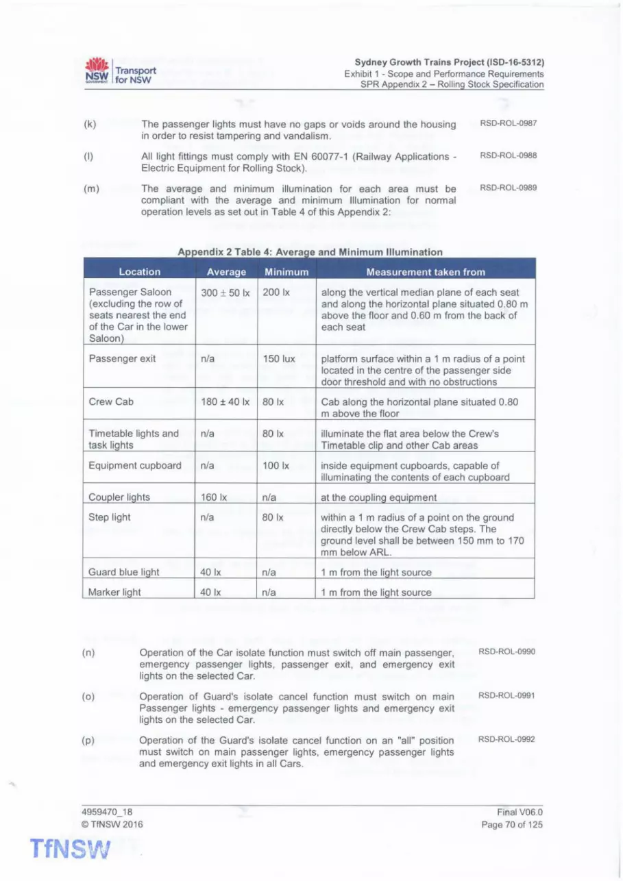
~ti I Transport NfilY for NSW
Sydney Growth Trains Project (ISD-16-5312) Exhibit 1 - Scope and Performance Requirements
SPR Appendix 2 - Rolling Stock Specification
(k)
(I)
(m)
The passenger lights must have no gaps or voids around the housing in order to resist tampering and vandalism .
All light fittings must comply with EN 60077-1 (Railway Applications -Electric Equipment for Rolling Stock).
The average and minimum illumination for each area must be compliant with the average and minimum Illumination for normal operation levels as set out in Table 4 of this Appendix 2:
RSD-ROL-0987
RSD-ROL-0988
RSD-ROL-0989
Passenger Saloon 300 ± 50 Ix 200 Ix along the vertical median plane of each seat (excluding the row of and along the horizontal plane situated 0.80 m seats nearest the end above the floor and 0.60 m from the back of of the Car in the lower each seat Saloon
Passenger exit n/a 150 lux platform surface within a 1 m radius of a point located in the centre of the passenger side door threshold and with no obstructions
Crew Cab 180 ± 40 Ix 80 Ix Cab along the horizontal plane situated 0.80 m above the floor
Timetable lights and n/a 80 Ix illuminate the flat area below the Crew's task Ii hts Timetable clip and other Cab areas
Equipment cupboard n/a 100 Ix inside equipment cupboards, capable of illuminatin the contents of each cupboard
hts 160 Ix n/a at the GOU
Step light n/a 80 Ix within a 1 m radius of a point on the ground directly below the Crew Cab steps. The ground level shall be between 150 mm to 170 mm below ARL.
Guard blue Ii ht 40 Ix n/a 1 m from the Ii ht source
Marker Ii ht 40 Ix n/a 1 m from the Ii ht source
(n) Operation of the Car isolate function must switch off main passenger, emergency passenger lights, passenger exit, and emergency exit lights on the selected Car.
RSD-ROL-0990
(o)
(p )
Operation of Guard's isolate cancel function must switch on main Passenger lights - emergency passenger lights and emergency exit lights on the selected Car.
Operation of the Guard's isolate cancel function on an "all" position must switch on main passenger lights, emergency passenger lights and emergency exit lights in all Cars.
4959470_18 © TfNSW 2016
TfNSW
RSD-ROL-0991
RSD-ROL-0992
Final V06.0 Page 70 of 125

~- Transport ··~· I ~ forNSW
Sydney Growth Trains Project (ISD-16-5312) Exhibit 1 - Scope and Performance Requirements
SPR Appendix 2 - Rolling Stock Specification
(q)
( r)
(s)
3.13.1.
(a)
(b)
(c)
Operation of the pantograph up pushbutton must switch on all main passenger lights, emergency passenger lights and emergency exit lights of all Cars that are not isolated if the battery charging system is operational .
The passenger lights must switch on automatically when the lighting battery is being charged if the Set is in the Normal mode.
When the supply is below normal operating parameters and/or there is an operational fault the conditions set out below must be achieved:
(i)
(ii)
(iii)
passenger lights on charging. Operating the passenger lights on pushbutton must turn on main passenger lights when the associated lighting batteries are being charged and if the Set is not in Stabled State;
passenger lights on - battery. Operating the passenger lights on pushbutton must turn on emergency passenger lighting when the associated lighting battery's voltage is above the battery low voltage cut-out level and if the Set is not in Stabled State; and
emergency lights condition . passenger lighting must be maintained at normal operating levels for 15 seconds following the failure of the battery charging system . If the battery charging system restarts within this time, the passenger lighting must revert to condition described in section 3.13 (s)(i) (passenger lights on - charging) of this Appendix 2 when the battery charging system re-starts. If the battery charging system does not restart within this time, the passenger lighting must switch to the condition described in section 3.13 ( s )(ii) (passenger lights on - battery) of this Appendix 2.
Emergency lighting operation
Emergency passenger lights must be provided to achieve the following illumination levels:
(i)
(ii)
In Emergency Passenger Stage 1 Lighting the passenger Saloon lighting illumination levels must be an average of at least 75 Ix and a minimum of 20 Ix measured in the vertical median plane of each seat and along the Horizontal plane situated 0.80 m above the floor and 0.60 m from the back of each seat; and
In Emergency Passenger Stage 2 Lighting the passenger Saloon lighting illumination levels must be at least 30 Ix at stairs and exits.
Emergency Operation Stage 1 Lighting must be when the EAPS lighting battery charging system supply is unavailable and the Set is not in Stabled State.
The following lights must be available to be illuminated continuously:
(i)
(ii)
Crew Cab lights;
cupboard lights;
4959470_18 ©TfNSW 2016
RSD-ROL-0993
RSD-ROL-0994
RSD-ROL-0995
RSD-ROL-0996
RSD-ROL-0997
RSD-ROL-0998
RSD-ROL-0999
RSD-ROL-1000
RSD-ROL-1001
RSD-ROL-1002
RSD-ROL-1003
RSD-ROL-1004
RSD-ROL-1005
Final V06.0 Page 71 of 125
TfNSVv
~t) / Transport ~ forNSW
Sydney Growth Trains Project (ISD-16-5312) Exhibit 1 - Scope and Performance Requirements
SPR Appendix 2 - Rolling Stock Specification
(d)
(e)
(f)
3.13.2.
(a)
(b)
(c)
(d)
(e)
(f)
(iii)
(iv)
(v)
(vi)
(vii)
(viii)
(ix)
(x)
Crew step lights;
coupler lights;
timetable lights;
marker lights;
Guard's blue light;
emergency exit and detrainment ramp lights;
main passenger lighting or Emergency Passenger Stage Lighting; and
main passenger lighting or Emergency Passenger Stage 2 Lighting.
When the Set is not in Stabled State, Emergency Operation Stage 2 Lighting must be available when the EAPS lighting battery charging system remains unavailable and the Emergency Stage 1 Lighting timer has expired.
In Stage 2 the following lights must be available to be illuminated continuously before the battery is depleted to the point of low voltage cut out:
(i)
(ii)
(iii)
(iv)
(v)
main passenger lighting or Emergency Passenger Stage 2 Lighting;
emergency exit and detrainment ramp lights;
marker lights;
timetable lights; and
cupboard lights.
After the low voltage cut out has activated, the marker lights must remain illuminated until the battery has no remaining charge.
Passenger exit lighting
Passenger exit lighting must be provided at each passenger bodyside door.
The light must not visually hinder passengers using the doorway.
It must be positioned in a way so that it does not point directly into passengers eyes.
The passenger exit lights must illuminate the door threshold and the platform surface within a 1 m radius of a point located in the centre of the passenger bodyside door threshold .
The passenger exit lights must illuminate as the door opens.
The passenger exit lights at each individual doorway must switch off when the individual passenger bodyside doors are fully closed .
4959470_18 ©TfNSW 2016
TfNSW
RSD-ROL-1006
RSD-ROL-1007
RSD-ROL-1008
RSD-ROL-1009
RSD-ROL-1010
RSD-ROL-1011
RSD-ROL-1012
RSD-ROL-1013
RSD-ROL-1014
RSD-ROL-1015
RSD-ROL-1016
RSD-ROL-1017
RSD-ROL-1018
RSD-ROL-1019
RSD-ROL-1020
RSD-ROL-1021
RSD-ROL-1022
RSD-ROL-1023
RSD-ROL-1024
RSD-ROL-1025
RSD-ROL-1026
RSD-ROL-1027
Final V06.0 Page 72 of 125

~· I Transport ~ forNSW
Sydney Growth Trains Project (ISD-16-5312) Exhibit 1 - Scope and Performance Requirements
SPR Appendix 2 - Rolling Stock Specification
(g)
3.13.3.
(a)
(b)
(c)
(d)
(e)
(f)
(g)
(h)
(i)
(k)
(I)
(m)
The passenger exit lights must be located no higher than 300 mm above the floor, must be protected from Vandalism and not lit when the passenger doors are closed and interlocked.
Crew lighting
The Crew Cab lighting must be controlled by a pushbutton, multiple way switching, located on the Driver's Workstation, the Guard's Workstation and within the Crew Cab at the Driver's and Guard's side doorways.
The Crew Cab lights must turn on when the external step light or the door key switch is operated.
The Crew Cab light fittings must be recessed into the cab ceiling panels.
Timetable and task lights must be provided in each Crew Cab, with a provision that in the Driver's Cab it must be possible for the Guard, the Driver or both to illuminate the Timetable and other areas of the cab.
Task lighting must be adequate to enable Driver and Guard to carry out all normal activities especially when the Set is moving between stations without turning on the general cab lighting.
An identifying Guard's blue light must be fitted above all Crew Cab side doors on the Car exterior.
The Guard's blue lights must be illuminated only on the Crew Cab where the Guard's Station is activated.
The Guard's blue light must cycle on and off to approximately 1 Hz on any Crew Cab where unauthorised access has occurred and a TMS indication must be provided to the Crew.
Crew Cab step lights must remain operable in any operational state (see section 2.21 of this Appendix 2) and must be operated via multiple way switching.
The light must remain illuminated for at least 20 minutes after stabling of the Set unless manually switched off by means of the step light switch.
Each Crew Cab step tread must be illuminated.
The step light switch must be positioned at the following locations:
(i)
(ii)
interior - on the Driver's Workstation, the Guard's Workstation; and
exterior - mounted on the body fixed externally located within reach of a person standing at the trackside directly in line with the Crew Cab steps or alternatively may be integrated with the external Cab access lock.
Lights must be provided in each equipment cupboard, which must operate when the cupboard door is opened.
4959470_18 ©TfNSW 2016
RSD-ROL-1028
RSD-ROL-1029
RSD-ROL-1030
RSD-ROL-1031
RSD-ROL-1032
RSD-ROL-1033
RSD-ROL-1034
RSD-ROL-1035
RSD-ROL-1036
RSD-ROL-1037
RSD-ROL-1038
RSD-ROL-1039
RSD-ROL-1040
RSD-ROL-1041
RSD-ROL-1042
RSD-ROL-1043
Final V06.0 Page 73 of 125
TfNSW

~Ii / Transport ~ forNSW
Sydney Growth Trains Project (ISD-16-5312) Exhibit 1 - Scope and Performance Requirements
SPR Appendix 2 - Rolling Stock Specification
3.13.4.
(a)
(b)
(c)
(d)
(e)
3.14.
(a)
(b)
(c)
(d)
(e)
(f)
(g)
End detrainment lighting
The end detrainment steps, the terminal end detrainment doorway and end detrainment ramp must be provided with illumination to enable their use and to enable persons to move clear of the steps and ramp.
The end detrainment step and ramp light must remain operable whenever the Set is not in Stabled State.
The end detrainment step light must be illuminated automatically on opening of the terminal end detrainment door.
The terminal end detrainment doorway must be illuminated automatically on opening of the terminal end detrainment door.
The end detrainment lights for the ramp must be illuminated automatically on deployment of the terminal end emergency detrainment ramp.
CCTV
Each Set must be provided with an on-board digital Closed Circuit Television system (CCTV) utilising proven, fit for purpose components.
The CCTV system must comply with applicable sections of T MU SY 10001 ST - Public Transport Closed Circuit Television (CCTV) Functional Requirements Standard.
The CCTV system must comply with T HR RS 13002 ST - Passenger Rolling Stock Surveillance systems Performance Requirements.
The CCTV system must comply with "National Code of Practice for CCTV systems for Mass Passenger Transport for Counter-Terrorism".
The CCTV system must provide, at a minimum, full coverage of the following:
(i)
(ii)
(iii)
internal passenger areas, including:
(A) all passenger entry and exit points of the Set;
(B) stairways within passenger Saloons;
(C) all PEI locations;
(D) all internal EDR locations; and
(E) all Vestibules, End Saloons, upper Saloons and lower Saloons.
the interface between the passenger bodyside doors and platforms; and
the view ahead from each end of the Set.
The CCTV system must include built-in security to prevent configuration changes or tampering by unauthorised persons.
The CCTV cameras must operate using industry standard protocols and compression.
4959470_18 ©TfNSW 2016
TfNSW
RSD-ROL-1044
RSD-ROL-1045
RSD-ROL-1046
RSD-ROL-1047
RSD-ROL-1048
RSD-ROL-1049
RS D-ROL-1 050
RSD-ROL-1051
RSD-ROL-1052
RSD-ROL-1053
RSD-ROL-1054
RSD-ROL-1055
RSD-ROL-1056
RSD-ROL-1057
RSD-ROL-1058
RSD-ROL-1059
RSD-ROL-1060
RSD-ROL-1061
RSD-ROL-1062
RSD-ROL-1063
Final V06.0 Page74of125

~· I Transport ~ forNSW
Sydney Growth Trains Project (150-16-5312) Exhibit 1 - Scope and Performance Requirements
SPR Appendix 2 - Rolling Stock Specification
(h)
3.14.1.
(a)
(b)
(c)
(d)
(e)
(f)
(g)
{h)
3.14.2.
(a)
{b)
3.14.3.
(a)
3.14.4.
(a)
The CCTV system must record images from all cameras in all environmental conditions whenever the Set is not in Stabled State.
Internal cameras
The internal cameras must provide clear coverage of all PEI, doorways and emergency egress devices.
The internal CCTV cameras must be positioned to minimise obstruction by fixtures or passengers.
The CCTV system must record both Crew and passenger audio synchronised to the image data from the initial activation of the PEI until the call has been terminated.
On activation of a PEI , the CCTV system must display a camera with the view of the first PEI in the queue to a configurable combination of Crew members.
Internal camera images must be recorded when Presentation State is active. Maintenance staff must be able to disable this feature if required.
A camera must be installed in each Crew Cab.
The Crew Cab camera must become part of the Set CCTV system .
The Crew Cab camera when fitted , must be able to record video of the driver and guard positions including as much of the workstations as is practicable.
External bodyside cameras
Each Set must incorporate external bodyside cameras to enable the train-platform interface to be monitored by Crew to assist train dispatch procedures.
The external bodyside CCTV must allow the Crew to readily detect persons (including children of 1.1 m height} or obstacles at the trainplatform interface.
Unit end cameras
One end of Set CCTV camera must be provided at each end of each Set to record the track, infrastructure, other trains and objects on or about the track, to the extent permitted by the weather conditions, the ambient, incident and contrasting lighting conditions and the performance of the cameras selected.
Resolution
Each camera must provide a frame rate of not less than 12 frames per second.
4959470_18 ©TfNSW 2016
RSD-ROL-1064
RSD-ROL-1065
RSD-ROL-1066
RSD-ROL-1067
RSD-ROL-1068
RSD-ROL-1069
RSD-ROL-1070
RSD-ROL-1071
RSD-ROL-1072
RSD-ROL-1073
RSD-ROL-1074
RSD-ROL-1075
RSD-ROL-1076
Final V06.0 Page 75 of 125
TfNS~V

~Ii I Transport ~ forNSW
Sydney Growth Trains Project (ISD-16-5312) Exhibit 1 - Scope and Performance Requirements
SPR Appendix 2 - Rolling Stock Specification
3.14.5.
(a)
(b)
(c)
(d)
(e)
(f)
3.14.6.
(a)
(b)
Crew access and viewing
Each Set must enable the Crew to select the passenger areas for viewing of camera coverage.
The method of display of internal CCTV images on a monitor must enable the Guard to select individual cameras or a group of cameras up to coverage of all cameras on a Car, and must allow scrolling through images.
When external CCTV images are displayed on a monitor, images from external cameras on one side of the Set must be displayed in real-time and be visible simultaneously.
When internal smoke is detected each Set must automatically alert the Crew and display the smoke affected area.
The CCTV monitors in any Crew Cab with an active Guard's workstation must continuously display internal passenger area images unless:
(i)
(ii)
(iii)
(iv)
a PEI or EDR device is activated or a fire alarm is triggered. In this event, all monitors in the cab must then display the image from the camera giving coverage of the PEI, EDR device or smoke detection system alarm, together with an appropriate indication of the location and reason for the display;
the Set is at a point 300 m before a station at which it is scheduled to stop, At this time external camera images need to be viewed on the appropriate platform side monitor until a point 300 m beyond that station. The distances must be independently adjustable on demand and at no cost to the TfNSW;
the Guard has selected the display of external camera images (for example, if a Set makes an unscheduled stop). In this case, the display of images relating to condition (i) must override this selection; or
the Guard has selected a blank screen with negligible light output for a local monitor. In this case, the display of images relating to conditions (i) and (ii) must override this selection.
However, a control facility, local to the monitor, must be provided for each CCTV monitor in the Crew Cab allowing external camera images to be displayed irrespective of Set side.
Monitors
One colour touch-activated monitor must be provided on the back wall on each side of each Crew Cab such that when the guard is standing at the crew bodyside door to operate the passenger door controls the Guard can quickly switch between observing the Set-platform interface and the CCTV monitor.
The minimum CCTV monitor size must be at least a 17" diagonal with a display resolution of not less than 1280 x 1024.
4959470_18 ©TfNSW 2016
TfNSW
RSD-ROL-1077
RSD-ROL-1078
RSD-ROL-1079
RSD-ROL-1080
RSD-ROL-1081
RSD-ROL-1082
RSD-ROL-1083
RSD-ROL-1084
RSD-ROL-1085
RSD-ROL-1086
RSD-ROL-1087
RSD-ROL-1088
Final V06.0 Page 76 of 125

~t) I Transport ~ forNSW
Sydney Growth Trains Project (ISD-16-5312) Exhibit 1 - Scope and Performance Requirements
SPR Appendix 2 - Rolling Stock Specification
(c)
3.15.
(a)
(b)
(c)
(d)
(e)
It must be possible for the Guard to use the touch screen in order to increase the size of any of the CCTV images (internal or external), 1 image at a time, with the size increase as a minimum equalling that of the native camera resolution. Any summary train status information must remain visible when viewing an enlarged image.
Monitoring systems
Each Set must be equipped with a Train Management System (TMS) that is able to generate and receive information on the Train status and location, provide fault diagnosis information, identify rectification action required and store vehicle data.
The TMS must have defined levels of access with appropriate restrictions to each user including Drivers, Guards or Maintenance Staff.
The TMS must provide a Crew interface to display status and fault information in the Crew Cab.
The TMS must interface to and monitor all major subsystems on the Set.
The TMS must also monitor and record:
(i)
(ii)
(iii)
(iv)
(v)
(vi)
(vii)
(viii)
(ix)
Car brake isolating cocks:
(A) brake system isolating cocks;
(B) Park Brake 1 and 2 isolating cocks;
(C) bogie 1 and 2 brake isolating cocks; and
(D) bogie 1 and 2 EP isolating cocks.
driving trailer Car isolating cocks:
(A) Trip Gear isolation cocks;
(B) safety apparatus isolation; and
(C) vigilance isolation.
circuit breakers panels within each Car to indicate a tripped circuit breaker;
occurrence of locked axle(s) and its location(s) within the Set;
occurrence of spring failure(s) and its location(s) within the Set;
the status of the WSP;
the status of the Trip Gear;
PEI failure(s), including failure to respond at start-up;
communication Equipment failure(s);
4959470_18 ©TfNSW 2016
RSD-ROL-1089
RSD-ROL-1090
RSD-ROL-1091
RSD-ROL-1092
RSD-ROL-1093
RSD-ROL-1094
RSD-ROL-1095
RSD-ROL-1096
RSD-ROL-1097
RSD-ROL-1098
RSD-ROL-1099
RSD-ROL-1100
RSD-ROL-1101
RSD-ROL-1102
RSD-ROL-1103
RSD-ROL-1104
RSD-ROL-1105
RSD-ROL-1106
RSD-ROL-1107
RSD-ROL-1108
RSD-ROL-1109
RSD-ROL-1110
Final V06.0 Page 77 of 125
TfNSV'/

4''1; I Transport ~ forNSW
Sydney Growth Trains Project (ISD-16-5312) Exhibit 1 - Scope and Performance Requirements
SPR Appendix 2 - Rolling Stock Specification
(f)
(g)
(h)
(i)
(j)
(k)
(I)
3.15.1.
(a)
(x)
(xi)
(xii)
(xiii)
(xiv)
(xv)
(xvi)
door failures described in section 3.11 (a) of this Appendix 2 and the location(s) within the Set;
door faults relevant for maintenance including general access system performance for detecting changes that would lead to a failure if not corrected;
partial or full deployment of the end detrainment system;
emergency egress through the intercar door(s):
(A) if locked; and
(B) if activated.
operation of the EDR Crew Override and Crew Override Cancel;
EDR Stage 1 Activations for the following locations:
(A) Saloon side Crew transverse door EDR;
(B) internal passenger bodyside door EDR;
(C) gangway intercar door EDR; and
(D) Saloon intercar door EDR.
EDR Stage 2 Activations.
All traction subsystem faults must be recorded by the TMS within second of occurrence.
The TMS must ensure time synchronisation on all Set systems that provide time-stamped records and/or display the time.
The TMS must record all information including alerts, system events and faults time stamped in UTC.
The TMS must display the local date and time to the Crew.
The TMS must minimise risk and impact of any single point of failure in the system.
A single point of failure of any individual part of the TMS must not result in the loss of data.
In the event of a TMS failure, each Set must be able to complete an operational run while continuing to provide the following functionality:
(i)
(ii)
Safety critical alarms must continue to be provided to the Crew.
The Crew must retain control of safety critical systems.
TMS emulator
The Supplier must provide a TMS emulator that emulates TMS screen functionality and appearance.
4959470_18 ©TfNSW 2016
TfNSW
RSD-ROL-1111
RSD-ROL-1112
RSD-ROL-1113
RSD-ROL-1114
RSD-ROL-1115
RSD-ROL-1116
RSD-ROL-1117
RSD-ROL-1118
RSD-ROL-1119
RSD-ROL-1120
RSD-ROL-1121
RSD-ROL-1122
RSD-ROL-1123
RSD-ROL-1124
RSD-ROL-1125
RSD-ROL-1126
RSD-ROL-1127
RSD-ROL-1128
RSD-ROL-1129
RSD-ROL-1130
RSD-ROL-1131
RSD-ROL-1132
RSD-ROL-1133
Final V06.0 Page 78 of 125

~· 1 Transport ~~ forNSW
Sydney Growth Trains Project (ISD-16-5312) Exhibit 1 - Scope and Performance Requirements
SPR Appendix 2 - Rolling Stock Specification
(b)
(c)
(d)
(e)
3.15.2.
(a)
(b)
3.15.3.
(a)
(b)
(c)
(d)
(e)
3.15.4.
(a)
(b)
(c)
(d)
The TMS emulator must be able to run on a Windows compatible personal computer with an enterprise license to allow installation on any TfNSW or Operator computer.
The Supplier must provide an updated TMS emulator whenever the TMS is updated.
The Supplier must provide a user manual whenever the TMS emulator is updated.
The Supplier must incorporate the final version of the TMS software into the Operator's simulator.
Global Positioning System (GPS)
Each Set must be equipped with GPS equipment to provide information to other on-train systems - to provide control to systems and to enable continuous logging of the Set position.
The position management system must be accurate to better than 50 metres even when GPS signal is lost.
Event logging and display
The TMS must incorporate an event logger to record faults and events from monitored systems.
The level (priority), Crew role applicability, audible tone (or otherwise) of all faults and events must be configurable.
Where the event is a fault presented to the Crew, the TMS must provide detail of the fault and rectification action where appropriate.
It must be possible for the Crew to acknowledge and dismiss presented events to reduce Crew distraction.
Critical events must be automatically transmitted remotely to the Asset Information System , the Operator and the Train Controller.
Train Preparation
The TMS must facilitate a Train Preparation routine to determine that the Set satisfies the requirements of the Minimum Operating Standards for Available Sets prior to entering service.
As part of Train Preparation the TMS must be powered up and the Driver and Guard prompted to input their personal codes into the TMS. Once logged in , the TMS must provide prompts to the Crew to complete Train Preparation.
Train Preparation routines must be provided for each subsystem and must be automated so far as is reasonably practicable.
Where a test is semi-automated and requires action by the Crew, the TMS must guide the Crew through the proper sequence and finalisation of actions and the resulting state of the system.
4959470_18 ©TfNSW2016
RSD-ROL-1134
RSD-ROL-1135
RSD-ROL-1136
RSD-ROL-1137
RSD-ROL-1 138
RSD-ROL-1139
RSD-ROL-1140
RSD-ROL-1141
RSD-ROL-1142
RSD-ROL-1143
RSD-ROL-1144
RSD-ROL-1145
RSD-ROL-1146
RSD-ROL-1147
RSD-ROL-1148
Final V06.0 Page 79 of 125
TfN:' ·~} .. ,. ~ ... ~·

4''1i I Transport ~ forNSW
Sydney Growth Trains Project (ISD-16-5312) Exhibit 1 - Scope and Performance Requirements
SPR Appendix 2 - Rolling Stock Specification
(e)
(f)
(g)
{h)
(i)
(j)
(k)
(I)
3.15.5.
(a)
(b)
(c)
{d)
There must be no requirement for Crew members to walk down the side of the Set to complete the part of the Train Preparation procedure that has been tested by the TMS.
Each Set must automatically report remotely to the Asset Management System and the Operator the results of the Train Preparation.
On completion of the Train Preparation a status report in the form of a Train Certificate must be provided.
An on-screen and a hard copy of the Train Certificate must be produced from this test if required by the Driver, Guard or other authorised person.
The Train Certificate must indicate three levels of result:
(i)
(ii)
(iii)
pass - the system concerned conforms to the Minimum Standards in full;
fail - the system concerned does not conform to the Minimum Standards; or
OMET - the system concerned conforms to the Minimum Standards for a Set entering service from an Out Depot but does not conform to the Minimum Standards for a Set entering service from the Maintenance Facility Site.
The Train Certificate must be available at any time the Set is in Normal State.
Each Set must enable the Crew to restore the Set to the Minimum Standards, when a Set fails the Train Preparation routine, without accessing the track, as far as is reasonably practicable.
The preparation routine must be developed in conjunction with TfNSW and must include scenarios for a Driver preparation, a Guard preparation and a joint preparation.
Remote data communications
The TMS must support remote communications of data from the passenger information system, CCTV system, TMS, Event Recorder, passenger counting system, energy metering system and any infrastructure monitoring systems to the Asset Management System and the Operator whilst the Set is in service.
The TMS must support remote condition monitoring of the Set systems.
The remote monitoring function must support transmission of real time status data and where available from the available stored event data for all systems monitored.
Each Set must automatically report remotely the Timetable performance of the Set on departure at each stopping station to the Asset Management System and the Operator and, where relevant, any other person responsible for Train Control.
4959470_18 ©TfNSW2016
TfNSW
RSD-ROL-1149
RSD-ROL-1150
RSD-ROL-1151
RSD-ROL-1152
RSD-ROL-1153
RSD-ROL-1154
RSD-ROL-1155
RSD-ROL-1156
RSD-ROL-1157
RSD-ROL-1158
RSD-ROL-1159
RSD-ROL-1160
RSD-ROL-1161
RSD-ROL-1162
RSD-ROL-1163
Final V06.0 Page 80 of 125

~Ii I Transport ~ forNSW
Sydney Growth Trains Project (ISD-16-5312) Exhibit 1 - Scope and Performance Requirements
SPR Appendix 2 - Rolling Stock Specification
(e)
3.15.6.
(a)
(b)
(c)
(d)
(e)
(f)
(g)
(h)
(i)
(j)
(k)
3.15.7.
(a)
The Supplier must obtain TfNSW's approval of all data interchange formats for data to be provided to the Operator, Train Controller or TfNSW.
Event recorder
Each Set must be equipped with two Event Recorders to record Set performance and operational data.
Both Event Recorders must record the same operational data.
In addition to the minimum requirements T HR RS 00600 ST, the Event Recorders must record the following items:
(i)
(ii)
(iii)
(iv)
(v)
(vi)
emergency egress - cover/seal , device activation, inhibit status;
PEI - initiation, connection, calling location, escalation and termination;
Crew Intercom - initiation, connection and termination ;
smoke detection - detection, location and severity;
door status - isolated, inhibited, released, opened and closed; and
Crew door - use including emergency close command.
The Event Recorder must have sufficient capacity to record and store a minimum of seven days of operational data.
Each Set must allow remote download of Event Recorder data whilst the Set is in service without any impact to recording functionality.
The time to remotely download eight hours of Event Recorder data must be less than five minutes.
The Event Recorder data must be downloadable by authorised personnel with physical access whilst the Set is in operational service.
The Event Recorders must only be accessible by authorised personnel.
The Event Recorder data must be tamper resistant such that any tampering and corruption of data can be detected and identified.
The Event Recorder or Event Recorder memory must be removable by authorised personnel without affecting the data stored to enable chain of custody/evidence processes to be followed.
Any abnormal operation of the Event Recorder must be shown on the TMS alarm display and the status of the Event Recorders in the Set must be displayed to the Driver without the requirement for Driver navigation of any TMS screens.
Integrated condition monitoring system
Two Sets of the Initial Fleet must be fitted with an integrated condition monitoring system.
4959470_18 ©TfNSW2016
RSD-ROL-1164
RSD-ROL-1165
RSD-ROL-1166
RSD-ROL-1167
RSD-ROL-1168
RSD-ROL-1169
RSD-ROL-1170
RSD-ROL-1171
RSD-ROL-1172
RSD-ROL-1173
RSD-ROL-1174
RSD-ROL-1175
RSD-ROL-1176
RSD-ROL-1177
RSD-ROL-1178
RSD-ROL-1179
RSD-ROL-1180
RSD-ROL-1181
RSD-ROL-2011
Final V06.0 Page 81 of 125
TtNsv~;

~Ii I Transport ~~ forNSW
Sydney Growth Trains Project (ISD-16-5312) Exhibit 1 - Scope and Performance Requirements
SPR Appendix 2 - Rolling Stock Specification
(b)
3.16.
(a)
(b)
(c)
(d)
3.17.
(a)
(b)
3.18.
(a)
(b)
(c)
(d)
(e)
(f)
4959470_18
The integrated condition monitoring system must include the following:
(i)
(ii)
track geometry measurement system; and
overhead wire measurement system.
Passenger counting system
Each Set must provide real time calculation of customer numbers by Car using either passenger load sensing based on average mass or, automatic customer counting equipment.
The passenger counting system data must be stored in such a manner to enable analysis of passenger patronage on the Set and individual Cars by direction, route, location and date/time.
The passenger counting system data must be able to be accessed by authorised personnel on board and remotely in real time.
Historical passenger counting system data for the previous 31 days must be able to be downloaded remotely.
Energy monitoring system
Each Set must have facilities to monitor, record and download the net energy consumption. This consumption must be divided into the following:
(i)
(ii)
(iii)
(iv)
traction energy consumed;
regenerated power returned to OHW;
HVAC; and
auxiliaries minus HVAC.
The totalised energy consumption information must be available on each Set and also remotely.
Driver Safety Systems
Each Set must include a Trip Gear System that complies with the requirements of T HR RS 00840 ST - Driver Safety Systems.
The leading and trailing Trip Gear must always be lowered.
When two Sets are coupled (i.e. 16 Cars) the intermediate Trip Gears must be able to be raised and isolated.
The status of the Trip Gear (raised/lowered/isolated) must be displayed to the Driver.
Facilities to manually raise, lower, and isolate the Trip Gear must be provided at or near the Trip Gear.
Each Set must provide the Driver the facility to reset the Trip Gear from the Driver's Workstation whilst the Set is stationary
© TfNSW 2016
TfNSW
RSD-ROL-2012
RSD-ROL-2013
RSD-ROL-2014
RSD-ROL-1182
RSD-ROL-11 83
RSD-ROL-1184
RSD-ROL-1185
RSD-ROL-1186
RSD-ROL-1187
RSD-ROL-1188
RSD-ROL-1189
RSD-ROL-1190
RSD-ROL-1191
RSD-ROL-1192
RSD-ROL-1193
RSD-ROL-1194
RSD-ROL-1195
RSD-ROL-1196
RSD-ROL-1197
Final V06.0
Page 82 of 125

4''1i I Transport ~ forNSW
Sydney Growth Trains Project (ISD-16-5312) Exhibit 1 - Scope and Performance Requirements
SPR Appendix 2 - Rolling Stock Specification
(g)
(h)
(i)
(k)
(I)
(m)
(n)
(o)
(p)
(q)
(r)
3.19.
(a)
(b)
Each Set must enable the Trip Gear to be completely reset remotely within 10 seconds.
Each Set must include an Operator Enable System that complies with the requirements of T HR RS 00840 ST - Driver Safety Systems.
The Operator Enable System should comply with T HR RS 20003 SP - Passenger Rolling Stock Driver Safety Systems.
Each Set must include a vigilance system that complies with the requirements of T HR RS 00840 ST - Driver Safety Systems.
The vigilance system should comply with T HR RS 20003 SP -Passenger Rolling Stock Driver Safety Systems.
In the event of a failure of a Driver Safety System or a subsidiary device that prevents movement of the Set, each Set must allow for a second Crew member to over-ride the system by depressing the "emergency button".
This emergency button must be located such that the Driver cannot operate it whilst driving each Set.
This emergency button must be located such that the second Crew member can view the Brake Pipe gauge, the Driver, and the track and signals ahead while operating the emergency button.
This emergency button must be located such that the second Crew member does not need to stand to operate it.
The button must be aligned such that it cannot be operated by having an object put on top of it.
The emergency button must be non-latching i.e. the second Crew member must be required to continually depress it in order to over-ride the system .
The emergency button must only allow traction to be available if one of the Driver detection devices is also enabled (i.e. the Driver either operates the Master Controller detection device or the OEP).
Advanced train control migration system (AMS)
Each Set must be fitted with ETCS Level 2 equipment, certified to European Railway Agency ERTMS Set of specifications #2 as modified by T HR SC 01650 SP - ETCS Onboard Equipment.
The AMS equipment must be able to:
(i)
(ii)
(iii)
(iv)
be type approved for use in ETCS Level 1;
comply with the TfNSW Cab Fit Out Requirements Specification 4547794 Ver 2.0 unless otherwise agreed by TfNSW;
comply with TfNSW Onboard Requirements Specification 4153546 Ver 2.0 unless otherwise agreed by TfNSW; and
be upgradable to ETCS Level 2 by delayed Level 2 commissioning.
4959470_18 ©TfNSW 2016
RSD-ROL-1198
RSD-ROL-1199
RSD-ROL-1200
RSD-ROL-1201
RSD-ROL-1202
RSD-ROL-1203
RSD-ROL-1204
RSD-ROL-1205
RSD-ROL-1206
RSD-ROL-1207
RSD-ROL-1208
RSD-ROL-1209
RSD-ROL-1210
RSD-ROL-1211
RSD-ROL-1212
RSD-ROL-1213
RSD-ROL-1214
RSD-ROL-1215
Final V06.0

4'" I Transport ~ forNSW
Sydney Growth Trains Project (ISD-16-5312) Exhibit 1 - Scope and Performance Requirements
SPR Appendix 2 - Rolling Stock Specification
(c)
(d)
(e)
(f)
(g)
As part of the design of the AMS installation, the position of the Driver Machine Interface (DMI) and other controls required for the operation of the AMS must be subject to a human factors review of the driver's desk layout.
The Supplier must develop and implement an AMS reliability improvement solution which reduces the impact on system reliability arising from the removal of one of the redundant TMS screens to accommodate the AMS screen/driver machine interface.
The design solution for enhanced reliability must include identification of the Operator's minimum requirements for a Set to remain in service to the end of an Availability Period with one failed screen (either AMS or TMS).
Prior to the Provisional Acceptance of each Set the Supplier must implement a solution which displays the TMS speedometer in event of a failure of the AMS equipment resulting in an isolation of the AMS.
As soon as is reasonably practicable, the Supplier must develop and implement its final design solution which, in the event of a screen failure, provides an alternative means for the Driver to have displayed the pertinent information from the AMS and TMS, and provide acknowledgement where required, to safely manage the Set in revenue service until the end of the Availability Period.
4959470_18 ©TfNSW 2016
TfNSW
RSD-ROL-1216
RSD-ROL-2004
RSD-ROL-2005
RSD-ROL-2006
RSD-ROL-2007
Final V06.0
Page 84 of 125

~t; I Transport ~~v:! for NSW
Sydney Growth Trains Project (ISD-16-5312) Exhibit 1 - Scope and Performance Requirements
SPR Appendix 2 - Rolling Stock Specification
4. Communications
(a)
Set-Borne
Communication with the Fleet is enabled through the following components :
(i)
(ii)
(iii)
(iv)
CTIP Shore;
Set-borne Telemetry System ;
the Fleet Gateway; and
the Set-borne Gateway.
Appendix 2 Figure 2: Set Communications Overview
- I Wir.eless
Set-borne Gateway (Logical Interface for exp ing Set-Borne Services)
- I Wir.e less
INFORMATION
INFORMATION
INFORMATION
INFORMATION
INFORMATION
- I Wir.el eSs
Shorebased
Operator Operator Data Link Data Link
-1 Supplier Data Link
tii • Operator f~ ___ Fl_e_et_M_a_na_g_en_ie_n_t _Da_ta_11_nk_--<~>----~t supptier
Fleet Managffilent Gateway
4.2. Communication Network Standards
(a)
(b)
4959470_18
Each Set must comply with T HR TE 41001 ST - Packet Switched Networks Wired - Local , Metropolitan, and Wide Area Networks.
Each Set must comply with T HR TE 41002 ST - Wireless Data Communications in LIPD Class Licensed Bands.
© TfNSW 2016
RSD-ROL-1217
RSD-ROL-1218
Final V06.0 Page 85 of 125
TfNSW
~" I Transport ~~\ft forNSW
Sydney Growth Trains Project (ISD-16-5312) Exhibit 1 - Scope and Performance Requirements
SPR Appendix 2 - Rolling Stock Specification
(c)
(d)
Each Set must comply with T HR TE 81001 ST - Telecommunications Equipment - Physical Interfaces and Environmental Conditions.
Each Set must comply with T HR TE 81002 ST - Telecommunications Equipment Network Management.
4.3. On-train communication system
(a)
(b)
4.4.
4.4.1.
(a)
(b)
4959470 18
Each Set must provide on-train communications systems for :
(i)
(ii)
(iii)
(iv)
(v)
(vi)
(vii)
(viii)
(ix)
(x)
(xi)
(xii)
audio communications between Crew (Crew Intercom);
audio communications between passengers in the Vestibule area/designated Wheelchair Spaces and Crew (Passenger Emergency Intercom);
audio communications between Crew and passengers throughout all passenger areas (internal PA);
audio communications between Crew and passengers outside the Set standing on platforms (external PA);
augmented hearing for internal DVNmanual announcements;
automated audio and visual door movement warnings to passengers;
bell communications between the Crew;
a Door Warning Device (DWD);
external horn, operated by the Crew and audible to persons outside the Set;
radio communications between the Set and external systems, both voice and data;
signage throughout each Set including fixed and electronic passenger information displays; and
video surveillance of all passenger areas throughout each Set.
The on-train communications system must be capable of full-duplex voice communications.
Communications equipment
Communications equipment Control
Control of the communications equipment must be independent of other Set systems with the exception the Door Warning Device, and the TMS which will display data and status information as well as being the human to machine interface to the communication system equipment.
Other than those required by the Crew and passengers to operate the equipment, no switches or controls must be externally accessible.
© TfNSW 2016
RSD-ROL-1219
RSD-ROL-1220
RSD-ROL-1221
RSD-ROL-1222
RSD-ROL-1223
RSD-ROL-1224
RSD-ROL-1225
RSD-ROL-1226
RSD-ROL-1227
RSD-ROL-1228
RSD-ROL-1229
RSD-ROL-1230
RSD-ROL-1231
RSD-ROL-1232
RSD-ROL-1233
RSD-ROL-1234
RSD-ROL-1235
RSD-ROL-1236
Final V06.0 Page 86 of 125
TfNSW

~'1i I Transport ~ forNSW
Sydney Growth Trains Project (150-16-5312) Exhibit 1 - Scope and Performance Requirements
SPR Appendix 2 - Rolling Stock Specification
(c)
(d)
(e)
(f)
4.4.2.
(a)
(b)
(c)
4.4.3.
(a)
{b)
(c)
(d)
(e)
(f)
(g)
4.4.4.
(a)
The equipment and systems must permit concurrent use by both the Driver and Guard e.g. Train Radio and Crew Intercom.
The handset position of any communications equipment must be consistent with current installation position and must ensure that use of the handset does not conflict with the use of other controls.
The output of each handset must be adjusted by an automatic gain control to maintain a constant output signal.
Set-wide communications must be consistent across all Cars.
Communications equipment protection
Any equipment with a conductive surface or controls that may be contacted by passengers or Crew must include an equipotential bond to each Set frame to eliminate any risk of shock.
Equipment must be protected against continuous overload, short circuit or open circuit output.
There must be no adverse effect if the PA, Intercom or other equipment or systems in the same Crew Cab or in separate Cabs are operated at the same time.
Communications equipment performance
The signal to noise ratio for amplifiers must be 70 dB or better, when any controls are adjusted for maximum output.
There must be no discernible feedback, cross-talk, interference or noise produced by equipment or systems including amplifiers, or other components or switching functions either electrical or mechanical.
When equipment is in the quiescent state no discernible noise must emanate from it either by virtue of an output to speakers, sounders or earpieces or by virtue of noise transmission through components and housings or any other means.
The total harmonic distortion must not be discernible and for audio equipment the power and output amplifiers must not exceed 0.4% at the rated output.
Amplifier design must be Class D, commonly referred to as "digital amplifiers" to reduce power demand, heat dissipation requirements and packaging size.
Indicators for power, output and status where provided on the front panel of the equipment must be clearly identified.
All the communication equipment must communicate clear and intelligible messages to all passengers and Crew as selected.
Equipment self test
The communications equipment must be self-monitoring and must include self-test capabilities for all equipment in each Car.
4959470_18 ©TfNSW2016
RSD-ROL-1237
RSD-ROL-1238
RSD-ROL-1239
RSD-ROL-1240
RSD-ROL-1241
RSD-ROL-1242
RSD-ROL-1243
RSD-ROL-1244
RSD-ROL-1245
RSD-ROL-1 246
RSD-ROL-1247
RSD-ROL-1248
RSD-ROL-1249
RSD-ROL-1250
RSD-ROL-1251
Final V06.0 Page 87 of 125
TfNS

~t) I Transport ~ forNSW
Sydney Growth Trains Project (ISD-16-5312) Exhibit 1 - Scope and Performance Requirements
SPR Appendix 2 - Rolling Stock Specification
(b)
4.5.
4.5.1.
(a)
(b)
(c)
4.5.2.
(a)
(b)
The self-test must be performed as part of Train Preparation and must be reported as part of the status report.
Crew communications
Crew communication interface
As a minimum requirement, the Crew's communication system must include:-
(i)
(ii)
(iii)
(iv)
handset;
PA pushbutton ;
Intercom pushbutton; and
Passenger Emergency Intercom direct reply pushbutton.
The controls must be ergonomically designed and extended operation of the pushbuttons must not cause operator fatigue.
Handsets must be provided for the Driver and also for the Guard at their seat and also in locations that can be easily reached when operating the door controls.
Train radio
Each Crew Cab must be fitted with GSM-R Train Radio equipment type approved for use on the NSW Digital Train Radio System (DTRS) and comprising:
(i)
(ii)
(iii)
(iv)
(v)
(vi)
(vii)
(viii)
DTRS cab radio unit (CRU) with integral power supply for IRU;
human machine interface (HMI);
Cab radio amplifier and speaker assembly;
roof top 1800/900 MHz DTRS antenna;
SIM cards programmed for the DTRS network
Interrogator Reader Unit (IRU);
IRU under train antenna; and
all cables, fittings and mounting brackets.
Each Cab Radio Unit must be interfaced to the following on-board systems:
(i)
(ii)
(iii)
input from the Driver's Safety Device alert relay rebroadcast as a DSD text message to the signaller;
remote (off-Set) PA audio rebroadcast to the Set communications system ;
input from a PEI call escalation to redirect duplex audio from the calling PEI to the appropriate Network Control Officer (signaller) for the network location of the Set; and
4959470_18 ©TfNSW 2016
TfNSW
RSD-ROL-1252
RSD-ROL-1253
RSD-ROL-1254
RSD-ROL-1255
RSD-ROL-1256
RSD-ROL-1257
RSD-ROL-1258
RSD-ROL-1259
RSD-ROL-1260
RSD-ROL-1261
RSD-ROL-1262
RSD-ROL-1263
RSD-ROL-1264
RSD-ROL-1265
RSD-ROL-1266
RSD-ROL-1267
RSD-ROL-1 268
RSD-ROL-1269
RSD-ROL-1270
RSD-ROL-1271
RSD-ROL-1272
Final V06.0 Page 88 of 125

(i'1i I Transport ~ forNSW
Sydney Growth Trains Project (ISD-16-5312) Exhibit 1 - Scope and Performance Requirements
SPR Appendix 2 - Rolling Stock Specification
(c)
{d)
4.5.3.
(a)
(b)
(c)
(d)
(e)
(f)
(g)
{h)
(i)
4.5.4.
(a)
(b)
(c)
(d)
(iv) extended 110 V de power to the CRU after stabling if required by the CRU power on request relay.
A Crew member in the non-driving cab must be able to monitor any voice calls made or received by the Driver's Train Radio via each Set's communications system.
Both the Driver's and Guard's Train Radio will switch to yard group call if the Set enters a maintenance centre or depot equipped with yard mode transponders.
Bell system
A bell system must be provided to permit the Crew to communicate throughout the Set using Morse or other types of codes.
The bell system must comply with section 13.3.2.2 of AS 7533.3.
The bell must operate in all modes of each Set where Crew or maintenance personnel may be present irrespective of the status of the overhead or ac auxiliary supply.
The bell system must be operated by a momentary action pushbutton.
Sounding of the bell signal must commence immediately the Driver's or Guard's pushbutton is operated and cease immediately the Driver's or Guard's pushbutton is released, provided that the bell has sounded for a minimum time adjustable in the range of 98 - 108 ms.
A bell signal must be received in all Crew Cabs irrespective of whether they are active or not.
The bell must be an independent hard wired system, must not interfere with any system or equipment and must not be affected by any system or equipment.
The bell system must be clearly distinguishable from other sounds in the Crew workstations.
The bell must sound like the bells fitted to the majority of the TfNSW Fleet.
The bell must be mounted to prevent access of unauthorised personnel.
Crew Intercom operation
Each Set must be equipped with an on-train communications system that permits the Crew to communicate with each other between Crew workstations.
The Intercom equipment must operate independently of the operation of the PA equipment except that user interfaces may be common.
The Intercom equipment must operate separately and independently from the OVA and Door Warning Device.
The Intercom communications must not be audible on the PA.
4959470_18 ©TfNSW 2016
RSD-ROL-1273
RSD-ROL-1274
INFORMATION
RSD-ROL-1275
RSD-ROL-1276
RSD-ROL-1277
RSD-ROL-1278
RSD-ROL-1279
RSD-ROL-1280
RSD-ROL-1281
RSD-ROL-1282
RSD-ROL-1283
RSD-ROL-1284
RSD-ROL-1285
RSD-ROL-1286
RSD-ROL-1287
RSD-ROL-1288
Final V06.0
nG._91of 125
NS·~

di) I Transport ~ forNSW
Sydney Growth Trains Project (150-16-5312) Exhibit 1 - Scope and Performance Requirements
SPR Appendix 2 - Rolling Stock Specification
(e)
(f)
(g)
(h)
(i)
(k)
(I)
(m)
4.5.5.
(a)
(b)
(c)
(d)
(e)
(f)
(g)
(h)
The PA communications must not be audible on the Intercom, except that a minimal and non-interfering low level of acoustic audio coupling from passenger area speakers to Crew and PEI can be allowed .
The equipment must provide visual indication to the Crew or passenger initiating the call that the call is audible in the passenger area(s) or Crew Cab, as appropriate.
Each Set must provide the capacity to handle multiple passenger and Crew calls.
The priority order and queue management of passenger and Crew calls must be configurable.
The Crew Intercom must provide the capacity to handle multiple calls from passengers and Crew.
Passenger Emergency Intercom input priority order must be:
(i)
(ii)
(iii)
Guard or Driver Crew Intercom;
Guard or Driver reply to PEI ; and
passenger calling from PEI.
The Intercom must only be available in an Active Crew Cab.
The Driver and Guard must have the same facilities and access.
Both the Driver and Guard must be able to access and operate the system at the same time.
Incoming call operation
Calls must be queued and addressed in turn as the call at the head of the queue is cleared.
The queue status must be displayed to the Crew.
The Intercom must provide a visual and audible annunciation to the Crew of each new call received, and must indicate whether the caller is a passenger or Crew.
For calls from passengers, the TMS must display the location of each caller.
A separate tone must be triggered in the event of an Emergency Door Release device being operated and the local PEI to that Emergency Door must be entered into the queue.
If there is no other call in progress, a Crew call must be connected to the Crew immediately.
When there is already a call in progress , the call must not interrupt the current call , but must visually and audibly alert the Crew of the call waiting .
Operation of the PEI system must not interrupt or disable other communication systems such as the Train Radio.
4959470_18 ©TfNSW 2016
TfNSW
RSD-ROL-1289
RSD-ROL-1290
RSD-ROL-1291
RSD-ROL-1292
RSD-ROL-1293
RSD-ROL-1294
RSD-ROL-1295
RSD-ROL-1296
RSD-ROL-1297
RSD-ROL-1298
RSD-ROL-1299
RSD-ROL-1300
RSD-ROL-1301
RSD-ROL-1302
RSD-ROL-1303
RSD-ROL-1304
RSD-ROL-1305
RSD-ROL-1306
RSD-ROL-1307
RSD-ROL-1308
Final V06.0 Page 90 of 125

~Ii I Transport ~ forNSW
Sydney Growth Trains Project (ISD-16-5312) Exhibit 1 - Scope and Performance Requirements
SPR Appendix 2 - Rolling Stock Specification
(i)
(j)
(k)
(I)
(m)
4.5.6.
(a)
(b)
(c)
4.5.6.1.
(a)
(b)
(c)
(d)
(e)
A passenger-to-Crew call must initially only be heard in the active Guard's Workstation .
The Crew member taking the PEI call must be able to hold that call and operate the Intercom to the other Crew member.
On completing that Crew Intercom call , communication must then be re-established with the original PEI call .
A Crew-to-Crew call must be heard throughout all Active Crew Cabs, and must be inaudible to passengers.
The Intercom must maintain a connection until the Crew presses the "CLEAR CALL" button located at the microphone/control panel , or all Crew Cabs are deactivated, or the calling PEI is deactivated.
Passenger Emergency Intercom (PEI)
The on-train communications system must incorporate accessible Passenger Emergency Intercoms (PEI) that permit passengers to communicate with Crew in case of emergency or where assistance is required .
A PEI must be provided at locations:
(i)
(ii)
in vestibules; and
wheelchair and Priority Seating areas.
Each Set must escalate a PEI call to the Train Radio to allow response by an appropriate Network Control Officer (signaller) in the event of Crew inactivity or lack of response after 120 seconds which can be configured by the Operator.
PEI operation
Passengers will initiate a call to the Crew by operating a pushbutton on a PEI interface panel.
During all normal running conditions a passenger, within 250 mm of the microphone, must be heard clearly by the Crew, or Operator staff member receiving an escalated PEI call, when the PEI call is established.
During all normal running conditions any reply from the Guard, within 250 mm of the microphone, to a passenger must be clearly heard at a distance of at least one (1) metre from the PEI.
The PEI must include an indicator LED that is illuminated when the unit is operational.
If a PEI call remains unanswered by the Driver or Guard after 30 seconds then an additional visual/audio alert must warn the Crew that the call will escalate in 60 seconds.
4959470_18 ©TfNSW 2016
RSD-ROL-1309
RSD-ROL-1310
RSD-ROL-1311
RSD-ROL-1312
RSD-ROL-1 313
RSD-ROL-1314
RSD-ROL-1315
RSD-ROL-1316
RSD-ROL-1317
RSD-ROL-1318
INFORMATION
RSD-ROL-1319
RSD-ROL-1320
RSD-ROL-1321
RSD-ROL-1322
Final V06.0 Page 91 of 125
TfNSW

4''1i I Transport ~ forNSW
Sydney Growth Trains Project (ISD-16-5312) Exhibit 1 - Scope and Performance Requirements
SPR Appendix 2 - Rolling Stock Specification
(f)
(g)
(h)
(i)
(k)
(I)
(m)
If, following a further 60 seconds neither the Guard nor the Driver respond, and if the Train Radio, Intercom or PA on the Set are not being used (i.e. no change of state), then the PEI unit must be connected automatically to the Train Radio system to enable the PEI call to be answered directly by an Operator staff member not on board the Set.
All time limits must be adjustable by the Supplier at no cost to the TfNSW on request.
The PEI must remain operational in all isolated Cars.
On operation of an internal EDR the local PEI must initiate a call to the Crew to enable them to communicate with the passenger operating the EDR.
On operation of a PEI the CCTV system must be controlled to show an image of the PEI to the Guard and Driver (although the display to the Driver may be suppressed if required by the Operator).
When connected to a PEI call, the Crew must be able to use the "Push to Talk" button on the handset to speak to the passenger and release the "Push to talk" button to mute the Crew's voice.
With the "Push to Talk" button depressed, the speaker in the active PEI unit must continue to emit the Crew's speech irrespective of whether the passenger is silent or talking.
The Crew must not be able to detect any acoustic feedback through the active PEI unit.
4.6. Passenger information system
(a)
(b)
(c)
(d)
(e)
(f)
(g)
(h)
Each Set must incorporate a passenger information system .
The passenger information system must manage and control annunciation of information on the PA system, hearing augmentation loop, as well as the internal and external passenger information displays.
The passenger information system must operate automatically without Crew input other than initial route set-up.
The passenger information system must convey to passengers the current and next station(s).
The passenger information system must allow for configurable selection of information and method(s) used to convey information to passengers.
The passenger information system must provide a Crew interface at all Crew workstations to select pre-set messages for display and/or annunciation.
The passenger information system must provide a remote interface to select pre-set messages for display and/or annunciation .
The passenger information system must enable remote update of message and Timetable data.
4959470_18
©TfNSW 2016
TfNSW
RSD-ROL-1323
RSD-ROL-1324
RSD-ROL-1325
RSD-ROL-1326
RSD-ROL-1327
RSD-ROL-1328
RSD-ROL-1329
RSD-ROL-1330
RSD-ROL-1331
RSD-ROL-1332
RSD-ROL-1333
RSD-ROL-1334
RSD-ROL-1335
RSD-ROL-1336
RSD-ROL-1337
RSD-ROL-1338
Final V06.0
Page 92 of 125

(i'1i I Transport ~ forNSW
Sydney Growth Trains Project (ISD-16-5312) Exhibit 1 - Scope and Performance Requirements
SPR Appendix 2 - Rolling Stock Specification
(i)
4.6.1.
(a)
(b)
(c)
(d)
(e)
4.6.1.1.
(a)
The passenger information displays must be linked with the PA system and hearing augmentation loop such that all internal visual displays are synchronised with the corresponding audio announcement.
In-Car visual Passenger Information Displays
Each Car must be fitted with at least six (6) internal passenger information displays which must be positioned to allow all seated passengers (including within allocated spaces) to easily view the information under normal payload.
The displays must show information to match the automated announcements of the DVA.
The type of display, character size, colour, brightness and positioning must be such that every seated passenger position and Wheelchair Space must be in visual range of a display for person having 6/18 vision.
When either the Guard or Driver uses the manual PA facility the display must say "Guard Announcement" or "Driver Announcement" as appropriate with international symbols for deafness.
Following a Guard or Driver manual announcement, all visual displays must refresh within 2 seconds to show the current relevant text message without triggering the audio announcement.
System requirements
The display system must comply with the following:
(i)
(ii)
(iii)
(iv)
(v)
(vi)
(vii)
(viii)
(ix)
font sizes must be compliant with DSAPT requirements for viewing distance;
displays must be visible in all lighting conditions;
display housings must be fully integrated into each Set and not convey an "added on" appearance;
displays must incorporate a fault monitoring facility to report faults to the TMS;
the display control system must be able to send a test message to each display for use by Crew when preparing the Set. This message must enable any single failed display element to be detected;
must have sufficient display area to show the final destination and stopping pattern , scrolling if necessary;
both upper and lower case fonts must be displayable;
the display matrix size must be able to display a reduced number of larger characters, in upper and lower case;
fonts must maximise the clarity of the display. The proposed character fonts must be supplied for approval by the Operator and compliant with DSAPT.
4959470_18 © TfNSW 2016
RSD-ROL-1339
RSD-ROL-1340
RSD-ROL-1341
RSD-ROL-1342
RSD-ROL-1343
RSD-ROL-1344
RSD-ROL-1345
RSD-ROL-1346
RSD-ROL-1347
RSD-ROL-1348
RSD-ROL-1349
RSD-ROL-1350
RSD-ROL-1351
RSD-ROL-1352
RSD-ROL-1353
RSD-ROL-1354
Final V06.0 Page 93 of 125
TfN i J

(\'1i I Transport ~ forNSW
Sydney Growth Trains Project (150-16-5312) Exhibit 1 - Scope and Performance Requirements
SPR Appendix 2 - Rolling Stock Specification
4.6.2.
(a)
(b)
(c)
4.6.3.
(a)
(b)
(c)
(d)
(e)
(f)
(g)
(x)
(xi)
(xii)
(xiii)
(xiv)
(xv)
text must be displayed in English sentence case . Text must provide maximum colour contrast to its background. Yellow text on black background is preferred ;
text must provide maximum colour contrast to its background with yellow text on black background being preferred;
messages must be able to be scrolled in either the horizontal or the vertical direction as defined in the message script;
a minimum of 24 characters must be visible at any one time;
changes to the automated announcement script must be reflected in the displayed message script; and
displays must be able to display special event messages on either the top line or the bottom line, or both lines of each display.
External Passenger information displays
Each end of each Set must be fitted with external passenger information displays (headboard display).
The headboard display must display the destination.
Each Set's external passenger information display must be readable by passengers on a platform from a distance of 50 m away as the Set approaches/departs a station .
Public Address system
Each Set must incorporate a PA (Public Address) system which complies with T MU TE 61003 ST and must include a hearing augmentation loop.
The PA system must be operable by Crew from the Crew Cabs.
The Crew must be able to select whether the PA is heard:
(i)
(ii)
(iii)
internal to the Set;
external to the Set (either side or both sides); and/or
internal and external to the Set (internal plus either side external or internal plus both sides external).
Each Set must enable remote users to make PA announcements to the internal Set speakers via the Train Radio.
The PA system must provide pre-recorded information to be triggered automatically by the passenger information system.
The PA system must provide pre-recorded information to be triggered manually by the Crew.
If there is a current OVA announcement in progress, the OVA announcement must be interrupted.
4959470_18 ©TfNSW 2016
TfNSW
RSD-ROL-1355
RSD-ROL-1356
RSD-ROL-1357
RSD-ROL-1358
RSD-ROL-1359
RSD-ROL-1360
RSD-ROL-1361
RSD-ROL-1362
RSD-ROL-1363
RSD-ROL-1364
RSD-ROL-1365
RSD-ROL-1366
RSD-ROL-1367
RSD-ROL-1368
RSD-ROL-1369
RSD-ROL-1370
RSD-ROL-1371
RSD-ROL-1372
RSD-ROL-1373
Final V06.0 Page 94 of 125

~'1i I Transport ~ forNSW
Sydney Growth Trains Project (ISD-16-5312) Exhibit 1 - Scope and Performance Requirements
SPR Appendix 2 - Rolling Stock Specification
(h)
(i)
(k)
(I)
There must be a provision to restart the OVA message if required by the Crew on completion of the PA announcement.
The PA system must provide high quality audio in all passenger Saloon areas with a speech transmission index of not less than 0.6 when measured in accordance with EN 60268-16 FULL STI.
The PA system must automatically adjust the volume of both manual and pre-recorded announcements to compensate for the ambient noise in each Car.
The PA must have a test mode facility so that either the Driver or the Guard may set up an audible warning that will continue until cancelled to enable either Crew member to walk through the Set and confirm that the internal PA is operational.
Either Crew member must be able to cancel the test mode from any Active Crew Cab.
4.6.3.1. Assisted listening
(a)
(b)
(c)
(d)
4.6.4.
(a)
(b)
(c)
(d)
4.6.5.
(a)
(b)
The internal PA system must include assisted listening technology (hearing loops) to augment announcements (automatic and manual) for the hearing impaired.
Hearing loop coverage must be available to seated areas of 3 seats or more on all Cars .
The hearing loop signal over the stated coverage area must have a signal to noise ratio greater than or equal to 15 dB when measured with a bandwidth ranging from 100 Hz - 5 kHz at 1.2 m above the floor level with the test loop in the vertical plane.
Appropriate signage complying with Australian Standards AS 1428.1 and AS 1428.2 indicating the presence of a hearing assistance loop must be installed in suitable locations in each Car.
External PA
The Crew must be able to make announcements outside the Set.
The external PA must default to operate only on the side that the passenger bodyside doors are open/released.
The Crew must be able to select to make external PA announcements on either or both sides of the Set independent of the door status.
The selection button for making announcements on both sides of the Set must require press to talk and must not latch.
Digital Voice Annunciator (OVA)
The OVA must be connected via the internal PA when there is no current Crew announcement in progress and a OVA announcement has been triggered.
A 2 second pause must separate each OVA announcement from any preceding Crew announcement.
4959470_18 ©TfNSW2016
RSD-ROL-1374
RSD-ROL-1375
RSD-ROL-1376
RSD-ROL-1377
RSD-ROL-1378
RSD-ROL-1379
RSD-ROL-1380
RSD-ROL-1381
RSD-ROL-1382
RSD-ROL-1383
RSD-ROL-1384
RSD-ROL-1385
RSD-ROL-1386
RSD-ROL-1387
RSD-ROL-1388
Final V06.0 Page 95 of 125

....
~Ii I Transport ~~ forNSW
Sydney Growth Trains Project (ISD-16-5312) Exhibit 1 - Scope and Performance Requirements
SPR Appendix 2 - Rolling Stock Specification
(c)
4.6.6.
(a)
(b)
(c)
(d)
(e)
(f)
(g)
(h)
(i)
4.6.7.
(a)
(b)
(c)
(d)
(e)
4959470_18
The priority order for the PA system must be as follows:
(i)
(ii)
Guard or Driver PA operation (or remote operation if the Driver and Guard are incapacitated) (equal);
DVA input to PA system; and
Door Warning Device (DWD)
The Supplier must provide to each Set a Door Warning Device (DWD) which must provide door warning closing messages and door movement warning cues integrated with the door control system and must operate on door opening and closing .
At the initiation of the door closing cycle a door closing intermittent alert tone must commence.
The alert tone must only be heard in the vicinity of the doors, i.e. it must not be distributed by the Car speakers, and must cease when the doors have closed and locked.
A tone consistent with that used on recent TfNSW Fleet rolling stock must be adopted.
A separate control must be available at each Crew door control station to generate an announcement such as "Please stand clear, train is due to depart".
The announcement must be readily re-programmable and must be heard in the Vestibule.
Additional visual cues for door movement must commence upon opening or closing the door.
The visual cue must be a white light located to be visible from the inside and the outside of the Set and must be off when in the closed position .
The light must differentiate between doors moving I doors open.
Speakers
Speakers must be provided in passenger areas for clear communication to the passengers or Crew from the PA, Digital Voice Annunciator, PEI and like systems.
Speakers must be concealed from passengers.
The speakers must be protected from Vandalism , dust, moisture and insects.
The speaker assembly must be suitable for high quality voice announcements and background music.
The internal speaker volume must be able to be adjusted:
(i)
(ii)
manually by the Crew;
automatically as a function of the timetable settings and Train location;
RSD-ROL-1389
RSD-ROL-1390
RSD-ROL-1391
RSD-ROL-1392
RSD-ROL-1393
RSD-ROL-1394
RSD-ROL-1395
RSD-ROL-1396
RSD-ROL-1397
RSD-ROL-1398
RSD-ROL-1399
RSD-ROL-1400
RSD-ROL-1401
RSD-ROL-1402
RSD-ROL-1403
RSD-ROL-1404
RSD-ROL-1405
RSD-ROL-1406
RSD-ROL-1407
Final V06.0 Page 96 of 125

4''1i / Transport ~~ forNSW
Sydney Growth Trains Project (ISD-16-5312) Exhibit 1 - Scope and Performance Requirements
SPR Appendix 2 - Rolling Stock Specification
4.6.7.1.
(a)
(b)
(c)
(d)
4.6.7.2.
(a)
(b)
(c)
(d)
(iii)
(iv)
automatically as a function of time of day; and
automatically as a function of the OVA library volume settings.
Speakers in Crew areas
Speaker assemblies must be provided in the Crew Cabs to provide clear communication in all normal-operating conditions from the PA, OVA, Train Radio, Intercom and like systems.
The Crew must be able to adjust the speaker volume in each Cab.
The Cab speaker volume must reset to a default setting upon Cab activation.
A separate speaker must be provided for the Train Radio .
External speakers
External PA Speakers must be fitted near the passenger bodyside doors on both sides of all Cars.
The appearance and location of the external speaker assemblies must be consistent throughout the fleet.
The design of the external speaker assembly and housing must preclude the ingress of dust or moisture to the Car body even if the speaker is missing.
The external speaker volume must be able to be adjusted:
(i)
(ii)
(iii)
(iv)
manually by the Crew;
automatically as a function of the timetable settings and Train location;
automatically as a function of time of day; and
automatically as a function of the OVA library volume settings.
4. 7. External horn
(a)
(b)
(c)
(d)
(e)
Each Set must be equipped with a town horn and a country horn.
Controls must be provided in close proximity to the Driver permitting the Driver to operate either horn individually or both horns simultaneously.
Each Set must be equipped with a yard horn.
The yard horn control must be a separate control and must be provided in close proximity to the Driver.
When activated, the yard horn control will sound the horn in the direction of travel for a period of time that must be adjustable, on demand by the Operator.
4959470_18 ©TfNSW 2016
RSD-ROL-1408
RSD-ROL-1409
RSD-ROL-1410
RSD-ROL-1411
RSD-ROL-1412
RSD-ROL-1413
RSD-ROL-1414
RSD-ROL-1415
RSD-ROL-1416
RSD-ROL-1417
RSD-ROL-1418
RSD-ROL-1419
RSD-ROL-1420
RSD-ROL-1421
RSD-ROL-1422
RSD-ROL-1423
RSD-ROL-1424
RSD-ROL-1425
RSD-ROL-1426
Final V06.0
TfNSV\/

~" I Transport ~~ forNSW
Sydney Growth Trains Project (ISD-16-5312) Exhibit 1 - Scope and Performance Requirements
SPR Appendix 2 - Rolling Stock Specification
(f) The yard horn sound level must be as detailed in Table 5 in this Appendix 2 below.
Appendix 2 Table 5: Yard horn sound level
RSD-ROL-1427
LA1 (60 seconds)
7 m,90 deg from
LAeq (60 seconds)
7 m, 90 deg from
front of train front of train
LAmax (60 seconds)
60 m, 0 deg from
front of train
(g)
(h)
--79-81 dB A 54-56 dB A 64-66 dB A
The Supplier must demonstrate the lack of tonality of the yard horn for its suitability for use in public and work areas.
The yard horn noise level must be assessed against ISO 7731 Ergonomics - Danger signals for public and work areas - Auditory danger signals.
4.8. Commercial radio
(a)
(b)
(c)
(d)
(e)
(f)
The Crew Cab must be provided with a commercial radio able to receive all commercial radio broadcasts on the AM and FM bands.
The commercial radio must only be available when the Cab is occupied by authorised staff.
The commercial radio unit must be mounted within the Crew Workstation area, in such a way as to prevent unauthorised removal and within arm's length of a seated Crew member.
The on/off, volume and tuning controls must be adjustable from the normal driving position.
The commercial radio must be fitted with an automatic interrupt feature to interface with the Set in such a way that the commercial radio is silenced when the Crew is transmitting and receiving messages.
The automatic interrupt feature must incorporate a delay to permit replies to be transmitted and received before the commercial radio is reconnected.
4.9. Telemetry system
(a)
(b)
The Operator currently operates a telemetry system on the Waratah Fleet. The Common Telemetry Infrastructure Platform (CTIP) provides a shared computing platform for non-critical on-train applications.
The Operator would consider providing the Supplier with Set-borne CTIP systems for fitment and integration by the Supplier.
4959470_18 ©TfNSW 2016
TfNSW
RSD-ROL-1428
RSD-ROL-1429
RSD-ROL-1430
RSD-ROL-1431
RSD-ROL-1432
RSD-ROL-1433
RSD-ROL-1434
RSD-ROL-1435
INFORMATION
INFORMATION
Final V06.0 Page 98 of 125

(fl) I Transport ~ forNSW
Sydney Growth Trains Project (ISD-16-5312) Exhibit 1 - Scope and Performance Requirements
SPR Appendix 2 - Rolling Stock Specification
(c)
(d)
(e)
(f)
(g)
(h)
(i)
(k)
(I)
(m)
(n)
The Supplier must provide a Set-borne Telemetry System on each Set enabling the Operator to receive telemetry data from the Set and communicate with Set-borne non-safety critical systems.
The Supplier should utilise the current CTIP system .
Each Set-borne Telemetry System must be able to communicate with the CTIP Shore system.
The Set-borne Telemetry System communication and messages must conform to the current formats, schemas and protocols.
The Set-borne Telemetry System must be able to communicate with the TMS and subsystems on the Set via the Set-borne Gateway.
Each Set-borne Telemetry System requires access to services provided by the Supplier Set-borne systems such as the OVA system . The Supplier must expose services to the Set-borne Telemetry System utilising the Set-borne Gateway as a single point of access.
The Supplier must be responsible for the management of interfaces between the Set-borne Telemetry System and the Set-borne Supplier systems.
The Supplier must fit the Set-borne Telemetry System according to the following configuration guidelines:
(i)
(ii)
(iii)
two 'headless' units (without a screen) in each Set.
each unit must be located in an equipment rack with like equipment or similar location where suitable environmental conditions are maintained and cabling to the required systems can be provided.
each unit being a 19 inch rack form factor system; and
The Crew interface with the Set-borne Telemetry System must be via the TMS system and display units.
The Supplier must supply and install antennae, conduits and cabling for the Set-borne Telemetry Systems.
The CTIP antenna must have the requisite bandwidth and performance characteristics to utilise the GSM, CDMA, 3G, 3GPP L TE (4G), 3GPP L TE-Advanced and 802.11 bands existing or planned throughout the areas in which each Set may operate.
Each antenna mounted to each Set must be located and connected to optimise antenna performance taking into account issues such as:
(i)
(ii)
(iii)
(iv)
(v)
the antenna's angle of view (coverage);
proximity to other antennae (e.g. desensitisation, etc);
signal loss in cabling;
ground plane requirements;
protection from damage;
interference,
4959470_18 ©TfNSW 2016
RSD-ROL-1436
RSD-ROL-1437
RSD-ROL-1438
RSD-ROL-1439
RSD-ROL-1440
RSD-ROL-1441
RSD-ROL-1442
RSD-ROL-1443
RSD-ROL-1444
RSD-ROL-1445
RSD-ROL-1446
RSD-ROL-1447
RSD-ROL-1448
RSD-ROL-1449
RSD-ROL-1450
RSD-ROL-1451
RSD-ROL-1452
RSD-ROL-1453
RSD-ROL-1454
RSD-ROL-1455
Final V06.0 Page 99 of 125
TfNS\l\l

~t) / Transport ~~ forNSW
Sydney Growth Trains Project (ISD-16-5312) Exhibit 1 - Scope and Performance Requirements
SPR Appendix 2 - Rolling Stock Specification
(o)
(p)
4.10.
(a)
(b)
(c)
(d)
(e)
(f)
(g)
4.11.
(a)
(vi)
(vii)
ease of maintenance; and,
reliability and robustness.
The Supplier must establish the cabling for a redundant high-speed data network (of at least 100 Mbps) for the telemetry units and this cabling must be, to the maximum extent possible, dedicated and not part of a shared Set network.
The Supplier must provide suitable cabling between the Set-based telemetry units and the CTIP antenna, allowing remote users access to any Set-borne telemetry unit.
Set-borne Gateway
Each Set must operate a Set-Borne Gateway to enable bidirectional communication between the Fleet Gateway and the Fleet.
Each Set-borne Gateway must manage communication and transactions with:
(i)
(ii)
(iii)
(iv)
Fleet Gateway;
Digital Train Radio System ;
Set-borne Telemetry System ; and
Train Management System and subsystems.
Each Set-borne Gateway must enable the Supplier and the Operator to interact with the Set in near-real-time without adverse impact to other Set-borne systems.
Each Set must be secured from unauthorised electronic and wireless access for all systems and data including the data communication links, Fleet Gateways or Shore based systems.
The Set-borne Gateway interfaces and protocols must, to the maximum extent possible , be consistent with existing Set-borne Integration definitions and Set to Shore Integration definitions.
The Set-borne Gateway interface with Shore based systems must be:
(i)
(ii)
(iii)
(iv)
Internet Protocol based;
able to support IEEE 802.11 ac Wi-Fi protocol;
able to support 3GPP L TE; and
able to support 3GPP L TE-Advanced.
The Set-borne Gateway must be able to automatically and dynamically switch between available networks and protocols for 3GPP L TE, 3GPP L TE-Advanced and Wi-Fi as required.
Set-borne Gateway transactions
Each Set must report and record Set-borne Gateway transaction faults with identification of the cause and responsible subsystem .
4959470_18 ©TfNSW 2016
TfNSW
RSD-ROL-1456
RSD-ROL-1457
RSD-ROL-1458
RSD-ROL-1459
RSD-ROL-1460
RSD-ROL-1461
RSD-ROL-1462
RSD-ROL-1463
RSD-ROL-1464
RSD-ROL-1465
RSD-ROL-1466
RSD-ROL-1467
RSD-ROL-1468
RSD-ROL-1469
RSD-ROL-1470
RSD-ROL-1471
RSD-ROL-1472
RSD-ROL-1473
RSD-ROL-1474
RSD-ROL-1475
Final V06.0 Page 100of125

~· 1 Transport ~ forNSW
Sydney Growth Trains Project (ISD-16-5312) Exhibit 1 - Scope and Performance Requirements
SPR Appendix 2 - Rolling Stock Specification
(b)
(c)
(d)
(e)
(f)
Each Set must record evidence of each Set-borne Gateway transaction for at least 30 days as a train subsystem record log.
Each Set interface with the Fleet Gateway interface must support quality of service networking.
Each Set must ensure that the interface with the Fleet Gateway does not adversely impact on any system on the train.
Each Set interface with the Fleet Gateway must enable transactions to be nominated to be sent by:
(i)
(ii)
(iii)
Wi-Fi connection only;
L TE/L TE-Advanced connection only; or
any available connection (Wi-Fi or L TE/L TE-Advanced).
Each Set must support the following transactions with the Fleet Gateway and the Set-borne Telemetry System :
(i)
(ii)
(iii)
(iv)
(v)
(vi)
(vii)
(viii)
(ix)
real-time publication of alerts and recorded data;
retrieval of alerts and recorded data;
retrieval of stored Event Recorder data;
retrieval of logged energy data;
retrieval of train subsystem record log files;
retrieval of stored CCTV and associated data including audio;
loading of passenger information System data prior to its effective date and time, including at a minimum:
(A) timetable and System data; and
(B) audio and voice files.
real-time remote control of the passenger information system including:
(A) update of current and next run number;
(B) update of stopping pattern information, destination, scheduled messages;
(C) set up of a message to be displayed on the passenger information displays;
(D) set up of a message or audio to be played on the PA; and
(E) override any existing message displayed or played.
streaming of real-time CCTV camera imagery to the Operator;
4959470_18 ©TfNSW 2016
RSD-ROL-1476
RSD-ROL-1477
RSD-ROL-1478
RSD-ROL-1479
RSD-ROL-1480
RSD-ROL-1481
RSD-ROL-1482
RSD-ROL-1483
RSD-ROL-1484
RSD-ROL-1485
RSD-ROL-1486
RSD-ROL-1487
RSD-ROL-1488
RSD-ROL-1489
RSD-ROL-1490
RSD-ROL-1491
RSD-ROL-1492
RSD-ROL-1493
RSD-ROL-1494
RSD-ROL-1495
RSD-ROL-1496
RSD-ROL-1497
RSD-ROL-1498
RSD-ROL-1499
Final V06.0 Page 101 of 125
TfNSW

(iii I Transport ~ forNSW
Sydney Growth Trains Project (150-16-5312) Exhibit 1 - Scope and Performance Requirements
SPR Appendix 2 - Rolling Stock Specification
(g)
(h)
(i)
(j)
(k)
(I)
(m)
(n)
(o)
(x)
(xi)
publication of journey status data, including train identification, current and next run number, location, variance to timetable, speed, door status, odometer and passenger counts by Car; and
retrieval of journey data for each scheduled stop including station, run number, arrival and departure times, estimated passengers at departure by Car, and variance to timetable.
Each Set must automatically transition to use new or remotely loaded passenger information system data at its effective date and time.
Each Set must ensure the continued normal operation of the passenger information system whilst data is being remotely uploaded and transitioned into use.
Each Set must enable the remote download of sixty (60) minutes of stored CCTV data for all internal cameras of one (1) Car within sixty (60) minutes whilst operating in service.
Each Set must automatically adjust the CCTV camera imagery quality to adapt to the bandwidth available to minimise latency and ensure useability.
Each Set must ensure that on-board recorded CCTV camera imagery quality is not affected by adjustments to the imagery being transmitted off the Set.
Each Set must enable the Operator upon stabling request to enable stabling at the completion of the transaction(s) or after a maintainer configurable (gateway transaction stabling timeout) if any of the following transactions are in progress:
(i)
(ii)
(iii)
loading of passenger information system data;
retrieval of stored Event Recorder data; and
retrieval of stored CCTV and associated data including audio.
Each Set must support the remote retrieval of data at any time whenever the Set is powered using search request parameters including:
(i)
(ii)
(iii)
(iv)
date and time range;
location (at station , between stations);
device (e.g . camera(s) , event-recorder(s), subsystem equipment); and
Train Run.
Each Set must automatically report the results of the Train Preparation self-tests to the Operator.
Each Set must provide a configurable update rate, in seconds, for real-time remote publication, specified from one update per second upwards.
4959470_18 ©TfNSW 2016
TfNSW
RSD-ROL-1500
RSD-ROL-1501
RSD-ROL-1502
RSD-ROL-1503
RSD-ROL-1504
RSD-ROL-1505
RSD-ROL-1506
RSD-ROL-1507
RSD-ROL-1508
RSD-ROL-1509
RSD-ROL-1510
RSD-ROL-1511
RSD-ROL-1512
RSD-ROL-1513
RSD-ROL-1514
RSD-ROL-1515
RSD-ROL-1516
RSD-ROL-1517
Final V06.0 Page 102 of 125

~t) I Transport ~ forNSW
Sydney Growth Trains Project (ISD-16-5312) Exhibit 1 - Scope and Performance Requirements
SPR Appendix 2 - Rolling Stock Specification
(p)
(q)
(r)
4.12.
(a)
(b)
(c)
The Supplier must, to the maximum extent possible, utilise the existing interfaces with the Fleet Gateway interface ensuring :
(i) management of transaction limits and concurrency controls;
(ii) interface and transmission protocols;
(iii) data interchange formats and configuration control;
(iv) optimisation of available bandwidth;
(v) L TE/L TE-Advanced and Wi-Fi selection and switching rules; and
(vi) quality of service networking rules.
Any amendment requests for the Set interface and Fleet Gateway interface must be submitted for Approval in accordance with the Review Procedures.
Each Set should ensure that the Supplier interface requirements to each Set do not limit or constrain performance of the Operator interfaces to each Set.
Advertising screens
The Passenger Information System must include one advertising screen in each Vestibule with the contents capable of being updated from the Fleet Gateway.
The dimension of the advertising screen must be maximised.
The advertising screen must be capable of displaying colour, high definition (1080p) images and videos.
4959470_18 ©TfNSW 2016
RSD-ROL-1518
RSD-ROL-1519
RSD-ROL-1520
RSD-ROL-1521
RSD-ROL-1522
RSD-ROL-1523
RSD-ROL-1524
RSD-ROL-1525
RSD-ROL-1526
RSD-ROL-2008
RSD-ROL-2009
RSD-ROL-2010
Final V06.0 Page 103of125
TfNSW

~'1i / Transport ~~ forNSW
Sydney Growth Trains Project (ISD-16-5312) Exhibit 1 - Scope and Performance Requirements
SPR Appendix 2 - Rolling Stock Specification
5. Passenger environment
(a)
(b)
Each Set's interior fittings , panels, flooring and surfaces must be sufficiently robust to avoid scuffing, impact or abrasion damage from contact with wheelchairs , passenger luggage and other foreseeable items.
Each Set's interior fittings , panels, flooring and surfaces must be sufficiently robust to avoid damage from spills and leaks from rain , food , drinks, cleaning agents and other foresee.able items.
5.1. Seating
(a)
(b)
(c)
(d)
(e)
(f)
(g)
(h)
(i)
(j)
(k)
(I)
Passenger seating and arrangement must deliver a level of comfort identical or superior to the Baseline Product.
The allocated seat width per passenger at seat level must be at least 445 mm, not including armrests .
If the Supplier has not provided the proposed seat design previously they must:
(i)
(ii)
undertake seat comfort testing and engage an independent expert in seat design to carry out the testing as detailed in Appendix 1 of FE 038; and
develop an optimum seat design using a trade-off study which must be submitted for technical review as part of the Final Design Documentation .
The seat and seat layout must maximise the available legroom for seated passengers .
The seating must use individual passenger position seat squabs and backs.
All passenger seats must have a backrest of sufficient height to comply with section 7 of T MU RS 01000 ST.
The backrest height must also take into account ease of access, CCTV coverage while providing support for up to the 95th percentile male passenger.
The design of seats and their positions in the Car must minimise the risk of retention of objects and the risk of injury to passengers as they sit or move across a seat.
The space underneath the seats must be clearly visible.
Seat coverings or underlay, when undamaged, must prevent the transmission of liquids to the materials inside or beneath them , including the seat cushions.
The coverings of passenger seats must be a trade off between appearance , cleanability, vandal resistance, repairability and longevity.
Seat covers must be removable to allow for cleaning or quick replacement.
4959470_18 © TfNSW 2016
TfNSW
RSD-ROL-1 527
RSD-ROL-1528
RSD-ROL-1529
RSD-ROL-1530
RSD-ROL-1531
RSD-ROL-1532
RSD-ROL-1533
RSD-ROL-1 534
RSD-ROL-1535
RSD-ROL-1536
RSD-ROL-1 537
RSD-ROL-1538
RSD-ROL-1539
RSD-ROL-1540
RSD-ROL-1541
RSD-ROL-1542
Final V06.0 Page 104 of 125

• 1 Transport ~ forNSW
Sydney Growth Trains Project (ISD-16-5312) Exhibit 1 - Scope and Performance Requirements
SPR Appendix 2 - Rolling Stock Specification
(m)
(n)
(o)
5.1.1.
(a)
(b)
(c)
(d)
(e)
(f)
(g)
(h)
(i)
(k)
Seat cover material must be moquette.
Where equipment is mounted under passenger seats the area must be sealed to prevent the ingress of water to at least AS/NZS 60529, IP 56.
The materials selected must not become readily soiled and must be easily cleaned , impervious and chemically unaffected by water, paint, human waste, Graffiti removers, Washplant solutions, cleaning solutions, food and drink spills.
Saloon seating
Passenger seating must be arranged laterally in groups of 3 persons plus 2 persons per row in the Saloon area. Where space permits, single seats must be provided to maximise seating capacity.
All Saloon seats must be aligned with the body windows to provide a clear view to the Car exterior for all seated passengers.
The unobstructed aisle width in the transverse seating Saloons must be at least 450 mm , with a preference for 470 mm . Wider aisle widths are preferred.
The spacing between seats facing in the same direction must allow for a minimum dimension of 700 mm between the back of the front walkover seat to the front of the backrest of rear walkover seat.
The spacing between fixed seats and the back of the adjacent walkover seat facing in the same direction must allow for a minimum dimension of 670 mm. The measurement must be taken at 100 mm above the highest point of the rear seat squab and parallel to the floor.
Each Set must include reversible seating in the upper and lower passenger Saloon areas such that when the seat back is reversed for travel in the opposite direction, the seat squab must maintain the angle between squab and back.
The force required to reverse a seat must not exceed 100 N when applied perpendicular to the centre of rotation at the grab handle adjacent to the aisle.
The seat back must be able to be reversed for at least 75,000 cycles without failure .
The reversible seat back mechanism must control movement of the seat back to contain passengers when subject to an impulsive force such as would be experienced by the seats in the collision performance conditions as defined in section 2.16 of this Appendix 2, but allow the seat back position to be changed easily by passengers when required.
The reversible mechanisms and operation must minimise finger or rubbish entrapment.
Armrests must be fitted to the aisle side of all transverse passenger seats.
4959470_18 © TfNSW 2016
RSD-ROL-1543
RSD-ROL-1 544
RSD-ROL-1545
RSD-ROL-1546
RSD-ROL-1547
RSD-ROL-1 548
RSD-ROL-1549
RSD-ROL-1 550
RSD-ROL-1551
RSD-ROL-1 552
RSD-ROL-1553
RSD-ROL-1554
RSD-ROL-1555
RSD-ROL-1556
Final V06.0 Page 105of125
TfNSW

~tJi I Transport ~ forNSW
Sydney Growth Trains Project (ISD-16-5312) Exhibit 1 - Scope and Performance Requirements
SPR Appendix 2 - Rolling Stock Specification
(I)
(m)
(n)
(o)
(p)
5.1.2.
(a)
(b)
(c)
Passenger grab handles must be fitted between individual backrests and on the backrest of the aisle side of all transverse passenger seats to aid the movement of passengers.
The seat squab and back must be easily removable by Maintenance Staff with an approved key or tool.
The locking mechanism for the seat squab and back must be positioned such that they are not obvious to passengers.
The following loads must be withstood without failure or permanent deformation:
(i)
(ii)
(iii)
(iv)
(v)
(vi)
(vii)
a horizontal distributed load of 1400 N per passenger applied in the fore and then aft direction to the upper edge of the seat back cushion ;
a vertical distributed load of 1400 N per passenger applied on the top edge of the seat back with the seat back in the fore and aft position;
a vertical load of 1400 N per passenger applied in the centre of the seat cushion;
a vertical load of 1400 N per passenger applied in the centre of the front edge of the seat;
a horizontal load of 1400 N applied laterally at the top edge of the arm rest, both directions;
a vertical load of 1400 N applied at the top edge of the arm rest; and
an impact simulating two 95th percentile adult males being thrown simultaneously into the seat back with a velocity of 2.5 m/s without permanent deformation and with a velocity of 3.0 m/s without ultimate failure.
The seat must withstand without failure the following tests:
(i)
(ii)
two 18 kg fabric covered torsos attached to a 914 mm pendulum and swinging through a 15 degree arc, striking the back cushion 5000 times with the contact point vertically below the pendulum pivot point.
5000 vertical drop impacts on the centre of the seat cushion using a 68 kg fabric covered wooden buttock, free dropped 150 mm.
End Saloon seating
All End Saloon area passenger seating must be arranged Longitudinally.
The End Saloon seat and window heights must allow for clear visibility to the exterior of the Car for seated passengers.
There must be no seating in the doorway Vestibule areas.
4959470_18
©TfNSW 2016
TfNSW
RSD-ROL-1557
RSD-ROL-1558
RSD-ROL-1559
RSD-ROL-1560
RSD-ROL-1561
RSD-ROL-1562
RSD-ROL-1563
RSD-ROL-1564
RSD-ROL-1565
RSD-ROL-1566
RSD-ROL-1567
RSD-ROL-1568
RSD-ROL-1569
RSD-ROL-1570
RSD-ROL-1571
RSD-ROL-1572
RSD-ROL-1573
Final V06.0 Page 106 of 125

• 1 Transport ~ forNSW
Sydney Growth Trains Project (ISD-16-5312) Exhibit 1 - Scope and Performance Requirements
SPR Appendix 2 - Rolling Stock Specification
(d)
(e)
(f)
(g)
(h)
(i)
(k)
(I)
Except behind a Crew Cab, each End Saloon area of all Cars, must have at least eight passenger seats provided.
At least one passenger seat must be provided behind a Crew Cab.
All End Saloon area passenger seating must provide a minimum of 480 mm width at the seated passenger shoulder height except behind a Crew Cab, where the seating must provide a minimum of 450 mm width at the seated passenger shoulder height.
Space must be provided for wheelchair passengers. This space must be at the Car ends with the wheelchair users seated in a Longitudinal direction with a view towards the bodyside passenger doors. No Wheelchair Spaces must be located in the End Saloons adjacent to Crew Cabs.
At allocated Wheelchair Spaces flip up seats must be provided , they must be of minimum thickness when raised so as to provide allocated spaces and access paths, and be of the same level of comfort as the other End Saloon seating.
Flip up seats over an allocated Wheelchair Space must be joined so that they can be raised/lowered together in one movement.
The force required to raise or lower a flip up seat must not exceed 50 N.
Flip up seats adjacent to the end wall in an allocated Wheelchair Space must be flush with the wall with no filler required when in the lowered position.
Priority Seating must be fixed and located in close proximity to the Wheelchair Spaces. Seat covers should be the same style but different colour to other fixed/flip up seats.
5.2. Flooring
(a)
(b)
(c)
(d)
(e)
The floors and steps must be supplied with slip resistant surfaces having a coefficient of friction equal to or greater than 0.42 for wet conditions and 0.7 for dry conditions when tested to AS/NZS 4586.
The floor covering must maintain this performance level throughout its life.
The floor covering must have as few seams as possible , all seams must be fully sealed and welded and must not create a tripping hazard.
All floors and steps must withstand a force of 1000 N and all floor coverings must withstand a force of 294 N applied over an area of 25 mm2 without suffering permanent deformation or damage.
All floors and steps must meet the requ irements as detailed in TfNSW specification FE 087 sections:
(i)
(ii)
(iii)
2.11 ;
2.14;
2.15;
4959470_18 ©TfNSW 2016
RSD-ROL-1574
RSD-ROL-1575
RSD-ROL-1576
RSD-ROL-1577
RSD-ROL-1578
RSD-ROL-1579
RSD-ROL-1580
RSD-ROL-1581
RSD-ROL-1582
RSD-ROL-1583
RSD-ROL-1584
RSD-ROL-1585
RSD-ROL-1586
RSD-ROL-1587
RSD-ROL-1588
RSD-ROL-1589
RSD-ROL-1590
Final V06.0 Page 107of125
TfNSV"1

~'1i I Transport ~ forNSW
Sydney Growth Trains Project (ISD-16-5312) Exhibit 1 - Scope and Performance Requirements
SPR Appendix 2 - Rolling Stock Specification
(f)
(g)
(h)
(i)
(k)
(I)
(iv)
(v)
2.16; and
2.17.
All Saloon floor to wall interfaces must have a nominal radius of 50 mm , except in the Saloon lower deck where the side wall to floor interface must be a nominal radius of 250 mm, and in the Saloon upper deck where the side wall to floor interface must be a nominal radius of 100 mm .
The floor covering must continue up the walls for at least 150 mm, except in the Saloon upper deck where it must continue up the walls for 100 mm or to the seat rail.
All floor covering material and joins must be impervious and chemically unaffected by water, paint, human waste, Graffiti removers, Washplant solutions, cleaning solutions, food and drink spills.
The floor design must allow the floor covering to be removed and replaced without damage to the floor sub structure.
The floor of the Cab must be sloped towards the Saloon to prevent the ingress of any liquid spills.
A small step may be placed across the Crew Cab internal door threshold to assist in meeting the sound attenuation property of the door however this step must not impede access of any person through the door.
The flooring adjacent to stairs, doors and other potential hazards must be highlighted visually to alert both sighted and visually impaired passengers of the hazard.
5.3. Handrails, grabrails and steps
(a)
(b)
(c)
(d)
(e)
(f)
(g )
(h)
Handrails and/or grabrails must be installed along access paths wherever passengers are likely to require additional support or passive guidance.
All internal handrails must be the colour of AS 2700 ASY15 "Sunflower" yellow.
Handrails must be provided in the Vestibule and End Saloon.
Handrails must be provided on each corner of the gangway interior.
Hanging hand-grabs must be mounted in areas where handrails cannot be mounted, such as allocated Wheelchair Spaces and must not be strap loops.
All handrails must withstand loads of at least 2200 N applied in any direction without detachment or permanent deformation.
Handrails must be provided on both sides of the Crew bodyside doorways inside the Crew Cab adjacent to the Crew bodyside door permitting the Crew, while standing, to hold on and view the exterior of the Set while the Set is moving.
Steps must have a colour contrasted , slip resistant nosing.
4959470_18 © TfNSW 2016
TfNSW
RSD-ROL-1591
RSD-ROL-1592
RSD-ROL-1593
RSD-ROL-1594
RSD-ROL-1595
RSD-ROL-1596
RSD-ROL-1 597
RSD-ROL-1598
RSD-ROL-1599
RSD-ROL-1600
RSD-ROL-1601
RSD-ROL-1602
RSD-ROL-1603
RSD-ROL-1 604
RSD-ROL-1605
RSD-ROL-1606
RSD-ROL-1607
Final V06.0 Page 108 of 125

~· I Transport ~ forNSW
Sydney Growth Trains Project (ISD-16-5312) Exhibit 1 - Scope and Performance Requirements
SPR Appendix 2 - Rolling Stock Specification
(i) The nosing of steps must be provided on the full trafficable width of the step.
5.4. Draught screens
(a)
(b)
(c)
(d)
(e)
(f)
(g)
Draught screens must be provided at each passenger door portal to protect seated passengers and allocated spaces from adverse weather conditions when the doors are opened.
Draught screens must be transparent and maximise visibility throughout the Car.
Draught screens must extend from below seat level to Car ceiling level.
Draught screens must extend from Car wall to the seat knee-edge, and must protect seated passengers against wind and rain.
Draught screens must be recessed from the doorway by at least 200 mm except for single seats behind the Crew Cab.
Draught screens must provide a vertical grab rail at the edge closest to the centre of the Car.
Draught screens must, at a minimum, be partially glazed such that they do not create blind spots and provide an open plan feel.
5.5. Wi-Fi & mobile activity
(a)
(b)
(c)
(d)
(e)
Each Set must be capable of fitment of equipment to provide Wi-Fi service coverage in all Cars to provide public internet access for passengers.
The installation of any equipment to enable public internet access must not require retrofitting of train antenna/s, power, data cabling or other infrastructure to support the service
Any network required to support the Wi-Fi equipment must be separate from any Set control equipment, networks or systems.
The public internet access service will be provided by TfNSW.
In all areas of each Set there must be no reduction in the quality of any public mobile telecommunication service connectivity.
4959470_18 ©TfNSW 2016
RSD-ROL-1608
RSD-ROL-1609
RSD-ROL-1610
RSD-ROL-1611
RSD-ROL-1612
RSD-ROL-1613
RSD-ROL-1614
RSD-ROL-1615
RSD-ROL-1616
RSD-ROL-1617
RSD-ROL-1618
RSD-ROL-1619
RSD-ROL-1620
Final V06.0
PaJf9NSW

~t; I Transport ~~ forNSW
Sydney Growth Trains Project (ISD-16-5312) Exhibit 1 - Scope and Performance Requirements
SPR Appendix 2 - Rolling Stock Specification
6. Crew cab
(a)
(b)
The Supplier must deliver the Crew Cab and other Crew controls throughout the Set in accordance with the attributes outlined in the Baseline Product Operating Manual and any other documentation relevant to the design and function of the Crew Cab of the Supplier's Baseline train as included in Appendix 12 and any deviations to the Baseline Product also outlined in Appendix 12.
In addition each Set must include the following requirements:
(i)
(ii)
(iii)
(iv)
(v)
(vi)
(vii)
(viii)
(ix)
(x)
(xi)
(xii)
(xiii)
A hard wired indicator must be used to notify the Driver of a locked axle.
A hard wired indicator must be used to notify the Driver of an air bag fault.
Backup analogue gauges viewable from the driver position must be provided in addition to the TMS display.
The backup analogue gauges must indicate the following of the local trailer Car:
(A) main reservoir pressure;
(B) brake pipe pressure;
(C) brake cylinder bogie 1 pressure; and
(D) brake cylinder bogie 2 pressure.
The above analogue gauges must only be active following the use of a bypass switch key switch (Access 2 Security).
In this case the corresponding indicators on the driver displays must be suppressed.
Cars without a Cab must be fitted with brake cylinder pressure gauges that can be viewed by Crew within the Car, but cannot be viewed by passengers .
A wheelchair ramp complying with AS/NZS 3856.1 must be supplied for each Crew Cab.
Each Set must have a storage area for a wheelchair ramp accessible from within each Crew Cab.
The ramps must be stored securely, rattle and noise free in cabinets locked with Access 1 Security keys.
Safety equipment and emergency equipment (outlined in the Baseline Product Operating Manuals) must be provided in each Crew Cab, stored in a Safety Equipment Locker.
The safety equipment locker must be fitted with a Brooks "Pullrite" yellow plastic seal.
Equipment such as air pipes, conduits, ducts, cabling , terminals and connectors must be hidden from view and must not interfere with Crew operations.
4959470_18 ©TfNSW 2016
TfNSW
RSD-ROL-1621
RSD-ROL-1622
RSD-ROL-1623
RSD-ROL-1624
RSD-ROL-1625
RSD-ROL-1626
RSD-ROL-1627
RSD-ROL-1628
RSD-ROL-1629
RSD-ROL-1630
RSD-ROL-1631
RSD-ROL-1632
RSD-ROL-1633
RSD-ROL-1634
RSD-ROL-1635
RSD-ROL-1636
RSD-ROL-1637
RSD-ROL-1638
RSD-ROL-1639
Final V06.0 Page110of125

4''1i I Transport ~ forNSW
Sydney Growth Trains Project (ISD-16-5312) Exhibit 1 - Scope and Performance Requirements
SPR Appendix 2 - Rolling Stock Specification
7. Mock-ups and prototypes
(a)
(b)
(c)
(d)
(e)
(f)
(g)
TfNSW will consider an application to waive Mock-Up and prototype requirements where the Supplier evidences to the satisfaction of TfNSW that the extent of the changes to the Baseline Product, are minimal and have no impact on human factors requirements.
If required , the Supplier must develop full -scale high fidelity Mock-ups of sufficient quality to be used for user group review and public relations purposes.
If required, the Supplier must develop Mock-ups and prototypes to enable consultation with relevant stake holders and user groups in accordance with section 6.6 of T HR HF 00001 ST during the Detail Design Review.
If required , the Supplier must develop Mock-ups and prototypes based on the risk to the project with consideration of the following as a minimum:
(i)
(ii)
(iii)
(iv)
(v)
design changes that impact the human machine interface and/or Crew Workstations;
novel features of the design;
new features and/or systems to TfNSW;
significant human computer interactions including TMS, ETCS, DTRS; and
provisions for DOO.
If required, the Mock-ups and prototypes must be available early enough to enable feedback from stakeholder consultation to be incorporated into the Detailed Design Review.
If required, the Supplier must develop full -scale high fidelity Mock-ups of the Crew Cab and all Crew Workstations, or applicable portions thereof, including but not limited to:
(i)
(ii)
(iii)
all Crew controls and indicators;
Crew seating ; and
Crew access and egress.
If required , the Supplier must develop full-scale high fidelity Mock-ups of the passenger areas, or applicable portions thereof, including features such as:
(i) seating, including each type of seat;
(ii) doorways, including any associated door controls;
(iii) emergency access and egress;
(iv) PE ls;
(v) allocated wheelchair spaces;
4959470_18 © TfNSW 2016
RSD-ROL-1640
RSD-ROL-1641
RSD-ROL-1642
RSD-ROL-1643
RSD-ROL-1644
RSD-ROL-1 645
RSD-ROL-1646
RSD-ROL-1647
RSD-ROL-1648
RSD-ROL-1649
RSD-ROL-1650
RSD-ROL-1651
RSD-ROL-1652
RSD-ROL-1653
RSD-ROL-1654
RSD-ROL-1655
RSD-ROL-1656
RSD-ROL-1657
RSD-ROL-1658
RSD-ROL-1659
Final V06.0 Page 11 1 of 125
TfNSW

~· I Transport ~~ forNSW
Sydney Growth Trains Project (ISD-16-5312) Exhibit 1 - Scope and Performance Requirements
SPR Appendix 2 - Rolling Stock Specification
(h)
(i)
(j)
(k)
(I)
(m)
(vi) stairways;
(vii) any gradients of flooring;
(viii) hand and grab rails;
(ix) representative lighting;
(x) floor coverings; and
(xi) power sockets.
If required , the Supplier must develop full-scale functional prototype of the end detrainment system that will be used to demonstrate ease of operation, operating time, and detrainment times.
Any Mock-ups and prototypes must be stored at a location within New South Wales to be agreed with TfNSW.
Any Mock-ups and prototypes must be stored and made available for a duration to be agreed with TfNSW.
Any Mock-ups and prototypes must be finished in a way that is visually representative of the schedule of finishes and schedule of decals.
If applicable, any Mock-ups must be fully accessible to mobility impaired persons to provide accessibility for stakeholder engagement purposes.
If applicable, any Mock-ups must be sufficiently ventilated and robust to accommodate a representative sample of the user population, including a minimum of two persons for Crew areas and minimum of 20 persons for passenger areas.
4959470_18 ©TfNSW 2016
TfNSW
RSD-ROL-1660
RSD-ROL-1661
RSD-ROL-1662
RSD-ROL-1663
RSD-ROL-1664
RSD-ROL-1665
RSD-ROL-1666
RSD-ROL-1667
RSD-ROL-1668
RSD-ROL-1669
RSD-ROL-1670
RSD-ROL-1671
Final V06.0 Page 112of125

• 1 Transport ~ forNSW
Sydney Growth Trains Project (ISD-16-5312) Exhibit 1 - Scope and Performance Requirements
SPR Appendix 2 - Rolling Stock Specification
8. Spare Driver Trailer Car
(a)
4959470_18
The Supplier must store and maintain the configuration of the Spare Driver Trailer Car such that it can replace a damaged Driver Trailer Car on a Set within thirty (30) calendar days of receipt of a notice from TfNSW's Representative to replace the damaged Driver Trailer Car.
© TfNSW 2016
RSD-ROL-2015
Final V06.0 Page 113 of 125
TfNSW

~'1i I Transport ~ forNSW
Sydney Growth Trains Project (150-16-5312) Exhibit 1 - Scope and Performance Requirements
SPR Appendix 2 - Rolling Stock Specification
Attachment A - Acceleration performance
0.90
0.80
0.70 I
0.60
0.50
Ci) --- 0.40 fl)
---E -c .Q 0.30 -('a .... Q,)
Ci) (.)
0.20 (.) <(
0.10
0.00
-0.10
-0.20
-0.30
4959470_18
TfNSW016
0.8 m/s/s Acceleration Crush Load Acceleration versus Speed for Various Gradients
.. .. t r ,. -~ ,.
r r t
t
I
f I
1 f
+- .. ~ + ,. -
I ~ __ ,
I
l I Speed (km/h)
-+- -~r- -..
.j. - 0.00%
t - 0.25%
1.00%
1.25%
- 1.67%
- 2.50%
- 3.33%
T i-- --1---1
Final V06.0 Page 114of125

~l}.i Transport ··~· I ~ forNSW
1.10
1.00
0.90
0.80
0.70
0.60
-Ill --~ 0.50 -c .2 0 0 - .4 (IJ .... ~ Q)
8 0.30 <t
0.20
0.10
-0.10
-0.20
-0.30
4959470_18 © TfNSW 2016
t
Sydney Growth Trains Project (ISD-16-5312) Exhibit 1 - Scope and Performance Requirements
SPR Appendix 2 - Rolling Stock Specification
1 m/s/s Acceleration Crush Load Acceleration versus Speed for Various Gradients
20
+
40
t
I
I i
..
t
t
+
+
60
t ~
Speed {km/h)
+
t
+
+
- 0.00%
- 0.25%
1.00%
1.25%
- 1.67%
- 2.50%
- 3.33%
I-
140
Final V06.0 Page 115 of 125
TfNSW

(iii I Transport ~ forNSW
Sydney Growth Trains Project (ISD-16-5312) Exhibit 1 - Scope and Performance Requirements
SPR Appendix 2 - Rolling Stock Specification
Attachment B - Washplant facilities Washplant Facility Details
Each washplant facility cleans the Car exterior sides and part of the roof area. Details of the washplant facilities are as follows:
1.1
1 .1 .1
1.1.2
1.2
1.2.1
1.2.2
1.2.3
1.2.4
1.2.5
1.2.6
1.2.7
1.2.8
1.2.9
1.2.10
1.2.11
1.2.12
1.2.13
1.3
1.3.1
1.3.2
1.3.3
1.3.4
1.3.5
1.3.6
1.3.7
1.3.8
1.4
1.4.1
1.4.2
1.4.3
4959470_18 ©TfNSW 2016
TfNSW
General Parameters:
Propulsion Method
Maximum Track Grade
Wash Parameters
Train Wash Speed
Detergent application arch
Sprav Nozzle Brand
Nozzle Type/Size
Nozzle anqle
Nozzle flow
Nozzle quantity
Spray Pressure
Brush Diameter
Brush Material
Detergent Active Ingredient
Detergent Supplier
Concentration Tarqet
Rinse Parameters
Train Rinsinq Speed
Spray Nozzle Brand
Nozzle Type/Size
Nozzle anqle
Nozzle flow
Nozzle quantity
Spray Pressure
Rinse Aqent
Foam Acid application
Nozzle anqle
Qperatinq pressure
Flow to foam arch
Train towed or driven
1.961 %
3.5 km/h
Spraying Systems Company
H 1/4 U.SS.4008 (Note 1)
40 deqree V-Jet
4 to 5 litres per minute
9 per side (Total 18)
7 bar (100 psi)
833 mm (3 off each side)
Polypropylene
Oxalic Acid
Applied Chemicals No. 2-544
(Note 2)
3.5 km/h
Sprayinq Systems Company
H 1/4 U.SS.5030 to H 1/4 U.SS.5050 (Note 3)
40 deqrees
1250 to 1600 litres per minute
26 per side (Total 52)
7 bar (100 psi)
Fresh tap water (Note 4)
80 degree V-Jet
25 to 30 psi
30 to 40 litres/min
Final V06.0 Page 116 of 125

4'tJi I Transport ~ forNSW
Additional Notes
Sydney Growth Trains Project (ISD-16-5312) Exhibit 1 - Scope and Performance Requirements
SPR Appendix 2 - Rolling Stock Specification
Note 1: The detergent arches are no longer in use. The application of detergent is via the foam arch where:
- Nozzle Quantity is 9 per side,
- Nozzle type Bex K Ball F80.10.
Note 2: The active ingredient, Oxalic Acid is supplied as 20% of total Train wash solution in its raw form. The active ingredient Oxalic Acid is further reduced by dilution when it enters the Acid blend tank prior to delivery to the train. The active ingredient Oxalic Acid is controlled at 1% (+or- 0.5%) on application to the train .
Note 3: The nozzles used in the washplant provide a uniform coverage of detergent and rinse water over the exterior sides and roof of a double deck railcar.
Note 4: Recycled water is also returned from the rinse cycle tank and sprayed onto the 6 scrub brushes when in use. Rinse water is maintained at 7pH .
4959470_18 ©TfNSW 2016
Final V06.0 Page 117 of 125
TfNSW

~" I Transport ~ forNSW
Sydney Growth Trains Project (ISD-16-5312) Exhibit 1 - Scope and Performance Requirements
SPR Appendix 2 - Rolling Stock Specification
Attachment C - Door positions and axle numbers See next page.
4959470_18 ©TfNSW 2016
TfNSW
Final V06.0 Page 118 of 125

~" I Transport ~ forNSW
,,
" "
Ill .. 1
Ill ·
fl [<
,. '
).fRPKE fOfl THE 0)01• J ,gN t
,, ,, J
11 11
"'' Ill ··
, Jo .rJuh CUMUL! ivr ·,F'EFH: c A'.0 t. ·~A)., '' .! 0 ~111/\ r 1"11Jl ! . r '1 J· J f.f AC-11 1;
Ollf.(! l LOUlfMl'. flALL B• ,C;1 d ~ r.1 H"feLD r"' ~ II[ 11, • ,m Jf c• 111 '• ff·:.• f'.)
D 1p, c;-rn EC'N''IE~- ,or.A·rn J•1 bCl • 1 » _ !"lR~Ht.Ll"l~..Jn'..'~'Jt.. ,.,··1 _i'i-~ ,.,.
[((1,C
' ' ,(IQ(Trr ===================
4959470_18 ©TfNSW 2016
,,, ' '
QJ o~ JD
1 .:.,
Sydney Growth Trains Project (ISD-16-5312) Exhibit 1 - Scope and Performance Requirements
SPR Appendix 2 - Rolling Stock Specification
7 ~:
''
• Ill· '" , " Ill
Final V06.0 Page 119 of 125
TfNSW

~Ii I Transport ~ forNSW
Sydney Growth Trains Project (ISD-16-5312) Exhibit 1 - Scope and Performance Requirements
SPR Appendix 2 - Rolling Stock Specification
Attachment D - Finite element and fatigue life analyses For the component to be analysed, a computer-based Finite Element Analysis (FEA) would be expected to use beam , plate, brick, spring and contact elements where appropriate to accurately model the physical structure of the component and appropriately model details such as welds.
For all FEA software used in design analysis, benchmarking information must be provided. The software used would be expected to be commercially available and verified through industry use in product design and manufacturing.
For each component analysed, a FEA Report must contain data to fully define the model used for analysis.
The FEA report must include model definition data, such as:
Solution options;
units definition;
material property tables;
element properties for the types of elements used (i.e. beam , plate , brick etc);
load case data (including static and fatigue testing);
load combination data (including static and fatigue testing);
details of any physical constraints placed on the model ;
general solution data;
Process warning reports (including an explanation of the warnings and their implications on the solution); and
details of all assumptions made.
the FEA report must include calculations for the following:
beam element properties;
equivalent nodal loads;
pressure loads: normal;
tangential (forces); and
inertia reactions.
The report must contain details of the method used and results obtained in order to verify the accuracy of the FEA software model. This would be expected to use calculations, using engineering equations in a manual checking area of the model, or actual physical testing to verify model stresses due to various loading conditions.
For the Car bogies FEA the models would be expected to include inputs for suspension loads, track input, thermal (braking) input, torsional loads and extra loads that may be expected, such as from wheel damage.
The report must include full isometric plots of the mesh used, covering:
plot of elements;
plot of elements, loads and constrained nodes;
4959470_18 © TfNSW 2016
TfNSW
Final V06.0 Page 120 of 125

4't) I Transport ~ forNSW
Sydney Growth Trains Project (ISD-16-5312) Exhibit 1 - Scope and Performance Requirements
SPR Appendix 2 - Rolling Stock Specification
plot of critical areas where high stresses are expected, such as corners, brackets, and holes; and
details of any internal features, such as internal webs or additional internal strengthening.
The report must contain a comparison of calculated loads and the summation of all loads case/combination nodal reactions (i.e. sum of model global forces and moments).
The report must contain deformed shape plots of the whole model at an appropriate exaggeration factor.
Convergence testing must be carried out in high stress areas to confirm model accuracy.
Evidence of convergence testing must be provided. [Note: The model would be expected to have converged if maximum stress difference is less than or equal to 5% between convergence iterations].
All stress contour plots must identify the stress concentrations and the levels of stress at the location.
Stress concentrations must not be obscured by other elements and contours must be generated for all elements and nodes. Masking is not permitted, unless agreed that the area is unimportant.
All stress concentrations must be identified and any critical areas would be expected to be modelled in greater detail.
Information provided on stress analysis regions must be in addition to all other information requested .
The report must contain the following full model stress contour plots. Plots are to be isometric with top and bottom fibre surfaces identified. Plots are to be A4 minimum .
Von Mises stresses for maximum of top or bottom fibre: all load cases/combinations analysed.
detailed stress contour plots must be provided for areas to be analysed for fatigue.
Von Mises stresses: all load cases/combinations analysed.
major and minor principal stresses: all load cases/combinations analysed .
Apart from linear elastic analysis, other analysis requirements, due to the nature of the Car body structure, must include:-
non-linear elastic analysis (to be confirmed prior to the CDR);
buckling, including non-linear geometry;
crash worthiness; and
simulation of missile penetration including material failure .
The FEA analysis for Car bodies must follow the procedure shown in Figure 1.
The FEA analysis for Car bogies including the static test for correlation purposes must follow the procedure shown in Figure 2.
The Supplier must conduct the bogie life testing to UIC 615 - 4 or equivalent. If the bogie fails as a result of this test the Supplier must submit a proposal and undertake the process as described in Figure 2 as appropriate.
The Supplier may wish to consider carrying out non-destructive testing of weld regions, especially on the first production products, to verify their integrity.
4959470_18 ©TfNSW 2016
Final V06.0 Page 121of125
TfNSW

4''1i I Transport ~ forNSW
F. E.A. Report
IFa'll~ Report
Sydney Growth Trains Project (ISD-16-5312) Exhibit 1 - Scope and Performance Requirements
SPR Appendix 2 - Roll ing Stock Specification
Acceptal:i e Na! -· IFreq11211Cy
Figure 1: Car Body- Design and Test Procedure for Structure and Fatigue
4959470_18 © TfNSW 2016
TfNSW
Final V06.0 Page 122 of 125

~Ii I Transport ~ forNSW
Cons- eraoonof Loca.I Ttack c
IF . EA Repo.n
Faf _ ife Ev tic>
Sydney Growth Trains Project (ISD-16-5312) Exhibit 1 - Scope and Performance Requirements
SPR Appendix 2 - Rolling Stock Specification
Trac Geom:!tay Parameter .Spectr
U5- Trac Geometry Speotrum,
e1c.
Dynamic Test Report
End
Figure 2: Car Bogies - Design and Test Procedure for Structure and Fatigue
4959470_18 ©TfNSW 2016
Final V06.0 Page 123of125
TfNSW

~" / Transport ~ forNSW
Sydney Growth Trains Project (ISD-16-5312) Exhibit 1 - Scope and Performance Requirements
SPR Appendix 2 - Rolling Stock Specification
Attachment E - Isolating cock positions See next page
4959470_18 ©TfNSW 2016
TfNSW
Final V06.0 Page124of125

~" I Transport ~ forNSW
~:I~
Ii:'
" Si "' ii I lE
! !!! .. ii.,
i "' ..
lE
(/) lE :z:
0 .. I-(/) 0 Q_
:::::.:::: ! \._) ~"' 0 \._) ~ ~ "'IE :z: I- .. <r: __J
~ UJ 0 (/) .. __J "' <r: :z: 0::: LLJ I->< ! ., LLJ ~
iii"' " ~ "' ..
lE
~ "'
! ~!ii Si iii~"' ~ i:l Si ;;
"'
~I a:
4959470_18 © TfNSW 2016
:
;!
;;;
:l:
:
;!
;;;
:l:
O.!E
!! !I
::;;
1! ;i "'
;;;
~ !i!
!! ii
'.!
1!
~
:%
!!! !I
!!! ii
::;;
1! Ill !l
;;;
!!! ii
!!! ii
-'
1!
~ :%
!! !I
....
~a: I
! Si !!I~ "'"' Si I:! i ..
=~ !g h
um
lE ii~
.. !
"'~ ., i
"' ~ I!
.. ~I= §~ ~~
um
.. Ii:'~
lE
! "'~ i ..
§ Po
~ .. lE
u &~
lE I
.. !
~~ i "' !!I
"' !I
lE I
..,ill Si "
n ~Si
~s !il!il ....
Ii:'
!!I "' !::! :I~ 1:11:!
-~ ~" .,, "'~ L
5 Iii
~ :; h ii H
!!I "':!'
~
u H
lE I
~It iii -"'~
.,, ..
"' " ~ !l! i o: Ii ! .. " p~ i~
~h
~ !!
H ~ ~
"~
!!I "' Ii
!il!il!il === !!!
; "'"'ii'
; I !I f! I<
I~
; O.l!i
Sydney Growth Trains Project (ISD-16-5312) Exhibit 1 - Scope and Performance Requirements
SPR Appendix 2 - Rolling Stock Specification
Final V06.0 Page 125 of 125
TfNSW

Transport for NSW
Sydney Growth Trains Project {ISD-16-5312)
Exhibit 1 - Scope and Performance Requirements SPR Appendix 3 - ICT Shore Side Specification
Date of Issue
Document Number:
Status
16 NOVEMBER 2016
4959480 15
FINAL
COMMERCIAL IN CONFIDENCE
fNSW

~t) I Transport ~ forNSW
Sydney Growth Trains Project (ISD-16-5312) Exhibit 1 - Scope and Performance Requirements
SPR Appendix 3 - ICT Shore Side Specification
Table of Contents 1. ICT Shore Systems Requirements .............. .. .. .. ...... .. .. .. .................................... .. ........ .. ............ .. .... 3
2. Asset Information System ..... .. ............ ......................... ...... ... .. .................... .............. ....................... 4
2.1. Asset Information System - General .. ............ .... .. ...... .................... .. .... .. .............. .. .......... .... ... 4
2.2. Access to Supplier Systems .. ........ .. .. .. .......................... .... .. .. .......................................... .. .... .. 5
2.3. Asset Information System - Functional Capabilities ........ ........ ................ .. .......... .. .............. .. .. 5
3. System Integration and Interfaces .. .. ......... .. .. .. .................................................. .. .................... .. .... 10
4. Business to Business (B2B) Gateway .. .. ...................................... .. ........ .... .. .. ............................... 11
4.1. B2B Gateway Capabilities .... .... ........ .......... .. .................. .. .. .................... .......... .. .. .. .. ............. 11
4.2 . Enterprise System B2B Integration and Synchronisation Interactions ...... .. .......... .... .... .... .. .. 11
4.3. Fleet Scheduling B2B Interactions .... ...... ...... .............. .. .... .... .......... .... .. .. ...... .. .......... .. .. ...... .. 12
4.4. Fleet Maintenance B2B Interactions ...... .. .. ........ .. .......... .. .... .... ............ ...... ...... .... .. .. ...... .. .. .. . 13
4.5. Defect Management B2B Interactions ................ .. ........ .. ...... .. ...... .. .... ...... .. .............. ........ .. ... 13
4.6. Incident Management B2B Interactions .. ........ ...... .... .... .. .. .. .. ........................ .. .. .. .... .... .. .. .. .. .. 14
4.7. Work Order Management B2B Interactions .... .. ................ .. .. .. .. ...... .. ...... .. ................ .. ...... .. .. 14
4.8. Financial B2B Interactions .. ............ ...... .... .......... .. ........ .. .... ........ ...... .. .. ........ .. .. .. .. ...... .. .... .... . 15
5. Fleet Communications .. ... .. ...... .. .. .. ... ............... .. .. .. .... ....... ... .. .. ... ... ...... ... .. .......... ....... .............. .. .... 16
5.1. Fleet Gateway Capabilities ........... .. ........ .. ............ .. ...... .. ........ .. ............ .. .. .. .............. .. ........... 17
5.2. Fleet Gateway Interactions ........ .. .. .. ............ .. ........... .. ................................ ................... .. ...... 17
6. Shore Based Train Data Utilities .......... .. .... .. ........ ........ .. .. .. .. ........ .. ........ .... .. .... .................... .... ..... 20
7. ICT Operation ..... ........... .. ..... .. ... ....... .... .. ......... ... ... ..... .... .. ..... .... ..... .... ..... ... .......... .... .. ... ... .. ...... ..... 22
7.1. Help Desk ........................... .... ..... ... .. ...... .......... .. .. .. ... .. ... .. ...... .......... .... .. .. .... .. ........ .. .... ...... .. . 22
7.2. System Maintenance ........ ... .. ... ............................................................................................. 22
7.3. Release Management .. .. .......... .. ............. ........ ...... ..................... .... .. .. .............................. .... . 23
7.4. Collaborative Quality Assurance and End-to-End Testing .. .... .. ............ .. .............................. 23
7.5. Infrastructure Architecture and Redundancy ...... .. ............................ .... ...... .. .......... .. ...... ....... 23
7.6. System Availability ........... .......... .. ........... ........................................................ ....................... 23
7.7. Degraded ICT Shore Systems Operation .. ................ .. ................ .. ........................ .. .. .... ........ 23
7.8. Disaster Recovery .......... .. ...... ... .. .. ... .... ........... .......... .......... ......... ......... ... .... ... .. .. ... ....... .. ... ... 24
7.9. Business Continuity .. ...... .... ...... ...... ... .... .. .... ..... .... ..... .. ...... ... .. .... ......... ... ... ..... ... .. ... .. ...... ....... 24
4959480_15
© TfNSW 2016
TfNS\"'
Final V06.0
Page 2 of 24

~t) I Transport ~ forNSW
Sydney Growth Trains Project (ISD-16-5312) Exhibit 1 - Scope and Performance Requirements
SPR Appendix 3 - ICT Shore Side Specification
1. ICT Shore Systems Requirements
(a)
(b)
(c)
(d)
(e)
(f)
The Supplier networks and systems must comply with the following standards:
(i)
(ii)
(iii)
(iv)
T HR TE 41001 ST Packet Switched Networks Wired -Local, Metropolitan, and Wide Area Networks;
T HR TE 41002 ST Wireless Data Communications in LIPD Class Licensed Bands;
T HR TE 81001 ST Telecommunication Equipment -Physical Interfaces and Environmental Conditions; and
T HR TE 81002 ST Telecommunication Equipment Network Management.
The Supplier must provide and operate ICT Shore Systems capable of managing the Assets and performing the Maintenance Services.
The Supplier must provide and operate ICT Shore Systems capable of recording, calculating and reporting on performance in accordance with the performance monitoring, measuring and reporting requirements set out in section 5 (Reporting Requirements) of the SPR.
The Supplier must provide and operate ICT Shore Systems capable of calculating and substantiating all components of the TLS Payments to be calculated pursuant to the TLS Deed including clause 20 (Payment for TLS Phase Activities) and clause 22 (Payment Terms).
The Supplier must provide a managed "Fleet Gateway" for the Operator to remotely and securely communicate bi-directionally with the Fleet.
Supplier systems must be synchronised to Coordinated Universal Time (UTC). All integration transactions, interfaces and messages must be time stamped with the current date and time (in UTC format) .
4959480_15 ©TfNSW 2016
RSD-ICT-0001
RSD-ICT-0002
RSD-ICT-0003
RSD-ICT-0004
RSD-ICT-0005
RSD-ICT-0006
RSD-ICT-0007
RSD-ICT-0008
RSD-ICT-0009
RSD-ICT-0010
Final V06.0 Page 3 of 24
TfNSW

(\+i) I Transport ~~ forNSW
Sydney Growth Trains Project (ISD-16-5312) Exhibit 1 - Scope and Performance Requirements
SPR Appendix 3 - ICT Shore Side Specification
2. Asset Information System
2.1. Asset Information System - General
(a)
(b)
(c)
(d)
(e)
(f)
(g)
(h)
(i)
The Supplier must operate an Asset Information System ("AIS"), supporting the following functional capabilities:
(i)
(ii)
(iii)
(iv)
(v)
(vi)
(vii)
(viii)
(ix)
(x)
Asset Management;
Fleet Planning and Scheduling ;
Preventative and Corrective Maintenance;
Train Alert Management;
Defect Management;
Incident Management;
FRACAS;
Defect Attribution;
Performance Management; and
Configuration Management.
The AIS must comply with the requirements of T MU AM 02001 ST -Asset Information Management as it applies to relevant Assets.
The AIS should be, to the maximum extent possible, a modular Enterprise System available as a commercial off-the-shelf system , customised to meet the asset management requirements of the SPR, including section 2.18 (Asset Management) and Appendix 05 Through Life Support Specification.
The AIS must provide the Operator direct access to monitoring , review, ad hoc enquiry, searching and custom report generation facilities for current and historical information at any time.
The Supplier must be responsible for providing the Operator nominated users with adequate documentation and training for use of the AIS.
The AIS must have external network interfaces to the Operator systems in a format compliant with the Business-to-Business Interface Design as provided .
The AIS must generate, as far as reasonably practicable, the content of the periodic performance reporting as required by section 5 (Reporting Requirements) of the SPR.
The AIS must store current and the complete historical record of all asset information in a secured environment for the Contract Term.
The Supplier must ensure that the AIS is populated with all asset management information for all Assets as required by the SPR, section 2.18 (Asset Management) and Appendix 05 Through Life Support Specification , including at a minimum :
4959480_15 ©TfNSW 2016
TfNSW
RSD-ICT-0011
RSD-ICT-0012
RSD-ICT-0013
RSD-ICT-0014
RSD-ICT-0015
RSD-ICT-0016
RSD-ICT-0017
RSD-ICT-0018
RSD-ICT-0019
RSD-ICT-0020
RSD-ICT-0021
RS D-1 CT-0022
RSD-ICT-0023
RSD-ICT-0024
RSD-ICT-0025
RSD-ICT-0026
RSD-ICT-0027
RSD-ICT-0028
RSD-ICT-0029
Final V06.0
Page 4 of 24

~'1i I Transport ~ forNSW
Sydney Growth Trains Project (ISD-16-5312) Exhibit 1 - Scope and Performance Requirements
SPR Appendix 3 - ICT Shore Side Specification
(i)
(ii)
information for all asset types including:
(A) the Sets;
(B) the Maintenance Facility;
(C) Spares; and
(D) other plant and equipment items required to perform the TLS Phase Activities.
data relevant to each Asset, including at a minimum:
(A) information required to support the AIS and other asse! management system/s;
(B) Technical Documents;
(C) training materials and packages;
(D) metering data relevant to asset class and individual Asset;
(E) information transmitted I retrieved from the Set; and
(F) any other information required to perform the Maintenance Activities.
The Supplier must ensure that all asset management activities are recorded in the AIS :
(i)
(ii)
as near as Real-time for all electronic transactions ; and
within 24 hours for manual transactions and activities.
2.2. Access to Supplier Systems
(a)
(b)
2.3.
2.3.1.
(a)
2.3.2.
(a)
The Supplier must provide the Operator remote access for 10 users to the AIS . The number of users must be able to be extended on request by TfNSW.
Access must be provided by unique user credentials, generic access must not be provided.
Asset Information System - Functional Capabilities
Asset Management
The AIS, must enable management of all Assets, asset hierarchies and Technical Maintenance Plans (TMP).
Fleet Planning and Scheduling
The AIS , must manage the planning and communication of maintenance schedules in order to minimise service interruption and ensure the Fleet is maintained in accordance with the TMP and comply with Minimum Operating Standards for Available Sets.
4959480_15 ©TfNSW 2016
RSD-ICT-0030
RSD-ICT-0031
RSD-ICT-0032
RSD-ICT-0033
RS D-1 CT-0034
RSD-ICT-0035
RSD-ICT-0036
RSD-ICT-0037
RSD-ICT-0038
RSD-ICT-0039
RSD-ICT-0040
RSD-ICT-0041
RSD-ICT-0042
RSD-ICT-0043
RSD-ICT-0044
RSD-ICT-0045
RSD-ICT-0046
RSD-ICT-0047
RSD-ICT-0048
Final V06.0 Page 5 of 24
TfNS\11

~~ I Transport ~ forNSW
Sydney Growth Trains Project (ISD-16-5312) Exhibit 1 - Scope and Performance Requirements
SPR Appendix 3 - ICT Shore Side Specification
(b)
(c)
(d)
(e)
(f)
(g)
(h)
(i)
2.3.3.
(a)
(b)
(c)
(d)
The AIS must be capable of accepting a timetable transaction provided by the Operator with content including:
(i)
(ii)
(iii)
(iv)
a periodic copy of the Standard Working Timetable;
the daily timetable;
Day-of-Operation Timetable; and
additional updates to the Day-of-Operation Timetable as changes occur.
The AIS must provide to the Operator a transaction , in the form of a Call In Request, containing the requested presentation of Sets at the Maintenance Facility Site in the next 7 day period.
The AIS must include within the Call In Request, a Call in List for each day within the 7 day period. The Call In List must nominate a list of Sets by number and return priority that the Supplier requests the Operator schedule for return to the Maintenance Facility Site . Each Call In List must identify changes to previous Call In Lists.
The AIS must be capable of receiving a Run Out List transaction from the Operator, at least twice per day, detailing the allocation of Sets to timetabled services.
The Supplier must provide an updated Run Out List to the Operator for any changes to actual Sets entering service from the Maintenance Facility Site.
The AIS must produce an Availability Declaration transaction to the Operator, indicating the availability of all Sets, identifying trains withdrawn or withheld from service.
The AIS must be capable of receiving a Run In List transaction from the Operator, at least twice per day, reflecting the Call In Request and detailing the Sets planned for return to the Maintenance Facility Site with expected times for arrival.
The AIS must be capable of receiving updates from the Operator during the day, in the form of a Run In List transaction, to reflect changes to Fleet allocations as a result of operational changes , including transpositions and swaps.
Preventative and Corrective Maintenance
The AIS must ensure all maintenance activities are planned, controlled , recorded and monitored by the AIS.
The AIS must be used to generate work instructions for scheduled preventative maintenance tasks in accordance with the TMP and include any identified Defect associated with the Set for rectification.
After maintenance activities are complete, the AIS must update and close Defects in the AIS, including details of any work undertaken.
After maintenance activities are complete, the AIS must provide notification to the Operator of maintenance activities completed and closure of Defects.
4959480_15
© TfNSW 2016
TfNSW
RSD-ICT-0049
RSD-ICT-0050
RSD-ICT-0051
RSD-ICT-0052
RSD-ICT-0053
RSD-ICT-0054
RSD-ICT-0055
RS D-1 CT-0056
RSD-ICT-0057
RSD-ICT-0058
RSD-ICT-0059
RSD-ICT-0060
RSD-ICT-0061
RSD-ICT-0062
RSD-ICT-0063
RSD-ICT-0064
Final V06.0 Page 6 of 24
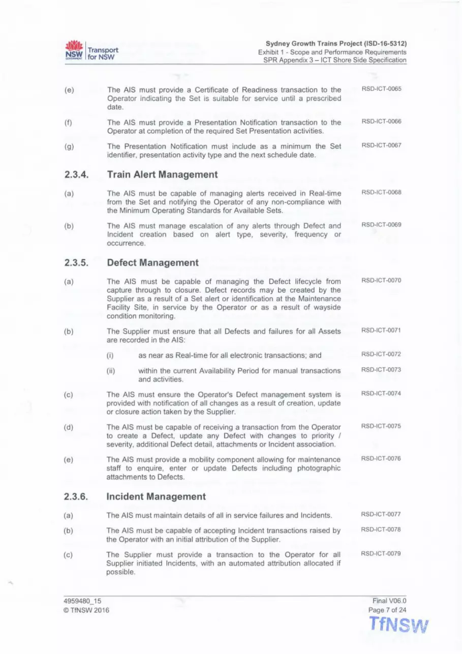
~'1; I Transport ~ forNSW
Sydney Growth Trains Project (ISD-16-5312) Exhibit 1 - Scope and Performance Requirements
SPR Appendix 3 - ICT Shore Side Specification
(e)
(f)
(g)
2.3.4.
(a)
(b)
2.3.5.
(a)
(b)
(c)
(d)
(e)
2.3.6.
(a)
(b)
(c)
The AIS must provide a Certificate of Readiness transaction to the Operator indicating the Set is su itable for service until a prescribed date.
The AIS must provide a Presentation Notification transaction to the Operator at completion of the required Set Presentation activities.
The Presentation Notification must include as a minimum the Set identifier, presentation activity type and the next schedule date.
Train Alert Management
The AIS must be capable of managing alerts received in Real-time from the Set and notifying the Operator of any non-compliance with the Minimum Operating Standards for Available Sets.
The AIS must manage escalation of any alerts through Defect and Incident creation based on alert type, severity, frequency or occurrence.
Defect Management
The AIS must be capable of managing the Defect lifecycle from capture through to closure. Defect records may be created by the Supplier as a result of a Set alert or identification at the Maintenance Facility Site , in service by the Operator or as a result of wayside condition monitoring.
The Supplier must ensure that all Defects and failures for all Assets are recorded in the AIS:
(i)
(ii)
as near as Real-time for all electronic transactions; and
within the current Availability Period for manual transactions and activities.
The AIS must ensure the Operator's Defect management system is provided with notification of all changes as a result of creation , update or closure action taken by the Supplier.
The AIS must be capable of receiving a transaction from the Operator to create a Defect, update any Defect with changes to priority I severity, additional Defect detail , attachments or Incident association.
The AIS must provide a mobility component allowing for maintenance staff to enquire, enter or update Defects including photographic attachments to Defects.
Incident Management
The AIS must maintain details of all in service failures and Incidents.
The AIS must be capable of accepting Incident transactions raised by the Operator with an initial attribution of the Supplier.
The Supplier must provide a transaction to the Operator for all Supplier initiated Incidents, with an automated attribution allocated if possible.
4959480_15
© TfNSW 2016
RSD-ICT-0065
RS 0 -1 CT-0066
RSD-ICT-0067
RSD-ICT-0068
RSD-ICT-0069
RSD-ICT-0070
RSD-ICT-0071
RSD-ICT-0072
RSD-ICT-0073
RSD-ICT-0074
RSD-ICT-0075
RSD-ICT-0076
RSD-ICT-0077
RSD-ICT-0078
RSD-ICT-0079
Final V06.0 Page 7 of 24
TfNSW

4''1i I Transport ~ forNSW
Sydney Growth Trains Project (ISD-16-5312) Exhibit 1 - Scope and Performance Requirements
SPR Appendix 3 - ICT Shore Side Specification
(d)
(e)
(f)
(g)
(h)
2.3.7.
(a)
(b)
(c)
(d)
2.3.8.
(a)
(b)
The Supplier must issue a transaction to the Operator for all changes made to an Incident in the AIS.
The Supplier must be capable of updating the AIS with any changes received in a transaction from the Operator, including final attribution.
The AIS must associate any Incidents created by the Operator with existing Defects based on Set Number, date/time, component item, Defect identification and provide the associated Defect number to the Operator.
The AIS must be capable of retaining and providing all necessary information to support the determination of the attribution.
The Supplier attributed Incidents must be recorded in the AIS for the purposes of being used in the calculation of the TLS Payment claims and Reliability and Disruption Adjustments (if any).
Defect Attribution
The AIS must ascribe a recommended Defect attribution, wherever possible, to service Incidents and Defects based on the Minimum Operating Standards for Available Sets and the TLS Deed.
The Defect attribution must be recorded within the Incident details in the AIS to support any attribution meetings.
The AIS must be capable of receiving a transaction from the Operator to update Defect attribution based on determination of any attribution meetings or review.
Final Defect attribution must be able to be amended or confirmed to the Supplier by notification or a transaction from the Operator.
FRACAS
The AIS must be capable of:
(i)
(ii)
(iii)
(iv)
(v)
(vi)
recording and capturing information about hardware failures and software Defects with associated component items;
identifying, selecting and prioritising failures and Defects with associated component items;
provide information to support the analysis and identification of the root cause of failures;
identifying, implementing and verifying corrective actions to prevent recurrence of failures ;
providing information from failure analysis and corrective actions to support reliability data analysis; and
providing reports for reliability and quality metrics.
The FRACAS function should provide analytic capabilities to support trend and predictive analysis.
4959480_15 ©TfNSW 2016
TfNSW
RSD-ICT-0080
RSD-ICT-0081
RSD-JCT-0082
RSD-ICT-0083
RSD-JCT-0084
RSD-ICT-0085
RSD-ICT-0086
RSD-ICT-0087
RSD-ICT-0088
RSD-ICT-0089
RSD-ICT-0090
RSD-JCT-0091
RSD-JCT-0092
RSD-JCT-0093
RSD-ICT-0094
RSD-ICT-0095
RSD-ICT-0096
Final V06.0 Page 8 of 24
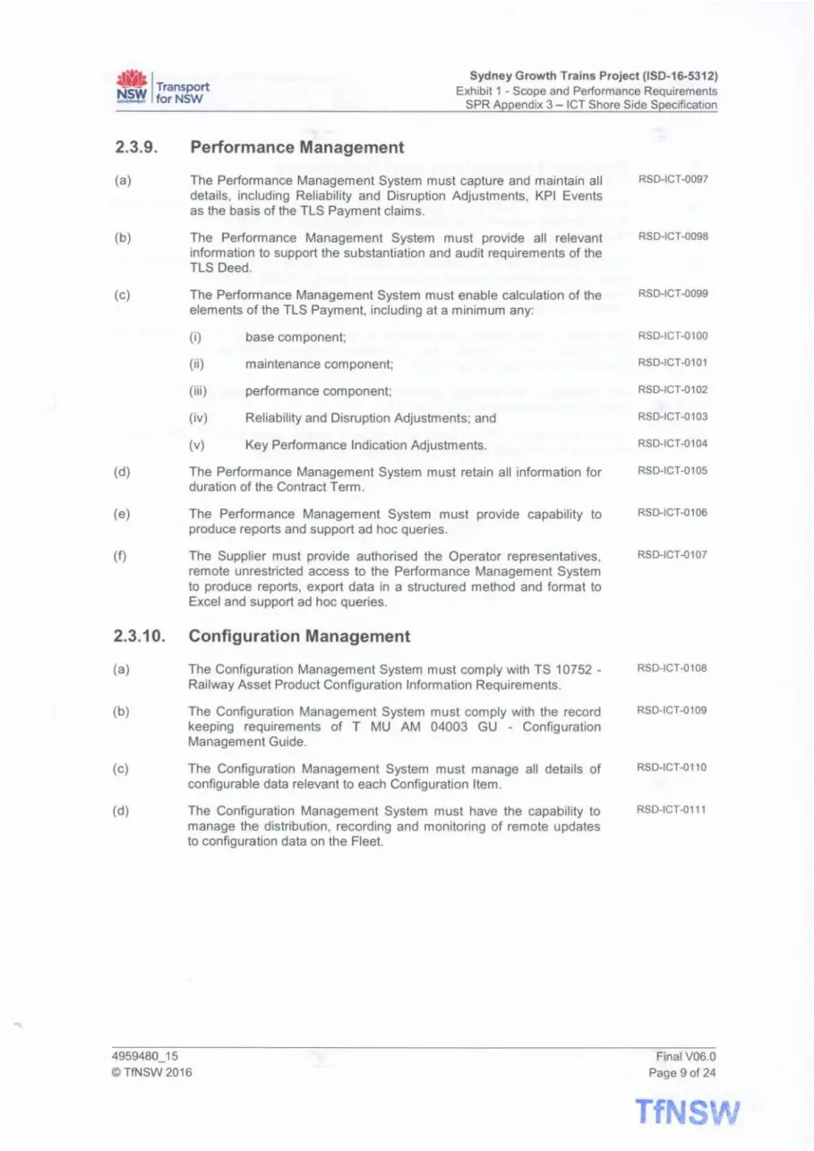
• , Transport ~ forNSW
Sydney Growth Trains Project (ISD-16-5312) Exhibit 1 - Scope and Performance Requirements
SPR Appendix 3 - ICT Shore Side Specification
2.3.9.
(a)
(b)
(c)
(d)
(e)
(f)
2.3.10.
(a)
(b)
(c)
(d)
Performance Management
The Performance Management System must capture and maintain all details, including Reliability and Disruption Adjustments, KPI Events as the basis of the TLS Payment claims.
The Performance Management System must provide all relevant information to support the substantiation and audit requirements of the TLS Deed.
The Performance Management System must enable calculation of the elements of the TLS Payment, including at a minimum any:
(i)
(ii)
(iii)
(iv)
(v)
base component;
maintenance component;
performance component;
Reliability and Disruption Adjustments; and
Key Performance Indication Adjustments.
The Performance Management System must retain all information for duration of the Contract Term.
The Performance Management System must provide capability to produce reports and support ad hoc queries.
The Supplier must provide authorised the Operator representatives, remote unrestricted access to the Performance Management System to produce reports, export data in a structured method and format to Excel and support ad hoc queries.
Configuration Management
The Configuration Management System must comply with TS 10752 -Railway Asset Product Configuration Information Requirements .
The Configuration Management System must comply with the record keeping requirements of T MU AM 04003 GU - Configuration Management Guide.
The Configuration Management System must manage all details of configurable data relevant to each Configuration Item.
The Configuration Management System must have the capability to manage the distribution, recording and monitoring of remote updates to configuration data on the Fleet.
4959480_15 ©TfNSW 2016
RSD-ICT-0097
RSD-ICT-0098
RSD-ICT-0099
RSD-ICT-0100
RSD-ICT-0101
RSD-ICT-0102
RSD-ICT-0103
RSD-ICT-0104
RSD-ICT-0105
RSD-ICT-0106
RSD-ICT-0107
RSD-ICT-0108
RSD-ICT-0109
RSD-ICT-0110
RSD-ICT-0111
Final V06.0 Page 9 of 24
TfNSW

~'1i I Transport ~ forNSW
Sydney Growth Trains Project (ISD-16-5312) Exhibit 1 - Scope and Performance Requirements
SPR Appendix 3 - ICT Shore Side Specification
3. System Integration and Interfaces
(a)
(b)
(c)
(d)
(e)
TfNSW intends to leverage the existing systems and interfaces in use at the Operator supporting all external integration through the B2B or Fleet Gateways.
TfNSW intends to limit or minimise any change to existing interfaces, message management systems or gateways in use by the Operator in order to mitigate any impact on the current Operator applications, interfaces and operations.
The Supplier must request any changes to the interface design or specification and provide the proposed detailed interface specifications for approval by TfNSW.
Any changes to the interface specification, protocols and message formats must be agreed in writing by TfNSW.
TfNSW reserves the right to approve or not approve any requests for change to the interface design at its absolute and sole discretion.
4959480_15 ©TfNSW 2016
TfNSW
INFORMATION
INFORMATION
RSD-ICT-011 2
RSD-ICT-0113
INFORMATION
Final V06.0 Page 10 of 24

~" I Transport ~ forNSW
Sydney Growth Trains Project (ISD-16-5312) Exhibit 1 - Scope and Performance Requirements
SPR Appendix 3 - ICT Shore Side Specification
4. Business to Business (B2B) Gateway
(a)
(b)
(c)
The Supplier must provide a secure Business to Business ("B2B") Gateway interface to the Operator communications network.
The B2B Gateway must be capable of integrating with the existing Operator B2B Gateway and able to support transactions comprising:
(i)
(ii)
Supplier and the Operator Shore based Enterprise Systems interactions; and
Operator bi-directional Fleet communications via the Fleet Gateway.
The Supplier must provide transactional and data integration with the Operator, utilising the B2B Gateway capability, in a format compliant with the existing Business-to-Business Interface Design Document.
4.1. 828 Gateway Capabilities
(a)
{b)
The B2B Gateway interface must enable a non-repudiating message handling service able to demonstrate:
(i)
(ii)
(iii)
(iv)
(v)
(vi)
guaranteed message delivery;
send I receive I acknowledgement messaging capability;
an ability to resend I replay messages;
fault tolerance;
an ability to suspend, hold and restart message queuing; and
conformance to B2B standards and best practice .
The B2B Gateway must be responsible for all data translation and transformation required to interface with the Supplier Shore based Enterprise Systems.
RSD-ICT-0114
RSD-ICT-0115
RSD-ICT-0116
RSD-ICT-0117
RSD-ICT-0118
RSD-ICT-0119
RSD-ICT-0120
RSD-ICT-0121
RSD-ICT-0122
RSD-ICT-0123
RSD-ICT-0124
RSD-ICT-0125
RSD-ICT-0126
4.2. Enterprise System 828 Integration and Synchronisation Interactions
(a) The following functional integration elements are required to be supported by the Supplier (as a minimum) to ensure interorganisational information exchange and system synchronisation .
(i) Fleet scheduling;
(ii) Fleet maintenance;
(iii) Defect management;
(iv) Incident Management;
(v) work order management; and
(vi) financial.
4959480_15 ©TfNSW 2016
RSD-ICT-0127
RSD-ICT-0128
RSD-ICT-0129
RSD-ICT-0130
RSD-ICT-0131
RSD-ICT-0132
RSD-ICT-0133
Final V06.0 Page 11 of 24
TfNSV'i
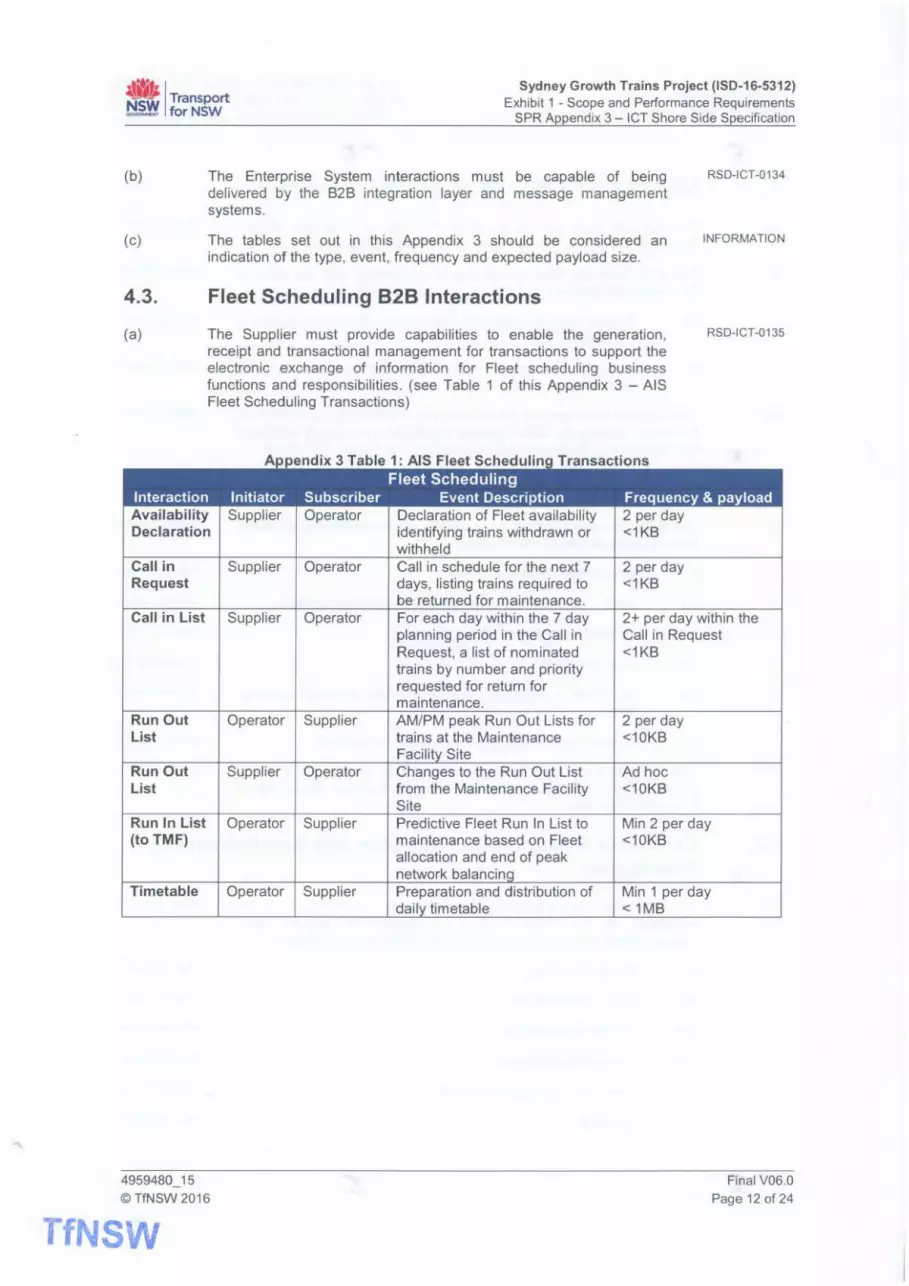
~'1i I Transport ~ forNSW
Sydney Growth Trains Project (ISD-16-5312) Exhibit 1 - Scope and Performance Requirements
SPR Appendix 3 - ICT Shore Side Specification
(b)
(c)
The Enterprise System interactions must be capable of being delivered by the B2B integration layer and message management systems.
The tables set out in this Appendix 3 should be considered an indication of the type, event, frequency and expected payload size.
4.3. Fleet Scheduling 828 Interactions
(a) The Supplier must provide capabilities to enable the generation, receipt and transactional management for transactions to support the electronic exchange of information for Fleet scheduling business functions and responsibilities. (see Table 1 of this Appendix 3 - AIS Fleet Scheduling Transactions)
A • d" 3 T bl 1 AIS Fl t S h d r T • f Fleet Scheduling
RSD-ICT-0134
INFORMATION
RSD-ICT-0135
Interaction Initiator Subscriber Event Description Frequency & payload Availability Declaration
Call in Request
Call in List
Run Out List
Run Out List
Run In List (to TMF)
Timetable
4959480_15 ©TfNSW 2016
TfNSW
Supplier Operator
Supplier Operator
Supplier Operator
Operator Supplier
Supplier Operator
Operator Supplier
Operator Supplier
Declaration of Fleet availability identifying trains withdrawn or withheld Call in schedule for the next 7 days, listing trains required to be returned for maintenance. For each day within the 7 day planning period in the Call in Request, a list of nominated trains by number and priority requested for return for maintenance. AM/PM peak Run Out Lists for trains at the Maintenance Facility Site Changes to the Run Out List from the Maintenance Facility Site Predictive Fleet Run In List to maintenance based on Fleet allocation and end of peak network balancinq Preparation and distribution of daily timetable
2 per day <1KB
2 per day <1KB
2+ per day within the Call in Request <1KB
2 per day <10KB
Ad hoc <10KB
Min 2 per day <10KB
Min 1 per day <1MB
Final V06.0 Page 12 of 24

4't}; I Transport ~.~ forNSW
Sydney Growth Trains Project (150-16-5312) Exhibit 1 - Scope and Performance Requirements
SPR Appendix 3 - ICT Shore Side Specification
4.4. Fleet Maintenance 828 Interactions
(a) The Supplier must provide capabilities to enable the generation, receipt and transactional management for transactions to support electronic exchange of information for Fleet maintenance business functions and responsibilities. (see Table 2 of this Appendix 3 - AIS Fleet Maintenance Transactions)
RSD-ICT-0136
Appendix 3 Table 2: AIS Fleet Maintenance Transactions Fleet Maintenance
Interaction Initiator Subscriber Event Description Frequency & payload
Maintenance Supplier Operator Completion of Preventative and <10 per day Complete Corrective Maintenance <1KB Certificate of Supplier Operator Maintenance complete and issue <10 per day Readiness & of new certificate and expiry date <1KB Handover or update to existing certificate Certificate Presentation Supplier Operator Completion of any Train wash or Min weekly per Notification other Presentation activity Set
<1KB
4.5. Defect Management 828 Interactions
(a) The Supplier must provide capabilities to enable the generation, receipt and transactional management for transactions to support electronic exchange of information for Defect management business functions and responsibilities. (see Table 3 of this Appendix 3 - AIS Defect Management Transactions)
RSD-ICT-0137
A d" 3 T bl 3 AIS D f t M • tT f Defect Management
Interaction Initiator Subscriber Event Description Frequency & payload
Create New Supplier Operator Creation of a new train Defect Ad hoc Defect <1 OKS plus
attachments Receive New Operator Supplier Advice of a new train Defect Ad hoc Defect created by the Operator <10KB plus
attachments Update Supplier Operator Update details of an existing Ad hoc Defect Defect: <10KB plus Details Attachments attachments
Priority I Severity Actions Incident association Attribution
4959480 15 Final V06.0
© TfNSW 2016
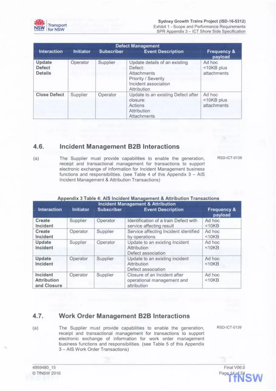
•r•~• ~l!' I Transport ~.~ forNSW
Sydney Growth Trains Project (ISD-16-5312) Exhibit 1 - Scope and Performance Requirements
SPR Appendix 3 - ICT Shore Side Specification
Defect Management Interaction Initiator Subscriber Event Description Frequency &
payload Update Operator Supplier Update details of an existing Ad hoc Defect Defect: <10KB plus Details Attachments attachments
Priority I Severity Incident association Attribution
Close Defect Supplier Operator Update to an existing Defect after Ad hoc closure : <10KB plus Actions attachments Attribution Attachments
4.6. Incident Management 828 Interactions
(a) The Supplier must provide capabilities to enable the generation, receipt and transactional management for transactions to support electronic exchange of information for Incident Management business functions and responsibilities . (see Table 4 of this Appendix 3 - AIS Incident Management & Attribution Transactions)
A d' 3 T bl 4 AIS I 'd t M • t & Att 'b f T Incident Management & Attribution
Interaction Initiator Subscriber Event Description
Create Supplier Operator Identification of a train Defect with Incident service affectinq result Create Operator Supplier Service affecting Incident identified Incident by operations Update Suppl ier Operator Update to an existing Incident Incident Attribution
Defect association Update Operator Supplier Update to an existing incident Incident Attribution
Defect association Incident Operator Supplier Closure of an Incident after Attribution operational management and and Closure attribution
4. 7. Work Order Management 828 Interactions
(a) The Suppl ier must provide capabilities to enable the generation, receipt and transactional management for transactions to support electronic exchange of information for work order management business functions and responsibilities . (see Table 5 of th is Appendix 3 - AIS Work Order Transactions)
4959480_15 © TfNSW 2016
RSD-ICT-01 38
f
Frequency & payload
Ad hoc <10KB Ad hoc <10KB Ad hoc <10KB
Ad hoc <10KB
Ad hoc <10KB
RSD-ICT-01 39
Final V06.0
PagY1 2 SW

~Ii / Transport ~ forNSW
Interaction
Create Work Order
Work Order Receipt
Work Order Completion
A •
Initiator
Operator
Supplier
Supplier
Sydney Growth Trains Project (ISD-16-5312) Exhibit 1 - Scope and Performance Requirements
SPR Appendix 3 - ICT Shore Side Specification
d" 3 T bl 5 AIS W k 0 d T f Work Order Management
Subscriber Event Description Frequency & payload
Supplier Work order being created to Ad hoc authorise undertaking of a <1 KB plus work reimbursable action instructions and/or
attachments Operator Receipt acknowledgement with Ad hoc
confirmation of expected <1KB completion details
Operator Advice of work order being Ad hoc complete with actual dates and <1KB details
4.8. Financial 828 Interactions
(a) The Supplier must provide capabilities to enable the generation, receipt and transactional management for transactions to support electronic exchange of information for financial business functions and responsibilities. (see Table 6 of this Appendix 3 - AIS Financial Transactions)
Interaction
Submit Payment Claim
Payment Claim Approval Payment Remittance
4959480_15 ©TfNSW 2016
A ••
Initiator
Supplier
Operator
Operator
d" 3 T bl 6 AIS F" . IT f Financial
Subscriber Event Description
Operator Periodic submission of payment claim for TLS Payments, net of Reliability and Disruption Adjustments
Supplier Advice of final payment claim approval
Supplier Advice of payables remittance
RSD-ICT-0140
Frequency & payload Monthly <1MB
Monthly <1KB
Monthly <1KB
Final V06.0 Page 15 of 24
TfNSW

"" I Transport ~~ forNSW
Sydney Growth Trains Project (ISD-16-5312) Exhibit 1 - Scope and Performance Requirements
SPR Appendix 3 - ICT Shore Side Specification
5. Fleet Communications
(a)
(b)
(c)
(d)
(e)
(f)
The Operator currently communicates bi -directionally with the Waratah Fleet via:
(i)
(ii)
the shore and Set based CTIP systems as the primary pathway; and
the Supplier hosted Fleet Gateway utilising the 828 Gateway message routing as a secondary pathway.
Appendix 3 Figure 1: Shore I Set Communication View
Communication System View
Supplier ICI" System
121 Component
?IGPP / SGPP LTE I 802.llWHI
AppllcatlonServer
Aopllu tton
~ niJ Replacement Train
< : ~ !GPP /3GPPLT1'/ . . ~ I02.11 Wl·fl
~ SydneyTrainsPrim•ryTra in Communication P•th
The Supplier must supply a managed gateway service for the Supplier and the Operator ICT Shore Systems to wirelessly interact with the required train-borne systems in Real-time.
The Supplier must provide the capability to enable the Operator to communicate with the Fleet via the 828 Gateway utilising the Supplier Fleet Gateway.
The Supplier must reuse, to the maximum extent practicable, any existing ICT Shore based Fleet Gateway systems currently implemented by the Operator.
The Supplier must be responsible for the management, maintenance and operational support of all equipment and software required to support the Fleet Gateway services.
The Supplier must supply all technical specifications and artefacts required for the Operator ICT Systems to interoperate with the Fleet Gateway services.
4959480_15
© TfNSW 2016
TfNSW
INFORMATION
INFORMATION
INFORMATION
RSD-ICT-0141
RSD-ICT-0142
RSD-ICT-0143
RSD-ICT-0144
RSD-ICT-0145
Final V06.0
Page 16 of24

~" I Transport ~ forNSW
Sydney Growth Trains Project (ISD-16-5312) Exhibit 1 - Scope and Performance Requirements
SPR Appendix 3 - ICT Shore Side Specification
5.1. Fleet Gateway Capabilities
(a)
(b)
(c)
(d)
(e)
(f)
(g)
(h)
(i)
(k)
(I)
(m)
The train-borne interfaces are specified in further detail in section 4 (Communications) of Appendix 2 (Rolling Stock Specification).
The Fleet Gateway must manage the transactions between the Supplier and the Operator shore-based interfaces and the Set interface.
The Fleet Gateway must be a highly secure, reliable and available managed gateway service.
The Fleet Gateway must be capable of supporting interactions in a format compliant with the Business-to-Business Interface Design Document.
The Fleet Gateway must provide data from the Set in a structured format compliant with the Business-to-Business Interface Design Document.
The Fleet Gateway must communicate with the Set using an open industry standard communications protocol.
The Fleet Gateway must be responsible for all data translation and transformation required to interoperate with the Set interface.
The Fleet Gateway services must be designed to meet an availability and reliability target of 99.98%.
The Fleet Gateway services must comply with the requirements of ISO/IEC 27001 Information technology - Security techniques -Information security management systems - Requirements.
The Fleet Gateway solution must be designed for scalability to support the option to extend the Fleet.
The Fleet Gateway must support quality of service networking with the Set interface.
The Fleet Gateway must manage transaction concurrency and transaction constraint (e.g. number of requests by transaction type).
The Fleet Gateway must ensure that the integration with the Set interface does not adversely impact on the performance, integrity and security of the Set.
5.2. Fleet Gateway Interactions
(a) The Supplier shore based Fleet Gateway must manage the end to end interoperability between the ICT Shore Systems and the Fleet Gateway interface, for the transactions summarised in Table 7 of this Appendix 3 - Fleet Gateway Transactions.
Appendix 3 Table 7: Fleet Gateway Transactions Shore based train Gateway
INFORMATION
RSD-ICT-0146
RSD-ICT-0147
RSD-ICT-0148
RSD-ICT-0149
RSD-ICT-0150
RSD-ICT-0151
RSD-ICT-0152
RSD-ICT-0153
RSD-ICT-0154
RSD-ICT-0155
RSD-ICT-0156
RSD-ICT-0157
RSD-ICT-0158
Interaction Initiator Subscriber Event Description Frequency &
4959480_15 ©TfNSW 2016
payload
Final V06.0 Page 17 of 24
TfNSW

~Ii I Transport ti~ forNSW
Interaction
Request train events
Publish train events
Request train kms
Send train kms
Request stored CCTV
Send stored CCTV
Request Event Recorder data
Send Event Recorder data
Request recorded train events
Send recorded train events
Send train preparation certificate
Load timetable
4959480_15 ©TfNSW 2016
TfNSW
Initiator
Operator
Supplier
Operator
Supplier
Operator
Supplier
Operator
Supplier
Operator
Supplier
Supplier
Operator
Sydney Growth Trains Project (ISD-16-5312) Exhibit 1 - Scope and Performance Requirements
SPR Appendix 3 - ICT Shore Side Specification
Shore based train Gateway Subscriber Event Description
Supplier Initiate request to receive defined train alerts, Defects and recorded data from a train
Operator Publishes alerts, Defects and recorded data requested from a train
Supplier Initiate request to receive the kms for a train
Operator Sends requested train kms
Supplier Receives requests for retrieval of post event CCTV and associated voice recordings and meta data from a train
Operator Sends requested post event CCTV footage, voice recordings and meta data from a train
Supplier Receives requests for retrieval of Event Recorder data from a train
Operator Sends requested Event Recorder data from a train
Supplier Receives requests for retrieval of stored alerts, Defects and recorded data from a train
Operator Sends requested stored alerts, Defects and recorded data from a train
Operator Results of a Crew initiated train preparation
Supplier Receives new timetable to use for passenger information, once activation date and time reached .
Frequency & payload
<5 per train <1KB
<50 I day I train <1KB
1 per Set <1KB
1 per Set <1KB
<10 I day <1KB
<10 I day >200MB
<10 I day <1KB
<10/day <20MB
<10 I day <1KB
<10/day <20MB
1 per train prep <1MB
1 Daily I train & <5 per day I train <10MB
Final V06.0 Page 18 of 24

4\tJ I Transport ~ forNSW
Interaction
Load train announcement
Load transposition
Update OVA library
Send update OVA status
Request live CCTV
Send live CCTV
Retrieve system logs
Send system logs
Request system configuration status
Send system configuration status
Request AMS juridical recorder data
Send AMS juridical recorder data
4959480_15 © TfNSW 2016
Initiator
Operator
Operator
Operator
Supplier
Operator
Supplier
Operator
Supplier
Operator
Supplier
Operator
Supplier
Sydney Growth Trains Project (ISD-16-5312) Exhibit 1 - Scope and Performance Requirements
SPR Appendix 3 - ICT Shore Side Specification
Shore based train Gateway Subscriber Event Description
Supplier Receives a special message to be loaded in the Passenger Information System on board a train for immediate play or for discretion of the Crew.
Supplier Receives a request to load changes to the current or nextTrip. Changesinciude stopping pattern and messages.
Supplier Receives a new or updated audio and text library to be loaded
Operator Sends the outcome of OVA library update
Supplier Receives request to secure a connection to a train camera, with quality of service to ensure optimum streaming
Operator Sends a secure, live stream from a train camera. Manages the quality of outbound stream
Supplier Requests retrieval of system log files from a train
Operator Send requested system log files from a train
Supplier Receives software configuration status request
Operator Sends software configuration status
Supplier Receives requests for retrieval of AMS juridical recorder data from a train
Operator Sends requested AMS juridical recorder data from a train
Frequency & payload
< 50 per day I fleet <1KB
< 50 per day <1KB
Quarterly I train <100MB
Quarterly I train <1KB
<10 per week <1KB
<10 per week <600 KB/sec per stream
<5 I day <1KB
<5 I day <2MB
Ad hoc <1KB
Ad hoc <1MB
<10 per day <1KB
<10 per day <20MB
Final V06.0 Page 19 of 24
TfNSVtl

~Ii / Transport ~~ forNSW
Sydney Growth Trains Project (ISD-16-5312) Exhibit 1 - Scope and Performance Requirements
SPR Appendix 3 - ICT Shore Side Specification
6. Shore Based Train Data Utilities
(a)
(b)
(c)
(d)
(e)
(f)
(g)
(h)
(i)
The Supplier must deliver methods and utilities to enable the Operator to retrieve, view, analyse and produce reports of Set Event Recorder data, CCTV stored footage and associated data including audio.
The Supplier must deliver methods enabling the Operator to retrieve Set recorded data and Set sub system logs in a structured format for HVAC, Communications, Surveillance and Set-borne Gateway systems. Log files for other subsystems must be provided if available and re-design of those subsystems is not required.
The Supplier must provide all necessary documentation and assistance to enable the Operator to view, analyse and produce reports of Set recorded data and Set sub system logs.
The Supplier must provide throughout the Contract Term any relevant utilities that are available, or become available, which are used in support of the Supplier's Maintenance obligations and which would enhance the Operator's ability to view, analyse or report on SGT recorded data and Set sub system logs retrieved from the Set.
Without limiting or affecting the provisions of the Project Agreements, the Supplier must assign to TfNSW an enterprise licence to enable the Operator to utilise all supplied utilities, software or tools.
The Supplier must be responsible for providing the Operator with adequate documentation and training to enable effective use of each supplied viewer and utility.
The Supplier must provide ongoing support and maintenance services for all supplied systems, viewers and utilities required to access and view Set data.
The Supplier must ensure all supplied utilities are compatible with the Operator standard desktop operating environment.
The CCTV utility must provide, at a minimum, the following capabilities:
(i)
(ii)
(iii)
Replay controls including forward and reverse viewing, frame step forwards and backwards and variable playback speed;
Ability to display single and multiple cameras:
(A) For a single camera view, display at the same pixel resolution as the recording (1:1); and
(B) For a multiple camera view, all camera views are to be correctly time synchronised with each other and synchronisation is to be maintained when switching between individual cameras whilst playing.
Display of all cameras in their correct aspect ratio, regardless of whether single or multiple cameras are being displayed;
4959480_15 ©TfNSW 2016
TfNSW
RSD-ICT-0159
RSD-ICT-2001
RSD-ICT-2002
RSD-ICT-2003
RSD-ICT-0160
RSD-ICT-0161
RSD-ICT-0162
RSD-ICT-0163
RSD-ICT-0164
RSD-ICT-0165
RSD-ICT-0166
RSD-ICT-0167
RSD-ICT-0168
RSD-ICT-0169
Final V06.0 Page 20 of 24

~· 1 Transport ~ forNSW
Sydney Growth Trains Project (ISD-16-5312) Exhibit 1 - Scope and Performance Requirements
SPR Appendix 3 - ICT Shore Side Specification
(k)
(iv)
(v)
(vi)
(vii)
Ability for recorded audio to be replayed in correct synchronisation with the associated camera;
Ability to search by:
(A) date and time;
(B) location (i.e. nearest station); and
(C) events that trigger the initiated display of the CCTV to the Driver.
Ability to display metadata (i.e. date, time, car identifier, camera identifier, location, event); and
Ability to verify the authenticity and integrity of the footage, recordings and associated data.
The Event Recorder utility must provide, at a minimum, the following capabilities:
(i)
(ii)
(iii)
(iv)
(v)
(vi)
Ability to select and deselect signals and data elements recorded for replay;
Selected signals and data element values are visible when replayed;
Replay controls include forward and reverse viewing;
Ability to verify the authenticity and integrity of the information to be replayed ;
Ability to select information for replay by date and time; and
Ability to export selected information in a structured format suitable for Excel.
The Supplier must supply all equipment and software required to enable the Operator to power on, connect to and search, select and extract data from a physically retrieved:
(i)
(ii)
(iii)
CCTV digital video recorder;
CCTV disk drive(s); and
Event Recorder.
4959480_15 ©TfNSW 2016
RSD-ICT-0170
RSD-ICT-0171
RSD-ICT-0172
RSD-ICT-0173
RSD-ICT-0174
RSD-ICT-0175
RSD-ICT-0176
RSD-ICT-0177
RSD-ICT-0178
RSD-ICT-0179
RSD-ICT-0180
RSD-ICT-0181
RSD-ICT-0182
RSD-ICT-0183
RSD-ICT-0184
RSD-ICT-0185
RSD-ICT-0186
RSD-ICT-0187
Final V06.0 Page 21 of 24
TfNSW

...
4't) I Transport ~fil4Y for NSW
Sydney Growth Trains Project (ISD-16-5312) Exhibit 1 - Scope and Performance Requirements
SPR Appendix 3 - ICT Shore Side Specification
7. ICT Operation
7.1. Help Desk
(a)
(b)
The Supplier must provide a Help Desk to the Operator for functional and technical support of major ICT and other systems including:
(i)
(ii)
(iii)
(iv)
(v)
(vi)
the Fleet Gateway;
the Business to Business (B2B) Gateway;
the shore-based train data utilities;
remote access to Supplier shore-based systems;
Supplier shore based systems, including ICT Shore Systems; and
any other systems, services and utilities provided by the Supplier.
The Supplier must ensure the Help Desk:
(i)
(ii)
(iii)
(iv)
(v)
(vi)
(vii)
(viii)
(ix)
is available on a 24/7 basis;
is accessible through a single point of contact at all times;
has provision to manage multiple requests , with automatic diverts being in place to alternative, suitably qualified staff;
gives immediate priority to calls relating to Sets in service;
follows up any calls that cannot be answered immediately as soon as possible;
Personnel at all times have immediate access to the appropriate manuals, and any other expertise and technical information required to provide accurate and timely advice;
has on line access to Set information as available to determine the status of the train from its systems;
calls are all recorded; and
records all reported Defects, failures or faults in the FRACAS system .
7.2. System Maintenance
(a)
(b)
4959480_15
Any system maintenance must be performed out of operational peaks and any associated outages must be scheduled and managed in accordance with the ICT Coordination Protocol.
Routine system maintenance must be, to the maximum extent possible, planned to minimise or mitigate any interruption, disruption or degradation to any System or business operation .
© TfNSW 2016
TfNSV\f
RSD-ICT-0188
RSD-ICT-0189
RSD-ICT-0190
RSD-I CT-0191
RSD-ICT-0192
RSD-ICT-0193
RSD-ICT-0194
RSD-ICT-0195
RSD-ICT-0196
RSD-ICT-0197
RSD-ICT-0198
RSD-ICT-0199
RSD-ICT-0200
RSD-ICT-0201
RSD-ICT-0202
RSD-ICT-0203
RS D-1 CT-0204
RSD-ICT-0205
RSD-ICT-0206
Final V06.0 Page 22 of 24

4''1i I Transport ~ forNSW
Sydney Growth Trains Project (ISD-16-5312) Exhibit 1 - Scope and Performance Requirements
SPR Appendix 3 - ICT Shore Side Specification
7 .3. Release Management
(a)
(b)
(c)
(d)
The Supplier must provide release schedules for system upgrade, defect repairs to the enterprise and integration systems.
Each release must be supported by a release plan which identifies all stakeholders and activities for release co-ordination between the Supplier and the Operator.
Each release must be scheduled and managed in accordance with the ICT Coordination Protocol and relevant Project Plans.
It is a requirement that release management schedules be aligned between the parties to ensure minimal impacts on business operation , ICT and business overheads.
RSD-ICT-0207
RSD-ICT-0208
RSD-ICT-0209
RSD-ICT-0210
7.4. Collaborative Quality Assurance and End-to-End Testing
(a)
(b)
(c)
The Supplier must provide and support fully integrated, separate and isolated environments for the purposes of functional and integration testing, support and training .
The Supplier must provide a test plan in order to identify roles , responsibilities and expectations of all parties in the verification and assurance of system changes in each application development release.
The Supplier must ensure all affected stakeholders have tested , verified and accepted all software changes prior to production release.
7 .5. Infrastructure Architecture and Redundancy
(a)
(b)
The Supplier must design the production environment infrastructure topology, including server, network and database layers, identifying redundancy and failover in order to mitigate any Single Point of Failure impacting normal business operation .
The Supplier must design an infrastructure topology, including server, network and database layers to provide an isolated, fully integrated test and support environments.
7.6. System Availability
(a) The Supplier must record and report all outages. An outage is considered to be any event, planned or unplanned, where a significant component of the solution is unavailable to support the efficient operation of the Supplier maintenance and/or Fleet delivery obligations, integration with the Fleet or operation of B2B transactional management systems.
7. 7. Degraded ICT Shore Systems Operation
(a) The Supplier must have the capacity to continue system operation in a degraded mode throughout any planned or unplanned service impact.
4959480_15 © TfNSW 2016
RSD-ICT-0211
RSD-ICT-0212
RSD-ICT-0213
RSD-ICT-0214
RSD-ICT-021 5
RSD-ICT-0216
RSD-ICT-0217
Final V06.0 Page 23 of 24
TfNSW

~· 1 Transport ~ forNSW
Sydney Growth Trains Project (ISD-16-5312) Exhibit 1 - Scope and Performance Requirements
SPR Appendix 3 - ICT Shore Side Specification
(b) The Supplier must have the ability to isolate system components for maintenance whilst continuing to operate on redundant or parallel infrastructure.
7 .8. Disaster Recovery
(a)
(b)
(c)
(d)
The Supplier must develop and maintain the physical disaster recovery infrastructure for the operation of the ICT Shore Systems.
The Supplier must implement and continue to operate the DRP following the notification of a disaster event in accordance with the processes and framework included in the ICT Coordination Protocol.
The Supplier must continue to operate the DRP until such time as the primary services are restored to a normal state and a convenient time is agreed with the Operator so as to minimise further operational disruption.
The Supplier must test the DRP on a regular basis and provide notification to the Operator of the schedule for any DRP tests, results and actions arising from any tests.
7 .9. Business Continuity
(a)
(b)
The BCP must ensure that any planned, unplanned or disaster event must not affect the delivery of operational services to a normal timetable.
The Supplier must test the BCP, to the maximum extent possible, in conjunction with any planned DRP test activities.
4959480_15 ©TfNSW 2016
TfNSW
RSD-ICT-0218
RSD-ICT-0219
RSD-ICT-0220
RSD-ICT-0221
RSD-ICT-0222
RSD-ICT-0223
RSD-ICT-0224
Final V06.0 Page 24 of 24

~,,,. --NSW GOVERNMENT
Transport for NSW
Sydney Growth Trains Project (ISD-16-5312)
Exhibit 1 - Scope and Performance Requirements SPR Appendix 4 - Maintenance Facility Site
Date of Issue
Document Number:
Status
03 NOVEMBER 2016 '"
4959469_12
FINAL
COMMERCIAL IN CONFIDENCE
TfNSW

• 1 Transport ~ forNSW
Sydney Growth Trains Project (ISD-16-5312) Exhibit 1 - Scope and Performance Requirements
SPR Appendix 4 - Maintenance Facility Site
Table of Contents 1. Introduction .. ....... .. ... ..... ............... ................................. .... ....... .. .......... .. ...... .... ...... .... ...... ................ 3
2. Description of the Maintenance Facility Site and other background information ... ............... ..... ... .. 4
2.1 . Inspection and maintenance roads , plant and equipment. ..... .. .... ............. ....... ... .. .......... ... .... . 6
2.2. Shared Facilities: office space and car parking .. .... ... .. ... ... .. .. ... .. ... .. ... .... ... .. ... .... ....... .... ... ...... . 8
2.3. Stores areas ... ...... ... .... ... ............................... .. .. ..... .. .... ........... .. .... .. .. ... .. ...... .... ... ... ........ ......... 9
2.4. Security and fire protection .......................... ....................................... ............ ..................... .... 9
2.5. Wheel lathe ..... .......... ... ... .. ... .... ... .. ..... ... ... ...... ...... ..... ... ................... .. ...... ........... ............. ..... .. 10
2.6. Wash plant ...... ... ........ .. ......... .. ..... ........ ....... .......... .... ..... ..... ... .... .. ..... ... ....... .. .. ... ..... .. .... ... .... .. 10
2.7. Internal access roads and walkways ......... .... .... ......... .. ........ ........... .. .. ........ ......... ... ........ .... .. 10
2.8. Power supplies .................. ........ .... .. ......... ............. .............................. ..... .................... ..... .. .. 10
2.9. Traction power ... ........ .. .... ... ... ....... ..... ...... ...... ........ .... .... ..... .. .. .. ...... .... .. ..... ............. ... ... ......... 10
Attachment A: Sketch TF18 MF01 .. .... .... ........ .... ..... ..... ... .. .... .................... .......... .... .......... .......... ...... .. . 12
4959469_12
TfNSW2016
Final V06.0 Page 2of13

(I_) I Transport ~ forNSW
Sydney Growth Trains Project (ISD-16-5312) Exhibit 1 - Scope and Performance Requirements
SPR Appendix 4 - Maintenance Facility Site
1 . Introduction (a)
(b)
(c)
The Operator has agreed to designate space within the Mortdale Maintenance Centre as the Maintenance Facility Site.
Further information on the Maintenance Facility, the Maintenance Facility Site, and the existing facilities, plant and equipment and configuration of the overall Mortdale Maintenance Centre is provided in this Appendix 4.
The Supplier may use the Maintenance Facility Site for commissioning the Sets, but must be cognisant of the size of the Maintenance Facility Site and the maintenance requirements of any Sets already in service.
4959469_12 ©TfNSW 2016
INFORMATION
INFORMATION
RS D-MAS-0001
Final V06.0 Page 3 of 13
TfNSW

• 1 Transport ~ forNSW
Sydney Growth Trains Project (150-16-5312) Exhibit 1 - Scope and Performance Requirements
SPR Appendix 4 - Maintenance Facility Site
2. Description of the Maintenance Facility Site and other background information
(a)
(b)
(c)
The Maintenance Facility Site is located within the Mortdale Maintenance Centre.
The Maintenance Facility Site is adjacent to the lllawarra Line.
The approximate area of the Mortdale Maintenance Centre is ind icated in Figure 1 of this Appendix 4, with the Maintenance Facility Site indicated in red and the area of the facilities to be shared by the Operator and Supplier ("Shared Facilities") indicated in blue:
INFORMATION
INFORMATION
INFORMATION
Final V06.0 Page 4 of 13

• 1 ~SW Transport ....,._,., forNSW
Sydney Growth Trains Project (ISD-16-5312) Exhibit 1 - Scope and Performance Requirements
SPR Appendix 4 - Maintenance Facility Site
4959469_12 ©TfNSW 2016
Final V06.0 Page 5 of 13
TfNSW

• 1 Transport ~ forNSW
Sydney Growth Trains Project (ISD-16-5312) Exhibit 1 - Scope and Performance Requirements
SPR Appendix 4 - Maintenance Facility Site
4959469_12 ©TfNSW 2016
TfNSW
Final V06.0 Page 6 of 13

.:.t: .. I ~ NSW Transport __...., forNSW
Sydney Growth Trains Project (ISD-16-5312) Exhibit 1 - Scope and Performance Requirements
SPR Appendix 4 - Maintenance Facility Site
4959469_12 ©TfNSW 2016
Final V06.0 Page 7 of 13
TtNsw

dJ; I Transport ~ forNSW
Sydney Growth Trains Project (ISD-16-5312) Exhibit 1 - Scope and Performance Requirements
SPR Appendix 4 - Maintenance Facility Site
4959469_12 ©TfNSW 2016
TfNSW
Final V06.0 Page 8 of 13

.• :.....: ... I ~ Transport ~ forNSW
Sydney Growth Trains Project (ISD-16-5312) Exhibit 1 - Scope and Performance Requirements
SPR Appendix 4 - Maintenance Facility Site
2.4. Security and fire protection
(a)
(b)
(c)
(d)
(e)
The Mortdale Maintenance Centre is protected with the following security systems:
(i)
(ii)
(iii)
(iv)
High security fencing and controlled access gates for pedestrians and vehicles;
A perimeter intrusion detection system (installed along the entire fence line);
Virtual trip lines for CCTV; and
A thermal camera and beam array detection located at the rail entrance (installed to detect unauthorised intruders entering via the corridor).
There is a contract security guard at the gate house adjacent to the administration building. The guard is provided through the Operator's funded and managed contract and is present on 24/7 basis.
Road access gates are mechanised and under the supervision of security personnel.
Turnstile gates, controlled by access cards, are installed for pedestrian access.
The CCTV security installation covers external areas of buildings, access pathways, car parking etc. The system is self-contained and monitored from the administration building. The system is also used to assist Mortdale Maintenance Centre operations.
4959469_12 ©TfNSW 2016
INFORMATION
INFORMATION
INFORMATION
INFORMATION
INFORMATION
INFORMATION
INFORMATION
INFORMATION
INFORMATION
Final V06.0
SW

t_W) I Transport ~ forNSW
Sydney Growth Trains Project (ISD-16-5312) Exhibit 1 - Scope and Performance Requirements
SPR Appendix 4 - Maintenance Facility Site
(f)
(g)
Fire protection systems have been installed and are in operation at the Mortdale Maintenance Centre. These cover the whole of the Mortdale Maintenance Centre and their ongoing maintenance and operation will remain the responsibility of the Operator.
For the purposes of operation and maintenance of these systems, the Supplier must co-operate with the Operator to ensure their ongoing effectiveness.
2.5. Wheel lathe
(a) There is no wheel lathe at the Mortdale Maintenance Centre.
2.6. Wash plant
(a) There is a wash plant at the Mortdale Maintenance Centre on a dedicated wash road, which runs along the eastern boundary of the site, beyond No. 12 Road. The wash plant will remain under the control of the Operator.
2.7. Internal access roads and walkways
(a)
(b)
(c)
(d)
The Mortdale Maintenance Centre has internal vehicular access roads and pedestrian walkways.
There are existing connecting roads from the Mortdale Maintenance Centre to the local road network.
The Supplier must provide emergency access and egress provisions for and across the Maintenance Facility Site with due consideration of the requirements of all personnel working at the Mortdale Maintenance Centre.
The Supplier must agree arrangements regarding emergency access and egress with the Operator within 90 Business Days of the Commencement Date of the MF Works Deed.
2.8. Power supplies
(a)
(b)
The Supplier must assess the suitability of the existing power supplies to meet its needs in performing the TLS Phase Activities .
The Supplier must ensure that all general power/electrical supply to the Maintenance Facility Site, including lighting, power outlets in offices, amenities and working areas (including workshops) are separately metered.
(i) The Supplier must nominate the expected power draw for the Maintenance Facility Site.
2.9. Traction power
(a)
(b)
The Operator will provide existing traction overhead structures and overhead wiring, including isolation capability for overhead wiring .
The Operator will provide traction power.
4959469_12 ©TfNSW 2016
TfNSW
INFORMATION
RSD-MAS-0006
INFORMATION
INFORMATION
INFORMATION
INFORMATION
RSD-MAS-0007
INFORMATION
RSD-MAS-0008
RSD-MAS-0009
RSD-MAS-0010
INFORMATION
INFORMATION
Final V06.0 Page 10of13

....
~ IJJ; ·~ ... I NSW Transport _, forNSW
4959469_12 ©TfNSW 2016
Sydney Growth Trains Project (ISD-16-5312) Exhibit 1 - Scope and Performance Requirements
SPR Appendix 4 - Maintenance Facility Site
Final V06.0 Page 11 of 13
TfNSW

~- I Transport ~ forNSW
Sydney Growth Trains Project (ISD-16-5312) Exhibit 1 - Scope and Performance Requirements
SPR Appendix 4 - Maintenance Facility Site
Attachment A: Sketch TF18 MF01
4959469_12 ©TfNSW 2016
TfNSW Final V06.0
Page 12 of 13

>
• 1 Transport ~ forNSW
Sydney Growth Tra ins Project (ISD-1 6-5312) Exhibit 1 - Scope and Performance Requirements
SPR Appendix 4 - Maintenance Facility Site
4959469_12
© TfNSW 2016
Final V06.0
Page 13 of1 3

'''" --NSW GOVERNMENT
Transport for NSW
Sydney Growth Trains Project (ISD-16-5312)
Exhibit 1 - Scope and Performance Requirements SPR Appendix 5 - Through Life Support Specification
Date of Issue
Document Number:
Status
03 NOVEMBER 2016 _
4959467_16
FINAL
COMMERCIAL IN CONFIDENCE
TfNSW

~t;_) I Transport ~ forNSW
Sydney Growth Trains Project (ISD-16-5312) Exhibit 1 - Scope and Performance Requirements
SPR Appendix 5 - Through Life Support Specification
Table of Contents 1. Introduction ..... ..... .... ... ..... ... ...... ..... .. ... .... ... .......... .............. .... ............ .... ..... .. .. .......... .................... ... 4
1.1. TLS Phase Activities .. ...................... ..... .......... ........ .. ........ .. ... .. ....... ... ............. .. ... .... ... .. ..... .... .. 4
1.2 . Overall requirements .. ...... .. ... ... ... ........ ......... ... ..... ... ...... ... .. .... .... ........ ....... ......... ......... .... ........ 4
1.3. Interfaces, reporting and communication .. .. .... ... .. .. .. ... ... ..... .... ...... .. .. .... .......... .... ... ...... ... ... ... .. 4
1.4. Policies and procedures ....... .. .. ... ..... ..... .... .... .... .. ... ... .. ... ... ....... .... ..................... .. ... ............. .. .. 5
1.5. Information and Communications Technology (ICT) ..... .... ........ .. .. ... .. ........ ...... .. ...... ....... ....... . 5
2. Set Maintenance Services .... .... ....... ....... .. .. .. ........ ... ...... .... .. .. ...... .......... ....... ..... ..... ...... .. .. .. ... .... ... ... 6
2.1. Maintenance and repairs .... .. ..... ...... .... ... ... .... ..... .. .... .. ... .. .... ....... .. ... .. .... ... ....... .. .... ..... .. ...... ... .. 6
2.2 . Maintenance and repair services .. .... .... .... ... ...... .... .... .................... ........ ......... ........................ 6
2.3. The Operator to deliver Sets for maintenance ...... ...... ........... ..... .. .......................................... 8
2.4. Supplier to operate Sets within the Maintenance Facility Site ... ....... .. ... ...... .. ... .. ................. .. . 9
2.5. Issue of Certificates of Readiness and Handover ... ... .... .. .................... ... ........................ .. .... .. 9
2.6. Operator's Personnel attending to in service trains ...... ... ...... ............ .... ..... .. ........ .... ... .. ... ..... 10
2.7. Supplier Related Incident response .... ..... ..... .... ................................................................. ... 11
2.8. Wheel Profiling ...... .... ..... .... ... ...... .... .... ... ....... .... .. ... ..... .. .. ............... ... .. ... .. ... .. .. ..... .... .... .... ...... 12
2.9. Track possessions ..... ..... ............ ..... ...... ... .... .... .... ................ ..... ............ .... .... ..... ................... 12
3. Presentation services ......... .... .... .. ... ...... ..... ...... ..... .... ..... ... ... .... ... .. .. ... ... ..... ..... ........ ......... .. ... ....... . 13
3.1. Presentation service quality requirements ........ ... ...... .... ...... ....... ....... ......... ........... ..... .... ... ... 13
3.2. Cleaning services for Sets in the Maintenance Facility Site .. ...... ... .. .. ...... ....... ....... .. .... .... .. ... 13
3.3. Cleaning services for Sets not in the Maintenance Facility Site .. ..... ... ... ... ... ...... .. .... ... .. .. ... ... 14
3.4. Exterior washing ............................ ..... ..... ........ ........ .... .... .......... ............. ......... .................. .. .. 14
3.5. Bio-cleaning .. ............... ..... ......... .......................................... ..... ...... .... .... .... ...... .......... ...... ..... 14
4. Operations Services ............ .... ... ... ........ ....... .......... .... .. ... .... ......... ......... .. .. ... .. ... .. ... .... ....... ...... .. ... . 15
4.1. Overview of Operations Services .... ... ...... .. .. ... .... .... .... .... .... ........ .. ........ ... .. .. ..... .. ......... .... .. ... 15
4.2. Updates to Manuals and Timetable Information Stored in the TMS .. ....... ... ... ...... .... ...... ...... 15
4.3. Updates to Operator decals, route maps and passenger information posters .... ....... .... ..... .. 16
4.4. Updates to Digital Voice Annunciator ... ..... .. ........... .... ...... ................ .. ... .... ... .... ... ........ ... .. ... .. 16
4.5. Downloading of Event Recorder and TMS data ... .... .. .. .... .. .... ........ .... ..... .... .. .... ..... .. ... ... .... .. . 16
4.6. Retrieval of CCTV images ....... ...... .. .. .. .. .... ... .... .. ... .. .. ........... ... ... ......... ..... .. ... ....... ... ..... ... ...... 17
4.7. ICT Telemetry Units maintenance and repair ..................................... ................ .... ... .. .. ........ 17
5. Technical Services ........ ..... ........... ............... .. ........ ..... ...... .. ... ..... ... .. ... ... ...... ................. .... .... ........ 20
6. Logistical Support Services .. ..... .. .. ....... ...... ............. .. .. ..... .......... .... .... .. ...... ... .. .. ....... ... .... .. .. ....... ... 21
6.1. Configuration Management ...... .... ..... .... ........................ ..... ....... ...... ........ .. ....... ...... ....... .. ... ... 21
4959467_16 © TfNSW 2016
TfNSW
Final V06.0 Page 2 of 38
"D'J; I Transport ~ forNSW
Sydney Growth Trains Project (ISD-16-5312) Exhibit 1 - Scope and Performance Requirements
SPR Appendix 5 - Through Life Support Specification
6.2. Training of the Operator's Personnel ...... .. ...... .... .... .. .......... .. ................................................ . 22
6.3. Documentation and manuals for the Operator's Personnel ........ .. .............. .... .. .. .............. .. .. 23
6.4. Support equipment for the Operator's personnel ........ .. ... .... .. .. .... ...... .. .. .. .... .. ...... .. .... ...... ..... 24
6.5. Spares support ......... ................ .. ....... ............ .............................. ............ .. ....................... ..... 25
6.6. Asset Information System ... .. ....................... ................ .... ... .. .. .. ... ..... ..... .... ... ....... ........ ...... .... 26
6.7. Logistical support at the Maintenance End Date .. .. .. .. ........................................................... 26
6.8. Spare Driver Trailer Car .. ...... ........................................... ...... ............. ...... ..... .... ........ .... ....... 26
7. Reimbursable Repairs ........ .. ... .... ... .... .. ..... .. .................... .... ................ ........ ... .... ............... ............ 28
8. Maintenance Facility Support Services ................................ .... .. .. .. .. .......... .. .......... .... ......... .... .. .. .. 29
8.1. Supplier's obligations for maintenance and repair of the Maintenance Facility .................... 29
8.2. Maintenance interfaces within the Mortdale Maintenance Centre .. .. .... .. ......... .. ........ ........ .. . 29
8.3. Maintenance interfaces by discipline .... .... ..... .... ...... .... ... ..... .... ...... .. ....... .... .................. .... .. ... 30
4959467_16
© TfNSW 2016
Final V06.0
Page 3 of 38
TfNSW

• , Transport ~ forNSW
Sydney Growth Trains Project (ISD-16-5312) Exhibit 1 - Scope and Performance Requirements
SPR Appendix 5 - Through Life Support Specification
1. Introduction (a) The Supplier must provide the TLS Phase Activities for the Assets in
accordance with the requirements of this Appendix 5.
1.1. TLS Phase Activities
(a) The TLS Phase Activities include the following elements:
(i)
(ii)
(iii)
(iv)
(v)
(vi)
(vii)
Set Maintenance Services in accordance with section 2 (Set Maintenance Services) of this Appendix 5;
Presentation Services in accordance with section 3 (Presentation Services) of this Appendix 5;
Operations Services in accordance with section 4 (Operations Services) of this Appendix 5;
Technical Services in accordance with section 5 (Technical Services) of this Appendix 5;
Logistical Support Services in accordance with section 6 (Logistical Support Services) of this Appendix 5;
Reimbursable Repairs in accordance with section 7 (Reimbursable Repairs) of this Appendix 5; and
Maintenance Facility Support Services in accordance with section 8 (Maintenance Facility Support Services) of this Appendix 5.
1.2. Overall requirements
(a)
(b)
(c)
The TLS Phase Activities must be performed so as to deliver the capability to operate and maintain the Sets in a safe, planned and systematic manner and ensure the achievement of the Required Availability and Required Reliability.
The Supplier must provide the TLS Phase Activities so as to ensure the Sets meet the Minimum Operating Standards for Available Sets.
The Supplier must comply with the management requirements contained in the SPR.
1.3. Interfaces, reporting and communication
(a)
(b)
The Supplier must coordinate all TLS Phase Activities with the Operator in accordance with the Interface Protocols.
The Supplier must conduct periodic Asset Condition Assessments in accordance with the SPR.
4959467_16 ©TfNSW 2016
TfNSW
RSD-TLS-0001
INFORMATION
INFORMATION
INFORMATION
INFORMATION
INFORMATION
INFORMATION
INFORMATION
INFORMATION
RS D-TLS-0002
RSD-TLS-0003
RS D-TLS-0004
RSD-TLS-0005
RS D-TLS-0006
Final V06.0 Page 4 of 38

(\tj: I Transport ~ forNSW
Sydney Growth Trains Project (ISD-16-5312) Exhibit 1 - Scope and Performance Requirements
SPR Appendix 5 - Through Life Support Specification
1.4. Policies and procedures
(a)
(b)
The Supplier must ensure that the Supplier's Personnel working at the Maintenance Facility Site comply with all applicable requirements of the Operator's and NSW Rail Entities' policies and procedures relating to that site.
The Supplier must ensure that the Supplier's Personnel working on the Network, Out Depots or Other Sites comply with all applicable requirements of the Operator's and NSW Rail Entities' policies and procedures relating to those sites.
RSD-TLS-0007
RS D-TLS-0008
1.5. Information and Communications Technology (ICT)
(a) This Appendix 5 must be read in conjunction with Appendix 3 of the SPR which describes the requirements for ICT systems to support the management of the Assets throughout the TLS Phase.
4959467_16 © TfNSW 2016
RSD-TLS-0009
Final V06.0 Page 5 of 38
TfNSW

• 1 Transport ~ forNSW
Sydney Growth Trains Project (ISD-16-5312) Exhibit 1 - Scope and Performance Requirements
SPR Appendix 5 - Through Life Support Specification
2. Set Maintenance Services
2.1. Maintenance and repairs
(a) The Supplier must maintain the Sets:
(i)
(ii)
(iii)
(iv)
(v)
in accordance with:
(A) this Appendix 5;
(B) the Technical Maintenance Plan ;
(C) the other relevant Project Plans;
(D) Good Industry Practice;
(E) all applicable TfNSW, Operator, Australian and international standards ;
(F) all applicable laws; and
(G) the other requirements of the TLS Deed;
so that it is able to provide the Required Availability and Reliability;
so that the requirements of the SPR, the Final Design Documentation and the Technical Maintenance Plans are at all times met during the TLS Phase;
so that all Defects are corrected in accordance with the requirements of the Project Agreements; and
so that they remain , at all times during the TLS Phase, fit for their intended purpose.
2.2. Maintenance and repair services
(a) Without lim iting section 2.1 of this Appendix 5, the Supplier must provide the following maintenance and repair services in relation to the Sets:
(i)
(ii)
(iii)
(iv)
(v)
(vi)
(vii)
(viii)
the provision of trained , competent and certified personnel to perform maintenance and repairs ;
all routine maintenance activities and their management;
all major overhaul activities and their management;
mid life refurbishment and its management;
all other routine inspection and servicing ;
defect finding and testing ;
unscheduled repairs ;
in service Defect rectification and trouble shooting ;
4959467_16 © TfNSW 2016
TfNSW
RSO-TLS-0010
RSO-TLS-0011
RS 0-TLS-0012
RS O-TLS-0013
RS O-TLS-0014
RSO-TLS-0015
RSO-TLS-0016
RS O-TLS-0017
RS O-TLS-0018
RSO-TLS-0019
RSO-TLS-0020
RS O-TLS-0021
RSO-TLS-0022
RSO-TLS-0023
RSO-TLS-0024
RSO-TLS-0025
RS 0-TLS-0026
RSO-TLS-0027
RSO-TLS-0028
RSO-TLS-0029
RSO-TLS-0030
RSO-TLS-0031
Final V06.0 Page 6 of 38

~ ·~_) I Transport ~ forNSW
(ix)
(x)
(xi)
(xii)
(xiii)
(xiv)
(xv)
(xvi)
(xvii)
(xviii)
(xix)
(xx)
(xxi)
(xxii)
Sydney Growth Trains Project (ISD-16-5312) Exhibit 1 - Scope and Performance Requirements
SPR Appendix 5 - Through Life Support Specification
repair and/or replacement of components consumed, worn or damaged through operation of the Sets;
provision of Handover Certificates for each Set;
provision of Certificates of Readiness for each Set;
supply, storage, maintenance and replacement of all Spares, Consumables and Special Tools;
periodic component change out;
repair and overhaul of all components in or on the Sets;
support for Set recovery services;
collision repairs;
maintaining passenger amenity standards;
refurbishment services;
updating documentation in Configuration Management Documentation);
accordance with the Plan (including Design
collecting, analysing and maintaining data concerning the maintenance and operation of each Set and updating the Operator's AIS accordingly, via the Fleet Gateway in accordance with Appendix 3;
maintain power, cabling , antenna, and Set data network infrastructure for the on-Set ICT Telemetry Units and undertake routine cleaning of the on-Set ICT Telemetry Units in accordance with section 4.7.5; and
reporting to TfNSW and the Operator on the maintenance undertaken on all Sets.
RSD-TLS-0032
RSD-TLS-0033
RSD-TLS-0034
RS D-TLS-0035
RSD-TLS-0036
RSD-TLS-0037
RSD-TLS-0038
RSD-TLS-0039
RS D-TLS-0040
RS D-TLS-0041
RS D-TLS-0042
RSD-TLS-0043
RSD-TLS-0044
RSD-TLS-0045
(b) At the Maintenance Facility Site, the Supplier must perform the following maintenance and repair services:
RS D-TLS-0046
(i)
(ii)
(iii)
(iv)
(v)
(vi)
(vii)
4959467_16 ©TfNSW 2016
maintenance and repair of Sets;
ensuring that the Sets meet the Minimum Operating Standards for Available Sets;
collecting Sets from the Handover Point for maintenance;
delivering Sets to the Pick-up Point for collection by the Operator;
inspecting all Sets prior to delivery to the Pick-up Point to verify that they meet the Minimum Operating Standards for Available Sets;
issuing Certificates of Readiness and Handover Certificates as set out in section 2.5 of this Appendix 5;
ensuring that the emergency equipment locker is sealed once the content has been inspected and confirmed as complete;
RSD-TLS-0047
RSD-TLS-0048
RS D-TLS-0049
RS D-TLS-0050
RSD-TLS-0051
RSD-TLS-0052
RSD-TLS-0053
Final V06.0 Page 7 of 38
TfNSW

~ Transport ··~· I ~ forNSW
Sydney Growth Trains Project (150-16-5312) Exhibit 1 - Scope and Performance Requirements
SPR Appendix 5 - Through Life Support Specification
(c)
(d)
(e)
(f)
(g)
(viii)
(ix)
(x)
(xi)
notifying the Operator when Sets are planned to be Available and providing notice to the Operator should a Set not be Available;
notifying the Operator of known conditions with Sets that may prevent a Set from complying with the Minimum Operating Standards for Available Sets prior to the time that Set is required for service;
identifying Defects within each Set; and
reporting information as required by section 6.6 of this Appendix 5 by the commencement of the next Business Day to the Operator.
At Other Sites, the Supplier's responsibilities include:
(i)
(ii)
(iii)
responding to Defects on Sets that do not meet the Minimum Operating Standards for Available Sets and rectifying Defects that may prevent Sets from being Available;
attending to Incidents that require intervention by the Supplier's personnel; and
undertaking major overhaul activities, mid life refurbishment and collision repairs where TfNSW has agreed that these activities may be undertaken at an Other Site in preference to the Maintenance Facility Site.
The Performance Operating Standards define a measure, a tolerance and a time limit for outstanding Defects to remain on Sets before triggering the KPI for Passenger Amenity Defects Overdue or Other Defects Overdue and/or declaring a Set Not into Service (NIS). Where a Set is declared NIS it will be deemed not to have met the Minimum Operating Standards for Available Sets.
The Supplier must provide the TLS Phase Activities to ensure that Sets and the Maintenance Facility satisfy the relevant KPI Regime.
TfNSW may, at its convenience, audit a sample of Sets to assess their presentation and compliance with the Minimum Operating Standards for Available Sets.
The Supplier must take corrective action on any audit findings.
2.3. The Operator to deliver Sets for maintenance
(a)
(b)
(c)
The Operator will endeavour to deliver Sets that require Scheduled Maintenance to the Handover Point at the times specified in the Run In List.
The Operator will endeavour to deliver Sets that require Unscheduled Maintenance to the Handover Point within the time periods specified in the Interface Protocols.
Sets that do not meet the Minimum Operating Standards for Available Sets will be either stabled at the nearest Out Depot, returned to the Maintenance Facility Site or worked out of service as determined by the Operator.
4959467_16 ©TfNSW 2016
TfNSW
RS D-TLS-0054
RS D-TLS-0055
RSD-TLS-0056
RSD-TLS-0057
RSD-TLS-0058
RS D-TLS-0059
RSD-TLS-0060
RSD-TLS-2011
INFORMATION
RSD-TLS-0061
INFORMATION
RSD-TLS-0062
INFORMATION
INFORMATION
INFORMATION
Final V06.0 Page 8 of 38

•_) I Transport ~ forNSW
Sydney Growth Trains Project (ISD-16-5312) Exhibit 1 - Scope and Performance Requirements
SPR Appendix 5 - Through Life Support Specification
2.4. Supplier to operate Sets within the Maintenance Facility Site
(a)
(b)
(c)
The Supplier must accept Sets from the Train Crew at the Handover Point in accordance with the Run In List.
The Supplier must operate Sets within the Maintenance Facility Site.
The Supplier must deliver Available Sets to the Pick-up Point for collection by Train Crew in accordance with the Run Out List.
2.5. Issue of Certificates of Readiness and Handover
(a)
(b)
(c)
For Sets departing the Maintenance Facility Site after Scheduled Maintenance, the Supplier must:
(i)
(ii)
(iii)
(iv)
(v)
issue a Certificate of Readiness with each Set ready for collection by the Operator;
enter the Certificate of Readiness unique identifying number and the 'valid until ' date into the TMS and provide an electronic copy of the Certificate of Readiness to the Operator;
issue a Handover Certificate for each Set that is ready for collection by the Operator; and
ensure that a hard copy of the Handover Certificate is placed in the leading Cab of the Set and an electronic copy provided to the Operator; and
ensure that a history of each Set's Certificate of Readiness is maintained within the Supplier's AIS as part of its Configuration Management Plan.
For Sets departing the Maintenance Facility Site or an Out Depot after Unscheduled Maintenance, the Supplier must:
(i)
(ii)
(iii)
issue a Handover Certificate for each Set that is ready for collection by the Operator; and
ensure that a hard copy of the Handover Certificate is placed in the leading Cab of the Set and an electronic copy provided to the Operator; and
ensure that the details of the unscheduled work completed are maintained within the Supplier's AIS.
A Certificate of Readiness issued in accordance with section 2.5(a) of this Appendix 5 must:
(i) advise the Driver and TfNSW's Representative that all Scheduled Maintenance has been completed on the Set in accordance with its Technical Maintenance Plan and associated procedures;
4959467_16 ©TfNSW 2016
RSD-TLS-0063
RS 0-TLS-0064
RSD-TLS-0065
RSD-TLS-0066
RSD-TLS-0067
RS D-TLS-0068
RSD-TLS-0069
RSD-TLS-0070
RSD-TLS-0071
RSD-TLS-0072
RSD-TLS-0073
RSD-TLS-0074
RSD-TLS-0075
RSD-TLS-0076
RSD-TLS-0077
Final V06.0 Page 9 of 38
TfNSW

~~ I Transport ~ forNSW
Sydney Growth Trains Project (ISD-16-5312) Exhibit 1 - Scope and Performance Requirements
SPR Appendix 5 - Through Life Support Specification
(d)
(ii)
(iii)
include details of the scheduled work completed and an acknowledgment that the Set is ready for service for a specified period (at least until it is scheduled for return to the Maintenance Facility Site); and
identify the Set numbers, date and time and date for recertification.
A Handover Certificate issued in accordance with section 2.5(a) or 2.5(b) of this Appendix 5 must:
(i)
(ii)
(iii)
when issued at the Maintenance Facility Site, advise the Driver and TfNSW's Representative that the Set meets the Minimum Operating Standards for Available Sets and is ready for service;
when issued at a stabling location, certify that the Unscheduled Maintenance undertaken has been completed, recorded and signed off in accordance with approved procedures, that no interfacing systems are affected, and that the Train Preparation routine has been satisfactorily completed and a hard copy of the Train Certificate is attached to the Handover Certificate;
identify the Set numbers, date and time of issue.
2.6. Operator's Personnel attending to in service trains
(a)
(b)
(c)
(d)
(e)
(f)
(g)
4959467_16
Mechanical Control may advise the Supplier of possible Defects on Sets when in service or at an Out Depot.
The Supplier may request assistance from the Operator to resolve an in service Defect by contacting Mechanical Control and requesting Equipment Examiners attendance at the defective Set.
The Operator may (but is not obliged to) provide Equipment Examiners to assist the Supplier in attending and rectifying defects in service.
The Supplier must not rely on the Operator's Equipment Examiners to rectify in service Defects.
The Supplier must provide ongoing certification and relevant retraining of the Mechanical Control personnel and Equipment Examiners in fault rectification of the Sets prior to the Supplier requesting assistance.
Where communications with Mechanical Control or Equipment Examiners utilise the Operator's Train Radio communications system, the Supplier must comply with all the Operator's communications protocols and procedures.
The Supplier must issue those Equipment Examiners who have been deemed competent to rectify defects on the Set by the Supplier with a certificate of competency.
© TfNSW 2016
TfNSW
RSD-TLS-0078
RSD-TLS-0079
RS D-TLS-0080
RSD-TLS-0081
RSD-TLS-0082
RS D-TLS-0083
INFORMATION
INFORMATION
INFORMATION
RS D-TLS-0084
RS D-TLS-0085
RSD-TLS-0086
RSD-TLS-0087
Final V06 .0
Page 10 of 38

. , NSW Transport _,_,., forNSW
Sydney Growth Trains Project (ISD-16-5312) Exhibit 1 - Scope and Performance Requirements
SPR Appendix 5 - Through Life Support Specification
(h)
(i)
(k)
(I)
The Supplier must ensure that the Operator's Personnel requested by the Supplier to perform defect rectification tasks on the Set are competent and are provided with the test equipment, Special Tools, keys or passwords and other equipment required and have adequate Safe Working Method Statement (SWMS) knowledge for the task being requested.
The Supplier must acknowledge that the Operator's Personnel will be acting as the Supplier's agent when performing any rectification tasks on a Set. The acts or omissions of the Operator's Personnel, when so acting will not:
(i)
(ii)
relieve the Supplier from, or alter or affect, the Supplier's obligations or liabilities, whether under the Project Agreements or otherwise according to Law; or
prejudice TfNSW's rights against the Supplier, whether under the Project Agreements or otherwise according to Law, or void any warranties or other inspection certificates issued by the Supplier for that Set.
The Supplier must monitor the expiry date of the certificates of competency issued to the Operator's Personnel to ensure that Personnel working on the Sets remain competent and qualified at all times.
The Supplier must not request the Operator's Personnel who do not have a valid certificate of competence to perform any of the TLS Phase Activities on any Asset.
The Supplier must provide training and certification for the Operator's maintenance personnel who the Operator may provide in accordance with section 2.6(b) of this Appendix 5.
2. 7. Supplier Related Incident response
(a)
(b)
The Supplier must provide and locate a Help Desk at the Rail Management Centre or other location as TfNSW agrees.
Where a Supplier Related Incident occurs in respect of a Set, the Supplier must:
(i)
(ii)
(iii)
(iv)
(v)
(vi)
provide Help Desk and other support for 24 hours per day, 7 days per week, to the Operator;
ensure that all Help Desk and other support adheres to the Interface Protocols;
ensure that Supplier Related Incidents are recorded;
expedite attention to Defects in service and minimise in service delays due to Defects;
if required assist TfNSW and the Operator with recovery of the Set in accordance with the TLS Deed;
attend to Incidents that require intervention by the Supplier's Personnel; and
4959467_16 ©TfNSW 2016
RSD-TLS-0088
RS D-TLS-0089
RSD-TLS-0090
RSD-TLS-0091
RSD-TLS-0092
RS D-TLS-0093
RSD-TLS-0094
RSD-TLS-0095
RS D-TLS-0096
RSD-TLS-0097
RSD-TLS-0098
RSD-TLS-0099
RSD-TLS-0100
RSD-TLS-0101
RSD-TLS-0102
Final V06.0
Page 11 of 38
TfNSW

~~_) I Transport ~ forNSW
Sydney Growth Trains Project (ISD-16-5312) Exhibit 1 - Scope and Performance Requirements
SPR Appendix 5 - Through Life Support Specification
(vii) perform any other actions required by the Incident and Security Management Plan as described in section 2.9 of the SPR.
2.8. Wheel Profiling
(a)
(b)
(c)
(d)
(e)
(f)
The Supplier must be responsible for wheelset management, routine inspection of wheels and for the profiling of wheels in accordance with the TLS Deed and replacement of wheels that may be required.
The Supplier must prepare an annual and monthly schedule of planned wheel profiling and provide that to the Operator.
The Supplier must provide to the Operator a specification for profiling of Wheelsets on the Underfloor Wheel Profiling Plant.
The Supplier must request Train Paths from the Operator for the Sets to be sent to the Underfloor Wheel Profiling Plant.
The Supplier must request access from the Operator to the Underfloor Wheel Profiling Plant.
The Operator will move the Sets to and from the Underfloor Wheel Profiling Plant.
2.9. Track possessions
(a)
(b)
(c)
(d)
(e)
(f)
The Operator will provide the Supplier with an indicative 12-month schedule of planned track possessions.
Track possessions on the running lines adjacent to the Maintenance Facility Site may inhibit access to and/or require the isolation of overhead wire power supply to or within the Maintenance Facility Site.
Regardless of inclusion in the indicative schedule, the Operator may give notice to the Supplier at least 30 days prior to the commencement of a track possession and provide an amended Run In List and Run Out List.
The Supplier must update the Maintenance Works Program and the call-in schedule for Sets required to be delivered to the Maintenance Facility, consistent with the requirements of the amended Run In List and Run Out List.
The Supplier must have contingency plans to cater for track possessions which may occur due to scheduled or unplanned events within the Maintenance Facility or on the neighbouring running lines.
The Supplier will not be entitled to compensation for a track possession that was included in the 12-month schedule or given at least 30 days prior notice.
4959467_16 ©TfNSW 2016
TfNSW
RSD-TLS-0103
RS D-TLS-0104
RSD-TLS-0105
RS D-TLS-0106
RSD-TLS-0107
RS D-TLS-0108
INFORMATION
INFORMATION
INFORMATION
INFORMATION
RSD-TLS-0109
RSD-TLS-0110
INFORMATION
Final V06.0 Page 12 of 38

(Wji I Transport ~ forNSW
Sydney Growth Trains Project (ISD-16-5312) Exhibit 1 - Scope and Performance Requirements
SPR Appendix 5 - Through Life Support Specification
3. Presentation services
3.1. Presentation service quality requirements
(a)
(b)
(c)
(d)
(e)
The Supplier must undertake Deep Cleans, Major Cleans, Daily Cleans and Turnaround Cleans when the Sets are in the Maintenance Facility Site.
Sets leaving the Maintenance Facility Site must be cleaned to a level suitable for the Sets to be considered Available.
On a quarterly basis the Supplier must audit the Passenger Amenity KPI Items in the Performance Operating Standards and record relevant details in the Supplier's AIS as part of the Defect reporting requirements.
The presentation of the Sets cleaned by the Supplier may be monitored through a process of audit and customer feedback.
The Operator will conduct regular surveys across their fleet for cleanliness and passenger amenity. As part of this survey process, Sets ready for departure from the Maintenance Facility Site may be randomly audited to ensure that the cleaning is being performed and that the passenger amenity meets the minimum standard specified in the Train Presentation Manual.
RSD-TLS-0111
RSD-TLS-0112
RSD-TLS-0113
INFORMATION
INFORMATION
3.2. Cleaning services for Sets in the Maintenance Facility Site
(a)
(b)
(c)
(d)
(e)
The Supplier must undertake internal cleaning of all Sets at the Maintenance Facility Site prior to departure.
The Supplier must provide cleaning of Sets at the Maintenance Facility Site in accordance with the cleaning standards defined in the Train Presentation Manual as follows:
(i)
(ii)
(iii)
(iv)
a Deep Clean for each Set at least every third scheduled inspection;
a Major Clean for each Set at least at a frequency equivalent to every scheduled inspection;
a Turnaround Clean for Sets returned to service on the same day (Sets in and out of the Maintenance Facility Site between the AM and PM peaks); and
a Daily Clean for Sets exiting the Maintenance Facility Site after an overnight stay.
The Supplier will be reimbursed for the cost of carrying out the Daily Clean or Turnaround Clean where the work is required solely as a result of a Reimbursable Repair.
The Supplier must remove Minor Graffiti from the Sets arriving on the Maintenance Facility Site prior to return to service.
Removal of Major Graffiti that occurs whilst the train is under the control of the Supplier is the Supplier's responsibility and cost.
4959467_16 ©TfNSW 2016
RSD-TLS-0114
RSD-TLS-0115
RSD-TLS-0116
RSD-TLS-0117
RSD-TLS-0118
RSD-TLS-0119
INFORMATION
RSD-TLS-0120
RSD-TLS-0121
Final V06.0 Page 13 of 38
TfNSW

(Wj; I Transport ~ forNSW
Sydney Growth Trains Project (150-16-5312) Exhibit 1 - Scope and Performance Requirements
SPR Appendix 5 - Through Life Support Specification
(f)
(g)
(h)
Removal of Major Graffiti that occurs in service will be dealt with as a Reimbursable Repair.
Removal of Graffiti by the Supplier must result in the Set showing no evidence of Graffiti and being suitable for return to service. Any affected area from external Graffiti must be washed before the Set is returned to service.
For the purpose of counting and reporting Graffiti removal, the Supplier must:
(i)
(ii)
count the number of Graffiti Tags removed; and
report monthly on the number of Graffiti Tags removed.
INFORMATION
RSD-TLS-0122
RSD-TLS-0123
RSD-TLS-0124
RSD-TLS-0125
3.3. Cleaning services for Sets not in the Maintenance Facility Site
(a) The Operator will be responsible for Daily Cleans and Turnaround Cleans of Sets that are stabled outside the Maintenance Facility Site.
3.4. Exterior washing
(a)
(b)
The Operator will timetable Sets through a wash plant to clean the exterior of the Sets.
The Supplier must manually clean the front and rear faces of each Set at the Maintenance Facility Site prior to departure.
3.5. Bio-cleaning
(a)
(b)
(c)
(d)
(e)
Following a Network Incident, a Set may be returned by the Operator to the Maintenance Facility Site for bio-cleaning.
In such circumstances, the Supplier must provide appropriate biocleaning services as may be required .
The Supplier must certify the Set has been cleaned at completion of bio-cleaning.
Bio-cleaning requirements will be dealt with as a Reimbursable Damage Event.
For the purposes of clause 16.?(a) of the TLS Deed, if the only repair work required as a result of the Incident is bio-cleaning, that repair work shall be completed
4959467_16 ©TfNSW2016
TfNSW
INFORMATION
INFORMATION
RSD-TLS-0126
RSD-TLS-2001
RSD-TLS-2002
RSD-TLS-2003
RSD-TLS-2004
RSD-TLS-2005
Final V06.0 Page 14 of 38

(iji I Transport ~ forNSW
Sydney Growth Trains Project (ISD-16-5312) Exhibit 1 - Scope and Performance Requirements
SPR Appendix 5 - Through Life Support Specification
4. Operations Services
4.1. Overview of Operations Services
(a)
(b)
(c)
(d)
The Supplier must provide the following Operations Services:
(i)
(ii)
(iii)
(iv)
(v)
(vi)
(vii)
updating the manuals and Timetable information stored in the TMS;
updating the network route maps, passenger information posters and other Operator decals within the Sets;
updating the Digital Voice Annunciator;
downloading data from the Event Recorders, AMS juridical recorders (if fitted} , and the TMS;
retrieval of image data from the CCTV recorder;
removal and replacement of failed ICT Telemetry Units (CTIP or equivalent) with ratable spare Telemetry Units from spares stock provided, free issue; and
scheduled maintenance of the ICT Telemetry Units {CTIP or equivalent).
The Supplier will be entitled to payment for these Operations Services in accordance with the Supplier's Schedule of Rates unless it is required to undertake the work due to a Supplier Related Problem with the Set or the ICT Shoreside systems.
The Supplier must include verification of the functionality and calibration status of those subsystems that provide evidence for the purposes of any investigations in the appropriate maintenance schedules in the Technical Maintenance Plan.
The Supplier must download the data in a manner that meets the requirements of the Operator's standard software download protocols and maintains data integrity including a clear evidence trail in compliance with the evidence requirements of the Evidence Act 1995 (NSW).
RSD-TLS-0127
RSD-TLS-0128
RSD-TLS-01 29
RSD-TLS-0130
RSD-TLS-01 31
RS D-TLS-0132
RS D-TLS-0133
RSD-TLS-0134
INFORMATION
RSD-TLS-0135
RS D-TLS-01 36
4.2. Updates to Manuals and Timetable Information Stored in the TMS
(a) When requested by the Operator, the Supplier must update the Train Operations Manual, other manuals and procedures and Timetable information stored in the TMS, at the next Scheduled Maintenance inspection or earlier.
4959467_16 © TfNSW2016
RSD-TLS-0137
Final V06.0 Page 15 of 38
TfNS\fJ

.ttt•· 1 ~ Transport ~ forNSW
Sydney Growth Trains Project (150-16-5312) Exhibit 1 - Scope and Performance Requirements
SPR Appendix 5 - Through Life Support Specification
4.3. Updates to Operator decals, route maps and passenger information posters
(a) When requested by the Operator, the Supplier must update the network route maps, passenger information posters and other Operator decals on the Sets. The Supplier must install this signage at the next Scheduled Maintenance inspection.
4.4. Updates to Digital Voice Annunciator
(a)
(b)
The Operator will provide the digital recordings for loading into the Sets .
When requested by the Operator, the Supplier must update the Digital Voice Announcements at the next Scheduled Maintenance inspection or earlier.
4.5. Downloading of Event Recorder and TMS data
(a)
(b)
(c)
(d)
(e)
(f)
(g)
From time to time, the Operator, NSW or Federal Police or another investigative authority may require downloading of data from the Event Recorder, AMS juridical recorders (if fitted), and the TMS to assist with the investigation of Incidents, train performance monitoring or other matters.
The Supplier must download the data from the Event Recorder, AMS juridical recorders and the TMS in a secure way using authorised personnel when requested.
The Operator will own all data created by the Event Recorder, the AMS juridical recorder and the TMS.
The Supplier may utilise Event Recorder data, TMS data and AMS juridical recorder data to assist with the analysis of Car Defects and Defect investigation.
When the Supplier utilises Event Recorder data and AMS juridical data which may be destroyed or corrupted by such action, the Supplier must first download all stored data in accordance with the Operator's standard software download protocol and in manner that maintains data integrity and includes a clear evidence trail in compliance with the evidence requirements of the Evidence Act 1995 (NSW), to ensure data integrity is maintained for at least 30 Business Days.
When the Supplier removes or replaces a defective Event Recorder or AMS juridical recorder, the Supplier must download all stored data in accordance with the Operator's standard software download protocol and in manner that maintains data integrity and includes a clear evidence trail in compliance with the evidence requirements of the Evidence Act 1995 (NSW), and hold that data for at least 30 Business Days.
When the Operator requests 'in service' data for the Set during the 30 Business Day period that the Supplier is holding the downloaded data, the Supplier must provide the data to the Operator as if the Set had continued 'in service' without maintenance intervention.
4959467_16 ©TfNSW 2016
TfNSW
RSD-TLS-0138
INFORMATION
RSD-TLS-0139
INFORMATION
RSD-TLS-0140
INFORMATION
INFORMATION
RSD-TLS-0141
RSD-TLS-0142
RSD-TLS-0143
Final V06.0
Page 16 of 38

•-'- Transport ···~ , ~ forNSW
Sydney Growth Trains Project (ISD-16-5312) Exhibit 1 - Scope and Performance Requirements
SPR Appendix 5 - Through Life Support Specification
4.6. Retrieval of CCTV images
(a)
(b)
(c)
{d)
(e)
(f)
(g)
{h)
4.7.
4.7.1.
(a)
{b)
(c)
From time to time, the Operator, NSW or Federal Police or another investigative authority may require downloading of image data from the CCTV recorder to assist with the investigation of Incidents or other matters.
The Supplier must provide image data from the CCTV system in a secure way using authorised personnel.
The Operator will own all image data created by the CCTV systems.
The Supplier may utilise CCTV stored data to assist with the analysis of Car Defects and Defect investigation.
When the Supplier uses stored CCTV information which may be destroyed or corrupted by such an action, the Supplier must maintain all stored CCTV data for at least 30 Business Days.
The Supplier must keep secure all CCTV images at all times when:
(i)
(ii)
the Sets are within the Maintenance Facility Site; and
undertaking maintenance of the CCTV systems outside of the Maintenance Facility Site.
When the Supplier removes or replaces a defective CCTV data recorder unit, the Supplier must maintain the stored data for at least 30 Business Days and record details of the Car and Set numbers, removal time and date etc. with the data.
When the Operator requests 'in service' stored data for a Set during this 30 Business Day period, the Supplier must provide the stored data to the Operator as if the Set had continued 'in service' without maintenance intervention.
ICT Telemetry Units maintenance and repair
Service Request Initiation
The Operator will initiate service requests for any failed ICT Telemetry Units which will include the unique identifier of the failed Telemetry Unit, the Set that the Telemetry Unit is installed in and the level of service required.
The Supplier must respond within the timeframes specified depending upon the level of response requested by the Operator:
(i)
(ii)
"Normal Response" - Telemetry Unit replacement required
"Urgent Response" - Replacement required .
A service request will not be a reason for a Set being declared unavailable or for a Set being deemed Available being declared unavailable as a result of a failed Telemetry Unit (Telemetry Unit operation is not included in the Minimum Operating Standard for Available Sets).
4959467_16 © TfNSW 2016
INFORMATION
RSD-TLS-0144
INFORMATION
INFORMATION
RSD-TLS-0145
RS D-TLS-0146
RSD-TLS-01 47
RSD-TLS-0148
RSD-TLS-0149
RSD-TLS-0150
INFORMATION
RSD-TLS-0151
RSD-TLS-0152
RS 0-TLS-0153
INFORMATION
Final V06.0 Page 17 of 38
TfN 'IJ

~ Transport .• ~..:·~ I ~ forNSW
Sydney Growth Trains Project (ISD-16-5312) Exhibit 1 - Scope and Performance Requirements
SPR Appendix 5 - Through Life Support Specification
4.7.2.
(a)
(b)
4.7.3.
(a)
(b)
(c)
4.7.4.
(a)
(b)
(c)
Time to respond
The Supplier must hold a stock of up to 3 replacement Telemetry Units (free issue by the Operator) at the Maintenance Facility Site .
The Supplier must respond to the Operator's service requests within the times specified in Table 1 of this Appendix 5, Telemetry Unit Response and Repair Times .
Ap d" 5 T bl 1 T I t U "t R dR tT"mes
Service Level Service Request Time to Replace Acknowledgement
Normal response Availability Periods
Urgent response
Unit Replacement
The Supplier must replace the failed Telemetry Units.
The Supplier must check that the replacement Telemetry Unit's diagnostic LEDs illuminate correctly once installed.
The Supplier must pack the failed Telemetry Unit into free issue reusable shipping cases and ship the failed Telemetry Unit to the equipment supplier for repair.
Reporting
The Supplier must prepare monthly reimbursable reports to identify the consumption of Telemetry Unit reimbursable items, including the number of services provided and the total cost.
The consumption of Telemetry Unit reimbursable items must be included in the reimbursables monthly report to include the number of services provided and the total cost.
The Supplier must send (within two working days of the Operations Services being performed} a report of the work to the Operator and the hardware supplier that includes:
(i)
(ii)
(iii)
the date and time that the Operations Services commenced and were completed;
the Set number and Car number involved; and
the unique identifiers for the failed Telemetry Unit and the replacement Telemetry Unit.
4959467_16 © TfNSW 2016
TfNSW
RSD-TLS-0154
RSD-TLS-0155
RS D-TLS-0156
RSD-TLS-0157
RSD-TLS-0158
RSD-TLS-0159
RSD-TLS-0160
RSD-TLS-0161
RS D-TLS-0162
RSD-TLS-0163
RS D-TLS-0164
Final V06.0 Page 18 of 38

~·_) I Transport ~ forNSW
Sydney Growth Trains Project (ISD-16-5312) Exhibit 1 - Scope and Performance Requirements
SPR Appendix 5 - Through Life Support Specification
4.7.5.
(a)
(b)
Telemetry Unit Scheduled Maintenance
The Supplier must undertake the Telemetry Unit Scheduled Maintenance which consists of cleaning the system, fan and tray according to the manufacturer's instructions.
The Supplier must integrate the Telemetry Unit Scheduled Maintenance into the Technical Maintenance Plan for the Sets.
4959467_16 ©TfNSW 2016
RSD-TLS-0165
RS D-TLS-0166
Final V06.0 Page 19 of 38
TfNSW

....
~-}; I Transport ~ forNSW
Sydney Growth Trains Project (ISD-16-5312) Exhibit 1 - Scope and Performance Requirements
SPR Appendix 5 - Through Life Support Specification
5. Technical Services
(a) The Supplier must maintain a technical support capacity for the Sets that includes:
(i)
(ii)
(iii)
(iv)
(v)
(vi)
(vii)
4959467_16
©TfNSW 2016
TfNSW
assisting with design of modifications or variations requested by the Operator, whether or not these are Variations for the purpose of the TLS Deed;
updating Design Documentation and all other Technical Documents for the Assets as and when required;
updating of Technical Maintenance Plans and Maintenance Works Program described in the SPR as and when required;
timely assistance and support for any safety investigations or audits by the Operator, ONRSR, OTSI (Office of Transport Safety Investigations) or other Investigative Authorities as required;
redesign of componentry due to obsolescence, lack of supply, shortfall in technical performance or reliability or for any other reason which results in a failure to achieve the Minimum Operating Standards for Available Sets;
ongoing training material updates for the Operator and/or the Supplier's personnel to reflect any changes to Set systems, equipment or Set operation; and
providing support, on request, to allow updates to the Operator's simulators to ensure functionality of the simulator matches the status of the Sets .
RSD-TLS-0167
RSD-TLS-0168
RSD-TLS-0169
RSD-TLS-0170
RSD-TLS-0171
RS D-TLS-0172
RSD-TLS-0173
RSD-TLS-0174
Final V06.0
Page 20 of 38

(I)} I Transport ~~ forNSW
Sydney Growth Trains Project (ISD-16-5312) Exhibit 1 - Scope and Performance Requirements
SPR Appendix 5 - Through Life Support Specification
6. Logistical Support Services
6.1. Configuration Management
(a)
(b)
(c)
(d)
(e)
(f)
(g)
(h)
During the TLS Phase, the Supplier must maintain a Configuration Management System.
The Supplier's Configuration Management System must provide the Operator and the Supplier with the latest configuration status of all Sets including a record of the "Variation Order" approving the Variation, the tasks undertaken as a result and the revised status of the equipment after the Variation was completed .
The Supplier's Configuration Management System must track all other configuration changes including engineering manuals, training manuals, Simulator systems and manuals, Driver and Guard operational manuals stored in the TMS, service sheets, procedures, work instructions and any other safety related document or systems.
The Configuration Management System must be developed in accordance with the Configuration Management Plan.
The level of detail on Configuration Items tracked through the Configuration Management System must be based on an analysis of the applicable hazards and the criticality of failures analysed for the Configuration Item during the Delivery Phase and any subsequent analysis based on maintenance history and Defect analysis.
The Configuration Management System must include information on the removal of Configuration Items and the fitment of replacement Configuration Items for all Configuration Items identified as safety critical as part of an analysis of the applicable hazards and the criticality of failures.
The Supplier must make the information contained within the Configuration Management System available for audit by TfNSW or its nominated contractors and the Operator.
The Supplier must track the following Configuration Items, including but not limited to:
(i) bogies;
(ii) wheels;
(iii) axles;
(iv) bearings;
(v) suspension;
(vi) brake components;
(vii) traction system components;
(viii) couplers and draw gear;
(ix) compressed air system components;
4959467_16 ©TfNSW 2016
RSD-TLS-0175
RS D-TLS-0176
RSD-TLS-0177
RSD-TLS-0178
RS D-TLS-0179
RS D-TLS-0180
RSD-TLS-0181
RS D-TLS-0182
RS D-TLS-0183
RS D-TLS-0184
RS D-TLS-0185
RSD-TLS-0186
RSD-TLS-0187
RSD-TLS-0188
RSD-TLS-0189
RS D-TLS-0190
RSD-TLS-0191
Final V06.0 Page 21of38
TfNSlf/

• 1 Transport ~ forNSW
Sydney Growth Trains Project (ISD-16-5312) Exhibit 1 - Scope and Performance Requirements
SPR Appendix 5 - Through Life Support Specification
(x)
(xi)
(xii)
(xiii)
(xiv)
(xv)
(xvi)
(xvii)
(xviii)
doors and door systems;
heating, ventilation and air conditioning (HVAC) equipment;
gangways;
pantographs;
communications equipment
safety equipment (including detrainment equipment, event recorder, AMS equipment, CCTV, Driver's safety systems and fire and life safety systems);
TMS equipment and configuration;
Technical Maintenance Plan and other manuals; and
as built and as in service drawings.
6.2. Training of the Operator's Personnel
(a)
(b)
(c)
(d)
The Supplier must provide initial training to the Operator's Personnel in the form of train the trainer courses in accordance with section 2.17.2 of the SPR.
The Operator will train other Operator Personnel for which its trainers are trained .
In providing this training the:
(i)
(ii)
(iii)
(iv)
(v)
Supplier must use experienced trainers in the operational and maintenance areas concerned to train the Operator's Personnel;
Supplier must provide to the Operator a summary of the relevant experience and curriculum vitae of each of the trainers to be used in providing the training 3 months prior to commencement of training;
Supplier must provide both training materials and classroom training to the Operator's training personnel and engineering related personnel; and
Operator's trainers will provide a second level of training to the majority of Operator's Personnel.
Supplier must provide the training packages for the second level training but will not be required to provide the training itself, which will be delivered by the Operator.
Supplier must develop and provide a set of training packages for the trainees nominated in the Operational Readiness Training section of the SPR for the following number of trainees:
(i)
(ii)
Train Crew trainers - 32 Driver Trainers and 20 Guard Trainers;
Mechanical Control - 13 Controllers;
4959467_16 ©TfNSW 2016
TtNsw
RS D-TLS-0192
RSD-TLS-0193
RSD-TLS-0194
RS D-TLS-0195
RS D-TLS-0196
RSD-TLS-0197
RS D-TLS-0198
RS D-TLS-0199
RS D-TLS-0200
RSD-TLS-0201
INFORMATION
RSD-TLS-0202
RS D-TLS-0203
RS D-TLS-0204
RSD-TLS-0205
INFORMATION
RSD-TLS-0206
RSD-TLS-0207
RSD-TLS-0208
RSD-TLS-0209
Final V06.0 Page 22 of 38

• 1 Transport ~ forNSW
Sydney Growth Trains Project (ISD-16-5312) Exhibit 1 - Scope and Performance Requirements
SPR Appendix 5 - Through Life Support Specification
(e)
(f)
(g)
(h)
(i)
(j)
(k)
(iii)
(iv)
(v)
(vi)
(vii)
(viii)
Equipment Examiners - 23 Examiners and 30 RSD maintenance personnel ;
station personnel trainers - 2 Trainers;
security personnel trainers - 2 Trainers;
train presentation trainers - 2 Trainers; and
The Operator's engineers and quality assurance personnel 10 Engineers and 8 QA personnel.
The Operator's Rail Emergency Train Recovery Unit - 9 people;
These training programs shall enable the Operator's trainers who have been trained by the Supplier to deliver training and assessment to the Operator's personnel (including trainers).
The Suppliers training program must:
(i)
(ii)
(iii)
(iv)
establish training objectives and recommended training methods;
integrate the use of the existing train simulators into the training methods;
establish training requirements for the Operator's personnel; and
establish training requirements for emergency services personnel and the Operator's personnel involved in emergency response.
The Supplier must provide the training aids and material in support of all training conducted as part of the transition from the Delivery Phase to the TLS Phase 1 month prior to the training course provision.
The Supplier must supply drafts of the training aids and material demonstrating the format and approach to the Operator 2 months prior to completion of the training aids and material.
The Supplier must deliver six full Sets of training aids and material and an electronic copy of all training aids and material (in a data format to be approved by the Operator) for use by the Operator in conducting follow on training .
Training aids and material must be appropriate for the level of training to be conducted and shall meet the Australian vocational education and training (VET) Quality Framework.
The Supplier must supply and maintain operating and maintenance manuals for the Sets, its installed equipment, the Maintenance Facility Site and the Maintenance Facility Equipment.
RS D-TLS-021 0
RSD-TLS-0211
RS D-TLS-0212
RS D-TLS-0213
RS D-TLS-0214
RSD-TLS-0215
RS D-TLS-0216
RS D-TLS-0217
RS D-TLS-0218
RS D-TLS-0219
RSD-TLS-0220
RSD-TLS-0221
RSD-TLS-0222
RSD-TLS-0223
RSD-TLS-0224
RSD-TLS-0225
RS D-TLS-0226
6.3. Documentation and manuals for the Operator's Personnel
(a)
4959467_16
The Supplier must supply the following quantity of each manual for use by the Operator:
© TfNSW 2016
RSD-TLS-0227
Final V06.0 Page 23 of 38
TfN~ Vtl
(Wji I Transport ~ forNSW
Sydney Growth Trains Project (150-16-5312) Exhibit 1 - Scope and Performance Requirements
SPR Appendix 5 - Through Life Support Specification
(b)
(c)
(d)
6.4.
6.4.1.
(a)
(b)
6.4.2.
(a)
(b)
(c)
(d)
(i)
(ii)
(iii)
(iv)
(v)
(vi)
(vii)
(viii)
Systems Manuals - Operator I Supplier generated (6 copies);
Operator Manuals (6 copies);
Presentation Manuals (6 copies);
Maintenance Manuals (6 copies);
Station personnel Manuals (6 copies);
Security personnel Manuals (6 copies);
Incident Response Manuals (6 copies); and
an electronic copy of each manual in a data format to be approved by the Operator.
The manuals described in RTP-TLS-0224 above must be submitted 3 months before delivery of Set 1.
The Supplier must provide manuals in support of its own operations, in the range and quantity necessary to fulfil its obligations during the TLS Phase. The Supplier must make its manuals available to the Operator for inspection as requested .
Updates to manuals must be provided to the Operator as part of the maintain manuals process referred to in section 2.17.2(d) of the SPR.
Support equipment for the Operator's personnel
Equipment Examiners
The Supplier must supply any Special Tools and other equipment required by the Operator's Equipment Examiners in support of 'in service' maintenance performed during Set operations.
The Supplier must provide a list of the support equipment to be provided, prior to the commencement of the first training session for Equipment Examiners and maintenance personnel , and provide 50 sets of the Special Tools and equipment as a condition precedent to Provisional Acceptance of Set 1.
Pony bogies
The Operator's existing pony bogies are Hegenscheidt Model No. 08-1160.
The Supplier must provide two (2) pony bogies. Hegenscheidt Model No. 08-1160 pony bogies must be provided unless the design of the Sets precludes the use of this model.
If the Supplier uses a design that is not compatible with the Operator's Pony Bogies, it must design, build and supply to the Operator two (2) pony bogies suitable for recovery of a Set and acceptable for use by the Operator's Rail Emergency Train Recovery Unit.
One pony bogie must be stored at the Maintenance Facility Site. One pony bogie will be stored by the Operator.
4959467_16 ©TfNSW 2016
TfNSW
RSD-TLS-0228
RSD-TLS-0229
RSD-TLS-0230
RSD-TLS-0231
RSD-TLS-0232
RSD-TLS-0233
RSD-TLS-0234
RSD-TLS-0235
RSD-TLS-0236
RSD-TLS-0237
RSD-TLS-0238
RSD-TLS-0239
RSD-TLS-0240
INFORMATION
RSD-TLS-0241
RSD-TLS-0242
RSD-TLS-0243
Final V06.0 Page 24 of 38

(WJ; I Transport ~ forNSW
Sydney Growth Trains Project (ISD-16-5312) Exhibit 1 - Scope and Performance Requirements
SPR Appendix 5 - Through Life Support Specification
(e)
(f)
6.4.3.
(a)
(b)
(c)
(d)
(e)
(f)
6.5.
6.5.1.
(a)
6.5.2.
(a)
The Supplier must maintain and certify the pony bogie stored at the Maintenance Facility Site.
The Supplier must supply the Pony Bogies at least one (1) month prior to commencement of Verification Activities required by the Verification Plan to be performed prior to Provisional Acceptance of the first Set.
Lifting Beams
If the design of the Sets is not compatible with the existing lifting beams used by the Operator's Emergency Train Recovery Unit, the Supplier must design, build and supply one (1) set of lifting beams suitable for lifting and recovery of any Car on a Set and acceptable for use by the Operator's Rail Emergency Train Recovery Unit.
A set of lifting beams shall be sufficient to allow a complete Car to be lifted and moved by a suitable crane .
The set of lifting beams, if supplied, must be stored at the Maintenance Facility Site.
The Supplier must maintain and certify the set of lifting beams stored at the Maintenance Facility Site.
The Supplier must maintain, provide operating and maintenance documentation and certify any lifting beam supplied for the use of the Operator's Emergency Train Recovery Unit.
The Supplier must supply the lifting beams at least (1) month prior to commencement of Verification Activities required by the Verification Plan to be performed prior to Provisional Acceptance of the first Set.
Spares support
Transportability of spares
The Supplier must transport the Spares, Consumables and Special Tools to and from the Maintenance Facility Site and to other locations where Spares and Consumables may be necessary to achieve the Required Availability.
Maintenance of sufficient Spares
Without limiting its obligations with respect to Spares and Special Tools as set out in the Project Agreements, the Supplier must:
(i)
(ii)
refine its Spares requirements throughout the Contract Term based upon its needs in providing maintenance;
hold sufficient Spares of critical and long lead time components to ensure that Sets can be returned to service in less than 1 month following the delivery of the Set to the Maintenance Facility Site and TfNSW's instruction to carry out the repairs following an incident described in SPR 2.18.1(b);
4959467_16 ©TfNSW2016
RSD-TLS-0244
RSD-TLS-0245
RSD-TLS-0246
INFORMATION
RSD-TLS-0247
RSD-TLS-0248
RSD-TLS-0249
RS D-TLS-0250
RSD-TLS-0251
RS D-TLS-0252
RSD-TLS-0253
RSD-TLS-0254
Final V06.0 Page 25 of 38
TfNSW

(I_) I Transport ~ forNSW
Sydney Growth Trains Project (ISD-16-5312) Exhibit 1 - Scope and Performance Requirements
SPR Appendix 5 - Through Life Support Specification
(iii)
(iv)
(v)
stock sufficient quantities of all the spare parts identified in the Spares List for the duration of the TLS Phase;
store and maintain spare parts in a manner to minimise deterioration; and
retain for the TLS Phase, all tooling including patterns, jigs, moulds and other production equipment necessary to manufacture replacement Cars or spare parts for the repair of major collision or other damage.
6.6. Asset Information System
(a)
(b)
(c)
The Supplier must operate, maintain and support for the TLS Phase all Supplier ICT systems, including:
(i)
(ii)
(iii)
(iv)
(v)
(vi)
(vii)
Asset Information System (AIS);
Performance Management;
Configuration Management;
Supplier provided utilities;
B2B Gateway and Supplier integration services;
Fleet Gateway; and
Set-borne Gateway.
The Supplier must for the TLS Phase operate and continue to provide the support and services specified in Appendix 3.
The AIS must provide complete details of the TLS Phase Activities carried out in respect of the Sets, the Maintenance Facility and Maintenance Facility Equipment and allow interaction with the Operator's enterprise systems via the B2B and Fleet Gateways as required by Appendix 3 of the SPR.
6.7. Logistical support at the Maintenance End Date
(a) Without limiting the requirements of the TLS Deed, the Supplier must provide all necessary logistical support to TfNSW and the Operator at the Maintenance End Date to enable a smooth handover of the Fleet maintenance responsibility which includes:
(i)
(ii)
(iii)
assistance with asset condition inspections;
transfer of Spares and Special Tools to the new maintainer;
handover of documents (including Technical Maintenance Plans), Asset Information from the AIS and transfer of the Maintenance Facility Site.
6.8. Spare Driver Trailer Car
(a) The Supplier must ensure that the Spare Driver Trailer Car:
(i)
4959467_16 ©TfNSW 2016
TfNS~l
is stored securely and safely;
RSO-TLS-0255
RSO-TLS-0256
RSO-TLS-0257
RSO-TLS-0258
RSO-TLS-0259
RSO-TLS-0260
RSO-TLS-0261
RS 0-TLS-0262
RS O-TLS-0263
RSO-TLS-0264
RSO-TLS-0265
RSO-TLS-0266
RSO-TLS-0267
RS O-TLS-0268
RS 0-TLS-0269
RSO-TLS-0270
RSO-TLS-0271
RSO-TLS-2006
RSO-TLS-2007
Final V06.0 Page 26 of 38

• , Transport ~ forNSW
(ii)
(iii)
(iv)
4959467_16 ©TfNSW 2016
Sydney Growth Trains Project (150-16-5312) Exhibit 1 - Scope and Performance Requirements
SPR Appendix 5 - Through Life Support Specification
that parts are not removed for use on other Cars;
that any required time-based maintenance is undertaken as required; and
that, where required on the remainder of the Sets, all appropriate upgrades and modifications are undertaken on the Spare Driver Trailer Car.
RSD-TLS-2008
RSD-TLS-2009
RSD-TLS-2010
Final V06.0 Page 27 of 38
TfNSW

~'_) I Transport ~ forNSW
Sydney Growth Trains Project (ISD-16-5312) Exhibit 1 - Scope and Performance Requirements
SPR Appendix 5 - Through Life Support Specification
7. Reimbursable Repairs
(a)
(b)
TfNSW's Representative:
(i)
(ii)
may (but is not obliged to) direct the Supplier to carry out Reimbursable Repairs; and
except in the case of Reimbursable Repairs arising out of Vandalism or Major Graffiti , must specify the time within which such Reimbursable Repairs must be carried out.
If TfNSW's Representative gives a direction, the Supplier must carry out the Reimbursable Repairs:
(i)
(ii)
within the time specified by TfNSW's Representative; or
in the case of Reimbursable Repairs arising out of Vandalism or Major Graffiti , within the time period specified below:
(A) Minor Vandalism -
(B) Major Vandalism - ; and
(C) Major Graffiti - .
4959467_16 ©TfNSW 2016
TfNSW
RSD-TLS-0272
RSD-TLS-0273
RSD-TLS-0274
RSD-TLS-0275
RSD-TLS-0276
RSD-TLS-0277
RSD-TLS-0278
RSD-TLS-0279
RS D-TLS-0280
Final V06.0 Page 28 of 38

• 1 Transport ~ forNSW
Sydney Growth Trains Project (150-16-5312) Exhibit 1 - Scope and Performance Requirements
SPR Appendix 5 - Through Life Support Specification
8. Maintenance Facility Support Services
8.1. Supplier's obligations for maintenance and repair of the Maintenance Facility
(a)
(b)
(c)
(d)
The Supplier must maintain the Maintenance Facility:
(i)
(ii)
in accordance with:
(A) this Appendix 5;
(B) the Asset Management Plan;
(C) the other relevant Project Plans;
(D) Good Industry Practice;
(E) all applicable TfNSW, Operator, Australian and international standards;
(F) all applicable Jaws; and
(G) the other requirements of the TLS Deed;
so that it is able to provide the Required Availability and Required Reliability.
The Supplier must maintain and repair the Maintenance Facility, all access routes on the Maintenance Facility Site, the Maintenance Facility Equipment and the Spares so that:
(i)
(ii)
(iii)
(iv)
it is able to meet the requirements of the SPR, and the Availability and Reliability requirements in the TLS Deed;
the requirements contained in the Technical Documents are at all times met during the TLS Period;
all Defects are promptly rectified; and
they remain, at all times during the TLS Period, fit for their intended purpose.
The Supplier must keep the general appearance of the Maintenance Facility Site and surrounds in clean, tidy and presentable condition with regular attention to buildings and grounds maintenance.
The Asset Management Plan must include the Maintenance Facility and is to is to be developed in accordance with section 2.18.1 of the SPR.
RS D-TLS-0281
RSD-TLS-0282
RS D-TLS-0283
RSD-TLS-0284
RSD-TLS-0285
RSD-TLS-0286
RSD-TLS-0287
RSD-TLS-0288
RSD-TLS-0289
RS D-TLS-0290
RS D-TLS-0291
RSD-TLS-0292
RSD-TLS-0293
RS D-TLS-0294
RSD-TLS-0295
RS D-TLS-0296
RSD-TLS-0297
8.2. Maintenance interfaces within the Mortdale Maintenance Centre
(a) Within the Mortdale Maintenance Centre, the Supplier and the Operator will have maintenance responsibilities for adjacent assets . Maintenance responsibility interfaces are intended to generally align with operational control of the assets and the Maintenance Facility Site boundaries unless otherwise determined by practical considerations .
4959467_16 ©TfNSW 2016
INFORMATION
Final V06.0 Page 29 of 38
TfNSW

• , Transport ~ forNSW
Sydney Growth Trains Project (ISD-16-5312) Exhibit 1 - Scope and Performance Requirements
SPR Appendix 5 - Through Life Support Specification
(b)
(c)
(d)
(e)
(f)
(g)
(h)
(i)
8.3.
8.3.1.
(a)
(b)
(c)
(d)
The Supplier must undertake all cleaning and housekeeping matters within the Maintenance Facility Site and its portion of the Shared Facilities.
Attachment A to this Appendix 5 indicates the initial proposed allocation of control for facilities and services.
The following section of this Appendix 5 details the parties' respective obligations for the maintenance of physical interfaces in the Mortdale Maintenance Centre. Some maintenance interfaces do not align directly with the boundaries of the Maintenance Facility Site.
The Supplier must co-operate with TfNSW to agree final details of the parties' respective responsibilities for maintenance interfaces and associated matters as a condition precedent to Provisional Acceptance of the first Set. The responsibilities for maintenance interfaces will be as set out in this section 8 and Attachment A, unless otherwise agreed.
The Operator will be responsible for maintenance of infrastructure at the Mortdale Maintenance Centre where the Supplier does not have responsibility.
The Supplier must cooperate as necessary to facilitate the safe and timely maintenance of infrastructure at the Mortdale Maintenance Centre where responsibility for maintenance interfaces rests with other parties.
The Supplier must ensure that planning for infrastructure maintenance is included in the agenda of regular meetings between the Operator and the Supplier with the objectives of avoiding disruption to both parties' operations and achieving the necessary maintenance tasks in an efficient and effective manner.
The Supplier and the Operator may, by giving written notice, propose changes to maintenance boundaries from time to time to improve the way the interfaces are managed, or to take account of changed circumstances.
Maintenance interfaces by discipline
Buildings
The Operator will be responsible for overall maintenance of the main maintenance shed.
The Supplier must make good any damage caused by the Supplier to the building including any services.
Ancillary buildings wholly within the Maintenance Facility Site boundary must be maintained by the Supplier.
Buildings which are not wholly within the Maintenance Facility Site boundary will be maintained by the Operator. This includes buildings in shared areas, such as the administration building and the gatehouse.
4959467_16
©TfNSW 2016
TfNSW
RSD-TLS-0298
INFORMATION
INFORMATION
RS D-TLS-0299
INFORMATION
RS D-TLS-0300
RSD-TLS-0301
INFORMATION
INFORMATION
RS D-TLS-0302
RSD-TLS-0303
INFORMATION
Final V06.0
Page 30 of 38

4'tJ; I Transport ~ forNSW
Sydney Growth Trains Project (ISD-16-5312) Exhibit 1 - Scope and Performance Requirements
SPR Appendix 5 - Through Life Support Specification
(e)
(f)
8.3.2.
(a)
(b)
(c)
8.3.3.
(a)
8.3.4.
(a)
(b}
8.3.5.
(a)
(b)
8.3.6.
(a)
(b)
The Supplier must maintain and keep clean its portion of the administration building and main maintenance shed including the removal of graffiti.
The Supplier must maintain all walkway surfaces and markings within the Maintenance Facility Site and its portion of the Shared Facilities.
Civil
The Supplier must maintain roads and pathways within the Maintenance Facility Site.
The Supplier must maintain retaining walls and embankments within the Maintenance Facility Site.
The Supplier must supply and maintain all signage within the Maintenance Facility Site and its portion of the Shared Facilities.
Drainage
The Supplier must maintain drainage within the Maintenance Facility Site.
Trackwork
Trackwork will be maintained by the Operator.
The Supplier must maintain trackwork associated with any specialist equipment installed by the Supplier that involves rail or rail based components.
Overhead wiring (OHW)
The Operator will maintain OHW throughout the Mortdale Maintenance Centre up to but excluding the isolation switches for Inspection Roads Nos. 1, 2 and 3 at M 17 +566 and for the Loop Road at M17+605. Refer Penshurst to Sutherland 1500 Volt Sectioning Diagram 69 EL0099563 (attached as Attachment B to this Appendix 5).
The Supplier must maintain the isolation switches for Inspection Roads Nos. 1, 2 and 3 at M17+566 and for the Loop Road at M 17 +605 and the OHW beyond these switches to the ends of these roads in the Maintenance Facility Site. Refer Penshurst to Sutherland 1500 Volt Sectioning Diagram 69 EL0099563 (attached as Attachment B to this Appendix 5).
Earthing, bonding and negative returns
The Operator will maintain earthing systems and 1500V negative return unless the Supplier's design includes a negative return switching system .
If any negative return switching system is installed, the Supplier must maintain such system up to and including the negative return switch .
4959467_16
©TfNSW 2016
RSD-TLS-0304
RSD-TLS-0305
RSD-TLS-0306
RSD-TLS-0307
RSD-TLS-0308
RSD-TLS-0309
INFORMATION
RSD-TLS-0310
INFORMATION
RSD-TLS-0311
INFORMATION
RS D-TLS-0312
Final V06.0 Page 31 of 38
TfNSW ..

(_W) I Transport ~ forNSW
Sydney Growth Trains Project (ISD-16-5312) Exhibit 1 - Scope and Performance Requirements
SPR Appendix 5 - Through Life Support Specification
8.3.7.
(a)
(b)
8.3.8.
(a)
(b)
8.3.9.
(a)
8.3.10.
(a)
(b)
(c)
Overhead wiring structures (OHWS)
The Operator will maintain any OHWS within the Mortdale Maintenance Centre up to and including the isolation points nominated.
The Supplier must maintain any OHWS structures beyond the points nominated.
Shore supply system
The Operator will provide and maintain a 415V supply of suitable capacity to the main switch of the Train Supply Distribution Board in the Lifting Shop.
The Supplier must maintain the shore supply power system downstream from, and including, the main switch of the Train Supply Distribution Board.
Electrical high voltage
The Operator will maintain the electrical high voltage supply to the substation area.
Signalling
No signals are present within the operational area controlled by the Supplier.
The Operator will maintain all signalling assets at the Mortdale Maintenance Centre.
The Supplier must provide access to the Operator to any signalling cables or other assets identified within the Maintenance Facility Site for maintenance purposes.
8.3.11. Combined services routes (CSR)
(a)
(b)
8.3.12.
(a)
(b)
8.3.13.
(a)
The Operator will maintain any combined services routes including services used by the Operator.
The Supplier must maintain any combined services routes exclusively serving the Maintenance Facility Site.
Effluent treatment plant
The Supplier must maintain the effluent treatment plant.
The Operator will maintain any drainage into the effluent treatment system upstream of the Maintenance Facility Site boundary.
Communications infrastructure
The Supplier must provide and maintain any communications equipment necessary for train movement communications with the Operator (e.g . radios, etc).
4959467_16 ©TfNSW 2016
TfNSW
INFORMATION
RSD-TLS-0313
INFORMATION
RSD-TLS-0314
INFORMATION
INFORMATION
INFORMATION
RS 0-TLS-0315
INFORMATION
RSD-TLS-0316
RS O-TLS-0317
INFORMATION
RS D-TLS-0318
Final V06.0
Page 32 of 38

~tJ; I Transport ~ forNSW
Sydney Growth Trains Project (ISD-16-5312) Exhibit 1 - Scope and Performance Requirements
SPR Appendix 5 - Through Life Support Specification
(b)
(c)
8.3.14.
(a)
8.3.15.
(a)
8.3.16.
(a)
(b)
(c)
(d)
8.3.17.
(a)
(b)
(c)
8.3.18.
(a)
(b)
The Supplier must provide and maintain any communications equipment necessary for announcements across the Maintenance Facility Site.
The Supplier must provide reasonable access to any Operator's communications assets within the Maintenance Facility Site for maintenance purposes.
Landscaping
The Supplier must maintain landscaping within the Maintenance Facility Site.
Fencing
The Operator will maintain the perimeter fencing to the Mortdale Maintenance Centre.
Security systems
The Supplier will be responsible for security of the Maintenance Facility Site, notwithstanding that it is within the Mortdale Maintenance Centre.
Any security systems installed by the Supplier are the responsibility of the Supplier.
The Operator will maintain any existing security systems.
The Operator's existing security systems may be used to provide input to the Supplier's proposed security arrangements.
Fire fighting systems
The Operator will maintain existing fire fighting systems. It is intended that a single party will be responsible for maintenance and operation of all fire fighting systems.
The Supplier must ensure any MF Works include consideration of fire fighting requirements and that the Operator is fully consulted during the design phase regarding any amendments to the fire fighting systems.
The Supplier must seek the Operator's agreement to fire fighting system modifications (and any altered maintenance implications).
Walkways and lighting
The Supplier must maintain all walkways within the Maintenance Facility Site in a safe condition.
The Supplier must maintain all lighting within the Maintenance Facility Site.
4959467_16
©TfNSW 2016
RSD-TLS-0319
RSD-TLS-0320
RSD-TLS-0321
INFORMATION
RSD-TLS-0322
RSD-TLS-0323
INFORMATION
INFORMATION
INFORMATION
RSD-TLS-0324
RSD-TLS-0325
RSD-TLS-0326
RSD-TLS-0327
Final V06.0 Page 33 of 38
TfNS

• 1 Transport ~ forNSW
Sydney Growth Trains Project (ISD-16-5312) Exhibit 1 - Scope and Performance Requirements
SPR Appendix 5 - Through Life Support Specification
8.3.19.
(a)
(b)
(c)
8.3.20.
(a)
8.3.21.
(a)
Utilities
Electricity: 415V and 240V supply will be separately metered for the Maintenance Facility Site. The Supplier must maintain electrical assets downstream of the metering point.
Potable water: The Supplier must maintain pipes, fittings and fixtures within the Maintenance Facility Site.
Gas: The Supplier must maintain any pipes, fittings and fixtures within the Maintenance Facility Site.
Electrolysis mitigation system
The Operator will maintain electrolysis mitigation systems.
Interlocking systems
The Supplier must maintain the existing "Annett" key system or any similar additional or replacement systems within the Maintenance Facility Site.
8.3.22. CCTV
(a)
(b)
8.3.23.
(a)
(b)
8.3.24.
(a)
8.3.25.
(a)
(b)
4959467_16
The Operator will maintain the existing CCTV equipment at the Maintenance Facility Site .
The Supplier must maintain additional CCTV equipment installed within the Maintenance Facility Site.
Compressed air
The Supplier must maintain the compressor room , the compressor and reticulation to all areas within the Maintenance Facility Site.
The Operator will maintain the compressed air reticulation system downstream of the Maintenance Facility Site.
Craneage
The Supplier must maintain all craneage within the Maintenance Facility Site.
Public address system
The Operator will maintain the existing public address system at the Mortdale Maintenance Centre.
The Supplier must maintain any public address system installed to exclusively serve the Maintenance Facility Site.
© TfNSW 2016
TfNSW
RSD-TLS-0328
RSD-TLS-0329
RSD-TLS-0330
INFORMATION
RSD-TLS-0331
INFORMATION
RSD-TLS-0332
RSD-TLS-0333
INFORMATION
RSD-TLS-0334
INFORMATION
RSD-TLS-0335
Final V06.0 Page 34 of 38

(WJ; I Transport ~ forNSW
Sydney Growth Trains Project (ISD-16-5312) Exhibit 1 - Scope and Performance Requirements
SPR Appendix 5 - Through Life Support Specification
4959467_16 ©TfNSW 2016
Final V06.0 Page 35 of 38
TfNS\1'!

• 1 Transport ~ forNSW
Sydney Growth Trains Project (ISD-16-5312) Exhibit 1 - Scope and Performance Requirements
SPR Appendix 5 - Through Life Support Specification
4959467_16 ©TfNSW 2016
TfNSW
Final V06.0 Page 36 of 38

4WJi I Transport ~ forNSW
Sydney Growth Trains Project (ISD-16-5312) Exhibit 1 - Scope and Performance Requirements
SPR Appendix 5 - Through Life Support Specification
Attachment B - Penshurst to Sutherland 1 SOOV Sectioning Diagram: No. EL0099563 (Diagram 69)
4959467_16 ©TfNSW 2016
Final V06.0 Page 37 of 38
TfNSW

~
.t:.tlf. I Sydney Growth Trains Project (ISD-16-5312) 4!ll!P Transport Exhibit 1 - Scope and Performance Requirements ~ for NSW SPR Appendix 5 - Through Life Support Specification
~ z en ~
4959467_16
© TINSW2016
I I A
l<l •. ! "' f q ~ ... l r ~ ~ I COH~:QU(!1. OH
B c
lKJI~-18 '·f"'-' ,, )
• . ~
D E
'101E """~'' llfl .... I ltl It• I ...... •·' ... ' ·111> tl"•I"• "' .... ,.,l ••• .. ,.,. II A•t ••U• l' ·"'"""'A<• .. •'1111' ' ...... !'"""' 1 o~•nut·i.,....., , _...,or•• .. ,,..
F G K
~~;.;;;;;mr"l::'.'r....;;---i-1 -== .... -.. 1 " ..... I' r±!:::: ~ r&A ... A ... n d • 01.1:111o f
NOT AVAIL A9l l 'OQ ElC CTRIC TRACTION
MORTOALE t( r i:!ij' . ·~· ... -- ~" "·"'' MAINTENANCE
' ~ ( AOAO No L ,. •·• "' CENTRE .JM~'], ~ ......... _· .. , •c•o..... rw ,.,. • ., , , .,, .... ,,.,,,,,." ••••
M N
:~:;;!:~!:ir:
p
':.W ]" J.11• COMO
SU9STAT ION
DIAGRAM
~ ~ ~ ~ r ; ~ I " &:~~ A.:ci I ! .~ .. t«I l>e .. zi: ·v:::::ae·r ' \' "· ·' ,.. .
( ,. i 5 ~ < -5 ~ .... "j
~j(S w -- ~ ~ ~ ~ ,.., ~ ~ ~ 0 - 00 •
~ ~ ; ~ ~ ~ . ~
0 :I: Q..
I
<=
"' "' ;· 5i j ~
i j ~ -!!O -
~ ; 0. - 0
=~~ ~i~ www ~~~ ZZc
~ffi b w"'-' c :::>a..
'iW t .. , ...
~
• 1( .. 1/1
~ ~ ~ J u ' •
~" Transport NSW Sy,_in+·" :·r· ns
MAINTENANCE OtAECTOR.a.TE
""" ~'" ,. -· ..._,,__,,___ ).. ·.r, •I ';) 'iJ) • ::: n :.:.:: =~ --• -· 'I" '1) t !f r\ l(
MOATO•l£ ~ ·~ I I I I "'"""'"G·"'".· I ~ ~ ~ I~ ,. ...... I - - , ,
~ : ~; ~ ~ .:
11.W -•H• !~) ......
:; ,
H ·-t, ·. ~ ·r.. .b , .... ,~ -, I r. ,, .~ .. ·· S[(TtONIN(j l"UT f - U( ..... ~• U·o20 ':1 _ '.'.::J '- c•e. , ..
; ~I ~ ~ ';:;\ ("-s'":.7.~~.~SJ
..... _ ~h •. -, .. -====-=-: 11•rw11 -""Gf."'" -c.;.tt .. _ ... -u~~.~: .. r~~ .. ~.~J
21 ~ ~ •:
rQ ~ lgj
APPROvrD
J.JU., , PCll<ICIPll HH TAICt.l £NC.IMHQ. S.I~ . • .
fl!' 'l!l"MTL'Arr; m "lf' \ rff AND •N>".r lllF•Fllf')R't'lllJr'l""l l~~l .. <YTl_,r.W-.iu.M
LAST AMENDED TO ADV.CE 150026
Om G.J. Cktl S.P
Passed C.W. 09-02-16
TO BE PRINTED IN COLOUR ON A3 MINIMUM UNCONTROLLED WHEN PRINTED
•ozn
..... <1 ''ft ... -- I rr.;: C::I 11 .,,,.,., 11:1 KlVJ I T'J:. '":o: I """ 1::::11 } /' . .. ..... at
.; !;
9 ...
'·~!'~-;rr
"'•«• ... , (~T........:O~
OIAG TO
r.r:•••r •~'"OflVf """'IO ••t(ol<• ..... . . "~" ~-"1"00< "" ••• ~ - •·•~• .. ~·ar """" -... ; •" '" ,._ ., ..... ·•••1•91-t•o. ,,
~m,.f !.
' r .. :.-.-. ~ , ...... :~~:~'.~~-y . ~~~~:!. ~ ...... ~~, ... :.1 ~
PENSHURST TO SUTHERLAND 1500 VOLT SECTIONING DIAGRAM
.,, ., ... ,. SUHtCRl.AND suesu.no-.
~::: :: a
•11utw .. 1u °'" ...... . '"''" t .... ,~
DATE IN FORCE
09-02-16 N!! EL0099563
r~5[~~::::;:~~o(:~, ..... I\
CO•U9«.1(0 OH QI.AG"
TIME IN FORCE
NIL ISSUE I H3
·M•S OIMIRAM ;su1 ~Pooucro TO Sff' )WAN E)CISTING '"'~R:•ST~UCTURf :oNr r'fW"'oN I DIAGRA M
6
9
Final V06.0
Page 38 of 38

....
i,,,. --NSW GOVERNMENT
Transport for NSW
Sydney Growth Trains Project {ISD-16-5312)
Exhibit 1 - Scope and Performance Requirements SPR Appendix 6 - Running Time and Energy Performance Requirements
Date of Issue
Document Number:
Status
03 NOVEMBER 2016
4959472 17
FINAL
COMMERCIAL IN CONFIDENCE
TfNSW
~· 1 Transport ~ forNSW
Sydney Growth Trains Project (ISD-16-5312) Exhibit 1 - Scope and Performance Requirements
SPR Appendix 6 - Running Time and Energy Performance Requirements
Table of Contents 1 . Overview and scope ........... ..... ... .... .. ... ............... .................. ............ .............. ...... .... .. ....... .... ... ....... 3
1.1. General ... ...... ..................... .. .................. ................ ....................... .................... ..... .... .. ... .. ... ... . 3
2. Running time and energy performance requirements ...... ............ ................................ .... ... ..... .. .. ... 4
2.1. Running time performance ... .. .. ....... ... ... .................. .. ... .. .... .... ... ............. ... .... .... ...... ...... ....... ... 4
2.2. Energy performance .......... ............... .......... ..... ..... ...... ........ ......................... ...... ... .. ....... ... .. ..... 4
4959472_17 © TfNSW 2016
TfNSW Final V06.0 Page 2 of 9
~tJi I Transport ~fil'.{ for NSW
Sydney Growth Trains Project (150-16-5312) Exhibit 1 - Scope and Performance Requirements
SPR Appendix 6 - Running Time and Energy Performance Requirements
1 . Overview and scope
1.1. General
(a) This Appendix describes the running time and energy performance requirements for each Set.
4959472_17 ©TfNSW 2016
INFORMATION
Final V06.0 Page 3 of 9
TfNSV\l

~'1.i I Transport ~~ forNSW
Sydney Growth Trains Project (ISD-16-5312) Exhibit 1 - Scope and Performance Requirements
SPR Appendix 6 - Running Time and Energy Performance Requirements
2. Running time and energy performance requirements
2.1. Running time performance
(a) Each Set must be designed , manufactured and maintained so as to be able to meet the running times as specified:
(i)
(ii)
as the section running times for the routes stopping at each station , as listed below in Tables 1-5 of th is Appendix 6; and
in AW3 loading with standing areas carrying 420 kg/m2 (6 passengers/m2).
2.2. Energy performance
(a)
(b)
(c)
(d)
4959472_17
Each Set must not draw more current than detailed in T HR EL 90003 ST.
The Proponent must complete Table 6 of this Appendix 6 "Predicted Energy Consumption", which will be bound as a table in Section 5.6 of Appendix 12, taking into account the following assumptions:
(i)
(ii)
(iii)
(iv)
(v)
(vi)
(vii)
(viii)
section running times for the routes, as · listed below in Tables 1-5 of this Appendix 6 with an acceleration rate of 1.0 m/s2 and 0.8m/s2
;
in AW3 loading with standing areas carrying 420 kg/m2 (6 passengers/m2).
external ambient temperature of 30 °C;
solar radiation of 1070 W/m2;
Set door openings consistent with the dwell times indicated in Tables 1-5 of this Appendix 6;
OHW line voltage during regenerative braking of 1650 Volts ;
during dynamic braking the line must be considered to have an average receptivity of 20%; and
1450 Volts when powering .
Each Set must be designed, manufactured and maintained so as to not exceed the energy consumption requirements specified in Section 5.6 of Appendix 12.
The Supplier must verify the actual energy consumption of the Sets against the energy consumption specified in Section 5.6 of Appendix 12.
Ttt.fSW016
RSD-RAE-0001
RSD-RAE-0002
RS D-RAE-0003
RSD-RAE-0004
RSD-RAE-0005
RS D-RAE-0006
RSD-RAE-0007
RSD-RAE-0008
RSD-RAE-0009
RSD-RAE-0010
RSD-RAE-0011
RSD-RAE-0012
RSD-RAE-0013
RSD-RAE-0014
RSD-RAE-0015
Final V06.0
Page 4 of 9
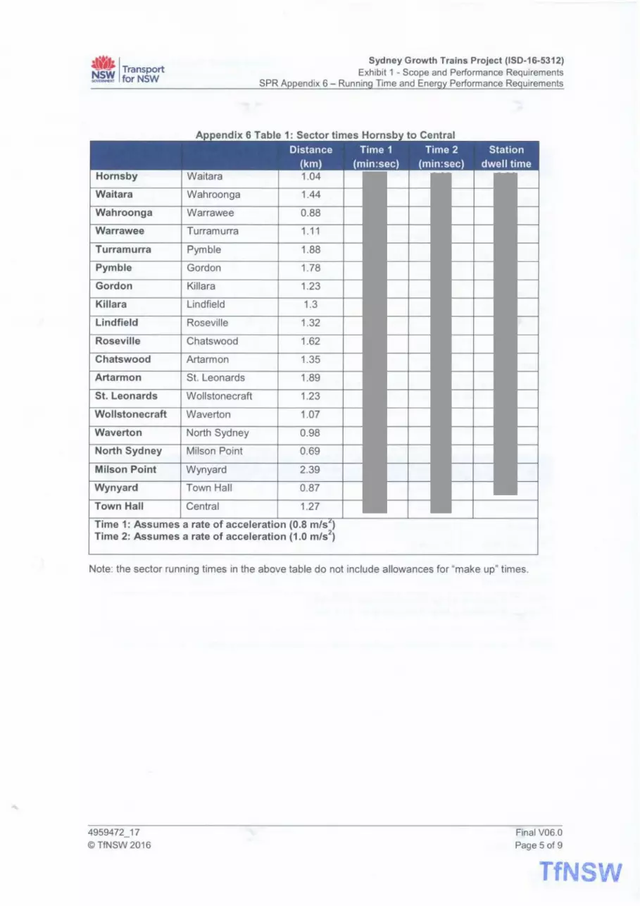
4lit> I Transport ~ forNSW
Hornsby
Waitara
Wahroonga
Warrawee
Turramurra
Pymble
Gordon
Killara
Lindfield
Roseville
Chatswood
Artarmon
St. Leonards
Wollstonecraft
Waverton
North Sydney
Milson Point
Wyn yard
Town Hall
Sydney Growth Trains Project (ISD-16-5312) Exhibit 1 - Scope and Performance Requirements
SPR Appendix 6 - Running Time and Energy Performance Requirements
A I I d" 6 T bl 1 S t f H b t C t I
Distance Time 1 Time2 Station {km) {min:sec) {min:sec) dwell time
Waitara 1.04
Wahroonga 1.44
Warrawee 0.88
Turramurra 1.11
Pymble 1.88
Gordon 1.78
Killara 1.23
Lindfield 1.3
Roseville 1.32
Chatswood 1.62
Artarmon 1.35
St. Leonards 1.89
Wollstonecraft 1.23
Waverton 1.07
North Sydney 0.98
Milson Point 0.69
Wyn yard 2.39
Town Hall 0.87
Central 1.27
Time 1: Assumes a rate of acceleration (0.8 m/sL) Time 2: Assumes a rate of acceleration (1.0 m/s2
)
Note: the sector running times in the above table do not include allowances for "make up" times.
4959472_17 ©TfNSW 2016
Final V06.0 Page 5 of 9
TfNSW
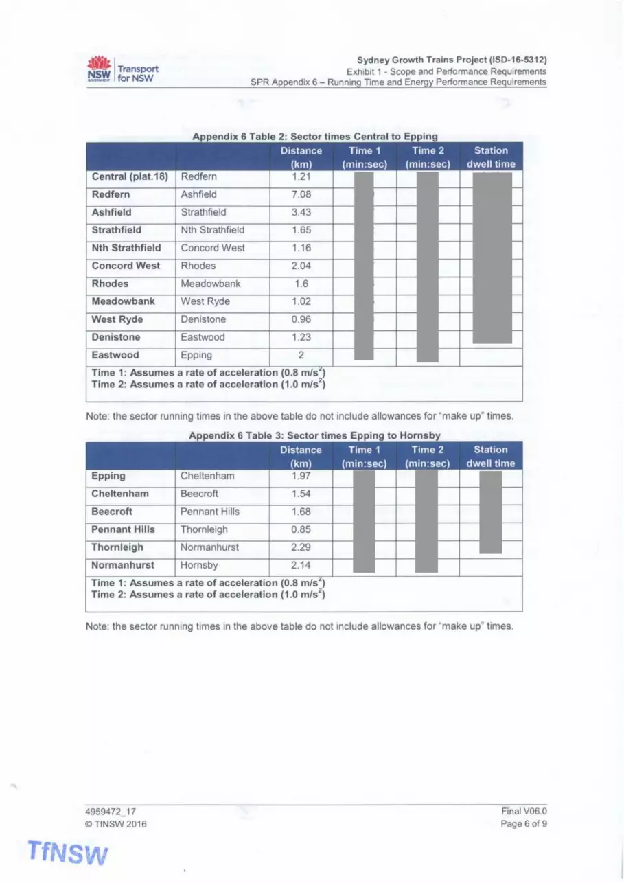
~t; I Transport ~ forNSW
Sydney Growth Trains Project (ISD-16-5312) Exhibit 1 - Scope and Performance Requirements
SPR Appendix 6 - Running Time and Energy Performance Requirements
A d' 6 T bl 2 S t f C t It E I
Distance Time 1 Time 2 Station (km) (min:sec) (min:sec) dwell time
Central (plat.18) Redfern 1.21
Redfern Ashfield 7.08
Ashfield Strathfield 3.43
Strathfield Nth Strathfield 1.65
Nth Strathfield Concord West 1.16
Concord West Rhodes 2.04
Rhodes Meadowbank 1.6
Meadowbank West Ryde 1.02
West Ryde Denistone 0.96
Denistone Eastwood 1.23
Eastwood Epping 2
Time 1: Assumes a rate of acceleration (0.8 mis") Time 2: Assumes a rate of acceleration (1.0 mls2
)
Note: the sector running times in the above table do not include allowances for "make up" times.
Appendix 6 Table 3: Sector times Epping to Hornsby
Distance Time 1 Time2 Station (km) (min:sec) (min:sec) dwell time
Epping Cheltenham 1.97
Cheltenham Beecroft 1.54
Beecroft Pennant Hills 1.68
Pennant Hills Thornleigh 0.85
Thornleigh Normanhurst 2.29
Normanhurst Hornsby 2.14
Time 1: Assumes a rate of acceleration (0.8 mis") Time 2: Assumes a rate of acceleration (1.0 mls2
)
Note: the sector running times in the above table do not include allowances for "make up" times.
4959472_17 ©TfNSW 2016
TfNSW
Final V06.0 Page 6 of 9

~~ I Transport ~ forNSW
Bondi Junction
Edgecliff
Kings Cross
Martin Place
Town Hall
Central
Redfern
Erskineville
St Peters
Sydenham
Tempe
Wolli Creek
Arncliffe
Banksia
Rockdale
Koga rah
Carlton
Allawah
Hurstville
Penshurst
Mortdale
Oatley
Como
Jannali
Sutherland
Loftus
Engadine
Heathcote
Sydney Growth Trains Project (ISD-16-5312) Exhibit 1 - Scope and Performance Requirements
SPR Appendix 6 - Running Time and Energy Performance Requirements
Appendix 6 Table 4: Sector times Bondi Junction to Waterfall
Distance Time 1 Time 2 Station (km) (min:sec) (min:sec) dwell time
Edgecliff 1.97
Kings Cross 1.41
Martin Place 1.3
Town Hall 0.85
Central 1.28
Redfern 1.22
Erskineville 1.5
St Peters 0.9
Syd en ham 1.59
Tempe 1.51
Wolli Creek 0.4
Arncliffe 1.2
Banksia 1.16
Rockdale 0.74
Koga rah 2.01
Carlton 1.03
Allawah 1.08
Hurstville 1.12
Penshurst 1.31
Mortdale 0.92
Oatley 1.23
Como 2.96
Janna Ii 1.5
Sutherland 1.92
Loftus 1.6
Engadine 4.51
Heathcote 2.4
Waterfall 5.55
Time 1: Assumes a rate of acceleration (0.8 m/s") Time 2: Assumes a rate of acceleration (1.0 m/s2
)
Note: the sector running times in the above table do not include allowances for "make up" times.
4959472_17 ©TfNSW 2016
Final V06.0 Page 7 of 9

ti'1i I Transport ~~ forNSW
Waterfall
Heathcote
Engadine
Loftus
Sutherland
Jannali
Como
Oatley
Mortdale
Penshurst
Hurstville
Allawah
Carlton
Kogarah
Rockdale
Banksia
Arncliffe
Wolli Creek
Tempe
Syd en ham
St Peters
Erskineville
Redfern
Central
Town Hall
Martin Place
Kings Cross
Edgecliff
Sydney Growth Trains Project (ISD-16-5312) Exhibit 1 - Scope and Performance Requirements
SPR Appendix 6 - Running Time and Energy Performance Requirements
Appendix 6 Table 5: Sector times Waterfall to Bondi Junction Distance Time 1 Time 2 Station
(km) (min:sec) (min:sec) dwell time Heathcote 5.54
Engadine 2.4
Loftus 4.47
Sutherland 1.64
Jannali 1.92
Como 1.48
Oatley 2.98
Mortdale 1.22
Penshurst 0.93
Hurstville 1.27
Allawah 1.17
Carlton 0.96
Koga rah 1.14
Rockdale 1.18
Banksia 0.83
Arncliffe 1.16
Wolli Creek 1.04
Tempe 0.56
Sydenham 1.5
St Peters 1.44
Erskineville 0.9
Redfern 1.66
Central 1.22
Town Hall 1.32
Martin Place 0.88
Kings Cross 1.31
Edgecliff 1.41
Bondi Junction 1.95
Time 1: Assumes a rate of acceleration (0.8 m/s') Time 2: Assumes a rate of acceleration (1.0 m/s2
)
Note: the sector running times in the above table do not include allowances for "make up" times.
4959472_17 ©TfNSW 2016
TfNSW
Final V06.0 Page 8 of 9

~'1.i I Transport ~ forNSW
Route Traction from energy tables consumed above
Table 1
Table 2
Table 3
Table 4
Table 5
6 I I • I
Sydney Growth Trains Project (ISD-16-5312) Exhibit 1 - Scope and Performance Requirements
SPR Appendix 6 - Running Time and Energy Performance Requirements
•I . • • I • I • I I I
Traction Net HVAC Auxiliaries Total energy traction energy other than energy
regenerated energy consumed HVAC consumed (Dynamic energy Braking) consumed
Note: Traction energy regenerated includes energy returned to the OHW and energy that may be used by the HVAC and auxil iaries.
The missing information in Table 6 is included in section 5.6 of Appendix 12.
4959472_17 © TfNSW 2016
Final V06.0
Page 9 of 9
TfNS\1\1

~-tk --NSW GOVERNMENT
Transport for NSW
Sydney Growth Trains Project (ISD-16-5312)
Exhibit 1 - Scope and Performance Requirements SPR Appendix 7 - Schedule of Deliverables
Date of Issue
Document Number:
Status
03 NOVEMBER 2016
4959473 15
FINAL
COMMERCIAL IN CONFIDENCE
TfNSW

...
.. ~t·· 1 ~ Transport ~ forNSW
Sydney Growth Trains Project (ISD-16-5312) Exhibit 1 - Scope and Performance Requirements
SPR Appendix 7 - Schedule of Deliverables
Table of Contents 1. Overview .......................................................................................................................................... 3
2. Schedule of Deliverables ................................................................................................................. 4
4959473_15 ©TfNSW2016
TfNSW
Final V06.0 Page 2 of 11

·lWJi I Transport ~ forNSW
Sydney Growth Trains Project (ISD-16-5312) Exhibit 1 - Scope and Performance Requirements
SPR Appendix 7 - Schedule of Deliverables
1. Overview
(a)
(b)
(c)
(d)
This Appendix comprises the "Schedule of Deliverables" for the Project.
This Schedule of Deliverables specifies certain Deliverables required to be delivered by the Supplier to TfNSW as part of the Project Activities.
For each item listed, the Schedule of Deliverables specifies:
(i)
(ii)
the milestone(s) for delivery (within the Delivery Phase and TLS Phase); and
the status of each of the relevant Deliverables at each milestone, using the following terminology:
(A) S - to be delivered as a Submitted Document;
(B) C - to be submitted for Review under the Review Procedures and achieve Confirmed Document status;
(C) A - to be reviewed annually and resubmitted if updated; and
(D) V - to be reviewed if a Variation is issued and resubmitted if updated as a result of the Variation.
Grey highlighting denotes where the Deliverable is not required to overlap into another phase of the Project - e.g. the Deliverable is related to the Delivery Phase only or the TLS Phase only.
4959473_15 ©TfNSW 2016
INFORMATION
INFORMATION
INFORMATION
INFORMATION
INFORMATION
INFORMATION
INFORMATION
INFORMATION
INFORMATION
INFORMATION
Final V06.0 Page 3 of 11
TfNSW

-t ~ z en ~
~~ Transport ··~· I ~\Y torNSW
2. Schedule of Deliverables
DELIVERABLE
Project Management Plan
Organisation chart
Delivery Program
Register of Submitted Documents
Authorisation and Accreditation Plan
Accreditation for design, construction, testing and I commissioning of rolling stock
Accreditation for maintenance, modification and I refurbishment of rolling stock
Accreditation Variation support documents
AEO authorisation
4959473_15
©TfNSW 2016
I
ti "O ro ._ ._ ro ... 3: g <( u
s
s
I
I
I
c 0 ·;; ro ~ :c 0 ~
s
c
s
I
I
I
I
a:: Cl. Cl. c
s
s
DELIVERY PHASE
I
I
I
I
a:: c V'l
c
c
s
s
I
I
I
a:: c Cl.
I
I
I
a:: c c
I
I
I
a:: a:: I-
I
I
a:: > V'l
I
I
I
~ c ro ... a. l1J u u <(
I
I
I
Sydney Growth Trains Project (ISD-16-5312) Exhibit 1 - Scope and Performance Requirements
SPR Appendix 7 - Schedule of Deliverables
l1J l1J u "' c ro l1J .I: E ci..
E ~ 8 I-
c
s
c
s
s
s
I
TLS PHASE
a:: Cl. Cl.
~ I-
s
I
~ ·o 'ii .g l1J Cl.
A
~ Ei
"O c ro :c
Final V06.0
Page 4 of 11

~- Transport ·~~· I ~~ forNSW
DELIVERABLE
Maintenance Facility Site Safety Assurance Report
Set Design Safety Assurance Report
Set Construction Safety Assurance Report
Set Dynamic Testing Safety Assurance Report
Set Safety Assurance Report
TLS Phase Safety Assurance Report
Stakeholder Management
I Stakeh:lder Man-a~:~ent Plan
Quality Management
Quality Plan
Internal audit schedule
Supplier hold points and witness points
;;t Workmanship quality standards
;z en :E 4959473_15
©TfNSW 2016
ti "C Ill .... .... Ill ... 3:: g <( u
c 0 ·;; Ill
~ :c 0 :E
a: D.. D.. 0
DELIVERY PHASE
a: 0 VI
c
I
a: 0 D..
c
I
a: 0 0
c
c
I
a: a: ...
c
I
a: > VI
I
Ill ... c Ill ... a. Ill ... ... <(
c
c
I
Sydney Growth Trains Project (150-16-5312) Exhibit 1 - Scope and Performance Requirements
SPR Appendix 7 - Schedule of Deliverables
~ Ill c "' Ill Ill
ef E VI 0 ..... u ...
c
I
I
I
TLS PHASE
a: D.. D..
~ ...
I
I
I
~ ·o 'ii .g Ill
D..
v
v
v
~ ~
"C c Ill
::c
I I I I , I I I I I I I I I I
I I I c I I I I I I c I I A
s s A
s
I I I I I I s I I I I s
Final V06.0
Page 5of11

-t ..., z CJ)
·~
~
~~ Transport ·~~· I ~~ torNSW
DELIVERABLE
Configuration Management Plan
Configuration items
Product configuration information
Safety Management Plan
Safety Management System
Training Management Plan
4959473_15
© TfNSW 2016
t; "C "' .... .... "' .. 3:: g <C u
c: 0
·;;
"' ~ :c 0 :E
a: a.. a.. 0
s
DELIVERY PHASE
a: 0 VI
c
c
s
a: 0 a..
c
a: 0 0
c
a: a: I-
a: r;;
QI
"' c: "' .. c. QI
"' "' <C
s
Sydney Growth Trains Project (ISD-16-5312) Exhibit 1 - Scope and Performance Requirements
SPR Appendix 7 - Schedule of Deliverables
QI QI
"' "' c: "' QI ~ E a.. E VI
8~
c
c
c
s
c
s
TLS PHASE
a: a.. a.. ~ I-
s
s
l: ·;:; '6 .g QI a..
A
A
A
~ i;
"C c:
"' :I:
s
Final V06.0
Page 6of1 1

-I ...., z (/) ~ .. .....
t.U_ffe Transport ··~· I ~ torNSW
DELIVERABLE
System Engineering Management Plan
System requirement specifications
Design Books
Operational concepts
Brake performance calculations
Architectural design description
Human factors integration plan (HFIP)
Human factors integration report
RAM Management Plan
Preliminary RAM analysis
RAM target apportionment
4959473_15
© TfNSW 2016
ti "C ro ... ... ro
g~ u
c: 0
·.;; ro ~ :c 0
::iE
a: Q. Q. 0
DELIVERY PHASE
a: 0
"'
c
c
c
c
c
c
a: 0 Q.
c
c
c
a: 0 0
c
a: a: I-
a: ~
~ c: ro .... Q. ~ ... ~
Sydney Growth Trains Project (ISD-16-5312) Exhibit 1 - Scope and Performance Requirements
SPR Appendix 7 - Schedule of Deliverables
~ ~ c: "' ~ ro E~ E "' 0 ..... u I-
c
c
s
TLS PHASE
a: Q. Q.
~ I-
~ ·o 'i5 0
·;: ~
Q.
v
... ~
11) "C c: ro J:
Final V06.0
Page 7of11

~ en ~
~~ Transport ·~~· I ~ forNSW
DELIVERABLE
System RAM requirements
Reliability analysis and prediction
System Safety Plan
Preliminary hazard analysis
Project hazard log
System hazard & Safety risk analysis
Safety target apportionment
System Safety requirements
Schedule of Safety Assurance deliverables
Safety Interface Agreements
Safety Assurance reports
EMC Management Plan
Electromagnetic compatibility analysis report
Power supply system compatibility analysis report
4959473_15
©TfNSW 2016
c: ... 0 u "C ·;; ni ... ni ... ni "' ~ 3 :c 8 <( 0
~
I I s
I I
I I s
I I
I
I I
I I
I I
I I
DELIVERY PHASE
a: a: a: a: Q. Q. 0 0 0 0 VI Q. 0
c
I c
I I c I I
I I c
I s I s I s I s
I I c I I
I I I c
I I I c
I I I I c
I I I I c
I I I I c
c
c
c
QI u c:
a: a: ni ... a: > Q. I- VI QI
u u <(
I I I I
I I I I
I s I I s I
I I I
I I I I
I c I I c I
Sydney Growth Trains Project (ISD-16-5312) Exhibit 1 - Scope and Performance Requirements
SPR Appendix 7 - Schedule of Deliverables
TLS PHASE
QI QI ~ u "' c: ni a: ·;:; QI .c: Q. :c Q. E Q. VI 0 E VI
_, I- ... 0 _, QI u I- Q.
s I s
c
s I I A
I I v
c I I A
c I I A
... QI > 0
"C c: ni :I:
I c
Final V06.0
Page 8 of 11

:;! z r.n .e-~
,
.:.b" Transport ··~· I ~ forNSW
DELIVERABLE
Track detection systems compatibility analysis report
Electromagnetic compatibility case
Power supply system compatibility case
Track detection systems compatibility case
Verification Plan
Verification Program
Verification Procedures
Verification Reports
Verification matrix
Vehicle Information Pack (T HR RS 00814 ST)
Test notification -4959473_15
© TfNSW 2016
I
t:: "'C "' .... .... "' g~ u
I
c 0 ·~
"' ~ :a 0 ~
s
I
DELIVERY PHASE
Sydney Growth Trains Project (ISD-16-5312) Exhibit 1 - Scope and Performance Requirements
SPR Appendix 7 - Schedule of Deliverables
TLS PHASE
~ ~ QJ
g:I a:I a:I a:I a: I a:I ~ ~~ ~ o o o a: > ~ e~ o "' ~ o t- "' ~ E~
a: ~ ~
~ I-
~ ·;:::; :c -~ ~
~ i;
"'C c "' :c
c I I
c c
s c
c
c c
I I I I
I c -c -c
c
c
c
c
s
~ 8 I-
I
~
Final V06.0
Page 9 of 11

-f ...., z en :E
~f!J Transport ·~~ I ~'I!, forNSW
DELIVERABLE
Operational Readiness Plan
Training needs analysis
Training packages
Operations and Maintenance Manual for each key Asset (except Sets)
Set Maintenance Manual
Set Operating Manual
Set Cleaning Manual
ICT Management
ICT Management Plan
Asset Management
Asset Management Plan
Technical maintenance plans
Maintenance Works Program
4959473_15
©TfNSW 2016
ti -0 .,, .... .... .,, g~ u
c 0 ·;; .,, ~ :a 0 ~
a: ~ ~ 0
DELIVERY PHASE
a: 0 VI
a: 0 ~
a: 0 0
c
c
a: a: I-
a: > VI
c
c
c
c
c
~ c .,, ii. QI u u <
Sydney Growth Trains Project (ISD-16-5312) Exhibit 1 - Scope and Performance Requirements
SPR Appendix 7 - Schedule of Deliverables
QI QI u Ill c .,, QI .t: E ~ E VI 0 ..... u I-
c
c
c
c
c
c
c
TLS PHASE
a: ~ ~
~ I-
~ ·u '5 .~ ~ ~
v
v
v
.... QI
i; -0 c .,, J:
c
c
c
c
c
I I lclclcl I I I c I I I c I
c c
c c
c s
A
A
A
c
c
Final V06.0
Page 10 of 11

-t ...., z en ~
>
~t; I Transport ~ forNSW
DELIVERABLE
Vandalism and Graffiti Management Plan
Technical Packages (including Technical Reports I and Technical Documents)
Mock-ups and prototypes
Stakeholder engagement report
Escrow deposits
Schedule of finishes
Schedule of decals
Data interchange formats
Delivery Phase Progress Report
TLS Phase Performance Report
4959473_15 ©TfNSW 2016
I
I
t "C "' ... ... "' ... 3: g ct u
I
I
I
c 0 ... "' ~ :.c 0 ::E
I
I
I
er: a. a. 0
s
DELIVERY PHASE
I
I
I
er: 0 VI
c
c
c
I
I
I
er: 0 a.
c
c
c
I
I
I
er: 0 0
c
c
c
c
c
c
I
I
I
er: er: I-
er: i:;;
I c
I
I
I
I
I
f! c "' ... a. Cll u u ct
s
I
I
I
Sydney Growth Trains Project (ISD-16-5312) Exhibit 1 - Scope and Performance Requirements
SPR Appendix 7 - Schedule of Deliverables
Cll Cll u "' c "' Cll ~ E a. E~ 8 I-
c
c
c
I
TLS PHASE
er: a. a. ~ I-
s
I
~ ·;::; :c .g Cll a.
v
... Cll > 0
"C c "' ::c
Final V06.0
Page 11 of 11

.t'tk --NSW GOVERNMENT
Transport for NSW
Sydney Growth Trains Project (ISD-16-5312)
Exhibit 1 - Scope and Performance Requirements
SPR Appendix 8 - Authorised Engineering Organisation Services
Date of Issue Document Number: Status
02 NOVEMBER 2016 4959476_12 FINAL COMMERCIAL IN CONFIDENCE
TfNSW

-I ...., z (/)
~
AEO Authorisation Process SGT - ISD-16-5312 - SPR -Appendix 08 AEO Services.XLS
Who fills it in? The AEO reoresentative of the aoolicant oraanisation in coniunction with an ASA Facilitator The AEO representative may call on SME support from within the applicant organisation in completing the engineering services scoping matrix
When is it used? It is completed during the initial scoping meeting with the ASA facilitator and developed during preparation for assessment and is to be submitted as
art of the aoolication to beain the formal AEO assessment
What documents are used in coniunction with it? TMU MD 00009 ST AEO Authorisation Reauirements (which includes auidance on a reauirements
Applicant organisations evidence records of actual deployment against management process documentations, while carrying out defined services
AEO letter of authorisation
Review the asset life cvcle staaes vour oraanisation ooerates within (listed on the horizontal axis Insert an 'A' or 'P/A' (see 'Definitions' work sheet for details) in the square(s) corresponding to the engineering disciplines and asset life cycle stages applicable to your organisation. NOTE that it is sufficient that an organisation provides a process and the competence to provide a service (they need to have justified confidence that the service is capable of being delivered competently) . The ASA recognises that organisations will have different approaches to sourcing resources to suooort their services. Work with vour facilitator to incoroorate anv notes reaardina the context within which vou are seekina authorisation
© State of NSW through Transport for NSW
Asset Standards Authority
2 of 5

Troley1 Trail«
Other Rail Vehicles
Rolling Stock Subsystems
SupelVl$orY lll'Ki Control Systems
Cables and Routes. Optical fibre and other
Apphcabons and Systems -T•phon (VOfP and Anelo Appl1cat1ons and Sys1ams - Passenger Information Systems
Applica11ons and Systems - Al9rm and CCTV Surveillance
Commurwc:MloM Nelworii.s W11'9d • Packel awltched (IP MPLS K)
Networii:s Wired· Circuit switched (SOH. D'h'OM. ek:)
Networks Wlrele11 • Packet IW!k:hed (W1F1. W1Max. L TE etc Networks Wireless· Circuit switched (Radio systems PMR. Tetra etc)
Telecommunrcallona Power Systems and FdtlH
Network and lnformnon M en\ Sysi.ns and Security
l/Vheel/Rad Interface
Ra!l-Spec1flc Survey
Civil-Survey
CMI • Geoteehnteal
CIVIi-CSR
Clvll·Earthwori1;1
CIVIi • Road1 and pavements
CIVIi ·Drainage and Hydrology
Manage Buildings Work
Atchltecturat Design
BU11dtngs and Stallons Specialist Buildings Expertise (must specify In the Nottis)
Bu11di S\Nctures (must 1pec1fy In Iha Notaos)
Building Serv!ees (must specify In the Notes)
Specialist Rail Systems Buildings Expertise (must specify in ltw Notes)
Hi Vol Aenel Fffdefs
High Voltage Cables
Tracbon Substation and SectJOnrng Hut
01stnbut1on Substnons
Systems Engfneeong (al! SE .. rvicH)
Systems Assurance
SystemsEngt~enng F'""'-"-"''-=""-'c=~'-""""'-"-~~~~~~~~~+--+--4--4+--+--4--4+--+--4~+--+--4~+--+-+~+--+--+~+--+--+~+--+--+--1
and Assurance (alHl'VICH)
Venftcalion and Validation
Acousbc I Nolsa EngneeOng
Flra and Lit. Safety (lntraslructure Of Vehicles)
DOA Compliance Senllces (Infrastructure or Vehicles)
:~: ~~:& Sustannabthty and Environmental Serv1cH (Eng1M«lnv-relaled)
Engineenn Competence Man ent
Mult1-0lsc1pl1ne Engineenng Management Use notes to elaborate)
Other SpeclaHst Enginffflng Services (un1pec:1fled)
Configuration Mana ment
"Assure only" means that the AEO does not produce the actual dellverable/sef"o/ICe, but h"11s competence. processes and systems In place to assure it (I e providing coofidence that lhe reqU1rements llfe f\Jlftled) A For example, a company may spec1ahse In providing Independent W'lspection1. venficabon, certrfication, assessments, tesling design reviews, installation QA inspections, fabrication QA lnspeclioos etc
Such an "assurance• AEO may be engaged directly or indlr.cllyw1th Tl'NSW (or by an AEO) to assure some work or service produced by another AEO . or w1l leaflHJp with lhe oth« AEO producing the setVlee
PIA "Produce/Assure• means the organ1sation produces I delivers and assures eng1n..ing seNice/pfoduct wl\h., the scope of a selecled lrfe cycle process/ activity for a parbculat eng1neerrig cbC1pline/servica
Rol~na Stock sub-svstems PIA ts reauired onlv for where deslon and lnteoration resoonsitlthtv is at s~svstem level
Signed
Name Jrn Modrouvanos
Position Director Anet Standards Authonty
Dated
CS!a1a al NSW1'YougnT1anspon lor NSW TfNSW Au.iStand•daA<11.ho•qo
3d5

-f ...., z en ~
Engmeenng Services Defin~ions
.&.\,._1.; Transport NSW ... ,_,. 1 ,_,..,~- .. , !-4 c.;,f ''·IL,
Asset Life Cvcle Activities :
, ..... , r=;.~i-~ -i==-:~==~~=~~~==.::::s,~:=~~=ne~tcmandperfor~~ando~.~~~ [~~~ ___ __ _ ___ E 1~~_.,per_l?m!'Jl~aridt~fls~~-"~11bsnicUe(!!l!On!lost.qlt!!~~1£ilse. ___ _ _ BRSl_LRDDeveqiment ~- _ ~meeing51ftl011indevelopn:Q_'ilebusloessreq...rements • IS.l'f:lle~IK>llOevelopment Enganeenng~1oltheprelened(llll0n _
!""'~ __ _ ""'"11---~ ~"""""""""'_ -~.determine-___ .._......, _____ c1ei:nn_ """' __ ---~~-_a1~£_~t_w:l'!_~e-~l:!f!ne~-~asse __ ts_c:an_ ~111n_~-~.l1J:!~
Concepl :~~tyChanqeF\lrNig .~'RtneeflO!lf'4l!J!inkllde!l11~11\elo.eysafetynsk5,howhey'llllbec_on•oledandfie_plan~1dewbeshowllv5 W'lbe<bie
[~SO!!Yelopment _ -4E-~deYeq:men!Ql_the_sys~_reipfemen_l,'.._.rdJl;ing~~~ll'leSS_~en_ts_
"""' """""""' ....
ln1eg1a1e TestandCommisSIOl'I
"'se!MalnlenanCe
"""""
(Cona!ptl~enca--~!ll __j~rtgtnee1rog~to!_therelllferu~ns~~~s¢kien--1deblllogotlUl_~_lendeflorde1aited- ~and~_IUCllOn __ --·_
t~AF( ~ - -- -1=-:::·:.~~olm•lmll~l~'1Qnsnnl~ol~~ _--"'-lef!al~li!ffltnl_ ·- •• - -- -···Folowo~lpll!Wllllcf_~tr~'11ln_/llalellaband~ftJftlC\Hd{~__g:)~ocb;;!_s__._?_bespokej_ • • _ _ _ --~/F~ _ ·Manufatll.rrogol~I orbbnai110nol5lrutllnlelemen1S111he!Kt«Jprior10stwl'IJ~Rlf! _ _ ,Consln.ldlOnlmlilla~ ___lConslruCbOnkrs1alat.1onofassetsonsne oncefieyhaYl!beenshflP'ld~'ile~_/hctoly _ ISWsy;iemlniegrabOn Qncenivd.1111- trslel!'Sh ____ te!!!Shavebeen_"""'_llCINt1111'1Slaledon~~~wnmenee_connec:"°'*11eg1-a110noltiese~1-s~ Tes11ng_andfomm15!~ Tes~~F~T.~T...§lland~tnl!S_IOflH''!l,_l'llOop«allOl'I -
,AcceplanteSeMces ~wp.l!S_1'110~lli'lns~J.~'1e.~1!Mln~OfQan!Sat!On"!"';l.a:s?.C.~ ... and1~~_g>ef~l (F'laiAsset M.lentenance 4Eng_rneenogqiuts_1n1oplartrll!lQm111ntet1a1Uolassels ,Mai1J1a1n ll¥,lrade Ass4tts -f E~ll'lg wpuls en cany1ng_ wt asset mamlen<tnee Of wades tvoug'1oul thl!I operaD'lal loleume
~:::~~~ ~~=-:__~~:-=:~~~~ - -~- --iPlant?eoorn~al J~~"ll'JIS_11to~lhedecomlTll!i3'0flllgllllddl'fO'lll~lriHxplrfdas~- _ 1Concb:IDecomlTll!i~ ~-!flgrp.ils1ntodeco•111111551?""9anddloiposal l'bde1eAs~ConioJ,a'ationDi11J ·Eno•rieetml!1lU~11110\.CdatMass!'lcon"1tlra•1011data
Soecialist Enaineerina Services I DisciDlines :
RollngSloC~
~lnl:IControlS~tems
Communca1IOl'IS
T~<* engineering
Cr.dandrelaled ,.,._ ..
Butingslnl:IStalOl'll
""""" ,......,.,
i~~ ___ t;=_=:=:::::;t0:.;sl0Ck
;HiiavyCommulilr_E~I~ !PrtM51()nolSl!MCl!Srdaledtot-.yrilll~rolrigsloC~ 1TrackMactwle JP'romlonolseMCeSrelated1otac~machrles
~RoodRailV~ ,;PrOVISKM'l_ofser.1Ce5relaled10_roadrMvehdes T_r~l_Tra11ef •• ----· _ • _ --- !~_plSl!MCl!!lrebtfld10toleysh~ __ ~ --ot.erRailV~ _ ·- • _ _ _ _ l~1011_oherv1cemlated1oollerrol!g_~!Otkf~.tralet:J _ _ _ _ •
l'RolllJ!ScockSiJ>sy.stems__ _ • • _ l~_ . ?prodllclslllld-rebwq_kl~0141ofl'llefcomec:1edandllllefacMpartslhilt_f!fbrns•t1SkM•comporient_of.a~rcl11~slock~tem _ -~andConudSt!ll!ms J~ot~rela'!d10ralfwa{_~t:or11f'Oiandanoc:11t!'d1ailtra!licrnanagementsp1emS_ _ • _
flriterlod.ln!ISysll!!M _ f~.P'~_rebtfldto_r~~terb:~f'l!l'Y'lemSJ~O!.~-~lfl'bMecf) _____ -----!ratkslde~ys~sl~~ . 1~.£!!~r.bted10~1-:s?~9nalhr:ig_~!{~~!~.lrillnde~.Ajf>..A_l_Q_~L Cidesn!Routn. Cpllelltaeand~J l~~~relaledlO_~le~_tu(.llOn_LCSR.~Prtstt::J,_~lh!and.'?fler~~and~~ ~-~ ?l"P"""~""!!9-~.l Aff'c:atvtsandSys~"'.T9fpllony(VOl'andAnaklgueJ _ !Pn:Mston_ofSl!!'Y1CeSreiallngtoleleooml!lun1Ca~~-atiabJue\llJIP~lelephorm ~llOllSandSystems_-Pnsengei_ln_~SY$1fm!_ ~-~-?s•kln~r'*1gs10Ckand~_5eMee5_ielamg1opr;senget11lorma110n_s:rstems,helppowi1S.t111_s1nonandrolllr!!!..!._~~-l<ttess___.!Y!le!llS
===-~=~·==~:;~delMf!!L- -r=-~==-:::::~~=~-=~~m:~~-~~~~~--- -· : - - - -- -tetworks Wr!d- Pickel SWtk:hed {IP MPlS elC) !'l'fOVISIOll_of 5'MCe5 relaung lOneflltakbas!d packet sv.i1died sys11'1111 IP MPLS etc. _ _
;Networks W•!d·_Cifcu.1 SW!!diedlSD-1 D'f,00 elCJ l'fi:wmonofSl!M(:l!S rela1ing toCWCl.1!1 !;'M\Chednetwor~sysiems SOHJ>WOM ATM ISDl~andolttef :NetworksW•eleu_-:_facketswilched{Wf1W1Ma.- _~TE!!E.) f'.wm!Ofl~l~rebungtoyaci<e!S"MlchedWll'ei<>q_!YS!ems,W•Fi.Wmax .. 3G.~£1.~e14G.LT~_.. ·- ·-· ----- __ _ _ NetworksW•elm·Clfl:utl~~J~.~lemS-~ Tetrte_I& ;PTl.Msf?l~~-reb~to_?Wl~WlfMs~~.@SM_GS~,_2Q.~tv~j,_mcble_radto_~~-P!wR.!etra ~e!t _
!EE:'-£=--..;,~~~ . je:E".::3E~ES:~~~~-zs::-;.:.:::-;:--·"·--~~~"'-1~!-~_, :.:____iDes9J.c~ns!n1r;gw·main111n_~.inffa5IJUdl.-e_~Ofpo5*_Jrl_Nldi~~-~-!l.~~-01_~1onrew~J!.- ------- - _ - -- -- - - -.-~ --~ ~ 1ConJionents!_Stucl.fe_ _ j~andcorrpehen51onoldesignseleciicnma~behaYo.ranr:lpetbmtna!capal*tyoltl'ilck~ty
1.::_~-."""L_ =~::::==~~~= ::: =~ :=:::::=::::::::}:::::::~=:=::: ~~ ===~=~~~g1~S~W.US$Ych ICMl-Geoledntal Promionof~llYl!11ga1tOnSS~ar'll~ISMtfll!JISIO~Mwela!r"fJP!lf'pl_l(Jl~1~~cllfl;!lmalfl~ll'tdOJnrlgdecomrmSIOllll"!l,__ofCN1IMSelS ~:.C§R ·- ~ -~ ~ _ PnMsoo_ofseMCesrela1edroCMla~tsofalrombr!!«lseMCe1rootesl0~1e~~~IK:lflSorl-NlVEJOWefc:lblesando!her~sucttaswa1er111¥1S iCMl-Tuorelmg PYCM51011ofstMCeSrelated1Droad radandpedestnan 1Unnelsandassocialeduflworks _ _ lCMl-Brd]esandS_tucklles ProYISIOllofseMCesr511edklrood railandpedestr1i111~andra~nuc1~es.IQH/'IS Masts Garnnes V..ncts re~wals.!'=)
rr;:::~.:PMmen;;-:-:- - _ =::=:::::;!-!~~==~r:,~:==~~cur~-::-_-_--_---_------------------ _ ·CMl-~lfld¥ology jP'rcMslonolSl!l'VUSrelaled1Dtac~i:h11'1a!!'.SJSlemS_~Woodassessmen1anr:I_~,~
Manage8'.llkingWOO.S_ .:~al~rd-~!ybuiidl'lg5wor~ _ .
l==~:\mUS1~111-~~ 1=:1::m~;;~.=l;;:;=~==-~~=ac:MleS~~.001Mcmdl"~ _ ·!Mdngs~1mus1~1nfietbesl lButinss~l.fdlulldingrelaledcMl~lis_ _ lbldngSer..as-{must~111hef~J . :!!utingM!flo.'leeSjlOluarrpe plUITU\ganddl'MlillJl! el!lc~ log!l•ng 1-NAC,_BMS FreRl'YICeSJ
j5peciab-1RMSY$""11S-- '""'"9'-"P'<--_ {_mustse!?'len_tle~J _ i~t_RM§yslElnl- Buiking5~(1orl!larTJlle PllS ~A.~O:TV_I~ . __
:::-~:::-:::~ - - -:- :- :-:::--:-JPr~-~-==::=:~::s~~~.ieedel __ cat*~~~ - -- -: _-- ~ - _- --: - -
11.-si.m1a11ems.o_._"""'''" _ t'-!OYrs'°""_ seMCeSrelatedlr;l•_"_"" ___ ""'_ - "'""_ {ndoo!and- ""'°"_ ""1arcts11-Nswi-- sta1'°"_""_ seci~-huts____ _ _ __ ·-_ • _ _ _ _ _ DrsirbutonSOOstatom PrOYlSIOl'lolseMteSrelaledlD<tnlbuMinS\J)sta!Q'ISl!_\Wlocatoonssuch•s_padrrounts.depols.stabOOSJ
1111j1VoltlgeProlecuonSys_tems Pn:Msionof~reiated1Dl-NelecJl?lp1~'!_ln~lem!(C~,VTsproiecMinx:he!nes~!ladng} _
~===~ighhngPrOletlDi ·- t=::~~====~~°':t~~~:~:-~~=;~~f!'~~~ftl~!Klll!~J.~.~y~~des_91.gadrlg9M~~ 8ectncalCa11rolSys111111LSCAOAHmus~~11.he~J. • J~olS8V!Ce!l relaled10M:trical~~1em(separi~•.11honsa1or1_gryen~MaslerSta1on~1anr:lflefd~tlkxe~_R_Tl.ls}}__ ···- .. __ _
l=~·~andModellrci •. __ -t::;:z:=:10~5IX)~~!!~ww..:;:=~~~~~~ed_Ancholed~_C>.wheadconcilc10r_Rltrl.fr<edand~9M1_~Ral1e_~_tw.y_~oc.QtfN..!2''-~
Cl Sltte of NSW through Tr&nsport for NSW
TMU M000009 fl SGT· IS0..16-5312 - SPR -A.ppendix 08 AEO S.rv1ces.XLS
A55e l St•ndards Authority 4ol5

-t -h z C/J ~
}
EngJl'leenng Services Deftnllons
Standalone Services · ISyslemSE~~l.-S~9'1VlteSj ~Mana9enwi~and~<ina1onolal~iems_~rigs~onlirge~f'«'l"CIS__Jl!assel~!tonnttt(~_!!a~~~man¥-!olo!)
'.~~ --_-- t~=-~=-==~--~~;=-~~i;;_~~;:.:=;~u:=~~~~by~~b~J !Safety Erigireemg/Assuraoce !Provision of speak setvlU!S'" system safely_ imllfl!ll'U Mld management m bne wrlh he ASA Sp-iem _Safe1'J Standard fol tjew« Al'~edAuelS TS 20001 2013
SvsterME~and~:~~~z;=~l{ISA) _ t~-~~~=.;:1Y::S:1~~~re:;~::=.~1ie~~~~=:c.,(~~:;'~';'1~~ttv..tlalsobere1predat~l8fs~~~111emadelofle~llalnpictfleuse-(al5e!Vtt5) rt=~c:r~- 1==-=-=-~~~~~~·~=1;:~$=·=r~=~~;'-!:t::,~~~~~~ft~~~:!;:-:~
,Req.ntnents~_I~ jf>fCM$ion.of~~ll'lf!qJlll!fTll!!11Smanagemen1 n:t.rlng1~emeots~ andorwingapture~VaridVevidetttrdO••~ts-~!_IOOllOdemoos'nleJll~IWI~ lnterfaee~t _ jPr1MS1011of~peakseMee5ll'IW11ertice~1 n:l~~fringJl~~ts ldeo•~ngand~ngJ11erbr::eOW!lefl.~interikele!tspecika110nSanddes-2:!!_ h~1ems ln!f:9rak:lrlSeMces{use_~lotes~elabaf111t) ______ PTCMS10nOf'lpf!C1fi~_seMCeS111sy51ems1nt~ra1K>r1,whoseac1V11ies~lystarta1!~1111t'!l.r1111onandcoou•M1hooghK>1111£;'ll_rat1onoffieiesledsys1Pmintolheraospon_ne!WO!\.._ _ _
_ ,Vef!!!a~_~Villlda~ _ --- _ Prov"!Ofl_ylspeciic_~_Jllll'l'lllCll!IO!J.andvaiidlik:lrl .. rduling__rnar.agemenlofevdenoP~~fn:im~VandV~J~_ll'Yll'w.S,~~f»:!w!g.SlllllNb!.~.lllltll,_mpeclO'landlfoslwlg) _ _ _ Acousld~lndVibra..-iEngoneemg l~ofspeakservus111roseandlllbl'aoonengJieernJillldcon•~laba1emen1 genefrlylo11Wofldes91~ent bu1iiho10conc:tJc.trm!3Sl.A'ementscUingtOn5"1.ltllDn ~allDn<WldOf'!Pngmamtenantephasesoftll!!~ts!seetablebekiwb rl'IOfedelalh)
IFnillldLrlllSale1-j(ln!r.tstrucanorVehdei . :~olspeak.seivw;;esreialed10_fnandloll!saf .. 1)'(111tas"1.lt\lrl!!)l.....ndi!sl -Mon.AssetSpeaflcEngmeemg D™~ ~(lnlras-.Xt1norVe!wdesJ jPfommolspecik_se1V1CeSrela1ed100isablif1 Dnown1nnonAc1c:omphanoe
Serw:es ~Sustatnabllliyll!ld~flVlfOll!llef'ltalSeivu!i_~~-1eb~ jPfOllSIO!!O!'J)et1~111_S\l,1il~ty_errvironm1'11llll 11!111!S~1'?"'anci'orm_!!!!l8110n.f<!ll'flU111Sua"1__!01!leeonct'p1illlddesl!lflS~bu1CCNklabollaverpu_1~cc>mlluehOn~lllalfl~~or~_~sl0!\!!9
r~~~l~l~lolWxwarej J=~~Sl!IVUS~~~~~=~=.°'~=?~==~pansof" 1°""-'"""""""""" ~-----.. .--..-8~'-""''"" .. '"-""'-""'"-'""""'-N" iConig..q~~ Pf~~~~~~~·-~-- -- -- -- -- ' -- - ' - -1niewa11!dlo910c.s_ ~CN1Smof~$4!JV~reB1edlo111l!!)l.atedlogl$11C~am1sandsys1~dl!llllleled10J_MW{tllS_~_~anld:honalsen11U1olletl!dl!Y!l!easseisi.qiilef_:,!;9 rolmgs10e_~ ~~ ks5et ~!Pr1MSionofsM1+cesofesW.Sh!l'IQ ~ in'IPltm"fllr"'1 mamla111100111 "'1DIOYl!ll15PKl<llPS!assetmanaaem"f'l!at1!V1Ues related lrl TttSW111 ollier e~temlllP¥1"'5111~rieW"lll tS05500\
Mse1Managetnen1 ---- -- -- - --
lkowttc/Nohe ind Vlbntlon Engineering Detail G~ flt. appropriate 1ub-dlscipllne c1n be hied In thl Notn section using 1ub dlsclplint code prOYlded) Sul>dhc:_Jph ___________ ,One~ __ _ _ _ __
'Mleel-Rallfb5eandVibrallclll(NandV}{tN01jitbseandvi:lralle!'11RS5iromlhe111reratW.bl!~_!ier.tll~~wtMsol~~5~Roklg!10e~ _ _ __ _ T1acJ..OeSl'Jfl·"°"· andVibraim.(l'Ml3J Vlbrallonissues retated!o nck~. dlaradem!IC!J rd.dng_. """''. ITll\lgallOl\pnxb:ts, and~~aodsru::lurtMadlatednorse_. and ur.elg-oo.m.bome_noiseandvblallOI\
Speoalis1 Vbra\JOn ___E_ruc!ural E~ mues tl'Nll4 Srucuiral ~D'allon effecl'!I indiJWl!I vblabOrH'lCiJcl!d d.lmaqe _!Obuilanip, lunneh and oflef slr\IC1\ll'M
~skXkOesigntbseandVibra11DnjtM)2J~~bseandvba11Dn1S$LJl!$1S$0C.lltedW11tlrcklgs10ek indudingvitll!l!landbogiedeslgfl ~panelW:wauon_iractm~ andau-cond!IOlqWltS
__ ~1nJCbon_f~11-N_!lij.t.'leasi.nrneot.as3"smen1.~!andm11gahOnol~Jl!llffilll'dby"con~tn.ICllOl\andma.nienan.:e11C1M~.~ratl E11W001T1e11lal~IAS5e-ssrn1!111 and S1atemenl'!l:-N_andV(mreljtJeaweon.""l assessmen1andmi!19i'11DnolenvrorvnenlalroseandvUauonetfel;f!ic:iJeloriew01~nlr<JS~Ue operabonalprackeS 111rolngsl0d
CS!lte of NSWthrough Tr•mpor1 lo1 NSW
E~=:.,J;;$:]1::=._~~~~~~-:;~~=~~;;=~·::=~~~~~~tsauon_andwitsol~and~_ e.!:;~~:t:~1=:,::;~~~=·::i:~~=~::=~T:::a~ha-:;:::;,=ted,..ths~ds,s~1ams._r~m"'"'.arn~~19 -Electro-Accustcs(IN11llAc.ous1edesignbMeaf~sys1emsocnnpt.ti11cacti"ensys1em5 _
_ <:.k:npa!JOl\lll Health and~lefy lf<li12)\~'-'emeni and 15St!Ssment ol ~tonal noise exposn lor l!lrflloyees
~R~~-{:Zatt--=~~~==~~:~~~:~-'~,..~ . .f0!!1~~___!,.~o,!ll!bMc!.and~l!flec~ __
T MU MO 00009 F1 SGT· lS0-16-531 2 • SPR · Appendix 08 AEO Sern;es.XLS
Asset S!anda1d1Authonty S ol S

lll.k --NSW GOVERNMENT
Transport for NSW
Sydney Growth Trains Project (ISD-16-5312)
Exhibit 1 - Scope and Performance Requirements SPR Appendix 9 - Environment & Sustainability
Date of Issue
Document Number:
Status
03 NOVEMBER 2016 _
4959479_15
FINAL
COMMERCIAL IN CONFIDENCE
TfNS ~~

• 1 Transport ~ forNSW
Sydney Growth Trains Project (ISD-16-5312) Exhibit 1 - Scope and Performance Requirements
SPR Appendix 9 - Environment & Sustainability
Table of Contents 1. Overview and scope ... ... .. ... .... ... .. ....... ... .. .... ...... ....... ...... .................. .......... ........................ .. ...... .. ... 3
1.1. General .... ...................... .. ...... ... .... .. .. ..... .. .. .. ...... ....... ... ... ..... ....... ..... ....... ... .. .... .... ..... ..... .... .... .. 3
2. Performance Requirements ... .. ... .... .................. ... .......... ....................... ... ..... .... .... ........ ................... 4
2.1. Systems and processes ... ........ .... ..... .. ... .......... .......................... ... ........ .... ............................ .. 4
2.2. Climate change ...... ... .. .. ...... .... ........... .... .. ....... .... .................. ............ ... ...... .. ......... .. ........ ...... ... 4
2.3. Carbon management and energy efficiency .... .. .... ........ .. ..... .. .............. ...... ........ .... ....... .. ..... .. . 4
2.4. Operational energy ........ ....... ..... .... .... .... .... ... .. ... ... .... .. .. ... .. ........ ..... .. .. .. ...... .... ................ ..... .. .. 5
2.5. Water resources ......... .. .... ....... .. ............................... .................. ....... ..... .. .. .... ... ... ... ... ... ... ... .... 5
2.6. Waste and materials .......... ...... .. .. .. .... ... ........... .. .... ..... .... ... ... ..... .... .. .. ..... .. .......... ......... .. ......... . 6
2.7. Waste ..... ........ ........... ... .... ..... ... ..... .... .... ..... ............. ........ .. .. .. .... .... ..... .... ... ........ ..... ........ ... ... .... 6
2.8. Materials ........... ... ... ..... ..... .. ...... ... ...... .... ..... ... .... ... ... ... ...... .. .. .. ........... .... .... .. ... ..... ........... .... .... . 6
2.9. Volatile organic compounds ... ...... ... .... .......... ....... ..... ...... .. .. ....... ..... .......... ... ... .... ...... .. .... ........ 7
2.10. Pollution control ... ... ..... ...... ......... .. .... ... ... ...... .... .. ..... ..... .... ...... ... ..... ..... ... ...... .... ...... .... ... .... .... .. 7
2.11 . Supply chain ... ......... ..... ... .. .. .. .. ... .... ... ...... ..... .. ....... .. ... .... ........ ..... .... ........ .... ...... ... .. .. ... ........ ... . 7
2.12. Sustainable procurement. ... .. ...... .... ... ....... ... ...... .. ... ......... ...................... .................................. 8
4959479_15 © TfNSW 2016
TfNSW
Final V06.0
Page 2 of 8

(i}> I Transport ~ forNSW
Sydney Growth Trains Project (ISD-16-5312) Exhibit 1 - Scope and Performance Requirements
SPR Appendix 9 - Environment & Sustainability
1. Overview and scope
1.1. General
(a)
(b)
(c)
(d)
(e)
(f)
(g)
(h)
The Supplier must implement the requirements contained within this document where "reasonable and feasible". "Reasonable" relates to the application of judgement in arriving at a decision, taking into account mitigation benefits, cost of mitigation versus benefits provided, stakeholder views and the nature and extent of potential improvements. "Feasible" relates to engineering considerations and what is practical to implement.
Notwithstanding section 1.1(a) above, the Supplier must comply with all applicable environmental and sustainability Laws, including all Environmental Law, and must implement all requirements of this document. Where requirements are stated to be implemented "where reasonable and feasible", the Supplier must undertake its own assessment of the measure (or initiative) using the guidance provided in section 1.1 (a) above and document the findings of the assessment. The documented findings must be made available to TfNSW on request.
The scope of this plan covers the supply of the Sets, the operation of and use of the Maintenance Facility Site and the performance of the MF Works Activities at the Maintenance Facility Site .
In implementing this plan, it is acknowledged that it may not be reasonable to implement some measures where there are no configuration changes to the existing operations of the Maintenance Facility Site.
The Supplier must comply with the requirements and guidelines of the "NSW Government Environmental Management Systems Guidelines" for all Project Activities.
The Supplier must comply with the requirements of the "Transport for NSW Sustainable Design Guidelines (SDG)" for any Maintenance Facility upgrade works where relevant.
The Supplier must produce an ISO 14025 "Environmental Product Declaration" for the Sets and comply with the requirements of UNCPC 495 rolling stock product declaration.
The requirements set out in this Appendix 9 are in addition to, and do not limit, the environmental and energy requirements set out in the TLS Deed (in particular, clause 2 (Land and the Environment) of Schedule 9 to the TLS Deed).
4959479_15 ©TfNSW 2016
RSD-ENV-0001
RSD-ENV-0002
RSD-ENV-0003
RSD-ENV-0004
RSD-ENV-0005
RSD-ENV-0006
RSD-ENV-0007
RSD-ENV-0008
Final V06.0 Page 3 of 8
TfNSW

.tt.t•. , 4!W~ Transport ~ forNSW
Sydney Growth Trains Project (ISD-16-5312) Exhibit 1 - Scope and Performance Requirements
SPR Appendix 9 - Environment & Sustainability
2. Performance Requirements
2.1. Systems and processes
(a)
(b)
(c)
The Supplier's Environmental Management System must integrate with the "Transport Environment and Sustainability Policy Framework" .
The Supplier must identify and implement the systems that will be used to support environmental and sustainability management including:
(i)
(ii)
(iii)
(iv)
(v)
management strategies and procedures for ongoing compliance;
management strategies and procedures for the review of environmental control performance;
processes and methodologies for surveillance monitoring and corrective action;
processes for complaint handling, incident and emergency response; and
the interface with other operational procedures and processes.
The Supplier must assist TfNSW and NSW Rail Entities with the creation of the Environmental Management Plan prior to the delivery of the first Set.
2.2. Climate change
(a) The Supplier must develop and implement climate change initiatives that ensure all Supplier's products are designed and constructed to be resilient to the effects of climate change as they are known at the TLS Start Date . This will include (but not be limited to) potential temperature changes as well as potential changes in the frequency, duration and intensity of storm events.
2.3. Carbon management and energy efficiency
(a)
(b)
The Supplier must minimise carbon emissions associated with the Project Activities where reasonable and feasible, including through the use of:
(i)
(ii)
(iii)
(iv)
energy avoidance and reduction strategies;
low carbon and energy efficiency practices and initiatives;
low carbon transportation options; and
alternative sustainable fuels.
Where there is a substantial Configuration change, the Supplier must develop, implement and maintain a methodology for the identification of opportunities to reduce overall carbon emissions and energy use of the Maintenance Facility Site.
4959479_15 ©TfNSW 2016
TfNSW
RSD-ENV-0009
RSD-ENV-0010
RSD-ENV-0011
RSD-ENV-0012
RSD-ENV-0013
RSD-ENV-0014
RSD-ENV-0015
RSD-ENV-0016
RSD-ENV-0017
RSD-ENV-0018
RSD-ENV-0019
RSD-ENV-0020
RSD-ENV-0021
RSD-ENV-0022
RSD-ENV-0023
Final V06.0 Page 4 of 8

• , Transport ~ forNSW
Sydney Growth Trains Project (ISD-16-5312) Exhibit 1 - Scope and Performance Requirements
SPR Appendix 9 - Environment & Sustainability
(c)
(d)
(e)
The Supplier must encourage mass transit, shared and active transport, and develop and implement green travel plans for the Supplier's Personnel.
Where reasonable and feasible , the Supplier must ensure that all vehicles, plant and equipment, are:
(i)
(ii)
(iii)
(iv)
selected and operated for optimum energy efficiency;
not left idling when not in use;
fitted with catalytic converters, diesel particulate filters or equ ivalent devices where reasonable and feasible; and
well maintained and serviced in accordance with relevant equipment maintenance documentation to reduce emissions.
The Supplier must ensure that the energy efficiency of all plug-in electrical equipment used at the Maintenance Facility Site complies with the requirements of the NSW Government Resources Efficiency Policy GREP), "E3 standards for new electrical appliances and equipment". This applies to all equipment purchased after the TLS Start Date.
2.4. Operational energy
(a)
(b)
(c)
(d)
(e)
The Supplier must minimise energy demand for the Maintenance Services.
The Supplier must maximise the energy efficiency of lighting where reasonable and feasible.
The Supplier must maximise the use of bio-fuels where reasonable and feasible and must demonstrate to TfNSW where these efforts have been made.
Where reasonable and feasible, the Supplier must monitor energy consumption of the Maintenance Facility Site, including electrical energy and fuel. Results must be provided to TfNSW upon request.
The Supplier must undertake an annual energy audit of its maintenance operations to identify opportunities to reduce energy consumption.
2.5. Water resources
(a)
(b)
The Supplier must monitor and m1rnm1se water use and demand, including total water and potable water consumption . Where reasonable and feasible :
(i)
(ii)
water efficient controls, fixtures and fittings shall be utilised ; and
rainwater and stormwater shall be collected and re-used .
The Supplier must undertake a water balance study that describes the sources, uses and estimated quantities of potable and non-potable water which will be created and used in the performance of the Maintenance Services.
4959479_15 © TfNSW 2016
RSD-ENV-0024
RSD-ENV-0025
RSD-ENV-0026
RSD-ENV-0027
RSD-ENV-0028
RSD-ENV-0029
RSD-ENV-0030
RS 0 -E NV-0031
RSD-ENV-0032
RSD-ENV-0033
RSD-ENV-0034
RSD-ENV-0035
RSD-ENV-0036
RSD-ENV-0037
RSD-ENV-0038
RSD-ENV-0039
Final V06.0 Page 5 of 8
TfNSW

• , Transport ~ forNSW
Sydney Growth Trains Project (ISD-16-5312) Exhibit 1 - Scope and Performance Requirements
SPR Appendix 9 - Environment & Sustainability
2.6. Waste and materials
(a)
{b)
The Supplier must identify and implement waste minimisation initiatives and material selection strategies to minimise the embodied carbon and lifecycle impacts and maximise recycling opportunities and use of recycled materials of waste and materials associated with the Project Activities.
The Supplier must comply with the requirements and guidance of the UNIFE "Manual Railway Industry Substance List" for all Project Activities and all Assets as well as the ASA standard (prohibited substance list).
2.7. Waste
(a)
(b)
(c)
(d)
(e)
The Supplier must:
(i)
(ii)
minimise waste generation; and
demonstrate waste minimisation, recycling and resource recovery through design refinement, construction planning and construction methods.
The Supplier must implement the following waste management measures:
(i)
(ii)
(iii)
(iv)
provide commingled recycling bins adjacent to all general waste bins;
provide separate bins for storage of specialist waste streams, including oil, electrical and electronic waste, and equipment waste;
recycle specialist wastes, where reasonably practicable; and
provide sufficient on-site storage space for the safe storage of recyclable waste and general waste prior to collection for treatment and disposal.
The Supplier must ensure that 80% of office waste is recycled or alternatively beneficially reused during the TLS Phase.
The Supplier must ensure that any waste generated is classified and disposed of at a facility licensed to accept that waste in accordance with the NSW Environment Protection Authority (EPA) Waste Classification Guidelines.
The Supplier must keep up-to-date records of waste produced and disposed of to be made available to TfNSW for the purposes of reporting against the "Government Resource Efficiency Policy (GREP)" requirements.
2.8. Materials
(a) Materials used in the manufacture of the Assets must not contain asbestos, lead, cadmium , cyanide, mercury, halons, chlorofluorocarbons (CFC's) , hydrochlorofluorcarbons (HCFC's) , polychlorinated biphenyls (PCB's), chlorinated solvents or other environmentally degrading substances.
4959479_15 ©TfNSW 2016
TfNSW
RSD-ENV-0040
RSD-ENV-0041
RSD-ENV-0042
RSD-ENV-0043
RSD-ENV-0044
RSD-ENV-0045
RSD-ENV-0046
RSD-ENV-0047
RSD-ENV-0048
RSD-ENV-0049
RSD-ENV-0050
RSD-ENV-0051
RS 0-E NV-0052
RSD-ENV-0053
Final V06.0 Page 6 of 8

~" I Transport ~ forNSW
Sydney Growth Trains Project (ISD-16-5312) Exhibit 1 - Scope and Performance Requirements
SPR Appendix 9 - Environment & Sustainability
(b)
(c)
{d)
Where unavoidable, the Supplier must obtain TfNSW's written approval for the use of materials or components containing such substances.
The Supplier must use recycled and recyclable materials where feasible and reasonable, without compromising the structural integrity, longevity and visual quality of materials and structures.
The Supplier must apply the Australian Government Department of Health guidance on materials prohibited or restricted by legislation in Australia in the "chemicals banned or severely restricted in Australia fact sheet" at the website - www.nicnas.gov.au.
2.9. Volatile organic compounds
(a)
{b)
2.10.
(a)
(b)
(c)
2.11.
2.11.1.
(a)
4959479_15
All surface coatings must comply with the Australian Paint Approval Scheme (APAS).
The Supplier must use low volatile organic compound finishes, sealants and adhesives as required by the ASA Standard prohibited substance list. Reporting to TfNSW will be required in accordance with GREP.
Pollution control
The Supplier must target zero pollution incidents, reportable under the Protection of the Environment Operations Act 1997 (NSW) through the TLS Phase.
Should there be any incidents that cause or threaten environmental harm, the Supplier must report those incidents immediately and without delay to the NSW EPA and all other authorities as required by the Protection of the Environment Operations Act 1997 (NSW). Such incidents must also be reported to TfNSW immediately.
The Supplier must comply with the requirements of the Sydney Trains Environmental Protection Licence 12208 where relevant. The EPL will be provided to the Supplier by TfNSW.
Supply chain
Workforce during TLS Phase
The Supplier must develop and implement a Workforce Skills, Training and Development Management Plan. The plan shall address:
(i)
(ii)
(iii)
(iv)
approaches to the provision of relevant nationally recognised accredited training;
utilisation of possible industry and skills partnerships;
use of existing government training, development and employment programs;
apprentice and trainee schemes, work experience, graduate and intern placements;
© TfNSW 2016
RSD-ENV-0054
RSD-ENV-0055
RSD-ENV-0056
RSD-ENV-0057
RSD-ENV-0058
RSD-ENV-0059
RSD-ENV-0060
RSD-ENV-0061
RSD-ENV-0062
RSD-ENV-0063
RSD-ENV-0064
RSD-ENV-0065
RSD-ENV-0066
Final V06.0 Page 7 of 8
TfNStA1

• 1 Transport ~ forNSW
Sydney Growth Trains Project (ISD-16-5312) Exhibit 1 - Scope and Performance Requirements
SPR Appendix 9 - Environment & Sustainability
(b)
2.12.
(a)
(b)
(c)
(v)
(vi)
use of small to medium enterprises, Aboriginal and non for profit enterprises; and
diversity and inclusion.
The plan shall be issued to TfNSW for review and approval.
Sustainable procurement
The Supplier must ensure that all materials, products and services are sourced and produced in accordance with the requirements of BS 8903.
The Supplier must include environmental and social criteria in the selection process for Subcontractors.
The Supplier must ensure that Subcontractors do not have any prior convictions for environmental pollution.
4959479_15 ©TfNSW 2016
TfNSW
RSD-ENV-0067
RSD-ENV-0068
RSD-ENV-0069
RSD-ENV-0070
RSD-ENV-0071
RSD-ENV-0072
Final V06.0 Page 8 of 8

~-) --NSW GOVERNMENT
Transport for NSW
Sydney Growth Trains Project {ISD-16-5312)
Exhibit 1 - Scope and Performance Requirements SPR Appendix 10 - Initial Interface Protocols
Date of Issue
Document Number:
Status
03 NOVEMBER 2016 -
4959481 16
FINAL
COMMERCIAL IN CONFIDENCE
TfNSW

• 1 Transport ~ forNSW
Sydney Growth Trains Project (ISD-16-5312) Exhibit 1 - Scope and Performance Requirements
SPR Appendix 10 - Initial Interface Protocols
Table of Contents 1. Overview and scope .... ..... .............. ... ........... .. ....... ...................... ................................................ .. .. 4
1.1. Scope ... .. .... ..... ... .. ................ .. ......... .............. ... ..... ... .. .. ........ ........ .. .... .. .. .... .... ... .. ... ....... ..... ...... 4
1.2. Purpose of this Document .. ...... .. .. ... ................ .. ....... ... .... ............ .. .. ....... .......... .. .......... .. ... .. .. .. 4
1.3. Updates to the Interface Protocols .. ... .................... ..... .... ... .... .. .... ..... .. ... .... .. ..... .... .... .... .......... 4
1.4. Implementing the Interface Protocols ............. ..... ............. .......... ... .... ................... .. ... .. .. ... .. ... .. 5
2. Performance and Commercial Management... ..................... .............. ... ... ............. ........... ........... .... 6
2.1. Regular and Ad Hoc Meetings of Representatives .. ..... ...... .... ....... ..... ... ...... .... .... .. ...... .. ....... .. 6
2.2. Reporting ..... ...... .. .......... ...... ......... .... ....... .............. ...... ................ ........ .... ............................ .... 7
2.3. Issue Resolution .. .... ... ..... ........ .... ... .... .... ............ .... .... ..... ... ..... .. ... .. .... ........ ... ....... .. ...... .. ... ... .. . 7
3. Movement of Sets ...... .... .... ... ..... .. ....... ............. ... ....... ..... ..... ..... .... ... ..... ...... ..... .... ........... .... ..... .... .... 9
3.1. Control of Set Movements ..... .. ...... ..... ... .. .... .......... ......... ... ...... ..... ......... ...... .... ... ..... .. ... ..... .... .. 9
3.2. Operations at the Maintenance Facility Site ... .... ..... .... ..... ... .... .. .. .. .. ... ... .... ... ...... ... ... ... ...... ..... . 9
3.3. Maintenance Facility Site Train Arrivals ... ... .......... ..... ..... ... ... ...... ....... ..... ...... ... ..... .. ... ....... ... . 10
3.4. Restricted Operations within the Maintenance Facility Site ..... ... .. ......... ... ...... .......... .... .. ... ... 10
3.5. Signal System Failure .. .. ...... ... ........ .. ............. ..... ........................................................... ........ 10
3.6. Calling in Sets to the Maintenance Facility Site ... .... ..... .... .. .... ... ...... ..... .. .... .. ... .... .. .. ..... ... ..... 11
3.7. Receipt of Sets to the Maintenance Facility Site ..... .. ... ... ........... .... ...... ..... ..... .. ........ ...... ....... 11
3.8. Dispatch of Sets from Maintenance Facility Site .... .... ..... ........... ................... .......... .............. 12
3.9. Train Paths to and from Maintenance Facility Site ... .... .. .......................... ..... ..... .. ... .... .......... 12
3.10. Movement of Sets to and from Other Sites ... ....... ..... ......... ..... ................. ... ............. ..... ...... .. 12
4. Train Crew Duties at the Maintenance Facility Site .. ............. ... ........ ... .... ... ...... .... ...... .. .... ......... ... . 14
5. Disruptions .... .... .. ...... .... ......... ... ............................ ...... ... ... .. ... ...... ... ..... ....... .. .............. ... ......... ....... 15
5.1. Disruptions ....... ... .... ....... .... .. .. .. ....... ....... ....... .... ........................ ............................................. 15
5.2 . Other Activities Affecting the Supplier's Operations ................ ............ ............... .... ..... .......... 15
6. Availability ... ..... .. ...... .... ..... ...... ....... .. .... ................ ..... ..... ... .... ... .... ... ... ... .... ... .... ... .... ... .. ... ........... .... 16
6.1. Notice of Availability ..... ........ .. .... ........ .. ... .. ... ..................... ... .. ........ ................ ..... .................. 16
6.2. Special Events .. .... ... ... .............. ... ...... ............ ........... ............................... ..... ............ ............ . 16
6.3. Notice by the Operator of a Set that does not meet the Requirements of the Minimum Operating Standards for Available Sets ...... ..... ... ....... ... ... ..... .... ........ ........ ..... .... .. ... ... ........ ... ............ . 16
6.4. Notice by the Supplier of a Set not Available .. .... ..... ...... .... .. ... .... ......... .. .... ....................... .... 17
6.5. Substituting Spare Sets .. ..................... .............. ..... ..... ..... .... ... .............................................. 17
6.6. Withholding/Withdrawing Sets from Service .. ..... ...... ..... .. .. .... ....... .............. ... ... ..... .... ....... .... 17
6.7. Deemed Available .... ... .... .. ..... .... ...... ............. .... ....... .... .... ...... ... .. .... .... ................... ..... .... ...... 17
4959481_16 © TfNSW 2016
TfNSV\I
Final V06.0 Page 2 of 25

(_IJ; I Transport ~ forNSW
Sydney Growth Trains Project (ISD-16-5312) Exhibit 1 - Scope and Performance Requirements
SPR Appendix 10 - Initial Interface Protocols
7. Reliability ...... ... .. ... .. ............ ... .. .. .. ....... .... .. ...... .... ...... .... .. ..... .. .............. ... .. .. .. ... .............. ... .... ...... ... 18
7.1. Reporting of Daily Set/Fleet Reliability ...... .. ............ .... ............ .......... .. .... .. ............ .... ............ 18
7.2. Supplier Response to Defective Sets .................. .... .... .. .... .. .................... ...... ........................ 18
7.3. Failure Attribution ........ ...... .. .... .. ... ..... ... .... ....... ... .. ....... ... .......... .... ... .... ..... ...... ..... .... .. .... .... ... . 19
7.4. Help Desk Support ............ .. .... .. .. .......... .. ...... .......... .. .... ..... ............... .. .. ...................... .... .. .... 19
8. Access to the Maintenance Facility Site and the Sets .. .... .. .. .............. .. .. .. .............. .... .. .......... ...... 21
8.1. Interfaces with Other Users on the Site .... .. .... .. .. .......... .... .. ........................ .............. .. ........... 21
8.2. Maintenance Facility Site Induction Process ......................................................................... 21
8.3. Access to the Site by the Operator's Personnel ...... .............. .. .... .. .......... .. .. ............ .. .. ........ .. 21
9. Wheel Profiling .......... ............ ........... .. ....... ......... ........ ........ ..... ..... .... ..... ...... .... ................... .... .. .. ... . 22
9.1. Wheel Profiling Schedule .......... .. .... .. ........ .. .............. .... .. ...... ...... .... .. .. .. .... .................... .. ...... 22
9.2. Wheel Profiling Specification .............................. ...... .... ................... ....... .... ...... ..... ........... .. .. . 22
9.3. Train Movements for Wheel Profiling .. .... .. .. .. ...... .. .. .. ................ .... ............ .. .. .. ........ .. ............ 22
9.4. Wheel Profiling Plant .......... .. ...... .. .... ... .... .. .... ..... .. .... ........ .... .. .......... .. .............. .. .. .... ...... .. .. ... 22
10. Audits ........................... ...................... .... .. ...... .... ........... ... .... .. .. ..... ........ ... ........... ...................... . 23
10.1. Audit Schedule .... .. ........ .. ... .... .... .... ...... .. ...... .... ..................... .... .......... .. ..... ................... .. .. .... 23
10.2. Compliance Audits .... ..... ......... .. ...... ......... ........ ... ... ........................ .... .... .. .. ...... ....... .. ..... ..... ... 23
10.3. KPI Product Audits .... .... .... .. .... .. ........................ .. .. .. .. ...... .. .... ................. .. ....... .. .. ...... .. .. .. .. .... 23
11. Incident Management .................... ........ .. .. ...... .... ....... .. ...... ............ ........ .. .... ... .. ........ .......... .. .... 24
11 .1. Incident ................................................ .. ................................ .. ........ .. ...... .. ...................... .. .... 24
11 .2. Incident Management Framework .. .. ........ .. ................................ .. .......... .. ....................... .. .... 24
11.3. Stakeholder Communications ...... ......... .. .. ......... .... ........ ............ ............... ... .......................... 24
11.4. Legislative Notification ... ... ...... ... ... .. ..... ............ ... ........ ... ... ..... ...... .... ...... .... ... .... ....... .. ............ 25
4959481_16 ©TfNSW 2016
Final V06.0 Page 3 of 25
TfNSW

tf~ I Transport ~ forNSW
Sydney Growth Trains Project (ISD-16-5312) Exhibit 1 - Scope and Performance Requirements
SPR Appendix 10 - Initial Interface Protocols
1. Overview and scope
1.1. Scope
(a)
(b)
(c)
This Appendix describes the minimum requirements for the Interface Protocols.
This Appendix identifies a range of operational interfaces between TfNSW, the Operator and the Supplier for which documented protocols will need to be put in place.
To the extent that there is conflict and/or ambiguity between this Appendix and other SPR requirements, the other SPR requirements will take precedence.
1.2. Purpose of this Document
(a) The intended purpose of this document is to:
(i)
(ii)
(iii)
enable the Supplier, TfNSW and the Operator's Personnel involved in managing the operational interfaces to have a clear understanding of their responsibilities by:
(A) describing interface administration by the Supplier, TfNSW and the Operator under the TLS Deed, and
(B) specifying the operational interfaces between the Supplier, TfNSW and the Operator;
define the protocol at each of the points of interface. The Interface Protocols describe:
(A) who is involved at the interface;
(B) what information needs to be provided - including the format, by when , how often and how it is to be provided; and
(C) what actions are required and procedures that need to be followed; and
provide an agreed set of procedures to support the operational and administrative interfaces between the Supplier, TfNSW and the Operator. The procedures will include guidelines for managing the interfaces when there are changes or disruption to normal operations.
1.3. Updates to the Interface Protocols
(a) The Supplier may, by giving written notice, propose changes to the Interface Protocols from time to time to improve the way the interfaces are managed, or to take account of changed circumstances.
4959481_16 ©TfNSW 2016
TfNSV\f
INFORMATION
INFORMATION
INFORMATION
INFORMATION
INFORMATION
INFORMATION
INFORMATION
INFORMATION
INFORMATION
INFORMATION
INFORMATION
INFORMATION
INFORMATION
Final V06.0 Page 4 of 25

• 1 Transport ~ forNSW
Sydney Growth Trains Project (ISD-16-5312) Exhibit 1 - Scope and Performance Requirements
SPR Appendix 10 - Initial Interface Protocols
(b)
(c)
Changes to Interface Protocols may include changes to the management and co-ordination of:
(i) the Contract Review Meetings;
(ii) arrangement of Network Access Rights;
(iii) Incident/failure attribution process; and
(iv) requests for and provision of Reimbursable Through Life Support.
Clause 16.12 of the TLS Deed must apply to any changes to the Interface Protocols .
1.4. Implementing the Interface Protocols
(a)
{b)
The Supplier's Representative must ensure that the Interface Protocols, procedures and administrative processes described in this document are implemented within its organisation.
Implementation of this document must include ensuring that sufficient Personnel are involved in each interface activity and administrative process and that they:
(i)
(ii)
understand their roles and responsibilities , and
are competent and trained to undertake the interface activity in a safe manner.
4959481_16 © TfNSW 2016
INFORMATION
RSD-llP-0001
RSD-llP-0002
RSD-llP-0003
RSD-llP-0004
RSD-llP-0005
Final V06.0 Page 5 of 25
TfNSW

.t:..t•· 1 4>\W~ Transport ~ forNSW
Sydney Growth Trains Project (ISD-16-5312) Exhibit 1 - Scope and Performance Requirements
SPR Appendix 10 - Initial Interface Protocols
2. Performance and Commercial Management
2.1. Regular and Ad Hoc Meetings of Representatives
(a)
2.1.1.
(a)
(b)
2.1.2.
(a)
(b)
(c)
2.1.3.
(a)
2.1.4.
(a)
(b)
4959481_16
The Supplier's Representative must have regular meetings with the Operator to manage the performance of the Sets.
Meeting Frequency
The Suppl ier's Representative must establish a schedule of meetings to be held with the Operator and must meet regularly during the TLS Phase, and may also meet on an ad hoc basis as required by the Operator.
The schedule of meetings must include:
(i) daily;
(ii) weekly;
(iii) monthly; and
(iv) quarterly.
Daily Meeting
A daily meeting must be held each Business Day during the Weekday AM Availability Period during the TLS Phase.
The purpose of this meeting is to review and discuss Availability, recent incident details impacting Required Availability and, where relevant, Defects reported, fixed and outstanding .
The meeting must also include resolution of any incident attribution issues in accordance with the specified procedure (to be developed).
Weekly Meeting
A weekly review meeting must be held to discuss Availability, Reliability, Reimbursable Through Life Support, emerging failure trends, FRACAS investigation status , repeat failures, modification status and any safety issues that may have arisen that require action .
Monthly Meeting
A monthly meeting must be held , within 7 days following month's end , to discuss the Supplier's performance of the TLS Phase Activities during the TLS Phase.
A relevant TLS Phase Performance Report for that month must be produced by the Supplier.
TfNSWSW2016
RSD-llP-0006
RSD-llP-0007
RSD-llP-0008
RSD-llP-0009
RSD-llP-0010
RSD-llP-0011
RSD-llP-0012
RSD-llP-0013
RSD-llP-0014
Final V06.0 Page 6 of 25

t\11' I Transport ~ forNSW
Sydney Growth Trains Project (ISD-16-5312) Exhibit 1 - Scope and Performance Requirements
SPR Appendix 10 - Initial Interface Protocols
2.1.5.
(a)
2.1.6.
(a)
(b)
(c)
(d)
Quarterly Meeting
Agenda items for the quarterly meeting must be as per monthly meetings, with the Supplier's Representative and the Operator's Representative in attendance.
Meeting Agendas and Minutes
The Operator's Representative will arrange for the setting and distribution of the agenda for scheduled and ad hoc meetings.
The Operator's Representative will arrange for the recording of minutes, review and comment by the Supplier's Representative and distribution of the agreed minutes to all relevant stakeholders.
The Operator and the Supplier may agree to split the scheduled meetings into multiple meetings for efficiency.
The Supplier must develop and maintain a governance chart recording each meeting title, the frequency, the standard items discussed, the chair, the attendees, escalation paths and references to any meeting terms of reference.
2.2. Reporting
(a)
(b)
(c)
The Supplier must provide the reports specified in the SPR as well as any other agreed reports to monitor performance.
The reports must be produced in a timely manner, allowing reasonable time for review prior to the relevant meeting in which the report's content is to be discussed.
Specific reports that may be requested by the Operator as a result of Recurrent Defects and/or potential Supplier Events of Default must be provided.
2.3. Issue Resolution
(a)
(b)
(c)
Resolution of interface administration and operational interface issues, in the first instance, will be by discussion between the representatives.
The Operator's Representative and the Supplier's Representative will ensure that any decisions concerning the resolution of such issues must be consistent with the TLS Deed.
If necessary, unresolved issues may require escalation and further instructions to determine the outcome. In such cases, it is generally anticipated that the timing shown in Table 1 of this Appendix 10 will be used to escalate the issues if unresolved.
4959481_16 ©TfNSW2016
RSD-llP-0015
INFORMATION
INFORMATION
INFORMATION
RSD-llP-0016
RSD-llP-0017
RSD-llP-0018
RSD-llP-0019
RSD-llP-0020
RSD-llP-0021
INFORMATION
Final V06.0 Page 7 of 25
TfNSW

• 1 Transport ~ forNSW
Sydney Growth Trains Project (150-16-5312) Exhibit 1 - Scope and Performance Requirements
SPR Appendix 10 - Initial Interface Protocols
(d)
(e)
Appendix 10 Table 1: Issue Escalation Times
1 4 daily meetings
2 3 weekly meetings
3 2 monthly meetings
4 1 quarterly meeting
If TfNSW, the Operator or the Supplier considers that an issue is sufficiently serious that it warrants escalation immediately they may escalate it as they see fit.
The escalation process does not affect either party's right to initiate the dispute resolution procedure set out in the Dispute Resolution Procedures in the TLS Deed.
4959481_16 ©TfNSW 2016
TfNS\l\I
RSD-llP-0022
INFORMATION
Final V06.0 Page 8 of 25

4't.i I Transport ~ forNSW
Sydney Growth Trains Project (150-16-5312) Exhibit 1 - Scope and Performance Requirements
SPR Appendix 10 - Initial Interface Protocols
3. Movement of Sets
3.1. Control of Set Movements
(a)
(b)
(c)
3.1.1.
(a)
(b)
(c)
{d)
3.1.2.
(a)
(b)
(c)
Signals within the Sydney Trains Maintenance Centre, including the Maintenance Facility Site, the stabling roads and the train wash , will be under the control of the Operator.
The Operator's shunter or signaller will control all train movements at the Sydney Trains Maintenance Centre except within the Maintenance Facility Site.
The Supplier must set all manual points within the Maintenance Facility Site.
Radio Communications
Train operations within the Sydney Trains Maintenance Centre are facilitated by a dedicated radio channel provided by the Operator.
Control of train movements throughout the signalled areas, the unsignalled areas and specialised plant areas will utilise this channel.
The Supplier must use this dedicated radio channel to communicate with the Operator's shunter.
The Supplier must acquire the necessary equipment to allow it to communicate with the Operator's shunter on the dedicated radio channel.
Prioritising Set Movements
Timetabled Set movements and movements to a departure road for handover to Train Crew in preparation for a timetabled departure have priority over non-timetabled and unplanned train movements.
In the event of degraded operations on the Network trains entering and leaving the Sydney Trains Maintenance Centre will take priority over internal movements.
The Supplier's nominated person must communicate with the Operator's shunter as required to discuss planned train movements and other relevant operational matters .
3.2. Operations at the Maintenance Facility Site
(a)
(b)
(c)
The Operator's signaller will set signals within the signalled area of the Maintenance Facility Site in accordance with the agreed shunt plan and requests by the Operator's shunter on site.
If the Supplier's nominated representative makes a change request (through the Operator's shunter) the Operator's signaller will use reasonable endeavours to accommodate and implement the change.
All shunting related tasks within the Maintenance Facility Site will be the responsibility of the Supplier.
4959481_16 ©TfNSW 2016
INFORMATION
INFORMATION
RSD-llP-0023
INFORMATION
RSD-llP-0024
RSD-llP-0025
RSD-llP-0026
INFORMATION
INFORMATION
RSD-11 P-0027
INFORMATION
INFORMATION
RSD-11 P-0028
Final V06.0 Page 9 of 25
TfNSW

• , Transport ~ forNSW
Sydney Growth Trains Project (150-16-5312) Exhibit 1 - Scope and Performance Requirements
SPR Appendix 10 - Initial Interface Protocols
3.3. Maintenance Facility Site Train Arrivals
(a)
(b)
3.3.1.
(a)
(b)
(c)
The Operator's signaller will ensure that signals are set to facilitate arrivals to the Maintenance Facility Site in accordance with the shunt plan (including any changes as per Section 3.2 of this Appendix 10).
The Supplier must plan its activities in such a way so as to ensure that a suitable location is kept clear to accept a train arriving at the Maintenance Facility Site from the Network.
Carry Over Passengers
Train Crew will attend to passengers prior to entering the Maintenance Facility Site in accordance with Sydney Train's Train Working Procedure TWP100, Responsibilities of Train Crew.
Where passengers are overcarried and Train Crew require assistance from the Supplier, then that assistance must be provided to ensure the safe movement of the passenger(s) from the train off the Maintenance Facility Site.
If passengers are overcarried and are not detected by the Train Crew, then the Supplier must provide assistance to the passenger(s) to ensure safe movement from the train off the Maintenance Facility Site.
INFORMATION
RSD-11 P-0029
INFORMATION
RSD-llP-0030
RSD-llP-0031
3.4. Restricted Operations within the Maintenance Facility Site
(a)
(b)
A number of planned and unplanned circumstances can result in operational restrictions. As a general principle, the Supplier's nominated person and the Operator's shunter will use reasonable endeavours in these circumstances to minimise the disruption to planned operations.
Signal blocking may be applied to restrict train movements for the protection of Personnel , for example during planned maintenance or ad hoc local inspections. In such circumstances the Operator's signaller will apply and remove the signal blocks as requested by the Operator's shunter on site.
3.5. Signal System Failure
(a)
(b)
(c)
(d)
4959481_16
In the event of either party becoming aware of a failure of the signalling system the Supplier's nominated person and the Operator's shunter will confer to ensure appropriate call(s) for maintenance response are initiated promptly.
The Operator's shunter will inform the Operator's Signaller who will contact the Rail Management Centre (RMC), who will initiate the maintenance response via the Operator's signal maintainers.
In the event of a signal failure the Operator's shunter will coordinate ongoing operations under degraded mode.
The Operator's signaller will coordinate the maintenance response in cooperation with the Operator's shunter.
© TfNSW 2016
TfNS 1\1
INFORMATION
INFORMATION
RSD-llP-0032
INFORMATION
INFORMATION
INFORMATION
Final V06.0 Page 10 of 25

• 1 Transport ~ forNSW
Sydney Growth Trains Project (ISD-16-5312) Exhibit 1 - Scope and Performance Requirements
SPR Appendix 10 - Initial Interface Protocols
3.6.
3.6.1.
(a)
(b)
(c)
(d)
(e)
(f)
(g)
3.6.2.
(a)
(b)
3.6.3.
(a)
(b)
Calling in Sets to the Maintenance Facility Site
Daily Call In List
The Supplier must provide a daily Call In List to the Fleet Controller in Mechanical Control by 1600 hours each day or more frequently as agreed between TfNSW, the Operator and the Supplier.
The Supplier must populate Call In Lists that interface with the Operator's systems, with electronic and paper backups if the system interface fails . The Operator's system requirements call-ins are shown in section 4.3 of Appendix 3.
The Call In List must list the Sets that the Supplier proposes to be delivered to the Maintenance Facility Site for the following seven days on a rolling basis.
The Call In List must be in ascending date order.
For each day within the Call In List, the Sets must be listed in order of preference.
The number of Sets to be called in must not exceed the number of timetabled incoming runs.
The Fleet Controller in Mechanical Control will use reasonable endeavours to arrange Sets to be delivered in order of preference to the Maintenance Facility Site but may be unable to achieve the preference order of the call-in schedule.
Alterations to the Call In List (Scheduled Maintenance)
If the Supplier alters the Call In List the Supplier must advise the Fleet Controller in Mechanical Control of any alterations no later than two days prior to the date on which the Supplier proposes that the relevant Set(s) be presented.
The Fleet Controller in Mechanical Control will use reasonable endeavours to deliver the requested Set(s) on the proposed date.
Special Call Ins (Unscheduled Maintenance)
The Supplier may request a 'special call in' of a Set to the Maintenance Facility Site on a particular day. For special call ins, the Supplier must advise the Fleet Controller in Mechanical Control no later than 1200 hours on the day before the proposed special call-in .
The Fleet Controller will use reasonable endeavours to deliver the requested Set(s).
3.7. Receipt of Sets to the Maintenance Facility Site
(a)
(b)
The Supplier must develop, implement and maintain a set of procedures for receipt of Sets at the Maintenance Facility Site.
The Supplier must accept Sets delivered to the Handover Point by the Operator.
4959481_16 ©TfNSW 2016
RSD-llP-0033
RSD-llP-0034
RSD-11 P-0035
RSD-llP-0036
RSD-llP-0037
RSD-11 P-0038
INFORMATION
RSD-llP-0039
INFORMATION
RSD-11 P-0040
INFORMATION
RSD-llP-0041
RSD-llP-0042
Final V06 .0 Page 11 of 25
TfNSW
• 1 Transport ~ forNSW
Sydney Growth Trains Project (150-16-5312) Exhibit 1 - Scope and Performance Requirements
SPR Appendix 10 - Initial Interface Protocols
(c) The Supplier must facilitate movement of Sets from the Handover Point to the required location (i.e. the Maintenance Facility Site building or the stabling road(s) within the Maintenance Facility Site).
3.8. Dispatch of Sets from Maintenance Facility Site
(a)
(b)
(c)
(d)
The Supplier must develop, implement and maintain a set of procedures for dispatch of Sets at the Maintenance Facility Site.
The Supplier must deliver Sets to the Pick-up Point at the Required Delivery Time, as required by the Train Plan.
The Supplier must ensure that Sets delivered to the Pick-up Point satisfy the Minimum Operating Standards for Available Sets.
The Operator will be responsible for collecting the Set from the Pickup Point.
3.9. Train Paths to and from Maintenance Facility Site
(a)
(b)
The number of Train Paths available to and from Maintenance Facility Site during the delivery and commissioning period will be negotiated and agreed 6 months prior to the annual Timetable period commencing in October 2017.
The number of Trains Paths available to and from Maintenance Facility Site for steady state cleaning, maintenance and repair workloads will be negotiated and agreed 18 months prior to the annual Timetable period commencing in October 2018.
3.10. Movement of Sets to and from Other Sites
3.10.1. Agreed Activities
(a)
(b}
(c)
(d)
Where TfNSW has agreed that major overhaul activities, such as periodic component change out and mid-life refurbishment, and collision repairs ("Agreed Activities") can be undertaken at an Other Site, the Operator will provide Train Paths between the Maintenance Facility Site and the Other Site for the purposes of undertaking this work.
The Supplier must provide to the Operator at least 3 months prior to the commencement of the new financial year a proposed annual requirement for Train Paths broken down into each month ("Agreed Activity Schedule").
The number of Trains Paths to be provided to cover the Agreed Activities shall be agreed on an annual basis.
The Operator will endeavour to move the Sets to the Other Site in accordance with the Agreed Activity Schedule.
4959481_16 ©TfNSW 2016
TfNS\.!'J
RSD-llP-0043
RSD-llP-0044
RSD-llP-0045
RSD-11 P-0046
INFORMATION
INFORMATION
INFORMATION
INFORMATION
RSD-llP-2001
INFORMATION
INFORMATION
Final V06.0 Page 12 of 25

(I.) I Transport ~ forNSW
Sydney Growth Trains Project (ISD-16-5312) Exhibit 1 - Scope and Performance Requirements
SPR Appendix 10 - Initial Interface Protocols
3.10.2.
(a)
(b)
Other Activities
Where a need arises to move Sets to an Other Site for reasons other than for Agreed Activities the Supplier must request additional Train Paths from the Operator.
The Operator will use reasonable endeavours to but is not obliged to provide additional Train Paths or to move Sets to an Other Site for reasons other than for Agreed Activities .
4959481_16 ©TfNSW 2016
RSD-llP-2002
INFORMATION
Final V06.0

• 1 Transport ~ forNSW
Sydney Growth Trains Project (ISD-16-5312) Exhibit 1 - Scope and Performance Requirements
SPR Appendix 10 - Initial Interface Protocols
4. Train Crew Duties at the Maintenance Facility Site
(a)
(b)
(c)
(d)
(e)
Rail vehicle movements within the Maintenance Facility Site will be conducted by the Train Crew or the Supplier's Personnel.
The Supplier must allow Train Crew to enter the Maintenance Facility Site when required for train crewing duties including:
(i)
(ii)
delivering a Set to a Handover Point;
collecting a Set from a Pick-up Point, preparing the Set and departing the Maintenance Facility Site.
Train Crew will not move Sets other than to Handover Points and from Pick-up Points.
The Supplier must move Sets for all maintenance related movements.
The Supplier must ensure adequate competent and authorised Supplier's Personnel are available to operate the Sets within the Maintenance Facility Site.
4959481_16 ©TfNSW 2016
TfNSW
RSD-llP-0047
RSD-llP-0048
RSD-llP-0049
RSD-llP-0050
INFORMATION
RSD-llP-0051
RSD-llP-0052
Final V06.0 Page 14 of 25

t_i) I Transport ~ forNSW
Sydney Growth Trains Project (ISD-16-5312) Exhibit 1 - Scope and Performance Requirements
SPR Appendix 10 - Initial Interface Protocols
5. Disruptions
5.1. Disruptions
(a)
(b)
The Operator will, as soon as practicable, notify the Supplier if it is unable to deliver a Set to the Maintenance Facility Site or unable to allow a Set to depart the Maintenance Facility Site at the agreed time due to unplanned events that may occur. Unplanned events could include Network congestion, emergency track closures, infrastructure failure , or Train Crew availability.
When advised by the Operator, the Supplier must notify the Operator within 24 hours of any impact on the daily call-in schedule or on the number of Available Sets for any Availability Period, as a result of these unplanned events.
INFORMATION
RSD-11 P-0053
5.2. Other Activities Affecting the Supplier's Operations
(a)
(b)
(c)
(d)
The Operator will provide to the Supplier an indicative 6 month schedule of other planned activities, such as infrastructure maintenance, replacement or upgrade works, which may affect the operation of the Maintenance Facility Site or the Sets.
Regardless of inclusion in the indicative schedule, the Operator may give notice to the Supplier at least 30 days prior to the commencement of such works.
The Supplier must update the Maintenance Works Program and the call-in schedule for Sets required to be delivered to the Maintenance Facility Site, consistent with the planned works.
The Supplier must also have contingency plans to cater for emergency works which may be necessary from time to time and may affect the Maintenance Facility Site or the Sets.
4959481_16 ©TfNSW 2016
INFORMATION
INFORMATION
RSD-llP-0054
RSD-llP-0055
Final V06.0
Page 15 of 25
TfNSW

• 1 Transport ~ forNSW
Sydney Growth Trains Project (ISD-16-5312) Exhibit 1 - Scope and Performance Requirements
SPR Appendix 10 - Initial Interface Protocols
6. Availability
6.1. Notice of Availability
(a)
(b)
The Supplier must provide an Availability report to the Operator containing information on Availability of the Sets 2 hours prior to each Availability Period , including:
(i) Required Availability;
(ii) Available Sets;
(iii) Sets not Available; and
(iv) Spare Sets.
Sets stabled at the Operator's stabling facilities will be assumed to be Available, unless the Supplier advises otherwise in the Availability report.
6.2. Special Events
(a)
(b)
(c)
The Operator will provide to the Supplier an indicative 12-month schedule of special events to which the Additional Required Availability specified in clause 16.9 of the TLS Deed applies .
In accordance with clause 16.9 of the TLS Deed the Operator may also nominate 4 additional events in a calendar year as Additional Special Events.
The Operator may also from time to time request ad-hoc Additional Required Availability in accordance with clause 16.10 of the TLS Deed.
RSD-llP-0056
INFORMATION
INFORMATION
INFORMATION
INFORMATION
6.3. Notice by the Operator of a Set that does not meet the Requirements of the Minimum Operating Standards for Available Sets
(a)
(b)
If the Operator becomes aware that a Set at a Maintenance Location or in service does not meet the Minimum Operating Standards for Available Sets, the Operator will advise the Supplier as soon as practicable to maximise the opportunity for the Supplier to offer another Set for use by the Operator.
Notification from the Operator that a Set does not meet the Minimum Operating Standards for Available Sets may be from:
(i)
(ii)
(iii)
The Shift Manager, Rail Management Centre (RMC) to Help Desk,
Mechanical Control to Help Desk, or
The Operator's Representative to the Supplier's Representative.
4959481_16 ©TfNSW 2016
TfNSW
INFORMATION
INFORMATION
INFORMATION
INFORMATION
INFORMATION
Final V06.0 Page 16 of 25

• 1 Transport ~ forNSW
Sydney Growth Trains Project (ISD-16-5312) Exhibit 1 - Scope and Performance Requirements
SPR Appendix 10 - Initial Interface Protocols
(c) The Operator's Representative will analyse the llMS Incident Reports and the Asset Information System to confirm which Incidents are attributable to the Supplier and advise the Supplier at the daily meetings.
6.4. Notice by the Supplier of a Set not Available
(a)
(b)
The Supplier must advise the Operator when it becomes aware that a Set is not Available.
The Supplier must, in the first instance, advise the Fleet Controller in Mechanical Control that a Set is not available. If this is not possible the Supplier must advise Train Control or the Operator's Representative.
6.5. Substituting Spare Sets
(a)
(b)
The Supplier must advise the Operator's Representative of Spare Sets that may be used by the Operator as substitutes.
Depending on the notice period given the Operator may accept or decline the offer of a substitute Set or decide another course of action (for example, assign another type of train to the run, cancel the service, etc.).
6.6. Withholding/Withdrawing Sets from Service
(a)
(b)
The Supplier must develop, implement and maintain a procedure for Sets to be withheld or withdrawn from service.
The Supplier must advise the Operator's Representative of Sets to be withheld or withdrawn from service in accordance with the specified procedure.
6.7. Deemed Available
(a) The Supplier must advise the Operator when it considers that a Set is deemed Available.
4959481_16 ©TfNSW 2016
INFORMATION
RSD-llP-0057
RSD-llP-0058
RSD-llP-0059
INFORMATION
RSD-llP-0060
RSD-llP-0061
RSD-11 P-0062
Final V06.0 Page 17 of 25

t\'1; I Transport ~ forNSW
Sydney Growth Trains Project (ISD-16-5312) Exhibit 1 - Scope and Performance Requirements
SPR Appendix 10 - Initial Interface Protocols
7. Reliability
7.1. Reporting of Daily Set/Fleet Reliability
(a)
(b)
(c)
{d)
(e)
(f)
(g)
7.2.
7.2.1.
(a)
(b)
Daily Set reliability is achieved when the Sets operate 'in service' without incurring a Supplier Related Incident.
It will be assumed that Sets operate reliably 'in service' each day unless reported otherwise (i.e. reporting on reliability will be by exception only whenever the Sets do not operate within 2 minutes 59 seconds of Timetable or are cancelled) due to a Supplier Related Problem.
Reliability and Disruption Adjustments will be made based on the performance measures specified in the TLS Deed.
The Supplier must advise the Operator when it becomes aware that a Set is not expected to be reliable in service so that the Operator can take appropriate action.
The primary line of communication for the Supplier to advise a Set is not expected to be reliable must be to Mechanical Control. If this is not possible the Supplier must advise Train Control or the Operator's Representative.
Notification from the Operator that a Set is 'not reliable' will be from:
(i)
(ii)
Mechanical Control to Help Desk, or
The Operator's Representative to the Supplier's Representative.
The Operator's Representative will analyse the llMS Incident Reports and the Asset Information System to confirm which Incidents and Defects are attributable to the Supplier and advise the Supplier at the daily meetings.
Supplier Response to Defective Sets
When in use on the Sydney Trains Network
When requested by the Operator, the Supplier must call out appropriate Personnel to assist Sets when in use by the Operator on the Network for:
(i)
(ii)
defective Sets, and
in response to an Incident.
The areas that may request Supplier Personnel to assist a Set are:
(i)
(ii)
(iii)
Mechanical Control to the Help Desk,
the Shift Manager, Rail Management Centre (RMC) to Help Desk for Incidents,
The Operator's Representative to the Supplier's Representative; and
4959481_16 ©TfNSW 2016
TfNSW
INFORMATION
INFORMATION
INFORMATION
RSD-llP-0063
RSD-llP-0064
INFORMATION
INFORMATION
INFORMATION
INFORMATION
RSD-llP-0065
RSD-llP-0066
RSD-llP-0067
RSD-llP-0068
RSD-llP-0069
RSD-llP-0070
RSD-llP-0071
Final V06.0 Page 18 of 25

"1i •t.) I Transport ~ forNSW
Sydney Growth Trains Project (ISD-16-5312) Exhibit 1 - Scope and Performance Requirements
SPR Appendix 10 - Initial Interface Protocols
7.2.2.
(a)
(b)
(iv) TfNSW's Representative to the Supplier's Representative.
At Maintenance Locations
The Supplier may access the Sets for the purposes of Unscheduled Maintenance when stabled at Maintenance Locations.
Access to the sites will be in accordance with section 8.3 of this Appendix, Supplier Access to Other Sites.
RSD-llP-0072
INFORMATION
RSD-llP-0073
7.2.3. At Other Maintenance Centres or other Maintenance Facilities
(a)
(b)
(c)
The Supplier may request access to Maintenance Centre equipment for the purposes of maintenance of its Sets when at other Maintenance Centres.
Access may be granted at the discretion of the Operator.
The Supplier will be charged for any costs incurred by the Operator in providing access.
7.3. Failure Attribution
(a)
(b)
(c)
The Operator will notify the Supplier of an Incident associated with the Sets as described in section 7.1 of this Appendix. The Operator's system requirements for incident notification are shown in section 4.6 of Appendix 3.
The Supplier will be notified of all Incidents attributed to them .
The failure attribution is detailed further in the procedure specified in the Annexure 5 of Schedule 15 to the TLS Deed.
7.4. Help Desk Support
(a)
(b)
(c)
The Supplier must establish a Help Desk support facility.
The Help Desk must be staffed continuously (i .e. on a 24 hours a day, 7 days a week basis) and must:
(i)
(ii)
(iii)
provide a single point of contact for reporting Defects on Sets to the Supplier,
assist Mechanical Control , Equipment Examiners and the Operator's maintenance Personnel in attending to in-service Defects, and
provide advice to operational personnel on aspects of the Sets. Operational Personnel may include Train Drivers, Guards, Mechanical Control Personnel and Equipment Examiners or other Personnel as identified.
The Supplier must acknowledge the immediate nature of responding to Incidents via the Help Desk and must have in place protocols for reporting the time the call was logged, the time to respond and the nature of the request for assistance.
4959481_16 ©TfNSW2016
INFORMATION
INFORMATION
INFORMATION
INFORMATION
INFORMATION
INFORMATION
RSD-llP-0074
RSD-llP-0075
RSD-llP-0076
RSD-11 P-0077
RSD-llP-0078
RSD-llP-0079
Final V06.0 Page 19 of 25
TfNSlA.!

• , Transport ~ forNSW
Sydney Growth Trains Project (ISD-16-5312) Exhibit 1 - Scope and Performance Requirements
SPR Appendix 10 - Initial Interface Protocols
7.4.1.
(a)
(b)
(c)
(d)
(e)
(f)
(g)
(h)
(i)
(j)
(k)
(I)
(m)
Help Desk Location, Support and Communications Arrangements
The Supplier must locate the primary Help Desk support facility in the Rail Management Centre (RMC) at a permanent location, unless otherwise agreed with the Operator.
The Supplier must utilise the provided desk, meal, change and toilet facilities within the Rail Management Centre (RMC).
The Supplier must use the voice communications system located at the Help Desk support facility desk to enable the Help Desk support facility to communicate from within the Rail Management Centre (RMC).
The Rail Management Centre (RMC) will provide the required training, security and clearance to the Supplier nominated Help Desk support facility Personnel.
Supplier Personnel operating within the Rail Management Centre (RMC) must adhere to the operational processes and procedures that govern the Rail Management Centre (RMC).
The Supplier must utilise the existing ICT infrastructure to enable connection of ICT equipment to the Help Desk support facility desk. The Supplier must to liaise with the service provider for ICT support of facilities provided in the Rail Management Centre (RMC).
The Supplier must provide the necessary ICT equipment for a single workstation. The Supplier must also provide a very high rate digital subscriber line service which interfaces with the RMC communications system in order to support the functions of the Help Desk support facility.
The Supplier must develop a Help Desk operations procedure that will define the interaction with the relevant sections of the RMC.
The RMC will review and update, if necessary, RMC procedures to define the interaction with the Help Desk support facility.
Neither TfNSW or the Operator represent or warrant that the Rail Management Centre (RMC) will always be available, and will not provide a Help Desk support facility, in the event that the Rail Management Centre (RMC) is not able to be utilised.
The Supplier must ensure that a Help Desk facility is immediately available at an alternative location in the event the Rail Management Centre (RMC) cannot be utilised.
In the event of communications/ICT be unavailable the Supplier must continue to provide Help Desk support functions in accordance with the section 2.7 of Appendix 5.
The Rail Management Centre (RMC) will provide support to the Supplier in the event of a fault, in accordance with Rail Management Centres (RMC) procedures.
4959481_16 ©TfNSW 2016
TfNSW
RSD-11 P-0080
RSD-llP-0081
RSD-llP-0082
INFORMATION
RSD-llP-0083
RSD-llP-0084
RSD-llP-0085
RSD-llP-0086
INFORMATION
INFORMATION
RSD-llP-0087
RSD-llP-0088
INFORMATION
Final V06.0 Page 20 of 25
tlJi I Transport ~ forNSW
Sydney Growth Trains Project (ISD-16-5312) Exhibit 1 - Scope and Performance Requirements
SPR Appendix 10 - Initial Interface Protocols
8. Access to the Maintenance Facility Site and the Sets
8.1. Interfaces with Other Users on the Site
(a)
(b)
(c)
The Supplier must enter into a Safety Interface Agreement for the Maintenance Facility Site in accordance with clause 7.3 of the TLS Deed, which must detail the safety interfaces between the Supplier and other users of the Sydney Trains Maintenance Centre site as part of its Safety Accreditation Strategy.
The Supplier must comply with the Safety Interface Agreement.
The Safety Interface Agreement must identify the safety interfaces between the Supplier and other users on the Sydney Trains Maintenance Centre site and provide detail as to how they will be managed.
8.2. Maintenance Facility Site Induction Process
(a) The Supplier must produce and manage an induction process for all the Supplier's Personnel , TfNSW Personnel , the Operator's Personnel, contractors and visitors to the Maintenance Facility Site .
8.3. Access to the Site by the Operator's Personnel
(a)
(b)
(c)
The Supplier must provide Train Crew with sufficient access to perform their duties at the Maintenance Facility Site.
The Supplier must provide local direct access to the Asset Information System at the Maintenance Facility Site to be used by one of the Operator's Personnel at any time.
The Supplier must allow infrastructure maintenance Personnel and authorised contractors to access the Maintenance Facility Site to maintain infrastructure systems or lands within the leased area in respect of which the Operator has operations or maintenance responsibility.
4959481 _16
© TfNSW 2016
RSD-llP-0089
RSD-llP-0090
RSD-llP-0091
RSD-llP-0092
RSD-l lP-0093
RSD-l lP-0094
RSD-llP-0095
Final V06.0
Page 21 of 25
TfNSW

._) I Transport ~ forNSW
Sydney Growth Trains Project (ISD-16-5312) Exhibit 1 - Scope and Performance Requirements
SPR Appendix 10 - Initial Interface Protocols
9. Wheel Profiling
9.1. Wheel Profiling Schedule
(a)
(b)
The Supplier must provide to the Operator at least 3 months prior to the commencement of the new financial year an annual requirement for wheel profiling broken down into each month.
The Supplier must provide to the Operator at least 1 week prior to the commencement of the relevant month the planned wheel profiling for the next month and the following month.
9.2. Wheel Profiling Specification
(a) The Supplier must provide to the Operator a specification for profiling of Wheelsets on the Underfloor Wheel Profiling Plant.
(i) The specification is to cover all matters required to be done to the wheels and the Set to enable the Set to return directly to service from the site where the wheel profiling has occurred.
9.3. Train Movements for Wheel Profiling
(a)
(b)
(c)
(d)
The Supplier must request Train Paths from the Operator for the Sets to be sent to the Underfloor Wheel Profiling Plant in accordance with the wheel profiling schedule for planned wheel profiling.
The Supplier must request Train Paths from the Operator for the Sets to be sent to the Underfloor Wheel Profiling Plant for unplanned or emergency wheel profiling.
The Operator will endeavour to move the Sets to the Underfloor Wheel Profiling Plant in accordance with the schedule.
The Operator will endeavour to but not be obliged to move Sets to the Underfloor Wheel Profiling Plant within 24 hours for unplanned or emergency wheel profiling.
9.4. Wheel Profiling Plant
(a)
(b)
The Operator will negotiate for the Sets to access the Underfloor Wheel Profiling Plant in accordance with the Supplier's annual and monthly plans .
The Operator will use reasonable endeavours to negotiate for the Sets to access the Underfloor Wheel Profiling Plant in the event of unplanned or emergency wheel profiling being required.
4959481_16 ©TfNSW 2016
TfNSW
RSD-llP-0096
RSD-llP-0097
RSD-llP-0098
RSD-llP-0099
RSD-llP-0100
RSD-llP-0101
INFORMATION
INFORMATION
INFORMATION
INFORMATION
Final V06.0
Page 22 of 25

4WJi I Transport ~ forNSW
Sydney Growth Trains Project (ISD-16-5312) Exhibit 1 - Scope and Performance Requirements
SPR Appendix 10 - Initial Interface Protocols
10.
10.1.
(a)
10.2.
(a)
(b)
(c)
10.3.
(a)
(b)
Audits
Audit Schedule
An audit schedule will be jointly developed by TfNSW and the Supplier.
Compliance Audits
TfNSW (or any person authorised by TfNSW) may audit the performance of the Sets and any of the TLS Phase activities.
The Supplier's Representative must ensure that the audit Personnel are provided with the necessary access to the Maintenance Facility Site, Sets and TLS Phase records .
TfNSW may utilise internal or external resources or these audits.
KPI Product Audits
Sets ready for departure from the Maintenance Facility Site may be randomly audited to ensure that KPI Regime targets are being met.
These audits may include but not be limited to:
(i)
(ii)
(iii)
unreported defects;
configuration; and
presentation
4959481_16 ©TfNSW 2016
RSD-llP-0102
INFORMATION
RSD-llP-0103
INFORMATION
INFORMATION
INFORMATION
INFORMATION
INFORMATION
INFORMATION
Final V06.0 Page 23 of 25
TfN \ftf

~'1,i I Transport ~ forNSW
Sydney Growth Trains Project (ISD-16-5312) Exhibit 1 - Scope and Performance Requirements
SPR Appendix 10 - Initial Interface Protocols
11.
11.1.
(a)
11.2.
(a)
11.2.1.
(a)
(b)
(c)
11.2.2.
(a)
11.2.3.
(a)
11.3.
(a)
(b)
(c)
Incident Management
Incident
For the purposes of this section an incident is defined as "a localised event, either accident or deliberate, which may result in death or injury, or damage to property, which requires - depending on the incident level - a particular response from the Operator and involved external organisations/agencies.
Incident Management Framework
The Operator's Incident Management Framework provides the overall guidelines and procedures for the Operator's response to incidents occurring on the Sydney Metropolitan Network.
Control
The Operator will lead the incident response, with appropriate support, if the incident occurs on the Sydney Metropolitan Network.
The Operator will lead the incident response, with appropriate support, if the incident occurs at the interface between the Sydney Metropolitan Network and the Maintenance Facility Site.
The Supplier must lead the incident response, with appropriate support, if the incident occurs wholly within the Maintenance Facility Site.
Process
The Operator will and the Supplier must develop appropriate process and procedures to enable end to end integrated incident management.
Incident Classifications
All incidents will be classified by the Operator in accordance with the Operator's Incident Management Framework.
Stakeholder Communications
Each organisation must maintain a communications stakeholder matrix to manage communications and regular reporting requirements across all phases of the incident management process.
An incident on the Sydney Metropolitan Network must be communicated through the normal business protocols.
The Help Desk support facility will be notified of any incidents that are classified as greater than a Level 1 (Routine) incident under Operator's Incident Management Framework by the Rail Management Centre.
4959481_16 ©TfNSW 2016
TfNSW
INFORMATION
INFORMATION
INFORMATION
INFORMATION
RSD-llP-0104
RSD-llP-0105
INFORMATION
RSD-llP-0106
RSD-llP-0107
INFORMATION
Final V06.0 Page 24 of 25
• , Transport ~ forNSW
Sydney Growth Trains Project (ISD-16-5312) Exhibit 1 - Scope and Performance Requirements
SPR Appendix 10 - Initial Interface Protocols
(d)
(e)
11.4.
(a)
(b)
The Help Desk support facility must notify the Supplier and other relevant stakeholders as required.
The Supplier must notify the Operator of any incidents that occur wholly within the Maintenance Facility Site.
Legislative Notification
Any incidents that are required to be notified through legislation must be reported to the appropriate authority (for example, ONRSR, OTSI , WorkCover) by the lead organisation and the organisation that identifies the incident.
In the event that a Notifiable Incident is identified after the event (for example during maintenance or during the Operator's track inspections) then the identifying organisation must report to the appropriate authority.
4959481_16 ©TfNSW 2016
RSD-llP-0108
RSD-llP-0109
RSD-llP-0110
RSD-llP-0111
Final V06.0
Page 25 of 25
TfNS\l\f

~-t.k --NSW GOVERNMENT
Transport for NSW
Sydney Growth Trains Project (ISD-16-5312)
Exhibit 1 - Scope and Performance Requirements SPR Appendix 11 - Initial Project Plans
Date of Issue
Document Number:
Status
03 NOVEMBER 2016
5130490_8
FINAL
COMMERCIAL IN CONFIDENCE
TfNSW

~t) I Transport ~~ forNSW
Sydney Growth Trains Project (ISD-16-5312) Exhibit 1 - Scope and Performance Requirements
SPR Appendix 11 - Initial Project Plans
Table of Contents 1. Initial Project Plans .. .... .. ... .. ............... ......... .... .... .............. .. .. ...... .... ...................... ......... ....... .......... . 3
2. TfNSW comments on Initial Project Plans ..... ..... .. .. ........... .. ..... .. ... ...... .... ........ ........ .......... ......... ..... 4
5130490_8 © TfNSW 2016
TfNSW
Final V06.0 Page 2 of 6
J


j


~•t1 --NSW GOVERNMENT
Transport for NSW
Sydney Growth Trains Project (ISD-16-5312)
Exhibit 1 - Scope and Performance Requirements SPR Appendix 12 - Design Books
Date of Issue
Document Number:
Status
16 NOVEMBER 2016
5130492 10
FINAL
COMMERCIAL IN CONFIDENCE
TfNSV\/


Tf SW


.t,,,. --NSW GOVERNMENT
Transport forNSW
Sydney Growth Trains Project (ISD-16-5312)
Exhibit 1 - Scope and Performance Requirements SPR Appendix 13 - Not Used
Date of Issue
Document Number:
Status
03 NOVEMBER 2016
4959468 11
FINAL
COMMERCIAL IN CONFIDENCE
TfNSW

~" I Transport ~~ forNSW
This page has been left intentionally blank.
4959468_11 © TfNSW 2016
TfNSW
Sydney Growth Trains Project (150-16-5312) Exhibit 1 - Scope and Performance Requirements
SPR Appendix 13 - Not Used
Final V06.0
Page 2 of 2

l\,,,. --NSW GOVERNMENT
Transport for NSW
Sydney Growth Trains Project (ISD-16-5312)
Exhibit 1 - Scope and Performance Requirements SPR Appendix 14 -Technical Glossary
Date of Issue
Document Number:
Status
16 NOVEMBER 2016
5112177 14
FINAL
COMMERCIAL IN CONFIDENCE
TfNSVV

4''1i I Transport ~\Y forNSW
Sydney Growth Trains Project (ISD-16-5312) Exhibit 1 - Scope and Performance Requirements
SPR Appendix 14- Technical Glossary
1. Technical Glossary
1.1. Definitions In this Volume, unless the context otherwise requires, the following expressions have the following meanings:
Access 1 Security
Access 2 Security
Access 3 Security
Active Crew Cab
Active Driver's Cab
Active Driver's Workstation
Active Guard's Cab
Active Guard's Workstation
Advanced Train Control Migration System (AMS)
Allocated Space
Alternate Access Panel
5112177_14
© TfNSW 2016
TfNSW
Height parameter measured vertically upwards from the internal floor level.
Height parameters for the Set shall be measured vertically from the top of the rail.
The level of locked security access on the Set that allows access to equipment by Presentation Staff, Crew, authorised engineers and Maintenance Staff.
The level of locked security access on the Set that allows access to e ui ment by Crew, authorised en ineers and Maintenance Staff.
The level of locked security access on the Set that allows access to e ui ment onl b authorised en ineers and Maintenance Staff.
A Crew Cab in which the Driver or Guard has inserted and operated a key in the relevant Workstation to enable control power. Not more than one Crew Cab shall be an Active Driver's Cab and not more than one Crew Cab shall be an Active Guard's Cab in a Set under normal conditions.
An Active Crew Cab in which the key or key card has been inserted into the Driver's Workstation.
The first Driver's Workstation in which the Driver has inserted and operated a key or a key card, activating the Driver's controls. Only one Driver's Workstation shall be active in a Set.
An Active Crew Cab in which the key or key card has been inserted into the Guard's Workstation.
The first Guard's Workstation in which the Guard has inserted and operated a key or key card , activating the Guard's controls. Only one Guard's Workstation shall be active in a Set. See also requirements for Repeater Guards.
Advanced Train Control Migration System is a Transport for NSW approved alternative strategy to implement ETCS level 1 limited supervision mode across the Sydney Metropolitan Network. AMS requires installation of ETCS level 4 equipment on trains operating in ETCS level 1 limited supervision mode where trackside equi ment is installed.
Space provided for use by passengers in wheelchairs as defined in Disability Standards for Accessible Public Trans ort.
Removable panels on the intercar doors that allows access through the an wa s in the event it is not possible to open the intercar doors.
Final V06.0
Page 2of17

~'1i I Transport ~~ forNSW
Term
ARS
Asset Management Plan
Asset Management Policy
Asset Management Strateqv
Asset Management System
Audible Indication Device
Automatic Brake
Automatic Train Protection (ATP)
Availability Declaration
AWO
AW1
AW2
AW3
Baseline Product
Baseline Product Operating Manual
Blended Braking
Brake Pipe
Business Continuity Plan (BCP)
Business to Business (B2B)
5112177_14
© TfNSW 2016
Sydney Growth Trains Project (ISD-16-5312) Exhibit 1 - Scope and Performance Requirements
SPR Appendix 14- Technical Glossary
Definition
Automatic Route Settinq
Asset Management Plan means the Project Plan of that name described in section 2.18.1 of the SPR.
Asset Management Policy means the policy developed by the Supplier's senior management team to set the policy direction and planning for the management of all Assets.
The Asset Management Strategy is the strategy developed to meet the requirements of section 2.18.1 of the SPR.
The system developed to deliver the management of Assets and incorporating the Asset Management Policy, the Asset Management Strategy, Asset Management Plans and the Asset Information System.
The device that indicates to the Guard by means of audible tones that the passenger bodyside doors are closed and locked and the relevant safety Systems are activated.
A wheel or disc based Friction Braking System controlled by Brake Pipe pressure.
A System that provides continuous authority protection to prevent train passing red signals or exceeding defined speed limits.
A notification provided by the Supplier indicating a Set is available for allocation to service.
Tare load - empty new Set prepared for operation.
Seated load - AWO plus full seated load of passengers; Driver and Guard
Is a peak loaded train with a fully seated load of passengers plus standees at 2.5 passenqers per m2
.
Is a crush loaded train with a fully seated load of passengers plus standees at 6 passengers per m2
.
The Supplier's most recent, existing train design as supplied, which is currently operating on the Sydney Metropolitan Network.
The manual included in Appendix 12C.
A combination of Electric Braking and Friction Braking.
Air pipe connecting the braking system along the length of the Set and is used both for continuity proving and brake control.
A process framework that ensures in the event of a disaster the business can continue to function .
Business to business for the purposes of electronic document and transactional exchange between two orqanisations.
Final V06.0
Page 3 of 17
TfNSW

~· I Transport ~ forNSW
Term
Business-to-Business Interface Design Document
Cab
Cab Radio Unit
Call In List
Call In Request
Certificate of Readiness
Circuit Breaker
City Underground
Class D
Closed Circuit Television (CCTV)
Common Telemetry Infrastructure Platform (CTIP)
Component Change Out (CCO)
Configuration
Configuration Item
Configuration Manaqement System
Contract Management Systems
Contract Review Meeting
Control Power
Controls
5112177_14
©TfNSW 2016
TfNSW
Sydney Growth Trains Project (ISD-16-5312) Exhibit 1 - Scope and Performance Requirements
SPR Appendix 14- Technical Glossary
Definition
The document describing the data model, interface design, specification and interactions between Sydney Trains and Supplier Systems via the B2B Gateway.
The secure area of the leading and trailing Cars occupied bv Crew.
The main Train Radio equipment rack containing the radio communications unit and power suooly for the on-board DTRS train radio.
A list provided to the Operator requesting Sets required to return to the Maintenance Facility Site, with priority and expected date and time.
A request issued by the Supplier to Operator identifying the Sets to be returned to the Maintenance Facility Site for planned or unplanned maintenance.
A certificate issued by the maintainer certifying that the train has passed a maintenance inspection (or intervention) and is fit for service until a defined future date.
A resettable overcurrent protective device that operates (trips) after a certain current level is exceeded for a certain lenqth of time.
That part of the TfNSW rail network within Sydney city centre that is underground including all tracks from Central to Central via Circular Quay.
A class-D amplifier means an electronic amplifier in which the amplifying devices operate as electronic switches and not as linear qain devices.
A System of cameras and monitoring equipment that transmits images over a closed circuit for security monitoring purposes. The System does not receive an outside sional or feed, nor does it broadcast the imaqes.
General purpose Set-borne Telemetry System developed by TfNSW, currently implemented on the Waratah fleet.
Maintenance activity where a maintainable component on a Set is replaced with a refurbished component within a specified periodicity.
The interrelated functional and physical characteristics of a product defined in the Product Configuration Information.
An entity within a Configuration that satisfies an end use function.
The management processes and procedures which permit the requirements of the Confiquration Manaqement Plan to be achieved.
A collection of Operator Systems used to manage and report on contract performance, KPls, performance based adjustments, payment calculation and reconciliation.
A meeting held in accordance with section 4.1 of the SPR.
Power which oriqinates from the Set control batteries.
The equipment provided for a Driver or Guard to enable a Set to be operated.
Final V06.0
Page 4 of 17

• , Transport ~ forNSW
Coordinated Universal Time
Crew Cab
Crew Intercom (Cl)
Crew Override
Crew Override Cancel
Crew Workstation
CTIP Shore
Dail Cleans
Day-of-Operation Timetable
DOA
Deep Cleans
Degraded
Delivery Phase Progress Report DPPR
Design Overspeed
5112177_14
©TfNSW2016
Sydney Growth Trains Project (ISD-16-5312) Exhibit 1 - Scope and Performance Requirements
SPR Appendix 14- Technical Glossary
Universal time standard, also known as Universal Time Coordinated and formall known as Greenwich Mean Time.
Refers to the Driver's Cab and/or Guard's Cab and is used in a context where re uirements are a licable to both.
A System that allows the Crew to communicate with each other between the Crew Cabs and with passengers via the Passenger Emergency Intercom PEI.
The control facility provided to enable Crew to inhibit an EDR Stage 2 Activation after an EDR Sta e 1 Activation.
The control facility provided to enable Crew to cancel the Crew Override facilit .
Refers to the area in the Crew Cab at which the Crew sit to operate the train . The Crew Workstation houses the Systems and controls used to operate the Set.
The Shore based component of CTIP, providing a gateway to the Set-borne Telemetry Systems. Managed by the Operator and currently used to support communication with the Waratah Fleet and integration with the Operator shore based ICT S stems.
As defined in the Train Presentation Manual.
The Daily Timetable applicable for the current operating day amended to include an late STNs or service chan es not included in the Dail Timetable.
Disabilit Discrimination Act 1992 Comlaw.
"Deep Clean" means a Major Clean with additional attention to items/areas which build up dirt and grime. It is intended to bring the Set to near new condition . A Deep Clean is usually conducted every third Major Cleaning cycle (i.e., every 3 months for trains with a 30 day scheduled maintenance cycle). In addition to the items addressed as part of a Major Clean, the following is required of a Deep Clean: Interior: seats to be wet vacuumed; scuff marks/ingrained marks to be removed, especially from floors and window pans; grime removal from handrails, base of seat pedestals, and other areas prone to grime build up; dust to be removed from air conditioning duct work; touch up painting internal and external; graffiti shadowing to be removed; etc. Crew cabs: Inspect and clean all areas subject to dirt and grime build up, such as crevices and seat pedestal bases; touch up paint as may be necessa .
A piece of equipment or a Set shall be in a Degraded state when it does not assess its full functionalit .
The report described in section 5.1(a) of the SPR.
A speed that is in excess of the Maximum Operational Speed and shall only appl to specific tests.
Final V06.0
Page 5of17
TfNSW

4''1J I Transport ~~ forNSW
Term
Digital Train Radio (DTR)
Digital Train Radio System (DTRS)
Digital Voice Annunciation (OVA)
Disaster Recovery Plan (DRP)
Door Warning Device (DWD)
Download
Draftgear
Driver Safety System
Driver Trailer Car
Driver Trainer
Driver's Cab
Driver's Safety Device (DSD)
Driver's Workstation
DSAPT
Duaaan Method
EDR Override Time Delay (T2)
EDR Stage 1 Activation
EDR Stage 1 Alarm
EDR Stage 1 Time Delay (T1)
5112177_14
©TfNSW2016
TfNSW
Sydney Growth Trains Project (ISD-16-5312) Exhibit 1 - Scope and Performance Requirements
SPR Appendix 14-Technical Glossary
Definition
A radio communication System fitted to the Set that uses the Global System for Mobile Communications - Railway (GSM-R) as modified for the Sydney Metropolitan Network.
Digital Train Radio System means the GSM-R network installed around the Sydney Metropolitan network and the radios using that network.
A System that audibly advises passengers of the timetabled destination and route information of the Set.
A set of policies and procedures to enable the recovery or continuation of vital technology infrastructure and Systems following a natural or human-induced disaster.
A device provided to give audible warning to Passengers of door movement.
The movement of data (or a copy of the data) out of an ICT System.
The coupling System, including couplers, drawbars and energy absorbing units employed for mechanically ioininq Cars or Sets toqether.
Equipment for bringing a Set to a stop, consisting of Operator Enable System, Trip Gear, control qovernor and Vigilance Control.
Driver Trailer Car is the first or the last Car in a Set.
TfNSW staff whose role requires them to ride in the active driving cab with a Driver undergoing training, and observe the operation and control of the train. May take notes for future reference. Might intervene in the control of the train under certain circumstances.
A Cab fitted at the outer end of the Set with facilities for a Driver and a Guard to carry out their duties.
Any one of the following devices: Operator Enable System, Trip Gear or Vigilance Control.
The desk in front of and around the Driver on which the controls are arranqed.
Disability Standards for Accessible Public Transport 2002 incorporating Amendment 2010 (No. 1 ).
Duaaan 1997, method of simulating the heat release rate of a train fire .
The delay period initiated after Crew Override has been enabled, affecting all door EDR devices (except Crew Bodyside and intercar door EDR devices), and during which an EDR Stage 2 Activation is inhibited.
The removal of the EDR sealing device.
An EDR Stage 1 alarm is intended to alert the Crew to a request for an EDR activation and enable the Crew to accept or override the request.
The delay period initiated at individual EDR devices after an EDR Stage 1 Activation, and during which an EDR Stage 2 Activation shall be inhibited.
Final V06.0
Page 6 of 17

4lili I Transport ~ forNSW
Term
EDR Stage 2 Activation
EDR Stage 2 Alarm
Electric Brake
Electric Braking
Electrical Auxiliaries On State
Electrical Auxiliary Power Supply (EAPS)
Electromagnetic Compatibility (EMC)
EMC Management Plan
Emergency (Get-home) Mode
Emergency Brake
Emerqency Couplinq
Emergency Door
Emergency Door Release (EDR)
Emergency Operation Stage 1 Lighting
Emergency Operation Staqe 2 Liqhtinq
Emergency Passenger Stage 1 Lighting
Emergency Passenger Stage 2 Lighting
Emergency Services
Emergency State
5112177_14
© TfNSW 2016
Sydney Growth Trains Project (ISD-16-5312) Exhibit 1 - Scope and Performance Requirements
SPR Appendix 14- Technical Glossary
Definition
The operation of an active EDR control.
An EDR Stage 2 alarm is intended to alert the Crew that an EDR has been activated.
Equipment fitted to the Set that allows Electric Brakinq.
The use of the traction package to decelerate the Set using the traction motors as generators either returning the power generated to the supply System or expellinq it as heat via a resistor bank.
A state that the Set is in when the maintenance facility shed supply is connected which provides the Set with 415 V ac auxiliary power. Referred to in section 2.21.2 of Appendix 2.
Equipment fitted to the Set that provides the on-board auxiliary electrical equipment and Systems with power.
Ability of electronic equipment and systems to operate in proximity of electromechanical devices, without causing or suffering unacceptable deqradation in output or performance.
EMC Management Plan means the Project Plan of that name described in section 2.14.1 of the SPR.
A mode that is used in the event of a failed PWM encoder or a disrupted traction enable siqnal. Referred to in section 2.21.9 of Aooendix 2.
Maximum application of the Automatic Brake System, which shall be pneumatically applied via ventinq the Brake Pipe to atmosphere.
Couplinq arranqement allowinq a Set to be towed in an emerqency.
A passenger bodyside door that is a designated passenger egress point in emergency situations.
A control fitted to a door to enable it to be opened in emergency situations and with a loss of emerqency power.
The Set lighting state referred to in section 3.13.1 (b) of Appendix 2.
The Set lighting state referred to in section 3.13.1 ( d} of Appendix 2.
The Set Passenger lighting state referred to in section 3.13.1 (a) Appendix 2.
The Set Passenger lighting state referred to in section 3.13.1 (a) Appendix 2.
Police, Fire, Ambulance, State Emerqency Service & Rural Fire Service
A state that the Set is in when the battery chargers are not providing control and liqhtinq power. Referred to in section 2.21.6 of Appendix 2.
Final V06.0
Page 7 of 17
TfNSW

4'1i I Transport ~ forNSW
Term
Emergency Train Recovery Unit
EMU
End Saloon
Enterprise Risk Management (ERM)
Enterprise System
Environment and Sustainability Management Plan
Environmental Management Plan
Environmental Manaqement System
EP Brake
European Train Control System (ETCS)
Event Recorder
Fail-safe
FEA
Fleet Controller
Fleet Gateway
Fleet Management Systems
Friction Braking
FTE
5112177_14
©TfNSW2016
TfNSW
Sydney Growth Trains Project (ISD-16-5312) Exhibit 1 - Scope and Performance Requirements
SPR Appendix 14- Technical Glossary
Definition
TfNSW's internal team responsible for the safe recovery of rolling stock that has been involved in an Incident. The Emergency Train Recovery Unit comprises the personnel and their associated recovery equipment.
Electric Multiple Unit
Enclosed passenger area at the end of a Car.
Enterprise risk management (ERM) is the process of planning, organising, leading, and controlling the activities of an organisation in order to minimise the effects of risk on an organisation's capital and earnings.
Enterprise Systems are large-scale, integrated application software packages that support business processes, information flows, reporting, and data analytics.
Environment and Sustainability Management Plan means the Project Plan of that name described in section 2.20.1 of the SPR.
The Plan identifies environmental aspects and significant impacts, to help ensure the related environmental opportunities are realised and risks are properly managed.
The System established under the Environmental Management Plan for the assessment, management and control of environmental impacts.
Electro-pneumatic control of the friction brake.
Means the European Train Control System referred to in section 3.19 of Appendix 2.
A device that records data about the operation of the Set performance and control in response to those controls and other train control systems.
A System which is self-proving (i.e. signal required to prove safe) and whose functional loss requires at least two independent simultaneous subsystem failures to cause an unsafe state. Any subsystem failure shall be self-annunciating.
Finite Element Analysis
The Operator's designated rolling stock maintenance personnel who undertake the Mechanical Control function in the Rail Management Centre
ICT shore based System operated by the Supplier, providing a communication channel for the bi-directional exchange of data between Supplier ICT Shore Systems and the Fleet.
A collection of Operator Systems used to manage and report on the status of rolling stock fleet, fleet scheduling and allocation to operational service, maintenance planning, incidents and defects.
The use of friction to decelerate a Set, using brake shoes or pads applied to the wheels or to discs.
Full time equivalent
Final V06.0
Page 8 of 17

~'1i I Transport ~ forNSW
Term
Full Service Brake
General Purpose Outlet (GPO)
Graffiti Tag
Guard
Guard's Cab
Guard's Workstation
Handover Certificate
Help Desk
High Speed Circuit Breaker (HSCB)
HVAC
ICT
ICT Asset Management Plan
ICT Coordination Protocol
ICT Management Plan
ICT Shore Description
ICT Shore Systems
llMS Incident Reports
Incident Management
Incident Management Framework
5112177_14
© TfNSW 2016
Sydney Growth Trains Project (ISD-16-5312) Exhibit 1 - Scope and Performance Requirements
SPR Appendix 14 - Technical Glossary
Definition
Maximum application of the Service Brake.
Australian industry-standard, 3-pin , switched electrical socket, supplying 240 Vac 50 Hz electrical power for loads drawing up to 10 amps.
A single signature, word, symbol or defacement upon any surface on, or in, a Set or the Maintenance Facility.
TfNSW staff on a passenger train who carries out safeworking duties and is responsible for the safety and supervision of passengers. The Guard normally operates from a Workstation in an Active Guard's Workstation in the Cab at the rear of the Set. Under some conditions the Guard may need to operate from the same Cab as the Driver.
The Cab at the rear of the Set when used exclusively by Guards to carry out their duties.
Location at which the Guard will carry out assigned functions; typically at the rear of the Set but may be in a shared Cab with the Driver.
A certificate issued by an authorised maintainer certifying that the Set is fit to return to service after a maintenance intervention.
The Supplier support facility providing technical and functional support for major ICT Systems and integration with TfNSW Enterprise Systems and the Fleet.
A Circuit Breaker in the Main Power Supply circuit that protects the OHW equipment in the event of overcurrent.
Heating, Ventilation and Air Conditioning
Information and Communications Technoloqy
ICT Asset Management Plan means the plan described in section 2.21 .1 (b )(iii) of the SPR.
Part of the ICT Management Plan developed to identify the interaction and responsibilities of each party in respect of ICT operational management during the project delivery and TLS phases.
ICT Management Plan means the Project Plan of that name described in section 2.21 .1 of the SPR.
The Supplier's design solution in response to the SPR.
Applications and infrastructure operating at the Supplier or Operator premises supporting back office or Fleet functions.
The reports on incidents on the Network generated by the Operator's computerised Incident Information Manaqement System.
The process of managing Incidents as described in TfNSW's Incident Management Framework.
The Sydney Trains documents "Incident Management Framework", Parts 1, 2 and 3, issued 20 November 2014.
Final V06.0
Page 9 of 17
TfNSW

~'1i I Transport ~ forNSW
Term
In-service
Integrated Test Management Plan
Intercom
Internet Protocol (IP)
Interrogator Reader Unit (IRU)
Jerk
Key Performance Indication Adjustments
Key Performance Indicator (KPI)
KPI Events
Lateral
LED
Life Cycle
Local EDR Alarm
Longitudinal
LTE
L TE-Advanced
Main Power Supply (MPS)
Maintainability
5112177_14
© TfNSW 2016
TfNSW
Sydney Growth Trains Project (ISD-16-5312) Exhibit 1 - Scope and Performance Requirements
SPR Appendix 14- Technical Glossary
Definition
A Set that has passed Train Preparation and is taken out of a stabling area or the Maintenance Facility Site.
The plan described in section 2.21 .1 (b )(iv) of the SPR.
System used to provide two way on-train voice communications .
A communications protocol for computers connected to a network, especially the Internet, specifying the format for addresses and units of transmitted data.
Rack mounted electronic equipment interfaced to the DTR and used to read location signals from track mounted transponders at the boundary of each signalling area.
The time rate of change of acceleration , stated in terms of metres per second per second per second, which is abbreviated to m/s3
.
Adjustments to the TLS Payment based on achievement or failure in respect of performance based KPls.
Key Performance Indicator
Any service incident which triqqers a performance based KPI in the Deed .
Perpendicular to the direction of the track in the horizontal plane.
Light emitting diode
The series of phases or events that constitute the total existence of a System or physical component, from the start of concept planning until the product is finally disposed of.
The Local EDR alarm is an audible alarm in the Passenger area immediately adjacent to the EDR which will be of sufficient loudness to attract attention of surrounding Passengers to the opened EDR sealing device.
Parallel to the direction of the track along the centre line of the Car.
Long-Term Evolution (L TE) is a standard for wireless communication of high-speed data for mobile phones and data terminals.
L TE Advanced is a mobile communication standard and a major enhancement of the L TE standard.
Main power supply the equipment for collection , isolation, and control of current from the overhead wiring electrical supply infrastructure and the return System to the rails .
The relative ease and economy of time and resources with which an item can be retained in , or restored to, a specified condition when maintenance is performed by personnel having specified skill levels, using prescribed procedures and resources, at each prescribed level of maintenance and repair. In this context, it is a function of design (definition from MIL-HDBK-470A Designing and Developing Maintainable Products and Systems).
Final V06.0
Page 10of17

~· I Transport ~ forNSW
Term
Maintenance Centre
Maintenance Roads
Maintenance Staff
Major Clean
Major Vandalism
Manufacturi ng and Procurement Plan
Master Control Key
Master Control Switch
Master Controller
Maximum Operating Speed
Mechanical Control
Miniature Circuit Breaker (MCB)
Minor Derailment
Minor Vandalism
Mock-up
MPM
Network Control Officer (NCO)
5112177_14
© TfNSW2016
Sydney Growth Trains Project (ISD-16-5312) Exhibit 1 - Scope and Performance Requirements
SPR Appendix 14-Technical Glossary
Definition
A location where trains can be maintained, which is operated and managed by TfNSW
Electrified rail tracks with associated work platforms, services and equipment that are located within the Maintenance Facility and designed for the inspection, servicinQ and repair of the Sets.
TfNSW staff whose role requires them to access Sets for routine and breakdown maintenance purposes.
As defined in the Train Presentation Manual.
Vandalism that will require more than 10 man days of effort to repair or will consume more than the current available stock of Spare parts to repair.
The Project Plan of that name described in section 2.15.1 of the SPR.
The key that operates the Master Control Switch as referred to in section 3.6.6.(d) of Aooendix 2.
That part of the Master Controller described in section 3.6.6.(d) of Appendix 2.
Main driving control , which provides full control over the direction, acceleration and deceleration of the Set.
The maximum speed at which the Set can operate defined in section 2.7.(c) of Appendix 2.
A section located within TfNSW's Rail Management Centre, which : a) arranges for pre-positioning of Sets for maintenance; b) receives and logs Defects reported by TfNSW Crew; c) provides advice to the Crew to resolve technical difficulties; d) calls out Equipment Examiners to attend to defective Sets; and e) nominates a location for defective Sets worked out of service.
A Circuit Breaker in the Control Power or auxiliary power circuits that protects against overcurrent in an individual circuit.
A derailment which occurs at low speed with light vertical wheel loads (i.e. Cars not fully loaded) and there are minimal markings to wheel flanges or treads with no evidence of heavy impact on rails , points, crossovers, check rails and other track components.
Vandalism that is not Major Vandalism .
Full size representations (Mock-ups) of elements of the Set as detailed in section 7 of Aooendix 2.
Major periodic maintenance
A competent worker who authorises, and may issue, occupancy authorities, and who manages rail traffic paths to ensure safe and efficient transit of ra il traffic in the Network.
Final V06.0
Page 11 of 17
TfNSW

~" I Transport ~~ forNSW
Term
Nightsafe
Normal State
Notices of Concession
OEM
OMET
Operational Readiness Plan
Operational Speed Range
Operator Enable Handle (OEH)
Operator Enable Pedal (OEP)
Operator Enable System
Operator's Representative
OSCAR
OTR
Overhead Wire (OHW)
Park Brake
Passenger Emergency Intercom (PEI)
Presentation Notification
5112177_14
©TfNSW 2016
TfNSW
Sydney Growth Trains Project (ISD-16-5312) Exhibit 1 - Scope and Performance Requirements
SPR Appendix 14 - Technical Glossary
Definition
A state in which the access to a Car placed in Nightsafe mode is limited such that passengers are prohibited from entering the Car but may exit the Car via the intercar access doors.
The Set's state when it is ready to enter or in service. Referred to in section 2.21.4 of Appendix 2.
The concessions requested by the Supplier which have been granted or rejected by TfNSW, as set out in Table 1 of Annexure A.
Original equipment manufacturer
Operating Manual Electric Trains, refer to the Minimum Operating Standards.
The Project Plan of that name described in section 2.17.1 of the SPR.
The normal range of speeds achieved by the Set during use, between 0 km/h and the Maximum Operating Speed.
That part of the Operator Enable System operated by the use of the hand by the Driver.
That part of the Operator Enable System operated by the use of the foot by the Driver.
A Crew-controlled safety device, when powering , braking or coasting, which activates an Emergency Brake application in the event of the Driver failing to apply the required force to the control. The Driver shall use his/her hand (by means of the Operator Enable Handle) or foot (by means of the Operator Enable Pedal) for its operation . The System was formerly known as the Deadman System or the Driver Detection Device and may still be referred to as such in various reference documentation, such as standards.
The person nominated by the Operator to interface with the Supplier's Representative. The Operator's Representative may appoint other Operator's Personnel to undertake specific functions on behalf of the Operator.
The fleet of suburban 4th generation trains (H-cars) supplied by UGL Rail that entered service from 2006.
On Time Running
The wiring System located above the track that provides a nominal 1500 V de power supply to the train .
A brake that is applied to hold the train stationary.
Intercom device provided to enable Passengers to contact the Crew.
A notification provided by the Supplier indicating the Presentation activity performed on a Set and the date of next Presentation activity.
Final V06.0
Page 12 of 17

(it) I Transport ~fil't for NSW
Term
Presentation Staff
Presentation State
Primavera
Priority Seatinq
Product Configuration Information
Project Training Target
Public Address (PA)
Quality Plan
Rail Assets
Rail Management Centre
RAM Management Plan
Real-time
Recovery Mode
Release Management Plan
Reliability
RETRU
Risk Management Plan
Routine Maintenance (RM)
5112177_14
©TfNSW 2016
Sydney Growth Trains Project (150-16-5312) Exhibit 1 - Scope and Performance Requirements
SPR Appendix 14- Technical Glossary
Definition
TfNSW staff whose role requires them to clean the Sets. Presentation Staff includes carriage cleaners and rover cleaners. Carriage cleaners will access the Set normally when Stabled in order to clean passenger and Crew compartments. Rover cleaners will ride the Set when in service moving though the passenger compartments of the Set clearing litter etc.
Train state that allows presentation staff to access the train and carry out presentation (cleaning) operations. Referred to in section 2.21 .3 of Appendix 2.
A proprietary project scheduling and management software application supplied by Primavera Systems Inc.
Seating which is allocated to elderly, sick or disabled people.
The documentation requirements for product design, realisation, verification, operation and support.
Project Training Target means the number of persons participating in structured training, as set out in the Training Management Guidelines.
A System that audibly transmits information and messages to passengers.
The Project Plan of that name described in section 2.5.1 of the SPR.
All assets delivered or maintained by the Supplier in accordance with the Deed, including, but limited to, the Fleet, Maintenance Facility, Spares, Maintenance Facility Equipment, tools and machinery, ICT Systems and other infrastructure to support the Fleet.
The centre used by TfNSW for the control of trains on the Rail Network.
The Project Plan of that name described in section 2.12.1 of the SPR.
With respect to ICT Systems, refers to data that is received with negligible delay after the moment of its first creation . Negligible delay means the stricter of either: a time delay that is so very small as to not potentially impact any supporting business or ICT processes, or a time delay of no more than 1 second.
Is a mode applied to the Set to allow the Set to couple to rolling stock from different TfNSW fleets. Referred to in section 2.21.8 of Appendix 2.
The Project Plan of that name described in section 2.21.1 (b )(v) of the SPR.
The probability that an item can perform its intended function for a specified interval under stated conditions (definition from MIL-STD-721 C).
Rail Emergency Train Recovery Unit
The Project Plan of that name described in section 2.6.1 of the SPR.
Routine Maintenance
Final V06.0
Page 13of17
TfNSW

~'1i I Transport ~ forNSW
Term
Run In List
Run Out List
Safe
Safety
Safety Apparatus
Safety Assurance
Safety Assurance Reports
Safety Equipment Locker
Safety Management System
SAi
Saloon
Scharfenberg Type 10
Security Staff
Senior Control Group
Service Brake
Service Payment
Set Cleaninq Manual
Set Construction Safety Assurance Report
Set Desiqn Book
Set Design Safety Assurance Report
5112177_14
© TfNSW 2016
TfNS"'I
Sydney Growth Trains Project (ISD-16-5312) Exhibit 1 - Scope and Performance Requirements
SPR Appendix 14 - Technical Glossary
Definition
A list prepared at the start of an Availability Period, and updated as changes occur to the operation throughout the Availability Period, indicating the planned stablinq locations for the Fleet at the end of operational services.
A list indicating the actual assignment of the Fleet to journeys for the current Availability Period.
A condition where the risk of a safety incident is reduced to a level SFAIRP.
The avoidance of incidents; freedom from unacceptable risk.
Train-borne Systems that provide a means of maintaining train safety in the event of incorrect action or inactivity by the train Crew.
Safety Assurance is the application of safety engineering practices, intended to minimise the risks of operational hazards
The reports described in section 2.3 of the SPR.
The Safety Equipment Locker is a cupboard inside the Crew Cab containing items as specified in the Baseline Product Operating Manual.
The system described in section 2.8.1 of the SPR.
Safety Apparatus Isolation
A separate section of the Set in which Passengers are seated in transverse direction.
A commonly used type of fully automatic railway coupling between trains.
TfNSW staff whose role requires them to ride the passenger areas of the Set but who also need access to Crew areas if required. They require good visibility within passenqer areas.
The body described in section 4.2 of the SPR.
The brake System used during normal operation of electric braking blended with Friction Braking.
The periodic payment to the Supplier comprising base, maintenance and performance related components.
The manual described in section 2.17.2 of the SPR.
The report described in section 2.3 of the SPR.
The Supplier's desiqn solution in response to the SPR.
The report described in section 2.3 of the SPR.
Final V06.0
Page 14 of 17

• 1 Transport ~~ forNSW
Term
Set Dynamic Testing Safety Assurance Report
Set Maintenance Manual
Set Number
Set Operating Manual
Set Safety Assurance Report
Set-borne Gateway
Set-borne Telemetry System
SF Al RP
Shared Facilities
Shift Manager, Rail Management Centre
Shore based Enterprise Systems
Side Sill
Single Point of Failure
Spare Driver Trailer Car
Stabled
Stabled State
Stabling State
Stakeholder Management Plan
Standard Working Timetable (SWTT)
5112177_14
© TfNSW 2016
Sydney Growth Trains Project (ISD-16-5312) Exhibit 1 - Scope and Performance Requirements
SPR Appendix 14- Technical Glossary
Definition
The report described in section 2.3 of the SPR.
The manual described in section 2.17 .2 of the SPR.
A unique identifier associated with a Set
The manual described in section 2.17.2 of the SPR.
The report described in section 2.3 of the SPR.
A Set based Supplier System enabling communication with the Fleet Gateway and integration with the Set-borne Telemetry System and the TMS.
Set based telemetry System enabling the Operator to communicate bi-directionally with the Fleet via CTIP Shore.
So far as is reasonably practicable
"Shared Facilities" means those areas and resources at the Maintenance Centre which are used by both the Operator and the Supplier. Shared Facilities include the administration building, the car park and services necessary to support the Maintenance Facility Site and the Supplier's operations within the administration building.
The person in charge of the Operator's Rail Management Centre on any given work shift.
Same meaning as Enterprise System, operated in a shore-based data centre.
The main Longitudinal structural member of the Car body.
A part of a System that, if it fails, will stop the entire System from working.
Spare Driver Trailer Car means the spare Driver Trailer Car referred to in section 8 of SPR Appendix 2.
A state that the Set is switched to when out of use and parked.
A state that the Set is switched to when out of use and parked. Referred to in section 2.21.1 of Appendix 2.
A transition state that the Set is in prior to attaining the Stabled State. Its primary intent is to enable an orderly shut-down of Set Systems prior to the removal of overheard and control power. Referred to in section 2.21.5 of Appendix 2.
The Project Plan of that name described in section 2.4 of the SPR.
The long term timetable prepared and approved by TfNSW.
Final V06.0
Page 15of17
TfNSV\!

4''1i I Transport ~ forNSW
Term
Storage Road
System Safety Plan
Tangara
Tangent Track
Tare
Task
Technical Maintenance Plan (TMP)
Telemetry Unit
Through Life Support Description
TLS Phase Performance Report
Tolerance
Trailer Driver Car (TDC)
Train Certificate
Train Radio
Train Stop
Trainee
5112177_14
© TfNSW 2016
Sydney Growth Trains Project (150-16-5312) Exhibit 1 - Scope and Performance Requirements
SPR Appendix 14- Technical Glossary
Definition
Electrified rail tracks designated for the storage of Sets and other TfNSW electric trains awaiting maintenance in the Maintenance Facility or awaiting delivery to TfNSW after underqoing maintenance.
The Proiect Plan of that name described in section 2.13.1 of the SPR.
The fleet of suburban 3rd generation trains (T cars and G cars) supplied by Goninan that entered service from 1988.
Track which is straight with zero horizontal curvature (a horizontal curve radius of infinity).
The mass of a Set with no Crew and no passengers but otherwise complete and ready for service with all systems operational. Note that testing in the Tare condition shall include the Crew and testing personnel and equipment. Also referred to as AWO.
An individually identifiable, discrete element of work to be carried out during the Delivery Phase or the TLS phase.
The defined set of maintenance activities and work instructions required to be carried out on each individual asset.
The rack mounted Set borne hardware upon which the Set-borne Telemetry System operates and communicates with the Set systems.
The Supplier's design solution in response to the SPR.
The report described in section 5.1 (b) of the SPR.
The amount by which a measurement or calculation may vary and still be acceptable and which does not compromise function . Where no Tolerance is stated on a physical property contained throughout the TfNSW Train Performance Specification, the supplier shall define the range of values to be used.
Trailer Driver Car (TDC) has the same meaning as Driver Trailer Car.
The train status report referred to in section 3.15.4 of Appendix 2.
A radio communications System to facilitate secure communications between Train Crew, signallers , control officers (collectively known as network control officers (NCOs)) and other operations and engineering staff. Train Radio is used to pass safeworking and other safety related information between rail staff.
A track-side mechanical mechanism which when raised , is struck by the trip on a passing Set causing it to stop.
Person undertaking training .
Final V06.0
Page 16 of 17

~· I Transport ~ forNSW
Term
Training Management Guidelines
Training Management Plan
Trip Gear
Turnaround Clean
Upload
Vandalism and Graffiti Management Plan
Verification
Vestibule
Waratah
Wash Mode
Wash plant
Wheel Slide Protection (WSP)
Wheelchair Space
Work Breakdown Structure (WBS)
Working Timetable (WTT)
Workstation
5112177_14
© TfNSW2016
Sydney Growth Trains Project (150-16-5312) Exhibit 1 - Scope and Performance Requirements
SPR Appendix 14- Technical Glossary
Definition
Training Management Guidelines means the document titled 'Training Management Guidelines' prepared by the New South Wales Government Department of Premier and Cabinet dated February 2009, as updated from time to time.
Training Management Plan means the Project Plan of that name.
A pneumatic valve mechanically operated by a trackside train stop, which , if so operated, causes an Emergency Brake application and loss of traction.
As defined in the Train Presentation Manual.
The movement of data (or a copy of the data) into an ICT System.
The Project Plan of that name described in section 2.19.1 of the SPR.
Confirmation by examination and provis ions of objective evidence that specified requirements have been fulfilled (IEEE definition).
The area between the end and centre saloons and adjacent to the side entry door.
The fleet of suburban 4th generation trains A delivered by Reliance Rail under a Public Private Partnership in 2011 .
The mode required to prepare the Set for operation through a Washplant as referred to in section 2.21 .7. of Appendix 2.
Comprises the plant, equipment, related facilities , associated trackwork and hard stand areas provided to carry out automated, drive through washing of the external surfaces of trains.
A System that controls wheel slip and slide under traction and braking conditions to maximise effective adhesion allowing higher acceleration and brakinq rates and to minimise damage to wheels and rails.
Area within the Set, which is allocated to the use of disabled or movement impaired people travell inq in wheelchairs or motorised scooters.
Work Breakdown Structure
Working Timetable
A Guard's Workstation or a Driver's Workstation.
Final V06.0
Page 17 of 17
TfNS\J\l
