unit – i - mechanisms and cams – smea1402
TRANSCRIPT
1
SCHOOL OF MECHANICAL ENGINEERING
DEPARTMENT OF MECHANICAL ENGINEERING
UNIT – I - MECHANISMS AND CAMS – SMEA1402
2
MECHANICS OF MACHINES (SMEA1402)
2019 REGULATIONS
B.E. MECHANICAL ENGINEERING
UNIT 1 MECHANISMS AND CAMS
INTRODUCTION
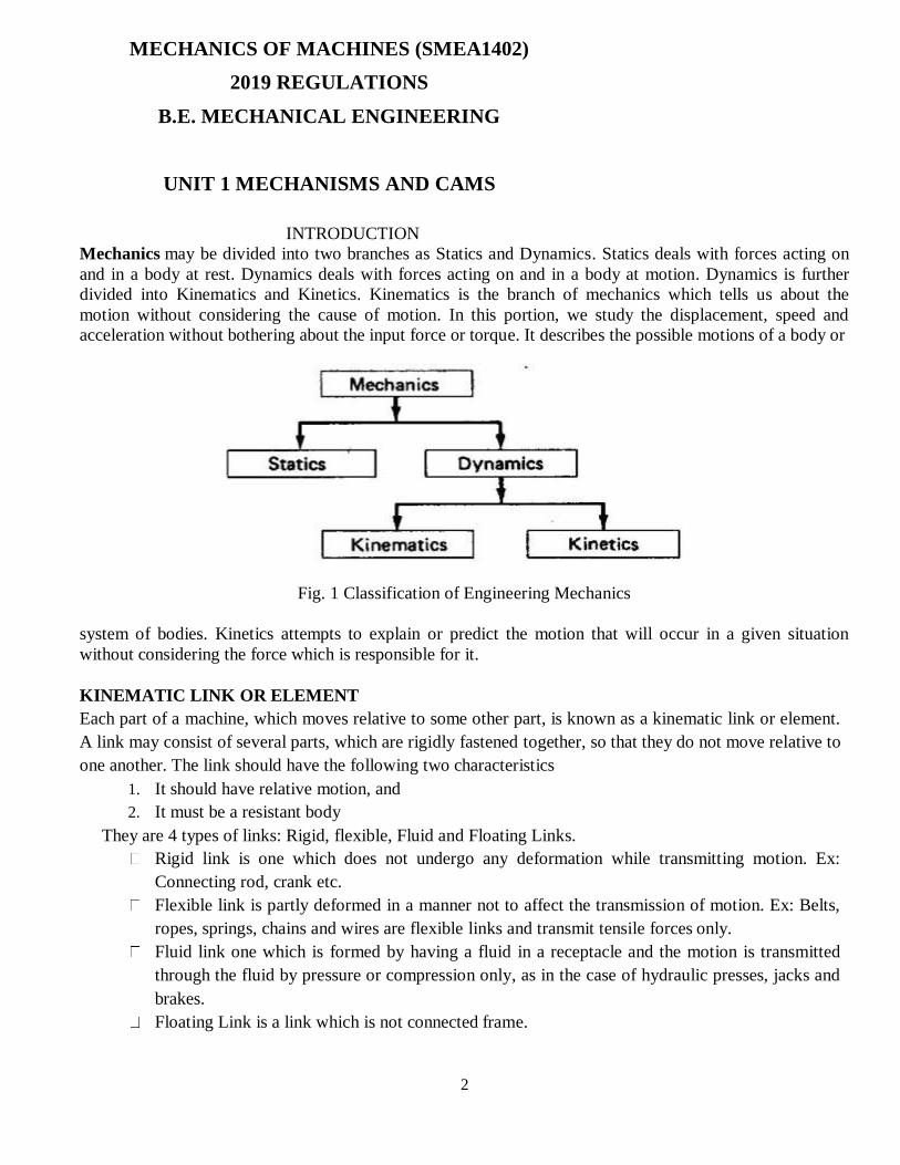
Mechanics may be divided into two branches as Statics and Dynamics. Statics deals with forces acting on
and in a body at rest. Dynamics deals with forces acting on and in a body at motion. Dynamics is further
divided into Kinematics and Kinetics. Kinematics is the branch of mechanics which tells us about the
motion without considering the cause of motion. In this portion, we study the displacement, speed and
acceleration without bothering about the input force or torque. It describes the possible motions of a body or
Fig. 1 Classification of Engineering Mechanics
system of bodies. Kinetics attempts to explain or predict the motion that will occur in a given situation
without considering the force which is responsible for it.
KINEMATIC LINK OR ELEMENT
Each part of a machine, which moves relative to some other part, is known as a kinematic link or element.
A link may consist of several parts, which are rigidly fastened together, so that they do not move relative to
one another. The link should have the following two characteristics
1. It should have relative motion, and
2. It must be a resistant body
They are 4 types of links: Rigid, flexible, Fluid and Floating Links.
Rigid link is one which does not undergo any deformation while transmitting motion. Ex:
Connecting rod, crank etc.
Flexible link is partly deformed in a manner not to affect the transmission of motion. Ex: Belts,
ropes, springs, chains and wires are flexible links and transmit tensile forces only.
Fluid link one which is formed by having a fluid in a receptacle and the motion is transmitted
through the fluid by pressure or compression only, as in the case of hydraulic presses, jacks and
brakes.
Floating Link is a link which is not connected frame.
3
TYPES OF JOINTS
The usual types of joints in a chain are
Binary joint
Ternary joint
Quaternary joint
Binary Joint
If two links are joined at the same connection, it is called a binary joint.
Ternary Joint
If three links are joined at a connection, it is known as a ternary joint. It is considered equivalent
to two binary joints since fixing of any one link constitutes two binary joints with each of the other two
links.
Quaternary Joint
If four links are joined at a connection, it is known as a quaternary joint. It is considered
equivalent to three binary joints since fixing of any one link constitutes three binary joints.
In general, if ‘n’ number of links that are connected at a joint, it is equivalent to (n-1) binary joints.
KINEMATIC PAIRS
Pairing elements: the geometrical forms by which two members of a mechanism are joined
together, so that the relative motion between these two is consistent are known as pairing elements and
the pair so formed is called kinematic pair. Each individual link of a mechanism forms a pairing
element.
KINEMATIC CONSTRAINTS
Two or more rigid bodies in space are collectively called a rigid body system. We can hinder the
motion of these independent rigid bodies with kinematic constraints. Kinematic constraints are
constraints between rigid bodies that result in the decrease of the degrees of freedom of rigid body
system.
The three main types of constrained motion in kinematic pair are,
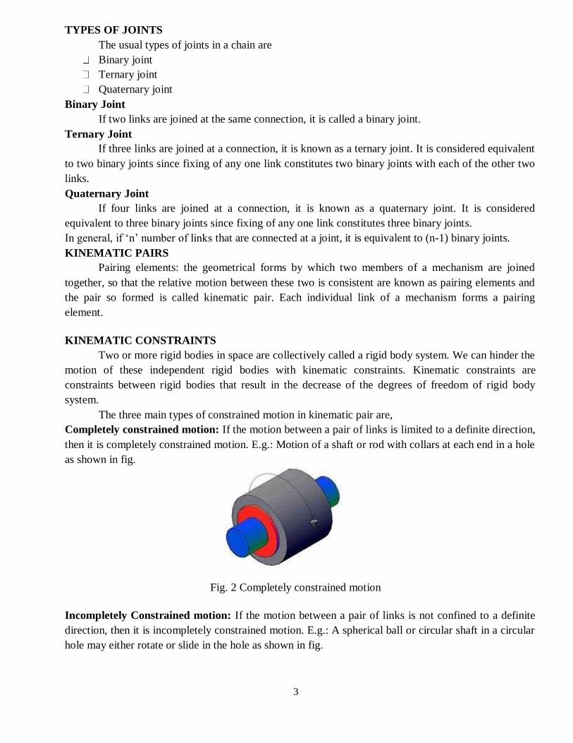
Completely constrained motion: If the motion between a pair of links is limited to a definite direction,
then it is completely constrained motion. E.g.: Motion of a shaft or rod with collars at each end in a hole
as shown in fig.
Fig. 2 Completely constrained motion
Incompletely Constrained motion: If the motion between a pair of links is not confined to a definite
direction, then it is incompletely constrained motion. E.g.: A spherical ball or circular shaft in a circular
hole may either rotate or slide in the hole as shown in fig.

4
Fig. 3 Incompletely constrained motion
Successfully constrained motion or partially constrained motion: If the motion in a definite
direction is not brought about by itself but by some other means, then it is known as successfully
constrained motion. E.g.: Foot step Bearing shown in fig.
Fig. 4 Successfully constrained motion
TYPES OF KINEMATIC PAIRS
Kinematic pairs according to nature of relative motion.
Sliding pair: If two links have a sliding motion relative to each other, they form a sliding pair. A
rectangular rod in a rectangular hole in a prism is an example of a sliding pair.
Fig. 5 Sliding pair
Turning Pair: When on link has a turning or revolving motion relative to the other, they constitute a
turning pair or revolving pair.
Fig. 6 Turning pair
Rolling pair: When the links of a pair have a rolling motion relative to each other, they form a rolling
pair. e.g. A rolling wheel on a flat surface, ball and roller bearings.
5
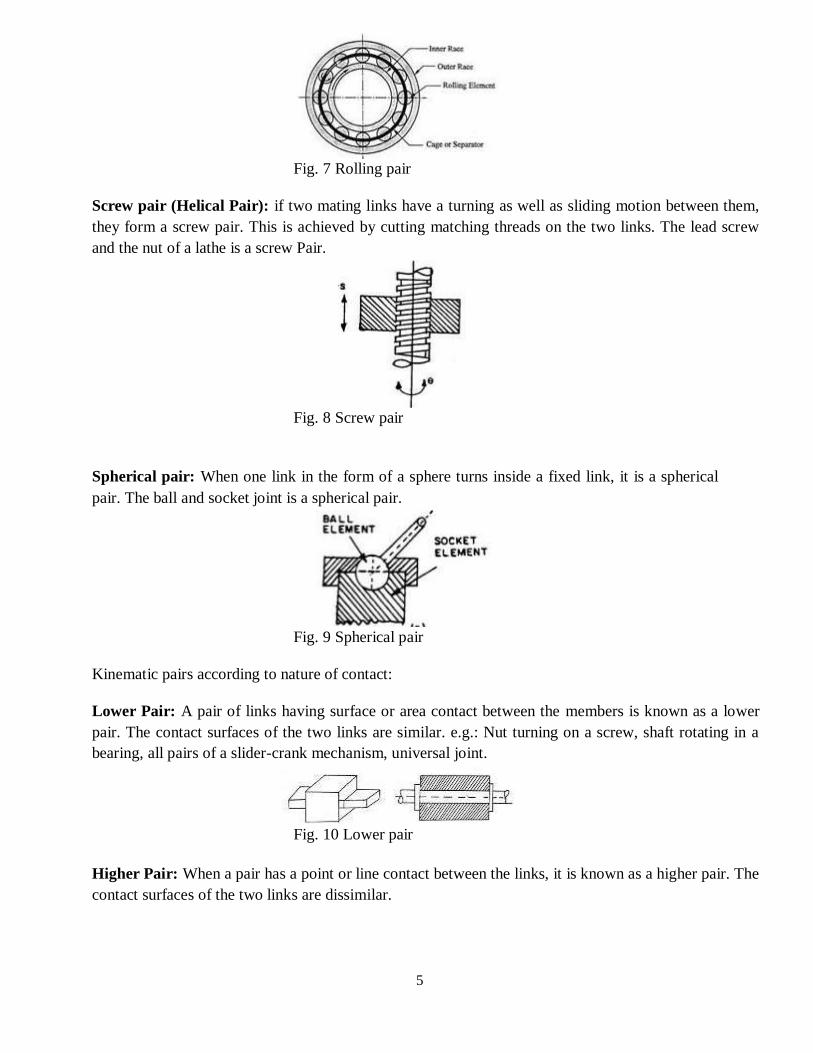
Fig. 7 Rolling pair
Screw pair (Helical Pair): if two mating links have a turning as well as sliding motion between them,
they form a screw pair. This is achieved by cutting matching threads on the two links. The lead screw
and the nut of a lathe is a screw Pair.
Fig. 8 Screw pair
Spherical pair: When one link in the form of a sphere turns inside a fixed link, it is a spherical
pair. The ball and socket joint is a spherical pair.
Fig. 9 Spherical pair
Kinematic pairs according to nature of contact:
Lower Pair: A pair of links having surface or area contact between the members is known as a lower
pair. The contact surfaces of the two links are similar. e.g.: Nut turning on a screw, shaft rotating in a
bearing, all pairs of a slider-crank mechanism, universal joint.
Fig. 10 Lower pair
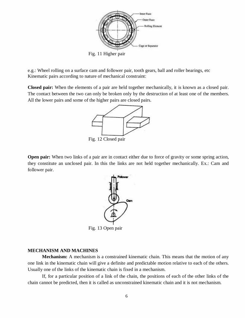
Higher Pair: When a pair has a point or line contact between the links, it is known as a higher pair. The
contact surfaces of the two links are dissimilar.
6
Fig. 11 Higher pair
e.g.: Wheel rolling on a surface cam and follower pair, tooth gears, ball and roller bearings, etc
Kinematic pairs according to nature of mechanical constraint:
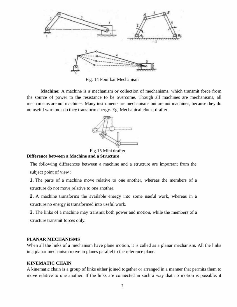
Closed pair: When the elements of a pair are held together mechanically, it is known as a closed pair.
The contact between the two can only be broken only by the destruction of at least one of the members.
All the lower pairs and some of the higher pairs are closed pairs.
Fig. 12 Closed pair
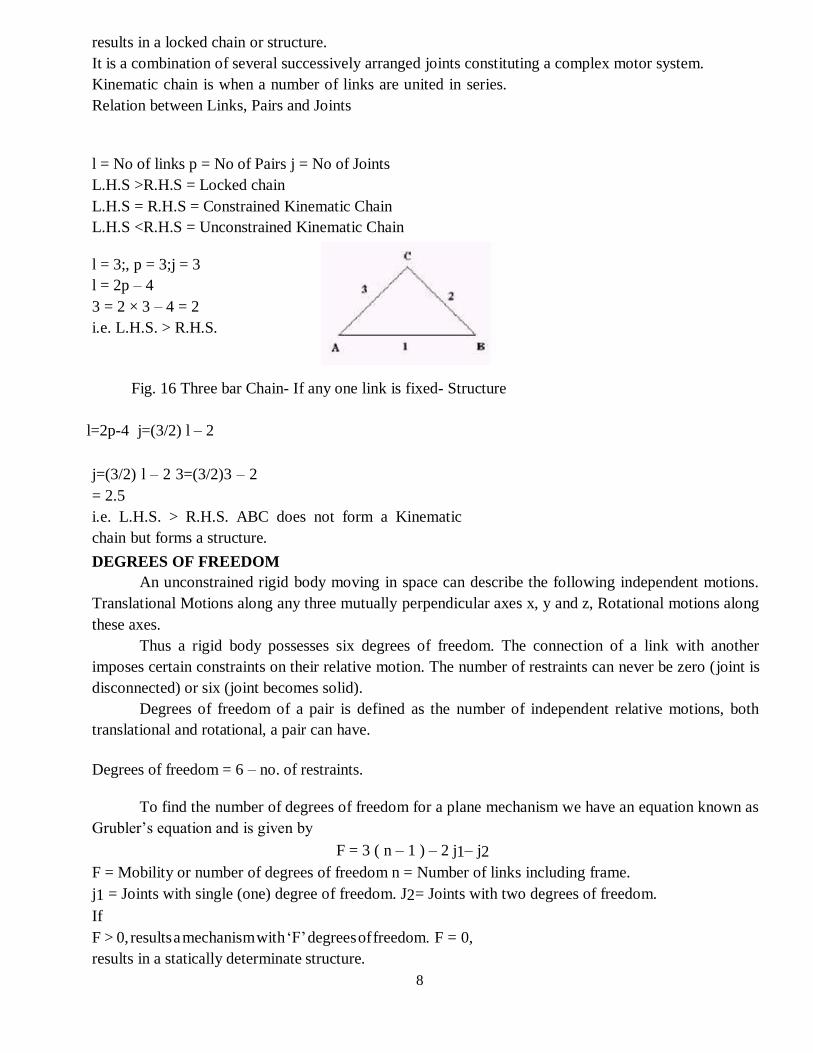
Open pair: When two links of a pair are in contact either due to force of gravity or some spring action,
they constitute an unclosed pair. In this the links are not held together mechanically. Ex.: Cam and
follower pair.
Fig. 13 Open pair
MECHANISM AND MACHINES
Mechanism: A mechanism is a constrained kinematic chain. This means that the motion of any
one link in the kinematic chain will give a definite and predictable motion relative to each of the others.
Usually one of the links of the kinematic chain is fixed in a mechanism.
If, for a particular position of a link of the chain, the positions of each of the other links of the
chain cannot be predicted, then it is called as unconstrained kinematic chain and it is not mechanism.
7
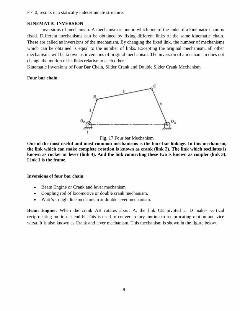
Fig. 14 Four bar Mechanism
Machine: A machine is a mechanism or collection of mechanisms, which transmit force from
the source of power to the resistance to be overcome. Though all machines are mechanisms, all
mechanisms are not machines. Many instruments are mechanisms but are not machines, because they do
no useful work nor do they transform energy. Eg. Mechanical clock, drafter.
Fig.15 Mini drafter
Difference between a Machine and a Structure
The following differences between a machine and a structure are important from the
subject point of view :
1. The parts of a machine move relative to one another, whereas the members of a
structure do not move relative to one another.
2. A machine transforms the available energy into some useful work, whereas in a
structure no energy is transformed into useful work.
3. The links of a machine may transmit both power and motion, while the members of a
structure transmit forces only.
PLANAR MECHANISMS
When all the links of a mechanism have plane motion, it is called as a planar mechanism. All the links
in a planar mechanism move in planes parallel to the reference plane.
KINEMATIC CHAIN
A kinematic chain is a group of links either joined together or arranged in a manner that permits them to
move relative to one another. If the links are connected in such a way that no motion is possible, it
8
results in a locked chain or structure.
It is a combination of several successively arranged joints constituting a complex motor system.
Kinematic chain is when a number of links are united in series.
Relation between Links, Pairs and Joints
l = No of links p = No of Pairs j = No of Joints
L.H.S >R.H.S = Locked chain
L.H.S = R.H.S = Constrained Kinematic Chain
L.H.S <R.H.S = Unconstrained Kinematic Chain
l = 3;, p = 3;j = 3
l = 2p – 4
3 = 2 × 3 – 4 = 2
i.e. L.H.S. > R.H.S.
Fig. 16 Three bar Chain- If any one link is fixed- Structure
l=2p-4 j=(3/2) l – 2
j=(3/2) l – 2 3=(3/2)3 – 2
= 2.5
i.e. L.H.S. > R.H.S. ABC does not form a Kinematic
chain but forms a structure.
DEGREES OF FREEDOM
An unconstrained rigid body moving in space can describe the following independent motions.
Translational Motions along any three mutually perpendicular axes x, y and z, Rotational motions along
these axes.
Thus a rigid body possesses six degrees of freedom. The connection of a link with another
imposes certain constraints on their relative motion. The number of restraints can never be zero (joint is
disconnected) or six (joint becomes solid).
Degrees of freedom of a pair is defined as the number of independent relative motions, both
translational and rotational, a pair can have.
Degrees of freedom = 6 – no. of restraints.
To find the number of degrees of freedom for a plane mechanism we have an equation known as
Grubler’s equation and is given by
F = 3 ( n – 1 ) – 2 j1– j2
F = Mobility or number of degrees of freedom n = Number of links including frame.
j1 = Joints with single (one) degree of freedom. J2= Joints with two degrees of freedom.
If
F > 0, results a mechanism with ‘F’ degrees of freedom. F = 0,
results in a statically determinate structure.
9
F < 0, results in a statically indeterminate structure.
KINEMATIC INVERSION
Inversions of mechanism: A mechanism is one in which one of the links of a kinematic chain is
fixed. Different mechanisms can be obtained by fixing different links of the same kinematic chain.
These are called as inversions of the mechanism. By changing the fixed link, the number of mechanisms
which can be obtained is equal to the number of links. Excepting the original mechanism, all other
mechanisms will be known as inversions of original mechanism. The inversion of a mechanism does not
change the motion of its links relative to each other.
Kinematic Inversions of Four Bar Chain, Slider Crank and Double Slider Crank Mechanism
Four bar chain
Fig. 17 Four bar Mechanism
One of the most useful and most common mechanisms is the four-bar linkage. In this mechanism,
the link which can make complete rotation is known as crank (link 2). The link which oscillates is
known as rocker or lever (link 4). And the link connecting these two is known as coupler (link 3).
Link 1 is the frame.
Inversions of four bar chain
Beam Engine or Crank and lever mechanism.
Coupling rod of locomotive or double crank mechanism.
Watt’s straight line mechanism or double lever mechanism.
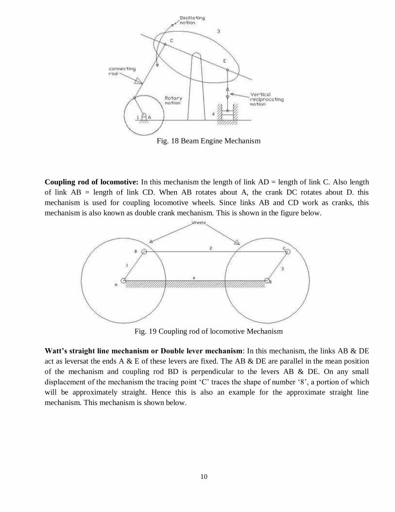
Beam Engine: When the crank AB rotates about A, the link CE pivoted at D makes vertical
reciprocating motion at end E. This is used to convert rotary motion to reciprocating motion and vice
versa. It is also known as Crank and lever mechanism. This mechanism is shown in the figure below.
10
Fig. 18 Beam Engine Mechanism
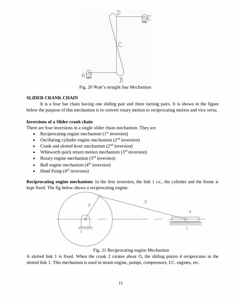
Coupling rod of locomotive: In this mechanism the length of link AD = length of link C. Also length
of link AB = length of link CD. When AB rotates about A, the crank DC rotates about D. this
mechanism is used for coupling locomotive wheels. Since links AB and CD work as cranks, this
mechanism is also known as double crank mechanism. This is shown in the figure below.
Fig. 19 Coupling rod of locomotive Mechanism
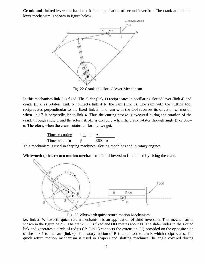
Watt’s straight line mechanism or Double lever mechanism: In this mechanism, the links AB & DE
act as leversat the ends A & E of these levers are fixed. The AB & DE are parallel in the mean position
of the mechanism and coupling rod BD is perpendicular to the levers AB & DE. On any small
displacement of the mechanism the tracing point ‘C’ traces the shape of number ‘8’, a portion of which
will be approximately straight. Hence this is also an example for the approximate straight line
mechanism. This mechanism is shown below.
11
Fig. 20 Watt’s straight line Mechanism
SLIDER CRANK CHAIN
It is a four bar chain having one sliding pair and three turning pairs. It is shown in the figure
below the purpose of this mechanism is to convert rotary motion to reciprocating motion and vice versa.
Inversions of a Slider crank chain
There are four inversions in a single slider chain mechanism. They are
Reciprocating engine mechanism (1st inversion)
Oscillating cylinder engine mechanism (2nd inversion)
Crank and slotted lever mechanism (2nd inversion)
Whitworth quick return motion mechanism (3rd inversion)
Rotary engine mechanism (3rd inversion)
Bull engine mechanism (4th inversion)
Hand Pump (4th inversion)
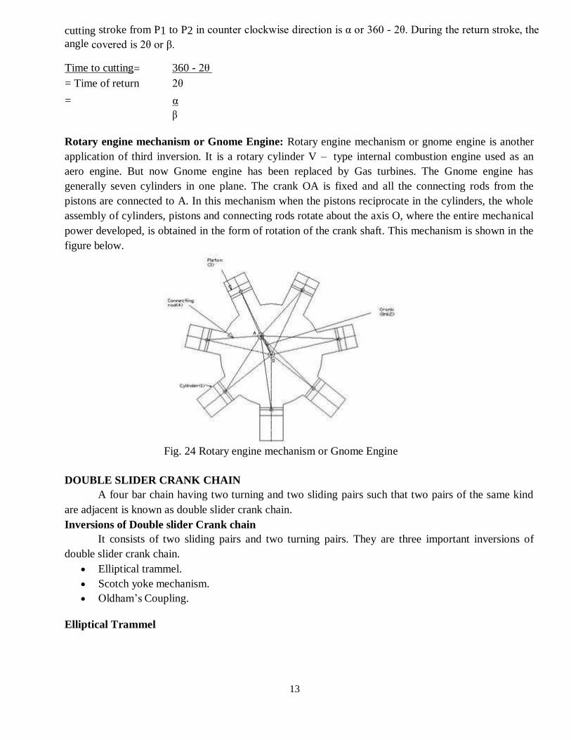
Reciprocating engine mechanism: In the first inversion, the link 1 i.e., the cylinder and the frame is
kept fixed. The fig below shows a reciprocating engine.
Fig. 21 Reciprocating engine Mechanism
A slotted link 1 is fixed. When the crank 2 rotates about O, the sliding piston 4 reciprocates in the
slotted link 1. This mechanism is used in steam engine, pumps, compressors, I.C. engines, etc.
12
Crank and slotted lever mechanism: It is an application of second inversion. The crank and slotted
lever mechanism is shown in figure below.
Fig. 22 Crank and slotted lever Mechanism
In this mechanism link 3 is fixed. The slider (link 1) reciprocates in oscillating slotted lever (link 4) and
crank (link 2) rotates. Link 5 connects link 4 to the ram (link 6). The ram with the cutting tool
reciprocates perpendicular to the fixed link 3. The ram with the tool reverses its direction of motion
when link 2 is perpendicular to link 4. Thus the cutting stroke is executed during the rotation of the
crank through angle α and the return stroke is executed when the crank rotates through angle β or 360–
α. Therefore, when the crank rotates uniformly, we get,
Time to cutting = α = α .
Time of return β 360 – α
This mechanism is used in shaping machines, slotting machines and in rotary engines.
Whitworth quick return motion mechanism: Third inversion is obtained by fixing the crank
Fig. 23 Whitworth quick return motion Mechanism
i.e. link 2. Whitworth quick return mechanism is an application of third inversion. This mechanism is
shown in the figure below. The crank OC is fixed and OQ rotates about O. The slider slides in the slotted
link and generates a circle of radius CP. Link 5 connects the extension OQ provided on the opposite side
of the link 1 to the ram (link 6). The rotary motion of P is taken to the ram R which reciprocates. The
quick return motion mechanism is used in shapers and slotting machines.The angle covered during
13
cutting stroke from P1 to P2 in counter clockwise direction is α or 360 - 2θ. During the return stroke, the
angle covered is 2θ or β.
Time to cutting= 360 - 2θ
= Time of return 2θ
= α
β
Rotary engine mechanism or Gnome Engine: Rotary engine mechanism or gnome engine is another
application of third inversion. It is a rotary cylinder V – type internal combustion engine used as an
aero engine. But now Gnome engine has been replaced by Gas turbines. The Gnome engine has
generally seven cylinders in one plane. The crank OA is fixed and all the connecting rods from the
pistons are connected to A. In this mechanism when the pistons reciprocate in the cylinders, the whole
assembly of cylinders, pistons and connecting rods rotate about the axis O, where the entire mechanical
power developed, is obtained in the form of rotation of the crank shaft. This mechanism is shown in the
figure below.
Fig. 24 Rotary engine mechanism or Gnome Engine
DOUBLE SLIDER CRANK CHAIN
A four bar chain having two turning and two sliding pairs such that two pairs of the same kind
are adjacent is known as double slider crank chain.
Inversions of Double slider Crank chain
It consists of two sliding pairs and two turning pairs. They are three important inversions of
double slider crank chain.
Elliptical trammel.
Scotch yoke mechanism.
Oldham’s Coupling.
Elliptical Trammel
14
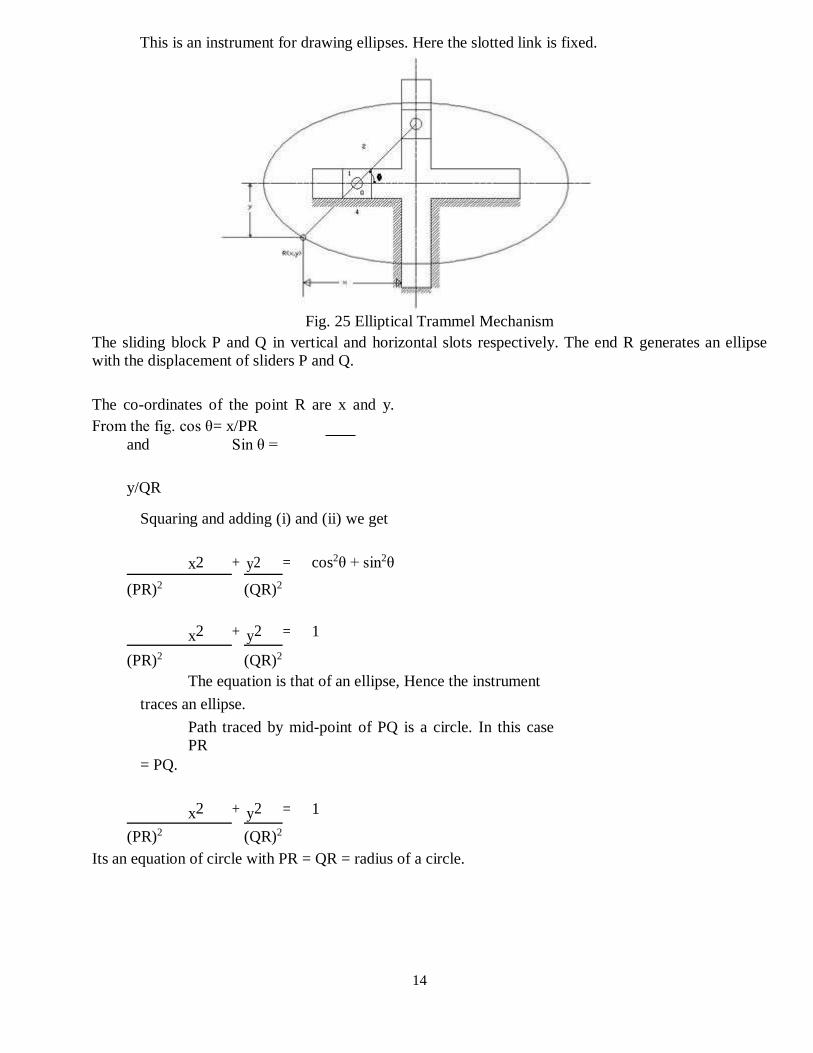
This is an instrument for drawing ellipses. Here the slotted link is fixed.
Fig. 25 Elliptical Trammel Mechanism
The sliding block P and Q in vertical and horizontal slots respectively. The end R generates an ellipse
with the displacement of sliders P and Q.
The co-ordinates of the point R are x and y.
From the fig. cos θ= x/PR
and Sin θ =
y/QR
Squaring and adding (i) and (ii) we get
x2 + y2 = cos2θ + sin2θ
(PR)2 (QR)2
x2 + y2 = 1
(PR)2 (QR)2
The equation is that of an ellipse, Hence the instrument
traces an ellipse.
Path traced by mid-point of PQ is a circle. In this case
PR
= PQ.
x2 + y2 = 1
(PR)2 (QR)2
Its an equation of circle with PR = QR = radius of a circle.
15
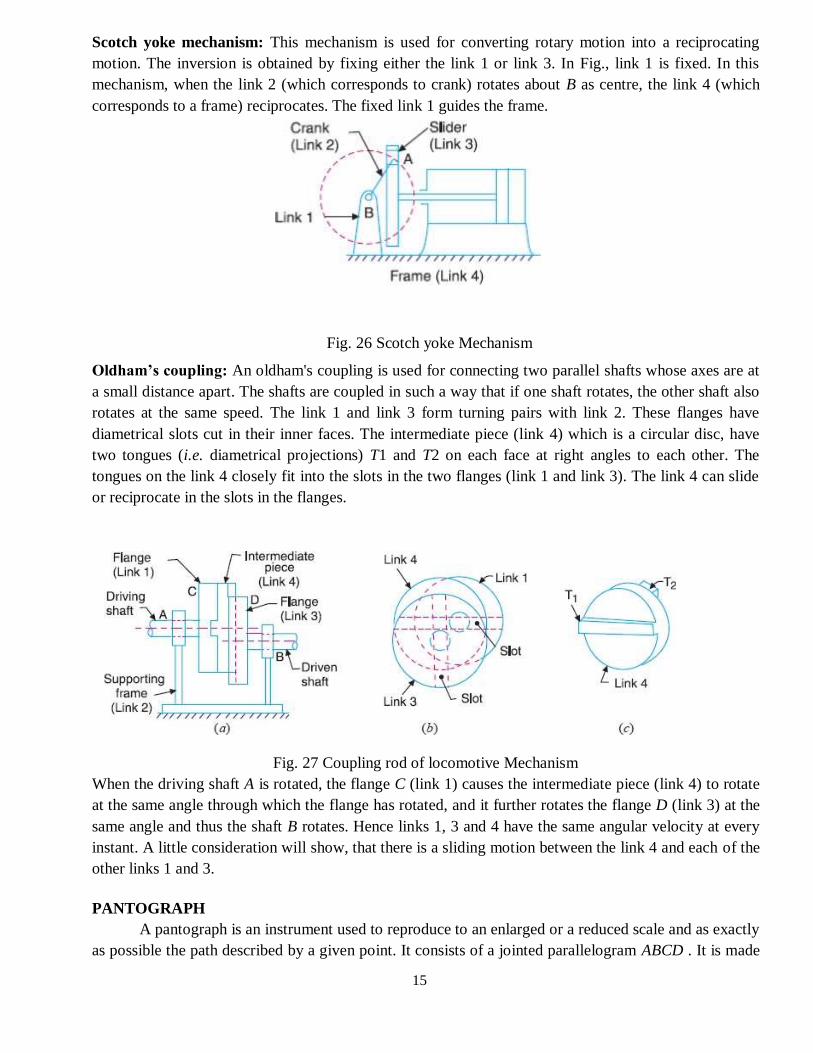
Scotch yoke mechanism: This mechanism is used for converting rotary motion into a reciprocating
motion. The inversion is obtained by fixing either the link 1 or link 3. In Fig., link 1 is fixed. In this
mechanism, when the link 2 (which corresponds to crank) rotates about B as centre, the link 4 (which
corresponds to a frame) reciprocates. The fixed link 1 guides the frame.
Fig. 26 Scotch yoke Mechanism
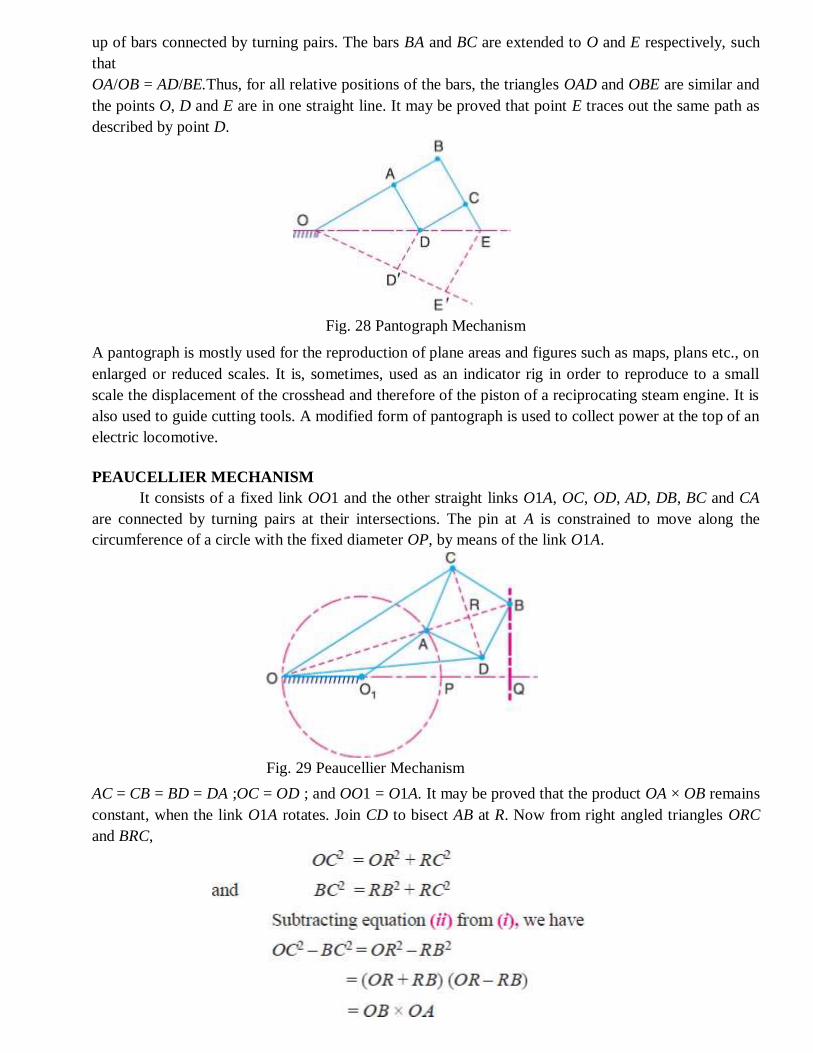
Oldham’s coupling: An oldham's coupling is used for connecting two parallel shafts whose axes are at
a small distance apart. The shafts are coupled in such a way that if one shaft rotates, the other shaft also
rotates at the same speed. The link 1 and link 3 form turning pairs with link 2. These flanges have
diametrical slots cut in their inner faces. The intermediate piece (link 4) which is a circular disc, have
two tongues (i.e. diametrical projections) T1 and T2 on each face at right angles to each other. The
tongues on the link 4 closely fit into the slots in the two flanges (link 1 and link 3). The link 4 can slide
or reciprocate in the slots in the flanges.
Fig. 27 Coupling rod of locomotive Mechanism
When the driving shaft A is rotated, the flange C (link 1) causes the intermediate piece (link 4) to rotate
at the same angle through which the flange has rotated, and it further rotates the flange D (link 3) at the
same angle and thus the shaft B rotates. Hence links 1, 3 and 4 have the same angular velocity at every
instant. A little consideration will show, that there is a sliding motion between the link 4 and each of the
other links 1 and 3.
PANTOGRAPH
A pantograph is an instrument used to reproduce to an enlarged or a reduced scale and as exactly
as possible the path described by a given point. It consists of a jointed parallelogram ABCD . It is made
16
up of bars connected by turning pairs. The bars BA and BC are extended to O and E respectively, such
that
OA/OB = AD/BE.Thus, for all relative positions of the bars, the triangles OAD and OBE are similar and
the points O, D and E are in one straight line. It may be proved that point E traces out the same path as
described by point D.
Fig. 28 Pantograph Mechanism
A pantograph is mostly used for the reproduction of plane areas and figures such as maps, plans etc., on
enlarged or reduced scales. It is, sometimes, used as an indicator rig in order to reproduce to a small
scale the displacement of the crosshead and therefore of the piston of a reciprocating steam engine. It is
also used to guide cutting tools. A modified form of pantograph is used to collect power at the top of an
electric locomotive.
PEAUCELLIER MECHANISM
It consists of a fixed link OO1 and the other straight links O1A, OC, OD, AD, DB, BC and CA
are connected by turning pairs at their intersections. The pin at A is constrained to move along the
circumference of a circle with the fixed diameter OP, by means of the link O1A.
Fig. 29 Peaucellier Mechanism
AC = CB = BD = DA ;OC = OD ; and OO1 = O1A. It may be proved that the product OA × OB remains
constant, when the link O1A rotates. Join CD to bisect AB at R. Now from right angled triangles ORC
and BRC,
17
Since OC and BC are of constant length, therefore the product OB × OA remains constant. Hence the
point B traces a straight path perpendicular to the diameter OP.
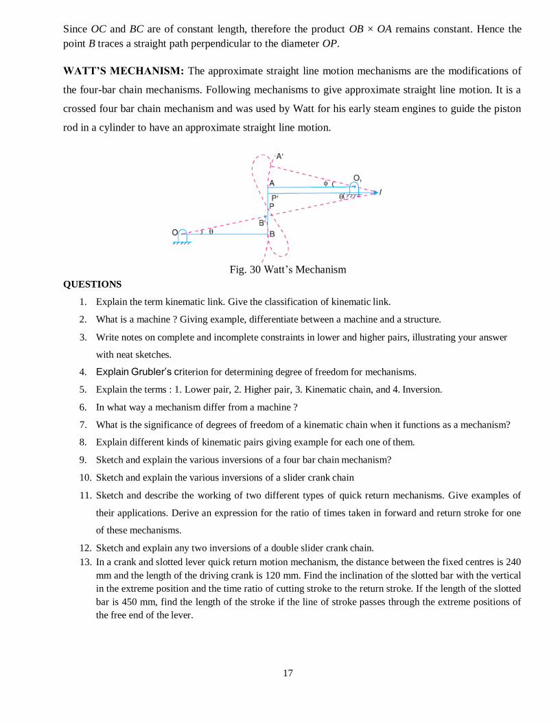
WATT’S MECHANISM: The approximate straight line motion mechanisms are the modifications of
the four-bar chain mechanisms. Following mechanisms to give approximate straight line motion. It is a
crossed four bar chain mechanism and was used by Watt for his early steam engines to guide the piston
rod in a cylinder to have an approximate straight line motion.
Fig. 30 Watt’s Mechanism
QUESTIONS
1. Explain the term kinematic link. Give the classification of kinematic link.
2. What is a machine ? Giving example, differentiate between a machine and a structure.
3. Write notes on complete and incomplete constraints in lower and higher pairs, illustrating your answer
with neat sketches.
4. Explain Grubler’s criterion for determining degree of freedom for mechanisms.
5. Explain the terms : 1. Lower pair, 2. Higher pair, 3. Kinematic chain, and 4. Inversion.
6. In what way a mechanism differ from a machine ?
7. What is the significance of degrees of freedom of a kinematic chain when it functions as a mechanism?
8. Explain different kinds of kinematic pairs giving example for each one of them.
9. Sketch and explain the various inversions of a four bar chain mechanism?
10. Sketch and explain the various inversions of a slider crank chain
11. Sketch and describe the working of two different types of quick return mechanisms. Give examples of
their applications. Derive an expression for the ratio of times taken in forward and return stroke for one
of these mechanisms.
12. Sketch and explain any two inversions of a double slider crank chain.
13. In a crank and slotted lever quick return motion mechanism, the distance between the fixed centres is 240
mm and the length of the driving crank is 120 mm. Find the inclination of the slotted bar with the vertical
in the extreme position and the time ratio of cutting stroke to the return stroke. If the length of the slotted
bar is 450 mm, find the length of the stroke if the line of stroke passes through the extreme positions of
the free end of the lever.
18
UNIT I KINEMATICS OF CAM MECHANISMS
INTRODUCTION
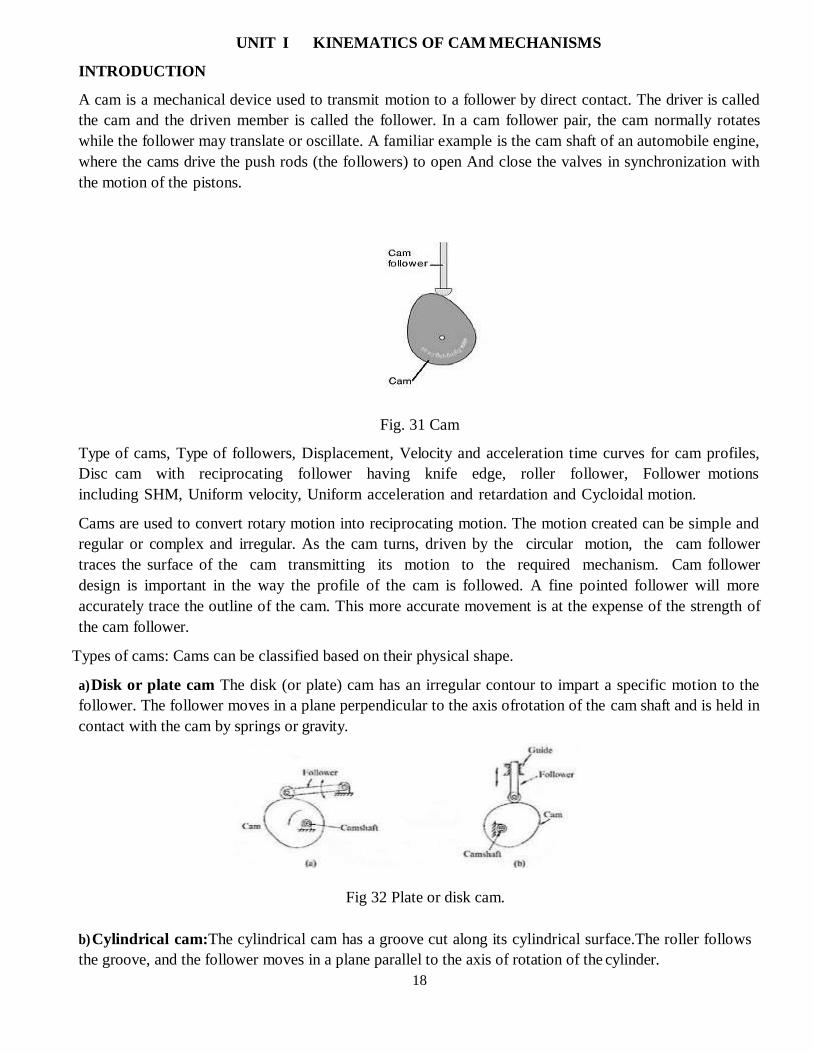
A cam is a mechanical device used to transmit motion to a follower by direct contact. The driver is called
the cam and the driven member is called the follower. In a cam follower pair, the cam normally rotates
while the follower may translate or oscillate. A familiar example is the cam shaft of an automobile engine,
where the cams drive the push rods (the followers) to open And close the valves in synchronization with
the motion of the pistons.
Fig. 31 Cam
Type of cams, Type of followers, Displacement, Velocity and acceleration time curves for cam profiles,
Disc cam with reciprocating follower having knife edge, roller follower, Follower motions
including SHM, Uniform velocity, Uniform acceleration and retardation and Cycloidal motion.
Cams are used to convert rotary motion into reciprocating motion. The motion created can be simple and
regular or complex and irregular. As the cam turns, driven by the circular motion, the cam follower
traces the surface of the cam transmitting its motion to the required mechanism. Cam follower
design is important in the way the profile of the cam is followed. A fine pointed follower will more
accurately trace the outline of the cam. This more accurate movement is at the expense of the strength of
the cam follower.
Types of cams: Cams can be classified based on their physical shape.
a) Disk or plate cam The disk (or plate) cam has an irregular contour to impart a specific motion to the
follower. The follower moves in a plane perpendicular to the axis ofrotation of the cam shaft and is held in
contact with the cam by springs or gravity.
Fig 32 Plate or disk cam.
b) Cylindrical cam:The cylindrical cam has a groove cut along its cylindrical surface.The roller follows
the groove, and the follower moves in a plane parallel to the axis of rotation of the cylinder.
19
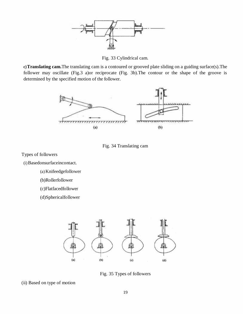
Fig. 33 Cylindrical cam.
c) Translating cam.The translating cam is a contoured or grooved plate sliding on a guiding surface(s).The
follower may oscillate (Fig.3 a)or reciprocate (Fig. 3b).The contour or the shape of the groove is
determined by the specified motion of the follower.
Fig. 34 Translating cam
Types of followers
(i) Basedonsurfaceincontact.
(a) Knifeedgefollower
(b)Rollerfollower
(c)Flatfacedfollower
(d)Sphericalfollower
Fig. 35 Types of followers
(ii) Based on type of motion
20
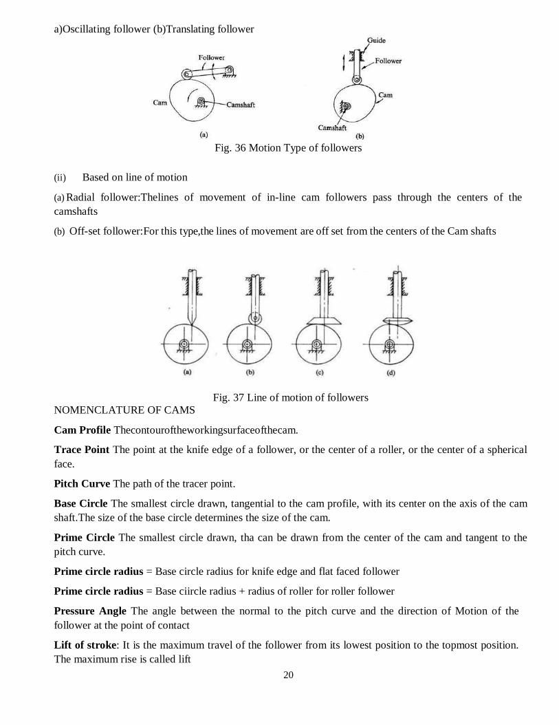
a)Oscillating follower (b)Translating follower
Fig. 36 Motion Type of followers
(ii) Based on line of motion
(a) Radial follower:Thelines of movement of in-line cam followers pass through the centers of the
camshafts
(b) Off-set follower:For this type,the lines of movement are off set from the centers of the Cam shafts
Fig. 37 Line of motion of followers
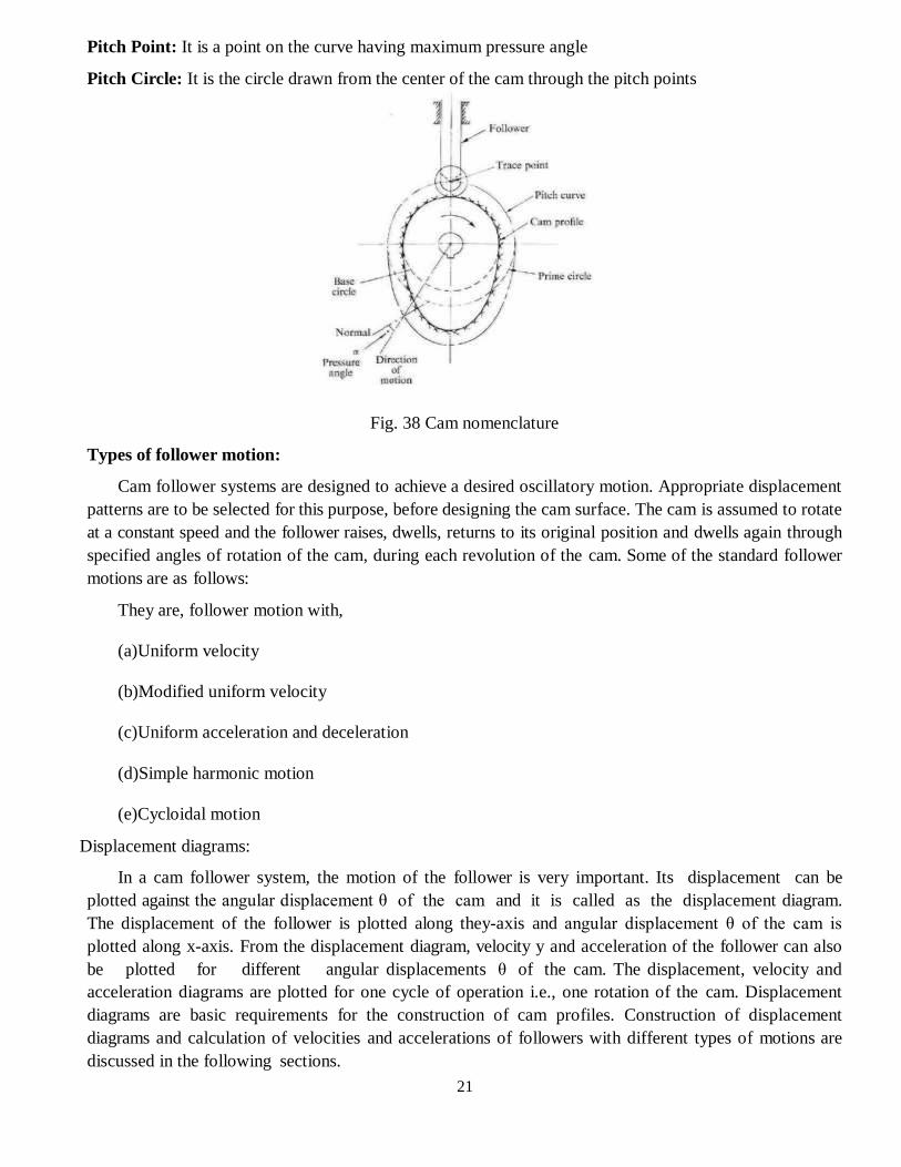
NOMENCLATURE OF CAMS
Cam Profile Thecontouroftheworkingsurfaceofthecam.
Trace Point The point at the knife edge of a follower, or the center of a roller, or the center of a spherical
face.
Pitch Curve The path of the tracer point.
Base Circle The smallest circle drawn, tangential to the cam profile, with its center on the axis of the cam
shaft.The size of the base circle determines the size of the cam.
Prime Circle The smallest circle drawn, tha can be drawn from the center of the cam and tangent to the
pitch curve.
Prime circle radius = Base circle radius for knife edge and flat faced follower
Prime circle radius = Base ciircle radius + radius of roller for roller follower
Pressure Angle The angle between the normal to the pitch curve and the direction of Motion of the
follower at the point of contact
Lift of stroke: It is the maximum travel of the follower from its lowest position to the topmost position.
The maximum rise is called lift
21
Pitch Point: It is a point on the curve having maximum pressure angle
Pitch Circle: It is the circle drawn from the center of the cam through the pitch points
Fig. 38 Cam nomenclature
Types of follower motion:
Cam follower systems are designed to achieve a desired oscillatory motion. Appropriate displacement
patterns are to be selected for this purpose, before designing the cam surface. The cam is assumed to rotate
at a constant speed and the follower raises, dwells, returns to its original position and dwells again through
specified angles of rotation of the cam, during each revolution of the cam. Some of the standard follower
motions are as follows:
They are, follower motion with,
(a)Uniform velocity
(b)Modified uniform velocity
(c)Uniform acceleration and deceleration
(d)Simple harmonic motion
(e)Cycloidal motion
Displacement diagrams:
In a cam follower system, the motion of the follower is very important. Its displacement can be
plotted against the angular displacement θ of the cam and it is called as the displacement diagram.
The displacement of the follower is plotted along they-axis and angular displacement θ of the cam is
plotted along x-axis. From the displacement diagram, velocity y and acceleration of the follower can also
be plotted for different angular displacements θ of the cam. The displacement, velocity and
acceleration diagrams are plotted for one cycle of operation i.e., one rotation of the cam. Displacement
diagrams are basic requirements for the construction of cam profiles. Construction of displacement
diagrams and calculation of velocities and accelerations of followers with different types of motions are
discussed in the following sections.
22
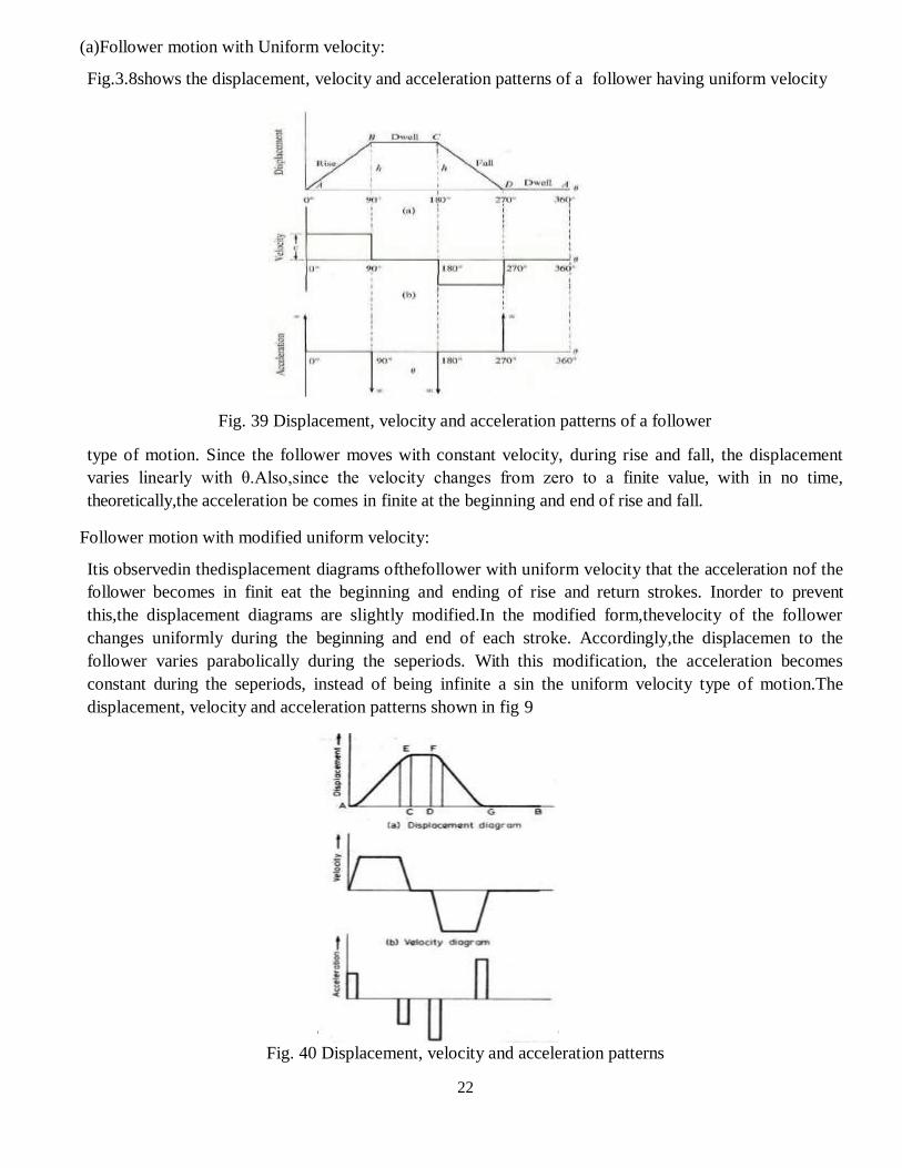
(a)Follower motion with Uniform velocity:
Fig.3.8shows the displacement, velocity and acceleration patterns of a follower having uniform velocity
Fig. 39 Displacement, velocity and acceleration patterns of a follower
type of motion. Since the follower moves with constant velocity, during rise and fall, the displacement
varies linearly with θ.Also,since the velocity changes from zero to a finite value, with in no time,
theoretically,the acceleration be comes in finite at the beginning and end of rise and fall.
Follower motion with modified uniform velocity:
Itis observedin thedisplacement diagrams ofthefollower with uniform velocity that the acceleration nof the
follower becomes in finit eat the beginning and ending of rise and return strokes. Inorder to prevent
this,the displacement diagrams are slightly modified.In the modified form,thevelocity of the follower
changes uniformly during the beginning and end of each stroke. Accordingly,the displacemen to the
follower varies parabolically during the seperiods. With this modification, the acceleration becomes
constant during the seperiods, instead of being infinite a sin the uniform velocity type of motion.The
displacement, velocity and acceleration patterns shown in fig 9
Fig. 40 Displacement, velocity and acceleration patterns
23
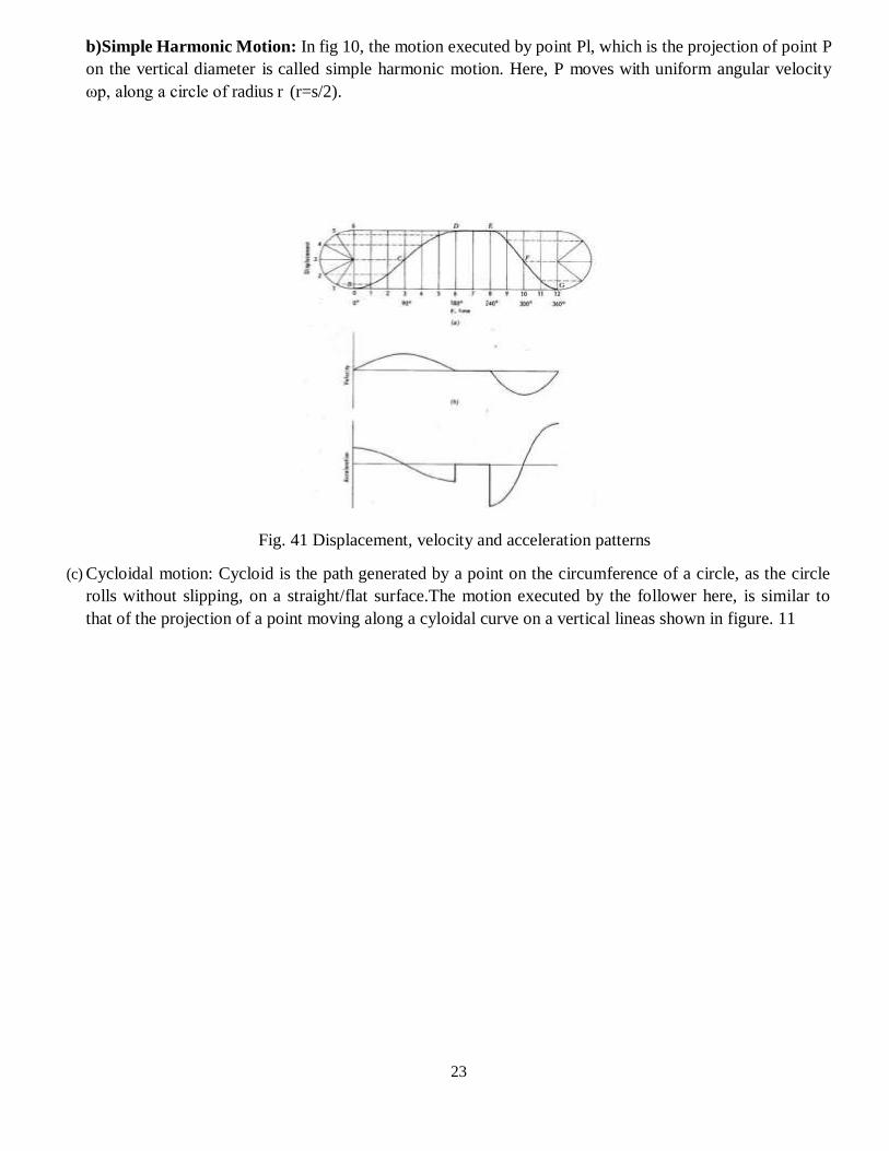
b)Simple Harmonic Motion: In fig 10, the motion executed by point Pl, which is the projection of point P
on the vertical diameter is called simple harmonic motion. Here, P moves with uniform angular velocity
ωp, along a circle of radius r (r=s/2).
Fig. 41 Displacement, velocity and acceleration patterns
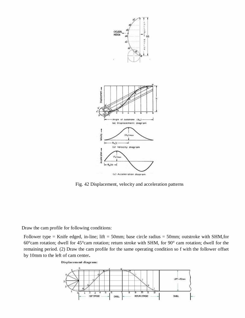
(c) Cycloidal motion: Cycloid is the path generated by a point on the circumference of a circle, as the circle
rolls without slipping, on a straight/flat surface.The motion executed by the follower here, is similar to
that of the projection of a point moving along a cyloidal curve on a vertical lineas shown in figure. 11
24
Fig. 42 Displacement, velocity and acceleration patterns
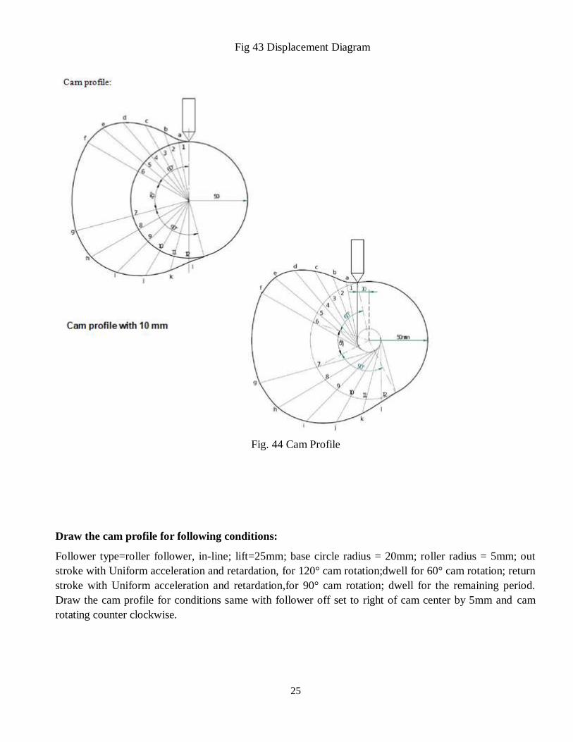
Draw the cam profile for following conditions:
Follower type = Knife edged, in-line; lift = 50mm; base circle radius = 50mm; outstroke with SHM,for
60°cam rotation; dwell for 45°cam rotation; return stroke with SHM, for 90° cam rotation; dwell for the
remaining period. (2) Draw the cam profile for the same operating condition so f with the follower offset
by 10mm to the left of cam center.
25
Fig 43 Displacement Diagram
Fig. 44 Cam Profile
Draw the cam profile for following conditions:
Follower type=roller follower, in-line; lift=25mm; base circle radius = 20mm; roller radius = 5mm; out
stroke with Uniform acceleration and retardation, for 120° cam rotation;dwell for 60° cam rotation; return
stroke with Uniform acceleration and retardation,for 90° cam rotation; dwell for the remaining period.
Draw the cam profile for conditions same with follower off set to right of cam center by 5mm and cam
rotating counter clockwise.
26
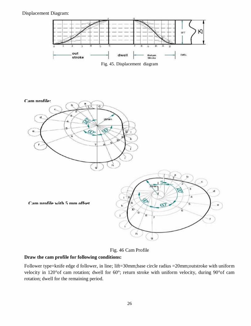
Displacement Diagram:
Fig. 45. Displacement diagram
Fig. 46 Cam Profile
Draw the cam profile for following conditions:
Follower type=knife edge d follower, in line; lift=30mm;base circle radius =20mm;outstroke with uniform
velocity in 120°of cam rotation; dwell for 60°; return stroke with uniform velocity, during 90°of cam
rotation; dwell for the remaining period.
Cam profile:
Cam profile with 5 mm offset
27
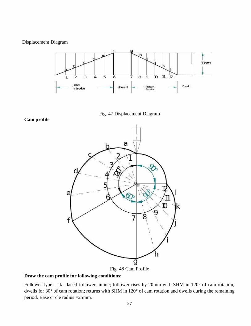
Displacement Diagram
Fig. 47 Displacement Diagram
Cam profile
Fig. 48 Cam Profile
Draw the cam profile for following conditions:
Follower type = flat faced follower, inline; follower rises by 20mm with SHM in 120° of cam rotation,
dwells for 30° of cam rotation; returns with SHM in 120° of cam rotation and dwells during the remaining
period. Base circle radius =25mm.
28
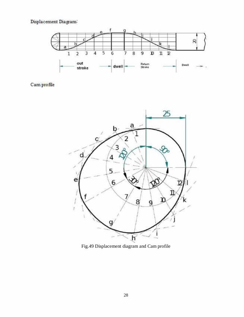
Fig.49 Displacement diagram and Cam profile
29
Layout of plate cam profiles:
Drawing the displacement diagrams for the different kinds of the motions and the plate cam
profiles for these different motions and different followers.
SHM, Uniform velocity, Uniform acceleration and retardation and Cycloidal motions
Knife-edge, Roller, Flat-faced and Mushroom followers.
Derivatives of Follower motion:
Velocity and acceleration of the followers for various types of motions.
Calculation of Velocity and acceleration of the followers for various types of motions.
Circular arc and Tangent cams:
Circular arc
Tangent cam
Standard cam motion:
Simple Harmonic Motion
Uniform velocity motion
Uniform acceleration and retardation motion
Cycloidal motion
Pressure angle and undercutting:
Pressure angle
Undercutting
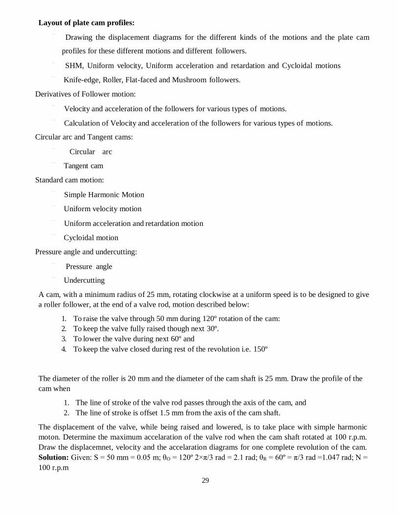
A cam, with a minimum radius of 25 mm, rotating clockwise at a uniform speed is to be designed to give
a roller follower, at the end of a valve rod, motion described below:
1. To raise the valve through 50 mm during 120º rotation of the cam:
2. To keep the valve fully raised though next 30º.
3. To lower the valve during next 60º and
4. To keep the valve closed during rest of the revolution i.e. 150º
The diameter of the roller is 20 mm and the diameter of the cam shaft is 25 mm. Draw the profile of the
cam when
1. The line of stroke of the valve rod passes through the axis of the cam, and
2. The line of stroke is offset 1.5 mm from the axis of the cam shaft.
The displacement of the valve, while being raised and lowered, is to take place with simple harmonic
moton. Determine the maximum accelaration of the valve rod when the cam shaft rotated at 100 r.p.m.
Draw the displacemnet, velocity and the accelaration diagrams for one complete revolution of the cam.
Solution: Given: S = 50 mm = 0.05 m; θO = 120º 2×π/3 rad = 2.1 rad; θR = 60º = π/3 rad =1.047 rad; N =
100 r.p.m
30
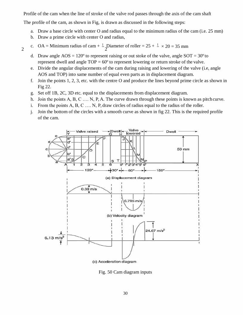
Profile of the cam when the line of stroke of the valve rod passes through the axis of the cam shaft
The profile of the cam, as shown in Fig, is drawn as discussed in the following steps:
a. Draw a base circle with center O and radius equal to the minimum radius of the cam (i.e. 25 mm)
b. Draw a prime circle with center O and radius,
c. OA = Minimum radius of cam + 1 2
Diameter of roller = 25 + 1 2
× 20 = 35 mm
d. Draw angle AOS = 120º to represent raising or out stoke of the valve, angle SOT = 30º to
represent dwell and angle TOP = 60º to represent lowering or return stroke of the valve.
e. Divide the angular displacements of the cam during raising and lowering of the valve (i.e, angle
AOS and TOP) into same number of equal even parts as in displacement diagram.
f. Join the points 1, 2, 3, etc. with the centre O and produce the lines beyond prime circle as shown in
Fig 22.
g. Set off 1B, 2C, 3D etc. equal to the displacements from displacement diagram.
h. Join the points A, B, C …. N, P, A. The curve drawn through these points is known as pitch curve.
i. From the points A, B, C …. N, P, draw circles of radius equal to the radius of the roller.
j. Join the bottom of the circles with a smooth curve as shown in fig 22. This is the required profile
of the cam.
Fig. 50 Cam diagram inputs
31
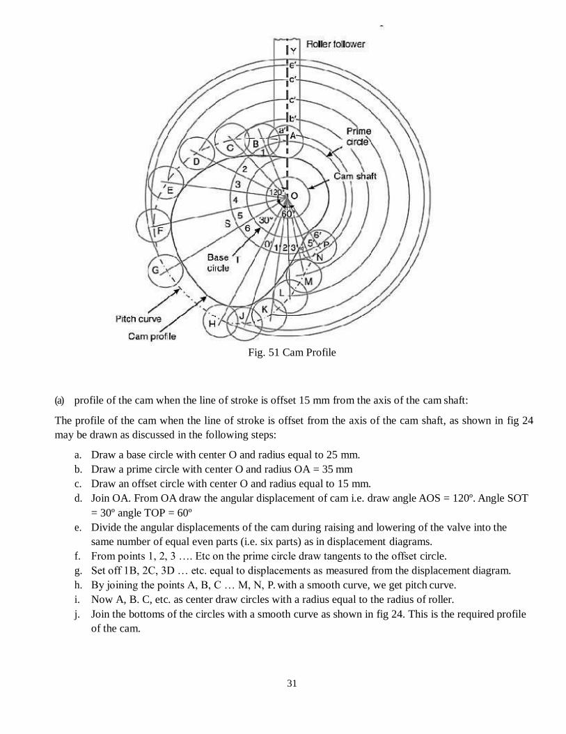
Fig. 51 Cam Profile
(a) profile of the cam when the line of stroke is offset 15 mm from the axis of the cam shaft:
The profile of the cam when the line of stroke is offset from the axis of the cam shaft, as shown in fig 24
may be drawn as discussed in the following steps:
a. Draw a base circle with center O and radius equal to 25 mm.
b. Draw a prime circle with center O and radius OA = 35 mm
c. Draw an offset circle with center O and radius equal to 15 mm.
d. Join OA. From OA draw the angular displacement of cam i.e. draw angle AOS = 120º. Angle SOT
= 30º angle TOP = 60º
e. Divide the angular displacements of the cam during raising and lowering of the valve into the
same number of equal even parts (i.e. six parts) as in displacement diagrams.
f. From points 1, 2, 3 …. Etc on the prime circle draw tangents to the offset circle.
g. Set off 1B, 2C, 3D … etc. equal to displacements as measured from the displacement diagram.
h. By joining the points A, B, C … M, N, P. with a smooth curve, we get pitch curve.
i. Now A, B. C, etc. as center draw circles with a radius equal to the radius of roller.
j. Join the bottoms of the circles with a smooth curve as shown in fig 24. This is the required profile
of the cam.
32
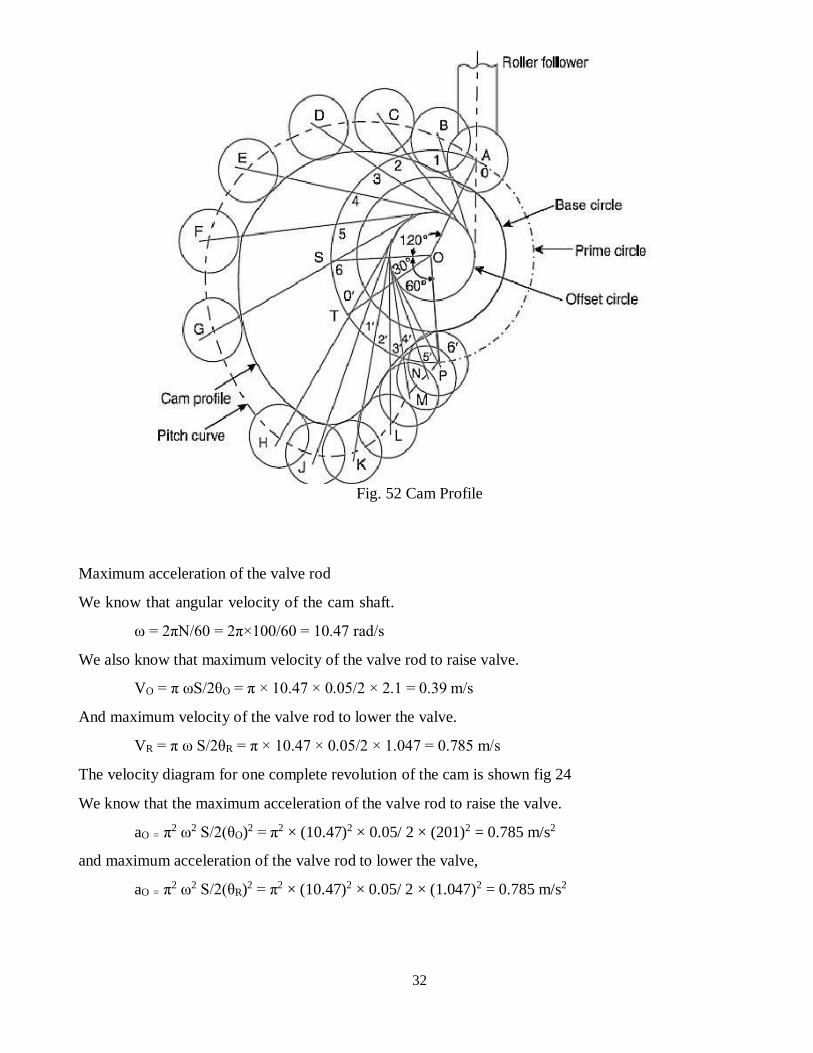
Fig. 52 Cam Profile
Maximum acceleration of the valve rod
We know that angular velocity of the cam shaft.
ω = 2πN/60 = 2π×100/60 = 10.47 rad/s
We also know that maximum velocity of the valve rod to raise valve.
VO = π ωS/2θO = π × 10.47 × 0.05/2 × 2.1 = 0.39 m/s
And maximum velocity of the valve rod to lower the valve.
VR = π ω S/2θR = π × 10.47 × 0.05/2 × 1.047 = 0.785 m/s
The velocity diagram for one complete revolution of the cam is shown fig 24
We know that the maximum acceleration of the valve rod to raise the valve.
aO = π2 ω2 S/2(θO)2 = π2 × (10.47)2 × 0.05/ 2 × (201)2 = 0.785 m/s2
and maximum acceleration of the valve rod to lower the valve,
aO = π2 ω2 S/2(θR)2 = π2 × (10.47)2 × 0.05/ 2 × (1.047)2 = 0.785 m/s2
33
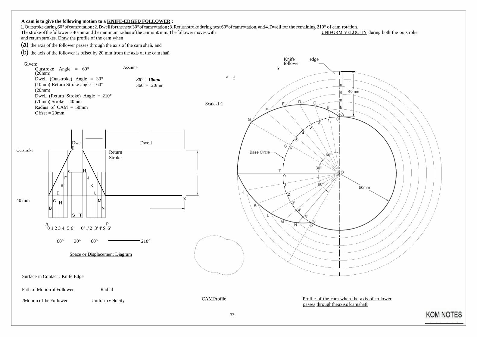
A cam is to give the following motion to a KNIFE-EDGED FOLLOWER :
1. Outstroke during 60° of cam rotation ; 2. Dwell for the next 30° of cam rotation ; 3. Return stroke during next 60° of cam rotation, and 4. Dwell for the remaining 210° of cam rotation.
The stroke of the follower is 40 mm and the minimum radius of the cam is 50 mm. The follower moves with UNIFORM VELOCITY during both the outstroke
and return strokes. Draw the profile of the cam when
(a) the axis of the follower passes through the axis of the cam shañ, and
(b) the axis of the follower is offset by 20 mm from the axis of the cam shañ.
Given: Outstroke Angle = 60° (20mm)
Assume
Knife edge follower
y
Dwell (Outstroke) Angle = 30°
(10mm) Return Stroke angle = 60°
(20mm)
Dwell (Return Stroke) Angle = 210°
(70mm) Stroke = 40mm
Radius of CAM = 50mm
Offset = 20mm
30° = 10mm
360° = 120mm
* f
Scale-1:1
Outstroke
Dwe
ll
Return
Stroke
Dwell
c H
40 mm H
A 0 1 2 3 4 5 6 0’ 1' 2’ 3' 4' 5’ 6'
60° 30° 60° 210°
Space or Displacement Diagram
Surface in Contact : Knife Edge
Path of Motion of Follower Radial
/Motion of the Follower Uniform Velocity
CAM Profile
Profile of the cam when the axis of follower
passes through the axis of cam shaft
E
C
P
S T
34
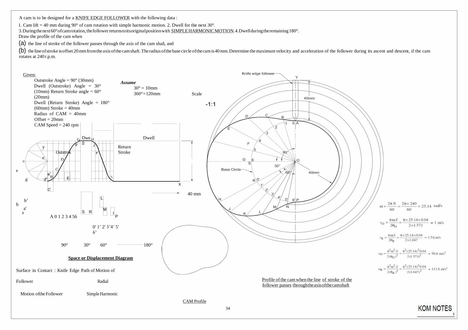
A cam is to be designed for a KNIFE EDGE FOLLOWER with the following data :
1. Cam lift = 40 mm during 90° of cam rotation with simple harmonic motion. 2. Dwell for the next 30°.
3. During the next 60° of cam rotation, the follower returns to its original position with SIMPLE HARMONIC MOTION . 4. Dwell during the remaining 180°.
Draw the profile of the cam when
(a) the line of stroke of the follower passes through the axis of the cam shañ, and
(b) the line of stroke is offset 20 mm from the axis of the cam shaft. The radius of the base circle of the cam is 40 mm. Determine the maximum velocity and acceleration of the follower during its ascent and descent, if the cam
rotates at 240 r.p.m.
Given:
Outstroke Angle = 90° (30mm)
Dwell (Outstroke) Angle = 30°
(10mm) Return Stroke angle = 60°
(20mm)
Dwell (Return Stroke) Angle = 180°
(60mm) Stroke = 40mm
Radius of CAM = 40mm
Offset = 20mm
CAM Speed = 240 rpm
Assume
30° = 10mm
360° = 120mm
Scale
y
Outstrok
e
Dwe
ll
Return
Stroke
Dwell
e
d d'
b’
b a'
a A 0 1 2 3 4 56
0' 1’ 2' 3’4’ 5'
6’
40 mm
90° 30° 60° 180°
Space or Displacement Diagram
Surface in Contact : Knife Edge Path of Motion of
Follower Radial
Motion of the Follower Simple Harmonic
CAM Profile
Profile of the cam when the line of stroke of the
follower passes through the axis of the cam shaft
e’
S R
E
I P
35
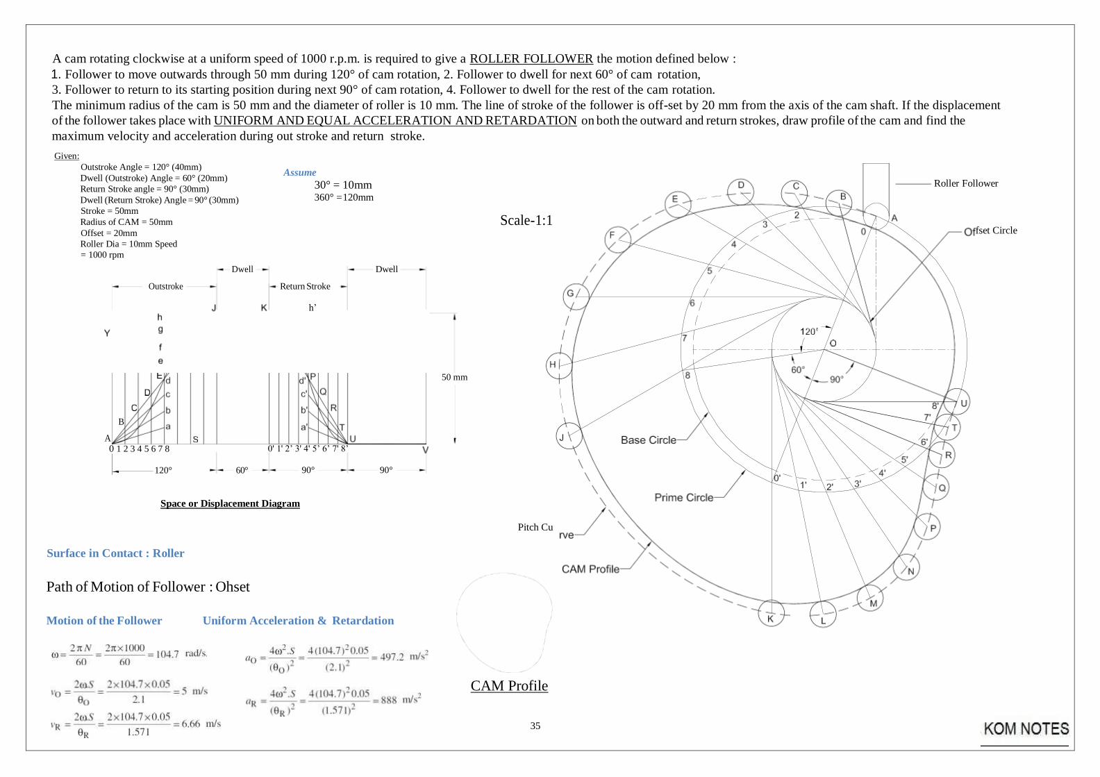
A cam rotating clockwise at a uniform speed of 1000 r.p.m. is required to give a ROLLER FOLLOWER the motion defined below :
1. Follower to move outwards through 50 mm during 120° of cam rotation, 2. Follower to dwell for next 60° of cam rotation,
3. Follower to return to its starting position during next 90° of cam rotation, 4. Follower to dwell for the rest of the cam rotation.
The minimum radius of the cam is 50 mm and the diameter of roller is 10 mm. The line of stroke of the follower is off-set by 20 mm from the axis of the cam shaft. If the displacement
of the follower takes place with UNIFORM AND EQUAL ACCELERATION AND RETARDATION on both the outward and return strokes, draw profile of the cam and find the
maximum velocity and acceleration during out stroke and return stroke.
Given:
Outstroke Angle = 120° (40mm)
Dwell (Outstroke) Angle = 60° (20mm)
Return Stroke angle = 90° (30mm)
Dwell (Return Stroke) Angle = 90° (30mm)
Stroke = 50mm
Radius of CAM = 50mm
Offset = 20mm
Roller Dia = 10mm Speed
= 1000 rpm
Assume
30° = 10mm 360° = 120mm
Scale-1:1
Roller Follower
fset Circle
Outstroke
Dwell
Return Stroke
h’
Dwell
50 mm
B
A 0 1 2 3 4 5 6 7 8
120° 60°
0' 1' 2’ 3' 4' 5’ 6’ 7' 8’
90°
90°
Space or Displacement Diagram
Surface in Contact : Roller
Path of Motion of Follower : Ohset
Pitch Cu
Motion of the Follower Uniform Acceleration & Retardation
CAM Profile
36
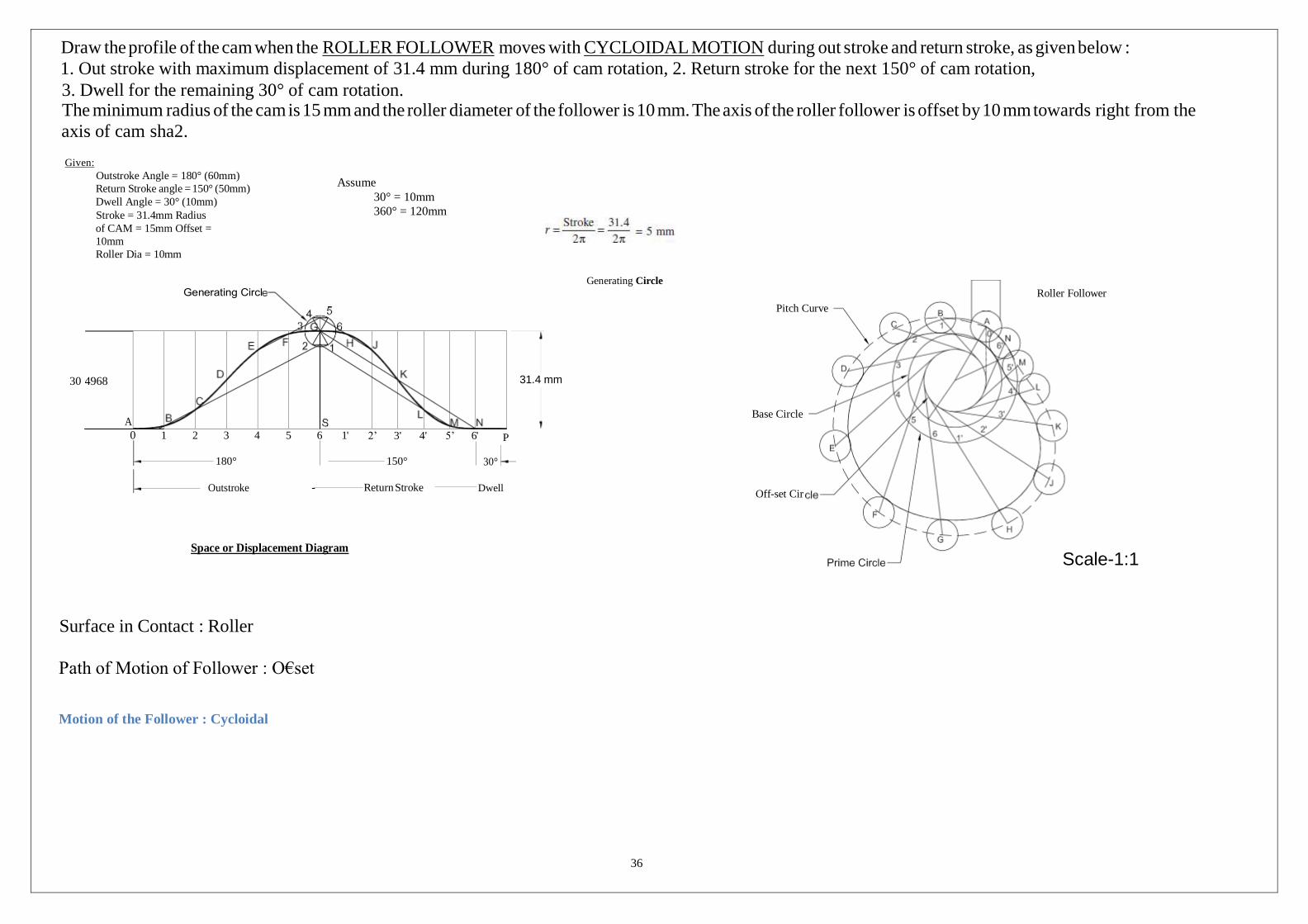
Draw the profile of the cam when the ROLLER FOLLOWER moves with CYCLOIDAL MOTION during out stroke and return stroke, as given below :
1. Out stroke with maximum displacement of 31.4 mm during 180° of cam rotation, 2. Return stroke for the next 150° of cam rotation,
3. Dwell for the remaining 30° of cam rotation. The minimum radius of the cam is 15 mm and the roller diameter of the follower is 10 mm. The axis of the roller follower is offset by 10 mm towards right from the
axis of cam sha2.
Given:
Outstroke Angle = 180° (60mm)
Return Stroke angle = 150° (50mm)
Dwell Angle = 30° (10mm)
Stroke = 31.4mm Radius
of CAM = 15mm Offset =
10mm
Roller Dia = 10mm
Assume
30° = 10mm
360° = 120mm
Generating Circle
30
Pitch Curve
Roller Follower
0 1 2 3 4 5 6 1'
180°
2’ 3' 4' 5’ 6'
150°
P
30°
Base Circle
Outstroke - Return Stroke Dwell
Off-set Cir
Space or Displacement Diagram
Surface in Contact : Roller
Path of Motion of Follower : O€set
Motion of the Follower : Cycloidal
Scale-1:1
31.4 mm
.4968
A
37
CAM Profile
QUESTIONS
14. Explain the term kinematic link. Give the classification of kinematic link.
15. What is a machine ? Giving example, differentiate between a machine and a structure.
16. Write notes on complete and incomplete constraints in lower and higher pairs, illustrating
your answer with neat sketches.
17. Explain Grubler’s criterion for determining degree of freedom for mechanisms.
18. Explain the terms : 1. Lower pair, 2. Higher pair, 3. Kinematic chain, and 4. Inversion.
19. In what way a mechanism differ from a machine ?
20. What is the significance of degrees of freedom of a kinematic chain when it functions as
a mechanism?
21. Explain different kinds of kinematic pairs giving example for each one of them.
22. Sketch and explain the various inversions of a four bar chain mechanism?
23. Sketch and explain the various inversions of a slider crank chain
24. Sketch and describe the working of two different types of quick return mechanisms. Give
examples of their applications. Derive an expression for the ratio of times taken in
forward and return stroke for one of these mechanisms.
25. Sketch and explain any two inversions of a double slider crank chain.
26. In a crank and slotted lever quick return motion mechanism, the distance between the
fixed centres is 240 mm and the length of the driving crank is 120 mm. Find the
inclination of the slotted bar with the vertical in the extreme position and the time ratio of
cutting stroke to the return stroke. If the length of the slotted bar is 450 mm, find the
length of the stroke if the line of stroke passes through the extreme positions of the free
end of the lever.
1
SCHOOL OF MECHANICAL ENGINEERING
DEPARTMENT OF MECHANICAL ENGINEERING
UNIT – II - FLY WHEELS AND BALANCING – SMEA1402
2
FLYWHEEL AND TURNING MOMENT DIAGRAMS
INTRODUCTION
Application of slider-crank mechanism can be found in reciprocating (steam) engines in the
power plant i.e. internal combustion engines, generators to centrifugal pumps, etc. Output is non-
uniform torque from crankshaft; accordingly there will be fluctuation is speed and subsequently
in voltage generated in the generator that is objectionable or undesirable. Output torque at shaft
is required to be uniform. Other kind of applications can be in punch press. It requires huge
amount of power for small time interval. Remaining time of cycle it is ideal. Large motor that
can supply huge quantity of energy for a small interval is required. Output power at piston is
required to be non-uniform. These can be overcome by using flywheel at the crank- shaft. This
will behave like a reservoir of energy. This will smoothen out the non-uniform output torque
from crankshaft. Also it will store energy during the ideal time and redistribute during the deficit
period.
Turning moment diagrams and fluctuations of the crank shaft speed:
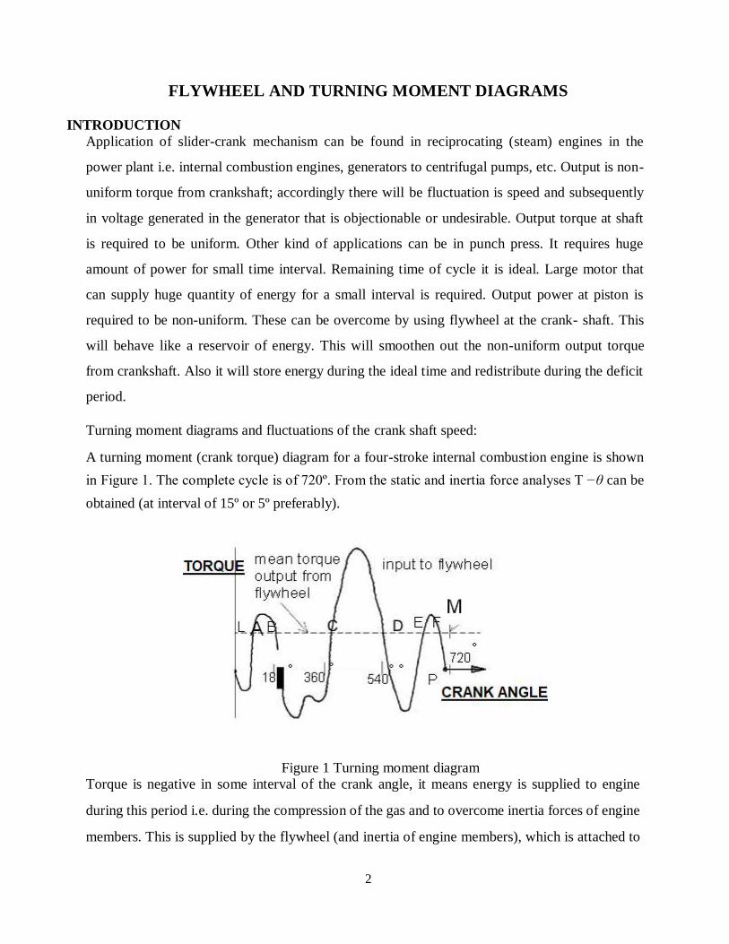
A turning moment (crank torque) diagram for a four-stroke internal combustion engine is shown
in Figure 1. The complete cycle is of 720º. From the static and inertia force analyses T −θ can be
obtained (at interval of 15º or 5º preferably).
Figure 1 Turning moment diagram
Torque is negative in some interval of the crank angle, it means energy is supplied to engine
during this period i.e. during the compression of the gas and to overcome inertia forces of engine
members. This is supplied by the flywheel (and inertia of engine members), which is attached to
3
TL
the crankshaft. When flywheel is attached to the crankshaft. LM in diagram shown is the mean
torque line. It is defined as
N
∑ i T = i=1 (1) m N
If, Tm = 0 then no net energy in the system, Tm ⟩0 then there is an excess of the net energy in the system
and Tm ⟨0 then there is a deficit of the net energy in the system. Area OLMP = net (energy) area of
turning moment diagram = Tm (4π ) . During interval AB, CD and EF , the crank torque is more
than the mean torque means hence excess of energy is supplied to crank i.e. it will accelerate (ω
↑) . During other interval i.e LA, BC, DE and FM, the crank torque T is less than the mean torque
Tm i.e. there is deficit in energy i.e. crank will decelerate (ω ↓) .
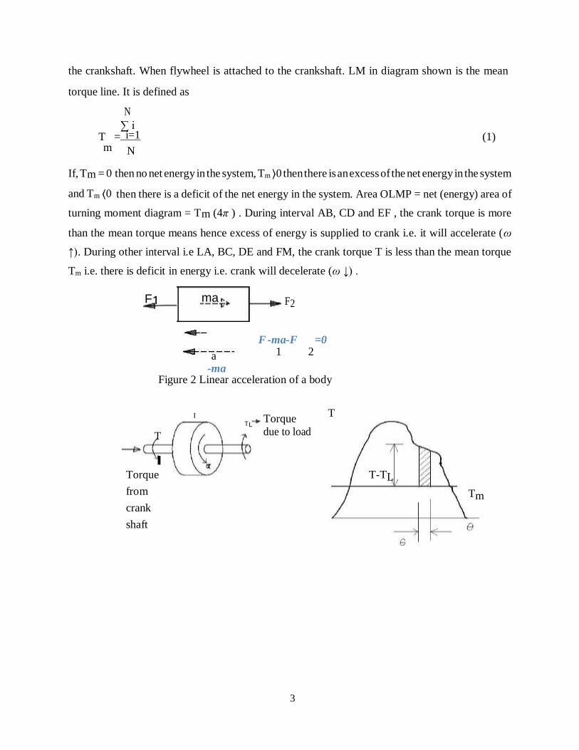
F2
F -ma-F =0
a 1 2
-ma Figure 2 Linear acceleration of a body
I Torque T
T due to load
Torque
from
crank
shaft
T-TL
Tm
F1 ma
4
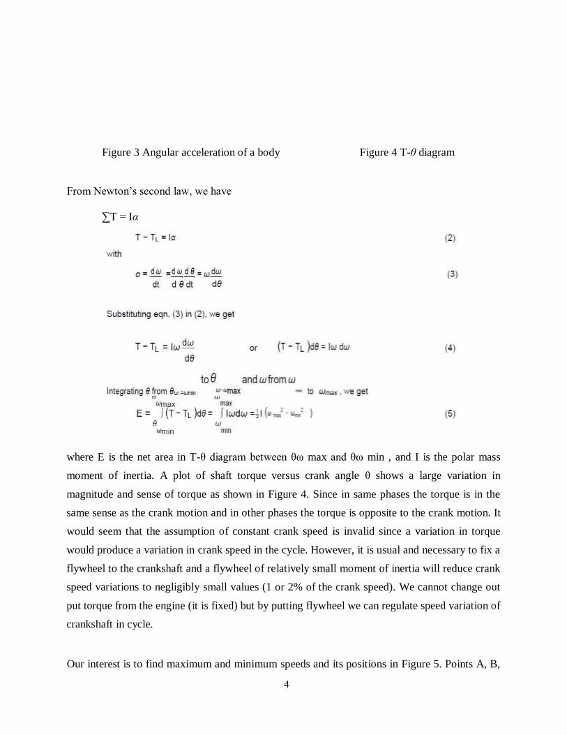
Figure 3 Angular acceleration of a body Figure 4 T-θ diagram
From Newton’s second law, we have
∑T = Iα
where E is the net area in T-θ diagram between θω max and θω min , and I is the polar mass
moment of inertia. A plot of shaft torque versus crank angle θ shows a large variation in
magnitude and sense of torque as shown in Figure 4. Since in same phases the torque is in the
same sense as the crank motion and in other phases the torque is opposite to the crank motion. It
would seem that the assumption of constant crank speed is invalid since a variation in torque
would produce a variation in crank speed in the cycle. However, it is usual and necessary to fix a
flywheel to the crankshaft and a flywheel of relatively small moment of inertia will reduce crank
speed variations to negligibly small values (1 or 2% of the crank speed). We cannot change out
put torque from the engine (it is fixed) but by putting flywheel we can regulate speed variation of
crankshaft in cycle.
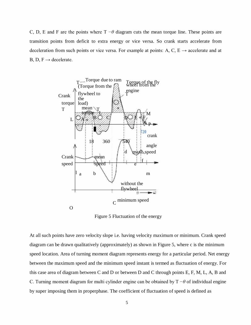
Our interest is to find maximum and minimum speeds and its positions in Figure 5. Points A, B,
5
L
C, D, E and F are the points where T −θ diagram cuts the mean torque line. These points are
transition points from deficit to extra energy or vice versa. So crank starts accelerate from
deceleration from such points or vice versa. For example at points: A, C, E → accelerate and at
B, D, F → decelerate.
T Torque due to ram
Torque of the fly
(Torque from the wheel from the
Crank flywheel to the
engine T
torque load)
T mean T + torque L M
L A + B C D E + F
- -
-
18 360 540
-
720
P
crank
Crank mean
angle
d maxi. speed
speed speed e f
l a b m
without the flywheel
C minimum speed
O
Figure 5 Fluctuation of the energy
At all such points have zero velocity slope i.e. having velocity maximum or minimum. Crank speed
diagram can be drawn qualitatively (approximately) as shown in Figure 5, where c is the minimum
speed location. Area of turning moment diagram represents energy for a particular period. Net energy
between the maximum speed and the minimum speed instant is termed as fluctuation of energy. For
this case area of diagram between C and D or between D and C through points E, F, M, L, A, B and
C. Turning moment diagram for multi cylinder engine can be obtained by T −θ of individual engine
by super imposing them in properphase. The coefficient of fluctuation of speed is defined as
6
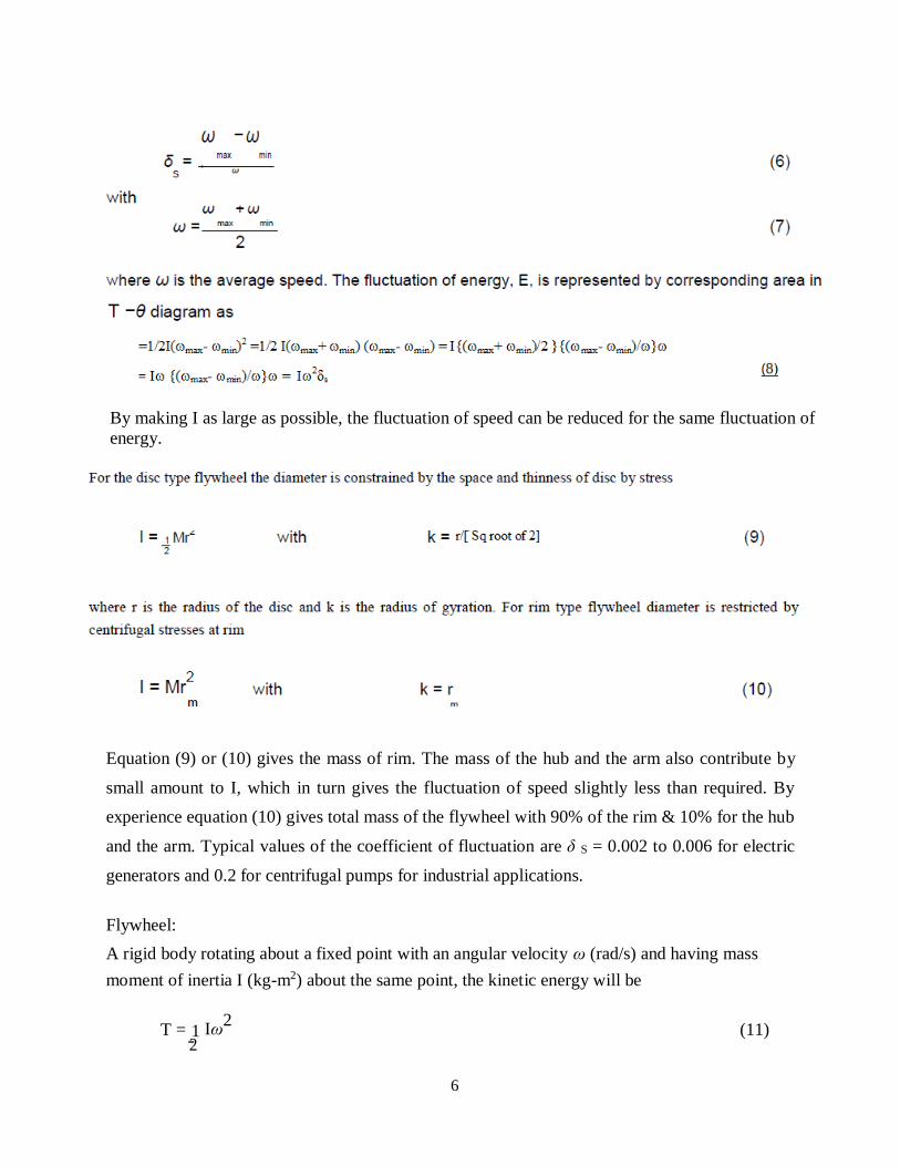
By making I as large as possible, the fluctuation of speed can be reduced for the same fluctuation of
energy.
Equation (9) or (10) gives the mass of rim. The mass of the hub and the arm also contribute by
small amount to I, which in turn gives the fluctuation of speed slightly less than required. By
experience equation (10) gives total mass of the flywheel with 90% of the rim & 10% for the hub
and the arm. Typical values of the coefficient of fluctuation are δ S = 0.002 to 0.006 for electric
generators and 0.2 for centrifugal pumps for industrial applications.
Flywheel:
A rigid body rotating about a fixed point with an angular velocity ω (rad/s) and having mass
moment of inertia I (kg-m2) about the same point, the kinetic energy will be
T = 1 Iω2
(11) 2
7
max min
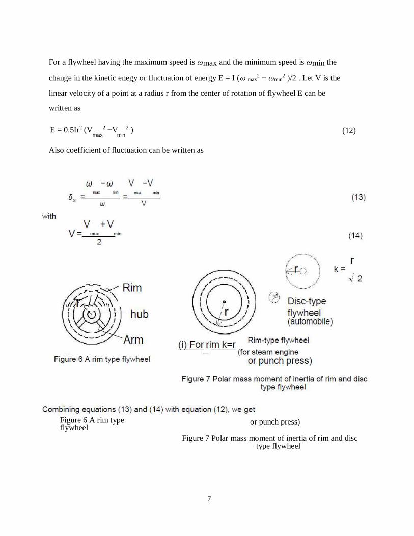
For a flywheel having the maximum speed is ωmax and the minimum speed is ωmin the
change in the kinetic enegy or fluctuation of energy E = I (ω max2 − ωmin
2 )/2 . Let V is the
linear velocity of a point at a radius r from the center of rotation of flywheel E can be
written as
E = 0.5Ir2 (V 2 −V 2 ) (12)
Also coefficient of fluctuation can be written as
Figure 6 A rim type flywheel
or punch press)
Figure 7 Polar mass moment of inertia of rim and disc type flywheel
8
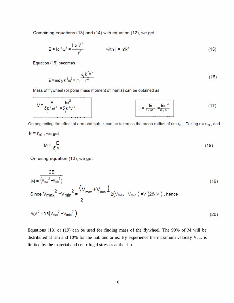
Equations (18) or (19) can be used for finding mass of the flywheel. The 90% of M will be
distributed at rim and 10% for the hub and arms. By experience the maximum velocity Vmax is
limited by the material and centrifugal stresses at the rim.
9
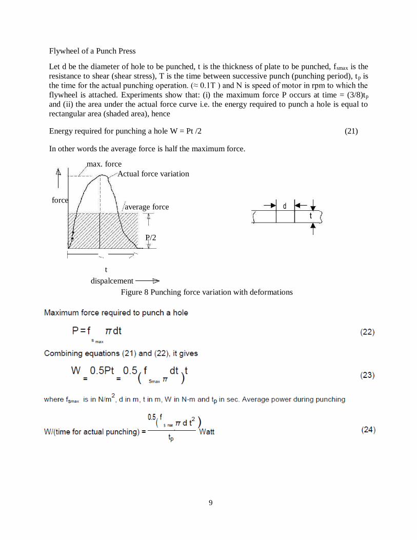
Flywheel of a Punch Press
Let d be the diameter of hole to be punched, t is the thickness of plate to be punched, fsmax is the
resistance to shear (shear stress), T is the time between successive punch (punching period), tp is
the time for the actual punching operation. (≈ 0.1T ) and N is speed of motor in rpm to which the
flywheel is attached. Experiments show that: (i) the maximum force P occurs at time = (3/8)tp
and (ii) the area under the actual force curve i.e. the energy required to punch a hole is equal to
rectangular area (shaded area), hence
Energy required for punching a hole W = Pt /2 (21)
In other words the average force is half the maximum force.
max. force
Actual force variation
force
average force
P/2
t
dispalcement
Figure 8 Punching force variation with deformations
10
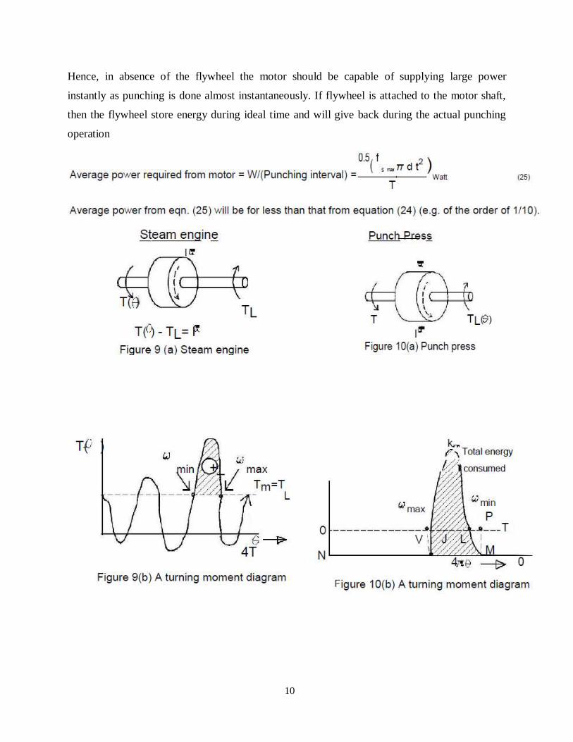
Hence, in absence of the flywheel the motor should be capable of supplying large power
instantly as punching is done almost instantaneously. If flywheel is attached to the motor shaft,
then the flywheel store energy during ideal time and will give back during the actual punching
operation
11
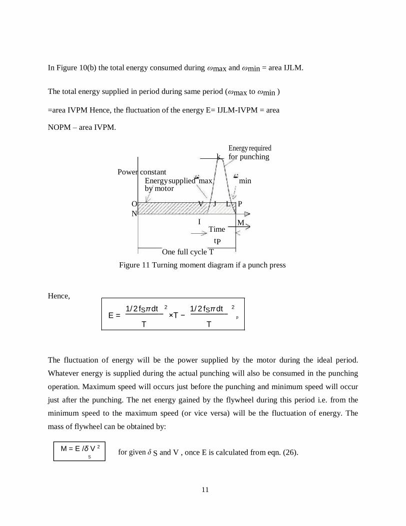
In Figure 10(b) the total energy consumed during ωmax and ωmin = area IJLM.
The total energy supplied in period during same period (ωmax to ωmin )
=area IVPM Hence, the fluctuation of the energy E= IJLM-IVPM = area
NOPM – area IVPM.
Energy required k for punching
Power constant Energy supplied max min by motor
O V J L P
N I M
Time
tP
One full cycle T
Figure 11 Turning moment diagram if a punch press
Hence,
The fluctuation of energy will be the power supplied by the motor during the ideal period.
Whatever energy is supplied during the actual punching will also be consumed in the punching
operation. Maximum speed will occurs just before the punching and minimum speed will occur
just after the punching. The net energy gained by the flywheel during this period i.e. from the
minimum speed to the maximum speed (or vice versa) will be the fluctuation of energy. The
mass of flywheel can be obtained by:
for given δ S and V , once E is calculated from eqn. (26).
E = 1/ 2 fSπ dt
2
×T − 1/ 2 fSπ dt
2
M = E /δ V 2 S
12
max min
4 6
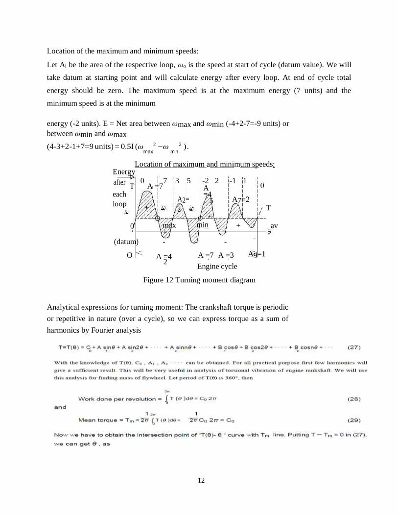
Location of the maximum and minimum speeds:
Let Ai be the area of the respective loop, ωo is the speed at start of cycle (datum value). We will
take datum at starting point and will calculate energy after every loop. At end of cycle total
energy should be zero. The maximum speed is at the maximum energy (7 units) and the
minimum speed is at the minimum
energy (-2 units). E = Net area between ωmax and ωmin (-4+2-7=-9 units) or
between ωmin and ωmax
(4-3+2-1+7=9 units) = 0.5I (ω 2 − ω 2 ) .
Location of maximum and minimum speeds: Energy
after T
0 A =7
7 3 5 -2 2 -1 1 0
each
loop +
A2=
2
A =4
5
+
A7=2 T
0 max +
min + av
(datum) - - - -
O A =4 A =7 A =3 A9=1 2
Engine cycle
Figure 12 Turning moment diagram
Analytical expressions for turning moment: The crankshaft torque is periodic
or repetitive in nature (over a cycle), so we can express torque as a sum of
harmonics by Fourier analysis
1
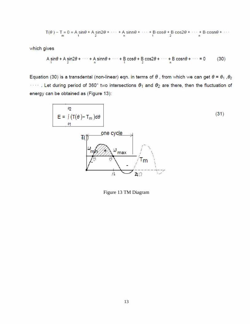
13
Figure 13 TM Diagram
14
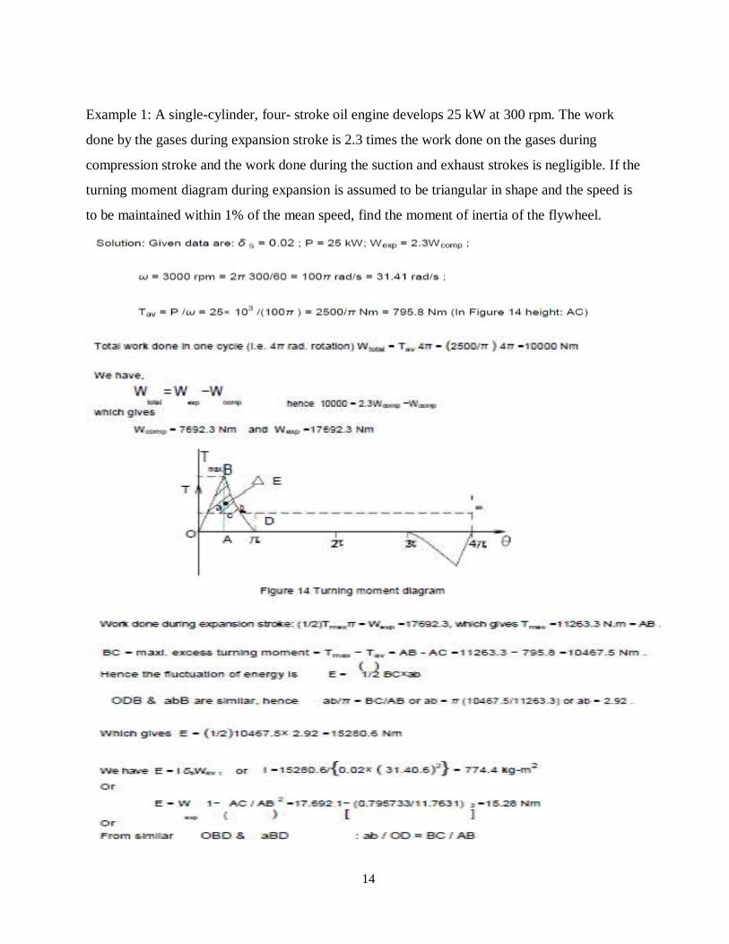
Example 1: A single-cylinder, four- stroke oil engine develops 25 kW at 300 rpm. The work
done by the gases during expansion stroke is 2.3 times the work done on the gases during
compression stroke and the work done during the suction and exhaust strokes is negligible. If the
turning moment diagram during expansion is assumed to be triangular in shape and the speed is
to be maintained within 1% of the mean speed, find the moment of inertia of the flywheel.
15
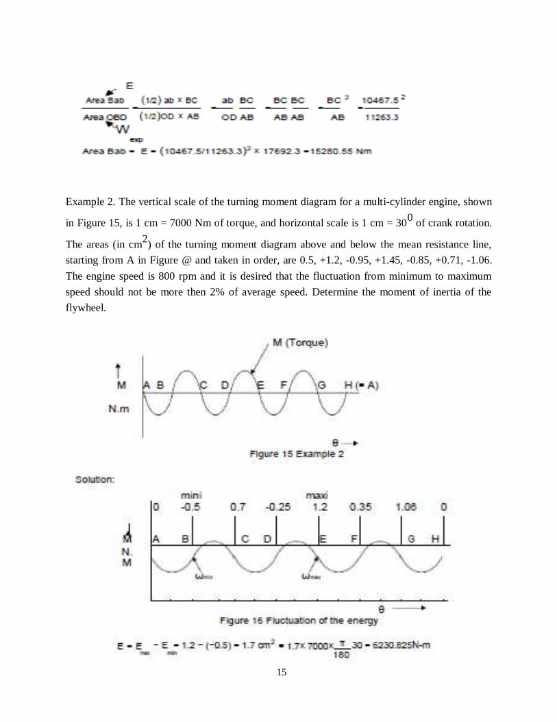
Example 2. The vertical scale of the turning moment diagram for a multi-cylinder engine, shown
in Figure 15, is 1 cm = 7000 Nm of torque, and horizontal scale is 1 cm = 300
of crank rotation.
The areas (in cm2) of the turning moment diagram above and below the mean resistance line,
starting from A in Figure @ and taken in order, are 0.5, +1.2, -0.95, +1.45, -0.85, +0.71, -1.06.
The engine speed is 800 rpm and it is desired that the fluctuation from minimum to maximum
speed should not be more then 2% of average speed. Determine the moment of inertia of the
flywheel.
16
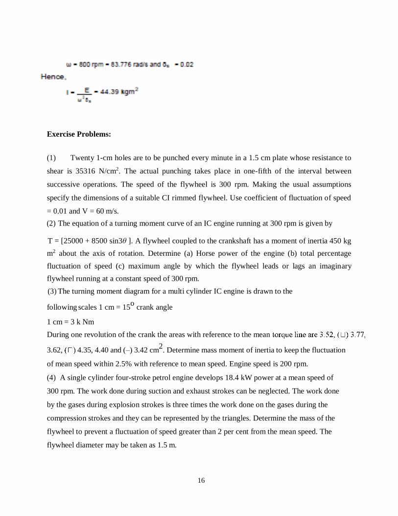
Exercise Problems:
(1) Twenty 1-cm holes are to be punched every minute in a 1.5 cm plate whose resistance to
shear is 35316 N/cm2. The actual punching takes place in one-fifth of the interval between
successive operations. The speed of the flywheel is 300 rpm. Making the usual assumptions
specify the dimensions of a suitable CI rimmed flywheel. Use coefficient of fluctuation of speed
= 0.01 and V = 60 m/s.
(2) The equation of a turning moment curve of an IC engine running at 300 rpm is given by
T = [25000 + 8500 sin3θ ]. A flywheel coupled to the crankshaft has a moment of inertia 450 kg
m2 about the axis of rotation. Determine (a) Horse power of the engine (b) total percentage
fluctuation of speed (c) maximum angle by which the flywheel leads or lags an imaginary
flywheel running at a constant speed of 300 rpm.
(3) The turning moment diagram for a multi cylinder IC engine is drawn to the
following scales 1 cm = 15o
crank angle
1 cm = 3 k Nm
During one revolution of the crank the areas with reference to the mean
3.62, 4.35, 4.40 and (–) 3.42 cm2. Determine mass moment of inertia to keep the fluctuation
of mean speed within 2.5% with reference to mean speed. Engine speed is 200 rpm.
(4) A single cylinder four-stroke petrol engine develops 18.4 kW power at a mean speed of
300 rpm. The work done during suction and exhaust strokes can be neglected. The work done
by the gases during explosion strokes is three times the work done on the gases during the
compression strokes and they can be represented by the triangles. Determine the mass of the
flywheel to prevent a fluctuation of speed greater than 2 per cent from the mean speed. The
flywheel diameter may be taken as 1.5 m.
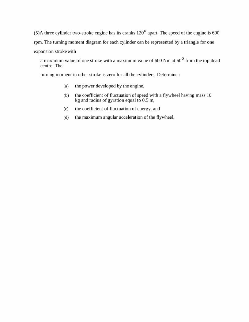
(5)A three cylinder two-stroke engine has its cranks 120o
apart. The speed of the engine is 600
rpm. The turning moment diagram for each cylinder can be represented by a triangle for one
expansion stroke with
a maximum value of one stroke with a maximum value of 600 Nm at 60o
from the top dead centre. The
turning moment in other stroke is zero for all the cylinders. Determine :
(a) the power developed by the engine,
(b) the coefficient of fluctuation of speed with a flywheel having mass 10 kg and radius of gyration equal to 0.5 m,
(c) the coefficient of fluctuation of energy, and
(d) the maximum angular acceleration of the flywheel.
BALANCING
Balancing is the process of eliminating or at least reducing the ground forces and
moments. It is achieved by changing the location of the mass centers of links.
Balancing of rotating parts is a well known problem. A rotating body with fixed
rotation axis can be fully balanced i.e. all the inertia forces and moments. For
mechanism containing links rotating about axis which are not fixed, force balancing is
possible, moment balancing by itself may be possible, but both not possible. We
generally try to do force balancing. A fully force balance is possible, but any action in
force balancing severe the moment balancing.
Balancing of rotating masses:
The process of providing the second mass in order to counteract the effect of the
centrifugal force of the first mass is called balancing of rotating masses.
Static balancing:
The net dynamic force acting on the shaft is equal to zero. This requires that the line of
action of three centrifugal forces must be the same. In other words, the centre of the
masses of the system must lie on the axis of the rotation. This is the condition for static
balancing.
Dynamic balancing: The net couple due to dynamic forces acting on the shaft is equal to zero. The algebraic
sum of the moments about any point in the plane must be zero.
Various cases of balancing of rotating masses:
Balancing of a single rotating mass by single mass rotating in the same plane.
Balancing of a single rotating mass by two masses rotating in the different plane.
Balancing of a several masses rotating in single plane.
Balancing of a several masses rotating in different planes.
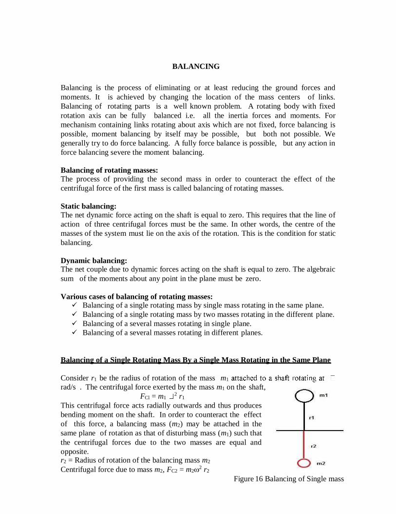
Balancing of a Single Rotating Mass By a Single Mass Rotating in the Same Plane
Consider r1 be the radius of rotation of the mass m1
rad/s . The centrifugal force exerted by the mass m1 on the shaft,
FCl = m1 2 r1
This centrifugal force acts radially outwards and thus produces
bending moment on the shaft. In order to counteract the effect
of this force, a balancing mass (m2) may be attached in the
same plane of rotation as that of disturbing mass (m1) such that
the centrifugal forces due to the two masses are equal and
opposite. r2 = Radius of rotation of the balancing mass m2
Centrifugal force due to mass m2, FC2 = m22 r2
Figure 16 Balancing of Single mass
m1 2 r1 =
m22r2
m1 r1 = m2r2
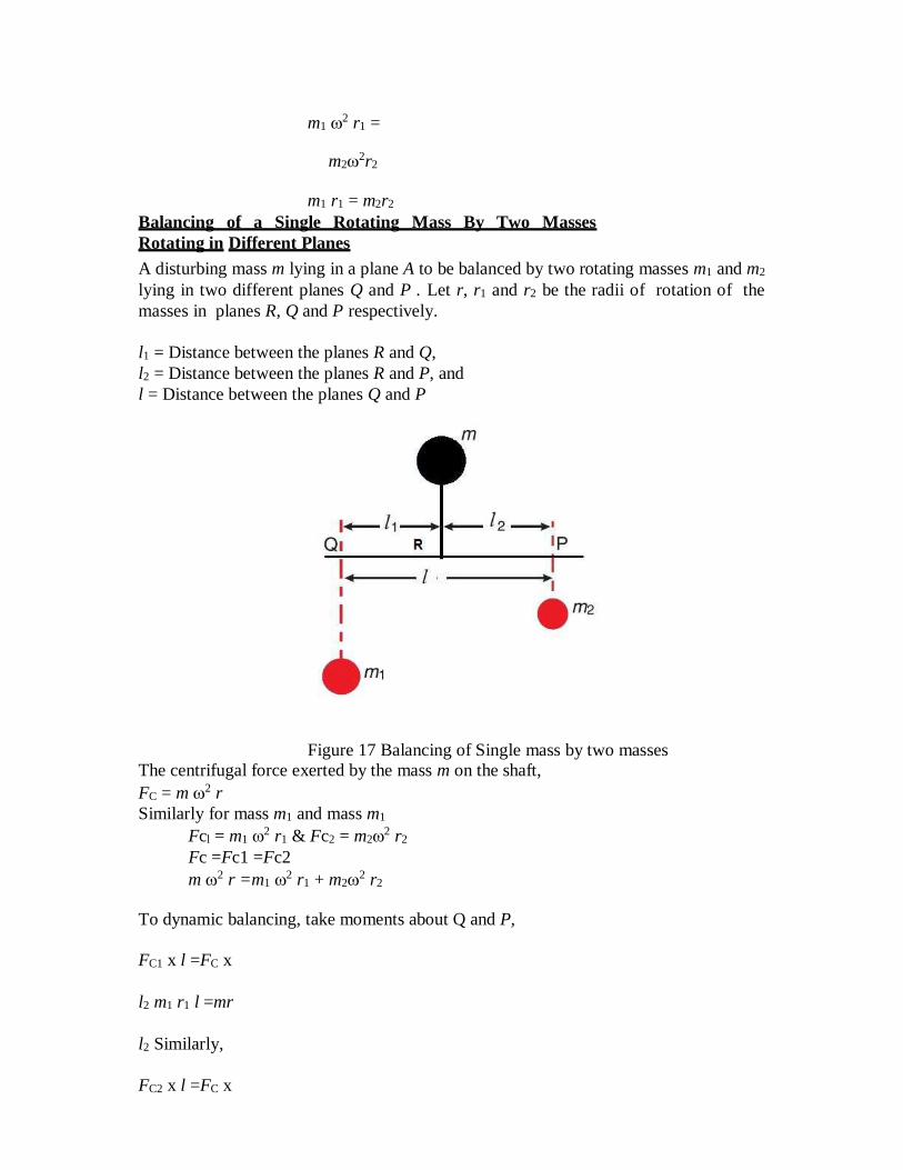
Balancing of a Single Rotating Mass By Two Masses
Rotating in Different Planes
A disturbing mass m lying in a plane A to be balanced by two rotating masses m1 and m2
lying in two different planes Q and P . Let r, r1 and r2 be the radii of rotation of the
masses in planes R, Q and P respectively.
l1 = Distance between the planes R and Q,
l2 = Distance between the planes R and P, and
l = Distance between the planes Q and P
Figure 17 Balancing of Single mass by two masses
The centrifugal force exerted by the mass m on the shaft,
FC = m 2 r
Similarly for mass m1 and mass m1
Fcl = m1 2 r1 & Fc2 = m22 r2
Fc =Fc1 =Fc2
m 2 r =m1 2 r1 + m22 r2
To dynamic balancing, take moments about Q and P,
FC1 x l =FC x
l2 m1 r1 l =mr
l2 Similarly,
FC2 x l =FC x
l1 m2 r2 l
=mrl1
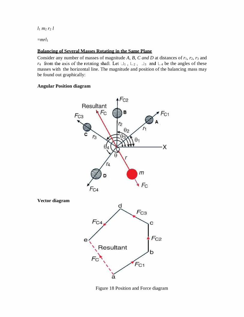
Balancing of Several Masses Rotating in the Same Plane
Consider any number of masses of magnitude A, B, C and D at distances of r1, r2, r3 and
r4 1 2 3 4 be the angles of these
masses with the horizontal line. The magnitude and position of the balancing mass may
be found out graphically:
Angular Position diagram
Vector diagram
Figure 18 Position and Force diagram
1mm = 1kg-m
Force Polygon
Problem 1:
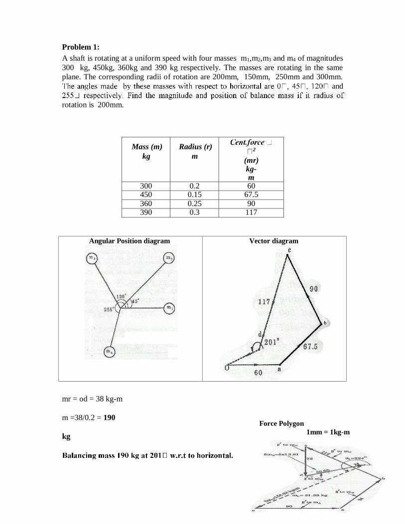
A shaft is rotating at a uniform speed with four masses m1,m2,m3 and m4 of magnitudes
300 kg, 450kg, 360kg and 390 kg respectively. The masses are rotating in the same
plane. The corresponding radii of rotation are 200mm, 150mm, 250mm and 300mm.
and
rotation is 200mm.
Mass (m)
kg
Radius (r)
m 2
(mr) kg-m
300 0.2 60 450 0.15 67.5
360 0.25 90 390 0.3 117
mr = od = 38 kg-m
m =38/0.2 = 190
kg
Vector diagram Angular Position diagram
Problem 2: Four masses m1, m2, m3 and m4 are 200 kg, 300 kg, 240 kg and 260 kg respectively.
The corresponding radii of rotation are 0.2 m, 0.15 m, 0.25 m and 0.3 m respectively
and the angles between successive masses are 45°, 75° and 135°. Find the position and
magnitude of the balance mass required, if its radius of rotation is 0.2 m.
Analytical method
Resolving m1.r1, m2.r2, m3.r3 and m4.r4 horizontally,
H = m1.r1 cosϴ1 + m2.r2 cosϴ2 + m3.r3 cosϴ3 + m4.r4 cosϴ4
= 40 cos0° + 45cos45° + 60 cos120° + 78cos255°
= 40 + 31.8 - 30 -20.2 = 21.6 kg-m
Resolving vertically,
V = m1.r1 sin ϴ1 + m2.r2 sin ϴ2 + m3.r3 sin ϴ3+ m4.r4 sin ϴ4
= 40 sin0° + 45sin45° + 60 sin120° + 78sin255°
= 0 + 31.8+ 52 - 75.3 = 8.5 kg-m
Resultant, R =√ + = √21.6 + 8.5 = 23.2 kg-m
mr = R = 23.2 or m = 23.2 / r = 23.2 / 0.2 = 116 kg
tanϴ = = .
.
ϴ = 21.50
= 0.3985
Angle of the balancing mass from the horizontal mass is ϴ = 1800 + 21.50 = 201.50
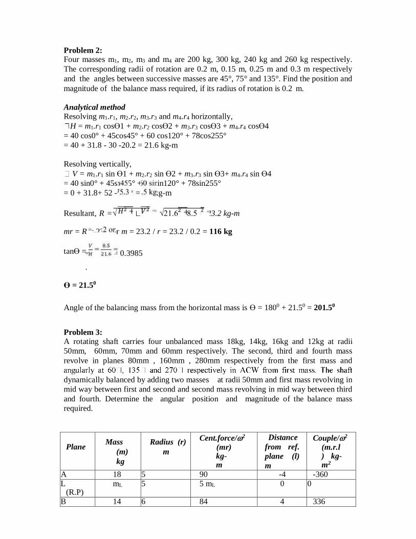
Problem 3:
A rotating shaft carries four unbalanced mass 18kg, 14kg, 16kg and 12kg at radii
50mm, 60mm, 70mm and 60mm respectively. The second, third and fourth mass
revolve in planes 80mm , 160mm , 280mm respectively from the first mass and
dynamically balanced by adding two masses at radii 50mm and first mass revolving in
mid way between first and second and second mass revolving in mid way between third
and fourth. Determine the angular position and magnitude of the balance mass
required.
Plane Mass
(m)
kg
Radius (r)
m
Cent.force/2
(mr) kg-m
Distance
from ref.
plane (l)
m
Couple/2
(m.r.l) kg-m2
A 18 5 90 -4 -360
L (R.P)
mL 5 5 mL 0 0
B 14 6 84 4 336
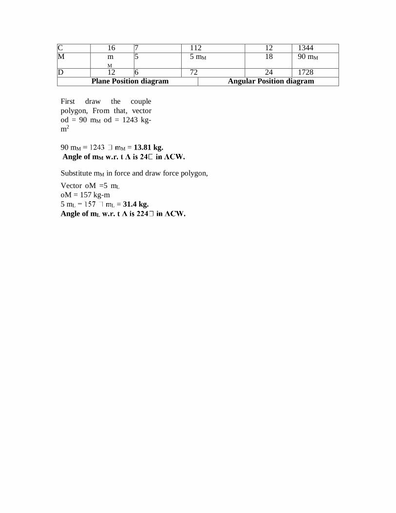
C 16 7 112 12 1344 M m
M 5 5 mM 18 90 mM
D 12 6 72 24 1728
Plane Position diagram Angular Position diagram
First draw the couple
polygon, From that, vector
od = 90 mM od = 1243 kg-
m2
90 mM M = 13.81 kg.
Angle of mM
Substitute mM in force and draw force polygon,
Vector oM =5 mL
oM = 157 kg-m
5 mL L = 31.4 kg.
Angle of mL
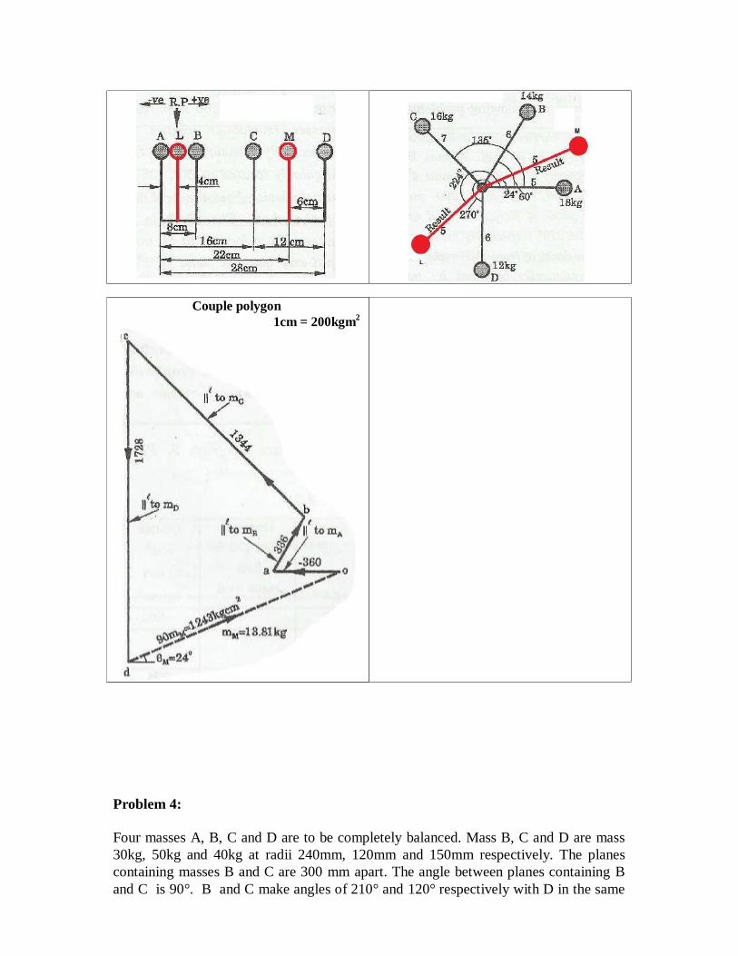
Problem 4:
Four masses A, B, C and D are to be completely balanced. Mass B, C and D are mass
30kg, 50kg and 40kg at radii 240mm, 120mm and 150mm respectively. The planes
containing masses B and C are 300 mm apart. The angle between planes containing B
and C is 90°. B and C make angles of 210° and 120° respectively with D in the same
Couple polygon
1cm = 200kgm2
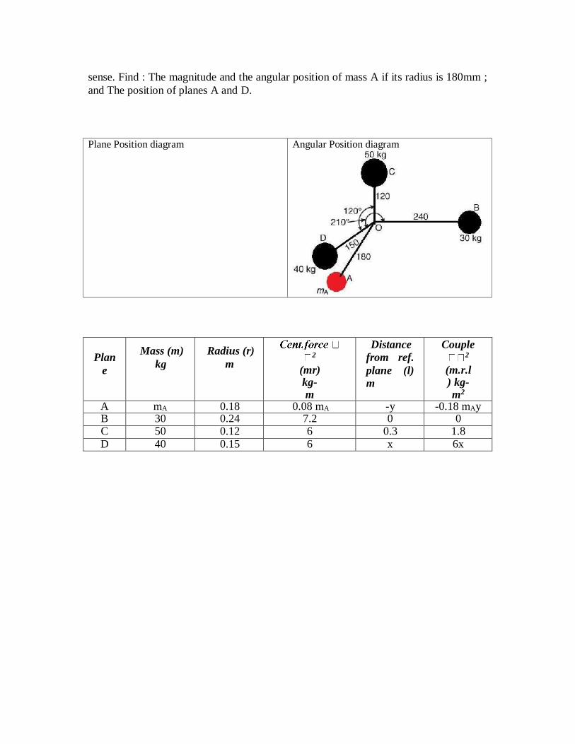
sense. Find : The magnitude and the angular position of mass A if its radius is 180mm ;
and The position of planes A and D.
Plan
e
Mass (m)
kg
Radius (r)
m 2
(mr) kg-m
Distance
from ref.
plane (l)
m
Couple 2
(m.r.l) kg-m2
A mA 0.18 0.08 mA -y -0.18 mAy B 30 0.24 7.2 0 0 C 50 0.12 6 0.3 1.8
D 40 0.15 6 x 6x
Angular Position diagram Plane Position diagram
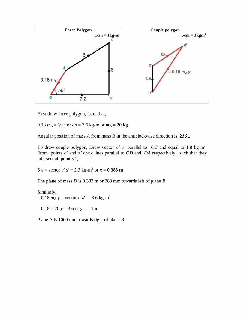
First draw force polygon, from that,
0.18 mA = Vector do = 3.6 kg-m or mA = 20 kg
Angular position of mass A from mass B in the anticlockwise direction is
To draw couple polygon, Draw vector o’ c’ parallel to OC and equal to 1.8 kg-m2.
From points c’ and o’ draw lines parallel to OD and OA respectively, such that they
intersect at point d’ ,
6 x = vector c′ d′ = 2.3 kg-m2 or x = 0.383 m
The plane of mass D is 0.383 m or 383 mm towards left of plane B.
Similarly,
– 0.18 mA.y = vector o’d’ = 3.6 kg-m2
– 0.18 × 20 y = 3.6 or y = – 1 m
Plane A is 1000 mm towards right of plane B.
5cm = 1kgm2
Couple polygon
1cm = 1kg-m
Force Polygon
1mm = 0.01kg-m
Force Polygon
1mm = 0.001kgm2
Couple polygon
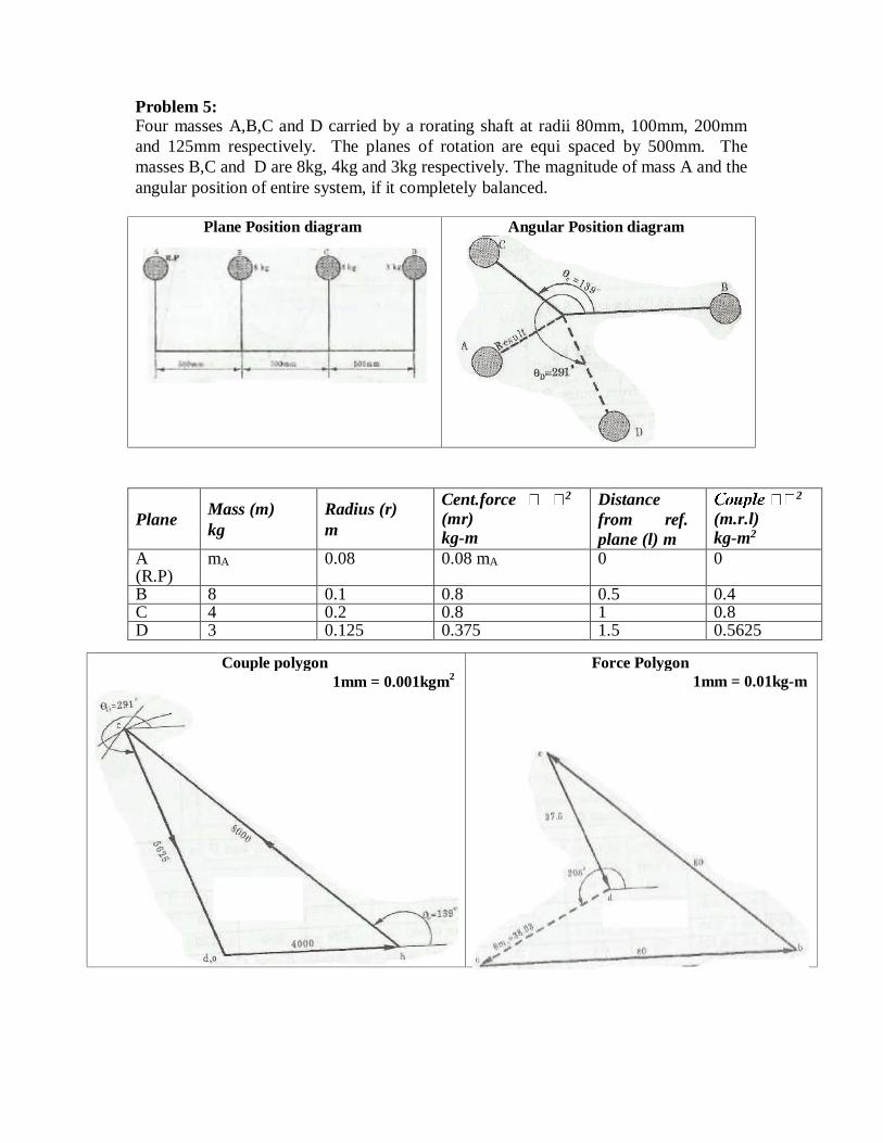
Problem 5: Four masses A,B,C and D carried by a rorating shaft at radii 80mm, 100mm, 200mm
and 125mm respectively. The planes of rotation are equi spaced by 500mm. The
masses B,C and D are 8kg, 4kg and 3kg respectively. The magnitude of mass A and the
angular position of entire system, if it completely balanced.
Plane Mass (m)
kg
Radius (r)
m
Cent.force 2
(mr) kg-m
Distance
from ref.
plane (l) m
2
(m.r.l) kg-m2
A (R.P)
mA 0.08 0.08 mA 0 0
B 8 0.1 0.8 0.5 0.4 C 4 0.2 0.8 1 0.8 D 3 0.125 0.375 1.5 0.5625
Angular Position diagram Plane Position diagram
First draw the couple polygon with the mrl values. Assuming angle of mass B as
horizontal, form a triangle to find the angular position for C and D.
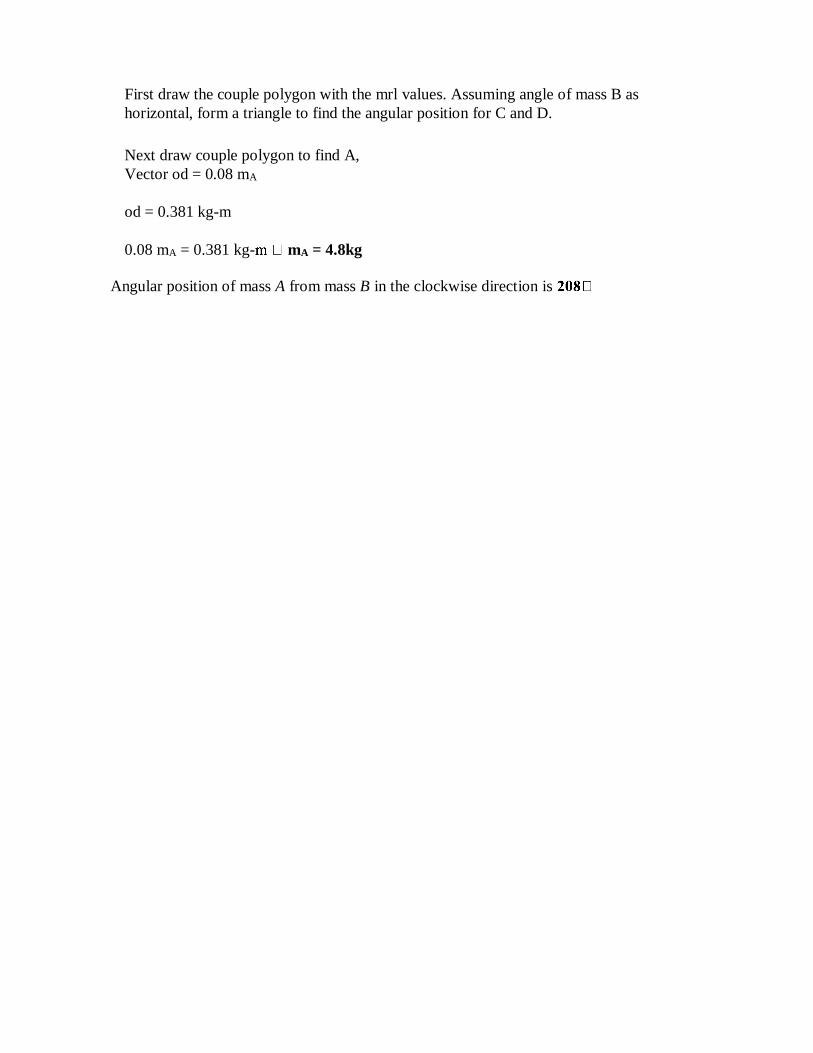
Next draw couple polygon to find A,
Vector od = 0.08 mA
od = 0.381 kg-m
0.08 mA = 0.381 kg- mA = 4.8kg
Angular position of mass A from mass B in the clockwise direction is
Page 10 of 25
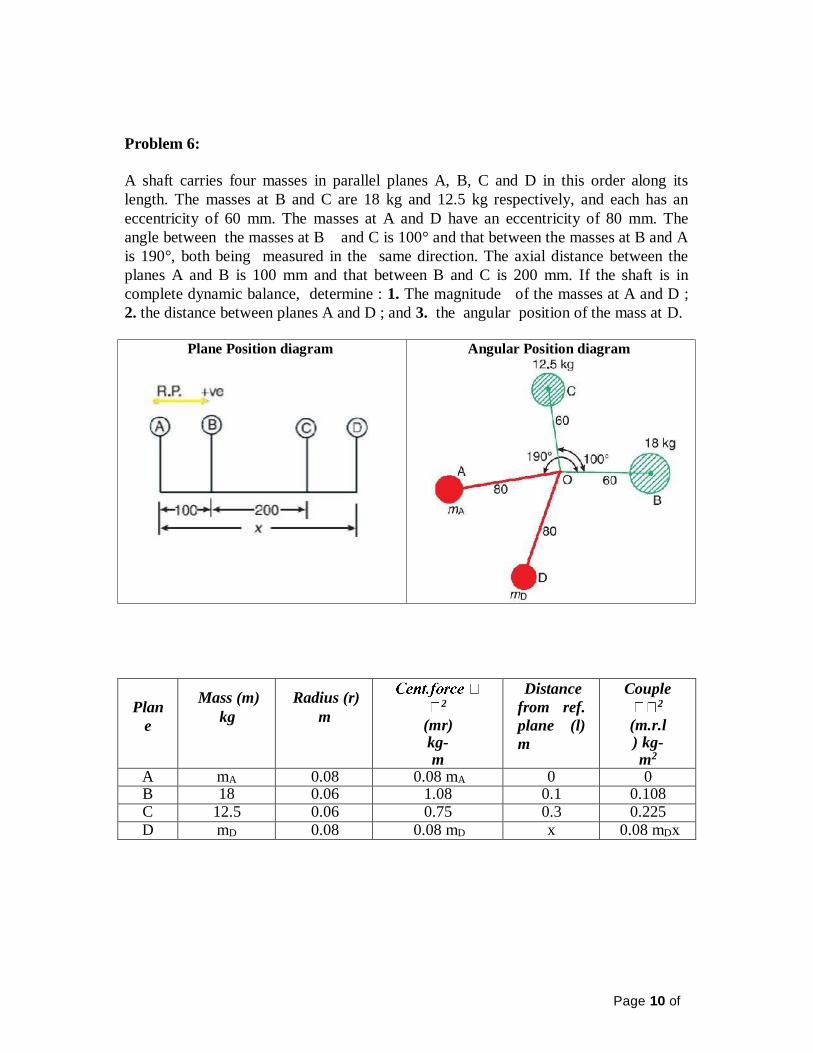
Problem 6:
A shaft carries four masses in parallel planes A, B, C and D in this order along its
length. The masses at B and C are 18 kg and 12.5 kg respectively, and each has an
eccentricity of 60 mm. The masses at A and D have an eccentricity of 80 mm. The
angle between the masses at B and C is 100° and that between the masses at B and A
is 190°, both being measured in the same direction. The axial distance between the
planes A and B is 100 mm and that between B and C is 200 mm. If the shaft is in
complete dynamic balance, determine : 1. The magnitude of the masses at A and D ;
2. the distance between planes A and D ; and 3. the angular position of the mass at D.
Plan
e
Mass (m)
kg
Radius (r)
m 2
(mr) kg-m
Distance
from ref.
plane (l)
m
Couple 2
(m.r.l) kg-m2
A mA 0.08 0.08 mA 0 0 B 18 0.06 1.08 0.1 0.108 C 12.5 0.06 0.75 0.3 0.225
D mD 0.08 0.08 mD x 0.08 mDx
Angular Position diagram Plane Position diagram
Page 11 of 25
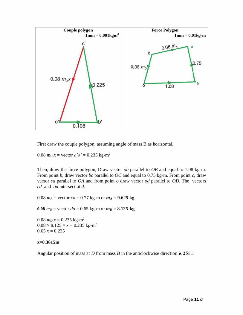
First draw the couple polygon, assuming angle of mass B as horizontal.
0.08 mD.x = vector c’o’ = 0.235 kg-m2
Then, draw the force polygon, Draw vector ob parallel to OB and equal to 1.08 kg-m.
From point b, draw vector bc parallel to OC and equal to 0.75 kg-m. From point c, draw
vector cd parallel to OA and from point o draw vector od parallel to OD. The vectors
cd and od intersect at d.
0.08 mA = vector cd = 0.77 kg-m or mA = 9.625 kg
0.08 mD = vector do = 0.65 kg-m or mD = 8.125 kg
0.08 mD.x = 0.235 kg-m2
0.08 × 8.125 × x = 0.235 kg-m2
0.65 x = 0.235
x=0.3615m
Angular position of mass at D from mass B in the anticlockwise direction
Force Polygon
1mm = 0.01kg-m
Couple polygon
1mm = 0.001kgm2
Page 12 of 25
Exercises Problems: 1. Four masses A, B, C and D are attached to a shaft and revolve in the same plane.
The masses are 12 kg, 10 kg, 18 kg and 15 kg respectively and their radii of
rotations are 40 mm, 50 mm, 60 mm and 30 mm. The angular position of the
masses B, C and D are 60°, 135° and 270° from the mass A. Find the
magnitude and position of the balancing mass at a radius of 100 mm. [Ans. 7.56 kg ; 87° clockwise from A]
2. A shaft carries five masses A, B, C, D and E which revolve at the same radius in
planes which are equidistant from one another. The magnitude of the masses in
planes A, C and D are 50 kg, 40 kg and 80 kg respectively. The angle between A
and C is 90° and that between C and D is 135°. Determine the magnitude of the
masses in planes B and E and their positions to put the shaft in complete rotating
balance. [Ans. 12 kg, 15 kg ; 130° and 24° from mass A in anticlockwise direction]
3. A, B, C and D are four masses carried by a rotating shaft at radii 100 mm, 150
mm, 150 mm and 200 mm respectively. The planes in which the masses rotate
are spaced at 500 mm apart and the magnitude of the masses B, C and D are 9
kg, 5 kg and 4 kg respectively. Find the required mass A and the relative angular
settings of the four masses so that the shaft shall be in complete balance. [Ans. 10 kg ; Between B and A 165°, Between B and C 295°, Between B and D 145°]
4. Four masses A, B, C and D revolve at equal radii and are equally spaced along a
shaft. The mass B is 7 kg and the radii of C and D make angles of 90° and 240°
respectively with the radius of B. Find the magnitude of the masses A, C and D
and the angular position of A so that the system may be completely balanced. [Ans. 5 kg ; 6 kg ; 4.67 kg ; 205° from mass B in anticlockwise direction]
5. A rotating shaft carries four masses A, B, C and D which are radially attached to
it. The mass centres are 30 mm, 38 mm, 40 mm and 35 mm respectively from
the axis of rotation. The masses A, C and D are 7.5 kg, 5 kg and 4 kg
respectively. The axial distances between the planes of rotation of A and B is
400 mm and between B and C is 500 mm. The masses A and C are at right
angles to each other. Find for a complete balance, 1. the angles between the masses B and D from mass A,
2. the axial distance between the planes of rotation of C and D,
3. the magnitude of mass B. [Ans. 162.5°, 47.5° ; 511 mm : 9.24 kg]
Unit II
Balancing
The Partial Balance of Two-cylinder Locomotives
It is normal for the cranks to be at right angles and as a result the secondary forces are
small and in opposite directions. As a result they are usually neglected and only the
primary forces and couples are considered.
It is usual to balance about two-thirds of the reciprocating parts with masses fixed to
the wheels.The unbalanced vertical components of the reciprocating masses give rise
to a variation of rail pressure known as Hammer Blow and a Rocking Couple about a
fore and aft horizontal axis.The unbalanced reciprocating masses cause a variation
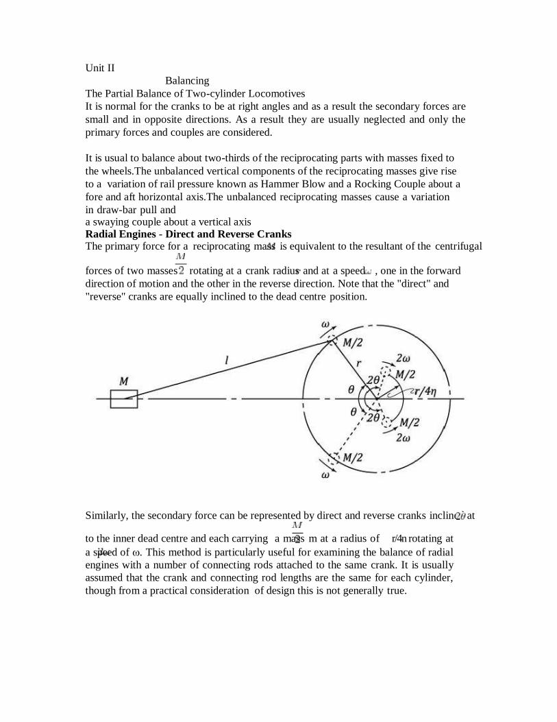
in draw-bar pull and a swaying couple about a vertical axis Radial Engines - Direct and Reverse Cranks The primary force for a reciprocating mass is equivalent to the resultant of the centrifugal
forces of two masses rotating at a crank radius and at a speed , one in the forward
direction of motion and the other in the reverse direction. Note that the "direct" and
"reverse" cranks are equally inclined to the dead centre position.
Similarly, the secondary force can be represented by direct and reverse cranks inclined at
to the inner dead centre and each carrying a mass m at a radius of r/4n rotating at
a speed of . This method is particularly useful for examining the balance of radial
engines with a number of connecting rods attached to the same crank. It is usually
assumed that the crank and connecting rod lengths are the same for each cylinder,
though from a practical consideration of design this is not generally true.

Example 1
A motor armature is in running balance when weights of 0.130 oz. and 0.075 oz. (There are
16 oz. in 1 lb.) are added temporarily in the positions shown in the planes
and
diagram.n the
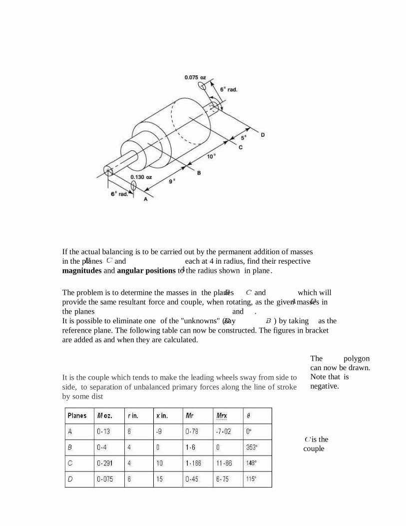
If the actual balancing is to be carried out by the permanent addition of masses
in the planes and each at 4 in radius, find their respective
magnitudes and angular positions to the radius shown in plane .
The problem is to determine the masses in the planes and which will
provide the same resultant force and couple, when rotating, as the given masses in
the planes and .
It is possible to eliminate one of the "unknowns" (say ) by taking as the
reference plane. The following table can now be constructed. The figures in bracket
are added as and when they are calculated.
It is the couple which tends to make the leading wheels sway from side to
side, to separation of unbalanced primary forces along the line of stroke
by some dist
The polygon
can now be drawn.
Note that is
negative.
is the
couple
16
The value of is now for divided by the appropriate value of .
With this information the Force polygon can be constructed in
which and give the same resultant as and . The value and angular position of can now be added to the table. The required magnitudes of and are calculated by dividing by the
corresponding value for .
Tractive force
The term tractive force can either refer to the total traction a vehicle exerts on a
surface, or the amount of the total traction that is parallel to the direction of motion. Tractive effort
The term tractive effort is often qualified as starting tractive effort, continuous
tractive effort and maximum tractive effort. These terms apply to different
operating conditions, but are related by common mechanical factors:input torque to
the driving wheels, the wheel diameter, coefficient of friction (μ) between the driving
wheels and supporting surface, and the weight applied to the driving wheels (m).
The product of μ and m is
the factor of adhesion, which determines the maximum torque that can be applied
before the onset of wheelspin or wheelslip.
Starting tractive effort: Starting tractive effort is the tractive force that can be
generated at a standstill. This figure is important on railways because it determines the
maximum train weight that a locomotive can set into motion.
Maximum tractive effort: Maximum tractive effort is defined as the highest tractive
force that can be generated under any condition that is not injurious to the vehicle or
machine. In most cases, maximum tractive effort is developed at low speed and may
be the same as the starting tractive effort.
Continuous tractive effort: Continuous tractive effort is the tractive force that can
be maintained indefinitely, as distinct from the higher tractive effort that can be
maintained for a limited period of time before the power transmission system
overheats. Due to the relationship between power (P), velocity (v) and force (F),
described as: P = vF or P/v = F tractive effort inversely varies with speed at any given level of available power.
Continuous tractive effort is often shown in graph form at a range of speeds as part of
a tractive effort curve.[2]
Vehicles having a hydrodynamic coupling, hydrodynamic torque multiplier or
electric motor as part of the power transmission system may also have a maximum
continuous tractive effort rating, which is the highest tractive force that can be
produced for a short period of time without causing component harm. The period of
time for which the maximum continuous tractive effort may be safely generated is
usually limited by thermal considerations. such as temperature rise in a traction
motor.
Hammer blow
Hammer blow, in rail terminology, refers to a vertical force which alternately adds
to and subtracts from the locomotive's weight on a wheel.
It is transferred to the track by the driving wheels of many steam locomotives. It is an
17
out-of- balance force on the wheel (known as overbalance. It is the result of a
compromise when a locomotive's wheels are unbalanced to off-set horizontal
reciprocating masses, such
as connecting rods and pistons, to improve the ride. The hammer blow may cause
damage to the locomotive and track if the wheel/rail force is high enough. 'Dynamic
augment' is the US term for the same force.
Principles The addition of extra weights on the wheels reduces the unbalanced reciprocating forces on the locomotive but causes it to be out of balance vertically creating hammer blow. Locomotives were balanced to their individual cases, especially if several of the same
design were constructed (a class). Each class member was balanced for its normal
operating
speed. Between 40% and 50% of the reciprocating weights on each side were
balanced by rotating weights in the wheels.
Causes While the coupling rods of a locomotive can be completely balanced by weights on
the driving wheels since their motion is completely rotational, the reciprocating
motions of the pistons, piston rods, main rods and valve gear cannot be balanced in
this way. A two- cylinder locomotive has its two cranks "quartered" — set at 90°
apart — so that the four power strokes of the double-acting pistons are evenly
distributed around the cycle and there are no points at which both pistons are at top
or bottom dead centre simultaneously.
A four-cylinder locomotive can be completely balanced in the longitudinal and
vertical axes, although there are some rocking and twisting motions which can be
dealt with in the locomotive's suspension and centring; a three-cylinder locomotive
can also be better balanced, but a two-cylinder locomotive only balanced for
rotation will surge fore and aft.
Additional balance weight — "overbalance" — can be added to counteract this, but
at the cost of adding vertical forces, hammer blow. This can be extremely damaging
to the track, and in extreme cases can actually cause the driving wheels to leave the
track entirely.
The heavier the reciprocating machinery, the greater these forces are, and the greater
a problem this becomes. Except for a short period early in the twentieth century
when balanced compound locomotives were tried, American railroads were not
interested in locomotives with inside cylinders, so the problem of balance could not
be solved by adding more cylinders per coupled wheel set. As locomotives got
larger and more powerful, their reciprocating machinery had to get stronger and thus
heavier, and thus the problems posed by imbalance and hammer blow became more
severe. Higher speeds also increased unbalanced forces which rise with the square of
the wheel rotational speed.
Swaying couple is produced due to unbalanced parts of the primary disturbing forces
acting at a distance between the line of stroke of the cylinders. Hammer blow is the
maximum value of the unbalanced vertical force of the balance weights.
18
Examples
1. A single cylinder engine has stroke of 50 cm and runs at 300 rpm. The reciprocating
masses are 60 kg and revolving masses are equivalent to 35 kg at a radius of 20 cm at a
radius of 20 cm. Determine the balancing mass to be placed opposite to the crank at a
radius of 40 cm which is equivalent to mass of revolving masses and two third of
reciprocating masses. Find the magnitude of the remaining unbalanced force when the
crank has turned through 30 degrees from inner dead centre.
Given Data:
r2= 0.5/2= 0.25 m
N = 300 rpm
ῳ = 2πN/60 = 2 X π X 300 / 60 = 31.42 rad / s
Balancing masses to be placed at a radius of b (0.4) =
B We know that,
Bb = +C When all the masses rotating in same
plane. Where,
= revolving masses = 35 kg
= = 60
= 0.2 m
C = fraction of reciprocating masses to be balanced =
2/3 Bb = (35 X 0.2) + .
B X 0.4 = 17
B = 42.5 kg
Balancing mass (B) = 42.5 kg To find the remaining unbalanced
force, We know that, ∑H = Horizontal component of unbalanced force (or) Unbalanced force along the line of stroke
= (1 –C ) (ὼ) r cos ʘ
∑V= Vertical component of unbalanced force (or) Unbalanced force perpendicular to
the line of stroke
=C (ὼ) r sin ʘ
R = Resultant of unbalanced force
= ∑ + ∑
= (ὼ) r (ὼ) r ((1 – C ) (ὼ) cos ʘ) + (C (ὼ) sin ʘ)
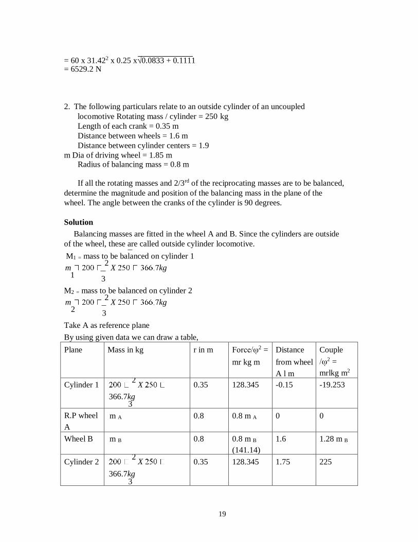
19
= 60 x 31.422 x 0.25 x√0.0833 + 0.1111 = 6529.2 N
2. The following particulars relate to an outside cylinder of an uncoupled
locomotive Rotating mass / cylinder = 250 kg
Length of each crank = 0.35 m
Distance between wheels = 1.6 m
Distance between cylinder centers = 1.9
m Dia of driving wheel = 1.85 m Radius of balancing mass = 0.8 m
If all the rotating masses and 2/3rd of the reciprocating masses are to be balanced,
determine the magnitude and position of the balancing mass in the plane of the
wheel. The angle between the cranks of the cylinder is 90 degrees.
Solution
Balancing masses are fitted in the wheel A and B. Since the cylinders are outside
of the wheel, these are called outside cylinder locomotive.
M1 = mass to be balanced on cylinder 1
m 2
X kg 1
3
M2 = mass to be balanced on cylinder 2
m 2
X kg 2
3
Take A as reference plane
By using given data we can draw a table,
Plane Mass in kg r in m Force/ῳ2 =
mr kg m
Distance
from wheel
A l m
Couple
/ῳ2 =
mrlkg m2
Cylinder 1 2
X
366.7kg 3
0.35 128.345 -0.15 -19.253
R.P wheel
A
m A 0.8 0.8 m A 0 0
Wheel B m B 0.8 0.8 m B
(141.14)
1.6 1.28 m B
Cylinder 2 2
X
366.7kg 3
0.35 128.345 1.75 225
20
Draw a couple polygon first, since it contains only one unknown and measure 1.28 m B
1.28 m B = 222.72 kg
m 222.72
kg b 1.28
Substitute m B value in force column and draw force polygon
Measure
0.8 m A = 139.2
mA = 139.2/0.8
= 174 kg
Measure =
175 degrees
from
cylinder1
3. The Centre distance between the cylinders of inner cylinder locomotive is 0.8m.
It has a stroke of 0.5m. The rotating mass per cylinder is equivalent to 200kg at the
crank pin and the reciprocating mass per cylinder is 240kg. The wheel Centre lines
are 1.7m apart. The cranks are at right angle.
The whole of the rotating mass and 2/3rd of the reciprocating masses are
balanced by masses at a radius of 0.6m. Find the magnitude and direction of the
balancing masses.
Find the hammer blow, variation in tractive effort and the magnitude of the
swaying couple at a speed of 300 rpm
Solution
Since whole of the rotating masses (m1) and 2/3rd of the reciprocating masses
(m2) are balanced,
The total balancing mass / cylinder = m1 + Cm2
= 200 + 2/3 X 240
= 320 kg
To balance the above masses in cylinder B and C, we place balancing masses mA
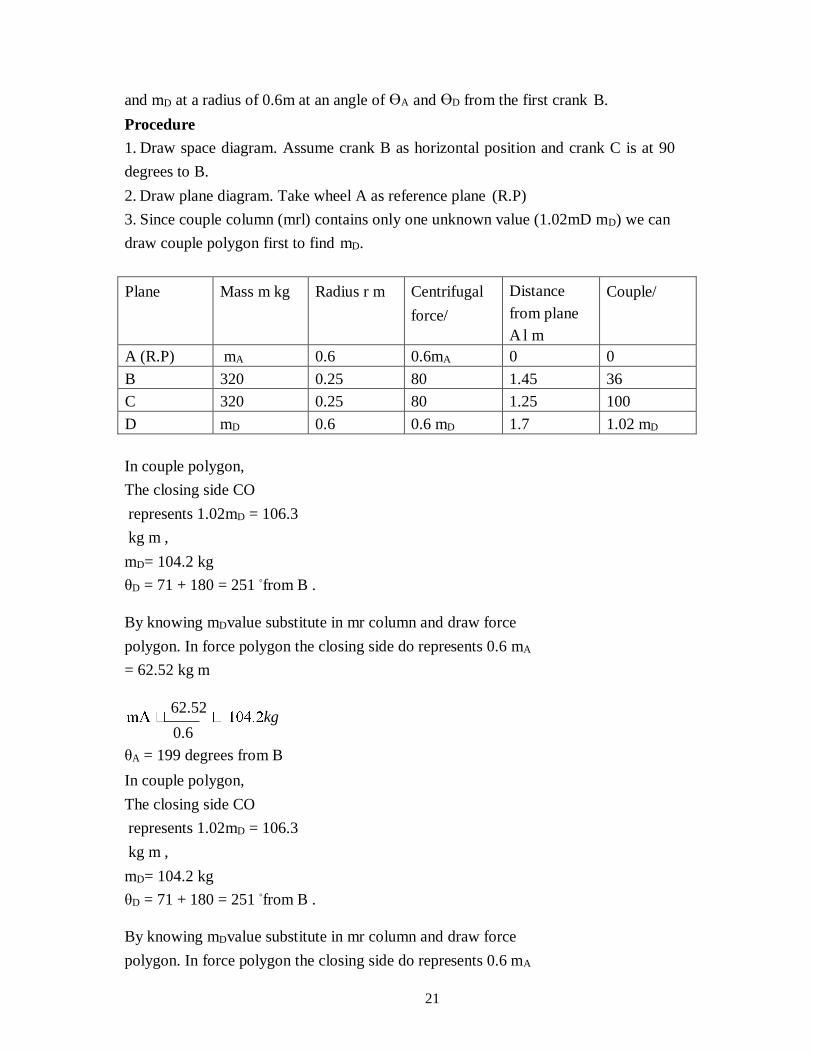
21
and mD at a radius of 0.6m at an angle of ӨA and ӨD from the first crank B.
Procedure
1. Draw space diagram. Assume crank B as horizontal position and crank C is at 90
degrees to B.
2. Draw plane diagram. Take wheel A as reference plane (R.P)
3. Since couple column (mrl) contains only one unknown value (1.02mD mD) we can
draw couple polygon first to find mD.
Plane Mass m kg Radius r m Centrifugal
force/
Distance
from plane
A l m
Couple/
A (R.P) mA 0.6 0.6mA 0 0
B 320 0.25 80 1.45 36
C 320 0.25 80 1.25 100
D mD 0.6 0.6 mD 1.7 1.02 mD
In couple polygon,
The closing side CO
represents 1.02mD = 106.3
kg m ,
mD= 104.2 kg
θD = 71 + 180 = 251 ◦from B .
By knowing mDvalue substitute in mr column and draw force
polygon. In force polygon the closing side do represents 0.6 mA
= 62.52 kg m
62.52
kg 0.6
θA = 199 degrees from B
In couple polygon,
The closing side CO
represents 1.02mD = 106.3
kg m ,
mD= 104.2 kg
θD = 71 + 180 = 251 ◦from B .
By knowing mDvalue substitute in mr column and draw force
polygon. In force polygon the closing side do represents 0.6 mA
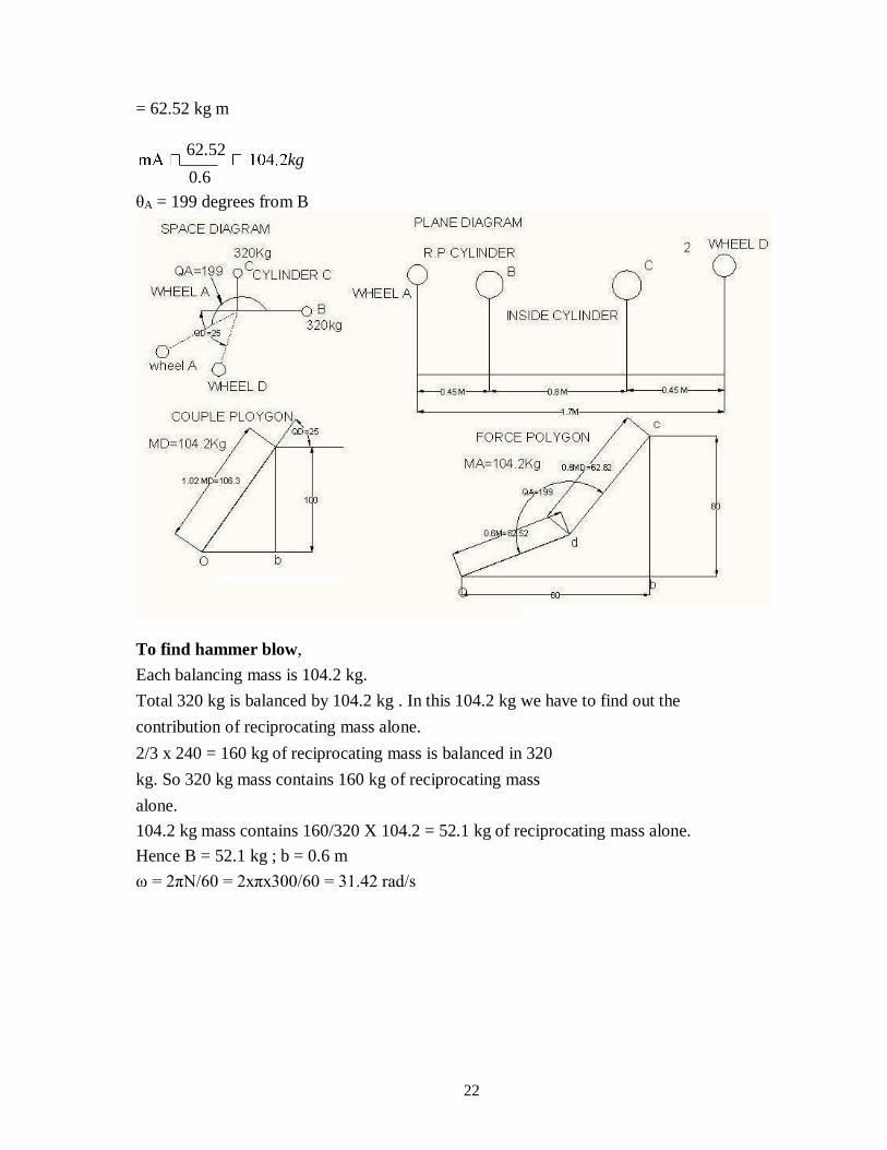
22
= 62.52 kg m
62.52
kg 0.6
θA = 199 degrees from B
To find hammer blow,
Each balancing mass is 104.2 kg.
Total 320 kg is balanced by 104.2 kg . In this 104.2 kg we have to find out the
contribution of reciprocating mass alone.
2/3 x 240 = 160 kg of reciprocating mass is balanced in 320
kg. So 320 kg mass contains 160 kg of reciprocating mass
alone.
104.2 kg mass contains 160/320 X 104.2 = 52.1 kg of reciprocating mass alone.
Hence B = 52.1 kg ; b = 0.6 m
ω = 2πN/60 = 2xπx300/60 = 31.42 rad/s
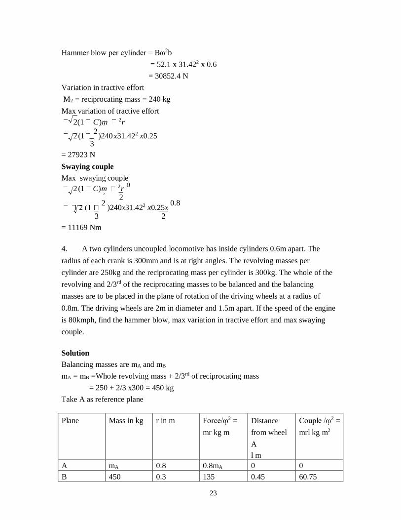
23
2
Hammer blow per cylinder = Bω2b
= 52.1 x 31.422 x 0.6
= 30852.4 N
Variation in tractive effort
M2 = reciprocating mass = 240 kg
Max variation of tractive effort
2(1 C)m 2r
2 (1 2
)240 x31.422 x0.25 3
= 27923 N
Swaying couple
Max swaying couple
2 (1 C)m 2r a
2 2
)240x31.422 x0.25x 0.8
3 2
= 11169 Nm
4. A two cylinders uncoupled locomotive has inside cylinders 0.6m apart. The
radius of each crank is 300mm and is at right angles. The revolving masses per
cylinder are 250kg and the reciprocating mass per cylinder is 300kg. The whole of the
revolving and 2/3rd of the reciprocating masses to be balanced and the balancing
masses are to be placed in the plane of rotation of the driving wheels at a radius of
0.8m. The driving wheels are 2m in diameter and 1.5m apart. If the speed of the engine
is 80kmph, find the hammer blow, max variation in tractive effort and max swaying
couple.
Solution
Balancing masses are mA and mB
mA = mB =Whole revolving mass + 2/3rd of reciprocating mass
= 250 + 2/3 x300 = 450 kg
Take A as reference plane
Plane Mass in kg r in m Force/ῳ2 =
mr kg m
Distance
from wheel
A
l m
Couple /ῳ2 =
mrl kg m2
A mA 0.8 0.8mA 0 0
B 450 0.3 135 0.45 60.75
2
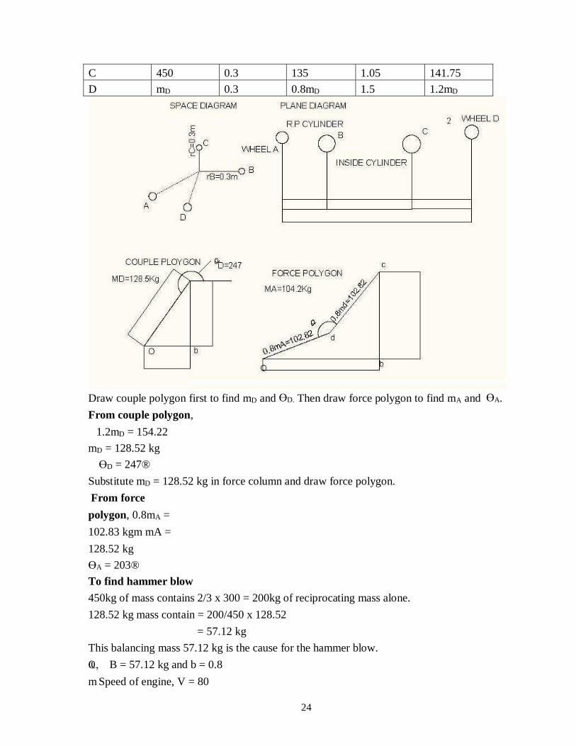
24
C 450 0.3 135 1.05 141.75
D mD 0.3 0.8mD 1.5 1.2mD
Draw couple polygon first to find mD and ӨD. Then draw force polygon to find mA and ӨA.
From couple polygon,
1.2mD = 154.22
mD = 128.52 kg
ӨD = 247®
Substitute mD = 128.52 kg in force column and draw force polygon.
From force
polygon, 0.8mA =
102.83 kgm mA =
128.52 kg
ӨA = 203®
To find hammer blow
450kg of mass contains 2/3 x 300 = 200kg of reciprocating mass alone.
128.52 kg mass contain = 200/450 x 128.52
= 57.12 kg
This balancing mass 57.12 kg is the cause for the hammer blow.
Ҩ, B = 57.12 kg and b = 0.8
m Speed of engine, V = 80
25
2
km/hr
= 22.22 m/s
Angular velocity (Ѡ) = V /radius of wheel
= 22.22/1.5
= 14.815 rad/s
Hammer blow = B ῳ2b
= 57.12 x 14.852x 0.8
= 10.029 N
To find max variation in tractive effort
C) 2r
2 (1 2
)300 x14.8152 x0.8 3
= 9312 N
To find max swaying couple, q
C) 2
2r
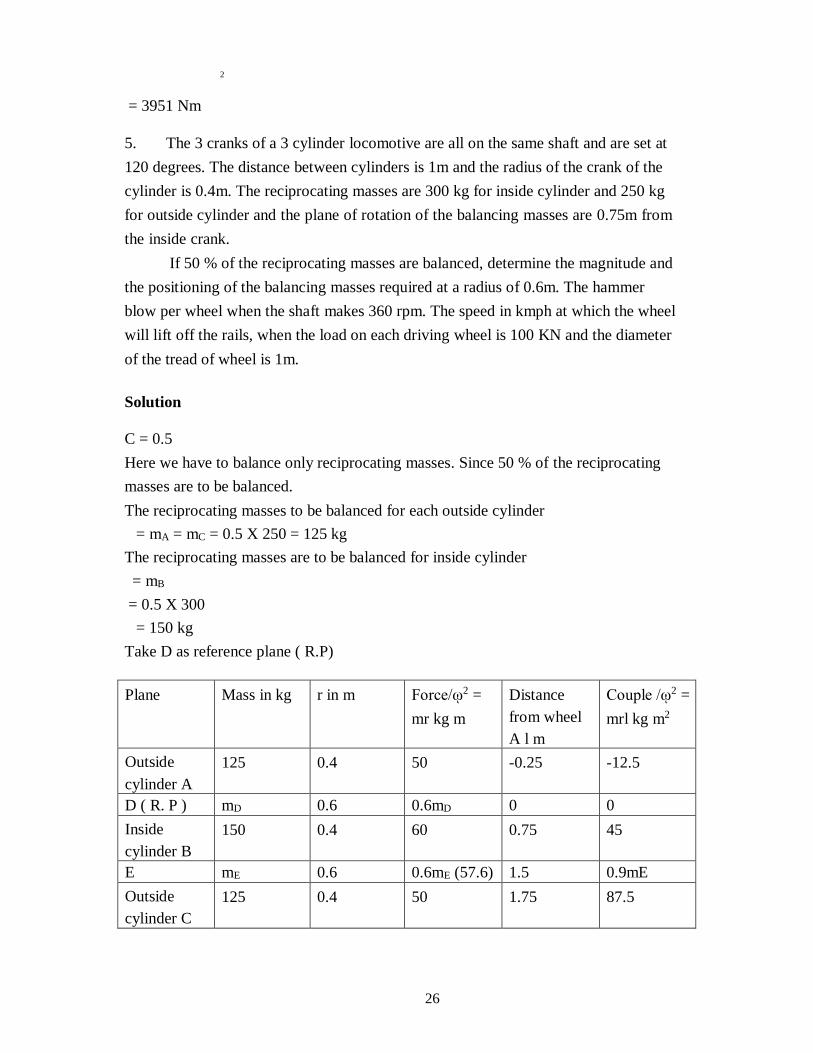
26
2
= 3951 Nm
5. The 3 cranks of a 3 cylinder locomotive are all on the same shaft and are set at
120 degrees. The distance between cylinders is 1m and the radius of the crank of the
cylinder is 0.4m. The reciprocating masses are 300 kg for inside cylinder and 250 kg
for outside cylinder and the plane of rotation of the balancing masses are 0.75m from
the inside crank.
If 50 % of the reciprocating masses are balanced, determine the magnitude and
the positioning of the balancing masses required at a radius of 0.6m. The hammer
blow per wheel when the shaft makes 360 rpm. The speed in kmph at which the wheel
will lift off the rails, when the load on each driving wheel is 100 KN and the diameter
of the tread of wheel is 1m.
Solution
C = 0.5
Here we have to balance only reciprocating masses. Since 50 % of the reciprocating
masses are to be balanced.
The reciprocating masses to be balanced for each outside cylinder
= mA = mC = 0.5 X 250 = 125 kg
The reciprocating masses are to be balanced for inside cylinder
= mB
= 0.5 X 300
= 150 kg
Take D as reference plane ( R.P)
Plane Mass in kg r in m Force/ῳ2 =
mr kg m
Distance
from wheel
A l m
Couple /ῳ2 =
mrl kg m2
Outside
cylinder A
125 0.4 50 -0.25 -12.5
D ( R. P ) mD 0.6 0.6mD 0 0
Inside
cylinder B
150 0.4 60 0.75 45
E mE 0.6 0.6mE (57.6) 1.5 0.9mE
Outside
cylinder C
125 0.4 50 1.75 87.5
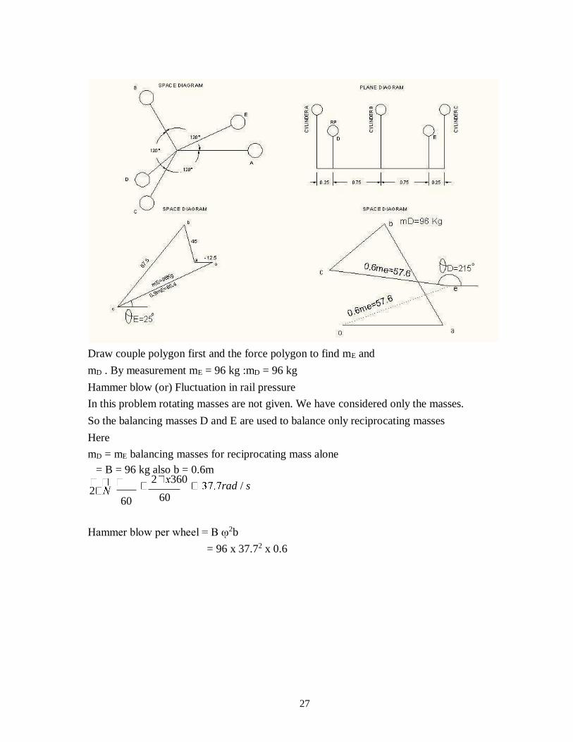
27
Draw couple polygon first and the force polygon to find mE and
mD . By measurement mE = 96 kg :mD = 96 kg
Hammer blow (or) Fluctuation in rail pressure
In this problem rotating masses are not given. We have considered only the masses.
So the balancing masses D and E are used to balance only reciprocating masses
Here
mD = mE balancing masses for reciprocating mass alone
= B = 96 kg also b = 0.6m
2 60
2 360 rad / s
60
Hammer blow per wheel = B ῳ2b
= 96 x 37.72 x 0.6
28
= 81866.3 N
peed in km/hr at which the wheel will lift off the rails when the load on each driving
wheel is 100 KN and the diameter of the tread of driving wheel is 1m.
lim iting
Vlim
iting
X m / s
= 150 km/hr
.
1
SCHOOL OF MECHANICAL ENGINEERING
DEPARTMENT OF MECHANICAL ENGINEERING
UNIT – III - FREE VIBRATION – SMEA1402
2
UNIT III
FREE VIBRATION
BASIC FEATURES OF VIBRATORY SYSTEMS
Periodic Motion
The motion which repeats after a regular interval of time is called periodic motion.
Frequency
The number of cycles completed in a unit time is called frequency. Its unit is cycles per second
(cps) or Hertz (Hz).
Time Period
Time taken to complete one cycle is called periodic time. It is represented in seconds/cycle.
Amplitude
The maximum displacement of a vibrating system or body from the mean equilibrium position is
called amplitude.
Free Vibrations
When a system is disturbed, it starts vibrating and keeps on vibrating thereafter without the action
of external force. Such vibrations are called free vibrations.
Natural Frequency
When a system executes free vibrations which are undamped, the frequency of such a system is
called natural frequency.
Forced Vibrations
The vibrations of the system under the influence of an external force are called forced vibrations.
The frequency of forced vibrations is equal to the forcing frequency.
Resonance
When frequency of the exciting force is equal to the natural frequency of the system it is called
resonance. Under such conditions the amplitude of vibration builds up dangerously.
Degree of Freedom
The degree of freedom of a vibrating body or system implies the number of independent
coordinates which are required to define the motion of the body or system at given instant.
3
LUMPED MASS PARAMETER SYSTEMS
Instead of considering distributed mass, a lumped mass is easier to analyse, whose dynamic behaviour
can be determined by one independent principal coordinate, in a single degree freedom system. It is
important to study the single degree freedom system for a clear understanding of basic features of a
vibration problem.
Elements of Lumped Parameter Vibratory System
The elements constituting a lumped parameter vibratory system are :
The Mass
The mass is assumed to be rigid and concentrated at the centre of gravity.
The Spring
It is assumed that the elasticity is represented by a helical spring. When deformed it stores
energy. The energy stored in the spring is given by
wherek is stiffness of the spring. The force at the spring is given by
F= k x
The springs work as energy restoring element. They are treated massless.
The Damper
In a vibratory system the damper is an element which is responsible for loss of energy
in the system. It converts energy into heat due to friction which may be either sliding
friction or viscous friction. A vibratory system stops vibration because of energy
conversion by damper. There are two types of dampers.
Viscous Damper
A viscous damper consists of viscous friction which converts energy into heat due to this. For this
damper, force is proportional to the relative velocity.
Fd α relative velocity (v)
Fd = cv
wherec is constant of proportionality and it is called coefficient of damping.
The coefficient of viscous damping is defined as the force in ‘N’ when velocity is 1 m/s.
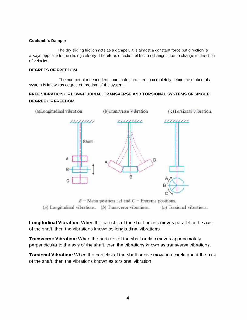
4
Coulumb’s Damper
The dry sliding friction acts as a damper. It is almost a constant force but direction is
always opposite to the sliding velocity. Therefore, direction of friction changes due to change in direction
of velocity.
DEGREES OF FREEDOM
The number of independent coordinates required to completely define the motion of a
system is known as degree of freedom of the system.
FREE VIBRATION OF LONGITUDINAL, TRANSVERSE AND TORSIONAL SYSTEMS OF SINGLE
DEGREE OF FREEDOM
Longitudinal Vibration: When the particles of the shaft or disc moves parallel to the axis
of the shaft, then the vibrations known as longitudinal vibrations.
Transverse Vibration: When the particles of the shaft or disc moves approximately
perpendicular to the axis of the shaft, then the vibrations known as transverse vibrations.
Torsional Vibration: When the particles of the shaft or disc move in a circle about the axis
of the shaft, then the vibrations known as torsional vibration
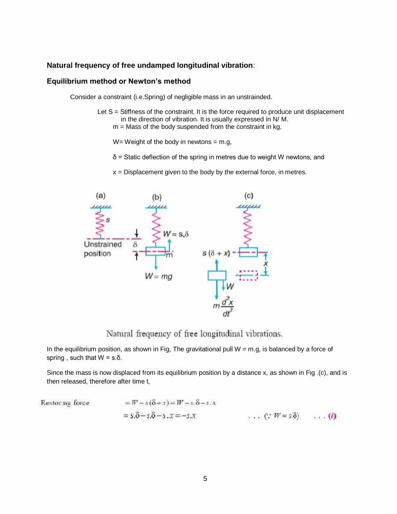
5
Natural frequency of free undamped longitudinal vibration:
Equilibrium method or Newton’s method
Consider a constraint (i.e.Spring) of negligible mass in an unstrainded.
Let S = Stiffness of the constraint. It is the force required to produce unit displacement in the direction of vibration. It is usually expressed in N/ M.
m = Mass of the body suspended from the constraint in kg,
W= Weight of the body in newtons = m.g,
δ = Static deflection of the spring in metres due to weight W newtons, and
x = Displacement given to the body by the external force, in metres.
In the equilibrium position, as shown in Fig, The gravitational pull W = m.g, is balanced by a force of
spring , such that W = s.δ.
Since the mass is now displaced from its equilibrium position by a distance x, as shown in Fig .(c), and is
then released, therefore after time t,
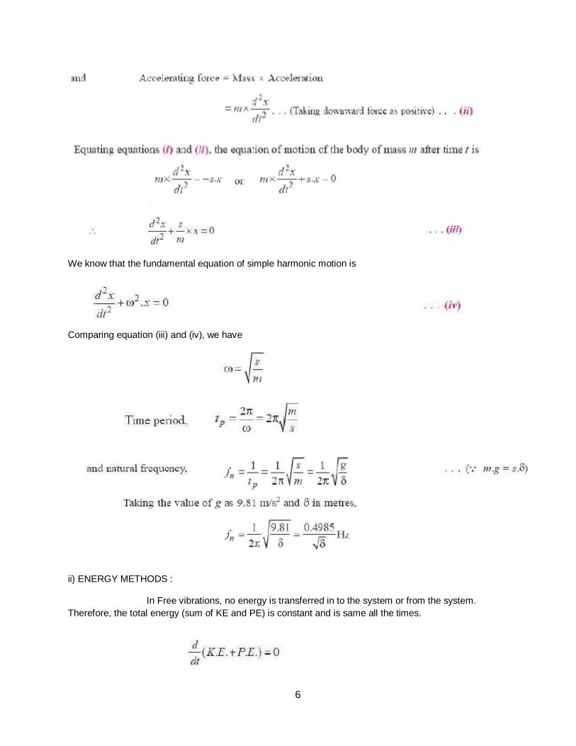
6
We know that the fundamental equation of simple harmonic motion is
Comparing equation (iii) and (iv), we have
ii) ENERGY METHODS :
In Free vibrations, no energy is transferred in to the system or from the system.
Therefore, the total energy (sum of KE and PE) is constant and is same all the times.
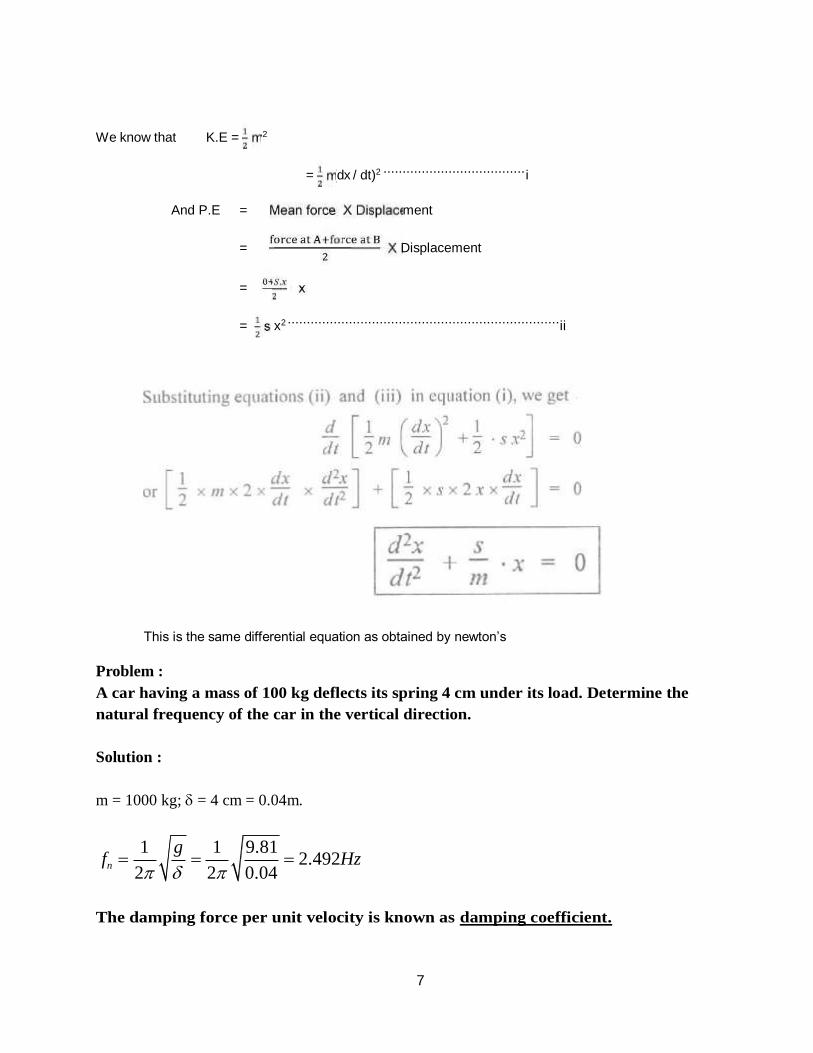
7
1 g
2
1 9.81
2 0.04
We know that K.E = mv2
= m (dx / dt)2 ..................................... i
And P.E = Mean force X Displacement
= X Displacement
= . x
= s x2 ....................................................................... ii
This is the same differential equation as obtained by newton’s
Problem :
A car having a mass of 100 kg deflects its spring 4 cm under its load. Determine the
natural frequency of the car in the vertical direction.
Solution :
m = 1000 kg; = 4 cm = 0.04m.
fn 2.492Hz
The damping force per unit velocity is known as damping coefficient.
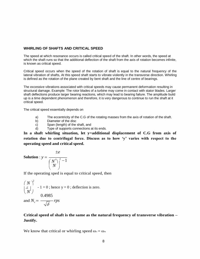
8
N
WHIRLING OF SHAFTS AND CRITICAL SPEED
The speed at which resonance occurs is called critical speed of the shaft. In other words, the speed at which the shaft runs so that the additional deflection of the shaft from the axis of rotation becomes infinite, is known as critical speed.
Critical speed occurs when the speed of the rotation of shaft is equal to the natural frequency of the lateral vibration of shafts, At this speed shaft starts to vibrate violently in the transverse direction. Whirling is defined as the rotation of the plane created by bent shaft and the line of centre of bearings.
The excessive vibrations associated with critical speeds may cause permanent deformation resulting in structural damage. Example: The rotor blades of a turbine may come in contact with stator blades. Larger shaft deflections produce larger bearing reactions, which may lead to bearing failure. The amplitude build up is a time dependent phenomenon and therefore, it is very dangerous to continue to run the shaft at it critical speed.
The critical speed essentially depends on
a) The eccentricity of the C.G of the rotating masses from the axis of rotation of the shaft. b) Diameter of the disc c) Span (length) of the shaft, and d) Type of supports connections at its ends.
In a shaft whirling situation, let y=additional displacement of C.G from axis of
rotation due to centrifugal force. Discuss as to how ‘y’ varies with respect to the
operating speed and critical speed.
e
Solution : y 2 c 1
N
If the operating sped is equal to critical speed, then
N 2
c
- 1 = 0 ; hence y = 0 ; deflection is zero.
N 0.4985
and Nc rps
Critical speed of shaft is the same as the natural frequency of transverse vibration –
Justify.
We know that critical or whirling speed c = n
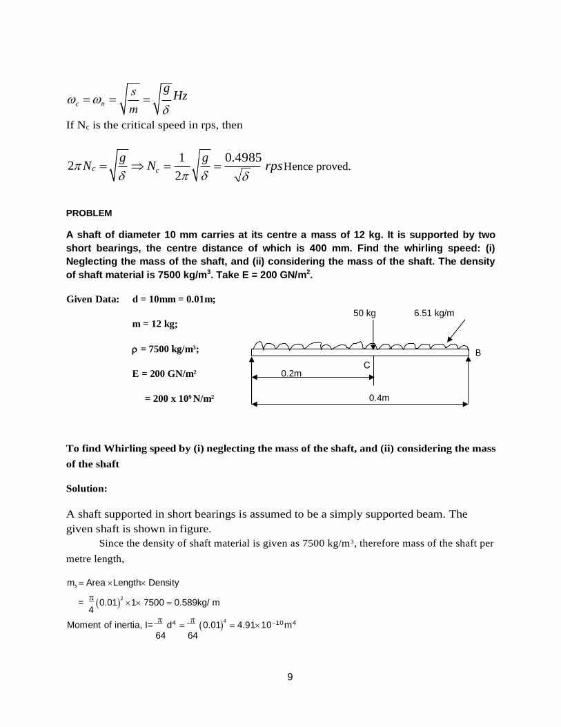
9
g
1 g
2
c n g
Hz
If Nc is the critical speed in rps, then
2 N c Nc 0.4985
rps Hence proved.
PROBLEM
A shaft of diameter 10 mm carries at its centre a mass of 12 kg. It is supported by two
short bearings, the centre distance of which is 400 mm. Find the whirling speed: (i)
Neglecting the mass of the shaft, and (ii) considering the mass of the shaft. The density
of shaft material is 7500 kg/m3. Take E = 200 GN/m2.
Given Data: d = 10mm = 0.01m;
m = 12 kg;
= 7500 kg/m3;
E = 200 GN/m2
= 200 x 109 N/m2
50 kg 6.51 kg/m
B
To find Whirling speed by (i) neglecting the mass of the shaft, and (ii) considering the mass
of the shaft
Solution:
A shaft supported in short bearings is assumed to be a simply supported beam. The
given shaft is shown in figure.
Since the density of shaft material is given as 7500 kg/m3, therefore mass of the shaft per
metre length,
ms Area Length Density
=
0.012
1 7500 0.589kg/ m 4
Moment of inertia, I=
d4
0.014
4.911010m4 64 64
0.2m
0.4m
10
1
0.4985
9 10
n
We known the static deflection due to a mass of 12 kg at C,
Wa2b2
1 3EI.l
12 9.81 0.22
0.22
3 200 109 4.911010 0.4
1.598 103m
......Here a = 0.2m, and b=0.2m
and the static deflection due to mass of the shaft,
5 wl4 5 0.589 9.810.44
s
384
EI
384
200 10 4.9110
1.961105m
(i) Neglecting the mass of the shaft:
The natural frequency of transverse vibrations is given by
f 0.4985
12.47Hz
We know that whirling speed (Ncr) of the shaft in r.p.s is equal to the frequency of transverse
vibration in Hz.
Ncr = 12.47 r.p.s. = 12.47 x 60 = 748.22 r.p.m
(ii) Considering the mass of the shaft:
The natural frequency of transverse vibrations is given by
fn 0.4985
12.41Hz
Therefore, whirling speed,
Ncr = 12.41 r.p.s. = 12.41 x 60 = 744.63 r.p.m
s 1
1.27
0.4985
1.598 10 3 1.961105
1.27
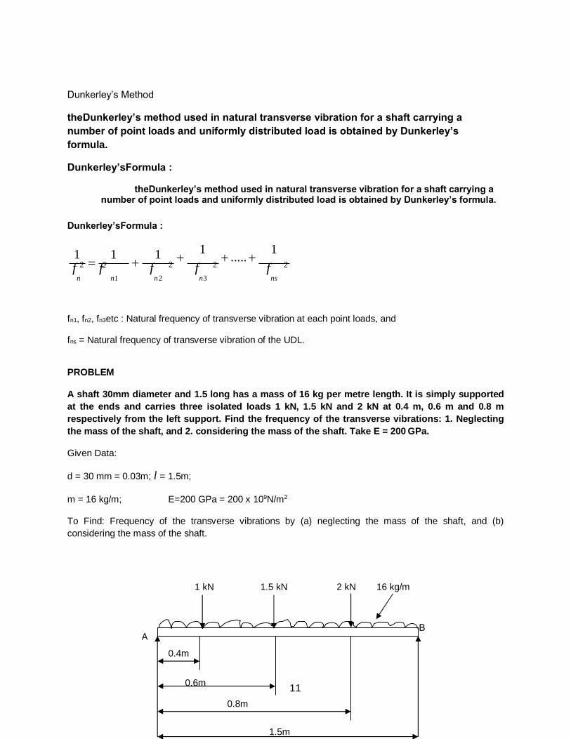
11
Dunkerley’s Method
theDunkerley’s method used in natural transverse vibration for a shaft carrying a
number of point loads and uniformly distributed load is obtained by Dunkerley’s
formula.
Dunkerley’sFormula :
theDunkerley’s method used in natural transverse vibration for a shaft carrying a number of point loads and uniformly distributed load is obtained by Dunkerley’s formula.
Dunkerley’sFormula :
1
1
1 1
..... 1
f 2 f2 f 2 f 2 f 2
n n1 n 2 n3 ns
fn1, fn2, fn3etc : Natural frequency of transverse vibration at each point loads, and
fns = Natural frequency of transverse vibration of the UDL.
PROBLEM
A shaft 30mm diameter and 1.5 long has a mass of 16 kg per metre length. It is simply supported
at the ends and carries three isolated loads 1 kN, 1.5 kN and 2 kN at 0.4 m, 0.6 m and 0.8 m
respectively from the left support. Find the frequency of the transverse vibrations: 1. Neglecting
the mass of the shaft, and 2. considering the mass of the shaft. Take E = 200 GPa.
Given Data:
d = 30 mm = 0.03m; l = 1.5m;
m = 16 kg/m; E=200 GPa = 200 x 109N/m2
To Find: Frequency of the transverse vibrations by (a) neglecting the mass of the shaft, and (b)
considering the mass of the shaft.
1 kN 1.5 kN 2 kN 16 kg/m
A
0.4m
0.6m
0.8m
1.5m
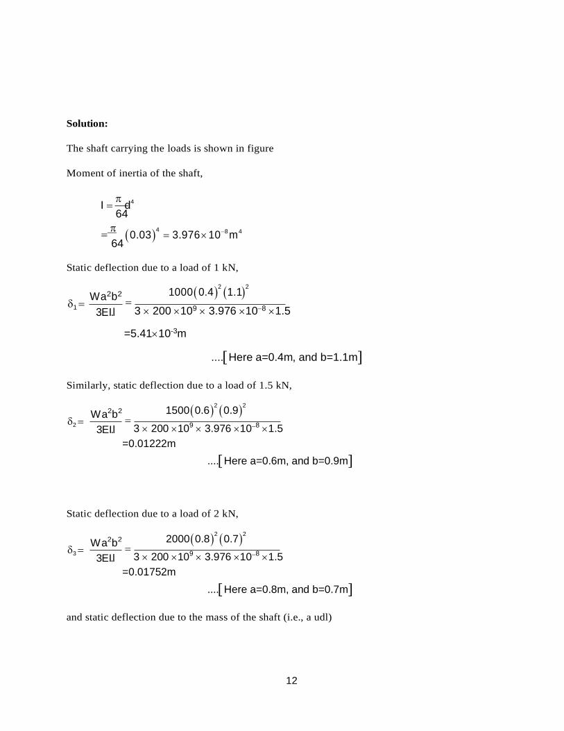
12
Solution:
The shaft carrying the loads is shown in figure
Moment of inertia of the shaft,
I
d4
64
64 0.03
4 3.976 108 m4
Static deflection due to a load of 1 kN,
1
Wa2b2
3EI.l
1000 0.42
1.12
3 200 109 3.976 108 1.5
=5.4110-3m
....Here a=0.4m, and b=1.1m
Similarly, static deflection due to a load of 1.5 kN,
2
Wa2b2
3EI.l
1500 0.62
0.92
3 200 109 3.976 108 1.5
=0.01222m
....Here a=0.6m, and b=0.9m
Static deflection due to a load of 2 kN,
3
Wa2b2
3EI.l
2000 0.82
0.72
3 200 109 3.976 108 1.5
=0.01752m
....Here a=0.8m, and b=0.7m
and static deflection due to the mass of the shaft (i.e., a udl)
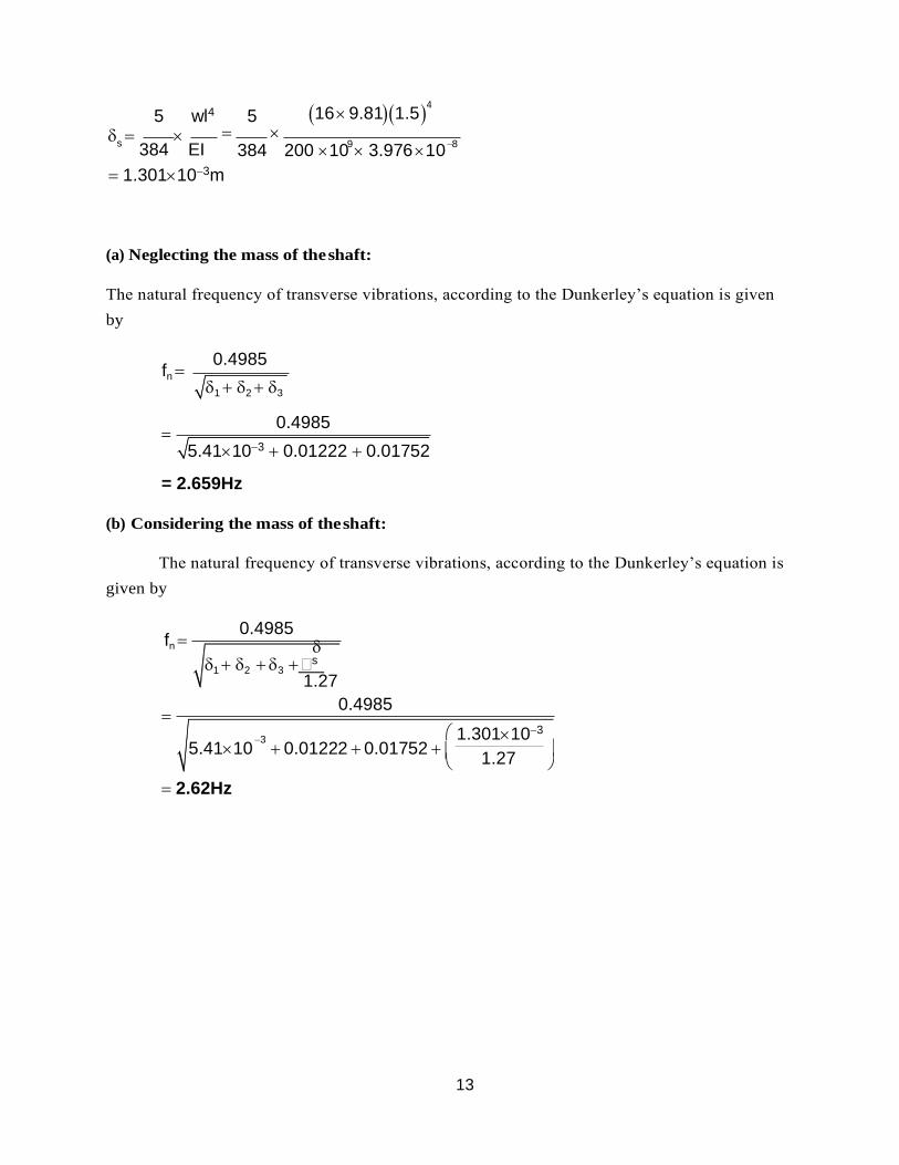
13
9 8
5 wl4 5 16 9.811.54
s
384
EI
384 200 10 3.976 10
1.301103m
(a) Neglecting the mass of the shaft:
The natural frequency of transverse vibrations, according to the Dunkerley’s equation is given
by
fn
0.4985
= 2.659Hz
(b) Considering the mass of the shaft:
The natural frequency of transverse vibrations, according to the Dunkerley’s equation is
given by
fn
0.4985
1 2 3 s 1.27
0.4985
2.62Hz
1 2 3
0.4985
5.41103 0.01222 0.01752
5.4110 0.01222 0.01752 3 1.301103
1.27
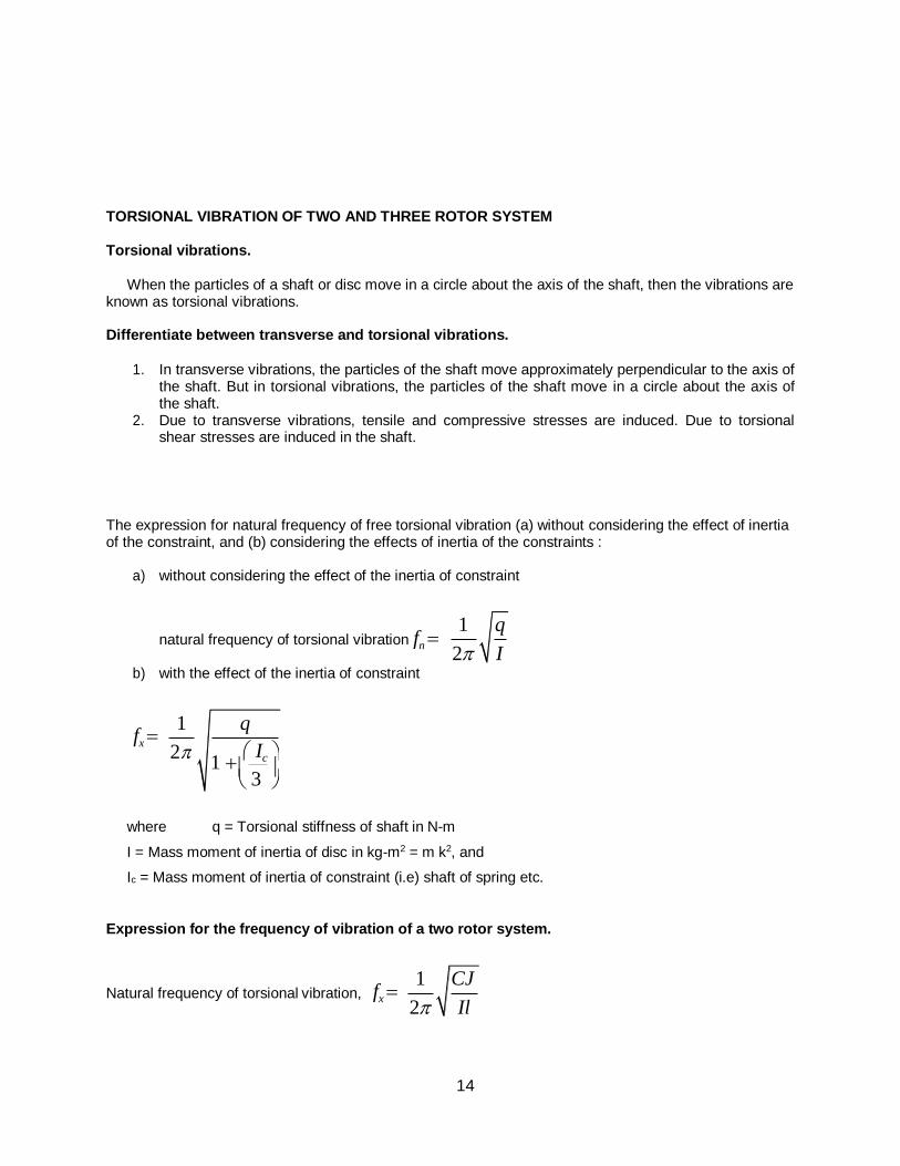
14
TORSIONAL VIBRATION OF TWO AND THREE ROTOR SYSTEM
Torsional vibrations.
When the particles of a shaft or disc move in a circle about the axis of the shaft, then the vibrations are known as torsional vibrations.
Differentiate between transverse and torsional vibrations.
1. In transverse vibrations, the particles of the shaft move approximately perpendicular to the axis of
the shaft. But in torsional vibrations, the particles of the shaft move in a circle about the axis of the shaft.
2. Due to transverse vibrations, tensile and compressive stresses are induced. Due to torsional shear stresses are induced in the shaft.
The expression for natural frequency of free torsional vibration (a) without considering the effect of inertia of the constraint, and (b) considering the effects of inertia of the constraints :
a) without considering the effect of the inertia of constraint
natural frequency of torsional vibration fn
b) with the effect of the inertia of constraint
fx
where q = Torsional stiffness of shaft in N-m
I = Mass moment of inertia of disc in kg-m2 = m k2, and
Ic = Mass moment of inertia of constraint (i.e) shaft of spring etc.
Expression for the frequency of vibration of a two rotor system.
Natural frequency of torsional vibration, fx
1 q
2 I
1
2
q
1 Ic
3
1 CJ
2 Il
15
B
Where C = rigidity modulus of shaft, I = Mass M.I of rotor J = Polar M.I of shaft, and I = Length of node from rotor.
Two equations for two rotor system are :
1) lA IA = lB IB and (2) l = lA + lB
2) From equation (1), if IB value is large,
then l
= lA -IA
IB
; then lB value will be lesser that
the value of lA. It means that the rotor having larger mass moment of inertia will have node closer to it.
The equation used to obtain torsionally equivalent shaft of a stepped shaft.
The total angle of twist of the shaft is equal to the sum of the angle of twists of different lengths.
So = 1+2+3
Or
Tl
Tl1
Tl2
Tl3
CJ CJ1 CJ2 CJ3
l
l1 l2
l3
J J1 J2 J3
l
d
4
l1
d
4
l2
d
2
l3
d
2
32 32 1 32 2 32 3
Let d = d1, then
d 4
d 4
l l1 l2 1
l3 1
d2 d3
where l = Length of a torsionally equivalent shaft.
PROBLEM
A shaft of 100mm diameter and 1 metre long is fixed at one end and the other end carries a
flywheel of mass 1 tonne. The radius of gyration of the fly wheel is 0.5m. Find the frequency of
torsional vibrations. If the modulus of rigidity for the shaft material is 80 GN/m2
Given data:
16
1 q
2 l
1 785.6 103
2 250
D=100mm=0.1m;l=1m;m=1tonne=1000kg;
K=0.5m;C=80GN/m2 =80x109N/m2.
To find:
Frequency of torsional vibrations (fn).
Solution:
We know that polar moment of inertia of the shaft.
j d 4
(0.1)94 .82 10
6 m4
32 32
Torsional stiffness of the shaft is given by
C.J 80 109 (9.82106 ) q= 785.6 103
l 1 N m.
We also know that mass moment of inertia of the shaft.
1=m.k2=1000(0.5)2=250kg-m2.
Frequency of torsional vibrations.
fn 8.922Hz.
Damped free vibration
It is the resistance to the motion of a vibrating body. The vibrations associated with this
resistance are known as damped vibrations.
Types of damping:
(1) Viscous damping
(2) Dry friction or coulomb damping
(3) Solid damping or structural damping
(4) Slip or interfacial damping.
17
5000
c c
Damping ratio ().
It is defined as the ratio of actual damping coefficient (c) to the critical damping coefficient (CC).
Mathematically, Damping ratio cc 2mn
logarithmic decrement.
Logarithmic decrement is defines as the natural logarithm of the amplitude reduction factor. The
amplitude reduction factor is the ratio of any two successive amplitudes on the same side of the mean position.
=log x1
log xn
e x
e x
2 n1
It is a convenient way to measure the amount of damping is to measure the rate of decay of
oscillation. This is best expressed by the term L.D. it is defined as the natural logarithm of the ratio of
any two successive amplitudes.
A vibrating system consist of a mass of 7 kg and a spring stiffness 50 N/cm and damper of damping coefficient 0.36 Ncm-1 sec. find damping factor.
Solution :
m= 7 kg; s=50 N/cm = 5000 N/m ; c = 0.36 N/cm/sec = 36 N/m/sec
n 26.72 rad/sec
cc = 2 m n = 2 X 7 X 26.72 = 374.16 N/m/s
18
Damping factor = c
0.0962
cc
PROBLEM A vibrating system consists of a mass of 8 kg, spring of stiffness 5.6 N/mm and a dashpot of
damping coefficient of 40 N/m/s. Find:
(a) the critical damping coefficient, (b) the damping factor, (c) the natural frequency of damped vibration, (d) the logarithmic decrement, (e) the ratio of two consecutive amplitudes, and (f) the number of cycles after which the original amplitude is reduced to 20 percent
Given data:
m = 8 kg; s = 5.6 N/mm = 5.6 x 10³ N/m; C = 40 N/ m/ s
Solution:
(a) Critical damping coefficient (cc):
We know that
cc 2mn 2m 2
(b) Damping factor ():
cc 2 422.32N/m/s
We know that,
Damping factor, c
cc
40
422.32
0.0945
(c) Natural frequency of damped vibration (fd):
We know that the circular frequency of damped vibrations,
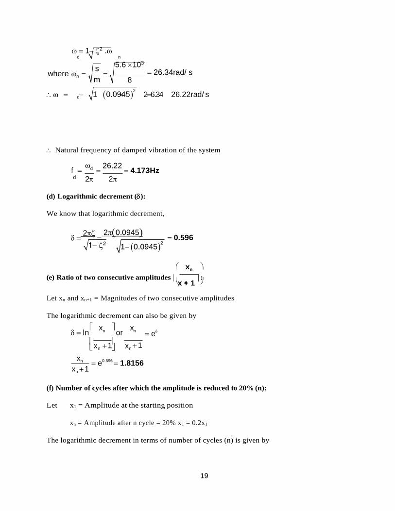
19
s
m
1 0.0945
x 1 x
1 2 . d n
5.6 103 where n 26.34rad/ s
8
d 1 0.09452
26.34 26.22rad/ s
Natural frequency of damped vibration of the system
f
d
d 2
26.22 4.173Hz
2
(d) Logarithmic decrement ():
We know that logarithmic decrement,
2
20.0945
0.596
xn
(e) Ratio of two consecutive amplitudes x + 1
: n
Let xn and xn+1 = Magnitudes of two consecutive amplitudes
The logarithmic decrement can also be given by
ln xn
or
xn
e
n n 1
xn
xn 1 e0.596
1.8156
(f) Number of cycles after which the amplitude is reduced to 20% (n):
Let x1 = Amplitude at the starting position
xn = Amplitude after n cycle = 20% x1 = 0.2x1
The logarithmic decrement in terms of number of cycles (n) is given by
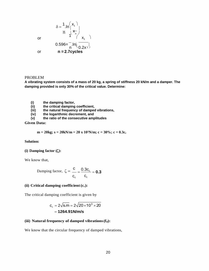
20
1
.ln x1
n
or 1
n x1
0.596= n
.ln 0.2x
or n = 2.7cycles
PROBLEM A vibrating system consists of a mass of 20 kg, a spring of stiffness 20 kN/m and a damper. The
damping provided is only 30% of the critical value. Determine:
(i) the damping factor, (ii) the critical damping coefficient, (iii) the natural frequency of damped vibrations, (iv) the logarithmic decrement, and (v) the ratio of the consecutive amplitudes
Given Data:
m = 20kg; s = 20kN/m = 20 x 103N/m; c = 30%; c = 0.3cc
Solution:
(i) Damping factor ():
We know that,
Damping factor, c
cc
0.3cc
cc
0.3
(ii) Critical damping coefficient (cc):
The critical damping coefficient is given by
cc 2 2
1264.91N/m/s
(iii) Natural frequency of damped vibrations (fd):
We know that the circular frequency of damped vibrations,
x
1
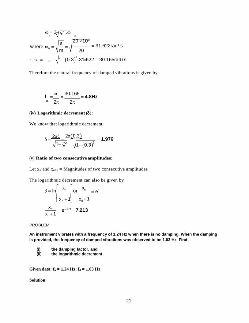
21
s
m
1 0.3
x 1 x
1 2 . d n
20 103 where n 31.622rad/ s
20
d 1 0.32 .31.622 30.165rad / s
Therefore the natural frequency of damped vibrations is given by
f
d
d 2
30.165 4.8Hz
2
(iv) Logarithmic decrement ():
We know that logarithmic decrement,
2
20.3
1.976
(v) Ratio of two consecutive amplitudes:
Let xn and xn+1 = Magnitudes of two consecutive amplitudes
The logarithmic decrement can also be given by
ln xn
or
xn
e
n n 1
xn
xn 1 e1.976
7.213
PROBLEM
An instrument vibrates with a frequency of 1.24 Hz when there is no damping. When the damping
is provided, the frequency of damped vibrations was observed to be 1.03 Hz. Find:
(i) the damping factor, and (ii) the logarithmic decrement
Given data: fn = 1.24 Hz; fd = 1.03 Hz
Solution:
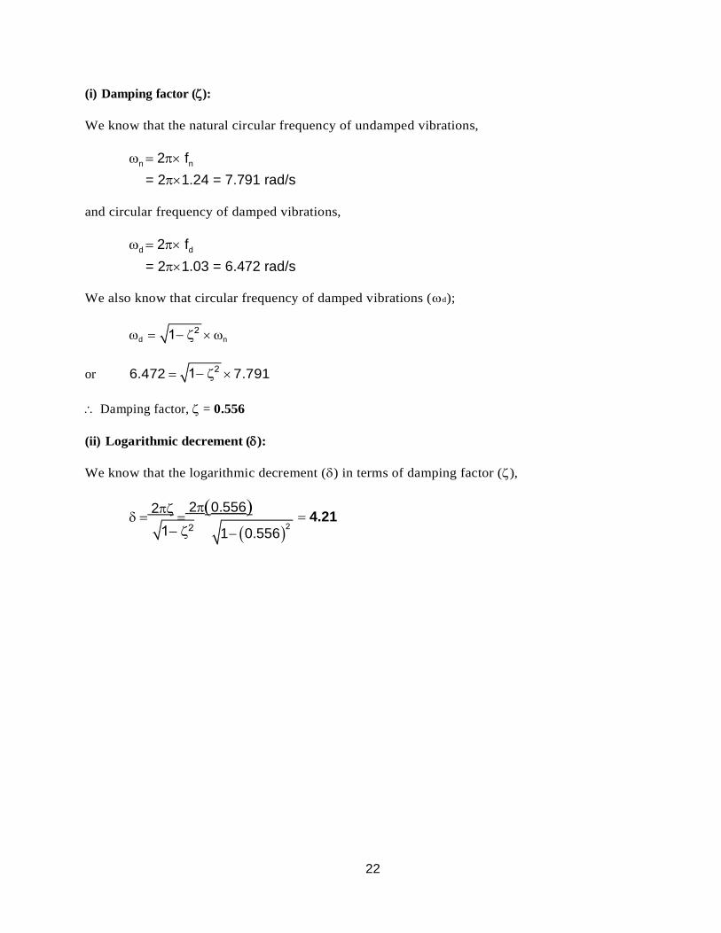
22
1 0.556
(i) Damping factor ():
We know that the natural circular frequency of undamped vibrations,
n 2 fn
= 21.24 = 7.791 rad/s
and circular frequency of damped vibrations,
d 2 fd
= 21.03 = 6.472 rad/s
We also know that circular frequency of damped vibrations (d);
d n
or 6.472 7.791
Damping factor, = 0.556
(ii) Logarithmic decrement ():
We know that the logarithmic decrement () in terms of damping factor (),
2
20.556
4.21
1
SCHOOL OF MECHANICAL ENGINEERING
DEPARTMENT OF MECHANICAL ENGINEERING
UNIT – IV - FORCED VIBRATION – SMEA1402
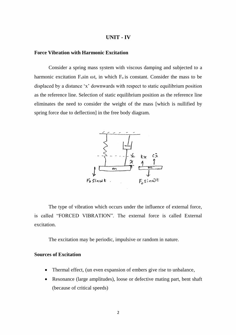
2
UNIT - IV
Force Vibration with Harmonic Excitation
Consider a spring mass system with viscous damping and subjected to a
harmonic excitation Fosin t, in which Fo is constant. Consider the mass to be
displaced by a distance ‘x’ downwards with respect to static equilibrium position
as the reference line. Selection of static equilibrium position as the reference line
eliminates the need to consider the weight of the mass [which is nullified by
spring force due to deflection] in the free body diagram.
The type of vibration which occurs under the influence of external force,
is called “FORCED VIBRATION”. The external force is called External
excitation.
The excitation may be periodic, impulsive or random in nature.
Sources of Excitation
Thermal effect, (un even expansion of embers give rise to unbalance,
Resonance (large amplitudes), loose or defective mating part, bent shaft
(because of critical speeds)
3
From Neton’s 2nd law of motion.
Rate of change of momentum = - Fs = Fd + Fo Sint
i.e, mx = -kx - 𝑐�� + Fo Sint
mx + cx + kx = Fo Sint Governing differential equation … (1)
Governing Differential Equation Eqn (1) is Non-homogeneous, 2nd
order Diff. eqn of motion. The complete solution consists of two parts (i)
complementary function part [xc] (ii) particular integral part [xp]
We know, that
Xc = xeXc = X𝑒−𝑤𝑛𝑡 sin [d +]
where d = n √1 − 2
Due to exponential decay, xc dies out eventually. This part is called
‘transient motion’ particular integral part [xp]
xp = X sin [t +] …(2)
Where X =Fo
√[k−m2]2+[c]2 …(2A)
The amplitude of x of the particular Internal Part Replace by does not
depend on time. In other words, the amplitude of vibration represented by Xp
does not change with time and therefore it is called steady state motion.
Also tan = 2r
1−r2 …(3)
Where r = frequency ration =
𝑛 & = Phase angle
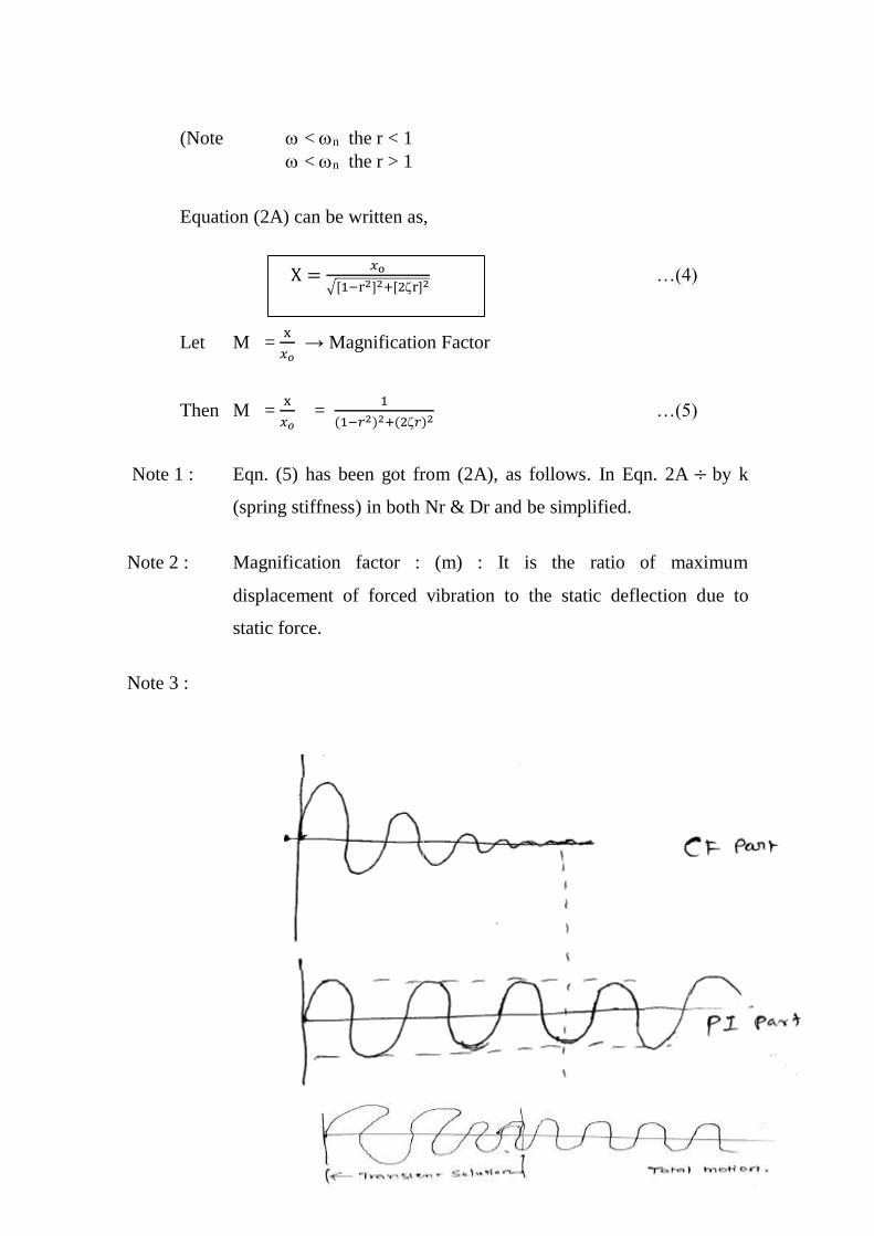
4
(Note < n the r < 1
< n the r > 1
Equation (2A) can be written as,
X =𝑥o
√[1−r2]2+[2r]2 …(4)
Let M = x
𝑥𝑜 → Magnification Factor
Then M = x
𝑥𝑜 =
1
(1−𝑟2)2+(2𝑟)2 …(5)
Note 1 : Eqn. (5) has been got from (2A), as follows. In Eqn. 2A ÷ by k
(spring stiffness) in both Nr & Dr and be simplified.
Note 2 : Magnification factor : (m) : It is the ratio of maximum
displacement of forced vibration to the static deflection due to
static force.
Note 3 :
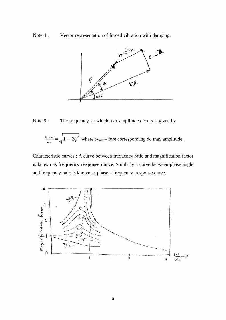
5
Note 4 : Vector representation of forced vibration with damping.
Note 5 : The frequency at which max amplitude occurs is given by
max
𝑛 = √1 − 22
where max – fore corresponding do max amplitude.
Characteristic curves : A curve between frequency ratio and magnification factor
is known as frequency response curve. Similarly a curve between phase angle
and frequency ratio is known as phase – frequency response curve.
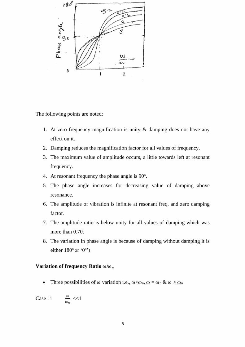
6
The following points are noted:
1. At zero frequency magnification is unity & damping does not have any
effect on it.
2. Damping reduces the magnification factor for all values of frequency.
3. The maximum value of amplitude occurs, a little towards left at resonant
frequency.
4. At resonant frequency the phase angle is 90.
5. The phase angle increases for decreasing value of damping above
resonance.
6. The amplitude of vibration is infinite at resonant freq. and zero damping
factor.
7. The amplitude ratio is below unity for all values of damping which was
more than 0.70.
8. The variation in phase angle is because of damping without damping it is
either 180o or ‘0o’)
Variation of frequency Ratio /n
Three possibilities of variation i.e., <n, = n & > n
Case : i
𝑛 <<1
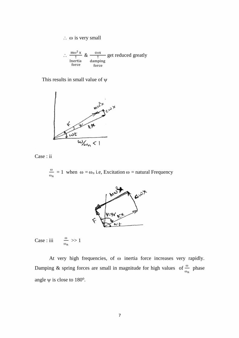
7
is very small
m2 x
↑Inertia
force
& cx
↑damping
force
get reduced greatly
This results in small value of
Case : ii
𝑛 = 1 when = n i.e, Excitation = natural Frequency
Case : iii
𝑛 >> 1
At very high frequencies, of inertia force increases very rapidly.
Damping & spring forces are small in magnitude for high values of
𝑛 phase
angle is close to 180o.
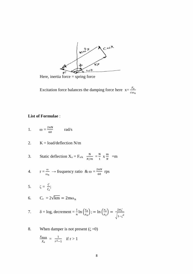
8
Here, inertia force = spring force
Excitation force balances the damping force here x= 𝐹𝑜
𝑐𝜔𝑛
List of Formulae :
1. = 2πN
60 rad/s
2. K = load/deflection N/m
3. Static deflection Xo = Fo/k N
𝑁/𝑚 =
N
1 x
m
𝑁 =m
4. r =
𝑛 → frequency ratio & =
2𝜋𝑁
60 rps
5. = 𝐶
𝐶𝑐;
6. Cc = 2√km = 2m𝑛
7. δ = log, decrement = 1
𝑛ln (
𝑥𝑜
𝑥𝑛) ; = ln (
𝑥1
𝑥2) =
2𝜋
√1−2
8. When damper is not present ( =0)
𝑋max
𝑋𝑜 =
1
𝑟2−1 if r > 1
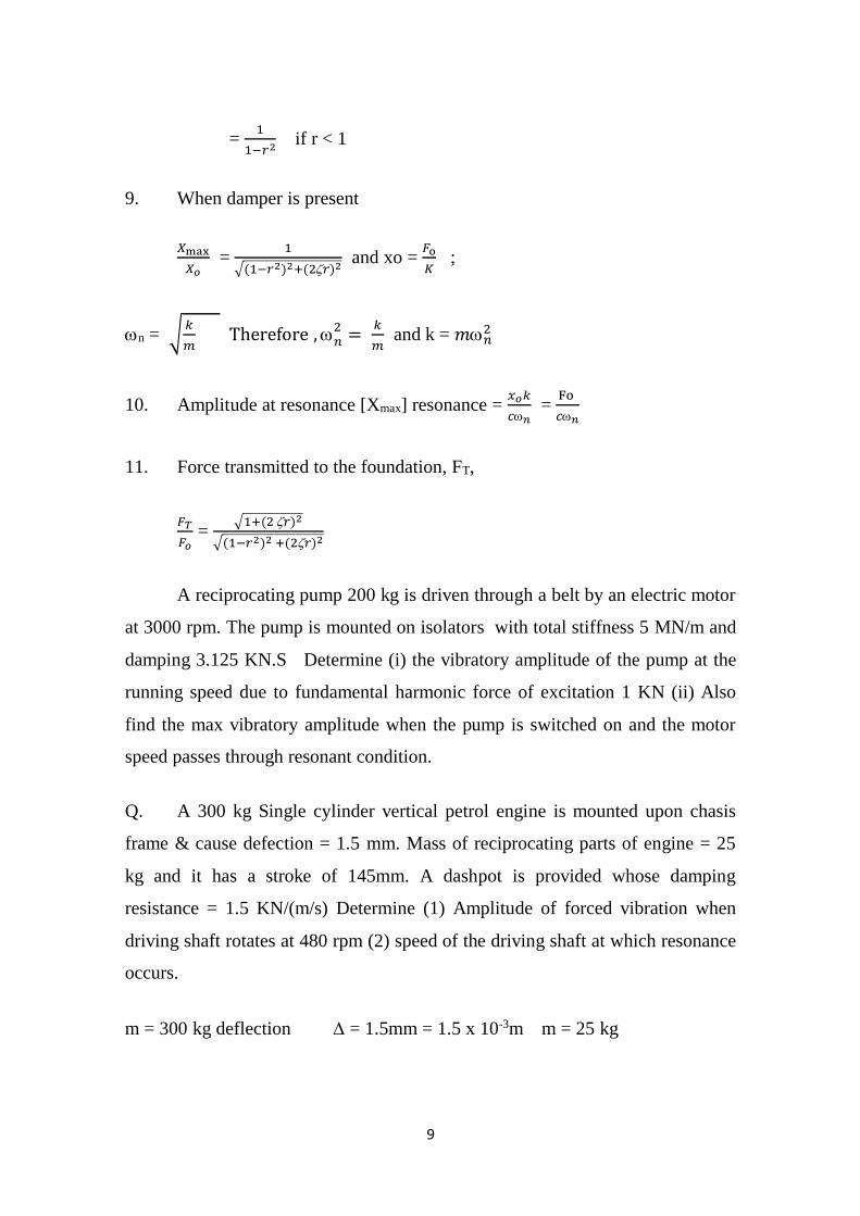
9
= 1
1−𝑟2 if r < 1
9. When damper is present
𝑋max
𝑋𝑜 =
1
√(1−𝑟2)2+(2𝑟)2 and xo =
𝐹o
𝐾 ;
n = √𝑘
𝑚 Therefore ,𝑛
2 = 𝑘
𝑚 and k = 𝑚𝑛
2
10. Amplitude at resonance [Xmax] resonance = 𝑥𝑜𝑘
𝑐𝑛 =
Fo
𝑐𝑛
11. Force transmitted to the foundation, FT,
𝐹𝑇
𝐹𝑜 =
√1+(2 𝑟)2
√(1−𝑟2)2 +(2𝑟)2
A reciprocating pump 200 kg is driven through a belt by an electric motor
at 3000 rpm. The pump is mounted on isolators with total stiffness 5 MN/m and
damping 3.125 KN.S Determine (i) the vibratory amplitude of the pump at the
running speed due to fundamental harmonic force of excitation 1 KN (ii) Also
find the max vibratory amplitude when the pump is switched on and the motor
speed passes through resonant condition.
Q. A 300 kg Single cylinder vertical petrol engine is mounted upon chasis
frame & cause defection = 1.5 mm. Mass of reciprocating parts of engine = 25
kg and it has a stroke of 145mm. A dashpot is provided whose damping
resistance = 1.5 KN/(m/s) Determine (1) Amplitude of forced vibration when
driving shaft rotates at 480 rpm (2) speed of the driving shaft at which resonance
occurs.
m = 300 kg deflection = 1.5mm = 1.5 x 10⁻³m m = 25 kg
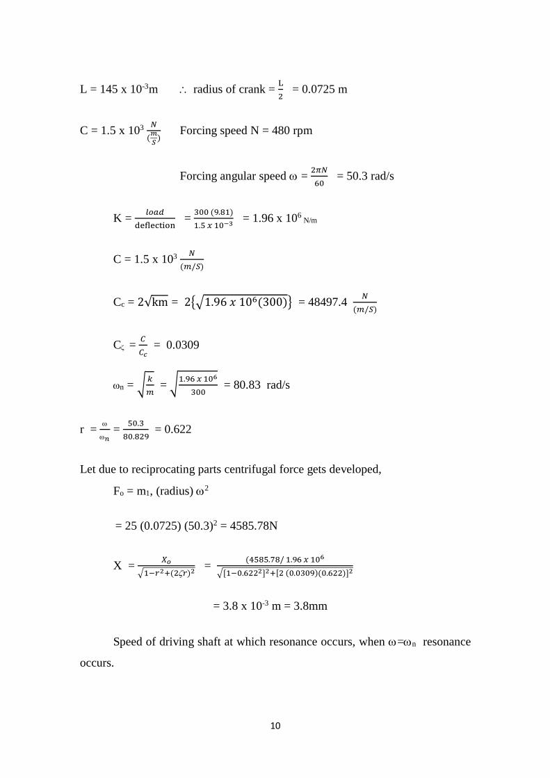
10
L = 145 x 10-3m radius of crank = L
2 = 0.0725 m
C = 1.5 x 10³ 𝑁
(𝑚
𝑆) Forcing speed N = 480 rpm
Forcing angular speed = 2𝜋𝑁
60 = 50.3 rad/s
K = 𝑙𝑜𝑎𝑑
deflection =
300 (9.81)
1.5 𝑥 10−3 = 1.96 x 10⁶
N/m
C = 1.5 x 10³ 𝑁
(𝑚/𝑆)
Cc = 2√km = 2{√1.96 𝑥 106(300)} = 48497.4 𝑁
(𝑚/𝑆)
C = 𝐶
𝐶𝑐 = 0.0309
n = √𝑘
𝑚 = √
1.96 𝑥 106
300 = 80.83 rad/s
r =
𝑛 =
50.3
80.829 = 0.622
Let due to reciprocating parts centrifugal force gets developed,
Fo = m1, (radius) 2
= 25 (0.0725) (50.3)2 = 4585.78N
X = 𝑋𝑜
√1−𝑟2+(2𝑟)2 =
(4585.78/ 1.96 𝑥 106
√[1−0.6222]2+[2 (0.0309)(0.622)]2
= 3.8 x 10⁻³ m = 3.8mm
Speed of driving shaft at which resonance occurs, when =n resonance
occurs.
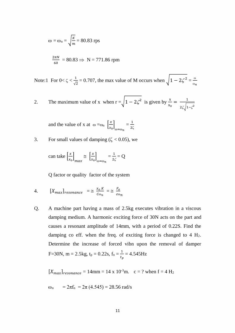
11
= n = √𝐾
𝑚 = 80.83 rps
2𝜋𝑁
60 = 80.83 N = 771.86 rpm
Note:1 For 0< < 1
√2 = 0.707, the max value of M occurs when √1 − 2 2
=
𝑛
2. The maximum value of x when r =√1 − 22 is given by
x
x0=
1
2√1−2
and the value of x at =n [𝑥
𝑥0]=𝑛
= 1
2
3. For small values of damping ( < 0.05), we
can take [𝑥
𝑥0]
𝑚𝑎𝑥 [
𝑥
𝑥0]=𝑛
= 1
2 = Q
Q factor or quality factor of the system
4. [𝑋𝑚𝑎𝑥]𝑟𝑒𝑠𝑜𝑛𝑎𝑛𝑐𝑒 = 𝑥𝑜 𝐾
𝐶𝑛 =
𝐹𝑜
𝑐𝑛
Q. A machine part having a mass of 2.5kg executes vibration in a viscous
damping medium. A harmonic exciting force of 30N acts on the part and
causes a resonant amplitude of 14mm, with a period of 0.22S. Find the
damping co eff. when the freq. of exciting force is changed to 4 H2.
Determine the increase of forced vibn upon the removal of damper
F=30N, m = 2.5kg, tp = 0.22s, fn = 1
𝑡𝑝 = 4.545Hz
[𝑋𝑚𝑎𝑥]𝑟𝑒𝑠𝑜𝑛𝑎𝑛𝑐𝑒 = 14mm = 14 x 10-3m. c = ? when f = 4 H2
n = 2πfn = 2π (4.545) = 28.56 rad/s
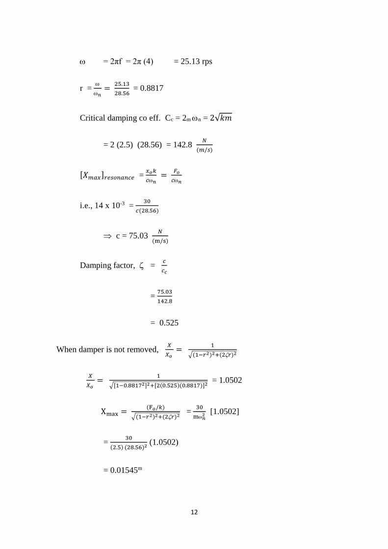
12
= 2πf = 2π (4) = 25.13 rps
r =
𝑛=
25.13
28.56 = 0.8817
Critical damping co eff. Cc = 2m n = 2√𝑘𝑚
= 2 (2.5) (28.56) = 142.8 𝑁
(𝑚/𝑠)
[𝑋𝑚𝑎𝑥]𝑟𝑒𝑠𝑜𝑛𝑎𝑛𝑐𝑒 = 𝑥𝑜𝑘
𝑐𝑛 =
𝐹𝑜
𝑐𝑛
i.e., 14 x 10-3 = 30
𝑐(28.56)
c = 75.03 𝑁
(m/s)
Damping factor, = 𝑐
𝑐𝑐
= 75.03
142.8
= 0.525
When damper is not removed, 𝑋
𝑋𝑜 =
1
√(1−𝑟2)2+(2𝑟)2
𝑋
𝑋𝑜 =
1
√[1−0.88172]2+[2(0.525)(0.8817)]2 = 1.0502
Xmax = (F𝑜/𝑘)
√(1−𝑟2)2+(2𝑟)2 =
30
m𝑛2 [1.0502]
= 30
(2.5) (28.56)2 (1.0502)
= 0.01545m
13
= 15.45mm
When damper is removed
Xmax
X0 =
1
1−𝑟2 r < 1
Xmax =𝐹𝑜/𝑘
1−𝑟2 (𝑋𝑜 =
F0
𝑘)
= 30
2.5(28.56)2 [
1
1−(0.8817)2]& 𝑘=𝑚𝜔𝑛
2
= 0.06609m
= 66.09mm
% increase in amplitude
= [Xmax]𝑁𝑜𝑑𝑎𝑚𝑝𝑖𝑛𝑔 − [X max]damping
[Xmax]damping
= [ 66.09 15.45]/15.45
= 321.92%
A 12 Kg mass is suspended from end of helical spring, other end is fixed,
spring stiffness =15 N/mm. Due to viscous damping, amplitude decreases to
1/10th of initial value in 4 oscillations. If a periodic force 150 cos 50t N is
applied at mass in vertical direction, find amplitude of forced vibration. What is
its value of resonance?
14
m = 12 kg k = 15𝑁
mm x
1000mm
1m= 15 𝑥 103 N
m
x4 = 0.1 xo
𝑥𝑜
𝑥4 = 10
Logarithmic decrement, δ = 1
4ln[10] = 0.5756
= 𝛿
√(2𝜋)2+𝛿2 = 0.09122
n = √𝑘
𝑚= √
15 𝑥 103
12 = 35.3 rps
Fx = Fo cos t
= 50 cos 50t
Fo = 150N & = 50 rad/s
freq. ratio r =
𝑛=
50
35.3 = 1.416
Cc = √km2
= √15 𝑥 103 (12)2 = 848.52
𝑁
(𝑚/𝑠)
= 𝑐
𝐶𝑐
0.09122 = 𝑐
848.52 c = 77.40 =
𝑁
(𝑚/𝑠)
𝑋
𝐹𝑜/𝑘 =
1
√[1−1.4162]2+[2(0.09122)(1.416)]2
𝑋
[150/15𝑥103 = 0.09637
15
X = [150
15 𝑥103] 0.9637
= 9.637 x 10⁻³m
= 9.637mm
Amplitude at resonance,
[𝑋𝑚𝑎𝑥]𝑟𝑒𝑠𝑜𝑛𝑎𝑛𝑐𝑒 = xok
𝑐𝑛 =
𝐹𝑜
𝑐𝑛
= 150
(77.40)(35.3)
= 0.05490m
= 54.9mm
Force transmitted to the foundation, FT
FT
𝐹𝑜 =
√1+(2𝑟)2
√[1−𝑟2]2+[2𝑟]
Also X
𝑋0 = M
1
√(1−𝑟2)2+(2𝑟)2
A machine of mass one tonne is acted upon by an external force of 2450
N at a frequency of 1500 rpm. To reduce the effects of vibration. Isolator of
rubber having a static deflection of 2mm under the m/c load and an estimated
damping = 0.2 are used. Determine (1) the force transmitted to the foundation
(2) the amplitude of vibration of m/c (3) The phase lag.
Given = 2 x 10⁻³m m= 1000kg F = 2450 N
Forcing frequency = 2𝜋𝑁
60=
2𝜋(1500)
60 = 157 rad/s
= 0.2
16
K = Force or load
𝑆𝑡𝑎𝑡𝑖𝑐 𝑑𝑒𝑓𝑙𝑒𝑐𝑡𝑖𝑜𝑛 =
𝑚𝑔
∆ =
1000 (9.81)
2 𝑥 10−3 = 49 x 105 N/m
n = √k
𝑚 = √
49 x 105
1000 = 70 rad/s
Freq ratio ‘r’ =
𝑛 =
157
70 = 2.2428
Let force transmitted to the foundation, = FT
FT
𝐹𝑜 =
√1+[2𝑟]2
√[1−𝑟2]2+[2𝑟]2
FT
𝐹𝑜 =
√1+[2(0.2)(2.24280]2
√[1−2.24282)2+[2(0.2)(2.2428)]2
FT
2450 =
1.3434
4.128
= 0.3254
Also
X
𝑋𝑜 =
1
√(1−𝑟)2+(2𝑟)2
𝑋 = 𝐹𝑜/𝑘
√(1−𝑟2)2+(2𝑟)2
= [2450 /49x105]
4.128
=1.211 x 10⁻⁴m
= 0.121mm
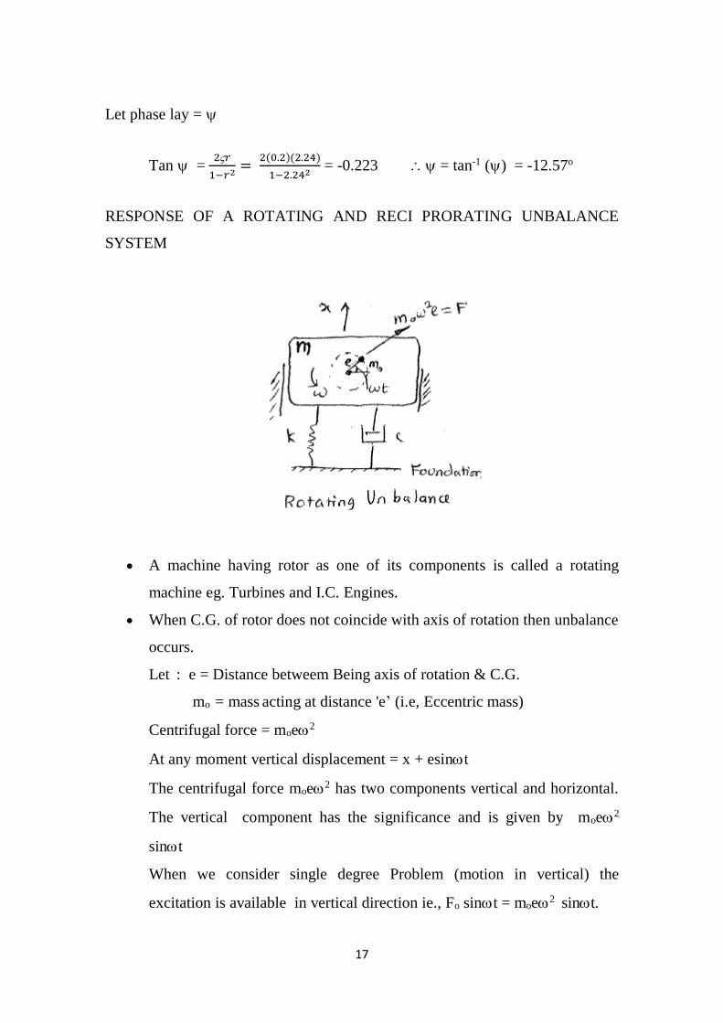
17
Let phase lay =
Tan = 2𝑟
1−𝑟2=
2(0.2)(2.24)
1−2.242 = -0.223 = tan-1 () = -12.57o
RESPONSE OF A ROTATING AND RECI PRORATING UNBALANCE
SYSTEM
A machine having rotor as one of its components is called a rotating
machine eg. Turbines and I.C. Engines.
When C.G. of rotor does not coincide with axis of rotation then unbalance
occurs.
Let : e = Distance betweem Being axis of rotation & C.G.
mo = mass acting at distance 'e’ (i.e, Eccentric mass)
Centrifugal force = moe2
At any moment vertical displacement = x + esint
The centrifugal force moe2 has two components vertical and horizontal.
The vertical component has the significance and is given by moe2
sint
When we consider single degree Problem (motion in vertical) the
excitation is available in vertical direction ie., Fo sint = moe2 sint.
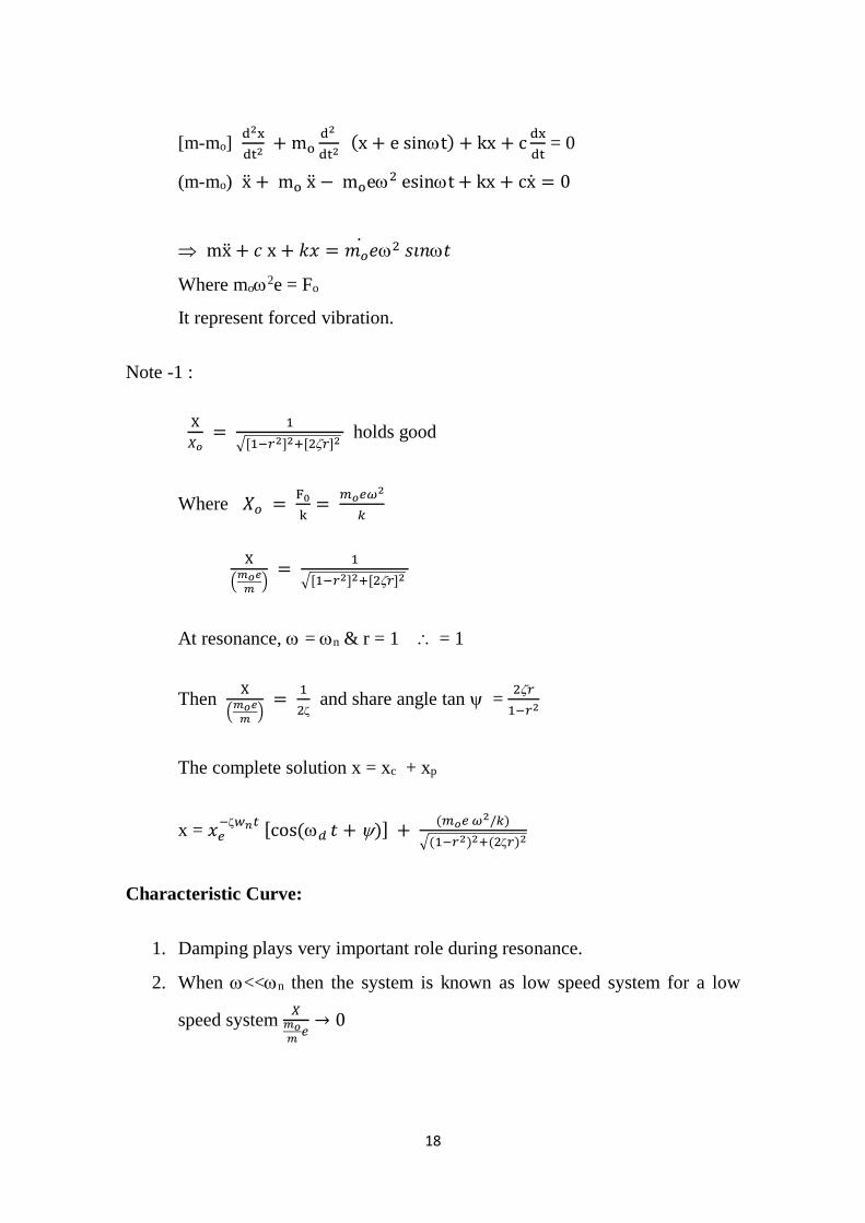
18
[m-mo] d2x
dt2 + mo
d2
dt2 (x + e sint) + kx + c
dx
dt = 0
(m-mo) x + mo x − moe2 esint + kx + cx = 0
mx + 𝑐 x + 𝑘𝑥 = 𝑚𝑜𝑒2 𝑠𝑖𝑛𝑡
Where mo2e = Fo
It represent forced vibration.
Note -1 :
X
𝑋𝑜 =
1
√[1−𝑟2]2+[2𝑟]2 holds good
Where 𝑋𝑜 = F0
k=
𝑚𝑜𝑒𝜔2
𝑘
X
(𝑚𝑜𝑒
𝑚)
= 1
√[1−𝑟2]2+[2𝑟]2
At resonance, = n & r = 1 = 1
Then X
(𝑚𝑜𝑒
𝑚)
= 1
2 and share angle tan =
2𝑟
1−𝑟2
The complete solution x = xc + xp
x = 𝑥𝑒−𝑤𝑛𝑡
[cos(𝑑 𝑡 + )] + (𝑚𝑜𝑒 𝜔2/𝑘)
√(1−𝑟2)2+(2𝑟)2
Characteristic Curve:
1. Damping plays very important role during resonance.
2. When <<n then the system is known as low speed system for a low
speed system 𝑋
𝑚𝑜𝑚
𝑒→ 0
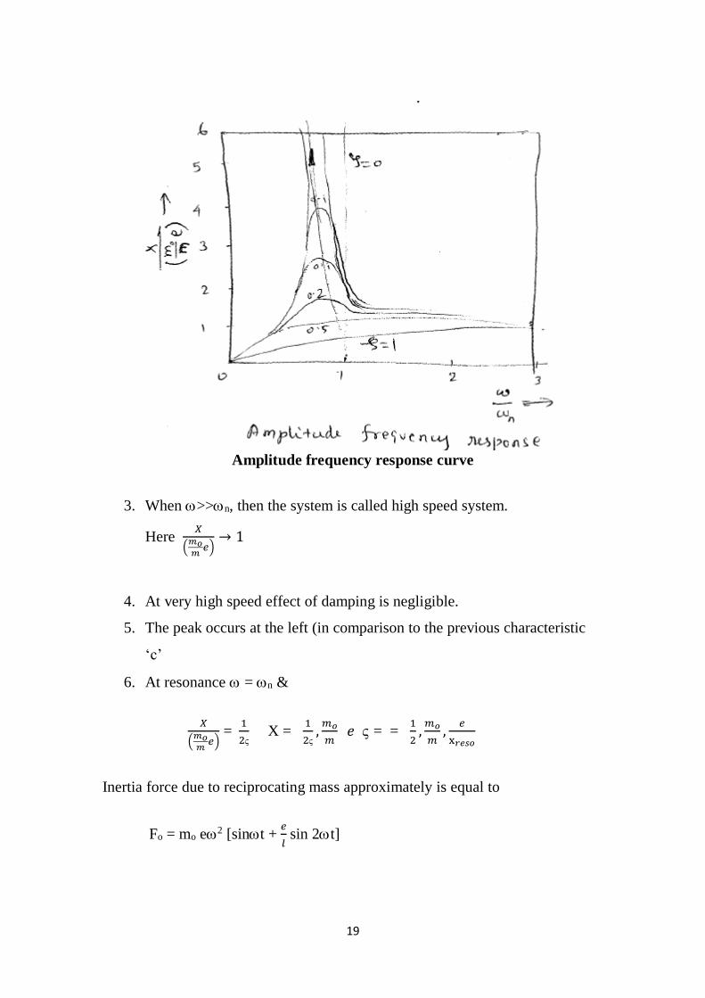
19
Amplitude frequency response curve
3. When >>n, then the system is called high speed system.
Here 𝑋
(𝑚𝑜𝑚
𝑒)→ 1
4. At very high speed effect of damping is negligible.
5. The peak occurs at the left (in comparison to the previous characteristic
‘c’
6. At resonance = n &
𝑋
(𝑚𝑜𝑚
𝑒) =
1
2 X =
1
2,
𝑚𝑜
𝑚 𝑒 = =
1
2,
𝑚𝑜
𝑚,
𝑒
x𝑟𝑒𝑠𝑜
Inertia force due to reciprocating mass approximately is equal to
Fo = mo e2 [sint + 𝑒
𝑙 sin 2t]
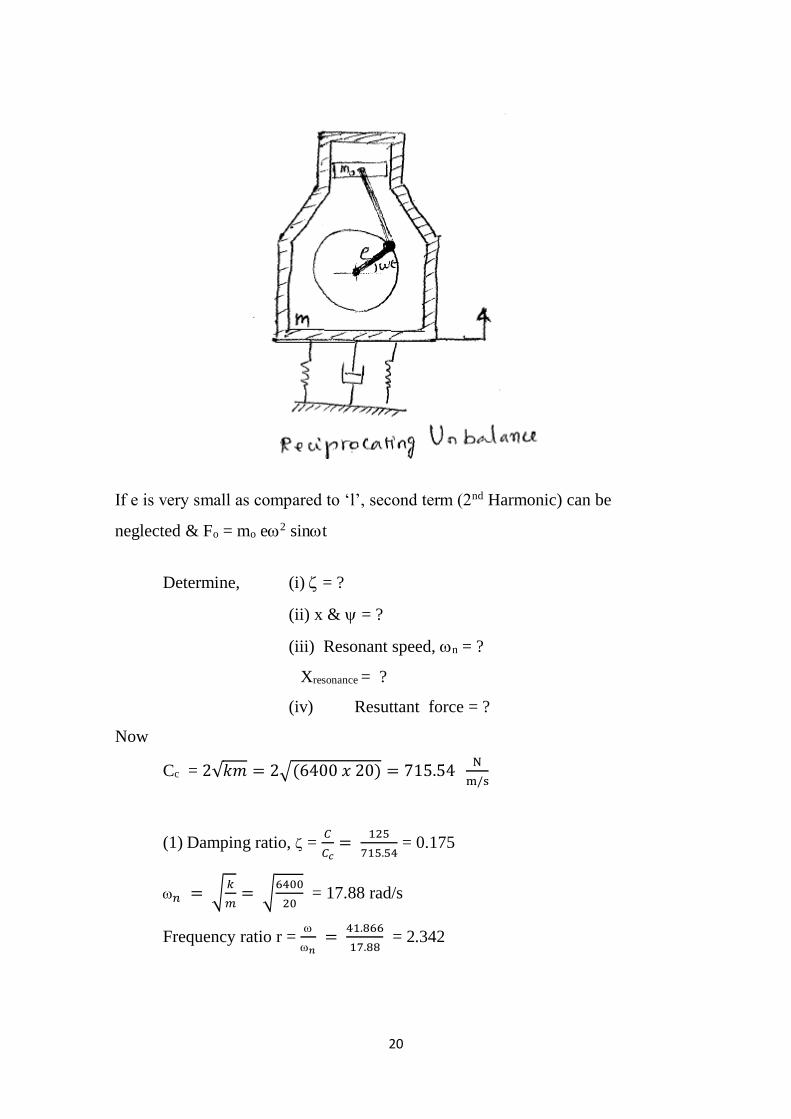
20
If e is very small as compared to ‘l’, second term (2nd Harmonic) can be
neglected & Fo = mo e2 sint
Determine, (i) = ?
(ii) x & = ?
(iii) Resonant speed, n = ?
Xresonance = ?
(iv) Resuttant force = ?
Now
Cc = 2√𝑘𝑚 = 2√(6400 𝑥 20) = 715.54 N
m/s
(1) Damping ratio, = 𝐶
𝐶𝑐=
125
715.54 = 0.175
𝑛 = √𝑘
𝑚= √
6400
20 = 17.88 rad/s
Frequency ratio r =
𝑛 =
41.866
17.88 = 2.342
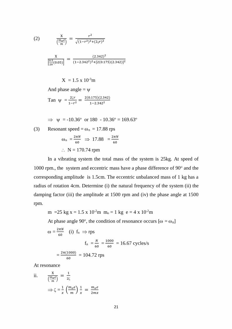
21
(2) X
(𝑚𝑜𝑒
𝑚)
= 𝑟2
√(1−𝑟2)2+(2𝑟)2
X
[0.5
20(0.05)]
= (2.342)2
(1−2.3422)2+[2(0.175)(2.342)]2
X = 1.5 x 10⁻³m
And phase angle =
Tan = 2𝑟
1−𝑟2=
2(0.175)(2.342)
1−2.3422
= -10.36 or 180 - 10.36 = 169.63
(3) Resonant speed = n = 17.88 rps
n = 2𝜋𝑁
60 17.88 =
2𝜋𝑁
60
N = 170.74 rpm
In a vibrating system the total mass of the system is 25kg. At speed of
1000 rpm., the system and eccentric mass have a phase difference of 90 and the
corresponding amplitude is 1.5cm. The eccentric unbalanced mass of 1 kg has a
radius of rotation 4cm. Determine (i) the natural frequency of the system (ii) the
damping factor (iii) the amplitude at 1500 rpm and (iv) the phase angle at 1500
rpm.
m =25 kg x = 1.5 x 10⁻²m mo = 1 kg e = 4 x 10⁻²m
At phase angle 90, the condition of resonance occurs [ = n]
= 2𝜋𝑁
60 (i) fn rps
fn = 𝑁
60 =
1000
60 = 16.67 cycles/s
= 2π(1000)
60 = 104.72 rps
At resonance
ii. X
(𝑚𝑜𝑒
𝑚)
= 1
2
= 1
𝑥 (
𝑚𝑜𝑒
𝑚)
1
𝑥 =
𝑚𝑜𝑒
2𝑚𝑥
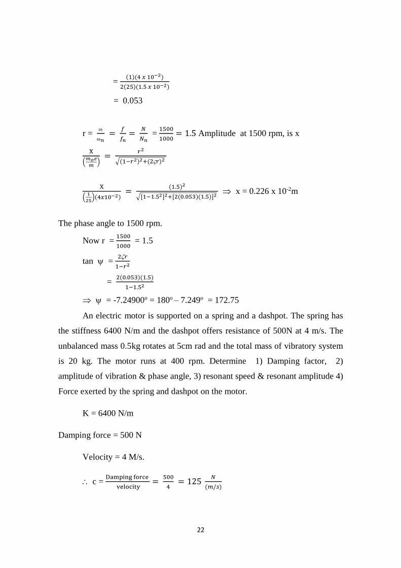
22
= (1)(4 𝑥 10−2)
2(25)(1.5 𝑥 10−2)
= 0.053
r =
𝑛 =
𝑓
𝑓𝑛=
𝑁
𝑁𝑛 =
1500
1000= 1.5 Amplitude at 1500 rpm, is x
X
(𝑚𝑜𝑒
𝑚)
= 𝑟2
√(1−𝑟2)2+(2𝑟)2
X
(1
25)(4𝑥10−2)
= (1.5)2
√[1−1.52]2+[2(0.053)(1.5)]2 x = 0.226 x 10⁻²m
The phase angle to 1500 rpm.
Now r = 1500
1000 = 1.5
tan = 2𝑟
1−𝑟2
= 2(0.053)(1.5)
1−1.52
= -7.24900o = 180o – 7.249o = 172.75
An electric motor is supported on a spring and a dashpot. The spring has
the stiffness 6400 N/m and the dashpot offers resistance of 500N at 4 m/s. The
unbalanced mass 0.5kg rotates at 5cm rad and the total mass of vibratory system
is 20 kg. The motor runs at 400 rpm. Determine 1) Damping factor, 2)
amplitude of vibration & phase angle, 3) resonant speed & resonant amplitude 4)
Force exerted by the spring and dashpot on the motor.
K = 6400 N/m
Damping force = 500 N
Velocity = 4 M/s.
c = Damping force
velocity=
500
4 = 125
𝑁
(𝑚/𝑠)
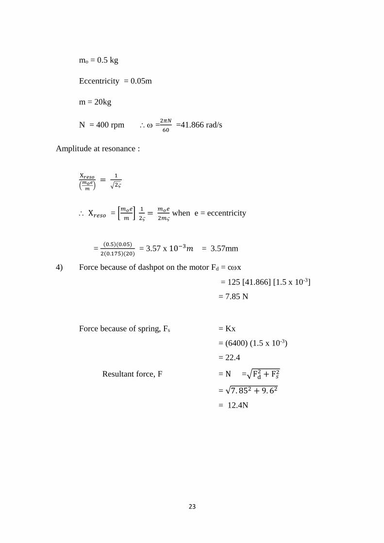
23
mo = 0.5 kg
Eccentricity = 0.05m
m = 20kg
N = 400 rpm =2𝜋𝑁
60 =41.866 rad/s
Amplitude at resonance :
X𝑟𝑒𝑠𝑜
(𝑚𝑜𝑒
𝑚)
= 1
√2
X𝑟𝑒𝑠𝑜 = [𝑚𝑜𝑒
𝑚]
1
2=
𝑚𝑜𝑒
2𝑚 when e = eccentricity
= (0.5)(0.05)
2(0.175)(20) = 3.57 x 10⁻³𝑚 = 3.57mm
4) Force because of dashpot on the motor Fd = cx
= 125 [41.866] [1.5 x 10⁻³]
= 7.85 N
Force because of spring, Fs = Kx
= (6400) (1.5 x 10⁻³)
= 22.4
Resultant force, F = N =√Fd2 + F𝑠
2
= √7. 852 + 9. 62
= 12.4N

1
SCHOOL OF MECHANICAL ENGINEERING
DEPARTMENT OF MECHANICAL ENGINEERING
UNIT – V - GOVERNORS AND GYROSCOPES – SMEA1402
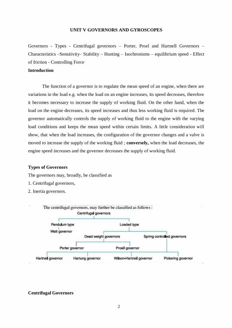
2
UNIT V GOVERNORS AND GYROSCOPES
Governors - Types - Centrifugal governors – Porter, Proel and Hartnell Governors –
Characteristics –Sensitivity– Stability – Hunting – Isochronisms – equilibrium speed - Effect
of friction - Controlling Force
Introduction
The function of a governor is to regulate the mean speed of an engine, when there are
variations in the load e.g. when the load on an engine increases, its speed decreases, therefore
it becomes necessary to increase the supply of working fluid. On the other hand, when the
load on the engine decreases, its speed increases and thus less working fluid is required. The
governor automatically controls the supply of working fluid to the engine with the varying
load conditions and keeps the mean speed within certain limits. A little consideration will
show, that when the load increases, the configuration of the governor changes and a valve is
moved to increase the supply of the working fluid ; conversely, when the load decreases, the
engine speed increases and the governor decreases the supply of working fluid.
Types of Governors
The governors may, broadly, be classified as
1. Centrifugal governors,
2. Inertia governors.
Centrifugal Governors
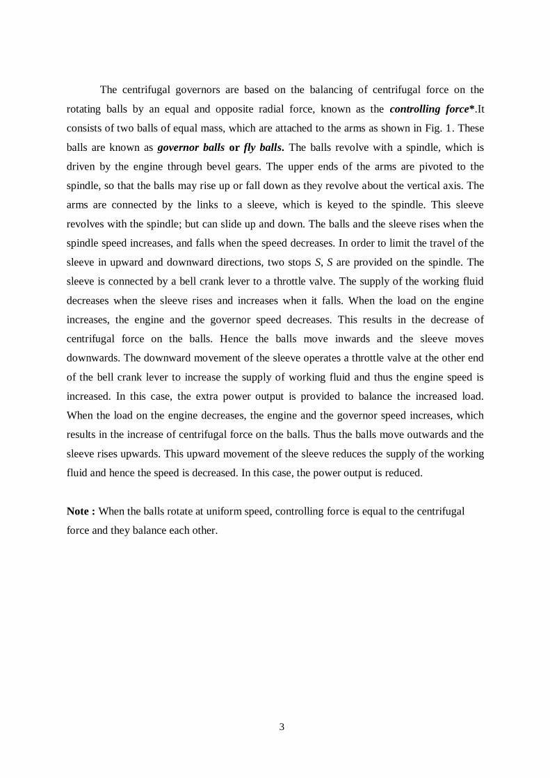
3
The centrifugal governors are based on the balancing of centrifugal force on the
rotating balls by an equal and opposite radial force, known as the controlling force*.It
consists of two balls of equal mass, which are attached to the arms as shown in Fig. 1. These
balls are known as governor balls or fly balls. The balls revolve with a spindle, which is
driven by the engine through bevel gears. The upper ends of the arms are pivoted to the
spindle, so that the balls may rise up or fall down as they revolve about the vertical axis. The
arms are connected by the links to a sleeve, which is keyed to the spindle. This sleeve
revolves with the spindle; but can slide up and down. The balls and the sleeve rises when the
spindle speed increases, and falls when the speed decreases. In order to limit the travel of the
sleeve in upward and downward directions, two stops S, S are provided on the spindle. The
sleeve is connected by a bell crank lever to a throttle valve. The supply of the working fluid
decreases when the sleeve rises and increases when it falls. When the load on the engine
increases, the engine and the governor speed decreases. This results in the decrease of
centrifugal force on the balls. Hence the balls move inwards and the sleeve moves
downwards. The downward movement of the sleeve operates a throttle valve at the other end
of the bell crank lever to increase the supply of working fluid and thus the engine speed is
increased. In this case, the extra power output is provided to balance the increased load.
When the load on the engine decreases, the engine and the governor speed increases, which
results in the increase of centrifugal force on the balls. Thus the balls move outwards and the
sleeve rises upwards. This upward movement of the sleeve reduces the supply of the working
fluid and hence the speed is decreased. In this case, the power output is reduced.
Note : When the balls rotate at uniform speed, controlling force is equal to the centrifugal
force and they balance each other.
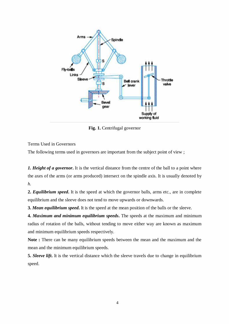
4
Fig. 1. Centrifugal governor
Terms Used in Governors
The following terms used in governors are important from the subject point of view ;
1. Height of a governor. It is the vertical distance from the centre of the ball to a point where
the axes of the arms (or arms produced) intersect on the spindle axis. It is usually denoted by
h.
2. Equilibrium speed. It is the speed at which the governor balls, arms etc., are in complete
equilibrium and the sleeve does not tend to move upwards or downwards.
3. Mean equilibrium speed. It is the speed at the mean position of the balls or the sleeve.
4. Maximum and minimum equilibrium speeds. The speeds at the maximum and minimum
radius of rotation of the balls, without tending to move either way are known as maximum
and minimum equilibrium speeds respectively.
Note : There can be many equilibrium speeds between the mean and the maximum and the
mean and the minimum equilibrium speeds.
5. Sleeve lift. It is the vertical distance which the sleeve travels due to change in equilibrium
speed.
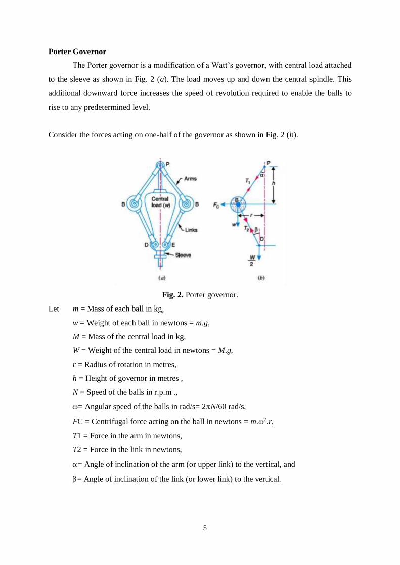
5
Porter Governor
The Porter governor is a modification of a Watt’s governor, with central load attached
to the sleeve as shown in Fig. 2 (a). The load moves up and down the central spindle. This
additional downward force increases the speed of revolution required to enable the balls to
rise to any predetermined level.
Consider the forces acting on one-half of the governor as shown in Fig. 2 (b).
Fig. 2. Porter governor.
Let m = Mass of each ball in kg,
w = Weight of each ball in newtons = m.g,
M = Mass of the central load in kg,
W = Weight of the central load in newtons = M.g,
r = Radius of rotation in metres,
h = Height of governor in metres ,
N = Speed of the balls in r.p.m .,
= Angular speed of the balls in rad/s= 2N/60 rad/s,
FC = Centrifugal force acting on the ball in newtons = m..r,
T1 = Force in the arm in newtons,
T2 = Force in the link in newtons,
= Angle of inclination of the arm (or upper link) to the vertical, and
= Angle of inclination of the link (or lower link) to the vertical.
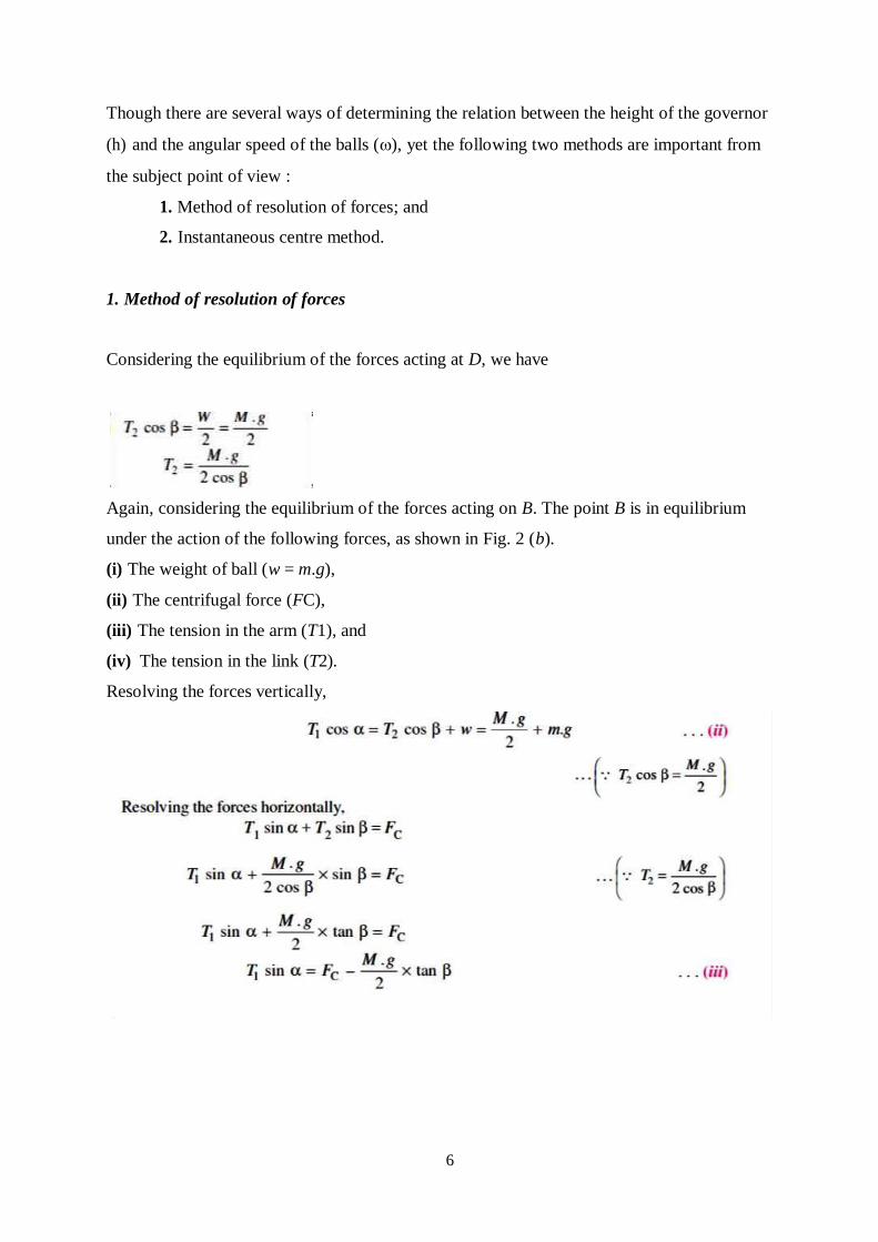
6
Though there are several ways of determining the relation between the height of the governor
(h) and the angular speed of the balls (), yet the following two methods are important from
the subject point of view :
1. Method of resolution of forces; and
2. Instantaneous centre method.
1. Method of resolution of forces
Considering the equilibrium of the forces acting at D, we have
Again, considering the equilibrium of the forces acting on B. The point B is in equilibrium
under the action of the following forces, as shown in Fig. 2 (b).
(i) The weight of ball (w = m.g),
(ii) The centrifugal force (FC),
(iii) The tension in the arm (T1), and
(iv) The tension in the link (T2).
Resolving the forces vertically,
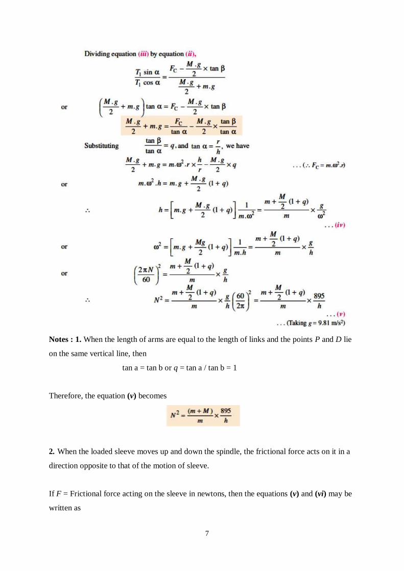
7
Notes : 1. When the length of arms are equal to the length of links and the points P and D lie
on the same vertical line, then
tan a = tan b or q = tan a / tan b = 1
Therefore, the equation (v) becomes
2. When the loaded sleeve moves up and down the spindle, the frictional force acts on it in a
direction opposite to that of the motion of sleeve.
If F = Frictional force acting on the sleeve in newtons, then the equations (v) and (vi) may be
written as
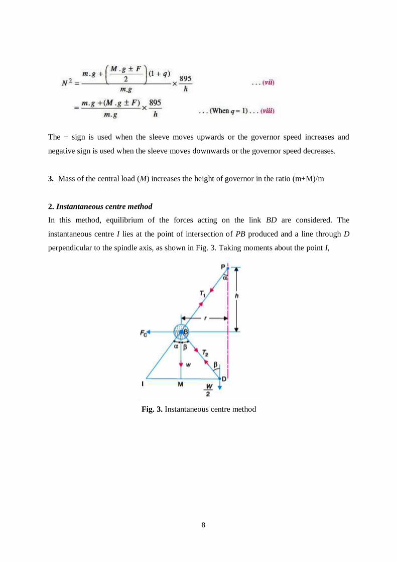
8
The + sign is used when the sleeve moves upwards or the governor speed increases and
negative sign is used when the sleeve moves downwards or the governor speed decreases.
3. Mass of the central load (M) increases the height of governor in the ratio (m+M)/m
2. Instantaneous centre method
In this method, equilibrium of the forces acting on the link BD are considered. The
instantaneous centre I lies at the point of intersection of PB produced and a line through D
perpendicular to the spindle axis, as shown in Fig. 3. Taking moments about the point I,
Fig. 3. Instantaneous centre method
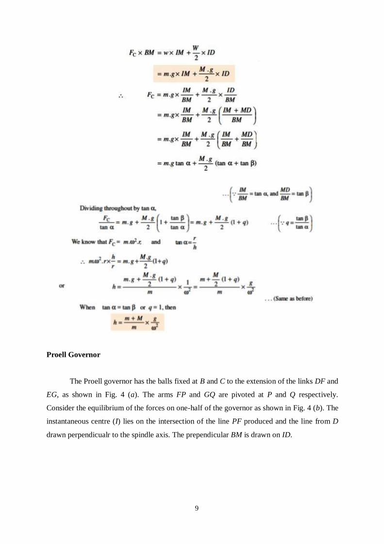
9
Proell Governor
The Proell governor has the balls fixed at B and C to the extension of the links DF and
EG, as shown in Fig. 4 (a). The arms FP and GQ are pivoted at P and Q respectively.
Consider the equilibrium of the forces on one-half of the governor as shown in Fig. 4 (b). The
instantaneous centre (I) lies on the intersection of the line PF produced and the line from D
drawn perpendicualr to the spindle axis. The prependicular BM is drawn on ID.
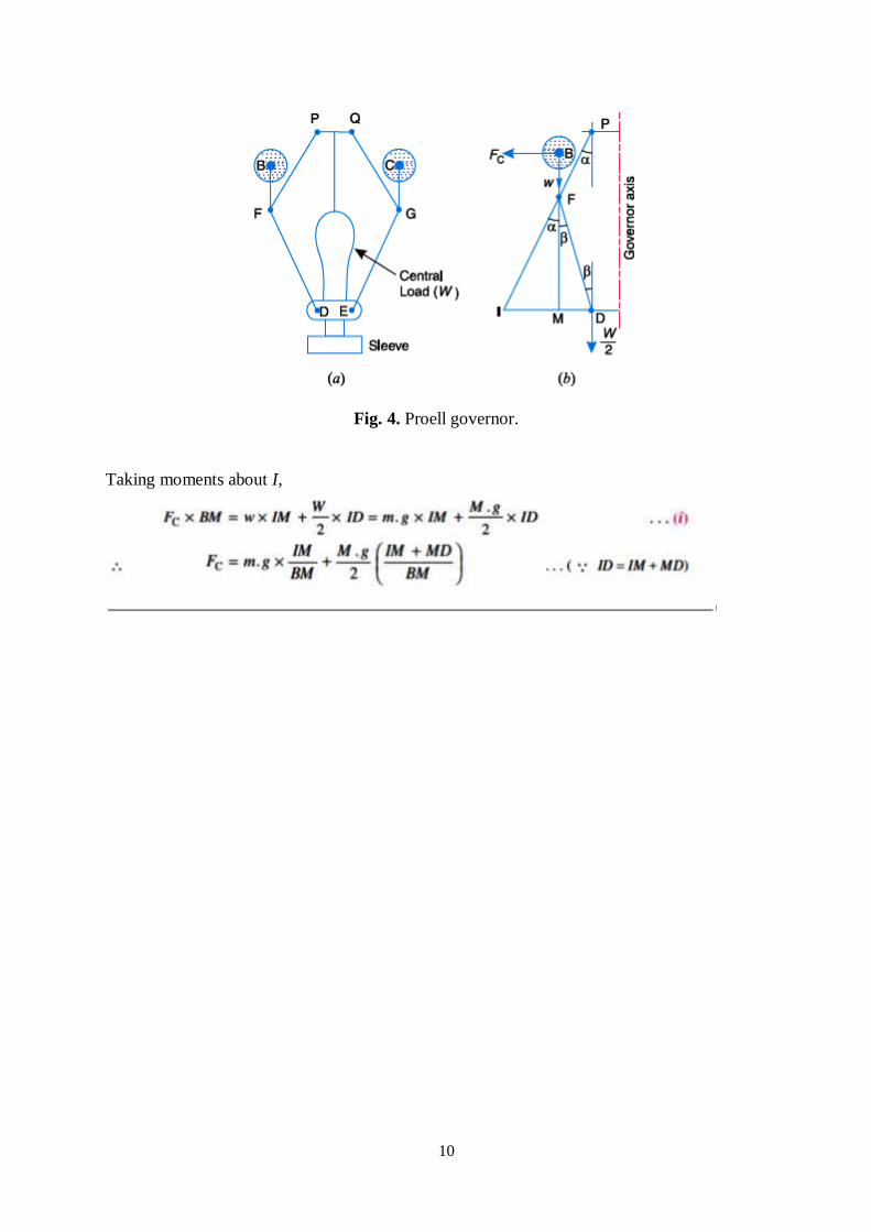
10
Fig. 4. Proell governor.
Taking moments about I,
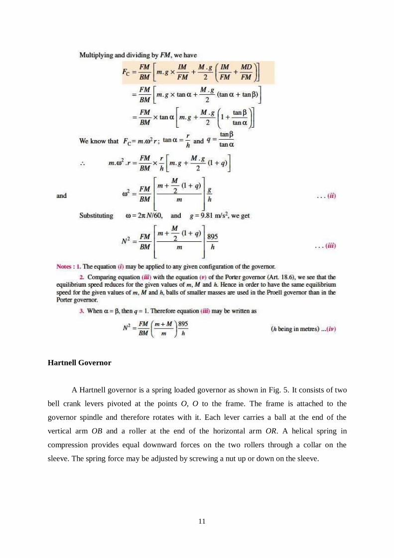
11
Hartnell Governor
A Hartnell governor is a spring loaded governor as shown in Fig. 5. It consists of two
bell crank levers pivoted at the points O, O to the frame. The frame is attached to the
governor spindle and therefore rotates with it. Each lever carries a ball at the end of the
vertical arm OB and a roller at the end of the horizontal arm OR. A helical spring in
compression provides equal downward forces on the two rollers through a collar on the
sleeve. The spring force may be adjusted by screwing a nut up or down on the sleeve.
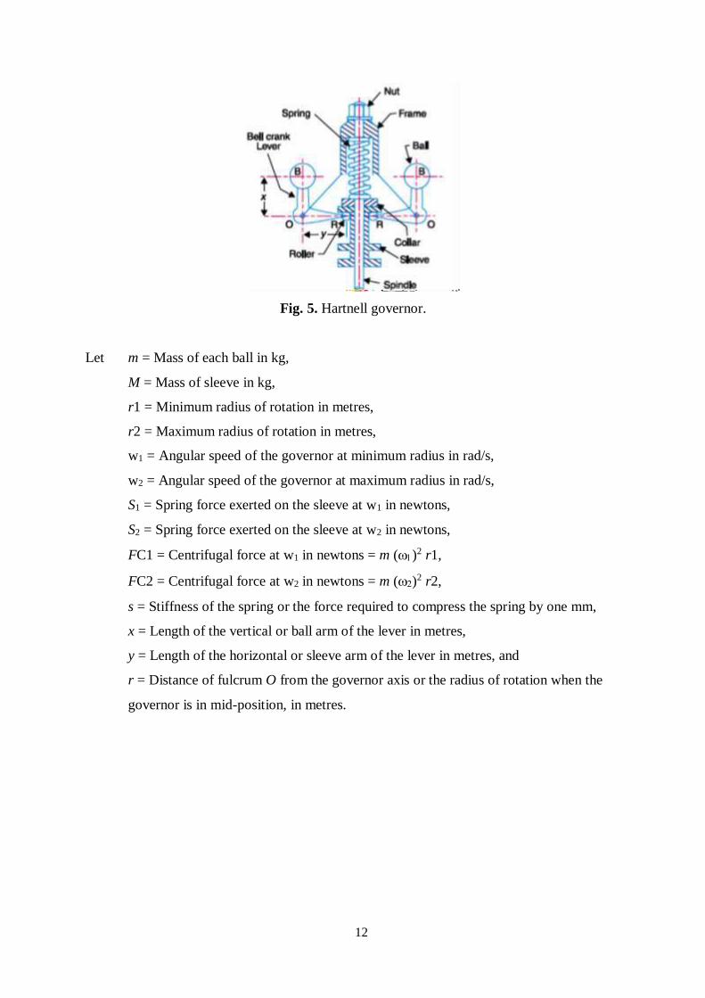
12
Fig. 5. Hartnell governor.
Let m = Mass of each ball in kg,
M = Mass of sleeve in kg,
r1 = Minimum radius of rotation in metres,
r2 = Maximum radius of rotation in metres,
w1 = Angular speed of the governor at minimum radius in rad/s,
w2 = Angular speed of the governor at maximum radius in rad/s,
S1 = Spring force exerted on the sleeve at w1 in newtons,
S2 = Spring force exerted on the sleeve at w2 in newtons,
FC1 = Centrifugal force at w1 in newtons = m ()2 r1,
FC2 = Centrifugal force at w2 in newtons = m ()2 r2,
s = Stiffness of the spring or the force required to compress the spring by one mm,
x = Length of the vertical or ball arm of the lever in metres,
y = Length of the horizontal or sleeve arm of the lever in metres, and
r = Distance of fulcrum O from the governor axis or the radius of rotation when the
governor is in mid-position, in metres.
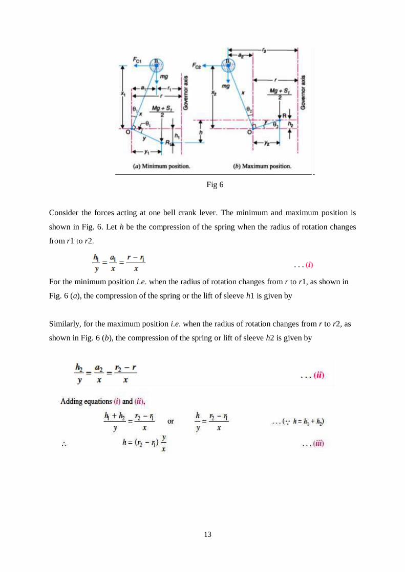
13
Fig 6
Consider the forces acting at one bell crank lever. The minimum and maximum position is
shown in Fig. 6. Let h be the compression of the spring when the radius of rotation changes
from r1 to r2.
For the minimum position i.e. when the radius of rotation changes from r to r1, as shown in
Fig. 6 (a), the compression of the spring or the lift of sleeve h1 is given by
Similarly, for the maximum position i.e. when the radius of rotation changes from r to r2, as
shown in Fig. 6 (b), the compression of the spring or lift of sleeve h2 is given by
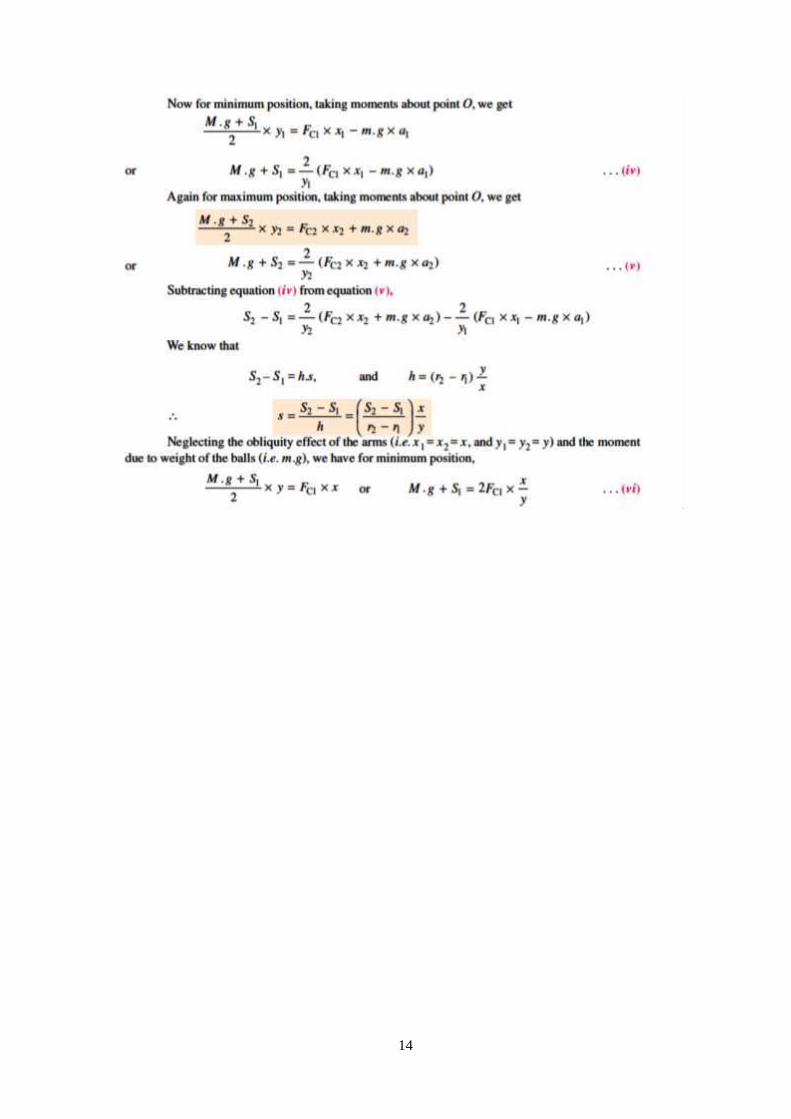
14
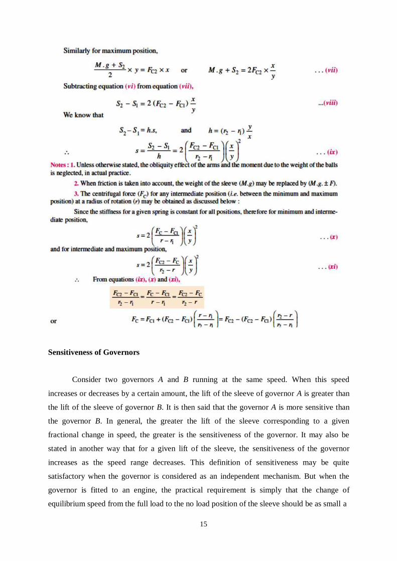
15
Sensitiveness of Governors
Consider two governors A and B running at the same speed. When this speed
increases or decreases by a certain amount, the lift of the sleeve of governor A is greater than
the lift of the sleeve of governor B. It is then said that the governor A is more sensitive than
the governor B. In general, the greater the lift of the sleeve corresponding to a given
fractional change in speed, the greater is the sensitiveness of the governor. It may also be
stated in another way that for a given lift of the sleeve, the sensitiveness of the governor
increases as the speed range decreases. This definition of sensitiveness may be quite
satisfactory when the governor is considered as an independent mechanism. But when the
governor is fitted to an engine, the practical requirement is simply that the change of
equilibrium speed from the full load to the no load position of the sleeve should be as small a
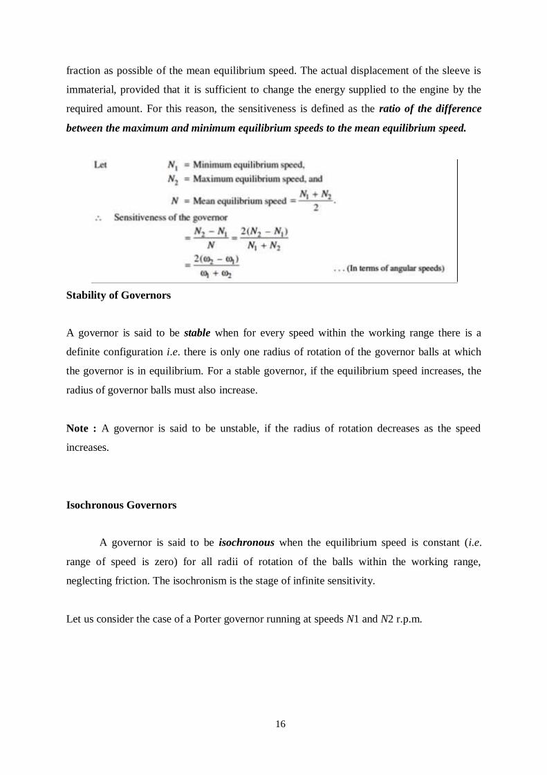
16
fraction as possible of the mean equilibrium speed. The actual displacement of the sleeve is
immaterial, provided that it is sufficient to change the energy supplied to the engine by the
required amount. For this reason, the sensitiveness is defined as the ratio of the difference
between the maximum and minimum equilibrium speeds to the mean equilibrium speed.
Stability of Governors
A governor is said to be stable when for every speed within the working range there is a
definite configuration i.e. there is only one radius of rotation of the governor balls at which
the governor is in equilibrium. For a stable governor, if the equilibrium speed increases, the
radius of governor balls must also increase.
Note : A governor is said to be unstable, if the radius of rotation decreases as the speed
increases.
Isochronous Governors
A governor is said to be isochronous when the equilibrium speed is constant (i.e.
range of speed is zero) for all radii of rotation of the balls within the working range,
neglecting friction. The isochronism is the stage of infinite sensitivity.
Let us consider the case of a Porter governor running at speeds N1 and N2 r.p.m.
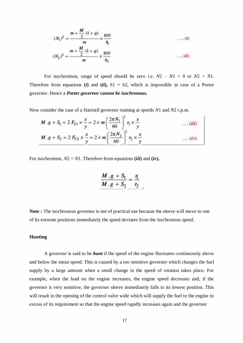
17
For isochronism, range of speed should be zero i.e. N2 – N1 = 0 or N2 = N1.
Therefore from equations (i) and (ii), h1 = h2, which is impossible in case of a Porter
governor. Hence a Porter governor cannot be isochronous.
Now consider the case of a Hartnell governor running at speeds N1 and N2 r.p.m.
For isochronism, N2 = N1. Therefore from equations (iii) and (iv),
Note : The isochronous governor is not of practical use because the sleeve will move to one
of its extreme positions immediately the speed deviates from the isochronous speed.
Hunting
A governor is said to be hunt if the speed of the engine fluctuates continuously above
and below the mean speed. This is caused by a too sensitive governor which changes the fuel
supply by a large amount when a small change in the speed of rotation takes place. For
example, when the load on the engine increases, the engine speed decreases and, if the
governor is very sensitive, the governor sleeve immediately falls to its lowest position. This
will result in the opening of the control valve wide which will supply the fuel to the engine in
excess of its requirement so that the engine speed rapidly increases again and the governor
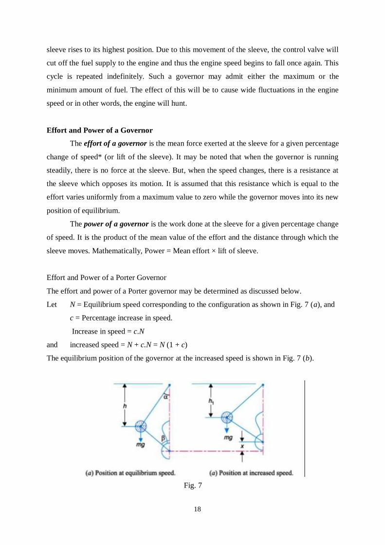
18
sleeve rises to its highest position. Due to this movement of the sleeve, the control valve will
cut off the fuel supply to the engine and thus the engine speed begins to fall once again. This
cycle is repeated indefinitely. Such a governor may admit either the maximum or the
minimum amount of fuel. The effect of this will be to cause wide fluctuations in the engine
speed or in other words, the engine will hunt.
Effort and Power of a Governor
The effort of a governor is the mean force exerted at the sleeve for a given percentage
change of speed* (or lift of the sleeve). It may be noted that when the governor is running
steadily, there is no force at the sleeve. But, when the speed changes, there is a resistance at
the sleeve which opposes its motion. It is assumed that this resistance which is equal to the
effort varies uniformly from a maximum value to zero while the governor moves into its new
position of equilibrium.
The power of a governor is the work done at the sleeve for a given percentage change
of speed. It is the product of the mean value of the effort and the distance through which the
sleeve moves. Mathematically, Power = Mean effort × lift of sleeve.
Effort and Power of a Porter Governor
The effort and power of a Porter governor may be determined as discussed below.
Let N = Equilibrium speed corresponding to the configuration as shown in Fig. 7 (a), and
c = Percentage increase in speed.
Increase in speed = c.N
and increased speed = N + c.N = N (1 + c)
The equilibrium position of the governor at the increased speed is shown in Fig. 7 (b).
Fig. 7
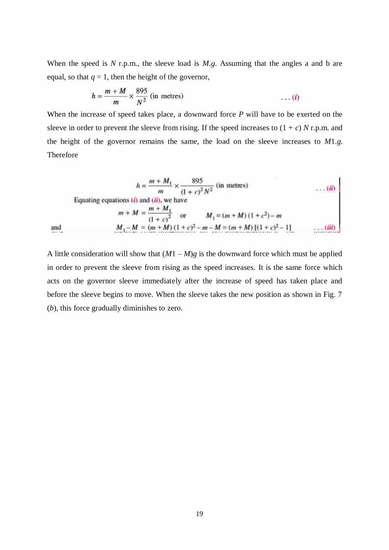
19
When the speed is N r.p.m., the sleeve load is M.g. Assuming that the angles a and b are
equal, so that q = 1, then the height of the governor,
When the increase of speed takes place, a downward force P will have to be exerted on the
sleeve in order to prevent the sleeve from rising. If the speed increases to (1 + c) N r.p.m. and
the height of the governor remains the same, the load on the sleeve increases to M1.g.
Therefore
A little consideration will show that (M1 – M)g is the downward force which must be applied
in order to prevent the sleeve from rising as the speed increases. It is the same force which
acts on the governor sleeve immediately after the increase of speed has taken place and
before the sleeve begins to move. When the sleeve takes the new position as shown in Fig. 7
(b), this force gradually diminishes to zero.
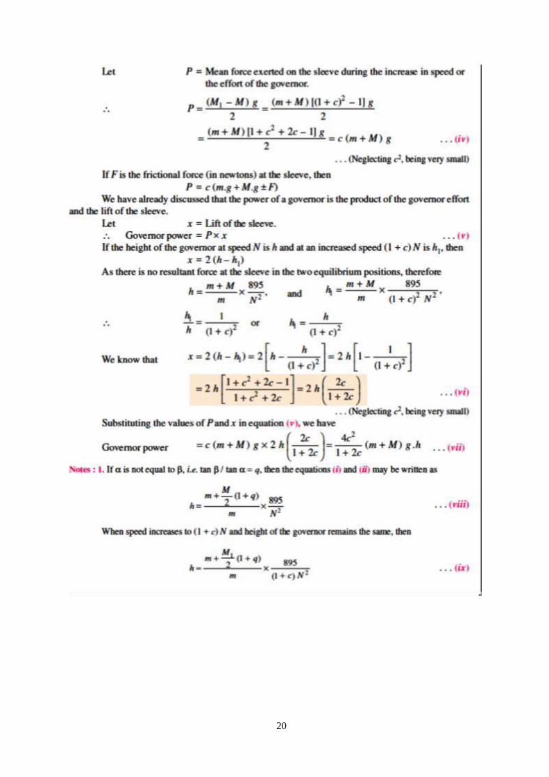
20
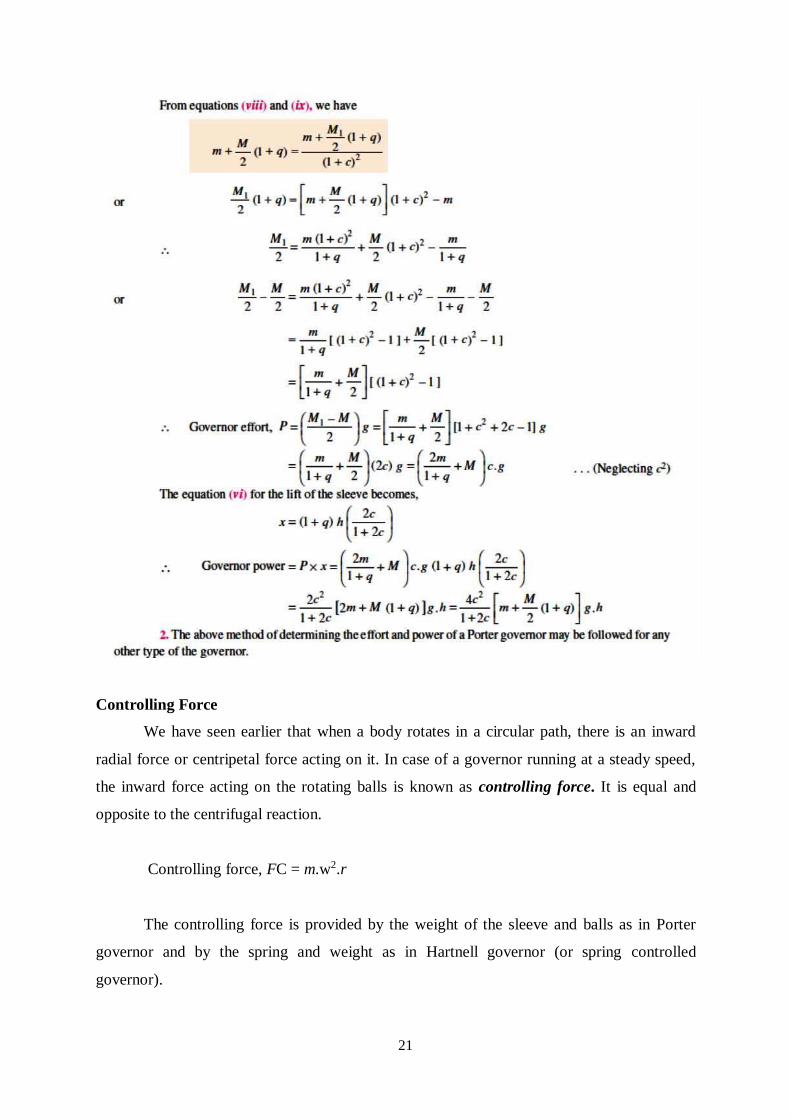
21
Controlling Force
We have seen earlier that when a body rotates in a circular path, there is an inward
radial force or centripetal force acting on it. In case of a governor running at a steady speed,
the inward force acting on the rotating balls is known as controlling force. It is equal and
opposite to the centrifugal reaction.
Controlling force, FC = m.w2.r
The controlling force is provided by the weight of the sleeve and balls as in Porter
governor and by the spring and weight as in Hartnell governor (or spring controlled
governor).
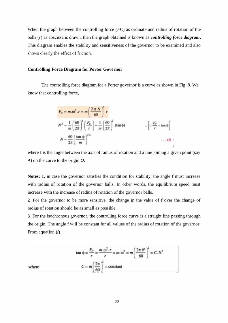
22
When the graph between the controlling force (FC) as ordinate and radius of rotation of the
balls (r) as abscissa is drawn, then the graph obtained is known as controlling force diagram.
This diagram enables the stability and sensitiveness of the governor to be examined and also
shows clearly the effect of friction.
Controlling Force Diagram for Porter Governor
The controlling force diagram for a Porter governor is a curve as shown in Fig. 8. We
know that controlling force,
where f is the angle between the axis of radius of rotation and a line joining a given point (say
A) on the curve to the origin O.
Notes: 1. in case the governor satisfies the condition for stability, the angle f must increase
with radius of rotation of the governor balls. In other words, the equilibrium speed must
increase with the increase of radius of rotation of the governor balls.
2. For the governor to be more sensitive, the change in the value of f over the change of
radius of rotation should be as small as possible.
3. For the isochronous governor, the controlling force curve is a straight line passing through
the origin. The angle f will be constant for all values of the radius of rotation of the governor.
From equation (i)
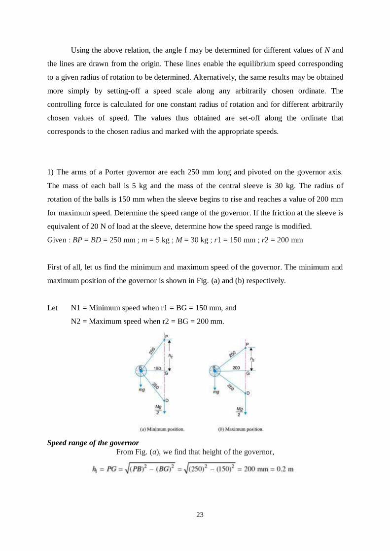
23
Using the above relation, the angle f may be determined for different values of N and
the lines are drawn from the origin. These lines enable the equilibrium speed corresponding
to a given radius of rotation to be determined. Alternatively, the same results may be obtained
more simply by setting-off a speed scale along any arbitrarily chosen ordinate. The
controlling force is calculated for one constant radius of rotation and for different arbitrarily
chosen values of speed. The values thus obtained are set-off along the ordinate that
corresponds to the chosen radius and marked with the appropriate speeds.
1) The arms of a Porter governor are each 250 mm long and pivoted on the governor axis.
The mass of each ball is 5 kg and the mass of the central sleeve is 30 kg. The radius of
rotation of the balls is 150 mm when the sleeve begins to rise and reaches a value of 200 mm
for maximum speed. Determine the speed range of the governor. If the friction at the sleeve is
equivalent of 20 N of load at the sleeve, determine how the speed range is modified.
Given : BP = BD = 250 mm ; m = 5 kg ; M = 30 kg ; r1 = 150 mm ; r2 = 200 mm
First of all, let us find the minimum and maximum speed of the governor. The minimum and
maximum position of the governor is shown in Fig. (a) and (b) respectively.
Let N1 = Minimum speed when r1 = BG = 150 mm, and
N2 = Maximum speed when r2 = BG = 200 mm.
Speed range of the governor
From Fig. (a), we find that height of the governor,
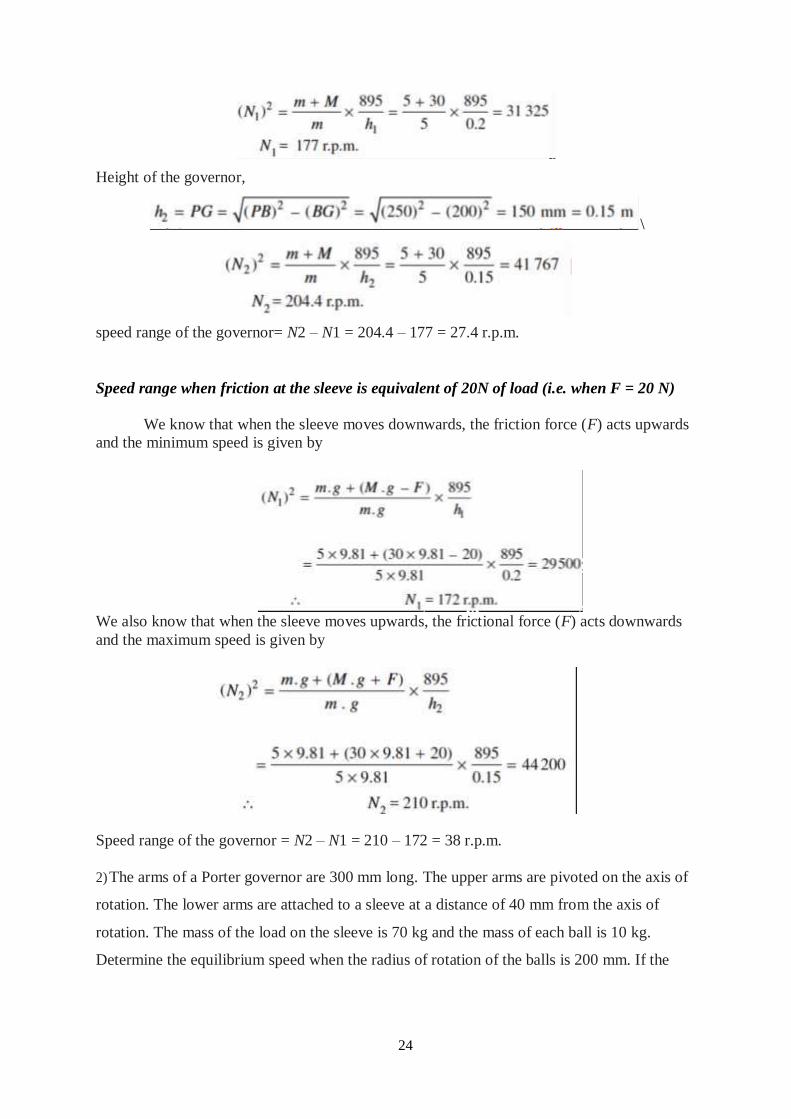
24
Height of the governor,
\
speed range of the governor= N2 – N1 = 204.4 – 177 = 27.4 r.p.m.
Speed range when friction at the sleeve is equivalent of 20N of load (i.e. when F = 20 N)
We know that when the sleeve moves downwards, the friction force (F) acts upwards
and the minimum speed is given by
We also know that when the sleeve moves upwards, the frictional force (F) acts downwards
and the maximum speed is given by
Speed range of the governor = N2 – N1 = 210 – 172 = 38 r.p.m.
2) The arms of a Porter governor are 300 mm long. The upper arms are pivoted on the axis of
rotation. The lower arms are attached to a sleeve at a distance of 40 mm from the axis of
rotation. The mass of the load on the sleeve is 70 kg and the mass of each ball is 10 kg.
Determine the equilibrium speed when the radius of rotation of the balls is 200 mm. If the
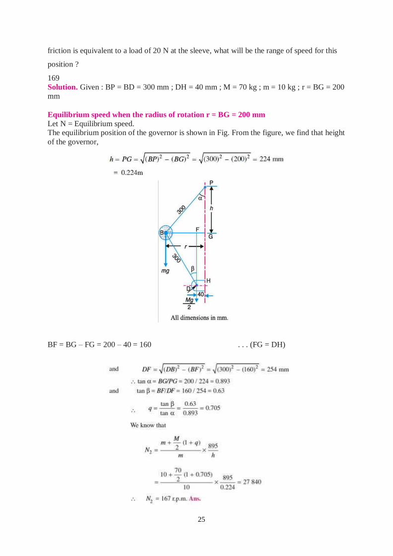
25
friction is equivalent to a load of 20 N at the sleeve, what will be the range of speed for this
position ?
169
Solution. Given : BP = BD = 300 mm ; DH = 40 mm ; M = 70 kg ; m = 10 kg ; r = BG = 200
mm
Equilibrium speed when the radius of rotation r = BG = 200 mm
Let N = Equilibrium speed. The equilibrium position of the governor is shown in Fig. From the figure, we find that height
of the governor,
BF = BG – FG = 200 – 40 = 160 . . . (FG = DH)
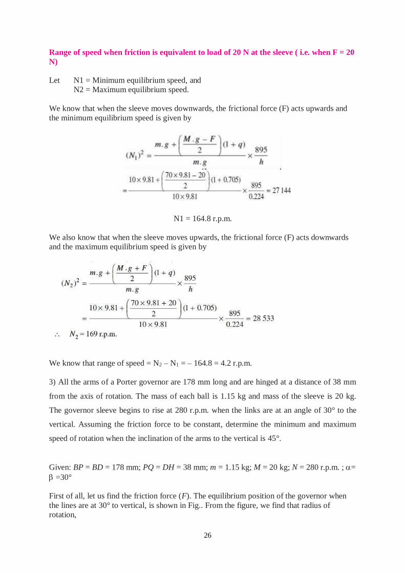
26
Range of speed when friction is equivalent to load of 20 N at the sleeve ( i.e. when F = 20
N)
Let N1 = Minimum equilibrium speed, and
N2 = Maximum equilibrium speed.
We know that when the sleeve moves downwards, the frictional force (F) acts upwards and
the minimum equilibrium speed is given by
N1 = 164.8 r.p.m.
We also know that when the sleeve moves upwards, the frictional force (F) acts downwards
and the maximum equilibrium speed is given by
We know that range of speed = N2 – N1 = – 164.8 = 4.2 r.p.m.
3) All the arms of a Porter governor are 178 mm long and are hinged at a distance of 38 mm
from the axis of rotation. The mass of each ball is 1.15 kg and mass of the sleeve is 20 kg.
The governor sleeve begins to rise at 280 r.p.m. when the links are at an angle of 30° to the
vertical. Assuming the friction force to be constant, determine the minimum and maximum
speed of rotation when the inclination of the arms to the vertical is 45°.
Given: BP = BD = 178 mm; PQ = DH = 38 mm; m = 1.15 kg; M = 20 kg; N = 280 r.p.m. ; =
=30°
First of all, let us find the friction force (F). The equilibrium position of the governor when
the lines are at 30° to vertical, is shown in Fig.. From the figure, we find that radius of
rotation,
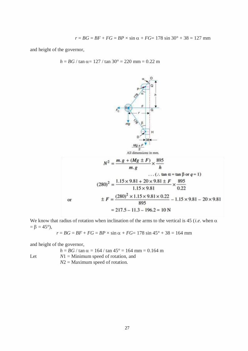
27
r = BG = BF + FG = BP × sin + FG= 178 sin 30° + 38 = 127 mm
and height of the governor,
h = BG / tan = 127 / tan 30° = 220 mm = 0.22 m
We know that radius of rotation when inclination of the arms to the vertical is 45 (i.e. when
= = 45°),
r = BG = BF + FG = BP × sin + FG= 178 sin 45° + 38 = 164 mm
and height of the governor,
h = BG / tan = 164 / tan 45° = 164 mm = 0.164 m
Let N1 = Minimum speed of rotation, and
N2 = Maximum speed of rotation.
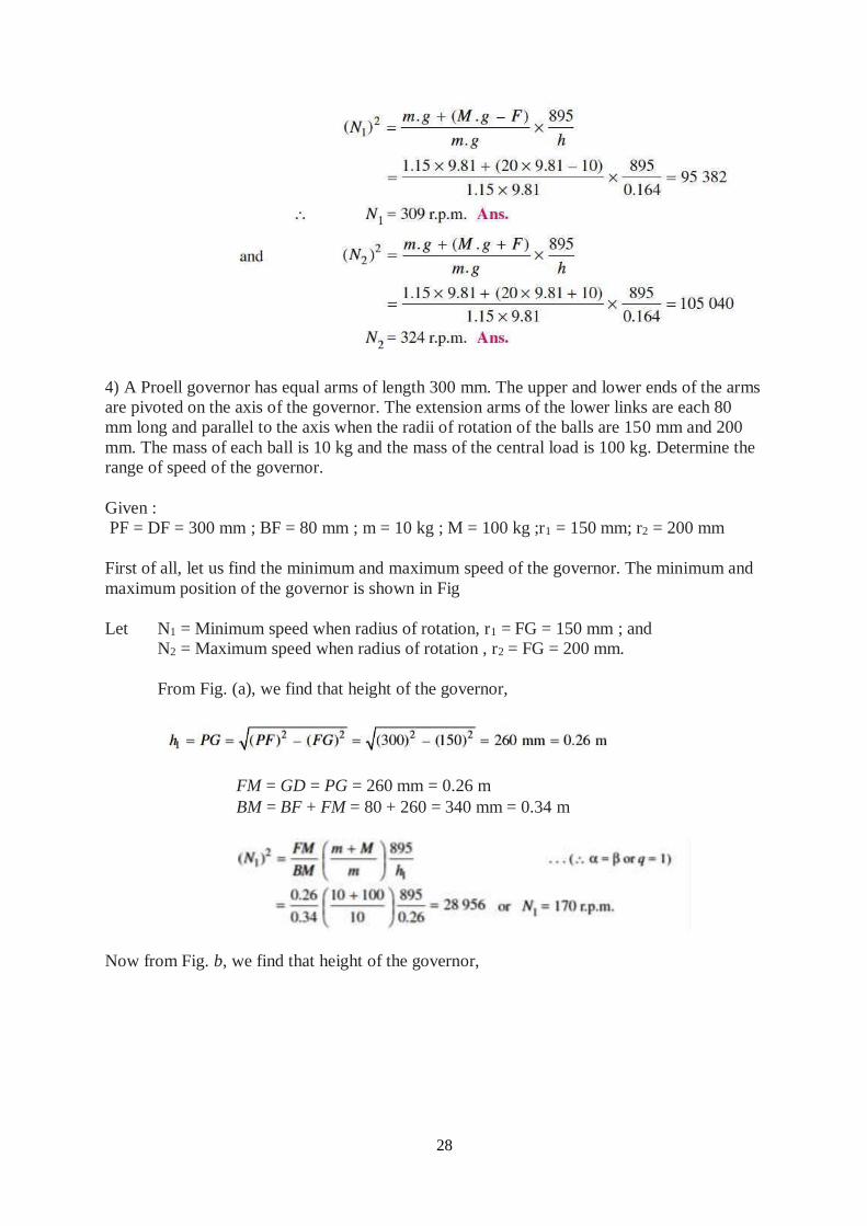
28
4) A Proell governor has equal arms of length 300 mm. The upper and lower ends of the arms
are pivoted on the axis of the governor. The extension arms of the lower links are each 80
mm long and parallel to the axis when the radii of rotation of the balls are 150 mm and 200
mm. The mass of each ball is 10 kg and the mass of the central load is 100 kg. Determine the
range of speed of the governor.
Given :
PF = DF = 300 mm ; BF = 80 mm ; m = 10 kg ; M = 100 kg ;r1 = 150 mm; r2 = 200 mm
First of all, let us find the minimum and maximum speed of the governor. The minimum and
maximum position of the governor is shown in Fig
Let N1 = Minimum speed when radius of rotation, r1 = FG = 150 mm ; and
N2 = Maximum speed when radius of rotation , r2 = FG = 200 mm.
From Fig. (a), we find that height of the governor,
FM = GD = PG = 260 mm = 0.26 m
BM = BF + FM = 80 + 260 = 340 mm = 0.34 m
Now from Fig. b, we find that height of the governor,
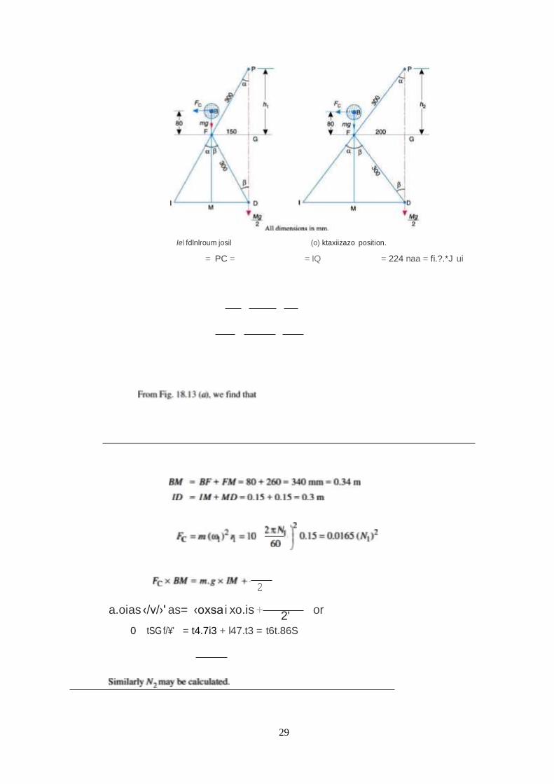
29
Ie\ fdlnlroum josil (o) ktaxiizazo position.
= PC = = IQ = 224 naa = fi.?.*J ui
a.oias ‹/v/›' as= ‹oxsa i xo.is + 2'
or
0 tSG f/¥' = t4.7i3 + l47.t3 = t6t.86S
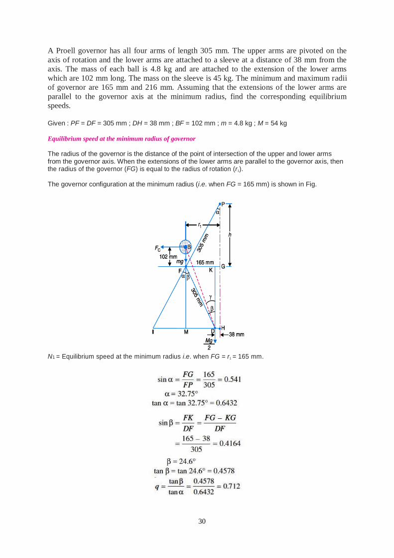
30
A Proell governor has all four arms of length 305 mm. The upper arms are pivoted on the
axis of rotation and the lower arms are attached to a sleeve at a distance of 38 mm from the
axis. The mass of each ball is 4.8 kg and are attached to the extension of the lower arms
which are 102 mm long. The mass on the sleeve is 45 kg. The minimum and maximum radii
of governor are 165 mm and 216 mm. Assuming that the extensions of the lower arms are
parallel to the governor axis at the minimum radius, find the corresponding equilibrium
speeds.
Given : PF = DF = 305 mm ; DH = 38 mm ; BF = 102 mm ; m = 4.8 kg ; M = 54 kg
Equilibrium speed at the minimum radius of governor
The radius of the governor is the distance of the point of intersection of the upper and lower arms from the governor axis. When the extensions of the lower arms are parallel to the governor axis, then the radius of the governor (FG) is equal to the radius of rotation (r1).
The governor configuration at the minimum radius (i.e. when FG = 165 mm) is shown in Fig.
N1 = Equilibrium speed at the minimum radius i.e. when FG = r1 = 165 mm.
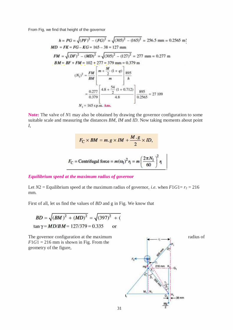
31
From Fig, we find that height of the governor
Note: The valve of N1 may also be obtained by drawing the governor configuration to some
suitable scale and measuring the distances BM, IM and ID. Now taking moments about point
I,
Equilibrium speed at the maximum radius of governor
Let N2 = Equilibrium speed at the maximum radius of governor, i.e. when F1G1= r2 = 216
mm.
First of all, let us find the values of BD and g in Fig. We know that
The governor configuration at the maximum radius of
F1G1 = 216 mm is shown in Fig. From the
geometry of the figure,
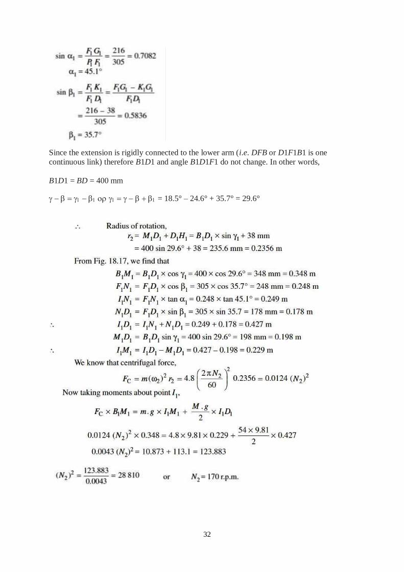
32
Since the extension is rigidly connected to the lower arm (i.e. DFB or D1F1B1 is one
continuous link) therefore B1D1 and angle B1D1F1 do not change. In other words,
B1D1 = BD = 400 mm
= 18.5° – 24.6° + 35.7° = 29.6°
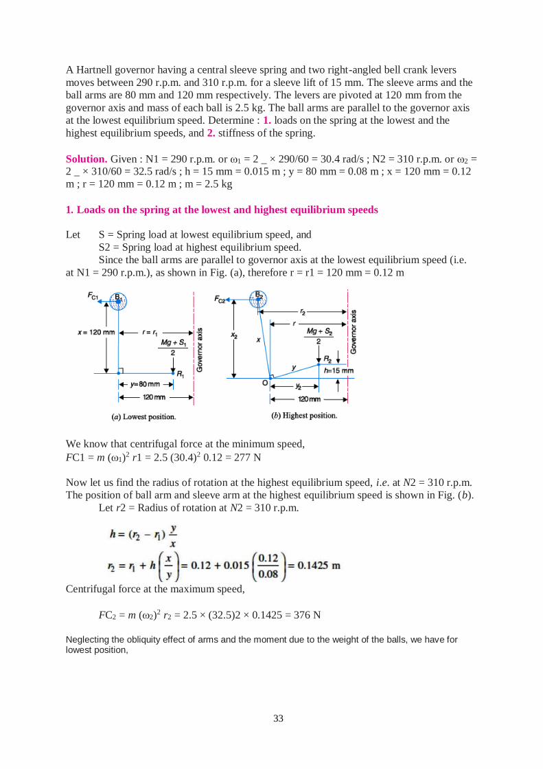
33
A Hartnell governor having a central sleeve spring and two right-angled bell crank levers
moves between 290 r.p.m. and 310 r.p.m. for a sleeve lift of 15 mm. The sleeve arms and the
ball arms are 80 mm and 120 mm respectively. The levers are pivoted at 120 mm from the
governor axis and mass of each ball is 2.5 kg. The ball arms are parallel to the governor axis
at the lowest equilibrium speed. Determine : 1. loads on the spring at the lowest and the
highest equilibrium speeds, and 2. stiffness of the spring.
Solution. Given : N1 = 290 r.p.m. or 1 = 2 _ × 290/60 = 30.4 rad/s ; N2 = 310 r.p.m. or 2 = 2 _ × 310/60 = 32.5 rad/s ; h = 15 mm = 0.015 m ; y = 80 mm = 0.08 m ; x = 120 mm = 0.12
m ; r = 120 mm = 0.12 m ; m = 2.5 kg
1. Loads on the spring at the lowest and highest equilibrium speeds
Let S = Spring load at lowest equilibrium speed, and
S2 = Spring load at highest equilibrium speed.
Since the ball arms are parallel to governor axis at the lowest equilibrium speed (i.e.
at N1 = 290 r.p.m.), as shown in Fig. (a), therefore r = r1 = 120 mm = 0.12 m
We know that centrifugal force at the minimum speed,
FC1 = m (1)2 r1 = 2.5 (30.4)2 0.12 = 277 N
Now let us find the radius of rotation at the highest equilibrium speed, i.e. at N2 = 310 r.p.m.
The position of ball arm and sleeve arm at the highest equilibrium speed is shown in Fig. (b).
Let r2 = Radius of rotation at N2 = 310 r.p.m.
Centrifugal force at the maximum speed,
FC2 = m (2)2 r2 = 2.5 × (32.5)2 × 0.1425 = 376 N
Neglecting the obliquity effect of arms and the moment due to the weight of the balls, we have for lowest position,
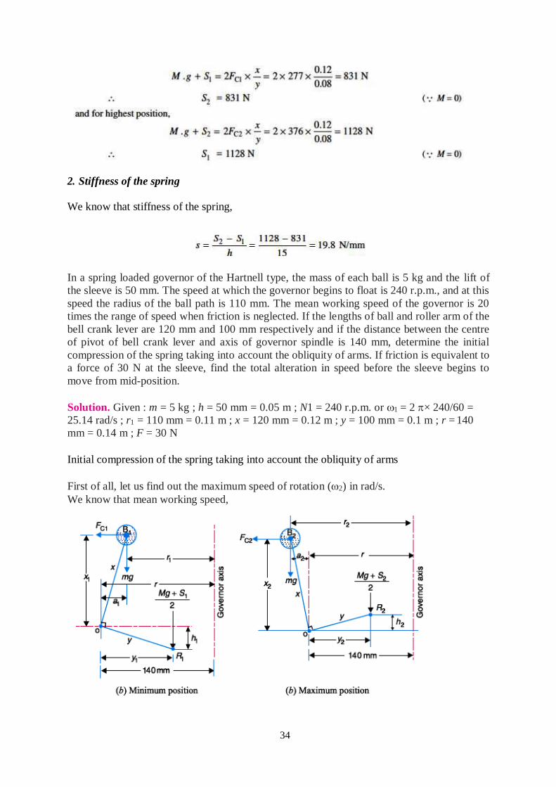
34
2. Stiffness of the spring
We know that stiffness of the spring,
In a spring loaded governor of the Hartnell type, the mass of each ball is 5 kg and the lift of
the sleeve is 50 mm. The speed at which the governor begins to float is 240 r.p.m., and at this
speed the radius of the ball path is 110 mm. The mean working speed of the governor is 20
times the range of speed when friction is neglected. If the lengths of ball and roller arm of the
bell crank lever are 120 mm and 100 mm respectively and if the distance between the centre
of pivot of bell crank lever and axis of governor spindle is 140 mm, determine the initial
compression of the spring taking into account the obliquity of arms. If friction is equivalent to
a force of 30 N at the sleeve, find the total alteration in speed before the sleeve begins to
move from mid-position.
Solution. Given : m = 5 kg ; h = 50 mm = 0.05 m ; N1 = 240 r.p.m. or 1 = 2 × 240/60 =
25.14 rad/s ; r1 = 110 mm = 0.11 m ; x = 120 mm = 0.12 m ; y = 100 mm = 0.1 m ; r = 140
mm = 0.14 m ; F = 30 N
Initial compression of the spring taking into account the obliquity of arms
First of all, let us find out the maximum speed of rotation (2) in rad/s.
We know that mean working speed,
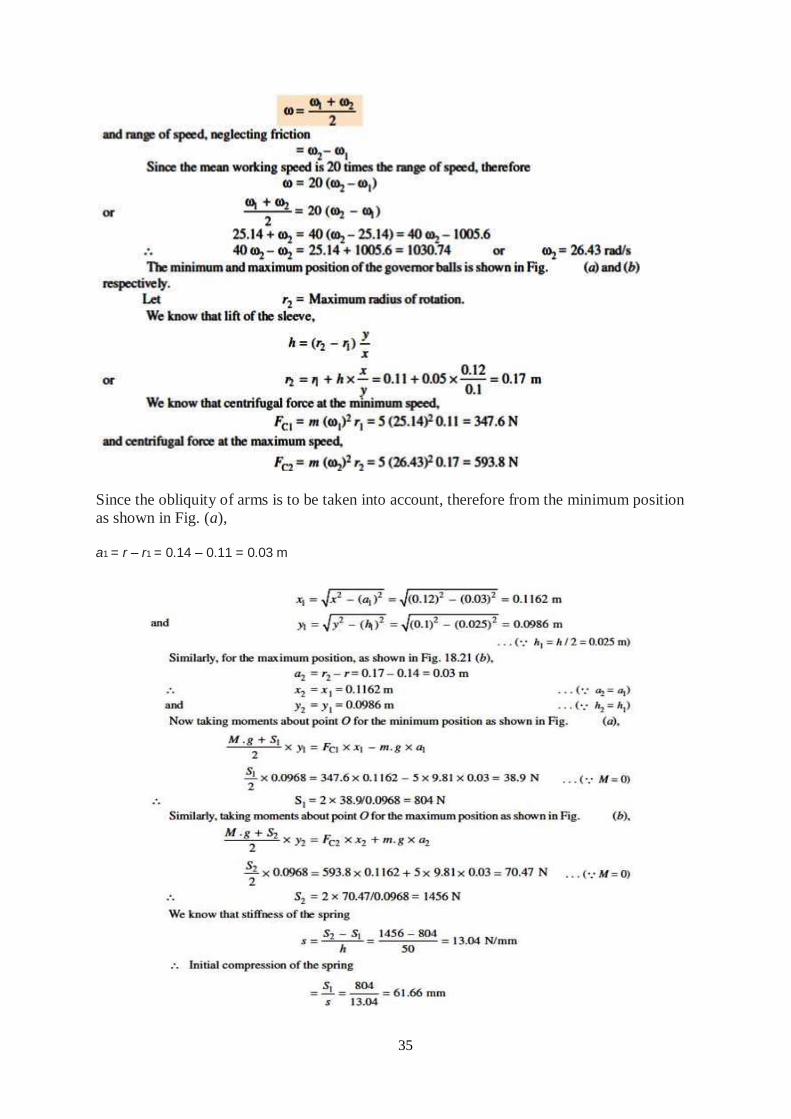
35
Since the obliquity of arms is to be taken into account, therefore from the minimum position
as shown in Fig. (a),
a1 = r – r1 = 0.14 – 0.11 = 0.03 m
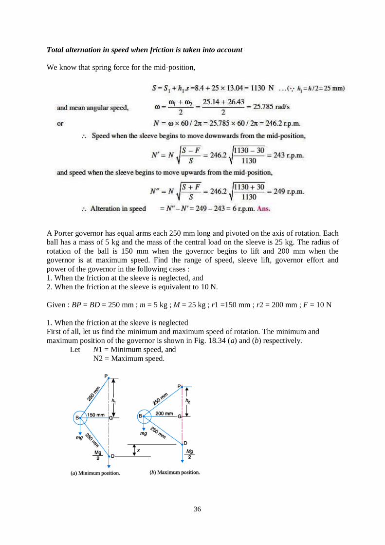
36
Total alternation in speed when friction is taken into account
We know that spring force for the mid-position,
A Porter governor has equal arms each 250 mm long and pivoted on the axis of rotation. Each
ball has a mass of 5 kg and the mass of the central load on the sleeve is 25 kg. The radius of
rotation of the ball is 150 mm when the governor begins to lift and 200 mm when the
governor is at maximum speed. Find the range of speed, sleeve lift, governor effort and
power of the governor in the following cases :
1. When the friction at the sleeve is neglected, and
2. When the friction at the sleeve is equivalent to 10 N.
Given : BP = BD = 250 mm ; m = 5 kg ; M = 25 kg ; r1 =150 mm ; r2 = 200 mm ; F = 10 N
1. When the friction at the sleeve is neglected
First of all, let us find the minimum and maximum speed of rotation. The minimum and
maximum position of the governor is shown in Fig. 18.34 (a) and (b) respectively.
Let N1 = Minimum speed, and
N2 = Maximum speed.
37
From Fig a
`
Range of speed
We know that range of speed = N2 – N1 = 189 – 164 = 25 r.p.m.
Sleeve lift
We know that sleeve lift, x = 2 (h1 – h2) = 2 (200 – 150) = 100 mm = 0.1 m
Governor effort
Let c = Percentage increase in speed. We know that increase in speed or range of speed,
c.N1 = N2 – N1 = 25 r.p.m.
c = 25/N1 = 25/164 = 0.152
We know that governor effort
P = c (m + M) g = 0.152 (5 + 25) 9.81 = 44.7 N
Power of the governor
We know that power of the governor = P.x = 44.7 × 0.1 = 4.47 N-m
2. When the friction at the sleeve is taken into account
38
Range of speed
We know that range of speed = N2 – N1 = 192.4 – 161 = 31.4 r.p.m.
Sleeve lift
The sleeve lift (x) will be same as calculated above. Sleeve lift, x = 100 mm = 0.1 m
Governor effort
Let c = Percentage increase in speed. We know that increase in speed or range of speed,
c.N1 = N2 – N1 = 31.4 r.p.m.
c = 31.4/N1 = 31.4/161 = 0.195
We know that governor effort,
P = c (m.g + M.g + F) = 0.195 (5 × 9.81 + 25 × 9.81 + 10) N= 57.4 N
Power of the governor
We know that power of the governor= P.x = 57.4 × 0.1 = 5.74 N-m
Exercise Problems
1) A loaded governor of the Porter type has equal arms and links each 250 mm long. The
mass of each ball is 2 kg and the central mass is 12 kg. When the ball radius is 150 mm, the
valve is fully open and when the radius is 185 mm, the valve is closed. Find the maximum
speed and the range of speed. If the maximum speed is to be increased 20% by an addition of
mass to the central load, find what additional mass is required.
[Ans. 193 r.p.m. ; 16 r.p.m.; 6.14 kg]
2) In a Porter governor, the upper and lower arms are each 250 mm long and are pivoted on
the axis of rotation. The mass of each rotating ball is 3 kg and the mass of the sleeve is 20 kg.
The sleeve is in its lowest position when the arms are inclined at 30° to the governor axis.
The lift of the sleeve is 36 mm. Find the force of friction at the sleeve, if the speed at the
moment it rises from the lowest position is equal to the speed at the moment it falls from the
highest position. Also, find the range of speed of the governor.
[Ans. 9.8 N ; 16 r.p.m.]
3) A Proell governor has all the four arms of length 250 mm. The upper and lower ends of the
arms are pivoted on the axis of rotation of the governor. The extension arms of the lower
links are each 100 mm long and parallel to the axis when the radius of the ball path is 150
mm. The mass of each ball is 4.5 kg and the mass of the central load is 36 kg. Determine the
equilibrium speed of the governor.
[Ans. 164 r.p.m.]
4) A Proell governor has arms of 300 mm length. The upper arms are hinged on the axis of
rotation, whereas the lower arms are pivoted at a distance of 35 mm from the axis of rotation.
The extension of lower arms to which the balls are attached are 100 mm long. The mass of
each ball is 8 kg and the mass on the sleeve is 60 kg. At the minimum radius of rotation of
200 mm, the extensions are parallel to the governor axis. Determine the equilibrium speed of
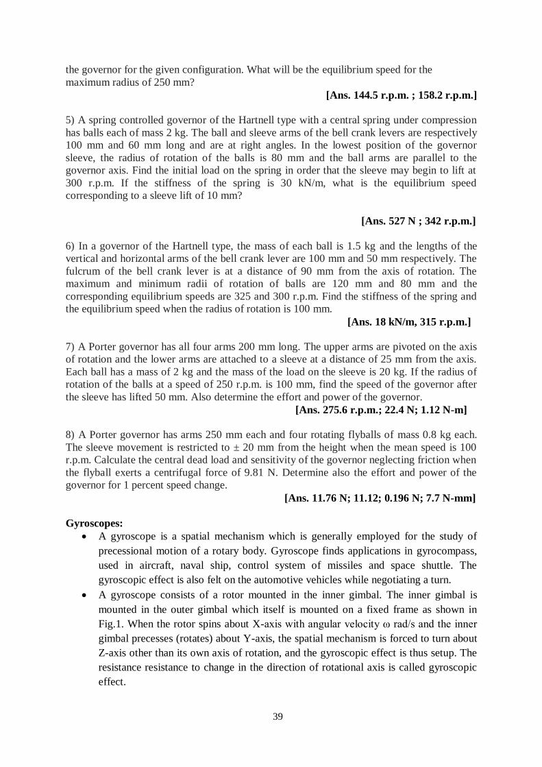
39
the governor for the given configuration. What will be the equilibrium speed for the
maximum radius of 250 mm?
[Ans. 144.5 r.p.m. ; 158.2 r.p.m.]
5) A spring controlled governor of the Hartnell type with a central spring under compression
has balls each of mass 2 kg. The ball and sleeve arms of the bell crank levers are respectively
100 mm and 60 mm long and are at right angles. In the lowest position of the governor
sleeve, the radius of rotation of the balls is 80 mm and the ball arms are parallel to the
governor axis. Find the initial load on the spring in order that the sleeve may begin to lift at
300 r.p.m. If the stiffness of the spring is 30 kN/m, what is the equilibrium speed
corresponding to a sleeve lift of 10 mm?
[Ans. 527 N ; 342 r.p.m.]
6) In a governor of the Hartnell type, the mass of each ball is 1.5 kg and the lengths of the
vertical and horizontal arms of the bell crank lever are 100 mm and 50 mm respectively. The
fulcrum of the bell crank lever is at a distance of 90 mm from the axis of rotation. The
maximum and minimum radii of rotation of balls are 120 mm and 80 mm and the
corresponding equilibrium speeds are 325 and 300 r.p.m. Find the stiffness of the spring and
the equilibrium speed when the radius of rotation is 100 mm.
[Ans. 18 kN/m, 315 r.p.m.]
7) A Porter governor has all four arms 200 mm long. The upper arms are pivoted on the axis
of rotation and the lower arms are attached to a sleeve at a distance of 25 mm from the axis.
Each ball has a mass of 2 kg and the mass of the load on the sleeve is 20 kg. If the radius of
rotation of the balls at a speed of 250 r.p.m. is 100 mm, find the speed of the governor after
the sleeve has lifted 50 mm. Also determine the effort and power of the governor.
[Ans. 275.6 r.p.m.; 22.4 N; 1.12 N-m]
8) A Porter governor has arms 250 mm each and four rotating flyballs of mass 0.8 kg each.
The sleeve movement is restricted to ± 20 mm from the height when the mean speed is 100
r.p.m. Calculate the central dead load and sensitivity of the governor neglecting friction when
the flyball exerts a centrifugal force of 9.81 N. Determine also the effort and power of the
governor for 1 percent speed change.
[Ans. 11.76 N; 11.12; 0.196 N; 7.7 N-mm]
Gyroscopes:
A gyroscope is a spatial mechanism which is generally employed for the study of
precessional motion of a rotary body. Gyroscope finds applications in gyrocompass,
used in aircraft, naval ship, control system of missiles and space shuttle. The
gyroscopic effect is also felt on the automotive vehicles while negotiating a turn.
A gyroscope consists of a rotor mounted in the inner gimbal. The inner gimbal is
mounted in the outer gimbal which itself is mounted on a fixed frame as shown in
Fig.1. When the rotor spins about X-axis with angular velocity ω rad/s and the inner
gimbal precesses (rotates) about Y-axis, the spatial mechanism is forced to turn about
Z-axis other than its own axis of rotation, and the gyroscopic effect is thus setup. The
resistance resistance to change in the direction of rotational axis is called gyroscopic
effect.
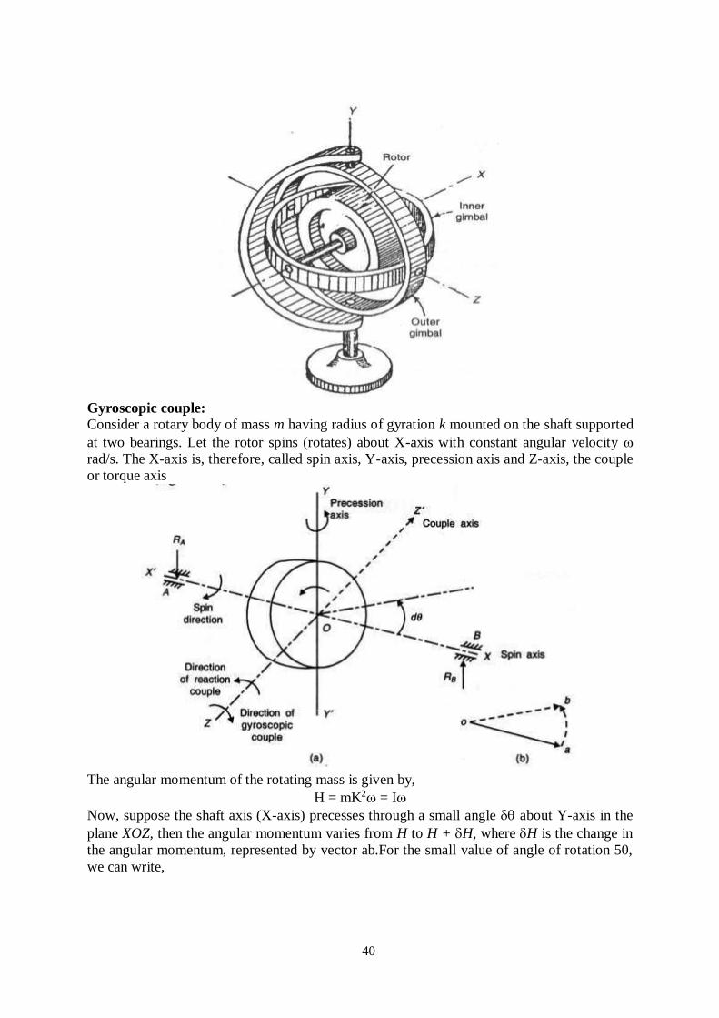
40
Gyroscopic couple:
Consider a rotary body of mass m having radius of gyration k mounted on the shaft supported
at two bearings. Let the rotor spins (rotates) about X-axis with constant angular velocity
rad/s. The X-axis is, therefore, called spin axis, Y-axis, precession axis and Z-axis, the couple
or torque axis
The angular momentum of the rotating mass is given by,
H = mK2 = I
Now, suppose the shaft axis (X-axis) precesses through a small angle about Y-axis in the
plane XOZ, then the angular momentum varies from H to H + H, where H is the change in
the angular momentum, represented by vector ab.For the small value of angle of rotation 50,
we can write,
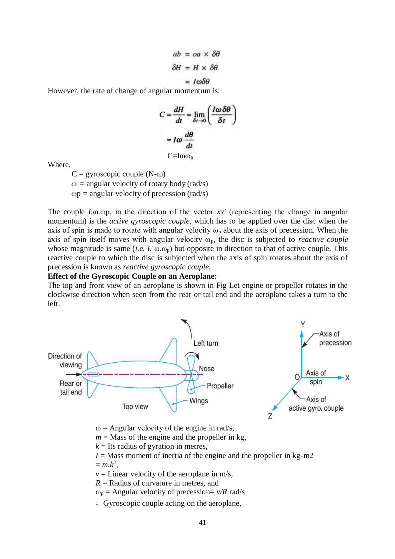
41
However, the rate of change of angular momentum is:
Where,
C = gyroscopic couple (N-m)
C=Ip
= angular velocity of rotary body (rad/s)
p = angular velocity of precession (rad/s)
The couple I.ω.ωp, in the direction of the vector xx′ (representing the change in angular
momentum) is the active gyroscopic couple, which has to be applied over the disc when the
axis of spin is made to rotate with angular velocity ωp about the axis of precession. When the
axis of spin itself moves with angular velocity ωp, the disc is subjected to reactive couple
whose magnitude is same (i.e. I. ω.ωp) but opposite in direction to that of active couple. This
reactive couple to which the disc is subjected when the axis of spin rotates about the axis of
precession is known as reactive gyroscopic couple.
Effect of the Gyroscopic Couple on an Aeroplane:
The top and front view of an aeroplane is shown in Fig Let engine or propeller rotates in the
clockwise direction when seen from the rear or tail end and the aeroplane takes a turn to the
left.
ω = Angular velocity of the engine in rad/s,
m = Mass of the engine and the propeller in kg,
k = Its radius of gyration in metres,
I = Mass moment of inertia of the engine and the propeller in kg-m2
= m.k2,
v = Linear velocity of the aeroplane in m/s,
R = Radius of curvature in metres, and ωp = Angular velocity of precession= v/R rad/s
∴ Gyroscopic couple acting on the aeroplane,
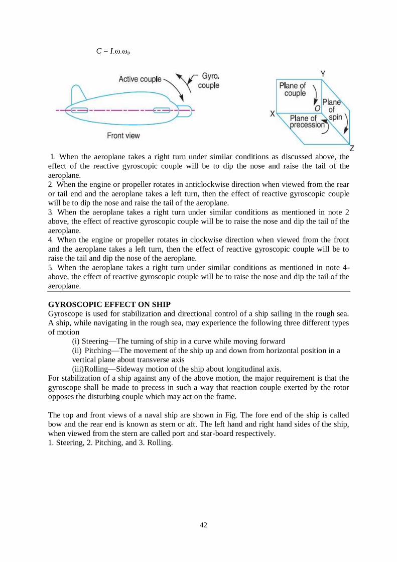
42
C = I.ω.ωp
1. When the aeroplane takes a right turn under similar conditions as discussed above, the
effect of the reactive gyroscopic couple will be to dip the nose and raise the tail of the
aeroplane.
2. When the engine or propeller rotates in anticlockwise direction when viewed from the rear
or tail end and the aeroplane takes a left turn, then the effect of reactive gyroscopic couple
will be to dip the nose and raise the tail of the aeroplane.
3. When the aeroplane takes a right turn under similar conditions as mentioned in note 2
above, the effect of reactive gyroscopic couple will be to raise the nose and dip the tail of the
aeroplane.
4. When the engine or propeller rotates in clockwise direction when viewed from the front
and the aeroplane takes a left turn, then the effect of reactive gyroscopic couple will be to
raise the tail and dip the nose of the aeroplane.
5. When the aeroplane takes a right turn under similar conditions as mentioned in note 4-
above, the effect of reactive gyroscopic couple will be to raise the nose and dip the tail of the
aeroplane.
GYROSCOPIC EFFECT ON SHIP
Gyroscope is used for stabilization and directional control of a ship sailing in the rough sea.
A ship, while navigating in the rough sea, may experience the following three different types
of motion
(i) Steering—The turning of ship in a curve while moving forward
(ii) Pitching—The movement of the ship up and down from horizontal position in a
vertical plane about transverse axis
(iii) Rolling—Sideway motion of the ship about longitudinal axis.
For stabilization of a ship against any of the above motion, the major requirement is that the
gyroscope shall be made to precess in such a way that reaction couple exerted by the rotor
opposes the disturbing couple which may act on the frame.
The top and front views of a naval ship are shown in Fig. The fore end of the ship is called
bow and the rear end is known as stern or aft. The left hand and right hand sides of the ship,
when viewed from the stern are called port and star-board respectively.
1. Steering, 2. Pitching, and 3. Rolling.
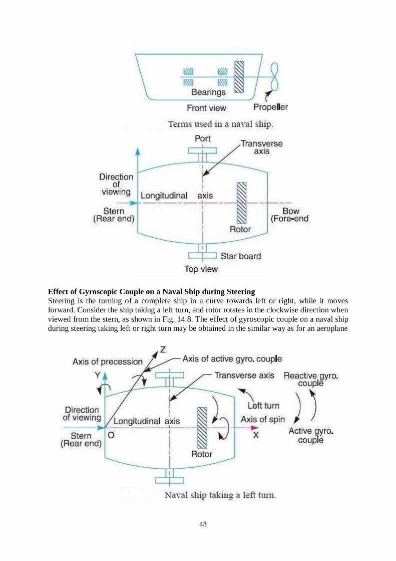
43
Effect of Gyroscopic Couple on a Naval Ship during Steering
Steering is the turning of a complete ship in a curve towards left or right, while it moves
forward. Consider the ship taking a left turn, and rotor rotates in the clockwise direction when
viewed from the stern, as shown in Fig. 14.8. The effect of gyroscopic couple on a naval ship
during steering taking left or right turn may be obtained in the similar way as for an aeroplane
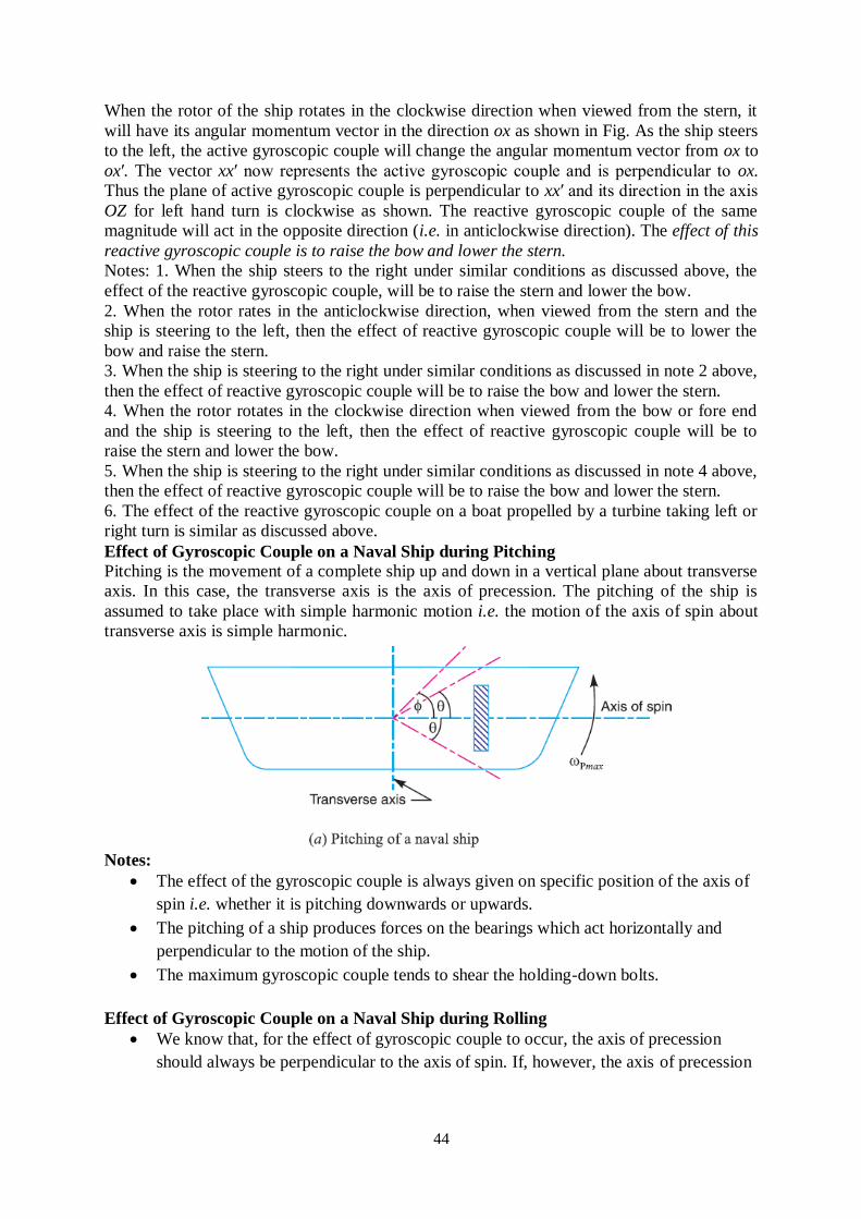
44
When the rotor of the ship rotates in the clockwise direction when viewed from the stern, it
will have its angular momentum vector in the direction ox as shown in Fig. As the ship steers
to the left, the active gyroscopic couple will change the angular momentum vector from ox to
ox′. The vector xx′ now represents the active gyroscopic couple and is perpendicular to ox.
Thus the plane of active gyroscopic couple is perpendicular to xx′ and its direction in the axis
OZ for left hand turn is clockwise as shown. The reactive gyroscopic couple of the same
magnitude will act in the opposite direction (i.e. in anticlockwise direction). The effect of this
reactive gyroscopic couple is to raise the bow and lower the stern.
Notes: 1. When the ship steers to the right under similar conditions as discussed above, the
effect of the reactive gyroscopic couple, will be to raise the stern and lower the bow.
2. When the rotor rates in the anticlockwise direction, when viewed from the stern and the
ship is steering to the left, then the effect of reactive gyroscopic couple will be to lower the
bow and raise the stern.
3. When the ship is steering to the right under similar conditions as discussed in note 2 above,
then the effect of reactive gyroscopic couple will be to raise the bow and lower the stern.
4. When the rotor rotates in the clockwise direction when viewed from the bow or fore end
and the ship is steering to the left, then the effect of reactive gyroscopic couple will be to
raise the stern and lower the bow.
5. When the ship is steering to the right under similar conditions as discussed in note 4 above,
then the effect of reactive gyroscopic couple will be to raise the bow and lower the stern.
6. The effect of the reactive gyroscopic couple on a boat propelled by a turbine taking left or
right turn is similar as discussed above.
Effect of Gyroscopic Couple on a Naval Ship during Pitching
Pitching is the movement of a complete ship up and down in a vertical plane about transverse
axis. In this case, the transverse axis is the axis of precession. The pitching of the ship is
assumed to take place with simple harmonic motion i.e. the motion of the axis of spin about
transverse axis is simple harmonic.
Notes:
The effect of the gyroscopic couple is always given on specific position of the axis of
spin i.e. whether it is pitching downwards or upwards.
The pitching of a ship produces forces on the bearings which act horizontally and
perpendicular to the motion of the ship.
The maximum gyroscopic couple tends to shear the holding-down bolts.
Effect of Gyroscopic Couple on a Naval Ship during Rolling
We know that, for the effect of gyroscopic couple to occur, the axis of precession
should always be perpendicular to the axis of spin. If, however, the axis of precession
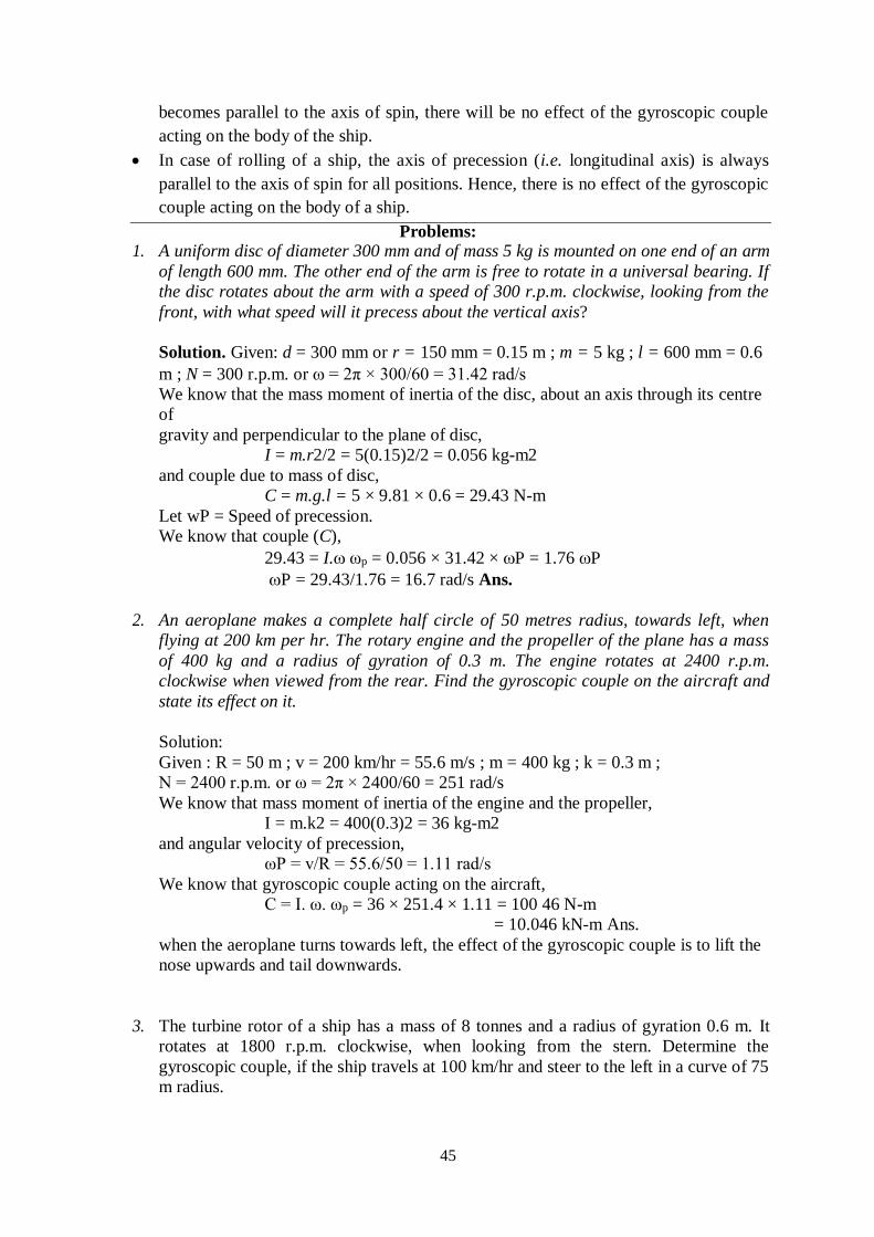
45
becomes parallel to the axis of spin, there will be no effect of the gyroscopic couple
acting on the body of the ship.
In case of rolling of a ship, the axis of precession (i.e. longitudinal axis) is always
parallel to the axis of spin for all positions. Hence, there is no effect of the gyroscopic
couple acting on the body of a ship.
Problems: 1. A uniform disc of diameter 300 mm and of mass 5 kg is mounted on one end of an arm
of length 600 mm. The other end of the arm is free to rotate in a universal bearing. If
the disc rotates about the arm with a speed of 300 r.p.m. clockwise, looking from the
front, with what speed will it precess about the vertical axis?
Solution. Given: d = 300 mm or r = 150 mm = 0.15 m ; m = 5 kg ; l = 600 mm = 0.6
m ; N = 300 r.p.m. or = 2π × 300/60 = 31.42 rad/s
We know that the mass moment of inertia of the disc, about an axis through its centre
of
gravity and perpendicular to the plane of disc,
I = m.r2/2 = 5(0.15)2/2 = 0.056 kg-m2
and couple due to mass of disc,
C = m.g.l = 5 × 9.81 × 0.6 = 29.43 N-m
Let wP = Speed of precession.
We know that couple (C),
29.43 = I. ωp = 0.056 × 31.42 × P = 1.76 P
P = 29.43/1.76 = 16.7 rad/s Ans.
2. An aeroplane makes a complete half circle of 50 metres radius, towards left, when
flying at 200 km per hr. The rotary engine and the propeller of the plane has a mass
of 400 kg and a radius of gyration of 0.3 m. The engine rotates at 2400 r.p.m.
clockwise when viewed from the rear. Find the gyroscopic couple on the aircraft and
state its effect on it.
Solution:
Given : R = 50 m ; v = 200 km/hr = 55.6 m/s ; m = 400 kg ; k = 0.3 m ;
N = 2400 r.p.m. or ω = 2π × 2400/60 = 251 rad/s
We know that mass moment of inertia of the engine and the propeller,
I = m.k2 = 400(0.3)2 = 36 kg-m2
and angular velocity of precession,
ωP = v/R = 55.6/50 = 1.11 rad/s
We know that gyroscopic couple acting on the aircraft,
C = I. ω. ωp = 36 × 251.4 × 1.11 = 100 46 N-m
= 10.046 kN-m Ans.
when the aeroplane turns towards left, the effect of the gyroscopic couple is to lift the
nose upwards and tail downwards.
3. The turbine rotor of a ship has a mass of 8 tonnes and a radius of gyration 0.6 m. It
rotates at 1800 r.p.m. clockwise, when looking from the stern. Determine the
gyroscopic couple, if the ship travels at 100 km/hr and steer to the left in a curve of 75
m radius.
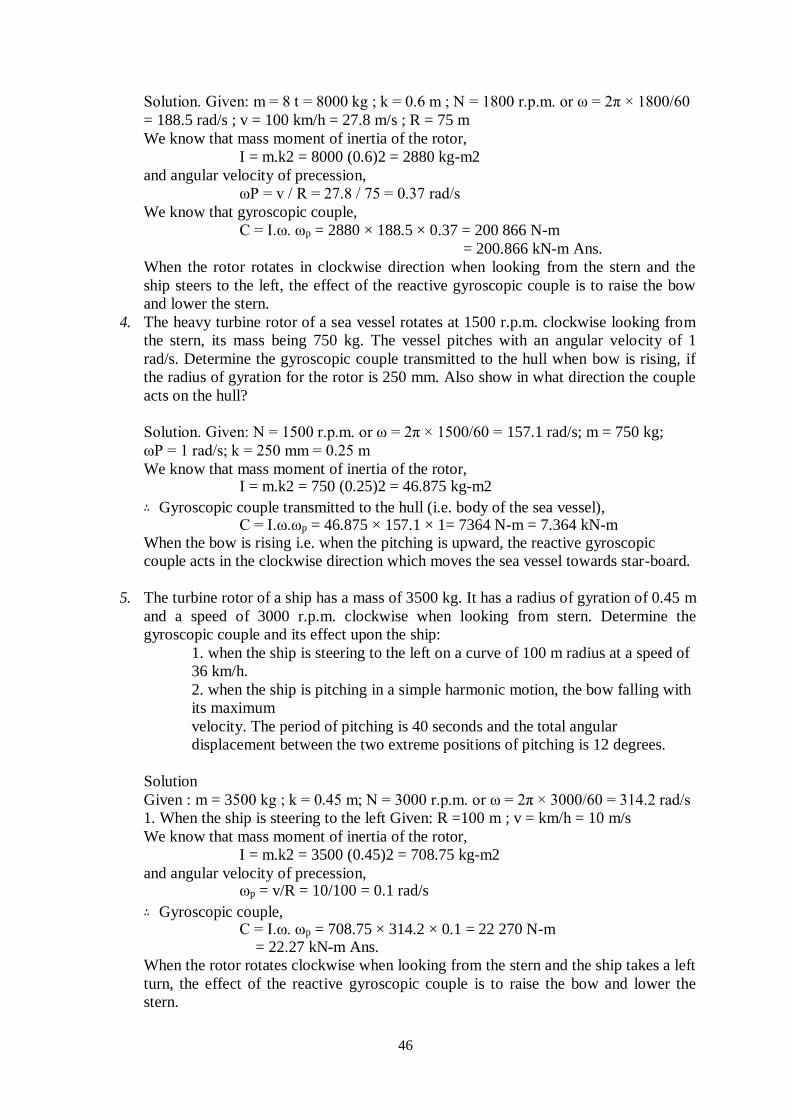
46
Solution. Given: m = 8 t = 8000 kg ; k = 0.6 m ; N = 1800 r.p.m. or ω = 2π × 1800/60
= 188.5 rad/s ; v = 100 km/h = 27.8 m/s ; R = 75 m
We know that mass moment of inertia of the rotor,
I = m.k2 = 8000 (0.6)2 = 2880 kg-m2
and angular velocity of precession,
ωP = v / R = 27.8 / 75 = 0.37 rad/s
We know that gyroscopic couple,
C = I.ω. ωp = 2880 × 188.5 × 0.37 = 200 866 N-m
= 200.866 kN-m Ans.
When the rotor rotates in clockwise direction when looking from the stern and the
ship steers to the left, the effect of the reactive gyroscopic couple is to raise the bow
and lower the stern.
4. The heavy turbine rotor of a sea vessel rotates at 1500 r.p.m. clockwise looking from
the stern, its mass being 750 kg. The vessel pitches with an angular velocity of 1
rad/s. Determine the gyroscopic couple transmitted to the hull when bow is rising, if
the radius of gyration for the rotor is 250 mm. Also show in what direction the couple
acts on the hull?
Solution. Given: N = 1500 r.p.m. or ω = 2π × 1500/60 = 157.1 rad/s; m = 750 kg;
ωP = 1 rad/s; k = 250 mm = 0.25 m
We know that mass moment of inertia of the rotor, I = m.k2 = 750 (0.25)2 = 46.875 kg-m2
∴ Gyroscopic couple transmitted to the hull (i.e. body of the sea vessel), C = I.ω.ωp = 46.875 × 157.1 × 1= 7364 N-m = 7.364 kN-m
When the bow is rising i.e. when the pitching is upward, the reactive gyroscopic
couple acts in the clockwise direction which moves the sea vessel towards star-board.
5. The turbine rotor of a ship has a mass of 3500 kg. It has a radius of gyration of 0.45 m
and a speed of 3000 r.p.m. clockwise when looking from stern. Determine the
gyroscopic couple and its effect upon the ship:
1. when the ship is steering to the left on a curve of 100 m radius at a speed of
36 km/h.
2. when the ship is pitching in a simple harmonic motion, the bow falling with
its maximum
velocity. The period of pitching is 40 seconds and the total angular
displacement between the two extreme positions of pitching is 12 degrees.
Solution
Given : m = 3500 kg ; k = 0.45 m; N = 3000 r.p.m. or ω = 2π × 3000/60 = 314.2 rad/s
1. When the ship is steering to the left Given: R =100 m ; v = km/h = 10 m/s
We know that mass moment of inertia of the rotor,
I = m.k2 = 3500 (0.45)2 = 708.75 kg-m2
and angular velocity of precession, ωp = v/R = 10/100 = 0.1 rad/s
∴ Gyroscopic couple, C = I.ω. ωp = 708.75 × 314.2 × 0.1 = 22 270 N-m
= 22.27 kN-m Ans.
When the rotor rotates clockwise when looking from the stern and the ship takes a left
turn, the effect of the reactive gyroscopic couple is to raise the bow and lower the
stern.
47
2. When the ship is pitching with the bow falling
Given: tp = 40 s
Since the total angular displacement between the two extreme positions of pitching is
12°
(i.e. 2φ = 12°), therefore amplitude of swing,
φ = 12 / 2 = 6° = 6 × π/180 = 0.105 rad
and angular velocity of the simple harmonic motion,
ω1 = 2π / tp = 2π / 40 = 0.157 rad/s
We know that maximum angular velocity of precession,
ωp = φ.ω1 = 0.105 × 0.157 = 0.0165 rad/s
∴ Gyroscopic couple, C = I.ω. ωp = 708.75 × 314.2 × 0.0165 = 3675 N-m = 3.675 kN-m Ans.
When the bow is falling (i.e. when the pitching is downward), the effect of the
reactive gyroscopic couple is to move the ship towards port side.
EXERCISES
1. A flywheel of mass 10 kg and radius of gyration 200 mm is spinning about its axis,
which is horizontal and is suspended at a point distant 150 mm from the plane of
rotation of the flywheel. Determine the angular velocity of precession of the flywheel.
The spin speed of flywheel is 900 r.p.m. [Ans. 0.39 rad/s]
2. A horizontal axle AB, 1 m long, is pivoted at the mid point C. It carries a weight of 20
N at A and a wheel weighing 50 N at B. The wheel is made to spin at a speed of 600
r.p.m in a clockwise direction looking from its front. Assuming that the weight of the
flywheel is uniformly distributed around the rim whose mean diameter is 0.6 m,
calculate the angular velocity of precession of the system around the vertical axis
through C.
[Ans. 0.52 rad/s]
3. Each paddle wheel of a steamer have a mass of 1600 kg and a radius of gyration of
1.2 m. The steamer turns to port in a circle of 160 m radius at 24 km / h, the speed of
the paddles being 90 r.p.m. Find the magnitude and effect of the gyroscopic couple
acting on the steamer. [Ans. 905.6 N-m]
4. An aeroplane makes a complete half circle of 50 metres radius, towards left, when
flying at 200 km per hour. The rotary engine and the propeller of the plane has a mass
of 400 kg with a radius of gyration of 300 mm. The engine runs at 2400 r.p.m.
clockwise, when viewed from the rear. Find the gyroscopic couple on the aircraft and
state its effect on it. What will be the effect, if the aeroplane turns to its right instead
of to the left?
[Ans. 10 kN-m]
5. The rotor of the turbine of a yacht makes 1200 r.p.m. clockwise when viewed from
stern. The rotor has a mass of 750 kg and its radius of gyration is 250 mm. Find the
maximum gyroscopic couple transmitted to the hull (body of the yacht) when yacht
pitches with maximum angular velocity of 1 rad /s. What is the effect of this couple?
[Ans. 5892 N-m]

48