ug-2021-36 ref-mha1kim5psoc4 user guide - infineon
TRANSCRIPT
User guide Please read the Important notice and the Safety precautions and the Warnings Revision 1.0
www.infineon.com page 1 of 27 2021-09-14
UG-2021-36
REF-MHA1KIM5PSOC4 user guide
Washing machine motor control reference design
About this document
Scope and purpose
This user manual provides an overview of the REF-MHA1KIM5PSOC4 home appliance board including its main features, key data, pin assignments and mechanical dimensions.
REF-MHA1KIM5PSOC4 reference board is based on PSoC 4100S Plus and IKCM10H60GA IPM (CIPOS™ Mini 600 V,
10 A three-phase intelligent power module), which was developed to support customers in designing their own
projects, such as drum or top-loading washing machines.
Intended audience
This user manual is intended for all technical specialists who are familiar with motor control and high-power
electronics converters, and also have some experience in the development of washing machines. This board is intended to be used under laboratory conditions.
Reference Board/Kit
Product(s) embedded on a PCB with a focus on specific applications and defined use cases that may include software. PCB and auxiliary circuits are optimized for the requirements of the target application.
Note: Boards do not necessarily meet safety, EMI, quality standards (for example UL, CE) requirements.
User guide 2 of 27 Revision 1.0
2021-09-14
REF-MHA1KIM5PSOC4 user guide PSoC® 4 home appliance board for washing machine
Important notice
Important notice
“Evaluation Boards and Reference Boards” shall mean products embedded on a printed circuit board
(PCB) for demonstration and/or evaluation purposes, which include, without limitation, demonstration, reference and evaluation boards, kits and design (collectively referred to as “Reference Board”).
Environmental conditions have been considered in the design of the Evaluation Boards and Reference Boards provided by Infineon Technologies. The design of the Evaluation Boards and Reference Boards has been tested by Infineon Technologies only as described in this document. The design is not qualified
in terms of safety requirements, manufacturing and operation over the entire operating temperature
range or lifetime. The Evaluation Boards and Reference Boards provided by Infineon Technologies are subject to functional
testing only under typical load conditions. Evaluation Boards and Reference Boards are not subject to the
same procedures as regular products regarding returned material analysis (RMA), process change notification (PCN) and product discontinuation (PD).
Evaluation Boards and Reference Boards are not commercialized products, and are solely intended for
evaluation and testing purposes. In particular, they shall not be used for reliability testing or production. The Evaluation Boards and Reference Boards may therefore not comply with CE or similar standards
(including but not limited to the EMC Directive 2004/EC/108 and the EMC Act) and may not fulfill other requirements of the country in which they are operated by the customer. The customer shall ensure that
all Evaluation Boards and Reference Boards will be handled in a way which is compliant with the relevant
requirements and standards of the country in which they are operated.
The Evaluation Boards and Reference Boards as well as the information provided in this document are
addressed only to qualified and skilled technical staff, for laboratory usage, and shall be used and
managed according to the terms and conditions set forth in this document and in other related
documentation supplied with the respective Evaluation Board or Reference Board. It is the responsibility of the customer’s technical departments to evaluate the suitability of the
Evaluation Boards and Reference Boards for the intended application, and to evaluate the completeness
and correctness of the information provided in this document with respect to such application.
The customer is obliged to ensure that the use of the Evaluation Boards and Reference Boards does not cause any harm to persons or third party property.
The Evaluation Boards and Reference Boards and any information in this document is provided "as is" and Infineon Technologies disclaims any warranties, express or implied, including but not limited to
warranties of non-infringement of third party rights and implied warranties of fitness for any purpose, or for merchantability.
Infineon Technologies shall not be responsible for any damages resulting from the use of the Evaluation Boards and Reference Boards and/or from any information provided in this document. The customer is
obliged to defend, indemnify and hold Infineon Technologies harmless from and against any claims or damages arising out of or resulting from any use thereof.
Infineon Technologies reserves the right to modify this document and/or any information provided herein at any time without further notice.
User guide 3 of 27 Revision 1.0
2021-09-14
REF-MHA1KIM5PSOC4 user guide PSoC® 4 home appliance board for washing machine
Safety precautions
Safety precautions
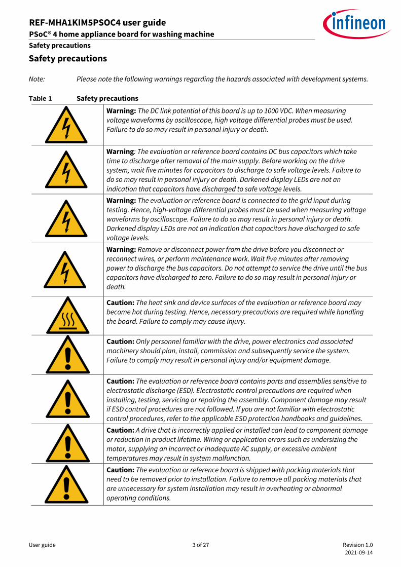
Note: Please note the following warnings regarding the hazards associated with development systems.
Table 1 Safety precautions
Warning: The DC link potential of this board is up to 1000 VDC. When measuring voltage waveforms by oscilloscope, high voltage differential probes must be used.
Failure to do so may result in personal injury or death.
Warning: The evaluation or reference board contains DC bus capacitors which take time to discharge after removal of the main supply. Before working on the drive system, wait five minutes for capacitors to discharge to safe voltage levels. Failure to
do so may result in personal injury or death. Darkened display LEDs are not an
indication that capacitors have discharged to safe voltage levels.
Warning: The evaluation or reference board is connected to the grid input during testing. Hence, high-voltage differential probes must be used when measuring voltage
waveforms by oscilloscope. Failure to do so may result in personal injury or death.
Darkened display LEDs are not an indication that capacitors have discharged to safe
voltage levels.
Warning: Remove or disconnect power from the drive before you disconnect or reconnect wires, or perform maintenance work. Wait five minutes after removing
power to discharge the bus capacitors. Do not attempt to service the drive until the bus capacitors have discharged to zero. Failure to do so may result in personal injury or
death.
Caution: The heat sink and device surfaces of the evaluation or reference board may
become hot during testing. Hence, necessary precautions are required while handling
the board. Failure to comply may cause injury.
Caution: Only personnel familiar with the drive, power electronics and associated machinery should plan, install, commission and subsequently service the system.
Failure to comply may result in personal injury and/or equipment damage.
Caution: The evaluation or reference board contains parts and assemblies sensitive to
electrostatic discharge (ESD). Electrostatic control precautions are required when
installing, testing, servicing or repairing the assembly. Component damage may result if ESD control procedures are not followed. If you are not familiar with electrostatic
control procedures, refer to the applicable ESD protection handbooks and guidelines.
Caution: A drive that is incorrectly applied or installed can lead to component damage
or reduction in product lifetime. Wiring or application errors such as undersizing the motor, supplying an incorrect or inadequate AC supply, or excessive ambient
temperatures may result in system malfunction.
Caution: The evaluation or reference board is shipped with packing materials that need to be removed prior to installation. Failure to remove all packing materials that are unnecessary for system installation may result in overheating or abnormal
operating conditions.
User guide 4 of 27 Revision 1.0
2021-09-14
REF-MHA1KIM5PSOC4 User Manual PSoC® 4 home appliance board for washing machine
Table of contents
Table of contents
About this document ....................................................................................................................... 1
Important notice ............................................................................................................................ 2
Safety precautions .......................................................................................................................... 3
Table of contents ............................................................................................................................ 4
1 The board at a glance .............................................................................................................. 5 1.1 Block diagram .......................................................................................................................................... 5
1.2 Main features ........................................................................................................................................... 5
1.3 Board parameter and technical data ..................................................................................................... 7 1.4 Pin assignment of PSoC 4100S Plus ........................................................................................................ 9
2 System and functional desciption ........................................................................................... 11 2.1 Getting started ....................................................................................................................................... 12
2.2 FOC introduction ................................................................................................................................... 12 2.3 Main features ......................................................................................................................................... 13
3 System design....................................................................................................................... 15
3.1 Schematics ............................................................................................................................................ 15 3.1.1 MCU section using PSoC 4100S Plus ............................................................................................... 15
3.1.2 Inverter section using IKCM10H60GA .............................................................................................. 16 3.1.3 DC bus voltage sampling section ..................................................................................................... 16 3.1.4 Motor-phase current sampling with internal OP AMPs .................................................................. 17
3.1.5 Inverter overcurrent protection section with internal comparator ............................................... 18
3.1.6 Over-temperature and VFO circuit .................................................................................................. 18
3.1.7 EMI filter and AC-DC conversion ...................................................................................................... 19
3.1.8 Auxiliary power supply ..................................................................................................................... 20 3.2 PCB layout ............................................................................................................................................. 21 3.3 Bill of material (BOM) ............................................................................................................................ 23
4 System performance ............................................................................................................. 25
5 Appendices ........................................................................................................................... 26 5.1 Abbreviations and definitions ............................................................................................................... 26
Revision history ............................................................................................................................. 26
User guide 5 of 27 Revision 1.0
2021-09-14
REF-MHA1KIM5PSOC4 user guide PSoC® 4 home appliance board for washing machine
The board at a glance
ardware description of REF-MHA1KIM5PSOC4
1 The board at a glance
REF-MHA1KIM5PSOC4 is a reference board based on the PSoC 4100S Plus and CIPOS™ Mini 600 V, 10 A three-
phase intelligent power module (IPM).
The REF-MHA1KIM5PSOC4 board was designed for customers interested in washer solutions.The features of this
board are described in the main features’ chapter of this document (UG-2021-36), whereas the remaining paragraphs provide information enabling customers to copy, modify and qualify the design for production according to their own specific requirements.
1.1 Block diagram
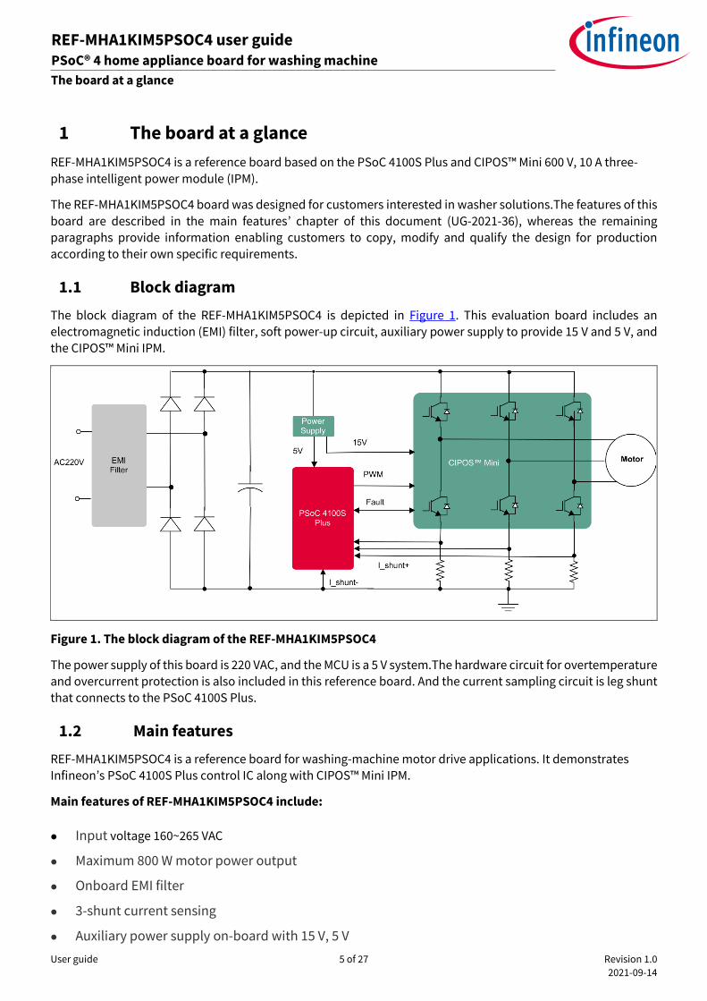
The block diagram of the REF-MHA1KIM5PSOC4 is depicted in Figure 1. This evaluation board includes an electromagnetic induction (EMI) filter, soft power-up circuit, auxiliary power supply to provide 15 V and 5 V, and
the CIPOS™ Mini IPM.
Figure 1. The block diagram of the REF-MHA1KIM5PSOC4
The power supply of this board is 220 VAC, and the MCU is a 5 V system.The hardware circuit for overtemperature and overcurrent protection is also included in this reference board. And the current sampling circuit is leg shunt that connects to the PSoC 4100S Plus.
1.2 Main features
REF-MHA1KIM5PSOC4 is a reference board for washing-machine motor drive applications. It demonstrates Infineon’s PSoC 4100S Plus control IC along with CIPOS™ Mini IPM.
Main features of REF-MHA1KIM5PSOC4 include:
⚫ Input voltage 160~265 VAC
⚫ Maximum 800 W motor power output
⚫ Onboard EMI filter
⚫ 3-shunt current sensing
⚫ Auxiliary power supply on-board with 15 V, 5 V
User guide 6 of 27 Revision 1.0
2021-09-14
REF-MHA1KIM5PSOC4 user guide PSoC® 4 home appliance board for washing machine
The board at a glance
ardware description of REF-MHA1KIM5PSOC4
⚫ Overcurrent protection
⚫ Overtemperature hardware protection
⚫ Sensing of DC-link voltage
⚫ Fault diagnostic output
⚫ Measurement test points compatible to standard oscilloscope probes
The specific IC number of this board is CY8C4146AZI-S443, which is a part of the PSoC 4100S Plus family. Its main features include:
⚫ 32-bit MCU subsystem
48 MHz Arm® Cortex®-M0+ CPU with a DMA controller
64 KB flash and 8 KB SRAM
External 4 to 33 MHz oscillator (ECO) with PLL and 32 kHz watch crystal oscillator (WCO)
⚫ Programmable analog blocks
Two op amps with reconfigurable high-drive, external and high-bandwidth internal drive, and comparator modes and ADC input buffering capability. Op amps can operate in deep sleep low-power mode.
12-bit 1-Msps SAR ADC with differential and single-ended modes, and channel sequencer with signal averaging
Single-slope 10-bit ADC function provided by a capacitance sensing block
Two current DACs (IDACs) for general-purpose or capacitive sensing applications on any pin
Two low-power comparators that operate in deep sleep low-power mode
⚫ Programmable digital blocks
Programmable logic blocks allowing Boolean operations to be performed on port inputs and outputs
⚫ Low-power 1.71 V to 5.5 V operation
Deep sleep mode with operational analog and 2.5 A digital system current
⚫ Serial communication
Four independent, run-time reconfigurable serial communication blocks (SCBs) with re-configurable I2C, SPI,
or UART functionality
⚫ Timing and pulse-width modulation
Eight 16-bit timer/counter/pulse-width modulator (TCPWM) blocks
Center-aligned, edge, and pseudo-random modes
Comparator-based triggering of Kill signals for motor drive and other high-reliability digital logic applications
Quadrature decoder
⚫ Clock sources
4 to 33 MHz external crystal oscillator (ECO)
PLL to generate 48 MHz frequency
32 kHz watch crystal oscillator (WCO)
User guide 7 of 27 Revision 1.0
2021-09-14
REF-MHA1KIM5PSOC4 user guide PSoC® 4 home appliance board for washing machine
The board at a glance
ardware description of REF-MHA1KIM5PSOC4
±2% internal main oscillator (IMO)
32 kHz internal low-power oscillator (ILO)
⚫ Packages
48 TQFP
⚫ I/O subsystem
Up to 38 GPIOs
Main features of CIPOS™ Mini IPM IKCM10H60GA include:
⚫ Concept based on TRENCHSTOP™ IGBT
⚫ 10 A of inverter current rating
⚫ Rugged SOI gate driver technology
⚫ Integrated bootstrap function
⚫ Overcurrent shutdown
⚫ All 6 switches turn off during protection
⚫ Undervoltage lockout at all channels
⚫ Cross-conduction prevention
⚫ Built-in temperature monitoring
⚫ Motor power rating up to 1000 W at 10 kHz
⚫ UL certified
1.3 Board parameter and technical data
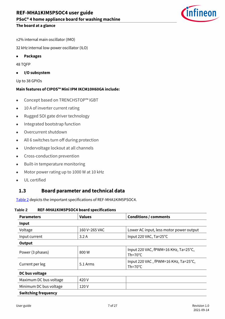
Table 2 depicts the important specifications of REF-MHA1KIM5PSOC4.
Table 2 REF-MHA1KIM5PSOC4 board specifications
Parameters Values Conditions / comments
Input
Voltage 160 V~265 VAC Lower AC input, less motor power output
Input current 3.2 A Input 220 VAC, Ta=25°C
Output
Power (3 phases) 800 W Input 220 VAC, fPWM=16 KHz, Ta=25°C,
Th=70°C
Current per leg 5.1 Arms Input 220 VAC , fPWM=16 KHz, Ta=25°C,
Th=70°C
DC bus voltage
Maximum DC bus voltage 420 V
Minimum DC bus voltage 120 V
Switching frequency
User guide 8 of 27 Revision 1.0
2021-09-14
REF-MHA1KIM5PSOC4 user guide PSoC® 4 home appliance board for washing machine
The board at a glance
ardware description of REF-MHA1KIM5PSOC4
Parameters Values Conditions / comments
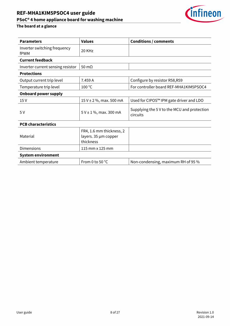
Inverter switching frequency
fPWM 20 KHz
Current feedback
Inverter current sensing resistor 50 mΩ
Protections
Output current trip level 7.459 A Configure by resistor R58,R59
Temperature trip level 100 °C For controller board REF-MHA1KIM5PSOC4
Onboard power supply
15 V 15 V ± 2 %, max. 500 mA Used for CIPOS™ IPM gate driver and LDO
5 V 5 V ± 1 %, max. 300 mA Supplying the 5 V to the MCU and protection circuits
PCB characteristics
Material FR4, 1.6 mm thickness, 2 layers. 35 µm copper
thickness
Dimensions 115 mm x 125 mm
System environment
Ambient temperature From 0 to 50 °C Non-condensing, maximum RH of 95 %
User guide 9 of 27 Revision 1.0
2021-09-14
REF-MHA1KIM5PSOC4 user guide PSoC® 4 home appliance board for washing machine
The board at a glance
ardware description of REF-MHA1KIM5PSOC4
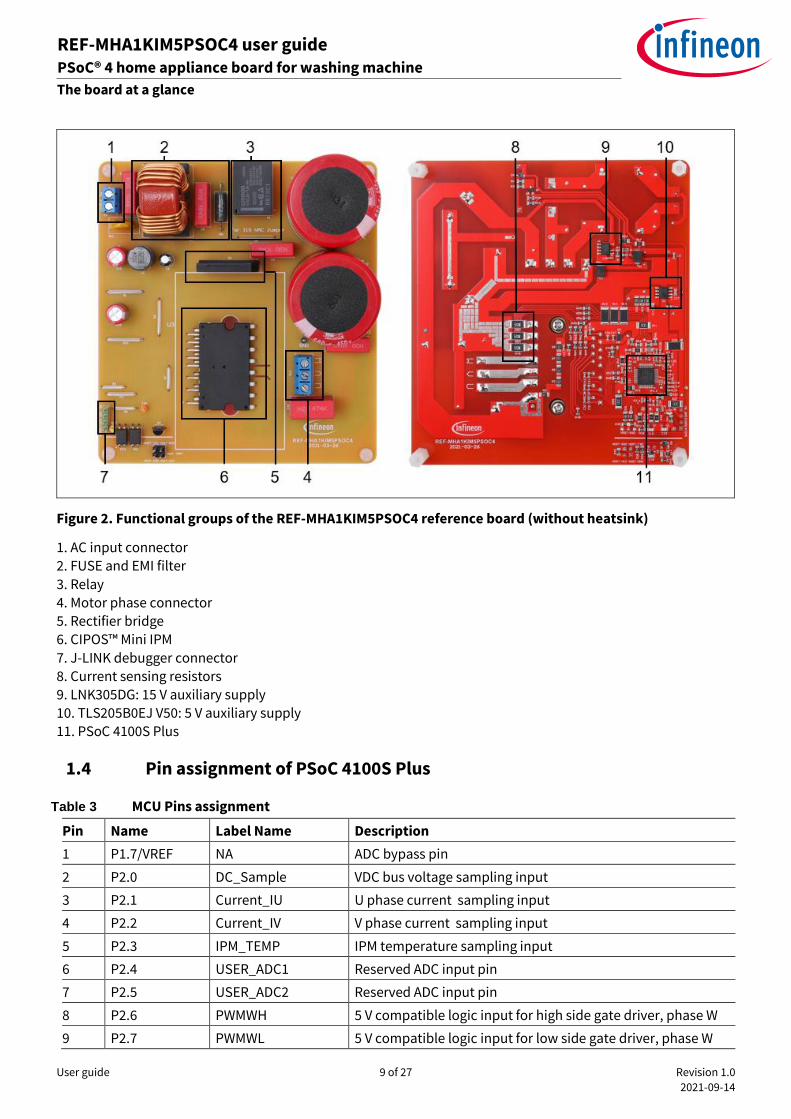
Figure 2. Functional groups of the REF-MHA1KIM5PSOC4 reference board (without heatsink)
1. AC input connector 2. FUSE and EMI filter
3. Relay
4. Motor phase connector 5. Rectifier bridge
6. CIPOS™ Mini IPM
7. J-LINK debugger connector 8. Current sensing resistors
9. LNK305DG: 15 V auxiliary supply 10. TLS205B0EJ V50: 5 V auxiliary supply
11. PSoC 4100S Plus
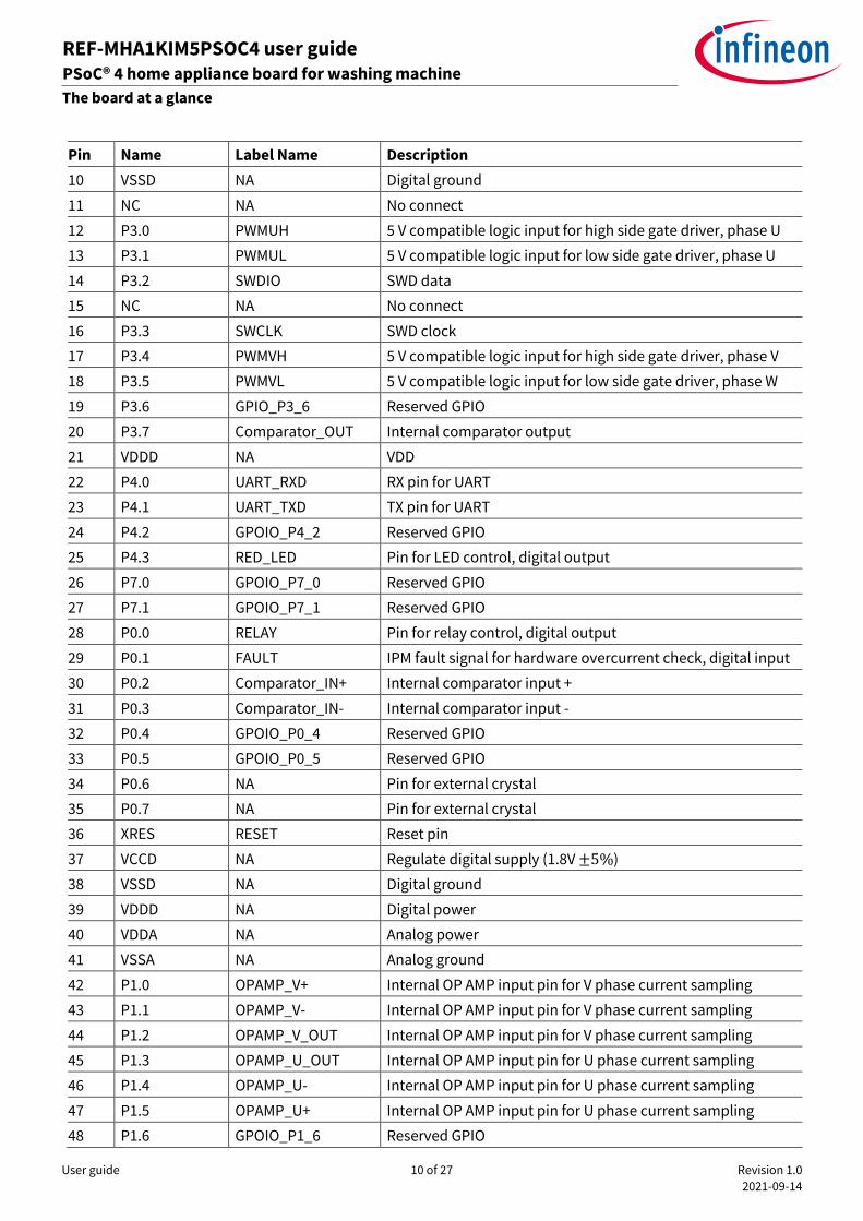
1.4 Pin assignment of PSoC 4100S Plus
Table 3 MCU Pins assignment
Pin Name Label Name Description
1 P1.7/VREF NA ADC bypass pin
2 P2.0 DC_Sample VDC bus voltage sampling input
3 P2.1 Current_IU U phase current sampling input
4 P2.2 Current_IV V phase current sampling input
5 P2.3 IPM_TEMP IPM temperature sampling input
6 P2.4 USER_ADC1 Reserved ADC input pin
7 P2.5 USER_ADC2 Reserved ADC input pin
8 P2.6 PWMWH 5 V compatible logic input for high side gate driver, phase W
9 P2.7 PWMWL 5 V compatible logic input for low side gate driver, phase W
User guide 10 of 27 Revision 1.0
2021-09-14
REF-MHA1KIM5PSOC4 user guide PSoC® 4 home appliance board for washing machine
The board at a glance
ardware description of REF-MHA1KIM5PSOC4
Pin Name Label Name Description
10 VSSD NA Digital ground
11 NC NA No connect
12 P3.0 PWMUH 5 V compatible logic input for high side gate driver, phase U
13 P3.1 PWMUL 5 V compatible logic input for low side gate driver, phase U
14 P3.2 SWDIO SWD data
15 NC NA No connect
16 P3.3 SWCLK SWD clock
17 P3.4 PWMVH 5 V compatible logic input for high side gate driver, phase V
18 P3.5 PWMVL 5 V compatible logic input for low side gate driver, phase W
19 P3.6 GPIO_P3_6 Reserved GPIO
20 P3.7 Comparator_OUT Internal comparator output
21 VDDD NA VDD
22 P4.0 UART_RXD RX pin for UART
23 P4.1 UART_TXD TX pin for UART
24 P4.2 GPOIO_P4_2 Reserved GPIO
25 P4.3 RED_LED Pin for LED control, digital output
26 P7.0 GPOIO_P7_0 Reserved GPIO
27 P7.1 GPOIO_P7_1 Reserved GPIO
28 P0.0 RELAY Pin for relay control, digital output
29 P0.1 FAULT IPM fault signal for hardware overcurrent check, digital input
30 P0.2 Comparator_IN+ Internal comparator input +
31 P0.3 Comparator_IN- Internal comparator input -
32 P0.4 GPOIO_P0_4 Reserved GPIO
33 P0.5 GPOIO_P0_5 Reserved GPIO
34 P0.6 NA Pin for external crystal
35 P0.7 NA Pin for external crystal
36 XRES RESET Reset pin
37 VCCD NA Regulate digital supply (1.8V ±5%)
38 VSSD NA Digital ground
39 VDDD NA Digital power
40 VDDA NA Analog power
41 VSSA NA Analog ground
42 P1.0 OPAMP_V+ Internal OP AMP input pin for V phase current sampling
43 P1.1 OPAMP_V- Internal OP AMP input pin for V phase current sampling
44 P1.2 OPAMP_V_OUT Internal OP AMP input pin for V phase current sampling
45 P1.3 OPAMP_U_OUT Internal OP AMP input pin for U phase current sampling
46 P1.4 OPAMP_U- Internal OP AMP input pin for U phase current sampling
47 P1.5 OPAMP_U+ Internal OP AMP input pin for U phase current sampling
48 P1.6 GPOIO_P1_6 Reserved GPIO
User guide 11 of 27 Revision 1.0
2021-09-14
REF-MHA1KIM5PSOC4 user guide PSoC® 4 home appliance board for washing machine
System and functional desciption
ardware description of REF-MHA1KIM5PSOC4
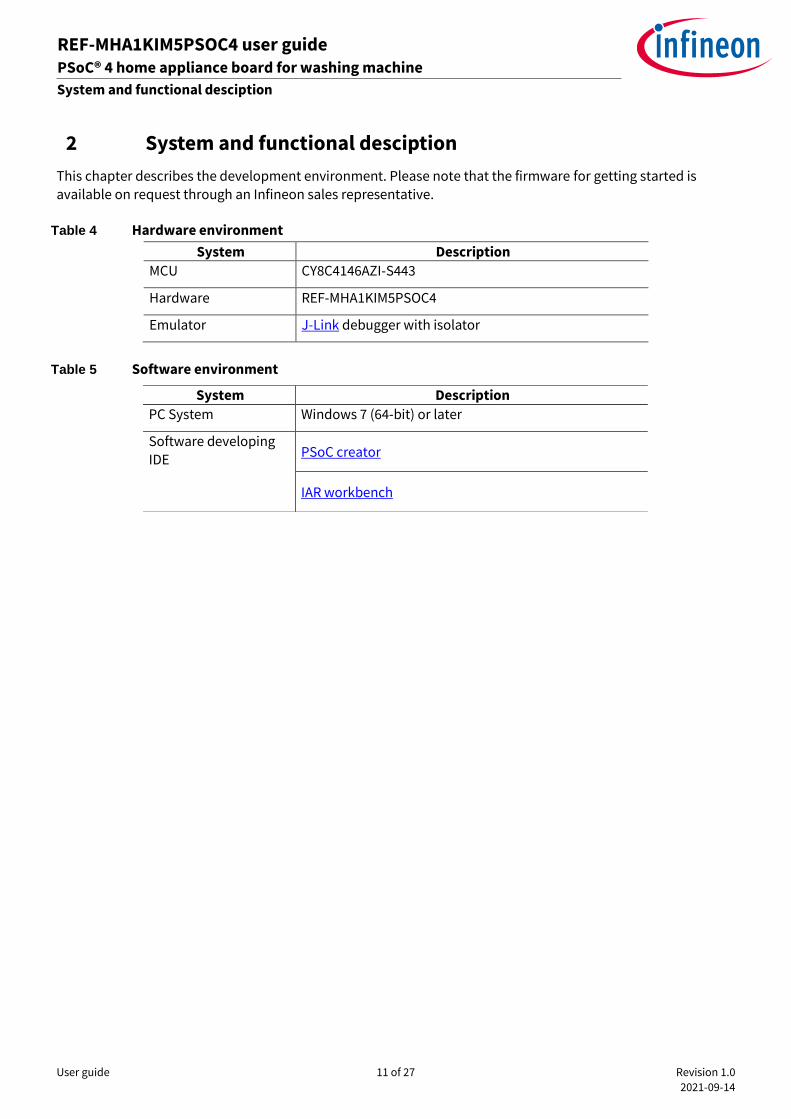
2 System and functional desciption
This chapter describes the development environment. Please note that the firmware for getting started is
available on request through an Infineon sales representative.
Table 4 Hardware environment
System Description
MCU CY8C4146AZI-S443
Hardware REF-MHA1KIM5PSOC4
Emulator J-Link debugger with isolator
Table 5 Software environment
System Description
PC System Windows 7 (64-bit) or later
Software developing IDE
PSoC creator
IAR workbench
User guide 12 of 27 Revision 1.0
2021-09-14
REF-MHA1KIM5PSOC4 user guide PSoC® 4 home appliance board for washing machine
System and functional desciption
ardware description of REF-MHA1KIM5PSOC4
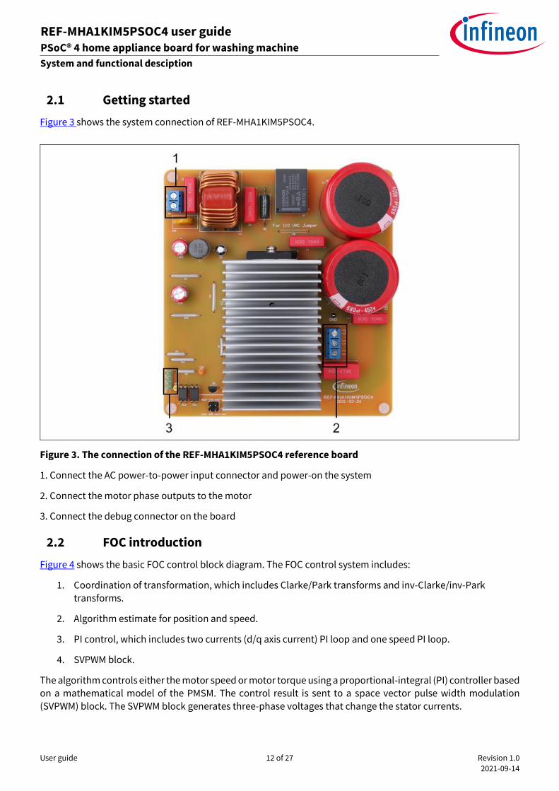
2.1 Getting started
Figure 3 shows the system connection of REF-MHA1KIM5PSOC4.
Figure 3. The connection of the REF-MHA1KIM5PSOC4 reference board
1. Connect the AC power-to-power input connector and power-on the system
2. Connect the motor phase outputs to the motor
3. Connect the debug connector on the board
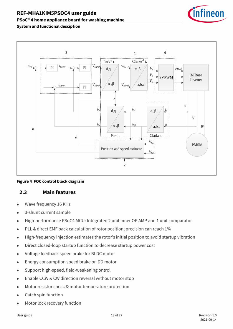
2.2 FOC introduction
Figure 4 shows the basic FOC control block diagram. The FOC control system includes:
1. Coordination of transformation, which includes Clarke/Park transforms and inv-Clarke/inv-Park transforms.
2. Algorithm estimate for position and speed.
3. PI control, which includes two currents (d/q axis current) PI loop and one speed PI loop.
4. SVPWM block.
The algorithm controls either the motor speed or motor torque using a proportional-integral (PI) controller based on a mathematical model of the PMSM. The control result is sent to a space vector pulse width modulation (SVPWM) block. The SVPWM block generates three-phase voltages that change the stator currents.
User guide 13 of 27 Revision 1.0
2021-09-14
REF-MHA1KIM5PSOC4 user guide PSoC® 4 home appliance board for washing machine
System and functional desciption
ardware description of REF-MHA1KIM5PSOC4
PI
PI
PI d,q
α ,β
d,q
α ,β
α ,β
a,b,c
3-Phase
Inverter
PMSMPosition and speed estimate
nref
n
Park t. Clarke t.
iSq
iSd
iSα
iSβ
VSqref
VSdref
iSqref
iSdref
VSαref
VSβref
Park-1 t.
SVPWM
α ,β
a,b,c
Clarke-1 t.
Va
Vb
Vc
PWM
ia
ib
U
V
W
θ
VSα
VSβ
3 4
2
1
Figure 4 FOC control block diagram
2.3 Main features
⚫ Wave frequency 16 KHz
⚫ 3-shunt current sample
⚫ High-performance PSoC4 MCU: Integrated 2 unit inner OP AMP and 1 unit comparator
⚫ PLL & direct EMF back calculation of rotor position; precision can reach 1%
⚫ High-frequency injection estimates the rotor’s initial position to avoid startup vibration
⚫ Direct closed-loop startup function to decrease startup power cost
⚫ Voltage feedback speed brake for BLDC motor
⚫ Energy consumption speed brake on DD motor
⚫ Support high-speed, field-weakening ontrol
⚫ Enable CCW & CW direction reversal without motor stop
⚫ Motor resistor check & motor temperature protection
⚫ Catch spin function
⚫ Motor lock recovery function
User guide 14 of 27 Revision 1.0
2021-09-14
REF-MHA1KIM5PSOC4 user guide PSoC® 4 home appliance board for washing machine
System and functional desciption
ardware description of REF-MHA1KIM5PSOC4
⚫ Support position angle control
⚫ OOB function; precision at 100 g
⚫ Weight function precision less than 1 kg
⚫ Wide range speed adjustment: 1 Hz to 350 Hz
⚫ Class B and UL certification
⚫ Full protection
⚫ Stop protect function
User guide 15 of 27 Revision 1.0
2021-09-14
REF-MHA1KIM5PSOC4 user guide PSoC® 4 home appliance board for washing machine
System design
ardware description of REF-MHA1KIM5PSOC4
3 System design
3.1 Schematics
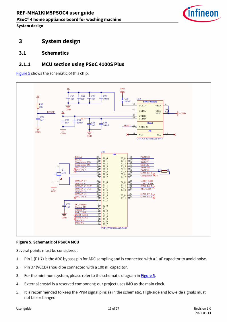
3.1.1 MCU section using PSoC 4100S Plus
Figure 5 shows the schematic of this chip.
Figure 5. Schematic of PSoC4 MCU
Several points must be considered:
1. Pin 1 (P1.7) is the ADC bypass pin for ADC sampling and is connected with a 1 uF capacitor to avoid noise.
2. Pin 37 (VCCD) should be connected with a 100 nF capacitor.
3. For the minimum system, please refer to the schematic diagram in Figure 5.
4. External crystal is a reserved component; our project uses IMO as the main clock.
5. It is recommended to keep the PWM signal pins as in the schematic. High-side and low-side signals must
not be exchanged.
User guide 16 of 27 Revision 1.0
2021-09-14
REF-MHA1KIM5PSOC4 user guide PSoC® 4 home appliance board for washing machine
System design
ardware description of REF-MHA1KIM5PSOC4
6. Internal OPAMP and comparator pins are fixed.
7. P2.0~P2.5 can be used as ADC sampling pins.
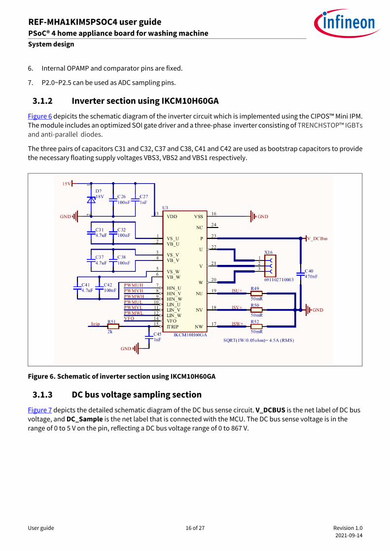
3.1.2 Inverter section using IKCM10H60GA
Figure 6 depicits the schematic diagram of the inverter circuit which is implemented using the CIPOS™ Mini IPM.
The module includes an optimized SOI gate driver and a three-phase inverter consisting of TRENCHSTOP™ IGBTs
and anti-parallel diodes.
The three pairs of capacitors C31 and C32, C37 and C38, C41 and C42 are used as bootstrap capacitors to provide
the necessary floating supply voltages VBS3, VBS2 and VBS1 respectively.
Figure 6. Schematic of inverter section using IKCM10H60GA
3.1.3 DC bus voltage sampling section
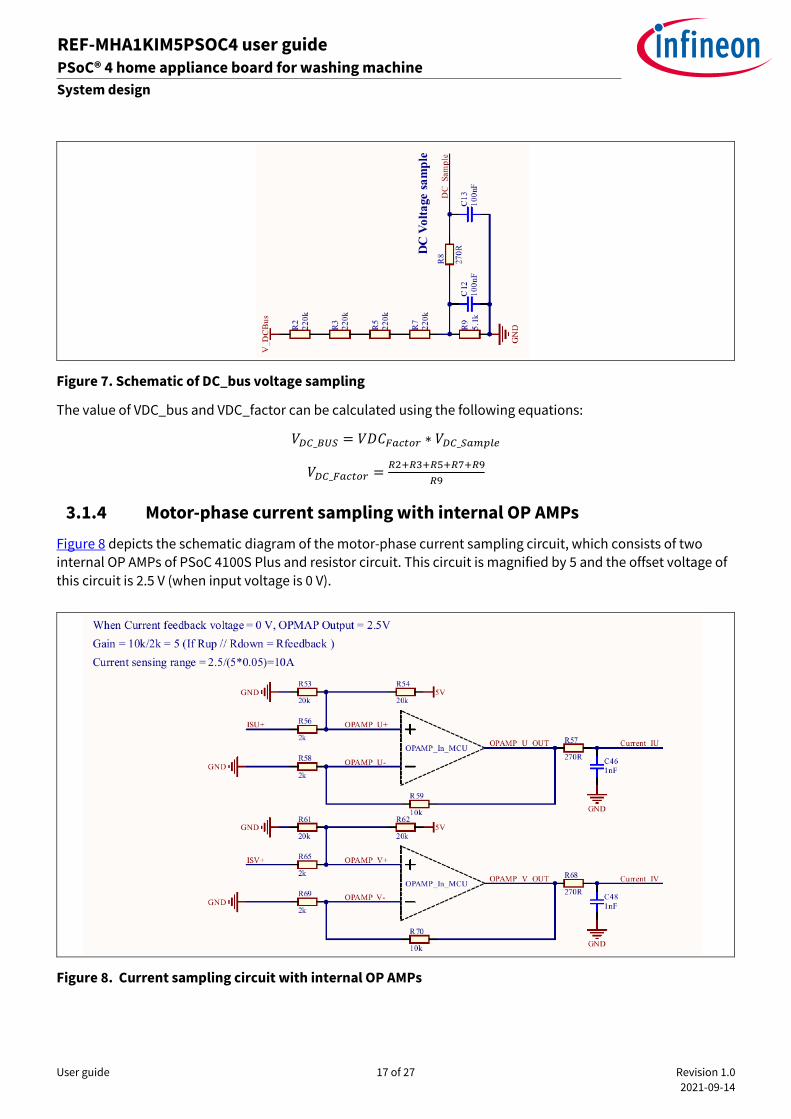
Figure 7 depicts the detailed schematic diagram of the DC bus sense circuit. V_DCBUS is the net label of DC bus
voltage, and DC_Sample is the net label that is connected with the MCU. The DC bus sense voltage is in the
range of 0 to 5 V on the pin, reflecting a DC bus voltage range of 0 to 867 V.
User guide 17 of 27 Revision 1.0
2021-09-14
REF-MHA1KIM5PSOC4 user guide PSoC® 4 home appliance board for washing machine
System design
ardware description of REF-MHA1KIM5PSOC4
Figure 7. Schematic of DC_bus voltage sampling
The value of VDC_bus and VDC_factor can be calculated using the following equations:
𝑉𝐷𝐶_𝐵𝑈𝑆 = 𝑉𝐷𝐶𝐹𝑎𝑐𝑡𝑜𝑟 ∗ 𝑉𝐷𝐶_𝑆𝑎𝑚𝑝𝑙𝑒
𝑉𝐷𝐶_𝐹𝑎𝑐𝑡𝑜𝑟 =𝑅2+𝑅3+𝑅5+𝑅7+𝑅9
𝑅9
3.1.4 Motor-phase current sampling with internal OP AMPs
Figure 8 depicts the schematic diagram of the motor-phase current sampling circuit, which consists of two
internal OP AMPs of PSoC 4100S Plus and resistor circuit. This circuit is magnified by 5 and the offset voltage of
this circuit is 2.5 V (when input voltage is 0 V).
Figure 8. Current sampling circuit with internal OP AMPs
User guide 18 of 27 Revision 1.0
2021-09-14
REF-MHA1KIM5PSOC4 user guide PSoC® 4 home appliance board for washing machine
System design
ardware description of REF-MHA1KIM5PSOC4
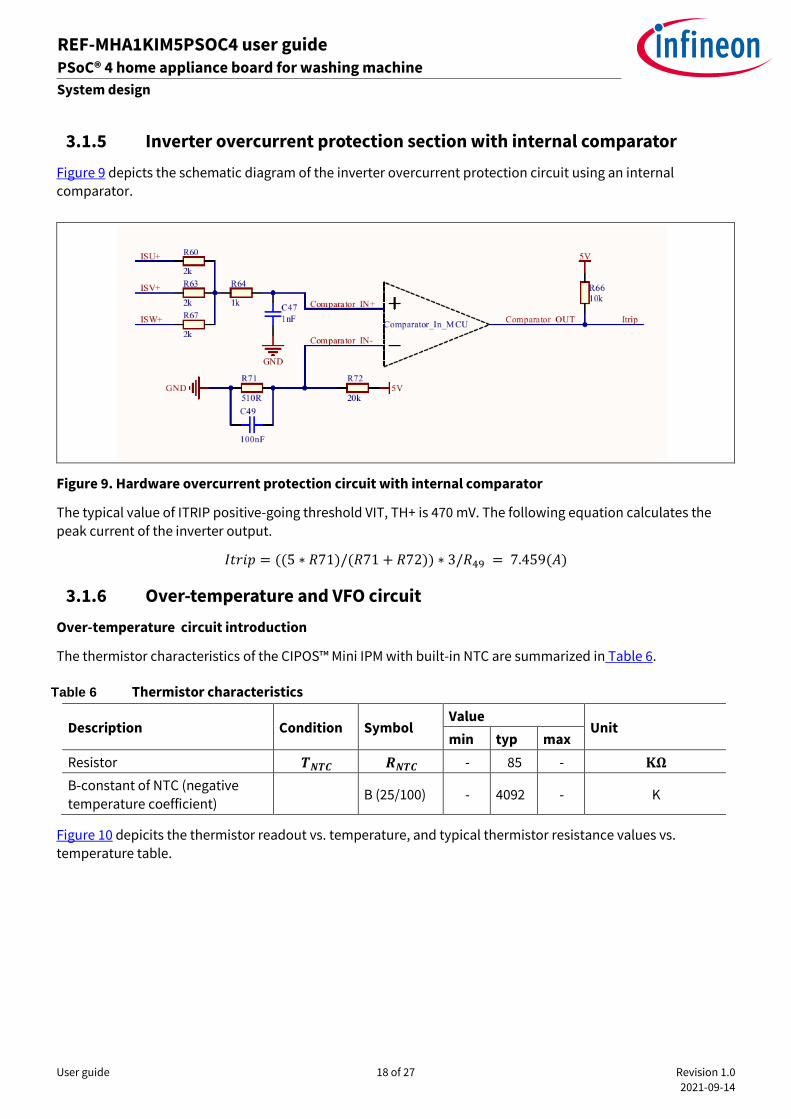
3.1.5 Inverter overcurrent protection section with internal comparator
Figure 9 depicts the schematic diagram of the inverter overcurrent protection circuit using an internal comparator.
Figure 9. Hardware overcurrent protection circuit with internal comparator
The typical value of ITRIP positive-going threshold VIT, TH+ is 470 mV. The following equation calculates the
peak current of the inverter output.
𝐼𝑡𝑟𝑖𝑝 = ((5 ∗ 𝑅71)/(𝑅71 + 𝑅72)) ∗ 3/𝑅49 = 7.459(𝐴)
3.1.6 Over-temperature and VFO circuit
Over-temperature circuit introduction
The thermistor characteristics of the CIPOS™ Mini IPM with built-in NTC are summarized in Table 6.
Table 6 Thermistor characteristics
Description Condition Symbol Value
Unit min typ max
Resistor 𝑻𝑵𝑻𝑪 𝑹𝑵𝑻𝑪 - 85 - 𝐊𝛀
B-constant of NTC (negative
temperature coefficient) B (25/100) - 4092 - K
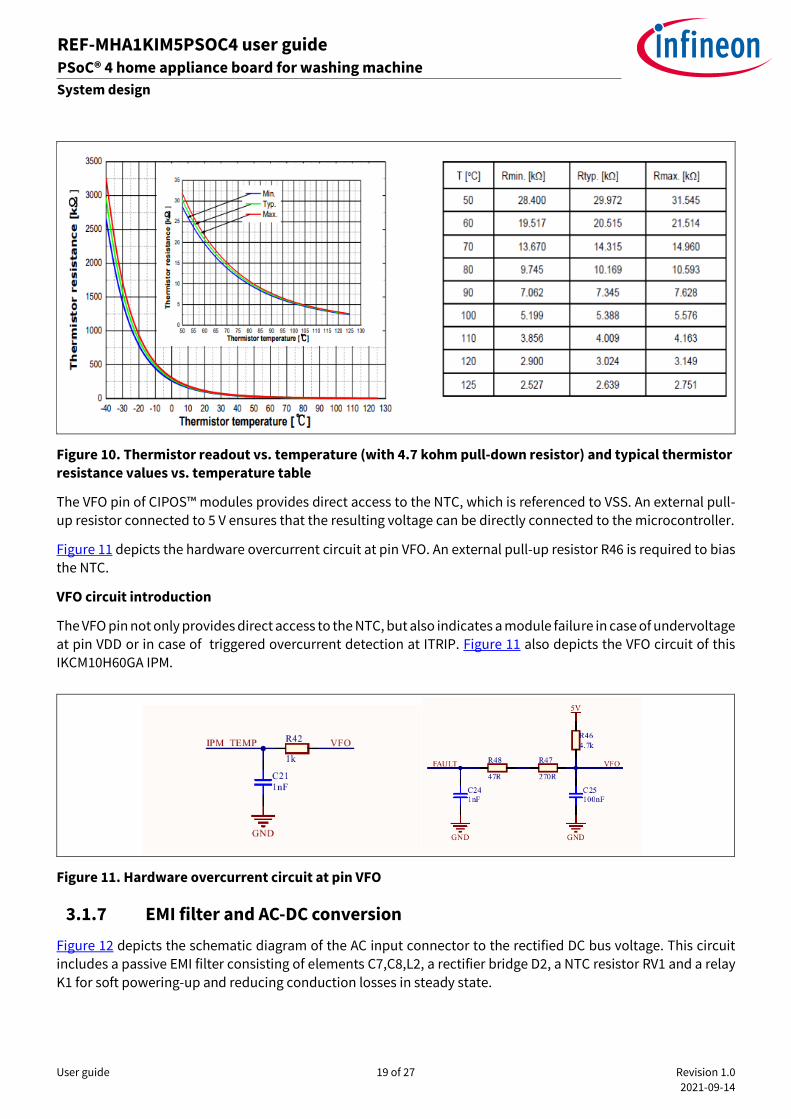
Figure 10 depicits the thermistor readout vs. temperature, and typical thermistor resistance values vs. temperature table.
User guide 19 of 27 Revision 1.0
2021-09-14
REF-MHA1KIM5PSOC4 user guide PSoC® 4 home appliance board for washing machine
System design
ardware description of REF-MHA1KIM5PSOC4
Figure 10. Thermistor readout vs. temperature (with 4.7 kohm pull-down resistor) and typical thermistor resistance values vs. temperature table
The VFO pin of CIPOS™ modules provides direct access to the NTC, which is referenced to VSS. An external pull-
up resistor connected to 5 V ensures that the resulting voltage can be directly connected to the microcontroller.
Figure 11 depicts the hardware overcurrent circuit at pin VFO. An external pull-up resistor R46 is required to bias the NTC.
VFO circuit introduction
The VFO pin not only provides direct access to the NTC, but also indicates a module failure in case of undervoltage at pin VDD or in case of triggered overcurrent detection at ITRIP. Figure 11 also depicts the VFO circuit of this
IKCM10H60GA IPM.
Figure 11. Hardware overcurrent circuit at pin VFO
3.1.7 EMI filter and AC-DC conversion
Figure 12 depicts the schematic diagram of the AC input connector to the rectified DC bus voltage. This circuit includes a passive EMI filter consisting of elements C7,C8,L2, a rectifier bridge D2, a NTC resistor RV1 and a relay
K1 for soft powering-up and reducing conduction losses in steady state.
User guide 20 of 27 Revision 1.0
2021-09-14
REF-MHA1KIM5PSOC4 user guide PSoC® 4 home appliance board for washing machine
System design
ardware description of REF-MHA1KIM5PSOC4
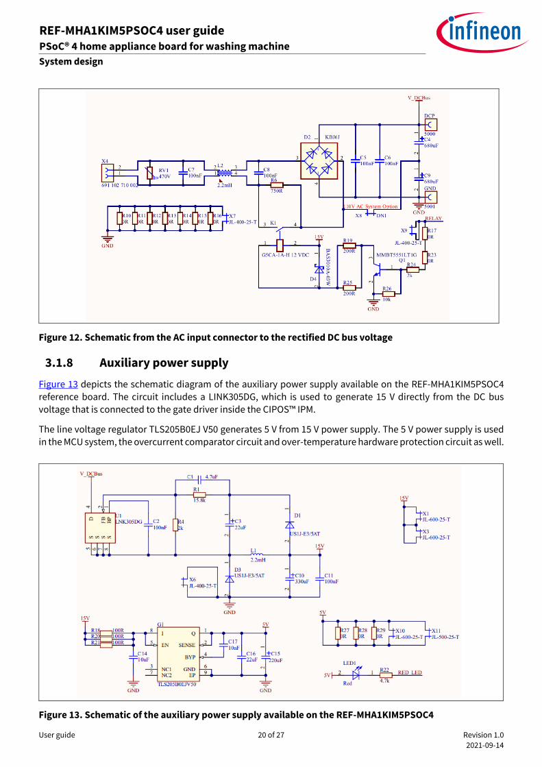
Figure 12. Schematic from the AC input connector to the rectified DC bus voltage
3.1.8 Auxiliary power supply
Figure 13 depicts the schematic diagram of the auxiliary power supply available on the REF-MHA1KIM5PSOC4
reference board. The circuit includes a LINK305DG, which is used to generate 15 V directly from the DC bus voltage that is connected to the gate driver inside the CIPOS™ IPM.
The line voltage regulator TLS205B0EJ V50 generates 5 V from 15 V power supply. The 5 V power supply is used
in the MCU system, the overcurrent comparator circuit and over-temperature hardware protection circuit as well.
Figure 13. Schematic of the auxiliary power supply available on the REF-MHA1KIM5PSOC4
User guide 21 of 27 Revision 1.0
2021-09-14
REF-MHA1KIM5PSOC4 user guide PSoC® 4 home appliance board for washing machine
System design
ardware description of REF-MHA1KIM5PSOC4
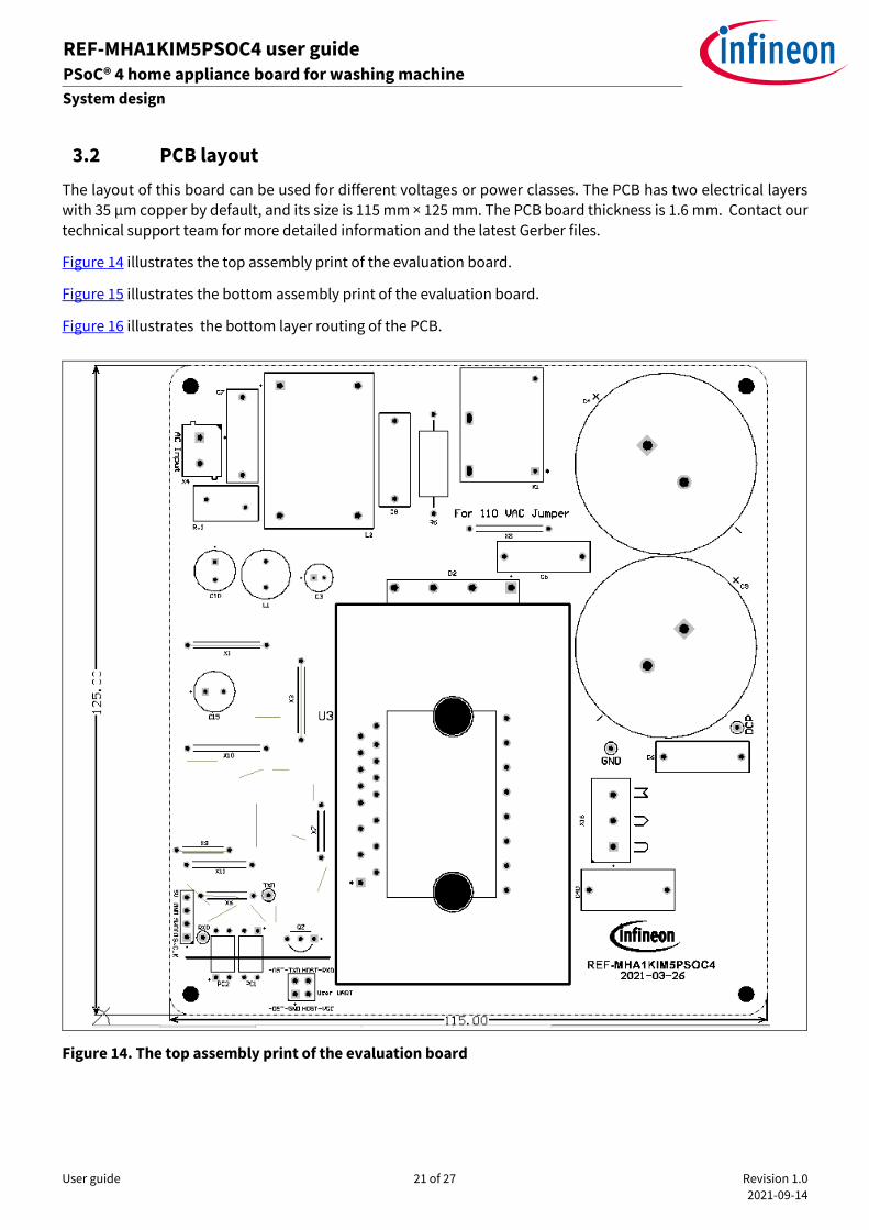
3.2 PCB layout
The layout of this board can be used for different voltages or power classes. The PCB has two electrical layers with 35 µm copper by default, and its size is 115 mm × 125 mm. The PCB board thickness is 1.6 mm. Contact our
technical support team for more detailed information and the latest Gerber files.
Figure 14 illustrates the top assembly print of the evaluation board.
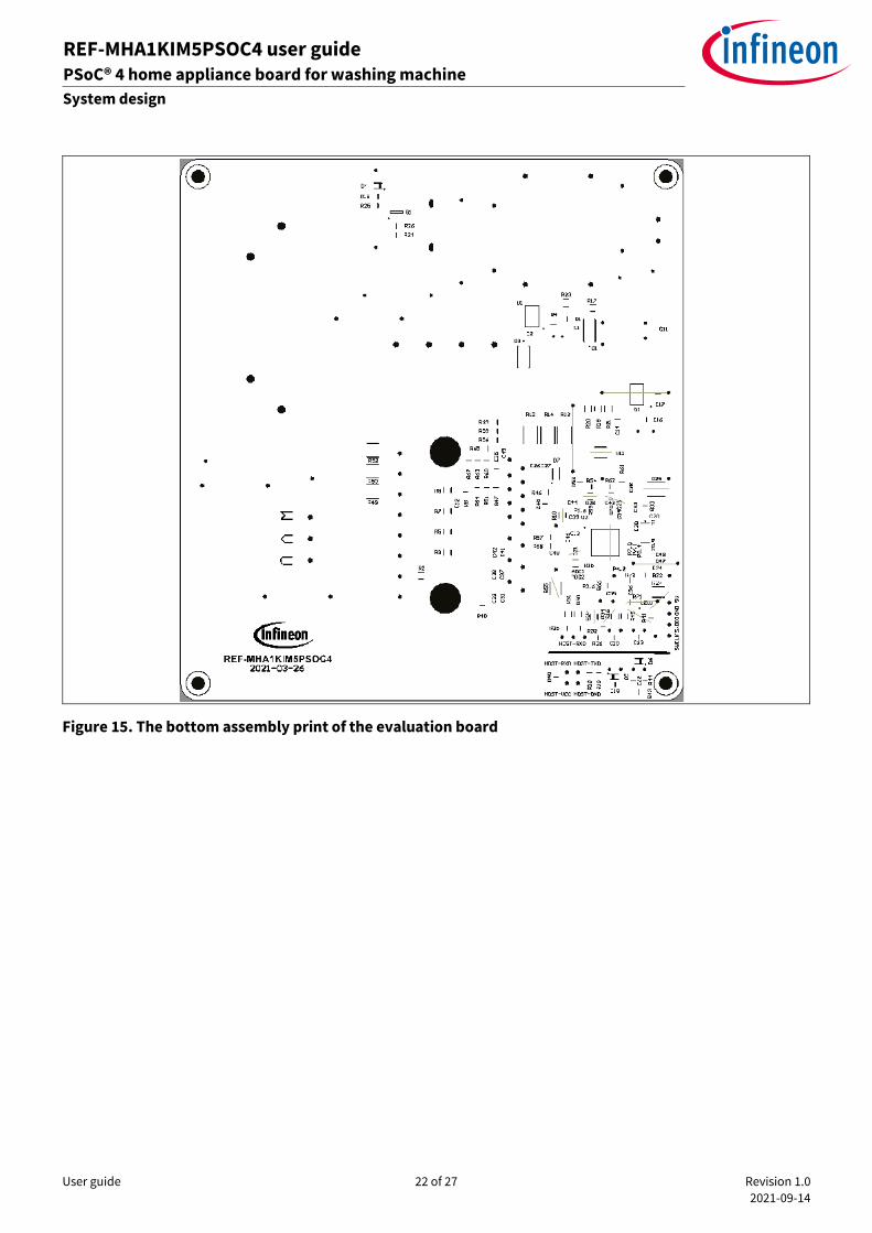
Figure 15 illustrates the bottom assembly print of the evaluation board.
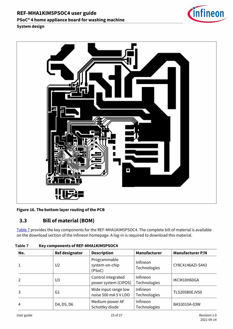
Figure 16 illustrates the bottom layer routing of the PCB.
Figure 14. The top assembly print of the evaluation board
User guide 22 of 27 Revision 1.0
2021-09-14
REF-MHA1KIM5PSOC4 user guide PSoC® 4 home appliance board for washing machine
System design
ardware description of REF-MHA1KIM5PSOC4
Figure 15. The bottom assembly print of the evaluation board
User guide 23 of 27 Revision 1.0
2021-09-14
REF-MHA1KIM5PSOC4 user guide PSoC® 4 home appliance board for washing machine
System design
ardware description of REF-MHA1KIM5PSOC4
Figure 16. The bottom layer routing of the PCB
3.3 Bill of material (BOM)
Table 7 provides the key components for the REF-MHA1KIM5PSOC4. The complete bill of material is available on the download section of the Infineon homepage. A log-in is required to download this material.
Table 7 Key components of REF-MHA1KIM5PSOC4
No. Ref designator Description Manufacturer Manufacturer P/N
1 U2
Programmable system-on-chip
(PSoC)
Infineon
Technologies CY8C4146AZI-S443
2 U3 Control integrated
power system (CIPOS)
Infineon
Technologies IKCM10H60GA
3 G1 Wide input range low
noise 500 mA 5 V LDO
Infineon
Technologies TLS205B0EJV50
4 D4, D5, D6 Medium-power AF
Schottky diode
Infineon
Technologies BAS3010A-03W
User guide 24 of 27 Revision 1.0
2021-09-14
REF-MHA1KIM5PSOC4 user guide PSoC® 4 home appliance board for washing machine
System design
ardware description of REF-MHA1KIM5PSOC4
No. Ref designator Description Manufacturer Manufacturer P/N
5 L2
IND / STD / 2.2mH / 8A / 30% / -40 °C to 125 °C / 14mR / THT /
common mode choke
Wurth Elektronik 7448258022
6 C5, C6, C7, C8
CAP / FILM / 100nF / 630V / 10% / MKP (Metallized
Polypropylene) / -40
°C to 105 °C
Wurth Elektronik 890324025017CS
7 C4, C9
CAP / ELCO / 680uF /
450V / 20% /
Aluminiumelectrolytic
/ -25 °C to 105 °C
Wurth Elektronik 861141486026
8 C15
CAP / ELCO / 220uF /
35V / 20% / aluminiumelectrolytic
/ -40 °C to 105 °C
Wurth Elektronik 860020574012
9 X16 Terminal block, 3Pins, 5.00mm pitch, board
to cable
Wurth Elektronik 691102710003
User guide 25 of 27 Revision 1.0
2021-09-14
REF-MHA1KIM5PSOC4 user guide PSoC® 4 home appliance board for washing machine
System performance
ardware description of REF-MHA1KIM5PSOC4
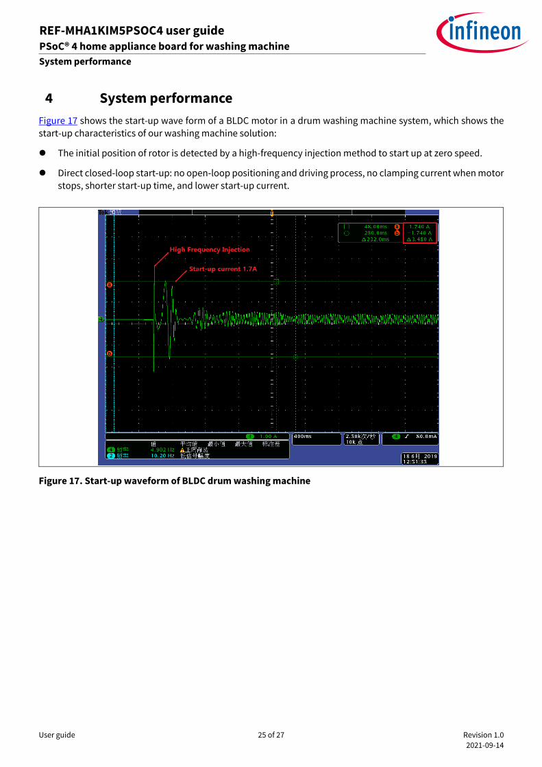
4 System performance
Figure 17 shows the start-up wave form of a BLDC motor in a drum washing machine system, which shows the
start-up characteristics of our washing machine solution:
⚫ The initial position of rotor is detected by a high-frequency injection method to start up at zero speed.
⚫ Direct closed-loop start-up: no open-loop positioning and driving process, no clamping current when motor stops, shorter start-up time, and lower start-up current.
Figure 17. Start-up waveform of BLDC drum washing machine
User guide 26 of 27 Revision 1.0
2021-09-14
REF-MHA1KIM5PSOC4 user guide PSoC® 4 home appliance board for washing machine
Appendices
ardware description of REF-MHA1KIM5PSOC4
5 Appendices
5.1 Abbreviations and definitions
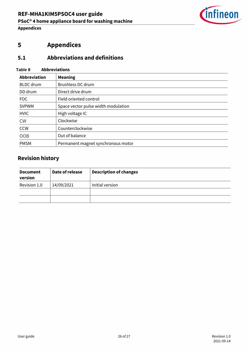
Table 8 Abbreviations
Abbreviation Meaning
BLDC drum Brushless DC drum
DD drum Direct drive drum
FOC Field oriented control
SVPWM Space vector pulse width modulation
HVIC High voltage IC
CW Clockwise
CCW Counterclockwise
OOB Out of balance
PMSM Permanent magnet synchronous motor
Revision history
Document
version
Date of release Description of changes
Revision 1.0 14/09/2021 Initial version
Published by
Infineon Technologies AG
81726 Munich, Germany
© 2021 Infineon Technologies AG.
All Rights Reserved.
Do you have a question about this
document?
Email: [email protected]
Document reference
For further information on the product, technology, delivery terms and conditions and prices please contact your nearest Infineon Technologies office (www.infineon.com). WARNINGS Due to technical requirements products may contain dangerous substances. For information on the types in question please contact your nearest Infineon Technologies office. Except as otherwise explicitly approved by Infineon Technologies in a written document signed by authorized representatives of Infineon Technologies, Infineon Technologies’ products may not be used in any applications where a failure of the product or any consequences of the use thereof can reasonably be expected to result in personal injury.
Edition 2021-09-14
UG-2021-36
Trademarks All referenced product or service names and trademarks are the property of their respective owners.