\u003ctitle\u003ehigh-space bandwidth product computer-generated holography using volume...
TRANSCRIPT

High space bandwidth product computer-generated holograms usingvolume holography
Joseph Rosen
Optical Signal Processing Branch, Rome Laboratory,Hanscom Airforce Base, MA 01731,
E-Mail: ROSEN@PL9000 .PLH.AF.MIL,
Mordechai Segev, Ainnon Yariv
California Institute of Technology,
128—95, Pasadena, CA 91125Tel. (818)356.-4823; Fax (818)405—0928,
Jacob Barhen
Jet Propulsion Laboratory,California Institute of Technology,
Pasadena, CA 91109.
ABSTRACTWe suggest a method for coding high resolution computer—generated volume
holograms. It involves splitting the computer—generated hologram intomultiple holograms, each individually recorded as a volume hologramutilizing the maximal resolution available from the spatial lightmodulator. Our method enables their simultaneous subsequentreconstruction. We demonstrate the recording and the reconstruction ofa computer—generated volume hologram with a space bandwidth product muchhigher than the maximal one of the spatial light modulator used as an
interface. Finally, we analyze the scheduling procedure of the multiple
holographic recording process in photorefractive medium in this specific
application.
1. INTRODUCTION
Binary computer-generated holograms (CGHs) are becoming essentialcomponents in optical signal processing schemes. Apart from their use as
216 ISPIE Vol. 2026 0-8194-1275-9/93/$6.00
Downloaded From: http://proceedings.spiedigitallibrary.org/ on 09/12/2013 Terms of Use: http://spiedl.org/terms

a means for storage and reconstruction of images, these holograms canserve as spatial filters, optical elements and as the basic component ininterconnection networks. CGHs are created in an electronic computer,
and displayed on spatial light modulators (SLMs). This providesreal-time variability, which enhances the flexibility of the holograms,and makes them suitable for applications such as adaptive optics andreconfigurable interconnects.
Unfortunately, most currently available SLMs suffer from a limitedinformation capacity, low resolution, distortions, non—uniformities andinter—pixel dead areas. This substantially deteriorates the spacebandwidth product (SBP) of the CGHs, and results in a undesireddifference between the original image and the one actually reconstructedfrom a CGH.
In this Letter we demonstrate a method for increasing the SBP of abinary CGH much above the maximal resolution available from the SLM. Itincludes splitting the CGH into secondary holograms, each utilizing themaximal resolution available from the SLM. The individual secondaryholograms are sequentially transmitted from the computer to the SLM, andimaged onto a volume holographic medium. They are then converted tovolume holograms, all recorded with the same reference wave, and storedin the volume of the holographic medium. The subsequent readout resultsin the reconstruction of the whole original high resolution image, witha large reduction in the reconstruction error. In this vein, we haveused a photorefractive (PR) crystal as the storage medium, and alsoutilize its coupling properties for significantly improving therecording efficiency of the multiple volume (secondary) holograms.
2. ERROR REDUCTION BY USING COMPUTER-GENERATED VOLUME HOLOGRAPHY
Consider a binary CGH expressed by the spatial distribution (in theplane of the SLM) of H(u,v), which is the Fourier transform of h(x,y).The hologram is designed to reconstruct the image f(x,y) in a sub—areaA in the x—y plane. The reconstruction error (per pixel in A) is definedas:
efIf(x,y)_pfi(x,y)I2thdy
SPIEVo!. 2026/217
Downloaded From: http://proceedings.spiedigitallibrary.org/ on 09/12/2013 Terms of Use: http://spiedl.org/terms

where h(x,y) is the part of h(x,y) included in the sub-area A, and /3 is
a constant which is designed to minimize the reconstruction error1. Weshow that the reconstruction error of a conventional binary CGHdecreases when the area of the reconstructed image becomes smaller. In
fact, the error should theoretically completely disappear when the imageis a single point. Based on this observation, we analyze a general caseof a complicated image, and desire to code its Fourier transform by theCGH. We decompose the image into simple primitives of a small area, andcalculate a CGH for each one of them. The whole set of CGHs issequentially transmitted to an SLM, and imaged onto a PR crystal. TheCGHs are converted to volume holograms by the method we introduced in aprevious work2, and stored in the crystal as thick gratings. The volumeholograms are formed due to interference between a nonzero diffractionorder (off the SLM) which bears the holographic data, and the zero(non—diffracted) order. The resultant thick gratings differ from eachother by their periodicity and orientation, and may be addressed(reconstructed) individually as separate data pages2, or as a one, highresolution, image. Here we utilize the last option and reconstruct the
original high SBP image, by illuminating the crystal with a readout beamdirected along the optical axis. In this method, the reconstructionerror of the full image is the average of all the errors of theprimitives. Therefore, as we choose smaller primitives the overall erroris reduced. The maximal number of primitives that can be used in this
technique is limited only by the scheduling procedure of the holographicrecording in the PR crystal3. As will be shown below, the maximal number
of stored holograms can be larger, in this special configuration, thanin the usual recording procedures.
The classic methods of coding a complex function F(u,v) on a binary
CGH (the detour coding methods4) are based on replacing every analogvalue of F(u,v) by a binary valued matrix. As the matrix becomes larger,the original values are described more precisely, and the reconstruction
error decreases. Most currently available SLMs, however, contain only asmall amount of binary pixels, and this limits the resolution F(u,v). On
a SLM of 128x128 pixels, for example, only a binary CGH of a function of
8x8 can be displayed, making the commonly accepted5 assumption that everyoriginal value is expressed by a binary 16x16 matrix. The immediateconclusion is that, wherever the SLM possesses a low resolution, one has
to use another method. In any case, one should expect in such instance
218 ISPIE Vol. 2026
Downloaded From: http://proceedings.spiedigitallibrary.org/ on 09/12/2013 Terms of Use: http://spiedl.org/terms

a significant reconstruction error for coding high dynamic rangefunctions. In the present work, we choose to design the CGHs by theProjection Onto Constraint Set (POCS) algorithm1, since it is fast andyields relatively small reconstruction errors. The constraints in theimage plane are to obtain (I) a desired complex amplitude distributionat an a priori defined sub—area, and (II) its conjugate opposite at aregion that corresponds to the reflection of that sub—area with respectto the origin. The constraint in the CGH plane is the binarization ofthe hologram's values. As mentioned above, an image of a small area can
significantly reduce the reconstruction error, while larger imagesinclude larger errors. To demonstrate this principle we calculate thereconstruction error from two binary CGHs that were designed using thePOCS algorithm. The CGHs were of two images that extend over differentareas: the images of the letters "R" and "0". Figure 1 shows thereconstruction error e (according to Eq. 1) versus the image area
(number of pixels).
3. EXPERIMENTAL RESULTS
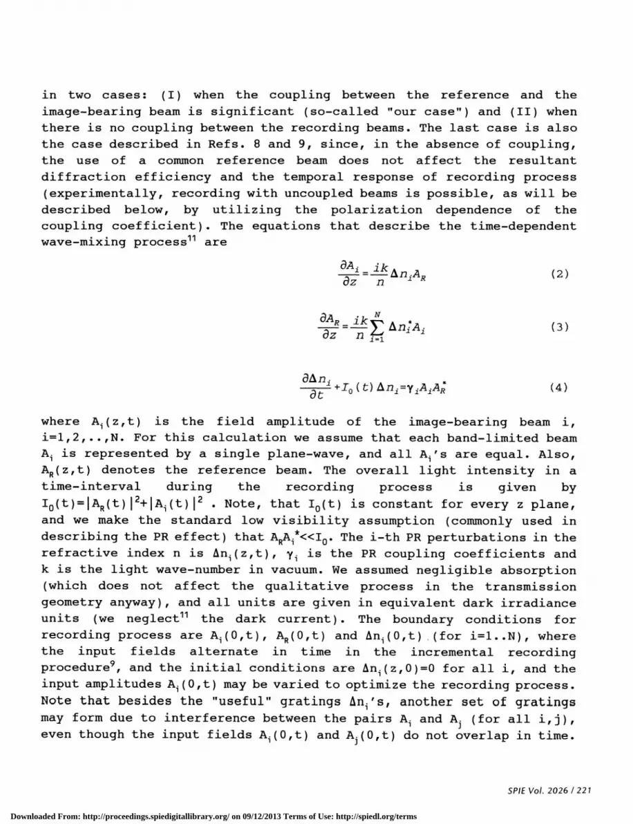
Our experimental setup is sketched in Fig. 2. Each binary CGH isdisplayed on the SLM, coherently imaged onto a PR crystal, and convertedto a volume hologram2. In this process all the CGHs are recorded with thesame reference wave: the zero—th order of diffraction from the SLM.Therefore, illuminating with a readout beam along the optical axis(which propagates counter to the zero order) results in Bragg matchingto all the stored holograms, and reconstructs all the primitivessimultaneously (and hence the whole high resolution image).
We defined the smallest primitive (or the most delicate partition) ofa complicated image as a point, and recorded a volume CGH for each pointthat composed the image. Since a binary CGH of a point is merely onerectangular grating (owing to the binary nature of the SLM), and bearsno additional information, we expect to have the minimal reconstructionerror for each one of them. The relative intensity of each reconstructed
point can be controlled either by the scheduling in the recordingprocess of the multiple holograms, or by the angular response of the PRcrystal. Its phase is obtained by the proper lateral shift of thegrating on the SLM. The minor reconstruction errors using this methodoriginate from small non—uniformities in the PR crystal and aberrationsof the optical system, rather than from the lack of resolution in the
SPIE Vol. 2026 /219
Downloaded From: http://proceedings.spiedigitallibrary.org/ on 09/12/2013 Terms of Use: http://spiedl.org/terms
SLM as in planar CGHs. Ideally, every binary grating can bereconstructed into a desired point with no error at all. Moreover, since
the reminiscent errors are not fundamentally built-in in the codingmethod, the recorded CGHs can be iteratively corrected6, and all theerrors can, in principle, be eliminated.
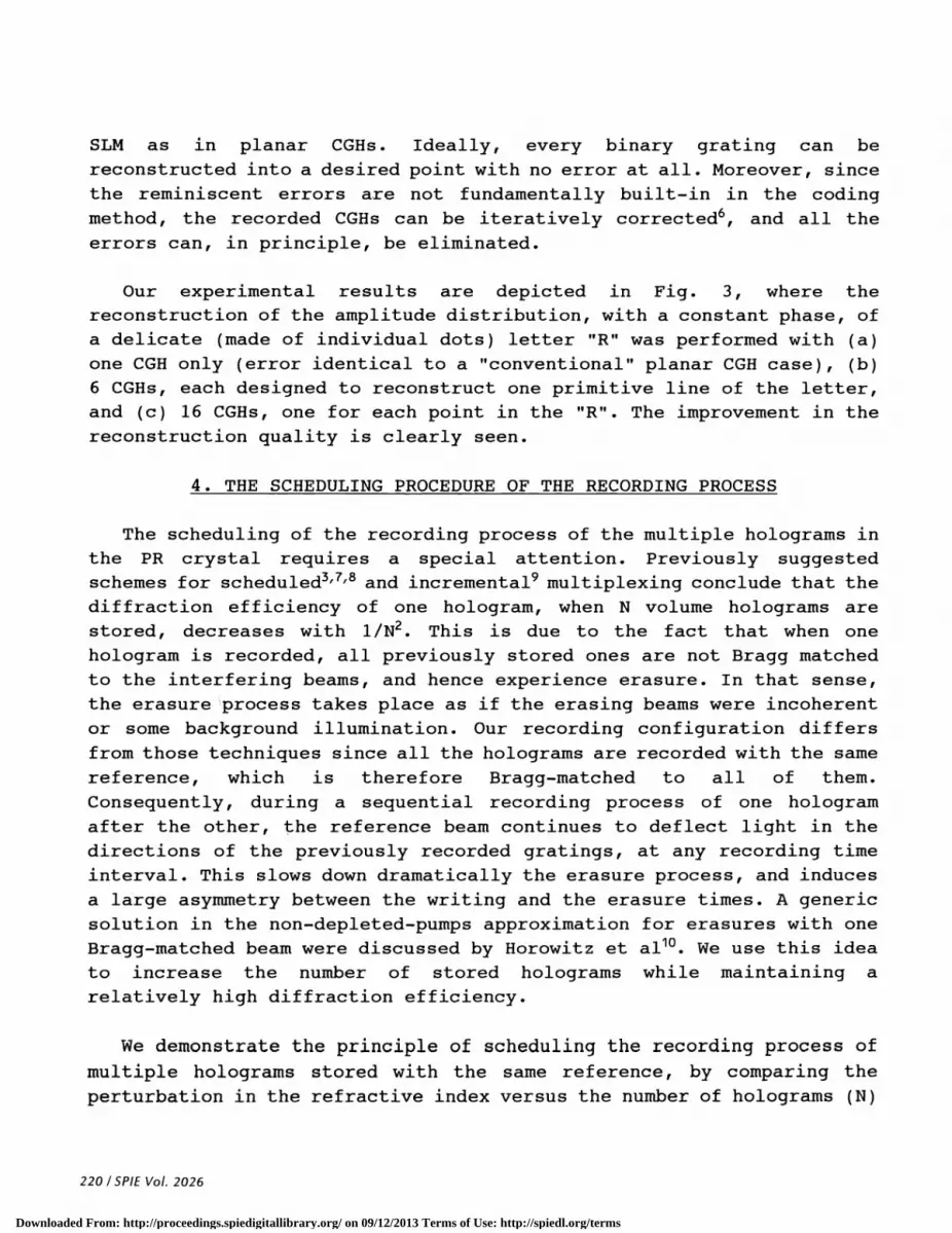
Our experimental results are depicted in Fig. 3, where thereconstruction of the amplitude distribution, with a constant phase, ofa delicate (made of individual dots) letter "R" was performed with (a)one CGH only (error identical to a "conventional" planar CGH case), (b)6 CGHs, each designed to reconstruct one primitive line of the letter,and (c) 16 CGHs, one for each point in the "R". The improvement in thereconstruction quality is clearly seen.
4. THE SCHEDULING PROCEDURE OF THE RECORDING PROCESS
The scheduling of the recording process of the multiple holograms in
the PR crystal requires a special attention. Previously suggestedschemes for scheduled3'7'8 and incremental9 multiplexing conclude that the
diffraction efficiency of one hologram, when N volume holograms arestored, decreases with 1/N2. This is due to the fact that when onehologram is recorded, all previously stored ones are not Bragg matchedto the interfering beams, and hence experience erasure. In that sense,the erasure process takes place as if the erasing beams were incoherentor some background illumination. Our recording configuration differsfrom those techniques since all the holograms are recorded with the same
reference, which is therefore Bragg—matched to all of them.Consequently, during a sequential recording process of one hologramafter the other, the reference beam continues to deflect light in thedirections of the previously recorded gratings, at any recording timeinterval. This slows down dramatically the erasure process, and induces
a large asymmetry between the writing and the erasure times. A genericsolution in the non—depleted—pumps approximation for erasures with oneBragg—matched beam were discussed by Horowitz et a110. We use this ideato increase the number of stored holograms while maintaining arelatively high diffraction efficiency.
We demonstrate the principle of scheduling the recording process of
multiple holograms stored with the same reference, by comparing theperturbation in the refractive index versus the number of holograms (N)
220/SPIE Vol. 2026
Downloaded From: http://proceedings.spiedigitallibrary.org/ on 09/12/2013 Terms of Use: http://spiedl.org/terms
in two cases: (I) when the coupling between the reference and theimage—bearing beam is significant (so—called "our case") and (II) whenthere is no coupling between the recording beams. The last case is alsothe case described in Refs. 8 and 9, since, in the absence of coupling,the use of a common reference beam does not affect the resultant
diffraction efficiency and the temporal response of recording process(experimentally, recording with uncoupled beams is possible, as will be
described below, by utilizing the polarization dependence of thecoupling coefficient). The equations that describe the time-dependentwave—mixing process1' are
--=--iAfljAR (2)az n
/AR.1kAn*A (3)
3n. *
at1 ( C) AflfYAlAR (4)
where A1(z,t) is the field amplitude of the image-bearing beam i,i=1,2,. .,N. For this calculation we assume that each band—limited beam
A1 is represented by a single plane—wave, and all A's are equal. Also,AR(z,t) denotes the reference beam. The overall light intensity in atime—interval during the recording process is given byIo(t)=IAR(t)12+IA,(t)12 . Note, that 10(t) is constant for every z plane,and we make the standard low visibility assumption (commonly used indescribing the PR effect) that ARA1*<<Io. The i-th PR perturbations in therefractive index n is An,(z,t), y1 is the PR coupling coefficients andk is the light wave—number in vacuum. We assumed negligible absorption
(which does not affect the qualitative process in the transmissiongeometry anyway), and all units are given in equivalent dark irradianceunits (we neglect11 the dark current). The boundary conditions for
recording process are A1(O,t), AR(O,t) and An1(O,t) (for i=1..N), wherethe input fields alternate in time in the incremental recordingprocedure9, and the initial conditions are An1(z,O)=O for all i, and the
input amplitudes A,(O,t) may be varied to optimize the recording process.Note that besides the "useful" gratings in,'s, another set of gratings
may form due to interference between the pairs A1 and A3 (for all i,j),
even though the input fields A1(O,t) and A(O,t) do not overlap in time.
SPIE Vol. 2026 / 221
Downloaded From: http://proceedings.spiedigitallibrary.org/ on 09/12/2013 Terms of Use: http://spiedl.org/terms

We have performed a preliminary check on the theoretical results, bycomparing, in both cases, the maximal number of holograms to be recorded
that yielded a given diffraction efficiency. When we used ordinarypolarized beams in the recording process in BaTiO3, the beams did notcouple and we were able to store not more than 20 holograms with adiffraction efficiency of about 1% per hologram. When we usedextraordinary polarization we successfully stored more than 50holograms, with the same diffraction efficiency threshold. Thisqualitatively proves our conclusions. However, since good Bragg matchingis required in the readout process, the use of identical polarizationsfor both the recording and the readout process is highly desirable.Otherwise, the difference in the refractive indices in this anisotropic
crystal deteriorates the quality of the high-resolution reconstructedimage. Therefore, for high density data storage, as well as in the
application presented here, the recording beams always couple to eachother. Therefore a more general comparison between the models forcoupled and uncoupled beams in the recording process is required. Sincethis extends beyond the scope of the issues presented here, we providea complete treatment for coupled recording beams elsewhere.
5. CONCLUSIONS
In conclusion, we have demonstrated a new technique to code high SBPcomputer—generated holograms, at a resolution which greatly exceeds the
limitations imposed by the interfacing spatial light modulator. We notethat this is the first (to the best of our knowledge) successful attemptof computer controlling information stored in a volume. Our method isuseful for coding masks, filters, interconnects and optical elements for
applications where high resolution is required but storing large amountsof data is not necessary. Besides signal processing purposes, it can beused as a network of reconfigurable interconnects for computation tasks,
and even for coding three-dimensional images (for example, the points in
Fig. 3c can be of minimal sizes in different planes of reconstruction).
6. ACKNOWLEDGMENTS
The work of JR. was done while he was a National Research CouncilResearch Associate at Rome Laboratory. The work of M.S. and A.Y. was
supported by the Defense Advanced Research Projects Agency (DARPA) .Thework of J.B. was supported by NASA's Office of Advanced Concepts and
Technology.
222 / SPIE Vol. 2026
Downloaded From: http://proceedings.spiedigitallibrary.org/ on 09/12/2013 Terms of Use: http://spiedl.org/terms

8. REFERENCES
1. J. P. Allebach and D. W. Sweeny, "Iterative approaches tocomputer generated holography," Proc. SPIE Vol. 884, pp. 2-91988.
2. J. Rosen, M. Segev and A. Yariv, "Wavelength-multiplexedcomputer-generated volume holography," Opt. Lett. Vol. 16, pp.744—746, 1993.
3. K. Bløtekjaer, "Limitations on holographic storage capacity ofphotochromic and photorefractive media," Appl. Opt. Vol. 18,pp. 57—67, 1979.
4. W. H. Lee, "Computer—generated holograms: techniques andapplications" , Prog. in Optics, E. Wolf ed. , vol . 16 , p.119—232, North—Holland (1978).
5. see, for example, C. H. Han and D. P. Casasent, "Experimental
comparison of computer generated holograms," Proc. SPIE Vol. 884,
pp. 72—80 (1988).6. J. Rosen, L. Shiv, J. Stein and J. Shamir, "Electro-optical
hologram generation on spatial light modulators," J. Opt. Soc. Am.A Vol. 9, pp. 1159—1166 (1992).
7. D. Psaltis, D. Brady and K. Wagner, "Adaptive optical networksusing photorefractive crystals," Appi. Opt. Vol. 27, pp. 1752-1759, 1988.
8. E. S. Maniloff and K. M. Johnson, "Maximized photorefractive
holographic storage," J. Appl. Phys. Vol. 70, pp. 4702-4707,1991.
9. Y. Taketomi, J. E. Ford, H. Sasaki, J. Ma, Y. Fainman and S. H.
Lee, "Incremental recording for photorefractive hologrammultiplexing," Opt. Lett. Vol. 16, pp. 1774-1776 (1991); commentand reply: E. S. Maniloff and K. M. Johnson, Opt. Lett. Vol. 17,
pp. 961—962 (1992).10. M. Horowitz, D. Kligler and B. Fischer, "Time-dependent
behavior of photorefractive two— and four—wave mixing," J. Opt.Soc. Am. B Vol. 8, pp. 2204—2217 1991.
11. M. Segev, D. Engin, A. Yariv and G. C. Valley,"Temporalevolution of fanning in photorefractive materials," Opt. Lett.,June 1993.
SPIE Vol. 2026 / 223
Downloaded From: http://proceedings.spiedigitallibrary.org/ on 09/12/2013 Terms of Use: http://spiedl.org/terms

aU
"4
Figure 1: The reconstruction error e asreconstructed image area A, for images of the"0" (0).
a function of theletters "R" (+) and
Carrier
Light
Figure 2: The experimental setup.
224 ISPIE Vol. 2026
++
0
÷
0
0.30
0.25 -
0.20 -
+0.15 -
0.10 -0
0.05 - 0I-
>.
+
0
+
0
I -
0 1000 2000 500O 4000
A (Number of Pixels I
PRCrystal
ReadoutBeam
ReconstructedImage
Screen
Downloaded From: http://proceedings.spiedigitallibrary.org/ on 09/12/2013 Terms of Use: http://spiedl.org/terms
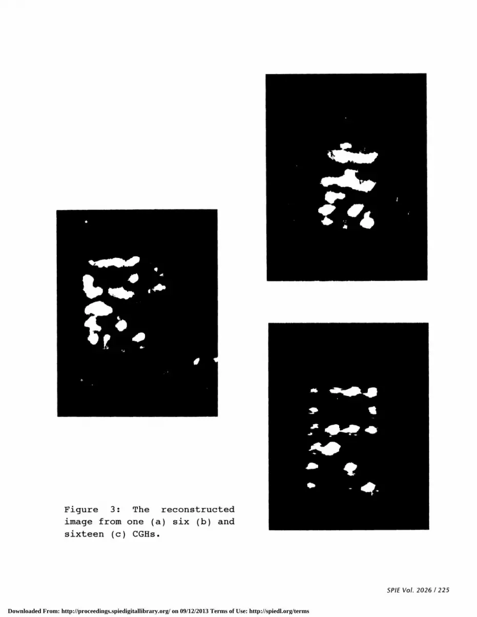
Figure 3: The reconstructedimage from one (a) six (b) andsixteen (c) CGHs.
SPIE Vol. 2026 / 225
Downloaded From: http://proceedings.spiedigitallibrary.org/ on 09/12/2013 Terms of Use: http://spiedl.org/terms

3
25
2
1.5
1
0.5
0
N (Number of Holograms)30
Figure 4: The photorefractive index-perturbation <An> in threecases: (I) from the numerical solution of Eqs. 2-4, withamplitude ratio 1:2 (upper solid curve), (II) for uncoupledbeams with amplitude ration 1:2 (lower dashed curve) and (III)for uncoupled beams with amplitude ration 1:1 (middle dotted
curve)
226/SPIEVoL 2026
0 5 10 15 20 25
Downloaded From: http://proceedings.spiedigitallibrary.org/ on 09/12/2013 Terms of Use: http://spiedl.org/terms