type 546, 546s, and 546ns electro-pneumatic transducers
TRANSCRIPT
www.Fisher.com
D20
0108
X01
2
Type 546, 546S, and 546NS Electro-PneumaticTransducersContents
Introduction 1. . . . . . . . . . . . . . . . . . . . . . . . . . . . . . . Scope of Manual 1. . . . . . . . . . . . . . . . . . . . . . . . . Description 2. . . . . . . . . . . . . . . . . . . . . . . . . . . . . . Specifications 2. . . . . . . . . . . . . . . . . . . . . . . . . . . . Educational Services 2. . . . . . . . . . . . . . . . . . . . . .
Installation 5. . . . . . . . . . . . . . . . . . . . . . . . . . . . . . . . Mounting 5. . . . . . . . . . . . . . . . . . . . . . . . . . . . . . . . Pressure Connections 5. . . . . . . . . . . . . . . . . . . . . Diagnostic Connections 5. . . . . . . . . . . . . . . . . . . Electrical Connections 6. . . . . . . . . . . . . . . . . . . . .
Operating Information 7. . . . . . . . . . . . . . . . . . . . . . Adjustments 7. . . . . . . . . . . . . . . . . . . . . . . . . . . . . Calibration 8. . . . . . . . . . . . . . . . . . . . . . . . . . . . . . .
Equipment Required 8. . . . . . . . . . . . . . . . . . . . . Calibration Procedure 8. . . . . . . . . . . . . . . . . . . . Recalibration 9. . . . . . . . . . . . . . . . . . . . . . . . . . . .
Changing Output Pressure Range 9. . . . . . . . . . Reversing the Action 9. . . . . . . . . . . . . . . . . . . . . . Split Range Operation 10. . . . . . . . . . . . . . . . . . . .
Principle of Operation 10. . . . . . . . . . . . . . . . . . . . . Maintenance 11. . . . . . . . . . . . . . . . . . . . . . . . . . . . .
Type 82 Relay Removal and Replacement 12. . Type 82 Relay Maintenance 12. . . . . . . . . . . . . . Replacing the Feedback Bellows Assembly 13.Troubleshooting 13. . . . . . . . . . . . . . . . . . . . . . . . .
Electrical 13. . . . . . . . . . . . . . . . . . . . . . . . . . . . . . Pneumatic 14. . . . . . . . . . . . . . . . . . . . . . . . . . . . .
Alignment 14. . . . . . . . . . . . . . . . . . . . . . . . . . . . . . . Span Adjustment 14. . . . . . . . . . . . . . . . . . . . . . . Torque Motor Frame 14. . . . . . . . . . . . . . . . . . . . Armature Travel Stop 15. . . . . . . . . . . . . . . . . . . Coil 15. . . . . . . . . . . . . . . . . . . . . . . . . . . . . . . . . . .
Parts Ordering 15. . . . . . . . . . . . . . . . . . . . . . . . . . . . Parts List 15. . . . . . . . . . . . . . . . . . . . . . . . . . . . . . . .
Repair Kits for Type 546, 546S,and 546NS Transducers 15. . . . . . . . . . . . . . .
Type 546, 546S, & 546NS Transducers 16. . . . Torque Motor 17. . . . . . . . . . . . . . . . . . . . . . . . . . . Type 82 Relay 18. . . . . . . . . . . . . . . . . . . . . . . . . . Diagnostic Connections 19. . . . . . . . . . . . . . . . . . Mounting Parts 19. . . . . . . . . . . . . . . . . . . . . . . . . .
Loop Schematics/Nameplates 21. . . . . . . . . . . . . . CSA Schematics 21. . . . . . . . . . . . . . . . . . . . . . . . FM Schematics 23. . . . . . . . . . . . . . . . . . . . . . . . . .
W2115/IL
TYPE 546
FILTERREGULATOR
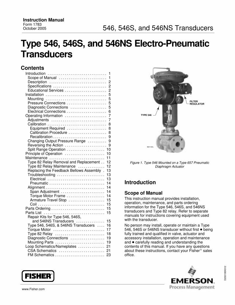
Figure 1. Type 546 Mounted on a Type 657 PneumaticDiaphragm Actuator
Introduction
Scope of ManualThis instruction manual provides installation,operation, maintenance, and parts orderinginformation for the Type 546, 546S, and 546NStransducers and Type 82 relay. Refer to separatemanuals for instructions covering equipment usedwith the transducer.No person may install, operate or maintain a Type546, 546S or 546NS transducer without first � beingfully trained and qualified in valve, actuator andaccessory installation, operation and maintenanceand � carefully reading and understanding thecontents of this manual. If you have any questionsabout these instructions, contact your Fisher� salesoffice.
Instruction ManualForm 1783October 2005 546, 546S, and 546NS Transducers
546, 546S, and 546NS TransducersInstruction Manual
Form 1783October 2005
2
DescriptionThe Type 546 or 546NS transducer (figure 1)receives either a voltage (V dc) or a current (mA dc)input signal and transmits a proportional pneumaticoutput pressure to a final control element. The Type546S transducer receives a current (mA dc) inputsignal and transmits a proportional pneumatic outputpressure. A typical application is in electronic controlloops where the final control element, generally acontrol valve, is pneumatically operated. The inputsignal, output pressure range, and electricalclassification, if approved, of each transducer isindicated on the nameplate attached to the cover, asshown in figures 13, 15, and 16.
The Type 546S transducer is approved as beingintrinsically safe when used with certain barriersystems. Refer to the Loop Schematics section ofthis manual.
The Type 546NS transducer is designed for nuclearpower applications. The Type 546NS constructionincludes materials that provide superior performancein elevated temperature and radiation environments.
The O-rings are EPDM (ethylene propylene) and thediaphragms are EPDM/Nomex�. EPDMdemonstrates superior temperature capability andshelf life over nitrile. The Nomex diaphragm fabricdemonstrates improved strength retention atelevated temperature and radiation conditions.
CAUTION
Use a clean, dry, oil-free air supplywith instruments containing EPDMcomponents. EPDM is subject todegradation when exposed topetroleum-based lubricants.
Under Fisher’s 10CFR50, Appendix B, qualityassurance program, the Type 546NS transducer isqualified “commercial grade dedicated”. These canbe supplied as 10CFR, Part 21 items.
SpecificationsSpecifications for the Type 546, 546S, and 546NSare listed in table 1.
Educational ServicesFor information on available courses for Type 546,546S and 546NS transducers, as well as a variety ofother products, contact:
Emerson Process ManagementEducational Services, RegistrationP.O. Box 190; 301 S. 1st Ave.Marshalltown, IA 50158−2823Phone: 800−338−8158 orPhone: 641−754−3771 FAX: 641−754−3431e-mail: [email protected]
Note
Neither Emerson�, Emerson ProcessManagement, Fisher, nor any of theiraffiliated entities assumesresponsibility for the selection, use,and maintenance of any product.Responsibility for the selection, use,and maintenance of any productremains with the purchaser andend-user.
546, 546S, and 546NS TransducersInstruction ManualForm 1783October 2005
3
Table 1. Specifications
Available Configurations
Type 546: Electro-pneumatic signal transducerwith explosion-proof case and coverType 546S: Similar to Type 546 except designedfor intrinsically safe, non-incendive, ordust-ignition applicationsType 546NS: Similar to Type 546 exceptprovided with EPDM elastomers for use inelevated temperature and radiation environmentsAll transducer types can be ordered with orwithout a 67 Series filter regulator. A 51 mm (2 inch) circular supply pressure gauge may bemounted on the regulator
Input Signals(1)
Type 546 and 546NS: � 4 to 20 mA dc, � 10 to50 mA dc, � 1 to 9 V dc, or � two-way splitrange using any half of one of the standard inputsignal spansType 546S: � 4 to 20 mA dc, or � For FactoryMutual only, a two-way split range using eitherhalf of the 16 mA dc span. Signal must notexceed 30 V dc, 20 mA dc
Internal Resistance of Torque Motor
4 to 20 mA dc Input Signal: 176 ±10 ohms10 to 50 mA dc Input Signal: 90 ±10 ohms1 to 9 V dc Input Signal: 1300 ±50 ohms(temperature-compensated circuit)
Output Signals(1)
Ranges:(1)
For 546 and 546NS: 0.2 to 1.0 bar (3 to 15 psig),0.4 to 2.0 bar (6 to 30 psig), 0 to 1.2 bar (0 to 18psig), or 0 to 2.3 bar (0 to 33 psig)For 546S: 0.2 to 1.0 bar (3 to 15 psig), 0.4 to 2.0bar (6 to 30 psig), or 0 to 2.3 bar (0 to 33 psig)Action: Type 546 and 546NS are field-reversiblebetween direct and reverse action. The Type546S is available with either direct or reverseaction but cannot be reversed in the field.
Supply Pressure(1,4)
Recommended: 0.3 bar (5 psig) higher thanupper range limit of output signalMaximum: 3.5 bar (50 psig)
Maximum Steady-State Air Consumption(1,2)
At 1.4 bar (20 psig) Supply Pressure: 0.6normal m3/hr (0.35 scfm)
At 2.4 bar (35 psig) Supply Pressure: 0.8normal m3/hr (0.50 scfm)
Maximum Output Air Capacity(2)
At 1.4 bar (20 psig) Supply Pressure: 13.4normal m3/hr (8.0 scfm)At 2.4 bar (35 psig) Supply Pressure: 19.3normal m3/hr (11.5 scfm)
Performance(3)
Actuator Loading Time: See figure 6Reference Accuracy: ±0.75% of output signalspanIndependent Linearity:(1) ±0.50% of outputsignal spanOpen Loop Gain:(1) 26Frequency Response:(1) Gain is attenuated 3 dBat 20 Hz with transducer output signal piped to atypical instrument bellows with 305 mm (12inches) of 1/4 inch tubingElectromagnetic Interference (EMI)(1): Testedper IEC 61326-1 (Edition 1.1). Meets emissionlevels for Class A equipment (industrial locations)and Class B equipment (domestic locations).Meets immunity requirements for industriallocations (Table A.1 in the IEC specificationdocument). Immunity performance shown intable 2.
Operative Ambient Temperature Limits(1,4)
−40 to 66�C (−40 to +150�F)
Electrical ClassificationHazardous Area:
Explosion proof, Dust-Ignition proof, Intrinsically Safe Explosion proof, Non-incendive, Dust-Ignition proof, Intrinsically Safe
Refer to the Hazardous Area Classificationbulletins 9.2:001 and 9.2:002, table 3, and figures12, 13, 14, 15, and 16 for specific approvalinformation.NEMA 3R, CSA enclosure 3(NEMA 3R mounting orientation requires ventlocation to be below horizontal. Vent is shown infigure 9, key 69.)
AdjustmentsZero and Span Adjustments: Screwdriveradjustments located inside case (see figure 4)
(continued)
APPROVED
546, 546S, and 546NS TransducersInstruction Manual
Form 1783October 2005
4
Table 1. Specifications (continued)
ConnectionsSupply Pressure: 1/4-inch NPT female locatedon side of case, (or located on the Type 67 AFRfilter-regulator if mounted)Output Pressure: 1/4-inch NPT female locatedon side of caseVent: 1/4-inch NPT female with screen located onrelayElectrical: 1/2-inch NPT female located onbottom of case
Approximate Weight4.1 kg (9 pounds)
Declaration of SEP
Fisher Controls International LLC declares thisproduct to be in compliance with Article 3paragraph 3 of the Pressure Equipment Directive(PED) 97 / 23 / EC. It was designed andmanufactured in accordance with SoundEngineering Practice (SEP) and cannot bear theCE marking related to PED compliance.
However, the product may bear the CE markingto indicate compliance with other applicable ECDirectives.
1. These terms are defined in ISA Standard S51.1.2. Normal m3/hr—Normal cubic meters per hour (0�C and 1.01325 bar absolute). Scfm—Standard cubic feet per minute (60�F and 14.7 psia).3. Performance values are obtained using a Type 546 or Type 546S transducer with a 4 to 20 mA dc input signal and a 0.2 to 1 bar (3 to 15 psig) or a 0.4 to 2 bar (6 to 30 psig) output signal. Ambient temperature is 24�C (73�F). A transducer with other input or output signals might exceed these values. Reference accuracies of ±3.5% can be expectedwith output ranges starting near zero psig.4. The pressure/temperature limits in this document and any applicable standard or code limitation should not be exceeded.
Table 2. Immunity PerformancePort Phenomenon Basic Standard Performance Criteria(1)
Electrostatic discharge (ESD) IEC 61000-4-2 A
Enclosure Radiated EM field IEC 61000-4-3 AEnclosureRated power frequency magnetic field IEC 61000-4-8 ABurst (fast transients) IEC 61000-4-4 A
I/O signal/control Surge IEC 61000-4-5 BI/O signal/controlConducted RF IEC 61000-4-6 A
Specification limit = ±1% of span1. A=No degradation during testing. B = Temporary degradation during testing, but is self-recovering.
Table 3. Hazardous Area ClassificationsCertification Body Type Certification Obtained Entity Rating Temperature Code Enclosure Rating
546S
(Intrinsic Safety)Class/Division�Class I Division 1 GP A,B,C,D perdrawing 29A1594
− − − T5 (Tamb = 66�C) CSA ENC 3
CSA546, 546NS
(Explosion Proof)Class/Division�Class I, Division 1, Group C,D�Class II, Division 1, Groups E,F,G
− − − T5 (Tamb = 66�C) CSA ENC 3
546, 546NS Class I, Division 2, Groups A,B,C,DClass II, Division 2, Groups E,F,G − − − T5 CSA ENC 3
546S
(Intrinsic Safety)Class/Division�Class I, II, III Division 1Groups A,B,C,D,E,F,G per drawing 26A5936
Vmax = 33.3 V dcImax = 175 mACi = 0Li = 0
T4A (Tamb = 66�C) NEMA 3R
FM
546, 546NS
(Explosion Proof)Class/Division�Class I, Division 1, Groups C,D�Class II, Division 1, Groups E,F,G
− − − T5 (Tamb = 60�C) NEMA 3R
546, 546S, 546NS Class I, Division 2, Groups A,B,C,DClass II, Division 2, Groups F,G − − − T5 NEMA 3R
546, 546S, and 546NS TransducersInstruction ManualForm 1783October 2005
5
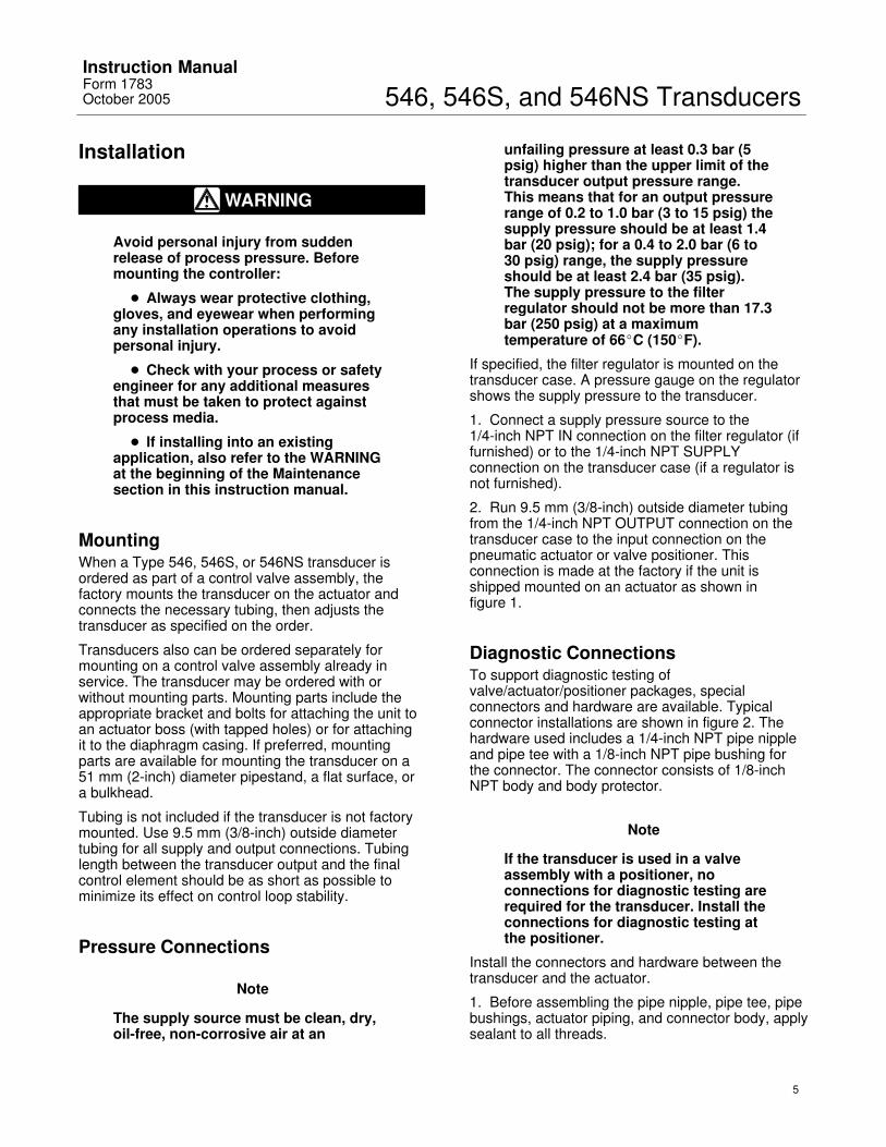
Installation
WARNING
Avoid personal injury from suddenrelease of process pressure. Beforemounting the controller:
� Always wear protective clothing,gloves, and eyewear when performingany installation operations to avoidpersonal injury.
� Check with your process or safetyengineer for any additional measuresthat must be taken to protect againstprocess media.
� If installing into an existingapplication, also refer to the WARNINGat the beginning of the Maintenancesection in this instruction manual.
MountingWhen a Type 546, 546S, or 546NS transducer isordered as part of a control valve assembly, thefactory mounts the transducer on the actuator andconnects the necessary tubing, then adjusts thetransducer as specified on the order.
Transducers also can be ordered separately formounting on a control valve assembly already inservice. The transducer may be ordered with orwithout mounting parts. Mounting parts include theappropriate bracket and bolts for attaching the unit toan actuator boss (with tapped holes) or for attachingit to the diaphragm casing. If preferred, mountingparts are available for mounting the transducer on a51 mm (2-inch) diameter pipestand, a flat surface, ora bulkhead.
Tubing is not included if the transducer is not factorymounted. Use 9.5 mm (3/8-inch) outside diametertubing for all supply and output connections. Tubinglength between the transducer output and the finalcontrol element should be as short as possible tominimize its effect on control loop stability.
Pressure Connections
Note
The supply source must be clean, dry,oil-free, non-corrosive air at an
unfailing pressure at least 0.3 bar (5psig) higher than the upper limit of thetransducer output pressure range.This means that for an output pressurerange of 0.2 to 1.0 bar (3 to 15 psig) thesupply pressure should be at least 1.4bar (20 psig); for a 0.4 to 2.0 bar (6 to30 psig) range, the supply pressureshould be at least 2.4 bar (35 psig).The supply pressure to the filterregulator should not be more than 17.3bar (250 psig) at a maximumtemperature of 66�C (150�F).
If specified, the filter regulator is mounted on thetransducer case. A pressure gauge on the regulatorshows the supply pressure to the transducer.
1. Connect a supply pressure source to the 1/4-inch NPT IN connection on the filter regulator (iffurnished) or to the 1/4-inch NPT SUPPLYconnection on the transducer case (if a regulator isnot furnished).
2. Run 9.5 mm (3/8-inch) outside diameter tubingfrom the 1/4-inch NPT OUTPUT connection on thetransducer case to the input connection on thepneumatic actuator or valve positioner. Thisconnection is made at the factory if the unit isshipped mounted on an actuator as shown in figure 1.
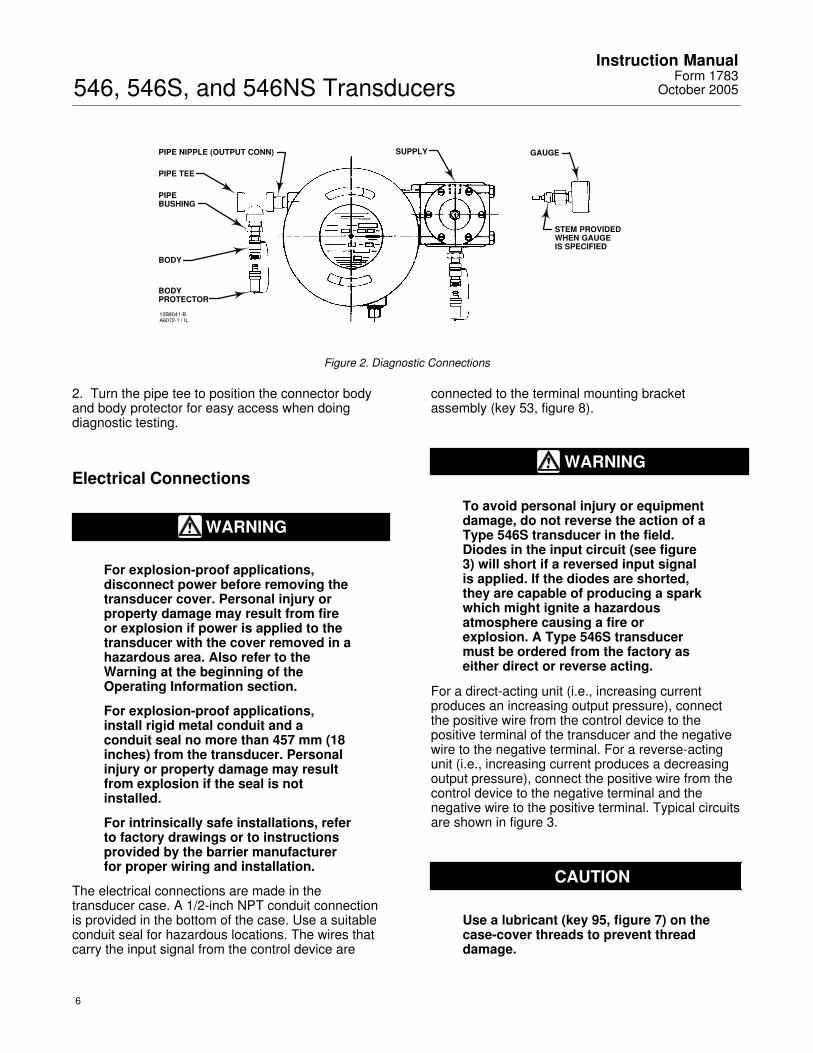
Diagnostic ConnectionsTo support diagnostic testing ofvalve/actuator/positioner packages, specialconnectors and hardware are available. Typicalconnector installations are shown in figure 2. Thehardware used includes a 1/4-inch NPT pipe nippleand pipe tee with a 1/8-inch NPT pipe bushing forthe connector. The connector consists of 1/8-inchNPT body and body protector.
Note
If the transducer is used in a valveassembly with a positioner, noconnections for diagnostic testing arerequired for the transducer. Install theconnections for diagnostic testing atthe positioner.
Install the connectors and hardware between thetransducer and the actuator.
1. Before assembling the pipe nipple, pipe tee, pipebushings, actuator piping, and connector body, applysealant to all threads.
546, 546S, and 546NS TransducersInstruction Manual
Form 1783October 2005
6
PIPE NIPPLE (OUTPUT CONN)
12B8041-BA6072-1 / IL
PIPE TEE
PIPEBUSHING
BODY
BODYPROTECTOR
SUPPLY GAUGE
STEM PROVIDEDWHEN GAUGEIS SPECIFIED
Figure 2. Diagnostic Connections
2. Turn the pipe tee to position the connector bodyand body protector for easy access when doingdiagnostic testing.
Electrical Connections
WARNING
For explosion-proof applications,disconnect power before removing thetransducer cover. Personal injury orproperty damage may result from fireor explosion if power is applied to thetransducer with the cover removed in ahazardous area. Also refer to theWarning at the beginning of theOperating Information section.
For explosion-proof applications,install rigid metal conduit and aconduit seal no more than 457 mm (18inches) from the transducer. Personalinjury or property damage may resultfrom explosion if the seal is notinstalled.
For intrinsically safe installations, referto factory drawings or to instructionsprovided by the barrier manufacturerfor proper wiring and installation.
The electrical connections are made in thetransducer case. A 1/2-inch NPT conduit connectionis provided in the bottom of the case. Use a suitableconduit seal for hazardous locations. The wires thatcarry the input signal from the control device are
connected to the terminal mounting bracketassembly (key 53, figure 8).
WARNING
To avoid personal injury or equipmentdamage, do not reverse the action of aType 546S transducer in the field.Diodes in the input circuit (see figure3) will short if a reversed input signalis applied. If the diodes are shorted,they are capable of producing a sparkwhich might ignite a hazardousatmosphere causing a fire orexplosion. A Type 546S transducermust be ordered from the factory aseither direct or reverse acting.
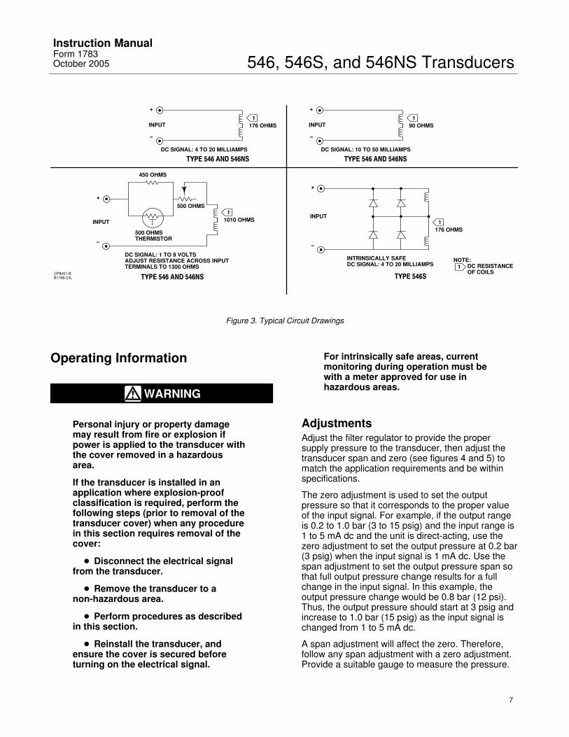
For a direct-acting unit (i.e., increasing currentproduces an increasing output pressure), connectthe positive wire from the control device to thepositive terminal of the transducer and the negativewire to the negative terminal. For a reverse-actingunit (i.e., increasing current produces a decreasingoutput pressure), connect the positive wire from thecontrol device to the negative terminal and thenegative wire to the positive terminal. Typical circuitsare shown in figure 3.
CAUTION
Use a lubricant (key 95, figure 7) on thecase-cover threads to prevent threaddamage.
546, 546S, and 546NS TransducersInstruction ManualForm 1783October 2005
7
DC SIGNAL: 1 TO 9 VOLTSADJUST RESISTANCE ACROSS INPUTTERMINALS TO 1300 OHMS 1
1
+
−
TYPE 546 AND 546NS
176 OHMS
DC SIGNAL: 4 TO 20 MILLIAMPS
INPUT1
+
−
TYPE 546 AND 546NS
90 OHMS
DC SIGNAL: 10 TO 50 MILLIAMPS
INPUT
1
+
−
TYPE 546S
176 OHMS
INTRINSICALLY SAFEDC SIGNAL: 4 TO 20 MILLIAMPS
INPUT
NOTE:DC RESISTANCEOF COILS
1
+
−
TYPE 546 AND 546NS
1010 OHMSINPUT
500 OHMSTHERMISTOR
450 OHMS
500 OHMS
CP8401-BB1766-2/IL
Figure 3. Typical Circuit Drawings
Operating Information
WARNING
Personal injury or property damagemay result from fire or explosion ifpower is applied to the transducer withthe cover removed in a hazardousarea.
If the transducer is installed in anapplication where explosion-proofclassification is required, perform thefollowing steps (prior to removal of thetransducer cover) when any procedurein this section requires removal of thecover:
� Disconnect the electrical signalfrom the transducer.
� Remove the transducer to anon-hazardous area.
� Perform procedures as describedin this section.
� Reinstall the transducer, andensure the cover is secured beforeturning on the electrical signal.
For intrinsically safe areas, currentmonitoring during operation must bewith a meter approved for use inhazardous areas.
AdjustmentsAdjust the filter regulator to provide the propersupply pressure to the transducer, then adjust thetransducer span and zero (see figures 4 and 5) tomatch the application requirements and be withinspecifications.
The zero adjustment is used to set the outputpressure so that it corresponds to the proper valueof the input signal. For example, if the output rangeis 0.2 to 1.0 bar (3 to 15 psig) and the input range is1 to 5 mA dc and the unit is direct-acting, use thezero adjustment to set the output pressure at 0.2 bar(3 psig) when the input signal is 1 mA dc. Use thespan adjustment to set the output pressure span sothat full output pressure change results for a fullchange in the input signal. In this example, theoutput pressure change would be 0.8 bar (12 psi).Thus, the output pressure should start at 3 psig andincrease to 1.0 bar (15 psig) as the input signal ischanged from 1 to 5 mA dc.
A span adjustment will affect the zero. Therefore,follow any span adjustment with a zero adjustment.Provide a suitable gauge to measure the pressure.
546, 546S, and 546NS TransducersInstruction Manual
Form 1783October 2005
8
Calibration
Equipment RequiredChoose a current or voltage source that is capable,without switching ranges, of driving the transducerthrough its entire input range. Switching ranges on acurrent or voltage source will produce spikes ormid-scale reverses in the input signal presented tothe transducer, causing errors.
Calibration Procedure
Note
The following calibration procedure isfor a Type 546, 546S, or 546NStransducer with a 4 to 20 mA dc inputsignal range and a 0.2 to 1.0 bar (3 to15 psig) output range. Calibratetransducers with other inputs andoutputs in a similar manner.
1. Check the supply pressure to ensure it agreeswith the minimum pressure on the transducernameplate.
2. Adjust the input current to 4.00 mA dc.
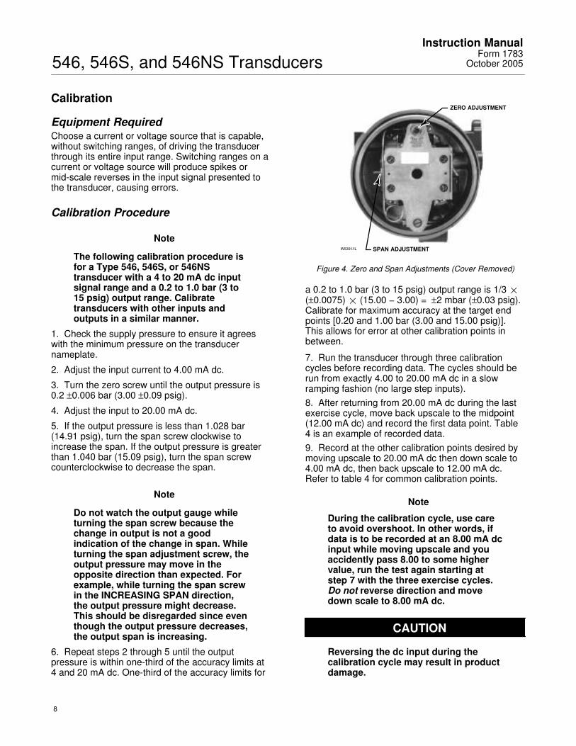
3. Turn the zero screw until the output pressure is0.2 ±0.006 bar (3.00 ±0.09 psig).
4. Adjust the input to 20.00 mA dc.
5. If the output pressure is less than 1.028 bar(14.91 psig), turn the span screw clockwise toincrease the span. If the output pressure is greaterthan 1.040 bar (15.09 psig), turn the span screwcounterclockwise to decrease the span.
Note
Do not watch the output gauge whileturning the span screw because thechange in output is not a goodindication of the change in span. Whileturning the span adjustment screw, theoutput pressure may move in theopposite direction than expected. Forexample, while turning the span screwin the INCREASING SPAN direction,the output pressure might decrease.This should be disregarded since eventhough the output pressure decreases,the output span is increasing.
6. Repeat steps 2 through 5 until the outputpressure is within one-third of the accuracy limits at4 and 20 mA dc. One-third of the accuracy limits for
W5391/IL
ZERO ADJUSTMENT
SPAN ADJUSTMENT
Figure 4. Zero and Span Adjustments (Cover Removed)
a 0.2 to 1.0 bar (3 to 15 psig) output range is 1/3 �(±0.0075)� (15.00 − 3.00) = ±2 mbar (±0.03 psig).Calibrate for maximum accuracy at the target endpoints [0.20 and 1.00 bar (3.00 and 15.00 psig)].This allows for error at other calibration points inbetween.
7. Run the transducer through three calibrationcycles before recording data. The cycles should berun from exactly 4.00 to 20.00 mA dc in a slowramping fashion (no large step inputs).8. After returning from 20.00 mA dc during the lastexercise cycle, move back upscale to the midpoint(12.00 mA dc) and record the first data point. Table4 is an example of recorded data.9. Record at the other calibration points desired bymoving upscale to 20.00 mA dc then down scale to4.00 mA dc, then back upscale to 12.00 mA dc.Refer to table 4 for common calibration points.
Note
During the calibration cycle, use careto avoid overshoot. In other words, ifdata is to be recorded at an 8.00 mA dcinput while moving upscale and youaccidently pass 8.00 to some highervalue, run the test again starting atstep 7 with the three exercise cycles.Do not reverse direction and movedown scale to 8.00 mA dc.
CAUTION
Reversing the dc input during thecalibration cycle may result in productdamage.
546, 546S, and 546NS TransducersInstruction ManualForm 1783October 2005
9
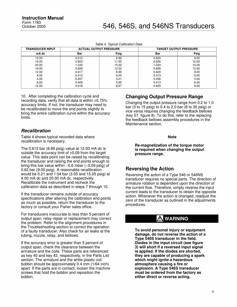
Table 4. Typical Calibration DataTRANSDUCER INPUT ACTUAL OUTPUT PRESSURE TARGET OUTPUT PRESSURE
mA dc Bar Psig Bar Psig12.0016.0020.0016.0012.008.004.008.00
12.00
0.6120.8231.0350.8280.6170.4130.2070.4090.618
8.8911.9515.0212.028.966.003.015.958.97
0.6200.8261.0330.8260.6200.4130.2060.4130.620
9.0012.0015.0012.009.006.003.006.009.00
10. After completing the calibration cycle andrecording data, verify that all data is within ±0.75%accuracy limits. If not, the transducer may need tobe recalibrated to move the end points slightly tobring the entire calibration curve within the accuracylimits.
RecalibrationTable 4 shows typical recorded data whererecalibration is necessary.
The 0.612 bar (8.89 psig) value at 12.00 mA dc isoutside the accuracy limit of ±0.09 from the targetvalue. This data point can be raised by recalibratingthe transducer and raising the end points enough tobring this low value within −0.6 mbar (−0.09 psig) of0.62 bar (9.00 psig). A reasonable recalibrationwould be 0.21 and 1.04 bar (3.05 and 15.05 psig) at4.00 mA dc and 20.00 mA dc, respectively.Recalibrate the instrument and recheck thecalibration data as described in steps 7 through 10.
If the transducer remains outside of accuracyspecifications after altering the calibration end pointsas much as possible, return the transducer to thefactory or consult your Fisher sales office.
For transducers inaccurate to less than 5 percent ofoutput span, relay repair or replacement may correctthe problem. Refer to the alignment procedures inthe Troubleshooting section to correct the operationof a faulty transducer. Also check for air leaks at thetubing, nozzle, relay, and bellows.
If the accuracy error is greater than 5 percent ofoutput span, check the clearance between thearmature and the coils. These parts are referencedas key 40 and key 42, respectively, in the Parts Listsection. The armature and the white plastic coilbobbin should be approximately 0.4 mm (1/64 inch)apart. If the parts are in contact, loosen the machinescrews that hold the bobbin and reposition thebobbin.
Changing Output Pressure RangeChanging the output pressure range from 0.2 to 1.0bar (3 to 15 psig) to 0.4 to 2.0 bar (6 to 30 psig) orvice versa requires changing the feedback bellows(key 57, figure 8). To do this, refer to the replacingthe feedback bellows assembly procedures in theMaintenance section.
Note
Re-magnetization of the torque motoris required when changing the outputpressure range.
Reversing the ActionReversing the action of a Type 546 or 546NStransducer requires no special parts. The direction ofarmature rotation is dependent upon the direction ofthe current flow. Therefore, simply reverse the inputcurrent leads to the transducer to obtain the oppositeaction. Whenever the action is changed, readjust thezero of the transducer as outlined in the adjustmentsprocedures.
WARNING
To avoid personal injury or equipmentdamage, do not reverse the action of aType 546S transducer in the field.Diodes in the input circuit (see figure3) will short if a reversed input signalis applied. If the diodes are shorted,they are capable of producing a sparkwhich might ignite a hazardousatmosphere causing a fire orexplosion. A Type 546S transducermust be ordered from the factory aseither direct or reverse acting.
546, 546S, and 546NS TransducersInstruction Manual
Form 1783October 2005
10
Table 5. Feedback Bellows Output Pressure RangeOPERATION INPUT SIGNAL, DC BELLOWS SIZEOPERATION INPUT SIGNAL, DC
Full Half QuarterBar Psig Bar Psig Bar Psig
Full Range 1 to 9 V(1)
4 to 20 mA10 to 50 mA
0.2 to 1.0 3 to 15 0.4 to 2.0 6 to 30 − − − − − −
Split Range 4 to 12 mA or 12 to 20 mA10 to 30 mA or 30 to 50 mA1 to 5 V dc or 5 to 9 V dc
− − − − − − 0.2 to 1.0 3 to 15 0.4 to 2.0 6 to 30
1. Temperature compensated circuit.
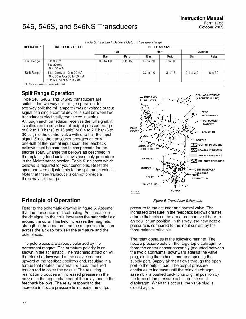
Split Range OperationType 546, 546S, and 546NS transducers aresuitable for two-way split range operation. In atwo-way split the milliampere (mA) or voltage outputsignal of a single control device is split between twotransducers electrically connected in series.Although each transducer receives the full signal, itis calibrated to provide a full output pressure rangeof 0.2 to 1.0 bar (3 to 15 psig) or 0.4 to 2.0 bar (6 to30 psig) to the control valve with one-half the inputsignal. Since the transducer operates on onlyone-half of the normal input span, the feedbackbellows must be changed to compensate for theshorter span. Change the bellows as described inthe replacing feedback bellows assembly procedurein the Maintenance section. Table 5 indicates whichbellows is required for your conditions. Reset thespan and zero adjustments to the split range values.Note that these transducers cannot provide athree-way split range.
Principle of OperationRefer to the schematic drawing in figure 5. Assumethat the transducer is direct-acting. An increase inthe dc signal to the coils increases the magnetic fieldaround the coils. This field increases the magneticstrength in the armature and the magnetic attractionacross the air gap between the armature and thepole pieces.
The pole pieces are already polarized by thepermanent magnet. The armature polarity is asshown in the schematic. The magnetic attraction willtherefore be downward at the nozzle end andupward at the feedback bellows end, resulting in atorque that rotates the armature about the fixedtorsion rod to cover the nozzle. The resultingrestriction produces an increased pressure in thenozzle, in the upper chamber of the relay, and in thefeedback bellows. The relay responds to theincrease in nozzle pressure to increase the output
FEEDBACKBELLOWS
POLEPIECES
COIL
ARMATURETORSION ROD
EXHAUST
OUTPUT
RELAY
VALVE PLUG
SUPPLY
FIXEDRESTRICTION
CENTER SPACERASSEMBLY
EXHAUST PRESSURE
SUPPLY PRESSURE
NOZZLE PRESSURE
OUTPUT PRESSURE
NOZZLE
ARMATURE
PERMANENTMAGNET
ZEROADJUSTMENT
SPAN ADJUSTMENT(MAGNETIC SHUNT)
CP4285−AA1505−3 / IL
Figure 5. Transducer Schematic
pressure to the actuator and control valve. Theincreased pressure in the feedback bellows createsa force that acts on the armature to move it back toan equilibrium position. In this way, the new nozzlepressure is compared to the input current by theforce-balance principle.
The relay operates in the following manner. Thenozzle pressure acts on the large top diaphragm toforce the center spacer assembly (mounted betweenthe two diaphragms) downward against the valveplug, closing the exhaust port and opening thesupply port. Supply air then flows through the openport to the output load. The output pressurecontinues to increase until the relay diaphragmassembly is pushed back to its original position bythe force of the pressure acting on the smalldiaphragm. When this occurs, the valve plug isclosed again.
546, 546S, and 546NS TransducersInstruction ManualForm 1783October 2005
11
When a decreasing dc signal is received, themagnetic attraction across the air gap is reduced.The armature rotates to uncover the nozzle and
decrease the pressure in the nozzle, relay, andfeedback bellows. The relay diaphragm assemblymoves upward, and the exhaust port opens to bleedthe output pressure to atmosphere.
The output decreases until the diaphragm assemblyis forced back to its original position and the exhaustport is closed again. The reduced pressure in thefeedback bellows diminishes the force to return thearmature to the equilibrium position.
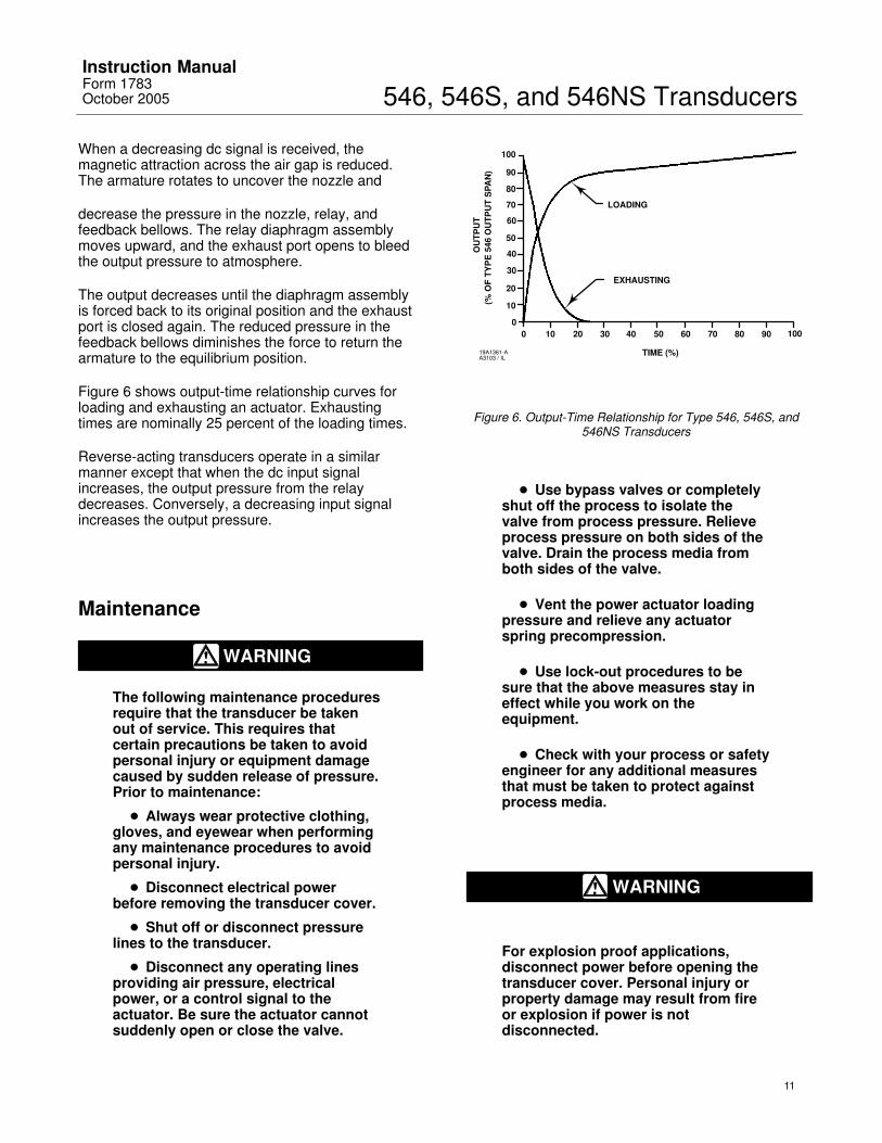
Figure 6 shows output-time relationship curves forloading and exhausting an actuator. Exhaustingtimes are nominally 25 percent of the loading times.
Reverse-acting transducers operate in a similarmanner except that when the dc input signalincreases, the output pressure from the relaydecreases. Conversely, a decreasing input signalincreases the output pressure.
Maintenance
WARNING
The following maintenance proceduresrequire that the transducer be takenout of service. This requires thatcertain precautions be taken to avoidpersonal injury or equipment damagecaused by sudden release of pressure.Prior to maintenance:
� Always wear protective clothing,gloves, and eyewear when performingany maintenance procedures to avoidpersonal injury.
� Disconnect electrical powerbefore removing the transducer cover.
� Shut off or disconnect pressurelines to the transducer.
� Disconnect any operating linesproviding air pressure, electricalpower, or a control signal to theactuator. Be sure the actuator cannotsuddenly open or close the valve.
LOADING
EXHAUSTING
TIME (%)
0 10 20 30 40 50 60 70 80 90 1000
10
20
30
40
50
60
70
80
90
100
OU
TPU
T(%
OF
TYP
E 5
46 O
UTP
UT
SPA
N)
19A1361-AA3103 / IL
Figure 6. Output-Time Relationship for Type 546, 546S, and546NS Transducers
� Use bypass valves or completelyshut off the process to isolate thevalve from process pressure. Relieveprocess pressure on both sides of thevalve. Drain the process media fromboth sides of the valve.
� Vent the power actuator loadingpressure and relieve any actuatorspring precompression.
� Use lock-out procedures to besure that the above measures stay ineffect while you work on theequipment.
� Check with your process or safetyengineer for any additional measuresthat must be taken to protect againstprocess media.
WARNING
For explosion proof applications,disconnect power before opening thetransducer cover. Personal injury orproperty damage may result from fireor explosion if power is notdisconnected.
546, 546S, and 546NS TransducersInstruction Manual
Form 1783October 2005
12
CAUTION
The presence of Fisher personnel andalso approval agency personnel maybe required if you service (other thannormal, routine maintenance, such ascalibration) or replace components ona transducer that carries a third-partyapproval. When you replacecomponents, use only componentsspecified by the factory. Substitutionwith other components may void thethird-party approval. Also, always useproper component replacementtechniques, as presented in thismanual. Improper techniques cancause poor quality repairs and impairthe safety features of the device.
Maintenance of the transducer consists of relayrepair or replacement, and replacement of thefeedback bellows.
Figure 8 shows the torque motor and associatedparts. Shaded key numbers indicate parts thatshould not be disassembled from the torque motorbecause the magnetism in the torque motor magnetswill decrease permanently.
Certain troubleshooting and alignment proceduresare described at the end of this section. These mayserve as a guide to correct some problems.Improper supply pressure and mechanical defects inpneumatic and electrical connections should beapparent upon inspection and repaired asappropriate.
CAUTION
Never disassemble the torque motorassembly because the magnetism inthe torque motor magnets willdecrease permanently. Shaded keynumbers indicate parts that should notbe disassembled from the torquemotor (see figure 8). If troubleshootingor alignment attempts indicate either afaulty torque motor or the necessity ofdisassembling the torque motor,return the entire transducer to thefactory, or consult your Fisher salesoffice.
Type 82 Relay Removal andReplacement
WARNING
Refer to the WARNING at thebeginning of this section.
Use the following procedure when removing andreplacing a relay assembly. Refer to figure 9 for keynumber locations, unless otherwise directed.1. Loosen the two mounting screws (key 68), andremove the relay assembly from the transducer case(key 1, figure 7).2. To install the replacement relay assembly, installthe two relay mounting screws (key 68) into the relayassembly. Apply lubricant (key 96) to the O-rings,and make sure the O-rings (keys 72, 73, and 74) arein place on the relay assembly.3. Install the relay assembly on the transducer case.Tighten the mounting screws.4. With the torque motor installed, apply supplypressure to the transducer case, and check the relayassembly for leaks with a soap solution.
Type 82 Relay Maintenance
WARNING
Refer to the WARNING at thebeginning of this section.
Use the procedure below to repair the relayassembly. Refer to figure 9 for key number locations.Obtain the relay repair kit listed in the parts list. Thiskit provides the parts, alignment tool, and aninstruction sheet used when repairing the relayassembly.1. Remove the two screws (key 77), valve plugspring seat (key 64), valve plug spring (key 70) andvalve plug (key 63).2. Remove the six screws (key 76, not shown) andseparate the relay body (key 60), casing spacer (key61), and relay casing (key 62) by inserting ascrewdriver between the external casting lugs. Twistthe screwdriver to separate parts.3. Remove the upper diaphragm (key 66), lowerdiaphragm assembly (key 65), and relay spring (key71). Clean and inspect relay parts before replacingthem.4. Remove the restriction assembly (key 67) andreplace the O-rings (keys 74 and 75). Apply lubricant
546, 546S, and 546NS TransducersInstruction ManualForm 1783October 2005
13
(key 96) to the O-rings before installing therestriction assembly into the relay body.
5. The restriction hole (see figure 9) in the restrictionassembly is 0.41 mm (0.016 inches) in diameter.Clean the hole with solvent and blow dry withcompressed air. If the hole is plugged, insert a wirein the hole. Then, clean with solvent and blow drywith compressed air. Do not enlarge the hole.Reinstall the restriction assembly in the relay body.Do not overtighten.
WARNING
A plugged restriction hole may affectproduct performance, causing loopinstability, which may result inpersonal injury or property damage.
6. The restriction hole in the relay body is 0.51 mm(0.020 inches) in diameter. If the hole is plugged,insert a wire into the hole and clean it out. Do notenlarge the hole.
7. Insert the new lower diaphragm assemblythrough the casing spacer, replace the relay spring,and position the parts on the relay body. Position thenew upper diaphragm on the relay casing andposition the relay casing on the upper diaphragm.Ensure that the exterior casting lugs on the relaybody, casing spacer, and relay casing are aligned.
8. Invert the relay and install the six screws (key76), but do not tighten.
9. Insert the alignment tool through the brass supplyseat in the relay body, and into the exhaust seat ofthe lower diaphragm assembly to align the parts.
10. Ensure the diaphragms are flat between therelay body, casing spacer, and relay casing. Tightenthe six screws (key 76).
11. Remove the alignment tool, and reassemble thevalve plug, valve plug spring, valve plug spring seatand the two screws (key 77).
12. Install the two relay mounting screws (key 68)into the relay assembly. Apply lubricant (key 96) tothe O-rings, and make sure the O-rings (keys 72, 73,and 74) are in place on the relay assembly.
13. Install the relay assembly on the transducercase. Tighten the mounting screws.
14. With the torque motor installed, apply supplypressure to the transducer case, and check the relayassembly for leaks with a soap solution.
Replacing the Feedback BellowsAssembly
WARNING
Refer to the WARNING at thebeginning of this section.
Refer to figure 8 for key number locations.
1. Loosen the hex nut (key 31).
2. Remove the bellows screw (key 56) and O-ring(key 36) under the head of the bellows screw.
3. Pull the bellows assembly (key 57) out. Thearmature is slotted to allow removal of the bellowsassembly.
4. Inspect and, if necessary, replace the two O-rings(key 36). Make sure the O-rings under the bellowsassembly are in place.
5. Choose the correct bellows assembly as outlinedin table 5. Install the new bellows assembly. Makesure that the O-ring (key 36) is in place.
6. Install the bellows screw and O-ring, and tightenthe screw. Be sure the bellows assembly is notdistorted in any direction. Tighten the hex nut (key 31).
7. Refer to the adjusting zero and span proceduresin the Adjustments section.
TroubleshootingThis section contains some checks for operationaldifficulties that may be encountered. If correcting thedifficulties is not possible, contact your Fisher salesoffice or service center.
Electrical1. Check the output of the control device. Make surethat it is reaching the transducer.
2. Check the dc input signal. It should be the sameas the range stamped on the transducer nameplate.
3. Check the resistance of the transducer circuit tosee that it coincides with the value listed on thecircuit identification tag located on the torque motor.
4. Check the terminal lugs for proper connections. Ifreverse action of the transducer is observed, simplyreverse the input leads as indicated in the Reversingthe Action procedures in the Operating Informationsection.
546, 546S, and 546NS TransducersInstruction Manual
Form 1783October 2005
14
Pneumatic
CAUTION
Do not attempt to remove the nozzle(key 19, figure 8) for any reason.Nozzle removal requiresdisassembling the torque motor.Disassembling the torque motor willpermanently reduce the strength of themagnets, causing improper operation.Also, do not adjust the baffle (key 18,figure 8). The spacing between thebaffle and nozzle is preset and lockedat the factory to obtain optimumperformance of the transducer.
1. Connect supply pressure and a pressure gaugeto monitor the output. Check the operation of thetransducer as follows:
a. Force the baffle (key 18, figure 8) against thenozzle. The output pressure should build up toapproximately the supply pressure. If it does not,check for a leak in the pneumatic system or aburr on the nozzle.
b. Force the baffle away from the nozzle. Theoutput pressure should drop to less than 0.07 bar(1 psig). If it does not, check the flame arrestorsin the transducer case (see figure 7). If the flamearrestors require cleaning, first remove the torquemotor assembly from the case by removing fourmachine screws (key 9, figure 7). Then, clean theflame arrestors by blowing them out with airpressure.
2. Check zero and span adjustment for propersetting. Refer to the adjustments procedure.
3. Check the supply pressure. It should be at least0.3 bar (5 psig) above the upper limit of the outputpressure range.
4. Check the filter regulator for moisture in thedripwell. Drain off any moisture, and clean the filterelement if necessary.
5. If the transducer cycles, be sure there are nosharp bends in the copper capillary feedback tubing(key 56, figure 8) and that the tubing is not plugged.
6. Check the nozzle. If it is clogged, remove theentire torque motor assembly from the case byremoving four machine screws (key 9, figure 7). Runa wire through the nozzle from the underside of theassembly.
7. Erratic operation may be caused by metal chipsin the air gap between the armature and the polepieces. Blow any chips out of the torque motorassembly with low pressure air.
8. If a problem persists, check the relay asdescribed in the Type 82 Relay Maintenanceprocedures in this section.
AlignmentThe following alignment procedures can be used inconjunction with troubleshooting procedures tocorrect the operation of a faulty transducer.
Span AdjustmentRefer to figure 8 for key number locations, unlessotherwise directed.
If setting the required span is not possible, additionalspan adjustment can be obtained by shifting theentire span adjustment assembly (key 55) at theflexure pivot end. The alignment procedure is asfollows:
1. Shut off the dc input signal and supply pressureto the transducer.
2. Disconnect the external lead wires from theterminal mounting bracket assembly (key 53).
3. Loosen the four machine screws (key 9, figure 7)that hold the torque motor assembly to the case.Remove the entire torque motor assembly from thecase.
4. Loosen the two flexure pivot screws (key 25) thathold the flexure pivot to the torque motor assemblybase.
5. Slide the span adjustment assembly in or out asrequired. Sliding it in toward the base decreases thespan; sliding it out away from the base increases thespan.
6. Tighten the flexure pivot screws. Replace thetorque motor assembly, and tighten the screws (key9, figure 7). Make sure that the O-ring (key 37) is inplace. Connect the external lead wires, and turn onthe air supply.
7. Make final adjustment of the span with the spanadjustment screw.
Torque Motor FrameThe top pole piece plate (key 50, figure 8) of thetorque motor can become twisted with respect to thebottom pole piece plate (key 51, figure 8). If thishappens, return the transducer to the factory,service center, or contact your Fisher sales office.
546, 546S, and 546NS TransducersInstruction ManualForm 1783October 2005
15
Armature Travel StopThe armature travel stop (key 52, figure 8) must bein place to prevent overstressing the armature andcoil support (key 41, figure 8) due to over-travel. Theclearance between the armature and travel stopshould be 0.13 mm (0.005 inches).
The two screws at the base of the travel stop can beloosened if an alignment is necessary.
CoilThe coil assembly (key 42, figure 8) consists of anylon bobbin wound with wire. The coils are notattached to the armature itself, and therefore, theymust not touch the armature, or armaturemovements will be restricted. If this problem exists,loosen the two screws that attach each coilassembly to the armature and coil support. Sightdown the armature and realign the coil assembliesfor clearance with the armature. Tighten the screws.
Parts OrderingWhenever corresponding with the sales office aboutthis equipment, mention the serial number of theunit. This serial number can be found on thenameplate. When ordering replacement parts, alsostate the complete 11-character part number of eachpart needed as found in the following parts list.
Note
In the torque motor assembly drawing(figure 8), there are many shaded keynumbers. The shading indicates thatthese parts should not bedisassembled and that they are notavailable as individual items.Consequently, no part numbers areshown for these parts in the Parts List.
Note
Use only genuine Fisher replacementparts. Components that are notsupplied by Fisher should not, underany circumstances, be used in anyFisher instrument. The use ofcomponents not manufactured byFisher will void your warranty, mightadversely affect the performance ofthe instrument, and might jeopardizeworker and workplace safety.
Note
Neither Emerson, Emerson ProcessManagement, Fisher, nor any of theaffiliated entities assumesresponsibility for the selection, use,and maintenance of any product.Responsibility for the selection, use,and maintenance of any productremains with the purchaser andend-user.
Parts List
Repair Kits for Type 546, 546S, and546NS Transducers
Description Part Number
Type 546 and 546S Transducer Repair KitKit includes keys 6, 12, 36, 37, and 58 R546X000022
Type 546NS Transducer Repair KitKit includes keys 6, 12, 36, 37, and 58 R546X000032
Type 82 Relay Repair Kit(for Type 546 and 546S only)This kit includes keys 63, 65, 66, 69, 70, 72,73, 74, 75. Kit also includes instruction sheetand alignment tool R82X0000022
Type 82 Relay Replacement Assembly(for Type 546 and 546S) Assembly includestwo mounting screws (Key 68) 10A8593X082
Type 82 Relay Replacement Assembly(for Type 546NS) Assembly includestwo mounting screws (key 68) 10A8593X142
546, 546S, and 546NS TransducersInstruction Manual
Form 1783October 2005
16
67 SERIES FILTER REGULATOR TORQUE MOTOR
FLAME ARRESTOR
TYPE 82 RELAY
FLAMEARRESTOR
APPLY LUBRICANT/SEALANT
NOTE: KEY 4 NOT SHOWN30A8595-LB1768-3 / IL
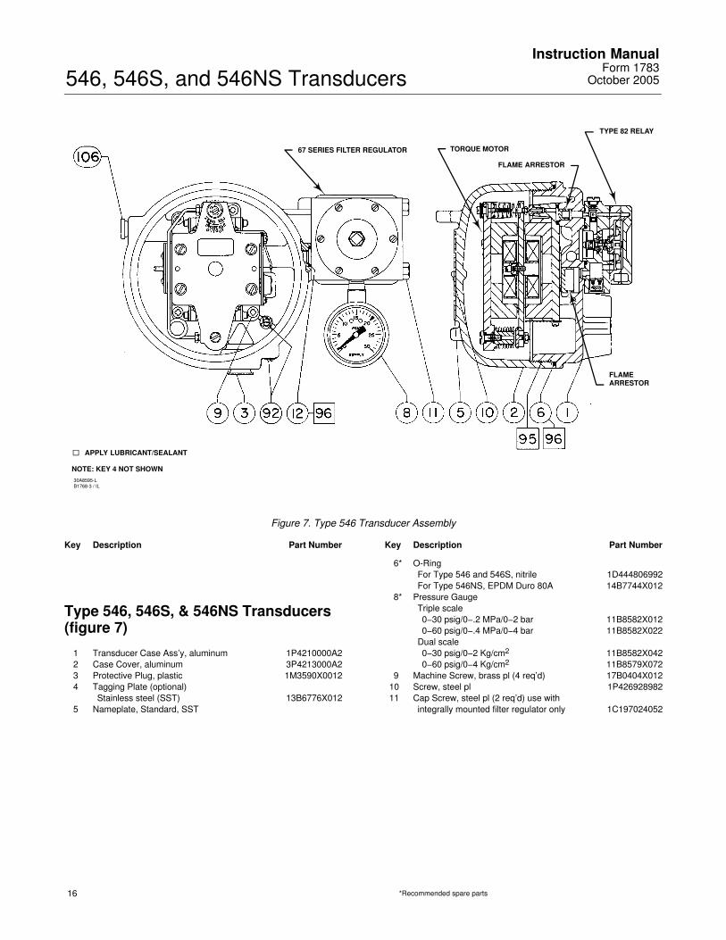
Figure 7. Type 546 Transducer Assembly
Key Description Part Number
Type 546, 546S, & 546NS Transducers(figure 7)
1 Transducer Case Ass’y, aluminum 1P4210000A22 Case Cover, aluminum 3P4213000A23 Protective Plug, plastic 1M3590X00124 Tagging Plate (optional)
Stainless steel (SST) 13B6776X0125 Nameplate, Standard, SST
Key Description Part Number
6* O-RingFor Type 546 and 546S, nitrile 1D444806992For Type 546NS, EPDM Duro 80A 14B7744X012
8* Pressure GaugeTriple scale0−30 psig/0−.2 MPa/0−2 bar 11B8582X0120−60 psig/0−.4 MPa/0−4 bar 11B8582X022
Dual scale0−30 psig/0−2 Kg/cm2 11B8582X0420−60 psig/0−4 Kg/cm2 11B8579X072
9 Machine Screw, brass pl (4 req’d) 17B0404X01210 Screw, steel pl 1P42692898211 Cap Screw, steel pl (2 req’d) use with
integrally mounted filter regulator only 1C197024052
*Recommended spare parts
546, 546S, and 546NS TransducersInstruction ManualForm 1783October 2005
17
30A8594-KB1767-3
APPLY LUBRICANT/SEALANT
NOTES:1. SHADED KEY NUMBERS INDICATE PARTS SHOULD NOT BE DISASSEMBLED FROM TORQUE MOTOR.2. KEY NUMBERS 22 AND 103 ARE NOT SHOWN.
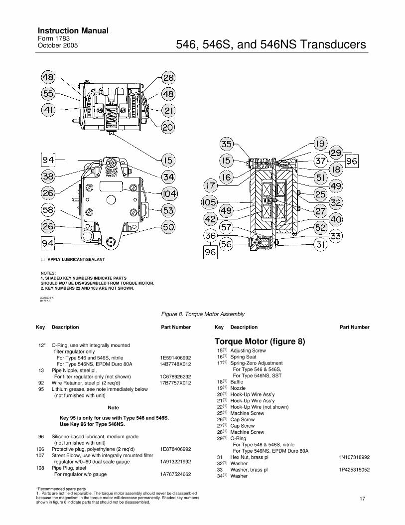
Figure 8. Torque Motor Assembly
Key Description Part Number
12* O-Ring, use with integrally mountedfilter regulator onlyFor Type 546 and 546S, nitrile 1E591406992For Type 546NS, EPDM Duro 80A 14B7748X012
13 Pipe Nipple, steel pl,For filter regulator only (not shown) 1C678926232
92 Wire Retainer, steel pl (2 req’d) 17B7757X01295 Lithium grease, see note immediately below
(not furnished with unit)
Note
Key 95 is only for use with Type 546 and 546S.Use Key 96 for Type 546NS.
96 Silicone-based lubricant, medium grade(not furnished with unit)
106 Protective plug, polyethylene (2 req’d) 1E878406992107 Street Elbow, use with integrally mounted filter
regulator w/0−60 dual scale gauge 1A913221992108 Pipe Plug, steel
For regulator w/o gauge 1A767524662
Key Description Part Number
Torque Motor (figure 8)15(1) Adjusting Screw16(1) Spring Seat17(1) Spring-Zero Adjustment
For Type 546 & 546S,For Type 546NS, SST
18(1) Baffle19(1) Nozzle20(1) Hook-Up Wire Ass’y21(1) Hook-Up Wire Ass’y22(1) Hook-Up Wire (not shown)25(1) Machine Screw26(1) Cap Screw27(1) Cap Screw28(1) Machine Screw29(1) O-Ring
For Type 546 & 546S, nitrileFor Type 546NS, EPDM Duro 80A
31 Hex Nut, brass pl 1N10731899232(1) Washer33 Washer, brass pl 1P42531505234(1) Washer
*Recommended spare parts1. Parts are not field repairable. The torque motor assembly should never be disassembledbecause the magnetism in the torque motor will decrease permanently. Shaded key numbersshown in figure 8 indicate parts that should not be disassembled.
546, 546S, and 546NS TransducersInstruction Manual
Form 1783October 2005
18
A1504-1 / IL
NOTE:KEY 76 IS NOT SHOWN
APPLY LUBRICANT/SEALANT
RESTRICTION HOLES
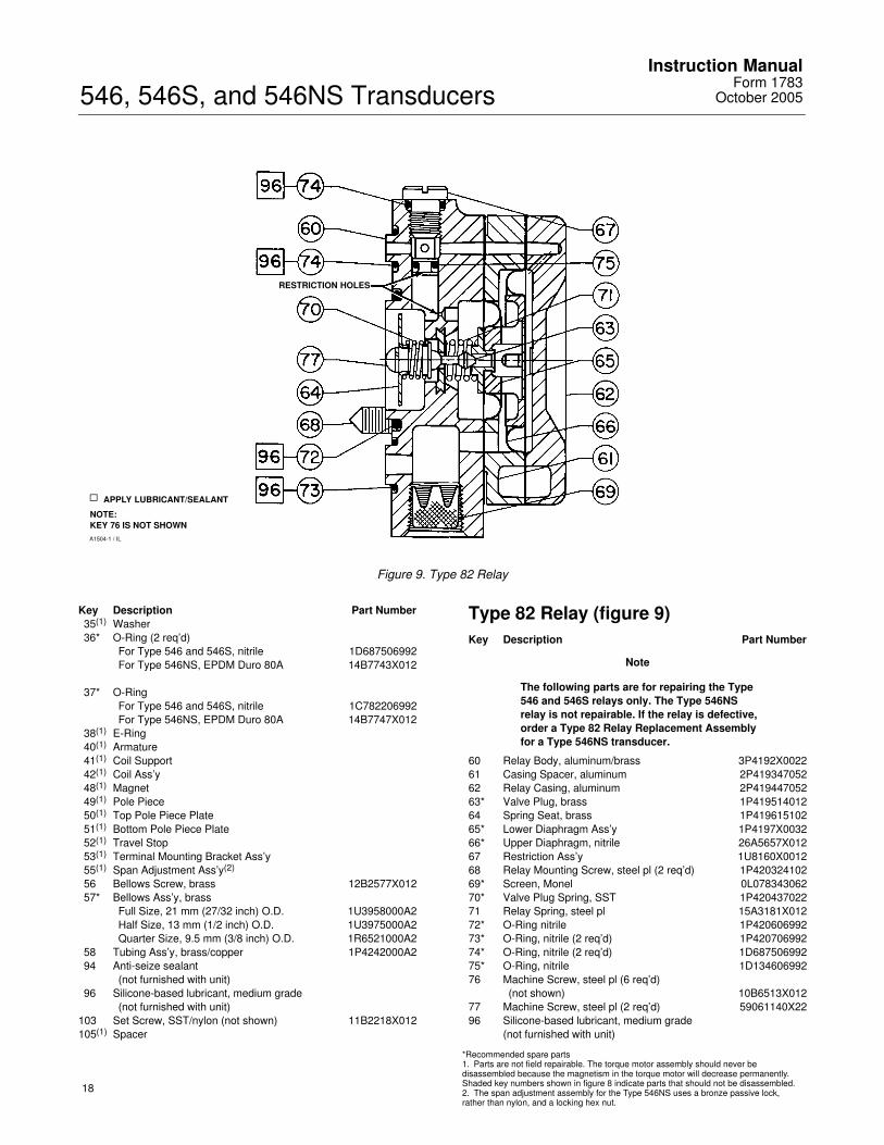
Figure 9. Type 82 Relay
Key Description Part Number35(1) Washer36* O-Ring (2 req’d)
For Type 546 and 546S, nitrile 1D687506992For Type 546NS, EPDM Duro 80A 14B7743X012
37* O-RingFor Type 546 and 546S, nitrile 1C782206992For Type 546NS, EPDM Duro 80A 14B7747X012
38(1) E-Ring40(1) Armature41(1) Coil Support42(1) Coil Ass’y48(1) Magnet49(1) Pole Piece50(1) Top Pole Piece Plate51(1) Bottom Pole Piece Plate52(1) Travel Stop53(1) Terminal Mounting Bracket Ass’y55(1) Span Adjustment Ass’y(2)
56 Bellows Screw, brass 12B2577X01257* Bellows Ass’y, brass
Full Size, 21 mm (27/32 inch) O.D. 1U3958000A2Half Size, 13 mm (1/2 inch) O.D. 1U3975000A2Quarter Size, 9.5 mm (3/8 inch) O.D. 1R6521000A2
58 Tubing Ass’y, brass/copper 1P4242000A294 Anti-seize sealant
(not furnished with unit)96 Silicone-based lubricant, medium grade
(not furnished with unit)103 Set Screw, SST/nylon (not shown) 11B2218X012105(1) Spacer
Type 82 Relay (figure 9)Key Description Part Number
Note
The following parts are for repairing the Type546 and 546S relays only. The Type 546NSrelay is not repairable. If the relay is defective,order a Type 82 Relay Replacement Assemblyfor a Type 546NS transducer.
60 Relay Body, aluminum/brass 3P4192X002261 Casing Spacer, aluminum 2P41934705262 Relay Casing, aluminum 2P41944705263* Valve Plug, brass 1P41951401264 Spring Seat, brass 1P41961510265* Lower Diaphragm Ass’y 1P4197X003266* Upper Diaphragm, nitrile 26A5657X01267 Restriction Ass’y 1U8160X001268 Relay Mounting Screw, steel pl (2 req’d) 1P42032410269* Screen, Monel 0L07834306270* Valve Plug Spring, SST 1P42043702271 Relay Spring, steel pl 15A3181X01272* O-Ring nitrile 1P42060699273* O-Ring, nitrile (2 req’d) 1P42070699274* O-Ring, nitrile (2 req’d) 1D68750699275* O-Ring, nitrile 1D13460699276 Machine Screw, steel pl (6 req’d)
(not shown) 10B6513X01277 Machine Screw, steel pl (2 req’d) 59061140X2296 Silicone-based lubricant, medium grade
(not furnished with unit)
*Recommended spare parts1. Parts are not field repairable. The torque motor assembly should never be disassembled because the magnetism in the torque motor will decrease permanently.Shaded key numbers shown in figure 8 indicate parts that should not be disassembled.2. The span adjustment assembly for the Type 546NS uses a bronze passive lock, rather than nylon, and a locking hex nut.
546, 546S, and 546NS TransducersInstruction ManualForm 1783October 2005
19
48A9176-BA5425-1 / IL
TYPE 546TRANSDUCER
TYPE 585SIZE 25 AND 50ACTUATORS
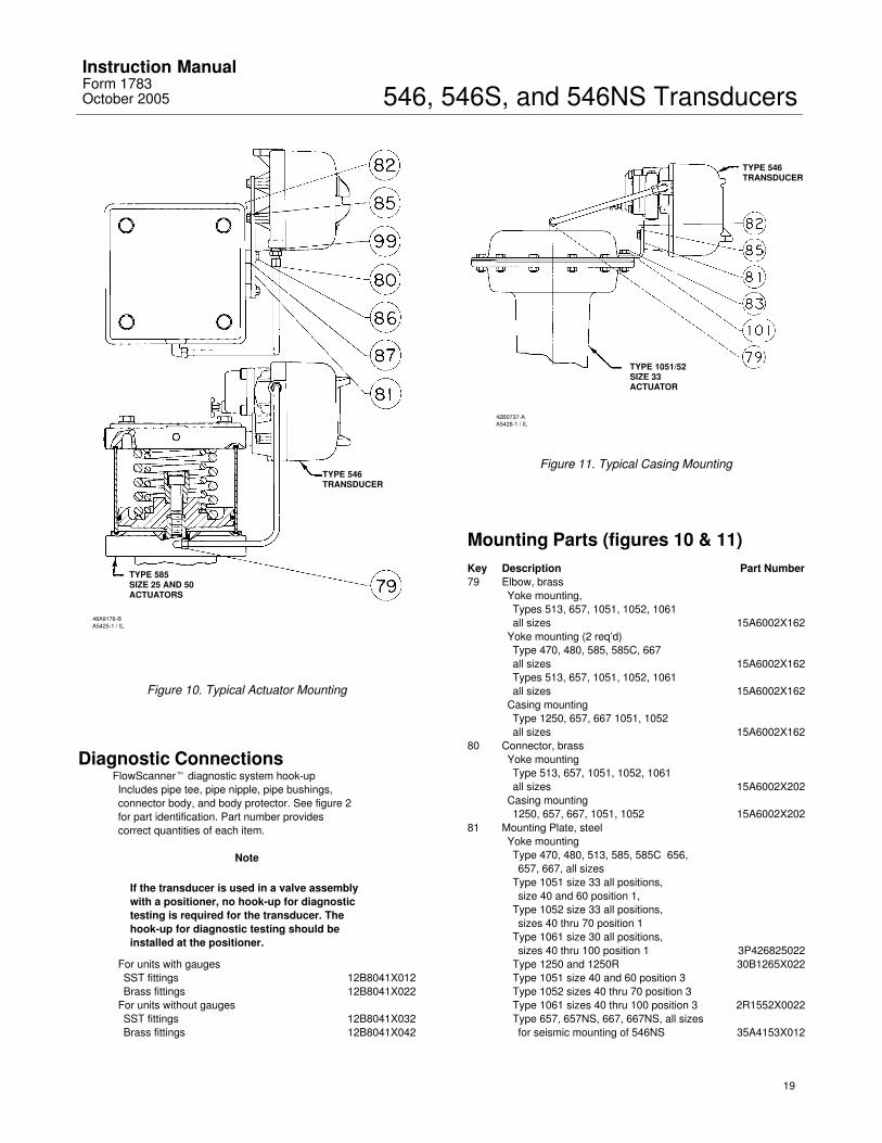
Figure 10. Typical Actuator Mounting
Diagnostic ConnectionsFlowScanner� diagnostic system hook-upIncludes pipe tee, pipe nipple, pipe bushings, connector body, and body protector. See figure 2 for part identification. Part number providescorrect quantities of each item.
Note
If the transducer is used in a valve assemblywith a positioner, no hook-up for diagnostictesting is required for the transducer. Thehook-up for diagnostic testing should beinstalled at the positioner.
For units with gaugesSST fittings 12B8041X012Brass fittings 12B8041X022
For units without gaugesSST fittings 12B8041X032Brass fittings 12B8041X042
42B0737-AA5426-1 / IL
TYPE 546TRANSDUCER
TYPE 1051/52SIZE 33ACTUATOR
Figure 11. Typical Casing Mounting
Mounting Parts (figures 10 & 11)Key Description Part Number79 Elbow, brass
Yoke mounting,Types 513, 657, 1051, 1052, 1061all sizes 15A6002X162
Yoke mounting (2 req’d)Type 470, 480, 585, 585C, 667all sizes 15A6002X162Types 513, 657, 1051, 1052, 1061all sizes 15A6002X162
Casing mountingType 1250, 657, 667 1051, 1052all sizes 15A6002X162
80 Connector, brassYoke mountingType 513, 657, 1051, 1052, 1061all sizes 15A6002X202
Casing mounting1250, 657, 667, 1051, 1052 15A6002X202
81 Mounting Plate, steelYoke mountingType 470, 480, 513, 585, 585C 656,657, 667, all sizes
Type 1051 size 33 all positions,size 40 and 60 position 1,
Type 1052 size 33 all positions,sizes 40 thru 70 position 1
Type 1061 size 30 all positions,sizes 40 thru 100 position 1 3P426825022
Type 1250 and 1250R 30B1265X022Type 1051 size 40 and 60 position 3Type 1052 sizes 40 thru 70 position 3Type 1061 sizes 40 thru 100 position 3 2R1552X0022Type 657, 657NS, 667, 667NS, all sizesfor seismic mounting of 546NS 35A4153X012
546, 546S, and 546NS TransducersInstruction Manual
Form 1783October 2005
20
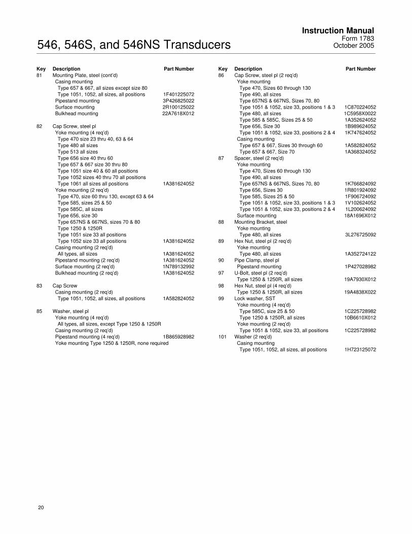
Key Description Part Number81 Mounting Plate, steel (cont’d)
Casing mountingType 657 & 667, all sizes except size 80Type 1051, 1052, all sizes, all positions 1F401225072
Pipestand mounting 3P426825022Surface mounting 2R100125022Bulkhead mounting 22A7618X012
82 Cap Screw, steel plYoke mounting (4 req’d)Type 470 size 23 thru 40, 63 & 64Type 480 all sizesType 513 all sizesType 656 size 40 thru 60Type 657 & 667 size 30 thru 80Type 1051 size 40 & 60 all positionsType 1052 sizes 40 thru 70 all positionsType 1061 all sizes all positions 1A381624052
Yoke mounting (2 req’d)Type 470, size 60 thru 130, except 63 & 64Type 585, sizes 25 & 50Type 585C, all sizesType 656, size 30Type 657NS & 667NS, sizes 70 & 80Type 1250 & 1250RType 1051 size 33 all positionsType 1052 size 33 all positions 1A381624052
Casing mounting (2 req’d)All types, all sizes 1A381624052
Pipestand mounting (2 req’d) 1A381624052Surface mounting (2 req’d) 1N789132992Bulkhead mounting (2 req’d) 1A381624052
83 Cap ScrewCasing mounting (2 req’d)Type 1051, 1052, all sizes, all positions 1A582824052
85 Washer, steel plYoke mounting (4 req’d)All types, all sizes, except Type 1250 & 1250R
Casing mounting (2 req’d)Pipestand mounting (4 req’d) 1B865928982Yoke mounting Type 1250 & 1250R, none required
Key Description Part Number86 Cap Screw, steel pl (2 req’d)
Yoke mountingType 470, Sizes 60 through 130Type 490, all sizesType 657NS & 667NS, Sizes 70, 80Type 1051 & 1052, size 33, positions 1 & 3 1C870224052Type 480, all sizes 1C5958X0022Type 585 & 585C, Sizes 25 & 50 1A352624052Type 656, Size 30 1B989624052Type 1051 & 1052, size 33, positions 2 & 4 1K747624052
Casing mountingType 657 & 667, Sizes 30 through 60 1A582824052Type 657 & 667, Size 70 1A368324052
87 Spacer, steel (2 req’d)Yoke mountingType 470, Sizes 60 through 130Type 490, all sizesType 657NS & 667NS, Sizes 70, 80 1K766824092Type 656, Sizes 30 1R801924092Type 585, Sizes 25 & 50 1F906724092Type 1051 & 1052, size 33, positions 1 & 3 1V102624052Type 1051 & 1052, size 33, positions 2 & 4 1L200624092
Surface mounting 18A1696X01288 Mounting Bracket, steel
Yoke mountingType 480, all sizes 3L276725092
89 Hex Nut, steel pl (2 req’d)Yoke mountingType 480, all sizes 1A352724122
90 Pipe Clamp, steel plPipestand mounting 1P427028982
97 U-Bolt, steel pl (2 req’d)Type 1250 & 1250R, all sizes 19A7930X012
98 Hex Nut, steel pl (4 req’d)Type 1250 & 1250R, all sizes 19A4838X022
99 Lock washer, SSTYoke mounting (4 req’d)Type 585C, size 25 & 50 1C225728982Type 1250 & 1250R, all sizes 10B6610X012
Yoke mounting (2 req’d)Type 1051 & 1052, size 33, all positions 1C225728982
101 Washer (2 req’d)Casing mountingType 1051, 1052, all sizes, all positions 1H723125072
546, 546S, and 546NS TransducersInstruction ManualForm 1783October 2005
21
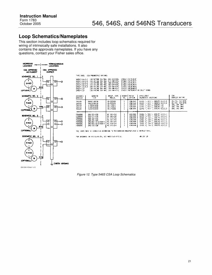
Loop Schematics/NameplatesThis section includes loop schematics required forwiring of intrinsically safe installations. It alsocontains the approvals nameplates. If you have anyquestions, contact your Fisher sales office.
29A1594-H Sheet 1 of 2
Figure 12. Type 546S CSA Loop Schematics
546, 546S, and 546NS TransducersInstruction Manual
Form 1783October 2005
22
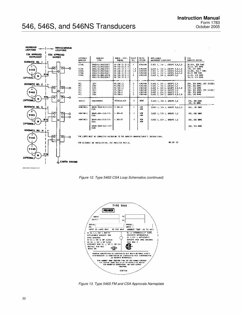
29A1594-H Sheet 2 of 2
Figure 12. Type 546S CSA Loop Schematics (continued)
Figure 13. Type 546S FM and CSA Approvals Nameplate
546, 546S, and 546NS TransducersInstruction ManualForm 1783October 2005
23
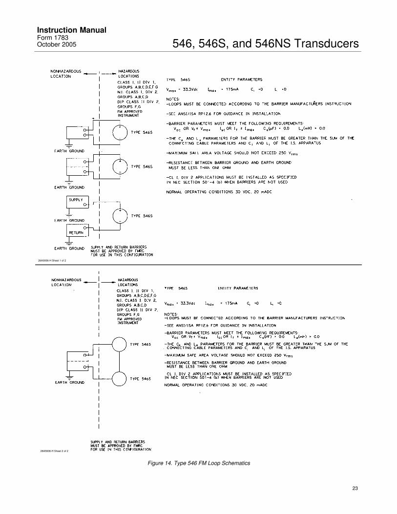
26A5936-H Sheet 1 of 2
26A5936-H Sheet 2 of 2
Figure 14. Type 546 FM Loop Schematics
546, 546S, and 546NS TransducersInstruction Manual
Form 1783October 2005
24
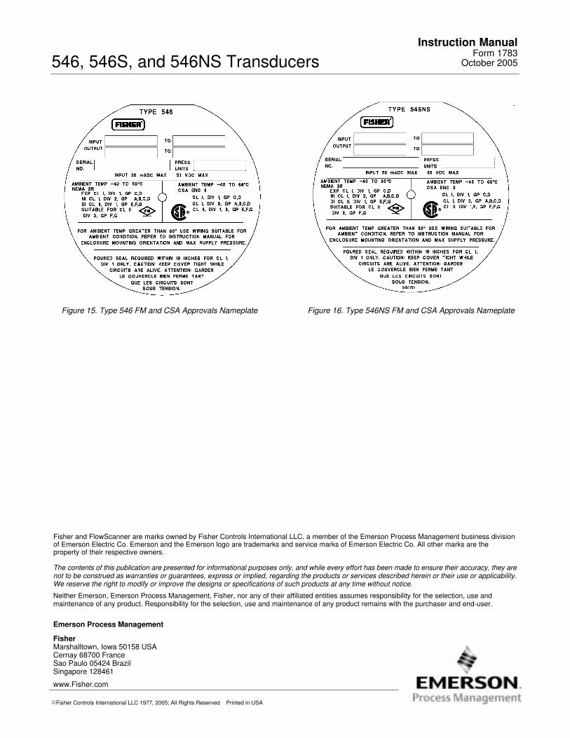
Figure 15. Type 546 FM and CSA Approvals Nameplate Figure 16. Type 546NS FM and CSA Approvals Nameplate
Fisher Marshalltown, Iowa 50158 USACernay 68700 France Sao Paulo 05424 BrazilSingapore 128461
Emerson Process Management
www.Fisher.com
The contents of this publication are presented for informational purposes only, and while every effort has been made to ensure their accuracy, they arenot to be construed as warranties or guarantees, express or implied, regarding the products or services described herein or their use or applicability.We reserve the right to modify or improve the designs or specifications of such products at any time without notice.
Neither Emerson, Emerson Process Management, Fisher, nor any of their affiliated entities assumes responsibility for the selection, use and maintenance of any product. Responsibility for the selection, use and maintenance of any product remains with the purchaser and end-user.
�Fisher Controls International LLC 1977, 2005; All Rights Reserved Printed in USA
Fisher and FlowScanner are marks owned by Fisher Controls International LLC, a member of the Emerson Process Management business divisionof Emerson Electric Co. Emerson and the Emerson logo are trademarks and service marks of Emerson Electric Co. All other marks are the property of their respective owners.