two photogrammetric methods for measuring flat elements in buildings under construction
TRANSCRIPT
Automation in Construction 17 (2008) 517–525www.elsevier.com/locate/autcon
Review
Two photogrammetric methods for measuring flat elementsin buildings under construction
Celestino Ordóñez a,⁎, Pedro Arias a, José Herráez b, Jaime Rodríguez c, María T. Martín c
a Mining School, University of Vigo, Rua Maxwell s/n, 36310 Vigo, Spainb Cartographic Engineering School, University of Valencia, 46022 Valencia, Spain
c Surveying Engineering School, University of Santiago de Compostela, Spain
Accepted 29 November 2007
Abstract
Usually, determining the dimensions of flat surfaces in buildings under construction, such as window cavities and façade coating materials, aredone by direct measuring methods using tapes and plummets. Sometimes these methods suppose a slow and highly risky work for operators. Thisresearch proposes the substitution of these procedures by indirect methods based on close range photogrammetry and laser distance measurement.First, we show the design, construction and calibration of a system composed by a digital camera and a lasermeter mounted on a support withmultiple turning positions. Next, two different façade element measuring methodologies are shown. The first method is based on taking a singlephotograph and measuring the distance to the object. The second one is based on taking three photographs and three distances measured at threedifferent calibrated positions. Finally the accuracy of each methodology is analyzed and the pros and cons of each one are shown.© 2007 Elsevier B.V. All rights reserved.
Keywords: Close range photogrammetry; Laser; Calibration; Façade
Contents
1. Introduction . . . . . . . . . . . . . . . . . . . . . . . . . . . . . . . . . . . . . . . . . . . . . . . . . . . . . . . . . . . . . 5182. Design and construction of the measuring support . . . . . . . . . . . . . . . . . . . . . . . . . . . . . . . . . . . . . . . . . 5183. Equipment calibration . . . . . . . . . . . . . . . . . . . . . . . . . . . . . . . . . . . . . . . . . . . . . . . . . . . . . . . . 5194. Object dimension determination . . . . . . . . . . . . . . . . . . . . . . . . . . . . . . . . . . . . . . . . . . . . . . . . . . . 520
4.1. Methodology based on 1 photograph and 1 object distance. . . . . . . . . . . . . . . . . . . . . . . . . . . . . . . . . . 5204.2. Methodology based on 3 photographs and 3 object distances . . . . . . . . . . . . . . . . . . . . . . . . . . . . . . . . . . 521
5. Results . . . . . . . . . . . . . . . . . . . . . . . . . . . . . . . . . . . . . . . . . . . . . . . . . . . . . . . . . . . . . . . . 5225.1. Calibration . . . . . . . . . . . . . . . . . . . . . . . . . . . . . . . . . . . . . . . . . . . . . . . . . . . . . . . . . . 5225.2. Methodology based on 1 photograph and 1 object distance . . . . . . . . . . . . . . . . . . . . . . . . . . . . . . . . . 5225.3. Methodology based in 3 photographs and 3 object distances . . . . . . . . . . . . . . . . . . . . . . . . . . . . . . . . . . 523
6. Method comparison . . . . . . . . . . . . . . . . . . . . . . . . . . . . . . . . . . . . . . . . . . . . . . . . . . . . . . . . . 5237. Conclusions . . . . . . . . . . . . . . . . . . . . . . . . . . . . . . . . . . . . . . . . . . . . . . . . . . . . . . . . . . . . . 524Acknowledgments . . . . . . . . . . . . . . . . . . . . . . . . . . . . . . . . . . . . . . . . . . . . . . . . . . . . . . . . . . . . . 525References . . . . . . . . . . . . . . . . . . . . . . . . . . . . . . . . . . . . . . . . . . . . . . . . . . . . . . . . . . . . . . . . . 525
⁎ Corresponding author. E.T.S.I.MINAS, Campus universitario, Universidad de Vigo, 36310 Vigo, Spain. Tel.: +34 986814052; fax: +34 986811924.E-mail addresses: [email protected] (C. Ordóñez), [email protected] (P. Arias), [email protected] (J. Herráez), [email protected] (J. Rodríguez),
[email protected] (M.T. Martín).
0926-5805/$ - see front matter © 2007 Elsevier B.V. All rights reserved.doi:10.1016/j.autcon.2007.11.003
518 C. Ordóñez et al. / Automation in Construction 17 (2008) 517–525
1. Introduction
Direct methods are commonly used to measure elements in theconstruction field, where operators have to move within buildingsunder construction, leaning out fromwindows and climbing roofsin order to hang tapes and plummets. The substitution of thesemethods by indirect ones based on close range photogrammetrywill allow us to eliminate any contact with the object andminimizethe risks that operators are exposed to. It will also increasemeasuring precision, reduce time used and eliminate coarse errors,like mistakes when writing down a measurement. Besides, it willbe possible to create a digital record of the photographed objects.
Now, in order to really be accepted in this field, thesemethods must be of low cost, and accessible to people that donot have any knowledge of photogrammetry and topography.Low cost close range photogrammetry has been under study forthe last few years by researchers that have in mind to close thegap between photogrammetry and non specialized users. It ismainly based on the use of low cost digital cameras and theelimination of methods and topographic equipment for groundcontrol points measurement. Architecture and cultural heritageconservation examples where these methods have been usedcan be found in [1,15,16].
Works based on a single photograph without any groundcontrol points have been used to determine the inner orientationparameters and the orientation angles by tracing parallel andperpendicular lines from other objects [20]. In order to obtain thecamera inner orientation parameters [18], a similar treatmentthrough a photographic shot of an unknown scale introducinga distance in the space object have been also done. Thesemethodologies make it possible to construct 3D models using asingle photogrammetric image with geometrical restrictionsbased on geometric relationships among straight lines such ascoplanarity, parallelism, perpendicularity, symmetry and distance[9]. Works based on several photographs are more frequent in theconstruction field. Building structural analysis stage that show aclear collapse risk have been evaluated through these methods[14] or by themeasuring and study of distortions on bridges [8,11]where close range photogrammetry has also been applied to.
Apart from these conventional methodologies, we can findinvestigations where different information acquisition systemsare combined. We basically point out research based on multi-image photogrammetry using mounted cameras over acalibrated base or through compositions of images obtainedthrough movement [2], based on laser scanning techniques withindependent digital photogrammetry [3] or combined in singlesystem [13], or other methods based on tacheometers withintegrated camera [22], among others. Within the robotic field,an automatic laser-based system was developed to measure theinternal profiles of structures, using a laser pointer source on arotating optical device fixed on to a laser measurement meter,with a notebook computer that controls the lasermeter and therotating device to estimate the scanned profile shape and todetermine the resulting cross-section area [4]. Close rangephotogrammetry and laser measurement, applied jointly in away that their axes are parallel, were used to determine the flatsurface dimensions on the rectangular advertisement panels [6].
In this paper two different measuring methodologies based ona system formed by a digital camera and a handheld lasermeter,both mounted on a calibrated support in different turning po-sitions of the laser, were proposed to determine the dimensionsof one or more elements contained in a façade. The benefits ofeach methodology and the comparison of both of them areshown.
2. Design and construction of the measuring support
The support system for the measuring equipment we makereference to in this article has been designed considering thedifferent situations that can pop up on the daily routine forwhich the device has been conceived for. The system charac-teristics must be as follow:
a) Physical requirements:1. Must be able to be used with or without a tripod.2. Must be small and light for easy handling.3. Must provide a rigid link between the photographic
camera and the lasermeter, avoiding looseness.4. The camera and the lasermeter must be easily and quick-
ly mounted and dismounted without the need of re-calibration.
b) Technical requirements:1. Must be valid for every type of cameras and lasermeters.2. Must allow connection with peripheral equipment (for
example, a personal digital assistant).3. The camera and the lasermeter must be able to adopt
different relative positions, allowing the exact repeat-ability. Horizontal and vertical movement must beprovided, in order to overcome any type of obstacles inthe data gathering process. The movement must be quickand precise, without using any tools.
4. The maximum turning angles of the lasermeter must besuch that the laser pointer will be visible in the picture. Inour particular case, with a 60 g angular opening cameraand a 15 cm base support, the maximum turning anglescalculated were 37 g and 30 g from the left and right to thecentral position, respectively.
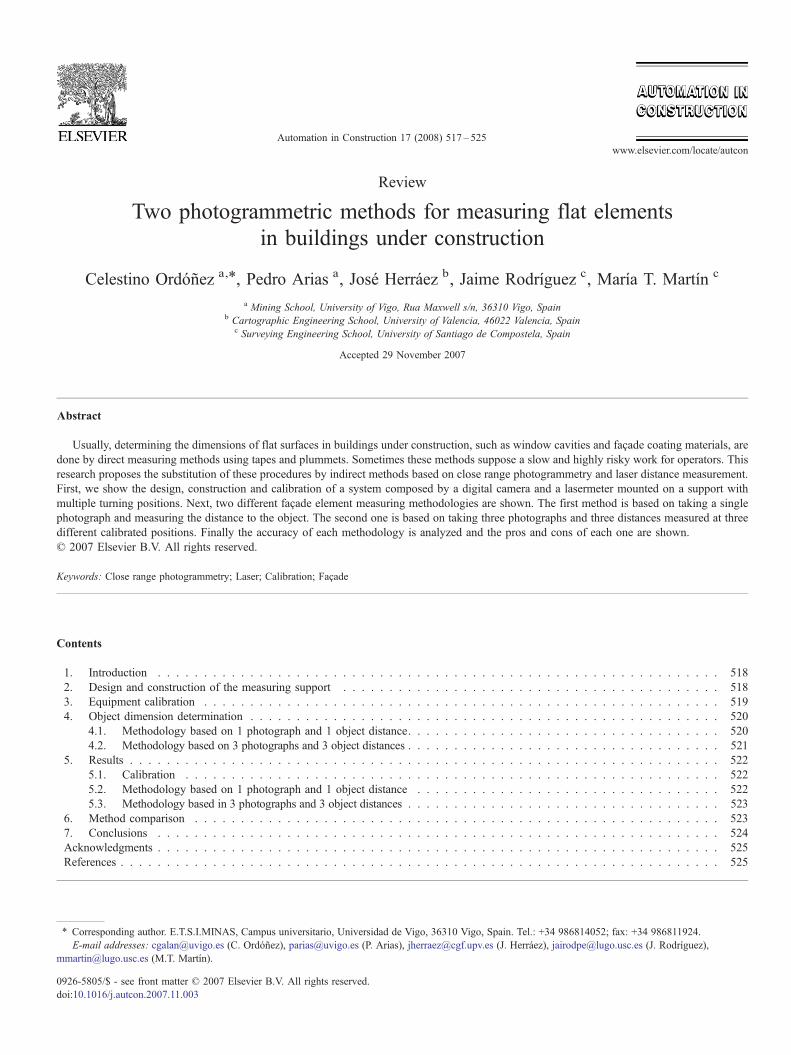
For the support design, CAD SolidWorks [19] was used, thatallows the evaluation of the element assembly,movement viability,and final weigh and appearance. Fig. 1 shows the 3D model donewith this program, and the basic elements are indicated.
Once the support was designed, steel was selected as the basematerial to build the support body in order to guarantee that thesystem does not deform and the soundness of the calibrationand measuring method developed, apart from its ease to bemechanized. All this at the expense of sacrificing the finalweight of the equipment, for which at its final development lightmaterial with the same consistency will be used.
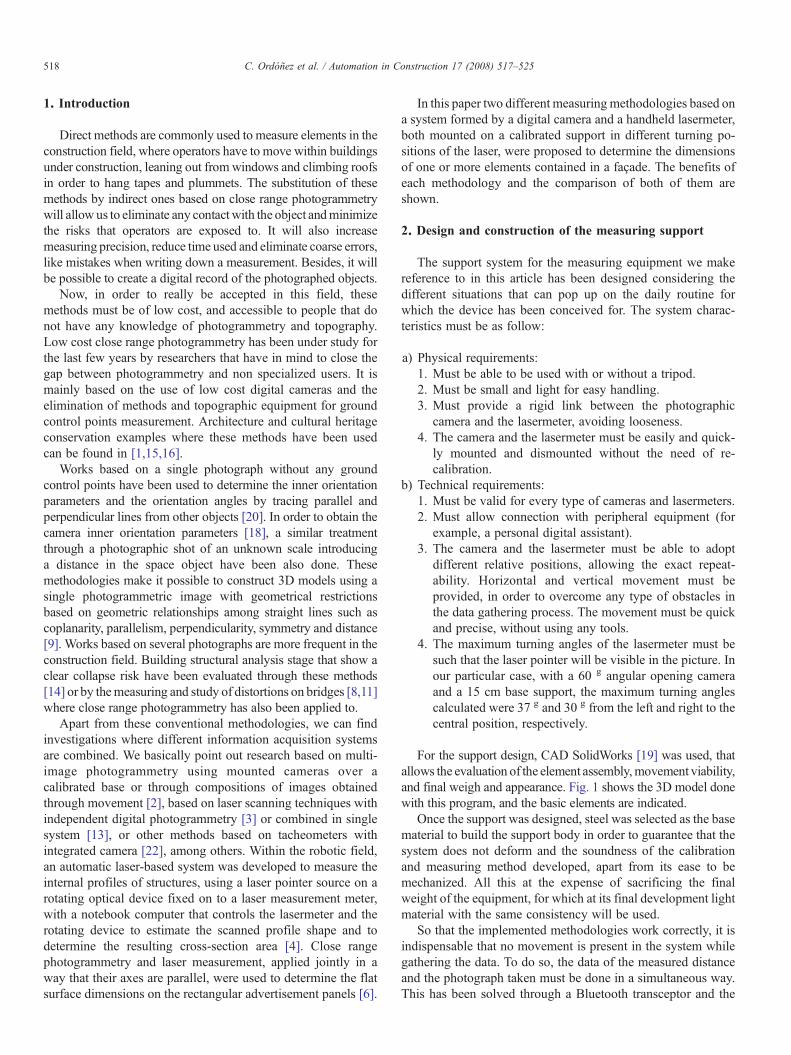
So that the implemented methodologies work correctly, it isindispensable that no movement is present in the system whilegathering the data. To do so, the data of the measured distanceand the photograph taken must be done in a simultaneous way.This has been solved through a Bluetooth transceptor and the
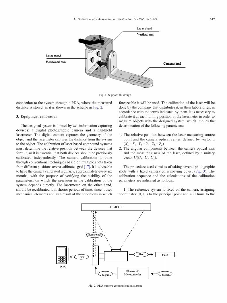
Fig. 1. Support 3D design.
519C. Ordóñez et al. / Automation in Construction 17 (2008) 517–525
connection to the system through a PDA, where the measureddistance is stored, as it is shown in the scheme in Fig. 2.
3. Equipment calibration
The designed system is formed by two information capturingdevices: a digital photographic camera and a handheldlasermeter. The digital camera captures the geometry of theobject and the lasermeter captures the distance from the systemto the object. The calibration of laser based compound systemsmust determine the relative position between the devices thatform it, so it is essential that both devices should be previouslycalibrated independently. The camera calibration is donethrough conventional techniques based on multiple shots takenfrom different positions over a calibrated grid [17]. It is advisableto have the camera calibrated regularly, approximately every sixmonths, with the purpose of verifying the stability of theparameters, on which the precision in the calibration of thesystem depends directly. The lasermeter, on the other hand,should be recalibrated it in shorter periods of time, since it usesmechanical elements and as a result of the conditions in which
Fig. 2. PDA-camera com
foreseeable it will be used. The calibration of the laser will bedone by the company that distributes it, in their laboratories, inaccordance with the terms indicated by them. It is necessary tocalibrate it at each turning position of the lasermeter in order tomeasure objects with the designed system, which implies thedetermination of the following parameters:
1. The relative position between the laser measuring sourcepoint and the camera optical center, defined by vector L(XL−Xo, YL−Yo, ZL−Zo).
2. The angular components between the camera optical axisand the measuring axis of the laser, defined by a unitaryvector U(UX, UY, UZ).
The procedure used consists of taking several photographicshots with a fixed camera on a moving object (Fig. 3). Thecalibration sequence and the calculations of the calibrationparameters are indicated as follows:
1. The reference system is fixed on the camera, assigningcoordinates (0,0,0) to the principal point and null turns to the
munication system.
0@
0@
Fig. 3. System calibration process.
520 C. Ordóñez et al. / Automation in Construction 17 (2008) 517–525
image plane. That way, the laser pointer coordinates in the spaceobject for each taken shot can be calculated by applying the co-linearity condition [21] as follows:
X ið ÞPL ¼ Z ið Þ
PLy ið ÞPL
�cð1Þ
Y ið ÞPL ¼ Z ið Þ
PLy ið ÞPL
�cð2Þ
where:
(XPL(i) ,YPL
(i) ,ZPL(i) ) object coordinates of the laser pointer
(xPL(i) ,yPL
(i) ,−c) laser pointer photocoordinates
2. The laser measurements origin determination and itsdirection vector are given by the expression:
XL
YLZL
1A ¼
X ið ÞPL
Y ið ÞPL
Z ið ÞPL
0B@
1CA� Dm ið Þ
L
UX
UY
UZ
0@
1A ð3Þ
where,
DmL(i) is the measured distance by the laser on each position.
The resulting unknowns in each shot are the laser measurementorigin coordinates (XL, YL, ZL), their direction vector U(UX, UY,UZ), and the coordinate ZPL
(i).3. Substituting Eqs. (1) and (2) in (3), and developing the
equation system for three or more laser pointer space positions,an estimation of the unknown values and its precision isobtained by using the least square method [12].
4. Object dimension determination
The dimensions of the photographed elements, in bothmethods,are determined from the coordinates in the object space of the points
that define the border, in such a way that the absolute orientation isnot necessary in any case when determining such magnitudesthrough the differences between the relative coordinates.
4.1. Methodology based on 1 photograph and 1 object distance
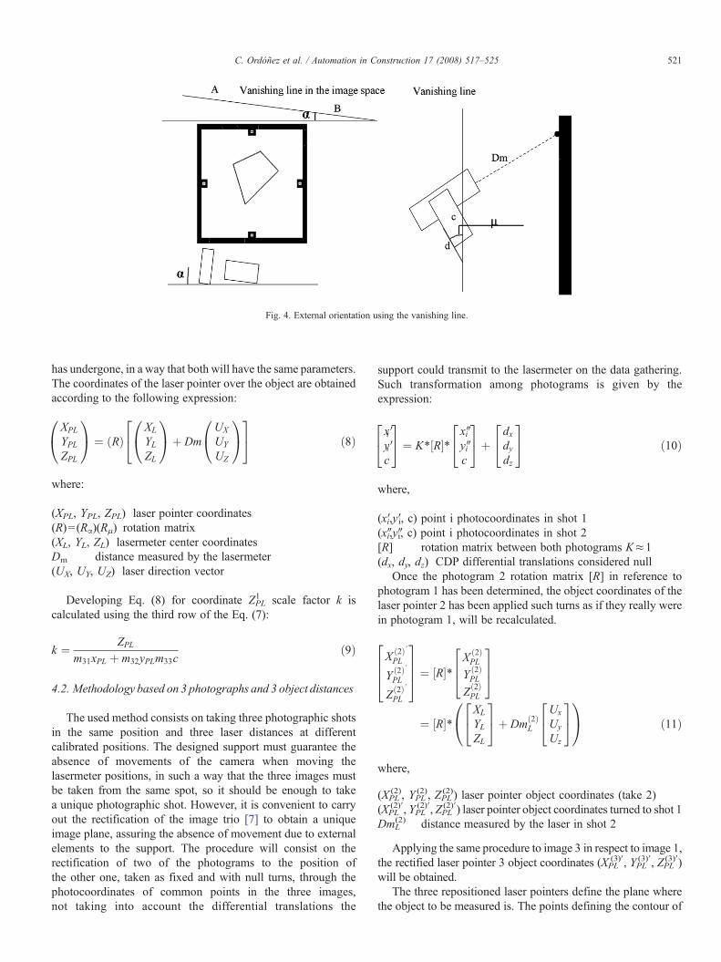
The method used to determine such coordinates is based onthe external orientation of the image plane through parallel andperpendicular lines visible in the photograph [9], by restrictingthe turn calculations, through determining the vanishing line inthe image space, to only two.
The placing of vanishing points that define the vanishingline can be done correctly using the object to be measured orany other element that will comply with such restrictions and itis placed in the same plane, and even over elements that whilebeing out of our measuring plane are parallel to it [5].
First step in establishing the external orientation consists ondetermining the rotation angles α and μ (Fig. 4) by placing theimage plane parallel to the object plane. The rotation angles aregiven by the following equations if A and B (Fig. 4) are the twovanishing points, with image coordinates (xa, ya) and (xb, yb),respectively, obtained by the intersection from the imageparallel straight lines in the object space:
a ¼ arctanxa � xbya � yb
ð4Þ
A ¼ arctancd
ð5ÞWhere c is the focal distance of the camera and d the distancebetween the main point and the vanishing line in the imagespace, where the value is given by the following expression:
d ¼ jyaxb � ybxajffiffiffiffiffiffiffiffiffiffiffiffiffiffiffiffiffiffiffiffiffiffiffiffiffiffiffiffiffiffiffiffiffiffiffiffiffiffiffiffiffiffiffixb � xað Þ2þ yb � yað Þ2
q ð6Þ
Knowing the spatial position of the image, a system ofcoordinates customized to our purposes in order to apply thecolinearity condition and to obtain coordinates of any point inthe object space is defined. In order to achieve this we will placethe coordinate system in the optical center of the camera, in away that X and Y axis are parallel to the plane that contains theobject. The defined colinearity results in:
XYZ
1A ¼ k Rað Þ RA
� � xy�c
0@
1A ð7Þ
where:
(X, Y, Z) The coordinates of any given point in the object space(x, y, −c) the photocoordinates of the point in the image spacek The scale coefficient(Rα) α angle rotation matrix(Rμ) μ angle rotation matrix
In order to determine k, it is necessary to supply thelasermeter with the same α and μ rotation angles that the camera
0@
24
Fig. 4. External orientation using the vanishing line.
521C. Ordóñez et al. / Automation in Construction 17 (2008) 517–525
has undergone, in a way that both will have the same parameters.The coordinates of the laser pointer over the object are obtainedaccording to the following expression:
XPL
YPLZPL
1A ¼ Rð Þ
XL
YLZL
0@
1Aþ Dm
UX
UY
UZ
0@
1A
24
35 ð8Þ
where:
(XPL, YPL, ZPL) laser pointer coordinates(R)= (Rα)(Rμ) rotation matrix(XL, YL, ZL) lasermeter center coordinatesDm distance measured by the lasermeter(UX, UY, UZ) laser direction vector
Developing Eq. (8) for coordinate ZPL1 scale factor k is
calculated using the third row of the Eq. (7):
k ¼ ZPLm31xPL þ m32yPLm33c
ð9Þ
4.2. Methodology based on 3 photographs and 3 object distances
The used method consists on taking three photographic shotsin the same position and three laser distances at differentcalibrated positions. The designed support must guarantee theabsence of movements of the camera when moving thelasermeter positions, in such a way that the three images mustbe taken from the same spot, so it should be enough to takea unique photographic shot. However, it is convenient to carryout the rectification of the image trio [7] to obtain a uniqueimage plane, assuring the absence of movement due to externalelements to the support. The procedure will consist on therectification of two of the photograms to the position ofthe other one, taken as fixed and with null turns, through thephotocoordinates of common points in the three images,not taking into account the differential translations the
support could transmit to the lasermeter on the data gathering.Such transformation among photograms is given by theexpression:
x Viy Vic
35 ¼ K⁎ R½ �⁎
xWiyWic
24
35þ
dxdydz
24
35 ð10Þ
where,
(x′i,y′i, c) point i photocoordinates in shot 1(x″i,y″i, c) point i photocoordinates in shot 2[R] rotation matrix between both photograms K≈1(dx, dy, dz) CDP differential translations considered null
Once the photogram 2 rotation matrix [R] in reference tophotogram 1 has been determined, the object coordinates of thelaser pointer 2 has been applied such turns as if they really werein photogram 1, will be recalculated.
X 2ð Þ VPL
Y 2ð Þ VPL
Z 2ð Þ VPL
2664
3775 ¼ R½ �⁎
X 2ð ÞPL
Y 2ð ÞPL
Z 2ð ÞPL
264
375
¼ R½ �⁎XL
YLZL
24
35þ Dm 2ð Þ
L
Ux
Uy
Uz
24
35
0@
1A ð11Þ
where,
(XPL(2), YPL
(2), ZPL(2)) laser pointer object coordinates (take 2)
(XPL(2)′, YPL
(2)′, ZPL(2)′) laser pointer object coordinates turned to shot 1
DmL(2) distance measured by the laser in shot 2
Applying the same procedure to image 3 in respect to image 1,the rectified laser pointer 3 object coordinates (XPL
(3)′, YPL(3)′, ZPL
(3)′)will be obtained.
The three repositioned laser pointers define the plane wherethe object to be measured is. The points defining the contour of

j
j
522 C. Ordóñez et al. / Automation in Construction 17 (2008) 517–525
that object are contained in the plane, and then obligatorilyverify the expression:
Xi � X 1ð ÞPL Vx Wx
Yi � Y 1ð ÞPL Vy Wy
Zi � Z 1ð ÞPL Vz Wz
j ¼ 0 ð12Þ
where,
(Vx,VY,VZ) vector formed by(XPL(1),YPL
(1), ZPL(1)) and(XPL
(2)′, YPL(2)′, ZPL
(2)′)(Wx,Wy,Wz) vector formed by (XPL
(1),YPL(1),ZPL
(1))and (XPL(3)′,YPL
(3)′, ZPL(3)′)
(Xi, Yi, Zi) vertex coordinates in the object plane
Imposing the co-linearity condition (1) and (2) to each pointdetermining the shape of the object in photogram 1 and forcingthem to comply with the belonging to the laser defined plane(12), we obtain:
Zix Vi�c
� X 1ð ÞPL Vx Wx
Ziy Vi�c
� Y 1ð ÞPL Vy Wy
Zi � Z 1ð ÞPL Vz Wz
j¼ 0 ð13Þ
where,
(x′i, y′i, c) vertex “i” photocoordinatesExpression from Zi is obtained by determining (Xi, Yi) throughexpressions (1) and (2). The same procedure is repeated foreach vertex i of the object to be measured.
5. Results
To prove the suitability of the system, a series of tests havebeen done using the following instruments:
1) Calibrated camera Canon EOS 10D:Focal distance: 20.2157 mm±0.004Format: (22.5203×15.0132) mm
(3,072×2,048) pixelsPrincipal point: (11.1601, 7.5245) mmRadial distortion parameters:
K1=2.186e−4 mm−1 ±1.6e−6K1=−4.360e−7 mm−3 ±1.1e−8
Decentring distortion parameters:P1=4.034e−5 mm−1 ±2.2e−6P1=−1.726e−5 mm−1 ±2.9e−6
2) Lasermeter Zinder Leica Disto Plus:Precision:±1.5 mm (between 0.2 and 200 m)
Table 1Calibration results of the set camera-lasermeter. Units are meters
Value Vertical downwards parallel Vertical upwards parallel
XL−X0 −0.2142±0.00479 −0.2059±0.00860YL−Y0 +0.0221±0.0052 −0.0229±0.00976ZL−Z0 +0.1344±0.0090 +0.1451±0.01281Ux −0.0207±0.00165 −0.0418±0.00206Uy −0.4084±0.00082 +0.39173±0.00100
5.1. Calibration
The results obtained in the calibration are shown in Table 1.As it can be seen, the highest precision is obtained in thehorizontal convergent position of the lasermeter. Such precisionis slightly diminished in the parallel axis position, and at agreater value in the laser divergent position (this is logical,hence, the inverse intersection is supposed to be done with thesmallest angles at the different positions). In any case theobtained precisions are quite satisfactory in all the calibratedturning positions, with standard deviations lower than 1 cm.
On the other hand, the distance to the object is a determinantfactor of the angular field of the system. In short distances, theangular field for the divergent lasermeter position is outstandinglyreduced, the exactly opposite happens for the convergent case. Assuch distance increases, the opposite occurs. However, theconvergent position covers, in any case, a greater angular fieldthan the one for the camera, while the divergent position reachessuch value, in the best of the cases, at infinite object distance.
So, taking both factors into consideration, the results show abetter adjustment and a greater range of options in the lasermeterconvergent position.
It is to be highlighted from the test done in the systemcalibration, in the first place, the mechanical and dimensionalstability shown by the system, proving that the variations in theresults done through repeated studies during several sessions, inthe different positions studied, are insignificant. Such resultreinforces the initial hypothesis in the use of heavy materials ofgreat sturdiness, as it verifies the reliability of the mechanismsused for the fitting of the positions at different turns.
In the same way, it can be stated that the mechanicaladjustment solutions of the different elements are satisfactory, aconclusion that can be reached through repeating the formerprocess after mounting and dismounting the camera, and thelasermeter, in repeated occasions, which shows that the supportfit solutions adopted avoid any recalibration of the system,ensuring the exact position.
Finally, the results obtained using the second measuringmethodology have verified the existing independence betweenthe camera and the lasermeter due to the support, that isolate bothelements from relative movements when one of them varies.
5.2. Methodology based on 1 photograph and 1 objectdistance
The best results with this methodology were obtained whenthe camera axis is not perpendicular to the wall plane, in a waythat it is easier to define the vanishing lines.
Horizontal divergent Horizontal parallel Horizontal convergent
−0.1640±0.00694 −0.2111±0.00059 −0.2352±0.00017+0.0003±0.00034 −0.0001±0.00017 −0.0012±0.00010+0.1733±0.01319 +0.1169±0.00140 +0.14742±0.0012−0.3921±0.00009 −0.0335±0.00012 +0.3611±0.00005+0.01090±0.00004 +0.0193±0.00008 +0.0023±0.00004
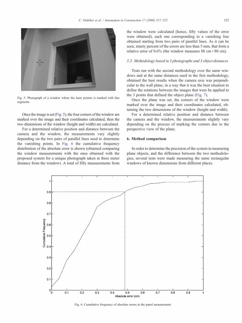
Fig. 5. Photograph of a window where the laser pointer is marked with linesegments.
523C. Ordóñez et al. / Automation in Construction 17 (2008) 517–525
Once the image is set (Fig. 5), the four corners of thewindow aremarked over the image and their coordinates calculated, then thetwo dimensions of the window (height and width) are calculated.
For a determined relative position and distance between thecamera and the window, the measurements vary slightlydepending on the two pairs of parallel lines used to determinethe vanishing points. In Fig. 6 the cumulative frequencydistribution of the absolute error is shown (obtained comparingthe window measurements with the ones obtained with theproposed system for a unique photograph taken at three meterdistance from the window). A total of fifty measurements from
Fig. 6. Cumulative frequency of absolu
the window were calculated (hence, fifty values of the errorwere obtained), each one corresponding to a vanishing lineobtained starting from two pairs of parallel lines. As it can beseen, ninety percent of the errors are less than 5 mm, that form arelative error of 0.6% (the window measures 88 cm×80 cm).
5.3. Methodology based in 3 photographs and 3 object distances
Tests run with the second methodology over the same win-dows and at the same distances used in the first methodology,obtained the best results when the camera axis was perpendi-cular to the wall plane, in a way that it was the best situation todefine the rotations between the images that were be applied tothe 3 points that defined the object plane (Fig. 7).
Once the plane was set, the corners of the window weremarked over the image and their coordinates calculated, ob-taining the two dimensions of the window (height and width).
For a determined relative position and distance betweenthe camera and the window, the measurements slightly varydepending on the process of marking the corners due to theperspective view of the plane.
6. Method comparison
In order to determine the precision of the system in measuringplane objects, and the difference between the two methodolo-gies, several tests were made measuring the same rectangularwindows of known dimensions from different places.
te errors in the panel measurement.
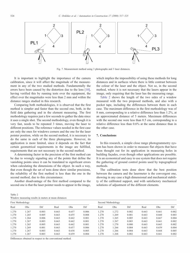
Fig. 7. Measurement method using 3 photographs and 3 laser distances.
524 C. Ordóñez et al. / Automation in Construction 17 (2008) 517–525
It is important to highlight the importance of the cameracalibration, since it will affect the magnitude of the measure-ment in any of the two studied methods. Fundamentally theerrors have been caused by the distortion due to the lens [10],having verified this by running tests over the equipment, theeffect over the magnitudes were less than 2 mm and within thedistance ranges studied in this research.
Comparing both methodologies, it is observed that the firstmethod is simpler and faster than the second one, both, in thefield data gathering and in the element measuring. The firstmethodology requires just a few seconds to gather the data sinceit uses a single shot. The second methodology, even though it isvery fast, needs to be repeated 3 times, moving the laser todifferent positions. The reference values needed in the first caseare only the ones for windows corners and the one for the laserpointer position, while on the second method, it is necessary todo the same in each of the three photograms. However, itsapplication is more limited, since it depends on the fact thatcertain geometrical requirements in the image are fulfilled,requirements that are not necessary in the second method.
A determining factor in the precision of the first method canbe due to wrongly signaling any of the points that define thevanishing points since it can be translated to significant errorswhen calculating the dimensions of the object. In such a way,that even though the set of tests done show similar precisions,the reliability of the first method is less than the one in thesecond method, due to this circumstance.
Another disadvantage of the first method compared to thesecond one is that the laser pointer needs to appear in the image,
Table 2Window measuring results in meters at mean distances
First Methodology
Real Obs Dif Real Obs Dif
1.270 1.267 0.003 0.663 0.657 0.0061.270 1.265 0.005 0.663 0.655 0.0081.270 1.264 0.006 0.663 0.662 0.0011.270 1.267 0.003 0.663 0.662 0.0011.270 1.265 0.005 0.663 0.662 0.0011.270 1.269 0.001 0.663 0.657 0.0061.270 1.267 0.003 0.663 0.658 0.0051.270 1.267 0.003 0.663 0.659 0.004
Differences obtained in respect to the conventional method.
which implies the impossibility of using these methods for longdistances and in surfaces where there is little contrast betweenthe colour of the laser and the object. Not so, in the secondmethod, where it is not necessary that the lasers appear in theimage, only requiring that the laser has the measuring range.
Table 2 shows the length of the two sides of a windowmeasured with the two proposed methods, and also with apocket tape, including the differences between them in eachcase. The maximum difference in the first methodology was of8 mm, corresponding to a relative difference less than 1.2%, atan approximated distance of 5 meters. Maximum differenceswith the second one were less than 0.5 cm, corresponding to arelative difference less than 0.6% at the same distance than inthe other case.
7. Conclusions
In this research, a simple close range photogrammetry sys-tem has been shown in order to measure flat objects that havebeen thought out for its application in measuring holes inbuilding façades, even though other applications are possible.It is an economical and easy to use system that does not requirethe gathering of ground control points used by topographicalmethods.
The calibration tests done show that the best positionbetween the camera and the lasermeter is the convergent one,showing in any case a high dimensional and mechanical stabili-ty of the calibrated support, and with satisfactory mechanicalsolutions of adjustment of the different elements.
Second Methodology
Real Obs Dif Real Obs Dif
1.270 1.272 0.002 0.663 0.661 0.0021.270 1.269 0.001 0.663 0.660 0.0031.270 1.265 0.005 0.663 0.667 0.0041.270 1.267 0.003 0.663 0.661 0.0021.270 1.270 0.000 0.663 0.665 0.0021.270 1.266 0.004 0.663 0.659 0.0041.270 1.266 0.004 0.663 0.668 0.0051.270 1.268 0.002 0.663 0.661 0.002
525C. Ordóñez et al. / Automation in Construction 17 (2008) 517–525
The system and the measuring methods in this article haveshown to be useful to measure flat elements, where adequateprecisions for the building field were obtained, for short andmedium distances (lower than 15 meters), reducing its precisionas the distance increases, due to the laser precision and thevertexes definition of the image elements.
In the first methodology the best results were obtained withoblique shots from the object that allowed a better determinationof the vanishing points. In the second one, the best results wereobtained with frontal shots from the object, although obliqueones gave very good results too.
The methodology based on one shoot has shown to besimpler but of more limited use, both for its precision as for thegeometrical restrictions that must be fulfilled in the image as thevisibility need of the laser pointer. The second method, despitethe increasing time needed for the field data gathering, hasshown a higher precision and total independency from thegeometrical characteristics of the image and the showing of thelaser pointer in it.
Although satisfactory results were obtained in the experi-ments carried out, work on improving the design and the weightof the equipment as well as new measurement determinationmethods that imply less intervention from the user is beingcarried forward.
Acknowledgments
The authors thank the Ministerio de Fomento (Spain) forfunding this work via its project no. C44/2006.
References
[1] A. Almagro, Photogrammetry for everybody, XVII CIPA Symposium.Recife, Olinda, Brazil (1999), http://cipa.icomos.org/fileadmin/papers/olinda/99c302.pdf.
[2] A. Bartoli, P. Sturm, Constrained Structure and Motion From MultipleUncalibrated Views of a Piecewise Planar Scene, IJCV — InternationalJournal of Computer Vision 52 (1) (April 2003) 45–64.
[3] A. Guarnieri, A. Vettore, S. El-Hakim, L. Gonzo, Digital photogrammetryand laser scanning in cultural heritage survey, International Archieves ofPhotogrammetry and Remote Sensing, Istanbul, Turkey, 2004, pp. 154–158.
[4] AmpereA.Tseng,Masahito Tanaka,Bharath Leeladharan, Laser-based internalprofile measurement system, Automation in Construction 11 (2002) 667–679.
[5] A. Criminisi, I. Reid, A. Zisserman, Single view metrology, Proccedings ofthe 11th International Conference on Computer Vision, Kerkyra, Greece,1999, pp. 434–441.
[6] A.M.G. Tommaselli, M.L. Lopes Reiss, A Photogrammetric Method forSingle Orientation and Measurement, Photogrammetric Engineering &Remote Sensing 71 (6) (2005) 727–732.
[7] Changming Sun, Uncalibrated three-view image rectification, Image andVision Computing 21 (3) (2003) 259–269.
[8] D. Jáuregui, R. Kenneth, R. White, B. Clinton, B. Woodward, Kenneth R.Leitch, Non contact Photogrammetric Measurement of Vertical BridgeDeflection, Journal of Bridge Engineering 8 (4) (2004) 212–222.
[9] F.A. Van den Heuvel, 3D reconstruction from a single image usinggeometric constraints, ISPRS Journal of Photogrammetry and RemoteSensing 53 (1998) 354–368.
[10] J. Cardenal, E. Mata, P. Castro, J. Delgado, M.A. Hernández, J.L. Perez, M.Ramos, M. Torres, Evaluation of a digital non metric camera (Canon D30) forthe photogrammetric recording of historical buildings, International Archievesof Photogrammetry andRemote Sensing, Istanbul, Turkey, 2004, pp. 564–569.
[11] K.R. Leitch, Close-range photogrammetric measurement of bridge deforma-tions, PhD Thesis, State University Las Cruces, New México, EEUU, 2002.
[12] M. Chueca, J.L. Berné, J. Herráez, Redes Topográficas y Locales.Microgeodesia. Escuela técnica Superior de Ingeniería Geodésica, in: S.A.Paraninfo (Ed.), Cartográfia y Topografía, Universidad Politécnica deValencia, 1996, 448 pp.
[13] M. Bouroumand, N. Studnicka, The fusion of laser scanning and closerange photogrammetry in Bam. Laser-photogrammetric mapping of BamCitadel (Arg-e-Bam)/Iran, International Archives of Photogrammetry andRemote Sensing, Istanbul, Turkey, 2004, pp. 979–983.
[14] O. Altan, G. Toz, S. Kulur, D. Seker, S. Volz, D. Fritsch, M. Sester,Photogrammetry and geographic information systems for quick assess-ment, documentation and analysis of earthquakes, ISPRS Journal ofPhotogrammetry and Remote Sensing 55 (5–6) (2001) 359–372.
[15] P. Arias, C. Ordóñez, H. Lorenzo, J. Herráez, Documentation for thepreservation of traditional agro-industrial buildings inN.W. Spain using simpleclose range photogrammetry, Survey Review 38 (300) (2006) 525–540.
[16] P. Waldhäusl, C. Ogleby, Rules for Simple Photogrammetric Documenta-tion of Architecture, In Close Range Techniques and Machine Vision,Proceedings of the Symposium of Commission Vof ISPRS in Melbourne,Australia, 1994, p. 426.
[17] R.J. Valkenburg, Camera calibration using multiple references, Image andVision Computing New Zealand, Industrial Research Limited, Lower Hutt,1996, pp. 61–66.
[18] R.M. Haralick, Determining camera parameters from the perspectiveprojection of a rectangle, Pattern Recognition 22 (3) (1989) 225–230.
[19] SolidWorks, 3D Mechanical Design Software, Reference Manual,Dassault Systems S.A., 2005.
[20] U. Ethrog, Non-metric camera calibration and photo orientationusing parallel and perpendicular lines of the photographed objects,Photogrammetria 39 (1984) 13–22.
[21] W. Zhizhuo, Chapters 1 and 14. Principles of Photogrammetry (withremote sensing), Press of Wuhan Tecnical University of Surveying andMapping, Publishing House of Surveying and Mapping, Beijing, 1990.
[22] Zuxun Zhang, Shunyi Zheng, Zongqian Zhan, Digital terrestrial photogram-metrywith Photo Total Station, International Archives of Photogrammetry andRemote Sensing, Istanbul, Turkey, 2004, pp. 232–236.