tutorial- 8: combined loadings - chapter 1
TRANSCRIPT

2005 Pearson Education South Asia Pte Ltd
TUTORIAL-6 : Combined Loadings
1
Stress in Shaft due to Bending Load and Torsion
T
x y
z
A shaft has a diameter of 4 cm. The
cutting section shows in the figure is
subjected to a bending moment of 2 kNm
and a torque of 2.5 kNm.
Determine:
1. The critical point of the section
2. The stress state of the critical point.
PROBLEM-1
TUTORIAL- 8: Combined Loadings

2005 Pearson Education South Asia Pte Ltd
TUTORIAL-6 : Combined Loadings
2
T
x y
z
Analysis to identify the critical point
Maximum shear stresses occur at the
peripheral of the section or on the
outer surface of the shaft.
Due to the torque T
Due to the bending moment M
Maximum tensile stress occurs at the
bottom point (A) of the section.
Conclusion: the bottom point (A) is the critical point
A
PROBLEM-1
TUTORIAL- 8: Combined Loadings

2005 Pearson Education South Asia Pte Ltd
TUTORIAL-6 : Combined Loadings
3
PROBLEM-1
T
x y
z
Stress components at point A
Due to the torque T
Due to the bending moment M
A
198.94 MPa 4
(0.02)
2)(2500)(0.0
2J
cTτ
318.31 MPa 4
4(0.02)
2)(2000)(0.0
zI
cM
318.31 MPa
198.94 MPa
Stress state at critical point A
x = 318.31 MPa txy = 198.94 MPa
TUTORIAL- 8: Combined Loadings
2005 Pearson Education South Asia Pte Ltd
TUTORIAL-6 : Combined Loadings
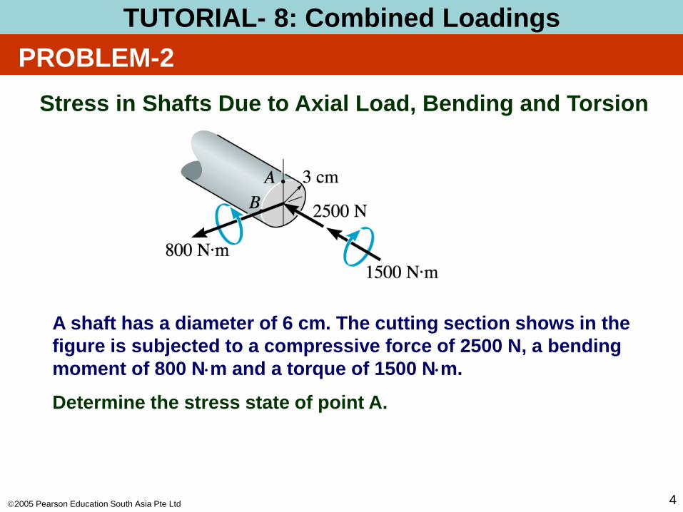
4
Stress in Shafts Due to Axial Load, Bending and Torsion
A shaft has a diameter of 6 cm. The cutting section shows in the
figure is subjected to a compressive force of 2500 N, a bending
moment of 800 Nm and a torque of 1500 Nm.
Determine the stress state of point A.
PROBLEM-2
TUTORIAL- 8: Combined Loadings
2005 Pearson Education South Asia Pte Ltd
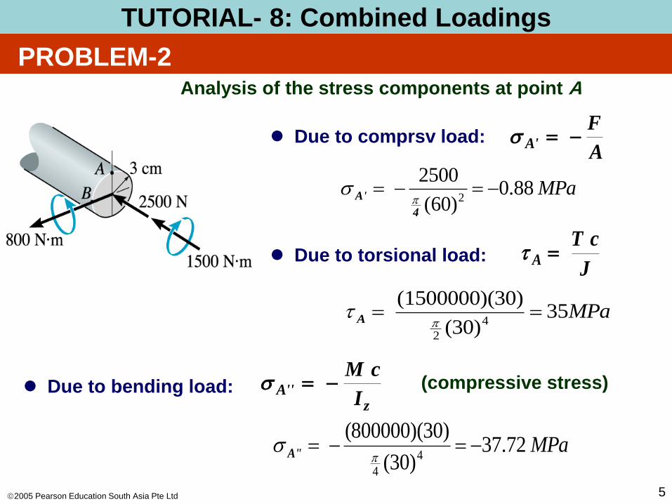
TUTORIAL-6 : Combined Loadings
5
Analysis of the stress components at point A
Due to comprsv load:
Due to torsional load: J
cTA t
A
FA'
Due to bending load: z
'A'I
cM (compressive stress)
PROBLEM-2
MPa88.0)60(
25002
4
A'
MPa35)30(
30)(1500000)(4
2
t A
MPa72.37)30(
)30)(800000(4
4
'A'
TUTORIAL- 8: Combined Loadings

2005 Pearson Education South Asia Pte Ltd
TUTORIAL-6 : Combined Loadings
6
Stress state at point A
Shear stress: txy = tA = 35 MPa
Normal stress: x = A’ + A”
txy
x
PROBLEM-2
= (– 0.88 – 37.72) MPa
= – 38.6 MPa
TUTORIAL- 8: Combined Loadings
2005 Pearson Education South Asia Pte Ltd
TUTORIAL-6 : Combined Loadings
7
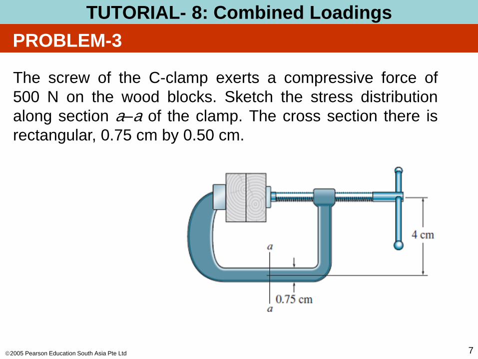
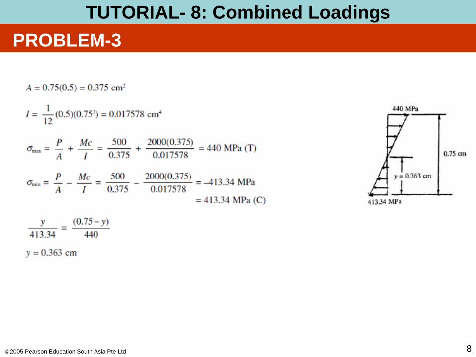
The screw of the C-clamp exerts a compressive force of
500 N on the wood blocks. Sketch the stress distribution
along section a–a of the clamp. The cross section there is
rectangular, 0.75 cm by 0.50 cm.
PROBLEM-3
TUTORIAL- 8: Combined Loadings
2005 Pearson Education South Asia Pte Ltd
TUTORIAL-6 : Combined Loadings
8
PROBLEM-3
TUTORIAL- 8: Combined Loadings

2005 Pearson Education South Asia Pte Ltd
TUTORIAL-6 : Combined Loadings
9
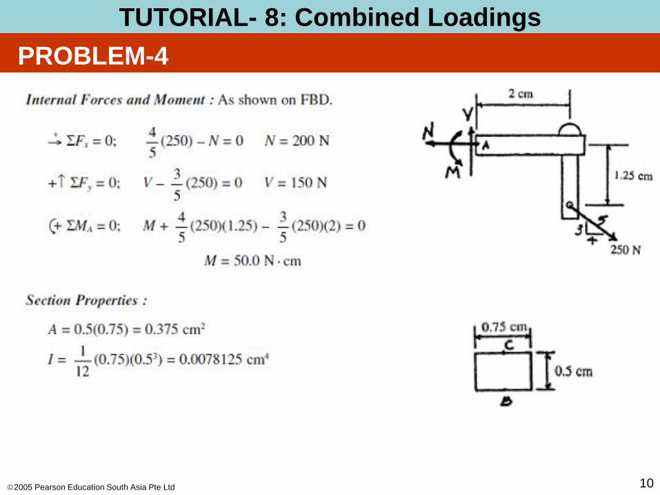
The joint is subjected to a force of 250 N as shown. Sketch
the normal-stress distribution acting over section a–a if the
member has a rectangular cross section of width 0.5 cm
and thickness 0.75 cm.
PROBLEM-4
TUTORIAL- 8: Combined Loadings
2005 Pearson Education South Asia Pte Ltd
TUTORIAL-6 : Combined Loadings
10
PROBLEM-4
TUTORIAL- 8: Combined Loadings

2005 Pearson Education South Asia Pte Ltd
TUTORIAL-6 : Combined Loadings
11
PROBLEM-4
TUTORIAL- 8: Combined Loadings
2005 Pearson Education South Asia Pte Ltd
TUTORIAL-6 : Combined Loadings
12
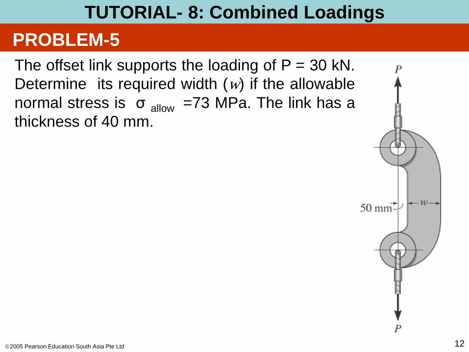
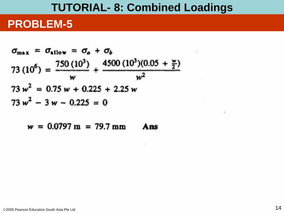
The offset link supports the loading of P = 30 kN.
Determine its required width (w) if the allowable
normal stress is σ allow =73 MPa. The link has a
thickness of 40 mm.
PROBLEM-5
TUTORIAL- 8: Combined Loadings

2005 Pearson Education South Asia Pte Ltd
TUTORIAL-6 : Combined Loadings
13
PROBLEM-5
TUTORIAL- 8: Combined Loadings
2005 Pearson Education South Asia Pte Ltd
TUTORIAL-6 : Combined Loadings
14
PROBLEM-5
TUTORIAL- 8: Combined Loadings
2005 Pearson Education South Asia Pte Ltd
TUTORIAL-6 : Combined Loadings
15
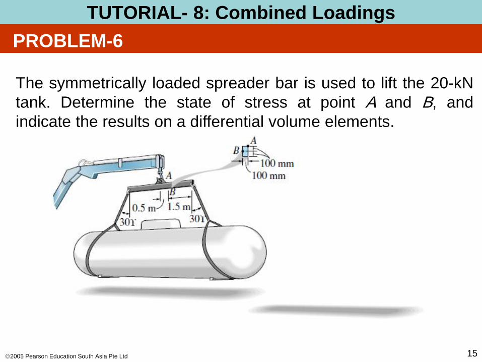
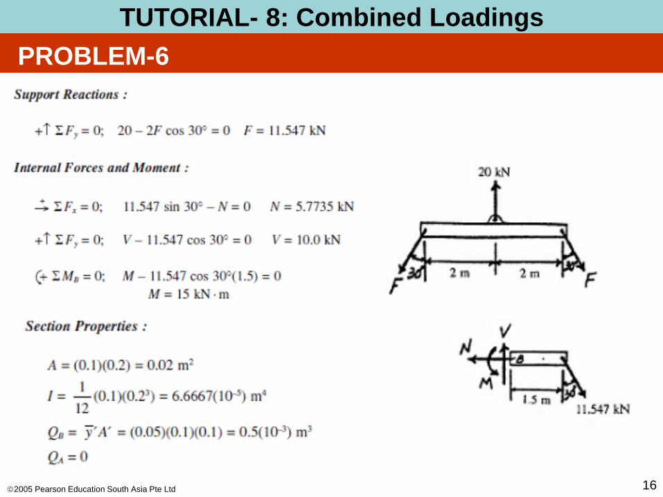
The symmetrically loaded spreader bar is used to lift the 20-kN
tank. Determine the state of stress at point A and B, and
indicate the results on a differential volume elements.
PROBLEM-6
TUTORIAL- 8: Combined Loadings
2005 Pearson Education South Asia Pte Ltd
TUTORIAL-6 : Combined Loadings
16
PROBLEM-6
TUTORIAL- 8: Combined Loadings

2005 Pearson Education South Asia Pte Ltd
TUTORIAL-6 : Combined Loadings
17
PROBLEM-6
TUTORIAL- 8: Combined Loadings
A B
2005 Pearson Education South Asia Pte Ltd
TUTORIAL-6 : Combined Loadings
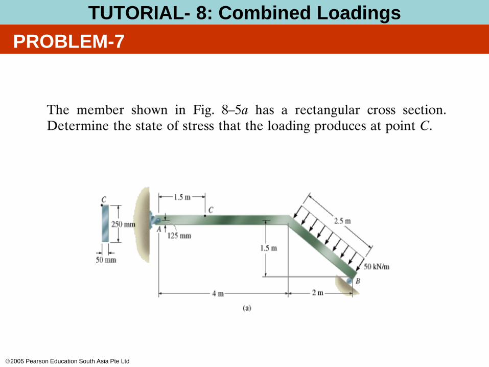
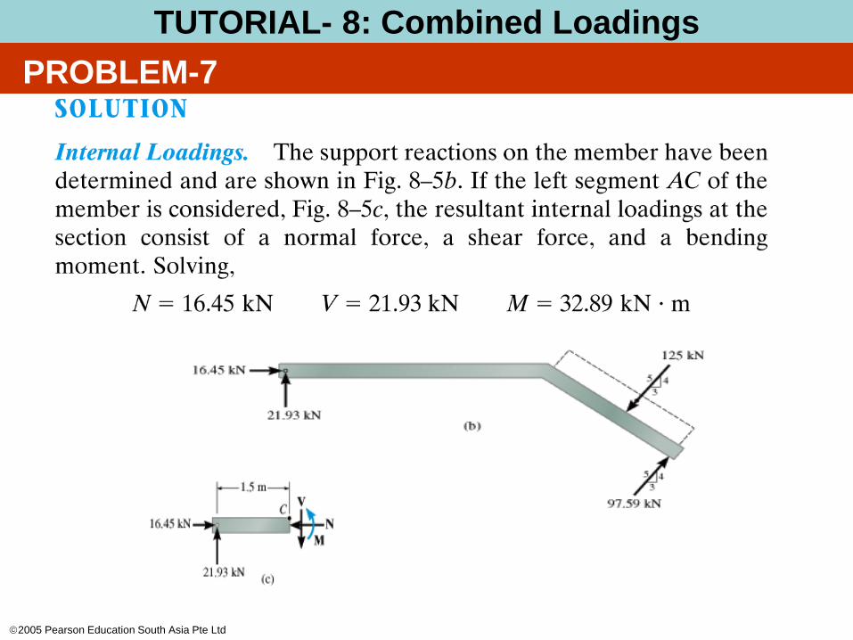
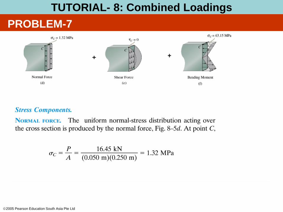
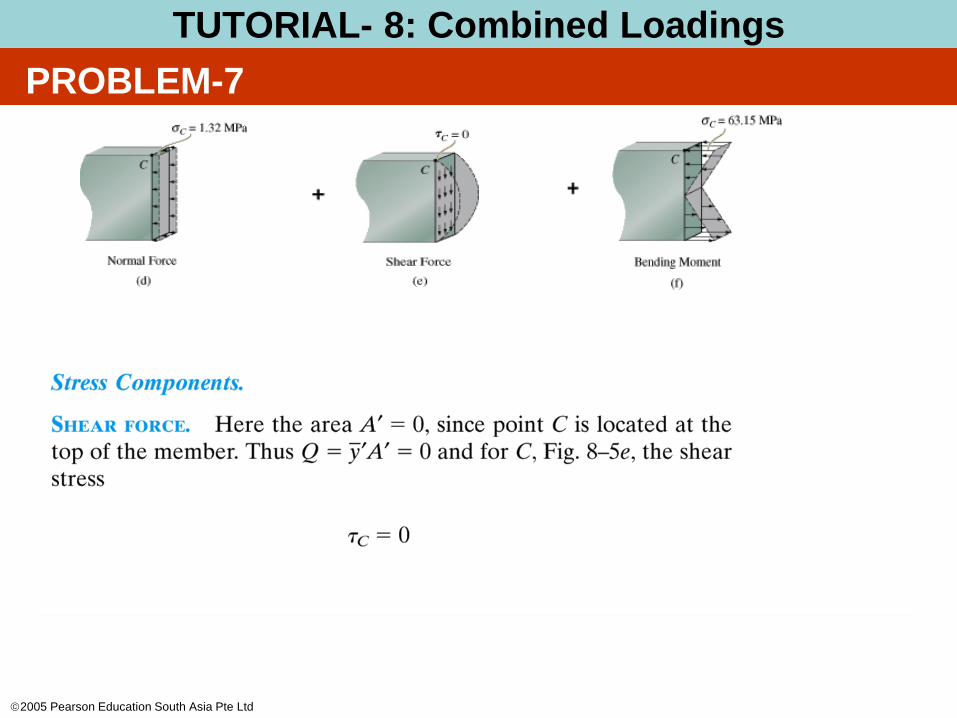
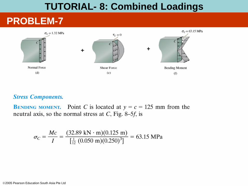
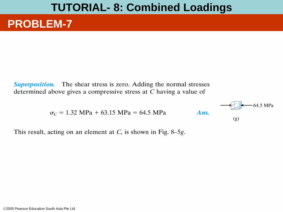
PROBLEM-7
TUTORIAL- 8: Combined Loadings
2005 Pearson Education South Asia Pte Ltd
TUTORIAL-6 : Combined Loadings
PROBLEM-7
TUTORIAL- 8: Combined Loadings
2005 Pearson Education South Asia Pte Ltd
TUTORIAL-6 : Combined Loadings
PROBLEM-7
TUTORIAL- 8: Combined Loadings
2005 Pearson Education South Asia Pte Ltd
TUTORIAL-6 : Combined Loadings
PROBLEM-7
TUTORIAL- 8: Combined Loadings
2005 Pearson Education South Asia Pte Ltd
TUTORIAL-6 : Combined Loadings
PROBLEM-7
TUTORIAL- 8: Combined Loadings
2005 Pearson Education South Asia Pte Ltd
TUTORIAL-6 : Combined Loadings
PROBLEM-7
TUTORIAL- 8: Combined Loadings