builtworks tutorial
TRANSCRIPT
2012
BuiltWorks Tutorial Volume 1. Modeling basics
BuiltWorks Tutorial SolidACE, Ltd.
BuiltWorks Tutorial
Volume 1. Modeling basics
This document has been created with the intention to help the user of BuiltWorks software application to
understand the basic tools, techniques and workflows working with BuiltWorks to create demo models for
self learning purposes. It is assumed that user of this manual is familiar with SolidWorks software from
Dassault Systèmes SolidWorks Corp.
All effort was made to make this document complete and accurate; however no warranty or fitness is
implied. SolidACE Ltd. has neither liability nor responsibility to any person or entity with respect to any loss
or damages in connection with or arising from the information provided in this manual or using the
described software applications.
The information is provided on “as-is” basis. The menu texts, titles of windows, button images or texts,
texts of dialogs and screenshot pictures may differ from the actual view of the software applications.
SolidACE and BuiltWorks logo are either registered or unregistered trademarks or service marks of
SolidACE Ltd. All other brands, product names and registered or unregistered trademarks are property of
their respective owners.
Copyright © 2012 SolidACE, Ltd. All rights reserved.
Lukiškių str. 3, VI floor
LT-01108, Vilnius, Lithuania
Email: [email protected]
www.solidace.com
v.3.0 January, 2012

BuiltWorks Tutorial SolidACE, Ltd.
Table of Contents
Introduction ....................................................................................................................................................... 1
Purpose of this Tutorial .................................................................................................................................. 1
Prerequisites .................................................................................................................................................. 1
I. Creating a new document ...................................................................................................................... 2
II. Creating Grid System ............................................................................................................................. 3
III. Creating Member Group (columns) between two Sketch Points .......................................................... 5
IV. Creating Member Group (beams) on selected Sketch Segments .......................................................... 8
V. Creating Member Array (secondary beams) ........................................................................................ 10
VI. Exporting model to Structural Analysis program (STAAD.Pro) ............................................................ 12
VII. Analyzing the model in STAAD.Pro ...................................................................................................... 14
VIII. Importing analysis results from STAAD.Pro ......................................................................................... 18
IX. Aligning Members ................................................................................................................................ 20
X. Detailing Connections – Trim ............................................................................................................... 22
XI. Copying Connections ........................................................................................................................... 25
XII. Creating an End Plate ........................................................................................................................... 29
XIII. Generating Drawings and BOM ........................................................................................................... 31
User Notes ....................................................................................................................................................... 37
BuiltWorks Tutorial SolidACE, Ltd.
- 1 -
Introduction BuiltWorks is a software application for real-time steel design within the native SolidWorks environment,
providing tools for 3D solid parametric modeling, analysis and design, connection detailing and automated
generation of both drawings and bills of materials.
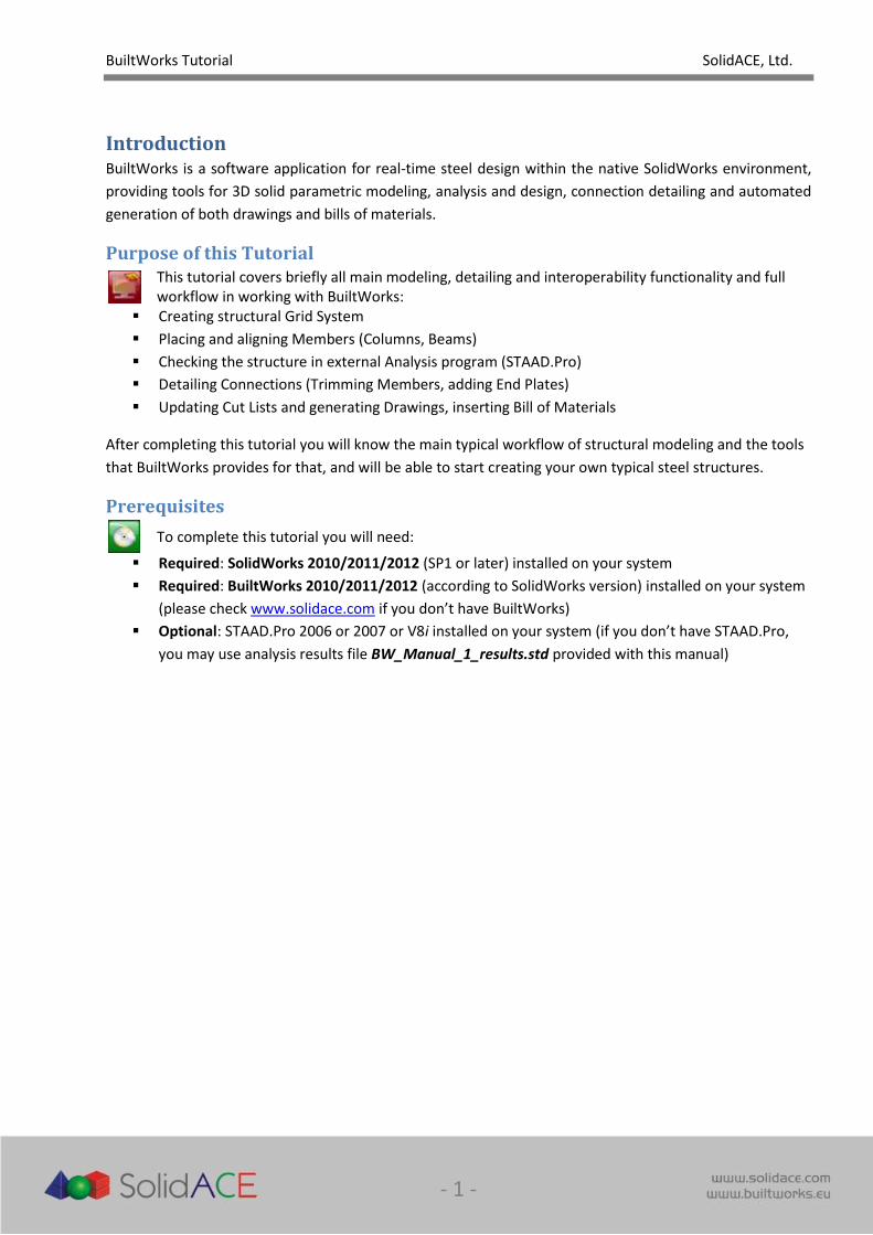
Purpose of this Tutorial
This tutorial covers briefly all main modeling, detailing and interoperability functionality and full workflow in working with BuiltWorks:
Creating structural Grid System
Placing and aligning Members (Columns, Beams)
Checking the structure in external Analysis program (STAAD.Pro)
Detailing Connections (Trimming Members, adding End Plates)
Updating Cut Lists and generating Drawings, inserting Bill of Materials
After completing this tutorial you will know the main typical workflow of structural modeling and the tools
that BuiltWorks provides for that, and will be able to start creating your own typical steel structures.
Prerequisites
To complete this tutorial you will need:
Required: SolidWorks 2010/2011/2012 (SP1 or later) installed on your system
Required: BuiltWorks 2010/2011/2012 (according to SolidWorks version) installed on your system
(please check www.solidace.com if you don’t have BuiltWorks)
Optional: STAAD.Pro 2006 or 2007 or V8i installed on your system (if you don’t have STAAD.Pro,
you may use analysis results file BW_Manual_1_results.std provided with this manual)
BuiltWorks Tutorial SolidACE, Ltd.
- 2 -
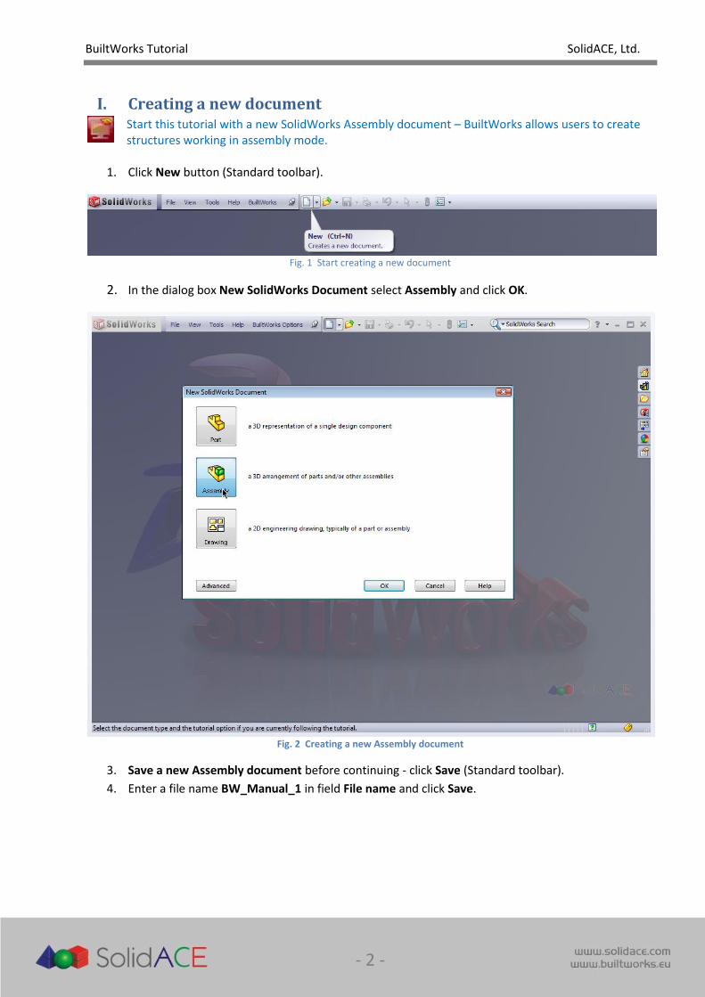
I. Creating a new document
Start this tutorial with a new SolidWorks Assembly document – BuiltWorks allows users to create structures working in assembly mode.
1. Click New button (Standard toolbar).
Fig. 1 Start creating a new document
2. In the dialog box New SolidWorks Document select Assembly and click OK.
Fig. 2 Creating a new Assembly document
3. Save a new Assembly document before continuing - click Save (Standard toolbar).
4. Enter a file name BW_Manual_1 in field File name and click Save.
BuiltWorks Tutorial SolidACE, Ltd.
- 3 -
II. Creating Grid System
To have a reference for your future structure you need to have a system of sketch lines. BuiltWorks provides a tool to create the parametric reference Grid System according to structural rules.
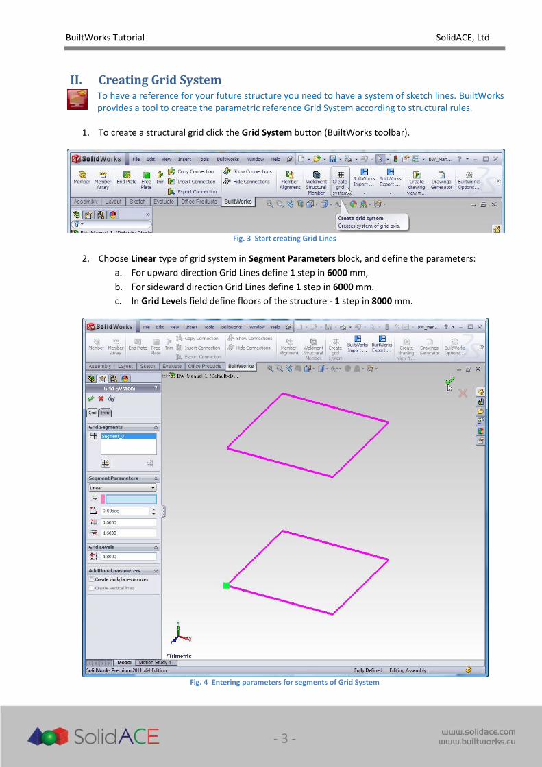
1. To create a structural grid click the Grid System button (BuiltWorks toolbar).
Fig. 3 Start creating Grid Lines
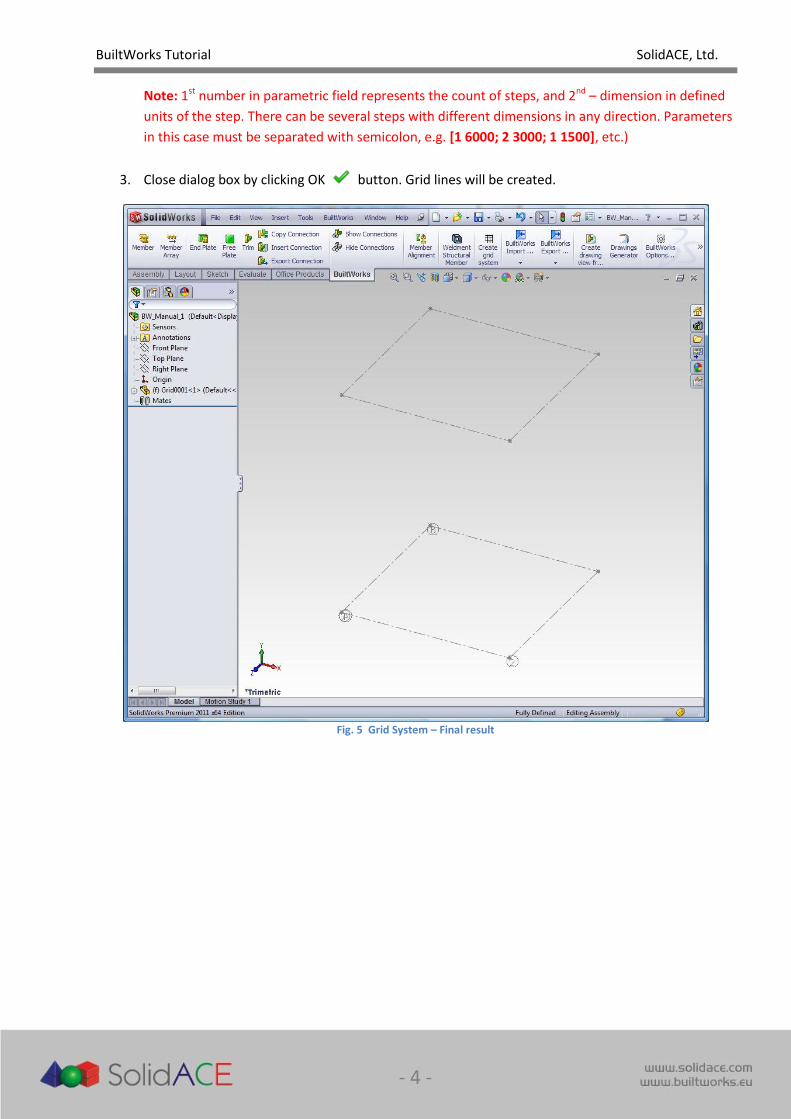
2. Choose Linear type of grid system in Segment Parameters block, and define the parameters:
a. For upward direction Grid Lines define 1 step in 6000 mm,
b. For sideward direction Grid Lines define 1 step in 6000 mm.
c. In Grid Levels field define floors of the structure - 1 step in 8000 mm.
Fig. 4 Entering parameters for segments of Grid System
BuiltWorks Tutorial SolidACE, Ltd.
- 4 -
Note: 1st number in parametric field represents the count of steps, and 2nd – dimension in defined
units of the step. There can be several steps with different dimensions in any direction. Parameters
in this case must be separated with semicolon, e.g. [1 6000; 2 3000; 1 1500], etc.)
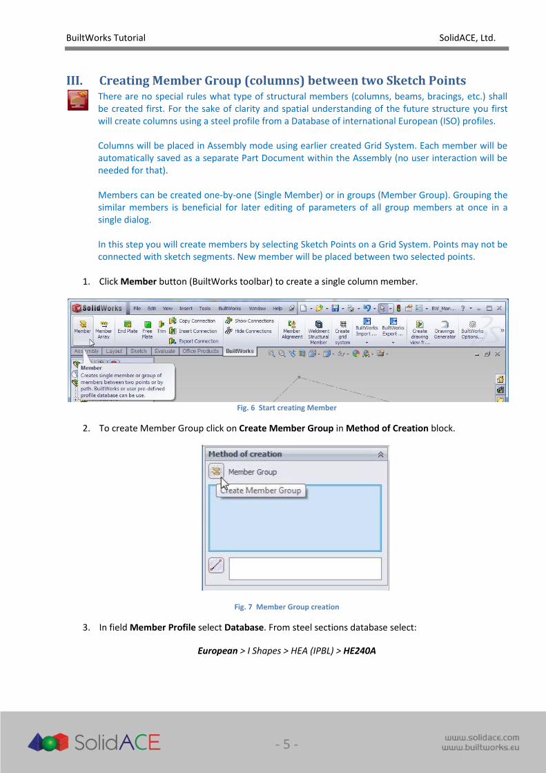
3. Close dialog box by clicking OK button. Grid lines will be created.
Fig. 5 Grid System – Final result
BuiltWorks Tutorial SolidACE, Ltd.
- 5 -
III. Creating Member Group (columns) between two Sketch Points
There are no special rules what type of structural members (columns, beams, bracings, etc.) shall be created first. For the sake of clarity and spatial understanding of the future structure you first will create columns using a steel profile from a Database of international European (ISO) profiles. Columns will be placed in Assembly mode using earlier created Grid System. Each member will be automatically saved as a separate Part Document within the Assembly (no user interaction will be needed for that). Members can be created one-by-one (Single Member) or in groups (Member Group). Grouping the similar members is beneficial for later editing of parameters of all group members at once in a single dialog. In this step you will create members by selecting Sketch Points on a Grid System. Points may not be connected with sketch segments. New member will be placed between two selected points.
1. Click Member button (BuiltWorks toolbar) to create a single column member.
Fig. 6 Start creating Member
2. To create Member Group click on Create Member Group in Method of Creation block.
Fig. 7 Member Group creation
3. In field Member Profile select Database. From steel sections database select:
European > I Shapes > HEA (IPBL) > HE240A

BuiltWorks Tutorial SolidACE, Ltd.
- 6 -
4. In the Member Orientation preview window select central base point.
5. Select point on the intersection of 1 and A grid lines at the bottom grid level, and then the
corresponding point at the top grid level.
Fig. 8 Choose Member Profile, define Profile Base Point, and select grid points for placing members
6. HE240A column member preview will be displayed. Not leaving the Member Group dialog repeat
placing columns of the same group around the square of the grid lines (lower, then upper level on
B1, B2, A2 intersections).
BuiltWorks Tutorial SolidACE, Ltd.
- 7 -
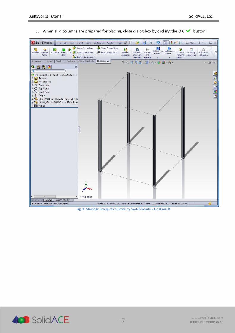
7. When all 4 columns are prepared for placing, close dialog box by clicking the OK button.
Fig. 9 Member Group of columns by Sketch Points – Final result
BuiltWorks Tutorial SolidACE, Ltd.
- 8 -
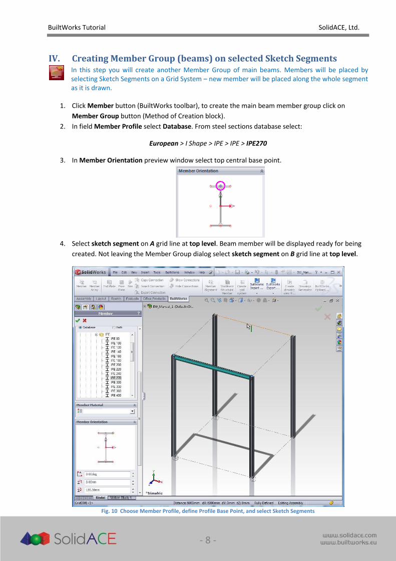
IV. Creating Member Group (beams) on selected Sketch Segments
In this step you will create another Member Group of main beams. Members will be placed by selecting Sketch Segments on a Grid System – new member will be placed along the whole segment as it is drawn.
1. Click Member button (BuiltWorks toolbar), to create the main beam member group click on
Member Group button (Method of Creation block).
2. In field Member Profile select Database. From steel sections database select:
European > I Shape > IPE > IPE > IPE270
3. In Member Orientation preview window select top central base point.
4. Select sketch segment on A grid line at top level. Beam member will be displayed ready for being
created. Not leaving the Member Group dialog select sketch segment on B grid line at top level.
Fig. 10 Choose Member Profile, define Profile Base Point, and select Sketch Segments
BuiltWorks Tutorial SolidACE, Ltd.
- 9 -
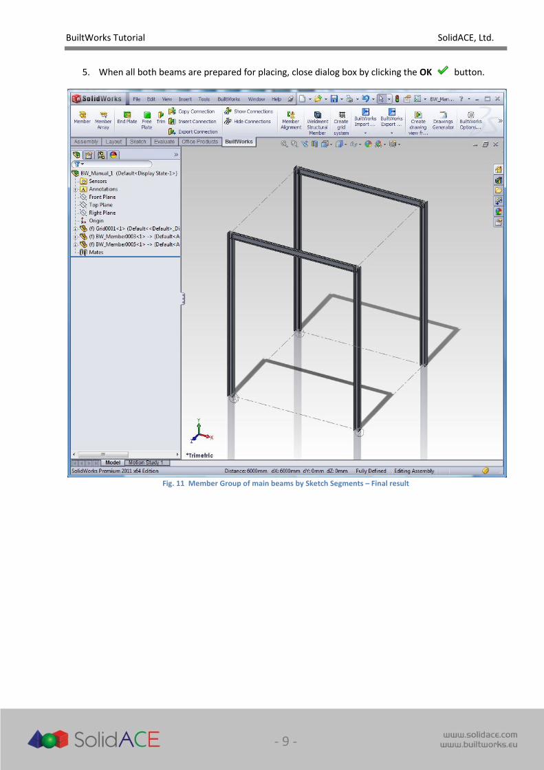
5. When all both beams are prepared for placing, close dialog box by clicking the OK button.
Fig. 11 Member Group of main beams by Sketch Segments – Final result
BuiltWorks Tutorial SolidACE, Ltd.
- 10 -
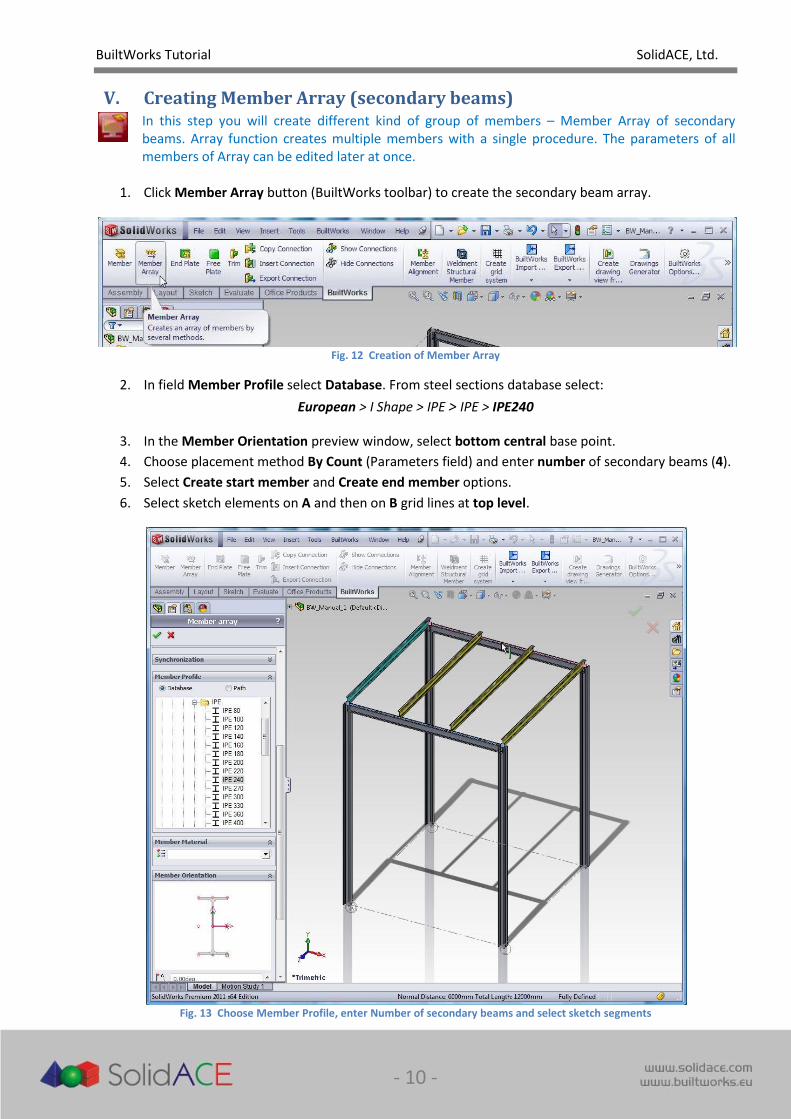
V. Creating Member Array (secondary beams)
In this step you will create different kind of group of members – Member Array of secondary beams. Array function creates multiple members with a single procedure. The parameters of all members of Array can be edited later at once.
1. Click Member Array button (BuiltWorks toolbar) to create the secondary beam array.
Fig. 12 Creation of Member Array
2. In field Member Profile select Database. From steel sections database select:
European > I Shape > IPE > IPE > IPE240
3. In the Member Orientation preview window, select bottom central base point.
4. Choose placement method By Count (Parameters field) and enter number of secondary beams (4).
5. Select Create start member and Create end member options.
6. Select sketch elements on A and then on B grid lines at top level.
Fig. 13 Choose Member Profile, enter Number of secondary beams and select sketch segments
BuiltWorks Tutorial SolidACE, Ltd.
- 11 -
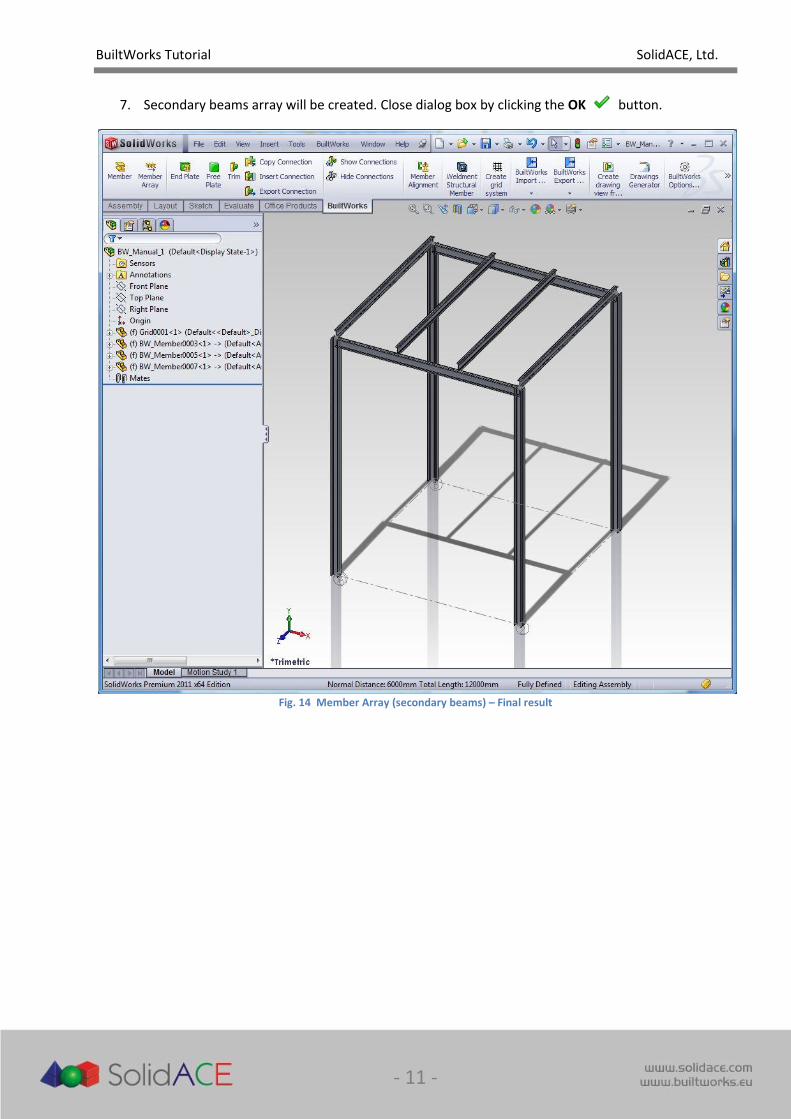
7. Secondary beams array will be created. Close dialog box by clicking the OK button.
Fig. 14 Member Array (secondary beams) – Final result
BuiltWorks Tutorial SolidACE, Ltd.
- 12 -
VI. Exporting model to Structural Analysis program (STAAD.Pro)
Created structure must be analyzed to prove the sufficient strength. Steel structures are best analyzed with special Structural Analysis programs that use Design Code check based methods for analysis. BuiltWorks provides a link between various Structural Analysis applications. In this step we will export model data with the pre-defined parameters for analysis to Structural Analysis application STAAD.Pro. With STAAD.Pro BuiltWorks has the bi-directional link, which means that after analysis, the results can be brought back to SolidWorks by allowing users to automatically update the model according to the results of the analysis.
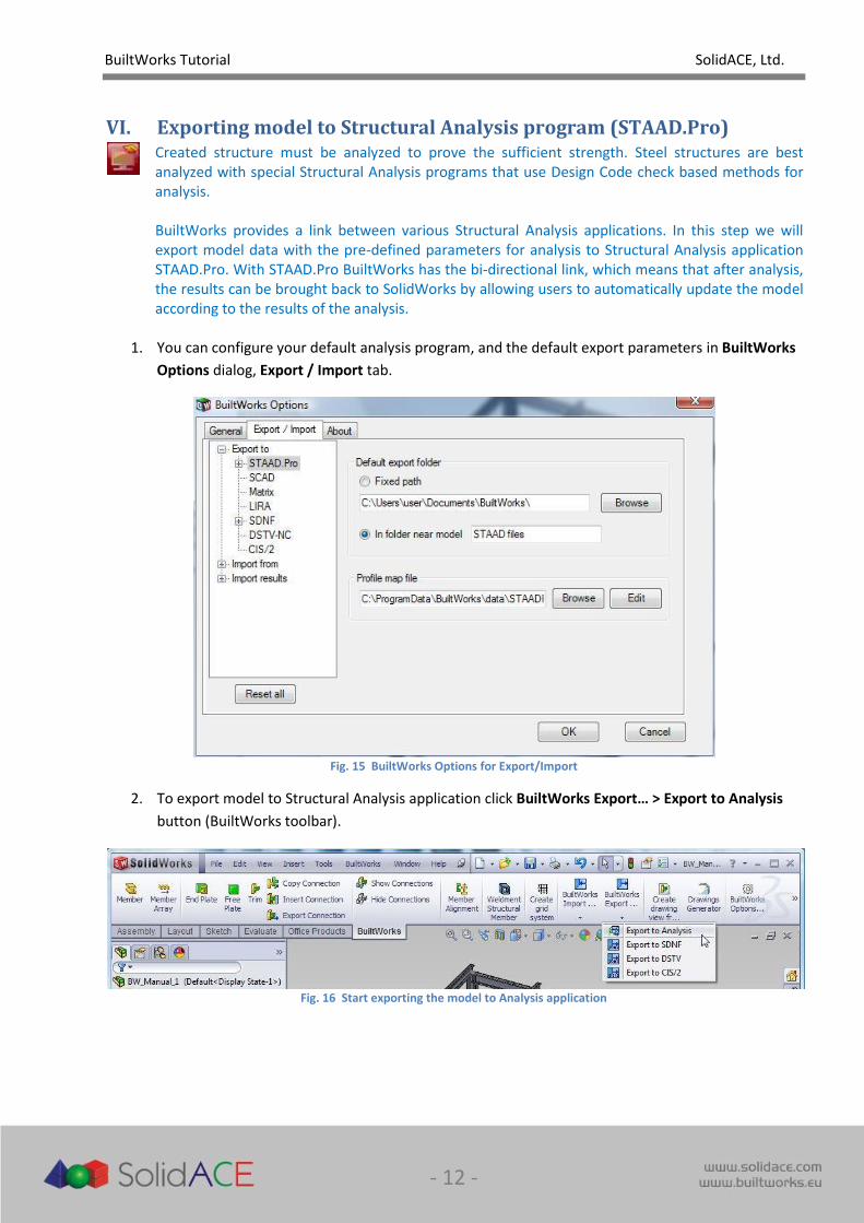
1. You can configure your default analysis program, and the default export parameters in BuiltWorks
Options dialog, Export / Import tab.
Fig. 15 BuiltWorks Options for Export/Import
2. To export model to Structural Analysis application click BuiltWorks Export… > Export to Analysis
button (BuiltWorks toolbar).
Fig. 16 Start exporting the model to Analysis application

BuiltWorks Tutorial SolidACE, Ltd.
- 13 -
3. Define the parameters for analysis in STAAD.Pro:
a. In the Export Data field select Object type BW objects, chose to Export all geometries and
also select Export offsets option.
b. In Geometry parameters field set units to METER. Leave option Create groups by section
unselected.
c. In Design parameters field select desired design code (EC3) and also select Create
unification groups, CHECK and SELECT parameters, enter a number of iterations for
analysis (1).
Fig. 17 Export to Analysis Panel
4. After clicking OK button the export file will be created. You will be prompted if you want to
open the export file for analysis.
5. If you have STAAD.Pro installed in your system, choose [Yes] to open the file, and the application
will be started automatically opening the exported model.
Note: If you don’t have STAAD.Pro installed on your computer, you may choose not to open the
analysis file. In this case please skip next Chapter of this manual and continue from Chapter
“VIII. Importing analysis results from STAAD.Pro”
BuiltWorks Tutorial SolidACE, Ltd.
- 14 -
VII. Analyzing the model in STAAD.Pro
This Chapter is dedicated to the methods of performing the Structural Analysis of the created model in STAAD.Pro NOTE: In order to complete this step you must have STAAD.Pro installed in your system and have some basic knowledge of this system and structural analysis methods. If you don’t have STAAD.Pro installed on your system, please skip this step and continue from the Chapter “VIII. Importing analysis results from STAAD.Pro”.
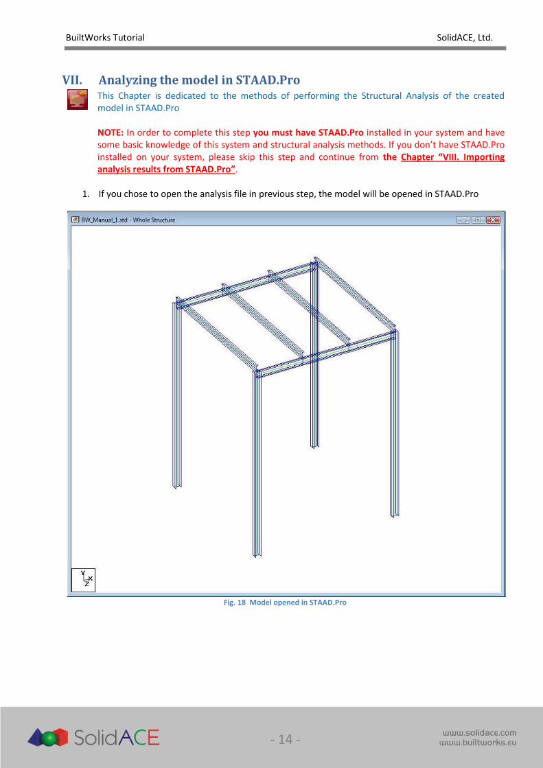
1. If you chose to open the analysis file in previous step, the model will be opened in STAAD.Pro
Fig. 18 Model opened in STAAD.Pro
BuiltWorks Tutorial SolidACE, Ltd.
- 15 -
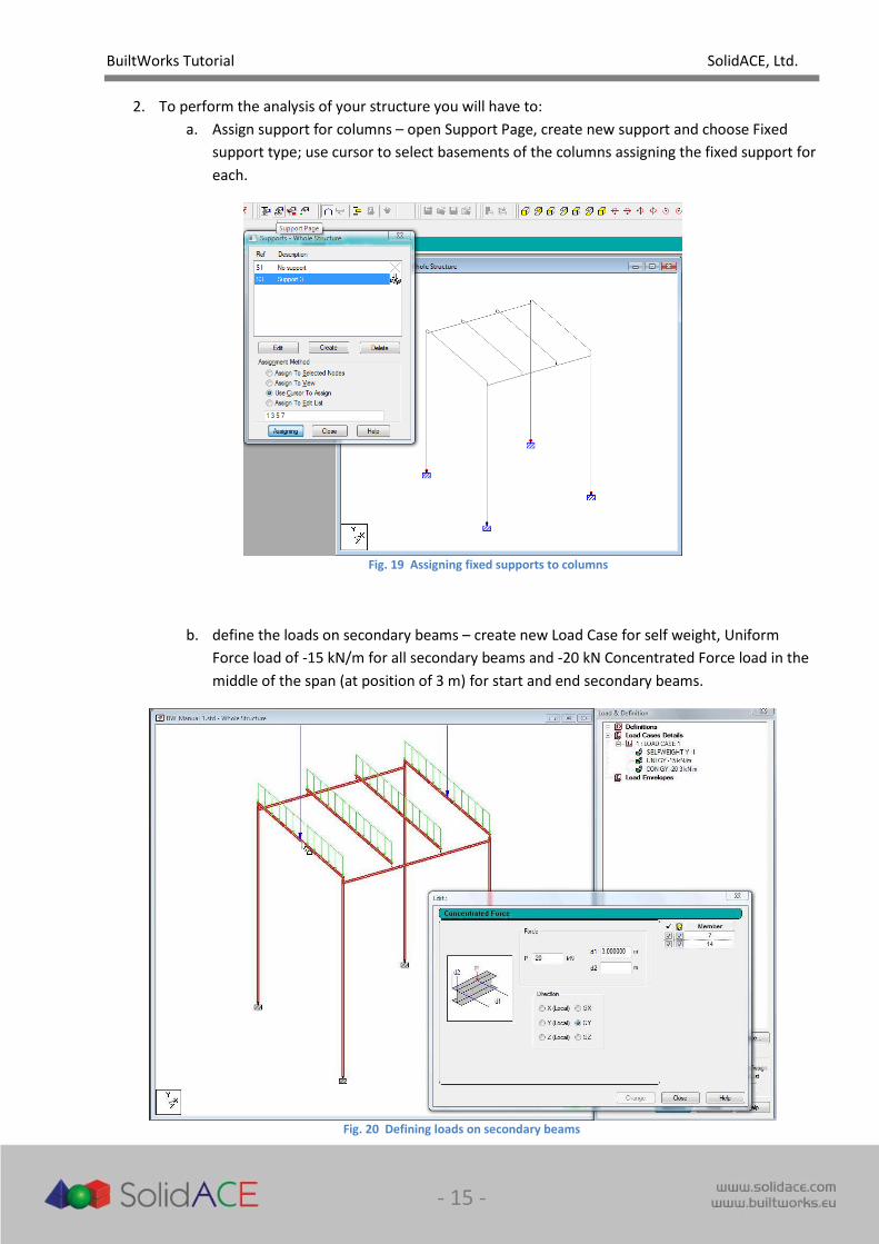
2. To perform the analysis of your structure you will have to:
a. Assign support for columns – open Support Page, create new support and choose Fixed
support type; use cursor to select basements of the columns assigning the fixed support for
each.
Fig. 19 Assigning fixed supports to columns
b. define the loads on secondary beams – create new Load Case for self weight, Uniform
Force load of -15 kN/m for all secondary beams and -20 kN Concentrated Force load in the
middle of the span (at position of 3 m) for start and end secondary beams.
Fig. 20 Defining loads on secondary beams
BuiltWorks Tutorial SolidACE, Ltd.
- 16 -
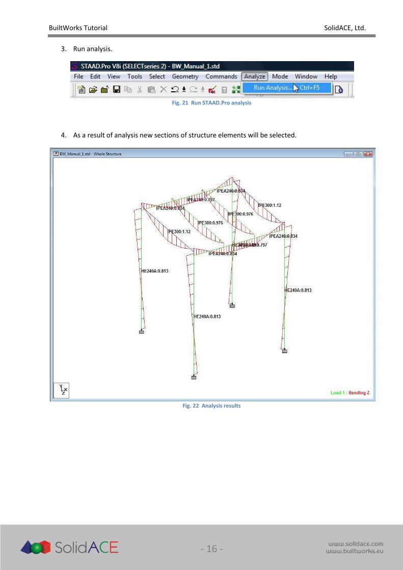
3. Run analysis.
Fig. 21 Run STAAD.Pro analysis
4. As a result of analysis new sections of structure elements will be selected.
Fig. 22 Analysis results
BuiltWorks Tutorial SolidACE, Ltd.
- 17 -
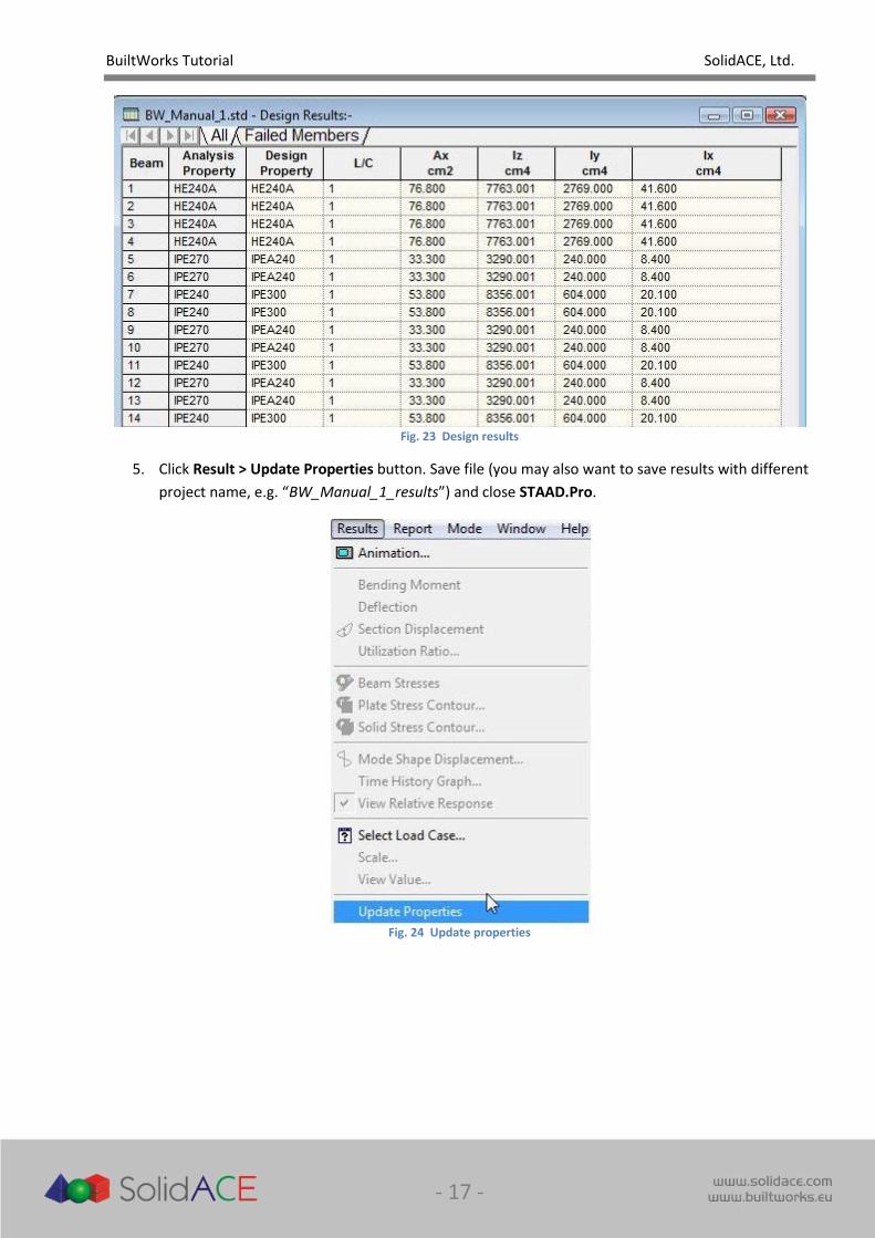
Fig. 23 Design results
5. Click Result > Update Properties button. Save file (you may also want to save results with different
project name, e.g. “BW_Manual_1_results”) and close STAAD.Pro.
Fig. 24 Update properties

BuiltWorks Tutorial SolidACE, Ltd.
- 18 -
VIII. Importing analysis results from STAAD.Pro
In this step the analysis results are being imported from STAAD.Pro back to SolidWorks automatically updating the model with the members’ information that has changed during the analysis process. NOTE 1: If you don’t have STAAD.Pro installed on your system and you skipped previous step, you may import as analysis results the resulting file (BW_Manual_1_results.std), provided with this tutorial. NOTE 2: STAAD.Pro should be closed before importing analysis result file.
1. For analysis results import click BuiltWorks Import… > Import Analysis Result button (BuiltWorks
toolbar).
Fig. 25 Start importing Analysis Results
2. Select analysis file and click OK .
Fig. 26 Select the resulting Analysis file for import
BuiltWorks Tutorial SolidACE, Ltd.
- 19 -
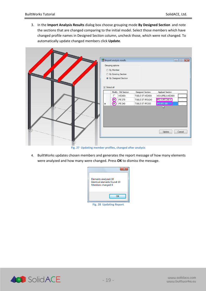
3. In the Import Analysis Results dialog box choose grouping mode By Designed Section and note
the sections that are changed comparing to the initial model. Select those members which have
changed profile names in Designed Section column, uncheck those, which were not changed. To
automatically update changed members click Update.
Fig. 27 Updating member profiles, changed after analysis
4. BuiltWorks updates chosen members and generates the report message of how many elements
were analyzed and how many were changed. Press OK to dismiss the message.
Fig. 28 Updating Report

BuiltWorks Tutorial SolidACE, Ltd.
- 20 -
IX. Aligning Members
In previous step the profiles of main beams and array of secondary beams has been changed because of the proposed changes from analysis results. Therefore the orientation of beams has been displaced. To fix the locations of beams you will need to use Member Alignment command.
1. To start alignment of members procedure click Member Alignment button (BuiltWorks toolbar).
Fig. 29 Start Member Alignment
2. In the Alignment dialog box choose Align type – By offset (members will be only moved).
3. When field Align to (blue) is highlighted, select in a graphic window the face of the top of column
(Align to field is updated and the highlight is changed to the field Object to align).
4. When field Objects to align (pink) is highlighted, in a graphic window select:
a. Top face of one of main beams;
b. Bottom face of one of secondary beams.
Fig. 30 Selecting faces of Members to be aligned to each other
5. Click OK in Alignment dialog. When function discovers that you are trying to align a Member
that belongs to a Group or Array it will ask if you want to apply this alignment function to all
Members of that feature. You may choose Yes, if you want that all Members of Group or Array be
aligned, or you may choose No, if you want to align only the selected member. In this case we will
choose to align all Members of the Array – click button Yes.
BuiltWorks Tutorial SolidACE, Ltd.
- 21 -
Fig. 31 Prompt to align all Members of Group or Array
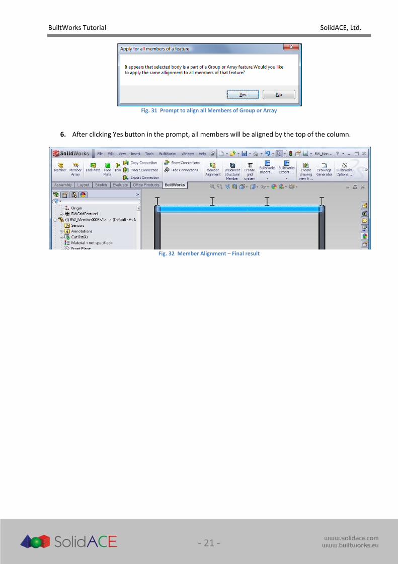
6. After clicking Yes button in the prompt, all members will be aligned by the top of the column.
Fig. 32 Member Alignment – Final result
BuiltWorks Tutorial SolidACE, Ltd.
- 22 -
X. Detailing Connections – Trim
In this chapter you will perform the detailing of Connections by trimming intersecting members.
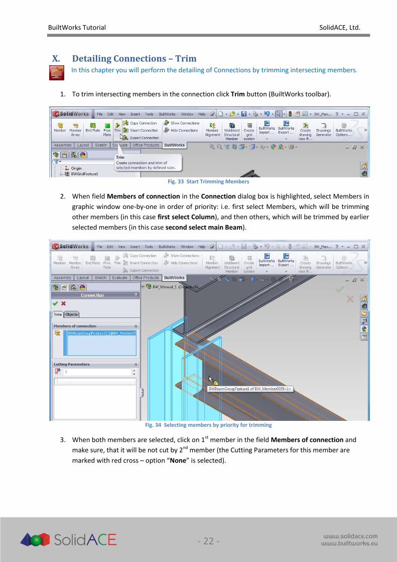
1. To trim intersecting members in the connection click Trim button (BuiltWorks toolbar).
Fig. 33 Start Trimming Members
2. When field Members of connection in the Connection dialog box is highlighted, select Members in
graphic window one-by-one in order of priority: i.e. first select Members, which will be trimming
other members (in this case first select Column), and then others, which will be trimmed by earlier
selected members (in this case second select main Beam).
Fig. 34 Selecting members by priority for trimming
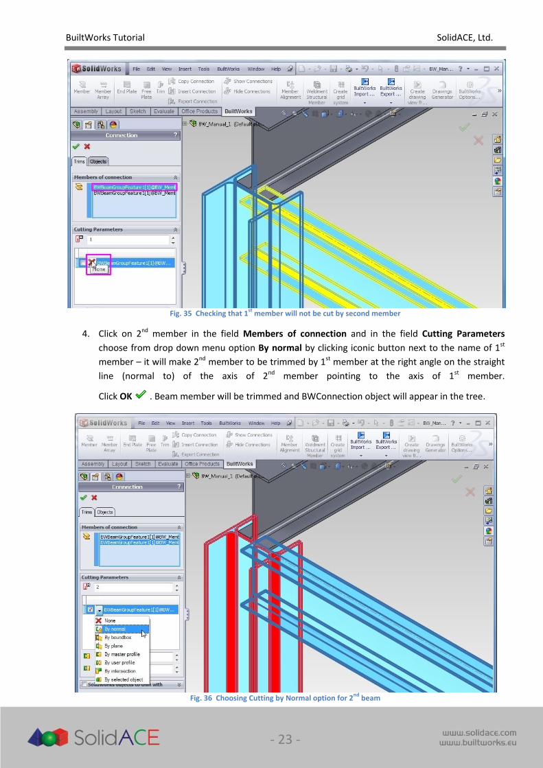
3. When both members are selected, click on 1st member in the field Members of connection and
make sure, that it will be not cut by 2nd member (the Cutting Parameters for this member are
marked with red cross – option “None” is selected).
BuiltWorks Tutorial SolidACE, Ltd.
- 23 -
Fig. 35 Checking that 1
st member will not be cut by second member
4. Click on 2nd member in the field Members of connection and in the field Cutting Parameters
choose from drop down menu option By normal by clicking iconic button next to the name of 1st
member – it will make 2nd member to be trimmed by 1st member at the right angle on the straight
line (normal to) of the axis of 2nd member pointing to the axis of 1st member.
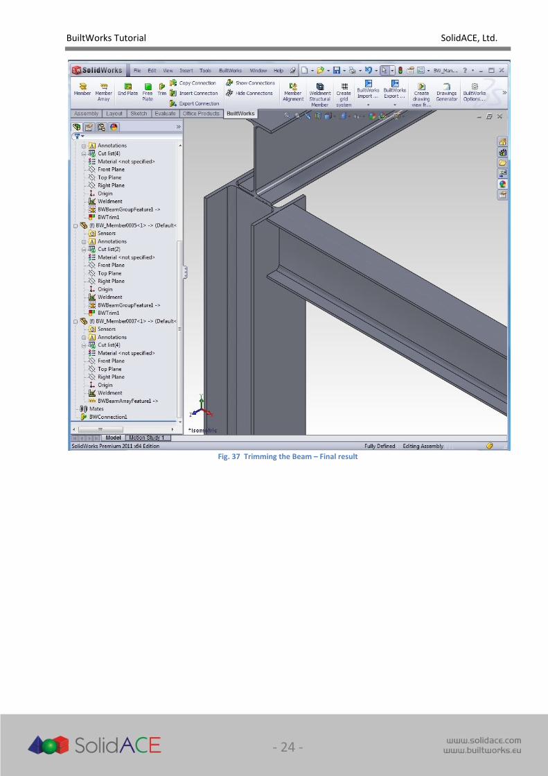
Click OK . Beam member will be trimmed and BWConnection object will appear in the tree.
Fig. 36 Choosing Cutting by Normal option for 2
nd beam
BuiltWorks Tutorial SolidACE, Ltd.
- 24 -
Fig. 37 Trimming the Beam – Final result
BuiltWorks Tutorial SolidACE, Ltd.
- 25 -
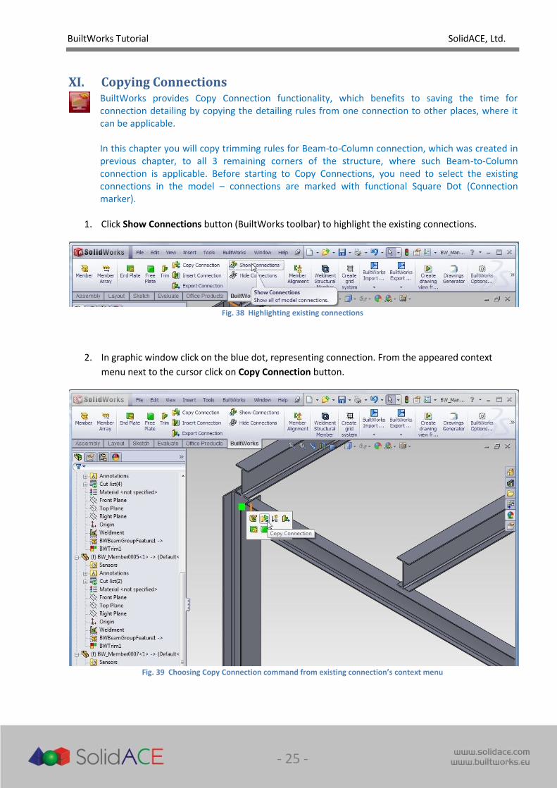
XI. Copying Connections
BuiltWorks provides Copy Connection functionality, which benefits to saving the time for connection detailing by copying the detailing rules from one connection to other places, where it can be applicable. In this chapter you will copy trimming rules for Beam-to-Column connection, which was created in previous chapter, to all 3 remaining corners of the structure, where such Beam-to-Column connection is applicable. Before starting to Copy Connections, you need to select the existing connections in the model – connections are marked with functional Square Dot (Connection marker).
1. Click Show Connections button (BuiltWorks toolbar) to highlight the existing connections.
Fig. 38 Highlighting existing connections
2. In graphic window click on the blue dot, representing connection. From the appeared context
menu next to the cursor click on Copy Connection button.
Fig. 39 Choosing Copy Connection command from existing connection’s context menu
BuiltWorks Tutorial SolidACE, Ltd.
- 26 -
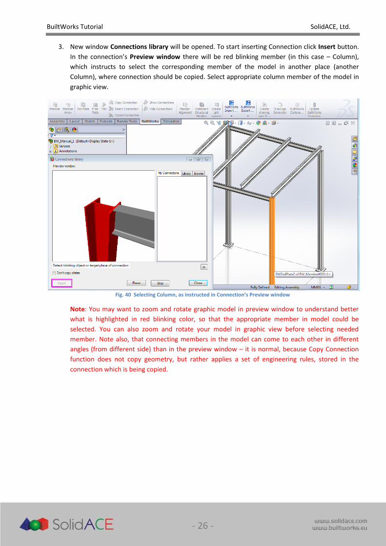
3. New window Connections library will be opened. To start inserting Connection click Insert button.
In the connection’s Preview window there will be red blinking member (in this case – Column),
which instructs to select the corresponding member of the model in another place (another
Column), where connection should be copied. Select appropriate column member of the model in
graphic view.
Fig. 40 Selecting Column, as instructed in Connection’s Preview window
Note: You may want to zoom and rotate graphic model in preview window to understand better
what is highlighted in red blinking color, so that the appropriate member in model could be
selected. You can also zoom and rotate your model in graphic view before selecting needed
member. Note also, that connecting members in the model can come to each other in different
angles (from different side) than in the preview window – it is normal, because Copy Connection
function does not copy geometry, but rather applies a set of engineering rules, stored in the
connection which is being copied.
BuiltWorks Tutorial SolidACE, Ltd.
- 27 -
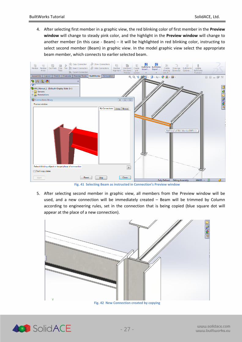
4. After selecting first member in a graphic view, the red blinking color of first member in the Preview
window will change to steady pink color, and the highlight in the Preview window will change to
another member (in this case - Beam) – it will be highlighted in red blinking color, instructing to
select second member (Beam) in graphic view. In the model graphic view select the appropriate
beam member, which connects to earlier selected beam.
Fig. 41 Selecting Beam as instructed in Connection’s Preview window
5. After selecting second member in graphic view, all members from the Preview window will be
used, and a new connection will be immediately created – Beam will be trimmed by Column
according to engineering rules, set in the connection that is being copied (blue square dot will
appear at the place of a new connection).
Fig. 42 New Connection created by copying
BuiltWorks Tutorial SolidACE, Ltd.
- 28 -
6. Repeat this action for remaining two corners of the model, where Beam-to-Column connection is
applicable and close preview window. Note BWConnection objects that will appear in the Feature
Tree view after each new connection will be created.
Note: if some parts of the model in the Feature Tree will be marked with the Traffic Lights icon ,
use Update BuiltWorks Features button in BuiltWorks menu to update your model. Function
“Update BuiltWorks Features” works faster than SolidWorks “Rebuild” function for assemblies, in
which parts are automatically created from assembly mode using BuiltWorks modeling tools.
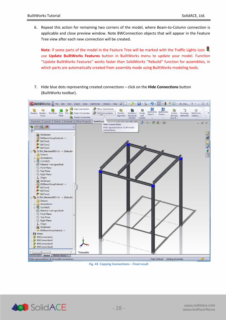
7. Hide blue dots representing created connections – click on the Hide Connections button
(BuiltWorks toolbar).
Fig. 43 Copying Connections – Final result
BuiltWorks Tutorial SolidACE, Ltd.
- 29 -
XII. Creating an End Plate
In this chapter you will perform another Connection detailing function – create the End Plate for the member (Column base plate). Note, that creating the End Plate also creates the connection – the rule of creating End Plate with all parameters which can be copied to another place equally as copying the connection with trimming rules. Connection can have a combined set of rules (some members trimmed, some have end plates added) and all these rules will be applied in another place where connection is copied.
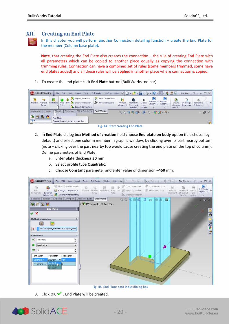
1. To create the end plate click End Plate button (BuiltWorks toolbar).
Fig. 44 Start creating End Plate
2. In End Plate dialog box Method of creation field choose End plate on body option (it is chosen by
default) and select one column member in graphic window, by clicking over its part nearby bottom
(note – clicking over the part nearby top would cause creating the end plate on the top of column).
Define parameters of End Plate:
a. Enter plate thickness 30 mm
b. Select profile type Quadratic,
c. Choose Constant parameter and enter value of dimension –450 mm.
Fig. 45 End Plate data input dialog box
3. Click OK . End Plate will be created.

BuiltWorks Tutorial SolidACE, Ltd.
- 30 -
4. In the same way create all another end plates.
Fig. 46 Model with End Plates – Final result
NOTE! Please save all your work before proceeding to the next chapter “Generating Drawings and BOM”.
BuiltWorks Tutorial SolidACE, Ltd.
- 31 -
XIII. Generating Drawings and BOM
In this final chapter of the tutorial you will learn how to automate the preparation of Drawings of the designed structure and insert the Bill of Materials (BOM). Drawings and BOMs are used later in manufacturing and erection of the structure. BOM for BuiltWorks model is created basing on cut-list properties of both – SolidWorks documents as well as BuiltWorks custom properties.
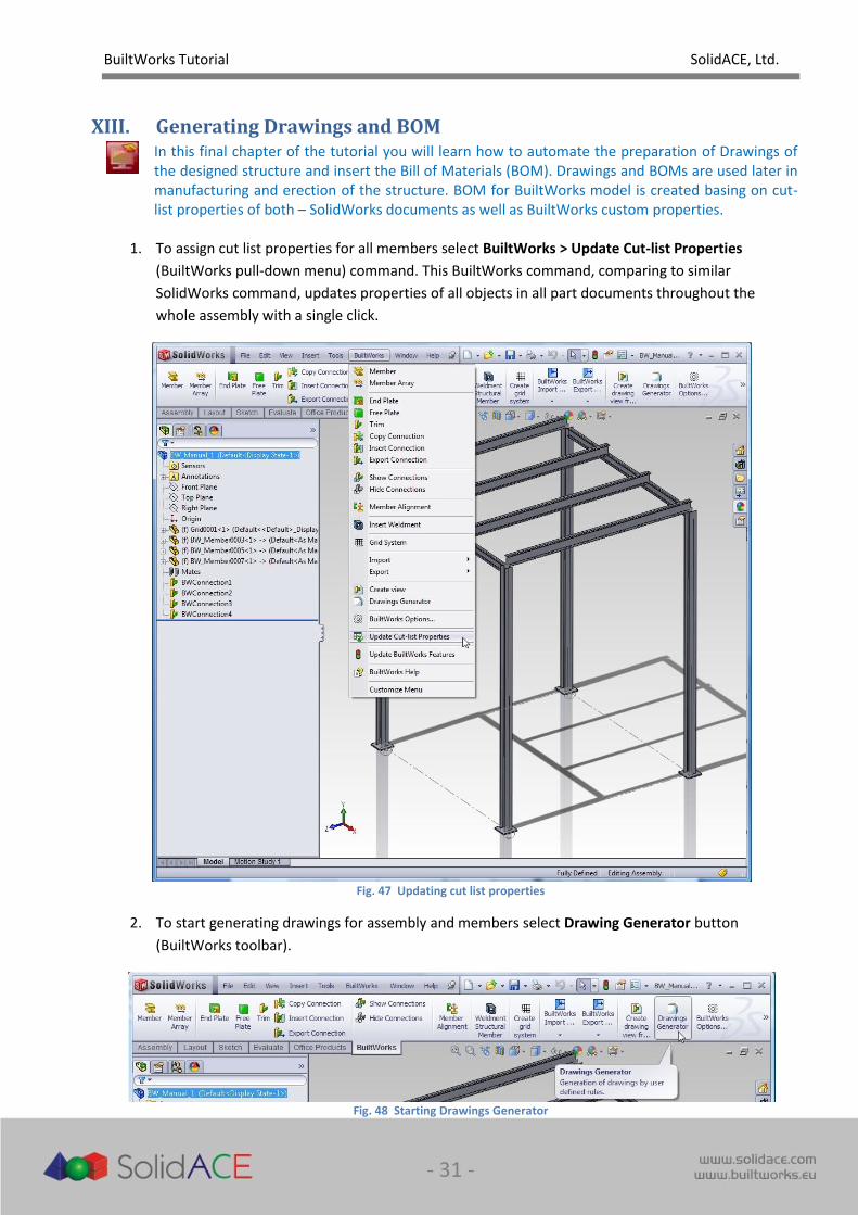
1. To assign cut list properties for all members select BuiltWorks > Update Cut-list Properties
(BuiltWorks pull-down menu) command. This BuiltWorks command, comparing to similar
SolidWorks command, updates properties of all objects in all part documents throughout the
whole assembly with a single click.
Fig. 47 Updating cut list properties
2. To start generating drawings for assembly and members select Drawing Generator button
(BuiltWorks toolbar).
Fig. 48 Starting Drawings Generator
BuiltWorks Tutorial SolidACE, Ltd.
- 32 -
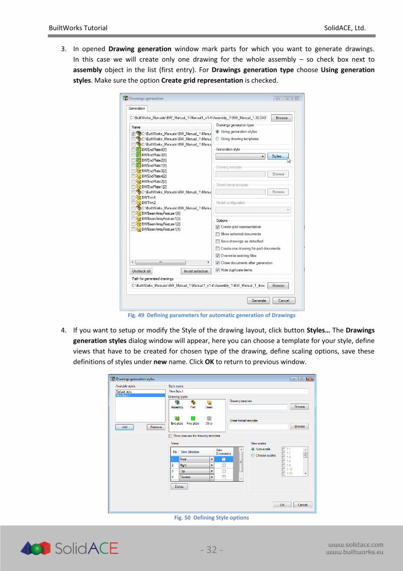
3. In opened Drawing generation window mark parts for which you want to generate drawings.
In this case we will create only one drawing for the whole assembly – so check box next to
assembly object in the list (first entry). For Drawings generation type choose Using generation
styles. Make sure the option Create grid representation is checked.
Fig. 49 Defining parameters for automatic generation of Drawings
4. If you want to setup or modify the Style of the drawing layout, click button Styles… The Drawings
generation styles dialog window will appear, here you can choose a template for your style, define
views that have to be created for chosen type of the drawing, define scaling options, save these
definitions of styles under new name. Click OK to return to previous window.
Fig. 50 Defining Style options
BuiltWorks Tutorial SolidACE, Ltd.
- 33 -
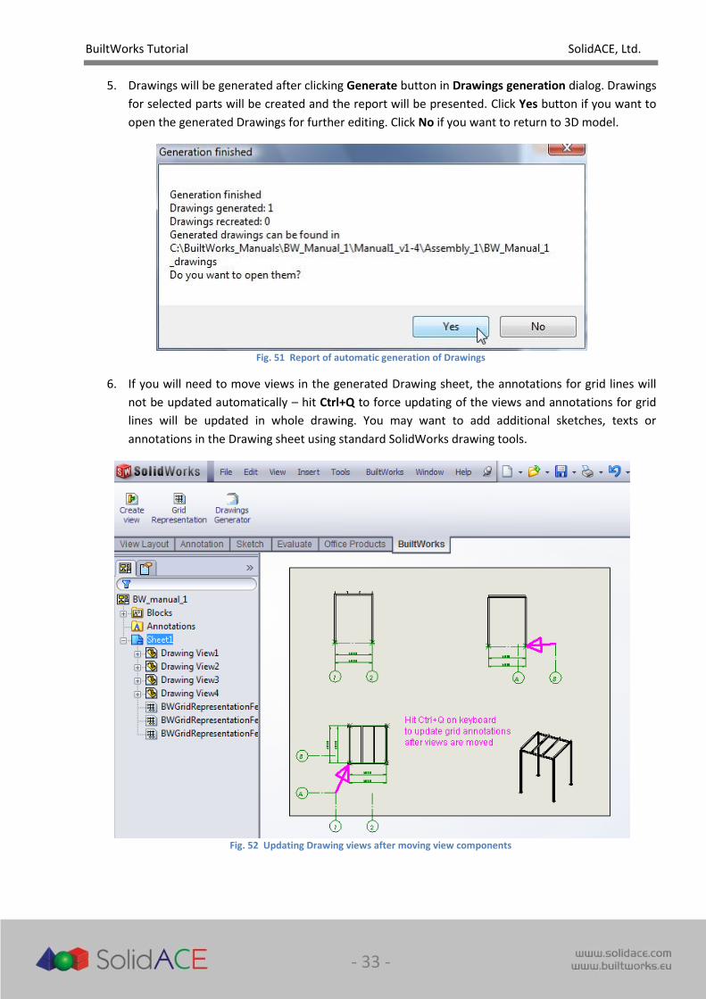
5. Drawings will be generated after clicking Generate button in Drawings generation dialog. Drawings
for selected parts will be created and the report will be presented. Click Yes button if you want to
open the generated Drawings for further editing. Click No if you want to return to 3D model.
Fig. 51 Report of automatic generation of Drawings
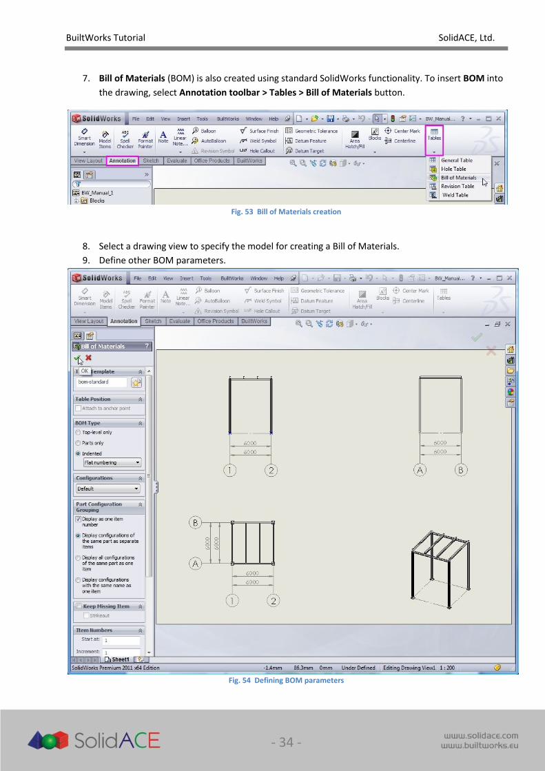
6. If you will need to move views in the generated Drawing sheet, the annotations for grid lines will
not be updated automatically – hit Ctrl+Q to force updating of the views and annotations for grid
lines will be updated in whole drawing. You may want to add additional sketches, texts or
annotations in the Drawing sheet using standard SolidWorks drawing tools.
Fig. 52 Updating Drawing views after moving view components
BuiltWorks Tutorial SolidACE, Ltd.
- 34 -
7. Bill of Materials (BOM) is also created using standard SolidWorks functionality. To insert BOM into
the drawing, select Annotation toolbar > Tables > Bill of Materials button.
Fig. 53 Bill of Materials creation
8. Select a drawing view to specify the model for creating a Bill of Materials.
9. Define other BOM parameters.
Fig. 54 Defining BOM parameters
BuiltWorks Tutorial SolidACE, Ltd.
- 35 -
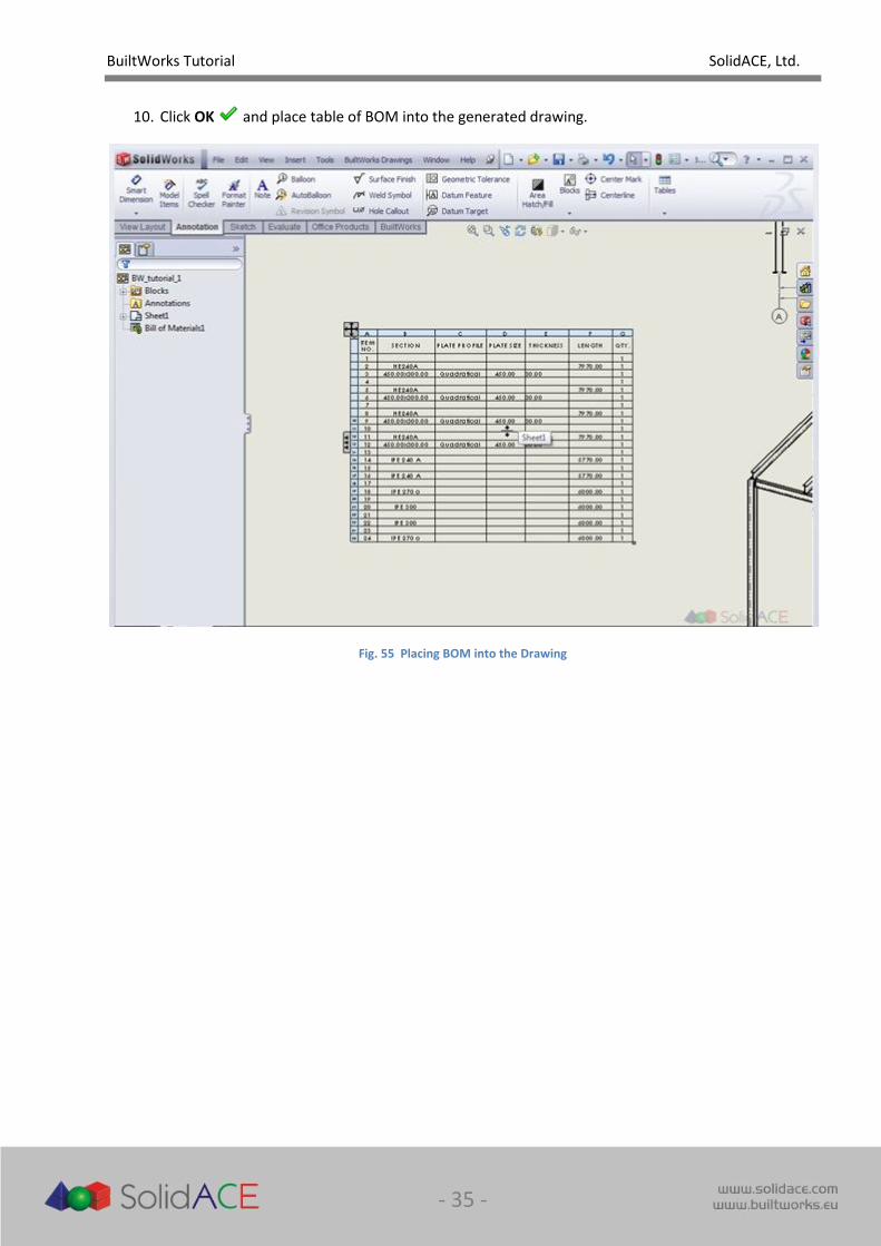
10. Click OK and place table of BOM into the generated drawing.
Fig. 55 Placing BOM into the Drawing

BuiltWorks Tutorial SolidACE, Ltd.
- 36 -
Congratulations! You have completed this tutorial.

BuiltWorks Tutorial SolidACE, Ltd.
- 37 -
User Notes
We appreciate your feedback and comments about BuiltWorks functionality and this document.
Please send your suggestions of requests to us by email [email protected]