tsgw3#5(99)585 - 3gpp
TRANSCRIPT
1/40
TSG-RAN Working Group 3 meeting #5 TSGW3#5(99)585Helsinki, Finland 5 - 9 July 1999
Agenda Item: 6.1
Source: Editor (Nortel Networks)
Title: TS 25.401 UTRAN Overall Description V1.1.1
Document for: Approval
___________________________________________________________________________Editor's Note : Revision marks show the changes based on decisions at the last meeting.These changes have not yet been approved in RAN WG3.

3GPP
TS 25.401 V1.0.31.1 (1999-0506)Technical Specification
3rd Generation Partnership Project (3GPP);Technical Specification Group (TSG) RAN;
UTRAN Overall Description[UMTS <spec>]
<
3GPP
TS 25.401 V1.0.31.1 (1999-0506)4[UMTS <spec>]
Reference<Workitem> (<Shortfilename>.PDF)
Keywords<keyword[, keyword]>
3GPP
Postal address
Office address
Individual copies of this deliverablecan be downloaded fromhttp://www.3gpp.org
Copyright Notification
No part may be reproduced except as authorized by written permission.The copyright and the foregoing restriction extend to reproduction in all media.
©All rights reserved.
3GPP
TS 25.401 V1.0.31.1 (1999-0506)5[UMTS <spec>]
Contents
Intellectual Property Rights ............................................................................................................................... 7
Foreword ............................................................................................................................................................ 7
1 Scope ....................................................................................................................................................... 7
2 References................................................................................................................................................ 7
3 Definitions, symbols and abbreviations................................................................................................... 73.1 Definitions ......................................................................................................................................................... 73.2 Abbreviations..................................................................................................................................................... 93.3 Notation ............................................................................................................................................................. 9
4 General principles.................................................................................................................................... 9
5 UMTS General architecture................................................................................................................... 105.1 Overview.......................................................................................................................................................... 105.2 General protocols architecture ......................................................................................................................... 105.2.1 User plane................................................................................................................................................... 105.2.2 Control plane .............................................................................................................................................. 11
6 UTRAN Architecture............................................................................................................................. 116.1 UTRAN Identifiers .......................................................................................................................................... 126.1.1 UE Identifiers ............................................................................................................................................. 126.1.1.1 Usage of RNTI...................................................................................................................................... 136.1.2 Identifiers for dedicated resources within UTRAN.................................................................................... 136.1.2.1 Radio Network Control Plane identifiers.............................................................................................. 136.1.2.2 Transport Network Control Plane identifiers........................................................................................ 136.1.2.3 Binding identifier.................................................................................................................................. 136.2 Transport Addresses......................................................................................................................................... 14
7 UTRAN Functions description .............................................................................................................. 147.1 List of functions ............................................................................................................................................... 147.2 Functions description ....................................................................................................................................... 157.2.1 Functions related to overall system access control..................................................................................... 157.2.1.1 Admission Control................................................................................................................................ 167.2.1.2 Congestion Control............................................................................................................................... 167.2.1.3 System information broadcasting ......................................................................................................... 167.2.2 Functions related to security and privacy ................................................................................................... 167.2.2.1 Use of Temporary Identifier ................................................................................................................. 167.2.2.2 Radio channel ciphering ....................................................................................................................... 167.2.2.3 Radio channel deciphering.................................................................................................................... 177.2.3 Functions related to handover .................................................................................................................... 177.2.3.1 Radio environment survey .................................................................................................................... 177.2.3.2 Handover decision ................................................................................................................................ 177.2.3.3 Macro-diversity control ........................................................................................................................ 177.2.3.4 Handover Control ................................................................................................................................. 187.2.3.5 Handover execution .............................................................................................................................. 187.2.3.6 Handover completion............................................................................................................................ 187.2.3.7 SRNS Relocation .................................................................................................................................. 187.2.3.7.1 Access Network Triggered SRNS Relocation................................................................................. 187.2.3.7.2 Core Network Triggered SRNS Relocation .................................................................................... 197.2.3.8 Inter-System handover.......................................................................................................................... 197.2.3.8.1 Handover from UMTS to GSM ...................................................................................................... 197.2.3.8.2 Handover from GSM to UMTS ...................................................................................................... 197.2.4 Functions related to radio resource management and control .................................................................... 197.2.4.1 Radio bearer connection set-up and release (Radio Bearer Control) .................................................... 207.2.4.2 Reservation and release of physical radio channels.............................................................................. 207.2.4.3 Allocation and deallocation of physical radio channels........................................................................ 207.2.4.4 Allocation of Downlink Channelisation Codes .................................................................................... 20
3GPP
TS 25.401 V1.0.31.1 (1999-0506)6[UMTS <spec>]
7.2.4.5 Packet data transfer over radio function ............................................................................................... 207.2.4.6 RF power control .................................................................................................................................. 217.2.4.6.1 UL OUTER LOOP POWER CONTROL....................................................................................... 217.2.4.6.2 DL OUTER LOOP POWER CONTROL....................................................................................... 217.2.4.6.3 UL INNER LOOP POWER CONTROL ........................................................................................ 217.2.4.6.4 DL INNER LOOP POWER CONTROL ........................................................................................ 217.2.4.6.5 UL OPEN LOOP POWER CONTROL.......................................................................................... 217.2.4.6.6 DL OPEN LOOP POWER CONTROL.......................................................................................... 217.2.4.7 Radio channel coding ........................................................................................................................... 227.2.4.8 Radio channel decoding........................................................................................................................ 227.2.4.9 Channel coding control......................................................................................................................... 227.2.4.10 Initial (random) access detection and handling..................................................................................... 227.2.4.11 CN Distribution function for Non Access Stratum messages ............................................................... 22
8 Mobility Management ........................................................................................................................... 228.1 Dedicated Connection ...................................................................................................................................... 228.2 Consequences for Mobility Handling .............................................................................................................. 23
9 Synchronisation ..................................................................................................................................... 239.1 SYNCHRONISATION MODEL..................................................................................................................... 239.1.1 Time Alignment handling........................................................................................................................... 249.1.2 [FDD — Frame synchronisation ................................................................................................................ 249.1.3 Radio Interface Synchronisation ................................................................................................................ 249.1.4 Ciphering handling ..................................................................................................................................... 249.1.5 Time-of-day handling................................................................................................................................. 249.2 Network Synchronisation................................................................................................................................. 259.3 Radio interface synchronisation....................................................................................................................... 259.4 [FDD — Frame Synchronisation].................................................................................................................... 279.4.1 General principles for frame synchronisation............................................................................................. 279.4.2 UE Frame Number definition..................................................................................................................... 289.4.3 CFN-CELL FN Offset................................................................................................................................ 289.4.4 Use of frame numbers in uplink and downlink transmission ..................................................................... 299.4.5 Timing adjustment in Iub/Iur interfaces ..................................................................................................... 309.4.6 Initial synchronisation of the first dedicated branch................................................................................... 309.4.7 Initial synchronisation of a additional soft handover branches .................................................................. 309.4.8 Maintaining offset ...................................................................................................................................... 309.4.9 Synchronisation of L1 configuration changes ............................................................................................ 319.5 Node Synchronisation ...................................................................................................................................... 31
10 UTRAN O&M Requirements................................................................................................................ 31O&M of Node B ............................................................................................................................................................... 3110.1.1 Implementation Specific O&M .................................................................................................................. 3210.1.2 Logical O&M ............................................................................................................................................. 32
11 UTRAN Interfaces................................................................................................................................. 3211.1 General Protocol Model for UTRAN Interfaces .............................................................................................. 3311.1.1 General ....................................................................................................................................................... 3311.1.2 Horizontal Layers ....................................................................................................................................... 3311.1.3 Vertical Planes............................................................................................................................................ 3311.1.3.1 Control Plane ........................................................................................................................................ 3311.1.3.2 User Plane............................................................................................................................................. 3311.1.3.3 Transport Network Control Plane......................................................................................................... 3311.1.3.4 Transport Network User Plane ............................................................................................................. 3411.2 Protocol Model (Informative) .......................................................................................................................... 3411.2.1 RACH Transport Channel .......................................................................................................................... 3411.2.2 FACH Transport Channel........................................................................................................................... 3511.2.3 DCH Transport Channel............................................................................................................................. 36
12 UTRAN Performance Requirements ..................................................................................................... 3712.1 UTRAN delay requirements ............................................................................................................................ 37Annex A Document Stability Assessment Table............................................................................................................. 38
History.............................................................................................................................................................. 38
3GPP
TS 25.401 V1.0.31.1 (1999-0506)7[UMTS <spec>]
Intellectual Property Rights
ForewordThis Technical Specification has been produced by the 3rd Generation Partnership Project, Technical SpecificationGroup <TSG name>.The contents of this TS may be subject to continuing work within the 3GPP and may change following formal TSGapproval. Should the TSG modify the contents of this TS, it will be re-released with an identifying change of releasedate and an increase in version number as follows:
Version m.t.e
where:
m indicates [major version number]
x the second digit is incremented for all changes of substance, i.e. technical enhancements, corrections,updates, etc.
y the third digit is incremented when editorial only changes have been incorporated into the specification.
1 ScopeThis document describes the overall architecture of the UTRAN, including internal interfaces and assumptions on theradio and Iu interfaces.
2 ReferencesThis text block applies to ALL deliverables. The sub-division below applies optionally to TSs.The following documents contain provisions which, through reference in this text, constitute provisions of the presentdocument.
• References are either specific (identified by date of publication, edition number, version number, etc.) ornon-specific.
• For a specific reference, subsequent revisions do not apply.
• For a non-specific reference, the latest version applies.
• A non-specific reference to an ETS shall also be taken to refer to later versions published as an EN with the samenumber.
[1] Merged UTRAN Architecture Description V0.0.2
[2] UMTS 23.10 : UMTS Access Stratum Services and Functions
[3] UMTS 25.211: Physical channels and mapping of transport channels onto physical channels(FDD)
Editor's Note : [1] is a temporary reference only to ease the definition of what should be in the different sections of thisdocument.
3 Definitions, symbols and abbreviations
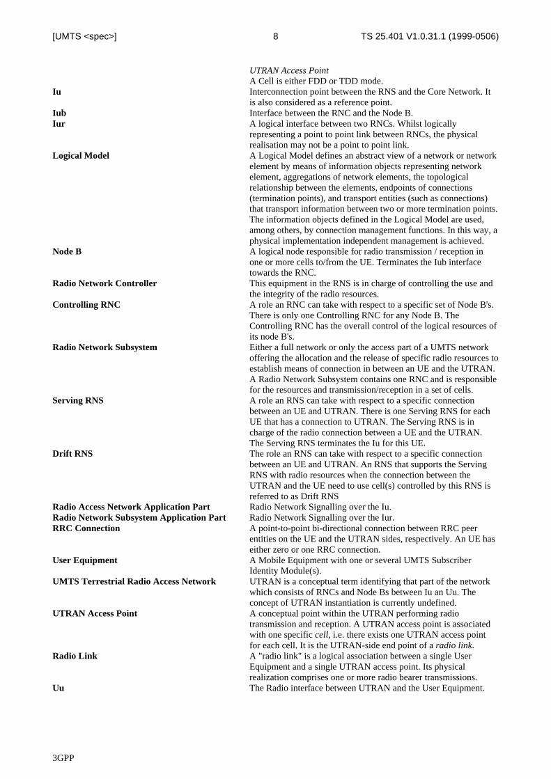
3.1 DefinitionsEditor's Note : Cleaned version of section 5.1 from [1] with a reference to a more general vocabulary document
ALCAP Generic name for the transport signalling protocols used to set-upand tear-down transport bearers.
Cell A cell is a geographical area that can be identified by a UserEquipment from a (cell) identification that is broadcast from one
3GPP
TS 25.401 V1.0.31.1 (1999-0506)8[UMTS <spec>]
UTRAN Access PointA Cell is either FDD or TDD mode.
Iu Interconnection point between the RNS and the Core Network. Itis also considered as a reference point.
Iub Interface between the RNC and the Node B.Iur A logical interface between two RNCs. Whilst logically
representing a point to point link between RNCs, the physicalrealisation may not be a point to point link.
Logical Model A Logical Model defines an abstract view of a network or networkelement by means of information objects representing networkelement, aggregations of network elements, the topologicalrelationship between the elements, endpoints of connections(termination points), and transport entities (such as connections)that transport information between two or more termination points.The information objects defined in the Logical Model are used,among others, by connection management functions. In this way, aphysical implementation independent management is achieved.
Node B A logical node responsible for radio transmission / reception inone or more cells to/from the UE. Terminates the Iub interfacetowards the RNC.
Radio Network Controller This equipment in the RNS is in charge of controlling the use andthe integrity of the radio resources.
Controlling RNC A role an RNC can take with respect to a specific set of Node B's.There is only one Controlling RNC for any Node B. TheControlling RNC has the overall control of the logical resources ofits node B's.
Radio Network Subsystem Either a full network or only the access part of a UMTS networkoffering the allocation and the release of specific radio resources toestablish means of connection in between an UE and the UTRAN.A Radio Network Subsystem contains one RNC and is responsiblefor the resources and transmission/reception in a set of cells.
Serving RNS A role an RNS can take with respect to a specific connectionbetween an UE and UTRAN. There is one Serving RNS for eachUE that has a connection to UTRAN. The Serving RNS is incharge of the radio connection between a UE and the UTRAN.The Serving RNS terminates the Iu for this UE.
Drift RNS The role an RNS can take with respect to a specific connectionbetween an UE and UTRAN. An RNS that supports the ServingRNS with radio resources when the connection between theUTRAN and the UE need to use cell(s) controlled by this RNS isreferred to as Drift RNS
Radio Access Network Application Part Radio Network Signalling over the Iu.Radio Network Subsystem Application Part Radio Network Signalling over the Iur.RRC Connection A point-to-point bi-directional connection between RRC peer
entities on the UE and the UTRAN sides, respectively. An UE haseither zero or one RRC connection.
User Equipment A Mobile Equipment with one or several UMTS SubscriberIdentity Module(s).
UMTS Terrestrial Radio Access Network UTRAN is a conceptual term identifying that part of the networkwhich consists of RNCs and Node Bs between Iu an Uu. Theconcept of UTRAN instantiation is currently undefined.
UTRAN Access Point A conceptual point within the UTRAN performing radiotransmission and reception. A UTRAN access point is associatedwith one specific cell, i.e. there exists one UTRAN access pointfor each cell. It is the UTRAN-side end point of a radio link.
Radio Link A "radio link" is a logical association between a single UserEquipment and a single UTRAN access point. Its physicalrealization comprises one or more radio bearer transmissions.
Uu The Radio interface between UTRAN and the User Equipment.
3GPP
TS 25.401 V1.0.31.1 (1999-0506)9[UMTS <spec>]
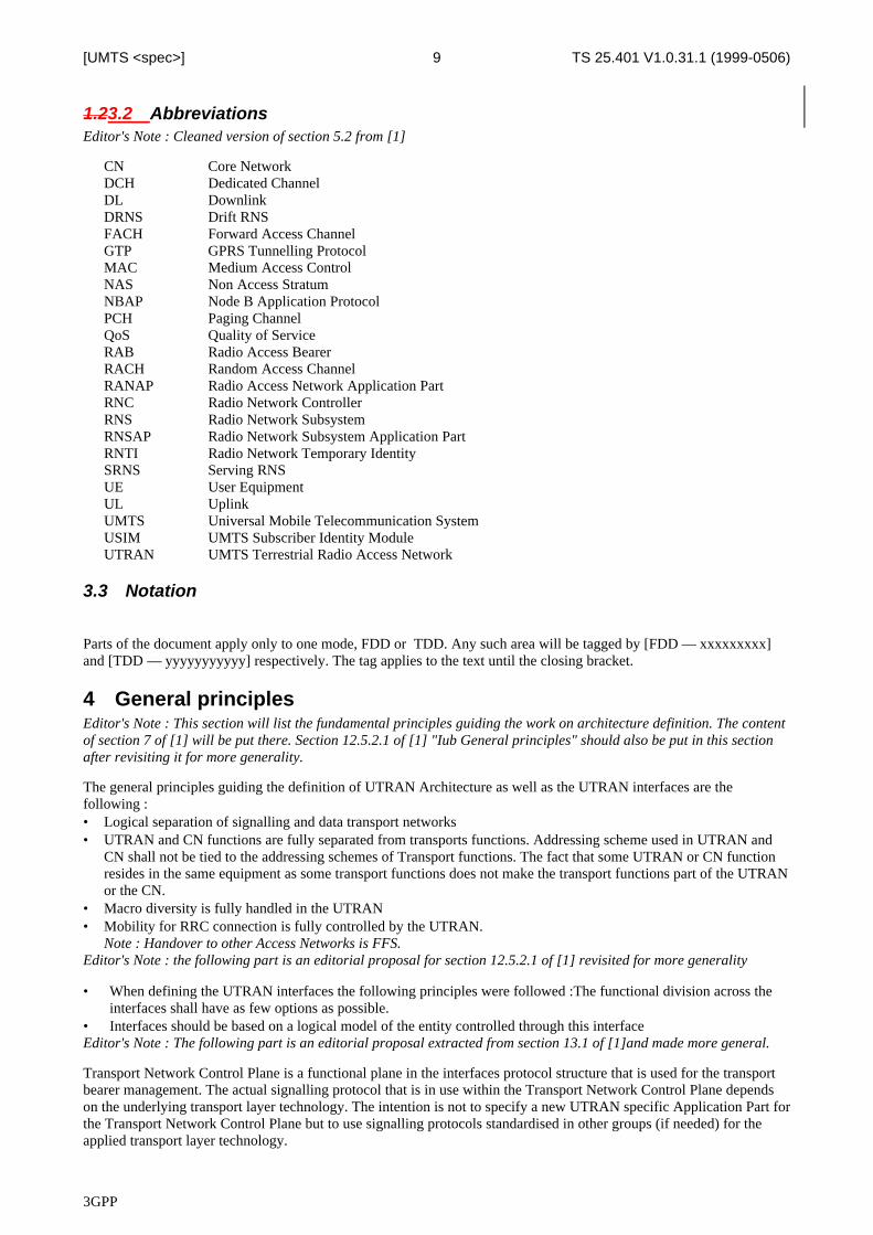
1.23.2 AbbreviationsEditor's Note : Cleaned version of section 5.2 from [1]
CN Core NetworkDCH Dedicated ChannelDL DownlinkDRNS Drift RNSFACH Forward Access ChannelGTP GPRS Tunnelling ProtocolMAC Medium Access ControlNAS Non Access StratumNBAP Node B Application ProtocolPCH Paging ChannelQoS Quality of ServiceRAB Radio Access BearerRACH Random Access ChannelRANAP Radio Access Network Application PartRNC Radio Network ControllerRNS Radio Network SubsystemRNSAP Radio Network Subsystem Application PartRNTI Radio Network Temporary IdentitySRNS Serving RNSUE User EquipmentUL UplinkUMTS Universal Mobile Telecommunication SystemUSIM UMTS Subscriber Identity ModuleUTRAN UMTS Terrestrial Radio Access Network
3.3 Notation
Parts of the document apply only to one mode, FDD or TDD. Any such area will be tagged by [FDD — xxxxxxxxx]and [TDD — yyyyyyyyyyy] respectively. The tag applies to the text until the closing bracket.
4 General principlesEditor's Note : This section will list the fundamental principles guiding the work on architecture definition. The contentof section 7 of [1] will be put there. Section 12.5.2.1 of [1] "Iub General principles" should also be put in this sectionafter revisiting it for more generality.
The general principles guiding the definition of UTRAN Architecture as well as the UTRAN interfaces are thefollowing :• Logical separation of signalling and data transport networks• UTRAN and CN functions are fully separated from transports functions. Addressing scheme used in UTRAN and
CN shall not be tied to the addressing schemes of Transport functions. The fact that some UTRAN or CN functionresides in the same equipment as some transport functions does not make the transport functions part of the UTRANor the CN.
• Macro diversity is fully handled in the UTRAN• Mobility for RRC connection is fully controlled by the UTRAN.
Note : Handover to other Access Networks is FFS.Editor's Note : the following part is an editorial proposal for section 12.5.2.1 of [1] revisited for more generality
• When defining the UTRAN interfaces the following principles were followed :The functional division across theinterfaces shall have as few options as possible.
• Interfaces should be based on a logical model of the entity controlled through this interfaceEditor's Note : The following part is an editorial proposal extracted from section 13.1 of [1]and made more general.
Transport Network Control Plane is a functional plane in the interfaces protocol structure that is used for the transportbearer management. The actual signalling protocol that is in use within the Transport Network Control Plane dependson the underlying transport layer technology. The intention is not to specify a new UTRAN specific Application Part forthe Transport Network Control Plane but to use signalling protocols standardised in other groups (if needed) for theapplied transport layer technology.
3GPP
TS 25.401 V1.0.31.1 (1999-0506)10[UMTS <spec>]
5 UMTS General architecture
5.1 Overview.
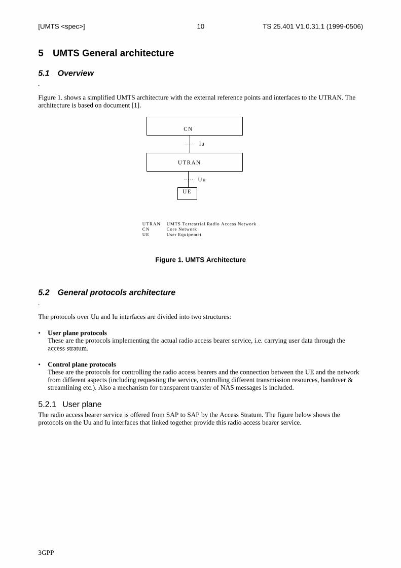
Figure 1. shows a simplified UMTS architecture with the external reference points and interfaces to the UTRAN. Thearchitecture is based on document [1].
Iu
U T R A N
U E
Uu
U T R A N UMTS Terrestrial Radio Access NetworkC N Core NetworkU E User Equipemet
C N
Figure 1. UMTS Architecture
5.2 General protocols architecture.
The protocols over Uu and Iu interfaces are divided into two structures:
• User plane protocolsThese are the protocols implementing the actual radio access bearer service, i.e. carrying user data through theaccess stratum.
• Control plane protocols
These are the protocols for controlling the radio access bearers and the connection between the UE and the networkfrom different aspects (including requesting the service, controlling different transmission resources, handover &streamlining etc.). Also a mechanism for transparent transfer of NAS messages is included.
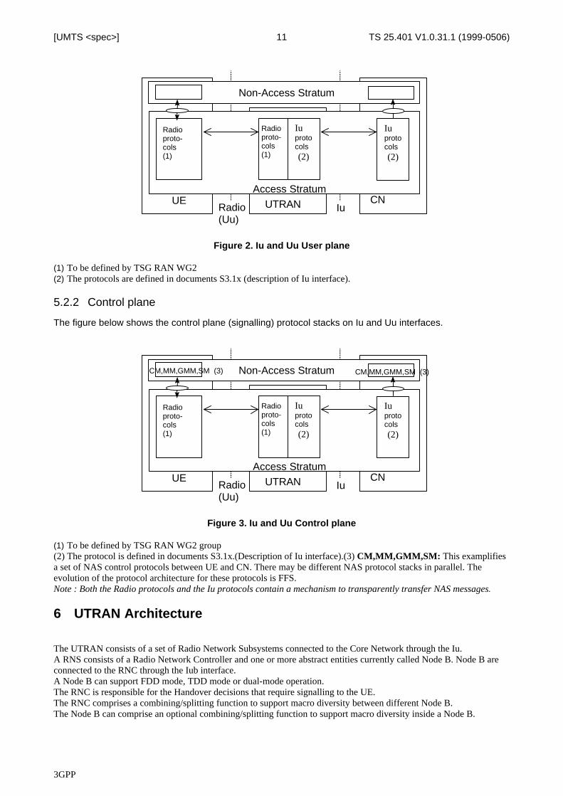
5.2.1 User planeThe radio access bearer service is offered from SAP to SAP by the Access Stratum. The figure below shows theprotocols on the Uu and Iu interfaces that linked together provide this radio access bearer service.
3GPP
TS 25.401 V1.0.31.1 (1999-0506)11[UMTS <spec>]
UTRANUE CNAccess Stratum
Non-Access Stratum
Radio(Uu)
Iu
Radioproto-cols(1)
Radioproto-cols(1)
Iuprotocols(2)
Iuprotocols(2)
Figure 2. Iu and Uu User plane
(1) To be defined by TSG RAN WG2(2) The protocols are defined in documents S3.1x (description of Iu interface).
5.2.2 Control plane
The figure below shows the control plane (signalling) protocol stacks on Iu and Uu interfaces.
UTRANUE CNAccess Stratum
Non-Access Stratum
Radio(Uu)
Iu
Radioproto-cols(1)
Radioproto-cols(1)
Iuprotocols(2)
Iuprotocols(2)
CM,MM,GMM,SM (3) CM,MM,GMM,SM (3)
Figure 3. Iu and Uu Control plane
(1) To be defined by TSG RAN WG2 group(2) The protocol is defined in documents S3.1x.(Description of Iu interface).(3) CM,MM,GMM,SM: This examplifiesa set of NAS control protocols between UE and CN. There may be different NAS protocol stacks in parallel. Theevolution of the protocol architecture for these protocols is FFS.Note : Both the Radio protocols and the Iu protocols contain a mechanism to transparently transfer NAS messages.
6 UTRAN Architecture
The UTRAN consists of a set of Radio Network Subsystems connected to the Core Network through the Iu.A RNS consists of a Radio Network Controller and one or more abstract entities currently called Node B. Node B areconnected to the RNC through the Iub interface.A Node B can support FDD mode, TDD mode or dual-mode operation.The RNC is responsible for the Handover decisions that require signalling to the UE.The RNC comprises a combining/splitting function to support macro diversity between different Node B.The Node B can comprise an optional combining/splitting function to support macro diversity inside a Node B.
3GPP
TS 25.401 V1.0.31.1 (1999-0506)12[UMTS <spec>]
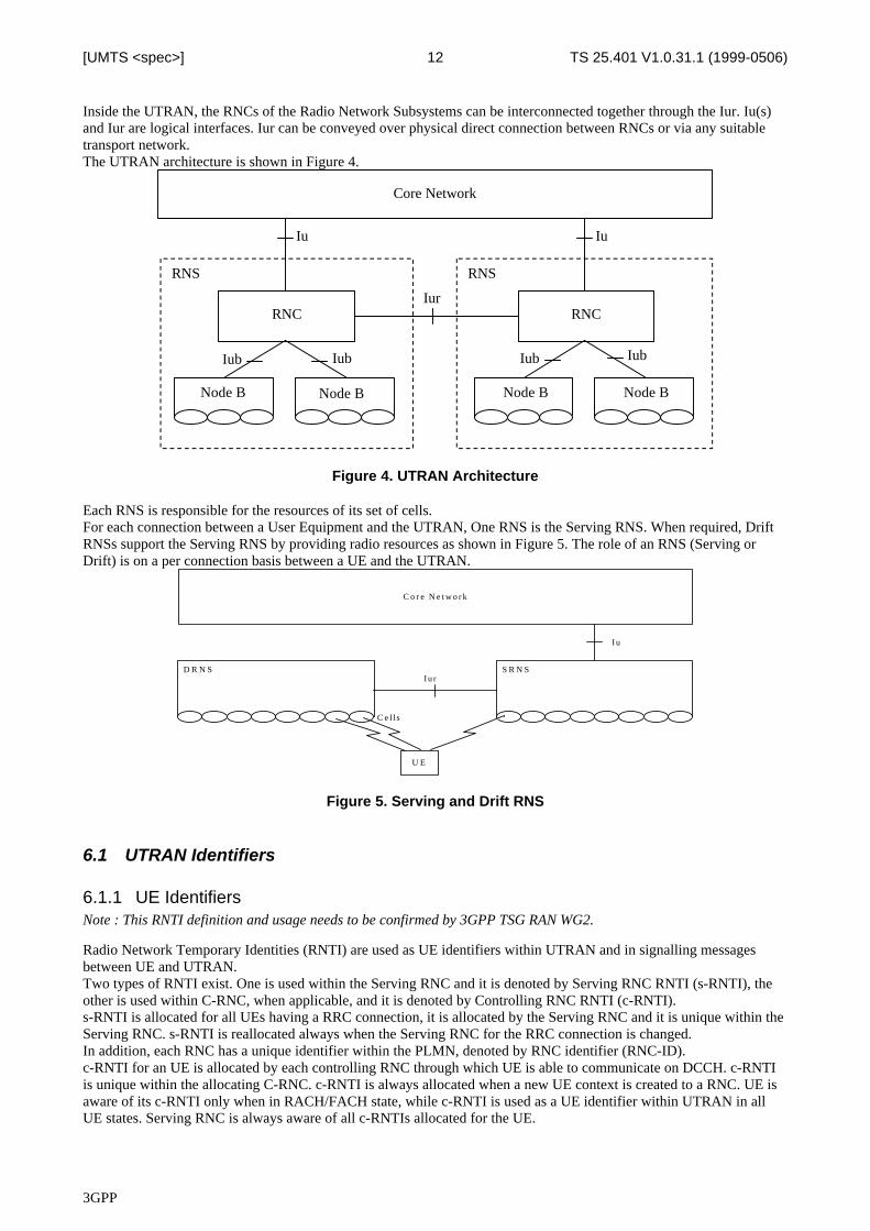
Inside the UTRAN, the RNCs of the Radio Network Subsystems can be interconnected together through the Iur. Iu(s)and Iur are logical interfaces. Iur can be conveyed over physical direct connection between RNCs or via any suitabletransport network.The UTRAN architecture is shown in Figure 4.
RNS
RNC
RNS
RNC
Core Network
Node B Node B Node B Node B
Iu Iu
Iur
Iub IubIub Iub
Figure 4. UTRAN Architecture
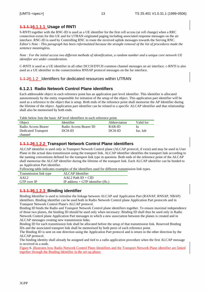
Each RNS is responsible for the resources of its set of cells.For each connection between a User Equipment and the UTRAN, One RNS is the Serving RNS. When required, DriftRNSs support the Serving RNS by providing radio resources as shown in Figure 5. The role of an RNS (Serving orDrift) is on a per connection basis between a UE and the UTRAN.
S R N S
C o r e N e t w o r k
I u
D R N SI u r
U E
C e l ls
Figure 5. Serving and Drift RNS
6.1 UTRAN Identifiers
6.1.1 UE IdentifiersNote : This RNTI definition and usage needs to be confirmed by 3GPP TSG RAN WG2.
Radio Network Temporary Identities (RNTI) are used as UE identifiers within UTRAN and in signalling messagesbetween UE and UTRAN.Two types of RNTI exist. One is used within the Serving RNC and it is denoted by Serving RNC RNTI (s-RNTI), theother is used within C-RNC, when applicable, and it is denoted by Controlling RNC RNTI (c-RNTI).s-RNTI is allocated for all UEs having a RRC connection, it is allocated by the Serving RNC and it is unique within theServing RNC. s-RNTI is reallocated always when the Serving RNC for the RRC connection is changed.In addition, each RNC has a unique identifier within the PLMN, denoted by RNC identifier (RNC-ID).c-RNTI for an UE is allocated by each controlling RNC through which UE is able to communicate on DCCH. c-RNTIis unique within the allocating C-RNC. c-RNTI is always allocated when a new UE context is created to a RNC. UE isaware of its c-RNTI only when in RACH/FACH state, while c-RNTI is used as a UE identifier within UTRAN in allUE states. Serving RNC is always aware of all c-RNTIs allocated for the UE.
3GPP
TS 25.401 V1.0.31.1 (1999-0506)13[UMTS <spec>]
1.1.1.16.1.1.1 Usage of RNTIS-RNTI together with the RNC-ID is used as a UE identifier for the first cell access (at cell change) when a RRCconnection exists for this UE and for UTRAN originated paging including associated response messages on the airinterface. RNC-ID is used by Controlling RNC to route the received uplink messages towards the Serving RNC.Editor's Note : This paragraph has been reformulated because the straight removal of the list of procedures made thesentence meaningless.
Note : For the initial access two different methods of identification, a random number and a unique core network UEidentifier are under consideration.
C-RNTI is used as a UE identifier in all other DCCH/DTCH common channel messages on air interface. c-RNTI is alsoused as a UE identifier in the connectionless RNSAP protocol messages on the Iur interface.
1.1.26.1.2 Identifiers for dedicated resources within UTRAN
6.1.2.1 Radio Network Control Plane identifiersEach addressable object in each reference point has an application part level identifier. This identifier is allocatedautonomously by the entity responsible for initiation of the setup of the object. This application part identifier will beused as a reference to the object that is setup. Both ends of the reference point shall memorise the AP Identifier duringthe lifetime of the object. Application part identifier can be related to a specific ALCAP identifier and that relationshipshall also be memorised by both ends.
Table below lists the basic AP level identifiers in each reference point.Object Identifier Abbreviation Valid forRadio Access Bearer Radio Access Bearer ID RAB-ID IuDedicated Transportchannel
DCH-ID DCH-ID Iur, Iub
1.1.1.26.1.2.2 Transport Network Control Plane identifiersALCAP identifier is used only in Transport Network Control plane (ALCAP protocol, if exist) and may be used in UserPlane in the actual data transmission using the transport link. ALCAP identifier identifies the transport link according tothe naming conventions defined for the transport link type in question. Both ends of the reference point of the ALCAPshall memorise the ALCAP identifier during the lifetime of the transport link. Each ALCAP identifier can be binded toan Application Part identifier.Following table indicates examples of the identifiers used for different transmission link types.Transmission link type ALCAP IdentifierAAL2 AAL2 Path ID + CIDGTP over IP IP address + GTP identifier (ffs.)
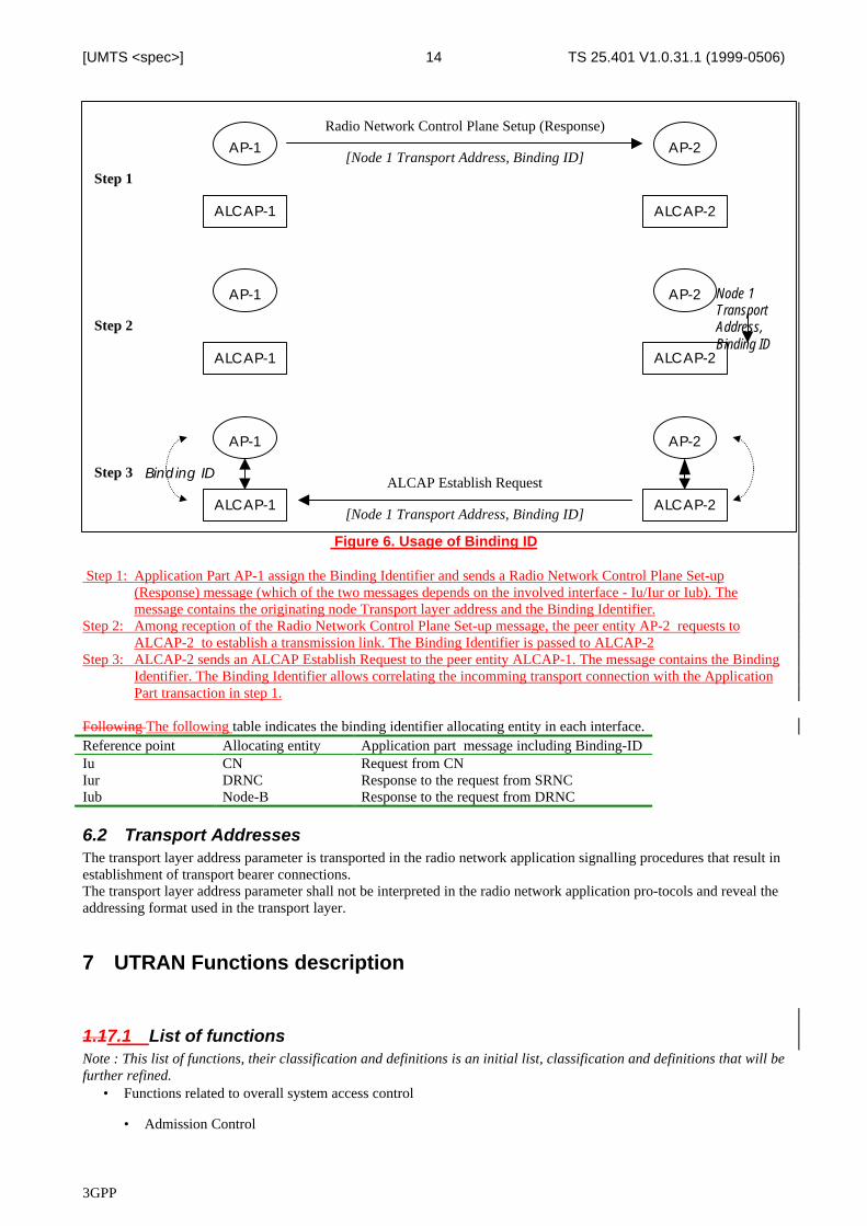
1.1.1.36.1.2.3 Binding identifierBinding Identifier is used to initialise the linkage between ALCAP and Application Part (RANAP, RNSAP, NBAP)identifiers. Binding identifier can be used both in Radio Network Control plane Application Part protocols and inTransport Network Control Plane's ALCAP protocol.Binding ID binds the Radio and Transport Network Control plane identifiers together. To ensure maximal independenceof those two planes, the binding ID should be used only when necessary: Binding ID shall thus be used only in RadioNetwork Control plane Application Part messages in which a new association between the planes is created and inALCAP messages creating new transmission links.Binding ID for each transmission link shall be allocated before the setup of that transmission link. Reserved BindingIDs and the associated transport link shall be memorised by both peers of each reference point.The Binding ID is sent on one direction using the Application Part protocol and is return in the other direction by theALCAP protocol.The binding identity shall already be assigned and tied to a radio application procedure when the first ALCAP messageis received in a node.Figure 6. illustrates how Radio Network Control Plane Identifiers and the Transport Network Plane identifier are linkedtogether through the Binding Identifier in the set-up phase:
3GPP
TS 25.401 V1.0.31.1 (1999-0506)14[UMTS <spec>]
[Node 1 Transport Address, Binding ID]AP-1 AP-2
ALCAP-1 ALCAP-2
Step 1
AP-1 AP-2
ALCAP-1 ALCAP-2
[Node 1 Transport Address, Binding ID]
Step 2
AP-1 AP-2
ALCAP-1 ALCAP-2
Step 3ALCAP Establish Request
Radio Network Control Plane Setup (Response)
Node 1TransportAddress,Binding ID
Binding ID
Figure 6. Usage of Binding ID
Step 1: Application Part AP-1 assign the Binding Identifier and sends a Radio Network Control Plane Set-up(Response) message (which of the two messages depends on the involved interface - Iu/Iur or Iub). Themessage contains the originating node Transport layer address and the Binding Identifier.
Step 2: Among reception of the Radio Network Control Plane Set-up message, the peer entity AP-2 requests toALCAP-2 to establish a transmission link. The Binding Identifier is passed to ALCAP-2
Step 3: ALCAP-2 sends an ALCAP Establish Request to the peer entity ALCAP-1. The message contains the BindingIdentifier. The Binding Identifier allows correlating the incomming transport connection with the ApplicationPart transaction in step 1.
Following The following table indicates the binding identifier allocating entity in each interface.Reference point Allocating entity Application part message including Binding-IDIu CN Request from CNIur DRNC Response to the request from SRNCIub Node-B Response to the request from DRNC
6.2 Transport AddressesThe transport layer address parameter is transported in the radio network application signalling procedures that result inestablishment of transport bearer connections.The transport layer address parameter shall not be interpreted in the radio network application pro-tocols and reveal theaddressing format used in the transport layer.
7 UTRAN Functions description
1.17.1 List of functionsNote : This list of functions, their classification and definitions is an initial list, classification and definitions that will befurther refined.
• Functions related to overall system access control
• Admission Control
3GPP
TS 25.401 V1.0.31.1 (1999-0506)15[UMTS <spec>]
• Congestion Control
• System information broadcasting
• Functions related to security and privacy
• Use of Temporary Identifier
• Radio channel ciphering
• Radio channel deciphering
• Functions related to handover
• Radio environment survey
• Handover decision
• Macro-diversity control
• Handover Control
• Handover execution
• Handover completion
• SRNS Relocation
• Inter-System handover
• Functions related to radio resource management and control
• Radio bearer connection set-up and release (Radio Bearer Control)
• Reservation and release of physical radio channels
• Allocation and deallocation of physical radio channels
• Packet data transfer over radio function
• RF power control
• RF power setting
• Radio channel coding
• Radio channel decoding
• Channel coding control
• Initial (random) access detection and handling
• CN Distribution function for Non Access Stratum messages
7.2 Functions description
7.2.1 Functions related to overall system access controlSystem access is the means by which a UMTS user is connected to the UMTS in order to use UMTS services and/orfacilities. User system access may be initiated from either the mobile side, e.g. a mobile originated call, or the networkside, e.g. a mobile terminated call.
3GPP
TS 25.401 V1.0.31.1 (1999-0506)16[UMTS <spec>]
1.1.1.17.2.1.1 Admission ControlThe purpose of the admission control is to admit or deny new users, new radio access bearers or new radio links (forexample due to handover). The admission control should try to avoid overload situations and base its decisions oninterference and resource measurements. The admission control is employed at for example initial UE access, RABassignment/reconfiguration and at handover. These cases may give different answers depending on priority andsituation.Note : This admission Control function is related to Radio ResourcesAdmission control in a DRNC is implicitly invoked during radio link setup/modify.Information on UL intreferences and DL power on cells controlled by the DRNC should be available across Iur.Additional information exchanges between admission control functions located in different RNCs are for further study.The Admission Control function based on UL interference and DL power is located in the Controlling RNC.The Node B shall be able to report UL interference measurements and DL power information over Iub.The Controlling RNC controls this reporting function, i.e. if these information need to be reported and the period ofthese reports.Note : Other parameters for Admission Control are FFS.
1.1.1.27.2.1.2 Congestion ControlThe task of congestion control is to monitor, detect and handle situations when the system is reaching a near overload oran overload situation with the already connected users. This means that some part of the network has run out, or willsoon run out of resources. The congestion control should then bring the system back to a stable state as seamless aspossible.Note : This admission Control function is related to Radio Resources
1.1.1.37.2.1.3 System information broadcastingThis function provides the mobile station with the information which is needed to camp on a cell and to set up aconnection in idle mode and to perform a handover or route packets in communication mode. The tasks may include :
• access rights
• frequency bands used
• configuration of logical channels, PCH, FACH and RACH channel structure of the cell etc.
• network and cell identities
• information for location registration purposes
• UE idle mode cell selection and cell re-selection criteria
• UE transmission power control information
• UE access and admission control information
Because of its close relation to the basic radio transmission and the radio channel structure, the basic control andsynchronisation of this function should be located in UTRAN.
1.1.27.2.2 Functions related to security and privacy
7.2.2.1 Use of Temporary IdentifierUTRAN shall, as far as possible, use a temporary identifier instead of the permanent CN assigned identity (e.g. IMSI,International Mobile Subscriber Identity).This function is located in the UE and in the UTRAN
1.1.1.27.2.2.2 Radio channel cipheringThis function is a pure computation function whereby the radio transmitted data can be protected against a non-authorised third-party. Ciphering may be based on the usage of a session-dependent key, derived through signallingand/or session dependent information.This function is located in the UE and in the UTRAN.
3GPP
TS 25.401 V1.0.31.1 (1999-0506)17[UMTS <spec>]
1.1.1.37.2.2.3 Radio channel decipheringThis function is a pure computation function which is used to restore the original information from the cipheredinformation. The deciphering function is the complement function of the ciphering function, based on the sameciphering key.This function is located in the UE and in the UTRAN.
1.1.37.2.3 Functions related to handover
7.2.3.1 Radio environment surveyThis function performs measurements on radio channels (current and surrounding cells) and translates thesemeasurements into radio channel quality estimates. Measurements may include :
1. received signal strengths (current and surrounding cells),
2. estimated bit error ratios, (current and surrounding cells),
3. estimation of propagation environments (e.g. high-speed, low-speed, satellite, etc.),
4. transmission range (e.g. through timing information),
5. Doppler shift,
6. synchronisation status,
7. Received interference level,
8. Total DL transmission power per cell.
In order for these measurements and the subsequent analysis to be meaningful, some association between themeasurements and the channels to which they relate should be made in the analysis. Such association may include theuse of identifiers for the network, the base station, the cell (base station sector) and/or the radio channel.This function is located in the UE and in the UTRAN.
1.1.1.27.2.3.2 Handover decisionThis function consists of gathering estimates of the quality of the radio channels (including estimates from surroundingcells) from the measuring entities and to assess the overall quality of service of the call. The overall quality of service iscompared with requested limits and with estimates from surrounding cells. Depending on the outcome of thiscomparison, the macro-diversity control function or the handover control function may be activated.This function may also include functionalities to assess traffic loading distribution among radio cells and to decide onhanding over traffic between cells for traffic reasons.The location of this function is depending on the handover principle chosen.
• if network only initiated handover, this function is located in the RNC;
• if mobile only initiated handover, this function is located in the UE;
• if both the mobile and the network can initiate handover, this function will be located in both the RNC and theUE.
7.2.3.3 Macro-diversity controlUpon request of the Handover Decision function, this function controls the duplication/ replication of informationstreams to receive/ transmit the same information through multiple physical channels (possibly in different cells) from/towards a single mobile terminal.This function also controls the combining of information streams generated by a single source (diversity link), butconveyed via several parallel physical channels (diversity sub-links). Macro diversity control should interact withchannel coding control in order to reduce the bit error ratio when combining the different information streams. Thisfunction controls macro-diversity execution which is located at the two endpoints of the connection element on whichmacro-diversity is applied (diversity link), that is at the access point and also at the mobile termination .In some cases, depending on physical network configuration, there may be several entities which combine the differentinformation streams, e.g. one entity combines information streams on radio signal basis, another combines informationstreams on wireline signal basis.
3GPP
TS 25.401 V1.0.31.1 (1999-0506)18[UMTS <spec>]
This function is typically located in the UTRAN. However, depending on the physical network architecture, some bitstream combining function within the CN may have to be included in the control.A DRNS may perform macro-diversity combining/splitting of data streams communicated via its cells. The SRNSperforms macro-diversity combining/splitting of Iur data streams received from/sent to DRNS(s), and data streamscommunicated via its own cells.When requesting the addition of a new cell for a UE-UTRAN connection, the RNC of the SRNS (i.e. the SRNC) canexplicitly request to the RNC of the DRNS (i.e. the DRNC) a new Iur data stream, in which case the macro-diversitycombining and splitting function within the DRNS is not used for that cell. Otherwise, the DRNS takes the decisionThe internal DRNS handling of the macro-diversity combining (respectively splitting) of Iub (respectively Iur) DCHframes is controlled by the DRNS.Node B may perform macro-diversity combining/splitting of data streams communicated via its cells. The ControllingRNC performs macro-diversity combining/splitting of Iub data streams received from/sent to several Node B(s).When requesting the addition of a new cell for a UE-UTRAN connection, the Controlling RNC can explicitly requestto the Node B a new Iub data stream, in which case the macro-diversity combining and splitting function within theNode B is not used for that cell. Otherwise, the Node B takes the decision whether macro-diversity combining andsplitting function is used inside the Node B for that cell i.e. whether a new Iub data stream shall be added or not.The internal Node B handling of the macro-diversity combining/splitting of radio frames is controlled by the Node B.
1.1.1.47.2.3.4 Handover ControlIn the case of switched handover, this function is responsible for the overall control of the handover execution process.It initiates the handover execution process in the entities required and receives indications regarding the results.Due to the close relationship with the radio access and the Handover Decision function, this function should be locatedin the UTRAN.
1.1.1.57.2.3.5 Handover executionThis function is in control of the actual handing over of the communication path. It comprises two sub-processes:handover resource reservation and handover path switching. The handover resource reservation process will reserveand activate the new radio and wireline resources that are required for the handover. When the new resources aresuccessfully reserved and activated, the handover path switching process will perform the final switching from the oldto the new resources, including any intermediate path combination required, e.g. radio link addition and radio linkdeletion in the soft handover case.This function is located in the UTRAN for UTRAN internal path switching and in the CN for CN path switching.
1.1.1.67.2.3.6 Handover completionThis function will free up any resources that are no longer needed. A re-routing of the call may also be triggered inorder to optimise the new connection.This function is located both in the UTRAN and in the CN.
1.1.1.77.2.3.7 SRNS RelocationThe SRNS Relocation function coordinates the activities when the SRNS role is to be taken over by another RNS.SRNS relocation implies that the Iu interface connection point is moved to the new RNS.This function is located in the RNC and the CN.
1.1.1.1.17.2.3.7.1 Access Network Triggered SRNS RelocationOne Access Network triggered function needed over the Iu interface is the function for SRNS Relocation. SRNSRelocation needs support from the Core Network to be executed.
3GPP
TS 25.401 V1.0.31.1 (1999-0506)19[UMTS <spec>]
S R N S
C o r e N e t w o r k
I u
D R N SI u r
U E
R N S
C o r e N e t w o r k
I u
S R N S
U E
A fte r S R N S R e l o c a t i o nB e f o r e S R N S R e l o c a t i o n
C e l l s
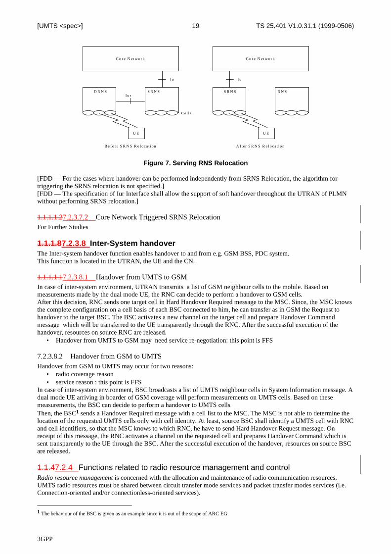
Figure 7. Serving RNS Relocation
[FDD — For the cases where handover can be performed independently from SRNS Relocation, the algorithm fortriggering the SRNS relocation is not specified.][FDD — The specification of Iur Interface shall allow the support of soft handover throughout the UTRAN of PLMNwithout performing SRNS relocation.]
1.1.1.1.27.2.3.7.2 Core Network Triggered SRNS RelocationFor Further Studies
1.1.1.87.2.3.8 Inter-System handoverThe Inter-system handover function enables handover to and from e.g. GSM BSS, PDC system.This function is located in the UTRAN, the UE and the CN.
1.1.1.1.17.2.3.8.1 Handover from UMTS to GSMIn case of inter-system environment, UTRAN transmits a list of GSM neighbour cells to the mobile. Based onmeasurements made by the dual mode UE, the RNC can decide to perform a handover to GSM cells.After this decision, RNC sends one target cell in Hard Handover Required message to the MSC. Since, the MSC knowsthe complete configuration on a cell basis of each BSC connected to him, he can transfer as in GSM the Request tohandover to the target BSC. The BSC activates a new channel on the target cell and prepare Handover Commandmessage which will be transferred to the UE transparently through the RNC. After the successful execution of thehandover, resources on source RNC are released.
• Handover from UMTS to GSM may need service re-negotiation: this point is FFS
7.2.3.8.2 Handover from GSM to UMTSHandover from GSM to UMTS may occur for two reasons:
• radio coverage reason• service reason : this point is FFS
In case of inter-system environment, BSC broadcasts a list of UMTS neighbour cells in System Information message. Adual mode UE arriving in boarder of GSM coverage will perform measurements on UMTS cells. Based on thesemeasurements, the BSC can decide to perform a handover to UMTS cellsThen, the BSC1 sends a Handover Required message with a cell list to the MSC. The MSC is not able to determine thelocation of the requested UMTS cells only with cell identity. At least, source BSC shall identify a UMTS cell with RNCand cell identifiers, so that the MSC knows to which RNC, he have to send Hard Handover Request message. Onreceipt of this message, the RNC activates a channel on the requested cell and prepares Handover Command which issent transparently to the UE through the BSC. After the successful execution of the handover, resources on source BSCare released.
1.1.47.2.4 Functions related to radio resource management and controlRadio resource management is concerned with the allocation and maintenance of radio communication resources.UMTS radio resources must be shared between circuit transfer mode services and packet transfer modes services (i.e.Connection-oriented and/or connectionless-oriented services).
1 The behaviour of the BSC is given as an example since it is out of the scope of ARC EG
3GPP
TS 25.401 V1.0.31.1 (1999-0506)20[UMTS <spec>]
1.1.1.17.2.4.1 Radio bearer connection set-up and release (Radio Bearer Control)This function is responsible for the control of connection element set-up and release in the radio access sub network.The purpose of this function is
1. to participate in the processing of the end-to-end connection set-up and release,
2. and to manage and maintain the element of the end-to-end connection, which is located in the radio access subnetwork.
In the former case, this function will be activated by request from other functional entities at call set-up/release. In thelatter case, i.e. when the end-to-end connection has already been established, this function may also be invoked to caterfor in-call service modification or at handover execution. This function interacts with the reservation and release ofphysical (radio) channels function.This function is located both in the UE and in the RNC.
1.1.1.27.2.4.2 Reservation and release of physical radio channelsThis function consists of translating the connection element set-up or release requests into physical radio channelrequests, reserving or releasing the corresponding physical radio channels and acknowledging this reservation/ releaseto the requesting entity.This function may also perform physical channel reservation and release in the case of a handover. Moreover, theamount of radio resource required may change during a call, due to service requests from the user or macro-diversityrequests. Therefore, this function must also be capable of dynamically assigning physical channels during a call.Note: This function may or may not be identical to the function allocation and deallocation of physical radiochannels. The distinction between the two functions is required e.g. to take into account sharing a physical radiochannel by multiple users in a packet data transfer mode.This function is located in the UTRAN.
1.1.1.37.2.4.3 Allocation and deallocation of physical radio channelsThis function is responsible, once physical radio channels have been reserved, for actual physical radio channel usage,allocating or deallocating the corresponding physical radio channels for data transfer. Acknowledging this allocation/deallocation to the requesting entity is for further study.Note: This function may or may not be identical to the function reservation and release of physical radio channels.The distinction between the two functions is required e.g. to take into account sharing a physical radio channel bymultiple users in a packet data transfer mode.This function is located in the UTRAN.
1.1.1.47.2.4.4 Allocation of Downlink Channelisation CodesAllocation of downlink channelisation codes of cells belonging to DRNS is performed in DRNS.Editors note: Note that this does not imply that the signalling of the code allocation to the UE must be done from theDRNS.
Allocation of downlink channelisation codes of cells belonging to Node B is performed in the Controlling RNC.
1.1.1.57.2.4.5 Packet data transfer over radio functionThis function provides packet data transfer capability across the UMTS radio interface. This function includesprocedures which:
1. provide packet access control over radio channels,
2. provide packet multiplexing over common physical radio channels,
3. provide packet discrimination within the mobile terminal,
4. provide error detection and correction,
5. provide flow control procedures.
This function is located in both the UE and in the UTRAN.It encompasses :
1. Channel type switching : UTRAN shall have the possibility to dynamically, during an RRC connection, switchbetween a Common Transport and a Dedicated Transport Channel. This to optimise the radio resource utilisationand to achieve the QoS requested by the packet data user.
3GPP
TS 25.401 V1.0.31.1 (1999-0506)21[UMTS <spec>]
2. Channel rate modification : UTRAN shall have the possibility to dynamically, during an RRC connection,modify the channel rate of a Dedicated Transport Channel. This to optimise the radio resource utilisation and toachieve the QoS requested by the packet data user.
3. Packet scheduling : When performing data transfer, it shall be possible to schedule data transmissions accordingto QoS.
4. Retransmission : For assured mode radio access bearers, UTRAN shall support retransmission ofunacknowledged data over the radio interface. This, in order to assure a certain packet loss probability.
5. Packet discard : If, for example, the communication over the radio interface fails and parts of an Access StratumSDU (e.g. an IP packet) are lost, or due to congestion within UTRAN a part of an Access Stratum SDU isdropped, UTRAN shall discard the whole Access Stratum SDU. This is to ensure that radio resources are notunnecessarily wasted. It is expected that higher layers (transport protocols) will perform the necessaryretransmissions.
6. Avoidance of IP fragmentation; UTRAN shall be able to handle Access Stratum SDUs up to a size which is largeenough to avoid IP fragmentation in most cases.
7.2.4.6 RF power controlThis group of functions controls the level of the transmitted power in order to minimise interference and keep thequality of the connections. It consist of the following functions: UL Outer Loop Power Control, DL Outer Loop PowerControl, UL Inner Loop Power Control, DL Inner Loop Power Control, UL Open Loop Power Control and DL OpenLoop Power Control.
1.1.1.1.17.2.4.6.1 UL OUTER LOOP POWER CONTROLThe UL Outer Loop Power Control located in the SRNC sets the target quality value for the UL Inner Loop PowerControl located in Node B. It receives input from quality estimates of the transport channel. The UL outer loop powercontrol is mainly used for a long-term quality control of the radio channel.This function is located in the UTRAN.If the connection involves both a SRNS and a DRNS the function UL Outer Loop Power Control (located in the SRNC)sets the target quality for the UL Inner Loop Power Control function (located in Node B). Additional qualityinformation for the case when macro diversity combining is performed in DRNC is for further study.Note : some additional function is needed for resource negotiation between the SRNS and the DRNS across the Iur. Thisis FFS.
1.1.1.1.27.2.4.6.2 DL OUTER LOOP POWER CONTROLThe DL Outer Loop Power Control sets the target quality value for the DL inner loop power control. It receives inputfrom quality estimates of the transport channel, measured in the UE. The DL outer loop power control is mainly usedfor a long-term quality control of the radio channel.This function is located mainly in the UE, but some control parameters are set by the UTRAN.The SRNC, regularly (or under some algorithms), sends the target down link power range based on the measurementreport from UE.
1.1.1.1.37.2.4.6.3 UL INNER LOOP POWER CONTROLThe UL Inner Loop Power Control sets the power of the uplink dedicated physical channels. It receives the qualitytarget from UL Outer Loop Power Control and quality estimates of the uplink dedicated physical control channel. Thepower control commands are sent on the downlink dedicated physical control channel to the UE.This function is located in both the UTRAN and the UE.
1.1.1.1.47.2.4.6.4 DL INNER LOOP POWER CONTROLThe DL Inner Loop Power Control sets the power of the downlink dedicated physical channels. It receives the qualitytarget from DL Outer Loop Power Control and quality estimates of the downlink dedicated physical control channel.The power control commands are sent on the uplink dedicated physical control channel to the UTRAN.This function is located in both the UTRAN and the UE.
1.1.1.1.57.2.4.6.5 UL OPEN LOOP POWER CONTROLThe UL Open Loop Power Control sets the initial power of the UE, i.e. at random access. The function uses UEmeasurements and broadcasted cell/system parameters as input.This function is located in both the UTRAN and the UE.
1.1.1.1.67.2.4.6.6 DL OPEN LOOP POWER CONTROL
3GPP
TS 25.401 V1.0.31.1 (1999-0506)22[UMTS <spec>]
The DL Open Loop Power Control sets the initial power of downlink channels. It receives downlink measurementreports from the UE.This function is located in both the UTRAN and the UE.
1.1.1.77.2.4.7 Radio channel codingThis function introduces redundancy into the source data flow, increasing its rate by adding information calculated fromthe source data, in order to allow the detection or correction of signal errors introduced by the transmission medium.The channel coding algorithm(s) used and the amount of redundancy introduced may be different for the different typesof logical channels and different types of data.This function is located in both the UE and in the UTRAN.
1.1.1.87.2.4.8 Radio channel decodingThis function tries to reconstruct the source information using the redundancy added by the channel coding function todetect or correct possible errors in the received data flow. The channel decoding function may also employ a priori errorlikelihood information generated by the demodulation function to increase the efficiency of the decoding operation. Thechannel decoding function is the complement function to the channel coding function.This function is located in both the UE and in the UTRAN.
1.1.1.97.2.4.9 Channel coding controlThis function generates control information required by the channel coding/ decoding execution functions. This mayinclude channel coding scheme, code rate, etc.This function is located in both the UE and in the UTRAN.
1.1.1.107.2.4.10 Initial (random) access detection and handlingThis function will have the ability to detect an initial access attempt from a mobile station and will respondappropriately. The handling of the initial access may include procedures for a possible resolution of colliding attempts,etc. The successful result will be the request for allocation of appropriate resources for the requesting mobile station.This function is located in the UTRAN.
1.1.1.117.2.4.11 CN Distribution function for Non Access Stratum messagesIn the RRC protocol, messages from the NAS shall be transparently transferred within the Access Stratum using theDirect Transfer procedure. In the two CN scenario, a distribution function in the UE and the SRNC shall handle a CNdiscriminator to direct messages to the appropriate NAS entity i.e. the appropriate Mobility Management instance in theUE domain and the appropriate CN domain.In the downlink direction, the signaling bearers addressing shall be used to identify the originating CN domain (e.g.from CN node originating address). The process performed by the distribution function simply consists in adding oneCN discriminatior to the value corresponding to the originating CN domain and passing the NAS message to theunderneath protocol layers for transparent transfer to the UE.In the uplink direction, the process performed by the distribution function in the SRNC consists in removing the CNdiscriminatior inserted by the peer UE function and distribute the NAS message to the corresponding RANAP instancefor transfer over Iu interface.This function is located in both the UE and in the SRNC.
8 Mobility Management
Note : Location based services have not been yet considered and need further studies.
1.18.1 Dedicated ConnectionBased on [2], the UE may either have or not have a dedicated connection :
1. There exists a dedicated connection established over the Dedicated Control Service Access Point (DC-SAP)from the Access Stratum.In this case, the CN can reach the UE by the dedicated connection SAP on the CN side, and the UTRAN has acontext with the UE and CN for this particular connection. This context is erased when the connection isreleased. The dedicated connection can be initiated from the UE only.
Editor's note : A dedicated connection is currently defined as Signalling Connection in [2]. Note that in the radiointerface, dedicated or common channels can be used.
3GPP
TS 25.401 V1.0.31.1 (1999-0506)23[UMTS <spec>]
Depending on the activity of a UE, the location of the UE is known either on cell level (higher activity) or in alarger area consisting of several cells (lower activity). This will (i) minimise the number of location updatemessages for moving UEs with low activity and (ii) remove the need for paging for UEs known on cell level.
2. There does not exist a dedicated connection.In this case, the CN must reach the UE via the Notification SAP. The message sent to the UE can be a request tothe UE to establish a dedicated connection. The UE is addressed with a user/terminal identity and a 'geographicalarea'.
8.2 Consequences for Mobility HandlingIt is generally agreed [1] to contain radio access specific procedures within UTRAN. This means that all cell levelmobility should be handled within UTRAN. Also the cell structure of the radio network should not necessarily beknown outside the UTRAN.When there exists a dedicated connection to the UE, the UTRAN shall handle the radio interface mobility of the UE.This includes procedures such as soft handover, and procedures for handling mobility in the RACH/PCH substate.Editor's note : Some reference will be necessary to a 3GPP TSG RAN WG2 document that defines that substate.
When there does not exist a dedicated connection to the UE, no UE information in UTRAN is needed. In this case, themobility is handled directly between UE and CN outside access stratum (e.g. by means of registration procedures).When paging the UE, the CN indicates a 'geographical area' that is translated within UTRAN to the actual cells thatshall be paged. A 'geographical area' shall be identified in a cell-structure independent way. One possibility is the use of'Location Area identities'.During the lifetime of the dedicated connection, the registrations to the CN are suppressed by the UE. When a dedicatedconnection is released, the UE performs a new registration to the CN, if needed.Thus, the UTRAN does not contain any permanent 'location registers' for the UE, but only temporary contexts for theduration of the dedicated connection. This context may typically contain location information (e.g. current cell(s) of theUE) and information about allocated radio resources and related connection references.
9 Synchronisation
This section describes a number of synchronisation principles grouped into three groups: Network Synchronisation,Frame Synchronisation and Node Synchronisation.
1.19.1 SYNCHRONISATION MODELThe Synchronisation model includes nodes and interactions in UTRAN as well as points at interactions to CoreNetwork (CN) and User Equipment (UE).The objectives with the sync model are to describe where the interactions mainly take place and to define the followingterms:
• Time Alignment handling• Frame synchronisation• Radio Interface Synchronisation handling• Ciphering handling
3GPP
TS 25.401 V1.0.31.1 (1999-0506)24[UMTS <spec>]
TimeAlignmenthandling
FrameSynchronisationhandling
RadioSynchronisation handling
NodeB
RNC
Vocoder
NodeB
NodeB
NodeB
NodeB
Cipheringhandling
RNS
UTRAN
CN
Time-of-dayhandling(FFS)
UE1 UE2
RNC
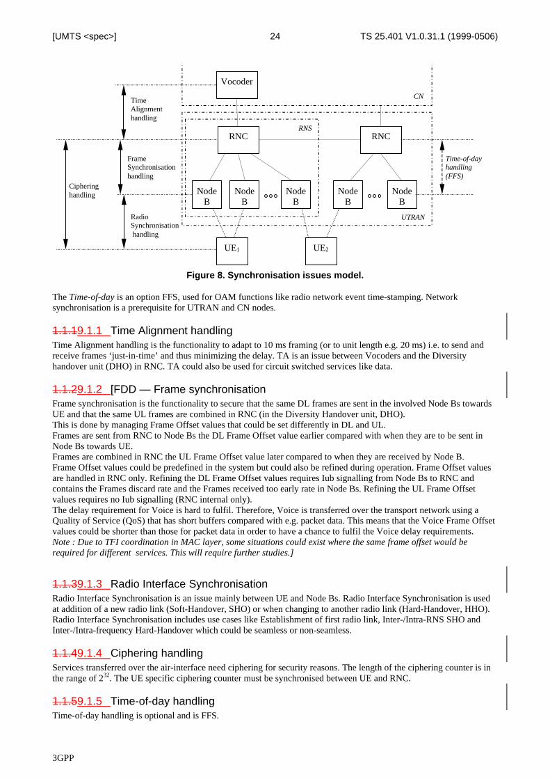
Figure 8. Synchronisation issues model.
The Time-of-day is an option FFS, used for OAM functions like radio network event time-stamping. Networksynchronisation is a prerequisite for UTRAN and CN nodes.
1.1.19.1.1 Time Alignment handlingTime Alignment handling is the functionality to adapt to 10 ms framing (or to unit length e.g. 20 ms) i.e. to send andreceive frames ‘just-in-time’ and thus minimizing the delay. TA is an issue between Vocoders and the Diversityhandover unit (DHO) in RNC. TA could also be used for circuit switched services like data.
1.1.29.1.2 [FDD — Frame synchronisationFrame synchronisation is the functionality to secure that the same DL frames are sent in the involved Node Bs towardsUE and that the same UL frames are combined in RNC (in the Diversity Handover unit, DHO).This is done by managing Frame Offset values that could be set differently in DL and UL.Frames are sent from RNC to Node Bs the DL Frame Offset value earlier compared with when they are to be sent inNode Bs towards UE.Frames are combined in RNC the UL Frame Offset value later compared to when they are received by Node B.Frame Offset values could be predefined in the system but could also be refined during operation. Frame Offset valuesare handled in RNC only. Refining the DL Frame Offset values requires Iub signalling from Node Bs to RNC andcontains the Frames discard rate and the Frames received too early rate in Node Bs. Refining the UL Frame Offsetvalues requires no Iub signalling (RNC internal only).The delay requirement for Voice is hard to fulfil. Therefore, Voice is transferred over the transport network using aQuality of Service (QoS) that has short buffers compared with e.g. packet data. This means that the Voice Frame Offsetvalues could be shorter than those for packet data in order to have a chance to fulfil the Voice delay requirements.Note : Due to TFI coordination in MAC layer, some situations could exist where the same frame offset would berequired for different services. This will require further studies.]
1.1.39.1.3 Radio Interface SynchronisationRadio Interface Synchronisation is an issue mainly between UE and Node Bs. Radio Interface Synchronisation is usedat addition of a new radio link (Soft-Handover, SHO) or when changing to another radio link (Hard-Handover, HHO).Radio Interface Synchronisation includes use cases like Establishment of first radio link, Inter-/Intra-RNS SHO andInter-/Intra-frequency Hard-Handover which could be seamless or non-seamless.
1.1.49.1.4 Ciphering handlingServices transferred over the air-interface need ciphering for security reasons. The length of the ciphering counter is inthe range of 232. The UE specific ciphering counter must be synchronised between UE and RNC.
1.1.59.1.5 Time-of-day handlingTime-of-day handling is optional and is FFS.
3GPP
TS 25.401 V1.0.31.1 (1999-0506)25[UMTS <spec>]
1.29.2 Network SynchronisationThe Network Synchronisation relates to the stability of the clocks in the UTRAN. The standard will specify theperformance requirements on the radio interface. Also the characteristics on the UTRAN internal interfaces, inparticular Iub, need to be specified.Editor's note : The short-term stability (e.g. over a symbol or frame) of the Node B transmitter is an issue for the L1EG. However, the long-term stability is related to the Node Synchronisation (see below), and may need to be specifiedtaking the Node Synchronisation into account.
1.39.3 Radio interface synchronisationThis section firstly defines some physical channel timing parameters that are necessary for the radio interfacesynchronisation. See [37] for more details. Then the radio interface synchronisation procedure is described.The following assumptions are considered:• a Node B covers N cells, where N ≥1;
• each Node B has a Reference Frame Number (RFN) which counts from 0 to M-1 in Radio Frame intervals;
• each cell has a Frame Number (FN) which counts from 0 to M-1 in Radio Frame intervals;
• the cell FN is broadcasted on the BCCH;
• cells are asynchronous among each others (Primary CCPCH are not synchronised).
Note : No assumptions have been made on the values of the Frame Number. The following alternatives are possible:• each cell has an independent FN;
• FN is unique inside each Node B;
• FN is unique inside each RNS;
• FN is unique in a PLMN.
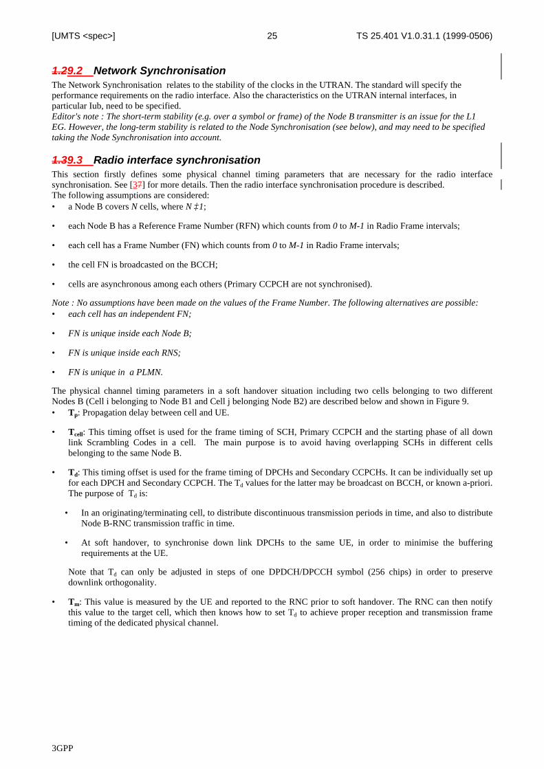
The physical channel timing parameters in a soft handover situation including two cells belonging to two differentNodes B (Cell i belonging to Node B1 and Cell j belonging Node B2) are described below and shown in Figure 9.• Tp: Propagation delay between cell and UE.
• Tcell: This timing offset is used for the frame timing of SCH, Primary CCPCH and the starting phase of all downlink Scrambling Codes in a cell. The main purpose is to avoid having overlapping SCHs in different cellsbelonging to the same Node B.
• Td: This timing offset is used for the frame timing of DPCHs and Secondary CCPCHs. It can be individually set upfor each DPCH and Secondary CCPCH. The Td values for the latter may be broadcast on BCCH, or known a-priori.The purpose of Td is:
• In an originating/terminating cell, to distribute discontinuous transmission periods in time, and also to distributeNode B-RNC transmission traffic in time.
• At soft handover, to synchronise down link DPCHs to the same UE, in order to minimise the bufferingrequirements at the UE.
Note that Td can only be adjusted in steps of one DPDCH/DPCCH symbol (256 chips) in order to preservedownlink orthogonality.
• Tm: This value is measured by the UE and reported to the RNC prior to soft handover. The RNC can then notifythis value to the target cell, which then knows how to set Td to achieve proper reception and transmission frametiming of the dedicated physical channel.
3GPP
TS 25.401 V1.0.31.1 (1999-0506)26[UMTS <spec>]
Node B1, Cell i DPCH (TX)
Node B1, Cell i DPCH (RX at UE)
Tp,1i
Tcell,i
Td,i
Node B2 Reference FN
Node B1, Cell i PRIMARY CCPCH (TX)
Node B1, Cell i PRIMARY CCPCH (RX at UE)
Tp,1i
Tm
Node B2, Cell j PRIMARY CCPCH (TX)
Tp,2
Node B2, Cell j DPCH(TX)
Tp,2j
Node B2, Cell j PRIMARY CCPCH (RX at UE)
Tcell,j
Td,j
Node B1 Reference FN
10 ms
Node B1, Cell i FN
Node B2, Cell j FN
SCH
SCH
…
…
Node B2, Cell j DPCH (RX at UE)
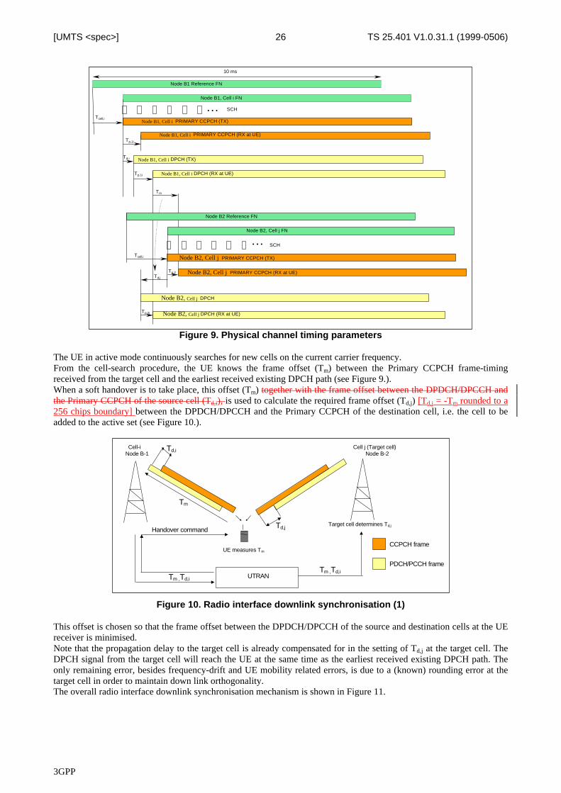
Figure 9. Physical channel timing parameters
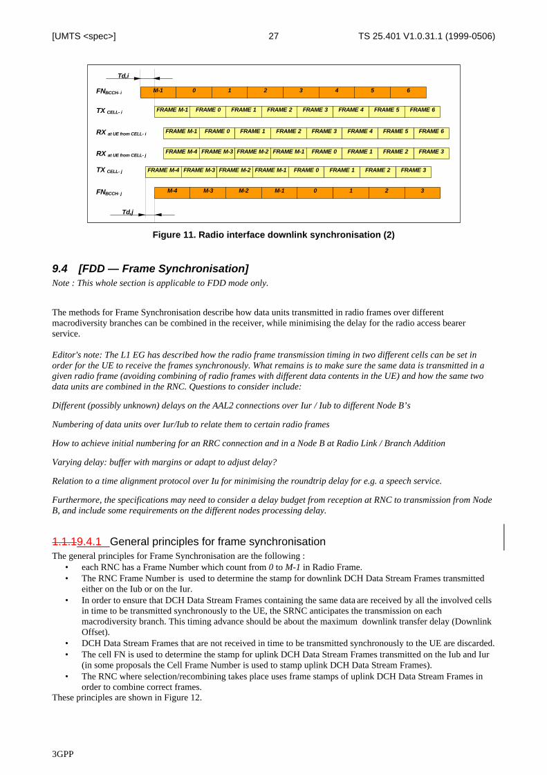
The UE in active mode continuously searches for new cells on the current carrier frequency.From the cell-search procedure, the UE knows the frame offset (Tm) between the Primary CCPCH frame-timingreceived from the target cell and the earliest received existing DPCH path (see Figure 9.).When a soft handover is to take place, this offset (Tm) together with the frame offset between the DPDCH/DPCCH andthe Primary CCPCH of the source cell (Td,i), is used to calculate the required frame offset (Td,j) [Td,j = -Tm rounded to a256 chips boundary] between the DPDCH/DPCCH and the Primary CCPCH of the destination cell, i.e. the cell to beadded to the active set (see Figure 10.).
CCPCH frame
PDCH/PCCH frame
UE measures Tm
Handover command
Tm
Tm ,Td,i
Cell-i∈ Node B-1
Cell j (Target cell)∈ Node B-2
Tm ,Td,iUTRAN
Target cell determines Td,jTd,j
Td,i
Figure 10. Radio interface downlink synchronisation (1)
This offset is chosen so that the frame offset between the DPDCH/DPCCH of the source and destination cells at the UEreceiver is minimised.Note that the propagation delay to the target cell is already compensated for in the setting of Td,j at the target cell. TheDPCH signal from the target cell will reach the UE at the same time as the earliest received existing DPCH path. Theonly remaining error, besides frequency-drift and UE mobility related errors, is due to a (known) rounding error at thetarget cell in order to maintain down link orthogonality.The overall radio interface downlink synchronisation mechanism is shown in Figure 11.
3GPP
TS 25.401 V1.0.31.1 (1999-0506)27[UMTS <spec>]
FNBCCH- i
TX CELL- i
M-1 0 1 2 3 4 65
Td,i
FNBCCH- j
TX CELL- j
M-4 M-3 M-2 M-1 0 1 32
FRAME M-1 FRAME 0 FRAME 1 FRAME 2 FRAME 3 FRAME 4 FRAME 6FRAME 5
FRAME M-4 FRAME M-3 FRAME M-2 FRAME M-1 FRAME 0 FRAME 1 FRAME 3FRAME 2
FRAME M-1 FRAME 0 FRAME 1 FRAME 2 FRAME 3 FRAME 4 FRAME 6FRAME 5
FRAME M-4 FRAME M-3 FRAME M-2 FRAME M-1 FRAME 0 FRAME 1 FRAME 3FRAME 2
RX at UE from CELL- i
RX at UE from CELL- j
Td,j
Figure 11. Radio interface downlink synchronisation (2)
9.4 [FDD — Frame Synchronisation]Note : This whole section is applicable to FDD mode only.
The methods for Frame Synchronisation describe how data units transmitted in radio frames over differentmacrodiversity branches can be combined in the receiver, while minimising the delay for the radio access bearerservice.
Editor's note: The L1 EG has described how the radio frame transmission timing in two different cells can be set inorder for the UE to receive the frames synchronously. What remains is to make sure the same data is transmitted in agiven radio frame (avoiding combining of radio frames with different data contents in the UE) and how the same twodata units are combined in the RNC. Questions to consider include:
Different (possibly unknown) delays on the AAL2 connections over Iur / Iub to different Node B’s
Numbering of data units over Iur/Iub to relate them to certain radio frames
How to achieve initial numbering for an RRC connection and in a Node B at Radio Link / Branch Addition
Varying delay: buffer with margins or adapt to adjust delay?
Relation to a time alignment protocol over Iu for minimising the roundtrip delay for e.g. a speech service.
Furthermore, the specifications may need to consider a delay budget from reception at RNC to transmission from NodeB, and include some requirements on the different nodes processing delay.
1.1.19.4.1 General principles for frame synchronisationThe general principles for Frame Synchronisation are the following :
• each RNC has a Frame Number which count from 0 to M-1 in Radio Frame.• The RNC Frame Number is used to determine the stamp for downlink DCH Data Stream Frames transmitted
either on the Iub or on the Iur.• In order to ensure that DCH Data Stream Frames containing the same data are received by all the involved cells
in time to be transmitted synchronously to the UE, the SRNC anticipates the transmission on eachmacrodiversity branch. This timing advance should be about the maximum downlink transfer delay (DownlinkOffset).
• DCH Data Stream Frames that are not received in time to be transmitted synchronously to the UE are discarded.• The cell FN is used to determine the stamp for uplink DCH Data Stream Frames transmitted on the Iub and Iur
(in some proposals the Cell Frame Number is used to stamp uplink DCH Data Stream Frames).• The RNC where selection/recombining takes place uses frame stamps of uplink DCH Data Stream Frames in
order to combine correct frames.These principles are shown in Figure 12.
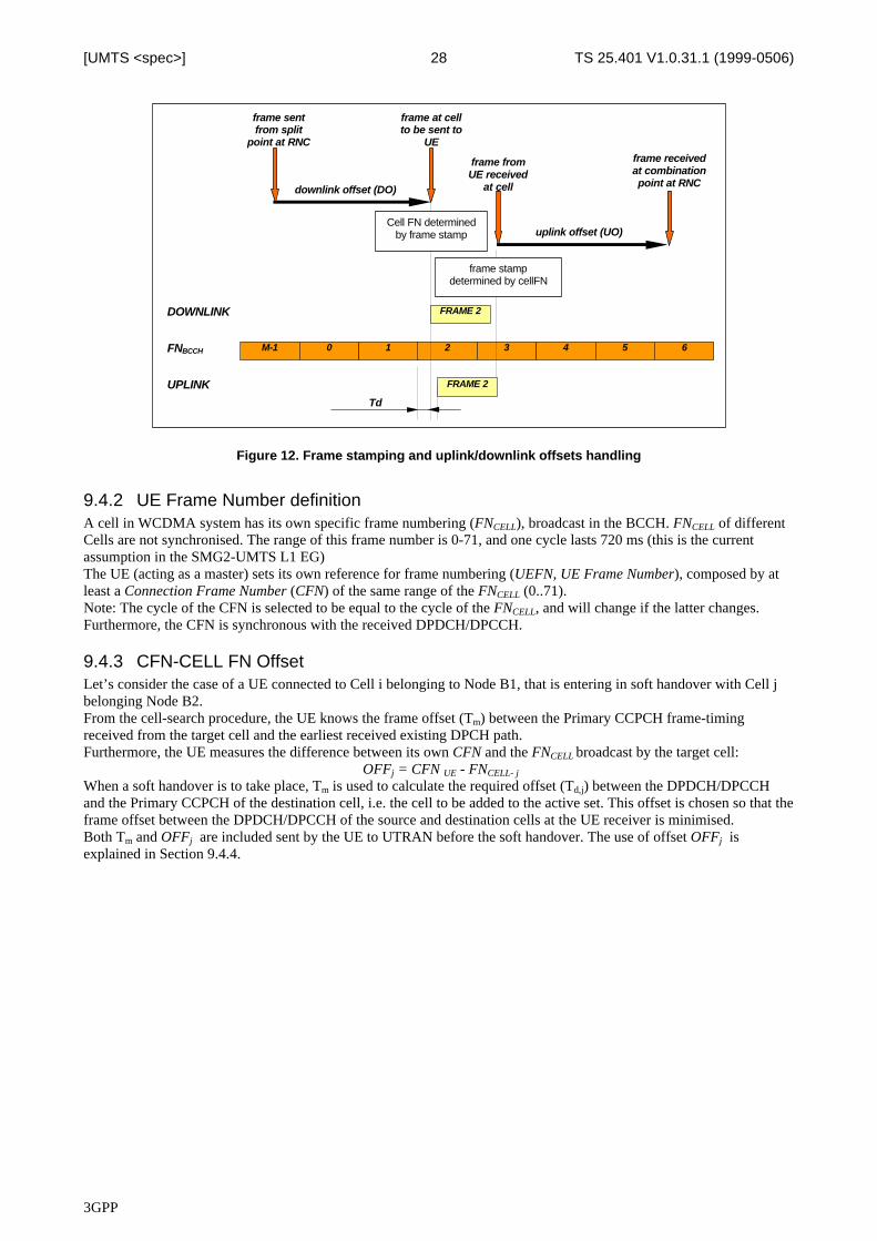
3GPP
TS 25.401 V1.0.31.1 (1999-0506)28[UMTS <spec>]
Td
FNBCCH M-1
DOWNLINK
UPLINK
0 1 2 3 4 65
FRAME 2
FRAME 2
downlink offset (DO)
uplink offset (UO)
frame sentfrom split
point at RNC
frame at cellto be sent to
UE
frame fromUE received
at cell
frame receivedat combinationpoint at RNC
Cell FN determinedby frame stamp
frame stampdetermined by cellFN
Figure 12. Frame stamping and uplink/downlink offsets handling
9.4.2 UE Frame Number definitionA cell in WCDMA system has its own specific frame numbering (FNCELL), broadcast in the BCCH. FNCELL of differentCells are not synchronised. The range of this frame number is 0-71, and one cycle lasts 720 ms (this is the currentassumption in the SMG2-UMTS L1 EG)The UE (acting as a master) sets its own reference for frame numbering (UEFN, UE Frame Number), composed by atleast a Connection Frame Number (CFN) of the same range of the FNCELL (0..71).Note: The cycle of the CFN is selected to be equal to the cycle of the FNCELL, and will change if the latter changes.Furthermore, the CFN is synchronous with the received DPDCH/DPCCH.
9.4.3 CFN-CELL FN OffsetLet’s consider the case of a UE connected to Cell i belonging to Node B1, that is entering in soft handover with Cell jbelonging Node B2.From the cell-search procedure, the UE knows the frame offset (Tm) between the Primary CCPCH frame-timingreceived from the target cell and the earliest received existing DPCH path.Furthermore, the UE measures the difference between its own CFN and the FNCELL broadcast by the target cell:
OFFj = CFN UE - FNCELL- j
When a soft handover is to take place, Tm is used to calculate the required offset (Td,j) between the DPDCH/DPCCHand the Primary CCPCH of the destination cell, i.e. the cell to be added to the active set. This offset is chosen so that theframe offset between the DPDCH/DPCCH of the source and destination cells at the UE receiver is minimised.Both Tm and OFFj are included sent by the UE to UTRAN before the soft handover. The use of offset OFFj isexplained in Section 9.4.4.
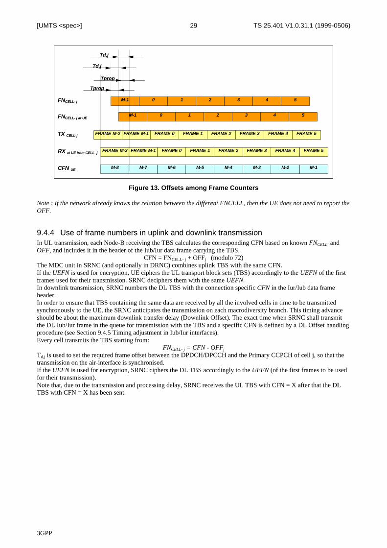
3GPP
TS 25.401 V1.0.31.1 (1999-0506)29[UMTS <spec>]
FNCELL- j
TX CELL-j
M-1 0 1 2 3 4 5
Tprop
FRAME M-2 FRAME M-1 FRAME 0 FRAME 1 FRAME 2 FRAME 3 FRAME 5FRAME 4
FRAME M-2 FRAME M-1 FRAME 0 FRAME 1 FRAME 2 FRAME 3 FRAME 5FRAME 4RX at UE from CELL- j
M-8 M-7 M-6 M-5 M-4 M-3 M-1M-2CFN UE
M-1 0 1 2 3 4 5FNCELL- j at UE
Td,j
Td,j
Tprop
Figure 13. Offsets among Frame Counters
Note : If the network already knows the relation between the different FNCELL, then the UE does not need to report theOFF.
9.4.4 Use of frame numbers in uplink and downlink transmissionIn UL transmission, each Node-B receiving the TBS calculates the corresponding CFN based on known FNCELL andOFF, and includes it in the header of the Iub/Iur data frame carrying the TBS.
CFN = FNCELL- j + OFFj (modulo 72)The MDC unit in SRNC (and optionally in DRNC) combines uplink TBS with the same CFN.If the UEFN is used for encryption, UE ciphers the UL transport block sets (TBS) accordingly to the UEFN of the firstframes used for their transmission. SRNC deciphers them with the same UEFN.In downlink transmission, SRNC numbers the DL TBS with the connection specific CFN in the Iur/Iub data frameheader.In order to ensure that TBS containing the same data are received by all the involved cells in time to be transmittedsynchronously to the UE, the SRNC anticipates the transmission on each macrodiversity branch. This timing advanceshould be about the maximum downlink transfer delay (Downlink Offset). The exact time when SRNC shall transmitthe DL Iub/Iur frame in the queue for transmission with the TBS and a specific CFN is defined by a DL Offset handlingprocedure (see Section 9.4.5 Timing adjustment in Iub/Iur interfaces).Every cell transmits the TBS starting from:
FNCELL- j = CFN - OFFj
Td,j is used to set the required frame offset between the DPDCH/DPCCH and the Primary CCPCH of cell j, so that thetransmission on the air-interface is synchronised.If the UEFN is used for encryption, SRNC ciphers the DL TBS accordingly to the UEFN (of the first frames to be usedfor their transmission).Note that, due to the transmission and processing delay, SRNC receives the UL TBS with CFN = X after that the DLTBS with CFN = X has been sent.
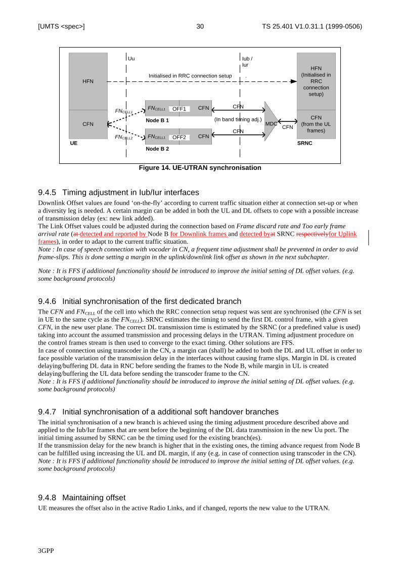
3GPP
TS 25.401 V1.0.31.1 (1999-0506)30[UMTS <spec>]
FNCELL1
FN
FNCELL2
Uu
MDC
CFN
(In band timing adj.)
CFNCFNCFN
HFN
CFN(from the UL
frames)
HFN(Initialised in
RRCconnection
setup)
UE SRNC
Iub /Iur
Initialised in RRC connection setup .
FNCELL1 CFNOFF1
Node B 1
FNCELL1 CFNOFF2
Node B 2
Figure 14. UE-UTRAN synchronisation
9.4.5 Timing adjustment in Iub/Iur interfacesDownlink Offset values are found ‘on-the-fly’ according to current traffic situation either at connection set-up or whena diversity leg is needed. A certain margin can be added in both the UL and DL offsets to cope with a possible increaseof transmission delay (ex: new link added).The Link Offset values could be adjusted during the connection based on Frame discard rate and Too early framearrival rate (at detected and reported by Node B for Downlink frames and detected byat SRNC respectivelyfor Uplinkframes), in order to adapt to the current traffic situation.Note : In case of speech connection with vocoder in CN, a frequent time adjustment shall be prevented in order to avidframe-slips. This is done setting a margin in the uplink/downlink link offset as shown in the next subchapter.
Note : It is FFS if additional functionality should be introduced to improve the initial setting of DL offset values. (e.g.some background protocols)
9.4.6 Initial synchronisation of the first dedicated branchThe CFN and FNCELL of the cell into which the RRC connection setup request was sent are synchronised (the CFN is setin UE to the same cycle as the FNCELL). SRNC estimates the timing to send the first DL control frame, with a givenCFN, in the new user plane. The correct DL transmission time is estimated by the SRNC (or a predefined value is used)taking into account the assumed transmission and processing delays in the UTRAN. Timing adjustment procedure onthe control frames stream is then used to converge to the exact timing. Other solutions are FFS.In case of connection using transcoder in the CN, a margin can (shall) be added to both the DL and UL offset in order toface possible variation of the transmission delay in the interfaces without causing frame slips. Margin in DL is createddelaying/buffering DL data in RNC before sending the frames to the Node B, while margin in UL is createddelaying/buffering the UL data before sending the transcoder frame to the CN.Note : It is FFS if additional functionality should be introduced to improve the initial setting of DL offset values. (e.g.some background protocols)
9.4.7 Initial synchronisation of a additional soft handover branchesThe initial synchronisation of a new branch is achieved using the timing adjustment procedure described above andapplied to the Iub/Iur frames that are sent before the beginning of the DL data transmission in the new Uu port. Theinitial timing assumed by SRNC can be the timing used for the existing branch(es).If the transmission delay for the new branch is higher that in the existing ones, the timing advance request from Node Bcan be fulfilled using increasing the UL and DL margin, if any (e.g. in case of connection using transcoder in the CN).Note : It is FFS if additional functionality should be introduced to improve the initial setting of DL offset values. (e.g.some background protocols)
9.4.8 Maintaining offsetUE measures the offset also in the active Radio Links, and if changed, reports the new value to the UTRAN.
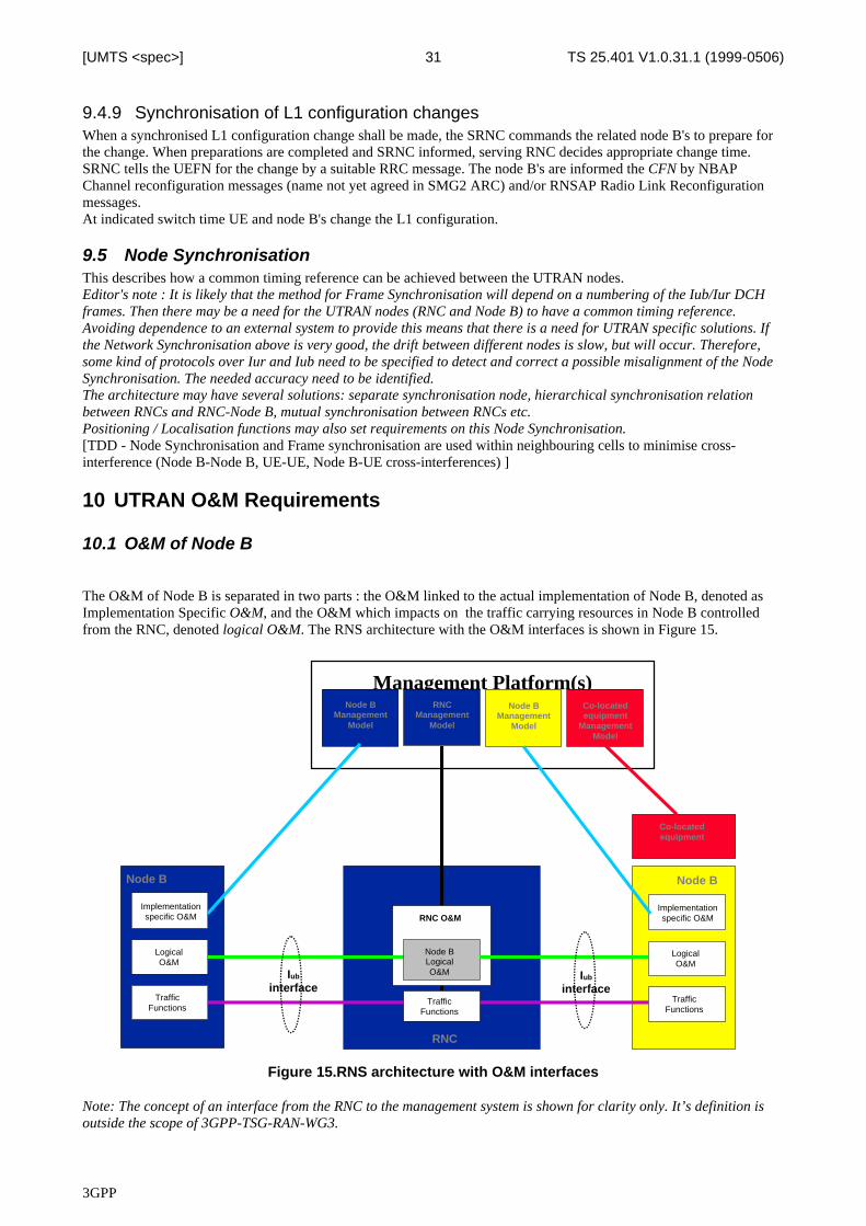
3GPP
TS 25.401 V1.0.31.1 (1999-0506)31[UMTS <spec>]
9.4.9 Synchronisation of L1 configuration changesWhen a synchronised L1 configuration change shall be made, the SRNC commands the related node B's to prepare forthe change. When preparations are completed and SRNC informed, serving RNC decides appropriate change time.SRNC tells the UEFN for the change by a suitable RRC message. The node B's are informed the CFN by NBAPChannel reconfiguration messages (name not yet agreed in SMG2 ARC) and/or RNSAP Radio Link Reconfigurationmessages.At indicated switch time UE and node B's change the L1 configuration.
9.5 Node SynchronisationThis describes how a common timing reference can be achieved between the UTRAN nodes.Editor's note : It is likely that the method for Frame Synchronisation will depend on a numbering of the Iub/Iur DCHframes. Then there may be a need for the UTRAN nodes (RNC and Node B) to have a common timing reference.Avoiding dependence to an external system to provide this means that there is a need for UTRAN specific solutions. Ifthe Network Synchronisation above is very good, the drift between different nodes is slow, but will occur. Therefore,some kind of protocols over Iur and Iub need to be specified to detect and correct a possible misalignment of the NodeSynchronisation. The needed accuracy need to be identified.The architecture may have several solutions: separate synchronisation node, hierarchical synchronisation relationbetween RNCs and RNC-Node B, mutual synchronisation between RNCs etc.Positioning / Localisation functions may also set requirements on this Node Synchronisation.[TDD - Node Synchronisation and Frame synchronisation are used within neighbouring cells to minimise cross-interference (Node B-Node B, UE-UE, Node B-UE cross-interferences) ]
10 UTRAN O&M Requirements
10.1 O&M of Node B
The O&M of Node B is separated in two parts : the O&M linked to the actual implementation of Node B, denoted asImplementation Specific O&M, and the O&M which impacts on the traffic carrying resources in Node B controlledfrom the RNC, denoted logical O&M. The RNS architecture with the O&M interfaces is shown in Figure 15.
Management Platform(s)
Node B
RNCManagement
Model
Implementationspecific O&M
Iub
interface
LogicalO&M
Node BManagement
Model
TrafficFunctions
Node B
Implementationspecific O&M
LogicalO&M
TrafficFunctions
RNC O&M
Node BLogicalO&M
TrafficFunctions
Co-locatedequipment
Node BManagement
Model
Co-locatedequipment
ManagementModel
RNC
Iub
interface
Figure 15.RNS architecture with O&M interfaces
Note: The concept of an interface from the RNC to the management system is shown for clarity only. It’s definition isoutside the scope of 3GPP-TSG-RAN-WG3.
3GPP
TS 25.401 V1.0.31.1 (1999-0506)32[UMTS <spec>]
Note: The presentation of the O&M functions within the management system is shown for clarity only. Their actualimplementation is outside the scope of 3GPP-TSG-RAN-WG3.
Note: Implementation Specific O&M can be routed directly to the management system through a specific interface or itcan be routed via the RNC, thus sharing the same physical transport as the Iub interface.
Note: The standardisation of the Implementation Specific O&M is outside the scope of 3GPP-TSG-RAN-WG3. The3GPP-TSG-RAN-WG3 should only address the bearer for the Implementation Specific O&M.
Note: The categorisation of Node B O&M functions into either Logical or Implementation Specific O&M is FFS.
Note: The concept of an interface to support signalling between co-located equipment and the management system isFFS.
10.1.1 Implementation Specific O&MThe Implementation Specific O&M functions are heavily dependent on the implementation of Node B, both for itshardware components and for the management of the software components. It needs therefore to be implementationdependent, and be performed between Node B and the management system.• This means that the standardisation in 3GPP-TSG-RAN-WG3 should only address the transport of O&M signalling
between the management system and Node B. This transport can be performed by a transport mechanism, possiblyIP. The transport can be potenstially across the RNC, but not necessarilly. Between RNC and Node B, dedicatedPVCs or SVCs could be used.
10.1.2 Logical O&MThe Node B provides at the minimum access to a set of logical resources e.g. ports both on the Iub interface and on theUu (radio) interface. These logical resources are controlled by the RNC on the Iub interface by the Traffic managementfunctions.Since the RR layer is probably within the RNC, the RNC should know about the availability status of a given cell.Similarly, it would be beneficial that the RNC has a view of the available radio resources for each cell. This iscompatible with the fact that the RR layer is responsible for the management of the system load in interferences inparticular at the RNS level.The management of these logical resources is desirable (but it should be noted that it is not absolutely necessary) for theproper operation of the RNS. Actually, the Radio Resource algorithms within the RNC can only be optimised with theknowledge of the available logical resources within each Node B of the RNS. Actually, because of soft handover, someknowledge on neighbour RNS may be beneficial as well.The management of the logical resources of Node B needs to be performed on the Iub interface. In order to reach thatobjective, it is necessary that a logical model of Node B is defined, and then the procedures to manage these resourceswill be defined on the Iub.
11 UTRAN InterfacesEditor's Note : Editorial work for splitting between S3.01 and S3.10, S3.20 and S3.30 is still ongoing. This will affectsections 11 and sections 12.
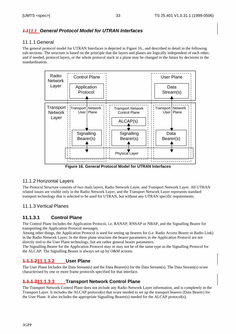
3GPP
TS 25.401 V1.0.31.1 (1999-0506)33[UMTS <spec>]
1.111.1 General Protocol Model for UTRAN Interfaces
11.1.1 GeneralThe general protocol model for UTRAN Interfaces is depicted in Figure 16., and described in detail in the followingsub-sections. The structure is based on the principle that the layers and planes are logically independent of each other,and if needed, protocol layers, or the whole protocol stack in a plane may be changed in the future by decisions in thestandardisation.
ApplicationProtocol
DataStream(s)
ALCAP(s)
TransportNetwork
Layer
Physical Layer
SignallingBearer(s)
TransportUser
NetworkPlane
Control Plane User Plane
TransportUser
NetworkPlane
Transport NetworkControl Plane
RadioNetwork
Layer
SignallingBearer(s)
DataBearer(s)
Figure 16. General Protocol Model for UTRAN Interfaces
11.1.2 Horizontal LayersThe Protocol Structure consists of two main layers, Radio Network Layer, and Transport Network Layer. All UTRANrelated issues are visible only in the Radio Network Layer, and the Transport Network Layer represents standardtransport technology that is selected to be used for UTRAN, but without any UTRAN specific requirements.
11.1.3 Vertical Planes
11.1.3.1 Control PlaneThe Control Plane Includes the Application Protocol, i.e. RANAP, RNSAP or NBAP, and the Signalling Bearer fortransporting the Application Protocol messages.Among other things, the Application Protocol is used for setting up bearers for (i.e. Radio Access Bearer or Radio Link)in the Radio Network Layer. In the three plane structure the bearer parameters in the Application Protocol are notdirectly tied to the User Plane technology, but are rather general bearer parameters.The Signalling Bearer for the Application Protocol may or may not be of the same type as the Signalling Protocol forthe ALCAP. The Signalling Bearer is always set up by O&M actions.
1.1.1.211.1.3.2 User PlaneThe User Plane Includes the Data Stream(s) and the Data Bearer(s) for the Data Stream(s). The Data Stream(s) is/arecharacterised by one or more frame protocols specified for that interface.
1.1.1.311.1.3.3 Transport Network Control PlaneThe Transport Network Control Plane does not include any Radio Network Layer information, and is completely in theTransport Layer. It includes the ALCAP protocol(s) that is/are needed to set up the transport bearers (Data Bearer) forthe User Plane. It also includes the appropriate Signalling Bearer(s) needed for the ALCAP protocol(s).
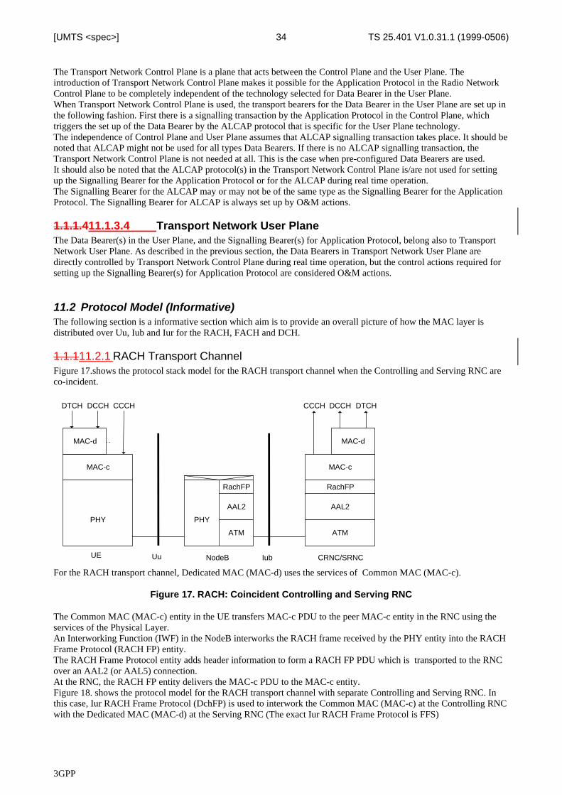
3GPP
TS 25.401 V1.0.31.1 (1999-0506)34[UMTS <spec>]
The Transport Network Control Plane is a plane that acts between the Control Plane and the User Plane. Theintroduction of Transport Network Control Plane makes it possible for the Application Protocol in the Radio NetworkControl Plane to be completely independent of the technology selected for Data Bearer in the User Plane.When Transport Network Control Plane is used, the transport bearers for the Data Bearer in the User Plane are set up inthe following fashion. First there is a signalling transaction by the Application Protocol in the Control Plane, whichtriggers the set up of the Data Bearer by the ALCAP protocol that is specific for the User Plane technology.The independence of Control Plane and User Plane assumes that ALCAP signalling transaction takes place. It should benoted that ALCAP might not be used for all types Data Bearers. If there is no ALCAP signalling transaction, theTransport Network Control Plane is not needed at all. This is the case when pre-configured Data Bearers are used.It should also be noted that the ALCAP protocol(s) in the Transport Network Control Plane is/are not used for settingup the Signalling Bearer for the Application Protocol or for the ALCAP during real time operation.The Signalling Bearer for the ALCAP may or may not be of the same type as the Signalling Bearer for the ApplicationProtocol. The Signalling Bearer for ALCAP is always set up by O&M actions.
1.1.1.411.1.3.4 Transport Network User PlaneThe Data Bearer(s) in the User Plane, and the Signalling Bearer(s) for Application Protocol, belong also to TransportNetwork User Plane. As described in the previous section, the Data Bearers in Transport Network User Plane aredirectly controlled by Transport Network Control Plane during real time operation, but the control actions required forsetting up the Signalling Bearer(s) for Application Protocol are considered O&M actions.
11.2 Protocol Model (Informative)The following section is a informative section which aim is to provide an overall picture of how the MAC layer isdistributed over Uu, Iub and Iur for the RACH, FACH and DCH.
1.1.111.2.1 RACH Transport ChannelFigure 17.shows the protocol stack model for the RACH transport channel when the Controlling and Serving RNC areco-incident.
For the RACH transport channel, Dedicated MAC (MAC-d) uses the services of Common MAC (MAC-c).
Figure 17. RACH: Coincident Controlling and Serving RNC
The Common MAC (MAC-c) entity in the UE transfers MAC-c PDU to the peer MAC-c entity in the RNC using theservices of the Physical Layer.An Interworking Function (IWF) in the NodeB interworks the RACH frame received by the PHY entity into the RACHFrame Protocol (RACH FP) entity.The RACH Frame Protocol entity adds header information to form a RACH FP PDU which is transported to the RNCover an AAL2 (or AAL5) connection.At the RNC, the RACH FP entity delivers the MAC-c PDU to the MAC-c entity.Figure 18. shows the protocol model for the RACH transport channel with separate Controlling and Serving RNC. Inthis case, Iur RACH Frame Protocol (DchFP) is used to interwork the Common MAC (MAC-c) at the Controlling RNCwith the Dedicated MAC (MAC-d) at the Serving RNC (The exact Iur RACH Frame Protocol is FFS)
PHY PHY
ATM
RachFP
ATM
RachFP
MAC-c
IubUE NodeB CRNC/SRNCUu
MAC-d
CCCH DCCH DTCH
AAL2 AAL2
MAC-c
MAC-d
CCCHDTCH DCCH
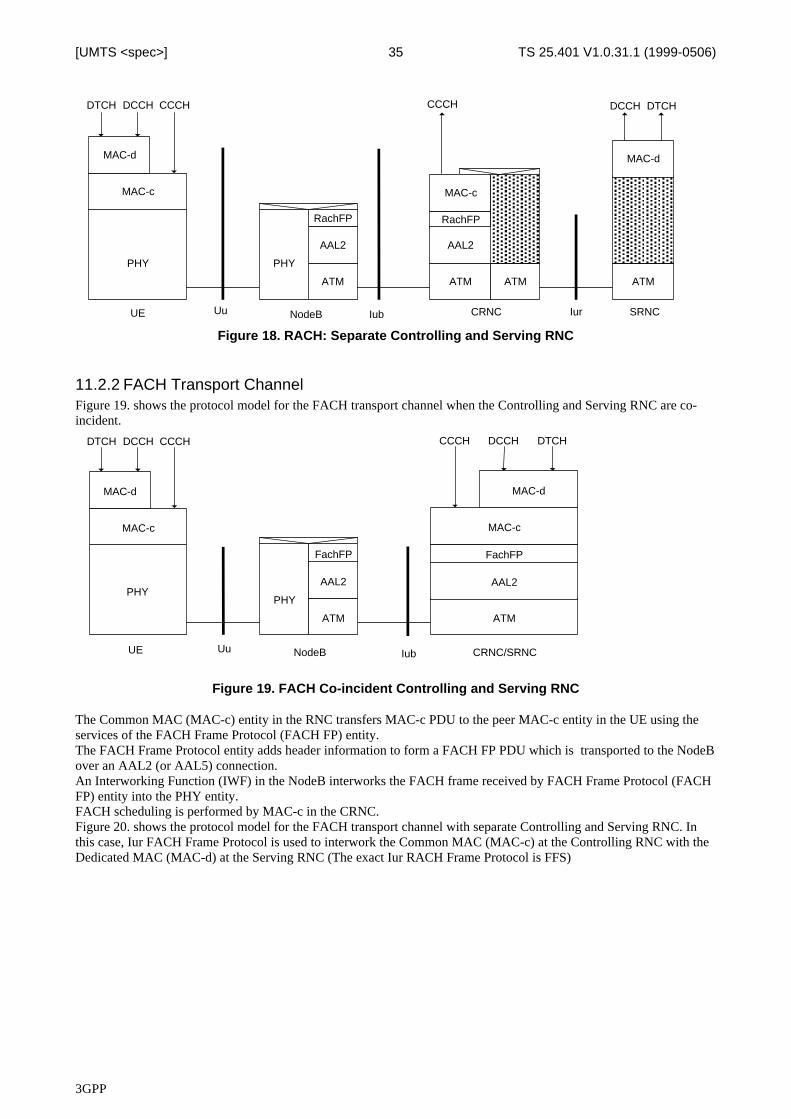
3GPP
TS 25.401 V1.0.31.1 (1999-0506)35[UMTS <spec>]
Figure 18. RACH: Separate Controlling and Serving RNC
11.2.2 FACH Transport ChannelFigure 19. shows the protocol model for the FACH transport channel when the Controlling and Serving RNC are co-incident.
Figure 19. FACH Co-incident Controlling and Serving RNC
The Common MAC (MAC-c) entity in the RNC transfers MAC-c PDU to the peer MAC-c entity in the UE using theservices of the FACH Frame Protocol (FACH FP) entity.The FACH Frame Protocol entity adds header information to form a FACH FP PDU which is transported to the NodeBover an AAL2 (or AAL5) connection.An Interworking Function (IWF) in the NodeB interworks the FACH frame received by FACH Frame Protocol (FACHFP) entity into the PHY entity.FACH scheduling is performed by MAC-c in the CRNC.Figure 20. shows the protocol model for the FACH transport channel with separate Controlling and Serving RNC. Inthis case, Iur FACH Frame Protocol is used to interwork the Common MAC (MAC-c) at the Controlling RNC with theDedicated MAC (MAC-d) at the Serving RNC (The exact Iur RACH Frame Protocol is FFS)
PHYPHY
ATM
FachFP
ATM
FachFP
MAC-c
IubUE NodeB CRNC/SRNCUu
MAC-d
CCCH DCCH DTCH
AAL2 AAL2
MAC-c
MAC-d
CCCHDTCH DCCH
PHY PHY
ATM
RachFP
ATM
RachFP
MAC-c
IubUE NodeB CRNCUu
ATM ATM
Iur
MAC-d
CCCH DCCH DTCH
SRNC
AAL2 AAL2
MAC-c
MAC-d
CCCHDTCH DCCH
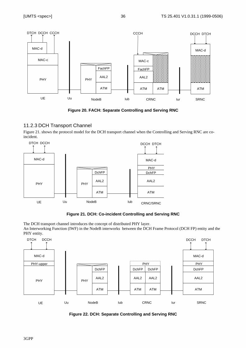
3GPP
TS 25.401 V1.0.31.1 (1999-0506)36[UMTS <spec>]
Figure 20. FACH: Separate Controlling and Serving RNC
11.2.3 DCH Transport ChannelFigure 21. shows the protocol model for the DCH transport channel when the Controlling and Serving RNC are co-incident.
Figure 21. DCH: Co-incident Controlling and Serving RNC
The DCH transport channel introduces the concept of distributed PHY layer.An Interworking Function (IWF) in the NodeB interworks between the DCH Frame Protocol (DCH FP) entity and thePHY entity.
Figure 22. DCH: Separate Controlling and Serving RNC
PHY PHY
ATM
FachFP
IubUE NodeB CRNCUu Iur SRNC
AAL2
ATM
FachFP
MAC-c
ATM ATM
MAC-d
CCCH DCCH DTCH
AAL2
MAC-c
MAC-d
CCCHDTCH DCCH
PHY PHY
ATM
DchFP
ATM
DchFP
IubUE NodeB CRNC/SRNCUu
MAC-d
DCCH DTCH
MAC-d
PHY
AAL2 AAL2
DTCH DCCH
PHY PHY
ATM
DchFP
ATM
MAC-d
IubUE NodeB CRNCUu SRNC
ATM ATM
Iur
MAC-d
DCCH DTCH
DchFP
PHY-upper PHY
AAL2 AAL2
DTCH DCCH
AAL2 AAL2
DchFP DchFP
PHY
3GPP
TS 25.401 V1.0.31.1 (1999-0506)37[UMTS <spec>]
Figure 22. shows the protocol model for the DCH transport channel with separate Controlling and Serving RNC. In thiscase, the Iub DCH FP is terminated in the CRNC and interworked with the Iur DCH FP through a PHY function. Thisfunction performs optional soft handover or can be a null function.
12 UTRAN Performance Requirements
12.1 UTRAN delay requirementsThe maximum transmission delay of a diversity branch and the maximum processing delay introduced by singleUTRAN network elements shall be defined.
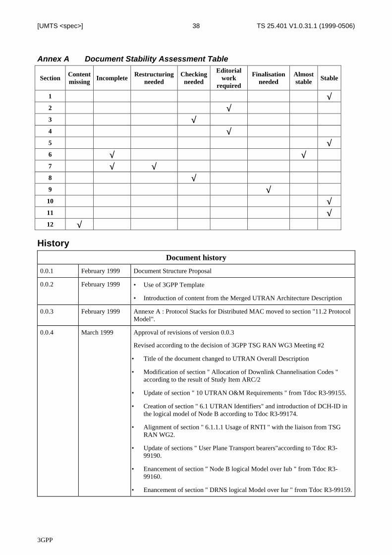
3GPP
TS 25.401 V1.0.31.1 (1999-0506)38[UMTS <spec>]
Annex A Document Stability Assessment Table
SectionContentmissing Incomplete
Restructuringneeded
Checkingneeded
Editorialwork
required
Finalisationneeded
Almoststable Stable
1 √√2 √√3 √√4 √√5 √√6 √√ √√7 √√ √√8 √√9 √√
10 √√11 √√12 √√
History
Document history
0.0.1 February 1999 Document Structure Proposal
0.0.2 February 1999 • Use of 3GPP Template
• Introduction of content from the Merged UTRAN Architecture Description
0.0.3 February 1999 Annexe A : Protocol Stacks for Distributed MAC moved to section "11.2 ProtocolModel".
0.0.4 March 1999 Approval of revisions of version 0.0.3
Revised according to the decision of 3GPP TSG RAN WG3 Meeting #2
• Title of the document changed to UTRAN Overall Description
• Modification of section " Allocation of Downlink Channelisation Codes "according to the result of Study Item ARC/2
• Update of section " 10 UTRAN O&M Requirements " from Tdoc R3-99155.
• Creation of section " 6.1 UTRAN Identifiers" and introduction of DCH-ID inthe logical model of Node B according to Tdoc R3-99174.
• Alignment of section " 6.1.1.1 Usage of RNTI " with the liaison from TSGRAN WG2.
• Update of sections " User Plane Transport bearers"according to Tdoc R3-99190.
• Enancement of section " Node B logical Model over Iub " from Tdoc R3-99160.
• Enancement of section " DRNS logical Model over Iur " from Tdoc R3-99159.
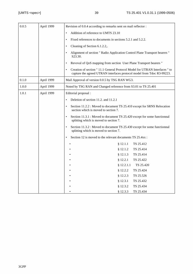
3GPP
TS 25.401 V1.0.31.1 (1999-0506)39[UMTS <spec>]
0.0.5 April 1999 Revision of 0.0.4 according to remarks sent on mail reflector :
• Addition of reference to UMTS 23.10
• Fixed references to documents in sections 5.2.1 and 5.2.2.
• Cleaning of Section 6.1.2.2,.
• Alignment of section " Radio Application Control Plane Transport bearers "S23.30.
• Revoval of QoS mapping from section User Plane Transport bearers "
• Creation of section " 11.1 General Protocol Model for UTRAN Interfaces " tocapture the agreed UTRAN interfaces protocol model from Tdoc R3-99223.
0.1.0 April 1999 Mail Approval of version 0.0.5 by TSG RAN WG3.
1.0.0 April 1999 Noted by TSG RAN and Changed reference from S3.01 to TS 25.401
1.0.1 April 1999 Editorial proposal :
• Deletion of section 11.2. and 11.2.1
• Section 11.2.2 : Moved to document TS 25.410 except for SRNS Relocationsection which is moved to section 7.
• Section 11.3.1 : Moved to document TS 25.420 except for some functionnalsplitting which is moved to section 7.
• Section 11.3.2 : Moved to document TS 25.430 except for some functionnalsplitting which is moved to section 7.
• Section 12 is moved to the relevant documents TS 25.4xx :
• § 12.1.1 ⇒ TS 25.412
• § 12.1.2 ⇒ TS 25.414
• § 12.1.3 ⇒ TS 25.414
• § 12.2.1 ⇒ TS 25.422
• § 12.2.1.1 ⇒ TS 25.420
• § 12.2.2 ⇒ TS 25.424
• § 12.2.3 ⇒ TS 25.526
• § 12.3.1 ⇒ TS 25.432
• § 12.3.2 ⇒ TS 25.434
• § 12.3.3 ⇒ TS 25.434
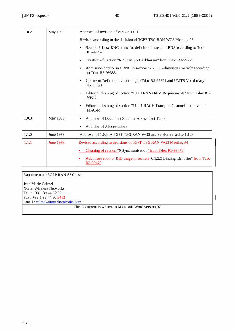
3GPP
TS 25.401 V1.0.31.1 (1999-0506)40[UMTS <spec>]
1.0.2 May 1999 Approval of revision of version 1.0.1
Revised according to the decision of 3GPP TSG RAN WG3 Meeting #3
• Section 3.1 use RNC in the Iur definition instead of RNS according to TdocR3-99262.
• Creation of Section "6.2 Transport Addresses" from Tdoc R3-99275.
• Admission control in CRNC in section "7.2.1.1 Admission Control" accordingto Tdoc R3-99388.
• Update of Definitions according to Tdoc R3-99321 and UMTS Vocabularydocument.
• Editorial cleaning of section "10 UTRAN O&M Requirements" from Tdoc R3-99322.
• Editorial cleaning of section "11.2.1 RACH Transport Channel": removal ofMAC-lc
1.0.3 May 1999 • Addition of Document Stability Assessment Table
• Addition of Abbreviations
1.1.0 June 1999 Approval of 1.0.3 by 3GPP TSG RAN WG3 and version raised to 1.1.0
1.1.1 June 1999 Revised according to decisions of 3GPP TSG RAN WG3 Meeting #4
• Cleaning of section "9 Synchronisation" from Tdoc R3-99470
• Add illustration of BID usage in section "6.1.2.3 Binding identifier" from TdocR3-99479
Rapporteur for 3GPP RAN S3.01 is:
Jean Marie CalmelNortel Wireless NetworksTel. : +33 1 39 44 52 82Fax : +33 1 39 44 50 5412Email : [email protected]
This document is written in Microsoft Word version 97