tsgr2#6(99)907 - 3gpp
TRANSCRIPT
TSG-RAN Working Group 2 (Radio layer 2 and Radio layer 3) TSGR2#6(99)907Sophia Antipolis 16th to 20th July 1999
Agenda Item: 5
Source: Rapporteur (CSELT)
Document for: Approval
Title: Results of the e-mail correspondence group on RRM
__________________________________________________________________
3G TR 25.922 V0.2.21 (1999-06)Technical Report
3rd Generation Partnership Project;Technical Specification Group RAN;
Working Group 2 (WG2)Radio Resource Management Strategies
(3G TR 25.922 version 0.2.1)
The present document has been developed within the 3rd Generation Partnership Project (3GPP TM) and may be further elaborated for the purposes of 3GPP.The present document has not been subject to any approval process by the 3GPP Organisational Partners and shall not be implemented.This Specification is provided for future development work within 3GPP only. The Organisational Partners accept no liability for any use of thisSpecification.Specifications and reports for implementation of the 3GPP TM system should be obtained via the 3GPP Organisational Partners' Publications Offices.
ETSI
3G TR 25.922 V0.2.21 (1999-06)33G TR 25.922 version 0.2.1
ReferenceDTS/TSG<name abbv>-0<WG no><spec no> U
Keywords<keyword[, keyword]>
3GPP
Postal address
3GPP support office address650 Route des Lucioles - Sophia Antipolis
Valbonne - FRANCETel.: +33 4 92 94 42 00 Fax: +33 4 93 65 47 16
Internethttp://www.3gpp.org
ETSI
3G TR 25.922 V0.2.21 (1999-06)43G TR 25.922 version 0.2.1
Contents
Foreword ............................................................................................................................................................ 8
1 Scope ....................................................................................................................................................... 9
2 References ............................................................................................................................................... 9
3 Definitions, symbols and abbreviations .................................................................................................. 93.1 Definitions.......................................................................................................................................................... 93.2 Symbols.............................................................................................................................................................. 93.3 Abbreviations ..................................................................................................................................................... 9
4 General Description of Radio Resource Management .......................................................................... 12
5 Idle Mode Tasks .................................................................................................................................... 125.1 Overview .......................................................................................................................................................... 125.2 Service type in Idle mode ................................................................................................................................. 125.3 Criteria for Cell Selection and Reselection ...................................................................................................... 125.3.1 Cell Selection Monitoring Frequency or Cell Set ............................................................................................ 125.3.2 Cell Re-Selection Monitoring Frequency or Cell Set ....................................................................................... 125.4 Location Registration .................................................................................................................................................. 125.5 Broadcast information receiving ...................................................................................................................... 12
6 RRC Connection Mobility ..................................................................................................................... 136.1 General Description of Connected Mode ......................................................................................................... 136.1.1 Handover .................................................................................................................................................... 136.1.1.1 Strategy ................................................................................................................................................. 136.1.1.2 Causes ................................................................................................................................................... 136.1.1.3 Cell Set for the Handover Preparation .................................................................................................. 146.1.1.4 Hard Handover ..................................................................................................................................... 146.1.1.4.1 Hard Handover (FDD and TDD Hard) ........................................................................................... 146.1.1.5 Soft Handover ....................................................................................................................................... 146.1.1.5.1 Soft Handover Parameters and definitions ...................................................................................... 146.1.1.5.2 General Scheme of Soft Handover Algorithm ................................................................................. 146.1.1.5.3 Soft Handover Execution ................................................................................................................................... 166.1.1.6 Inter System Handover ......................................................................................................................... 186.1.1.6.1 Handover 3G to 2G ......................................................................................................................... 186.1.2 Radio Link Management ............................................................................................................................ 18
7 Admission Control ................................................................................................................................. 197.1 Overall strategies ............................................................................................................................................. 197.2 Scenarios .......................................................................................................................................................... 207.2.1 CAC performed in SRNS ........................................................................................................................... 207.2.2 CAC performed in DRNC .......................................................................................................................... 207.2.2.1 Case of DCH ......................................................................................................................................... 207.2.2.2 Case of Common Transport Channels .................................................................................................. 21
8 Radio Access Bearer Control ................................................................................................................ 218.1 Radio Access Bearer Control – Overview of Procedures ................................................................................ 218.2 Usage of RAB control procedures ................................................................................................................... 228.2.1 Examples of Radio Access Bearer Setup .................................................................................................... 228.2.2 Examples of Physical Channel Reconfiguration ......................................................................................... 228.2.2.1 Increased UL data, with switch from RACH/FACH to DCH/DCH ...................................................... 228.2.2.2 Increased DL data, no Transport channel type switching ..................................................................... 238.2.2.3 Decrease DL data, no Transport channel type switching ...................................................................... 248.2.2.4 Decreased UL data, with switch from DCH/DCH to RACH/FACH ..................................................... 248.2.3 Examples of Transport Channel Reconfiguration ....................................................................................... 248.2.3.1 Increased UL data, with no transport channel type switching ............................................................... 258.2.3.2 Decreased DL data, with switch from DCH/DCH to RACH/FACH ..................................................... 258.2.4 Examples of RAB and Signalling link Reconfiguration ............................................................................. 268.3 RRC Elementary Procedures........................................................................................ Error! Bookmark not defined.
ETSI
3G TR 25.922 V0.2.21 (1999-06)53G TR 25.922 version 0.2.1
9 Dynamic Channel Allocation ................................................................................................................ 269.1 DCA (FDD) ..................................................................................................................................................... 269.2 DCA (TDD) ..................................................................................................................................................... 269.2.1 Channel Allocation ..................................................................................................................................... 269.2.1.1 Resource allocation to cells (slow DCA) .............................................................................................. 269.2.1.2 Resource allocation to bearer services (fast DCA) ............................................................................... 279.2.2 Measurements Reports from UE to the UTRAN ........................................................................................ 28
10 Power Management ............................................................................................................................... 2810.1 Variable Rate Packet Transmission.................................................................................................................. 2810.1.1 Downlink Power Management ................................................................................................................... 2810.1.2 Uplink Power Management ........................................................................................................................ 2810.2 Site Selection Diversity Power Control (SSDT) .............................................................................................. 29
11 Radio Link Surveillance ........................................................................................................................ 3011.1 Mode Control strategies for tx diversity........................................................................................................... 3011.1.1 TX diversity modes .................................................................................................................................... 3011.1.2 Mode Control Strategies ............................................................................................................................. 3011.1.2.1 DPCH 3011.1.2.2 Common channels ............................................................................................................................................... 30
12 Codec mode control ............................................................................................................................... 3112.1 AMR mode control ................................................................................................................................................... 31
13 Appendix A - (Simulations on Fast Dynamic Channel Allocation) ...................................................... 3313.1 Simulation environment ................................................................................................................................... 3313.2 Results .............................................................................................................................................................. 3313.2.1 Macro UDD 144 ......................................................................................................................................... 3313.2.2 Micro UDD 384 ......................................................................................................................................... 3413.2.2.1 Code rate 1 ............................................................................................................................................ 3413.2.2 Code rate 2/3 ......................................................................................................................................... 3413.3 Conclusions ...................................................................................................................................................... 35
14 Appendix B (Radio Access Bearer Control – Overview of Procedures: message exchange andparameters used) .................................................................................................................................... 36
14.1 Examples of Radio Access Bearer Setup ......................................................................................................... 3614.1.1 RRC Parameters in RAB Setup .................................................................................................................. 3614.1.2 RRC Parameters in RAB Setup Complete .................................................................................................. 3614.2 Examples of Physical Channel Reconfiguration .............................................................................................. 3614.2.1 Increased UL data, with switch from RACH/FACH to DCH/DCH............................................................ 3614.2.1.1 RRC Parameters in Measurement Report ............................................................................................. 3714.2.1.2 RRC Parameters in Physical Channel Reconfiguration ........................................................................ 3714.2.1.3 RRC Parameters in Physical Channel Reconfiguration Complete ........................................................ 3714.2.2 Increased DL data, no Transport channel type switching ........................................................................... 3714.2.2.1 RRC Parameters in Physical Channel Reconfiguration ........................................................................ 3714.2.2.2 RRC Parameters in Physical Channel Reconfiguration Complete ........................................................ 3814.2.3 Decrease DL data, no Transport channel type switching ............................................................................ 3814.2.3.1 RRC Parameters in Physical Channel Reconfiguration ........................................................................ 3814.2.3.2 RRC Parameters in Physical Channel Reconfiguration Complete ........................................................ 3814.2.4 Decreased UL data, with switch from DCH/DCH to RACH/FACH .......................................................... 3814.2.4.1 RRC Parameters in Physical Channel Reconfiguration ........................................................................ 3914.2.4.2 RRC Parameters in Physical Channel Reconfiguration Complete ........................................................ 3914.3 Examples of Transport Channel Reconfiguration ............................................................................................ 3914.3.1 Increased UL data, with no transport channel type switching .................................................................... 3914.3.1.1 RRC Parameters in Measurement Report ............................................................................................. 3914.3.1.2 RRC Parameters in Transport Channel Reconfiguration ...................................................................... 3914.3.1.3 RRC Parameters in Transport Channel Reconfiguration Complete ...................................................... 4014.3.2 Decreased DL data, with switch from DCH/DCH to RACH/FACH .......................................................... 4014.3.2.1 RRC Parameters in Transport Channel Reconfiguration ...................................................................... 4014.3.2.2 RRC Parameters in Transport Channel Reconfiguration Complete ...................................................... 4014.4 Examples of RAB and Signalling link Reconfiguration ................................................................................... 4114.4.1 RRC Parameters in Radio access bearer reconfiguration ........................................................................... 41
ETSI
3G TR 25.922 V0.2.21 (1999-06)63G TR 25.922 version 0.2.1
14.4.2 RRC Parameters in Radio access bearer reconfiguration Complete ........................................................... 41
15 Appendix C (Flow-chart of a general scheme of the Soft Handover algorithm) .................................. 41
16 Appendix D (SSDT performance) ......................................................................................................... 42
17 History ................................................................................................................................................... 43
Foreword............................................................................................................................................................ 8
1 Scope ....................................................................................................................................................... 9
2 References ............................................................................................................................................... 9
3 Definitions, symbols and abbreviations .................................................................................................. 93.1 Definitions.......................................................................................................................................................... 93.2 Symbols.............................................................................................................................................................. 93.3 Abbreviations..................................................................................................................................................... 9
4 General Description of Radio Resource Management .......................................................................... 12
5 Idle Mode Tasks .................................................................................................................................... 125.1 Overview.......................................................................................................................................................... 125.2 Service type in Idle mode................................................................................................................................. 125.3 Criteria for Cell Selection and Reselection ...................................................................................................... 125.3.1 Cell Selection Monitoring Frequency or Cell Set ............................................................................................ 125.3.2 Cell Re-Selection Monitoring Frequency or Cell Set....................................................................................... 125.4 Location Registration.................................................................................................................................................. 125.5 Broadcast information receiving ...................................................................................................................... 12
6 RRC Connection Mobility..................................................................................................................... 136.1 General Description of Connected Mode......................................................................................................... 136.1.1 Handover .................................................................................................................................................... 136.1.1.1 Strategy................................................................................................................................................. 136.1.1.2 Causes................................................................................................................................................... 136.1.1.3 Cell Set for the Handover Preparation .................................................................................................. 146.1.1.4 Hard Handover ..................................................................................................................................... 146.1.1.4.1 Hard Handover (FDD and TDD Hard) ........................................................................................... 146.1.1.5 Soft Handover....................................................................................................................................... 146.1.1.6 Inter System Handover ......................................................................................................................... 186.1.1.6.1 Handover 3G to 2G......................................................................................................................... 186.1.2 Radio Link Management ............................................................................................................................ 19
7 Admission Control................................................................................................................................. 207.1 Overall strategies ............................................................................................................................................. 207.2 Scenarios.......................................................................................................................................................... 207.2.1 CAC performed in SRNS ........................................................................................................................... 207.2.2 CAC performed in DRNC .......................................................................................................................... 217.2.2.1 Case of DCH......................................................................................................................................... 217.2.2.2 Case of Common Transport Channels .................................................................................................. 22
8 Radio Access Bearer Control ................................................................................................................ 228.1 Radio Access Bearer Control – Overview of Procedures ................................................................................ 228.2 Usage of RAB control procedures ................................................................................................................... 228.2.1 Examples of Radio Access Bearer Setup.................................................................................................... 238.2.2 Examples of Physical Channel Reconfiguration......................................................................................... 238.2.2.1 Increased UL data, with switch from RACH/FACH to DCH/DCH...................................................... 238.2.2.2 Increased DL data, no Transport channel type switching ..................................................................... 248.2.2.3 Decrease DL data, no Transport channel type switching ...................................................................... 248.2.2.4 Decreased UL data, with switch from DCH/DCH to RACH/FACH..................................................... 258.2.3 Examples of Transport Channel Reconfiguration....................................................................................... 258.2.3.1 Increased UL data, with no transport channel type switching............................................................... 258.2.3.2 Decreased DL data, with switch from DCH/DCH to RACH/FACH..................................................... 268.2.4 Examples of RAB and Signalling link Reconfiguration ............................................................................. 268.3 RRC Elementary Procedures....................................................................................................................................... 27
ETSI
3G TR 25.922 V0.2.21 (1999-06)73G TR 25.922 version 0.2.1
9 Dynamic Channel Allocation ................................................................................................................ 279.1 DCA (FDD) ..................................................................................................................................................... 279.1.1 Radio Resource Allocation Tasks (RACH/FACH and RACH+FAUSCH/FACH)...Error! Bookmark not defined.9.1.2 Radio Resource Allocation tasks (DCH/DCH and DCH/DCH+DSCH)...................Error! Bookmark not defined.9.2 DCA (TDD) ..................................................................................................................................................... 279.2.1 Channel Allocation..................................................................................................................................... 279.2.1.1 Resource allocation to cells (slow DCA) .............................................................................................. 289.2.1.2 Resource allocation to bearer services (fast DCA) ............................................................................... 289.2.2 Measurements Reports from UE to the UTRAN........................................................................................ 29
10 Power Management ............................................................................................................................... 2910.1 Variable Rate Packet Transmission.................................................................................................................. 2910.1.1 Downlink Power Management ................................................................................................................... 2910.1.2 Uplink Power Management ........................................................................................................................ 30
11 Radio Link Surveillance ........................................................................................................................ 30
12 Codec mode control............................................................................................................................... 3012.1 AMR mode control ................................................................................................................................................... 30
13 Appendix A - (Simulations on Fast Dynamic Channel Allocation) ...................................................... 3213.1 Simulation environment ................................................................................................................................... 3213.2 Results.............................................................................................................................................................. 3213.2.1 Macro UDD 144......................................................................................................................................... 3213.2.2 Micro UDD 384 ......................................................................................................................................... 3313.2.2.1 Code rate 1............................................................................................................................................ 3313.2.2 Code rate 2/3......................................................................................................................................... 3413.3 Conclusions...................................................................................................................................................... 34
14 Appendix B (Radio Access Bearer Control – Overview of Procedures: message exchange andparameters used) .................................................................................................................................... 35
14.1 Examples of Radio Access Bearer Setup ......................................................................................................... 3514.1.1 RRC Parameters in RAB Setup .................................................................................................................. 3514.1.2 RRC Parameters in RAB Setup Complete.................................................................................................. 3514.2 Examples of Physical Channel Reconfiguration .............................................................................................. 3514.2.1 Increased UL data, with switch from RACH/FACH to DCH/DCH............................................................ 3614.2.1.1 RRC Parameters in Measurement Report ............................................................................................. 3614.2.1.2 RRC Parameters in Physical Channel Reconfiguration ........................................................................ 3614.2.1.3 RRC Parameters in Physical Channel Reconfiguration Complete ........................................................ 3614.2.2 Increased DL data, no Transport channel type switching ........................................................................... 3714.2.2.1 RRC Parameters in Physical Channel Reconfiguration ........................................................................ 3714.2.2.2 RRC Parameters in Physical Channel Reconfiguration Complete ........................................................ 3714.2.3 Decrease DL data, no Transport channel type switching............................................................................ 3714.2.3.1 RRC Parameters in Physical Channel Reconfiguration ........................................................................ 3714.2.3.2 RRC Parameters in Physical Channel Reconfiguration Complete ........................................................ 3714.2.4 Decreased UL data, with switch from DCH/DCH to RACH/FACH .......................................................... 3814.2.4.1 RRC Parameters in Physical Channel Reconfiguration ........................................................................ 3814.2.4.2 RRC Parameters in Physical Channel Reconfiguration Complete ........................................................ 3814.3 Examples of Transport Channel Reconfiguration ............................................................................................ 3814.3.1 Increased UL data, with no transport channel type switching .................................................................... 3814.3.1.1 RRC Parameters in Measurement Report ............................................................................................. 3914.3.1.2 RRC Parameters in Transport Channel Reconfiguration ...................................................................... 3914.3.1.3 RRC Parameters in Transport Channel Reconfiguration Complete ...................................................... 3914.3.2 Decreased DL data, with switch from DCH/DCH to RACH/FACH .......................................................... 3914.3.2.1 RRC Parameters in Transport Channel Reconfiguration ...................................................................... 4014.3.2.2 RRC Parameters in Transport Channel Reconfiguration Complete ...................................................... 4013.4 Examples of RAB and Signalling link Reconfiguration................................................................................... 4014.4.1 RRC Parameters in Radio access bearer reconfiguration ........................................................................... 4114.4.2 RRC Parameters in Radio access bearer reconfiguration Complete ........................................................... 41
15 History ................................................................................................................................................... 42
ETSI
3G TR 25.922 V0.2.21 (1999-06)83G TR 25.922 version 0.2.1
ForewordThis Technical Specification has been produced by the 3GPP.
The contents of the present document are subject to continuing work within the TSG and may change following formalTSG approval. Should the TSG modify the contents of this TS, it will be re-released by the TSG with an identifyingchange of release date and an increase in version number as follows;
Version x.y.z
where:
x the first digit:
1 presented to TSG for information;
2 presented to TSG for approval;
3 Indicates TSG approved document under change control.
y the second digit is incremented for all changes of substance, i.e. technical enhancements, corrections, updates,etc.
z the third digit is incremented when editorial only changes have been incorporated in the specification;
ETSI
3G TR 25.922 V0.2.21 (1999-06)93G TR 25.922 version 0.2.1
1 ScopeThe present document shall describe RRM strategies supported by UTRAN specifications and typical algorithms.
2 ReferencesThe following documents contain provisions which, through reference in this text, constitute provisions of the presentdocument.
• References are either specific (identified by date of publication, edition number, version number, etc.) ornon-specific.
• For a specific reference, subsequent revisions do not apply.
• For a non-specific reference, the latest version applies.
• A non-specific reference to an ETS shall also be taken to refer to later versions published as an EN with the samenumber.
[1] 3GPP Homepage: www.3GPP.org[2] TS25.301, Radio Interface Protocol Architecture[3] TS25.302, Layer 1; General requirements[4] TS25.303, UE States and Procedures in Connected Mode[5] TS25.304, Description of procedures in idle Mode[6] TS25.322, Description of RLC protocol[7] TS25.331, Description of RRC protocol[8] TS25.391, Description of principles for error handling and message description[9] ETSI UMTS 25.XX: ”Vocabulary for the UTRAN”[10] S25.231, Physical layer Measurements[11] TS 26.010, Mandatory Speech Codec speech processing functions AMR Speech Codec; GeneralDescription
3 Definitions, symbols and abbreviations
3.1 DefinitionsSee [9] for a definition of fundamental concepts and vocabulary.
3.2 SymbolsFor the purposes of the present document, the following symbols apply:
3.3 AbbreviationsFor the purposes of the present document, the following abbreviations apply:
ARQ Automatic Repeat Request
BCCH Broadcast Control Channel
BCH Broadcast Channel
C- Control-
ETSI
3G TR 25.922 V0.2.21 (1999-06)103G TR 25.922 version 0.2.1
CC Call Control
CCCH Common Control Channel
CCH Control Channel
CCTrCH Coded Composite Transport Channel
CN Core Network
CRC Cyclic Redundancy Check
DC Dedicated Control (SAP)
DCA Dynamic Channel Allocation
DCCH Dedicated Control Channel
DCH Dedicated Channel
DL Downlink
DRNC Drift Radio Network Controller
DSCH Downlink Shared Channel
DTCH Dedicated Traffic Channel
FACH Forward Link Access Channel
FAUSCH Fast Uplink Signalling Channel
FCS Frame Check Sequence
FDD Frequency Division Duplex
GC General Control (SAP)
HO Handover
ITU International Telecommunication Union
kbps kilo-bits per second
L1 Layer 1 (physical layer)
L2 Layer 2 (data link layer)
L3 Layer 3 (network layer)
LAC Link Access Control
LAI Location Area Identity
MAC Medium Access Control
MM Mobility Management
Nt Notification (SAP)
OCCCH ODMA Common Control Channel
ODCCH ODMA Dedicated Control Channel
ODCH ODMA Dedicated Channel
ODMA Opportunity Driven Multiple Access
ETSI
3G TR 25.922 V0.2.21 (1999-06)113G TR 25.922 version 0.2.1
ORACH ODMA Random Access Channel
ODTCH ODMA Dedicated Traffic Channel
PCCH Paging Control Channel
PCH Paging Channel
PDU Protocol Data Unit
PHY Physical layer
PhyCH Physical Channels
RACH Random Access Channel
RLC Radio Link Control
RNC Radio Network Controller
RNS Radio Network Subsystem
RNTI Radio Network Temporary Identity
RRC Radio Resource Control
SAP Service Access Point
SCCH Synchronization Control Channel
SCH Synchronization Channel
SDU Service Data Unit
SRNC Serving Radio Network Controller
SRNS Serving Radio Network Subsystem
TCH Traffic Channel
TDD Time Division Duplex
TFCI Transport Format Combination Indicator
TFI Transport Format Indicator
TMSI Temporary Mobile Subscriber Identity
TPC Transmit Power Control
U- User-
UE User Equipment
UER User Equipment with ODMA relay operation enabled
UL Uplink
UMTS Universal Mobile Telecommunications System
URA UTRAN Registration Area
UTRA UMTS Terrestrial Radio Access
UTRAN UMTS Terrestrial Radio Access Network
ETSI
3G TR 25.922 V0.2.21 (1999-06)123G TR 25.922 version 0.2.1
4 General Description of Radio Resource Management
5 Idle Mode Tasks
5.1 Overview[A complete overview of idle mode tasks is contained in section 4.1 of S25.304. For the purpose of this recommendationsome specific test will be developed.]
5.2 Service type in Idle mode[In this section, the impact of service type on RRM strategies will be addressed, also based on section 4.3 of S25.304]Services are distinguished into categories defined in section 4.3 of TS 25.304; also the categorisation of cells accordingto services they can offer is provided in section 4.3 of TS 25.304. In the following, some typical examples of the use ofthe different types of cells are provided.
Low priority suitable cells.
These may be used for the support of multilayered networks.
“operator only” cell.
The aim of this type of cell is to allow the operator using and test newly deployed cells without being disturbed bynormal traffic.
5.3 Criteria for Cell Selection and Reselection
5.3.14 Cell Selection Monitoring Frequency or Cell Set
5.3.25 Cell Re-Selection Monitoring Frequency or Cell Set
5.4 Location RegistrationThe location registration procedure is defined in TS 25.304. The strategy used for the update of the location registrationhas to be set by the operator and, for instance, can be done regularly and when entering a new registration area. Thesame would apply for the update of the NAS defined service area which can be performed regularly and when entering anew NAS defined service area.
5.5 Broadcast information receiving[In this section the possible uses of broadcast system information on RRM strategies will be addressed also based onsection 6 of S25.304]
ETSI
3G TR 25.922 V0.2.21 (1999-06)133G TR 25.922 version 0.2.1
6 RRC Connection Mobility
6.1 General Description of Connected Mode[The overall description of the connected mode is contained in section 4 of S25.303. For the purpose of thisrecommendation some specific test will be developed.]
6.1.1 Handover
6.1.1.1 Strategy
The handover strategy employed by the network for radio link control determines the handover decision that will bemade based on the measurement results reported by the UE/RNC and various parameters set for each cell. Networkdirected handover might also occur for reasons other than radio link control, e.g. to control traffic distribution betweencells. The network operator will determine the exact handover strategies.. Possible types of Handover are as follows:
• Handover 3G -3G:
• FDD soft/softer handover;
• FDD inter-frequency hard handover;
• FDD/TDD Handover;
• TDD/FDD Handover;
• TDD/TDD Handover;
• Handover 3G - 2G:
• Handover to GSM
6.1.1.2 Causes
The following is a non-exhaustive list for causes for the initiation of a handover process.
• Uplink quality
• Uplink signal strength
• Downlink quality
• Downlink signal strength
• Distance
• Change of service
• Better cell
• O&M intervention
• Directed retry
• Traffic
• Pre-emption
ETSI
3G TR 25.922 V0.2.21 (1999-06)143G TR 25.922 version 0.2.1
6.1.1.3 Cell Set for the Handover Preparation
6.1.1.4 Hard Handover
6.1.1.4.1 Hard Handover (FDD and TDD Hard)
[Test to be deployed also based on section 7.3.7 of S25.303]The hard handover procedure is defined in section 7.3.7 of TS 25.303.
Two main strategies can be used in order to determine the need for an hard handover:
• received measurements reports
• load control
6.1.1.5 Soft Handover
6.1.1.5.1 Soft Handover Parameters and definitions
Soft Handover is an handover in which the mobile station starts communication with a new BS on a same carrierfrequency, or sector of the same site (softer handover), performing utmost a change of code. For this reason SoftHandover allows easily the provision of macrodiversity transmission; for this intrinsic characteristic terminology tendsto identify Soft Handover with macrodiversity even if they are two different concepts; for its nature soft handover isused in CDMA systems where the same frequency is assigned to adjacent cells. As a result of this definition there areareas of the UE operation in which the UE is connected to a number of BSs. With reference to Soft Handover, the“Active Set” is defined as the set of BSs the UE is simultaneously connected to (i.e., the UTRA cells currently assigninga downlink DPCH to the UE constitute the active set).
The Soft Handover procedure is composed of a number of single functions:
• Measurements;
• Filtering of Measurements;
• Reporting of Measurement results;
• The Soft Handover Algorithm;
• Execution of Handover.
The reminder of the document focuses on the Soft Handover Algorithm. The measurements of the monitored cellsfiltered in a suitable way constitute the basic input of the Soft Handover Agorithm.
In order to exhaustively describe the Soft Handover Algorithm the following definitions are relevant:
“Candidate Set”: the cells that are not currently in the Active Set but have been received by the UE with sufficientstrength to indicate that the associated DPCH could be successfully demodulated.
“Neighbor Set”: the cells that are not currently in the Active Set or the Candidate Set but are likely candidates forhandoff.
Based on the measurements of the set of cells monitored, the Soft Handover function evaluates if any BS should beadded to (“add”), removed from (“drop”), or replaced in (“rep”) the Active Set; performing than what is known as"Active Set Update" procedure.
6.1.1.5.2 General Scheme of Soft Handover Algorithm
For the description of a general Scheme of Soft Handover algorithm the definition of the following parameters isneeded:
AS_Th: Threshold for macro diversity;
ETSI
3G TR 25.922 V0.2.21 (1999-06)153G TR 25.922 version 0.2.1
AS_Th_Hyst: Hysteresis for the threshold;
AS_Rep_Hyst: Replacement Hysteresis;
AS_Max_Size: Maximum size of Active Set
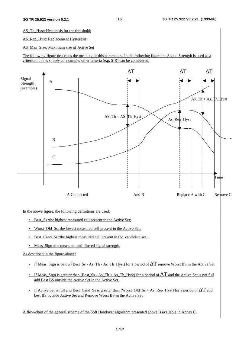
The following figure describes the meaning of this parameters. In the following figure the Signal Strength is used as acriterion; this is simply an example: other criteria (e.g. SIR) can be considered.
AS_Th – AS_Th_HystAs_Rep_Hyst
As_Th + As_Th_Hyst
A Connected Add B Replace A with C Remove C
A
B
C
Time
SignalStrength(example)
∆T ∆T ∆T
In the above figure, the following definitions are used:
• Best_Ss :the highest measured cell present in the Active Set;
• Worst_Old_Ss: the lowest measured cell present in the Active Set;
• Best_Cand_Set:the highest measured cell present in the candidate set .
• Meas_Sign :the measured and filtered signal strength.
As described in the figure above:
• If Meas_Sign is below (Best_Ss - As_Th - As_Th_Hyst) for a period of ∆T remove Worst BS in the Active Set.
• If Meas_Sign is greater than (Best_Ss - As_Th + As_Th_Hyst) for a period of ∆T and the Active Set is not fulladd Best BS outside the Active Set in the Active Set.
• If Active Set is full and Best_Cand_Ss is greater than (Worst_Old_Ss + As_Rep_Hyst) for a period of ∆T addbest BS outside Active Set and Remove Worst BS in the Active Set.
A flow-chart of the general scheme of the Soft Handover algorithm presented above is available in Annex C.
ETSI
3G TR 25.922 V0.2.21 (1999-06)163G TR 25.922 version 0.2.1
6.1.1.5.3 Soft Handover Execution
The serving cell (s) (the cells in the active set) are expected to have knowledge of the service used by the UE. The newcell decided to be added to the active set shall be informed that a new connection is desired, and it needs to have thefollowing minimum information forwarded to it via UTRAN.
• Maximum data rate of the connection and other service parameters, such as coding schemes, number of parallelcode channels etc. parameters which form the set of parameters describing the different transport channelconfigurations in use both uplink and downlink.
• The UE ID and uplink scrambling code
• The relative timing information of the new cell, in respect to the timing UE is experiencing from the existingconnections (as measured by the UE at its location). Based on this the new cellcan determine what should be thetiming of the transmission initiated in respect to the timing of the common channels (BCCH) of the new cell.
As a response the UE needs to know via the existing connections:
• From which frame (assuming active set update accepted) does the new cell initiate the transmission to the UE
• What channelisation code(s) are used for that transmission. The channelisation codes from different cells are notrequired to be the same as they are under different scrambling code anyway.
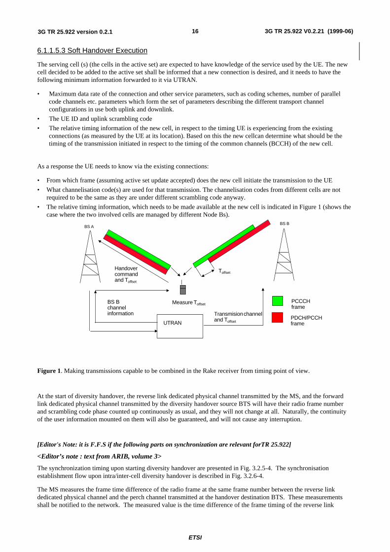
• The relative timing information, which needs to be made available at the new cell is indicated in Figure 1 (shows thecase where the two involved cells are managed by different Node Bs).
PCCCHframe
PDCH/PCCHframe
Measure Toffset
Handovercommandand Toffset
UTRANNetwork
Transmision channeland Toffset
BS Bchannelinformation
BS ABS B
Toffset
Figure 1. Making transmissions capable to be combined in the Rake receiver from timing point of view.
At the start of diversity handover, the reverse link dedicated physical channel transmitted by the MS, and the forwardlink dedicated physical channel transmitted by the diversity handover source BTS will have their radio frame numberand scrambling code phase counted up continuously as usual, and they will not change at all. Naturally, the continuityof the user information mounted on them will also be guaranteed, and will not cause any interruption.
[Editor's Note: it is F.F.S if the following parts on synchronization are relevant forTR 25.922]
<Editor’s note : text from ARIB, volume 3>
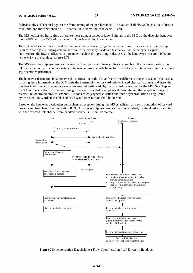
The synchronization timing upon starting diversity handover are presented in Fig. 3.2.5-4. The synchronisationestablishment flow upon intra/inter-cell diversity handover is described in Fig. 3.2.6-4.
The MS measures the frame time difference of the radio frame at the same frame number between the reverse linkdedicated physical channel and the perch channel transmitted at the handover destination BTS. These measurementsshall be notified to the network. The measured value is the time difference of the frame timing of the reverse link
ETSI
3G TR 25.922 V0.2.21 (1999-06)173G TR 25.922 version 0.2.1
dedicated physical channel against the frame timing of the perch channel. The values shall always be positive values inchip units, and the range shall be 0 ∼“reverse link scrambling code cycle-1” chip.
The MS notifies the frame time difference measurement values as layer 3 signals to the BSC via the diversity handoversource BTS with the DCH of the reverse link dedicated physical channel.
The BSC notifies the frame time difference measurement result, together with the frame offset and slot offset set upupon originating/ terminating call connection, to the diversity handover destination BTS with layer 3 signals.Furthermore, the BSC notifies radio parameters such as the spreading codes used at the handover destination BTS etc.,to the MS via the handover source BTS.
The MS starts the chip synchronisation establishment process of forward link channel from the handover destinationBTS with the notified radio parameters. The reverse link channels being transmitted shall continue transmission withoutany operations performed.
The handover destination BTS receives the notification of the above frame time difference frame offset, and slot offset.Utilising these informations, the BTS starts the transmission of forward link dedicated physical channels and starts thesynchronization establishment process of reverse link dedicated physical channel transmitted by the MS. See chapter3.2.5.1 for the specific transmission timing of forward link dedicated physical channels, and the reception timing ofreverse link dedicated physical channel. As soon as chip synchronisation and frame synchronisation using FrameSynchronization Word are established, hard wired transmission shall be started.
Based on the handover destination perch channel reception timing, the MS establishes chip synchronisation of forwardlink channel from handover destination BTS. As soon as chip synchronisation is established, maximal ratio combiningwith the forward link channel from handover source BTS shall be started.
MS diversity handover sou
e BTS
diversit handover destinationBTS
Frame time differencemeasurement
Start forward link chip sync.establishment process Start forward link normal transmission
• Send transmission information (whenthere is transmission info.)
• Stop transmission of symbol for transportchannel (when there is no transmissioninformation)
Forward link chip synchronizationestablished
Start maximal ratio combining
Start reverse link chip synchronizationestablishment process
Reverse link chip synchronizationestablished
Frame synchronization judgement(Frame Synchronization Word detectedor CRC OK detected)
Reverse link synchronization established
Start hard wired transmssion of reverse link received information
during communication
Forward link transmission
Reverse linktransmission
FRAME TIME DIFFERENCEMEASUREMENT VALUE
layer 3 signal
Figure 2 Synchronisation Establishment Flow Upon Intra/Inter-cell Diversity Handover
ETSI
3G TR 25.922 V0.2.21 (1999-06)183G TR 25.922 version 0.2.1
6.1.1.6 Inter System Handover
6.1.1.6.1 Handover 3G to 2G
The handover between from UTRA and to GSM system offering world-wide coverage already today has been one of themain design criteria taken into account in the UTRA frame timing definition. The GSM compatible multi-framestructure, with the super-frame being multiple of 120 ms, allows similar timing for inter-system measurements as in theGSM system itself. The compatibility in timing is important, that when operating in UTRA mode, a multi-mode UE isable to catch the desired information from the synchronization bursts in the synchronization frame on a GSM carrierwith the aid of the frequency correction burst. This way the relative timing between a GSM and UTRA carriers ismaintained similar to the timing between two asynchronous GSM carriers.
UTRA/FDD-GSM dual mode UEs The handover from UTRA/FDD to GSM can be implemented without simultaneoususe of two receiver chains. Although the frame length is different from GSM frame length, the GSM traffic channel andUTRA FDD channels use similar 120 ms multi-frame structure. Similar timing can be naturally done with UTRA TDDmode as well.
A UE can do the measurements by using idle periods in the downlink transmission, where such idle periods are createdby using the downlink slotted mode as defined in reference [2] WG1 Specification. In addition to downlink slottedframes for measurements, the UTRAN will provide uplink slotted frames to allow the UE to GSM cells on frequenciesclosed to the FDD uplink band. The slotted mode is under the control of the UTRAN, and the UTRAN shouldcommunicate to the UE which frame is slotted. .
Alternatively independent measurements not relying on the slotted mode, but using a dual receiver approach can beperformed, where the GSM receiver branch can operate independently of the UTRA FDD receiver branch.
For smooth inter-operation between the systems, information needs to be exchanged between the systems, in order toallow the UTRAN to notify the UE of the existing GSM frequencies in the area ( see section 6.1.1.2.1.4). Further moreintegrated operation is needed for the actual handover where the current service is maintained, taking naturally intoaccount the lower data rate capabilities in GSM when compared to UTRA maximum data rates reaching all the way to 2Mbits/s.
UTRA/TDD-GSM dual mode terminals The Handover from UTRA/TDD to GSM can be implemented withoutsimultaneous use of two receiver chains. Although the frame length is different from GSM frame length, the GSM trafficchannel and UTRA TDD channels rely on similar 120 ms multi-frame structure.
A UE can do the measurements either by efficiently using idle slots or by requesting free continuous periods in thedownlink part obtained by reducing the spreading factor and compressing in time TS occupation in a form similar to theFDD slotted mode. The low-cost constraint excludes the dual receiver approach.
For smooth inter-operation, inter-system information exchanges are needed in order to allow The UTRAN to notify theUE of the existing GSM frequencies in the area and vice versa. Further more integrated operation is needed for theactual handover where the current service is maintained, taking naturally into account the lower data rate capabilities inGSM when compared to UMTS maximum data rates reaching all the way to 2 Mbits/s.
Basic requirements to correctly perform a handover in GSM are described in GSM 05.08 “Radio subsystem link
6.1.2 Radio Link Management
[Test to be deployed also based on sections 7.3.4, 7.3.5, 7.3.6 of S25.303]
6.1.2.1 Radio Link Addition (FDD soft-add)The radio link addition procedure is defined in section 7.3.4 of TS 25.303.
ETSI
3G TR 25.922 V0.2.21 (1999-06)193G TR 25.922 version 0.2.1
Basically, the strategies that can be used in order to determine the need for radio link addition are based on the receivedmeasurements reports sent by the UE.
6.1.2.2 Radio Link Removal (FDD soft-drop)The radio link removal procedure is defined in section 7.3.5 of TS 25.303.
Two main strategies can be used in order to determine the need for a radio link removal:
• received measurements reports sent by the UE
• load control
6.1.2.3 Combined Radio Link addition and removalThe combined radio link addition and removal procedure is defined in section 7.3.6 of TS 25.303.
Two main strategies can be used in order to determine the need for a combined radio link addition and removal:
• received measurements reports sent by the UE
• load control
7 Admission Control
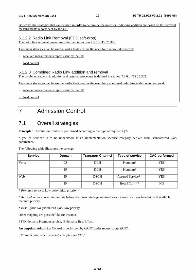
7.1 Overall strategiesPrinciple 1: Admission Control is performed according to the type of required QoS.
“Type of service” is to be understood as an implementation specific category derived from standardized QoSparameters.
The following table illustrates the concept :
Service Domain Transport Channel Type of service CAC performed
CS DCH Premium* YESVoice
IP DCH Premium* YES
IP DSCH Assured Service** YESWeb
IP DSCH Best Effort*** NO
* Premium service: Low delay, high priority.
* Assured Service: A minimum rate below the mean rate is guaranteed, service may use more bandwidth if available,medium priority.
* Best Effort: No guaranteed QoS, low priority.
Other mapping are possible like for instance:
PSTN domain: Premium service, IP domain: Best Effort.
Assumption: Admission Control is performed by CRNC under request from SRNC.
[Editor’S note, other criteria/principles are FFS]
ETSI
3G TR 25.922 V0.2.21 (1999-06)203G TR 25.922 version 0.2.1
7.2 Scenarios
7.2.1 CAC performed in SRNS
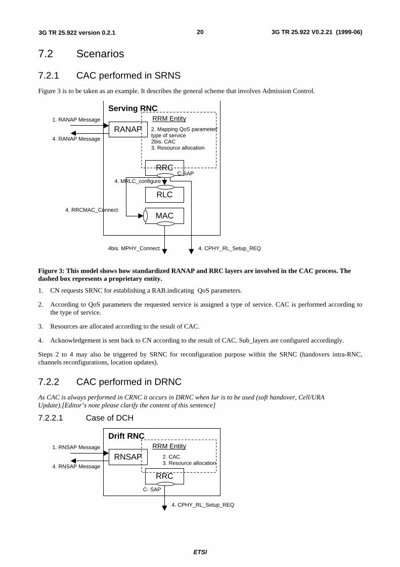
Figure 3 is to be taken as an example. It describes the general scheme that involves Admission Control.
Serving RNC
RANAP
RRC
RRM Entity
4. CPHY_RL_Setup_REQ
C-SAP
1. RANAP Message
4. RANAP Message
2. Mapping QoS parameter/type of service2bis. CAC3. Resource allocation
MAC4. RRCMAC_Connect
4bis. MPHY_Connect
RLC
4. MRLC_configure
Figure 3: This model shows how standardized RANAP and RRC layers are involved in the CAC process. Thedashed box represents a proprietary entity.
1. CN requests SRNC for establishing a RAB.indicating QoS parameters.
2. According to QoS parameters the requested service is assigned a type of service. CAC is performed according tothe type of service.
3. Resources are allocated according to the result of CAC.
4. Acknowledgement is sent back to CN according to the result of CAC. Sub_layers are configured accordingly.
Steps 2 to 4 may also be triggered by SRNC for reconfiguration purpose within the SRNC (handovers intra-RNC,channels reconfigurations, location updates).
7.2.2 CAC performed in DRNC
As CAC is always performed in CRNC it occurs in DRNC when Iur is to be used (soft handover, Cell/URAUpdate).[Editor’s note please clarify the content of this sentence]
7.2.2.1 Case of DCH
Drift RNC
RNSAP
RRC
RRM Entity
4. CPHY_RL_Setup_REQ
C- SAP
1. RNSAP Message
4. RNSAP Message
2. CAC3. Resource allocation
ETSI
3G TR 25.922 V0.2.21 (1999-06)213G TR 25.922 version 0.2.1
Figure 4: This model shows how standardized RNSAP and RRC layers are involved in the CAC process. Thedashed box represents a proprietary entity.
1. SRNC requests DRNC for establishing a Radio Link, indicating DCH characteristics. These implicitly contains allQoS requirements and are enough as inputs to the CAC algorithm.
2. CAC is performed according to DCH characteristics.
3. Resources are allocated according to the result of CAC.
4. Acknowledgement is sent back to CN according to the result of CAC.
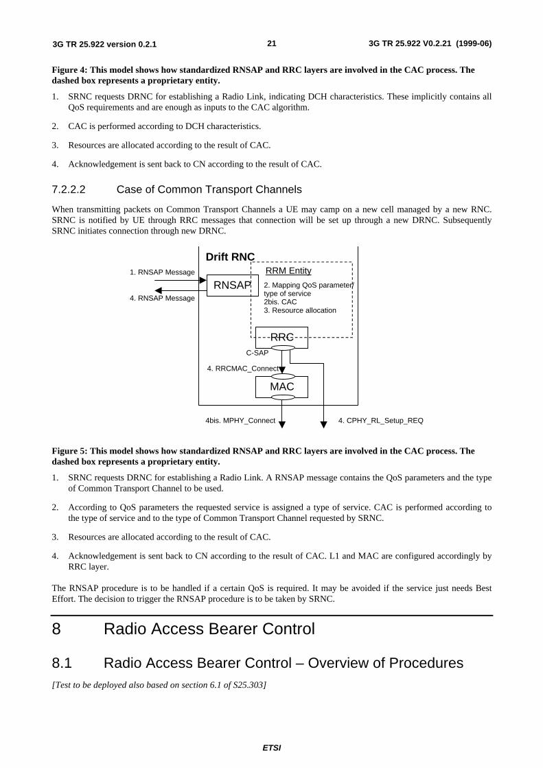
7.2.2.2 Case of Common Transport Channels
When transmitting packets on Common Transport Channels a UE may camp on a new cell managed by a new RNC.SRNC is notified by UE through RRC messages that connection will be set up through a new DRNC. SubsequentlySRNC initiates connection through new DRNC.
Drift RNC
RNSAP
RRC
RRM Entity
4. CPHY_RL_Setup_REQ
C-SAP
1. RNSAP Message
4. RNSAP Message
2. Mapping QoS parameter/type of service2bis. CAC3. Resource allocation
MAC
4. RRCMAC_Connect
4bis. MPHY_Connect
Figure 5: This model shows how standardized RNSAP and RRC layers are involved in the CAC process. Thedashed box represents a proprietary entity.
1. SRNC requests DRNC for establishing a Radio Link. A RNSAP message contains the QoS parameters and the typeof Common Transport Channel to be used.
2. According to QoS parameters the requested service is assigned a type of service. CAC is performed according tothe type of service and to the type of Common Transport Channel requested by SRNC.
3. Resources are allocated according to the result of CAC.
4. Acknowledgement is sent back to CN according to the result of CAC. L1 and MAC are configured accordingly byRRC layer.
The RNSAP procedure is to be handled if a certain QoS is required. It may be avoided if the service just needs BestEffort. The decision to trigger the RNSAP procedure is to be taken by SRNC.
8 Radio Access Bearer Control
8.1 Radio Access Bearer Control – Overview of Procedures[Test to be deployed also based on section 6.1 of S25.303]
ETSI
3G TR 25.922 V0.2.21 (1999-06)223G TR 25.922 version 0.2.1
8.2 Usage of RAB control proceduresRadio access bearer control procedures are used to control the UE and system resources. This section explains how thesystem works with respect to these procedures and how e.g. traffic volume measurements could trigger these procedures.
First a Radio access bearer setup is shown, where pre-configuration of transport channels are exemplified. Further, theprocedures Physical channel reconfiguration and Transport channel reconfiguration are shown in several examples. It isalso explained how these last two procedures are used in the system for resource control of services with variable bitrate,i.e. transport channel type switching. Finally, usage of Radio access bearer reconfiguration is shown in an examplewhere the MAC multiplexing is changed.
8.2.1 Examples of Radio Access Bearer Setup
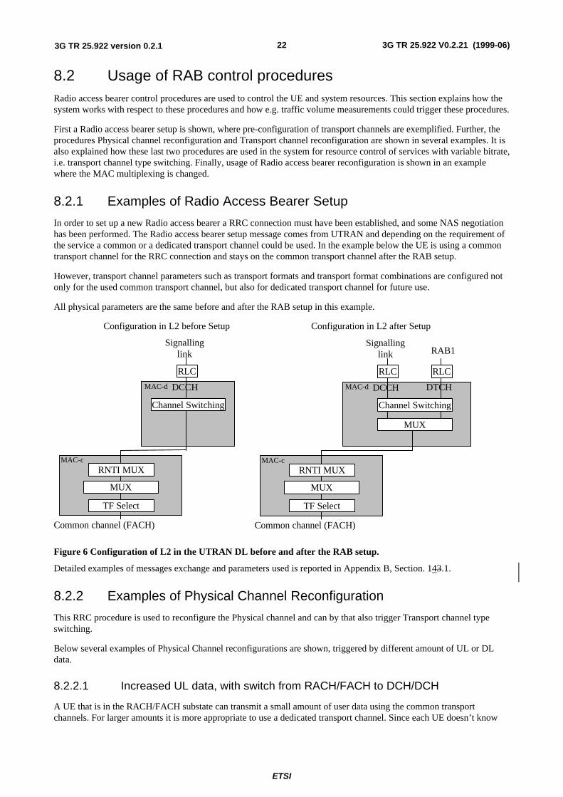
In order to set up a new Radio access bearer a RRC connection must have been established, and some NAS negotiationhas been performed. The Radio access bearer setup message comes from UTRAN and depending on the requirement ofthe service a common or a dedicated transport channel could be used. In the example below the UE is using a commontransport channel for the RRC connection and stays on the common transport channel after the RAB setup.
However, transport channel parameters such as transport formats and transport format combinations are configured notonly for the used common transport channel, but also for dedicated transport channel for future use.
All physical parameters are the same before and after the RAB setup in this example.
MAC-c
MAC-d
Configuration in L2 before Setup
RLC
TF Select
Common channel (FACH)
Channel Switching
Configuration in L2 after Setup
RNTI MUX
Signallinglink
DCCH
MUX
MAC-c
MAC-d
RLC
TF Select
Common channel (FACH)
RLC
Channel Switching
MUX
RNTI MUX
Signallinglink RAB1
DCCH DTCH
MUX
Figure 6 Configuration of L2 in the UTRAN DL before and after the RAB setup.
Detailed examples of messages exchange and parameters used is reported in Appendix B, Section. 143.1.
8.2.2 Examples of Physical Channel Reconfiguration
This RRC procedure is used to reconfigure the Physical channel and can by that also trigger Transport channel typeswitching.
Below several examples of Physical Channel reconfigurations are shown, triggered by different amount of UL or DLdata.
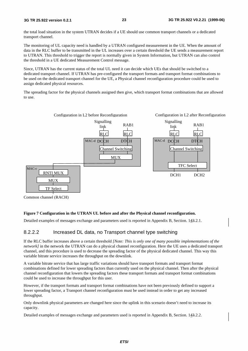
8.2.2.1 Increased UL data, with switch from RACH/FACH to DCH/DCH
A UE that is in the RACH/FACH substate can transmit a small amount of user data using the common transportchannels. For larger amounts it is more appropriate to use a dedicated transport channel. Since each UE doesn’t know
ETSI
3G TR 25.922 V0.2.21 (1999-06)233G TR 25.922 version 0.2.1
the total load situation in the system UTRAN decides if a UE should use common transport channels or a dedicatedtransport channel.
The monitoring of UL capacity need is handled by a UTRAN configured measurement in the UE. When the amount ofdata in the RLC buffer to be transmitted in the UL increases over a certain threshold the UE sends a measurement reportto UTRAN. This threshold to trigger the report is normally given in System Information, but UTRAN can also controlthe threshold in a UE dedicated Measurement Control message.
Since, UTRAN has the current status of the total UL need it can decide which UEs that should be switched to adedicated transport channel. If UTRAN has pre-configured the transport formats and transport format combinations tobe used on the dedicated transport channel for the UE, a Physical channel reconfiguration procedure could be used toassign dedicated physical resources.
The spreading factor for the physical channels assigned then give, which transport format combinations that are allowedto use.
MAC-c
MAC-d MAC-d
Configuration in L2 before Reconfiguration
RLC
TF Select
Common channel (RACH)
RLC
Channel Switching
MUX
Configuration in L2 after Reconfiguration
RLC
DCH1
RLC
TFC Select
DCH2
Channel Switching
RNTI MUX
Signallinglink RAB1
DCCH DTCH
Signallinglink RAB1
DCCH DTCH
MUX
Figure 7 Configuration in the UTRAN UL before and after the Physical channel reconfiguration.
Detailed examples of messages exchange and parameters used is reported in Appendix B, Section. 143.2.1.
8.2.2.2 Increased DL data, no Transport channel type switching
If the RLC buffer increases above a certain threshold [Note: This is only one of many possible implementations of thenetwork] in the network the UTRAN can do a physical channel reconfiguration. Here the UE uses a dedicated transportchannel, and this procedure is used to decrease the spreading factor of the physical dedicated channel. This way thisvariable bitrate service increases the throughput on the downlink.
A variable bitrate service that has large traffic variations should have transport formats and transport formatcombinations defined for lower spreading factors than currently used on the physical channel. Then after the physicalchannel reconfiguration that lowers the spreading factors these transport formats and transport format combinationscould be used to increase the throughput for this user.
However, if the transport formats and transport format combinations have not been previously defined to support alower spreading factor, a Transport channel reconfiguration must be used instead in order to get any increasedthroughput.
Only downlink physical parameters are changed here since the uplink in this scenario doesn’t need to increase itscapacity.
Detailed examples of messages exchange and parameters used is reported in Appendix B, Section. 143.2.2.
ETSI
3G TR 25.922 V0.2.21 (1999-06)243G TR 25.922 version 0.2.1
8.2.2.3 Decrease DL data, no Transport channel type switching
Since downlink channelization codes are a scarce resource a UE with a too high, allocated gross bit rate (low spreadingfactor) must be reconfigured and use a more appropriate channelization code (with higher spreading factor). This couldbe triggered by a threshold for the RLC buffer content and some inactivity timer, i.e. that the buffer content stays acertain time below this threshold. [Note: This is only one of many possible implementations of the network].
After the physical channel has been reconfigured, some of the transport formats and transport format combinations thatrequire a low SF can not be used. However, these are stored and could be used if the physical channel is reconfiguredlater to use a lower spreading factor.
Detailed examples of messages exchange and parameters used is reported in Appendix B, Section. 143.2.3.
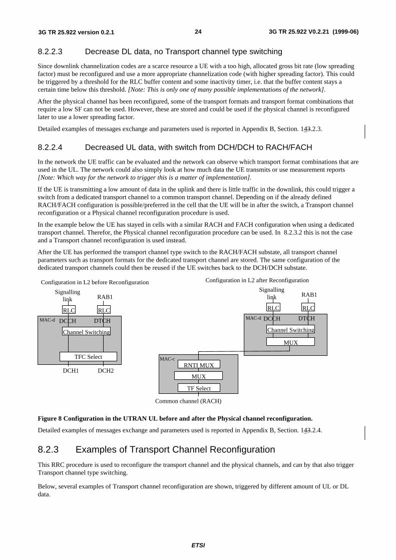
8.2.2.4 Decreased UL data, with switch from DCH/DCH to RACH/FACH
In the network the UE traffic can be evaluated and the network can observe which transport format combinations that areused in the UL. The network could also simply look at how much data the UE transmits or use measurement reports[Note: Which way for the network to trigger this is a matter of implementation].
If the UE is transmitting a low amount of data in the uplink and there is little traffic in the downlink, this could trigger aswitch from a dedicated transport channel to a common transport channel. Depending on if the already definedRACH/FACH configuration is possible/preferred in the cell that the UE will be in after the switch, a Transport channelreconfiguration or a Physical channel reconfiguration procedure is used.
In the example below the UE has stayed in cells with a similar RACH and FACH configuration when using a dedicatedtransport channel. Therefor, the Physical channel reconfiguration procedure can be used. In 8.2.3.2 this is not the caseand a Transport channel reconfiguration is used instead.
After the UE has performed the transport channel type switch to the RACH/FACH substate, all transport channelparameters such as transport formats for the dedicated transport channel are stored. The same configuration of thededicated transport channels could then be reused if the UE switches back to the DCH/DCH substate.
MAC-c
MAC-dMAC-d
Configuration in L2 after Reconfiguration
RLC
TF Select
Common channel (RACH)
RLC
Channel Switching
MUX
Configuration in L2 before Reconfiguration
RLC
DCH1
RLC
TFC Select
DCH2
Channel Switching
RNTI MUX
Signallinglink RAB1
DCCH DTCH
Signallinglink RAB1
DCCH DTCH
MUX
Figure 8 Configuration in the UTRAN UL before and after the Physical channel reconfiguration.
Detailed examples of messages exchange and parameters used is reported in Appendix B, Section. 143.2.4.
8.2.3 Examples of Transport Channel Reconfiguration
This RRC procedure is used to reconfigure the transport channel and the physical channels, and can by that also triggerTransport channel type switching.
Below, several examples of Transport channel reconfiguration are shown, triggered by different amount of UL or DLdata.
ETSI
3G TR 25.922 V0.2.21 (1999-06)253G TR 25.922 version 0.2.1
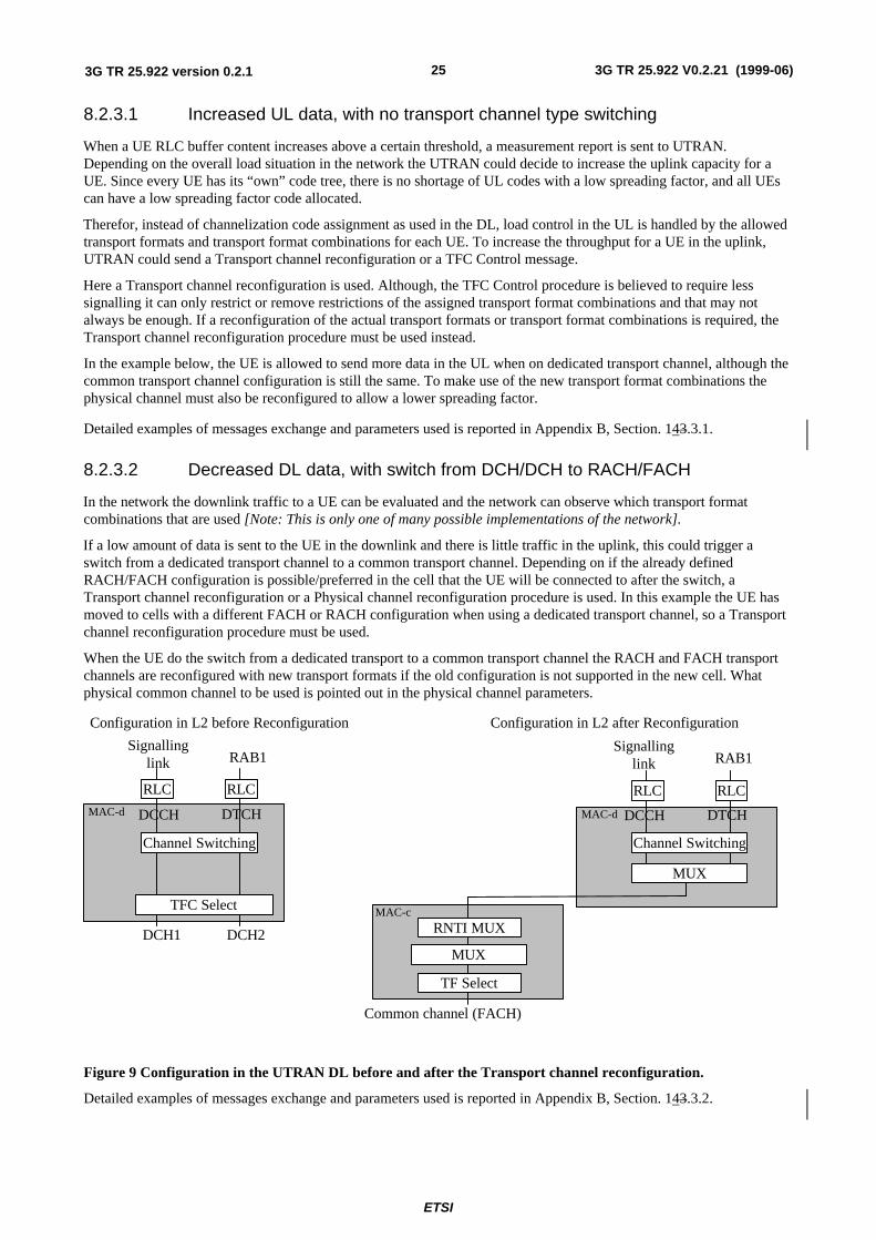
8.2.3.1 Increased UL data, with no transport channel type switching
When a UE RLC buffer content increases above a certain threshold, a measurement report is sent to UTRAN.Depending on the overall load situation in the network the UTRAN could decide to increase the uplink capacity for aUE. Since every UE has its “own” code tree, there is no shortage of UL codes with a low spreading factor, and all UEscan have a low spreading factor code allocated.
Therefor, instead of channelization code assignment as used in the DL, load control in the UL is handled by the allowedtransport formats and transport format combinations for each UE. To increase the throughput for a UE in the uplink,UTRAN could send a Transport channel reconfiguration or a TFC Control message.
Here a Transport channel reconfiguration is used. Although, the TFC Control procedure is believed to require lesssignalling it can only restrict or remove restrictions of the assigned transport format combinations and that may notalways be enough. If a reconfiguration of the actual transport formats or transport format combinations is required, theTransport channel reconfiguration procedure must be used instead.
In the example below, the UE is allowed to send more data in the UL when on dedicated transport channel, although thecommon transport channel configuration is still the same. To make use of the new transport format combinations thephysical channel must also be reconfigured to allow a lower spreading factor.
Detailed examples of messages exchange and parameters used is reported in Appendix B, Section. 143.3.1.
8.2.3.2 Decreased DL data, with switch from DCH/DCH to RACH/FACH
In the network the downlink traffic to a UE can be evaluated and the network can observe which transport formatcombinations that are used [Note: This is only one of many possible implementations of the network].
If a low amount of data is sent to the UE in the downlink and there is little traffic in the uplink, this could trigger aswitch from a dedicated transport channel to a common transport channel. Depending on if the already definedRACH/FACH configuration is possible/preferred in the cell that the UE will be connected to after the switch, aTransport channel reconfiguration or a Physical channel reconfiguration procedure is used. In this example the UE hasmoved to cells with a different FACH or RACH configuration when using a dedicated transport channel, so a Transportchannel reconfiguration procedure must be used.
When the UE do the switch from a dedicated transport to a common transport channel the RACH and FACH transportchannels are reconfigured with new transport formats if the old configuration is not supported in the new cell. Whatphysical common channel to be used is pointed out in the physical channel parameters.
MAC-d
Configuration in L2 before Reconfiguration
RLC
DCH1
RLC
TFC Select
DCH2
Channel Switching
Signallinglink RAB1
DCCH DTCH
MAC-c
MAC-d
Configuration in L2 after Reconfiguration
RLC
TF Select
Common channel (FACH)
RLC
Channel Switching
MUX
RNTI MUX
Signallinglink RAB1
DCCH DTCH
MUX
Figure 9 Configuration in the UTRAN DL before and after the Transport channel reconfiguration.
Detailed examples of messages exchange and parameters used is reported in Appendix B, Section. 143.3.2.
ETSI
3G TR 25.922 V0.2.21 (1999-06)263G TR 25.922 version 0.2.1
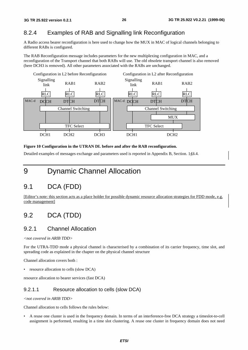
8.2.4 Examples of RAB and Signalling link Reconfiguration
A Radio access bearer reconfiguration is here used to change how the MUX in MAC of logical channels belonging todifferent RABs is configured.
The RAB Reconfiguration message includes parameters for the new multiplexing configuration in MAC, and areconfiguration of the Transport channel that both RABs will use. The old obsolete transport channel is also removed(here DCH3 is removed). All other parameters associated with the RABs are unchanged.
MAC-dMAC-d
Configuration in L2 before Reconfiguration
RLC
DCH1
RLC
DCH2
RLC
TFC Select
DCH3
Channel Switching
Configuration in L2 after Reconfiguration
RLC
DCH1
RLC
TFC Select
RLC
Channel Switching
MUX
DCH2
Signallinglink RAB1
DCCH DTCH
RAB2
DTCH
Signallinglink RAB1
DCCH DTCH
RAB2
DTCH
Figure 10 Configuration in the UTRAN DL before and after the RAB reconfiguration.
Detailed examples of messages exchange and parameters used is reported in Appendix B, Section. 143.4.
9 Dynamic Channel Allocation
9.1 DCA (FDD)[Editor’s note: this section acts as a place holder for possible dynamic resource allocation strategies for FDD mode, e.g.code management]
9.2 DCA (TDD)
9.2.1 Channel Allocation
<not covered in ARIB TDD>
For the UTRA-TDD mode a physical channel is characterised by a combination of its carrier frequency, time slot, andspreading code as explained in the chapter on the physical channel structure
Channel allocation covers both :
• resource allocation to cells (slow DCA)
resource allocation to bearer services (fast DCA)
9.2.1.1 Resource allocation to cells (slow DCA)
<not covered in ARIB TDD>
Channel allocation to cells follows the rules below:
• A reuse one cluster is used in the frequency domain. In terms of an interference-free DCA strategy a timeslot-to-cellassignment is performed, resulting in a time slot clustering. A reuse one cluster in frequency domain does not need
ETSI
3G TR 25.922 V0.2.21 (1999-06)273G TR 25.922 version 0.2.1
frequency planning. If there is more than one carrier available for a single operator also other frequency reuse patters>1 are possible.
• Any specific time slot within the TDD frame is available either for uplink or downlink transmission . UL/DLresources allocation is thus able to adapt itself to time varying asymmetric traffic.
• In order to accommodate the traffic load in the various cells the assignment of the timeslots (both UL and DL) to thecells is dynamically (on a coarse time scale) rearranged (slow DCA) taking into account that strongly interferingcells use different timeslots. Thus resources allocated to adjacent cells may also overlap depending on theinterference situation.
• Due to idle periods between successive received and transmitted bursts, UEs can provide the network withinterference measurements in time slots different from the one currently used. The availability of such informationenables the operator to implement the DCA algorithm suited to the network.
• For instance, the prioritized assignment of time slots based on interference measurements results in a clustering inthe time domain and in parallel takes into account the demands on locally different traffic loads within the network.
9.2.1.2 Resource allocation to bearer services (fast DCA)
<not covered in ARIB TDD>
Fast channel allocation refers to the allocation of one or multiple physical channels to any bearer service Resource units(RUs) are acquired (and released) according to a cell-related preference list derived from the slow DCA scheme.
1. The following principles hold for fast channel allocation:The basic RU used for channel allocation is one code /timeslot / (frequency).
2. Multirate services are achieved by pooling of resource units. This can be made both in the code domain (pooling ofmultiple codes within one timeslot = multicode operation) and time domain (pooling of multiple timeslots withinone frame = multislot operation). Additionally, any combination of both is possible. Simulation results reported inAppendix A, recommend that the DCA prefers code pooling , over time slot pooling, for UDD packet data; the useof code pooling in fact results in lower number of unsatisfied users.
3. Since the maximal number of codes per time slot in UL/DL depends on several physical circumstances like ,channel characteristics, environments, etc. (see description of physical layer) and whether additional techniques tofurther enhance capacity are applied (for example smart antennas),. the DCA algorithm has to be independent ofthis number. Additionally, time-hopping can be used to average inter-cell interference in case of low-medium bitrate users.
• 4. Channel allocation differentiates between RT and NRT bearer services:RT services: Channels remainallocated for the whole duration the bearer service is established . The allocated resources may change becauseof a channel reallocation procedure (e.g. VBR).
• NRT services: Channels are allocated for the period of the transmission of a dedicated data packet only UDDchannel allocation is performed using ‘best effort strategy’, i.e. resources available for NRT services aredistributed to all admitted NRT services with pending transmission requests. The number of channels allocatedfor any NRT service is variable and depends at least on the number of current available resources and thenumber of NRT services attempting for packet transmission simultaneously. Additionally, prioritisation ofadmitted NRT services is possible.
5. Channel reallocation procedures (intra-cell handover) can be triggered for many reasons:
• To cope with varying interference conditions.
• In case of high rate RT services (i.e. services requiring multiple resource units) a ‘channel reshuffling procedure’ isrequired to prevent a fragmentation of the allocated codes over to many timeslots. This is achieved by freeing theleast loaded timeslots (timeslots with minimum used codes) by performing a channel reallocation procedure.
• When using smart antennas, channel reallocation is useful to keep spatially separated the different users in the sametimeslot.
ETSI
3G TR 25.922 V0.2.21 (1999-06)283G TR 25.922 version 0.2.1
9.2.2 Measurements Reports from UE to the UTRAN
While in active mode the DCA needs measurements for the reshuffling procedure (intra-cell handover). Thespecification of the measurements to be performed is contained in Section 7.4 in [10]. In this section the relevantmeasurement reports are presented:
• Pathloss of a sub-set of cells (pathloss is quantized in NPL [e.g. 128] intervals ; [max. number of cells is 30].• Inter-cell interference measurements of all DL time slots requested by the UTRAN (interference is quantized in NICI
[e.g. 32] intervals, due to asymmetry up to 14 time slots are possible)• BER of serving link (quantized in NBER [e.g. 16] intervals)• Transmission power of the UE on serving link (separated in NTX [e.g. 64] intervals)
• DTX flag link• ffs
Further measurements and reports can be requested by the UTRAN.
The RLC informs the DCA about transmission errors. The interaction between DCA and RLC depends on the RLCoperation mode. Details are for further study.
10 Power Management
10.1 Variable Rate Packet Transmission
10.1.1 Downlink Power Management
When the connection for packet services is established, the RRC considers the down-link traffic conditions, then assignsthe TFCS to MAC and allowable transmission power to L1. The allowable transmission power is determined accordingto the service requirements and the traffic conditions, and is updated for each user when the traffic conditions change.
During a call, the physical layer averages the transmission power for that UE over one or several frames. If the averagedtransmission power for the UE becomes higher than the allowable transmission power, that is, the channel conditions arebad, L1 indicates with the primitive MPHY-STATUS to the MAC that the “Allowable transmission power has beenreached”. The MAC in response reduces the data rate within TFCS, and the power control procedure then reduces thetotal transmission power for that UE and excess interference to other UEs is avoided.
When channel conditions improve and the averaged transmission power falls [x] dB below than the allowabletransmission power the physical layer indicates with the primitive MPHY-STATUS to the MAC that the “Averagetransmission power is
below allowable transmission power by xdB” (the values for [x] are chosen to match the power requirements of differentincrements for the transport channels within the TFCS). The MAC in response increases the data rate by increasing thenumber of transport blocks delivered to L1 and the physical layer increases the total transmission power to the UE bythe predefined amount. This allows data that was buffered during bad channel conditions to be delivered to the UE.
10.1.2 Uplink Power Management
When the connection for packet services is established, the RRC assigns the TFCS to MAC and the allowabletransmission power to L1. The allowable transmission power corresponds to the UE capability class. During a call, thephysical layer averages the transmission power over one or several frames. If the averaged transmission power becomeshigher than the allowable transmission power, L1 indicates with the primitive MPHY-STATUS to the MAC that the“Allowable transmission power has been reached”. The MAC in response reduces the data rate within TFCS, and thepower control procedure then reduces the total transmission power.
When channel conditions improve and the averaged transmission power falls [x] dB below than the allowabletransmission power the physical layer indicates with the primitive MPHY-STATUS to the MAC that the “Averagetransmission power is below allowable transmission power by xdB” (the values for [x] are chosen to match the powerrequirements of different increments in the number of transport channels within the TFCS). The MAC in response
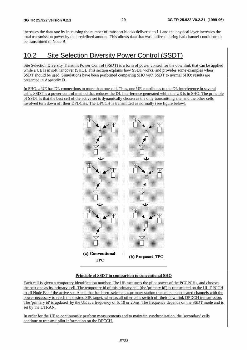
ETSI
3G TR 25.922 V0.2.21 (1999-06)293G TR 25.922 version 0.2.1
increases the data rate by increasing the number of transport blocks delivered to L1 and the physical layer increases thetotal transmission power by the predefined amount. This allows data that was buffered during bad channel conditions tobe transmitted to Node B.
10.2 Site Selection Diversity Power Control (SSDT)Site Selection Diversity Transmit Power Control (SSDT) is a form of power control for the downlink that can be appliedwhile a UE is in soft handover (SHO). This section explains how SSDT works, and provides some examples whenSSDT should be used. Simulations have been performed comparing SHO with SSDT to normal SHO: results arepresented in Appendix D.
In SHO, a UE has DL connections to more than one cell. Thus, one UE contributes to the DL interference in severalcells. SSDT is a power control method that reduces the DL interference generated while the UE is in SHO. The principleof SSDT is that the best cell of the active set is dynamically chosen as the only transmitting site, and the other cellsinvolved turn down off their DPDCHs. The DPCCH is transmitted as normally (see figure below).
Principle of SSDT in comparison to conventional SHO
Each cell is given a temporary identification number. The UE measures the pilot power of the PCCPCHs, and choosesthe best one as its 'primary' cell. The temporary id of this primary cell (the 'primary id') is transmitted on the UL DPCCHto all Node Bs of the active set. A cell that has been selected as primary station transmits its dedicated channels with thepower necessary to reach the desired SIR target, whereas all other cells switch off their downlink DPDCH transmission.The 'primary id' is updated by the UE at a frequency of 5, 10 or 20ms. The frequency depends on the SSDT mode and isset by the UTRAN.
In order for the UE to continuously perform measurements and to maintain synchronisation, the 'secondary' cellscontinue to transmit pilot information on the DPCCH.
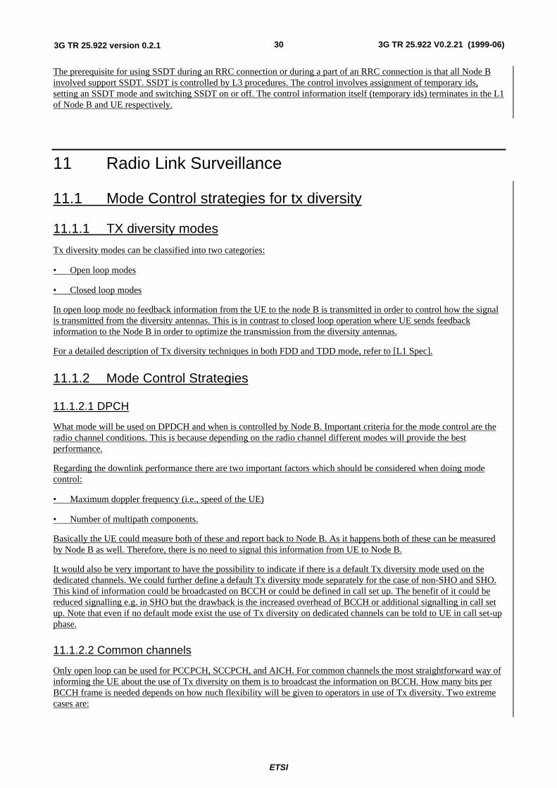
ETSI
3G TR 25.922 V0.2.21 (1999-06)303G TR 25.922 version 0.2.1
The prerequisite for using SSDT during an RRC connection or during a part of an RRC connection is that all Node Binvolved support SSDT. SSDT is controlled by L3 procedures. The control involves assignment of temporary ids,setting an SSDT mode and switching SSDT on or off. The control information itself (temporary ids) terminates in the L1of Node B and UE respectively.
11 Radio Link Surveillance
11.1 Mode Control strategies for tx diversity
11.1.1 TX diversity modes
Tx diversity modes can be classified into two categories:
• Open loop modes
• Closed loop modes
In open loop mode no feedback information from the UE to the node B is transmitted in order to control how the signalis transmitted from the diversity antennas. This is in contrast to closed loop operation where UE sends feedbackinformation to the Node B in order to optimize the transmission from the diversity antennas.
For a detailed description of Tx diversity techniques in both FDD and TDD mode, refer to [L1 Spec].
11.1.2 Mode Control Strategies
11.1.2.1 DPCH
What mode will be used on DPDCH and when is controlled by Node B. Important criteria for the mode control are theradio channel conditions. This is because depending on the radio channel different modes will provide the bestperformance.
Regarding the downlink performance there are two important factors which should be considered when doing modecontrol:
• Maximum doppler frequency (i.e., speed of the UE)
• Number of multipath components.
Basically the UE could measure both of these and report back to Node B. As it happens both of these can be measuredby Node B as well. Therefore, there is no need to signal this information from UE to Node B.
It would also be very important to have the possibility to indicate if there is a default Tx diversity mode used on thededicated channels. We could further define a default Tx diversity mode separately for the case of non-SHO and SHO.This kind of information could be broadcasted on BCCH or could be defined in call set up. The benefit of it could bereduced signalling e.g. in SHO but the drawback is the increased overhead of BCCH or additional signalling in call setup. Note that even if no default mode exist the use of Tx diversity on dedicated channels can be told to UE in call set-upphase.
11.1.2.2 Common channels
Only open loop can be used for PCCPCH, SCCPCH, and AICH. For common channels the most straightforward way ofinforming the UE about the use of Tx diversity on them is to broadcast the information on BCCH. How many bits perBCCH frame is needed depends on how nuch flexibility will be given to operators in use of Tx diversity. Two extremecases are:
ETSI
3G TR 25.922 V0.2.21 (1999-06)313G TR 25.922 version 0.2.1
• Most limited flexibility: one bit every BCCH frame is used to indicate if Tx diversity is being used on PCCPCH,SCCPCH and AICH
• Maximum flexibility: use of Tx diversity on different broadcast channels can be controlled independently. Obviousway of informing UE about this is to transmit 3 bits of information in each BCCH frame. Note that the impact of theuse of 3 bits on the overall BCCH capacity has to be further considered.
12 Codec mode control
12.1 AMR mode control
The AMR speech codec consists of the multi-rate speech codec with eight source rates from 4.75kbit/s to 12.2 kbit/s [11]. The change between the AMR specified rates is proposed to occur in theWCDMA in downlink, when traffic on the air interface exceeds the acceptable load, or when theconnection based FER value indicates the bad quality of the connection. In uplink the correspondingchange can be made when there is need to extend the uplink coverage area for speech by using severalAMR modes or when the measured load on the air interface is reported to exceed the acceptable level.
In principle the speech coder is capable of switching its bit rate every 20 ms speech frame uponcommand. [11] However in practice the AMR mode adaptation is needed less frequently.
In WCDMA the network architecture has been defined to consist of two different network domains;UTRAN and Core Network (CN). Due to this definition and decisions about the location of theTranscoder, the AMR related functions are forced to divide between the previously mentionednetwork domains.
The location of the Transcoder in WCDMA was defined to be in the core network domain, andlogically outside the Access Stratum. Thus also the location of the AMR speech codec is into the CoreNetwork as well.
From the data transfer point of view the defined location of the encoder in the NW side means that atleast all AMR coded data is going to be transmitted not only via Iub and air interface but also via Iu –interface. (see Figure 12)
The functionality of the codec mode control on the contrary can not locate in the Transcoder, becausethis control entity needs information from the air interface to make decision about the valid AMRmodes for the AMR related connections. Thus the only domain, which can provide this kind ofinformation from the air interface to AMR codec mode control entity, is UTRAN. In GSM the controlof the codec mode is provided by the BTS, but in WCDMA this solution is not applicable due to softhandover procedure defined for the dedicated traffic channels. Thus the AMR mode control functionshould be a part of the RNC functionality. In RNC the most natural place to perform the control of theAMR mode is RRM, because RRM is already responsible for reserving and controlling resourcesfrom the air interface. Thus all information, which is needed for the AMR adaptation, can be foundfrom the RRM, which is a part of the current L3 functionality. (see Figure 12)
ETSI
3G TR 25.922 V0.2.21 (1999-06)323G TR 25.922 version 0.2.1
Airinterface
Iub Iu
Control of AMR modesNo further requirementsdue to AMR
AMR speech codec AMR speechcodec
Uplink AMR mode command
Uplink speech data with the commanded AMR mode
Downlink AMR modecommand
Downlink speech data with the commanded AMR mode
MS BS RNC TC
Figure 12
In the WCDMA the AMR mode adaptation is carried out with the aid of AMR mode control function,which is responsible for detecting the need of the AMR mode adaptation and to initiate requiredprocedures to change the current AMR mode to the newly selected AMR mode. The AMR modechange request can be made with the aid of the AMR mode command, which is sent from the RNCeither to the Transcoder for downlink data transfer or to the UE for uplink data transfer. In principlethe supported AMR mode adaptation can be asymmetric, which implies the possibility to use differentAMR modes in uplink and downlink during active speech call.
Therefore, the role of the RRM during the AMR coded speech call will be basically the role of thesupervisor of the connection.
The AMR mode command is used to change the current AMR mode to the new one, which suits betterto the conditions on the air interface. The command is sent from the UTRAN to the appropriate AMRcodec, which locates either in the transcoder or in the UE. In which encoder the command is sentdepends on direction of the data transmission. If the AMR mode - in question - is intended to be usedin downlink the command is sent to the encoder inside the transcoder via Iu –interface, whereas AMRcode needed on uplink is sent to the UE through air interface.
The initialization of AMR mode command will base on load information, which has been receivedfrom the air interface. The following table shows the required information during the AMR modeadaptation in WCDMA:
Information used in AMRcontrol
Load
Downlink information BS reports total BS transmission power
Uplink information BS measurers total interference level
When RRM indicates the need for the AMR mode adaptation, RRC may generate the requested AMRmode command and send it to the encoder, or RRC may request MAC –d to perform the samefunctions. Which layer is used depend on whether the AMR mode command is intended to use onuplink or on downlink, and whether inband or outband signaling is used for transferring the commandfrom the UTRAN to the encoder.
For the downlink, the AMR mode command from RNC to TC is realised as inband.
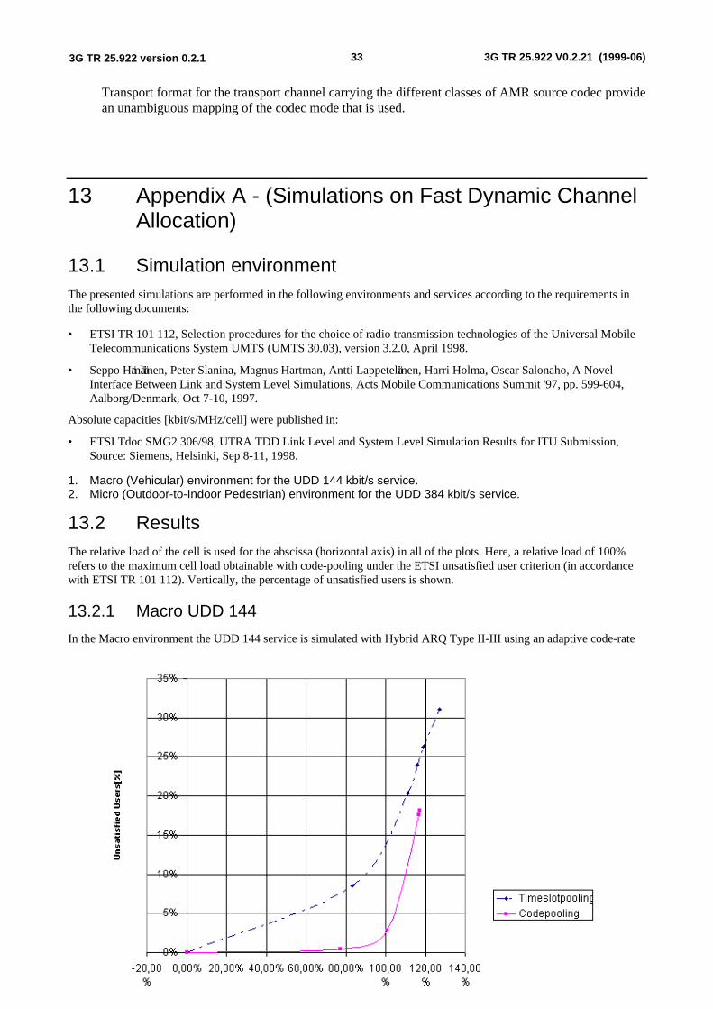
ETSI
3G TR 25.922 V0.2.21 (1999-06)333G TR 25.922 version 0.2.1
Transport format for the transport channel carrying the different classes of AMR source codec providean unambiguous mapping of the codec mode that is used.
13 Appendix A - (Simulations on Fast Dynamic ChannelAllocation)
13.1 Simulation environmentThe presented simulations are performed in the following environments and services according to the requirements inthe following documents:
• ETSI TR 101 112, Selection procedures for the choice of radio transmission technologies of the Universal MobileTelecommunications System UMTS (UMTS 30.03), version 3.2.0, April 1998.
• Seppo Hämäläinen, Peter Slanina, Magnus Hartman, Antti Lappeteläinen, Harri Holma, Oscar Salonaho, A NovelInterface Between Link and System Level Simulations, Acts Mobile Communications Summit '97, pp. 599-604,Aalborg/Denmark, Oct 7-10, 1997.
Absolute capacities [kbit/s/MHz/cell] were published in:
• ETSI Tdoc SMG2 306/98, UTRA TDD Link Level and System Level Simulation Results for ITU Submission,Source: Siemens, Helsinki, Sep 8-11, 1998.
1. Macro (Vehicular) environment for the UDD 144 kbit/s service.2. Micro (Outdoor-to-Indoor Pedestrian) environment for the UDD 384 kbit/s service.
13.2 ResultsThe relative load of the cell is used for the abscissa (horizontal axis) in all of the plots. Here, a relative load of 100%refers to the maximum cell load obtainable with code-pooling under the ETSI unsatisfied user criterion (in accordancewith ETSI TR 101 112). Vertically, the percentage of unsatisfied users is shown.
13.2.1 Macro UDD 144
In the Macro environment the UDD 144 service is simulated with Hybrid ARQ Type II-III using an adaptive code-rate
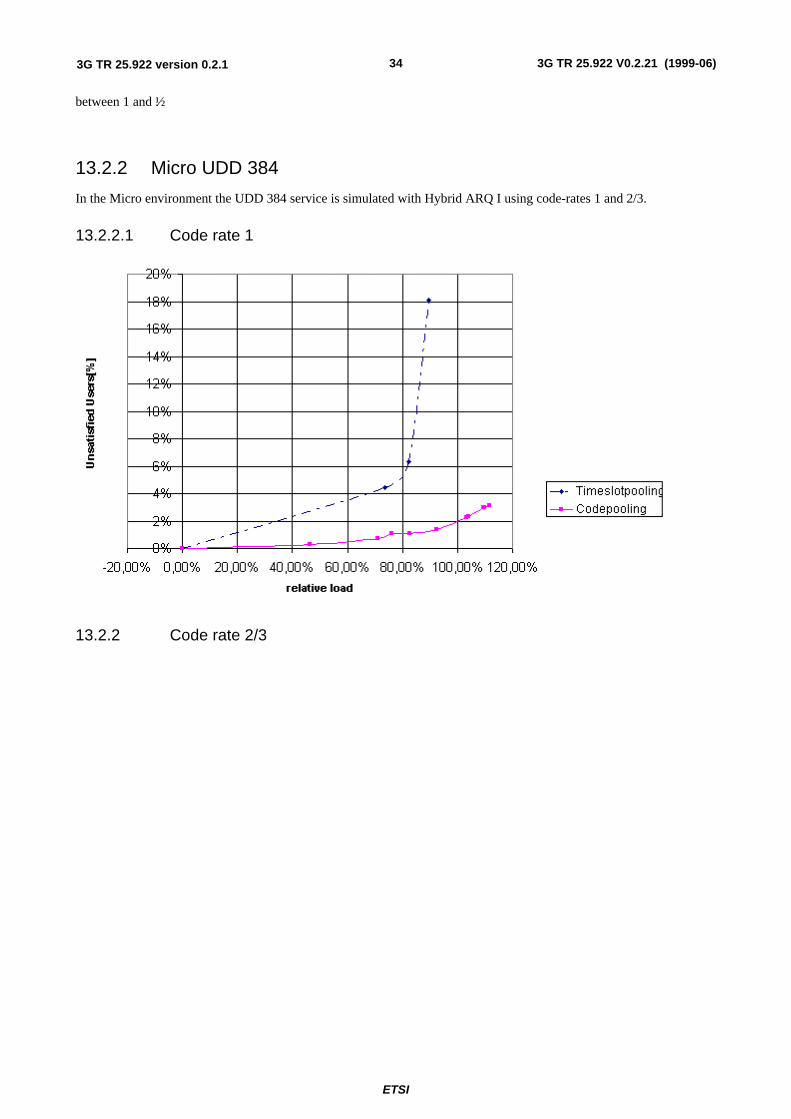
ETSI
3G TR 25.922 V0.2.21 (1999-06)343G TR 25.922 version 0.2.1
between 1 and ½.
13.2.2 Micro UDD 384
In the Micro environment the UDD 384 service is simulated with Hybrid ARQ I using code-rates 1 and 2/3.
13.2.2.1 Code rate 1
13.2.2 Code rate 2/3
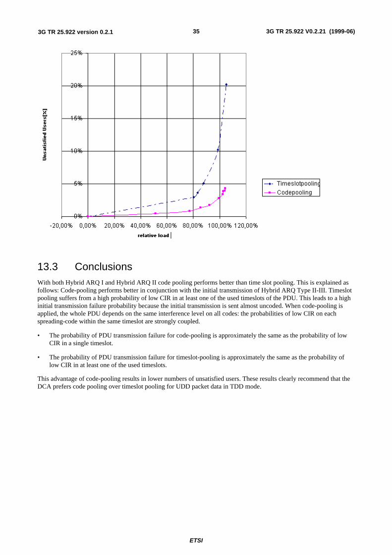
ETSI
3G TR 25.922 V0.2.21 (1999-06)353G TR 25.922 version 0.2.1
13.3 ConclusionsWith both Hybrid ARQ I and Hybrid ARQ II code pooling performs better than time slot pooling. This is explained asfollows: Code-pooling performs better in conjunction with the initial transmission of Hybrid ARQ Type II-III. Timeslotpooling suffers from a high probability of low CIR in at least one of the used timeslots of the PDU. This leads to a highinitial transmission failure probability because the initial transmission is sent almost uncoded. When code-pooling isapplied, the whole PDU depends on the same interference level on all codes: the probabilities of low CIR on eachspreading-code within the same timeslot are strongly coupled.
• The probability of PDU transmission failure for code-pooling is approximately the same as the probability of lowCIR in a single timeslot.
• The probability of PDU transmission failure for timeslot-pooling is approximately the same as the probability oflow CIR in at least one of the used timeslots.
This advantage of code-pooling results in lower numbers of unsatisfied users. These results clearly recommend that theDCA prefers code pooling over timeslot pooling for UDD packet data in TDD mode.
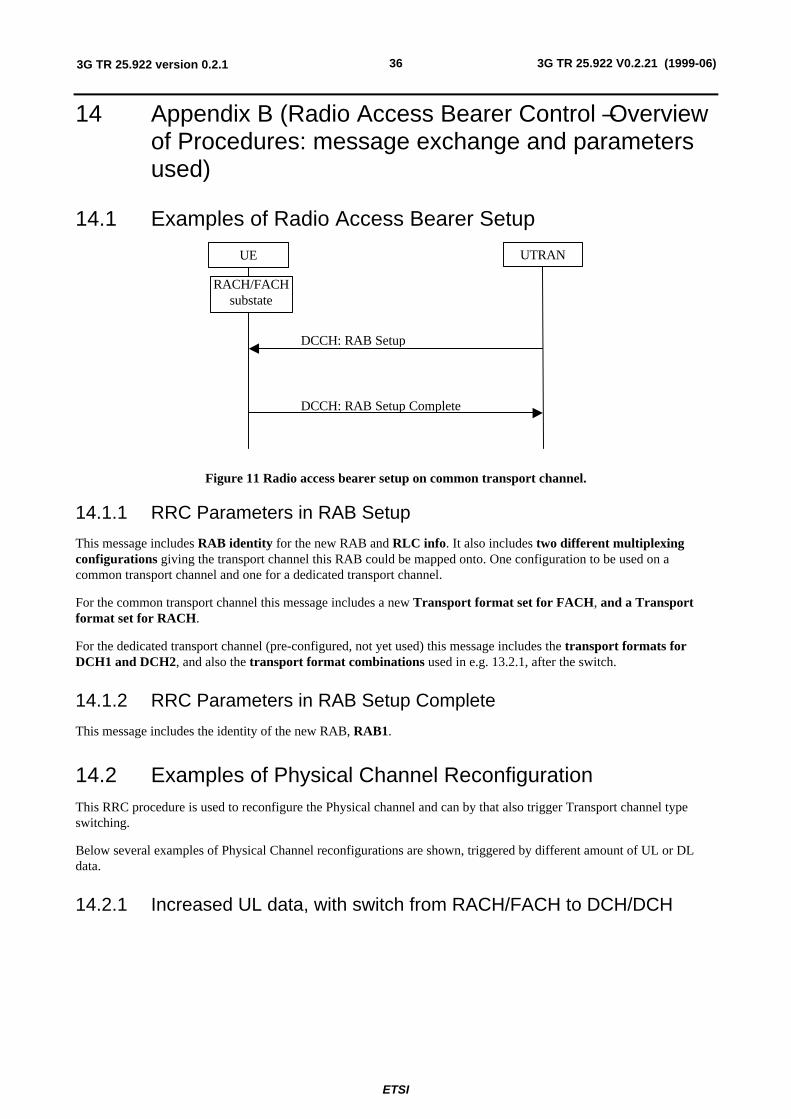
ETSI
3G TR 25.922 V0.2.21 (1999-06)363G TR 25.922 version 0.2.1
14 Appendix B (Radio Access Bearer Control – Overviewof Procedures: message exchange and parametersused)
14.1 Examples of Radio Access Bearer Setup
UTRAN
DCCH: RAB Setup
DCCH: RAB Setup Complete
RACH/FACHsubstate
UE
Figure 11 Radio access bearer setup on common transport channel.
14.1.1 RRC Parameters in RAB Setup
This message includes RAB identity for the new RAB and RLC info. It also includes two different multiplexingconfigurations giving the transport channel this RAB could be mapped onto. One configuration to be used on acommon transport channel and one for a dedicated transport channel.
For the common transport channel this message includes a new Transport format set for FACH, and a Transportformat set for RACH.
For the dedicated transport channel (pre-configured, not yet used) this message includes the transport formats forDCH1 and DCH2, and also the transport format combinations used in e.g. 13.2.1, after the switch.
14.1.2 RRC Parameters in RAB Setup Complete
This message includes the identity of the new RAB, RAB1.
14.2 Examples of Physical Channel ReconfigurationThis RRC procedure is used to reconfigure the Physical channel and can by that also trigger Transport channel typeswitching.
Below several examples of Physical Channel reconfigurations are shown, triggered by different amount of UL or DLdata.
14.2.1 Increased UL data, with switch from RACH/FACH to DCH/DCH
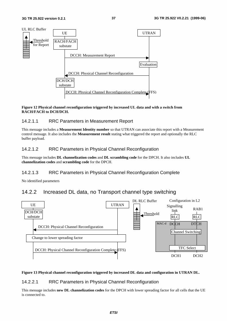
ETSI
3G TR 25.922 V0.2.21 (1999-06)373G TR 25.922 version 0.2.1
UTRAN
DCCH: Physical Channel Reconfiguration
Evaluation
DCCH: Physical Channel Reconfiguration Complete (FFS)
RACH/FACHsubstate
UE
DCH/DCHsubstate
UL RLC Buffer
Thresholdfor Report
DCCH: Measurement Report
Figure 12 Physical channel reconfiguration triggered by increased UL data and with a switch fromRACH/FACH to DCH/DCH.
14.2.1.1 RRC Parameters in Measurement Report
This message includes a Measurement Identity number so that UTRAN can associate this report with a Measurementcontrol message. It also includes the Measurement result stating what triggered the report and optionally the RLCbuffer payload.
14.2.1.2 RRC Parameters in Physical Channel Reconfiguration
This message includes DL channelization codes and DL scrambling code for the DPCH. It also includes ULchannelization codes and scrambling code for the DPCH.
14.2.1.3 RRC Parameters in Physical Channel Reconfiguration Complete
No identified parameters
14.2.2 Increased DL data, no Transport channel type switching
MAC-d
UTRAN
DCCH: Physical Channel Reconfiguration
DCCH: Physical Channel Reconfiguration Complete (FFS)
DL RLC Buffer
ThresholdDCH/DCHsubstate
Change to lower spreading factor
UEConfiguration in L2
RLC
Signallinglink
DCH1
RLC
RAB1
TFC Select
DCH2
Channel Switching
DCCH DTCH
Figure 13 Physical channel reconfiguration triggered by increased DL data and configuration in UTRAN DL.
14.2.2.1 RRC Parameters in Physical Channel Reconfiguration
This message includes new DL channelization codes for the DPCH with lower spreading factor for all cells that the UEis connected to.
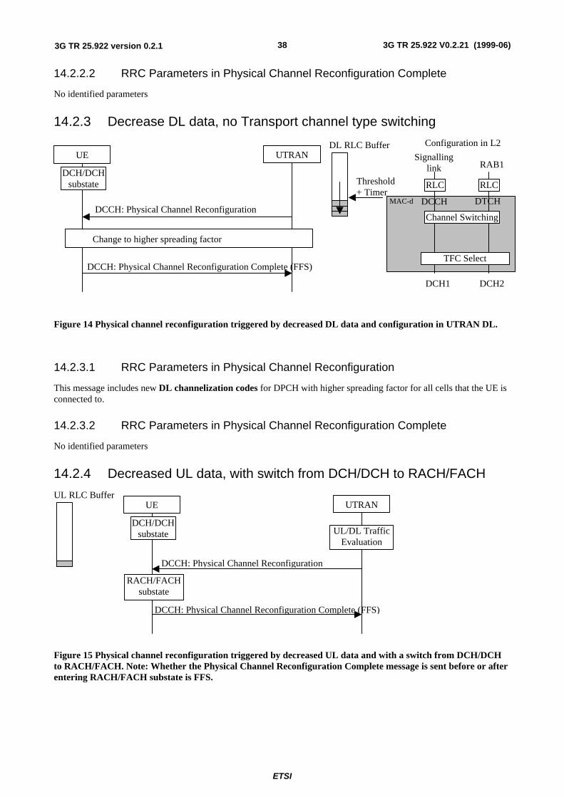
ETSI
3G TR 25.922 V0.2.21 (1999-06)383G TR 25.922 version 0.2.1
14.2.2.2 RRC Parameters in Physical Channel Reconfiguration Complete
No identified parameters
14.2.3 Decrease DL data, no Transport channel type switching
MAC-d
UTRAN
DCCH: Physical Channel Reconfiguration
DCCH: Physical Channel Reconfiguration Complete (FFS)
DL RLC Buffer
Threshold+ Timer
Change to higher spreading factor
UEConfiguration in L2
RLC
DCH1
RLC
TFC Select
DCH2
Channel Switching
Signallinglink RAB1
DCCH DTCH
DCH/DCHsubstate
Figure 14 Physical channel reconfiguration triggered by decreased DL data and configuration in UTRAN DL.
14.2.3.1 RRC Parameters in Physical Channel Reconfiguration
This message includes new DL channelization codes for DPCH with higher spreading factor for all cells that the UE isconnected to.
14.2.3.2 RRC Parameters in Physical Channel Reconfiguration Complete
No identified parameters
14.2.4 Decreased UL data, with switch from DCH/DCH to RACH/FACH
UTRAN
DCCH: Physical Channel Reconfiguration
UL RLC Buffer
UL/DL TrafficEvaluation
DCCH: Physical Channel Reconfiguration Complete (FFS)
RACH/FACHsubstate
UE
DCH/DCHsubstate
Figure 15 Physical channel reconfiguration triggered by decreased UL data and with a switch from DCH/DCHto RACH/FACH. Note: Whether the Physical Channel Reconfiguration Complete message is sent before or afterentering RACH/FACH substate is FFS.
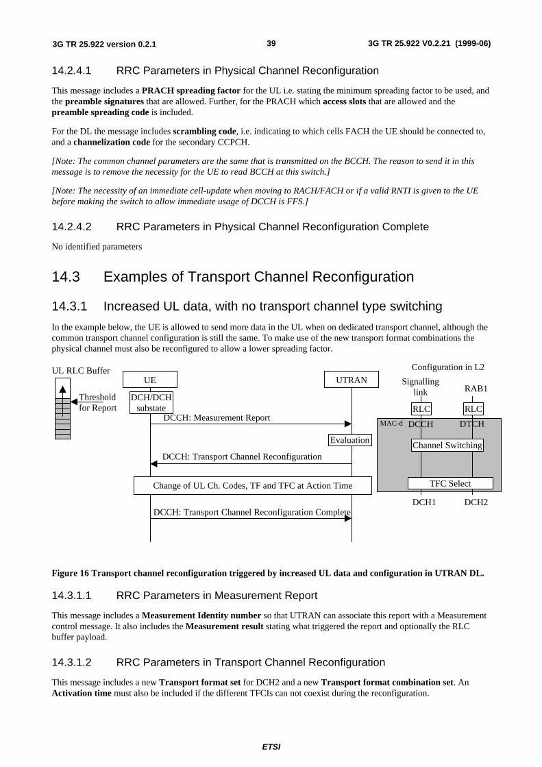
ETSI
3G TR 25.922 V0.2.21 (1999-06)393G TR 25.922 version 0.2.1
14.2.4.1 RRC Parameters in Physical Channel Reconfiguration
This message includes a PRACH spreading factor for the UL i.e. stating the minimum spreading factor to be used, andthe preamble signatures that are allowed. Further, for the PRACH which access slots that are allowed and thepreamble spreading code is included.
For the DL the message includes scrambling code, i.e. indicating to which cells FACH the UE should be connected to,and a channelization code for the secondary CCPCH.
[Note: The common channel parameters are the same that is transmitted on the BCCH. The reason to send it in thismessage is to remove the necessity for the UE to read BCCH at this switch.]
[Note: The necessity of an immediate cell-update when moving to RACH/FACH or if a valid RNTI is given to the UEbefore making the switch to allow immediate usage of DCCH is FFS.]
14.2.4.2 RRC Parameters in Physical Channel Reconfiguration Complete
No identified parameters
14.3 Examples of Transport Channel Reconfiguration
14.3.1 Increased UL data, with no transport channel type switching
In the example below, the UE is allowed to send more data in the UL when on dedicated transport channel, although thecommon transport channel configuration is still the same. To make use of the new transport format combinations thephysical channel must also be reconfigured to allow a lower spreading factor.
MAC-d
UTRAN
DCCH: Transport Channel Reconfiguration
DCCH: Transport Channel Reconfiguration Complete
UL RLC Buffer
Thresholdfor Report
DCCH: Measurement Report
Evaluation
Change of UL Ch. Codes, TF and TFC at Action Time
UE
Configuration in L2
RLC
DCH1
RLC
TFC Select
DCH2
Channel Switching
Signallinglink RAB1
DCCH DTCH
DCH/DCHsubstate
Figure 16 Transport channel reconfiguration triggered by increased UL data and configuration in UTRAN DL.
14.3.1.1 RRC Parameters in Measurement Report
This message includes a Measurement Identity number so that UTRAN can associate this report with a Measurementcontrol message. It also includes the Measurement result stating what triggered the report and optionally the RLCbuffer payload.
14.3.1.2 RRC Parameters in Transport Channel Reconfiguration
This message includes a new Transport format set for DCH2 and a new Transport format combination set. AnActivation time must also be included if the different TFCIs can not coexist during the reconfiguration.
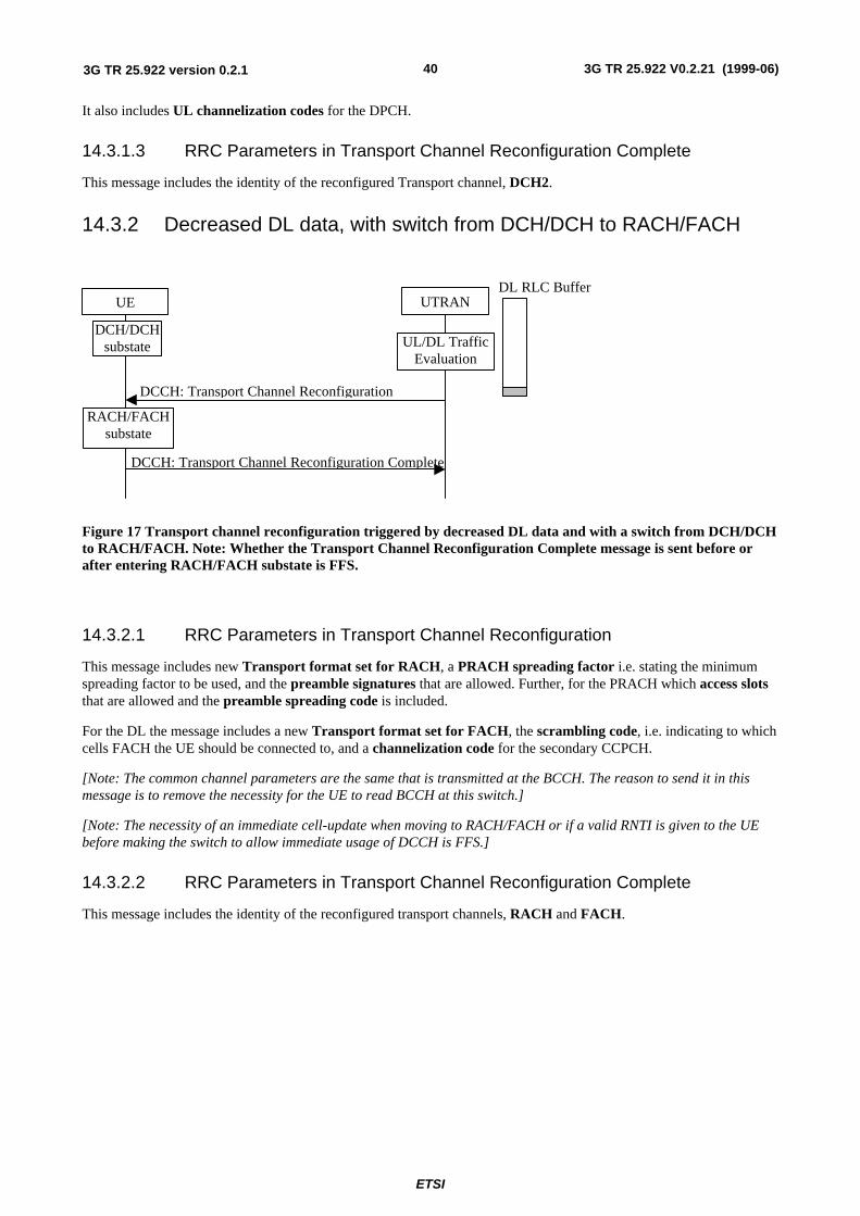
ETSI
3G TR 25.922 V0.2.21 (1999-06)403G TR 25.922 version 0.2.1
It also includes UL channelization codes for the DPCH.
14.3.1.3 RRC Parameters in Transport Channel Reconfiguration Complete
This message includes the identity of the reconfigured Transport channel, DCH2.
14.3.2 Decreased DL data, with switch from DCH/DCH to RACH/FACH
UTRAN
DCCH: Transport Channel Reconfiguration
DL RLC Buffer
UL/DL TrafficEvaluation
DCCH: Transport Channel Reconfiguration Complete
RACH/FACHsubstate
UE
DCH/DCHsubstate
Figure 17 Transport channel reconfiguration triggered by decreased DL data and with a switch from DCH/DCHto RACH/FACH. Note: Whether the Transport Channel Reconfiguration Complete message is sent before orafter entering RACH/FACH substate is FFS.
14.3.2.1 RRC Parameters in Transport Channel Reconfiguration
This message includes new Transport format set for RACH, a PRACH spreading factor i.e. stating the minimumspreading factor to be used, and the preamble signatures that are allowed. Further, for the PRACH which access slotsthat are allowed and the preamble spreading code is included.
For the DL the message includes a new Transport format set for FACH, the scrambling code, i.e. indicating to whichcells FACH the UE should be connected to, and a channelization code for the secondary CCPCH.
[Note: The common channel parameters are the same that is transmitted at the BCCH. The reason to send it in thismessage is to remove the necessity for the UE to read BCCH at this switch.]
[Note: The necessity of an immediate cell-update when moving to RACH/FACH or if a valid RNTI is given to the UEbefore making the switch to allow immediate usage of DCCH is FFS.]
14.3.2.2 RRC Parameters in Transport Channel Reconfiguration Complete
This message includes the identity of the reconfigured transport channels, RACH and FACH.
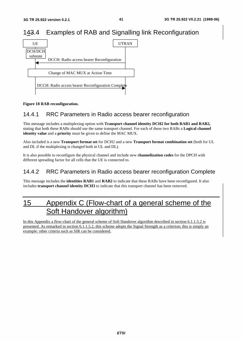
ETSI
3G TR 25.922 V0.2.21 (1999-06)413G TR 25.922 version 0.2.1
143.4 Examples of RAB and Signalling link Reconfiguration
UTRAN
DCCH: Radio access bearer Reconfiguration
DCCH: Radio access bearer Reconfiguration Complete
UE
Change of MAC MUX at Action Time
DCH/DCHsubstate
Figure 18 RAB reconfiguration.
14.4.1 RRC Parameters in Radio access bearer reconfiguration
This message includes a multiplexing option with Transport channel identity DCH2 for both RAB1 and RAB2,stating that both these RABs should use the same transport channel. For each of these two RABs a Logical channelidentity value and a priority must be given to define the MAC MUX.
Also included is a new Transport format set for DCH2 and a new Transport format combination set (both for ULand DL if the multiplexing is changed both in UL and DL).
It is also possible to reconfigure the physical channel and include new channelization codes for the DPCH withdifferent spreading factor for all cells that the UE is connected to.
14.4.2 RRC Parameters in Radio access bearer reconfiguration Complete
This message includes the identities RAB1 and RAB2 to indicate that these RABs have been reconfigured. It alsoincludes transport channel identity DCH3 to indicate that this transport channel has been removed.
15 Appendix C (Flow-chart of a general scheme of theSoft Handover algorithm)
In this Appendix a flow-chart of the general scheme of Soft Handover algorithm described in section 6.1.1.5.2 ispresented. As remarked in section 6.1.1.5.2, this scheme adopts the Signal Strength as a criterion; this is simply anexample: other criteria such as SIR can be considered.
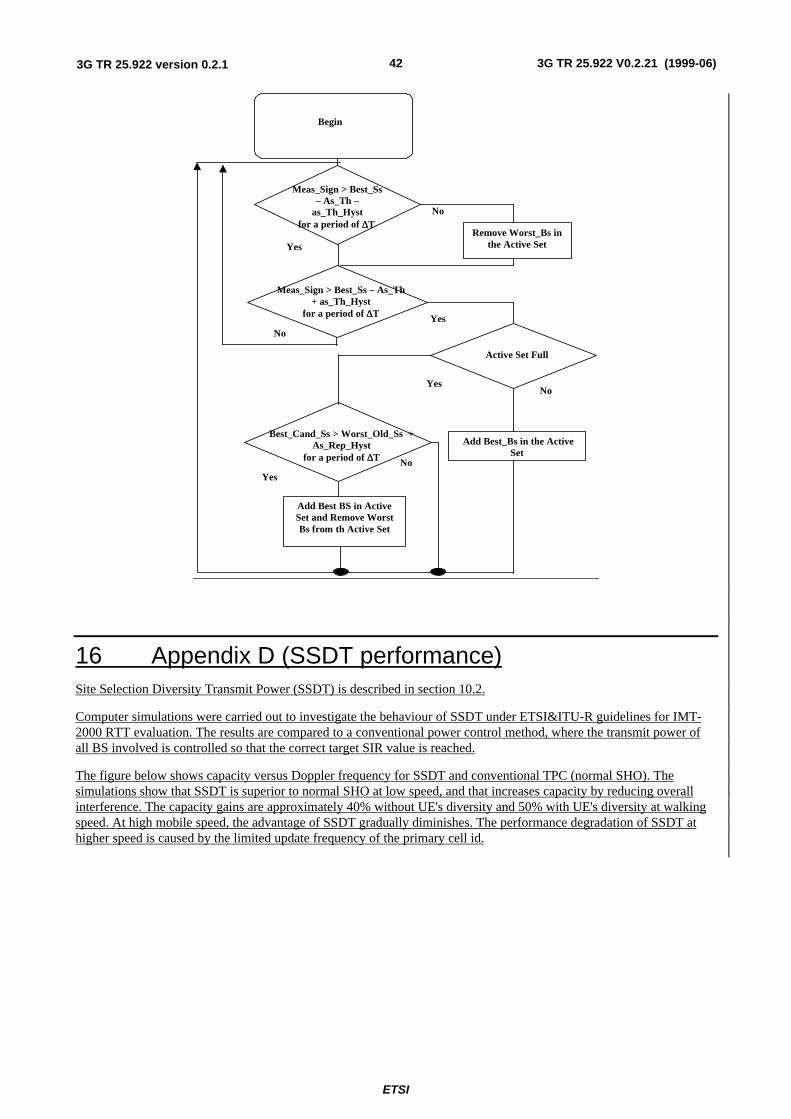
ETSI
3G TR 25.922 V0.2.21 (1999-06)423G TR 25.922 version 0.2.1
Meas_Sign > Best_Ss– As_Th –
as_Th_Hyst for a period of ∆∆T
Yes
No
Remove Worst_Bs inthe Active Set
Meas_Sign > Best_Ss – As_Th+ as_Th_Hyst
for a period of ∆∆T
No
Yes
Add Best_Bs in the ActiveSet
Best_Cand_Ss > Worst_Old_Ss +As_Rep_Hyst
for a period of ∆∆T
Yes
No
Active Set Full
NoYes
Add Best BS in ActiveSet and Remove WorstBs from th Active Set
Begin
16 Appendix D (SSDT performance)Site Selection Diversity Transmit Power (SSDT) is described in section 10.2.
Computer simulations were carried out to investigate the behaviour of SSDT under ETSI&ITU-R guidelines for IMT-2000 RTT evaluation. The results are compared to a conventional power control method, where the transmit power ofall BS involved is controlled so that the correct target SIR value is reached.
The figure below shows capacity versus Doppler frequency for SSDT and conventional TPC (normal SHO). Thesimulations show that SSDT is superior to normal SHO at low speed, and that increases capacity by reducing overallinterference. The capacity gains are approximately 40% without UE's diversity and 50% with UE's diversity at walkingspeed. At high mobile speed, the advantage of SSDT gradually diminishes. The performance degradation of SSDT athigher speed is caused by the limited update frequency of the primary cell id.
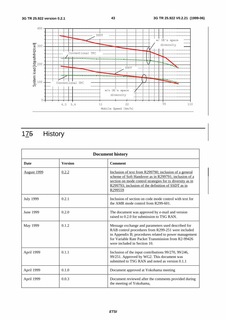
ETSI
3G TR 25.922 V0.2.21 (1999-06)433G TR 25.922 version 0.2.1
0
100
200
300
400
5.4 11 110
Mobile Speed [km/h]
w/ UE's space
diversity
w/o UE's space
diversity
SSDT
SSDT
Conventional TPC
Conventional TPC
55224.3
175 History
Document history
Date Version Comment
August 1999 0.2.2 Inclusion of text from R299790; inclusion of a generalscheme of Soft Handover as in R299791; inclusion of asection on mode control strategies for tx diversity as inR299793; inclusion of the definition of SSDT as inR299559
July 1999 0.2.1 Inclusion of section on code mode control with text forthe AMR mode control from R299-601.
June 1999 0.2.0 The document was approved by e-mail and versionraised to 0.2.0 for submission to TSG RAN.
May 1999 0.1.2 Message exchange and parameters used described forRAB control procedures from R299-251 were includedin Appendix B; procedures related to power managementfor Variable Rate Packet Transmission from R2-99426were included in Section 10.
April 1999 0.1.1 Inclusion of the input contributions 99/270, 99/246,99/251. Approved by WG2. This document wassubmitted to TSG RAN and noted as version 0.1.1
April 1999 0.1.0 Document approved at Yokohama meeting
April 1999 0.0.3 Document reviewed after the comments provided duringthe meeting of Yokohama,
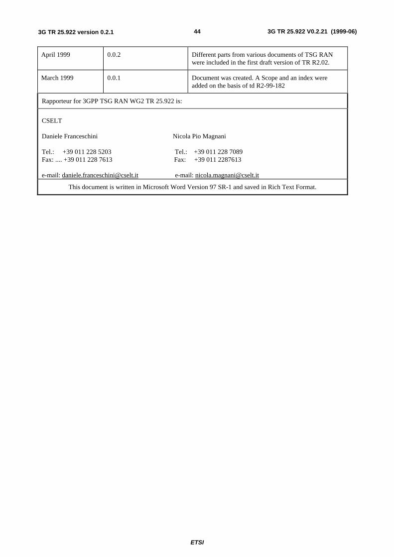
ETSI
3G TR 25.922 V0.2.21 (1999-06)443G TR 25.922 version 0.2.1
April 1999 0.0.2 Different parts from various documents of TSG RANwere included in the first draft version of TR R2.02.
March 1999 0.0.1 Document was created. A Scope and an index wereadded on the basis of td R2-99-182
Rapporteur for 3GPP TSG RAN WG2 TR 25.922 is:
CSELT
Daniele Franceschini Nicola Pio Magnani
Tel.: +39 011 228 5203 Tel.: +39 011 228 7089Fax: .... +39 011 228 7613 Fax: +39 011 2287613
e-mail: [email protected] e-mail: [email protected]
This document is written in Microsoft Word Version 97 SR-1 and saved in Rich Text Format.