transport and biodegradation of toxic organics in biofilms
TRANSCRIPT
ELSEVIER Journal of Hazardous Materials 41 (1995) 267-285
JOURNALOF HflZHRDOUS mffrERIIILS
Transport and biodegradation of toxic organics in biofilms
Tian C. Zhang a, Y.C. Fu b, Paul L. Bishop c'*, Margaret Kupferl&, Sean FitzGerald ~, Henry Hongshen Jiang ¢, Christopher Harmer a
aDepartment of Civil Engineering, University of Nebraska, Lincoln, NB 68588, USA b Greenland Environmental Engineering and Protection Inc., Taipei, Taiwan, ROC
c Department of Civil and Environmental Engineering, University of Cincinnati, Cincinnati, OH 45221, USA
dCH2M Hill, One Dayton Center, Suite 1400, Dayton, OH 45402, USA
Received 27 June 1994; accepted in revised form 15 November 1994
Abstract
This paper summarizes our studies on transport and biodegradation of azo dyes in aerobic biofilms. Three lab-scale rotating drum biofilm reactors (RDBRs) were used to culture the biofilms. Synthetic, municipal-type wastewater, spiked with several azo dyes, was continuously fed into the RDBRs. The study has revealed that Acid Orange 7 (AO7) and Acid Orange 8 (AO8) can be degraded aerobically in an efficient and effective manner under properly controlled operating conditions. The other dyes tested, however, are essentially non-degradable in an aerobic reactor. Microelectrodes and a microslicing technique have been used to elucidate changes in the structure of biofilms with depth and to determine the influence of these changes on mass transport and transformation processes. The results show that biofilms are non- homogeneous and highly stratified. Accordingly, biofilm is usually characterized by aerobic and anaerobic zones, with the anaerobic part used to break the azo bond and the aerobic surface layer to achieve the mineralization of anaerobically recalcitrant intermediates. Results concern- ing the inhibition effect of azo dyes on biofilm COD removal and respiration rate are also presented in this paper.
1. Introduction
Azo dyes compr i se the m a j o r f ract ion of the co loran t s in use today. There are at least 3000 azo dyes used in the textile, paper , food, cosmetics, and pha rmaceu t i ca l indust r ies [ i ] . Azo dyes are c o m m o n was tewate r con t aminan t s which are p o o r l y r emoved by mos t was tewate r t r ea tmen t processes. It is es t imated tha t 15% of these dyes find their way into the env i ronmen t [2]. In addi t ion , resis tance to aerobic
* Corresponding author. Tel.: 513-556-3675. Fax: 513-556-2599.
0304-3894/95/$09.50 © 1995 Elsevier Science B.V. All rights reserved SSDI 0 3 0 4 - 3 8 9 4 ( 9 4 ) 0 0 1 1 8-9
268 T.C. Zhang et al./Journal of Hazardous Materials 41 (1995) 267-285
degradation and their incomplete mineralization under anaerobic conditions may lead to accumulation of dyes or more toxic intermediates in the environment. Therefore, azo dyes were selected as target compounds for study in this research. They were also chosen because, as a class of compounds, they range from fairly easily biodegradable to essentially non-degradable, and because of their potential for con- version into genotoxic metabolites. As such, they serve as an effective test of both the ability of biofilms to degrade recalcitrant organics, and of the importance of organic structure on ease of biodegradability within a class of compounds.
What little information is available on fates of toxic organics in wastewater treatment plants is generally limited to the activated sludge process. However, there is evidence that fixed biofilm treatment processes may be more amenable to removal of xenobiotic organics than suspended growth systems [3]. The biofilm can support different populations which degrade different substrates at different points within the biofilm. For a wastewater containing a mixture of conventional pollutants and toxic organics, all organics will diffuse into the biofilm but the conventional organics will degrade much more quickly leaving only the toxics to penetrate deeper into the biofilm. Microorganisms adapted to degradation of these toxic compounds could then become established there where they would experience little competition. Based on this consid- eration, a biofilm system was employed to investigate biodegradation of azo dyes.
The overall goals of this research were: to study biodegradation of toxic organics in microbial biofilms by evaluating transport mechanisms of contaminants into and out of the biofilm, to determine how changes in environmental conditions affect growth and biodegradation kinetics in the biofilms, and to elucidate some of the fundamental characteristics of the biofilm process.
This research consisted of three stages. The first stage was to examine biodegrada- tion of several azo dyes, including Acid Orange 7 (AO7), Acid Orange 8 (AO8), Acid Orange 10 (AO10), and Acid Red 14 (AR14), and to evaluate the rate of the azo cleavage reaction in biofilms as a function of bulk-phase parameters. The study in this stage involved running statistically designed kinetics experiments on three lab-scale biofilm reactors. The second stage was to study biofilm development and structure under a variety of growth conditions and in the presence of toxicants. The study of this second stage was conducted by examining the thickness distribution within the biofilm reactors and evaluating the spatial distributions of biofilm properties, such as density, porosity, bacterial trophic population, and mean pore size of water channels within the biofilm. The third stage was a study of the effect of biofilm structure on transformation processes in biofilms. The objective of this paper is to summarize this research.
2. Materials and methods
2.1. Reactors, biofilm culturing, and statistically designed kinetics tests
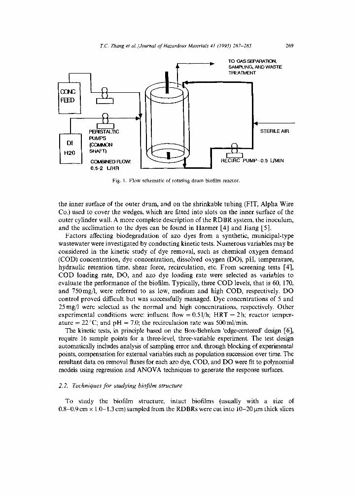
Lab-scale RDBRs were used to develop biofilms for this study. Fig. 1 shows the flow schematic of a RDBR. Biofilm growth occurs on the surface of the rotating drum, on
T.C. Zhang et al./Journal of Hazardous Materials 41 (1995) 267-285 269
C~
PERISTALTIC PUMPS (COMMON SHAFT)
COMBINED FLOW: 0,5-2 L/HR
~ d
,., J
I
' ,
v TO GAS SEPARATION. SA,IVlPt_ING. AND WASTE TREATMENT
STERILE AIR
i RECIRC PUMP--0.5 L/MIN
Fig. 1. Flow schematic of rotating drum biofilm reactor.
the inner surface of the outer drum, and on the shrinkable tubing (FIT, Alpha Wire Co.) used to cover the wedges, which are fitted into slots on the inner surface of the outer cylinder wall. A more complete description of the RDBR system, the inoculum, and the acclimation to the dyes can be found in Harmer [4] and Jiang [5].
Factors affecting biodegradation of azo dyes from a synthetic, municipal-type wastewater were investigated by conducting kinetic tests. Numerous variables may be considered in the kinetic study of dye removal, such as chemical oxygen demand (COD) concentration, dye concentration, dissolved oxygen (DO), pH, temperature, hydraulic retention time, shear force, recirculation, etc. From screening tests [4], COD loading rate, DO, and azo dye loading rate were selected as variables to evaluate the performance of the biofilm. Typically, three COD levels, that is 60, 170, and 750mg/1, were referred to as low, medium and high COD, respectively. DO control proved difficult but was successfully managed. Dye concentrations of 5 and 25 mg/1 were selected as the normal and high concentrations, respectively. Other experimental conditions were: influent flow = 0.51/h; HRT = 2h; reactor temper- ature = 22 °C; and pH = 7.0; the recirculation rate was 500 ml/min.
The kinetic tests, in principle based on the Box-Behnken 'edge-centered' design [6], require 16 sample points for a three-level, three-variable experiment. The test design automatically includes analysis of sampling error and, through blocking of experimental points, compensation for external variables such as population succession over time. The resultant data on removal fluxes for each azo dye, COD, and DO were fit to polynomial models using regression and ANOVA techniques to generate the response surfaces.
2.2. Techniques for studying biofilm structure
To study the biofilm structure, intact biofilms (usually with a size of 0.8-0.9 cm x 1.0 1.3 cm) sampled from the RDBRs were cut into 10-20 lain thick slices
270 "1~C. Zhang et al./Journal of Hazardous Materials 41 (1995) 267-285
using a cryogenic microtome (Ultracut E, Reichert-Jung Company, Austria) following the procedure of Zhang and Bishop [7]. The biofilms were divided into three or four layers by collecting the sliced biofilm into three or four different bottles containing 20ml dilute solution (0.85% NaC1) each. After homogenization with a vortexer, the bacterial suspensions from each layer were then used to determine biofilm properties based on the experimental methods and theoretical considerations of Zhang and Bishop [7, 8] and Zhang et al. [9] as follows. (a) Densities of biofilms based on total solids (TS) and total volatile solids (TVS) were measured according to Standard Methods [10]. (b) The methods for heterotrophic plate count (HPC), facultative plate count (FPC), and nitrifiers were the same as those in Zhang et al. [9] and He [11]. (c) The viable cells inside the biofilm were determined by measuring lipid phosphate content [7], while metabolically active biofilm populations were evaluated by the INT test [7, 12]. (d) The volume fraction of water, or porosity of the biofilm, is defined as that portion of a biofilm section that is occupied by water outside of the cells [7, 13]. The determination of biofilm porosity is described in Zhang and Bishop [7]. (e) The specific surface area and the size of water channels within the biofilm were evaluated based on the Acid Red 18 (AR18) adsorption test [7, 8].
2.3. Microelectrode studies
The microelectrode technique is one of the most powerful analytical techniques that has been developed for characterizing chemical and metabolic activity gradients in biofilms. In this study, the microelectrode technique was used to: (a) determine the variation in oxygen diffusivity with depth in the biofilm by measuring unsteady-state variation of DO concentrations inside deactivated biofilms [14]; (b) measure substra- te concentration profiles with biofilms [9, 15]; (c) evaluate the relationship between organic loading and respiration rate under various operational conditions [16]; and (d) to study the inhibition effect of azo dyes on bioactivity of biofilms [17]. 02, NH~-, NO3, and pH microelectrodes were used in this study. All microelectrodes used had tip diameters ranging from 2 to 4 ~tm. The procedure for fabrication of recessed cathode oxygen microelectrodes and ion-selective microelectrodes is described in Refs. [16, 18, 19].
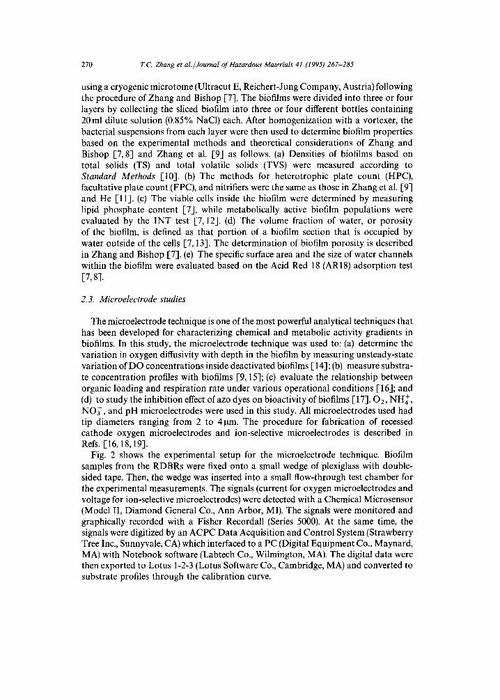
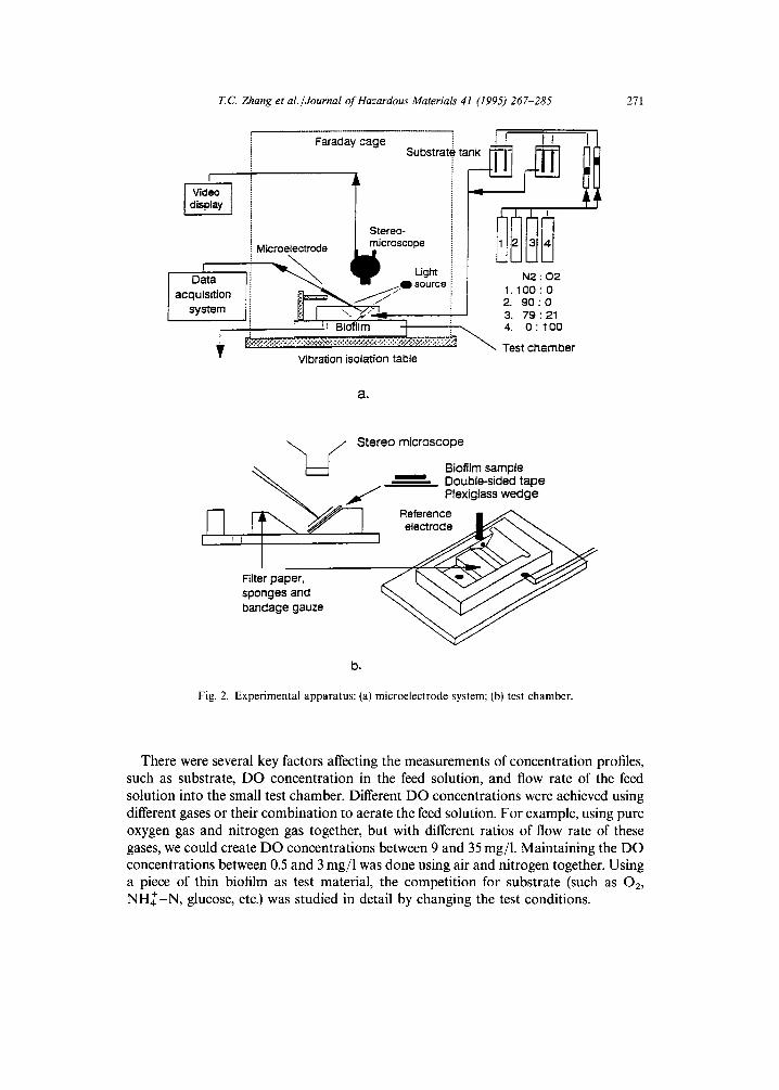
Fig. 2 shows the experimental setup for the microelectrode technique. Biofilm samples from the RDBRs were fixed onto a small wedge of plexiglass with double- sided tape. Then, the wedge was inserted into a small flow-through test chamber for the experimental measurements. The signals (current for oxygen microelectrodes and voltage for ion-selective microelectrodes) were detected with a Chemical Microsensor (Model II, Diamond General Co., Ann Arbor, MI). The signals were monitored and graphically recorded with a Fisher Recordall (Series 5000). At the same time, the signals were digitized by an ACPC Data Acquisition and Control System (Strawberry Tree Inc., Sunnyvale, CA) which interfaced to a PC (Digital Equipment Co., Maynard, MA) with Notebook software (Labtech Co., Wilmington, MA). The digital data were then exported to Lotus 1-2-3 (Lotus Software Co., Cambridge, MA) and converted to substrate profiles through the calibration curve.
T,C Zhang et al./Journal of Hazardous Materials 41 (1995) 267-285
i
] display
Data acquisition
system
Substrate t
Microelectrode microscope
p Ught N2 : 02 ~ , 0 source 1. 1 O0 : 0
• 2. 90:0 I ......... ~ ~ 3. 79 : z l ~= Bicffilm I 4. 0:100
~ . ' . . ; . , , w :',~;~:.~>:,y,< ~ Test claarnber Vibration isolation table
a.
271
",~ / Stereo microscope
~-~ ~ Biofilm sample ~ ~ Double-sided tape
~ Plexiglass wedge ~--] ~ i i ? ~ - / ~ " ~ . ~ " ~ . Reference II ~
bandage gauze ~ ~ T ~
b.
Fig. 2. Experimental apparatus: (a) microelectrode system; (b) test chamber.
There were several key factors affecting the measurements of concentration profiles, such as substrate, DO concentration in the feed solution, and flow rate of the feed solution into the small test chamber. Different DO concentrations were achieved using different gases or their combination to aerate the feed solution. For example, using pure oxygen gas and nitrogen gas together, but with different ratios of flow rate of these gases, we could create DO concentrations between 9 and 35 mg/1. Maintaining the DO concentrations between 0.5 and 3 mg/1 was done using air and nitrogen together. Using a piece of thin biofilm as test material, the competition for substrate (such as 02, N H ~ - N , glucose, etc.) was studied in detail by changing the test conditions.
272 T.C. Zhang et al./Journal of Hazardous Materials 41 (1995) 267-285
3. Results and discussion
3.1. Response surfaces of A07 and A08
When biofilm substrate removal rates stabilized, the test matrix was run, varying COD loading flux, dye loading flux, and DO levels. The sampling interval was determined to be 12h, considering the characteristic times [20] associated with reaching pseudo-steady state concentration. The effects of these relatively rapid changes in environmental conditions on removal efficiencies and biofilm sloughing were compensated for by partially randomizing test points in three consecutive test blocks [4, 5]. In total, 16 points at different conditions were tested for AO7 and AO8, respectively. Then, the first step in the analysis was to determine the best polynomial regression fit to the data. Algebraic expressions were then tried to represent diffusion- limited kinetics, inhibition, and parallel reactions to derive the removal model for each dye tested.
As a result of regression, it was found that: (a) AO7 removal was zero order overall with respect to AO7 concentration; and (b) COD flux was a more significant variable for COD removal than influent COD concentration. Using models which assumed two parallel mechanisms yielded the best fit with the experimental data. The best of these models was
2 ) , ---- 0.015 JAOV = 0.002901 Jxf~COD ~- + DO + 0.000198 x/DO 0.015 + Jcoo' (1)
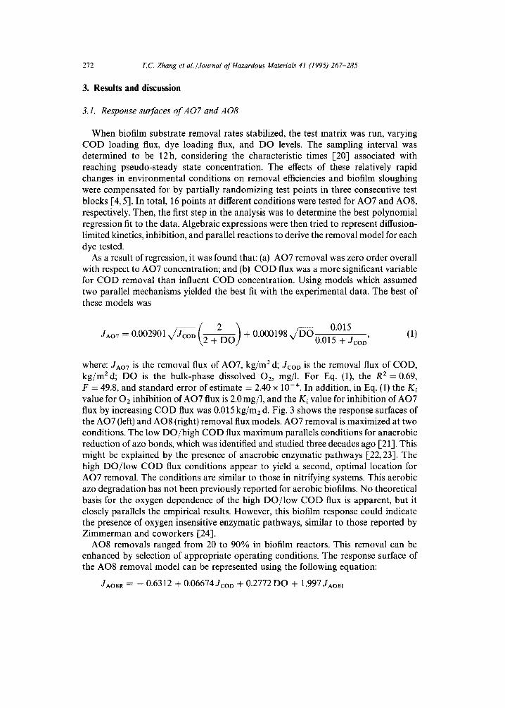
where: JAO7 is the removal flux of AO7, kg/m 2 d; JCOD is the removal flux of COD, kg/mEd; DO is the bulk-phase dissolved 02, mg/1. For Eq. (1), the R 2 - - 0.69, F = 49.8, and standard error of estimate = 2.40 x 10 -4. In addition, in Eq. (1) the Ki value for O2 inhibition of AO7 flux is 2.0 mg/1, and the Ki value for inhibition of AO7 flux by increasing COD flux was 0.015 kg/m2 d. Fig. 3 shows the response surfaces of the AO7 (left) and AO8 (right) removal flux models. AO7 removal is maximized at two conditions. The low DO/high COD flux maximum parallels conditions for anaerobic reduction of azo bonds, which was identified and studied three decades ago [21]. This might be explained by the presence of anaerobic enzymatic pathways [22, 23]. The high DO/low COD flux conditions appear to yield a second, optimal location for AO7 removal. The conditions are similar to those in nitrifying systems. This aerobic azo degradation has not been previously reported for aerobic biofilms. No theoretical basis for the oxygen dependence of the high DO/low COD flux is apparent, but it closely parallels the empirical results. However, this biofilm response could indicate the presence of oxygen insensitive enzymatic pathways, similar to those reported by Zimmerman and coworkers [24].
AO8 removals ranged from 20 to 90% in biofilm reactors. This removal can be enhanced by selection of appropriate operating conditions. The response surface of the AO8 removal model can be represented using the following equation:
JAO8R = -- 0.6312 + 0.06674JcoD + 0.2772 DO + 1.997JAo81
T.C Zhang et al./Journal of Hazardous Materials 41 (1995) 267-285 273
-- 0.7597 D O JAO8] -- 0.024 D O JCOD -- 0.1368 JCOD JAOal
+ 0.5435 D O JcoD JAosl, (2)
where JAOSR is the removal flux of AOS, g / m 2 d; JAOal is the input flux of AO8, g / m 2 d; JCOD is the removal flux of COD, g / m 2 d; D O is the bulk-phase dissolved 02, mg/1.
( a ) . ~
~, 0.8 .....
~ 0.7
~ 0.5
~" 0.4
E 0.3
o. 10
30~------.~. " /-- 2 2 0 ' ~'ern,.,.. 3° 4 ° " - ~ / 5 o o C O D
• .,'a/~/.x, g/~2.~ay
(b)
:~ 0.4
~ 0.3
0.2
O E ® 0.1 n,,'
O~ 0.C
i i ~
• . • . . . . . . . . . i ~- i
i • i ~ i ~ . . . . . ~ ............... . . . .
• i i ~ i ~ . . . . i . . . . . i
Io~o-~-~ : - " / 4 , , . , 20~"~--_~ / ^.~
,...,_ 30>"----~ ~ 2 "~' ~OD Re/-n,,., .... 4 0 ~ n . ~ n 0
• ' u v a l P l u ~ _ _ - -
"~ ~,,~2.~aj "
Fig. 3. Response surfaces of the AO7 (left) and AO8 (right) removal flux models.
274 T. C. Zhan g et al. /Journal o f Hazardous Materials 41 (1995) 267-285
For Eq. (2), R 2 = 0.91 and standard error of estimate = 0.092. As shown in Fig. 3, the response surface of the AO8 removal model is quite similar to that for the AO7 removal model. However, the AO7 two-mechanism model is not applicable to AO8 removal because (a) no suitable Kioxyge, and Kicoo could be found to fit the experi- mental data, and (b) the AO8 input concentration must be taken into account to derive an AO8 removal model of high R ~. The fact that AO8 removal highly depended on input AO8 concentration probably shows that AO8 is more toxic than AO7.
From Fig. 3, it can be seen that the 'saddle' of the response surface corresponds to one of the least efficient sets of operating conditions for AO7 or AO8 removal. It is interesting to note that the EPA recommended design loadings for first-stage rotating biological contactors (RBCs) fall in this region [25].
3.2. Biodegradation of AOlO and AR14
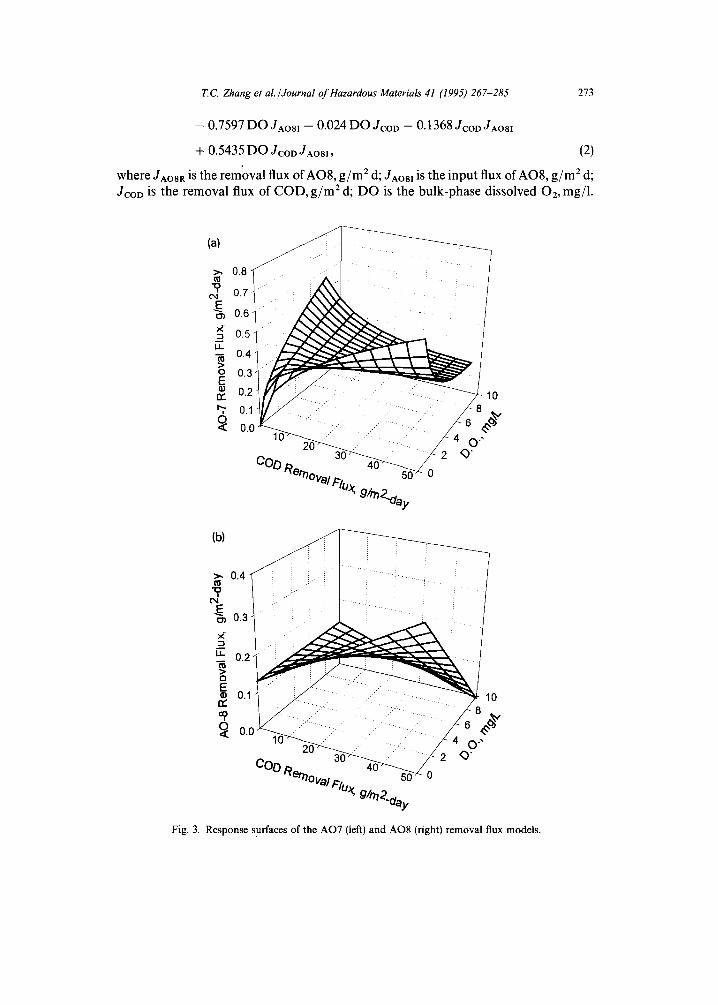
Degradation of AO10 and ARI4 in biofilm reactors was studied under various conditions. AO10 and AR14 removals were both up to 60%, but only when bulk
SO~H
o s° d N Ha
II N N II
N
C . I . A c i d O r a n g e 7 C . I . A c i d O r a n g e 8
~ O~SO3Na N NaO3S INI N OH N
SO
SOzNa C. I . A c i d O r a n g e 10 C . I . A c i d Red 14
Fig. 4. Chemical structures of azo dyes used.
T.C Zhang et al./Journal of Hazardous Materials 41 (1995) 267-285 275
liquid DO was less than 1 mg/l. Whenever DO was higher, no degradation occurred at any influent COD level. Most likely, AO10 and AR14 degradation occurred under anaerobic conditions in the biofilm. Later, this possibility was proved by using an oxygen microelectrode to measure the DO concentration profiles under similar test conditions.
The different behaviors of the four dyes are probably caused by their different structures. Molecular structures for tested dyes appear in Fig. 4. Among the four dyes studied, AO7 is the simplest one. With one methyl group more than AO7, AO8 has a similar degradation pattern to AO7, but at a lower rate of removal. AO10 has two sulfonate groups and that might be the factor that makes the azo bond hard to degrade aerobically. AO14 has the most complicated structure, and consequently it cannot be degraded aerobically.
3.3. Impact of dyes on biofilm accumulation
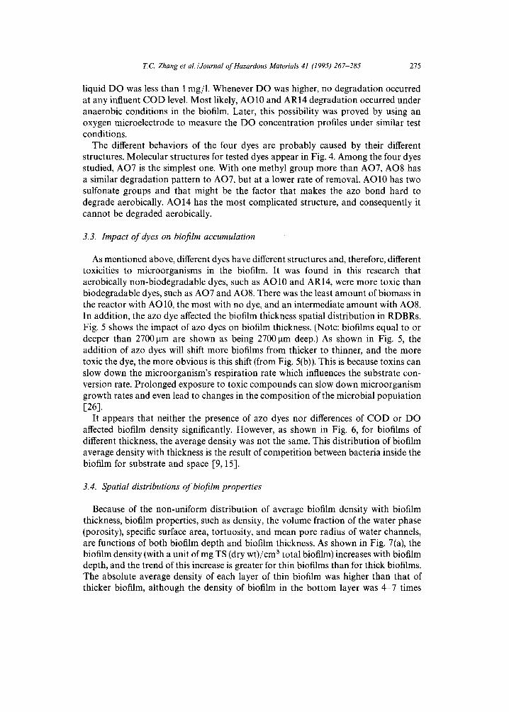
As mentioned above, different dyes have different structures and, therefore, different toxicities to microorganisms in the biofilm. It was found in this research that aerobically non-biodegradable dyes, such as AO10 and AR14, were more toxic than biodegradable dyes, such as AO7 and AO8. There was the least amount of biomass in the reactor with AO10, the most with no dye, and an intermediate amount with AO8. In addition, the azo dye affected the biofilm thickness spatial distribution in RDBRs. Fig. 5 shows the impact of azo dyes on biofilm thickness. (Note: biofilms equal to or deeper than 2700 ~tm are shown as being 2700 gm deep.) As shown in Fig. 5, the addition of azo dyes will shift more biofilms from thicker to thinner, and the more toxic the dye, the more obvious is this shift (from Fig. 5(b)). This is because toxins can slow down the microorganism's respiration rate which influences the substrate con- version rate. Prolonged exposure to toxic compounds can slow down microorganism growth rates and even lead to changes in the composition of the microbial population [26].
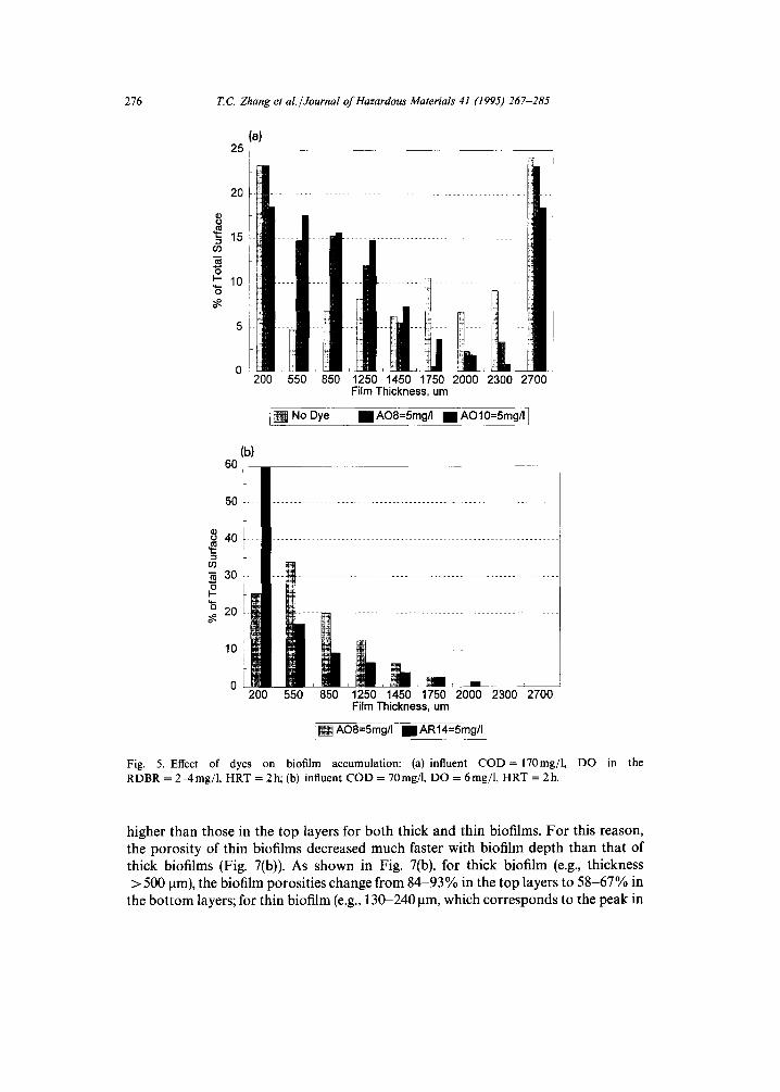
It appears that neither the presence of azo dyes nor differences of COD or DO affected biofilm density significantly. However, as shown in Fig. 6, for biofilms of different thickness, the average density was not the same. This distribution of biofilm average density with thickness is the result of competition between bacteria inside the biofilm for substrate and space [9, 15].
3.4. Spatial distributions of biofilm properties
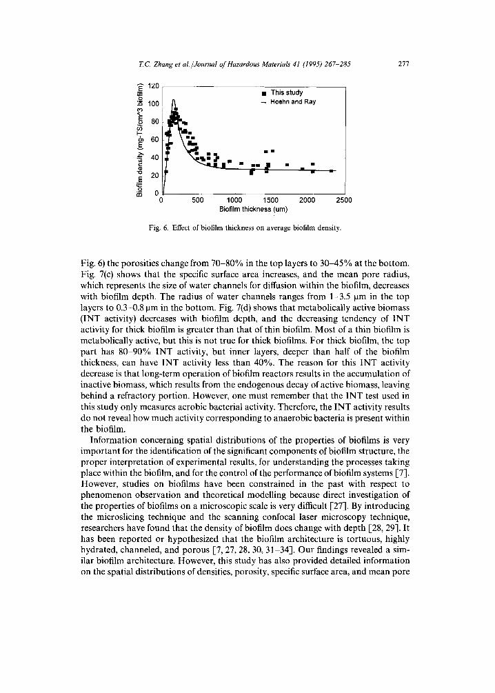
Because of the non-uniform distribution of average biofilm density with biofilm thickness, biofilm properties, such as density, the volume fraction of the water phase (porosity), specifc surface area, tortuosity, and mean pore radius of water channels, are functions of both biofilm depth and biofilm thickness. As shown in Fig. 7(a), the biofilm density (with a unit of mg TS (dry wt)/cm 3 total biofilm) increases with biofilm depth, and the trend of this increase is greater for thin biofilms than for thick biofilms. The absolute average density of each layer of thin biofilm was higher than that of thicker biofilm, although the density of biofilm in the bottom layer was 4-7 times
276 T.C. Zhang et al./Journal of Hazardous Materials 41 (1995) 267-285
(a) 25 I
20
d) O
'~" 15
"5 I.- 10
200 550 850 1250 1450 1750 2000 2300 2700 Film Thickness, um
i [ ] No Dye I IAO8=5mg/I I IAO10=5mg/I]
(b) 60,
50
30 o
L "~ 20 ! ; i
1°i ii- OL
200 550 850 1250 1450 1750 2000 2300 2700 Film Thickness, um
: [ ] AO8=5mg/I • AR14=5mg/I,
Fig. 5. Effect of dyes on biofilm accumulation: (a) influent COD= 170mg/1, DO in the RDBR = 2-4mg/1, HRT = 2h; (b) influent COD = 70mg/l, DO = 6mg/1, HRT = 2h.
higher than those in the top layers for both thick and thin biofilms. For this reason, the porosity of thin biofilms decreased much faster with biofilm depth than that of thick biofilms (Fig. 7(b)). As shown in Fig. 7(b), for thick biofilm (e.g., thickness > 500 ~tm), the biofilm porosities change from 84-93% in the top layers to 58-67% in
the bottom layers; for thin biofilm (e.g., 130-240 ~tm, which corresponds to the peak in
T.C Zhang et al./Journal of Hazardous Materials 41 (1995) 267-285
= • T h i s study 100 - - Hoehn and Ray
8o
~, 60
l " ~ j e • • • ,11 • • 40
- ,,= -o 2 0 IF • • =
E 0 , , n-t
0 5 0 0 1 0 0 0 1 5 0 0 2 0 0 0 2 5 0 0
B io f i lm t h i c k n e s s ( u m )
Fig. 6. Effect of biofilm thickness on average biofilm density.
277
Fig. 6) the porosities change from 70-80% in the top layers to 30-45% at the bottom. Fig. 7(c) shows that the specific surface area increases, and the mean pore radius, which represents the size of water channels for diffusion within the biofilm, decreases with biofilm depth. The radius of water channels ranges from 1-3.5 ~tm in the top layers to 0.3-0.8 ~tm in the bottom. Fig. 7(d) shows that metabolically active biomass (INT activity) decreases with biofilm depth, and the decreasing tendency of INT activity for thick biofilm is greater than that of thin biofilm. Most of a thin biofilm is metabolically active, but this is not true for thick biofilms. For thick biofilm, the top part has 80-90% INT activity, but inner layers, deeper than half of the biofilm thickness, can have INT activity less than 40%. The reason for this INT activity decrease is that long-term operation of biofilm reactors results in the accumulation of inactive biomass, which results from the endogenous decay of active biomass, leaving behind a refractory portion. However, one must remember that the INT test used in this study only measures aerobic bacterial activity. Therefore, the INT activity results do not reveal how much activity corresponding to anaerobic bacteria is present within the biofilm.
Information concerning spatial distributions of the properties of biofilms is very important for the identification of the significant components of biofilm structure, the proper interpretation of experimental results, for understanding the processes taking place within the biofilm, and for the control of the performance of biofilm systems [7]. However, studies on biofilms have been constrained in the past with respect to phenomenon observation and theoretical modelling because direct investigation of the properties of biofilms on a microscopic scale is very difficult [-27]. By introducing the microslicing technique and the scanning confocal laser microscopy technique, researchers have found that the density of biofilm does change with depth [-28, 29]. It has been reported or hypothesized that the biofilm architecture is tortuous, highly hydrated, channeled, and porous [7, 27, 28, 30, 31-34-]. Our findings revealed a sim- ilar biofilm architecture. However, this study has also provided detailed information on the spatial distributions of densities, porosity, specific surface area, and mean pore
278 ZC. Zhang et al./Journal of Hazardous Materials 41 (1995) 267-285
(uJn) sn{peJ aJod ueelN
0
, f I m I
• mcI 3 [] ¢
¢~ 0 i • c~ z
(SJ.-fF~vUJ) eaJe aoepns oy{oa<l S
~ l \ I /
g ~
• w []
o
('"lgo{q £vU~O/SJ.-6w)/o,!sugo
8
0
o/ : .R
g
i
(%) ~{AI~e IN I
c~
Oo
ge~, c ~
c O ' ~ •
~ m .q D
(%)/qisoJocl
e~
A
' 2 °
m e.~
. .Q
c
e.,
E
0
8 ° .~
' r "
%
r.Z
k ~
T.C. Zhang et al./Journal of Hazardous Materials 41 (1995) 267-285 279
radius of the biofilm. The information from this study should be helpful in obtaining a clearer physical description of biofilms. The results show direct experimental evidence indicating the stratified structure of biofilms, which conflicts with the a priori assumption of many biofilm models, i.e., a uniform spatial distribution of the particu- lar components.
Previous research has shown that the stratified structure of biofilms greatly affects internal mass transport processes [7, 8, 193. Because of the non-homogeneous spatial distributions of biofilm properties, the substrate must diffuse through a complex network of passages which become more and more tortuous. In addition, the stratified biofilm structure greatly affects the substrate effective diffusivity within the biofilm. The ratio of effective diffusivity of oxygen in biofilm to that in bulk solution (De/DD) decreases with biofilm depth.
3.5. Biodegradation/transformation in biofilms
What is the effect of stratified biofilm structure and the increase of mass transport resistance with biofilm depth on biodegradation/transformation processes? Some of the answers are as follows.
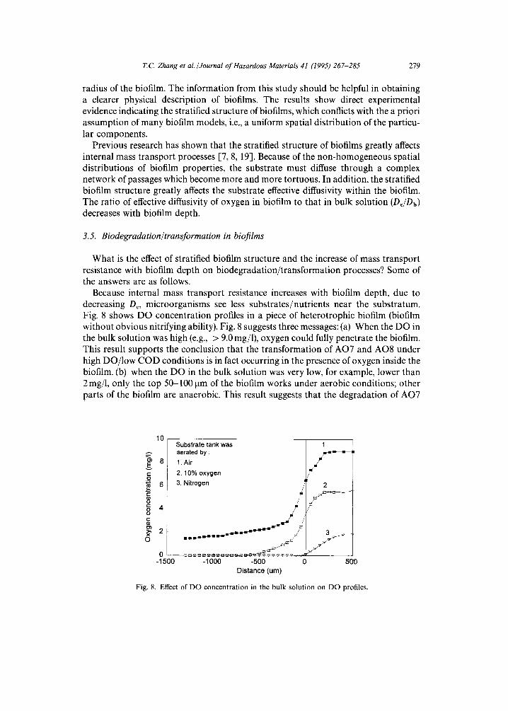
Because internal mass transport resistance increases with biofilm depth, due to decreasing De, microorganisms see less substrates/nutrients near the substratum. Fig. 8 shows DO concentration profiles in a piece of heterotrophic biofilm (biofilm without obvious nitrifying ability). Fig. 8 suggests three messages: (a) When the DO in the bulk solution was high (e.g., > 9.0 mg/1), oxygen could fully penetrate the biofilm. This result supports the conclusion that the transformation of AO7 and AO8 under high DO/low COD conditions is in fact occurring in the presence of oxygen inside the biofilm. (b) when the DO in the bulk solution was very low, for example, lower than 2 mg/1, only the top 50-100 pm of the biofilm works under aerobic conditions; other parts of the biofilm are anaerobic. This result suggests that the degradation of AO7
10
¢--
O
e"
O O
o
$ubstrate tank was aerated by :
8 1. Air
2. 10% oxygen
6 3. Nitrogen
4
2
-1500 -1000
2
-500 Distance (um)
0 500
Fig. 8. Effect of DO concentration in the bulk solution on DO profiles.
280 T.C Zhang et al./Journal of Hazardous Materials 41 (1995) 267-285
and AO8 under high COD/low DO conditions, as well as the decolorization of AO10 and AR14, was completed under anoxic or anaerobic conditions even though the bulk liquid was partially oxygenated. (c) If the DO in the bulk solution is around 2-5 mg/1, it is likely that the film will be aerobic at the surface but anaerobic/anoxic deeper inside. Since the azo bond can break very easily under anaerobic conditions, but very few can be cleaved aerobically, it may be an advantage of a biofilm treatment process to combine these two mechanisms together; that is, using the anaerobic part to break the azo bond and the aerobic surface layers to achieve the mineralization of anaer- obically recalcitrant intermediates.
The stratified biofilm structure is the main physical reason for internal mass transport resistance to increase with biofilm depth. As a result of this mass transport resistance, biofilms are often characterized by aerobic and anaerobic zones. The effect of this two-zone structure on conventional COD removal and biodegradation of toxic organics was further investigated. The investigation consisted of two steps. The first was to investigate the respiration rate in biofilm and the ratio of respiration rate to total COD removal rate. This information was then used to elucidate the percentage of COD removal contributed by aerobic reactions. The second step was to investigate the inhibition effect of azo dyes on primary substrate removal and the oxygen utilization rate of biofilms.
Oxygen flux in the diffusion boundary layer above the biofilm should be equal to the total respiration rate (or total aerobic reaction rate) of the biofilm at steady state. The oxygen flux (J) can be determined using the following film theory:
J = ( D b / L 1 ) ( C b - Cs), (3)
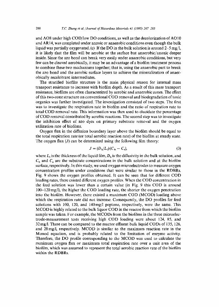
where Ll is the thickness of the liquid film, Db is the diffusivity in the bulk solution, and Cb and Cs are the substrate concentrations in the bulk solution and at the biofilm surface, respectively. In this study, we used oxygen microelectrodes to measure oxygen concentration profiles under conditions that were similar to those in the RDBRs. Fig. 9 shows the oxygen profiles obtained. It can be seen that for different COD loading rates, there existed different oxygen profiles. When the COD concentration in the feed solution was lower than a certain value (in Fig. 9 this COD is around 100-120 mg/1), the higher the COD loading rate, the shorter the oxygen penetration into the biofilm. However, there existed a maximum COD (MCOD) loading above which the respiration rate did not increase. Consequently, the DO profles for feed solutions with 100, 120, and 140mg/1 peptone, respectively, were the same. This MCOD is highly related to the bulk liquor COD in the reactor from which the biofilm sample was taken. For example, the MCODs from the biofilms in the three microelec- trode-measurement tests receiving high COD loading were about 124, 85, and 32mg/1. These can be compared to the reactor effluent bulk liquid CODs of 135, 126, and 28 mg/1, respectively. MCOD is similar to the maximum reaction rate in the Monod equation, and is probably related to the limitation of enzyme activity. Therefore, the DO profile corresponding to the MCOD was used to calculate the maximum oxygen flux or maximum total respiration rate over a unit area of the biofilm, which was assumed to represent the total aerobic reaction rate of the biofilm within the RDBRs.
T.C Zhang et al. /Journal of Hazardous Materials 41 (1995) 267-285 281
2 -0.4
Liquid
e ne Re
ne ne
-0.3 -0.2 -0.1 0.0 0.0 0.2 0.3 0.4 0.5
Distance (mm)
Fig. 9. Oxygen profiles in biofilm with peptone added. Biofilm obtained from a reactor fed with 749 mg/1 COD and 5 mg/1 AR14. DI water samples contained 2 mmol/l KCI as electrolyte.
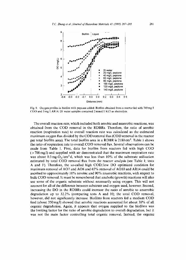
The overall reaction rate, which included both aerobic and anaerobic reactions, was obtained from the COD removal in the RDBRs. Therefore, the ratio of aerobic reaction (respiration rate) to overall reaction rate was calculated as the estimated maximum oxygen flux divided by the COD removal flux (COD removal in the reactor per total biofilm area). The total biofilm area in a RDBR is 2180 cm 2. Table 1 shows the ratio of respiration rate to overall COD removal flux. Several observations can be made from Table 1. First, data for biofilm from reactors fed with high COD (> 700 rag/l) and supplied with air demonstrated that the maximum respiration rate was about 0.3 mg-O2/cmEd, which was less than 10% of the substrate utilization estimated by total COD removal flux from the reactor analysis (see Table 1; tests A and F). Therefore, the so-called high COD/low DO optimized condition for maximum removal of AO7 and AO8 and 65% removal of AO10 and AR14 could be ascribed to approximately 10% aerobic and 90% anaerobic reactions, with respect to bulk COD removal. It must be remembered that anabolic (growth) reactions will also use some of the organic substrate without necessarily using oxygen. This will not account for all of the difference between substrate and oxygen used, however. Second, increasing the DO in the RDBRs could increase the ratio of aerobic to anaerobic degradation up to 32.2% (comparing tests A and H); the total COD removal, however, did not significantly increase. Biofilms from reactors fed a medium COD feed (about 350mg/1) showed that aerobic reactions accounted for about 30% of all organic degradation. Again, it appears that oxygen supplied to the biofilms was the limiting factor for the ratio of aerobic degradation to overall degradation, but it was not the main factor controlling total organic removal. Instead, the organic
282 T.C. Zhang et al./Journal of Hazardous Materials 41 (1995) 267-285
Table 1 Ratio of respiration rate to overall COD removal rate
Test no. COD (rag/l) COD removal flux Estimated max. 02 flux % aerobic inf./eft. (mg/cm 2 d) (mg/cm 2 d) reaction
A 749/135 3.32 0.298 9.0 B 337/126 1.16 0.318 27.4 C 100/28 0.40 0.289 72.9 D 330/52 1.53 0.368 >24.0 E 330/52 1.53 0.460 > 30.1 F 810/92 3.95 0.291 7.4 G 159/31 0.70 0.190 27.0 H 712/126 2.23 1.038 32.2
Experimental conditions: A: in feed, AR 14 = 5.0 mg/l; the sampled film thickness (BT) = 325 p.m; and most biofilm was at anaerobic conditions in the RDBR. B: in feed, AO10 = 5.0mg/l; BT = 4001xm. C: AO10 = 5.0mg/l; the biofilm thickness = 475ktm. D: no azo dye added; BT = 2000~tm. E: no dye; BT = 250 p.m. F: no dye; BT = 7751am. G: no dye; BT = 900 p.m. H: no dye; BT = 15501am. For A-G, the RDBRs were aerated with air; for H, the RDBR was aerated with pure 02. The tests for measuring the 02 profiles were performed with feed solution bubbled with air (21%) 02 for tests A-G, and pure oxygen for test H.
concen t ra t ion in the reac tor con t ro l l ed the to ta l C O D ut i l iza t ion rate because the to ta l C O D remova l flux was no t affected by the oxygen fluxes. Hence, increas ing the D O in fixed-film reactors m a y not be the most a p p r o p r i a t e way to increase the efficiency of o rganic removal , except when aerobic condi t ions are required. Thi rd , azo dyes m a y be inh ib i to ry and reduce the C O D ut i l iza t ion rate. Tests on biofi lms from reac tors fed only conven t iona l organics showed higher remova l of C O D than those f rom reactors fed with azo dyes. This th i rd obse rva t ion p r o m p t e d us to conduc t inh ib i t ion tests.
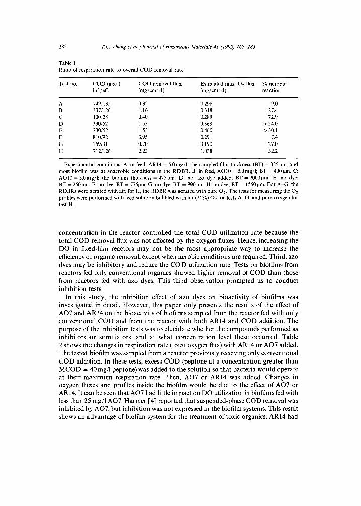
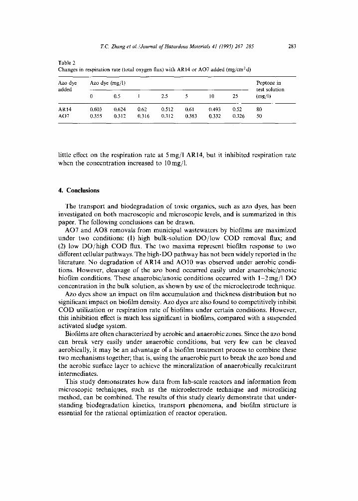
In this s tudy, the inhib i t ion effect of azo dyes on b ioac t iv i ty of biofi lms was invest igated in detail . However , this p a p e r only presents the results of the effect of AO7 and AR14 on the b ioac t iv i ty of biofi lms sampled f rom the reac tor fed with only conven t iona l C O D and from the reac tor with bo th AR14 and C O D addi t ion . The pu rpose of the inhib i t ion tests was to e lucidate whether the c o m p o u n d s per formed as inhib i tors or s t imulators , and at wha t concen t ra t ion level these occurred. Table 2 shows the changes in resp i ra t ion rate ( total oxygen flux) with AR14 or A O 7 added. The tested biofi lm was sampled from a reac tor previous ly receiving only conven t iona l C O D addi t ion . In these tests, excess C O D (peptone at a concen t ra t ion greater than M C O D -- 40 mg/1 peptone) was a d d e d to the so lu t ion so tha t bac te r ia would opera te at their m a x i m u m resp i ra t ion rate. Then, AO7 or AR14 was added. Changes in oxygen fluxes and profiles inside the biofi lm would be due to the effect of AO7 or AR14. It can be seen tha t AO7 had litt le impac t on D O ut i l iza t ion in biofi lms fed with less than 25 mg/1 AO7. H a r m e r [4] r epor t ed tha t suspended-phase C O D remova l was inhibi ted by AO7, bu t inhib i t ion was no t expressed in the biofi lm systems. This result shows an advan tage of biofi lm system for the t r ea tment of toxic organics. AR14 had
T. C. Zhang et al. /Journal of Hazardous Materials 41 (1995) 267-285
Table 2 Changes in respiration rate (total oxygen flux) with AR14 or AO7 added (mg/cm 2 d)
283
Azo dye Azo dye (mg/l) added
0 0.5 1 2.5 5 10 25
AR14 0.603 0.624 0.62 0.512 0.61 0.493 0.52 80 AO7 0.355 0.312 0.316 0.312 0.383 0.332 0.326 50
Peptone in test solution (mg/1)
little effect on the respiration rate at 5 rag/1 AR14, but it inhibited respiration rate when the concentration increased to 10 mg/1.
4. Conclusions
The transport and biodegradation of toxic organics, such as azo dyes, has been investigated on both macroscopic and microscopic levels, and is summarized in this paper. The following conclusions can be drawn.
AO7 and AO8 removals from municipal wastewaters by biofilms are maximized under two conditions: (1)high bulk-solution DO/low COD removal flux; and (2) low DO/high COD flux. The two maxima represent biofilm response to two different cellular pathways. The high-DO pathway has not been widely reported in the literature. No degradation of AR14 and AO10 was observed under aerobic condi- tions. However, cleavage of the azo bond occurred easily under anaerobic/anoxic biofilm conditions. These anaerobic/anoxic conditions occurred with 1-2 mg/1 DO concentration in the bulk solution, as shown by use of the microelectrode technique.
Azo dyes show an impact on film accumulation and thickness distribution but no significant impact on biofilm density. Azo dyes are also found to competitively inhibit COD utilization or respiration rate of biofilms under certain conditions. However, this inhibition effect is much less significant in biofilms, compared with a suspended activated sludge system.
Biofilms are often characterized by aerobic and anaerobic zones. Since the azo bond can break very easily under anaerobic conditions, but very few can be cleaved aerobically, it may be an advantage of a biofilm treatment process to combine these two mechanisms together; that is, using the anaerobic part to break the azo bond and the aerobic surface layer to achieve the mineralization of anaerobically recalcitrant intermediates.
This study demonstrates how data from lab-scale reactors and information from microscopic techniques, such as the microelectrode technique and microslicing method, can be combined. The results of this study clearly demonstrate that under- standing biodegradation kinetics, transport phenomena, and biofilm structure is essential for the rational optimization of reactor operation.
284 T.C. Zhang et al./Journal of Hazardous Materials 41 (1995) 267-285
Acknowledgements
This research was funded by a grant from the National Institute for Environmental Health Sciences, the National Institutes for Health, as part of the Superfund Basic Research Program.
References
[1] U. Meyer, Biodegradation of synthetic organic colorants, in: T. Leisinger, A.M. Cook, J. Nuesch and R. Hutter (Eds.), Microbial Degradation of Xenobiotics and Recalcitrant Compounds, Academic Press, London, 1981, pp. 371-385.
[2] A.A. Vaidya and K.V. Datye, Environmental pollution during chemical processing of synthetic fibers, Colourage, 14 (1982) 3-10.
[3] P.L. Bishop and N.E. Kinner, Aerobic fixed-film processes, in: H.J. Rehn and G. Reed (Eds.), Biotechnology, Vol. 8, VCH Verlagsgesellschaft, Weinheim, 1986, pp. 136-176.
[4] C. Harmer, Factors affecting secondary utilization kinetics of azo dye in wastewater biofilms, M.S. Thesis, University of Cincinnati, Cincinnati, OH, 1991.
[5] H.H. Jiang, Factors affecting azo dye degradation in wastewater biofilms, M.S. Thesis, University of Cincinnati, Cincinnati, OH, 1992.
[6] E.I. DuPont de Nemours & Co., Strategy of Experimentation, Wilmington, Delaware, 1975. [7] T.C. Zhang and P.L. Bishop, Density, porosity and pore structure of biofilms, Water Res., 28 (1994)
2267-2277. [8] T.C. Zhang and P.L. Bishop, Evaluation of tortuosity factors and effective diffusivities in biofilms,
Water Res., 28 (1994) 2279-2287. [9] T.C. Zhang, Y.C. Fu and P.L. Bishop, Competition in biofilms, in: 2nd Internat. Specialized Conf. on
Biofilm Reactors, 29 September-1 October, Paris, France, 1993, pp. 705-712. [10] L. Clesceri, A. Greenberg and R. Trussell (Eds.), Standard Methods for the Examination of Water and
Wastewater, 17th edn., American Public Health Association, Washington, DC, 1989. [11] Y. He, AO7 degradation and its effect on nitrification, M.S. Thesis, University of Cincinnati,
Cincinnati, OH, 1991. [12] B.E. Rittmann, F. Trinet, D. Amar and T.H. Chang, Measurement of the activity ofa biofilm: Effects
of surface loading and detachment on a three-phase, iiquid-fluidized-bed reactor, Water Sci. Teehnol., 26(3-4) (1992) 585-594.
[13] O. Wanner, Modeling population dynamics, in: W.G. Characklis and P.A. Wilderer (Eds.), Structure and Function of Biofilms, Wiley, New York, 1989, 91-110.
[14] Y.C. Fu, T.C. Zhang and P.L. Bishop, Determination of effective oxygen diffusivity in biofilms grown in a completely mixed biodrum reactor, in: Proc. 2nd Internat. Specialized Conf. on Biofilm Reactors, 29 September-1 October, Paris, France, 1993, pp. 543-550.
[15] T.C. Zhang, Y.C. Fu and P.L. Bishop, Competition for substrate and space in biofilms, in: Proc. Water Environment Federation Conf., Anaheim, CA, 1993, pp. 349-360.
[16] Y.C. Fu, Characterizing oxygen profiles and determining oxygen diffusivity in biofilm during biode- gradation of azo dyes, Ph.D. Dissertation, University of Cincinnati, Cincinnati, OH, 1993.
[17] Y.C. Fu, H.H. Jiang and P.L. Bishop, An inhibition study of the effect of azo dyes on bioactivity of biofilms, in: 1st Internat. Specialized Conf. on Microorganisms in Activated Sludge and Biofilm Processes, 27-28 September, Paris, France, 1993, pp. 347-354.
[18] R.A. Linsenmeier and C.M. Yancey, Improved fabrication of double-barreled recessed cathode 02 microelectrode, J. Appl. Physiol., 63 (1987) 2554-2557.
[19] T.C. Zhang, Influence of biofilm structure on transport and transformation processes in biofilms, Ph.D. dissertation, University of Cincinnati, Cincinnati, OH, 1994.
[20] W.G. Characklis and K.C. Marshall (Eds.), Biofilms, Wiley, New York, 1990.
T.C. Zhang et al./Journal of Hazardous Materials 41 (1995) 267-285 285
1-21] J. Fouts, J. Kamm and B. Brodie, Enzymatic reduction of protonsil and other azo dyes, J. Pharmacol. Exp. Therapy, 120 (1957) 291-300.
[22] K. Chung, G. Fulk and M. Egan, Reduction of azo dyes by intestinal anaerobes, Appl. Environ. Microbiology, 35(1) (1978) 558-562.
[23] K. Wuhrmann, K. Mechsner and T. Kappeler, Investigation on rate-determining factors in the microbial reduction of azo dyes, European J. Appl. Microbiol. Biotech., 9 (1980) 325-338.
[24] T. Zimmerman, H. Kulla and T. Leisinger, Properties of purified orange II azo reductase, The enzyme initiating azo dye degradation by Pseudomonas KF46, European J. Biochem., 129 (1982) 197-203.
1,25] R.C. Brenner, J. Heidman, E. Opatken and A. Petrasek, Design information on rotating biological contactors, EPA-600/S2-84-106, US EPA/MERL, Cincinnati, OH, 1984.
1-26] Z. Lewandowski, Behavior of biological reactors in the presence of toxic compounds, Water Res., 21 (1987) 147-153.
1-27] M.W. Rapporteur, W.A. Hamilton, D.A. Stahl, P.S. Handley, O. Wanner, N.C. Holm, D.M. Ward, J.G. Kuenen, P.A. Wilderer, N.P. Revsbech, J.W.T. Wimpenny and M.A. Rubio, Group report: Spatial distribution of biotic and abiotic components in the biofilm, in: W.G. Characklis and P.A. Wilderer (Eds.), Structure and Function of Biofilms, Wiley, New York, 1989, pp. 165-190.
[28] J.R. Lawrence, D.R. Korber, B.D. Hoyle, J.W. Costerton and D.E. Caldwell, Optical sectioning of microbial biofilms, J. Bacteriol., 173 (1991) 6558-6567.
1-29] S. Masuda, Y. Watanabe and M. Ishiguro, Biofilm properties and simultaneous nitrification and denitrification in aerobic rotating biological contactors, Water Sci. Techol., 23 (1991) 1355-1364.
1-30] P.L. Bishop and N.E. Kinner, Aerobic fixed-film processes, in: H.I. Rehn and G. Reed (Eds.), Biotechnology, Vol. 8, VCH Verlagsgesellschaft, Weinheim, 1986.
1-31] R.W. Robinson, D.E. Akin, R.A. Nordstedt, M.V. Thomas and H.C. Aldrich, Light and electron microscopic examinations of methane-producing biofilms from anaerobic fixed-bed reactors, Appl. Environ. Microbiol., 48 (1984) 127-136.
[32] J.W. Costerton, Z. Lewandowski, D. de Beer, D. Caldwell, D. Korber and G. James, Biofilms, the customized microniche, J. Bacteriol., 176 (1994) 2137-2142.
[33] D. de Beer, P. Stoodley, F. Roe and Z. Lewandowski, Effects of biofilm structures on oxygen distribution and mass transport, Biotechnol. Bioeng., 43 (1994) 1131-1138.
[34] G.M. Wolfaardt, J.R. Lawrence, R.D. Robarts, S.J. Caldwell and D.E. Caldwell, Multicellular organization in a degradative biofilm community, Appl. Environ. Microbiol., 60 (1994) 434-446.