transmission loading relief (tlr) and hour-ahead atc
TRANSCRIPT
Proceedings of the 33rd Hawaii International Conference on System Sciences - 2000
Transmission Loading Relief (TLR) and Hour-Ahead ATC
Santiago Grijalva Peter W. [email protected] [email protected]
Department of Electrical and Computer EngineeringUniversity of Illinois at Urbana-Champaign
1406 W. Green St.Urbana, IL
.
Abstract
In open-access electricity markets the reservations oftransmission services are based on data resulting fromthe off-line computation of Available Transfer Capability(ATC). When ATC data is inaccurate or misused, securityviolations can emerge and cause operators andoperations planners to invoke Transmission LoadingRelief (TLR) procedures. This paper illustrates therelationship between TLR and ATC, and presents possibleapproaches to reducing the need to invoke TLRprocedures while improving the utilization of thetransmission system.
Keywords: Transmission loading relief, off-line ATC,hour-ahead ATC.
1. Introduction
The North American Electric Reliability Council (NERC)has developed an Operating Manual that addresses multitude of issues associated with electric power systemoperations [1]. This manual includes the TransmissionLoading Relief (TLR) procedure for dealing with issuesthat focus primarily on the relationship betweeninterchange transactions and security violations. Sinceinterchange transactions are typically created through theuse of Available Transfer Capability (ATC) information,there should be a very close relationship between the neefor TLR and the accuracy and use of ATC information.In other words, if the ATC information is accurate at thetime a transaction is arranged, and it is used properly, thethe need for TLR should be due only to unanticipatedchanges in system conditions. Such changes could bsystem loading patterns, the status of lines and facilitiesgeneration scheduling, and model parameter values.
0-7695-0493-0/00
a
d
n
e,
This paper examines two important aspects of ATCaccuracy and use. The first considers the non-simultaneous nature of posted numbers. The secondconsiders the chaining of numbers between areas withconnecting paths.
2. Background on ATC
Quantifying the capabilities of a transmission system forinterchange has been of interest for over 25 years [2-4].These earlier methods focused primarily on SimultaneousInterchange Capability (SIC) rather than wheelingcapabilities. The application of SIC was more of anemergency capability in case local generation was lostand massive import was required. The terminology ofAvailable Transfer Capability (ATC) was created toquantify open access to transmission facilities [5,6]. Assuch, it is used to reserve transmission services needed foreconomic transactions between suppliers and consumersThe theoretical foundations and computational burdens ofATC are essentially identical to those of SIC.
A large percentage of ATC calculations performed todayutilize linear load flow techniques to approximatelypredict changes in line loading in response to transfersand line outages. In their simplest form, these linearmethods rely exclusively on distributions factors [7]. ThePower Transfer Distribution Factor (PTDF) is a “power”version of traditional linear circuit analysis with currentdivision. The Line Outage Distribution Factor (LODF)also uses traditional linear circuit analysis to computethese “large-change” sensitivities. While some work hasbeen done on including dynamic constraints on transfers[8], the core ATC computation considers static constraintsonly. References [9-11] provide additional analysis oferrors associated with ATC calculations.
$10.00 (c) 2000 IEEE 1
Proceedings of the 33rd Hawaii International Conference on System Sciences - 2000
Currently, the following procedure referred to as off-lineATC, is used to provide ATC information for commercialpurposes:
1. The security coordinator builds a regional model forthe expected peak conditions. The model includespower flow base case, contingencies, monitoredelements and directions.
2. The security coordinator computes firm and non-firmATC based on the set of proposed directions on amonthly, weekly and daily basis, and posts the resultson the Open Access Same-time Information System(OASIS).
3. Marketers use ATC data to propose transactions andmake reservations of transmission services.
4. Control areas verify and debug the OASIS values forthe day, including specific system changes andoperational considerations.
5. As the time for transaction implementationapproaches, control areas perform security analysis toidentify potential problems.
The process has been implemented within a dailyframework due to important technical reasons related tothe fact that ATC is a massive and complicatedcomputational task, and that making its results availabledemands a large data integration effort. The same reasonhave left many ATC issues unsolved, and set challengesregarding ATC procedures and computational methods.
3. TLR and ATC
Transmission loading relief (TLR) is a sequence ofactions taken during operations planning or during real-time operation to avoid or remedy security violationsassociated with the transmission system. Informal or"local" TLR has been in existence for as long astransmission lines have been subject to limitations.System planners and operators have developed systematprocedures to assist in the avoidance or elimination oftransmission loading problems. These procedures aretypically unique to each control area and may vary widelyacross the interconnected grid. Formal TLR proceduresare identified by NERC in [1] as a mechanism to ensurecertain consistencies and fairness in resolving issues osecurity that arise due to financial transactions. Theseprocedures are briefly summarized below.
The process starts when a security coordinator (such as NERC council - MAIN, ECAR, etc.) identifies a
0-7695-0493-0/00 $
s
ic
f
a
transmission facility within its security area that is aboutto, or has exceeded the operating security limit. At thispoint the security coordinator may invoke local TLR orNERC TLR. This NERC TLR procedure involves thefollowing “levels” (Detailed explanations of the actionsassociated with each of these levels if given in [1]):
Level 1: Notify security coordinators of situation Level 2a: Hold interchange transactions at current levels Level 2b: Reallocate Firm Transmission Service Level 2c: Reallocate Nonfirm Transmission Service Level 3: Curtail Nonfirm transactions Level 4: Reconfigure transmission and generation Level 5: Curtail Firm transactions Level 6: Implement emergency procedures
The transmission relief procedure depends on the resultsof off-line ATC, which has a number of limitations:
a) Off-line ATC does not include in the computationinformation about the actual transactions that willtake place in the region and the impact of those thattake place out of it. It is a non-simultaneouscomputation.
b) The operating conditions of the system at non-peakhours can considerably differ from those at the peakhour. Presumably, but not necessarily, the magnitudeof the flows in the system will in general be larger atthe peak hour and ATC would be computed for themost restrictive condition. While this is safe, ATCcan be largely underestimated for non-peak hours,which will result in a sub-utilization of the systemtransmission capabilities.
c) Numerical errors are present in off-line ATC becauseit often neglects the influence of reactive power, useslinear models and assumes constant distributionfactors. The current practice attempts to account forthese errors through the transmission reliabilitymargin (TRM).
These limitations create the following problems in TLR:
a) TLR decisions can be inaccurate as they are based onthe planning results of daily ATC and PTDFs fromthe off-line computation.
b) The implementation of TLR to relieve and overloadcan originate new constrained facilities in the system.
c) TLR is an iterative process that requires largeamounts of data and precise and fast coordinationamong the security coordinators and otherparticipants in the operation of the grid. The
2
10.00 (c) 2000 IEEE 2
_________
Proceedings of the 33rd Hawaii International Conference on System Sciences - 2000
procedure requires the area holding the constrainedfacility to interact with all the agents involved in atransaction, and notify them every time the procedurechanges from one TLR level to another.
d) The procedure opens opportunities for economicgaming, which can reduce the efficiency of themarket.
The following section focuses on the problems associatedwith the fact that ATC numbers are non-simultaneous.
4
VOcsdns
_______________________________________________
__ _________
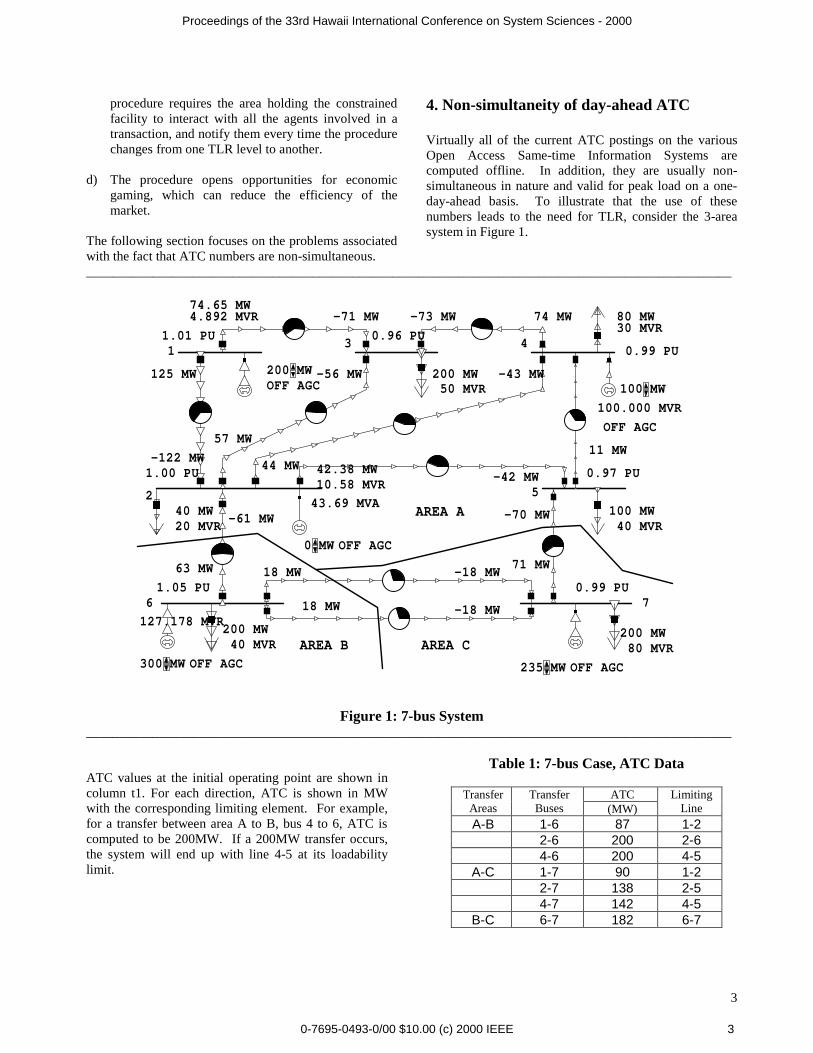
ATC values at the initial operating point are shown incolumn t1. For each direction, ATC is shown in MWwith the corresponding limiting element. For example,for a transfer between area A to B, bus 4 to 6, ATC iscomputed to be 200MW. If a 200MW transfer occurs,the system will end up with line 4-5 at its loadabilitylimit.
0-7695-0493-0/00
. Non-simultaneity of day-ahead ATC
irtually all of the current ATC postings on the variouspen Access Same-time Information Systems are
omputed offline. In addition, they are usually non-imultaneous in nature and valid for peak load on a one-ay-ahead basis. To illustrate that the use of theseumbers leads to the need for TLR, consider the 3-areaystem in Figure 1.
AREA A
AREA B AREA C
1
2
3 4
5
6 7
200 MWMW
0 MWMW
300 MWMW 235 MWMW
200 MW 50 MVR
80 MW 30 MVR
100 MW 40 MVR
40 MW 20 MVR
0.99 PU
0.97 PU
0.99 PU1.05 PU
1.00 PU
0.96 PU1.01 PU
125 MW
-122 MW
74.65 MW-71 MW -73 MW 74 MW
57 MW
-56 MW
42.38 MW-42 MW
-43 MW
44 MW 11 MW
-70 MW
71 MW-18 MW 18 MW
-61 MW
63 MW
100 MWMW
200 MW 40 MVR
200 MW 80 MVR
18 MW -18 MW
OFF AGC
OFF AGC
OFF AGC
OFF AGC
OFF AGC
10.58 MVR
43.69 MVA
127.178 MVR
100.000 MVR
4.892 MVR
_________________________________________
Figure 1: 7-bus System______________________________________________________________________________________
$
Table 1: 7-bus Case, ATC Data
ATCTransferAreas
TransferBuses (MW)
LimitingLine
A-B 1-6 87 1-22-6 200 2-64-6 200 4-5
A-C 1-7 90 1-22-7 138 2-54-7 142 4-5
B-C 6-7 182 6-7
3
10.00 (c) 2000 IEEE 3
Proceedings of the 33rd Hawaii International Conference on System Sciences - 2000
Case A: Simultaneous transactions
Given this system data, suppose that the followingtransmission reservations occur (which are all possibleafter the initial posting):
Direction 1-6: 50MWDirection 2-6: 150WDirection 4-6: 180MW
If these transactions are implemented, line 4-5 will havean overload of 17% and line 2-6 will have an overloadof 80%! When this schedule is analyzed prior toimplementation, TLR will have to be invoked to relievethe overloading of these lines. Each participatingcontrol area for the transaction will implement a localTLR procedure, which would imply the rearrangementof its own resources, or ask the security coordinator fora NERC TLR procedure, which would require therearrangement of the resources of all the interconnectionentities involved in the transaction.
Note that TLR becomes necessary because ATC valueswere not obtained from a simultaneous simulation. Thisis a serious shortcoming of current ATC computations.
Once TLR is initiated, the process determines for eachtype of transaction the impact of those that affect theloading of the facility in 5% or more based on PTDFs.Then transactions are curtailed in a progressive,prioritized manner. If no more transactions can becurtailed, the process goes to the next TLR level.
Case B: Sequential transactions: off-line ATC
As an alternative approach, consider a sequence oftransactions starting at the initial operating point usedabove. The results for the sequence are shown on Table2. In this case, ATC values remain as those computedby the off-line ATC process as the transactions takeplace.
1. At time t1 marketer M1 proposes a transaction T1of 150 MW from A-B in the direction 4-6. As ATCis 200MW, the transfer should create no problemand there should be 50MW available for direction4-6 after the transaction is implemented.
2. At time t2 marketer M2 reads ATC for direction 6-7 to be 182MW and proposes a transaction T2 of150 MW. As a result, line 4-5 presents an overloadof 8% that needs to be relieved.
0-7695-0493-0/00
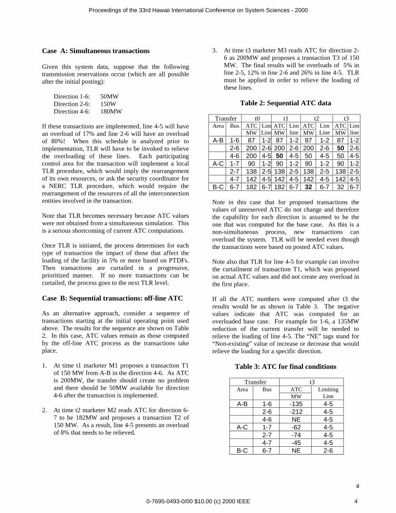
3. At time t3 marketer M3 reads ATC for direction 2-6 as 200MW and proposes a transaction T3 of 150MW. The final results will be overloads of 5% inline 2-5, 12% in line 2-6 and 26% in line 4-5. TLRmust be applied in order to relieve the loading ofthese lines.
Table 2: Sequential ATC data
Transfer t0 t1 t2 t3ATC ATC ATC ATCArea BusMW
LimLine MW
Limline MW
LimLine MW
Limline
A-B 1-6 87 1-2 87 1-2 87 1-2 87 1-22-6 200 2-6 200 2-6 200 2-6 50 2-64-6 200 4-5 50 4-5 50 4-5 50 4-5
A-C 1-7 90 1-2 90 1-2 90 1-2 90 1-22-7 138 2-5 138 2-5 138 2-5 138 2-54-7 142 4-5 142 4-5 142 4-5 142 4-5
B-C 6-7 182 6-7 182 6-7 32 6-7 32 6-7
Note in this case that for proposed transactions thevalues of unreserved ATC do not change and thereforethe capability for each direction is assumed to be theone that was computed for the base case. As this is anon-simultaneous process, new transactions canoverload the system. TLR will be needed even thoughthe transactions were based on posted ATC values.
Note also that TLR for line 4-5 for example can involvethe curtailment of transaction T1, which was proposedon actual ATC values and did not create any overload inthe first place.
If all the ATC numbers were computed after t3 theresults would be as shown in Table 3. The negativevalues indicate that ATC was computed for anoverloaded base case. For example for 1-6, a 135MWreduction of the current transfer will be needed torelieve the loading of line 4-5. The “NE” tags stand for“Non-existing” value of increase or decrease that wouldrelieve the loading for a specific direction.
Table 3: ATC for final conditions
Transfer t3ATCArea BusMW
LimitingLine
A-B 1-6 -135 4-52-6 -212 4-54-6 NE 4-5
A-C 1-7 -62 4-52-7 -74 4-54-7 -45 4-5
B-C 6-7 NE 2-6
4
$10.00 (c) 2000 IEEE 4
Proceedings of the 33rd Hawaii International Conference on System Sciences - 2000
Even though this is a very simple case, the presence ofnegative values and “NE” tags give us a feeling of whyTLR levels and generation re-dispatch are needed in theimplementation of TLR procedures.
Case C: Sequential transactions - updated ATC
Start again with the system at the initial operating pointshown in Figure 1. Let us perform a sequence oftransactions and write down the results on Table 4.
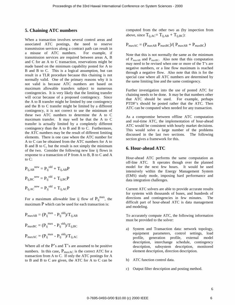
1. As in Case B, at time t1 marketer M1 proposes a150MW transaction T1 from areas A-B in thedirection 4-6 whose ATC is 200MW. 50MW mustremain as shown in column t1. Other ATC valuesare recomputed and updated in column t1. Notethat constraining elements can also change. Forexample, for transaction 2-7, line 2-5 has beenreplaced by line 4-5 as the new constrainingelement.
2. At time t2 marketer M2 proposes a transaction fromarea B-C in direction 6-7 of 100MW. As ATC is123 there should be no problem. At t2 23MWremain available in that direction. All other ATCvalues are recomputed.
3. At time t3 marketer M3 proposes a 30MWtransaction from areas A-C, direction 2-6. As ATCis 42, this is possible and there are 12 MWremaining in that direction. All other ATC valuesare recomputed.
4. At time t4 transaction T1 is cancelled relieving 150MW in direction 4-6. All other ATC values arerecomputed.
Table 4: Case C: ATC is updated.
t0 t1 t2 t3 t4Area Bus ATC Lim ATC LimATC Lim ATC Lim ATC Lim
A-B 1-6 87 1-2 59 1-2 28 4-5 8 4-5 91 1-22-6 200 2-6 59 2-6 42 4-5 12 4-5 194 2-54-6 200 4-5 50 4-5 9 4-5 4 4-5 154 4-5
A-C 1-7 90 1-2 61 1-2 14 4-5 5 4-5 72 2-52-7 138 2-5 81 4-5 15 4-5 6 4-5 63 2-54-7 142 4-5 35 4-5 7 4-5 3 4-5 92 2-5
B-C 6-7 182 6-7 123 4-5 23 4-5 7 4-5 91 6-7
Case C is an ideal case in which ATC is updated eachtime a transaction takes place, is proposed, or areservation is made. Note that ATC values remainpositive. This occurs because transactions T1, T2, T3
0-7695-0493-0/00 $
and T4 were based on true ATC values. For this idealcase, no TLR procedure is required.
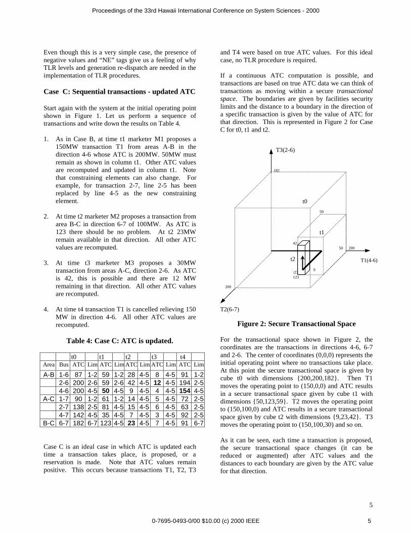
If a continuous ATC computation is possible, andtransactions are based on true ATC data we can think oftransactions as moving within a secure transactionalspace. The boundaries are given by facilities securitylimits and the distance to a boundary in the direction ofa specific transaction is given by the value of ATC forthat direction. This is represented in Figure 2 for CaseC for t0, t1 and t2.
Figure 2: Secure Transactional Space
For the transactional space shown in Figure 2, thecoordinates are the transactions in directions 4-6, 6-7and 2-6. The center of coordinates (0,0,0) represents theinitial operating point where no transactions take place.At this point the secure transactional space is given bycube t0 with dimensions {200,200,182}. Then T1moves the operating point to (150,0,0) and ATC resultsin a secure transactional space given by cube t1 withdimensions {50,123,59}. T2 moves the operating pointto (150,100,0) and ATC results in a secure transactionalspace given by cube t2 with dimensions {9,23,42}. T3moves the operating point to (150,100,30) and so on.
As it can be seen, each time a transaction is proposed,the secure transactional space changes (it can bereduced or augmented) after ATC values and thedistances to each boundary are given by the ATC valuefor that direction.
T1(4-6)
T2(6-7)
T3(2-6)
200
182
200
59
123
t0
t1
t2
5042
9\23
5
10.00 (c) 2000 IEEE 5
Proceedings of the 33rd Hawaii International Conference on System Sciences - 2000
5. Chaining ATC numbers
When a transaction involves several control areas andassociated ATC postings, the need to reservetransmission services along a contract path can result ina misuse of ATC numbers. For example, iftransmission services are required between areas A, Band C for an A to C transaction, reservations might bemade based on the minimum capability posted for A toB and B to C. This is a logical assumption, but canresult in a TLR procedure because this chaining is notnormally valid. One of the primary reasons why it isnot valid is because ATC numbers are based onmaximum allowable transfers subject to numerouscontingencies. It is very likely that the limiting transferwill occur because of a proposed contingency. Sincethe A to B transfer might be limited by one contingencyand the B to C transfer might be limited by a differentcontingency, it is not correct to use the minimum ofthese two ATC numbers to determine the A to Cmaximum transfer. It may well be that the A to Ctransfer is actually limited by a completely differentcontingency than the A to B and B to C. Furthermore,the ATC numbers may be the result of different limitingelements. There is one case where the ATC number forA to C can be obtained from the ATC numbers for A toB and B to C, but the result is not simply the minimumof the two. Consider the following new line ij flows inresponse to a transaction of P from A to B, B to C and Ato C:
Pij,ABnew = Pij
old + Tij,ABP
Pij,BCnew = Pij
old + Tij,BCP
Pij,ACnew = Pij
old + Tij,ACP
For a maximum allowable line ij flow of Pijmax
, themaximum P which can be used for each transaction is:
PmaxAB = (Pijmax - Pij
old)/Tij,AB
PmaxBC = (Pijmax - Pij
old)/Tij,BC
PmaxAC = (Pijmax - Pij
old)/Tij,AC
Where all of the P’s and T’s are assumed to be positivenumbers. In this case, PmaxAC is the correct ATC for atransaction from A to C. If only the ATC postings for Ato B and B to C are given, the ATC for A to C can be
0-7695-0493-0/00
computed from the other two as (by inspection fromabove, since Tij,AC= Tij,AB + Tij,BC):
PmaxAC = (PmaxAB PmaxBC)/( PmaxAB + PmaxBC)
Note that this is not normally the same as the minimumof PmaxAB and PmaxBC. Also note that this computationmay need to be revised when one or more of the T’s arenegative numbers, or a line flow maximum is reachedthrough a negative flow. Also note that this is for thespecial case where all ATC numbers are determined bythe same limiting line and the same contingency.
Further investigation into the use of posted ATC forchaining needs to be done. It may be that numbers otherthat ATC should be used. For example, perhapsPTDF’s should be posted rather that the ATC. ThenATC can be computed when needed for any transaction.
As a compromise between offline ATC computationand real-time ATC, the implementation of hour-aheadATC would be consistent with hourly market decisions.This would solve a large number of the problemsdiscussed in the last two sections. The followingsection gives a framework for this.
6. Hour-ahead ATC
Hour-ahead ATC performs the same computation asoff-line ATC. It operates though over the plannedmodel for the next few hours. It would be usedintensively within the Energy Management System(EMS) study mode, imposing hard performance anddata integration challenges.
Current ATC solvers are able to provide accurate resultsfor systems with thousands of buses, and hundreds ofdirections and contingencies in few minutes. Thedifficult part of hour-ahead ATC is data managementand modeling.
To accurately compute ATC, the following informationmust be provided to the solver:
a) System and Transaction data: network topology,equipment parameters, control settings, loadprofile, generation profile, external modeldescription, interchange schedule, contingencydescription, subsystem description, monitoredelement description, direction description.
b) ATC function control data.
c) Output filter description and posting method.
6
$10.00 (c) 2000 IEEE 6
Proceedings of the 33rd Hawaii International Conference on System Sciences - 2000
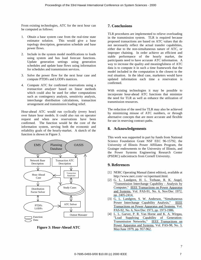
From existing technologies, ATC for the next hour canbe computed as follows:
1. Obtain a base system case from the real-time stateestimator solution. This would give a basetopology description, generation schedule and basepower flows.
2. Include in the system model modifications to loadsusing system and bus load forecast functions.Update generation settings using generationschedules and update base flows using informationfor schedules and transmission services.
3. Solve the power flow for the next hour case andcompute PTDFs and LODFs matrices.
4. Compute ATC for confirmed reservations using atransaction analyzer based on linear methodswhich could also be used for other computationssuch as contingency analysis, sensitivity analysis,interchange distribution calculations, transactionarrangement and transmission loading relief.
Hour-ahead ATC would run cyclically (every hour)over future hour models. It could also run on operatorrequest and when new reservations have beenconfirmed. The function would be the core of theinformation system, serving both the economic andreliability goals of the hourly-market. A sketch of thefunction is shown in Figure 3.
FunctionData
Figure 3: Hour-Ahead ATC
Hour AheadCase
PTDFsLODFs
Network BaseDescription
DistributionFactor Solver
StudyC
StudyC
Study Cases
Output Manager
TransactionAnalyzer
EMS PlanningDatabase
OASIS
Transaction ATCDescription
ATC Solver
0-7695-0493-0/00 $
7. Conclusions
TLR procedures are implemented to relieve overloadingin the transmission system. TLR is required becauseproposed transactions are based on ATC values that donot necessarily reflect the actual transfer capabilities,either due to the non-simultaneous nature of ATC, orimproper chaining. In order achieve an efficient andstable performance of the hourly market, theparticipants need to have accurate ATC information. Away to increase the quality and meaningfulness of ATCdata is to compute it in such a time framework that themodel included in the computation is the closest to thereal situation. In the ideal case, marketers would haveupdated information each time a reservation isconfirmed.
With existing technologies it may be possible toincorporate hour-ahead ATC functions that minimizethe need for TLR as well as enhance the utilization oftransmission resources.
The reduction of the need for TLR may also be achievedby minimizing misuse of ATC numbers, or throughalternative concepts that are more accurate and flexiblefor use in reserving contract paths.
8. Acknowledgements
This work was supported in part by funds from NationalScience Foundation Grant NSF EEC 96-15792, theUniversity of Illinois Power Affiliates Program, theGrainger endowments to the University of Illinois, andthe Power Systems Engineering Research Center(PSERC) subcontracts from Cornell University.
9. References
[1] NERC Operating Manual (latest edition), available athttp://www.nerc.com/~oc/opermanl.html.
[2] G. L. Landgren, H. L. Terhune, R. K. Angel,"Transmission Interchange Capability - Analysis byComputer," IEEE Transactions on Power Apparatusand Systems, Vol. PAS-91, No. 6, Nov/Dec 1972,pp. 2405-2414.
[3] G. L. Landgren, S. W. Anderson, "SimultaneousPower Interchange Capability Analysis," IEEETransactions on Power Apparatus and Systems, Vol.PAS-92, No. 6, Nov/Dec 1973, pp. 1973-1986.
[4] L. L. Garver, P. R. Van Horne and K. A. Wirgau,"Load Supplying Capability of Generation-Transmission Networks," IEEE Transactions onPower Apparatus and Systems, Vol. PAS-98, No. 3,May/June 1979, pp. 957-962.
7
10.00 (c) 2000 IEEE 7
Proceedings of the 33rd Hawaii International Conference on System Sciences - 2000
[5] Transmission Transfer Capability Task Force,"Transmission Transfer Capability", North AmericanElectric Reliability Council, Princeton, New Jersey,May 1995.
[6] Transmission Transfer Capability Task Force,"Available Transfer Capability Definitions andDetermination", North American Electric ReliabilityCouncil, Princeton, New Jersey, June 1996.
[7] P. W. Sauer, "On the Formulation of PowerDistribution Factors for Linear Load Flow Methods,"IEEE Transactions on Power Apparatus andSystems, Vol. PAS-100, No. 2, February 1981, pp.764-770.
[8] P. W. Sauer, K. D. Demaree and M. A. Pai,"Stability Limited Load Supply and InterchangeCapability," IEEE Transactions on Power Apparatusand Systems, Vol. PAS-102, No. 11, November1983, pp. 3637-3643.
[9] P. W. Sauer, “Technical Challenges of ComputingAvailable Transfer Capability (ATC) in ElectricPower Systems”, Proceedings of the ThirtiethAnnual (1997) Hawaii International Conference onSystem Sciences, Vol V, Maui, Hawaii, January 7-10, 1997, pp. 589-593.
[10]P. W. Sauer, “Alternatives for calculatingTransmission Reliability Margin (TRM) inAvailable Transfer Capability (ATC) “,Proceedings of the Thirty-First Annual (1998)Hawaii International Conference on SystemSciences, Vol III, Kona, Hawaii, January 6-9, 1998,p. 89.
[11]S. Grijalva and P. W. Sauer, "Reactive PowerConsiderations in Linear ATC Computation",Proceedings of the Thirty-Second Annual (1999)Hawaii International Conference on SystemSciences, Maui, Hawaii, January 5-8, 1999. pp. 1-11.
0-7695-0493-0/00
Santiago Grijalva was born in Quito-Ecuador inNovember 1970. He received the Electrical Engineerdegree from the National Polytechnic University-Ecuador in 1994, the MSc. diploma in InformationSystems from the Army Polytechnic University-Ecuador in 1997, and the MSc. degree in ElectricalEngineering from the University of Illinois at Urbana-Champaign in 1999. From 1995 to 1997 he worked atthe Ecuadorian National Center of Energy Control onmaintenance and development of real-time SCADA-EMS systems. He is currently a Graduate Student and aResearch Assistant at the University of Illinois atUrbana-Champaign. His interests are concentrated inpower system control and operation, real-time powerapplications, and information systems.
Peter W. Sauer obtained his Bachelor of Science degreein Electrical Engineering from the University ofMissouri at Rolla in 1969, the Master of Science andPh.D. degrees in Electrical Engineering from PurdueUniversity in 1974 and 1977 respectively. From 1969to 1973, he was the electrical engineer on a designassistance team for the Tactical Air Command atLangley Air Force Base, Virginia, working on designand construction of airfield lighting and electricaldistribution systems. He has been on the faculty atIllinois since 1977 where he teaches courses and directsresearch on power systems and electric machines. Hismain interests are in modeling and simulation of powersystem dynamics with applications to steady-state andtransient stability analysis. From August 1991 toAugust 1992 he served as the Program Director forPower Systems in the Electrical and CommunicationSystems Division of the National Science Foundation inWashington D.C. He is the Chairman of the IEEEPower Engineering Society (PES) Working Group onDynamic Security Assessment, and Chairman of theIEEE Central Illinois Chapter of PES. He is a registeredProfessional Engineer in Virginia and Illinois and aFellow of the IEEE.
8
$10.00 (c) 2000 IEEE 8