automatic tool changer (atc) installation manual
TRANSCRIPT

© Copyright 2016 ShopBot Tools, Inc. page 1
ShopBotTools.com888-680-4466 •
Automatic Tool Changer (ATC)Installation Manual

Automatic Tool Changer (ATC) Installation Manual • December 1, 2016
© Copyright 2016 ShopBot Tools, Inc. page 2
Automatic Tool Changer (ATC) Installation Manual • December 1, 2016
© Copyright 2016 ShopBot Tools, Inc. page 3
Table of Contents
Introduction .............................................................................................................................................................................................. 5Safety Note ................................................................................................................................................................................................ 5ATC Installation (Mechanical) .............................................................................................................................................................. 7Mounting the Spindle ............................................................................................................................................................................ 7Mount Dust Collection Bracket .......................................................................................................................................................... 8Mount Upper Y-Axis E-Chain Bracket ............................................................................................................................................... 9Mount Tool Bar ......................................................................................................................................................................................... 9Mount Tool Chuck .................................................................................................................................................................................10Mount Main Air Assembly ..................................................................................................................................................................10Mount ATC Dust Skirt ...........................................................................................................................................................................11Table Drawing .........................................................................................................................................................................................12ATC Installation (Pneumatic) .............................................................................................................................................................13Supplied Tubing .....................................................................................................................................................................................13Main Air Supply ......................................................................................................................................................................................13ATC Installation (Electrical) .................................................................................................................................................................16ATC Software Setup and Tool Calibration .....................................................................................................................................16Installing ATC Software .......................................................................................................................................................................16USB Cable .................................................................................................................................................................................................17Software Inputs and Outputs Check ..............................................................................................................................................17ShopBot Setup (TS) ...............................................................................................................................................................................22Home Machine (C3) ..............................................................................................................................................................................25Calibration Routine (CN74) ................................................................................................................................................................25Set Fixed Z Zero Plate Location ........................................................................................................................................................28Set Up Tool Holders ..............................................................................................................................................................................29Zero Tools in Rack (CN72) ...................................................................................................................................................................31Change Tools (C1) ..................................................................................................................................................................................32Get Plate Offset (CN73) ........................................................................................................................................................................32Zero Various Z Heights (C2) ...............................................................................................................................................................33Regularly Used ATC Files .....................................................................................................................................................................34Create a Tool Change File ...................................................................................................................................................................34Spindle Warmup Routine (C5) ..........................................................................................................................................................35Run File ......................................................................................................................................................................................................35If Something Goes Wrong ..................................................................................................................................................................35

Automatic Tool Changer (ATC) Installation Manual • December 1, 2016
© Copyright 2016 ShopBot Tools, Inc. page 4

Automatic Tool Changer (ATC) Installation Manual • December 1, 2016
© Copyright 2016 ShopBot Tools, Inc. page 5
Introduction
The ShopBot Automatic Tool Changer (ATC) automates the bit changing process during projects that require multiple tool changes. The ATC system includes a 5HP HSD spindle, a pneumatically-assisted Z-axis, six-position tool bank standard, up to eight tool positions for our four foot wide tool (10 for a five foot and 12 for a six foot), fixed-position Z zero plate, chuck holder, pneumatically operated dust skirt, and ATC interface card.
The ATC reduces the time a project must remain on the machine by automatically changing cutting bits between cuts, thus eliminating the need to change and calibrate tools by hand. The ATC allows the PRSalpha to cut complete projects where tool changes are required without additional inputs.
The 5HP HSD spindle assembly is fan cooled - in the lower part it has air cooled bearings. The ATC requires 6-7 cfm @ 90 psi of compressed air; PORTABLE AIR COMPRESSORS ARE NOT RECOM-MENDED as they can have trouble keeping this pressure reliably and have a reduced service life.
The ShopBot ATC is available in the following voltages:(#12520) HSD ATC 5HP 220V 1PH (#12521) HSD ATC 5HP 380/460V 3PH (#12540) HSD ATC 5HP 230V 3PH
The ShopBot ATC can be an upgrade to the E series (aluminum table sides) PRTalpha machines with the addition of a retro Z-axis. The E series table allows for crucial table positioning without a complete rebuild of the table. See ATC table plans before installation.
Safety Note
While running the ATC, ensure the compressed air is connected prior to turning off the power. If the compressed air is NOT connected, and the power is turned off, the spindle will crash to the table.

Automatic Tool Changer (ATC) Installation Manual • December 1, 2016
© Copyright 2016 ShopBot Tools, Inc. page 6

Automatic Tool Changer (ATC) Installation Manual • December 1, 2016
© Copyright 2016 ShopBot Tools, Inc. page 7
ATC Installation (Mechanical)
This section assumes that, except for the table assembly (a drawing for this is provided under “Table drawing”), the ShopBot has been assembled using the instructions provided in the ShopBot assembly manual. This means that the ShopBot is at a point in which it is able to connect and move under the control of a computer. Wire/cable management may be left until the ATC installation has been com-pleted.
VERY IMPORTANT! For New Table Setups
The location of the table bed is extremely critical for ATC. Excess overages in the X dimension could mean tooling collisions, insufficient cutting area, and dropped tooling. At the end of this section there is a table drawing that shows how the table should be set up. Pay close attention to the relationship between table sides and the table surface.
For Previously Assembled Tables
Loosen the bolts that are attached to the table side extrusions and slide table sides in the positive X direction until the table is in the position called out in the table drawings at the end of this section.
Mounting the Spindle
The ShopBot ATC is equipped with a 5HP HSD spindle. The spindle is cooled by an electric fan, but also has air-cooled lower bearings. The air required for cooling the lower bearings is 60 psi (4 bar).
The spindle also has an internal drawbar that holds the tool cones in place during cutting; this requires 90-100 psi (6-7 bar).
Power up the ShopBot and position the YZ car so that it is in a location where the front and back of the Z-axis may be reached.
Use the keypad mode (K) on the computer to move the Z-axis to a height close to the table’s surface.
Rest the spindle on its end as seen to the left. Position the Z-axis up or down using the keypad mode again until the holes in the Z-axis align with the mounting holes in the spindle plate.
Tighten spindle securely to Z-axis with six 5/16” x 1 1/2” socket head screws.
Automatic Tool Changer (ATC) Installation Manual • December 1, 2016
© Copyright 2016 ShopBot Tools, Inc. page 8
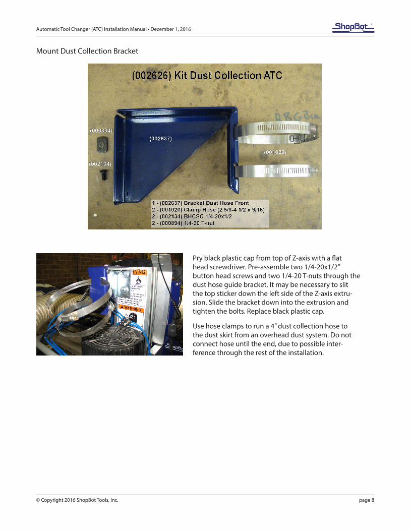
Mount Dust Collection Bracket
Pry black plastic cap from top of Z-axis with a flat head screwdriver. Pre-assemble two 1/4-20x1/2” button head screws and two 1/4-20 T-nuts through the dust hose guide bracket. It may be necessary to slit the top sticker down the left side of the Z-axis extru-sion. Slide the bracket down into the extrusion and tighten the bolts. Replace black plastic cap.
Use hose clamps to run a 4” dust collection hose to the dust skirt from an overhead dust system. Do not connect hose until the end, due to possible inter-ference through the rest of the installation.
Automatic Tool Changer (ATC) Installation Manual • December 1, 2016
© Copyright 2016 ShopBot Tools, Inc. page 9
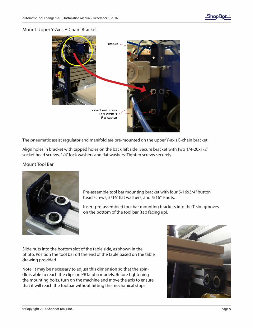
Mount Upper Y-Axis E-Chain Bracket
The pneumatic assist regulator and manifold are pre-mounted on the upper Y-axis E-chain bracket.
Align holes in bracket with tapped holes on the back left side. Secure bracket with two 1/4-20x1/2” socket head screws, 1/4” lock washers and flat washers. Tighten screws securely.
Mount Tool Bar
Pre-assemble tool bar mounting bracket with four 5/16x3/4” button head screws, 5/16” flat washers, and 5/16” T-nuts.
Insert pre-assembled tool bar mounting brackets into the T-slot grooves on the bottom of the tool bar (tab facing up).
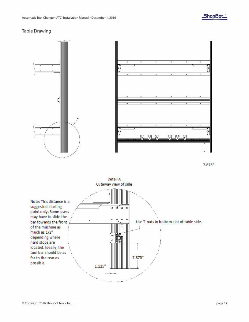
Slide nuts into the bottom slot of the table side, as shown in the photo. Position the tool bar off the end of the table based on the table drawing provided.
Note: It may be necessary to adjust this dimension so that the spin-dle is able to reach the clips on PRTalpha models. Before tightening the mounting bolts, turn on the machine and move the axis to ensure that it will reach the toolbar without hitting the mechanical stops.
Automatic Tool Changer (ATC) Installation Manual • December 1, 2016
© Copyright 2016 ShopBot Tools, Inc. page 10
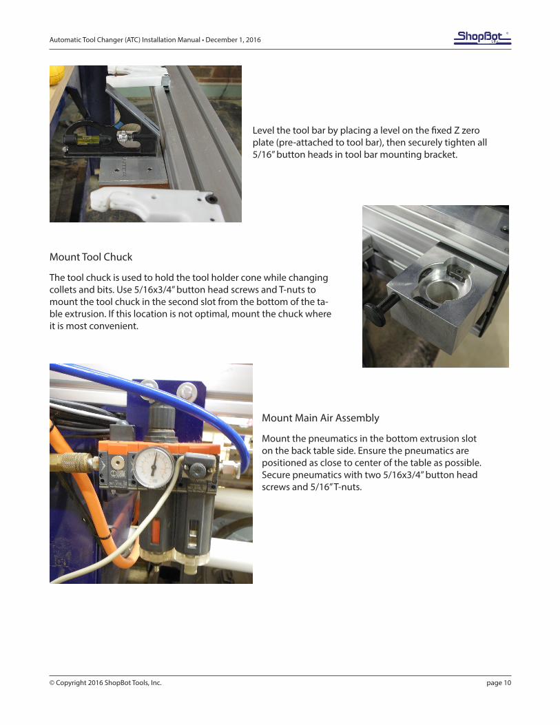
Level the tool bar by placing a level on the fixed Z zero plate (pre-attached to tool bar), then securely tighten all 5/16” button heads in tool bar mounting bracket.
Mount Tool Chuck
The tool chuck is used to hold the tool holder cone while changing collets and bits. Use 5/16x3/4” button head screws and T-nuts to mount the tool chuck in the second slot from the bottom of the ta-ble extrusion. If this location is not optimal, mount the chuck where it is most convenient.
Mount Main Air Assembly
Mount the pneumatics in the bottom extrusion slot on the back table side. Ensure the pneumatics are positioned as close to center of the table as possible. Secure pneumatics with two 5/16x3/4” button head screws and 5/16” T-nuts.
Automatic Tool Changer (ATC) Installation Manual • December 1, 2016
© Copyright 2016 ShopBot Tools, Inc. page 11
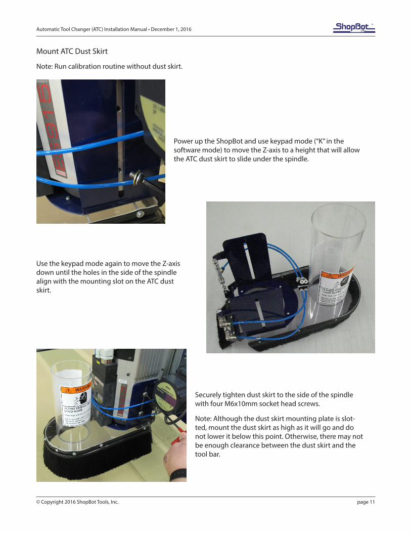
Mount ATC Dust Skirt
Note: Run calibration routine without dust skirt.
Power up the ShopBot and use keypad mode (“K” in the software mode) to move the Z-axis to a height that will allow the ATC dust skirt to slide under the spindle.
Use the keypad mode again to move the Z-axis down until the holes in the side of the spindle align with the mounting slot on the ATC dust skirt.
Securely tighten dust skirt to the side of the spindle with four M6x10mm socket head screws.
Note: Although the dust skirt mounting plate is slot-ted, mount the dust skirt as high as it will go and do not lower it below this point. Otherwise, there may not be enough clearance between the dust skirt and the tool bar.
Automatic Tool Changer (ATC) Installation Manual • December 1, 2016
© Copyright 2016 ShopBot Tools, Inc. page 12
Table Drawing
Automatic Tool Changer (ATC) Installation Manual • December 1, 2016
© Copyright 2016 ShopBot Tools, Inc. page 13
ATC Installation (Pneumatic)
This portion of the installation covers the pneumatic system routing and hook-ups.
Supplied Tubing
• Three pieces of 5/32” tubing (001349)• Three pieces of ¼” tubing (002704)• One piece of 3/8” tubing (001350)
Note: Lengths may have to be cut to fit depending on plunge and routing paths of machine.
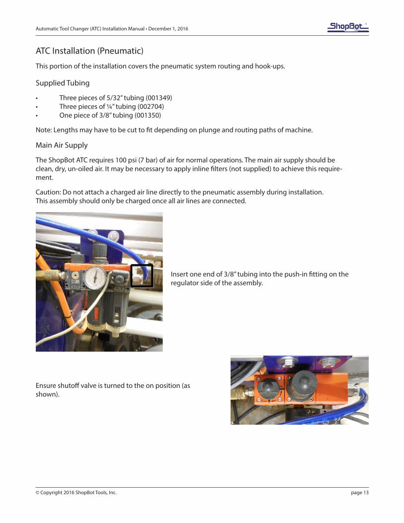
Main Air Supply
The ShopBot ATC requires 100 psi (7 bar) of air for normal operations. The main air supply should be clean, dry, un-oiled air. It may be necessary to apply inline filters (not supplied) to achieve this require-ment.
Caution: Do not attach a charged air line directly to the pneumatic assembly during installation. This assembly should only be charged once all air lines are connected.
Insert one end of 3/8” tubing into the push-in fitting on the regulator side of the assembly.
Ensure shutoff valve is turned to the on position (as shown).
Automatic Tool Changer (ATC) Installation Manual • December 1, 2016
© Copyright 2016 ShopBot Tools, Inc. page 14
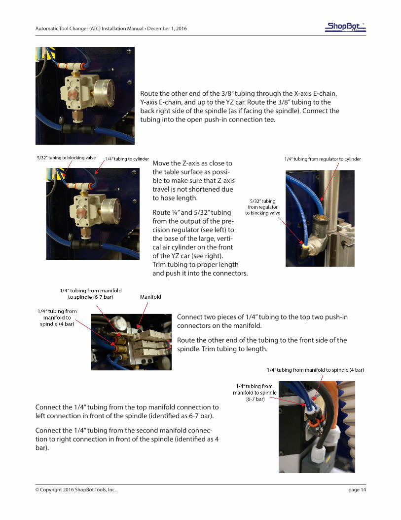
Route the other end of the 3/8” tubing through the X-axis E-chain, Y-axis E-chain, and up to the YZ car. Route the 3/8” tubing to the back right side of the spindle (as if facing the spindle). Connect the tubing into the open push-in connection tee.
Move the Z-axis as close to the table surface as possi-ble to make sure that Z-axis travel is not shortened due to hose length.
Route ¼” and 5/32” tubing from the output of the pre-cision regulator (see left) to the base of the large, verti-cal air cylinder on the front of the YZ car (see right). Trim tubing to proper length and push it into the connectors.
Connect two pieces of 1/4” tubing to the top two push-in connectors on the manifold.
Route the other end of the tubing to the front side of the spindle. Trim tubing to length.
Connect the 1/4” tubing from the top manifold connection to left connection in front of the spindle (identified as 6-7 bar).
Connect the 1/4” tubing from the second manifold connec-tion to right connection in front of the spindle (identified as 4 bar).
Automatic Tool Changer (ATC) Installation Manual • December 1, 2016
© Copyright 2016 ShopBot Tools, Inc. page 15
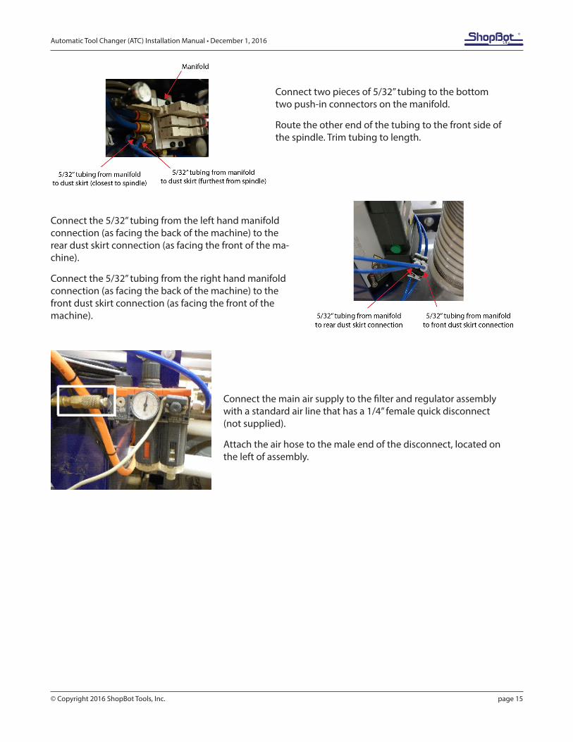
Connect two pieces of 5/32” tubing to the bottom two push-in connectors on the manifold.
Route the other end of the tubing to the front side of the spindle. Trim tubing to length.
Connect the 5/32” tubing from the left hand manifold connection (as facing the back of the machine) to the rear dust skirt connection (as facing the front of the ma-chine).
Connect the 5/32” tubing from the right hand manifold connection (as facing the back of the machine) to the front dust skirt connection (as facing the front of the machine).
Connect the main air supply to the filter and regulator assembly with a standard air line that has a 1/4” female quick disconnect (not supplied).
Attach the air hose to the male end of the disconnect, located on the left of assembly.
Automatic Tool Changer (ATC) Installation Manual • December 1, 2016
© Copyright 2016 ShopBot Tools, Inc. page 16
ATC Installation (Electrical)
This portion of the installation will cover the electrical system, wire routing, and the hook-up requirements.
Emergency Stop Switch and Three-Button Pendant Install
The three-button pendant and the separate emergency stop are bundled together for shipping. Both must be attached for either one to function.
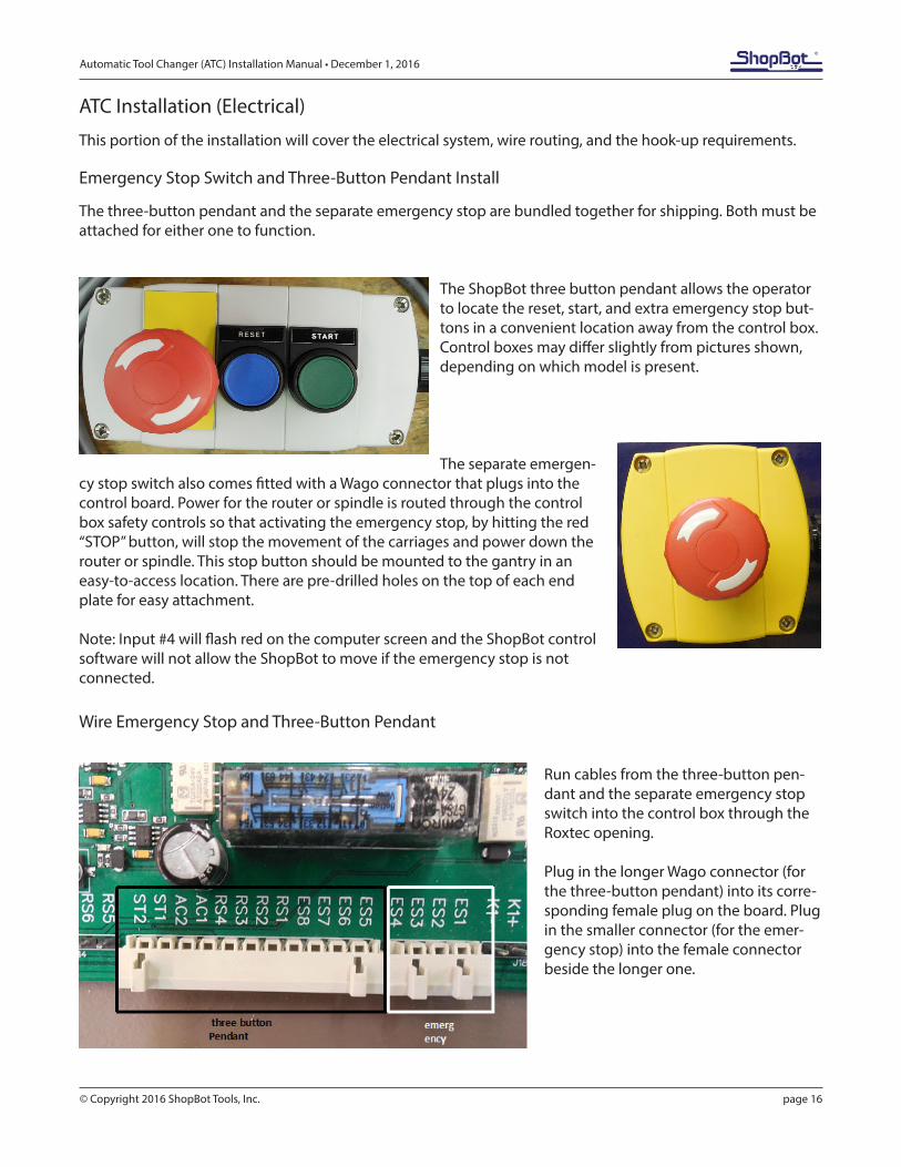
The ShopBot three button pendant allows the operator to locate the reset, start, and extra emergency stop but-tons in a convenient location away from the control box. Control boxes may differ slightly from pictures shown, depending on which model is present.
The separate emergen-cy stop switch also comes fitted with a Wago connector that plugs into the control board. Power for the router or spindle is routed through the control box safety controls so that activating the emergency stop, by hitting the red “STOP” button, will stop the movement of the carriages and power down the router or spindle. This stop button should be mounted to the gantry in an easy-to-access location. There are pre-drilled holes on the top of each end plate for easy attachment.
Note: Input #4 will flash red on the computer screen and the ShopBot control software will not allow the ShopBot to move if the emergency stop is not connected.
Wire Emergency Stop and Three-Button Pendant
Run cables from the three-button pen-dant and the separate emergency stop switch into the control box through the Roxtec opening.
Plug in the longer Wago connector (for the three-button pendant) into its corre-sponding female plug on the board. Plug in the smaller connector (for the emer-gency stop) into the female connector beside the longer one.
Automatic Tool Changer (ATC) Installation Manual • December 1, 2016
© Copyright 2016 ShopBot Tools, Inc. page 17
Wiring the Proximity Switches and Z Zero Plate
Run cables from proximity switches and Z zero plate through the Roxtec opening into the control box.
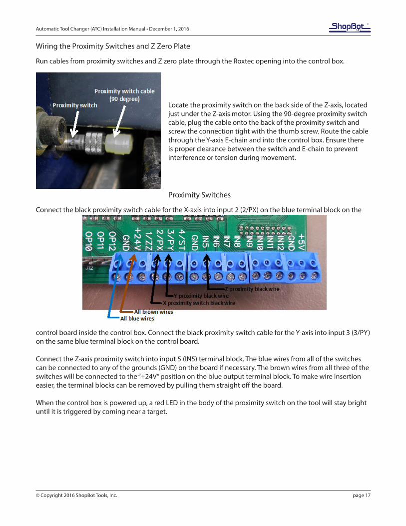
Locate the proximity switch on the back side of the Z-axis, located just under the Z-axis motor. Using the 90-degree proximity switch cable, plug the cable onto the back of the proximity switch and screw the connection tight with the thumb screw. Route the cable through the Y-axis E-chain and into the control box. Ensure there is proper clearance between the switch and E-chain to prevent interference or tension during movement.
Proximity Switches
Connect the black proximity switch cable for the X-axis into input 2 (2/PX) on the blue terminal block on the
control board inside the control box. Connect the black proximity switch cable for the Y-axis into input 3 (3/PY) on the same blue terminal block on the control board.
Connect the Z-axis proximity switch into input 5 (IN5) terminal block. The blue wires from all of the switches can be connected to any of the grounds (GND) on the board if necessary. The brown wires from all three of the switches will be connected to the “+24V” position on the blue output terminal block. To make wire insertion easier, the terminal blocks can be removed by pulling them straight off the board. When the control box is powered up, a red LED in the body of the proximity switch on the tool will stay bright until it is triggered by coming near a target.
Automatic Tool Changer (ATC) Installation Manual • December 1, 2016
© Copyright 2016 ShopBot Tools, Inc. page 18
Z Zero Plate
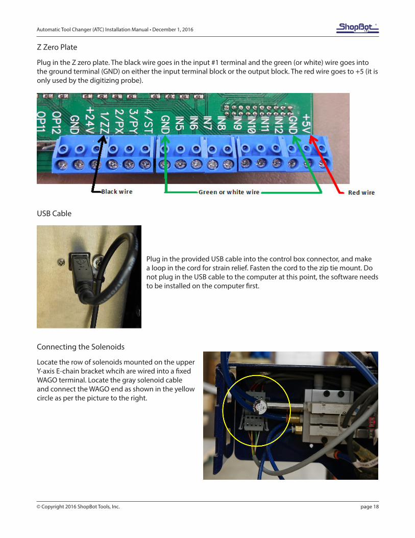
Plug in the Z zero plate. The black wire goes in the input #1 terminal and the green (or white) wire goes into the ground terminal (GND) on either the input terminal block or the output block. The red wire goes to +5 (it is only used by the digitizing probe).
USB Cable
Plug in the provided USB cable into the control box connector, and make a loop in the cord for strain relief. Fasten the cord to the zip tie mount. Do not plug in the USB cable to the computer at this point, the software needs to be installed on the computer first.
Connecting the Solenoids
Locate the row of solenoids mounted on the upper Y-axis E-chain bracket whcih are wired into a fixed WAGO terminal. Locate the gray solenoid cable and connect the WAGO end as shown in the yellow circle as per the picture to the right.
Automatic Tool Changer (ATC) Installation Manual • December 1, 2016
© Copyright 2016 ShopBot Tools, Inc. page 19
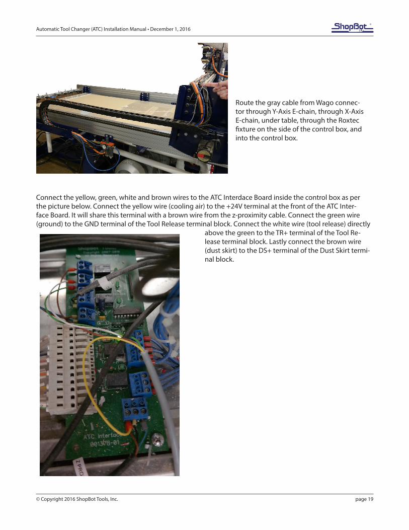
Route the gray cable from Wago connec-tor through Y-Axis E-chain, through X-Axis E-chain, under table, through the Roxtec fixture on the side of the control box, and into the control box.
Connect the yellow, green, white and brown wires to the ATC Interdace Board inside the control box as per the picture below. Connect the yellow wire (cooling air) to the +24V terminal at the front of the ATC Inter-face Board. It will share this terminal with a brown wire from the z-proximity cable. Connect the green wire (ground) to the GND terminal of the Tool Release terminal block. Connect the white wire (tool release) directly
above the green to the TR+ terminal of the Tool Re-lease terminal block. Lastly connect the brown wire (dust skirt) to the DS+ terminal of the Dust Skirt termi-nal block.
Automatic Tool Changer (ATC) Installation Manual • December 1, 2016
© Copyright 2016 ShopBot Tools, Inc. page 20
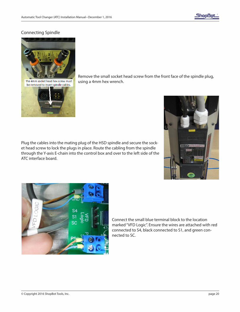
Connecting Spindle
Remove the small socket head screw from the front face of the spindle plug, using a 4mm hex wrench.
Plug the cables into the mating plug of the HSD spindle and secure the sock-et head screw to lock the plugs in place. Route the cabling from the spindle through the Y-axis E-chain into the control box and over to the left side of the ATC interface board.
Connect the small blue terminal block to the location marked “VFD Logic”. Ensure the wires are attached with red connected to S4, black connected to S1, and green con-nected to SC.
Automatic Tool Changer (ATC) Installation Manual • December 1, 2016
© Copyright 2016 ShopBot Tools, Inc. page 21
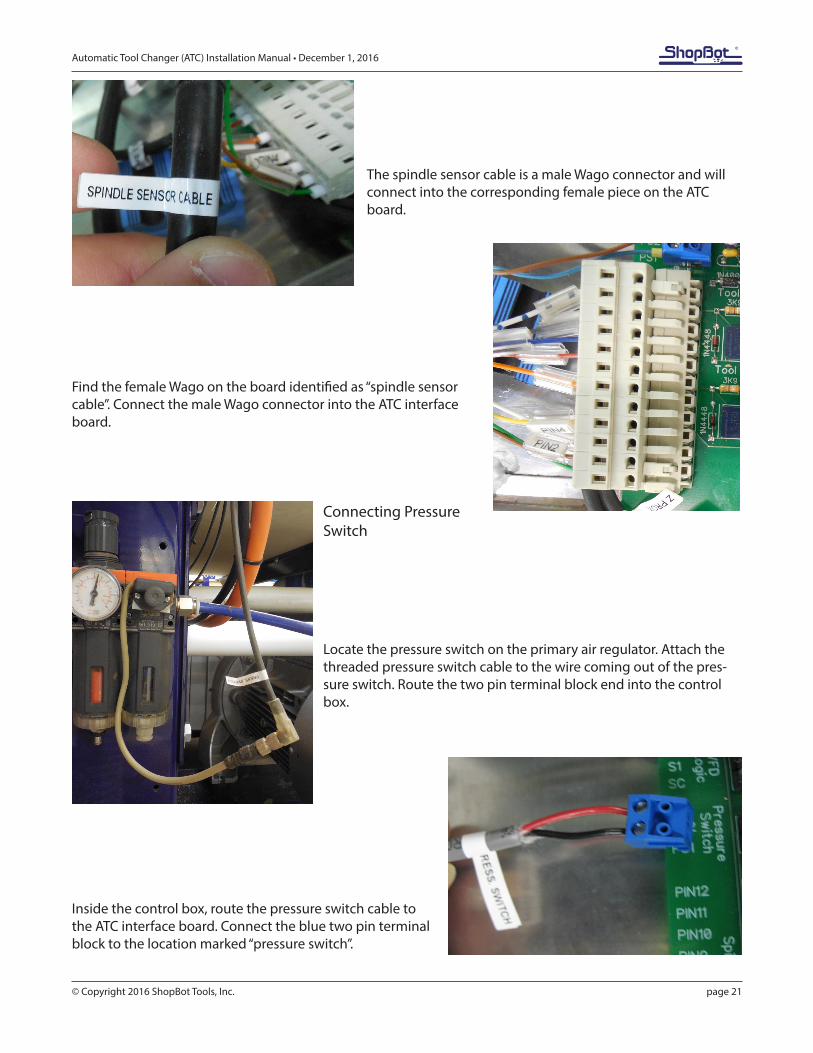
The spindle sensor cable is a male Wago connector and will connect into the corresponding female piece on the ATC board.
Find the female Wago on the board identified as “spindle sensor cable”. Connect the male Wago connector into the ATC interface board.
Connecting Pressure Switch
Locate the pressure switch on the primary air regulator. Attach the threaded pressure switch cable to the wire coming out of the pres-sure switch. Route the two pin terminal block end into the control box.
Inside the control box, route the pressure switch cable to the ATC interface board. Connect the blue two pin terminal block to the location marked “pressure switch”.
Automatic Tool Changer (ATC) Installation Manual • December 1, 2016
© Copyright 2016 ShopBot Tools, Inc. page 22
ATC Software Setup and Tool Calibration
This portion of the installation covers the software setup and tool calibration.
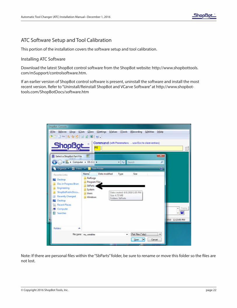
Installing ATC Software
Download the latest ShopBot control software from the ShopBot website: http://www.shopbottools.com/mSupport/controlsoftware.htm.
If an earlier version of ShopBot control software is present, uninstall the software and install the most recent version. Refer to “Uninstall/Reinstall ShopBot and VCarve Software” at http://www.shopbot-tools.com/ShopBotDocs/software.htm
Note: If there are personal files within the “SbParts” folder, be sure to rename or move this folder so the files are not lost.
Automatic Tool Changer (ATC) Installation Manual • December 1, 2016
© Copyright 2016 ShopBot Tools, Inc. page 23
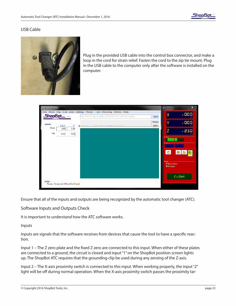
USB Cable
Plug in the provided USB cable into the control box connector, and make a loop in the cord for strain relief. Fasten the cord to the zip tie mount. Plug in the USB cable to the computer only after the software is installed on the computer.
Ensure that all of the inputs and outputs are being recognized by the automatic tool changer (ATC).
Software Inputs and Outputs Check
It is important to understand how the ATC software works.
Inputs
Inputs are signals that the software receives from devices that cause the tool to have a specific reac-tion.
Input 1 – The Z zero plate and the fixed Z zero are connected to this input. When either of these plates are connected to a ground, the circuit is closed and input “1” on the ShopBot position screen lights up. The ShopBot ATC requires that the grounding clip be used during any zeroing of the Z-axis.
Input 2 – The X-axis proximity switch is connected to this input. When working properly, the input “2” light will be off during normal operation. When the X-axis proximity switch passes the proximity tar-
Automatic Tool Changer (ATC) Installation Manual • December 1, 2016
© Copyright 2016 ShopBot Tools, Inc. page 24
gets, the light will turn on. These are used for homing the X and Y positions and for limiting the safe table cutting boundaries, among other things.
Input 3 – The Y-axis proximity switch is connected to this input. During normal operation, the input “3” light will be off in the ShopBot position screen. If the Y-axis proximity switch passes the proxim-ity targets, the light will turn on. Among other things, this feature will be used for homing the X and Y positions and for limiting the safe table cutting boundaries.
Input 4 – This input is connected to the stop switch. When active, the switch allows for use of the tool and when inactive, the connection is severed and the tool comes to a stop.
Input 5 – The Z-axis proximity switch is connected to this input. When working properly, the input “5” light will be ON during normal operation. When the Z-axis proximity switch passes the proximity tar-gets, the light will be turned OFF. This switch will be used most often for a reference location in zeroing the bits in the tool rack and for limiting the safe Z cutting boundary.
Input 6 – NA
Input 7 – Drawbar closed.
Input 8 – Drawbar open (changing tools).
Outputs
Outputs are signals that ShopBot software is sending to cause a desired action. Unused outputs can be programed to activate other peripherals using an optional relay board.
Output 1 – Switches on the spindle.
Output 2 – NA
Output 3 – Toggles the ATC dust skirt gate open.
Output 4 – Turns on during machine operation (safety flashing screen). Required for spindle “on” sig-nal.
Output 5 – NA
Output 6 - NA
Output 7 – NA
Output 8 - Toggles the spindle drawbar open /close (releases tool holders from spindle).
Caution: When the spindle is not spinning it is possible to drop the tools from the spindle if this output is triggered.
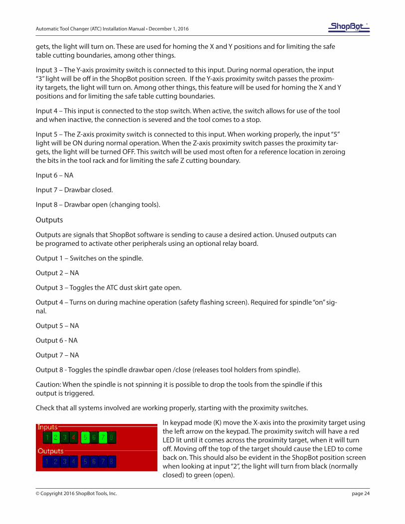
Check that all systems involved are working properly, starting with the proximity switches.
In keypad mode (K) move the X-axis into the proximity target using the left arrow on the keypad. The proximity switch will have a red LED lit until it comes across the proximity target, when it will turn off. Moving off the top of the target should cause the LED to come back on. This should also be evident in the ShopBot position screen when looking at input “2”, the light will turn from black (normally closed) to green (open).
Automatic Tool Changer (ATC) Installation Manual • December 1, 2016
© Copyright 2016 ShopBot Tools, Inc. page 25
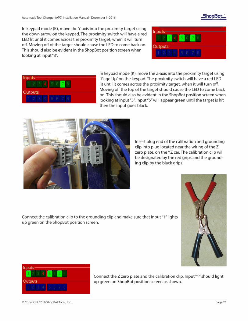
In keypad mode (K), move the Y-axis into the proximity target using the down arrow on the keypad. The proximity switch will have a red LED lit until it comes across the proximity target, when it will turn off. Moving off of the target should cause the LED to come back on. This should also be evident in the ShopBot position screen when looking at input “3”.
In keypad mode (K), move the Z-axis into the proximity target using “Page Up” on the keypad. The proximity switch will have a red LED lit until it comes across the proximity target, when it will turn off. Moving off the top of the target should cause the LED to come back on. This should also be evident in the ShopBot position screen when looking at input “5”. Input “5” will appear green until the target is hit then the input goes black.
Insert plug end of the calibration and grounding clip into plug located near the wiring of the Z zero plate, on the YZ car. The calibration clip will be designated by the red grips and the ground-ing clip by the black grips.
Connect the calibration clip to the grounding clip and make sure that input “1” lights up green on the ShopBot position screen.
Connect the Z zero plate and the calibration clip. Input “1” should light up green on ShopBot position screen as shown.
Automatic Tool Changer (ATC) Installation Manual • December 1, 2016
© Copyright 2016 ShopBot Tools, Inc. page 26
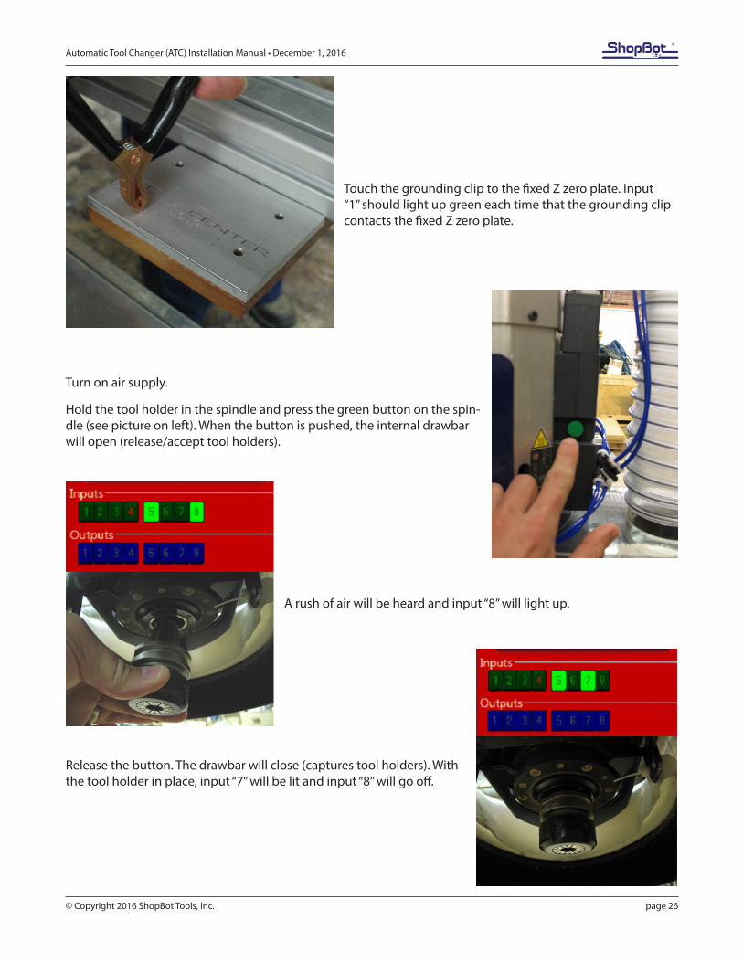
Touch the grounding clip to the fixed Z zero plate. Input “1” should light up green each time that the grounding clip contacts the fixed Z zero plate.
Turn on air supply.
Hold the tool holder in the spindle and press the green button on the spin-dle (see picture on left). When the button is pushed, the internal drawbar will open (release/accept tool holders).
A rush of air will be heard and input “8” will light up.
Release the button. The drawbar will close (captures tool holders). With the tool holder in place, input “7” will be lit and input “8” will go off.
Automatic Tool Changer (ATC) Installation Manual • December 1, 2016
© Copyright 2016 ShopBot Tools, Inc. page 27
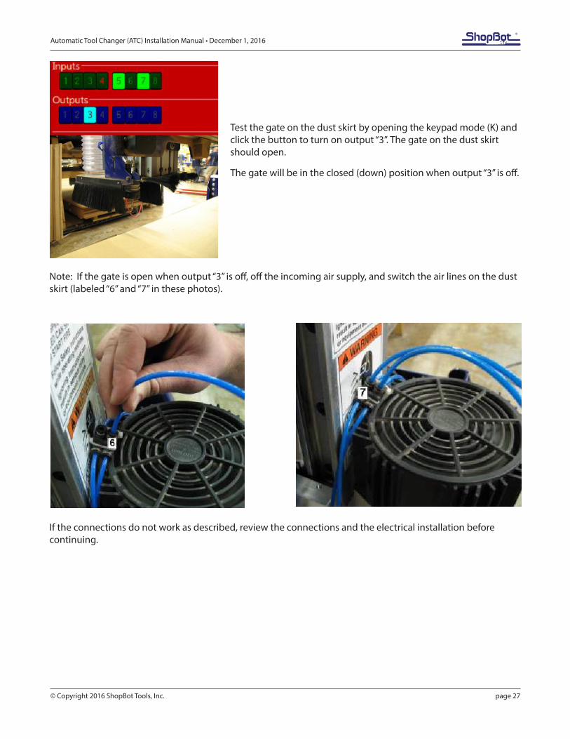
Test the gate on the dust skirt by opening the keypad mode (K) and click the button to turn on output “3”. The gate on the dust skirt should open.
The gate will be in the closed (down) position when output “3” is off.
Note: If the gate is open when output “3” is off, off the incoming air supply, and switch the air lines on the dust skirt (labeled “6” and “7” in these photos).
If the connections do not work as described, review the connections and the electrical installation before continuing.
Automatic Tool Changer (ATC) Installation Manual • December 1, 2016
© Copyright 2016 ShopBot Tools, Inc. page 28
ShopBot Setup (TS)
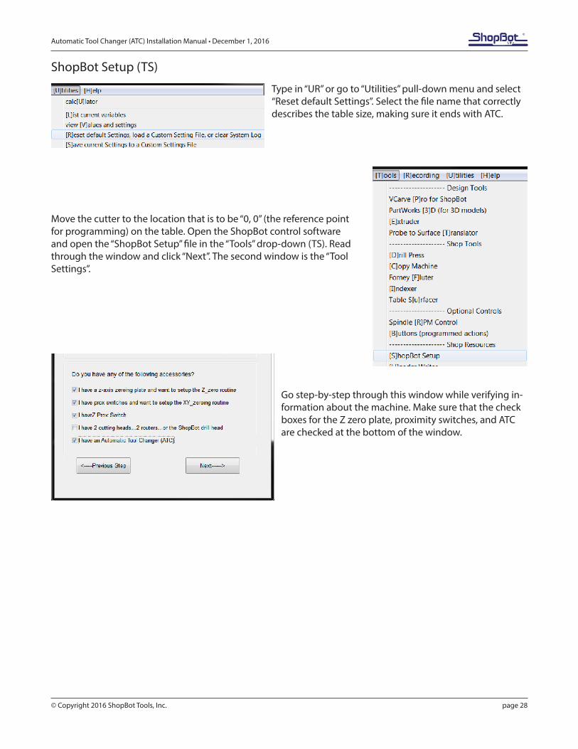
Type in “UR” or go to “Utilities” pull-down menu and select “Reset default Settings”. Select the file name that correctly describes the table size, making sure it ends with ATC.
Move the cutter to the location that is to be “0, 0” (the reference point for programming) on the table. Open the ShopBot control software and open the “ShopBot Setup” file in the “Tools” drop-down (TS). Read through the window and click “Next”. The second window is the “Tool Settings”.
Go step-by-step through this window while verifying in-formation about the machine. Make sure that the check boxes for the Z zero plate, proximity switches, and ATC are checked at the bottom of the window.
Automatic Tool Changer (ATC) Installation Manual • December 1, 2016
© Copyright 2016 ShopBot Tools, Inc. page 29
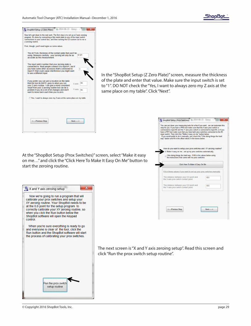
In the “ShopBot Setup (Z Zero Plate)” screen, measure the thickness of the plate and enter that value. Make sure the input switch is set to “1”. DO NOT check the “Yes, I want to always zero my Z axis at the same place on my table”. Click “Next”.
At the “ShopBot Setup (Prox Switches)” screen, select “Make it easy on me…” and click the “Click Here To Make It Easy On Me” button to start the zeroing routine.
The next screen is “X and Y axis zeroing setup”. Read this screen and click “Run the prox switch setup routine”.
Automatic Tool Changer (ATC) Installation Manual • December 1, 2016
© Copyright 2016 ShopBot Tools, Inc. page 30
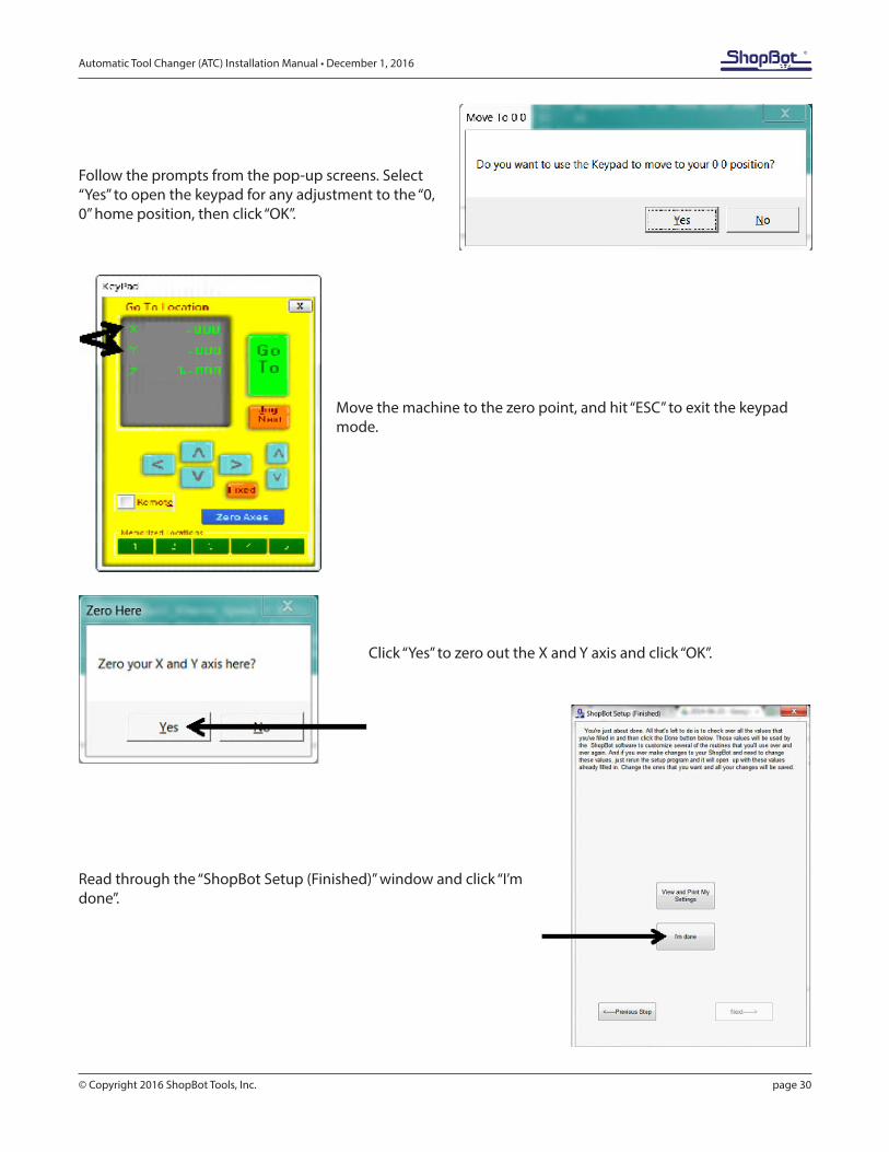
Follow the prompts from the pop-up screens. Select “Yes” to open the keypad for any adjustment to the “0, 0” home position, then click “OK”.
Move the machine to the zero point, and hit “ESC” to exit the keypad mode.
Click “Yes” to zero out the X and Y axis and click “OK”.
Read through the “ShopBot Setup (Finished)” window and click “I’m done”.
Automatic Tool Changer (ATC) Installation Manual • December 1, 2016
© Copyright 2016 ShopBot Tools, Inc. page 31
Home Machine (C3)
Type (TS) for ShopBot setup, then type C3 in the ShopBot 3 software. The tool will end up at the home location previously set in the ShopBot Setup routine.
Calibration Routine (CN74)
The ATC calibration routine (CN74) is programmed to find and record the clip locations. This document will walk through the process.
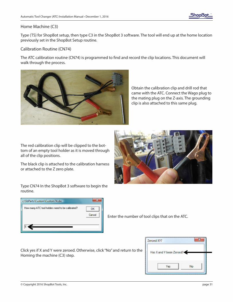
Obtain the calibration clip and drill rod that came with the ATC. Connect the Wago plug to the mating plug on the Z-axis. The grounding clip is also attached to this same plug.
The red calibration clip will be clipped to the bot-tom of an empty tool holder as it is moved through all of the clip positions.
The black clip is attached to the calibration harness or attached to the Z zero plate.
Type CN74 In the ShopBot 3 software to begin the routine.
Enter the number of tool clips that on the ATC.
Click yes if X and Y were zeroed. Otherwise, click “No” and return to the Homing the machine (C3) step.
Automatic Tool Changer (ATC) Installation Manual • December 1, 2016
© Copyright 2016 ShopBot Tools, Inc. page 32
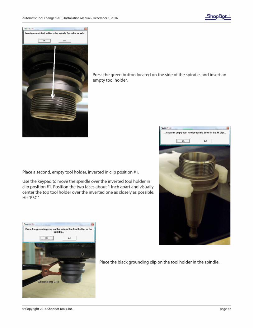
Press the green button located on the side of the spindle, and insert an empty tool holder.
Place a second, empty tool holder, inverted in clip position #1.
Use the keypad to move the spindle over the inverted tool holder in clip position #1. Position the two faces about 1 inch apart and visually center the top tool holder over the inverted one as closely as possible. Hit “ESC”.
Place the black grounding clip on the tool holder in the spindle.
Automatic Tool Changer (ATC) Installation Manual • December 1, 2016
© Copyright 2016 ShopBot Tools, Inc. page 33
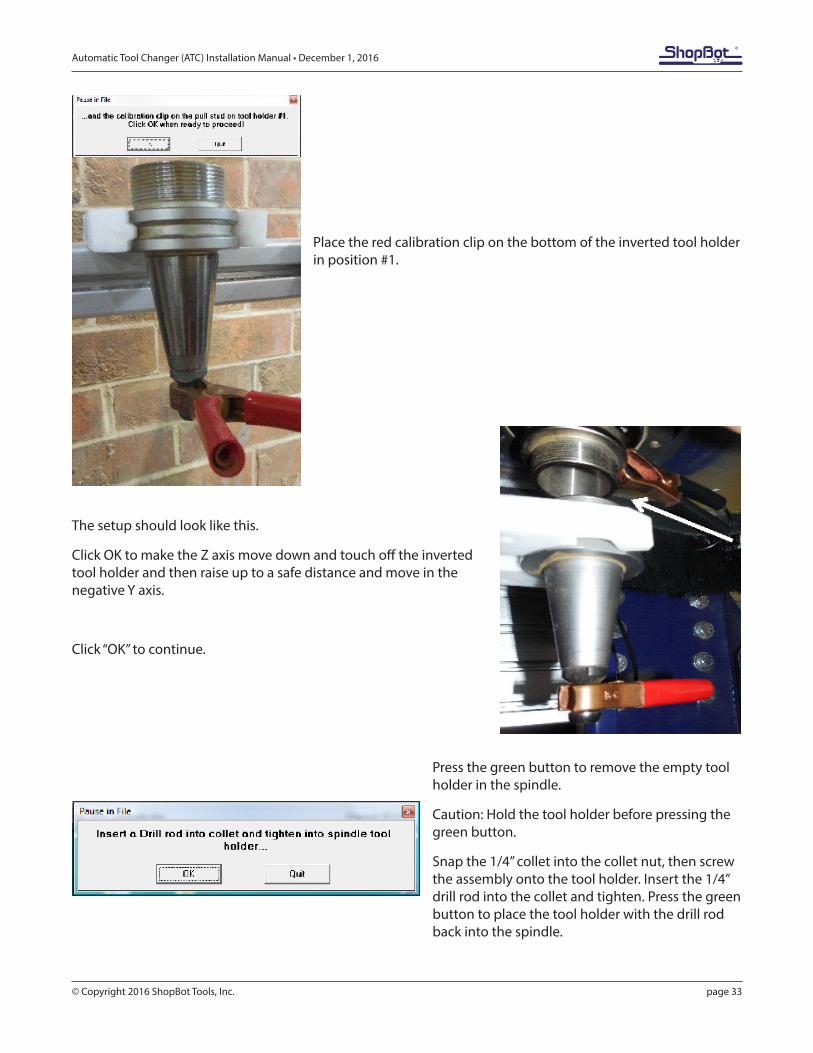
Place the red calibration clip on the bottom of the inverted tool holder in position #1.
The setup should look like this.
Click OK to make the Z axis move down and touch off the inverted tool holder and then raise up to a safe distance and move in the negative Y axis.
Click “OK” to continue.
Press the green button to remove the empty tool holder in the spindle.
Caution: Hold the tool holder before pressing the green button.
Snap the 1/4” collet into the collet nut, then screw the assembly onto the tool holder. Insert the 1/4” drill rod into the collet and tighten. Press the green button to place the tool holder with the drill rod back into the spindle.
Automatic Tool Changer (ATC) Installation Manual • December 1, 2016
© Copyright 2016 ShopBot Tools, Inc. page 34
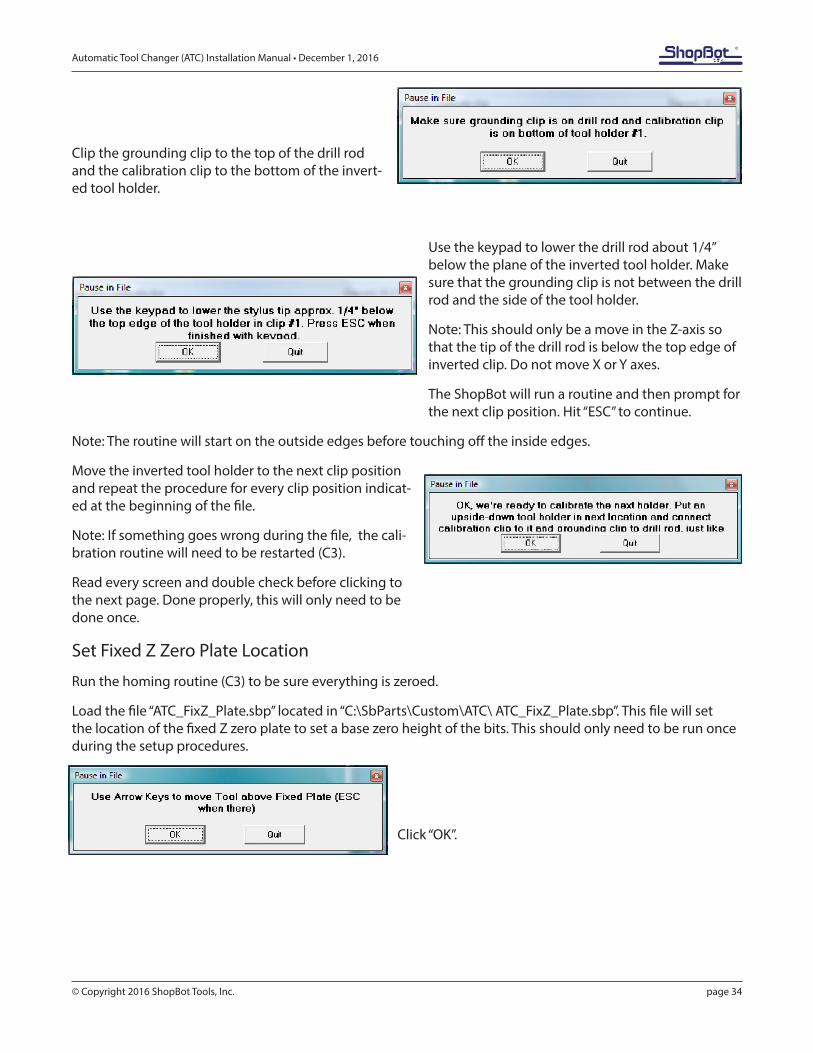
Clip the grounding clip to the top of the drill rod and the calibration clip to the bottom of the invert-ed tool holder.
Use the keypad to lower the drill rod about 1/4” below the plane of the inverted tool holder. Make sure that the grounding clip is not between the drill rod and the side of the tool holder.
Note: This should only be a move in the Z-axis so that the tip of the drill rod is below the top edge of inverted clip. Do not move X or Y axes.
The ShopBot will run a routine and then prompt for the next clip position. Hit “ESC” to continue.
Note: The routine will start on the outside edges before touching off the inside edges.
Move the inverted tool holder to the next clip position and repeat the procedure for every clip position indicat-ed at the beginning of the file.
Note: If something goes wrong during the file, the cali-bration routine will need to be restarted (C3).
Read every screen and double check before clicking to the next page. Done properly, this will only need to be done once.
Set Fixed Z Zero Plate Location
Run the homing routine (C3) to be sure everything is zeroed.
Load the file “ATC_FixZ_Plate.sbp” located in “C:\SbParts\Custom\ATC\ ATC_FixZ_Plate.sbp”. This file will set the location of the fixed Z zero plate to set a base zero height of the bits. This should only need to be run once during the setup procedures.
Click “OK”.
Automatic Tool Changer (ATC) Installation Manual • December 1, 2016
© Copyright 2016 ShopBot Tools, Inc. page 35
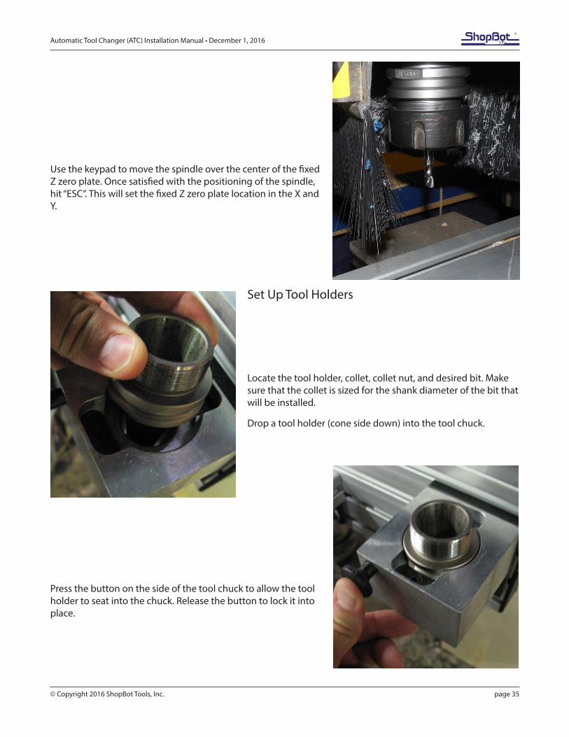
Use the keypad to move the spindle over the center of the fixed Z zero plate. Once satisfied with the positioning of the spindle, hit “ESC”. This will set the fixed Z zero plate location in the X and Y.
Set Up Tool Holders
Locate the tool holder, collet, collet nut, and desired bit. Make sure that the collet is sized for the shank diameter of the bit that will be installed.
Drop a tool holder (cone side down) into the tool chuck.
Press the button on the side of the tool chuck to allow the tool holder to seat into the chuck. Release the button to lock it into place.
Automatic Tool Changer (ATC) Installation Manual • December 1, 2016
© Copyright 2016 ShopBot Tools, Inc. page 36
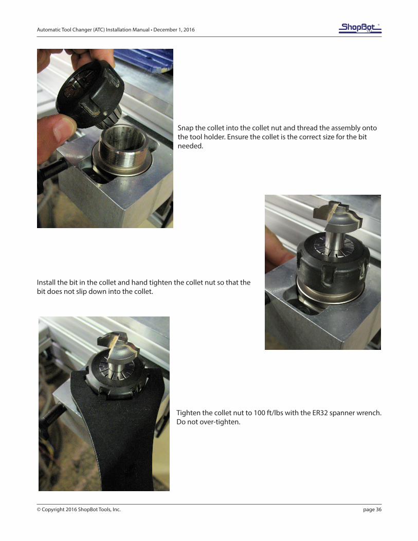
Snap the collet into the collet nut and thread the assembly onto the tool holder. Ensure the collet is the correct size for the bit needed.
Install the bit in the collet and hand tighten the collet nut so that the bit does not slip down into the collet.
Tighten the collet nut to 100 ft/lbs with the ER32 spanner wrench. Do not over-tighten.
Automatic Tool Changer (ATC) Installation Manual • December 1, 2016
© Copyright 2016 ShopBot Tools, Inc. page 37
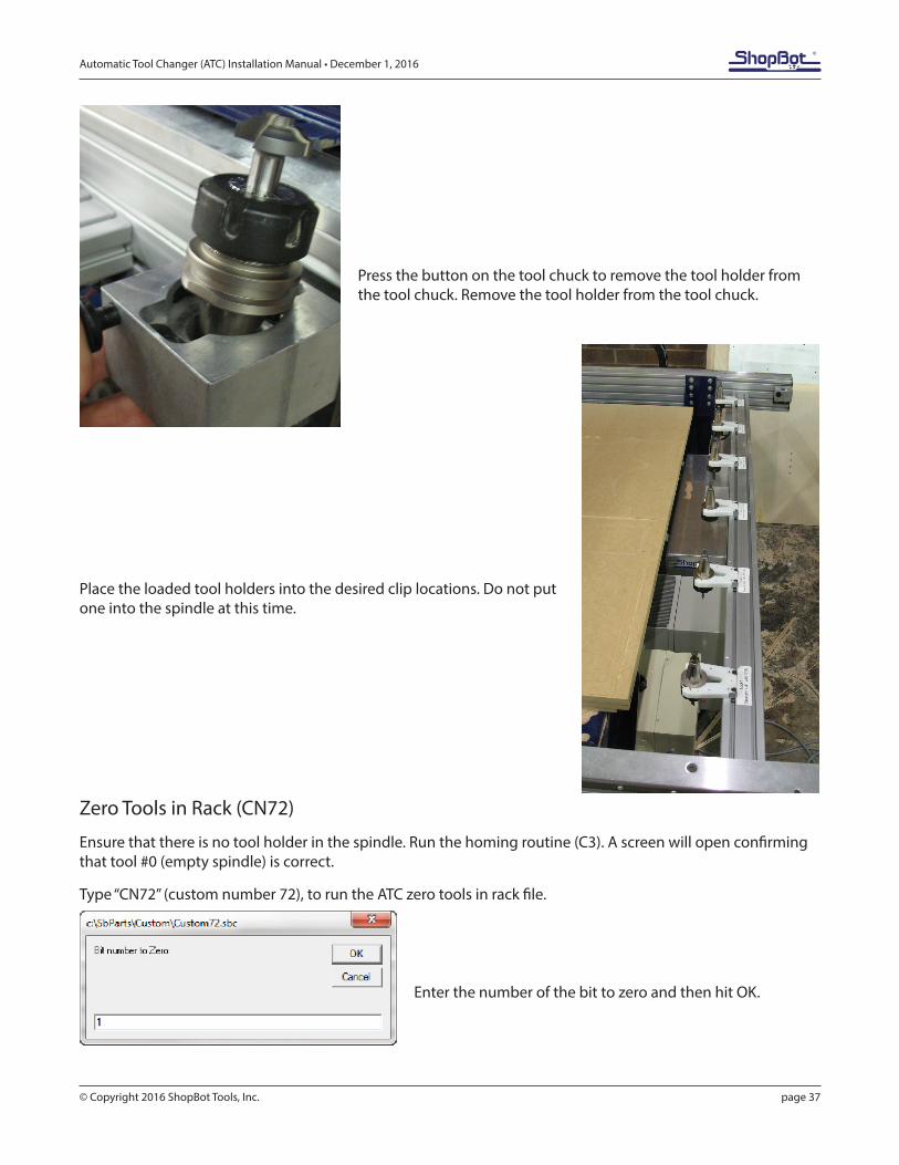
Press the button on the tool chuck to remove the tool holder from the tool chuck. Remove the tool holder from the tool chuck.
Place the loaded tool holders into the desired clip locations. Do not put one into the spindle at this time.
Zero Tools in Rack (CN72)
Ensure that there is no tool holder in the spindle. Run the homing routine (C3). A screen will open confirming that tool #0 (empty spindle) is correct.
Type “CN72” (custom number 72), to run the ATC zero tools in rack file.
Enter the number of the bit to zero and then hit OK.
Automatic Tool Changer (ATC) Installation Manual • December 1, 2016
© Copyright 2016 ShopBot Tools, Inc. page 38
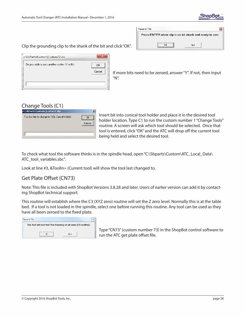
Clip the grounding clip to the shank of the bit and click “OK”.
If more bits need to be zeroed, answer “Y”. If not, then input “N”.
Change Tools (C1)
Insert bit into conical tool holder and place it in the desired tool holder location. Type C1 to run the custom number 1 “Change Tools” routine. A screen will ask which tool should be selected. Once that tool is entered, click “OK” and the ATC will drop off the current tool being held and select the desired tool.
To check what tool the software thinks is in the spindle head, open “C:\Sbparts\Custom\ATC_Local_Data\ATC_tool_variables.sbc”.
Look at line #3, &ToolIn= (Current tool) will show the tool last changed to.
Get Plate Offset (CN73)
Note: This file is included with ShopBot Versions 3.8.28 and later. Users of earlier version can add it by contact-ing ShopBot technical support.
This routine will establish where the C3 (XYZ zero) routine will set the Z zero level. Normally this is at the table bed. If a tool is not loaded in the spindle, select one before running this routine. Any tool can be used as they have all been zeroed to the fixed plate.
Type “CN73” (custom number 73) in the ShopBot control software to run the ATC get plate offset file.
Automatic Tool Changer (ATC) Installation Manual • December 1, 2016
© Copyright 2016 ShopBot Tools, Inc. page 39
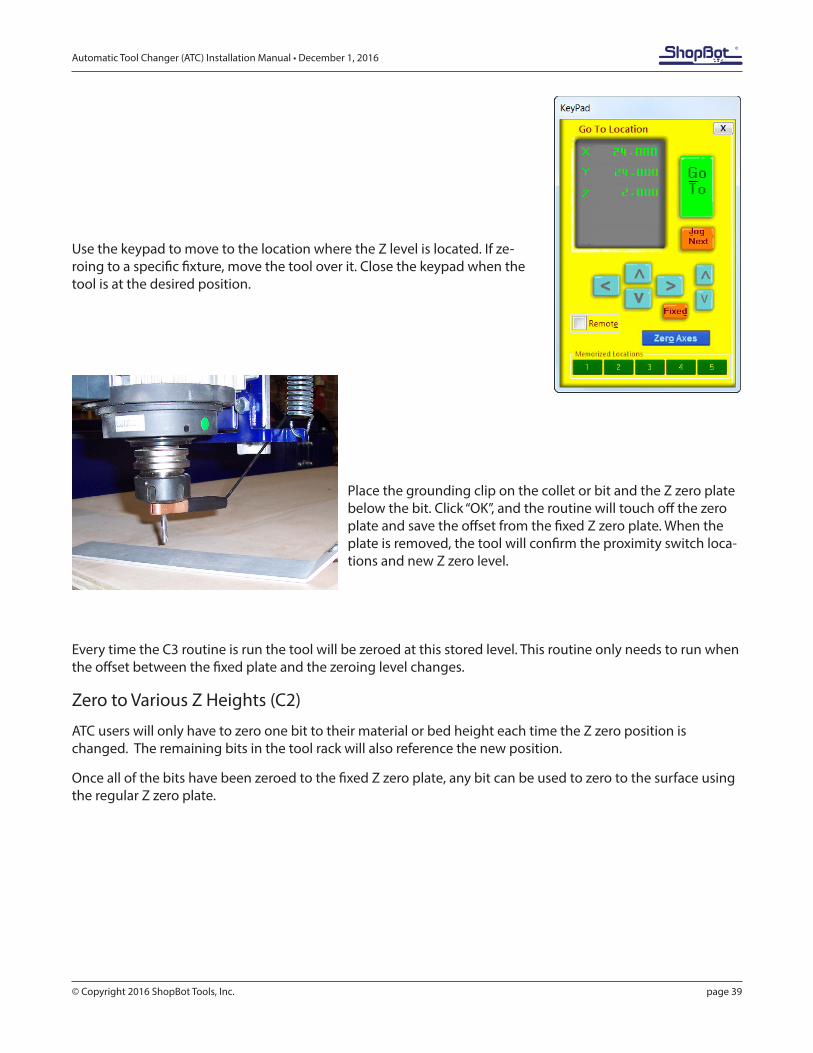
Use the keypad to move to the location where the Z level is located. If ze-roing to a specific fixture, move the tool over it. Close the keypad when the tool is at the desired position.
Place the grounding clip on the collet or bit and the Z zero plate below the bit. Click “OK”, and the routine will touch off the zero plate and save the offset from the fixed Z zero plate. When the plate is removed, the tool will confirm the proximity switch loca-tions and new Z zero level.
Every time the C3 routine is run the tool will be zeroed at this stored level. This routine only needs to run when the offset between the fixed plate and the zeroing level changes.
Zero to Various Z Heights (C2)
ATC users will only have to zero one bit to their material or bed height each time the Z zero position is changed. The remaining bits in the tool rack will also reference the new position.
Once all of the bits have been zeroed to the fixed Z zero plate, any bit can be used to zero to the surface using the regular Z zero plate.
Automatic Tool Changer (ATC) Installation Manual • December 1, 2016
© Copyright 2016 ShopBot Tools, Inc. page 40
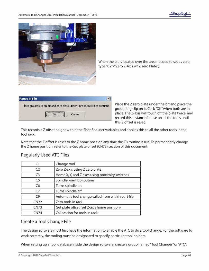
When the bit is located over the area needed to set as zero, type “C2” (“Zero Z-Axis w/ Z zero Plate”).
Place the Z zero plate under the bit and place the grounding clip on it. Click “OK” when both are in place. The Z-axis will touch off the plate twice, and record this distance for use on all the tools until this Z offset is reset.
This records a Z offset height within the ShopBot user variables and applies this to all the other tools in the tool rack.
Note that the Z offset is reset to the Z home position any time the C3 routine is run. To permanently change the Z home position, refer to the Get plate offset (CN73) section of this document.
Regularly Used ATC Files
C1 Change toolC2 Zero Z-axis using Z zero plateC3 Home X, Y, and Z axes using proximity switchesC5 Spindle warmup routineC6 Turns spindle onC7 Turns spindle offC9 Automatic tool change called from within part file
CN72 Zero tools in rackCN73 Get plate offset (set Z-axis home position)CN74 Calibration for tools in rack
Create a Tool Change File
The design software must first have the information to enable the ATC to do a tool change. For the software to work correctly, the tooling must be designated to specify particular tool holders.
When setting up a tool database inside the design software, create a group named “Tool Changer” or “ATC”.
Automatic Tool Changer (ATC) Installation Manual • December 1, 2016
© Copyright 2016 ShopBot Tools, Inc. page 41
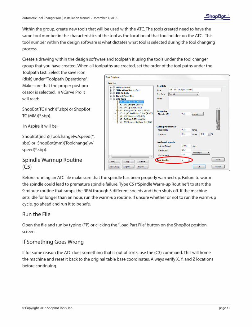
Within the group, create new tools that will be used with the ATC. The tools created need to have the same tool number in the characteristics of the tool as the location of that tool holder on the ATC. This tool number within the design software is what dictates what tool is selected during the tool changing process.
Create a drawing within the design software and toolpath it using the tools under the tool changer group that you have created. When all toolpaths are created, set the order of the tool paths under the Toolpath List. Select the save icon (disk) under “Toolpath Operations”. Make sure that the proper post pro-cessor is selected. In VCarve Pro it will read:
ShopBot TC (Inch)(*.sbp) or ShopBot TC (MM)(*.sbp).
In Aspire it will be:
ShopBot(inch)(Toolchange)w/speed(*.sbp) or ShopBot(mm)(Toolchange)w/speed(*.sbp).
Spindle Warmup Routine (C5)
Before running an ATC file make sure that the spindle has been properly warmed-up. Failure to warm the spindle could lead to premature spindle failure. Type C5 (“Spindle Warm-up Routine”) to start the 9 minute routine that ramps the RPM through 3 different speeds and then shuts off. If the machine sets idle for longer than an hour, run the warm-up routine. If unsure whether or not to run the warm-up cycle, go ahead and run it to be safe.
Run the File
Open the file and run by typing (FP) or clicking the “Load Part File” button on the ShopBot position screen.
If Something Goes Wrong
If for some reason the ATC does something that is out of sorts, use the (C3) command. This will home the machine and reset it back to the original table base coordinates. Always verify X, Y, and Z locations before continuing.

Automatic Tool Changer (ATC) Installation Manual • December 1, 2016
© Copyright 2016 ShopBot Tools, Inc. page 42