towards the development of an efficient immersed particle heat exchanger: particles transfer from...
TRANSCRIPT

PROCEEDINGS OF ECOS 2012 - THE 25TH INTERNATIONAL CONFERENCE ON
EEEEFFICIENCY, CCCCOST, OOOOPTIMIZATION, SSSSIMULATION AND ENVIRONMENTAL IMPACT OF ENERGY SYSTEMS
JUNE 26-29, 2012, PERUGIA, ITALY
Towards the development of an efficient immersed particle heat exchanger: particles
transfer from low to high pressure
Luciano A. Catalano a, Riccardo Amirante b, Stefano Copertino c, Paolo Tamburrano d , Fabio De Bellis e
a Polytechnic of Bari, Italy, [email protected] b Polytechnic of Bari, Italy, [email protected]
c Polytechnic of Bari, Italy, [email protected] d Polytechnic of Bari, Italy, [email protected]
e Polytechnic of Bari, Italy, [email protected]
Abstract: An innovative heat exchange device has been recently proposed, which employs an intermediate solid medium to transfer heat from a gas flow at low pressure and high temperature to another gas flow at higher pressure but lower temperature, with negligible pressure losses. In this paper, a key component of this innovative heat exchanger is analyzed in deep, namely the pressurization device responsible for the particles transit between the two separate environments. The operation of the proposed pressurization system is described in detail and then modeled as a zero-dimensional time-dependent system to analyze the influence of the related mass and energy losses onto the heat exchanger efficiency. An experimental test rig reproducing the pressurization tank has been also set up: the data collected at different operating conditions confirmed the reliability of the analytical model and the negligible energy losses occurring in the pressurization process.
Keywords: Gas turbines, external combustion, innovative heat exchanger, pressurization.
1. Introduction Nowadays, natural gas turbines dominate the field of power generation because of their black start capabilities, high efficiency, lower capital costs, shorter installation times, better emission characteristics and abundance of natural gas supplies. Gas turbines for power generation are employed in both simple and combined cycles: technical improvements such as material advancements and cooling innovations have contributed to enhance their efficiency: accordingly, combined cycle plants are the thermal plants with the highest efficiency (about 60% [1]). However, internal combustion demands the use of clean fuels, which are significantly more expensive than coal or orimulsion or biomass; moreover, their availability is also limited by geo-political aspects. These arguments explain why stand-alone steam power plants using cheaper fuels, in external combustion mode, are still under construction. Their development and maintenance is only slowed down by the introduction of international agreements and taxes aiming at limiting CO2 emissions and thus at avoiding lower efficiency plants.
Externally fired gas turbines would combine the higher efficiency of a combined cycle plant with the advantages of burning cheaper fuels. However, their development and application is limited by the intrinsic difficulties in realizing gas to gas heat exchangers working at very high temperature and characterized by high thermal efficiency and by a limited pressure drop. Designing and manufacturing high-efficiency heat exchangers is also a limiting factor in the development of gas turbines employing heat recovery Joule-Brayton cycle [2,3,4] .
2
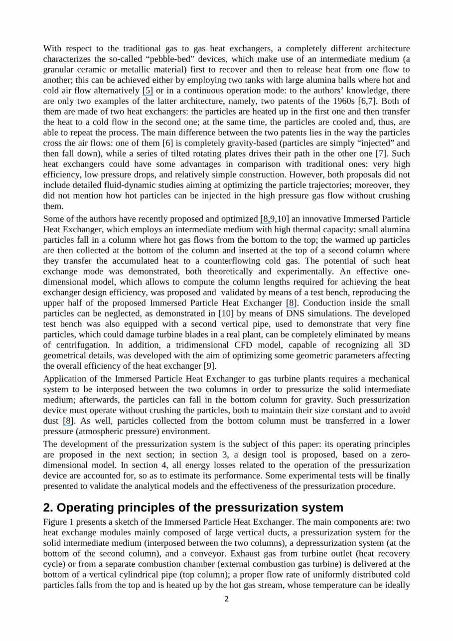
With respect to the traditional gas to gas heat exchangers, a completely different architecture characterizes the so-called “pebble-bed” devices, which make use of an intermediate medium (a granular ceramic or metallic material) first to recover and then to release heat from one flow to another; this can be achieved either by employing two tanks with large alumina balls where hot and cold air flow alternatively [5] or in a continuous operation mode: to the authors’ knowledge, there are only two examples of the latter architecture, namely, two patents of the 1960s [6,7]. Both of them are made of two heat exchangers: the particles are heated up in the first one and then transfer the heat to a cold flow in the second one; at the same time, the particles are cooled and, thus, are able to repeat the process. The main difference between the two patents lies in the way the particles cross the air flows: one of them [6] is completely gravity-based (particles are simply “injected” and then fall down), while a series of tilted rotating plates drives their path in the other one [7]. Such heat exchangers could have some advantages in comparison with traditional ones: very high efficiency, low pressure drops, and relatively simple construction. However, both proposals did not include detailed fluid-dynamic studies aiming at optimizing the particle trajectories; moreover, they did not mention how hot particles can be injected in the high pressure gas flow without crushing them.
Some of the authors have recently proposed and optimized [8,9,10] an innovative Immersed Particle Heat Exchanger, which employs an intermediate medium with high thermal capacity: small alumina particles fall in a column where hot gas flows from the bottom to the top; the warmed up particles are then collected at the bottom of the column and inserted at the top of a second column where they transfer the accumulated heat to a counterflowing cold gas. The potential of such heat exchange mode was demonstrated, both theoretically and experimentally. An effective one-dimensional model, which allows to compute the column lengths required for achieving the heat exchanger design efficiency, was proposed and validated by means of a test bench, reproducing the upper half of the proposed Immersed Particle Heat Exchanger [8]. Conduction inside the small particles can be neglected, as demonstrated in [10] by means of DNS simulations. The developed test bench was also equipped with a second vertical pipe, used to demonstrate that very fine particles, which could damage turbine blades in a real plant, can be completely eliminated by means of centrifugation. In addition, a tridimensional CFD model, capable of recognizing all 3D geometrical details, was developed with the aim of optimizing some geometric parameters affecting the overall efficiency of the heat exchanger [9].
Application of the Immersed Particle Heat Exchanger to gas turbine plants requires a mechanical system to be interposed between the two columns in order to pressurize the solid intermediate medium; afterwards, the particles can fall in the bottom column for gravity. Such pressurization device must operate without crushing the particles, both to maintain their size constant and to avoid dust [8]. As well, particles collected from the bottom column must be transferred in a lower pressure (atmospheric pressure) environment.
The development of the pressurization system is the subject of this paper: its operating principles are proposed in the next section; in section 3, a design tool is proposed, based on a zero-dimensional model. In section 4, all energy losses related to the operation of the pressurization device are accounted for, so as to estimate its performance. Some experimental tests will be finally presented to validate the analytical models and the effectiveness of the pressurization procedure.
2. Operating principles of the pressurization system Figure 1 presents a sketch of the Immersed Particle Heat Exchanger. The main components are: two heat exchange modules mainly composed of large vertical ducts, a pressurization system for the solid intermediate medium (interposed between the two columns), a depressurization system (at the bottom of the second column), and a conveyor. Exhaust gas from turbine outlet (heat recovery cycle) or from a separate combustion chamber (external combustion gas turbine) is delivered at the bottom of a vertical cylindrical pipe (top column); a proper flow rate of uniformly distributed cold particles falls from the top and is heated up by the hot gas stream, whose temperature can be ideally

3
decreased to the particle inlet temperature, before leaving the column at its top. The warmed up particles are then delivered into the bottom column: since the pressure in the bottom column is greater than the pressure in the top column, a pressurization system must increase pressure on the solid particles without damaging them and with minimal energy losses. The bottom column operates in a similar mode: rather cold (compressed) air enters the column at the bottom and flows upwards, in counter-flow with the hot particles falling from the top. Hot air leaves the column at the top, whereas cold particles are collected by means of a depressurization system, and delivered back at the top of the plant by using a conveyor. In this process, heat is absorbed from the hot gas, temporarily stored and then released in the second pipe, where the cold stream is warmed up.
Figure 1- Immersed Particle Heat Exchanger
As shown in Figure 1, the pressurization system proposed in this paper is mainly composed of one pressurization tank placed between the two columns, one duct connecting the pressurization tank with the bottom column and four control valves. The opening and closing of the control valves must automatically be regulated by a proper control system. The following four steps are performed during one pressurization cycle:
Pressurization
System
Depressurization
System
Hot Gas Inlet
Cold Gas Outlet
M
Conveyor
Hot Gas Outlet
A
C
D
B
Cold Gas lnlet
Particles

4
1. Tank filling. At the beginning of the cycle, the four valves are in the closed position: the first phase begins when the valve A opens and the solid particles can fall into the pressurization tank.
2. Pressurization. After the particles have entered the tank, the valve A closes and the pressurization phase begins by opening the pressurization valve B: a small amount of compressed gas moves from the bottom column to the tank. As a result, the pressure in the tank increases until it attains the pressure in the bottom column.
3. Particle discharge (from the pressurization tank to the bottom column). This phase starts when the valve C opens and the solid particles can fall down for gravity from the pressurization tank into the bottom column.
4. Depressurization. After the particles have been discharged from the tank, valves B and C are closed and the compressed gas, which remains in the tank, must be ejected in order to return the atmospheric pressure in the pressurization tank and to begin a new cycle. This result is achieved by opening the depressurization valve D.
The following sections proposed a simple design tool for the proposed pressurization device. This zero-dimensional model will be also employed for analyzing its energy losses, related both to the loss of compressed gas discharged into the external environment during the depressurization phase and to the cooling of the hot particles entering the tank, due to the presence of the cold residual gas remaining in the capacity at the end of the depressurization phase.
3.ZERO-DIMENSIONAL MODEL This section proposes a 0-D model for evaluating the main dimensions of the pressurization tank: the duration of each cycle, denoted with tc , can be split as: �� = �� + �� + ��(1) where �� is the time interval of the filling phase, �� is the time interval of the particle discharge phase and tx amounts the time intervals spent for the pressurization and depressurization phases and for the valves actuation. Furthermore, we assume the equality between the mass flow rates of particles entering the tank and those discharged from the tank to the bottom column: this condition is satisfied if the two valves A and C have the same size, since the mass flow rate of solid particles falling from a reservoir depends only on the size of the orifice and on the diameter of the particles [11]. Equality of inlet and outlet mass flow rates implies that �� and �� are equal; accordingly, tc
can be expressed as:
�� = 2�� + ��(2) Assuming that the particles occupy the entire volume of the pressurization tank at the end of the filling phase, the mass flow rate of particles discharged from the pressurization tank into the bottom column can be evaluated as:
� � = ������ (3) where ρp is the density of the intermediate medium and Vt is the volume of the tank. The value of ṁp calculated by means of Equation 3 represents the mass flow rate of particles discharged when the valve C is kept in the open position by the control system, whereas ṁp is equal to zero in the remaining period of the pressurization cycle. As shown in Figure 2, the particles are discharged intermittently from the tank: indeed ṁp varies with time from zero to the constant value expressed by Equation 3.
Since the Immersed Particle Heat Exchanger must operate continuously in a real plant, an accumulation grid must be inserted below the pressurization system, in order to achieve a constant mass flow rate of particles in the bottom column. During stationary mode operation, the constant mass flow rate of particles in the bottom column must be equal to the average value of ṁp, which is indicated with ��� in Figure 2. It is noteworthy that ��� must be equal to the mass flow rate required

5
for heating the compressed gas in the bottom column. Since thermal capacities of particles and of gas must be equal for a counterflow heat exchanger, ���must be computed as:
��� = ��,� � ��� (4)
Figure 2- Mass flow rate of particles discharged from the pressurization tank into the bottom
column
In equation 4, cp,g is the gas specific heat (supposed constant), cp is the particle specific heat and ṁg
is the gas mass flow rate flowing through the bottom column. Furthermore, the average mass flow rate of particles discharged from the pressurization tank into the bottom column is related to the tank volume as follows:
��� = ������ (5) Combining Equations 4 and 5, we obtain Equation 6, which expresses the volume of the pressurization tank depending on the gas mass flow rate, the phisical properties of the particles, and the cycle time (or, equivalently, the number of cycles per seconds, indicated with n) :
�� = ��,� � ����� �� = ��,� � �����1�(6)
Equation 6 can be manipulated by employing the equation of the gas mass flow rate, that is � � = ��� ��� (A is the sectional area of the bottom column crossed by the compressed gas,��� and �� are respectively the gas density and the gas velocity computed in a cross section of the bottom column near the outlet), by the formula of tank volume Vt = At Ht (At and Ht are respectively the section and the height of the hopper), and by introducing the parameter α=At /A. The resulting expression can be used to determine the height of the pressurization tank depending on the geometrical parameter α, the physical properties of the particles (��,�� ), the velocity and the density of the compressed gas in the bottom column (�� , ��� ), and the number of cycles n:
�� = 1� ��,���� ������
1�(7) In Figure 3, Ht is plotted as a function of n and vg , for an external combustion gas turbine working at very high turbine inlet temperature (!�� = 1400 K) and very high pressure ratio ("�� = 30 bar), with the assumption that � = 1 and the particle material is alumina (�� = 3600 Kg/m3 , �� = 1025 J/(Kg K)). The graph shows that, for fixed values of vg , Ht increases as n decreases. As a consequence, the assumption of low values of n causes large values of Ht: this means that, for a fixed sectional area, the pressurization tank has greater heat exchange surface with the outside and this could imply
� �
td td td tf + tx tf + tx
�� �� time
���
#$%&�'

6
greater cooling of the hot particles. Therefore, the better choice is to fix high values for n, in order to reduce the effects of the heat exchange with the external environment.
Figure 3- �� versus�� for 3 values of n (external combustion gas turbine)
4. Analysis of energy losses
4.1 Energy loss due to the lost compressed gas During the discharge of the solid particles from the pressurization tank into the bottom column, the connection between the bottom column and the tank is kept open by the pressurization valve (valve B in Figure 1). At the end of this phase, which occurs when all solid particles have been transferred from the pressurization tank into the bottom column, and the valve C and B are closed, the pressurization tank is full of compressed gas. In order to repeat the pressurization cycle, this gas must be ejected to the outside and this is achieved during the last phase of the cycle, by opening the valve D. The compressed gas ejected into the external environment represents an energy loss, which is investigated in this section by means of the quantification of the lost compressed gas flow rate, with respect to the overall gas flow rate flowing through the bottom column.
The mass flow rate of compressed gas discharged into the external environment, ṁlost , can be expressed as follows:
� ()*� = ()*��� (8) where ()*� is the mass of compressed gas lost in one cycle: with the worst hypothesis, this amount can be considered equal to the entire mass of gas in the pressurization tank immediately before the opening of the depressurization valve. Therefore, with this hypothesis, Equation 8 can be written as:
� ()*� = ��� ���� (9) Using Equation 9 and the formula of ��(Equation 6), the ratio ṁlost /ṁg can be expressed through Equation 10: � ()*� � � = ��� ���� � � = ��,�������� (10) The denominator of Equation 10 is significantly larger than the numerator, since the intermediate medium must be characterized by large values of specific heat and density.
0
50
100
150
200
250
300
1 1,5 2 2,5 3
Ht
(mm)
vg (m/s)
Tank length (α=1, pgc = 30 bar, Tg
c = 1400 K)
80
100
120
n
[cycles/h]

7
In Figure 4, ṁlost /ṁg is plotted as a function of !�� and "�� , assuming that the intermediate medium
is alumina.
Figure 4 – � ()*�/ � �% versus !�� for 3 values of pgc (external combustion gas turbine)
As shown by the trends of the graph, ṁlost /ṁg% increases both with decreasing !�� and with increasing "�� , but the maximum value of ṁlost /ṁg% is under 0.35%.
4.2 Cooling of the hot particles in the central tank After having entered the tank, the hot particles mix with the cold residual gas remained in the capacity at the end of the depressurization phase. The cooling of the hot particles and the related energy loss can be estimated by means of the following numerical analysis.
The first step is to calculate the temperature of the residual gas in the pressurization tank at the end of the depressurization phase. With reference to Figure 5 consider the mass of gas inside the pressurization tank immediately before the opening of the depressurization valve and assume the process to be adiabatic: application of the first law of thermodynamics to this mass leads to /0�� =∆2(11)
Figure 5- Depressurization phase
In equation 11, Lext is the work done by the gas on the external environment and ∆U is the variation of the internal energy between the final and the initial state. Pressure, temperature and density of the compressed gas in the pressurization tank at the beginning of the depressurization phase can be assumed equal to the values of pressure, temperature and density occurring in the outlet of the bottom column, namely "�� , !�� and ��� . Indicating with "3�4 the atmospheric pressure, with "��,
!�� , ��� respectively pressure, temperature and density of gas at the end of the expansion, and assuming constant specific heats cv,g and cp,g , one gets:
0,1
0,15
0,2
0,25
0,3
0,35
0,4
900 1000 1100 1200 1300 1400 1500
ṁlo
st/
ṁg
( %
)
Tgc (K)
20
25
30
pgc (bar)
"3�4= "��
"�� ��� !�� "�� ��� !��
Beginning of the depressurization End of the depressurization
8
−6"3�4 7 1��� −
1���89 = �:,�;!�� − !��<(12) Adding and subtracting the term "�� /��� to the first member, being "3�4= "�� , after few steps we
obtain the expression of !��:
!�� = !��= 61 + "��"�� (= − 1)9(13) Equation 13 allows to calculate the temperature of the residual gas in the pressurization tank at the end of the depressurization phase, as well as the temperature of the residual gas when the particles enter the pressurization tank at the beginning of the cycle.
In order to evaluate the cooling of the hot particles entering the pressurization tank when the valve A is kept opened, we can equate the final internal energy with the initial internal energy of the system composed by both the residual gas and the intermediate medium:
�:,� ��!�� + �� �!�>? = !�)@�;�:,� �� + �� �<(14) where �� is the mass of residual gas, mp is the mass of particles contained in the central tank,!�)@� is the particle temperature after the cooling, and !�>? is the particle temperature before the cooling, namely the temperature of the particles after the heat exchange in the top column.
Recovering !�)@� from Equation 14, and assuming that the volume of the particles contained in the tank is equal to the entire tank volume, after few steps we obtain Equation 15:
!�)@� =��,�= ���!�� + ����!�>?��,�= ��� + ���� (15)
Equation 15 can be used to compute the temperature of the solid particles !�)@� after the heat
exchange with the cold residual gas at the temperature !�� , which can be calculated through Equation 13.
Both Equations 13 and 15 allow to evaluate the energy loss due to the cooling of the solid particles in the following manner:
1) For given values of !�� and "�� , according to the characteristics of the heat exchanger, the
temperature !��is calculated through Equation 13;
2) Since the bottom column is a counter-flow heat exchanger, the difference of temperature ∆T between the hot particles and the compressed gas is almost constant over the entire column length, and ∆T depends on the efficiency of the heat exchanger, so it is possible to assign a constant value to ∆T;
3) Once fixed ∆T, !�)@� can be calculated through:!�)@� = ∆! + !��; 4) By recovering !�>? from Equation 15, one gets the value of !�>? as
!�>? = !�)@�(��,�= ��� + ����) − ��,�= ���!������ (16) 5) The energy loss is quantified by means of the difference !�>? − !�)@�. Computations from item 1) to item 5) have been repeated for different values of !�� , "�� , ∆T in order to evaluate the energy loss for several operating conditions. In each case, the energy loss results to be negligible. Here we report two significant cases, for heat recovery cycles and for external combustion gas turbines, with the assumption that the intermediate medium is alumina.
9
For the heat recovery cycle, typical values are "�� = 10 bar, ∆T = 50 K, !�� = 1000 K. From these fixed values, computation from item a) to item d) leads to the results !�)@� = 1050 K and !�>? = 1050,03 K. The difference !�>? − !�)@� and thus the corresponding energy loss is almost null.
For external combustion plant, we report a critical case, occurring at very high pressure ratio and high turbine inlet temperature, i.e. "�� = 35 bar and !�� = 1500 K. From these fixed values and assuming ∆T = 50 K, the result of computation from item a) to item d) is !�)@� = 1550 K and !�>? = 1550,03 K. Also in this case, the energy loss due to the particle cooling is absolutely negligible.
In conclusion, due to the great difference between heat capacities of the intermediate medium and of the residual gas, the hot particles do not undergo any significant cooling before being discharged into the bottom column.
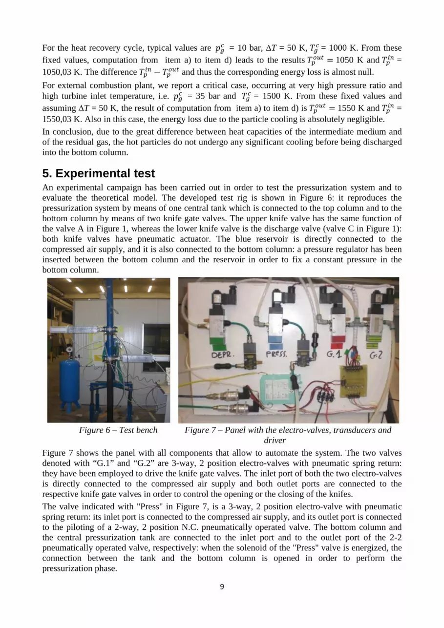
5. Experimental test An experimental campaign has been carried out in order to test the pressurization system and to evaluate the theoretical model. The developed test rig is shown in Figure 6: it reproduces the pressurization system by means of one central tank which is connected to the top column and to the bottom column by means of two knife gate valves. The upper knife valve has the same function of the valve A in Figure 1, whereas the lower knife valve is the discharge valve (valve C in Figure 1): both knife valves have pneumatic actuator. The blue reservoir is directly connected to the compressed air supply, and it is also connected to the bottom column: a pressure regulator has been inserted between the bottom column and the reservoir in order to fix a constant pressure in the bottom column.
Figure 6 – Test bench Figure 7 – Panel with the electro-valves, transducers and
driver
Figure 7 shows the panel with all components that allow to automate the system. The two valves denoted with “G.1” and “G.2” are 3-way, 2 position electro-valves with pneumatic spring return: they have been employed to drive the knife gate valves. The inlet port of both the two electro-valves is directly connected to the compressed air supply and both outlet ports are connected to the respective knife gate valves in order to control the opening or the closing of the knifes.
The valve indicated with "Press" in Figure 7, is a 3-way, 2 position electro-valve with pneumatic spring return: its inlet port is connected to the compressed air supply, and its outlet port is connected to the piloting of a 2-way, 2 position N.C. pneumatically operated valve. The bottom column and the central pressurization tank are connected to the inlet port and to the outlet port of the 2-2 pneumatically operated valve, respectively: when the solenoid of the "Press" valve is energized, the connection between the tank and the bottom column is opened in order to perform the pressurization phase.

10
At the same way, the valve indicated with "Depr" in Figure 7, which is a 3-way, 2 position electro-valve with pneumatic spring return, pilots a 3-way, 2 position N.C. pneumatically operated valve. This couple of valves allows to perform the depressurization phase; the inlet port of the 3-2 pneumatically operated valve is directly connected to the central tank: when the solenoid of the "Depr" valve is energized, the compressed gas in the pressurization tank is discharged into the external environment.
Figure 8 – Driver scheme
The solenoids of the electro-valves have been driven with an external PC by means of a DAQ card: between the data card and the solenoids we have inserted a driver, shown in the bottom right of Figure 7, since the solenoids require 24 Volt power supply with approximately 0.21 A absorbed current to move the internal spool, whereas the maximum current tolerable by the data card is 0.5 mA. The scheme of the driver is reported in Figure 8, and it consists of one transistor, one diode and one resistance, connected as in the scheme: with this configuration, the current flowing through the output channel of the data card is different from the current absorbed by the solenoid coils. The panel also reports two pressure transducers, allowing to measure pressure in the pressurization tank and in the bottom column, and the linearizer of the thermocouple inserted into the central tank.
Each test starts with the top column filled with alumina under atmospheric pressure, and keeping a constant pressure in the bottom column. The entire pressurization cycle has been performed for several values of pressure in the bottom column, in particular from 2 to 10 bar. At first, the particles are loaded into the pressurization tank by the opening of the upper knife gate valve; then, this valve is closed and the pressurization phase begins when the solenoid of the "Press" valve is energized and it opens the connection between the bottom column and the central tank. After the pressure in the tank has reached the pressure in the bottom column, the lower knife valve is opened and the particles are discharged into the bottom column. At the end, after closing the lower knife valve and the connection between the bottom column and the central tank, the compressed air remained in the tank is discharged into the atmosphere by energizing the solenoid of the "Depr" valve.
The experimental tests have been initially performed in order to evaluate the reliability of the knife gate valves: the tests have shown that the upper valve and the lower valve are capable of regulating the passage of the particles respectively from the top column to the central tank and from the central tank to the bottom column. Many tests have been performed under perfect air tightness condition; however, particle crushing has become significant after such a long operation time: this results in a diminished capability of ensuring total air tightness in the closed position, since some particles were stuck between the knife and the valve seat, causing air leakage. In future works, this drawback will be analyzed in order to find a mechanical solution which ensures total air tightness for a long operation time.
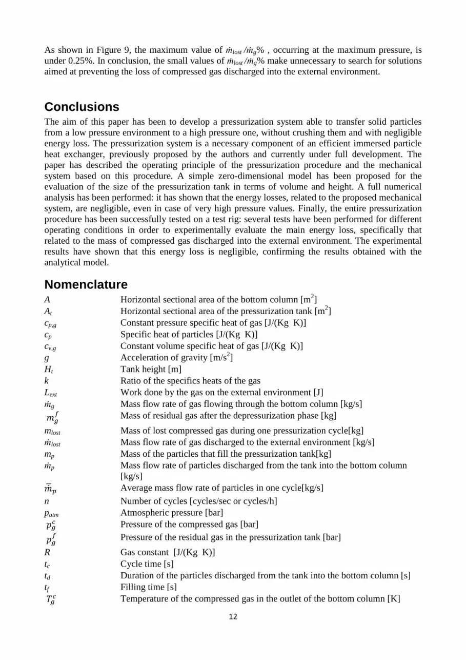
Repeated tests, performed under perfect air tightness condition, have allowed to analyze the losses of the developed system, in particular the mass of compressed air discharged to the atmosphere: the ratio ṁlost /ṁg has been experimentally determined for several different pressures in the bottom column, and the experimental values have been compared with those achieved by means of the numerical analysis. The graph in Figure 9 reports the comparison between the experimental curve
5V
24V
Diode
Solenoid
Transistor From DAQ

11
and the theoretical curve, for different pressure levels: the two curves almost overlap each other, and this proves the reliability of the numerical model.
Figure 9 – 4� ABC&4� D % versus "�� (experimental and numerical)
The comparison has been achieved in the following manner. The ratio ṁlost /ṁg% can be expressed through equation 17: � ()*� � � % = ()*�������� 100%(17) The mass of lost compressed gas, namely mlost , can be calculated with Equation 18, which expresses the difference between the mass of gas in the tank before the depressurization phase and the mass of gas remaining in the tank at the end of the discharge to the atmosphere:
()*� = 7"��!�� −"��!��8
��F (18) The velocity of gas in the bottom column can be recovered from Equation 7 as
�� = ����������,���� (19) Substituting Equation 19 and Equation 18 into Equation 17 and assuming α = 1, we obtain the expression of ṁlost /ṁg , depending on the physical properties of the particles and on the values of pressure and temperature of the gas within the central tank at the beginning and at the end of the depressurization phase :
� ()*� � � % =��,� 7"��!�� −
"��!��8����F 100%(20) Note that Equation 20 coincides with Equation 10 if we neglect the mass of gas remaining in the pressurization tank at the end of the depressurization phase.
The experimental curve in Figure 9 has been obtained by employing Equation 20, and using the values of pressure and temperature, namely "�� , !�� , "��, !��, which have been measured during the experimental tests. On the contrary, the numerical curve has been determined, for fixed value of "�� , !�� and "�� , by employing Equation 13 to calculate !�� ; the corresponding values have been substituted into Equation 20 to calculate ṁlost /ṁg% .
0
0,05
0,1
0,15
0,2
0,25
0,3
0 2 4 6 8 10
ṁlost / ṁg
( %)
Pressure(bar)
NUMERICAL
EXPERIMENTAL
12
As shown in Figure 9, the maximum value of ṁlost /ṁg% , occurring at the maximum pressure, is under 0.25%. In conclusion, the small values of ṁlost /ṁg% make unnecessary to search for solutions aimed at preventing the loss of compressed gas discharged into the external environment.
Conclusions The aim of this paper has been to develop a pressurization system able to transfer solid particles from a low pressure environment to a high pressure one, without crushing them and with negligible energy loss. The pressurization system is a necessary component of an efficient immersed particle heat exchanger, previously proposed by the authors and currently under full development. The paper has described the operating principle of the pressurization procedure and the mechanical system based on this procedure. A simple zero-dimensional model has been proposed for the evaluation of the size of the pressurization tank in terms of volume and height. A full numerical analysis has been performed: it has shown that the energy losses, related to the proposed mechanical system, are negligible, even in case of very high pressure values. Finally, the entire pressurization procedure has been successfully tested on a test rig: several tests have been performed for different operating conditions in order to experimentally evaluate the main energy loss, specifically that related to the mass of compressed gas discharged into the external environment. The experimental results have shown that this energy loss is negligible, confirming the results obtained with the analytical model.
Nomenclature A Horizontal sectional area of the bottom column [m2] At Horizontal sectional area of the pressurization tank [m2] cp,g Constant pressure specific heat of gas [J/(Kg K)] cp Specific heat of particles [J/(Kg K)] cv,g Constant volume specific heat of gas [J/(Kg K)] g Acceleration of gravity [m/s2] Ht Tank height [m] k Ratio of the specifics heats of the gas Lext Work done by the gas on the external environment [J] ṁg Mass flow rate of gas flowing through the bottom column [kg/s] �� Mass of residual gas after the depressurization phase [kg]
mlost Mass of lost compressed gas during one pressurization cycle[kg] ṁlost Mass flow rate of gas discharged to the external environment [kg/s] mp Mass of the particles that fill the pressurization tank[kg] ṁp Mass flow rate of particles discharged from the tank into the bottom column
[kg/s] ��� Average mass flow rate of particles in one cycle[kg/s]
n Number of cycles [cycles/sec or cycles/h] patm Atmospheric pressure [bar] "�� Pressure of the compressed gas [bar]
"�� Pressure of the residual gas in the pressurization tank [bar]
R Gas constant [J/(Kg K)] tc Cycle time [s] td Duration of the particles discharged from the tank into the bottom column [s] tf Filling time [s] !�� Temperature of the compressed gas in the outlet of the bottom column [K]
13
!�� Temperature of the residual gas in the pressurization tank[K]
!�>? Temperature of particles entering the pressurization tank [K] !�)@� Temperature of particles exiting the pressurization tank [K] tx Interval time occurring for pressurization, depressurization and valve actuation [s] vg Gas velocity in the bottom column[m/s] Vt Volume of the pressurization tank[m3] α Ratio between At and A ∆U Variation of the internal energy [J] ∆T Temperature gradient along the bottom column [k] ��� Density of gas in the outlet of the bottom column [kg/m3]
��� Density of the residual gas in the pressurization tank [kg/m3]
�p Particle density [kg/m3]
References
[1] Correa M. S., Power generation and aeropropulsion gas turbines: From combustion science to combustion technology. International Symposium on Combustion, Volume 27, Issue 2, 1998, Pages 1793–1807.
[2] McDonald, C. F. e Wilson, D. G., The utilization of recuperated and regenerated turbine engine cycles for high-efficiency gas turbine in 21ct century, Applied Thermal Engineering, 1995, Vol. 16, No. 8-9, pp. 635-653.
[3] Rolls Royce Group plc., Annual Report and Accounts, 2008, available at www.rolls-royce.com/reports/2008.
[4] Dallenback, P.A., Improved gas turbine efficiency through alternative regenerator configuration, ASME, Journal of Gas Turbine and Power, 2002.,Vol. 124, pp. 441-446.
[5] Zimmermann, P., Cardenas, A., Hirsch, C., and Sattlemayer, T., Simulation of a Micro Turbine’s Dynamic Behavior in a Biomass Incineration Power Plant Based on the Pebble Heater Technology, ASME Paper GT2009-59305, Orlando, FL, USA, 2009.
[6] Brzozowski, W., Dul, J., Yerouchalmi, D., and Jadrowitch, B., Pebble Bed Heat Exchanger, U.S. Patent Office, 1968, U.S. Patent No. 3488402.
[7] Theoclitus, G., Pebble Bed Heat Exchanger, Canadian Intellectual Property Office,1958, CA 557552D.
[8] Catalano L. A., De Bellis F., Amirante R., Rignanese M., An Immersed Particle Heat Exchanger for Externally Fired and Heat Recovery Gas Turbines, Journal of Engineering for Gas Turbine and Power, March 2011, Vol. 133, Issue 3, 032301 (7 pages).
[9] F. De Bellis, L. A. Catalano, “CFD Optimization of an Immersed Particles Heat Exchanger”, Third International Conference on Applied Energy - 16-18 May 2011 - Perugia, Italy. Also selected and approved for publication, Applied Sciences – Special Issue: ICAE 2011, APEN-D-11-01319.
[10] L. Nettis, F. De Bellis, L. Catalano, R. Verzicco, “Unsteady Conjugate Heat Transfer Analysis of an Immersed Particle Innovative Heat Exchanger”, accepted for publication, Journal of Thermal Science and Engineering Applications, TSEA-11-1057Hilton J. E., Mason L. R., Cleary P. W., The effect of gas dynamics on pressurization tank discharge rate, CSIRO Mathematical and Information Sciences, Clayton, Victoria, Australia, 9-11 December 2009.
[11] Hilton J. E., Mason L. R., Cleary P. W., The effect of gas dynamics on hopper discharge rate, Seventh International Conference on CFD in the Minerals and Process Industries, 2009, CSIRO, Melbourne.