air cooled heat exchanger design
TRANSCRIPT

SlideShare Explore Search You
UploadLoginSignup
Search
HomeTechnologyEducationMore Topics
For UploadersCollect Leads
Search


5.7.4 Airside Design Clearances The clearance between the ACHE and grade, of one fan diameter, is reasonable forlarge gra...

5.7.7 Fan Drives Wedge VBelts and gearboxes are both disliked on site, owing to their maintenance difficulties.Toothed "...

FIGURE 17 HEADER TYPES Refinery Process Stream Purification Refinery Process Catalysts TroubleshootingRefinery Process C...

5.8 Arrangement 5.8.1 Introduction The manufacturer needs to be informed of the available space where theexchanger is to ...

It has been accepted in the past that it is easier to achieve good air distribution in an induced draught unit. However,w...
(e) The fan selection should allow for a suitable margin to avoid stalling when fouled. If allied to a tight noisespecif...

Air Cooled Heat Exchanger Design

Air Cooled Heat Exchanger Design

Air Cooled Heat Exchanger Design

Air Cooled Heat Exchanger Design
Air Cooled Heat Exchanger Design

Air Cooled Heat Exchanger Design

Air Cooled Heat Exchanger Design

Air Cooled Heat Exchanger Design

Air Cooled Heat Exchanger Design
Air Cooled Heat Exchanger Design

Air Cooled Heat Exchanger Design

Air Cooled Heat Exchanger Design

Air Cooled Heat Exchanger Design

Air Cooled Heat Exchanger Design
Air Cooled Heat Exchanger Design

Air Cooled Heat Exchanger Design

Air Cooled Heat Exchanger Design

Air Cooled Heat Exchanger Design

Air Cooled Heat Exchanger Design
Air Cooled Heat Exchanger Design

Air Cooled Heat Exchanger Design

Air Cooled Heat Exchanger Design

Air Cooled Heat Exchanger Design

Air Cooled Heat Exchanger Design

Air Cooled Heat Exchanger Design
Air Cooled Heat Exchanger Design

Air Cooled Heat Exchanger Design

Air Cooled Heat Exchanger Design

Air Cooled Heat Exchanger Design

Air Cooled Heat Exchanger Design
Air Cooled Heat Exchanger Design

Air Cooled Heat Exchanger Design

Air Cooled Heat Exchanger Design

Air Cooled Heat Exchanger Design

Upcoming SlideShare
Loading in...5× 33 of 80
Air Cooled Heat Exchanger Design10,464
ShareLikeDownload
Gerard B. Hawkins, http://Twitter.com/GBHEnterprisesFollow0 0 0 0
Published on Oct 16, 2013
Air Cooled Heat Exchanger Design
0 INTRODUCTION/PURPOSE 1 SCOPE 2 FIELD OF
...Published in: Technology, Business
0 Comments2 LikesStatisticsNotes
Full NameComment goes here.12 hours ago Delete Reply Spam BlockAre you sure you want to Yes NoYour message goes here
Share your thoughts...Post
Be the first to comment
bilel mannoubi , technical manager at unici at unici2 weeks ago
ramesh periyasamy , ENGINEER at CLASSIK COOLING TOWERS at CLASSIK COOLING TOWERS1 year ago
No DownloadsViewsTotal Views10,464On Slideshare0From Embeds0Number of Embeds2ActionsShares0Downloads679Comments0Likes2Embeds 0No embeds
No notes for slide
Air Cooled Heat Exchanger Design
1. 1. GBH Enterprises, Ltd. Process Engineering Guide: GBHEPEGHEA513 Air Cooled Heat ExchangerDesign Information contained in this publication or as otherwise supplied to Users is believed to be accurateand correct at time of going to press, and is given in good faith, but it is for the User to satisfy itself of thesuitability of the information for its own particular purpose. GBHE gives no warranty as to the fitness of thisinformation for any particular purpose and any implied warranty or condition (statutory or otherwise) isexcluded except to the extent that exclusion is prevented by law. GBHE accepts no liability resulting fromreliance on this information. Freedom under Patent, Copyright and Designs cannot be assumed. RefineryProcess Stream Purification Refinery Process Catalysts Troubleshooting Refinery Process Catalyst StartUp /Shutdown Activation Reduction Insitu Exsitu Sulfiding Specializing in Refinery Process Catalyst
Performance Evaluation Heat & Mass Balance Analysis Catalyst Remaining Life Determination CatalystDeactivation Assessment Catalyst Performance Characterization Refining & Gas Processing & PetrochemicalIndustries Catalysts / Process Technology Hydrogen Catalysts / Process Technology – Ammonia CatalystProcess Technology Methanol Catalysts / process Technology – Petrochemicals Specializing in theDevelopment & Commercialization of New Technology in the Refining & Petrochemical Industries Web Site:www.GBHEnterprises.com
2. 2. Process Engineering Guide: Air Cooled Heat Exchanger Design CONTENTS SECTION 0INTRODUCTION/PURPOSE 3 1 SCOPE 3 2 FIELD OF APPLICATION 3 3 DEFINITIONS 3 4SUITABILITY FOR AIR COOLING 4 4.1 4.2 Options Available For Cooling Choice of Cooling System 4 95 SPECIFICATION OF AN AIR COOLED HEAT EXCHANGER 16 Description and Terminology GeneralThermal Duty and Design Margins Process Pressure Drop Design Ambient Conditions Process PhysicalProperties Mechanical Design Constraints Arrangement Air Side Fouling Economic Factors in Design 16 1919 20 21 25 26 33 33 34 5.1 5.2 5.3 5.4 5.5 5.6 5.7 5.8 5.9 5.10 Refinery Process Stream Purification RefineryProcess Catalysts Troubleshooting Refinery Process Catalyst StartUp / Shutdown Activation Reduction Insitu Exsitu Sulfiding Specializing in Refinery Process Catalyst Performance Evaluation Heat & Mass BalanceAnalysis Catalyst Remaining Life Determination Catalyst Deactivation Assessment Catalyst PerformanceCharacterization Refining & Gas Processing & Petrochemical Industries Catalysts / Process Technology Hydrogen Catalysts / Process Technology – Ammonia Catalyst Process Technology Methanol Catalysts /process Technology – Petrochemicals Specializing in the Development & Commercialization of NewTechnology in the Refining & Petrochemical Industries Web Site: www.GBHEnterprises.com
3. 3. 6 CONTROL 35 7 PRESSURE RELIEF 37 8 ASSESSMENT OF OFFERS 37 8.1 8.2 8.3 8.4 GeneralManual Checking Of Designs Computer Assessment Bid Comparison 37 37 39 40 9 FOULING ANDCORROSION 40 9.1 9.2 Fouling Corrosion 40 41 10 OPERATION AND MAINTENANCE 42 10.1 10.210.3 10.4 Performance Testing AirSide Cleaning Mechanical Maintenance Tubeside Access 42 45 48 48 11REFERENCES 50 Refinery Process Stream Purification Refinery Process Catalysts Troubleshooting RefineryProcess Catalyst StartUp / Shutdown Activation Reduction Insitu Exsitu Sulfiding Specializing in RefineryProcess Catalyst Performance Evaluation Heat & Mass Balance Analysis Catalyst Remaining LifeDetermination Catalyst Deactivation Assessment Catalyst Performance Characterization Refining & GasProcessing & Petrochemical Industries Catalysts / Process Technology Hydrogen Catalysts / ProcessTechnology – Ammonia Catalyst Process Technology Methanol Catalysts / process Technology –Petrochemicals Specializing in the Development & Commercialization of New Technology in the Refining &Petrochemical Industries Web Site: www.GBHEnterprises.com
4. 4. APPENDICES A PRELIMINARY ESTIMATION OF ACHE SIZE AND COST 51 TABLES 1ATTRIBUTES AND APPLICATIONS OF COMMON METHODS OF ACHE CONTROL 36 2 AIRCOOLED HEAT EXCHANGER FAULT FINDING CHART 43 3 SUGGESTED FILM RESISTANCE FORUSE IN PRELIMINARY EXCHANGER SIZING 52 FIGURES 1 DIRECT CONTACT CONDENSER 5 2USE OF RAW WATER ON A "ONCE THROUGH" BASIS 5 3 INDIRECT COOLING WITH RAWWATER VIA SECONDARY COOLANT 6 COOLING WATER CIRCUIT WITH AN EVAPORATIVECOOLING TOWER 7 5 DRY COOLING TOWER 8 6 INDIRECT AIR COOLING VIA A SECONDARYCOOLANT 8 7 COSTS OF AIR COOLED HEAT EXCHANGERS 11 4 Refinery Process StreamPurification Refinery Process Catalysts Troubleshooting Refinery Process Catalyst StartUp / ShutdownActivation Reduction Insitu Exsitu Sulfiding Specializing in Refinery Process Catalyst PerformanceEvaluation Heat & Mass Balance Analysis Catalyst Remaining Life Determination Catalyst DeactivationAssessment Catalyst Performance Characterization Refining & Gas Processing & Petrochemical IndustriesCatalysts / Process Technology Hydrogen Catalysts / Process Technology – Ammonia Catalyst ProcessTechnology Methanol Catalysts / process Technology – Petrochemicals Specializing in the Development &Commercialization of New Technology in the Refining & Petrochemical Industries Web Site:www.GBHEnterprises.com
5. 5. 8 AIR FLOW NEAR AN AIR COOLED HEAT EXCHANGER 12 9 INFLUENCE OF LOCATION ONAIR RECIRCULATION 14 10 TYPICAL AIR COOLED HEAT EXCHANGER 16 11 BUNDLES, BAYSAND UNITS 18 15 TYPICAL TEMPERATURE VARIATION THROUGHOUT A HOT SUMMER'S DAY25 16 TYPES OF FINNED TUBING 29 17 HEADER TYPES 32 18 CURVES FOR COST FUNCTION "C"53 19 CURVES FOR AREA FUNCTION "K" 53 20 NONLINEAR TEMPERATURE ENTHALPYCURVES 55 21 CORRECTION FACTOR FOR SMALL EXCHANGERS 55 DOCUMENTS REFERREDTO IN THIS PROCESS ENGINEERING GUIDE 57 Refinery Process Stream Purification Refinery Process

Catalysts Troubleshooting Refinery Process Catalyst StartUp / Shutdown Activation Reduction Insitu Exsitu Sulfiding Specializing in Refinery Process Catalyst Performance Evaluation Heat & Mass BalanceAnalysis Catalyst Remaining Life Determination Catalyst Deactivation Assessment Catalyst PerformanceCharacterization Refining & Gas Processing & Petrochemical Industries Catalysts / Process Technology Hydrogen Catalysts / Process Technology – Ammonia Catalyst Process Technology Methanol Catalysts /process Technology – Petrochemicals Specializing in the Development & Commercialization of NewTechnology in the Refining & Petrochemical Industries Web Site: www.GBHEnterprises.com
6. 6. 0 INTRODUCTION/PURPOSE This Guide was prepared for GBH Enterprises. 1 SCOPE This document isintended to provide a guide to the process engineer who may be involved in the specification or operation ofAir Cooled Heat Exchangers (ACHEs). It is concerned with such matters as choice of exchanger, specificationof duty, location, and assessment of tenders, control and maintenance. It does not aim to give detailedinformation on the thermal design or rating of ACHEs. It is assumed that readers of the Guide have somegeneral knowledge of heat transfer. However, for the benefit of those readers who are unfamiliar with aircooled heat exchangers, sub clause 5.1 gives a simple description and some of the more common terminologyused to describe these items. It may be beneficial to read sub clause 5.1 as a precursor to this Guide. 2 FIELDOF APPLICATION This Guide applies to process engineers in GBH Enterprises worldwide, who may beinvolved in the specification, design, rating or operation of heat transfer equipment. 3 DEFINITIONS For thepurposes of this Guide, the following definitions apply: ACHE Air Cooled Heat Exchanger. A heat exchangerdesigned for the cooling and/or condensation of fluids by means of atmospheric air flowing over the outside ofa bank of tubes through which the fluid to be cooled flows. Refinery Process Stream Purification RefineryProcess Catalysts Troubleshooting Refinery Process Catalyst StartUp / Shutdown Activation Reduction Insitu Exsitu Sulfiding Specializing in Refinery Process Catalyst Performance Evaluation Heat & Mass BalanceAnalysis Catalyst Remaining Life Determination Catalyst Deactivation Assessment Catalyst PerformanceCharacterization Refining & Gas Processing & Petrochemical Industries Catalysts / Process Technology Hydrogen Catalysts / Process Technology – Ammonia Catalyst Process Technology Methanol Catalysts /process Technology – Petrochemicals Specializing in the Development & Commercialization of NewTechnology in the Refining & Petrochemical Industries Web Site: www.GBHEnterprises.com
7. 7. HTRI Heat Transfer Research Incorporated. A cooperative research organization, based in the USA,involved in research into heat transfer in industrial sized equipment, and the production of design guides andcomputer programs for the design of such equipment. HTFS Heat Transfer and Fluid Flow Service. Acooperative research organization, with headquarters in the UK, involved in research into the fundamentals ofheat transfer and two phase flow and the production of design guides and computer programs for the design ofindustrial heat exchange equipment. 4 SUITABILITY FOR AIR COOLING Although this Guide isprincipally concerned with air cooled heat exchangers, they are only one of several possible ways of rejectingheat to the environment. Before deciding on the use of air cooling, the alternatives should be considered andtheir relative merits assessed. Moreover, heat rejected to the environment is wasted. Full benefit should betaken of the work on Process Integration to reduce this waste heat as far as practicable. See Refs. [14] and[15]. 4.1 Options Available For Cooling 4.1.1 General The principal possibilities for process plant heatrejection are: (a) Direct contact cooling. (b) Direct cooling in a heat exchanger, using sea or river water on a"once through" basis. (c) Indirect cooling using a secondary coolant, with sea or river water as the ultimateheat sink. (d) Cooling water from an evaporative cooling tower. (e) Cooling water from a "Dry CoolingTower". (f) Cooling water from an air cooled heat exchanger. Refinery Process Stream Purification RefineryProcess Catalysts Troubleshooting Refinery Process Catalyst StartUp / Shutdown Activation Reduction Insitu Exsitu Sulfiding Specializing in Refinery Process Catalyst Performance Evaluation Heat & Mass BalanceAnalysis Catalyst Remaining Life Determination Catalyst Deactivation Assessment Catalyst PerformanceCharacterization Refining & Gas Processing & Petrochemical Industries Catalysts / Process Technology Hydrogen Catalysts / Process Technology – Ammonia Catalyst Process Technology Methanol Catalysts /process Technology – Petrochemicals Specializing in the Development & Commercialization of NewTechnology in the Refining & Petrochemical Industries Web Site: www.GBHEnterprises.com
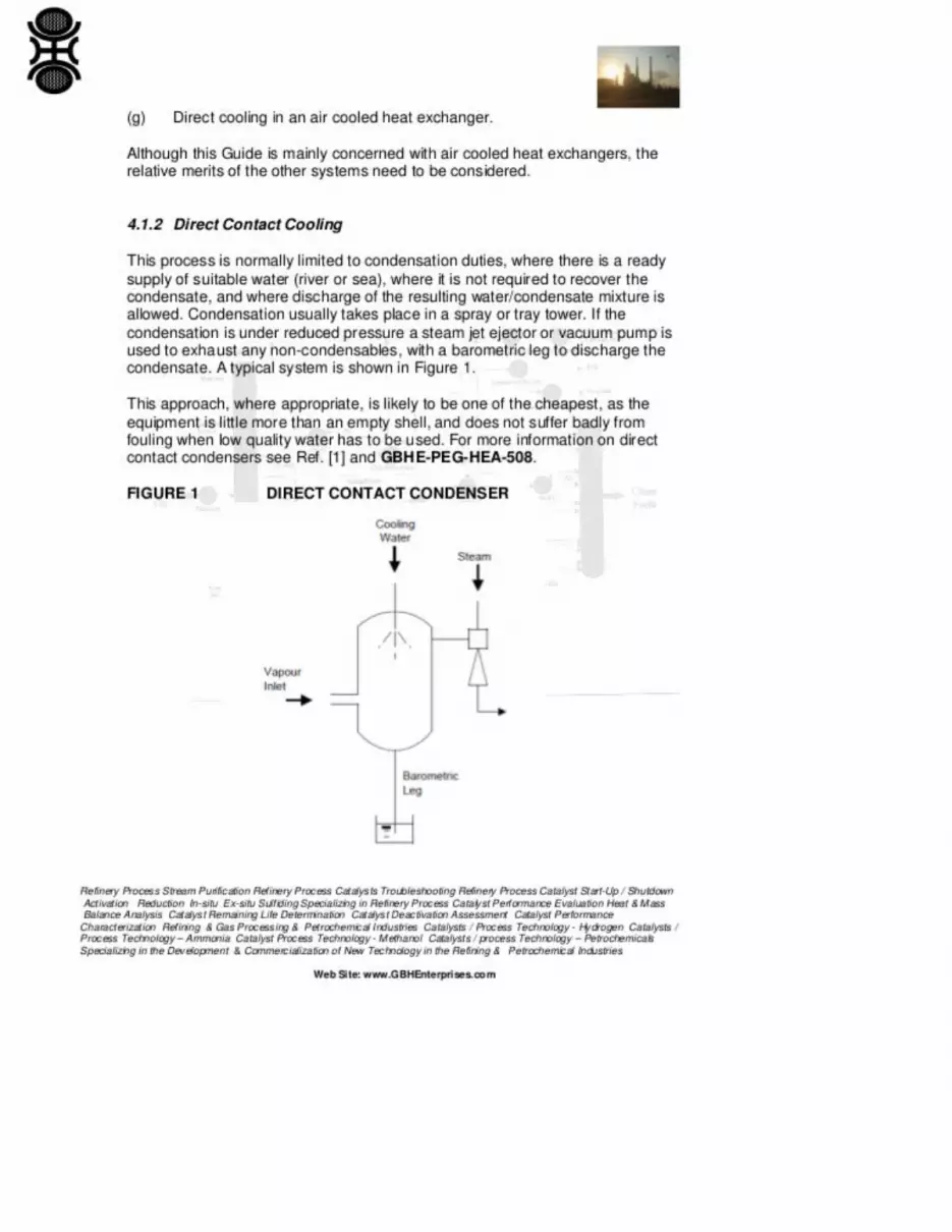
8. 8. (g) Direct cooling in an air cooled heat exchanger. Although this Guide is mainly concerned with air cooledheat exchangers, the relative merits of the other systems need to be considered. 4.1.2 Direct Contact CoolingThis process is normally limited to condensation duties, where there is a ready supply of suitable water (riveror sea), where it is not required to recover the condensate, and where discharge of the resultingwater/condensate mixture is allowed. Condensation usually takes place in a spray or tray tower. If thecondensation is under reduced pressure a steam jet ejector or vacuum pump is used to exhaust any non

condensables, with a barometric leg to discharge the condensate. A typical system is shown in Figure 1. Thisapproach, where appropriate, is likely to be one of the cheapest, as the equipment is little more than an emptyshell, and does not suffer badly from fouling when low quality water has to be used. For more information ondirect contact condensers see Ref. [1] and GBHEPEGHEA508. FIGURE 1 DIRECT CONTACTCONDENSER Refinery Process Stream Purification Refinery Process Catalysts Troubleshooting RefineryProcess Catalyst StartUp / Shutdown Activation Reduction Insitu Exsitu Sulfiding Specializing in RefineryProcess Catalyst Performance Evaluation Heat & Mass Balance Analysis Catalyst Remaining LifeDetermination Catalyst Deactivation Assessment Catalyst Performance Characterization Refining & GasProcessing & Petrochemical Industries Catalysts / Process Technology Hydrogen Catalysts / ProcessTechnology – Ammonia Catalyst Process Technology Methanol Catalysts / process Technology –Petrochemicals Specializing in the Development & Commercialization of New Technology in the Refining &Petrochemical Industries Web Site: www.GBHEnterprises.com
9. 9. 4.1.3 Use of Raw Water On A "Once Through" Basis For cases where there is a ready supply of river or seawater, but where direct contact between the process fluid and the water is not possible, the use of such wateron a "once through" basis in a heat exchanger offers the simplest and often cheapest solution. The heat sink isgenerally coolest when direct cooling of this type is used. Figure 2 shows a typical arrangement. FIGURE 2USE OF RAW WATER ON A "ONCE THROUGH" BASIS However, sea water is corrosive and river watermay be also, and either may give rise to severe fouling problems from scaling, sedimentation andmicroorganisms. The effective treatment of the large volumes of raw water involved, to reduce the foulingtendency, is often impracticable. 4.1.4 Indirect Cooling With A Secondary Coolant An indirect system, asshown in Figure 3, can be used where one or more of the following conditions apply: (a) If the raw coolingwater is particularly corrosive. (b) If it is important that the process cooling water be clean. (c) If the risk ofleakage of water into the process is unacceptable. Refinery Process Stream Purification Refinery ProcessCatalysts Troubleshooting Refinery Process Catalyst StartUp / Shutdown Activation Reduction Insitu Exsitu Sulfiding Specializing in Refinery Process Catalyst Performance Evaluation Heat & Mass BalanceAnalysis Catalyst Remaining Life Determination Catalyst Deactivation Assessment Catalyst PerformanceCharacterization Refining & Gas Processing & Petrochemical Industries Catalysts / Process Technology Hydrogen Catalysts / Process Technology – Ammonia Catalyst Process Technology Methanol Catalysts /process Technology – Petrochemicals Specializing in the Development & Commercialization of NewTechnology in the Refining & Petrochemical Industries Web Site: www.GBHEnterprises.com
10. 10. FIGURE 3 INDIRECT COOLING WITH RAW WATER VIA SECONDARY COOLANT The secondarycoolant may be either clean water, dosed with suitable chemicals to prevent corrosion or, where the mixing ofwater and process fluid cannot be tolerated, some other suitable fluid. It is usually cheapest to cool thecirculated fluid in a platetype exchanger, which can use plates of a corrosion resistant material, such astitanium, and can be easily cleaned. This system may be particularly appropriate where there are severalseparate cooling duties and the only available water is corrosive or fouling. By providing a central supply ofclean noncorrosive fluid, cooled in one exchanger designed to handle the raw water, the process exchangersmay all be fabricated in less expensive materials. This system has the disadvantage that the secondary coolanthas to be run at a temperature above that of the raw water, in order to provide a driving force for the cooler, sothat the available temperature driving force in the process coolers is reduced. Refinery Process StreamPurification Refinery Process Catalysts Troubleshooting Refinery Process Catalyst StartUp / ShutdownActivation Reduction Insitu Exsitu Sulfiding Specializing in Refinery Process Catalyst PerformanceEvaluation Heat & Mass Balance Analysis Catalyst Remaining Life Determination Catalyst DeactivationAssessment Catalyst Performance Characterization Refining & Gas Processing & Petrochemical IndustriesCatalysts / Process Technology Hydrogen Catalysts / Process Technology – Ammonia Catalyst ProcessTechnology Methanol Catalysts / process Technology – Petrochemicals Specializing in the Development &Commercialization of New Technology in the Refining & Petrochemical Industries Web Site:www.GBHEnterprises.com
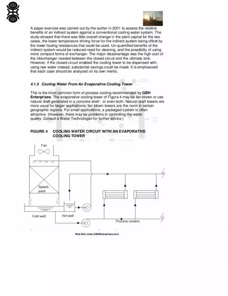
11. 11. A paper exercise was carried out by the author in 2001 to assess the relative benefits of an indirect systemagainst a conventional cooling water system. The study showed that there was little overall change in the plantcapital for the two cases, the lower temperature driving force for the indirect system being offset by the lowerfouling resistances that could be used. Unquantified benefits of the indirect system would be reduced need forcleaning, and the possibility of using more compact forms of exchanger. The major disadvantage was the highcost of the interchanger needed between the closed circuit and the ultimate sink. However, if the closed circuitenabled the cooling tower to be dispensed with, using raw water instead, substantial savings could be made. It

is emphasized that each case should be analyzed on its own merits. 4.1.5 Cooling Water From An EvaporativeCooling Tower This is the most common form of process cooling recommended by GBH Enterprises. Theevaporative cooling tower of Figure 4 may be fanblown or use natural draft generated in a concrete shell oreven both. Natural draft towers are more usual for larger applications; fan blown towers are the norm incertain geographic regions. For small applications, a packaged system is often attractive. (However, there maybe problems in controlling the water quality. Consult a Water Technologist for further advice.) FIGURE 4COOLING WATER CIRCUIT WITH AN EVAPORATIVE COOLING TOWER Refinery Process StreamPurification Refinery Process Catalysts Troubleshooting Refinery Process Catalyst StartUp / ShutdownActivation Reduction Insitu Exsitu Sulfiding Specializing in Refinery Process Catalyst PerformanceEvaluation Heat & Mass Balance Analysis Catalyst Remaining Life Determination Catalyst DeactivationAssessment Catalyst Performance Characterization Refining & Gas Processing & Petrochemical IndustriesCatalysts / Process Technology Hydrogen Catalysts / Process Technology – Ammonia Catalyst ProcessTechnology Methanol Catalysts / process Technology – Petrochemicals Specializing in the Development &Commercialization of New Technology in the Refining & Petrochemical Industries Web Site:www.GBHEnterprises.com
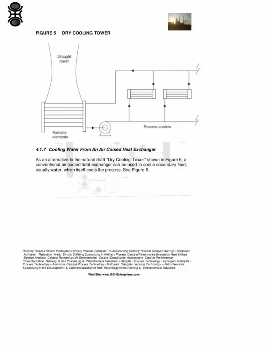
12. 12. The fanblown option, because the towers are relatively low and the mass transfer efficiency high, mayproduce an unpleasant plume, especially in winter. One of the principal problems of evaporative coolingsystems is the quality of water. The cooling tower can be an ideal environment for the growth ofmicroorganisms, and the tower itself acts as an efficient scrubber for dust laden air. Severe fouling and/orcorrosion problems can result if an adequate water treatment program is not maintained, or if the heatexchangers are not carefully designed or correctly operated. An evaporative system requires a supply of makeup water, the minimum acceptable quality of which depends on the nature of the water treatment programused. In general, modern nonchromate systems require a purer makeup water than do the earlier chromatebased treatments. The system, in general, also requires a blowdown which, because of the treatment chemicalsadded, may be subject to environmental constraints. For further information see consult a Water Technologist.4.1.6 Cooling Water From A "Dry Cooling Tower" The "Dry Cooling Tower" of Figure 5 replaces theevaporative cooling pack of an ordinary cooling tower by radiator elements, with the water in closed tubes.There is a saving of water, there is no plume and clean water is used for process cooling. However, drycooling is more expensive than evaporative cooling, as the heat transfer coefficient to the air is low, and thetemperature approach is to the drybulb temperature rather than the lower wetbulb value. No example of adry cooling tower is known in a process plant, although they have been used in thermal power stations.Refinery Process Stream Purification Refinery Process Catalysts Troubleshooting Refinery Process CatalystStartUp / Shutdown Activation Reduction Insitu Exsitu Sulfiding Specializing in Refinery Process CatalystPerformance Evaluation Heat & Mass Balance Analysis Catalyst Remaining Life Determination CatalystDeactivation Assessment Catalyst Performance Characterization Refining & Gas Processing & PetrochemicalIndustries Catalysts / Process Technology Hydrogen Catalysts / Process Technology – Ammonia CatalystProcess Technology Methanol Catalysts / process Technology – Petrochemicals Specializing in theDevelopment & Commercialization of New Technology in the Refining & Petrochemical Industries Web Site:www.GBHEnterprises.com
13. 13. FIGURE 5 DRY COOLING TOWER 4.1.7 Cooling Water From An Air Cooled Heat Exchanger As analternative to the natural draft "Dry Cooling Tower" shown in Figure 5, a conventional air cooled heatexchanger can be used to cool a secondary fluid, usually water, which itself cools the process. See Figure 6.Refinery Process Stream Purification Refinery Process Catalysts Troubleshooting Refinery Process CatalystStartUp / Shutdown Activation Reduction Insitu Exsitu Sulfiding Specializing in Refinery Process CatalystPerformance Evaluation Heat & Mass Balance Analysis Catalyst Remaining Life Determination CatalystDeactivation Assessment Catalyst Performance Characterization Refining & Gas Processing & PetrochemicalIndustries Catalysts / Process Technology Hydrogen Catalysts / Process Technology – Ammonia CatalystProcess Technology Methanol Catalysts / process Technology – Petrochemicals Specializing in theDevelopment & Commercialization of New Technology in the Refining & Petrochemical Industries Web Site:www.GBHEnterprises.com
14. 14. FIGURE 6 INDIRECT AIR COOLING VIA A SECONDARY COOLANT This may be chosen forvarious reasons: (a) If the direct air cooler has to be made of expensive material, there may be an economiccase for using an indirect system. (b) Low pressure gases tend to require a high ratio of pressure drop toabsolute pressure when cooled or condensed in an air cooled heat exchanger, which may be expensive incompressor power, and a directcontact exchanger with an indirect air cooled heat exchanger may be

economic. (c) Freezing or control problems might be eased by adopting an indirect system. An indirect systemusing recirculated condensate with a jet condenser (the "Heller" system) has been extensively used in thermalpower stations. 4.1.8 Direct Cooling In An Air Cooled Heat Exchanger Straight forward air cooling is themost common alternative to a cooling tower system for process cooling. It is particularly attractive whensupplies of suitable water for evaporative cooling are not readily available, or there are severe environmentalrestrictions on discharge of cooling tower blowdown. Refinery Process Stream Purification Refinery ProcessCatalysts Troubleshooting Refinery Process Catalyst StartUp / Shutdown Activation Reduction Insitu Exsitu Sulfiding Specializing in Refinery Process Catalyst Performance Evaluation Heat & Mass BalanceAnalysis Catalyst Remaining Life Determination Catalyst Deactivation Assessment Catalyst PerformanceCharacterization Refining & Gas Processing & Petrochemical Industries Catalysts / Process Technology Hydrogen Catalysts / Process Technology – Ammonia Catalyst Process Technology Methanol Catalysts /process Technology – Petrochemicals Specializing in the Development & Commercialization of NewTechnology in the Refining & Petrochemical Industries Web Site: www.GBHEnterprises.com
15. 15. If it is possible for all cooling duties to be done using air cooling, the capital and running costs of anevaporative cooling system and all the associated fouling and corrosion problems are removed. Against this,the capital costs of the actual process exchangers are higher for air cooling, and the coolers requireconsiderable space within the plant structure and generally require more maintenance than shell and tubeunits. 4.2 Choice of Cooling System 4.2.1 Economic Factors In order to choose correctly between theavailable cooling systems, it is necessary to estimate the cost of the various options, not only as a coolingsystem, but also in their effect on the overall plant performance and efficiency. For example, a water cooledrefrigerant condenser will, in general, condense the refrigerant at a lower temperature, and hence pressure,than will an air cooled condenser. The compression ratio of the water cooled system will be lower, which maylead to significant savings in refrigerant compressor power and cost. Thus, the choice of system may begoverned by more complex considerations than the simple cost and power consumption of the cooling systemitself. The accurate estimation of the advantages of the available cooling systems will always be a lengthy andtime consuming process, and will be difficult to justify for any but the largest plants. The engineer will have tomake the choice in many cases without the benefit of such a study, so some general "rules of thumb" may behelpful. As with all such rules, they should be qualified by common sense and discretion: (a) Should water beavailable near the plant battery limits, in sufficient quantity to ensure the cooling of every part of the unit, thenuse it in preference to air cooling, either directly or with an indirect system. (b) If it will be necessary to usetown's mains water, or other highly treated water, for the makeup of evaporative towers, then choose aircooling. (c) If the average level of heat rejection is 20°C or less above air design ambient temperature, choosewater cooling. If 30°C or more choose air cooling. If 2030°C, there is unlikely to be a strong economic caseeither way. Refinery Process Stream Purification Refinery Process Catalysts Troubleshooting RefineryProcess Catalyst StartUp / Shutdown Activation Reduction Insitu Exsitu Sulfiding Specializing in RefineryProcess Catalyst Performance Evaluation Heat & Mass Balance Analysis Catalyst Remaining LifeDetermination Catalyst Deactivation Assessment Catalyst Performance Characterization Refining & GasProcessing & Petrochemical Industries Catalysts / Process Technology Hydrogen Catalysts / ProcessTechnology – Ammonia Catalyst Process Technology Methanol Catalysts / process Technology –Petrochemicals Specializing in the Development & Commercialization of New Technology in the Refining &Petrochemical Industries Web Site: www.GBHEnterprises.com
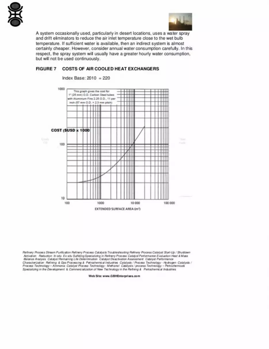
16. 16. It is worth reemphasizing that the only reliable method of choosing is by making a serious and expensivecosted study of the options. In assessing the difference between systems, it is necessary to include thedifference in piping, erection and electrical costs, as well as the capital costs. In many cases this is not apracticable proposition, as much of the required information may not be available at the time the decision hasto be made. In performing these comparisons it will be necessary to make an estimate of the cost of air cooledheat exchangers. Manufacturers will normally be prepared to provide budget costs of ACHEs if the duties arewell enough defined. Alternatively, the engineer could perform a preliminary design, and obtain a costestimate, by using Figure 7. However, for rough preliminary costing, the method described in Appendix Amay be used. This bypasses the step of designing the exchanger, going straight from duty to an estimate ofcost and plot area. 4.2.2 Process Considerations There are some occasions when consideration should be givento factors other than the straight economic choice of an ACHE, for process reasons. Ambient air temperaturesvary more than cooling tower water temperatures. If the product being cooled is adversely affected by lowtemperatures the most common being freezing/crystallization, hydrate formation, cooling below the pourpoint, or wax deposition, then it is usually possible to use an ACHE with special precautions, such as

recirculation of warm air from the bundle outlet to the air inlet, to attemper the ambient air. Such solutions areexpensive, clumsy and not too reliable. Steam coils mounted below the main bundle may be a better option,although they are wasteful of energy. Alternatively, an indirect cooling system may be cheaper and easier tooperate. See also Clause 6 on Control. It is more economic to cool hot streams with air, and cooler streamswith water. It is therefore sometimes suggested that to cool a product from, say, 100°C to 40°C air cooling beused from 100°C to say 55°C and a water cooled trim cooler from 55°C to 40°C. This is rarely justified. Theextra pressure drop of the trim cooler and its associated piping may lead to a less economic air cooler duty;and the additional cost of the water supply, trim cooler and pipework are usually more than the reduction inACHE cost. Of course, if the process demands cooling to a particularly low temperature, then the use of a trimwater cooler will permit reaching a lower temperature, possibly reducing or avoiding a refrigeration load. Inthis case, look at the possibility of cooling by water only, unless the process inlet temperature is so high that itcould lead to problems on the water side, such as boiling or excessive fouling. Refinery Process StreamPurification Refinery Process Catalysts Troubleshooting Refinery Process Catalyst StartUp / ShutdownActivation Reduction Insitu Exsitu Sulfiding Specializing in Refinery Process Catalyst PerformanceEvaluation Heat & Mass Balance Analysis Catalyst Remaining Life Determination Catalyst DeactivationAssessment Catalyst Performance Characterization Refining & Gas Processing & Petrochemical IndustriesCatalysts / Process Technology Hydrogen Catalysts / Process Technology – Ammonia Catalyst ProcessTechnology Methanol Catalysts / process Technology – Petrochemicals Specializing in the Development &Commercialization of New Technology in the Refining & Petrochemical Industries Web Site:www.GBHEnterprises.com
17. 17. A system occasionally used, particularly in desert locations, uses a water spray and drift eliminators toreduce the air inlet temperature close to the wet bulb temperature. If sufficient water is available, then anindirect system is almost certainly cheaper. However, consider annual water consumption carefully. In thisrespect, the spray system will usually have a greater hourly water consumption, but will not be usedcontinuously. FIGURE 7 COSTS OF AIR COOLED HEAT EXCHANGERS Index Base: 2010 = 220Refinery Process Stream Purification Refinery Process Catalysts Troubleshooting Refinery Process CatalystStartUp / Shutdown Activation Reduction Insitu Exsitu Sulfiding Specializing in Refinery Process CatalystPerformance Evaluation Heat & Mass Balance Analysis Catalyst Remaining Life Determination CatalystDeactivation Assessment Catalyst Performance Characterization Refining & Gas Processing & PetrochemicalIndustries Catalysts / Process Technology Hydrogen Catalysts / Process Technology – Ammonia CatalystProcess Technology Methanol Catalysts / process Technology – Petrochemicals Specializing in theDevelopment & Commercialization of New Technology in the Refining & Petrochemical Industries Web Site:www.GBHEnterprises.com
18. 18. 4.2.3 Layout ACHEs are bulky, and produce noise and warm air. Their siting should be considered at anearly stage of plant design. The total plot area can be estimated by the method given in Appendix A, or othermethods. It is probable that no convenient area is available at grade for the coolers, and that they will have tobe mounted above other equipment. Pipe tracks are often convenient. It is usual to find a place for ACHEswithout great difficulty, but remember that high mounted ACHEs will not benefit from any ground attenuationof noise when community noise calculations are made. Finding a grade position for the ACHEs might beworth more than 15 dB in the noise calculations. A check on possible air recirculation within banks andbetween banks should be made. This check will owe more to art than to science, but some guidance may behelpful. The airflow pattern into an ACHE shows a high velocity near the edge of the inlet (see Figure 8). Thisis associated with a low air pressure, and there is a risk that the warm air from the outlet will be sucked intothe inlet. This is particularly true of forced draft units. As a general rule, some warm air recirculation willoccur with all long forced draft ACHE banks in a quartering wind (induced draft should avoid this form of airrecirculation). Should the air inlet be restricted, for instance by neighboring buildings or too low a fan height,this effect will be increased. Refinery Process Stream Purification Refinery Process Catalysts TroubleshootingRefinery Process Catalyst StartUp / Shutdown Activation Reduction Insitu Exsitu Sulfiding Specializing inRefinery Process Catalyst Performance Evaluation Heat & Mass Balance Analysis Catalyst Remaining LifeDetermination Catalyst Deactivation Assessment Catalyst Performance Characterization Refining & GasProcessing & Petrochemical Industries Catalysts / Process Technology Hydrogen Catalysts / ProcessTechnology – Ammonia Catalyst Process Technology Methanol Catalysts / process Technology –Petrochemicals Specializing in the Development & Commercialization of New Technology in the Refining &Petrochemical Industries Web Site: www.GBHEnterprises.com
19. 19. FIGURE 8 AIR FLOW NEAR AN AIR COOLED HEAT EXCHANGER If there is more than one ACHE

bank on a site, air recirculation between banks is possible. The following recommendations represent theideal: (a) f the banks are close to each other, then sheet the space between them to prevent downflow of air.Otherwise separate the banks by 15 m if on the same level, or by 30 m if on differing levels. This will preventrecirculation in "no wind" conditions, but the plume from one bank may be blown to another in a turbulentwind. (b) Downwind of large buildings, where downdraughts are possible, the very turbulent air indicatesseparation of banks by 60 m. The longitudinal axis of the bank should be across the airflow from the building.(c) As far as possible, avoid close proximity to sources of stray heat, such as furnaces. Also avoid placingACHE fans above the exhaust of a mechanical draft evaporative cooler. (d) "A" or "V" frame air cooled heatexchangers in a cross wind may suffer from reverse flow through the upwind and downwind banksrespectively. These points are illustrated in Figure 9. Refinery Process Stream Purification Refinery ProcessCatalysts Troubleshooting Refinery Process Catalyst StartUp / Shutdown Activation Reduction Insitu Exsitu Sulfiding Specializing in Refinery Process Catalyst Performance Evaluation Heat & Mass BalanceAnalysis Catalyst Remaining Life Determination Catalyst Deactivation Assessment Catalyst PerformanceCharacterization Refining & Gas Processing & Petrochemical Industries Catalysts / Process Technology Hydrogen Catalysts / Process Technology – Ammonia Catalyst Process Technology Methanol Catalysts /process Technology – Petrochemicals Specializing in the Development & Commercialization of NewTechnology in the Refining & Petrochemical Industries Web Site: www.GBHEnterprises.com
20. 20. In practice, these ideal requirements are unlikely to be met. If they cannot be, the possible increase in airtemperature into the coolers should be estimated, and the design air temperature to the ACHE adjustedaccordingly. For critical duties in difficult locations, wind tunnel studies may be necessary to determine theinfluence of neighboring structures on the performance. However, such tests are difficult and expensive toconduct, and it may be worth reconsidering the decision to use air cooling. 4.2.4 Site Conditions Various siteconditions may force the choice of air or water cooling. (a) Environmental conditions may forbid the use ofcooling towers or mechanical draft evaporative towers, by imposing excessively stringent constraints onplumes or discharge of the blowdown. (b) If there is a shortage of suitable makeup water, water cooling maybe impracticable. (c) An excessively stringent noise requirement may force water cooling, (see 4.2.5). When,as is the case in dry tropical climates, there is a large difference between wet and dry bulb temperature, watercooling will be especially favorable. unfortunately, water is often in short supply in such climates. RefineryProcess Stream Purification Refinery Process Catalysts Troubleshooting Refinery Process Catalyst StartUp /Shutdown Activation Reduction Insitu Exsitu Sulfiding Specializing in Refinery Process CatalystPerformance Evaluation Heat & Mass Balance Analysis Catalyst Remaining Life Determination CatalystDeactivation Assessment Catalyst Performance Characterization Refining & Gas Processing & PetrochemicalIndustries Catalysts / Process Technology Hydrogen Catalysts / Process Technology – Ammonia CatalystProcess Technology Methanol Catalysts / process Technology – Petrochemicals Specializing in theDevelopment & Commercialization of New Technology in the Refining & Petrochemical Industries Web Site:www.GBHEnterprises.com
21. 21. FIGURE 9 INFLUENCE OF LOCATION ON AIR RECIRCULATION Refinery Process StreamPurification Refinery Process Catalysts Troubleshooting Refinery Process Catalyst StartUp / ShutdownActivation Reduction Insitu Exsitu Sulfiding Specializing in Refinery Process Catalyst PerformanceEvaluation Heat & Mass Balance Analysis Catalyst Remaining Life Determination Catalyst DeactivationAssessment Catalyst Performance Characterization Refining & Gas Processing & Petrochemical IndustriesCatalysts / Process Technology Hydrogen Catalysts / Process Technology – Ammonia Catalyst ProcessTechnology Methanol Catalysts / process Technology – Petrochemicals Specializing in the Development &Commercialization of New Technology in the Refining & Petrochemical Industries Web Site:www.GBHEnterprises.com
22. 22. 4.2.5 Noise Noise specifications fall into two classes: (a) Limitations near the ACHE to protect the hearingof operators. (b) Limitation at points remote from the plant, to protect the amenity of neighboringcommunities. The actual specification of maximum permitted noise levels will vary from case to case, and issubject to control by the planning authorities. Machinery Section should be consulted for further information.Refinery Process Stream Purification Refinery Process Catalysts Troubleshooting Refinery Process CatalystStartUp / Shutdown Activation Reduction Insitu Exsitu Sulfiding Specializing in Refinery Process CatalystPerformance Evaluation Heat & Mass Balance Analysis Catalyst Remaining Life Determination CatalystDeactivation Assessment Catalyst Performance Characterization Refining & Gas Processing & PetrochemicalIndustries Catalysts / Process Technology Hydrogen Catalysts / Process Technology – Ammonia CatalystProcess Technology Methanol Catalysts / process Technology – Petrochemicals Specializing in the

Development & Commercialization of New Technology in the Refining & Petrochemical Industries Web Site:www.GBHEnterprises.com
23. 23. Any reasonable hearing protection specification can be met at reasonable cost, using normal designs andstandard fans, although hearing protection devices may have to be specified for personnel working in thevicinity of the unit. Community noise specifications can be very difficult to meet. A tight noise specification,coupled with the requirements of E494 relating to fans, (see also sub clause 5.7.5), can lead to a practicallyimpossible task for the ACHE designer, and certainly will result in very expensive designs. Great attentionshould be given to the alternate cooling methods evaporative or dry cooling towers. Should the use ofACHEs be inevitable, it is difficult to recommend any general rules, for each case will be different. A noiseexpert and an ACHE expert should be consulted from the earliest possible stage, and a flexible attitude to fanrequirements and to ACHE siting taken. Planning authorities sometimes impose a more stringent noisespecification at night time than during daytime. As ambient air temperatures are usually lower at night, it maybe possible to run the fans at slower speed during the night time. As noise increases with the fifth or sixthpower of the tip speed, this can give a marked reduction in noise. 4.2.6 Ambient Conditions The size andhence cost of an air cooled heat exchanger is sensitive to the assumed design air inlet temperature, especiallywhen it is required to cool the process to a relatively low temperature. Ambient air dry bulb temperatures varysignificantly over short time periods and in the height of summer can reach 2530°C for short periods, even inthe UK. For overseas locations, significantly higher figures may be regularly attained. In contrast, the wetbulb temperature, which controls the recool temperature of a wet cooling tower, does not vary so much, asthe relative humidity is generally lower in warmer weather. In selecting the maximum design inlet airtemperature, it is the engineer's responsibility to consider the frequency with which the chosen temperaturemay be exceeded, and to assess the level of risk involved in underdesigning against the cost of a tooconservative design. This is discussed in more detail in sub clause 5.5. The minimum design temperature isimportant in considering control and winterization requirements (see below). Refinery Process StreamPurification Refinery Process Catalysts Troubleshooting Refinery Process Catalyst StartUp / ShutdownActivation Reduction Insitu Exsitu Sulfiding Specializing in Refinery Process Catalyst PerformanceEvaluation Heat & Mass Balance Analysis Catalyst Remaining Life Determination Catalyst DeactivationAssessment Catalyst Performance Characterization Refining & Gas Processing & Petrochemical IndustriesCatalysts / Process Technology Hydrogen Catalysts / Process Technology – Ammonia Catalyst ProcessTechnology Methanol Catalysts / process Technology – Petrochemicals Specializing in the Development &Commercialization of New Technology in the Refining & Petrochemical Industries Web Site:www.GBHEnterprises.com
24. 24. 5 SPECIFICATION OF AN AIR COOLED HEAT EXCHANGER 5.1 Description And TerminologyThis sub clause is intended to give a brief description of typical Air Cooled Heat Exchangers and to explainthe terminology for the benefit of those who are not familiar with the items. An Air Cooled Heat Exchanger(ACHE) is a device for cooling and/or condensing a fluid, usually called the Process Fluid, using atmosphericair as the heat sink. The process fluid flows through the tubeside of one or more bundles of tubes; the air flowsin cross flow over the outside of the tubes, assisted by a fan or fans. An example familiar to everyone is themotor car radiator. In principle, there are many ways in which an ACHE could be arranged; this Guide ingeneral is confined to the sorts of design that are found in the chemical and petrochemical industry. Figure 10shows the major parts of a typical air cooled heat exchanger. Refinery Process Stream Purification RefineryProcess Catalysts Troubleshooting Refinery Process Catalyst StartUp / Shutdown Activation Reduction Insitu Exsitu Sulfiding Specializing in Refinery Process Catalyst Performance Evaluation Heat & Mass BalanceAnalysis Catalyst Remaining Life Determination Catalyst Deactivation Assessment Catalyst PerformanceCharacterization Refining & Gas Processing & Petrochemical Industries Catalysts / Process Technology Hydrogen Catalysts / Process Technology – Ammonia Catalyst Process Technology Methanol Catalysts /process Technology – Petrochemicals Specializing in the Development & Commercialization of NewTechnology in the Refining & Petrochemical Industries Web Site: www.GBHEnterprises.com
25. 25. FIGURE 10 TYPICAL AIR COOLED HEAT EXCHANGER Notes to Figure 10: (1) The supports for thefan and motor have been omitted for clarity. (2) One fan and plenum have been omitted to show the tubing.The central elements of an ACHE are the TUBES through which the process fluid flows. Although plain tubescould be, and in certain rare circumstances are, used, in almost all cases the tubes are finned on the outside.This is to counter the relatively poor film heat transfer coefficient that occurs on the air side. Sub clause 5.7.3describes the types of finned tube in common use. Tubes are typically from 2 to 12 m long. The tubes aregrouped in BUNDLES, typically 12 m wide. Within the bundle, the tubes are arranged in horizontal rows,
with a tube spacing marginally greater than the fin o.d. A bundle will usually contain between 3 and 6 rows oftubes, with successive rows staggered to give a triangular tube pitch. Refinery Process Stream PurificationRefinery Process Catalysts Troubleshooting Refinery Process Catalyst StartUp / Shutdown ActivationReduction Insitu Exsitu Sulfiding Specializing in Refinery Process Catalyst Performance Evaluation Heat &Mass Balance Analysis Catalyst Remaining Life Determination Catalyst Deactivation Assessment CatalystPerformance Characterization Refining & Gas Processing & Petrochemical Industries Catalysts / ProcessTechnology Hydrogen Catalysts / Process Technology – Ammonia Catalyst Process Technology MethanolCatalysts / process Technology – Petrochemicals Specializing in the Development & Commercialization ofNew Technology in the Refining & Petrochemical Industries Web Site: www.GBHEnterprises.com
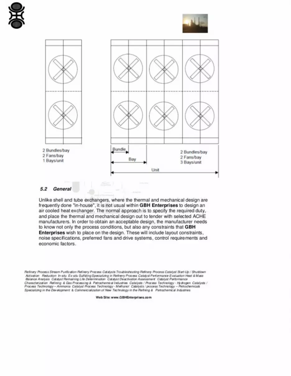
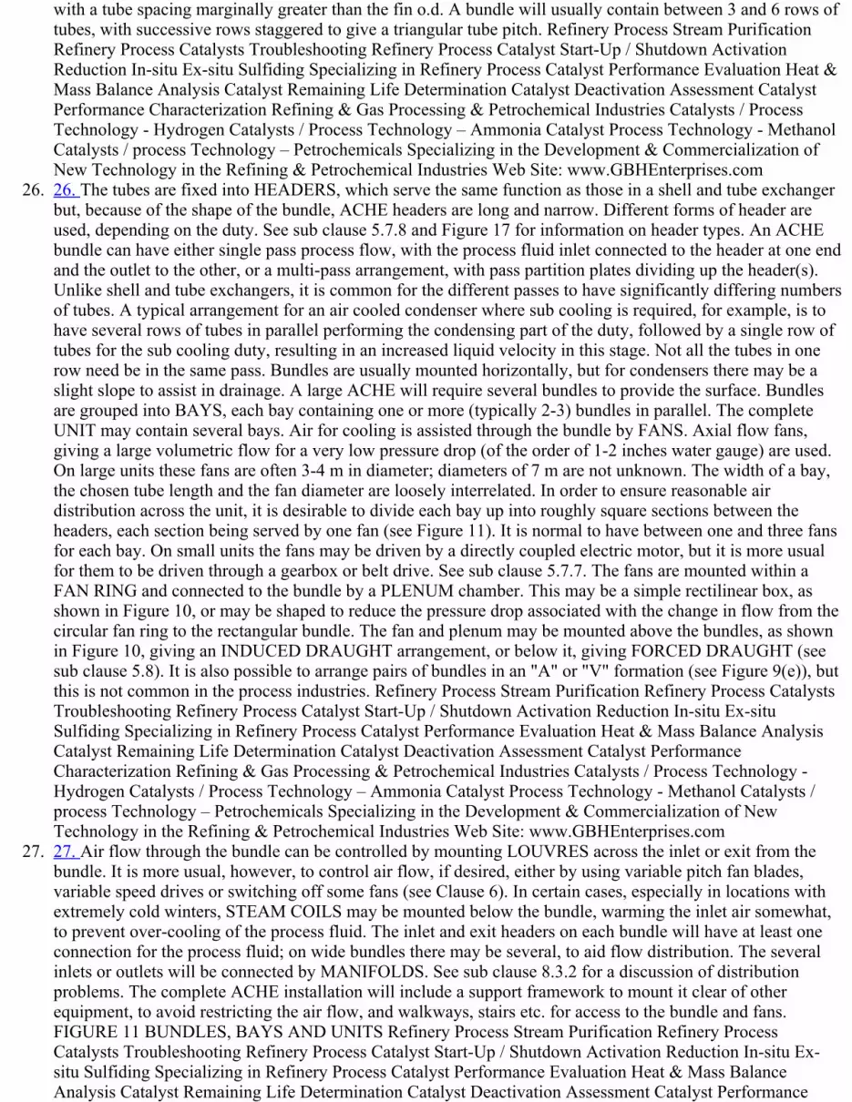
26. 26. The tubes are fixed into HEADERS, which serve the same function as those in a shell and tube exchangerbut, because of the shape of the bundle, ACHE headers are long and narrow. Different forms of header areused, depending on the duty. See sub clause 5.7.8 and Figure 17 for information on header types. An ACHEbundle can have either single pass process flow, with the process fluid inlet connected to the header at one endand the outlet to the other, or a multipass arrangement, with pass partition plates dividing up the header(s).Unlike shell and tube exchangers, it is common for the different passes to have significantly differing numbersof tubes. A typical arrangement for an air cooled condenser where sub cooling is required, for example, is tohave several rows of tubes in parallel performing the condensing part of the duty, followed by a single row oftubes for the sub cooling duty, resulting in an increased liquid velocity in this stage. Not all the tubes in onerow need be in the same pass. Bundles are usually mounted horizontally, but for condensers there may be aslight slope to assist in drainage. A large ACHE will require several bundles to provide the surface. Bundlesare grouped into BAYS, each bay containing one or more (typically 23) bundles in parallel. The completeUNIT may contain several bays. Air for cooling is assisted through the bundle by FANS. Axial flow fans,giving a large volumetric flow for a very low pressure drop (of the order of 12 inches water gauge) are used.On large units these fans are often 34 m in diameter; diameters of 7 m are not unknown. The width of a bay,the chosen tube length and the fan diameter are loosely interrelated. In order to ensure reasonable airdistribution across the unit, it is desirable to divide each bay up into roughly square sections between theheaders, each section being served by one fan (see Figure 11). It is normal to have between one and three fansfor each bay. On small units the fans may be driven by a directly coupled electric motor, but it is more usualfor them to be driven through a gearbox or belt drive. See sub clause 5.7.7. The fans are mounted within aFAN RING and connected to the bundle by a PLENUM chamber. This may be a simple rectilinear box, asshown in Figure 10, or may be shaped to reduce the pressure drop associated with the change in flow from thecircular fan ring to the rectangular bundle. The fan and plenum may be mounted above the bundles, as shownin Figure 10, giving an INDUCED DRAUGHT arrangement, or below it, giving FORCED DRAUGHT (seesub clause 5.8). It is also possible to arrange pairs of bundles in an "A" or "V" formation (see Figure 9(e)), butthis is not common in the process industries. Refinery Process Stream Purification Refinery Process CatalystsTroubleshooting Refinery Process Catalyst StartUp / Shutdown Activation Reduction Insitu ExsituSulfiding Specializing in Refinery Process Catalyst Performance Evaluation Heat & Mass Balance AnalysisCatalyst Remaining Life Determination Catalyst Deactivation Assessment Catalyst PerformanceCharacterization Refining & Gas Processing & Petrochemical Industries Catalysts / Process Technology Hydrogen Catalysts / Process Technology – Ammonia Catalyst Process Technology Methanol Catalysts /process Technology – Petrochemicals Specializing in the Development & Commercialization of NewTechnology in the Refining & Petrochemical Industries Web Site: www.GBHEnterprises.com
27. 27. Air flow through the bundle can be controlled by mounting LOUVRES across the inlet or exit from thebundle. It is more usual, however, to control air flow, if desired, either by using variable pitch fan blades,variable speed drives or switching off some fans (see Clause 6). In certain cases, especially in locations withextremely cold winters, STEAM COILS may be mounted below the bundle, warming the inlet air somewhat,to prevent overcooling of the process fluid. The inlet and exit headers on each bundle will have at least oneconnection for the process fluid; on wide bundles there may be several, to aid flow distribution. The severalinlets or outlets will be connected by MANIFOLDS. See sub clause 8.3.2 for a discussion of distributionproblems. The complete ACHE installation will include a support framework to mount it clear of otherequipment, to avoid restricting the air flow, and walkways, stairs etc. for access to the bundle and fans.FIGURE 11 BUNDLES, BAYS AND UNITS Refinery Process Stream Purification Refinery ProcessCatalysts Troubleshooting Refinery Process Catalyst StartUp / Shutdown Activation Reduction Insitu Exsitu Sulfiding Specializing in Refinery Process Catalyst Performance Evaluation Heat & Mass BalanceAnalysis Catalyst Remaining Life Determination Catalyst Deactivation Assessment Catalyst Performance
Characterization Refining & Gas Processing & Petrochemical Industries Catalysts / Process Technology Hydrogen Catalysts / Process Technology – Ammonia Catalyst Process Technology Methanol Catalysts /process Technology – Petrochemicals Specializing in the Development & Commercialization of NewTechnology in the Refining & Petrochemical Industries Web Site: www.GBHEnterprises.com
28. 28. 5.2 General Unlike shell and tube exchangers, where the thermal and mechanical design are frequentlydone "inhouse", it is not usual within GBH Enterprises to design an air cooled heat exchanger. The normalapproach is to specify the required duty, and place the thermal and mechanical design out to tender withselected ACHE manufacturers. In order to obtain an acceptable design, the manufacturer needs to know notonly the process conditions, but also any constraints that GBH Enterprises wish to place on the design. Thesewill include layout constraints, noise specifications, preferred fans and drive systems, control requirementsand economic factors. Refinery Process Stream Purification Refinery Process Catalysts TroubleshootingRefinery Process Catalyst StartUp / Shutdown Activation Reduction Insitu Exsitu Sulfiding Specializing inRefinery Process Catalyst Performance Evaluation Heat & Mass Balance Analysis Catalyst Remaining LifeDetermination Catalyst Deactivation Assessment Catalyst Performance Characterization Refining & GasProcessing & Petrochemical Industries Catalysts / Process Technology Hydrogen Catalysts / ProcessTechnology – Ammonia Catalyst Process Technology Methanol Catalysts / process Technology –Petrochemicals Specializing in the Development & Commercialization of New Technology in the Refining &Petrochemical Industries Web Site: www.GBHEnterprises.com
29. 29. 5.3 Thermal Duty And Design Margins See GBHEPEGHEA504 for guidance on design margins forheat exchangers. The thermal duty will usually be specified by the process engineer, who should also beresponsible for deciding on an appropriate design margin over the flowsheet duty. The information should berecorded on the standard GBH Enterprises Engineering Data Sheet. A design margin may be specified forseveral reasons: (a) The section of plant may be required to run at instantaneous rates above the normal plantthroughput as part of the normal plant operation. Designing for this condition does not represent a true designmargin, as the higher rate represents normal conditions. (b) The engineer may wish to make provision forfuture plant uprating. If it is probable that the plant will be uprated at some future date, there may be a case forincreasing the design throughput, with a corresponding increase in heat load. However, the heat transfercoefficient under the initial operating conditions will be lower than the design figure because of the lowervelocities; the performance under the initial operating conditions should be checked to determine the expecteddesign margin. It may be preferable to make provision for increasing the size of the ACHE at some later date,by adding further bundles in parallel with the original ones. (c) It is probable that an air cooled heat exchangeron a critical duty will be condensing and/or cooling a complex mix of products. The physical properties of themixture may be uncertain, and plant measurements of actual flowrates and compositions may be unreliable.Hence, the possibility of enforcing any thermal guarantee is remote. The manufacturer is under great pressureto design as cheap a unit as possible. Further, the heat transfer data used by the manufacturer to design thecooler are, at best, subject to some uncertainty. It is generally advisable, for a critical duty, to provide someform of safety margin to allow for uncertainties in the design methods. A thermal design margin (safetyfactor) may be provided in several different ways, which have their own advantages and disadvantages. It isimportant that the engineer understands the implications of these. The engineer should be wary of disclosingdesign margins to a manufacturer, as the latter may be tempted to design with negative margins himself,knowing that in many cases, actual performance checks under design conditions may be difficult orimpossible. Refinery Process Stream Purification Refinery Process Catalysts Troubleshooting RefineryProcess Catalyst StartUp / Shutdown Activation Reduction Insitu Exsitu Sulfiding Specializing in RefineryProcess Catalyst Performance Evaluation Heat & Mass Balance Analysis Catalyst Remaining LifeDetermination Catalyst Deactivation Assessment Catalyst Performance Characterization Refining & GasProcessing & Petrochemical Industries Catalysts / Process Technology Hydrogen Catalysts / ProcessTechnology – Ammonia Catalyst Process Technology Methanol Catalysts / process Technology –Petrochemicals Specializing in the Development & Commercialization of New Technology in the Refining &Petrochemical Industries Web Site: www.GBHEnterprises.com
30. 30. Because of this, it may be necessary to produce a separate data sheet which is sent to the manufacturer, onwhich certain items have been removed or altered. This sheet should be included, suitably annotated, in theplant manual, along with the correct data sheets, so that the true situation is recorded: (1) The provision ofexcess surface: If the extra surface is provided by increasing the number of tubes per pass, this may proveunsatisfactory. It will result in a more expensive unit but because of the lower process side velocity, and hencecoefficient, there may be little effective increase in performance. It is better to provide the extra area by

increasing the exchanger length. It is not possible to use this approach without declaring it to themanufacturer. (2) Increasing the design ambient air temperature: Sometimes a higher air temperature isspecified for critical services than for others. This suffers from the disadvantage that the actual margin onperformance at normal air temperatures will depend on the product temperature. A refrigerant condensermight have 25% margin; for a reactor cooler/condenser, with a higher outlet temperature, it could be only 5%.The specification of design ambient temperature is discussed in sub clause 5.5. It should be used to ensure thata critical unit is designed to meet its duty on warm days, but it is not recommended to use this parameter tocontrol design margins at other ambient conditions. (3) Increasing the design process throughput: As a meansof providing a design margin, this suffers from the same disadvantage as increasing the number of tubes,namely that under normal conditions the tubeside performance will be poorer than design, so the margin maybe less than expected. If this approach is used, and the higher throughput is not actually likely to occur, theallowable pressure drop supplied to the manufacturer should be increased above the actual value by the squarelaw, in order to avoid undue constraints. As the unit will end up being designed for a flowrate above that atwhich the plant will run, it will not be possible to do performance checks at design conditions. (4) Increasingthe design fouling resistance: This reduces the overall heat transfer coefficient, resulting in a larger surfacearea being selected for the ACHE. The manufacturer will seek to minimize the area, within the constraints ofallowable pressure drop; the film coefficients used by the manufacturer will not be affected by the "safetymargin" as is the case for using an increased throughput. The approach is useful when dealing with amanufacturer, as it means that the safety margin does not have to be revealed. However, it is good RefineryProcess Stream Purification Refinery Process Catalysts Troubleshooting Refinery Process Catalyst StartUp /Shutdown Activation Reduction Insitu Exsitu Sulfiding Specializing in Refinery Process CatalystPerformance Evaluation Heat & Mass Balance Analysis Catalyst Remaining Life Determination CatalystDeactivation Assessment Catalyst Performance Characterization Refining & Gas Processing & PetrochemicalIndustries Catalysts / Process Technology Hydrogen Catalysts / Process Technology – Ammonia CatalystProcess Technology Methanol Catalysts / process Technology – Petrochemicals Specializing in theDevelopment & Commercialization of New Technology in the Refining & Petrochemical Industries Web Site:www.GBHEnterprises.com
31. 31. practice to disclose the actual safety margins in the final documentation, so the expected fouling resistanceshould be recorded in the final revisions of the data sheets. (5) Reducing the design process outlettemperature: In many ways this is the most satisfactory form of safety margin, and it does allow the final unitto be checked against design conditions. However, it suffers from the same drawback as does raising thedesign air temperature, in that the margin will appear greater for units with a low outlet temperature. 5.4Process Pressure Drop As a general rule, high heat transfer coefficients tend to be associated with highpressure gradients. In some cases the section of the plant upstream of the ACHE is required, for processreasons, to run at a higher pressure than the downstream, and any pressure drop not absorbed by the exchangerwill be taken by a control valve. An example of this might be where the product from a pressure reactor is tobe cooled before storage at atmospheric pressure. In these cases the pressure drop can be regarded as "free"and it will usually pay the engineer to design the unit to absorb as much of the available pressure drop aspossible, consistent with the requirements for control. However, in general, pressure drop has to be providedby a pump or compressor. The cost of pressure drop may be considerable, especially with less dense fluids, asthe power absorbed is proportional to the volumetric throughput times the pressure drop. However, a largepressure drop with viscous fluids, by improving the process side heat transfer coefficient and hence reducingthe exchanger capital cost, may more than outweigh the cost of the pressure drop. For low pressurecondensation duties, particularly vacuum condensers, it is usually necessary to limit the pressure drop, as thecondensing temperature, and hence the driving force, falls with reducing pressure. Fouling resistancesspecified frequently take no account of the effect of fouling layer thickness on pressure drop. As the pressuredrop for a single phase fluid through a pipe varies inversely with the fifth power of the diameter, anysignificant fouling layer can have a noticeable effect. Refinery Process Stream Purification Refinery ProcessCatalysts Troubleshooting Refinery Process Catalyst StartUp / Shutdown Activation Reduction Insitu Exsitu Sulfiding Specializing in Refinery Process Catalyst Performance Evaluation Heat & Mass BalanceAnalysis Catalyst Remaining Life Determination Catalyst Deactivation Assessment Catalyst PerformanceCharacterization Refining & Gas Processing & Petrochemical Industries Catalysts / Process Technology Hydrogen Catalysts / Process Technology – Ammonia Catalyst Process Technology Methanol Catalysts /process Technology – Petrochemicals Specializing in the Development & Commercialization of NewTechnology in the Refining & Petrochemical Industries Web Site: www.GBHEnterprises.com

32. 32. The effect of pressure drop on ACHE cost is so complex, especially with viscous products, that it is notpossible to suggest simple rules. Comparison of the estimated exchanger and pressure drop costs, togetherwith common sense, should show if there is a serious problem. If so, the only solution is to make severaldesigns at varying pressure drop, with a computer, and compare the resultant overall costs. (see also subclause 8.3) 5.5 Design Ambient Conditions 5.5.1 Dry Bulb Air Temperature The specified ambienttemperature is an important parameter affecting plant costs and operability. A rigorous examination of theeffect of ambient design temperature on plant economics will be so expensive and time consuming as to beimpracticable. The best that can be hoped for is a crude optimization of the largest units, perhaps so inaccurateas to be misleading. In general, the effect of too low a design air temperature will be a turndown of the planton hot days. The true cost of such turndown depends on market conditions at that time and hence is almostimpossible to forecast. The engineer will, therefore, have to make a judgment, based on no sound data. Thefollowing data are given as a guide: (a) Lenient Design (Noncritical duties): The chosen temperature isexceeded for approximately 450 hours per year. (5% frequency). (b) Moderate Design (Normal duties): Thechosen temperature is exceeded for approximately 150 hours per year. (1.7% frequency). (c) Very SafeDesign (Critical duties only): The chosen temperature is exceeded for only 30 hours per year. (0.3%frequency). Ideally, temperature frequency data should be obtained for the works where the exchanger is to beinstalled. Failing this, the Meteorological Offices maintain records for a number of locations throughout yourgeographic region, but it should be remembered that weather conditions can vary significantly over smalldistances, so these data may not be representative. Refinery Process Stream Purification Refinery ProcessCatalysts Troubleshooting Refinery Process Catalyst StartUp / Shutdown Activation Reduction Insitu Exsitu Sulfiding Specializing in Refinery Process Catalyst Performance Evaluation Heat & Mass BalanceAnalysis Catalyst Remaining Life Determination Catalyst Deactivation Assessment Catalyst PerformanceCharacterization Refining & Gas Processing & Petrochemical Industries Catalysts / Process Technology Hydrogen Catalysts / Process Technology – Ammonia Catalyst Process Technology Methanol Catalysts /process Technology – Petrochemicals Specializing in the Development & Commercialization of NewTechnology in the Refining & Petrochemical Industries Web Site: www.GBHEnterprises.com
33. 33. The normal ambient air temperature within the plant will be higher than that for the surroundings, due toheat escapes from other items of equipment. The proximity of potential sources of warm air (e.g. furnaces)should be considered when choosing the location of the air cooled heat exchanger, and selecting the designtemperature. As a guide, the inplant temperature may be 23°C over the local ambient temperature. Theminimum expected air temperature should be specified, as this not only determines the performance of theunit on cold days, and shows up any tendency for process freezing etc., but is also needed to determine themaximum power drawn by the fans. FIGURE 15 TYPICAL TEMPERATURE VARIATIONTHROUGHOUT A HOT SUMMER'S DAY Refinery Process Stream Purification Refinery Process CatalystsTroubleshooting Refinery Process Catalyst StartUp / Shutdown Activation Reduction Insitu ExsituSulfiding Specializing in Refinery Process Catalyst Performance Evaluation Heat & Mass Balance AnalysisCatalyst Remaining Life Determination Catalyst Deactivation Assessment Catalyst PerformanceCharacterization Refining & Gas Processing & Petrochemical Industries Catalysts / Process Technology Hydrogen Catalysts / Process Technology – Ammonia Catalyst Process Technology Methanol Catalysts /process Technology – Petrochemicals Specializing in the Development & Commercialization of NewTechnology in the Refining & Petrochemical Industries Web Site: www.GBHEnterprises.com
34. 34. 5.5.2 Altitude Although within Europe most plants are sited at an altitude not far above sea level, this maynot be the case for overseas locations. The performance of a given air cooled heat exchanger will be less athigher altitude due to the falloff in air density, and hence volumetric heat capacity. (At 1500 m the air densityis approximately 85% of that at sea level for the same ambient temperature). 5.6 Process Physical PropertiesAlthough manufacturers of air cooled heat exchangers will generally have access to physical property data forthe more common fluids encountered, they are unlikely to have reliable data for many of the mixtures that areused within all industries, especially where these exhibit nonideal behavior. The best way of supplying thesedata, especially for multicomponent condensation, is in the form of a "Physical Properties Profile", where theproperties of the vapor and liquid phases together with the heat load and weight fraction vapor are given for arange of temperature values spanning the expected operating conditions. Such data can be generated for mostcases. See GBHEPEGHEA500. 5.7 Mechanical Design Constraints 5.7.1 Standard Specifications Thespecification generally used for the purchase of GBHE recommended ACHEs, is largely concerned with themechanical specification of the heat exchanger. The Process Engineer should discuss this with themanufacturer, based on the use of "normal" ACHE bundles, with welded steel headers, and round steel tubes

and aluminium fins. For many duties, especially with low pressure and clean fluids, other forms of ACHE aremore efficient. If offers for "different" ACHEs are required. Refinery Process Stream Purification RefineryProcess Catalysts Troubleshooting Refinery Process Catalyst StartUp / Shutdown Activation Reduction Insitu Exsitu Sulfiding Specializing in Refinery Process Catalyst Performance Evaluation Heat & Mass BalanceAnalysis Catalyst Remaining Life Determination Catalyst Deactivation Assessment Catalyst PerformanceCharacterization Refining & Gas Processing & Petrochemical Industries Catalysts / Process Technology Hydrogen Catalysts / Process Technology – Ammonia Catalyst Process Technology Methanol Catalysts /process Technology – Petrochemicals Specializing in the Development & Commercialization of NewTechnology in the Refining & Petrochemical Industries Web Site: www.GBHEnterprises.com
35. 35. 5.7.2 Materials Of Construction Tube materials will normally be dictated by process considerations, thechoice being beyond the scope of this Guide. Three fin materials are commonly used in fin tubes aluminium,steel and copper. The virtues and disadvantages of the three metals can be summarized: (a) Aluminium: is themost cost effective of the three, having good thermal conductivity and reasonable cost per square meter. (Thecost of heat transfer surface is "per square meter", not "per ton"). Aluminium has adequate corrosionresistance for most ACHE applications, though it is reasonable to have some reservations on this question.The almost universal choice of aluminium fins in process ACHEs involves the use of helical fins on roundtubes. The performance of aluminium fins is much better than that of steel fins, and they are much cheaperthan copper helical fins. (b) Steel fins: often galvanized, are occasionally used in process plants. Steel,galvanized, is much the same cost "per square meter" as aluminium. However, it is rather a poor conductor,resulting in low fin efficiencies. The result is that steel finned exchangers are much more expensive than arealuminium finned. They are, in some atmospheres, more resistant to corrosion. They are also much strongerthan are aluminium fins, but cost has limited their use to some particularly corrosive services. The effortsmade to improve air quality at these sites has been such that aluminium finned tubes are now acceptable, andthere now seems hardly any market for steel finned ACHEs on process plants. (c) Copper: is about the samecost/ton as aluminium, and over three times its density. It is thus more expensive "per square meter" and littleadvantage can be taken of its superior thermal conductivity in round helical fin tubes, where fin thickness isdictated by manufacturing considerations, resulting in very high fin efficiencies for aluminium fins. Especiallywhen tinned, copper offers superior corrosion resistance to either of the other metals. The cost disadvantage ofcopper in relation to aluminium is reversed if very thin fins can be Refinery Process Stream PurificationRefinery Process Catalysts Troubleshooting Refinery Process Catalyst StartUp / Shutdown ActivationReduction Insitu Exsitu Sulfiding Specializing in Refinery Process Catalyst Performance Evaluation Heat &Mass Balance Analysis Catalyst Remaining Life Determination Catalyst Deactivation Assessment CatalystPerformance Characterization Refining & Gas Processing & Petrochemical Industries Catalysts / ProcessTechnology Hydrogen Catalysts / Process Technology – Ammonia Catalyst Process Technology MethanolCatalysts / process Technology – Petrochemicals Specializing in the Development & Commercialization ofNew Technology in the Refining & Petrochemical Industries Web Site: www.GBHEnterprises.com
36. 36. used, taking advantage of the good fabrication possibilities of copper. Such ACHEs will be present on allsites, probably as diesel or transformer coolers. However, copper finned ACHEs have scarcely been used forprocess units. Thus aluminium finning is the almost invariable choice for process ACHEs. The choice of tubemetal to which it is applied is determined by process requirements; carbon steel is probably used in 90% ofcases. With applied helical fin aluminium/steel fintubes, the aluminium is of rather high purity, usually 99.6%,though 99.5% is usually specified. This has an electrolytic potential lower than that of carbon steel, or anyother tube metal commonly used in process plants. The aluminium therefore acts as a sacrificial protection tothe steel. The result is that external corrosion of the tube is virtually unknown over the finned portion offintubes. Some manufacturers leave an unfinned part near the tubesheet. This will be subject to corrosion if itis longer than 10 mm, and the provision of protection of these parts (by e.g. galvanization or zinc spray) maybe considered. If aluminium tubes are used with aluminium fins, it is necessary to check that the tube iselectropositive to the fins at the temper used for both. If not, preferential pitting and failure of the tube mayoccur. The corrosion to be avoided is a general corrosion of the fins. Unprotected fins would have corrodedrapidly in the atmosphere in certain plant locations; certainly, with the lower rows of fintube protected, life ofaluminium surfaces will be similar to that of the plant. At less aggressive site locations, including coastal siteswith chlorine in the air, atmospheric corrosion of the general finned surface is rarely important. As explainedin 5.9, corrosion associated with fouling may be serious. Should atmospheric corrosion occur, the corrosionproduct is bulky and adherent, and very difficult to remove. It will cause an increased resistance to airflow,and hence loss of performance. Generally, there will be preferential corrosion close to the tube, which will

cause further loss of performance due to decreased fin thermal efficiency, and the fin may be seriouslyweakened. Refinery Process Stream Purification Refinery Process Catalysts Troubleshooting Refinery ProcessCatalyst StartUp / Shutdown Activation Reduction Insitu Exsitu Sulfiding Specializing in Refinery ProcessCatalyst Performance Evaluation Heat & Mass Balance Analysis Catalyst Remaining Life DeterminationCatalyst Deactivation Assessment Catalyst Performance Characterization Refining & Gas Processing &Petrochemical Industries Catalysts / Process Technology Hydrogen Catalysts / Process Technology –Ammonia Catalyst Process Technology Methanol Catalysts / process Technology – PetrochemicalsSpecializing in the Development & Commercialization of New Technology in the Refining & PetrochemicalIndustries Web Site: www.GBHEnterprises.com
37. 37. 5.7.3 Fintube Type 5.7.3.1 Introduction There are many different varieties of finned tubing available. (See,for example, sheet AE2 of Ref. [11]). The types commonly found within normal process ACHEs are showndiagrammatically in Figure 16. (a) "G" Fins: This is the recommended form of tubing for process duties mosttypically recommended by GBH Enterprises. These finned tubes are manufactured by opening up a groove inthe base tube, tension winding a strip of fin material into the grove, and then peening the base tube so that thefin is securely held. The resultant tubing is robust, with little likelihood of the fin coming away from the basetube. It is sometimes suggested that water can enter the crack between tube and fin and cause a thermalresistance at this point. Some tubes submitted to the British Nonferrous Research Association for long termmarine and industrial corrosion tests indeed show corrosion at this point; however, when tested for heattransfer, they showed a small increase in heat transfer coefficient compared to new tubes. There is a suspicionthat preferential corrosion may occur near the base of "G" fins, which would lead to a weakening of the finsand a loss of performance. There is no known evidence to support this suggestion, but it remains a naggingdoubt. The remaining types of finned tubing are not generally recommended for process duties, but aredescribed below for completeness. (b) Edge footed or "I" Fin: A strip of metal is tension wound onto theoutside of the tube to give a continuous spiral. This fintube interface is not recommended, and will rarely befound on process ACHEs, although such tubing may be found on steam heated process air heaters, which canbe considered to be a type of ACHE. As the fins are not positively located onto the base tube, relativemovement of fins tends to occur, and continuous contact between the fin base and the tube cannot beguaranteed. In the extreme, if the fin should break or become detached at one end, the complete fin spiral canend up at one end of the tube, leaving a bare tube. Refinery Process Stream Purification Refinery ProcessCatalysts Troubleshooting Refinery Process Catalyst StartUp / Shutdown Activation Reduction Insitu Exsitu Sulfiding Specializing in Refinery Process Catalyst Performance Evaluation Heat & Mass BalanceAnalysis Catalyst Remaining Life Determination Catalyst Deactivation Assessment Catalyst PerformanceCharacterization Refining & Gas Processing & Petrochemical Industries Catalysts / Process Technology Hydrogen Catalysts / Process Technology – Ammonia Catalyst Process Technology Methanol Catalysts /process Technology – Petrochemicals Specializing in the Development & Commercialization of NewTechnology in the Refining & Petrochemical Industries Web Site: www.GBHEnterprises.com
38. 38. (c) "L" Fin: This is similar in construction to the "I" fin, except that the strip from which the fin is madehas an "L" foot formed in it before the strip is tension wound onto the tube, to give more or less continuouscover of aluminium over the tube. Although this construction does give an improved heat transfer areabetween the tube and the fin and more positive location, its use is not recommended. A particularly damagingform of corrosion occurs when a bundle is wetted, possibly during construction or shutdown. Water betweenthe fins can infiltrate the space between tube and fin by capillary action. A galvanic cell is set up betweenaluminium and steel, and aluminium oxide corrosion product is formed. This makes an effective insulatingblanket between tube and fin. Although only indirectly concerned with corrosion, there is another point toavoid with "L"!fins. The base of the fin will not be truly flat, and there will only be a relatively smallproportion of the base of the fin in contact with the tube. In the case of fins made with McElroy machines, thisproportion might only be 2030%. The result is that any interface thermal resistance will be multiplied by thisratio, when related to the whole outside surface of the tube. Such a resistance will be present if mill scale isnot removed from the tube before finning, and can be appreciable. Values as high as 0.0008 W/m2.K (basedon bare tube area) have been measured with "L" fin tubes in new condition. If the mill scale is removed, thenthe tube is very liable to corrosion before the finning is applied. Some McElroy machines have a sand blastincorporated, thus avoiding these troubles. Careful inspection of tubing is necessary before "L" fins areapplied. (d) "LL" Fins: These fins, which are like "L" fins but with the flange extended to be under theneighboring fin, are sometimes specified. These are intended to give better cover of the base tube with thealuminium. Since there is no risk of corrosion of the base tube, there seems little point in paying extra for this
type of tube. They have the disadvantages of simple "L" fins. (e) "E" Fins: Fintube can be formed by anextruding operation, rather like an exaggerated thread rolling process. If an aluminium tube is threaded over asteel tube, and fins formed on the aluminium, then a "muff" fin or "E" fin is formed. Many advantages areclaimed for these fintubes, especially that the continuous cover of the steel prevents corrosion. However, noexternal corrosion of the steel will occur in any case, because of the galvanic protection afforded by ordinaryaluminium fins, so this advantage can be dismissed. The fins are, however, stronger than are "G" fins, soRefinery Process Stream Purification Refinery Process Catalysts Troubleshooting Refinery Process CatalystStartUp / Shutdown Activation Reduction Insitu Exsitu Sulfiding Specializing in Refinery Process CatalystPerformance Evaluation Heat & Mass Balance Analysis Catalyst Remaining Life Determination CatalystDeactivation Assessment Catalyst Performance Characterization Refining & Gas Processing & PetrochemicalIndustries Catalysts / Process Technology Hydrogen Catalysts / Process Technology – Ammonia CatalystProcess Technology Methanol Catalysts / process Technology – Petrochemicals Specializing in theDevelopment & Commercialization of New Technology in the Refining & Petrochemical Industries Web Site:www.GBHEnterprises.com
39. 39. resist damage from being walked on or from cleaning better than do other aluminium fins. (f) Ellipticaltubing: The specification of rectangular steel fins galvanized onto elliptical tubing was based on the normaldesign of exchanger offered by GEA. GEA claimed as the advantage for this type of tubing that the airsidepressure drop characteristics are superior to those of round tube. Recent experience of trying to retubeexchangers dating from that period has shown that the elliptical tubing is expensive and hard to obtain.Moreover, the manufacturing process for the finned tube, which involved rolling round tube to an ellipticalcross section, threading the fins on and rerolling the ends to a circular cross section for welding into thetubesheet, was prone to cause cracking of the tube ends. GEA appear no longer to offer it as their standard.FIGURE 16 TYPES OF FINNED TUBING Refinery Process Stream Purification Refinery Process CatalystsTroubleshooting Refinery Process Catalyst StartUp / Shutdown Activation Reduction Insitu ExsituSulfiding Specializing in Refinery Process Catalyst Performance Evaluation Heat & Mass Balance AnalysisCatalyst Remaining Life Determination Catalyst Deactivation Assessment Catalyst PerformanceCharacterization Refining & Gas Processing & Petrochemical Industries Catalysts / Process Technology Hydrogen Catalysts / Process Technology – Ammonia Catalyst Process Technology Methanol Catalysts /process Technology – Petrochemicals Specializing in the Development & Commercialization of NewTechnology in the Refining & Petrochemical Industries Web Site: www.GBHEnterprises.com
40. 40. 5.7.3.2 Tubing Dimensions Although different dimensions may be used, the commonest form ofaluminium finned tubing has a base tube outside diameter of one inch. Fin heights are usually either 0.5 or0.625 inches, with a typical fin thickness of 0.4 to 0.5 mm. The usual fin density is 11 fins/inch (433/m).However, in particularly dirty environments it may be advisable to reduce this to 8!(315/m) or even 7fins/inch (275/m), at least for the lower rows. 5.7.3.3 Temperature Limitations Specification of the type of fin,still holds. The temperature limits for the various types of fin should preferably refer to the tube metaltemperature, rather than the fluid temperature. However, any proposal which is based on metal, rather thanfluid temperature, may be considered carefully. Refinery Process Stream Purification Refinery ProcessCatalysts Troubleshooting Refinery Process Catalyst StartUp / Shutdown Activation Reduction Insitu Exsitu Sulfiding Specializing in Refinery Process Catalyst Performance Evaluation Heat & Mass BalanceAnalysis Catalyst Remaining Life Determination Catalyst Deactivation Assessment Catalyst PerformanceCharacterization Refining & Gas Processing & Petrochemical Industries Catalysts / Process Technology Hydrogen Catalysts / Process Technology – Ammonia Catalyst Process Technology Methanol Catalysts /process Technology – Petrochemicals Specializing in the Development & Commercialization of NewTechnology in the Refining & Petrochemical Industries Web Site: www.GBHEnterprises.com
41. 41. 5.7.4 Airside Design Clearances The clearance between the ACHE and grade, of one fan diameter, isreasonable for large grademounted exchangers, but for pipe track mounted or smaller ACHEs, this may bereduced to 0.75 × fan diameter. Work by CMB Russell showed that obstructions in the fan discharge are moredamaging than those in the inlet, so the provisions of S.14.1.5 and S.14.1.6 should apply also to the fandischarge (particularly for induced draught and rooftype exchangers). 5.7.5 Noise The noise levels asspecified, although they could be met, may result in rather expensive fans. The specification of noise levelsnear the ACHE to protect operator hearing is straightforward. Should there be a community noiserequirement, then the noise specialist will specify a limit on sound power (PWL) and will then suggest that arecognized method be used to measure the PWL on site, probably the OCMA NWG specifications. Inpractice, the noise level due to the fans away from the near field of an ACHE bank is often below the
background noise level. In these conditions, the measurement of ACHE PWL is impracticable; guaranteescannot be enforced. Insist that the specialist translate the allowable sound power into a sound pressure level(SPL) near the fan. The allowable SPL near the fan can be calculated from the PWL with a loss of accuracy ofonly a decibel or so, and can be guaranteed and measured. It is probable that a lower noise level will berequired at night than during the day. As ambient temperatures drop at night, the fan speed can be reducedwith a reduction in noise level, provided that variable speed fan control is used. This advantage does not applyto variable pitch control, the noise being almost independent of blade pitch. The reduction in noise can be verydramatic: the sound power level for a given fan varies typically with the speed raised to the power 5 or 6.5.7.6 Fan Characteristics It is most unwise to operate a fan at a point near the stall region, and somerequirements to avoid this are necessary. Fans meeting these requirements will be operating at a very poorefficiency when at the design point with clean fin surface. The requirement may affect the thermal designadversely, especially if there are severe noise limitations. The effect of stall is much more severe with broadchord fans, than is the case with the narrow chord. Refinery Process Stream Purification Refinery ProcessCatalysts Troubleshooting Refinery Process Catalyst StartUp / Shutdown Activation Reduction Insitu Exsitu Sulfiding Specializing in Refinery Process Catalyst Performance Evaluation Heat & Mass BalanceAnalysis Catalyst Remaining Life Determination Catalyst Deactivation Assessment Catalyst PerformanceCharacterization Refining & Gas Processing & Petrochemical Industries Catalysts / Process Technology Hydrogen Catalysts / Process Technology – Ammonia Catalyst Process Technology Methanol Catalysts /process Technology – Petrochemicals Specializing in the Development & Commercialization of NewTechnology in the Refining & Petrochemical Industries Web Site: www.GBHEnterprises.com
42. 42. 5.7.7 Fan Drives Wedge VBelts and gearboxes are both disliked on site, owing to their maintenancedifficulties. Toothed "timing" belts, however, although they are specifically excluded, have shown goodperformance on many duties. It seems reasonable to recommend them for drive motors up to 30!kW. 5.7.8Header Types Figure 17 shows diagrammatically some of the header types used in ACHEs. Should it beessential to avoid tubeside leakage of an ACHE, then a manifold type of header may be used. This permitsradiography of tube and manifold welds; the tube may be left unfinned to permit ultrasonic inspection to thefirst, say, 200 mm of the tube from the manifold, to check against erosion (but see 5.7.2). Headers betweenpasses may be avoided by the use of Ubends. Tube fixing will be by welding when leakage is feared, and,although welding and inspection are possible when plug headers are used, both are more difficult than is thecase when cover plate or "D" type headers are used. Equally, inspection of tubes and tube ends for damage,corrosion or erosion is more difficult with plug headers. Although plugs resist leakage better than willrectangular joints, cover plate or "D" type headers will normally be the choice when manifold headers areunacceptable, and precautions against leakage are necessary. A dummy tubesheet may be used to prevent thespread to atmosphere of any leakage that might occur at the tube ends. See also sub clause 10.4 for furthercomments on header types. Refinery Process Stream Purification Refinery Process Catalysts TroubleshootingRefinery Process Catalyst StartUp / Shutdown Activation Reduction Insitu Exsitu Sulfiding Specializing inRefinery Process Catalyst Performance Evaluation Heat & Mass Balance Analysis Catalyst Remaining LifeDetermination Catalyst Deactivation Assessment Catalyst Performance Characterization Refining & GasProcessing & Petrochemical Industries Catalysts / Process Technology Hydrogen Catalysts / ProcessTechnology – Ammonia Catalyst Process Technology Methanol Catalysts / process Technology –Petrochemicals Specializing in the Development & Commercialization of New Technology in the Refining &Petrochemical Industries Web Site: www.GBHEnterprises.com
43. 43. FIGURE 17 HEADER TYPES Refinery Process Stream Purification Refinery Process CatalystsTroubleshooting Refinery Process Catalyst StartUp / Shutdown Activation Reduction Insitu ExsituSulfiding Specializing in Refinery Process Catalyst Performance Evaluation Heat & Mass Balance AnalysisCatalyst Remaining Life Determination Catalyst Deactivation Assessment Catalyst PerformanceCharacterization Refining & Gas Processing & Petrochemical Industries Catalysts / Process Technology Hydrogen Catalysts / Process Technology – Ammonia Catalyst Process Technology Methanol Catalysts /process Technology – Petrochemicals Specializing in the Development & Commercialization of NewTechnology in the Refining & Petrochemical Industries Web Site: www.GBHEnterprises.com
44. 44. 5.8 Arrangement 5.8.1 Introduction The manufacturer needs to be informed of the available space wherethe exchanger is to be located, and also what provisions are to be made for access. The process engineer mayhave a preference for a forced or induced draught unit. There are no hard and fast rules governing which typeof unit should be used. The major relative advantages of the two types are outlined in 5.8.2 and 5.8.3. 5.8.2Forced Draught Units (a) They are usually cheaper. (b) The required power is lower than for an induced

draught unit. (c) The fans are closer to the ground and thus are easier to support and maintain. (d) The fan anddrive are not exposed to the hot exit air. 5.8.3 Induced Draught Units (a) The bottom rows of tubes, which arethose most prone to fouling, are more accessible forcleaning. (b) The plenum chamber protects the bundlefrom harsh weather conditions, (e.g. hail stones), and prevents people from walking on it. (c) There is lesslikelihood of air recirculation because of the higher momentum. (d) If the process fluid is a liquid, leaks fromthe bundle should not fall onto the fan. (But spray could be thrown over a wider area than with forced draughtunits). Refinery Process Stream Purification Refinery Process Catalysts Troubleshooting Refinery ProcessCatalyst StartUp / Shutdown Activation Reduction Insitu Exsitu Sulfiding Specializing in Refinery ProcessCatalyst Performance Evaluation Heat & Mass Balance Analysis Catalyst Remaining Life DeterminationCatalyst Deactivation Assessment Catalyst Performance Characterization Refining & Gas Processing &Petrochemical Industries Catalysts / Process Technology Hydrogen Catalysts / Process Technology –Ammonia Catalyst Process Technology Methanol Catalysts / process Technology – PetrochemicalsSpecializing in the Development & Commercialization of New Technology in the Refining & PetrochemicalIndustries Web Site: www.GBHEnterprises.com
45. 45. It has been accepted in the past that it is easier to achieve good air distribution in an induced draught unit.However, work by Russell and Berryman of HTFS on ¼ scale models have suggested that the reverse is infact the case, but that the overall effect on performance is not great in either case. Particularly if the ACHE isa large unit, with multiple bundles, the arrangement of the manifolds connecting the units to the remainder ofthe plant could cause maldistribution problems. This is discussed more fully in sub clause 10.1.2. 5.9 Air SideFouling When specifying ACHEs for a plant, it should be first decided if fin fouling and/or corrosion is likelyto be a serious problem. If not, then it is recommended that no particular arrangements to ease cleaning shouldbe specified at the design stage. All sites without severe fouling, report that they are well able to cope with thecleaning problems. If serious fouling is expected, then the choice of direct air cooling for the plant should beseriously questioned. Is water really not available for evaporative cooling? If not, could not an indirect waterACHE followed by a process shell and tube exchanger be used? (It is simple to provide a water cooler thatwill not corrode and can be easily cleaned). Remember that the recommendations for precautions to be takenon a site with fouling problems will be very expensive, particularly when coupled with noise limitations, andthis will modify the economic choice of cooling systems. Should direct air cooling be considered the correctchoice, then the following should be added to the specifications: (a) Induced draught ACHEs should be usedin all cases where design temperature does not prevent this. (b) Particular attention should be paid to givinggood access to the bundles for cleaning, including access inside the plenum hoods. (c) The fin pitch in thelower two rows should be limited, perhaps to 275 fins/meter (7!fins/inch). (d) The tube pitch should be suchas to give at least Ý ins (9 mm) between the fin tips. Refinery Process Stream Purification Refinery ProcessCatalysts Troubleshooting Refinery Process Catalyst StartUp / Shutdown Activation Reduction Insitu Exsitu Sulfiding Specializing in Refinery Process Catalyst Performance Evaluation Heat & Mass BalanceAnalysis Catalyst Remaining Life Determination Catalyst Deactivation Assessment Catalyst PerformanceCharacterization Refining & Gas Processing & Petrochemical Industries Catalysts / Process Technology Hydrogen Catalysts / Process Technology – Ammonia Catalyst Process Technology Methanol Catalysts /process Technology – Petrochemicals Specializing in the Development & Commercialization of NewTechnology in the Refining & Petrochemical Industries Web Site: www.GBHEnterprises.com
46. 46. (e) The fan selection should allow for a suitable margin to avoid stalling when fouled. If allied to a tightnoise specification, this will lead to an exceptionally expensive design of ACHE, owing to the limitation offan static pressure, leading to a very low face velocity of the air. In addition, one of the following may bespecified: (1) Protection by electrostatically applied coating. This is expensive, and will ordinarily be appliedto the bottom two tube rows of the bundle only. It is unproven in service, but is expected to overcome thedisadvantages of polyurethane coatings. It may have disadvantages of its own, and may be stripped whencleaning the bundle. (2) The use of galvanized steel fintubes (GEA ACHEs). This solution is expensive, andseems to have been discarded throughout GBHE; but there may be some atmospheres too corrosive toaluminium, where galvanized steel is satisfactory. (3) Sacrificial dummy tube rows may be provided beforethe tube bundle. It might be more effective, cheaper and less wasteful of power to provide a simple air filter ofthe plate type. 5.10 Economic Factors In Design Any ACHE design is a compromise between high fan powerand a smaller and cheaper exchanger, and low fan power with a larger exchanger thus a balance betweencapital and running cost has to be struck. If it is hoped to optimize these parameters the manufacturer needsinformation on the relative value to the project of capital and operating costs. There are many ways ofperforming such comparisons, but the simplest, which is generally adequate for this purpose, is to tell the

ACHE manufacturers by how much their offer will be penalized for each of kW of fan power installed. (i.e. 1kW is equivalent to $USD x of capital.). It is essential to impress on the tenderer that the offers will in fact bepenalized as indicated, and to do so. Unless this is done, past experience will convince the tenders that goodintentions will last no longer than the arrival of the lowest cost quotation, and that they might as well use asmuch fan power as they think they can get away with. You will not then have properly optimized designsoffered. Refinery Process Stream Purification Refinery Process Catalysts Troubleshooting Refinery ProcessCatalyst StartUp / Shutdown Activation Reduction Insitu Exsitu Sulfiding Specializing in Refinery ProcessCatalyst Performance Evaluation Heat & Mass Balance Analysis Catalyst Remaining Life DeterminationCatalyst Deactivation Assessment Catalyst Performance Characterization Refining & Gas Processing &Petrochemical Industries Catalysts / Process Technology Hydrogen Catalysts / Process Technology –Ammonia Catalyst Process Technology Methanol Catalysts / process Technology – PetrochemicalsSpecializing in the Development & Commercialization of New Technology in the Refining & PetrochemicalIndustries Web Site: www.GBHEnterprises.com
RecommendedMore from this author
Business Catalyst Integration with Muse
Getting Started with Dreamweaver CS5 and Business Catalyst
Heat exchanger design handbookJuan Guillermo45,113
Fundamentals of heat exchanger designJuan Guillermo18,131

Heat exchanger design handbookvijayabhaskar8313,528
Shell and tube heat exchanger designhossie31,999
Selection and Design of CondensersGerard B. Hawkins6,906
Shell and Tube Heat Exchangers Using Cooling WaterGerard B. Hawkins3,335
Pressure Relief SystemsGerard B. Hawkins375
Shell And Tube Heat Exchanger Design Based On TEMA StandardsAndarini Bambang1,389

Air cooled condensersRAVI PAL SINGH482
HEAT EXCHANGER DESIGNMS DHONI12,715
Heat exchangersRijumoni Boro38,216
Design of condenserSohail Ahmad Malik28,929
Heat ExchangersSABIQ Company20,276
Selection of Internals for Distillation ColumnsGerard B. Hawkins3,048

Hvac Engineer's Handbook, Eleventh Edition, F. PorgesMuzamil Ahmad14,361
Pressure Relief Systems Vol 2Gerard B. Hawkins320
Pressure Relief SystemsGerard B. Hawkins375
GAS DISPERSION A Definitive Guide to Accidental Releases of Heavy GasesGerard B. Hawkins266
101 Things That Can Go Wrong on a Primary Reformer Best Practices GuideGerard B. Hawkins785
El impacto en el rendimiento del catalizador por envenenamiento y ensuciamien...Gerard B. Hawkins385
Theory of Carbon Formation in Steam ReformingGerard B. Hawkins454
Adiabatic Reactor Analysis for Methanol Synthesis Plant Note Book Series: P...Gerard B. Hawkins296
STEAMING PROCEDURE FOR VULCAN STEAM REFORMING CATALYSTSGerard B. Hawkins351

Calculation of an Ammonia Plant Energy Consumption:Gerard B. Hawkins879
Calculation of Caloric Value and other Characteristic Data of Fuel GasGerard B. Hawkins240
Pickling & PassivationGerard B. Hawkins404
Piping and Vessels Flushing and Cleaning ProcedureGerard B. Hawkins2,485

DESIGN OF VENT GAS COLLECTION AND DESTRUCTION SYSTEMSGerard B. Hawkins511
PRACTICAL GUIDE ON THE SELECTION OF PROCESS TECHNOLOGY FOR THE TREATMENT OFA...Gerard B. Hawkins296
PRACTICAL GUIDE ON THE REDUCTION OF DISCHARGES TO ATMOSPHERE OF VOLATILEORGA...Gerard B. Hawkins403
EnglishEspanolPortuguesFrançaisDeutsche
AboutDev & APIBlogTermsPrivacyCopyrightSupport

LinkedIn Corporation © 2015
×
Share Clipboard
×
Enter email addresses
From Add a message
SendEmail sent successfully..
FacebookTwitterLinkedInGoogle+
Link
Public clipboards featuring this slide
×
No public clipboards found for this slide
×

Save the most important slides with Clipping
Clipping is a handy way to collect and organize the most important slides from a presentation. Youcan keep your great finds in clipboards organized around topics.
Start clippingNo thanks. Continue to download.
Save this document