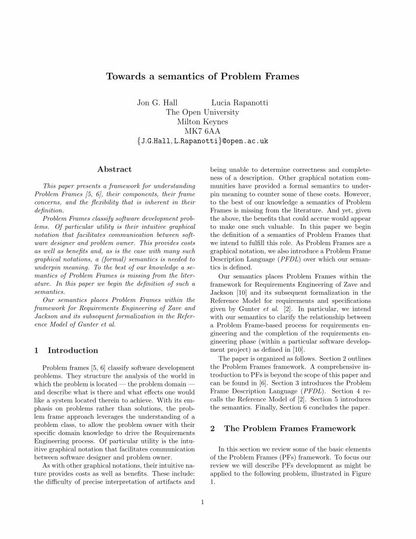
towards a semantics of problem frames
TRANSCRIPT
T e c h n i c a l R e p o r t N o : 2 0 0 3 / 0 5
Towards a semantics of Problem Frames
Jon G Hall Lucia Rapanotti
2003
Department of Computing Faculty of Mathematics and Computing The Open University Walton Hall, Milton Keynes MK7 6AA United Kingdom http://computing.open.ac.uk
l
Towards a semantics of Problem Frames
Jon G. Hall Lucia RapanottiThe Open University
Milton KeynesMK7 6AA
{J.G.Hall, L.Rapanotti}@open.ac.uk
Abstract
This paper presents a framework for understandingProblem Frames [5, 6], their components, their frameconcerns, and the flexibility that is inherent in theirdefinition.
Problem Frames classify software development prob-lems. Of particular utility is their intuitive graphicalnotation that facilitates communication between soft-ware designer and problem owner. This provides costsas well as benefits and, as is the case with many suchgraphical notations, a (formal) semantics is needed tounderpin meaning. To the best of our knowledge a se-mantics of Problem Frames is missing from the liter-ature. In this paper we begin the definition of such asemantics.
Our semantics places Problem Frames within theframework for Requirements Engineering of Zave andJackson and its subsequent formalization in the Refer-ence Model of Gunter et al.
1 Introduction
Problem frames [5, 6] classify software developmentproblems. They structure the analysis of the world inwhich the problem is located — the problem domain —and describe what is there and what effects one wouldlike a system located therein to achieve. With its em-phasis on problems rather than solutions, the prob-lem frame approach leverages the understanding of aproblem class, to allow the problem owner with theirspecific domain knowledge to drive the RequirementsEngineering process. Of particular utility is the intu-itive graphical notation that facilitates communicationbetween software designer and problem owner.
As with other graphical notations, their intuitive na-ture provides costs as well as benefits. These include:the difficulty of precise interpretation of artifacts and
being unable to determine correctness and complete-ness of a description. Other graphical notation com-munities have provided a formal semantics to under-pin meaning to counter some of these costs. However,to the best of our knowledge a semantics of ProblemFrames is missing from the literature. And yet, giventhe above, the benefits that could accrue would appearto make one such valuable. In this paper we beginthe definition of a semantics of Problem Frames thatwe intend to fulfill this role. As Problem Frames are agraphical notation, we also introduce a Problem FrameDescription Language (PFDL) over which our seman-tics is defined.
Our semantics places Problem Frames within theframework for Requirements Engineering of Zave andJackson [10] and its subsequent formalization in theReference Model for requirements and specificationsgiven by Gunter et al. [2]. In particular, we intendwith our semantics to clarify the relationship betweena Problem Frame-based process for requirements en-gineering and the completion of the requirements en-gineering phase (within a particular software develop-ment project) as defined in [10].
The paper is organized as follows. Section 2 outlinesthe Problem Frames framework. A comprehensive in-troduction to PFs is beyond the scope of this paper andcan be found in [6]. Section 3 introduces the ProblemFrame Description Language (PFDL). Section 4 re-calls the Reference Model of [2]. Section 5 introducesthe semantics. Finally, Section 6 concludes the paper.
2 The Problem Frames Framework
In this section we review some of the basic elementsof the Problem Frames (PFs) framework. To focus ourreview we will describe PFs development as might beapplied to the following problem, illustrated in Figure1.
1
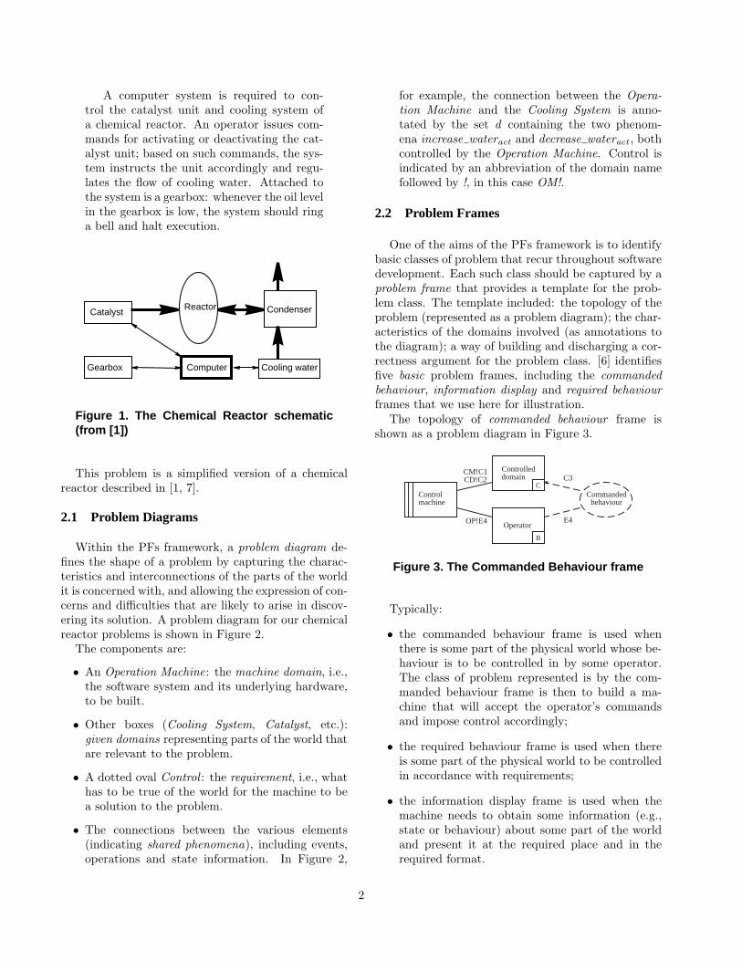
A computer system is required to con-trol the catalyst unit and cooling system ofa chemical reactor. An operator issues com-mands for activating or deactivating the cat-alyst unit; based on such commands, the sys-tem instructs the unit accordingly and regu-lates the flow of cooling water. Attached tothe system is a gearbox: whenever the oil levelin the gearbox is low, the system should ringa bell and halt execution.
Reactor
Cooling waterComputerGearbox
CondenserCatalyst
Figure 1. The Chemical Reactor schematic(from [1])
This problem is a simplified version of a chemicalreactor described in [1, 7].
2.1 Problem Diagrams
Within the PFs framework, a problem diagram de-fines the shape of a problem by capturing the charac-teristics and interconnections of the parts of the worldit is concerned with, and allowing the expression of con-cerns and difficulties that are likely to arise in discov-ering its solution. A problem diagram for our chemicalreactor problems is shown in Figure 2.
The components are:
• An Operation Machine: the machine domain, i.e.,the software system and its underlying hardware,to be built.
• Other boxes (Cooling System, Catalyst, etc.):given domains representing parts of the world thatare relevant to the problem.
• A dotted oval Control : the requirement, i.e., whathas to be true of the world for the machine to bea solution to the problem.
• The connections between the various elements(indicating shared phenomena), including events,operations and state information. In Figure 2,
for example, the connection between the Opera-tion Machine and the Cooling System is anno-tated by the set d containing the two phenom-ena increase wateract and decrease wateract , bothcontrolled by the Operation Machine. Control isindicated by an abbreviation of the domain namefollowed by !, in this case OM!.
2.2 Problem Frames
One of the aims of the PFs framework is to identifybasic classes of problem that recur throughout softwaredevelopment. Each such class should be captured by aproblem frame that provides a template for the prob-lem class. The template included: the topology of theproblem (represented as a problem diagram); the char-acteristics of the domains involved (as annotations tothe diagram); a way of building and discharging a cor-rectness argument for the problem class. [6] identifiesfive basic problem frames, including the commandedbehaviour, information display and required behaviourframes that we use here for illustration.
The topology of commanded behaviour frame isshown as a problem diagram in Figure 3.
Controlmachine
Operator
Controlleddomain
CM!C1CD!C2
Commandedbehaviour
OP!E4
C3
E4
B
C
Figure 3. The Commanded Behaviour frame
Typically:
• the commanded behaviour frame is used whenthere is some part of the physical world whose be-haviour is to be controlled in by some operator.The class of problem represented is by the com-manded behaviour frame is then to build a ma-chine that will accept the operator’s commandsand impose control accordingly;
• the required behaviour frame is used when thereis some part of the physical world to be controlledin accordance with requirements;
• the information display frame is used when themachine needs to obtain some information (e.g.,state or behaviour) about some part of the worldand present it at the required place and in therequired format.
2
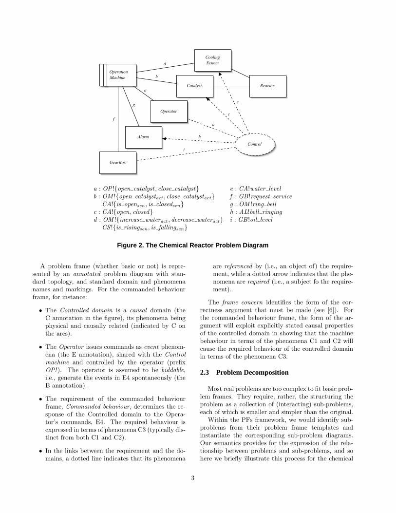
ReactorCatalyst
Operator
b
d
a
GearBox
f
Control
c
a
i
OperationMachine
CoolingSystem
Alarm
g
h
e
a : OP !{open catalyst , close catalyst} e : CA!water levelb : OM !{open catalystact , close catalystact} f : GB !request service
CA!{is opensen , is closedsen} g : OM !ring bellc : CA!{open, closed} h : AL!bell ringingd : OM !{increase wateract , decrease wateract} i : GB !oil level
CS !{is risingsen , is fallingsen}
Figure 2. The Chemical Reactor Problem Diagram
A problem frame (whether basic or not) is repre-sented by an annotated problem diagram with stan-dard topology, and standard domain and phenomenanames and markings. For the commanded behaviourframe, for instance:
• The Controlled domain is a causal domain (theC annotation in the figure), its phenomena beingphysical and causally related (indicated by C onthe arcs).
• The Operator issues commands as event phenom-ena (the E annotation), shared with the Controlmachine and controlled by the operator (prefixOP! ). The operator is assumed to be biddable,i.e., generate the events in E4 spontaneously (theB annotation).
• The requirement of the commanded behaviourframe, Commanded behaviour, determines the re-sponse of the Controlled domain to the Opera-tor’s commands, E4. The required behaviour isexpressed in terms of phenomena C3 (typically dis-tinct from both C1 and C2).
• In the links between the requirement and the do-mains, a dotted line indicates that its phenomena
are referenced by (i.e., an object of) the require-ment, while a dotted arrow indicates that the phe-nomena are required (i.e., a subject fo the require-ment).
The frame concern identifies the form of the cor-rectness argument that must be made (see [6]). Forthe commanded behaviour frame, the form of the ar-gument will exploit explicitly stated causal propertiesof the controlled domain in showing that the machinebehaviour in terms of the phenomena C1 and C2 willcause the required behaviour of the controlled domainin terms of the phenomena C3.
2.3 Problem Decomposition
Most real problems are too complex to fit basic prob-lem frames. They require, rather, the structuring theproblem as a collection of (interacting) sub-problems,each of which is smaller and simpler than the original.
Within the PFs framework, we would identify sub-problems from their problem frame templates andinstantiate the corresponding sub-problem diagrams.Our semantics provides for the expression of the rela-tionship between problems and sub-problems, and sohere we briefly illustrate this process for the chemical
3
reactor.The chemical reactor problem can be decomposed
into three distinct sub-problems:
• a commanded behaviour frame allowing the oper-ator to control the catalyst;
• a required behaviour frame regulating the waterflow for cooling; and
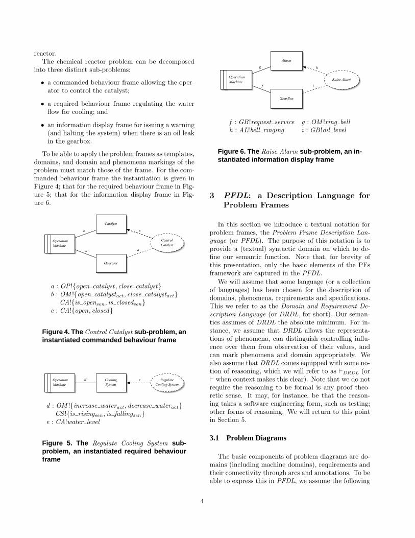
• an information display frame for issuing a warning(and halting the system) when there is an oil leakin the gearbox.
To be able to apply the problem frames as templates,domains, and domain and phenomena markings of theproblem must match those of the frame. For the com-manded behaviour frame the instantiation is given inFigure 4; that for the required behaviour frame in Fig-ure 5; that for the information display frame in Fig-ure 6.
Catalyst
Operator
b
a
ControlCatalyst
c
a
OperationMachine
a : OP !{open catalyst , close catalyst}b : OM !{open catalystact , close catalystact}
CA!{is opensen , is closedsen}c : CA!{open, closed}
Figure 4. The Control Catalyst sub-problem, aninstantiated commanded behaviour frame
d RegulateCooling System
e OperationMachine
CoolingSystem
d : OM !{increase wateract , decrease wateract}CS !{is risingsen , is fallingsen}
e : CA!water level
Figure 5. The Regulate Cooling System sub-problem, an instantiated required behaviourframe
Alarm
g
GearBox
f
Raise Alarm
h
OperationMachine
i
f : GB !request service g : OM !ring bellh : AL!bell ringing i : GB !oil level
Figure 6. The Raise Alarm sub-problem, an in-stantiated information display frame
3 PFDL: a Description Language forProblem Frames
In this section we introduce a textual notation forproblem frames, the Problem Frame Description Lan-guage (or PFDL). The purpose of this notation is toprovide a (textual) syntactic domain on which to de-fine our semantic function. Note that, for brevity ofthis presentation, only the basic elements of the PFsframework are captured in the PFDL.
We will assume that some language (or a collectionof languages) has been chosen for the description ofdomains, phenomena, requirements and specifications.This we refer to as the Domain and Requirement De-scription Language (or DRDL, for short). Our seman-tics assumes of DRDL the absolute minimum. For in-stance, we assume that DRDL allows the representa-tions of phenomena, can distinguish controlling influ-ence over them from observation of their values, andcan mark phenomena and domain appropriately. Wealso assume that DRDL comes equipped with some no-tion of reasoning, which we will refer to as `DRDL (or` when context makes this clear). Note that we do notrequire the reasoning to be formal is any proof theo-retic sense. It may, for instance, be that the reason-ing takes a software engineering form, such as testing;other forms of reasoning. We will return to this pointin Section 5.
3.1 Problem Diagrams
The basic components of problem diagrams are do-mains (including machine domains), requirements andtheir connectivity through arcs and annotations. To beable to express this in PFDL, we assume the following
4

given sets1:
[PFDomain], [PFMachine],[PFRequirement], [PFPhenomena]
For the grounding of a problem, both domains andrequirements are named and described in DRDL:
PFDomainName::= PFDomain→ DRDL
PFDomainDescription::= PFDomain→ DRDL
PFRequirementName::= PFRequirement→ DRDL
PFRequirementDescription::= PFRequirement→ DRDL
Phenomena are also named and described in theDRDL:
PFPhenomenaDesignation::= PFPhenomena→ DRDL
Phenomena are partitioned in sets of phenomenathat can be either controlled or observed by each do-main and the machine:
PFControlled::= PFDomain ∪ PFMachine→ PFPhenomena
PFObserved::= PFDomain ∪ PFMachine→ PFPhenomena
Similarly, some phenomena can be either requiredor referenced by the requirement:
PFRequired::= PFRequirement→ PFPhenomena
PFReferenced::= PFRequirement→ PFPhenomena
We will bundle all annotating functions into a prob-lem diagram annotation:
PFAnnotation ::=〈PFDomainName, PFDomainDescription, ...
PFRequired, PFReferenced〉
A problem diagram is a set of domains, a single ma-chine, a single (set of) requirement(s), and an annota-tion, i.e.:
PFProblemDiagram ::=(P PFDomain, PFMachine,
PFRequirement, PFAnnotation)
For a concrete example of a PFDL description, thePFDL description of the chemical reactor problem di-agram is shown in Figure 7.
1The notion of a given set is as in the formal notation Z [9].
3.2 Problem Frames
As already mentioned, basic problem frames aretemplates for classes of problems. [6] provides a tem-plate language enriched over that for problem diagramsby the introduction of domain and phenomena mark-ings. These markings must be matched by problemdiagram elements for the problem frame template toapply.
Each domain can be marked as either biddable, lex-ical or causal (which are distinct):
PFDomainMarking::= PFDomain→ {B, X, C}
Each (set of) phenomena can be marked as eithercausal, symbolic or event (also distinct):
PFPhenomenaMarking::= PFPhenomena→ {C, Y, E}
The diagram of a problem frame is called a frame di-agram and is a problem diagram augmented with mark-ing for domains and phenomena:
PFFrameDiagram ::=(PFProblemDiagram,
PFDomainMarking, PFPhenomenaMarking)
A Problem Frame provides a frame concern, i.e., atemplate for correctness argument which is commonto all problem of that class. We assume that frameconcerns are taken from another given set:
[PFFrameConcern]
and so may define:
PFProblemFrame ::=(PFFrameDiagram, PFFrameConcern)
A PFDL representation of commanded behaviourframe of Section2.2 is given in Figure 8. The readerwill note that the phenomena controlled by the opera-tor are event phenomena (marking E), while all otherphenomena are causal (marking C); such markings willdefine the applicability of the problem frame to a prob-lem diagram.
4 The Reference Model
The Reference Model [10, 2, 4] is based on the widelyaccepted separation between the system and its envi-ronment, a number of key artifacts which pertain tothe two, and a vocabulary, which is used to describe
5
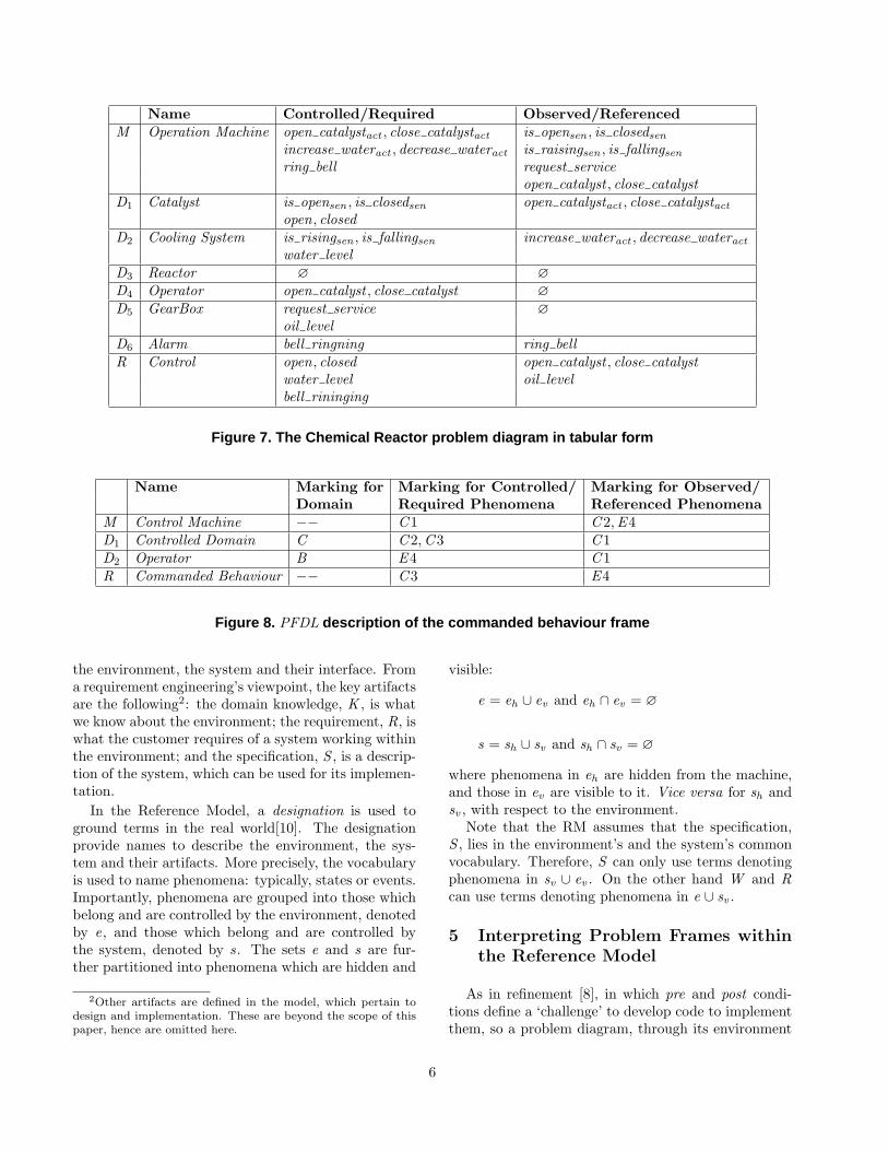
Name Controlled/Required Observed/ReferencedM Operation Machine open catalystact , close catalystact is opensen , is closedsen
increase wateract , decrease wateract is raisingsen , is fallingsenring bell request service
open catalyst , close catalystD1 Catalyst is opensen , is closedsen open catalystact , close catalystact
open, closedD2 Cooling System is risingsen , is fallingsen increase wateract , decrease wateract
water levelD3 Reactor ∅ ∅D4 Operator open catalyst , close catalyst ∅D5 GearBox request service ∅
oil levelD6 Alarm bell ringning ring bellR Control open, closed open catalyst , close catalyst
water level oil levelbell rininging
Figure 7. The Chemical Reactor problem diagram in tabular form
Name Marking for Marking for Controlled/ Marking for Observed/Domain Required Phenomena Referenced Phenomena
M Control Machine −− C1 C2,E4D1 Controlled Domain C C2,C3 C1D2 Operator B E4 C1R Commanded Behaviour −− C3 E4
Figure 8. PFDL description of the commanded behaviour frame
the environment, the system and their interface. Froma requirement engineering’s viewpoint, the key artifactsare the following2: the domain knowledge, K , is whatwe know about the environment; the requirement, R, iswhat the customer requires of a system working withinthe environment; and the specification, S , is a descrip-tion of the system, which can be used for its implemen-tation.
In the Reference Model, a designation is used toground terms in the real world[10]. The designationprovide names to describe the environment, the sys-tem and their artifacts. More precisely, the vocabularyis used to name phenomena: typically, states or events.Importantly, phenomena are grouped into those whichbelong and are controlled by the environment, denotedby e, and those which belong and are controlled bythe system, denoted by s. The sets e and s are fur-ther partitioned into phenomena which are hidden and
2Other artifacts are defined in the model, which pertain todesign and implementation. These are beyond the scope of thispaper, hence are omitted here.
visible:
e = eh ∪ ev and eh ∩ ev = ∅
s = sh ∪ sv and sh ∩ sv = ∅
where phenomena in eh are hidden from the machine,and those in ev are visible to it. Vice versa for sh andsv , with respect to the environment.
Note that the RM assumes that the specification,S , lies in the environment’s and the system’s commonvocabulary. Therefore, S can only use terms denotingphenomena in sv ∪ ev . On the other hand W and Rcan use terms denoting phenomena in e ∪ sv .
5 Interpreting Problem Frames withinthe Reference Model
As in refinement [8], in which pre and post condi-tions define a ‘challenge’ to develop code to implementthem, so a problem diagram, through its environment
6
and requirements, defines a ‘challenge’ to develop a ma-chine specification to discharge them. Whereas refine-ment is mature, and has formal notation up to the jobof representing a challenge3 we, as yet, do not. We willtherefore be forced to improvise, notationally, some-what.
As the basis for our semantics, we use the followingdefinition. Given a world description K , a requirementdescriptions R, and sets of shared phenomena c (con-trolled by the machine domain) and o (observed by themachine domain) over some DRDL, we define a ‘chal-lenge to find a satisfying specification’ as
c, o : [K ,R] = {S | S controls c∧ S observes o
∧ K ,S `DRDL R}
As such, c, o : [K ,R] stands for the set of all specifi-cations that control phenomena in the set c, observephenomena in the set o, and which, in the context ofK are capable of discharging R, as per [10, 2, 4]. Asindicated in the notation, the details of `DRDL will beprovided by the DRDL. We also note that c, o : [K ,R]can be empty (as when R is false, for instance), inwhich case there is no satisfying specification, i.e., thesystem cannot be built. Referring to the original Ref-erence Model, c = sv , i.e., the machine controlled phe-nomena shared with the environment, and o = ev , themachine visible shared phenomena.
Within the PFs framework, the environment is de-scribed through a set of domains. Also, there is a sep-aration between the concept of domain and its descrip-tion. Therefore, in the semantics, for convenience, wewill identify
c, o : [{D1, ...,Dn},R]
and
c, o : [DD1 ∧ ... ∧ DDn ,DR]
where DDi = PFDomainDescription(Di) and DR =PFRequirementDescription(R).
5.1 Problem Diagrams as challenges
Given a problem diagram PD =〈{D1, ...,Dn},M ,R,A〉 expressed in PFDL over aDRDL, we define its semantics as:
c, o : [{D1, ...,Dn},R]
3The reader may be familiar with the refinement notationw : [pre, post ] which stands for (all) code that, by changing onlyvariables in w will take as input state satisfying pre and producestate satisfying post .
where c = PFControlled(M ) and o =PFObserved(M ).
The reader will note that, discharging the correct-ness argument associated with the diagram is part ofthe challenge, specifically that K ,S `DRDL R, and thatS controls c and S observes o.
As an example, assuming the annotation given inFigure 7, the semantics of the chemical reactor problemdiagram is the following challenge:
{open catalystact , close catalystact ,increase wateract , decrease wateract , ring bell},
{is opensen , is closedsen , is raisingsen ,is fallingsen , request service,
open catalyst , close catalyst}: [{Catalyst ,CoolingSystem,Operator ,
Reactor ,GearBox},Control ]
5.2 Problem Frames Semantics
A Problem Frame is a template for a class of prob-lems. By ‘applying’ a problem frame to a problem di-agram, we can derive a (sub-)problem diagram whosesemantics is a challenge. This allows for a process ofproblem decomposition in which the sub-problem dia-grams are projections of the original problem diagramthrough a collection of problem frames.
Semantically, we can see the application of a prob-lem frame to a problem diagram as matching topolo-gies, and domain and arc markings. We say thata frame diagram PF = 〈〈D ,M ,R,A〉,m〉 matches aproblem diagram PD = 〈D ′,M ′,R′,A′〉 when there isa injective correspondence ι : D → D ′ which respectsthe topology, domain and arc markings.
An problem frame instantiation is then the applica-tion of iota to 〈D ,M ,R,A〉.
5.3. Working with the semantics
Extending the analogy with refinement, working to-wards an S ∈ c, o : [K ,R] will be an exploration of thedesign choices at each stage: because we work withinall of software—including architectures, etc—and notjust code, the design space is possibly much larger thanthat in refinement.
Problem frames, as templates, allow the navigationaround the design space through dividing up the prob-lem.
Let us illustrate this idea with an example. Fromthe Chemical Reactor above, we have three sub-problem diagrams corresponding to the required be-haviour, commanded behaviour, and information dis-play frames. The decomposition of the Chemical Re-actor problem into three sub-problems is illustrated in
7

c1, o1 : [{Catalyst ,Operator},Control Catalyst ]
c2, o2 : [{Cooling System},Regulate Cooling System]
c3, o3 : [{Alarm,GearBox},Raise Alarm]↑ Decomposition, ↓ Recomposition
c, o : [{Catalyst ,Cooling System,Operator ,Alarm,Reactor ,GearBox},Control ]
Figure 9. The decomposition/recomposition relationship between the Chemical reactor problem dia-gram and its sub-problem diagrams
Figure 9, in which:
c1 = {open catalystact , close catalystact}o1 = {is opensen , is closedsen ,
open catalyst , close catalyst}c2 = {increase wateract , decrease wateract}o2 = {is raisingsen , is fallingsen}c3 = {ring bell}o3 = {request service}c = c1 ∪ c2 ∪ c3
o = o1 ∪ o2 ∪ o3
As for refinement, given a possible decompositionthrough the application of problem frames, there willbe a corresponding composition concern (analogous torefinement’s verification condition) that should be ableto convince us of the validity of the recomposition. Ourpoint is that backwards argument identifies the sub-problems that should concern us; the forwards argu-ment requires that composition concerns.
In this chemical reactor example for instance, thereis a requirement that when the oil level in the gearboxis low, the machine should sound an alarm and halt(the information display sub-problem). On the otherhand, the machine is always required to regulate thecooling system (the required behaviour sub-problem).The composition of these two sub-problem needs tocontinue to guarantee the safe functioning of the reac-tor. This concern therefore must be addressed at thecomposition level.
6 Discussion and Future Work
In this paper we have suggested a semantics for ele-ments of the PFs framework. We have introduced theProblem Frame Description Language (PFDL), overa Domain and Requirements Description Language(DRDL), for the description of problem diagrams andproblem frames. We have defined the meaning of aproblem frame as a template for problem diagrams, anda semantics for problem diagrams within the Reference
Model, given in terms of challenges, i.e., c, o : [K ,R],a notion that we have also introduced.
It is worth stressing that our semantics is based ona weak notion of correctness. This differs from thatof the Reference Model, which is based on universalquantification over all ‘phenomena’ sequences’. Theactual wording used by the authors is that:
A requirement with an environment con-straint should always be verified by a demon-stration or proof that specified properties,conjoined with domain knowledge, guaranteethe satisfaction of the requirement.
In our semantics we relax that notion of proof to itsweakest (non-technical) meaning:
facts, evidence, argument, etc. establishingor helping to establish a fact.
We might, with this definition, also admit proofs ofthe type ‘there is no example that a system did notsatisfy the requirements’ (a testing ‘proof’); anotheris the ‘customers were convinced by the arguments ofthe developers’; another is ‘a formal refinement of therequirements to code was performed, with all verifi-cation conditions being discharged’; another is ‘DonKnuth wrote it’; yet another is ‘we’ll fix it in the nextrelease’. Clearly, the nature of `DRDL and that of therequirements are closely related; in the case when therequirements include safety (as would be the case ina safety critical system, for instance), the strength of`DRDL must provide for their discharge.
The development of the c, o : [K ,R] needs manythings. Most importantly, the availability of a ‘weakestenvironment predicate transformer’ (analogous to theweakest precondition semantics of refinement) wouldplace the semantic basis of the manipulation of suchexpressions on a much firmer footing, and even lead ustowards a requirements engineering notion of ‘refine-ment’ that forms a lattice over such objects; given a
8
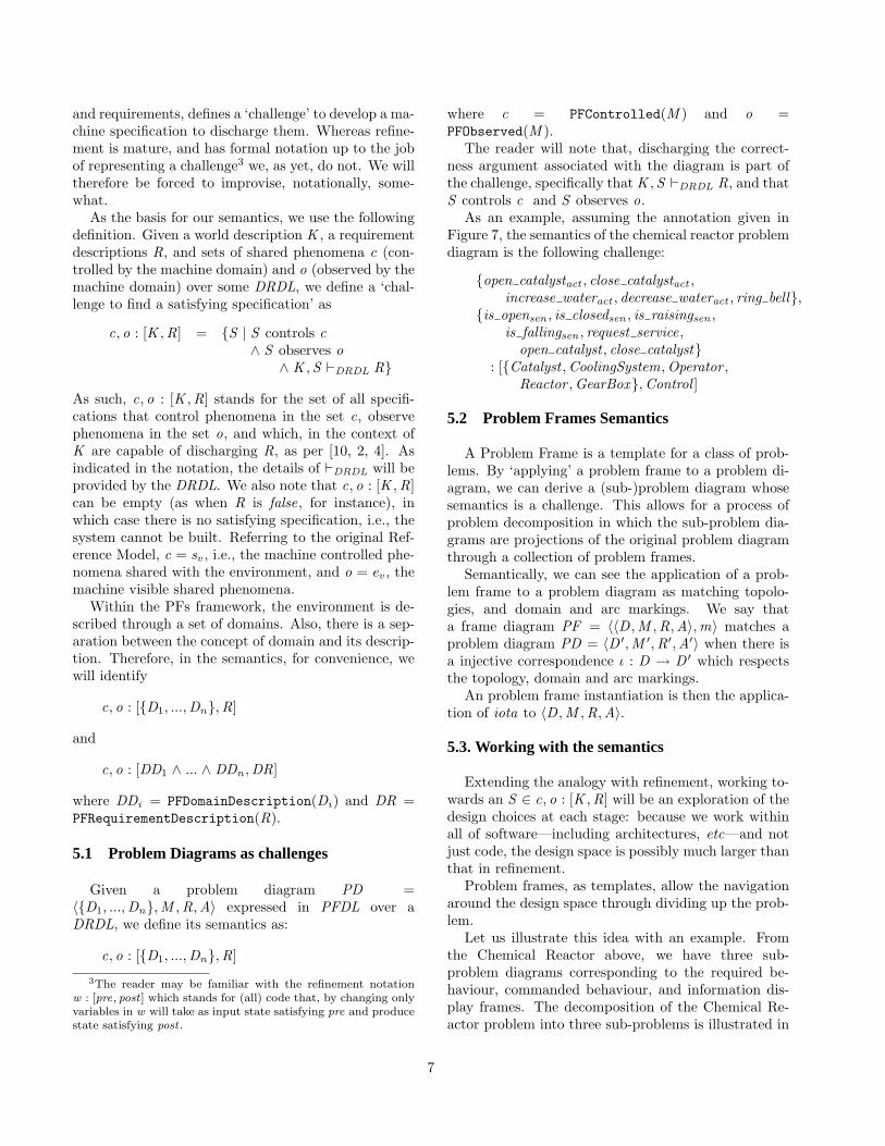
problem, the refinement relation v would justify therelationship, as summarised in Figure 10:
problem v partial soln0 v . . . v specification
problems solutions
←increasingly customer-friendly
increasingly developer-friendly→
Figure 10. The move between problem andsolution domains (after [8, Figure 1.6, page9])
The import of this paper is to provide a formal se-mantics for elements of the PFs framework. The extentof the uses to which it can be put is still unexplored andprovides a focus for further research. However, some ofthe immediate benefits of it are already apparent. Asfor other formal semantics, it can act as an arbiter ofcommunication between two parties and could be usedas the basis of tool support for PFs. To be sure, manyof the engineering notions that are present in computerscience are based on the definition of a mathematicalbasis provided by a formal semantics.
7 Acknowledgements
Our heartfelt thank you goes to Michael Jackson,Bashar Nuseibeh and Robin Laney for their patient lis-tening and insightful suggestions. We also acknowledgethe kind support of our colleagues in the Departmentof Computing, the Open University.
References
[1] O. Dieste, A. Silva, Requirements: Closing the Gapbetween Domain and Computing Knowledge, Proceed-ings of SCI2000, Vol. II (Information Systems Devel-opment), 2000.
[2] C.A. Gunter, E.L. Gunter, M. Jackson, P. Zave “Areference model for requirements and specifications”,IEEE Software, 17(3):37-43, 2000.
[3] J.G. Hall, M. Jackson, R.C. Laney, B. Nuseibeh,L. Rapanotti, Relating Software Requirements and Ar-chitectures using Problem Frames, IEEE Proceedingsof RE’02, Essen, Germany, 2002.
[4] J.G. Hall, L. Rapanotti, A reference Model for Re-quirements Engineering, Submitted to RE’03, 2003.
[5] M. Jackson, Software Requirements & Specifications:a Lexicon of Practice, Principles, and Prejudices,Addison-Wesley, 1995.
[6] M. Jackson, Problem Frames, ACM Press Books, Ad-dison Wesley, 2001.
[7] N. Leveson, Software Safety: why, what and how,ACM Computing Survey, 18(2),:125-163, 1986.
[8] , C. Morgan, Programming from Specifications.Prentice-Hall International, 1990.
[9] J.M. .Spivey, The Z Notation. Prentice-Hall Interna-tional, 1988.
[10] P. Zave, M. Jackson, Four Dark Corners of Require-ments Engineering, ACM Transactions on SoftwareEngineering and Methodology, Vol. 6, No. 1, January1997, pp.1-30.
9