thi na minuut tietoa na unitate
TRANSCRIPT
THI NA MINUUT TIETOA NA UNITATE US009808201B2
( 12 ) United States Patent Braido et al .
( 10 ) Patent No . : US 9 , 808 , 201 B2 ( 45 ) Date of Patent : Nov . 7 , 2017
( 54 ) SENSORS FOR PROSTHETIC HEART DEVICES
( 58 ) Field of Classification Search CPC . . . . . . . . A61F 2 / 24 ; A61F 2 / 2412 ; A61F 2 / 2418 ;
A61F 2 / 2472 ; A61B 5 / 02 , A61B 5 / 02158 ; A61B 5 / 026 ; A61B 2562 / 0247
See application file for complete search history . ( 71 ) Applicant : St . Jude Medical , Cardiology
Division , Inc . , St . Paul , MN ( US ) ( 56 ) References Cited
U . S . PATENT DOCUMENTS ( 72 ) Inventors : Peter N . Braido , Wyoming , MN ( US ) ;
Mina S . Fahim , Shoreview , MN ( US ) ; Steven Frederick Anderl , Forest Lake , MN ( US ) ; Jason White , Smyrna , GA ( US ) ; Paul E . Ashworth , Wyoming , MN ( US ) ; Morgan Low , Winnetka , CA ( US ) ; Loell Boyce Moon , Ham Lake , MN ( US ) ; Neelakantan Saikrishnan , Plymouth , MN ( US )
4 , 275 , 469 A 4 , 491 , 986 A
6 / 1981 Gabbay 1 / 1985 Gabbay ( Continued )
FOREIGN PATENT DOCUMENTS
DE DE ( 73 ) Assignee : St . Jude Medical , Cardiology
Division , Inc . , St . Paul , MN ( US )
19857887 B4 5 / 2005 10121210 B4 11 / 2005
( Continued ) ( * ) Notice : OTHER PUBLICATIONS Subject to any disclaimer , the term of this
patent is extended or adjusted under 35 U . S . C . 154 ( b ) by 0 days . International Search Report and Written Opinion for Application
No . PCT / US2015 / 044969 dated Dec . 11 , 2015 . ( Continued ) ( 21 ) Appl . No . : 14 / 825 , 471
( 22 ) Filed : Aug . 13 , 2015 ( 65 ) Prior Publication Data
US 2016 / 0045165 A1 Feb . 18 , 2016
Primary Examiner — David Isabella Assistant Examiner — Dinah Baria ( 74 ) Attorney , Agent , or Firm — Lerner , David , Littenberg , Krumholz & Mentlik , LLP
Related U . S . Application Data ( 60 ) Provisional application No . 62 / 038 , 512 , filed on Aug .
18 , 2014 .
( 51 ) Int . Ci . A61F 2 / 24 ( 2006 . 01 ) A61B 5 / 00 ( 2006 . 01 )
( Continued ) ( 52 ) U . S . CI .
CPC . . . . . . . . . . . . . . A61B 5 / 6862 ( 2013 . 01 ) ; A61B 5 / 02 ( 2013 . 01 ) ; A61B 5 / 026 ( 2013 . 01 ) ; A61B
5 / 0215 ( 2013 . 01 ) ; ( Continued )
( 57 ) ABSTRACT Prosthetic heart devices may be implanted into the heart with a sensor coupled to the device , the sensor being configured to measure physiological data , such as blood pressure , in the heart . Devices that may employ such sensors include prosthetic heart valves and occlusion devices , although sensor systems may be deployed in the heart separate from other implantable devices . The sensors may include a body with different configurations for attaching to the implantable device , such as apertures for sutures or fingers for connecting to structures of the implantable device . The sensors may provide data that allow a determi nation of aortic regurgitation or other information indicative
( Continued )
5100 5106
500 . 5100 mm 500 520
5100 515
; 166 . . 520 . .
.
* * wycin . . * * * * * * * 178 * * * * *
* R 176 *
* * *
* * * * * 522 515 500
US 9 , 808 , 201 B2 Page 2
of function of the implantable device and patient health during and after implantation of the device .
16 Claims , 35 Drawing Sheets
( 51 )
( 52 )
Int . Cl . A61F 2 / 844 ( 2013 . 01 ) A61B 5 / 0215 ( 2006 . 01 ) A61B 5 / 02 ( 2006 . 01 ) A61B 5 / 026 ( 2006 . 01 ) A61B 17 / 00 ( 2006 . 01 ) A61B 17 / 12 ( 2006 . 01 ) U . S . CI . CPC . . . . . A61B 5 / 02028 ( 2013 . 01 ) ; A61B 5 / 02158
( 2013 . 01 ) ; A61B 5 / 6847 ( 2013 . 01 ) ; A61B 17 / 0057 ( 2013 . 01 ) ; A61B 17 / 12122 ( 2013 . 01 ) ; A61F 2 / 24 ( 2013 . 01 ) ; A61F 2 / 2412 ( 2013 . 01 ) ;
A61F 2 / 2418 ( 2013 . 01 ) ; A61F 2 / 2445 ( 2013 . 01 ) ; A61F 2 / 2448 ( 2013 . 01 ) ; A61F 2 / 2472 ( 2013 . 01 ) ; A61F 2 / 844 ( 2013 . 01 ) ;
A61B 2017 / 00022 ( 2013 . 01 ) ; A61B 2017 / 00575 ( 2013 . 01 ) ; A61B 2017 / 00632
( 2013 . 01 ) ; A61B 2562 / 0247 ( 2013 . 01 ) ; A61F 2210 / 0066 ( 2013 . 01 ) ; A61F 2220 / 0016
( 2013 . 01 ) ; A61F 2220 / 0075 ( 2013 . 01 ) ; A61F 2230 / 0008 ( 2013 . 01 ) ; A61F 2230 / 0034
( 2013 . 01 ) ; A61F 2230 / 0065 ( 2013 . 01 ) ; A61F 2250 / 001 ( 2013 . 01 ) ; A61F 2250 / 0002
( 2013 . 01 ) ; A61F 2250 / 0004 ( 2013 . 01 ) ; A61F 2250 / 0063 ( 2013 . 01 ) ; A61F 2250 / 0065
( 2013 . 01 )
6 , 908 , 481 B2 6 / 2005 Cribier 7 , 025 , 780 B2 4 / 2006 Gabbay 7 , 137 , 184 B2 11 / 2006 Schreck 7 , 160 , 322 B2 1 / 2007 Gabbay 7 , 247 , 167 B2 7 / 2007 Gabbay 7 , 267 , 686 B2 9 / 2007 DiMatteo et al . 7 , 374 , 573 B2 5 / 2008 Gabbay 7 , 381 , 218 B2 6 / 2008 Schreck 7 , 452 , 371 B211 / 2008 Pavcnik et al . 7 , 524 , 331 B2 4 / 2009 Birdsall RE40 , 816 E 6 / 2009 Taylor et al . 7 , 585 , 321 B2 9 / 2009 Cribier 7 , 731 , 742 B2 6 / 2010 Schlick et al . 7 , 846 , 203 B2 12 / 2010 Cribier 7 , 846 , 204 B2 12 / 2010 Letac et al . 7 , 909 , 770 B2 3 / 2011 Stern et al . 7 , 914 , 569 B2 3 / 2011 Nguyen et al . D648 , 854 S 11 / 2011 Braido D652 , 926 S 1 / 2012 Braido D652 , 927 S 1 / 2012 Braido et al . D653 , 341 S 1 / 2012 Braido et al . D653 , 342 S 1 / 2012 Braido et al . D653 , 343 S 1 / 2012 Ness et al . D654 , 169 S 2 / 2012 Braido D654 , 170 S 2 / 2012 Braido et al . D660 , 432 S 5 / 2012 Braido D660 , 433 S 5 / 2012 Braido et al . D660 , 967 S 5 / 2012 Braido et al .
2002 / 0036220 A1 3 / 2002 Gabbay 2003 / 0023303 A1 1 / 2003 Palmaz et al . 2003 / 0130726 A1 7 / 2003 Thorpe et al . 2004 / 0049262 A1 3 / 2004 Obermiller et al . 2004 / 0093075 Al 5 / 2004 Kuehne 2005 / 0060030 A1 3 / 2005 Lashinski et al . 2005 / 0096726 A1 5 / 2005 Sequin et al . 2005 / 0154321 A1 7 / 2005 Wolinsky et al . 2005 / 0165317 A1 7 / 2005 Turner et al . 2005 / 0256566 A1 11 / 2005 Gabbay 2006 / 0008497 Al 1 / 2006 Gabbay 2006 / 0122692 A1 6 / 2006 Gilad et al . 2006 / 0129216 A1 6 / 2006 Hastings et al . 2006 / 0149360 A1 7 / 2006 Schwammenthal et al . 2006 / 0173532 A1 8 / 2006 Flagle et al . 2006 / 0178740 A1 8 / 2006 Stacchino et al . 2006 / 0206202 AL 9 / 2006 Bonhoeffer et al 2006 / 0241744 A1 10 / 2006 Beith 2006 / 0241745 Al 10 / 2006 Solem 2006 / 0259137 Al 11 / 2006 Artof et al . 2006 / 0265056 A 11 / 2006 Nguyen et al . 2006 / 0276813 Al 12 / 2006 Greenberg 2007 / 0067027 A1 3 / 2007 Moaddeb et al . 2007 / 0067029 A1 3 / 2007 Gabbay 2007 / 0093890 A1 4 / 2007 Eliasen et al . 2007 / 0100435 A1 5 / 2007 Case et al . 2007 / 0118210 A1 5 / 2007 Pinchuk 2007 / 0129637 A1 6 / 2007 Wolinsky et al . 2007 / 0213813 Al 9 / 2007 Von Segesser et al . 2007 / 0233228 Al 10 / 2007 Eberhardt et al . 2007 / 0244545 Al 10 / 2007 Birdsall et al . 2007 / 0288087 A1 12 / 2007 Fearnot et al . 2008 / 0021552 A1 1 / 2008 Gabbay 2008 / 0027483 Al 1 / 2008 Cartledge et al . 2008 / 0039934 Al 2 / 2008 Styrc 2008 / 0051838 A1 2 / 2008 Shuros et al . 2008 / 0082164 A1 4 / 2008 Friedman 2008 / 0097595 A1 4 / 2008 Gabbay 2008 / 0114452 A1 5 / 2008 Gabbay 2008 / 0125853 Al 5 / 2008 Bailey et al . 2008 / 0140189 A1 6 / 2008 Nguyen et al . 2008 / 0147183 A1 6 / 2008 Styrc 2008 / 0154355 Al 6 / 2008 Benichou et al . 2008 / 0154356 Al 6 / 2008 Obermiller et al . 2008 / 0243245 A1 10 / 2008 Thambar et al . 2008 / 0255662 A 10 / 2008 Stacchino et al . 2008 / 0262602 A1 10 / 2008 Wilk et al . 2008 / 0269879 A1 10 / 2008 Sathe et al . 2009 / 0112309 A1 4 / 2009 Jaramillo et al . 2009 / 0138079 Al 5 / 2009 Tuval et al . 2009 / 0234404 Al 9 / 2009 Fitzgerald et al .
( 56 ) References Cited
U . S . PATENT DOCUMENTS 4 , 759 , 758 A 7 / 1988 Gabbay 4 , 878 , 906 A 11 / 1989 Lindemann et al . 4 , 922 , 905 A 5 / 1990 Strecker 4 , 994 , 077 A 2 / 1991 Dobben 5 , 411 , 552 A 5 / 1995 Andersen et al . 5 , 480 , 423 A 1 / 1996 Ravenscroft et al . 5 , 487 , 760 A 1 / 1996 Villafana 5 , 847 , 760 A 12 / 1998 Elmaliach et al . 5 , 855 , 601 A 1 / 1999 Bessler et al . 5 , 935 , 163 A 8 / 1999 Gabbay 5 , 961 , 549 A 10 / 1999 Nguyen et al . 6 , 083 , 257 A 7 / 2000 Taylor et al . 6 , 090 , 140 A 7 / 2000 Gabbay 6 , 214 , 036 B1 4 / 2001 Letendre et al . 6 , 264 , 691 B1 7 / 2001 Gabbay 6 , 267 , 783 B1 . 7 / 2001 Letendre et al . 6 , 287 , 339 B1 9 / 2001 Vazquez et al . 6 , 331 , 163 B1 * 12 / 2001 Kaplan . . . . . . . . . . . . . . . . A61B 5 / 0031
600 / 373 6 , 368 , 348 B1 4 / 2002 Gabbay 6 , 419 , 695 B1 7 / 2002 Gabbay 6 , 468 , 660 B2 10 / 2002 Ogle et al . 6 , 488 , 702 B1 12 / 2002 Besselink 6 , 517 , 576 B2 2 / 2003 Gabbay 6 , 533 , 810 B2 3 / 2003 Hankh et al . 6 , 582 , 464 B2 6 / 2003 Gabbay 6 , 610 , 088 B1 8 / 2003 Gabbay 6 , 685 , 625 B2 2 / 2004 Gabbay 6 , 719 , 789 B2 4 / 2004 Cox 6 , 730 , 118 B2 5 / 2004 Spenser et al . 6 , 783 , 556 B1 8 / 2004 Gabbay 6 , 790 , 230 B2 9 / 2004 Beyersdorf et al . 6 , 869 , 444 B2 3 / 2005 Gabbay 6 , 893 , 460 B2 5 / 2005 Spenser et al .

US 9 , 808 , 201 B2 Page 3
( 56 ) References Cited WO wo WO WO
U . S . PATENT DOCUMENTS
WO DE TI 2010 / 0036484 A1 2010 / 0049306 A1 2010 / 0087907 A1 2010 / 0131055 Al 2010 / 0168778 Al 2010 / 0168839 Al 2010 / 0185277 Al 2010 / 0191326 Al 2010 / 0204781 A1 2010 / 0204785 Al 2010 / 0217382 Al 2010 / 0249911 A1 2010 / 0249923 Al 2011 / 0029072 A1 2013 / 0006352 A1 2016 / 0045316 Al *
2 / 2010 Hariton et al . 2 / 2010 House et al . 4 / 2010 Lattouf 5 / 2010 Case et al . 7 / 2010 Braido 7 / 2010 Braido et al . 7 / 2010 Braido et al . 7 / 2010 Alkhatib 8 / 2010 Alkhatib 8 / 2010 Alkhatib 8 / 2010 Chau et al . 9 / 2010 Alkhatib 9 / 2010 Alkhatib et al . 2 / 2011 Gabbay 1 / 2013 Yaron 2 / 2016 Braido . . . . . . . . . . . . . . . .
WO Wo wo wo WO WO WO WO WO WO WO WO WO WO
0154625 A1 0156500 A2 0176510 A2 0236048 A1 0247575 A2 03047468 A1 03103539 AL
2005055883 Al 2006073626 A2 2008006003 A2 2008024180 A1 2008071817 Al 2009006602 A1 2010008548 A2 2010008549 Al 2010096176 Al 2010098857 Al 2012106344 Al 2015058808 AL
8 / 2001 8 / 2001
10 / 2001 5 / 2002 6 / 2002 6 / 2003 12 / 2003 6 / 2005 7 / 2006 1 / 2008 2 / 2008 6 / 2008 1 / 2009 1 / 2010 1 / 2010 8 / 2010 9 / 2010 8 / 2012 4 / 2015
A61B 5 / 6862 623 / 2 . 38 OTHER PUBLICATIONS
2016 / 0256274 AL 9 / 2016 Hayoz
FOREIGN PATENT DOCUMENTS DE EP EP EP EP EP EP FR FR
202008009610 U1 0850607 AL 1000590 A1 1050265 A2 1584306 A1 1598031 A2 1360942 B1 2850008 A1 2847800 B1 9117720 A1 9716133 A1 9832412 A2 9913801 A1 0128459 Al 0149213 A2
12 / 2008 7 / 1998 5 / 2000
11 / 2000 10 / 2005 11 / 2005 12 / 2005
7 / 2004 10 / 2005 11 / 1991 5 / 1997 7 / 1998 3 / 1999 4 / 2001 7 / 2001
International Search Report and Written Opinion for Application No . PCT / US2015 / 044962 dated Oct . 30 , 2015 . Catheter - implanted prosthetic heart valves , Knudsen , L . L . , et al . , The International Journal of Artificial Organs , vol . 16 , No . 5 1993 , pp . 253 - 262 . Transluminal Aortic Valve Placement , Moazami , Nader , et al . , ASAIO Journal , 1996 ; 42 : M381 - M385 . Transluminal Catheter Implanted Prosthetic Heart Valves , Andersen , Henning Rud , International Journal of Angiology 7 : 102 106 ( 1998 ) . Transluminal implantation of artificial heart valves , Andersen , H . R . , et al . , European Heart Journal ( 1992 ) 13 , 704 - 708 . Is it Reasonable to Treat All Calcified Stenotic Aortic Valves With a Valved Stent ? , 579 - 584 , Zegdi , Rachid , MD , PhD et al . , J . of the American College of Cardiology , vol . 51 , No . 5 , Feb . 5 , 2008 .
WO WO WO WO WO WO * cited by examiner
U . S . Patent Nov . 7 , 2017 Sheet 1 of 35 US 9 , 808 , 201 B2
132
168 162 160
142 1420 now . 102
141 min 100
now . 166 WWW . . . . . . m
A 178 wwwww
140 . . . 104 * * * * * * * * * * * * * www . . . . wwww
*
* * * * * * * * * * * *
176 130 130
FIG . 1
? ? ? ? ? ? ? ? ? ? ? ? ?
? ? ? ? ? ? ? ? ? ? . ? ? : ? ? ? ? ' ' ? . ? ' . ? : ? . : ? ? ? ? ? . . ? ? ? ? ? ? ? ? ? ? ? : * : ? ?
? ? ? ? ? v : ; ? ? ? ? ? ? ? ? ? ? ? ? ? ? ? ?
? * . ; . ? ? ? . . .
. ? ? ? . ? . ' . ? ? . ? . ? . * . ? . . * : : : ? ? ? . ; . ? . ? . ' . ? .
?
: . .
? ? . *
? : : ; : ? : * . ? . ? ?
?
*
? : ?
US 9 , 808 , 20182
? . ? . ; . ? . ? . ? ?
? ? .
?
?
?
?
?
. ? . ? . ?
?
?
? . ? .
? ? . ? . ? . ?
? . ? . ' . ? . . ? ? ? ? . ? . . ? . . ? . ?
; ' ? . ; . ? . f . ? . ?
?
?
?
? ? ?
?
? ?
?
?
?
?
?
?
?
.
? . . . . .
?
? ?
?
?
?
.
.
. . .
.
.
.
: . . : . . . . . ? : * . "
. ? ? ? ? : * . ? . ? . . : ? . ; . ? ? : : ? . ; . . ; . ? ? ? ? ? ? ? : ? . ' . ? ? ? ? ? . ? . . .
? ? ? ? ? ? ? ? ? ? ? ?
° ; " * . " . , ? . ? ? ? . ' . ? ? ?
. : ? ? ? ? ? ? ? ? ? ? ? ? ?
? ? ? ? ? ? ? ?
. ' . ? ? ? ? ? . ? ? ? ? ? ? ? . ?
? ? ? ? ? ' . ? . ? ? ? ? ? ? ? ? ? ? ? ? ? ? ? ? : ? 1 . ? . : ?
? ? ? ? ? . ? ? . ?
? ? ? ? ? . . ? . ? . ? ? . ?? . ? . ? ? ? ? ? ? ? ? ? ? ? . . ? . . q ? ? . . . ? . ? . ' ? . . ? ? ? . ? . . ? ? . ? ? .
? ? ? ? ? ? ? ? ? ? ? ? ? ? ? ? ? ? ? 4 ' . r ' ? ? ? ? ? ? ? ? ? ? ? : ; ? . ? ? ? ? ? ? ? * .
? ? ? ? ? ?
? ? ? ? ? ? ? ' . ? ? ? ? ? ? ? ? ? ? ? ? ? ? ? ? ? ? ? ? ? ? ? ? ? ? ? ? ? ? ? ? ? ? ? ? ? ? ? ?
? ? ? ? ? ? : ? . ? ? ? ?
? ? ? . ? . r . * ? . . ? ? . ? ? ? ? ? ? ? ? ? ? ? ? ? ? ? ? ? ? . ? ? ? ? ? . . ? . ?
? ? ? ? ? ? ? ? ?
: ? ? ? ? ? ? . : ? ? ? ? ? ? ? ? ? ? ? ? ? ? ? ? ? ? ? ? ? ? ? ? ? ? ? ? ? ? ? ? ? ? ? ?
. ? . . ? . -
; ; : ; ? . ; . ? ? ? . ? ? z . * . ? ? : : . . ? . . ? . : ? . . ? . ? ? ? . ? . * ? . ; . ? . ? . ' . ? ? : : . ; . . ; . . . ; : ? ' ? .
? ? ? ? ? ? ?
: ? ? ? ? ?
? ? ? ? ? ? ? ? ? ? ? ? ? ? ? ? ? ? ? ? ? ? ? ? ? ? ? ? ? ? ? ? ? ? ?
? ? ? ? ? ?
? ? ? ? ? * -
? : ? ? ? ? ? ? ? ? ? ? ? ? ? ? ? 1 . ? ? ? ? ? ? ? ? ? ? ? ? ? ? ? ? ? . ? ? . ? ? ? ? ? ? ?
. . ? ? ? ? . ; . ?
? ? ? ? ? ? ? ? ? ? . . ? ? ? ? ? ? ? ? ? ? . * . ? . . ? ? : ? ? . ; . . .
. .
? ? ? ? ? ? . ?
???
?
?
?
? . * ? . . ?
?
?
* . ?
?
?
? ?
?
?
?
?
* . ? ?
?
?
? ?
? ? ? ?
?
?
? ? ?
? ? ?
? .
? ?
? :
?
?
?
?
?
? ? ? . ? ? . ?
?
?
?
?
?
?
?
?
?
. * .
" ? ?
? ? ?
? ? ? . : . ' . ?
? ? ? ? ' - . ; . ? . ; . ? ? ? ? ? ? ?
? ? ? ? ?
?
? ?
? ?
? ? ? ? ? ? .
? ' r ' ? ? ? ? ? ? ?
. ? . ? . ? ? ? ? . . ; . ?
? ; ?
?
.
. ? ? ? ? ? ? . ? : . ?
- ? ? ? ? ? ? ? * * - . ri
? ? ? . * . ; . ? . ; ? : ? : ? ? ? ? . ? ? ? ? ? ? ? ? ? ? ?
' * . ? ? * * : * . : ? . ? · ?
; . ? ? : : ?
* . *
.
' , ; : - . ? ° ; ? ? ? ? ? 8 : : " : ? . . ? . . ? . ? . * . ? ? ? ? ? ? ? ? ? ? ? ? ?
? ? ? . ; . . ?
? . ? . ?
: ? : :
: -
! : |
?
?
?
?
?
Flo . 2
. 1 ? ? ? . ' . ?
? ? . . ? . ? ? . ;
. ? ? ? ? ? ? ? ?
? . : ? ? ? x
:
* .
z
- . - ? ? : ? : ? ? ? ? ??? ? ? . ;
? - ? ? ? ? ? ? ? ? ? ? ? ? ? ? ? ? ? ? ? ? ? ?
, ? ' . ? ? ? : ? '
. . . ? . ? ? ? ? ? ? ? ? ? ?
? ? ? ? ? ? ? ? ? ? ? ?
Sheet 2 of 35
?????? ???? ?? ??? ?? ???
* * * ? ????????????? htttm
? ? ? ? ? ? ? ? ? ? ?
* . ? . . . ? ? ? . * . ; "
? ? ? ? ? ? ? ? ? ? ? ?
? ? ? ? * ? ? ? ? : ; . ? : * * * * ' r ' ? ? ? ? *
? ? . ? ? ? ? ? ? ? ? ? ? ? ? ? ? ? ? ?? . ? ? ? . ; 1 * . ? '
? ? . ? . ? ? ? ? ? ? ? ? ? ? ? ? ? ? ? ? ? ? ? ? ' . ? ? ? ? . . * . ' . ? ? ? ? . * . ?
? ? ? ? ? ? ? ? ? ? ? ? '
? ? . ? . ? . ? . ? ? ? . ? . ? ? ? ?
??? tt « ! ? *
? ? ? : ? ? ? ? . . ? ? ? ? ?
? ? ? ? ? ? ? .
? ? ? ? ? ? ? . ? . . ? ?
.
?
? ? ? ? ? ? : ? : ; ? ? ? ? ? ?
? ?
?
? ? ? ?
? ? ? ? ? ? ? ? ? ? ? * . ? . ? ? ? ? ? . * . ? . * * . ?
? ? ? ? ? ? ? ? ? ? : ? ? ? ? ? ? . ' . ? ? * * . ? * ; . * . ? . ?
? ? . ? . * ? ? . : ? : ? . ? . ; . ? ? ? ? ? ? ? ? ? ? ? ? ? ? ? ?
? ? . . . . * . ; ? ? . ? . ? . ? * ; * . ?
? ? ? ? ? ? ? ? ? ? ? ? ? ? ? ? ?? ? . * . ? . ? . ? ? ? . ? . ' . ? . ? ? :
? :
? ?
?
?
?
?
?
? ? ?
?
?
?
? ? . * . ? . .
? . ?
? . ; . ?
?
?
?
? . ; . ?
_ Nov . 7 , 2017
' ? ? ? M ? ? . ; . 1 ' ? . . ? ? . ? ? ? ? ? ? ? ? ' ? ? ? ?? 1 . * ? ? ? ? ? ? ? ? . ' . ? ? ? ? ? . * . ? ? ? ? ? ? ? ?
? ? ? ? ? ? ? ? ? ? ? ? : ; ? . ? ? ? ? ? ? ? ? ? ? ? ?
? ? : ? : ? . * . ; : . ? . . . . . . ? ? . ? . . ? . . ? ? ? ? . » , * , ? . ?
? ? ? ? ? ? ? ? ? ? ? ? ? ? ? ? ? ? ? ? ? ? ? ? ? ' * . ? ? ? ? . ? . ? . * : * ? . ? . ' . ? ? ? ? ? . ? ? ? '
? ? ? ? ? ? ? ? ? ? ? ? ? : . ? ? ? ? ' . ' ?
?
?
? . . ? ? ? ? ? ? ? ? ? ? ' ? z . * . " ' . ? ? . ? :
? ? ? ? ? ? ? ? ? ? ? ? ? ? ? ? ? ? ? ? ? ? ? ? ? ? ? ? ? ? ? ? ? ? . : ? ? ' . ? ? : ? ? . '
? ? ? ? ? ? ? ? ? ? ? ? ? ? ? . ? . ' . ? ? ? . ; . . ? . ' ?
? ? ? ? ? ? ? ? ? ? ? ? ? ? ? ? ? ? ? ? : ? '
? ? . * ? . ' . ? ? ? ? . ; . ? ? ? ? ? ? ? ? ? ? ? ? ? ? ? ? ? ? ? ? ? ? ? . ? ? '
? ?
?
? ? ?
? ? : ? . : ? ? ? ? ? ? ? 1 ' .
? ?
? ? ? ?
?
? ? ? ? ? ? ? ? ? ? . . ? ? ? ? ' .
: ? ? ? ? ? ? ? ? ? ? ? ? ? ? ? . ? ? . ? . ? . . . ? ? . ? : ? . ; . - . . ? . ? . ; . ?
? ? ? ' . ? ? ? ? ? ? ? ? ? ? ' . * . ' . ? . * ? * . ' . ? ? ? ? . ? .
: ? ? ? ? ? ? ? ? ? ? ? ? ? ? ? ? ? ? ? ? ? ? ? | ? ? ? ? ? ? ? ? ? ? ? ? ? ? ? ? ? ? ? ? . ? ? : . ? ? : * »
. . ? ? ? ? ? ? : . . ? . ? . ; . ? . . ? . * . ; . ; . ; . ? . ; . ? . ? . ? . ? ? . ?
? ?? ? ' ? ? ? : - ? : ? ? ? ? ? · : ; ? . ? ? ? ? . ? : ? ? : ? '
' * . ? . ?
; ; ? . ? ? ? ? ? ? ? ? ? ?
' * . ?
?
? . 1
* ? . ; . 1 .
? * . ?
?
? . ?
n : ?
?
? ?
?
?
?
1
'
? . ? . . ?
?
. .
. . . .
. ?
? . ? . ? . ? ? ?
? ? ? ?
. ; ? ? ?
. . ; 1 . ? ? ? . . ? . ; . * . ? . . ? . ?
? ? ? ? ? ? ? ? ? ? . - . . ?
? ? q ? ? ? ? ? ? ? ? ? ? ' . ? ? ? ? ? ? ?
?
? ? ? ?
? ?
?
? ?
? .
" ? ? ? : 1 ? ? ? ?
? ?
? ?
? ?
? ? ? ? ? ?
? ? ? . ; ? ?
? ? ? ? ? ?
? ? ? ? ?
z . * . ? . ?
? ? ? ? . *
? ? ? ? ? ? ? ?
- . ? ? . ? . ; : . ? . ' . ?
? ? ? ? ? ? ? ?
? ? ? ?
? ' ?
.
U , S , Patent
. :
' ? ? ? ? ? ? ? ? ? ? ? ? ? ? . ? * * ? : 1 . ? ? : ? - ? . * . ; ; ; ;
? ? ? ? ? ? ? ? ? ? ? ? ?
? ? ? ? ? ? ? ? ? ? ? _ . . ? ? ? ? ? ? ? ? ? ? ?
? : ? : ;
? ; - . ; . * .
? ? ? ?
? . ? . ' ? . .
U . S . Patent Nov . 7 , 2017 Sheet 3 of 35 US 9 , 808 , 201 B2
300 300mm proprietario traditional
306 mm 304
t asining birisining in 302 marisini sering menga
Bibertine terminologia pripovedo peitsinduer og prioritering vid gaminary
* * * * * * * * * FIG . 3A Etteteline Tiga 310
320 308 308 306 307 307
ani nair 305 05 302 si
* * * * * * *
*
301 mm
300 304
FIG . 3B 322
U . S . Patent Nov . 7 , 2017 Sheet 4 of 35 US 9 , 808 , 201 B2
410a 4100
400
493 * * *
410b 4100
* as k 402
????? on statisti i
???????? ambit meni FIG . 4A
410a 410b 400 400
4100 - 410d * * * * * * * * * * * * * * * * * * *
*
* * * * *
* * * * * *
402 402
wwwwww
FIG . 4B
US 9 , 808 , 201 B2
162b ' 410d '
410b
8L1
991
1 - 400
*
921
* * * *
S
in " : ????????? ? : ; - ; . ? ? ? ? ???????????????????????????????
??????????????????????????????????
S1 '
FIG . 4E S2
* * * * * * * * *
Ratif
- - • • • • • •
4100 '
*
* *
* * * *
• • • • • • •
??????? ? » ! ; ; ; ; ; . ig - ; - - ; ; ??????? : ; ????
Sheet 5 of 35
* *
* * * *
*
400 '
FIG . 40
* * *
162a
* * * *
4106 410a '
*
* * *
* * *
?
162b
itrii ?????? ?
4100
* * * *
Nov . 7 , 2017
*
400
*
* *
' . . .
.
.
ZS IS
FIG . 4D
* * * * * * *
* * * * * * * * * * *
*
*
* *
* *
atent
400
410a
4100
162a
US 9 , 808 , 201 B2
Airitemsenserver
HTT
* * * CUVMPREMENTRINTENNHENYANMYMPHP + MYMPHPMYANMYMPHPMYAVPN MYMYMPHPMYAMMMMMMM
MMMMMMMMMMMMMMMMMMMMMMMMMMMMMMMMMMM M
M .
* * *
W
ARNINMENTERNMNMNMNMNS - WINSTANMP - MMMMM MENTRAME . WANSYMMENTRAMMENTERNET / PTFESS
* * FAMINTOMMINAIMPANSPSSYPHONEYON PPTTERMANAS APP
? MMMM
M
MMMMMMMMMMMMM * WINCOMM MMMMMMMMMMMM “ SHARMANIMAGAMEWneWWW MWWW
STEMPERAMMMMMMMMMMMMMMMMMMMMMMMM M
WWWW . YOU ' '
A
( ANMAMMMMMMMMMMMA /
IMMY WWW
Preserver
MM
MMMMMMONSTEM WP - M
IMOWA
wwwroom
MMONOMISSETNAMENTANMAtime - Mon MAMAMMANYWAYAMAMAMAMAHAMM - WWW - WWW
4
WW . MWWW .
MMMMMMMMMMMMM PHPWINSTANTOSH SMWWMWMANNA M AMAHAMPMW - PAMM
Airiti YPW - WMSTEMMMMMMMMMMMMMMONMYMWAYMONT
,
NARTY - WWW WSS - AMMENT
WWW . SINNINESSESSANAMIN MAMAHAMMENTENTAIWANNNNNNNNNNNNNNNNNNNNNNNNNNNNNNNNNNNNNNNNNNNNNNNN MMMMMMMMMMMMMMMMEPAINMNMN
VWMmmmmmerien WWW . PTT W
writy / MM / MOVIEW A TCOMMMMMMMMMMMMMMM
MOMO
: :
www CROSSween - MISSAN
WWW . MMMMMMMMMMMMMMMMMMMMMMMMMMMMMMMMMMMMMMMMMMMMMMM WAN
WWWW
MMMMMMMMMMMMMMMMMMMMMMY MMMMMMMMMMMMMMMMMMMMMMMMMMMMMMMMMM PWMANIMMENT - SYMMENSESSENSArra MMMMMMMMMMMMMMMMMMMMMMMMMMMMMMMMMMMMMMM
WWW . NNNNNNAMAHAMMAMAHAMMY THERMISSANWHITANMNMNMNMN
THINA
Sheet 6 of 35
WWW MWWWresometernme WWW . MWWM " :
FIG . 4F
YAMAMAMAMAHAMM - WWWWWWWW . MMMMM
MIMONOMAN
WWWWINNONOMYSTEAMSUNNAMyy - MMMMMM SAMMERALPHAMMMMMMMMMMMMMMMMMMMMMMMINI 400
MINI
www . w
ww
TEMENTRAM MMP
SAMPMAMAMMMMMMENTAMMMMMMMMMMMMMM
WWW
- - - - - - - - - - PPV - MKVMMMMMMMMMENT / WWW PTTY
, WANTAMIN WWW . SINAIMGSHW
ESTHMMMMMMMMMMMM : :
.
.
M MMMMMMMMMMMMMM
WWW990MM - WWW
WWW MWWW . MMMMMMMMMMMMMMMMMMMM
NEWS
THANNA
NANONOMANONOMANNNNNNNNNNNNNNNNNNNNNNNNNNNNNNY * SINANON - MAMMMMMMM
W
WW . MMMMMMMMY
WWW . MYWWW . MWWMVVMMMMMMMSNISSANY
www . wenwenwowSymm
www . mwww MMMMMMMMMMMMMMMMMMMMMMMMMMMMMMMMMMMMMMMMMMMMMMMM
“
WWW WHATERNATHAMMENT MYSTEAMMMM MWWW . MMMMMMMMUNITIMMYCINKw
Nov . 7 , 2017
MMMMMMMMMMMMMMMARTY Some
MMMMMMMMMMMMMMMMM
M MMMMMMMMMMMMMMMMMMMMMMMMMMMMM ,
W ANNAIMENTRANSFORMANIMMY Po w eremon M MMMMMMM
www www . www
.
mmmwwmv WWW . MMMmmmmm
www . momonomationationation
Hom
atent
102
166
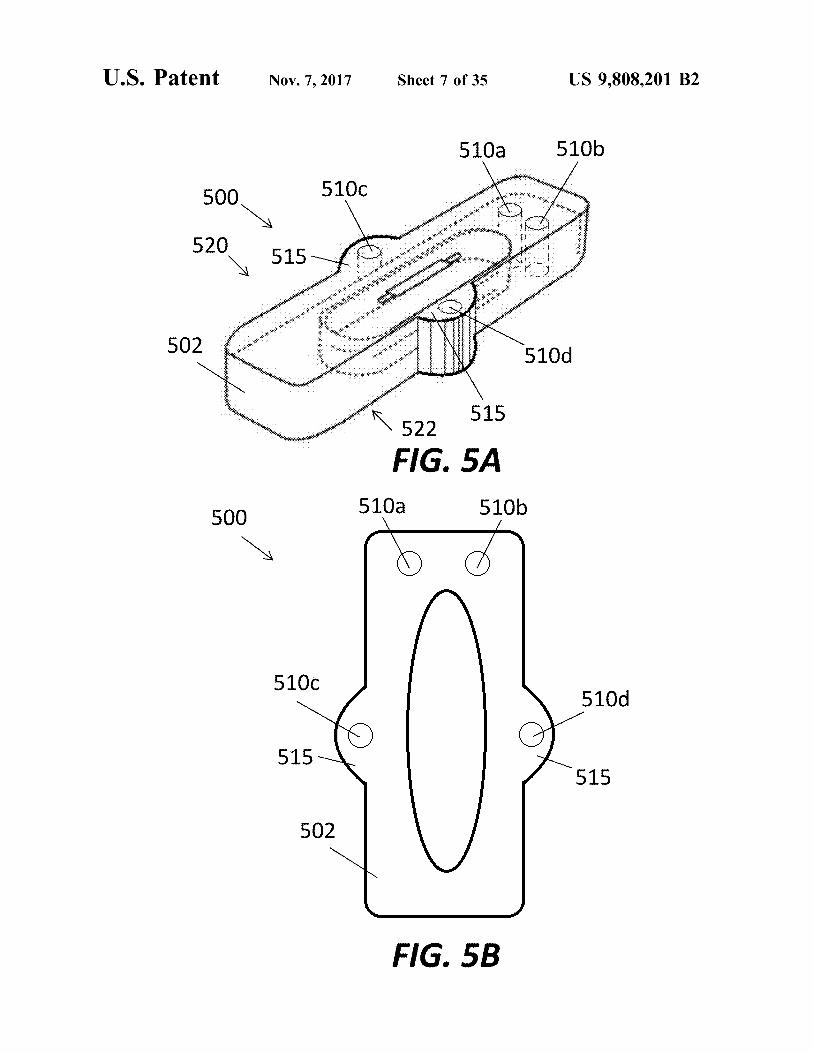
U . S . Patent Nov . 7 , 2017 Sheet 7 of 35 US 9 , 808 , 201 B2
5100 510b
5100 500
520 515 . . : :
on assistenti initiati * * * * *
502 so e wwwwww wwwwwww * * *
????? 5100
????? 522 515 FIG . 5A
510a 5106 IG . SACO 500
5100 510d
515 515
502
FIG . 5B
166
176
; ; ; ; - - ; - « ; ; ; ; ;
Us 9 , 808 , 201 B2
?????????????? . wc : e " ? " a
!
???????????????????????????? . ?
? ; ; ; ; ;
??? !
?????????????????????????????????????????????? ???????????????????????????????????
1626
510b
??????????? ; , .
eed ; : f
510g S10d 54
?
: ? ?
- ; - ; " ; ri
?????????????????? ? » ????????? ? ? ? $
: : - ; ?????????? ? ?
: : - * * * ?????????????? ; : :
Sheet 8 of 35
X
????????????????????????????????????? ;
? ? ? ? ? ? ? ? ? ? ? ? : : : ?????????????????
?? ? ? ? ? ? ? ? ? ? ? ?
FIG . 50 500
500 Fid . 50
s ??????? ??????????? ; ;
riPti :
??
? ? ? ??? - ; ; s - ?? k
-
; etriccir ? ????????????? ; » ?????? .
/
510c - 510c X
_ Nov . 7 , 2017
????????????????????? ? ??????????????????????????????? » ? ?????????? ? } ?
????????????????????????????????
510a 510a
??????????????????? : : eo ssit ????????????????????
?? ????????????????????? ? » ! ? : -
162a
: ??????????????????? ?
????
? ? ? ? ? ?
? ? ? ? ? ? ? ? ? ? ? ? ? ? ?
? ?
?
? ? ? ?
? ? ? ?
? ?
? ? ? ? ? ?
?
????? ; ;
* * * * * *
U , S , Patent
g ?
_
_ $
166
178
US 9 , 808 , 201 B2
- S5
- 6100
610b
162b
*
.
* * * * * * * * * *
im
*
??? ; ; ; ; ? : ; i - ; : ???????????????
* * *
O _ _ _
* * *
???????????? ; ri : ? ; * * ????????? ? " * * * : A
* * * * *
FIG . 6C
H
??????????????????????? * * * * * *
*
*
s
itt
- - 009
; : : - ; : ????????? » crritis : : : ???? : ?
Sheet 9 of 35
* * *
1620
610a
nininin
FIG . 6B FIG . 6B
162a
6 + 15451
permitt
* * * * * * * *
* * * * * * * * * * * * * *
* * *
* *
* * *
Nov . 7 , 2017
6100 6150 6150
th
* * * * *
600 009
6156
??????????????????????????????????? ; ;
* * * * * * * *
610b
* * * * * * *
FIG . 6A
* * *
* * * * * *
* * * * * * * * * * * *
. .
U . S . Patent
141 . . . . . .
615a
A 610a fo
140 * *
142
602 602
100
600
-
-
?
?
? ?
?
- -
-
?
? ??????????
-
?
176 ? ?
- -
-
US 9 , 808 , 201B2
-
?
- -
* *
-
* * * ???????????
-
?
-
?
????????????????? ; : 5
: * * * ???????????????? ri ; - s
feris ? ??????? ? '
?
-
?
-
f
? ? ? .
eris ????????????????????? ? ?
?
?
? ?
-
?
???? ? ? ? ? ? ? ? ? ? ? ?
-
?
-
?
????????? ? ? ????????????? ? ?
- - - - -
???
?
Sheet 10 Of 35
?
? ; ????????????????????? ? ??????????????????????? q : } ?
Flc . 7
- cxiftis ? ? ? ??????
- - - -
-
? ?
???
??????????????? . -
? . ??
????????????????? -
?
-
? ? ? .
168
?
??? ; ; qrw : * ??????
stiksik -
mixtx * - '
?
142 , ??????? ? . ? .
?
? .
_ Nov . 7 , 2017
?
?
???????????? rie ????????????? - ? ? ?
?
* *
; ? "
* ?
?
* * * * * * * ? ' i8
?
* - ; rkweila ???????? ? ?
1
? ? ?? * *
? ???? ? feti
-
-
-
-
.
? .
?
-
-
?
? ?
? ? ?
? ?
? ? ?
? ? ? ?
? ? ?
??????????? ? ? ? ? . ???? : ???? ? ?
U , S , Patent
5
g
$
10b
178
176
166 ??????? ? ? ? ? ?
162e
US 9 , 808 , 201B2
???????? ???? e ' rv ???
iews ???????? : ; ? ?????
; t
??????????????????????? ; » ; wa
* * * ehend ?????????????? ? ???????
FIG . 8C
miferica ????????
????????????? ? ????????? ; ; r ??????
? : » : : : ??????????????
S6
? ; . ' - * * * * ; t ????????? : sf ???????????? ?????
7108
????????????????????? ? ei ????????????????????????? : ;
Sheet 11 0f 35
??? : : : : - : : - ; i ??
700
162d 162d
FIG . 8B
; ; ;
; ; - - ;
» ???????? ?
??????????????? : »
? ????? ;
????????????????????? ???????????? ; y de ; « ; chr
7106
.
a vir ?? » s ??????
; ? * * * * * ; ; erecre
* * * : iFirstfi
_ Nov . 7 , 2017
??????????????????????????????? ;
]
????????? ; ir - t
? ? ? ? ? ? ? ? :
FIG . 84 ???????????????????????????
ri ?? ? ? ?
???????????????????? ; : : : ??????????????????
? ????????????????????? * ; ? erriet ? ????????????????????????????? ? ? ?
??????? : ? ? ? ? ?
?
? ? ? ? ? ?
?
?
?
?
? ?
?
?
?
? ?
?
*
??? - 140
715 1
700
710a
702
U , S , Patent
; _ $ $
_ $
162e
166
178 ? 9 [ [
US 9 , 808 , 201B2
??????? ? ? ? •••••••••••••••
? ?????????????? ? ? ? ? ? : ????????????????????
810b
S8
??????????? perie
: q ?? : : : : : ?????? . ?
?
???????????????????????????? ? - ; f "
FIG . 96
??
???????????????????????? ?????????????????????? ? ?? ;
????????????????????? ? ? ? ?
; " ?????????????????????????? : ofct ?????? ; ??? ????????????????????????????? ??????????????????
810c
810a
Sheet 12 of 35
e ?????????????????
800
162f
????????????????????? ? ?
162d
FIG . 98
?????????????????????? ? ?????????? gei : : : ; : ;
???????????????????????????????????? : * •• ?????????
•
. 810d 810b
tº • •
/ com ??????????????????? ? ; » ???? ;
_ Nov . 7 , 2017
??????????????????? - t ?????????????????????
? ????????????????????????? ??????? ' teritur ????????? ?
wwws ??
FIO . 9A
???????? : » ? $ - er ??????????????
?
? i - ? tricr ?????? ????? * * * * * * * g * * * * * * * *
? ? ? ? ?
?
?
? ? ?
?
? ?
?
? ?
?
? ?
?
?
??
? ?
?
? ? ? ? ?
?
?
?
?
?
?
008
? ? ? ?
815
, ? ? ? ? ?
810c 810a
802
U , S , Patent
g 5
$
$
.
99
178
US 9 , 808 , 201 B2
176
162e
* * * *
62e
? ? ? ???? ? ????????? ;
9106 9100 9016 —
- 910d
OIS
; " ??????? ; * ??? ??? ? ? ?
OTS
- ? ? ? ; P ????????????????????????
F
» ; » # • #
FIG . 10C
* * * * *
? ? ? ? ? ? ? ? " ? * * *
$
2 W A
? ? ? ? ?
? ? ? ? ?
???????????????? ; - - ; ; r ????????????????????
? ! , ;
Sheet 13 of 35
9102 910a - 9100 -
162f
*
* * *
006
router
FIG . 10B
1620 162d
* * * * * * *
* *
* * * *
* * *
* *
tek * * *
910b 9016
* * * * * * * * *
2915b
9150 10d
??????????????????
1910d
*
Nov . 7 , 2017
* * *
* * * *
? ; » ;
prispevkomitoporta
A
- ??????????????? w
FIG . 10A
n
i ; - r - : i ; me ;
* * *
V
*
* * * * * * * * * * * * *
* *
* * *
*
* *
*
TOI
*
*
*
*
*
*
*
*
*
*
* * * * *
to
*
U . S . Patent
900
902
910a 910a
915a
9100
9150
US 9 , 808 , 201 B2
tetés
1006b
FIG . 110
. . meetav com
we meant
1004 1004
t
1006b 1006b
1002
* * 1994 * * * * * * * * * * * * * * * * * * * * * * * * * * * * * * * * * * * * * * * * * * * * *
o
wever
be
1006a
Baie
Sheet 14 of 35
the moderne
meeste
Ahmedlce
7
t
items *
FIG . 11A
30 ) * * * * * * * *
01
1004
* * * *
1006b
0
1st
* * * *
Nov . 7 , 2017
1002
1000
FIG . 11B
1010 1010
1006a
. .
Y
: 17 L
U . S . Patent
1002
1010
1006a
178
166
176
US 9 , 808 , 201B2
??????????? ???????????????? ????? ? ? ? ? ? ? ? ? ? ?
??????????????? ?? ?
??????????????????? ???????????????? - ? ? » : i
?????????????? ?????????? - ?? ? ? ? » ! ]
FIG , 11F
1000
?????????????????? : ?
??????????????????????? s ? : : : - ;
? ; rii
102
1000
; ; ; ; ; ed ?????????????
- ereiger ??????????????? - fpecie x ' °
e
; ?
Sheet 15 of 35
.
???????????????????????? ? ? - ??? ?
???????????????? ??????????????????????????????????? ?
FIG . 110
• • • • • t
•
* * ; ; .
??????????? : qq ????????????????????
? ? ? ? ? ? ???????????????????? ??????????????? ? " ? * * * *
??????????????? eri ? ? ?
?
???????????????????????????? ? ? ??? ?????????????????????????????????
- *
?
?
?
_ Nov . 7 , 2017
?
??????????????????????????
w / * * * * * * *
???????????? ww
?
? ??????
-
FIG . 11E
????? ????????????????????? ?
: *
•••••••••••••• ; » : : : .
> ? ???? - cheste ? ?
?
?
?
? ?
?
?
? ? ? ? ? ? ? ? ?
? ?
? ?
? ?
?
&
102 1000 _
?
?
; mca ? ? ?
? ?
U , S , Patent
'
140
100
? 141
142
U . S . Patent Nov . 7 , 2017 Sheet 16 of 35 US 9 , 808 , 201 B2
1100 1100 1100
2 71501105 1115a , 1105
1115a 1105
1102 1102 - 1116
- 1116 1115b
1115b
FIG . 12A FIG . 12B
einen 1100
inti
166 J X 166 166
iittimet L
178 178
FIG . 120 FIG . 12D
atent Nov . 7 , 2017 Nov . 7 , 2017 Sheet 17 of 35 US 9 , 808 , 201 B2
1200 1200 120 1218 1218 AMAMAHAMAMAMAMAHAMAMAHAMAMAMAMAHAMAHAMAHAMAHAMMMMMMMMMM 1215 1215
1215
61218 w 1202 1202 wwwwwwwwwwwwwwwwwwwwwwwwwwwwwwwwwwwwwwwwwwwwwwwwwwwwwwwwwwwwwwwwwwwwwwwwwwwwwwwwwww 1216
FIG . 13A FIG . 13B
11001 160 160 y 160 160 1 > 162 162 V
166
178
FIG . 13C
160
US 9 , 808 , 201 B2
I 160
1163
162 '
FIG . 14C
-
- -
-
Sheet 18 of 35
.
160
160
-
-
-
-
-
-
* * * * * *
* * * * * * * * * * *
-
-
*
-
-
-
-
00 * * * *
-
* * * * * *
1302C
* * * * * * * * * * ! ! 4 : 12
. . . . . .
1302b
:
Nov . 7 , 2017
* * * * : : * :
FIG . 14B
1302a
s
*
17
* * * *
* * * *
FIG . 14A
os
U . S . Patent
1300
1302
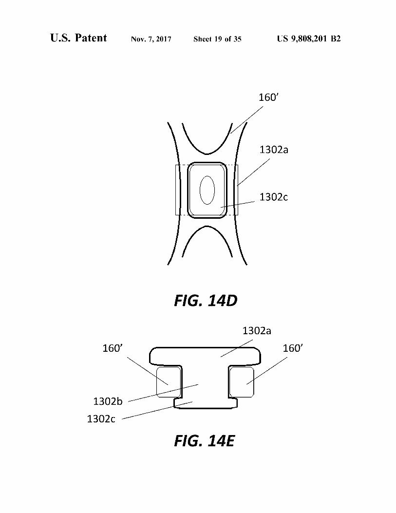
U . S . Patent Nov . 7 , 2017 Sheet 19 of 35 US 9 , 808 , 201 B2
160
1302a
13020
FIG . 14D 1302a
160 ' 160 ' 160 '
1302b 13020
FIG . 14E
U . S . Patent Nov . 7 , 2017 Sheet 20 of 35 US 9 , 808 , 201 B2
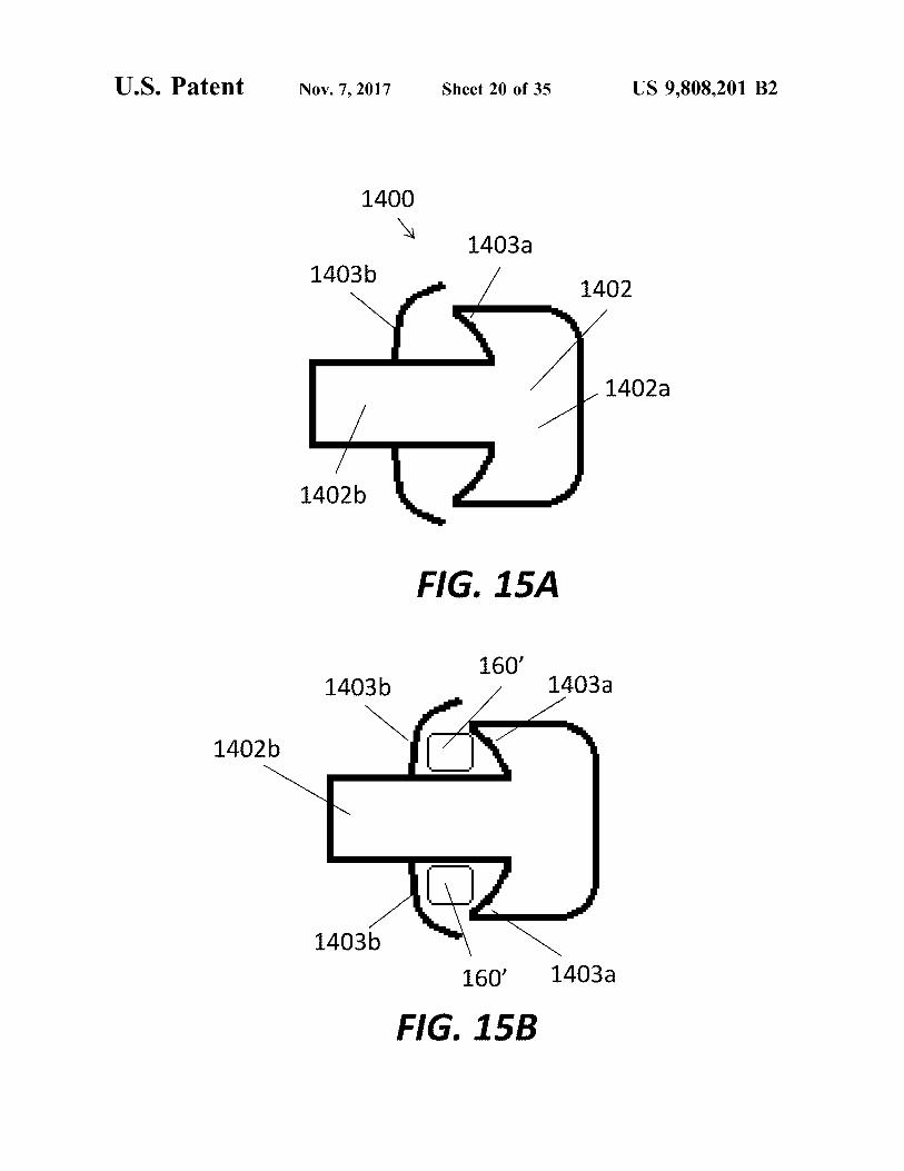
1400 1403a
1403b 1402
1402a
1402b
FIG . 15A 160 '
1403b 1403a
1402b
1403b 1403a 160 '
FIG . 15B
atent Nov . 7 , 2017 Sheet 21 of 35 US 9 , 808 , 201 B2
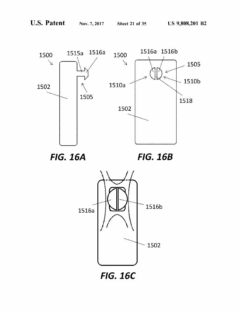
1500 1515a 1516a 1500 1516a 1516b - 1505 rhy V L OD 15106 1510b
1502 1502 1510a 1510a 1 1505 * 1505
1518 1502
FIG . 16A FIG . 16B
1516b 1516a
- 1502
FIG . 160
U . S . Patent Nov . 7 , 2017 Sheet 22 of 35 US 9 , 808 , 201 B2
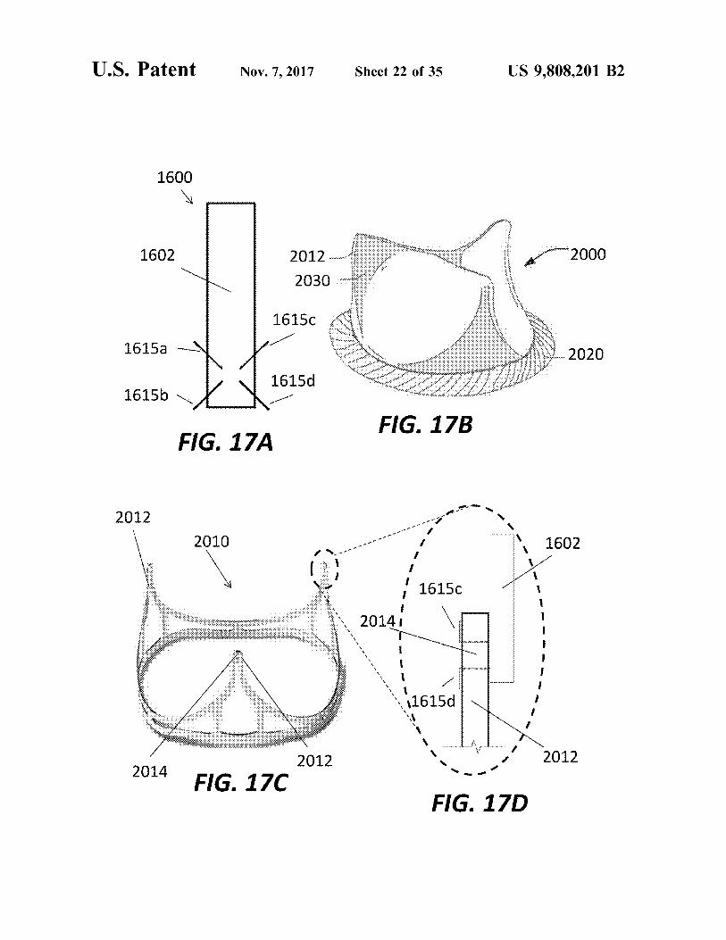
1600
Wie
1602 * 2000 2012 .
2030 wie
16150 : .
1615a - 2020 2020 * * * - * * * * 1615d * * *
1615b V 16150 * ??????????? * * * *
FIG . 17B FIG . 17A
-
2012 - - -
-
2010 -
- - Ti 1602 - -
i 1615c 20141
w
more wwwwwwww 11615d power met mense me die
2012 2012 2014 2014 FIG . 170
FIG . 17D
U . S . Patent Nov . 7 , 2017 Sheet 23 of 35 US 9 , 808 , 201 B2
2000 2012 www 2030
. SEN1 . . . "
* 2020 * * X
w - SEN2
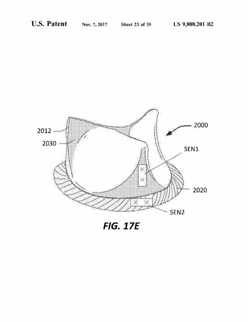
FIG . 17E
U . S . Patent Nov . 7 , 2017 Sheet 24 of 35 US 9 , 808 , 201 B2
2310
2000
2100 2012
ostos 2030 www .
*
2300
* * *
2020 2200
2320 FIG . 17F
U . S . Patent Nov . 7 , 2017 Sheet 25 of 35 US 9 , 808 , 201 B2
2310 2300
2100 ' 2000 W
ritimit
2012 - 2030
WW
2020
2007
2320 FIG . 176
U . S . Patent Nov . 7 , 2017 Sheet 26 of 35 US 9 , 808 . 201 B2
- 2100
2300 " 2310
2000 “ … … … … … … … …
2012 wome … … … …
2030 ?
2020
2320 " 2200 FIG . 17H
U . S . Patent Nov . 7 , 2017 Sheet 27 of 35 US 9 , 808 , 201 B2
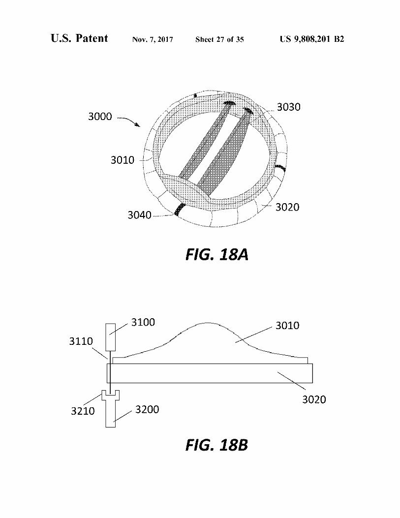
3030 3000
3010 O
3020 3040 + + + +
FIG . 18A
3010 3110 7 3100
3020 3210 3200
FIG . 18B
US 9 , 808 , 201 B2
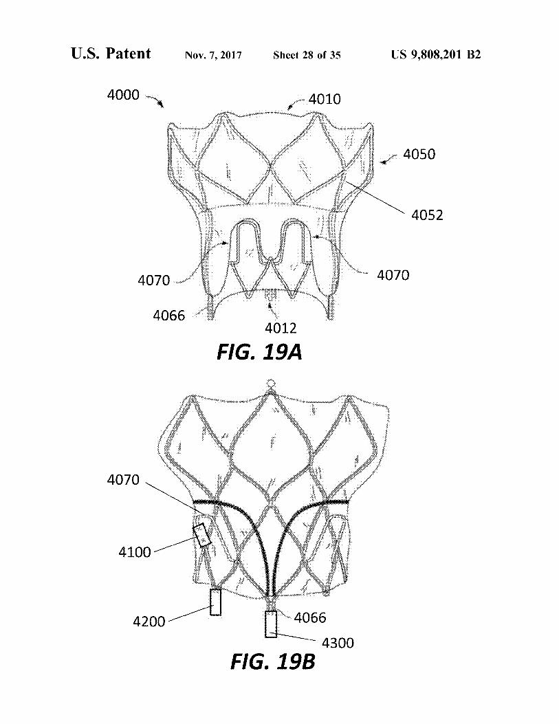
4050
4052
4070
WN W * NA
*
* * * * * * * * * * * * * * * * * * *
sono *
* * * * *
. :
. '
.
* * * * * *
4010 * * * *
* * *
*
Sheet 28 of 35
.
wwwww
4012
4300 4066 -
FIG . 19B
FIG . 19A
* * * * * * * * * *
* * * * * 14
Nov . 7 , 2017
* . . * . .
4070
4066
4200
U . S . Patent
4000
4100
4070
U . S . Patent atent Nov . 7 , 2017 Sheet 29 of 35 US 9 , 808 , 201 B2
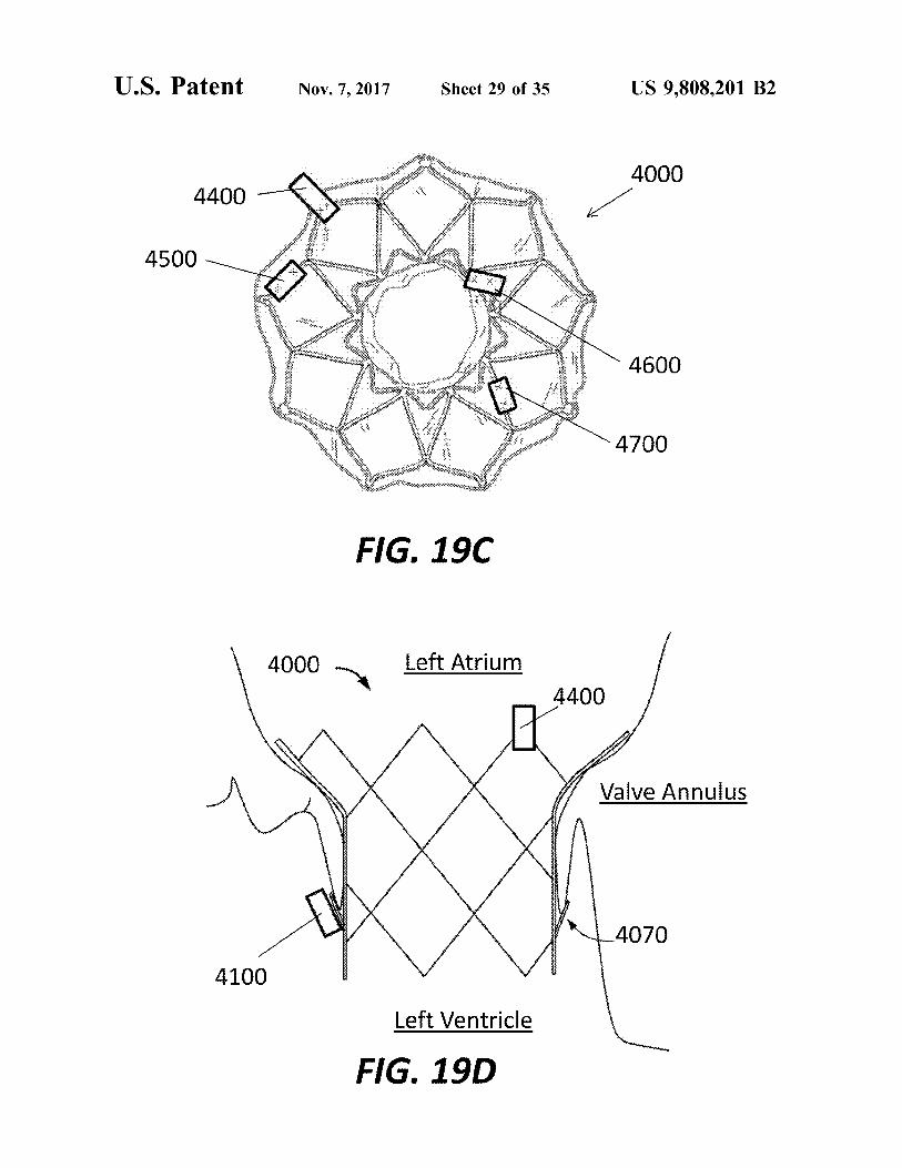
4000 4400 4400 .
* * * * * *
4500 tre
bank , * * * * * * * *
víifi - 4600
* * *
4700
FIG . 19C
4000 Left Atrium 4400 14400
Valve Annulus
4070
4100
Left Ventricle
FIG . 19D
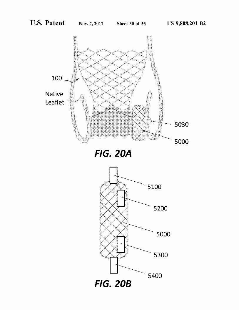
U . S . Patent Nov . 7 , 2017 Sheet 30 of 35 US 9 , 808 , 201 B2
MWWW .
. . . * * * * * * * * * * *
. . . 100 * * *
. . .
* * * * *
* *
*
* * * Native Leaflet
5030
5000
FIG . 20A
5100 * * * * * * * *
* * * * * * + 91 : : : : : : : : : : : : : : : : : : : *
5200 : : : : : : : : : 42143 : 31 : 33 : 14
: : : : : 43 : 44431
5000 . . Bits : 5 : 14 : 13 : 35 : 31 : 40 : 010 : : : : :
IB : 113 : 11 : : 313333 . : : : : : : : : :
* * * * * *
5300
5400 FIG . 20B
atent Nov . 7 , 2017 Sheet 31 of 35 US 9 , 808 , 201 B2
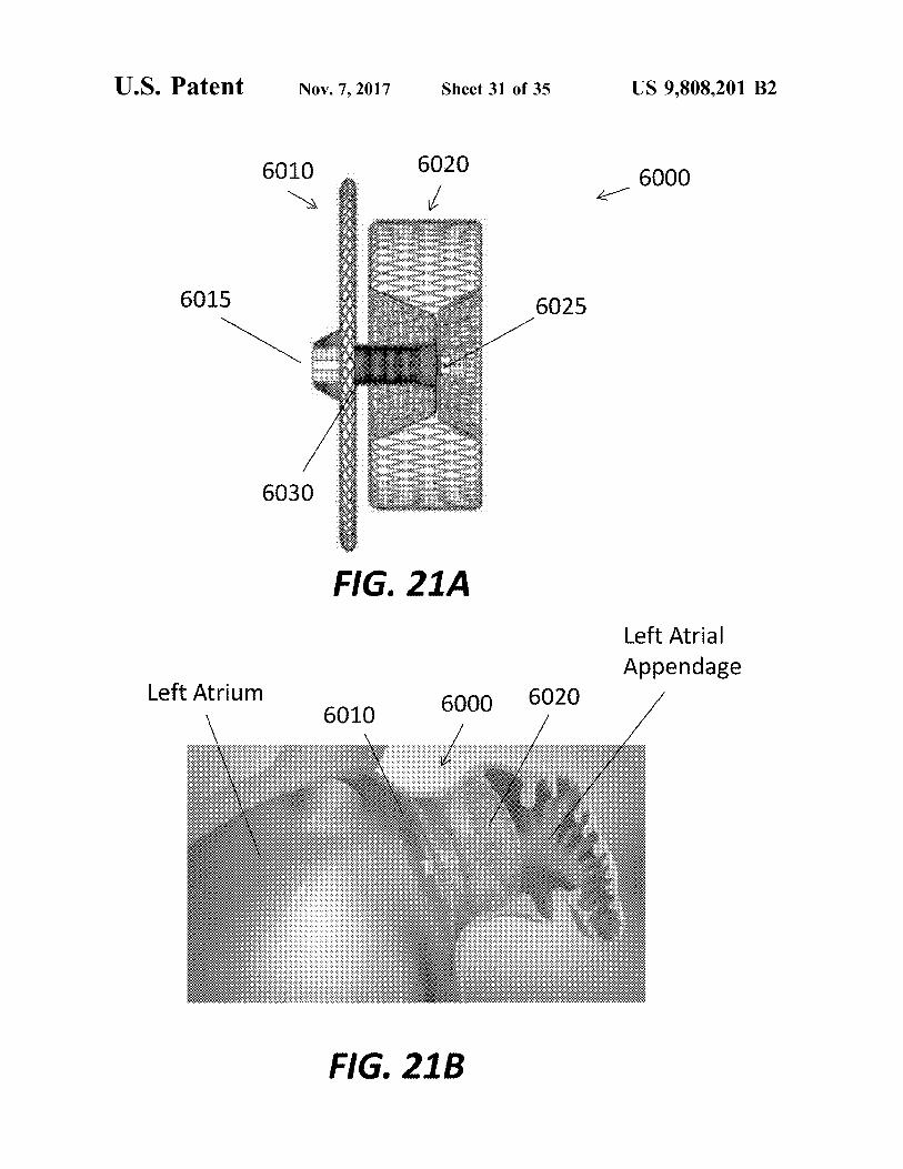
6010 6020 K 6000
6015 6025
WWW * V * XXXWWW .
6030
FIG . 21A Left Atrial Appendage
Left Atrium 6010 6000 6020
FIG . 21B
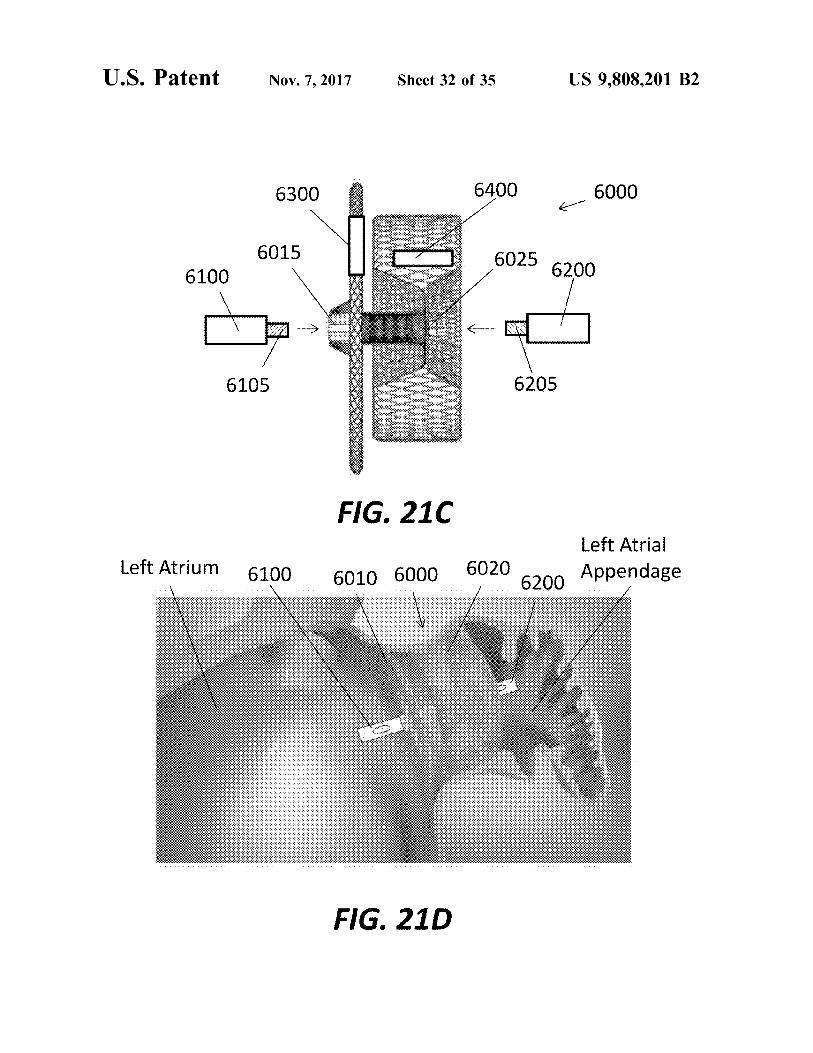
U . S . Patent Nov . 7 , 2017 Sheet 32 of 35 US 9 , 808 , 201 B2
6300 6400 6000 6015 6025 6200 6100 2015 1
- 025 - -
6105 6205
FIG . 210
Left Atrium 6100 6010 6000 Left Atrial
6020 6200 Appendage
FIG . 21D
US 9 , 808 , 201 B2
1
. . .
,
.
.
Ww
?
* *
*
* .
.
* *
.
.
. .
*
*
VEDP LVEDP
*
) $ € !
* *
* *
. . '
Sheet 33 of 35
LVEDP
inv
99
- Y
ORS i diem
FIG . 22A
.
FIG . 22B
' n
E
i
. .
.
. . .
. . . 4 .
.
.
. . .
.
V
* * *
* *
.
. .
.
.
.
. .
.
* . *
- + .
*
Nov . 7 , 2017
SMRTIS ?
* KA * * *
. . . .
2 . 4 .
. . .
.
. . ,
*
* *
-
.
. . -
WEDNW *
25 .
WA ,
2 -
U . S . Patent
1
el
U . S . Patent Nov . 7 , 2017 Sheet 34 of 35 US 9 , 808 , 201 B2
Aortography after valve deployment
is ? MI AR
ARI > = 25 SARIS TTETEE ( AR etiology )
Corrective measures
wwwwwwww
ARI > = 25
No More measurements wwwwwwwwwwwwwwwwwwwwwwwwwwwwwwwwww
FIG . 23
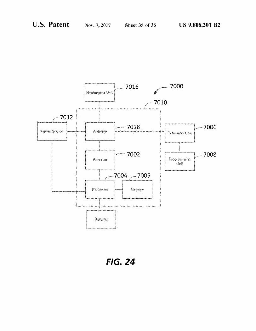
FIG . 24
* * * * * , * . . * * * * * mm .
" ?? ???????? ???? ????
. Locx
.
. . 70047005
. . . " 222222222222222222222222222222 * * * * * * * * * * * * * * * * * * * * * * * * * * * * * * * * * * * * * * * * * * * * * * * * * * * * * * * * * * * * * * * * * * * wwwwwwwwww . wwwwwwwwwwwwwwwww * *
* 2
*
Clowwood RXX * * *
e
* * 8002 . 7002 = = = = = = = = = = = = * *
* * viro 22222222222222222 wyty :
*
. * * * * * * * * * * * * * * * * * * * * * * * * F r * * * * * * * * * * * * * * * * * * * * * * * * * * * * * * * .
suoneen - * - * - * - * * - - * - * * - * . Anwa Power Sauce . 9002 7018 L
- - - - - - - - - - - - - - - - - ?? ?? ?? ?? ?? ?? ?? ?? ?? ???? ?? ? ?? ? ?? ??? ??? ??? ??? ??? ??? ??? ??? ??? ???
o . . . . 70121 - - - - - - - *
* * * * * * * * * * * * * * * * * * * * * * * * * * * * * * * * * * * * * * * * * * * * * * * * * * * * * * * * * * * * * * . w . * * * * * * * * * * * * * * * * * * * * * * * * . . OTOLAR www OTOL
. * *
- 2222222224 m . 7000 7000 7016 7016 mechanging the
* * * * * * * * * * * * * * * * * *
US 9 , 808 , 201 B2 Sheet 35 of 35 Nov . 7 , 2017 U . S . Patent
US 9 , 808 , 201 B2
SENSORS FOR PROSTHETIC HEART DEVICES
there is a need for improvements in the devices , systems , and methods for accurately measuring parameters associated with proper prosthetic heart valve functionality . Among other advantages , the present disclosure may address one or
5 more of these needs . CROSS - REFERENCE TO RELATED
APPLICATIONS
The present application claims the benefit of the filing BRIEF SUMMARY date of U . S . Provisional Patent Application No . 62 / 038 , 512 , titled “ Prosthetic Heart Devices Having Diagnostic Capa According to one embodiment of the disclosure , a pros bilities , ” filed Aug . 18 , 2014 , the disclosure of which is 10 thetic heart valve system comprising includes a prosthetic hereby incorporated by reference herein . heart valve and a first sensor . The prosthetic heart valve
includes a stent extending from an outflow portion to an BACKGROUND inflow portion and having an expanded condition and a
collapsed condition , and a valve assembly mounted to the The present disclosure relates to heart valve replacement 15 stent . The first sensor is configured to measure physiological
and repair devices such as collapsible prosthetic heart data , the first sensor including a body and a plurality of valves . More particularly , the present disclosure relates to apertures extending through the body and adapted to receive devices and methods for using prosthetic heart devices at least one suture therethrough for attaching the sensor to having diagnostic capabilities . the stent .
Diseased or damaged native heart valves may be repaired 20 According to another embodiment of the disclosure , a or replaced using prosthetic devices . In some instances , prosthetic heart valve system includes a prosthetic heart devices such as annuloplasty rings are used to repair and valve and a sensor . The prosthetic heart valve includes a restore the function of a malfunctioning native heart valve . stent extending from an outflow portion to an inflow portion If repair is not possible , the function of native heart valves and has an expanded condition and a collapsed condition , may be replaced by prosthetic devices , such as surgical 25 and a valve assembly mounted to the stent . The sensor is valves . Such a replacement typically requires an open - heart configured to measure physiological data , the sensor includ surgical procedure . ing a body , the body having a first side , a second side
In addition to these devices , prosthetic heart valves that opposite the first side , and a pair of fingers extending away are collapsible to a relatively small circumferential size can from the body on the first side of the body , the fingers and be delivered into a patient less invasively than surgical 30 the first side of the body defining a channel extending along valves . For example , a collapsible valve may be delivered a length of the body , the sensor being connectable to the into a patient via a tube - like delivery apparatus such as a stent . catheter , a trocar , a laparoscopic instrument , or the like . This According to a further embodiment of the disclosure , a collapsibility can avoid the need for more invasive proce prosthetic heart valve system includes a prosthetic heart dures such as full open - chest , open - heart surgery . 35 valve and a sensor . The prosthetic heart valve includes a
Collapsible prosthetic heart valves ( sometimes referred to stent extending from an outflow portion to an inflow portion herein as transcatheter valves or transcatheter implants ) and has an expanded condition and a collapsed condition , typically take the form of a valve structure mounted on a and a valve assembly mounted to the stent . The sensor is stent . There are two types of stents on which the valve configured to measure physiological data , the sensor includ structures are ordinarily mounted : a self - expanding stent and 40 ing a body . A first finger has a first end attached to the body a balloon - expandable stent . To place such valves into a and a free end , the free end being configured to hook over delivery apparatus and ultimately into a patient , the valve at least one strut of the stent to attach the sensor to the stent . must first be collapsed or crimped to reduce its circumfer According to another embodiment of the disclosure , a ential size . prosthetic heart valve system includes a prosthetic heart When a collapsed prosthetic valve has reached the desired 45 valve and a sensor . The prosthetic heart valve includes a
implant site in the patient ( e . g . , at or near the annulus of the stent extending from an outflow portion to an inflow portion patient ' s heart valve that is to be replaced by the prosthetic and has an expanded condition and a collapsed condition , valve ) , the prosthetic valve can be deployed or released from the stent being formed of a plurality of struts , a strut aperture the delivery apparatus and re - expanded to full operating being formed at an intersection of at least two of the struts , size . For balloon - expandable valves , this generally involves 50 and a valve assembly mounted to the stent . The sensor is releasing the entire valve , and then expanding a balloon configured to measure physiological data , the sensor includ positioned within the valve stent . For self - expanding valves , ing a body , the body being configured to be coupled to the on the other hand , the stent automatically expands as the stent . The body includes a first body section having a first sheath covering the valve is withdrawn . width , a middle body section having a second width smaller
It would be advantageous to monitor the function of 55 than the first width , and a third body section having a third prosthetic devices , including annuloplasty rings , surgical width greater than the second width and smaller than the first valves and transcatheter valves , before , during and after width . implantation to ensure proper functioning for short - term and According to still another embodiment of the disclosure , long - term assessment . For example , calcification of the a prosthetic heart valve system includes a prosthetic heart aortic valve may affect the performance and anchoring of 60 valve and a sensor . The prosthetic heart valve includes a transcathether implants . Calcification may also be associated stent extending from an outflow portion to an inflow portion with leakage , such as paravalvular leakage around the exte - and has an expanded condition and a collapsed condition , rior of a medical device or aortic regurgitation through the the stent being formed of a plurality of struts , a strut aperture interior of a medical device . being formed at an intersection of at least two of the struts .
There therefore is a need for improvements in the devices , 65 A valve assembly is mounted to the stent . The sensor is systems , and methods for monitoring prosthetic heart configured to measure physiological data , the sensor includ devices before , during and after implantation . Specifically , ing a body configured to be coupled to the stent . The body
US 9 , 808 , 201 B2
includes a head having a first width and a shank having a According to a further embodiment of the disclosure , a second width smaller than the first width . prosthetic heart valve system includes a prosthetic heart
According to yet another embodiment of the disclosure , a valve , an occlusion device , and a first sensor . The prosthetic prosthetic heart valve system includes a prosthetic heart heart valve includes a stent extending from an outflow valve and a sensor . The prosthetic heart valve includes a 5 portion to an inflow portion and has an expanded condition stent extending from an outflow portion to an inflow portion and a collapsed condition . A valve assembly is mounted to and has an expanded condition and a collapsed condition , the stent . A collapsible and expandable occlusion device is the stent being formed of a plurality of struts , a strut aperture configured for positioning between the prosthetic heart valve being formed at an intersection of at least two of the struts . and a native valve annulus in which the prosthetic heart A valve assembly is mounted to the stent . The sensor is 10 valve is implanted so that a first end of the occlusion device configured to measure physiological data , the sensor includ - faces toward the outflow portion of the stent and a second ing a body , the body including a connecting member adapted end of the occlusion device faces toward the inflow portion to couple the sensor to the stent , the connecting member of the stent . The first sensor is configured to be attached to including a shaft projecting away from the body to a free 15 the occlusion device , the first sensor including a body and end , and a head at the free end of the shaft . being configured to measure physiological data . According to a further embodiment of the disclosure , a In still a further embodiment of the disclosure , a collaps
prosthetic heart valve system includes a prosthetic heart ible and expandable occlusion system for placement within valve and a sensor . The prosthetic heart valve includes a a vasculature of a patient includes a disc - shaped portion stent extending from an outflow portion to an inflow portion 20 coupled to a cylindrical portion by a connector . The cylin and having a plurality of stent posts , at least one stent post drical portion has a first diameter and the disc - shaped defining an aperture . The sensor is configured to measure portion has a second diameter greater than the first diameter physiological data , the sensor including a body , the body when the occlusion system is in an expanded condition . A including a plurality of fingers extending away from the first sensor is configured to be attached to the cylindrical body for connecting the sensor to the stent , at least two of 25 portion , the first sensor including a body and being config the fingers extending away from one another in the absence ured to measure physiological data . of applied forces .
According to still another embodiment of the disclosure , BRIEF DESCRIPTION OF THE DRAWINGS a sensor system includes a collapsible and expandable sensor frame having an outflow frame section , an inflow 30 FIG . 1 is a side elevational view of a conventional frame section , and a frame coupling portion connecting the prosthetic heart valve . outflow frame section to the inflow frame section . A first FIG . 2 is a highly schematic cross - sectional view taken sensor is coupled to the sensor frame , the first sensor along line A - A of FIG . 1 and showing the prosthetic heart including a body , the first sensor being configured to mea valve disposed within a native valve annulus . sure physiological data . A second sensor is coupled to the 35 FIG . 3A is a perspective view of a wireless microelec sensor frame , the second sensor including a body , the second tromechanical ( MEM ) sensor . sensor being configured to measure physiological data . In an FIG . 3B is a cross - sectional view taken along line B - B of expanded condition the outflow frame section and inflow frame section each has an arcuate configuration . FIG . 3A .
According to another embodiment of the disclosure , a 40 FIG . 4A is a perspective view of a MEM sensor according prosthetic heart valve system includes a prosthetic heart to one embodiment of the disclosure . valve and two sensors . The prosthetic heart valve includes a FIG . 4B is a plan view of the sensor of FIG . 4A . support structure extending from an outflow portion to an FIG . 4C is a highly schematic developed view of the inflow portion , a cuff attached to the inflow portion of the prosthetic heart valve of FIG . 1 in an expanded condition support structure , and a valve assembly mounted to the 45 with MEM sensors attached thereto . support structure . The first sensor includes a body and is FIG . 4D is an enlarged partial view of one of the attached configured to measure physiological data and has a male sensors of FIG . 4C . coupling portion extending from the body . The second FIG . 4E is an enlarged partial view of another of the sensor includes a body and is configured to measure physi - attached sensors of FIG . 4C . ological data and has a female coupling , the male coupling 50 FIG . 4F is a highly schematic developed view of the stent portion of the first sensor configured to mate with the female of the prosthetic heart valve of FIG . 4C in a collapsed coupling portion of the second sensor . condition with MEM sensors attached thereto .
According to yet another embodiment of the disclosure , a FIG . 5A is a perspective view of a MEM sensor according prosthetic heart valve system includes a prosthetic heart to another embodiment of the disclosure . valve and a first sensor . The prosthetic heart valve includes 55 FIG . 5B is a top plan view of the sensor of FIG . 5A . a stent extending from an outflow portion to an inflow FIG . 5C is a highly schematic developed view of the portion and has an expanded condition and a collapsed prosthetic heart valve of FIG . 1 in an expanded condition condition . The stent includes a plurality of struts defining at with the sensor of FIG . 5A attached thereto . least one annular row of cells , at least one engaging arm , and FIG . 5D is an enlarged partial view of the attached sensor at least one commissure attachment feature positioned at a 60 of FIG . 5C . terminal end of the stent . The engaging arm has a first FIG . 6A is a top plan view of a MEM sensor according to position and is nested within one of the cells and a second a further embodiment of the disclosure . position projecting outwardly from the one cell . A valve FIG . 6B is a highly schematic developed view of the assembly is mounted to the stent . The first sensor includes a prosthetic heart valve of FIG . 1 in an expanded condition body and is configured to measure physiological data and is 65 with the sensor of FIG . 6A attached thereto . coupled to the engaging arm or to the commissure attach - FIG . 6C is an enlarged partial view of the attached sensor ment feature . of FIG . 6B .
US 9 , 808 , 201 B2
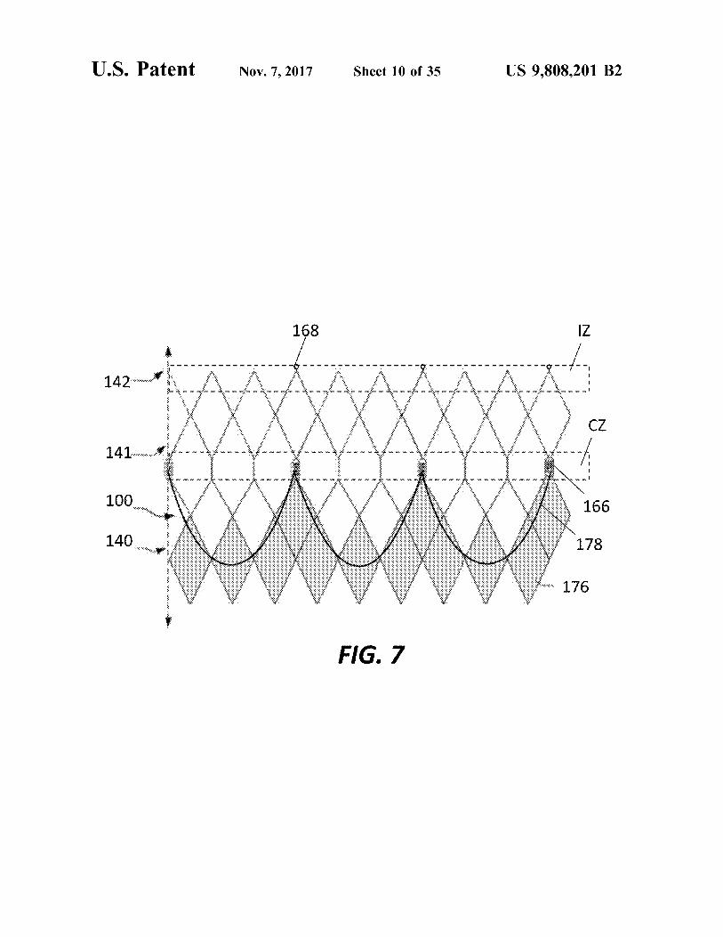
FIG . 7 is a highly schematic developed view of the FIG . 15B is an enlarged partial cross - section of the sensor prosthetic heart valve of FIG . 1 in an expanded condition of FIG . 15A attached to the modified stent of FIG . 14B . showing outflow attachment locations for a MEM sensor . FIG . 16A is a side view of a MEM sensor according to
FIG . 8A is a top plan view of a MEM sensor according to still another embodiment of the disclosure . yet another embodiment of the disclosure . FIG . 16B is a bottom plan view of the sensor of FIG . 16A .
FIG . 8B is a highly schematic developed view of the FIG . 16C is an enlarged partial view of the sensor of prosthetic heart valve of FIG . 1 in an expanded condition FIGS . 16A - B attached to the modified stent of FIG . 14B . with the sensor of FIG . 8A attached thereto . FIG . 17A is a bottom plan view of a MEM sensor FIG . 8C is an enlarged partial view of the attached sensor according to still a further embodiment of the disclosure . of FIG . 8A . FIG . 17B is a perspective view of a surgical prosthetic FIG . 9A is a top plan view of a MEM sensor according to still another embodiment of the disclosure . heart valve .
FIG . 17C is a perspective view of a stent for use in the FIG . 9B is a highly schematic developed view of the prosthetic heart valve of FIG . 1 in an expanded condition prosthetic heart valve of FIG . 17B . with the sensor of FIG . 9A attached thereto . FIG . 17D is an enlarged side view of the sensor of FIG .
FIG . 9C is an enlarged partial view of the attached sensor 17A coupled to the stent of FIG . 17C . of FIG . 9A . FIG . 17E is a perspective view of the surgical prosthetic
FIG . 10A is a top plan view of a MEM sensor according heart valve of FIG . 17B with sensors according to FIG . 17A to another embodiment of the disclosure . attached thereto .
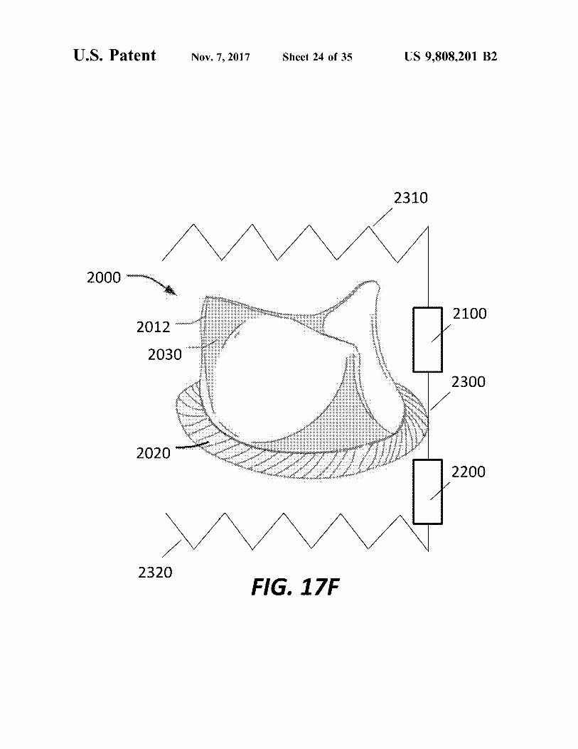
FIG . 10B is a highly schematic developed view of the 20 FIG . 17F is a perspective view of the surgical prosthetic prosthetic heart valve of FIG . 1 in an expanded condition heart valve of FIG . 17B with MEM sensors and a sensor with the sensor of FIG . 10A attached thereto . frame attached thereto .
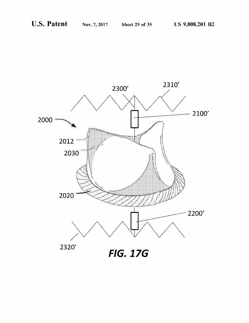
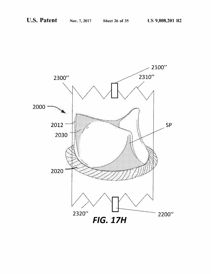
FIG . 10C is an enlarged partial view of the attached sensor FIG . 176 is a perspective view of the surgical prosthetic of FIG . 10A . heart valve of FIG . 17B with MEM sensors and a sensor
FIG . 11A is a perspective view of a MEM sensor accord - 25 frame attached thereto according to a further embodiment of ing to a further embodiment of the disclosure . the disclosure .
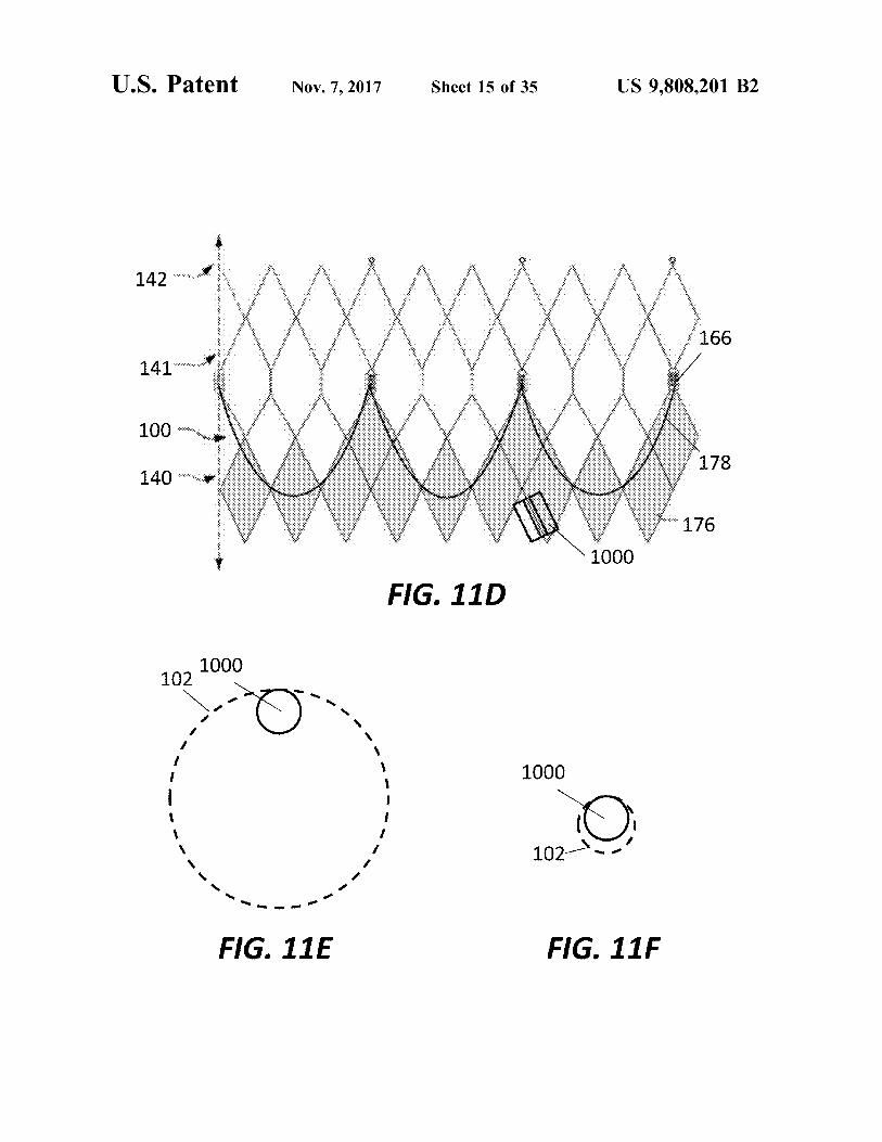
FIG . 11B is a transverse cross - section of the sensor of FIG . 17H is a perspective view of the surgical prosthetic FIG . 11A . heart valve of FIG . 17B with MEM sensors and a sensor FIG . 11C is a transverse cross - section of the sensor of frame attached thereto according to yet another embodiment FIG . 11A coupled to a strut of the prosthetic heart valve of 30 01 30 of the disclosure . FIG . 1 . FIG . 18A is a perspective view of a mechanical prosthetic FIG . 11D is a highly schematic developed view of the heart valve . prosthetic heart valve of FIG . 1 in an expanded condition with the sensor of FIG . 11A attached thereto . FIG . 18B is a side view of the prosthetic heart valve of
FIG . 11E is a highly schematic end view of the sensor of 35 F 25 FIG . 18A with a pair of MEM sensors attached thereto . FIG . 11A attached to the prosthetic heart valve of FIG . 1 in FIG . 19A is a partial side elevational view of a prosthetic the expanded condition . mitral valve .
FIG . 11F is a highly schematic end view of the sensor of FIG . 19B is a partial side elevational view of the pros FIG . 11A attached to the prosthetic heart valve of FIG . 1 in thetic mitral valve of FIG . 19B with outflow MEM sensors the collapsed condition . 40 attached thereto .
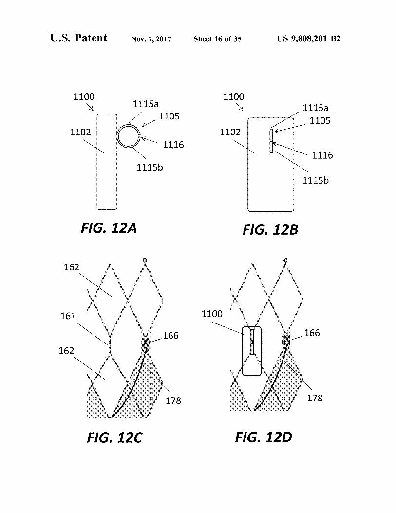
FIG . 12A is a side view of a MEM sensor according to FIG . 19C is an end view of the prosthetic mitral valve of still another embodiment of the disclosure . FIG . 19B with inflow MEM sensors attached thereto .
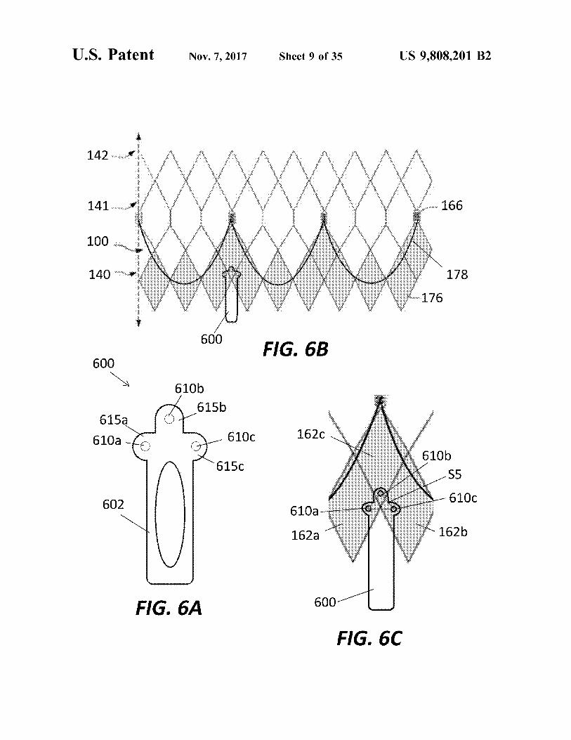
FIG . 12B is a bottom plan view of the sensor of FIG . 12A . FIG . 19D is a highly schematic representation of the FIG . 12C is an enlarged partial view of the heart valve of prosthetic mitral valve of FIG . 19A implanted into a native
FIG . 1 . 45 mitral valve annulus with inflow and outflow MEM sensors FIG . 12D is an enlarged partial view of the sensor of attached to the prosthetic valve .
FIGS . 12A - B attached to the prosthetic heart valve of FIG . FIG . 20A is a highly schematic view of an occluder positioned between the prosthetic heart valve of FIG . 1 and
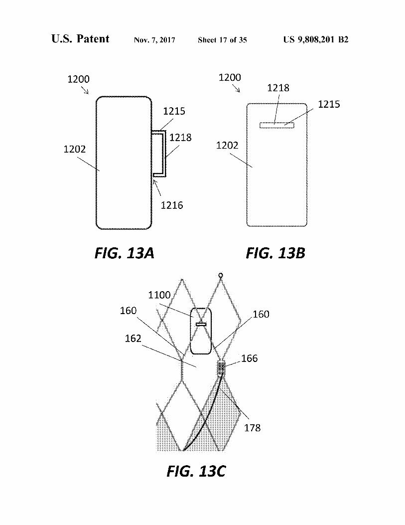
FIG . 13A is an enlarged top view of a MEM sensor a native aortic valve leaflet . according to yet another embodiment of the disclosure . 50 FIG . 20B is a highly schematic view of the occluder of
FIG . 13B is a bottom plan view of the sensor of FIG . 13A . FIG . 20A with inflow and outflow MEM sensors attached FIG . 13C is an enlarged partial view of the sensor of thereto . FIGS . 13A - B attached to the prosthetic heart valve of FIG . FIG . 21A is a cross - sectional view of a closure device FIG . 14A is an end view of a MEM sensor according to 55 * s according to an embodiment of the disclosure .
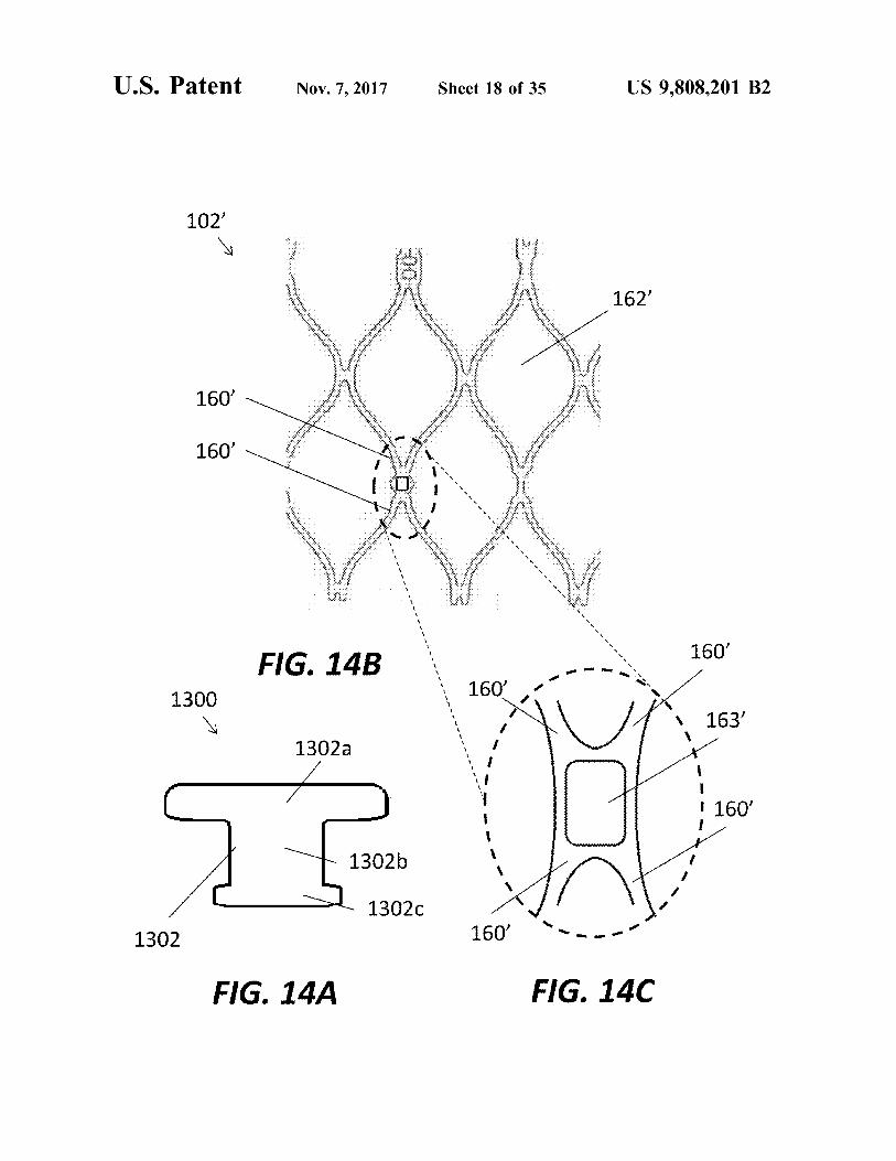
a further embodiment of the disclosure . FIG . 21B is a highly schematic view of the closure device FIG . 14B is a highly schematic developed view of a fra of FIG . 21A implanted into a left atrial appendage .
portion of a modified stent for a prosthetic heart valve in an FIG . 21C is a cross - sectional view of the closure device expanded condition . of FIG . 21A with MEM sensors attached thereto .
FIG . 14C is an enlarged partial view of the modified stent 60 FIG . 21D is a highly schematic view of the closure device of FIG . 14B . of FIG . 21A with MEM sensors attached thereto implanted
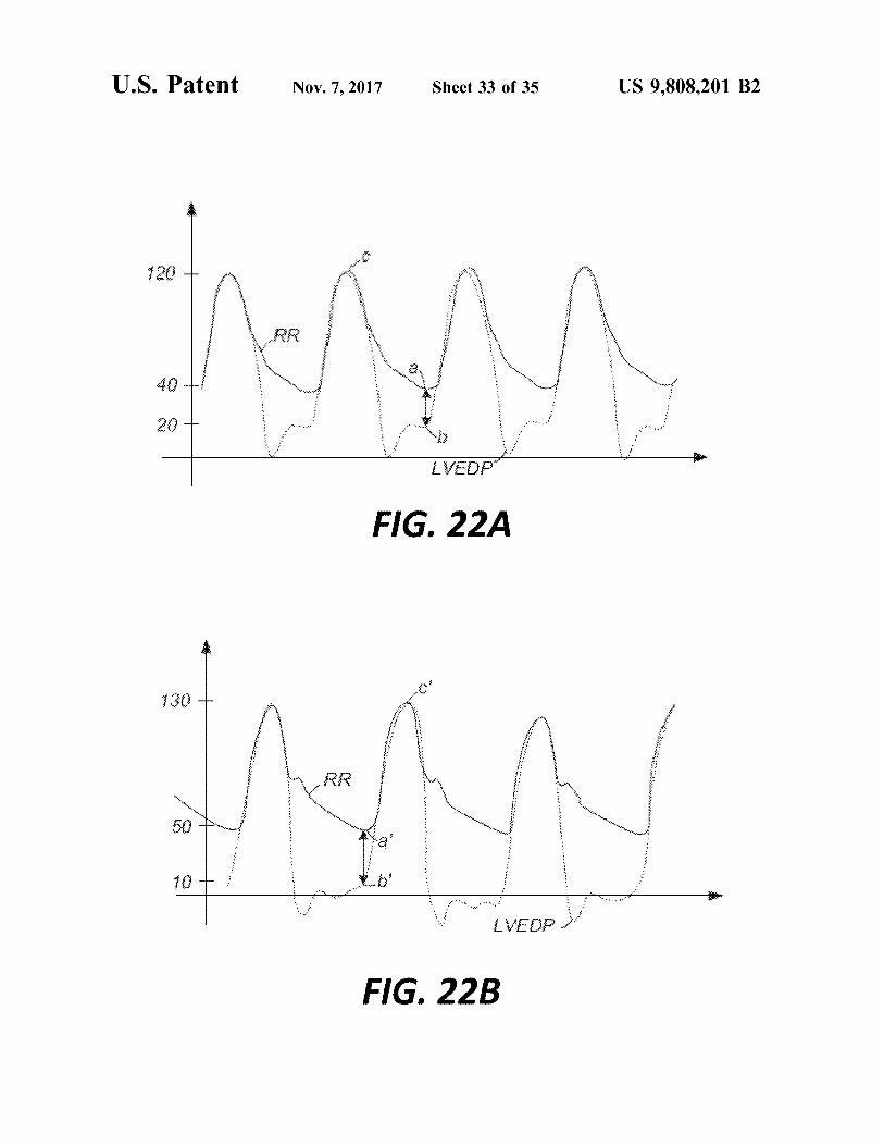
FIG . 14D is an enlarged partial view of the sensor of FIG . into the left atrial appendage . 14A attached to the stent of FIG . 14B . FIGS . 22A and 22B are graphs showing examples of
FIG . 14E is an enlarged partial cross - section of the sensor hemodynamic assessments during transcatheter aortic valve of FIG . 14A attached to the stent of FIG . 14B . 65 replacement procedures .
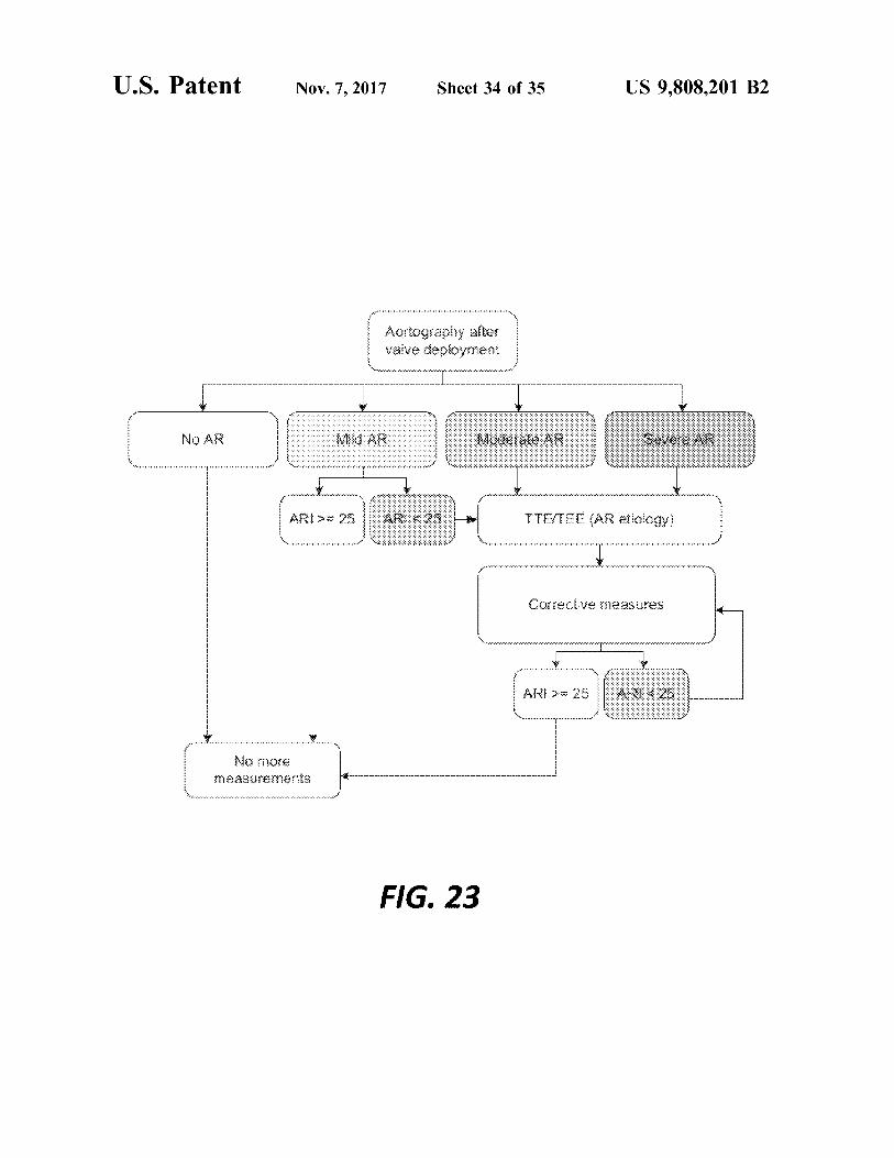
FIG . 15A is an end view of a MEM sensor according to FIG . 23 is a flow chart showing one possible method of another embodiment of the disclosure . using a prosthetic heart valve with sensors attached thereto .
US 9 , 808 , 201 B2
FIG . 24 is a schematic representation of a system for coapting with one another . As a prosthetic aortic valve , valve valve evaluation using the sensors of the present disclosure . 100 has three leaflets 178 . However , it will be appreciated
that other prosthetic heart valves with which the sensors of DETAILED DESCRIPTION the present disclosure may be used may have a greater or
5 lesser number of leaflets . As used herein in connection with prosthetic aortic heart Although cuff 176 is shown in FIG . 1 as being disposed
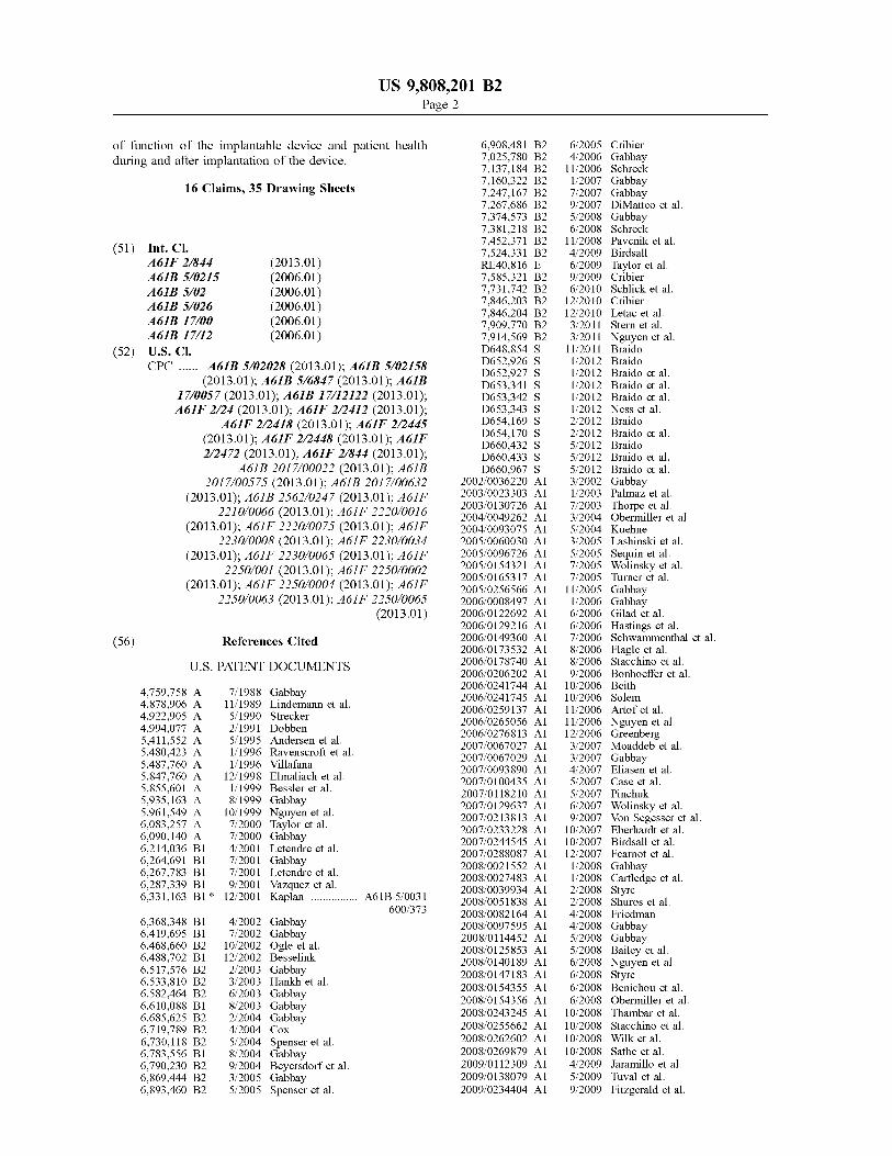
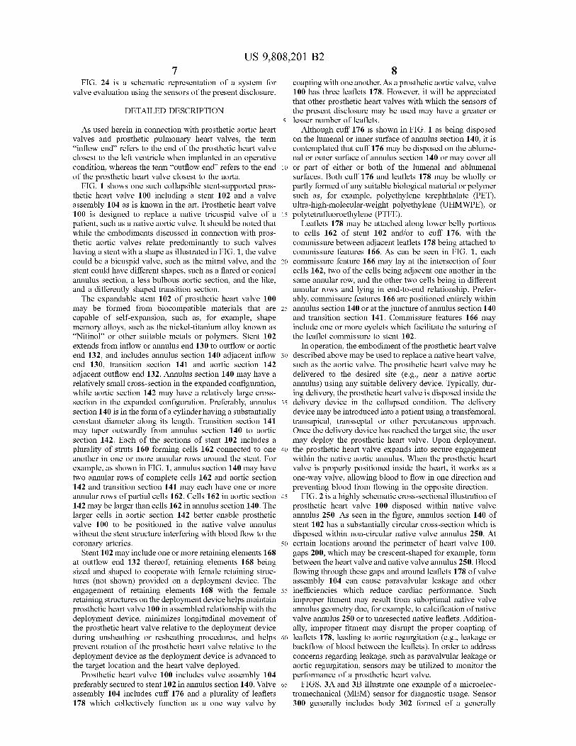
valves and prosthetic pulmonary heart valves , the term on the lumenal or inner surface of annulus section 140 , it is " inflow end ” refers to the end of the prosthetic heart valve contemplated that cuff 176 may be disposed on the ablume closest to the left ventricle when implanted in an operative nal or outer surface of annulus section 140 or may cover all condition , whereas the term “ outflow end ” refers to the end 10 or part of either or both of the lumenal and ablumenal of the prosthetic heart valve closest to the aorta . surfaces . Both cuff 176 and leaflets 178 may be wholly or
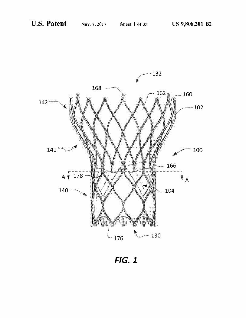
FIG . 1 shows one such collapsible stent - supported pros - partly formed of any suitable biological material or polymer thetic heart valve 100 including a stent 102 and a valve such as , for example , polyethylene terephthalate ( PET ) , assembly 104 as is known in the art . Prosthetic heart valve ultra - high - molecular - weight polyethylene ( UHMWPE ) , or 100 is designed to replace a native tricuspid valve of a 15 polytetrafluoroethylene ( PTFE ) . patient , such as a native aortic valve . It should be noted that Leaflets 178 may be attached along lower belly portions while the embodiments discussed in connection with pros - to cells 162 of stent 102 and / or to cuff 176 , with the thetic aortic valves relate predominantly to such valves commissure between adjacent leaflets 178 being attached to having a stent with a shape as illustrated in FIG . 1 , the valve commissure features 166 . As can be seen in FIG . 1 , each could be a bicuspid valve , such as the mitral valve , and the 20 commissure feature 166 may lay at the intersection of four stent could have different shapes , such as a flared or conical cells 162 , two of the cells being adjacent one another in the annulus section , a less bulbous aortic section , and the like , same annular row , and the other two cells being in different and a differently shaped transition section . annular rows and lying in end - to - end relationship . Prefer
The expandable stent 102 of prosthetic heart valve 100 ably , commissure features 166 are positioned entirely within may be formed from biocompatible materials that are 25 annulus section 140 or at the juncture of annulus section 140 capable of self - expansion , such as , for example , shape and transition section 141 . Commissure features 166 may memory alloys , such as the nickel - titanium alloy known as include one or more eyelets which facilitate the suturing of “ Nitinol ” or other suitable metals or polymers . Stent 102 the leaflet commissure to stent 102 . extends from inflow or annulus end 130 to outflow or aortic In operation , the embodiment of the prosthetic heart valve end 132 , and includes annulus section 140 adjacent inflow 30 described above may be used to replace a native heart valve , end 130 , transition section 141 and aortic section 142 such as the aortic valve . The prosthetic heart valve may be adjacent outflow end 132 . Annulus section 140 may have a delivered to the desired site ( e . g . , near a native aortic relatively small cross - section in the expanded configuration , annulus ) using any suitable delivery device . Typically , dur while aortic section 142 may have a relatively large cross ing delivery , the prosthetic heart valve is disposed inside the section in the expanded configuration . Preferably , annulus 35 delivery device in the collapsed condition . The delivery section 140 is in the form of a cylinder having a substantially device may be introduced into a patient using a transfemoral , constant diameter along its length . Transition section 141 transapical , transseptal or other percutaneous approach . may taper outwardly from annulus section 140 to aortic Once the delivery device has reached the target site , the user section 142 . Each of the sections of stent 102 includes a may deploy the prosthetic heart valve . Upon deployment , plurality of struts 160 forming cells 162 connected to one 40 the prosthetic heart valve expands into secure engagement another in one or more annular rows around the stent . For within the native aortic annulus . When the prosthetic heart example , as shown in FIG . 1 , annulus section 140 may have valve is properly positioned inside the heart , it works as a two annular rows of complete cells 162 and aortic section one - way valve , allowing blood to flow in one direction and 142 and transition section 141 may each have one or more preventing blood from flowing in the opposite direction . annular rows of partial cells 162 . Cells 162 in aortic section 45 FIG . 2 is a highly schematic cross - sectional illustration of 142 may be larger than cells 162 in annulus section 140 . The prosthetic heart valve 100 disposed within native valve larger cells in aortic section 142 better enable prosthetic annulus 250 . As seen in the figure , annulus section 140 of valve 100 to be positioned in the native valve annulus stent 102 has a substantially circular cross - section which is without the stent structure interfering with blood flow to the disposed within non - circular native valve annulus 250 . At coronary arteries . 50 certain locations around the perimeter of heart valve 100 ,
Stent 102 may include one or more retaining elements 168 gaps 200 , which may be crescent - shaped for example , form at outflow end 132 thereof , retaining elements 168 being between the heart valve and native valve annulus 250 . Blood sized and shaped to cooperate with female retaining struc - flowing through these gaps and around leaflets 178 of valve tures ( not shown ) provided on a deployment device . The assembly 104 can cause paravalvular leakage and other engagement of retaining elements 168 with the female 55 inefficiencies which reduce cardiac performance . Such retaining structures on the deployment device helps maintain improper fitment may result from suboptimal native valve prosthetic heart valve 100 in assembled relationship with the annulus geometry due , for example , to calcification of native deployment device , minimizes longitudinal movement of valve annulus 250 or to unresected native leaflets . Addition the prosthetic heart valve relative to the deployment device ally , improper fitment may disrupt the proper coapting of during unsheathing or resheathing procedures , and helps 60 leaflets 178 , leading to aortic regurgitation ( e . g . , leakage or prevent rotation of the prosthetic heart valve relative to the backflow of blood between the leaflets ) . In order to address deployment device as the deployment device is advanced to concerns regarding leakage , such as paravalvular leakage or the target location and the heart valve deployed . aortic regurgitation , sensors may be utilized to monitor the
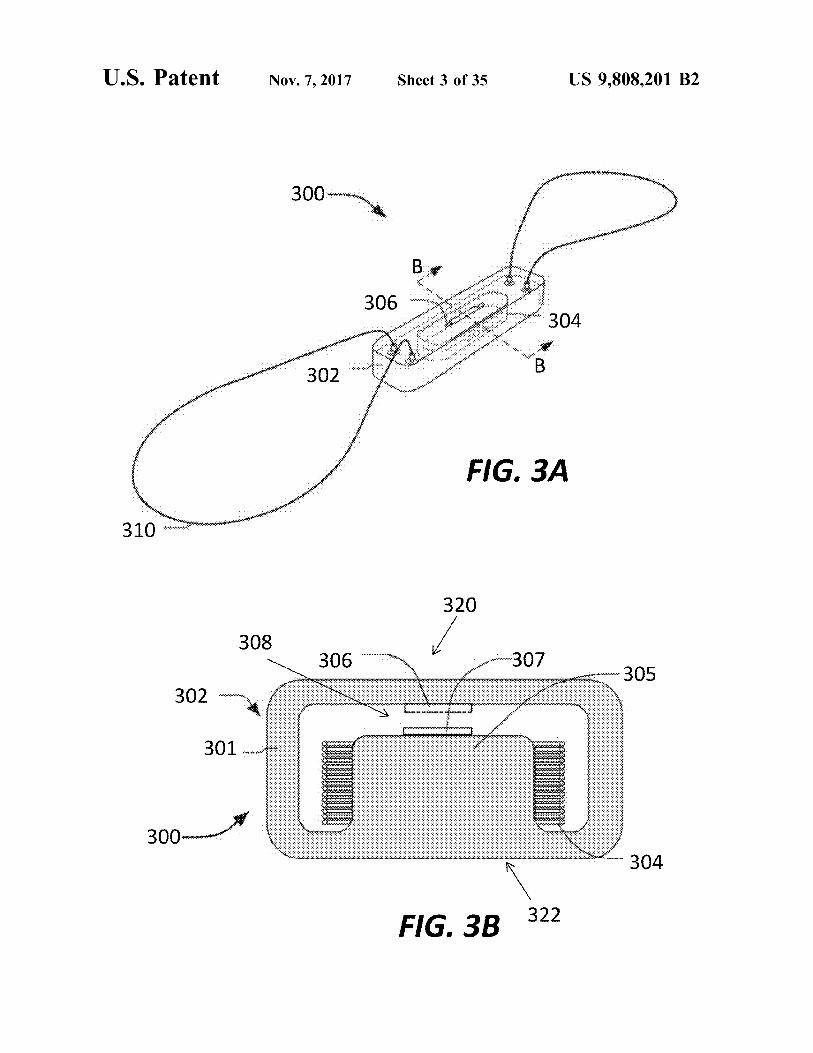
Prosthetic heart valve 100 includes valve assembly 104 performance of a prosthetic heart valve . preferably secured to stent 102 in annulus section 140 . Valve 65 FIGS . 3A and 3B illustrate one example of a microelec assembly 104 includes cuff 176 and a plurality of leaflets tromechanical ( MEM ) sensor for diagnostic usage . Sensor 178 which collectively function as a one way valve by 300 generally includes body 302 formed of a generally
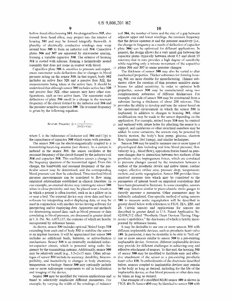
US 9 , 808 , 201 B2 10 .
hollow fused silica housing 301 . An elongated boss 305 , also coil 304 , the number of turns and the size of a gap between formed from fused silica , may project into the interior of adjacent upper and lower windings , the resonant frequency housing 301 and may be formed integrally therewith . A that the device operates at and the pressure sensitivity ( i . e . , plurality of electrically conductive windings may wrap the change in frequency as a result of deflection of capacitor around boss 305 to form an inductor coil 304 . Capacitive 5 plate 306 ) can be optimized for different applications . In plates 306 and 307 are separated by micrometer spacing , general , the design allows for a very small gap between the forming a variable capacitor 308 . The exterior of housing capacitor plates ( typically between about 0 . 5 and about 35 301 is coated with silicone , forming a hermetically sealed microns ) that in turn provides a high degree of sensitivity
while requiring only a minute movement of the capacitive assembly that does not come in contact with blood . Capacitive plate 306 is sensitive to pressure and experi - 10 ple ri 10 plates 306 and 307 to sense pressure changes .
ences nanometer scale deflections due to changes in blood The thickness of sensor 300 may also be varied to alter pressure acting on the sensor 300 . In that regard , body 302 mechanical properties . Thicker substrates for forming hous includes an active face 320 and a passive face 322 , the ing 301 are more durable for manufacturing . Thinner sub measurements being taken at the active face . It should be strates allow for creation of thin pressure sensitive mem understood that although sensor 300 includes active face 320 ce 320 15 branes for added sensitivity . In order to optimize both and passive face 322 , other sensors may have other con properties , sensor 300 may be manufactured using two
complementary substrates of different thicknesses . For figurations , such as two active faces . The nanometer scale example , one side of sensor 300 may be constructed from a deflections of plate 306 result in a change in the resonant frequency of the circuit formed by the inductor coil 304 and substrate having a thickness of about 200 microns . This the pressure - sensitive capacitor 308 . The resonant frequency 2 20 provides the ability to develop and tune the sensor based on is given by the following equation : the operational environment in which the sensor 300 is
implanted . In addition to changes to housing 301 , other modifications may be made to the sensor depending on the application . For example , nitinol loops 310 may be omitted
Resonant Frequency fr = — 27V LxC ( p ) 25 and replaced with suture holes for attaching the sensor to a support , and cantilevers or other structural members may be added . In some variations , the sensors may be powered by
where L is the inductance of inductor coil 304 and C ( p ) is kinetic motion , the body ' s heat pump , glucose , electron the capacitance of capacitor 308 which varies with pressure . flow , Quantum Dot Energy , and similar techniques .
The sensor 300 can be electromagnetically coupled to a 30 Sensors 300 may be used to measure one or more types of transmitting / receiving antenna ( not shown ) . As a current is physiological data including real time blood pressure ; flow induced in the sensor 300 , the sensor oscillates at the velocity ( e . g . , blood flow ) ; apposition forces based on pres resonant frequency of the circuit formed by the inductor coil sure changes due to interaction between two surfaces of the 304 and capacitor 308 . This oscillation causes a change in prosthetic valve ; impingement forces , which are correlated the frequency spectrum of the transmitted signal . From this 35 to pressure changes caused by the interaction between a change , the bandwidth and resonant frequency of the par - surface of the prosthetic device and native tissue ; cardiac ticular sensor may be determined , and the corresponding output ; effective orifice area ; pressure drop ; temperature ; blood pressure can then be calculated . Time - resolved blood motion ; and aortic regurgitation . Sensor 300 provides time pressure measurements can be correlated to flow using resolved pressure data which may be correlated to the empirical relationships established in clinical literature . In 40 parameters of interest based on empirical correlations that one example , an external device may interrogate sensor 300 have been presented in literature . In some examples , sensors when in close proximity and may be placed near a location 300 may function similar to piezo - electric strain gauges to in which a patient is often located , such as in a pillow or in directly measure a parameter . Other parameters may be or near a bed . The external device may store data and have indirectly calculated . One specific method of using sensors software for interpreting and / or displaying data , or may be 45 300 to measure aortic regurgitation will be described in used in conjunction with another device having software for greater detail below with references to FIGS . 22A , 22B , and interpreting and / or displaying data . Apparatus and methods 23 . Certain sensors and applications for sensors are for determining sensed data , such as blood pressure or data described in greater detail in U . S . Patent Application No . correlating to blood pressure , are discussed in greater detail 62 / 038 , 512 titled “ Prosthetic Heart Devices Having Diag in U . S . Pat . No . 6 , 855 , 115 , the contents of which are hereby 50 nostic Capabilities , ” the disclosure of which is hereby incor incorporated by reference herein . porated by reference herein . As shown , sensor 300 includes optional Nitinol loops 310 It may be desirable to use one or more sensors 300 with
extending from each end of body 302 to stabilize the sensor different implantable devices , such as prosthetic heart valve at an implant location . It will be appreciated that sensor 300 100 . In particular , it may be desirable to be able to “ bolt on ” includes no additional leads , batteries , or active - fixation 55 one or more sensors similar to sensor 300 to a pre - existing mechanisms . Sensor 300 is an externally modulated induc - implantable device . However , different implantable devices tor - capacitor circuit , which is powered using radio fre may provide for different challenges in achieving easy and quency by the transmitting antenna . Additionally , sensor 300 effective attachment of sensors . To that end , the housing 301 may be relatively small ( e . g . , 3 . 5x2x15 mm ) . Other advan - of sensor 300 may be modified to facilitate easy and effec tages of sensor 300 include its accuracy , durability , biocom - 60 tive attachment of the sensor to a pre - existing prosthetic patibility , and insensitivity to changes in body chemistry , heart valve 100 . In embodiments of the disclosure described temperature , or biology . Sensor 300 may optionally include below , sensors coupled to implantable devices may remain one or more radiopaque components to aid in localization in the body as long as desired , including for the life of the and imaging of the device . implantable device , so that blood pressure or other data may
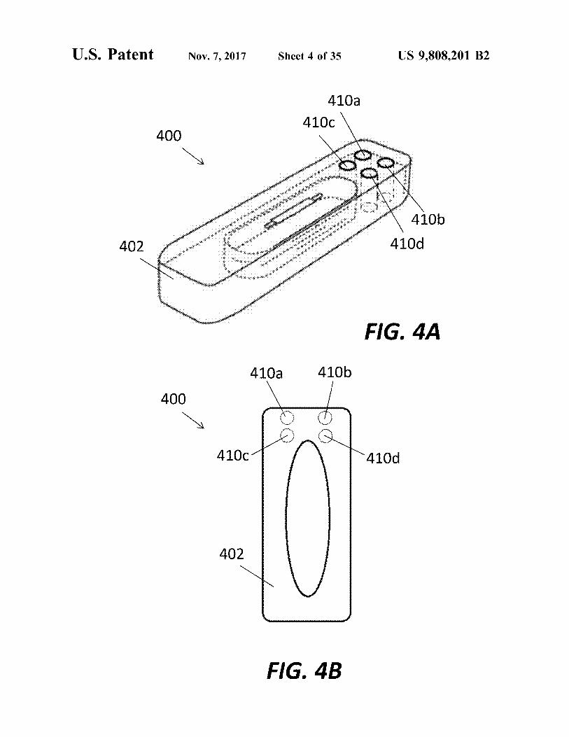
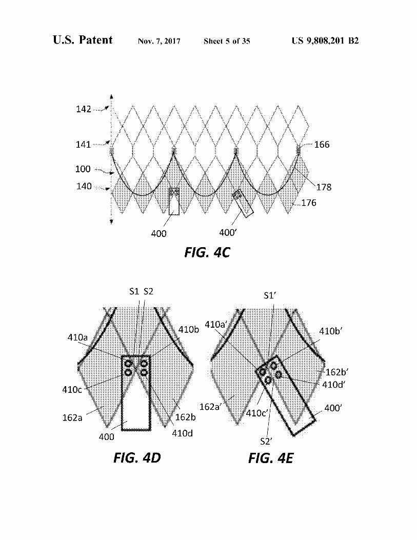
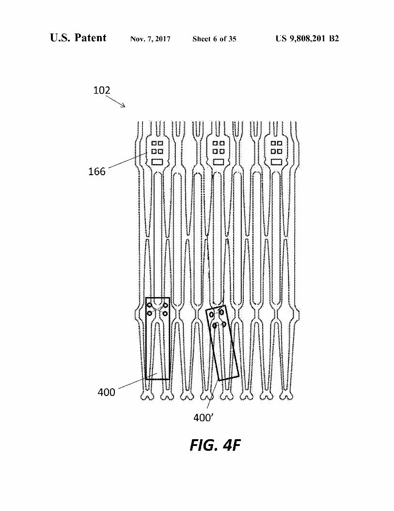
Sensor 300 may be modified for various applications and 65 be taken as long as desired . tuned to selectively emphasize different parameters . For One example of a modified MEM sensor 400 is shown in example , by varying the width of the windings of inductor FIGS . 4A - B . Sensor 400 may be identical to sensor 300 with
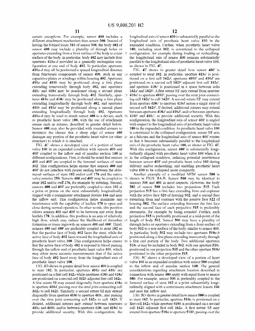
US 9 , 808 , 201 B2 11 12
certain exceptions . For example , sensor 400 includes a longitudinal axis of sensor 400 is substantially parallel to the different attachment mechanism than sensor 300 . Instead of longitudinal axis of prosthetic heart valve 100 in the having the Nitinol loops 310 of sensor 300 , the body 402 of expanded condition . Further , when prosthetic heart valve sensor 400 may include a plurality of through holes or 100 , including stent 102 , is constricted to the collapsed apertures extending from a front surface of the body to a rear 5 configuration , for example during loading or resheathing , surface of the body . In particular , body 402 may include four the longitudinal axis of sensor 400 remains substantially apertures 410a - d provided in a generally rectangular con - parallel to the longitudinal axis of prosthetic heart valve 100 , figuration at one end of body 402 . In particular , apertures as shown in FIG . 4F . 410a - d may all be positioned a spaced longitudinal distance FIG . 4E shows in greater detail how sensor 400 ' is from functional components of sensor 400 , such as any 10 coupled to stent 102 . In particular , aperture 410a ' is posi capacitive plates or windings within housing 402 . Apertures tioned on a first cell 162a ' , apertures 410b ' and 410d ' are 410a and 410b may be positioned along a first plane positioned on a second cell 162b ' adjacent first cell 162a ' , extending transversely through body 402 , and apertures and aperture 410c ' is positioned in a space between cells 410c and 410d may be positioned along a second plane 162a ' and 1626 ' . A first suture Sl ' may extend from aperture extending transversely through body 402 . Similarly , aper - 15 410a ' to aperture 4106 ' , passing over the strut joint connect tures 410a and 410c may be positioned along a first plane ing cell 162a ' to cell 162b ' . A second suture S2 ' may extend extending longitudinally through body 402 , and apertures from aperture 410c ' to aperture 410d ' across a single strut of 4106 and 410d may be positioned along a second plane second cell 1626 ' . If desired , additional sutures may extend extending longitudinally through body 402 . Apertures between apertures 410a ' and 410d " , and / or between apertures 410a - d may be used to attach sensor 400 to a device , such 20 4100 ' and 410c ' , to provide additional security . With this as prosthetic heart valve 100 , with the use of attachment configuration , the longitudinal axis of sensor 400 ' is angled means such as sutures , described in greater detail below . with respect to the longitudinal axis of prosthetic heart valve Sensor 400 may also be provided with rounded corners to 100 in the expanded condition . As prosthetic heart valve 100 minimize the chance that a sharp edge of sensor 400 is constricted to the collapsed configuration , suture Sl ' acts damages any portion of the prosthetic heart valve ( or other 25 as a fulcrum and the longitudinal axis of sensor 400 ' rotates structure ) to which it is attached . so that it becomes substantially parallel to the longitudinal
FIG . 4C shows a developed view of a portion of heart axis of the prosthetic heart valve 100 , as shown in FIG . 4F . valve 100 in an expanded condition with sensors 400 and With this configuration , sensor 400 ' is substantially longi 400 ' coupled to the inflow end of annulus section 140 in tudinally aligned with prosthetic heart valve 100 when it is different configurations . First , it should be noted that sensors 30 in the collapsed condition , reducing potential interference 400 and 400 ' are coupled to the lumenal surfaces of stent between sensor 400 ' and prosthetic heart valve 100 during 102 . This configuration helps ensure that sensors 400 and delivery and / or resheathing , and enabling prosthetic heart 400 ' do not interfere with proper sealing between the ablu - valve 100 to be collapsed more compactly . menal surfaces of stent 102 and / or cuff 176 and the native Another example of a modified MEM sensor 500 is valve annulus 250 . Sensors 400 and 400 ' may be coupled to 35 shown in FIGS . 5A - B . Sensor 500 may be identical to stent 102 and / or cuff 176 , for example by suturing . Second , sensors 300 and 400 in most respects . However , the body sensors 400 and 400 ' are preferably coupled to stent 102 at 502 of sensor 500 includes two projections 515 . Each a point or points on the stent substantially longitudinally projection 515 has a first face extending from and coplanar aligned with a commissure attachment feature 166 and near with the active face 520 of housing 502 , and a second face the inflow end . This configuration helps minimize any 40 extending from and coplanar with the passive face 522 of interference with the capability of leaflets 178 to open and housing 502 . The surface extending between the first face close during normal operation . In other words , this position and the second face of each projection 515 is preferably allows sensors 400 and 400 ' to be between and away from atraumatic , for example by being rounded . Further , each leaflets 178 . In addition , this position is an area of relatively projection 515 is preferably positioned at a mid - point of the high flow , which may reduce the likelihood of thrombus 45 length of body 502 . Sensor 500 may have a plurality of formation or tissue ingrowth on sensors 400 and 400 ' . Third , through holes or apertures extending from a front surface of sensors 400 and 400 ' are preferably coupled to stent 102 so body 502 to a rear surface of the body , similar to sensor 400 . that the passive face of body 402 faces the stent , while the In particular , body 502 may include two apertures 510a - b active face of body 402 faces toward the longitudinal axis of positioned along a first plane extending transversely through prosthetic heart valve 100 . This configuration helps ensure 50 a first end portion of the body . Two additional apertures that the active face of body 402 is exposed to blood passing 510c - d may be included in body 502 , with one aperture 510c through the inflow end of prosthetic heart valve 100 , which positioned in one projection 515 and the other aperture 510d may allow more accurate measurements than if the active positioned in the other projection 515 . face of body 402 faced away from the longitudinal axis of FIG . 5C shows a developed view of a portion of heart prosthetic heart valve 100 . 55 valve 100 in an expanded condition with sensor 500 coupled
FIG . 4D shows in greater detail how sensor 400 is coupled to the inflow end of annulus section 140 . The general to stent 102 . In particular , apertures 410a and 410c are considerations regarding attachment location described in positioned on a first cell 162a while apertures 410b and 410d connection with sensor 400 apply with equal force to sensor are positioned on a second cell 162b adjacent first cell 162a . 500 . For example , sensor 500 is preferably coupled to the A first suture S1 may extend diagonally from aperture 410a 60 lumenal surface of stent 102 at a point substantially longi to aperture 410d , passing over the strut joint connecting cell tudinally aligned with a commissure attachment feature 166 162a to cell 1626 . Similarly , a second suture S2 may extend and near the inflow end . diagonally from aperture 410b to aperture 410c , also passing FIG . 5D shows in greater detail how sensor 500 is coupled over the strut joint connecting cell 162a to cell 162b . If to stent 102 . In particular , aperture 510a is positioned on a desired , additional sutures may extend between apertures 65 first cell 162a while aperture 510b is positioned on a second 410a and 410b , and / or between apertures 410c and 410d , to cell 162b adjacent first cell 162a . A first suture S3 may provide additional security . With this configuration , the extend from aperture 510a to aperture 5106 , passing over the
US 9 , 808 , 201 B2 13 14
strut joint connecting cell 162a to cell 1626 . Aperture 5100 While FIGS . 4A - 6C show various MEM sensors and their is positioned in a space between cells 162a and 162b , while attachment to the inflow end of prosthetic heart valve 100 , aperture 510d is positioned on second cell 162b . A second FIGS . 7 - 10C show additional variations of MEM sensors suture S4 may extend from aperture 510c to aperture 510d and their attachment to the outflow end of prosthetic heart across a single strut 160 of cell 162b . Since apertures 5 valve 100 . 510c - 510d are positioned at a longitudinal midpoint of FIG . 7 is a highly schematic developed view of prosthetic sensor 500 , those apertures are aligned along the length of heart valve 100 in the expanded condition . When attaching sensor 500 with at least some active components of the a sensor to the outflow end of prosthetic heart valve 100 , the
sensor is preferably positioned so that it does not interfere sensor , such as capacitive plates or inductor coils . Thus , suture S4 preferably extends from aperture 510c to 510d 10 with normal operation of the prosthetic heart valve . In
particular , two outflow zones which may be less suitable for only along passive face 522 of housing 502 , which may help sensor attachment are shown in FIG . 7 . As described above suture S4 avoid interference with measurements taken by in connection with FIG . 1 , one or more retaining elements sensor 500 . With the configuration described above , the 168 may be positioned at the outflow end 132 of stent 102 . longitudinal axis of sensor 500 is angled with respect to the 15 Because retaining elements 168 are configured to mate with longitudinal axis of prosthetic heart valve 100 in the corresponding retaining structures on a deployment device expanded condition . As prosthetic heart valve 100 is con ( not shown ) , it is preferable that sensors not be positioned in stricted to the collapsed configuration , suture S3 acts as a an interlock zone IZ , which extends around the circumfer fulcrum and the longitudinal axis of sensor 500 rotates so ence of stent 102 at retaining elements 168 and positions just that it is substantially parallel to the longitudinal axis of the 20 proximal of the retaining elements . If sensors were posi prosthetic heart valve 100 . During this rotation , suture S4 tioned in interlock zone IZ , the ability of retaining elements slides along the strut 160 of cell 162b extending between 168 to properly engage the retaining structures on the apertures 510c and 510d . Similar to the configuration of deployment device might be hindered . Similarly , it is pref sensor 400 ' described above , sensor 500 is substantially erable that sensors be positioned so that they do not interfere longitudinally aligned with prosthetic heart valve 100 when 25 with the proper functioning of leaflets 178 . To avoid such it is in the collapsed condition , reducing potential interfer - interference , it is preferable that sensors not be positioned in ence between sensor 500 and prosthetic heart valve 100 that a commissure zone CZ , which extends around the circum would prevent the prosthetic heart valve from collapsing to ference of stent 102 for the length of commissure features a compact size during delivery and / or resheathing . 166 . The commissure zone CZ may extend an additional
Yet another example of a modified MEM sensor 600 is 30 distance toward the inflow and outflow ends of stent 102 to shown in FIG . 6A . Sensor 600 may be identical to sensors provide an additional buffer zone to keep sensors clear of 300 and 400 in most respects . However , the body 602 of leaflets 178 . The interlock zone IZ and commissure zone CZ sensor 600 includes three projections 615a - c extending from may also have a relatively large amount of curvature , and one end of body 602 . In particular , projection 615b extends have additional thickness due to other components attached along the longitudinal axis of body 602 , while two projec - 35 to stent 102 in these locations , particularly with stent 102 is tions 615a and 615c extend transverse to the longitudinal in a crimped or loaded condition . If a sensor attached to stent axis of body 602 . Similar to projections 515 of sensor 500 , 102 is not substantially rigid , the sensor may be crushed or projections 615a - c of sensor 600 are preferably rounded to otherwise damage , particularly during loading , if coupled in minimize interference between the projections 615a - c and the interlock or commissure zones . In one example , when the prosthetic valve 100 to which the sensor is attached . 40 stent 102 is in the expanded condition , the longitudinal Sensor 600 has a plurality of apertures 610a - c extending distance between commissure features 166 and retaining from a front surface of the projections 615a - c to a rear elements 168 is about 20 mm , with a desirable position for surface of the projections , respectively . sensor attachment being in about the center 10 mm of this
FIG . 6B shows a developed view of a portion of heart about 20 mm distance . valve 100 in an expanded condition with sensor 600 coupled 45 A further example of a modified MEM sensor 700 is to the inflow end of annulus section 140 . The general shown in FIG . 8A . Sensor 700 may be identical to sensor considerations regarding attachment location described in 500 in most respects . For example , the body 702 of sensor connection with sensor 400 apply with equal force to sensor 700 includes two projections 715 , each projection 715 600 . FIG . 6C shows in greater detail how sensor 600 is having a first face extending from and coplanar with an coupled to stent 102 . In particular , aperture 610a is posi - 50 active face of housing 702 , and a second face extending tioned on a first cell 162a in a first annular row , and aperture from and coplanar with the passive face of housing 702 . The 610c is positioned on a second cell 162b in the first annular surface extending between the first face and the second face row adjacent first cell 162a . Aperture 610b is positioned on of each projection 715 is preferably atraumatic , for example a third cell 162c , the third cell being in a second longitudinal by being rounded . Further , each projection 715 is preferably row of cells and being formed in part by struts 160 forming 55 positioned at a mid - point of the length of body 702 . Sensor cells 162a and 162b . A first suture S5 may extend from 700 has first and second apertures 710a , 710b , one extending aperture 610a to aperture 610b , from aperture 610b to through each projection 715 so as to be positioned along a aperture 610c , and from aperture 610c back to aperture plane extending transversely through body 702 . 610a , forming a triangle . Suture S5 couples sensor 600 to FIG . 8B shows a developed view of a portion of heart prosthetic heart valve 100 at the struts 160 forming the joint 60 valve 100 in an expanded condition with sensor 700 coupled between cells 162a - c . With the configuration described to an outflow portion of aortic section 142 . As described in above , the longitudinal axis of sensor 600 is substantially connection with FIG . 7 , sensor 700 is preferably attached to parallel to the longitudinal axis of prosthetic heart valve 100 s tent 102 between interlock zone IZ and commissure zone in both the expanded and collapsed conditions . Although CZ so that sensor 700 does not interfere with the coaptation suture S5 is described as a single suture , it should be 65 of the leaflets or with the coupling of retaining elements 168 understood that multiple separate sutures may be used to of stent 102 to a delivery device . In addition , similar to the achieve the same attachment configuration . sensors positioned on the inflow portion of stent 102 , sensor
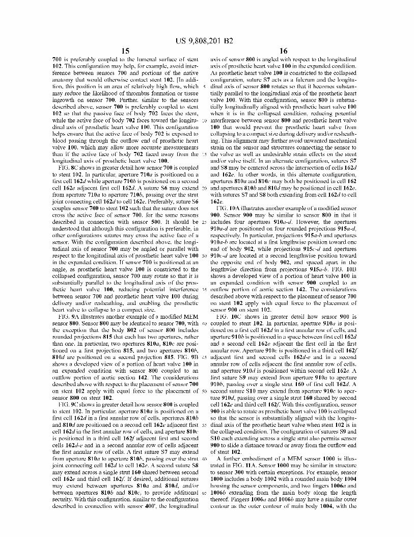
US 9 , 808 , 201 B2 15
700 is preferably coupled to the lumenal surface of stent axis of sensor 800 is angled with respect to the longitudinal 102 . This configuration may help , for example , avoid inter axis of prosthetic heart valve 100 in the expanded condition . ference between sensors 700 and portions of the native As prosthetic heart valve 100 is constricted to the collapsed anatomy that would otherwise contact stent 102 . [ In addi - configuration , suture S7 acts as a fulcrum and the longitu tion , this position is an area of relatively high flow , which 5 dinal axis of sensor 800 rotates so that it becomes substan may reduce the likelihood of thrombus formation or tissue tially parallel to the longitudinal axis of the prosthetic heart ingrowth on sensor 700 . Further , similar to the sensors valve 100 . With this configuration , sensor 800 is substan described above , sensor 700 is preferably coupled to stent t ially longitudinally aligned with prosthetic heart valve 100 102 so that the passive face of body 702 faces the stent , when it is in the collapsed condition , reducing potential while the active face of body 702 faces toward the longitu - 10 interference between sensor 800 and prosthetic heart valve dinal axis of prosthetic heart valve 100 . This configuration 100 that would prevent the prosthetic heart valve from helps ensure that the active face of body 702 is exposed to collapsing to a compact size during delivery and / or resheath blood passing through the outflow end of prosthetic heart ing . This alignment may further avoid unwanted mechanical valve 100 , which may allow more accurate measurements strain on the sensor and structures connecting the sensor to than if the active face of body 702 faced away from the 15 the valve as well as undesirable strain effects on the stent longitudinal axis of prosthetic heart valve 100 . and / or valve itself . In an alternate configuration , sutures S7
FIG . 8C shows in greater detail how sensor 700 is coupled and S8 may be centered across the intersection of cells 162d to stent 102 . In particular , aperture 710a is positioned on a and 162e . In other words , in this alternate configuration , first cell 162d while aperture 710b is positioned on a second apertures 810a and 810c may both be positioned in cell 162 cell 162e adjacent first cell 162d . A suture S6 may extend 20 and apertures 8106 and 810d may be positioned in cell 162e , from aperture 710a to aperture 710b , passing over the strut with sutures S7 and S8 both extending from cell 162d to cell joint connecting cell 162d to cell 162e . Preferably , suture S6 162e . couples sensor 700 to stent 102 such that the suture does not FIG . 10A illustrates another example of a modified sensor cross the active face of sensor 700 , for the same reasons 900 . Sensor 900 may be similar to sensor 800 in that it described in connection with sensor 500 . It should be 25 includes four apertures 910a - d . However , the apertures understood that although this configuration is preferable , in 910a - d are positioned on four rounded projections 915a - d , other configurations sutures may cross the active face of a respectively . In particular , projections 915a - b and apertures sensor . With the configuration described above , the longi - 910a - b are located at a first lengthwise position toward one tudinal axis of sensor 700 may be angled or parallel with end of body 902 , while projections 915c - d and apertures respect to the longitudinal axis of prosthetic heart valve 100 30 910c - d are located at a second lengthwise position toward in the expanded condition . If sensor 700 is positioned at an the opposite end of body 902 , and spaced apart in the angle , as prosthetic heart valve 100 is constricted to the lengthwise direction from projections 915a - b . FIG . 10B collapsed configuration , sensor 700 may rotate so that it is shows a developed view of a portion of heart valve 100 in substantially parallel to the longitudinal axis of the pros an expanded condition with sensor 900 coupled to an thetic heart valve 100 , reducing potential interference 35 outflow portion of aortic section 142 . The considerations between sensor 700 and prosthetic heart valve 100 during described above with respect to the placement of sensor 700 delivery and / or resheathing , and enabling the prosthetic o n stent 102 apply with equal force to the placement of heart valve to collapse to a compact size . sensor 900 on stent 102 .
FIG . 9A illustrates another example of a modified MEM FIG . 10C shows in greater detail how sensor 900 is sensor 800 . Sensor 800 may be identical to sensor 700 , with 40 coupled to stent 102 . In particular , aperture 910a is posi the exception that the body 802 of sensor 800 includes tioned on a first cell 162d in a first annular row of cells , and rounded projections 815 that each has two apertures , rather aperture 910b is positioned in a space between first cell 162d than one . In particular , two apertures 810a , 810c are posi - and a second cell 162e adjacent the first cell in the first tioned on a first projection 815 , and two apertures 810b , annular row . Aperture 910c is positioned in a third cell 162f 810d are positioned on a second projection 815 . FIG . 9B 45 adjacent first and second cells 162d - e and in a second shows a developed view of a portion of heart valve 100 in annular row of cells adjacent the first annular row of cells , an expanded condition with sensor 800 coupled to an and aperture 910d is positioned within second cell 162e . A outflow portion of aortic section 142 . The considerations first suture S9 may extend from aperture 910a to aperture described above with respect to the placement of sensor 700 910b , passing over a single strut 160 of first cell 162d . A on stent 102 apply with equal force to the placement of 50 second suture S10 may extend from aperture 910c to aper sensor 800 on stent 102 . ture 910d , passing over a single strut 160 shared by second
FIG . 9C shows in greater detail how sensor 800 is coupled cell 162e and third cell 162f . With this configuration , sensor to stent 102 . In particular , aperture 810a is positioned on a 900 is able to rotate as prosthetic heart valve 100 is collapsed first cell 162d in a first annular row of cells , apertures 810b so that the sensor is substantially aligned with the longitu and 810d are positioned on a second cell 162e adjacent first 55 dinal axis of the prosthetic heart valve when stent 102 is in cell 162d in the first annular row of cells , and aperture 8100 the collapsed condition . The configuration of sutures S9 and is positioned in a third cell 162f adjacent first and second S10 each extending across a single strut also permits sensor cells 162d - e and in a second annular row of cells adjacent 900 to slide a distance toward or away from the outflow end the first annular row of cells . A first suture S7 may extend of stent 102 . from aperture 810a to aperture 8106 , passing over the strut 60 A further embodiment of a MEM sensor 1000 is illus joint connecting cell 162d to cell 162e . A second suture S8 trated in FIG . 11A . Sensor 1000 may be similar in structure may extend across a single strut 160 shared between second to sensor 300 with certain exceptions . For example , sensor cell 162e and third cell 162f . If desired , additional sutures 1000 includes a body 1002 with a rounded main body 1004 may extend between apertures 810a and 810d , and / or housing the sensor components , and two fingers 1006a and between apertures 8106 and 810c , to provide additional 65 1006b extending from the main body along the length security . With this configuration , similar to the configuration thereof . Fingers 10060 and 1006b may have a similar outer described in connection with sensor 400 ' , the longitudinal contour as the outer contour of main body 1004 , with the
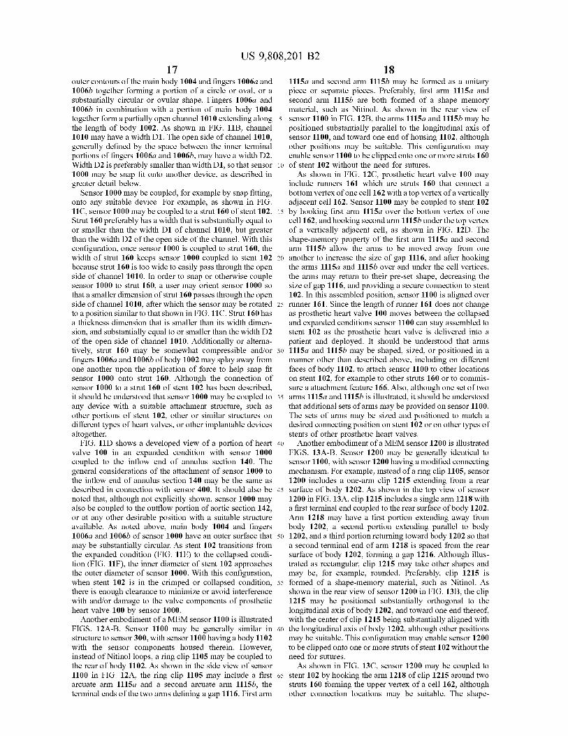
17 US 9 , 808 , 201 B2
18 outer contours of the main body 1004 and fingers 1006a and 1115a and second arm 1115b may be formed as a unitary 1006b together forming a portion of a circle or oval , or a piece or separate pieces . Preferably , first arm 1115a and substantially circular or ovular shape . Fingers 1006a and second arm 1115b are both formed of a shape memory 1006b in combination with a portion of main body 1004 material , such as Nitinol . As shown in the rear view of together form a partially open channel 1010 extending along 5 sensor 1100 in FIG . 12B , the arms 1115a and 1115b may be the length of body 1002 . As shown in FIG . 11B , channel positioned substantially parallel to the longitudinal axis of 1010 may have a width D1 . The open side of channel 1010 , sensor 1100 , and toward one end of housing 1102 , although generally defined by the space between the inner terminal other positions may be suitable . This configuration may portions of fingers 1006? and 1006b , may have a width D2 . enable sensor 1100 to be clipped onto one or more struts 160 Width D2 is preferably smaller than width D1 , so that sensor 10 of stent 102 without the need for sutures . 1000 may be snap fit onto another device , as described in As shown in FIG . 12C , prosthetic heart valve 100 may greater detail below . include runners 161 which are struts 160 that connect a
Sensor 1000 may be coupled , for example by snap fitting , bottom vertex of one cell 162 with a top vertex of a vertically onto any suitable device . For example , as shown in FIG . adjacent cell 162 . Sensor 1100 may be coupled to stent 102 11C , sensor 1000 may be coupled to a strut 160 of stent 102 . 15 by hooking first arm 1115a over the bottom vertex of one Strut 160 preferably has a width that is substantially equal to cell 162 , and hooking second arm 1115b under the top vertex or smaller than the width D1 of channel 1010 , but greater of a vertically adjacent cell , as shown in FIG . 12D . The than the width D2 of the open side of the channel . With this shape - memory property of the first arm 1115a and second configuration , once sensor 1000 is coupled to strut 160 , the arm 1115b allow the arms to be moved away from one width of strut 160 keeps sensor 1000 coupled to stent 102 20 another to increase the size of gap 1116 , and after hooking because strut 160 is too wide to easily pass through the open the arms 11150 and 1115b over and under the cell vertices , side of channel 1010 . In order to snap or otherwise couple the arms may return to their pre - set shape , decreasing the sensor 1000 to strut 160 , a user may orient sensor 1000 so size of gap 1116 , and providing a secure connection to stent that a smaller dimension of strut 160 passes through the open 102 . In this assembled position , sensor 1100 is aligned over side of channel 1010 , after which the sensor may be rotated 25 runner 161 . Since the length of runner 161 does not change to a position similar to that shown in FIG . 11C . Strut 160 has as prosthetic heart valve 100 moves between the collapsed a thickness dimension that is smaller than its width dimen - and expanded conditions sensor 1100 can stay assembled to sion , and substantially equal to or smaller than the width D2 stent 102 as the prosthetic heart valve is delivered into a of the open side of channel 1010 . Additionally or alterna - patient and deployed . It should be understood that arms tively , strut 160 may be somewhat compressible and / or 30 11150 and 1115b may be shaped , sized , or positioned in a fingers 1006? and 1006b of body 1002 may splay away from manner other than described above , including on different one another upon the application of force to help snap fit faces of body 1102 , to attach sensor 1100 to other locations sensor 1000 onto strut 160 . Although the connection of on stent 102 , for example to other struts 160 or to commis sensor 1000 to a strut 160 of stent 102 has been described , sure a attachment feature 166 . Also , although one set of two it should be understood that sensor 1000 may be coupled to 35 arms 1115a and 1115b is illustrated , it should be understood any device with a suitable attachment structure , such as that additional sets of arms may be provided on sensor 1100 . other portions of stent 102 , other or similar structures on The sets of arms may be sized and positioned to match a different types of heart valves , or other implantable devices desired connecting position on stent 102 or on other types of altogether . stents of other prosthetic heart valves .
FIG . 11D shows a developed view of a portion of heart 40 Another embodiment of a MEM sensor 1200 is illustrated valve 100 in an expanded condition with sensor 1000 FIGS . 13A - B . Sensor 1200 may be generally identical to coupled to the inflow end of annulus section 140 . The sensor 1100 , with sensor 1200 having a modified connecting general considerations of the attachment of sensor 1000 to mechanism . For example , instead of a ring clip 1105 , sensor the inflow end of annulus section 140 may be the same as 1200 includes a one - arm clip 1215 extending from a rear described in connection with sensor 400 . It should also be 45 surface of body 1202 . As shown in the top view of sensor noted that , although not explicitly shown , sensor 1000 may 1200 in FIG . 13A , clip 1215 includes a single arm 1218 with also be coupled to the outflow portion of aortic section 142 , a first terminal end coupled to the rear surface of body 1202 . or at any other desirable position with a suitable structure Arm 1218 may have a first portion extending away from available . As noted above , main body 1004 and fingers body 1202 , a second portion extending parallel to body 1006? and 1006b of sensor 1000 have an outer surface that 50 1202 , and a third portion returning toward body 1202 so that may be substantially circular . As stent 102 transitions from a second terminal end of arm 1218 is spaced from the rear the expanded condition ( FIG . 11E ) to the collapsed condi - surface of body 1202 , forming a gap 1216 . Although illus tion ( FIG . 11F ) , the inner diameter of stent 102 approaches trated as rectangular , clip 1215 may take other shapes and the outer diameter of sensor 1000 . With this configuration , may be , for example , rounded . Preferably , clip 1215 is when stent 102 is in the crimped or collapsed condition , 55 formed of a shape - memory material , such as Nitinol . As there is enough clearance to minimize or avoid interference shown in the rear view of sensor 1200 in FIG . 13B , the clip with and / or damage to the valve components of prosthetic 1215 may be positioned substantially orthogonal to the heart valve 100 by sensor 1000 . longitudinal axis of body 1202 , and toward one end thereof ,
Another embodiment of a MEM sensor 1100 is illustrated with the center of clip 1215 being substantially aligned with FIGS . 12A - B . Sensor 1100 may be generally similar in 60 the longitudinal axis of body 1202 , although other positions structure to sensor 300 , with sensor 1100 having a body 1102 may be suitable . This configuration may enable sensor 1200 with the sensor components housed therein . However , to be clipped onto one or more struts of stent 102 without the instead of Nitinol loops , a ring clip 1105 may be coupled to need for sutures . the rear of body 1102 . As shown in the side view of sensor As shown in FIG . 13C , sensor 1200 may be coupled to 1100 in FIG . 12A , the ring clip 1105 may include a first 65 stent 102 by hooking the arm 1218 of clip 1215 around two arcuate arm 1115a and a second arcuate arm 1115b , the struts 160 forming the upper vertex of a cell 162 , although terminal ends of the two arms defining a gap 1116 . First arm other connection locations may be suitable . The shape
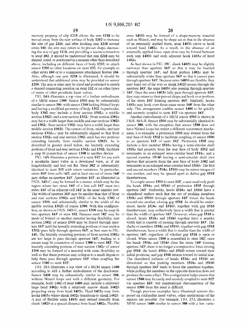
US 9 , 808 , 201 B2 20
memory property of clip 1215 allows the arm 1218 to be arms 1403b may be formed of a shape - memory material moved away from the rear surface of body 1202 to increase such as Nitinol , and may be shape set so that in the absence the size of gap 2116 , and after hooking arm 1218 around of an externally applied force , arms 1403b curve or hook struts 160 , the arm may return to its pre - set shape , decreas - toward head 1402a . As a result , in the absence of an ing the size of gap 1216 , and providing a secure connection 5 externally applied force , open slots may be formed between to stent 102 . It should be understood that arm 1218 may be each arm 1403b and each adjacent hook 1403a of head shaped , sized , or positioned in a manner other than described 1402a . above , including on different faces of body 1202 , to attach As best shown in FIG . 15C , shank 1402b may be slightly sensor 1200 to other locations on stent 102 , for example to narrower than aperture 163 ' so that it may be inserted other struts 160 or to a commissure attachment feature 166 . 10 through aperture 163 ' , and front portion 1402a may be Also , although one arm 1218 is illustrated , it should be substantially wider than aperture 163 ' so that it cannot pass understood that additional arms may be provided on sensor through aperture 163 ' . Because arms 1403b are flexible , they 1200 . The arm or arms may be sized and positioned to match may bend out of the way as shank 1402b passes through the a desired connecting position on stent 102 or on other types aperture 163 ' , the arms 1403b also passing through aperture of stents of other prosthetic heart valves . 15 163 ' . Once the arms 1403b fully pass through aperture 163 ' ,
FIG . 14A illustrates a top view of a further embodiment they may return to their pre - set shape and hook over portions of a MEM sensor 1300 . Sensor 1300 may be substantially of the struts 160 ' forming aperture 163 ' . Similarly , hooks similar to sensor 300 , with sensor 1300 lacking Nitinol loops 1403a may hook over those same struts 160 ' from the other and having a modified geometry of body 1302 . In particular , side . This arrangement enables sensor 1400 to be quickly body 1302 may include a front section 1302a , a middle 20 and securely coupled to stent 102 ' via aperture 163 ' . section 1302b , and a rear section 1302c . Front section 1302a Another embodiment of a MEM sensor 1500 is shown in may have a width larger than middle and rear sections 1302b FIGS . 16A - B . Sensor 1500 may be substantially identical to and 1302c . Rear section 1302c may have a width larger than sensor 300 , with the exception that sensor 1500 does not middle section 1302b . The centers of front , middle , and rear have Nitinol loops but rather a different securement mecha sections 1302a - c may be substantially aligned so that front 25 nism . For example , a protrusion 1505 may extend from the section 1302a and rear section 1302c each has two portions rear face of body 1502 to facilitate coupling of sensor 1500 extending laterally from middle section 1302b . As is to an aperture 163 ' of stent 102 ' . Protrusion 1505 may described in greater detail below , the laterally extending include a first member 1510a having a semi - circular shaft portions of front and rear sections 1302a and 1302c facilitate 1515a that projects from the rear face of body 1502 and a snap fit connection of sensor 1300 to another device . 30 terminates in an enlarged semi - circular head 1516a , and a
FIG . 14B illustrates a portion of a stent 102 ' for use with second member 1510b having a semi - circular shaft ( not a prosthetic heart valve in a developed view , as if cut shown ) that projects from the rear face of body 1502 and longitudinally and laid out flat . Stent 102 ' is substantially terminates in an enlarged semi - circular head 1516b . The first identical to stent 102 with minor variations . In particular , and second members 1510a , 1510b may be mirror images of struts 160 ' form cells 162 ' , and at least one set of struts 160 ' 35 one another , and may be spaced apart to define gap 1518 may define an aperture 163 ' . Aperture 163 ' , as illustrated in therebetween . FIGS . 14B - C , may be formed in a runner , which may be the To couple sensor 1500 to stent 102 ' , a user need only push region where two struts 160 ' of a first cell 162 ' meet two the heads 1516a and 1516b of protrusion 1505 through struts 160 ' of an adjacent cell 162 ' in the same annular row . aperture 163 ' . Preferably , heads 1516a and 1516b have a The width of aperture 163 ' may be smaller than that of front 40 chamfered surface such that the act of pushing members and rear sections 1302a and 1302c of the body 1302 of 1510a and 1510b through aperture 163 ' forces the heads sensor 1300 , and substantially similar to the width of the toward one another , closing gap 1518 . As should be under middle section 1302b of sensor 1300 . With this configura - stood , heads 1516a and 1516b , together with gap 1518 tion , as shown in FIGS . 14D - E , sensor 1300 may be snap fit therebetween , may collectively have a width that is greater into aperture 163 ' of stent 102 . Because stent 102 ' may be 45 than the width of aperture 163 ' . However , when gap 1518 is made of Nitinol or another material having flexibility , rear closed , heads 1516a and 1516b together have a smaller section 1302c of sensor 1300 may be forced through aper - width that is capable of passing through aperture 163 ' . The ture 163 ' until the laterally extending portions of rear section shafts of members 1510a and 1510b , together with gap 1518 1302c pass fully through aperture 163 ' , as best seen in FIG . therebetween , have a width that is smaller than the width of 14E . The laterally extending portions of front section 1302a 50 aperture 163 ' , regardless of whether gap 1518 is open or are too large to pass through aperture 163 ' , leading to a closed . When sensor 1500 is assembled to stent 102 ' , once secure snap fit connection of sensor 1300 to stent 102 ' . The the heads 1516a and 1516b clear the struts 160 ' forming laterally extending portions of rear section 1302c of sensor aperture 163 ' , there is no longer a compressive force closing 1300 may be formed of a material with some flexibility as gap 1518 , the heads 1516a and 1516b return toward their well so that these portions may collapse to a small degree to 55 initial positions , and gap 1518 returns toward its initial size . help them pass through aperture 163 ' when coupling the The chamfered surfaces of heads 1516a and 1516b are sensor 1300 to stent 102 ' . directional so that pushing members 1510a and 1510b
FIG . 15A illustrates a top view of a MEM sensor 1400 through aperture 163 ' tends to force the members together , according to still a further embodiment of the disclosure . while pulling the members in the opposite direction does not Sensor 1400 may be substantially similar to sensor 300 , 60 produce the same effect . This configuration helps ensure that without Nitinol loops and with a different geometry . For sensor 1500 may be easily and securely coupled to stent 102 ' example , body 1402 of stent 1400 may include a relatively via aperture 163 ' , but unintentional disconnection of the large head 1402a with a relatively narrow shank 1402b sensor 1500 from the stent is difficult . projecting away from head 1402a . Head 1402a may form Though previous examples have illustrated sensors dis hooks 1403a where shank 1402a transitions to shank 1402b . 65 posed on collapsible heart valves , other applications of the A pair of flexible arms 1403b may extend laterally from sensors are possible . For example , FIG . 17A illustrates a shank 1402b at a spaced distance from head 1402a . Flexible MEM sensor 1600 similar to sensor 300 with a few varia
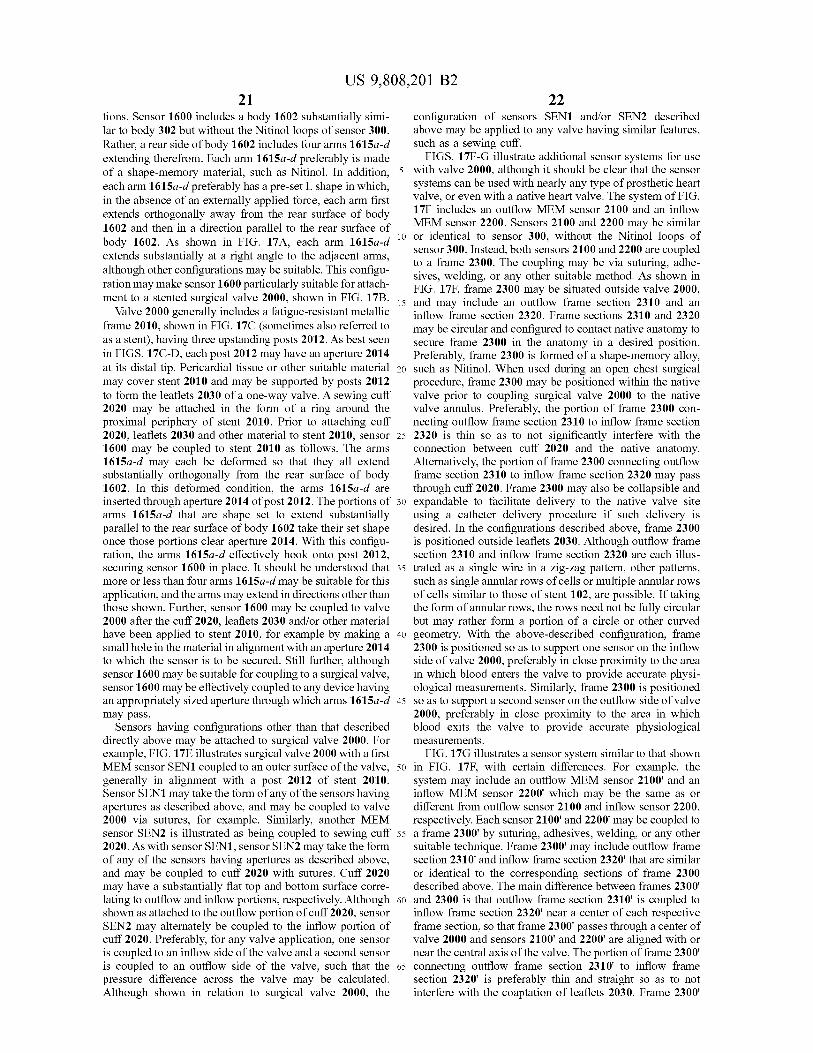
US 9 , 808 , 201 B2 22
tions . Sensor 1600 includes a body 1602 substantially simi - configuration of sensors SEN1 and / or SEN2 described lar to body 302 but without the Nitinol loops of sensor 300 . above may be applied to any valve having similar features , Rather , a rear side of body 1602 includes four arms 1615a - d such as a sewing cuff . extending therefrom . Each arm 1615a - d preferably is made FIGS . 17F - G illustrate additional sensor systems for use of a shape - memory material , such as Nitinol . In addition , 5 with valve 2000 , although it should be clear that the sensor each arm 1615a - d preferably has a pre - set L shape in which , systems can be used with nearly any type of prosthetic heart in the absence of an externally applied force , each arm first valve , or even with a native heart valve . The system of FIG . extends orthogonally away from the rear surface of body 17F includes an outflow MEM sensor 2100 and an inflow
MEM sensor 2200 . Sensors 2100 and 2200 may be similar 1602 and then in a direction parallel to the rear surface of body 1602 . As shown in FIG . 17A , each arm 1615a - d ' 10 or identical to sensor 300 , without the Nitinol loops of
sensor 300 . Instead , both sensors 2100 and 2200 are coupled extends substantially at a right angle to the adjacent arms , to a frame 2300 . The coupling may be via suturing , adhe although other configurations may be suitable . This configu sives , welding , or any other suitable method . As shown in ration may make sensor 1600 particularly suitable for attach FIG . 17F , frame 2300 may be situated outside valve 2000 , ment to a stented surgical valve 2000 , shown in FIG . 17B . 15 and may include an outflow frame section 2310 and an Valve 2000 generally includes a fatigue - resistant metallic inflow frame section 2320 . Frame sections 2310 and 2320 frame 2010 , shown in FIG . 17C ( sometimes also referred to may be circular and configured to contact native anatomy to as a stent ) , having three upstanding posts 2012 . As best seen secure frame 2300 in the anatomy in a desired position . in FIGS . 17C - D , each post 2012 may have an aperture 2014 Preferably , frame 2300 is formed of a shape - memory alloy , at its distal tip . Pericardial tissue or other suitable material 20 such as Nitinol . When used during an open chest surgical may cover stent 2010 and may be supported by posts 2012 procedure , frame 2300 may be positioned within the native to form the leaflets 2030 of a one - way valve . A sewing cuff valve prior to coupling surgical valve 2000 to the native 2020 may be attached in the form of a ring around the valve annulus . Preferably , the portion of frame 2300 con proximal periphery of stent 2010 . Prior to attaching cuff n ecting outflow frame section 2310 to inflow frame section 2020 , leaflets 2030 and other material to stent 2010 , sensor 25 2320 is thin so as to not significantly interfere with the 1600 may be coupled to stent 2010 as follows . The arms connection between cuff 2020 and the native anatomy . 1615a - d may each be deformed so that they all extend Alternatively , the portion of frame 2300 connecting outflow substantially orthogonally from the rear surface of body frame section 2310 to inflow frame section 2320 may pass 1602 . In this deformed condition , the arms 1615a - d are through cuff 2020 . Frame 2300 may also be collapsible and inserted through aperture 2014 of post 2012 . The portions of 30 expandable to facilitate delivery to the native valve site arms 1615a - d that are shape set to extend substantially using a catheter delivery procedure if such delivery is parallel to the rear surface of body 1602 take their set shape desired . In the configurations described above , frame 2300 once those portions clear aperture 2014 . With this configu - is positioned outside leaflets 2030 . Although outflow frame ration , the arms 1615a - d effectively hook onto post 2012 , section 2310 and inflow frame section 2320 are each illus securing sensor 1600 in place . It should be understood that 35 trated as a single wire in a zig - zag pattern , other patterns , more or less than four arms 1615a - d may be suitable for this such as single annular rows of cells or multiple annular rows application , and the arms may extend in directions other than of cells similar to those of stent 102 , are possible . If taking those shown . Further , sensor 1600 may be coupled to valve the form of annular rows , the rows need not be fully circular 2000 after the cuff 2020 , leaflets 2030 and / or other material but may rather form a portion of a circle or other curved have been applied to stent 2010 , for example by making a 40 geometry . With the above - described configuration , frame small hole in the material in alignment with an aperture 2014 2300 is positioned so as to support one sensor on the inflow to which the sensor is to be secured . Still further , although side of valve 2000 , preferably in close proximity to the area sensor 1600 may be suitable for coupling to a surgical valve , in which blood enters the valve to provide accurate physi sensor 1600 may be effectively coupled to any device having ological measurements . Similarly , frame 2300 is positioned an appropriately sized aperture through which arms 1615a - d 45 so as to support a second sensor on the outflow side of valve may pass . 2000 , preferably in close proximity to the area in which
Sensors having configurations other than that described blood exits the valve to provide accurate physiological directly above may be attached to surgical valve 2000 . For measurements . example , FIG . 17E illustrates surgical valve 2000 with a first FIG . 17G illustrates a sensor system similar to that shown MEM sensor SEN1 coupled to an outer surface of the valve , 50 in FIG . 17F , with certain differences . For example , the generally in alignment with a post 2012 of stent 2010 . system may include an outflow MEM sensor 2100 ' and an Sensor SEN1 may take the form of any of the sensors having inflow MEM sensor 2200 ' which may be the same as or apertures as described above , and may be coupled to valve different from outflow sensor 2100 and inflow sensor 2200 , 2000 via sutures , for example . Similarly , another MEM respectively . Each sensor 2100 ' and 2200 may be coupled to sensor SEN2 is illustrated as being coupled to sewing cuff 55 a frame 2300 ' by suturing , adhesives , welding , or any other 2020 . As with sensor SEN1 , sensor SEN2 may take the form suitable technique . Frame 2300 ' may include outflow frame of any of the sensors having apertures as described above , section 2310 ' and inflow frame section 2320 ' that are similar and may be coupled to cuff 2020 with sutures . Cuff 2020 or identical to the corresponding sections of frame 2300 may have a substantially flat top and bottom surface corre - described above . The main difference between frames 2300 lating to outflow and inflow portions , respectively . Although 60 and 2300 is that outflow frame section 2310 ' is coupled to shown as attached to the outflow portion of cuff 2020 , sensor inflow frame section 2320 ' near a center of each respective SEN2 may alternately be coupled to the inflow portion of frame section , so that frame 2300 ' passes through a center of cuff 2020 . Preferably , for any valve application , one sensor valve 2000 and sensors 2100 ' and 2200 ' are aligned with or is coupled to an inflow side of the valve and a second sensor near the central axis of the valve . The portion of frame 2300 ' is coupled to an outflow side of the valve , such that the 65 connecting outflow frame section 2310 ' to inflow frame pressure difference across the valve may be calculated . Section 2320 ' is preferably thin and straight so as to not Although shown in relation to surgical valve 2000 , the interfere with the coaptation of leaflets 2030 . Frame 2300
23 US 9 , 808 , 201 B2
24 and sensors 2100 ' and 2200 ' may be positioned within the pass through ( or be sutured onto ) cuff 3020 . Although not native anatomy after implantation of valve 2000 in an required , coupling element 3110 preferably has a sufficient otherwise similar fashion to that described for frame 2300 . stiffness to keep a stable positional relationship between It should further be understood that frame 2300 ' and sensors coupling element 3110 and sensor 3100 . In one example , 2100 ' and 2200 may be used with any other type of 5 coupling element 3110 may be a metal wire , such as a prosthetic heart valve that can coapt over the portion of Nitinol wire . Coupling element 3210 of sensor 3200 pref frame 2300 ' connecting outflow frame section 2310 ' to erably has a complementary shape and / or structure to cou inflow frame section 2320 ' . Similarly , frame 2300 ' with pling element 3110 . For example , coupling element 3110 sensors 2100 ' and 2200 may be implanted for use with a may have threads configured to threadingly couple to cou native valve , with the native valve leaflets coapting over the 10 pling element 3210 . In other embodiments , coupling ele portion of frame 2300 ' connecting outflow frame section ment 3110 may have a press fit relationship with coupling 2310 ' to inflow frame section 2320 ' . The embodiment element 3210 . To achieve the press fit relationship , an end described in connection with FIG . 17G may be advanta - portion of coupling element 3110 may have a shape that geous because frame 2300 ' is mostly independent of pros - corresponds to the shape of a recess in coupling element thetic heart valve 2000 and can be used with other types of 15 3210 . Still further , coupling element 3110 may be sutured to valve devices ( or native valves ) and may be implanted after coupling element 3210 to couple sensor 3100 to sensor implantation of a prosthetic valve . However , the embodi - 3200 . Other arrangements for joining coupling element 3110 ment described in connection with FIG . 17F may be advan - to coupling element 3210 are also possible , including a snap tageous because it avoids potential interference between fit , a ball and socket connection , adhesives , welding and coaptation of valve leaflets and a frame structure extending 20 other known techniques . Even further , outflow sensor 3100 through the valves . may be stapled , glued , sutured , or the like to the outflow end
FIG . 17H illustrates a sensor system similar to that shown of cuff 3020 , either directly or by stapling coupling element in FIG . 176 , with certain differences . For example , the 3110 to cuff 3020 . If sensor 3100 is directly stapled to cuff system may include an outflow MEM sensor 2100 " and an 3020 , the coupling element 3100 may be unnecessary . inflow MEM sensor 2200 " which may be the same as or 25 Similarly , inflow sensor 3200 may alternatively be stapled , different from outflow sensor 2100 ' and inflow sensor 2200 ' , glued , sutured , or the like to the inflow end of cuff 3020 . respectively . Each sensor 2100 " and 2200 " may be coupled prosthetic heart valve 4000 according another embodi to a frame 2300 " by suturing , adhesives , welding , or any ment of the disclosure is illustrated in FIG . 19A . Prosthetic other suitable technique . Frame 2300 " may include outflow heart valve 4000 may be similar to prosthetic heart valve 100 frame section 2310 " and inflow frame section 2320 " that are 30 in a number of ways , with certain differences making it similar or identical to the corresponding sections of frame particularly suitable for use to replace the mitral valve . 2300 ' described above . The main difference between frames Prosthetic heart valve 4000 may include a flared stent 4050 2300 " and 2300 ' is that outflow frame section 2310 " is and a valve assembly having three leaflets attached to a coupled to inflow frame section 2320 " with frame portions cylindrical cuff . Prosthetic heart valve 4000 is collapsible extending outside the leaflets and through the cuff 2020 . 35 and expandable and designed for replacement of a native This embodiment provides the benefits of having sensors mitral valve . Prosthetic heart valve 4000 has an inflow end 2100 " and 2200 " centered along the path of blood flow , 4010 , an outflow end 4012 , a substantially cylindrical por without having any structures running through the leaflets tion nearer outflow end 4012 , and an outwardly flared and possibly interfering with coaptation of the leaflets . In portion nearer inflow end 4010 when in the expanded this embodiment , although two struts are shown connecting 40 condition . It should be understood that prosthetic heart 4000 outflow frame section 2310 " and inflow frame section is not limited to replacement of mitral valves , and may be 2320 " , it may be useful to use three struts for connection , used to replace other heart valves . each strut running along a stent post SP of the valve 2000 , Stent 4050 includes a plurality of struts 4052 forming for example . Having three struts as described above may aid three circumferential rows of cells ( best seen in FIG . 19B ) . in centering sensors 2100 " and 2200 " in the path of blood 45 Commissure attachment features ( CAFs ) 4066 may be flow . included near outflow end 4012 . The first row of cells may FIGS . 18A - B illustrate yet another application for sen - be disposed adjacent outflow end 4012 and the third row of
sors , a mechanical valve 3000 used for replacing the func - cells may be disposed adjacent inflow end 4010 . Stent 4050 tion of a native heart valve . Mechanical valve 3000 may may include securement features to help secure valve 4000 function similarly to surgical valve 2000 or prosthetic heart 50 within the mitral valve annulus . These securement features valve 100 to replace the function of , for example , an aortic may be in the form of struts forming engaging arms 4070 valve or a mitral valve . Generally , valve 3000 includes nested within particular cells of stent 4050 . Engaging arms sewing cuff 3020 , support structure 3010 , and two actuating 4070 are shape set or biased to project outwardly from those flaps 3030 which function as leaflets to enable one - way flow . particular cells , and may be configured to engage portions of Cuff 3020 may include a number of marker bands 3040 to 55 heart tissue ( e . g . , native mitral valve leaflets ) when pros aid in localization . Sensors may be coupled to mechanical thetic heart valve 4000 is deployed in a patient . Each valve 3000 in a number of ways . engaging arm 4070 may be formed of a shape - memory alloy ,
One configuration of attaching an outflow MEM sensor and is preferably formed from the same material as stent 3100 and an inflow MEM sensor 3200 to mechanical valve 4050 . Engaging arms 4070 may include two substantially 3000 is shown in FIG . 18B . In particular , outflow sensor 60 parallel struts connected to one another by a rounded strut . 3100 may be substantially similar or identical to sensor 300 , The free end of each engaging arm 4070 defined by the but without the Nitinol loops of sensor 300 . Instead , sensor rounded strut projects outwardly into engagement with the 3100 includes a coupling element 3110 . Similarly , inflow surrounding tissue . In certain arrangements , the engaging sensor 3200 may be substantially similar or identical to arms 4070 may clip over the native mitral valve leaflets to sensor 300 , but without the Nitinol loops of sensor 300 , and 65 hold prosthetic valve 4000 in place . includes a coupling element 3210 . As shown , coupling FIG . 19B illustrates three potential configurations for element 3110 may be a male coupling element configured to attaching an outflow sensor to valve 4000 . In one arrange
25 US 9 , 808 , 201 B2
26 ment , outflow MEM sensor 4100 may be coupled to valve well as inflow and outflow sensor configurations , may be 4000 by suturing to one or more struts of an engagement arm suitable for other heart valves . 4070 . Sensor 4100 may take the form of any suitable sensor The sensors described above or sensors similar to those described above including , for example , a sensor with described above may be used in still other applications . For apertures to facilitate suturing , such as sensor 400 or 500 . 5 example , sensors may be used with vascular stents , plugs When engagement arm 4070 is clipped over a native mitral and / or occluders to take measurements , such as pressure valve leaflet , outflow sensor 4100 will be positioned within measurements , on one or both ends of the device . For the left ventricle . In another arrangement , an outflow MEM example , FIG . 20A illustrates prosthetic heart valve 100 sensor 4200 may be coupled to one or more struts 4052 at implanted in the native aortic valve annulus , with an
10 occluder 5000 positioned between valve 100 and a native the annulus portion of the stent 4050 near outflow end 4012 . valve leaflet . Occluder 5000 may be used to fill irregularities Outflow sensor 4200 may take the form of any of the between prosthetic heart valve 100 and the native valve above - described sensors suitable for connection to stent annulus . Occluder 5000 may be conformable to allow for 4050 , including the sensors with apertures . In a third superior sealing between the perimeter of prosthetic heart arrangement , an outflow MEM sensor 4300 may be coupled 15 15 valve 100 and the native valve annulus while exerting a low to CAF 4066 , for example by suturing . As with the other radial outward force . For example , occluder 5000 may be a outflow sensors described immediately above , outflow sen - metallic structure that may be longitudinally stretched from sor 4300 may take any suitable form described above , a relaxed condition to the stretched condition . In the relaxed including sensors with apertures to facilitate suturing to condition , occluder 5000 may have a cross - section that is CAF 4066 . Although three outflow sensors 4100 - 4300 are 20 greater in size than it is in the stretched condition . Thus , illustrated in FIG . 19B , this is for purposes of illustration occluder 5000 may be flexible and capable of contracting in only , and generally only a single outflow sensor would be the radial direction when a force is applied thereto to attached to valve 4000 . conform to the shape of the annulus in which it is implanted .
In addition to an outflow sensor , an inflow sensor may Moreover , the ability of occluder 5000 to longitudinally also be coupled to valve 4000 . FIG . 19C illustrates valve 25 stretch may enable the occluder 5000 to be delivered 4000 from inflow end 4010 and shows different configura - through a small diameter catheter . tions for attaching an inflow sensor to valve 4000 . For Occluder 5000 may be formed from a tubular section of example , inflow MEM sensor 4400 may be coupled to and braided fabric comprising a plurality of braided strands . The extend outwardly from one or more struts 4052 on the inflow strands forming the braid may have a predetermined relative end 4010 of stent 4050 . Alternatively , inflow MEM sensor 30 orientation with respect to one another ( e . g . , a helical braid ) . 4500 may be coupled to and extend along a strut 4052 at the The ends of the strands may be located at a leading end inflow end 4010 of stent 4050 . As another alternative , inflow ( relatively far from a user implanting the occluder ) and a MEM sensor 4600 may be coupled to and extend along a trailing end ( relatively close to the user ) , and may be affixed strut 4052 adjacent to the valve assembly on the inflow side to one another by any suitable means to prevent unraveling , of the valve leaflets . Inflow sensor 4600 may be coupled to 35 such as by soldering , brazing , welding , gluing , tying , or additional struts not visible in FIGS . 19A - B , the additional clamping . Moreover , occluder 5000 may comprise a plural struts extending in the longitudinal direction of stent 4050 i ty of layers of braided fabric and / or other occluding mate and being configured to provide additional support for the rial ( e . g . , a filler material ) such that occluder 5000 is capable attachment of a cuff , skirt , or similar structure to stent 4050 . of at least partially inhibiting blood flow therethrough in As a still further alternative , inflow MEM sensor 4700 may 40 order to facilitate the formation of thrombus and epithelial be coupled to and extend along a strut 4052 , similar to inflow ization . The metal forming occluder 5000 may be a shape sensor 4500 but positioned farther from the inflow end 4010 memory material with elastic and / or memory properties , than inflow sensor 4500 . Each inflow sensor 4400 - 4700 may such as Nitinol , although other materials may be suitable . take the form of any of the sensors described above , for Additional details of occluder 5000 and similar occluders example a sensor with suitably positioned apertures to 45 are provided in U . S . Patent Publication No . 2014 / 0277426 , facilitate suturing of the inflow sensor to valve 4000 . the disclosure of which is hereby incorporated by reference Although four inflow sensors 4400 - 4700 are illustrated in herein . FIG . 19C , this is for purposes of illustration only , and As shown in FIG . 20A , occluder 5000 is disposed generally only a single inflow sensor would be attached to between prosthetic heart valve 100 and a native aortic valve valve 4000 . 50 leaflet . An anchor 5030 attached to the body of occluder
FIG . 19D illustrates heart valve 4000 implanted within 5000 via a cord , may have one or more sharp ends for the native mitral valve annulus with outflow sensor 4100 piercing through the native valve leaflet . Once anchor 5030 coupled to one of the engaging arms 4070 and inflow sensor has passed through the native valve leaflet , occluder 5000 is 4400 coupled to and extending from struts 4052 at inflow effectively affixed to the native valve leaflet and secured in end 4010 of valve 4000 . With this particular configuration , 55 place between prosthetic heart valve 100 and the native outflow sensor 4100 is positioned within the left ventricle valve leaflet . In one variation of this embodiment , anchor and inflow sensor 4400 is positioned within the left atrium 5030 may be configured to secure occluder 5000 to pros during normal operation , the two sensors providing the thetic heart valve 100 by being fastened to select cells of ability to detect , for example , the pressure difference stent 102 between the two heart chambers during operation of valve 60 One or more sensors may be coupled to occluder 5000 so 4000 . Additional details of prosthetic heart valve 4000 and that measurements , such as pressure measurements , may be similar prosthetic heart valves are described in greater detail taken after prosthetic heart valve 100 and occluder 5000 are in U . S . Provisional Patent Application No . 62 / 137 , 444 titled implanted . For example , FIG . 20B provides a closer view of “ Prosthetic Mitral Valve , " the disclosure of which is hereby occluder 5000 , with anchor 5030 omitted for clarity , illus incorporated by reference herein . It should be understood 65 trating potential configurations for attaching sensors to that although valve 4000 is described for use as a replace - occluder 5000 . In particular , outflow MEM sensor 5100 may ment for the mitral valve , the same or similar structure , as be coupled to a first end of occluder 5000 . Outflow sensor
US 9 , 808 , 201 B2 27 28
5100 may take the form of any of those described above that intended to help maintain the closure device 6000 in position may be suitable for attachment to occluder 5000 , including , at the target site , as described in greater detail below . The for example , sensors with apertures to facilitate suturing . In second expanded volume portion 6020 may , in some cases , one example , the end of occluder 5000 facing the aorta may be a generally cylindrical body that is substantially thicker not have a closed metallic stent structure , but may have a 5 in the axial direction than first portion 6010 and axially substantially cylindrical stent structure filled with a filler disposed toward the second end . The second expanded material . In that embodiment , sensor 5100 may be attached volume portion 6020 may be sized to be somewhat larger in directly to the filler material , for example by sutures . How diameter ( e . g . , about 10 - 30 % ) than the inside diameter of the ever , if occluder 5000 includes a closed stent structure at the vessel , cavity , or lumen to be occluded to facilitate anchor end facing the aorta , sensor 5100 may be connected , for 10 ing of the device to prevent dislodgement , but not so large example by suturing , directly to the stent structure . In both as to not fit in the vessel , cavity or lumen . cases , outflow sensor 5100 may extend away from the end of occluder 5000 and toward the aorta , and may be config At the same time , the first expanded volume portion 6010
of the closure device 6000 may have a diameter that is larger ured to take measurements within the aorta , for example pressure readings . Alternatively , outflow MEM sensor 5200 15th 5200 15 than the diameter of the second expanded volume portion may be coupled along the length of the body of occluder 6020 . This larger diameter is intended to abut the wall 5000 instead of at an end . This coupling may be effected by , surrounding the abnormal aperture to prevent device move for example , suturing outflow sensor 5200 directly to the ment further into the aperture and to assist in sealing the stent structure of occluder 5000 and / or to a fabric provided aperture . For example , the first expanded volume portion on or within the stent structure . If positioned along the body 20 6010 may be oversized so as to overlie the ostium or opening of occluder 5000 , outflow sensor 5200 should be positioned of the LAA in a position adjacent to , and in flush contact closer to the end of the occluder facing the aorta . In addition with , the wall of the atrium . The first expanded volume to an outflow sensor 5100 or 5200 , an inflow MEM sensor portion 6010 may also be flexible so as to be capable of 5300 or 5400 may also be coupled to occluder 5000 . Inflow conforming to the curvature of the wall of the atrium in LAA sensor 5300 may be attached to occluder 5000 in the same 25 applications or other vascular structures in other applica manner as outflow sensor 5200 and may take a similar form , tions . Although one configuration of the first and second the difference being that inflow sensor 5300 is configured to expanded volume portions 6010 , 6020 is described above be positioned within the left ventricle when occluder 5000 is and shown in the figures , various other configurations and implanted in the native valve annulus . Similarly , inflow sizes may be used depending on the particular application or MEM sensor 5400 may be coupled to occluder 5000 in a 30 condition to be treated . For example , one or both expanded similar manner as outflow sensor 5100 , and may take a volume portions 6010 , 6020 may be thin disks or disks similar or identical form to outflow sensor 5100 , the differ having a convex distal end , or the device may include a ence being that inflow sensor 5400 is configured to extend smaller diameter cylindrical portion between two larger into the left ventricle . Preferably , a single inflow sensor and diameter disks . Moreover , the depth or thickness of the first a single outflow sensor are used with occluder 5000 to 35 and / or second expanded volume portions may depend on the determine the pressure difference , or other relevant param - thickness and number of layers used to make the medical eters , between the aorta and the left ventricle during opera - device 6000 . tion of prosthetic heart valve 100 . It should further be The first expanded volume portion 6010 , the second understood that although occluder 5000 is illustrated for use expanded volume portion 6020 , and the axial portion 6030 in the native valve annulus of the aortic valve , the same or 40 may each be formed of a shape - memory alloy , such as similar structures may be used in other heart valves , or in braided Nitinol , to facilitate collapsing the closure device other locations in the vasculature in which an occluder , plug , 6000 for minimally invasive delivery , and to facilitate or stent may be used , and may include one or more sensors expansion to a pre - set shape upon delivery of the closure as desired to make desired physiological measurements . device 6000 to the intended location . A first coupling 6015
The sensors described above may have still further appli - 45 may be disposed adjacent the first expanded volume portion cations , for example with other occluders , for example those 6010 and may enable connection of a delivery device or used to treat patent foramen ovale ( “ PFO ” ) , atrial septal other device to closure device 6000 . For example , first defect ( “ ASD ” ) , ventricular septal defect ( “ VSD ' ) , patent coupling 6015 may include internal or external threads that ductus arteriosus ( “ PDS ” ) , or to close the left atrial append mate with corresponding threads of another device . A sec age ( “ LAA " ) . 50 ond coupling 6025 , similar to the first coupling 6015 , may
Closure devices may have various configurations depend be disposed adjacent to or within the second expanded ing on factors such as the type of abnormality to be volume portion 6020 . Second coupling 6025 may also occluded , the location of the target site , the condition of the include internal or external threads for connection to corre patient ' s vasculature , and the practitioner ' s preferences . For sponding threads of another device . It should be understood example , in the depicted embodiment of FIG . 21A , a closure 55 that other coupling mechanisms , such as press - fit or snap - fit device 6000 has a first expanded volume portion 6010 and arrangements , may be utilized in first and second couplings a second expanded volume portion 6020 that are substan 6015 , 6025 . Additional details of closure device 6000 and tially perpendicular to a central axis extending along closure similar devices are described in U . S . Pat . No . 8 , 758 , 389 , the device 6000 . The first expanded volume portion 6010 may disclosure of which is hereby incorporated by reference be proximate a first end of closure device 6000 , with the 60 herein . second expanded volume portion 6020 spaced axially from FIG . 21B is a schematic view of closure device 6000 the first expanded volume portion 6010 and proximate a positioned within the LAA of a left atrium . In patients with second end of closure device 6000 . The first expanded certain conditions , such as atrial fibrillation , blood clots may volume portion 6010 may be connected to the second tend to form in the LAA . Implanting a device such as closure expandable volume portion 6020 via an axial portion 6030 . 65 device 6000 may lead to partial or complete occlusion of the As depicted in FIG . 21A , the first expanded volume LAA , thus reducing the risk of thrombi breaking off the
portion 6010 may have the shape of a thin disk , and is LAA and entering the blood stream .
US 9 , 808 , 201 B2 29 30
FIG . 21C illustrates potential configurations for coupling One measure of regurgitation in aortic heart valves is the sensors to closure device 6000 . A first sensor may be aortic regurgitation index , which may be defined as the ratio coupled to closure device 6000 so as to be exposed to the left of the transvalvular gradient between the diastolic blood atrium in which blood is still flowing . A second sensor may pressure ( RRdia ) in the aorta and the left - ventricular end additionally or alternatively be coupled to closure device 5 diastolic blood pressure ( LVEDP ) to the systolic blood 600 so as to be exposed to the LAA , which is intended to be pressure ( RRsys ) in the aorta : [ ( RRdia - LVEDP ) / RRsys ] x sealed off from blood flow by closure device 6000 . For 100 . The aortic regurgitation index has an inverse correla example , a MEM sensor 6100 may take a similar form to tion to the severity of aortic regurgitation and allows a sensor 300 described above , but rather than having Nitinol physician to differentiate between patients with mild , mod loops , sensor 6100 may include a coupling end 6105 con - 10 erate , or severe aortic regurgitation . The aortic regurgitation figured to couple to first expanded volume 6010 , for index may also be independently used to predict the asso example to coupling 6015 . In that regard , coupling end 6105 ciated 1 - year mortality risk for a given patient upon collec may include threads that mate with corresponding threads in tion of data . coupling 6015 . Thus , coupling 6015 may serve to couple to FIG . 22A illustrates the aortic regurgitation index in a both a delivery device and sensor 6100 . In other embodi - 15 patient with moderate aortic regurgitation . As seen in the ments , coupling end 6105 may connect to coupling 6015 graph , the patient has an aortic diastolic blood pressure using a press fit or other suitable connection . Sensor 6100 ( RRdia ) of 40 , a left - ventricular end - diastolic blood pressure may be coupled to first expanded volume portion 6010 after ( LVEDP ) of 20 , and an aortic systolic blood pressure ( RR closure device 6000 has been implanted into the LAA . As sys ) of 120 . Using the formula for the aortic regurgitation shown in FIG . 21D , with the configuration described above , 20 index defined above yields the following : sensor 6100 , when coupled to closure device 6000 , extends outward from and substantially along the longitudinal axis ( RRdia - LVEDP ) / RRsysx100 = ( a - b ) / cx100 = ( 40 - 20 ) / of closure device 6000 . 120x100 = 16 . 7
Alternatively , MEM sensor 6300 may be coupled directly for a second patient , the aortic regurgitation index indi to first expanded volume 6010 such that , when closure 25 cates a trivial amount of aortic regurgitation as shown in device 6000 is implanted into the LAA , sensor 6300 is FIG . 22B . For this patient , the aortic diastolic blood pressure exposed to the left atrium . Sensor 6300 may take the form ( RRdia ) is 50 , the left - ventricular end - diastolic blood pres of any suitable sensor described above . For example , sensor sure ( LVEDP ) is 10 and the aortic systolic blood pressure is 6300 may be any of the sensors described above having 130 , yielding an aortic regurgitation index as calculated apertures to enable sensor 6300 to be coupled directly to the 30 below : frame of first expanded volume 6010 using sutures . Although FIG . 21C shows sensors 6100 and 6300 both ( RRdia - LVEDP ) / RRsysx100 = ( a ' - b ' ) / c ' x100 = ( 50 coupled to closure device , in practice , there is preferably 10 / 130x100 = 30 . 8 only a single sensor coupled to first expanded volume 6010 When used in conjunction with prosthetic heart valves , such that one sensor is exposed to the left atrium . 35 sensors 300 and the variations described above may measure
In addition or alternatively to a sensor exposed to the left blood pressure to determine an aortic regurgitation index atrium , one sensor is preferably coupled to second expanded and thus reveal the severity of the regurgitation . Based on volume 6020 so as to be exposed to the occluded LAA . For the calculated aortic regurgitation index , follow - up treat example , MEM sensor 6200 may take substantially the same ment may be advised . Additionally , sensors 300 and varia form as sensor 6100 , with coupling end 6205 threaded into 40 tions thereof described above may be used to decide when second coupling 6025 of second expanded volume 6020 . to fully deploy a partially deployed heart valve and the type Sensor 6200 may be coupled to second expanded volume of corrective measure necessary , if any . 6020 prior implantation of the closure device 6000 into the One example of a method using a prosthetic heart valve LAA . In another configuration , a MEM sensor 6400 , which having sensors is shown in FIG . 23 . In this method , a may be substantially identical to sensor 6300 , may be 45 preliminary technique , including but not limited to aortog coupled to second expanded volume 6020 , for example via raphy , may be performed after valve deployment in order to suturing or any other suitable attachment means . Again , make a preliminary assessment of aortic regurgitation . This although both sensors 6200 and 6400 are illustrated in FIG . preliminary assessment may provide a rough classification 21C , preferably only one sensor is attached to second of the regurgitation into four groups : no aortic regurgitation , expanded volume 6020 . FIG . 21D is a schematic illustration 50 mild aortic regurgitation , moderate aortic regurgitation , and of closure device 6000 implanted in the LAA with sensor severe aortic regurgitation . If the preliminary technique 6100 coupled to first expanded volume 6010 and sensor shows no aortic regurgitation , then no measurements are 6200 coupled to second expanded volume 6020 . With this taken and the procedure is determined to be a successful one configuration , measurements , such as blood flow or pressure ( e . g . , valve function is adequate ) . If the preliminary tech measurements , may be taken within the LAA and within the 55 nique shows that mild aortic regurgitation is present , then left atrium to determine , for example , if the LAA has been sensors 300 or variations thereof described above may be appropriately sealed off by closure device 6000 . used to quantify the amount of aortic regurgitation by
As noted above , there are many applications for sensors making measurements used to calculate an aortic regurgita 300 and modified versions of sensor 300 described above . tion index ( ARI ) , as described above . An aortic regurgitation When utilized on prosthetic heart valves implanted in the 60 index greater than or equal to 25 may indicate that the aortic native aortic valve , one such application is the assessment of regurgitation is negligible , which may result in no further the severity of aortic regurgitation . Aortic regurgitation may measurements or corrective measures . If , however , the index negatively affect the prognosis after transcatheter aortic is less than 25 , then the aortic regurgitation may be classified valve replacement , with increased morbidity and mortality as either moderate or severe . In either case , further diag in patients with more than mild regurgitation . Thus , tech - 65 nostic techniques , such as , for example , transesophageal niques may be employed using the sensors described above echocardiography ( TEE ) or transthoracic echocardiography to quantify the extent of regurgitation , if any . ( TTE ) , may be performed to further assess the situation ,
US 9 , 808 , 201 B2 31 32
followed by a corrective measure . The corrective measure tions based on the various algorithms described above . A may include any one or more of post - dilation techniques , memory 7005 may include data in the form of a dataset for snaring to adjust the position of the valve , valve - in - valve performing various steps of the algorithm . In some implantation ( e . g . , implanting an additional valve inside an examples , data from the sensors relating to pressure , forces already - implanted valve ) , balloon expansion , resheathing 5 and the like may be passed to processor 7004 and compared and redeploying techniques , deploying a valve of the same against a dataset stored in memory 7005 to determine if or different type , modified redeployment , or the addition of further treatment and / or diagnosis is necessary . Additionally , paravalvular leakage features , etc . Following the corrective data relating to valve diagnosis may be sent from program measure , sensors 300 or variations described above may be ming unit 7008 to processor 7004 and the processor may used to recalculate the aortic regurgitation index . If the 10 determine the appropriate course of action or send an alert aortic regurgitation index is greater than or equal to 25 , then the corrective measure may be considered successful and no to a clinician . Communication between programming unit
7008 and processor 7004 may be accomplished via com further measurements or measures are taken . If , however , the aortic regurgitation index remains below 25 , then further munication between antenna 7018 and telemetry unit 7006 . corrective measures may be necessary . This loop from 15 Additionally , sensors may be in communication with one or corrective measure to aortic regurgitation index calculation more wearable devices to enable the user to continuously may continue until satisfactory positioning and functioning monitor or track the functionality of a therapeutic device . of the prosthetic heart valve are achieved . Such wearable devices may track or log data , and if neces
In the example above , the calculation of the aortic regur sary , provide the data to a clinician or alert emergency gitation index using sensors 300 or variations thereof 20 personnel if immediate attention is needed . described above is performed after the implantation of the While the operation of the sensor ( s ) has been described , prosthetic heart valve to ensure proper functioning . Such it will be understood that other embodiments may be imple pressure measurement may also allow monitoring of overallm ented in a similar manner , and that combinations of these cardiac health of the patient , as well as functioning of the embodiments may be possible . For example , any number of prosthetic device . In addition , sensors may be used to 25 sensors may be used in a single patient and such sensors may monitor an implanted prosthetic heart valve or repair device be separate from the prosthetic replacement or repair device . at any time , including before implantation of a therapeutic It will also be noted that while the disclosures herein are device or after discharge of the patient from the hospital , and predominantly described in connection with the replacement for as long as the device is implanted in the patient . For of a tricuspid valve , the disclosures are equally applicable to example , sensors may be used to aid in the implantation of 30 the replacement of other valves , including a bicuspid valve , a therapeutic device . In one example , sensors may be used such as the mitral valve , as well as other implantable to virtually reconstruct the geometry of the native valve medical devices , such as annuloplasty rings or occlusion annulus to predict potential paravalvular leakage of a heart devices and devices for taking general measurements of the valve with known dimensions . Such sensors may be used vasculature for delivery of catheters . Additionally , in some alone or in combination with balloons , or balloon - expanded , 35 variations , one or more of the sensors may be radiopaque to or self - expanding diagnostic rings , holders , sizers , or stents . enable visualization during and / or after deployment . Sensors For valve - in - valve procedures , sensors on an already may also be in communication with a delivery system and / or implanted valve may be used to aid in docking a second other sensors to aid in placement , valve - in - valve or valve valve within the implanted valve . in - ring procedures , or to function as locators or docking
FIG . 24 is a schematic overview of one embodiment of 40 stations , the components of a valve diagnostic system 7000 including According to one embodiment of the disclosure , a pros an electronic subassembly 7010 disposed within a control thetic heart valve system comprises : module . It will be understood that the valve diagnostic a prosthetic heart valve including : system can include more , fewer , or different components and a stent extending from an outflow portion to an inflow can have a variety of different configurations . 45 portion and having an expanded condition and a collapsed Some of the components ( for example , power source condition ; and
7012 , antenna 7018 , receiver 7002 , and processor 7004 ) of a valve assembly mounted to the stent ; and valve diagnostic system 7000 can be positioned on one or a first sensor configured to measure physiological data , the more circuit boards or similar carriers . Any power source first sensor including a body and a plurality of apertures 7012 can be used including , for example , a battery , such as 50 extending through the body and adapted to receive at least a primary battery or a rechargeable battery . Examples of one suture therethrough for attaching the sensor to the other power sources include super capacitors , nuclear or stent ; and / or atomic batteries , mechanical resonators , infrared collectors , a second sensor configured to measure physiological data , thermally powered energy sources , flexural powered energy the second sensor including a body and a plurality of sources , bioenergy power sources , fuel cells , bioelectric 55 apertures extending through the body and adapted to cells , osmotic pressure pumps , and the like . receive at least one suture therethrough for attaching the
If the power source 7012 is a rechargeable battery , the sensor to the stent ; and / or battery may be recharged using the optional antenna 7018 , the first sensor is attached to the inflow portion of the stent if desired . Power can be provided to the battery for recharg - with a first suture and the second sensor is attached to the ing by inductively coupling the battery through the antenna 60 outflow portion of the stent with a second suture ; and / or to a recharging unit 7016 external to the user . the plurality of apertures includes four apertures arranged
A processor 7004 is included to obtain data from the in a rectangular pattern on one end of the body ; and / or sensors relating to force , pressure or elasticity measured by the body of the first sensor includes two lateral projections , each of the sensors . Any processor can be used and can be the plurality of apertures including at least one aperture as simple as an electronic device that , for example , is 65 extending through each of the two projections ; and / or capable of receiving and interpreting instructions from an the plurality of apertures includes two apertures extending external programming unit 7008 and performing calcula through each of the two projections ; and / or
US 9 , 808 , 201 B2 33 34
the plurality of apertures includes at least two apertures condition , the stent being formed of a plurality of struts , extending through the body exclusive of the projections ; a strut aperture being formed at an intersection of at least and / or two of the struts , and
the body of the first sensor includes four lateral projections , a valve assembly mounted to the stent ; and the plurality of apertures including at least one aperture 5 a sensor configured to measure physiological data , the extending through each of the four projections ; and / or sensor including a body , the body being configured to be
the body of the first sensor has opposed longitudinal sides coupled to the stent , and opposed ends , the body including a first projection on wherein the body includes a first body section having a first one of the ends , a second projection on one of the width , a middle body section having a second width longitudinal sides adjacent the use end and a third pro 10 smaller than the first width , and a third body section
having a third width greater than the second width and jection on another of the longitudinal sides adjacent the smaller than the first width ; and / or one end , and the plurality of apertures includes at least the strut aperture has an aperture width smaller than the first one aperture extending through each of the projections ; width of the first body section and the third width of the and / or 15 third body section ; and / or the first and second sensors are each configured to measure the second width of the middle body section is substantially
blood pressure and each include an induction coil dis equal to the aperture width of the strut aperture ; and / or posed within the respective body and a capacitor in the first and third body sections each include projecting electrical communication with the inductor coil . members extending laterally beyond the middle body According to another embodiment of the disclosure , a 20 section , and the at least two struts are configured to be
prosthetic heart valve system comprises : positioned between the projecting members of the first a prosthetic heart valve including : and third body members when the sensor is coupled to the a stent extending from an outflow portion to an inflow strut aperture ; and / or
portion and having an expanded condition and a collapsed the projecting members of the third body section are deflect condition ; and 25 able .
a valve assembly mounted to the stent ; and According to a still a further embodiment of the disclo a sensor configured to measure physiological data , the sure , a prosthetic heart valve system comprises :
sensor including a body , the body having a first side , a a prosthetic heart valve including : second side opposite the first side , and a pair of fingers a stent extending from an outflow portion to an inflow extending away from the body on the first side of the 30 portion and having an expanded condition and a collapsed body , the fingers and the first side of the body defining a condition , the stent being formed of a plurality of struts , channel extending along a length of the body , the sensor a strut aperture being formed at an intersection of at least being connectable to the stent ; and / or two of the struts ; and
each of the fingers has a free edge , and the channel has a a valve assembly mounted to the stent ; and a sensor con maximum width between the fingers that is greater than a 35 figured to measure physiological data , the sensor includ distance between the free edges ; and / or ing a body configured to be coupled to the stent , wherein
the first sensor is coupled to a strut of the stent the strut is the body includes a head having a first width and a shank positioned at least partially within the channel . having a second width smaller than the first width ; and / or According to a further embodiment of the disclosure , the strut aperture has an aperture width smaller than the first
a prosthetic heart valve system comprises : 40 width of the head ; and / or a prosthetic heart valve including : the aperture width is substantially equal to the second width a stent extending from an outflow portion to an inflow of the shank ; and / or
portion and having an expanded condition and a collapsed a pair of fingers extending laterally from the shank at a condition ; and spaced distance from the head , each finger extending
a valve assembly mounted to the stent ; 45 toward the head in the absence of externally applied a sensor configured to measure physiological data , the forces ; and / or the head includes a pair of hooked members
sensor including a body ; and each curving toward a corresponding finger ; and / or a first finger having a first end attached to the body and a free the at least two struts forming the strut aperture are adapted
end , the free end being configured to hook over at least to be positioned between one of the fingers and one of the one strut of the stent to attach the sensor to the stent ; 50 hooks when the sensor is coupled to the strut aperture . and / or According to yet another embodiment of the disclosure , a
the first finger includes a first portion extending substantially prosthetic heart valve system comprises : orthogonal to the body , a second portion extending sub - a prosthetic heart valve including : stantially orthogonally from the first portion , and a third a stent extending from an outflow portion to an inflow portion extending from the second portion and substan - 55 portion and having an expanded condition and a collapsed tially parallel to the first portion , a terminal end of the condition , the stent being formed of a plurality of struts , third portion and the body forming a gap therebetween ; a strut aperture being formed at an intersection of at least and / or two of the struts ; and
the first finger is coupled to a face portion of the body ; and / or a valve assembly mounted to the stent ; and a second finger having a first end attached to the body and 60 a sensor configured to measure physiological data , the
a free end , the free end of the first finger and the free end sensor including a body , the body including a connecting of the second finger forming a gap therebetween . member adapted to couple the sensor to the stent , the According to a still another embodiment of the disclosure connecting member including a shaft projecting away
a prosthetic heart valve system comprises : from the body to a free end , and a head at the free end of a prosthetic heart valve including : 65 the shaft ; and / or a stent extending from an outflow portion to an inflow the shaft includes a first shaft member and a second shaft
portion and having an expanded condition and a collapsed member spaced apart from the first shaft member by a
ondlor
US 9 , 808 , 201 B2 35 36
or
shaft gap , each of the first shaft member and the second a stent extending from an outflow portion to an inflow shaft member having a free end ; and / or portion ; and
the head includes a first head portion on the free end of the a valve assembly mounted to the stent ; first shaft member and a second head portion on the free wherein the frame coupling portion extends through the end of the second shaft member , the first head portion 5 stent of the prosthetic heart valve so that the first sensor being spaced apart from the second head portion by a head is positioned closer to the outflow portion of the prosthetic gap ; and / or heart valve than to the inflow portion and the second
the first shaft member , the second shaft member and the sensor is positioned closer to the inflow portion of the shaft gap collectively have a shaft width , and the first head prosthetic heart valve than to the outflow portion ; and / or portion , the second head portion and the head gap col - a prosthetic heart valve including : lectively have a head width that is greater than the shaft a stent extending from an outflow portion to an inflow width ; and / or the head has a chamfered surface ; and / or portion ;
the connecting member has a relaxed condition and a a cuff attached to the stent ; and compressed condition , the head gap being larger in the 15 a valve assembly mounted to the stent ; relaxed condition than in the compressed condition ; and wherein the frame coupling portion extends through the cuff
and outside of the valve assembly , the first sensor being the head width in the relaxed condition is greater than a positioned on the outflow portion of the prosthetic heart
width of the strut aperture and the head width in the valve and the second sensor being positioned on the compressed condition is smaller than the width of the strut 20 inflow portion of the prosthetic heart valve . aperture . According to a further embodiment of the disclosure , According to yet a further embodiment of the disclosure , a prosthetic heart valve system comprises :
a prosthetic heart valve system comprises : a prosthetic heart valve including : a prosthetic heart valve including : a support structure extending from an outflow portion to an a stent extending from an outflow portion to an inflow 25 inflow portion ;
portion and including a plurality of stent posts , at least one a cuff attached to the inflow portion of the support structure ; stent post defining an aperture ; and and
a valve assembly mounted to the stent ; and a sensor con - a valve assembly mounted to the support structure ; and figured to measure physiological data , the sensor includ - a first sensor including a body , the first sensor configured to ing a body , the body including a plurality of fingers 30 measure physiological data and having a male coupling extending away from the body for connecting the sensor portion extending from the body , and to the stent , at least two of the fingers extending away a second sensor including a body , the second sensor con from one another in the absence of applied forces ; and / or figured to measure physiological data and having a female
the plurality of fingers are spaced apart from one another , the coupling , the male coupling portion of the first sensor plurality of fingers being deformable so as to simultane - 35 configured to mate with the female coupling portion of the ously extend through the aperture of the stent post ; and / or second sensor ; and / or
each of the plurality of fingers has a first portion extending the male coupling portion is configured to threadingly from the body and an end portion , the plurality of fingers engage the female coupling portion ; and / or being deformable so that in a deformed condition , the end the male coupling portion and the female coupling portion portions extend substantially parallel to the first portions , 40 are configured to press - fit together ; and / or and in a relaxed condition , the end portions extend the male coupling portion is coupled to the cuff and to the transversely to the first portions . female coupling portion . According to another embodiment of the disclosure , a According to yet another embodiment of the disclosure a
sensor system comprises : prosthetic heart valve system comprises : a collapsible and expandable sensor frame having an outflow 45 a prosthetic heart valve including :
frame section , an inflow frame section , and a frame a stent extending from an outflow portion to an inflow coupling portion connecting the outflow frame section to portion and having an expanded condition and a collapsed the inflow frame section ; condition , the stent including a plurality of struts defining
a first sensor coupled to the sensor frame , the first sensor at least one annular row of cells , at least one engaging including a body , the first sensor being configured to 50 arm , and at least one commissure attachment feature measure physiological data ; and positioned at a terminal end of the stent , the engaging arm
a second sensor coupled to the sensor frame , the second having a first position and nested within one of the cells sensor including a body , the second sensor being config and a second position projecting outwardly from the one ured to measure physiological data , cell ; and
wherein in an expanded condition the outflow frame section 55 a valve assembly mounted to the stent ; and and inflow frame section each has an arcuate configura - a first sensor including a body , the first sensor configured to tion ; and / or the first sensor is coupled to the frame measure physiological data and being coupled to the coupling portion at a position closer to the outflow frame engaging arm or to the commissure attachment feature ; section than to the inflow frame section and the second and / or sensor is coupled to the frame coupling portion , at a 60 the engaging arm and the commissure attachment feature are position closer to the inflow frame section than to the both positioned on the outflow portion of the stent ; and / or outflow frame section ; and / or a second sensor including a body , the second sensor con
the outflow frame section and the inflow frame section are figured to measure physiological data and being coupled each wires formed with a zig - zag pattern ; and / or to the inflow portion of the stent .
the outflow frame section and the inflow frame section each 65 According to yet a further embodiment of the disclosure include at least one annular row of cells , and / or a prosthetic heart valve system comprises :
a prosthetic heart valve including : a prosthetic heart valve including :
37 US 9 , 808 , 201 B2
38 a stent extending from an outflow portion to an inflow axis of the stent is not parallel to the body axis of the
portion and having an expanded condition and a collapsed first sensor , and in the collapsed condition of the stent , condition , and the longitudinal axis of the stent is parallel to the body
a valve assembly mounted to the stent ; axis of the first sensor . a collapsible and expandable occlusion device configured 5 2 . The prosthetic heart valve system of claim 1 , further
for positioning between the prosthetic heart valve and a comprising : native valve annulus in which the prosthetic heart valve is a second sensor configured to measure physiological data , implanted so that a first end of the occlusion device faces the second sensor including a body and a plurality of toward the outflow portion of the stent and a second end apertures extending through the body of the second of the occlusion device faces toward the inflow portion of 10 sensor and adapted to receive at least one suture the stent ; and therethrough for attaching the second sensor to the
a first sensor configured to be attached to the occlusion stent . device , the first sensor including a body and being con - 3 . The prosthetic heart valve system of claim 2 , wherein figured to measure physiological data ; and / or the first sensor is attached to the inflow portion of the stent
a second sensor configured to be attached to the occlusion 15 and the second sensor is attached to the outflow portion of device , the second sensor including a body and being the stent with a second suture . configured to measure physiological data ; and / or 4 . The prosthetic heart valve system of claim 2 , wherein
the first sensor is coupled to the first portion of the occlusion the first and second sensors are each configured to measure device and the second sensor is coupled to the second blood pressure and each include an induction coil disposed portion of the occlusion device . 20 within the respective body and a capacitor in electrical According to still another embodiment of the disclosure , communication with the induction coil .
a collapsible and expandable occlusion system for place - 5 . The prosthetic heart valve system of claim 1 , wherein ment within a vasculature of a patient comprises ; the plurality of apertures includes four apertures arranged in a disc - shaped portion coupled to a cylindrical portion by a a rectangular pattern on one end of the body .
connector , the cylindrical portion having a first diameter 25 6 . The prosthetic heart valve system of claim 1 , wherein and the disc - shaped portion having a second diameter the body of the first sensor includes two lateral projections , greater than the first diameter when the occlusion system the plurality of apertures including at least one aperture is in an expanded condition ; and extending through each of the two projections .
a first sensor configured to be attached to the cylindrical 7 . The prosthetic heart valve system of claim 6 , wherein portion , the first sensor including a body and being 30 the plurality of apertures includes two apertures extending configured to measure physiological data ; and / or through each of the two projections .
a second sensor configured to be attached to the disc - shaped 8 . The prosthetic heart valve system of claim 6 , wherein portion , the second sensor including a body and being the plurality of apertures includes at least two additional configured to measure physiological data ; and / or apertures extending through the body exclusive of the pro
the disc - shaped portion includes a threaded coupling mem - 35 jections . ber and the first sensor has a threaded coupling portion 9 . The prosthetic heart valve of claim 6 , wherein the configured to threadingly mate to the threaded coupling inflow portion of the stent includes a first circumferential member of the disc - shaped portion ; and / or row of cells , each cell being defined by a plurality of struts ,
the cylindrical portion includes a threaded coupling member the at least one aperture in each of the two projections being and the second sensor has a threaded coupling portion 40 positioned on opposite sides of a selected strut of one of the configured to threadingly mate to the threaded coupling cells . member of the cylindrical portion . 10 . The prosthetic heart valve of claim 9 , wherein a Although the invention herein has been described with fastener extends from the at least one aperture in a first of the
reference to particular embodiments , it is to be understood two lateral projections to the at least one aperture in a second that these embodiments are merely illustrative of the prin - 45 of the two lateral projections , the selected strut being posi ciples and applications of the present invention . It is there - tioned between the fastener and the body of the first sensor . fore to be understood that numerous modifications may be 11 . The prosthetic heart valve of claim 10 , wherein the made to the illustrative embodiments and that other arrange - fastener has a first position relative to the selected strut when ments may be devised without departing from the spirit and the stent is in the collapsed condition , and a second position scope of the present invention as defined by the appended 50 relative to the selected strut when the stent is in the expanded claims . For example , features described in connection with condition , the first position being different than the second one embodiment may be combined with features described position . in connection with other embodiments . 12 . The prosthetic heart valve system of claim 1 , wherein
The invention claimed is : the body of the first sensor includes four lateral projections , 1 . A prosthetic heart valve system comprising : 55 the plurality of apertures including at least one aperture a prosthetic heart valve including : extending through each of the four projections .
a stent extending along a longitudinal axis from an 13 . The prosthetic heart valve system of claim 1 , wherein outflow portion to an inflow portion and having an the body of the first sensor has opposed longitudinal sides expanded condition and a collapsed condition ; and and opposed ends , the body of the first sensor including a
a valve assembly mounted to the stent ; and 60 first projection on one of the ends , a second projection on a first sensor configured to measure physiological data , one of the longitudinal sides adjacent the one end and a third
the first sensor including a body extending along a body projection on another of the longitudinal sides adjacent the axis and a plurality of apertures extending through the one end , and the plurality of apertures includes at least one body on opposite sides of the body axis , aperture extending through each of the projections .
wherein a first suture attaches the first sensor to the stent 65 14 . The prosthetic heart valve of claim 1 , wherein the via at least some of the plurality of apertures so that , in valve assembly includes a plurality of leaflets , a pair of the expanded condition of the stent , the longitudinal adjacent leaflets being coupled to one another and the stent
40 US 9 , 808 , 201 B2
39 at a commissure attachment feature , the first sensor being aligned with the commissure attachment feature in a longi tudinal direction of the stent extending from the inflow portion to the outflow portion .
15 . The prosthetic heart valve of claim 1 , wherein the 5 inflow portion of the stent includes a first circumferential row of cells , and a first of the plurality of apertures is positioned in a first cell in the first circumferential row , and a second of the plurality of apertures is positioned in a second cell in the first circumferential row directly adjacent 10 the first cell .
16 . The prosthetic heart valve of claim 15 , wherein the first suture extends from the first of the plurality of apertures to the second of the plurality of apertures .
* * * * * 15