thermal-comfort degradation by a visual comfort fuzzy-reasoning machine under natural ventilation
TRANSCRIPT

ELSEVIER
Applied Energy 48 (1994) 115 130 © 1994 Elsevier Science Limited
Printed in Great Britain. All rights reserved 0306-2619/94/$7.00
Thermal-Comfort Degradation by a Visual Comfort Fuzzy-Reasoning Machine under Natural Ventilation
A. I. Dounis
Department of Electronics Engineering, Hellenic Air Force Academy, Greece
M. J. Santamouris
Physics Department, University of Athens, Ipokratous 33 Str., 10680 Athens, Greece
C. C. Lefas
IT Department, Bank of Piraeus, 20, Amalias Ave., 10557 Athens, Greece
&
D. E. Manolakis
Department of Computer Engineering, TEl of Piraeus, P. Ralli & Thivon 250, 12244 Athens, Greece
ABSTRA CT
Fuzzy reasoning is used for visual comfort control in buildings. Natural ventilation is used to save energy and contribute to the achievement of thermal comfort. The present paper investigates the impact of natural ven- tilation on the thermal-comfort index, assuming the implementation of fuzz), reasoning for visual comfort control. Mathematical models are used to calculate the outdoor climate, the indoor climate and the thermal-com- fort index. Finally, a fuzzy-reasoning expert-system, using a linguistic type algorithm, is presented.
Aeff Ai
Aw
NOTATION
Effective slice area of the window (m 2) Area of wall/roof/surface (m 2) Area of window (rn 2)
115

116 A. I, Dounis et al.
ca
CT hco
hro
h w
ma mT P Pw Pws
QCOII Qinf Qint QverlI Qw RH RH' T.mb
u,
Xi Xo
Specific heat capacity of air (1005 J/kg°C) Specific heat-capacity of wall (J/kg°C) Convective heat-transfer coefficient for the external surface (W/m2°C) Radiative heat-transfer coefficient for the outside surface (W/m2°C) Window glass conductance (W/m2°C) Solar intensity on the surface (W/m 2) Indoor air mass (kg) Wall mass (kg) Atmospheric pressure (Pa) Partial vapour pressure of indoor air (Pa) Partial pressure of saturated water vapour at the indoor tempera- ture (Pa) Partial vapour-pressure of outdoor air (Pa) Partial pressure of saturated water-vapour at the outdoor tempera- ture (Pa) Heat flow due to convection (W) Heat flow due to infiltration (W) Internal gains (W) Heat transfer due to ventilation (W) Heat flux through the window (W) Indoor relative humidity Outdoor relative humidity Outdoor temperature (K) Temperature of walls (K) Thermal transmittance (W/m2°C) Average effective air velocity (m/s) Humidity ratio of indoor air (g/kg) Humidity ratio of outdoor air (g/kg)
Greek symbols o~ Absorptivity e Emittance p Air density (= 1-117 kg/m 3)
1 INTRODUCTION
The present paper investigates the impact of the thermal-comfort index PMV of natural ventilation and fuzzy control of the visual comfort. The system in this paper consists typically of a mono-zone building with a

Thermal-comfort degradation by visual con~brt fuzzy-reasoning machine 117
south-oriented direct gain window. A shading system is fitted to the win- dow: it is capable of blocking part or all of the incoming light. Also nat- ural ventilation for cooling is used. The ventilation air flow is controlled by the window opening and depends very much on the wind velocity and the difference between the outdoor and indoor temperature. ~'2
Solar gain is not always advantageous. Problems are encountered in passive building with poor control, e.g. the risk of overheating during hot summer days. z3 Such conditions, and overheating in particular, imply thermal discomfort, which is usually reduced by natural ventilation and window shadowing. 2 Natural ventilation also affects humidification or dehumidification. In particular, ventilative dilution is a simple and cheap method of achieving dehumidification. 4 According to moisture-control standards, 5 relative humidity should be lower than 70'70. For optimal- health conditions, the interior relative humidity should be held below 60%. 6 Mechanical ventilation can be used for this purpose, but natural ventilation is more within the spirit of passive solar design philosophy.
The presence of windows is an important factor in the psychological sensation of comfort. However, automatic control of window devices is not always accepted. Therefore, automatic control systems must have provisions for manual takeover. Visual comfort control is achieved by shading devices adapted to suit the window. Towards this end, a good controller regulates shadowing and incoming solar radiation simultane- ously, thereby limiting thermal discomfort] ~ 'J
The design of a suitable control-system poses a challenge in itself. Exact mathematical models are not easily obtainable for a typical build- ing and, even those that exist, are difficult to adapt to different buildings and handle fuzzy requirements poorly. In the end a reasoning system, capable of handling fuzzy personal requirements and not using exact mathematical descriptions of the building, is more suitable for handling this problem. The use of fuzzy logic in the reasoning machine offers several advantages. Firstly, fuzzy conditions and requirements are handled naturally. I°'~1 Secondly, easily implementable control strategies are obtained, and last, it does not require an exact mathematical model of the control process.~2'~3 The present paper examines the impact of natural ventilation in the design of a suitable fuzzy reasoning machine to control the visual comfort in a typical workspace environment. The design requires the mathematical analysis of the system, the calculation of the comfort parameters, the design of a suitable rule base and finally the development of a suitable reasoning system. The present paper outlines all these steps for a single room. The extension to multi-zone buildings is a straightforward once the basic rules are set, because no exact mathematical model is used.

118 A.I. Dounis et al.
2 MATHEMATICAL MODEL OF INDOOR CLIMATE
2.1 Indoor temperature model
Inside room air-temperature is controlled by a number of factors such as the heat flux coming into the room through the walls, windows and roof, air infiltration and ventilation, internal heat gain and heat flux through the window. The energy balance equation for the room air temperature Ta is
maCa dTa/dt-- Qcon + Qw + Qinf + Qint + Qvent
2.1.1 Heat f lux through the window For calculating the net heat gain through the window, an assumption is made that the heat capacity and the absorptivity of window glass are negligible. Then
aw = AwTglOlw - hw(Ta - Tamb)
where Iw is the total amount of solar radiation that reaches the window; Tgj is the transmissivity of glass; D is the window shadowing, computed from the visual comfort fuzzy
reasoning system.
2.1.2 Heat transfer due to convection The rate at which the heat enters the building through various walls/roofs is given by
6 Ocon= ~ a h c i ( ~ - Ta)
i=1
where i refers to the particular components, and hci is the heat-transfer coefficient between the internal surface and the room air.
2.1.3 Internal gains The internal gains that are contributed are given by
Qint = Hpnp + Hln 1 + Equipment
where He is the rate of heat production per person (W); np is the number of the persons in the room; Hi is the rate of heat production per lamp (W); nl is the number of the lamps.
2.1.4 Heat f lux due to infiltration Infiltration is a natural process of leakage of air through cracks or openings round windows/doors in the building. The amount of air

Thermal-comfort degradation by visual comfort fuzzy-reasoning machine 119
flow depends u p o n the pressure gradient f rom outside to inside as well as the flow resistance offered by the opening. The est imation based on the arbitrary number of air changes per hour in the room, is known as 'air change method ' and is given by following equation:
Qinf =- 1300V(Ta - Tamb)
where 1300 is the volumetr ic specific heat of air (j/m3°C), and V is the venti lat ion rate (m3/s).
The venti lat ion rate can be determined from the number of air changes per hour:
V = N x room volume/3600
2.1.5 Heat transfer due to natural ventilation This occurs when the windows are open. The heat flow is given by the following equation:
Qvent----- pC(I)v(Tamb -- Za)
Ac~ = Aw sin (aw)
Vcfr (1 32 = 0 v w + 1.12 10 -3 AT + 0-01) °s
@v = Ae,TV¢,r
where aw is the window opening angle (rad), Vw is the ou tdoor air velo- city (m/s), and @v is the natural venti lat ion air flow (m3/s).
2.1.6 Calculation of indoor air's relative-humidity The simplified dynamic model humidi ty ratio xi of room air is given by following differential equation:
G dxi/dt = ~ ( x i - Xo)
where xo is the humidi ty of the ou tdoor air, and G is the dry-air weight in the room.
The indoor relative humidi ty is computed by
Pw~ = e x p ( - 5 8 0 0 / T a + 1"3914 - 4 ' 8 6 X 10 6T a
- 1'4 X 10-ST 3 + 6"5459 X log (Ta))
Pw ~ x i e / ( x i -.I-- 0.622)
+ 4-1764 x 10-sT~
R H = PJPw~

120 A.I. Dounis et al.
2.2 Calculation of wall temperature
The differential equation that includes the heat flux through the walls, roof and floor is given by
mTC T dTi/dt = Qrad + Ocond - Oconv
where Qraa is the radiative rate of heat exchange; Qcona is the rate of heat flow through walls by conduction; Qconv is the rate of heat transfer due to convection.
2.2.1 Radiative heat exchange The radiative rate of heat exchange between two surfaces may be esti- mated from the relation:
6 Qrad = ~ AiFij°~(Ti 4 - Tj 4)
j=l
where F o is the configuration factor. This depends upon the emissitivity of each surface and the relative
view of geometrical shape factor between the surfaces.
2.2.2 Heat flow through walls with conduction The net rate of heat transfer qnr by radiation between a surface and its environment is
qnr = 80"Ta4mb -- 5-31 X 10 13T6mb
The first t e r m ~'o'T4mb gives the magnitude of the rate of radiant emission from the surface, and the second term 5.31 x 10-t3Ta6mb gives the downward longwave radiation rate from the atmosphere. However, the sol-air temperature 14 expression is given by
Tsa ---- (Tam b - 273) +(ceI t - q,r)/hso
where It is the solar intensity on a surface (W/m2), and hso is the outside surface heat-transfer coefficient (W/m2K).
hso = h~o + hro
where hro --- 4.14 W/me°C, and hco = 5-8 + 4.1 vw 14
Qcond = AiUi(Tsa - Ti)
U~ = 1/(1/hso + L/K)
where L is the thickness of the wall (m), and K is the thermal conductiv- ity, (W/InK).
Thermal-comfort degradation by visual comfort J'uzzy-reasoning machine 121
2 . 2 . 3 C a l c u l a t i o n o f m e a n r a d i a n t t e m p e r a t u r e
The mean radiant temperature Tmrt is defined as the temperature of a uniform enclosure with which a small black sphere would have the same radiation exchange as it does with the real environment.
The Tm~t has a considerable influence on a man's rate of heat loss and thus on his state of comfort PMV. ~5 The Tmr~ refers to the shape of the human body and for this reason alone, is a factor which is difficult to measure precisely. It has, therefore, been necessary to use rough approxi- mations, e.g. by calculating the mean radiant temperature of all the sur- faces areas in the enclosure: ~5
Tnm = ( A 1 T I + "" " + A 6 A 6 ) / A j + A~ + " " + A 6
2.3 Thermal-comfort index PMV
The index PMV is used to estimate moderate thermal environments. ~5 This index can be calculated for different combinat ions of metabolic rate, clothing, air temperature, Tmrt, air velocity and air humidity. For human thermal sensation, a scale of seven values was adopted (+3 to -3 ) . The equation including the above parameters is
PMV = [0.35 exp ( - O . 0 4 2 H M / A N ) + O . 0 3 2 ] H M / A y ( I - 0 )
- 0.32{4.066(35-7 - O . 0 2 7 5 H M / A y ( 1 - ~1) - 84-2 - Pw}
- 0 4 2 { H M / A ~ ( 1 - 0 ) - 58} - 1-4 10 3 H M / A y ( 3 4 - T.O
- O . O 0 1 7 H M / A y ( 4 4 - Pw) - 0"71~rFcL{(0 + 273)
- (Tmr~ + 273)} - Fc]lc(Oc~ - T a)
where Pw is the partial vapour-pressure of the ambient air; T a is the air temperature (K); o- is the Stefan-Bol tzman constant (W/m 2 K4);
Fc~ is the factor of clothing; h c is the convective heat transfer coefficient (W/m 2 K); H m / A N is the metabolic rate/body area (W/m2);
is the rate of work done (W).
3 M A T H E M A T I C A L M O D E L O F O U T D O O R C L I M A T E
3.1 Temperature
The ambient temperature can be expressed by the following expression:
Tamb(D ) = A i + B i sin (360D/365 + Fi)

122 A.I . Dounis et al.
where D is the day of the month, and the parameters A~, Bi, F~ are given in Kouremenos, D. & Antonopoulos, K. (1984, pers. comm.)
3.2 Wind speed
The daily variation of the wind speed Vw(t) in m/s units can be described as the sum of a daily constant value and a sine function:
Vw(t) = 1 + 60.5 sin [(t - d ) / ( e - d)Tr]
If t < d or t < e (during the night), then d = 0, and if t > d or t < e (during the day), then 6 - 1.
3.3 Relative humidity
The daily variation of the relative humidity can be obtained using
RH'(D) = Ai + Bi sin (360D/365 - F0
where D is the day of the month, and the parameters Ai, B~, Fi are given in Kouremenos, D. & Antonopoulos, K. (1984, pets. comm.)
For the calculation of outdoor humidity ratio Xo, the following equa- tions are used:
R H ' - ' ' P w / P w s
P's = exp (-5800/Tam b + 1"3914 - 4'86 × 10-rTamb + 4"1764 × 10-ST2mb 1 .4× -8 3 -- 10 Tam b + 6.5459 × log (Tamb))(Pa)
p " = x o P / ( x o + 0"622)(Pa) Xo = ( 0 " 6 2 2 P ' s R H ' ) / ( P - P'sRH)
4 DESIGN OF THE FUZZY REASONING MACHINE (FRM)
The FRM goal is to maintain the illumination level within desirable lim- its, while maintaining glare within acceptable limits. Consequently, the process outputs are the real illumination (ILLroa~) and the real glare (mea- sured by the daylight glare index DGIreal)- The FRM outputs are deter- ministic signals driving the process actuators. These are the motor moving the shadowing curtain and the artificial lighting switch. The lat- ter activator is of the ON/OFF type, whereas the former accepts signals (or commands) and is capable of placing the curtain at any point be- tween the extreme limits (curtain ON and curtain OFF, respectively). Thus, the curtain controller is an analogue system. The curtain controller may also contain a local control sub-system (e.g. a Proportional-Inte-

Thermal-comfort degradation by visual comfort fuzzy-reasoning machine 123
gral-Differential (PID) controller) to enhance the curtain response to external commands, but this is of no consequence to the F R M design and cannot be influenced by the F R M design. For the FRM, it is as- sumed that once a command is given to position the curtain at a certain point, the curtain actuator does so with negligible delay.
The membership functions of actuators D (window shadowing) and AL (artificial lighting) and the variables DILL (difference between real and desirable illuminance) and DDGI (difference between real and desir- able glare) appear in reference 8.
The fuzzification interface measures the values of input variables and performs a scale mapping of the range of values of input variables to corresponding universes of discourse. Also, the fuzzification interface performs the function of fuzzification that converts input data into suit- able linguistic values which will be viewed as labels of fuzzy sets.
The inference engine received the fuzzy outputs of the fuzzifier and the logic rules (rules of thumb) from the rule base and computes the fuzzy outputs D and AL.
The defuzzification interface receives these outputs and, using the cen- tre-of-area method (COA), computes the crisp values needed to drive the actuators. The COA method gives the control action possibility distribu- tion centre-of-gravity. ~6
C O N T R O L RULES OF VISUAL C O M F O R T
1. IF DILL VVB AND DDGI UNC THEN D VBS AND AL OFF 2. IF DILL VB AND DDGI UNC THEN D BVBS AND AL OFF 3. IF DILL BVB AND DDGI UNC THEN D BS AND AL OFF 4. IF DILL B AND DDGI UNC THEN D BBS AND AL OFF 5. IF DILL BB AND DDGI UNC THEN D MS AND AL OFF 6. IF DILL M AND DDGI UNC THEN D BMS AND AL OFF 7. IF DILL BM AND DDGI UNC THEN D SS AND AL OFF 8. IF DILL S AND DDGI UNC THEN D BSS AND AL OFF 9. IF DILL BS AND DDGI UNC THEN DVSS AND AL OFF
10. IF DILL VS AND DDGI ACC THEN DVSS AND AL OFF 11. IF DILL BVS AND DDGI ACC THEN D BVSS AND AL OFF 12. IF DILL N AND DDGI IMP THEN D OPEN AND AL ON
4.1 Inference engine
Figure 1 shows the basic structure of the inference engine. ~7 Since the

124 A.I . Dounis et al.
process is not fuzzy, its input and output are not fuzzy either. On the other hand, since the user has fuzzy requirements, the inference engine must operate on fuzzy inputs and outputs. To match these two sub-sys- tems, fuzzification and defuzzification interfaces are necessary. Conse- quently, the inference engine structure is given by Fig. 1.
Using the rules and fuzzy sets, the following fuzzy relations and fuzzy matrices are obtained:
12
R~ = ~ {DILL(/) n D(/)} i=l
0 l0
0 0
0 0 0 0 0
i o
R l l =
0 0 0 0 0 0 0 0 0 0 0 1 0.9 0.8 0.7 0 0 0 0 0 0 0 0.8 1 0.9 0.9 0.8 0 0 0 0 0 0 0 0.9 1 0.9 0.9 0 0.5 0 0 0 0 0 0.8 0.8 1 0.9 0.9 0.8 0.7 0 0 0 0 0 0 0.8 1 0.9 0.9 0.8 0 0 0 0 0 0 0 0.8 1 0.9 0.9 0.8 0.1 0 0 0 0 0 0 0.8 1 0.9 0.9 0.4 0 ] 0 0 0 0 0 0.8 0.9 1 0.9 0.6 0
o 0 0 0 0 0 0 0.8 0.9 1 0.9 0 0 0 0 0 0 0 0.8 0.9 1 0.
1 0 0 0 0 0 0 0 0 0 0.8
12
R2~ = w {DDGI(i) n D(i)} i=1
-1 0 0 0.9 0 0 0.8 0 0 0.7 0 0 0 0.8 0.8 0 0.9 0.9 0 1 0.9 0 0.9 0.9 0 0.8 0.8 0 0 0 0 0 0 0 0 0
R21 =
0 0 0 0 0 0.8 0.9 0.9 0.9 0.8 0.8 0.9 1
I
0 0 0 0 0 0 0 0 0 0 0 0 0 0 0 0 0 0 0 0 0 0.8 1 0 0 0 0 0 0 0.8 0.9 0.7 0 0 0 0 0 0.6 0.6 0.7 0 0 0 0 0 0 0 0.7 0 0 0 0 0 0 0 0.7 0.5 0.5 0.5 0.5 0.5 0.5 0 0.7 0.7 0.7 0.7 0.7 0.7 0.7 0 0.8 0.8 0.8 0.8 0.8 0.8 0.8 0 0.9 0.9 0.9 0.9 0.9 0.90.9 0 1 1 1 1 1 1 1 0
12
R I 2 = k3 {DILL(/') ~ AL(i)} i : 1

Thermal-comfort degradation by visual comfort fuzzy-reasoning machine 125
R12 =
0.7 0.7 0.2 0 0.2 0.8 I 1 0.8 0.2 0 0 0 0 1 0.8 0.2 0 0 0 0 1 0.8 0.2 0 0 0 0 1 0.8 0.2 0 0 0 0 I 0.8 0.2 0 0 0 0 1 0.8 0.2 0 0 0 0 1 0.8 0.2 0 0 0 0 1 0.8 0.2 0 0 0 0 1 0.8 0.2 0 0 0 0 1 0.8 0.2 0 0 0 0 1 0.8 0.2 0 0 0 0
12 R22 = U
i=1
-0 0 0 0 0.8 0.9
R22 = 1
0.9 0.8 0.8 0.9 1
{DDGI(i) n AL(i)}
0 0 0 0.2 0.8 0 0 0 0.2 0.8 0 0 0 0,2 0.8 0 0 0 0.2 0.7 0,8 0.2 0 0 0 0 0.8 0.2 0 0 0 0 0.8 0.2 0 0 0 0 0.8 0.2 0 0 0 0 0.8 0.2 0 0 0 0 0.8 0,2 0 0 0 0 0.8 0.2 0 0 0 0 0.8 0.2 0 0 0 0
1 0.9 0.8 0.7
DILL b - -
DDGI
_ . _ _ _ . ~ DILL°Rll
! oooi;.22 Fig. 1. Structure of inference engine.
D b
AL

126 d. 1. Dounis et al.
IZlumlnance(lux) 1600
J u n e
1400
1200
1000
800
600
400
200 ~ . ' ~ - ' ~
0 ' J 5 6 7 8
A M
J
I I I I I I [ I
9 10 11 12 13 14 15 16
Time(h)
I I
17 18 19
.......... u n c o n l x ' o l l e d I L L - - c o n t r o l l e d I L L - - ~ e s l r e a I L L ( 2 5 0 1 u x )
Fig. 2. Illuminance (ILL) vs time for a single day with and without control shading.
The fuzzy outputs are given by the following equations:
D = (DILLoRII) n (DDGI o R21)
AL = (DILLoR20 ca (DDGI o R2~)
The results of the FRM application are given in Fig. 2.
5 RESULTS AND DISCUSSION
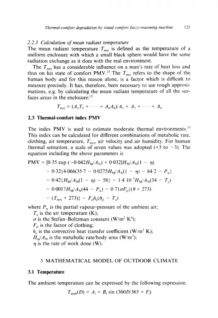
PMV in the summer time (June) is shown in Figs 3 and 4. The natural ventilation operates with a window opening of 5 ° or 30 °. The visual comfort FRM is in operation.
Visual-comfort control results in the correct illumination conditions and limitation of glare. Simultaneously the window-shadowing actuator limits the incoming solar radiation. This results in the limitation of solar gain and in the reduction of indoor temperature, as is shown in Fig. 4 i.e. a decrease of PMV occurs.
When the 5 ° window opening is employed, the PMV is reduced (after 2 p.m., see Fig. 3). This is the result of the indoor temperature fall (Fig. 5) and of the indoor-air velocity increase. These parameters depend on the window opening, which is necessary to achieve thermal comfort dur- ing the afternoon, i.e. -0-5 < PMV < +0.5. Finally, the night cooling (in the summer) affects the thermal comfort by removing the addition ther- mal load.
The second situation examined is when the window opening angle is
Thermal-comfort degradation by visual comfort fuzzy-reasoning machine
PMV J u n e
127
1,4
1.2
1
0.8
0,6
0.4
0.21
0 [ I I 1 I I I I [ L I [ I I I I I I I I I
5 6 7 8 9 10 11 12 13 14 15 16 17 18 19 20 21 22 23 24 25 26 27 28 29
Am Time(h)
~ W = 5 e
P M V w i t h o u t N . V . - - - ~ P M V w i t h N , V . ~ P M V w i t h o u t shad ing
Fig. 3. Thermal comfort (PMV) vs time for a single day (aw = 5°). PMV is shown (a) with natural ventilation; (b) without natural ventilation, and (c) without shading.
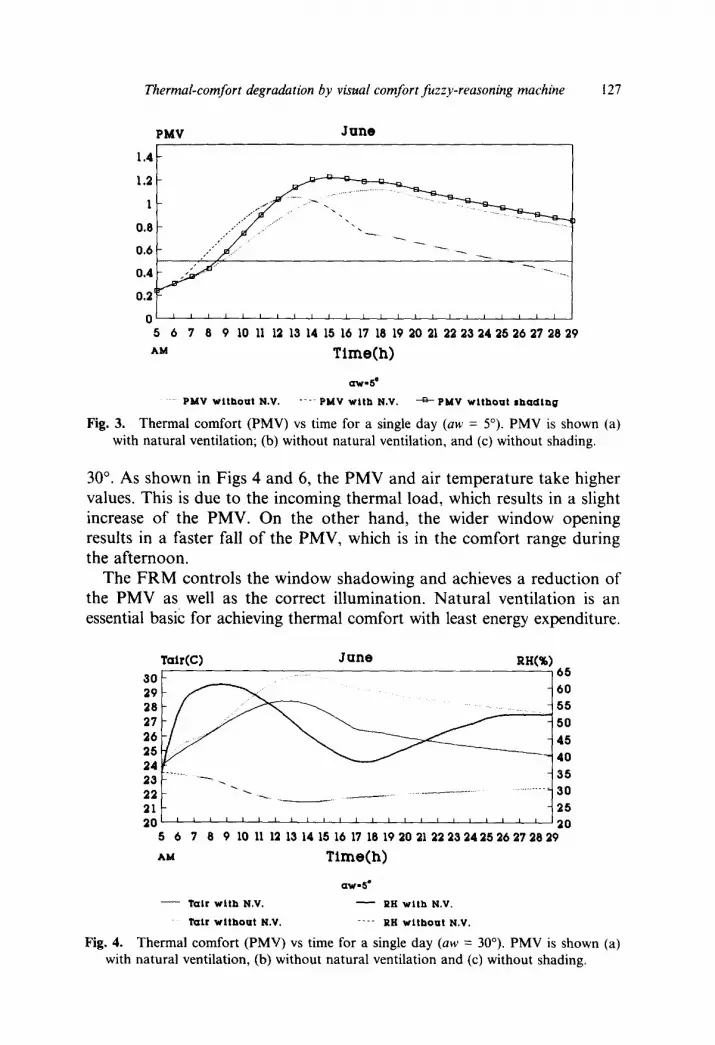
30 °. As shown in Figs 4 and 6, the PMV and air temperature take higher values. This is due to the incoming thermal load, which results in a slight increase of the PMV. On the other hand, the wider window opening results in a faster fall of the PMV, which is in the comfort range during the afternoon.
The FRM controls the window shadowing and achieves a reduction of the PMV as well as the correct illumination. Natural ventilation is an essential basic for achieving thermal comfort with least energy expenditure.
TalrCC) J u n e RH(%) 3 O .... 6 5
29 60 28 55 27 50 26' 45 251 40 24
22 . . . . . . . . . . . 3 0
21 25 2 0 I L L I I | i I 1 I I 1 I I I I t I L I I I I ~ 0
5 6 7 6 9 10 11 12 13 14 15 16 17 18 19 20 21 22 23 24 25 26 27 28 29
AM T i m e ( h )
Q W . S °
- - ' l a i r w i t h N.V. ~ R H w i t h N.V,
l a i r w i t h o u t N . V . - - - - R H w i t h o u t N . V .
Fig. 4. Thermal comfort (PMV) vs time for a single day (aw = 30°). PMV is shown (a) with natural ventilation, (b) without natural ventilation and (c) without shading.

128 A . I . Dounis et al.
)MY J u n e
1.4
1.2
0.8 / " / " "
o. ,
0,4
0.2
0 5 6 7 8 9 10 11 12 13 14 15 16 17 18 19 20 2i 22 23 2 4 2 5 2 6 27 28 29
^ " Time(h)
a w . 3 0 °
P M V w i t h o u t N . V , - - - - P M V w i t h N , V . ~ P M V w i t h o u t s h a d i n g
Fig. 5. Indoor temperature ( T a i r ) and relative humidity (RH) vs time for a single day (aw -- 5 °) are shown: (a) Tai r with natural ventilation, (b) Tai r without natural ventilation,
(c) RH with natural ventilation, and (d) RH without natural ventilation.
The FRM system achieves maximum exploitation of the natural ventila- tion to control thermal comfort, without the use of auxiliary cooling. Using auxiliary cooling is necessary from 9 a.m. to 2 p.m., where the natural ventilation does not contribute sufficiently to reduce the PMV. The auxiliary cooling is a basic actuator in an integrated FRM system. 9
Tair(C) J u n e RH(%) 30 65 29 60 28 .. 55 27 5 0
2 6 4 5
2 5 4 0 2 4
.......... ~ 3 5 2 3 2 2 ~ ~ ~ . . . . . . . . . . . . . . . . . . . . . . . . . . . . . . . 3 0
21 2 5 2 0 J i , J J J i J J J i i i t l 1 1 ~ i i J i J 2 0
5 6 7 8 9 10 11 12 13 14 15 16 17 18 19 2 0 21 2 2 2 3 2 4 2 5 2 6 2 7 2 8 2 9
^ - Time(h)
a ' W - 3 0 "
- - T a t r w i t h N . V . ~ RH w i t h N . V ,
"rair w i t h o u t N . V . - - - - RH w i t h o u t N . V .
Fig. 6. Indoor temperature (Tair) and relative humidity (RH) vs time for a single day (an, = 30 °) are shown: (a) Tai r with natural ventilation, (b) Tair without natural ventilation,
(c) RH with natural ventilation, and (d) RH without natural ventilation.

Thermal-comfort degradation by visual comJbrt fuzzy-reasoning machine 129
6 CONCLUSIONS
Based on the results of the simulation, the following conclusions are obtained:
• The FRM of visual comfort has a mild effect on the PMV as it limits the incoming solar radiation, resulting in the reduction of PMV. Consequently, the visual comfort FRM has to be considered in conjunction with the thermal comfort FRM.
• The control of natural ventilation in a space does not demand a sophisticated control system. The vent window can be a simple two- position actuator, activated by the PMV level and the outdoor tem- perature.
• The increase of indoor-air velocity results in the reduction of PMV. Therefore, the outdoor-air velocity is an important parameter, affecting the natural ventilation.
• The expression of the parameters of shading, ventilation, thermal comfort and visual discomfort on the basis of the human subjectiv- ity (namely as thermal discomfort or poor illumination) suits the determination of those parameters as fuzzy variables. Conse- quently, an integrated FRM system of comfort can satisfy these complex interactions.
A C K N O W L E D G E M E N T
The work reported in this paper was supported partially by the A. Onasis Foundat ion, to which authors are grateful.
R E F E R E N C E S
l. Liem, S. H., Lute, P. J., Van Paassen, A. H. & Vrwaal, M., Passive Building Control System. CEC-project 'pastor', 1989.
2. Cook, J., Passive Cooling. MIT Press, Cambridge, MA, 1989. 3. Van Paassen, A. H. C., Control of passive solar-system, 2nd European Conf
On Architecture, Paris, France, 4-8 December 1989, pp. 376-9. 4. Baker, N., Comfort and passive cooling. Workshop on Passive Cooling,
ISPRA, Italy, 2~, April 1990, pp. 1-19. 5. McIntyre, D. A., Indoor Climate, Applied Science Publishers, London, 1980. 6. Sterlug, E. M., ASHRAE Trans., 91 (1985) pp. 811. 7. Dounis, A. I., Santamouris, M. & Lefas, C. C., Implementation of A.I. tech-
niques in thermal-comfort control for passive solar buildings. Energy Con- version & Manage., 33(3) (1992) 175-82.
8. Dounis, A. I., Santamouris, M. & Lefas, C. C., Building visual comfort

130 A.I. Dounis et al.
control with fuzzy reasoning. Energy Conversion & Manage., 34(1) (1993) 17-28.
9. Dounis, A. I., Fuzzy logic expert system for visual and thermal comfort control in buildings. Doctoral Thesis, Technical University of Crete, Greece, 1992.
10. Zadeh, L. A., Fuzzy sets. Int. Control, 8 (1965) 338-53. 11. Zadeh, L. A., Outline of a new approach to the analysis of complex systems
and decision processes. IEEE Trans., SMC-3(1) (1973) 29-44. 12. Mamdani, E. H., Application of fuzzy algorithms for control of a simple
dynamic plant, Proc. lEE Control & Sci., 12(12)(1974) 1585-8. 13. Mamdani, E. H., Application of fuzzy logic to approximate reasoning using
linguistic synthesis. IEE Trans. Computers, 26(12) (1977) 1182-91. 14. Sodha, M. S., Bansal, N. K., Kumar, A., Bansal, P. K. & Malic, M. A. S.,
Solar Passive Building, Pergamon Press, Oxford, 1986, pp. 176--8. 15. Fanger, P. O., Thermal Comfort Analysis and Applications in Environmental
Engineering, ed. Robert E. Krieger. Publishing Co. Melbourne, FL, 1982, pp. 143-8.
16. Lee, C. C., Fuzzy logic in control systems--Fuzzy logic controller, IEEE Trans., SMC-16(15) (1990) 638-55.
17. Gupta, M. M., Kiszka, J. B. & Trojan, G. M., Multivariable structure of fuzzy control systems. IEEE Trans., SMS-16(5) (1986) 638-55.