the suds manual - ors
TRANSCRIPT
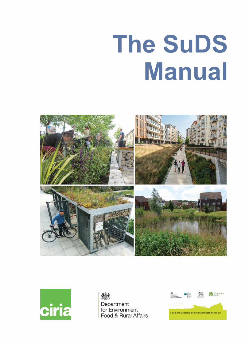
This guidance covers the planning, design, construction and maintenance of Sustainable DrainageSystems (SuDS) to assist with their effective implementation within both new and existing developments.It looks at how to maximise amenity and biodiversity benefits, and deliver the key objectives of managingflood risk and water quality. There is also supporting information covering topics such as materials,landscape design, maintenance, community engagement and costs and benefits.
The information presented in this publication is a compendium of good practice, based on existingguidance and research both in the UK and internationally, and the practical experience of the authors,project steering group and industry.
This guidance provides the framework for designing SuDS with confidence and to maximise benefits. Itscontents are relevant for a wide-range of professions and roles and it highlights that through engagementand collaboration SuDS can be integrated into the design of urban areas, to create high quality places forfuture generations.
The key message is that SuDS should be designed to maximise the opportunities and benefits that can besecured from surface water management.
C753
Th
eS
uD
SM
an
ual
CIR
IA
The SuDSManual
9 780860 177593C753
Project funders (see inside back cover)
ACO
Campbell Reith
Concrete Pipeline System Association
DARD Rivers Agency Northern Ireland
Department for Environment, Food and RuralAffairs
Dŵr Cymru/Welsh Water
Environment Agency
Highways England
Hydro International
Llywodraeth Cymru/Welsh Government
London Drainage Engineering Group
National House Builders Council
Northern Ireland Environment Agency
Permavoid
Polypipe
Scottish Environment Protection Agency
Stormwater Management
WSP Parsons Brinckerhoff
XP Solutions

Who we areEstablished in 1960, CIRIA is a highly regarded, industry-responsive, not for profit research and information association, which encompasses the construction and built environment industries.
CIRIA operates across a range of market sectors and disciplines, providing a platform for collaborative projects and dissemination by enhancing industry performance, and sharing knowledge and innovation across the built environment.
As an authoritative provider of good practice guidance, solutions and information, CIRIA operates as a knowledge-base for disseminating and delivering a comprehensive range of business improvement services and research products for public and private sector organisations, as well as academia.
How to get involvedCIRIA manage or actively participate in several topic-specific learning and business networks and clubs:
Where we areDiscover how your organisation can benefit from CIRIA’s authoritative and practical guidance – contact us by:
Post Griffin Court, 15 Long Lane, London, EC1A 9PN, UKTelephone +44 (0)20 7549 3300Fax +44 (0)20 7549 3349Email [email protected] www.ciria.org
(for details of membership, networks, events, collaborative projects and to access CIRIA publications through the bookshop)
zz Core membershipAllows your employees to assist with the development of and access to good practice guidance, formal networks, facilitation, conferences, workshops and training.
zz Associate membershipAllows your employees to access CIRIA’s services. Members are able to access exclusive content via the CIRIA website.
zz The CIRIA NetworkA member-based community where clients and professionals meet, develop and share knowledge about specific topics relevant to construction and the built environment.
zz CIRIA Books ClubMembers can buy most CIRIA publications at half price and can attend a range of CIRIA conferences at reduced rates.
zz Project fundingProject funders influence the direction of the research and gain early access to the results.
zz LACL (Local Authority Contaminated Land Network)LACL helps local authorities address responsibilities under Part IIA of the Environmental Protection Act 1990.
zz EMSAGG (European Marine Sand and Gravel Group)CIRIA provides secretariat support to EMSAGG, including management of the Group’s conferences, workshops and website and producing its newsletter.
zz BRMF (Brownfield Risk Management Forum)Promoting sustainable and good practice in brownfield projects in the UK.
CIRIA C753 London, 2015
The SuDS Manual
B Woods Ballard HR WallingfordS Wilson The Environmental Protection Group
H Udale-Clarke HR WallingfordS Illman Illman Young Landscape Design
T Scott Grant AssociatesR Ashley Ecofutures/University of Sheffield
R Kellagher HR Wallingford
Griffin Court, 15 Long Lane, London, EC1A 9PNTel: 020 7549 3300 Fax: 020 7549 3349Email: [email protected] Website: www.ciria.org
CIRIA SuDS Manual 2015
The SuDS Manualii
The SuDS Manual
Woods Ballard, B, Wilson, Udale-Clarke, H, Illman, S, Scott, T, Ashley, R, Kellagher, R
CIRIA
C753 © CIRIA 2015 RP992 ISBN: 978-0-86017-760-9
Version 5 including errata 2016
British Library Cataloguing in Publication Data
A catalogue record is available for this book from the British Library
Keywords
Sustainable drainage, flood risk management, water quality, amenity, biodiversity, environmental good practice, sustainable construction, urban hydrogeology, rivers and waterways
Reader interest
Sustainable drainage systems (SuDS) are designed to maximise the opportunities and benefits we obtain from surface water management. SuDS can deliver four main benefits by improving the way we manage water quantity, water quality, amenity and biodiversity
Classification
Availability Unrestricted
Content Technical guidance
Status Committee-guided
User Developers, landscape architects, architects, consulting engineers, planners, local authorities, lead local flood authorities, highway authorities, environmental regulators, sewerage undertakers and other organisations involved in the provision and maintenance of surface water drainage to new and existing developments
Published by CIRIA, Griffin Court, 15 Long Lane, London, EC1A 9PN, UK
This publication is designed to provide accurate and authoritative information on the subject matter covered. It is sold and/or distributed with the understanding that neither the authors nor the publisher is thereby engaged in rendering a specific legal or any other professional service. While every effort has been made to ensure the accuracy and completeness of the publication, no warranty or fitness is provided or implied, and the authors and publisher shall have neither liability nor responsibility to any person or entity with respect to any loss or damage arising from its use.
All rights reserved. No part of this publication may be reproduced or transmitted in any form or by any means, including photocopying and recording, without the written permission of the copyright holder, application for which should be addressed to the publisher. Such written permission must also be obtained before any part of this publication is stored in a retrieval system of any nature.
If you would like to reproduce any of the figures, text or technical information from this or any other CIRIA publication for use in other documents or publications, please contact CIRIA publishing for more details on copyright terms and charges at: [email protected] or tel: 020 7549 3300.

iiiThe SuDS Manual
CIRIA SuDS Manual 2015
Summary
This guidance covers the planning, design, construction and maintenance of Sustainable Drainage Systems (SuDS) to assist with their effective implementation within both new and existing developments. It looks at how to maximise amenity and biodiversity benefits, and deliver the key objectives of managing flood risk and water quality. There is also supporting information covering topics such as materials, landscape design, maintenance, community engagement and costs and benefits.
The information presented in this publication is a compendium of good practice, based on existing guidance and research both in the UK and internationally, and the practical experience of the authors, project steering group and industry.
This guidance provides the framework for designing SuDS with confidence and to maximise benefits. Its contents are relevant for a wide-range of professions and roles and it highlights that through engagement and collaboration SuDS can be integrated into the design of urban areas, to create high quality places for future generations.
The key message is that SuDS should be designed to maximise the opportunities and benefits that can be secured from surface water management.

CIRIA SuDS Manual 2015
iv The SuDS Manual
Foreword
When the first SuDS Manual was published in 2007, SuDS was still in its infancy in the UK. Technical advice on design and construction was sparse and spread across many separate publications. For the first time the original SuDS Manual placed this information in one place, making it a valuable resource for anyone engaged in SuDS delivery. Yet for guidance and examples we still had to rely a great deal on schemes from other countries where the implementation of SuDS was far more advanced. Since that time SuDS implementation has moved on a great deal in the UK. There are now plenty of examples from all the UK nations that demonstrate the benefits to be gained from SuDS and these offer reliable and detailed recommendations for their planning, design, construction, maintenance and operation. The world of SuDS has indeed moved on. So it is timely that a new edition of the SuDS Manual is now available. Not only does this new edition update the extensive technical information, it includes new guidance on SuDS components and the delivery of SuDS in a variety of situations.
It should be clear from the engaging examples in this Manual that SuDS provide real benefits to society and to the environment, moving surface water from a problem to a valuable resource. For the first time the guidance includes how to plan for and manage extreme rain events so that communities can be more resilient to flooding. There are some excellent examples that demonstrate how good design can deliver far more appealing places in which to live and work, and this, in time, should lead to properties that have improved value and are easier to insure. Provided that drainage is considered early enough in the outline design of a new development then there is no reason why SuDS should not become the norm everywhere.
The Manual is primarily aimed at UK applications, though it will be of interest to all engaged in drainage work globally. It recognises the need for better information and engagement for those involved in the development process, from planners, landscape architects, designers, engineers, architects and in some instances the community. It is structured in a way that allows easy access whether it be for high level appreciation of the concepts only, or for detailed design guidance.
I am grateful to the members of the project steering group who reviewed and contributed to this important work, and to the energy and effectiveness of the project team. They have delivered a master-piece of technical guidance that will last for many years. I thoroughly recommend it to you.
David BalmforthChairman, project steering group

vThe SuDS Manual
CIRIA SuDS Manual 2015
Acknowledgements
This publication is the result of CIRIA Research Project (RP)992.
AuthorsBridget Woods Ballard MA MSc CEng MICEBridget Woods Ballard is a principal engineer at HR Wallingford. She has more than 20 years’ experience in hydrology and sustainable flood risk management and has been a key contributor to research on SuDS costs, maintenance, performance and liabilities for regulators, the water industry and other private sector organisations. She was the principal author of the previous SuDS Manual (CIRIA C697) and since then has drafted BS 8582:2013, and has advised English and Welsh governments during the development of their national standards and associated guidance.
Steve Wilson MSc BEng CEng MICE CEnv CSci CWEM MCIWEM FGSSteve is technical director of the Environmental Protection Group Limited. He is a UK registered ground engineering adviser and has had a wide ranging career in geotechnical and environmental engineering. Steve has demonstrated that SuDS can be used on any site in the UK to provide cost-effective surface water drainage systems. Steve also undertakes research and development work that helps to dispel a lot of the myths that surround the use of SuDS. Most recently Steve has been busy helping landscape architects successfully design retrofit schemes in a number of different locations.
Helen Udale-Clarke BEng(Hons) MPhilHelen is a principal engineer at HR Wallingford. She has more than 20 years’ experience in drainage, flood and climate change risk assessments, with a particular interest in the development of guidance and working with stakeholders.
Sue Illman BA DipLA GradDipCons(AA) PPLI Hon FSE Hon Fellow (UoG)Sue is managing director of Illman Young, a landscape architectural practice based in Cheltenham, and was president of the Landscape Institute from 2012–2014. Sue’s practice works across most planning and development sectors, but she is probably best known for her advocacy work promoting integrated water management and SuDS through inter-professional collaboration. The integration of grey, green and blue in urban landscapes has never been more relevant, and is a subject that Sue continues to promote. In addition to her current role, she is a champion for flood mitigation and resilience on behalf of the Construction Industry Council (CIC).
Tamasine Scott MA (Hons) LArch CMLITamasine is a landscape architect and senior associate of Grant Associates. She has led a variety of large and small projects, from cooled conservatories and university campuses in Singapore to secondary schools in the UK and urban parks in Spain. SuDS has become second nature in her design process, integrating the functional requirements of water management within playful and thriving landscapes. Tamsine is fascinated by using SuDS in the design process to integrate landscape, architecture and engineering, thereby achieving diverse landscapes that ultimately enrich experience.
Richard Ashley BSc MPhil CEng MICERichard is a civil engineer with 50 years’ urban drainage experience in practice and as an academic. He is Emeritus professor of urban water, University of Sheffield, adjunct professor, Lulea Technical University

CIRIA SuDS Manual 2015
vi The SuDS Manual
and professor of flood resilience at UNESCO IHE, Delft. He was also recipient of the (IWA/IAHR) Joint Committee on Urban Drainage triennial career achievement award in 2014 and for research into sustainable water systems in 2008. Richard has worked on over 500 publications, advising governments and international institutions on urban water, flooding and water sensitive urban design.
Richard Kellagher BEng MSc CEng MICE MCIWEMRichard Kellagher is a technical director at HR Wallingford. He has been involved in drainage and SuDS research and has produced a number of guidance documents on drainage-related issues for both CIRIA and HR Wallingford. Richard’s experience in drainage includes research projects for UKWIR, sewerage modelling, expert witness work on flooding incidents, master plans for cities overseas and leading or participating in a number of European research projects.
Project steering groupFollowing CIRIA’s usual practice, the project was guided by a project steering group (PSG) that comprised:
Deonie Allen* Heriot Watt UniversityDavid Balmforth (chair) MWH GlobalAndy Bailey Highways EnglandAdam Baylis Environment AgencyDavid Bliss Environment AgencySally Boorer National House Building CouncilSimon Boots Campbell ReithJo Bradley* Environment AgencyBob Bray Robert Bray AssociatesSimon Bunn Cambridgeshire City CouncilBronwyn Buntine Kent County CouncilPhil Chatfield Llywodraeth Cymru Welsh GovernmentPeter Close Northern Ireland Environment AgencyStuart Crisp Concrete Pipeline Systems AssociationOwen Davies Royal Borough Greenwich (formerly London Borough Lambeth)/London
Drainage Engineering GroupPaul Davies* ArupPeter Dawson Essex County CouncilChristopher Digman* MWH GlobalAlison Duffy* University of AbertayMartin Fairley ACOGrant Gahagan Department for Environment, Food and Rural AffairsJonathan Glerum Anglian WaterRod Green Environmental Protection Group (formerly Polypipe)Andrew Hemingway* Scottish Environment Protection AgencyMike Henderson AecomIan Holt London Borough of HaringeyPhilip Hulme Environment AgencyJeremy Jones Atkins (formerly Dŵr Cymru Welsh Water)Andrew Leadbetter Peterborough City CouncilLian Lundy* University of MiddlesexPeter Martin Black & Veatch

viiThe SuDS Manual
CIRIA SuDS Manual 2015
Netsanet Mebrate XP SolutionsAnthony McCloy McCloy ConsultingHelen McHollan Illman Young Landscape DesignBrian Morrow* Independent (formerly United Utilities)Stuart Nelmes BWB ConsultingRoger Nowell Sheffield City CouncilFola Ogunyoye Royal HaskoningDHVJohn Oldfield Bedford Group of Internal Drainage BoardsChris Patmore WSP Parsons BrinckerhoffWarren Peppard Lincolnshire County CouncilDavid Porter* DARD Rivers Agency Northern IrelandJudith Puckmayr Robert Bray Associates (formerly Illman Young Landscape Design)Neill Robinson-Welsh Stormwater ManagementBrian Smith Yorkshire WaterJason Shingleton PolypipeAmy Shoesmith Dŵr Cymru Welsh WaterDavid Singleton DSA Environment & DesignAlex Stephenson Hydro InternationalKevin Tidy Bracknell ForestChryse Tinsley* Leicester City CouncilZorica Todorovic* AtkinsPhil Tomlinson PermavoidMichael Vout Telford and Wrekin CouncilDavid Watkins Cornwall County CouncilLes Watson Scottish Environment Protection Agency*corresponding members
CIRIA Project managersPaul Shaffer Project directorSuzanne Simmons Project managerSirio D’Aleo Project assistantPaul Beverley EditorClare Drake Publications manager
Project fundersACOCampbell ReithConcrete Pipeline System AssociationDARD Rivers Agency Northern IrelandDepartment for Environment, Food and Rural AffairsDŵr Cymru Welsh WaterEnvironment AgencyHighways EnglandHydro International
Llywodraeth Cymru Welsh GovernmentLondon Drainage Engineering GroupNHBC FoundationNorthern Ireland Environment AgencyPermavoidPolypipeScottish Environment Protection AgencyStormwater ManagementWSP Parsons BrinckerhoffXP Solutions

CIRIA SuDS Manual 2015
viii The SuDS Manual
Other contributorsAs well as recognising the significant additional contributions from the project team of HR Wallingford, The Environmental Protection Group, Illman Young Landscape Design, Grant Associates and Ecofutures, CIRIA would like to recognise the contributions and support from:
Bob Allen Aggregate IndustriesJulia Baker Parsons BrinckerhoffAlan Bamforth ABGJessica Bastock London Borough of Lambeth (formerly London Borough of Tower Hamlets)Victoria Boorman London Borough of HillingdonVictoria Brayshaw Dudleys Consulting Engineers (formerly Redrow)Tom Butterworth Natural EnglandBrian D’Arcy University of AbertaySamantha Davenport Natural EnglandLuke Engleback Studio EnglebackDuncan Faulkener JBA ConsultingDusty Gedge Green Roof ConsultancyMartina Girvan Arcadis (formerly Aecom)Gary Grant Green Roof ConsultancyKeith Harvey Aggregate IndustriesPaul Hlinovsky BMT WBMGordon Hunt Oxfordshire County CouncilAnne Jaluzot Trees and Design Action GroupSue James Trees and Design Action GroupKirsten Johnstone Environment AgencyDavid Jones Llywodraeth Cymru Welsh GovernmentLian Lundy Middlesex UniversityGordon Mitchell University of LeedsMartin Moss Natural EnglandTerry Nash UK Rainwater Management AssociationKeith Oldham ACO (formerly ABG)Helen O’Brien Leicester City CouncilTim O’Hare Tim O’Hare AssociatesMartin Osborne MouchelKevin Reid Greater London AuthorityMike Revitt University of MiddlesexSanti Santhalingam Highways EnglandRuth Thorp Grant AssociatesTony Weber BMT WBMMike Whitehead Highways EnglandPeter Worrall Penny Anderson Associates

ixThe SuDS Manual
CIRIA SuDS Manual 2015
Contents
Summary . . . . . . . . . . . . . . . . . . . . . . . . . . . . . . . . . . . . . . . . . . . . . . . . . . . . . . . . . . . . . . . . . . . . . . . . . . . . . . . . . . . . . iii
Foreword . . . . . . . . . . . . . . . . . . . . . . . . . . . . . . . . . . . . . . . . . . . . . . . . . . . . . . . . . . . . . . . . . . . . . . . . . . . . . . . . . . . . . . iv
Acknowledgements . . . . . . . . . . . . . . . . . . . . . . . . . . . . . . . . . . . . . . . . . . . . . . . . . . . . . . . . . . . . . . . . . . . . . . . . . . . . . . v
Part A Introduction to the SuDS Manual . . . . . . . . . . . . . . . . . . . . . . . . . . . . . . . . . . . . . . . . . . . . . . . . . . . . . . . . . . .2
Executive summary . . . . . . . . . . . . . . . . . . . . . . . . . . . . . . . . . . . . . . . . . . . . . . . . . . . . . . . . . . . . . . . . . . . . . 5Introduction to the SuDS Manual. . . . . . . . . . . . . . . . . . . . . . . . . . . . . . . . . . . . . . . . . . . . . . . . . . . . . . . . .11
Part B Philosophy and approach . . . . . . . . . . . . . . . . . . . . . . . . . . . . . . . . . . . . . . . . . . . . . . . . . . . . . . . . . . . . . . . 16
1 The philosophy of SuDS . . . . . . . . . . . . . . . . . . . . . . . . . . . . . . . . . . . . . . . . . . . . . . . . . . . . . . . . . . .181.1 Delivering multiple benefits . . . . . . . . . . . . . . . . . . . . . . . . . . . . . . . . . . . . . . . . . . . . . . .191.2 Managing surface water runoff . . . . . . . . . . . . . . . . . . . . . . . . . . . . . . . . . . . . . . . . . . . .211.3 Delivering resilience . . . . . . . . . . . . . . . . . . . . . . . . . . . . . . . . . . . . . . . . . . . . . . . . . . . . .241.4 Making developments more sustainable. . . . . . . . . . . . . . . . . . . . . . . . . . . . . . . . . . . . .261.5 Complying with legislation and regulations . . . . . . . . . . . . . . . . . . . . . . . . . . . . . . . . . . .261.6 The SuDS design philosophy. . . . . . . . . . . . . . . . . . . . . . . . . . . . . . . . . . . . . . . . . . . . . . .271.7 References . . . . . . . . . . . . . . . . . . . . . . . . . . . . . . . . . . . . . . . . . . . . . . . . . . . . . . . . . . . . .30
2 Introducing the SuDS design approach. . . . . . . . . . . . . . . . . . . . . . . . . . . . . . . . . . . . . . . . . . . . . . .322.1 The principle and objectives of SuDS design . . . . . . . . . . . . . . . . . . . . . . . . . . . . . . . . .332.2 SuDS design criteria . . . . . . . . . . . . . . . . . . . . . . . . . . . . . . . . . . . . . . . . . . . . . . . . . . . . .342.3 The role of the designer . . . . . . . . . . . . . . . . . . . . . . . . . . . . . . . . . . . . . . . . . . . . . . . . . .352.4 Assessing and approving SuDS schemes . . . . . . . . . . . . . . . . . . . . . . . . . . . . . . . . . . . .35
3 Designing for water quantity. . . . . . . . . . . . . . . . . . . . . . . . . . . . . . . . . . . . . . . . . . . . . . . . . . . . . . . .363.1 Water quantity design objective . . . . . . . . . . . . . . . . . . . . . . . . . . . . . . . . . . . . . . . . . . . .373.2 Water quantity design criteria. . . . . . . . . . . . . . . . . . . . . . . . . . . . . . . . . . . . . . . . . . . . . .393.3 Water quantity design standards . . . . . . . . . . . . . . . . . . . . . . . . . . . . . . . . . . . . . . . . . . .443.4 References . . . . . . . . . . . . . . . . . . . . . . . . . . . . . . . . . . . . . . . . . . . . . . . . . . . . . . . . . . . . .48
4 Designing for water quality . . . . . . . . . . . . . . . . . . . . . . . . . . . . . . . . . . . . . . . . . . . . . . . . . . . . . . . . .504.1 Water quality design objective . . . . . . . . . . . . . . . . . . . . . . . . . . . . . . . . . . . . . . . . . . . . .514.2 Water quality design criteria . . . . . . . . . . . . . . . . . . . . . . . . . . . . . . . . . . . . . . . . . . . . . . .564.3 Water quality design standards . . . . . . . . . . . . . . . . . . . . . . . . . . . . . . . . . . . . . . . . . . . .594.4 References . . . . . . . . . . . . . . . . . . . . . . . . . . . . . . . . . . . . . . . . . . . . . . . . . . . . . . . . . . . . .64
5 Designing for amenity . . . . . . . . . . . . . . . . . . . . . . . . . . . . . . . . . . . . . . . . . . . . . . . . . . . . . . . . . . . . .665.1 Amenity design objective . . . . . . . . . . . . . . . . . . . . . . . . . . . . . . . . . . . . . . . . . . . . . . . . .675.2 Amenity design criteria . . . . . . . . . . . . . . . . . . . . . . . . . . . . . . . . . . . . . . . . . . . . . . . . . . .705.3 References . . . . . . . . . . . . . . . . . . . . . . . . . . . . . . . . . . . . . . . . . . . . . . . . . . . . . . . . . . . . .78
6 Designing for biodiversity . . . . . . . . . . . . . . . . . . . . . . . . . . . . . . . . . . . . . . . . . . . . . . . . . . . . . . . . . .806.1 Biodiversity design objective . . . . . . . . . . . . . . . . . . . . . . . . . . . . . . . . . . . . . . . . . . . . . .816.2 Biodiversity design criteria . . . . . . . . . . . . . . . . . . . . . . . . . . . . . . . . . . . . . . . . . . . . . . . .836.3 SuDS design characteristics to support biodiversity . . . . . . . . . . . . . . . . . . . . . . . . . . .896.4 References . . . . . . . . . . . . . . . . . . . . . . . . . . . . . . . . . . . . . . . . . . . . . . . . . . . . . . . . . . . . .91
Part C Applying the approach . . . . . . . . . . . . . . . . . . . . . . . . . . . . . . . . . . . . . . . . . . . . . . . . . . . . . . . . . . . . . . . . . . 92
7 The SuDS design process. . . . . . . . . . . . . . . . . . . . . . . . . . . . . . . . . . . . . . . . . . . . . . . . . . . . . . . . . .947.1 Introduction . . . . . . . . . . . . . . . . . . . . . . . . . . . . . . . . . . . . . . . . . . . . . . . . . . . . . . . . . . . .957.2 SuDS and the planning system. . . . . . . . . . . . . . . . . . . . . . . . . . . . . . . . . . . . . . . . . . . . .967.3 SuDS design and stakeholder engagement . . . . . . . . . . . . . . . . . . . . . . . . . . . . . . . . . .997.4 Stage 1: Setting strategic SWM objectives . . . . . . . . . . . . . . . . . . . . . . . . . . . . . . . . . . .997.5 Stage 2: Conceptual design . . . . . . . . . . . . . . . . . . . . . . . . . . . . . . . . . . . . . . . . . . . . . 1007.6 Stage 3: Outline design . . . . . . . . . . . . . . . . . . . . . . . . . . . . . . . . . . . . . . . . . . . . . . . . . 118
CIRIA SuDS Manual 2015
x The SuDS Manual
7.7 Stage 4: Detailed design. . . . . . . . . . . . . . . . . . . . . . . . . . . . . . . . . . . . . . . . . . . . . . . . 1237.8 References . . . . . . . . . . . . . . . . . . . . . . . . . . . . . . . . . . . . . . . . . . . . . . . . . . . . . . . . . . . 126
8 Designing for specific site conditions . . . . . . . . . . . . . . . . . . . . . . . . . . . . . . . . . . . . . . . . . . . . . . 1268.1 Introduction . . . . . . . . . . . . . . . . . . . . . . . . . . . . . . . . . . . . . . . . . . . . . . . . . . . . . . . . . . 1298.2 Contaminated soils or groundwater below the site . . . . . . . . . . . . . . . . . . . . . . . . . . 1298.3 High groundwater levels below the site . . . . . . . . . . . . . . . . . . . . . . . . . . . . . . . . . . . . 1328.4 Sloping sites . . . . . . . . . . . . . . . . . . . . . . . . . . . . . . . . . . . . . . . . . . . . . . . . . . . . . . . . . . 1348.5 Very flat sites . . . . . . . . . . . . . . . . . . . . . . . . . . . . . . . . . . . . . . . . . . . . . . . . . . . . . . . . . .1378.6 Sites with potentially unstable subsurface rocks or soil workings . . . . . . . . . . . . . . 1398.7 Sites with very deep backfill . . . . . . . . . . . . . . . . . . . . . . . . . . . . . . . . . . . . . . . . . . . . . 1398.8 SuDS on floodplains. . . . . . . . . . . . . . . . . . . . . . . . . . . . . . . . . . . . . . . . . . . . . . . . . . . . 1408.9 References . . . . . . . . . . . . . . . . . . . . . . . . . . . . . . . . . . . . . . . . . . . . . . . . . . . . . . . . . . . .141
9 Designing for roads and highways . . . . . . . . . . . . . . . . . . . . . . . . . . . . . . . . . . . . . . . . . . . . . . . . . .1429.1 Introduction . . . . . . . . . . . . . . . . . . . . . . . . . . . . . . . . . . . . . . . . . . . . . . . . . . . . . . . . . . 1439.2 Approval and adoption of SuDS in or adjacent to roads. . . . . . . . . . . . . . . . . . . . . . . 1439.3 Interface with buried utility services . . . . . . . . . . . . . . . . . . . . . . . . . . . . . . . . . . . . . . 1449.4 Connections between features below roads . . . . . . . . . . . . . . . . . . . . . . . . . . . . . . . . 1449.5 Application of SuDS for road drainage. . . . . . . . . . . . . . . . . . . . . . . . . . . . . . . . . . . . . 1449.6 Allowing water to infiltrate in close proximity to the road pavement . . . . . . . . . . . . . .1479.7 Filter drains for road drainage . . . . . . . . . . . . . . . . . . . . . . . . . . . . . . . . . . . . . . . . . . . 1489.8 Swales for road drainage . . . . . . . . . . . . . . . . . . . . . . . . . . . . . . . . . . . . . . . . . . . . . . . .1499.9 Roads for exceedance flow management . . . . . . . . . . . . . . . . . . . . . . . . . . . . . . . . . . .1519.10 Treating road runoff . . . . . . . . . . . . . . . . . . . . . . . . . . . . . . . . . . . . . . . . . . . . . . . . . . . . .1519.11 Designing safe SuDS adjacent to roads . . . . . . . . . . . . . . . . . . . . . . . . . . . . . . . . . . . .1529.12 Retrofitting SuDS for roads . . . . . . . . . . . . . . . . . . . . . . . . . . . . . . . . . . . . . . . . . . . . . . .1529.13 The maintenance of SuDS adjacent to roads . . . . . . . . . . . . . . . . . . . . . . . . . . . . . . . 1539.14 Additional guidance relevant for SuDS draining roads . . . . . . . . . . . . . . . . . . . . . . . . 153
9.15 References. . . . . . . . . . . . . . . . . . . . . . . . . . . . . . . . . . . . . . . . . . . . . . . . . . . . . . . . . . . . . . . . . . . . 15410 Designing for urban areas . . . . . . . . . . . . . . . . . . . . . . . . . . . . . . . . . . . . . . . . . . . . . . . . . . . . . . . 156
10.1 Objectives for surface water management in the urban environment . . . . . . . . . . . .15710.2 Delivering the SuDS design criteria within urban areas . . . . . . . . . . . . . . . . . . . . . . . .16510.3 Different urban development typologies . . . . . . . . . . . . . . . . . . . . . . . . . . . . . . . . . . . . 17410.4 Case studies. . . . . . . . . . . . . . . . . . . . . . . . . . . . . . . . . . . . . . . . . . . . . . . . . . . . . . . . . . 19610.5 References . . . . . . . . . . . . . . . . . . . . . . . . . . . . . . . . . . . . . . . . . . . . . . . . . . . . . . . . . . . 202
Part D Technical detail . . . . . . . . . . . . . . . . . . . . . . . . . . . . . . . . . . . . . . . . . . . . . . . . . . . . . . . . . . . . . . . . . . . . . . . 204
11 Rainwater harvesting . . . . . . . . . . . . . . . . . . . . . . . . . . . . . . . . . . . . . . . . . . . . . . . . . . . . . . . . . . . 20611.1 General description . . . . . . . . . . . . . . . . . . . . . . . . . . . . . . . . . . . . . . . . . . . . . . . . . . . . .20711.2 Selection and siting of RWH systems. . . . . . . . . . . . . . . . . . . . . . . . . . . . . . . . . . . . . . .21111.3 Hydraulic design. . . . . . . . . . . . . . . . . . . . . . . . . . . . . . . . . . . . . . . . . . . . . . . . . . . . . . . .21211.4 Treatment design . . . . . . . . . . . . . . . . . . . . . . . . . . . . . . . . . . . . . . . . . . . . . . . . . . . . . . .22611.5 Amenity design. . . . . . . . . . . . . . . . . . . . . . . . . . . . . . . . . . . . . . . . . . . . . . . . . . . . . . . . .22711.6 Biodiversity design. . . . . . . . . . . . . . . . . . . . . . . . . . . . . . . . . . . . . . . . . . . . . . . . . . . . . .22711.7 Physical specifications . . . . . . . . . . . . . . . . . . . . . . . . . . . . . . . . . . . . . . . . . . . . . . . . . .22711.8 Materials. . . . . . . . . . . . . . . . . . . . . . . . . . . . . . . . . . . . . . . . . . . . . . . . . . . . . . . . . . . . . .22711.9 Landscape design and planting . . . . . . . . . . . . . . . . . . . . . . . . . . . . . . . . . . . . . . . . . . .22811.10 Construction requirements . . . . . . . . . . . . . . . . . . . . . . . . . . . . . . . . . . . . . . . . . . . . . . .22811.11 Operation and maintenance requirements . . . . . . . . . . . . . . . . . . . . . . . . . . . . . . . . . .22811.12 References . . . . . . . . . . . . . . . . . . . . . . . . . . . . . . . . . . . . . . . . . . . . . . . . . . . . . . . . . . . 230
12 Green roofs . . . . . . . . . . . . . . . . . . . . . . . . . . . . . . . . . . . . . . . . . . . . . . . . . . . . . . . . . . . . . . . . . . . .23212.1 General description . . . . . . . . . . . . . . . . . . . . . . . . . . . . . . . . . . . . . . . . . . . . . . . . . . . . 23312.2 General design considerations. . . . . . . . . . . . . . . . . . . . . . . . . . . . . . . . . . . . . . . . . . . 23612.3 Selection and siting of green roofs . . . . . . . . . . . . . . . . . . . . . . . . . . . . . . . . . . . . . . . .23712.4 Hydraulic design. . . . . . . . . . . . . . . . . . . . . . . . . . . . . . . . . . . . . . . . . . . . . . . . . . . . . . . 23812.5 Treatment design . . . . . . . . . . . . . . . . . . . . . . . . . . . . . . . . . . . . . . . . . . . . . . . . . . . . . . .24012.6 Amenity design. . . . . . . . . . . . . . . . . . . . . . . . . . . . . . . . . . . . . . . . . . . . . . . . . . . . . . . . .24112.7 Biodiversity design. . . . . . . . . . . . . . . . . . . . . . . . . . . . . . . . . . . . . . . . . . . . . . . . . . . . . .242

xiThe SuDS Manual
CIRIA SuDS Manual 2015
12.8 Physical specifications . . . . . . . . . . . . . . . . . . . . . . . . . . . . . . . . . . . . . . . . . . . . . . . . . .24512.9 Materials. . . . . . . . . . . . . . . . . . . . . . . . . . . . . . . . . . . . . . . . . . . . . . . . . . . . . . . . . . . . . .24712.10 Landscape design and planting . . . . . . . . . . . . . . . . . . . . . . . . . . . . . . . . . . . . . . . . . . .24912.11 Construction requirements . . . . . . . . . . . . . . . . . . . . . . . . . . . . . . . . . . . . . . . . . . . . . . .25012.12 Operation and maintenance requirements . . . . . . . . . . . . . . . . . . . . . . . . . . . . . . . . . .25112.13 References . . . . . . . . . . . . . . . . . . . . . . . . . . . . . . . . . . . . . . . . . . . . . . . . . . . . . . . . . . . 253
13 Infiltration systems . . . . . . . . . . . . . . . . . . . . . . . . . . . . . . . . . . . . . . . . . . . . . . . . . . . . . . . . . . . . . .25613.1 General description . . . . . . . . . . . . . . . . . . . . . . . . . . . . . . . . . . . . . . . . . . . . . . . . . . . . .25713.2 General design considerations. . . . . . . . . . . . . . . . . . . . . . . . . . . . . . . . . . . . . . . . . . . 26013.3 Selection and siting of infiltration components . . . . . . . . . . . . . . . . . . . . . . . . . . . . . .26113.4 Hydraulic design. . . . . . . . . . . . . . . . . . . . . . . . . . . . . . . . . . . . . . . . . . . . . . . . . . . . . . . .26213.5 Treatment design . . . . . . . . . . . . . . . . . . . . . . . . . . . . . . . . . . . . . . . . . . . . . . . . . . . . . . 26313.6 Amenity design. . . . . . . . . . . . . . . . . . . . . . . . . . . . . . . . . . . . . . . . . . . . . . . . . . . . . . . . 26313.7 Biodiversity design. . . . . . . . . . . . . . . . . . . . . . . . . . . . . . . . . . . . . . . . . . . . . . . . . . . . . 26313.8 Physical specifications . . . . . . . . . . . . . . . . . . . . . . . . . . . . . . . . . . . . . . . . . . . . . . . . . 26413.9 Materials. . . . . . . . . . . . . . . . . . . . . . . . . . . . . . . . . . . . . . . . . . . . . . . . . . . . . . . . . . . . . 26413.10 Landscape design and planting . . . . . . . . . . . . . . . . . . . . . . . . . . . . . . . . . . . . . . . . . . 26513.11 Construction requirements . . . . . . . . . . . . . . . . . . . . . . . . . . . . . . . . . . . . . . . . . . . . . . 26513.12 Operation and maintenance requirements . . . . . . . . . . . . . . . . . . . . . . . . . . . . . . . . . 26613.13 References . . . . . . . . . . . . . . . . . . . . . . . . . . . . . . . . . . . . . . . . . . . . . . . . . . . . . . . . . . . 269
14 Proprietary treatment systems. . . . . . . . . . . . . . . . . . . . . . . . . . . . . . . . . . . . . . . . . . . . . . . . . . . . .27014.1 General description . . . . . . . . . . . . . . . . . . . . . . . . . . . . . . . . . . . . . . . . . . . . . . . . . . . . .27114.2 General design considerations. . . . . . . . . . . . . . . . . . . . . . . . . . . . . . . . . . . . . . . . . . . .27114.3 Selection and siting of proprietary treatment systems . . . . . . . . . . . . . . . . . . . . . . . .28114.4 Hydraulic design. . . . . . . . . . . . . . . . . . . . . . . . . . . . . . . . . . . . . . . . . . . . . . . . . . . . . . . .28214.5 Treatment design . . . . . . . . . . . . . . . . . . . . . . . . . . . . . . . . . . . . . . . . . . . . . . . . . . . . . . .28214.6 Amenity design. . . . . . . . . . . . . . . . . . . . . . . . . . . . . . . . . . . . . . . . . . . . . . . . . . . . . . . . 28414.7 Biodiversity design. . . . . . . . . . . . . . . . . . . . . . . . . . . . . . . . . . . . . . . . . . . . . . . . . . . . . 28414.8 Physical specifications . . . . . . . . . . . . . . . . . . . . . . . . . . . . . . . . . . . . . . . . . . . . . . . . . 28414.9 Materials. . . . . . . . . . . . . . . . . . . . . . . . . . . . . . . . . . . . . . . . . . . . . . . . . . . . . . . . . . . . . 28514.10 Landscape design and planting . . . . . . . . . . . . . . . . . . . . . . . . . . . . . . . . . . . . . . . . . . 28514.11 Construction requirements . . . . . . . . . . . . . . . . . . . . . . . . . . . . . . . . . . . . . . . . . . . . . . 28514.12 Operation and maintenance requirements . . . . . . . . . . . . . . . . . . . . . . . . . . . . . . . . . 28614.13 References . . . . . . . . . . . . . . . . . . . . . . . . . . . . . . . . . . . . . . . . . . . . . . . . . . . . . . . . . . . 288
15 Filter strips . . . . . . . . . . . . . . . . . . . . . . . . . . . . . . . . . . . . . . . . . . . . . . . . . . . . . . . . . . . . . . . . . . . . 29015.1 General description . . . . . . . . . . . . . . . . . . . . . . . . . . . . . . . . . . . . . . . . . . . . . . . . . . . . .29115.2 General design considerations. . . . . . . . . . . . . . . . . . . . . . . . . . . . . . . . . . . . . . . . . . . 29215.3 Selection and siting of filter strips . . . . . . . . . . . . . . . . . . . . . . . . . . . . . . . . . . . . . . . . 29315.4 Hydraulic design. . . . . . . . . . . . . . . . . . . . . . . . . . . . . . . . . . . . . . . . . . . . . . . . . . . . . . . 29315.5 Treatment design . . . . . . . . . . . . . . . . . . . . . . . . . . . . . . . . . . . . . . . . . . . . . . . . . . . . . . 29415.6 Amenity design. . . . . . . . . . . . . . . . . . . . . . . . . . . . . . . . . . . . . . . . . . . . . . . . . . . . . . . . 29515.7 Biodiversity design. . . . . . . . . . . . . . . . . . . . . . . . . . . . . . . . . . . . . . . . . . . . . . . . . . . . . 29515.8 Physical specifications . . . . . . . . . . . . . . . . . . . . . . . . . . . . . . . . . . . . . . . . . . . . . . . . . 29615.9 Materials. . . . . . . . . . . . . . . . . . . . . . . . . . . . . . . . . . . . . . . . . . . . . . . . . . . . . . . . . . . . . 29615.10 Landscape design and planting . . . . . . . . . . . . . . . . . . . . . . . . . . . . . . . . . . . . . . . . . . 29615.11 Construction requirements . . . . . . . . . . . . . . . . . . . . . . . . . . . . . . . . . . . . . . . . . . . . . . .29715.12 Operation and maintenance requirements . . . . . . . . . . . . . . . . . . . . . . . . . . . . . . . . . 29815.13 References . . . . . . . . . . . . . . . . . . . . . . . . . . . . . . . . . . . . . . . . . . . . . . . . . . . . . . . . . . . 300
16 Filter drains . . . . . . . . . . . . . . . . . . . . . . . . . . . . . . . . . . . . . . . . . . . . . . . . . . . . . . . . . . . . . . . . . . . 30216.1 General description . . . . . . . . . . . . . . . . . . . . . . . . . . . . . . . . . . . . . . . . . . . . . . . . . . . . 30316.2 General design considerations. . . . . . . . . . . . . . . . . . . . . . . . . . . . . . . . . . . . . . . . . . . 30416.3 Selection and siting of filter drains. . . . . . . . . . . . . . . . . . . . . . . . . . . . . . . . . . . . . . . . 30516.4 Hydraulic design. . . . . . . . . . . . . . . . . . . . . . . . . . . . . . . . . . . . . . . . . . . . . . . . . . . . . . . 30616.5 Treatment design . . . . . . . . . . . . . . . . . . . . . . . . . . . . . . . . . . . . . . . . . . . . . . . . . . . . . . .30716.6 Amenity design. . . . . . . . . . . . . . . . . . . . . . . . . . . . . . . . . . . . . . . . . . . . . . . . . . . . . . . . 30816.7 Biodiversity design. . . . . . . . . . . . . . . . . . . . . . . . . . . . . . . . . . . . . . . . . . . . . . . . . . . . . 30816.8 Physical specifications . . . . . . . . . . . . . . . . . . . . . . . . . . . . . . . . . . . . . . . . . . . . . . . . . 308

CIRIA SuDS Manual 2015
xii The SuDS Manual
16.9 Materials. . . . . . . . . . . . . . . . . . . . . . . . . . . . . . . . . . . . . . . . . . . . . . . . . . . . . . . . . . . . . 30816.10 Landscape design and planting . . . . . . . . . . . . . . . . . . . . . . . . . . . . . . . . . . . . . . . . . . 30816.11 Construction requirements . . . . . . . . . . . . . . . . . . . . . . . . . . . . . . . . . . . . . . . . . . . . . . 30916.12 Operation and maintenance requirements . . . . . . . . . . . . . . . . . . . . . . . . . . . . . . . . . 30916.13 References . . . . . . . . . . . . . . . . . . . . . . . . . . . . . . . . . . . . . . . . . . . . . . . . . . . . . . . . . . . .311
17 Swales . . . . . . . . . . . . . . . . . . . . . . . . . . . . . . . . . . . . . . . . . . . . . . . . . . . . . . . . . . . . . . . . . . . . . . . .31217.1 General description . . . . . . . . . . . . . . . . . . . . . . . . . . . . . . . . . . . . . . . . . . . . . . . . . . . . .31317.2 General design considerations. . . . . . . . . . . . . . . . . . . . . . . . . . . . . . . . . . . . . . . . . . . .31617.3 Selection and siting of swales . . . . . . . . . . . . . . . . . . . . . . . . . . . . . . . . . . . . . . . . . . . .31717.4 Hydraulic design. . . . . . . . . . . . . . . . . . . . . . . . . . . . . . . . . . . . . . . . . . . . . . . . . . . . . . . .31817.5 Treatment design . . . . . . . . . . . . . . . . . . . . . . . . . . . . . . . . . . . . . . . . . . . . . . . . . . . . . . .32117.6 Amenity design. . . . . . . . . . . . . . . . . . . . . . . . . . . . . . . . . . . . . . . . . . . . . . . . . . . . . . . . .32217.7 Biodiversity design. . . . . . . . . . . . . . . . . . . . . . . . . . . . . . . . . . . . . . . . . . . . . . . . . . . . . .32317.8 Physical specifications . . . . . . . . . . . . . . . . . . . . . . . . . . . . . . . . . . . . . . . . . . . . . . . . . .32317.9 Materials. . . . . . . . . . . . . . . . . . . . . . . . . . . . . . . . . . . . . . . . . . . . . . . . . . . . . . . . . . . . . .32417.10 Landscape design and planting . . . . . . . . . . . . . . . . . . . . . . . . . . . . . . . . . . . . . . . . . . .32617.11 Construction requirements . . . . . . . . . . . . . . . . . . . . . . . . . . . . . . . . . . . . . . . . . . . . . . .32617.12 Operation and maintenance requirements . . . . . . . . . . . . . . . . . . . . . . . . . . . . . . . . . .32717.13 References . . . . . . . . . . . . . . . . . . . . . . . . . . . . . . . . . . . . . . . . . . . . . . . . . . . . . . . . . . . 330
18 Bioretention systems . . . . . . . . . . . . . . . . . . . . . . . . . . . . . . . . . . . . . . . . . . . . . . . . . . . . . . . . . . . 33218.1 General description . . . . . . . . . . . . . . . . . . . . . . . . . . . . . . . . . . . . . . . . . . . . . . . . . . . . 33318.2 General design considerations. . . . . . . . . . . . . . . . . . . . . . . . . . . . . . . . . . . . . . . . . . . 33918.3 Selection and siting of bioretention systems . . . . . . . . . . . . . . . . . . . . . . . . . . . . . . . 34018.4 Hydraulic design. . . . . . . . . . . . . . . . . . . . . . . . . . . . . . . . . . . . . . . . . . . . . . . . . . . . . . . .34118.5 Treatment design . . . . . . . . . . . . . . . . . . . . . . . . . . . . . . . . . . . . . . . . . . . . . . . . . . . . . . 34318.6 Amenity design. . . . . . . . . . . . . . . . . . . . . . . . . . . . . . . . . . . . . . . . . . . . . . . . . . . . . . . . 34518.7 Biodiversity design. . . . . . . . . . . . . . . . . . . . . . . . . . . . . . . . . . . . . . . . . . . . . . . . . . . . . 34518.8 Physical specifications . . . . . . . . . . . . . . . . . . . . . . . . . . . . . . . . . . . . . . . . . . . . . . . . . 34518.9 Materials. . . . . . . . . . . . . . . . . . . . . . . . . . . . . . . . . . . . . . . . . . . . . . . . . . . . . . . . . . . . . 35018.10 Landscape design and planting . . . . . . . . . . . . . . . . . . . . . . . . . . . . . . . . . . . . . . . . . . .35218.11 Construction requirements . . . . . . . . . . . . . . . . . . . . . . . . . . . . . . . . . . . . . . . . . . . . . . 35418.12 Operation and maintenance requirements . . . . . . . . . . . . . . . . . . . . . . . . . . . . . . . . . 35518.13 References . . . . . . . . . . . . . . . . . . . . . . . . . . . . . . . . . . . . . . . . . . . . . . . . . . . . . . . . . . . .357
19 Trees . . . . . . . . . . . . . . . . . . . . . . . . . . . . . . . . . . . . . . . . . . . . . . . . . . . . . . . . . . . . . . . . . . . . . . . . . 36019.1 General description . . . . . . . . . . . . . . . . . . . . . . . . . . . . . . . . . . . . . . . . . . . . . . . . . . . . .36119.2 General design considerations. . . . . . . . . . . . . . . . . . . . . . . . . . . . . . . . . . . . . . . . . . . 36419.3 Selection and siting of trees . . . . . . . . . . . . . . . . . . . . . . . . . . . . . . . . . . . . . . . . . . . . . 36919.4 Hydraulic design. . . . . . . . . . . . . . . . . . . . . . . . . . . . . . . . . . . . . . . . . . . . . . . . . . . . . . . .37019.5 Treatment design . . . . . . . . . . . . . . . . . . . . . . . . . . . . . . . . . . . . . . . . . . . . . . . . . . . . . . .37219.6 Amenity design. . . . . . . . . . . . . . . . . . . . . . . . . . . . . . . . . . . . . . . . . . . . . . . . . . . . . . . . .37319.7 Biodiversity design. . . . . . . . . . . . . . . . . . . . . . . . . . . . . . . . . . . . . . . . . . . . . . . . . . . . . .37419.8 Physical specifications . . . . . . . . . . . . . . . . . . . . . . . . . . . . . . . . . . . . . . . . . . . . . . . . . .37419.9 Materials. . . . . . . . . . . . . . . . . . . . . . . . . . . . . . . . . . . . . . . . . . . . . . . . . . . . . . . . . . . . . .37619.10 Landscape design and planting . . . . . . . . . . . . . . . . . . . . . . . . . . . . . . . . . . . . . . . . . . 38019.11 Construction requirements . . . . . . . . . . . . . . . . . . . . . . . . . . . . . . . . . . . . . . . . . . . . . . .38119.12 Operation and maintenance requirements . . . . . . . . . . . . . . . . . . . . . . . . . . . . . . . . . 38219.13 References . . . . . . . . . . . . . . . . . . . . . . . . . . . . . . . . . . . . . . . . . . . . . . . . . . . . . . . . . . . 383
20 Pervious pavements . . . . . . . . . . . . . . . . . . . . . . . . . . . . . . . . . . . . . . . . . . . . . . . . . . . . . . . . . . . . 38620.1 General description . . . . . . . . . . . . . . . . . . . . . . . . . . . . . . . . . . . . . . . . . . . . . . . . . . . . .38720.2 General design considerations. . . . . . . . . . . . . . . . . . . . . . . . . . . . . . . . . . . . . . . . . . . 39320.3 Selection and siting of pervious pavements . . . . . . . . . . . . . . . . . . . . . . . . . . . . . . . . 39520.4 Overall design requirements. . . . . . . . . . . . . . . . . . . . . . . . . . . . . . . . . . . . . . . . . . . . . .39720.5 Hydraulic design. . . . . . . . . . . . . . . . . . . . . . . . . . . . . . . . . . . . . . . . . . . . . . . . . . . . . . . 40020.6 Treatment design . . . . . . . . . . . . . . . . . . . . . . . . . . . . . . . . . . . . . . . . . . . . . . . . . . . . . . 40620.7 Amenity design. . . . . . . . . . . . . . . . . . . . . . . . . . . . . . . . . . . . . . . . . . . . . . . . . . . . . . . . .40720.8 Biodiversity design. . . . . . . . . . . . . . . . . . . . . . . . . . . . . . . . . . . . . . . . . . . . . . . . . . . . . .40720.9 Structural design (pavement engineering) . . . . . . . . . . . . . . . . . . . . . . . . . . . . . . . . . 408

xiiiThe SuDS Manual
CIRIA SuDS Manual 2015
20.10 Physical specifications . . . . . . . . . . . . . . . . . . . . . . . . . . . . . . . . . . . . . . . . . . . . . . . . . .42020.11 Materials. . . . . . . . . . . . . . . . . . . . . . . . . . . . . . . . . . . . . . . . . . . . . . . . . . . . . . . . . . . . . .42220.12 Landscape design and planting . . . . . . . . . . . . . . . . . . . . . . . . . . . . . . . . . . . . . . . . . . .42520.13 Construction requirements . . . . . . . . . . . . . . . . . . . . . . . . . . . . . . . . . . . . . . . . . . . . . . .42620.14 Operation and maintenance requirements . . . . . . . . . . . . . . . . . . . . . . . . . . . . . . . . . .42920.15 References . . . . . . . . . . . . . . . . . . . . . . . . . . . . . . . . . . . . . . . . . . . . . . . . . . . . . . . . . . . .431
21 Attenuation storage tanks . . . . . . . . . . . . . . . . . . . . . . . . . . . . . . . . . . . . . . . . . . . . . . . . . . . . . . . 43621.1 General description . . . . . . . . . . . . . . . . . . . . . . . . . . . . . . . . . . . . . . . . . . . . . . . . . . . . .43721.2 Selection and siting of attenuation tank systems. . . . . . . . . . . . . . . . . . . . . . . . . . . . 44621.3 General design considerations. . . . . . . . . . . . . . . . . . . . . . . . . . . . . . . . . . . . . . . . . . . .44721.4 Structural design . . . . . . . . . . . . . . . . . . . . . . . . . . . . . . . . . . . . . . . . . . . . . . . . . . . . . . .44721.5 Hydraulic design. . . . . . . . . . . . . . . . . . . . . . . . . . . . . . . . . . . . . . . . . . . . . . . . . . . . . . . .45721.6 Treatment design . . . . . . . . . . . . . . . . . . . . . . . . . . . . . . . . . . . . . . . . . . . . . . . . . . . . . . 45921.7 Amenity design. . . . . . . . . . . . . . . . . . . . . . . . . . . . . . . . . . . . . . . . . . . . . . . . . . . . . . . . 45921.8 Biodiversity design. . . . . . . . . . . . . . . . . . . . . . . . . . . . . . . . . . . . . . . . . . . . . . . . . . . . . 45921.9 Physical specifications . . . . . . . . . . . . . . . . . . . . . . . . . . . . . . . . . . . . . . . . . . . . . . . . . 46021.10 Materials. . . . . . . . . . . . . . . . . . . . . . . . . . . . . . . . . . . . . . . . . . . . . . . . . . . . . . . . . . . . . 46321.11 Landscape design and planting . . . . . . . . . . . . . . . . . . . . . . . . . . . . . . . . . . . . . . . . . . 46421.12 Construction requirements . . . . . . . . . . . . . . . . . . . . . . . . . . . . . . . . . . . . . . . . . . . . . . 46421.13 Operation and maintenance requirements . . . . . . . . . . . . . . . . . . . . . . . . . . . . . . . . . .46721.14 References . . . . . . . . . . . . . . . . . . . . . . . . . . . . . . . . . . . . . . . . . . . . . . . . . . . . . . . . . . . 468
22 Detention basins . . . . . . . . . . . . . . . . . . . . . . . . . . . . . . . . . . . . . . . . . . . . . . . . . . . . . . . . . . . . . . . .47222.1 General description . . . . . . . . . . . . . . . . . . . . . . . . . . . . . . . . . . . . . . . . . . . . . . . . . . . . .47322.2 General design considerations. . . . . . . . . . . . . . . . . . . . . . . . . . . . . . . . . . . . . . . . . . . .47422.3 Selection and siting of detention basins . . . . . . . . . . . . . . . . . . . . . . . . . . . . . . . . . . . .47522.4 Hydraulic design. . . . . . . . . . . . . . . . . . . . . . . . . . . . . . . . . . . . . . . . . . . . . . . . . . . . . . . .47622.5 Treatment design . . . . . . . . . . . . . . . . . . . . . . . . . . . . . . . . . . . . . . . . . . . . . . . . . . . . . . .47722.6 Amenity design. . . . . . . . . . . . . . . . . . . . . . . . . . . . . . . . . . . . . . . . . . . . . . . . . . . . . . . . .47822.7 Biodiversity design. . . . . . . . . . . . . . . . . . . . . . . . . . . . . . . . . . . . . . . . . . . . . . . . . . . . . .47922.8 Physical specifications . . . . . . . . . . . . . . . . . . . . . . . . . . . . . . . . . . . . . . . . . . . . . . . . . .47922.9 Materials. . . . . . . . . . . . . . . . . . . . . . . . . . . . . . . . . . . . . . . . . . . . . . . . . . . . . . . . . . . . . 48022.10 Landscape design and planting . . . . . . . . . . . . . . . . . . . . . . . . . . . . . . . . . . . . . . . . . . 48022.11 Construction requirements . . . . . . . . . . . . . . . . . . . . . . . . . . . . . . . . . . . . . . . . . . . . . . .48122.12 Operation and maintenance requirements . . . . . . . . . . . . . . . . . . . . . . . . . . . . . . . . . .48122.13 Reference . . . . . . . . . . . . . . . . . . . . . . . . . . . . . . . . . . . . . . . . . . . . . . . . . . . . . . . . . . . . 483
23 Ponds and wetlands . . . . . . . . . . . . . . . . . . . . . . . . . . . . . . . . . . . . . . . . . . . . . . . . . . . . . . . . . . . . 48423.1 General description . . . . . . . . . . . . . . . . . . . . . . . . . . . . . . . . . . . . . . . . . . . . . . . . . . . . 48523.2 General design considerations. . . . . . . . . . . . . . . . . . . . . . . . . . . . . . . . . . . . . . . . . . . 48923.3 Selection and siting of ponds or wetlands. . . . . . . . . . . . . . . . . . . . . . . . . . . . . . . . . . 49023.4 Hydraulic design. . . . . . . . . . . . . . . . . . . . . . . . . . . . . . . . . . . . . . . . . . . . . . . . . . . . . . . .49123.5 Treatment design . . . . . . . . . . . . . . . . . . . . . . . . . . . . . . . . . . . . . . . . . . . . . . . . . . . . . . 49223.6 Amenity design. . . . . . . . . . . . . . . . . . . . . . . . . . . . . . . . . . . . . . . . . . . . . . . . . . . . . . . . 49323.7 Biodiversity design. . . . . . . . . . . . . . . . . . . . . . . . . . . . . . . . . . . . . . . . . . . . . . . . . . . . . 49423.8 Physical specifications . . . . . . . . . . . . . . . . . . . . . . . . . . . . . . . . . . . . . . . . . . . . . . . . . 49523.9 Materials. . . . . . . . . . . . . . . . . . . . . . . . . . . . . . . . . . . . . . . . . . . . . . . . . . . . . . . . . . . . . .49723.10 Landscape design and planting . . . . . . . . . . . . . . . . . . . . . . . . . . . . . . . . . . . . . . . . . . 49823.11 Construction requirements . . . . . . . . . . . . . . . . . . . . . . . . . . . . . . . . . . . . . . . . . . . . . . 50023.12 Operation and maintenance requirements . . . . . . . . . . . . . . . . . . . . . . . . . . . . . . . . . 50023.13 References . . . . . . . . . . . . . . . . . . . . . . . . . . . . . . . . . . . . . . . . . . . . . . . . . . . . . . . . . . . 503
Part E Supporting guidance . . . . . . . . . . . . . . . . . . . . . . . . . . . . . . . . . . . . . . . . . . . . . . . . . . . . . . . . . . . . . . . . . . 504
24 Hydrology and hydraulics: design methods and calculations . . . . . . . . . . . . . . . . . . . . . . . . . . . 50624.1 Introduction . . . . . . . . . . . . . . . . . . . . . . . . . . . . . . . . . . . . . . . . . . . . . . . . . . . . . . . . . . .50724.2 Runoff estimation methods . . . . . . . . . . . . . . . . . . . . . . . . . . . . . . . . . . . . . . . . . . . . . 50824.3 Greenfield sites: peak runoff rate estimation . . . . . . . . . . . . . . . . . . . . . . . . . . . . . . . .51024.4 Greenfield sites: runoff volume estimation . . . . . . . . . . . . . . . . . . . . . . . . . . . . . . . . . .51624.5 Previously developed sites: peak runoff rate and runoff volume estimation. . . . . . .518

CIRIA SuDS Manual 2015
xiv The SuDS Manual
24.6 The proposed development site: peak runoff rate and runoff volume estimation . . . .51924.7 Climate change and urban creep allowances . . . . . . . . . . . . . . . . . . . . . . . . . . . . . . . .52624.8 Designing for Interception. . . . . . . . . . . . . . . . . . . . . . . . . . . . . . . . . . . . . . . . . . . . . . . .52724.9 Designing for attenuation storage . . . . . . . . . . . . . . . . . . . . . . . . . . . . . . . . . . . . . . . . 53024.10 Designing for long-term storage . . . . . . . . . . . . . . . . . . . . . . . . . . . . . . . . . . . . . . . . . . 53324.11 Conveyance design . . . . . . . . . . . . . . . . . . . . . . . . . . . . . . . . . . . . . . . . . . . . . . . . . . . . .53724.12 Exceedance design . . . . . . . . . . . . . . . . . . . . . . . . . . . . . . . . . . . . . . . . . . . . . . . . . . . . 53824.13 Surface water pumping station design . . . . . . . . . . . . . . . . . . . . . . . . . . . . . . . . . . . . 53924.14 References . . . . . . . . . . . . . . . . . . . . . . . . . . . . . . . . . . . . . . . . . . . . . . . . . . . . . . . . . . . 539
25 Infiltration: design methods . . . . . . . . . . . . . . . . . . . . . . . . . . . . . . . . . . . . . . . . . . . . . . . . . . . . . . .54225.1 General concepts. . . . . . . . . . . . . . . . . . . . . . . . . . . . . . . . . . . . . . . . . . . . . . . . . . . . . . 54325.2 Evaluating potential constraints to the use of infiltration . . . . . . . . . . . . . . . . . . . . . 54425.3 Infiltration testing methods. . . . . . . . . . . . . . . . . . . . . . . . . . . . . . . . . . . . . . . . . . . . . . 54925.4 The impacts of siltation on infiltration system performance . . . . . . . . . . . . . . . . . . . 55025.5 Reuse of existing soakaways . . . . . . . . . . . . . . . . . . . . . . . . . . . . . . . . . . . . . . . . . . . . .55125.6 Infiltration system hydraulic design . . . . . . . . . . . . . . . . . . . . . . . . . . . . . . . . . . . . . . . .55125.7 Emptying time checks . . . . . . . . . . . . . . . . . . . . . . . . . . . . . . . . . . . . . . . . . . . . . . . . . . .55725.8 References . . . . . . . . . . . . . . . . . . . . . . . . . . . . . . . . . . . . . . . . . . . . . . . . . . . . . . . . . . . 558
26 Water quality management: design methods . . . . . . . . . . . . . . . . . . . . . . . . . . . . . . . . . . . . . . . . 56026.1 Introduction . . . . . . . . . . . . . . . . . . . . . . . . . . . . . . . . . . . . . . . . . . . . . . . . . . . . . . . . . . .56126.2 Protecting surface waters . . . . . . . . . . . . . . . . . . . . . . . . . . . . . . . . . . . . . . . . . . . . . . . .56126.3 Protecting groundwater . . . . . . . . . . . . . . . . . . . . . . . . . . . . . . . . . . . . . . . . . . . . . . . . . 56226.4 The level of pollution in surface water runoff . . . . . . . . . . . . . . . . . . . . . . . . . . . . . . . 56326.5 Treatment processes within SuDS . . . . . . . . . . . . . . . . . . . . . . . . . . . . . . . . . . . . . . . . 56326.6 Evidence relating to managing water quality risks . . . . . . . . . . . . . . . . . . . . . . . . . . . 56326.7 Methods for managing pollution risks . . . . . . . . . . . . . . . . . . . . . . . . . . . . . . . . . . . . . 56526.8 Designing a treatment system using a SuDS Management Train . . . . . . . . . . . . . . . .57426.9 References . . . . . . . . . . . . . . . . . . . . . . . . . . . . . . . . . . . . . . . . . . . . . . . . . . . . . . . . . . . .576Annex 1 Contaminants in urban runoff and their potential toxicity . . . . . . . . . . . . . . . . . . . . . .579Annex 2 Types of pollutant removal mechanisms in SuDS. . . . . . . . . . . . . . . . . . . . . . . . . . . . 585Annex 3 SuDS performance data . . . . . . . . . . . . . . . . . . . . . . . . . . . . . . . . . . . . . . . . . . . . . . . . .587Annex 4 Groundwater protection evidence . . . . . . . . . . . . . . . . . . . . . . . . . . . . . . . . . . . . . . . . 589Annex 5 Ellis et al, 2012 . . . . . . . . . . . . . . . . . . . . . . . . . . . . . . . . . . . . . . . . . . . . . . . . . . . . . . . .591
27 Pollution prevention strategies . . . . . . . . . . . . . . . . . . . . . . . . . . . . . . . . . . . . . . . . . . . . . . . . . . . 59627.1 General description . . . . . . . . . . . . . . . . . . . . . . . . . . . . . . . . . . . . . . . . . . . . . . . . . . . . .59727.2 Avoid polluting materials and activities . . . . . . . . . . . . . . . . . . . . . . . . . . . . . . . . . . . . 59827.3 Minimise polluting materials or activities . . . . . . . . . . . . . . . . . . . . . . . . . . . . . . . . . . 59827.4 Prevent pollutants mixing with rainfall . . . . . . . . . . . . . . . . . . . . . . . . . . . . . . . . . . . . . 59927.5 Provide education and training. . . . . . . . . . . . . . . . . . . . . . . . . . . . . . . . . . . . . . . . . . . 60027.6 References . . . . . . . . . . . . . . . . . . . . . . . . . . . . . . . . . . . . . . . . . . . . . . . . . . . . . . . . . . . 602
28 Inlets, outlets and flow control systems . . . . . . . . . . . . . . . . . . . . . . . . . . . . . . . . . . . . . . . . . . . . 60428.1 Introduction . . . . . . . . . . . . . . . . . . . . . . . . . . . . . . . . . . . . . . . . . . . . . . . . . . . . . . . . . . 60528.2 General design considerations. . . . . . . . . . . . . . . . . . . . . . . . . . . . . . . . . . . . . . . . . . . 60628.3 Inlet and outlet layout . . . . . . . . . . . . . . . . . . . . . . . . . . . . . . . . . . . . . . . . . . . . . . . . . . .60728.4 Inlet systems . . . . . . . . . . . . . . . . . . . . . . . . . . . . . . . . . . . . . . . . . . . . . . . . . . . . . . . . . 60828.5 Outlet structure (outlets and flow control systems) . . . . . . . . . . . . . . . . . . . . . . . . . . .61628.6 Flow measurement . . . . . . . . . . . . . . . . . . . . . . . . . . . . . . . . . . . . . . . . . . . . . . . . . . . . .62828.7 References . . . . . . . . . . . . . . . . . . . . . . . . . . . . . . . . . . . . . . . . . . . . . . . . . . . . . . . . . . . 629
29 Landscape . . . . . . . . . . . . . . . . . . . . . . . . . . . . . . . . . . . . . . . . . . . . . . . . . . . . . . . . . . . . . . . . . . . . 63029.1 Introduction . . . . . . . . . . . . . . . . . . . . . . . . . . . . . . . . . . . . . . . . . . . . . . . . . . . . . . . . . . .63129.2 Landscape character. . . . . . . . . . . . . . . . . . . . . . . . . . . . . . . . . . . . . . . . . . . . . . . . . . . 63329.3 Site considerations . . . . . . . . . . . . . . . . . . . . . . . . . . . . . . . . . . . . . . . . . . . . . . . . . . . . 63429.4 Bioengineering . . . . . . . . . . . . . . . . . . . . . . . . . . . . . . . . . . . . . . . . . . . . . . . . . . . . . . . . .63729.5 Topsoils, ameliorants and mulches . . . . . . . . . . . . . . . . . . . . . . . . . . . . . . . . . . . . . . . 63929.6 Choosing the right plants . . . . . . . . . . . . . . . . . . . . . . . . . . . . . . . . . . . . . . . . . . . . . . . 64229.7 Grass. . . . . . . . . . . . . . . . . . . . . . . . . . . . . . . . . . . . . . . . . . . . . . . . . . . . . . . . . . . . . . . . .64729.8 Designing for maintenance . . . . . . . . . . . . . . . . . . . . . . . . . . . . . . . . . . . . . . . . . . . . . . 650

xvThe SuDS Manual
CIRIA SuDS Manual 2015
29.9 References . . . . . . . . . . . . . . . . . . . . . . . . . . . . . . . . . . . . . . . . . . . . . . . . . . . . . . . . . . . .65230 Materials . . . . . . . . . . . . . . . . . . . . . . . . . . . . . . . . . . . . . . . . . . . . . . . . . . . . . . . . . . . . . . . . . . . . . 654
30.1 Introduction . . . . . . . . . . . . . . . . . . . . . . . . . . . . . . . . . . . . . . . . . . . . . . . . . . . . . . . . . . 65530.2 Standards and certification schemes . . . . . . . . . . . . . . . . . . . . . . . . . . . . . . . . . . . . . 65630.3 Generic approaches to materials specification. . . . . . . . . . . . . . . . . . . . . . . . . . . . . . .65730.4 Soils and aggregates . . . . . . . . . . . . . . . . . . . . . . . . . . . . . . . . . . . . . . . . . . . . . . . . . . . 65830.5 Geosynthetics . . . . . . . . . . . . . . . . . . . . . . . . . . . . . . . . . . . . . . . . . . . . . . . . . . . . . . . . 66030.6 References . . . . . . . . . . . . . . . . . . . . . . . . . . . . . . . . . . . . . . . . . . . . . . . . . . . . . . . . . . . .670
31 Construction . . . . . . . . . . . . . . . . . . . . . . . . . . . . . . . . . . . . . . . . . . . . . . . . . . . . . . . . . . . . . . . . . . .67431.1 Construction best practice for SuDS . . . . . . . . . . . . . . . . . . . . . . . . . . . . . . . . . . . . . . .67531.2 Construction programming for SuDS . . . . . . . . . . . . . . . . . . . . . . . . . . . . . . . . . . . . . . .67731.3 Construction method statements . . . . . . . . . . . . . . . . . . . . . . . . . . . . . . . . . . . . . . . . .67931.4 Erosion control . . . . . . . . . . . . . . . . . . . . . . . . . . . . . . . . . . . . . . . . . . . . . . . . . . . . . . . . .68131.5 Sediment control . . . . . . . . . . . . . . . . . . . . . . . . . . . . . . . . . . . . . . . . . . . . . . . . . . . . . . 68331.6 Pollution control . . . . . . . . . . . . . . . . . . . . . . . . . . . . . . . . . . . . . . . . . . . . . . . . . . . . . . . 68431.7 SuDS construction inspections . . . . . . . . . . . . . . . . . . . . . . . . . . . . . . . . . . . . . . . . . . 68631.8 Summary. . . . . . . . . . . . . . . . . . . . . . . . . . . . . . . . . . . . . . . . . . . . . . . . . . . . . . . . . . . . . 68731.9 References . . . . . . . . . . . . . . . . . . . . . . . . . . . . . . . . . . . . . . . . . . . . . . . . . . . . . . . . . . . 688
32 Operation and maintenance. . . . . . . . . . . . . . . . . . . . . . . . . . . . . . . . . . . . . . . . . . . . . . . . . . . . . . 69032.1 Introduction . . . . . . . . . . . . . . . . . . . . . . . . . . . . . . . . . . . . . . . . . . . . . . . . . . . . . . . . . . .69132.2 Operation and maintenance manual . . . . . . . . . . . . . . . . . . . . . . . . . . . . . . . . . . . . . . 69232.3 Level of operation and maintenance . . . . . . . . . . . . . . . . . . . . . . . . . . . . . . . . . . . . . . 69332.4 Operation and maintenance activity categories . . . . . . . . . . . . . . . . . . . . . . . . . . . . . 69432.5 Health and safety. . . . . . . . . . . . . . . . . . . . . . . . . . . . . . . . . . . . . . . . . . . . . . . . . . . . . . 69532.6 Regular maintenance . . . . . . . . . . . . . . . . . . . . . . . . . . . . . . . . . . . . . . . . . . . . . . . . . . 69632.7 Occasional maintenance. . . . . . . . . . . . . . . . . . . . . . . . . . . . . . . . . . . . . . . . . . . . . . . . 69932.8 Remedial maintenance . . . . . . . . . . . . . . . . . . . . . . . . . . . . . . . . . . . . . . . . . . . . . . . . . .70332.9 Frequency of maintenance tasks . . . . . . . . . . . . . . . . . . . . . . . . . . . . . . . . . . . . . . . . . .70432.10 Applying the principles of landscape management . . . . . . . . . . . . . . . . . . . . . . . . . . .70532.11 References . . . . . . . . . . . . . . . . . . . . . . . . . . . . . . . . . . . . . . . . . . . . . . . . . . . . . . . . . . . .706
33 Waste management . . . . . . . . . . . . . . . . . . . . . . . . . . . . . . . . . . . . . . . . . . . . . . . . . . . . . . . . . . . . .70833.1 Introduction . . . . . . . . . . . . . . . . . . . . . . . . . . . . . . . . . . . . . . . . . . . . . . . . . . . . . . . . . . .70933.2 Waste management requirements. . . . . . . . . . . . . . . . . . . . . . . . . . . . . . . . . . . . . . . . .70933.3 Sediment characterisation and disposal . . . . . . . . . . . . . . . . . . . . . . . . . . . . . . . . . . . .71233.4 References . . . . . . . . . . . . . . . . . . . . . . . . . . . . . . . . . . . . . . . . . . . . . . . . . . . . . . . . . . . .714
34 Community engagement. . . . . . . . . . . . . . . . . . . . . . . . . . . . . . . . . . . . . . . . . . . . . . . . . . . . . . . . . .71634.1 Introduction – what is Community Engagement? . . . . . . . . . . . . . . . . . . . . . . . . . . . . .71734.2 The benefits of successful engagement . . . . . . . . . . . . . . . . . . . . . . . . . . . . . . . . . . . .71834.3 Developing an engagement plan . . . . . . . . . . . . . . . . . . . . . . . . . . . . . . . . . . . . . . . . . .71934.4 Delivering engagement . . . . . . . . . . . . . . . . . . . . . . . . . . . . . . . . . . . . . . . . . . . . . . . . . .72234.5 References . . . . . . . . . . . . . . . . . . . . . . . . . . . . . . . . . . . . . . . . . . . . . . . . . . . . . . . . . . . .732
35 Costs and benefits . . . . . . . . . . . . . . . . . . . . . . . . . . . . . . . . . . . . . . . . . . . . . . . . . . . . . . . . . . . . . .73435.1 Introduction . . . . . . . . . . . . . . . . . . . . . . . . . . . . . . . . . . . . . . . . . . . . . . . . . . . . . . . . . . .73535.2 Key concepts for assessing costs and benefits . . . . . . . . . . . . . . . . . . . . . . . . . . . . . .73835.3 Estimating costs . . . . . . . . . . . . . . . . . . . . . . . . . . . . . . . . . . . . . . . . . . . . . . . . . . . . . . .74135.4 Assessing benefits. . . . . . . . . . . . . . . . . . . . . . . . . . . . . . . . . . . . . . . . . . . . . . . . . . . . . .74835.5 Comparing costs and benefits . . . . . . . . . . . . . . . . . . . . . . . . . . . . . . . . . . . . . . . . . . . .75135.6 References . . . . . . . . . . . . . . . . . . . . . . . . . . . . . . . . . . . . . . . . . . . . . . . . . . . . . . . . . . . .756
36 Health and safety . . . . . . . . . . . . . . . . . . . . . . . . . . . . . . . . . . . . . . . . . . . . . . . . . . . . . . . . . . . . . . .75836.1 Introduction . . . . . . . . . . . . . . . . . . . . . . . . . . . . . . . . . . . . . . . . . . . . . . . . . . . . . . . . . . .75936.2 SuDS health and safety: the context . . . . . . . . . . . . . . . . . . . . . . . . . . . . . . . . . . . . . . .76036.3 Effective health and safety risk management. . . . . . . . . . . . . . . . . . . . . . . . . . . . . . . .76136.4 Health and safety risk assessment requirements . . . . . . . . . . . . . . . . . . . . . . . . . . . .76936.5 Health and safety legislation . . . . . . . . . . . . . . . . . . . . . . . . . . . . . . . . . . . . . . . . . . . . .77236.6 References . . . . . . . . . . . . . . . . . . . . . . . . . . . . . . . . . . . . . . . . . . . . . . . . . . . . . . . . . . . .773
Appendices . . . . . . . . . . . . . . . . . . . . . . . . . . . . . . . . . . . . . . . . . . . . . . . . . . . . . . . . . . . . . . . . . . . . . . . . . . . . . . . . . . 776
A Glossary and abbreviations . . . . . . . . . . . . . . . . . . . . . . . . . . . . . . . . . . . . . . . . . . . . . . . . . . . . . . .778

CIRIA SuDS Manual 2015
xvi The SuDS Manual
Glossary . . . . . . . . . . . . . . . . . . . . . . . . . . . . . . . . . . . . . . . . . . . . . . . . . . . . . . . . . . . . . . . . . . . . . .779Abbreviations . . . . . . . . . . . . . . . . . . . . . . . . . . . . . . . . . . . . . . . . . . . . . . . . . . . . . . . . . . . . . . . . . . .794
B Checklists. . . . . . . . . . . . . . . . . . . . . . . . . . . . . . . . . . . . . . . . . . . . . . . . . . . . . . . . . . . . . . . . . . . . . 802B.1 SuDS design and land use planning submissions . . . . . . . . . . . . . . . . . . . . . . . . . . . 803B.2 Scheme design checklist . . . . . . . . . . . . . . . . . . . . . . . . . . . . . . . . . . . . . . . . . . . . . . . .811B.3 SuDS health and safety risk assessment checklist . . . . . . . . . . . . . . . . . . . . . . . . . . .816B.4 Infiltration assessment . . . . . . . . . . . . . . . . . . . . . . . . . . . . . . . . . . . . . . . . . . . . . . . . . 822B.5 SuDS component design checklists. . . . . . . . . . . . . . . . . . . . . . . . . . . . . . . . . . . . . . . .826B.6 Construction method statements and assessment checklists. . . . . . . . . . . . . . . . . 854B.7 Construction specification . . . . . . . . . . . . . . . . . . . . . . . . . . . . . . . . . . . . . . . . . . . . . . 859B.8 Maintenance Plan and checklist . . . . . . . . . . . . . . . . . . . . . . . . . . . . . . . . . . . . . . . . . 865B.9 Adoption handover checklist. . . . . . . . . . . . . . . . . . . . . . . . . . . . . . . . . . . . . . . . . . . . . 883B.10 References . . . . . . . . . . . . . . . . . . . . . . . . . . . . . . . . . . . . . . . . . . . . . . . . . . . . . . . . . . . 885
C Design example . . . . . . . . . . . . . . . . . . . . . . . . . . . . . . . . . . . . . . . . . . . . . . . . . . . . . . . . . . . . . . . . 888C.1 Site description . . . . . . . . . . . . . . . . . . . . . . . . . . . . . . . . . . . . . . . . . . . . . . . . . . . . . . . 889C.2 Stage 1: Strategic surface water management objectives . . . . . . . . . . . . . . . . . . . . 889C.3 Stage 2: Conceptual design . . . . . . . . . . . . . . . . . . . . . . . . . . . . . . . . . . . . . . . . . . . . . 890C.4 Stage 3: Outline design . . . . . . . . . . . . . . . . . . . . . . . . . . . . . . . . . . . . . . . . . . . . . . . . . 903C.5 Stage 4: Detailed design. . . . . . . . . . . . . . . . . . . . . . . . . . . . . . . . . . . . . . . . . . . . . . . . 908C.6 References . . . . . . . . . . . . . . . . . . . . . . . . . . . . . . . . . . . . . . . . . . . . . . . . . . . . . . . . . . . .937
BoxesBox 1.1 Benefits of SuDS. . . . . . . . . . . . . . . . . . . . . . . . . . . . . . . . . . . . . . . . . . . . . . . . . . . . . . . . . . . . . . . . . . . . . . . . 20Box 1.2 The SuDS approach to managing surface water runoff . . . . . . . . . . . . . . . . . . . . . . . . . . . . . . . . . . . . . . . . .21Box 1.3 Functions of SuDS components . . . . . . . . . . . . . . . . . . . . . . . . . . . . . . . . . . . . . . . . . . . . . . . . . . . . . . . . . . . 28Box 3.1 Return periods, probability of occurrence and critical durations . . . . . . . . . . . . . . . . . . . . . . . . . . . . . . . . 44Box 4.1 Factors influencing pollution levels in urban runoff . . . . . . . . . . . . . . . . . . . . . . . . . . . . . . . . . . . . . . . . . . . .52Box 4.2 Pollutant concentrations and loads . . . . . . . . . . . . . . . . . . . . . . . . . . . . . . . . . . . . . . . . . . . . . . . . . . . . . . . . 54Box 4.3 Good practice for SuDS treatment design . . . . . . . . . . . . . . . . . . . . . . . . . . . . . . . . . . . . . . . . . . . . . . . . . . . 58Box 4.4 UK regulations for discharges to groundwaters . . . . . . . . . . . . . . . . . . . . . . . . . . . . . . . . . . . . . . . . . . . . . . 62Box 5.1 Amenity, place-making and liveability . . . . . . . . . . . . . . . . . . . . . . . . . . . . . . . . . . . . . . . . . . . . . . . . . . . . . . 67Box 6.1 Useful definitions . . . . . . . . . . . . . . . . . . . . . . . . . . . . . . . . . . . . . . . . . . . . . . . . . . . . . . . . . . . . . . . . . . . . . . . 82Box 6.2 The importance of grasslands . . . . . . . . . . . . . . . . . . . . . . . . . . . . . . . . . . . . . . . . . . . . . . . . . . . . . . . . . . . . 90Box 11.1 Rainwater harvesting for schools, Essex . . . . . . . . . . . . . . . . . . . . . . . . . . . . . . . . . . . . . . . . . . . . . . . . . . . 209Box 11.2 Runoff yield calculation (intermediate method: water supply only) . . . . . . . . . . . . . . . . . . . . . . . . . . . . . 219Box 11.3 Non-potable water demand calculation (intermediate method: water supply only) . . . . . . . . . . . . . . . . 220Box 11.4 Tank storage volume calculation: simple method, water conservation + surface water
management, passive control. . . . . . . . . . . . . . . . . . . . . . . . . . . . . . . . . . . . . . . . . . . . . . . . . . . . . . . . . . . . 221Box 11.5 Tank storage volume calculation: intermediate method, water conservation + surface water
management, passive control. . . . . . . . . . . . . . . . . . . . . . . . . . . . . . . . . . . . . . . . . . . . . . . . . . . . . . . . . . . . 222Box 11.6 Tank storage volume calculation: detailed method, water conservation + surface water
management, passive control. . . . . . . . . . . . . . . . . . . . . . . . . . . . . . . . . . . . . . . . . . . . . . . . . . . . . . . . . . . . 223Box 12.1 Reported evidence of Interception delivered by green roofs . . . . . . . . . . . . . . . . . . . . . . . . . . . . . . . . . . . 239Box 18.1 Example specification for a bioretention filter medium . . . . . . . . . . . . . . . . . . . . . . . . . . . . . . . . . . . . . . . 350Box 19.1 Trees and runoff volume reduction. . . . . . . . . . . . . . . . . . . . . . . . . . . . . . . . . . . . . . . . . . . . . . . . . . . . . . . . 363Box 19.2 Performance of trees in removing phosphorous and nitrogen . . . . . . . . . . . . . . . . . . . . . . . . . . . . . . . . . 373Box 19.3 Example specification for soil to provide rooting environment in modular structures and rafts . . . . . . 377Box 19.4 Example specification for structural soil . . . . . . . . . . . . . . . . . . . . . . . . . . . . . . . . . . . . . . . . . . . . . . . . . . . 379Box 19.5 Testing and approval of tree soils and structural soils . . . . . . . . . . . . . . . . . . . . . . . . . . . . . . . . . . . . . . . . 381Box 20.1 Units used for infiltration . . . . . . . . . . . . . . . . . . . . . . . . . . . . . . . . . . . . . . . . . . . . . . . . . . . . . . . . . . . . . . . . 397Box 21.1 The use of BBA and other certification schemes . . . . . . . . . . . . . . . . . . . . . . . . . . . . . . . . . . . . . . . . . . . . 460Box 24.1 A summary of the approach to modelling paved surfaces using the UKWIR UK runoff model. . . . . . . . 525Box 24.2 A summary of the approach to modelling pervious surfaces using the UKWIR runoff model . . . . . . . . 526Box 24.3 Simple approaches to Interception delivery and compliance assessment . . . . . . . . . . . . . . . . . . . . . . . 528Box 26.1 Generic findings regarding the removal of TSS and metals . . . . . . . . . . . . . . . . . . . . . . . . . . . . . . . . . . . . 564Box 26.2 Steps of the simple index approach . . . . . . . . . . . . . . . . . . . . . . . . . . . . . . . . . . . . . . . . . . . . . . . . . . . . . . . 567Box 28.1 Structural trash screen design criteria. . . . . . . . . . . . . . . . . . . . . . . . . . . . . . . . . . . . . . . . . . . . . . . . . . . . . 628Box 30.1 Geomembranes and construction . . . . . . . . . . . . . . . . . . . . . . . . . . . . . . . . . . . . . . . . . . . . . . . . . . . . . . . . 665Box 30.2 Independent verification . . . . . . . . . . . . . . . . . . . . . . . . . . . . . . . . . . . . . . . . . . . . . . . . . . . . . . . . . . . . . . . . 667Box 31.1 General construction issues relating to SuDS. . . . . . . . . . . . . . . . . . . . . . . . . . . . . . . . . . . . . . . . . . . . . . . 675Box 35.1 Examples of methods for quantifying benefits . . . . . . . . . . . . . . . . . . . . . . . . . . . . . . . . . . . . . . . . . . . . . . 749

xviiThe SuDS Manual
CIRIA SuDS Manual 2015
Box B.1 An example SuDS specification. . . . . . . . . . . . . . . . . . . . . . . . . . . . . . . . . . . . . . . . . . . . . . . . . . . . . . . . . . . 862Box B.2 Example SuDS Maintenance Plan for Robinswood Primary School . . . . . . . . . . . . . . . . . . . . . . . . . . . . . 873
Case studiesCase study 1.1 The Circle, Uptown Normal, Illinois . . . . . . . . . . . . . . . . . . . . . . . . . . . . . . . . . . . . . . . . . . . . . . . . . . . . . . . . . 20Case study 1.2 Fair Street vertical rain garden, London. . . . . . . . . . . . . . . . . . . . . . . . . . . . . . . . . . . . . . . . . . . . . . . . . . . . . 25Case study 5.1 The Triangle, Swindon . . . . . . . . . . . . . . . . . . . . . . . . . . . . . . . . . . . . . . . . . . . . . . . . . . . . . . . . . . . . . . . . . . . 69Case study 6.1 Manor Park, Sheffield . . . . . . . . . . . . . . . . . . . . . . . . . . . . . . . . . . . . . . . . . . . . . . . . . . . . . . . . . . . . . . . . . . . 83Case study 6.2 Green roof at Horniman Museum, London . . . . . . . . . . . . . . . . . . . . . . . . . . . . . . . . . . . . . . . . . . . . . . . . . . 84Case study 6.3 Gosforth Valley wetlands, Dronfield . . . . . . . . . . . . . . . . . . . . . . . . . . . . . . . . . . . . . . . . . . . . . . . . . . . . . . . . 86Case study 6.4 Watercolour, Redhill, Surrey . . . . . . . . . . . . . . . . . . . . . . . . . . . . . . . . . . . . . . . . . . . . . . . . . . . . . . . . . . . . . . 88Case study 7.1 Singleton Hill, Ashford, Kent . . . . . . . . . . . . . . . . . . . . . . . . . . . . . . . . . . . . . . . . . . . . . . . . . . . . . . . . . . . . . 103Case study 10.1 Hunter Avenue, Kent . . . . . . . . . . . . . . . . . . . . . . . . . . . . . . . . . . . . . . . . . . . . . . . . . . . . . . . . . . . . . . . . . . . 159Case study 10.2 Bristol Harbourside . . . . . . . . . . . . . . . . . . . . . . . . . . . . . . . . . . . . . . . . . . . . . . . . . . . . . . . . . . . . . . . . . . . . 196Case study 10.3 Derbyshire Street . . . . . . . . . . . . . . . . . . . . . . . . . . . . . . . . . . . . . . . . . . . . . . . . . . . . . . . . . . . . . . . . . . . . . . 197Case study 10.4 Rathbone Market . . . . . . . . . . . . . . . . . . . . . . . . . . . . . . . . . . . . . . . . . . . . . . . . . . . . . . . . . . . . . . . . . . . . . . 198Case study 10.5 Tanner Springs Park . . . . . . . . . . . . . . . . . . . . . . . . . . . . . . . . . . . . . . . . . . . . . . . . . . . . . . . . . . . . . . . . . . . . 199Case study 10.6 Augustenborg . . . . . . . . . . . . . . . . . . . . . . . . . . . . . . . . . . . . . . . . . . . . . . . . . . . . . . . . . . . . . . . . . . . . . . . . . 200Case study 10.7 Benthemplein Water Square . . . . . . . . . . . . . . . . . . . . . . . . . . . . . . . . . . . . . . . . . . . . . . . . . . . . . . . . . . . . . 201Case study 12.1 Kanes Food, Evesham . . . . . . . . . . . . . . . . . . . . . . . . . . . . . . . . . . . . . . . . . . . . . . . . . . . . . . . . . . . . . . . . . . 241Case study 12.2 Abbey Hive, Camden, London . . . . . . . . . . . . . . . . . . . . . . . . . . . . . . . . . . . . . . . . . . . . . . . . . . . . . . . . . . . . 244Case study 12.3 Sharrow School, Sheffield . . . . . . . . . . . . . . . . . . . . . . . . . . . . . . . . . . . . . . . . . . . . . . . . . . . . . . . . . . . . . . . 244Case study 34.1 Upton – large-scale housing estate . . . . . . . . . . . . . . . . . . . . . . . . . . . . . . . . . . . . . . . . . . . . . . . . . . . . . . . 725Case study 34.2 Priors Farm, Oakley – small-scale retrofit demonstration project. . . . . . . . . . . . . . . . . . . . . . . . . . . . . . . 728Case study 35.1 Herne Hill and Dulwich flood alleviation scheme . . . . . . . . . . . . . . . . . . . . . . . . . . . . . . . . . . . . . . . . . . . . 736Case study 35.2 Application of the BeST tool to compare the benefits of different drainage options. . . . . . . . . . . . . . . . 752
EquationsEquation 15.1 Manning’s equation for filter strip design . . . . . . . . . . . . . . . . . . . . . . . . . . . . . . . . . . . . . . . . . . . . . . . . . . 295Equation 18.1 Calculating required bioretention surface area. . . . . . . . . . . . . . . . . . . . . . . . . . . . . . . . . . . . . . . . . . . . . . 342Equation 18.2 Forebay design . . . . . . . . . . . . . . . . . . . . . . . . . . . . . . . . . . . . . . . . . . . . . . . . . . . . . . . . . . . . . . . . . . . . . . . . 347Equation 20.1 Equation to estimate outfall pipe spacing . . . . . . . . . . . . . . . . . . . . . . . . . . . . . . . . . . . . . . . . . . . . . . . . . . 404Equation 20.2 Darcy’s law to calculate sub-base flow. . . . . . . . . . . . . . . . . . . . . . . . . . . . . . . . . . . . . . . . . . . . . . . . . . . . . 404Equation 23.1 Water quality treatment volume calculation using variable rainfall depths (for Scotland) . . . . . . . . . . . 492Equation 24.1 Estimating the flow frequency curve using the FEH statistical method . . . . . . . . . . . . . . . . . . . . . . . . . . 511Equation 24.2 FEH statistical method: catchment descriptor equation . . . . . . . . . . . . . . . . . . . . . . . . . . . . . . . . . . . . . . 512Equation 24.3 IH124: Catchment descriptor equation . . . . . . . . . . . . . . . . . . . . . . . . . . . . . . . . . . . . . . . . . . . . . . . . . . . . 513Equation 24.4 Fixed percentage runoff model . . . . . . . . . . . . . . . . . . . . . . . . . . . . . . . . . . . . . . . . . . . . . . . . . . . . . . . . . . . 517Equation 24.5 Modified rational method equation to determine peak flow rates . . . . . . . . . . . . . . . . . . . . . . . . . . . . . . 520Equation 24.6 Fixed UK runoff model . . . . . . . . . . . . . . . . . . . . . . . . . . . . . . . . . . . . . . . . . . . . . . . . . . . . . . . . . . . . . . . . . . 521Equation 24.7 Variable UK runoff model. . . . . . . . . . . . . . . . . . . . . . . . . . . . . . . . . . . . . . . . . . . . . . . . . . . . . . . . . . . . . . . . 522Equation 24.8 The UKWIR UK runoff model . . . . . . . . . . . . . . . . . . . . . . . . . . . . . . . . . . . . . . . . . . . . . . . . . . . . . . . . . . . . . 523Equation 24.9 Integration of storage volume from depth/area relationship. . . . . . . . . . . . . . . . . . . . . . . . . . . . . . . . . . . 532Equation 24.10 Estimating the extra runoff volume from a development site compared to the greenfield equivalent . 534Equation 24.11 Estimating the extra runoff volume from a proposed development site compared to the previously
developed site. . . . . . . . . . . . . . . . . . . . . . . . . . . . . . . . . . . . . . . . . . . . . . . . . . . . . . . . . . . . . . . . . . . . . . . . . 536Equation 24.12 Manning’s conveyance equation. . . . . . . . . . . . . . . . . . . . . . . . . . . . . . . . . . . . . . . . . . . . . . . . . . . . . . . . . . 537Equation 25.1 Determination of maximum depth of water for plane infiltration systems . . . . . . . . . . . . . . . . . . . . . . . . 553Equation 25.2 Procedure for design of plane infiltration systems . . . . . . . . . . . . . . . . . . . . . . . . . . . . . . . . . . . . . . . . . . . 554Equation 25.3 Procedure to determine the base area required for a given maximum depth . . . . . . . . . . . . . . . . . . . . . 555Equation 25.4 Determination of maximum depth of water for 3D infiltration systems . . . . . . . . . . . . . . . . . . . . . . . . . . 555Equation 25.5 Procedure for design of 3D infiltration systems . . . . . . . . . . . . . . . . . . . . . . . . . . . . . . . . . . . . . . . . . . . . . 556Equation 25.6 Equations to calculate the time to empty an infiltration system . . . . . . . . . . . . . . . . . . . . . . . . . . . . . . . . 558Equation 28.1 Standard orifice equation . . . . . . . . . . . . . . . . . . . . . . . . . . . . . . . . . . . . . . . . . . . . . . . . . . . . . . . . . . . . . . . 618Equation 28.2 Total flow capacity of a perforated riser. . . . . . . . . . . . . . . . . . . . . . . . . . . . . . . . . . . . . . . . . . . . . . . . . . . . 619Equation 35.1 Calculating present value and net present value . . . . . . . . . . . . . . . . . . . . . . . . . . . . . . . . . . . . . . . . . . . . 740
FiguresFigure 1.1 The Circle in Uptown Normal, Illinois, USA . . . . . . . . . . . . . . . . . . . . . . . . . . . . . . . . . . . . . . . . . . . . . . . . . . . 20Figure 1.2 Impacts of urbanisation on a catchment . . . . . . . . . . . . . . . . . . . . . . . . . . . . . . . . . . . . . . . . . . . . . . . . . . . . 22Figure 1.3 SuDS using natural processes . . . . . . . . . . . . . . . . . . . . . . . . . . . . . . . . . . . . . . . . . . . . . . . . . . . . . . . . . . . . 23Figure 1.4 SuDS providing urban cooling . . . . . . . . . . . . . . . . . . . . . . . . . . . . . . . . . . . . . . . . . . . . . . . . . . . . . . . . . . . . . 25Figure 1.5 Fair Street vertical rain garden . . . . . . . . . . . . . . . . . . . . . . . . . . . . . . . . . . . . . . . . . . . . . . . . . . . . . . . . . . . . 25Figure 1.6 Examples of commonly used SuDS for different development types . . . . . . . . . . . . . . . . . . . . . . . . . . . . . 30

CIRIA SuDS Manual 2015
xviii The SuDS Manual
Figure 2.1 The four pillars of SuDS design. . . . . . . . . . . . . . . . . . . . . . . . . . . . . . . . . . . . . . . . . . . . . . . . . . . . . . . . . . . . 33Figure 3.1 Example of a runoff hydrograph . . . . . . . . . . . . . . . . . . . . . . . . . . . . . . . . . . . . . . . . . . . . . . . . . . . . . . . . . . . 38Figure 3.2 Controlling runoff rates using attenuation storage. . . . . . . . . . . . . . . . . . . . . . . . . . . . . . . . . . . . . . . . . . . . 38Figure 3.3 Example of the combined effect of multiple attenuation systems . . . . . . . . . . . . . . . . . . . . . . . . . . . . . . . 39Figure 4.1 Example of flow, pollutant concentration and pollutant load build-up during a rainfall event . . . . . . . . . 54Figure 5.1 The green . . . . . . . . . . . . . . . . . . . . . . . . . . . . . . . . . . . . . . . . . . . . . . . . . . . . . . . . . . . . . . . . . . . . . . . . . . . . . 69Figure 5.2 Play pump (a) and hand pump (b) in the kitchen garden . . . . . . . . . . . . . . . . . . . . . . . . . . . . . . . . . . . . . . . 69Figure 5.3 Orange Park, London . . . . . . . . . . . . . . . . . . . . . . . . . . . . . . . . . . . . . . . . . . . . . . . . . . . . . . . . . . . . . . . . . . . . .71Figure 5.4 Examples of bioretention systems providing traffic calming measures, Llanelli . . . . . . . . . . . . . . . . . . . . .72Figure 5.5 Rain garden, Ribblesdale Road, Nottingham. . . . . . . . . . . . . . . . . . . . . . . . . . . . . . . . . . . . . . . . . . . . . . . . . .72Figure 5.7 Greenwich University vegetable growing plot . . . . . . . . . . . . . . . . . . . . . . . . . . . . . . . . . . . . . . . . . . . . . . . . .73Figure 5.8 Portland City Council edible garden . . . . . . . . . . . . . . . . . . . . . . . . . . . . . . . . . . . . . . . . . . . . . . . . . . . . . . . . .73Figure 5.9 Canalside living, Redhill, Surrey . . . . . . . . . . . . . . . . . . . . . . . . . . . . . . . . . . . . . . . . . . . . . . . . . . . . . . . . . . . .73Figure 5.10 SuDS and play. . . . . . . . . . . . . . . . . . . . . . . . . . . . . . . . . . . . . . . . . . . . . . . . . . . . . . . . . . . . . . . . . . . . . . . . . . .74Figure 5.11 Alcester Primary Care Centre . . . . . . . . . . . . . . . . . . . . . . . . . . . . . . . . . . . . . . . . . . . . . . . . . . . . . . . . . . . . . .75Figure 5.12 Planted canal, Stamford . . . . . . . . . . . . . . . . . . . . . . . . . . . . . . . . . . . . . . . . . . . . . . . . . . . . . . . . . . . . . . . . . .75Figure 5.13 Inlet, Heriot Watt Science Park . . . . . . . . . . . . . . . . . . . . . . . . . . . . . . . . . . . . . . . . . . . . . . . . . . . . . . . . . . . . .75Figure 5.14 Signage and todder-proof fencing at a supermarket site . . . . . . . . . . . . . . . . . . . . . . . . . . . . . . . . . . . . . . . .76Figure 5.15 Pond dipping . . . . . . . . . . . . . . . . . . . . . . . . . . . . . . . . . . . . . . . . . . . . . . . . . . . . . . . . . . . . . . . . . . . . . . . . . . . 77Figure 5.16 Shared learning at Stebonheath. . . . . . . . . . . . . . . . . . . . . . . . . . . . . . . . . . . . . . . . . . . . . . . . . . . . . . . . . . . 77Figure 5.17 SuDS outreach project, Portland . . . . . . . . . . . . . . . . . . . . . . . . . . . . . . . . . . . . . . . . . . . . . . . . . . . . . . . . . . .78Figure 5.18 Planting at Coppetts Wood Primary School . . . . . . . . . . . . . . . . . . . . . . . . . . . . . . . . . . . . . . . . . . . . . . . . . . .78Figure 6.1 View over the park showing the SuDS working as predicted following heavy rain in 2007 . . . . . . . . . . . 83Figure 6.2 Pond dipping as part of an educational programme for schools. . . . . . . . . . . . . . . . . . . . . . . . . . . . . . . . . 83Figure 6.3 Green roof at Horniman Museum, London . . . . . . . . . . . . . . . . . . . . . . . . . . . . . . . . . . . . . . . . . . . . . . . . . . 84Figure 6.4 The wetlands and example of activities by the volunteers. . . . . . . . . . . . . . . . . . . . . . . . . . . . . . . . . . . . . . 86Figure 6.5 Green corridors. . . . . . . . . . . . . . . . . . . . . . . . . . . . . . . . . . . . . . . . . . . . . . . . . . . . . . . . . . . . . . . . . . . . . . . . . .87Figure 6.6 Watercolour, Redhill . . . . . . . . . . . . . . . . . . . . . . . . . . . . . . . . . . . . . . . . . . . . . . . . . . . . . . . . . . . . . . . . . . . . . 88Figure 6.7 Pond and grassland habitat mosaic, Moreton-In-Marsh Community Hospital, Gloucestershire . . . . . . . 89Figure 6.8 Infiltration basin with wildflower turf and grass seeding, Victoria Park Health Centre, Leicester . . . . . . .91Figure 6.9 Wetland with marginal aquatics, grasses, sedges, rushes and wildflower grass seed mix, Kington,
Herefordshire . . . . . . . . . . . . . . . . . . . . . . . . . . . . . . . . . . . . . . . . . . . . . . . . . . . . . . . . . . . . . . . . . . . . . . . . . . .91Figure 7.1 The four stages of SuDS design . . . . . . . . . . . . . . . . . . . . . . . . . . . . . . . . . . . . . . . . . . . . . . . . . . . . . . . . . . . 95Figure 7.2 The drainage system design process: links with land use planning . . . . . . . . . . . . . . . . . . . . . . . . . . . . . . .97Figure 7.3 The conceptual design process . . . . . . . . . . . . . . . . . . . . . . . . . . . . . . . . . . . . . . . . . . . . . . . . . . . . . . . . . . 101Figure 7.4 Characterising flow routes and discharge points . . . . . . . . . . . . . . . . . . . . . . . . . . . . . . . . . . . . . . . . . . . . 103Figure 7.5 Singleton Hill . . . . . . . . . . . . . . . . . . . . . . . . . . . . . . . . . . . . . . . . . . . . . . . . . . . . . . . . . . . . . . . . . . . . . . . . . . 103Figure 7.6 Defining surface water sub-catchments . . . . . . . . . . . . . . . . . . . . . . . . . . . . . . . . . . . . . . . . . . . . . . . . . . . 110Figure 7.7 Defining parks, open spaces and corridors . . . . . . . . . . . . . . . . . . . . . . . . . . . . . . . . . . . . . . . . . . . . . . . . . 111Figure 7.8 Defining the road network . . . . . . . . . . . . . . . . . . . . . . . . . . . . . . . . . . . . . . . . . . . . . . . . . . . . . . . . . . . . . . . 112Figure 7.9 SuDS component selection process . . . . . . . . . . . . . . . . . . . . . . . . . . . . . . . . . . . . . . . . . . . . . . . . . . . . . . 114Figure 7.10 Defining exceedance routes . . . . . . . . . . . . . . . . . . . . . . . . . . . . . . . . . . . . . . . . . . . . . . . . . . . . . . . . . . . . . 117Figure 7.11 The outline design process . . . . . . . . . . . . . . . . . . . . . . . . . . . . . . . . . . . . . . . . . . . . . . . . . . . . . . . . . . . . . . 119Figure 7.12 Site and sub-catchment scale component sizing for outline design. . . . . . . . . . . . . . . . . . . . . . . . . . . . . 121Figure 7.13 The detailed design process . . . . . . . . . . . . . . . . . . . . . . . . . . . . . . . . . . . . . . . . . . . . . . . . . . . . . . . . . . . . . 123Figure 8.1 Contaminated land and SuDS: typical capping layers . . . . . . . . . . . . . . . . . . . . . . . . . . . . . . . . . . . . . . . . 131Figure 8.2 Unlined permeable pavement on a contaminated site, Stamford, Lincolnshire . . . . . . . . . . . . . . . . . . . 131Figure 8.3 Locating infiltration systems beneath layers of contamination and/or removal of contaminated soils
from around soakaways. . . . . . . . . . . . . . . . . . . . . . . . . . . . . . . . . . . . . . . . . . . . . . . . . . . . . . . . . . . . . . . . . 132Figure 8.4 Lined permeable pavement constructed over a former landfill site, Portsmouth . . . . . . . . . . . . . . . . . . 132Figure 8.5 Shallow swale on a site with shallow groundwater, Witney, Oxfordshire . . . . . . . . . . . . . . . . . . . . . . . . . 133Figure 8.6 Cross-section showing example SuDS on a sloping site . . . . . . . . . . . . . . . . . . . . . . . . . . . . . . . . . . . . . . 135Figure 8.7 Retaining wall and waterfall (a) and planted pool with overflow to play basin (b), Springhill Co-housing, Stroud. . . . . . . . . . . . . . . . . . . . . . . . . . . . . . . . . . . . . . . . . . . . . . . . . . . . . . . . . . . . . . . . . . . . . 135Figure 8.8a Check dams in a swale, Oxfordshire. . . . . . . . . . . . . . . . . . . . . . . . . . . . . . . . . . . . . . . . . . . . . . . . . . . . . . . 136Figure 8.8b Check dam in a swale during construction, Lincoln . . . . . . . . . . . . . . . . . . . . . . . . . . . . . . . . . . . . . . . . . . 136Figure 8.8c Check dams can be combined with road/pedestrian crossings, Upton, Northamptonshire . . . . . . . . . 136Figure 8.9 Impact of geology on water flows from infiltration drainage on sloping sites. . . . . . . . . . . . . . . . . . . . . . 136Figure 8.10 Example comparison of piped drainage system to a SuDS scheme . . . . . . . . . . . . . . . . . . . . . . . . . . . . . 138Figure 9.1 Concrete block permeable paving used for a residential road, Cambridge . . . . . . . . . . . . . . . . . . . . . . . 145Figure 9.2 Concrete grid grass reinforcement along tramlines, Switzerland . . . . . . . . . . . . . . . . . . . . . . . . . . . . . . . 145Figure 9.3 Swale and wetland systems with reinforced grass used in less trafficked areas such as laybys
and field access points, A16, Lincolnshire . . . . . . . . . . . . . . . . . . . . . . . . . . . . . . . . . . . . . . . . . . . . . . . . . 145

xixThe SuDS Manual
CIRIA SuDS Manual 2015
Figure 9.4 Swale on a steeply sloping road, Oxfordshire . . . . . . . . . . . . . . . . . . . . . . . . . . . . . . . . . . . . . . . . . . . . . . . 146Figure 9.5 Swale and wetland system, A16, Lincolnshire. . . . . . . . . . . . . . . . . . . . . . . . . . . . . . . . . . . . . . . . . . . . . . . 146Figure 9.6 Filter drain, A7, Dumfries and Galloway . . . . . . . . . . . . . . . . . . . . . . . . . . . . . . . . . . . . . . . . . . . . . . . . . . . . 146Figure 9.7 Detention basin draining a rural road, Oxfordshire. . . . . . . . . . . . . . . . . . . . . . . . . . . . . . . . . . . . . . . . . . . 146Figure 9.8 Wetland draining a complex traffic island, M4 junction 11, Reading . . . . . . . . . . . . . . . . . . . . . . . . . . . . 147Figure 9.9 Bioretention system, inner ring road around Ashford town centre . . . . . . . . . . . . . . . . . . . . . . . . . . . . . . 147Figure 9.10 Installation of vortex separator, M25 . . . . . . . . . . . . . . . . . . . . . . . . . . . . . . . . . . . . . . . . . . . . . . . . . . . . . . 147Figure 9.11 Geocellular storage below roundabout, A595 Parton to Lillyhall . . . . . . . . . . . . . . . . . . . . . . . . . . . . . . . 147Figure 9.12 Detail of a bioretention system designed to prevent water ingress into adjacent sub-base . . . . . . . . . 148Figure 9.13 Water flows from shallow swales acting as edge drains for the road sub-base. . . . . . . . . . . . . . . . . . . . 148Figure 9.14 Filter drain details for cuttings – combined surface water and groundwater drainage . . . . . . . . . . . . . 149Figure 9.15 Swale detail. . . . . . . . . . . . . . . . . . . . . . . . . . . . . . . . . . . . . . . . . . . . . . . . . . . . . . . . . . . . . . . . . . . . . . . . . . . 150Figure 9.16 Kerb drains and channel connected to swale . . . . . . . . . . . . . . . . . . . . . . . . . . . . . . . . . . . . . . . . . . . . . . . 150Figure 9.17 Outlet from kerb drain into swale . . . . . . . . . . . . . . . . . . . . . . . . . . . . . . . . . . . . . . . . . . . . . . . . . . . . . . . . . 150Figure 9.18 Swale set back from road, Elvetham Heath. . . . . . . . . . . . . . . . . . . . . . . . . . . . . . . . . . . . . . . . . . . . . . . . . 150Figure 9.19 Highway acting as a flood pathway in an exceedance event . . . . . . . . . . . . . . . . . . . . . . . . . . . . . . . . . . . 151Figure 10.1 Hunter Avenue . . . . . . . . . . . . . . . . . . . . . . . . . . . . . . . . . . . . . . . . . . . . . . . . . . . . . . . . . . . . . . . . . . . . . . . . 159Figure 10.2 Pervious surfaces. . . . . . . . . . . . . . . . . . . . . . . . . . . . . . . . . . . . . . . . . . . . . . . . . . . . . . . . . . . . . . . . . . . . . . 161Figure 10.3 Kerb drainage, rills and channels . . . . . . . . . . . . . . . . . . . . . . . . . . . . . . . . . . . . . . . . . . . . . . . . . . . . . . . . . 161Figure 10.4 Planted channels . . . . . . . . . . . . . . . . . . . . . . . . . . . . . . . . . . . . . . . . . . . . . . . . . . . . . . . . . . . . . . . . . . . . . . 161Figure 10.5 Bioretention systems and rain gardens . . . . . . . . . . . . . . . . . . . . . . . . . . . . . . . . . . . . . . . . . . . . . . . . . . . . 162Figure 10.6 Swales and linear wetlands. . . . . . . . . . . . . . . . . . . . . . . . . . . . . . . . . . . . . . . . . . . . . . . . . . . . . . . . . . . . . . 162Figure 10.7 On-plot SuDS. . . . . . . . . . . . . . . . . . . . . . . . . . . . . . . . . . . . . . . . . . . . . . . . . . . . . . . . . . . . . . . . . . . . . . . . . . 162Figure 10.8 Green roofs . . . . . . . . . . . . . . . . . . . . . . . . . . . . . . . . . . . . . . . . . . . . . . . . . . . . . . . . . . . . . . . . . . . . . . . . . . . 163Figure 10.9 Public spaces . . . . . . . . . . . . . . . . . . . . . . . . . . . . . . . . . . . . . . . . . . . . . . . . . . . . . . . . . . . . . . . . . . . . . . . . . 163Figure 10.10 Playful and informative elements . . . . . . . . . . . . . . . . . . . . . . . . . . . . . . . . . . . . . . . . . . . . . . . . . . . . . . . . . 163Figure 10.11 Example of a bioretention system upstream of an existing gully . . . . . . . . . . . . . . . . . . . . . . . . . . . . . . . 165Figure 10.12 Communal space using runoff as a resource . . . . . . . . . . . . . . . . . . . . . . . . . . . . . . . . . . . . . . . . . . . . . . . 167Figure 10.13 Rain garden with weirs to control flows on sloping site in Ashford, Kent . . . . . . . . . . . . . . . . . . . . . . . . . 168Figure 10.14 Multi-functional civic space. . . . . . . . . . . . . . . . . . . . . . . . . . . . . . . . . . . . . . . . . . . . . . . . . . . . . . . . . . . . . . 169Figure 10.15 Benthemplein Water Square, Rotterdam. . . . . . . . . . . . . . . . . . . . . . . . . . . . . . . . . . . . . . . . . . . . . . . . . . . 170Figure 10.16 Multi-functional streetscape . . . . . . . . . . . . . . . . . . . . . . . . . . . . . . . . . . . . . . . . . . . . . . . . . . . . . . . . . . . . . .171Figure 10.17 Multi-functional use of elevated spaces . . . . . . . . . . . . . . . . . . . . . . . . . . . . . . . . . . . . . . . . . . . . . . . . . . . 172Figure 10.18 Roadside rills, Cambridge . . . . . . . . . . . . . . . . . . . . . . . . . . . . . . . . . . . . . . . . . . . . . . . . . . . . . . . . . . . . . . . 172Figure 10.19 Typologies within the urban landscape . . . . . . . . . . . . . . . . . . . . . . . . . . . . . . . . . . . . . . . . . . . . . . . . . . . . 175Figure 10.20 Typology 1 – Small residential infill. . . . . . . . . . . . . . . . . . . . . . . . . . . . . . . . . . . . . . . . . . . . . . . . . . . . . . . . 179Figure 10.21 Typology 2 – Medium residential infill . . . . . . . . . . . . . . . . . . . . . . . . . . . . . . . . . . . . . . . . . . . . . . . . . . . . . 181Figure 10.22 Typology 3 – Mixed use . . . . . . . . . . . . . . . . . . . . . . . . . . . . . . . . . . . . . . . . . . . . . . . . . . . . . . . . . . . . . . . . . 183Figure 10.23 Typology 4 – Destination public realm . . . . . . . . . . . . . . . . . . . . . . . . . . . . . . . . . . . . . . . . . . . . . . . . . . . . . 185Figure 10.24 Typology 5 – Transitional public realm . . . . . . . . . . . . . . . . . . . . . . . . . . . . . . . . . . . . . . . . . . . . . . . . . . . . . 187Figure 10.25 Typology 6 – Elevated spaces . . . . . . . . . . . . . . . . . . . . . . . . . . . . . . . . . . . . . . . . . . . . . . . . . . . . . . . . . . . . 189Figure 10.26 Typology 7 – Neighbourhood street . . . . . . . . . . . . . . . . . . . . . . . . . . . . . . . . . . . . . . . . . . . . . . . . . . . . . . . 191Figure 10.27 Typology 8 – Civic street . . . . . . . . . . . . . . . . . . . . . . . . . . . . . . . . . . . . . . . . . . . . . . . . . . . . . . . . . . . . . . . . 193Figure 10.28 Typology 9 – Greenway . . . . . . . . . . . . . . . . . . . . . . . . . . . . . . . . . . . . . . . . . . . . . . . . . . . . . . . . . . . . . . . . . 195Figure 11.1 Rainwater harvesting storage tanks for domestic and commercial application . . . . . . . . . . . . . . . . . . . 207Figure 11.2 Columbus School and College. . . . . . . . . . . . . . . . . . . . . . . . . . . . . . . . . . . . . . . . . . . . . . . . . . . . . . . . . . . . 209Figure 11.3 A conceptual gravity-fed RWH system . . . . . . . . . . . . . . . . . . . . . . . . . . . . . . . . . . . . . . . . . . . . . . . . . . . . . 210Figure 11.4 A conceptual pumped rainwater harvesting system. . . . . . . . . . . . . . . . . . . . . . . . . . . . . . . . . . . . . . . . . . 211Figure 11.5 1 in 100 year, 6-hour rainfall depths for the UK . . . . . . . . . . . . . . . . . . . . . . . . . . . . . . . . . . . . . . . . . . . . . 214Figure 11.6 Average annual rainfall for the UK . . . . . . . . . . . . . . . . . . . . . . . . . . . . . . . . . . . . . . . . . . . . . . . . . . . . . . . . 215Figure 11.7 The simple method for sizing RWH tanks – for water conservation only . . . . . . . . . . . . . . . . . . . . . . . . . 218Figure 11.8 The simple look-up approach for sizing RWH tanks – aggregated for various occupancy rates . . . . . . 219Figure 11.9 Additional storage volume VSC required for surface water management, over and above the
storage needed for water conservation, simple approach. . . . . . . . . . . . . . . . . . . . . . . . . . . . . . . . . . . . . 222Figure 11.10 Rainwater harvesting tanks with active control for surface water management. . . . . . . . . . . . . . . . . . . 225Figure 11.11 Rainwater harvesting storage tanks during construction . . . . . . . . . . . . . . . . . . . . . . . . . . . . . . . . . . . . . 228Figure 12.1 Section showing typical extensive green roof components . . . . . . . . . . . . . . . . . . . . . . . . . . . . . . . . . . . . 234Figure 12.2 The Savill Garden extensive green roof . . . . . . . . . . . . . . . . . . . . . . . . . . . . . . . . . . . . . . . . . . . . . . . . . . . . 235Figure 12.3 British Horse Society sedum blanket . . . . . . . . . . . . . . . . . . . . . . . . . . . . . . . . . . . . . . . . . . . . . . . . . . . . . . 235Figure 12.4 Examples of accessible green roof with intensive and extensive planting, Bishops Square, London. . 235Figure 12.5 Domestic green roofing, Swansea . . . . . . . . . . . . . . . . . . . . . . . . . . . . . . . . . . . . . . . . . . . . . . . . . . . . . . . . 237Figure 12.6 Distribution of runoff response (0% imperviousness means no runoff) . . . . . . . . . . . . . . . . . . . . . . . . . 239
CIRIA SuDS Manual 2015
xx The SuDS Manual
Figure 12.7 Green roof bus stop, Dundee City Centre . . . . . . . . . . . . . . . . . . . . . . . . . . . . . . . . . . . . . . . . . . . . . . . . . . 241Figure 12.8 Green roof bike shelter at Six Acres Estate, Islington, London . . . . . . . . . . . . . . . . . . . . . . . . . . . . . . . . . 241Figure 12.9 Kanes Food wildflower green roof. . . . . . . . . . . . . . . . . . . . . . . . . . . . . . . . . . . . . . . . . . . . . . . . . . . . . . . . . 241Figure 12.10 Biodiverse green roof with varied substrate depths. . . . . . . . . . . . . . . . . . . . . . . . . . . . . . . . . . . . . . . . . . 243Figure 12.11 Biodiverse green roof, Unicorn Grocery, Manchester . . . . . . . . . . . . . . . . . . . . . . . . . . . . . . . . . . . . . . . . . 243Figure 12.12 Abbey Hive biodiverse roof . . . . . . . . . . . . . . . . . . . . . . . . . . . . . . . . . . . . . . . . . . . . . . . . . . . . . . . . . . . . . . 244Figure 12.13 Sharrow School green roof . . . . . . . . . . . . . . . . . . . . . . . . . . . . . . . . . . . . . . . . . . . . . . . . . . . . . . . . . . . . . . 244Figure 12.14 Example details of outlet from a green roof – subsurface outlet (top), and open outlet (bottom). . . . . 247Figure 12.15 Installing a green roof outlet with surface overflow . . . . . . . . . . . . . . . . . . . . . . . . . . . . . . . . . . . . . . . . . . 248Figure 13.1 Soakaway details (including a pre-treatment system) . . . . . . . . . . . . . . . . . . . . . . . . . . . . . . . . . . . . . . . . 258Figure 13.2 Soakaway details – concrete ring soakaway . . . . . . . . . . . . . . . . . . . . . . . . . . . . . . . . . . . . . . . . . . . . . . . . 258Figure 13.3 Infiltration trench . . . . . . . . . . . . . . . . . . . . . . . . . . . . . . . . . . . . . . . . . . . . . . . . . . . . . . . . . . . . . . . . . . . . . . 259Figure 13.4 Plan view of infiltration basin . . . . . . . . . . . . . . . . . . . . . . . . . . . . . . . . . . . . . . . . . . . . . . . . . . . . . . . . . . . . 259Figure 13.5 Elevation of infiltration basin. . . . . . . . . . . . . . . . . . . . . . . . . . . . . . . . . . . . . . . . . . . . . . . . . . . . . . . . . . . . . 260Figure 13.6 Large infiltration basins, Ipswich . . . . . . . . . . . . . . . . . . . . . . . . . . . . . . . . . . . . . . . . . . . . . . . . . . . . . . . . . 260Figure 13.7 Small infiltration basin, Cambourne . . . . . . . . . . . . . . . . . . . . . . . . . . . . . . . . . . . . . . . . . . . . . . . . . . . . . . . 260Figure 14.1 Schematic of a commonly used treatment channel . . . . . . . . . . . . . . . . . . . . . . . . . . . . . . . . . . . . . . . . . . .274Figure 14.2 Treatment channel installations showing discrete 1 m sections. . . . . . . . . . . . . . . . . . . . . . . . . . . . . . . . .274Figure 14.3 Treatment channels with filter medium inserts. . . . . . . . . . . . . . . . . . . . . . . . . . . . . . . . . . . . . . . . . . . . . . .274Figure 14.4 Simplified flow pattern in a vortex separator . . . . . . . . . . . . . . . . . . . . . . . . . . . . . . . . . . . . . . . . . . . . . . . . 275Figure 14.5 Hydrodynamic separator with a separate external bypass . . . . . . . . . . . . . . . . . . . . . . . . . . . . . . . . . . . . 275Figure 14.6 Hydrodynamic separator with an internal (or integral) bypass . . . . . . . . . . . . . . . . . . . . . . . . . . . . . . . . . 276Figure 14.7 Typical schematic of a hydrodynamic separator unit . . . . . . . . . . . . . . . . . . . . . . . . . . . . . . . . . . . . . . . . . 277Figure 14.8 Schematic of a vortex-enhanced sedimentation and media filtration system. . . . . . . . . . . . . . . . . . . . . 278Figure 14.9 Large oil separator under construction . . . . . . . . . . . . . . . . . . . . . . . . . . . . . . . . . . . . . . . . . . . . . . . . . . . . 279Figure 14.10 Outline diagram of a prefabricated, single chamber, full retention, Class 1 separator . . . . . . . . . . . . . 280Figure 14.11 Outline diagram of a prefabricated, multi-chamber, full retention, Class 1 separator . . . . . . . . . . . . . . 281Figure 14.12 Multi-process system. . . . . . . . . . . . . . . . . . . . . . . . . . . . . . . . . . . . . . . . . . . . . . . . . . . . . . . . . . . . . . . . . . . 281Figure 15.1 Filter strip at motorway ervices draining to filter drain, Hopwood . . . . . . . . . . . . . . . . . . . . . . . . . . . . . . . 291Figure 15.2 Filter strip schematic . . . . . . . . . . . . . . . . . . . . . . . . . . . . . . . . . . . . . . . . . . . . . . . . . . . . . . . . . . . . . . . . . . . 292Figure 16.1 Examples of filter drains . . . . . . . . . . . . . . . . . . . . . . . . . . . . . . . . . . . . . . . . . . . . . . . . . . . . . . . . . . . . . . . . 304Figure 16.2 Filter drain schematic . . . . . . . . . . . . . . . . . . . . . . . . . . . . . . . . . . . . . . . . . . . . . . . . . . . . . . . . . . . . . . . . . . 304Figure 16.3 Filter drain with exceedance event managed within play area, Exwick, Devon . . . . . . . . . . . . . . . . . . . . 307Figure 16.4 Filter drain with planting, Exwick, Devon . . . . . . . . . . . . . . . . . . . . . . . . . . . . . . . . . . . . . . . . . . . . . . . . . . . 308Figure 17.1 Typical conveyance/attenuation swale . . . . . . . . . . . . . . . . . . . . . . . . . . . . . . . . . . . . . . . . . . . . . . . . . . . . 314Figure 17.2 Typical dry swale. . . . . . . . . . . . . . . . . . . . . . . . . . . . . . . . . . . . . . . . . . . . . . . . . . . . . . . . . . . . . . . . . . . . . . . 314Figure 17.3 Typical wet swale . . . . . . . . . . . . . . . . . . . . . . . . . . . . . . . . . . . . . . . . . . . . . . . . . . . . . . . . . . . . . . . . . . . . . . 315Figure 17.4 Examples of different swale types and designs . . . . . . . . . . . . . . . . . . . . . . . . . . . . . . . . . . . . . . . . . . . . . 315Figure 17.5 Typical plan view of a swale. . . . . . . . . . . . . . . . . . . . . . . . . . . . . . . . . . . . . . . . . . . . . . . . . . . . . . . . . . . . . . 316Figure 17.6 Swale with vertical side . . . . . . . . . . . . . . . . . . . . . . . . . . . . . . . . . . . . . . . . . . . . . . . . . . . . . . . . . . . . . . . . . 317Figure 17.7 Impact of flow depth on hydraulic roughness . . . . . . . . . . . . . . . . . . . . . . . . . . . . . . . . . . . . . . . . . . . . . . . 319Figure 17.8 Dry swale with overlying flow control, Upton, Northamptonshire. . . . . . . . . . . . . . . . . . . . . . . . . . . . . . . . 319Figure 17.9 Examples of swales providing a vegetated corridor . . . . . . . . . . . . . . . . . . . . . . . . . . . . . . . . . . . . . . . . . . 322Figure 17.10 School children in a shallow swale designed for play, Worcestershire . . . . . . . . . . . . . . . . . . . . . . . . . . . 323Figure 17.11 Linear wet swale, Junction 4 M8, West Lothian . . . . . . . . . . . . . . . . . . . . . . . . . . . . . . . . . . . . . . . . . . . . . 323Figure 17.12 Check dam wall using local materials, Sheffield . . . . . . . . . . . . . . . . . . . . . . . . . . . . . . . . . . . . . . . . . . . . . 324Figure 17.13 Typical check dam details . . . . . . . . . . . . . . . . . . . . . . . . . . . . . . . . . . . . . . . . . . . . . . . . . . . . . . . . . . . . . . . 325Figure 17.14 Roadside swale with granular check dams . . . . . . . . . . . . . . . . . . . . . . . . . . . . . . . . . . . . . . . . . . . . . . . . . 325Figure 17.15 Timber check dams, Rednock School, Gloucestershire . . . . . . . . . . . . . . . . . . . . . . . . . . . . . . . . . . . . . . . 325Figure 17.16 Swale during construction showing coir matting used to protect soils from erosion before the
establishment of vegetation, University of York . . . . . . . . . . . . . . . . . . . . . . . . . . . . . . . . . . . . . . . . . . . . . 327Figure 17.17 Grass cutting of roadside swale, Stirlingshire . . . . . . . . . . . . . . . . . . . . . . . . . . . . . . . . . . . . . . . . . . . . . . . 328Figure 18.1 Components of a bioretention system . . . . . . . . . . . . . . . . . . . . . . . . . . . . . . . . . . . . . . . . . . . . . . . . . . . . . 334Figure 18.2 Section through a simple rain garden with outlet pipe. . . . . . . . . . . . . . . . . . . . . . . . . . . . . . . . . . . . . . . . 336Figure 18.3 Examples of rain gardens under construction and planted, Cheltenham . . . . . . . . . . . . . . . . . . . . . . . . 336Figure 18.4 Raised planter at Hollickwood School, London . . . . . . . . . . . . . . . . . . . . . . . . . . . . . . . . . . . . . . . . . . . . . . 337Figure 18.5 Section through a raised planter . . . . . . . . . . . . . . . . . . . . . . . . . . . . . . . . . . . . . . . . . . . . . . . . . . . . . . . . . 337Figure 18.6 Bioretention tree pits, Portland, Oregon . . . . . . . . . . . . . . . . . . . . . . . . . . . . . . . . . . . . . . . . . . . . . . . . . . . 338Figure 18.7 Bioretention swale . . . . . . . . . . . . . . . . . . . . . . . . . . . . . . . . . . . . . . . . . . . . . . . . . . . . . . . . . . . . . . . . . . . . . 338Figure 18.8 Anaerobic bioretention system . . . . . . . . . . . . . . . . . . . . . . . . . . . . . . . . . . . . . . . . . . . . . . . . . . . . . . . . . . . 337Figure 18.9 Partially raised rain gardens on sloping sites . . . . . . . . . . . . . . . . . . . . . . . . . . . . . . . . . . . . . . . . . . . . . . . 338Figure 18.10 Inlets to a bioretention system as used in Lambeth, London . . . . . . . . . . . . . . . . . . . . . . . . . . . . . . . . . . 344
xxiThe SuDS Manual
CIRIA SuDS Manual 2015
Figure 18.11 Example of a bioretention system with a simple sediment forebay, Nottingham . . . . . . . . . . . . . . . . . . 344Figure 18.12 Bioretention system inundated during heavy rain, showing submerged forebay (front left),
Portland, Oregon. . . . . . . . . . . . . . . . . . . . . . . . . . . . . . . . . . . . . . . . . . . . . . . . . . . . . . . . . . . . . . . . . . . . . . . 344Figure 18.13 Example of inlets for bioretention systems . . . . . . . . . . . . . . . . . . . . . . . . . . . . . . . . . . . . . . . . . . . . . . . . . 344Figure 18.14 Shaping the bottom of a system . . . . . . . . . . . . . . . . . . . . . . . . . . . . . . . . . . . . . . . . . . . . . . . . . . . . . . . . . . 346Figure 18.15 Outfall from simple rain garden . . . . . . . . . . . . . . . . . . . . . . . . . . . . . . . . . . . . . . . . . . . . . . . . . . . . . . . . . . 346Figure 18.16 Inlet and overflow outlet configuration (small scale). . . . . . . . . . . . . . . . . . . . . . . . . . . . . . . . . . . . . . . . . . 347Figure 18.17 Inlet and overflow outlet configuration (medium/large scale) . . . . . . . . . . . . . . . . . . . . . . . . . . . . . . . . . . 347Figure 18.18 Example of a simple rain garden overflow, Portland. . . . . . . . . . . . . . . . . . . . . . . . . . . . . . . . . . . . . . . . . . 347Figure 18.19 Example planting schemes for bioretention systems. . . . . . . . . . . . . . . . . . . . . . . . . . . . . . . . . . . . . . . . . 351Figure 18.20 Typical planting layout . . . . . . . . . . . . . . . . . . . . . . . . . . . . . . . . . . . . . . . . . . . . . . . . . . . . . . . . . . . . . . . . . . 352Figure 19.1 How trees can enhance an urban street . . . . . . . . . . . . . . . . . . . . . . . . . . . . . . . . . . . . . . . . . . . . . . . . . . . 360Figure 19.2 Percival Triangle, Islington. . . . . . . . . . . . . . . . . . . . . . . . . . . . . . . . . . . . . . . . . . . . . . . . . . . . . . . . . . . . . . . 360Figure 19.3 Collection of surface water runoff for trees. . . . . . . . . . . . . . . . . . . . . . . . . . . . . . . . . . . . . . . . . . . . . . . . . 361Figure 19.4 Trees used to enhance swales . . . . . . . . . . . . . . . . . . . . . . . . . . . . . . . . . . . . . . . . . . . . . . . . . . . . . . . . . . . 362Figure 19.5 Properties of a tree system draining surface water from a road highway . . . . . . . . . . . . . . . . . . . . . . . . 363Figure 19.6 Tree pit in Bourke Street, Melbourne . . . . . . . . . . . . . . . . . . . . . . . . . . . . . . . . . . . . . . . . . . . . . . . . . . . . . . 363Figure 19.7 The use of structural growing media in retrofitting (a) and new-build (b) . . . . . . . . . . . . . . . . . . . . . . . . . 364Figure 19.8 Placement of modular structures in a tree pit. . . . . . . . . . . . . . . . . . . . . . . . . . . . . . . . . . . . . . . . . . . . . . . 365Figure 19.9 Pinning out of cellular confinement system and aggregate infill . . . . . . . . . . . . . . . . . . . . . . . . . . . . . . . . 365Figure 19.10 Geocellular systems for trees, showing filling of geocellular rafts with structural growing medium . . . 366Figure 19.11 Tree planters . . . . . . . . . . . . . . . . . . . . . . . . . . . . . . . . . . . . . . . . . . . . . . . . . . . . . . . . . . . . . . . . . . . . . . . . . . 366Figure 19.12 Integrated system of trees and green roofs . . . . . . . . . . . . . . . . . . . . . . . . . . . . . . . . . . . . . . . . . . . . . . . . 369Figure 19.13 Linear tree pit, Leicester . . . . . . . . . . . . . . . . . . . . . . . . . . . . . . . . . . . . . . . . . . . . . . . . . . . . . . . . . . . . . . . . 370Figure 19.14 Popular benches around trees in Norwich. . . . . . . . . . . . . . . . . . . . . . . . . . . . . . . . . . . . . . . . . . . . . . . . . . 372Figure 19.15 Key details of tree structures . . . . . . . . . . . . . . . . . . . . . . . . . . . . . . . . . . . . . . . . . . . . . . . . . . . . . . . . . . . . 373Figure 19.16 Examples of inlets to allow surface water runoff to infiltrate into tree pits . . . . . . . . . . . . . . . . . . . . . . . .374Figure 19.17 Planting beds protect existing mature trees and provide seating, Islington, London . . . . . . . . . . . . . . . 375Figure 20.1 Park and ride scheme on the outskirts of Cambridge using concrete block permeable paving . . . . . . 386Figure 20.2 Private driveway using natural stone as permeable paving . . . . . . . . . . . . . . . . . . . . . . . . . . . . . . . . . . . . 386Figure 20.3 Car park at East Midlands Airport with porous asphalt surfacing . . . . . . . . . . . . . . . . . . . . . . . . . . . . . . . 387Figure 20.4 Plastic grids at Lake Garda, Italy . . . . . . . . . . . . . . . . . . . . . . . . . . . . . . . . . . . . . . . . . . . . . . . . . . . . . . . . . 387Figure 20.5 Concrete grids in a park and ride overflow car park, Gwynedd . . . . . . . . . . . . . . . . . . . . . . . . . . . . . . . . . 387Figure 20.6 Construction of pavement using resin bound post consumer recycled glass aggregate . . . . . . . . . . . . 388Figure 20.7 Retail development car park with porous concrete, High Wycombe. . . . . . . . . . . . . . . . . . . . . . . . . . . . . 388Figure 20.8 Macro pervious pavement under construction in the Midlands – kerb drain collector/pollution
trap with connectors before placing diffusers and permeable sub-base to left . . . . . . . . . . . . . . . . . . . 389Figure 20.9 Macro pervious pavement in warehouse yard in north-west England with channel collection/
pollution trap and concrete pavement construction. . . . . . . . . . . . . . . . . . . . . . . . . . . . . . . . . . . . . . . . . . 389Figure 20.10 Construction of sports drainage and attenuation layer below school sports pitch in Hull . . . . . . . . . . . 389Figure 20.11 Construction of attenuation and irrigation system used below equestrian surfacing . . . . . . . . . . . . . . 389Figure 20.12 Pervious pavement system types: Type A – total infiltration . . . . . . . . . . . . . . . . . . . . . . . . . . . . . . . . . . . 390Figure 20.13 Pervious pavement system types: Type B – partial infiltration . . . . . . . . . . . . . . . . . . . . . . . . . . . . . . . . . 391Figure 20.14 Pervious pavement system types: Type C – no infiltration. . . . . . . . . . . . . . . . . . . . . . . . . . . . . . . . . . . . . 391Figure 20.15 Example of rainwater harvesting system . . . . . . . . . . . . . . . . . . . . . . . . . . . . . . . . . . . . . . . . . . . . . . . . . . . 392Figure 20.16 Concrete block permeable paving with geocellular sub-base replacement system . . . . . . . . . . . . . . . . 392Figure 20.17 Soil classification guide . . . . . . . . . . . . . . . . . . . . . . . . . . . . . . . . . . . . . . . . . . . . . . . . . . . . . . . . . . . . . . . . . 394Figure 20.18 Examples of different block paving finishes . . . . . . . . . . . . . . . . . . . . . . . . . . . . . . . . . . . . . . . . . . . . . . . . 396Figure 20.19 Pervious pavement design flow chart. . . . . . . . . . . . . . . . . . . . . . . . . . . . . . . . . . . . . . . . . . . . . . . . . . . . . . 397Figure 20.20 Concrete block permeable paving after a 50 mm rainfall event . . . . . . . . . . . . . . . . . . . . . . . . . . . . . . . . 400Figure 20.21 Control of water on sloping sites. . . . . . . . . . . . . . . . . . . . . . . . . . . . . . . . . . . . . . . . . . . . . . . . . . . . . . . . . . 401Figure 20.23 Layers in a road pavement construction . . . . . . . . . . . . . . . . . . . . . . . . . . . . . . . . . . . . . . . . . . . . . . . . . . . 406Figure 20.24 Flow diffuser to distribute roof runoff into permeable sub-base. . . . . . . . . . . . . . . . . . . . . . . . . . . . . . . . 418Figure 20.25 Perforated pipe outlets below sub-base . . . . . . . . . . . . . . . . . . . . . . . . . . . . . . . . . . . . . . . . . . . . . . . . . . . 419Figure 20.26 Fin drain outlet from pervious surface sub-base . . . . . . . . . . . . . . . . . . . . . . . . . . . . . . . . . . . . . . . . . . . . 419Figure 20.27 Landscape detail for pervious pavement. . . . . . . . . . . . . . . . . . . . . . . . . . . . . . . . . . . . . . . . . . . . . . . . . . . 424Figure 20.28 Hotel car park with grass-reinforced concrete blending into the surrounding landscape,
Cambridgeshire . . . . . . . . . . . . . . . . . . . . . . . . . . . . . . . . . . . . . . . . . . . . . . . . . . . . . . . . . . . . . . . . . . . . . . . 424Figure 20.29 Layer of protective DBM over sub-base after coring and before laying concrete block
permeable paving. . . . . . . . . . . . . . . . . . . . . . . . . . . . . . . . . . . . . . . . . . . . . . . . . . . . . . . . . . . . . . . . . . . . . . 427Figure 20.30 Deep cleaning a supermarket car park, Dundee. . . . . . . . . . . . . . . . . . . . . . . . . . . . . . . . . . . . . . . . . . . . . 429Figure 21.1 Geocellular storage system under construction . . . . . . . . . . . . . . . . . . . . . . . . . . . . . . . . . . . . . . . . . . . . . 438Figure 21.2 Structural frame being constructed . . . . . . . . . . . . . . . . . . . . . . . . . . . . . . . . . . . . . . . . . . . . . . . . . . . . . . . 439

CIRIA SuDS Manual 2015
xxii The SuDS Manual
Figure 21.3 Frame covered by outer skin . . . . . . . . . . . . . . . . . . . . . . . . . . . . . . . . . . . . . . . . . . . . . . . . . . . . . . . . . . . . . 439Figure 21.4 Schematic of 3D system in storage and attenuation mode. . . . . . . . . . . . . . . . . . . . . . . . . . . . . . . . . . . . 440Figure 21.5 Man access chambers located within the structure. . . . . . . . . . . . . . . . . . . . . . . . . . . . . . . . . . . . . . . . . . 440Figure 21.6 Schematic of 2D system in attenuation storage mode (central inlet pipe) . . . . . . . . . . . . . . . . . . . . . . . 441Figure 21.7 Schematics of 2D systems in attenuation storage mode (upflow filling) . . . . . . . . . . . . . . . . . . . . . . . . . 441Figure 21.8 Typical layout of an arched system. . . . . . . . . . . . . . . . . . . . . . . . . . . . . . . . . . . . . . . . . . . . . . . . . . . . . . . . 442Figure 21.9 Direct access chamber into concrete pipe . . . . . . . . . . . . . . . . . . . . . . . . . . . . . . . . . . . . . . . . . . . . . . . . . 442Figure 21.10 Typical layout of concrete pipe system. . . . . . . . . . . . . . . . . . . . . . . . . . . . . . . . . . . . . . . . . . . . . . . . . . . . . 443Figure 21.11 Installation of oversized plastic pipe attenuation tanks. . . . . . . . . . . . . . . . . . . . . . . . . . . . . . . . . . . . . . . 444Figure 21.12 Typical corrugated steel tank under construction. . . . . . . . . . . . . . . . . . . . . . . . . . . . . . . . . . . . . . . . . . . . 445Figure 21.13 Precast concrete box culvert being installed as part of a SuDS scheme . . . . . . . . . . . . . . . . . . . . . . . . . 445Figure 21.14 Typical layout of hybrid tank . . . . . . . . . . . . . . . . . . . . . . . . . . . . . . . . . . . . . . . . . . . . . . . . . . . . . . . . . . . . . 446Figure 21.15 Hybrid tank of reinforced earth and concrete roof panels . . . . . . . . . . . . . . . . . . . . . . . . . . . . . . . . . . . . . 446Figure 21.16 Typical loads to be considered in structural design of attenuation tanks . . . . . . . . . . . . . . . . . . . . . . . . 448Figure 21.17 Simplified summary of structural design process for geocellular units . . . . . . . . . . . . . . . . . . . . . . . . . . 449Figure 21.18 Manifold to distribute flows from large pipe into geocellular tank . . . . . . . . . . . . . . . . . . . . . . . . . . . . . . 458Figure 21.19 Some system configurations allow jetting equipment to move within the structure . . . . . . . . . . . . . . . . 463Figure 21.20 Example of sediment forebay . . . . . . . . . . . . . . . . . . . . . . . . . . . . . . . . . . . . . . . . . . . . . . . . . . . . . . . . . . . . 464Figure 21.21 Flotation and movement caused by rainwater in excavation. . . . . . . . . . . . . . . . . . . . . . . . . . . . . . . . . . . 465Figure 22.1 Detention basin with landscape design providing attractive amenity space, Hamilton, Leicester . . . . 473Figure 22.2 Plan and elevation of vegetated detention basin . . . . . . . . . . . . . . . . . . . . . . . . . . . . . . . . . . . . . . . . . . . . .474Figure 22.3 Detention basin serving a housing estate, Stirling . . . . . . . . . . . . . . . . . . . . . . . . . . . . . . . . . . . . . . . . . . . 476Figure 22.4 Detention basin in a roundabout, DEX, Dunfermline . . . . . . . . . . . . . . . . . . . . . . . . . . . . . . . . . . . . . . . . . 476Figure 22.5 Example of urban hard surfaced off-line detention basin with geometric design to enhance
amenity use, Rotterdam, the Netherlands. . . . . . . . . . . . . . . . . . . . . . . . . . . . . . . . . . . . . . . . . . . . . . . . . . 478Figure 22.6 Examples of detention basins with easy access for maintenance . . . . . . . . . . . . . . . . . . . . . . . . . . . . . . 481Figure 23.1 Soft landscaped pond, Elvetham Heath, Hampshire . . . . . . . . . . . . . . . . . . . . . . . . . . . . . . . . . . . . . . . . . 486Figure 23.2 Hard landscaped planted pond, Springhill, Gloucestershire . . . . . . . . . . . . . . . . . . . . . . . . . . . . . . . . . . . 486Figure 23.3 Wetland, Banner Country Park, Upton, Northamptonshire . . . . . . . . . . . . . . . . . . . . . . . . . . . . . . . . . . . . 487Figure 23.4 Plan view and profile of pond details . . . . . . . . . . . . . . . . . . . . . . . . . . . . . . . . . . . . . . . . . . . . . . . . . . . . . . 487Figure 23.5 Typical planted pond edge details . . . . . . . . . . . . . . . . . . . . . . . . . . . . . . . . . . . . . . . . . . . . . . . . . . . . . . . . 488Figure 23.6 Typical non-planted pond edge details. . . . . . . . . . . . . . . . . . . . . . . . . . . . . . . . . . . . . . . . . . . . . . . . . . . . . 488Figure 23.7 Pond with baffles and islands, Augustenborg, Sweden . . . . . . . . . . . . . . . . . . . . . . . . . . . . . . . . . . . . . . . 489Figure 23.8 Approach to managing risks associated with a steep-sided pond that also adds amenity value,
Upton, Northamptonshire . . . . . . . . . . . . . . . . . . . . . . . . . . . . . . . . . . . . . . . . . . . . . . . . . . . . . . . . . . . . . . . 490Figure 23.9 Pond dipping platform, Matchborough First School, Worcestershire . . . . . . . . . . . . . . . . . . . . . . . . . . . . 493Figure 23.10 Urban pond, Western Harbour, Malmö, Sweden . . . . . . . . . . . . . . . . . . . . . . . . . . . . . . . . . . . . . . . . . . . . . 493Figure 23.11 Balancing pond with marginal wetland treatment zone, Hopwood Park motorway services, M42,
Worcestershire . . . . . . . . . . . . . . . . . . . . . . . . . . . . . . . . . . . . . . . . . . . . . . . . . . . . . . . . . . . . . . . . . . . . . . . . 494Figure 23.12 Energy dissipating inlet channels for ponds, Augustenborg, Sweden. . . . . . . . . . . . . . . . . . . . . . . . . . . . 496Figure 23.13 Details for a typical geosynthetic liner . . . . . . . . . . . . . . . . . . . . . . . . . . . . . . . . . . . . . . . . . . . . . . . . . . . . . 496Figure 23.14 Details for a typical geomembrane liner . . . . . . . . . . . . . . . . . . . . . . . . . . . . . . . . . . . . . . . . . . . . . . . . . . . 497Figure 23.15 Details for a typical clay liner . . . . . . . . . . . . . . . . . . . . . . . . . . . . . . . . . . . . . . . . . . . . . . . . . . . . . . . . . . . . 498Figure 23.16 Geometric design of pond in an urban area, Malmö, Sweden. . . . . . . . . . . . . . . . . . . . . . . . . . . . . . . . . . 498Figure 23.17 Examples of different types of planting . . . . . . . . . . . . . . . . . . . . . . . . . . . . . . . . . . . . . . . . . . . . . . . . . . . . 499Figure 24.1 Hydrological areas . . . . . . . . . . . . . . . . . . . . . . . . . . . . . . . . . . . . . . . . . . . . . . . . . . . . . . . . . . . . . . . . . . . . . 514Figure 24.2 UK and Ireland growth curves . . . . . . . . . . . . . . . . . . . . . . . . . . . . . . . . . . . . . . . . . . . . . . . . . . . . . . . . . . . . 515Figure 24.4 Attenuation storage in dry or wet components . . . . . . . . . . . . . . . . . . . . . . . . . . . . . . . . . . . . . . . . . . . . . . 531Figure 24.5 Examples of attenuation storage locations . . . . . . . . . . . . . . . . . . . . . . . . . . . . . . . . . . . . . . . . . . . . . . . . . 531Figure 24.6 On-line vs off-line storage . . . . . . . . . . . . . . . . . . . . . . . . . . . . . . . . . . . . . . . . . . . . . . . . . . . . . . . . . . . . . . . 531Figure 24.7 Example of a stage-storage curve . . . . . . . . . . . . . . . . . . . . . . . . . . . . . . . . . . . . . . . . . . . . . . . . . . . . . . . . 532Figure 24.9 Example of a stage discharge curve. . . . . . . . . . . . . . . . . . . . . . . . . . . . . . . . . . . . . . . . . . . . . . . . . . . . . . . 533Figure 24.10 Difference in runoff volume for developments where all pervious areas are assumed not to drain
to the drainage network. . . . . . . . . . . . . . . . . . . . . . . . . . . . . . . . . . . . . . . . . . . . . . . . . . . . . . . . . . . . . . . . . 535Figure 24.11 Difference in runoff volume for developments where all pervious areas are assumed to drain
to the drainage network. . . . . . . . . . . . . . . . . . . . . . . . . . . . . . . . . . . . . . . . . . . . . . . . . . . . . . . . . . . . . . . . . 535Figure 25.1 Typical surface water management infiltration system . . . . . . . . . . . . . . . . . . . . . . . . . . . . . . . . . . . . . . . 544Figure 25.2 Soil texture classification. . . . . . . . . . . . . . . . . . . . . . . . . . . . . . . . . . . . . . . . . . . . . . . . . . . . . . . . . . . . . . . . 545Figure 25.3 Local soil testing misrepresenting wider soil properties . . . . . . . . . . . . . . . . . . . . . . . . . . . . . . . . . . . . . . 547Figure 25.4 Decision guide for the use of infiltration systems . . . . . . . . . . . . . . . . . . . . . . . . . . . . . . . . . . . . . . . . . . . . 548Figure 25.5 Example of reduction in infiltration rate with successive tests . . . . . . . . . . . . . . . . . . . . . . . . . . . . . . . . . 549Figure 25.6 Effect of silt on performance of infiltration . . . . . . . . . . . . . . . . . . . . . . . . . . . . . . . . . . . . . . . . . . . . . . . . . 551
xxiiiThe SuDS Manual
CIRIA SuDS Manual 2015
Figure 25.7 Hydraulic design process. . . . . . . . . . . . . . . . . . . . . . . . . . . . . . . . . . . . . . . . . . . . . . . . . . . . . . . . . . . . . . . . 552Figure 25.8 Graph to determine maximum depth for 3D infiltration systems . . . . . . . . . . . . . . . . . . . . . . . . . . . . . . . 557Figure 27.1 Examples of signage that can be used on public drains . . . . . . . . . . . . . . . . . . . . . . . . . . . . . . . . . . . . . . 601Figure 27.2 Example of the type of information that can be used in public campaigns . . . . . . . . . . . . . . . . . . . . . . . 602Figure 28.1 Examples of inlet/outlet systems . . . . . . . . . . . . . . . . . . . . . . . . . . . . . . . . . . . . . . . . . . . . . . . . . . . . . . . . . 606Figure 28.2 Examples of poor and improved inlet and outlet configurations . . . . . . . . . . . . . . . . . . . . . . . . . . . . . . . . 607Figure 28.3 Examples of low-flow inlet pipes and channels to SuDS components . . . . . . . . . . . . . . . . . . . . . . . . . . . 610Figure 28.4 Examples of high-flow inlet pipes to SuDS components . . . . . . . . . . . . . . . . . . . . . . . . . . . . . . . . . . . . . . 611Figure 28.5 Timber sleeper edging with gaps, University of York. . . . . . . . . . . . . . . . . . . . . . . . . . . . . . . . . . . . . . . . . . 611Figure 28.6 Roadside lateral inlets . . . . . . . . . . . . . . . . . . . . . . . . . . . . . . . . . . . . . . . . . . . . . . . . . . . . . . . . . . . . . . . . . . 612Figure 28.7 Kerb collection system being used to drain a carriageway in conjunction with a swale . . . . . . . . . . . . . 612Figure 28.8 Examples of flow spreading/energy dissipation inlets . . . . . . . . . . . . . . . . . . . . . . . . . . . . . . . . . . . . . . . . 613Figure 28.9 Requirements for flow bypass structures . . . . . . . . . . . . . . . . . . . . . . . . . . . . . . . . . . . . . . . . . . . . . . . . . . 613Figure 28.10 Simple overflow inlet to detention basin; no restriction on flow passed downstream as shown
but could be combined with a flow control . . . . . . . . . . . . . . . . . . . . . . . . . . . . . . . . . . . . . . . . . . . . . . . . . 614Figure 28.11 Example of landscaped flow splitter structure, River Chelt . . . . . . . . . . . . . . . . . . . . . . . . . . . . . . . . . . . . 614Figure 28.12 Conceptual design for engineered inlet flow divider . . . . . . . . . . . . . . . . . . . . . . . . . . . . . . . . . . . . . . . . . . 615Figure 28.13 Head–discharge relationship for a simple orifice plate . . . . . . . . . . . . . . . . . . . . . . . . . . . . . . . . . . . . . . . 617Figure 28.14 T-piece orifice structure with pipe base providing permanent water level control. . . . . . . . . . . . . . . . . . 617Figure 28.15 Example of screened orifice outfall with T-piece structure . . . . . . . . . . . . . . . . . . . . . . . . . . . . . . . . . . . . 618Figure 28.16 Effective head for orifice discharge calculations . . . . . . . . . . . . . . . . . . . . . . . . . . . . . . . . . . . . . . . . . . . . 618Figure 28.17 Multiple orifice plate. . . . . . . . . . . . . . . . . . . . . . . . . . . . . . . . . . . . . . . . . . . . . . . . . . . . . . . . . . . . . . . . . . . . 619Figure 28.19 Conceptual layout of protected perforated riser outlet structure for small pond . . . . . . . . . . . . . . . . . . 620Figure 28.20 Examples of outlet control weir structures . . . . . . . . . . . . . . . . . . . . . . . . . . . . . . . . . . . . . . . . . . . . . . . . . 621Figure 28.21 Example of head–discharge relationship for passive devices (vortex flow controls). . . . . . . . . . . . . . . . 622Figure 28.22 Comparison of hydraulic performance for various devices . . . . . . . . . . . . . . . . . . . . . . . . . . . . . . . . . . . . 623Figure 28.23 Examples of varying hydraulic performance for passive (vortex) type devices . . . . . . . . . . . . . . . . . . . . 623Figure 28.24 Example of a “snail” type device. . . . . . . . . . . . . . . . . . . . . . . . . . . . . . . . . . . . . . . . . . . . . . . . . . . . . . . . . . 624Figure 28.25 Example of a conical type device . . . . . . . . . . . . . . . . . . . . . . . . . . . . . . . . . . . . . . . . . . . . . . . . . . . . . . . . . 624Figure 28.26 Two passive devices for multiple flow control . . . . . . . . . . . . . . . . . . . . . . . . . . . . . . . . . . . . . . . . . . . . . . . 624Figure 28.27 Examples of debris guards over low-flow outlet control structures. . . . . . . . . . . . . . . . . . . . . . . . . . . . . . 626Figure 28.28 Examples of trash screens . . . . . . . . . . . . . . . . . . . . . . . . . . . . . . . . . . . . . . . . . . . . . . . . . . . . . . . . . . . . . . 627Figure 29.1 Examples of soil conditioning equipment . . . . . . . . . . . . . . . . . . . . . . . . . . . . . . . . . . . . . . . . . . . . . . . . . . 637Figure 29.2 Bioengineered slope stabilisation options. . . . . . . . . . . . . . . . . . . . . . . . . . . . . . . . . . . . . . . . . . . . . . . . . . 638Figure 29.3 Bioengineered bank reinforcement options . . . . . . . . . . . . . . . . . . . . . . . . . . . . . . . . . . . . . . . . . . . . . . . . 639Figure 30.1 Construction of a drainage layer. . . . . . . . . . . . . . . . . . . . . . . . . . . . . . . . . . . . . . . . . . . . . . . . . . . . . . . . . . 659Figure 30.2 Applying pressure to a taped joint to ensure adequate sealing. . . . . . . . . . . . . . . . . . . . . . . . . . . . . . . . . 666Figure 30.3 Installation of pond liner with protection fleece . . . . . . . . . . . . . . . . . . . . . . . . . . . . . . . . . . . . . . . . . . . . . 667Figure 30.4 Geocomposite drainage layer . . . . . . . . . . . . . . . . . . . . . . . . . . . . . . . . . . . . . . . . . . . . . . . . . . . . . . . . . . . . 668Figure 30.5 Geocomposite drainage strips used below permeable paving . . . . . . . . . . . . . . . . . . . . . . . . . . . . . . . . . 668Figure 30.6 Example of topsoil retention on slope using cellular confinement . . . . . . . . . . . . . . . . . . . . . . . . . . . . . . 670Figure 30.7 Example of coir matting for a swale . . . . . . . . . . . . . . . . . . . . . . . . . . . . . . . . . . . . . . . . . . . . . . . . . . . . . . . 670Figure 30.8 Example of synthetic matting . . . . . . . . . . . . . . . . . . . . . . . . . . . . . . . . . . . . . . . . . . . . . . . . . . . . . . . . . . . . 670Figure 31.1 Inadvertent compaction of subgrade below pervious surface construction intended to infiltrate
water to ground. Compaction will reduce the infiltration rate . . . . . . . . . . . . . . . . . . . . . . . . . . . . . . . . . . 678Figure 31.2 Absence of erosion protection before establishment of vegetation . . . . . . . . . . . . . . . . . . . . . . . . . . . . . 678Figure 31.3 Concrete block permeable paving being constructed at the end of the project . . . . . . . . . . . . . . . . . . . 679Figure 31.4 Temporary surface over permeable sub-base in parking bays (geotextile and hardcore) . . . . . . . . . . . 680Figure 32.1 Grass cuttings. . . . . . . . . . . . . . . . . . . . . . . . . . . . . . . . . . . . . . . . . . . . . . . . . . . . . . . . . . . . . . . . . . . . . . . . . 697Figure 32.2 De-silting . . . . . . . . . . . . . . . . . . . . . . . . . . . . . . . . . . . . . . . . . . . . . . . . . . . . . . . . . . . . . . . . . . . . . . . . . . . . . 699Figure 32.3 Floating excavator working in small pond . . . . . . . . . . . . . . . . . . . . . . . . . . . . . . . . . . . . . . . . . . . . . . . . . . 701Figure 33.1 Sediment categorisation and associated disposal options . . . . . . . . . . . . . . . . . . . . . . . . . . . . . . . . . . . . 713Figure 34.1 Installing SuDS on the model . . . . . . . . . . . . . . . . . . . . . . . . . . . . . . . . . . . . . . . . . . . . . . . . . . . . . . . . . . . . 725Figure 34.2 Replacing impermeable surfaces with porous surfaces . . . . . . . . . . . . . . . . . . . . . . . . . . . . . . . . . . . . . . 725Figure 34.3 The teachers’ SuDS session . . . . . . . . . . . . . . . . . . . . . . . . . . . . . . . . . . . . . . . . . . . . . . . . . . . . . . . . . . . . . 727Figure 34.4 Banner produced to advertise the SuDS Fair . . . . . . . . . . . . . . . . . . . . . . . . . . . . . . . . . . . . . . . . . . . . . . . 727Figure 34.5 Public drop-in session . . . . . . . . . . . . . . . . . . . . . . . . . . . . . . . . . . . . . . . . . . . . . . . . . . . . . . . . . . . . . . . . . . 728Figure 34.6 Exhibition board for drop-in session. . . . . . . . . . . . . . . . . . . . . . . . . . . . . . . . . . . . . . . . . . . . . . . . . . . . . . . 728Figure 34.7 Information leaflet showing rain garden design options . . . . . . . . . . . . . . . . . . . . . . . . . . . . . . . . . . . . . . 729Figure 34.8 Information leaflet showing rain garden planting options . . . . . . . . . . . . . . . . . . . . . . . . . . . . . . . . . . . . . 730Figure 34.9 A completed rain garden . . . . . . . . . . . . . . . . . . . . . . . . . . . . . . . . . . . . . . . . . . . . . . . . . . . . . . . . . . . . . . . . 731Figure 34.10 Priors Farm rain garden roundel . . . . . . . . . . . . . . . . . . . . . . . . . . . . . . . . . . . . . . . . . . . . . . . . . . . . . . . . . . 731
CIRIA SuDS Manual 2015
xxiv The SuDS Manual
Figure 34.11 Interpretation board for the public open space. . . . . . . . . . . . . . . . . . . . . . . . . . . . . . . . . . . . . . . . . . . . . . 731Figure 35.1 Flooding in Turney Road, 2004 . . . . . . . . . . . . . . . . . . . . . . . . . . . . . . . . . . . . . . . . . . . . . . . . . . . . . . . . . . . 736Figure 35.2 Dulwich Park geocellular storage tank during construction. . . . . . . . . . . . . . . . . . . . . . . . . . . . . . . . . . . . 736Figure 35.3 Earth bunds integrated into a new play area. . . . . . . . . . . . . . . . . . . . . . . . . . . . . . . . . . . . . . . . . . . . . . . . 736Figure 35.4 An example SuDS expenditure profile . . . . . . . . . . . . . . . . . . . . . . . . . . . . . . . . . . . . . . . . . . . . . . . . . . . . . 739Figure 35.5 Impact pathway for assessing the benefits of flood risk reduction . . . . . . . . . . . . . . . . . . . . . . . . . . . . . . 748Figure 35.6 Comparison of options: costs vs benefits . . . . . . . . . . . . . . . . . . . . . . . . . . . . . . . . . . . . . . . . . . . . . . . . . . 753Figure 35.7 Process for estimating NPV where all benefits can be directly monetised (a), and where some
benefits cannot be directly monetised (b) . . . . . . . . . . . . . . . . . . . . . . . . . . . . . . . . . . . . . . . . . . . . . . . . . . 754Figure 36.1 Risk assessment process . . . . . . . . . . . . . . . . . . . . . . . . . . . . . . . . . . . . . . . . . . . . . . . . . . . . . . . . . . . . . . . 770Figure B.1 Filter strip dimensions (plan). . . . . . . . . . . . . . . . . . . . . . . . . . . . . . . . . . . . . . . . . . . . . . . . . . . . . . . . . . . . . 829Figure B.2 Adoption process . . . . . . . . . . . . . . . . . . . . . . . . . . . . . . . . . . . . . . . . . . . . . . . . . . . . . . . . . . . . . . . . . . . . . . 883Figure C.1 Site characterisation . . . . . . . . . . . . . . . . . . . . . . . . . . . . . . . . . . . . . . . . . . . . . . . . . . . . . . . . . . . . . . . . . . . 892Figure C.2 Development characterisation . . . . . . . . . . . . . . . . . . . . . . . . . . . . . . . . . . . . . . . . . . . . . . . . . . . . . . . . . . . 894Figure C.3 Main flow routes and discharge points . . . . . . . . . . . . . . . . . . . . . . . . . . . . . . . . . . . . . . . . . . . . . . . . . . . . 896Figure C.4 Overview of proposed SuDS components and Management Train . . . . . . . . . . . . . . . . . . . . . . . . . . . . . . 903Figure C.5 Proposed flow controls and exceedance flow routes . . . . . . . . . . . . . . . . . . . . . . . . . . . . . . . . . . . . . . . . . 907Figure C.6 Residential soakaway . . . . . . . . . . . . . . . . . . . . . . . . . . . . . . . . . . . . . . . . . . . . . . . . . . . . . . . . . . . . . . . . . . 910Figure C.7 Residential infiltration permeable block pavement . . . . . . . . . . . . . . . . . . . . . . . . . . . . . . . . . . . . . . . . . . 913Figure C.8 Civic street infiltration tree pit. . . . . . . . . . . . . . . . . . . . . . . . . . . . . . . . . . . . . . . . . . . . . . . . . . . . . . . . . . . . 917Figure C.9 Civic street infiltration bioretention systems . . . . . . . . . . . . . . . . . . . . . . . . . . . . . . . . . . . . . . . . . . . . . . . . 919Figure C.10 Supermarket roof rainwater harvesting systems . . . . . . . . . . . . . . . . . . . . . . . . . . . . . . . . . . . . . . . . . . . . 923Figure C.11 Supermarket lined permeable pavement . . . . . . . . . . . . . . . . . . . . . . . . . . . . . . . . . . . . . . . . . . . . . . . . . . 925Figure C.12 Supermarket detention basin . . . . . . . . . . . . . . . . . . . . . . . . . . . . . . . . . . . . . . . . . . . . . . . . . . . . . . . . . . . . 926Figure C.13 Filter strip (and downstream filter drain) serving the lorry park. . . . . . . . . . . . . . . . . . . . . . . . . . . . . . . . . 927Figure C.14 Lorry park filter drain . . . . . . . . . . . . . . . . . . . . . . . . . . . . . . . . . . . . . . . . . . . . . . . . . . . . . . . . . . . . . . . . . . . 929Figure C.15 Industrial site underdrained swale . . . . . . . . . . . . . . . . . . . . . . . . . . . . . . . . . . . . . . . . . . . . . . . . . . . . . . . . 931Figure C.16 Strategic site conveyance swale . . . . . . . . . . . . . . . . . . . . . . . . . . . . . . . . . . . . . . . . . . . . . . . . . . . . . . . . . . 935Figure C.17 Strategic amenity pond . . . . . . . . . . . . . . . . . . . . . . . . . . . . . . . . . . . . . . . . . . . . . . . . . . . . . . . . . . . . . . . . . 936
TablesTable 1.1 Types of SuDS components. . . . . . . . . . . . . . . . . . . . . . . . . . . . . . . . . . . . . . . . . . . . . . . . . . . . . . . . . . . . . . . 29Table 2.1 Design criteria for SuDS. . . . . . . . . . . . . . . . . . . . . . . . . . . . . . . . . . . . . . . . . . . . . . . . . . . . . . . . . . . . . . . . . . 34Table 2.2 Generic criteria of a good design . . . . . . . . . . . . . . . . . . . . . . . . . . . . . . . . . . . . . . . . . . . . . . . . . . . . . . . . . . 35Table 3.1 Water quantity design criteria and example indicators . . . . . . . . . . . . . . . . . . . . . . . . . . . . . . . . . . . . . . . . 40Table 4.1 Sources of pollution from impermeable surfaces. . . . . . . . . . . . . . . . . . . . . . . . . . . . . . . . . . . . . . . . . . . . . 55Table 4.2 Water quality design criteria and example indicators. . . . . . . . . . . . . . . . . . . . . . . . . . . . . . . . . . . . . . . . . . 56Table 4.3 Minimum water quality management requirements for discharges to receiving surface waters
and groundwater . . . . . . . . . . . . . . . . . . . . . . . . . . . . . . . . . . . . . . . . . . . . . . . . . . . . . . . . . . . . . . . . . . . . . . . 63Table 5.1 Types of amenity benefits delivered by SuDS . . . . . . . . . . . . . . . . . . . . . . . . . . . . . . . . . . . . . . . . . . . . . . . . 68Table 5.2 Amenity design criteria and example indicators . . . . . . . . . . . . . . . . . . . . . . . . . . . . . . . . . . . . . . . . . . . . . . .70Table 6.1 Biodiversity design criteria and example indicators . . . . . . . . . . . . . . . . . . . . . . . . . . . . . . . . . . . . . . . . . . . 83Table 7.1 SuDS component delivery of design criteria . . . . . . . . . . . . . . . . . . . . . . . . . . . . . . . . . . . . . . . . . . . . . . . . 113Table 8.1 Calculated flow rates through a geomembrane liner with 0.3 m of water ponded on the liner . . . . . . . 134Table 10.1 Summary of SuDS design criteria . . . . . . . . . . . . . . . . . . . . . . . . . . . . . . . . . . . . . . . . . . . . . . . . . . . . . . . . . 166Table 11.1 RWH objectives and design implications . . . . . . . . . . . . . . . . . . . . . . . . . . . . . . . . . . . . . . . . . . . . . . . . . . . 209Table 11.2 Summary of occupancy rates for new market housing in (i) Cherwell District and (ii)
Oxfordshire County. . . . . . . . . . . . . . . . . . . . . . . . . . . . . . . . . . . . . . . . . . . . . . . . . . . . . . . . . . . . . . . . . . . . . 216Table 11.3 Occupancy by accommodation type and number of bedrooms, England 2004–2007. . . . . . . . . . . . . . 216Table 11.4 Suggested initial runoff coefficients for RWH yield analysis . . . . . . . . . . . . . . . . . . . . . . . . . . . . . . . . . . . 217Table 11.5 Runoff coefficients with initial losses for RWH yield analysis . . . . . . . . . . . . . . . . . . . . . . . . . . . . . . . . . . 217Table 11.6 Operation and maintenance requirements for RWH systems . . . . . . . . . . . . . . . . . . . . . . . . . . . . . . . . . . 229Table 12.1 Comparison of extensive and intensive green roof systems . . . . . . . . . . . . . . . . . . . . . . . . . . . . . . . . . . . 236Table 12.2 Summary of available evidence of performance of green roofs . . . . . . . . . . . . . . . . . . . . . . . . . . . . . . . . 239Table 12.3 Green roof substrate specifications . . . . . . . . . . . . . . . . . . . . . . . . . . . . . . . . . . . . . . . . . . . . . . . . . . . . . . . 249Table 12.4 Planting for green roofs . . . . . . . . . . . . . . . . . . . . . . . . . . . . . . . . . . . . . . . . . . . . . . . . . . . . . . . . . . . . . . . . . 250Table 12.5 Operation and maintenance requirements for green roofs . . . . . . . . . . . . . . . . . . . . . . . . . . . . . . . . . . . . 253Table 13.1 Operation and maintenance requirements for soakaways . . . . . . . . . . . . . . . . . . . . . . . . . . . . . . . . . . . . 267Table 13.2 Operation and maintenance requirements for infiltration basins . . . . . . . . . . . . . . . . . . . . . . . . . . . . . . . 268Table 14.1 Proprietary systems classified on basis of main treatment process . . . . . . . . . . . . . . . . . . . . . . . . . . . . 272Table 14.2 An example of operation and maintenance requirements for a proprietary treatment system . . . . . . . 287Table 15.1 Operation and maintenance requirements for filter strips. . . . . . . . . . . . . . . . . . . . . . . . . . . . . . . . . . . . . 299Table 16.1 Operation and maintenance requirements for filter drains . . . . . . . . . . . . . . . . . . . . . . . . . . . . . . . . . . . . 310

xxvThe SuDS Manual
CIRIA SuDS Manual 2015
Table 17.1 Operation and maintenance requirements for swales . . . . . . . . . . . . . . . . . . . . . . . . . . . . . . . . . . . . . . . . 329Table 18.1 Pollution removal for bioretention systems designed to FAWB guidelines. . . . . . . . . . . . . . . . . . . . . . . . 344Table 18.2 Example grading for a bioretention filter medium. . . . . . . . . . . . . . . . . . . . . . . . . . . . . . . . . . . . . . . . . . . . 351Table 18.3 Operation and maintenance requirements for bioretention systems . . . . . . . . . . . . . . . . . . . . . . . . . . . . 357Table 19.1 Specification for soil appropriate for use in modular structures and raft systems . . . . . . . . . . . . . . . . . 378Table 19.2 Example grading for soil appropriate for use in modular structures and raft systems . . . . . . . . . . . . . . 378Table 19.3 Operation and maintenance requirements for trees . . . . . . . . . . . . . . . . . . . . . . . . . . . . . . . . . . . . . . . . . 382Table 20.1 Guidance on selection of a pavement system type . . . . . . . . . . . . . . . . . . . . . . . . . . . . . . . . . . . . . . . . . . 397Table 20.2 Evidence of durability and clogging of the surfaces of pervious pavements . . . . . . . . . . . . . . . . . . . . . . 401Table 20.3 Interception storage provided by pervious pavements . . . . . . . . . . . . . . . . . . . . . . . . . . . . . . . . . . . . . . . 405Table 20.4 Equilibrium subgrade CBR estimation . . . . . . . . . . . . . . . . . . . . . . . . . . . . . . . . . . . . . . . . . . . . . . . . . . . . . 409Table 20.5 Traffic loading categories for pervious pavement design. . . . . . . . . . . . . . . . . . . . . . . . . . . . . . . . . . . . . . 411Table 20.6 Stiffness of various materials used in pervious surface construction . . . . . . . . . . . . . . . . . . . . . . . . . . . 413Table 20.7 Typical construction thickness for grass reinforcement and resin bound materials over subgrade
of 5% CBR or greater . . . . . . . . . . . . . . . . . . . . . . . . . . . . . . . . . . . . . . . . . . . . . . . . . . . . . . . . . . . . . . . . . . . 414Table 20.8 Typical construction thickness for porous asphalt over subgrade with 5% CBR or greater . . . . . . . . . . 415Table 20.9 Typical construction thickness for porous concrete over subgrade with 5% CBR or greater . . . . . . . . . 416Table 20.10 Typical construction thickness for modular paving over subgrade with 5% CBR or greater . . . . . . . . . . 418Table 20.11 Properties assumed in generic concrete block permeable paving design in Table 20.10 . . . . . . . . . . . 419Table 20.12 Bedding and jointing layer specification (2/6.3 to BS 7533-13:2009). . . . . . . . . . . . . . . . . . . . . . . . . . . 422Table 20.13 Typical grading requirements for sub-base aggregates . . . . . . . . . . . . . . . . . . . . . . . . . . . . . . . . . . . . . . . 423Table 20.14 Sub-base aggregate specification requirements . . . . . . . . . . . . . . . . . . . . . . . . . . . . . . . . . . . . . . . . . . . . 424Table 20.15 Operation and maintenance requirements for pervious pavements . . . . . . . . . . . . . . . . . . . . . . . . . . . . 430Table 21.1 Classification and recommended calculations for geocellular systems . . . . . . . . . . . . . . . . . . . . . . . . . . 450Table 21.2 Sediment loading and potential loss of storage . . . . . . . . . . . . . . . . . . . . . . . . . . . . . . . . . . . . . . . . . . . . . 463Table 21.3 Operation and maintenance requirements for attenuation storage tanks. . . . . . . . . . . . . . . . . . . . . . . . 468Table 22.1 Operation and maintenance requirements for detention basins . . . . . . . . . . . . . . . . . . . . . . . . . . . . . . . 483Table 23.1 Operation and maintenance requirements for ponds and wetlands. . . . . . . . . . . . . . . . . . . . . . . . . . . . . 502Table 24.1 Summary of runoff estimation methods . . . . . . . . . . . . . . . . . . . . . . . . . . . . . . . . . . . . . . . . . . . . . . . . . . . 509Table 24.2 UK and Ireland growth curve factors . . . . . . . . . . . . . . . . . . . . . . . . . . . . . . . . . . . . . . . . . . . . . . . . . . . . . . 516Table 24.3 Recommended values of IF . . . . . . . . . . . . . . . . . . . . . . . . . . . . . . . . . . . . . . . . . . . . . . . . . . . . . . . . . . . . . . 522Table 24.4 Relationship between SOIL types and decay coefficient C . . . . . . . . . . . . . . . . . . . . . . . . . . . . . . . . . . . . 522Table 24.5 UKWIR runoff equation: suggested parameter ranges. . . . . . . . . . . . . . . . . . . . . . . . . . . . . . . . . . . . . . . . 524Table 24.6 Interception mechanisms . . . . . . . . . . . . . . . . . . . . . . . . . . . . . . . . . . . . . . . . . . . . . . . . . . . . . . . . . . . . . . . 529Table 25.1 Typical infiltration coefficients based on soil texture . . . . . . . . . . . . . . . . . . . . . . . . . . . . . . . . . . . . . . . . . 546Table 25.2 Suggested factors of safety, F, for use in hydraulic design of infiltration systems . . . . . . . . . . . . . . . . . 553Table 26.1 Approaches to water quality risk management . . . . . . . . . . . . . . . . . . . . . . . . . . . . . . . . . . . . . . . . . . . . . . 566TAble 26.2 Pollution hazard indices for different land use classifications . . . . . . . . . . . . . . . . . . . . . . . . . . . . . . . . . 568Table 26.3 Indicative SuDS mitigation indices for discharges to surface waters . . . . . . . . . . . . . . . . . . . . . . . . . . . . 569Table 26.4 Indicative SuDS mitigation indices for discharges to groundwater. . . . . . . . . . . . . . . . . . . . . . . . . . . . . . 570Table 26.5 Risk matrix . . . . . . . . . . . . . . . . . . . . . . . . . . . . . . . . . . . . . . . . . . . . . . . . . . . . . . . . . . . . . . . . . . . . . . . . . . . 572Table 26.6 How to interpret the groundwater risk screening results . . . . . . . . . . . . . . . . . . . . . . . . . . . . . . . . . . . . . . 573Table 26.7 Indicative suitability of SuDS components within the Management Train . . . . . . . . . . . . . . . . . . . . . . . . 575Table 26.8 Total suspended solids: summary of a selection of monitoring datasets. . . . . . . . . . . . . . . . . . . . . . . . . 580Table 26.9 Total cadmium: summary of a selection of monitoring datasets. . . . . . . . . . . . . . . . . . . . . . . . . . . . . . . . 581Table 26.10 Total copper: summary of a selection of monitoring datasets. . . . . . . . . . . . . . . . . . . . . . . . . . . . . . . . . . 582Table 26.11 Total zinc: summary of a selection of monitoring datasets . . . . . . . . . . . . . . . . . . . . . . . . . . . . . . . . . . . . 583Table 26.12 Total nickel: summary of a selection of monitoring datasets . . . . . . . . . . . . . . . . . . . . . . . . . . . . . . . . . . 584Table 26.13 Performance of SuDS components in reducing urban runoff contamination . . . . . . . . . . . . . . . . . . . . . 587Table 26.14 Impermeability and pollution indices for different land use types1 . . . . . . . . . . . . . . . . . . . . . . . . . . . . . 593Table 26.15 Pollution mitigation indices for different SuDS components and conventional pipe drainage . . . . . . . 594Table 28.1 Typical outlet system components . . . . . . . . . . . . . . . . . . . . . . . . . . . . . . . . . . . . . . . . . . . . . . . . . . . . . . . . 617Table 29.1 Plant tolerances and constraints in SuDS . . . . . . . . . . . . . . . . . . . . . . . . . . . . . . . . . . . . . . . . . . . . . . . . . . 645Table 29.2 Factors and constraints governing grass establishment methods . . . . . . . . . . . . . . . . . . . . . . . . . . . . . . 648Table 29.3 Parameters for grass reinforcement . . . . . . . . . . . . . . . . . . . . . . . . . . . . . . . . . . . . . . . . . . . . . . . . . . . . . . 651Table 30.1 Common materials used in SuDS . . . . . . . . . . . . . . . . . . . . . . . . . . . . . . . . . . . . . . . . . . . . . . . . . . . . . . . . . 656Table 30.2 Commonly used specifications . . . . . . . . . . . . . . . . . . . . . . . . . . . . . . . . . . . . . . . . . . . . . . . . . . . . . . . . . . . 657Table 30.3 Materials used as drainage layers or in drainage trenches for SuDS . . . . . . . . . . . . . . . . . . . . . . . . . . . . 659Table 30.4 Most relevant application standards for geosynthetics . . . . . . . . . . . . . . . . . . . . . . . . . . . . . . . . . . . . . . . 661Table 30.5 Laboratory test methods for geotextiles . . . . . . . . . . . . . . . . . . . . . . . . . . . . . . . . . . . . . . . . . . . . . . . . . . . 662Table 30.6 Test methods for geosynthetic barriers . . . . . . . . . . . . . . . . . . . . . . . . . . . . . . . . . . . . . . . . . . . . . . . . . . . . 662Table 30.7 Geotextile design requirements . . . . . . . . . . . . . . . . . . . . . . . . . . . . . . . . . . . . . . . . . . . . . . . . . . . . . . . . . . 663

CIRIA SuDS Manual 2015
xxvi The SuDS Manual
Table 30.8 Design considerations for waterproof barriers in SuDS . . . . . . . . . . . . . . . . . . . . . . . . . . . . . . . . . . . . . . . 665Table 31.1 Maximum allowable velocities based on soil type . . . . . . . . . . . . . . . . . . . . . . . . . . . . . . . . . . . . . . . . . . . 682Table 31.2 Sediment control system design criteria . . . . . . . . . . . . . . . . . . . . . . . . . . . . . . . . . . . . . . . . . . . . . . . . . . . 683Table 31.3 Sources of hydrocarbon pollution on a construction site. . . . . . . . . . . . . . . . . . . . . . . . . . . . . . . . . . . . . . 686Table 32.1 Typical key SuDS components operation and maintenance activities . . . . . . . . . . . . . . . . . . . . . . . . . . . 695Table 35.1 Examples of types of benefits from using SuDS . . . . . . . . . . . . . . . . . . . . . . . . . . . . . . . . . . . . . . . . . . . . . 746Table 35.2 Summary of range of options and associated benefits . . . . . . . . . . . . . . . . . . . . . . . . . . . . . . . . . . . . . . . 752Table 36.1 Recommended depths and velocities for SuDS and exceedance flow routes . . . . . . . . . . . . . . . . . . . . . 764Table 36.2 SuDS risk assessment matrix . . . . . . . . . . . . . . . . . . . . . . . . . . . . . . . . . . . . . . . . . . . . . . . . . . . . . . . . . . . . 771Table B.1 Suggested pre-application discussion material . . . . . . . . . . . . . . . . . . . . . . . . . . . . . . . . . . . . . . . . . . . . . 804Table B.2 Conceptual drainage design documentation suggested for submission at outline planning. . . . . . . . . 806Table B.3 Detailed drainage design documentation suggested for submission at full planning . . . . . . . . . . . . . . 809Table B.4 Scheme design assessment checklist . . . . . . . . . . . . . . . . . . . . . . . . . . . . . . . . . . . . . . . . . . . . . . . . . . . . . 812Table B.5 SuDS health and safety risk assessment checklist . . . . . . . . . . . . . . . . . . . . . . . . . . . . . . . . . . . . . . . . . . 816Table B.6 Infiltration assessment checklist . . . . . . . . . . . . . . . . . . . . . . . . . . . . . . . . . . . . . . . . . . . . . . . . . . . . . . . . . 824Table B.7 Design assessment checklist: proprietary treatment system . . . . . . . . . . . . . . . . . . . . . . . . . . . . . . . . . . 827Table B.8 Minimum design requirements: filter strip. . . . . . . . . . . . . . . . . . . . . . . . . . . . . . . . . . . . . . . . . . . . . . . . . . 829Table B.9 Design assessment checklist: filter strip . . . . . . . . . . . . . . . . . . . . . . . . . . . . . . . . . . . . . . . . . . . . . . . . . . . 830Table B.10 Minimum design requirements: filter drain . . . . . . . . . . . . . . . . . . . . . . . . . . . . . . . . . . . . . . . . . . . . . . . . . 832Table B.11 Design assessment checklist: filter drain . . . . . . . . . . . . . . . . . . . . . . . . . . . . . . . . . . . . . . . . . . . . . . . . . . 833Table B.12 Minimum design requirements: swale . . . . . . . . . . . . . . . . . . . . . . . . . . . . . . . . . . . . . . . . . . . . . . . . . . . . . 835Table B.13 Design assessment checklist: swale . . . . . . . . . . . . . . . . . . . . . . . . . . . . . . . . . . . . . . . . . . . . . . . . . . . . . . 835Table B.14 Minimum design requirements: bioretention systems . . . . . . . . . . . . . . . . . . . . . . . . . . . . . . . . . . . . . . . . 839Table B.15 Design assessment checklist: bioretention system . . . . . . . . . . . . . . . . . . . . . . . . . . . . . . . . . . . . . . . . . . 839Table B.16 Design assessment checklist: pervious pavement . . . . . . . . . . . . . . . . . . . . . . . . . . . . . . . . . . . . . . . . . . 842Table B.17 Design assessment checklist: attenuation storage tank. . . . . . . . . . . . . . . . . . . . . . . . . . . . . . . . . . . . . . 845Table B.18 Minimum design requirements: basin . . . . . . . . . . . . . . . . . . . . . . . . . . . . . . . . . . . . . . . . . . . . . . . . . . . . . 847Table B.19 Design assessment checklist: basin . . . . . . . . . . . . . . . . . . . . . . . . . . . . . . . . . . . . . . . . . . . . . . . . . . . . . . 848Table B.20 Minimum design requirements: ponds/wetlands . . . . . . . . . . . . . . . . . . . . . . . . . . . . . . . . . . . . . . . . . . . . 851Table B.21 Design assessment checklist: pond/wetland . . . . . . . . . . . . . . . . . . . . . . . . . . . . . . . . . . . . . . . . . . . . . . . 851Table B.22 Construction assessment checklist . . . . . . . . . . . . . . . . . . . . . . . . . . . . . . . . . . . . . . . . . . . . . . . . . . . . . . . 857Table B.23 Construction specification examples and suitability for SuDS . . . . . . . . . . . . . . . . . . . . . . . . . . . . . . . . . 859Table B.24 Where to find information on maintenance activities and frequencies . . . . . . . . . . . . . . . . . . . . . . . . . . 867Table B.25 SuDS maintenance inspection checklist . . . . . . . . . . . . . . . . . . . . . . . . . . . . . . . . . . . . . . . . . . . . . . . . . . . 868Table B.26 SuDS adoption handover checklist. . . . . . . . . . . . . . . . . . . . . . . . . . . . . . . . . . . . . . . . . . . . . . . . . . . . . . . . 883Table C.1 Strategic surface water management objectives . . . . . . . . . . . . . . . . . . . . . . . . . . . . . . . . . . . . . . . . . . . . 890Table C.2 Site characterisation outcomes . . . . . . . . . . . . . . . . . . . . . . . . . . . . . . . . . . . . . . . . . . . . . . . . . . . . . . . . . . 891Table C.3 Development characterisation outcomes . . . . . . . . . . . . . . . . . . . . . . . . . . . . . . . . . . . . . . . . . . . . . . . . . . 893Table C.4 SuDS design criteria for the site . . . . . . . . . . . . . . . . . . . . . . . . . . . . . . . . . . . . . . . . . . . . . . . . . . . . . . . . . . 895Table C.5 Selection of SuDS components for residential development (A). . . . . . . . . . . . . . . . . . . . . . . . . . . . . . . . 897Table C.6 Selection of SuDS components for civic street (B) . . . . . . . . . . . . . . . . . . . . . . . . . . . . . . . . . . . . . . . . . . . 898Table C.7 Selection of SuDS components for supermarket (C) . . . . . . . . . . . . . . . . . . . . . . . . . . . . . . . . . . . . . . . . . 899Table C.8 Selection of SuDS components for industrial area (D) . . . . . . . . . . . . . . . . . . . . . . . . . . . . . . . . . . . . . . . . 901Table C.9 Greenfield runoff rates. . . . . . . . . . . . . . . . . . . . . . . . . . . . . . . . . . . . . . . . . . . . . . . . . . . . . . . . . . . . . . . . . . 904Table C.10 Catchment development details . . . . . . . . . . . . . . . . . . . . . . . . . . . . . . . . . . . . . . . . . . . . . . . . . . . . . . . . . . 905Table C.11 Greenfield runoff rates for each of the sub-catchments . . . . . . . . . . . . . . . . . . . . . . . . . . . . . . . . . . . . . . 906Table C.12 Sub-catchment attenuation volumes. . . . . . . . . . . . . . . . . . . . . . . . . . . . . . . . . . . . . . . . . . . . . . . . . . . . . . 907Table C.13 Summary of infiltration test results for residential area. . . . . . . . . . . . . . . . . . . . . . . . . . . . . . . . . . . . . . . 908Table C.14 Depth of water in the soakaway for different event durations (1:10 year) . . . . . . . . . . . . . . . . . . . . . . . . 910Table C.15 Depth of water in the pavement for different event durations . . . . . . . . . . . . . . . . . . . . . . . . . . . . . . . . . 912Table C.16 Summary of infiltration test results for civic street area . . . . . . . . . . . . . . . . . . . . . . . . . . . . . . . . . . . . . . 915Table C.17 Depth of water in the tree pit for different event durations . . . . . . . . . . . . . . . . . . . . . . . . . . . . . . . . . . . . 916Table C.18 Design characteristics for bioretention components . . . . . . . . . . . . . . . . . . . . . . . . . . . . . . . . . . . . . . . . . 918Table C.19 Depth velocity relationship for bioretention inlet . . . . . . . . . . . . . . . . . . . . . . . . . . . . . . . . . . . . . . . . . . . . 918Table C.20 Retail area detention basin area:depth profile . . . . . . . . . . . . . . . . . . . . . . . . . . . . . . . . . . . . . . . . . . . . . . 925Table C.21 Retail area detention basin depth:flow relationship for water quality. . . . . . . . . . . . . . . . . . . . . . . . . . . . 926Table C.22 Filter strip design data . . . . . . . . . . . . . . . . . . . . . . . . . . . . . . . . . . . . . . . . . . . . . . . . . . . . . . . . . . . . . . . . . . 927Table C.23 Industrial area filter strip depth:flow relationship for water quality. . . . . . . . . . . . . . . . . . . . . . . . . . . . . . 928Table C.24 Industrial site underdrained swale depth: flow relationship . . . . . . . . . . . . . . . . . . . . . . . . . . . . . . . . . . . 932Table C.25 Strategic swale depth:flow relationship for above grass flows . . . . . . . . . . . . . . . . . . . . . . . . . . . . . . . . . 934Table C.26 Strategic swale depth:flow relationship for below grass flows. . . . . . . . . . . . . . . . . . . . . . . . . . . . . . . . . . 934
1The SuDS Manual
CIRIA SuDS Manual 2015
The SuDS Manual
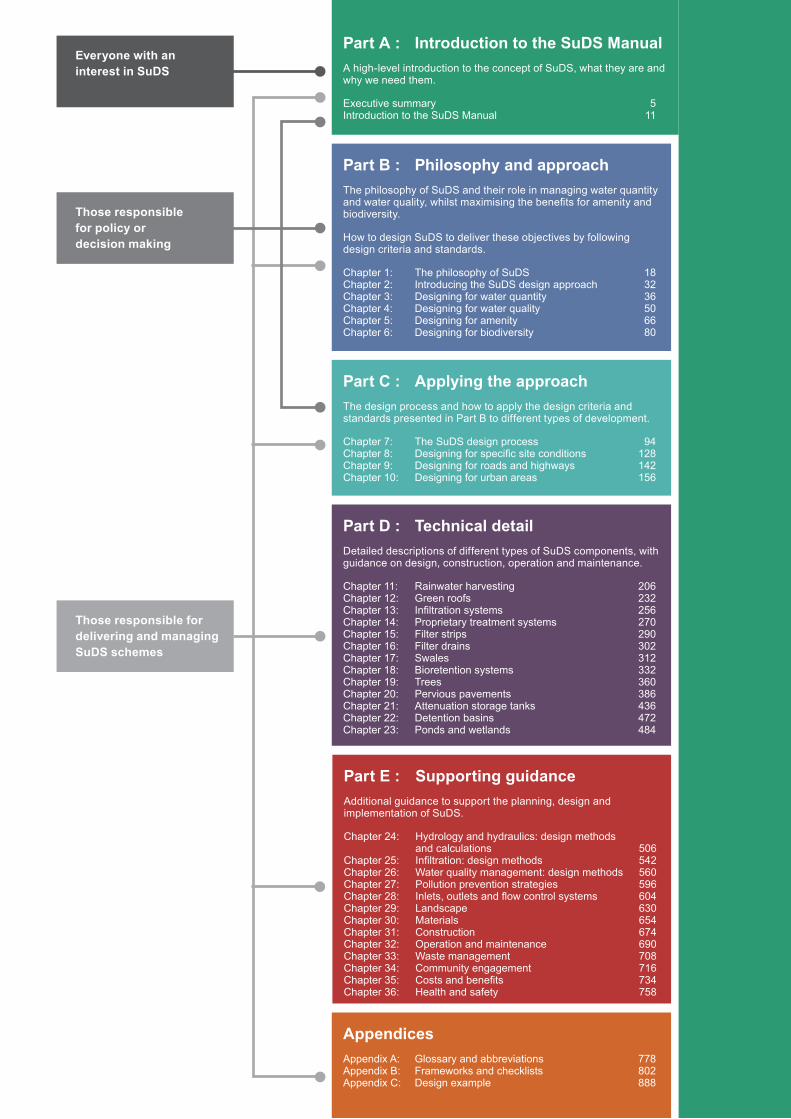
Part C : Applying the approachThe design process and how to apply the design criteria and standards presented in Part B to different types of development.
Chapter 7: The SuDS design process 94Chapter 8: Designing for specific site conditions 128Chapter 9: Designing for roads and highways 142Chapter 10: Designing for urban areas 156
Part D : Technical detailDetailed descriptions of different types of SuDS components, with guidance on design, construction, operation and maintenance.
Chapter 11: Rainwater harvesting 206Chapter 12: Green roofs 232Chapter 13: Infiltration systems 256Chapter 14: Proprietary treatment systems 270Chapter 15: Filter strips 290Chapter 16: Filter drains 302Chapter 17: Swales 312Chapter 18: Bioretention systems 332Chapter 19: Trees 360Chapter 20: Pervious pavements 386Chapter 21: Attenuation storage tanks 436Chapter 22: Detention basins 472Chapter 23: Ponds and wetlands 484
Part A : Introduction to the SuDS ManualA high-level introduction to the concept of SuDS, what they are and why we need them.
Executive summary 5Introduction to the SuDS Manual 11
Part B : Philosophy and approachThe philosophy of SuDS and their role in managing water quantity and water quality, whilst maximising the benefits for amenity and biodiversity.
How to design SuDS to deliver these objectives by following design criteria and standards.
Chapter 1: The philosophy of SuDS 18Chapter 2: Introducing the SuDS design approach 32Chapter 3: Designing for water quantity 36Chapter 4: Designing for water quality 50Chapter 5: Designing for amenity 66Chapter 6: Designing for biodiversity 80
Part E : Supporting guidanceAdditional guidance to support the planning, design and implementation of SuDS.
Chapter 24: Hydrology and hydraulics: design methods and calculations 506Chapter 25: Infiltration: design methods 542Chapter 26: Water quality management: design methods 560Chapter 27: Pollution prevention strategies 596Chapter 28: Inlets, outlets and flow control systems 604Chapter 29: Landscape 630Chapter 30: Materials 654Chapter 31: Construction 674Chapter 32: Operation and maintenance 690Chapter 33: Waste management 708Chapter 34: Community engagement 716Chapter 35: Costs and benefits 734Chapter 36: Health and safety 758
AppendicesAppendix A: Glossary and abbreviations 778Appendix B: Frameworks and checklists 802Appendix C: Design example 888
Everyone with an interest in SuDS
Those responsible for delivering and managing SuDS schemes
Those responsible for policy or decision making
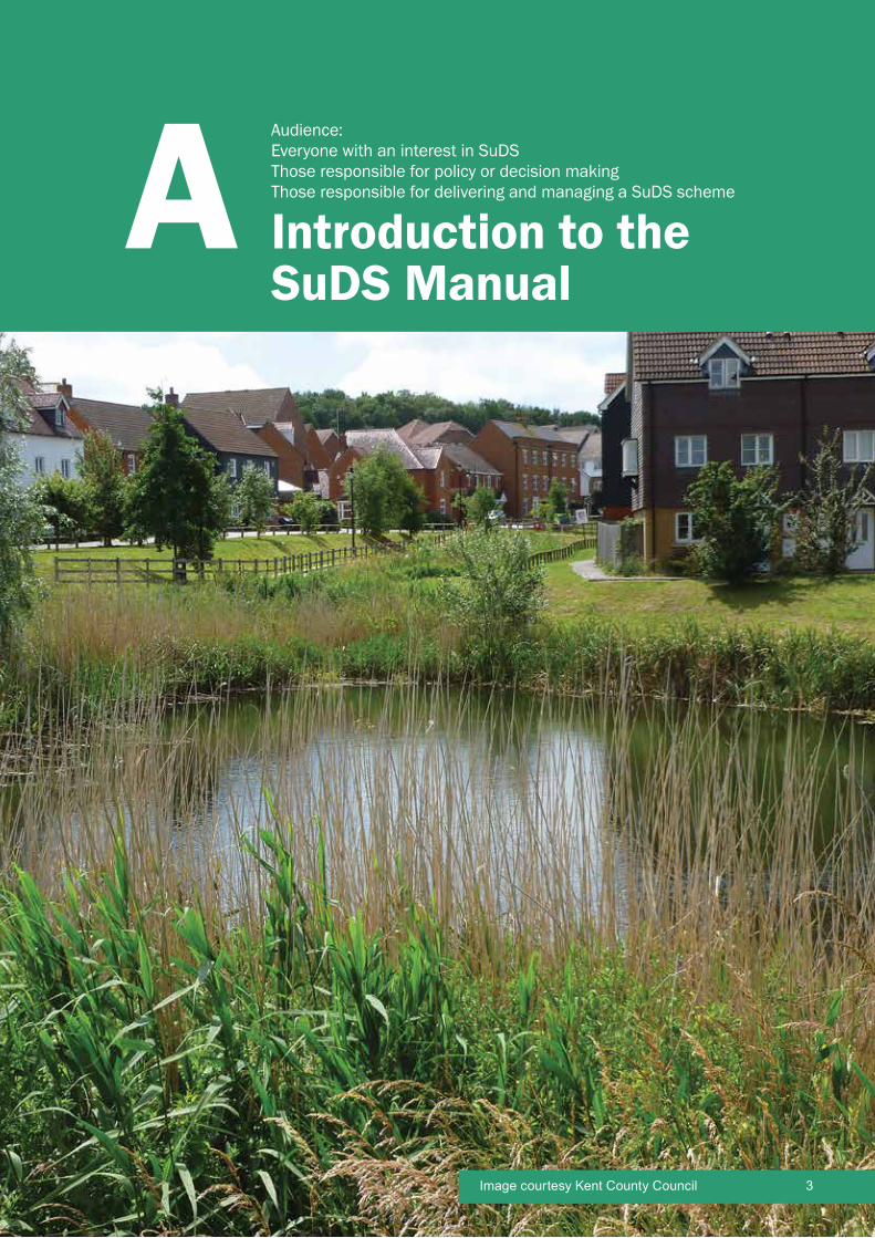
CIRIA SuDS Manual 2015
Introduction to the SuDS Manual
A Audience: Everyone with an interest in SuDSThose responsible for policy or decision makingThose responsible for delivering and managing a SuDS scheme
3Image courtesy Kent County Council
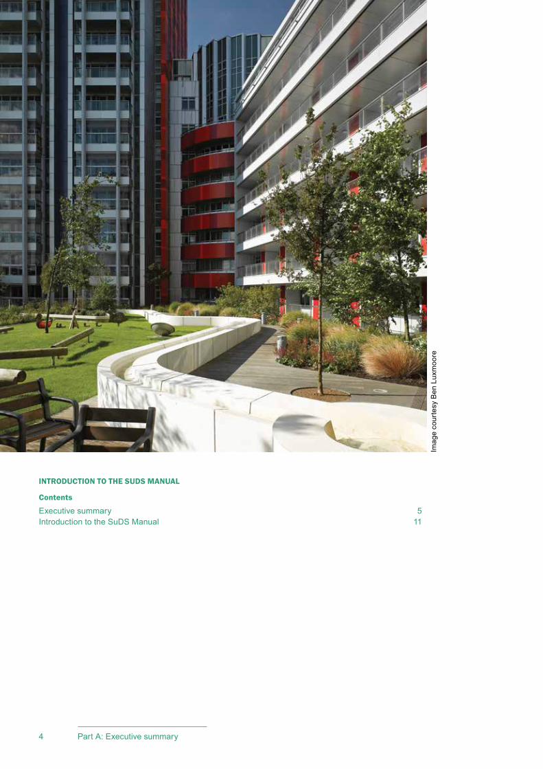
CIRIA SuDS Manual 2015
4 Part A: Executive summary
INTRODUCTION TO THE SUDS MANUAL
Contents
Executive summary 5Introduction to the SuDS Manual 11
Imag
e co
urte
sy B
en L
uxm
oore

5
CIRIA SuDS Manual 2015
Executive summary
Executive summary
WHY SUDS?
Surface water should be managed for maximum benefit, now and in the future. By working together we can integrate surface water management into the design of our towns and cities, protecting our environment and creating high quality places for future generations.
Why is managing surface water runoff so important?
When rain falls on a natural landscape, it soaks into the ground (infiltration), evaporates, is taken up by plants (evapotranspiration) and some of it eventually finds its way into streams and rivers.
These stages of the water cycle can be impeded when land is altered by development. In urban areas, there tends to be less permeable ground available for infiltration and less vegetation for evapotranspiration. When rain falls on impermeable surfaces, much more of it turns into surface water runoff, which can cause flooding, pollution and erosion problems.
Research shows that, if we don’t change the way that we design our urban areas and manage surface water runoff more effectively, these problems are going to get worse. Climate change projections show it is likely that heavy rainfall and flooding will become more frequent. Continuing to provide new sewer capacity to cope with these growing risks is unaffordable.
Climate change projections also suggest that water shortages will become more frequent, especially in the south-east of England where demand is rising due to a growing population. This will increase pressure on our existing water supplies and we will need to find ways to be more efficient and creative in capturing and using the rainwater that falls on our urban areas.
As well as contributing to more surface water runoff, increasing urbanisation has also reduced wildlife in urban areas. Where green spaces exist, these are often isolated from each other, which means that wildlife habitats become fragmented, preventing some species from being able to move between them. Eventually this leads to some species being lost from our green spaces, to the detriment of the local ecosystem and the human population.
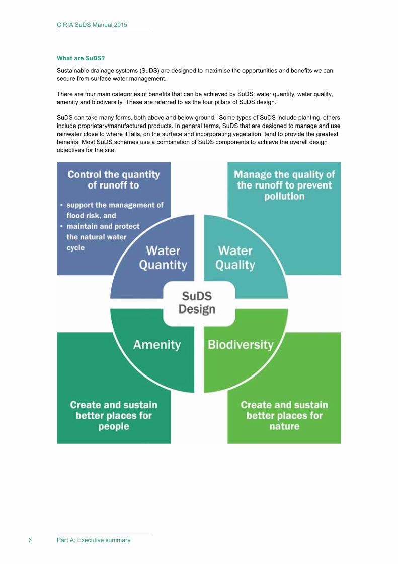
CIRIA SuDS Manual 2015
6 Part A: Executive summary
What are SuDS?
Sustainable drainage systems (SuDS) are designed to maximise the opportunities and benefits we can secure from surface water management.
There are four main categories of benefits that can be achieved by SuDS: water quantity, water quality, amenity and biodiversity. These are referred to as the four pillars of SuDS design.
SuDS can take many forms, both above and below ground. Some types of SuDS include planting, others include proprietary/manufactured products. In general terms, SuDS that are designed to manage and use rainwater close to where it falls, on the surface and incorporating vegetation, tend to provide the greatest benefits. Most SuDS schemes use a combination of SuDS components to achieve the overall design objectives for the site.
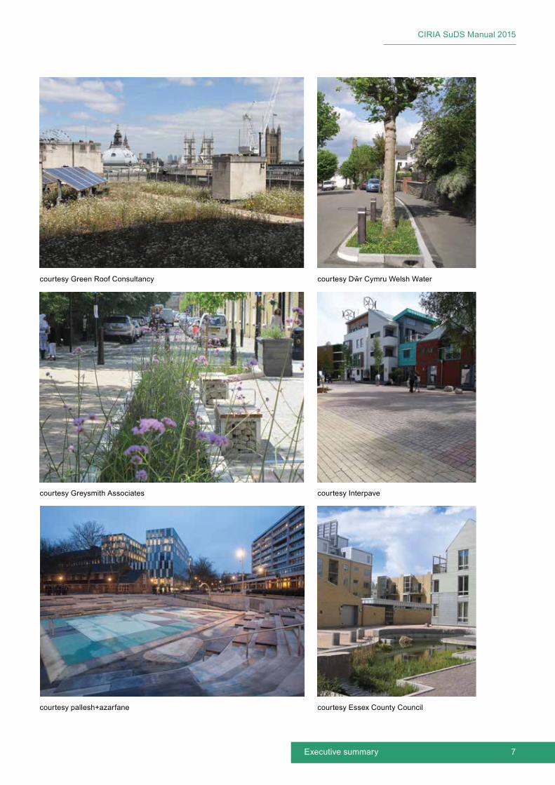
7
CIRIA SuDS Manual 2015
Executive summary
courtesy Green Roof Consultancy courtesy Dŵr Cymru Welsh Water
courtesy Greysmith Associates
courtesy pallesh+azarfane
courtesy Interpave
courtesy Essex County Council

CIRIA SuDS Manual 2015
8 Part A: Executive summary
Some examples of SuDS:
▪ Rainwater harvesting systems can collect rainwater from roofs and other paved surfaces for use on site.
▪ Green roofs, where a planted soil layer is constructed on a roof to create a living surface, can reduce surface runoff.
▪ Pervious pavements provide a hard surface that can be used for pedestrians or vehicles, while allowing rainwater to pass through to the soil or underground storage.
▪ Bioretention systems (including rain gardens) collect runoff, allowing it to pond temporarily on the surface before filtering through vegetation and underlying soils.
▪ Trees capture rainwater and provide evapotranspiration, biodiversity and shade.
▪ Swales, detention basins, ponds and wetlands slow the flow of water, store and treat runoff while draining it through the site and encouraging biodiversity.
▪ Soakaways and infiltration basins promote infiltration as an effective means of controlling runoff and supporting groundwater recharge.
What are the benefits of SuDS?
SuDS deliver high quality drainage while supporting urban areas to cope better with severe rainfall both now and in the future. SuDS also help counteract some of the impacts on our water cycle caused by increased urbanisation, such as reduced infiltration which in turn can result in diminished groundwater supplies.
SuDS can improve the quality of life in developments and urban spaces by making them more vibrant, visually attractive, sustainable and more resilient to change, by improving urban air quality, regulating building temperatures, reducing noise and delivering recreation and education opportunities. High quality SuDS designs that are integrated into the overall design of the development can attract tourism and investment, driving economic growth for the local area.
Where SuDS are designed to make efficient use of the space available, they can often cost less to implement than underground piped systems.
Where can you use SuDS?
SuDS can be used anywhere. SuDS can be used for new developments and redevelopments, and can be retrofitted into existing developments.
SuDS can be used in even the smallest spaces. Good SuDS design maximises the use of the available space by delivering efficient drainage together with other functions to help meet the objectives of the site. For example:
▪ pervious pavements can be used for parking
▪ rain gardens can be incorporated into traffic calming measures
▪ detention basins can also have recreational uses
▪ trees and green roofs can help to regulate building temperatures.
Most sites pose challenges of one sort or another, but the range of SuDS components and solutions available means that, with the timely engagement of the right expertise, effective SuDS schemes can be delivered for all developments. This includes:
▪ high density development sites
▪ steeply sloping sites

9
CIRIA SuDS Manual 2015
Executive summary
▪ flat sites
▪ sites with high groundwater levels
▪ sites within floodplains
▪ contaminated land sites
▪ sites with low infiltration capacity
▪ sites with unstable soils.
The three keys to successful SuDS implementation:
Consider how surface water runoff will be managed on your site from the start, and make it an integral part of the design process.
Put the right team together early in the process, so that urban planning, landscape architecture, architecture, drainage design and environmental aspects can be considered collectively.
Consult with relevant stakeholders early in the process, including the local planning authority, environmental regulator and those with responsibility for approving and maintaining the SuDS.
How do you design SuDS?
SuDS design should follow the guidance provided in the SuDS Manual, with due regard for any national or local regulatory requirements.
SuDS design should, as much as possible, be based around the following:
▪ using surface water runoff as a resource
▪ managing rainwater close to where it falls
▪ managing runoff on the surface
▪ allowing rainwater to soak into the ground
▪ promoting evapotranspiration
▪ slowing and storing runoff to mimic natural runoff characteristics
▪ reducing contamination of runoff through pollution prevention and controlling the runoff at source
▪ treating runoff to reduce the risk of urban contaminants causing environmental pollution.
Where to find further information
▪ A digital version of The SuDS Manual can be found at www.ciria.org
▪ A range of resources for those involved in delivering SuDS, including case studies, videos, presentations, fact sheets and links to research, can be found at: www.susdrain.org
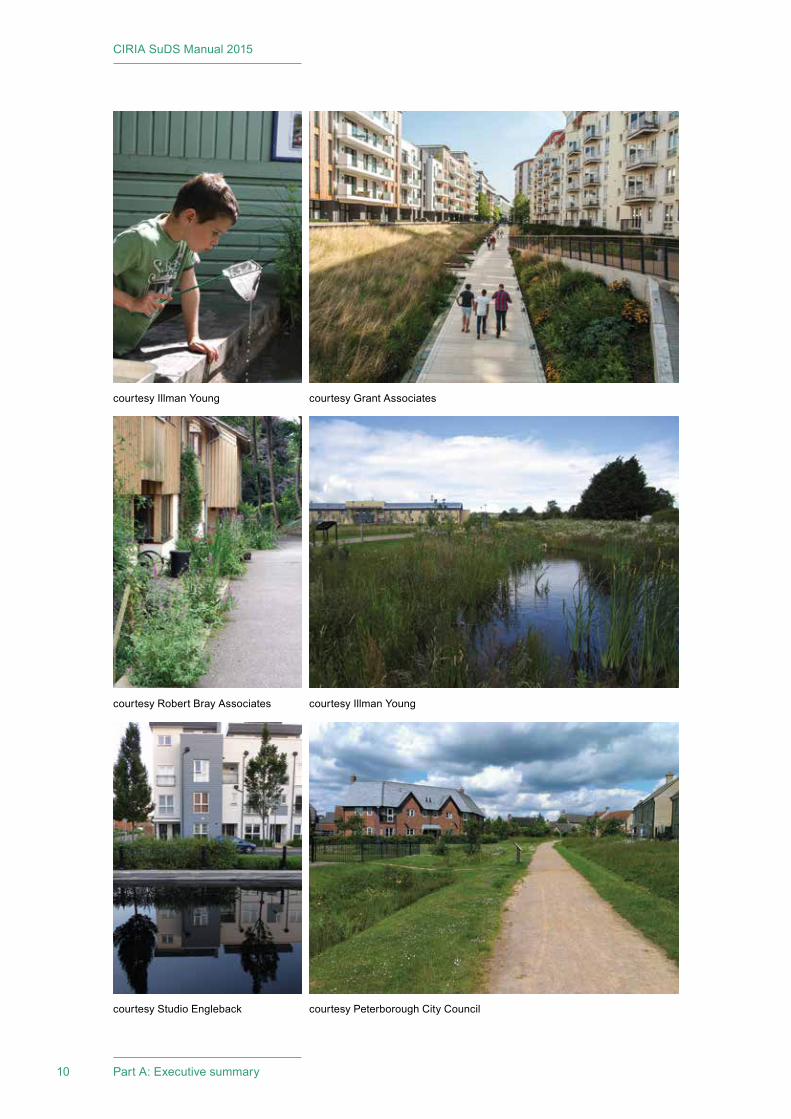
CIRIA SuDS Manual 2015
10 Part A: Executive summary
courtesy Illman Young courtesy Grant Associates
courtesy Robert Bray Associates
courtesy Studio Engleback
courtesy Illman Young
courtesy Peterborough City Council

11
CIRIA SuDS Manual 2015
Part A: Introduction to the SuDS Manual
Introduction to the SuDS ManualSCOPE OF GUIDANCE
This guidance covers the planning, design, construction and maintenance of sustainable drainage systems (SuDS) to assist with their effective implementation within both new and existing developments. The guidance looks at how to maximise amenity and biodiversity benefits, and deliver the key objectives of managing flood risk and water quality. There is also supporting information covering topics such as materials, landscape design, community engagement and costs and benefits.
The guidance presented in this publication is a compendium of good practice, based on existing guidance and research in the UK and internationally and the practical experience of the authors, the project steering group and industry.
As experience of SuDS implementation and long-term maintenance continues to increase across the UK, lessons will continue to be learned. Also, continuing research on SuDS performance, both in the UK and internationally, will influence how design practice evolves. This guidance, however, provides a framework for designing SuDS with confidence and to maximise benefits.
The guidance is relevant for a wide range of professions and roles, including (in no particular order):
▪ drainage and flood risk management engineers
▪ architects and landscape architects
▪ planners and urban designers
▪ site owners and developers
▪ planning and drainage approval bodies
▪ environmental regulators
▪ ecologists
▪ highways and road authorities
▪ sewerage undertakers
▪ drainage and landscape contractors
▪ proprietary drainage and other product manufacturers.
This manual is divided into five sections and is colour coded based on these sections. It starts with a high-level overview and progresses into more detailed guidance in the later sections. The sections have different intended audiences, so the level of technical understanding expected of the reader increases through the manual.
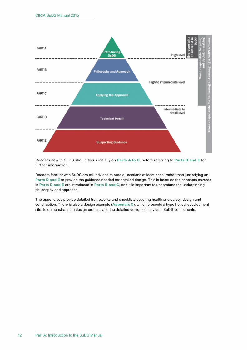
CIRIA SuDS Manual 2015
12 Part A: Introduction to the SuDS Manual
Readers new to SuDS should focus initially on Parts A to C, before referring to Parts D and E for further information.
Readers familiar with SuDS are still advised to read all sections at least once, rather than just relying on Parts D and E to provide the guidance needed for detailed design. This is because the concepts covered in Parts D and E are introduced in Parts B and C, and it is important to understand the underpinning philosophy and approach.
The appendices provide detailed frameworks and checklists covering health and safety, design and construction. There is also a design example (Appendix C), which presents a hypothetical development site, to demonstrate the design process and the detailed design of individual SuDS components.
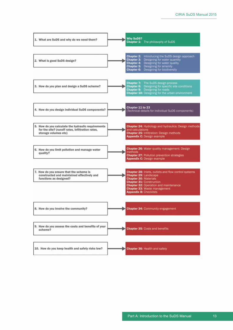
13
CIRIA SuDS Manual 2015
Part A: Introduction to the SuDS Manual
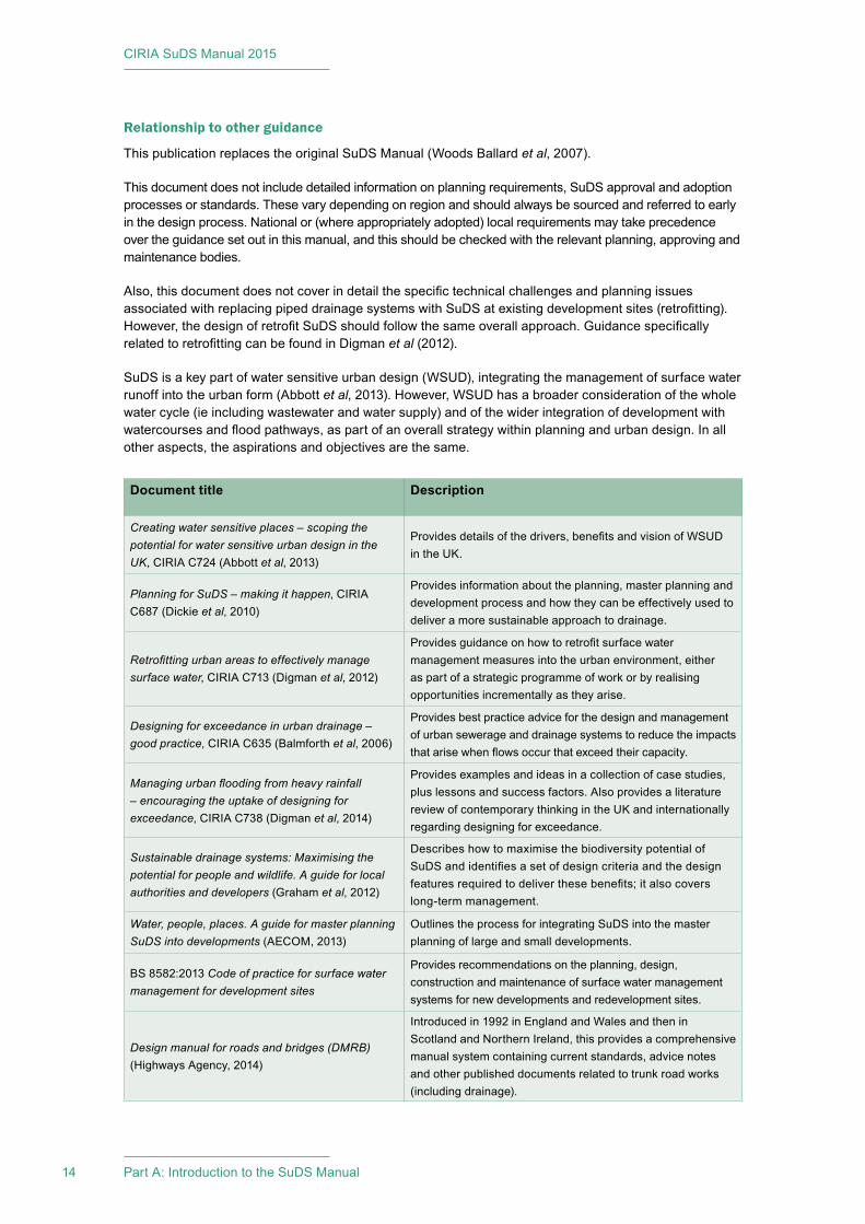
CIRIA SuDS Manual 2015
14 Part A: Introduction to the SuDS Manual
Relationship to other guidance
This publication replaces the original SuDS Manual (Woods Ballard et al, 2007).
This document does not include detailed information on planning requirements, SuDS approval and adoption processes or standards. These vary depending on region and should always be sourced and referred to early in the design process. National or (where appropriately adopted) local requirements may take precedence over the guidance set out in this manual, and this should be checked with the relevant planning, approving and maintenance bodies.
Also, this document does not cover in detail the specific technical challenges and planning issues associated with replacing piped drainage systems with SuDS at existing development sites (retrofitting). However, the design of retrofit SuDS should follow the same overall approach. Guidance specifically related to retrofitting can be found in Digman et al (2012).
SuDS is a key part of water sensitive urban design (WSUD), integrating the management of surface water runoff into the urban form (Abbott et al, 2013). However, WSUD has a broader consideration of the whole water cycle (ie including wastewater and water supply) and of the wider integration of development with watercourses and flood pathways, as part of an overall strategy within planning and urban design. In all other aspects, the aspirations and objectives are the same.
Document title Description
Creating water sensitive places – scoping the potential for water sensitive urban design in the UK, CIRIA C724 (Abbott et al, 2013)
Provides details of the drivers, benefits and vision of WSUD in the UK.
Planning for SuDS – making it happen, CIRIA C687 (Dickie et al, 2010)
Provides information about the planning, master planning and development process and how they can be effectively used to deliver a more sustainable approach to drainage.
Retrofitting urban areas to effectively manage surface water, CIRIA C713 (Digman et al, 2012)
Provides guidance on how to retrofit surface water management measures into the urban environment, either as part of a strategic programme of work or by realising opportunities incrementally as they arise.
Designing for exceedance in urban drainage – good practice, CIRIA C635 (Balmforth et al, 2006)
Provides best practice advice for the design and management of urban sewerage and drainage systems to reduce the impacts that arise when flows occur that exceed their capacity.
Managing urban flooding from heavy rainfall – encouraging the uptake of designing for exceedance, CIRIA C738 (Digman et al, 2014)
Provides examples and ideas in a collection of case studies, plus lessons and success factors. Also provides a literature review of contemporary thinking in the UK and internationally regarding designing for exceedance.
Sustainable drainage systems: Maximising the potential for people and wildlife. A guide for local authorities and developers (Graham et al, 2012)
Describes how to maximise the biodiversity potential of SuDS and identifies a set of design criteria and the design features required to deliver these benefits; it also covers long-term management.
Water, people, places. A guide for master planning SuDS into developments (AECOM, 2013)
Outlines the process for integrating SuDS into the master planning of large and small developments.
BS 8582:2013 Code of practice for surface water management for development sites
Provides recommendations on the planning, design, construction and maintenance of surface water management systems for new developments and redevelopment sites.
Design manual for roads and bridges (DMRB) (Highways Agency, 2014)
Introduced in 1992 in England and Wales and then in Scotland and Northern Ireland, this provides a comprehensive manual system containing current standards, advice notes and other published documents related to trunk road works (including drainage).

15
CIRIA SuDS Manual 2015
Part A: Introduction to the SuDS Manual
There are many other guidance documents or design manuals for SuDS in the UK (including several CIRIA publications) that should be referred to for information on specific topics. These are referenced at the end of the chapters, but some of the key documents are listed below. The susdrain website provides a platform for sharing the latest good practice, and it highlights other relevant initiatives: www.susdrain.org
References
ABBOTT, J, DAVIES, P, SIMKINS, P, MORGAN, C, LEVIN, D and ROBINSON, P (2013) Creating water sensitive places – scoping the potential for water sensitive urban design in the UK, C724, CIRIA, London, UK (ISBN: 978-0-86017-733-3). Go to: www.ciria.org
AECOM (2013) Water, people, places. A guide for master planning SuDS into developments, prepared by the Lead Local Flood Authorities of the South East of England, AECOM, London, UK. Go to: http://tinyurl.com/npdsf63
BALMFORTH, D, DIGMAN, C, KELLAGHER, R and BUTLER, D (2006) Designing for exceedance in urban drainage – good practice, C635, CIRIA, London, UK (ISBN: 978-0-86017-635-0). Go to: www.ciria.org
DICKIE, S, IONS, L, MCKAY, G and SHAFFER, P (2010) Planning for SuDS – making it happen, C687, CIRIA, London, UK (ISBN: 978-0-86017-687-9). Go to: www.ciria.org
DIGMAN, C, ASHLEY, R, BALMFORTH, D, STOVIN, V and GLERUM, J (2012) Retrofitting urban areas to effectively manage surface water, C713, CIRIA, London, UK (ISBN: 978-0-86017-715-9). Go to: www.ciria.org
DIGMAN, C, ASHLEY, R, HARGREAVES, P and GILL, E (2014) Managing urban flooding from heavy rainfall – encouraging the uptake of designing for exceedance, C738, CIRIA, London, UK (ISBN: 978-0-86017-742-5) Go to: www.ciria.org
GRAHAM, A, DAY, J, BRAY, B and MACKENZIE, S (2012) Sustainable drainage systems: Maximising the potential for people and wildlife – A guide for local authorities and developers, The Royal Society for the Protection of Birds and Wildfowl & Wetlands Trust, UK. Go to: http://tinyurl.com/pzwwaaz
HIGHWAYS AGENCY (2014) Design Manual for Roads and Bridges (DMRB), Highways Agency, London, UK. Go to: www.standardsforhighways.co.uk/dmrb
WOODS BALLARD, B, KELLAGHER, R, MARTIN, P, JEFFRIES, C, BRAY, R and SHAFFER, P (2007) The SuDS Manual, C697, CIRIA, London, UK (ISBN: 978-0-86017-697-8). Go to: www.ciria.org
Statutes
BS 8582:2013 Code of practice for surface water management for development sites
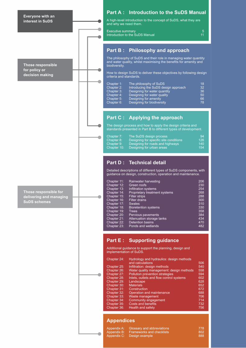
Part C : Applying the approachThe design process and how to apply the design criteria and standards presented in Part B to different types of development.
Chapter 7: The SuDS design process 94Chapter 8: Designing for specific site conditions 126Chapter 9: Designing for roads and highways 140Chapter 10: Designing for urban areas 154
Part D : Technical detailDetailed descriptions of different types of SuDS components, with guidance on design, construction, operation and maintenance.
Chapter 11: Rainwater harvesting 206Chapter 12: Green roofs 230Chapter 13: Infiltration systems 254Chapter 14: Proprietary treatment systems 268Chapter 15: Filter strips 288Chapter 16: Filter drains 300Chapter 17: Swales 310Chapter 18: Bioretention systems 330Chapter 19: Trees 358Chapter 20: Pervious pavements 384Chapter 21: Attenuation storage tanks 434Chapter 22: Detention basins 470Chapter 23: Ponds and wetlands 482
Part A : Introduction to the SuDS ManualA high-level introduction to the concept of SuDS, what they are and why we need them.
Executive summary 5Introduction to the SuDS Manual 11
Part B : Philosophy and approachThe philosophy of SuDS and their role in managing water quantity and water quality, whilst maximising the benefits for amenity and biodiversity.
How to design SuDS to deliver these objectives by following design criteria and standards.
Chapter 1: The philosophy of SuDS 18Chapter 2: Introducing the SuDS design approach 32Chapter 3: Designing for water quantity 36Chapter 4: Designing for water quality 50Chapter 5: Designing for amenity 66Chapter 6: Designing for biodiversity 78
Part E : Supporting guidanceAdditional guidance to support the planning, design and implementation of SuDS.
Chapter 24: Hydrology and hydraulics: design methods and calculations 506Chapter 25: Infiltration: design methods 540Chapter 26: Water quality management: design methods 558Chapter 27: Pollution prevention strategies 594Chapter 28: Inlets, outlets and flow control systems 602Chapter 29: Landscape 628Chapter 30: Materials 652Chapter 31: Construction 672Chapter 32: Operation and maintenance 688Chapter 33: Waste management 706Chapter 34: Community engagement 714Chapter 35: Costs and benefits 732Chapter 36: Health and safety 756
AppendicesAppendix A: Glossary and abbreviations 778Appendix B: Frameworks and checklists 802Appendix C: Design example 888
Everyone with an interest in SuDS
Those responsible for delivering and managing SuDS schemes
Those responsible for policy or decision making

CIRIA SuDS Manual 2015
Image courtesy Grant Associates
Philosophy and approachB Audience: Those responsible for policy or decision makingThose responsible for delivering and managing a SuDS scheme
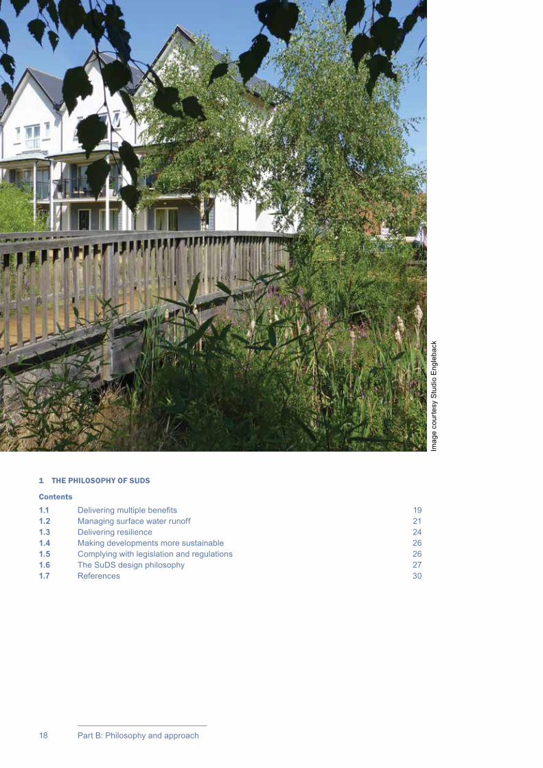
18 Part B: Philosophy and approach
1 THE PHILOSOPHY OF SUDS
Contents
1.1 Delivering multiple benefits 191.2 Managing surface water runoff 211.3 Delivering resilience 241.4 Making developments more sustainable 261.5 Complying with legislation and regulations 261.6 The SuDS design philosophy 271.7 References 30
Imag
e co
urte
sy S
tudi
o E
ngle
back

19Chapter 1: The philosophy of SuDS
CIRIA SuDS Manual 2015
The philosophy of SuDS
1.1 DELIVERING MULTIPLE BENEFITS
Sustainable drainage systems (SuDS) can deliver multiple benefits
Surface water is a valuable resource and this should be reflected in the way it is managed and used in the built environment. It can add to and enhance biodiversity, beauty, tranquillity and the natural aesthetic of buildings, places and landscapes and it can help make them more resilient to the changing climate.
The philosophy of sustainable drainage systems is about maximising the benefits and minimising the negative impacts of surface water runoff from developed areas.
The SuDS approach involves slowing down and reducing the quantity of surface water runoff from a developed area to manage downstream flood risk, and reducing the risk of that runoff causing pollution. This is achieved by harvesting, infiltrating, slowing, storing, conveying and treating runoff on site and, where possible, on the surface rather than underground. Water then becomes a much more visible and tangible part of the built environment, which can be enjoyed by everyone.
By adopting this approach, SuDS have the opportunity to deliver and enhance the green space within developments and link to wider green networks, supporting the provision of habitats and places for wildlife to live and flourish. The benefits to the community of using SuDS are also numerous, including improvements in health, well-being and quality of life (liveability) for both individuals and communities, which in turn can increase the value of property and the prosperity of the local economy (Box 1.1).
To maximise these benefits, surface water management should be considered from the beginning of the development planning process and throughout – influencing site layout and design, and the use and characteristics of urban spaces (see Case study 1.1). So it is important that, where appropriate, an interdisciplinary team (including planners, landscape architects, architects and drainage engineers) should work together from the outset.
There are many different ways that SuDS can be applied to deliver effective surface water management that are both value for money and inspirational. Depending on the opportunities and constraints of the site, the type of development planned and the characteristics of the surrounding area, this can be through a combination of components – open water, vegetated and hard landscaped, above and below ground.
SuDS can be used in even the smallest spaces – the apparent lack of space should never be a reason for not using SuDS. Designing SuDS so that the space performs multiple functions is particularly important in dense urban areas where space is at a premium (Box 1.2).
This manual provides guidance for designers to enable them to make informed choices that suit their specific circumstances and maximise opportunities at reasonable cost.
This chapter discusses how SuDS can deliver multiple benefits, the importance of managing surface water runoff in a sustainable way and what makes a drainage system sustainable.01
Chapter
Chapters 2–10 provide further details of the concepts introduced here.

CIRIA SuDS Manual 2015
20 Part B: Philosophy and approach
BOX1.1
Benefits of SuDS
▪ protecting people and property from increased flood risk resulting from the development
▪ protecting the quality of groundwater and surface waters from polluted runoff from the development
▪ protecting natural flow regimes (and thus the morphology and associated ecology) in rivers, lakes and streams
▪ supporting local natural habitats and associated ecosystems by encouraging greater biodiversity and linking habitats
▪ improving soil moisture and replenishing depleted groundwater levels
▪ providing society with a valuable supply of water
▪ creating attractive places where people want to live, work and play through the integration of water and green spaces with the built environment
▪ improving people’s understanding of how runoff from their development is being managed and used, and the benefits of more sustainable approaches
▪ supporting the creation of developments that are more able to cope with changes in climate
▪ delivering cost-effective infrastructure that uses fewer natural resources and has a smaller whole-life carbon footprint than conventional drainage.
Figure 1.1 The Circle in Uptown Normal, Illinois, USA (courtesy Town of Normal)
The Circle is an award winning multi-functional public space located in a roundabout, providing green space that hosts many community events, including farmers markets, blues festivals and arts festivals (as shown in Figure 1.1). It collects runoff from surrounding streets to alleviate downstream flooding, infiltrates, stores and treats the runoff, re-circulates the water into a public fountain that provides cooling for the area and the space even abates surrounding vehicle noise.
The Circle, Uptown Normal, IllinoisCASE STUDY
1.1
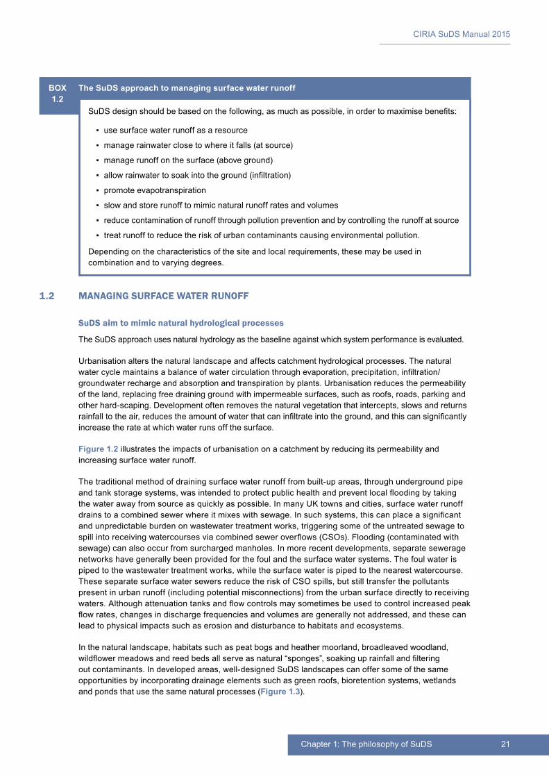
21Chapter 1: The philosophy of SuDS
CIRIA SuDS Manual 2015
1.2 MANAGING SURFACE WATER RUNOFF
SuDS aim to mimic natural hydrological processes
The SuDS approach uses natural hydrology as the baseline against which system performance is evaluated.
Urbanisation alters the natural landscape and affects catchment hydrological processes. The natural water cycle maintains a balance of water circulation through evaporation, precipitation, infiltration/groundwater recharge and absorption and transpiration by plants. Urbanisation reduces the permeability of the land, replacing free draining ground with impermeable surfaces, such as roofs, roads, parking and other hard-scaping. Development often removes the natural vegetation that intercepts, slows and returns rainfall to the air, reduces the amount of water that can infiltrate into the ground, and this can significantly increase the rate at which water runs off the surface.
Figure 1.2 illustrates the impacts of urbanisation on a catchment by reducing its permeability and increasing surface water runoff.
The traditional method of draining surface water runoff from built-up areas, through underground pipe and tank storage systems, was intended to protect public health and prevent local flooding by taking the water away from source as quickly as possible. In many UK towns and cities, surface water runoff drains to a combined sewer where it mixes with sewage. In such systems, this can place a significant and unpredictable burden on wastewater treatment works, triggering some of the untreated sewage to spill into receiving watercourses via combined sewer overflows (CSOs). Flooding (contaminated with sewage) can also occur from surcharged manholes. In more recent developments, separate sewerage networks have generally been provided for the foul and the surface water systems. The foul water is piped to the wastewater treatment works, while the surface water is piped to the nearest watercourse. These separate surface water sewers reduce the risk of CSO spills, but still transfer the pollutants present in urban runoff (including potential misconnections) from the urban surface directly to receiving waters. Although attenuation tanks and flow controls may sometimes be used to control increased peak flow rates, changes in discharge frequencies and volumes are generally not addressed, and these can lead to physical impacts such as erosion and disturbance to habitats and ecosystems.
In the natural landscape, habitats such as peat bogs and heather moorland, broadleaved woodland, wildflower meadows and reed beds all serve as natural “sponges”, soaking up rainfall and filtering out contaminants. In developed areas, well-designed SuDS landscapes can offer some of the same opportunities by incorporating drainage elements such as green roofs, bioretention systems, wetlands and ponds that use the same natural processes (Figure 1.3).
BOX1.2
The SuDS approach to managing surface water runoff
SuDS design should be based on the following, as much as possible, in order to maximise benefits:
▪ use surface water runoff as a resource
▪ manage rainwater close to where it falls (at source)
▪ manage runoff on the surface (above ground)
▪ allow rainwater to soak into the ground (infiltration)
▪ promote evapotranspiration
▪ slow and store runoff to mimic natural runoff rates and volumes
▪ reduce contamination of runoff through pollution prevention and by controlling the runoff at source
▪ treat runoff to reduce the risk of urban contaminants causing environmental pollution.
Depending on the characteristics of the site and local requirements, these may be used in combination and to varying degrees.
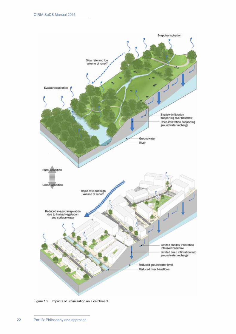
CIRIA SuDS Manual 2015
22 Part B: Philosophy and approach
Figure 1.2 Impacts of urbanisation on a catchment
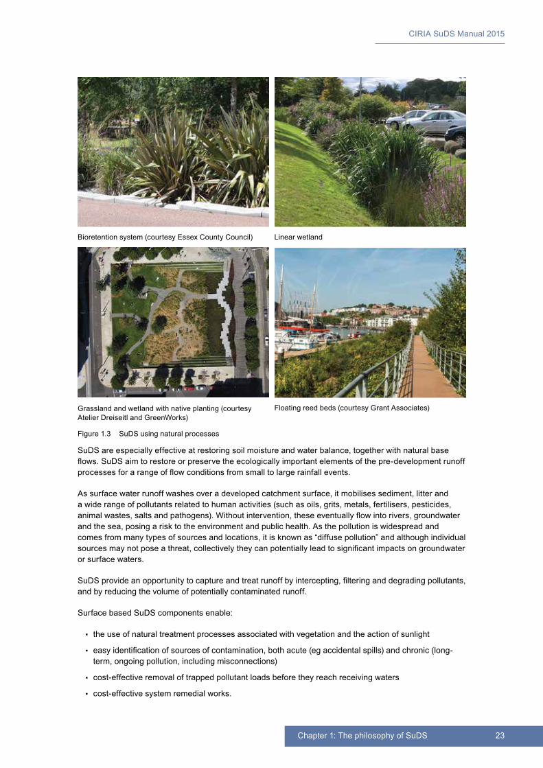
23Chapter 1: The philosophy of SuDS
CIRIA SuDS Manual 2015
SuDS are especially effective at restoring soil moisture and water balance, together with natural base flows. SuDS aim to restore or preserve the ecologically important elements of the pre-development runoff processes for a range of flow conditions from small to large rainfall events.
As surface water runoff washes over a developed catchment surface, it mobilises sediment, litter and a wide range of pollutants related to human activities (such as oils, grits, metals, fertilisers, pesticides, animal wastes, salts and pathogens). Without intervention, these eventually flow into rivers, groundwater and the sea, posing a risk to the environment and public health. As the pollution is widespread and comes from many types of sources and locations, it is known as “diffuse pollution” and although individual sources may not pose a threat, collectively they can potentially lead to significant impacts on groundwater or surface waters.
SuDS provide an opportunity to capture and treat runoff by intercepting, filtering and degrading pollutants, and by reducing the volume of potentially contaminated runoff.
Surface based SuDS components enable:
▪▪ the use of natural treatment processes associated with vegetation and the action of sunlight
▪▪ easy identification of sources of contamination, both acute (eg accidental spills) and chronic (long-term, ongoing pollution, including misconnections)
▪▪ cost-effective removal of trapped pollutant loads before they reach receiving waters
▪▪ cost-effective system remedial works.
Bioretention system (courtesy Essex County Council) Linear wetland
Grassland and wetland with native planting (courtesy Atelier Dreiseitl and GreenWorks)
Floating reed beds (courtesy Grant Associates)
Figure 1.3 SuDS using natural processes

CIRIA SuDS Manual 2015
24 Part B: Philosophy and approach
1.3 DELIVERING RESILIENCE
SuDS can cope well with severe rainfall, climate change and increasing urbanisation
There is strong evidence that the earth’s climate is changing because of human activity and that it will continue to change over the coming century, whether or not emissions of greenhouse gases are cut dramatically. Climate projections for the UK suggest that winters may become milder and wetter and summers may become warmer, particularly in the south-east. Some types of extreme events may become more frequent, such as heat waves, droughts and flooding, but due to the natural variability in the earth’s weather and limitations with climate modelling, this is currently less certain.
Wetter winters and potentially more frequent and higher intensity rainfall events (in summer as well as winter) are expected to increase runoff from urban and agricultural land. This in turn would increase the risk of flooding, discharges from CSOs, diffuse pollution and soil erosion, with potentially negative impacts for the natural environment as well as the human population.
These impacts could also be exacerbated by increased runoff from urban intensification/urban creep: increasing density of development which increases the impermeability of developed areas, causing rates and volumes of runoff to rise, such as paving over gardens, extending buildings or adding roads.
SuDS offer a robust approach to managing rainfall events that exceed design conditions: rainfall more severe than allowed for in the system design. In surface based systems, water levels rise gradually and visibly during large rainfall events. With SuDS, excess runoff can be readily conveyed from within the drainage system into defined safe exceedance conveyance pathways and storage zones. This enables communities to understand and prepare for flooding more effectively than when served by subsurface systems, where flooding can occur suddenly, when the design capacity is exceeded.
SuDS also offer a more adaptable way of draining surfaces under the threat of both climate change and urban intensification. This is because surface based systems can be designed to offer more flexible capacity, and they tend to have greater potential for enhancement in the future at a reasonable cost compared to subsurface systems.
Water availability in the summer is expected to decrease, the consequences of which are likely to be exacerbated by higher temperatures. For example, lower flows in rivers in the summer months would lead to reduced dilution of pollutants in runoff when summer rainfall events do occur. There may also be more frequent algal blooms and eutrophication. At the same time, population growth and higher summer temperatures are likely to lead to greater demand for water. The competing pressures of maintaining public water supply without causing environmental damage need to be managed sustainably. SuDS can help by supplementing water supplies through rainwater harvesting and reducing pollutant discharges into receiving waters.
As well as these impacts on water systems, climate change is also likely to affect many aspects of urban living, especially human health. Elevated summer temperatures, for example, have been shown to cause additional deaths – especially in cities. SuDS in various forms can help to provide urban cooling (Figure 1.4). Hard surfaces tend to heat up in high temperatures, but this can be counteracted by providing SuDS with permanent water and/or vegetation. For example, green roofs can help to insulate buildings, green walls and vertical gardens can support natural ventilation (see Case study 1.2), trees provide shade, and water features cool the air.
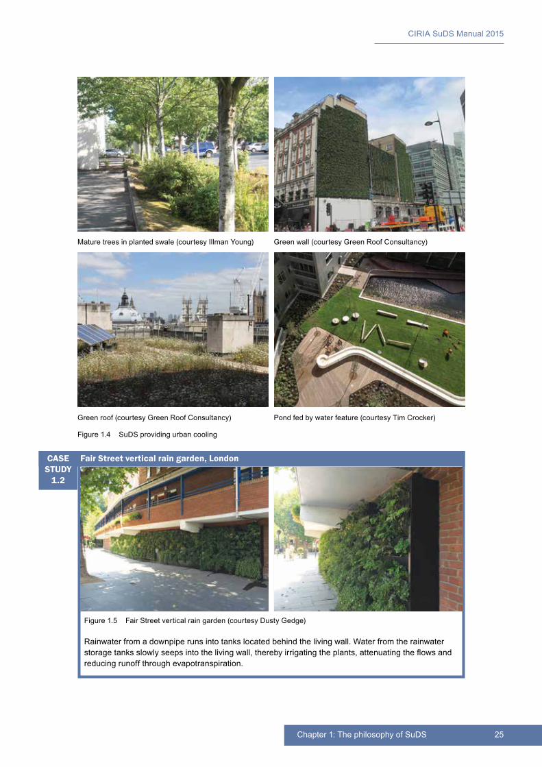
25Chapter 1: The philosophy of SuDS
CIRIA SuDS Manual 2015
Figure 1.5 Fair Street vertical rain garden (courtesy Dusty Gedge)
Rainwater from a downpipe runs into tanks located behind the living wall. Water from the rainwater storage tanks slowly seeps into the living wall, thereby irrigating the plants, attenuating the flows and reducing runoff through evapotranspiration.
Fair Street vertical rain garden, LondonCASE STUDY
1.2
Mature trees in planted swale (courtesy Illman Young) Green wall (courtesy Green Roof Consultancy)
Green roof (courtesy Green Roof Consultancy) Pond fed by water feature (courtesy Tim Crocker)
Figure 1.4 SuDS providing urban cooling
CIRIA SuDS Manual 2015
26 Part B: Philosophy and approach
1.4 MAKING DEVELOPMENTS MORE SUSTAINABLE
SuDS make developments more sustainable
Sustainable development aims to ensure a better quality of life, now and for generations to come. In the UK, this means meeting the following objectives (adapted from HM Government, 2005):
1 social progress that recognises the needs of everyone.
2 effective protection of the natural environment and processes.
3 the sustainable use of natural resources.
4 the maintenance of strong and stable levels of economic growth and employment.
Using SuDS for the sustainable management of surface water runoff can support:
▪▪ the management of flood risk through the control of both flow rates and volumes
▪▪ the preservation and support of habitats and biodiversity through the control of flows (and contaminants) to protect ecology and morphology
▪▪ the creation of sustainable habitats through the use of vegetated SuDS
▪▪ the prudent use of water resources through the implementation of rainwater harvesting systems
▪▪ the preservation of water resources through the protection of ground and surface water quality
▪▪ the sustainable use of natural resources through the minimisation of their use in SuDS design
▪▪ the reduction of embodied and operational carbon in drainage systems within manufacture and through the reduced use of pumping.
By taking advantage of natural systems and natural materials, most SuDS use fewer resources and less energy (leading to lower greenhouse gas emissions) than traditional drainage systems and, by using vegetation, can act as carbon sinks when in use.
Spatial planning and, in particular, local development planning policies and strategies are the most important instruments for promoting and delivering sustainable development in the UK. Taking a holistic and integrated approach to surface water management through the implementation of SuDS, improves water management and environmental protection at the strategic level (eg by contributing to green infrastructure), and contributes to local biodiversity and amenity objectives.
1.5 COMPLYING WITH LEGISLATION AND REGULATIONS
SuDS help deliver compliance with legislation and regulations
There are a great number of legal and other instruments that relate to the management of runoff and surface water. The European Union Water Framework Directive (European Commission, 2000) was transposed into UK national legislation in December 2003. This Directive takes account of all the different objectives for which the aquatic environment is protected (ecology, drinking water, health and particular habitats), and ensures that measures taken to achieve the objectives are co-ordinated properly.
The Water Framework Directive encourages a more sustainable approach to drainage by:
▪▪ establishing a holistic approach to managing the water environment, based on river basins, integrating water quantity with water quality considerations
▪▪ establishing quality objectives for all receiving waters, in order to achieve good status
▪▪ establishing a quality classification system for surface water that includes chemical, hydromorphological and ecological parameters
27Chapter 1: The philosophy of SuDS
CIRIA SuDS Manual 2015
▪▪ establishing a quality classification system for groundwater status and a requirement for the quality of groundwater not to result in any significant damage to terrestrial ecosystems
▪▪ establishing controls in relation to pollution of receiving waters from point and diffuse sources
▪▪ preventing deterioration in the status of receiving waters
▪▪ promoting sustainable water use based on long-term protection of water resources
▪▪ achieving environmental objectives in a cost-effective way.
Measures to prevent or control diffuse sources of pollution is a basic requirement of the Directive (Article 11 (h)). This means that all discharges of urban runoff have to be managed such that their impact on the receiving environment is mitigated. This effectively precludes the use of the traditional approach to drainage unless special controls are used to slow down flows and treat the runoff. SuDS provide a means of addressing many of the requirements above.
SuDS also provide the means to simultaneously support the delivery of a broad range of national and European requirements and strategies including those relating to:
▪▪ flood risk management
▪▪ water resource management
▪▪ climate change resilience
▪▪ green infrastructure
▪▪ wetland creation
▪▪ biodiversity and wildlife, and
▪▪ carbon reduction.
In particular, there are national and local flood risk regulations and guidance that encourage the better management of surface water management, some explicitly promoting the use of SuDS (following on from the Pitt Review, 2008).
National planning policy across the four administrations of the UK require planning authorities to give priority to SuDS in planning applications.
1.6 THE SUDS DESIGN PHILOSOPHY
SuDS schemes use multiple components working together
SuDS should not be thought of as an individual component (such as a filter strip, swale or detention pond – see Table 1.1), but as an interconnected system designed to manage, treat and make best use of surface water, from where it falls as rain to the point at which it is discharged into the receiving environment beyond the boundaries of the site. The approach to SuDS design was summarised in Box 1.2.
A central design concept for SuDS is the SuDS Management Train. This describes the use of a sequence of components that collectively provide the necessary processes to control the frequency of runoff, the flow rates and the volumes of runoff, and to reduce concentrations of contaminants to acceptable levels. There are six specific functions provided by SuDS components. These are not independent, and one component may provide two or more functions. These are summarised in Box 1.3.
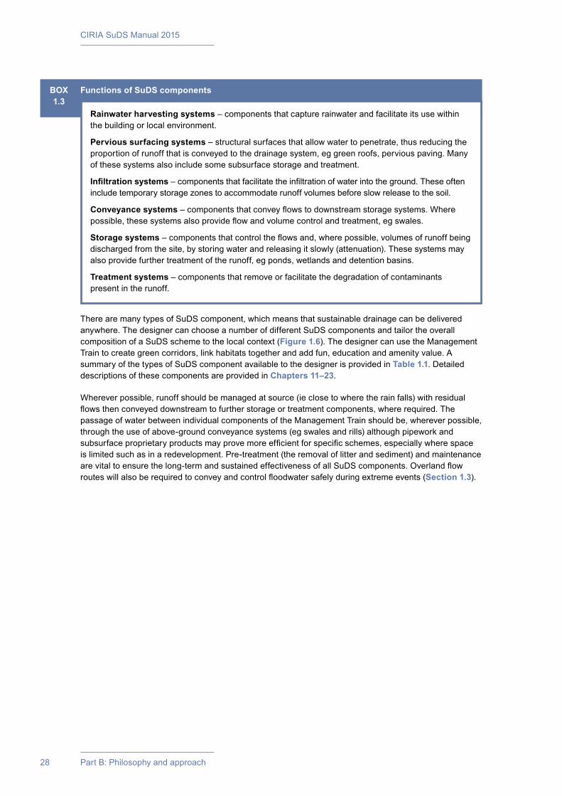
CIRIA SuDS Manual 2015
28 Part B: Philosophy and approach
There are many types of SuDS component, which means that sustainable drainage can be delivered anywhere. The designer can choose a number of different SuDS components and tailor the overall composition of a SuDS scheme to the local context (Figure 1.6). The designer can use the Management Train to create green corridors, link habitats together and add fun, education and amenity value. A summary of the types of SuDS component available to the designer is provided in Table 1.1. Detailed descriptions of these components are provided in Chapters 11–23.
Wherever possible, runoff should be managed at source (ie close to where the rain falls) with residual flows then conveyed downstream to further storage or treatment components, where required. The passage of water between individual components of the Management Train should be, wherever possible, through the use of above-ground conveyance systems (eg swales and rills) although pipework and subsurface proprietary products may prove more efficient for specific schemes, especially where space is limited such as in a redevelopment. Pre-treatment (the removal of litter and sediment) and maintenance are vital to ensure the long-term and sustained effectiveness of all SuDS components. Overland flow routes will also be required to convey and control floodwater safely during extreme events (Section 1.3).
BOX1.3
Functions of SuDS components
Rainwater harvesting systems – components that capture rainwater and facilitate its use within the building or local environment.
Pervious surfacing systems – structural surfaces that allow water to penetrate, thus reducing the proportion of runoff that is conveyed to the drainage system, eg green roofs, pervious paving. Many of these systems also include some subsurface storage and treatment.
Infiltration systems – components that facilitate the infiltration of water into the ground. These often include temporary storage zones to accommodate runoff volumes before slow release to the soil.
Conveyance systems – components that convey flows to downstream storage systems. Where possible, these systems also provide flow and volume control and treatment, eg swales.
Storage systems – components that control the flows and, where possible, volumes of runoff being discharged from the site, by storing water and releasing it slowly (attenuation). These systems may also provide further treatment of the runoff, eg ponds, wetlands and detention basins.
Treatment systems – components that remove or facilitate the degradation of contaminants present in the runoff.
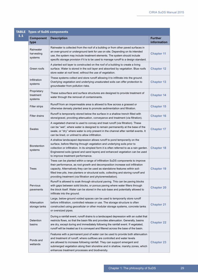
29Chapter 1: The philosophy of SuDS
CIRIA SuDS Manual 2015
TABLE1.1
Types of SuDS components
Component type
Description Further information
Rainwater harvesting systems
Rainwater is collected from the roof of a building or from other paved surfaces in an over-ground or underground tank for use on site. Depending on its intended use, the system may include treatment elements. The system should include specific storage provision if it is to be used to manage runoff to a design standard.
Chapter 11
Green roofsA planted soil layer is constructed on the roof of a building to create a living surface. Water is stored in the soil layer and absorbed by vegetation. Blue roofs store water at roof level, without the use of vegetation.
Chapter 12
Infiltration systems
These systems collect and store runoff allowing it to infiltrate into the ground. Overlying vegetation and underlying unsaturated soils can offer protection to groundwater from pollution risks.
Chapter 13
Proprietary treatment systems
These subsurface and surface structures are designed to provide treatment of water through the removal of contaminants.
Chapter 14
Filter stripsRunoff from an impermeable area is allowed to flow across a grassed or otherwise densely planted area to promote sedimentation and filtration.
Chapter 15
Filter drainsRunoff is temporarily stored below the surface in a shallow trench filled with stone/gravel, providing attenuation, conveyance and treatment (via filtration).
Chapter 16
Swales
A vegetated channel is used to convey and treat runoff (via filtration). These can be “wet”, where water is designed to remain permanently at the base of the swale, or “dry” where water is only present in the channel after rainfall events. It can be lined, or unlined to allow infiltration.
Chapter 17
Bioretention systems
A shallow landscaped depression allows runoff to pond temporarily on the surface, before filtering through vegetation and underlying soils prior to collection or infiltration. In its simplest form it is often referred to as a rain garden. Engineered soils (gravel and sand layers) and enhanced vegetation can be used to improve treatment performance.
Chapter 18
Trees
Trees can be planted within a range of infiltration SuDS components to improve their performance, as root growth and decomposition increase soil infiltration capacity. Alternatively they can be used as standalone features within soil-filled tree pits, tree planters or structural soils, collecting and storing runoff and providing treatment (via filtration and phytoremediation).
Chapter 19
Pervious pavements
Runoff is allowed to soak through structural paving. This can be paving blocks with gaps between solid blocks, or porous paving where water filters through the block itself. Water can be stored in the sub-base and potentially allowed to infiltrate into the ground.
Chapter 20
Attenuation storage tanks
Large, below-ground voided spaces can be used to temporarily store runoff before infiltration, controlled release or use. The storage structure is often constructed using geocellular or other modular storage systems, concrete tanks or oversized pipes.
Chapter 21
Detention basins
During a rainfall event, runoff drains to a landscaped depression with an outlet that restricts flows, so that the basin fills and provides attenuation. Generally, basins are dry, except during and immediately following the rainfall event. If vegetated, runoff will be treated as it is conveyed and filtered across the base of the basin.
Chapter 22
Ponds and wetlands
Features with a permanent pool of water can be used to provide both attenuation and treatment of runoff, where outflows are controlled and water levels are allowed to increase following rainfall. They can support emergent and submerged vegetation along their shoreline and in shallow, marshy zones, which enhances treatment processes and biodiversity.
Chapter 23
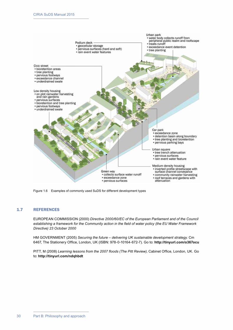
CIRIA SuDS Manual 2015
30 Part B: Philosophy and approach
1.7 REFERENCES
EUROPEAN COMMISSION (2000) Directive 2000/60/EC of the European Parliament and of the Council establishing a framework for the Community action in the field of water policy (the EU Water Framework Directive) 23 October 2000
HM GOVERNMENT (2005) Securing the future – delivering UK sustainable development strategy. Cm 6467, The Stationery Office, London, UK (ISBN: 978-0-10164-672-7). Go to: http://tinyurl.com/o367ocu
PITT, M (2008) Learning lessons from the 2007 floods (The Pitt Review), Cabinet Office, London, UK. Go to: http://tinyurl.com/ndqhbdt
Figure 1.6 Examples of commonly used SuDS for different development types

31Chapter 1: The philosophy of SuDS
CIRIA SuDS Manual 2015
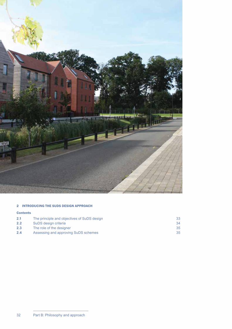
CIRIA SuDS Manual 2015
32 Part B: Philosophy and approach
2 INTRODUCING THE SUDS DESIGN APPROACH
Contents
2.1 The principle and objectives of SuDS design 332.2 SuDS design criteria 342.3 The role of the designer 352.4 Assessing and approving SuDS schemes 35
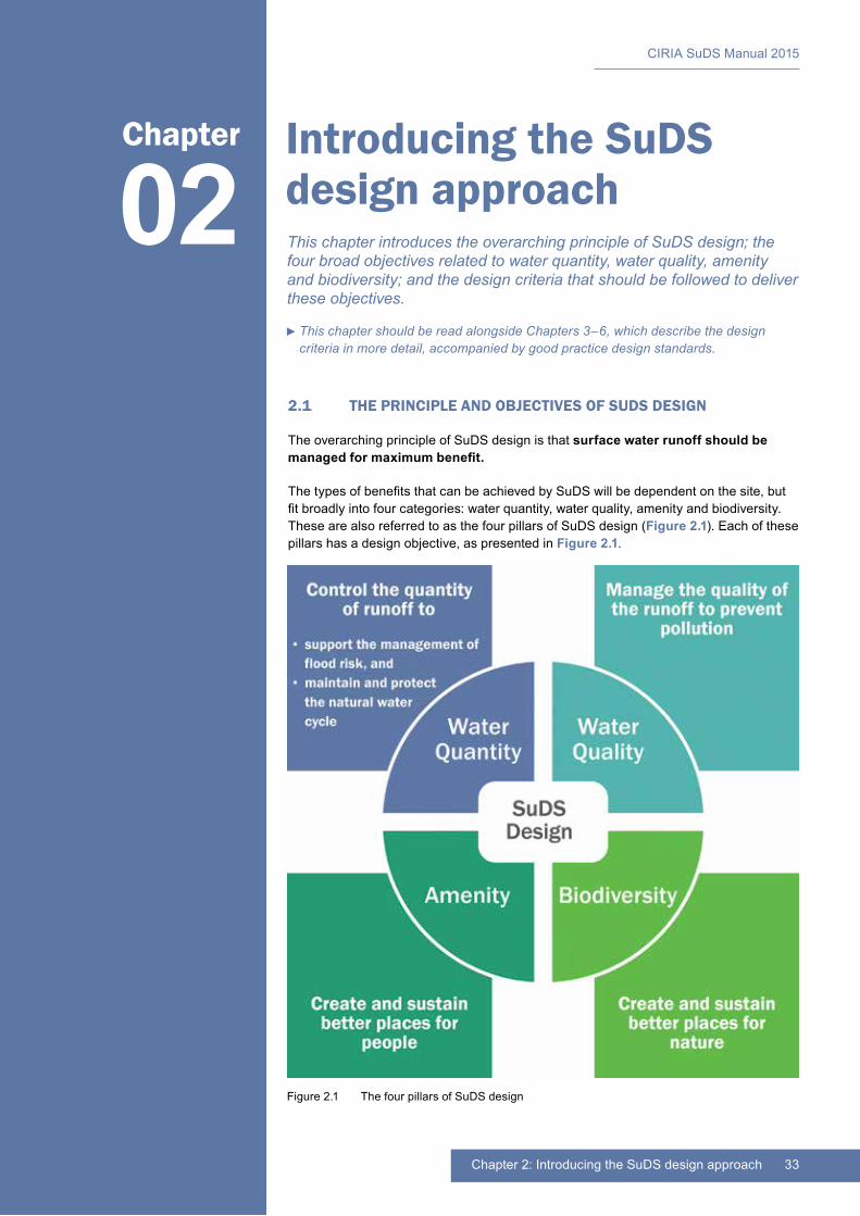
33Chapter 2: Introducing the SuDS design approach
CIRIA SuDS Manual 2015
Introducing the SuDS design approach
2.1 THE PRINCIPLE AND OBJECTIVES OF SUDS DESIGN
The overarching principle of SuDS design is that surface water runoff should be managed for maximum benefit.
The types of benefits that can be achieved by SuDS will be dependent on the site, but fit broadly into four categories: water quantity, water quality, amenity and biodiversity. These are also referred to as the four pillars of SuDS design (Figure 2.1). Each of these pillars has a design objective, as presented in Figure 2.1.
02Chapter
This chapter introduces the overarching principle of SuDS design; the four broad objectives related to water quantity, water quality, amenity and biodiversity; and the design criteria that should be followed to deliver these objectives.
Figure 2.1 The four pillars of SuDS design
This chapter should be read alongside Chapters 3–6, which describe the design criteria in more detail, accompanied by good practice design standards.
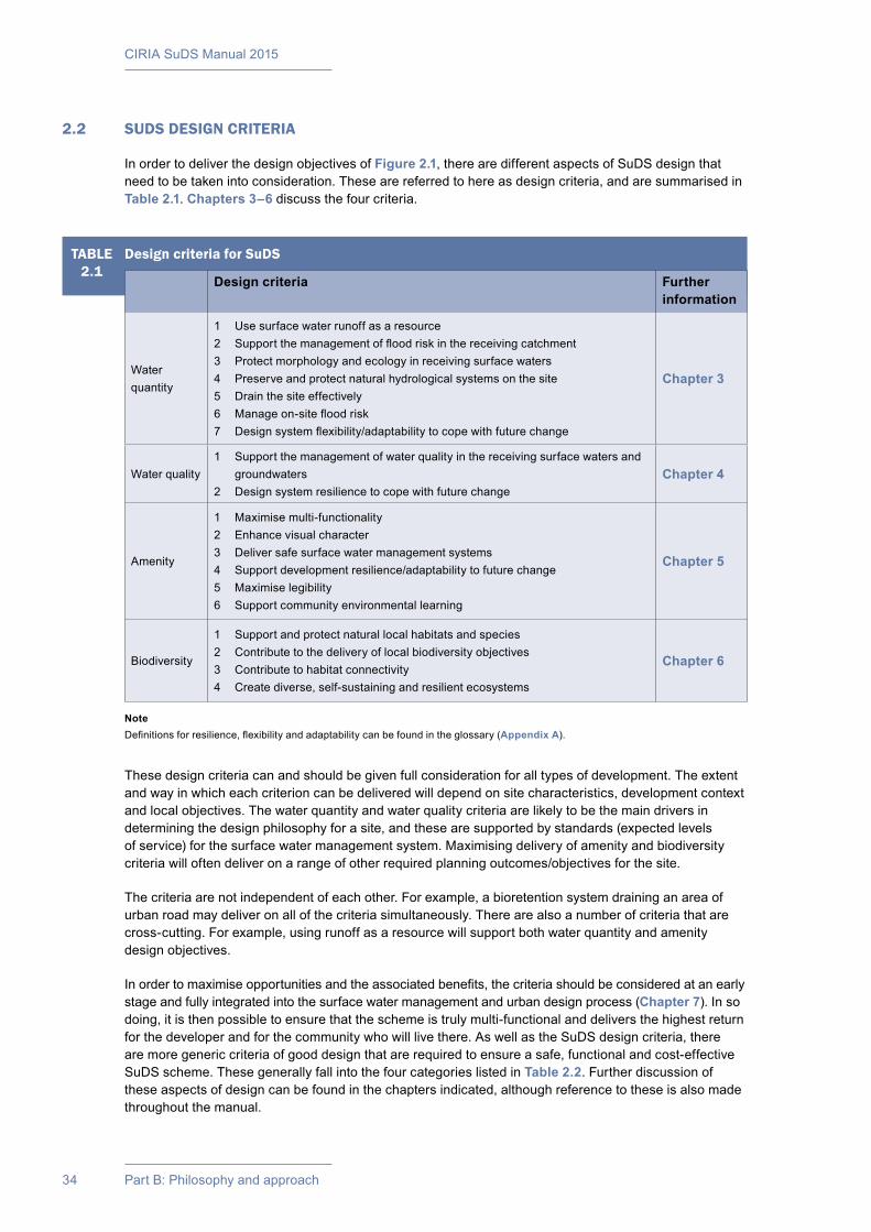
CIRIA SuDS Manual 2015
34 Part B: Philosophy and approach
2.2 SUDS DESIGN CRITERIA
In order to deliver the design objectives of Figure 2.1, there are different aspects of SuDS design that need to be taken into consideration. These are referred to here as design criteria, and are summarised in Table 2.1. Chapters 3–6 discuss the four criteria.
TABLE2.1
Design criteria for SuDS
Design criteria Further information
Water quantity
1 Use surface water runoff as a resource2 Support the management of flood risk in the receiving catchment3 Protect morphology and ecology in receiving surface waters4 Preserve and protect natural hydrological systems on the site5 Drain the site effectively6 Manage on-site flood risk7 Design system flexibility/adaptability to cope with future change
Chapter 3
Water quality1 Support the management of water quality in the receiving surface waters and
groundwaters2 Design system resilience to cope with future change
Chapter 4
Amenity
1 Maximise multi-functionality2 Enhance visual character3 Deliver safe surface water management systems4 Support development resilience/adaptability to future change5 Maximise legibility6 Support community environmental learning
Chapter 5
Biodiversity
1 Support and protect natural local habitats and species2 Contribute to the delivery of local biodiversity objectives3 Contribute to habitat connectivity4 Create diverse, self-sustaining and resilient ecosystems
Chapter 6
These design criteria can and should be given full consideration for all types of development. The extent and way in which each criterion can be delivered will depend on site characteristics, development context and local objectives. The water quantity and water quality criteria are likely to be the main drivers in determining the design philosophy for a site, and these are supported by standards (expected levels of service) for the surface water management system. Maximising delivery of amenity and biodiversity criteria will often deliver on a range of other required planning outcomes/objectives for the site.
The criteria are not independent of each other. For example, a bioretention system draining an area of urban road may deliver on all of the criteria simultaneously. There are also a number of criteria that are cross-cutting. For example, using runoff as a resource will support both water quantity and amenity design objectives.
In order to maximise opportunities and the associated benefits, the criteria should be considered at an early stage and fully integrated into the surface water management and urban design process (Chapter 7). In so doing, it is then possible to ensure that the scheme is truly multi-functional and delivers the highest return for the developer and for the community who will live there. As well as the SuDS design criteria, there are more generic criteria of good design that are required to ensure a safe, functional and cost-effective SuDS scheme. These generally fall into the four categories listed in Table 2.2. Further discussion of these aspects of design can be found in the chapters indicated, although reference to these is also made throughout the manual.
NoteDefinitions for resilience, flexibility and adaptability can be found in the glossary (Appendix A).
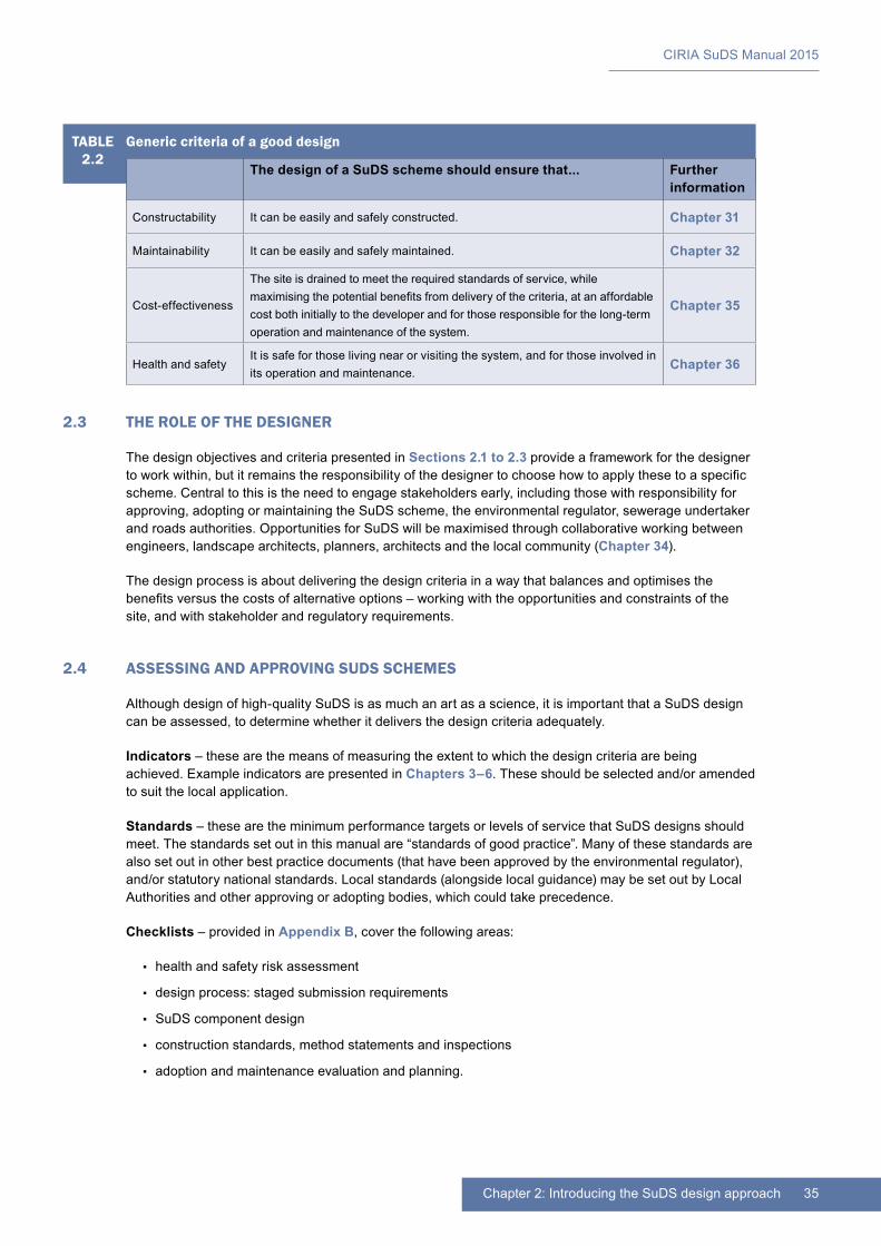
35Chapter 2: Introducing the SuDS design approach
CIRIA SuDS Manual 2015
2.3 THE ROLE OF THE DESIGNER
The design objectives and criteria presented in Sections 2.1 to 2.3 provide a framework for the designer to work within, but it remains the responsibility of the designer to choose how to apply these to a specific scheme. Central to this is the need to engage stakeholders early, including those with responsibility for approving, adopting or maintaining the SuDS scheme, the environmental regulator, sewerage undertaker and roads authorities. Opportunities for SuDS will be maximised through collaborative working between engineers, landscape architects, planners, architects and the local community (Chapter 34).
The design process is about delivering the design criteria in a way that balances and optimises the benefits versus the costs of alternative options – working with the opportunities and constraints of the site, and with stakeholder and regulatory requirements.
2.4 ASSESSING AND APPROVING SUDS SCHEMES
Although design of high-quality SuDS is as much an art as a science, it is important that a SuDS design can be assessed, to determine whether it delivers the design criteria adequately.
Indicators – these are the means of measuring the extent to which the design criteria are being achieved. Example indicators are presented in Chapters 3–6. These should be selected and/or amended to suit the local application.
Standards – these are the minimum performance targets or levels of service that SuDS designs should meet. The standards set out in this manual are “standards of good practice”. Many of these standards are also set out in other best practice documents (that have been approved by the environmental regulator), and/or statutory national standards. Local standards (alongside local guidance) may be set out by Local Authorities and other approving or adopting bodies, which could take precedence.
Checklists – provided in Appendix B, cover the following areas:
▪▪ health and safety risk assessment
▪▪ design process: staged submission requirements
▪▪ SuDS component design
▪▪ construction standards, method statements and inspections
▪▪ adoption and maintenance evaluation and planning.
TABLE2.2
Generic criteria of a good design
The design of a SuDS scheme should ensure that... Further information
Constructability It can be easily and safely constructed. Chapter 31
Maintainability It can be easily and safely maintained. Chapter 32
Cost-effectiveness
The site is drained to meet the required standards of service, while maximising the potential benefits from delivery of the criteria, at an affordable cost both initially to the developer and for those responsible for the long-term operation and maintenance of the system.
Chapter 35
Health and safetyIt is safe for those living near or visiting the system, and for those involved in its operation and maintenance.
Chapter 36
36 Part B: Philosophy and approach
3 DESIGNING FOR WATER QUANTITY
Contents
3.1 Water quantity design objective 373.2 Water quantity design criteria 393.3 Water quantity design standards 443.4 References 48
37Chapter 3: Designing for water quantity
CIRIA SuDS Manual 2015
Designing for water quantity
3.1 WATER QUANTITY DESIGN OBJECTIVE
Control the quantity of runoff to support the management of flood risk and maintain and protect the natural water cycle
In order to ensure that the surface water runoff from a developed site does not have a detrimental impact on people, property and the environment, it is important to control:
▪▪ how fast the runoff is discharged from the site (ie the peak runoff rate) and
▪▪ how much runoff is discharged from the site (ie the runoff volume).
SuDS that are designed to manage water quantity in this way reduce the likelihood of flooding caused by the development. They can help protect natural water cycles by promoting the recharge of soil moisture levels (and subsequent evapotranspiration processes), by maintaining stream and river baseflows, and by replenishing groundwater. They can also help reduce the risk of erosion of the banks and riverbed, caused as a result of the receiving watercourse experiencing more frequent bankfull or near bankfull conditions. Such erosion increases sediment loads and can degrade the ecological health of the watercourse.
SuDS are most effective at reducing flood risk for relatively high intensity, short and medium duration events. So SuDS are particularly important in mitigating potential increases in surface water flooding, sewer flooding and flooding from small and medium sized watercourses resulting from development. SuDS tend to have less impact on flood risk associated with larger rivers that are more sensitive to long duration events (such as the Thames or the Somerset Levels). However, this does not mean that SuDS are not required. Local hydraulic constraints and flow characteristics may mean that flow and volume control are still necessary for managing local flood risk and providing groundwater recharge, where appropriate. Reducing pollution, together with delivering amenity and biodiversity benefits for the site are also still very important.
SuDS for a single site could potentially be demonstrated to have limited impact, but it is the cumulative impact of all development in the catchment (combined with the potential effects of climate change) that should be taken into consideration.
3.1.1 Why should peak runoff rates be controlled?
Peak rates of surface water runoff discharged from a developed (ie relatively impermeable) site, if left uncontrolled, are normally significantly greater than from the site in its greenfield state. This is because the runoff drains off the surfaces of the developed site much quicker than the greenfield site and there is much more runoff,
03Chapter
This chapter explains the objective of designing for water quantity and the design criteria that should be followed to deliver this objective. Good practice design standards are also presented.
This chapter should be read alongside Chapters 4–6, to understand how the different SuDS design criteria relate to each other, and Chapter 7 to understand when and how to apply these criteria.
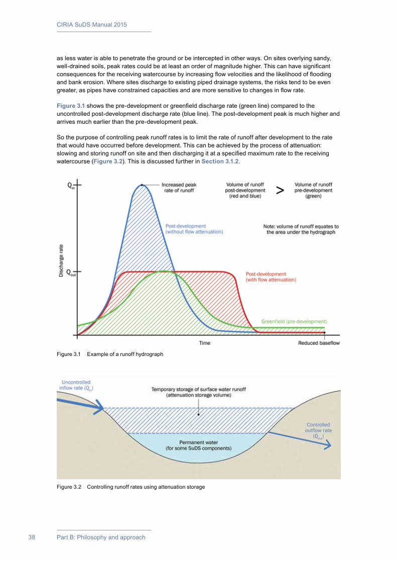
CIRIA SuDS Manual 2015
38 Part B: Philosophy and approach
as less water is able to penetrate the ground or be intercepted in other ways. On sites overlying sandy, well-drained soils, peak rates could be at least an order of magnitude higher. This can have significant consequences for the receiving watercourse by increasing flow velocities and the likelihood of flooding and bank erosion. Where sites discharge to existing piped drainage systems, the risks tend to be even greater, as pipes have constrained capacities and are more sensitive to changes in flow rate.
Figure 3.1 shows the pre-development or greenfield discharge rate (green line) compared to the uncontrolled post-development discharge rate (blue line). The post-development peak is much higher and arrives much earlier than the pre-development peak.
So the purpose of controlling peak runoff rates is to limit the rate of runoff after development to the rate that would have occurred before development. This can be achieved by the process of attenuation: slowing and storing runoff on site and then discharging it at a specified maximum rate to the receiving watercourse (Figure 3.2). This is discussed further in Section 3.1.2.
Figure 3.1 Example of a runoff hydrograph
Figure 3.2 Controlling runoff rates using attenuation storage
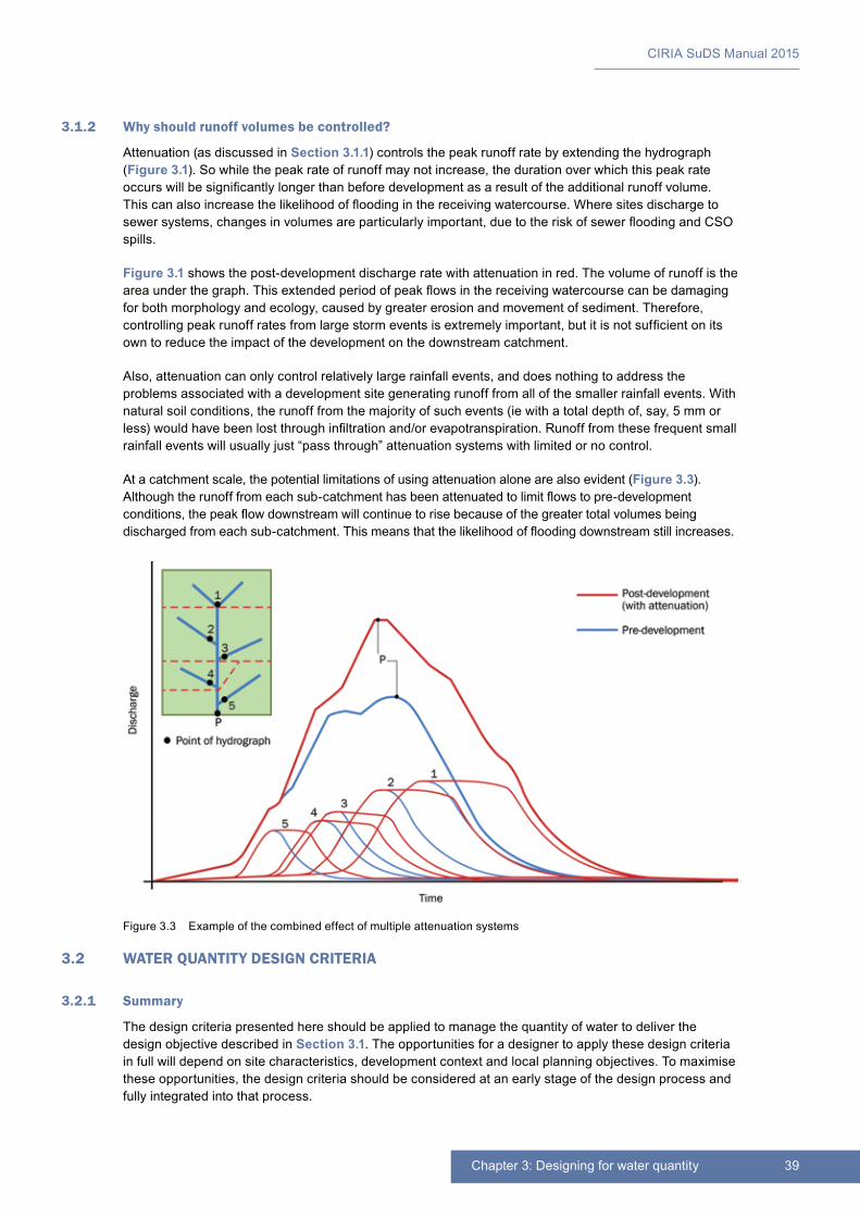
39Chapter 3: Designing for water quantity
CIRIA SuDS Manual 2015
3.1.2 Why should runoff volumes be controlled?
Attenuation (as discussed in Section 3.1.1) controls the peak runoff rate by extending the hydrograph (Figure 3.1). So while the peak rate of runoff may not increase, the duration over which this peak rate occurs will be significantly longer than before development as a result of the additional runoff volume. This can also increase the likelihood of flooding in the receiving watercourse. Where sites discharge to sewer systems, changes in volumes are particularly important, due to the risk of sewer flooding and CSO spills.
Figure 3.1 shows the post-development discharge rate with attenuation in red. The volume of runoff is the area under the graph. This extended period of peak flows in the receiving watercourse can be damaging for both morphology and ecology, caused by greater erosion and movement of sediment. Therefore, controlling peak runoff rates from large storm events is extremely important, but it is not sufficient on its own to reduce the impact of the development on the downstream catchment.
Also, attenuation can only control relatively large rainfall events, and does nothing to address the problems associated with a development site generating runoff from all of the smaller rainfall events. With natural soil conditions, the runoff from the majority of such events (ie with a total depth of, say, 5 mm or less) would have been lost through infiltration and/or evapotranspiration. Runoff from these frequent small rainfall events will usually just “pass through” attenuation systems with limited or no control.
At a catchment scale, the potential limitations of using attenuation alone are also evident (Figure 3.3). Although the runoff from each sub-catchment has been attenuated to limit flows to pre-development conditions, the peak flow downstream will continue to rise because of the greater total volumes being discharged from each sub-catchment. This means that the likelihood of flooding downstream still increases.
3.2 WATER QUANTITY DESIGN CRITERIA
3.2.1 Summary
The design criteria presented here should be applied to manage the quantity of water to deliver the design objective described in Section 3.1. The opportunities for a designer to apply these design criteria in full will depend on site characteristics, development context and local planning objectives. To maximise these opportunities, the design criteria should be considered at an early stage of the design process and fully integrated into that process.
Figure 3.3 Example of the combined effect of multiple attenuation systems
CIRIA SuDS Manual 2015
40 Part B: Philosophy and approach
Managing water quantity can also contribute to the design objectives for water quality, amenity and biodiversity. So these design criteria should be considered alongside design criteria for water quality, amenity and biodiversity (Chapter 2, Table 2.1 and Chapters 4–6).
Indicators can be used to evaluate the extent to which design criteria are being delivered by the SuDS design. Water quantity design criteria and example indicators are presented in Table 3.1.
TABLE3.1
Water quantity design criteria and example indicators
Water quantity design criterion Example indicator
1 Use surface water runoff as a resource
A proportion of runoff from rainfall events is harvested for use or infiltrated to support river baseflows and/or recharge groundwater.
2 Support the effective management of flood risk in the receiving catchment
Discharges to surface waters are prioritised over discharges to sewers.The rates and volumes of runoff for high return period events are controlled in accordance with the water quantity standards (Section 3.3).
3 Protect morphology and ecology in receiving surface waters
The rates and volumes of runoff for low return period events are controlled in accordance with the water quantity standards (Section 3.3).
4 Preserve and protect natural hydrological systems on the site
The natural hydrological drainage systems on the site are preserved or enhanced as part of the landscape and/or surface water management system.
5 Drain the site effectivelyRunoff from all rainfall events infiltrates or drains through the SuDS within a suitable time, so that the performance of the system for managing runoff from subsequent rainfall events is not reduced.
6 Manage on-site flood riskRunoff from rainfall events that exceeds the SuDS capacity is managed in identified exceedance routes and storage areas.
7 Design in system flexibility/adaptability to cope with future change
The SuDS design includes climate change and urban creep allowances, or is designed with the flexibility (and funding) to be suitably adapted during its design life.
These design criteria are discussed in more detail in the following subsections. Where minimum performance targets or specific levels of service should be achieved by a SuDS design, these are detailed in Section 3.3, and guidance is provided as to how these can be met. These generally mirror legislative or regulatory standards where they exist. However, local standards, as set out in supplementary planning documents (SPDs), may take precedence.
3.2.2 Water quantity criterion 1: Use surface water runoff as a resource
Using surface water runoff as a resource contributes to the water sensitive urban design (WSUD) philosophy of integrating water cycle management with the built environment (Morgan et al, 2013).
It is advantageous to design drainage systems that capture and use surface water because this (a) helps to reduce runoff volumes from the site and (b) allows this valuable resource (water) to be put to good use. This demonstrates how some amenity benefits are intrinsic in SuDS design.
Rainfall is likely to become an even more valuable resource in the future, as water becomes more scarce, due to climate change and rising population.
Direct harvesting at or near source for garden watering has been common practice for many years. In parts of the UK, especially the south-east of England, water resources are increasingly under stress due to rising demand for water and climate change. In such areas, harvested rainwater is increasingly being used for other purposes, but it may require treatment where there is a risk of human contact or consumption. (The level of treatment should be proportionate to the level of risk.) Harvested rainwater can be used for irrigating landscapes, and roof water can often be used directly for private or communal

41Chapter 3: Designing for water quantity
CIRIA SuDS Manual 2015
gardens and allotments, for car washing or for toilet flushing. Rainwater storage systems can be located in roof voids, beneath gardens, garages, driveways or areas of communal open space, or be part of boundary walls (Chapter 11).
Using surface water runoff as a resource can provide amenity benefits as well as water quantity benefits. For example, SuDS can be designed to support areas for water play and urban horticulture, providing recreational, educational and health and well-being benefits. These are discussed in Chapter 5 under: Amenity criterion 1: Maximise multi-functionality.
Using SuDS to promote infiltration is another way of protecting water resources, as this can potentially contribute both to the recharge of aquifers and to interflows through upper soil horizons that support baseflows in local rivers and streams (that may subsequently be abstracted for supply purposes).
3.2.3 Water quantity criteria 2 and 3: Support the management of flood risk in the receiving catchment, and protect morphology and ecology in receiving surface waters
To ensure that the site does not have a detrimental impact on the downstream catchment (increasing flood risk or causing morphological or ecological damage) and protects the natural water cycle, designers should do each of the following (which are discussed below):
1 Prioritise where surface water runoff is discharged.
2 Control the volume of runoff discharged from the site.
3 Control the peak runoff rates from the site.
Some receiving surface waters, such as estuaries, some large lakes and the sea, are normally not sensitive to the runoff from developed sites. In these cases, the control of peak runoff rates and runoff volumes is not necessary. However, even for these scenarios, SuDS are still important, particularly for the water quality benefits, but also for the amenity and biodiversity value they bring.
1 Prioritise where surface water runoff is discharged
The destination for surface water runoff that is not collected for use should be prioritised in the following order:
a infiltration
b discharge to surface waters
c discharge to a surface water sewer, highway drain or another drainage system
d discharge to a combined sewer.
Discharge to a foul sewer should not be considered as a possible option.
As much of the runoff as possible (subject to technical or cost constraints) should be discharged to each destination before a lower priority destination is considered.
Depending on the site characteristics, drainage from different parts of the site could have different drainage destinations.
Depending on the quantity of runoff and the potential for a particular destination to manage that runoff, small events might be discharged to a higher level destination, while larger events may need to utilise a lower priority destination.
Where runoff is to be discharged to a sewerage undertaker’s surface water sewer or combined sewer, the sewerage undertaker should be consulted as to whether any additional criteria or limiting discharge rates are required.
Where runoff is to be discharged to a watercourse, the relevant local flood authority should be consulted.

CIRIA SuDS Manual 2015
42 Part B: Philosophy and approach
2 Control the volume of runoff discharged from the site
The volume of runoff discharged from the site should be controlled for both frequent and extreme events by maximising opportunities to:
a use surface water runoff as a resource
b intercept and reduce runoff through evapotranspiration (eg using green roofs, trees or vegetated storage systems)
c intercept and reduce runoff through infiltration (eg using soakaways, bioretention systems, permeable pavements or infiltration basins).
See Section 3.3.1 water quantity standard 1.
3 Control peak runoff rates from the site
Peak runoff rates from the site (ie how fast the runoff is allowed to leave the site after development has taken place) should be controlled by maximising opportunities to capture runoff and slow flow rates through attenuation and flow controls (eg using swales, detention basins). Providing volumetric control measures (see above) can reduce the required downstream attenuation storage volumes (Section 3.3.2, water quantity standard 2).
Managing surface water runoff at or close to source helps prevent high rates and volumes of runoff being conveyed to large downstream attenuation systems.
There may be occasions, possibly in the lower reaches of large river catchments, where rapid discharge of runoff from the site would be a better strategy for managing flood risk than attenuation and slow release. If this can be demonstrated by detailed catchment modelling, this may be deemed appropriate by an approving body. This should be stated in the local flood risk management strategy and/or local supplementary planning documents.
3.2.4 Water quantity criterion 4: Preserve and protect natural hydrological systems on the site
Natural systems that deliver a specific hydrological function should be preserved and protected where possible, such as natural wetlands, stream and river corridors, high permeability soil features, areas of high water table, long-serving agricultural field ditches or ditch systems. Where such systems are dependent on particular runoff characteristics from the site, this should be taken into account within the SuDS design.
Where possible, clearing/grading/compaction should be limited, as these activities will have a negative effect on the natural runoff characteristics. Landscape and garden areas that have been compacted during construction should be returned to pre-construction permeability levels. Steep slopes or areas of the site with highly erodible soils should also be protected from additional runoff that could further destabilise material.
Local flood risk management strategies/river basin management plans may have strategic objectives for the management and/or improvement of local hydrological systems and may set local criteria for drainage systems that discharge to them.
Additional benefits of preserving natural hydrological systems can include the reduced need for cut and fill and the elimination of additional underground piping and pumping (Section 8.5.3).
3.2.5 Water quantity criterion 5: Drain the site effectively
A key requirement of the surface water management system is that it drains the site effectively. It should be designed with suitable gradients, so that there is a continuous flow of water through the system as any rainfall event drains through, allowing space for subsequent events to be stored and treated. Shallow gradients are usually suitable, particularly with surface features, and shallow gradients also help ensure that natural treatment processes work effectively.

43Chapter 3: Designing for water quantity
CIRIA SuDS Manual 2015
The design of the drainage system should take account of the time that it is likely to take for the runoff to drain through the system. Considerations should include:
1 the impact of potential downstream constraints (eg high water levels in the receiving watercourse) on the rate and/or duration over which effective drainage can occur
2 the rate at which infiltration is likely to occur, which will determine the time taken for infiltration storage components to empty for any particular event
3 the hydraulic gradient across the site and the design of storage and conveyance components, which will determine the time taken for runoff to drain through the SuDS.
Where discharge from the site could be constrained because of high water levels at the outfall from the site, the likelihood of such water levels coinciding with design events for the drainage system should be evaluated and accounted for as part of the design process (Chapter 24).
Where any part of the drainage system is at risk of being inundated from external sources during extreme conditions, the impact of any potential loss of storage (from either inundation or sediment deposition) on the system performance should be assessed.
The impact of runoff from areas outside the site should be taken into account when sizing the drainage system. Such runoff should be safely routed around or across the site, but will not require additional control, unless this is part of planning or drainage approval requirements.
Guidance on designing SuDS on sites with steep slopes, with no gradient or very shallow slopes, and on floodplains is provided in Chapter 8.
3.2.6 Water quantity criterion 6: Manage on-site flood risk
The surface water management system should be designed to ensure that the level of flood risk from the drainage system is acceptable for the site (Section 3.3.3).
All runoff should remain within the designated conveyance and storage areas for the design (standard of service) event, including an appropriate freeboard allowance. The designated drainage system may include areas that are only designed to flood on an infrequent basis – for example car parks, roads, recreation areas – and such areas will need to be managed with this purpose in mind. For larger events, the site layout should be designed so that exceedance flows (ie flows that exceed the capacity of the drainage system) are managed in safe conveyance and storage zones, such that the risk of flooding is acceptable for all people and property on the site.
SuDS components that are on the surface provide the best means of seeing when water levels are starting to rise. This enables residents and other users of the site to take action early and effectively. The change in water level will tend to be gradual, as it moves out of the bank, providing more warning and reducing the likely severity of the consequences.
Managing the risks associated with external sources of flooding (river, surface water, groundwater etc) should be dealt with as part of the flood risk mitigation strategy (as defined by the Flood Risk Assessment or Flood Consequence Assessment). Further details are provided in Chapter 7. Any additional design requirements for the SuDS scheme as part of a site flood risk mitigation strategy would be over and above the requirements described in this manual.
3.2.7 Water quantity criterion 7: Design in system flexibility/adaptability to cope with future change
In order that the drainage system will continue to provide effective protection for both the site and downstream areas, throughout its design life, SuDS should incorporate sufficient capacity and/or be sufficiently adaptable so as to be resilient to climate change and increases in the level of urbanisation of the contributing catchment.
CIRIA SuDS Manual 2015
44 Part B: Philosophy and approach
SuDS components are inherently more adaptable than fixed capacity, subsurface drainage infrastructure. In some cases where future ownership and investment capacity are assured, drainage systems might be designed with the flexibility for increasing capacity later in their design life, when climate change risks can be better quantified or when a higher level of service is required.
Otherwise, up-to-date rainfall intensity uplift factors for individual regions for climate change scenarios (Section 24.7.1) should be sourced from relevant ministerial or local government guidance, and incorporated within the design calculations to ensure the design is robust.
Increasing impermeability of the contributing catchment through the design life of the drainage system, should also be taken into account. Urban creep (ie the addition of patios, conservatories, extensions, impermeable driveways and other hardstandings) can be significant, particularly in low-to-medium-density developments, and an appropriate design factor should be agreed with the drainage approving body before drainage system design (Section 24.7.2).
3.3 WATER QUANTITY DESIGN STANDARDS
The following standards are standards of “good practice”. Local planning documents, national standards or other guidance from approving or adopting organisations may take precedence.
The research underpinning the standards on the use of peak flow rates and volume control of discharges is provided in Kellagher (2002).
BOX3.1
Return periods, probability of occurrence and critical durations
The return period of a rainfall event is the average time between events of a given or greater magnitude, usually expressed in years. A 100-year return period event refers to an event that occurs or is exceeded on average once every hundred years. This can also be expressed as the 1 in 100 or 1:100 year event.
Alternatively, an event can be described as having a probability of occurrence (or frequency of occurrence), which is 1/return period but often expressed as a percentage. For a 1:100 year event, this would be 1%, ie there is a 1% chance of the event occurring or being exceeded in any one year.
Estimates of return periods are subject to uncertainty, so in reality, consecutive events can occur at intervals greater or smaller than their average return period. A 1:1 year event refers to an event that has a 100% chance of occurring in any one year, and thus could be interpreted as a range of events beneath a certain threshold. However, for the purpose of these standards, when referring to a 1:1 year event, this should be taken as meaning an event that occurs, on average, once a year.
The critical duration is the duration of rainfall event for a specified return period event (usually given in hours) that results in the greatest peak flow rate, flood volume or flood level (depending on the purpose of the analysis) at a particular location. It will be different for different locations on a site.
3.3.1 Water quantity standard 1: Control of runoff volume
The volume of runoff should be controlled for the following two scenarios:
a Volume control for frequent rainfall events
The drainage system should be designed so that runoff from the site to receiving surface waters does not occur for the majority of small rainfall events.
b Volume control for extreme rainfall events
The drainage system should be designed so that the volume of runoff discharged from the site during extreme events (normally specified as a 1:100 year event) is controlled.
Interpretation of this standard is presented as follows.

45Chapter 3: Designing for water quantity
CIRIA SuDS Manual 2015
a) Volume control for frequent rainfall events
The prevention of runoff from the site for the majority of small (frequent) rainfall events (or for the initial depth of rainfall for larger events) is called Interception, and Interception of about 5 mm is normally achievable. From a hydraulic perspective, Interception is required to mimic greenfield hydraulic response characteristics where small rainfall events do not generally produce any runoff and thus to protect the morphology and ecology of the receiving watercourse, and the hydrological soil water balances in the catchment. Interception can be delivered using a variety of methods including rainwater harvesting, infiltration and evapotranspiration. Interception design methods are set out in Section 24.8.
This standard is the same as water quality standard 1 (Chapter 4). This is because the delivery of Interception provides both water quantity and water quality benefits. Compliance with this standard is not usually achievable during periods of wet weather, so a flexible approach is required (eg a requirement to achieve Interception for a given proportion of events during the summer and a lower proportion during the winter). In winter or during extended wet periods, the risks to the ecology and morphology of the receiving watercourse from urban runoff are likely to be lower.
b) Volume control for extreme rainfall events
Because the volume of runoff from the site can be, in many scenarios, as damaging to downstream flood risk as peak flow rates (Section 3.1), it is necessary to ensure that runoff volumes discharged from the site during extreme events are also controlled.
This means that, where possible, the volume of runoff from the site (or development) area should not exceed the volume of runoff from the equivalent area in its natural undeveloped or “greenfield” state (for the same rainfall event). Methods for estimating greenfield/pre-development runoff volumes are described in Section 24.4). Where flood risk from the receiving watercourse is particularly high, tighter local criteria for allowable volumes discharged from the site may need to be specified by the local regulator or drainage approving body and met by the drainage design.
The use of infiltration and rainwater harvesting are important mechanisms for delivering volume control: the greater the volume of runoff that is infiltrated or used on site, the lower the volume of runoff discharged. It is important to note that, for clay sites, greenfield runoff volumes will tend to be high because of the underlying impermeability. So the increase in volume for the developed site will be small. Where developments take place on more permeable soils, the difference will be far greater, but infiltration options should be available to assist in managing these larger volumes.
Ideally, the volumetric control of runoff should be demonstrated to meet greenfield runoff behaviour for all events and particularly those that are relevant for the mitigation of flood risk in the receiving watercourse. However, this would require the use of time series rainfall as part of a modelling exercise. Until this approach becomes standard industry practice, a simple method using the 1:100 year, 6 hour rainfall event can be sufficient for design purposes, as it represents a suitable event for protecting smaller watercourses that are most at risk from the effects of urban development. As designs for Interception will help control runoff volumes from smaller events, a single requirement for large events is considered pragmatic and not overly onerous.
Where controlling runoff to greenfield volumes is considered unachievable, then the runoff volume should be reduced as much as possible and any additional volume should be stored and released at a low rate that will not increase downstream flood risk (normally 2 l/s/ha is considered an appropriate rate (Kellagher, 2002)) using either of the following approaches*:
1 The additional runoff volume (ie the difference between the predicted development runoff volume and the estimated greenfield runoff volume for the 100 year event, often called Long-Term Storage) should be discharged from the site at a rate of 2 l/s/ha or less, while still allowing greenfield runoff peak flow rates to be applied for the greenfield runoff volume.
Note* The 6 hour event can be used unless more detailed local catchment modelling has been undertaken to justify an alternative duration.

CIRIA SuDS Manual 2015
46 Part B: Philosophy and approach
2 All the runoff from the site for the 1:100 year event should be discharged at either a rate of 2 l/s/ha or the average annual peak flow rate (ie the mean annual flood, QBAR), whichever is the greater.
Approach 2 provides a simpler approach, but results in larger storage volumes being required than Approach 1.
The calculation of the difference in volume between the developed and greenfield scenario (defined as the Long-Term Storage Volume) is set out in Section 24.10.
For previously developed sites, the surface water management system should be designed so that the volume of surface water runoff discharged from the site for the 1:100 year, 6 hour event is kept as close to greenfield conditions as possible. The runoff volume for the pre-development scenario may be very high and may be contributing to downstream flood risk – it should therefore only be allowed for the new development if the drainage approving body agrees that it is acceptable. Wherever runoff volumes cannot be sufficiently reduced, they should be discharged from the site at a rate of 2 l/s/ha or less (see above).
3.3.2 Water quantity standard 2: Control of peak rate of runoff
a Control peak runoff rates during events likely to impact on morphology, ecology or capacity of receiving surface waters, or capacity of receiving sewers
The drainage system should be designed so that peak runoff rates from the site for events likely to be significant for the morphology/ecology/capacity of receiving surface waters, or the capacity of receiving sewers (normally specified as approximately a 1:1 year event) are constrained to the greenfield rates of runoff for the same return period.
b Control peak runoff rates during extreme rainfall events
The drainage system should be designed so that the peak runoff rates for extreme rainfall events (normally specified as a 1:100 year event) are constrained to the greenfield rates of runoff for the same event.
The assessment of peak runoff rates and the design of attenuation storage systems is set out in Sections 24.6 and 24.9, respectively. The critical duration rainfall event should be used in determining the maximum attenuation storage volumes. Different critical durations will apply to different storage and conveyance elements used on the site.
Interpretation of this standard is presented as follows.
a) Control peak runoff rates during events likely to impact on morphology, ecology or capacity of the receiving surface waters, or the capacity of receiving sewers
A bankfull event for a stream or river tends to equate to about a 1:1 or 1:2 year event. By aiming to replicate greenfield runoff rates for this size of event, the receiving watercourse can be protected from erosion and the resulting morphological and ecological damage. For previously developed sites, site runoff rates should be reduced to the greenfield rates wherever possible.
By limiting discharges to sewers (and surface waters), this will reduce the impact on downstream capacity. If discharging to a combined sewer, this also reduces the impact on CSO spills and downstream wastewater treatment works.
For soils with relatively high permeabilities, the 1:1 year greenfield runoff rate may be considered too low to be feasible. In this case, a minimum throttle rate should be agreed by the drainage approving body. An appropriate limit is likely to be 1–2 l/s/ha. Guidance on controlling low flows is provided in Chapter 28.
b) Control peak runoff rates for extreme events to prevent surface water runoff from the site increasing downstream flood risk
Aiming to replicate greenfield runoff rates for extreme events helps ensure that the flood risk associated with the receiving watercourse/sewer is not increased by the development. Volume control (as required by water quantity standard 1) is also an important part of the flood risk mitigation approach.

47Chapter 3: Designing for water quantity
CIRIA SuDS Manual 2015
For previously developed sites, site runoff rates should be reduced to the greenfield rates wherever possible. Because the critical duration for the attenuation storage system for the proposed development will be much longer than the storm duration used for sizing pipework for the previously developed site, there is a risk that by allowing previously developed runoff rates to occur (over a much longer duration) receiving watercourse damage and flood risk could be considerably worsened. Thus, betterment of at least 30% should be considered as a minimum requirement (this will need establishing and agreeing with drainage approving body) and strong consideration should still be given to controlling volumes of runoff to greenfield equivalents (Section 3.3.1).
3.3.3 Water quantity standard 3: Control of on-site flood risk arising from the surface water management system
a SuDS capacity design
There should not be any flooding on site for events up to the agreed drainage system capacity (standard of service – usually a minimum of a 1:30 year event), unless areas are specifically designed to do so.
b Exceedance capacity design
The risks associated with events that exceed the capacity of the drainage system should be evaluated, and the design of the site and the drainage system should be integrated so that flooding is appropriately managed.
a) SuDS capacity design
The SuDS should be designed so that runoff is completely contained within the designated drainage system for all events up to the specified standard of service for the critical duration event for the system (Box 3.1). This level of service will normally be 1 in 30 years as a minimum unless otherwise specified by or agreed with the planning approval or SuDS approving body. As peak runoff rates will usually require control up to the 1 in 100 year (see water quantity standard 2), components may be designed to manage events up to this size. The designated drainage system is the combination of the above-ground and below-ground components of the system (eg pervious pavements, swales, detention basins and pipes) that are designed to receive runoff during an event that equates to the specified standard of service.
Unless specific adaptation measures are agreed, the design rainfall for this scenario should include an allowance for climate change, and the assumed impermeable area for the site should include an allowance for urban creep (Section 24.7).
The critical duration rainfall event should be used. Different critical durations will apply to different parts of the site.
The layout of the development site and the SuDS scheme should be designed so that any surface water that enters the site from off-site sources is conveyed safely around or through the site, without compromising the level of service of the proposed drainage system or introducing unacceptable additional risks on site or downstream.
Where runoff from off-site sources is drained together with the site runoff, the contributing catchment should be modelled as part of the drainage system in order to take full account of the additional inflows.
Where runoff from off-site sources is conveyed separately from the proposed drainage system, any flood risks associated with this source should be managed appropriately. This should be dealt with in the Flood Risk Assessment (FRA) (or Flood Consequence Assessment, FCA) and associated management strategy for the site.
b) Exceedance capacity design
Properties should be fully protected against flooding from the site drainage system for the 1:100 year event. Higher return periods may be specified for particular catchments or locations and this should

CIRIA SuDS Manual 2015
48 Part B: Philosophy and approach
be established by the FRA/FCA for the site. In Scotland, the standard requirement is for 1:200 year protection. The design rainfall for this scenario should include an allowance for climate change, and the assumed impermeable area for the site should include an allowance for urban creep (Section 24.7). The critical duration rainfall event should be used. Different critical durations will apply to different parts of the site.
The finished ground floor levels and the level of any opening into any basement of the proposed buildings on the site should be at least 300 mm above the predicted flood level associated with the above scenario – or as otherwise specified by the drainage approving body and confirmed within the site FRA/FCA.
Access should be provided into and through the site for emergency vehicles for extreme runoff events and where the site could be flooded from other sources.
The design of the drainage system for exceedance flow management should take account of any residual flood risks for the site that are identified by the FRA/FCA. An assessment should also be made of the potential significance of risks associated with the following scenarios:
1 a blockage or failure of any key component or structure
2 failure of any embankment that forms part of a storage component
3 rainfall events that are larger than the design storms used for the design of the drainage system
Where any of these scenarios are considered to present a significant risk for the site, a risk assessment should be undertaken to determine adequate risk mitigation measures.
When assessing the risks associated with conveyance routes or storage areas for exceedance flows, flow depths, velocities, duration and impact of the flooding to people and property on and off the site should be taken into account. Further guidance on designing for exceedance in urban drainage can be found in Digman et al (2006 and 2014).
3.4 REFERENCES
DIGMAN, C, BALMFORTH, D, KELLAGHER, R and BUTLER, D (2006) Designing for exceedance in urban drainage – good practice, C635, CIRIA, London, UK (ISBN: 978-0-86017-635-0). Go to: www.ciria.org
DIGMAN, C, ASHLEY, R, HARGREAVES, P and GILL, E (2014) Managing urban flooding from heavy rainfall – encouraging the uptake of designing for exceedance, C738, CIRIA, London, UK (ISBN: 978-0-86017-742-5). Go to: www.ciria.org
KELLAGHER, R (2002) Storage requirements for rainfall runoff from greenfield development sites, version 2, Report SR 580, HR Wallingford,Oxon, UK. Go to: http://eprints.hrwallingford.co.uk/1154/1/SR580.pdf
MORGAN, C, BEVINGTON, C, LEVIN, D, ROBINSON, P, DAVIS, P, ABBOTT, J and SIMKINS, P (2013) Water Sensitive Urban Design in the UK – Ideas for built environment practitioners, C723, CIRIA, London, UK (ISBN: 978-0-86017-726-5). Go to: www.ciria.org

49Chapter 3: Designing for water quantity
CIRIA SuDS Manual 2015
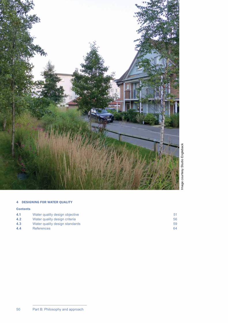
50 Part B: Philosophy and approach
4 DESIGNING FOR WATER QUALITY
Contents
4.1 Water quality design objective 514.2 Water quality design criteria 564.3 Water quality design standards 594.4 References 64
Imag
e co
urte
sy S
tudi
o E
ngle
back
51Chapter 4: Designing for water quality
CIRIA SuDS Manual 2015
Designing for water quality
4.1 WATER QUALITY DESIGN OBJECTIVE
Manage the quality of runoff to prevent pollution
Diffuse urban pollution (ie pollution from widespread multiple sources – see Chapter 1) is a significant factor in compromising groundwater and receiving water standards that are required under the EU Water Framework Directive. The UK government recognises that tackling diffuse pollution originating from urban runoff is a high priority and the increased use of SuDS is an important means of reducing urban runoff and improving the water quality of that runoff (Defra, 2012).
Agricultural land can also be a significant source of pollution, but this is not covered by this manual. Guidance on SuDS for agricultural sites is provided by Avery (2012).
Pipes are usually designed to convey water at velocities that keep sediment in suspension, preventing build-up within the pipe but transferring the runoff and any associated pollution directly to the receiving surface waters. Although some gullypots and catchpits can trap sediment, their efficacy is strongly linked to the frequency of maintenance, and there are significant risks associated with poor-quality water that is stored in them being remobilised and washed downstream. SuDS can treat and clean surface water runoff from urban areas so that the receiving environment is protected, while at the same time conveying, storing and infiltrating surface water to protect flood risk, river morphology and water resources, and delivering amenity and biodiversity value for the development.
There is large variability in the level of pollutants in urban runoff. Sources of pollution from impermeable surfaces are summarised in Table 4.1. Evidence relating to urban runoff pollution is presented in Section 26.4. Untrafficked areas are usually the least contaminated, with levels of contamination tending to rise with traffic intensities (particularly manoeuvring frequencies and lorry movements) and with higher risks of spillages and process contaminants from commercial and/or industrial activities.
04Chapter
This chapter explains the objective of designing for water quality and the design criteria that should be followed to deliver this objective. Good practice design standards are also presented.
This chapter should be read alongside Chapters 3, 5 and 6 to understand how the different SuDS design criteria relate to each other and Chapter 7 to understand when and how to apply these criteria.Guidance on designing individual SuDS components for treatment can be found in Chapters 11–23.Information regarding urban runoff contaminants, together with methods for assessing level of hazard, is presented in Chapter 26.

CIRIA SuDS Manual 2015
52 Part B: Philosophy and approach
Factors affecting pollution levels in urban runoff are set out in Box 4.1, with antecedent weather conditions (which affects the build-up of contaminants on the surface) and rainfall characteristics influencing the amount of pollution washed off the site in any individual rainfall event.
Information regarding urban runoff contaminants is presented in Chapter 26 (Annex 1) together with methods for assessing the level of hazard posed (Section 26.7).
The pollution risk posed by the site will depend on the sensitivity of the receiving environment, the pathway between the source of the runoff and the receiving waters, and the level of dilution available. The variety, scale and complexity of diffuse urban pollution can potentially lead to a range of intermittent acute (short-term) impacts and chronic (longer-term) impacts.
The overall impact of the site on water quality in the receiving waters is dependent on the following:
▪▪ the types of pollutants on the site, as these have different effects on the receiving water body (Table 4.1)
▪▪ the peak pollutant concentrations in the runoff from the site, as these can cause acute (short-term) toxicity in the receiving waters
▪▪ the total pollutant load likely to be conveyed in the runoff from the site to the receiving environment, as this can cause chronic (long-term) pollution and gradual deterioration, owing to cumulative build-up of pollutants.
The relationship between peak pollutant concentrations and total pollutant load is discussed in Box 4.2.
Potential impacts on receiving surface waters include the blanketing of river beds with sediment and the reduction of light penetration from suspended solids causing negative impacts on ecosystems. In some cases, this can result in the slow decline in biodiversity and ultimately the “death” of the river.
Dissolved pollutants and hydrocarbons can lead to reductions in natural oxygen levels in surface waters, toxic conditions, metals bioaccumulation, contamination of benthic organisms, and the death of fish and other animals. In extreme cases (often because of misconnections with the foul sewerage system), significant levels of pathogens may also be present in the runoff, and these can be hazardous to human health in the event of exposure.
Pollution of groundwater, although less obvious than pollution of surface waters, tends to be irreversible and permanent. Groundwater quality is at risk from both point source pollution (eg a leak from
BOX4.1
Factors influencing pollution levels in urban runoff
The amount and type of pollution washed off a surface will depend on many things including:
▪ planned activities on, above and adjacent to the surface that affect the deposition of pollutants, their retention on the surface and the extent to which they are mixed with runoff (including pollution prevention strategies – see Chapter 27)
▪ unplanned activities (accidents and spillages) that can cause temporary unexpected high pollutant concentrations – such as from a road accident or poor pollution prevention practices on construction sites, housing estates, commercial and industrial zones or waste management areas
▪ the surface location and type, affecting wash-off rates and contaminant movement mechanisms
▪ the drainage path
▪ the length of the dry weather period before the rainfall event
▪ the intensity and duration of the rainfall, and the associated flow velocities
▪ any further pollutant transformations occurring during residence and conveyance within gullies, chambers, pipe or channel networks, gravels, soils and vegetation and quiescent bodies of water.

53Chapter 4: Designing for water quality
CIRIA SuDS Manual 2015
an oil storage tank) and diffuse pollution (eg leaking sewers or infiltration of contaminated runoff). Good quality groundwater is crucial for water-dependent plants and animals, and as a source of drinking water. Nitrates, pesticides, solvents, metals, hydrocarbons and other pollutants can potentially find their way into groundwater with the level of risk posed depending on the following:
▪▪ The type of pollutant. Trace metal contaminants are conservative and will ultimately migrate through the unsaturated zone – the soil layer between the land surface and the groundwater level. Organic and some inorganic compounds, however, have the potential to undergo degradation as they pass through the soil. Usually biodegradation is the most important process affecting organic compounds, but other processes such as hydrolysis, reduction and substitution may be relevant to specific compounds and subsurface environments.
▪▪ The depth of the unsaturated zone. Greater depths will tend to increase the time taken for contaminants to migrate down to groundwater and potentially reduce the contaminant concentrations at this point, where degradation processes occur in the soil profile.
▪▪ The characteristics of the unsaturated zone. Some soils will provide better contaminant retention and storage, increasing the length of time before contaminants migrate down through the soil to groundwater, and better facilitating contaminant degradation. For example, fine grained materials will provide a better barrier to pollutant migration than materials with fissure or fracture flow paths.
▪▪ The level of build-up of contaminants within the soil profile. This will be a function of the contaminant loading rate and the length of time over which contaminants have accumulated. Higher loading rates are likely to reduce the period over which contaminants are retained within the soils and prevented from downward migration.
It is therefore important to design drainage systems to protect both surface waters and groundwaters, by assessing the potential risk posed by the site and putting in place adequate measures to reduce the risk to acceptable levels (Section 4.2.2). This helps ensure that all discharges meet the requirements of relevant legislation, and that discharges from SuDS are sufficiently low risk that they will not require “permitting” or “licensing” by the environmental regulator.
Designing for water quality using a risk-based approach is discussed in Section 4.2.
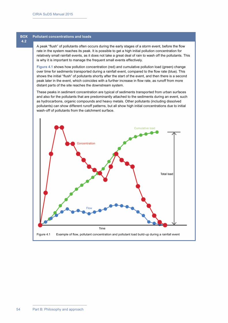
CIRIA SuDS Manual 2015
54 Part B: Philosophy and approach
BOX4.2
Pollutant concentrations and loads
A peak “flush” of pollutants often occurs during the early stages of a storm event, before the flow rate in the system reaches its peak. It is possible to get a high initial pollution concentration for relatively small rainfall events, as it does not take a great deal of rain to wash off the pollutants. This is why it is important to manage the frequent small events effectively.
Figure 4.1 shows how pollution concentration (red) and cumulative pollution load (green) change over time for sediments transported during a rainfall event, compared to the flow rate (blue). This shows the initial “flush” of pollutants shortly after the start of the event, and then there is a second peak later in the event, which coincides with a further increase in flow rate, as runoff from more distant parts of the site reaches the downstream system.
These peaks in sediment concentration are typical of sediments transported from urban surfaces and also for the pollutants that are predominantly attached to the sediments during an event, such as hydrocarbons, organic compounds and heavy metals. Other pollutants (including dissolved pollutants) can show different runoff patterns, but all show high initial concentrations due to initial wash-off of pollutants from the catchment surface.
Figure 4.1 Example of flow, pollutant concentration and pollutant load build-up during a rainfall event
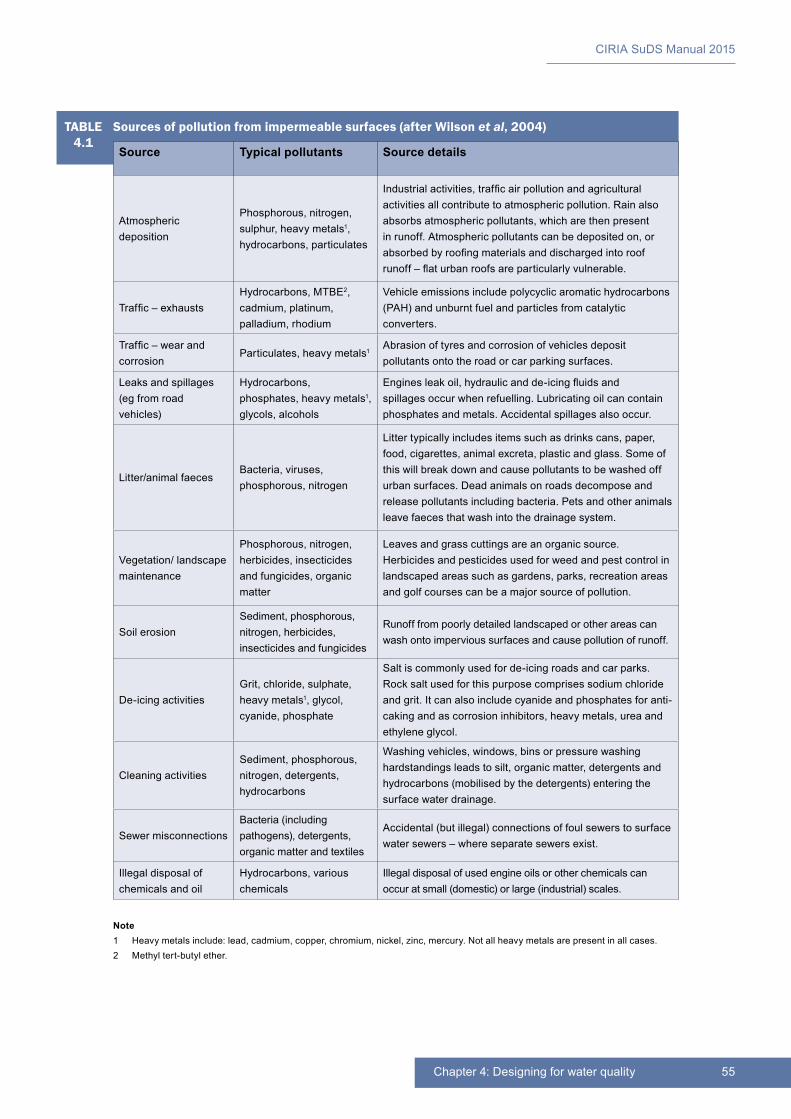
55Chapter 4: Designing for water quality
CIRIA SuDS Manual 2015
Note1 Heavy metals include: lead, cadmium, copper, chromium, nickel, zinc, mercury. Not all heavy metals are present in all cases.2 Methyl tert-butyl ether.
TABLE4.1
Sources of pollution from impermeable surfaces (after Wilson et al, 2004)
Source Typical pollutants Source details
Atmospheric deposition
Phosphorous, nitrogen, sulphur, heavy metals1, hydrocarbons, particulates
Industrial activities, traffic air pollution and agricultural activities all contribute to atmospheric pollution. Rain also absorbs atmospheric pollutants, which are then present in runoff. Atmospheric pollutants can be deposited on, or absorbed by roofing materials and discharged into roof runoff – flat urban roofs are particularly vulnerable.
Traffic – exhaustsHydrocarbons, MTBE2, cadmium, platinum, palladium, rhodium
Vehicle emissions include polycyclic aromatic hydrocarbons (PAH) and unburnt fuel and particles from catalytic converters.
Traffic – wear and corrosion
Particulates, heavy metals1Abrasion of tyres and corrosion of vehicles deposit pollutants onto the road or car parking surfaces.
Leaks and spillages (eg from road vehicles)
Hydrocarbons, phosphates, heavy metals1, glycols, alcohols
Engines leak oil, hydraulic and de-icing fluids and spillages occur when refuelling. Lubricating oil can contain phosphates and metals. Accidental spillages also occur.
Litter/animal faecesBacteria, viruses, phosphorous, nitrogen
Litter typically includes items such as drinks cans, paper, food, cigarettes, animal excreta, plastic and glass. Some of this will break down and cause pollutants to be washed off urban surfaces. Dead animals on roads decompose and release pollutants including bacteria. Pets and other animals leave faeces that wash into the drainage system.
Vegetation/ landscape maintenance
Phosphorous, nitrogen, herbicides, insecticides and fungicides, organic matter
Leaves and grass cuttings are an organic source. Herbicides and pesticides used for weed and pest control in landscaped areas such as gardens, parks, recreation areas and golf courses can be a major source of pollution.
Soil erosionSediment, phosphorous, nitrogen, herbicides, insecticides and fungicides
Runoff from poorly detailed landscaped or other areas can wash onto impervious surfaces and cause pollution of runoff.
De-icing activitiesGrit, chloride, sulphate, heavy metals1, glycol, cyanide, phosphate
Salt is commonly used for de-icing roads and car parks. Rock salt used for this purpose comprises sodium chloride and grit. It can also include cyanide and phosphates for anti-caking and as corrosion inhibitors, heavy metals, urea and ethylene glycol.
Cleaning activitiesSediment, phosphorous, nitrogen, detergents, hydrocarbons
Washing vehicles, windows, bins or pressure washing hardstandings leads to silt, organic matter, detergents and hydrocarbons (mobilised by the detergents) entering the surface water drainage.
Sewer misconnectionsBacteria (including pathogens), detergents, organic matter and textiles
Accidental (but illegal) connections of foul sewers to surface water sewers – where separate sewers exist.
Illegal disposal of chemicals and oil
Hydrocarbons, various chemicals
Illegal disposal of used engine oils or other chemicals can occur at small (domestic) or large (industrial) scales.
CIRIA SuDS Manual 2015
56 Part B: Philosophy and approach
4.2 WATER QUALITY DESIGN CRITERIA
4.2.1 Summary
The design criteria presented here should be applied to manage the quality of runoff to support and protect the natural environment effectively. Managing water quality can also contribute to the design criteria for water quantity, amenity and biodiversity and, therefore, should be considered alongside these (see Chapters 3, 5 and 6).
Indicators can be used to evaluate the extent to which these design criteria are being delivered by a SuDS design. Water quality design criteria and example indicators are presented in Table 4.2.
TABLE4.2
Water quality design criteria and example indicators
Water quality design criterion Example indicator
1 Support the management of water quality in receiving surface waters and groundwaters
The extent of pollution prevention activities in the catchment (Chapter 27)
The extent to which appropriate risk management measures for spillages are in place
The proportion of permeable surfacing, green roofs, and/or surfacing that discharges to a rainwater harvesting system or soil-based feature
Delivery of Interception and treatment to meet the standards set out in Section 4.3
The proportion of the surface water management system that is on or near the surface and facilitates treatment
The extent to which the design of the system demonstrates attention to sediment retention, such as forebays or hydrodynamic separators
2 Design system resilience to cope with future change
The design of the system includes allowances for climate change and urban creep
These design criteria are discussed in more detail in following subsections. Where minimum performance targets or specific levels of service should be achieved by a SuDS design, these are detailed in Section 4.3, and guidance is provided as to how these can be met. Regional or local standards as set out in adopted supplementary planning documents (SPDs) may take precedence.
4.2.2 Water quality criterion 1: Support the management of water quality in receiving surface waters and groundwaters
To protect the water quality of receiving surface waters and groundwaters effectively (both now and in the future), runoff discharged from the site should be of an acceptable water quality. Even where a receiving water already contains elevated levels of pollutants, and the surface water discharge is unlikely to have a significant impact, pollutants generated by site activities should be managed on site. This helps ensure that current or future water quality objectives for the receptor are not compromised and that risks associated with acute (temporary and unexpected high contaminant loadings) are minimised.
Pollution control can be achieved through:
▪▪ Pollution prevention: stopping contaminants becoming mixed with runoff, for example road sweeping, preventing misconnections, bunds for oil tanks, controlling sediment. Where pollution prevention is a fundamental part of environmental protection, it should deliver predictable and guaranteed outcomes. This is normally only achievable on sites where the site operator is also responsible for the drainage system and any downstream pollution, such as on industrial sites. Community strategies are valuable in reducing risks to downstream SuDS performance, but as these are voluntary, such strategies cannot be relied upon to deliver the required outcome. Pollution prevention strategies are discussed in detail in Chapter 27.

57Chapter 4: Designing for water quality
CIRIA SuDS Manual 2015
▪▪ Interception: preventing runoff (and the associated pollution load) from the majority of small rainfall events, for example through the use of pervious surfaces and vegetated collection systems. Interception helps facilitate the retention of pollutants in surface vegetation, soil or other material layers from where a proportion can often be degraded. This can reduce the potential total pollution load discharged to the receiving surface waters over the year (noting that risks to groundwater should always be managed effectively). The requirement for Interception is set out as water quality standard 1 in Section 4.3.1. It is also required by water quantity standard 1 in Section 3.3.1, and guidance on designing for Interception is set out in Section 24.8.
▪▪ Treatment: implementing SuDS components (in series where required) that use a range of treatment processes to reduce contaminant levels in the runoff to acceptable levels. Treatment components will often deliver Interception and usually also meet conveyance and storage requirements. The requirement for treatment is set out as water quality standard 2 in Section 4.3.2. Guidance on designing a treatment system is set out in Section 26.8.
▪▪ Maintenance and remedial work to remove captured pollutants and maintain system performance (Chapter 32).
Treatment design, wherever practicable, should be based on the good practice described in Box 4.3. The opportunities for a designer to apply these practices in full will be dependent on site characteristics, development context and local planning objectives. To maximise the opportunities afforded by these approaches, they should be considered at an early stage of the design process and fully integrated into that process.
The wide range and levels of contaminants in surface runoff, together with the natural variability associated with SuDS pollution removal processes (Section 26.6) means that water quality needs to be managed using a robust, risk-based approach. This is usually facilitated via a SuDS Management Train of a number of components in series that provide a range of treatment processes delivering gradual improvement in water quality and providing an environmental buffer for accidental spills or unexpected high pollutant loadings from the site (Section 26.8). In some cases, it may be possible to deliver the appropriate risk management using a single component, where this has been designed to deliver the required pollution control for the range of expected contaminants.
The most appropriate approach for managing pollution on any site often depends on how the site is split up in terms of ownership or use, the layout and characteristics of the development and the best ways of delivering the quantity, amenity and biodiversity design criteria (Chapters 3, 5 and 6).
Managing pollution close to its source can help keep pollutant levels and accumulation rates low – allowing natural treatment processes to be effective. This can help maximise the amenity and biodiversity value of downstream surface SuDS components and can keep maintenance activities straightforward and cost-effective. Where a site is owned or used by more than one individual or organisation (eg on commercial/industrial sites), it allows sources of pollution to be traced and controlled, so the location of SuDS components on a site can be fundamental to their success in managing pollution. Treatment can often be delivered within the same components that are delivering water quantity design criteria, hence requiring no extra cost or land-take.

CIRIA SuDS Manual 2015
58 Part B: Philosophy and approach
BOX4.3
Good practice for SuDS treatment design
1 Manage surface water runoff close to sourceWhere practicable, treatment systems should be designed to be close to the source of runoff. The advantages of this approach from a water quality perspective are as follows:
▪ It is easier to design effective treatment when the flow rate and pollutant loadings are relatively low.
▪ The treatment provided can be proportionate to the pollutant loadings, ie parts of the site with low pollutant loads do not need to have as much treatment as highly polluting parts of the site.
▪ Accidental spills or other pollution events can be isolated more easily and dealt with effectively without affecting the downstream drainage system.
▪ It encourages ownership of pollution, for example having treatment delivered on individual plots (where responsibility for performance and maintenance of the SuDS component(s) lies with the property owner) or adjacent to specific lengths of road.
▪ Poor treatment performance or component damage/failure can be isolated more easily and dealt with effectively without impacting on the whole site.
2 Treat surface water runoff on the surfaceWhere practicable, treatment systems should be designed to be on the surface. The advantages of this approach from a water quality perspective are as follows:
▪ Where sediments are exposed to UV light, photolysis and volatilisation processes can act to break down contaminants – specifically oils and other hydrocarbons.
▪ If sediment is trapped in accessible parts of the SuDS, it can be removed easily as part of routine landscape maintenance work.
▪ It enables use of evapotranspiration and some infiltration to the ground to reduce runoff volumes and associated total contaminant loads (ie Interception), provided that the risk to groundwater is managed appropriately (Section 26.7).
▪ It allows treatment to be delivered by vegetation.
▪ Sources of pollution can be easily identified.
▪ Accidental spills or misconnections are visible immediately and can be dealt with rapidly.
▪ Poor treatment performance or component damage/failure is easily identified during routine inspections, and remedial works can be planned efficiently.
3 Treat surface water runoff to remove a range of contaminantsThe SuDS design should consider the likely presence and significance of any contaminant that may pose a risk to the receiving environment, and the SuDS component or combination of components selected should include treatment processes that, in combination, are likely to reduce this risk to acceptably low levels.
4 Minimise risk of sediment remobilisationThe SuDS design should consider and mitigate the risks of sediments (and other contaminants) being remobilised and washed into receiving surface waters (or onto surfaces through which runoff is designed to infiltrate) during events greater than those for which the treatment component has been specifically designed. Guidance is provided in each of the technical component chapters (Chapters 11–23).
5 Minimise impacts from accidental spillsBy using a number of components in series, SuDS design can help ensure that accidental spills are trapped in/on upstream component surfaces, facilitating contamination management and removal. The selected SuDS components should deliver a robust treatment design that manages the risks appropriately – taking account of the uncertainty and variability associated with both the pollution loadings and the treatment processes.
59Chapter 4: Designing for water quality
CIRIA SuDS Manual 2015
4.2.3 Water quality criterion 2: Design system resilience to cope with future change
In order that the drainage system will continue to provide effective management of runoff to support and protect the natural environment, SuDS treatment designs should take account of the potential impacts of climate change on the system processes and associated performance, and consider measures/approaches that aim to make the system more resilient.
Key projected climate changes relevant for treatment systems are increases in ambient temperatures and reduced rainfall during the summer – both of which may affect the survival or success of some types of plants. Increased temperatures of runoff can also be damaging to sensitive ecosystems, but this risk should be mitigated to some extent through the use of SuDS.
It is less important to design in system resilience to manage increased runoff (for water quality management), due to the focus on preventing and/or treating relatively low flows.
4.3 WATER QUALITY DESIGN STANDARDS
The following are standards of “good practice”. Local planning documents or national standards may take precedence.
4.3.1 Water quality standard 1: Prevent runoff from the site to receiving surface waters for the majority of small rainfall events
No runoff should be discharged from the site to receiving surface waters or sewers for the majority of small (eg < 5 mm) rainfall events. This is termed Interception.
This standard is the same as water quantity standard 1a (Section 3.3.1). This is because the delivery of Interception provides both water quantity and water quality benefits.
Runoff from small rainfall events can pose a particular problem for water quality in receiving surface waters because:
▪▪ it contains the initial flush of pollutants that has built up on surfaces during the preceding dry period (Box 4.2)
▪▪ there are many more smaller rainfall events than larger ones, leading to frequent flushing of pollutants from surfaces
▪▪ the volume of runoff from all small rainfall events tends to comprise a significant proportion of the total runoff volume in any given period, and together with the relatively higher pollution concentrations, can contribute significantly to total pollutant loadings from the site over a specified period of time.
Retaining these regular events and their pollutant loads on site will help protect receiving surface waters against ongoing chronic pollution risks and contaminant accumulation. Where Interception includes infiltration, even though volumes may be small, the protection of groundwater should be fully considered and any risks managed to acceptable levels (Section 26.7). Although a proportion of pollutants retained within SuDS components in soils is likely to be degraded, some pollutants are likely to build up over time. Therefore, these may need removing during routine maintenance (eg sediments from sediment removal components) or as part of component rehabilitation (eg when the capacity of soil layers to retain pollutants has been exhausted, although this is unlikely to be required during the design life of the development, if the drainage system is designed correctly – see Scott Wilson, 2010).
Rainfall events that are less than or around 5 mm in depth comprise more than half of all rainfall events across the UK. On natural catchments, such events rarely produce any runoff at all. However, on impermeable catchments, runoff tends to be generated for almost all events. The hydraulic drivers for designing drainage systems that retain and prevent runoff from the first 5 mm of rainfall for the majority of rainfall events, are set out in Chapter 3 and include protecting the receiving surface waters from morphological and associated ecological damage from unnatural regular surface water discharges.
CIRIA SuDS Manual 2015
60 Part B: Philosophy and approach
Interception can be delivered via rainwater harvesting systems, green roofs, infiltration systems, pervious surfaces and vegetated SuDS. By using the storage available in soil or aggregate matrices, together with evapotranspiration and infiltration processes, many components can intercept 5 mm of rainfall for contributing surfaces several times greater than their own surface area. Interception design methods are set out in Section 24.8.
Requiring Interception for the “majority” of events recognises that once soils are saturated (mainly during or following long periods of wet winter weather) runoff will occur, and drainage systems cannot be expected to prevent this. Events that follow on quickly from a previous event may also not be completely captured by a drainage system designed for Interception.
Maximising Interception in the summer months is particularly important for protecting receiving surface waters. Runoff during the summer months can cause greater problems for receiving surface waters than runoff in winter months, due to low flows in the receiving surface water. Limited dilution of pollutants within runoff and within the receiving surface water receptor may cause increased localised pollutant impact.
4.3.2 Water quality standard 2: Treat runoff to prevent negative impacts on the receiving water quality
Runoff should be adequately treated to protect the receiving water body from:
1 Short-term acute pollution that may result from accidental spills or temporary high pollution loadings within the catchment area.
2 Long-term chronic pollution from the spectrum of runoff pollutant sources within the urban environment.
The extent of treatment required will depend on the land use, the level of pollution prevention in the catchment (Chapter 27) and for groundwater the natural protection afforded by underlying soil layers. High hazard sites will have a higher potential pollution load and higher potential maximum pollution concentrations. They will therefore tend to require more treatment than low hazard sites in order to deliver discharges of an acceptable quality. The land use will also dictate the likely significance of different types of contaminants in the runoff, and this may influence the treatment processes that need inclusion within the treatment system. The treatment processes provided by different SuDS components will have varying capabilities to remove different types of contaminants.
Most sites will be relatively low risk, and the risk can be mitigated by implementing SuDS components close to the source of runoff and in sequence where higher levels of protection are required (ie the SuDS Management Train). SuDS components usually offer a range of treatment processes and, in sequence, deliver gradual improvements in water quality, as well as providing an environmental buffer for accidental spills or unexpected high pollutant loadings from the site
Guidance on designing a treatment system using a SuDS Management Train is provided in Section 26.8.
Discharges to receiving waters that are close to a drinking water abstraction point may require greater protection, so an extra treatment component (over and above what is sufficient for standard discharges) may be required in the SuDS Management Train to adequately manage the risks associated with unexpected temporary high pollution loadings and/or poor system performance.
In England and Wales, reference to local planning documents should also be made to identify any further protection required for sites due to habitat conservation (Chapter 7). The implications of developments on or in close proximity to an area with an environmental designation, such as a site of special scientific interest (SSSI), should be considered via consultation with relevant conservation bodies such as Natural England.
Discharges from some land uses (eg industrial sites) may be considered particularly high risk – in which case the drainage system will need to be designed to meet the requirements established by a site-specific risk assessment (Section 26.7.3) and agreed with the environmental regulator. Design solutions will depend on the level of risk and may include one or more of the following:

61Chapter 4: Designing for water quality
CIRIA SuDS Manual 2015
▪▪ an additional SuDS component in the Management Train or an active intervention (eg stopcock, penstock or other control structure that is watertight at low hydraulic heads) to adequately manage the risks associated with spillages (acute pollution), poor system performance (eg due to seasonal impacts), the inherent performance variability of natural systems and/or delays in effecting maintenance
▪▪ a bespoke treatment system where the range, type and level of the contaminants and the performance of the system in managing the contaminants is well understood – in such scenarios, ongoing monitoring of the system will often be required
▪▪ prevention of the discharge (eg by covering the activity and draining the area to the foul sewer) or site-specific pollution prevention strategies.
The requirements for discharges to surface waters need to be considered where the runoff from frequent events (eg up to about a 1:1 year event) is conveyed via the drainage system to a receiving surface water body. The design water quality event for components that treat runoff as it flows through media or vegetation is usually set as the 1 year, 15 minute (or other relevant critical duration) event. For ponds the design water quality event is usually set as a depth of rainfall (Section 23.5). Where discharges to surface waters will only occur for larger events, pollution risks are generally not considered significant, and treatment is generally not required (although this should be checked on a site-specific basis with the environmental regulator).
With respect to the requirements for discharges to groundwater, the environmental regulators in different parts of the UK take different approaches to the level of infiltration considered to pose a potential risk:
▪▪ In England and Wales, the requirements for discharges to groundwater should be considered wherever there is a chance of infiltration, even when this will only be in small amounts (eg from the base of conveyance swales and detention basins), as well as for components designed specifically for infiltration.
▪▪ In Scotland and Northern Ireland, the requirements for discharges to groundwater only need to be considered where components are designed specifically for infiltration (eg soakaways, infiltration trenches, infiltration basins).
Groundwater protection is required for any event > 1 year where the runoff is discharged via infiltration.
The following points should be noted when using Table 4.3:
Discharges to either surface waters and/or groundwater
1 If the specific land use associated with the catchment to be drained is not given in the table, then guidance on the appropriate approach should be sought from the environmental regulator.
2 Contaminated runoff from areas handling hazardous or highly polluting materials, such as food waste, chemical and fuel handling areas, animal management and agricultural facilities*, vehicle refuelling or washing operations should be minimised (eg by covering) and any wash-off that is generated should be drained to an appropriately maintained and managed, sealed and discrete disposal solution, such as the foul sewer. The protection of nitrate-vulnerable zones is also likely to be relevant (https://www.gov.uk/nitrate-vulnerable-zones).
* Note that in England, guidance on rural SuDS is provided by Avery (2012).
3 Developments such as industrial sites, waste management sites and lorry and bus/coach parking or turning areas need to be discussed as part of pre-permitting discussions with the environmental regulator, and they may need authorisation (Box 4.4). In such circumstances SuDS may still be appropriate, but the design of the system will be dependent on the outcomes of a site-specific risk assessment (Section 26.7.3).
CIRIA SuDS Manual 2015
62 Part B: Philosophy and approach
Discharges to groundwater only
1 The discharge of clean roof water to the ground is acceptable provided that (a) all roof water downpipes are sealed against pollutants entering the system from polluted surface runoff, effluent disposal or other forms of discharge and (b) gross sediments and silts are removed upstream of the infiltration component.
2 There should be a minimum depth of 1 m of unsaturated aquifer material between the base of any infiltration system and the maximum likely groundwater level (taking account of potential shifts in groundwater level resulting from extended periods of wet weather). Evidence from groundwater records may demonstrate the maximum groundwater levels, but where there is any uncertainty, appropriate groundwater monitoring should be undertaken to demonstrate levels across the site. Ground investigation should establish the typical maximum upper level of the saturated layer of an unconfined aquifer. “Typical” in this context would be a representative winter water table level, based on hydrogeological records and/or expert opinion and discounting extremes in weather or artificial suppression by engineering techniques such as pumping.
3 The method of discharge should not create new pathways for pollutants to groundwater or mobilise contaminants already in the ground (EA, 2013).
4 For contaminated land sites, the site investigation report should be used to identify any residual hotspots where pollutants are still likely to be present, and these areas should be located on the site plan. Any infiltration through contaminated soils could potentially mobilise or remobilise pollutants, alter remedial measures undertaken on site and cause pollution of groundwater. Guidance on an appropriate approach for this should be sought from the environmental regulator. A discharge that disturbs land that subsequently causes a release of pollutants to groundwater may potentially require an environmental permit, or alter liabilities under Part IIa of the Environmental Protection Act 1990. Guidance on designing SuDS for contaminated land sites is included in Section 8.2.
BOX4.4
UK regulations for discharges to groundwaters
The regulators in England and Wales should be consulted if a discharge meets the definition of a groundwater activity under the Environmental Permitting (England and Wales) Regulations 2010 and does not meet an appropriate exemption.
In Northern Ireland, a discharge consent, groundwater authorisation or pollution prevention and control (PPC) permit may be required for surface water discharges to the ground.
In Scotland, an authorisation under the Water Environment (Controlled Activities) (Scotland) Regulations (CAR) 2011 or a pollution prevention and control (PPC) permit may be required. In Scotland, certain discharges to surface waters are automatically authorised by general binding rules (GBR). In such cases, it is not necessary to apply for authorisation from SEPA, but the design and discharge must comply with the conditions of the GBR.
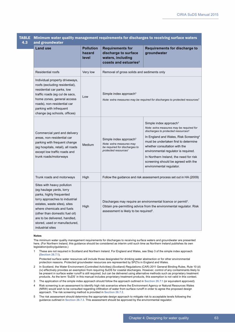
63Chapter 4: Designing for water quality
CIRIA SuDS Manual 2015
NotesThe minimum water quality management requirements for discharges to receiving surface waters and groundwater are presented here. (For Northern Ireland, this guidance should be considered as interim until such time as Northern Ireland publishes its own legislation/policy/guidance.)1 These are not required in Scotland and Northern Ireland. For England and Wales, see Step 3 of the simple index approach
(Section 26.7.1). Protected surface water resources will include those designated for drinking water abstraction or for other environmental
protection reasons. Protected groundwater resources are represented by SPZ1s in England and Wales.2 In Scotland, the Water Environment (Controlled Activities) (Scotland) Regulations (CAR) 2011 General Binding Rules, Rule 10 (d)
(iv) effectively provides an exemption from requiring SuDS for coastal discharges. However, control of any contaminants likely to be present in surface water runoff is still required, but can be delivered using alternative methods such as proprietary treatment products. As the term ‘SuDS’ in this manual includes proprietary treatment products, this exemption is not valid in this context.
3 The application of the simple index approach should follow the approach outlined in Section 26.7.1 (or equivalent approved).4 Risk screening is an assessment to identify high risk scenarios where the Environment Agency or Natural Resources Wales
(NRW) would wish to be consulted regarding infiltration of water from surface runoff in order to agree the proposed design approach. The risk screening method is provided in Section 26.7.2.
5 The risk assessment should determine the appropriate design approach to mitigate risk to acceptable levels following the guidance outlined in Section 26.7.3. This assessment should be approved by the environmental regulator.
TABLE4.3
Minimum water quality management requirements for discharges to receiving surface waters and groundwaterLand use Pollution
hazard level
Requirements for discharge to surface waters, including coasts and estuaries2
Requirements for discharge to groundwater
Residential roofs Very low Removal of gross solids and sediments only
Individual property driveways, roofs (excluding residential), residential car parks, low traffic roads (eg cul de sacs, home zones, general access roads), non-residential car parking with infrequent change (eg schools, offices)
LowSimple index approach3
Note: extra measures may be required for discharges to protected resources1
Commercial yard and delivery areas, non-residential car parking with frequent change (eg hospitals, retail), all roads except low traffic roads and trunk roads/motorways
Medium
Simple index approach3
Note: extra measures may be required for discharges to protected resources1
Simple index approach3
Note: extra measures may be required for discharges to protected resources1
In England and Wales, Risk Screening4 must be undertaken first to determine whether consultation with the environmental regulator is required.
In Northern Ireland, the need for risk screening should be agreed with the environmental regulator.
Trunk roads and motorways High Follow the guidance and risk assessment process set out in HA (2009)
Sites with heavy pollution (eg haulage yards, lorry parks, highly frequented lorry approaches to industrial estates, waste sites), sites where chemicals and fuels (other than domestic fuel oil) are to be delivered, handled, stored, used or manufactured, industrial sites
HighDischarges may require an environmental licence or permit3. Obtain pre-permitting advice from the environmental regulator. Risk assessment is likely to be required5.

CIRIA SuDS Manual 2015
64 Part B: Philosophy and approach
4.4 REFERENCES
AVERY, L (2012) Rural Sustainable Drainage Systems (RSuDS), Environment Agency, Bristol, UK (ISBN: 978-1-84911-277-2). Go to: http://tinyurl.com/lycwa3n
DEFRA (2012) Tackling water pollution from the urban environment. Consultation on a strategy to address diffuse water pollution from the built environment, Department for Environment, Food and Rural Affairs, London, UK. Go to: http://tinyurl.com/qayoywo
EA (2013) Groundwater protection: Principles and practice (GP3), Version 1.1, Environment Agency, Bristol, UK. Go to: http://tinyurl.com/pyvnmjt
HA (2009) “Road drainage and the water environment”. In: Design manual for roads and bridges (DMRB), vol 11, Section 3, Part 10, HD 45/09, Highways Agency, London, UK. Go to: http://tinyurl.com/p4yakc9
SCOTT WILSON (2010) Fate of highway contaminants in the unsaturated zone, final synthesis report, Highways Consultancy Group, Highways Agency, London, UK (unpublished)
Statutes
The Environmental Permitting (England and Wales) Regulations 2010 (No.675)
The Water Environment (Controlled Activities) (Scotland) Regulations (CAR) 2011 (No.209)

65Chapter 4: Designing for water quality
CIRIA SuDS Manual 2015
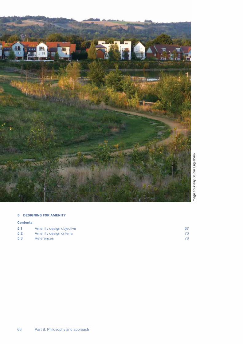
66 Part B: Philosophy and approach
5 DESIGNING FOR AMENITY
Contents
5.1 Amenity design objective 675.2 Amenity design criteria 705.3 References 78
Imag
e co
urte
sy S
tudi
o E
ngle
back
67Chapter 5: Designing for amenity
CIRIA SuDS Manual 2015
There are many amenity benefits that are intrinsic to SuDS – good SuDS design often provides amenity benefits while delivering water quantity, water quality and biodiversity benefits.
Where the concept of “creating and sustaining better places for people” is embedded in the design process, these benefits can be maximised. Table 5.1 provides a summary of how SuDS can add amenity value. Further information on amenity benefits of SuDS can be found in Digman et al (2015).
Designing for amenity
5.1 AMENITY DESIGN OBJECTIVE
Create and sustain better places for people
Good urban design aims to deliver attractive, pleasant, useful and above all “liveable” urban environments that support and enhance local communities (Box 5.1). Water is a valuable natural resource, and the management of rainfall and runoff can form a key part of an urban vision. Designs using surface water management systems to help structure the urban landscape can enrich its aesthetic and recreational value, promoting health and well-being and supporting green infrastructure. Water managed on the surface, rather than underground, can help to reduce summer temperatures, provide habitat for flora and fauna, act as a resource for local environmental education programmes and working groups and directly influence the sense of community and prosperity of an area. SuDS can provide opportunities for water to be visible and audible as it travels through the landscape – the places where water flows, stills, trickles or splashes are often where it is experienced and valued the most.
05Chapter
This chapter explains the objective of designing for amenity, and the design criteria that should be followed to deliver this objective.
This chapter should be read alongside Chapters 3, 4 and 6 to understand how the different SuDS design criteria relate to each other, and Chapter 7 to understand when and how to apply these criteria.Further discussion on designing for amenity specifically within the urban context can be found in Chapter 10.
BOX5.1
Amenity, place-making and liveability
Amenity may be defined as “a useful or pleasant facility or service”, which includes the tangible (something that can be measured in terms of use), and the less tangible (something that can be experienced as pleasure or aesthetic appreciation).
This definition is particularly relevant for describing the multi-functional opportunities associated with SuDS designs, and it provides a link to the concept of place-making, now commonly used in describing the quality of a space in urban design.
Amenity also covers liveability, which is associated with factors that improve the quality of life for inhabitants. Liveability encompasses the well-being of a community and of individuals and comprises the many characteristics that make a location a place where people want to live and work.
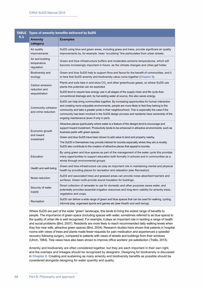
CIRIA SuDS Manual 2015
68 Part B: Philosophy and approach
Where SuDS are part of the wider “green” landscape, this tends to bring the widest range of benefits to people. The importance of green space (including spaces with water, sometimes referred to as blue space) to the quality of urban life is well recognised. For example, it plays an important role in tackling a range of health and social problems (Bird, 2007). Residents are more likely to reach recommended daily walking levels when they live near safe, attractive green spaces (Bird, 2004). Research studies have shown that patients in hospital rooms with views of trees and plants made fewer requests for pain medication and experienced a speedier recovery following surgery, compared to patients with views of streets and buildings from their windows (Ulrich, 1984). Tree views have also been shown to improve office workers’ job satisfaction (Trellis, 2013).
Amenity and biodiversity are often considered together, but they are each important in their own right, and the overlaps and linkages should be recognised by designers. Designing for biodiversity is discussed in Chapter 6. Creating and sustaining as many amenity and biodiversity benefits as possible should be considered alongside designing for water quantity and quality.
TABLE5.1
Types of amenity benefits delivered by SuDS
Amenity category
Examples
Air quality improvements
SuDS using blue and green areas, including grass and trees, provide significant air quality improvements by, for example, trees “scrubbing” fine particulates from urban streets.
Air and building temperature regulation
Green and blue infrastructure buffers and moderates extreme temperatures, which will become increasingly important in future, as the climate changes and cities get hotter.
Biodiversity and ecology
Green and blue SuDS help to support flora and fauna for the benefit of communities, and it is here that SuDS amenity and biodiversity value come together (Chapter 6).
Carbon emission reduction and sequestration
Plants and soils take in and store CO2 and other greenhouse gases, so where SuDS use plants this potential can be exploited.
SuDS tend to require less energy use in all stages of the supply chain and life cycle than conventional drainage and, by harvesting water at source, this also saves energy.
Community cohesion and crime reduction
SuDS can help bring communities together. By increasing opportunities for human interaction and creating more enjoyable environments, people are more likely to feel they belong to the community and take a greater pride in their neighbourhood. This is especially the case if the community has been involved in the SuDS design process and residents have ownership of the ongoing maintenance (even if only in part).
Economic growth and inward investment
Attractive places (particularly where water is a feature of the design) tend to encourage and support inward investment. Productivity tends to be enhanced in attractive environments, such as business parks with green spaces.
Green and blue SuDS have been shown to add value to land and property nearby.
The SuDS in themselves may provide interest for tourists especially where they are a novelty. SuDS also contribute to the creation of attractive places that appeal to tourists.
EducationBy using green and blue spaces as part of the management of the water cycle this provides many opportunities to support education both formally in schools and in communities as a whole through environmental groups.
Health and well-beingGreen and blue infrastructure can play an important role in maintaining mental and physical health by providing places for recreation and relaxation (see Recreation).
Noise reductionSuDS and associated trees and grassed areas can provide noise-absorbent barriers and surfaces. Green roofs provide sound insulation for buildings.
Security of water supply
Direct collection of rainwater to use for domestic and other purposes saves water, and potentially provides essential irrigation resources and long-term viability for amenity trees, vegetation and crops.
RecreationSuDS can deliver a wide range of green and blue spaces that can be used for walking, cycling, informal play, organised sports and games etc (see Health and well-being).
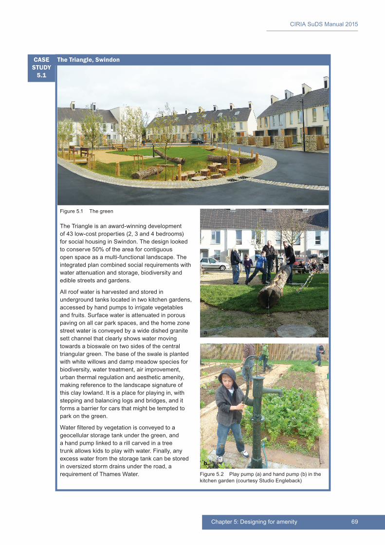
69Chapter 5: Designing for amenity
CIRIA SuDS Manual 2015
Figure 5.2 Play pump (a) and hand pump (b) in the kitchen garden (courtesy Studio Engleback)
b
a
Figure 5.1 The green
The Triangle is an award-winning development of 43 low-cost properties (2, 3 and 4 bedrooms) for social housing in Swindon. The design looked to conserve 50% of the area for contiguous open space as a multi-functional landscape. The integrated plan combined social requirements with water attenuation and storage, biodiversity and edible streets and gardens.
All roof water is harvested and stored in underground tanks located in two kitchen gardens, accessed by hand pumps to irrigate vegetables and fruits. Surface water is attenuated in porous paving on all car park spaces, and the home zone street water is conveyed by a wide dished granite sett channel that clearly shows water moving towards a bioswale on two sides of the central triangular green. The base of the swale is planted with white willows and damp meadow species for biodiversity, water treatment, air improvement, urban thermal regulation and aesthetic amenity, making reference to the landscape signature of this clay lowland. It is a place for playing in, with stepping and balancing logs and bridges, and it forms a barrier for cars that might be tempted to park on the green.
Water filtered by vegetation is conveyed to a geocellular storage tank under the green, and a hand pump linked to a rill carved in a tree trunk allows kids to play with water. Finally, any excess water from the storage tank can be stored in oversized storm drains under the road, a requirement of Thames Water.
The Triangle, SwindonCASE STUDY
5.1
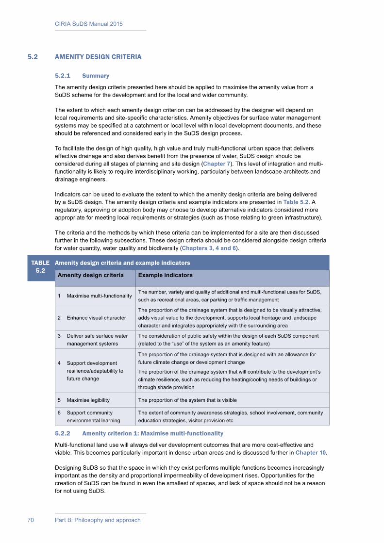
CIRIA SuDS Manual 2015
70 Part B: Philosophy and approach
5.2 AMENITY DESIGN CRITERIA
5.2.1 Summary
The amenity design criteria presented here should be applied to maximise the amenity value from a SuDS scheme for the development and for the local and wider community.
The extent to which each amenity design criterion can be addressed by the designer will depend on local requirements and site-specific characteristics. Amenity objectives for surface water management systems may be specified at a catchment or local level within local development documents, and these should be referenced and considered early in the SuDS design process.
To facilitate the design of high quality, high value and truly multi-functional urban space that delivers effective drainage and also derives benefit from the presence of water, SuDS design should be considered during all stages of planning and site design (Chapter 7). This level of integration and multi-functionality is likely to require interdisciplinary working, particularly between landscape architects and drainage engineers.
Indicators can be used to evaluate the extent to which the amenity design criteria are being delivered by a SuDS design. The amenity design criteria and example indicators are presented in Table 5.2. A regulatory, approving or adoption body may choose to develop alternative indicators considered more appropriate for meeting local requirements or strategies (such as those relating to green infrastructure).
The criteria and the methods by which these criteria can be implemented for a site are then discussed further in the following subsections. These design criteria should be considered alongside design criteria for water quantity, water quality and biodiversity (Chapters 3, 4 and 6).
5.2.2 Amenity criterion 1: Maximise multi-functionality
Multi-functional land use will always deliver development outcomes that are more cost-effective and viable. This becomes particularly important in dense urban areas and is discussed further in Chapter 10.
Designing SuDS so that the space in which they exist performs multiple functions becomes increasingly important as the density and proportional impermeability of development rises. Opportunities for the creation of SuDS can be found in even the smallest of spaces, and lack of space should not be a reason for not using SuDS.
TABLE5.2
Amenity design criteria and example indicators
Amenity design criteria Example indicators
1 Maximise multi-functionalityThe number, variety and quality of additional and multi-functional uses for SuDS, such as recreational areas, car parking or traffic management
2 Enhance visual characterThe proportion of the drainage system that is designed to be visually attractive, adds visual value to the development, supports local heritage and landscape character and integrates appropriately with the surrounding area
3 Deliver safe surface water management systems
The consideration of public safety within the design of each SuDS component (related to the “use” of the system as an amenity feature)
4 Support development resilience/adaptability to future change
The proportion of the drainage system that is designed with an allowance for future climate change or development change
The proportion of the drainage system that will contribute to the development’s climate resilience, such as reducing the heating/cooling needs of buildings or through shade provision
5 Maximise legibility The proportion of the system that is visible
6 Support community environmental learning
The extent of community awareness strategies, school involvement, community education strategies, visitor provision etc
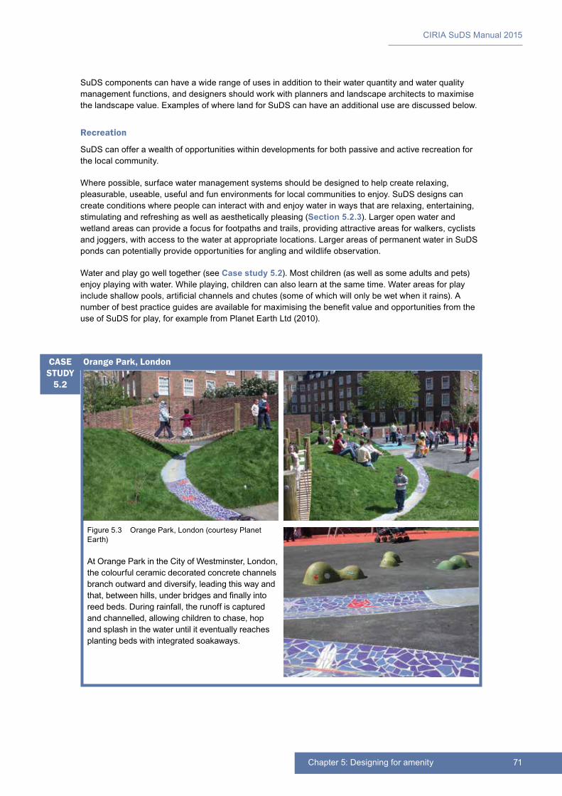
71Chapter 5: Designing for amenity
CIRIA SuDS Manual 2015
SuDS components can have a wide range of uses in addition to their water quantity and water quality management functions, and designers should work with planners and landscape architects to maximise the landscape value. Examples of where land for SuDS can have an additional use are discussed below.
Recreation
SuDS can offer a wealth of opportunities within developments for both passive and active recreation for the local community.
Where possible, surface water management systems should be designed to help create relaxing, pleasurable, useable, useful and fun environments for local communities to enjoy. SuDS designs can create conditions where people can interact with and enjoy water in ways that are relaxing, entertaining, stimulating and refreshing as well as aesthetically pleasing (Section 5.2.3). Larger open water and wetland areas can provide a focus for footpaths and trails, providing attractive areas for walkers, cyclists and joggers, with access to the water at appropriate locations. Larger areas of permanent water in SuDS ponds can potentially provide opportunities for angling and wildlife observation.
Water and play go well together (see Case study 5.2). Most children (as well as some adults and pets) enjoy playing with water. While playing, children can also learn at the same time. Water areas for play include shallow pools, artificial channels and chutes (some of which will only be wet when it rains). A number of best practice guides are available for maximising the benefit value and opportunities from the use of SuDS for play, for example from Planet Earth Ltd (2010).
Figure 5.3 Orange Park, London (courtesy Planet Earth)
At Orange Park in the City of Westminster, London, the colourful ceramic decorated concrete channels branch outward and diversify, leading this way and that, between hills, under bridges and finally into reed beds. During rainfall, the runoff is captured and channelled, allowing children to chase, hop and splash in the water until it eventually reaches planting beds with integrated soakaways.
Orange Park, LondonCASE STUDY
5.2
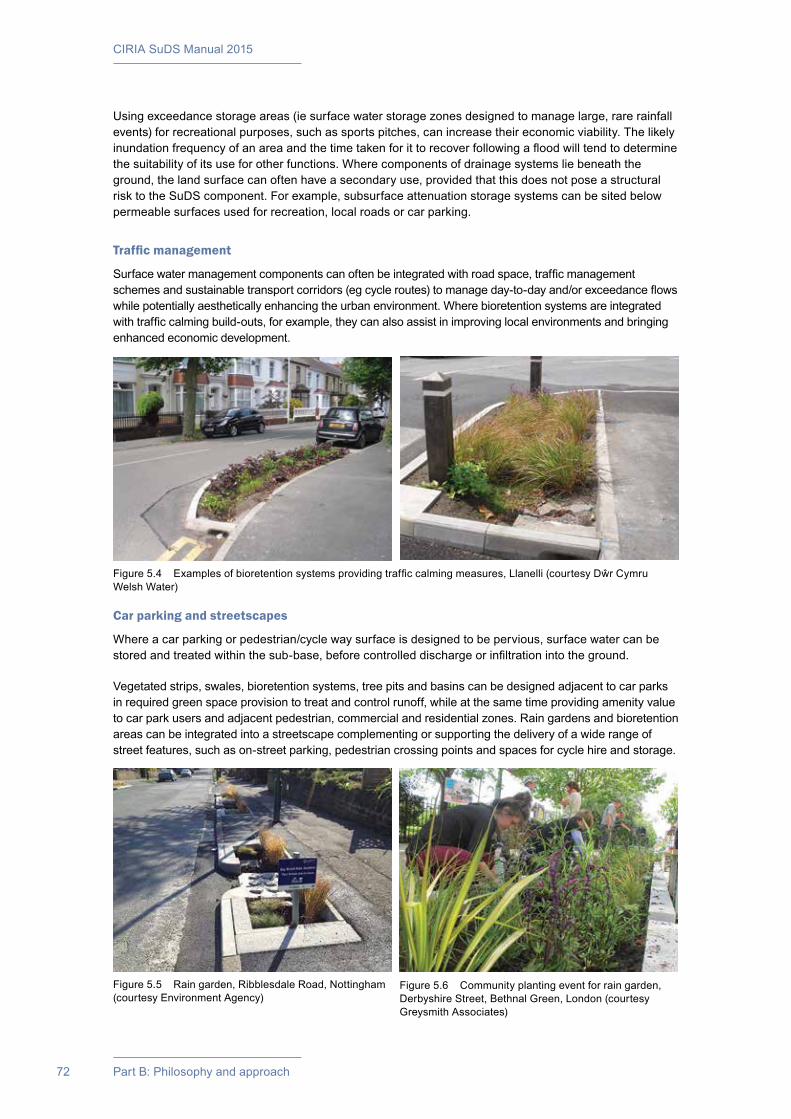
CIRIA SuDS Manual 2015
72 Part B: Philosophy and approach
Using exceedance storage areas (ie surface water storage zones designed to manage large, rare rainfall events) for recreational purposes, such as sports pitches, can increase their economic viability. The likely inundation frequency of an area and the time taken for it to recover following a flood will tend to determine the suitability of its use for other functions. Where components of drainage systems lie beneath the ground, the land surface can often have a secondary use, provided that this does not pose a structural risk to the SuDS component. For example, subsurface attenuation storage systems can be sited below permeable surfaces used for recreation, local roads or car parking.
Traffic management
Surface water management components can often be integrated with road space, traffic management schemes and sustainable transport corridors (eg cycle routes) to manage day-to-day and/or exceedance flows while potentially aesthetically enhancing the urban environment. Where bioretention systems are integrated with traffic calming build-outs, for example, they can also assist in improving local environments and bringing enhanced economic development.
Car parking and streetscapes
Where a car parking or pedestrian/cycle way surface is designed to be pervious, surface water can be stored and treated within the sub-base, before controlled discharge or infiltration into the ground.
Vegetated strips, swales, bioretention systems, tree pits and basins can be designed adjacent to car parks in required green space provision to treat and control runoff, while at the same time providing amenity value to car park users and adjacent pedestrian, commercial and residential zones. Rain gardens and bioretention areas can be integrated into a streetscape complementing or supporting the delivery of a wide range of street features, such as on-street parking, pedestrian crossing points and spaces for cycle hire and storage.
Figure 5.5 Rain garden, Ribblesdale Road, Nottingham (courtesy Environment Agency)
Figure 5.6 Community planting event for rain garden, Derbyshire Street, Bethnal Green, London (courtesy Greysmith Associates)
Figure 5.4 Examples of bioretention systems providing traffic calming measures, Llanelli (courtesy Dŵr Cymru Welsh Water)
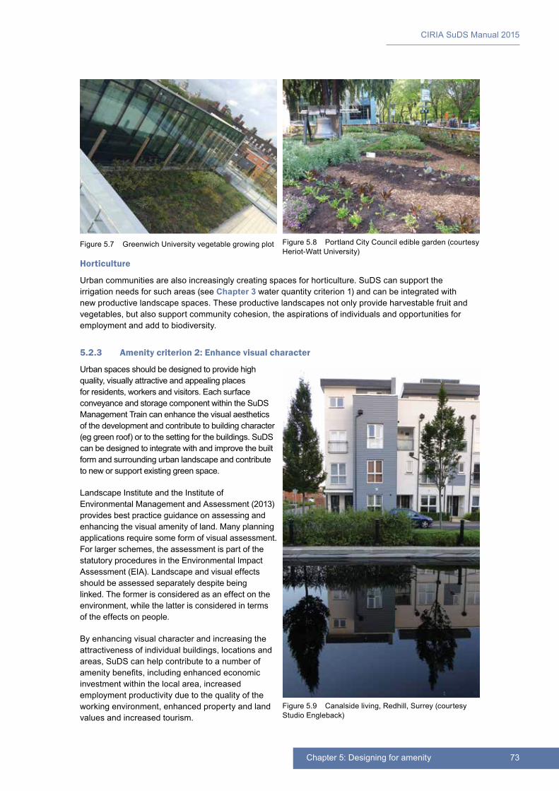
73Chapter 5: Designing for amenity
CIRIA SuDS Manual 2015
Horticulture
Urban communities are also increasingly creating spaces for horticulture. SuDS can support the irrigation needs for such areas (see Chapter 3 water quantity criterion 1) and can be integrated with new productive landscape spaces. These productive landscapes not only provide harvestable fruit and vegetables, but also support community cohesion, the aspirations of individuals and opportunities for employment and add to biodiversity.
5.2.3 Amenity criterion 2: Enhance visual character
Urban spaces should be designed to provide high quality, visually attractive and appealing places for residents, workers and visitors. Each surface conveyance and storage component within the SuDS Management Train can enhance the visual aesthetics of the development and contribute to building character (eg green roof) or to the setting for the buildings. SuDS can be designed to integrate with and improve the built form and surrounding urban landscape and contribute to new or support existing green space.
Landscape Institute and the Institute of Environmental Management and Assessment (2013) provides best practice guidance on assessing and enhancing the visual amenity of land. Many planning applications require some form of visual assessment. For larger schemes, the assessment is part of the statutory procedures in the Environmental Impact Assessment (EIA). Landscape and visual effects should be assessed separately despite being linked. The former is considered as an effect on the environment, while the latter is considered in terms of the effects on people.
By enhancing visual character and increasing the attractiveness of individual buildings, locations and areas, SuDS can help contribute to a number of amenity benefits, including enhanced economic investment within the local area, increased employment productivity due to the quality of the working environment, enhanced property and land values and increased tourism.
Figure 5.7 Greenwich University vegetable growing plot Figure 5.8 Portland City Council edible garden (courtesy Heriot-Watt University)
Figure 5.9 Canalside living, Redhill, Surrey (courtesy Studio Engleback)

CIRIA SuDS Manual 2015
74 Part B: Philosophy and approach
Not all of these benefits are exclusively because of SuDS, and many would come about anyway if green areas were used or open water features added to a landscape. It is important that visual benefits are not attributed incorrectly to SuDS unless greening of an area would not have happened without SuDS being installed (Chapter 35).
The visual aesthetic value should be considered at elevation as well as at ground level. Well designed and integrated SuDS components can contribute to urban art, townscape character and the distinctiveness of a location, attracting tourists and enhancing the quality of life of those who use the area. The ways in which runoff can be managed, to provide attractive and interesting visual structures on individual buildings such as roofs, walls, spouts, cascades, rain slides, rain chains etc, is only limited by the designer’s imagination and creativity and the need to ensure a safe environment.
The design of a surface SuDS component should enhance the experience of movement or tranquillity with opportunities taken to stimulate the senses, not only visually but also through sound and touch. Each component should be attractive, and wherever possible the value of water within each part of the system should be considered and promoted. Managing noise, by excluding unwanted sounds and replacing them with the tranquil sound of moving water, brings the visual and the auditory experience together in helping create enjoyable, tranquil and pleasant places.
As water flows from one component to the next, the structures that control movement should blend with the landscape and take into account the use and place of SuDS within the surrounding area. At the same time they should be visually neutral or positively interesting as part of the SuDS Management Train (Chapter 28).
5.2.4 Amenity criterion 3: Deliver safe surface water management systems
SuDS are no more hazardous than natural ponds and wetlands, puddles and surface runoff flows on roads, or in streams and rivers. Guidance on health and safety is provided in Chapter 36, which includes health and safety risk assessment processes and design approaches to mitigate any potential risks associated with the system. This criterion concerns the consideration of public safety related to the “use” of the system as an amenity feature or resource.
Figure 5.10 SuDS and play (courtesy DSA Environment and Design)
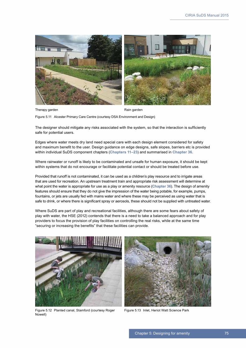
75Chapter 5: Designing for amenity
CIRIA SuDS Manual 2015
The designer should mitigate any risks associated with the system, so that the interaction is sufficiently safe for potential users.
Edges where water meets dry land need special care with each design element considered for safety and maximum benefit to the user. Design guidance on edge designs, safe slopes, barriers etc is provided within individual SuDS component chapters (Chapters 11–23) and summarised in Chapter 36.
Where rainwater or runoff is likely to be contaminated and unsafe for human exposure, it should be kept within systems that do not encourage or facilitate potential contact or should be treated before use.
Provided that runoff is not contaminated, it can be used as a children’s play resource and to irrigate areas that are used for recreation. An upstream treatment train and appropriate risk assessment will determine at what point the water is appropriate for use as a play or amenity resource (Chapter 36). The design of amenity features should ensure that they do not give the impression of the water being potable, for example, pumps, fountains, or jets are usually fed with mains water and where these may be perceived as using water that is safe to drink, or where there is significant spray or aerosols, these should not be supplied with untreated water.
Where SuDS are part of play and recreational facilities, although there are some fears about safety of play with water, the HSE (2012) contends that there is a need to take a balanced approach and for play providers to focus the provision of play facilities on controlling the real risks, while at the same time “securing or increasing the benefits” that these facilities can provide.
Therapy garden
Figure 5.11 Alcester Primary Care Centre (courtesy DSA Environment and Design)
Rain garden
Figure 5.12 Planted canal, Stamford (courtesy Roger Nowell)
Figure 5.13 Inlet, Heriot Watt Science Park
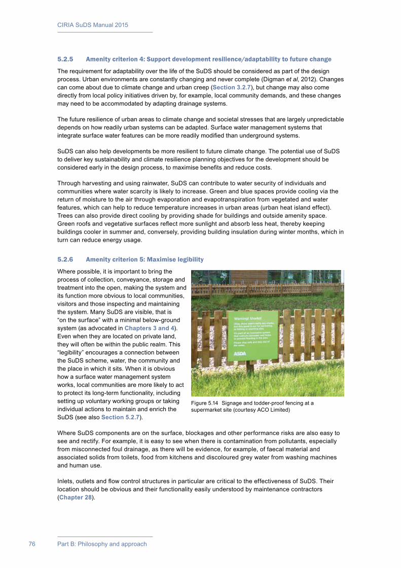
CIRIA SuDS Manual 2015
76 Part B: Philosophy and approach
5.2.5 Amenity criterion 4: Support development resilience/adaptability to future change
The requirement for adaptability over the life of the SuDS should be considered as part of the design process. Urban environments are constantly changing and never complete (Digman et al, 2012). Changes can come about due to climate change and urban creep (Section 3.2.7), but change may also come directly from local policy initiatives driven by, for example, local community demands, and these changes may need to be accommodated by adapting drainage systems.
The future resilience of urban areas to climate change and societal stresses that are largely unpredictable depends on how readily urban systems can be adapted. Surface water management systems that integrate surface water features can be more readily modified than underground systems.
SuDS can also help developments be more resilient to future climate change. The potential use of SuDS to deliver key sustainability and climate resilience planning objectives for the development should be considered early in the design process, to maximise benefits and reduce costs.
Through harvesting and using rainwater, SuDS can contribute to water security of individuals and communities where water scarcity is likely to increase. Green and blue spaces provide cooling via the return of moisture to the air through evaporation and evapotranspiration from vegetated and water features, which can help to reduce temperature increases in urban areas (urban heat island effect). Trees can also provide direct cooling by providing shade for buildings and outside amenity space. Green roofs and vegetative surfaces reflect more sunlight and absorb less heat, thereby keeping buildings cooler in summer and, conversely, providing building insulation during winter months, which in turn can reduce energy usage.
5.2.6 Amenity criterion 5: Maximise legibility
Where possible, it is important to bring the process of collection, conveyance, storage and treatment into the open, making the system and its function more obvious to local communities, visitors and those inspecting and maintaining the system. Many SuDS are visible, that is “on the surface” with a minimal below-ground system (as advocated in Chapters 3 and 4). Even when they are located on private land, they will often be within the public realm. This “legibility” encourages a connection between the SuDS scheme, water, the community and the place in which it sits. When it is obvious how a surface water management system works, local communities are more likely to act to protect its long-term functionality, including setting up voluntary working groups or taking individual actions to maintain and enrich the SuDS (see also Section 5.2.7).
Where SuDS components are on the surface, blockages and other performance risks are also easy to see and rectify. For example, it is easy to see when there is contamination from pollutants, especially from misconnected foul drainage, as there will be evidence, for example, of faecal material and associated solids from toilets, food from kitchens and discoloured grey water from washing machines and human use.
Inlets, outlets and flow control structures in particular are critical to the effectiveness of SuDS. Their location should be obvious and their functionality easily understood by maintenance contractors (Chapter 28).
Figure 5.14 Signage and todder-proof fencing at a supermarket site (courtesy ACO Limited)
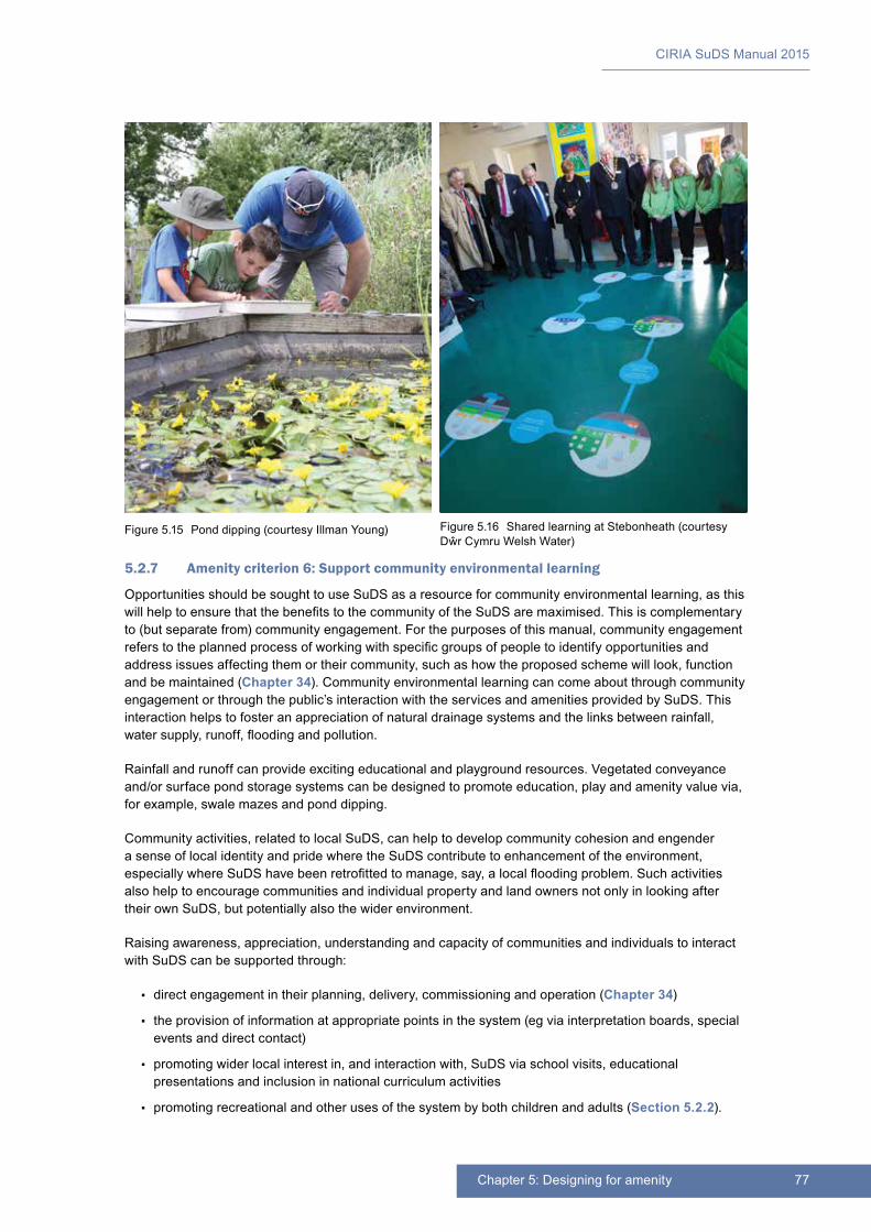
77Chapter 5: Designing for amenity
CIRIA SuDS Manual 2015
5.2.7 Amenity criterion 6: Support community environmental learning
Opportunities should be sought to use SuDS as a resource for community environmental learning, as this will help to ensure that the benefits to the community of the SuDS are maximised. This is complementary to (but separate from) community engagement. For the purposes of this manual, community engagement refers to the planned process of working with specific groups of people to identify opportunities and address issues affecting them or their community, such as how the proposed scheme will look, function and be maintained (Chapter 34). Community environmental learning can come about through community engagement or through the public’s interaction with the services and amenities provided by SuDS. This interaction helps to foster an appreciation of natural drainage systems and the links between rainfall, water supply, runoff, flooding and pollution.
Rainfall and runoff can provide exciting educational and playground resources. Vegetated conveyance and/or surface pond storage systems can be designed to promote education, play and amenity value via, for example, swale mazes and pond dipping.
Community activities, related to local SuDS, can help to develop community cohesion and engender a sense of local identity and pride where the SuDS contribute to enhancement of the environment, especially where SuDS have been retrofitted to manage, say, a local flooding problem. Such activities also help to encourage communities and individual property and land owners not only in looking after their own SuDS, but potentially also the wider environment.
Raising awareness, appreciation, understanding and capacity of communities and individuals to interact with SuDS can be supported through:
▪▪ direct engagement in their planning, delivery, commissioning and operation (Chapter 34)
▪▪ the provision of information at appropriate points in the system (eg via interpretation boards, special events and direct contact)
▪▪ promoting wider local interest in, and interaction with, SuDS via school visits, educational presentations and inclusion in national curriculum activities
▪▪ promoting recreational and other uses of the system by both children and adults (Section 5.2.2).
Figure 5.15 Pond dipping (courtesy Illman Young) Figure 5.16 Shared learning at Stebonheath (courtesy Dŵr Cymru Welsh Water)
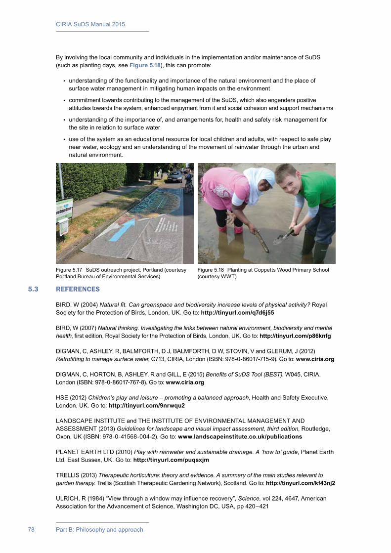
CIRIA SuDS Manual 2015
78 Part B: Philosophy and approach
By involving the local community and individuals in the implementation and/or maintenance of SuDS (such as planting days, see Figure 5.18), this can promote:
▪▪ understanding of the functionality and importance of the natural environment and the place of surface water management in mitigating human impacts on the environment
▪▪ commitment towards contributing to the management of the SuDS, which also engenders positive attitudes towards the system, enhanced enjoyment from it and social cohesion and support mechanisms
▪▪ understanding of the importance of, and arrangements for, health and safety risk management for the site in relation to surface water
▪▪ use of the system as an educational resource for local children and adults, with respect to safe play near water, ecology and an understanding of the movement of rainwater through the urban and natural environment.
5.3 REFERENCES
BIRD, W (2004) Natural fit. Can greenspace and biodiversity increase levels of physical activity? Royal Society for the Protection of Birds, London, UK. Go to: http://tinyurl.com/q7d6j55
BIRD, W (2007) Natural thinking. Investigating the links between natural environment, biodiversity and mental health, first edition, Royal Society for the Protection of Birds, London, UK. Go to: http://tinyurl.com/p86knfg
DIGMAN, C, ASHLEY, R, BALMFORTH, D J, BALMFORTH, D W, STOVIN, V and GLERUM, J (2012) Retrofitting to manage surface water, C713, CIRIA, London (ISBN: 978-0-86017-715-9). Go to: www.ciria.org
DIGMAN, C, HORTON, B, ASHLEY, R and GILL, E (2015) Benefits of SuDS Tool (BEST), W045, CIRIA, London (ISBN: 978-0-86017-767-8). Go to: www.ciria.org
HSE (2012) Children’s play and leisure – promoting a balanced approach, Health and Safety Executive, London, UK. Go to: http://tinyurl.com/9nrwqu2
LANDSCAPE INSTITUTE and THE INSTITUTE OF ENVIRONMENTAL MANAGEMENT AND ASSESSMENT (2013) Guidelines for landscape and visual impact assessment, third edition, Routledge, Oxon, UK (ISBN: 978-0-41568-004-2). Go to: www.landscapeinstitute.co.uk/publications
PLANET EARTH LTD (2010) Play with rainwater and sustainable drainage. A ‘how to’ guide, Planet Earth Ltd, East Sussex, UK. Go to: http://tinyurl.com/puqsxjm
TRELLIS (2013) Therapeutic horticulture: theory and evidence. A summary of the main studies relevant to garden therapy. Trellis (Scottish Therapeutic Gardening Network), Scotland. Go to: http://tinyurl.com/kf43nj2
ULRICH, R (1984) “View through a window may influence recovery”, Science, vol 224, 4647, American Association for the Advancement of Science, Washington DC, USA, pp 420–421
Figure 5.17 SuDS outreach project, Portland (courtesy Portland Bureau of Environmental Services)
Figure 5.18 Planting at Coppetts Wood Primary School (courtesy WWT)

79Chapter 5: Designing for amenity
CIRIA SuDS Manual 2015
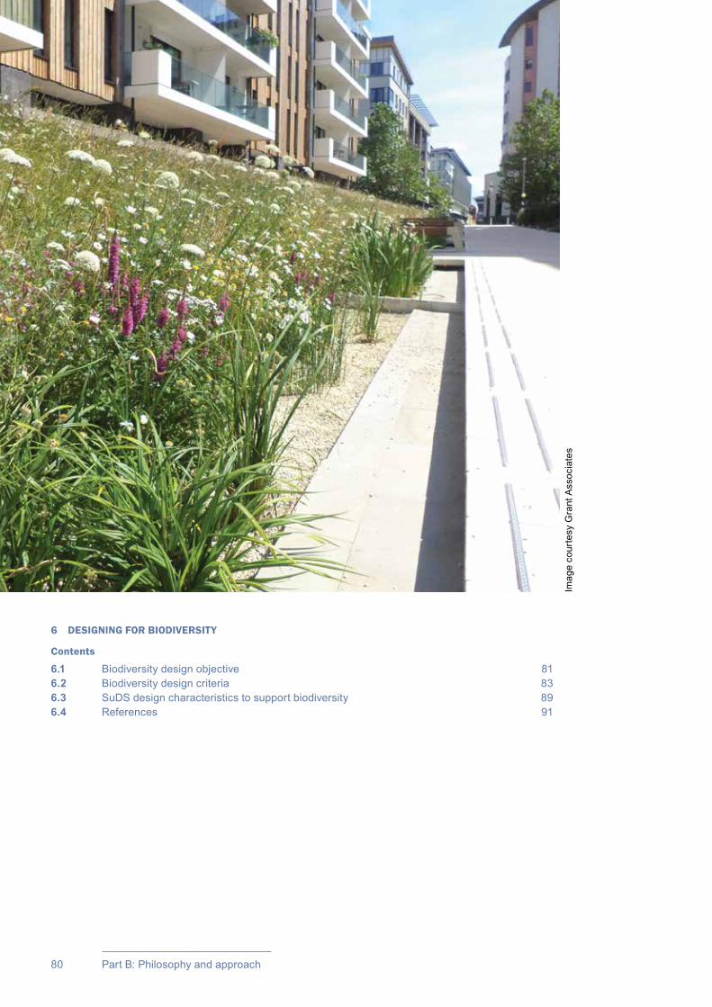
CIRIA SuDS Manual 2015
80 Part B: Philosophy and approach
6 DESIGNING FOR BIODIVERSITY
Contents
6.1 Biodiversity design objective 816.2 Biodiversity design criteria 836.3 SuDS design characteristics to support biodiversity 896.4 References 91
Imag
e co
urte
sy G
rant
Ass
ocia
tes

81Chapter 6: Designing for biodiversity
CIRIA SuDS Manual 2015
6.1 BIODIVERSITY DESIGN OBJECTIVE
Create and sustain better places for nature
Policy-makers now recognise the important contribution that designing for biodiversity can make to ecosystem services (Box 6.1) and improved community “living” space. “Connecting people with nature” is a UK government objective (Defra, 2011), which SuDS can help deliver.
The benefits of creating new habitats and rehabilitating or enhancing existing habitats through SuDS design go far beyond the contribution that planting makes to the functionality and performance of the drainage system (Chapters 3 and 4). Landscape features that support diverse habitats and associated ecosystems provide a healthy and stimulating environment that can add significant value to urban living (Chapter 5). The water within a SuDS component or scheme is an essential resource for the growth and development of plants and animals. Biodiversity value can be delivered by even very small, isolated schemes, but the greatest value is achieved where SuDS are planned as part of wider green landscapes, as they can then help provide important habitat and wildlife connectivity. With good design, SuDS can provide shelter, food and foraging and breeding opportunities for a variety of wildlife species including plants, amphibians, invertebrates, birds, bats and other mammals.
Designing SuDS space for biodiversity requires drainage designers, urban and landscape designers, planners and ecologists to work together. For many sites, a qualified ecologist is likely to be required for the project. However, all members of the SuDS design team should understand the principles behind designing for biodiversity and should recognise the benefits that result.
Amenity and biodiversity are often considered together, but they are each important in their own right and, although the overlaps and linkages should be recognised by designers, they are dealt with in separate chapters of this manual. Designing for amenity is discussed in Chapter 5. Creating and sustaining as many amenity and biodiversity benefits as possible should be considered alongside designing for water quantity and quality.
The design of habitats in SuDS needs consideration and integration at all stages in the planning process, from master planning to detailed design (Chapter 7), taking into consideration broader green infrastructure objectives where applicable, if it is to deliver maximum biodiversity value. There are well-established techniques for creating habitats in new landscapes serving developments, and these are described in general habitat creation guidance in Dale et al (2011) and for previously developed land in Jackson et al (2011). The formal process of integrating biodiversity considerations and delivery into all stages of the planning, design and development process is set out in BS 42020:2013.
06Chapter Designing for biodiversity
This chapter explains the objective of designing for biodiversity and the design criteria that should be followed to deliver this objective.
This chapter should be read alongside Chapters 3–5 to understand how the different SuDS design criteria relate to each other, and Chapter 7 to understand when and how to apply these criteria.Guidance on planting can be found in Chapter 29.

CIRIA SuDS Manual 2015
82 Part B: Philosophy and approach
BOX6.1
Useful definitions
Biodiversity encompasses the number, abundance and distribution of all species of life on earth. It includes the diversity of individual species, the genetic diversity within species and the range of habitats that support them. Biodiversity also includes humans and our interactions with the environment (Dale et al, 2011). Locally, biodiversity reflects the character of the plants and wildlife that share the space in which humans live, work and play.
Ecology is the study of plants and animals and the relationships between them and their physical environment.
An ecosystem is a biological community and its physical environment (Dale et al, 2011). Reconciliation ecology is the branch of ecology that studies ways to encourage biodiversity in human-dominated (eg urban) ecosystems.
Ecosystem services are the benefits provided by ecosystems that contribute to making human life both possible and worth living. Examples of ecosystem services include products such as food and water, regulation of floods, soil erosion and disease outbreaks, and non-material benefits such as recreational and spiritual benefits in natural areas (Albon et al, 2011).
Natural capital refers to the elements of nature that produce value to people, such as the stock of forests, water, land, minerals and oceans. These provide benefits such as food, clean air, wildlife, energy, wood, recreation and protection from hazards (Natural Capital Committee: http://tinyurl.com/ow3qf76).
Green infrastructure is a term to describe strategically planned and interconnected networks of natural and manmade green spaces (including blue space) or corridors that deliver a function for the local community.
TABLE6.1
Biodiversity design criteria and example indicators
Biodiversity design criteria Example indicator
1 Support and protect natural local habitat and species
The extent, quality and significance of local habitats supported or enhanced by the SuDS design
2 Contribute to the delivery of local biodiversity objectives
The habitats delivered by the SuDS design that meet objectives set out in local biodiversity frameworks/strategies
3 Contribute to habitat connectivityThe extent to which the SuDS scheme is integrated with wider green infrastructure strategies, or is helping to support or connect habitats.
4 Create diverse, self-sustaining and resilient ecosystems
The range and diversity of habitat types delivered or supported by the SuDS design, and the likely resilience of these habitats and the ecosystems they support to potential future change
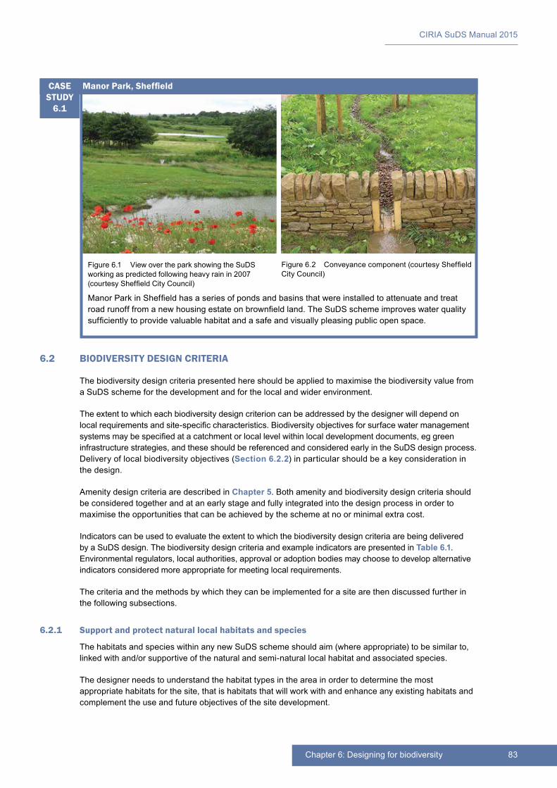
83Chapter 6: Designing for biodiversity
CIRIA SuDS Manual 2015
Figure 6.1 View over the park showing the SuDS working as predicted following heavy rain in 2007 (courtesy Sheffield City Council)
Figure 6.2 Conveyance component (courtesy Sheffield City Council)
Manor Park in Sheffield has a series of ponds and basins that were installed to attenuate and treat road runoff from a new housing estate on brownfield land. The SuDS scheme improves water quality sufficiently to provide valuable habitat and a safe and visually pleasing public open space.
Manor Park, SheffieldCASE STUDY
6.1
6.2 BIODIVERSITY DESIGN CRITERIA
The biodiversity design criteria presented here should be applied to maximise the biodiversity value from a SuDS scheme for the development and for the local and wider environment.
The extent to which each biodiversity design criterion can be addressed by the designer will depend on local requirements and site-specific characteristics. Biodiversity objectives for surface water management systems may be specified at a catchment or local level within local development documents, eg green infrastructure strategies, and these should be referenced and considered early in the SuDS design process. Delivery of local biodiversity objectives (Section 6.2.2) in particular should be a key consideration in the design.
Amenity design criteria are described in Chapter 5. Both amenity and biodiversity design criteria should be considered together and at an early stage and fully integrated into the design process in order to maximise the opportunities that can be achieved by the scheme at no or minimal extra cost.
Indicators can be used to evaluate the extent to which the biodiversity design criteria are being delivered by a SuDS design. The biodiversity design criteria and example indicators are presented in Table 6.1. Environmental regulators, local authorities, approval or adoption bodies may choose to develop alternative indicators considered more appropriate for meeting local requirements.
The criteria and the methods by which they can be implemented for a site are then discussed further in the following subsections.
6.2.1 Support and protect natural local habitats and species
The habitats and species within any new SuDS scheme should aim (where appropriate) to be similar to, linked with and/or supportive of the natural and semi-natural local habitat and associated species.
The designer needs to understand the habitat types in the area in order to determine the most appropriate habitats for the site, that is habitats that will work with and enhance any existing habitats and complement the use and future objectives of the site development.

CIRIA SuDS Manual 2015
84 Part B: Philosophy and approach
Characterising the main ecological communities that might naturally thrive in the locality is an effective starting point to define how best to conserve or create supportive habitats through the use of SuDS. Characterisation methods are described in Chapter 7.
The most appropriate ecological design for the site will depend on:
▪▪ habitats and biodiversity that thrive naturally in the locality
▪▪ wider regional habitats and biodiversity for which the provision of connectivity through the implementation of the SuDS would be of value
▪▪ whether there are significant natural local habitats such as wetlands that have been lost or fragmented over time, and whether it is appropriate for these to be recreated or reconnected as part of the development drainage design
▪▪ the characteristics of the site that will influence the suitability of vegetation, habitat types and the species they support, such as aspect, topography, soils, local climatic and hydrological variables
▪▪ the requirements of the new site and local community, for example proposed and/or existing use, amenity provision, development landscape character and style.
Figure 6.3 Green roof at Horniman Museum, London (courtesy Gary Grant)
A ten-year survey found that the green roof at Horniman Museum developed into species-rich grassland supporting a number of plants notable to London. This roof created the opportunity for these species to thrive and be enjoyed in a protected environment. The south-facing section is sandy and dry, dominated by grasses. The roof supports abundant meadow wildflowers and taller meadow grasses on the wetter north-facing section, and gaps in the turf have allowed further plant species and mosses to flourish.
Green roof at Horniman Museum, LondonCASE STUDY
6.2

85Chapter 6: Designing for biodiversity
CIRIA SuDS Manual 2015
6.2.2 Contribute to the delivery of local biodiversity objectives
SuDS design should prioritise habitats and species objectives that contribute to local, regional and national biodiversity targets (Four Countries’ Biodiversity Group, 2012).
Across Europe it is increasingly being recognised that there is a need to protect threatened species and habitats and promote biodiversity, including restoration of habitats (wildflower grasses, wetlands etc). SuDS can often be designed to benefit priority habitats (defined as those most threatened and requiring conservation action) and help deliver strategic objectives set out in national and local biodiversity strategies, frameworks and action plans.
National strategies recognise the importance of local level initiatives in creating and sustaining biodiversity, and the funding provided for biodiversity schemes can often help to co-fund and deliver better surface water management schemes (where these are supportive of biodiversity). When designing SuDS, co-operation with those delivering local biodiversity strategies (including Local Nature Partnerships) will ease approvals and also provide new opportunities to add value.
Effective and sympathetic Maintenance Plans for SuDS that take account of the wildlife supported by the habitat provided are essential, particularly where protected species such as bats, birds in the breeding season, water voles and great crested newts and other important invertebrates and mammals are likely to be present. It is important to seek expert advice from ecologists to produce a plan that maintains a favourable habitat for wildlife and, where they exist, protects sensitive and legally protected species. If protected species are recorded or designed for at the proposed site, details of the legal requirements associated with the species should be sought from relevant government agency guidance.
General guidance on Maintenance Plans is set out in Chapter 32 and maintenance requirements for specific SuDS components are provided in the individual technical component chapters (Chapters 11–23).
6.2.3 Contribute to habitat connectivity
The habitats within any new SuDS scheme should, where possible, link with other local and/or regional habitats to help build and enhance habitat connectivity within neighbourhoods and between rural/suburban areas and towns/cities. This will help mitigate the problems associated with habitat loss and fragmentation within urban areas. The SuDS design should consider existing or future planned habitat corridors and networks, and evaluate how the SuDS on the site can best support or contribute to these wider objectives by providing linking habitats or stepping stones – allowing wildlife to move from and to rural areas, as well as being urban habitats in their own right.
Green infrastructure is vital to the creation and maintenance of ecological function in urban space providing habitats for fauna in their own right, pathways for migrating animals and natural plant colonisation, as well as safe passage for surface water runoff that exceeds the drainage system capacity.
Healthy ecologically functioning habitats can be promoted by linking proposed development sites to adjacent areas with established or latent biodiversity potential and ideally with a well-developed assemblage of plants and animals that can easily colonise the new spaces created by the SuDS design. Unless there is significant existing contamination, all sites are likely to become colonised by plants, followed by animal species. Best practice SuDS design for biodiversity can ensure that this colonisation is high quality, high value and as rapid and robust as possible.
Examples of new developments where the design of the site is laid out around green corridors that convey surface water are shown in Figure 6.4.
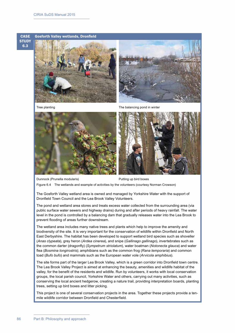
CIRIA SuDS Manual 2015
86 Part B: Philosophy and approach
Tree planting The balancing pond in winter
Dunnock (Prunella modularis) Putting up bird boxes
Figure 6.4 The wetlands and example of activities by the volunteers (courtesy Norman Crowson)
The Gosforth Valley wetland area is owned and managed by Yorkshire Water with the support of Dronfield Town Council and the Lea Brook Valley Volunteers.
The pond and wetland area stores and treats excess water collected from the surrounding area (via public surface water sewers and highway drains) during and after periods of heavy rainfall. The water level in the pond is controlled by a balancing dam that gradually releases water into the Lea Brook to prevent flooding of areas further downstream.
The wetland area includes many native trees and plants which help to improve the amenity and biodiversity of the site. It is very important for the conservation of wildlife within Dronfield and North East Derbyshire. The habitat has been developed to support wetland bird species such as shoveller (Anas clypeata), grey heron (Ardea cinerea), and snipe (Gallinago gallinago), invertebrates such as the common darter (dragonfly) (Sympetrum striolatum), water boatman (Notonecta glauca) and water flea (Bosmina longirostris); amphibians such as the common frog (Rana temporaria) and common toad (Bufo bufo) and mammals such as the European water vole (Arvicola amphibius).
The site forms part of the larger Lea Brook Valley, which is a green corridor into Dronfield town centre. The Lea Brook Valley Project is aimed at enhancing the beauty, amenities and wildlife habitat of the valley, for the benefit of the residents and wildlife. Run by volunteers, it works with local conservation groups, the local parish council, Yorkshire Water and others, carrying out many activities, such as conserving the local ancient hedgerow, creating a nature trail, providing interpretation boards, planting trees, setting up bird boxes and litter picking.
This project is one of several conservation projects in the area. Together these projects provide a ten-mile wildlife corridor between Dronfield and Chesterfield.
Gosforth Valley wetlands, DronfieldCASE STUDY
6.3
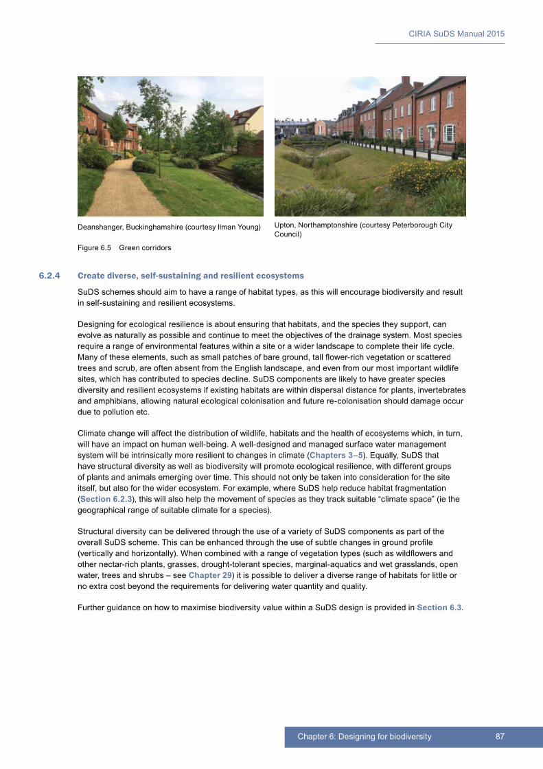
87Chapter 6: Designing for biodiversity
CIRIA SuDS Manual 2015
6.2.4 Create diverse, self-sustaining and resilient ecosystems
SuDS schemes should aim to have a range of habitat types, as this will encourage biodiversity and result in self-sustaining and resilient ecosystems.
Designing for ecological resilience is about ensuring that habitats, and the species they support, can evolve as naturally as possible and continue to meet the objectives of the drainage system. Most species require a range of environmental features within a site or a wider landscape to complete their life cycle. Many of these elements, such as small patches of bare ground, tall flower-rich vegetation or scattered trees and scrub, are often absent from the English landscape, and even from our most important wildlife sites, which has contributed to species decline. SuDS components are likely to have greater species diversity and resilient ecosystems if existing habitats are within dispersal distance for plants, invertebrates and amphibians, allowing natural ecological colonisation and future re-colonisation should damage occur due to pollution etc.
Climate change will affect the distribution of wildlife, habitats and the health of ecosystems which, in turn, will have an impact on human well-being. A well-designed and managed surface water management system will be intrinsically more resilient to changes in climate (Chapters 3–5). Equally, SuDS that have structural diversity as well as biodiversity will promote ecological resilience, with different groups of plants and animals emerging over time. This should not only be taken into consideration for the site itself, but also for the wider ecosystem. For example, where SuDS help reduce habitat fragmentation (Section 6.2.3), this will also help the movement of species as they track suitable “climate space” (ie the geographical range of suitable climate for a species).
Structural diversity can be delivered through the use of a variety of SuDS components as part of the overall SuDS scheme. This can be enhanced through the use of subtle changes in ground profile (vertically and horizontally). When combined with a range of vegetation types (such as wildflowers and other nectar-rich plants, grasses, drought-tolerant species, marginal-aquatics and wet grasslands, open water, trees and shrubs – see Chapter 29) it is possible to deliver a diverse range of habitats for little or no extra cost beyond the requirements for delivering water quantity and quality.
Further guidance on how to maximise biodiversity value within a SuDS design is provided in Section 6.3.
Deanshanger, Buckinghamshire (courtesy llman Young) Upton, Northamptonshire (courtesy Peterborough City Council)
Figure 6.5 Green corridors
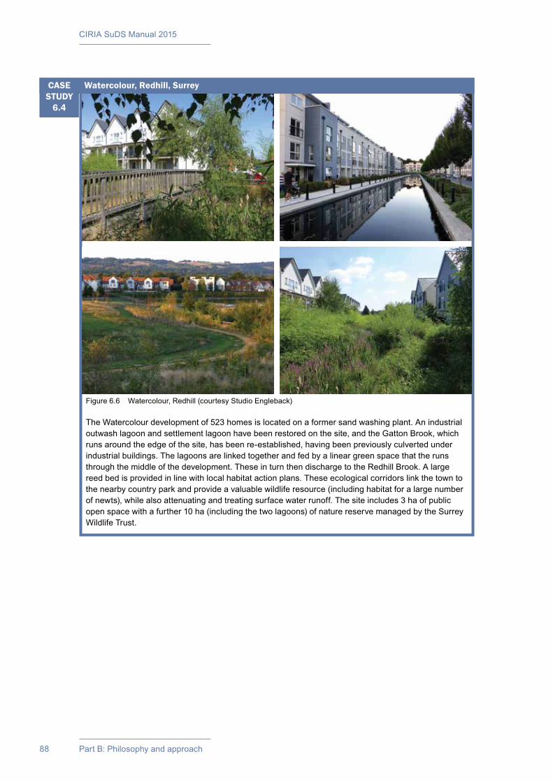
CIRIA SuDS Manual 2015
88 Part B: Philosophy and approach
Figure 6.6 Watercolour, Redhill (courtesy Studio Engleback)
The Watercolour development of 523 homes is located on a former sand washing plant. An industrial outwash lagoon and settlement lagoon have been restored on the site, and the Gatton Brook, which runs around the edge of the site, has been re-established, having been previously culverted under industrial buildings. The lagoons are linked together and fed by a linear green space that the runs through the middle of the development. These in turn then discharge to the Redhill Brook. A large reed bed is provided in line with local habitat action plans. These ecological corridors link the town to the nearby country park and provide a valuable wildlife resource (including habitat for a large number of newts), while also attenuating and treating surface water runoff. The site includes 3 ha of public open space with a further 10 ha (including the two lagoons) of nature reserve managed by the Surrey Wildlife Trust.
Watercolour, Redhill, SurreyCASE STUDY
6.4
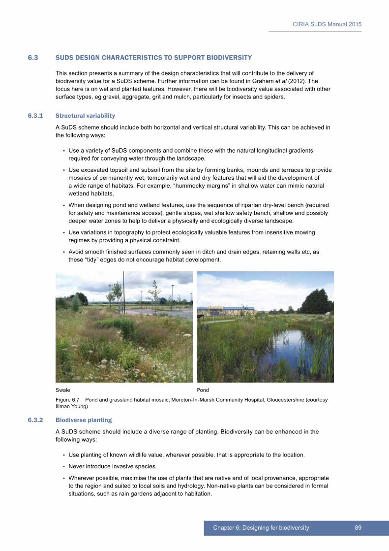
89Chapter 6: Designing for biodiversity
CIRIA SuDS Manual 2015
6.3 SUDS DESIGN CHARACTERISTICS TO SUPPORT BIODIVERSITY
This section presents a summary of the design characteristics that will contribute to the delivery of biodiversity value for a SuDS scheme. Further information can be found in Graham et al (2012). The focus here is on wet and planted features. However, there will be biodiversity value associated with other surface types, eg gravel, aggregate, grit and mulch, particularly for insects and spiders.
6.3.1 Structural variability
A SuDS scheme should include both horizontal and vertical structural variability. This can be achieved in the following ways:
▪▪ Use a variety of SuDS components and combine these with the natural longitudinal gradients required for conveying water through the landscape.
▪▪ Use excavated topsoil and subsoil from the site by forming banks, mounds and terraces to provide mosaics of permanently wet, temporarily wet and dry features that will aid the development of a wide range of habitats. For example, “hummocky margins” in shallow water can mimic natural wetland habitats.
▪▪ When designing pond and wetland features, use the sequence of riparian dry-level bench (required for safety and maintenance access), gentle slopes, wet shallow safety bench, shallow and possibly deeper water zones to help to deliver a physically and ecologically diverse landscape.
▪▪ Use variations in topography to protect ecologically valuable features from insensitive mowing regimes by providing a physical constraint.
▪▪ Avoid smooth finished surfaces commonly seen in ditch and drain edges, retaining walls etc, as these “tidy” edges do not encourage habitat development.
6.3.2 Biodiverse planting
A SuDS scheme should include a diverse range of planting. Biodiversity can be enhanced in the following ways:
▪▪ Use planting of known wildlife value, wherever possible, that is appropriate to the location.
▪▪ Never introduce invasive species.
▪▪ Wherever possible, maximise the use of plants that are native and of local provenance, appropriate to the region and suited to local soils and hydrology. Non-native plants can be considered in formal situations, such as rain gardens adjacent to habitation.
Swale Pond
Figure 6.7 Pond and grassland habitat mosaic, Moreton-In-Marsh Community Hospital, Gloucestershire (courtesy Illman Young)

CIRIA SuDS Manual 2015
90 Part B: Philosophy and approach
▪▪ Where non-native plants are used, only use plants of high nectar and aesthetic value. They should not be invasive, or liable to spread into and impact on important sensitive habitats, or dominate the planting scheme in which they have been included.
▪▪ Choose species which, when planted together, maximise all-year-round leaf coverage, flowering and fruiting periods to provide food and shelter for invertebrates and birds.
▪▪ Allow natural colonisation by plants and animals of desired/intended species to take place during the SuDS establishment process.
▪▪ Provide a variety of heights of grasses throughout the site, as wildlife will utilise grasses of different heights in a variety of ways (Box 6.2).
▪▪ Encourage flowers into grasslands (by natural colonisation, seeding or planting), as these provide nectar for a variety of insects.
▪▪ Consider planting gravel surfaces with nectar-rich plants, tolerant of drought, foot and vehicle damage, for example chamomile and thyme.
▪▪ Where SuDS components require 100% vegetation cover before the system is commissioned (eg swales) which means that turfing is essential, use flower-rich turf or add wildflower plugs to standard turf.
▪▪ Where necessary, use turfs that can withstand high flows and extended periods of waterlogging.
▪▪ Include trees, scrub and wet woodland features. These can increase habitats for amphibians and invertebrates and provide some valuable shaded areas. Appropriate management of these areas will be required to ensure that the intended biodiversity is retained.
▪▪ Maximise opportunities for providing or retaining dead wood in dry or wet areas. Dead and decaying wood is valuable for mosses, lichen and fungi. It is also particularly important for invertebrates, as many species rely on it for completing all or part of their life cycles. Standing deadwood can also provide cavities for birds and bats for breeding and roosting.
See Chapter 29 for further guidance on planting.
6.3.3 Biodiverse water features
A SuDS scheme should include biodiverse and resilient water features. These can be achieved in the following ways:
▪▪ Manage the risk of toxic, pathogenic or otherwise harmful substances and silts that can smother wildlife being discharged into the water feature (Chapter 4).
▪▪ Where possible, retain existing habitats and incorporate these into the landscape design, and locate SuDS near to less intensively managed landscapes that are near to (but not connected to) natural ponds and wetlands.
Box6.2
The importance of grasslands
Grasslands are particularly important for wildlife. For example:
▪ Birds and mammals will forage for seeds and insects in different lengths of grass.
▪ Taller grasses will help retain humidity and soil moisture, which will in turn benefit soil invertebrates.
▪ Longer swards provide somewhere for the eggs, pupae or larvae of some insects to over-winter in the grass thatch. They will also be used by bumble bees for nesting.
▪ Beneath trees and adjacent to shrubs, invertebrates that feed in the trees and bushes can pupate in the grass to complete their life cycle.
▪ Flying insects may shelter in longer grass during rain or sudden changes in temperature and roost overnight.
▪ Reptiles and amphibians will search for insects in longer grass and use it as cover when moving between sites.
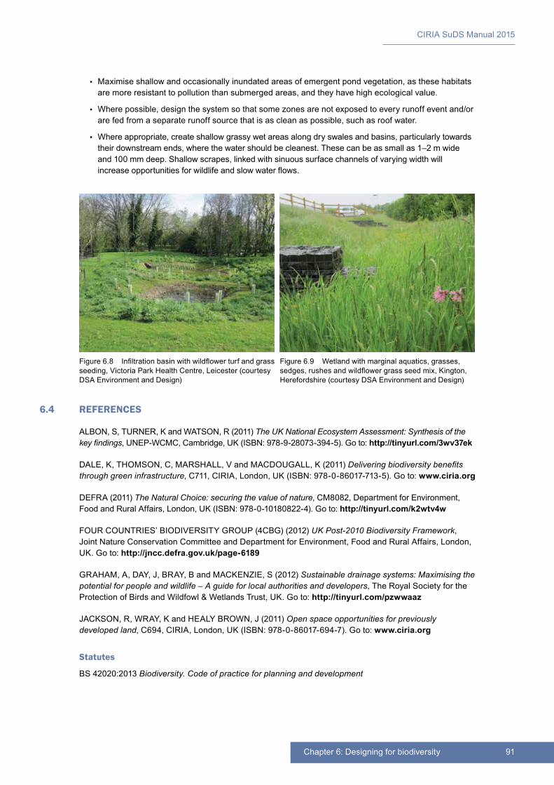
91Chapter 6: Designing for biodiversity
CIRIA SuDS Manual 2015
▪▪ Maximise shallow and occasionally inundated areas of emergent pond vegetation, as these habitats are more resistant to pollution than submerged areas, and they have high ecological value.
▪▪ Where possible, design the system so that some zones are not exposed to every runoff event and/or are fed from a separate runoff source that is as clean as possible, such as roof water.
▪▪ Where appropriate, create shallow grassy wet areas along dry swales and basins, particularly towards their downstream ends, where the water should be cleanest. These can be as small as 1–2 m wide and 100 mm deep. Shallow scrapes, linked with sinuous surface channels of varying width will increase opportunities for wildlife and slow water flows.
6.4 REFERENCES
ALBON, S, TURNER, K and WATSON, R (2011) The UK National Ecosystem Assessment: Synthesis of the key findings, UNEP-WCMC, Cambridge, UK (ISBN: 978-9-28073-394-5). Go to: http://tinyurl.com/3wv37ek
DALE, K, THOMSON, C, MARSHALL, V and MACDOUGALL, K (2011) Delivering biodiversity benefits through green infrastructure, C711, CIRIA, London, UK (ISBN: 978-0-86017-713-5). Go to: www.ciria.org
DEFRA (2011) The Natural Choice: securing the value of nature, CM8082, Department for Environment, Food and Rural Affairs, London, UK (ISBN: 978-0-10180822-4). Go to: http://tinyurl.com/k2wtv4w
FOUR COUNTRIES’ BIODIVERSITY GROUP (4CBG) (2012) UK Post-2010 Biodiversity Framework, Joint Nature Conservation Committee and Department for Environment, Food and Rural Affairs, London, UK. Go to: http://jncc.defra.gov.uk/page-6189
GRAHAM, A, DAY, J, BRAY, B and MACKENZIE, S (2012) Sustainable drainage systems: Maximising the potential for people and wildlife – A guide for local authorities and developers, The Royal Society for the Protection of Birds and Wildfowl & Wetlands Trust, UK. Go to: http://tinyurl.com/pzwwaaz
JACKSON, R, WRAY, K and HEALY BROWN, J (2011) Open space opportunities for previously developed land, C694, CIRIA, London, UK (ISBN: 978-0-86017-694-7). Go to: www.ciria.org
Statutes
BS 42020:2013 Biodiversity. Code of practice for planning and development
Figure 6.8 Infiltration basin with wildflower turf and grass seeding, Victoria Park Health Centre, Leicester (courtesy DSA Environment and Design)
Figure 6.9 Wetland with marginal aquatics, grasses, sedges, rushes and wildflower grass seed mix, Kington, Herefordshire (courtesy DSA Environment and Design)
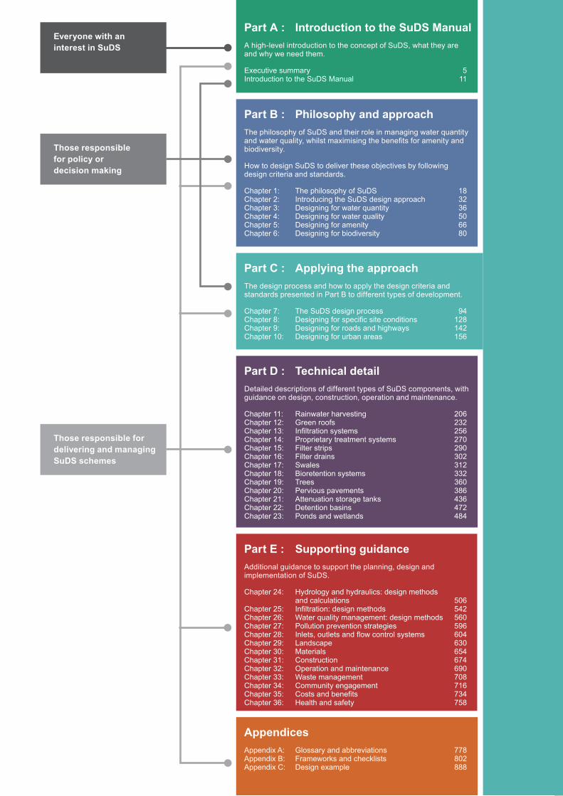
Part C : Applying the approachThe design process and how to apply the design criteria and standards presented in Part B to different types of development.
Chapter 7: The SuDS design process 94Chapter 8: Designing for specific site conditions 128Chapter 9: Designing for roads and highways 142Chapter 10: Designing for urban areas 156
Part D : Technical detailDetailed descriptions of different types of SuDS components, with guidance on design, construction, operation and maintenance.
Chapter 11: Rainwater harvesting 206Chapter 12: Green roofs 232Chapter 13: Infiltration systems 256Chapter 14: Proprietary treatment systems 270Chapter 15: Filter strips 290Chapter 16: Filter drains 302Chapter 17: Swales 312Chapter 18: Bioretention systems 332Chapter 19: Trees 360Chapter 20: Pervious pavements 386Chapter 21: Attenuation storage tanks 436Chapter 22: Detention basins 472Chapter 23: Ponds and wetlands 484
Part A : Introduction to the SuDS ManualA high-level introduction to the concept of SuDS, what they are and why we need them.
Executive summary 5Introduction to the SuDS Manual 11
Part B : Philosophy and approachThe philosophy of SuDS and their role in managing water quantity and water quality, whilst maximising the benefits for amenity and biodiversity.
How to design SuDS to deliver these objectives by following design criteria and standards.
Chapter 1: The philosophy of SuDS 18Chapter 2: Introducing the SuDS design approach 32Chapter 3: Designing for water quantity 36Chapter 4: Designing for water quality 50Chapter 5: Designing for amenity 66Chapter 6: Designing for biodiversity 80
Part E : Supporting guidanceAdditional guidance to support the planning, design and implementation of SuDS.
Chapter 24: Hydrology and hydraulics: design methods and calculations 506Chapter 25: Infiltration: design methods 542Chapter 26: Water quality management: design methods 560Chapter 27: Pollution prevention strategies 596Chapter 28: Inlets, outlets and flow control systems 604Chapter 29: Landscape 630Chapter 30: Materials 654Chapter 31: Construction 674Chapter 32: Operation and maintenance 690Chapter 33: Waste management 708Chapter 34: Community engagement 716Chapter 35: Costs and benefits 734Chapter 36: Health and safety 758
AppendicesAppendix A: Glossary and abbreviations 778Appendix B: Frameworks and checklists 802Appendix C: Design example 888
Everyone with an interest in SuDS
Those responsible for delivering and managing SuDS schemes
Those responsible for policy or decision making
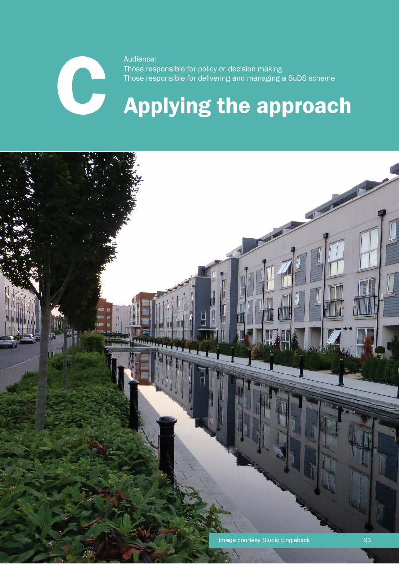
CIRIA SuDS Manual 2015
93Image courtesy Studio Engleback
Applying the approachC Audience: Those responsible for policy or decision makingThose responsible for delivering and managing a SuDS scheme
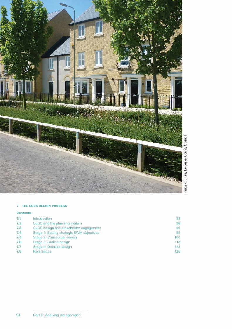
CIRIA SuDS Manual 2015
94 Part C: Applying the approach
7 THE SUDS DESIGN PROCESS
Contents
7.1 Introduction 957.2 SuDS and the planning system 967.3 SuDS design and stakeholder engagement 997.4 Stage 1: Setting strategic SWM objectives 997.5 Stage 2: Conceptual design 1007.6 Stage 3: Outline design 1187.7 Stage 4: Detailed design 1237.8 References 126
Imag
e co
urte
sy L
eice
ster
Cou
nty
Cou
ncil
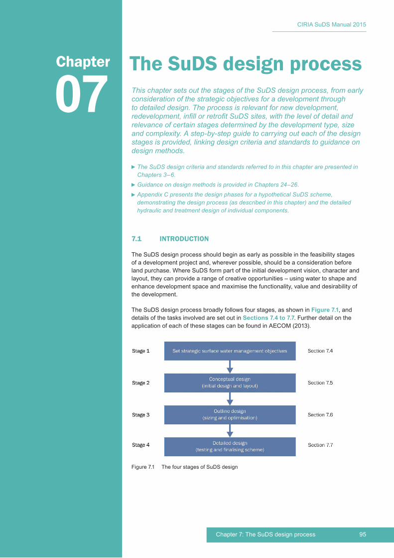
95Chapter 7: The SuDS design process
CIRIA SuDS Manual 2015
The SuDS design process
7.1 INTRODUCTION
The SuDS design process should begin as early as possible in the feasibility stages of a development project and, wherever possible, should be a consideration before land purchase. Where SuDS form part of the initial development vision, character and layout, they can provide a range of creative opportunities – using water to shape and enhance development space and maximise the functionality, value and desirability of the development.
The SuDS design process broadly follows four stages, as shown in Figure 7.1, and details of the tasks involved are set out in Sections 7.4 to 7.7. Further detail on the application of each of these stages can be found in AECOM (2013).
07Chapter
This chapter sets out the stages of the SuDS design process, from early consideration of the strategic objectives for a development through to detailed design. The process is relevant for new development, redevelopment, infill or retrofit SuDS sites, with the level of detail and relevance of certain stages determined by the development type, size and complexity. A step-by-step guide to carrying out each of the design stages is provided, linking design criteria and standards to guidance on design methods.
The SuDS design criteria and standards referred to in this chapter are presented in Chapters 3–6.Guidance on design methods is provided in Chapters 24–26.Appendix C presents the design phases for a hypothetical SuDS scheme, demonstrating the design process (as described in this chapter) and the detailed hydraulic and treatment design of individual components.
Figure 7.1 The four stages of SuDS design
CIRIA SuDS Manual 2015
96 Part C: Applying the approach
The SuDS design process is part of a much larger design process for the development as a whole and will therefore be influenced by the progress of the overall project. This means that there may be the need for iteration between stages, while the overall development and individual building designs progress alongside the SuDS design. For example, the layout of the system conceived at conceptual design stage may need to be reviewed once the preliminary SuDS component sizing has been carried out and as the overall layout for the site is refined.
The guidance in this chapter is most relevant for new development or redevelopment projects, although retrofit considerations are referenced. Detailed guidance on the design process and implementation mechanisms for retrofitting SuDS is provided in CIRIA C713 (Digman et al, 2012).
7.2 SUDS AND THE PLANNING SYSTEM
7.2.1 Integrating SuDS design and land use planning processes
The land use planning system controls development and use of land in the public interest at different scales. It is a plan-led system, requiring forward planning through development plans, and it gives local authority development plan policies pre-eminence in the determination of applications for planning permissions. This permission is required for all development, as defined in various planning Acts and Regulations.
Local criteria relevant to SuDS may be set via a local planning authority’s adopted planning instruments (including flooding and planning documents) and via standards set by drainage approving and/or adoption bodies (which may also refer to national standards where these exist). Both need to be checked before design starts, to ensure that designs are fully compliant with relevant requirements. Water management is an important planning consideration for any new development or redevelopment, with flooding, climate resilience, community value and changes to biodiversity and landscape being relevant material considerations, among others. SuDS can deliver benefits to, and be implemented at, a wide range of scales (from catchments to buildings) and the level of associated planning should be proportionate. Guidance on the incorporation of SuDS requirements into local spatial planning documents is provided in CIRIA C687 (Dickie et al, 2010) and University of Cambridge (2014).
The alignment and integration of the planning and drainage design process stages is set out in Figure 7.2.
For large sites, conceptual design is likely to form part of development master planning (Section 7.2.3), but for smaller sites, formal master planning may not be required. Outline designs will usually be required where outline planning permission is sought, and detailed design will be required for full planning permission. If outline planning permission is not a requirement for the development, then outline and detailed design would normally be undertaken as a single stage. The process steps described for outline design (Section 7.7), however, will still need to be carried out.
7.2.2 The importance of pre-application discussions
Pre-application discussions between planners and developers (or their consultants) is normally a requirement of the planning and/or drainage approval process – particularly for larger sites. It is highly recommended for all sites. These discussions can help significantly in ensuring that the expectations and objectives for the surface water management system, including approval and adoption requirements, are set out at an early stage in the design of development layouts and characteristics. This will also help to ensure that space is used as efficiently and cost-effectively as possible, and will maximise the benefits that can be achieved through effective integration of water management within the development.
In parallel with this, it is also advisable to have early engagement with the affected stakeholders (Section 7.3).
Suggested material for discussion at pre-application stage is set out in Appendix B (Section B.1.1, Table B.1).
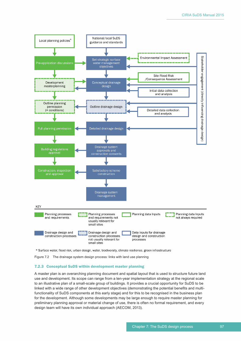
97Chapter 7: The SuDS design process
CIRIA SuDS Manual 2015
7.2.3 Conceptual SuDS within development master planning
A master plan is an overarching planning document and spatial layout that is used to structure future land use and development. Its scope can range from a ten-year implementation strategy at the regional scale to an illustrative plan of a small-scale group of buildings. It provides a crucial opportunity for SuDS to be linked with a wide range of other development objectives (demonstrating the potential benefits and multi-functionality of SuDS components at this early stage) and for this to be recognised in the business plan for the development. Although some developments may be large enough to require master planning for preliminary planning approval or material change of use, there is often no formal requirement, and every design team will have its own individual approach (AECOM, 2013).
Figure 7.2 The drainage system design process: links with land use planning
CIRIA SuDS Manual 2015
98 Part C: Applying the approach
Master planning is a collaborative process that provides the strategic framework for considering the whole range of requirements and objectives for a development and how they might be delivered. It should be a holistic framework within which all relevant stakeholders can contribute and work together in creating high-quality ‘places’ for future generations. It creates the opportunity for the use and management of rainwater and surface runoff to be fully considered in a strategic and collaborative way by drainage engineers, urban designers, highway engineers, architects, landscape architects, ecologists and community stakeholders (Section 7.3). For large sites, the design team will benefit from inputs from all these disciplines as the drainage concepts evolve. For small sites, inputs should be sought where necessary. There are many examples of master plans where surface water management has been used to structure and frame the development (eg Ashton Green, Leicester (Atlas, 2012) and North West Cambridge (University of Cambridge, 2015).
To maximise the value of water to all stakeholders and to deliver the most efficient and cost-effective design solutions, water management should be considered at all design scales. It should influence and enhance individual building form and performance, and then connect plot-level management components into the wider strategic drainage network and landscape setting. By bringing together SuDS with building, urban, service delivery and landscape design and form, designers can achieve a water-sensitive urban design perspective (Abbott et al, 2013).
7.2.4 The challenges of delivering SuDS for phased developments
On large sites where development may be completed in phases, there will need to be a strategic site surface water management system that allows different parts of the site to be developed at different times, while ensuring that each of the design criteria can continue to be met. This strategic system should be designed to manage the flows from the final developed site, and specific conditions will need to be set for each development plot so that the original design assumptions are not invalidated. Delivery of each of the design criteria should be considered at both a site level and a plot level to maximise the benefits and to reduce risks associated with non-development or substantially delayed development.
Consideration should be given to the relative benefits associated with providing strategic storage versus higher levels of plot-based storage or a combination of both. The adoption arrangements for elements of the strategic system that may lie outside the phase being developed will also require careful consideration and facilitation. Relevant catchment or sub-catchment planning strategies may determine where off-site or strategic drainage components are required or proposed, and their design characteristics. Consideration should also be given as to any specific requirements for pollution prevention strategies (affecting either the development design or future operational strategies) to manage pollution risks. This is usually most relevant for industrial sites.
Guidance on pollution prevention strategies is provided in Chapter 27.
7.2.5 SuDS design and the Environmental Impact Assessment
Environmental Impact Assessment (EIA) is the process by which the anticipated effects on the environment of a proposed development or project are measured. If the likely effects are unacceptable, the EIA will suggest design measures or other relevant mitigation measures to reduce or avoid those effects (eg pollution prevention strategies – Chapter 27). An EIA may not be required for smaller development sites.
The EIA may evaluate many of the strategic objectives for the site (Section 7.5) and may also undertake a number of the site and development characterisation steps required as part of the surface water management system conceptual design (Section 7.6). Where an EIA is available, it is likely to be a very valuable reference source for the SuDS designer – particularly the sections covering water resources and flood risk, water quality management, biodiversity, climate resilience, landscape, development character and visual amenity. SuDS may be highlighted in the EIA as a potential means of addressing some of the environmental impacts caused by the development.
99Chapter 7: The SuDS design process
CIRIA SuDS Manual 2015
7.2.6 SuDS design and the Flood Risk/Consequence Assessment
The Flood Risk Assessment (FRA) or Flood Consequence Assessment (FCA) for the site may be undertaken at a similar time to conceptual SuDS design. Delivering conceptual SuDS design as part of the FRA/FCA outputs will tend to make the design process more efficient and integrated, and produce the best outcomes. The FRA/FCA will identify key areas of the site that may or may not be suitable for SuDS components, and will also establish any flood hazards for the operation and performance of the drainage system. The FRA/FCA should also identify any specific requirements for surface water management on the site required by catchment- or sub-catchment-scale flood risk management strategies.
More detail on assessing the impact of pre-development flood risk and the potential impact on surface water management system design is provided in BS 8582:2013.
7.3 SUDS DESIGN AND STAKEHOLDER ENGAGEMENT
Successful delivery of SuDS often depends on co-ordination and communication between the developer/designer and a range of external stakeholders including local authority departments such as planning, drainage and flooding, ecology, open-space management and highways as well as environmental regulators, water and sewerage undertakers, local community group representatives, residents’ organisations and other private sector stakeholders.
There is a need for stakeholder involvement throughout the process of surface water management system design. The land-use planning process should be used to bring together the views of both statutory and non-statutory consultees with other interested parties, such as non-governmental organisations and the general public. This provides a mechanism for planners and environmental regulators to engage with others on SuDS – raising awareness, educating developers and promoting community interaction and learning opportunities.
For retrofit schemes, stakeholder engagement can facilitate potential partnership funding opportunities, where benefits from the scheme will accrue to multiple stakeholders, and this can help with securing the most cost-effective and highest quality schemes. The design process for such schemes should also encourage and involve local communities – the most successful outcomes will be delivered where communities can (because of effective education and awareness raising) act as a ‘client’ and ‘contributor’, understanding the role and opportunities of rainwater and surface water management in the landscape.
Engagement with the local community (whether this is with neighbouring inhabitants for new developments or current residents for retrofit sites) should be part of both the land use planning and SuDS design processes. There are many different engagement processes that can be used (ie inform, consult, involve, collaborate, empower), but most will include an element of education and awareness-raising. Understanding will tend to foster an appreciation of the role and benefits of SuDS in environmental protection, and an enhanced sense of responsibility for their upkeep and protection.
Guidance on working with communities is provided in Chapter 34.
7.4 STAGE 1: SETTING STRATEGIC SWM OBJECTIVES
The first stage of the SuDS design process is the setting of the strategic surface water management (SWM) objectives for the development.
Consultation with relevant stakeholders (Section 7.3) and reference to adopted local planning and regulatory guidance, policy (Section 7.2.1) and the site Environmental Impact Assessment (Section 7.2.5) and flood risk/consequence assessment (where available – see Section 7.2.6) should establish relevant local or site-specific strategic objectives including:
▪ flood risk management objectives
CIRIA SuDS Manual 2015
100 Part C: Applying the approach
▪ water quality management objectives
▪ community, social and amenity planning objectives
▪ habitat and biodiversity strategy requirements and needs
▪ viable long-term maintenance bodies for the proposed SuDS and any relevant SuDS adoption requirements (eg standards, criteria and/or guidance)
▪ climate change adaptation/climate resilience requirements and needs
▪ water supply objectives and constraints.
Early consideration of surface water management will provide designers with the opportunity to use SuDS that respond to the local context and character, enriching both the natural and built environment. By fully integrating the management of surface water with the wider development objectives and by considering all space as potentially multi-functional, surface water management systems can be used to enhance development viability by delivering the design criteria described in Chapters 3–6. This can result in a range of benefits, such as:
▪ an alternative water resource to improve future water security
▪ higher value amenity, recreation and education facilities within public open space
▪ improved habitats and biodiversity
▪ improved climate resilience for the development
▪ reduced pressure on sewerage infrastructure and reduced surface water flooding
▪ a natural ‘structure’ to the layout of the site where transport routes, public open space and buildings are aligned with flow conveyance routes, and public open space is integrated with green and blue flow storage and treatment components
▪ a mechanism for enhancing and defining the quality, character and visual aesthetics of both the built environment and green/open space
▪ a surface water management system that can be easily and cost-effectively maintained.
General guidance on using SuDS to deliver multiple benefits can be found in Chapter 1.
Guidance on opportunities for multi-functionality can be found in Chapters 5 and 10.
Guidance on delivering water quantity, water quality, amenity and biodiversity benefits can be found in Chapters 3–6 respectively.
Guidance on assessing the value of benefits can be found in Chapter 35.
7.5 STAGE 2: CONCEPTUAL DESIGN
The second stage of the SuDS design process is the conceptual design. The key outcome of this stage is to identify and assess potential SuDS components and linkages, in developing Management Trains for each area of the site.
The conceptual design stage process is shown in Figure 7.3 and described in the sections below.
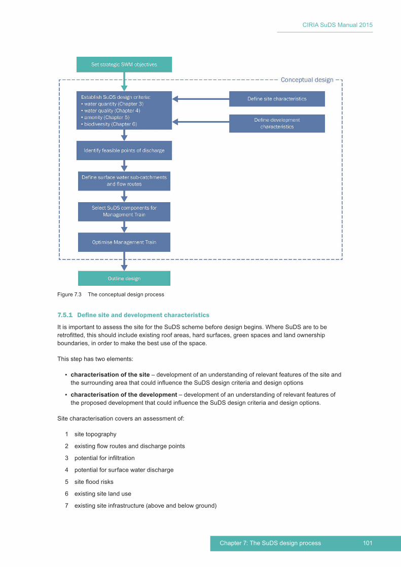
101Chapter 7: The SuDS design process
CIRIA SuDS Manual 2015
7.5.1 Definesiteanddevelopmentcharacteristics
It is important to assess the site for the SuDS scheme before design begins. Where SuDS are to be retrofitted, this should include existing roof areas, hard surfaces, green spaces and land ownership boundaries, in order to make the best use of the space.
This step has two elements:
▪ characterisation of the site – development of an understanding of relevant features of the site and the surrounding area that could influence the SuDS design criteria and design options
▪ characterisation of the development – development of an understanding of relevant features of the proposed development that could influence the SuDS design criteria and design options.
Site characterisation covers an assessment of:
1 site topography
2 existing flow routes and discharge points
3 potential for infiltration
4 potential for surface water discharge
5 site flood risks
6 existing site land use
7 existing site infrastructure (above and below ground)
Figure 7.3 The conceptual design process

CIRIA SuDS Manual 2015
102 Part C: Applying the approach
8 existing soils
9 local habitats and biodiversity
10 local landscape and townscape.
Development characterisation covers an assessment of:
11 proposed topography, land use and landscape characteristics
12 proposed flood risk management strategy
13 proposed site infrastructure
14 proposed building style and form
15 proposed adoption and maintenance of the surface water management system.
Each of these subjects is discussed in the sections below.
1 Site topography
▪ Do the site contours mean that flow paths will naturally occur in particular locations?
▪ Are there any low-lying areas where water will naturally accumulate?
▪ Are there any particularly flat or steep parts of the site?
Topography is a good indication of existing natural drainage pathways and will often help define appropriate natural routes for the surface runoff to follow, in order to efficiently drain the site from higher to lower levels using surface gradients, without relying on extra infrastructure or pumping.
Particularly steep slopes may not be suitable for conveyance routes, without measures to reduce gradients and/or flow velocities, and the siting of storage systems on slopes may require embankments, which should be avoided where possible.
Identification of low-lying areas will demonstrate where water will naturally accumulate, and these may be good locations for siting storage areas. Local historical knowledge and records of surface flooding will be valuable for this process.
Guidance on designing for both sloping and very flat sites is provided in Sections 8.4 and 8.5 respectively.
2 Existingflowroutesanddischargepoints
▪ How is the site currently drained?
▪ What are the existing flow paths across the site?
The natural drainage pattern for the site and existing flow paths and discharge points should be established (as illustrated in Figure 7.4) and an assessment made as to how these are likely to be modified by development. This is determined largely by topography and ground conditions, together with a review of historical drainage measures that have modified the original drainage pattern including land drainage, culverts and sewer networks. Current discharge points (whether to groundwater, surface waters or sewerage systems) should be established and characterised.
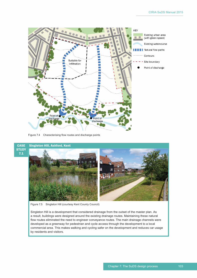
103Chapter 7: The SuDS design process
CIRIA SuDS Manual 2015
Figure 7.5 Singleton Hill (courtesy Kent County Council)
Singleton Hill is a development that considered drainage from the outset of the master plan. As a result, buildings were designed around the existing drainage routes. Maintaining these natural flow routes eliminated the need to engineer conveyance routes. The main drainage channels were developed as a greenway for pedestrian and cycle access through the development to a local commercial area. This makes walking and cycling safer on the development and reduces car usage by residents and visitors.
Singleton Hill, Ashford, KentCASE STUDY
7.1
Figure 7.4 Characterising flow routes and discharge points

CIRIA SuDS Manual 2015
104 Part C: Applying the approach
3 Potentialforinfiltration
▪ Is the soil or groundwater contaminated and, if so, what is the depth of any contamination sealing?
▪ What is the maximum likely groundwater level beneath the site?
▪ Is there any risk of groundwater flooding on or adjacent to the site?
▪ What is the infiltration capacity of the soil beneath the site?
▪ What is the designation of any groundwater resource beneath the site (eg source protection zones)?
▪ Is there a risk of subsidence or other soil instability from infiltrating water?*
▪ Are there any risks associated with infiltrating water close to existing basements, building foundations, tunnels, road/car park pavements or other surface or subsurface infrastructure?*
▪ Are there any constraints to water entry into existing pavement sub-base sections (on or adjacent to the site)?
(*If the area over which infiltration is taking place is large and at shallow depth, and providing the SuDS allow evaporation of water, then the risk is often no greater than that posed by an area of grass.)
The site area should be characterised in terms of the potential for infiltration (eg good/poor/not possible). This will identify areas where infiltration within the site can potentially be used as a method of disposing of surface water runoff, areas where infiltration can be used to deliver Interception (using low infiltration capacities), and areas where infiltration cannot or should not occur.
Guidance on the potential constraints to the use of infiltration and infiltration testing methods is provided in Section 25.2.
Guidance on sites with high groundwater levels, contaminated soils or groundwater is provided in Sections 8.2 and 8.3.
Guidance on the need to deliver Interception is provided in Sections 3.2.3 and 3.3.1 and Sections 4.2.2 and 4.3.1.
Guidance on designing Interception is provided in Section 24.8.
4 Potential for surface water discharge
▪ What options are there regarding discharge destinations?
Local surface waters that may be suitable for discharge of runoff should be evaluated in terms of their capacity, existing flood risk and any environmental or use designations. These will influence the viability of possible discharges and (when considered together with land use) provide an indication of the level of runoff treatment that might be required. If the SuDS are likely to discharge to a surface or combined sewer, then the surface waters receiving discharges from the sewerage system should be assessed.
Where discharges are proposed to existing sewers, early consultation should be undertaken with the relevant sewerage undertaker. Rights to discharge to any receiving watercourse should be established early in the design process, and the relevant stakeholders engaged appropriately.
Guidance on prioritising where surface water runoff is discharged is provided in Section 3.2.3.
5 Sitefloodrisks
▪ Is there a risk of groundwater flooding?
▪ Is there a risk of sewer flooding?
▪ Are there local fluvial and/or coastal flooding risks?
▪ Are there any local surface water flooding issues? If so, where?
▪ Are there any planned mitigation actions?

105Chapter 7: The SuDS design process
CIRIA SuDS Manual 2015
Pre-development flood risk should be established by the flood risk/consequence assessment for the site, which should have been considered during stage 1 (Setting strategic SWM objectives) but should be revisited here.
An assessment needs to be made of the extent to which the identified flood risk could impact on or be impacted by any site surface water management system. Consideration should be given to fluvial, coastal, groundwater, and surface water flood risks on the site, before the proposed development.
Guidance on managing on-site flood risk is provided in Sections 3.2.6 and 3.3.3.
Guidance on SuDS in floodplains is provided in Section 8.8.
6 Existing site land use
▪ How is the site currently used and will this continue after development (for retrofit schemes)?
▪ What opportunities are there to use the site more effectively for surface water management (for retrofit schemes)?
▪ How will the use of the site before the development impact on the extent to which runoff needs to be managed by the SuDS for the proposed site?
Where looking to retrofit SuDS, site surveys and community engagement can help to understand how the space is currently used.
Where the site has been developed previously (ie redevelopment sites), there should always be an aspiration to manage runoff to represent greenfield characteristics. This will help reduce any receiving watercourse flood risk (both now and under future climate change scenarios), thus contributing to more sustainable development. However, it is recognised that redevelopment sites tend to be more constrained in terms of space and infiltration may be more restricted, so drainage approving bodies (in conjunction with the environmental regulator) may agree that reductions to an agreed proportion of the previously developed rates/volumes are acceptable.
7 Existing site infrastructure
▪ What is the location, depth and capacity of existing drainage?
▪ Where are existing services located (including depth)?
▪ Are there any existing unique assets in the street(s) (eg sewer vent)?
▪ Are there any flood risk management assets on the site?
When building on brownfield or pre-developed sites, existing on-site infrastructure should be documented and mapped. It is important to understand the location and capacity of existing drainage, to determine what infrastructure could or should be reused in the SuDS scheme. Some of these features may have byelaws associated with them, and this should be checked at an early stage, along with any associated implications. Other buried infrastructure, such as utilities and other services, need to be located and considered – particularly with respect to access for inspection and maintenance. Existing services can sometimes be diverted (although this is usually only possible for larger sites), and this option can also be considered.
Asset databases of buried infrastructure available from utility providers or the local authority should not be considered as definitive and should be checked with surveys.
For sites where there is congestion of buried services (most common for retrofit sites), a specialist company should be employed to carry out a survey of buried services before starting any design.
Registered flood risk management assets should be identified from the local flood authority, and any interaction with the proposed drainage system should be considered and managed appropriately.

CIRIA SuDS Manual 2015
106 Part C: Applying the approach
8 Existing soils
▪ Is the existing soil on the site suitable for use in SuDS design?
An assessment should be carried out of the existing topsoil and subsoils on site, so that their suitability for reuse on the site can be determined and the handling and management of these soils can be carried out appropriately (Section 29.3.3). It may be appropriate for this to be undertaken by a qualified soil scientist.
9 Local habitats and biodiversity
▪ Which habitat types and species of flora and fauna are, or were (historically), prevalent in the area?
▪ Are there any locally important habitats, and how are these connected?
▪ Is there a local biodiversity strategy?
Existing site habitats should be characterised so that consideration can be given to which species of flora and fauna might be able to exploit new habitat potentially created by the SuDS scheme. This should normally be undertaken by an ecologist and should be documented within an ecological report for the site. The Chartered Institute of Ecology and Environmental Management provides a comprehensive source of guidance on species survey methods and ecological impact assessment techniques.
Existing and historic locally important habitats (eg marshland, ponds/wetlands, grasslands, riparian corridors) should be evaluated in order that they are supported and/or recreated where valuable and appropriate. Understanding existing habitat areas and how these are connected (or could be connected) will help to determine the extent to which the new SuDS might be able to enhance local ecological networks and corridors. Local biodiversity strategies should have been considered during stage 1 (setting strategic SWM objectives) but should be revisited at this stage.
Guidance on supporting and protecting natural local habitats and species, delivering local biodiversity objectives and creating habitat connectivity is provided in Chapter 6.
10 Local landscape and townscape
▪ Are there any conservation designations or planning constraints for the site that will affect the SuDS design?
▪ What are the existing green or blue assets on or near the site (eg parks, playgrounds, rivers, lakes, canals)?
▪ What are the potential climate change pressures for the area (eg urban heat island effect, water scarcity)?
Existing local landscape and townscape characteristics will help define:
▪ the likely suitability and detailing of different SuDS components
▪ the likely value of green and blue space, and natural assets (this may be a function of local housing densities)
▪ potential climate change pressures (eg urban heat island effects, water scarcity)
▪ climatic characteristics (eg is the area naturally dry or wet?)
▪ the relationship between existing development and any common local water features.
Landscape character assessments (Tudor, 2014) can be used to help support this characterisation process.
Planning and conservation designations for the local area may also be relevant to SuDS design and should have been considered during stage 1 (setting strategic SWM objectives) but should be revisited at this stage.

107Chapter 7: The SuDS design process
CIRIA SuDS Manual 2015
Guidance on landscape character is provided in Section 29.2.
Guidance on enhancing visual character is provided in Section 5.2.3.
Guidance on designing SuDS within the context of existing urban areas is provided in Chapter 10.
11 Proposed topography, land use and landscape characteristics
▪ How will the topography of the developed site change compared to the existing site?
▪ Is the proposed topography likely to present challenges?
▪ What are the proposed land uses for the site?
▪ What are the landscape requirements for the site?
▪ What will be the building density for the development?
▪ How will the site be used and maintained?
▪ How could locally important habitats be connected?
Any substantive changes to the topography required by the development will need to be taken into account, including any land raising required for flood risk management or contaminated land remediation purposes.
Where the topography is likely to provide particular challenges for the implementation of a surface water management system, consideration should be given to whether any beneficial changes could be made.
The extent of the development, likely building density, proposed land uses across the site, and the proposed landscape strategy will be key influences on the overall surface water management design philosophy. They will define the mix of impermeable and permeable surfaces to be drained or used for drainage, they will define the likely pollution hazard posed, and they will have a strong influence on the suitability of different SuDS components. Any pollution prevention strategies proposed for the site should be considered in terms of any potential impact on water-quality risk management for the site.
External landscape requirements (eg car parks and urban squares), amenity and recreation areas (eg sports fields and playgrounds) and other public open space planned for the site should be evaluated so that, where possible, it can be integrated with surface water management systems to deliver open space that is multi-functional and of high amenity and biodiversity value. Natural flow paths and manmade connection routes (eg roads, cycle paths and green corridors) are likely to be of particular importance in structuring a potential network for runoff conveyance and storage through the site. Consultation with stakeholders will be required to establish appropriate ownership and maintenance strategies for multi-functional land.
The characteristics of likely vehicle usage (including types of vehicles and likely speeds) on the site will be important. This can influence the type of surfacing and sub-base that might be suitable, the extent and location of parking requirements at roadsides (this may influence options for managing road runoff), the likely requirements for traffic calming measures and roundabouts (and the potential for integrating these with SuDS), and the potential for using roads as surface water runoff exceedance routes. Any requirements for special accessibility requirements, such as dropped kerbs, disabled parking or access for sweeping and/or winter gritting machines, may also impact on SuDS design and detailing.
An understanding should be developed of how the aesthetic appeal and tranquillity of diverse vegetated green spaces and open water features could add character and help create a sense of place, give the community a healthy outdoor environment that encourages outdoor activity and enjoyment and provide space where children can play and learn about water and the water environment.
Community engagement can provide valuable information regarding the community’s aspirations for future use and the opportunities and constraints for SuDS, such as potential traffic calming measures and car parking requirements.

CIRIA SuDS Manual 2015
108 Part C: Applying the approach
The potential use of underutilised land should be discussed with the appropriate landowners and tenants, with respect to making hard surfaces permeable, improving the landscaping or green infrastructure provision, or using the land directly as part of the surface water management strategy.
Guidance on designing SuDS to suit the proposed land use is provided in Chapter 10 (in particular see the typologies in Section 10.3).
Guidance on enhancing visual character and supporting community environmental learning is provided in Sections 5.2.3 and 5.2.7.
Guidance on the likely pollution hazard associated with different land use types and the potential implications for SuDS design is provided in Sections 4.2.2 and 4.3.2 and Chapter 26.
Guidance on community engagement is provided in Chapter 34.
12 Proposedfloodriskmanagementstrategy
▪ How could surface water management for the site be affected by or affect the flood risk management strategy?
An assessment needs to be made of the extent to which any identified flood risk mitigation strategies established by the FRA/FCA could impact on or be impacted by any site surface water management system.
This should have been considered during stage 1 (setting strategic SWM objectives) but should be revisited at this stage.
Guidance on managing on-site flood risk is provided in Sections 3.2.6 and 3.3.3.
Guidance on SuDS in floodplains is provided in Section 8.8.
13 Proposed site infrastructure
▪ How could the proposed site infrastructure be affected by or affect the scheme design?
▪ Where are existing and planned services located (including depth)?
▪ Can existing services be diverted (usually only possible for larger sites)?
▪ Can planned services be designed to fit around the SuDS?
Any planned subsurface or surface infrastructure (including proposed services) for the development should be mapped and evaluated to determine the potential impact on SuDS layout and design. Where SuDS are considered early in the development design process, there may be the flexibility to route planned services around SuDS locations.
14 Proposed building use, style and form
▪ How can the architecture and building design assist, improve and be part of surface water management (eg green roofs)?
▪ How can drivers and opportunities for building-scale rainwater harvesting (RWH) systems facilitate the use of RWH system storage for surface water management?
▪ How might water features best be used in the context of the proposed building use, style and form?
▪ How can water be conveyed from roofs and impermeable surfaces to SuDS components (downspouts, rain chains etc)?
▪ How can water enrich urban spaces and building fabric?
▪ How can the surface water management system help secure climate adaptability and resilience for the buildings (through securing a more sustainable water supply, providing urban shade, extra insulation and cooling etc)?

109Chapter 7: The SuDS design process
CIRIA SuDS Manual 2015
Understanding the proposed building types, density, quality, character, style and any applicable sustainability targets (eg DCLG, 2008) will maximise the benefits for the development.
At the building scale, SuDS are increasingly being seen as part of the fabric of buildings, for example, as landscapes, green walls and roofs, and as the key purpose of internal courtyards. Not only does this enhance the aesthetic quality of the buildings, but it brings among other things, climate and internal air quality benefits.
Guidance on maximising multi-functionality and supporting development resilience/adaptability to future change (including climate change) is provided in Sections 5.2.2 and 5.2.5.
Guidance on green roofs is provided in Chapter 12.
Guidance on RWH systems is provided in Chapter 11.
15 Proposed adoption and maintenance
▪ Who will have final ownership or adopt the SuDS?
▪ What approval criteria and processes will be set by the owner/adoption body?
▪ Who will be responsible for future maintenance of the SuDS?
▪ What is the likely level of maintenance?
Agreement on the organisation that will take long-term responsibility for the ownership and maintenance of the SuDS should have been established when the SWM objectives for the site were defined. Any remaining uncertainty should be removed at this stage, because without a confirmed adoption body, the proposed scheme (and thus development) will not be viable.
The adoption body may have independent approval criteria and processes, and these should be clearly understood by the designer, and evaluated for potential impacts on the design.
The body may also have their own protocols on the level of maintenance that they will provide for schemes, and this should also be given full consideration in the design.
Where SuDS are proposed in public open space, it will be necessary to ensure that the design meets the requirements of the local authority. Consideration needs to be given to the responsibilities for maintenance of any public open space where the primary function will be other than surface water management. For example, as part of the design of detention basins or exceedance storage areas that have an amenity use, a decision will need to be made regarding optimum maintenance for surface water management versus the designated amenity use.
7.5.2 Establish SuDS design criteria
A suite of SuDS design criteria should be developed for the SuDS scheme that:
1 aims to deliver on each of the criteria set out in the individual criteria chapters to the maximum extent practical for the site:
▪ water quantity (Chapter 3)
▪ water quality (Chapter 4)
▪ amenity (Chapter 5)
▪ biodiversity (Chapter 6)
(Note: the standards set out in Chapters 3 and 4 should be met in full, unless there are local or national standards that take precedence).
2 takes account of the strategic surface water management objectives established for the site (Section 7.5)
3 takes account of the opportunities, challenges and constraints identified by the site and development characterisation process (Section 7.6.1)
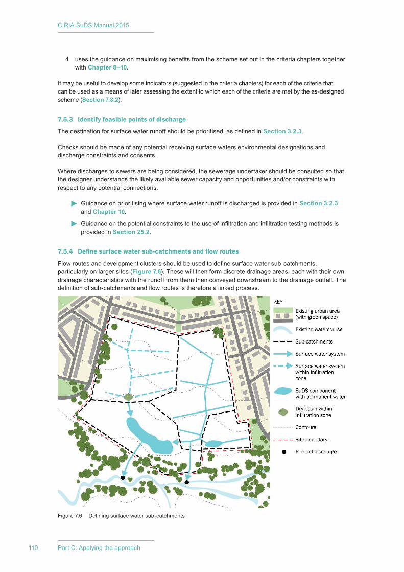
CIRIA SuDS Manual 2015
110 Part C: Applying the approach
4 uses the guidance on maximising benefits from the scheme set out in the criteria chapters together with Chapter 8–10.
It may be useful to develop some indicators (suggested in the criteria chapters) for each of the criteria that can be used as a means of later assessing the extent to which each of the criteria are met by the as-designed scheme (Section 7.8.2).
7.5.3 Identify feasible points of discharge
The destination for surface water runoff should be prioritised, as defined in Section 3.2.3.
Checks should be made of any potential receiving surface waters environmental designations and discharge constraints and consents.
Where discharges to sewers are being considered, the sewerage undertaker should be consulted so that the designer understands the likely available sewer capacity and opportunities and/or constraints with respect to any potential connections.
Guidance on prioritising where surface water runoff is discharged is provided in Section 3.2.3 and Chapter 10.
Guidance on the potential constraints to the use of infiltration and infiltration testing methods is provided in Section 25.2.
7.5.4 Definesurfacewatersub-catchmentsandflowroutes
Flow routes and development clusters should be used to define surface water sub-catchments, particularly on larger sites (Figure 7.6). These will then form discrete drainage areas, each with their own drainage characteristics with the runoff from them then conveyed downstream to the drainage outfall. The definition of sub-catchments and flow routes is therefore a linked process.
Figure 7.6 Defining surface water sub-catchments
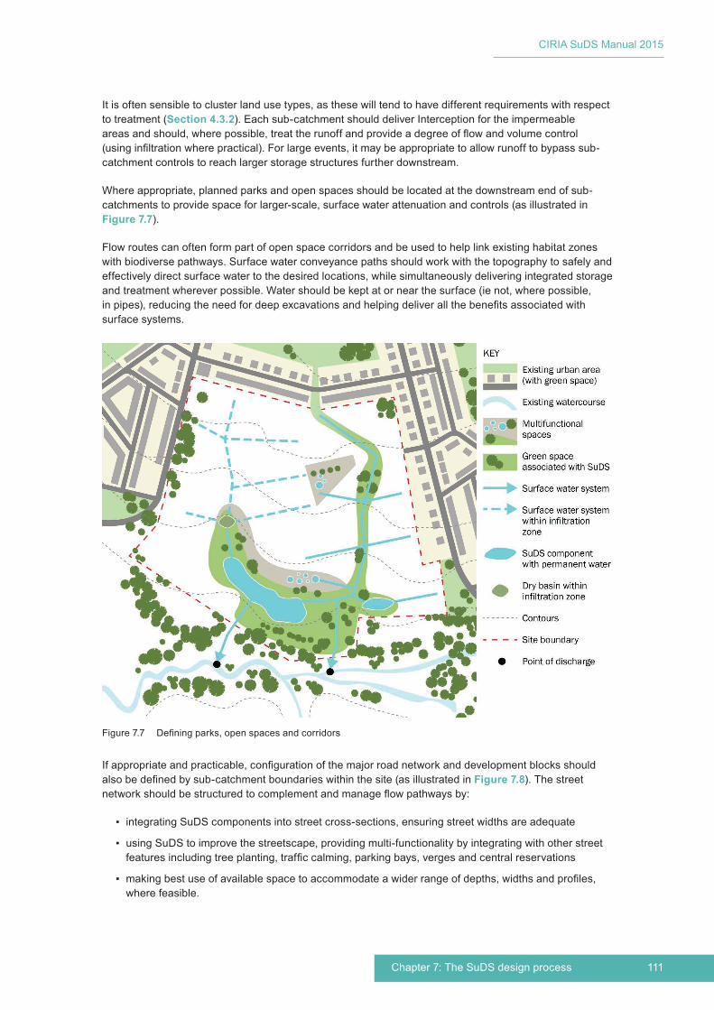
111Chapter 7: The SuDS design process
CIRIA SuDS Manual 2015
It is often sensible to cluster land use types, as these will tend to have different requirements with respect to treatment (Section 4.3.2). Each sub-catchment should deliver Interception for the impermeable areas and should, where possible, treat the runoff and provide a degree of flow and volume control (using infiltration where practical). For large events, it may be appropriate to allow runoff to bypass sub-catchment controls to reach larger storage structures further downstream.
Where appropriate, planned parks and open spaces should be located at the downstream end of sub-catchments to provide space for larger-scale, surface water attenuation and controls (as illustrated in Figure 7.7).
Flow routes can often form part of open space corridors and be used to help link existing habitat zones with biodiverse pathways. Surface water conveyance paths should work with the topography to safely and effectively direct surface water to the desired locations, while simultaneously delivering integrated storage and treatment wherever possible. Water should be kept at or near the surface (ie not, where possible, in pipes), reducing the need for deep excavations and helping deliver all the benefits associated with surface systems.
If appropriate and practicable, configuration of the major road network and development blocks should also be defined by sub-catchment boundaries within the site (as illustrated in Figure 7.8). The street network should be structured to complement and manage flow pathways by:
▪ integrating SuDS components into street cross-sections, ensuring street widths are adequate
▪ using SuDS to improve the streetscape, providing multi-functionality by integrating with other street features including tree planting, traffic calming, parking bays, verges and central reservations
▪ making best use of available space to accommodate a wider range of depths, widths and profiles, where feasible.
Figure 7.7 Defining parks, open spaces and corridors
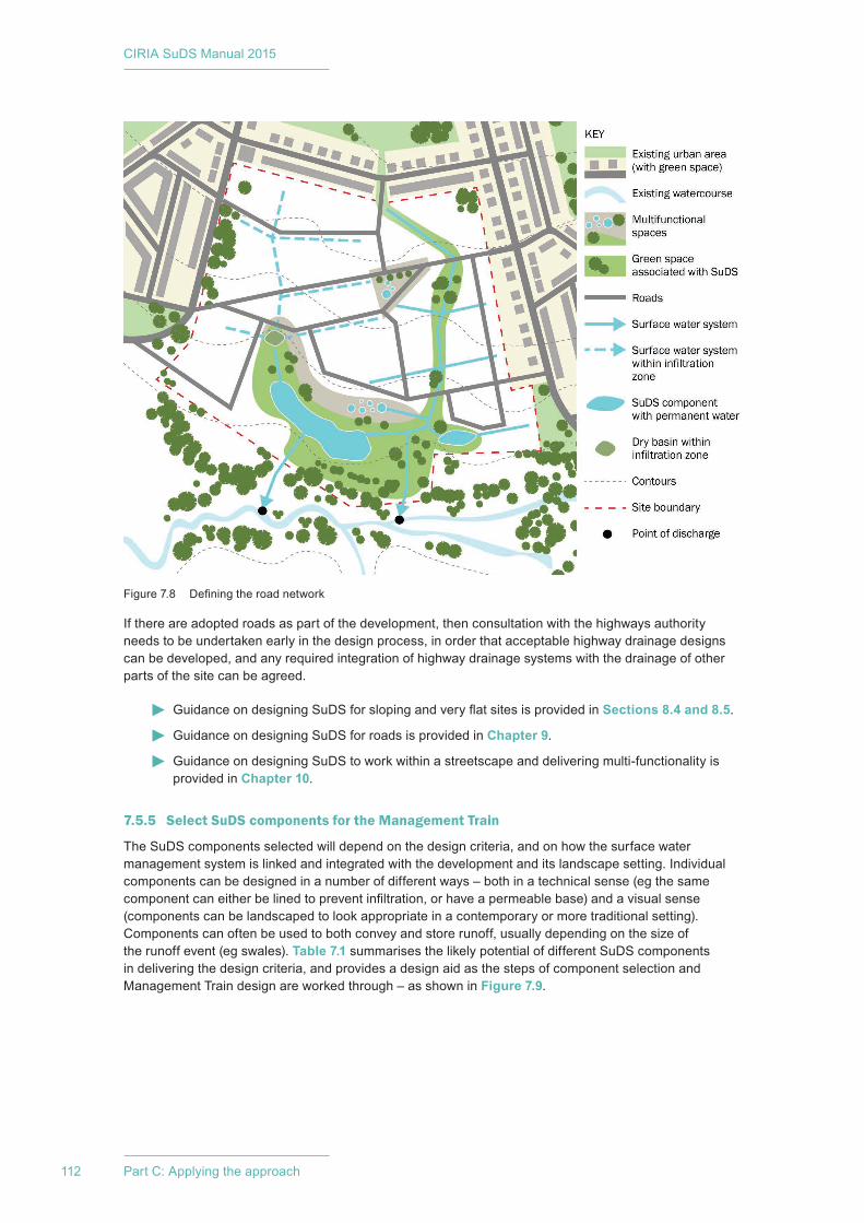
CIRIA SuDS Manual 2015
112 Part C: Applying the approach
If there are adopted roads as part of the development, then consultation with the highways authority needs to be undertaken early in the design process, in order that acceptable highway drainage designs can be developed, and any required integration of highway drainage systems with the drainage of other parts of the site can be agreed.
Guidance on designing SuDS for sloping and very flat sites is provided in Sections 8.4 and 8.5.
Guidance on designing SuDS for roads is provided in Chapter 9.
Guidance on designing SuDS to work within a streetscape and delivering multi-functionality is provided in Chapter 10.
7.5.5 Select SuDS components for the Management Train
The SuDS components selected will depend on the design criteria, and on how the surface water management system is linked and integrated with the development and its landscape setting. Individual components can be designed in a number of different ways – both in a technical sense (eg the same component can either be lined to prevent infiltration, or have a permeable base) and a visual sense (components can be landscaped to look appropriate in a contemporary or more traditional setting). Components can often be used to both convey and store runoff, usually depending on the size of the runoff event (eg swales). Table 7.1 summarises the likely potential of different SuDS components in delivering the design criteria, and provides a design aid as the steps of component selection and Management Train design are worked through – as shown in Figure 7.9.
Figure 7.8 Defining the road network
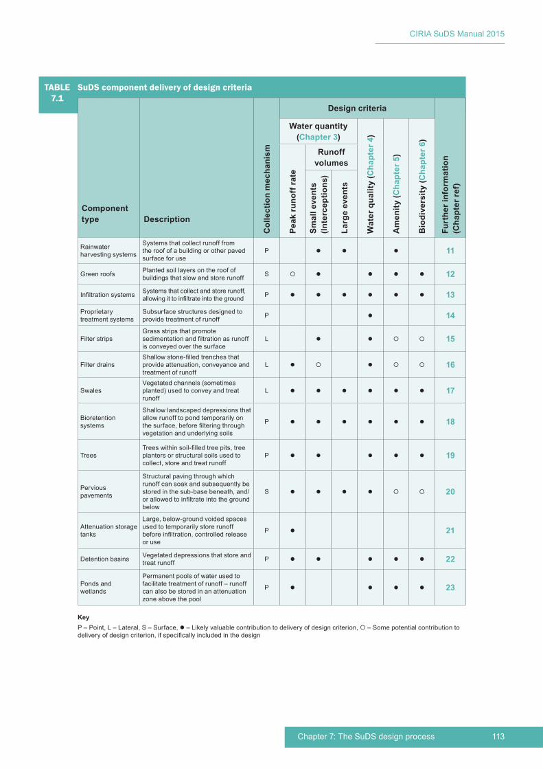
113Chapter 7: The SuDS design process
CIRIA SuDS Manual 2015
TABLE7.1
SuDS component delivery of design criteria
Component type Description
Col
lect
ion
mec
hani
sm
Design criteria
Furt
her i
nfor
mat
ion
(Cha
pter
ref)
Water quantity (Chapter 3)
Wat
er q
ualit
y (C
hapt
er 4
)
Am
enity
(Cha
pter
5)
Bio
dive
rsity
(Cha
pter
6)
Peak
runo
ff ra
te
Runoff volumes
Smal
l eve
nts
(Inte
rcep
tions
)
Larg
e ev
ents
Rainwater harvesting systems
Systems that collect runoff from the roof of a building or other paved surface for use
P 11
Green roofs Planted soil layers on the roof of buildings that slow and store runoff S 12
Infiltration systems Systems that collect and store runoff, allowing it to infiltrate into the ground P 13
Proprietary treatment systems
Subsurface structures designed to provide treatment of runoff P 14
Filter stripsGrass strips that promote sedimentation and filtration as runoff is conveyed over the surface
L 15
Filter drainsShallow stone-filled trenches that provide attenuation, conveyance and treatment of runoff
L 16
SwalesVegetated channels (sometimes planted) used to convey and treat runoff
L 17
Bioretention systems
Shallow landscaped depressions that allow runoff to pond temporarily on the surface, before filtering through vegetation and underlying soils
P 18
TreesTrees within soil-filled tree pits, tree planters or structural soils used to collect, store and treat runoff
P 19
Pervious pavements
Structural paving through which runoff can soak and subsequently be stored in the sub-base beneath, and/or allowed to infiltrate into the ground below
S 20
Attenuation storage tanks
Large, below-ground voided spaces used to temporarily store runoff before infiltration, controlled release or use
P 21
Detention basins Vegetated depressions that store and treat runoff P 22
Ponds and wetlands
Permanent pools of water used to facilitate treatment of runoff – runoff can also be stored in an attenuation zone above the pool
P 23
KeyP – Point, L – Lateral, S – Surface, – Likely valuable contribution to delivery of design criterion, – Some potential contribution to delivery of design criterion, if specifically included in the design
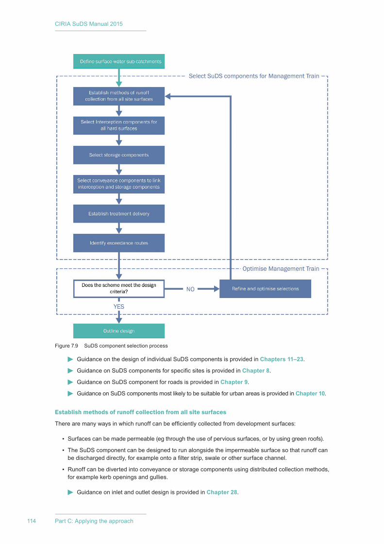
CIRIA SuDS Manual 2015
114 Part C: Applying the approach
Guidance on the design of individual SuDS components is provided in Chapters 11–23.
Guidance on SuDS components for specific sites is provided in Chapter 8.
Guidance on SuDS component for roads is provided in Chapter 9.
Guidance on SuDS components most likely to be suitable for urban areas is provided in Chapter 10.
Establish methods of runoff collection from all site surfaces
There are many ways in which runoff can be efficiently collected from development surfaces:
▪ Surfaces can be made permeable (eg through the use of pervious surfaces, or by using green roofs).
▪ The SuDS component can be designed to run alongside the impermeable surface so that runoff can be discharged directly, for example onto a filter strip, swale or other surface channel.
▪ Runoff can be diverted into conveyance or storage components using distributed collection methods, for example kerb openings and gullies.
Guidance on inlet and outlet design is provided in Chapter 28.
Figure 7.9 SuDS component selection process

115Chapter 7: The SuDS design process
CIRIA SuDS Manual 2015
Select Interception components for all hard surfaces
The first consideration in designing the SuDS Management Train for a site should be the delivery of Interception for each impermeable area, wherever possible. Interception is delivered where SuDS components are an integral part of the runoff surface or collection method (eg permeable pavements, green roofs, rainwater harvesting systems), and in such scenarios, the surface may also be able to provide Interception for adjacent runoff surfaces.
In areas where infiltration is possible, soakaways can be considered for roof water, and infiltration from swales, bioretention areas, dry basins and permeable surfaces can be used to manage as much surface water as possible (providing sufficient treatment is delivered before any discharge to groundwater). Where infiltration is impractical or inappropriate, very low infiltration rates and/or depths of soil storage can often be used for Interception, followed by conveyance to downstream attenuation and treatment components.
Guidance on the design of Interception is provided in Section 24.8.
Guidance on the design of infiltration components is provided in Chapter 25.
Guidance on the design of RWH systems is provided in Chapter 11.
Select storage components
There are likely to be a number of areas within the development that could potentially be combined with the delivery of attenuation storage, for example beneath permeable paving or recreation facilities, within small detention zones, ponds or channel conveyance routes. Distributing the storage areas across the site within multi-functional spaces, can be effective in terms of land-take, potentially reducing the need for a large downstream attenuation facility.
If rainwater harvesting and infiltration cannot be used on a site, there will be a need to manage the extra volumes of runoff from the site in some other way. This extra volume can either be spilled from the main drainage system into a separate storage area which is drained very slowly (this is termed Long-Term Storage), or the extra volume can be incorporated into the main attenuation storage for the site (but this is likely to substantially increase the required storage volumes). Long-Term Storage areas will only flood infrequently, so can often be recreation or other amenity areas.
Very initial estimates of required storage areas are usually pragmatic at this stage. These can be done using past experience, simple spreadsheet tools (that follow the processes set out in Chapters 24 and 25) or using the tools on www.uksuds.com
Where the development is to be phased, storage should, where possible, be delivered on individual plots. Where the SuDS design for individual plots relies on strategic storage, agreement on access, ownership and maintenance of these elements needs agreement at an early stage of the design.
Guidance relating to the delivery of storage components is set out in Sections 3.2.3, 3.3.1 and 3.3.2.
Guidance on the design of attenuation and Long-Term Storage components is provided in Sections 24.9 and 24.10.
Guidance on design of infiltration is provided in Chapter 25.
Select conveyance components to link Interception and storage components
As water is conveyed downstream, SuDS components should be linked using conveyance systems (eg swales, linear wetlands, channels, rills, pipes), which themselves may provide useful treatment, infiltration and/or storage.
Vegetated surface conveyance components will tend to deliver greater water quality, amenity and biodiversity benefits. They can also form part of open space corridors along important drainage features, and link existing habitat zones with biodiverse pathways.
CIRIA SuDS Manual 2015
116 Part C: Applying the approach
On steep sites, surface water conveyance routes will either need to be directed across the slope to reduce gradients and minimise erosive velocities or other mechanisms will be needed to reduce gradients, such as natural waterfalls, checkdams and baffles. Keeping water on the surface reduces the need for cover, which can create requirements for very deep excavations for piped systems.
On flat sites, careful design will be required, to ensure that conveyance gradients do not mean that downstream systems are very deep.
Guidance on designing SuDS for sloping and very flat sites is provided in Sections 8.4 and 8.5.
Guidance on designing SuDS for roads is provided in Chapter 9.
Guidance on designing SuDS to work within a streetscape and delivering multi-functionality is provided in Chapter 10.
Guidance on the design of conveyance systems is provided in Section 24.11.
Guidance on design of infiltration is provided in Chapter 25.
Establish treatment delivery
It is important that a SuDS scheme is developed with consideration of the pollution treatment requirements of different land use areas. Areas of the site with low contamination potential will represent opportunities for rainwater harvesting, and areas with low and medium contamination levels can usually be safely infiltrated. It is vital to ensure that relatively clean runoff is not mixed with poorer-quality runoff, thus rendering it less suitable for infiltration or harvesting. Where possible, different land uses (that have different pollution potential) should be clustered, so that Management Trains can be designed most efficiently. By implementing SuDS at a plot level, sources of pollution can be easily identified, and remedial actions and maintenance work can be undertaken by the plot owner/operator. Agreed pollution prevention strategies (eg specified as a condition of use) may influence the hazard posed by particular land use types, and these should be considered at this stage.
Sufficient treatment must be provided for both individual and/or combined sub-catchments, and an early review of likely treatment requirements for different land uses on the site should be undertaken following the design criteria in Chapter 4 and supporting guidance on design methods in Chapter 26. Where the development is to be phased, the drainage of individual plots should not rely on drainage systems on plots not yet developed to meet the standards and criteria set for the site. Where the development is to be phased, water quality management should, where possible, be delivered on individual plots. Where the SuDS design for individual plots relies on strategic treatment components, agreement on access, ownership and maintenance needs agreement at an early stage of the design.
Guidance on pollution prevention strategies is provided in Chapter 27.
Guidance on the likely pollution hazard associated with different land use types and the potential implications for SuDS design is described in Sections 4.2.2 and 4.3.2 and Chapter 26.
Identify exceedance routes and storage locations
Safe exceedance routes and storage areas should be considered and integrated within the development design (Figure 7.10). Exceedance routes can include roads on the site, and exceedance storage areas can include car parks, recreation areas and other areas of public open space, as long as their use for this purpose will not impede their normal function to the extent of putting people or vehicles at risk and that they can be maintained in the long term. Appropriate legal permissions and requirements for use of the land as an exceedance route should be sought at an early stage.
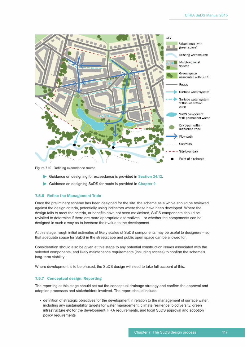
117Chapter 7: The SuDS design process
CIRIA SuDS Manual 2015
Guidance on designing for exceedance is provided in Section 24.12.
Guidance on designing SuDS for roads is provided in Chapter 9.
7.5.6 RefinetheManagementTrain
Once the preliminary scheme has been designed for the site, the scheme as a whole should be reviewed against the design criteria, potentially using indicators where these have been developed. Where the design fails to meet the criteria, or benefits have not been maximised, SuDS components should be revisited to determine if there are more appropriate alternatives – or whether the components can be designed in such a way as to increase their value to the development.
At this stage, rough initial estimates of likely scales of SuDS components may be useful to designers – so that adequate space for SuDS in the streetscape and public open space can be allowed for.
Consideration should also be given at this stage to any potential construction issues associated with the selected components, and likely maintenance requirements (including access) to confirm the scheme’s long-term viability.
Where development is to be phased, the SuDS design will need to take full account of this.
7.5.7 Conceptual design: Reporting
The reporting at this stage should set out the conceptual drainage strategy and confirm the approval and adoption processes and stakeholders involved. The report should include:
▪ definition of strategic objectives for the development in relation to the management of surface water, including any sustainability targets for water management, climate resilience, biodiversity, green infrastructure etc for the development, FRA requirements, and local SuDS approval and adoption policy requirements
Figure 7.10 Defining exceedance routes

CIRIA SuDS Manual 2015
118 Part C: Applying the approach
▪ identification of likely synergies and challenges, such as potential contribution of the site surface water management system to wider catchment objectives, such as biodiversity delivery and flood risk management
▪ any requirements/objectives imposed by a wider site surface water management strategy (ie where the site is a parcel of land that forms part of a larger development area)
▪ water quantity, water quality, amenity and biodiversity design criteria and standards relevant for the site
▪ constraints and opportunities for SuDS delivery, including any likely change in permeability of the site following development, proposed land use, site contamination levels, infiltration potential, public open space/green space/amenity provision requirements, local biodiversity characteristics, building types and forms, street types and forms
▪ initial scoping of potential costs and benefits of different SuDS options, in order to estimate any influence on development viability
▪ the outputs of any initial stakeholder consultations and implications for SuDS design and community engagement strategies
▪ the definition of surface water sub-catchments, land use types, flow routes, runoff destinations and Management Train options
▪ design methods to be used (eg for greenfield or previously developed runoff rate assessments) and justification
▪ likely SuDS components and initial estimate of space required (including access for maintenance), including the potential integration with the built form, connective pathways, green/public space
▪ consideration of key construction and maintenance issues.
At this stage, it is crucial to secure a complete understanding as to who will be the long-term owner of the drainage assets (some assets are likely to remain in private ownership, while others may be adopted by public bodies) and who will operate and maintain the assets. This will dictate any site-specific adoption criteria and also the required processes set by the relevant drainage adoption body.
Where the proposed system has operational requirements (eg pumping), the operation protocols and emergency procedures will need evaluating and agreeing with the adoption body.
Even at early stages in the design, it is important to ensure that long-term maintenance is as cost-effective as possible, and that any future owner will have easy access to all parts of the drainage system that may require future maintenance, and any equipment and skills required to undertake the work.
Options for the disposal of waste (arising from sedimentation and vegetation management) should also be considered.
Guidance on assessing potential costs and benefits of different SuDS options is provided in Chapter 35.
Guidance on operation and maintenance requirements is provided in Chapter 32.
Guidance on waste management requirements is provided in Chapter 33.
Guidance on community engagement strategies is provided in Chapter 34.
7.6 STAGE 3: OUTLINE DESIGN
The third stage of the SuDS design is the outline design, which should be developed alongside the agreed layout and design of the development, and landscape and building characteristics. Key steps in outline design are shown in Figure 7.11 and described in the following sections.
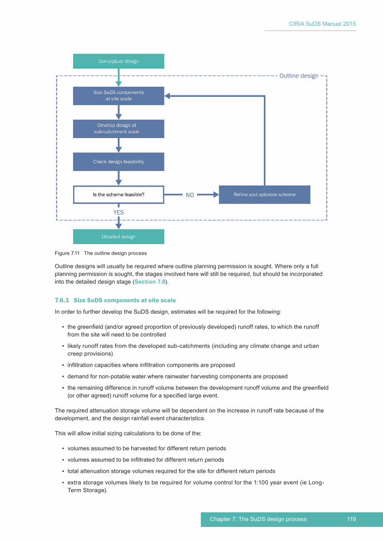
119Chapter 7: The SuDS design process
CIRIA SuDS Manual 2015
Outline designs will usually be required where outline planning permission is sought. Where only a full planning permission is sought, the stages involved here will still be required, but should be incorporated into the detailed design stage (Section 7.8).
7.6.1 Size SuDS components at site scale
In order to further develop the SuDS design, estimates will be required for the following:
▪ the greenfield (and/or agreed proportion of previously developed) runoff rates, to which the runoff from the site will need to be controlled
▪ likely runoff rates from the developed sub-catchments (including any climate change and urban creep provisions)
▪ infiltration capacities where infiltration components are proposed
▪ demand for non-potable water where rainwater harvesting components are proposed
▪ the remaining difference in runoff volume between the development runoff volume and the greenfield (or other agreed) runoff volume for a specified large event.
The required attenuation storage volume will be dependent on the increase in runoff rate because of the development, and the design rainfall event characteristics.
This will allow initial sizing calculations to be done of the:
▪ volumes assumed to be harvested for different return periods
▪ volumes assumed to be infiltrated for different return periods
▪ total attenuation storage volumes required for the site for different return periods
▪ extra storage volumes likely to be required for volume control for the 1:100 year event (ie Long-Term Storage).
Figure 7.11 The outline design process

CIRIA SuDS Manual 2015
120 Part C: Applying the approach
The design process is set out in Figure 7.11. Detailed guidance on each of the steps is presented in Chapters 24 and 25.
The design criteria and standards for water quantity are presented in Chapter 3.
Guidance on methods for estimating greenfield runoff rates is presented in Section 24.3.
Guidance on methods for estimating previously developed site runoff rates is presented in Section 24.5).
Guidance on methods for estimating runoff rates from the developed site surfaces is presented in Section 24.6.
Guidance on designing for climate resilience is provided in Section 3.2.7.
Guidance on climate change factors and urban creep factors is provided in Section 24.7.
Guidance on infiltration design is provided in Chapter 25.
Guidance on the design of RWH systems is provided in Chapter 11.
Guidance on attenuation storage design is presented in Section 24.9.
Guidance on Long-Term Storage design is presented in Section 24.10.
7.6.2 Develop design at sub-catchment scale
At this stage, the individual SuDS components should be sized, and their designs refined. Any assumptions made at conceptual design stage, such as infiltration capacities, groundwater levels and existing sewerage infrastructure and capacities, should be confirmed, using robust evaluation methods.
Required storage volumes should be distributed between sub-catchments (where appropriate), estimates should be made of required conveyance and exceedance flow rates and checks should be made that proposed treatment components are adequate. Any required flow control components should be defined and scoped. This process is set out in Figure 7.12.
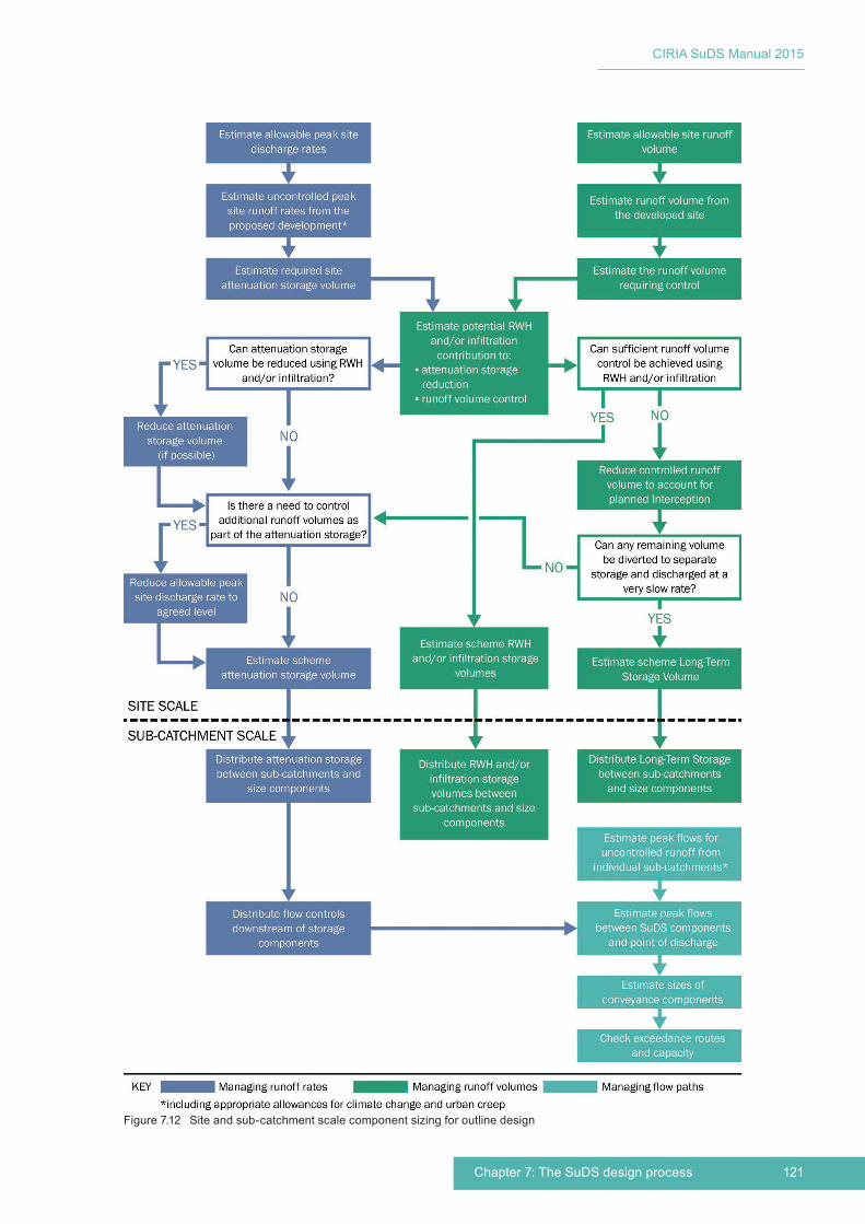
121Chapter 7: The SuDS design process
CIRIA SuDS Manual 2015
Figure 7.12 Site and sub-catchment scale component sizing for outline design
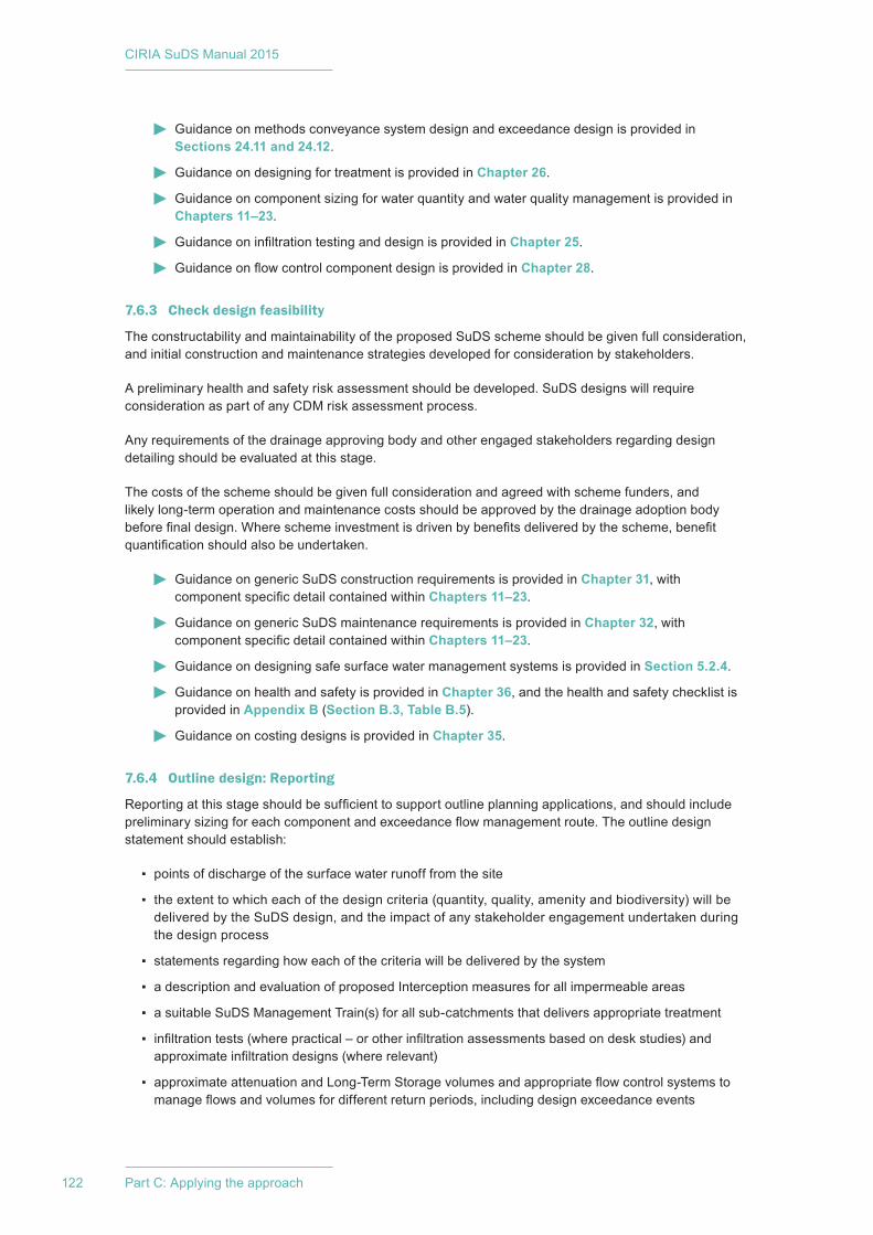
CIRIA SuDS Manual 2015
122 Part C: Applying the approach
Guidance on methods conveyance system design and exceedance design is provided in Sections 24.11 and 24.12.
Guidance on designing for treatment is provided in Chapter 26.
Guidance on component sizing for water quantity and water quality management is provided in Chapters 11–23.
Guidance on infiltration testing and design is provided in Chapter 25.
Guidance on flow control component design is provided in Chapter 28.
7.6.3 Check design feasibility
The constructability and maintainability of the proposed SuDS scheme should be given full consideration, and initial construction and maintenance strategies developed for consideration by stakeholders.
A preliminary health and safety risk assessment should be developed. SuDS designs will require consideration as part of any CDM risk assessment process.
Any requirements of the drainage approving body and other engaged stakeholders regarding design detailing should be evaluated at this stage.
The costs of the scheme should be given full consideration and agreed with scheme funders, and likely long-term operation and maintenance costs should be approved by the drainage adoption body before final design. Where scheme investment is driven by benefits delivered by the scheme, benefit quantification should also be undertaken.
Guidance on generic SuDS construction requirements is provided in Chapter 31, with component specific detail contained within Chapters 11–23.
Guidance on generic SuDS maintenance requirements is provided in Chapter 32, with component specific detail contained within Chapters 11–23.
Guidance on designing safe surface water management systems is provided in Section 5.2.4.
Guidance on health and safety is provided in Chapter 36, and the health and safety checklist is provided in Appendix B (Section B.3, Table B.5).
Guidance on costing designs is provided in Chapter 35.
7.6.4 Outline design: Reporting
Reporting at this stage should be sufficient to support outline planning applications, and should include preliminary sizing for each component and exceedance flow management route. The outline design statement should establish:
▪ points of discharge of the surface water runoff from the site
▪ the extent to which each of the design criteria (quantity, quality, amenity and biodiversity) will be delivered by the SuDS design, and the impact of any stakeholder engagement undertaken during the design process
▪ statements regarding how each of the criteria will be delivered by the system
▪ a description and evaluation of proposed Interception measures for all impermeable areas
▪ a suitable SuDS Management Train(s) for all sub-catchments that delivers appropriate treatment
▪ infiltration tests (where practical – or other infiltration assessments based on desk studies) and approximate infiltration designs (where relevant)
▪ approximate attenuation and Long-Term Storage volumes and appropriate flow control systems to manage flows and volumes for different return periods, including design exceedance events
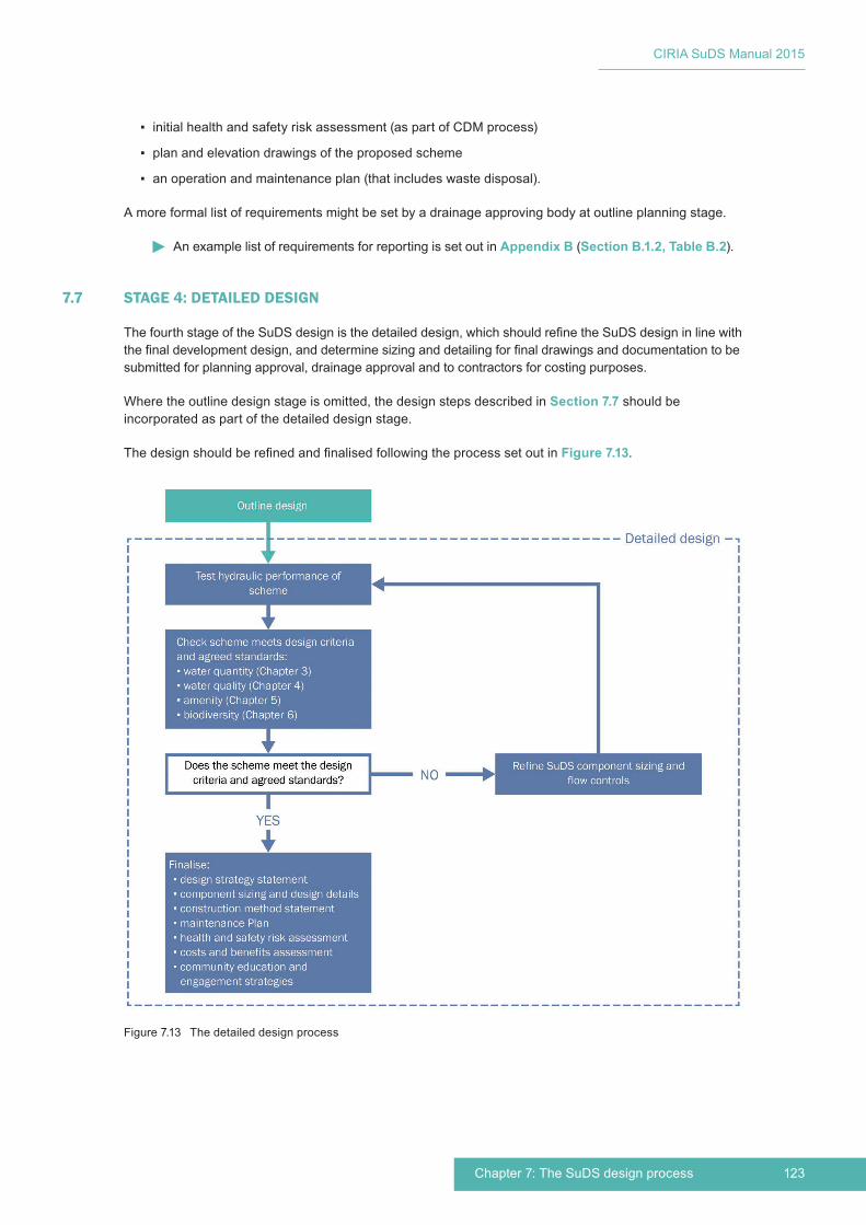
123Chapter 7: The SuDS design process
CIRIA SuDS Manual 2015
▪ initial health and safety risk assessment (as part of CDM process)
▪ plan and elevation drawings of the proposed scheme
▪ an operation and maintenance plan (that includes waste disposal).
A more formal list of requirements might be set by a drainage approving body at outline planning stage.
An example list of requirements for reporting is set out in Appendix B (Section B.1.2, Table B.2).
7.7 STAGE 4: DETAILED DESIGN
The fourth stage of the SuDS design is the detailed design, which should refine the SuDS design in line with the final development design, and determine sizing and detailing for final drawings and documentation to be submitted for planning approval, drainage approval and to contractors for costing purposes.
Where the outline design stage is omitted, the design steps described in Section 7.7 should be incorporated as part of the detailed design stage.
The design should be refined and finalised following the process set out in Figure 7.13.
Figure 7.13 The detailed design process

CIRIA SuDS Manual 2015
124 Part C: Applying the approach
7.7.1 Test hydraulic performance of scheme
The scheme should be tested hydraulically to identify the worst case hydraulic condition for each component for all design return periods. This should be undertaken using either design storms or time series rainfall (TSR) analysis.
The hydraulic performance of the system should then be optimised to make sure that all storage and conveyance areas are used as effectively as possible during design rainfall events. Drainage simulation models can be used where appropriate.
Consideration should be given to the extent to which the SuDS components should function during flood events affecting the receiving surface waters.
Account should also be taken of any overland flow routes across the site from external areas or other external flood sources. Such flows will either need to be routed around the site or conveyed across the site, either in exceedance routes or within the SuDS components themselves. The likely rates and volumes of these extra flows will need to be accounted for in the system design so that people and property on the site are not put at risk.
Exceedance routes should be evaluated and designed where required, ensuring appropriate levels of freeboard between extreme flood levels and building floor levels
Guidance on rainfall characteristics is provided in Section 24.2.3
Guidance on Interception, attenuation and Long-Term Storage design, conveyance and exceedance route sizing is presented in Sections 24.8 to 24.12.
Guidance on infiltration design is provided in Chapter 25.
Guidance on the design of RWH systems is provided in Chapter 11.
Guidance on design of inlets, outlets and flow control systems is provided in Chapter 28.
7.7.2 Check scheme meets design criteria and agreed standards
Checks should be made that the final scheme meets all of the design criteria established for the site (Section 7.6.2). At this stage, it is likely that the main checks will be that the system meets the agreed standards for quantity and quality, that:
▪ Interception is delivered for all hard areas
▪ peak rates of runoff for low return period events are adequately controlled
▪ peak rates of runoff for high return period events (including appropriate climate change and urban creep factors) are adequately controlled
▪ volumes of runoff for high return period events are adequately controlled
▪ high return period events (including appropriate climate change and urban creep factors) do not pose an unacceptable risk to people or property, as a result of the development
▪ the flow velocities and depths for regular events allow effective treatment to be delivered by components for which treatment performance is assumed.
The performance of the system with respect to the remaining water quantity and water quality criteria, and the amenity and biodiversity criteria is unlikely to change materially at this stage in the process. However if, because of non-compliance with the above standards, a decision is made that a component should change fundamentally (eg a surface component has to become a subsurface component), then a review of performance to the full suite of criteria will be required.
Indicators are likely to be a useful way of assessing the performance of the scheme to agreed criteria and where these have been established early in the design process – they can potentially form a framework

125Chapter 7: The SuDS design process
CIRIA SuDS Manual 2015
for the assessment process (eg “the proportion of the scheme that is on or near the surface” is likely to be a useful indicator of the extent to which the scheme might deliver a number of the water quality, amenity and biodiversity criteria).
Example indicators for water quantity, water quality, amenity and biodiversity criteria are presented in Chapters 3–6.
7.7.3 RefineSuDScomponentsizingandflowcontrols
Where the agreed standards (described in Section 7.8.2) are not met satisfactorily, the design will need to be revisited, and amendments made to component sizing and/or flow controls. The hydraulic testing will then need to be undertaken again. This process will usually occur iteratively until a satisfactory solution has been identified.
Guidance on Interception, attenuation and Long-Term Storage design, conveyance and exceedance route sizing is presented in Sections 24.8 to 24.12.
Guidance on infiltration design is provided in Chapter 25.
Guidance on the sizing of RWH systems is provided in Chapter 11.
Guidance on treatment design is presented in Chapter 26.
Guidance on sizing of inlets, outlets and flow control systems is provided in Chapter 28.
7.7.4 Finalise design
The final design should be refined, taking costs and benefits into account, together with any health and safety risk assessment (required as part of CDM), constructability and maintainability considerations.
Individual SuDS components should be finalised and detailed following the guidance within the technical component chapters of this manual and/or appropriate manufacturer literature.
Specifications will need to be prepared for all the materials used in the design, and for the construction and landscaping works, together with full construction method statements and Maintenance Plans.
Community education and engagement strategies for the completed system should be developed. In some cases these will evolve from community input provided during earlier design stages.
A design statement should be prepared, which includes a description of each of the system criteria and standards, and the approaches through which these criteria and standards have been met.
Guidance on component design is provided in Chapters 11–23.
Guidance on design of inlets, outlets and flow control systems is provided in Chapter 28.
Guidance on construction is provided in Chapter 31.
Guidance on maintenance of SuDS is provided in Chapter 32.
Guidance on waste management is provided in Chapter 33.
Guidance on community environmental learning is provided in Section 5.2.7.
Guidance on community engagement is provided in Chapter 34.
7.7.5 Detailed design: Reporting
At this stage, reporting should include the final detailed design and specification for the SuDS scheme sufficient to support a full planning application, including:
▪ infiltration and geotechnical test results and evaluation
CIRIA SuDS Manual 2015
126 Part C: Applying the approach
▪ design methods used (eg for greenfield or previously developed runoff rate assessments) and justification
▪ full calculations for the overall scheme and individual components
▪ justification of any non-compliance to national or local standards
▪ detailed design drawings
▪ materials specifications
▪ landscape specifications
▪ construction method statement
▪ scheme Maintenance Plan (including costs)
▪ final design statement.
A more formal list of requirements might be set by a drainage approving body at full planning application stage.
An example list of requirements for reporting is set out in Appendix B (Section B.1.3, Table B.3).
7.8 REFERENCES
ABBOTT, J, DAVIES, P, SIMKINS, P, MORGAN, C, LEVIN, D AND ROBINSON, P (2013) Creating water sensitive places – scoping the potential for water sensitive urban design in the UK, C724, CIRIA, London (ISBN: 978-0-86017-733-3). Go to: www.ciria.org
AECOM (2013) Water, People, Places – A guide for master planning SuDS into developments, Lead Local Flood Authorities of the South East of England, UK. Go to: http://tinyurl.com/npdsf63
ATLAS (2012) Case study: Ashton Green, Leicester: Planning for a sustainable community, Homes and Communities, Advisory Team for Large Applications Central Business Exchange, Milton Keynes, UK. Go to: http://tinyurl.com/owaqhaq
DCLG (2008) Code for sustainable homes, Department for Communities and Local Government, London, UK. Go to: http://tinyurl.com/cwjmpfa
DICKIE, S, IONS, L, MCKAY, G and SHAFFER, P (2010) Planning for SuDS – making it happen, C687, CIRIA, London, UK (ISBN: 978-0-86017-687-9). Go to: www.ciria.org
DIGMAN, C, ASHLEY, R, BALMFORTH, D, STOVIN, V and GLERUM, J (2012) Retrofitting urban areas to effectively manage surface water, C713, CIRIA, London (ISBN: 978-0-86017-715-9). Go to: www.ciria.org
TUDOR, C (2014) An approach to landscape character assessment, Natural England, London, UK (ISBN: 978-78367-141-0). Go to: http://tinyurl.com/mzvd7de
UNIVERSITY OF CAMBRIDGE (2014) Planning advice for integrated water management, Institute for Sustainability Leadership, University of Cambridge, Cambridge, UK. Go to: www.cisl.cam.ac.uk/natcap
UNIVERSITY OF CAMBRIDGE (2015) A new district is coming to Cambridge, North West Cambridge Development, University of Cambridge, Cambridge, UK. Go to: www.nwcambridge.co.uk
Statutes
BS 8582:2013 Code of practice for surface water management for development sites

127Chapter 7: The SuDS design process
CIRIA SuDS Manual 2015
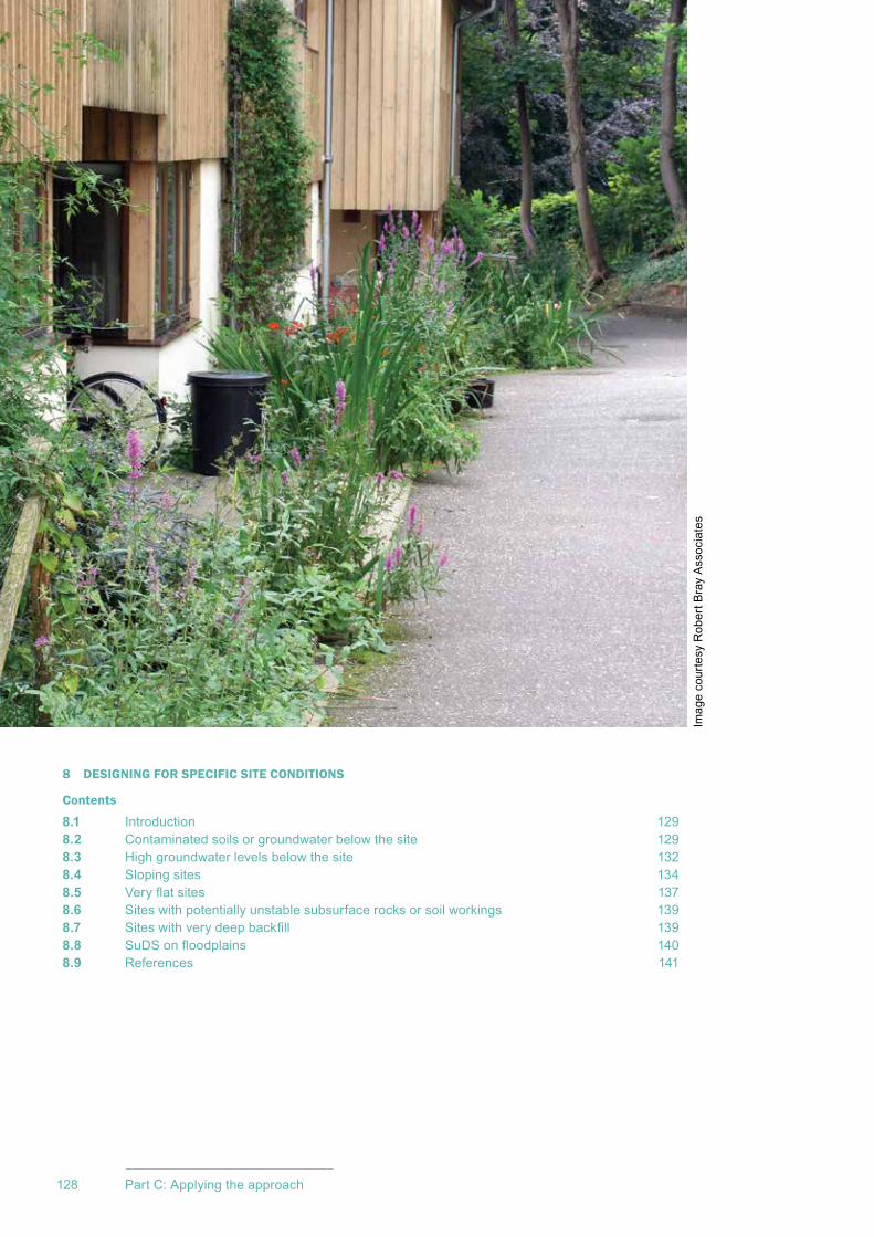
CIRIA SuDS Manual 2015
128 Part C: Applying the approach
8 DESIGNING FOR SPECIFIC SITE CONDITIONS
Contents
8.1 Introduction 1298.2 Contaminated soils or groundwater below the site 1298.3 High groundwater levels below the site 1328.4 Sloping sites 1348.5 Veryflatsites 1378.6 Sites with potentially unstable subsurface rocks or soil workings 1398.7 Siteswithverydeepbackfill 1398.8 SuDSonfloodplains 1408.9 References 141
Imag
e co
urte
sy R
ober
t Bra
y A
ssoc
iate
s
129Chapter 8: Designing for specific site conditions
CIRIA SuDS Manual 2015
Designing for specific site conditions
8.1 INTRODUCTION
SuDS can be delivered on all sites, but most sites will pose challenges of one sort or another in relation to the selection and integration of effective SuDS components. Most of these will be relatively straightforward to solve, using engineering and landscape best practice. However, there are a few challenges that have mistakenly been raised as potential reasons why SuDS cannot be used and these are addressed here.
This chapter demonstrates, with examples, how SuDS can be integrated into sites that have:
▪ contaminated soils or groundwater below the site
▪ high groundwater levels
▪ steep slopes
▪ no gradient or very shallow slopes
▪ underlying rocks or soils that are prone to instability, that is, slope stability, dissolution or other voids (eg old mine workings)
▪ siteswithverydeepbackfill(eginfilledopencastsites,oldlandfillsites)
▪ siteswithopenspaceinfloodplainzones.
8.2 CONTAMINATED SOILS OR GROUNDWATER BELOW THE SITE
8.2.1 The challenges
When designing a surface water management system for a site that overlies contaminated soil or groundwater, the following issues should be considered within the design process:
1 Thepresenceofcontaminationinthegroundmaypreventtheuseofinfiltration.This is because water soaking through the ground can mobilise contamination and thereby pollute groundwater.
2 ContaminatedgroundwatermayflowintotheSuDS.Thiswouldonlyoccurifunlined conveyance and/or attenuation components are located below maximum likely groundwater levels.
08Chapter
This chapter demonstrates how SuDS can be successfully designed for sites with conditions that are often considered challenging.
Guidance on designing SuDS for roads and highways can be found in Chapter 9.
Guidance on designing SuDS for roads and highways can be found in Chapter 9.Discussion on integrating SuDS into high density urban areas can be found in Chapter 10.Guidance on dealing with infiltration design challenges (eg high variability in infiltration rates and low infiltration rates) is set out in Chapter 25.
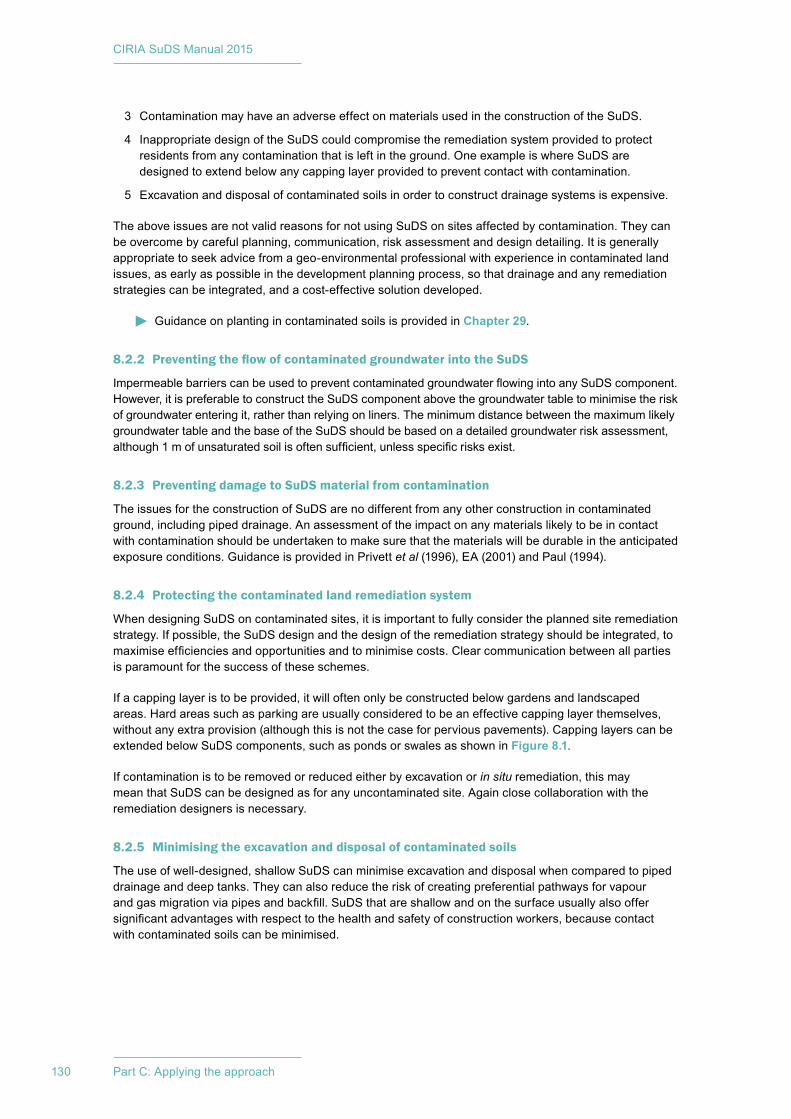
CIRIA SuDS Manual 2015
130 Part C: Applying the approach
3 Contamination may have an adverse effect on materials used in the construction of the SuDS.
4 Inappropriate design of the SuDS could compromise the remediation system provided to protect residents from any contamination that is left in the ground. One example is where SuDS are designed to extend below any capping layer provided to prevent contact with contamination.
5 Excavation and disposal of contaminated soils in order to construct drainage systems is expensive.
The above issues are not valid reasons for not using SuDS on sites affected by contamination. They can be overcome by careful planning, communication, risk assessment and design detailing. It is generally appropriate to seek advice from a geo-environmental professional with experience in contaminated land issues, as early as possible in the development planning process, so that drainage and any remediation strategies can be integrated, and a cost-effective solution developed.
Guidance on planting in contaminated soils is provided in Chapter 29.
8.2.2 Preventing the flow of contaminated groundwater into the SuDS
ImpermeablebarrierscanbeusedtopreventcontaminatedgroundwaterflowingintoanySuDScomponent.However, it is preferable to construct the SuDS component above the groundwater table to minimise the risk of groundwater entering it, rather than relying on liners. The minimum distance between the maximum likely groundwater table and the base of the SuDS should be based on a detailed groundwater risk assessment, although1mofunsaturatedsoilisoftensufficient,unlessspecificrisksexist.
8.2.3 Preventing damage to SuDS material from contamination
The issues for the construction of SuDS are no different from any other construction in contaminated ground, including piped drainage. An assessment of the impact on any materials likely to be in contact with contamination should be undertaken to make sure that the materials will be durable in the anticipated exposure conditions. Guidance is provided in Privett et al (1996),EA(2001)andPaul(1994).
8.2.4 Protecting the contaminated land remediation system
When designing SuDS on contaminated sites, it is important to fully consider the planned site remediation strategy. If possible, the SuDS design and the design of the remediation strategy should be integrated, to maximiseefficienciesandopportunitiesandtominimisecosts.Clearcommunicationbetweenallpartiesis paramount for the success of these schemes.
If a capping layer is to be provided, it will often only be constructed below gardens and landscaped areas. Hard areas such as parking are usually considered to be an effective capping layer themselves, without any extra provision (although this is not the case for pervious pavements). Capping layers can be extended below SuDS components, such as ponds or swales as shown in Figure 8.1.
If contamination is to be removed or reduced either by excavation or in situ remediation, this may mean that SuDS can be designed as for any uncontaminated site. Again close collaboration with the remediation designers is necessary.
8.2.5 Minimising the excavation and disposal of contaminated soils
The use of well-designed, shallow SuDS can minimise excavation and disposal when compared to piped drainage and deep tanks. They can also reduce the risk of creating preferential pathways for vapour andgasmigrationviapipesandbackfill.SuDSthatareshallowandonthesurfaceusuallyalsooffersignificantadvantageswithrespecttothehealthandsafetyofconstructionworkers,becausecontactwith contaminated soils can be minimised.
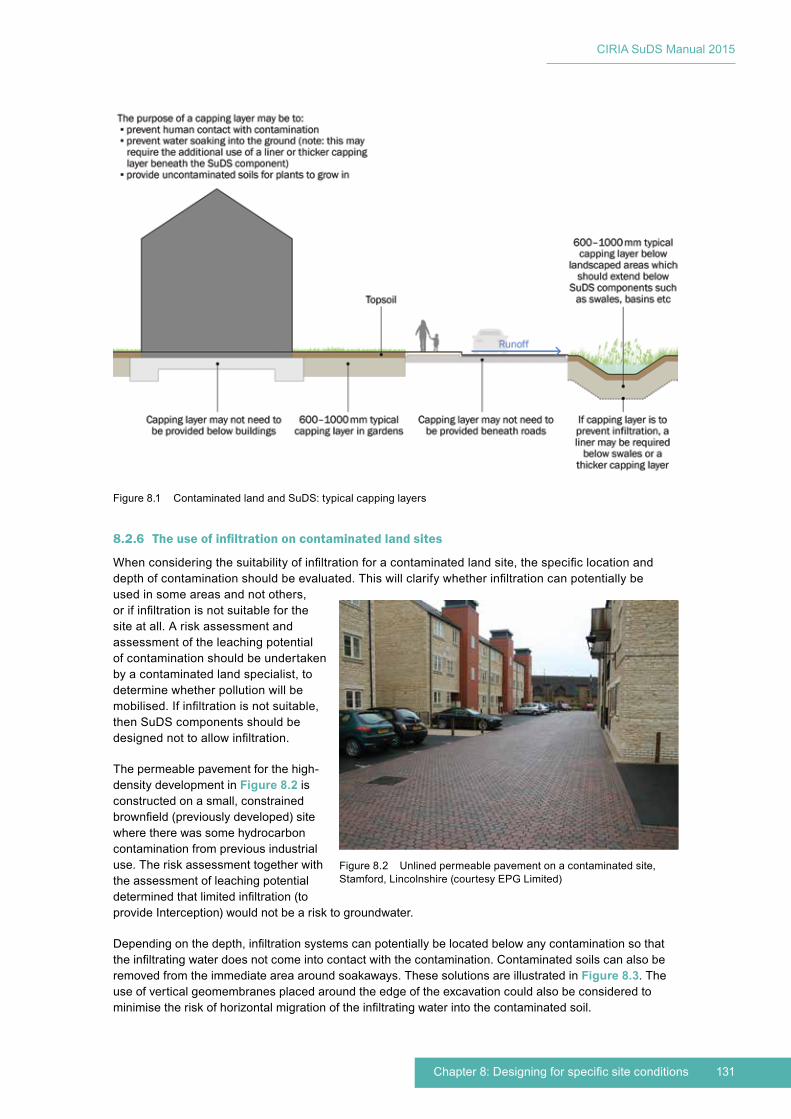
131Chapter 8: Designing for specific site conditions
CIRIA SuDS Manual 2015
8.2.6 The use of infiltration on contaminated land sites
Whenconsideringthesuitabilityofinfiltrationforacontaminatedlandsite,thespecificlocationanddepthofcontaminationshouldbeevaluated.Thiswillclarifywhetherinfiltrationcanpotentiallybeused in some areas and not others, orifinfiltrationisnotsuitableforthesite at all. A risk assessment and assessment of the leaching potential of contamination should be undertaken by a contaminated land specialist, to determine whether pollution will be mobilised.Ifinfiltrationisnotsuitable,then SuDS components should be designednottoallowinfiltration.
The permeable pavement for the high-density development in Figure 8.2 is constructed on a small, constrained brownfield(previouslydeveloped)sitewhere there was some hydrocarbon contamination from previous industrial use. The risk assessment together with the assessment of leaching potential determinedthatlimitedinfiltration(toprovide Interception) would not be a risk to groundwater.
Dependingonthedepth,infiltrationsystemscanpotentiallybelocatedbelowanycontaminationsothattheinfiltratingwaterdoesnotcomeintocontactwiththecontamination.Contaminatedsoilscanalsoberemoved from the immediate area around soakaways. These solutions are illustrated in Figure 8.3. The use of vertical geomembranes placed around the edge of the excavation could also be considered to minimisetheriskofhorizontalmigrationoftheinfiltratingwaterintothecontaminatedsoil.
Figure 8.1 Contaminated land and SuDS: typical capping layers
Figure 8.2 Unlined permeable pavement on a contaminated site, Stamford, Lincolnshire (courtesy EPG Limited)
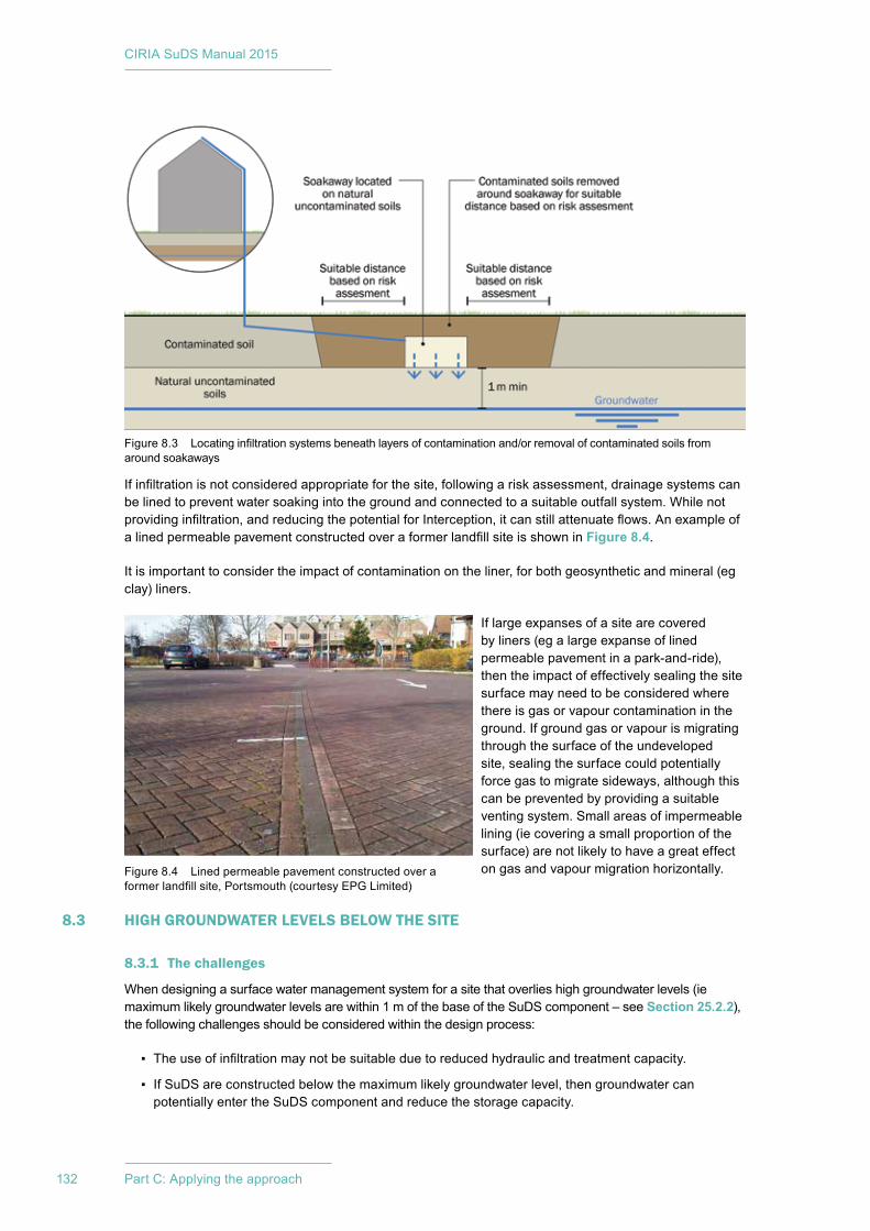
CIRIA SuDS Manual 2015
132 Part C: Applying the approach
Ifinfiltrationisnotconsideredappropriateforthesite,followingariskassessment,drainagesystemscanbe lined to prevent water soaking into the ground and connected to a suitable outfall system. While not providinginfiltration,andreducingthepotentialforInterception,itcanstillattenuateflows.AnexampleofalinedpermeablepavementconstructedoveraformerlandfillsiteisshowninFigure 8.4.
It is important to consider the impact of contamination on the liner, for both geosynthetic and mineral (eg clay) liners.
If large expanses of a site are covered by liners (eg a large expanse of lined permeable pavement in a park-and-ride), then the impact of effectively sealing the site surface may need to be considered where there is gas or vapour contamination in the ground. If ground gas or vapour is migrating through the surface of the undeveloped site, sealing the surface could potentially force gas to migrate sideways, although this can be prevented by providing a suitable venting system. Small areas of impermeable lining (ie covering a small proportion of the surface) are not likely to have a great effect ongasandvapourmigrationhorizontally.
8.3 HIGH GROUNDWATER LEVELS BELOW THE SITE
8.3.1 The challenges
When designing a surface water management system for a site that overlies high groundwater levels (ie maximum likely groundwater levels are within 1 m of the base of the SuDS component – see Section 25.2.2), the following challenges should be considered within the design process:
▪ Theuseofinfiltrationmaynotbesuitableduetoreducedhydraulicandtreatmentcapacity.
▪ If SuDS are constructed below the maximum likely groundwater level, then groundwater can potentially enter the SuDS component and reduce the storage capacity.
Figure 8.4 Lined permeable pavement constructed over a formerlandfillsite,Portsmouth(courtesyEPGLimited)
Figure8.3 Locatinginfiltrationsystemsbeneathlayersofcontaminationand/orremovalofcontaminatedsoilsfromaround soakaways
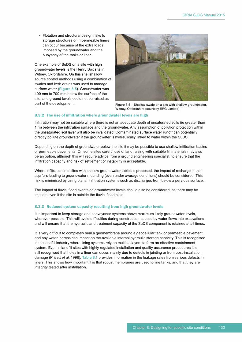
133Chapter 8: Designing for specific site conditions
CIRIA SuDS Manual 2015
▪ Flotation and structural design risks to storage structures or impermeable liners can occur because of the extra loads imposed by the groundwater and the buoyancy of the tanks or liner.
One example of SuDS on a site with high groundwater levels is the Henry Box site in Witney, Oxfordshire. On this site, shallow source control methods using a combination of swales and kerb drains was used to manage surface water (Figure 8.5). Groundwater was 400mmto700mmbelowthesurfaceofthesite, and ground levels could not be raised as part of the development.
8.3.2 The use of infiltration where groundwater levels are high
Infiltrationmaynotbesuitablewherethereisnotanadequatedepthofunsaturatedsoils(iegreaterthan1m)betweentheinfiltrationsurfaceandthegroundwater.Anyassumptionofpollutionprotectionwithinthe unsaturated soil layer will also be invalidated. Contaminated surface water runoff can potentially directly pollute groundwater if the groundwater is hydraulically linked to water within the SuDS.
Dependingonthedepthofgroundwaterbelowthesiteitmaybepossibletouseshallowinfiltrationbasinsorpermeablepavements.Onsomesitescarefuluseoflandraisingwithsuitablefillmaterialsmayalsobeanoption,althoughthiswillrequireadvicefromagroundengineeringspecialist,toensurethattheinfiltrationcapacityandriskofsettlementorinstabilityisacceptable.
Whereinfiltrationintositeswithshallowgroundwatertablesisproposed,theimpactofrechargeinthinaquifersleadingtogroundwatermounding(evenunderaverageconditions)shouldbeconsidered.Thisriskisminimisedbyusingplanarinfiltrationsystemssuchasdischargesfrombelowapervioussurface.
Theimpactoffluvialfloodeventsongroundwaterlevelsshouldalsobeconsidered,astheremaybeimpactsevenifthesiteisoutsidethefluvialfloodplain.
8.3.3 Reduced system capacity resulting from high groundwater levels
It is important to keep storage and conveyance systems above maximum likely groundwater levels, whereverpossible.Thiswillavoiddifficultiesduringconstructioncausedbywaterflowsintoexcavationsand will ensure that the hydraulic and treatment capacity of the SuDS component is retained at all times.
Itisverydifficulttocompletelysealageomembranearoundageocellulartankorpermeablepavement,and any water ingress can impact on the available internal hydraulic storage capacity. This is recognised inthelandfillindustrywhereliningsystemsrelyonmultiplelayerstoformaneffectivecontainmentsystem.Eveninlandfillsiteswithhighlyregulatedinstallationandqualityassuranceproceduresitisstill recognised that holes in a liner can occur, mainly due to defects in jointing or from post-installation damage (Privett et al, 1996). Table 8.1 provides information in the leakage rates from various defects in liners. This shows how important it is that robust membranes are used to line tanks, and that they are integrity tested after installation.
Figure 8.5 Shallow swale on a site with shallow groundwater, Witney, Oxfordshire (courtesy EPG Limited)
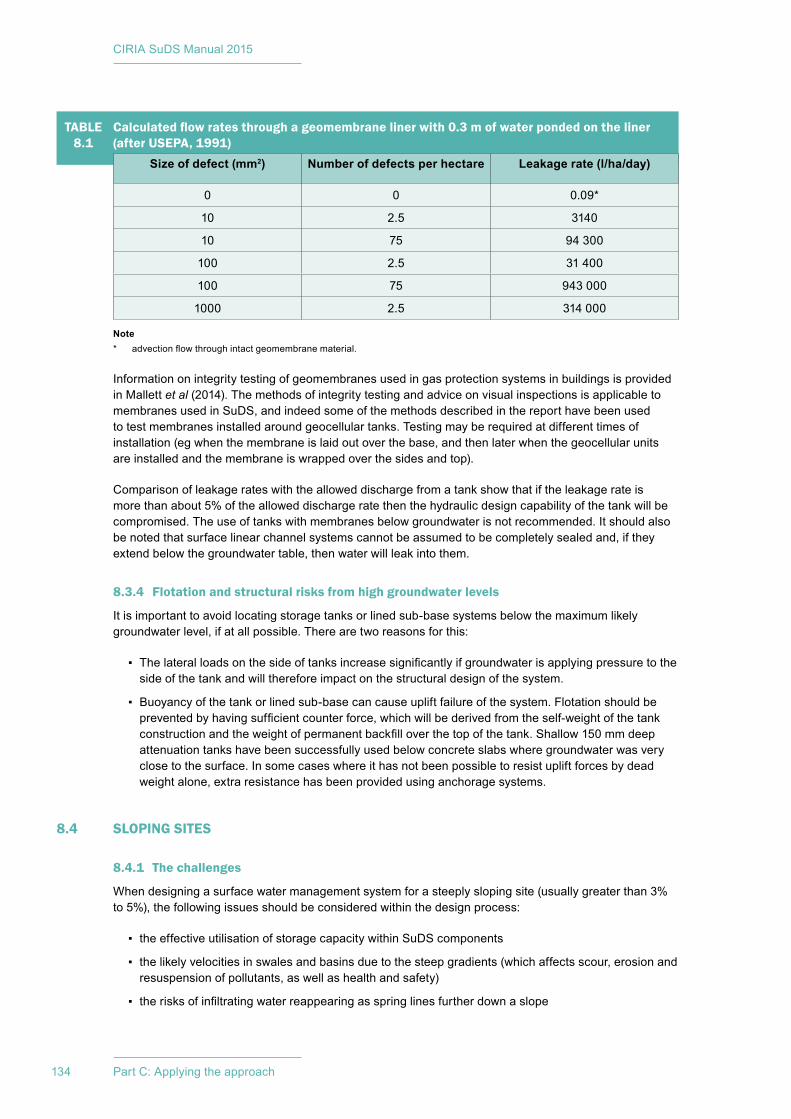
CIRIA SuDS Manual 2015
134 Part C: Applying the approach
Note* advectionflowthroughintactgeomembranematerial.
Information on integrity testing of geomembranes used in gas protection systems in buildings is provided in Mallett et al(2014).Themethodsofintegritytestingandadviceonvisualinspectionsisapplicabletomembranes used in SuDS, and indeed some of the methods described in the report have been used totestmembranesinstalledaroundgeocellulartanks.Testingmayberequiredatdifferenttimesofinstallation (eg when the membrane is laid out over the base, and then later when the geocellular units are installed and the membrane is wrapped over the sides and top).
Comparison of leakage rates with the allowed discharge from a tank show that if the leakage rate is more than about 5% of the allowed discharge rate then the hydraulic design capability of the tank will be compromised. The use of tanks with membranes below groundwater is not recommended. It should also be noted that surface linear channel systems cannot be assumed to be completely sealed and, if they extend below the groundwater table, then water will leak into them.
8.3.4 Flotation and structural risks from high groundwater levels
It is important to avoid locating storage tanks or lined sub-base systems below the maximum likely groundwater level, if at all possible. There are two reasons for this:
▪ Thelateralloadsonthesideoftanksincreasesignificantlyifgroundwaterisapplyingpressuretotheside of the tank and will therefore impact on the structural design of the system.
▪ Buoyancy of the tank or lined sub-base can cause uplift failure of the system. Flotation should be preventedbyhavingsufficientcounterforce,whichwillbederivedfromtheself-weightofthetankconstructionandtheweightofpermanentbackfilloverthetopofthetank.Shallow150mmdeepattenuation tanks have been successfully used below concrete slabs where groundwater was very close to the surface. In some cases where it has not been possible to resist uplift forces by dead weight alone, extra resistance has been provided using anchorage systems.
8.4 SLOPING SITES
8.4.1 The challenges
When designing a surface water management system for a steeply sloping site (usually greater than 3% to 5%), the following issues should be considered within the design process:
▪ the effective utilisation of storage capacity within SuDS components
▪ the likely velocities in swales and basins due to the steep gradients (which affects scour, erosion and resuspension of pollutants, as well as health and safety)
▪ therisksofinfiltratingwaterreappearingasspringlinesfurtherdownaslope
TABLE 8.1
Calculated flow rates through a geomembrane liner with 0.3 m of water ponded on the liner (after USEPA, 1991)
Size of defect (mm2) Number of defects per hectare Leakage rate (l/ha/day)
0 0 0.09*
10 2.5 3140
10 75 94300
100 2.5 31400
100 75 943000
1000 2.5 314000
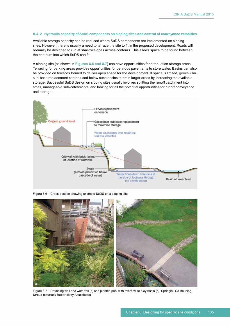
135Chapter 8: Designing for specific site conditions
CIRIA SuDS Manual 2015
8.4.2 Hydraulic capacity of SuDS components on sloping sites and control of conveyance velocities
Available storage capacity can be reduced where SuDS components are implemented on sloping sites.However,thereisusuallyaneedtoterracethesitetofitintheproposeddevelopment.Roadswillnormally be designed to run at shallow slopes across contours. This allows space to be found between thecontoursintowhichSuDScanfit.
A sloping site (as shown in Figures 8.6 and 8.7) can have opportunities for attenuation storage areas. Terracing for parking areas provides opportunities for pervious pavements to store water. Basins can also be provided on terraces formed to deliver open space for the development. If space is limited, geocellular sub-base replacement can be used below such basins to drain larger areas by increasing the available storage. Successful SuDS design on sloping sites usually involves splitting the runoff catchment into small, manageable sub-catchments, and looking for all the potential opportunities for runoff conveyance and storage.
a b
Figure 8.6 Cross-section showing example SuDS on a sloping site
Figure8.7 Retainingwallandwaterfall(a)andplantedpoolwithoverflowtoplaybasin(b),SpringhillCo-housing,Stroud (courtesy Robert Bray Associates)
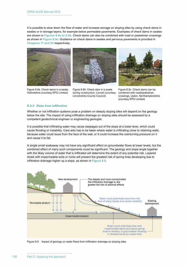
CIRIA SuDS Manual 2015
136 Part C: Applying the approach
Itispossibletoslowdowntheflowofwaterandincreasestorageonslopingsitesbyusingcheckdamsinswales or in storage layers, for example below permeable pavements. Examples of check dams in swales are shown in Figures 8.8a to 8.8b. Check dams can also be combined with road or pedestrian crossings as shown in Figure 8.8c. Guidance on check dams in swales and pervious pavements is provided in Chapters 17 and 20 respectively.
8.4.3 Risks from infiltration
Whetherornotinfiltrationsystemsposeaproblemonsteeplyslopingsiteswilldependonthegeologybelowthesite.Theimpactofusinginfiltrationdrainageonslopingsitesshouldbeassessedbyacompetent geotechnical engineer or engineering geologist.
Itispossiblethatinfiltratingwatermaycauseseepagesoutoftheslopeatalowerlevel,whichcouldcausefloodingorinstability.Carealsohastobetakenwherewaterisinfiltratingclosetoretainingwalls,because water could issue from the face of the wall, or it could increase the overturning pressure on it and cause it to fail.
Asinglesmallsoakawaymaynothaveanysignificanteffectongroundwaterflowsatlowerlevels,butthecombinedeffectofmanysuchcomponentscouldbesignificant.Thegeologyandslopeangletogetherwiththelikelyvolumeofwaterthatisinfiltratedwilldeterminetheextentofanypotentialrisk.Layeredstrata with impermeable soils or rocks will present the greatest risk of spring lines developing due to infiltrationdrainagehigherupaslope,asshowninFigure 8.9.
Figure 8.8a Check dams in a swale, Oxfordshire (courtesy EPG Limited)
Figure 8.8b Check dam in a swale during construction, Lincoln (courtesy Lincolnshire County Council)
Figure 8.8c Check dams can be combined with road/pedestrian crossings, Upton, Northamptonshire (courtesy EPG Limited)
Figure8.9 Impactofgeologyonwaterflowsfrominfiltrationdrainageonslopingsites
137Chapter 8: Designing for specific site conditions
CIRIA SuDS Manual 2015
8.5 VERY FLAT SITES
8.5.1 The challenges
Whendesigningasurfacewatermanagementsystemforaveryflatsite,thefollowingchallengesshouldbe considered within the design process:
▪ achievingsufficientgradientstodrainrunoffeffectively
▪ difficultyinmeetingoutletlevelstoexistingwatercoursesorsewers
▪ impacts of downstream water levels on drainage system performance.
8.5.2 Sufficiency of hydraulic gradients for effective drainage
Onveryflatsites,itisoftennotpossibletoconstructpipeddrainagesystemswithsufficientfallstoachieve minimum self-cleansing velocities. So using shallow SuDS components such as swales, pervious pavements or high capacity linear drainage channels is an advantage in these situations. Good SuDS design should aim to divide the site into small sub-catchments and provide local combined storage and conveyancecomponents.Thehydraulicheadthatdevelopsaswaterflowsintoandbuildsupinthesystemwillthencausewatertoflowoutofthesystem.
This is a common issue in low-lying coastal (internal drainage board) areas where piped drainage and the necessary cover often compromise the ability to achieve a suitable outfall. A common solution is to provide extensions of rhyne systems and provide storage volume within an on-site swale/rhyne system embedded throughout the development.
Onflatsites,orindeedanysitewhereastoragetankorlayerhasaflatbase,pondingofwatermayoccurin the base of the storage. If this occurs in systems that are not lined (where the soils are impermeable anddonotthereforeallowinfiltration),thewatercouldbeincontactwiththeunderlyingsoilsforasignificantlengthoftimeandcouldultimatelyreducethestrengthofthesoil.Ifpossible,aslightfallonany subgrade exposed to water is preferred, to avoid ponding of water. If this cannot be provided, then the reduction in strength due to waterlogging should be taken into account in the structural design of tanks or pervious pavements.
8.5.3 Meeting minimum outlet levels
A normal drainage system will often end up being fairly deep. Even using shallow SuDS components, the end of the surface water drainage system may still end up below the minimum allowable outfall level. In such cases, a pumping station will be necessary. Several SuDS schemes have included pumping stations, but they should be a last resort and only allowable in situations where guaranteed maintenance of the pumps can be ensured.
Figure 8.10 demonstrates the advantages of SuDS in meeting minimum outfall level constraints.
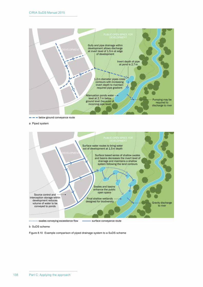
CIRIA SuDS Manual 2015
138 Part C: Applying the approach
a Piped system
b SuDS scheme
Figure8.10 ExamplecomparisonofpipeddrainagesystemtoaSuDSscheme
139Chapter 8: Designing for specific site conditions
CIRIA SuDS Manual 2015
8.6 SITES WITH POTENTIALLY UNSTABLE SUBSURFACE ROCKS OR SOIL WORKINGS
8.6.1 The challenges
When designing a surface water management system on a site that may be prone to subsurface soil or rock instability, the following issues should be considered within the design process:
▪ Waterinfiltrationintothegroundcancauseinstabilityinpoorlyconsolidatedsoils,becausethewatercan wash out the soil or cause it to compact. Also, rocks such as chalk may slowly dissolve over time.
▪ Waterfrominfiltrationsystemscancauseslopeorretainingwallfailure,becausewaterpressuremayincrease in the soil behind the slope or wall.
GuidanceonareasofpotentialsurfacegeologyinstabilitycanbefoundviaBGSinfiltrationmaps: http://tinyurl.com/oruu25r
8.6.2 Unstable soil or rock matrix
SuDSforsiteswheretherearesoilsorrockspronetoinstabilityshouldnotuseinfiltrationasarunoffdestination,anditmaybenecessarytolinesystemstopreventanywaterinfiltratingtheground.Thiswilldepend on the risks associated with any potential instability and the likely volume of water discharging to theinfiltrationdevicewhencomparedtonaturalexposuretorainfallonthesamearea.AsmallamountofinfiltrationtoprovideInterceptionmaynotbeaproblem.
Usinginfiltrationdrainageinchalkcancausesettlementduetosolutionofthechalkorinfilledfeaturesinthe surface of the chalk. Guidance is provided in Lord et al(2002).
TheuseofSuDSinsuchareaswithrock/soilinstabilityriskswillrequireadvicefromageotechnicalspecialist.Areasthatneedspecificcareincludetheareasaroundoldshaftsoraditsintomineworkings,shallowmineworkings,limestoneandareaswithburied,infilledsolutionfeatures.Shaftsandaditsandinfilledsolutionfeatureshaveoftenbeenfilledwithlooselycompactedsoilthathasverymarginalstability.Thepassageofwaterthroughitcancauselossofmaterial,asfinesarewashedout,leadingtocollapseof the soil mass.
8.6.3 Risks to slopes and/or retaining walls
Ifwaterisallowedtoinfiltratebehindslopesorretainingwalls,itcanincreaseporepressuresintheground.Thismayincreasethepressureonthewallorslopeandcauseittofail.Infiltrationdevicesshouldbelocatedatasufficientdistancefromslopesandretainingwallstopreventanyadverse effects on stability. The appropriate distance should be based on a slope/wall stability and groundwaterflowassessment.
8.7 SITES WITH VERY DEEP BACKFILL
8.7.1 The issues
Whendesigningasurfacewatermanagementsystemonasitelocatedaboveorclosetoinfilledopencastsitesoroldlandfillsites,thefollowingissuesshouldbeconsideredwithinthedesignprocess:
▪ Infiltratingwatercancausecompactionoftheexistingfillmaterial.
▪ Anysettlementofthebackfillislikelytocausesurfacelevelchanges,whichcanpotentiallyaffectgradients along a drainage system or cause damage to liners. Settlement can cause tension cracks thatallowmorewatertoinfiltrate,whichmaynotbeacceptable.Thisissuemayaffecttheviabilityofanentiredevelopment.Soifthesiteissuitablefordevelopmentoverthebackfillthenitwillmostlikely be suitable for some form of SuDS.
CIRIA SuDS Manual 2015
140 Part C: Applying the approach
8.7.2 Fill compaction
Themainconcernisthepotentialeffectofinfiltrationonsettlementofdeeperareasoffill.Infiltrationshouldbeavoidedunlessitcanbedemonstratedthatthefillmaterialissufficientlywellcompactedthatsettlementwillnotbeaproblem(aswellasbeingsufficientlypermeable).
As shown previously in Figure 8.4,adrainageschemehasusedpermeablepavingoveralandfillsiteinPortsmouth.Thesystemislinedtopreventinfiltration.
8.7.3 Surface settlement
SuDS such as swales and permeable pavements are likely to be more tolerant of movements due to settlement than piped drainage. Where there are potential risks, however, the effect on gradients should be assessed and any liners should be carefully detailed to prevent tearing. Pipe drainage can only tolerate a small amount of movement at the joints.
8.8 SUDS ON FLOODPLAINS
8.8.1 The issues
Onsomesites,floodplainsmightbetheonlyavailablepublicopenspace.Theroleofafloodplainisprimarilytomitigatefloodriskfromriversortides,andduringextremeeventstheseareaswillnaturallyfloodwithriverorseawater,makingthemineffectiveforuseinstoringsurfacewaterrunoff.Itishighlyunlikelythatanystoragevolumeachievedwithinafloodplainwouldbeallowedtomeetadevelopment’stotalsurfacewaterattenuationrequirement.Allstoragevolumeshouldnormallybeprovidedwithinthedevelopmentfootprint,outsideofthefloodplain.
Thepresenceofafloodplain,however,shouldnotprecludethesitefromincludingSuDS,astheycouldstill be effective in managing routine rainfall, and runoff may need to be discharged safely across the floodplain.SuDSinthefloodplainmayalsobeacceptableintermsofprovidingtreatmentforfrequentevents.ThedesignofthosepartsofSuDSinafloodplainshouldnotreducefloodplainstorageorconveyance.
8.8.2 Design considerations
AnySuDSwithinafloodplainshouldbeselectedanddesignedtakingaccountofthelikelyhighgroundwatertableandvulnerabilitytoerosionduringperiodsofhighflows/waterlevels.
Design of any conveyance routes should limit grading and the creation of surface features (such as bermsandunreinforcedchannels)thatcouldeitherreducefloodplaincapacityorbewashedoutinaflood.SurfacedischargefromSuDSshouldbedispersed(ieallowedtoshedoffassheetflow)withpointdischarges minimised or eliminated.
AllSuDSwithinorcrossingafloodplainshouldtakefullconsiderationofthelikelyinfluenceofriverwaterlevelsonthedesignperformance(intermsoflevel,frequency,durationandimpactonSuDSconveyanceandstorage).Combinedprobabilityassessmentsmayberequired.
Siltationandsubsequentclearanceafterafloodeventhassubsidedshouldalsobetakenintoaccountinthe design.
The SuDS shown in the development in Stamford in Figure 8.2arelocatedinthefloodplain.

141Chapter 8: Designing for specific site conditions
CIRIA SuDS Manual 2015
8.9 REFERENCES
EA(2001)Assessment and management of risks to buildings, building materials and services from land contamination,R&DTechnicalReportP5-035/TR/01,EnvironmentAgency,Bristol,UK(ISBN:1-85705-484-9). Go to: http://tinyurl.com/nut7yyf
LORD,J,CLAYTON,CandMORTIMORE,R(2002)Engineering in chalk,C574,CIRIA,London,UK(ISBN:978-0-86017-574-2).Goto:www.ciria.org
MALLETT,H,COX,L,WILSON,SandCORBAN,M(2014)Good practice on the testing and verification of protection systems for buildings against hazardous ground gases,C735,CIRIA,London,UK(ISBN:978-0-86017-739-5).Goto:www.ciria.org
PAUL, V (1994) Performance of building materials on contaminated land, BR 255, Building Research Establishment,London,UK(ISBN:978-0-85125-624-5)
PRIVETT,KD,MATTHEWS,SandHODGES,RA(1996)Barriers, liners and cover systems for containment and control of land contamination,SP124,CIRIA,London,UK(ISBN:978-0-86017-437-0).Go to: www.ciria.org
USEPA (1991) Design and construction of RCRA/CERCLA final covers,EPA/625/4-91/025,UnitedStatesEnvironmental Protection Agency, Washington DC, USA. Go to: http://tinyurl.com/pbldvcw
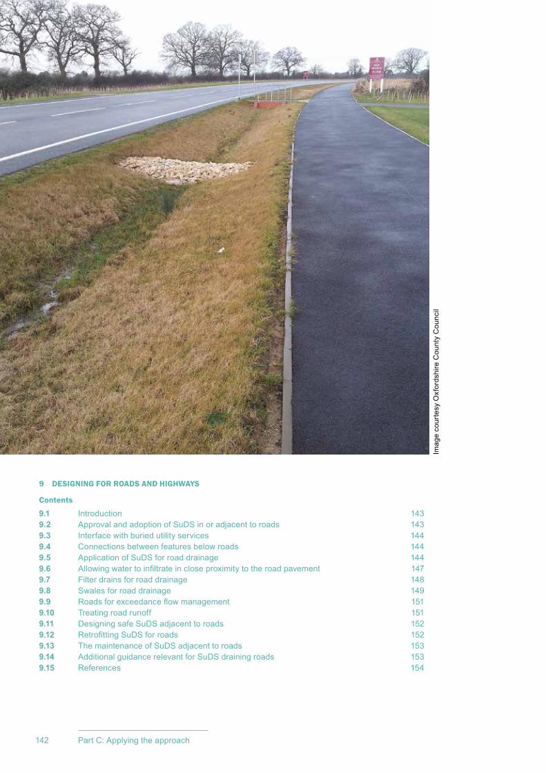
CIRIA SuDS Manual 2015
142 Part C: Applying the approach
9 DESIGNING FOR ROADS AND HIGHWAYS
Contents
9.1 Introduction 1439.2 Approval and adoption of SuDS in or adjacent to roads 1439.3 Interface with buried utility services 1449.4 Connections between features below roads 1449.5 Application of SuDS for road drainage 1449.6 Allowingwatertoinfiltrateincloseproximitytotheroadpavement 1479.7 Filter drains for road drainage 1489.8 Swales for road drainage 1499.9 Roadsforexceedanceflowmanagement 1519.10 Treatingroadrunoff 1519.11 DesigningsafeSuDSadjacenttoroads 1529.12 RetrofittingSuDSforroads 1529.13 ThemaintenanceofSuDSadjacenttoroads 1539.14 AdditionalguidancerelevantforSuDSdrainingroads 1539.15 References 154
ImagecourtesyOxfordshireCountyCouncil

143Chapter 9: Designing for roads and highways
CIRIA SuDS Manual 2015
9.1 INTRODUCTION
ThedrainageofroadsusingSuDSisadesignapplicationscenariothathasspecificchallengesowingtotheneedtoprotecttheroadpavementfromdamageandensurethatextrasafetyrisksarenotintroducedbythedesignofthedrainagesystem.
Road/highwaydesignrequirementswillalsobeakeyinfluence,andthereneedstobeco-operationbetweenroad/highwayandSuDSdesignerstoachievethemosteffectiveschemes.
ThischapterisnotintendedtobeacompleteguidetodesigningSuDSforroads.Itcoversthefollowingspecificconcernsandissuesthatareoftenraised:
1 general road drainage approval issues
2 interface with buried utility services
3 examplesofSuDScomponentsusedforroaddrainage
4 useofinfiltrationsystemsforroaddrainage
5 filterdraindesignissues
6 swale design issues
7 exceedanceflowmanagement
8 treatmentofroadrunoff
9 safety issues
10retrofittingSuDSforroaddrainageaspartofahighwaysimprovementscheme(butnotstandaloneretrofitofSuDS)
11maintenanceissues.
ThereisotherguidanceondesigningSuDSspecificallyforroads(includinghighways),andthisisreferencedattheendofthechapter(Section 9.14).
9.2 APPROVAL AND ADOPTION OF SUDS IN OR ADJACENT TO ROADS
Roads,overwhichthereisapublicrightofpassage,havetobeconstructedtoanagreedstandard,withpriortechnicalapprovalforthedesignhavingbeensecuredby
09Chapter Designing for roads and
highwaysThis chapter addresses specific design opportunities and constraints when implementing SuDS primarily in or adjacent to roads in new developments. It does not cover retrofitting SuDS into existing roads in any detail, although much of the advice may be relevant in that context. It is not intended to be a complete guide to designing SuDS for roads, as this is provided in other publications.
This chapter should be read alongside Chapters 3–8 and Chapter 10 in order to understand the many issues that influence the selection of appropriate SuDS for roads.
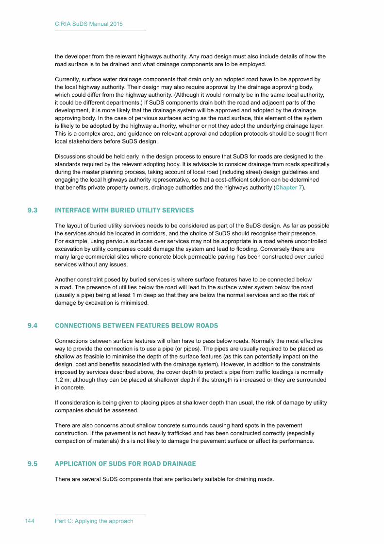
CIRIA SuDS Manual 2015
144 Part C: Applying the approach
thedeveloperfromtherelevanthighwaysauthority.Anyroaddesignmustalsoincludedetailsofhowtheroadsurfaceistobedrainedandwhatdrainagecomponentsaretobeemployed.
Currently,surfacewaterdrainagecomponentsthatdrainonlyanadoptedroadhavetobeapprovedbythelocalhighwayauthority.Theirdesignmayalsorequireapprovalbythedrainageapprovingbody,whichcoulddifferfromthehighwayauthority.(Althoughitwouldnormallybeinthesamelocalauthority,itcouldbedifferentdepartments.)IfSuDScomponentsdrainboththeroadandadjacentpartsofthedevelopment,itismorelikelythatthedrainagesystemwillbeapprovedandadoptedbythedrainageapprovingbody.Inthecaseofpervioussurfacesactingastheroadsurface,thiselementofthesystemislikelytobeadoptedbythehighwayauthority,whetherornottheyadopttheunderlyingdrainagelayer.Thisisacomplexarea,andguidanceonrelevantapprovalandadoptionprotocolsshouldbesoughtfromlocalstakeholdersbeforeSuDSdesign.
Discussions should be held early in the design process to ensure that SuDS for roads are designed to the standardsrequiredbytherelevantadoptingbody.Itisadvisabletoconsiderdrainagefromroadsspecificallyduringthemasterplanningprocess,takingaccountoflocalroad(includingstreet)designguidelinesandengagingthelocalhighwaysauthorityrepresentative,sothatacost-efficientsolutioncanbedeterminedthatbenefitsprivatepropertyowners,drainageauthoritiesandthehighwaysauthority(Chapter 7).
9.3 INTERFACE WITH BURIED UTILITY SERVICES
ThelayoutofburiedutilityservicesneedstobeconsideredaspartoftheSuDSdesign.Asfaraspossibletheservicesshouldbelocatedincorridors,andthechoiceofSuDSshouldrecognisetheirpresence.Forexample,usingpervioussurfacesoverservicesmaynotbeappropriateinaroadwhereuncontrolledexcavationbyutilitycompaniescoulddamagethesystemandleadtoflooding.Converselytherearemanylargecommercialsiteswhereconcreteblockpermeablepavinghasbeenconstructedoverburiedserviceswithoutanyissues.
Another constraint posed by buried services is where surface features have to be connected below aroad.Thepresenceofutilitiesbelowtheroadwillleadtothesurfacewatersystembelowtheroad(usuallyapipe)beingatleast1mdeepsothattheyarebelowthenormalservicesandsotheriskofdamagebyexcavationisminimised.
9.4 CONNECTIONS BETWEEN FEATURES BELOW ROADS
Connectionsbetweensurfacefeatureswilloftenhavetopassbelowroads.Normallythemosteffectivewaytoprovidetheconnectionistouseapipe(orpipes).Thepipesareusuallyrequiredtobeplacedasshallowasfeasibletominimisethedepthofthesurfacefeatures(asthiscanpotentiallyimpactonthedesign,costandbenefitsassociatedwiththedrainagesystem).However,inadditiontotheconstraintsimposedbyservicesdescribedabove,thecoverdepthtoprotectapipefromtrafficloadingsisnormally1.2m,althoughtheycanbeplacedatshallowerdepthifthestrengthisincreasedortheyaresurroundedinconcrete.
Ifconsiderationisbeinggiventoplacingpipesatshallowerdepththanusual,theriskofdamagebyutilitycompaniesshouldbeassessed.
Therearealsoconcernsaboutshallowconcretesurroundscausinghardspotsinthepavementconstruction.Ifthepavementisnotheavilytraffickedandhasbeenconstructedcorrectly(especiallycompactionofmaterials)thisisnotlikelytodamagethepavementsurfaceoraffectitsperformance.
9.5 APPLICATION OF SUDS FOR ROAD DRAINAGE
ThereareseveralSuDScomponentsthatareparticularlysuitablefordrainingroads.
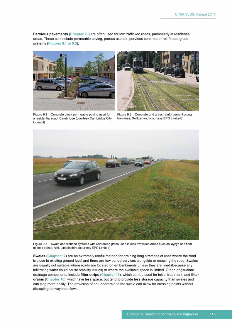
145Chapter 9: Designing for roads and highways
CIRIA SuDS Manual 2015
Pervious pavements (Chapter 20)areoftenusedforlowtraffickedroads,particularlyinresidentialareas.Thesecanincludepermeablepaving,porousasphalt,perviousconcreteorreinforcedgrasssystems(Figures 9.1 to 9.3).
Figure9.3 Swaleandwetlandsystemswithreinforcedgrassusedinlesstraffickedareassuchaslaybysandfieldaccesspoints,A16,Lincolnshire(courtesyEPGLimited)
Figure9.2 Concretegridgrassreinforcementalongtramlines,Switzerland(courtesyEPGLimited)
Figure9.1 Concreteblockpermeablepavingusedforaresidentialroad,Cambridge(courtesyCambridgeCityCouncil)
Swales(Chapter 17)areanextremelyusefulmethodfordraininglongstretchesofroadwheretheroadisclosetoexistinggroundlevelandtherearefewburiedservicesalongsideorcrossingtheroad.Swalesareusuallynotsuitablewhereroadsarelocatedonembankmentsunlesstheyarelined(becauseanyinfiltratingwatercouldcausestabilityissues)orwheretheavailablespaceislimited.Otherlongitudinaldrainagecomponentsincludefilter strips(Chapter 15),whichcanbeusedforinitialtreatment,andfilter drains (Chapter 16),whichtakelessspace,buttendtoprovidelessstoragecapacitythanswalesandcanclogmoreeasily.Theprovisionofanunderdraintotheswalecanallowforcrossingpointswithoutdisruptingconveyanceflows.
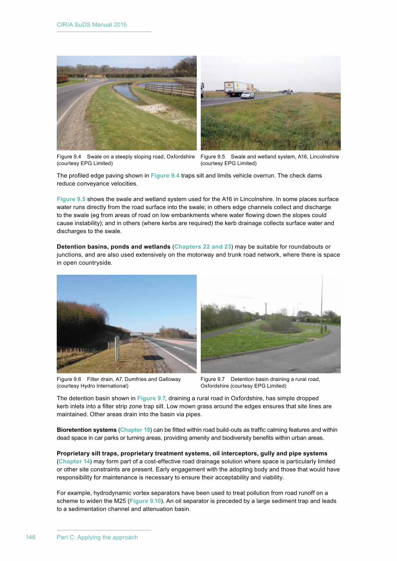
CIRIA SuDS Manual 2015
146 Part C: Applying the approach
TheprofilededgepavingshowninFigure 9.4 trapssiltandlimitsvehicleoverrun.Thecheckdamsreduceconveyancevelocities.
Figure 9.5showstheswaleandwetlandsystemusedfortheA16inLincolnshire.Insomeplacessurfacewaterrunsdirectlyfromtheroadsurfaceintotheswale;inothersedgechannelscollectanddischargetotheswale(egfromareasofroadonlowembankmentswherewaterflowingdowntheslopescouldcauseinstability);andinothers(wherekerbsarerequired)thekerbdrainagecollectssurfacewateranddischargestotheswale.
Detention basins, ponds and wetlands(Chapters 22 and 23)maybesuitableforroundaboutsorjunctions,andarealsousedextensivelyonthemotorwayandtrunkroadnetwork,wherethereisspaceinopencountryside.
The detention basin shown in Figure 9.7,drainingaruralroadinOxfordshire,hassimpledroppedkerbinletsintoafilterstripzonetrapsilt.Lowmowngrassaroundtheedgesensuresthatsitelinesaremaintained.Otherareasdrainintothebasinviapipes.
Bioretention systems(Chapter 18)canbefittedwithinroadbuild-outsastrafficcalmingfeaturesandwithindeadspaceincarparksorturningareas,providingamenityandbiodiversitybenefitswithinurbanareas.
Proprietary silt traps, proprietary treatment systems, oil interceptors, gully and pipe systems (Chapter 14)mayformpartofacost-effectiveroaddrainagesolutionwherespaceisparticularlylimitedorothersiteconstraintsarepresent.Earlyengagementwiththeadoptingbodyandthosethatwouldhaveresponsibilityformaintenanceisnecessarytoensuretheiracceptabilityandviability.
Forexample,hydrodynamicvortexseparatorshavebeenusedtotreatpollutionfromroadrunoffonaschemetowidentheM25(Figure 9.10).Anoilseparatorisprecededbyalargesedimenttrapandleadstoasedimentationchannelandattenuationbasin.
Figure9.4 Swaleonasteeplyslopingroad,Oxfordshire(courtesyEPGLimited)
Figure9.5 Swaleandwetlandsystem,A16,Lincolnshire(courtesyEPGLimited)
Figure9.6 Filterdrain,A7,DumfriesandGalloway(courtesyHydroInternational)
Figure9.7 Detentionbasindrainingaruralroad,Oxfordshire(courtesyEPGLimited)
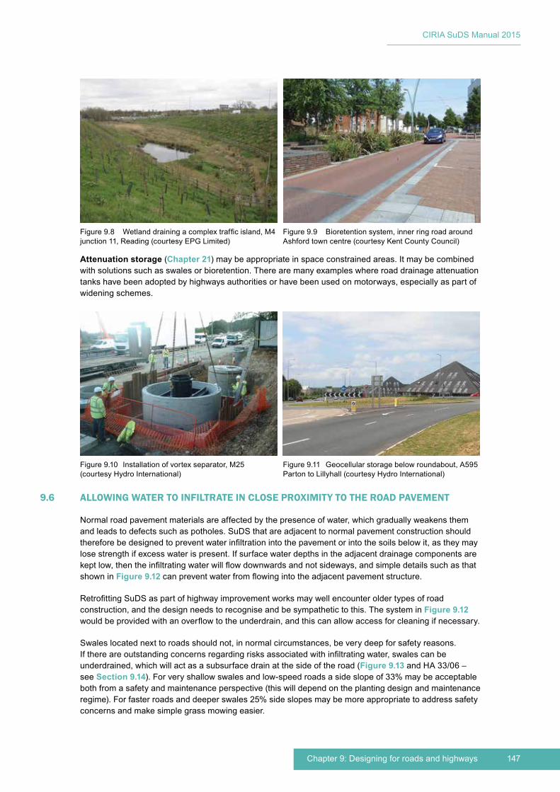
147Chapter 9: Designing for roads and highways
CIRIA SuDS Manual 2015
Attenuation storage(Chapter 21)maybeappropriateinspaceconstrainedareas.Itmaybecombinedwithsolutionssuchasswalesorbioretention.Therearemanyexampleswhereroaddrainageattenuationtankshavebeenadoptedbyhighwaysauthoritiesorhavebeenusedonmotorways,especiallyaspartofwideningschemes.
9.6 ALLOWING WATER TO INFILTRATE IN CLOSE PROXIMITY TO THE ROAD PAVEMENT
Normalroadpavementmaterialsareaffectedbythepresenceofwater,whichgraduallyweakensthemandleadstodefectssuchaspotholes.SuDSthatareadjacenttonormalpavementconstructionshouldthereforebedesignedtopreventwaterinfiltrationintothepavementorintothesoilsbelowit,astheymaylosestrengthifexcesswaterispresent.Ifsurfacewaterdepthsintheadjacentdrainagecomponentsarekeptlow,thentheinfiltratingwaterwillflowdownwardsandnotsideways,andsimpledetailssuchasthatshown in Figure 9.12canpreventwaterfromflowingintotheadjacentpavementstructure.
RetrofittingSuDSaspartofhighwayimprovementworksmaywellencounteroldertypesofroadconstruction,andthedesignneedstorecogniseandbesympathetictothis.ThesysteminFigure 9.12 wouldbeprovidedwithanoverflowtotheunderdrain,andthiscanallowaccessforcleaningifnecessary.
Swaleslocatednexttoroadsshouldnot,innormalcircumstances,beverydeepforsafetyreasons.Ifthereareoutstandingconcernsregardingrisksassociatedwithinfiltratingwater,swalescanbeunderdrained,whichwillactasasubsurfacedrainatthesideoftheroad(Figure 9.13andHA33/06–see Section 9.14).Forveryshallowswalesandlow-speedroadsasideslopeof33%maybeacceptablebothfromasafetyandmaintenanceperspective(thiswilldependontheplantingdesignandmaintenanceregime).Forfasterroadsanddeeperswales25%sideslopesmaybemoreappropriatetoaddresssafetyconcernsandmakesimplegrassmowingeasier.
Figure9.8 Wetlanddrainingacomplextrafficisland,M4junction11,Reading(courtesyEPGLimited)
Figure9.9 Bioretentionsystem,innerringroadaroundAshfordtowncentre(courtesyKentCountyCouncil)
Figure9.10 Installationofvortexseparator,M25(courtesyHydroInternational)
Figure9.11 Geocellularstoragebelowroundabout,A595PartontoLillyhall(courtesyHydroInternational)
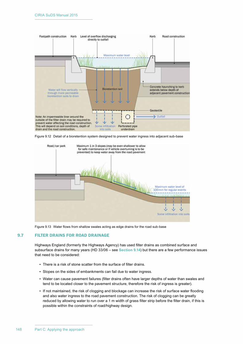
CIRIA SuDS Manual 2015
148 Part C: Applying the approach
9.7 FILTER DRAINS FOR ROAD DRAINAGE
HighwaysEngland(formerlytheHighwaysAgency)hasusedfilterdrainsascombinedsurfaceandsubsurfacedrainsformanyyears(HD33/06–seeSection 9.14)butthereareafewperformanceissuesthatneedtobeconsidered:
▪ Thereisariskofstonescatterfromthesurfaceoffilterdrains.
▪ Slopesonthesidesofembankmentscanfailduetowateringress.
▪ Watercancausepavementfailures(filterdrainsoftenhavelargerdepthsofwaterthanswalesandtendtobelocatedclosertothepavementstructure,thereforetheriskofingressisgreater).
▪ Ifnotmaintained,theriskofcloggingandblockagecanincreasetheriskofsurfacewaterfloodingandalsowateringresstotheroadpavementconstruction.Theriskofcloggingcanbegreatlyreducedbyallowingwatertorunovera1mwidthofgrassfilterstripbeforethefilterdrain,ifthisispossiblewithintheconstraintsofroad/highwaydesign.
Figure9.12 Detailofabioretentionsystemdesignedtopreventwateringressintoadjacentsub-base
Figure9.13 Waterflowsfromshallowswalesactingasedgedrainsfortheroadsub-base
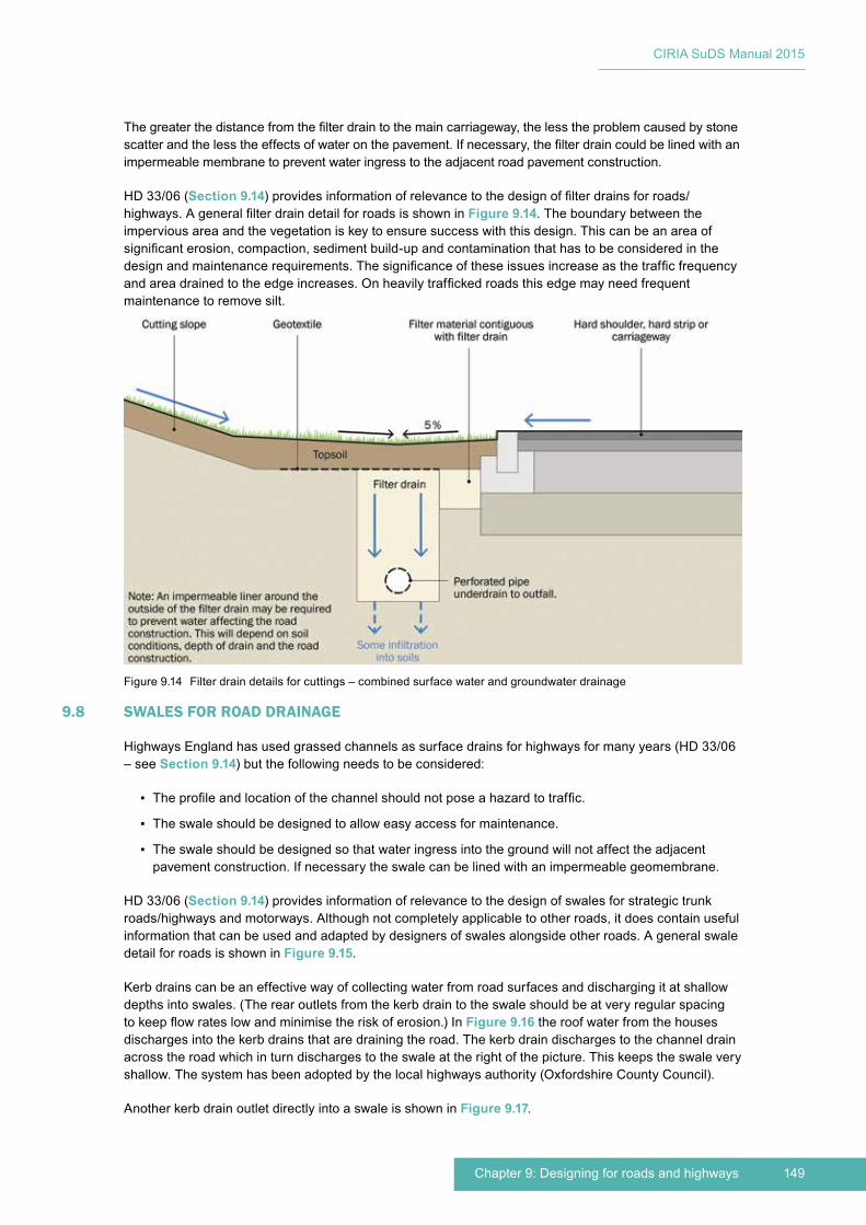
149Chapter 9: Designing for roads and highways
CIRIA SuDS Manual 2015
Thegreaterthedistancefromthefilterdraintothemaincarriageway,thelesstheproblemcausedbystonescatterandthelesstheeffectsofwateronthepavement.Ifnecessary,thefilterdraincouldbelinedwithanimpermeablemembranetopreventwateringresstotheadjacentroadpavementconstruction.
HD33/06(Section 9.14)providesinformationofrelevancetothedesignoffilterdrainsforroads/highways.AgeneralfilterdraindetailforroadsisshowninFigure 9.14.Theboundarybetweentheimperviousareaandthevegetationiskeytoensuresuccesswiththisdesign.Thiscanbeanareaofsignificanterosion,compaction,sedimentbuild-upandcontaminationthathastobeconsideredinthedesignandmaintenancerequirements.Thesignificanceoftheseissuesincreaseasthetrafficfrequencyandareadrainedtotheedgeincreases.Onheavilytraffickedroadsthisedgemayneedfrequentmaintenancetoremovesilt.
9.8 SWALES FOR ROAD DRAINAGE
HighwaysEnglandhasusedgrassedchannelsassurfacedrainsforhighwaysformanyyears(HD33/06–seeSection 9.14)butthefollowingneedstobeconsidered:
▪ Theprofileandlocationofthechannelshouldnotposeahazardtotraffic.
▪ Theswaleshouldbedesignedtoalloweasyaccessformaintenance.
▪ The swale should be designed so that water ingress into the ground will not affect the adjacent pavementconstruction.Ifnecessarytheswalecanbelinedwithanimpermeablegeomembrane.
HD33/06(Section 9.14)providesinformationofrelevancetothedesignofswalesforstrategictrunkroads/highwaysandmotorways.Althoughnotcompletelyapplicabletootherroads,itdoescontainusefulinformationthatcanbeusedandadaptedbydesignersofswalesalongsideotherroads.Ageneralswaledetail for roads is shown in Figure 9.15.
Kerbdrainscanbeaneffectivewayofcollectingwaterfromroadsurfacesanddischargingitatshallowdepthsintoswales.(Therearoutletsfromthekerbdraintotheswaleshouldbeatveryregularspacingtokeepflowrateslowandminimisetheriskoferosion.)InFigure 9.16theroofwaterfromthehousesdischargesintothekerbdrainsthataredrainingtheroad.Thekerbdraindischargestothechanneldrainacrosstheroadwhichinturndischargestotheswaleattherightofthepicture.Thiskeepstheswaleveryshallow.Thesystemhasbeenadoptedbythelocalhighwaysauthority(OxfordshireCountyCouncil).
AnotherkerbdrainoutletdirectlyintoaswaleisshowninFigure 9.17.
Figure9.14 Filterdraindetailsforcuttings–combinedsurfacewaterandgroundwaterdrainage
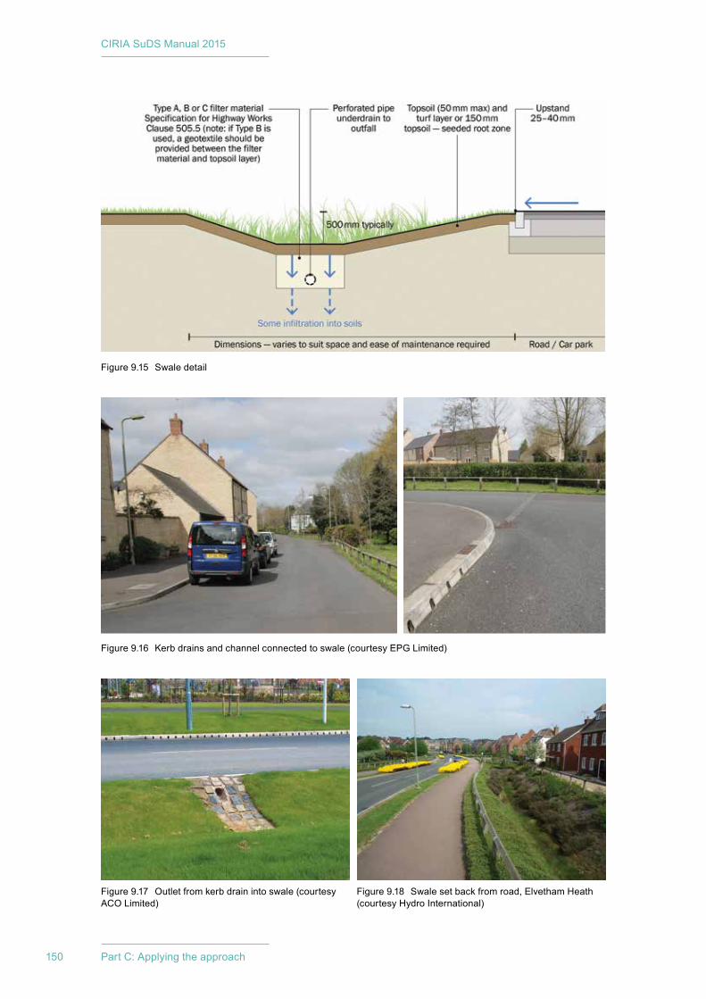
CIRIA SuDS Manual 2015
150 Part C: Applying the approach
Figure9.15 Swaledetail
Figure9.16 Kerbdrainsandchannelconnectedtoswale(courtesyEPGLimited)
Figure9.17 Outletfromkerbdrainintoswale(courtesyACOLimited)
Figure9.18 Swalesetbackfromroad,ElvethamHeath(courtesyHydroInternational)
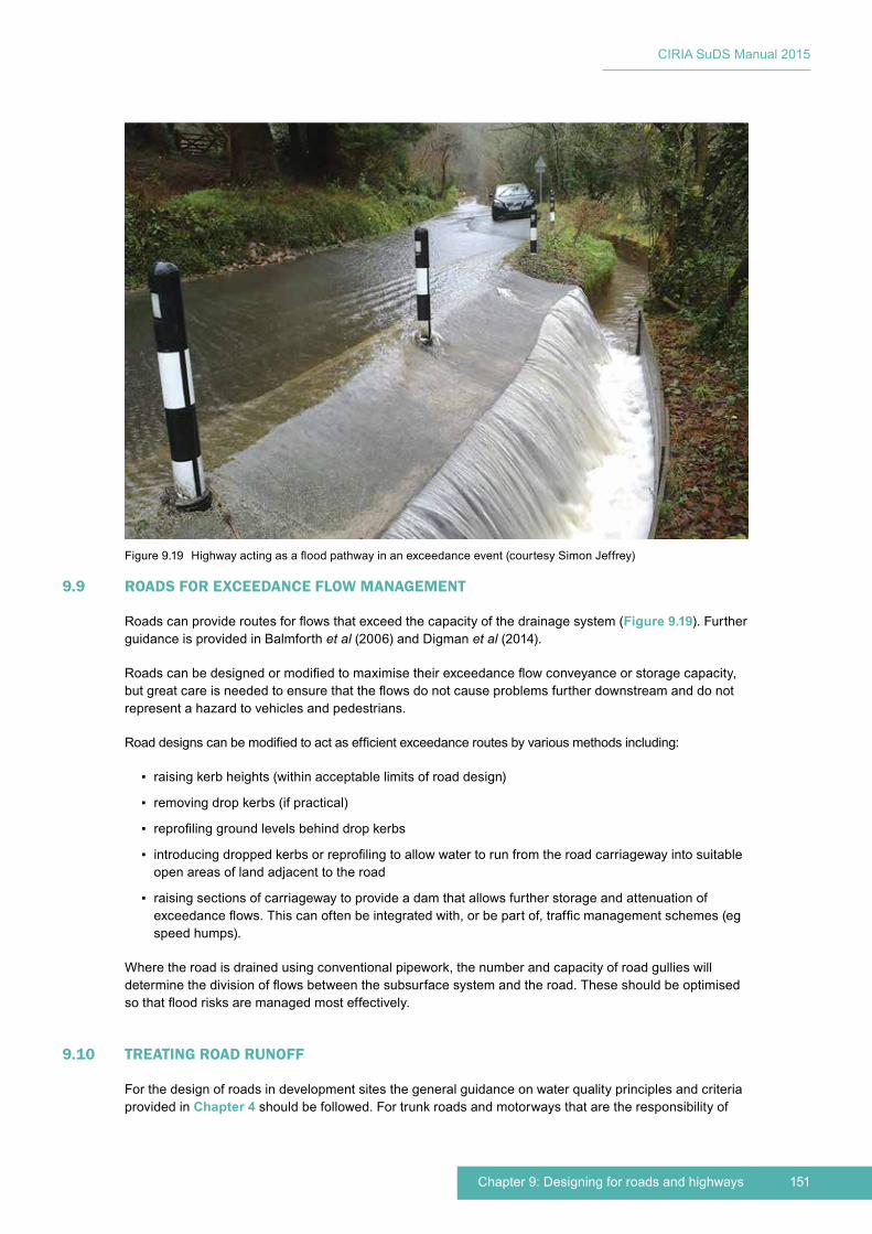
151Chapter 9: Designing for roads and highways
CIRIA SuDS Manual 2015
9.9 ROADS FOR EXCEEDANCE FLOW MANAGEMENT
Roadscanprovideroutesforflowsthatexceedthecapacityofthedrainagesystem(Figure 9.19).FurtherguidanceisprovidedinBalmforthet al(2006)andDigmanet al(2014).
Roadscanbedesignedormodifiedtomaximisetheirexceedanceflowconveyanceorstoragecapacity,butgreatcareisneededtoensurethattheflowsdonotcauseproblemsfurtherdownstreamanddonotrepresentahazardtovehiclesandpedestrians.
Roaddesignscanbemodifiedtoactasefficientexceedanceroutesbyvariousmethodsincluding:
▪ raisingkerbheights(withinacceptablelimitsofroaddesign)
▪ removingdropkerbs(ifpractical)
▪ reprofilinggroundlevelsbehinddropkerbs
▪ introducingdroppedkerbsorreprofilingtoallowwatertorunfromtheroadcarriagewayintosuitableopen areas of land adjacent to the road
▪ raisingsectionsofcarriagewaytoprovideadamthatallowsfurtherstorageandattenuationofexceedanceflows.Thiscanoftenbeintegratedwith,orbepartof,trafficmanagementschemes(egspeedhumps).
Wheretheroadisdrainedusingconventionalpipework,thenumberandcapacityofroadgullieswilldeterminethedivisionofflowsbetweenthesubsurfacesystemandtheroad.Theseshouldbeoptimisedsothatfloodrisksaremanagedmosteffectively.
9.10 TREATING ROAD RUNOFF
Forthedesignofroadsindevelopmentsitesthegeneralguidanceonwaterqualityprinciplesandcriteriaprovided in Chapter 4shouldbefollowed.Fortrunkroadsandmotorwaysthataretheresponsibilityof
Figure9.19 Highwayactingasafloodpathwayinanexceedanceevent(courtesySimonJeffrey)

CIRIA SuDS Manual 2015
152 Part C: Applying the approach
HighwaysEngland,therearespecificguidancedocumentsandriskassessmentapproachesprovidedinHD45/09(Section 9.14).HD33/06(Section 9.14)alsoincludesindicativetreatmentefficienciesfordrainagesystemsandguidanceonappropriatecombinationsofvegetativeandproprietarysystems.
Gullyemptying,roadsweepingandotherroadmaintenancetasksareimportantpollutionpreventionstrategiesforroadrunoff,andthetreatmentoftherunoffatorclosetoitssourceshouldbeapriority(Chapter 27).
Wintermaintenanceactivitiesandparticularlythegrittingofroadscanhaveadverseimpactsonthehealthofvegetationnexttoroads.Plantingshouldbespecifiedthatisastolerantaspossibleofpotentialhigherchloridelevelsinwinterrunoff.ThewinterperformanceofpervioussurfacesisdiscussedinChapter 20.
Inordertomaintainthefiltrationcapacityofvegetationsystemsattheedgeofroadsitisnecessarytoprotectthemfromruttingcausedbyvehicleoverrun.
9.11 DESIGNING SAFE SUDS ADJACENT TO ROADS
Anydrainagesystemneedstobesafeandtherearespecificsafetyconsiderationsforcomponentsthatlieadjacenttoroads.Theriskofavehicleoverturningandtheeaseofmaintenancearethemainissuestoconsiderwhendecidedonanappropriateslopetothesideoftheswale.Forswalesnexttohigh-speedroads,HighwaysEnglandspecifiesamaximumslopetotheswaleof1in5andamaximumwaterdepthof200mm(HA119/06–seeSection 9.14).Forslow-speedaccessroadsinresidentialareasasideslopeof1in3ismoreappropriateiftheswaleisveryshallow.Discouragingvehicleoverrunwithprofiledpaving(asshowninFigure 9.4)isalsousefulinthisrespect.
VegetationinSuDSshouldnotinterferewithsightlines.InFigure 9.7 the grass around the edge of the detentionbasiniscutregularlytomaintainsitelines.Thevegetationinthecentreofthedetentionbasincanbelefttogrowhigher.
9.12 RETROFITTING SUDS FOR ROADS
Themostlikelyoccasionswhereretrofittingintoanexistingroaddrainagesystemcouldbeconsideredtobepracticalandcosteffectiveare:
▪ duringroadreconstruction/resurfacingschemes
▪ duringlarge-scaledrainageimprovementschemes
▪ increasedresidentialexpansioninurbanandruralschemes.
FurtherinformationonretrofittingSuDSisprovidedinDigmanet al(2012).TheoverridingfactorinchoosingsuitablelocationsforretrofittingSuDSwillbetheexistingfallsonthecarriagewayandthelocationanddepthofburiedservices.BeforeanydesignworkonaretrofitSuDSisundertaken,acomprehensiveutilitiesandtopographicalsurveyshouldbecompletedsothattheSuDScanbedesignedaroundtheburiedservicesandexistinglevels.
Indenseurbanenvironments,roadsconstructedbeforethe1950scouldincludecrushedrockorhogginsub-base(hogginisanas-dugmixtureofclayeysandandgravelcommoninthesouth-eastofEngland),clinkerconstruction,granitesettconstructionorwoodentarblockconstruction.Designingaroundthesetypesofconstructionissite-specific.CareneedstobetakenthattheSuDSwillnotadverselyaffecttheconstructionbyallowingwaterintoitandtheimpactofbreakingintotheconstructiondoesnotcompromisethelong-termstabilityofthepavement.BreakingintoconcretepavementstoconstructSuDSalsoneedstobedonewithcaretoensurethatthestabilityofthepavementisnotadverselyaffected.
WhenretrofittingSuDStoexistingroads,thegradientsandkerblevelswillbeanimportantinfluenceondrainagepaths.Designersshouldalwayscheckexistinggradientsandfinishedkerbheightlevelsand

153Chapter 9: Designing for roads and highways
CIRIA SuDS Manual 2015
assessanylikelyfuturechangesthatmayoccurasaresultofmaintenanceworkstoensurethattheSuDSwilldraintheroadeffectivelyinthelongterm.
WhenretrofittingSuDSinruralroads,howtheroadisconstructed,drainedandmaintainedwillinfluencethedesign.Alargeproportionofruralroadshavebeenmaintainedbyhavinghadmanyapplicationsofsurfacedressing(chipandtar),solevelsandfallswillsimplyfollowtheoriginalprofile(whichwillhavebeenacarttrack).IftheroadisreconstructedtomodernstandardsthecrossfallsandlongitudinalgradientsmaychangeandwatermaynotflowtotheSuDS.
Itisimpossibletoprovideacompletelywater-tightroadconstruction,andthereisalwaysalevelofmoisturewithinanyroadconstruction,especiallyinthesub-base.Itisimportantthat,inadditiontonotincreasingthemoisturelevels,theretrofitSuDSdoesnotcutoffexistingdrainagepathswithinthesub-base.
FurtheradviceincludingpotentialretrofitopportunitiesforSuDSadjacenttoroadsisprovidedbyPittnerandAllerton(2009).
9.13 THE MAINTENANCE OF SUDS ADJACENT TO ROADS
ThemaintenancerequirementsforSuDSalongsideroadsarenodifferentfromthoseinothersituations,andreferenceshouldbemadetoChapter 32,andalsototheindividualtechnicalcomponentsectionsofthismanual.
SuDSdrainingroadsshouldbereinstatedandestablishedcorrectly,ifservicecompaniesdigtrenchesthroughthem.Theprofileofaswaleshouldbereinstatedtothecorrectlevelsanduseappropriatetopsoilandseeding.Therepairwillneedtobeprotectedfromerosionuntilthevegetationisfullyestablished.Pervioussurfacesandbioretentionsystemswillrequirethecorrectpermeablematerialstobeusedinreinstatement.
WhereverSuDSarepresentoverburiedservicestheyareanengineeringproblemintheeventofexcavation,andtheroadshouldbeclassifiedasastreetwithspecialengineeringdifficulties(SED)undertheNewRoadsandStreetWorksAct(NRSWA)1991.FurtherinformationonSEDsandtheNRSWAisprovidedbytheDepartmentforTransport(2012).
9.14 ADDITIONAL GUIDANCE RELEVANT FOR SUDS DRAINING ROADS
PittnerandAllerton(2009)providesguidanceonSuDSdesignandimplementationforroadsurfaces.
TheDesignManualforRoadsandBridges(DMRB)(HA,2014)includesthefollowingguidancerelevanttoSuDS:
▪ HD33/06Surface and subsurface drainage systems for highways
▪ HA37/97Hydraulic design of road edge surface water channels
▪ HD45/09Road drainage and the water environment
▪ HA78/96Design of outfalls for surface water channels
▪ HA83/99Safety aspects of road edge drainage features
▪ HA80/99Surface drainage of wide carriageways
▪ HA102/00Spacing of road gullies
▪ HA103/06Vegetated drainage systems for highway runoff
▪ HA105/04Sumpless gullies
▪ HA118/06Design of soakaways
CIRIA SuDS Manual 2015
154 Part C: Applying the approach
▪ HA119/06Grassed surface water channels for highway runoff
▪ HA217/08Alternative filter media and surface stabilisation techniques for combined surface and sub-surface drains
Thesedocumentsrefertodesignforthestrategicroadnetwork(SRN)andlocalhighwayauthorities(LHAs)shouldrefertopublishedguidanceiftheywishtoadaptthisguidanceforuseontheirnetworks(UKRoadsLiaisonGroup,2011).Theuseofstandarddesignsandspecificationisusefulandcanavoidmanypitfalls.However,itshouldberecognisedthateffectivedesignoftenrequiresstandardrequirementsandspecificationstobeadaptedtoparticularcircumstancesthatapplytoasite.
ItisonlytrunkroadsthatarerequiredtobedesignedaccordingtotheDMRBandintheManualofContractDocumentsforHighwayWorks(MCHW)Specificationforhighwayworks(HA,2005).Forallotherroads,thedecisionsonthechoiceofstandardsandtheirincorporationintodesignsremaininthehandsoflocalhighwayauthorities.
TheUKRoadsLiaisonGroup’sdocumenthasbeenwrittentoassisthighwayauthoritiesassessing“departures from Highways Agency’s Standards”anddesignerspreparingsubmissions.Thestatedaimisthatthedeparturesprocessshouldbeviewedasanopportunitytosimplyandeffectivelyrecordthebestjudgementsoftheprofessionalsinvolvedinthedeliveryofaroad/highwayscheme,ratherbeingoverlybureaucratic.
TheDMRBisfrequentlyamendedtoreflectadvancesindesignandconstructionpractice,andthereforethelistaboveshouldnotbeconsideredexhaustiveanddesignersshouldcheckwhetherupdatedversionhavebeenpublished.
Designing streets(TheScottishGovernment,2010)providesapolicystatementinScotlandforstreetdesignwithanemphasisonplace-making,includingtheuseofSuDS.
Manual for streets(DfTandDCLG,2007)providesguidanceondesign,planningandapprovalofnewresidentialstreetsandmodificationstoexistingones.
Manual for streets 2(CIHT,2010)isacompanionguidetotheManual for streetsanddemonstratesthrough guidance and case studies how the philosophies set out in Manual for streetscanbeextendedbeyondresidentialstreetstoencompassbothurbanandruralsituations.Itisintendedtofilltheperceivedgap in design advice between the Manual for streetsandtheDMRB.
9.15 REFERENCES
BALMFORTH,D,DIGMAN,C,KELLAGHER,RandBUTLER,D(2006)Designing for exceedance in urban drainage – good practice,C635,CIRIA,London,UK(ISBN:978-0-86017-635-0).Goto:www.ciria.org
CIHT(2010)Manual for streets 2. Wider application of the principles,CharteredInstitutionofHighwaysandTransportation,London,UK(ISBN:978-0-90293-343-9).Goto:http://tinyurl.com/ngvkyuo
DfT(2012)New Roads and Street Works Act 1991. Code of practice for the co-ordination of street works and works for road purposes and related matters, fourth edition,DepartmentforTransport,TheStationeryOffice,London,UK(ISBN:978-0-11553-251-1).Goto:http://tinyurl.com/pzbr8uv
DfTandCLG(2007)Manual for streets,ThomasTelford,London,UK(ISBN:978-0-72773-501-0). Goto:https://www.gov.uk/government/publications/manual-for-streets
DIGMAN,C,ASHLEY,R,BALMFORTH,D,BALMFORTH,D,STOVIN,VandGLERUM,J(2012)Retrofitting urban areas to effectively manage surface water,C713,CIRIA,London,UK(ISBN:978-0-86017-715-9).Goto: www.ciria.org

155Chapter 9: Designing for roads and highways
CIRIA SuDS Manual 2015
DIGMAN,C,ASHLEY,R,HARGREAVES,PandGILL,E(2014)Managing urban flooding from heavy rainfall – encouraging the uptake of designing for exceedance,C738,CIRIA,London,UK(ISBN:978-0-86017-742-5).Goto:www.ciria.org
HA(2005)“Specificationforhighwayworks”,volume1,Manual of Contract Documents for Highway Works (MCHW), TheStationeryOffice,London,UK(ISBN:978-0-11552-705-0). Goto:http://tinyurl.com/p4pb5pz
HA(2014)Design Manual for Roads and Bridges (DMRB),HighwaysAgency,London,UK. Goto:www.standardsforhighways.co.uk/dmrb
PITTNER,CandALLERTON,G(2009)SuDS for roads,WSPDevelopmentandTransportation,WSPGroup,Edinburgh,Scotland.Goto:http://tinyurl.com/kveukel
THESCOTTISHGOVERNMENT(2010)Designing streets. A Policy Statement for Scotland,TheScottishGovernment,Edinburgh,Scotland(ISBN:978-0-75598-264-6).Goto:http://tinyurl.com/on5e3cw
UKROADSLIAISONGROUP(2011)Design and maintenance guidance for local authority roads. Departures from standards: procedures for local highway authorities,DepartmentforTransport,London,UK.Goto:http://tinyurl.com/m4tm63x
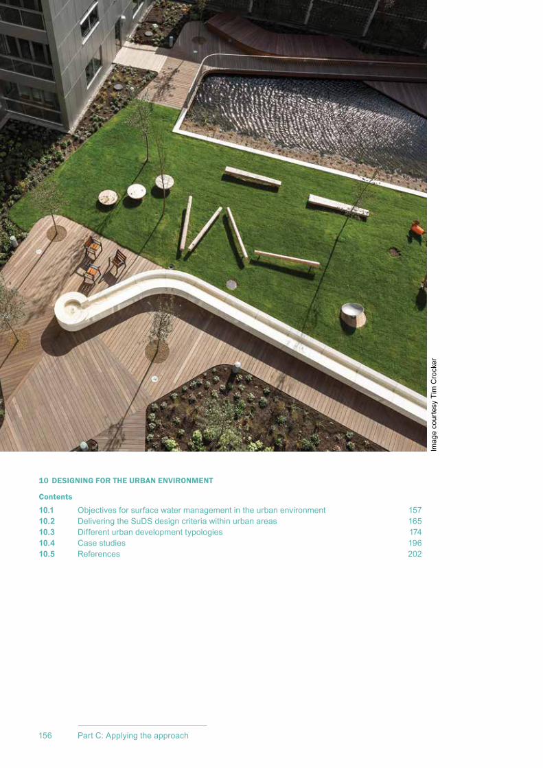
CIRIA SuDS Manual 2015
156 Part C: Applying the approach
10 DESIGNING FOR THE URBAN ENVIRONMENT
Contents
10.1 Objectives for surface water management in the urban environment 15710.2 Delivering the SuDS design criteria within urban areas 16510.3 Different urban development typologies 17410.4 Case studies 19610.5 References 202
Imag
e co
urte
sy T
im C
rock
er
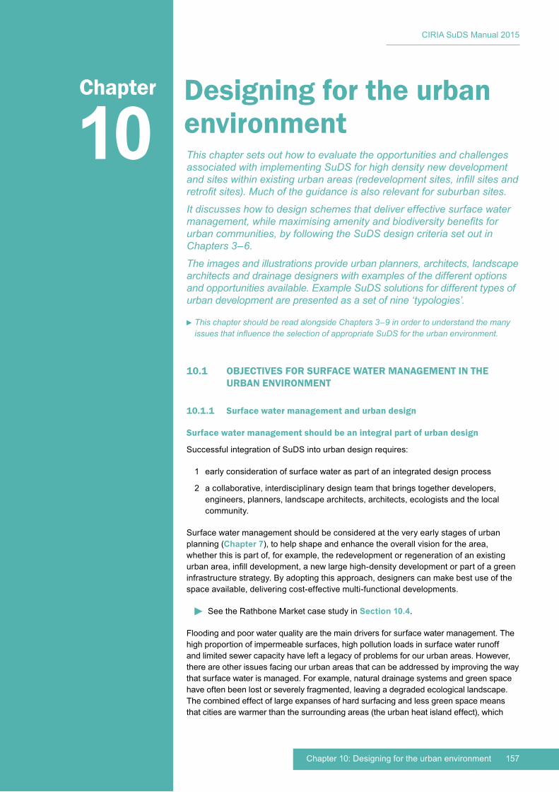
157Chapter 10: Designing for the urban environment
CIRIA SuDS Manual 2015
10.1 OBJECTIVES FOR SURFACE WATER MANAGEMENT IN THE URBAN ENVIRONMENT
10.1.1 Surface water management and urban design
Surface water management should be an integral part of urban design
Successful integration of SuDS into urban design requires:
1 early consideration of surface water as part of an integrated design process
2 a collaborative, interdisciplinary design team that brings together developers, engineers, planners, landscape architects, architects, ecologists and the local community.
Surface water management should be considered at the very early stages of urban planning (Chapter 7), to help shape and enhance the overall vision for the area, whether this is part of, for example, the redevelopment or regeneration of an existing urban area, infill development, a new large high-density development or part of a green infrastructure strategy. By adopting this approach, designers can make best use of the space available, delivering cost-effective multi-functional developments.
See the Rathbone Market case study in Section 10.4.
Flooding and poor water quality are the main drivers for surface water management. The high proportion of impermeable surfaces, high pollution loads in surface water runoff and limited sewer capacity have left a legacy of problems for our urban areas. However, there are other issues facing our urban areas that can be addressed by improving the way that surface water is managed. For example, natural drainage systems and green space have often been lost or severely fragmented, leaving a degraded ecological landscape. The combined effect of large expanses of hard surfacing and less green space means that cities are warmer than the surrounding areas (the urban heat island effect), which
10Chapter Designing for the urban
environmentThis chapter sets out how to evaluate the opportunities and challenges associated with implementing SuDS for high density new development and sites within existing urban areas (redevelopment sites, infill sites and retrofit sites). Much of the guidance is also relevant for suburban sites.
It discusses how to design schemes that deliver effective surface water management, while maximising amenity and biodiversity benefits for urban communities, by following the SuDS design criteria set out in Chapters 3–6.
The images and illustrations provide urban planners, architects, landscape architects and drainage designers with examples of the different options and opportunities available. Example SuDS solutions for different types of urban development are presented as a set of nine ‘typologies’.
This chapter should be read alongside Chapters 3–9 in order to understand the many issues that influence the selection of appropriate SuDS for the urban environment.
CIRIA SuDS Manual 2015
158 Part C: Applying the approach
can result in uncomfortable living conditions and health problems during periods of hot weather. Areas of planting or open water, and features that retain water can help reduce the temperature of urban surfaces during hot summer periods. Trees can help shade buildings, reducing internal air temperatures, and green roofs can improve a building’s thermal insulation properties.
The challenge of managing surface water effectively within the urban environment is intensifying with climate change, continued urbanisation and urban creep. Climate change projections indicate that more intense rainfall and higher temperatures will become more frequent in the UK. The density of development is also increasing and, with this, competition for the use of space is exacerbated. This means that reversing urban creep and maximising the multi-functionality of urban space is essential (Section 10.2.6).
The challenge for designers and planners is to create integrated urban spaces that include SuDS in creative and innovative ways, taking into consideration their potential contribution to a range of functions, such as flood risk management, water supply, green infrastructure, habitat provision, transport corridors, climate proofing, community identity, recreation and tourism. In this way, SuDS can make a significant contribution to the delivery of a wide range of local planning policies and objectives.
10.1.2 SuDS and urban place-making
SuDS can make a significant contribution to improving where we live and work
Good urban design should be about ‘place-making’ – all urban design projects should have a strong focus on the people and community that will inhabit and use the space, providing opportunities for people to interact with each other and their environment.
People have always been drawn to water in the urban environment, due to the beauty it can create in the landscape, its calming and cooling effects and its use for recreation. The positive presence of water within the urban environment can promote a strong sense of place, creating unique spaces that can be enjoyed by all. Features such as reflective pools, ponds, fountains, water playscapes, planted rills etc, if designed creatively, can help to bring an urban space to life and connect people, nature and water.
SuDS can make a significant contribution to supporting urban communities. People are more likely to feel that they belong to the local community and take a greater pride in their neighbourhood where they have opportunities for human interaction, such as recreational facilities and places to congregate. This in turn can have a wide range of secondary benefits, such as encouraging businesses to move into the neighbourhood, investment in amenity facilities and events and visitors to come and spend money. It can even lead to crime reduction. These benefits are discussed in more detail in Chapter 5.
Effective consideration of urban community needs and opportunities during the design stage can help maximise benefits (Chapter 34). For example, green spaces have an important role to play in improving the health and well-being of the urban population, as they can contribute towards the improvement of air quality, provide shade and urban cooling, as well as help play a part in surface water and wider flood risk management strategies for the area.
See the Bristol Harbourside case study in Section 10.4.
Connected green infrastructure can facilitate walking and cycling routes within tranquil settings and recreational green space. These benefits in turn provide opportunities for people to come into contact with nature, to experience the seasons, to become more active and to live and work in a more attractive and stimulating environment, all of which are proven to have positive effects on health and well-being.
10.1.3 Finding space for SuDS
Good SuDS design maximises the use of the available space
Sites within urban areas are often confined and restricted. Planning and design constraints are often tighter than at other sites, and land is often more valuable. Introducing SuDS can appear challenging
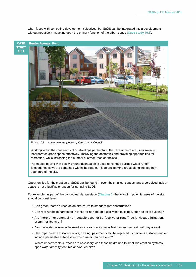
159Chapter 10: Designing for the urban environment
CIRIA SuDS Manual 2015
when faced with competing development objectives, but SuDS can be integrated into a development without negatively impacting upon the primary function of the urban space (Case study 10.1).
Opportunities for the creation of SuDS can be found in even the smallest spaces, and a perceived lack of space is not a justifiable reason for not using SuDS.
For example, as part of the conceptual design stage (Chapter 7) the following potential uses of the site should be considered:
▪ Can green roofs be used as an alternative to standard roof construction?
▪ Can roof runoff be harvested in tanks for non-potable use within buildings, such as toilet flushing?
▪ Are there other potential non-potable uses for surface water runoff (eg landscape irrigation, urban horticulture)?
▪ Can harvested rainwater be used as a resource for water features and recreational play areas?
▪ Can impermeable surfaces (roofs, parking, pavements etc) be replaced by pervious surfaces and/or include permeable sub-base in which water can be stored?
▪ Where impermeable surfaces are necessary, can these be drained to small bioretention systems, open water amenity features and/or tree pits?
Figure 10.1 Hunter Avenue (courtesy Kent County Council)
Working within the constraints of 50 dwellings per hectare, the development at Hunter Avenue incorporates green space effectively, improving the aesthetics and providing opportunities for recreation, while increasing the number of street trees on the site.
Permeable paving with below-ground attenuation is used to manage surface water runoff. Exceedance flows are contained within the road curtilage and parking areas along the southern boundary of the site.
Hunter Avenue, KentCASE STUDY10.1

CIRIA SuDS Manual 2015
160 Part C: Applying the approach
▪ Can private or public landscaped areas use or be redesigned to include tree pits, landscaping planters, rain gardens, bioretention systems or swales to provide storage and treatment of runoff?
▪ Can small areas in front or back gardens or yards be designed as bioretention planters to capture roof runoff or configured to include rainwater harvesting systems?
▪ Can proprietary products be used to help control flows, store water and/or provide treatment in confined spaces?
Traditionally, the perceived usable space for SuDS has been confined to what is deemed to be public space – from ‘fence to fence’ – which can limit the potential for SuDS implementation and a fully integrated approach. Looking at the urban space as being from ‘door to door’ (blurring the boundaries between public and private land) provides many more opportunities for using space efficiently. Underutilised land often falls along the interfaces between public and private land, such as grass verges and other small pockets of vegetation or paving. Reviewing this land and discussing potential opportunities with landowners and the community can unlock large areas that can be used to enhance the streetscape as a whole as well as supporting SuDS strategies. Facilitating this approach will require effective community engagement, but there is an increasing number of cases where this has been successfully achieved, as discussed in Chapter 34.
Integrating SuDS within urban space can also deliver biodiversity benefits. This may be through introducing or enhancing the green and blue space for the site, reconnecting fragmented green space in the surrounding area and/or linking with local green infrastructure.
Examples of where SuDS can enhance green infrastructure include:
▪ street trees as individual specimens, lines of trees that can connect green spaces together and groves of trees that can form habitat islands (Chapter 19)
▪ management of existing street trees and enhancement by using SuDS to increase air and water availability for tree roots
▪ maximising the plant coverage by replacing hard barriers with hedges etc
▪ extensive and intensive green roofs
▪ green walls and vertical gardens
▪ using SuDS components such as swales and detention basins within multi-functional landscape features
▪ using reinforced grass surfaces in place of hard surfaces where appropriate
▪ raised planters, which can provide temporary storage measures
▪ diversity of planting and habitat provision.
Urban SuDS should always take a form that responds to the location, character, drivers and opportunities associated with the site. There are a number of components or component derivations likely to be more relevant for dense urban areas. The examples given below are not exhaustive, and different components will develop as SuDS design progresses in the future. All of these types of components are used within the typologies presented and illustrated in Section 10.3. Guidance on how to design and implement the SuDS components is provided in Chapters 11–23.
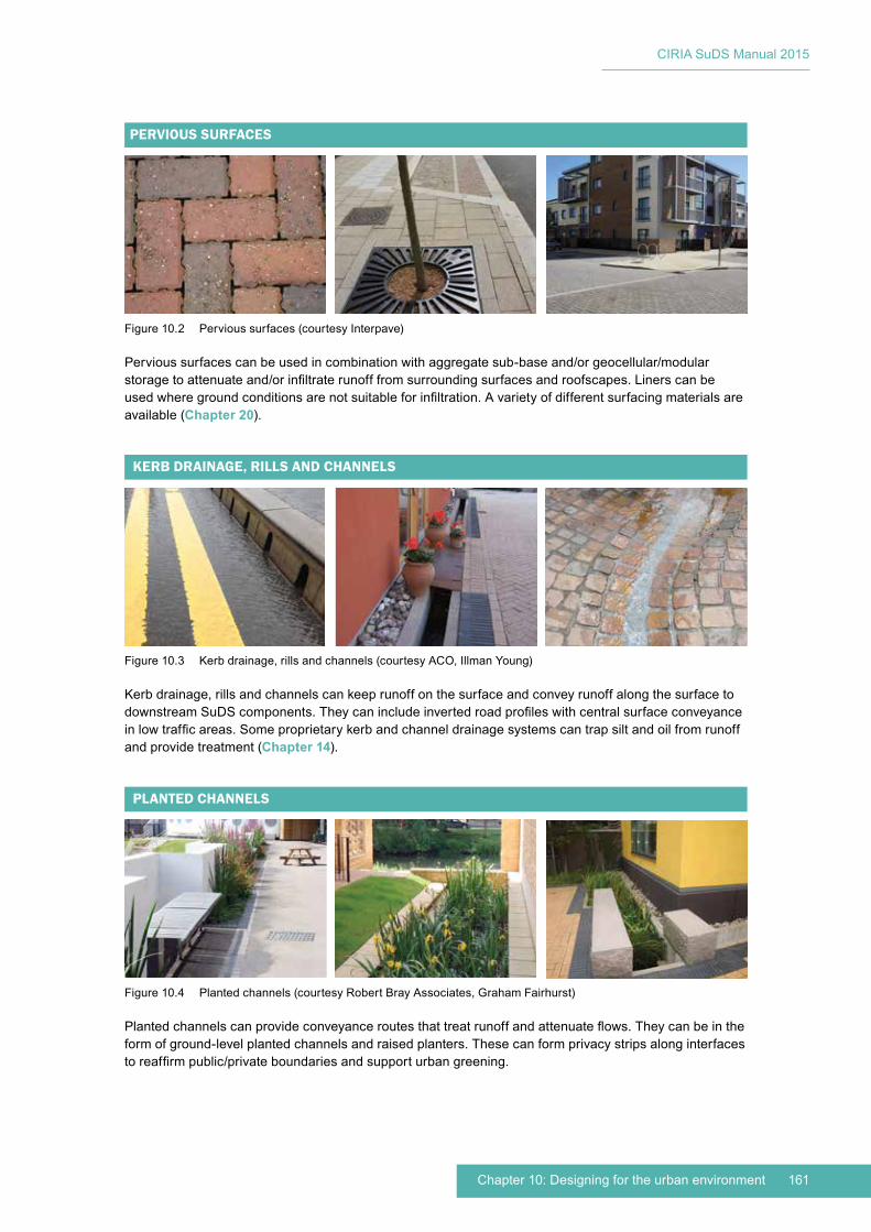
161Chapter 10: Designing for the urban environment
CIRIA SuDS Manual 2015
Figure 10.2 Pervious surfaces (courtesy Interpave)
Pervious surfaces can be used in combination with aggregate sub-base and/or geocellular/modular storage to attenuate and/or infiltrate runoff from surrounding surfaces and roofscapes. Liners can be used where ground conditions are not suitable for infiltration. A variety of different surfacing materials are available (Chapter 20).
PERVIOUS SURFACES
Figure 10.3 Kerb drainage, rills and channels (courtesy ACO, Illman Young)
Kerb drainage, rills and channels can keep runoff on the surface and convey runoff along the surface to downstream SuDS components. They can include inverted road profiles with central surface conveyance in low traffic areas. Some proprietary kerb and channel drainage systems can trap silt and oil from runoff and provide treatment (Chapter 14).
KERB DRAINAGE, RILLS AND CHANNELS
Figure 10.4 Planted channels (courtesy Robert Bray Associates, Graham Fairhurst)
Planted channels can provide conveyance routes that treat runoff and attenuate flows. They can be in the form of ground-level planted channels and raised planters. These can form privacy strips along interfaces to reaffirm public/private boundaries and support urban greening.
PLANTED CHANNELS
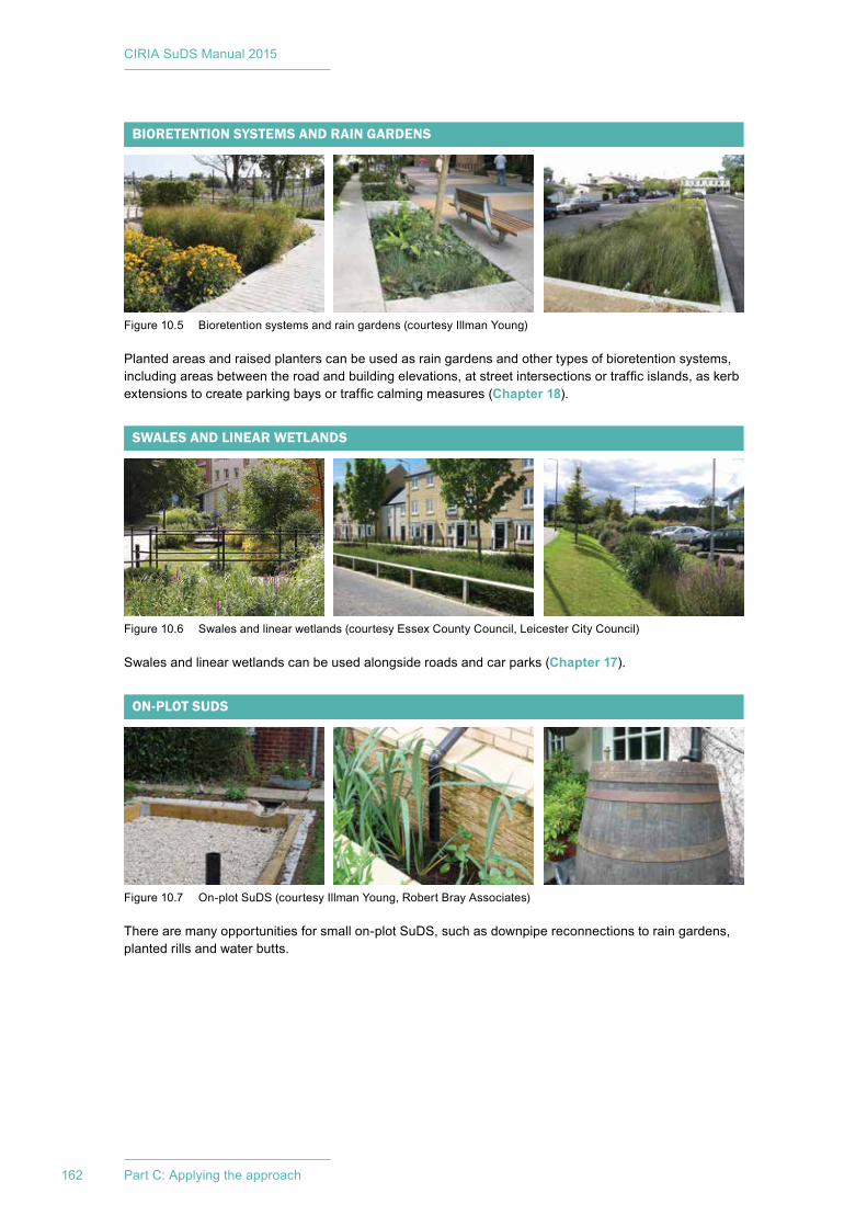
CIRIA SuDS Manual 2015
162 Part C: Applying the approach
SWALES AND LINEAR WETLANDS
Figure 10.6 Swales and linear wetlands (courtesy Essex County Council, Leicester City Council)
Swales and linear wetlands can be used alongside roads and car parks (Chapter 17).
Figure 10.7 On-plot SuDS (courtesy Illman Young, Robert Bray Associates)
There are many opportunities for small on-plot SuDS, such as downpipe reconnections to rain gardens, planted rills and water butts.
ON-PLOT SUDS
Figure 10.5 Bioretention systems and rain gardens (courtesy Illman Young)
Planted areas and raised planters can be used as rain gardens and other types of bioretention systems, including areas between the road and building elevations, at street intersections or traffic islands, as kerb extensions to create parking bays or traffic calming measures (Chapter 18).
BIORETENTION SYSTEMS AND RAIN GARDENS
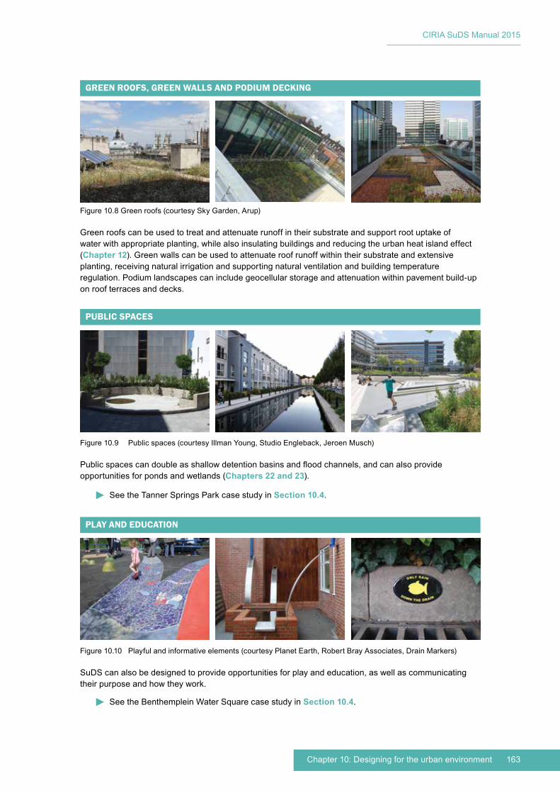
163Chapter 10: Designing for the urban environment
CIRIA SuDS Manual 2015
Figure 10.8 Green roofs (courtesy Sky Garden, Arup)
Green roofs can be used to treat and attenuate runoff in their substrate and support root uptake of water with appropriate planting, while also insulating buildings and reducing the urban heat island effect (Chapter 12). Green walls can be used to attenuate roof runoff within their substrate and extensive planting, receiving natural irrigation and supporting natural ventilation and building temperature regulation. Podium landscapes can include geocellular storage and attenuation within pavement build-up on roof terraces and decks.
GREEN ROOFS, GREEN WALLS AND PODIUM DECKING
Figure 10.9 Public spaces (courtesy Illman Young, Studio Engleback, Jeroen Musch)
Public spaces can double as shallow detention basins and flood channels, and can also provide opportunities for ponds and wetlands (Chapters 22 and 23).
PUBLIC SPACES
Figure 10.10 Playful and informative elements (courtesy Planet Earth, Robert Bray Associates, Drain Markers)
SuDS can also be designed to provide opportunities for play and education, as well as communicating their purpose and how they work.
PLAY AND EDUCATION
See the Tanner Springs Park case study in Section 10.4.
See the Benthemplein Water Square case study in Section 10.4.
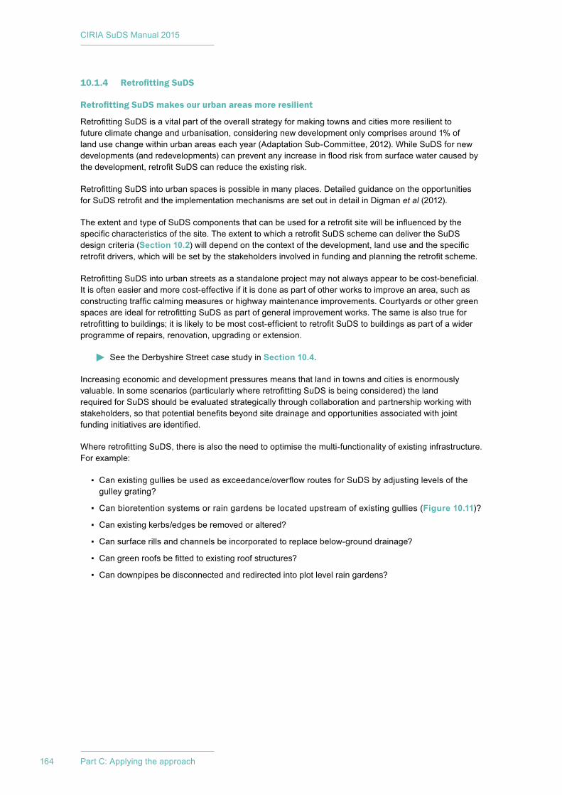
CIRIA SuDS Manual 2015
164 Part C: Applying the approach
10.1.4 Retrofitting SuDS
Retrofitting SuDS makes our urban areas more resilient
Retrofitting SuDS is a vital part of the overall strategy for making towns and cities more resilient to future climate change and urbanisation, considering new development only comprises around 1% of land use change within urban areas each year (Adaptation Sub-Committee, 2012). While SuDS for new developments (and redevelopments) can prevent any increase in flood risk from surface water caused by the development, retrofit SuDS can reduce the existing risk.
Retrofitting SuDS into urban spaces is possible in many places. Detailed guidance on the opportunities for SuDS retrofit and the implementation mechanisms are set out in detail in Digman et al (2012).
The extent and type of SuDS components that can be used for a retrofit site will be influenced by the specific characteristics of the site. The extent to which a retrofit SuDS scheme can deliver the SuDS design criteria (Section 10.2) will depend on the context of the development, land use and the specific retrofit drivers, which will be set by the stakeholders involved in funding and planning the retrofit scheme.
Retrofitting SuDS into urban streets as a standalone project may not always appear to be cost-beneficial. It is often easier and more cost-effective if it is done as part of other works to improve an area, such as constructing traffic calming measures or highway maintenance improvements. Courtyards or other green spaces are ideal for retrofitting SuDS as part of general improvement works. The same is also true for retrofitting to buildings; it is likely to be most cost-efficient to retrofit SuDS to buildings as part of a wider programme of repairs, renovation, upgrading or extension.
See the Derbyshire Street case study in Section 10.4.
Increasing economic and development pressures means that land in towns and cities is enormously valuable. In some scenarios (particularly where retrofitting SuDS is being considered) the land required for SuDS should be evaluated strategically through collaboration and partnership working with stakeholders, so that potential benefits beyond site drainage and opportunities associated with joint funding initiatives are identified.
Where retrofitting SuDS, there is also the need to optimise the multi-functionality of existing infrastructure. For example:
▪ Can existing gullies be used as exceedance/overflow routes for SuDS by adjusting levels of the gulley grating?
▪ Can bioretention systems or rain gardens be located upstream of existing gullies (Figure 10.11)?
▪ Can existing kerbs/edges be removed or altered?
▪ Can surface rills and channels be incorporated to replace below-ground drainage?
▪ Can green roofs be fitted to existing roof structures?
▪ Can downpipes be disconnected and redirected into plot level rain gardens?
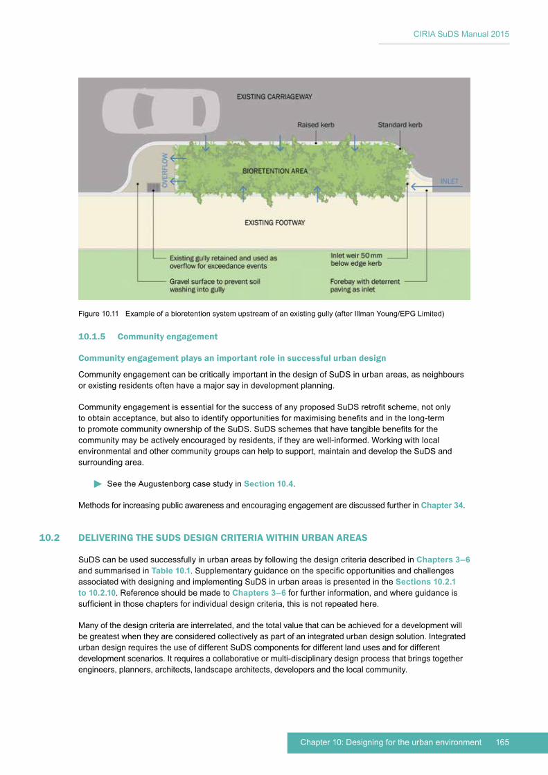
165Chapter 10: Designing for the urban environment
CIRIA SuDS Manual 2015
10.1.5 Community engagement
Community engagement plays an important role in successful urban design
Community engagement can be critically important in the design of SuDS in urban areas, as neighbours or existing residents often have a major say in development planning.
Community engagement is essential for the success of any proposed SuDS retrofit scheme, not only to obtain acceptance, but also to identify opportunities for maximising benefits and in the long-term to promote community ownership of the SuDS. SuDS schemes that have tangible benefits for the community may be actively encouraged by residents, if they are well-informed. Working with local environmental and other community groups can help to support, maintain and develop the SuDS and surrounding area.
See the Augustenborg case study in Section 10.4.
Methods for increasing public awareness and encouraging engagement are discussed further in Chapter 34.
10.2 DELIVERING THE SUDS DESIGN CRITERIA WITHIN URBAN AREAS
SuDS can be used successfully in urban areas by following the design criteria described in Chapters 3–6 and summarised in Table 10.1. Supplementary guidance on the specific opportunities and challenges associated with designing and implementing SuDS in urban areas is presented in the Sections 10.2.1 to 10.2.10. Reference should be made to Chapters 3–6 for further information, and where guidance is sufficient in those chapters for individual design criteria, this is not repeated here.
Many of the design criteria are interrelated, and the total value that can be achieved for a development will be greatest when they are considered collectively as part of an integrated urban design solution. Integrated urban design requires the use of different SuDS components for different land uses and for different development scenarios. It requires a collaborative or multi-disciplinary design process that brings together engineers, planners, architects, landscape architects, developers and the local community.
Figure 10.11 Example of a bioretention system upstream of an existing gully (after Illman Young/EPG Limited)
CIRIA SuDS Manual 2015
166 Part C: Applying the approach
10.2.1 Water quantity criterion 1: Use surface water runoff as a resource
SuDS provide a unique opportunity to exploit surface water runoff as a resource in urban areas, rather than regarding it as a nuisance and a waste product that should be removed as quickly as possible.
In a dense urban environment, climate change scenarios may mean that periods of water scarcity and associated controls on its use become more common, and the cost of water may rise. By taking opportunities to capture and store runoff (particularly from roofs), a supply of non-potable water can be secured and used either internally for the property (eg toilet flushing) or externally, such as landscape irrigation, urban food growing or as an educational resource for children’s play areas (Figure 10.12). Guidance on the design of rainwater harvesting systems for surface water management is provided in Chapter 11. Rainwater storage tanks can be included on roof space (blue roofs), within roof space, above ground within property curtilage, or below car parking areas.
Surface water runoff is also a valuable resource for the environment: a regular flow of water (if suitably treated) can help to sustain habitats that may otherwise be lost within the urban environment and can provide crucial ecological connectivity between other water bodies nearby (Section 10.2.3).
Summary of SuDS design criteria
Design criteria Section
Water quantity 1 Use surface water runoff as a resource 10.2.1
2 Support the management of flood risk in the receiving catchment10.2.2
3 Protect morphology and ecology in receiving surface waters
4 Preserve and protect natural hydrological systems on the site 10.2.3
5 Drain the site effectively10.2.4
6 Manage on-site flood risk
7 Design system flexibility/adaptability to cope with future change Chapter 3
Water quality 1 Support the management of water quality in the receiving surface waters and groundwaters
10.2.5
2 Design system resilience to cope with future change Chapter 4
Amenity 1 Maximise multi-functionality 10.2.6
2 Enhance visual character 10.2.7
3 Deliver safe surface water management systems 10.2.8
4 Support development resilience/adaptability to future change 10.2.9
5 Maximise legibility Chapter 5
6 Support community environmental learning 10.2.10
Biodiversity 1 Support and protect natural local habitats and species
Chapter 62 Contribute to the delivery of local biodiversity objectives
3 Contribute to habitat connectivity
4 Create diverse, self-sustaining and resilient ecosystems
TABLE10.1
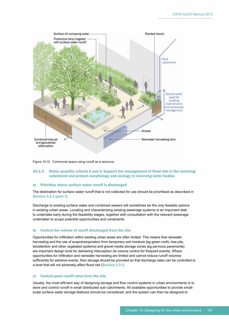
167Chapter 10: Designing for the urban environment
CIRIA SuDS Manual 2015
10.2.2 Water quantity criteria 2 and 3: Support the management of flood risk in the receiving catchment and protect morphology and ecology in receiving water bodies
a) Prioritise where surface water runoff is discharged
The destination for surface water runoff that is not collected for use should be prioritised as described in Section 3.2.3 (part 1).
Discharge to existing surface water and combined sewers will sometimes be the only feasible options in existing urban areas. Locating and characterising existing sewerage systems is an important task to undertake early during the feasibility stages, together with consultation with the relevant sewerage undertaker to scope potential opportunities and constraints.
b) Control the volume of runoff discharged from the site
Opportunities for infiltration within existing urban areas are often limited. This means that rainwater harvesting and the use of evapotranspiration from temporary soil moisture (eg green roofs, tree pits, bioretention and other vegetated systems) and gravel media storage zones (eg pervious pavements) are important design tools for delivering Interception (ie volume control for frequent events). Where opportunities for infiltration and rainwater harvesting are limited and cannot reduce runoff volumes sufficiently for extreme events, then storage should be provided so that discharge rates can be controlled to a level that will not adversely affect flood risk (Section 3.3.1).
c) Control peak runoff rates from the site
Usually, the most efficient way of designing storage and flow control systems in urban environments is to store and control runoff in small distributed sub-catchments. All available opportunities to provide small-scale surface water storage features should be considered, and the system can then be designed to
Figure 10.12 Communal space using runoff as a resource
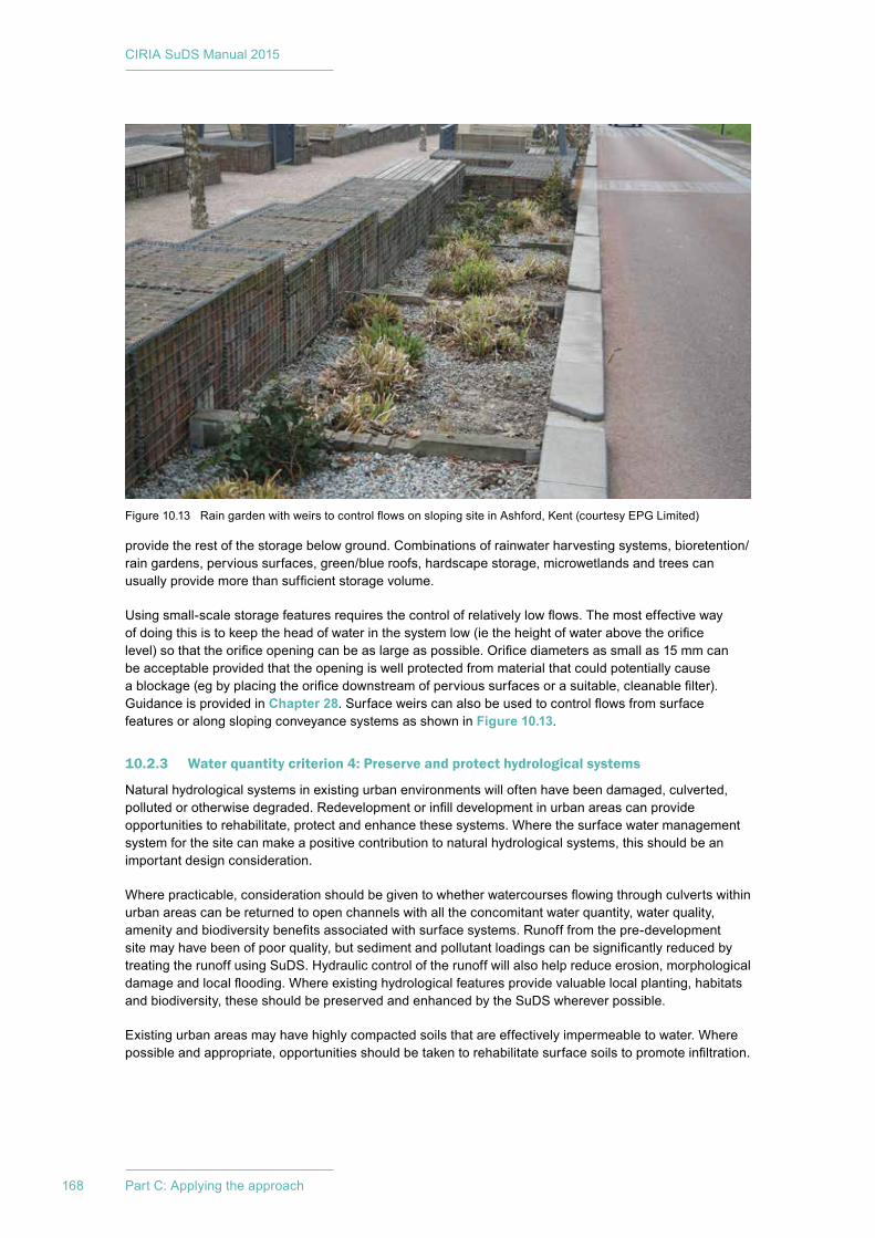
CIRIA SuDS Manual 2015
168 Part C: Applying the approach
provide the rest of the storage below ground. Combinations of rainwater harvesting systems, bioretention/rain gardens, pervious surfaces, green/blue roofs, hardscape storage, microwetlands and trees can usually provide more than sufficient storage volume.
Using small-scale storage features requires the control of relatively low flows. The most effective way of doing this is to keep the head of water in the system low (ie the height of water above the orifice level) so that the orifice opening can be as large as possible. Orifice diameters as small as 15 mm can be acceptable provided that the opening is well protected from material that could potentially cause a blockage (eg by placing the orifice downstream of pervious surfaces or a suitable, cleanable filter). Guidance is provided in Chapter 28. Surface weirs can also be used to control flows from surface features or along sloping conveyance systems as shown in Figure 10.13.
10.2.3 Water quantity criterion 4: Preserve and protect hydrological systems
Natural hydrological systems in existing urban environments will often have been damaged, culverted, polluted or otherwise degraded. Redevelopment or infill development in urban areas can provide opportunities to rehabilitate, protect and enhance these systems. Where the surface water management system for the site can make a positive contribution to natural hydrological systems, this should be an important design consideration.
Where practicable, consideration should be given to whether watercourses flowing through culverts within urban areas can be returned to open channels with all the concomitant water quantity, water quality, amenity and biodiversity benefits associated with surface systems. Runoff from the pre-development site may have been of poor quality, but sediment and pollutant loadings can be significantly reduced by treating the runoff using SuDS. Hydraulic control of the runoff will also help reduce erosion, morphological damage and local flooding. Where existing hydrological features provide valuable local planting, habitats and biodiversity, these should be preserved and enhanced by the SuDS wherever possible.
Existing urban areas may have highly compacted soils that are effectively impermeable to water. Where possible and appropriate, opportunities should be taken to rehabilitate surface soils to promote infiltration.
Figure 10.13 Rain garden with weirs to control flows on sloping site in Ashford, Kent (courtesy EPG Limited)
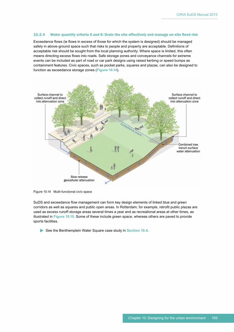
169Chapter 10: Designing for the urban environment
CIRIA SuDS Manual 2015
10.2.4 Water quantity criteria 5 and 6: Drain the site effectively and manage on-site flood risk
Exceedance flows (ie flows in excess of those for which the system is designed) should be managed safely in above-ground space such that risks to people and property are acceptable. Definitions of acceptable risk should be sought from the local planning authority. Where space is limited, this often means directing excess flows into roads. Safe storage zones and conveyance channels for extreme events can be included as part of road or car park designs using raised kerbing or speed bumps as containment features. Civic spaces, such as pocket parks, squares and plazas, can also be designed to function as exceedance storage zones (Figure 10.14).
SuDS and exceedance flow management can form key design elements of linked blue and green corridors as well as squares and public open areas. In Rotterdam, for example, retrofit public plazas are used as excess runoff storage areas several times a year and as recreational areas at other times, as illustrated in Figure 10.15. Some of these include green space, whereas others are paved to provide sports facilities.
See the Benthemplein Water Square case study in Section 10.4.
Figure 10.14 Multi-functional civic space
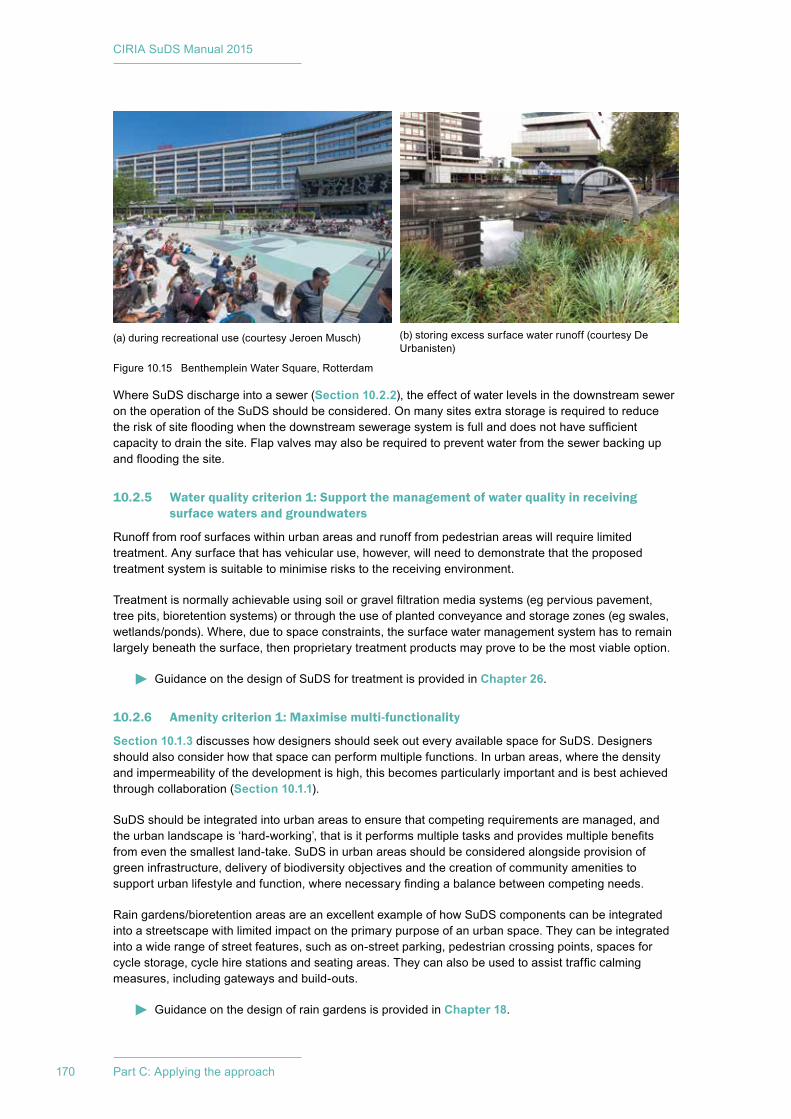
CIRIA SuDS Manual 2015
170 Part C: Applying the approach
Where SuDS discharge into a sewer (Section 10.2.2), the effect of water levels in the downstream sewer on the operation of the SuDS should be considered. On many sites extra storage is required to reduce the risk of site flooding when the downstream sewerage system is full and does not have sufficient capacity to drain the site. Flap valves may also be required to prevent water from the sewer backing up and flooding the site.
10.2.5 Water quality criterion 1: Support the management of water quality in receiving surface waters and groundwaters
Runoff from roof surfaces within urban areas and runoff from pedestrian areas will require limited treatment. Any surface that has vehicular use, however, will need to demonstrate that the proposed treatment system is suitable to minimise risks to the receiving environment.
Treatment is normally achievable using soil or gravel filtration media systems (eg pervious pavement, tree pits, bioretention systems) or through the use of planted conveyance and storage zones (eg swales, wetlands/ponds). Where, due to space constraints, the surface water management system has to remain largely beneath the surface, then proprietary treatment products may prove to be the most viable option.
Guidance on the design of SuDS for treatment is provided in Chapter 26.
10.2.6 Amenity criterion 1: Maximise multi-functionality
Section 10.1.3 discusses how designers should seek out every available space for SuDS. Designers should also consider how that space can perform multiple functions. In urban areas, where the density and impermeability of the development is high, this becomes particularly important and is best achieved through collaboration (Section 10.1.1).
SuDS should be integrated into urban areas to ensure that competing requirements are managed, and the urban landscape is ‘hard-working’, that is it performs multiple tasks and provides multiple benefits from even the smallest land-take. SuDS in urban areas should be considered alongside provision of green infrastructure, delivery of biodiversity objectives and the creation of community amenities to support urban lifestyle and function, where necessary finding a balance between competing needs.
Rain gardens/bioretention areas are an excellent example of how SuDS components can be integrated into a streetscape with limited impact on the primary purpose of an urban space. They can be integrated into a wide range of street features, such as on-street parking, pedestrian crossing points, spaces for cycle storage, cycle hire stations and seating areas. They can also be used to assist traffic calming measures, including gateways and build-outs.
Guidance on the design of rain gardens is provided in Chapter 18.
Figure 10.15 Benthemplein Water Square, Rotterdam
(a) during recreational use (courtesy Jeroen Musch) (b) storing excess surface water runoff (courtesy De Urbanisten)
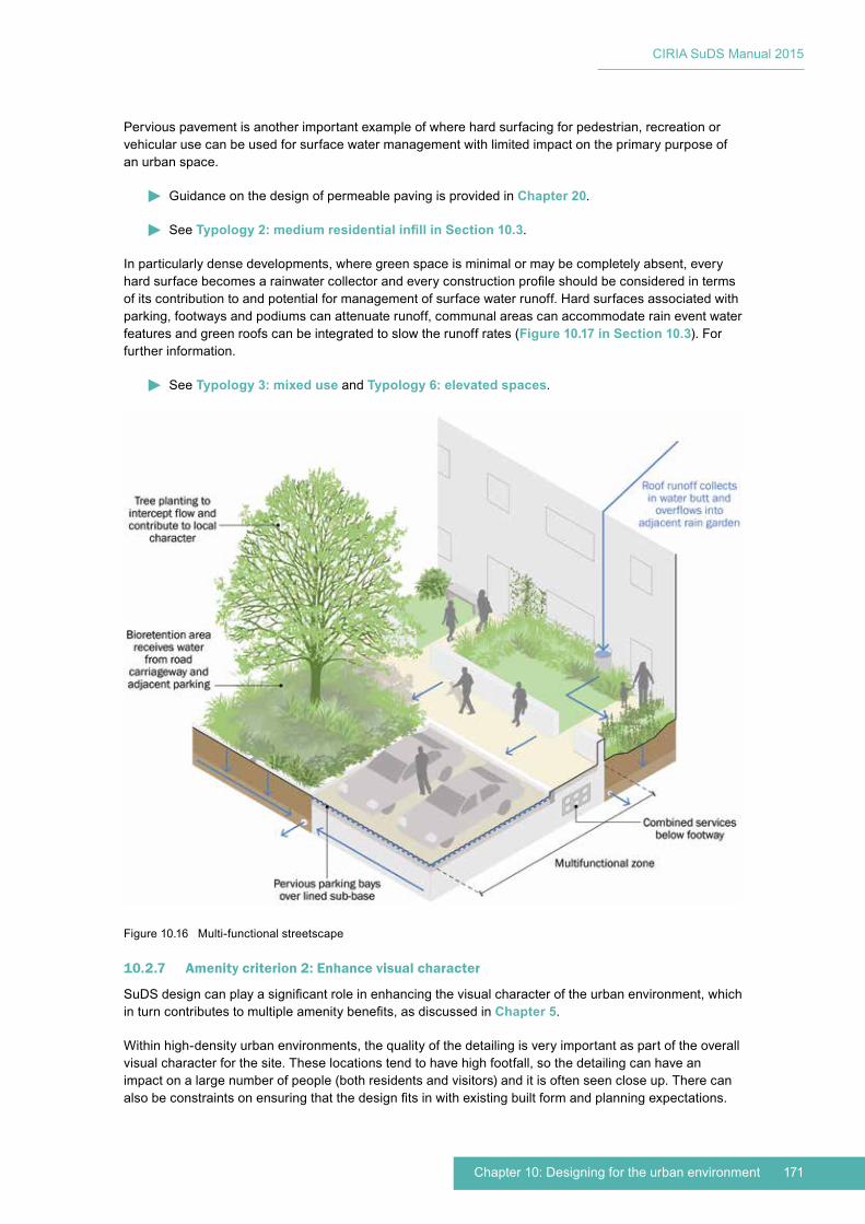
171Chapter 10: Designing for the urban environment
CIRIA SuDS Manual 2015
Pervious pavement is another important example of where hard surfacing for pedestrian, recreation or vehicular use can be used for surface water management with limited impact on the primary purpose of an urban space.
Guidance on the design of permeable paving is provided in Chapter 20.
See Typology 2: medium residential infill in Section 10.3.
In particularly dense developments, where green space is minimal or may be completely absent, every hard surface becomes a rainwater collector and every construction profile should be considered in terms of its contribution to and potential for management of surface water runoff. Hard surfaces associated with parking, footways and podiums can attenuate runoff, communal areas can accommodate rain event water features and green roofs can be integrated to slow the runoff rates (Figure 10.17 in Section 10.3). For further information.
See Typology 3: mixed use and Typology 6: elevated spaces.
10.2.7 Amenity criterion 2: Enhance visual character
SuDS design can play a significant role in enhancing the visual character of the urban environment, which in turn contributes to multiple amenity benefits, as discussed in Chapter 5.
Within high-density urban environments, the quality of the detailing is very important as part of the overall visual character for the site. These locations tend to have high footfall, so the detailing can have an impact on a large number of people (both residents and visitors) and it is often seen close up. There can also be constraints on ensuring that the design fits in with existing built form and planning expectations.
Figure 10.16 Multi-functional streetscape
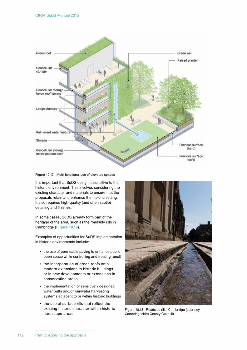
CIRIA SuDS Manual 2015
172 Part C: Applying the approach
It is important that SuDS design is sensitive to the historic environment. This involves considering the existing character and materials to ensure that the proposals retain and enhance the historic setting. It also requires high-quality (and often subtle) detailing and finishes.
In some cases, SuDS already form part of the heritage of the area, such as the roadside rills in Cambridge (Figure 10.18).
Examples of opportunities for SuDS implementation in historic environments include:
▪ the use of permeable paving to enhance public open space while controlling and treating runoff
▪ the incorporation of green roofs onto modern extensions to historic buildings or in new developments or extensions in conservation areas
▪ the implementation of sensitively designed water butts and/or rainwater harvesting systems adjacent to or within historic buildings
▪ the use of surface rills that reflect the existing historic character within historic hardscape areas.
Figure 10.18 Roadside rills, Cambridge (courtesy Cambridgeshire County Council)
Figure 10.17 Multi-functional use of elevated spaces

173Chapter 10: Designing for the urban environment
CIRIA SuDS Manual 2015
The use of landscape features for storing surface water runoff will require consideration of the impact on any trees in the vicinity and on any other landscape features of historic importance. Where infiltration is proposed, this also needs to ensure that it does not undermine historic buildings or archaeology.
The designation of a conservation area does not mean that new development is prohibited, but it does mean that any new development should make a positive contribution to the conservation area. Therefore, good design and detailing, with due regard to the use of materials, existing green (and blue) spaces, sight lines etc should meet the conservation area requirements.
Under the permitted development order, a council can make Article 4 (1 and 2) directions that withdraw ‘permitted development’ rights, which can affect existing features such as fence lines and trees. In sensitive locations it is, therefore, advisable to consult the development control section of the LPA to ascertain whether the work is permitted development and for advice on appropriate materials and design.
For listed buildings any external changes or additions required by SuDS need to be permitted by the local planning department, who may consult the relevant statutory authority (English Heritage, Cadw, Historic Scotland or NIEA). For grade 1 listing, any internal changes or additions will also need listed building consent. As with conservation areas, any proposal should retain and enhance the reason for listing, which means that consideration of materials and composition is important.
10.2.8 Amenity criterion 3: Deliver safe surface water management systems
The function and access requirements of the urban space should also be considered when designing SuDS schemes. The risks to health and safety associated with the SuDS scheme should be assessed during the early stages of the project and continually reviewed and reduced during the course of the project.
Considerations for safety when designing urban SuDS include the following:
▪ Edge conditions and fall protection need to be considered at an early stage to prevent later additions of barriers, which may clutter the landscape and prove detrimental to the overall character of the area.
▪ When designing SuDS with open water, the location, water depth and edge detail should be considered to protect the safety of users and workers. This does not discount their inclusion, but highlights the need to design out risk and to consult relevant groups to ensure that the end product is fit for purpose.
▪ In tight urban spaces, shallow gradients may not be achievable and/or capacity requirements may call for steeper gradients. In such cases, reinforced steeper gradients and hard edges may provide a solution. If so, the edge detail needs to be considered to promote the safety of users and workers – to prevent falls. Detailed paving, wide edge details with contrasting colours and planting can all promote a safe barrier-free landscape. For ground level features that are close to houses, schools or along busy pedestrian areas it may be best to use features that are normally dry with subsurface flow. In extreme events the water could be allowed to rise and gradually drain away.
▪ Runoff entering permanent water features should be treated by at least one treatment stage before discharge into the feature to minimise health risks (Chapter 26).
▪ Planting within any SuDS component needs to retain sightlines and avoid hidden or heavily shaded spaces, such as raising tree canopies to ensure that people can walk beneath them and see through them. The maintenance of sightlines is vital to ensure that vehicles can be manoeuvred safely and that all signage is visible. This also provides a degree of natural observation within the public realm and allows individuals to assess their personal security (see below).
▪ Opportunities for crime reduction should be identified by adopting the ‘secure by design’ approach, achieved by crime prevention through environmental design (CPTED).
▪ The location and/or load-bearing capacity of SuDS components should be reviewed to ensure that other features, such as building facades, can be maintained and accessed safely.
Reference should be made to the health and safety checklist provided in Appendix B.
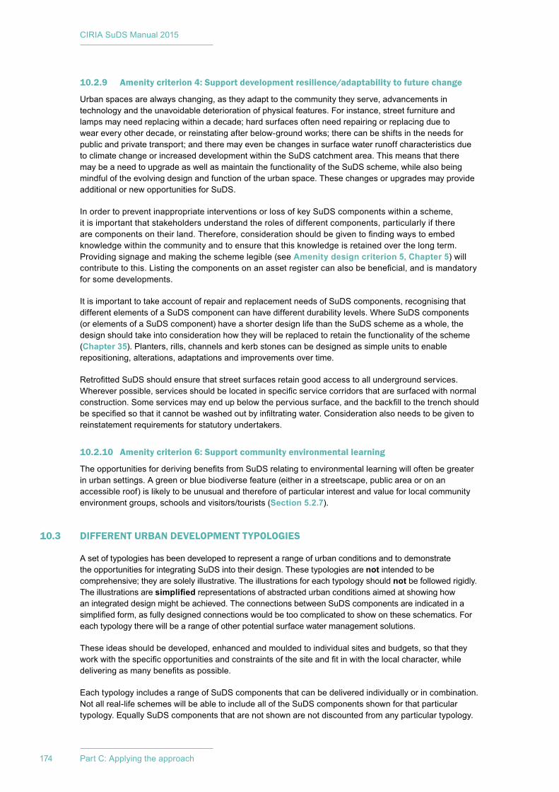
CIRIA SuDS Manual 2015
174 Part C: Applying the approach
10.2.9 Amenity criterion 4: Support development resilience/adaptability to future change
Urban spaces are always changing, as they adapt to the community they serve, advancements in technology and the unavoidable deterioration of physical features. For instance, street furniture and lamps may need replacing within a decade; hard surfaces often need repairing or replacing due to wear every other decade, or reinstating after below-ground works; there can be shifts in the needs for public and private transport; and there may even be changes in surface water runoff characteristics due to climate change or increased development within the SuDS catchment area. This means that there may be a need to upgrade as well as maintain the functionality of the SuDS scheme, while also being mindful of the evolving design and function of the urban space. These changes or upgrades may provide additional or new opportunities for SuDS.
In order to prevent inappropriate interventions or loss of key SuDS components within a scheme, it is important that stakeholders understand the roles of different components, particularly if there are components on their land. Therefore, consideration should be given to finding ways to embed knowledge within the community and to ensure that this knowledge is retained over the long term. Providing signage and making the scheme legible (see Amenity design criterion 5, Chapter 5) will contribute to this. Listing the components on an asset register can also be beneficial, and is mandatory for some developments.
It is important to take account of repair and replacement needs of SuDS components, recognising that different elements of a SuDS component can have different durability levels. Where SuDS components (or elements of a SuDS component) have a shorter design life than the SuDS scheme as a whole, the design should take into consideration how they will be replaced to retain the functionality of the scheme (Chapter 35). Planters, rills, channels and kerb stones can be designed as simple units to enable repositioning, alterations, adaptations and improvements over time.
Retrofitted SuDS should ensure that street surfaces retain good access to all underground services. Wherever possible, services should be located in specific service corridors that are surfaced with normal construction. Some services may end up below the pervious surface, and the backfill to the trench should be specified so that it cannot be washed out by infiltrating water. Consideration also needs to be given to reinstatement requirements for statutory undertakers.
10.2.10 Amenity criterion 6: Support community environmental learning
The opportunities for deriving benefits from SuDS relating to environmental learning will often be greater in urban settings. A green or blue biodiverse feature (either in a streetscape, public area or on an accessible roof) is likely to be unusual and therefore of particular interest and value for local community environment groups, schools and visitors/tourists (Section 5.2.7).
10.3 DIFFERENT URBAN DEVELOPMENT TYPOLOGIES
A set of typologies has been developed to represent a range of urban conditions and to demonstrate the opportunities for integrating SuDS into their design. These typologies are not intended to be comprehensive; they are solely illustrative. The illustrations for each typology should not be followed rigidly. The illustrations are simplified representations of abstracted urban conditions aimed at showing how an integrated design might be achieved. The connections between SuDS components are indicated in a simplified form, as fully designed connections would be too complicated to show on these schematics. For each typology there will be a range of other potential surface water management solutions.
These ideas should be developed, enhanced and moulded to individual sites and budgets, so that they work with the specific opportunities and constraints of the site and fit in with the local character, while delivering as many benefits as possible.
Each typology includes a range of SuDS components that can be delivered individually or in combination. Not all real-life schemes will be able to include all of the SuDS components shown for that particular typology. Equally SuDS components that are not shown are not discounted from any particular typology.
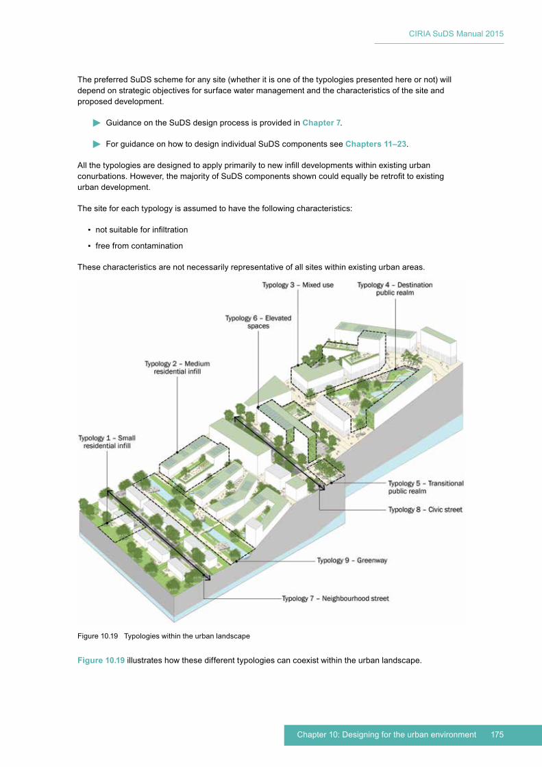
175Chapter 10: Designing for the urban environment
CIRIA SuDS Manual 2015
The preferred SuDS scheme for any site (whether it is one of the typologies presented here or not) will depend on strategic objectives for surface water management and the characteristics of the site and proposed development.
Guidance on the SuDS design process is provided in Chapter 7.
For guidance on how to design individual SuDS components see Chapters 11–23.
All the typologies are designed to apply primarily to new infill developments within existing urban conurbations. However, the majority of SuDS components shown could equally be retrofit to existing urban development.
The site for each typology is assumed to have the following characteristics:
▪ not suitable for infiltration
▪ free from contamination
These characteristics are not necessarily representative of all sites within existing urban areas.
Figure 10.19 illustrates how these different typologies can coexist within the urban landscape.
Figure 10.19 Typologies within the urban landscape
CIRIA SuDS Manual 2015
176 Part C: Applying the approach
Summaries of the typologies are provided here.
Typology 1 – Small residential infill
Low-density housing of detached and semi-detached dwellings. Typically this type of housing is located on sites with moderate space availability, which allow front and rear gardens, on-street public parking and off-street private parking, along with clear boundaries between public and private land. It is also assumed that these are relatively high value properties, based on the land-take within an urban setting.
Typology 2 – Medium residential infill
Medium-density housing development of apartments and maisonette style dwellings, typically low rise over two to three floors. The development is assumed to have combined utilities and services along with community gardens and limited on-street parking.
Typology 3 – Mixed use
Mixed-use development within moderate to high-density inner city location. Assumed to have retail and/or commercial space at lower levels beneath upper level residential apartments and private residential amenities deck/garden. Assumed to have public realm interfaces, surface and basement parking provision and associated servicing and access requirements.
Typology 4 – Destination public realm
An inner city space that provides a community focus, event areas and social function. These spaces can be hard paved squares and plazas or softer spaces associated with urban greening. Either way they are required to be flexible to accommodate the urban social calendar and variable numbers of people.
Typology 5 – Transitional public realm
An inner city space that is dominated by access requirements and confined by the existing built form. The design and SuDS opportunities of these spaces can often be challenging. Therefore this typology aims to provide ideas and insights to enable efficient and effective integration of SuDS in even the smallest urban spaces.
Typology 6 – Elevated spaces
This typology explores design of urban SuDS above ground level, from green walls and green roofs to amenity podium decks associated with residential and mixed-use developments.
Typology 7 – Neighbourhood street
Inner city streets that act as a local road or main road into residential areas, often with restricted space availability within existing built form and infrastructure. Residential neighbourhoods require a streetscape that may require parking provision, public transport links, ease of access into dwellings, servicing and trash collection, clear land ownership between public/private, along with adequate setbacks for privacy and regulation.
Typology 8 – Civic street
Inner city streets that have a community function and focus within a commercial setting. These streets often have changing characters, one day a retail street and the next market stalls and pop-up cafes. This typology demonstrates how SuDS can be integrated into these flexible civic spaces.
Typology 9 – Greenway
Inner city green corridors and disused historic infrastructure routes that become key pedestrian and cycle routes, connecting the city away from built-up areas, traffic and crowds. These spaces provide valuable

177Chapter 10: Designing for the urban environment
CIRIA SuDS Manual 2015
social and biodiverse landscapes as well as connective green infrastructure, while forming an important part of the urban SuDS strategy.
The following key should be used for all figures provided for the typologies:
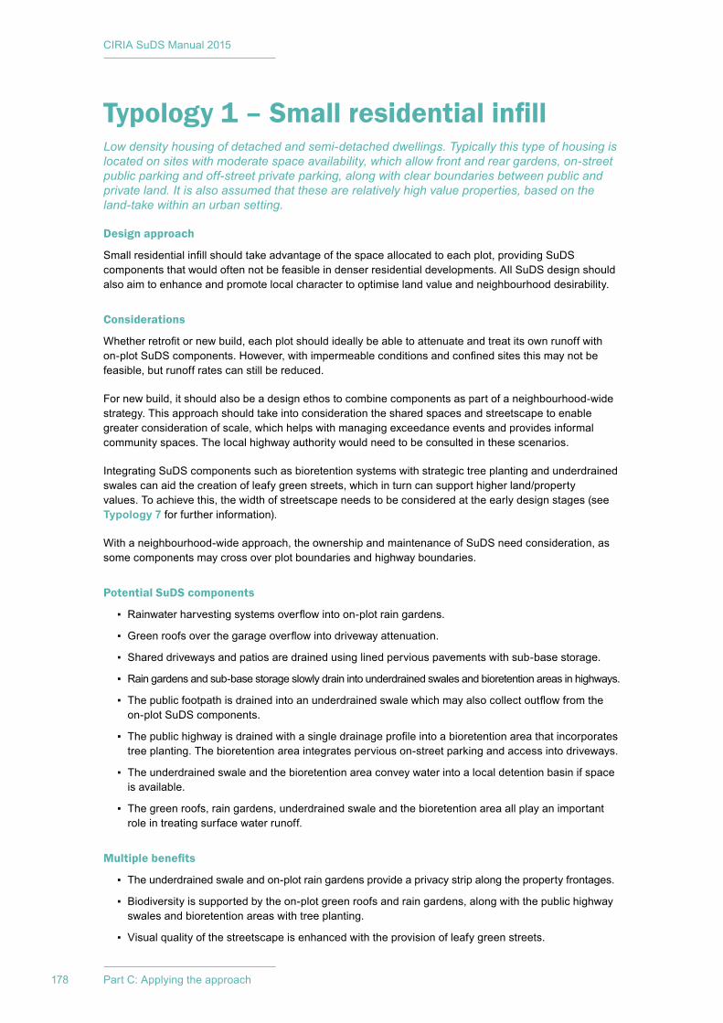
CIRIA SuDS Manual 2015
178 Part C: Applying the approach
Typology 1 – Small residential infillLow density housing of detached and semi-detached dwellings. Typically this type of housing is located on sites with moderate space availability, which allow front and rear gardens, on-street public parking and off-street private parking, along with clear boundaries between public and private land. It is also assumed that these are relatively high value properties, based on the land-take within an urban setting.
Design approach
Small residential infill should take advantage of the space allocated to each plot, providing SuDS components that would often not be feasible in denser residential developments. All SuDS design should also aim to enhance and promote local character to optimise land value and neighbourhood desirability.
Considerations
Whether retrofit or new build, each plot should ideally be able to attenuate and treat its own runoff with on-plot SuDS components. However, with impermeable conditions and confined sites this may not be feasible, but runoff rates can still be reduced.
For new build, it should also be a design ethos to combine components as part of a neighbourhood-wide strategy. This approach should take into consideration the shared spaces and streetscape to enable greater consideration of scale, which helps with managing exceedance events and provides informal community spaces. The local highway authority would need to be consulted in these scenarios.
Integrating SuDS components such as bioretention systems with strategic tree planting and underdrained swales can aid the creation of leafy green streets, which in turn can support higher land/property values. To achieve this, the width of streetscape needs to be considered at the early design stages (see Typology 7 for further information).
With a neighbourhood-wide approach, the ownership and maintenance of SuDS need consideration, as some components may cross over plot boundaries and highway boundaries.
Potential SuDS components
▪ Rainwater harvesting systems overflow into on-plot rain gardens.
▪ Green roofs over the garage overflow into driveway attenuation.
▪ Shared driveways and patios are drained using lined pervious pavements with sub-base storage.
▪ Rain gardens and sub-base storage slowly drain into underdrained swales and bioretention areas in highways.
▪ The public footpath is drained into an underdrained swale which may also collect outflow from the on-plot SuDS components.
▪ The public highway is drained with a single drainage profile into a bioretention area that incorporates tree planting. The bioretention area integrates pervious on-street parking and access into driveways.
▪ The underdrained swale and the bioretention area convey water into a local detention basin if space is available.
▪ The green roofs, rain gardens, underdrained swale and the bioretention area all play an important role in treating surface water runoff.
Multiple benefits
▪ The underdrained swale and on-plot rain gardens provide a privacy strip along the property frontages.
▪ Biodiversity is supported by the on-plot green roofs and rain gardens, along with the public highway swales and bioretention areas with tree planting.
▪ Visual quality of the streetscape is enhanced with the provision of leafy green streets.
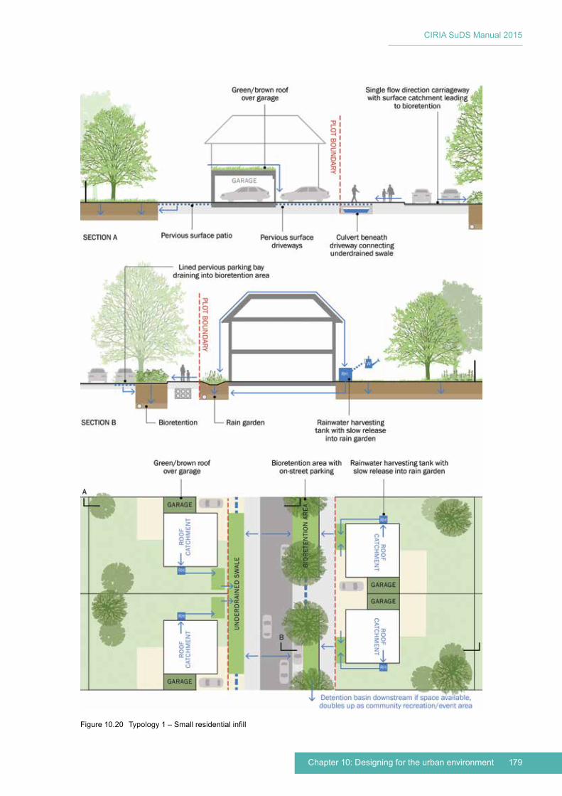
179Chapter 10: Designing for the urban environment
CIRIA SuDS Manual 2015
Figure 10.20 Typology 1 – Small residential infill

CIRIA SuDS Manual 2015
180 Part C: Applying the approach
Typology 2 – Medium residential infillMedium density housing development of apartments and maisonette style dwellings, typically low rise over two to three floors. The development is assumed to have combined utilities and services along with community gardens and limited on-street parking.
Design approach
Residential infill projects should deliver multiple benefits from good urban design and SuDS. This will embed SuDS components and support a range of amenities and services required by the community. SuDS in compact new-build residential areas should therefore give consideration to access, service routes, utilities, green infrastructure, biodiversity and community facilities such as outdoor dining areas, seating provision and productive zones.
Considerations
Measures can be small and simple with minimal investment, such as rain gardens, or more complex with greater investment, such as below-ground storage tanks. Even the simplest surface water management techniques are beneficial, but systems with greater diversity are inherently more adaptable to the changing urban climate. The ambition should therefore be to provide a range of SuDS components within a site-wide surface water management system.
Potential SuDS components
▪ Rainwater harvesting (integrated into roof level), green roofs and terraces attenuate roof runoff and overflow into below-ground storage tanks within communal areas.
▪ Hard surfaces are drained using pervious pavements with sub-base storage, which discharge into adjacent bioretention systems and trench planters.
▪ Bioretention systems and trench planters convey, attenuate and treat surface water, slowly discharging into a local detention basin if space is available.
▪ The vehicle carriageway is drained with an inverted drainage profile with surface catchment channels that discharge into a local detention basin (if space is available) or the local drainage system.
▪ The green roofs, planted trenches and bioretention systems all play an important role in treating surface water runoff.
Multiple benefits
▪ Stored water can be recirculated to tap points within the communal garden and within private courtyards and terraces for landscape maintenance and irrigation.
▪ The planted trenches provide a privacy strip along the property frontages to reaffirm personal boundaries and support urban greening.
▪ A communal garden provides outdoor recreation and gathering space.
▪ The private roof terraces and courtyards provide outdoor recreation and gathering spaces.
▪ Biodiversity is supported by the green roofs and communal gardens.
▪ Local amenities are enhanced with the provision of communal gardens.
181Chapter 10: Designing for the urban environment
CIRIA SuDS Manual 2015
Figure 10.21 Typology 2 – Medium residential infill
CIRIA SuDS Manual 2015
182 Part C: Applying the approach
Typology 3 – Mixed useMixed-use development within moderate to high density inner city location. Assumed to have retail and/or commercial space at lower levels beneath upper level residential apartments and private residential amenities deck/garden. Assumed to have public realm interfaces, surface and basement parking provision and associated servicing and access requirements.
Design approach
Mixed-use developments should take advantage of their scale and extent, providing SuDS components that would often not be feasible in smaller single use developments. Therefore, the approach to SuDS within mixed use development should start at a strategic level with site-wide consideration of economies of scale.
Considerations
The public boundary condition of a mixed use development is a key contributor to character and community engagement. Considering the SuDS as part of this condition will utilise the space efficiently while enhancing urban greening and streetscape quality.
Site services can be a dominant influence on layout and design. Requirements such as vehicle and pedestrian movement, building access, servicing, maintenance, utility routes, parking capacity, street furniture, green infrastructure and drainage all need to be established during the early design stages to ensure that the proposed scheme avoids conflicts with SuDS.
Mixed-use developments often require parking provision, and this space can almost always be utilised for SuDS. The layout and levels should be designed to maximise the potential for site-wide water management.
Amenity podium decks associated with residential and office developments provide an opportunity to store water and attenuate flow, while enhancing character and improve amenity provision. For further details refer to Typology 6.
With a site-wide approach the ownership and maintenance of SuDS needs consideration, as some SuDS components may cross boundaries.
Potential SuDS components
▪ Green roofs treat and attenuate runoff in their substrate and support root uptake with extensive planting. Geocellular storage layers can maximise the attenuation provided.
▪ Rainwater harvesting (integrated into roof/basement level) supports the buildings’ non-potable water requirements (including residential, office and commercial).
▪ Green roofs overflow into the car park attenuation.
▪ Private terraces and communal amenity deck use pervious surfaces over geocellular storage layers (hard and soft) to attenuate roof runoff and overflow into parking area sub-base storage and boundary bioretention/detention areas.
▪ Car park is drained using pervious pavements with sub-base storage, which discharge into adjacent bioretention/detention areas.
▪ Exceedance event capacity is provided within the car park using high kerbs and level changes to temporarily retain water.
▪ Pedestrian circulation spaces are drained using pervious pavements with sub-base storage, which discharge into adjacent bioretention systems.
▪ Bioretention systems convey, attenuate and treat surface water, slowly discharging into a boundary detention basin, if space is available.
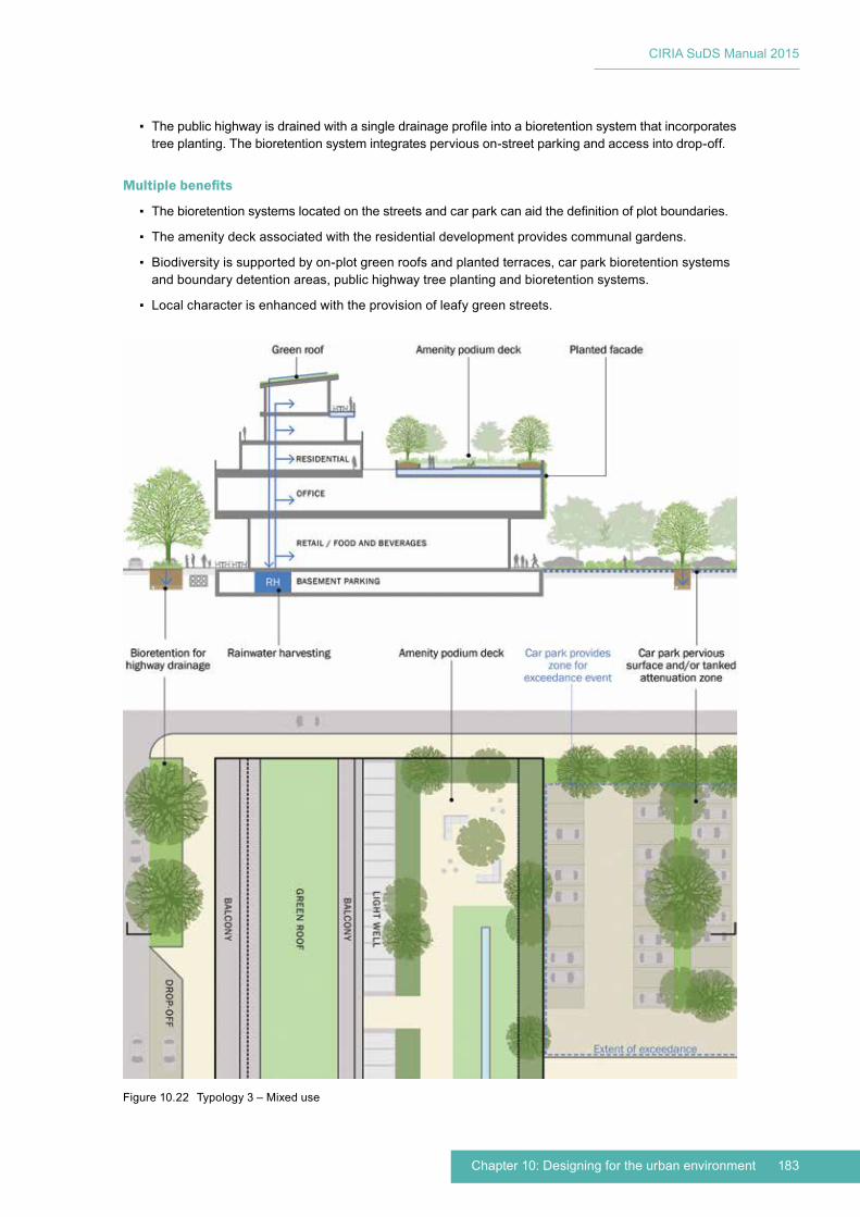
183Chapter 10: Designing for the urban environment
CIRIA SuDS Manual 2015
▪ The public highway is drained with a single drainage profile into a bioretention system that incorporates tree planting. The bioretention system integrates pervious on-street parking and access into drop-off.
Multiple benefits
▪ The bioretention systems located on the streets and car park can aid the definition of plot boundaries.
▪ The amenity deck associated with the residential development provides communal gardens.
▪ Biodiversity is supported by on-plot green roofs and planted terraces, car park bioretention systems and boundary detention areas, public highway tree planting and bioretention systems.
▪ Local character is enhanced with the provision of leafy green streets.
Figure 10.22 Typology 3 – Mixed use
CIRIA SuDS Manual 2015
184 Part C: Applying the approach
Typology 4 – Destination public realmAn inner city space that provides a community focus, event areas and social function. These spaces can be hard paved squares and plazas or softer spaces associated with urban greening. Either way they are required to be flexible to accommodate the urban social calendar and variable numbers of people.
Design approach
Inner city pocket parks, squares and plazas create openings in the urban form that provide rare opportunities to collect and treat the surface water runoff from a wider area. To use the space efficiently, the design should aim to accommodate the social and functional needs of a community alongside the needs of SuDS.
Considerations
Before the design process can begin, a high-level review of the location’s SuDS performance requirements (ie attenuation, storage, and treatment) is needed, as this will inform the design process.
Incorporating large-scale SuDS components into the public realm takes planning and consultation; it is important that the design process recognises the purpose of the new park/plaza, so that SuDS components do not conflict with that purpose, are integrated efficiently and are accepted by the local community.
SuDS components need to work with the functional requirements of the public realm, including: vehicle and pedestrian movement, building access, servicing, maintenance, utility routes, street parking, street furniture, green infrastructure and drainage.
Potential SuDS components
▪ During frequent rain events the surface water is collected and stored below the park’s surface, slowly releasing into the existing local drainage system.
▪ During exceedance events the park provides a temporary storage area, which enables the surface water runoff to be gradually released into the local drainage system. The change in level that defines the area could be used to provide seating or a performance arena. An overflow that discharges to the local drainage system should be provided to set the maximum exceedance water level.
▪ The hard surfaces surrounding the central green space are drained using pervious pavements with sub-base storage, which discharge into the below-ground attenuation of the park.
▪ Adjacent roof catchments can be drained into the central space via the pervious pavements and combined tree trenches placed along the conveyance route to provide natural irrigation.
Multiple benefits
▪ The park provides a public green space with a distinct and dynamic character.
▪ The park can support local community events, promote a local identity and aid wayfinding through the creation of a landmark.
▪ The educational value can be maximised to inform users of the park’s SuDS function, which they can witness themselves during exceedance events.
▪ Biodiversity is supported by the park’s planting strategy, which could include a range of flora to suit the variable planting conditions.
▪ Accessibility is retained by incorporating combined tree trenches below hard surfaces.
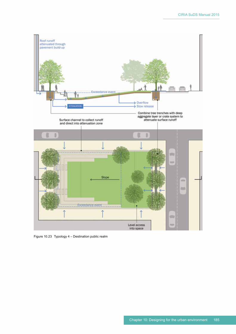
185Chapter 10: Designing for the urban environment
CIRIA SuDS Manual 2015
Figure 10.23 Typology 4 – Destination public realm
CIRIA SuDS Manual 2015
186 Part C: Applying the approach
Typology 5 – Transitional public realmAn inner city space that is dominated by access requirements and confined by the existing built form. The design and SuDS opportunities of these spaces can often be challenging. Therefore, this typology aims to provide ideas and insights to enable efficient and effective integration of SuDS in even the smallest urban spaces.
Design approach
Within these transitional urban spaces, SuDS should be seen as a sequence of simple components that combine to form a site-wide strategy. Therefore, implementing what may seem a small gesture adds to the bigger picture to meet the attenuation and reduced runoff rate targets.
Considerations
Confined inner city spaces between buildings or major infrastructure often require complex access and circulation patterns. This inevitably results in extensive areas of hard surfaces that may also be heavily trafficked, which can limit the feasibility of some SuDS components. Pervious pavements and underground storage/attenuation are usually the most applicable methods in these scenarios, allowing people to move freely through a space with wall-to-wall hard surfaces. The below-ground attenuation can be just below the surface within the pavement build-up or deeper within large tanks and combined with tree pits/trenches. All systems can receive runoff from surfaces and adjacent roofscapes.
Opportunities to animate the public realm with SuDS components should be embraced, as this increases awareness and supports localised character. Animation can take many forms, including surface water features, sound sculptures linked to underground tanks, digital displays that show water movement and quantity, and other information sources about what is happening below ground.
Potential SuDS components
▪ The hard surfaces are drained using lined pervious pavements with sub-base storage, which discharge into the local drainage system or SuDS components further down the site-wide Management Train.
▪ During heavier frequent rain events the surface water is also collected via inverted drainage profiles leading to surface channels, which discharge into a defined zone to create a rain event water feature. This water feature slowly drains into the below-ground attenuation.
▪ During exceedance events, sunken features, such as seating areas, can provide a temporary storage area, which enables the surface water runoff to be gradually released into the local drainage system. An overflow that discharges to the local drainage system should be provided to set the maximum exceedance water level.
▪ Adjacent roof catchments can be drained into the space via the pervious pavements.
▪ Combined tree trenches placed along the conveyance route provide natural irrigation for the trees and attenuate runoff rates.
Multiple benefits
▪ Trees provide evapotranspiration, urban greening, shade and shelter, wildlife habitat and seasonality.
▪ The rain event water features provide a distinct and dynamic character.
▪ The space can promote a local identity and aid wayfinding through the creation of a landmark.
▪ The educational value can be maximised to inform users of the space’s SuDS function, which they can witness themselves during regular rainfall events and exceedance events.
▪ Accessibility and the urban character is retained by incorporating combined tree trenches below hard surfaces.
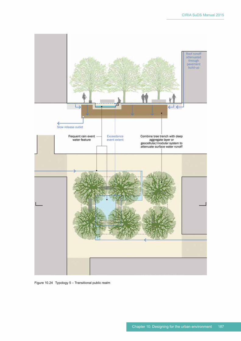
187Chapter 10: Designing for the urban environment
CIRIA SuDS Manual 2015
Figure 10.24 Typology 5 – Transitional public realm
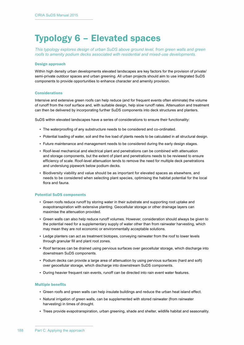
CIRIA SuDS Manual 2015
188 Part C: Applying the approach
Typology 6 – Elevated spacesThis typology explores design of urban SuDS above ground level, from green walls and green roofs to amenity podium decks associated with residential and mixed-use developments.
Design approach
Within high density urban developments elevated landscapes are key factors for the provision of private/semi-private outdoor spaces and urban greening. All urban projects should aim to use integrated SuDS components to provide opportunities to enhance character and amenity provision.
Considerations
Intensive and extensive green roofs can help reduce (and for frequent events often eliminate) the volume of runoff from the roof surface and, with suitable design, help slow runoff rates. Attenuation and treatment can then be delivered by incorporating further SuDS components into deck structures and planters.
SuDS within elevated landscapes have a series of considerations to ensure their functionality:
▪ The waterproofing of any substructure needs to be considered and co-ordinated.
▪ Potential loading of water, soil and the live load of plants needs to be calculated in all structural design.
▪ Future maintenance and management needs to be considered during the early design stages.
▪ Roof-level mechanical and electrical plant and penetrations can be combined with attenuation and storage components, but the extent of plant and penetrations needs to be reviewed to ensure efficiency of scale. Roof-level attenuation tends to remove the need for multiple deck penetrations and underslung pipework below podium decks.
▪ Biodiversity viability and value should be as important for elevated spaces as elsewhere, and needs to be considered when selecting plant species, optimising the habitat potential for the local flora and fauna.
Potential SuDS components
▪ Green roofs reduce runoff by storing water in their substrate and supporting root uptake and evapotranspiration with extensive planting. Geocellular storage or other drainage layers can maximise the attenuation provided.
▪ Green walls can also help reduce runoff volumes. However, consideration should always be given to the potential need for a supplementary supply of water other than from rainwater harvesting, which may mean they are not economic or environmentally acceptable solutions.
▪ Ledge planters can act as treatment biotopes, conveying rainwater from the roof to lower levels through granular fill and plant root zones.
▪ Roof terraces can be drained using pervious surfaces over geocellular storage, which discharge into downstream SuDS components.
▪ Podium decks can provide a large area of attenuation by using pervious surfaces (hard and soft) over geocellular storage, which discharge into downstream SuDS components.
▪ During heavier frequent rain events, runoff can be directed into rain event water features.
Multiple benefits
▪ Green roofs and green walls can help insulate buildings and reduce the urban heat island effect.
▪ Natural irrigation of green walls, can be supplemented with stored rainwater (from rainwater harvesting) in times of drought.
▪ Trees provide evapotranspiration, urban greening, shade and shelter, wildlife habitat and seasonality.
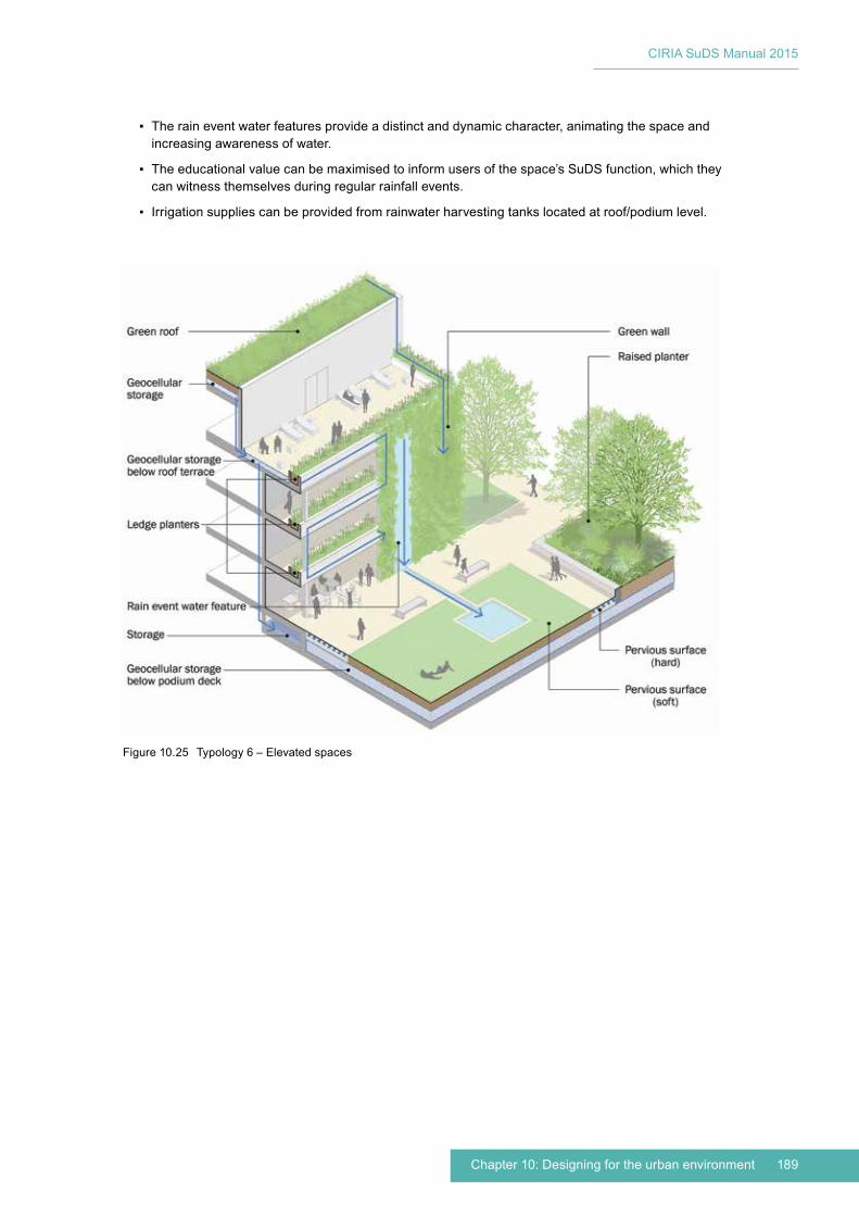
189Chapter 10: Designing for the urban environment
CIRIA SuDS Manual 2015
▪ The rain event water features provide a distinct and dynamic character, animating the space and increasing awareness of water.
▪ The educational value can be maximised to inform users of the space’s SuDS function, which they can witness themselves during regular rainfall events.
▪ Irrigation supplies can be provided from rainwater harvesting tanks located at roof/podium level.
Figure 10.25 Typology 6 – Elevated spaces

CIRIA SuDS Manual 2015
190 Part C: Applying the approach
Typology 7 – Neighbourhood streetUrban streets that act as a local road or main road into residential areas, often with restricted space availability within the existing built form and infrastructure. Residential neighbourhoods require a streetscape that may contain: public transport links; parking provision; ease of access into dwellings; servicing and trash collection; clear land ownership between public/private; along with adequate setbacks for privacy and regulation.
Design approach
The design of SuDS should focus on space efficiency and consistency to meet the functional and aesthetic demands of the streetscape.
Considerations
Simply providing the minimum space for carriageway and footway is not usually enough to support a sustainable urban design with integrated SuDS. During the master planning stages of a project, the street width needs to be realistic, that is wide enough to accommodate all the functions needed to support vehicle and pedestrian movement, building access, servicing, maintenance, utility routes, street parking, street furniture, green infrastructure and drainage. The dimensions of these elements will vary.
New-build streetscape should aim to include a linear element that acts as a multi-functional zone, combining parking, crossing points, traffic calming, green infrastructure, rain gardens, combined utility route and pedestrian footways. The width of this linear element is defined by the parking provision (parallel or perpendicular with the road) and the footway width. Filter strips and swales can also be incorporated, although they do require wider areas which need consideration during the master planning process.
Streetscape is often composed of public and private land, for instance in this typology public highway with footpath and private front gardens. Therefore when designing SuDS in the streetscape a door-to-door approach should be adopted to ensure that the space is fully utilised. For this typology, plot boundaries are clearly defined by building and fence lines, but the SuDS elements will need to flow across the boundaries.
Potential SuDS components
▪ Rainwater harvesting components overflow into on-plot rain gardens.
▪ Shared driveways and footpaths are drained using lined pervious pavements with sub-base storage.
▪ Rain gardens and sub-base storage slowly drain into highways trench planters, underdrained swales and/or bioretention systems.
▪ Trench planters collect, convey and treat runoff from adjacent footways and potentially roof catchment via downpipes. These can take the form of ground-level planted channels and/or raised planters.
▪ The public footpath is drained using lined pervious pavements with sub-base storage which discharge into the trench planters or bioretention systems.
▪ The public highway is drained with a single drainage profile into a bioretention system that incorporates tree planting and integrates pervious on-street parking and access into driveways.
▪ The trench planter and the bioretention system convey water into a local detention basin if space is available or the local drainage system.
▪ The trench planters and bioretention system with tree pits play an important role in treating surface water runoff.
Multiple benefits
▪ Multi-functional zones use space efficiently by combining street trees, on-street parking provision, footway, pedestrian crossing points, spaces for cycle storage, seating area etc. They can also be
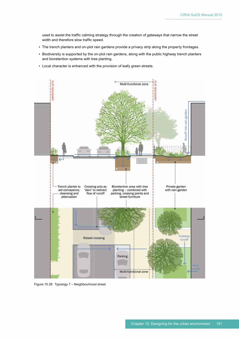
191Chapter 10: Designing for the urban environment
CIRIA SuDS Manual 2015
used to assist the traffic calming strategy through the creation of gateways that narrow the street width and therefore slow traffic speed.
▪ The trench planters and on-plot rain gardens provide a privacy strip along the property frontages.
▪ Biodiversity is supported by the on-plot rain gardens, along with the public highway trench planters and bioretention systems with tree planting.
▪ Local character is enhanced with the provision of leafy green streets.
Figure 10.26 Typology 7 – Neighbourhood street
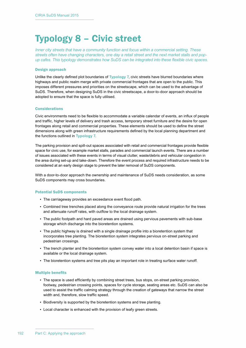
CIRIA SuDS Manual 2015
192 Part C: Applying the approach
Typology 8 – Civic streetInner city streets that have a community function and focus within a commercial setting. These streets often have changing characters, one day a retail street and the next market stalls and pop-up cafes. This typology demonstrates how SuDS can be integrated into these flexible civic spaces.
Design approach
Unlike the clearly defined plot boundaries of Typology 7, civic streets have blurred boundaries where highways and public realm merge with private commercial frontages that are open to the public. This imposes different pressures and priorities on the streetscape, which can be used to the advantage of SuDS. Therefore, when designing SuDS in the civic streetscape, a door-to-door approach should be adopted to ensure that the space is fully utilised.
Considerations
Civic environments need to be flexible to accommodate a variable calendar of events, an influx of people and traffic, higher levels of delivery and trash access, temporary street furniture and the desire for open frontages along retail and commercial properties. These elements should be used to define the street dimensions along with green infrastructure requirements defined by the local planning department and the functions outlined in Typology 7.
The parking provision and spill-out spaces associated with retail and commercial frontages provide flexible space for civic use, for example market stalls, parades and commercial launch events. There are a number of issues associated with these events in terms of visual clutter, waste/debris and vehicular congestion in the area during set-up and take-down. Therefore the event process and required infrastructure needs to be considered at an early design stage to prevent the later removal of SuDS components.
With a door-to-door approach the ownership and maintenance of SuDS needs consideration, as some SuDS components may cross boundaries.
Potential SuDS components
▪ The carriageway provides an exceedance event flood path.
▪ Combined tree trenches placed along the conveyance route provide natural irrigation for the trees and attenuate runoff rates, with outflow to the local drainage system.
▪ The public footpath and hard paved areas are drained using pervious pavements with sub-base storage which discharge into the bioretention systems.
▪ The public highway is drained with a single drainage profile into a bioretention system that incorporates tree planting. The bioretention system integrates pervious on-street parking and pedestrian crossings.
▪ The trench planter and the bioretention system convey water into a local detention basin if space is available or the local drainage system.
▪ The bioretention systems and tree pits play an important role in treating surface water runoff.
Multiple benefits
▪ The space is used efficiently by combining street trees, bus stops, on-street parking provision, footway, pedestrian crossing points, spaces for cycle storage, seating areas etc. SuDS can also be used to assist the traffic calming strategy through the creation of gateways that narrow the street width and, therefore, slow traffic speed.
▪ Biodiversity is supported by the bioretention systems and tree planting.
▪ Local character is enhanced with the provision of leafy green streets.
193Chapter 10: Designing for the urban environment
CIRIA SuDS Manual 2015
Figure 10.27 Typology 8 – Civic street
CIRIA SuDS Manual 2015
194 Part C: Applying the approach
Typology 9 – GreenwayInner city green corridors and disused historic infrastructure routes that become key pedestrian and cycle routes, connecting the city away from built-up areas, traffic and crowds. These spaces provide valuable social and biodiverse landscapes as well as connective green infrastructure, while forming an important part of the SuDS strategy for urban regeneration projects.
Design approach
Connectivity across urban landscapes supports healthy communities and promotes neighbourhood liveability. Historically, these routes are associated with canals or disused railways and historic infrastructure. Urban design master plans should consider integrating these features as purpose-made connective landscapes that also support the neighbourhood SuDS strategy.
Considerations
An important purpose of these green corridors should be to facilitate movement of people. Therefore path widths need to be suitable for all the intended users, and the predicted peak flow of people. Alongside this, the scale of strategic tree planting should also be incorporated, ensuring that the trees have enough space to mature.
SuDS components can be integrated with the tree planting but, where space allows, larger purpose-built SuDS components can also be used, such as detention basins and underdrained swales.
Directing runoff from frequent events into the greenways will provide natural irrigation for planting while treating runoff and providing a degree of natural attenuation.
Potential SuDS components
▪ Surface water runoff from adjacent streets and footways is directed into the greenway.
▪ Kerb drainage and channels keep the runoff on the surface with single drainage profiles to direct runoff into linear SuDS components.
▪ Incorporating landforms and deep planted troughs form flood channels, acting as detention basins during exceedance events.
▪ Underdrained grass areas use subsurface filter drains.
▪ Below-surface soakaways can be beneath planted areas or hard surfaces (only suitable for areas with adequate infiltration rates).
▪ A high level of strategic tree planting will increase runoff volume reduction.
▪ The hard surfaces surrounding the greenway are drained using pervious pavements with sub-base storage which discharge into the below-ground attenuation components.
Multiple benefits
▪ The greenway provides a public green space.
▪ The greenway connects the local community and promotes a local identity.
▪ Seating provision and gathering spaces enable people to interact with each other and their environment.
▪ The educational value can be maximised to inform users of the greenway’s SuDS function, which they can witness themselves during exceedance events.
▪ Biodiversity is supported by the greenway planting strategy, which could include a range of flora to suit the variable planting conditions.
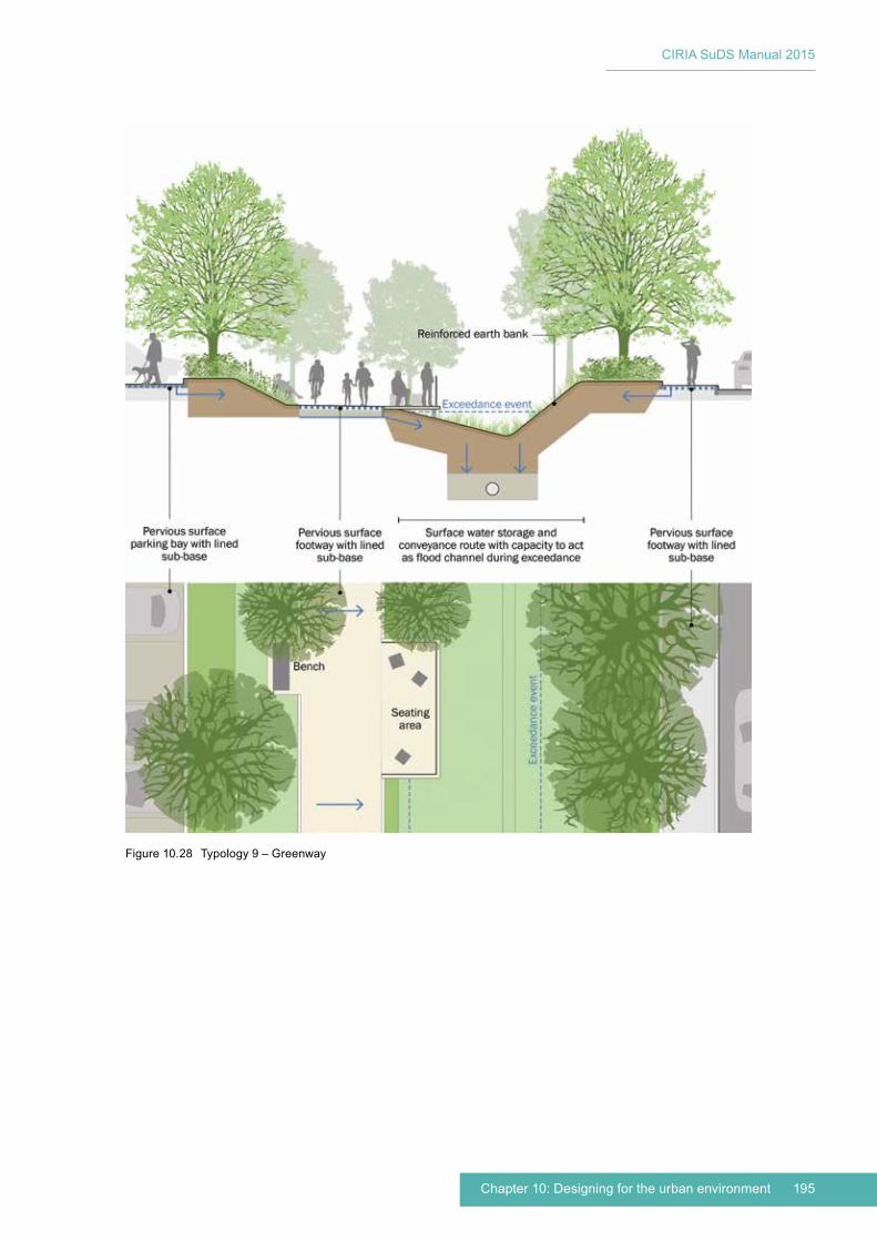
195Chapter 10: Designing for the urban environment
CIRIA SuDS Manual 2015
Figure 10.28 Typology 9 – Greenway
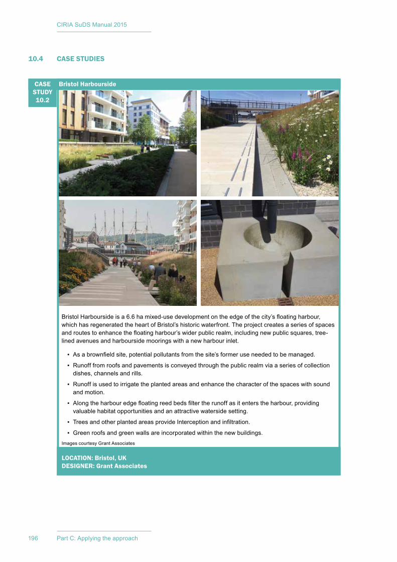
CIRIA SuDS Manual 2015
196 Part C: Applying the approach
10.4 CASE STUDIES
LOCATION: Bristol, UKDESIGNER: Grant Associates
Images courtesy Grant Associates
Bristol Harbourside is a 6.6 ha mixed-use development on the edge of the city’s floating harbour, which has regenerated the heart of Bristol’s historic waterfront. The project creates a series of spaces and routes to enhance the floating harbour’s wider public realm, including new public squares, tree-lined avenues and harbourside moorings with a new harbour inlet.
▪ As a brownfield site, potential pollutants from the site’s former use needed to be managed.
▪ Runoff from roofs and pavements is conveyed through the public realm via a series of collection dishes, channels and rills.
▪ Runoff is used to irrigate the planted areas and enhance the character of the spaces with sound and motion.
▪ Along the harbour edge floating reed beds filter the runoff as it enters the harbour, providing valuable habitat opportunities and an attractive waterside setting.
▪ Trees and other planted areas provide Interception and infiltration.
▪ Green roofs and green walls are incorporated within the new buildings.
Bristol HarboursideCASE STUDY10.2
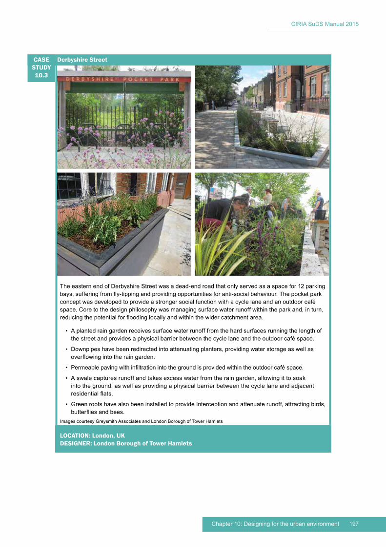
197Chapter 10: Designing for the urban environment
CIRIA SuDS Manual 2015
LOCATION: London, UKDESIGNER: London Borough of Tower Hamlets
Images courtesy Greysmith Associates and London Borough of Tower Hamlets
The eastern end of Derbyshire Street was a dead-end road that only served as a space for 12 parking bays, suffering from fly-tipping and providing opportunities for anti-social behaviour. The pocket park concept was developed to provide a stronger social function with a cycle lane and an outdoor café space. Core to the design philosophy was managing surface water runoff within the park and, in turn, reducing the potential for flooding locally and within the wider catchment area.
▪ A planted rain garden receives surface water runoff from the hard surfaces running the length of the street and provides a physical barrier between the cycle lane and the outdoor café space.
▪ Downpipes have been redirected into attenuating planters, providing water storage as well as overflowing into the rain garden.
▪ Permeable paving with infiltration into the ground is provided within the outdoor café space.
▪ A swale captures runoff and takes excess water from the rain garden, allowing it to soak into the ground, as well as providing a physical barrier between the cycle lane and adjacent residential flats.
▪ Green roofs have also been installed to provide Interception and attenuate runoff, attracting birds, butterflies and bees.
Derbyshire StreetCASE STUDY10.3

CIRIA SuDS Manual 2015
198 Part C: Applying the approach
LOCATION: London, UKDESIGNER: Churchman Landscape Architects
Images courtesy Ben Luxmoore, Tim Crocker and Churchman Landscape Architects
Rathbone Market is a high-density mixed-use development in east London, including social and private housing (650 homes) and 20 000 m2 of commercial space. It provides high-quality open space for residents as well as managing surface water runoff on site in order to limit discharge to the local drainage system.
▪ A pond provides a central visual feature, with plants around its margins designed to make the water relatively inaccessible. It can accommodate a 200 mm rise in water level following rainfall, providing 40 m3 of storage.
▪ Treatment is provided by a filter bed beneath the planting at the edge of the pond, plus a silt trap.
▪ Biodiverse roofs, with planting substrate and plug plants, provide Interception and attenuation of runoff before it drains down to podium level.
▪ The lowest level roof is not planted, but has a series of allotment beds for use by the residents. A water butt is provided to collect rainwater from an adjacent roof for use on the allotments. The paving around the beds is also designed to collect runoff, which drains to the pond.
▪ A living wall absorbs noise and the water features also provide white noise to reduce the impact of the noise from the nearby main road.
▪ Future phases of development will include green and brown roofs with storage beneath the planting substrate using an open cellular storage system. The capacity of these roofs will be around 110 m3.
▪ Connected tree pits with geotextile material for the root zone will provide further Interception and attenuation.
Rathbone MarketCASE STUDY10.4
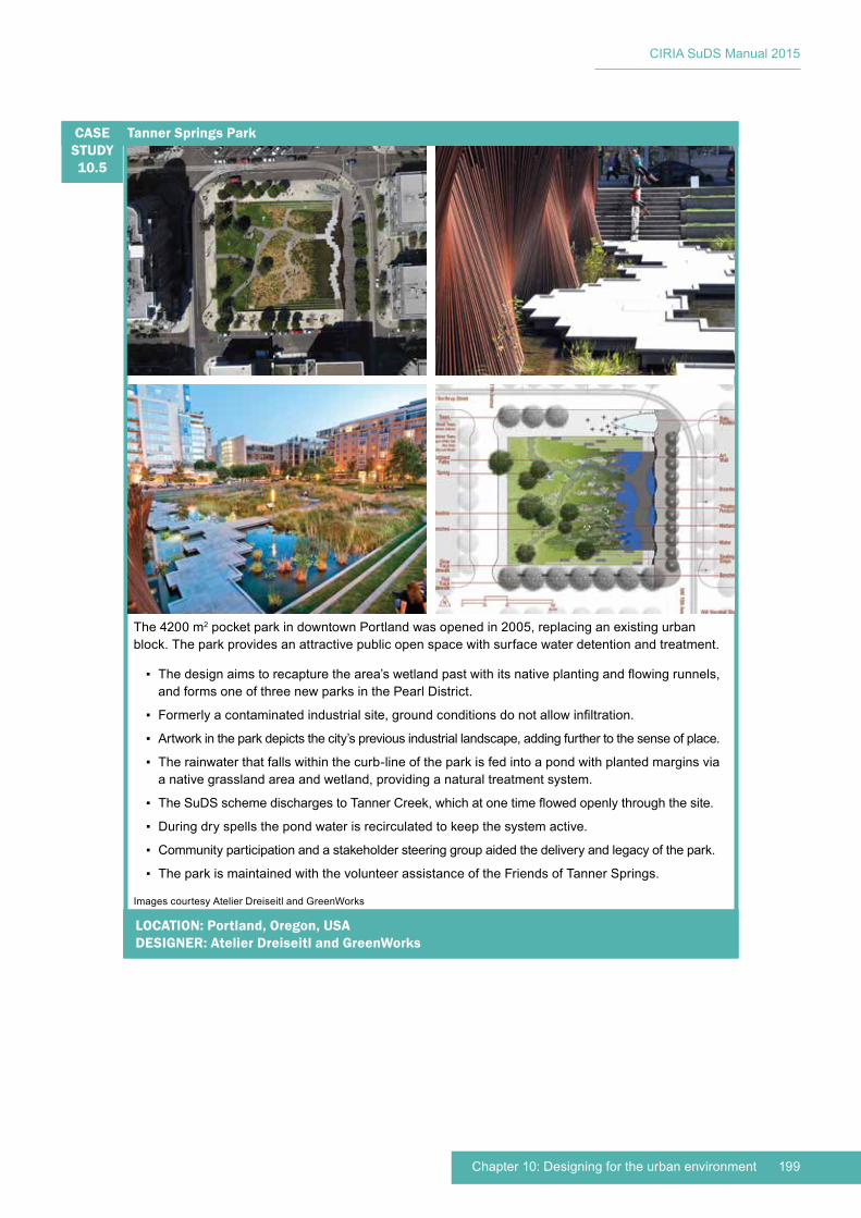
199Chapter 10: Designing for the urban environment
CIRIA SuDS Manual 2015
The 4200 m2 pocket park in downtown Portland was opened in 2005, replacing an existing urban block. The park provides an attractive public open space with surface water detention and treatment.
▪ The design aims to recapture the area’s wetland past with its native planting and flowing runnels, and forms one of three new parks in the Pearl District.
▪ Formerly a contaminated industrial site, ground conditions do not allow infiltration.
▪ Artwork in the park depicts the city’s previous industrial landscape, adding further to the sense of place.
▪ The rainwater that falls within the curb-line of the park is fed into a pond with planted margins via a native grassland area and wetland, providing a natural treatment system.
▪ The SuDS scheme discharges to Tanner Creek, which at one time flowed openly through the site.
▪ During dry spells the pond water is recirculated to keep the system active.
▪ Community participation and a stakeholder steering group aided the delivery and legacy of the park.
▪ The park is maintained with the volunteer assistance of the Friends of Tanner Springs.
Tanner Springs ParkCASE STUDY10.5
Images courtesy Atelier Dreiseitl and GreenWorks
LOCATION: Portland, Oregon, USADESIGNER: Atelier Dreiseitl and GreenWorks
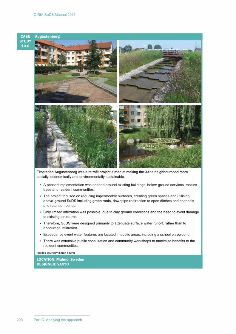
CIRIA SuDS Manual 2015
200 Part C: Applying the approach
Ekostaden Augustenborg was a retrofit project aimed at making the 33 ha neighbourhood more socially, economically and environmentally sustainable.
▪ A phased implementation was needed around existing buildings, below-ground services, mature trees and resident communities.
▪ The project focused on reducing impermeable surfaces, creating green spaces and utilising above-ground SuDS including green roofs, downpipe redirection to open ditches and channels and retention ponds.
▪ Only limited infiltration was possible, due to clay ground conditions and the need to avoid damage to existing structures.
▪ Therefore, SuDS were designed primarily to attenuate surface water runoff, rather than to encourage infiltration.
▪ Exceedance event water features are located in public areas, including a school playground.
▪ There was extensive public consultation and community workshops to maximise benefits to the resident communities.
AugustenborgCASE STUDY10.6
Images courtesy Illman Young
LOCATION: Malmö, SwedenDESIGNER: VASYD
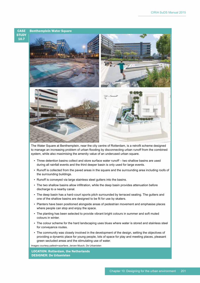
201Chapter 10: Designing for the urban environment
CIRIA SuDS Manual 2015
The Water Square at Benthemplein, near the city centre of Rotterdam, is a retrofit scheme designed to manage an increasing problem of urban flooding by disconnecting urban runoff from the combined system, while also maximising the amenity value of an underused urban square.
▪ Three detention basins collect and store surface water runoff – two shallow basins are used during all rainfall events and the third deeper basin is only used for large events.
▪ Runoff is collected from the paved areas in the square and the surrounding area including roofs of the surrounding buildings.
▪ Runoff is conveyed via large stainless steel gutters into the basins.
▪ The two shallow basins allow infiltration, while the deep basin provides attenuation before discharge to a nearby canal.
▪ The deep basin has a hard-court sports pitch surrounded by terraced seating. The gutters and one of the shallow basins are designed to be fit for use by skaters.
▪ Planters have been positioned alongside areas of pedestrian movement and emphasise places where people can stop and enjoy the space.
▪ The planting has been selected to provide vibrant bright colours in summer and soft muted colours in winter.
▪ The colour scheme for the hard landscaping uses blues where water is stored and stainless steel for conveyance routes.
▪ The community was closely involved in the development of the design, setting the objectives of providing a dynamic place for young people, lots of space for play and meeting places, pleasant green secluded areas and the stimulating use of water.
Benthemplein Water SquareCASE STUDY10.7
Images courtesy pallesh+azarfane, Jeroen Musch, De Urbanisten
LOCATION: Rotterdam, the NetherlandsDESIGNER: De Urbanisten

CIRIA SuDS Manual 2015
202 Part C: Applying the approach
10.5 REFERENCES
ADAPTATION SUBCOMMITTEE (2012) Climate change – is the UK preparing for flooding and water scarcity? Adaptation SubCommittee Progress Report 2012, The Committee on Climate Change, London, UK. Go to: http://tinyurl.com/oa3duq7
DIGMAN, C, ASHLEY, R, BALMFORTH, D, STOVIN, V and GLERUM, J (2012) Retrofitting urban areas to effectively manage surface water, C713, CIRIA, London, UK (ISBN: 987-0-86017-715-9). Go to: www.ciria.org

203Chapter 10: Designing for the urban environment
CIRIA SuDS Manual 2015
Part C : Applying the approachThe design process and how to apply the design criteria and standards presented in Part B to different types of development.
Chapter 7: The SuDS design process 94Chapter 8: Designing for specific site conditions 128Chapter 9: Designing for roads and highways 142Chapter 10: Designing for urban areas 156
Part D : Technical detailDetailed descriptions of different types of SuDS components, with guidance on design, construction, operation and maintenance.
Chapter 11: Rainwater harvesting 206Chapter 12: Green roofs 232Chapter 13: Infiltration systems 256Chapter 14: Proprietary treatment systems 270Chapter 15: Filter strips 290Chapter 16: Filter drains 302Chapter 17: Swales 312Chapter 18: Bioretention systems 332Chapter 19: Trees 360Chapter 20: Pervious pavements 386Chapter 21: Attenuation storage tanks 436Chapter 22: Detention basins 472Chapter 23: Ponds and wetlands 484
Part A : Introduction to the SuDS manualA high-level introduction to the concept of SuDS, what they are and why we need them.
Executive summary 5Introduction to the SuDS Manual 11
Part B : Philosophy and approachThe philosophy of SuDS and their role in managing water quantity and water quality, whilst maximising the benefits for amenity and biodiversity.
How to design SuDS to deliver these objectives by following design criteria and standards.
Chapter 1: The philosophy of SuDS 18Chapter 2: Introducing the SuDS design approach 32Chapter 3: Designing for water quantity 36Chapter 4: Designing for water quality 50Chapter 5: Designing for amenity 66Chapter 6: Designing for biodiversity 80
Part E : Supporting guidanceAdditional guidance to support the planning, design and implementation of SuDS.
Chapter 24: Hydrology and hydraulics: design methods and calculations 506Chapter 25: Infiltration: design methods 542Chapter 26: Water quality management: design methods 560Chapter 27: Pollution prevention strategies 596Chapter 28: Inlets, outlets and flow control systems 604Chapter 29: Landscape 630Chapter 30: Materials 654Chapter 31: Construction 674Chapter 32: Operation and maintenance 690Chapter 33: Waste management 708Chapter 34: Community engagement 716Chapter 35: Costs and benefits 734Chapter 36: Health and safety 758
AppendicesAppendix A: Glossary and abbreviations 778Appendix B: Frameworks and checklists 802Appendix C: Design example 888
Everyone with an interest in SuDS
Those responsible for delivering and managing SuDS schemes
Those responsible for policy or decision making

CIRIA SuDS Manual 2015
205Image courtesy Illman Young
Technical detailD Audience: Those responsible for delivering and managing a SuDS scheme
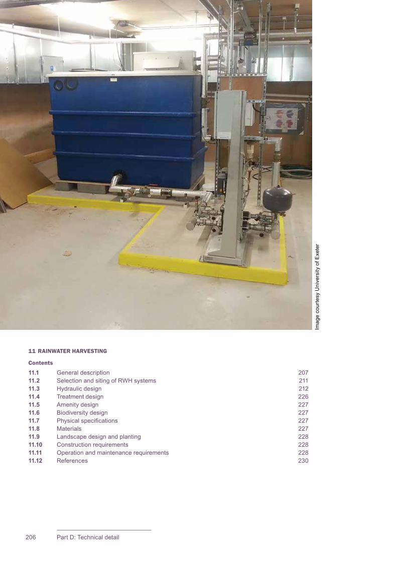
206 Part D: Technical detail
11 RAINWATER HARVESTING
Contents
11.1 General description 20711.2 Selection and siting of RWH systems 21111.3 Hydraulic design 21211.4 Treatment design 22611.5 Amenity design 22711.6 Biodiversity design 22711.7 Physical specifications 22711.8 Materials 22711.9 Landscape design and planting 22811.10 Construction requirements 22811.11 Operation and maintenance requirements 22811.12 References 230
Imag
e co
urte
sy U
nive
rsity
of E
xete
r
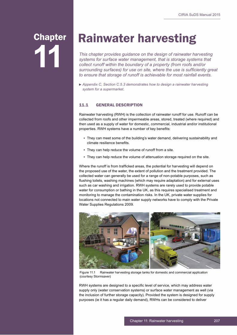
207Chapter 11: Rainwater harvesting
CIRIA SuDS Manual 2015
Rainwater harvesting
11.1 GENERAL DESCRIPTION
Rainwater harvesting (RWH) is the collection of rainwater runoff for use. Runoff can be collected from roofs and other impermeable areas, stored, treated (where required) and then used as a supply of water for domestic, commercial, industrial and/or institutional properties. RWH systems have a number of key benefits:
▪ They can meet some of the building’s water demand, delivering sustainability and climate resilience benefits.
▪ They can help reduce the volume of runoff from a site.
▪ They can help reduce the volume of attenuation storage required on the site.
Where the runoff is from trafficked areas, the potential for harvesting will depend on the proposed use of the water, the extent of pollution and the treatment provided. The collected water can generally be used for a range of non-potable purposes, such as flushing toilets, washing machines (which may require adaptation) and for external uses such as car washing and irrigation. RWH systems are rarely used to provide potable water for consumption or bathing in the UK, as this requires specialised treatment and monitoring to manage the contamination risks. In the UK, private water supplies for locations not connected to main water supply networks have to comply with the Private Water Supplies Regulations 2009.
RWH systems are designed to a specific level of service, which may address water supply only (water conservation systems) or surface water management as well (via the inclusion of further storage capacity). Provided the system is designed for supply purposes (ie it has a regular daily demand), RWHs can be considered to deliver
This chapter provides guidance on the design of rainwater harvesting systems for surface water management, that is storage systems that collect runoff within the boundary of a property (from roofs and/or surrounding surfaces) for use on site, where the use is sufficiently great to ensure that storage of runoff is achievable for most rainfall events.
11Chapter
Appendix C, Section C.5.3 demonstrates how to design a rainwater harvesting system for a supermarket.
Figure 11.1 Rainwater harvesting storage tanks for domestic and commercial application (courtesy Stormsaver)

CIRIA SuDS Manual 2015
208 Part D: Technical detail
Interception for the contributing impermeable area and to reduce the runoff volume. This is the focus of the design methods proposed in this chapter. However, designing systems for water conservation (supply) only is also included for completeness and comparison purposes.
Much of the cost of an RWH system is related to the provision of a storage tank, the pump and the power, controls and the pipework required for its operation. The cost of providing an additional 1 to 3 m3 of storage will therefore usually lead to a relatively small increase in the total system cost. For a property with a roof of 50 m2 the additional storage needed to capture a 60 mm (total depth) rainfall event would commonly be around 3 m3.
The principal documents that provide guidance on the design of RWH systems are as follows:
▪ BS 8515:2009+A1:2013 Rainwater harvesting systems. Code of practice
▪ BS 8542:2011 Calculating domestic water consumption in non-domestic buildings. Code of practice
▪ BS 8595:2013 Code of practice for the selection of water reuse systems
▪ EA (2010) Harvesting rainwater for domestic uses: an information guide.
Although water butts are often regarded as a form of RWH, in practice their value is limited to domestic watering during dry periods when there is garden water in the container. Water butts do not guarantee that storage will always be available, unless the system is designed so that any water stored above a set threshold drains slowly to the downstream drainage system or to a soakaway. However, there is no robust evidence regarding the potential effectiveness of such components during significant events and no guidance on the size of orifice and storage volume that may be required to ensure suitable performance levels. Modelling would, therefore, be required.
Table 11.1 summarises the different possible objectives for RWH systems and the implications for their design.
There are three main types of RWH system:
▪ gravity-based systems
▪ pumped systems
▪ composite systems
These are described in the following sections. In all cases there is a need to ensure that, if the store of non-potable water is depleted, an appropriate alternative supply of water is available for the relevant appliances.

209Chapter 11: Rainwater harvesting
CIRIA SuDS Manual 2015
TABLE11.1
RWH objectives and design implications
RWH for water conservation (supply) only
The RWH system is designed to supply water to the building that it serves. The storage provided is sized to capture and retain an appropriate volume of runoff from the contributing surface (the yield) to meet the projected building use requirements (the demand).
Although a proportion of the runoff from large events will normally be captured, the performance of such systems to manage extreme events cannot be relied upon, and therefore any potential contribution to surface water management should not be allowed as part of the design.
RWH for water conservation (supply) and surface water management, passive systems
The tanks for these systems are sized to accommodate the storage required for water supply plus the storage required to manage a specific depth of rainfall during a large event.
The term “passive” refers to the fact that the space available in the tank to store surface water runoff at any particular time is entirely dependent on the balance between the demand and supply, and the water level is not “managed” in an “active” way.
Where RWH systems are implemented for individual residential properties, surface water control for the design rainfall event is unlikely to be achieved for every property, and an average level of compliance will need to be assumed. Where groups of properties share a tank, or where consistent demand in commercial buildings is more likely, performance of the system is more certain.
RWH for water conservation (supply) and surface water management, active systems
If the water storage in a tank is actively managed, then all properties can be designed to comply with surface water management objectives, irrespective of the relative levels of demand and supply, provided the system is managed so that no runoff (of any significance) occurs for any event up to the design rainfall depth. There are two mechanisms available to ensure that sufficient tank volume is available to manage the design storm depth. These are:
▪ forecasting that a large event is approaching (days or hours ahead) and pumping the stored water away, or
▪ pumping out the stored water down to a set level whenever a threshold is exceeded.
The first option requires communication to rainfall event forecasting information. The second requires a timer delay so that water is pumped away at a set time after the event has passed.
BOX11.1
Rainwater harvesting for schools, Essex
At Columbus School and College in Chelmsford, rainwater is harvested from both sites in a combined storage and treatment facility. The water is then distributed for use in the toilets.
RWH forms part of a wider water management strategy, which also includes SuDS to manage local flooding, water-efficient fittings and fixtures plus leak detection systems and drought resistant planting.
The scheme forms part of a wider strategy by Essex County Council to improve sustainability standards and reduce costs.
Several other schools in the county also use RWH. Monitoring of different systems is helping to inform future schemes.
Figure 11.2 Columbus School and College (courtesy Essex County Council)
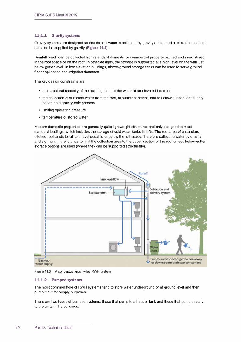
CIRIA SuDS Manual 2015
210 Part D: Technical detail
11.1.1 Gravity systems
Gravity systems are designed so that the rainwater is collected by gravity and stored at elevation so that it can also be supplied by gravity (Figure 11.3).
Rainfall runoff can be collected from standard domestic or commercial property pitched roofs and stored in the roof space or on the roof. In other designs, the storage is supported at a high level on the wall just below gutter level. In low elevation buildings, above-ground storage tanks can be used to serve ground floor appliances and irrigation demands.
The key design constraints are:
▪ the structural capacity of the building to store the water at an elevated location
▪ the collection of sufficient water from the roof, at sufficient height, that will allow subsequent supply based on a gravity-only process
▪ limiting operating pressure
▪ temperature of stored water.
Modern domestic properties are generally quite lightweight structures and only designed to meet standard loadings, which includes the storage of cold water tanks in lofts. The roof area of a standard pitched roof tends to fall to a level equal to or below the loft space, therefore collecting water by gravity and storing it in the loft has to limit the collection area to the upper section of the roof unless below-gutter storage options are used (where they can be supported structurally).
11.1.2 Pumped systems
The most common type of RWH systems tend to store water underground or at ground level and then pump it out for supply purposes.
There are two types of pumped systems: those that pump to a header tank and those that pump directly to the units in the buildings.
Figure 11.3 A conceptual gravity-fed RWH system
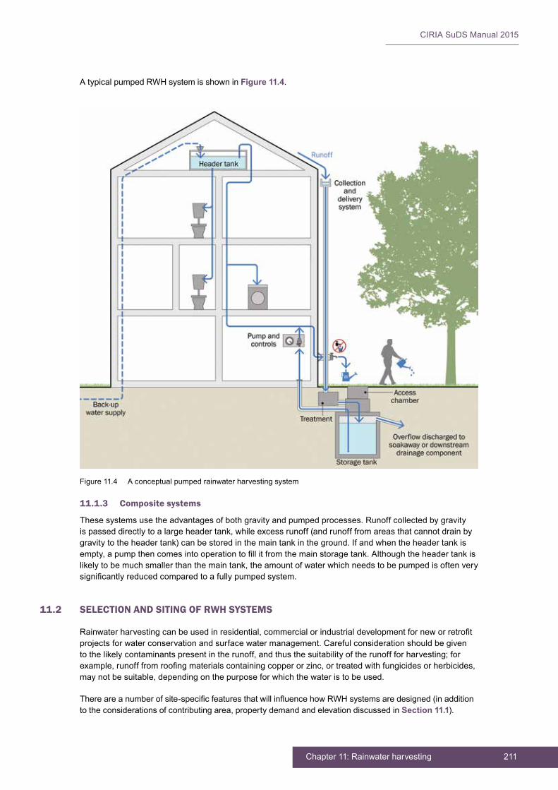
211Chapter 11: Rainwater harvesting
CIRIA SuDS Manual 2015
A typical pumped RWH system is shown in Figure 11.4.
11.1.3 Composite systems
These systems use the advantages of both gravity and pumped processes. Runoff collected by gravity is passed directly to a large header tank, while excess runoff (and runoff from areas that cannot drain by gravity to the header tank) can be stored in the main tank in the ground. If and when the header tank is empty, a pump then comes into operation to fill it from the main storage tank. Although the header tank is likely to be much smaller than the main tank, the amount of water which needs to be pumped is often very significantly reduced compared to a fully pumped system.
11.2 SELECTION AND SITING OF RWH SYSTEMS
Rainwater harvesting can be used in residential, commercial or industrial development for new or retrofit projects for water conservation and surface water management. Careful consideration should be given to the likely contaminants present in the runoff, and thus the suitability of the runoff for harvesting; for example, runoff from roofing materials containing copper or zinc, or treated with fungicides or herbicides, may not be suitable, depending on the purpose for which the water is to be used.
There are a number of site-specific features that will influence how RWH systems are designed (in addition to the considerations of contributing area, property demand and elevation discussed in Section 11.1).
Figure 11.4 A conceptual pumped rainwater harvesting system
CIRIA SuDS Manual 2015
212 Part D: Technical detail
Selection and siting of RWH systems will depend on the size and access requirements of the tank and the physical constraints of the site. In all cases, easy but safe access is needed to all components (filters, pumps etc) to ensure that there is no impediment to maintenance being carried out.
Storage tanks should be placed in a safe, secure location either underground, indoors, on roofs or adjacent to buildings (depending on the intended uses of the water). Tanks that are located underground tend to have improved performance with respect to the control of water temperature, reducing bacterial growth in summer and frost damage in winter. Where the tank has to be installed close to the building, structural considerations such as the depth of the foundations and the watertightness of the RWH unit and its overflow provision are particularly important. The presence of underground utilities may also constrain the location of the tank.
Tanks should not generally be placed on filled ground, and an adequate geotechnical investigation should be undertaken to ensure the suitability of the soils for the tank foundation.
The storage tank is quite likely to be empty for periods of time and, where groundwater levels are close to the ground surface, the issue of flotation will need to be addressed.
11.3 HYDRAULIC DESIGN
11.3.1 General
The sizing of an RWH storage tank is a function of:
▪ the demand for non-potable water from the tank
▪ the regularity of the demand
▪ the area contributing runoff to the tank
▪ the local seasonal rainfall characteristics
▪ the design level of service for the tank, with respect to the control of surface water.
An accurate assessment of the performance of an RWH system requires the pattern of demand to be modelled, together with a continuous rainfall time series and runoff model. This enables temporal patterns of supply, storage and demand to be predicted, together with frequencies of overflow operation and supply shortfall. However, in most instances, this approach is not needed and a simplified calculation of tank storage can be used.
The RWH code of practice BS 8515:2009+A1:2013 provides six ways of calculating tank sizes. These are:
1 the simple method – for water conservation
2 the intermediate method – for water conservation
3 the simple surface water management method – with passive control
4 the intermediate surface water management method – with passive control
5 the detailed surface water management method – with passive control
6 the surface water management method – with active control.
Each of these methods are discussed in the following sections. It should be noted that the surface water management options automatically provide an equivalent (or better) level of service with respect to water conservation (supply). An automated calculation of storage tank size for residential RWHs can be accessed from www.uksuds.com
In all cases, there is an assumption that regular daily demand will take place. If there are unusual demand requirements, then analysis from first principles will be needed. This applies to all uses of RWH systems – whether residential, commercial, industrial or institutional.

213Chapter 11: Rainwater harvesting
CIRIA SuDS Manual 2015
The primary parameters used for calculating the size of the storage are:
▪ the storm rainfall depth that is to be captured
▪ average annual rainfall (AAR)
▪ daily demand for non-potable water
▪ building occupancy
▪ contributing surface area.
These are described in the following subsections. Other parameters include the runoff factor and the filter efficiency factor.
Design level of service for the tank (design rainfall depth)
The design rainfall depth can be any value. However, site runoff volumetric control criteria are often linked to the 1 in 100 year, 6-hour event, which tends to be of the order of 60 mm in the UK (Figure 11.5).
Average annual rainfall for the UK
The average annual rainfall across the UK can be obtained by reference to tools such as the Flood Estimation Handbook (FEH) CEH, 1999) or the mapping from the older Flood Studies Report (FSR) (IOH, 1975). Figure 11.6 provides an indication of the annual rainfall depths across the UK.
Daily demand for non-potable water
The assumed consumption of non-potable water has historically been 50 litre/capita/day (l/c/d) for toilet flushing (assuming 9 litre cisterns). However, with recent developments in water-efficient appliance design (eg maximum toilet cistern size of 6 litres), daily household toilet usage is now thought to be closer to 20 l/c/d (Kellagher, 2012). The consumption of water in washing machines is believed to be of the same order at around 20 l/c/d. This means that 40 l/c/d could be assumed if both appliances use non-potable water. These figures have been based on research (Kellagher, 2012), but there is some degree of uncertainty over whether these figures are suitable averages to use, and as variations in water use are likely to be significant between households, it is important to assume a conservative (low) value when designing for surface water runoff management.
For commercial properties such as offices where toilet flushing alone is used during the working day, the consumption rate may be as low as 10 l/c/d. Guidance on water consumption for any category of building should be obtained when designing for non-potable water use (BS 8542:2011). For other buildings where water demand is driven by temporary customer use (eg schools, large stores, supermarkets) consumption needs to be based on specific information associated with the buildings being served.
Occupancy rates of domestic properties
The occupancy rates of properties are available from statistical information gathered by the government and regional authorities. These are linked to type of property which includes the number of bedrooms. The average occupancy values are supported with information on standard deviation, which is important when assessing the degree of compliance of individual property RWH systems in managing runoff from a specific design storm depth.
An illustration of values for household occupancy is provided in Table 11.2 and these are fairly representative of many other regions of the UK.
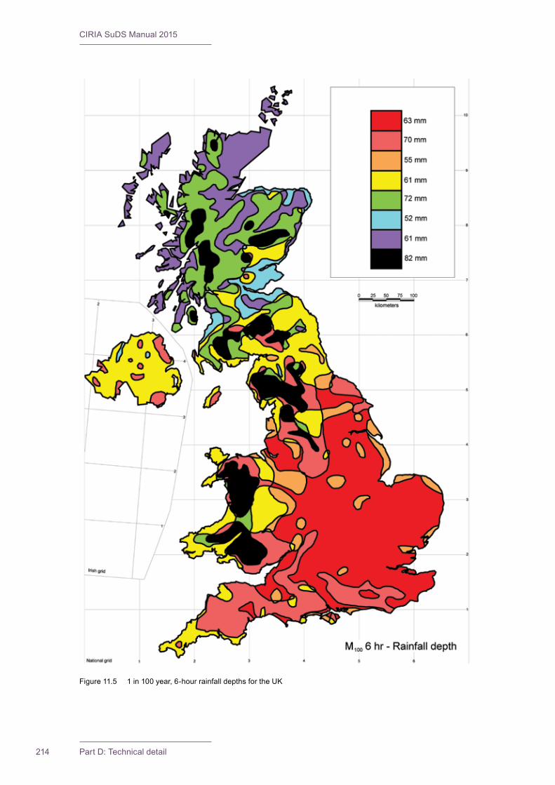
CIRIA SuDS Manual 2015
214 Part D: Technical detail
Figure 11.5 1 in 100 year, 6-hour rainfall depths for the UK
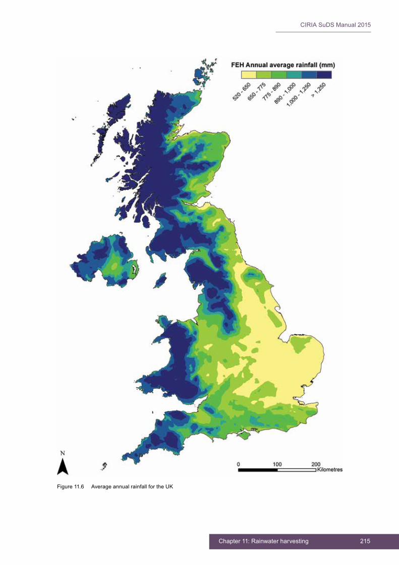
215Chapter 11: Rainwater harvesting
CIRIA SuDS Manual 2015
Figure 11.6 Average annual rainfall for the UK

CIRIA SuDS Manual 2015
216 Part D: Technical detail
Table 11.3 provides suggested typical occupancy rates for England, for all dwellings that are not assisted housing or in locations with unusual occupancy characteristics for economic or cultural reasons. Updated and equivalent data for England, Wales and Scotland is collected as part of the national census, and is available for each region: www.scotlandscensus.gov.uk/census-results / https://www.nomisweb.co.uk/census/2011
TABLE11.2
Summary of occupancy rates for new market housing in (i) Cherwell District and (ii) Oxfordshire County (from OCC, 2009)
Number of bedrooms in the property
0 1 2 3 4 ≥5 Overall
(i) Cherwell District
Properties sample size 3 84 210 243 145 87 772
Number of occupants 3 118 362 579 431 295 1788
Mean occupancy 1.00 1.40 1.72 2.38 2.97 3.39 2.32
Standard deviation 0.00 0.58 0.66 0.97 1.12 1.24 0.92
(ii) Oxfordshire
Properties sample size 28 514 1191 1044 809 311 3897
Number of occupants 31 716 2069 2453 2443 1138 8850
Mean occupancy 1.11 1.39 1.74 2.35 3.02 3.66 2.27
Standard deviation 0.42 0.56 0.73 1.02 1.17 1.32 0.95
TABLE11.3
Occupancy by accommodation type and number of bedrooms, England 2004–2007 (from DCLG, 2007)
Type of accommodation and number of bedrooms Mean household size
One bedroom 1.3
Two bedrooms 1.9
Three bedrooms 2.6
Four or more bedrooms 3.2
For water conservation design, a traditional rule of thumb is two persons per bedroom, although the figures in Table 11.3 indicate that this may be conservative, and perhaps the mean occupancy plus one standard deviation (if this is known) is a more reasonable estimate to use.
For surface water management design, the mean occupancy should be used, which is conservative for this aspect of the design.
Contributing plan areas
Contributing roof areas should be calculated in plan. It is important to use the actual roof plan area drained as it may not be possible to capture all the runoff from a roof area due to the various pitch arrangements of the property.
Runoff (yield) coefficients
It is important to recognise that many events are relatively small and therefore the initial wetting losses, especially for flat roofed areas, may be quite significant which can mean that the overall proportion of runoff for an event is much less than 100%. Where losses are complex and varied, such as on green roofs and permeable pavements, then analysis with a continuous rainfall time series, taking into account evapotranspiration may be necessary to get a sufficiently accurate estimate of the likely proportion of runoff. Table 11.4 provides suggested values for the average runoff coefficient.

217Chapter 11: Rainwater harvesting
CIRIA SuDS Manual 2015
The runoff coefficients suggested for green roofs and permeable pavements in particular are likely to be higher than would be observed for most small-to-medium events (ie they will give too high an estimate of yield and associated yield/demand ratio).
An alternative approach to the calculation of the runoff yield can be used which explicitly addresses both the losses for each event and the runoff coefficient losses once the collection surface is wet. Table 11.5 provides indicative values for various roof surfaces for this approach.
TABLE11.4
Suggested initial runoff coefficients for RWH yield analysis (from BS 8515:2009+A1:2013)
Surface type Runoff coefficient
Pitched roof with profiled metal sheeting 0.95
Pitched roof with tiles 0.90
Flat roof without gravel 0.80
Flat roof with gravel 0.60
Green roof, intensive1 0.30
Green roof, extensive1 0.60
Permeable pavement (concrete blocks)2 0.60
Road/pavement 0.75
Note1 Green roof runoff yield is particularly uncertain and varies with season. There may also be negative colouration impacts.2 This reflects the proportion of rainfall that finds its way through the overlying surface to subsurface collection points for RWH.
For small roofs, it is unlikely that green roofing would be used together with RWH as the natural losses from green roofs are large and demand would be significantly greater than the available supply. However, for very large roofs (or where demand is limited) there may be a need to use both in conjunction in order to adequately meet surface water volume control requirements.
Hydraulic filter efficiency
Runoff losses are increased by filter losses. Filters vary in the way they work, and these losses are also a function of the rainfall depths and intensities. It is best to use an appropriate coefficient for the actual filter used in the design (obtained from the manufacturer), but a coefficient of 90% can be adopted as a starting point.
TABLE11.5
Runoff coefficients with initial losses for RWH yield analysis (from BS 8515:2009+A1:2013)
Surface type Surface type runoff coefficient
Depression storage loss (mm)
Pitched roof with profiled metal sheeting 1.0 0.2
Pitched roof with tiles 1.0 0.4
Flat roof without gravel 0.95 1.0
Flat roof with gravel 0.95 2.0
Green roof, intensive1 0.80 2.0–6.0
Green roof, extensive1 0.80 2.0–4.0
Permeable pavement (concrete blocks) 0.90 4.0
Road/pavement 0.90 1.5
Note1 Green roof runoff yield is particularly uncertain and varies with season. There may also be negative colouration impacts.
Intensive and extensive green roofs are described in Chapter 12.
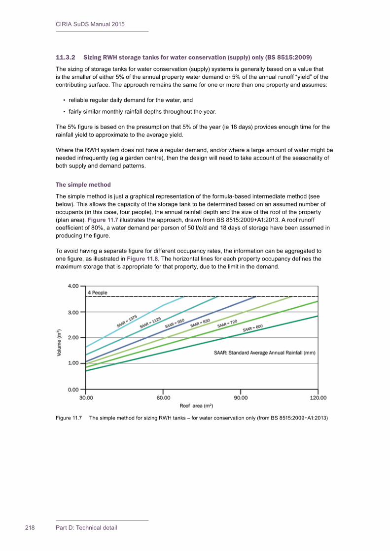
CIRIA SuDS Manual 2015
218 Part D: Technical detail
11.3.2 Sizing RWH storage tanks for water conservation (supply) only (BS 8515:2009)
The sizing of storage tanks for water conservation (supply) systems is generally based on a value that is the smaller of either 5% of the annual property water demand or 5% of the annual runoff “yield” of the contributing surface. The approach remains the same for one or more than one property and assumes:
▪ reliable regular daily demand for the water, and
▪ fairly similar monthly rainfall depths throughout the year.
The 5% figure is based on the presumption that 5% of the year (ie 18 days) provides enough time for the rainfall yield to approximate to the average yield.
Where the RWH system does not have a regular demand, and/or where a large amount of water might be needed infrequently (eg a garden centre), then the design will need to take account of the seasonality of both supply and demand patterns.
The simple method
The simple method is just a graphical representation of the formula-based intermediate method (see below). This allows the capacity of the storage tank to be determined based on an assumed number of occupants (in this case, four people), the annual rainfall depth and the size of the roof of the property (plan area). Figure 11.7 illustrates the approach, drawn from BS 8515:2009+A1:2013. A roof runoff coefficient of 80%, a water demand per person of 50 l/c/d and 18 days of storage have been assumed in producing the figure.
To avoid having a separate figure for different occupancy rates, the information can be aggregated to one figure, as illustrated in Figure 11.8. The horizontal lines for each property occupancy defines the maximum storage that is appropriate for that property, due to the limit in the demand.
Figure 11.7 The simple method for sizing RWH tanks – for water conservation only (from BS 8515:2009+A1:2013)
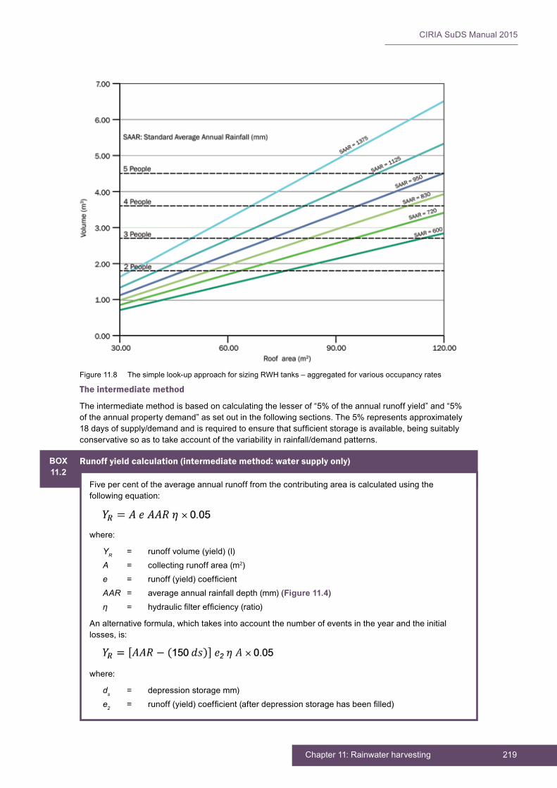
219Chapter 11: Rainwater harvesting
CIRIA SuDS Manual 2015
The intermediate method
The intermediate method is based on calculating the lesser of “5% of the annual runoff yield” and “5% of the annual property demand” as set out in the following sections. The 5% represents approximately 18 days of supply/demand and is required to ensure that sufficient storage is available, being suitably conservative so as to take account of the variability in rainfall/demand patterns.
Figure 11.8 The simple look-up approach for sizing RWH tanks – aggregated for various occupancy rates
BOX11.2
Runoff yield calculation (intermediate method: water supply only)
Five per cent of the average annual runoff from the contributing area is calculated using the following equation:
where:
YR = runoff volume (yield) (l)A = collecting runoff area (m2)e = runoff (yield) coefficientAAR = average annual rainfall depth (mm) (Figure 11.4)η = hydraulic filter efficiency (ratio)
An alternative formula, which takes into account the number of events in the year and the initial losses, is:
where:
ds = depression storage mm)e2 = runoff (yield) coefficient (after depression storage has been filled)

CIRIA SuDS Manual 2015
220 Part D: Technical detail
This formula assumes that there are 150 effective rainfall events in the year, which is a reasonable assumption for most of the UK.
11.3.3 Sizing RWH storage tanks for surface water management, with passive control
All surface water management methods are based on two criteria:
1 A design rainfall depth is to be captured by the system without the overflow coming into operation.
2 The average annual demand (DN) is greater than the average annual yield (YR) from the contributing area.
Where seasonal variability is significant, data should be used for the season for which large rainfall event control is relevant.
The demand assessment is based on assumed occupancy and water usage. As a result of the “passive” control approach and the variability in property occupancy (and therefore consumption), surface water control for the design event is unlikely to be achieved for every property. Where demand is lower than average, the RWH tank will tend to have lower availability for the storage of runoff. A rule of thumb should therefore be adopted that assumes that 30% of properties on any site will “fail” to control surface water runoff for the design event.
The water demand for a group of properties sharing a communal RWH tank is more predictable as the total population for a group of houses will tend to converge toward the average. Therefore the more properties there are sharing a tank, the less likely the tank is to fail to deliver surface water management for the design rainfall depth. Demand predictability is also likely to be higher for commercial properties.
There are design uncertainties regarding how many houses are needed to achieve sufficient convergence on the mean water consumption, and what the chance of “failure” is for the system with respect to managing the design event. These questions can be addressed using appropriate statistical analysis. However, as the consequences of failure of a communal system is greater (if it is being presumed that the runoff volume is being stored), a degree of conservatism needs to be exercised in the analysis of assessing the yield and demand ratio. As the number of properties served by a communal rainwater system increases, the uncertainty associated with the demand level reduces and the likelihood that YR/DN is greater than 0.9 is lowered.
The simple method
For the simple method, the YR/DN ratio should be less than 0.7. This method calculates the water conservation (supply) component and the surface water management storage volumes separately and simply adds them together. However, for the situation where the demand (DN) is more than three times the yield (YR) (ie where YR/DN < 0.33), the total storage that needs to be provided can be limited to the storage required for surface water management alone.
The storage calculation is set out in Box 11.4.
BOX11.3
Non-potable water demand calculation (intermediate method: water supply only)
Five per cent of the annual non-potable water demand is calculated using the following equation:
where:
DN = total annual property demand for non-potable water (l)Pd = daily demand per person (l)n = number of occupants in the property

221Chapter 11: Rainwater harvesting
CIRIA SuDS Manual 2015
BOX11.4
Tank storage volume calculation: simple method, water conservation + surface water management, passive control
When:
Then:
Total storage = VSC
Where:
VSC = storage volume (m3)A = contributing runoff area (m2)Rd = design storm event rainfall depth (mm)β = design storm event runoff coefficientη = hydraulic filter efficiency (ratio)
When:
Where:
YR = 5% of the annual volume (yield) (l) (Box 11.2)DN = 5% of the annual demand (l) (Box 11.3)
Then:
Total storage = VSC + YR
It is important to note that the design storm event runoff coefficient should be 90% or more from most surfaces which is different from the coefficient used for the calculation of YR. In contrast the coefficient η might be slightly less, in that the event is likely to be a higher intensity event, but this will be product-specific.
Figure 11.9 provides a look-up graph for VSC. It assumes that both the runoff factor and filter efficiency are 1.0 (ie no losses) and that the design rainfall event depth is 60 mm.
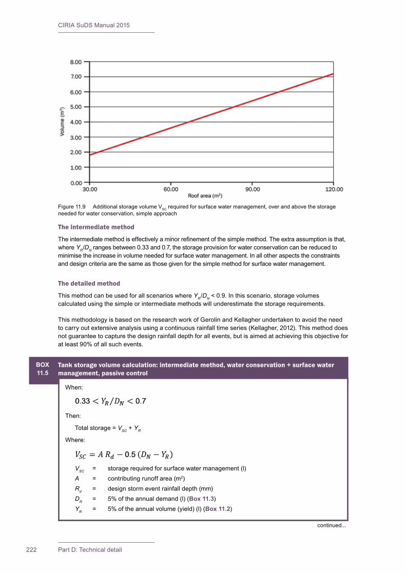
CIRIA SuDS Manual 2015
222 Part D: Technical detail
The intermediate method
The intermediate method is effectively a minor refinement of the simple method. The extra assumption is that, where YR/DN ranges between 0.33 and 0.7, the storage provision for water conservation can be reduced to minimise the increase in volume needed for surface water management. In all other aspects the constraints and design criteria are the same as those given for the simple method for surface water management.
The detailed method
This method can be used for all scenarios where YR/DN < 0.9. In this scenario, storage volumes calculated using the simple or intermediate methods will underestimate the storage requirements.
This methodology is based on the research work of Gerolin and Kellagher undertaken to avoid the need to carry out extensive analysis using a continuous rainfall time series (Kellagher, 2012). This method does not guarantee to capture the design rainfall depth for all events, but is aimed at achieving this objective for at least 90% of all such events.
Figure 11.9 Additional storage volume VSC required for surface water management, over and above the storage needed for water conservation, simple approach
BOX11.5
Tank storage volume calculation: intermediate method, water conservation + surface water management, passive control
When:
Then:
Total storage = VSC + YR
Where:
VSC = storage required for surface water management (l)A = contributing runoff area (m2)Rd = design storm event rainfall depth (mm)DN = 5% of the annual demand (l) (Box 11.3)YR = 5% of the annual volume (yield) (l) (Box 11.2)
continued...
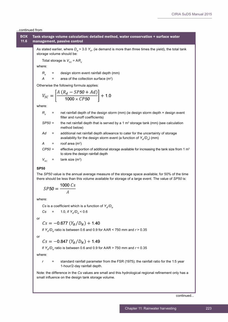
223Chapter 11: Rainwater harvesting
CIRIA SuDS Manual 2015
BOX11.6
Tank storage volume calculation: detailed method, water conservation + surface water management, passive control
As stated earlier, where DN > 3.0 YR, (ie demand is more than three times the yield), the total tank storage volume should be:
Total storage is VSC = ARd
where:
Rd = design storm event rainfall depth (mm)A = area of the collection surface (m2)
Otherwise the following formula applies:
where:
Rd = net rainfall depth of the design storm (mm) (ie design storm depth × design event filter and runoff coefficients)
SP50 = the net rainfall depth that is served by a 1 m3 storage tank (mm) (see calculation method below)
Ad = additional net rainfall depth allowance to cater for the uncertainty of storage availability for the design storm event (a function of YR/DN) (mm)
A = roof area (m2)CP50 = effective proportion of additional storage available for increasing the tank size from 1 m3
to store the design rainfall depthVSC = tank size (m3)
SP50The SP50 value is the annual average measure of the storage space available; for 50% of the time there should be less than this volume available for storage of a large event. The value of SP50 is:
where:
Cs is a coefficient which is a function of YR/DN
Cs = 1.0, if YR/DN < 0.6
or
if YR/DN ratio is between 0.6 and 0.9 for AAR < 750 mm and r > 0.35
or
if YR/DN ratio is between 0.6 and 0.9 for AAR > 750 mm and r < 0.35
where:
r = standard rainfall parameter from the FSR (1975); the rainfall ratio for the 1:5 year 1-hour/2-day rainfall depth.
Note: the difference in the Cs values are small and this hydrological regional refinement only has a small influence on the design tank storage volume.
continued...
...continued from
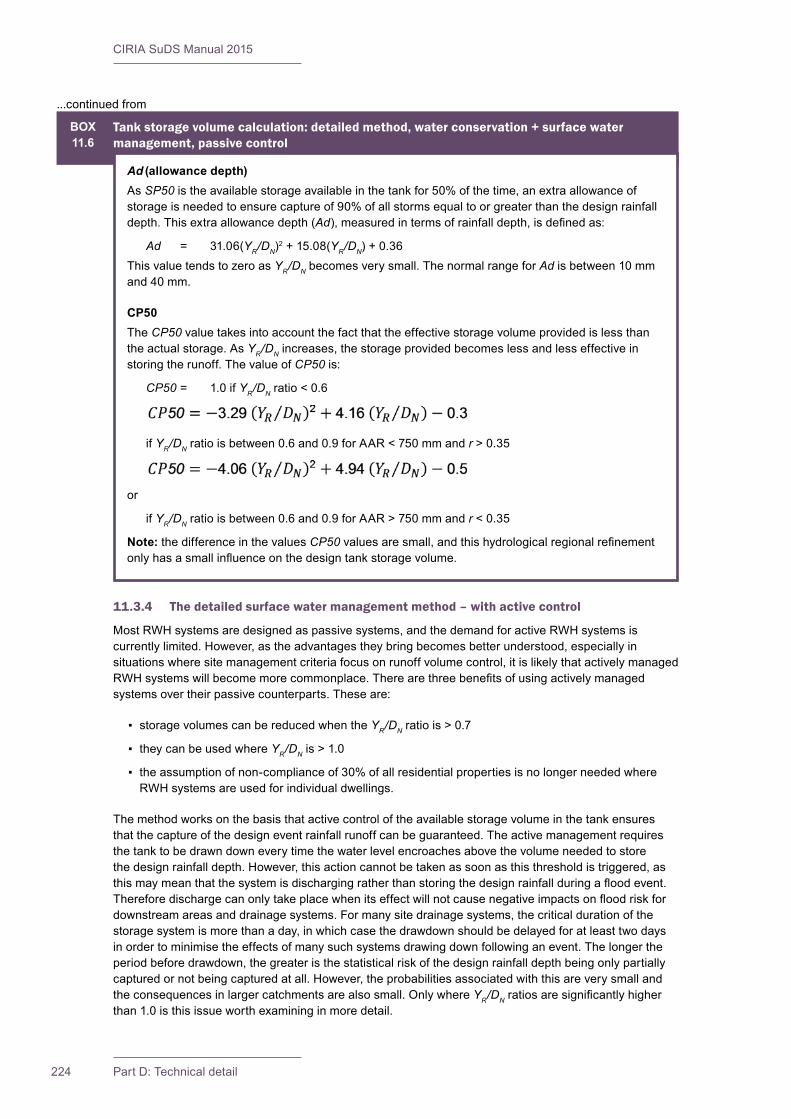
CIRIA SuDS Manual 2015
224 Part D: Technical detail
BOX11.6
Tank storage volume calculation: detailed method, water conservation + surface water management, passive control
Ad (allowance depth)As SP50 is the available storage available in the tank for 50% of the time, an extra allowance of storage is needed to ensure capture of 90% of all storms equal to or greater than the design rainfall depth. This extra allowance depth (Ad), measured in terms of rainfall depth, is defined as:
Ad = 31.06(YR/DN)2 + 15.08(YR/DN) + 0.36This value tends to zero as YR/DN becomes very small. The normal range for Ad is between 10 mm and 40 mm.
CP50The CP50 value takes into account the fact that the effective storage volume provided is less than the actual storage. As YR/DN increases, the storage provided becomes less and less effective in storing the runoff. The value of CP50 is:
CP50 = 1.0 if YR/DN ratio < 0.6
if YR/DN ratio is between 0.6 and 0.9 for AAR < 750 mm and r > 0.35
or
if YR/DN ratio is between 0.6 and 0.9 for AAR > 750 mm and r < 0.35
Note: the difference in the values CP50 values are small, and this hydrological regional refinement only has a small influence on the design tank storage volume.
11.3.4 The detailed surface water management method – with active control
Most RWH systems are designed as passive systems, and the demand for active RWH systems is currently limited. However, as the advantages they bring becomes better understood, especially in situations where site management criteria focus on runoff volume control, it is likely that actively managed RWH systems will become more commonplace. There are three benefits of using actively managed systems over their passive counterparts. These are:
▪ storage volumes can be reduced when the YR/DN ratio is > 0.7
▪ they can be used where YR/DN is > 1.0
▪ the assumption of non-compliance of 30% of all residential properties is no longer needed where RWH systems are used for individual dwellings.
The method works on the basis that active control of the available storage volume in the tank ensures that the capture of the design event rainfall runoff can be guaranteed. The active management requires the tank to be drawn down every time the water level encroaches above the volume needed to store the design rainfall depth. However, this action cannot be taken as soon as this threshold is triggered, as this may mean that the system is discharging rather than storing the design rainfall during a flood event. Therefore discharge can only take place when its effect will not cause negative impacts on flood risk for downstream areas and drainage systems. For many site drainage systems, the critical duration of the storage system is more than a day, in which case the drawdown should be delayed for at least two days in order to minimise the effects of many such systems drawing down following an event. The longer the period before drawdown, the greater is the statistical risk of the design rainfall depth being only partially captured or not being captured at all. However, the probabilities associated with this are very small and the consequences in larger catchments are also small. Only where YR/DN ratios are significantly higher than 1.0 is this issue worth examining in more detail.
...continued from
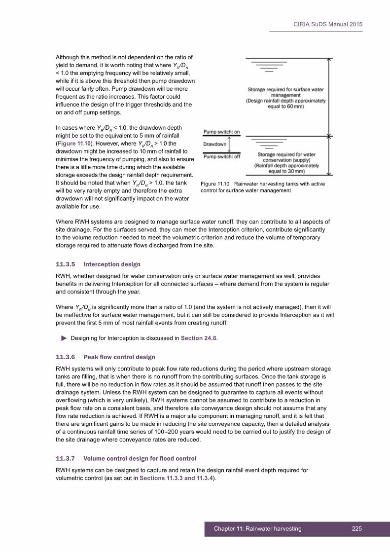
225Chapter 11: Rainwater harvesting
CIRIA SuDS Manual 2015
Although this method is not dependent on the ratio of yield to demand, it is worth noting that where YR/DN < 1.0 the emptying frequency will be relatively small, while if it is above this threshold then pump drawdown will occur fairly often. Pump drawdown will be more frequent as the ratio increases. This factor could influence the design of the trigger thresholds and the on and off pump settings.
In cases where YR/DN < 1.0, the drawdown depth might be set to the equivalent to 5 mm of rainfall (Figure 11.10). However, where YR/DN > 1.0 the drawdown might be increased to 10 mm of rainfall to minimise the frequency of pumping, and also to ensure there is a little more time during which the available storage exceeds the design rainfall depth requirement. It should be noted that when YR/DN > 1.0, the tank will be very rarely empty and therefore the extra drawdown will not significantly impact on the water available for use.
Where RWH systems are designed to manage surface water runoff, they can contribute to all aspects of site drainage. For the surfaces served, they can meet the Interception criterion, contribute significantly to the volume reduction needed to meet the volumetric criterion and reduce the volume of temporary storage required to attenuate flows discharged from the site.
11.3.5 Interception design
RWH, whether designed for water conservation only or surface water management as well, provides benefits in delivering Interception for all connected surfaces – where demand from the system is regular and consistent through the year.
Where YR/DN is significantly more than a ratio of 1.0 (and the system is not actively managed), then it will be ineffective for surface water management, but it can still be considered to provide Interception as it will prevent the first 5 mm of most rainfall events from creating runoff.
Designing for Interception is discussed in Section 24.8.
11.3.6 Peak flow control design
RWH systems will only contribute to peak flow rate reductions during the period where upstream storage tanks are filling, that is when there is no runoff from the contributing surfaces. Once the tank storage is full, there will be no reduction in flow rates as it should be assumed that runoff then passes to the site drainage system. Unless the RWH system can be designed to guarantee to capture all events without overflowing (which is very unlikely), RWH systems cannot be assumed to contribute to a reduction in peak flow rate on a consistent basis, and therefore site conveyance design should not assume that any flow rate reduction is achieved. If RWH is a major site component in managing runoff, and it is felt that there are significant gains to be made in reducing the site conveyance capacity, then a detailed analysis of a continuous rainfall time series of 100–200 years would need to be carried out to justify the design of the site drainage where conveyance rates are reduced.
11.3.7 Volume control design for flood control
RWH systems can be designed to capture and retain the design rainfall event depth required for volumetric control (as set out in Sections 11.3.3 and 11.3.4).
Figure 11.10 Rainwater harvesting tanks with active control for surface water management

CIRIA SuDS Manual 2015
226 Part D: Technical detail
The surface water management storage volume provided by the RWH systems will contribute to reducing the volume of attenuation storage required on the site. The critical duration of the design event for the site attenuation storage will be shortened due to the reduction in runoff volume delivered by the RWH system. The attenuation storage volume will be reduced by more than the amount of the RWH storage provided.
Designing for attenuation storage is discussed in Section 24.9.
11.3.8 Exceedance flow design
RWH systems for surface water management are designed to capture a specific depth of rainfall. They therefore only contribute to extreme event flow management during the initial stages of extended extreme events and during high intensity, short duration rainfall when site drainage systems are overwhelmed while the rainwater tanks are still capturing and storing runoff.
Consideration should be given to the design of the RWH overflow and the subsequent discharge pathway. Where infiltration systems are used for disposal of excess water, then consideration should be given to the likely frequency and consequences of potential exceedance events.
11.4 TREATMENT DESIGN
There are two aspects with regards to RWH system treatment design:
1 the contribution of RWH systems to the control of pollution from site surface water runoff
2 the treatment of the collected rainwater so that it is suitable for non-potable domestic or other uses
11.4.1 RWH contribution to site runoff pollution control
Roof runoff is significantly less polluted than runoff from road surfaces. Nevertheless, roofs may still generate pollutants such as sediments, PAHs and metals due to atmospheric deposition and runoff entrainment. In some cases, particularly in commercial environments, the wash-off of roofing constituents such as copper and zinc is a particular issue. Where roof runoff is captured by the RWH system, any pollutants from the roof surface will be captured by the collection and filtration system. Maintenance of the system is essential to prevent debris, sediment and other pollutants that accumulate in the filters from being discharged downstream, and to ensure the long-term performance of the system.
By reducing the volume of runoff generated from the site, particularly for small events, RWH systems can directly reduce the pollutant load discharged to receiving waters. They are considered as an effective Interception component for the roof contributing to the system – whether designed for surface water management or water conservation (supply) only.
11.4.2 Treatment of collected runoff for use
RWH systems designed to BS 8515:2009+A1:2013 should deliver a water quality that is suitable for applications such as toilet flushing, washing machines and garden watering. Runoff that contains a high pollutant loading (eg sediments or heavy metals) may only be appropriate for use after treatment. The use of the harvested runoff will dictate the extent and type of treatment that should be provided. Disinfection may be required where site-specific risk assessment indicates the need for a specific water quality. Useful references on this topic include BS 8515:2009+A1:2013, BS 8595:2013 and a number of papers particularly those from Fewtrell and Kay (2007a, 2007b).
Rainwater harvesting water quality treatment measures include: pre-treatment, filtration, biological treatment and disinfection. Storing the water below ground can reduce the need for water quality treatment by keeping the water cool. Cool water has higher oxygen concentrations and prevents bacteria growth, and the lack of light prevents algal growth. Filters can be implemented pre or post storage. Treatment technology is developing rapidly as RWH system uptake and development increases, and is not covered further here.
227Chapter 11: Rainwater harvesting
CIRIA SuDS Manual 2015
11.5 AMENITY DESIGN
RWH systems provide indirect amenity value by supporting the resilience of developments and their landscape to changes in climate and water resource availability. Occasionally, they can also provide direct amenity value when implemented above ground, if designed with visual interest and/or integrated with landscape features and/or combined with educational initiatives. RWH systems can be made visually attractive, with considered engineering and landscape design input.
11.6 BIODIVERSITY DESIGN
RWH tanks do not have any inherent biodiversity value, but they can help to reduce flows on the downstream system, and this can help facilitate biodiversity delivery in those areas.
11.7 PHYSICAL SPECIFICATIONS
11.7.1 Pre-treatment and inlets
Primary screening devices are used to prevent leaves and other debris from entering the tank. Primary screening devices often have a wire mesh screen installed near the downspout. If leaves pose a problem, a leaf screen should be installed along the entire gutter length.
First flush devices can be designed to divert the first part of the rainfall away from the main storage tank. The first flush picks up most of the dirt, debris, and contaminants (eg bird droppings) that collect on the roof. Consideration will then be required as to where this first flush is safely treated and managed downstream.
11.7.2 Underdrains and outlets
RWH systems need either an inlet valve that closes flow into the container when it is full, or an overflow arrangement that conveys excess surface water runoff away from the building without causing damage. Erosion protection measures for the overflow should be provided as necessary.
11.8 MATERIALS
11.8.1 Rainwater harvesting tank structures
Most rainwater collection tanks are manufactured from plastics, concrete or steel. When selecting a material and product type, consideration should be given to:
▪ the potential need for protection of the tank materials against the corrosive effects of the stored water and any disinfectants used
▪ the tank service life
▪ resistance to flotation and potential restraint options
▪ structural design and installation complexity
▪ ease of maintenance if the system blocks or becomes contaminated in some way
▪ aesthetics (where the tank is visually accessible).
The storage of rainwater does not have to be in a traditional tank; the void space in sub-base material of a permeable paving system or within geocellular modular units, encapsulated within a robust, weldable, geomembrane can also be used.
Geotextile and geomembrane specifications are presented in Chapter 30.

CIRIA SuDS Manual 2015
228 Part D: Technical detail
Tanks should be designed to prevent freezing during winter, and ingress of groundwater. Underground tanks should be properly designed and installed to withstand groundwater, earth and/or backfill pressures, surcharge loads, vehicular loading and flotation.
11.8.2 Collection and distribution systems
External pipework needs to designed to prevent freezing during winter.
Internal pipework needs to be distinguished from potable water pipework by using pipe materials which comply with the RWH code of practice BS 8515:2009+A1:2013.
11.9 LANDSCAPE DESIGN AND PLANTING
There are no landscape design aspects to the use of RWH systems unless the water is stored in a landscape feature.
RWH systems can be used to provide a supply of water for plant irrigation.
11.10 CONSTRUCTION REQUIREMENTS
RWH systems should be installed using safe construction methods, and manufacturers’ guidelines should be followed in all cases.
Care should be taken to avoid cross-connections, and pipe marking is essential. Reference should be made to the Water Supply (Water Fittings) Regulations 1999. Guidelines are available in BS 8515:2009+A1:2013 on pipe markings, fittings and other construction guidance. Any buried tank should be designed by a structural engineer to ensure that it is suitable for the ground conditions in which it is installed.
Modern developments often have quite small gardens and RWH tanks are often located close to a building. Careful consideration of the structural impact on the building of the excavation and subsequent operation of the system needs to be taken. Consideration should also be given to requirements for structural support (eg using appropriate concrete backfill around the unit). Flotation risk during periods of extended wet weather should also be checked.
The operation of the tank overflow when the system is full (including the frequency, volume and impact of spills) needs to be considered and designed to avoid damage or nuisance.
Surface water should not be diverted to the RWH system until the catchment area and overflow area have been stabilised.
More detail on construction activities and the programming of construction activities is provided in Chapter 32.
Generic health and safety considerations are discussed in Chapter 36.
11.11 OPERATION AND MAINTENANCE REQUIREMENTS
Any property with an RWH system installed should be provided with appropriate information as to what equipment has been installed, its purpose, its operation and maintenance requirements, the actions needed to address any potential failure and the expected performance of the system. Information on the options for external maintenance support should also be provided.
Figure 11.11 Rainwater harvesting storage tanks during construction (courtesy British Precast)

229Chapter 11: Rainwater harvesting
CIRIA SuDS Manual 2015
Most systems require periodic checking and maintenance to ensure trouble-free and reliable operation. There are wide differences in the extent of maintenance required for different systems, and manufacturers’ guidelines should always be followed. Table 11.6 provides guidance on the type of operational and maintenance requirements that may be appropriate. The list of actions is not exhaustive and some actions may not always be required.
Maintenance requirements are largely dependent on the runoff source and the runoff use (and thus treatment processes provided). This will range from weekly input through to rare intervention. Routine inspection of the filter system at quarterly annual intervals is advised, even if they do not appear to need specific intervention. Pumps need very little attention, but their design life is generally regarded as only being 10 years. Where automatic provision of potable water occurs (if and when rainwater is either not available or the system has failed), it is useful to have sensor warnings relayed in such a manner as to inform the user of the current status of the system.
RWH systems should be designed so that when there is an absence of rain, or a need to disconnect the system for maintenance or repair, that potable water is safely available for all appliances to avoid inconvenience.
Tanks should be accessible for internal inspection, and the cover should preferably be lockable. For more guidance on operation and maintenance of RWH systems, see BS 8515:2009+A1:2013.
The maintenance responsibility for an RWH system is usually with the owner of the property, but any communal systems require the participating community to be informed of the system, as detailed, but also be provided with information of who the organisation is that is maintaining the system and any financial commitments and any legally binding maintenance agreement.
TABLE11.6
Operation and maintenance requirements for RWH systems
Maintenance schedule Required action Typical frequency
Regular maintenance
Inspection of the tank for debris and sediment build-up, inlets/outlets/withdrawal devices, overflow areas, pumps, filters
Annually (and following poor performance)
Cleaning of tank, inlets, outlets, gutters, withdrawal devices and roof drain filters of silts and other debris
Annually (and following poor performance)
Occasional maintenance Cleaning and/or replacement of any filtersThree monthly (or as required)
Remedial actionsRepair of overflow erosion damage or damage to tank As required
Pump repairs As required

CIRIA SuDS Manual 2015
230 Part D: Technical detail
11.12 REFERENCES
CEH (1999) Flood Estimation Handbook (FEH), Centre for Ecology and Hydrology, Wallingford, Oxon, UK (ISBN: 978-1-90669-800-3). Go to: http://tinyurl.com/o8lslay
DCLG (2007) Survey of English housing – household characteristics: mean household size by type of accommodation and by number of bedrooms 2004–2007, Department for Communities and Local Government, London, UK
EA (2010) Harvesting rainwater for domestic uses: an information guide, Environment Agency, Bristol, UK. Go to: http://tinyurl.com/ppfgzor
FEWTRELL, L and KAY, D (2007a) “Quantitative microbial risk assessment with respect to Campylobacter spp. in toilets flushed with harvested rainwater” Water and Environment Journal, vol 21, 4, Wiley Online, London, UK, pp 275–280
FEWTRELL, L and KAY, D (2007b) “Microbial quality of rainwater supplies in developed countries: a review” Urban Water Journal, vol 4, 4, Taylor and Francis, London, UK pp 1–8
IOH (1975) Flood Studies Report, Institute of Hydrology, London, UK (superseded)
KELLAGHER, R (2012) Stormwater management using rainwater harvesting. Testing the Kellagher/Gerolin methodology on a pilot study, SR736, HR Wallingford, Wallingford, Oxon, UK
OCC (2009) Survey of new housing 2008: Summary of results, Oxfordshire County Council Policy Unit, Oxford, UK
Statutes
BS 8515:2009+A1:2013 Rainwater harvesting systems. Code of practice
BS 8542:2011 Calculating domestic water consumption in non-domestic buildings. Code of practice
BS 8595:2013 Code of practice for the selection of water reuse systems
The Water Supply (Water Fittings) Regulations 1999 (No.1148)
The Private Water Supplies Regulations 2009 (No.3101)

231Chapter 11: Rainwater harvesting
CIRIA SuDS Manual 2015
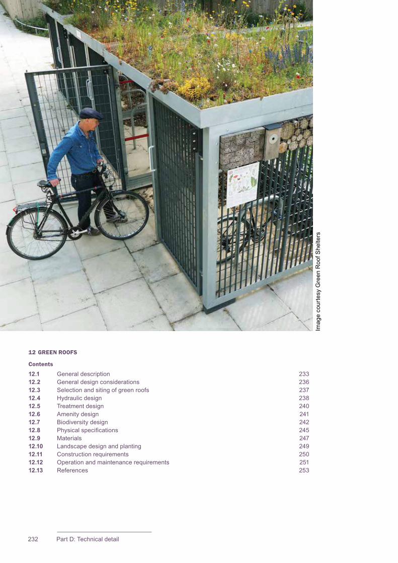
232 Part D: Technical detail
12 GREEN ROOFS
Contents
12.1 General description 23312.2 General design considerations 23612.3 Selection and siting of green roofs 23712.4 Hydraulic design 23812.5 Treatment design 24012.6 Amenity design 24112.7 Biodiversity design 24212.8 Physicalspecifications 24512.9 Materials 24712.10 Landscape design and planting 24912.11 Constructionrequirements 25012.12 Operationandmaintenancerequirements 25112.13 References 253
Imag
e co
urte
sy G
reen
Roo
f She
lters

233Chapter 12: Green roofs
CIRIA SuDS Manual 2015
12.1 GENERAL DESCRIPTION
Green roofs are areas of living vegetation, installed on the top of buildings, for a range of reasonsincludingvisualbenefit,ecologicalvalue,enhancedbuildingperformanceandthereduction of surface water runoff. Types of green roof can be divided into two main categories:
▪ Extensive roofs, have low substrate depths (and therefore low loadings on the building structure), simple planting and low maintenance requirements; they tend not to be accessible.
▪ Intensive roofs (or roof gardens) have deeper substrates (and therefore higher loadings on the building structure) that can support a wide variety of planting but which tend to require more intensive maintenance; they are usually accessible.
A blue roof is a roof design that is explicitly intended to store water. This storage can be designed as attenuation storage (with water released in a controlled manner), as storage for use such as irrigation (potentially of adjacent green roof areas), cooling water (for use in reducing the temperature of the roof on hot days, or for internal cooling plant) or non-potable use within the building, and/or for recreational opportunities. Blue roofs can include open water surfaces, storage within or beneath a porous medium or modular surfaces, or below a raised decking surface or impermeable cover. Green roofs that include reservoir storage zones beneath the growing medium could also be termed “blue roofs”. Blue roofs are not considered in detail in this chapter as they are, essentially, equivalent to other components described in this manual. The key design considerations are the structural capacity of the roof to deal with the extra loadings and thewaterproofingrequiredtoprotectthebuilding.
Although green roofs are generally more expensive than conventional roofs to construct andmaintain,theycanprovidemanylong-termbenefits.Thevegetatedcoverassemblyshouldbecompatiblewithanddesignedtoprotecttheunderlyingroofwaterproofingmaterials.Thedesignlifeoftheroofwaterproofingcanbeextendedbyprotectingthewaterproofingfrommechanicaldamage,shieldingitfromultravioletradiation,andbuffering temperature extremes.
Green roofs can improve the thermal performance of buildings, potentially reducing building energy costs, due to the plants and substrate cooling the roof through evapotranspiration during summer months. Winter insulation properties are dependent on the amount of water held by the roof, and in wet winters such as in the UK, gains will tend to be low. Green roofs willhelpcombattheurbanheatislandeffectwherethereisasufficientnumberinanurbanarea, as well as contributing to improved air quality by capturing dust particles.
Detailed UK guidance for green roofs is provided in Early et al (2007), The Greenroof Centre (2011) and GRO (2014).
A green roof consists of a system in which several materials are layered to achieve the desired vegetative cover and drainage characteristics. Design components vary depending on the green roof type and site constraints, but typically include the elements shown in Figure 12.1.
12Chapter Green roofs
This chapter provides guidance on the design of green roofs – that is, roofs with a vegetated surface that provide a degree of retention, attenuation and treatment of rainwater and promote evapotranspiration.
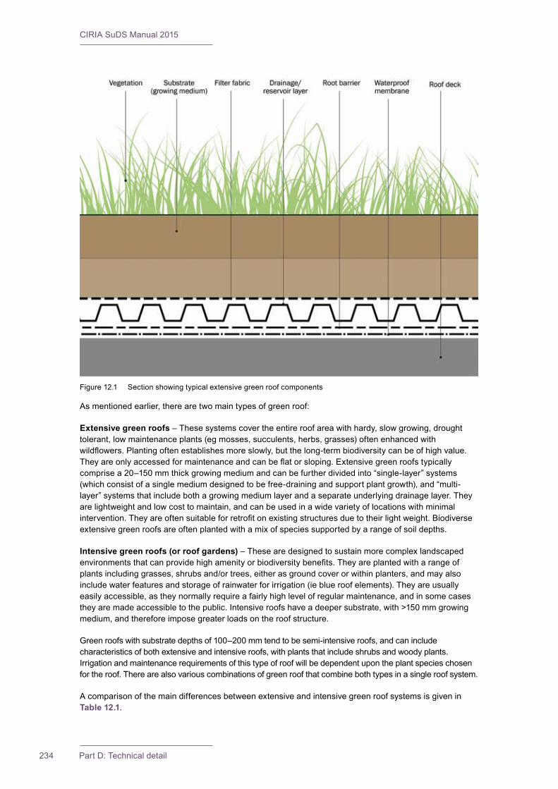
CIRIA SuDS Manual 2015
234 Part D: Technical detail
As mentioned earlier, there are two main types of green roof:
Extensive green roofs – These systems cover the entire roof area with hardy, slow growing, drought tolerant, low maintenance plants (eg mosses, succulents, herbs, grasses) often enhanced with wildflowers.Plantingoftenestablishesmoreslowly,butthelong-termbiodiversitycanbeofhighvalue.Theyareonlyaccessedformaintenanceandcanbeflatorsloping.Extensivegreenroofstypicallycomprisea20–150mmthickgrowingmediumandcanbefurtherdividedinto“single-layer”systems(which consist of a single medium designed to be free-draining and support plant growth), and “multi-layer” systems that include both a growing medium layer and a separate underlying drainage layer. They are lightweight and low cost to maintain, and can be used in a wide variety of locations with minimal intervention.Theyareoftensuitableforretrofitonexistingstructuresduetotheirlightweight.Biodiverseextensive green roofs are often planted with a mix of species supported by a range of soil depths.
Intensive green roofs (or roof gardens) – These are designed to sustain more complex landscaped environmentsthatcanprovidehighamenityorbiodiversitybenefits.Theyareplantedwitharangeofplants including grasses, shrubs and/or trees, either as ground cover or within planters, and may also include water features and storage of rainwater for irrigation (ie blue roof elements). They are usually easily accessible, as they normally require a fairly high level of regular maintenance, and in some cases theyaremadeaccessibletothepublic.Intensiveroofshaveadeepersubstrate,with>150mmgrowingmedium, and therefore impose greater loads on the roof structure.
Green roofs with substrate depths of 100–200 mm tend to be semi-intensive roofs, and can include characteristics of both extensive and intensive roofs, with plants that include shrubs and woody plants. Irrigation and maintenance requirements of this type of roof will be dependent upon the plant species chosen for the roof. There are also various combinations of green roof that combine both types in a single roof system.
A comparison of the main differences between extensive and intensive green roof systems is given in Table 12.1.
Figure 12.1 Section showing typical extensive green roof components
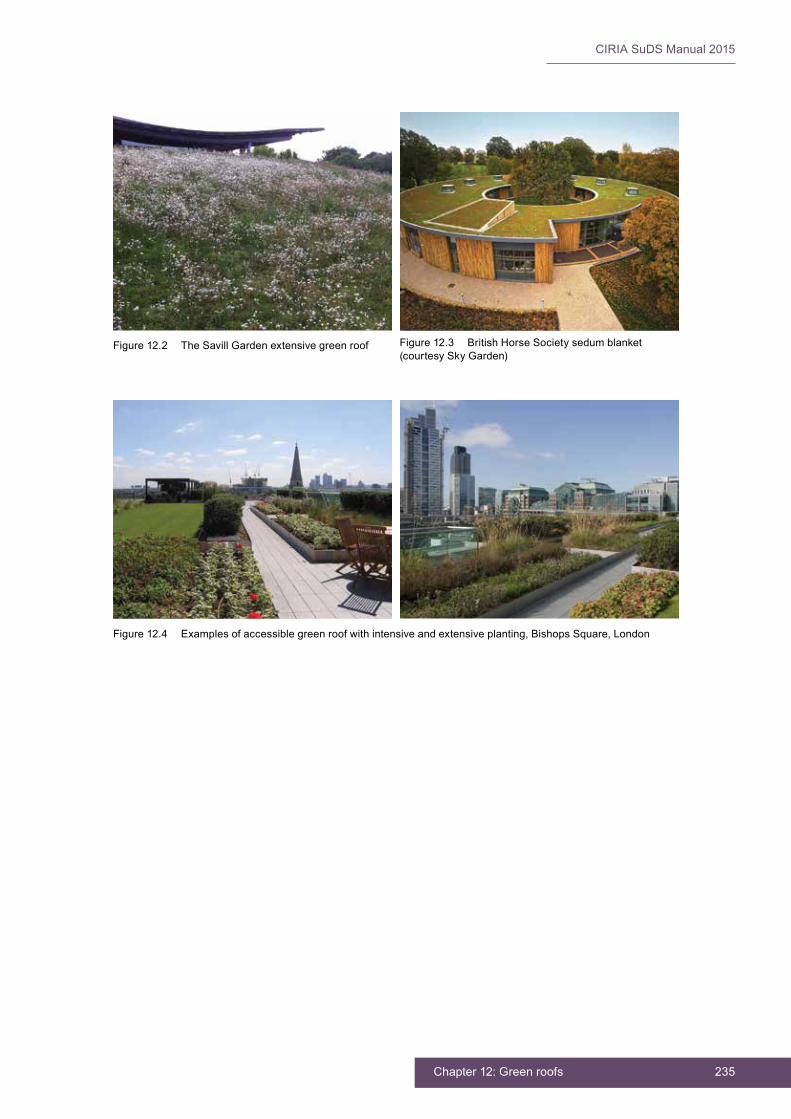
235Chapter 12: Green roofs
CIRIA SuDS Manual 2015
Figure 12.2 The Savill Garden extensive green roof Figure 12.3 British Horse Society sedum blanket (courtesy Sky Garden)
Figure 12.4 Examples of accessible green roof with intensive and extensive planting, Bishops Square, London

CIRIA SuDS Manual 2015
236 Part D: Technical detail
TABLE12.1
Comparison of extensive and intensive green roof systems
Extensive green roof Intensive green roof
Access Not usually accessible Accessible as public space or garden
Growing medium Thingrowingmedium20–150mm Deeper growing medium
Irrigation Only during plant establishment Occasional to frequent
Maintenance Minimal to none Low to high
Advantages ▪ lightweight
▪ suitable for roofs with slope of up to 1 in 3
▪ little or no need for irrigation and specialised drainage systems
▪ oftensuitableforretrofits
▪ little management of vegetation
▪ relatively inexpensive
▪ attractive to pioneer species colonisation, which can lead to a more biodiverse long-term ecosystem
▪ can support arrested pioneer communities, which are important for nature conservation
Disadvantages ▪ more stressful conditions for plants, leading
to lower potential diversity and associated biodiversity
▪ limited insulation provision
▪ limitedsurfacewaterretentionbenefits
▪ limitedaestheticbenefits
Advantages ▪ more favourable conditions for plants,
leading to greater potential diversity of plants and habitats
▪ good contribution to thermal performance of the building
▪ can be made very attractive
▪ often accessible, with opportunities forrecreationandamenitybenefits
▪ good surface water retention capacity
Disadvantages ▪ greater loading on roof structure
▪ need for irrigation and drainage systems requiring energy, water, materials
▪ higher capital and maintenance costs
12.2 GENERAL DESIGN CONSIDERATIONS
The successful design of a green roof will require collaboration between structural engineers (with particular respect to the structural capacity of the building to withstand the imposed loads), architects, landscape architects, ecologists, horticulturists and drainage engineers. It also requires consideration of the maintenance that will be required. Access to undertake the construction and maintenance easily and safely should be a high priority in designing the roof.
Health and safety risk management design is discussed in Chapter 36.
Important design considerations include:
▪ accessibility requirements
▪ biodiversity objectives
▪ amenity/aesthetic objectives and desired visual impact
▪ the saturated weight of the system and the load-bearing capacity of the underlying roof deck and structure
▪ other imposed loads, including maintenance loadings and snow cover
▪ the need for integration of rooftop equipment, such as vents, air-conditioning systems, solar panels and/or RWH systems
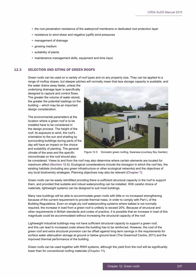
237Chapter 12: Green roofs
CIRIA SuDS Manual 2015
▪ the root penetration resistance of the waterproof membrane or dedicated root protection layer
▪ resistance to wind shear and negative (uplift) wind pressures
▪ management of drainage
▪ growing medium
▪ suitability of plants
▪ maintenance management skills, equipment and time input.
12.3 SELECTION AND SITING OF GREEN ROOFS
Green roofs can be used on a variety of roof types and on any property size. They can be applied to a range of rooftop slopes, but steeper pitches will normally mean that less storage capacity is available, and the water drains away faster, unless the underlyingdrainagelayerisspecificallydesignedtocaptureandcontrolflows.The greater the volume of water stored, the greater the potential loadings on the building – which may be an important design consideration.
The environmental parameters at the location where a green roof is to be installed have to be considered in the design process. The height of the roof, its exposure to wind, the roof’s orientation to the sun and shading by surrounding buildings during parts of the day will have an impact on the choice and suitability of planting. The general climateoftheareaandthespecificmicroclimate on the roof should also be considered. Views to and from the roof may also determine where certain elements are located for maximum effect (Section 12.6). Ecological considerations include the bioregion in which the roof lies, the existing habitats (including any green infrastructure or other ecological networks) and the objectives of any local biodiversity strategies. Planning objectives may also be relevant (Chapter 7).
Greenroofscanbeeasilyretrofittedprovidingthereissufficientstructuralcapacityintherooftosupportthem,andprovidedthatsuitableandrobustwaterproofingcanbeinstalled.Withcarefulchoiceofmaterials, lightweight systems can be designed to suit most buildings.
Many new buildings will be able to accommodate green roofs with little or no increased strengthening because of the current requirement to provide thermal mass, in order to comply with Part L of the BuildingRegulations.Evenonsingleplyroofwaterproofingsystemswhereballastisnotnormallyrequired, the increase in load from a green roof is unlikely to exceed 20%. Because of structural and other requirements in British standards and codes of practice, it is possible that an increase in load of this magnitude could be accommodated without increasing the structural capacity of the roof.
Lightweightindustrialbuildingsmaynothavesufficientstructuralcapacitytosupportagreenroof,and this can lead to increased costs where the building has to be reinforced. However, the cost of the green roof and extra structural provision can be offset against long-term savings in the requirements for surface water attenuation storage at ground or below-ground level (The Greenroof Centre, 2011) and the improved thermal performance of the building.
GreenroofscanbeusedtogetherwithRWHsystems,althoughtheyieldfromtheroofwillbesignificantlylowerthanforconventionalroofingmaterials(Chapter 11).
Figure12.5 Domesticgreenroofing,Swansea(courtesySkyGarden)

CIRIA SuDS Manual 2015
238 Part D: Technical detail
12.4 HYDRAULIC DESIGN
12.4.1 General
Although green roofs absorb most of the rainfall that they receive during frequent events, there will always be a need to discharge excess water to the building’s drainage system. The hydraulic performance of green roofs once saturated tends to be fairly similar to standard roofs. Therefore, the hydraulic design of greenroofdrainageshouldfollowtheadviceinBSEN12056-3:2000.Usefulinformationisalsoprovidedin BS 6229:2003. Detailed guidelines for the planning, execution and upkeep of green roof sites are contained within GRO (2014).
Greenroofsactalittlelikeordinarypervioussurfaces,particularlyintensiveroofswithsignificantdepthsof substrate. However, this similarity reduces for roofs with shallower substrate and steeper gradients, which only tend to attenuate runoff during small or initial stages of an event.
Hydraulic design for green roofs should consider two aspects of their performance:
▪ how the roof is likely to behave during an extreme storm (and its potential contribution to meeting the hydraulic standard of service for the whole site drainage system), which is likely to be limited
▪ how the roof is likely to perform through the year, with a focus on the reduction of runoff volume for the majority of rainfall events (ie Interception).
12.4.2 Interception design
The performance of green roofs in terms of reducing or preventing the runoff from normal rainfall events isusuallyverysignificantinthesummerduetotheevapotranspirationprocessesandtemporarystorageprovided by the roof.
All green roofs can be assumed to meet Interception requirements in the summer, based on their retentionof5mmofrainfall.However,roofsarelikelytostruggletomeetInterceptionrequirementsduring cold, wet winter periods when they are likely to be saturated for much of the time. The amount of rainfall that can be absorbed by a green roof before runoff takes place is very dependent on antecedent conditions. Thus, any assumptions regarding green roof performance during design storms should take a conservative position and consider whether the event is in summer or winter. Only an extended time series analysis will result in a reasonably accurate assessment of its likely performance. Any model shouldreflectthecharacteristicsoftheproposedgreenroof,andthismightrequirecalibrationagainstobserveddata,astherearecurrentlynomodellingtoolsavailablewhichspecificallyrepresentgreenroofrunoff. Evidence of green roof performance in reducing runoff from rainfall events is set out in Box 12.1.
It is uncommon to link a green roof to an RWH system, but in some circumstances this may be very beneficial(egifthevolumeofrunofffromthesitehastobeminimisedandthedemandfornon-potablewater is limited compared to the roof area). The colour of water collected from a green roof may preclude its internal use within the building, but it will be more suitable for irrigation.
For guidance on RWH system design, see Chapter 11.
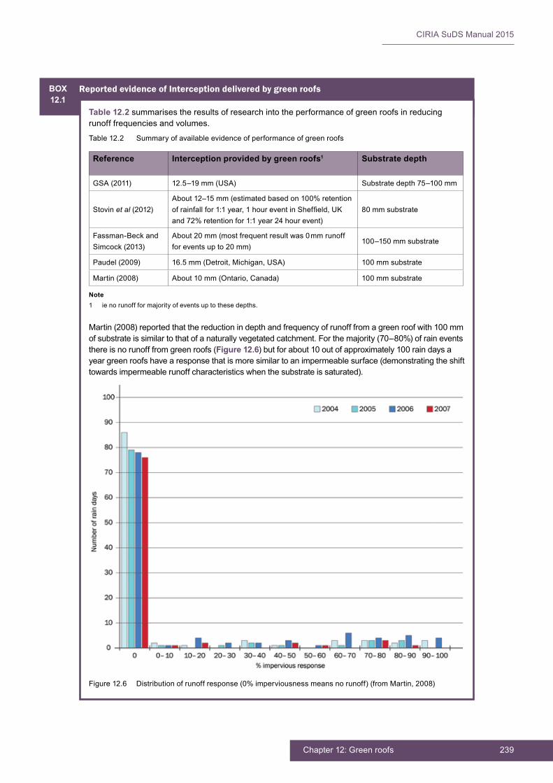
239Chapter 12: Green roofs
CIRIA SuDS Manual 2015
BOX12.1
Reported evidence of Interception delivered by green roofs
Table 12.2 summarises the results of research into the performance of green roofs in reducing runoff frequencies and volumes.
Table 12.2 Summary of available evidence of performance of green roofs
Reference Interception provided by green roofs1 Substrate depth
GSA (2011) 12.5–19mm(USA) Substratedepth75–100mm
Stovin et al (2012)About12–15mm(estimatedbasedon100%retentionofrainfallfor1:1year,1houreventinSheffield,UKand 72% retention for 1:1 year 24 hour event)
80 mm substrate
Fassman-Beck and Simcock (2013)
About 20 mm (most frequent result was 0 mm runoff for events up to 20 mm)
100–150mmsubstrate
Paudel (2009) 16.5mm(Detroit,Michigan,USA) 100 mm substrate
Martin (2008) About 10 mm (Ontario, Canada) 100 mm substrate
Martin (2008) reported that the reduction in depth and frequency of runoff from a green roof with 100 mm of substrate is similar to that of a naturally vegetated catchment. For the majority (70–80%) of rain events there is no runoff from green roofs (Figure 12.6) but for about 10 out of approximately 100 rain days a year green roofs have a response that is more similar to an impermeable surface (demonstrating the shift towards impermeable runoff characteristics when the substrate is saturated).
Figure 12.6 Distribution of runoff response (0% imperviousness means no runoff) (from Martin, 2008)
Note1 ie no runoff for majority of events up to these depths.

CIRIA SuDS Manual 2015
240 Part D: Technical detail
12.4.3 Peakflowcontroldesign
Greenroofscanprovidebenefitsintermsofreducingpeakflowratestothesitedrainagesystem–principallyforsmallandmedium-sizedevents.Theirimpacttendstobemostsignificantinsummer,where intense short duration events may generate very little runoff from the roof.
The reduction in the volume of runoff from a green roof for an extreme event is unlikely to impact on downstream attenuation storage requirements. Critical duration events for developments served by SuDS are commonly of the order of 12 to 36 hours, which tend to be representative of autumn and winter conditions, when reductions in runoff volumes from green roofs are likely to be small.
The depth of rainfall that will be stored in any rainfall event is a function of the antecedent soil moisture, thesoildepth,theroofgradientandanyspecificstorageprovisiondesignedwithinthedrainagelayer.The proportion of runoff from a green roof will increase as the duration and depth of the storm increases and the attenuation effects provided by the roof will reduce.
Where the design of the downstream drainage system (eg attenuation storage volumes and conveyance capacities)islinkedtothegreenroofperformance,thenthebenefitsshouldbeexplicitlydeterminedusingmodellingorevidence-basedinformation.Attenuationcanonlybeguaranteedifitisspecificallyincludedwithin the design as part of the drainage layer (and with the potential use of throttled outlets).
The storage characteristics of blue roofs will only be a function of the hydraulic controls at the outlet of thesystem.Althoughtheycanbedesignedtoattenuateflows,anyvolumetricreductionwillbelimitedto evaporation. The performance of a blue roof is more predictable than a green roof, as it usually constitutes a standard arrangement of attenuation storage and throttled outlets.
12.4.4 Volume control design
There is a growing body of evidence that green roofs considerably reduce the volume of runoff in warmer periodswhenthesoilmoisturedeficitishigh.Thetypeofplantsusedandsoildepthswillinfluenceevapotranspiration rates and available potential storage in the soil. Sedum roofs, due to the nature of the plants, tend to conserve water and have lower evapotranspiration rates during hot dry conditions (Stovin et al, 2012). The rate of evapotranspiration also depends on the volume of water stored (ie available) on the roof. If detailed modelling of roofs is carried out to assess runoff volume reduction accurately, then the model needs to incorporate an evapotranspiration rate relevant to the planting group, and a soil store component which adjusts the evapotranspiration rate with the volume of water stored. The rate of evapotranspiration is often assumed to be 3 mm/day in summer and 0 mm/day in mid-winter, but this may be lower for sedum roofs.
Blue roofs can also provide a reduction in the volume of runoff due to evaporation, and this process will be enhanced due to the solar warming of the water because of its shallow depth and exposed location. ThisislikelytobemoresignificantinclimateswarmerthanthatoftheUK.
12.4.5 Exceedanceflowdesign
Every roof structure and all roof drainage design should consider the impact of events that are greater thanthedesignevent,andtherisksassociatedwithexceedanceflowsshouldbeassessedandmanagedin an appropriate and safe way, to protect people and property. As wash-off of material could take place from green roofs, it is also important to assess potential failure mechanisms and their possible impacts. This assessment should then result in mitigation by either design adaptations or provision of further mitigation features.
12.5 TREATMENT DESIGN
The substrate used in the construction of green roofs should not add pollutants to the rainfall that percolates throughitinawaythatsometraditionalroofingmaterials(egcopper)can.Thepollutanthazardwillonlybedependent on atmospheric pollution and will therefore tend to be lower than from hard surfaces.
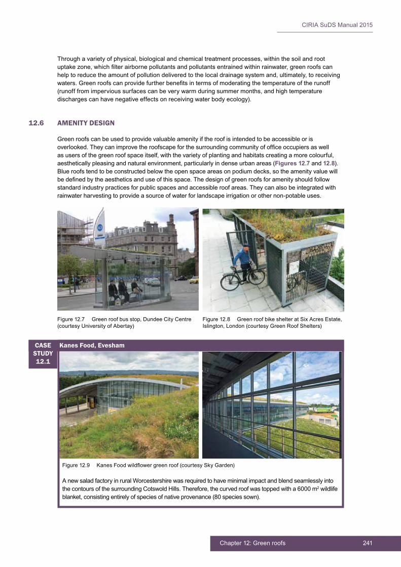
241Chapter 12: Green roofs
CIRIA SuDS Manual 2015
Through a variety of physical, biological and chemical treatment processes, within the soil and root uptakezone,whichfilterairbornepollutantsandpollutantsentrainedwithinrainwater,greenroofscanhelp to reduce the amount of pollution delivered to the local drainage system and, ultimately, to receiving waters.Greenroofscanprovidefurtherbenefitsintermsofmoderatingthetemperatureoftherunoff(runoff from impervious surfaces can be very warm during summer months, and high temperature discharges can have negative effects on receiving water body ecology).
12.6 AMENITY DESIGN
Green roofs can be used to provide valuable amenity if the roof is intended to be accessible or is overlooked.Theycanimprovetheroofscapeforthesurroundingcommunityofofficeoccupiersaswellas users of the green roof space itself, with the variety of planting and habitats creating a more colourful, aesthetically pleasing and natural environment, particularly in dense urban areas (Figures 12.7 and 12.8). Blue roofs tend to be constructed below the open space areas on podium decks, so the amenity value will bedefinedbytheaestheticsanduseofthisspace.Thedesignofgreenroofsforamenityshouldfollowstandard industry practices for public spaces and accessible roof areas. They can also be integrated with rainwater harvesting to provide a source of water for landscape irrigation or other non-potable uses.
Figure 12.7 Green roof bus stop, Dundee City Centre (courtesy University of Abertay)
Figure 12.8 Green roof bike shelter at Six Acres Estate, Islington, London (courtesy Green Roof Shelters)
Figure12.9 KanesFoodwildflowergreenroof(courtesySkyGarden)
A new salad factory in rural Worcestershire was required to have minimal impact and blend seamlessly into the contours of the surrounding Cotswold Hills. Therefore, the curved roof was topped with a 6000 m2 wildlife blanket, consisting entirely of species of native provenance (80 species sown).
Kanes Food, EveshamCASE STUDY12.1

CIRIA SuDS Manual 2015
242 Part D: Technical detail
Green roofs can be designed to deliver on a range of amenity principles including:
▪ climateresilience–throughimprovedbuildingthermalefficiency,reducedenergydemandandreduction of the urban heat island effect
▪ improved air quality – via the absorption of carbon dioxide, some air pollutants and dust
▪ reduced noise levels – due to extra acoustic dampening
▪ increased building service life, and enhanced sales or rental value due to the high aesthetic appeal, reduced energy costs and the building is associated with sustainable design and social responsibility.
Green roofs have also been shown to enhance the performance of photovoltaic panels where they are used in combination (Zinco, 2011, and The Biosolar Roof Project: www.biosolarroof.com).
12.7 BIODIVERSITY DESIGN
Green roofs can be designed to provide high ecological value. They can help to conserve valuable habitat and biodiversity and provide an oasis of life in an otherwise sterile urban environment. They can also contribute to networks, clusters and corridors of green space that connect previously fragmented habitats.
Evenindenselypopulatedareas,birds,bees,butterfliesandotherinsectsandinvertebratescanbeattracted to green roofs and gardens at great heights, which provide them with nesting and foraging habitats (Johnston and Newton, 2004). Green rooftops can provide a micro “stepping stone” habitat for birds and insects, connecting natural isolated habitat pockets with each other, or provide an “island” habitatabovethoseatgroundlevel.Greenroofscanbespecificallydesignedtoresembleendangeredecosystems or habitats, by choosing appropriate layouts, designs and planting schemes that will provide thedesiredhabitatforthespeciesconcerned.Comparedtoconventionalroofing,thesoilandvegetationon a green roof should also reduce the risk of raised runoff temperatures. This is particularly important where the runoff is into sensitive water bodies.
A green roof designed for minimal maintenance means that habitats are less likely to be disturbed and, with appropriate design, they can provide habitat for a wide range of vulnerable plants and ground-nestingbirds.Habitatscanbefurtherenhancedbyincorporatingartificialnestingsites,suchasbatboxes, bird boxes, bee hives/hotels.
Gedge et al (2012) describes how green roofs can be designed with invertebrates in mind. It suggests thatbydoingthistheoverallecologicalvalueofthegreenroofcanbeincreased,andotherbenefits,notably the attenuation of rainwater and evaporative cooling, can also be increased. The report reviews over a decade of research on the biodiversity of green roofs in London and Switzerland. It notes that it is possible to create arrested pioneer vegetation on green roofs, which is similar to some of the “openmosaic”habitatsfoundonunmanagedbrownfieldsites.Brownfieldsites,whicharetargetedforredevelopment by the planning system, often support rich assemblages of invertebrates. The loss of somebrownfieldsitescanbemitigated,inpart,bycreatingsimilarhabitatsonroofs.
The research in Switzerland found that extensive green roofs support a wide range of beetles, spiders and bees, including many red data book species (IUCN Red List of Threatened Species: www.iucnredlist.org). Varying the topography on the roofs in Switzerland meant that species associated with both bare dry areas as well as other species associated with more densely vegetated and damper mounds could occur together. In London, comparisons between sedum dominated roofs and “biodiverse” roofs with a wider range of plant species, showed that the number of invertebrate species on sedum roofs, though initially higher, fell over time as the roofs dried out, whereas the fauna of biodiverse green roof increased as the roofs matured. Both ubiquitous and specialist invertebrates are found on green roofs and a remarkably high percentage of species found (over 10%) were locally or nationally scarce or rare.
Theguidancerecommendsthatsufficientdepthofsubstrateisusedongreenroofs(nolessthan80mm)andthatthetopographyisvariedindepth(typicallybetween80and150mm)inordertoprovidearangeof habitats for invertebrates (Figure 12.10).
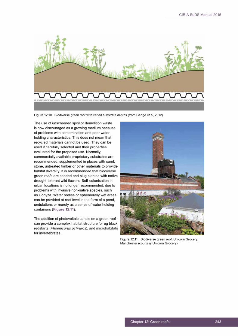
243Chapter 12: Green roofs
CIRIA SuDS Manual 2015
The use of unscreened spoil or demolition waste is now discouraged as a growing medium because of problems with contamination and poor water holding characteristics. This does not mean that recycled materials cannot be used. They can be used if carefully selected and their properties evaluated for the proposed use. Normally, commercially available proprietary substrates are recommended, supplemented in places with sand, stone, untreated timber or other materials to provide habitat diversity. It is recommended that biodiverse green roofs are seeded and plug planted with native drought-tolerantwildflowers.Self-colonisationinurban locations is no longer recommended, due to problems with invasive non-native species, such as Conyza. Water bodies or ephemerally wet areas can be provided at roof level in the form of a pond, undulations or merely as a series of water holding containers (Figure 12.11).
The addition of photovoltaic panels on a green roof can provide a complex habitat structure for eg black redstarts (Phoenicurus ochruros), and microhabitats for invertebrates.
Figure 12.10 Biodiverse green roof with varied substrate depths (from Gedge et al, 2012)
Figure 12.11 Biodiverse green roof, Unicorn Grocery, Manchester (courtesy Unicorn Grocery)
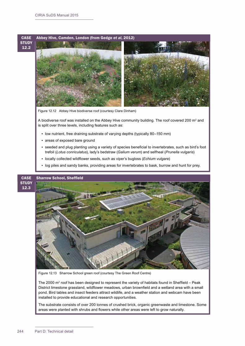
CIRIA SuDS Manual 2015
244 Part D: Technical detail
Figure 12.12 Abbey Hive biodiverse roof (courtesy Clare Dinham)
A biodiverse roof was installed on the Abbey Hive community building. The roof covered 200 m2 and is split over three levels, including features such as:
▪ lownutrient,freedrainingsubstrateofvaryingdepths(typically80–150mm)
▪ areas of exposed bare ground
▪ seededandplugplantingusingavarietyofspeciesbeneficialtoinvertebrates,suchasbird’sfoottrefoil (Lotus conriculatus), lady’s bedstraw (Galium verum) and selfheal (Prunella vulgaris)
▪ locallycollectedwildflowerseeds,suchasviper’sbugloss(Echium vulgare)
▪ log piles and sandy banks, providing areas for invertebrates to bask, burrow and hunt for prey.
Abbey Hive, Camden, London (from Gedge et al, 2012)CASE STUDY12.2
Figure 12.13 Sharrow School green roof (courtesy The Green Roof Centre)
The 2000 m2roofhasbeendesignedtorepresentthevarietyofhabitatsfoundinSheffield–PeakDistrictlimestonegrassland,wildflowermeadows,urbanbrownfieldandawetlandareawithasmallpond. Bird tables and insect feeders attract wildlife, and a weather station and webcam have been installed to provide educational and research opportunities.
The substrate consists of over 200 tonnes of crushed brick, organic greenwaste and limestone. Some areaswereplantedwithshrubsandflowerswhileotherareaswerelefttogrownaturally.
SharrowSchool,SheffieldCASE STUDY12.3

245Chapter 12: Green roofs
CIRIA SuDS Manual 2015
12.8 PHYSICAL SPECIFICATIONS
12.8.1 Fire resistance
Thefireresistanceofgreenroofsshouldbeconsidered.Allopenings,ventsetcshouldbeprotectedorsurroundedbynon-vegetativematerialssuchaspaversorpebblesorotherproprietaryfire-retardantproducts.TheroofsmusthaveadequateresistancetotheexternalspreadoffireasrequiredbyBuildingRegulation B4 (ODPM, 2002) or Regulation 12 in Scottish Government (2004). To achieve this, a risk assessment should be undertaken, considering factors such as the organic content of the substrate, the vegetationtypeandtheeffectsoftheseonthespreadoffire(Wilsonet al, 2004). German authorities onlyconsiderextensiveroofstobefireresistantif:
▪ the substrate/soil is >30 mm deep
▪ the substrate/soil contains less than 20% organic matter
▪ thereisa1mwidegravelorslabfirebreakevery40m
▪ gravel strips are provided around all structures penetrating the roof (FLL, 2002).
Detailed guidance is set out in the document DCLG (2013).
12.8.2 Insulation
No extra insulation is required for the successful establishment of a green roof, but designers often use theroofasanopportunitytoimprovethethermalefficiencyofthebuilding.Greenroofsmaybe“cold”where an air gap separates the membrane from the insulation beneath, or “warm” where insulation covers the waterproof layer.
12.8.3 Roof pitch
Toensuretheminimumfinishedfallof1in80,asrecommendedforflatroofsinBS6229:2003,fallsshouldbedesignedto1in40.Fallsshouldbeconsistentlygraded,withoutdeflectionsordepressions.
The construction effort and cost of green roofs tends to increase with roof pitch. For roofs steeper than 1 in 10, rapid runoff should be prevented by increasing the retention capacity of the system (using check damsorcellularstoragestructures).Forroofssteeperthan1in5,specificdesignadviceshouldbesought to determine appropriate steps that are required to:
▪ prevent soil slippage and erosion
▪ provide extra support with cross battens
▪ provide a raised grid structure to secure the plant growing substrate.
12.8.4 Roof support
The extra load imposed on the underpinning roof structure varies with the type of green roof, but it is typicallywithinarangeof0.7–5.0kN/m2. Intensive green roofs with trees together with an imposed “crowd” loading can impose loads of up to 10 kN/m2. The distributed load should account for a saturated soil (and snow loadings, if appropriate), and live loadings should account for maintenance staff and equipment, and visitors (if appropriate). Deeper planting beds can often be constructed over internal columns and walls where a higher overall loading capacity can be provided. The design of the supporting structure should only be undertaken by an experienced structural engineer.
Uplift pressures from wind are greatest at the corners of a roof, and these may be designated as vegetation-free zones with pavers used to prevent damage. However, green roofs are no more vulnerable tothisthreatthanconventionalroofing.Treesmayrequireshieldingfromthewindand/orshouldbeanchored. On tall buildings, higher wind speeds may increase water loss and/or damage plants through windburn, and may therefore prove a risk to the long-term survival or plant communities. Barriers (eg parapet walls) can be used to mitigate these effects.
CIRIA SuDS Manual 2015
246 Part D: Technical detail
12.8.5 Water storage and irrigation
Green roofs should be able to store water and not dry out too quickly. If this is not possible within the soil substrate, then additional forms of water storage in the base layer can be provided, or irrigation may be appropriate. Irrigation systems are generally not recommended for extensive roofs, due to the costs and operation associated with their implementation and management. However, they are often necessary for intensive roofs. If irrigation is required, base level irrigators that introduce water directly to the root zones via the drainage layer have the following advantages:
▪ Roots are encouraged to grow down into the deepest part of the soil medium where temperature and moisture conditions are most stable.
▪ A dry surface cover is maintained, thus discouraging the germination of weed seeds.
▪ Water losses due to evaporation are minimised.
However, if the system blocks, then it may need to be dug up which is likely to be costly.
More sustainable permanent irrigation systems include the use of air conditioning condensate or other readily-available non-potable supplies.
Provisionmightneedtobemadeforsupplementalirrigationduringthefirsttwogrowingseasonsafterinstallation to ensure plant survival, depending on the location and the types of plants being grown.
On blue roofs or mixed blue/green roofs, water can be stored for irrigation of the surrounding landscape by either active or passive irrigation systems.
12.8.6 Accessandsafeworking
Stairways, perimeter barriers, safe paths and in some cases lighting and lifts, all built to the relevant standards, are required if the green roof is to be used by people, whether the public or maintenance staff. Appropriate provision of safety attachment points and other features should be used to provide a safe working environment.
12.8.7 Pre-treatment and inlets
There is no requirement for pre-treatment or inlets for a green roof unless irrigation water is being applied. Standard pre-treatment/inlet requirements will need to be considered for drainage on blue roofs.
12.8.8 Outlets
All types of outlet should be designed in order to minimise the risk of blockage, which could have serious consequences. They should also be easily accessible for seasonal cleaning and in case of blockage. Detailed guidanceonthecapacityandlocationofrainwaterguttersandoutletsisgiveninBS12056-3:2000.Rainwateroutlets should accept runoff from both the drainage layer and the surface of the system.
Outlets should be separated from the growing medium, preventing the invasion of plant growth and the entry of loose gravel, as shown in Figure 12.14.Outletscanincludeflowcontrolsystemsdesignedtocontrolflowsintoroofdownpipesandthusdeliverspecificattenuationperformance.
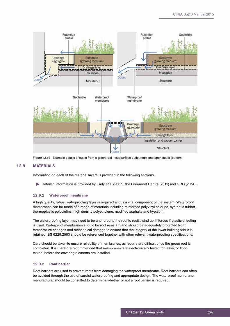
247Chapter 12: Green roofs
CIRIA SuDS Manual 2015
12.9 MATERIALS
Information on each of the material layers is provided in the following sections.
Detailed information is provided by Early et al (2007), the Greenroof Centre (2011) and GRO (2014).
12.9.1 Waterproof membrane
Ahighquality,robustwaterproofinglayerisrequiredandisavitalcomponentofthesystem.Waterproofmembranes can be made of a range of materials including reinforced polyvinyl chloride, synthetic rubber, thermoplasticpolyolefins,highdensitypolyethylene,modifiedasphaltsandhypalon.
Thewaterproofinglayermayneedtobeanchoredtotherooftoresistwindupliftforcesifplasticsheetingis used. Waterproof membranes should be root resistant and should be adequately protected from temperature changes and mechanical damage to ensure that the integrity of the lower building fabric is retained.BS6229:2003shouldbereferencedtogetherwithotherrelevantwaterproofingspecifications.
Careshouldbetakentoensurereliabilityofmembranes,asrepairsaredifficultoncethegreenroofiscompleted.Itisthereforerecommendedthatmembranesareelectronicallytestedforleaks,orfloodtested, before the covering elements are installed.
12.9.2 Root barrier
Root barriers are used to prevent roots from damaging the waterproof membrane. Root barriers can often beavoidedthroughtheuseofcarefulwaterproofingandappropriatedesign.Thewaterproofmembranemanufacturer should be consulted to determine whether or not a root barrier is required.
Figure 12.14 Example details of outlet from a green roof – subsurface outlet (top), and open outlet (bottom)
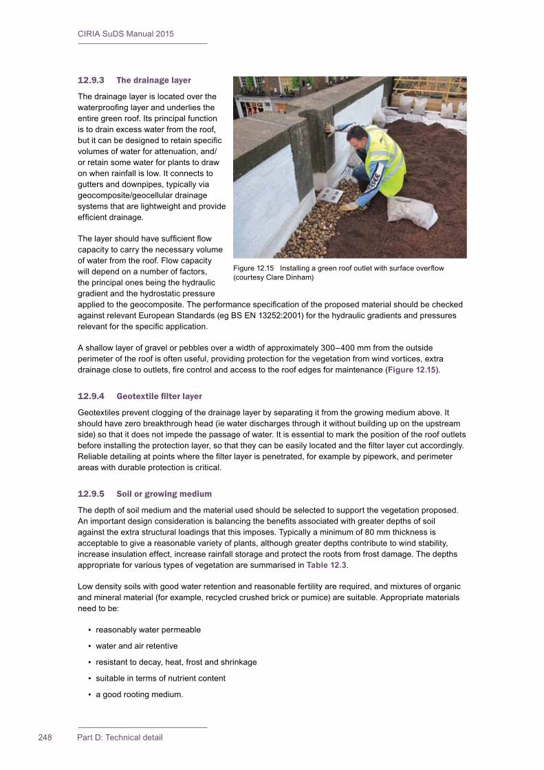
CIRIA SuDS Manual 2015
248 Part D: Technical detail
12.9.3 The drainage layer
The drainage layer is located over the waterproofinglayerandunderliestheentire green roof. Its principal function is to drain excess water from the roof, butitcanbedesignedtoretainspecificvolumes of water for attenuation, and/or retain some water for plants to draw on when rainfall is low. It connects to gutters and downpipes, typically via geocomposite/geocellular drainage systems that are lightweight and provide efficientdrainage.
Thelayershouldhavesufficientflowcapacity to carry the necessary volume of water from the roof. Flow capacity will depend on a number of factors, the principal ones being the hydraulic gradient and the hydrostatic pressure appliedtothegeocomposite.TheperformancespecificationoftheproposedmaterialshouldbecheckedagainstrelevantEuropeanStandards(egBSEN13252:2001)forthehydraulicgradientsandpressuresrelevantforthespecificapplication.
A shallow layer of gravel or pebbles over a width of approximately 300–400 mm from the outside perimeter of the roof is often useful, providing protection for the vegetation from wind vortices, extra drainageclosetooutlets,firecontrolandaccesstotheroofedgesformaintenance(Figure 12.15).
12.9.4 Geotextilefilterlayer
Geotextiles prevent clogging of the drainage layer by separating it from the growing medium above. It should have zero breakthrough head (ie water discharges through it without building up on the upstream side) so that it does not impede the passage of water. It is essential to mark the position of the roof outlets beforeinstallingtheprotectionlayer,sothattheycanbeeasilylocatedandthefilterlayercutaccordingly.Reliabledetailingatpointswherethefilterlayerispenetrated,forexamplebypipework,andperimeterareas with durable protection is critical.
12.9.5 Soilorgrowingmedium
The depth of soil medium and the material used should be selected to support the vegetation proposed. Animportantdesignconsiderationisbalancingthebenefitsassociatedwithgreaterdepthsofsoilagainst the extra structural loadings that this imposes. Typically a minimum of 80 mm thickness is acceptable to give a reasonable variety of plants, although greater depths contribute to wind stability, increase insulation effect, increase rainfall storage and protect the roots from frost damage. The depths appropriate for various types of vegetation are summarised in Table 12.3.
Low density soils with good water retention and reasonable fertility are required, and mixtures of organic and mineral material (for example, recycled crushed brick or pumice) are suitable. Appropriate materials need to be:
▪ reasonably water permeable
▪ water and air retentive
▪ resistant to decay, heat, frost and shrinkage
▪ suitable in terms of nutrient content
▪ a good rooting medium.
Figure12.15 Installingagreenroofoutletwithsurfaceoverflow(courtesy Clare Dinham)

249Chapter 12: Green roofs
CIRIA SuDS Manual 2015
Normal topsoil is too heavy and too nutrient rich for use on green roof systems and has a tendency to clogthefilterlayer.Thegrowingmediumshouldbecarefullyformulatedsothatitislightbutprovidesfor the oxygen, nutrient and moisture needed by the plants that the roof aims to support. An appropriate specificationforsoilforuseonextensiveroofsisprovidedinTable 12.3.
TABLE12.3
Greenroofsubstratespecifications(fromGRO,2014)
Reference values
Physical property Extensive Intensive
Particlesize≤0.063mm(fines) ≤15%(bymass) ≤20%(bymass)
Particle size > 4.0 mm ≤50%(bymass) ≤40%(bymass)
Maximum water holding capacity (MWHC) ≥25%≤65%(byvolume) ≥45%(byvolume)
Air content at MWHC ≥10%(byvolume) ≥10%(byvolume)
Water permeability 0.6–70 mm/min 0.3–30 mm/min
pH value 6.0–8.5 6.0–8.5
Organic content ≤65g/1 ≤90g/1
12.10 LANDSCAPE DESIGN AND PLANTING
Therooftopmicroclimateisadifficultenvironmentforplantstosurvivein,andtheadviceofalandscapearchitect or similar professional with experience of green roofs is essential. The vegetation has to deal with periodic rainfall alternating with hot and dry periods. Plants also have to contend with high winds and low winter temperatures (which is not ameliorated by the ambient heat stored in the ground).
To be able to survive, vegetation should have the following attributes:
▪ perennial or self-sowing
▪ drought tolerant, requiring little or no irrigation after establishment
▪ preference for well-drained soils
▪ rapid establishment
▪ self-sustaining, without the need for fertilisers, pesticides or herbicides
▪ ability to withstand heat, cold and high winds
▪ ability to tolerate poor soil
▪ low maintenance – needing little or no mowing or pruning
Some of these attributes may not be so relevant for intensive roofs where regular maintenance and irrigation can be provided, and where the depth of growing medium is less constrained. The choice of plants also depends on the other layers in the roof design (and vice versa) and on sun and shade conditions. In many cases there may be very good reasons to promote a wide range of plants, for example to improve water storage, improve evapotranspiration, enhance the aesthetics of the roof or encourage biodiversity. The use of a wider range of plants is dependent on other layers in the system and the accessibility or visibility of the roof. Claridge and Edwards (2012) suggest that planting a green roof with different species that have high water uptake rates under different soil moisture conditions can improve green roof performance. Suggestions for relevant plants with increasing depth of growing medium are given in Table 12.4.

CIRIA SuDS Manual 2015
250 Part D: Technical detail
Further planting guidance is provided by Early et al (2007), The Greenroof Centre and GRO (2014).
There are four basic methods of installing green roof vegetation:
▪ Pre-grown vegetation mats: These are pre-germinated mats that provide immediate full plant coverage and erosion control. These have minimal weed problems and require little maintenance, but may need some watering during the establishment period.
▪ Plugs or potted plants: Thesemayprovidemoreflexibility,butcoveragetakeslonger,anderosionmay be a risk. They will require watering and weeding during establishment.
▪ Cuttings/sprigs: These have to be hand planted, and require weeding, erosion control and watering initially.
▪ Seeds: These have to be hand or machine planted, and require weeding, erosion control and watering initially.
▪ Self-seeding: Green roofs can be left to colonise naturally.
Intensive green roofs can be landscaped and managed to suit local aesthetic and community requirements. Extensive green roofs tend to provide less conventional aesthetics. In practice, green roofs in city centres are not obvious to most passers-by, although they can be overlooked by high-rise buildings. Use of green roofs in suburban areas tend to use pitched roofs which are more visible.
12.11 CONSTRUCTION REQUIREMENTS
Advice on constructing green roofs is provided in Early et al (2007), The Greenroof Centre and GRO (2014).
TABLE12.4
Planting for green roofs (from Dunnett, 2003)
Depth of growing medium
Accessibility and visibility of roof
Inaccessible/not overlooked
Inaccessible/visible from a distance
Inaccessible/visible from a close distance
Accessible
0–50mmSimple sedum/moss communities
Simple sedum/moss communities
Simple sedum/moss communities
Simple sedum/moss communities
50–100mm
Dry meadow communities/low growing drought tolerant perennials, grasses and alpines, small bulbs
Dry meadow communities/low growing drought-tolerant perennials, grasses and alpines, small bulbs
Dry meadow communities/low growing drought-tolerant perennials, grasses and alpines, small bulbs
100–200 mm
Semi-extensive mixtures of low medium dry habitat perennials, grasses and annuals, small shrubs, lawn/turf grass
Semi-extensive mixtures of low medium dry habitat perennials, grasses and annuals, hardy shrubs
200–500mmMedium shrubs, edible plants, generalist perennials and grasses
>500mmSmall deciduous trees and conifers

251Chapter 12: Green roofs
CIRIA SuDS Manual 2015
Correct application of the waterproof membrane is essential to the viability of the green roof. Quality controlmustbeassuredthroughtheuseofcertifiedroofingproceduresandanelectronicwaterleakagetest immediately following membrane application to ensure that the surface is impermeable.
Temporary ballasting of individual components may be required during construction to prevent uplift due to wind. The growing medium should be protected from over-compaction during construction, and mulch, mat or other measures to control erosion of the growing medium should be maintained until 90% vegetation coverage is achieved. The growing medium and separation fabric should be isolated from sedimentation during construction.
Safe access is required for construction of the green roof, and also for all activities in areas beneath the roof. Ideally, the roof should be installed when no follow-on trades need access to the roof after installation, in order to reduce the risk of damage.
Further detail on construction activities and the programming of construction activities is provided in Chapter 31.
Generic health and safety guidance is presented in Chapter 36.
A construction phase health and safety plan is required under the Construction (Design and Management)Regulations(CDM)2015.Thisshouldensurethatallconstructionriskshavebeenidentifiedandeliminated/reducedand/orcontrolledwhereappropriate.
12.12 OPERATION AND MAINTENANCE REQUIREMENTS
Intensive green roofs are likely to require regular inspection and maintenance. Grassed areas may require mowing weekly or fortnightly, plant beds may require weeding on a weekly or fortnightly basis during thegrowingseason,andwildflowermeadowsmayrequireannualmowingwiththecuttingsremoved.Extensivegreenroofsshouldnormallyonlyrequirebiannualorannualvisitstoremovelitter,checkfirebreaks and drains and, in some cases, remove unwanted invasive plants. The most maintenance is generallyrequiredduringtheestablishmentstage(12to15months),andthisshouldusuallybemadetheresponsibility of the green roof provider. Maintenance contractors with specialist training in green roof care should be used, where possible.
Table 12.5 provides guidance on the type of operational and maintenance requirements that may be appropriate. The list of actions is not exhaustive and some actions may not always be required. Actual requirements will depend on the planting, the desired aesthetic and visual effect and the biodiversity objectivesforthesystem.Maintenancespecificationsandschedulesshouldthereforebespecifiedforany individual green roof.
If mechanical systems are located on the roof, then spill prevention measures should be exercised to ensure that roof runoff is not contaminated. The mechanical system area should be bunded and provided with separate drainage.
All maintenance actions carried out at roof level must be in full compliance with the appropriate health andsafetyregulations,andparticularlythosespecificallydealingwithworkingatheight.Trainingandguidance information on operating and maintaining the roof should be provided to all property owners and tenants. Safety fastenings will be required for personnel working on the roof.
Accessroutestotheroofshouldbedesignedandmaintainedtobesafeandefficient,andwalkwaysshould always be kept clear of obstructions. Secure points for harness attachments should be provided when access near to the roof edges is required.
Specificmaintenanceneedsofthegreenroofshouldbemonitoredandmaintenanceschedulesadjustedto suit requirements.
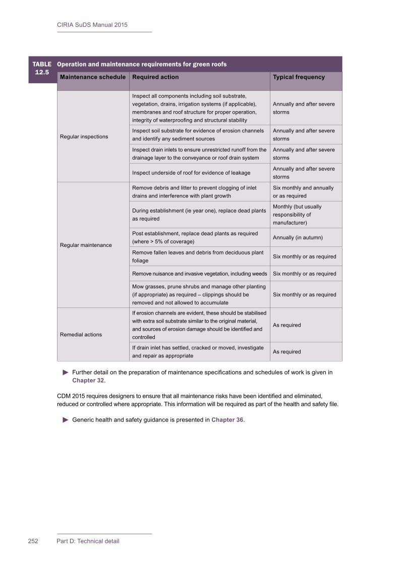
CIRIA SuDS Manual 2015
252 Part D: Technical detail
TABLE12.5
Operation and maintenance requirements for green roofs
Maintenance schedule Required action Typical frequency
Regular inspections
Inspect all components including soil substrate, vegetation, drains, irrigation systems (if applicable), membranes and roof structure for proper operation, integrityofwaterproofingandstructuralstability
Annually and after severe storms
Inspect soil substrate for evidence of erosion channels and identify any sediment sources
Annually and after severe storms
Inspect drain inlets to ensure unrestricted runoff from the drainage layer to the conveyance or roof drain system
Annually and after severe storms
Inspect underside of roof for evidence of leakageAnnually and after severe storms
Regular maintenance
Remove debris and litter to prevent clogging of inlet drains and interference with plant growth
Six monthly and annually or as required
During establishment (ie year one), replace dead plants as required
Monthly (but usually responsibility of manufacturer)
Post establishment, replace dead plants as required (where>5%ofcoverage)
Annually (in autumn)
Remove fallen leaves and debris from deciduous plant foliage
Six monthly or as required
Remove nuisance and invasive vegetation, including weeds Six monthly or as required
Mow grasses, prune shrubs and manage other planting (if appropriate) as required – clippings should be removed and not allowed to accumulate
Six monthly or as required
Remedial actions
If erosion channels are evident, these should be stabilised with extra soil substrate similar to the original material, andsourcesoferosiondamageshouldbeidentifiedandcontrolled
As required
If drain inlet has settled, cracked or moved, investigate and repair as appropriate
As required
FurtherdetailonthepreparationofmaintenancespecificationsandschedulesofworkisgiveninChapter 32.
CDM2015requiresdesignerstoensurethatallmaintenanceriskshavebeenidentifiedandeliminated,reducedorcontrolledwhereappropriate.Thisinformationwillberequiredaspartofthehealthandsafetyfile.
Generic health and safety guidance is presented in Chapter 36.

253Chapter 12: Green roofs
CIRIA SuDS Manual 2015
12.13 REFERENCES
CLARIDGE, N and EDWARDS, L (2012) Green roof technology – research, design and implementation of a green roof at the University of Canterbury,UniversityofCambridgeSustainabilityOffice,DepartmentofCivil Natural Resources Engineering, New Zealand. Go to: http://tinyurl.com/nvrsfto
DCLG (2013) Fire performance of green roofs and walls, Department of Communities and Local Government, London, UK (ISBN: 978-1-40983-997-2). Go to: http://tinyurl.com/kssv8w7
EARLY, P, GEDGE, D, NEWTON, J and WILSON, S (2007) Building Greener: Guidance on the use of green roofs, green walls and complementary features on buildings, C644, CIRIA, London (ISBN: 978-0-86017-644-2). Go to: www.ciria.org
FASSMAN-BECK, E and SIMCOCK, R (2013) Hydrology and water quality of living roofs in Auckland, University of Auckland and Landcare Research Ltd, Auckland, New Zealand. Go to: http://tinyurl.com/q34q2lv
FLL (2002) Guidelines for the planning, execution and upkeep of green roof sites, Forschungsgesellschaft Landschaftsentwicklung und Landschaftsbau e. V, Bonn, Germany. Go to: www.greenroofsouth.co.uk/FLL%20Guidelines.pdf
GEDGE, D, GRANT, G, KADAS, G and DINHAM, C (2012) Creating green roofs for invertebrates, a best practice guide, Buglife – The Invertebrate Conservation Trust, Peterborough, UK. Go to: http://tinyurl.com/n4uwolg
GRO (2014) The GRO green roof code. Green roof code of best practice for the UK 2014, The Greenroof Organisation,Sheffield,UK(ISBN:978-9-5683-781-3).Goto:http://tinyurl.com/naf6tha
GSA (2011) The benefits and challenges of green roofs on public and commercial buildings. A report of the US General Services Administration, US General Services Administration, Washington DC, USA. Go to: http://tinyurl.com/lh4yzj6
JOHNSTON, J and NEWTON, J (2004) Building Green – A guide to using plants on roofs, walls and pavements, Greater London Authority, London, UK. Go to: http://tinyurl.com/od42uv9
MARTIN, B K (2008) The dynamic response of a green roof, MA Thesis, University of Guelph, Ontario, Canada. Go to: http://tinyurl.com/p7cjtvr
ODPM (2002) The Building Regulations, Approved Document B4, External fire spread,OfficeoftheDeputyPrimeMinister,London,UK(ISBN:978-1-85946-201-0).Goto:http://tinyurl.com/yk8fhr
PAUDEL, B K (2009) “Calibration and testing of simple mass balance model for quantifying stormwater managementbenefitofanextensivegreenroof”,Electronic theses and dissertations, Paper 87, Deptartment of Civil and Environmental Engineering, University of Windsor, Windsor, UK. Go to: http://tinyurl.com/octzxut
THE GREENROOF CENTRE (2011) Green roof guide,TheGreenRoofCentre,GroundworkSheffield,andLife,Sheffield,UK.Goto:http://tinyurl.com/pulqh5l
THE SCOTTISH GOVERNMENT (2004) The Building (Scotland) Regulations 2004. Regulation 12 Structural fire precautions,TheScottishOffice,Edinburgh,Scotland. Go to: www.gov.scot/Resource/0039/00397456.pdf
STOVIN, V, VESUVIANO, G and KASMIN, H (2012) “The hydrological performance of a green roof test bed under UK climatic conditions” Journal of Hydrology,vol414–415,January2012,ElsevierBV,UK,pp148–161
WILSON, S, BRAY, R and COOPER, P (2004) Sustainable drainage systems: hydraulic, structural and water quality advice, C609, CIRIA, London, UK (ISBN: 978-0-86017-609-1). Go to: www.ciria.org

CIRIA SuDS Manual 2015
254 Part D: Technical detail
ZINCO (2011) Green roofing increases earnings from photovoltaic systems, press release, ZinCo, Nuetingen, Germany. Go to: http://tinyurl.com/og4vtkq
Statutes
BS 6229:2003 Flat roofs with continuously supported coverings. Code of practice
BSEN13252:2001Geotextiles and geotextile-related products. Characteristics required for use in drainage systems
BSEN12056-3:2000Gravity drainage systems inside buildings. Roof drainage, layout and calculation
Construction(DesignandManagement)Regulations(CDM)2015

255Chapter 12: Green roofs
CIRIA SuDS Manual 2015
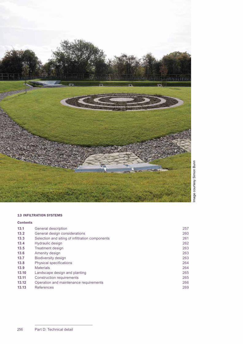
CIRIA SuDS Manual 2015
256 Part D: Technical detail
13 INFILTRATION SYSTEMS
Contents
13.1 General description 25713.2 General design considerations 26013.3 Selectionandsitingofinfiltrationcomponents 26113.4 Hydraulic design 26213.5 Treatmentdesign 26313.6 Amenitydesign 26313.7 Biodiversitydesign 26313.8 Physicalspecifications 26413.9 Materials 26413.10 Landscape design and planting 26513.11 Constructionrequirements 26513.12 Operationandmaintenancerequirements 26613.13 References 269
ImagecourtesySimonBunn

257Chapter 13: Infiltration systems
CIRIA SuDS Manual 2015
13.1 GENERAL DESCRIPTION
Therearemanydifferenttypesofdrainagecomponentthatcanbeusedtofacilitateinfiltration.Theseincludesoakaways,infiltrationtrenches,infiltrationblanketsandinfiltrationbasins.Bioretentionsystemsandperviouspavementcanalsobedesignedtoallowinfiltrationfromtheirbases(Chapters 18 and 20respectively).
Infiltrationcancontributetoreducingrunoffratesandvolumeswhilesupportingbaseflowandgroundwaterrechargeprocesses.Therateatwhichwatercanbeinfiltrateddependsontheinfiltrationcapacity(permeability)ofthesurroundingsoils.
Soakawaysareexcavationsthatarefilledwithavoid-formingmaterialthatallowsthetemporarystorageofwaterbeforeitsoaksintotheground.Historically,smallsoakawaysdrainingrunofffromasinglepropertywereeitherfilledwithrubbleorlinedwithbrickworkandweresitedbelowgardensanddriveswithnoformalprovisionforaccessandinspection.Manysmallsoakawaysarenowconstructedwithgeocellularunitsavailablefrombuilders’merchantspre-wrappedingeotextile.Thegeocellularunitsprovidegoodoverallstoragecapacitycomparedtorubblefill,andtheyallowthesizeofthestructurerequiredforanyapplicationtobeminimised.
Largersoakawaysmaybeconstructedwithperforatedprecastconcretemanholeringssurroundedwithgranularbackfillorusinggeocellularstructures(Chapter 21).Concretemanholesoakawayshavetheadvantageofaccessforinspectionandmaintenance(althoughanygravelsurroundcannotbeinspectedoreasilymaintained).Whenconsideringtheuseofgeocellularsystems,thelong-termstructuralintegrity,acceptanceforadoptionbytheSuDSsystemassetowner/operatorandtheanticipatedservicelifeoftheassetshouldbeaddressed.
Figure 13.1showsthecharacteristicsofatypicalgeocellularsoakawaywithpre-treatmentforalargersystemandFigure 13.2showsaprecastconcretesystem.AlternativeconfigurationsforgeocellularsystemsaredescribedinChapter 21.
13Chapter Infiltration systems
This chapter provides guidance on the design of infiltration systems – systems that are designed specifically to promote infiltration of surface water runoff into the ground. This includes soakaways, infiltration trenches, infiltration blankets and infiltration basins.
Guidance on the suitability of using infiltration, testing and design methods is provided in Chapter 25.
Appendix C, Section C.5.1 demonstrates how to design a residential soakaway.
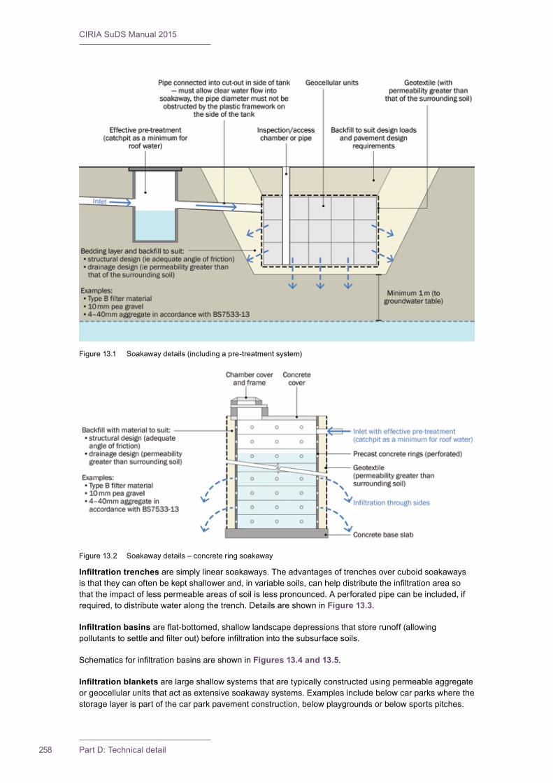
CIRIA SuDS Manual 2015
258 Part D: Technical detail
Infiltration trenchesaresimplylinearsoakaways.Theadvantagesoftrenchesovercuboidsoakawaysisthattheycanoftenbekeptshallowerand,invariablesoils,canhelpdistributetheinfiltrationareasothattheimpactoflesspermeableareasofsoilislesspronounced.Aperforatedpipecanbeincluded,ifrequired,todistributewateralongthetrench.DetailsareshowninFigure 13.3.
Infiltration basinsareflat-bottomed,shallowlandscapedepressionsthatstorerunoff(allowingpollutantstosettleandfilterout)beforeinfiltrationintothesubsurfacesoils.
SchematicsforinfiltrationbasinsareshowninFigures 13.4 and 13.5.
Infiltration blankets arelargeshallowsystemsthataretypicallyconstructedusingpermeableaggregateorgeocellularunitsthatactasextensivesoakawaysystems.Examplesincludebelowcarparkswherethestoragelayerispartofthecarparkpavementconstruction,belowplaygroundsorbelowsportspitches.
Figure13.1 Soakawaydetails(includingapre-treatmentsystem)
Figure13.2 Soakawaydetails–concreteringsoakaway
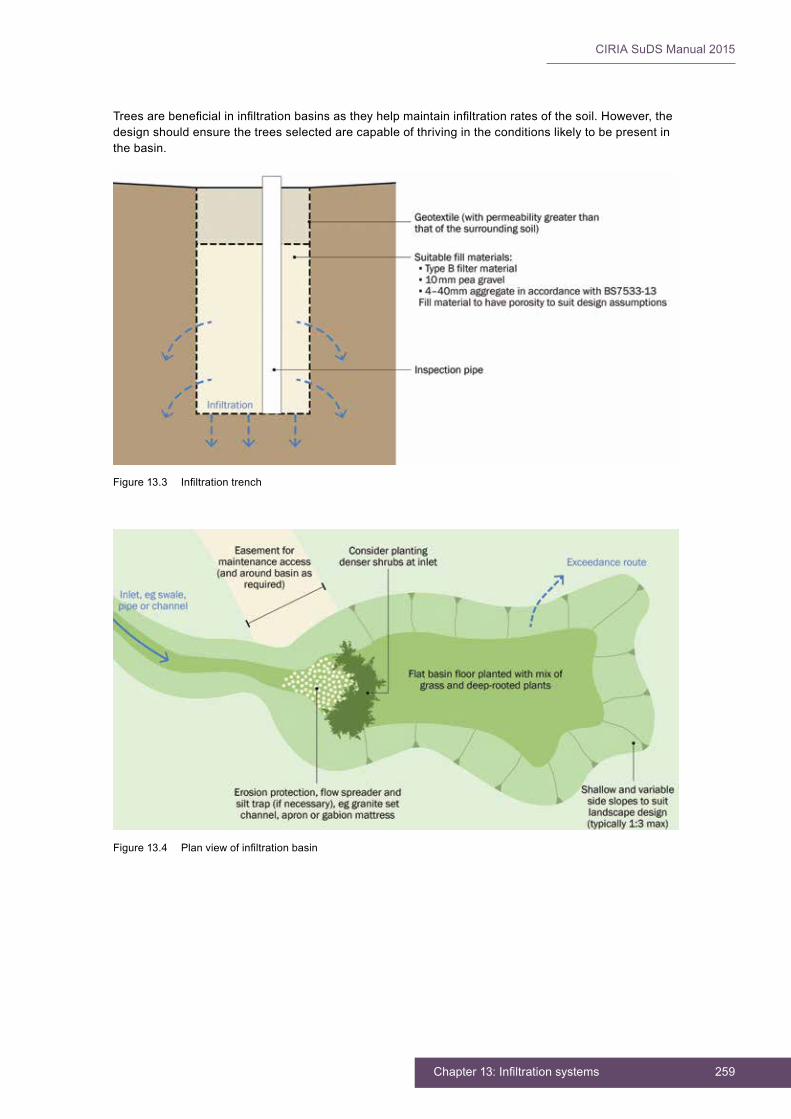
259Chapter 13: Infiltration systems
CIRIA SuDS Manual 2015
Figure13.3 Infiltrationtrench
Figure13.4 Planviewofinfiltrationbasin
Treesarebeneficialininfiltrationbasinsastheyhelpmaintaininfiltrationratesofthesoil.However,thedesignshouldensurethetreesselectedarecapableofthrivingintheconditionslikelytobepresentinthebasin.
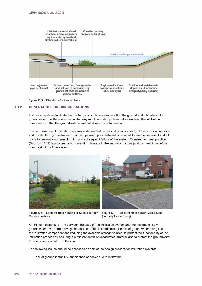
CIRIA SuDS Manual 2015
260 Part D: Technical detail
13.2 GENERAL DESIGN CONSIDERATIONS
Infiltrationsystemsfacilitatethedischargeofsurfacewaterrunofftothegroundandultimatelyintogroundwater.Itisthereforecrucialthatanyrunoffissuitablycleanbeforeenteringtheinfiltrationcomponentsothatthegroundwaterisnotputatriskofcontamination.
Theperformanceofinfiltrationsystemsisdependentontheinfiltrationcapacityofthesurroundingsoilsandthedepthtogroundwater.Effectiveupstreampre-treatmentisrequiredtoremovesedimentandsiltloadstopreventlong-termcloggingandsubsequentfailureofthesystem.Constructionbestpractice(Section 13.11)isalsocrucialtopreventingdamagetothesubsoilstructure(andpermeability)beforecommissioningofthesystem.
Aminimumdistanceof1mbetweenthebaseoftheinfiltrationsystemandthemaximumlikelygroundwaterlevelshouldalwaysbeadopted.Thisistominimisetheriskofgroundwaterrisingintotheinfiltrationcomponentandreducingtheavailablestoragevolume,toprotectthefunctionalityoftheinfiltrationprocessbyensuringasufficientdepthofunsaturatedmaterialandtoprotectthegroundwaterfromanycontaminationintherunoff.
Thefollowingissuesshouldbeassessedaspartofthedesignprocessforinfiltrationsystems:
▪ riskofgroundinstability,subsidenceorheaveduetoinfiltration
Figure13.5 Elevationofinfiltrationbasin
Figure13.6 Largeinfiltrationbasins,Ipswich(courtesyGrahamFairhurst)
Figure13.7 Smallinfiltrationbasin,Cambourne(courtesyIllmanYoung)

261Chapter 13: Infiltration systems
CIRIA SuDS Manual 2015
▪ riskofslopeinstabilityorsolifluctionduetoinfiltration
▪ riskofgroundwaterpollutionfrommobilisingexistingcontaminantsonthesite
▪ riskofpollutionfrominfiltratingpollutedsurfacewaterrunofffromthesite
▪ riskofgroundwaterfloodingduetoinfiltration
▪ riskofgroundwaterleakageintothesewers,basements,tunnelsorotherstructuresduetopromotinginfiltrationonthesite.
TheevaluationandmanagementoftheserisksisdiscussedindetailinChapter 25.Thedesignshouldensurethat,afterconstruction,theresidualriskswillbeacceptable.
Thebottomofanyinfiltrationsystemshouldbeflattoprovideuniformpondingandinfiltrationoftherunoffacrossthesurface.Thetoleranceonthebaselevelsshouldbeamaximumleveldifferenceof10mmin3m.
Thesideslopesofinfiltrationbasinsshouldnormallybenosteeperthan1in3toallowforvegetativestabilisation,mowing,accessandforpublicsafetyreasons.However,thisrequirementmayberelaxedifabasinisveryshallow(eglessthan500mmdeep).Steppedorbenchedslopesalsoofferarangeofhabitatsthatcansurvivefluctuatingwaterlevelsandwettodrysoilconditions.
Wherethetemporarystorageofwateroccursonthesurfaceinopenfeatures(ieinfiltrationbasins),thedepthsandrateofriseofthewatershouldbesufficientlylowsuchthatrisksposedbythewaterbodyareminimisedforsiteusersandoperators(takingintoaccountthetemporarynatureofthestoragefacilitywhichwillmeanthatusersarenotaccustomedtoitspresence).Ariskassessmentshouldbeundertakenofthefrequencyandrateoffloodingtoarangeofinundationdepthsinorderthatpublicsafetyisnotputatrisk(Chapter 36).Flatterslopestendtoimprovetheaesthetics,attheexpenseofextraland-take.Thereshouldalwaysbeappropriateaccesstotheinfiltrationbasinformaintenanceactivitiessuchasgrasscuttingandrehabilitationoftheinfiltrationsurface.Wheretreesareplantedinbasinstheyshouldnotpreventaccessordeterfuturemaintenance(egbecauseofrootprotectionzones).
Anyinspectionchambersshouldaimtoallowmaintenancefromthesurfacewithoutrequiringmanentry.
HealthandsafetyriskmanagementdesignguidanceispresentedinChapter 36.
13.3 SELECTION AND SITING OF INFILTRATION COMPONENTS
Soakawaysarebestsuitedtotheinfiltrationofrunofffromsmallareassuchasroofsofresidentialhousing.
Infiltrationcomponentscanoftenberetrofittedintoexistingdevelopments,todrainsmallareassuchasprivatedrivewaysandroofdrainage,providingthereissufficientoffsetfromstructures,slopesetc(Chapter 25).Onslopingsitestheymaybeabletobedesignedasaseriesofsmallerunits,ratherthanonelargesystem,thatarelocatedonplateauswithinthesite(egparkingareas).Theycanalsobeusedtomanageoverflowsfromwaterbuttsandotherrainwatercollectionsystems.Thesubsurfaceinfiltrationcomponentsrequirenonetland-take.Theycanbebuiltinmanyshapesandsizesandcanoftenbeaccommodatedwithinhigh-densityurbandevelopments.However,itisusuallynotdesirabletouse“open-access”infiltrationbasinswithinpublicopenspacethatinvolvesalotofpedestriantraffic,duetotheriskofdeteriorationoftheperformanceoftheinfiltrationsurfaceduetocompactionofthesurfacesoils.Infiltrationsystemsshouldnotnormallybeusedtodrainlandscapingorotherareaswithhighrisksofsoilerosionandloadings,duetotheriskofsedimentblockageandcloggingofthesoilssurroundingthecomponent.
ConstraintsontheuseandsitingofinfiltrationsystemsarediscussedinChapter 25.

CIRIA SuDS Manual 2015
262 Part D: Technical detail
13.4 HYDRAULIC DESIGN
13.4.1 General
Infiltrationsystemsshouldbedesignedtomanagestormsuptothedesignstandardofservicerequiredforthecontributingcatchmentarea:thiscouldbethe1:10or1:30yearstorm,orlarger.Asdischargecriteriafromadevelopmentsiteareusuallybasedona1:100yeareventplusanallowanceforclimatechange,theperformanceofinfiltrationsystemsundersuchconditionsneedstobeknown.Foreaseofdesign,andtominimisetheoccurrenceofsurfacefloodingwithinthedevelopment,thismayresultinthesoakawaysbeingdesignedtomanagethe1:100yearevent(plusclimatechangeallowance).
ThedesignofinfiltrationcomponentsshouldfollowtheadviceinChapter 25.
Theinfiltrationcomponentshoulddischargefromfulltohalf-fullwithinareasonabletimesothattheriskofitnotbeingabletomanageasubsequentrainfalleventisminimised.Wherecomponentsaredesignedtomanagethe1:10yearor1:30yearevent,itisusualtospecifythathalfemptyingoccurswithin24hours.Ifcomponentsaredesignedtoinfiltrateeventsgreaterthanthe1:30yearevent,designingtohalfemptyin24hourscanresultinverylargestoragerequirementsand,withagreementfromthedrainageapprovingbody,itmaybeappropriatetoallowlongerhalfemptyingtimes.Thisdecisionshouldbebasedonanassessmentoftheperformanceofthesystemandtheriskandconsequencesofconsecutiverainfalleventsoccurring.
The procedures outlined in Chapter 25shouldbefollowedforthehydraulicdesignofinfiltrationcomponents.
13.4.2 Interception design
InfiltrationcanplayanimportantroleinprovidingInterception–thecaptureandretentionofthefirst5mmofanyrainfallevent,evenonsiteswithlowinfiltrationrates.
Further guidance on Interception is provided in Section 24.8.
13.4.3 Peak flow control design
Infiltrationreducesrequiredattenuationstoragevolumes.Theextentofthisreductionforanyreturnperiodwillbedependentonthedesignstandardofservice,thevolumeofstorageprovidedandtheinfiltrationcapacityofthesurroundingsoils.
Guidance on designing for attenuation storage is provided in Section 24.9.
13.4.4 Volume control design
Infiltrationreducesthevolumeofrunoff.Theextentofthisreductionforanyreturnperiodwillbedependentonthedesignstandardofserviceandtheinfiltrationcapacityofthesurroundingsoils.
13.4.5 Exceedance flow design
Infiltrationcomponentsshouldbedesignedsothatexceedanceflowsaremanagedeffectively.Anexceedanceflowrouteortemporarystoragearea(eganopenspaceorexternalarea)willberequiredforrainfalleventsthatexceedthedesigncapacityoftheinfiltrationsystem.Thiscanbeachievedbyinstallinganoverflowpipeabovethedesignwaterstorageleveloftheinfiltrationsystemsandconveyingrunoffflowsdownstreamorbyeffectivemanagementofvolumesofwaterthatsurchargethesystem.
Guidance on exceedance design is provided in Section 24.12.
263Chapter 13: Infiltration systems
CIRIA SuDS Manual 2015
13.5 TREATMENT DESIGN
Theacceptabilityofinfiltrationdesign,fromagroundwaterprotectionperspective,willdependontheextentofthelikelyrunoffcontaminationandsiteandgroundcharacteristics.Anevaluationshouldbeundertakenusingthewaterqualityriskassessment(Section 26.7).Adepthofatleast1mofunsaturatedsoilsthatarenotcleangravelsorsimilarwithhighpermeabilities,and/orarenotfractureddepositswithrapidflowroutes(preferablywithsomeorganicandclaycontent)areknowntoprovidegoodprotectiontounderlyinggroundwater.
Sedimentationtendstooccurwithinthetemporarystoragearea–andanallowanceshouldalwaysbemadeforthisor,preferably,upstreamSuDScomponentsputinplacetoremovesedimentbeforeenteringthecomponent.
Thedeeperaninfiltrationsystemis,thegreatertheriskofbypassingtheprotectiveuppersoillayersanddecreasingthedistancetothewatertable.Thiscanleadtoanincreasedriskofgroundwaterpollution.Inthisrespectshallowanddispersedsystemsareusuallybest.Geotextilelayerscanbeusedwithininfiltrationcomponentsforadditionaltrappingofsurfacewaterrunoffparticulatesandhydrocarbons.
Section 26.6.3setsoutthekeyprocessesthathavebeenfoundtobeimportantforgroundwaterprotectionfromurbanrunoff.
13.6 AMENITY DESIGN
Soakawaysandtrenchesdonotusuallyhaveanyinherentamenityvalue,butsubsurfacesystemscanpromotethemulti-functionaluseofspacebyallowingtheoverlyingsurfacetobeusedforrecreationorotheramenityfacilities.
Theuseofinfiltrationbasinsasamenityfeaturesneedstobebalancedagainsttheincreasedmaintenancerequirementsthiscancause.Ifthebasinispurelyaestheticorbiodiverseandisnotusedasanactiveorpassiverecreationspacethenthereisnorealincreaseinmaintenance.Ifthesurfaceisgoingtobeusedbypedestriansorusedforplayinginformalsports,thiscancausethesurfacetobecomecompactedandrequiremorefrequentmaintenancetomaintaintheinfiltrationcapacity.Engineeredsoilsonthesurfacearelesslikelytobeadverselyaffectedandloseinfiltrationcapacity.Plantingtreesandshrubsratherthanjustgrass,andmulchingthesurfacelayerswillalsohelpmaintaintheinfiltrationrates(althoughthepresenceoftreesshouldnotimpedefuturemaintenance–Section 13.2).
Basinsshouldbedesignedwithshallowside-slopesandbenching,whichwillhelpmitigatesafetyrisksandalsoprovideforbiodiversityandhabitatcreation.Theformandaestheticappearanceofthefacilitywilldependonspecificsitecharacteristics,localpublicconcerns,anddevelopmentdesigncriteria.Fencingisgenerallynotdesirableasitmayreducetheamenitybenefitsprovidedbytheinfiltrationfacility,provideabarriertoeasymaintenanceandprovideatrapwherelitteranddeadvegetativematerialcouldcollect.Wherefencesarerequired,theyshouldbelow(toddler-proof),butfacilitatemovementofwildlife.
MoreinformationabouttheneedforfencesaroundSuDSisprovidedontheSusdrainwebsite: www.susdrain.org and in Chapter 36.
CommunityengagementisdiscussedinChapter 34.
LandscapeandplantingbestpracticeispresentedinChapter 29.
13.7 BIODIVERSITY DESIGN
Theecologicalvalueofthesystemcanbeenhancedbydiversifyingtheplanting(egincludingtrees,woodyshrubs,wildflowermixes–Chapters 6 and 29)orbyincludingbioretentionareaswithinthedesign.

CIRIA SuDS Manual 2015
264 Part D: Technical detail
13.8 PHYSICAL SPECIFICATIONS
Forsoakaways,thevoidshould(whererequired)beseparatedfromthesurroundingsoilusingasuitablegeotextile.Thiswillsupportthesoilaroundthesoakawayandpreventtheingressofbackfillmaterialintothetopofthesoakawayduringandaftersurfacereinstatement.Characteristicsofthegeotextileshouldsuitthesurroundingsoilparticlesizeandpermeability.
GuidanceonsuitablegeotextilespecificationsisgiveninSection 30.5.
Soakawaysshouldbeofsufficientstrengthtocaterfortheloadsactingonthemduringconstructionandduringtheirservicelife,especiallywheretheyarerequiredtobetrafficbearing.Thelong-termstrengthofmaterialsshouldbecarefullyconsidered.ThedesignandspecificationofgeocellularsoakawaysshouldfollowtheguidanceinChapter 21regardingstructuraldesignandmaterialspecification.Precastconcretemanholesshouldbesubjecttothenormalstructuraldesign/specificationforconcretedrainagestructures.
13.8.1 Pre-treatment and inlets
Infiltrationcomponentscanbesusceptibletohighfailureratesduetocloggingfromsedimentsandthereforerequireeffectivepre-treatmenttoremoveasmuchofboththesuspendedsolidsandfinesiltsfromtherunoffaspossible,beforetheyenterthesystem.Siltthatcausescloggingofinfiltrationsystemsismainly<6mmdiameterwhichisverysmall(Siriwardeneet al,2007).Designsshouldideallyincorporate“multiplepre-treatment”,usingpracticessuchasswales,sedimentbasinsandfilterstripsinseriesupstreamoftheinfiltrationbasintominimisetherisks.However,oftenthisisnotpracticalandforasmallsoakawayservingaroof,asmallcatchpitmaybetheonlypre-treatmentthatcaneffectivelybeprovided.
Aninfiltrationcomponentcanbedesignedofflinetoprovidevolumecontrolinlargerevents.Thismeansthatlowflowsdonotenterthesystem(whichminimisestheriskofclogging,butmeansthecomponentcannotdeliverInterceptionforthecontributingcatchment).
Inletchannelstoinfiltrationbasinsshouldbestabilisedusingappropriateerosioncontrol,suchasrip-rap,althoughinawell-designedsystem,flowswillbelowanderosionprotectionrequirementsshouldbeminimal.Alevelspreadershouldalsobeprovidedattheinlettothebasinfromthepre-treatmentsystemtopromoteshallowsheetflowintothebasin,whichwillmaximisepollutantremovalopportunities,andreducetherisksoferosion.
13.8.2 Outlets
Overflowofexcesssurfacewaterrunoffcanbeviaapipedoutletoroverfloworfromthetopofthesoakaway,ifconsideredappropriate,oraweiroverflowfromabasin.Theoverflowshouldnotimpedeaccesstoanyinlet/outlet/controlstructurethatmanagesmorefrequentflows.
13.9 MATERIALS
Thematerialsusedininfiltrationcomponentsaremainlyaggregate,geotextilesandengineeredsoilssuchasrootzoneoramendedsoilsforsimplebioretentionsystems.
Topsoilsorengineeredsoilsusedininfiltrationbasinsshouldbesufficientlypermeable.Theminimumpermeabilityassumedinthedesignshouldbestated,andthematerialshouldbetestedafterithasbeenplacedinaccordancewiththemethoddescribedforbioretentionsoilsinChapter 18.
FurtherinformationonengineeredsoilsandfiltermediaisprovidedinChapters 30 and 18.
265Chapter 13: Infiltration systems
CIRIA SuDS Manual 2015
13.10 LANDSCAPE DESIGN AND PLANTING
Infiltrationbasinsaretypicallygrassedstructures,butsomeadditionalvegetationcanenhancetheappearanceofthebasin,stabilisesideslopesandpreventerosion,andserveaswildlifehabitat.Plantingshouldbedesignedtosuitthespecificanticipatedsiteconditionswhichwillvaryfromwettodryconditions.Nativeplantsandvegetationmaybepreferableandmorehardytosurviveexpectedfluctuationsinsoilwaterlevels.
Vegetationalsoincreasestheeffectivenessofinfiltrationbyslowingtheflowsacrossthebasinandbymaintainingorenhancingtheporespaceintheunderlyingsoilsviadeeperrootingsystems.Densevegetationsuchasshrubsandmulchingwillalsominimisetheriskofcloggingofsurfacesoils(EmersonandTraver,2008).
Anyplantinginaninfiltrationbasinshouldbeabletowithstandperiodsofpondingandlengthydryperiods.Inordertoreducemaintenancerequirementsandincreaseaestheticandbiodiversityvalue,plantingwithwildflowermeadowmixescanbeconsidered(Chapter 29).
Infiltrationcomponentscanattracttherootsofplantsgrowingintheirvicinity–particularlyiftheplantsdonothaveaseparatesupplyofwater.Thisis,toacertainextent,anadvantageasplantrootstakeupextrawaterfromthesystemandrootsprovideextraopeningsinthesurroundingsoilforwatertoinfiltrate.However,toovigorousrootintrusionintosubsurfacesystems,especiallyfromlargershrubsandtrees,shouldbekeptincheckasitcanfillasignificantpercentageofthevoidspacerequiredforrunoffattenuationandcanalsocausestructuraldamage.
Fertilisingandtheapplicationofherbicidestoaninfiltrationsystemshouldbeavoidedtominimisetheriskofpollutantsandnutrientsenteringthegroundwater.
LandscapedesignandplantingbestpracticeispresentedindetailinChapter 29.
13.11 CONSTRUCTION REQUIREMENTS
Manyreportedfailuresofinfiltrationsystemscanbeattributedtopoordesign,inappropriatesoilsandcarelessconstruction.Theconstructionprocessthereforeneedscarefulplanningandimplementationtoensurethatitdoesnotadverselyaffecttheinfiltrationperformanceofthesystems.
FurtherdetailonconstructionactivitiesandtheprogrammingofconstructionactivitiesisprovidedinChapter 31.
Generic health and safety guidance is presented in Chapter 36.
AconstructionphasehealthandsafetyplanisrequiredundertheConstruction(DesignandManagement)Regulations(CDM)2015.Thisshouldensurethatallconstructionriskshavebeenidentifiedandeliminated/reducedand/orcontrolledwhereappropriate.
13.11.1 Soakaways, trenches and blankets
Soakaways,trenchesandblanketsshouldnotbeusedforuntreateddrainagefromconstructionsites,whererunoffislikelytocontainsilt,debrisandotherpollutants.
Perforated,precastconcreteringsoakawaysshouldbeinstalledwithinasquarepit,withsidedimensionsabouttwicetheselectedringdiameter.Theneedtooversizethesoakawaypitforthepurposesofconstructingtheringunitchambermaybeusedtoadvantagebyincorporatingthetotalexcavationvolumebelowthedischargeinvertinthedesignstoragevolume(BRE,1991).ExcavationsshouldbebackfilledwithasuitablepermeableaggregatematerialsuchasTypeBfiltermaterial,peagravelor4/40aggregateinaccordancewithBS7533-13:2009)–seeChapter 20 and Chapter 30.

CIRIA SuDS Manual 2015
266 Part D: Technical detail
Somenormallyhighlypermeablesoilsandsoftrocks(egchalk)canhavetheirpermeabilitysignificantlyreducedby“smearing”ofthesurfaceduringexcavation,especiallybymechanicaldiggers.Itisrecommendedthattheexposedsurfaceofthesoilismanuallycleanedofanysmearingbeforethegeotextileandgranularfillsurroundinganyinfiltrationsystemareinstalled.
13.11.2 Infiltration basins
Wherepossible,constructionofinfiltrationbasinsshouldtakeplaceafterthesitehasbeenstabilised,inordertominimisetheriskofprematuresystemfailureduetohighsedimentloadingsinrunofffromdisturbedground.Ifthisisnotpossible,theninitialexcavationshouldbecarriedouttowithin450mmofthebasinfloor,andfinalexcavationshouldbedelayeduntilaftersitestabilisation.Itisessentialthatinfiltrationbasinsshouldnotbeusedtomanageconstructionrunoffandtrapconstructionsediments.
Topsoilshouldnotbelaidinbasinswhenthegroundorthetopsoilissaturated.Thismaybeaconstrainttotheuseofinfiltrationbasinsiftheconstructionprogrammeisparticularlytight.
Allexcavationandlevellingshouldbeperformedbyequipmentwithtracksthatexertverylightpressures,topreventcompactionofthebasinfloor,whichmayreduceinfiltrationcapacity.Beforeandafterconstruction,othervehicularmovementsshouldbeprevented.
Thebaseofthebasinshouldbecarefullypreparedtoanevengradewithnosignificantundulations.Thesurfacesoilswithinthebasinshouldnotbesmearedorcompactedduringconstruction.Afterfinalgrading,thebasinfloorshouldbetilledtoadepthof150mmtoprovideawell-aerated,poroussurfacetexture.
Backfillingagainstinletandoutletstructuresneedstobecontrolledtominimisesettlementanderosion.Thetopsoilsusedtofinishthesideslopesneedtobesuitablyfertile,porousandofsufficientdepthtoensurehealthyvegetationgrowth.
Immediatelyfollowingbasinconstruction,thebaseandsideslopesshouldbestabilisedwithadensecoverageofwater-tolerantgrass.
13.12 OPERATION AND MAINTENANCE REQUIREMENTS
Infiltrationsystemswillrequireregularmaintenancetoensurecontinuingoperationtodesignperformancestandards,andalldesignersshouldprovidedetailedspecificationsandfrequenciesfortherequiredmaintenanceactivitiesalongwithlikelymachineryrequirementsandtypicalannualcosts–withintheMaintenancePlan.Differentdesignswillhavedifferentoperationandmaintenancerequirements,andthissectiongivessomegenericguidancefordifferentsystemtypes.
13.12.1 Soakaways, trenches and blankets
Thedesignofsoakaways,infiltrationtrenchesandblanketsshouldincludemonitoringpointswherethewaterlevelinthesystemcanbeobservedormeasured.Thiscaneitherbeviaaninspectionwellorinspectioncover(wheretheattenuationstoragespaceisavoid).Forlargerinstallationstheinspectionaccessshouldprovideaclearviewoftheinfiltrationsurface(evenifthestoragezoneisfilled).Forsmall,filledsoakaways,a50mmperforatedpipeisadequate.
Theusefullifeandeffectiveoperationofaninfiltrationcomponentisrelatedtothefrequencyofmaintenanceandtheriskofsedimentbeingintroducedintothesystem.
Aneasementshouldbeconsideredwheremultiplepropertiesdischargetoasinglesoakaway,toensurelong-termaccessformaintenancepurposes.
Table 13.1 providesguidanceonthetypeofoperationalandmaintenancerequirementsthatmaybeappropriateforsoakaways.Thelistofactionsisnotexhaustiveandsomeactionsmaynotalwaysberequired.
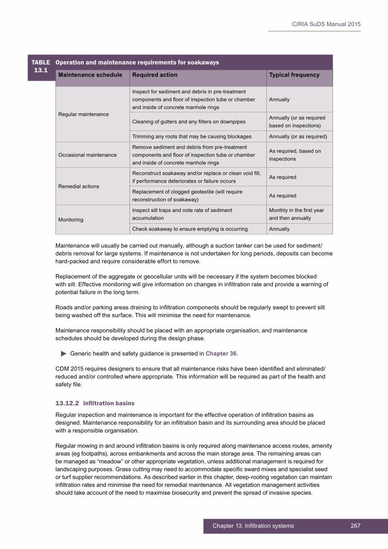
267Chapter 13: Infiltration systems
CIRIA SuDS Manual 2015
Maintenancewillusuallybecarriedoutmanually,althoughasuctiontankercanbeusedforsediment/debrisremovalforlargesystems.Ifmaintenanceisnotundertakenforlongperiods,depositscanbecomehard-packedandrequireconsiderableefforttoremove.
Replacementoftheaggregateorgeocellularunitswillbenecessaryifthesystembecomesblockedwithsilt.Effectivemonitoringwillgiveinformationonchangesininfiltrationrateandprovideawarningofpotentialfailureinthelongterm.
Roadsand/orparkingareasdrainingtoinfiltrationcomponentsshouldberegularlyswepttopreventsiltbeingwashedoffthesurface.Thiswillminimisetheneedformaintenance.
Maintenanceresponsibilityshouldbeplacedwithanappropriateorganisation,andmaintenanceschedulesshouldbedevelopedduringthedesignphase.
Generic health and safety guidance is presented in Chapter 36.
CDM2015requiresdesignerstoensurethatallmaintenanceriskshavebeenidentifiedandeliminated/reducedand/orcontrolledwhereappropriate.Thisinformationwillberequiredaspartofthehealthandsafetyfile.
13.12.2 Infiltration basins
Regularinspectionandmaintenanceisimportantfortheeffectiveoperationofinfiltrationbasinsasdesigned.Maintenanceresponsibilityforaninfiltrationbasinanditssurroundingareashouldbeplacedwitharesponsibleorganisation.
Regularmowinginandaroundinfiltrationbasinsisonlyrequiredalongmaintenanceaccessroutes,amenityareas(egfootpaths),acrossembankmentsandacrossthemainstoragearea.Theremainingareascanbemanagedas“meadow”orotherappropriatevegetation,unlessadditionalmanagementisrequiredforlandscapingpurposes.Grasscuttingmayneedtoaccommodatespecificswardmixesandspecialistseedorturfsupplierrecommendations.Asdescribedearlierinthischapter,deep-rootingvegetationcanmaintaininfiltrationratesandminimisetheneedforremedialmaintenance.Allvegetationmanagementactivitiesshouldtakeaccountoftheneedtomaximisebiosecurityandpreventthespreadofinvasivespecies.
TABLE13.1
Operation and maintenance requirements for soakaways
Maintenance schedule Required action Typical frequency
Regularmaintenance
Inspectforsedimentanddebrisinpre-treatmentcomponentsandfloorofinspectiontubeorchamberandinsideofconcretemanholerings
Annually
CleaningofguttersandanyfiltersondownpipesAnnually(orasrequiredbasedoninspections)
Trimminganyrootsthatmaybecausingblockages Annually(orasrequired)
OccasionalmaintenanceRemovesedimentanddebrisfrompre-treatmentcomponentsandfloorofinspectiontubeorchamberandinsideofconcretemanholerings
Asrequired,basedoninspections
Remedialactions
Reconstructsoakawayand/orreplaceorcleanvoidfill,ifperformancedeterioratesorfailureoccurs
As required
Replacementofcloggedgeotextile(willrequirereconstructionofsoakaway)
As required
Monitoring
Inspectsilttrapsandnoterateofsedimentaccumulation
Monthlyinthefirstyearand then annually
Checksoakawaytoensureemptyingisoccurring Annually

CIRIA SuDS Manual 2015
268 Part D: Technical detail
Adequateaccessshouldbeprovidedtotheinfiltrationbasinforinspectionandmaintenance,includingforappropriateequipmentandvehiclessuchasmowingequipment.Table 13.2 provides guidance on the typeofoperationalandmaintenancerequirementsthatmaybeappropriateforinfiltrationbasins.Thelistofactionsisnotexhaustiveandsomeactionsmaynotalwaysberequired.
TABLE13.2
Operation and maintenance requirements for infiltration basins
Maintenance schedule Required action Typical frequency
Regularmaintenance
Removelitter,debrisandtrash Monthly
Cutgrass–forlandscapedareasandaccessroutesMonthly(duringgrowingseason) or as required
Cutgrass–meadowgrassinandaroundbasinHalfyearly:spring(beforenestingseason)andautumn
ManageothervegetationandremovenuisanceplantsMonthlyatstart,thenasrequired
Occasionalmaintenance
Reseedareasofpoorvegetationgrowth Annually,orasrequired
Pruneandtrimtreesandremovecuttings As required
Removesedimentfrompre-treatmentsystemwhen50% full
As required
Remedialactions
Repairerosionorotherdamagebyreseedingorre-turfing
As required
Realigntherip-rap As required
Repairorrehabilitateinlets,outletsandoverflows As required
Rehabilitateinfiltrationsurfaceusingscarifyingandspikingtechniquesifperformancedeteriorates
As required
Relevel uneven surfaces and reinstate design levels As required
Monitoring
Inspectinlets,outletsandoverflowsforblockages,and clear if required
Monthly
Inspectbanksides,structures,pipeworketcforevidenceofphysicaldamage
Monthly
Inspectinletsandpre-treatmentsystemsforsiltaccumulation;establishappropriatesiltremovalfrequencies
Half yearly
Inspectinfiltrationsurfacesforcompactionandponding
Monthly
Accumulatedsedimentsonthesurfaceofinfiltrationsystemshavebeenshownnottoposeahazardtohumanhealth,wherepeopleareusingthebasinasanopenspace(ScottWilson,2010).However,ScottWilson(2010)showsthattheaccumulatedmaterialexceededthetotalorganiccarbon(TOC)criteriaforhazardouswaste,andtheaccumulatedsedimentwouldrequirewastepre-treatmenttolowertheorganiccontentbeforeoff-sitedisposal(othercontaminantlevelswerewellbelowhazardouswastecriteria).Compostingorwindrowingmightachievethis.Excavatedsedimentfrominfiltrationbasinsorpre-treatmentcomponentthatreceiverunofffromresidentialorstandardroadandroofareasaregenerallynottoxicandcanthereforebesafelydisposedofbyeitherlandapplicationoroff-sitedisposal.However,consultationshouldtakeplacewiththeenvironmentalregulatortoconfirmappropriateprotocols.Sedimenttestingmayberequiredbeforesedimentexcavation,todetermineitsclassificationandappropriatedisposalmethods.Forindustrialsiterunoff,sedimenttestingwillbeessential.Inthemajorityofcases,itwillbeacceptabletodistributethesedimentonsiteifthereisanappropriatesafeandacceptablelocationtodoso.

269Chapter 13: Infiltration systems
CIRIA SuDS Manual 2015
FurtherinformationonwastemanagementisprovidedinChapter 33.
MaintenancePlansandschedulesshouldbedevelopedbeforemaintenancecontractsarecommissioned.Specificmaintenanceneedsofthebasinshouldbemonitored,andmaintenanceschedulesadjustedtosuitrequirements.
CDM2015requiresdesignerstoensurethatallmaintenanceriskshavebeenidentified,eliminated,reducedand/orcontrolledwhereappropriate.Thisinformationwillberequiredaspartofthehealthandsafetyfile.
Generic health and safety guidance is presented in Chapter 36.
Providedpreventivemaintenancemeasuresareconscientiouslyundertaken,theneedforcorrectivemaintenanceshouldrarelyarise.
AdditionaldetailonthepreparationofmaintenancespecificationsandschedulesofworkisgiveninChapter 32.
13.13 REFERENCES
BRE(1991)Soakaway design,BREDigest365,BuildingResearchEstablishment,Bracknell,UK(ISBN:0-85125-502-7)
EMERSON,CHandTRAVER,RG(2008)“Multi-yearandseasonalvariationofinfiltrationfromstormwaterbestmanagementpractices”Journal of irrigation and drainage engineering,vol134,specialissueUrban Storm-Water Management,AmericanSocietyofCivilEngineers,Reston,VA,USA,pp598–605
SCOTTWILSON(2010)Fate of highway contaminants in the unsaturated zone, final synthesis report,HighwaysConsultancyGroup,HighwaysAgency,London,UK(unpublished)
SIRIWARDENE,NR,DELETIC,AandFLETCHER,TD(2007)“Cloggingofstormwatergravelinfiltrationsystemsandfilters:Insightsfromalaboratorystudy”Water Research,vol41,7,NationalCenterforBiotechnologyInformation,USNationalLibraryofMedicine,MD,USA,pp1433–1440
Statutes
BS7533-13:2009Pavement constructed with clay, natural stone or concrete pavers. Guide for the design of permeable pavements constructed with concrete paving blocks and flags, natural stone slabs and setts and clay pavers
Construction(DesignandManagement)Regulations2015
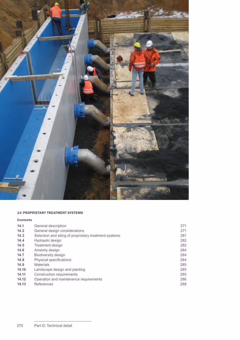
CIRIA SuDS Manual 2015
270 Part D: Technical detail
14 PROPRIETARY TREATMENT SYSTEMS
Contents
14.1 General description 27114.2 General design considerations 27114.3 Selection and siting of proprietary treatment systems 28114.4 Hydraulic design 28214.5 Treatment design 28214.6 Amenity design 28414.7 Biodiversity design 28414.8 Physicalspecifications 28414.9 Materials 28514.10 Landscape design and planting 28514.11 Construction requirements 28514.12 Operation and maintenance requirements 28614.13 References 288
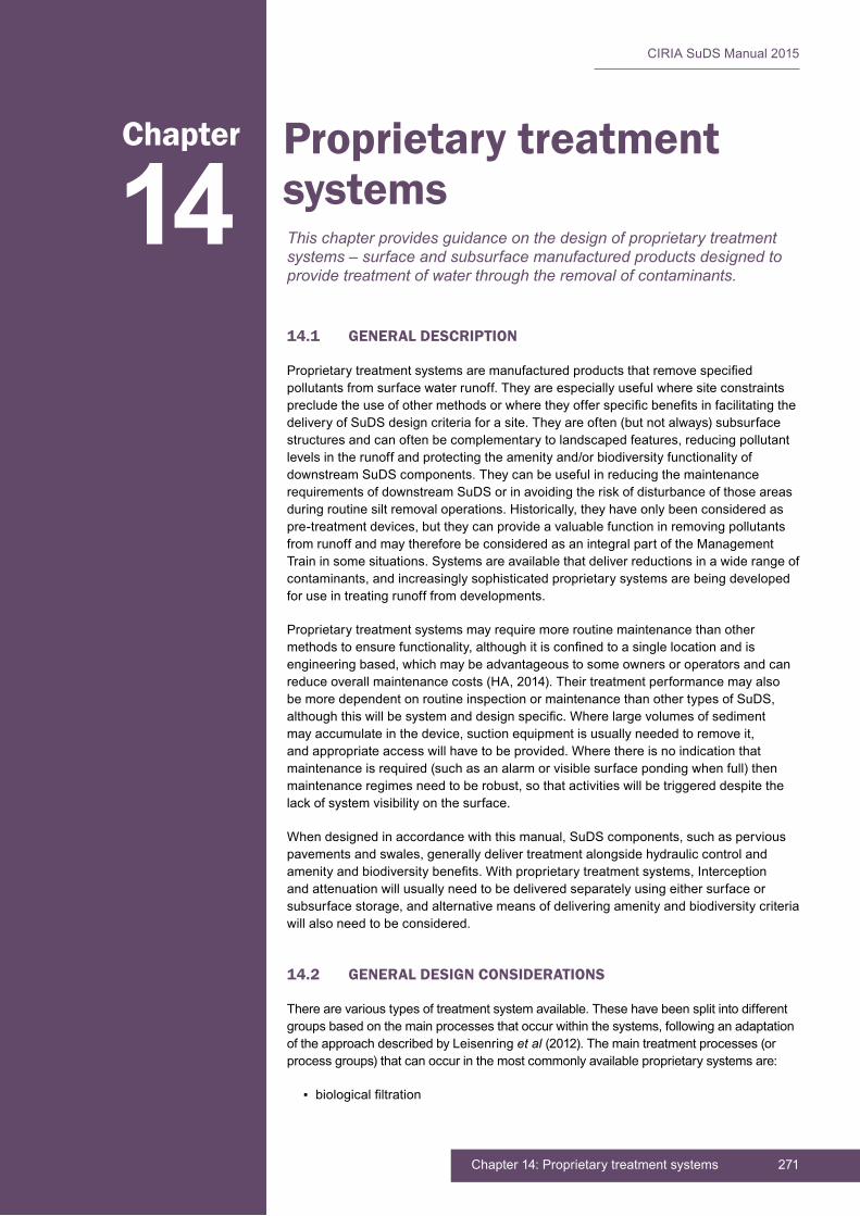
271Chapter 14: Proprietary treatment systems
CIRIA SuDS Manual 2015
14.1 GENERAL DESCRIPTION
Proprietarytreatmentsystemsaremanufacturedproductsthatremovespecifiedpollutants from surface water runoff. They are especially useful where site constraints precludetheuseofothermethodsorwheretheyofferspecificbenefitsinfacilitatingthedeliveryofSuDSdesigncriteriaforasite.Theyareoften(butnotalways)subsurfacestructuresandcanoftenbecomplementarytolandscapedfeatures,reducingpollutantlevelsintherunoffandprotectingtheamenityand/orbiodiversityfunctionalityofdownstreamSuDScomponents.TheycanbeusefulinreducingthemaintenancerequirementsofdownstreamSuDSorinavoidingtheriskofdisturbanceofthoseareasduringroutinesiltremovaloperations.Historically,theyhaveonlybeenconsideredaspre-treatmentdevices,buttheycanprovideavaluablefunctioninremovingpollutantsfromrunoffandmaythereforebeconsideredasanintegralpartoftheManagementTraininsomesituations.Systemsareavailablethatdeliverreductionsinawiderangeofcontaminants,andincreasinglysophisticatedproprietarysystemsarebeingdevelopedfor use in treating runoff from developments.
Proprietary treatment systems may require more routine maintenance than other methodstoensurefunctionality,althoughitisconfinedtoasinglelocationandisengineeringbased,whichmaybeadvantageoustosomeownersoroperatorsandcanreduceoverallmaintenancecosts(HA,2014).TheirtreatmentperformancemayalsobemoredependentonroutineinspectionormaintenancethanothertypesofSuDS,althoughthiswillbesystemanddesignspecific.Wherelargevolumesofsedimentmayaccumulateinthedevice,suctionequipmentisusuallyneededtoremoveit,andappropriateaccesswillhavetobeprovided.Wherethereisnoindicationthatmaintenanceisrequired(suchasanalarmorvisiblesurfacepondingwhenfull)thenmaintenanceregimesneedtoberobust,sothatactivitieswillbetriggereddespitethelackofsystemvisibilityonthesurface.
Whendesignedinaccordancewiththismanual,SuDScomponents,suchasperviouspavementsandswales,generallydelivertreatmentalongsidehydrauliccontrolandamenityandbiodiversitybenefits.Withproprietarytreatmentsystems,Interceptionandattenuationwillusuallyneedtobedeliveredseparatelyusingeithersurfaceorsubsurfacestorage,andalternativemeansofdeliveringamenityandbiodiversitycriteriawillalsoneedtobeconsidered.
14.2 GENERAL DESIGN CONSIDERATIONS
Therearevarioustypesoftreatmentsystemavailable.Thesehavebeensplitintodifferentgroupsbasedonthemainprocessesthatoccurwithinthesystems,followinganadaptationoftheapproachdescribedbyLeisenringet al (2012).Themaintreatmentprocesses(orprocessgroups)thatcanoccurinthemostcommonlyavailableproprietarysystemsare:
▪ biologicalfiltration
14Chapter Proprietary treatment
systemsThis chapter provides guidance on the design of proprietary treatment systems – surface and subsurface manufactured products designed to provide treatment of water through the removal of contaminants.

CIRIA SuDS Manual 2015
272 Part D: Technical detail
▪ filtration
▪ filtrationandadsorption
▪ physical removal of sediment
▪ physicalremovaloffloatables
▪ wetting and drying to promote degradation.
Thevarioustypesofsystem,togetherwiththemaintreatmentprocesses,aresetoutinTable 14.1.
Health and safety risk management design guidance is presented in Chapter 36.
TABLE14.1
Proprietary systems classified on basis of main treatment process
Proprietary systems Description Treatment processes Leisenring (2012) classification
Proprietarybioretentionsystems in concrete (or othermaterial)structures
Filtration devices that use soils (orotherfiltermedia)andwhichsupportplantsorbacterialbiofilms
Filtration,adsorption,bioremediation
Biologicalfiltration
Treatment channels
Channels that are designed to collect and treat water rather than convey it along the channel; can includeproprietaryfiltermediawithin the channel; can include weirandbafflesatintervalstotrapoilsandfloatables
Physical removal of sediment,oilsandfloatables;wettingand drying to promote degradation
Does not include test results for this type of system (note that there are examples in Europe that are certifiedbyDiBTinGermany)
Hydrodynamic or vortex separators
Structures that use gravity and centrifugal force to separate out and collect medium-sized (63 to 250 mm)sedimentsandotherlitterordebris;smallerparticlesmaybeabletoberemovedbyvaryingtheflowrateintothesystem
Physical removal of sedimentbygravity
Manufactured device – physical
Proprietaryfiltrationsystems
Devicesthatfilterwaterbypassingitthroughvariousfiltermedia;theyareconstructedbelowgroundinchambersanddonotsupportvegetation
Filtration and adsorption Filtration
Oil separators
Structures designed to separate gross amounts of oil and large size (> 250 mm)suspendedsolidsfromwater;theydothisbyallowing light non-aqueous phase liquids(LNAPL)tofloatandlargesediment particles to sink; many alsohavebaffles,coalescersand oil skimmers to speed-up or enhance performance
Physical removal of floatables,physicalremovalofsedimentbygravity
Oil/grit separators andbaffleboxes
Multi-processSystems that include multiple treatment processes in series
Various Multi-process

273Chapter 14: Proprietary treatment systems
CIRIA SuDS Manual 2015
14.2.1 Proprietary bioretention systems in concrete (or other material) structures
Theseareeffectivelyprefabricated,bioretentionsystemsortreepitsandshouldbehaveandbedesignedas such (Chapters 18 and 19).TheymayincludeproprietaryfiltermediathatshouldbedemonstratedasmeetingthecriteriasetbytheFacilityforAdvancedWaterBiofiltration(FAWB)(Chapter 18)orprovideequivalent or improved hydraulic and water quality performance. The proprietary structure can provide protectionfortreerootsfromcompactionifrequired,butasufficientvolumeofsoilshouldbeprovidedforhealthy tree growth (Chapter 19).
14.2.2 Treatment channels
Treatmentchannelsaresurfacechanneldrainagesystemsthataremodifiedtopreventorreducewaterflowalongthemwithbafflesand/orweirsatintervalsor,ifafiltermaterialisincluded,viaholesinthebase.Eachsectionofchannelmayhaveitsownoutlet.Thechannelsareasourcecontrolmethodandare different from standard channels that simply convey water to other features. They act as collectors ofwaterfromadjacentimpermeablesurfacesandthenstoreitbeforeallowingthewatertodischargedownstream to the next part of the system. The key to their successful use is that they should drain relatively small areas of hard surface to each metre of channel so that runoff volumes and pollution loads on any section of the channel are low (usually less than 25 m2 per metre length of channel for separation channels and up to 100 m2permetrelengthforfiltrationchannels,althoughitwillbespecifictoeachsiteandtothedimensionsofaparticularunit).Thelowflowsalsominimiseemulsificationofoilsandhelpintheir removal.
Thetwomaintypesoftreatmentchannelaredifferentiatedbytheprocesswithinthem:
▪ Withseparation,particulatepollutantsaretrappedbygravityseparation(settling)andfloatablessuchasoilsbyphysicalseparationusingweirandbaffleplates.Theywillnotremovedissolvedcontaminants.Alimitedamountofbiodegradationofhydrocarbonsoccurs;thisoccursastheaccumulatedsiltalternatelywetsanddries,especiallyinsummer.
▪ Withfiltration,somechannelsarefilledwithafiltermediumtoprovidefiltration(whichmayremovedissolved contaminants – Figure 14.4).Thesemayremovedissolvedcontaminants.Biodegradationoccurswithinthefiltermedium,duetowettinganddryingthroughallseasons,andtheeffectivenessdependsonthespecificpropertiesofthemedium.Thefiltermediumcanbelocatedindiscretecompartmentsformedbybafflesinthechanneltopromoteverticalwaterflowthroughthemedium.
Thechannelsrequireroutinemaintenancetoremoveaccumulatedsiltbuild-up,Thefrequencyis,however,dependentonspecificsiltloadandthedimensionsofthechannel;itcanvaryfrom6monthsto10years.Theyarenormallydesignedsothatifsiltdoesbuildup,itblockstheoutletandwateroverflowsto adjacent sections of channel over the surface. Thus if maintenance is not carried out the effects becomevisibleonthesurface.
A schematic of one particular type of treatment channel is shown in Figure 14.1 and a photo of the installation of a similar product is shown in Figure 14.2.Thisconceptcanalsobeincorporatedintokerbdrains. Simple treatment channels are shown in Figure 14.3.
Treatmentwithinopenchannelsbenefitsfromsedimentultravioletlightexposure(ifthecoverletsinsufficientlight)andcyclicalsedimentwettinganddrying,whichaidinbreakingdownpollutants.Drysiltsandsedimentsarealsoconsiderablysimplertoremove,asde-wateringisnotthenrequired.
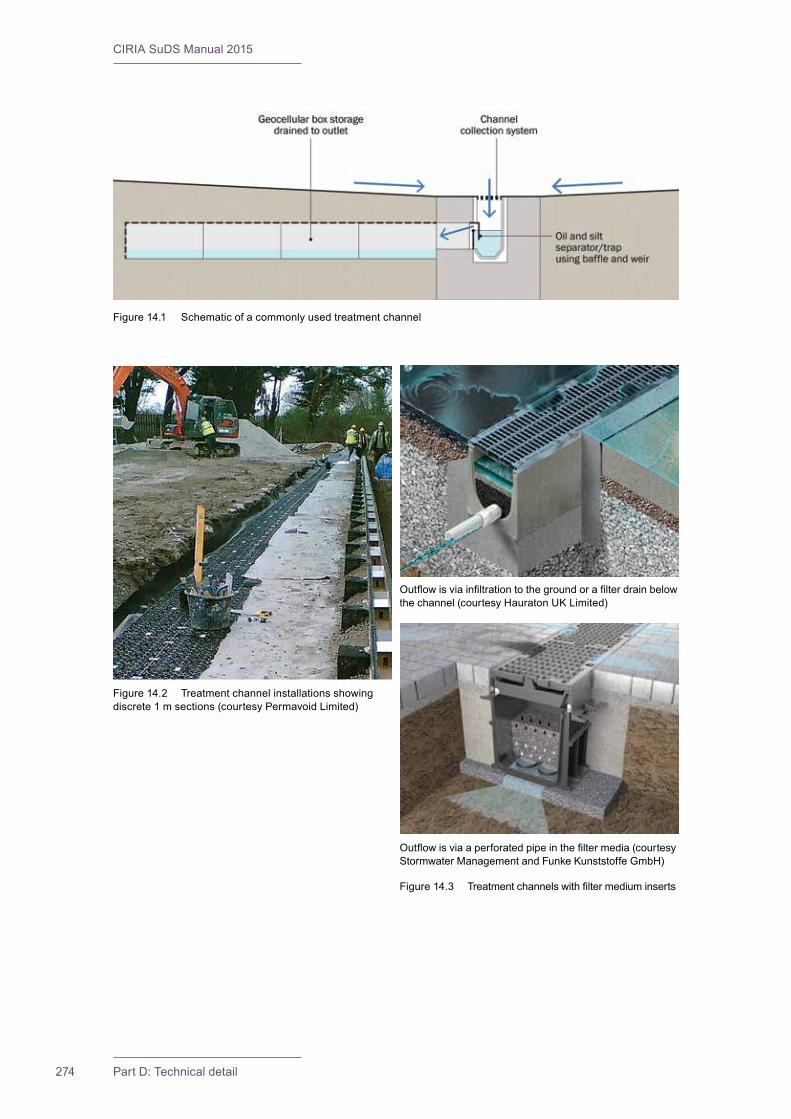
CIRIA SuDS Manual 2015
274 Part D: Technical detail
Figure 14.1 Schematic of a commonly used treatment channel
Figure 14.2 Treatment channel installations showing discrete1msections(courtesyPermavoidLimited)
Figure14.3 Treatmentchannelswithfiltermediuminserts
Outflowisviaaperforatedpipeinthefiltermedia(courtesyStormwaterManagementandFunkeKunststoffeGmbH)
Outflowisviainfiltrationtothegroundorafilterdrainbelowthechannel(courtesyHauratonUKLimited)
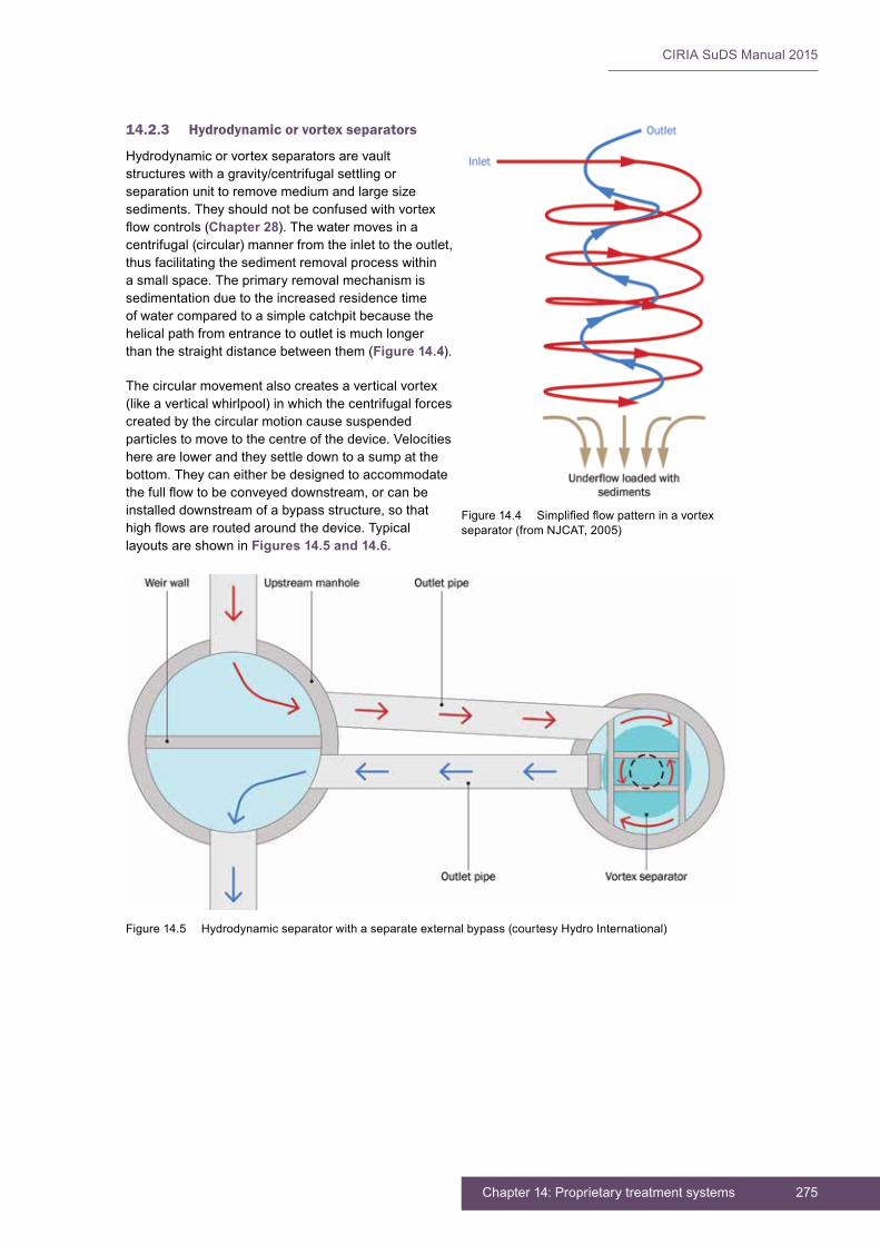
275Chapter 14: Proprietary treatment systems
CIRIA SuDS Manual 2015
14.2.3 Hydrodynamic or vortex separators
Hydrodynamic or vortex separators are vault structures with a gravity/centrifugal settling or separation unit to remove medium and large size sediments.Theyshouldnotbeconfusedwithvortexflowcontrols(Chapter 28).Thewatermovesinacentrifugal(circular)mannerfromtheinlettotheoutlet,thus facilitating the sediment removal process within a small space. The primary removal mechanism is sedimentation due to the increased residence time ofwatercomparedtoasimplecatchpitbecausethehelical path from entrance to outlet is much longer thanthestraightdistancebetweenthem(Figure 14.4).
The circular movement also creates a vertical vortex (likeaverticalwhirlpool)inwhichthecentrifugalforcescreatedbythecircularmotioncausesuspendedparticles to move to the centre of the device. Velocities here are lower and they settle down to a sump at the bottom.Theycaneitherbedesignedtoaccommodatethefullflowtobeconveyeddownstream,orcanbeinstalleddownstreamofabypassstructure,sothathighflowsareroutedaroundthedevice.Typicallayouts are shown in Figures 14.5 and 14.6.
Figure14.4 Simplifiedflowpatterninavortexseparator(fromNJCAT,2005)
Figure14.5 Hydrodynamicseparatorwithaseparateexternalbypass(courtesyHydroInternational)

CIRIA SuDS Manual 2015
276 Part D: Technical detail
Vortexseparatorsaremosteffectivewherethematerialstoberemovedfromrunoffareabletobesettled,orfloatables(whichcanbecaptured).Theycannotremovesmalldiametersolids(eg<115µm)withpoorsettleability,emulsionsordissolvedpollutants.Notethattheremovalofsettleableparticlesisdependentonresidencetimeandthereforeflowrate.Reducingflowratesintoadeviceincreasesresidencetimeandenablesremovalofparticleswithlongersettlingtimes.
Ifthefacilitydoesnothaveabypassforeventsexceedingthewaterqualityevent,itshouldbesizedtoaccommodatethepeakflowofthemaximumdesigneventlikelytobeconveyedbythesurfacewatermanagementsystem.Acheckshouldalsobemadethatthestatedremovalperformanceisapplicableforeventsuptoandincludingthedesignwaterqualityevent,asdescribedinSection 4.3.2 (rather than thedesignconveyanceeventforwhichpollutantremovalwillbelessofaconcern).Whereabypassisprovided,thefacilityshouldbesizedtoaccommodatealleventsuptoandincludingthedesignwaterquality event.
Thereisawidevarietyofproprietaryvortexseparatorunitswhichvaryconsiderablywithrespecttogeometryandtheinclusionofradialbafflesandinternalcircularchambers.Aswellasthestandardunits,somemanufacturersoffersupplementaryfeaturestoreducethevelocityoftheflowenteringthesystem(thusincreasingtheefficiencybyallowingmoresedimenttosettleout),reducingturbulenceorimprovingperformancebytheinclusionofstaticseparatorscreens.Theunitsaregenerallyprefabricatedasarangeofstandardunits,buttheycanoftenbecustomisedforaspecificsiteifrequired.
ThevarioustypesofvortexseparatorhavebeenplacedintosubcategoriesbytheUSEPA(1999).Theseareasfollows:
Simple vortex separators–theserelyonarotatingflowfieldinducedinthedevicetocauseenhancedgravitationalsettlementofsolidsinrunoff.Therotatingflowresultsinalongerflowpathandextendedresidencetimeforparticles,andthussettlementofagreatersizerangeofparticlesoccurs.
Advanced vortex separators–theseoperateinasimilarmannertosimplevortexseparatorsbuttheyhave internal components to control and enhance separation performance and provide isolated zones for capturedsedimentstopreventresuspensionandwashoutunderpeakflowconditions(seeanexampleschematic in Figure 14.7).
Figure14.6 Hydrodynamicseparatorwithaninternal(orintegral)bypass(courtesyHydroInternational)
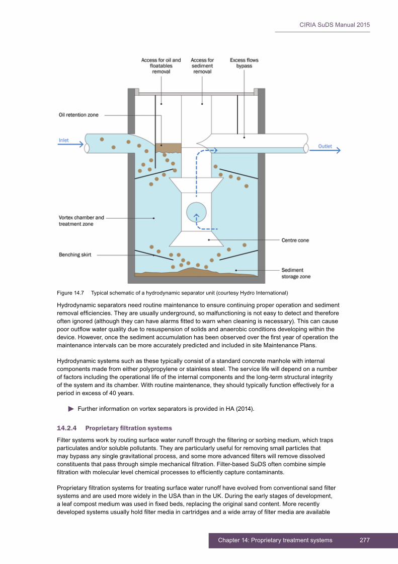
277Chapter 14: Proprietary treatment systems
CIRIA SuDS Manual 2015
Hydrodynamic separators need routine maintenance to ensure continuing proper operation and sediment removalefficiencies.Theyareusuallyunderground,somalfunctioningisnoteasytodetectandthereforeoftenignored(althoughtheycanhavealarmsfittedtowarnwhencleaningisnecessary).Thiscancausepooroutflowwaterqualityduetoresuspensionofsolidsandanaerobicconditionsdevelopingwithinthedevice.However,oncethesedimentaccumulationhasbeenobservedoverthefirstyearofoperationthemaintenanceintervalscanbemoreaccuratelypredictedandincludedinsiteMaintenancePlans.
Hydrodynamic systems such as these typically consist of a standard concrete manhole with internal componentsmadefromeitherpolypropyleneorstainlesssteel.Theservicelifewilldependonanumberof factors including the operational life of the internal components and the long-term structural integrity ofthesystemanditschamber.Withroutinemaintenance,theyshouldtypicallyfunctioneffectivelyforaperiod in excess of 40 years.
FurtherinformationonvortexseparatorsisprovidedinHA(2014).
14.2.4 Proprietary filtration systems
Filtersystemsworkbyroutingsurfacewaterrunoffthroughthefilteringorsorbingmedium,whichtrapsparticulatesand/orsolublepollutants.Theyareparticularlyusefulforremovingsmallparticlesthatmaybypassanysinglegravitationalprocess,andsomemoreadvancedfilterswillremovedissolvedconstituentsthatpassthroughsimplemechanicalfiltration.Filter-basedSuDSoftencombinesimplefiltrationwithmolecularlevelchemicalprocessestoefficientlycapturecontaminants.
ProprietaryfiltrationsystemsfortreatingsurfacewaterrunoffhaveevolvedfromconventionalsandfiltersystemsandareusedmorewidelyintheUSAthanintheUK.Duringtheearlystagesofdevelopment,aleafcompostmediumwasusedinfixedbeds,replacingtheoriginalsandcontent.Morerecentlydevelopedsystemsusuallyholdfiltermediaincartridgesandawidearrayoffiltermediaareavailable
Figure14.7 Typicalschematicofahydrodynamicseparatorunit(courtesyHydroInternational)
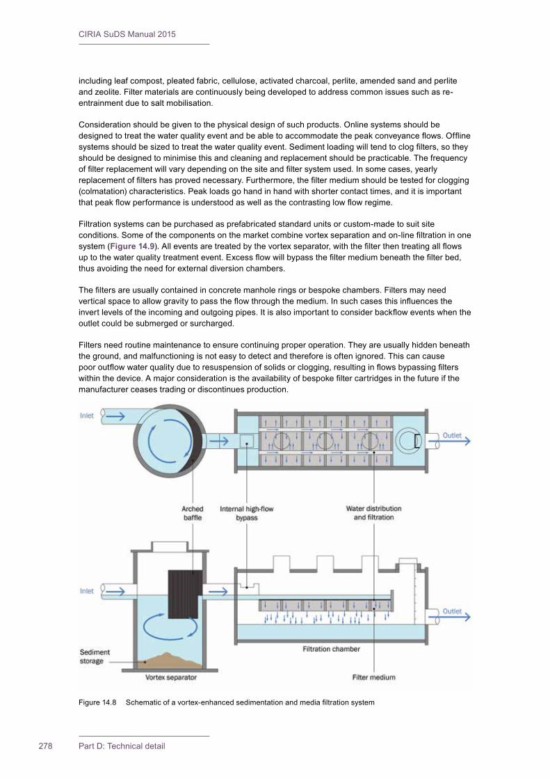
CIRIA SuDS Manual 2015
278 Part D: Technical detail
includingleafcompost,pleatedfabric,cellulose,activatedcharcoal,perlite,amendedsandandperliteandzeolite.Filtermaterialsarecontinuouslybeingdevelopedtoaddresscommonissuessuchasre-entrainmentduetosaltmobilisation.
Considerationshouldbegiventothephysicaldesignofsuchproducts.Onlinesystemsshouldbedesignedtotreatthewaterqualityeventandbeabletoaccommodatethepeakconveyanceflows.Offlinesystemsshouldbesizedtotreatthewaterqualityevent.Sedimentloadingwilltendtoclogfilters,sotheyshouldbedesignedtominimisethisandcleaningandreplacementshouldbepracticable.Thefrequencyoffilterreplacementwillvarydependingonthesiteandfiltersystemused.Insomecases,yearlyreplacementoffiltershasprovednecessary.Furthermore,thefiltermediumshouldbetestedforclogging(colmatation)characteristics.Peakloadsgohandinhandwithshortercontacttimes,anditisimportantthatpeakflowperformanceisunderstoodaswellasthecontrastinglowflowregime.
Filtrationsystemscanbepurchasedasprefabricatedstandardunitsorcustom-madetosuitsiteconditions.Someofthecomponentsonthemarketcombinevortexseparationandon-linefiltrationinonesystem (Figure 14.9).Alleventsaretreatedbythevortexseparator,withthefilterthentreatingallflowsuptothewaterqualitytreatmentevent.Excessflowwillbypassthefiltermediumbeneaththefilterbed,thusavoidingtheneedforexternaldiversionchambers.
Thefiltersareusuallycontainedinconcretemanholeringsorbespokechambers.Filtersmayneedverticalspacetoallowgravitytopasstheflowthroughthemedium.Insuchcasesthisinfluencestheinvertlevelsoftheincomingandoutgoingpipes.Itisalsoimportanttoconsiderbackfloweventswhentheoutletcouldbesubmergedorsurcharged.
Filtersneedroutinemaintenancetoensurecontinuingproperoperation.Theyareusuallyhiddenbeneaththeground,andmalfunctioningisnoteasytodetectandthereforeisoftenignored.Thiscancausepooroutflowwaterqualityduetoresuspensionofsolidsorclogging,resultinginflowsbypassingfilterswithinthedevice.Amajorconsiderationistheavailabilityofbespokefiltercartridgesinthefutureifthemanufacturer ceases trading or discontinues production.
Figure14.8 Schematicofavortex-enhancedsedimentationandmediafiltrationsystem

279Chapter 14: Proprietary treatment systems
CIRIA SuDS Manual 2015
14.2.5 Oil separators
Oil/water(orgravity)separatorsarewidelyusedtopreventhazardouschemicalandpetroleumproductsfromenteringwatercoursesandpublicsewers.Theyshouldbeinstalledclosetothepotentialpollutionsourcetominimiseemulsificationofoilsandtheircoatingofsediments.Anexampleofalargeoil/waterseparator under construction is shown in Figure 14.9.
Separatordesignsarealmostallbasedontheprincipleofseparationbyflotation,residencetimeandparticledensityandsize.Globulesoflowerdensityoilorgrease(LNAPLs)incleannon-turbulentwaterwillriseduetobuoyancy.Theextentofparticledisplacementdependsontheresidencetime.Onceonthesurface,theycanbeeffectivelyremovedbyskimming,pumpingetc.Gravityseparatorscannotbeusedfortheremovalofdissolvedoremulsifiedoilsandpollutants,suchascoolants,solublelubricants,glycolsandalcohols.Sinceresuspensionofaccumulatedsedimentsispossibleduringheavystormevents,separatorunitsaretypicallyinstalledoffline.
Gravityseparatorsareavailableasprefabricatedproprietarysystems,butcanalsobebuilt in situ. ThefacilitiesshouldcomplywithBSEN858-1:2002.GuidanceisalsoprovidedinPollutionPreventionGuidelines(PPG)3(EA/SEPA/EHSNI,2006).Thedesigncriteriaandspecificationsofaproprietarygravityseparatorunitshouldalwaysbeobtainedfromthemanufacturer.
ComparedtootherSuDS,thesefacilitiesrelyheavilyonfrequentroutinemaintenancetopreventpollution.Ifthisdoesnotoccur,experienceshowsthattheyquicklystarttoconveypollutiondownstream.Theyareusuallyhiddenbeneaththeground,andpollutionthatistrappedinthesystemisnotobviousandcancontributetothedeteriorationofdownstream water quality if allowed to accumulate. Thiscanbemitigatedtosomeextentbytheincorporationofautomaticmonitors,asrequiredbytheBritishStandard.However,themonitorsdoneedtobelinkedtoalocationthatisclearlyvisiblebythesitemanagementteamwhenitalarms.Thepollutedrunoffmayalsobecomevisibleintheoutfalltoanysurfacefeatures,whichwillgivewarning that maintenance is required.
There are two classes of systems. A Class 1 device meanstheresultanteffluentshouldcontain5mg/lhydrocarboncontentorlessunderstandardtestconditions. Class 2 devices can contain up to 100 mg/l in their discharge and are appropriate where drainageistoafoulsewer.Itshouldbenotedthatthese are the test requirements; in practice the effluentmaynotmeetthesestandards.
Withinthetwoclassesaretwotypesbasedonincomingandoutgoingflowcontrol–fullretentionorbypassseparators.Afullretentionunitisdesignedtotreatalltheincomingflowstothedesignatedclass.Bypass separators are limited in treating events up to acertainflowrate,afterwhichflowsarebypassedtothe receiving drainage system.
GuidanceontheselectionofoilseparatorsisprovidedinPPG3(EA/SEPA/EHSNI,2006).
Oil/waterseparatorsusedinthedrainageindustryusuallytaketheformofachamberornumberofchamberssituatedwithinadrainagesystemtocollecthydrocarbonpollutants.Themajorityofin situ separatorsareformedinconcrete.Prefabricatedunitsaregenerallymanufacturedinglass-reinforcedplastic,polyethylene,steelorconcrete.Systemsshouldbewatertightanddesignedtopreventflotationwhere there is a risk of high groundwater levels.
Figure14.9 Largeoilseparatorunderconstruction(courtesyACOLimited)

CIRIA SuDS Manual 2015
280 Part D: Technical detail
Oilseparatorsaredesignedforaspecificflowrate,unlikemostotherstructuralcontrols,whicharesizedonthebasisofcapturingandtreatingaspecificvolume.Theseparationchambershouldprovideforthreeseparatestoragevolumes:
▪ avolumeforseparatedoilstorageatthetopofthechamber
▪ avolumeforsettleablesolidsaccumulationatthebottomofthechamber
▪ a volume required to give adequate on-line detention time for separation of oil and sediment from the surface water runoff
AbasicapproachtosizingseparatorsissetoutinPPG3(EA/SEPA/EHSNI,2006).
Figures 14.10 and 14.11showschematicsofprefabricatedsingleandmulti-chamberseparators.
Atypicalgravityseparatorunitmaybeenhancedwithapre-treatmentvortexseparationchamber,oildraw-offdevicesthatcontinuouslyremovetheaccumulatedlightliquids,andflowcontrolvalvesregulatingtheflowrateintotheunit.Plateseparatorsprovidealternativeoptionsdesignedtoinducelaminarflowconditionsthroughaseriesofparallelplates.Theyaregenerallydesignedtotreatlowflowratesonly,butcanachievehighpollutantremovalefficiencies.
Figure14.10 Outlinediagramofaprefabricated,singlechamber,fullretention,Class1separator
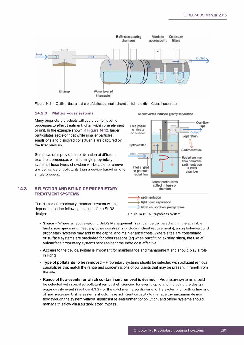
281Chapter 14: Proprietary treatment systems
CIRIA SuDS Manual 2015
Figure14.11 Outlinediagramofaprefabricated,multi-chamber,fullretention,Class1separator
14.2.6 Multi-process systems
Manyproprietaryproductswilluseacombinationofprocessestoeffecttreatment,oftenwithinoneelementorunit.IntheexampleshowninFigure 14.12,largerparticulatessettleorfloatwhilesmallerparticles,emulsionsanddissolvedconstituentsarecapturedbythefiltermedium.
Somesystemsprovideacombinationofdifferenttreatment processes within a single proprietary system.Thesetypesofsystemwillbeabletoremoveawiderrangeofpollutantsthanadevicebasedononesingle process.
14.3 SELECTION AND SITING OF PROPRIETARY TREATMENT SYSTEMS
Thechoiceofproprietarytreatmentsystemwillbedependent on the following aspects of the SuDS design:
▪ Space–Whereanabove-groundSuDSManagementTraincanbedeliveredwithintheavailablelandscapespaceandmeetanyotherconstraints(includingclientrequirements),usingbelow-groundproprietarysystemsmayaddtothecapitalandmaintenancecosts.Wheresitesareconstrainedorsurfacesystemsareprecludedforotherreasons(egwhenretrofittingexistingsites),theuseofsubsurfaceproprietarysystemstendstobecomemorecosteffective.
▪ Access to the device/system is important for maintenance and management and should play a role in siting.
▪ Type of pollutants to be removed–Proprietarysystemsshouldbeselectedwithpollutantremovalcapabilitiesthatmatchtherangeandconcentrationsofpollutantsthatmaybepresentinrunofffromthe site.
▪ Range of flow events for which contaminant removal is desired – Proprietary systems should beselectedwithspecifiedpollutantremovalefficienciesforeventsuptoandincludingthedesignwater quality event (Section 4.3.2)forthecatchmentareadrainingtothesystem(forbothonlineandofflinesystems).Onlinesystemsshouldhavesufficientcapacitytomanagethemaximumdesignflowthroughthesystemwithoutsignificantre-entrainmentofpollution,andofflinesystemsshouldmanagethisflowviaasuitablysizedbypass.
Figure 14.12 Multi-process system
CIRIA SuDS Manual 2015
282 Part D: Technical detail
Thesystemsshouldbedesignedtobeasshallowaspossiblebutcanoftenbelocatedunderroads,carparks and open space. There are instances where the use of proprietary SuDS can increase the length of timebetweenmaintenanceforothercomponents,andasaresultcanloweroverallmaintenanceliability.
14.4 HYDRAULIC DESIGN
14.4.1 General
Proprietarytreatmentsystemsshouldbedesignedsothattherunoffratesandvolumestothemarewithinthestatedperformanceenvelopefortheparticularsystem,throughoutitsintendedservicelife.Careisrequiredtoensurethatflowsfromlargerrainfalleventscanbemanagedbytheunitswithoutsignificantresuspensionofsedimentorotherpollutants.Ifthiscannotbeguaranteedthenlargerflowswillneedtobedivertedaroundthesystems.
14.4.2 Interception design
ProprietarytreatmentsystemsdonotgenerallyprovideInterception(exceptforproprietarybioretentionsystems,ifdesignedtodrainsmallcatchmentareas).
14.4.3 Peak flow control design
Proprietarytreatmentsystemsdonotgenerallyprovidepeakflowcontrol.
14.4.4 Volume control design
Proprietary treatment systems do not generally provide volume control.
14.4.5 Exceedance flow design
Proprietarytreatmentsystemsshouldbedesignedsothatrunoffratesandvolumesthatexceedthestatedsystem performance envelope are routed to the next part of the drainage system along safe exceedance flowpaths.Becausethesesystemscanstorelargeconcentratedvolumesoffreepollutants,itmaybenecessarytoconsidertheiroperationinfloodsituationswheresurchargingetccanbackwashpollutantsoutof a system.
Guidance on exceedance design is provided in Section 24.12.
14.5 TREATMENT DESIGN
Proprietary treatment systems include a wide variety of designs and component types that can provide arangeoftreatmentprocessesasdescribedinSection 14.2(biologicalfiltration,filtration,adsorption,physicalremovalofsedimentbysettling,removaloffloatablesoracombinationofprocesses).Wettinganddryingofsedimentalsopromotesdegradationoforganicpollutants.Theabilityofaspecificdeviceto remove particular pollutants from surface water runoff is related to the treatment processes it supports and the nature of pollutants as well as pollutant loading rates.
Thesizeanddensityofsedimentwillinfluencesedimentationandfiltration.Largediametersandparticles are much easier to capture than suspended clay colloidal particles and extremely small colloidal particlesmaybesubjecttoBrownianmovementandremainsuspendedindefinitely(althoughitisworthrememberingthatSuDSarenottryingtoremoveallpollutionfromrunoff,soinpracticethismaynotbeanissue).Thesmallertheparticlesizethemorelikelyitisthatsomeformoffiltrationmayberequiredtoremoveit.Itispreferabletoavoidoilsemulsifyinginthefirstplacebyavoidinglargeflowsofturbulentwater(ieuseproprietarysystemsthataresourcecontrolsystems).Ifoilsdobecomeemulsifiedtheywillrequirefiltrationtoremovethem.Dissolvedpollutants(zincandcopperarecommonlyindissolvedforminrunoff)mayrequireadsorptivefiltrationorprecipitationtobeeffectivelyremoved.

283Chapter 14: Proprietary treatment systems
CIRIA SuDS Manual 2015
Therefore,inasimilarmannertoanySuDScomponent,thesesystemsshouldbepartofanoverallManagement Train (Chapter 4).Theircontributiontomeetingtheobjectivesoftherequiredtreatmentstrategyatanyparticularsiteshouldbedemonstratedwithrespecttothetypeofcontaminantsthataremanagedbythesystemandthelikelyperformancelevel.Justificationshouldbeprovidedregardingthelevel of mitigation assumed for any product (Chapter 26, Tables 26.3 and 26.4).EvidenceofthepotentialefficiencyofcomponentsthatusedifferentprocesstypesispresentedinChapter 26, Annex 3.However,theseshouldnotbeassumedtobedeliveredbyaproposedcomponentwithoutappropriatesupportingevidence.Also,meetingexistingstandardsisnotadequatejustificationinitself,withoutevaluatingthestandards requirements in the light of the treatment methodology set out in this manual.
Manufacturersshouldprovideclearguidanceonhowtodesigntheirspecificsystemtomeetthestatedperformance envelope. They should state the pollution removal performance for each contaminant at a range of flowrates,andtheseshouldbeusedindeterminingcatchmentareasfortheupstreamdrainagesystem.
ThetreatmentperformanceofproprietarysystemsinthefieldtendstobeasvariableasmoretraditionalSuDSsuchasswalesorbasinsandcanbedependentonawiderangeoffactorsincluding:thecharacteristicsofthecontaminantspresentintherunoff,thetreatmentprocesstype(s)employedbythesystem,theinfluentconcentrations,theinflowrateandthemaintenancehistory.Theremayalsobeanobserveddeclineinperformanceofsomesystemsduringcoldweather(thosethataredependentlargelyonparticlesettlingtimebecausethechangesinwatertemperatureaffectthesettlingvelocityofparticles).Somemanufacturersmakeclaimsofguaranteedperformance,butsuchclaimsshouldbetreatedwithcaution(astheyshouldbefromdesignersofnon-proprietarysystems)unlesssupportedbyevidencefromindependentthirdparties(theevidenceisthattheyarejustasvariableasotherSuDSwhenplacedinrealsituationsoutsidethelaboratory).
Becauseallsystemsaredifferent,itisimportantthatevidenceisprovidedtosupportanyperformanceclaims.IntheUK,therearecurrentlynostandardisedtestingmethodsorreportingprotocolsforproprietarysurfacewaterrunofftreatmentproducts.However,itisrecommendedthatalltestingisundertakenbyorganisationsthatareindependentofthemanufacturerinordertoensurethatanyperformanceclaimsaresupportedbyrobustevidenceusingappropriatetestmethodsthatmayincludefieldtrialstodemonstratereal-worldperformance.Ifnot,thetestingandresultsshouldbepeer-reviewedbyanindependentthirdparty.Thereareinternationallyavailablestandardteststhatcanbecompleted(egStateofWashington,2011,StateofNewJersey,2013,DIBt,2011,andDierkeset al,2013)toallowthepublicationofperformancedata.
DIBt(2011)iswidelyusedinEurope,andtherearetreatmentchannelsandfiltersystemsthatmeettherequirementsofthisstandard.ThestandardsusedintheNetherlandsandproducedbyKiwaareverysimilartotheDIBtstandard.
ThereisalsoaUKtestprotocolunderpreparationatthetimeofwritingbyBritishWater,andthiswilldetailatestprocedurethatUKmanufacturerscanundertake,withindependentwitnessing.
Anyperformancetestingshouldtakeaccountofthefollowingrecommendations:
▪ Testingshouldbeundertakenoverarepresentativerangeofrainfalleventsthatareapplicabletothedesignandoperationofthesystem.Themaininterestistheperformanceforeventsuptoa1:1yearandtheriskofresuspensionduringlargereventsduetoturbulenceifthesystemisdesignedtobeonline.Laboratorytestdatashouldcoverdesignflowsintothesystemforarangeofrepresentativerainfalleventstoatleasta1:1yearevent.Greaterflowratesthanthedesigneventforwaterqualityshouldalsobetestedtoassessresuspensioninon-linesystems.
▪ Sedimentloadsandtheparticlesizedistributionisveryimportantandhasasignificantinfluenceonthe estimated performance. Tests should use particle sizes that are representative of the range of sizes likelytobepresentinsedimentinrunoff–withparticularimportancegiventothose<63µm;Particlesizerangesareespeciallyimportantwhentestingtheeffectivenessofhydrodynamicseparators,andthelargertheaverageparticlesizeusedforevaluation,thehigherthetreatmentefficiency.Thespecificgravityandgradingoftheparticlesusedinanyassessmentshouldbeclearlystatedandcomparedwiththesite-specificdesignrequirements.

CIRIA SuDS Manual 2015
284 Part D: Technical detail
▪ Measurementsofparticlesizedistributionshouldbeincludedinanysamplingandanalysisprogramme,toassesstheremovalefficiencyoftotalsuspendedsolids,aswellasthatofothercontaminants associated with various particle size fractions. There is a higher concentration of pollutantsinthesmallerparticlesizes(<63µm),butwhenexaminingthemassdistributionofthepollutants,particlesizesgreaterthan63µmmay,insomeinstances,beofequalconcern.
▪ Iffieldsamplingiscarriedout,theeffectsofsupernatantdisplacementandactive-particleremovalbythesystem(iehydrostaticversushydrodynamicseparation)shouldbedifferentiated.Thisrequiresflow-proportionalsamplingthroughouteachstormevent.
▪ Iffieldtestingiscarriedout,accountshouldbetakenofantecedentconditions,bypassflowsandresuspension when estimating the performance of the system.
▪ Asufficientnumberofstormsshouldbesamplediffieldtestsareundertaken,notonlytoobtainstatisticallysignificantdata,butalsotoincludeaswidearangeaspossibleofoperatingconditionstowhichthedevicewillbesubject.IntheUSA,thereisaphasedapproachtocertificationofproprietarysystemswherebylimiteduseisallowedbasedonlaboratoryteststoallowfielddatatobecollected.Thisavoidsstiflinginnovation.
▪ Treatmentperformanceshouldbeanalysedbyconsideringthetotalloadofpollutionwhichisthepreferablemethodforaccuracyandqualitycontrol.
▪ Stormsshouldbesampledsequentially,toallowforamass-balanceevaluation.
▪ Testingandmonitoringshouldberelevanttothepollutantsintendedforremovalbythedevice.
14.6 AMENITY DESIGN
Withtheexceptionofbiofiltrationsystemswithvegetation,proprietarysystemsdonotprovidedirectamenitybenefits,butamenityfeaturescanoftenbeimplementedontheoverlyingsurface,suchasparks.Theycanalsofacilitateamenityprovisionindownstreamsurfacefeaturesbydeliveringcleanwater.BiofiltrationsystemswithvegetationshouldbedesignedtodeliveramenityinaccordancewithChapter 18.
14.7 BIODIVERSITY DESIGN
Withtheexceptionofbiofiltrationsystemswithvegetation,proprietarysystemsdonotprovidebiodiversitybenefits.Theycanfacilitatebiodiversityprovisionindownstreamsurfacefeaturesbydeliveringcleanwatertothosefeatures.Biofiltrationsystemswithvegetationshouldbedesignedtodeliverbiodiversityinaccordance with Chapter 18.
14.8 PHYSICAL SPECIFICATIONS
Thespecificationofproprietarydeviceswillbebasedonmanufacturers’information.Thisshouldincludeall relevant information that is required to ensure that the system meets the claimed performance. The specificationshouldincludetheflowratesoverwhichtheclaimedperformancecanbeachievedandtherangeofpollutantsthatthesystemcanremove.ForTSSremoval,theparticlesizeanddensitywhichthesystemcaneffectivelyremoveatarangeofflowratesshouldbestated.
14.8.1 Pre-treatment and inlets
Proprietarysystemseitherhavetheirownspecificinletdetailsortheywillbefedbygullies,normaldrainagesystemsorproprietaryinletswhichmayprovidesomepre-treatment,ifdesignedassuch.Manufacturers’literatureshouldbeconsultedfordetailsofrequiredinletsforspecificdevices.Themaintenancerequirementsforanypre-treatmentelementsshouldbestatedbythemanufacturer,asthiswill have an impact on the performance of the downstream proprietary treatment system.

285Chapter 14: Proprietary treatment systems
CIRIA SuDS Manual 2015
14.8.2 Outlets
Specificrequiredoutletdetailsshouldbeprovidedbythemanufacturerofthedevice.
14.9 MATERIALS
Themainmaterialthatwillbespecifictoaproprietarydevicewillbethebespokefiltermedium.Themanufacturershouldprovidethespecificationforanybespokefiltermediumifapplicable,including:
▪ basematerial
▪ particlesizedistribution(grading)
▪ salt content
▪ permeability
▪ organic matter content
▪ pH
▪ electrical conductivity
▪ phosphorous content
▪ suppliersofthefiltermedium.
Filtermediashouldbeeasilyaccessibleforreplacement,andthefullspecificationofanycartridgesshouldalsobeprovidedsothattheycanbereplaced.Byprovidingthisinformation,thereislessriskofnotbeingabletoreplacethefiltermediumifthemanufacturerofthedevicegoesoutofbusiness,whichhasbeenaproblemonsomesitesintheUSA.Ifthefiltermediumissubjecttointellectualpropertyrightsorthereiscompetitiveadvantageinusingaspecificmaterialthenastatementthatthefiltermediumspecificationwillbemadeavailable–oravailableforacquisitionunderintellectualpropertysale–shouldbesufficienttoensurecontinuityofsupplyifthemanufacturerceasestrading.
Materialchoiceforthecomponentsandchamberswillaffecttheanticipatedassetlifetime.Thefunctionalperformanceofthedeviceintermsoftreatmentshouldnotbeconsideredinisolation,andthelong-termstructuralintegrity,environmentalimpactandwholelifevalueoftheassetneedtobetakenintoaccount.
14.10 LANDSCAPE DESIGN AND PLANTING
There are no landscape and vegetation requirements for most proprietary systems. For manufactured bioretentionsystemsandtreepits,theadviceinChapters 18 and 19shouldbefollowed.
14.11 CONSTRUCTION REQUIREMENTS
Whereunitsareprefabricated,constructionconcernsgenerallyrelateto:
1 compaction of foundations to ensure that uneven settling will not occur
2 qualitycontroloffoundationlevelstoensurethatinflowandoutflowpipesareatthecorrectelevation.
Particularattentionshouldbepaidtomanufacturers’informationinrespectofbackfillingandballasting.
Further detail on construction activities and the programming of construction activities is provided in Chapter 31.
Generic health and safety guidance is presented in Chapter 36.

CIRIA SuDS Manual 2015
286 Part D: Technical detail
A construction phase health and safety plan is required under the Construction (Design and Management)Regulations(CDM)2015.Thisshouldensurethatallconstructionriskshavebeenidentified,eliminated,reducedand/orcontrolledwhereappropriate.
Manufacturersshouldprovideadviceonwhetherthetreatmentsystemsneedtobeprotectedfromconstructionphaserunoff,andhowthiscanbestbeachieved.
14.12 OPERATION AND MAINTENANCE REQUIREMENTS
14.12.1 General guidance
Proprietary treatment systems will require routine maintenance to ensure continuing operation to designperformancestandards.Becauseofthewiderangeofdifferentdesignsandperformance,allmanufacturersshouldprovidedetailedspecificationsandfrequenciesfortherequiredmaintenanceactivities along with likely machinery requirements and typical annual costs for any given site. The treatmentperformanceofproprietarysystemsisstronglydependentonmaintenance,androbustmanagementplanswillberequiredtoensurethatmaintenanceiscarriedoutinthelongterm.Thereareexampleswherenotundertakingmaintenancehasledtopollution,andthecompaniesinvolvedhavebeenfined.Thecostofmaintenancewouldhavebeenmuchlessthanthesubsequentfineandclean-up costs. Different proprietary treatment devices will have different operation and maintenance requirements,butthissectiongivessomegenericguidance.Easeofaccessformaintenanceandinspectionisessential.Inparticular,accesslidsandcoversshouldbekeptaslightweightaspracticable.
Manyproprietarysystemsarebeneaththeground,andmalfunctioningisnoteasytodetect,anditistherefore often ignored unless alarms are provided or the system is designed to cause localised surface pondingiffull.Ifsystemsleadtoothersurfacefeatures,earlywarningofmaintenancebeingrequiredmaybeeasilyobservedattheinlettothefeature(whichshouldbedesignedtopreventitenteringthemainpartofthecomponent).Preferenceshouldbegiventosystemsordesignsthatgivesomeeasilyobservableindicationthatmaintenanceisrequired.
LackofroutinemaintenanceismorelikelytocausepooroutflowwaterqualitythanwithotherSuDSduetoresuspensionofsolidsandanaerobicconditionsdevelopingwithinthedevice.Forexample,anaerobicconditionscandevelopindeepsumpsandcatchpitsthatresultinnutrientsandmetalsbeingreleasedfromcapturedsediments.Duringthefirstfewmonthsafterinstallation,subsurfacetreatmentunitsshouldbevisuallyinspectedafterrainfallevents,andtheamountofdepositionmeasuredtogivetheoperatoranideaoftheexpectedrateofsedimentandoildeposition.Afterthisinitialperiod,systemsshouldbeinspectedeverysixmonthstoverifytheappropriatelevelofmaintenance.Duringtheseinspections,thefloatingdebrisandanyfloatingoilsshouldnormallyberemoved.Thismaybedoneusingavan-mountedsystem,withouttheneedforalargetanker.Siltshouldberemovedwhenitreaches75%ofthecapacityofthesump.Inmostsituations,theunitsshouldbefullycleanedoutatleastannually.Ifthereisasignificantspillofoil(orotherpollutant)thesystemshouldbecleanedimmediately.
Hilliges et al(2013)recommendscleaningtreatmentchannelsouteverysixmonths,inspringandafterthesummer.Thiswasbasedonobservedsiltbuildupforabusyroad(AADT57000vehiclesperday)andthisfrequencycouldpossiblybereducedinlesstraffickedareas.Experiencewithotherchannelsinlesstraffickedareasshowssiltremovalmayonlyberequiredevery10years.
Properdisposalofoil,solidsandfloatingdebrisremovedfromcomponentsmustbeensured,andtheenvironmentalregulatorshouldbeapproachedforadvicewherethereareanydoubtsconcerningdisposaloptions.Asmallportionofwaterwillberemovedalongwiththepollutantsduringtheclean-outprocess,whichshouldbeconsideredwhencostingsedimentdisposalprocesses.
Further guidance on waste management is given in Chapter 33.
Harmfulvapoursmaydevelopinsubsurfacefiltrationorhydrodynamicseparationunits,ashydrocarbonsmay remain there for extended periods of time. Appropriate testing for harmful vapours and venting

287Chapter 14: Proprietary treatment systems
CIRIA SuDS Manual 2015
shouldbeundertakenwheneveraccessformaintenanceisrequired.Removalofoil,siltandotherpollutantsmustbeinaccordancewiththeappropriatewastemanagementlegislation.
Maintenanceresponsibilityforallsystemsshouldbeplacedwithanappropriateorganisation,andMaintenancePlansandschedulesshouldbedevelopedduringthedesignphase.
FurtherdetailonthepreparationofmaintenancespecificationsandschedulesofworkisgiveninChapter 32.
Table 14.2providesguidanceonthetypeofoperationandmaintenanceschedulethatmaybeappropriateforaproprietarytreatmentsystem.Thelistofactionsisnotexhaustiveandsomeactionsmaynotalwaysberequired.
CDM2015requiresdesignerstoensurethatallmaintenanceriskshavebeenidentified,eliminated,reducedand/orcontrolledwhereappropriate.Thisinformationwillberequiredaspartofthehealthandsafetyfile.
Generic health and safety guidance is presented in Chapter 36.
14.12.2 Oil water separators
Specificrequirementsforoil/waterseparatorsareprovidedinPPG3(EA/SEPA/EHSNI,2006).Thefollowingitemsshouldbeundertakeneverysixmonthsasaminimum:
▪ check volume of sludge
▪ check thickness of light liquid
▪ check function of automatic closure device
▪ emptytheseparator,ifrequired
▪ checkthecoalescingmaterialandcleanorchangeifnecessary(class1only)
▪ checkthefunctionofthewarningdevice(iffitted)
Generalinspectionoftheintegrityofoil/waterseparatorsshouldoccuratamaximumfrequencyoffiveyears,andshouldcoverthefollowing:
▪ watertightness of system
TABLE14.2
An example of operation and maintenance requirements for a proprietary treatment system
Maintenance schedule Required action Typical frequency
Routine maintenance
Removelitteranddebrisandinspectforsediment,oilandgreaseaccumulation
Six monthly
Changethefiltermedia Asrecommendedbymanufacturer
Removesediment,oil,greaseandfloatablesAsnecessary–indicatedbysysteminspections or immediately following significantspill
Remedial actions Replace malfunctioning parts or structures As required
Monitoring
Inspectforevidenceofpooroperation Six monthly
Inspectfiltermediaandestablishappropriatereplacement frequencies
Six monthly
Inspectsedimentaccumulationratesandestablishappropriateremovalfrequencies
Monthlyduringfirsthalfyearofoperation,theneverysixmonths

CIRIA SuDS Manual 2015
288 Part D: Technical detail
▪ structural condition
▪ internal coatings
▪ in-builtparts
▪ electrical devices and installations
▪ adjustment of automatic closure devices
Itisusuallyarequirementthatseparatorsarefilledwithcleanwaterbeforebeingputintooperationandeach time after emptying for maintenance. Failure to do so will cause the separator to malfunction until surfacewaterbuildsuptherequiredpermanentwaterlevelinthefacility.Itispossibletofitanalarmtoseparatorsthatwillindicatewhenthecollectedoilvolumeisatamaximum,andthismaybearegulatoryrequirement.Thealarmsshouldbeplacedinalocationthatisclearlyvisibletothoseresponsibleformaintenance of the system.
14.13 REFERENCES
DIBt(2011)Approval Principles, Rainwater treatment plant. Part 1 Plant for connection with motor vehicle traffic areas of up to 2000 m2 and treatment of waste water prior to subsequent drainage to earth and ground water,DeutschesInstitutfurBautechnik,Berlin,Germany
DIERKES,C,WELKER,AandDIERSCHKE,M(2013)“Developmentoftestingproceduresforthecertificationofdecentralisedstormwatertreatmentfacilities–resultsoflaboratorytests”.In:Proc 8th int NOVATECH conference,23–27June2013,Lyon,France
EA/SEPA/EHSNI(2006)PollutionPreventionGuidelines(PPG)3Use and design of oil separators in surface water drainage systems,EnvironmentAgency/ScottishEnvironmentProtectionAgency,EnvironmentandHeritageServiceNorthernIreland,UK.Goto:http://tinyurl.com/nn6ha6s
HA(2014)“Vortexgritandoilseparatorsforusewithroaddrainagesystems”. Design Manual for Roads and Bridges, volume 4 Geotechnics and drainage, Section 2 Drainage,Part4,HA220/XXDraft(unpublished)
HILLIGES,R,SCHRIEWER,AandHELMREICH,B(2013)“Athree-stagetreatmentsystemforhighlypollutedurbanroadrunoff”Journal of Environmental Management,vol128,October2013,ElsevierBV,UK,pp306–312
LEISENRING,M,CLARY,JandHOBSON,P(2012)International Stormwater BMP Database. Manufactured devices performance summary,WERF,ASCE,EWRI,APWA,FHWA,USEPA,USA.Goto:http://tinyurl.com/qhl57bn
NJCAT(2005)NJCAT technology verification,HydroInternational,Clevendon,UK. Goto:www.state.nj.us/dep/dsr/bscit/FinalVer_Hydro.pdf
STATEOFNEWJERSEY(2013)Process for approval of use for manufactured treatment devices,NewJerseyDepartmentofEnvironmentProtection,StateofNewJersey,USA.Goto:http://tinyurl.com/ocbqfts
STATEOFWASHINGTON(2011)Technical guidance manual for evaluating emerging stormwater treatment technologies: Technology Assessment Protocol – Ecology (TAPE),PublicationNo11-10-061,WaterQualityProgramDepartmentofEcology,StateofWashington.Goto:http://tinyurl.com/oq68nz8
USEPA(1999)Stormwater technology fact sheet: Hydrodynamic separators,EPA832-F-99-017,USEnvironmentalProtectionAgency,WashingtonDC,USA.Goto:http://tinyurl.com/mluoajg

289Chapter 14: Proprietary treatment systems
CIRIA SuDS Manual 2015
Statutes
BSEN858-1:2002Separator systems for light liquids (eg oil and petrol). Principles of product design, performance and testing, marking and quality control
Construction(DesignandManagement)Regulations2015
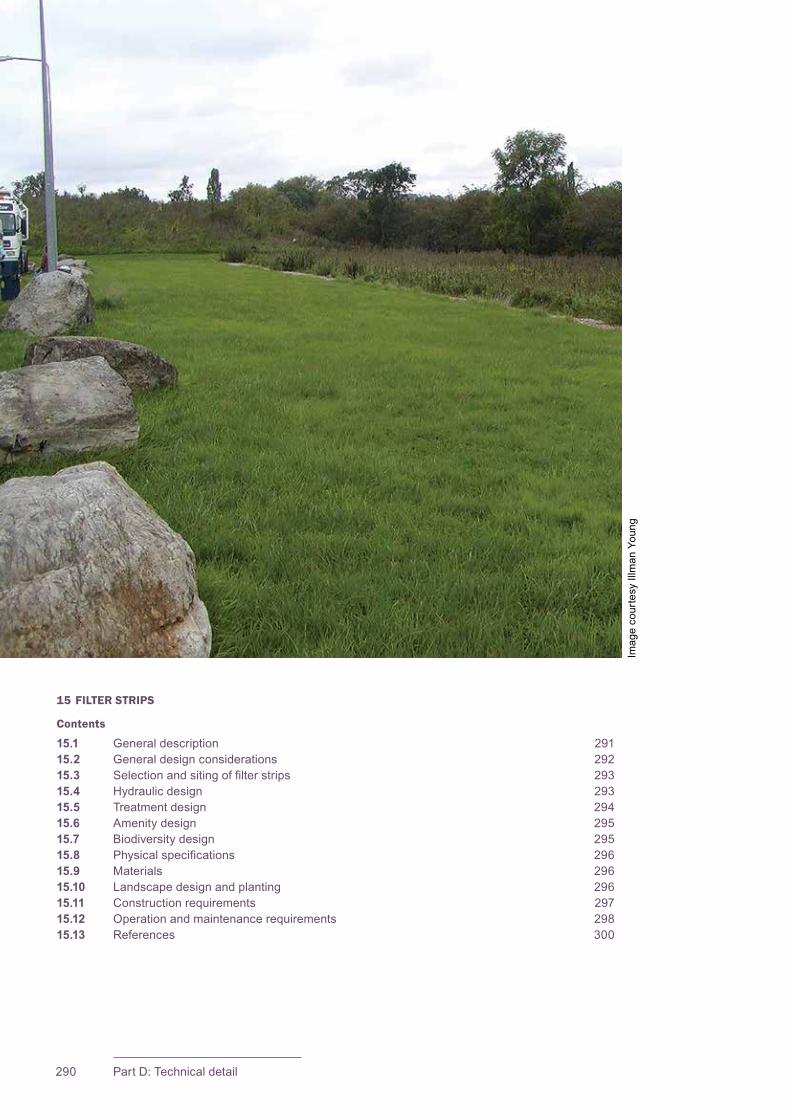
CIRIA SuDS Manual 2015
290 Part D: Technical detail
15 FILTER STRIPS
Contents
15.1 General description 29115.2 General design considerations 29215.3 Selectionandsitingoffilterstrips 29315.4 Hydraulicdesign 29315.5 Treatment design 29415.6 Amenity design 29515.7 Biodiversity design 29515.8 Physicalspecifications 29615.9 Materials 29615.10 Landscapedesignandplanting 29615.11 Construction requirements 29715.12 Operation and maintenance requirements 29815.13 References 300
Imag
e co
urte
sy Il
lman
You
ng
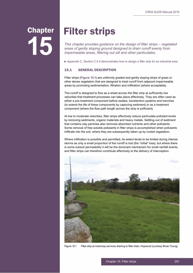
291Chapter 15: Filter strips
CIRIA SuDS Manual 2015
15.1 GENERAL DESCRIPTION
Filter strips (Figure 15.1) are uniformly graded and gently sloping strips of grass or other dense vegetation that are designed to treat runoff from adjacent impermeable areasbypromotingsedimentation,filtrationandinfiltration(whereacceptable).
Therunoffisdesignedtoflowasasheetacrossthefilterstripatsufficientlylowvelocitiesthattreatmentprocessescantakeplaceeffectively.Theyareoftenusedaseitherapre-treatmentcomponentbeforeswales,bioretentionsystemsandtrenches(to extend the life of these components by capturing sediment) or as a treatment component(wheretheflowpathlengthacrossthestripissufficient).
Atlowtomoderatevelocities,filterstripseffectivelyreduceparticulatepollutantlevelsbyremovingsediments,organicmaterialsandheavymetals.Settling-outofsedimentthatcontainsclayparticlesalsoremovesabsorbednutrientsandotherpollutants.Someremovaloffreesolublepollutantsinfilterstripsisaccomplishedwhenpollutantsinfiltrateintothesoil,wheretheyaresubsequentlytakenupbyrootedvegetation.
Whereinfiltrationispossibleandpermitted,itsextenttendstobelimitedduringintensestormsasonlyasmallproportionoftherunoffislost(the“initial”loss),butwherethereissomesubsoilpermeabilityitwillbethedominantmechanismforsmallrainfallevents,andfilterstripscanthereforecontributeeffectivelytothedeliveryofInterception.
15Chapter Filter strips
This chapter provides guidance on the design of filter strips – vegetated areas of gently sloping ground designed to drain runoff evenly from impermeable areas, filtering out silt and other particulates.
Appendix C, Section C.5.4 demonstrates how to design a filter strip for an industrial area.
Figure15.1 Filterstripatmotorwayservicesdrainingtofilterdrain,Hopwood(courtesyIllmanYoung)
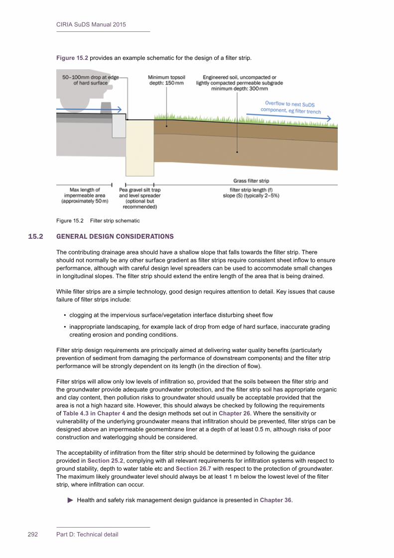
CIRIA SuDS Manual 2015
292 Part D: Technical detail
Figure 15.2providesanexampleschematicforthedesignofafilterstrip.
15.2 GENERAL DESIGN CONSIDERATIONS
Thecontributingdrainageareashouldhaveashallowslopethatfallstowardsthefilterstrip.Thereshouldnotnormallybeanyothersurfacegradientasfilterstripsrequireconsistentsheetinflowtoensureperformance,althoughwithcarefuldesignlevelspreaderscanbeusedtoaccommodatesmallchangesinlongitudinalslopes.Thefilterstripshouldextendtheentirelengthoftheareathatisbeingdrained.
Whilefilterstripsareasimpletechnology,gooddesignrequiresattentiontodetail.Keyissuesthatcausefailureoffilterstripsinclude:
▪ cloggingattheimpervioussurface/vegetationinterfacedisturbingsheetflow
▪ inappropriate landscaping, for example lack of drop from edge of hard surface, inaccurate grading creatingerosionandpondingconditions.
Filterstripdesignrequirementsareprincipallyaimedatdeliveringwaterqualitybenefits(particularlypreventionofsedimentfromdamagingtheperformanceofdownstreamcomponents)andthefilterstripperformancewillbestronglydependentonitslength(inthedirectionofflow).
Filterstripswillallowonlylowlevelsofinfiltrationso,providedthatthesoilsbetweenthefilterstripandthegroundwaterprovideadequategroundwaterprotection,andthefilterstripsoilhasappropriateorganicandclaycontent,thenpollutionriskstogroundwatershouldusuallybeacceptableprovidedthattheareaisnotahighhazardsite.However,thisshouldalwaysbecheckedbyfollowingtherequirementsof Table 4.3 in Chapter 4 and the design methods set out in Chapter 26.Wherethesensitivityorvulnerabilityoftheunderlyinggroundwatermeansthatinfiltrationshouldbeprevented,filterstripscanbedesignedaboveanimpermeablegeomembranelineratadepthofatleast0.5m,althoughrisksofpoorconstructionandwaterloggingshouldbeconsidered.
Theacceptabilityofinfiltrationfromthefilterstripshouldbedeterminedbyfollowingtheguidanceprovided in Section 25.2,complyingwithallrelevantrequirementsforinfiltrationsystemswithrespecttogroundstability,depthtowatertableetcandSection 26.7withrespecttotheprotectionofgroundwater.Themaximumlikelygroundwaterlevelshouldalwaysbeatleast1mbelowthelowestlevelofthefilterstrip,whereinfiltrationcanoccur.
Health and safety risk management design guidance is presented in Chapter 36.
Figure15.2 Filterstripschematic

293Chapter 15: Filter strips
CIRIA SuDS Manual 2015
15.3 SELECTION AND SITING OF FILTER STRIPS
Filterstripscanbeusedinavarietyofsituationsbutareparticularlywellsuitedformanagingrunofffromroadsbecausetheyarealinearfeatureandeasilyincorporatedintoroadsidespace.Theyarealsosuitableformanagingrunofffromcarparksandotherimpermeableandpermeableareas.Filterstripsshould be effectively incorporated into landscaping and public open spaces, so that their function is not compromisedbyactivityinthearea(egdamagefromparkingorpedestrians).
Theyareusefulonindustrialsitesbecauseanyvisiblepollutioncanbeidentified,thesourcetraced,thecontaminationremovedasfaraspossibleandthestriprehabilitatedrelativelyeasily.
Unlinedfilterstripsshouldnotbeusedonbrownfieldsitesunlessithasbeendemonstratedclearlythattheriskposedbyleachingofcontaminantsismanagedtoacceptablelevels.Unlinedfilterstripsshouldnotbeusedtotreatrunofffromareaswithhighcontaminantloadsiftheriskofgroundwaterpollutionduetoinfiltrationisunacceptablyhigh.Wherealinerisusedtopreventinfiltration,theseasonallyhighgroundwaterlevelshouldbebelowtheleveloftheliner.Ifinfiltrationisallowed,themaximumlikelygroundwaterlevelshouldbeatleast1mbelowthebaseofthesystem.
Filterstripsshouldnotbelocatedinareaswheretreesorstructureswillcauseshadeconditionsthatlimitgrassgrowth.
15.4 HYDRAULIC DESIGN
15.4.1 General
Maintainingsheetflowontothefilterstripisessential,andcaneffectivelybeachievedthroughtheuseofanappropriatelevelspreadingdevice,suchasagravelflowspreader(Section 28.4.6).
Filterstripsshouldbedesignedwithaminimumlongitudinalslope(ieslopealongthedirectionofflow)of1%(topreventponding)andamaximumslopeof5%topreventflowchannelling.Thetopandbottomoftheslopeshouldbeatthelowerendoftheallowablesloperangetoreduceflowvelocitiesandtherebyreducetheriskoferosion.Wherefilterstripslopesare>5%,aseriesoflevelspreaderscanbeusedtomaintainsheetflowasrunoffflowsoverthestrip.
Themaximum“length”ofimperviousareadrainingtofilterstripsshouldbecontrolledinordertoreducetheriskofconcentratedflows,althoughthiswillalsobedependentontheslopeoftheimpermeablearea,andontheeffectivenessofadoptedflowspreadingtechniques.Filterstriplengthstendtobedeterminedby treatment objectives (Section 15.5).
Maximumflowvelocitiesacrossthefilterstripof1.5m/sarerecommendedtopreventerosionduringdesignflows(notethatalowervelocityisrequiredfortreatment–Section 15.5).
Manning’s equation (Equation 15.1)canbeusedtodesignthefilterstripfordesignflowvelocities.
15.4.2 Interception design
Wheretopsoilsaresuitablypermeable,andunderlyingsoilshavesomecapacitytostoreand/orinfiltraterunoff,thenfilterstripswithveryshallowslopescanbedesignedtodeliverInterception(iereduceorpreventrunoffduringsmallrainfallevents).TheextentofInterceptiondeliveredwillbestronglydependentonfilterstriplength(seeFigure 15.2),whichalsoinfluencesdesigningfortreatment–Section 15.5.
Wherethereisinfiltrationcapacity,infiltrationisacceptableandthestripisdesignedtofacilitateevenlimitedinfiltration,thenacheckshouldbemadetodeterminewhetherthestripisabletodisposeof5mmrainfalldepthoverthecontributingcatchmentarea.
Wherethereisnoinfiltration,butthenaturalsurfacesoils(orimported/re-engineeredsoils)havewaterstoragecapacity,thenInterceptiondesignshouldfollowtheprinciplessetoutinSection 24.8.

CIRIA SuDS Manual 2015
294 Part D: Technical detail
15.4.3 Peakflowcontroldesign
Sheetflowacrossfilterstripsisnotusuallycontrolled,andinthissituationnoreductioninpeakflowisincludedwithindesigncalculations.
Todesignforthecontroloflowreturnperiodevents,animpermeablebermcouldbedesignedatthetoeoftheslope,withpipedoutletstocontrolflowrates.Considerationofmaintenancerequirements,particularlyintermsofpipeblockage,isrequiredtodeterminewhethersuchanapproachisrobustforlong-termperformance.
15.4.4 Volume control design
Filterstripsdonottendtoprovidesignificantinfiltrationduringlargestormevents,sotheydonotcontributetovolumetricreductionsduringdesignstorms.
15.4.5 Exceedanceflowdesign
Itisusualforexceedanceflows(ieforeventslargerthanthedesignevent)topassacrossthefilterstrip,andforanyresultantdamagetoberepairedpostevent.However,ifspecificprotectionisrequiredfordownstreamcomponents,thenabypassforthestripcouldbeconsidered.
15.5 TREATMENT DESIGN
Filterstripscanhelpretainrunofffromsmalleventsonsite(iedeliverInterception–Section 15.4.2), helpingtoreducethecontaminantloaddischargedtosurfacewatersviavolumetriccontrol.Theycanalsotreattheresidualrunoffbyfacilitatingsedimentationandfiltration.
Theacceptabilityofallowinginfiltrationfromthefilterstripwilldependontheextentofthelikelyrunoffcontamination and site characteristics (see Chapter 4, Table 4.3).
Filterstriplengths>2.5m(ideally3m)arevaluablewhereslopesareconstrainedtoatornear1%(ClaytorandSchueler,1996),particularlyforprotectingthefunctionalityofdownstreamcomponents(ieasapre-treatmentcomponent);andlengths>5mhavebeendemonstratedtobeveryeffectiveintermsofwaterqualityperformance(Barrettet al, 2004) even for steeper slopes, although the density of vegetationisanimportantfactor.AfilterstripstudybyCaltrans(2003)foundthatwhenslopesarelessthan 10% and the vegetation cover exceeds 80%, then an irreducible concentration is achieved at a strip lengthlessthan5m,iealongerstripisonlyrequiredwhereslopesexceed10%.Ata20%slope,itissuggestedthata1mlengthoffilterstripshouldbeprovidedforevery6mofimpermeableareaflowpathlength (Figure 15.2).
Researchhasshownconsistentremovaloftotalsuspendedsolidsandtotalheavymetals,andfrequentlyalsofordissolvedmetalswheredesignsconformtothecriteriasetoutabove.However,removalefficienciesarevariable,sofilterstripsshouldalwaysbeusedtogetherwithdownstreamtreatmentcomponents.EvidenceoftheremovalefficienciesoffilterstripsispresentedinChapter 26, Annex 3.
Good pollutant removal performance is required for all runoff events up to and including events that occur,onaverage,aboutonceayear(termedherethe1:1yearevent).Thedurationofthiseventshouldbetherelevantcriticaldurationforthefilterstripflowrate.Ifthefilterstripisdrainingaroad,then15minutesislikelytobeappropriate.Forthiswaterqualitydesignevent:
▪ theflowdepthshouldbelowerthantheheightofthevegetationandshouldthereforebelimitedtoapproximately100mmdepthtomaintaingoodlevelsoffiltration
▪ thepeakflowvelocityshouldbelowerthan0.3m/stopromoteparticulatesettlement
▪ thetimeoftravelofrunoffacrossthefilterstrip(residencetime=length/velocity)shouldbeatleast9minutes.
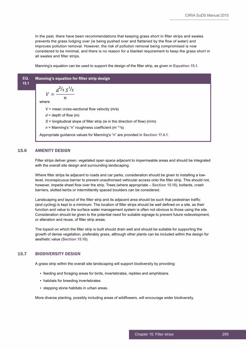
295Chapter 15: Filter strips
CIRIA SuDS Manual 2015
Inthepast,therehavebeenrecommendationsthatkeepinggrassshortinfilterstripsandswalespreventsthegrasslodgingover(iebeingpushedoverandflattenedbytheflowofwater)andimprovespollutionremoval.However,theriskofpollutionremovalbeingcompromisedisnowconsidered to be minimal, and there is no reason for a blanket requirement to keep the grass short in allswalesandfilterstrips.
Manning’sequationcanbeusedtosupportthedesignofthefilterstrip,asgiveninEquation 15.1.
15.6 AMENITY DESIGN
Filter strips deliver green, vegetated open space adjacent to impermeable areas and should be integrated withtheoverallsitedesignandsurroundinglandscaping.
Wherefilterstripslieadjacenttoroadsandcarparks,considerationshouldbegiventoinstallingalow-level,inconspicuousbarriertopreventunauthorisedvehicularaccessontothefilterstrip.Thisshouldnot,however,impedesheetflowoverthestrip.Trees(whereappropriate–Section 15.10), bollards, crash barriers,slottedkerbsorintermittentlyspacedboulderscanbeconsidered.
Landscapingandlayoutofthefilterstripanditsadjacentareashouldbesuchthatpedestriantraffic(andcycling)iskepttoaminimum.Thelocationoffilterstripsshouldbewelldefinedonasite,astheirfunctionandvaluetothesurfacewatermanagementsystemisoftennotobvioustothoseusingthesite.Consideration should be given to the potential need for suitable signage to prevent future redevelopment, oralterationandreuse,offilterstripareas.
Thetopsoilonwhichthefilterstripisbuiltshoulddrainwellandshouldbesuitableforsupportingthegrowthofdensevegetation,preferablygrass,althoughotherplantscanbeincludedwithinthedesignforaesthetic value (Section 15.10).
15.7 BIODIVERSITY DESIGN
Agrassstripwithintheoverallsitelandscapingwillsupportbiodiversitybyproviding:
▪ feeding and foraging areas for birds, invertebrates, reptiles and amphibians
▪ habitats for breeding invertebrates
▪ steppingstonehabitatsinurbanareas.
Morediverseplanting,possiblyincludingareasofwildflowers,willencouragewiderbiodiversity.
EQ.15.1
Manning’sequationforfilterstripdesign
where
V=meancross-sectionalflowvelocity(m/s)d=depthofflow(m)S=longitudinalslopeoffilterstrip(ieinthedirectionofflow)(m/m)n=Manning’s“n”roughnesscoefficient(m−1/3s)
Appropriate guidance values for Manning’s “n” are provided in Section 17.4.1.
CIRIA SuDS Manual 2015
296 Part D: Technical detail
15.8 PHYSICAL SPECIFICATIONS
15.8.1 Pre-treatment and inlets
Aflowspreadingdeviceshouldnormallybeincludedupstreamofthefilterstriptoensureconsistentlateralinflowalongthelengthofthedevice.Someofthesecanalsoprovidesomedegreeofpre-treatmentbytrappingsedimentupstreamofthestrip.Flowspreadingoptionsinclude:
▪ porous pavement strips
▪ stabilised turf strips
▪ slotted curbing
▪ gravel-filledtrenches(withlargerstoneswherethecontributingdrainageareaissteep),and
▪ concretesills.
Thereshouldalwaysbeadropofatleast50mmfromthepavementedgetothefilterstriptopreventtheformationofasedimentlip.
Allpre-treatment/flowspreadingdevicesshouldbedesignedwithmaintenanceconsiderationsinmind.
15.8.2 Outlets
Inmostsituations,theoutflowfromthefilterstripshouldberoutedintoadownstreamcomponent(egswale)forconveyanceandfurthertreatment,sonooutletmechanismisrequired.
15.9 MATERIALS
15.9.1 Level spreaders
Anyinterimlevelspreadersshouldbeconstructedofdurable,non-toxicmaterialgradedintothesoil–minimum150mmwide,50–100mmhigh,runningalongthelengthofthefilterstrip.
15.9.2 Subsoils
Ifsubsoilsarehighlycompactedorofsuchlowfertilityorsoilcompositionthatporespaceforwaterstorageisverylowandvegetationisunlikelytobecomeestablished,thesoilsshouldbetilledto300mmandamendedtomeetthespecificationsforengineeredsoilssetoutinSection 30.4.2.
15.9.3 Geotextiles/geomembranes
GeotextileandgeomembranespecificationsarepresentedinSection 30.5.
15.10 LANDSCAPE DESIGN AND PLANTING
Thefilterstripsurfaceshouldbeplantedwithanappropriategrassmixture,orturfed.Filterstripsaresubjecttobothwetanddryconditions,aswellassedimentanddebrisaccumulation.Amixtureofdry-areaandwet-areagrasses,abletopreventerosionandcapableofgrowingthroughanysiltdepositsisrequired.Adense,soilbinding,deeprootedvegetationcoverisrequired–thatwillneedtobemaintainedatlengthsof75–150mmtoensureeffectivefiltrationperformanceduringregularevents.Turf provides immediate protection, provided the seams are protected by laying the strips perpendicular totheflowofwaterandhandtampingthemafterlaying.Afilterstripisbestseededduringspringandearlysummermonthstogivevegetationthewholelengthofagrowingseasontoestablish.Longergrassesandwildflowerareas,ifconsideredbeneficialforotherreasons,arenotconsideredtoposeasignificantrisktoperformance.

297Chapter 15: Filter strips
CIRIA SuDS Manual 2015
Wherefilterstripsareusedtodrainrunofffromroadsorcarparkareasthatarelikelytoberegularlysaltedduringwintermonths,thentheplantingshouldbesalttolerant.
Treesanddensescrubshouldgenerallybeavoidedonthefilterstripunlesstheavailablefilterstripflowpathlengthissignificantlygreaterthanrequired(egparksandschoolswhereopenspaceareasmaybelarge).Althoughtheymayimproveaesthetics,itisdifficulttopreservethehealthydensevegetatedgroundcover,slopeuniformityandstabilitythatarerequiredforawell-functioningfilterstrip.Whereadditionalspaceisavailableandtheriskstofilterstripperformancehavebeenfullyconsidered,treescanpotentiallybeusedeitherastrafficbarriersorasamenityfeatures.
Filter strips should not be located in shaded areas because sunlight is required to ensure healthy plantgrowth.
Ifabermisconstructedatthetoeofthefilterstrip,thevegetationshouldberesistanttofrequentinundationwithintheshallowpondinglimit.
Fertilisingafilterstripshouldbeavoidedifpossible,particularlywherethereceivingenvironmentissensitivetonutrientloadings.
Landscape design and planting best practice is presented in detail in Chapter 29.
15.11 CONSTRUCTION REQUIREMENTS
Filterstripsshouldbeclearlymarkedbeforesiteworkbeginsandprotectedbysignageandsiltfencing,toavoidtheirdisturbanceduringconstruction.Novehiculartraffic,exceptthatspecificallyusedtoconstructthecomponent,shouldbeallowedclosetothefilterstrip.Excavatingequipmentshouldoperatefromthesideofthefilterstrip.Ifcompactionofsoilsdoesoccur,a300mmdepthofsoilshouldberemovedandreplacedwithablendoftopsoilandsandtopromoteinfiltrationandbiologicalgrowthortilledandenhancedtoachieveasimilarspecification.
Thefilterstripshouldbeconstructedusingcarefulgradingtechniquestoprovideanevenandconsistentlongitudinalslope,withnosevereundulationsthatwillcauselocalisedpondingorpromoteflowinchannels.Eventhesmallestnon-conformitiesmaycompromiseflowconditions.
Anewlyconstructedfilterstripshouldbeprotectedfromsurfacewaterflowsuntilvegetationhasbeenestablished.Thismaybeachievedby:
▪ divertingrunoffaroundthefilterstripuntilvegetationisestablished
▪ using pre-established turf or seeded mattresses
▪ coveringthefilterstripwithclearplasticuntilthevegetationiswellrooted
▪ placinganerosioncontrolblanketoverthefreshlyappliedseedmix.
Ideallyfilterstripsshouldbeplantedinthespring,whenvegetationcanbecomeestablishedwithminimumirrigationneeds.Ifmorethan30%ofthetreatmentareaisbareafterfourweeks,reseedingorreplantingwillberequiredtoachieve90%coverage.
Ifsedimentfromconstructionworkaccumulatesonafilterstrip,itshouldbeclearedandthestripfullyrehabilitatedbeforethedrainagesystemisadoptedbytheorganisationcarryingoutthemaintenance.
Further detail on construction activities and the programming of construction activities is provided in Chapter 31.
Generic health and safety guidance is presented in Chapter 36.

CIRIA SuDS Manual 2015
298 Part D: Technical detail
A construction phase health and safety plan is required under the Construction (Design and Management)Regulations(CDM)2015.Thisshouldensurethatallconstructionriskshavebeenidentified,eliminated,reducedand/orcontrolledwhereappropriate.
15.12 OPERATION AND MAINTENANCE REQUIREMENTS
Filterstripswillrequireregularmaintenancetoensurecontinuingoperationtodesignperformancestandards,andalldesignersshouldprovidedetailedspecificationsandfrequenciesfortherequiredmaintenanceactivitiesalongwithlikelymachineryrequirementsandtypicalannualcosts–withintheMaintenancePlan.Thetreatmentperformanceoffilterstripsisdependentonmaintenance,androbustmanagementplanswillberequiredtoensurethatmaintenanceiscarriedoutinthelongterm.Differentdesignswillhavedifferentoperationandmaintenancerequirements,butthissectiongivessomegenericguidance.
Maintenanceoffilterstripsisrelativelystraightforwardforlandscapecontractorsandtypicallythereshouldonlybeasmallamountofextrawork(ifany)requiredforafilterstripoverandabovewhatisnecessaryforstandardpublicopenspace.Providinglandscapemanagementisalreadyrequiredatsite,filterstripmaintenanceshouldthereforehavemarginalcostimplications.However,regularinspectionandmaintenanceisimportantfortheeffectiveoperationoffilterstripsasdesigned.Maintenanceresponsibilityforafilterstripshouldalwaysbeplacedwithanappropriateorganisation.Iffilterstripsareimplementedwithinprivateproperty,ownersshouldbeeducatedontheirroutinemaintenanceneeds,andshouldunderstandthelong-termMaintenancePlanandanylegallybindingmaintenanceagreement.
Accessformaintenancevehiclesshouldalwaysbeavailable.However,thisisnotusuallyaconstraintduetothelikelylocationofthefilterstripadjacenttoimpermeableareas.Litteranddebrisremovalshould be undertaken as part of general landscape maintenance for the site and before any other SuDS managementtask.Alllittershouldberemovedfromsite.
Themajormaintenancerequirementforfilterstripsismowing.Thisshouldideallyretaingrasslengthsof75–150mmacrossthemain“treatment”surfacetoassistinfilteringpollutantsandretainingsedimentsandtoreducetheriskofflatteningduringrunoffevents.However,longervegetationlengths,whereappropriate,arenotconsideredtoposeasignificantrisktofunctionality.
Grassclippingsshouldbedisposedofeitheroffsiteoroutsidetheareaofthefilterstriptoremovenutrientsandpollutants.Allvegetationmanagementactivitiesshouldtakeaccountoftheneedtomaximisebiosecurityandpreventthespreadofinvasivespecies.
Occasionally,sedimentwillneedtoberemoved(egoncedepositsexceed25mmindepth),althoughthiscanbeminimisedbyensuringthatupstreamareasarefullystabilisedinadvance.Availableevidencefrommonitoringstudiesindicatesthatsmalldistributedinfiltrationpracticessuchasfilterstripsdonotcontaminateunderlyingsoils,evenaftermorethan10yearsofoperation(TRCA,2008).Sedimentsexcavatedfromafilterstripthatreceivesrunofffromresidentialorstandardroadandroofareasaregenerally not of toxic or hazardous material and can therefore be safely disposed of by either land applicationorlandfilling.However,consultationshouldtakeplacewiththeenvironmentalregulatortoconfirmappropriateprotocols.Sedimenttestingmayberequiredbeforesedimentexcavationtodetermineitsclassificationandappropriatedisposalmethods.Forrunofffromstreetswithhighvehicletraffic,sedimenttestingwillbeessential.Inthemajorityofcases,itwillbeacceptabletodistributethesedimentonsiteifthereisanappropriatesafeandacceptablelocationtodoso.
Anydamageduetosedimentremovalorerosionshouldberepairedandimmediatelyreseededorplanted.
FurtherdetailonwastemanagementisprovidedinChapter 32.
Table 15.1 provides guidance on the type of operational and maintenance requirements that may be appropriate.Thelistofactionsisnotexhaustiveandsomeactionsmaynotalwaysberequired.
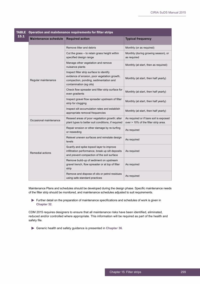
299Chapter 15: Filter strips
CIRIA SuDS Manual 2015
MaintenancePlansandschedulesshouldbedevelopedduringthedesignphase.Specificmaintenanceneedsofthefilterstripshouldbemonitored,andmaintenanceschedulesadjustedtosuitrequirements.
FurtherdetailonthepreparationofmaintenancespecificationsandschedulesofworkisgiveninChapter 32.
CDM2015requiresdesignerstoensurethatallmaintenanceriskshavebeenidentified,eliminated,reducedand/orcontrolledwhereappropriate.Thisinformationwillberequiredaspartofthehealthandsafetyfile.
Generic health and safety guidance is presented in Chapter 36.
TABLE15.1
Operationandmaintenancerequirementsforfilterstrips
Maintenance schedule Required action Typical frequency
Regular maintenance
Remove litter and debris Monthly (or as required)
Cutthegrass–toretaingrassheightwithinspecifieddesignrange
Monthly(duringgrowingseason),oras required
Manage other vegetation and remove nuisance plants
Monthly (at start, then as required)
Inspectfilterstripsurfacetoidentifyevidenceoferosion,poorvegetationgrowth,compaction, ponding, sedimentation and contamination (eg oils)
Monthly (at start, then half yearly)
Checkflowspreaderandfilterstripsurfaceforeven gradients
Monthly (at start, then half yearly)
Inspectgravelflowspreaderupstreamoffilterstrip for clogging
Monthly (at start, then half yearly)
Inspect silt accumulation rates and establish appropriate removal frequencies
Monthly (at start, then half yearly)
Occasional maintenanceReseedareasofpoorvegetationgrowth;alterplant types to better suit conditions, if required
As required or if bare soil is exposed over>10%ofthefilterstriparea.
Remedial actions
Repairerosionorotherdamagebyre-turfingor reseeding
As required
Relevel uneven surfaces and reinstate design levels
As required
Scarify and spike topsoil layer to improve infiltrationperformance,breakupsiltdepositsand prevent compaction of the soil surface
As required
Remove build-up of sediment on upstream graveltrench,flowspreaderorattopoffilterstrip
As required
Remove and dispose of oils or petrol residues using safe standard practices
As required

CIRIA SuDS Manual 2015
300 Part D: Technical detail
15.13 REFERENCES
BARRETT,M,LANTON,AandAUSTRHEIM-SMITH,S(2004)“Surfacewaterpollutionremovalinroadside vegetated buffer strips” Transportation research record no 1890,pp129–40. Goto:http://tinyurl.com/p59gmu3
CALTRANS(2003)Roadside Vegetated Treatment Sites (RVTS) Study, final report,CTSW-RT-03-028,CaltransDivisionofEnvironmentalAnalysis,CaliforniaDepartmentofTransportation,California,USA.Goto:http://tinyurl.com/onen3rv
CLAYTOR,RandSCHUELER,T(1996)Design of stormwater filtering systems, Centre for Watershed Protection, MD, USA
TRCA (2008) Performance evaluation of permeable pavement and a bioretention swale, Seneca College, King City, Ontario, Prepared by Toronto and Region Conservation under the Sustainable Technologies EvaluationProgram(STEP),Ontario,Canada.Goto:http://tinyurl.com/pflzwwv
Statutes
Construction (Design and Management) Regulations (CDM) 2015

301Chapter 15: Filter strips
CIRIA SuDS Manual 2015
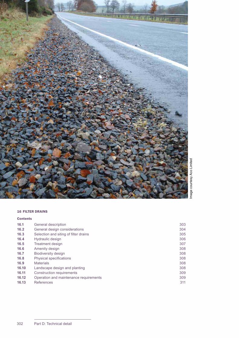
CIRIA SuDS Manual 2015
302 Part D: Technical detail
16 FILTER DRAINS
Contents
16.1 General description 30316.2 General design considerations 30416.3 Selectionandsitingoffilterdrains 30516.4 Hydraulic design 30616.5 Treatment design 30716.6 Amenity design 30816.7 Biodiversity design 30816.8 Physicalspecifications 30816.9 Materials 30816.10 Landscape design and planting 30816.11 Construction requirements 30916.12 Operation and maintenance requirements 30916.13 References 311
Imag
e co
urte
sy A
co L
imite
d

303Chapter 16: Filter drains
CIRIA SuDS Manual 2015
16.1 GENERAL DESCRIPTION
Filterdrainsareshallowtrenchesfilledwithstone/gravelthatcreatetemporarysubsurfacestoragefortheattenuation,conveyanceandfiltrationofsurfacewaterrunoff. The stone may be contained in a simple trench lined with a geotextile, geomembrane or other impermeable liner, or within a more structural facility such asaconcretetrough.Filterdrainsmaybelined(ifrequired)ormayallowinfiltrationdepending on the suitability of the underlying soils and the protection they afford to the groundwater (Sections 25.2 and 26.7).
Filterdrainsshouldideallyreceivelateralinflowfromanadjacentimpermeablesurfacethatispre-treatedusingavegetatedfilterstriporequivalent.Theyarenotnormallyintended to function as sediment traps and should be implemented downstream of a pre-treatment system in order to prevent clogging and failure. Where there is no effective upstream removal of sediments and silts, a geotextile (or other effective filtration)layerbelowthefilterdrainsurface,atashallowdepth,isrequiredthatcanberegularly removed and cleaned or replaced.
Filterdrainscanhelpreducepollutantlevelsinrunoffbyfilteringoutfinesediments,metals, hydrocarbons and other pollutants. They can also encourage adsorption and biodegradation processes. With adequate structural protection, geocellular products can be used as an alternative to some of the stone where the component is designed principally for conveyance: they have a higher void ratio but limited treatment capacity, andareoftenusedtoprovideadditionalstoragezonesforhighreturnperiodfloweventsinconjunctionwithothertreatmentcomponentsorgravellayersinthetrench.
Filter drains are on-line features, and designers should therefore take full consideration oftheinflowratesandvolumespotentiallyassociatedwithhighreturnperiodevents,ensuringthatthetrenchisadequatelyprotectedfromdamage,andexcessflowscanbeconveyed safely downstream.
Aperforatedpipeshouldbeprovidednearthebaseofthefilterdraintocollectandconvey water to downstream drainage components. Use of the available attenuation storageprovidedbythevoidsintheaggregatefillcanbemaximisedthroughtheuseofdownstreamflowcontrolsystems.Ahigh-levelperforatedpipecanbeinstalledtoprovideanoverflowforflowsinexcessofthedesignevent.Whereanetworkoffilterdrains is established, high-level pipes can be used to transfer excess waters around the system in the event of local overloading.
Filter drains can replace conventional pipework as conveyance systems, and the use of adjacentfilterstripsorflowspreaderscanremovetheneedforkerbsandgullieswhensystemsarelocatedadjacenttoroadsorhighways.Theyworkbestwhenincorporatedintoatreatmenttrain,andshouldbeusedinconjunctionwithotherSuDScomponentstosafelypassandstoreextremestormflows.
16Chapter Filter drains
This chapter provides guidance on the design of filter drains – linear drains consisting of a trench filled with a permeable aggregate material, often with a perforated pipe in the base of the trench to assist drainage.
Appendix C, Section C.5.4 demonstrates how to design a filter drain for an industrial area.
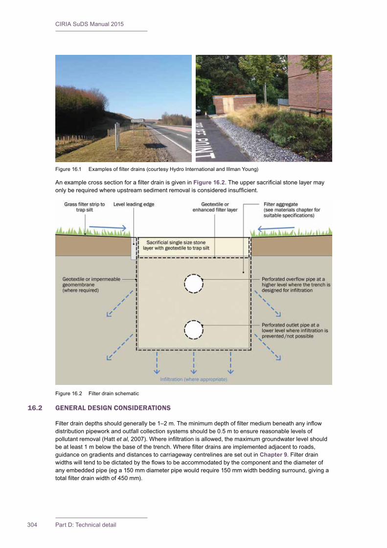
CIRIA SuDS Manual 2015
304 Part D: Technical detail
AnexamplecrosssectionforafilterdrainisgiveninFigure 16.2.Theuppersacrificialstonelayermayonlyberequiredwhereupstreamsedimentremovalisconsideredinsufficient.
16.2 GENERAL DESIGN CONSIDERATIONS
Filterdraindepthsshouldgenerallybe1–2m.Theminimumdepthoffiltermediumbeneathanyinflowdistributionpipeworkandoutfallcollectionsystemsshouldbe0.5mtoensurereasonablelevelsofpollutant removal (Hatt et al,2007).Whereinfiltrationisallowed,themaximumgroundwaterlevelshouldbeatleast1mbelowthebaseofthetrench.Wherefilterdrainsareimplementedadjacenttoroads,guidance on gradients and distances to carriageway centrelines are set out in Chapter 9. Filter drain widthswilltendtobedictatedbytheflowstobeaccommodatedbythecomponentandthediameterofanyembeddedpipe(ega150mmdiameterpipewouldrequire150mmwidthbeddingsurround,givingatotalfilterdrainwidthof450mm).
Figure16.1 Examplesoffilterdrains(courtesyHydroInternationalandIllmanYoung)
Figure 16.2 Filter drain schematic
305Chapter 16: Filter drains
CIRIA SuDS Manual 2015
Thevoidsratioandpermeabilityofthegranularfillshouldbesufficientlyhightoallowadequatepercolationand to control the risk of blockage. Consideration should be given as to whether the trench is required to withstandsurfaceloadingssuchasvehiculartraffic,asthiswillinfluencethetypeoffillthatwillbesuitable.Thestructuralrequirementsofgeocellularsystems(whichmaybespecifiedforenhancedstorageorconveyance purposes beneath the stone layer) are described in detail in Chapter 21. Such systems should bebelowtheminimum0.5mdepthrequiredforadequatepollutantremovalorelseadditionaldownstream(or upstream) treatment will usually be required. Where perforated pipes are used as distribution or collection systems, they should be set within appropriate depths of pipe bedding material. Perforated pipes requireasufficientareaofopeningstomanagetheexpectedflowrateofwaterintoandoutofthepipes.
Themosteffectivepre-treatmentoptionforfilterdrainsistohaverunoffflowoverasmallfilterstripbetweentheedgeofthedrainedareaandthetrench.Evena0.5mwidestripofgrasscanremoveasignificantamountofsiltandprolongthetimeuntilthedrainneedstobecleaned/rehabilitated.Anenhancedfilterlayerorgeotextilecanbeusedatahighlevelinthetrenchtoprovidepre-treatmentwhereother pre-treatment options are not practicable. However, this should only be used where inspection and maintenance regimes are regular and robust, as the system will tend to clog rapidly. Also, the layer should bereadilyseparablefromthesidesectionsasitwillrequireregularreplacement.Thefilterdrainshouldonly drain small areas if this form of pre-treatment is adopted.
AppropriategeotextileandgeomembranespecificationsaredescribedintheChapter 30.
Themaincauseofdamagetofilterdrainsisvehiclesrunningoffthecarriagewayandscatteringthefiltermaterial. This can cause a hazard to vehicles on the carriageway, and barriers such as bollards, large rocksorlowrailingsshouldbeusedtopreventtrafficfromrunningon,orparkingon,thefilterdrain.
Forallfilterdrains,anylengthsofperforatedpipesthataremorethan10mshouldbespacedbetweenaccesssumps(alsoknownascatchpits)sothatthepipescanbecleanedbyjettingoutorrodding(thesesumps can be up to 90 m apart for longer runs of trench). Access sumps should always be accessible andclearlyidentifiable.
Health and safety risk management design guidance is provided in Chapter 36.
16.3 SELECTION AND SITING OF FILTER DRAINS
Filterdrainsarebestlocatedadjacenttoimpermeablesurfacessuchascarparksorroads/highwayswithupstream pre-treatment systems. They can be used for draining residential and non-residential runoff and, when lined, can be used to manage surface water runoff from areas with high groundwater pollution risks. Unless effective pre-treatment of sediments is included within the design, they are applicable primarily to impervious areas where there are not high levels of particulates in the runoff.
Filter drains are generally appropriate for catchments with small impermeable areas. They can be effectively incorporated into the landscape and public open spaces, and with careful design can have minimalland-takerequirements.Theyarenotusuallyusedasretrofitcomponentsduetopotentialobstruction and interference with service routes.
Theuseoffilterdrainsistypicallyrestrictedtositeswithoutsignificantslopes,unlesstheycanbeplacedparallel to contours. The longitudinal slope should not exceed 2% because low velocities are required for stableconveyancethroughthefiltermediumandforpollutantremovalprocessestooccur.
Filterdrainsshouldnotbesitedonunstableground,andgroundstabilityshouldbeverifiedbyassessingsitesoilandgroundwaterconditions.Theyaredesignedforintermittentflowandshouldbeallowedto drain and re-aerate between rainfall events. They should not, therefore, be used on sites with a continuousflowfromgroundwaterorothersources.
Filter drains can prove a useful surface water management component on sites where vegetated systems areimpractical.Theycouldbeconstructedbeneathimpermeablesurfacing,providedthatsufficient

CIRIA SuDS Manual 2015
306 Part D: Technical detail
accessisincludedforinspectionandmaintenance,orgrassed/vegetatedsurfacing,providedthatanappropriate means of identifying and locating the trench is included within the design.
16.4 HYDRAULIC DESIGN
16.4.1 General
Therearethreeelementstothedesignoffilterdrains:
1 designofthefiltermaterialforadequatepercolationofwater–therateofpercolationisacompromisebetweenpollutantremovalandtheneedtorestricttheriskoffloodinginthecatchmentforthedesignstormevent,andtoactasanappropriatetricklingfilterforsmallevents,contacttimewith the aggregate should be maximised (via geometric design characteristics)
2 designofthefiltermaterialtostorewater–thegreaterthevoidratio,themorestorageisavailableinthe trench, and the level of storage available will depend on the throttle at the outlet
3 design of the pipe system to convey water
TherateofpercolationofwaterthroughthefiltermaterialcanbeestimatedroughlyusingDarcy’slaw.Therateofpercolationshouldbesufficienttomeetthedesigncriteria.Thestorageofwaterwithinthetrench and aggregate is dependent on the void ratio of the aggregate and the downstream throttle rate. Calculation methods are as for pervious pavements, as set out in Section 20.5.
Theslottedpipeinthebaseofthefilterdrainshouldbedesignedusingconventionalpipedesignmethodstoachievetheflowsrequiredtomeetthesite-specificdesigncriteria(Equation 20.2). The perforations inthepipeshouldbesufficienttoprovideadequateflowinthesamewayasforbioretentionsystemsin Section 18.8.2.
16.4.2 Interception design
FilterdrainscanonlydeliverasmallcontributiontoInterception(thepreventionofrunoffforthemajorityofsmallevents)wheretheydonotallowinfiltration.Somewaterwillsoakintothefiltermediumandwillalsoberemovedbyevapotranspirationandinfiltration(whereallowed)evenifpermeabilitylevelsareverylow.Theextentofthevolumetricreductioninrunoffwilldependontheinfiltrationrateofthesurroundingsoil, the catchment area, area and depth of the system, type of vegetation and the climate.
Interception design methods are set out in Section 24.8.
16.4.3 Peakflowcontroldesign
Aswellasdeterminingthedegreeoffiltration,theparticlesizeofthemediumalsodeterminestraveltimeinthefilterandcanthereforeplayaroleinmeetingpeakflowdischargeratecontrolrequirements.
Filterdrainscanhelptomanagepeakflowsbynaturallylimitingratesofconveyancethroughthefiltermedium,andalsobyprovidingattenuationstoragewhichfillswhentherateofflowattheoutletiscontrolled.Designandassessmentofthesurfaceandsubsurfacestoragevolumescanbedeterminedusing standard hydraulic assessment.
Subsurfacestoragecanbeprovidedbythevoidspaceinthefiltermediumand/ordrainagelayerinthesystem, ie:
Available attenuation storage in the filter medium and drainage layer of the bioretention system = Volume of system × void ratio in the soil/drainage layer
Duetothesmallrunoffareaslikelytobedischargingtothesystem,itmaybeappropriatetolinkadjacentsystemstogethersothatthesizeoftheopeningintheflowcontrolcanbelarger.
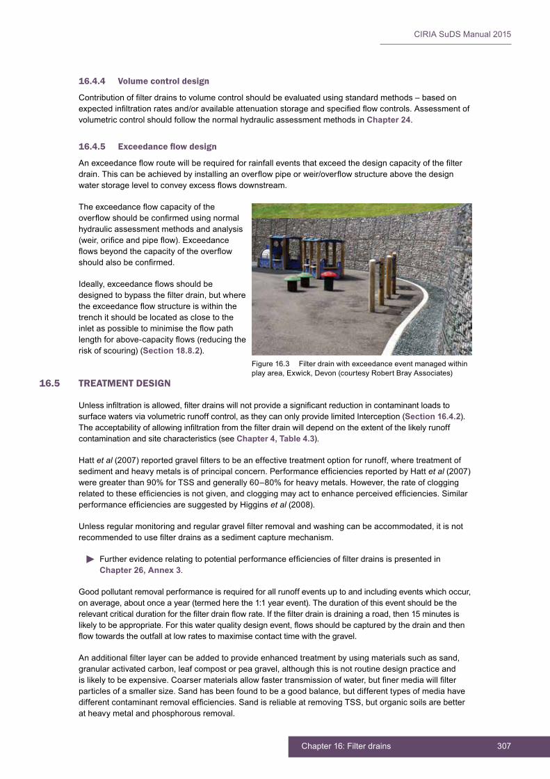
307Chapter 16: Filter drains
CIRIA SuDS Manual 2015
16.4.4 Volume control design
Contributionoffilterdrainstovolumecontrolshouldbeevaluatedusingstandardmethods–basedonexpectedinfiltrationratesand/oravailableattenuationstorageandspecifiedflowcontrols.Assessmentofvolumetric control should follow the normal hydraulic assessment methods in Chapter 24.
16.4.5 Exceedanceflowdesign
Anexceedanceflowroutewillberequiredforrainfalleventsthatexceedthedesigncapacityofthefilterdrain.Thiscanbeachievedbyinstallinganoverflowpipeorweir/overflowstructureabovethedesignwaterstorageleveltoconveyexcessflowsdownstream.
Theexceedanceflowcapacityoftheoverflowshouldbeconfirmedusingnormalhydraulic assessment methods and analysis (weir,orificeandpipeflow).Exceedanceflowsbeyondthecapacityoftheoverflowshouldalsobeconfirmed.
Ideally,exceedanceflowsshouldbedesignedtobypassthefilterdrain,butwheretheexceedanceflowstructureiswithinthetrench it should be located as close to the inletaspossibletominimisetheflowpathlengthforabove-capacityflows(reducingtherisk of scouring) (Section 18.8.2).
16.5 TREATMENT DESIGN
Unlessinfiltrationisallowed,filterdrainswillnotprovideasignificantreductionincontaminantloadstosurface waters via volumetric runoff control, as they can only provide limited Interception (Section 16.4.2). Theacceptabilityofallowinginfiltrationfromthefilterdrainwilldependontheextentofthelikelyrunoffcontamination and site characteristics (see Chapter 4, Table 4.3).
Hatt et al(2007)reportedgravelfilterstobeaneffectivetreatmentoptionforrunoff,wheretreatmentofsedimentandheavymetalsisofprincipalconcern.PerformanceefficienciesreportedbyHattet al (2007)were greater than 90% for TSS and generally 60–80% for heavy metals. However, the rate of clogging relatedtotheseefficienciesisnotgiven,andcloggingmayacttoenhanceperceivedefficiencies.SimilarperformanceefficienciesaresuggestedbyHigginset al (2008).
Unlessregularmonitoringandregulargravelfilterremovalandwashingcanbeaccommodated,itisnotrecommendedtousefilterdrainsasasedimentcapturemechanism.
FurtherevidencerelatingtopotentialperformanceefficienciesoffilterdrainsispresentedinChapter 26, Annex 3.
Good pollutant removal performance is required for all runoff events up to and including events which occur, on average, about once a year (termed here the 1:1 year event). The duration of this event should be the relevantcriticaldurationforthefilterdrainflowrate.Ifthefilterdrainisdrainingaroad,then15minutesislikelytobeappropriate.Forthiswaterqualitydesignevent,flowsshouldbecapturedbythedrainandthenflowtowardstheoutfallatlowratestomaximisecontacttimewiththegravel.
Anadditionalfilterlayercanbeaddedtoprovideenhancedtreatmentbyusingmaterialssuchassand,granular activated carbon, leaf compost or pea gravel, although this is not routine design practice and islikelytobeexpensive.Coarsermaterialsallowfastertransmissionofwater,butfinermediawillfilterparticles of a smaller size. Sand has been found to be a good balance, but different types of media have differentcontaminantremovalefficiencies.SandisreliableatremovingTSS,butorganicsoilsarebetterat heavy metal and phosphorous removal.
Figure 16.3 Filter drain with exceedance event managed within playarea,Exwick,Devon(courtesyRobertBrayAssociates)
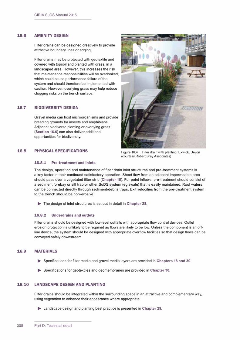
CIRIA SuDS Manual 2015
308 Part D: Technical detail
16.6 AMENITY DESIGN
Filter drains can be designed creatively to provide attractive boundary lines or edging.
Filter drains may be protected with geotextile and covered with topsoil and planted with grass, in a landscaped area. However, this increases the risk that maintenance responsibilities will be overlooked, which could cause performance failure of the system and should therefore be implemented with caution. However, overlying grass may help reduce clogging risks on the trench surface.
16.7 BIODIVERSITY DESIGN
Gravel media can host microorganisms and provide breeding grounds for insects and amphibians. Adjacentbiodiverseplantingoroverlyinggrass(Section 16.6) can also deliver additional opportunities for biodiversity.
16.8 PHYSICAL SPECIFICATIONS
16.8.1 Pre-treatment and inlets
Thedesign,operationandmaintenanceoffilterdraininletstructuresandpre-treatmentsystemsisakeyfactorintheircontinuedsatisfactoryoperation.Sheetflowfromanadjacentimpermeableareashouldpassoveravegetatedfilterstrip(Chapter 15).Forpointinflows,pre-treatmentshouldconsistofasedimentforebayorsilttraporotherSuDSsystem(egswale)thatiseasilymaintained.Roofwaterscanbeconnecteddirectlythroughsediment/debristraps.Exitvelocitiesfromthepre-treatmentsystemto the trench should be non-erosive.
The design of inlet structures is set out in detail in Chapter 28.
16.8.2 Underdrains and outlets
Filterdrainsshouldbedesignedwithlow-leveloutfallswithappropriateflowcontroldevices.Outleterosionprotectionisunlikelytoberequiredasflowsarelikelytobelow.Unlessthecomponentisanoff-linedevice,thesystemshouldbedesignedwithappropriateoverflowfacilitiessothatdesignflowscanbeconveyed safely downstream.
16.9 MATERIALS
SpecificationsforfiltermediaandgravelmedialayersareprovidedinChapters 18 and 30.
SpecificationsforgeotextilesandgeomembranesareprovidedinChapter 30.
16.10 LANDSCAPE DESIGN AND PLANTING
Filter drains should be integrated within the surrounding space in an attractive and complementary way, using vegetation to enhance their appearance where appropriate.
Landscape design and planting best practice is presented in Chapter 29.
Figure16.4 Filterdrainwithplanting,Exwick,Devon(courtesy Robert Bray Associates)

309Chapter 16: Filter drains
CIRIA SuDS Manual 2015
16.11 CONSTRUCTION REQUIREMENTS
Filter drains should be protected before completion and stabilisation of the upstream development areas. They should not be used for drainage of construction sites, where untreated runoff is likely to contain large amounts of silt, debris and other pollutants, as this will cause rapid clogging of the systems.
All trench excavations should follow construction best practice and be supported, if required. No personnel should be allowed to enter an unsupported trench deeper than 1.2 m. Trench supports should be designed to guarantee the safety of those working in the trench. Support may also be needed for shallower trenches in weak ground.
Filterdrainformationsshouldbeflatortoashallowgradetoreducetheriskofpondingandnegativefiltergradients.Geotextileandstonefillshouldbecleanbeforeconstruction.Backfillshouldbeplacedin100–150mmlayersandlightlycompactedasrequired.
All geotextiles should be wrapped and secured to prevent gravel or stone from clogging with sediments.
Thedrain-downtimeafterastormshouldbeobservedaftercompletionormodificationofthefacilitytoconfirmthatthedesireddraintimehasbeenobtained(BRE,1991).
Further detail on construction activities and the programming of construction activities is provided in Chapter 31.
AconstructionphasehealthandsafetyplanisrequiredundertheConstruction(DesignandManagement)Regulations(CDM)2015.Thisshouldensurethatallconstructionriskshavebeenidentified,eliminated,reducedand/orcontrolledwhereappropriate.
Generic health and safety guidance is presented in Chapter 36.
16.12 OPERATION AND MAINTENANCE REQUIREMENTS
Filter drains will require regular maintenance to ensure continuing operation to design performance standards,andalldesignersshouldprovidedetailedspecificationsandfrequenciesfortherequiredmaintenance activities along with likely machinery requirements and typical annual costs – within the MaintenancePlan.Thetreatmentperformanceoffilterdrainsisdependentonmaintenance,androbustmanagementplanswillberequiredtoensurethatmaintenanceiscarriedoutinthelongterm.Differentdesigns will have different operation and maintenance requirements, but this section gives some generic guidance.
Regularinspectionandmaintenanceisimportantfortheeffectiveoperationoffilterdrainsasdesigned.Maintenanceresponsibilityforafilterdrainshouldalwaysbeplacedwithanappropriateorganisation.Adequateaccessshouldalwaysbeprovidedtothefilterdrainforinspectionandmaintenance.Iffilterdrainsareimplementedwithinprivateproperty,ownersshouldbeeducatedontheirroutinemaintenance needs, and should understand the long-term Maintenance Plan and any legally binding maintenance agreement.
Litter (including leaf litter) and debris removal should be undertaken as part of general landscape maintenanceforthesiteandbeforeanyotherSuDSmanagementtask.Alllittershouldberemovedfrom site.
Table 16.1 provides guidance on the type of operational and maintenance requirements that may be appropriate. The list of actions is not exhaustive and some actions may not always be required.

CIRIA SuDS Manual 2015
310 Part D: Technical detail
TABLE16.1
Operationandmaintenancerequirementsforfilterdrains
Maintenance schedule Required action Typical frequency
Regular maintenance
Removelitter(includingleaflitter)anddebrisfromfilterdrain surface, access chambers and pre-treatment devices
Monthly (or as required)
Inspectfilterdrainsurface,inlet/outletpipeworkandcontrol systems for blockages, clogging, standing water and structural damage
Monthly
Inspect pre-treatment systems, inlets and perforated pipework for silt accumulation, and establish appropriate silt removal frequencies
Six monthly
Remove sediment from pre-treatment devices Six monthly, or as required
Occasional maintenance
Remove or control tree roots where they are encroaching thesidesofthefilterdrain,usingrecommendedmethods(eg NJUG, 2007 or BS 3998:2010)
As required
At locations with high pollution loads, remove surface geotextileandreplace,andwashorreplaceoverlyingfiltermedium
Five yearly, or as required
Clear perforated pipework of blockages As required
Sediments excavated from upstream pre-treatment devices that receive runoff from residential or standard road and roof areas are generally not toxic or hazardous material and can therefore be safely disposedofbyeitherlandapplicationorlandfilling.However,consultationshouldtakeplacewiththeenvironmentalregulatortoconfirmappropriatewastemanagementprotocolsandcompliancewithlegislation.Sedimenttestingmayberequiredbeforesedimentexcavationtodetermineitsclassificationand appropriate disposal methods. For industrial site runoff, sediment testing will be essential. In the majorityofcases,itwillbeacceptabletodistributethesedimentonsite,ifthereisanappropriatesafeand acceptable location to do so. Any damage due to sediment removal or erosion should be repaired and immediately reseeded or planted.
Further detail on waste management is provided in Chapter 32.
MaintenancePlansandschedulesshouldbedevelopedduringthedesignphase.Specificmaintenanceneedsofthefilterdrainshouldbemonitoredandmaintenanceschedulesadjustedtosuitrequirements.
FurtherdetailonthepreparationofmaintenancespecificationsandschedulesofworkisgiveninChapter 32.
CDM2015requiresdesignerstoensurethatallmaintenanceriskshavebeenidentified,eliminated,reducedand/orcontrolledwhereappropriate.Thisinformationwillberequiredaspartofthehealthandsafetyfile.
Generic health and safety guidance is presented in Chapter 36.

311Chapter 16: Filter drains
CIRIA SuDS Manual 2015
16.13 REFERENCES
BRE (1991) Soakaway design,BREDigest365,BuildingResearchEstablishment,Bracknell,UK(ISBN:0-85125-502-7)
HATT,BE,FLETCHER,TDandDELETIC,A(2007)“Treatmentperformanceofgravelfiltermedia:Implicationsfordesignandapplicationofstormwaterinfiltrationsystems”Water Research, vol 41, 12, ElsevierBV,UK,pp2513–2524
HIGGINS,N,JOHNSTON,P,GILL,L,BRUEN,MANDDESTA,M(2008)“HighwayrunoffinIrelandandmanagementwitha‘FrenchDrain’system”.In:Proc 11th int conf on urban drainage, Edinburgh, Scotland, UK,31Augustto5September2008,pp1–9.Goto:http://tinyurl.com/qxajdrz
NJUG (2007) Guidelines for the planning, installation and maintenance of utility apparatus in proximity to trees, volume 4, issue 2,NationalJointUtilitiesGroup,London,UK.Goto:http://tinyurl.com/q52orn6
Statutes
BS 3998:2010 Tree work. Recommendations
Construction(DesignandManagement)Regulations(CDM)2015
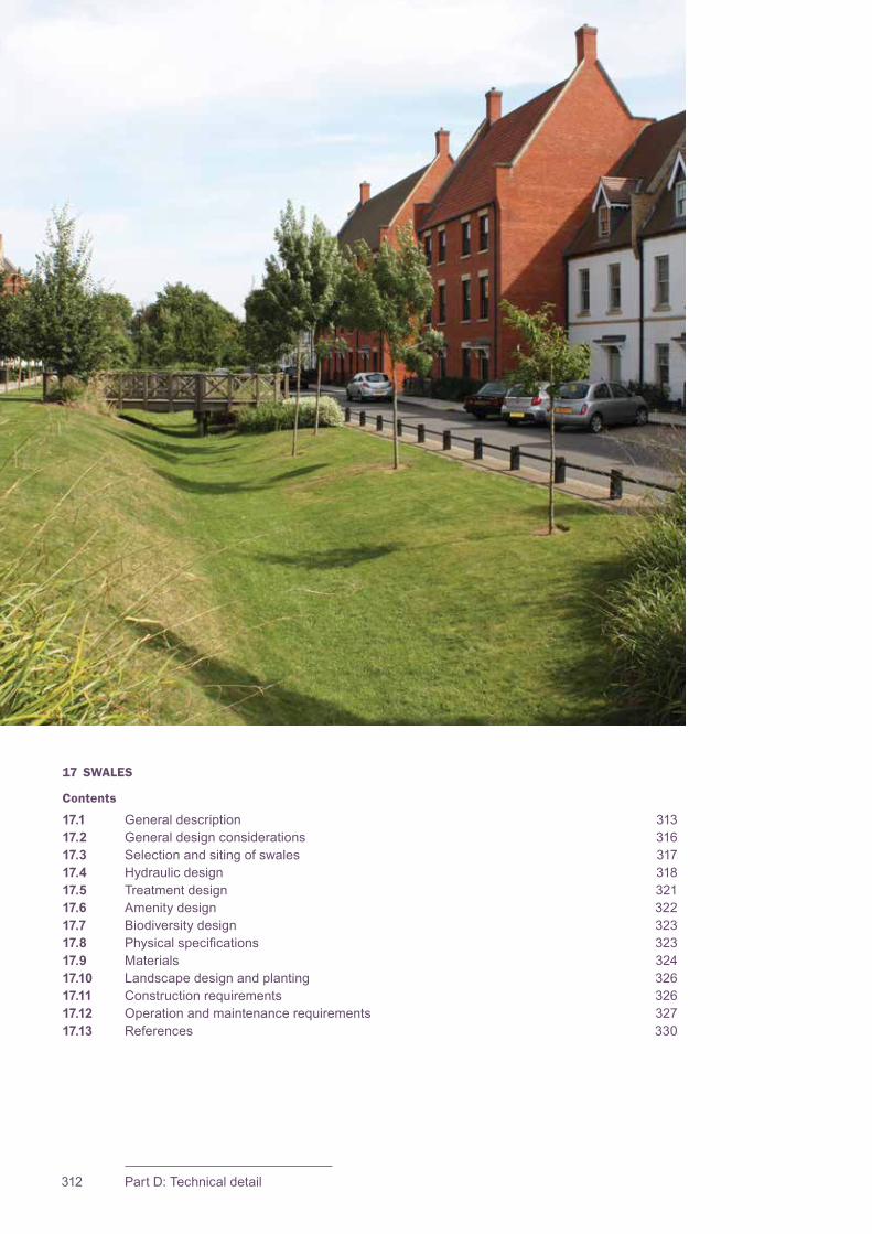
CIRIA SuDS Manual 2015
312 Part D: Technical detail
17 SWALES
Contents
17.1 General description 31317.2 General design considerations 31617.3 Selection and siting of swales 31717.4 Hydraulic design 31817.5 Treatment design 32117.6 Amenity design 32217.7 Biodiversity design 32317.8 Physicalspecifications 32317.9 Materials 32417.10 Landscape design and planting 32617.11 Construction requirements 32617.12 Operation and maintenance requirements 32717.13 References 330
313Chapter 17: Swales
CIRIA SuDS Manual 2015
17.1 GENERAL DESCRIPTION
Swalesareshallow,flatbottomed,vegetatedopenchannelsdesignedtoconvey,treatand often attenuate surface water runoff. When incorporated into site design, they can enhancethenaturallandscapeandprovideaestheticandbiodiversitybenefits.Theyareoftenusedtodrainroads,pathsorcarparks,whereitisconvenienttocollectdistributedinflowsofrunoff,orasameansofconveyingrunoffonthesurfacewhileenhancingaccesscorridorsorotheropenspace.Swalescanhaveavarietyofprofiles,canbeuniform or non-uniform, and can incorporate a range of different planting strategies, dependinguponthesitecharacteristicsandsystemobjectives.
Swales can replace conventional pipework as a means of conveying runoff, and the use of adjacentfilterstripsand/orflowspreaderscanalsoremovetheneedforkerbsandgullies.
Thestandardswalechannelisbroadandshallowandcoveredbyvegetation,usuallygrass,toslowthewater–facilitatingsedimentation,filtrationthroughtherootzoneandsoilmatrix,evapotranspirationandinfiltrationintotheunderlyingsoil.Aswalecanhavecheckdamsorbermsinstalledacrosstheflowpath,thattemporarilypondrunofftoincreasepollutantretentionandinfiltrationandfurtherdecreaseflowvelocity–particularly useful for sites with steeper gradients.
Therearethreetypesofswale,describedinSections 17.1.1 to 17.1.3.
17.1.1 Conveyance and attenuation swale
The conveyance swale is a shallow vegetated channel (Figure 17.1). These are particularly effective ways of collecting and conveying runoff from the drained area to anotherstageoftheSuDSManagementTrain.Theycanbedesignedfortreatmentand/orattenuation(whererequired),dependingonthelevelofflowconstraintandpondingdepthsdeliveredbythedesign.
Verysmallswales(“mini-swales”)canbeusedtomanagesmalleventswitheffectiveoverflowfacilitiestoalternativecomponents.
17Chapter Swales
This chapter provides guidance on the design of swales – shallow vegetated channels designed principally to convey and treat runoff.
Appendix C, Section C.5.4 demonstrates how to design an underdrained swale for an industrial area.Appendix C, Section C.5.5 demonstrates how to design a strategic conveyance swale.
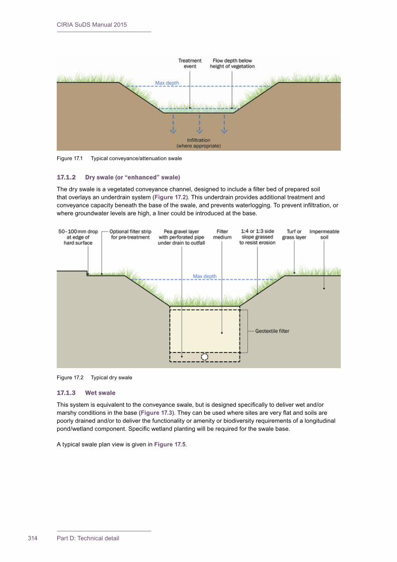
CIRIA SuDS Manual 2015
314 Part D: Technical detail
17.1.2 Dry swale (or “enhanced” swale)
Thedryswaleisavegetatedconveyancechannel,designedtoincludeafilterbedofpreparedsoilthat overlays an underdrain system (Figure 17.2). This underdrain provides additional treatment and conveyancecapacitybeneaththebaseoftheswale,andpreventswaterlogging.Topreventinfiltration,orwheregroundwaterlevelsarehigh,alinercouldbeintroducedatthebase.
17.1.3 Wet swale
Thissystemisequivalenttotheconveyanceswale,butisdesignedspecificallytodeliverwetand/ormarshyconditionsinthebase(Figure 17.3).Theycanbeusedwheresitesareveryflatandsoilsarepoorlydrainedand/ortodeliverthefunctionalityoramenityorbiodiversityrequirementsofalongitudinalpond/wetlandcomponent.Specificwetlandplantingwillberequiredfortheswalebase.
A typical swale plan view is given in Figure 17.5.
Figure17.1 Typicalconveyance/attenuationswale
Figure 17.2 Typical dry swale
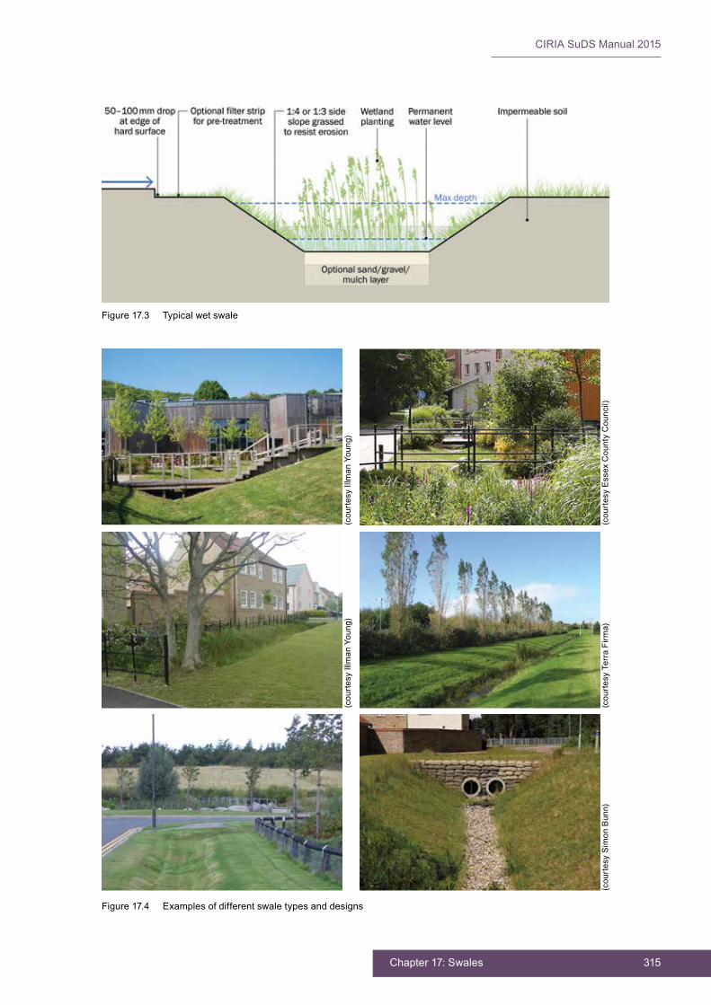
315Chapter 17: Swales
CIRIA SuDS Manual 2015
Figure 17.4 Examples of different swale types and designs
Figure 17.3 Typical wet swale
(cou
rtes
y Ill
man
You
ng)
(cou
rtes
y E
ssex
Cou
nty
Cou
ncil)
(cou
rtes
y Ill
man
You
ng)
(cou
rtes
y Te
rra
Firm
a)(c
ourt
esy
Sim
on B
unn)
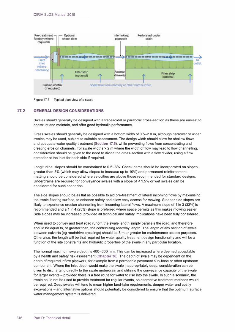
CIRIA SuDS Manual 2015
316 Part D: Technical detail
17.2 GENERAL DESIGN CONSIDERATIONS
Swalesshouldgenerallybedesignedwithatrapezoidalorparaboliccross-sectionastheseareeasiesttoconstruct and maintain, and offer good hydraulic performance.
Grassswalesshouldgenerallybedesignedwithabottomwidthof0.5–2.0m,althoughnarrowerorwiderswalesmaybeused,subjecttosuitableassessment.Thedesignwidthshouldallowforshallowflowsand adequate water quality treatment (Section 17.5),whilepreventingflowsfromconcentratingandcreatingerosionchannels.Forswalewidths>2mwherethewidthofflowmayleadtoflowchannelling,considerationshouldbegiventotheneedtodividethecross-sectionwithaflowdivider,usingaflowspreader at the inlet for each side if required.
Longitudinalslopesshouldbeconstrainedto0.5–6%.Checkdamsshouldbeincorporatedonslopesgreaterthan3%(whichmayallowslopestoincreaseupto10%)andpermanentreinforcementmattingshouldbeconsideredwherevelocitiesareabovethoserecommendedforstandarddesigns.Underdrainsarerequiredforconveyanceswaleswithaslopeof<1.5%orwetswalescanbeconsidered for such scenarios.
Thesideslopesshouldbeasflataspossibletoaidpre-treatmentoflateralincomingflowsbymaximisingtheswalefilteringsurface,toenhancesafetyandalloweasyaccessformowing.Steepersideslopesarelikelytoexperienceerosionchannellingfromincominglateralflows.Amaximumslopeof1in3(33%)isrecommendedanda1in4(25%)slopeispreferredwherespacepermitsasthismakesmowingeasier.Sideslopesmaybeincreased,providedalltechnicalandsafetyimplicationshavebeenfullyconsidered.
When used to convey and treat road runoff, the swale length simply parallels the road, and therefore shouldbeequalto,orgreaterthan,thecontributingroadwaylength.Thelengthofanysectionofswalebetweenculverts(egroad/drivecrossings)shouldbe5morgreaterformaintenanceaccesspurposes.Otherwise,thelengthwillbethatrequiredforwaterqualitytreatmentdesignfunctionalityandwillbeafunction of the site constraints and hydraulic properties of the swale in any particular location.
Thenormalmaximumswaledepthis400–600mm.Thiscanbeincreasedwheredeemedacceptablebyahealthandsafetyriskassessment(Chapter 36).Thedepthofswalemaybedependentonthedepthofrequiredinflowpipework,forexamplefromapermeablepavementsub-baseorotherupstreamcomponent.Wheretheinletdepthwouldmaketheswaleinappropriatelydeep,considerationcanbegiven to discharging directly to the swale underdrain and utilising the conveyance capacity of the swale for larger events – provided there is a free route for water to rise into the swale. In such a scenario, the swalecouldnotbeusedtoprovidetreatmentforregularevents,soalternativetreatmentmethodswouldberequired.Deepswaleswilltendtomeanhigherland-takerequirements,deeperwaterandcostlyexcavations–andalternativeoptionsshouldpotentiallybeconsideredtoensurethattheoptimumsurfacewater management system is delivered.
Figure 17.5 Typical plan view of a swale
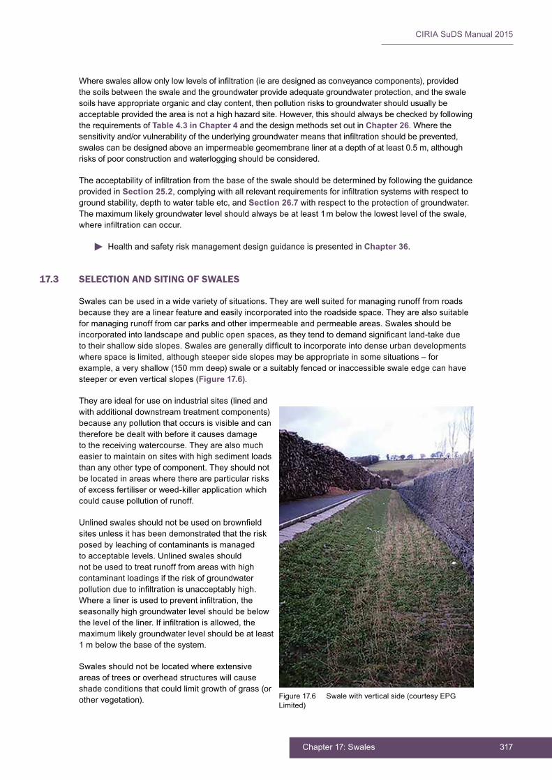
317Chapter 17: Swales
CIRIA SuDS Manual 2015
Whereswalesallowonlylowlevelsofinfiltration(iearedesignedasconveyancecomponents),providedthesoilsbetweentheswaleandthegroundwaterprovideadequategroundwaterprotection,andtheswalesoilshaveappropriateorganicandclaycontent,thenpollutionriskstogroundwatershouldusuallybeacceptableprovidedtheareaisnotahighhazardsite.However,thisshouldalwaysbecheckedbyfollowingthe requirements of Table 4.3 in Chapter 4 and the design methods set out in Chapter 26. Where the sensitivityand/orvulnerabilityoftheunderlyinggroundwatermeansthatinfiltrationshouldbeprevented,swalescanbedesignedaboveanimpermeablegeomembranelineratadepthofatleast0.5m,althoughrisksofpoorconstructionandwaterloggingshouldbeconsidered.
Theacceptabilityofinfiltrationfromthebaseoftheswaleshouldbedeterminedbyfollowingtheguidanceprovided in Section 25.2,complyingwithallrelevantrequirementsforinfiltrationsystemswithrespecttogroundstability,depthtowatertableetc,andSection 26.7 with respect to the protection of groundwater. Themaximumlikelygroundwaterlevelshouldalwaysbeatleast1mbelowthelowestleveloftheswale,whereinfiltrationcanoccur.
Health and safety risk management design guidance is presented in Chapter 36.
17.3 SELECTION AND SITING OF SWALES
Swalescanbeusedinawidevarietyofsituations.Theyarewellsuitedformanagingrunofffromroadsbecausetheyarealinearfeatureandeasilyincorporatedintotheroadsidespace.Theyarealsosuitableformanagingrunofffromcarparksandotherimpermeableandpermeableareas.Swalesshouldbeincorporatedintolandscapeandpublicopenspaces,astheytendtodemandsignificantland-takeduetotheirshallowsideslopes.Swalesaregenerallydifficulttoincorporateintodenseurbandevelopmentswherespaceislimited,althoughsteepersideslopesmaybeappropriateinsomesituations–forexample,averyshallow(150mmdeep)swaleorasuitablyfencedorinaccessibleswaleedgecanhavesteeper or even vertical slopes (Figure 17.6).
They are ideal for use on industrial sites (lined and with additional downstream treatment components) becauseanypollutionthatoccursisvisibleandcanthereforebedealtwithbeforeitcausesdamageto the receiving watercourse. They are also much easier to maintain on sites with high sediment loads than any other type of component. They should not belocatedinareaswherethereareparticularrisksof excess fertiliser or weed-killer application which could cause pollution of runoff.
Unlinedswalesshouldnotbeusedonbrownfieldsitesunlessithasbeendemonstratedthattheriskposedbyleachingofcontaminantsismanagedtoacceptablelevels.Unlinedswalesshouldnotbeusedtotreatrunofffromareaswithhighcontaminant loadings if the risk of groundwater pollutionduetoinfiltrationisunacceptablyhigh.Wherealinerisusedtopreventinfiltration,theseasonallyhighgroundwaterlevelshouldbebelowtheleveloftheliner.Ifinfiltrationisallowed,themaximumlikelygroundwaterlevelshouldbeatleast1mbelowthebaseofthesystem.
Swalesshouldnotbelocatedwhereextensiveareas of trees or overhead structures will cause shade conditions that could limit growth of grass (or other vegetation). Figure 17.6 Swale with vertical side (courtesy EPG
Limited)

CIRIA SuDS Manual 2015
318 Part D: Technical detail
17.4 HYDRAULIC DESIGN
17.4.1 General
Swaledesignisbasedonopenchanneldesign–balancingstorage,treatmentandinfiltrationduringsmallstormswiththeneedforpeakflowconveyanceduringlargerevents.Thehydraulicandtreatmentdesignforswalesisthereforeintegrallylinkedanddesignmethodsforbotharecoveredtogetherinthissection.
Thefollowingshouldbeaccountedforwhenconsideringthehydraulicdesignofallswales:
1 Theswaleshouldhaveadequatecapacitytoconveyand/orstorethedesignreturnperiodevent(componentlevelofservice).Itshouldbenotedthatwetswaleswilltendnottorecoversowellfromhighflows,soareducedlevelofservicemaybeappropriate.
2 Theswaleshouldhavetheabilitytosafelyconveyextremeeventflows,orelseexcessflowsshouldbesafelypassedtoappropriatetemporaryexceedanceflowstorageareasorconveyancepaths.
3 The design event runoff volumes should half empty within 24 hours. This will help to ensure that storageandtreatmentvolumesareavailableforsubsequenteventsand,fordry/conveyanceswales,shouldalsoprotectvegetationfromdamagebysaturatedconditions.
1 Conveyance swales
Vegetationintheswaleshouldtypicallybemaintainedataheightof75–150mmtopreventflatteningduringflowevents(orsuitableplantingspecifiedforagreaterdepthofflow).
Good pollutant removal performance is required for all runoff events up to and including events which occur,onaverage,aboutonceayear(termedherethe1:1yearevent).Thedurationofthiseventshouldbetherelevantcriticaldurationfortheswale.Iftheswaleisdrainingaroadthen15minutesislikelytobeappropriate.Forthiswaterqualitydesignevent:
▪ thedepthofflowshouldbemaintainedbelowtheheightofvegetation(ieusually<100mm)
▪ themaximumflowvelocityintheswaleforsuchaneventshouldbe0.3m/stoensureadequaterunofffiltration
▪ thetimeoftravelofrunoffalongtheswale(residencetime=length/velocity)shouldbeatleast9minutes(18minutesfromthetopoftheswale,iftheswalehaslateralinflowsalongitslength).
Tocalculatetheaveragevelocityofflowinaswale,Manning’sequationshouldbeused(Section 24.11.1). TheManning’s“n”value,orthe“roughnesscoefficient”indicatestowhatextentthesurfaceoftheswalewillresistflow,andiscriticalinitssizing.Thecoefficientvarieswiththetypeofvegetativecoverandtheflowdepth,andasuggestedrelationshipbetweenflowdepthandManning’s“n”forgrasschannelsisgiven in Figure 17.7withavalueof0.35recommendedforadepthofwaterbeloworequaltotheheightofthegrass.Thiscoefficientwillneedtobeincreasedforswalesthatincludelargerplantsand/oragreaterrangeofplantsizes.
Flowvelocitiesforextremeeventsshouldbekeptbelow1.0m/s(or2.0m/sifslopestability,soilerosionandsafetyconditionsallow)topreventerosion.TheaverageManning’s“n”valueforabovegrassflowswillneedtobeestimated,dependingontheflowdepth.
Checkdamsandappropriatepre-treatmentsystemscanbeusedtoimprovebothhydraulicandwaterqualityperformanceofaswalesystembyreducingvelocities,increasingresidencetimeandincreasinginfiltrationand/orstorage(Sections 17.8.1 and 17.9.2).
Whereswalesarebeingdesignedforconveyancecapacityinlargerevents,itissuggestedthatdesigncriteria for these systems should not assume extra allowances for loss of volume. Where swales are to bedesignedtodischargesignificantvolumesviainfiltration,thesystemsshouldbedesignedasaformofsoakawayorinfiltrationbasin(Chapter 13).
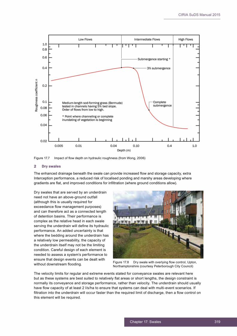
319Chapter 17: Swales
CIRIA SuDS Manual 2015
2 Dry swales
Theenhanceddrainagebeneaththeswalecanprovideincreasedflowandstoragecapacity,extraInterception performance, a reduced risk of localised ponding and marshy areas developing where gradientsareflat,andimprovedconditionsforinfiltration(wheregroundconditionsallow).
Dryswalesthatareservedbyanunderdrainneednothaveanabove-groundoutfall(although this is usually required for exceedanceflowmanagementpurposes)and can therefore act as a connected length ofdetentionbasins.Theirperformanceiscomplex as the relative head in each swale servingtheunderdrainwilldefineitshydraulicperformance. An added uncertainty is that wherethebeddingaroundtheunderdrainhasarelativelylowpermeability,thecapacityoftheunderdrainitselfmaynotbethelimitingcondition. Careful design of each element is neededtoassessasystem’sperformancetoensurethatdesigneventscanbedealtwithwithoutdownstreamflooding.
The velocity limits for regular and extreme events stated for conveyance swales are relevant here butasthesesystemsarebestsuitedtorelativelyflatareasorshortlengths,thedesignconstraintisnormally its conveyance and storage performance, rather than velocity. The underdrain should usually haveflowcapacityofatleast2l/s/hatoensurethatsystemscandealwithmulti-eventscenarios.Iffiltrationintotheunderdrainwilloccurfasterthantherequiredlimitofdischarge,thenaflowcontrolonthiselementwillberequired.
Figure17.7 Impactofflowdepthonhydraulicroughness(fromWong,2006)
Figure17.8 Dryswalewithoverlyingflowcontrol,Upton,Northamptonshire(courtesyPeterboroughCityCouncil)

CIRIA SuDS Manual 2015
320 Part D: Technical detail
3 Wet swales
Theconveyancecapacityofwetswalescanbedeterminedbyusingthesameapproachasforconveyance swales. The requirement to constrain velocities for the water quality treatment event to ensuresuitablevegetativefiltrationwillnotnormallyberelevant,astheshallower(orzerogradient)longitudinalslopesassociatedwithwetswaleswillensuresuitableretentiontimes.
Apermanentlywetswalebasecanprovidequiescentzonesfortheremovaloffineparticles–actingassmalllinearpond/wetlandsystems(Chapter 23). Wet swales are usually appropriate where sites are veryflatandsoilsarepoorlydrained,butcanbedesignedformorepermeablesitesusingimpermeablelinerstodeliverspecifictreatmentperformanceoramenityorbiodiversityrequirements.Wetswaleswilloccurnaturallywherehighwatertablesriseabovetheswalebase,butthisprovidesadirecthydrauliclinkbetweenrunoffandgroundwaterandshouldnotnormallybeallowed(Chapter 4).
Adequatepre-treatmentshouldbeincludedtoavoidtherapidbuild-upofsedimentsinmarshywetlandsurfaces(whichismoredifficultanddamagingtoremove)andtoensurethatanyareasofpermanentwaterdonotreceivecontaminatedrunoffthatcouldposearisktoamenityandbiodiversityperformanceof the system.
A minimum depth of water of 150 mm is usually appropriate to protect wetland vegetation from erosive flowsandmaintainadequateresilienceofthesystemtodrought.Maximumwaterdepthsshouldbesetonasite-by-sitebasis,takingintoaccountbothtechnical,amenity(includingsafety)andbiodiversitycriteria. Appropriate depth ranges should follow the guidance given for ponds and wetlands (Section 23.2).
17.4.2 Interception design
Conveyanceswalesanddry/enhancedswalesdeliverInterceptionbecausethereisusuallynorunofffromthemforthemajorityofsmallrainfallevents.Thewatersoaksintothesurfacevegetatedsoillayersandintotheunderlyingsoilsorothermedia,andisremovedbyevapotranspirationandinfiltration(whereallowed).Theextentofthevolumetricreductioninrunoffwilldependontheinfiltrationrateofthesurroundingsoil,thecapacityofanyunderlyingfiltermedia,thecatchmentarea,theareaoftheswale,the type of vegetation and the climate.
Wherethereisinfiltrationcapacity,infiltrationisacceptableandtheswaleisdesignedtofacilitateevenlimitedinfiltration,thenasimpleinfiltrationdesigncalculationwilldeterminewhethertheswaleisabletodisposeof5mmrainfalldepthoverthecontributingcatchmentarea(Section 25.6).
Wherethereisnoinfiltration,butthenaturalsurfacesoils(orimportedorre-engineeredsoils)havewaterstorage capacity, then Interception design should follow the principles set out in Section 24.8.
Interceptioncannotbeassumedforwetswales,unlessitsdeliveryisexplicitlydemonstratedinthedesign.
17.4.3 Peakflowcontroldesign
Swalescanhelpreduceflowratesfromasitebyfacilitatinginfiltrationand/orbyprovidingattenuationstorage.Forswales,thepeakflowcontroldesignandassessmentofthesurfacestoragevolumecanbedeterminedbyusingstandardhydraulicassessment.Infiltrationcontributionsshouldonlybeincludedfordryorenhancedswales,whereslopesare<1.5%andwherecontributionstopeakflowreductionsareexplicitlydeterminedbythedesign.Thedesigninflowsshouldalwaysincluderunofffromtheperviousside slopes draining to the swale.
Furtherstoragecanbeprovidedbeneaththeswalebaseusinggravelorotherfilter/drainagemediumorgeocellular crate systems (Chapter 21),thatis:
Available attenuation storage in the filter media and drainage layer of the swale system = volume of system × void ratio in the soil/drainage layer

321Chapter 17: Swales
CIRIA SuDS Manual 2015
Aflowcontrolstructureisgenerallyrequiredtoconstraintherateofwaterdischargedfromthesurfaceand/orsubsurfacesystem(Chapter 28).
17.4.4 Volume control design
Swalesarenotnormallyassumedtoprovideanyreductioninvolumeofrunoffforthe1:100year,6hourevent,butifinfiltrationratesfromthesystemaredeemedtobesignificantforthisscaleofevent,thenthisshouldbeexplicitlyaccountedforbythedesign.
17.4.5 Exceedanceflowdesign
Anexceedanceflowroutewillberequiredforrainfalleventsthatexceedthedesigncapacityoftheswale.Thiscanbeachievedbyinstallinganoverflowpipeorweir/overflowstructureabovethedesignwaterstorageleveltoconveyexcessflowsdownstream.Asswalestendtobelonglinearcomponents,severaloverflowsarelikelytoberequired.
Theexceedanceflowcapacityoftheoverflow(s)shouldbeconfirmedusingstandardhydraulicassessmentmethodsandanalysis(weir,orificeandpipeflow)(Section 24.12).Exceedanceflowsbeyondthecapacityoftheoverflow(s)shouldalsobereviewed.
Anyexceedanceflowstructureshouldbelocatedasclosetotheswaleinletaspossibletominimisetheflowpathlengthforabove-capacityflows(thusreducingtheriskofscouring).Vegetationinwetswalesislikelytobeespeciallyvulnerabletodamagefromhighflows.Alternatively,exceedanceflowscanbedivertedpasttheswaleusingalternativeflowroutes.
17.5 TREATMENT DESIGN
Swales can help retain runoff from small events on site (ie deliver Interception – Section 17.4.2), helping reduce the contaminant load discharged to surface waters via volumetric control. They can also treat the residual runoff through the following methods.
Conveyance and dry swales
▪ Coarsetomediumsedimentsandassociatedpollutants(suchasnutrients,freeoils/greaseandmetals)canberemovedbyfiltrationthroughsurfacevegetationandgroundcover.
▪ Fineparticulatesandassociatedcontaminantscanberemovedbyinfiltrationthroughtheunderlyingsoiland/orfiltermediumlayers.Thisprovidestreatmentbyfiltration,dissolvedpollutantremovalbysorptionofpollutantstothefiltermedium,andsomebiologicaluptakebyvegetationandsubsoilbiota.
▪ Organiccontaminantscanberemovedthroughphotolysisandvolatilisation.
Wet swales
▪ Fineparticulatescanberemovedbyadsorptionandsedimentation.
▪ Nutrientsanddissolvedmetalscanberemovedviabiodegradationandplantuptake.
Design characteristics to deliver good pollutant removal performance are covered in Section 17.4.1, due to thelinkwithhydraulicperformance.Inthepasttherehavebeenrecommendationsthatkeepinggrassshortinswalespreventsthegrasslodgingover(iebeingpushedoverandflattenedbytheflowofwater)andimprovespollutionremoval.However,theriskofpollutionremovalbeingcompromisedisnowconsideredtobeminimal,andthereisnoreasonforablanketrequirementtokeepgrassshortinallswales.
Theacceptabilityofallowinginfiltrationfromtheswalewilldependontheextentofthelikelyrunoffcontamination and site characteristics (see Chapter 4, Table 4.3).
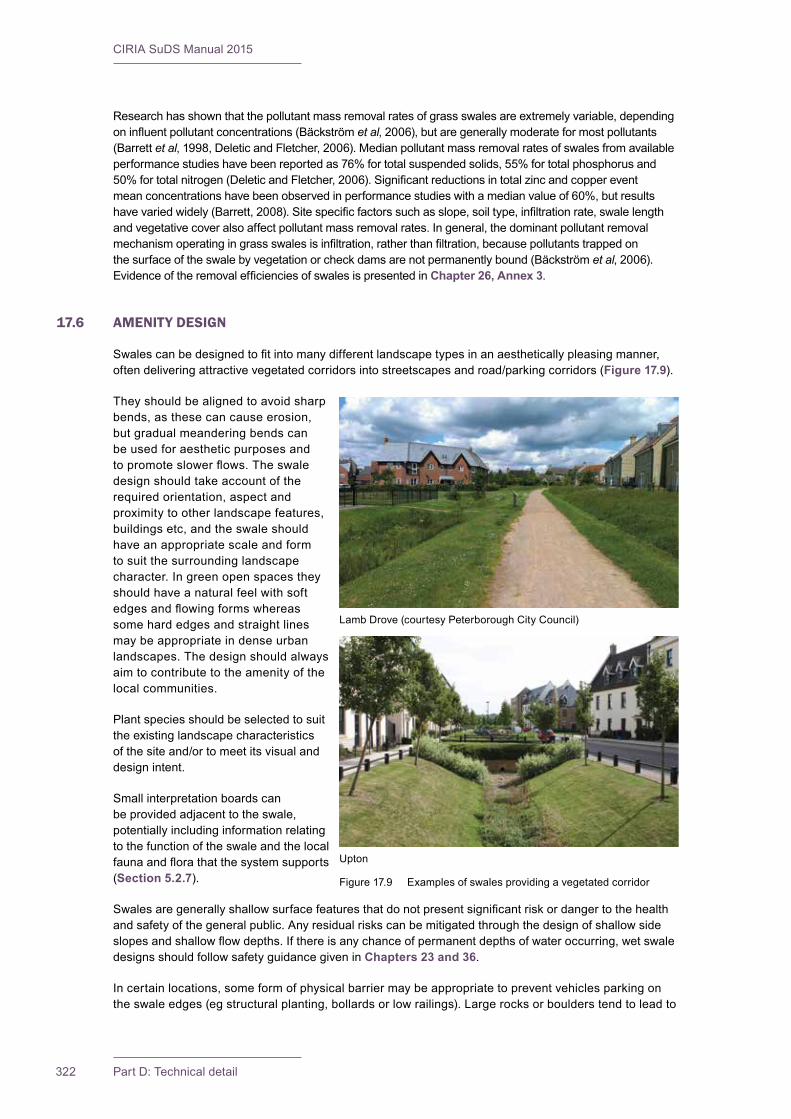
CIRIA SuDS Manual 2015
322 Part D: Technical detail
Researchhasshownthatthepollutantmassremovalratesofgrassswalesareextremelyvariable,dependingoninfluentpollutantconcentrations(Bäckströmet al,2006),butaregenerallymoderateformostpollutants(Barrett et al,1998,DeleticandFletcher,2006).Medianpollutantmassremovalratesofswalesfromavailableperformancestudieshavebeenreportedas76%fortotalsuspendedsolids,55%fortotalphosphorusand50%fortotalnitrogen(DeleticandFletcher,2006).Significantreductionsintotalzincandcoppereventmeanconcentrationshavebeenobservedinperformancestudieswithamedianvalueof60%,butresultshavevariedwidely(Barrett,2008).Sitespecificfactorssuchasslope,soiltype,infiltrationrate,swalelengthand vegetative cover also affect pollutant mass removal rates. In general, the dominant pollutant removal mechanismoperatingingrassswalesisinfiltration,ratherthanfiltration,becausepollutantstrappedonthesurfaceoftheswalebyvegetationorcheckdamsarenotpermanentlybound(Bäckströmet al, 2006). EvidenceoftheremovalefficienciesofswalesispresentedinChapter 26, Annex 3.
17.6 AMENITY DESIGN
Swalescanbedesignedtofitintomanydifferentlandscapetypesinanaestheticallypleasingmanner,oftendeliveringattractivevegetatedcorridorsintostreetscapesandroad/parkingcorridors(Figure 17.9).
Theyshouldbealignedtoavoidsharpbends,asthesecancauseerosion,butgradualmeanderingbendscanbeusedforaestheticpurposesandtopromoteslowerflows.Theswaledesign should take account of the required orientation, aspect and proximity to other landscape features, buildingsetc,andtheswaleshouldhave an appropriate scale and form to suit the surrounding landscape character. In green open spaces they should have a natural feel with soft edgesandflowingformswhereassome hard edges and straight lines maybeappropriateindenseurbanlandscapes. The design should always aimtocontributetotheamenityofthelocal communities.
Plantspeciesshouldbeselectedtosuitthe existing landscape characteristics ofthesiteand/ortomeetitsvisualanddesign intent.
Smallinterpretationboardscanbeprovidedadjacenttotheswale,potentially including information relating to the function of the swale and the local faunaandflorathatthesystemsupports(Section 5.2.7).
Swalesaregenerallyshallowsurfacefeaturesthatdonotpresentsignificantriskordangertothehealthandsafetyofthegeneralpublic.Anyresidualriskscanbemitigatedthroughthedesignofshallowsideslopesandshallowflowdepths.Ifthereisanychanceofpermanentdepthsofwateroccurring,wetswaledesigns should follow safety guidance given in Chapters 23 and 36.
Incertainlocations,someformofphysicalbarriermaybeappropriatetopreventvehiclesparkingontheswaleedges(egstructuralplanting,bollardsorlowrailings).Largerocksorboulderstendtoleadto
LambDrove(courtesyPeterboroughCityCouncil)
Upton
Figure17.9 Examplesofswalesprovidingavegetatedcorridor
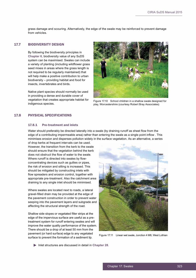
323Chapter 17: Swales
CIRIA SuDS Manual 2015
grassdamageandscouring.Alternatively,theedgeoftheswalemaybereinforcedtopreventdamagefrom vehicles.
17.7 BIODIVERSITY DESIGN
ByfollowingthebiodiversityprinciplesinChapter 6,biodiversityvalueofanySuDSsystemcanbemaximised.Swalescanincludeavarietyofplanting(includingwildflowergrassseed mixes in areas where the grass length is notrequiredtoberegularlymaintained)thatwillhelpmakeapositivecontributiontourbanbiodiversity–providinghabitatandfoodforinsects,invertebratesandbirds.
Nativeplantspeciesshouldnormallybeusedinprovidingadenseanddurablecoverofvegetationthatcreatesappropriatehabitatforindigenous species.
17.8 PHYSICAL SPECIFICATIONS
17.8.1 Pre-treatment and inlets
Watershouldpreferablybedirectedlaterallyintoaswale(bydrainingrunoffassheetflowfromtheedgeofacontributingimpermeablearea)ratherthanenteringtheswaleasasinglepointinflow.Thisminimises erosion and disperses pollution widely in the surface vegetation. As an alternative, a series ofdropkerbsatfrequentintervalscanbeused.However,thetransitionfromthekerbtotheswaleshouldensurethatthevegetationbehindthekerbdoesnotobstructtheflowofwatertotheswale.Whererunoffisdirectedintoswalesbyflow-concentrating devices such as gullies or pipes, the risk of erosion and silting is increased. This shouldbemitigatedbyconstructinginletswithflowspreadersanderosioncontrol,togetherwithappropriate pre-treatment. Also the catchment area drainingtoanysingleinletshouldbeminimised.
Where swales are located next to roads, a lateral gravel-filleddrainmaybeprovidedattheedgeofthe pavement construction in order to prevent water seepingintothepavementlayersandsubgradeandaffecting the structural strength of the road.
Shallowsideslopesorvegetatedfilterstripsattheedge of the impervious surface are useful as a pre-treatment system for runoff entering swales and will improve the water quality performance of the system. Thereshouldbeadropofatleast50mmfromthepavement (or hard surface) edge to any vegetated surface to prevent the formation of a sediment lip.
Inlet structures are discussed in detail in Chapter 28.
Figure 17.10 School children in a shallow swale designed for play,Worcestershire(courtesyRobertBrayAssociates)
Figure 17.11 Linear wet swale, Junction 4 M8, West Lothian
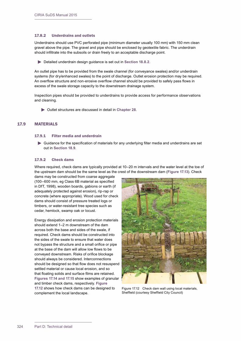
CIRIA SuDS Manual 2015
324 Part D: Technical detail
17.8.2 Underdrains and outlets
Underdrains should use PVC perforated pipe (minimum diameter usually 100 mm) with 150 mm clean gravelabovethepipe.Thegravelandpipeshouldbeenclosedbygeotextilefabric.Theunderdrainshouldinfiltrateintothesubsoilsordrainfreelytoanacceptabledischargepoint.
Detailed underdrain design guidance is set out in Section 18.8.2.
Anoutletpipehastobeprovidedfromtheswalechannel(forconveyanceswales)and/orunderdrainsystems(fordry/enhancedswales)tothepointofdischarge.Outleterosionprotectionmayberequired.Anoverflowstructureandnon-erosiveoverflowchannelshouldbeprovidedtosafelypassflowsinexcess of the swale storage capacity to the downstream drainage system.
Inspectionpipesshouldbeprovidedtounderdrainstoprovideaccessforperformanceobservationsand cleaning.
Outlet structures are discussed in detail in Chapter 28.
17.9 MATERIALS
17.9.1 Filter media and underdrain
Guidanceforthespecificationofmaterialsforanyunderlyingfiltermediaandunderdrainsaresetout in Section 18.9.
17.9.2 Check dams
Where required, check dams are typically provided at 10–20 m intervals and the water level at the toe of theupstreamdamshouldbethesamelevelasthecrestofthedownstreamdam(Figure 17.13). Check damsmaybeconstructedfromcoarseaggregate(100–600mm,egClass6BmaterialasspecifiedinDfT,1998),woodenboards,gabionsorearth(ifadequately protected against erosion), rip-rap or concrete (where appropriate). Wood used for check dams should consist of pressure treated logs or timbers,orwater-resistanttreespeciessuchascedar, hemlock, swamp oak or locust.
Energy dissipation and erosion protection materials should extend 1–2 m downstream of the dam acrossboththebaseandsidesoftheswale,ifrequired.Checkdamsshouldbeconstructedintothe sides of the swale to ensure that water does notbypassthestructureandasmallorificeorpipeatthebaseofthedamwillallowlowflowstobeconveyeddownstream.Risksoforificeblockageshouldalwaysbeconsidered.Interconnectionsshouldbedesignedsothatflowdoesnotresuspendsettled material or cause local erosion, and so thatfloatingsolidsandsurfacefilmsareretained.Figures 17.14 and 17.15 show examples of granular andtimbercheckdams,respectively.Figure 17.12showshowcheckdamscanbedesignedtocomplement the local landscape.
Figure 17.12 Check dam wall using local materials, Sheffield(courtesySheffieldCityCouncil)
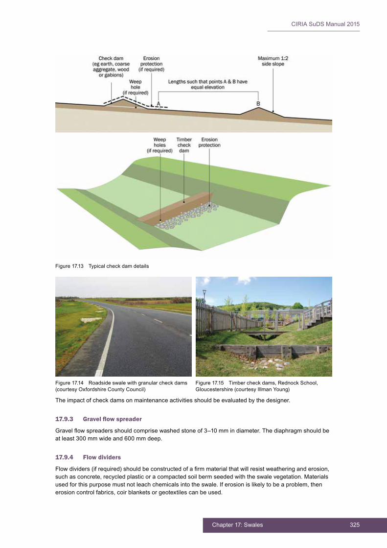
325Chapter 17: Swales
CIRIA SuDS Manual 2015
Theimpactofcheckdamsonmaintenanceactivitiesshouldbeevaluatedbythedesigner.
17.9.3 Gravelflowspreader
Gravelflowspreadersshouldcomprisewashedstoneof3–10mmindiameter.Thediaphragmshouldbeat least 300 mm wide and 600 mm deep.
17.9.4 Flow dividers
Flowdividers(ifrequired)shouldbeconstructedofafirmmaterialthatwillresistweatheringanderosion,suchasconcrete,recycledplasticoracompactedsoilbermseededwiththeswalevegetation.Materialsusedforthispurposemustnotleachchemicalsintotheswale.Iferosionislikelytobeaproblem,thenerosioncontrolfabrics,coirblanketsorgeotextilescanbeused.
Figure 17.13 Typical check dam details
Figure 17.14 Roadside swale with granular check dams (courtesy Oxfordshire County Council)
Figure17.15 Timbercheckdams,RednockSchool,Gloucestershire (courtesy Illman Young)

CIRIA SuDS Manual 2015
326 Part D: Technical detail
17.10 LANDSCAPE DESIGN AND PLANTING
Grassesandherbaceousspecieswithasoil-bindingrootstructureanddensecovershouldbefavouredalongthebottomoftheswalefortheirabilitytoincreaseinfiltration,stabilisesoils,retainandfilterpollutantsand assist with suspended solids retention. Where swales are used to drain runoff from roads or car park areasthatarelikelytoberegularlysaltedduringwintermonths,theplantingshouldbesalttolerant.
Theplantmaterialontheslopesofgrasschannelsshouldbecapableofwithstandingperiodicinundationinadditiontoextendedperiodsofdrought.Appropriatespeciesincluderobust,fine-growinggrassesandgroundcoversaswellaslowshrubspecies.Nativespeciesaregenerallymostappropriate,andmixturesofperennialryegrassandfescuesareparticularlysuitableforuseinswalesintheUK.Longergrassesandwildflowerareas,ifconsideredbeneficialforotherreasons,arenotconsideredtoposeasignificantrisk to performance.
Treescanbeincludedwithinadesign,providedthattherequiredsun-shadeconditionsneededforadequate growth of the predominant groundcover vegetation are fully considered. The requirements for topsoildepthsandspecificationswillvary,dependingonthedesignplanting.
Fertilisingaswaleshouldbeavoidedifpossible,particularlywherethereceivingenvironmentissensitiveto nutrient loadings.
Emergentvegetationcanbeplantedinwetswalesor,alternatively,wetlandsoilsmaybespreadontheswalebottomforseedstock.However,denseplantingshouldbeavoided,andsystemsshouldbeallowedtocolonisenaturallytoanextent.Forwetswales,itisbesttoplantseveralspeciestoincreasethechancethatatleastsomeoftheselectedspecieswillfindgrowingconditionsfavourable.
Fordryswales,plantscanbeplacedasturf,seedsorlesscommonlyasindividualplants,suchasplugplantsorrootedspecimens.Turfprovidesimmediateprotection,providedtheseamsareprotectedbylayingthestripsperpendiculartotheflowofwaterandhandtampingthemafterlaying.Turfshouldalsobesecuredwithpegswherehighflowvelocitiesareexpectedandonsideslopesthataregreaterthan1in4.Aswaleisbestseededduringspringandearlysummermonthstogivevegetationthewholelengthofagrowingseasontoestablish.Grasseswillneedtobemaintainedatlengthsof75–150mmtoensure performance during regular events.
Landscapedesignandplantingbestpracticeispresentedindetailin Chapter 29.
17.11 CONSTRUCTION REQUIREMENTS
Grassswalesshouldbeclearlymarkedbeforesiteworkbeginsandprotectedbysignageandsiltfencingtoavoidtheirdisturbanceduringconstruction.Novehiculartraffic,exceptthatspecificallyusedtoconstructthecomponent,shouldbeallowedclosetotheswale.Excavatingequipmentshouldoperatefromthesideoftheswaleandnotthebase.Ifcompactionofsoilsdoesoccur,aminimumof300mmdepthofsoilshouldberemovedandreplacedwithablendoftopsoilandsandtopromoteinfiltrationandbiologicalgrowth.
Careshouldbetakenthatdesignlevelsandslopesforinletsandswalebaseandsidesareconstructedaccuratelytoavoidrunoffbypassingswaleinlets,pondingintheswalebaseandflowchannelling.Eventhesmallestnon-conformitiesmaycompromiseflowconditions.
Swalesshouldnotreceiveanyrunoffuntilthevegetationisfullyestablishedandconstructionatthesitehasreachedastatewheresedimentloadswillnotcauserapidsiltationoftheswale.Thiscanbeachievedby:
▪ divertingflowsuntilthevegetationiswellrooted
▪ placinganerosioncontrolblanket(egjute,straworgeosyntheticmats)overthefreshlyappliedseedmix
▪ usingbareearthasatemporarycoverduringthewetseason–theseareasshouldbeseededwithasuitablegrassmixassoonastheweatherisconducivetoseedgermination.

327Chapter 17: Swales
CIRIA SuDS Manual 2015
If sediment from construction work accumulates onaswaleitshouldbeclearedandtheswalefullyrehabilitatedbeforethedrainagesystemisadoptedbytheorganisationcarryingoutthemaintenance.
Theswaleshouldbeplantedatatimeofyearwhensuccessfulplantestablishmentwithoutirrigation is most likely (noting that temporary irrigationmaystillberequirediftheperiodisespecially dry). Freshly seeded areas should bestabilisedwithappropriatetemporaryorpermanentsoilstabilisationmethods,suchaserosioncontrolmattingorblankets.Ifmorethan30%oftheplantedareaisbareafterfourweeks,reseedingorreplantingshouldbeconsideredtoachieve90%coverage.
Further detail on construction activities and the programming of construction activities is provided in Chapter 31.
A construction phase health and safety plan is required under the Construction (Design and Management) Regulations(CDM)2015.Thisshouldensurethatallconstructionriskshavebeenidentified,eliminated,reducedand/orcontrolledwhereappropriate.
Generic health and safety guidance is provided in Chapter 36.
17.12 OPERATION AND MAINTENANCE REQUIREMENTS
Swales will require regular maintenance to ensure continuing operation to design performance standards, andalldesignersshouldprovidedetailedspecificationsandfrequenciesfortherequiredmaintenanceactivities along with likely machinery requirements and typical annual costs – within the Maintenance Plan.Thetreatmentperformanceofswalesisdependentonmaintenance,androbustmanagementplanswillberequiredtoensuremaintenanceiscarriedoutinthelongterm.Differentdesignswillhavedifferentoperationandmaintenancerequirements,butthissectiongivessomegenericguidance.
Maintenance of swales is relatively straightforward for landscape contractors, and typically there should onlybeasmallamountofextrawork(ifany)requiredforaswaleoverandabovewhatisnecessaryforstandardpublicopenspace.Providedthatlandscapemanagementisalreadyrequiredatsite,swalemaintenance should have marginal cost implications. However, regular inspection and maintenance are importantfortheeffectiveoperationofswalesasdesigned.Maintenanceresponsibilityforaswaleshouldalwaysbeplacedwithanappropriateorganisation.Ifswalesareimplementedwithinprivateproperty,ownersshouldbeeducatedontheirroutinemaintenanceneeds,andshouldunderstandthelong-termMaintenancePlanandanylegallybindingmaintenanceagreement.
Adequateaccessshouldbeprovidedtoallswaleareasforinspectionandmaintenance,includingforappropriateequipmentandvehicles.LitteranddebrisremovalshouldbeundertakenaspartofgenerallandscapemaintenanceforthesiteandbeforeanyotherSuDSmanagementtask.Alllittershouldberemoved from site.
Themajormaintenancerequirementfordryswalesismowing.Mowingshouldideallyretaingrasslengthsof75–150mmacrossthemain“treatment”surface,toassistinfilteringpollutantsandretainingsedimentsandtoreducetheriskofflatteningduringrunoffevents.However,longervegetationlengths,whereappropriate,arenotconsideredtoposeasignificantrisktofunctionality.
Figure 17.16 Swale during construction showing coir matting usedtoprotectsoilsfromerosionbeforetheestablishmentofvegetation, University of York (courtesy Arup)
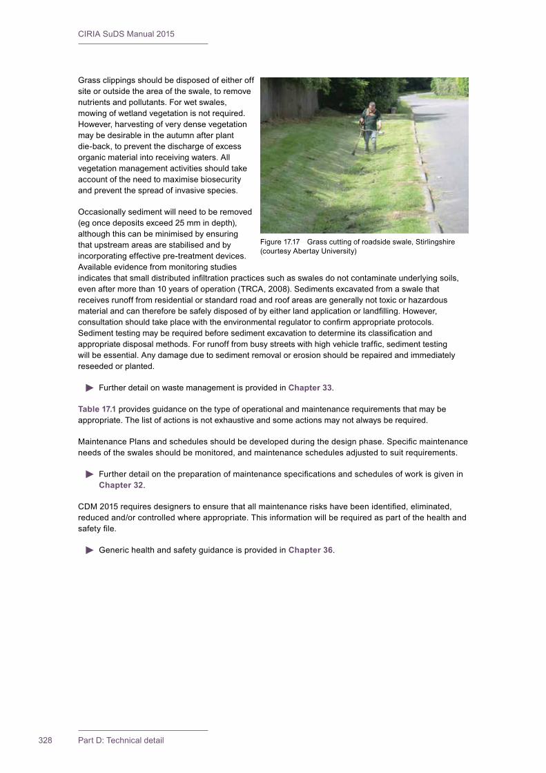
CIRIA SuDS Manual 2015
328 Part D: Technical detail
Grassclippingsshouldbedisposedofeitheroffsite or outside the area of the swale, to remove nutrients and pollutants. For wet swales, mowing of wetland vegetation is not required. However, harvesting of very dense vegetation maybedesirableintheautumnafterplantdie-back,topreventthedischargeofexcessorganic material into receiving waters. All vegetation management activities should take accountoftheneedtomaximisebiosecurityand prevent the spread of invasive species.
Occasionallysedimentwillneedtoberemoved(eg once deposits exceed 25 mm in depth), althoughthiscanbeminimisedbyensuringthatupstreamareasarestabilisedandbyincorporating effective pre-treatment devices. Availableevidencefrommonitoringstudiesindicatesthatsmalldistributedinfiltrationpracticessuchasswalesdonotcontaminateunderlyingsoils,even after more than 10 years of operation (TRCA, 2008). Sediments excavated from a swale that receivesrunofffromresidentialorstandardroadandroofareasaregenerallynottoxicorhazardousmaterialandcanthereforebesafelydisposedofbyeitherlandapplicationorlandfilling.However,consultationshouldtakeplacewiththeenvironmentalregulatortoconfirmappropriateprotocols.Sedimenttestingmayberequiredbeforesedimentexcavationtodetermineitsclassificationandappropriatedisposalmethods.Forrunofffrombusystreetswithhighvehicletraffic,sedimenttestingwillbeessential.Anydamageduetosedimentremovalorerosionshouldberepairedandimmediatelyreseeded or planted.
Further detail on waste management is provided in Chapter 33.
Table 17.1 providesguidanceonthetypeofoperationalandmaintenancerequirementsthatmaybeappropriate.Thelistofactionsisnotexhaustiveandsomeactionsmaynotalwaysberequired.
MaintenancePlansandschedulesshouldbedevelopedduringthedesignphase.Specificmaintenanceneedsoftheswalesshouldbemonitored,andmaintenanceschedulesadjustedtosuitrequirements.
FurtherdetailonthepreparationofmaintenancespecificationsandschedulesofworkisgiveninChapter 32.
CDM2015requiresdesignerstoensurethatallmaintenanceriskshavebeenidentified,eliminated,reducedand/orcontrolledwhereappropriate.Thisinformationwillberequiredaspartofthehealthandsafetyfile.
Generic health and safety guidance is provided in Chapter 36.
Figure 17.17 Grass cutting of roadside swale, Stirlingshire (courtesyAbertayUniversity)
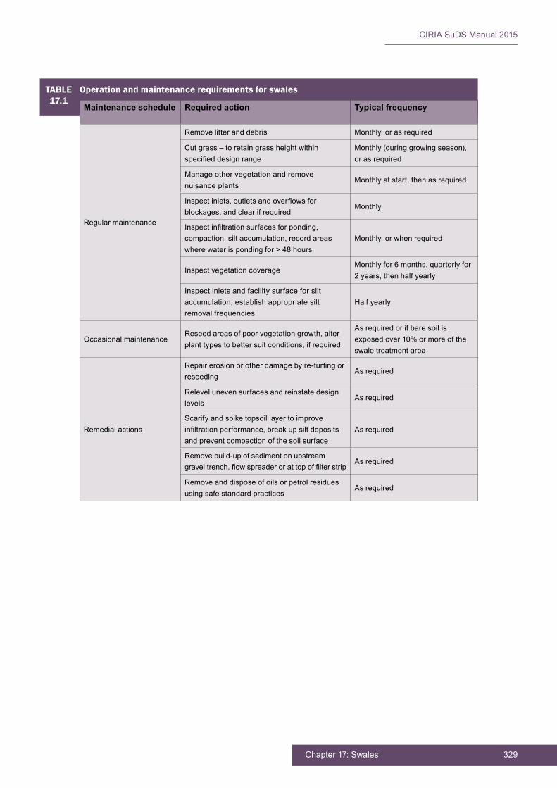
329Chapter 17: Swales
CIRIA SuDS Manual 2015
TABLE17.1
Operation and maintenance requirements for swales
Maintenance schedule Required action Typical frequency
Regular maintenance
Removelitteranddebris Monthly, or as required
Cut grass – to retain grass height within specifieddesignrange
Monthly (during growing season), or as required
Manage other vegetation and remove nuisance plants
Monthly at start, then as required
Inspectinlets,outletsandoverflowsforblockages,andclearifrequired
Monthly
Inspectinfiltrationsurfacesforponding,compaction, silt accumulation, record areas where water is ponding for > 48 hours
Monthly, or when required
Inspect vegetation coverageMonthly for 6 months, quarterly for 2 years, then half yearly
Inspect inlets and facility surface for silt accumulation,establishappropriatesiltremoval frequencies
Half yearly
Occasional maintenanceReseed areas of poor vegetation growth, alter planttypestobettersuitconditions,ifrequired
Asrequiredorifbaresoilisexposedover10%ormoreoftheswale treatment area
Remedial actions
Repairerosionorotherdamagebyre-turfingorreseeding
As required
Relevel uneven surfaces and reinstate design levels
As required
Scarify and spike topsoil layer to improve infiltrationperformance,breakupsiltdepositsand prevent compaction of the soil surface
As required
Removebuild-upofsedimentonupstreamgraveltrench,flowspreaderorattopoffilterstrip
As required
Remove and dispose of oils or petrol residues using safe standard practices
As required

CIRIA SuDS Manual 2015
330 Part D: Technical detail
17.13 REFERENCES
BÄCKSTRÖM,M,VIKLANDER,MANDMALMQVIST,P-A(2006)“Transportofstormwaterpollutantsthrough a roadside grassed swale” Urban Water Journal,vol3,2,TaylorandFrancisonline,UK,pp55–67
BARRETT,ME(2008)“ComparisonofBMPperformanceusingtheInternationalBMPDatabase”Journal of Irrigation and Drainage Engineering, vol 134, special issue Urban Storm-Water Management, American Society of Civil Engineers, Reston, VA, USA, pp 556–561
BARRETT,ME,WALSH,PM,MALINAJR,JFandCHARBENEAU,RJ(1998)“Performanceofvegetative controls for treating highway runoff” Journal of Environmental Engineering, vol 124, 11, American Society of Civil Engineers, Reston, VA, USA, pp 1121–1128
DELETIC,AandFLETCHER,TD(2006)“Performanceofgrassfiltersusedforstormwatertreatment–afieldandmodellingstudy”Journal of Hydrology,vol317,3–4,ElsevierBV,UK,pp261–275
DfT(1998)Manual of contract documents for highway works, Volume 1 Specification for highway works, HMSO,London,UK(ISBN:978-0-11552-705-0).Goto:www.standardsforhighways.co.uk/mchw/vol1
TRCA (2008) Performance evaluation of permeable pavement and a bioretention swale, Seneca College, King City, Ontario,PreparedbyTorontoandRegionConservationundertheSustainableTechnologiesEvaluationProgram(STEP),Ontario,Canada.Goto:http://tinyurl.com/pflzwwv
WONG, T H F (ed) (2006) Australian runoff quality – a guide to Water Sensitive Urban Design, Engineers Australia, New South Wales, Australia

331Chapter 17: Swales
CIRIA SuDS Manual 2015
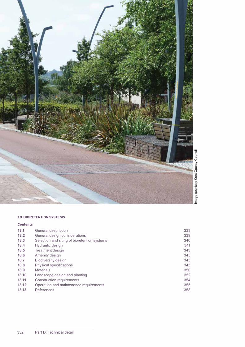
CIRIA SuDS Manual 2015
332 Part D: Technical detail
18 BIORETENTION SYSTEMS
Contents
18.1 General description 33318.2 General design considerations 33918.3 Selection and siting of bioretention systems 34018.4 Hydraulic design 34118.5 Treatment design 34318.6 Amenity design 34518.7 Biodiversity design 34518.8 Physicalspecifications 34518.9 Materials 35018.10 Landscape design and planting 35218.11 Construction requirements 35418.12 Operation and maintenance requirements 35518.13 References 358
Imag
e co
urte
sy K
ent C
ount
y C
ounc
il

333Chapter 18: Bioretention systems
CIRIA SuDS Manual 2015
18.1 GENERAL DESCRIPTION
Bioretention systems (including rain gardens) are shallow landscaped depressions that can reduce runoff rates and volumes, and treat pollution through the use of engineered soils and vegetation. They are particularly effective in delivering Interception and can also provide:
▪ attractive landscape features that are self-irrigating and fertilising
▪ habitat and biodiversity
▪ cooling of the local microclimate due to evapotranspiration.
Theyareaveryflexiblesurfacewatermanagementcomponentthatcanbeintegratedinto a wide variety of development landscapes using different shapes, materials, planting and dimensions. In a low density development, the system might have soft edges and gentle side slopes, while a high density application might have hard edges with vertical sides.
They are generally used for managing and treating runoff from frequent rainfall events. Where larger events are directed to the system, consideration of the impact of design velocities on the system will be required. It is often more appropriate to pass runofffromextremeeventsdirectlytodrainagecomponentsfurtherdownstream,viaanoverfloworbypass.
Runoffcollectedbythesystempondstemporarilyonthesurfaceandthenfiltersthroughthevegetationandunderlyingsoils.Specifiedengineeredsoilmixescanbeusedasfiltermediatoenhancebioretentiontreatmentperformance,anddesignscanbe implemented that include submerged anaerobic zones to promote nutrient removal.
Thefilteredrunoffiseithercollectedusinganunderdrainsystemor,ifsiteconditionsallow,fullyorpartiallyinfiltratedintothesurroundingsoil(subjecttosuitablesiteconditions – Chapter 25). Part of the runoff volume will be removed through evaporationandplanttranspiration.Themainhydraulicbenefitofusingbioretentionsystems is providing Interception. However, attenuation storage on the surface or within the drainage layer can be used to help manage runoff rates. Check dams or weirs can alsobeusedtoslowtheflowofwatermovingacrossthesurfaceofthesystem.
There are many different approaches to the design of bioretention systems and rain gardens. However, the main components that are usually provided in a bioretention system are shown in Figure 18.1 In general, the systems should not have impermeableliners,unlessthereisaspecificneedtopreventwaterfrominfiltrating,such as at locations close to structural foundations (Chapter 25) or for groundwater protection (Chapter 26).
18Chapter Bioretention systems
This chapter provides guidance on the design of bioretention systems (including rain gardens) – shallow planted depressions that allow runoff to pond temporarily on the surface, before filtering through vegetation and underlying soils for collection or infiltration.
Appendix C, Section C.5.2 demonstrates how to design an infiltrating bioretention system for a civic street.
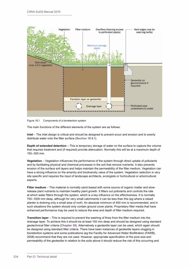
CIRIA SuDS Manual 2015
334 Part D: Technical detail
The main functions of the different elements of the system are as follows:
Inlet – The inlet design is critical and should be designed to prevent scour and erosion and to evenly distributewaterontothefiltersurface(Section 18.8.1).
Depth of extended detention – This is temporary storage of water on the surface to capture the volume thatrequirestreatmentand(ifrequired)provideattenuation.Normallythiswillbeatamaximumdepthof150–300 mm.
Vegetation–Vegetationinfluencestheperformanceofthesystemthroughdirectuptakeofpollutantsand by facilitating physical and chemical processes in the soil that remove nutrients. It also prevents erosionofthesurfacesoillayersandhelpsmaintainthepermeabilityofthefiltermedium.Vegetationcanhaveastronginfluenceontheamenityandbiodiversityvalueofthesystem.Vegetationselectionisverysitespecificandrequirestheinputoflandscapearchitects,ecologistsorhorticulturalorarboriculturalexperts.
Filter medium – This material is normally sand-based with some source of organic matter and slow-releaseplantnutrientstomaintainhealthyplantgrowth.Itfiltersoutpollutantsandcontrolstherateatwhichwaterfiltersthroughthesystem,whichisakeyinfluenceontheeffectiveness.Itisnormally750–1000 mm deep, although for very small catchments it can be less than this (eg where a raised planter is draining only a small area of roof). An absolute minimum of 400 mm is recommended, and in suchsituationsthesystemshouldonlycontaingroundcoverplants.Proprietaryfiltermediathathaveenhancedperformancemaybeusedtoreducetheareaanddepthoffiltermediumrequired.
Transition layer–Thisisrequiredtopreventthewashingoffinesfromthefiltermediumintothedrainage layer. To achieve this it should be at least 100 mm deep and should be designed using standard geotechnicalfiltercriteria(Chapter 30).Alternativelyageotextilelayercanbeused,whichagainshouldbedesignedusingstandardfiltercriteria.Therehavebeeninstancesofgeotextilelayersclogginginbioretentionsystemsandsomepublications(egtheFacilityforAdvancedWaterBiofiltration(FAWB),2008)recommendthattheyarenotused.However,appropriatespecificationoftheporesizeandpermeabilityofthegeotextileinrelationtothesoilsaboveitshouldreducetheriskofthisoccurringand
Figure 18.1 Components of a bioretention system

335Chapter 18: Bioretention systems
CIRIA SuDS Manual 2015
the risk should not be any different from that for clogging of a transition layer (Chapter 30). The main locationwheresiltaccumulatesinabioretentionsystemisonthesurfaceofthesoilfilter.
Drainage layer –Thepurposeofthislayeristocollectwaterfromthefiltermediumandallowittoreachthe perforated pipes easily. The drainage layer should provide adequate cover to the perforated pipes (typicallyatleast100mm)andshouldbeofsufficientthicknesstoensurethattheflowrateofwaterthroughittothepipesisgreaterthantheflowrateofwaterintothelayerfromtheoverlyingfiltermediumand/or transition layer. Geocellular units can also be used in place of the drainage layer and pipes, especiallyifextraattenuationstoragevolumeisrequired.
The depth of the drainage layer will be determined by the underdrain pipe diameter, minimum pipe cover, the level of the outfall/connection, slope of the underdrain and the length of the system being drained, and any requirements for storage. In general, the minimum pipe cover of the gravel drainage layer should be 50 mm to avoid ingress of the sand transition layer into the pipe. Where the drainage layer is acting as a storage layer, the depth should be determined using calculations or modelling but as a general guide the subsurfacestoragezoneshouldbeatleastaslargeasthesurfacestoragezonetoensurethatthefiltermedium does not become saturated after consecutive rainfall events.
Perforated pipes – These collect water from the system and convey it downstream. They may not be requiredifthesystemisdesignedtoinfiltrate.Pipesshouldhavearoddingeye,toallowaccessforcleaning(thiscouldbecombinedwiththeoverflow).
Overflow–Thisisachievedwithstandpipes,weirsorotherchanneltodirectflowtodownstreamcomponents,oncethevolumeofthesystemhasbeenexceeded.
There are many different variations of the bioretention system, described in the following sections.
18.1.1 Rain garden
Rain gardens are typically small systems that serve part of a single property (roof or driveway). They arelikelytobelessengineeredthanfullbioretentioncomponents.Insimpleraingardens,filteranddrainage layers are generally replaced by a thin (200–500 mm) layer of compost/sand-amended native soilsorspecifiedsoilmixes(engineeredsoils).Theyusuallyhaveasimpleinflowwhererainwaterentersthegardenandtheyhaveamaximumdepthofstandingwaterof150mm.Theycanhaveanabove-groundoverflowwhereexcesswaterexits,althoughinsomeinstancesasimpleunderdrainmaybemore effective than providing a small control structure (Figure 18.2). Guidance on simple rain gardens is provided in Bray et al (2012).
Rain gardens can offer a variety of creative design interpretations to suit the site. In Figure 18.3 the size and design of the rain gardens were chosen by the property owners to provide a distinctive feature in their gardens.
There needs to be a mechanism to ensure that property owners carry out the necessary maintenance of rain gardens so that they continue to perform their drainage function effectively.
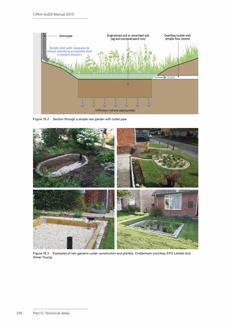
CIRIA SuDS Manual 2015
336 Part D: Technical detail
Figure 18.2 Section through a simple rain garden with outlet pipe
Figure18.3 Examplesofraingardensunderconstructionandplanted,Cheltenham(courtesyEPGLimitedandIllman Young)
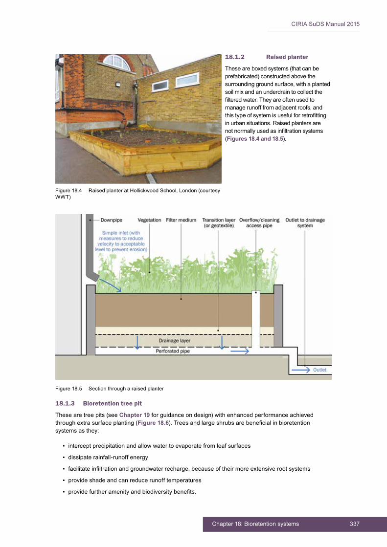
337Chapter 18: Bioretention systems
CIRIA SuDS Manual 2015
18.1.2 Raised planter
Theseareboxedsystems(thatcanbeprefabricated) constructed above the surrounding ground surface, with a planted soilmixandanunderdraintocollectthefilteredwater.Theyareoftenusedtomanagerunofffromadjacentroofs,andthistypeofsystemisusefulforretrofittingin urban situations. Raised planters are notnormallyusedasinfiltrationsystems(Figures 18.4 and 18.5).
Figure 18.4 Raised planter at Hollickwood School, London (courtesy WWT)
Figure 18.5 Section through a raised planter
18.1.3 Bioretention tree pit
These are tree pits (see Chapter 19 for guidance on design) with enhanced performance achieved throughextrasurfaceplanting(Figure 18.6).Treesandlargeshrubsarebeneficialinbioretentionsystems as they:
▪ intercept precipitation and allow water to evaporate from leaf surfaces
▪ dissipate rainfall-runoff energy
▪ facilitateinfiltrationandgroundwaterrecharge,becauseoftheirmoreextensiverootsystems
▪ provide shade and can reduce runoff temperatures
▪ providefurtheramenityandbiodiversitybenefits.
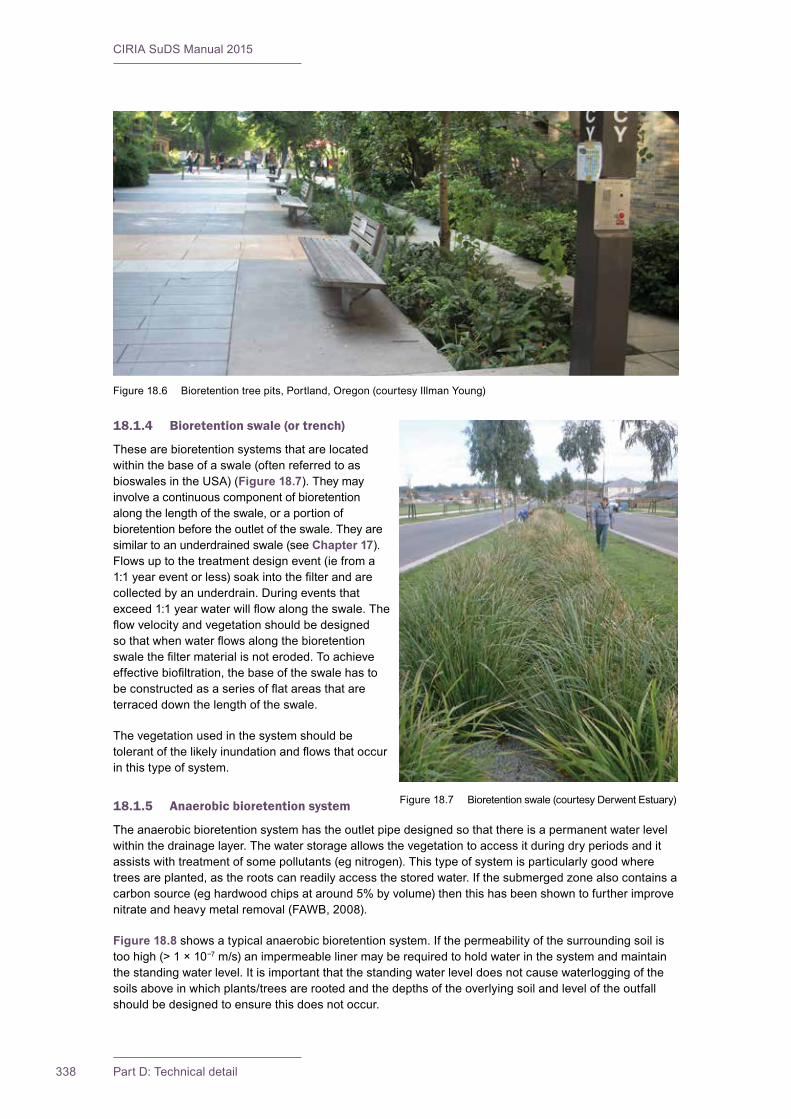
CIRIA SuDS Manual 2015
338 Part D: Technical detail
18.1.4 Bioretention swale (or trench)
These are bioretention systems that are located within the base of a swale (often referred to as bioswales in the USA) (Figure 18.7). They may involve a continuous component of bioretention along the length of the swale, or a portion of bioretention before the outlet of the swale. They are similar to an underdrained swale (see Chapter 17). Flows up to the treatment design event (ie from a 1:1yeareventorless)soakintothefilterandarecollected by an underdrain. During events that exceed1:1yearwaterwillflowalongtheswale.Theflowvelocityandvegetationshouldbedesignedsothatwhenwaterflowsalongthebioretentionswalethefiltermaterialisnoteroded.Toachieveeffectivebiofiltration,thebaseoftheswalehastobeconstructedasaseriesofflatareasthatareterraced down the length of the swale.
The vegetation used in the system should be tolerantofthelikelyinundationandflowsthatoccurin this type of system.
18.1.5 Anaerobic bioretention system
The anaerobic bioretention system has the outlet pipe designed so that there is a permanent water level within the drainage layer. The water storage allows the vegetation to access it during dry periods and it assists with treatment of some pollutants (eg nitrogen). This type of system is particularly good where trees are planted, as the roots can readily access the stored water. If the submerged zone also contains a carbon source (eg hardwood chips at around 5% by volume) then this has been shown to further improve nitrate and heavy metal removal (FAWB, 2008).
Figure 18.8 shows a typical anaerobic bioretention system. If the permeability of the surrounding soil is too high (> 1 × 10⁻⁷ m/s) an impermeable liner may be required to hold water in the system and maintain the standing water level. It is important that the standing water level does not cause waterlogging of the soils above in which plants/trees are rooted and the depths of the overlying soil and level of the outfall should be designed to ensure this does not occur.
Figure 18.6 Bioretention tree pits, Portland, Oregon (courtesy Illman Young)
Figure 18.7 Bioretention swale (courtesy Derwent Estuary)
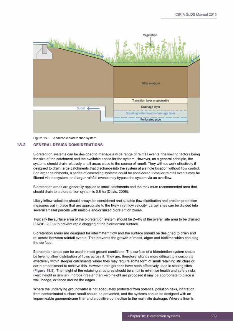
339Chapter 18: Bioretention systems
CIRIA SuDS Manual 2015
18.2 GENERAL DESIGN CONSIDERATIONS
Bioretention systems can be designed to manage a wide range of rainfall events, the limiting factors being the size of the catchment and the available space for the system. However, as a general principle, the systems should drain relatively small areas close to the source of runoff. They will not work effectively if designedtodrainlargecatchmentsthatdischargeintothesystematasinglelocationwithoutflowcontrol.For larger catchments, a series of cascading systems could be considered. Smaller rainfall events may be filteredviathesystem,andlargerrainfalleventsmaybypassthesystemviaanoverflow.
Bioretentionareasaregenerallyappliedtosmallcatchmentsandthemaximumrecommendedareathatshould drain to a bioretention system is 0.8 ha (Davis, 2008).
Likelyinflowvelocitiesshouldalwaysbeconsideredandsuitableflowdistributionanderosionprotectionmeasuresputinplacethatareappropriatetothelikelyinletflowvelocity.Largersitescanbedividedintoseveral smaller parcels with multiple and/or linked bioretention zones.
Typically the surface area of the bioretention system should be 2–4% of the overall site area to be drained (FAWB, 2009) to prevent rapid clogging of the bioretention surface.
Bioretentionareasaredesignedforintermittentflowandthesurfaceshouldbedesignedtodrainandre-aeratebetweenrainfallevents.Thispreventsthegrowthofmoss,algaeandbiofilmswhichcanclogthe surface.
Bioretention areas can be used in most ground conditions. The surface of a bioretention system should beleveltoallowdistributionofflowsacrossit.Theyare,therefore,slightlymoredifficulttoincorporateeffectively within steeper catchments where they may require some form of small retaining structure or earth embankment to achieve this. However, rain gardens have been effectively used in sloping sites (Figure 18.9). The height of the retaining structures should be small to minimise health and safety risks (kerb height or similar). If drops greater than kerb height are proposed it may be appropriate to place a wall, hedge, or fence around the edges.
Wheretheunderlyinggroundwaterisnotadequatelyprotectedfrompotentialpollutionrisks,infiltrationfrom contaminated surface runoff should be prevented, and the systems should be designed with an impermeable geomembrane liner and a positive connection to the main site drainage. Where a liner is
Figure 18.8 Anaerobic bioretention system
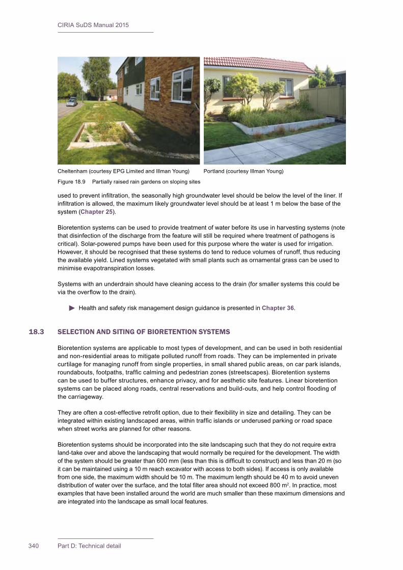
CIRIA SuDS Manual 2015
340 Part D: Technical detail
usedtopreventinfiltration,theseasonallyhighgroundwaterlevelshouldbebelowtheleveloftheliner.Ifinfiltrationisallowed,themaximumlikelygroundwaterlevelshouldbeatleast1mbelowthebaseofthesystem (Chapter 25).
Bioretention systems can be used to provide treatment of water before its use in harvesting systems (note that disinfection of the discharge from the feature will still be required where treatment of pathogens is critical). Solar-powered pumps have been used for this purpose where the water is used for irrigation. However, it should be recognised that these systems do tend to reduce volumes of runoff, thus reducing the available yield. Lined systems vegetated with small plants such as ornamental grass can be used to minimise evapotranspiration losses.
Systems with an underdrain should have cleaning access to the drain (for smaller systems this could be viatheoverflowtothedrain).
Health and safety risk management design guidance is presented in Chapter 36.
18.3 SELECTION AND SITING OF BIORETENTION SYSTEMS
Bioretention systems are applicable to most types of development, and can be used in both residential and non-residential areas to mitigate polluted runoff from roads. They can be implemented in private curtilage for managing runoff from single properties, in small shared public areas, on car park islands, roundabouts,footpaths,trafficcalmingandpedestrianzones(streetscapes).Bioretentionsystemscan be used to buffer structures, enhance privacy, and for aesthetic site features. Linear bioretention systemscanbeplacedalongroads,centralreservationsandbuild-outs,andhelpcontrolfloodingofthe carriageway.
Theyareoftenacost-effectiveretrofitoption,duetotheirflexibilityinsizeanddetailing.Theycanbeintegratedwithinexistinglandscapedareas,withintrafficislandsorunderusedparkingorroadspacewhen street works are planned for other reasons.
Bioretentionsystemsshouldbeincorporatedintothesitelandscapingsuchthattheydonotrequireextraland-take over and above the landscaping that would normally be required for the development. The width ofthesystemshouldbegreaterthan600mm(lessthanthisisdifficulttoconstruct)andlessthan20m(soitcanbemaintainedusinga10mreachexcavatorwithaccesstobothsides).Ifaccessisonlyavailablefromoneside,themaximumwidthshouldbe10m.Themaximumlengthshouldbe40mtoavoidunevendistributionofwateroverthesurface,andthetotalfilterareashouldnotexceed800m2. In practice, most examplesthathavebeeninstalledaroundtheworldaremuchsmallerthanthesemaximumdimensionsandare integrated into the landscape as small local features.
Cheltenham (courtesy EPG Limited and Illman Young) Portland (courtesy Illman Young)
Figure 18.9 Partially raised rain gardens on sloping sites
341Chapter 18: Bioretention systems
CIRIA SuDS Manual 2015
Greaterthicknessesoffiltermediumandasaturateddrainagelayer(anaerobicbioretentionsystem–Section 18.1) are more appropriate where trees will be planted in the system and also if the vegetation proposed is less tolerant of drought. The larger the surface area of the system the more valuable a permanentbodyofwateris,becauseitallowswatertobeevenlydistributedbelowthewholeofthefiltermedium and provides better irrigation for the plants that are remote from the inlet.
Theacceptabilityofinfiltrationfromthebaseofabioretentionsystemshouldbedeterminedbyfollowingthe guidance provided in Section 25.2,complyingwithallrelevantrequirementsforinfiltrationsystemswith respect to ground stability, depth to water table etc, and Section 26.7, with respect to the protection of groundwater.
Building control departments may require unlined rain gardens to be located greater than 5 m from building foundations. If rain gardens are located closer than 5 m, a full assessment of the risks should becarriedoutbyasuitablyqualifiedgeotechnicalengineerorengineeringgeologist.Ifaraingardenmanages water from a small area (< 20 m2) is less than 300 mm deep, has a surface area greater than 2 m2andisgreaterthan3mfromfoundations,suchanassessmentmaynotbenecessaryexceptforsiteswhere there is contamination, steep slopes nearby or a history of instability such as sink holes. The local building control department will be able to provide advice.
18.4 HYDRAULIC DESIGN
18.4.1 General
A key hydraulic design consideration for bioretention systems is the delivery of the runoff onto the surface ofthefiltermedium.Flowshouldnotscourthebioretentionsurfaceandneedstobeuniformlydistributedoverthefullfiltermediumsurfacearea.Inflowvelocitiesshouldbebelow0.5m/s(or1.5m/sforthe1:100year rainfall event).
When a bioretention system runs along the full length of a conveyance swale, the bed should be level in a series of terraces. For other applications, the desirable gradient of the bioretention zone is either horizontal or as close as possible to horizontal to encourage uniform distribution of runoff over the fullsurfaceareaofthebioretentionfiltermediumandtoallowefficienttemporarystorageofflowsfortreatment before bypass occurs.
In steeper areas, where a bioretention system is used at the end of swale, check dams can be implementedalongthesystemtoreduceflowvelocitiesdischargedontothebioretentionfiltermedium.A check dam is a simple structure or mechanism that can consist of anything from an area on an existingslopewherewatercantemporarilypondbeforeproceedingfurther,toasmallweirdevicethatpondswaterandspreadsitsflow.Itshouldbenotedthatcheckdamsshouldbedesignedtoalloweasymaintenance of grass, or other vegetation may be appropriate in these areas.
Morefrequentstormeventsaretreatedaswaterfiltersthroughthesystemandthosethatexceedthedesigntreatmentvolumeofwaterbypassthetreatmentsystemviaanoverflow.Thedesignapproachforbioretention systems is generally based on providing the following:
▪ sufficientsurfaceareaanddepthtocontaintherequiredtreatmentvolumeandallowinfiltrationtothefiltermediumbetweenstormevents(normally150–300mm)
▪ anadequatehydraulicresidence(filtration)timethroughthesystemtoenablesedimentsandattachedpollutantstoberetainedbyselectionofsuitableplanting/filtermedia
▪ extrastorageinthedrainagelayerbelowthefiltermediumifrequiredforattenuation.
Selectionofanappropriatebioretentionfiltermediumisakeydesignstepinvolvingconsiderationofthreeinterrelated factors:
▪ the saturated hydraulic conductivity (permeability) required to optimise the treatment performance of thebioretentioncomponentgivensiteconstraintsonavailablefiltermediumarea
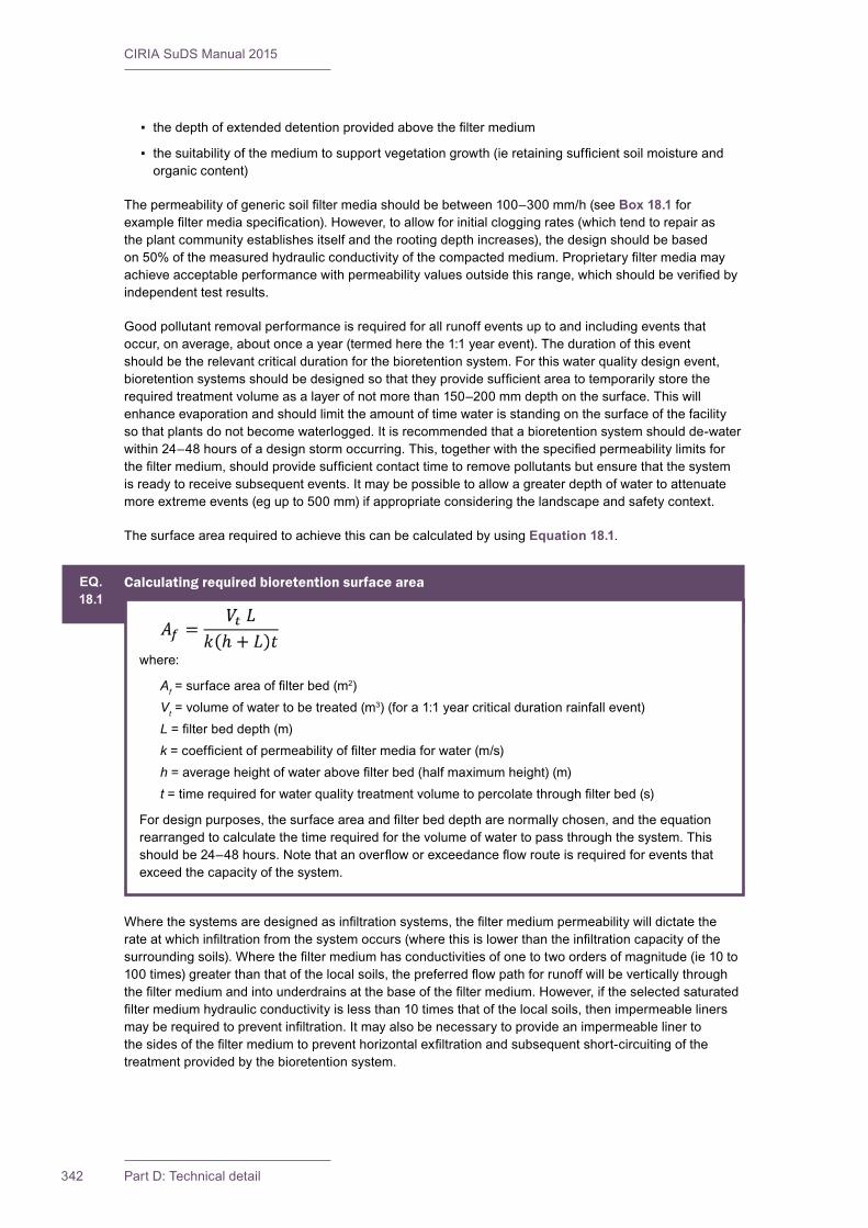
CIRIA SuDS Manual 2015
342 Part D: Technical detail
▪ thedepthofextendeddetentionprovidedabovethefiltermedium
▪ thesuitabilityofthemediumtosupportvegetationgrowth(ieretainingsufficientsoilmoistureandorganic content)
Thepermeabilityofgenericsoilfiltermediashouldbebetween100–300mm/h(seeBox 18.1 for examplefiltermediaspecification).However,toallowforinitialcloggingrates(whichtendtorepairasthe plant community establishes itself and the rooting depth increases), the design should be based on50%ofthemeasuredhydraulicconductivityofthecompactedmedium.Proprietaryfiltermediamayachieveacceptableperformancewithpermeabilityvaluesoutsidethisrange,whichshouldbeverifiedbyindependent test results.
Good pollutant removal performance is required for all runoff events up to and including events that occur, on average, about once a year (termed here the 1:1 year event). The duration of this event should be the relevant critical duration for the bioretention system. For this water quality design event, bioretentionsystemsshouldbedesignedsothattheyprovidesufficientareatotemporarilystoretherequired treatment volume as a layer of not more than 150–200 mm depth on the surface. This will enhance evaporation and should limit the amount of time water is standing on the surface of the facility so that plants do not become waterlogged. It is recommended that a bioretention system should de-water within24–48hoursofadesignstormoccurring.This,togetherwiththespecifiedpermeabilitylimitsforthefiltermedium,shouldprovidesufficientcontacttimetoremovepollutantsbutensurethatthesystemis ready to receive subsequent events. It may be possible to allow a greater depth of water to attenuate moreextremeevents(egupto500mm)ifappropriateconsideringthelandscapeandsafetycontext.
The surface area required to achieve this can be calculated by using Equation 18.1.
Wherethesystemsaredesignedasinfiltrationsystems,thefiltermediumpermeabilitywilldictatetherateatwhichinfiltrationfromthesystemoccurs(wherethisislowerthantheinfiltrationcapacityofthesurroundingsoils).Wherethefiltermediumhasconductivitiesofonetotwoordersofmagnitude(ie10to100times)greaterthanthatofthelocalsoils,thepreferredflowpathforrunoffwillbeverticallythroughthefiltermediumandintounderdrainsatthebaseofthefiltermedium.However,iftheselectedsaturatedfiltermediumhydraulicconductivityislessthan10timesthatofthelocalsoils,thenimpermeablelinersmayberequiredtopreventinfiltration.Itmayalsobenecessarytoprovideanimpermeablelinertothesidesofthefiltermediumtopreventhorizontalexfiltrationandsubsequentshort-circuitingofthetreatment provided by the bioretention system.
EQ.18.1
Calculating required bioretention surface area
where:
Af=surfaceareaoffilterbed(m2)
Vt = volume of water to be treated (m3) (for a 1:1 year critical duration rainfall event)L=filterbeddepth(m)k=coefficientofpermeabilityoffiltermediaforwater(m/s)h=averageheightofwaterabovefilterbed(halfmaximumheight)(m)t=timerequiredforwaterqualitytreatmentvolumetopercolatethroughfilterbed(s)
Fordesignpurposes,thesurfaceareaandfilterbeddeptharenormallychosen,andtheequationrearranged to calculate the time required for the volume of water to pass through the system. This shouldbe24–48hours.Notethatanoverfloworexceedanceflowrouteisrequiredforeventsthatexceedthecapacityofthesystem.

343Chapter 18: Bioretention systems
CIRIA SuDS Manual 2015
18.4.2 Interception design
BioretentionsystemsdeliverInterceptionbecausethereisnorunofffromthemforthemajorityofsmallrainfallevents.Thewatersoaksintothefiltermediumandisremovedbyevapotranspirationandinfiltration(whereallowed).Theextentofthevolumetricreductioninrunoffwilldependontheinfiltrationrateofthesurroundingsoil,thecatchmentarea,areaanddepthofthesystem,typeofvegetation and the climate.
Interception design should follow the guidance provided in Section 24.8.
18.4.3 Peakflowcontroldesign
Bioretentionsystemscanhelpreduceflowratesfromasitebyprovidingsomeattenuationstorageandcanreducestoragevolumerequirementswhereinfiltrationoccurs.Forbioretentionsystemsandraingardensthepeakflowcontroldesignandassessmentofthesurfacestoragevolumecanbedeterminedusingstandardhydraulicassessmentandtreatingthesurfaceofthesystemasaninfiltrationbasin.Thepermeabilityofthefiltermediumshouldbeusedastheinfiltrationrate.
Subsurfacestoragecanbeprovidedbythevoidspaceinthefiltermediumand/ordrainagelayerinthesystem:
Available attenuation storage in the filter medium and drainage layer of the bioretention system = Volume of system × porosity in the soil/drainage layer
The drainage layer materials normally used will have a porosity of at least 30%. Filter layer materials may have a lower porosity, but the value is easily measured by simple tests (Chapter 30).
Aflowcontrolstructuremayberequiredtoconstraintherateofwaterdischargedfromthesystem.Duetothesmallrunoffareaslikelytobedischargingtothesystem,itmaybeappropriatetolinkadjacentsystems together so that the control system can be larger, to reduce the risk of blockage.
18.4.4 Volume control design
Contribution of bioretention systems to volume control should be evaluated using standard methods, basedonexpectedinfiltrationratesand/oravailableattenuationstorageandspecifiedflowcontrols.Assessment of volumetric control should follow the method described in Chapter 3.
18.4.5 Exceedanceflowdesign
Anexceedanceflowroutewillberequiredforrainfalleventsthatexceedthedesigncapacityofthebioretentionsystem.Thiscanbeachievedbyinstallinganoverflowpipe,weiroroverflowstructureabovethedesignwaterstoragelevelofthereservoirlayertoconveyexcessflowsdownstream.
Theexceedanceflowcapacityoftheoverflowshouldbeconfirmedusingnormalhydraulicassessmentmethodsandanalysis(weir,orificeandpipeflow).Exceedanceflowsbeyondthecapacityoftheoverflowshouldalsobeconfirmed.
Anyexceedanceflowstructureshouldbelocatedinthebiofiltrationbasinandasclosetotheinletaspossibletominimisetheflowpathlengthforabove-capacityflows,thusreducingtheriskofscouring(Section 18.8.2).
18.5 TREATMENT DESIGN
Bioretention systems can provide very effective treatment functionality through:
▪ theremovalofsediments(especiallyfinesediment)andassociatedpollutants(suchasnutrients,freeoils/greaseandmetals)byfiltrationthroughsurfacevegetationandgroundcover

CIRIA SuDS Manual 2015
344 Part D: Technical detail
▪ theremovaloffineparticulatesandassociatedcontaminantsbyinfiltrationthroughtheunderlyingfiltermediumlayers–thisprovidestreatmentbyfiltration,extendeddetentiontreatmentandsomebiological uptake by vegetation and subsoil biota
▪ theremovalofdissolvedpollutantsbysorptionofpollutantstothefiltermedium.
The sizing of the bioretention surface area to deliver effective treatment is presented in Box 18.1 – due to its links with hydraulic performance of the system.
Theacceptabilityofallowinginfiltrationfromthebioretentioncomponentwilldependontheextentofthelikely runoff contamination and site characteristics (see Chapter 4, Table 4.3).
Correctly designed and maintained bioretention systems have been shown, in numerous studies, to retain pollutants, even when receiving snow melt that contains de-icing salt constituents (Muthanna et al, 2007). Pollutantremovalefficienciesofbioretentionsystemsthataredesignedinaccordancewiththeguidelinesfrom FAWB (2009) are summarised in Table 18.1.Notethatallquotedremovalefficienciesareeventspecificandwilldependonfactorssuchasantecedentconditions.
TABLE18.1
Pollution removal for bioretention systems designed to FAWB guidelines (after FAWB, 2009)
Pollutant Typical removal efficiency
TSS > 90%
Total phosphorous > 80%
Nitrogen 50% on average
Metals (zinc, lead, cadmium) > 90%
Metals (copper) up to 60%
Evidenceofthepollutantremovalefficienciesofbioretentioncomponents,fromtheInternationalBMPdatabase is presented in Chapter 26, Annex 3.
Vegetationthatgrowsinthefiltermediumenhancesitsfunctionbytrappingandabsorbingphysicalpollutantsandpreventingerosionofthefiltermedium.Italsoimprovestheperformanceofthesystembycontinuously breaking up the soil through plant growth to prevent clogging of the system, and providing biofilmsonplantrootsthatpollutantscanabsorborotherwiseadhereto.Whilethetypeofvegetationvariesdependingonlandscaperequirementsandclimate,thefiltrationprocessgenerallyimproveswithdenser and higher vegetation. The type of plants used in bioretention systems affects the treatment performance. A study by the FAWB (2008) and others has found that there is marked variation in pollutant removal per unit plant mass between different species. The key factors that should therefore be considered in design are:
▪ plantsthatarewell-adaptedtoephemeralwet/dryconditionsandhaveextensiverootsystemsarelikely to be most effective for treatment
▪ shallow-rooted plants are not particularly effective at nitrogen removal
▪ incorporating submerged zones will help maintain vegetation and avoid nitrogen spikes following dry periods of weather.
SoilfiltermediashouldbespecifiedtomeettheFAWB(2009)guidelines,asthisappearstobemosteffective for pollution removal (Chapter 30). For smaller-scale rain gardens that are only collecting roof water, the FAWB guidelines may be too onerous, although the permeability requirements should beretainedifthewaterleavesviaanunderdrain.Proprietaryfiltermediashouldhavedemonstratedperformancecharacteristicsthatareverifiedbyanindependenttestorganisation.
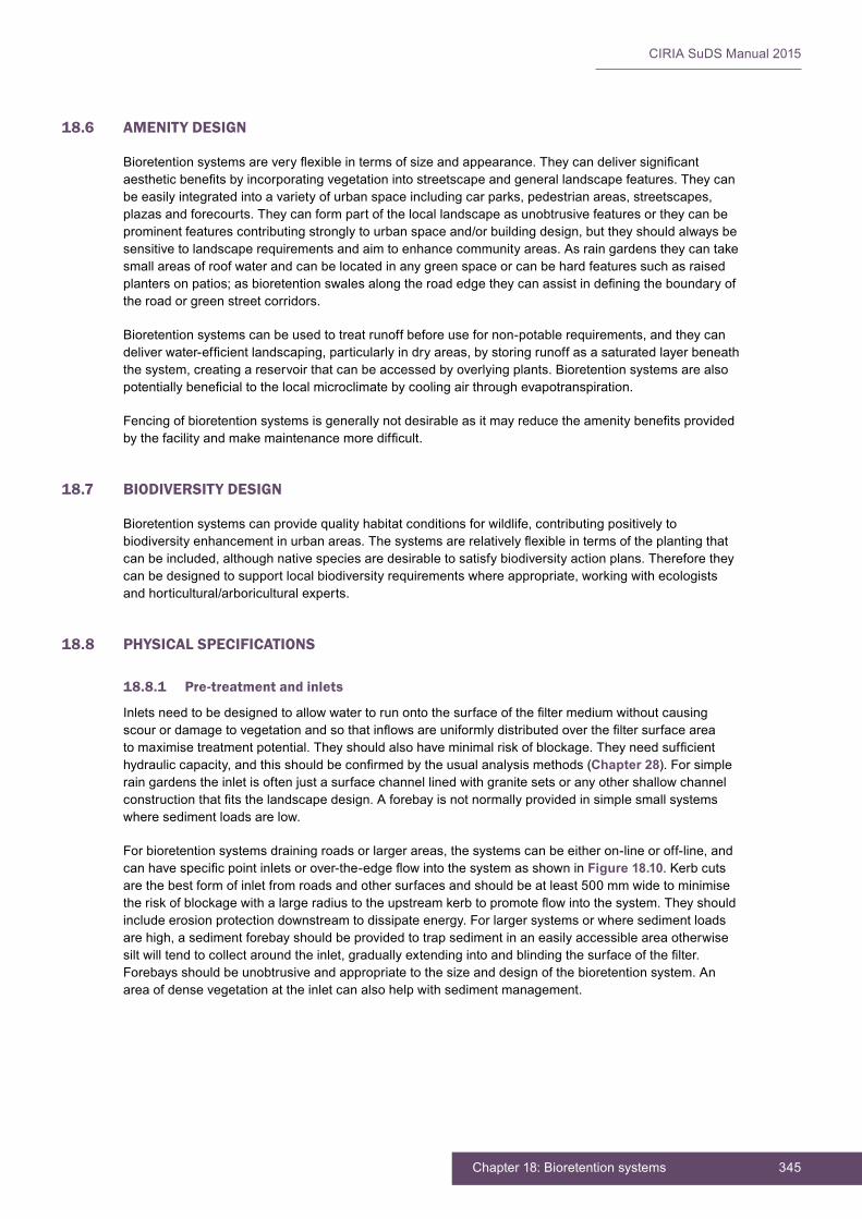
345Chapter 18: Bioretention systems
CIRIA SuDS Manual 2015
18.6 AMENITY DESIGN
Bioretentionsystemsareveryflexibleintermsofsizeandappearance.Theycandeliversignificantaestheticbenefitsbyincorporatingvegetationintostreetscapeandgenerallandscapefeatures.Theycanbe easily integrated into a variety of urban space including car parks, pedestrian areas, streetscapes, plazas and forecourts. They can form part of the local landscape as unobtrusive features or they can be prominent features contributing strongly to urban space and/or building design, but they should always be sensitive to landscape requirements and aim to enhance community areas. As rain gardens they can take small areas of roof water and can be located in any green space or can be hard features such as raised plantersonpatios;asbioretentionswalesalongtheroadedgetheycanassistindefiningtheboundaryofthe road or green street corridors.
Bioretention systems can be used to treat runoff before use for non-potable requirements, and they can deliverwater-efficientlandscaping,particularlyindryareas,bystoringrunoffasasaturatedlayerbeneaththe system, creating a reservoir that can be accessed by overlying plants. Bioretention systems are also potentiallybeneficialtothelocalmicroclimatebycoolingairthroughevapotranspiration.
Fencingofbioretentionsystemsisgenerallynotdesirableasitmayreducetheamenitybenefitsprovidedbythefacilityandmakemaintenancemoredifficult.
18.7 BIODIVERSITY DESIGN
Bioretention systems can provide quality habitat conditions for wildlife, contributing positively to biodiversityenhancementinurbanareas.Thesystemsarerelativelyflexibleintermsoftheplantingthatcan be included, although native species are desirable to satisfy biodiversity action plans. Therefore they can be designed to support local biodiversity requirements where appropriate, working with ecologists andhorticultural/arboriculturalexperts.
18.8 PHYSICAL SPECIFICATIONS
18.8.1 Pre-treatment and inlets
Inletsneedtobedesignedtoallowwatertorunontothesurfaceofthefiltermediumwithoutcausingscourordamagetovegetationandsothatinflowsareuniformlydistributedoverthefiltersurfaceareatomaximisetreatmentpotential.Theyshouldalsohaveminimalriskofblockage.Theyneedsufficienthydrauliccapacity,andthisshouldbeconfirmedbytheusualanalysismethods(Chapter 28). For simple raingardenstheinletisoftenjustasurfacechannellinedwithgranitesetsoranyothershallowchannelconstructionthatfitsthelandscapedesign.Aforebayisnotnormallyprovidedinsimplesmallsystemswhere sediment loads are low.
For bioretention systems draining roads or larger areas, the systems can be either on-line or off-line, and canhavespecificpointinletsorover-the-edgeflowintothesystemasshowninFigure 18.10. Kerb cuts are the best form of inlet from roads and other surfaces and should be at least 500 mm wide to minimise theriskofblockagewithalargeradiustotheupstreamkerbtopromoteflowintothesystem.Theyshouldinclude erosion protection downstream to dissipate energy. For larger systems or where sediment loads are high, a sediment forebay should be provided to trap sediment in an easily accessible area otherwise siltwilltendtocollectaroundtheinlet,graduallyextendingintoandblindingthesurfaceofthefilter.Forebays should be unobtrusive and appropriate to the size and design of the bioretention system. An area of dense vegetation at the inlet can also help with sediment management.
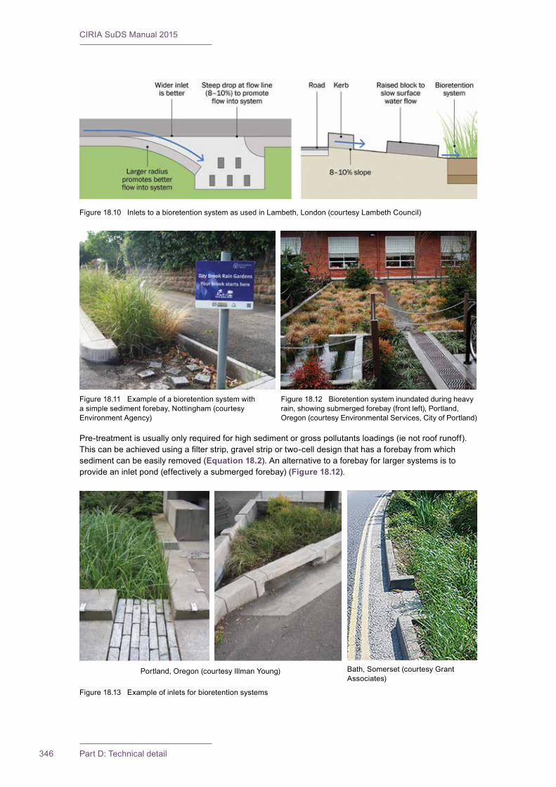
CIRIA SuDS Manual 2015
346 Part D: Technical detail
Pre-treatment is usually only required for high sediment or gross pollutants loadings (ie not roof runoff). Thiscanbeachievedusingafilterstrip,gravelstriportwo-celldesignthathasaforebayfromwhichsediment can be easily removed (Equation 18.2). An alternative to a forebay for larger systems is to provide an inlet pond (effectively a submerged forebay) (Figure 18.12).
Figure 18.10 Inlets to a bioretention system as used in Lambeth, London (courtesy Lambeth Council)
Figure18.11 Exampleofabioretentionsystemwitha simple sediment forebay, Nottingham (courtesy Environment Agency)
Figure 18.12 Bioretention system inundated during heavy rain, showing submerged forebay (front left), Portland, Oregon (courtesy Environmental Services, City of Portland)
Portland, Oregon (courtesy Illman Young)
Figure18.13 Exampleofinletsforbioretentionsystems
Bath, Somerset (courtesy Grant Associates)
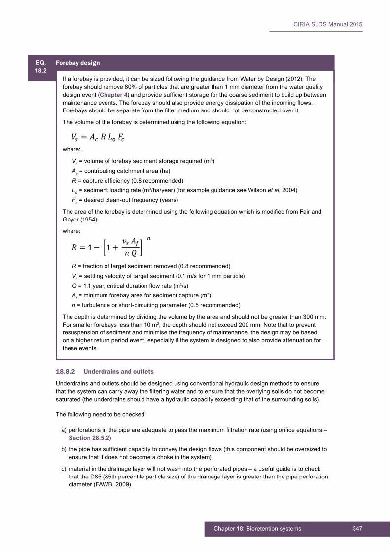
347Chapter 18: Bioretention systems
CIRIA SuDS Manual 2015
18.8.2 Underdrains and outlets
Underdrains and outlets should be designed using conventional hydraulic design methods to ensure thatthesystemcancarryawaythefilteringwaterandtoensurethattheoverlyingsoilsdonotbecomesaturated(theunderdrainsshouldhaveahydrauliccapacityexceedingthatofthesurroundingsoils).
The following need to be checked:
a) perforationsinthepipeareadequatetopassthemaximumfiltrationrate(usingorificeequations–Section 28.5.2)
b) thepipehassufficientcapacitytoconveythedesignflows(thiscomponentshouldbeoversizedtoensure that it does not become a choke in the system)
c) material in the drainage layer will not wash into the perforated pipes – a useful guide is to check that the D85 (85th percentile particle size) of the drainage layer is greater than the pipe perforation diameter (FAWB, 2009).
EQ.18.2
Forebay design
If a forebay is provided, it can be sized following the guidance from Water by Design (2012). The forebay should remove 80% of particles that are greater than 1 mm diameter from the water quality design event (Chapter 4)andprovidesufficientstorageforthecoarsesedimenttobuildupbetweenmaintenanceevents.Theforebayshouldalsoprovideenergydissipationoftheincomingflows.Forebaysshouldbeseparatefromthefiltermediumandshouldnotbeconstructedoverit.
The volume of the forebay is determined using the following equation:
where:
Vs = volume of forebay sediment storage required (m3)Ac = contributing catchment area (ha)R=captureefficiency(0.8recommended)L0 = sediment loading rate (m3/ha/year)(forexampleguidanceseeWilsonet al, 2004)Fc = desired clean-out frequency (years)
TheareaoftheforebayisdeterminedusingthefollowingequationwhichismodifiedfromFairandGayer (1954):
where:
R = fraction of target sediment removed (0.8 recommended)Vs = settling velocity of target sediment (0.1 m/s for 1 mm particle)Q=1:1year,criticaldurationflowrate(m3/s)Af = minimum forebay area for sediment capture (m2)n = turbulence or short-circuiting parameter (0.5 recommended)
The depth is determined by dividing the volume by the area and should not be greater than 300 mm. For smaller forebays less than 10 m2,thedepthshouldnotexceed200mm.Notethattopreventresuspension of sediment and minimise the frequency of maintenance, the design may be based on a higher return period event, especially if the system is designed to also provide attenuation for these events.
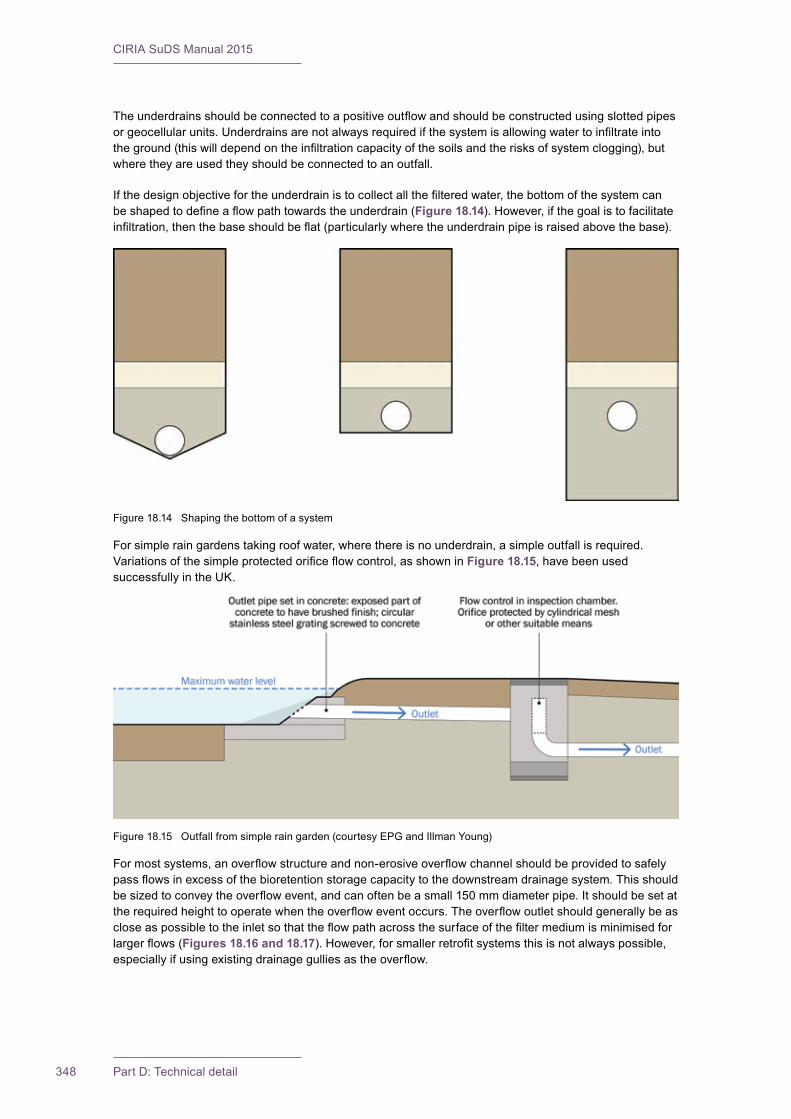
CIRIA SuDS Manual 2015
348 Part D: Technical detail
Theunderdrainsshouldbeconnectedtoapositiveoutflowandshouldbeconstructedusingslottedpipesorgeocellularunits.Underdrainsarenotalwaysrequiredifthesystemisallowingwatertoinfiltrateintotheground(thiswilldependontheinfiltrationcapacityofthesoilsandtherisksofsystemclogging),butwhere they are used they should be connected to an outfall.
Ifthedesignobjectivefortheunderdrainistocollectallthefilteredwater,thebottomofthesystemcanbeshapedtodefineaflowpathtowardstheunderdrain(Figure 18.14). However, if the goal is to facilitate infiltration,thenthebaseshouldbeflat(particularlywheretheunderdrainpipeisraisedabovethebase).
For simple rain gardens taking roof water, where there is no underdrain, a simple outfall is required. Variationsofthesimpleprotectedorificeflowcontrol,asshowninFigure 18.15, have been used successfully in the UK.
Formostsystems,anoverflowstructureandnon-erosiveoverflowchannelshouldbeprovidedtosafelypassflowsinexcessofthebioretentionstoragecapacitytothedownstreamdrainagesystem.Thisshouldbesizedtoconveytheoverflowevent,andcanoftenbeasmall150mmdiameterpipe.Itshouldbesetattherequiredheighttooperatewhentheoverfloweventoccurs.Theoverflowoutletshouldgenerallybeascloseaspossibletotheinletsothattheflowpathacrossthesurfaceofthefiltermediumisminimisedforlargerflows(Figures 18.16 and 18.17).However,forsmallerretrofitsystemsthisisnotalwayspossible,especiallyifusingexistingdrainagegulliesastheoverflow.
Figure 18.14 Shaping the bottom of a system
Figure 18.15 Outfall from simple rain garden (courtesy EPG and Illman Young)
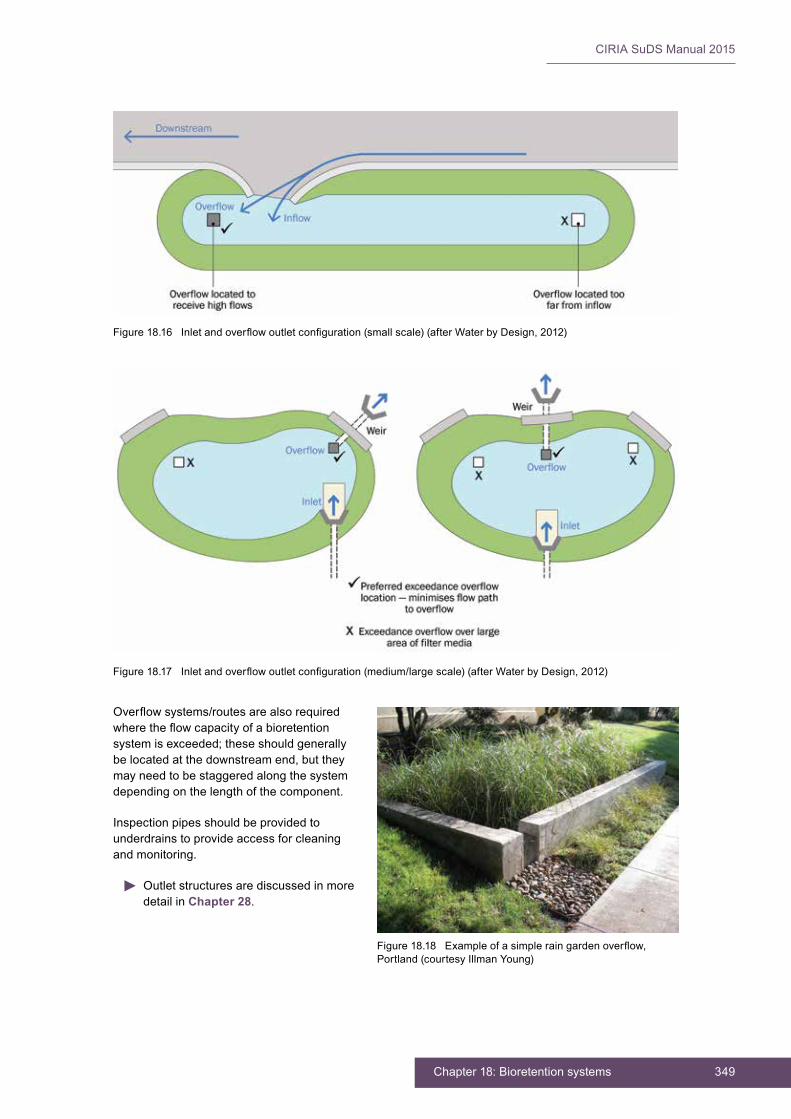
349Chapter 18: Bioretention systems
CIRIA SuDS Manual 2015
Overflowsystems/routesarealsorequiredwheretheflowcapacityofabioretentionsystemisexceeded;theseshouldgenerallybe located at the downstream end, but they may need to be staggered along the system depending on the length of the component.
Inspection pipes should be provided to underdrains to provide access for cleaning and monitoring.
Outlet structures are discussed in more detail in Chapter 28.
Figure18.16 Inletandoverflowoutletconfiguration(smallscale)(afterWaterbyDesign,2012)
Figure18.17 Inletandoverflowoutletconfiguration(medium/largescale)(afterWaterbyDesign,2012)
Figure18.18 Exampleofasimpleraingardenoverflow,Portland (courtesy Illman Young)

CIRIA SuDS Manual 2015
350 Part D: Technical detail
18.9 MATERIALS
18.9.1 Mulch layer (if required)
Theuseofanorganicmulchshouldgenerallybeavoidedforsystemswherethereisanoverflowpit,owingtotheriskofclogging.Inthecaseofinfiltrationsystems(withnooverflow),amulchmaybeused,butthereisstillariskofexcessivemovementofmaterialduringhighflows.Amulchlayer(withamaximumdepthof75mm)canbespreadoverthebioretentionareatoretainsomesoilmoisture.Organicmattingthatdegradeswithinsixmonths,bondedfibrematricmulchesoralayerofgravelcanbeusedas an alternative to standard organic mulches. A gravel mulch may be valuable where there is a need to protect the soil from erosion or decrease the drop to the water storage zone (for safety reasons), while still maintaining an acceptable ponding volume; however, high planting densities should be used, to compensate for the reduced spread of plants.
The best performance and prevention of erosion is likely to be achieved by using plants that give good ground cover rather than a mulch.
18.9.2 Filter media
Thefiltermediumshouldbesufficientlypermeabletoallowwatertopassthroughit,sothatthesurfaceoftheretentionareadoesnotbecomewaterlogged.Italsoneedstocontainsufficientorganicmaterialandplant nutrients to support the proposed vegetation.
Filtermediashouldbecorrectlyspecified.AnindicativespecificationisprovidedinBox 18.1, but others areavailable,andanyspecificationshouldtakeintoaccountsite-specificrequirementsandconstraints.Ifalternativespecificationsareused,thespecificationparametersshouldbeclearlystated,sothatintheeventthatasupplierceasestradingthefiltermaterialcanstillbereplacedonalike-for-likebasis.Notethatthisisadifferentspecificationfromtreesoil,andiftreesarebeingplantedinthesystemasoilscientistorarboriculturistshouldbeconsultedonthemostappropriatespecificationforthesystem.
Incorrectspecificationcancausereducedhydraulicconductivitythroughover-compactionorstructuralcollapse,leadingtoreductionintreatmentcapacityandsurfaceponding,lossofvegetationetc.Thefiltermedium should also be correctly installed with an appropriate level of compaction during installation to preventmigrationoffineparticles.
Afiltermediumthatisplaceduncompactedwillinitiallyshowaveryhighhydraulicconductivitywhichwill then rapidly decrease. So it is essential that testing of hydraulic conductivity be carried out on the compactedfiltermediumbeforeinstallation.
BOX18.1
Examplespecificationforabioretentionfiltermedium
Saturated hydraulic conductivity (permeability)The saturated hydraulic conductivity should be between 100 mm/h and 300 mm/h. This should be checked in situ,usingthesingleringinfiltrationtestmethodasdescribedinBSENISO22282-5:2012.
(Note that where larger volumes of engineered soil are to be used, it is wise to test the hydraulic conductivity before delivery to site using a laboratory test. ASTM F1815-06 is commonly used in other applications such as sports pitches.)
PorosityThe total porosity should be > 30% when tested in accordance with BS 1377-2:1990).
Particle size distributionParticle size distribution (PSD) is of secondary importance compared with saturated hydraulic conductivity. A material whose PSD falls within the following recommended range does not preclude the need for hydraulic conductivity testing, that is it does not guarantee that the
continued...
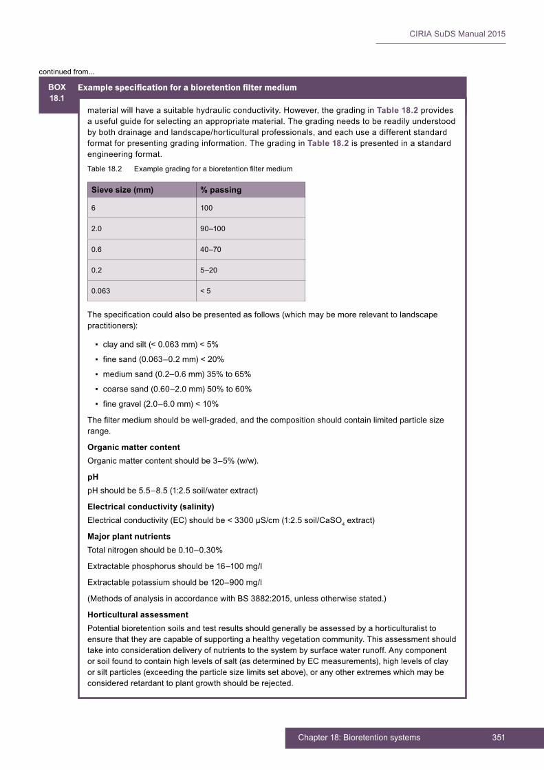
351Chapter 18: Bioretention systems
CIRIA SuDS Manual 2015
BOX18.1
Examplespecificationforabioretentionfiltermedium
material will have a suitable hydraulic conductivity. However, the grading in Table 18.2 provides a useful guide for selecting an appropriate material. The grading needs to be readily understood by both drainage and landscape/horticultural professionals, and each use a different standard format for presenting grading information. The grading in Table 18.2 is presented in a standard engineering format.
Table18.2 Examplegradingforabioretentionfiltermedium
Sieve size (mm) % passing
6 100
2.0 90–100
0.6 40–70
0.2 5–20
0.063 < 5
Thespecificationcouldalsobepresentedasfollows(whichmaybemorerelevanttolandscapepractitioners):
▪ clay and silt (< 0.063 mm) < 5%
▪ finesand(0.063–0.2mm)<20%
▪ medium sand (0.2–0.6 mm) 35% to 65%
▪ coarse sand (0.60–2.0 mm) 50% to 60%
▪ finegravel(2.0–6.0mm)<10%
Thefiltermediumshouldbewell-graded,andthecompositionshouldcontainlimitedparticlesizerange.
Organic matter contentOrganic matter content should be 3–5% (w/w).
pHpHshouldbe5.5–8.5(1:2.5soil/waterextract)
Electrical conductivity (salinity)Electrical conductivity (EC) should be < 3300 µS/cm (1:2.5 soil/CaSO4extract)
Major plant nutrientsTotal nitrogen should be 0.10–0.30%
Extractablephosphorusshouldbe16–100mg/l
Extractablepotassiumshouldbe120–900mg/l
(Methods of analysis in accordance with BS 3882:2015, unless otherwise stated.)
Horticultural assessmentPotential bioretention soils and test results should generally be assessed by a horticulturalist to ensure that they are capable of supporting a healthy vegetation community. This assessment should take into consideration delivery of nutrients to the system by surface water runoff. Any component or soil found to contain high levels of salt (as determined by EC measurements), high levels of clay orsiltparticles(exceedingtheparticlesizelimitssetabove),oranyotherextremeswhichmaybeconsideredretardanttoplantgrowthshouldberejected.
continued from...

CIRIA SuDS Manual 2015
352 Part D: Technical detail
For simple rain gardens draining a small area of roof (< 20 m2)thefiltermediumcouldbesubstitutedbya200–500 mm layer of engineered soil (Section 30.4.2) below the base, or, if the native soil is good quality subsoil,thenan“amendedsoil”couldbeusedcomprising:55%sand,30%existingsoil,15%compost.
Thematerialshouldbewellmixedandshouldmeetthepermeabilityrequirementsspecifiedinthebioretentionandengineeredsoilspecifications.
18.9.3 Transition layer or geotextile separator layer
ThetransitionlayershouldbespecifiedbasedonthegeotechnicalfiltercriteriadescribedinChapter 30, takingaccountofthegradingofthefiltermediumandthedrainagelayer.Thefiltercriteriaensurethatsoilparticlescannotbewashedfromonelayertoanother.Alternativelyageotextileseparatormaybeused,whichshouldmeetthegeotextilefiltercriteria(Chapter 30).
18.9.4 Drainage layer
Thedrainagelayershouldbemuchmorepermeablethanthefiltermedium.Therearevariousmaterialsthat can meet this requirement and may be suitable as the drainage layer:
▪ filterdrainmaterials–seeSection 30.4.1
▪ sub-base materials used below pervious surfaces, such as 4/20 aggregate – see Chapter 20
▪ geocellular units – see Chapter 21
Materials such as crushed recycled concrete may be appropriate for the drainage layer, but they should notcontainanyfineparticlesthatcouldwashoutofthedrainagelayer,contaminatingrunoffandpotentially blocking underdrain pipework. Crushed concrete should also be tested to make sure that it will not leach contaminants into the water.
18.10 LANDSCAPE DESIGN AND PLANTING
Plant selection will be dependent on design aspirations for the site. Planting in a bioretention system provides volumetric reduction of runoff, pollutant uptake through the soil and physical and chemical processesinthesoil.Plantsalsoaffectthelong-termhydraulicconductivityofthefiltermediumandhelpprevent erosion. The type of plants used in a bioretention system affects the system performance. The main criteria for plant selection are:
▪ surrounding landscape characteristics
▪ whether native or introduced species are appropriate
▪ availability of plants from local nurseries
▪ droughttolerance–capableofsurvivingextendeddryperiods
▪ tolerance of free-draining sandy soil
▪ tolerance of occasional inundation
▪ toleranceofexpectedpollutionloads
▪ fibrousrootstructurepropensity
▪ spreading growth form rather than clumping propensity.
Considerationshouldalsobegiventoshadetoleranceandheightrestrictions(egforsightlinesnexttohighways). The level of maintenance that plants will require is also an important consideration. Guidance on suitable plants for the UK is provided by the Bray et al(2012)butthechoiceissitespecificandrequiresinput from a landscape architect or other horticultural professional. Plant lists can lead to uniform standard designsolutionsanddiscouragecreativesitespecificdesign,soplantlistsarenotprovidedinthismanual.
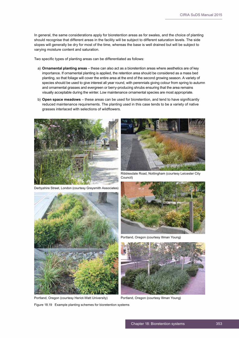
353Chapter 18: Bioretention systems
CIRIA SuDS Manual 2015
In general, the same considerations apply for bioretention areas as for swales, and the choice of planting shouldrecognisethatdifferentareasinthefacilitywillbesubjecttodifferentsaturationlevels.Thesideslopeswillgenerallybedryformostofthetime,whereasthebaseiswelldrainedbutwillbesubjecttovarying moisture content and saturation.
Twospecifictypesofplantingareascanbedifferentiatedasfollows:
a) Ornamental planting areas – these can also act as a bioretention areas where aesthetics are of key importance. If ornamental planting is applied, the retention area should be considered as a mass bed planting, so that foliage will cover the entire area at the end of the second growing season. A variety of species should be used to give interest all year round, with perennials giving colour from spring to autumn and ornamental grasses and evergreen or berry-producing shrubs ensuring that the area remains visually acceptable during the winter. Low maintenance ornamental species are most appropriate.
b) Open space meadows–theseareascanbeusedforbioretention,andtendtohavesignificantlyreduced maintenance requirements. The planting used in this case tends to be a variety of native grassesinterlacedwithselectionsofwildflowers.
Derbyshire Street, London (courtesy Greysmith Associates)
Ribblesdale Road, Nottingham (courtesy Leicester City Council)
Portland, Oregon (courtesy Heriot-Watt University)
Portland, Oregon (courtesy Illman Young)
Portland, Oregon (courtesy Illman Young)
Figure18.19 Exampleplantingschemesforbioretentionsystems
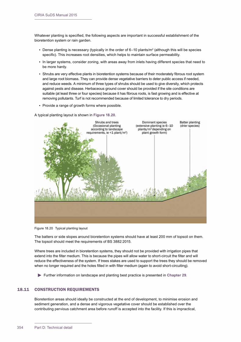
CIRIA SuDS Manual 2015
354 Part D: Technical detail
Whateverplantingisspecified,thefollowingaspectsareimportantinsuccessfulestablishmentofthebioretention system or rain garden.
▪ Dense planting is necessary (typically in the order of 6–10 plants/m2 (although this will be species specific).Thisincreasesrootdensities,whichhelpstomaintainsurfacepermeability.
▪ In larger systems, consider zoning, with areas away from inlets having different species that need to be more hardy.
▪ Shrubsareveryeffectiveplantsinbioretentionsystemsbecauseoftheirmoderatelyfibrousrootsystemand large root biomass. They can provide dense vegetative barriers to deter public access if needed, and reduce weeds. A minimum of three types of shrubs should be used to give diversity, which protects against pests and disease. Herbaceous ground cover should be provided if the site conditions are suitable(atleastthreeorfourspecies)becauseithasfibrousroots,isfastgrowingandiseffectiveatremoving pollutants. Turf is not recommended because of limited tolerance to dry periods.
▪ Provide a range of growth forms where possible.
A typical planting layout is shown in Figure 18.20.
The batters or side slopes around bioretention systems should have at least 200 mm of topsoil on them. The topsoil should meet the requirements of BS 3882:2015.
Where trees are included in bioretention systems, they should not be provided with irrigation pipes that extendintothefiltermedium.Thisisbecausethepipeswillallowwatertoshort-circuitthefilterandwillreduce the effectiveness of the system. If trees stakes are used to support the trees they should be removed whennolongerrequiredandtheholesfilledinwithfiltermedium(againtoavoidshort-circuiting).
Further information on landscape and planting best practice is presented in Chapter 29.
18.11 CONSTRUCTION REQUIREMENTS
Bioretention areas should ideally be constructed at the end of development, to minimise erosion and sediment generation, and a dense and vigorous vegetative cover should be established over the contributing pervious catchment area before runoff is accepted into the facility. If this is impractical,
Figure 18.20 Typical planting layout

355Chapter 18: Bioretention systems
CIRIA SuDS Manual 2015
bioretention areas should be protected from runoff by using silt fences or straw bales as recommended in Woods Ballard et al (2007).
InAustraliatherehasbeenasignificantissuewithbioretentionblinding,compactionandfailureduringthesiteconstructionphase.Oneapproachtoaddressthisistoplacethefiltermediuminthesystemand cover it with a temporary impermeable cover to collect all the silt and sediment that is washed into the depression during construction (ie the system is acting as a silt basin during construction). This impermeable layer and accumulated silt is removed once construction is completed and the system is planted. Relying on sediment fences and straw bales has not been found to be as effective as protecting the systems with a temporary cover.
To minimise the risk of premature system failure, the following points should be closely monitored during the construction of bioretention areas:
▪ Care should be taken not to over-compact the soils below the bioretention area, and particularly the filterandsoilplantingbed,asthiswillreduceinfiltrationcapacities.
▪ Toexcavateabioretentionarea,abackhoeexcavatorshouldbeused,andconstructionplantshouldavoidrunningoverthebioretentionarea.Forsmallersystemsandraingardens,handexcavationmay be more suitable if access is limited.
▪ If mulch is required, it should be applied before planting. It should not be piled up around plants, as this will cause disease and encourage pests. It should be 50–75 mm thick and should be kept clear ofplantstemsby50mmtopreventexcessivemoisturearoundthestems.
▪ Careshouldbetakentoensurethatgeotextilesarenotcloggedortornduringconstruction.
▪ Thefiltermediumshouldnotbeplacedifitissaturatedorifthegroundbelowthesystemissaturated.
Thefiltermediumshouldbetestedtoensurethatitmeetstherequiredcriteriabeforeplacing(Box 18.1). It is important to establish the planting in the systems as quickly as possible. Watering, weeding and replanting will be required during the establishment period to ensure that greater than 90% of plants survive and give good cover.
Thesurfaceofthefiltermediumshouldbefreeoflocaliseddepressionssothatwaterisdistributedevenlyacross the surface and prevents localised ponding and clogging. The surface levels should be within a tolerance of ± 25 mm for smaller systems and ± 40 mm for systems with an area greater than 300 m2. The thicknesses for the various layers should be constructed with a tolerance of + 25 mm (ie they should not be less than the design thickness). Levels around the edge of the system should be within ± 25 mm of design levels.
Further detail on construction activities and the programming of construction activities is provided in Chapter 31.
A construction phase health and safety plan is required under the Construction (Design and Management) Regulations (CDM) 2015. This should ensure that all construction risks have been identified,eliminated,reducedand/orcontrolledwhereappropriate.
Generic health and safety guidance is presented in Chapter 36.
18.12 OPERATION AND MAINTENANCE REQUIREMENTS
Dalrymple(2013)concludedthatbioretentionsystemswilltypicallyrequireapproximately2.5timesmoremaintenance than typical landscape designs. Bioretention systems will require regular maintenance to ensure continuing operation to design performance standards, and all designers should provide detailed specificationsandfrequenciesfortherequiredmaintenanceactivitiesalongwithlikelymachineryrequirements and typical annual costs – within the Maintenance Plan. The treatment performance of bioretention systems is dependent on maintenance, and robust management plans will be required to

CIRIA SuDS Manual 2015
356 Part D: Technical detail
ensure that maintenance is carried out in the long term. Different designs will have different operation and maintenance requirements, but this section gives some generic guidance. Ease of access for maintenance and inspection is essential.
The main cause of failure of bioretention systems is clogging of the surface, which is easily visible. Underdrains and drainage layers are beneath the ground, and malfunctioning is not so easy to detect and therefore could potentially be ignored. However, the results of any malfunction are likely to cause surfaceponding.Thecloggingofthesurfaceordrainagelayerscancausepooroutflowwaterqualityduetowaterbypassingthefiltermediumtotheoverflowmorefrequentlythanallowedfor.Duringthefirstfewmonths after installation, the system should be visually inspected after rainfall events, and the amount of depositionmeasured,togivetheoperatoranideaoftheexpectedrateofsedimentdeposition.Afterthisinitial period, systems should be inspected each quarter, to verify the appropriate level of maintenance.
Further detail on waste management is provided in Chapter 33.
Adequate access should be provided for all bioretention areas for inspection and maintenance, including for the appropriate equipment and vehicles.
Litter picking should be frequent, as rubbish is detrimental to the visual appearance of bioretention systems. Frequent street sweeping in the catchment area will increase the time interval between cleaning outforebaysorthefiltersurfaceandwillreducetheloadingoffinesuspendedsolidsthatcanpotentiallyclogthefiltermedium.
Allvegetationmanagementactivitiesshouldtakeaccountoftheneedtomaximisebiosecurityandprevent the spread of invasive species.
Maintenance responsibility for all systems should be placed with an appropriate organisation, and Maintenance Plans and schedules should be developed during the design phase. Table 18.3 provides guidance on the type of operation and maintenance schedule that may be appropriate. The list of actions isnotexhaustiveandsomeactionsmaynotalwaysberequired.Themostintensivemaintenanceisrequired during the establishment period. Herbicides and pesticides (such as Roundup) and fertilizers should not be used on bioretention systems. This is because these pollutants will wash through the system quite easily.
Sedimentsexcavatedfrompre-treatmentdevicesthatreceiverunofffromresidentialorstandardroadandroofareasaregenerallynottoxicorhazardousmaterialandcanthereforebesafelydisposedofbyeitherlandapplicationorlandfilling.However,consultationshouldtakeplacewiththeenvironmentalregulatortoconfirmappropriateprotocols.Sedimenttestingmayberequiredbeforesedimentexcavation,todetermineitsclassificationandappropriatedisposalmethods.Forindustrialsiterunoff,sedimenttestingwillbeessential.Inthemajorityofcases,itwillbeacceptabletodistributethesedimentonsite,ifthereisanappropriate safe and acceptable location to do so. Proper disposal of sediment and debris removed must be ensured, and the environmental regulator should be approached for advice where there are any doubts concerning disposal options.
Further detail on waste management is given in Chapter 33.
Specificmaintenanceneedsofthebioretentionareashouldbemonitored,andmaintenanceschedulesadjustedtosuitrequirements.
FurtherdetailonthepreparationofmaintenancespecificationsandschedulesofworkisgiveninChapter 32.
In general, the maintenance for bioretention areas can often be undertaken as part of routine landscape maintenance.
CDM2015requiresdesignerstoensurethatallmaintenanceriskshavebeenidentified,eliminated,reduced and/or controlled where appropriate. This information will be required as part of the health and safetyfile.
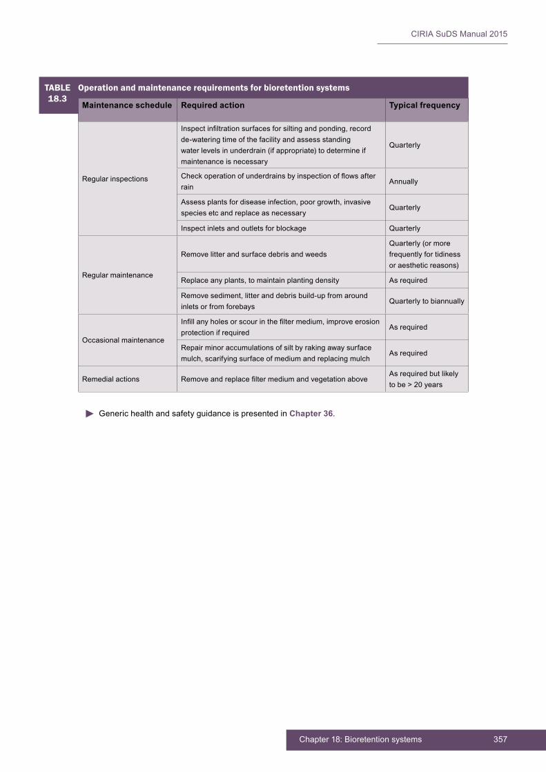
357Chapter 18: Bioretention systems
CIRIA SuDS Manual 2015
TABLE 18.3
Operation and maintenance requirements for bioretention systems
Maintenance schedule Required action Typical frequency
Regular inspections
Inspectinfiltrationsurfacesforsiltingandponding,recordde-watering time of the facility and assess standing water levels in underdrain (if appropriate) to determine if maintenance is necessary
Quarterly
Checkoperationofunderdrainsbyinspectionofflowsafterrain
Annually
Assess plants for disease infection, poor growth, invasive species etc and replace as necessary
Quarterly
Inspect inlets and outlets for blockage Quarterly
Regular maintenance
Remove litter and surface debris and weedsQuarterly (or more frequently for tidiness or aesthetic reasons)
Replace any plants, to maintain planting density As required
Remove sediment, litter and debris build-up from around inlets or from forebays
Quarterly to biannually
Occasional maintenance
Infillanyholesorscourinthefiltermedium,improveerosionprotection if required
As required
Repair minor accumulations of silt by raking away surface mulch, scarifying surface of medium and replacing mulch
As required
Remedial actions RemoveandreplacefiltermediumandvegetationaboveAs required but likely to be > 20 years
Generic health and safety guidance is presented in Chapter 36.

CIRIA SuDS Manual 2015
358 Part D: Technical detail
18.13 REFERENCES
BRAY, R, GEDGE, D, GRANT, G and LEUTHVILAY, L (2012) Rain garden guide, Thames Water, Environment Agency, CIRIA, UK. Go to: http://tinyurl.com/p5mfvq4
DALRYMPLE, B. (2012) “Bioretention myths busted!!”. In: Proc 2012 Stormwater Industry Association Queensland State conference, raining a revolution, 30–31 May 2012, Brisbane, Australia
DAVIS, A (2008) “Field performance of bioretention: Hydrology impacts” Journal of Hydrologic Engineering, vol 13, 2, American Society of Civil Engineers, Reston, VA, USA, pp 90–95
FAIR, G M and GEYER, J C (1954) Elements of water supply and wastewater disposal, John Wiley and Sons Inc, New York, USA (ISBN: 978-0-47125-115-6)
FAWB (2008) Advancing the design of stormwater biofiltration,FacilityforAdvancingWaterBiofiltration,Monash University, Victoria, Australia. Go to: http://tinyurl.com/olyr4fz
FAWB (2009) Stormwater biofiltration systems, adoption guidelines. Planning, design and practical implementation,version 1, FacilityforAdvancingWaterBiofiltration,MonashUniversity,Victoria,Australia(ISBN: 978-0-98058-311-3). Go to: http://tinyurl.com/opsjrsq
MUTHANNA, T M, VIKLANDER, M, BLECKEN, G AND THOROLFSSON, S T (2007) “Snowmelt pollutant removal in bioretention areas” Water Research, vol 41, 18, Norwegian University of Science and Technology, Norway, pp 4061–4072
WATER BY DESIGN (2012) Bioretention technical design guidelines, version 1, Healthy Waterways Limited, Brisbane, Australia. Go to: http://waterbydesign.com.au/techguide
WILSON, S, BRAY, R and COOPER, P (2004) Sustainable drainage systems. Hydraulic, structural and water quality advice, C609, CIRIA, London, UK (ISBN: 978-0-86017-609-1). Go to: www.ciria.org
WOODS BALLARD, B, KELLAGHER, R, MARTIN, P, JEFFRIES, C, BRAY, R and SHAFFER, P (2007) Site handbook for the construction of SUDS, C698, CIRIA, London, UK (ISBN: 978-0-86017-698-5). Go to: www.ciria.org
Statutes
ASTM F1815-06 Standard test methods for saturated hydraulic conductivity, water retention, porosity, and bulk density of athletic field rootzones
BS 1377-2:1990 Methods of test for soils for civil engineering purposes. Classification tests
BS EN ISO 22282-5:2012 Geotechnical investigation and testing. Geohydraulic testing. Infiltrometer tests
BS 3882:2015 Specification for topsoil
Construction (Design and Management) Regulations (CDM) 2015

359Chapter 18: Bioretention systems
CIRIA SuDS Manual 2015
CIRIA SuDS Manual 2015
360 Part D: Technical detail
19 TREES
Contents
19.1 General description 36119.2 General design considerations 36419.3 Selection and siting of trees 36919.4 Hydraulic design 37019.5 Treatment design 37219.6 Amenity design 37319.7 Biodiversity design 37419.8 Physicalspecifications 37419.9 Materials 37619.10 Landscape design and planting 38019.11 Construction requirements 38119.12 Operation and maintenance requirements 38219.13 References 383
Imag
e co
urte
sy Il
lman
You
ng

361Chapter 19: Trees
CIRIA SuDS Manual 2015
19.1 GENERAL DESCRIPTION
Trees can help protect and enhance the urban environment in a number of important ways (Figure 19.1). This includes:
▪ contributing to effective surface water management strategies
▪ adding beauty and character to the urban landscape, which in turn helps to improve the health and well-being of local communities, and raise the value of residential and commercial areas
▪ reducing annual building energy consumption by moderating the local climate – that is, keeping it cooler in summer and warmer in winter
▪ filtering harmful pollutants from the air
▪ masking and reducing unwanted noise
▪ creating vital wildlife habitats, enabling more species to thrive in the urban environment
▪ helping to slow down cars (trees can be used as an alternative to bollards and speed bumps or to reinforce the presence and enhance the role of a central reservation)
▪ providing a source of food
▪ absorbing and storing atmospheric carbon dioxide (carbon sequestration).
Trees and their planting structures provide benefits to surface water management in the following ways:
▪ Transpiration – This is the process by which water, taken in from the soil by tree roots, is evaporated through the pores or stomata on the surface of leaves (Nisbet, 2005). Trees draw large quantities of water from the soil, which can contribute to reducing runoff volumes (Box 19.1).
▪ Interception – Leaves, branches and trunk surfaces intercept (store and allow the water to evaporate) and absorb rainfall, reducing the amount of water that reaches the ground, delaying the onset and reducing the volume of runoff (Box 19.1).
▪ Increased infiltration – Root growth and decomposition increase soil infiltration capacity and rate, reducing runoff volumes.
▪ Phytoremediation – In the process of drawing water from the soil, trees also take up trace amounts of harmful chemicals, including metals, organic compounds, fuels and solvents that are present in the soil. Inside the tree, these chemicals can be transformed into less harmful substances, used as nutrients and/or stored in roots, stems and leaves.
19Chapter Trees
This chapter provides guidance on the design of SuDS schemes that use trees. This chapter does not provide guidance on the wider issues of using trees in urban planning and design.
Appendix C, Section C.5.2 demonstrates how to design an infiltration treee pit for a civic street.
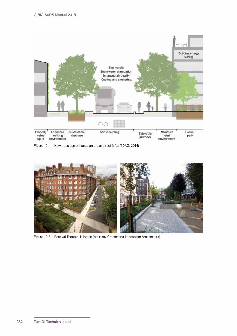
CIRIA SuDS Manual 2015
362 Part D: Technical detail
Figure 19.1 How trees can enhance an urban street (after TDAG, 2014)
Figure 19.2 Percival Triangle, Islington (courtesy Crasemann Landscape Architecture)
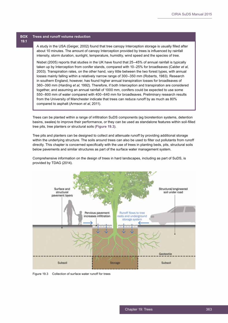
363Chapter 19: Trees
CIRIA SuDS Manual 2015
BOX19.1
Trees and runoff volume reduction
AstudyintheUSA(Geiger,2002)foundthattreecanopyInterceptionstorageisusuallyfilledafterabout10minutes.TheamountofcanopyInterceptionprovidedbytreesisinfluencedbyrainfallintensity, storm duration, sunlight, temperature, humidity, wind speed and the species of tree.
Nisbet (2005) reports that studies in the UK have found that 25–45% of annual rainfall is typically taken up by Interception from conifer stands, compared with 10–25% for broadleaves (Calder et al, 2003). Transpiration rates, on the other hand, vary little between the two forest types, with annual losses mainly falling within a relatively narrow range of 300–350 mm (Roberts, 1983). Research in southern England, however, has found higher annual transpiration losses for broadleaves of 360–390 mm (Harding et al, 1992). Therefore, if both Interception and transpiration are considered together, and assuming an annual rainfall of 1000 mm, conifers could be expected to use some 550–800 mm of water compared with 400–640 mm for broadleaves. Preliminary research results from the University of Manchester indicate that trees can reduce runoff by as much as 80% compared to asphalt (Armson et al, 2011).
TreescanbeplantedwithinarangeofinfiltrationSuDScomponents(egbioretentionsystems,detentionbasins,swales)toimprovetheirperformance,ortheycanbeusedasstandalonefeatureswithinsoil-filledtree pits, tree planters or structural soils (Figure 19.3).
Tree pits and planters can be designed to collect and attenuate runoff by providing additional storage withintheunderlyingstructure.Thesoilsaroundtreescanalsobeusedtofilteroutpollutantsfromrunoffdirectly.Thischapterisconcernedspecificallywiththeuseoftreesinplantingbeds,pits,structuralsoilsbelow pavements and similar structures as part of the surface water management system.
Comprehensive information on the design of trees in hard landscapes, including as part of SuDS, is provided by TDAG (2014).
Figure 19.3 Collection of surface water runoff for trees
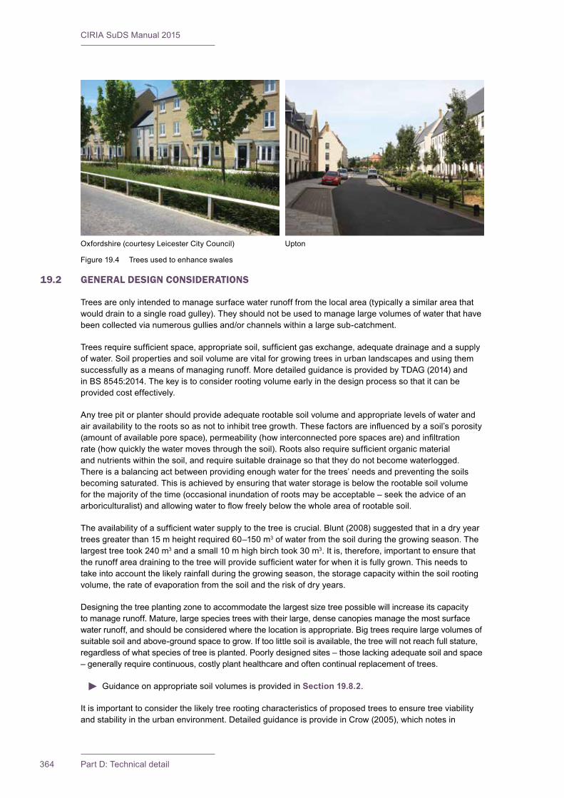
CIRIA SuDS Manual 2015
364 Part D: Technical detail
19.2 GENERAL DESIGN CONSIDERATIONS
Trees are only intended to manage surface water runoff from the local area (typically a similar area that would drain to a single road gulley). They should not be used to manage large volumes of water that have been collected via numerous gullies and/or channels within a large sub-catchment.
Treesrequiresufficientspace,appropriatesoil,sufficientgasexchange,adequatedrainageandasupplyof water. Soil properties and soil volume are vital for growing trees in urban landscapes and using them successfully as a means of managing runoff. More detailed guidance is provided by TDAG (2014) and in BS 8545:2014. The key is to consider rooting volume early in the design process so that it can be provided cost effectively.
Any tree pit or planter should provide adequate rootable soil volume and appropriate levels of water and airavailabilitytotherootssoasnottoinhibittreegrowth.Thesefactorsareinfluencedbyasoil’sporosity(amountofavailableporespace),permeability(howinterconnectedporespacesare)andinfiltrationrate(howquicklythewatermovesthroughthesoil).Rootsalsorequiresufficientorganicmaterialand nutrients within the soil, and require suitable drainage so that they do not become waterlogged. Thereisabalancingactbetweenprovidingenoughwaterforthetrees’needsandpreventingthesoilsbecoming saturated. This is achieved by ensuring that water storage is below the rootable soil volume for the majority of the time (occasional inundation of roots may be acceptable – seek the advice of an arboriculturalist)andallowingwatertoflowfreelybelowthewholeareaofrootablesoil.
Theavailabilityofasufficientwatersupplytothetreeiscrucial.Blunt(2008)suggestedthatinadryyeartrees greater than 15 m height required 60–150 m3 of water from the soil during the growing season. The largest tree took 240 m3 and a small 10 m high birch took 30 m3. It is, therefore, important to ensure that therunoffareadrainingtothetreewillprovidesufficientwaterforwhenitisfullygrown.Thisneedstotake into account the likely rainfall during the growing season, the storage capacity within the soil rooting volume, the rate of evaporation from the soil and the risk of dry years.
Designing the tree planting zone to accommodate the largest size tree possible will increase its capacity to manage runoff. Mature, large species trees with their large, dense canopies manage the most surface water runoff, and should be considered where the location is appropriate. Big trees require large volumes of suitable soil and above-ground space to grow. If too little soil is available, the tree will not reach full stature, regardless of what species of tree is planted. Poorly designed sites – those lacking adequate soil and space – generally require continuous, costly plant healthcare and often continual replacement of trees.
Guidance on appropriate soil volumes is provided in Section 19.8.2.
It is important to consider the likely tree rooting characteristics of proposed trees to ensure tree viability and stability in the urban environment. Detailed guidance is provide in Crow (2005), which notes in
Oxfordshire (courtesy Leicester City Council)
Figure 19.4 Trees used to enhance swales
Upton

365Chapter 19: Trees
CIRIA SuDS Manual 2015
particularthattreerootsdonotoccurinsignificantquantitiesatsubstantialdepths(eg>2m)inthesoilprofile(typically90–99%ofatree’stotalrootlengthoccursintheupper1mofsoil).Guidanceondesigning building foundations near trees is provided in Chapter 4.2 of NHBC (2014).
Trees for SuDS will tend to be located in an urban environment, and street trees in particular can be subjecttoconditionsthatmakeitdifficultforthemtothrive.Themainrisksaresoilcompactionbyvehicles and limited access to air and water for the roots.
There are various engineering structures that can be used to improve growing conditions for urban trees by expanding the rooting environment as much as possible beneath paved surfaces using load-bearing systems to avoid soil compaction around the roots (TDAG, 2014). These are discussed in the subsections below.
Theacceptabilityofinfiltrationfromatreepitshouldbedeterminedbyfollowingtheguidanceprovidedin Section 25.2,complyingwithallrelevantrequirementsforinfiltrationsystemswithrespecttogroundstability, depth to water table etc and Section 26.7 with respect to the protection of groundwater. The maximum likely groundwater level should always be at least 1 m below the lowest level of the tree pit, whereinfiltrationcanoccur.
Health and safety risk management design guidance is provided in Chapter 36.
Figure 19.5 Properties of a tree system draining surface water from a road highway (after TDAG, 2014)
Figure 19.6 Tree pit in Bourke Street, Melbourne
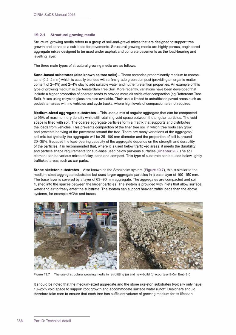
CIRIA SuDS Manual 2015
366 Part D: Technical detail
19.2.1 Structural growing media
Structural growing media refers to a group of soil-and-gravel mixes that are designed to support tree growth and serve as a sub-base for pavements. Structural growing media are highly porous, engineered aggregate mixes designed to be used under asphalt and concrete pavements as the load-bearing and levelling layer.
The three main types of structural growing media are as follows:
Sand-based substrates (also known as tree soils) – These comprise predominantly medium to coarse sand(0.2–2mm)whichisusuallyblendedwithafine-gradegreencompost(providinganorganicmattercontent of 2–4%) and 2–4% clay to add suitable water and nutrient retention properties. An example of this type of growing medium is the Amsterdam Tree Soil. More recently, variations have been developed that include a higher proportion of coarser sands to provide more air voids after compaction (eg Rotterdam Tree Soil).Mixesusingrecycledglassarealsoavailable.Theiruseislimitedtountraffickedpavedareassuchaspedestrian areas with no vehicles and cycle tracks, where high levels of compaction are not required.
Medium-sized aggregate substrates – This uses a mix of angular aggregate that can be compacted to 95% of maximum dry density while still retaining void space between the angular particles. The void spaceisfilledwithsoil.Thecoarseaggregateparticlesformamatrixthatsupportsanddistributestheloadsfromvehicles.Thispreventscompactionofthefinertreesoilinwhichtreerootscangrow,and prevents heaving of the pavement around the tree. There are many variations of the aggregate/soil mix but typically the aggregate will be 25–100 mm diameter and the proportion of soil is around 20–35%. Because the load-bearing capacity of the aggregate depends on the strength and durability oftheparticles,itisrecommendedthat,whereitisusedbelowtraffickedareas,itmeetsthedurabilityand particle shape requirements for sub-base used below pervious surfaces (Chapter 20). The soil element can be various mixes of clay, sand and compost. This type of substrate can be used below lightly traffickedareassuchascarparks.
Stone skeleton substrates – Also known as the Stockholm system (Figure 19.7), this is similar to the medium-sized aggregate substrates but uses larger aggregate particles in a base layer of 100–150 mm. The base layer is covered by a layer of 63–90 mm aggregate. The aggregates are compacted and soil flushedintothespacesbetweenthelargerparticles.Thesystemisprovidedwithinletsthatallowsurfacewaterandairtofreelyenterthesubstrate.Thesystemcansupportheaviertrafficloadsthantheabovesystems, for example HGVs and buses.
It should be noted that the medium-sized aggregate and the stone skeleton substrates typically only have 10–25% void space to support root growth and accommodate surface water runoff. Designers should thereforetakecaretoensurethateachtreehassufficientvolumeofgrowingmediumforitslifespan.
a
Figure19.7 Theuseofstructuralgrowingmediainretrofitting(a)andnew-build(b)(courtesyBjӧrnEmbrén)
b
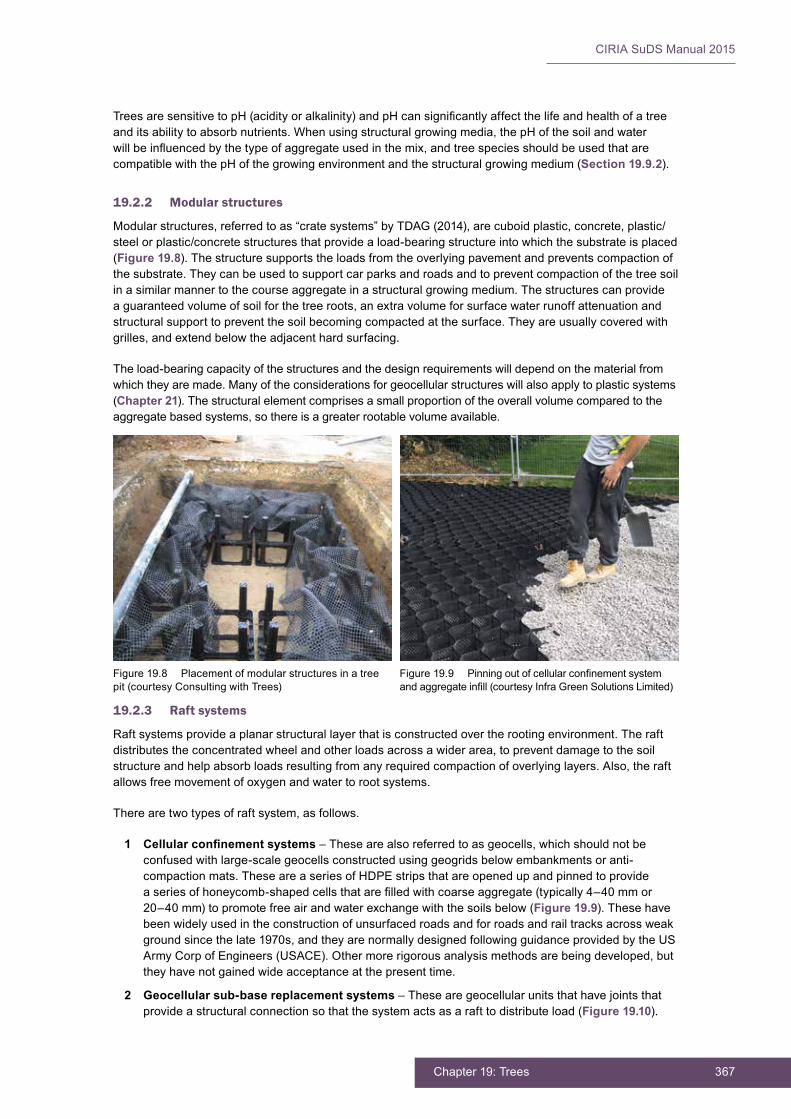
367Chapter 19: Trees
CIRIA SuDS Manual 2015
TreesaresensitivetopH(acidityoralkalinity)andpHcansignificantlyaffectthelifeandhealthofatreeand its ability to absorb nutrients. When using structural growing media, the pH of the soil and water willbeinfluencedbythetypeofaggregateusedinthemix,andtreespeciesshouldbeusedthatarecompatible with the pH of the growing environment and the structural growing medium (Section 19.9.2).
19.2.2 Modular structures
Modular structures, referred to as “crate systems” by TDAG (2014), are cuboid plastic, concrete, plastic/steel or plastic/concrete structures that provide a load-bearing structure into which the substrate is placed (Figure 19.8). The structure supports the loads from the overlying pavement and prevents compaction of the substrate. They can be used to support car parks and roads and to prevent compaction of the tree soil in a similar manner to the course aggregate in a structural growing medium. The structures can provide a guaranteed volume of soil for the tree roots, an extra volume for surface water runoff attenuation and structural support to prevent the soil becoming compacted at the surface. They are usually covered with grilles, and extend below the adjacent hard surfacing.
The load-bearing capacity of the structures and the design requirements will depend on the material from which they are made. Many of the considerations for geocellular structures will also apply to plastic systems (Chapter 21). The structural element comprises a small proportion of the overall volume compared to the aggregate based systems, so there is a greater rootable volume available.
19.2.3 Raft systems
Raft systems provide a planar structural layer that is constructed over the rooting environment. The raft distributes the concentrated wheel and other loads across a wider area, to prevent damage to the soil structure and help absorb loads resulting from any required compaction of overlying layers. Also, the raft allows free movement of oxygen and water to root systems.
There are two types of raft system, as follows.
1 Cellular confinement systems – These are also referred to as geocells, which should not be confused with large-scale geocells constructed using geogrids below embankments or anti-compaction mats. These are a series of HDPE strips that are opened up and pinned to provide aseriesofhoneycomb-shapedcellsthatarefilledwithcoarseaggregate(typically4–40mmor20–40 mm) to promote free air and water exchange with the soils below (Figure 19.9). These have been widely used in the construction of unsurfaced roads and for roads and rail tracks across weak ground since the late 1970s, and they are normally designed following guidance provided by the US Army Corp of Engineers (USACE). Other more rigorous analysis methods are being developed, but they have not gained wide acceptance at the present time.
2 Geocellular sub-base replacement systems – These are geocellular units that have joints that provide a structural connection so that the system acts as a raft to distribute load (Figure 19.10).
Figure 19.8 Placement of modular structures in a tree pit (courtesy Consulting with Trees)
Figure19.9 Pinningoutofcellularconfinementsystemandaggregateinfill(courtesyInfraGreenSolutionsLimited)
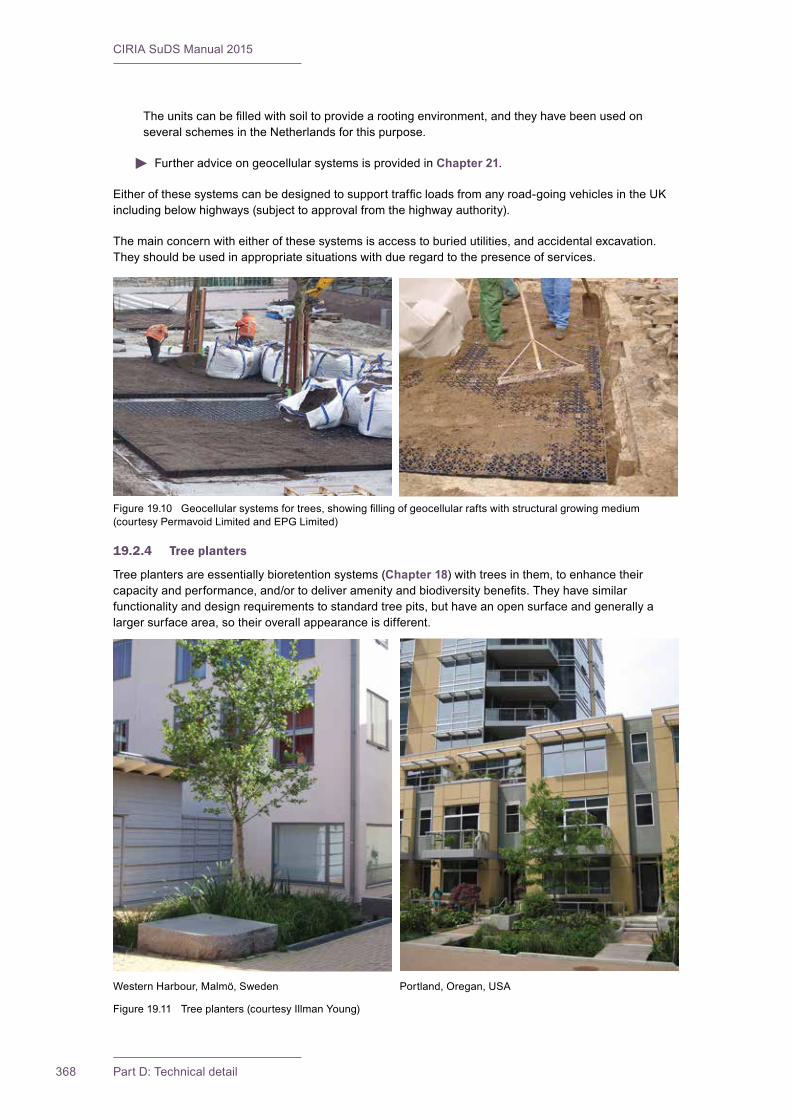
CIRIA SuDS Manual 2015
368 Part D: Technical detail
Theunitscanbefilledwithsoiltoprovidearootingenvironment,andtheyhavebeenusedonseveral schemes in the Netherlands for this purpose.
Further advice on geocellular systems is provided in Chapter 21.
Eitherofthesesystemscanbedesignedtosupporttrafficloadsfromanyroad-goingvehiclesintheUKincluding below highways (subject to approval from the highway authority).
The main concern with either of these systems is access to buried utilities, and accidental excavation. They should be used in appropriate situations with due regard to the presence of services.
19.2.4 Tree planters
Tree planters are essentially bioretention systems (Chapter 18) with trees in them, to enhance their capacityandperformance,and/ortodeliveramenityandbiodiversitybenefits.Theyhavesimilarfunctionality and design requirements to standard tree pits, but have an open surface and generally a larger surface area, so their overall appearance is different.
Figure19.10 Geocellularsystemsfortrees,showingfillingofgeocellularraftswithstructuralgrowingmedium(courtesy Permavoid Limited and EPG Limited)
Figure 19.11 Tree planters (courtesy Illman Young)
Western Harbour, Malmö, Sweden Portland, Oregan, USA

369Chapter 19: Trees
CIRIA SuDS Manual 2015
Wherethesensitivityand/orvulnerabilityofgroundwaterlyingbeneathatreemeansthatinfiltrationfrom contaminated surface runoff should be prevented, tree pits/planters etc should be designed with an impermeable geomembrane liner and positive drainage system to prevent waterlogging.
Health and safety risk management design guidance is provided in Chapter 36.
The inclusion or retention of trees in central reservations or on footways sometimes gives rise to safety concerns, and consideration should always be given to ensuring that sight lines are not put at risk by tree planting proposals. Any protective surface grilles or other protection overlying tree pits should be designed to minimise the risk of damage by potential transient loadings – which could cause trip hazards for pedestrians.
19.3 SELECTION AND SITING OF TREES
Suitable trees should be chosen on a site-by-site basis, based on the constraints and opportunities afforded by a particular location, and to achieve optimum delivery of hydraulic, water quality, amenity and biodiversity objectives. A landscape architect should advise on the most appropriate trees for a particular development scenario that are suitable for:
(a) thelikelyrunoffcharacteristics(flowrates,volumesandlikelycontaminants)
(b) the nature of the soil into which it is to be planted
(c) the location and characteristics of the planting site (eg narrow canopy trees may be required for street locations).
The principles of tree selection are presented in TDAG (2014).
The following characteristics tend to increase the effectiveness of trees in reducing surface water runoff andfilteringpollutants(notethatnotallarecomplementary)(CRWA,2009):
▪ widespreading and dense canopies
▪ long life expectancies
▪ fast growing rates
▪ high tolerance to summer drought
▪ tolerance of saturated soils
▪ resistance to air and water pollutants common in urban environments
▪ extensive root systems
▪ rough bark
▪ tomentose or dull foliage surface
▪ vertical branching structures.
Road salt is the most commonly used de-icing chemical in the UK. It is crushed rock salt, and the main component is sodium chloride. Both sodium and chloride ions can be harmful to some trees if there are excessive quantities in the soil. Salt damage occurs to trees through contamination of the soil around rootsorbysaltspray.Saltsprayismuchmorelikelyonroadswithfast-movingtraffic,suchasmotorwaysand trunk roads. It is likely to be less of a problem where vehicles are moving at low speeds, such as car parks and minor roads. In medium/high permeability soils such as sands and gravels (where the residence time of the water in the soil around the tree roots is low), the risk of the salt negatively affecting the tree is low. Also, trees generally take up less water in winter, and so if exposed to only a few instances of chloride-contaminated water the effects are likely to be minimal. Furthermore, the amount of salt applied to roads across the UK has reduced over recent years owing to generally milder winters and more targeted gritting. An arboriculturist should be consulted to choose appropriate species that are tolerant of salt if it considered likely that salt in runoff will adversely affect tree health.

CIRIA SuDS Manual 2015
370 Part D: Technical detail
Further advice is provided by Forest Research (2011).
It is important to locate tree pits at a reasonable distance from buried utility services such as electric cable and water pipes. Trenching works to repair the services can cut tree roots, and equally tree roots candamageutilityinfrastructure.Thereisnospecificminimumdistance(althoughutilityprovidersmayset required distances) and it will depend on the nature of the service, its resistance to movement and damage caused by trees and the consequence of any damage. However, the risk of damage can be minimised by installing root barriers around the rootable volume of soil (note that these can often be as simpleasusingstandardlargemanholerings,orgeotextilefabricsspecificallydesignedasrootbarriers).Underground utilities can be placed around and even through tree pits, geocellular crate systems and suspended pavement systems. However, all underground utilities should be protected from water and root penetration.
Detailed guidance is provided in BS 5837:2012.
19.4 HYDRAULIC DESIGN
19.4.1 General
Theremaybeopportunitiesforinfiltrationfromtreepits,evenincitycentreenvironments,anditisusuallyworthwhileundertakinginfiltrationtestingtoconfirmlikelyinfiltrationrates.
Whenstructuralsoilorthetreepitorplanterisbeingusedtostoresurfacewaterrunoffbeforeinfiltration,the subsoil may become saturated at times, resulting in lower soil strength. A geotechnical engineer shouldbeconsultedtodetermineifaseparationgeotextileorgeomembraneisnecessary.Lateralflowthrough structural soils can also be extremely rapid, and if the sub-base is permeable or has some permeableareas,throughflowislikelytobefast,whichshouldbetakenintoaccountinthedesign.Ifsurroundingareasareimpermeable,pondingispossibleandinsuchsituationsoverflowandunderdrainoutletsarelikelytoberequiredtopreventpondedwatersuffocatingtreesandtocontrolfloodriskseffectively.
Individual trees are likely to be less effective than linked, integrated tree systems in controlling surface waterrunoffasthelatterprovidegreatercapacity,flexibilityandopportunitiestoconveyandutiliseexceedanceflowseffectively.AnintegratedtreeandgreenroofsystemisshowninFigure 19.12.
Figure 19.13 shows a linear tree pit where water can drain through resin bound gravel, below which a combination of modular crates at each tree pit site and gabions in between allow water to drain along the linear strip.
19.4.2 Interception design
Interception provided by the tree canopy will vary with tree type and will increase over the life of a tree as itgrows.ForthefirstfewyearstheInterceptionmaybenegligible.ItisthereforebesttoignorethisaspectinthehydraulicdesignofSuDS,whilerecognisingthatitwillhavealong-termbenefitandwillreducevolumetric runoff loads to the surface water system in the future.
Wherewaterisdirectedtowardsatreepit,andthetreepitisdesignedtofacilitateevenlimitedinfiltration,then a check should be made to determine whether the tree is able to dispose of 5 mm rainfall depth over the contributing catchment area.
Wherethereisnoinfiltration,butthenaturalsurfacesoils(orimported/re-engineeredsoils)havewaterstorage capacity, then Interception design should follow the principles set out in Section 24.8.
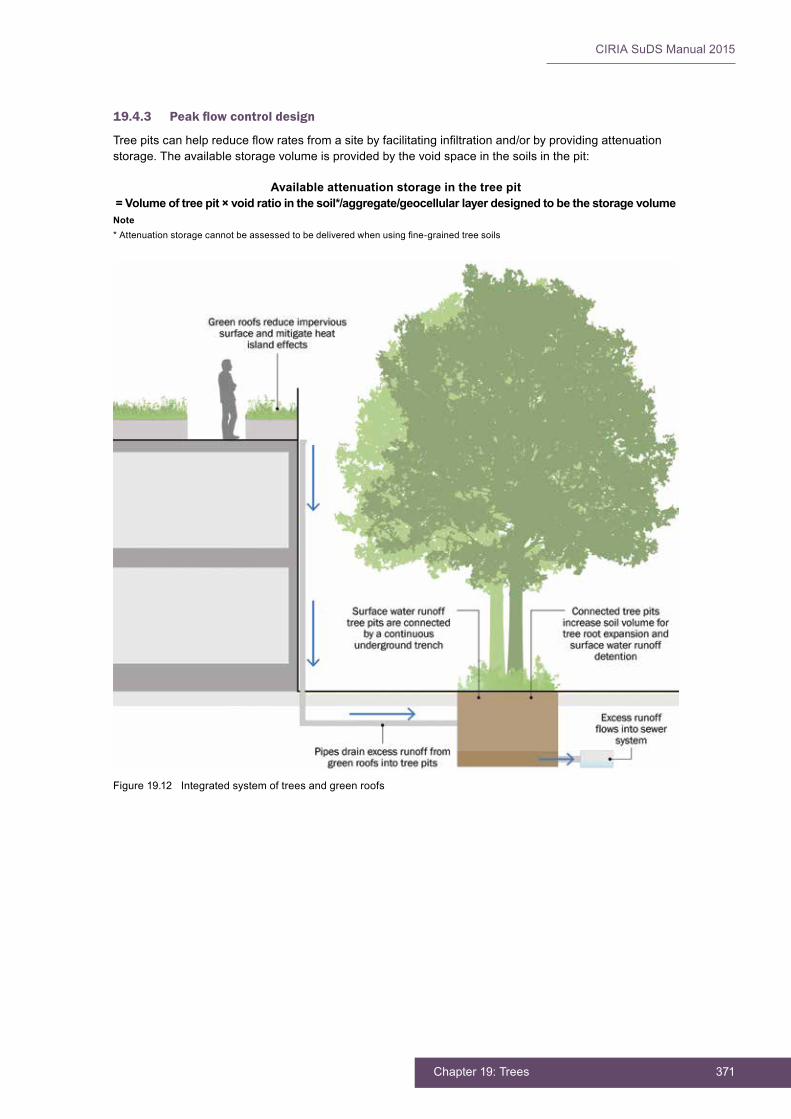
371Chapter 19: Trees
CIRIA SuDS Manual 2015
Figure 19.12 Integrated system of trees and green roofs
19.4.3 Peakflowcontroldesign
Treepitscanhelpreduceflowratesfromasitebyfacilitatinginfiltrationand/orbyprovidingattenuationstorage. The available storage volume is provided by the void space in the soils in the pit:
Available attenuation storage in the tree pit = Volume of tree pit × void ratio in the soil*/aggregate/geocellular layer designed to be the storage volumeNote*Attenuationstoragecannotbeassessedtobedeliveredwhenusingfine-grainedtreesoils
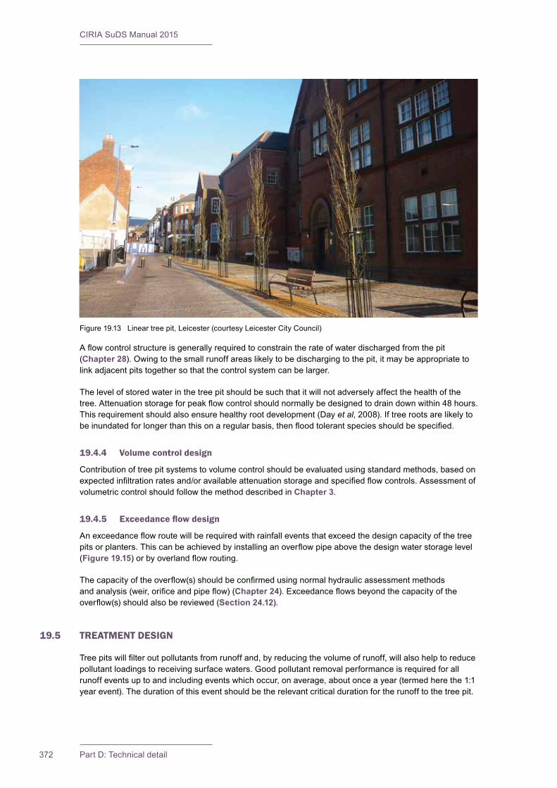
CIRIA SuDS Manual 2015
372 Part D: Technical detail
Aflowcontrolstructureisgenerallyrequiredtoconstraintherateofwaterdischargedfromthepit(Chapter 28). Owing to the small runoff areas likely to be discharging to the pit, it may be appropriate to link adjacent pits together so that the control system can be larger.
The level of stored water in the tree pit should be such that it will not adversely affect the health of the tree.Attenuationstorageforpeakflowcontrolshouldnormallybedesignedtodraindownwithin48hours.This requirement should also ensure healthy root development (Day et al, 2008). If tree roots are likely to beinundatedforlongerthanthisonaregularbasis,thenfloodtolerantspeciesshouldbespecified.
19.4.4 Volume control design
Contribution of tree pit systems to volume control should be evaluated using standard methods, based on expectedinfiltrationratesand/oravailableattenuationstorageandspecifiedflowcontrols.Assessmentofvolumetric control should follow the method described in Chapter 3.
19.4.5 Exceedanceflowdesign
Anexceedanceflowroutewillberequiredwithrainfalleventsthatexceedthedesigncapacityofthetreepitsorplanters.Thiscanbeachievedbyinstallinganoverflowpipeabovethedesignwaterstoragelevel(Figure 19.15)orbyoverlandflowrouting.
Thecapacityoftheoverflow(s)shouldbeconfirmedusingnormalhydraulicassessmentmethodsandanalysis(weir,orificeandpipeflow)(Chapter 24).Exceedanceflowsbeyondthecapacityoftheoverflow(s)shouldalsobereviewed(Section 24.12).
19.5 TREATMENT DESIGN
Treepitswillfilteroutpollutantsfromrunoffand,byreducingthevolumeofrunoff,willalsohelptoreducepollutant loadings to receiving surface waters. Good pollutant removal performance is required for all runoff events up to and including events which occur, on average, about once a year (termed here the 1:1 year event). The duration of this event should be the relevant critical duration for the runoff to the tree pit.
Figure 19.13 Linear tree pit, Leicester (courtesy Leicester City Council)

373Chapter 19: Trees
CIRIA SuDS Manual 2015
The tree soils can be designed using the same principles as bioretention systems described in Chapter 18. Many trees are able to remove a wide variety of pollutants from soil (USDA, 2006) including metals, pesticides and organic compounds. Excess nitrogen and phosphorus in soils are quickly taken up by trees with oxygen-rich rhizospheres, because osmosis can happen freely. Robust resilient trees can also metabolise contaminants (heavy metals, inorganic and organic compounds) into their carbon-rich heartwoods, removing them from the runoff.
Hydrocarbons tend to be trapped and degraded in the upper few centimetres of soil. Therefore, their removalwillbemoreefficientwhererunoffisdirectedontothesurfaceofthesoilsandwherethissurfaceis well exposed to sunlight. A depth of engineered soil suitable for tree growth has been demonstrated to remove 70–85% of heavy metal loadings (Xiao and McPherson, 2008).
Theacceptabilityofallowinginfiltrationfromthetreepitwilldependontheextentofthelikelyrunoffcontaminationandthecapabilityofthefilteringsoilstoremovepollution(seeChapter 4, Table 4.3). It is likely to be similar to bioretention systems, provided the design is undertaken in an equivalent way.
19.6 AMENITY DESIGN
Todelivermaximumamenitybenefits(Section 19.1), the location and type of tree planting should be planned and designed as a key part of landscape and built environment delivery.
Trees should be selected and planted to maximise their potential delivery of surface water management objectives, but also so that they have a positive visual impact on the urban environment, with wide-ranging seasonal interest. The implementation of trees for surface water runoff management should be integrated with the delivery of green street and green infrastructure strategies, transport (including walking, cycling and highways) strategies and with the overall urban design strategy.
Canopysizeandtreegrowthratehavebeenshowntohaveastronginfluenceonthecoolingperformance of trees and cooling objectives are best achieved through:
▪ setting canopy cover targets rather than driving design and management decisions on the basis of a number of trees
▪ providingnon-compactedrootingenvironment(s)ofsufficientsizetoachieveandsustainthedesiredcanopy cover target
▪ ensuring a good supply of water, particularly during extended heatwaves (TDAG, 2014).
BOX19.2
Performance of trees in removing phosphorous and nitrogen
A study of the nutrient removal performance of bioretention systems planted with trees in Australia (Denman et al, 2011) found that the inclusion of trees resulted in reductions of soluble nitrogen and phosphorous compared to unplanted control soils. A mix of deciduous and evergreen trees was used in the study, and came from a range of climates and environments. The removal of phosphorous was variable, and improved as the trees became more established over time. A reduction in concentration of 70–80% was achieved and, once stabilised, there was little difference in phosphorous removal between soils of different permeability. Nitrogen was produced by the planted systems during warmer months (output in leachate was greater than input) but overall the load was reduced and the concentration over time was reduced by 2–78%. The performance of tree pits in removing nitrogen was better with low hydraulic conductivity soils (4 mm/h) when compared to the medium and high permeability soils (95 mm/h and 170 mm/h respectively). However, 4 mm/h isunusuallylowforabioretentionsoilandislikelytocauseproblemswithwaterfilteringthroughitinthelongterm.Treespecieswasnotasignificantfactorintheperformanceofthesystemswithevergreen and deciduous trees giving similar results even during winter.
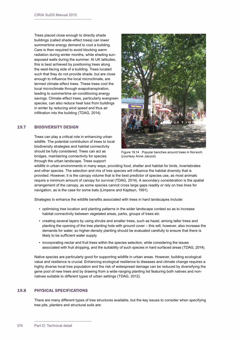
CIRIA SuDS Manual 2015
374 Part D: Technical detail
Trees placed close enough to directly shade buildings (called shade-effect trees) can lower summertime energy demand to cool a building. Care is then required to avoid blocking warm radiation during winter months, while shading sun-exposed walls during the summer. At UK latitudes, this is best achieved by positioning trees along the west-facing side of a building. Trees located such that they do not provide shade, but are close enoughtoinfluencethelocalmicroclimate,aretermed climate-effect trees. These trees cool the local microclimate through evapotranspiration, leading to summertime air-conditioning energy savings. Climate-effect trees, particularly evergreen species, can also reduce heat loss from buildings in winter by reducing wind speed and thus air infiltrationintothebuilding(TDAG,2014).
19.7 BIODIVERSITY DESIGN
Trees can play a critical role in enhancing urban wildlife. The potential contribution of trees to local biodiversity strategies and habitat connectivity should be fully considered. Trees can act as bridges, maintaining connectivity for species through the urban landscape. Trees support wildlife in urban environments in many ways, providing food, shelter and habitat for birds, invertebrates andotherspecies.Theselectionandmixoftreespecieswillinfluencethehabitatdiversitythatisprovided. However, it is the canopy volume that is the best predictor of species use, as most animals require a minimum amount of canopy for survival (TDAG, 2014). A secondary consideration is the spatial arrangement of the canopy, as some species cannot cross large gaps readily or rely on tree lines for navigation, as is the case for some bats (Limpens and Kapteyn, 1991).
Strategiestoenhancethewildlifebenefitsassociatedwithtreesinhardlandscapesinclude:
▪ optimising tree location and planting patterns in the wider landscape context so as to increase habitat connectivity between vegetated areas, parks, groups of trees etc
▪ creating several layers by using shrubs and smaller trees, such as hazel, among taller trees and planting the opening of the tree planting hole with ground cover – this will, however, also increase the demands for water, so higher-density planting should be evaluated carefully to ensure that there is likelytobesufficientwatersupply
▪ incorporating nectar and fruit trees within the species selection, while considering the issues associated with fruit dropping, and the suitability of such species in hard surfaced areas (TDAG, 2014).
Native species are particularly good for supporting wildlife in urban areas. However, building ecological value and resilience is crucial. Enhancing ecological resilience to diseases and climate change requires a highly diverse local tree population and the risk of widespread damage can be reduced by diversifying the gene pool of new trees and by drawing from a wide-ranging planting list featuring both natives and non-natives suitable to different types of urban settings (TDAG, 2012).
19.8 PHYSICAL SPECIFICATIONS
There are many different types of tree structures available, but the key issues to consider when specifying tree pits, planters and structural soils are:
Figure 19.14 Popular benches around trees in Norwich (courtesy Anne Jaluzot)
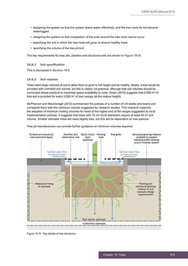
375Chapter 19: Trees
CIRIA SuDS Manual 2015
▪ designing the system so that the system drains water effectively, and the tree roots do not become waterlogged
▪ designing the system so that compaction of the soils around the tree roots cannot occur
▪ specifying the soil in which the tree roots will grow, to ensure healthy trees
▪ specifying the volume of the tree pit/soil.
The key requirements for tree pits, planters and structural soils are shown in Figure 19.15.
19.8.1 Soilspecification
This is discussed in Section 19.9.
19.8.2 Soil volumes
Trees need large volumes of soil to allow them to grow to full height and be healthy. Ideally, a tree would be provided with unlimited soil volume, but this is clearly not practical, although tree soil volumes should be connected where practical to maximise space availability to roots. Green (2010) suggests that 0.056 m3 of tree soil is provided for every 0.093 m2 of tree canopy (at the mature height).
McPherson and MacDonagh (2012) summarised the policies of a number of US states and towns and compared them with the minimum volume suggested by research studies. This research supports the adoption of minimum rooting volumes for trees at the higher end of the ranges suggested by local implementation policies. It suggests that trees with 75 cm trunk diameters require at least 40 m3 soil volume. Smaller diameter trees will need slightly less, but this will be dependent on tree species.
Tree pit manufacturers can provide further guidance on minimum volumes required.
Figure 19.15 Key details of tree structures
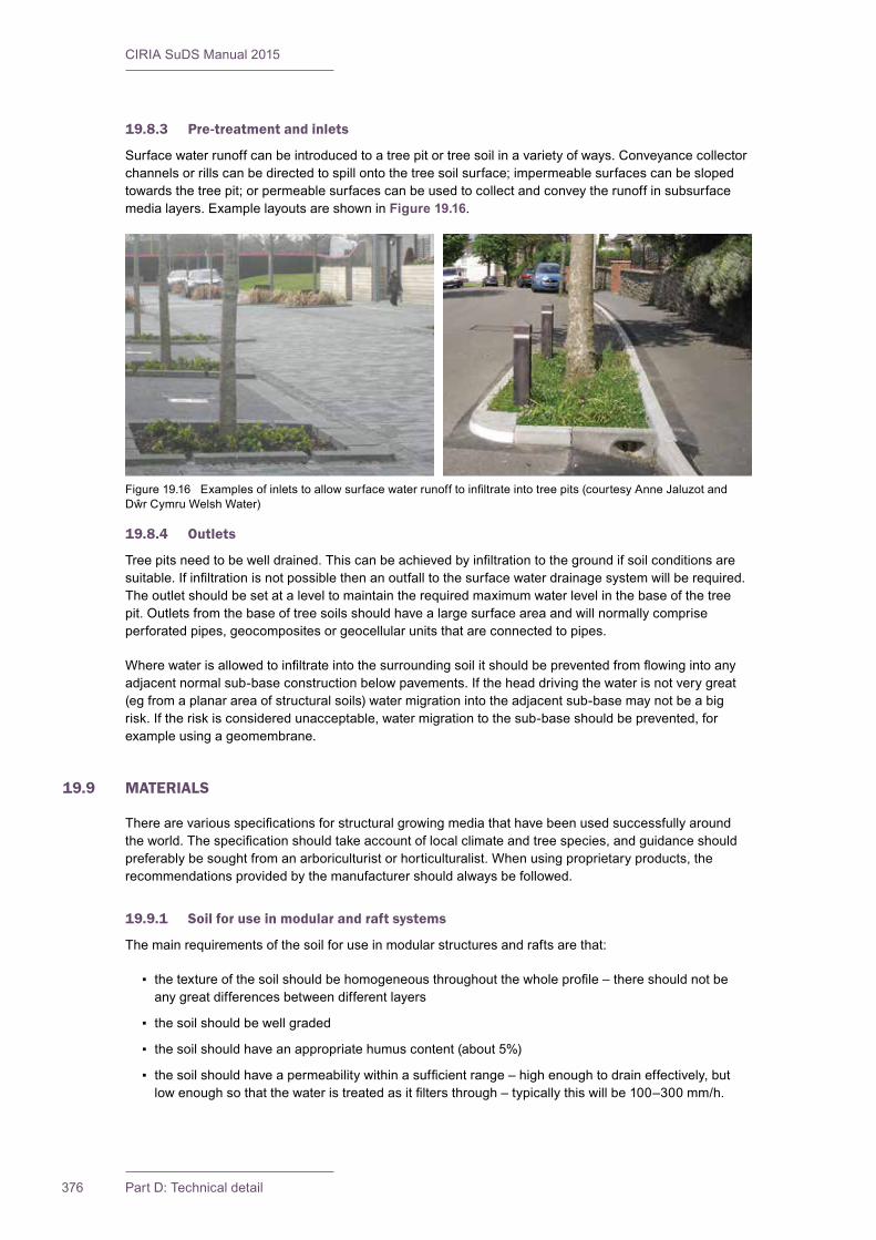
CIRIA SuDS Manual 2015
376 Part D: Technical detail
19.8.3 Pre-treatment and inlets
Surface water runoff can be introduced to a tree pit or tree soil in a variety of ways. Conveyance collector channels or rills can be directed to spill onto the tree soil surface; impermeable surfaces can be sloped towards the tree pit; or permeable surfaces can be used to collect and convey the runoff in subsurface media layers. Example layouts are shown in Figure 19.16.
19.8.4 Outlets
Treepitsneedtobewelldrained.Thiscanbeachievedbyinfiltrationtothegroundifsoilconditionsaresuitable.Ifinfiltrationisnotpossiblethenanoutfalltothesurfacewaterdrainagesystemwillberequired.The outlet should be set at a level to maintain the required maximum water level in the base of the tree pit. Outlets from the base of tree soils should have a large surface area and will normally comprise perforated pipes, geocomposites or geocellular units that are connected to pipes.
Wherewaterisallowedtoinfiltrateintothesurroundingsoilitshouldbepreventedfromflowingintoanyadjacent normal sub-base construction below pavements. If the head driving the water is not very great (eg from a planar area of structural soils) water migration into the adjacent sub-base may not be a big risk. If the risk is considered unacceptable, water migration to the sub-base should be prevented, for example using a geomembrane.
19.9 MATERIALS
Therearevariousspecificationsforstructuralgrowingmediathathavebeenusedsuccessfullyaroundtheworld.Thespecificationshouldtakeaccountoflocalclimateandtreespecies,andguidanceshouldpreferably be sought from an arboriculturist or horticulturalist. When using proprietary products, the recommendations provided by the manufacturer should always be followed.
19.9.1 Soil for use in modular and raft systems
The main requirements of the soil for use in modular structures and rafts are that:
▪ thetextureofthesoilshouldbehomogeneousthroughoutthewholeprofile–thereshouldnotbeany great differences between different layers
▪ the soil should be well graded
▪ the soil should have an appropriate humus content (about 5%)
▪ thesoilshouldhaveapermeabilitywithinasufficientrange–highenoughtodraineffectively,butlowenoughsothatthewateristreatedasitfiltersthrough–typicallythiswillbe100–300mm/h.
Figure19.16 Examplesofinletstoallowsurfacewaterrunofftoinfiltrateintotreepits(courtesyAnneJaluzotandDŵrCymruWelshWater)
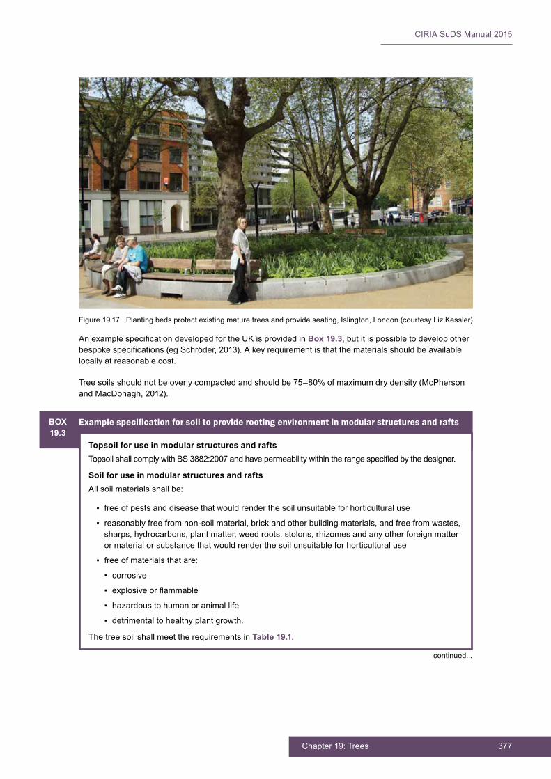
377Chapter 19: Trees
CIRIA SuDS Manual 2015
AnexamplespecificationdevelopedfortheUKisprovidedinBox 19.3, but it is possible to develop other bespokespecifications(egSchröder,2013).Akeyrequirementisthatthematerialsshouldbeavailablelocally at reasonable cost.
Tree soils should not be overly compacted and should be 75–80% of maximum dry density (McPherson and MacDonagh, 2012).
Figure 19.17 Planting beds protect existing mature trees and provide seating, Islington, London (courtesy Liz Kessler)
BOX19.3
Examplespecificationforsoiltoproviderootingenvironmentinmodularstructuresandrafts
Topsoil for use in modular structures and raftsTopsoilshallcomplywithBS3882:2007andhavepermeabilitywithintherangespecifiedbythedesigner.
Soil for use in modular structures and raftsAll soil materials shall be:
▪ free of pests and disease that would render the soil unsuitable for horticultural use
▪ reasonably free from non-soil material, brick and other building materials, and free from wastes, sharps, hydrocarbons, plant matter, weed roots, stolons, rhizomes and any other foreign matter or material or substance that would render the soil unsuitable for horticultural use
▪ free of materials that are:
▪ corrosive
▪ explosiveorflammable
▪ hazardous to human or animal life
▪ detrimental to healthy plant growth.
The tree soil shall meet the requirements in Table 19.1.
continued...
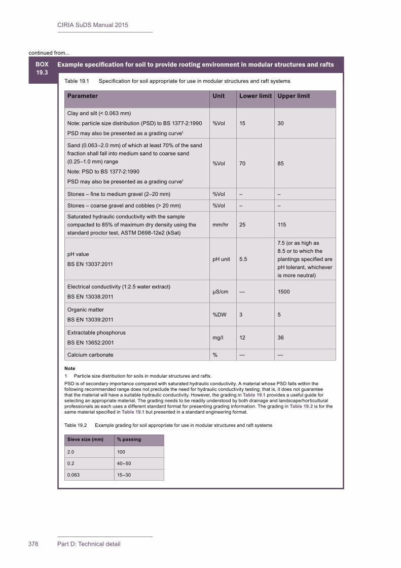
CIRIA SuDS Manual 2015
378 Part D: Technical detail
continued from...
BOX19.3
Examplespecificationforsoiltoproviderootingenvironmentinmodularstructuresandrafts
Table19.1 Specificationforsoilappropriateforuseinmodularstructuresandraftsystems
Parameter Unit Lower limit Upper limit
Clay and silt (< 0.063 mm)
Note: particle size distribution (PSD) to BS 1377-2:1990
PSD may also be presented as a grading curve1
%Vol 15 30
Sand (0.063–2.0 mm) of which at least 70% of the sand fraction shall fall into medium sand to coarse sand (0.25–1.0 mm) range
Note: PSD to BS 1377-2:1990
PSD may also be presented as a grading curve1
%Vol 70 85
Stones–finetomediumgravel(2–20mm) %Vol – –
Stones–coarsegravelandcobbles(>20mm) %Vol – –
Saturated hydraulic conductivity with the sample compacted to 85% of maximum dry density using the standard proctor test, ASTM D698-12e2 (kSat)
mm/hr 25 115
pH value
BS EN 13037:2011pH unit 5.5
7.5 (or as high as 8.5 or to which the plantingsspecifiedarepH tolerant, whichever is more neutral)
Electrical conductivity (1:2.5 water extract)
BS EN 13038:2011µS/cm — 1500
Organic matter
BS EN 13039:2011%DW 3 5
Extractable phosphorus
BS EN 13652:2001mg/l 12 36
Calcium carbonate % — —
Note1 Particle size distribution for soils in modular structures and rafts.PSD is of secondary importance compared with saturated hydraulic conductivity. A material whose PSD falls within the following recommended range does not preclude the need for hydraulic conductivity testing; that is, it does not guarantee that the material will have a suitable hydraulic conductivity. However, the grading in Table 19.1 provides a useful guide for selecting an appropriate material. The grading needs to be readily understood by both drainage and landscape/horticultural professionals as each uses a different standard format for presenting grading information. The grading in Table 19.2 is for the samematerialspecifiedinTable 19.1 but presented in a standard engineering format.
Table 19.2 Example grading for soil appropriate for use in modular structures and raft systems
Sieve size (mm) % passing
2.0 100
0.2 40–50
0.063 15–30

379Chapter 19: Trees
CIRIA SuDS Manual 2015
19.9.2 Structural growing media
A good structural growing medium will have known water-holding, drainage, structural and load-bearing characteristics (Day et al, 2008). It should be able to still support plant growth when compacted to 95% ofstandardProctordensity.Itshouldalsobesupportedbytheresultsoffieldtrialsthatdemonstrateitsperformance. A key requirement is that the materials should be available locally at reasonable cost. An examplespecificationforstructuralsoilisgiveninBox 19.4.
BOX19.4
Examplespecificationforstructuralsoil(fromDayet al, 2008)
Structural soil is a uniformly blended mix of crushed stone, clay loam and, if required, hydrogel. The constituents should be mixed to the following proportions:
▪ crushed stone: 80 kg dry weight
▪ loam: 20 kg dry weight
▪ hydrogel: 0.03 kg dry weight per 100 kg crushed stone
▪ total moisture: place at optimum moisture content as determined in compaction tests to BS 1377-4:1990
Crushed stoneAngular crushed rock of granite, limestone or similar
Grading (PSD to BS 1377-2:1990)
Sieve size % passing (by mass)
40 mm 90–100
28 mm 20–55
20 mm 10
Sieve size adapted to suit British/European Standard sizes
A ratio of nominal maximum to nominal minimum particle size of 2 is required
Acceptable aggregate dimensions should not exceed 2.5:1.0 for any two dimensions chosen
Minimum 90% with one fractured face, minimum 75% with two fractured faces
Resistance to fragmentation, LA: < 40%
Magnesium sulphate soundness: < 18%
Clay loamClayloambasedonUSDAclassificationsystem
Uniform composition, free of stones greater than 12.5 mm, lumps, plants, roots, debris or other extraneous matter; it shall not contain substances harmful to plant growth or human health
Nutrient levels as required for the types of plants to be grown
Organic matter content: 2–5% by dry weight
pH: between 6.0 and 7.6
Soluble salt: less than 1.0 millimho per cm
Cationexchangecapacity:>10
Carbon:nitrogen ratio: < 33:1
continued...
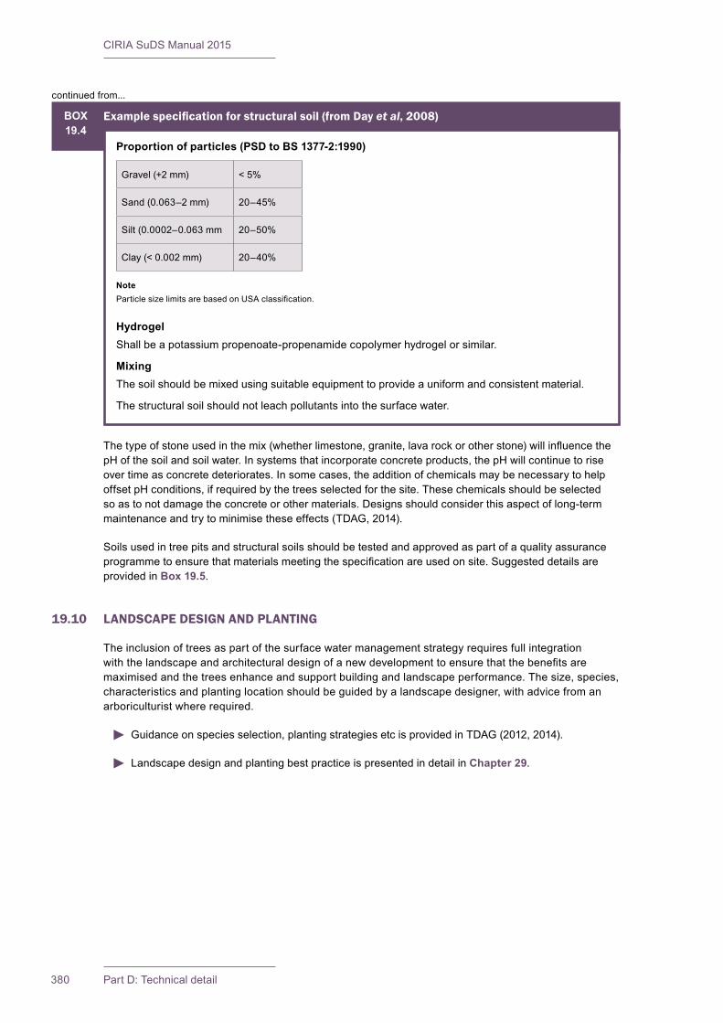
CIRIA SuDS Manual 2015
380 Part D: Technical detail
Thetypeofstoneusedinthemix(whetherlimestone,granite,lavarockorotherstone)willinfluencethepH of the soil and soil water. In systems that incorporate concrete products, the pH will continue to rise over time as concrete deteriorates. In some cases, the addition of chemicals may be necessary to help offset pH conditions, if required by the trees selected for the site. These chemicals should be selected so as to not damage the concrete or other materials. Designs should consider this aspect of long-term maintenance and try to minimise these effects (TDAG, 2014).
Soils used in tree pits and structural soils should be tested and approved as part of a quality assurance programmetoensurethatmaterialsmeetingthespecificationareusedonsite.Suggesteddetailsareprovided in Box 19.5.
19.10 LANDSCAPE DESIGN AND PLANTING
The inclusion of trees as part of the surface water management strategy requires full integration withthelandscapeandarchitecturaldesignofanewdevelopmenttoensurethatthebenefitsaremaximised and the trees enhance and support building and landscape performance. The size, species, characteristics and planting location should be guided by a landscape designer, with advice from an arboriculturist where required.
Guidance on species selection, planting strategies etc is provided in TDAG (2012, 2014).
Landscape design and planting best practice is presented in detail in Chapter 29.
BOX19.4
Examplespecificationforstructuralsoil(fromDayet al, 2008)
Proportion of particles (PSD to BS 1377-2:1990)
Gravel (+2 mm) < 5%
Sand (0.063–2 mm) 20–45%
Silt (0.0002–0.063 mm 20–50%
Clay (< 0.002 mm) 20–40%
NoteParticlesizelimitsarebasedonUSAclassification.
HydrogelShall be a potassium propenoate-propenamide copolymer hydrogel or similar.
MixingThe soil should be mixed using suitable equipment to provide a uniform and consistent material.
The structural soil should not leach pollutants into the surface water.
continued from...

381Chapter 19: Trees
CIRIA SuDS Manual 2015
19.11 CONSTRUCTION REQUIREMENTS
If sediment from construction work accumulates on the exposed surface of a tree pit or planter, it should be cleared and the pit fully rehabilitated before the drainage system is adopted by the organisation responsible for carrying out the maintenance.
It is important that the tree soils and structural soils are not damaged by inappropriate handling or compaction during construction. The soil should be placed when it is non-plastic (friable) in consistency withamoisturecontentatleast5%belowthesoil’splasticlimit.Itshouldnotbeplacedifisfrozenorduring heavy rainfall.
The tree soil and structural soil should be not be allowed to become mixed with other material such as sub-base or demolition debris. Handling the soil can destroy its structure, and so multiple handling should bekepttoaminimum.Itisvitalthatonceplaced,thesoilisnotcompactedbytramplingortraffickingbysite machinery.
The use of additional slow release fertilisers in the topsoil may be required (as advised by the tree specifier)tohelptreeestablishment.Theriskofthiscausingsurfacewaterpollutionhastobeweighedagainst the risk of the tree dying, but the use of fertilisers should be avoided wherever possible as they add nutrient load to the surface water.
Structural soils are load-bearing and form part of the sub-base construction to pavements. They should becompactedtoasuitabledensityasdefinedbythepavementdesigner.Rootscanstillpenetratethematerials because the density that roots can tolerate is dependent on the particle size distribution of the soils they are in.
BOX19.5
Testing and approval of tree soils and structural soils
Programme for sourcing soilSufficienttimeshouldbeallowedforsourcingandtestingtheproposedsoil(s)tomeettherequirementsofthesoilspecification.
Typically at least four weeks is recommended for sourcing soils, so that the necessary testing can beundertakentodemonstratecompliancewiththespecification.
Thecontractorshallprovidesoillaboratorytestcertificatestothecontractadministratorforreviewand approval.
Sampling protocolThe soil(s) to be considered for use should be sampled before placement and preferably while stockpiledatitssourceormanufacturer’slocation.
The sample(s) shall be representative of the soil to be used. One composite sample shall be taken for every 500 m3 of each type of soil to be used.
Each composite sample should be made up of 10 No. subsamples taken from evenly spaced locationsacrossthestockpile/field.Thesubsamplesshallbemixedtogetherandquartereddowntoform a 5 kg composite sample.
Each composite sample shall be placed in a clean, strong plastic bag, each labelled with the source referenceanddateofsampling.Othersamplesmayberequiredindifferentcontainersforspecificanalyses (eg organics).
Soils of different types should not be mixed to form a composite sample.
Soil testing facilitiesSoil samples shall be sent to a soil science testing facility (eg UK Accreditation Service (UKAS) and/orEAMonitoringCertificationScheme(MCERTS)accredited)witharequestforeachsampletobeanalysedinaccordancewiththescheduleprovidedinthespecification.

CIRIA SuDS Manual 2015
382 Part D: Technical detail
Further detail on construction activities and the programming of construction activities is provided in Chapter 31.
A construction phase health and safety plan is required under the Construction (Design and Management)Regulations2015.Thisshouldensurethatallconstructionriskshavebeenidentified,eliminated, reduced and/or controlled where appropriate.
Generic health and safety guidance is provided in Chapter 36.
19.12 OPERATION AND MAINTENANCE REQUIREMENTS
Maintenancerequirementsoftreeswillbegreatestduringthefirstfewyears,whenthetreeisbecomingestablished. Early maintenance should involve regular inspection, removal of invasive vegetation and possibly irrigation during long dry periods, particularly in soils with high void ratios. Tree roots need to establishgoodroot–soilcontactbeforetheycanefficientlyextractwaterfromthesoil.Theexpertiseof a arboriculturist/landscape architect with local knowledge should be sought regarding appropriate irrigation schedules. Maintenance responsibility for a tree pit or planter should always be placed with an appropriate organisation.
Table 19.3 provides guidance on the type of operational and maintenance requirements that may be appropriate. The list of actions is not exhaustive and some actions may not always be required.
Sediments excavated from a tree pit or planter that receive runoff from residential or standard road and roof areas are generally not toxic or hazardous material and can therefore be safely disposed of by either landapplicationorlandfilling.However,consultationshouldtakeplacewiththeenvironmentalregulatortoconfirmappropriateprotocols.Sedimenttestingmayberequiredbeforesedimentexcavationtodetermineitsclassificationandappropriatedisposalmethods.Forrunoff,frombusystreetswithhighvehicletrafficsediment testing will be essential.
Further detail on waste management is provided in Chapter 33.
MaintenancePlansandschedulesshouldbedevelopedduringthedesignphase.Specificmaintenanceneeds of the tree pits/planters should be monitored and maintenance schedules adjusted to suit requirements.
FurtherdetailonthepreparationofmaintenancespecificationsandschedulesofworkisgiveninChapter 31.
TABLE19.3
Operationandmaintenancerequirementsfortrees(afterCRWA,2009)
Maintenance schedule Required action Typical frequency
Regular maintenance
Remove litter and debris Monthly (or as required)
Manage other vegetation and remove nuisance plants
Monthly (at start, then as required)
Inspect inlets and outlets Inspect monthly
Occasional maintenance
Check tree health and manage tree appropriately
Annually
Remove silt build-up from inlets and surface and replace mulch as necessary
Annually, or as required
Water As required (in periods of drought)
MonitoringInspect silt accumulation rates and establish appropriate removal frequencies
Half yearly

383Chapter 19: Trees
CIRIA SuDS Manual 2015
Many of the specific maintenance activities for trees can be undertaken as part of a general landscaping or specific tree maintenance contracts.
CDM 2015 requires designers to ensure that all maintenance risks have been identified, eliminated, reduced and/or controlled where appropriate. This information will be required as part of the health and safety file.
Generic health and safety guidance is provided in Chapter 36.
19.13 REFERENCES
ARMSON, D, STRINGER, P and ENNOS, A R (2011) “The effects of trees and grass upon the temperatures and surface water runoff in urban areas” Building and Environment, vol 80, 2014, Elsevier BV, UK, pp 32–35
BLUNT, S M (2008) “Trees and pavements – are they compatible?” Arboricultural Journal, vol 31, 2, Taylor and Francis Online, UK, pp 73–80
CALDER, I R, REID, I, NISBET, T and GREEN, J C (2003) “Impact of lowland forests in England on water resources – application of the HYLUC model” Water Resources Research, vol 39, 11, American Geophysical Union, Washington DC, USA, pp 1319–1328
CROW, P (2005) The influence of soils and species on tree root depth, Information Note FCIN078, Forestry Commission, Edinburgh, Scotland. Go to: www.forestry.gov.uk/pdf/FCIN078.pdf/$FILE/FCIN078.pdf
CRWA (2009) Stormwater, trees and the urban environment. A comparative analysis of conventional tree pits and stormwater tree pits for stormwater management in ultra urban environments, Charles River Watershed Association, Massachusetts, USA Go to: http://tinyurl.com/ohvkajl
DAY, S D, DOVE, J E, BARTENS, J and HARRIS, J R (2008) “Stormwater management that combines paved surfaces and urban trees”. In: K R Reddy, M Khire and A N Alshawabkeh (eds) Geosustainability and geohazard mitigation: proceedings of selected sessions of GeoCongress 2008, 9–12 March, New Orleans, Louisiana, USA, American Society of Civil Engineers, Reston, VA, USA, pp 1129–1136
DENMAN, E C, MAY, P B AND MOORE, G M (2011) “The use of trees in urban stormwater management”. In: Proc conf Trees, people and the built environment. Proceedings of the Urban Tree Research Conference, April 2011, Parallel Session 2a: Trees and urban climate challenges, Institute of Chartered Foresters, Edinburgh, Scotland. Go to: http://tinyurl.com/k5qbqmw
FOREST RESEARCH (2011) De-icing salt damage to trees, Pathology advisory note No 11, Forest Research, Bristol, UK. Go to: http://tinyurl.com/oly87lv
GEIGER, J (2002) Is all your rainwater going down the drain? Center for Urban Forest Research, USDA Forest Services, California, USA. Go to: http://tinyurl.com/p8twe6s
GREEN, J (2010) “A new way to plant urban trees” The Dirt, American Society of Landscape Architects, Washington DC, USA. Go to: http://dirt.asla.org/2010/11/18/a-new-way-to-plant-urban-trees
HARDING, R J, HALL, R L, NEAL, C, ROBERTS, J M, ROSIER, P T W and KINNIBURGH, D G (1992) Hydrological impacts of broadleaf woodlands: Implications for water use and water quality, British Geological Survey Project Report 115/03/ST, National Rivers Authority, Wallingford, UK
LIMPENS, H J G A and KAPTEYN, K (1991) “Bats, their behaviour and linear landscape elements”, Myotis, International Journal of Bat Research, vol 29, Zoological Research Museum Alexander Koenig (ZFMR), Germany, pp 39–48

CIRIA SuDS Manual 2015
384 Part D: Technical detail
MCPHERSON, G and MACDONAGH, P L (2012) “Large trees for stormwater management: Fact vs Fiction”. In: Greenbuild 2012, Session E09, 15 November 2012, San Francisco, USA. Go to: http://tinyurl.com/o23vkdk
NHBC (2014) Building near trees, Standards, Chapter 4.2, National House Building Council, Bucks, UK (ISBN: 978-0-90725-720-2)
NISBET, T (2005) Water use by trees, Information Note, Forestry Commission, Edinburgh, Scotland (ISBN: 0-85538-654-1). Go to: www.forestry.gov.uk/pdf/FCIN065.pdf/$FILE/FCIN065.pdf
ROBERTS, J M (1983) “Forest transpiration: a conservative hydrological process?” Journal of Hydrology vol 66, 1–4, Elsevier BV, UK, pp 133–141
SCHRÖDER,K(2013)“Rootspaceunderneathtrafficlanes”Arboricultural Journal, vol 31, 1, Taylor and Francis Online, UK, pp 33–43
TDAG (2012) Trees in the townscape: a guide for decision makers, Trees and Design Action Group, UK. Go to: http://tinyurl.com/o9qqn3v
TDAG (2014) Trees in hard landscapes: a guide for delivery, Trees and Design Action Group, UK. Go to: http://tinyurl.com/k9jqx6u
USDA (2006) Urban watershed forestry manual. Part 2: Conserving and planting trees at development sites, NA-TP-01-06, Forest Service, United States Department of Agriculture, Washington DC, USA. Go to: http://tinyurl.com/q2xnhcy
XIAO, Q and MCPHERSON, E G (2008) Urban runoff pollutants removal of three engineered soils, Center for Urban Forest Research, USDA Forest Services, California, USA. Go to: http://tinyurl.com/qajsrjg
STATUTES
Regulations
Construction (Design and Management) Regulations (CDM) 2015
British Standards
BS 8545:2014 Trees: from nursery to independence in the landscape
BS 5837:2012 Trees in relation to design, demolition and construction. Recommendations
BS 3882:2007 Specification for topsoil and requirements for use
BS 1377-2:1990 Methods of test for soils for civil engineering purposes. Classification tests
BS 1377-4:1990 Methods of test for soils for civil engineering purposes. Compaction-related tests
BS EN 13037:2011 Soil improvers and growing media. Determination of pH
BS EN 13038:2011 Soil improvers and growing media. Determination of electrical conductivity
BS EN 13039:2011 Soil improvers and growing media. Determination of organic matter content and ash
BS EN 13652:2001 Soil improvers and growing media. Extraction of water soluble nutrients and elements
USA Standards
ASTM D698-12e2 Standard test methods for laboratory compaction characteristics of soil using standard effort (12 400 ft-lbf/ft3 (600 kN-m/m3))

385Chapter 19: Trees
CIRIA SuDS Manual 2015
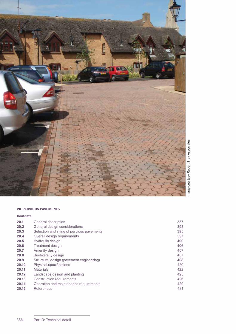
CIRIA SuDS Manual 2015
386 Part D: Technical detail
20 PERVIOUS PAVEMENTS
Contents
20.1 General description 38720.2 General design considerations 39320.3 Selection and siting of pervious pavements 39520.4 Overall design requirements 39720.5 Hydraulic design 40020.6 Treatment design 40620.7 Amenity design 40720.8 Biodiversity design 40720.9 Structural design (pavement engineering) 40820.10 Physicalspecifications 42020.11 Materials 42220.12 Landscapedesignandplanting 42520.13 Constructionrequirements 42620.14 Operationandmaintenancerequirements 42920.15 References 431
Imag
e co
urte
sy R
ober
t Bra
y A
ssoc
iate
s
387Chapter 20: Pervious pavements
CIRIA SuDS Manual 2015
20.1 GENERAL DESCRIPTION
Pervious pavements provide a pavement suitable for pedestrian and/or vehicular traffic,whileallowingrainwatertoinfiltratethroughthesurfaceandintotheunderlyingstructurallayers.Thewateristemporarilystoredbeneaththeoverlyingsurfacebeforeuse,infiltrationtotheground,orcontrolleddischargedownstream(Section 20.1.9).
Pervioussurfaces,togetherwiththeirassociatedsubstructures,areanefficientmeansofmanagingsurfacewaterrunoffclosetoitssource–interceptingrunoff,reducingthevolumeandfrequencyofrunoff,andprovidingatreatmentmedium.Treatmentprocessesthatoccurwithinthesurfacestructure,thesubsurfacematrix(includingsoillayerswhereinfiltrationisallowed)andthegeotextilelayersinclude:
▪ filtration
▪ adsorption
▪ biodegradation
▪ sedimentation.
Therearetwotypesofperviouspavementsthataredefinedonthebasisofthesurfacingmaterials:
Porous pavementsinfiltratewateracrosstheirentiresurfacematerial,forexamplereinforcedgrassorgravelsurfaces,resinboundgravel,porousconcreteand porous asphalt.
Permeable pavements have a surface that is formed of material that is itself impervioustowater.Thematerialsarelaidtoprovidevoidspacethroughthesurfacetothesub-base(egstandardconcreteblockpavingisspecificallydesignedtoallowrainwaterfallingontothesurfaceorrunoffdischargedoverthesurfacetoinfiltratethroughthejointsorvoidsbetweentheblocksintotheunderlyingpavementstructure).
Themaintypesofsurfacesusedaspartofperviouspavementconstructionare:
▪ modular permeable paving
▪ porous asphalt
▪ grass reinforcement
▪ resin bound gravel
▪ porous concrete
20Chapter Pervious pavements
This chapter provides guidance on the design of pervious pavements – pavements that are suitable for pedestrian and/or vehicular traffic, while allowing rainwater to infiltrate through the surface and into underlying structural and foundation layers.
Appendix C, Section C.5.1 demonstrates how to design an infiltrating pervious pavement for a residential area.
Appendix C, Section C.5.3 demonstrates how to design a lined pervious pavement for a supermarket.
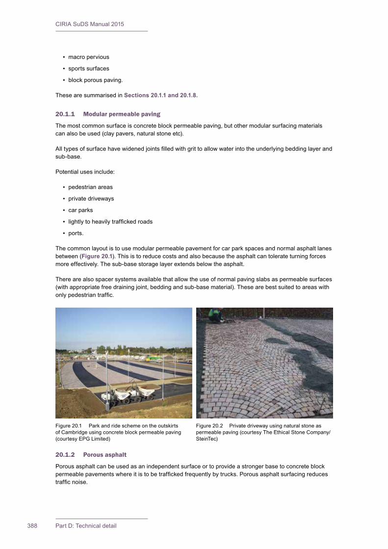
CIRIA SuDS Manual 2015
388 Part D: Technical detail
▪ macro pervious
▪ sports surfaces
▪ block porous paving.
These are summarised in Sections 20.1.1 and 20.1.8.
20.1.1 Modular permeable paving
Themostcommonsurfaceisconcreteblockpermeablepaving,butothermodularsurfacingmaterialscanalsobeused(claypavers,naturalstoneetc).
Alltypesofsurfacehavewidenedjointsfilledwithgrittoallowwaterintotheunderlyingbeddinglayerandsub-base.
Potentialusesinclude:
▪ pedestrian areas
▪ privatedriveways
▪ car parks
▪ lightlytoheavilytraffickedroads
▪ ports.
The common layout is to use modular permeable pavement for car park spaces and normal asphalt lanes between(Figure 20.1). This is to reduce costs and also because the asphalt can tolerate turning forces moreeffectively.Thesub-basestoragelayerextendsbelowtheasphalt.
Therearealsospacersystemsavailablethatallowtheuseofnormalpavingslabsaspermeablesurfaces(withappropriatefreedrainingjoint,beddingandsub-basematerial).Thesearebestsuitedtoareaswithonlypedestriantraffic.
20.1.2 Porous asphalt
Porous asphalt can be used as an independent surface or to provide a stronger base to concrete block permeablepavementswhereitistobetraffickedfrequentlybytrucks.Porousasphaltsurfacingreducestrafficnoise.
Figure20.2 Privatedrivewayusingnaturalstoneaspermeable paving (courtesy The Ethical Stone Company/SteinTec)
Figure20.1 Parkandrideschemeontheoutskirtsof Cambridge using concrete block permeable paving (courtesy EPG Limited)
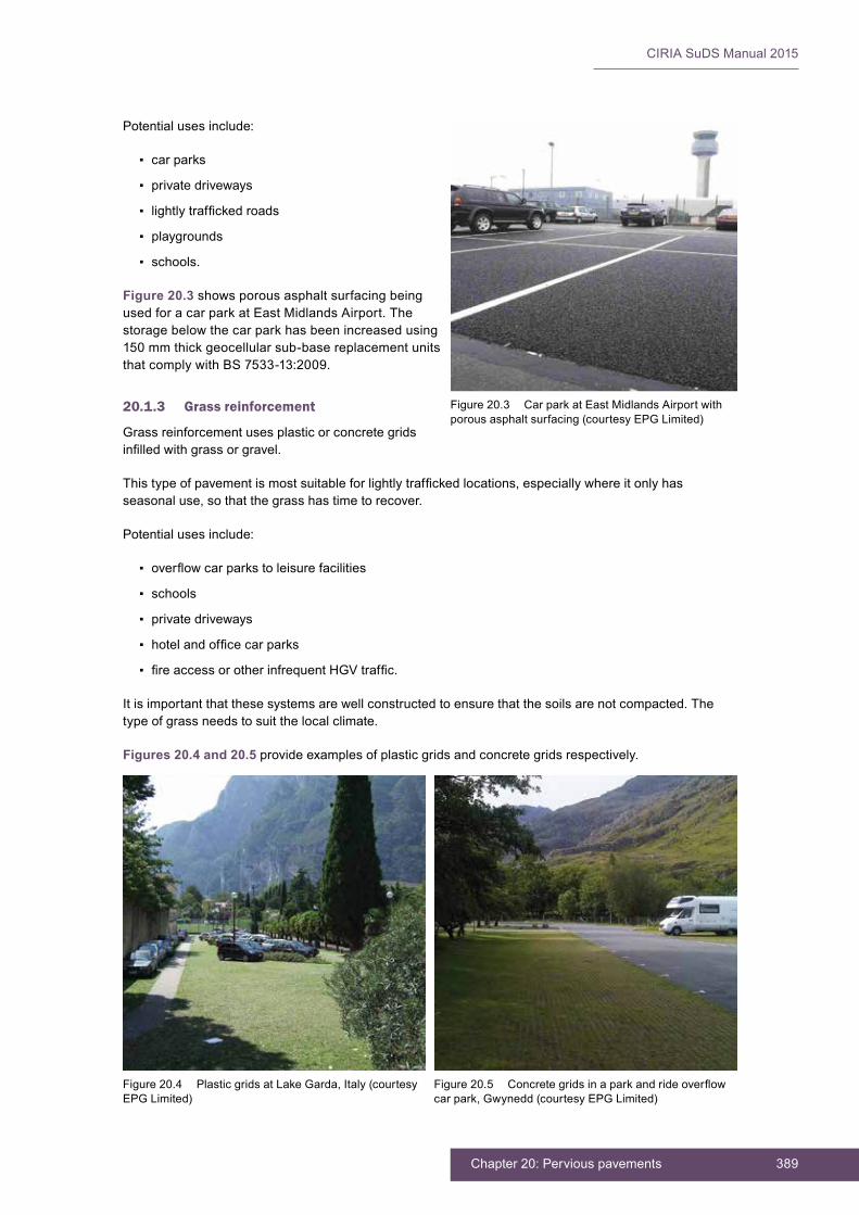
389Chapter 20: Pervious pavements
CIRIA SuDS Manual 2015
Potentialusesinclude:
▪ car parks
▪ privatedriveways
▪ lightlytraffickedroads
▪ playgrounds
▪ schools.
Figure 20.3 showsporousasphaltsurfacingbeingused for a car park at East Midlands Airport. The storagebelowthecarparkhasbeenincreasedusing150 mm thick geocellular sub-base replacement units thatcomplywithBS7533-13:2009.
20.1.3 Grass reinforcement
Grass reinforcement uses plastic or concrete grids infilledwithgrassorgravel.
Thistypeofpavementismostsuitableforlightlytraffickedlocations,especiallywhereitonlyhasseasonaluse,sothatthegrasshastimetorecover.
Potentialusesinclude:
▪ overflowcarparkstoleisurefacilities
▪ schools
▪ privatedriveways
▪ hotelandofficecarparks
▪ fireaccessorotherinfrequentHGVtraffic.
Itisimportantthatthesesystemsarewellconstructedtoensurethatthesoilsarenotcompacted.Thetype of grass needs to suit the local climate.
Figures 20.4 and 20.5 provideexamplesofplasticgridsandconcretegridsrespectively.
Figure20.3 CarparkatEastMidlandsAirportwithporous asphalt surfacing (courtesy EPG Limited)
Figure20.4 PlasticgridsatLakeGarda,Italy(courtesyEPG Limited)
Figure20.5 Concretegridsinaparkandrideoverflowcarpark,Gwynedd(courtesyEPGLimited)
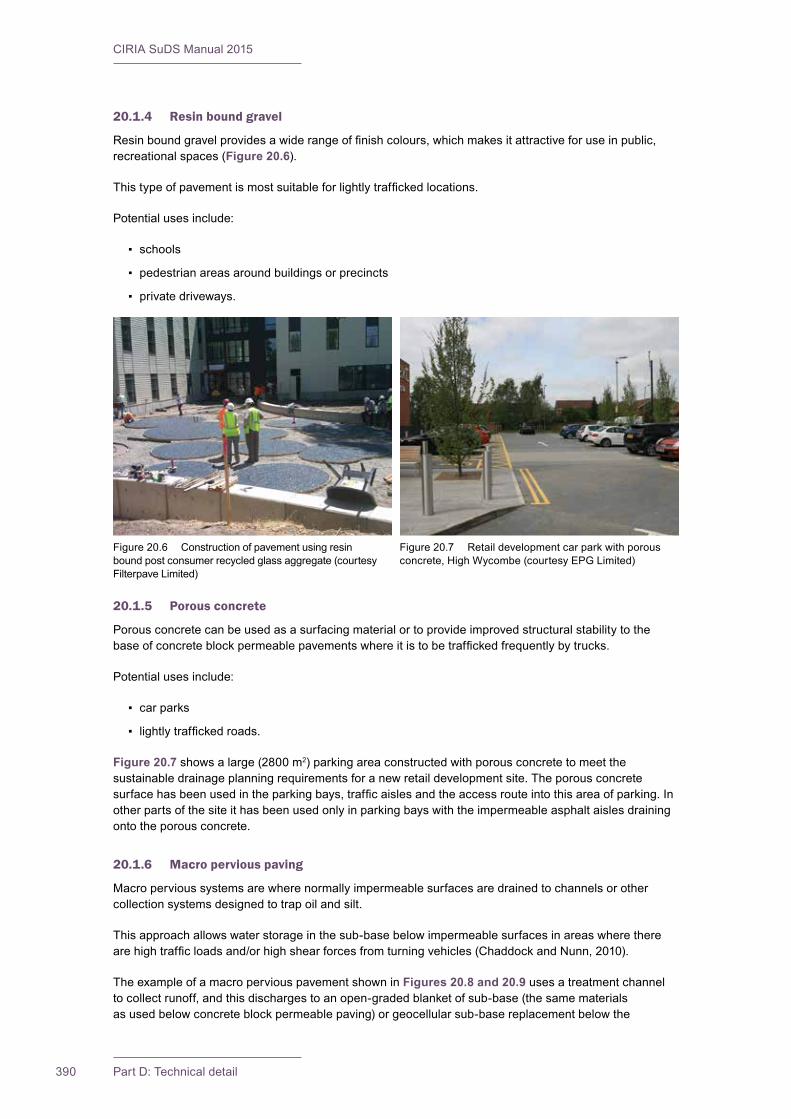
CIRIA SuDS Manual 2015
390 Part D: Technical detail
20.1.4 Resin bound gravel
Resinboundgravelprovidesawiderangeoffinishcolours,whichmakesitattractiveforuseinpublic,recreational spaces (Figure 20.6).
Thistypeofpavementismostsuitableforlightlytraffickedlocations.
Potentialusesinclude:
▪ schools
▪ pedestrian areas around buildings or precincts
▪ privatedriveways.
20.1.5 Porous concrete
Porous concrete can be used as a surfacing material or to provide improved structural stability to the baseofconcreteblockpermeablepavementswhereitistobetraffickedfrequentlybytrucks.
Potentialusesinclude:
▪ car parks
▪ lightlytraffickedroads.
Figure 20.7showsalarge(2800m2)parkingareaconstructedwithporousconcretetomeetthesustainabledrainageplanningrequirementsforanewretaildevelopmentsite.Theporousconcretesurfacehasbeenusedintheparkingbays,trafficaislesandtheaccessrouteintothisareaofparking.Inotherpartsofthesiteithasbeenusedonlyinparkingbayswiththeimpermeableasphaltaislesdrainingonto the porous concrete.
20.1.6 Macro pervious paving
Macropervioussystemsarewherenormallyimpermeablesurfacesaredrainedtochannelsorothercollection systems designed to trap oil and silt.
Thisapproachallowswaterstorageinthesub-basebelowimpermeablesurfacesinareaswheretherearehightrafficloadsand/orhighshearforcesfromturningvehicles(ChaddockandNunn,2010).
TheexampleofamacroperviouspavementshowninFigures 20.8 and 20.9 uses a treatment channel tocollectrunoff,andthisdischargestoanopen-gradedblanketofsub-base(thesamematerialsasusedbelowconcreteblockpermeablepaving)orgeocellularsub-basereplacementbelowthe
Figure20.6 Constructionofpavementusingresinbound post consumer recycled glass aggregate (courtesy Filterpave Limited)
Figure20.7 Retaildevelopmentcarparkwithporousconcrete,HighWycombe(courtesyEPGLimited)
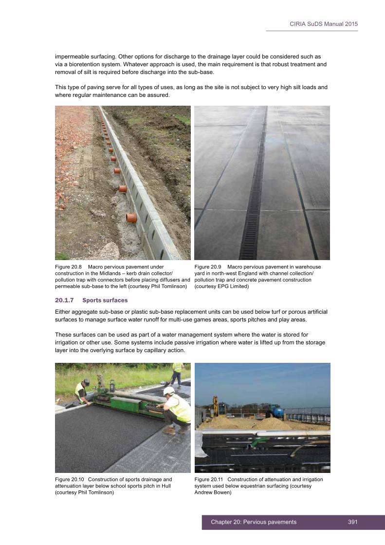
391Chapter 20: Pervious pavements
CIRIA SuDS Manual 2015
impermeable surfacing. Other options for discharge to the drainage layer could be considered such as viaabioretentionsystem.Whateverapproachisused,themainrequirementisthatrobusttreatmentandremoval of silt is required before discharge into the sub-base.
Thistypeofpavingserveforalltypesofuses,aslongasthesiteisnotsubjecttoveryhighsiltloadsandwhereregularmaintenancecanbeassured.
20.1.7 Sports surfaces
Eitheraggregatesub-baseorplasticsub-basereplacementunitscanbeusedbelowturforporousartificialsurfacestomanagesurfacewaterrunoffformulti-usegamesareas,sportspitchesandplayareas.
Thesesurfacescanbeusedaspartofawatermanagementsystemwherethewaterisstoredforirrigationorotheruse.Somesystemsincludepassiveirrigationwherewaterisliftedupfromthestoragelayer into the overlying surface by capillary action.
Figure20.8 MacroperviouspavementunderconstructionintheMidlands–kerbdraincollector/pollutiontrapwithconnectorsbeforeplacingdiffusersandpermeable sub-base to the left (courtesy Phil Tomlinson)
Figure20.9 Macroperviouspavementinwarehouseyardinnorth-westEnglandwithchannelcollection/pollution trap and concrete pavement construction (courtesy EPG Limited)
Figure20.10 ConstructionofsportsdrainageandattenuationlayerbelowschoolsportspitchinHull(courtesy Phil Tomlinson)
Figure20.11 Constructionofattenuationandirrigationsystemusedbelowequestriansurfacing(courtesyAndrewBowen)
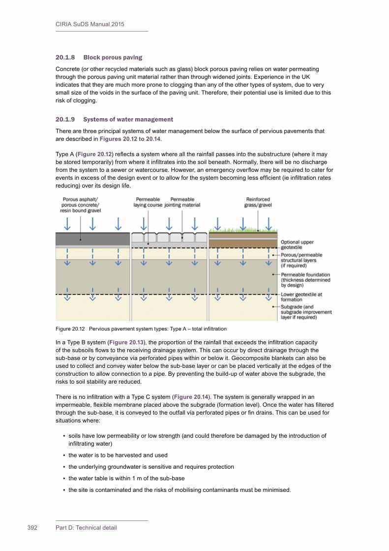
CIRIA SuDS Manual 2015
392 Part D: Technical detail
20.1.8 Block porous paving
Concrete(orotherrecycledmaterialssuchasglass)blockporouspavingreliesonwaterpermeatingthroughtheporouspavingunitmaterialratherthanthroughwidenedjoints.ExperienceintheUKindicatesthattheyaremuchmorepronetocloggingthananyoftheothertypesofsystem,duetoverysmallsizeofthevoidsinthesurfaceofthepavingunit.Therefore,theirpotentialuseislimitedduetothisrisk of clogging.
20.1.9 Systems of water management
Therearethreeprincipalsystemsofwatermanagementbelowthesurfaceofperviouspavementsthatare described in Figures 20.12 to 20.14.
Type A (Figure 20.12)reflectsasystemwherealltherainfallpassesintothesubstructure(whereitmaybestoredtemporarily)fromwhereitinfiltratesintothesoilbeneath.Normally,therewillbenodischargefromthesystemtoasewerorwatercourse.However,anemergencyoverflowmayberequiredtocaterforeventsinexcessofthedesigneventortoallowforthesystembecominglessefficient(ieinfiltrationratesreducing) over its design life.
In a Type B system (Figure 20.13),theproportionoftherainfallthatexceedstheinfiltrationcapacityofthesubsoilsflowstothereceivingdrainagesystem.Thiscanoccurbydirectdrainagethroughthesub-baseorbyconveyanceviaperforatedpipeswithinorbelowit.Geocompositeblanketscanalsobeusedtocollectandconveywaterbelowthesub-baselayerorcanbeplacedverticallyattheedgesoftheconstructiontoallowconnectiontoapipe.Bypreventingthebuild-upofwaterabovethesubgrade,therisks to soil stability are reduced.
ThereisnoinfiltrationwithaTypeCsystem(Figure 20.14).Thesystemisgenerallywrappedinanimpermeable,flexiblemembraneplacedabovethesubgrade(formationlevel).Oncethewaterhasfilteredthroughthesub-base,itisconveyedtotheoutfallviaperforatedpipesorfindrains.Thiscanbeusedforsituationswhere:
▪ soilshavelowpermeabilityorlowstrength(andcouldthereforebedamagedbytheintroductionofinfiltratingwater)
▪ thewateristobeharvestedandused
▪ theunderlyinggroundwaterissensitiveandrequiresprotection
▪ thewatertableiswithin1mofthesub-base
▪ the site is contaminated and the risks of mobilising contaminants must be minimised.
Figure20.12 Perviouspavementsystemtypes:TypeA–totalinfiltration
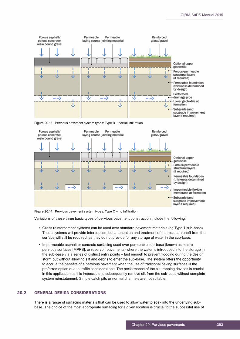
393Chapter 20: Pervious pavements
CIRIA SuDS Manual 2015
Variationsofthesethreebasictypesofperviouspavementconstructionincludethefollowing:
▪ Grass reinforcement systems can be used over standard pavement materials (eg Type 1 sub-base). ThesesystemswillprovideInterception,butattenuationandtreatmentoftheresidualrunofffromthesurfacewillstillberequired,astheydonotprovideforanystorageofwaterinthesub-base.
▪ Impermeableasphaltorconcretesurfacingusedoverpermeablesub-base(knownasmacropervioussurfaces[MPPS],orreservoirpavements)wherethewaterisintroducedintothestorageinthesub-baseviaaseriesofdistinctentrypoints–fastenoughtopreventfloodingduringthedesignstormbutwithoutallowingsiltanddebristoenterthesub-base.Thesystemofferstheopportunitytoaccruethebenefitsofaperviouspavementwhentheuseoftraditionalpavingsurfacesisthepreferredoptionduetotrafficconsiderations.Theperformanceofthesilttrappingdevicesiscrucialinthisapplicationasitisimpossibletosubsequentlyremovesiltfromthesub-basewithoutcompletesystem reinstatement. Simple catch pits or normal channels are not suitable.
20.2 GENERAL DESIGN CONSIDERATIONS
Thereisarangeofsurfacingmaterialsthatcanbeusedtoallowwatertosoakintotheunderlyingsub-base. The choice of the most appropriate surfacing for a given location is crucial to the successful use of
Figure20.13 Perviouspavementsystemtypes:TypeB–partialinfiltration
Figure20.14 Perviouspavementsystemtypes:TypeC–noinfiltration
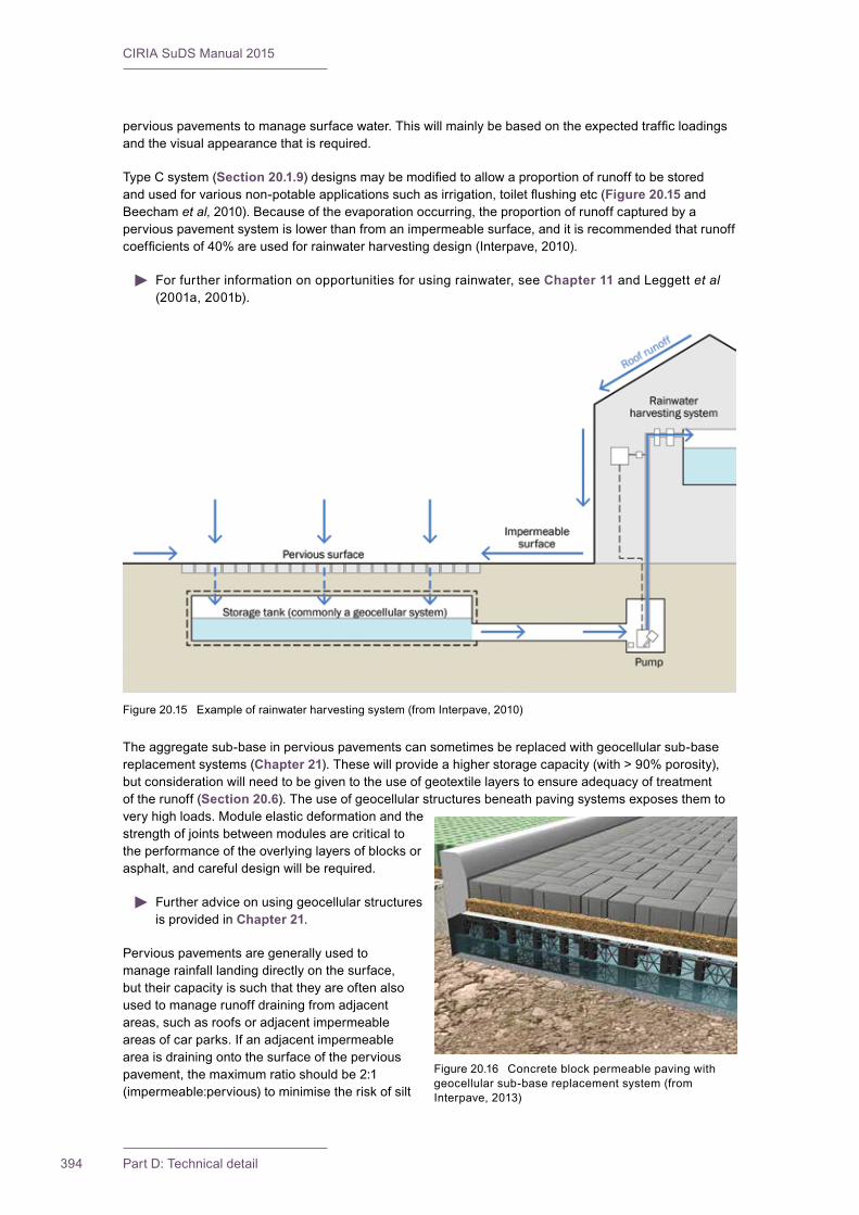
CIRIA SuDS Manual 2015
394 Part D: Technical detail
perviouspavementstomanagesurfacewater.Thiswillmainlybebasedontheexpectedtrafficloadingsand the visual appearance that is required.
Type C system (Section 20.1.9)designsmaybemodifiedtoallowaproportionofrunofftobestoredandusedforvariousnon-potableapplicationssuchasirrigation,toiletflushingetc(Figure 20.15 and Beecham et al,2010).Becauseoftheevaporationoccurring,theproportionofrunoffcapturedbyaperviouspavementsystemislowerthanfromanimpermeablesurface,anditisrecommendedthatrunoffcoefficientsof40%areusedforrainwaterharvestingdesign(Interpave,2010).
Forfurtherinformationonopportunitiesforusingrainwater,seeChapter 11 and Leggett et al (2001a,2001b).
Theaggregatesub-baseinperviouspavementscansometimesbereplacedwithgeocellularsub-basereplacement systems (Chapter 21).Thesewillprovideahigherstoragecapacity(with>90%porosity),butconsiderationwillneedtobegiventotheuseofgeotextilelayerstoensureadequacyoftreatmentof the runoff (Section 20.6).Theuseofgeocellularstructuresbeneathpavingsystemsexposesthemtovery high loads. Module elastic deformation and the strengthofjointsbetweenmodulesarecriticaltothe performance of the overlying layers of blocks or asphalt,andcarefuldesignwillberequired.
Further advice on using geocellular structures is provided in Chapter 21.
Pervious pavements are generally used to managerainfalllandingdirectlyonthesurface,but their capacity is such that they are often also used to manage runoff draining from adjacent areas,suchasroofsoradjacentimpermeableareas of car parks. If an adjacent impermeable area is draining onto the surface of the pervious pavement,themaximumratioshouldbe2:1(impermeable:pervious)tominimisetheriskofsilt
Figure20.15 Exampleofrainwaterharvestingsystem(fromInterpave,2010)
Figure20.16 Concreteblockpermeablepavingwithgeocellular sub-base replacement system (from Interpave,2013)
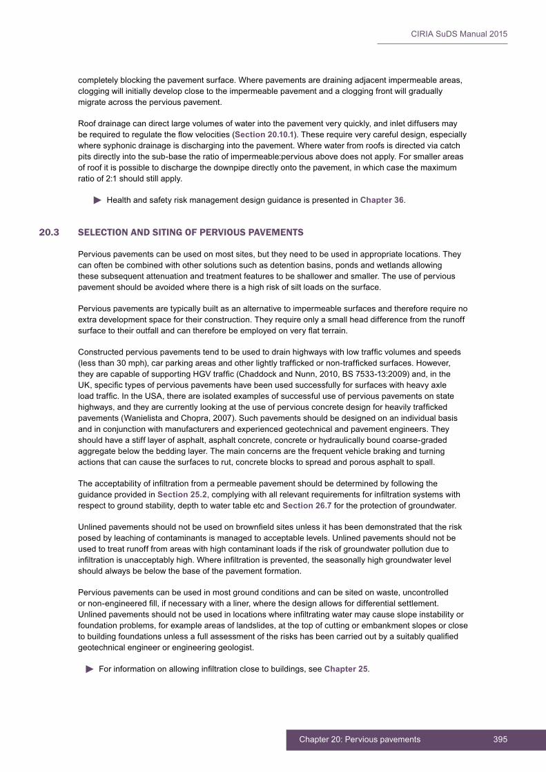
395Chapter 20: Pervious pavements
CIRIA SuDS Manual 2015
completelyblockingthepavementsurface.Wherepavementsaredrainingadjacentimpermeableareas,cloggingwillinitiallydevelopclosetotheimpermeablepavementandacloggingfrontwillgraduallymigrate across the pervious pavement.
Roofdrainagecandirectlargevolumesofwaterintothepavementveryquickly,andinletdiffusersmayberequiredtoregulatetheflowvelocities(Section 20.10.1).Theserequireverycarefuldesign,especiallywheresyphonicdrainageisdischargingintothepavement.Wherewaterfromroofsisdirectedviacatchpitsdirectlyintothesub-basetheratioofimpermeable:perviousabovedoesnotapply.Forsmallerareasofroofitispossibletodischargethedownpipedirectlyontothepavement,inwhichcasethemaximumratioof2:1shouldstillapply.
Health and safety risk management design guidance is presented in Chapter 36.
20.3 SELECTION AND SITING OF PERVIOUS PAVEMENTS
Perviouspavementscanbeusedonmostsites,buttheyneedtobeusedinappropriatelocations.Theycanoftenbecombinedwithothersolutionssuchasdetentionbasins,pondsandwetlandsallowingthesesubsequentattenuationandtreatmentfeaturestobeshallowerandsmaller.Theuseofperviouspavementshouldbeavoidedwherethereisahighriskofsiltloadsonthesurface.
Pervious pavements are typically built as an alternative to impermeable surfaces and therefore require no extradevelopmentspacefortheirconstruction.Theyrequireonlyasmallheaddifferencefromtherunoffsurfacetotheiroutfallandcanthereforebeemployedonveryflatterrain.
Constructedperviouspavementstendtobeusedtodrainhighwayswithlowtrafficvolumesandspeeds(lessthan30mph),carparkingareasandotherlightlytraffickedornon-traffickedsurfaces.However,theyarecapableofsupportingHGVtraffic(ChaddockandNunn,2010,BS7533-13:2009)and,intheUK,specifictypesofperviouspavementshavebeenusedsuccessfullyforsurfaceswithheavyaxleloadtraffic.IntheUSA,thereareisolatedexamplesofsuccessfuluseofperviouspavementsonstatehighways,andtheyarecurrentlylookingattheuseofperviousconcretedesignforheavilytraffickedpavements(WanielistaandChopra,2007).Suchpavementsshouldbedesignedonanindividualbasisandinconjunctionwithmanufacturersandexperiencedgeotechnicalandpavementengineers.Theyshouldhaveastifflayerofasphalt,asphaltconcrete,concreteorhydraulicallyboundcoarse-gradedaggregatebelowthebeddinglayer.Themainconcernsarethefrequentvehiclebrakingandturningactionsthatcancausethesurfacestorut,concreteblockstospreadandporousasphalttospall.
Theacceptabilityofinfiltrationfromapermeablepavementshouldbedeterminedbyfollowingtheguidance provided in Section 25.2,complyingwithallrelevantrequirementsforinfiltrationsystemswithrespecttogroundstability,depthtowatertableetcandSection 26.7fortheprotectionofgroundwater.
Unlinedpavementsshouldnotbeusedonbrownfieldsitesunlessithasbeendemonstratedthattheriskposedbyleachingofcontaminantsismanagedtoacceptablelevels.Unlinedpavementsshouldnotbeusedtotreatrunofffromareaswithhighcontaminantloadsiftheriskofgroundwaterpollutionduetoinfiltrationisunacceptablyhigh.Whereinfiltrationisprevented,theseasonallyhighgroundwaterlevelshouldalwaysbebelowthebaseofthepavementformation.
Perviouspavementscanbeusedinmostgroundconditionsandcanbesitedonwaste,uncontrolledornon-engineeredfill,ifnecessarywithaliner,wherethedesignallowsfordifferentialsettlement.Unlinedpavementsshouldnotbeusedinlocationswhereinfiltratingwatermaycauseslopeinstabilityorfoundationproblems,forexampleareasoflandslides,atthetopofcuttingorembankmentslopesorclosetobuildingfoundationsunlessafullassessmentoftheriskshasbeencarriedoutbyasuitablyqualifiedgeotechnical engineer or engineering geologist.
Forinformationonallowinginfiltrationclosetobuildings,seeChapter 25.
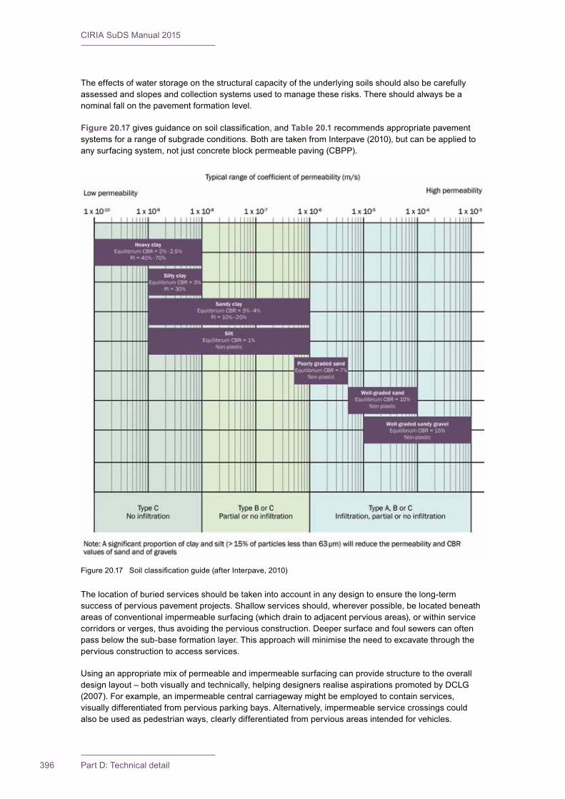
CIRIA SuDS Manual 2015
396 Part D: Technical detail
Figure20.17 Soilclassificationguide(afterInterpave,2010)
Theeffectsofwaterstorageonthestructuralcapacityoftheunderlyingsoilsshouldalsobecarefullyassessedandslopesandcollectionsystemsusedtomanagetheserisks.Thereshouldalwaysbeanominal fall on the pavement formation level.
Figure 20.17givesguidanceonsoilclassification,andTable 20.1 recommends appropriate pavement systemsforarangeofsubgradeconditions.BotharetakenfromInterpave(2010),butcanbeappliedtoanysurfacingsystem,notjustconcreteblockpermeablepaving(CBPP).
The location of buried services should be taken into account in any design to ensure the long-term successofperviouspavementprojects.Shallowservicesshould,whereverpossible,belocatedbeneathareasofconventionalimpermeablesurfacing(whichdraintoadjacentperviousareas),orwithinservicecorridorsorverges,thusavoidingtheperviousconstruction.Deepersurfaceandfoulsewerscanoftenpassbelowthesub-baseformationlayer.Thisapproachwillminimisetheneedtoexcavatethroughthepervious construction to access services.
Usinganappropriatemixofpermeableandimpermeablesurfacingcanprovidestructuretotheoveralldesignlayout–bothvisuallyandtechnically,helpingdesignersrealiseaspirationspromotedbyDCLG(2007).Forexample,animpermeablecentralcarriagewaymightbeemployedtocontainservices,visuallydifferentiatedfromperviousparkingbays.Alternatively,impermeableservicecrossingscouldalsobeusedaspedestrianways,clearlydifferentiatedfromperviousareasintendedforvehicles.
397Chapter 20: Pervious pavements
CIRIA SuDS Manual 2015
TABLE20.1
Guidance on selection of a pavement system type (after Interpave, 2010)
Ground characteristics Type A:total infiltration
Type B:partial infiltration
Type C:no infiltration
Permeability of subgrade definedbycoefficientofpermeability k (m/s)
1 × 10⁻⁶ to 1 × 10⁻³
1 × 10⁻⁸ to 1 × 10⁻⁶
1 × 10⁻¹⁰ to 1 × 10⁻⁸ (1)
Highestexpectedwaterlevelwithin1000mmofformation level
Pollutants present in subgrade
Groundconditionssuchthatinfiltrationofwaterisnotrecommended(solutionfeatures,oldmineworkingetc,Chapter 8)
BOX20.1
Units used for infiltration
TheSIunitofreportingsoilpermeabilityism/s.Therefore,soilinfiltrationratesareusuallyalsoreportedinm/s.Thereisageneralunderstandingwithintheindustryofwhatconstitutesahighorlowvaluequotedintheseunits.
Theinfiltrationrateofrainwaterintothetopsurfaceofaperviouspavementisoftencomparedtorainfallintensity.Rainfallintensityisreportedinmm/h,andthereforetheinfiltrationofwaterintothepervious pavement is reported in these units.
Note1 Partialinfiltrationsystemsmaybeusedinsoilswithpermeabilitylessthan10−8m/sbuttheinfiltrationofwaterisnotallowedforin
thestoragedesign.ThishelpswiththeprovisionofInterception.
Thereisanextensivebodyofevidencedemonstratingthatperviouspavementsperformadequatelyincoldclimates.Theytendtowithstandfreeze–thawconditionswellandtendtobelessaffectedbyfrostheavethanstandardpavementsurfacing(LakeCountyForestPreserves,2003;Kevernet al,2009)duetotheairintheaggregatebaseactingasaninsulatinglayerlimitingfrostpenetrationintothepavement,coupledwiththehigherinternallatentheatassociatedwiththehighersoilmoisturecontent.Perviouspavementsdonottendtoiceonthesurfacebecausewaterandmeltingsnowdrainstraightintothepavementratherthanpondingbeforerunoff.Perviouspavementsalsotendtothawfasterthannormalpavementsandthusrequirelowerthanaveragesaltapplications.Studieshavealsoshownlittlelossinthetreatmentperformanceofperviouspavementsduringcoldweather.However,theycandevelopahoarfrost on the surface more frequently than normal pavement construction.
20.4 OVERALL DESIGN REQUIREMENTS
Perviouspavementsprovidetwofunctions.
1 They need to be able to effectively capture the design storm event and discharge it in a controlled manner to the subgrade or drainage system.
2 Theyneedtoprovidesufficientstructuralresistancetowithstandtheloadingsimposedbyvehiclestravelling on the surface.
Thereforetherearetwosetsofcalculationsrequired,andthegreaterthicknessofpermeablesub-basefromthetwocalculationsisusedasthedesignthickness.Perviouspavementsgenerallyrequireflowcontrols at the outlets to ensure effective use of the storage in the sub-base. A recommended design flowchartisprovidedinFigure 20.19.
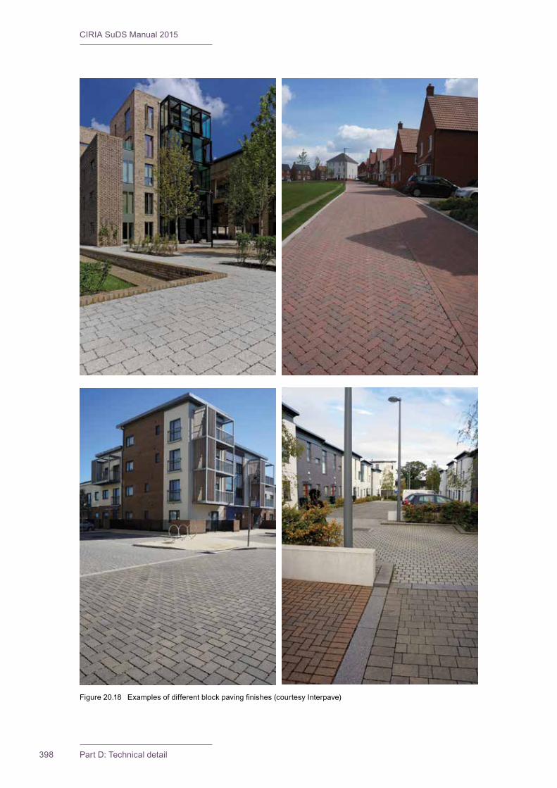
CIRIA SuDS Manual 2015
398 Part D: Technical detail
Figure20.18 Examplesofdifferentblockpavingfinishes(courtesyInterpave)
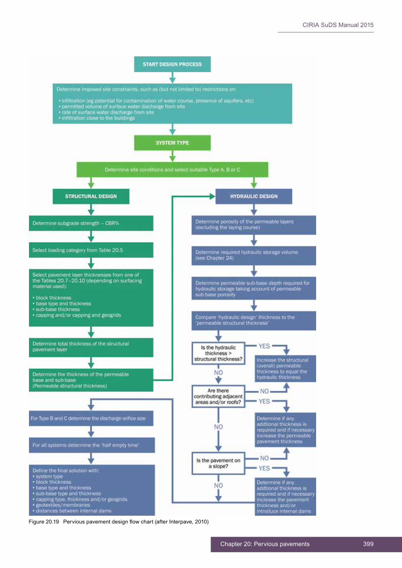
399Chapter 20: Pervious pavements
CIRIA SuDS Manual 2015
Figure20.19 Perviouspavementdesignflowchart(afterInterpave,2010)

CIRIA SuDS Manual 2015
400 Part D: Technical detail
20.5 HYDRAULIC DESIGN
20.5.1 General
Therearefouraspectstothehydraulicdesignofperviouspavements:
a) confirmationoftheadequacyoftherateofinfiltrationofrainwaterthroughthepavementsurface
b) calculation of the storage volume required for design storm event management
c) calculationoftheoutfallcapacityrequiredtoconveyandcontrolthedischargeofwaterfromthepavement structure
d)exceedancedesign
ExceedancedesignisdiscussedinSection 20.5.5,while(a),(b)and(c)arediscussedhere.
a) Infiltration of rainwater through the pervious surface
Thesurfaceinfiltrationrateshouldbesignificantlygreaterthanthedesignrainfallintensitytoavoidsurfacewaterponding,andthecalculationoftheinflowrateshouldincludeallanticipatedrunofffromadjacentareas.Typically,infiltrationcapacitiesofpervioussurfacesaresignificantlygreaterthandesignrainfall intensities and are not generally limiting factors for the use of a pervious pavement. Surface pondingofexceedanceeventsshouldbeplannedforinthedesign,takingaccountofthelikelywaterdepthonthesurfaceandthetimeforwhichitislikelytoremain.Notethatthesurfaceinfiltrationcapacityhasnorelationshiptotheinfiltrationcapacityofthesoilsbelowthepavementconstruction.
Aminimumvalueof2500mm/h(fornewpavements)isconsideredreasonableforapavementsurfacetobeconsideredperviousinrespectofsurfacewatermanagement(whentestedinaccordancewithstandardtestmethods).Theinfiltrationcapacityofthesurfacematerialsisnormallystatedbythesupplierormanufacturer.ThereisnostandardUKorEuropeantestprocedureformeasuringthesurfaceinfiltrationrateofpervioussurfaces.However,ASTMC1781M-13hasbeendevelopedforconcreteblockpermeable paving and ASTM C1701M-09 for pervious concrete (it could also be applied to other porous materialssuchasporousasphaltandgravel-orgrass-filledreinforcementsystems).ItisrecommendedthatmanufacturersshouldprovidesurfaceinfiltrationratesmeasuredusingtestmethodsandthattheyareadoptedasastandardmethodintheUKwiththefollowingamendments:
1 The results should be stated in both mm/h and m/s.
2 Sealingtheinfiltrationringtothesurfacetobetestedshouldbeachievedusingmasticsealant,rapidset mortar or other suitable sealant material.
Thereisnodoubtthattherateofinfiltrationthroughporousandpermeablesurfacesreducesovertime.Themainwaysthatthesurfacesbecomeblockedare:
▪ washingoftopsoilandconstructionmaterialsontothesurface–theserisksshouldbereducedthrough construction best practice and appropriate detailed design
▪ accumulation of silt and debris in the joints or pore spaces at or close to the surface
▪ theapplicationofgrittingsandtocarparksurfaces(notcommonpracticeintheUK)andtheuseofsandasajointingmaterialinconcreteblockpermeablepaving(notUKpractice)
▪ binderslumpingfromtheaggregatematrixinporousasphaltovertime,whichthendrainsintothevoids–theriskofthisoccurringshouldbereducedbytheuseofmodernbindertechnologytopromote adhesion of the binder.
However,itisveryrarethatthecloggingcausescompletesealingofthewholesurface,andnormallyitwillcontinuetoprovidesufficientdrainagecapacity.Itisrecommendedthatafactorofsafetyof10isappliedtothesurfaceinfiltrationrateofallsurfacetypes,toallowforcloggingtoaffectaproportionofthesurfaceareaoverthepavementdesignlife(iethelong-termsurfaceinfiltrationratewillbeaminimumof250mm/h).InformationonrehabilitatingpavementsthatsufferfromcloggingisprovidedinSection 20.14.
401Chapter 20: Pervious pavements
CIRIA SuDS Manual 2015
Despitethereductioninsurfaceinfiltrationrateovertime,theavailableevidence(Table 20.2) indicates thatthelong-termreducedrateismorethansufficientinmostcasestodealwithanyrainfallintensitieslikelytooccurintheUK.Evenifthepavementsbecomecompletelyclogged,theevidenceshowsthattheycanberehabilitatedusingsweeperscombinedwithre-grittingofthejoints.
Figure 20.20showsanexampleofconcreteblockpermeablepavingaftera50mmdepthrainfallevent.Thispavementwasaboutsixyearsoldatthetimeandhadnotbeenmaintainedinthattime.
TABLE20.2
Evidence of durability and clogging of the surfaces of pervious pavements
Pervious pavement type
Clogging mechanism
Evidence of likely clogging rates/extents
Rehabilitation mechanisms
Grass reinforcement (concrete grids)
Sand-filledvoidswithgrassovergrowthactlikesandfiltersandtrap sediment close to the surface
Cloggingdepthsof6–12mm(UrbanWaterways,2011);lossof60–75%oftheinitialsurfaceinfiltrationrateduring a simulated 35-year life (Jayasuriya et al,2007)
Clogged sand can be removed andreplacedwithmechanicalsweepers,althoughthegrasswillalsohavetobereseeded
Porous asphaltDustandsedimenttrapped in surface pores
Clogginginthetop25–75mmcanoccurrapidlywithoutgooddesignandmaintenance,wheresiltloadsaresignificant.EvidenceintheUKisthat pavements are still serviceable after about eight years
Rotatingsweeperandjetwash;useasurfacelayerwithfinerpores(iesmalleraggregate) and increasing aggregatesizewithdepth(BeeldensandHerrier,2006)
Porous concrete Dustandsedimenttrapped in surface pores
Clogginginthetop25–75mmcanoccurrapidlywithoutgooddesignandmaintenance,wheresiltloadsaresignificant
Useasurfacelayerwithfinerpores (ie smaller aggregate) and increasing aggregate sizewithdepth(BeeldensandHerrier,2006);specialistrotating and oscillating sweeper(thetypeusedtoremove tyre residue from airportrunways
Concrete block permeable paving
Dustandsedimentistrapped in the joints betweentheblocks
Penetrationto50mm(oversixyears)(UrbanWaterways,2011);lossof70–90%ofas-newsurfaceinfiltrationrateoverthefirstfewyearsofuseafterwhichinfiltrationrate levels off and remain effectively constant(Borgwardt,2006);inheavilytraffickedpavementsthewheeltracksmaybecomecompletelycloggedinafewyears(ChaddockandNunn,2010)
Brushing and suction sweepingofthesurface,replacementoftop20mmofjointingmaterial,herbicideapplicationandweedremovalprogrammes
b) Pavement subsurface storage capacity
Therequiredcapacityofthesub-basedependsonrainfallcharacteristics,designreturnperiod,infiltrationpotentialintothesubgrade,dischargeconstraints,andtheimpermeableareadrainingtothe pervious pavement.
Thethicknessofthesub-baserequiredcanbeobtainedbysimplecalculation(seeInterpave,2010)orbydetailed hydrological and hydraulic modelling. It should be noted that the Interpave procedure assumes notimeofconcentration,whichislikelytooutputaconservativedesigndepthrequirement.Proprietarydrainagesoftwarenowexiststhatcanpredicthydraulicprofilesacrossapavementandcomputescapacitiesfordesigneventsinmoredetail.However,manyofthealgorithmsinthemodelsarestillverysimpleandonlyapproximatetoactualperformance.
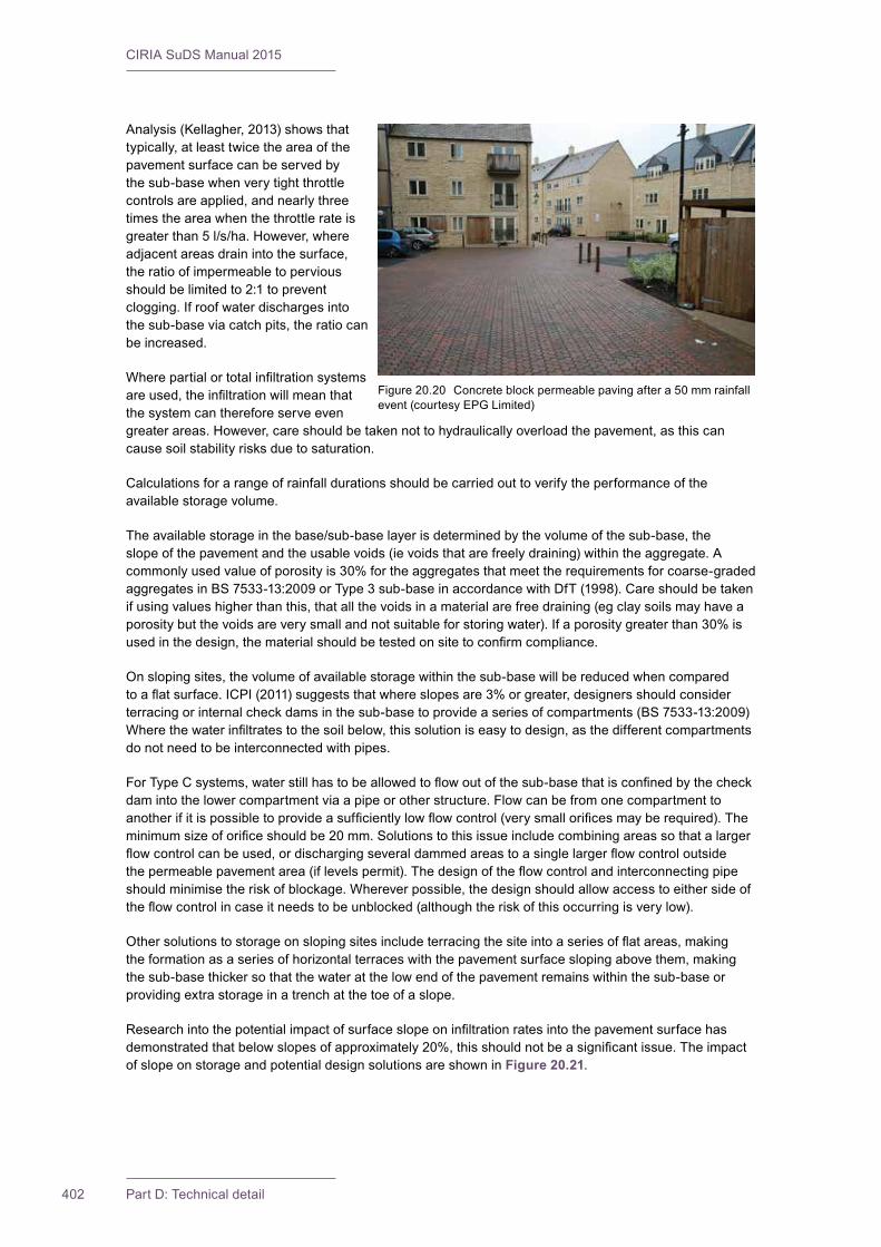
CIRIA SuDS Manual 2015
402 Part D: Technical detail
Analysis(Kellagher,2013)showsthattypically,atleasttwicetheareaofthepavement surface can be served by thesub-basewhenverytightthrottlecontrolsareapplied,andnearlythreetimestheareawhenthethrottlerateisgreaterthan5l/s/ha.However,whereadjacentareasdrainintothesurface,the ratio of impermeable to pervious shouldbelimitedto2:1topreventclogging.Ifroofwaterdischargesintothesub-baseviacatchpits,theratiocanbe increased.
Wherepartialortotalinfiltrationsystemsareused,theinfiltrationwillmeanthatthe system can therefore serve even greaterareas.However,careshouldbetakennottohydraulicallyoverloadthepavement,asthiscancause soil stability risks due to saturation.
Calculations for a range of rainfall durations should be carried out to verify the performance of the available storage volume.
Theavailablestorageinthebase/sub-baselayerisdeterminedbythevolumeofthesub-base,theslopeofthepavementandtheusablevoids(ievoidsthatarefreelydraining)withintheaggregate.Acommonlyusedvalueofporosityis30%fortheaggregatesthatmeettherequirementsforcoarse-gradedaggregatesinBS7533-13:2009orType3sub-baseinaccordancewithDfT(1998).Careshouldbetakenifusingvalueshigherthanthis,thatallthevoidsinamaterialarefreedraining(egclaysoilsmayhaveaporositybutthevoidsareverysmallandnotsuitableforstoringwater).Ifaporositygreaterthan30%isusedinthedesign,thematerialshouldbetestedonsitetoconfirmcompliance.
Onslopingsites,thevolumeofavailablestoragewithinthesub-basewillbereducedwhencomparedtoaflatsurface.ICPI(2011)suggeststhatwhereslopesare3%orgreater,designersshouldconsiderterracingorinternalcheckdamsinthesub-basetoprovideaseriesofcompartments(BS7533-13:2009)Wherethewaterinfiltratestothesoilbelow,thissolutioniseasytodesign,asthedifferentcompartmentsdonotneedtobeinterconnectedwithpipes.
ForTypeCsystems,waterstillhastobeallowedtoflowoutofthesub-basethatisconfinedbythecheckdamintothelowercompartmentviaapipeorotherstructure.Flowcanbefromonecompartmenttoanotherifitispossibletoprovideasufficientlylowflowcontrol(verysmallorificesmayberequired).Theminimumsizeoforificeshouldbe20mm.Solutionstothisissueincludecombiningareassothatalargerflowcontrolcanbeused,ordischargingseveraldammedareastoasinglelargerflowcontroloutsidethepermeablepavementarea(iflevelspermit).Thedesignoftheflowcontrolandinterconnectingpipeshouldminimisetheriskofblockage.Whereverpossible,thedesignshouldallowaccesstoeithersideoftheflowcontrolincaseitneedstobeunblocked(althoughtheriskofthisoccurringisverylow).
Othersolutionstostorageonslopingsitesincludeterracingthesiteintoaseriesofflatareas,makingtheformationasaseriesofhorizontalterraceswiththepavementsurfaceslopingabovethem,makingthesub-basethickersothatthewateratthelowendofthepavementremainswithinthesub-baseorprovidingextrastorageinatrenchatthetoeofaslope.
Researchintothepotentialimpactofsurfaceslopeoninfiltrationratesintothepavementsurfacehasdemonstratedthatbelowslopesofapproximately20%,thisshouldnotbeasignificantissue.TheimpactofslopeonstorageandpotentialdesignsolutionsareshowninFigure 20.21.
Figure20.20 Concreteblockpermeablepavingaftera50mmrainfallevent (courtesy EPG Limited)
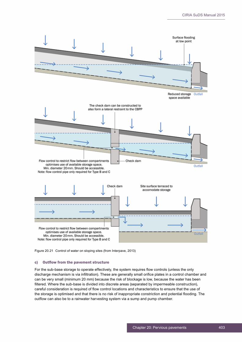
403Chapter 20: Pervious pavements
CIRIA SuDS Manual 2015
c) Outflow from the pavement structure
Forthesub-basestoragetooperateeffectively,thesystemrequiresflowcontrols(unlesstheonlydischargemechanismisviainfiltration).Thesearegenerallysmallorificeplatesinacontrolchamberandcanbeverysmall(minimum20mm)becausetheriskofblockageislow,becausethewaterhasbeenfiltered.Wherethesub-baseisdividedintodiscreteareas(separatedbyimpermeableconstruction),carefulconsiderationisrequiredofflowcontrollocationsandcharacteristicstoensurethattheuseofthestorageisoptimisedandthatthereisnoriskofinappropriateconstrictionandpotentialflooding.Theoutflowcanalsobetoarainwaterharvestingsystemviaasumpandpumpchamber.
Figure20.21 Controlofwateronslopingsites(fromInterpave,2013)
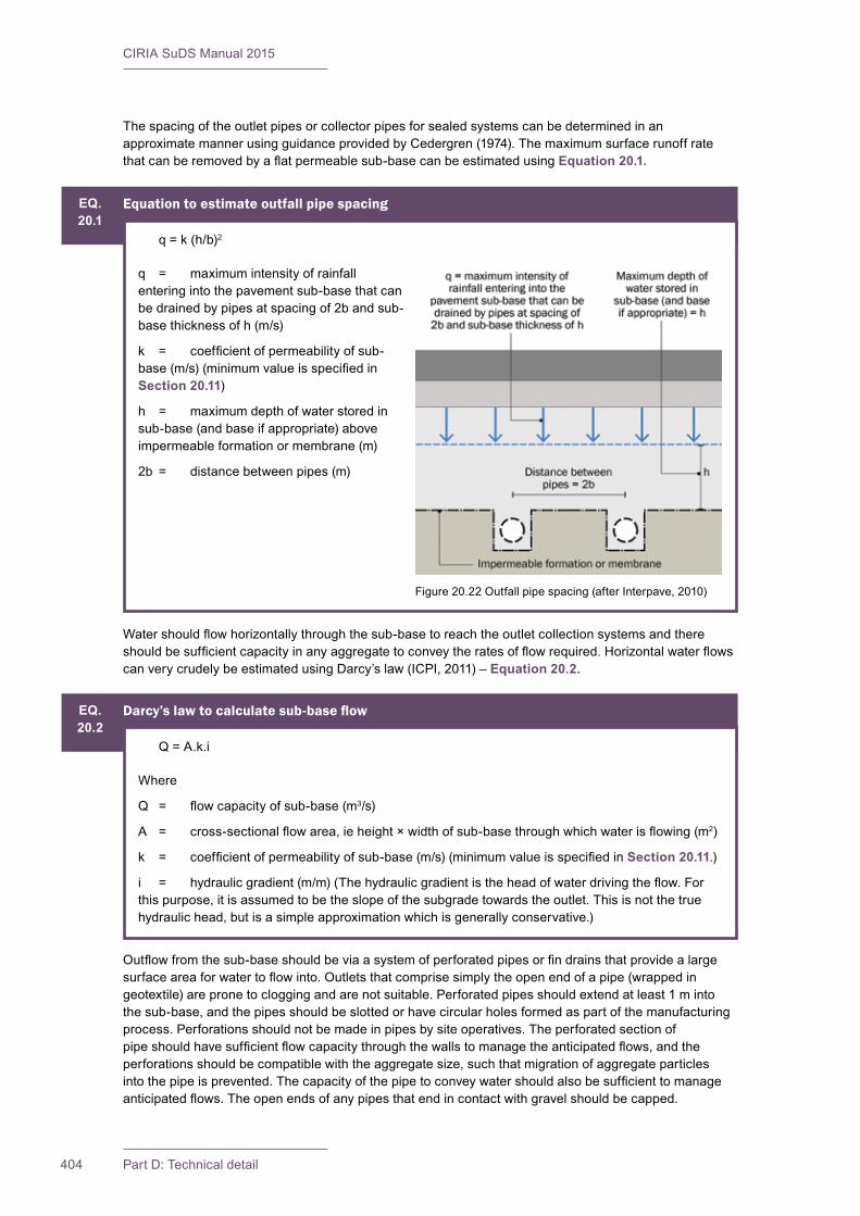
CIRIA SuDS Manual 2015
404 Part D: Technical detail
The spacing of the outlet pipes or collector pipes for sealed systems can be determined in an approximatemannerusingguidanceprovidedbyCedergren(1974).Themaximumsurfacerunoffratethatcanberemovedbyaflatpermeablesub-basecanbeestimatedusingEquation 20.1.
EQ.20.1
Equation to estimate outfall pipe spacing
q = k (h/b)2
q = maximumintensityofrainfallentering into the pavement sub-base that can bedrainedbypipesatspacingof2bandsub-base thickness of h (m/s)
k = coefficientofpermeabilityofsub-base(m/s)(minimumvalueisspecifiedinSection 20.11)
h = maximumdepthofwaterstoredinsub-base (and base if appropriate) above impermeable formation or membrane (m)
2b = distancebetweenpipes(m)
Figure20.22Outfallpipespacing(afterInterpave,2010)
EQ.20.2
Darcy’s law to calculate sub-base flow
Q = A.k.i
Where
Q = flowcapacityofsub-base(m3/s)
A = cross-sectionalflowarea,ieheight×widthofsub-basethroughwhichwaterisflowing(m2)
k = coefficientofpermeabilityofsub-base(m/s)(minimumvalueisspecifiedin Section 20.11.)
i = hydraulicgradient(m/m)(Thehydraulicgradientistheheadofwaterdrivingtheflow.Forthispurpose,itisassumedtobetheslopeofthesubgradetowardstheoutlet.Thisisnotthetruehydraulichead,butisasimpleapproximationwhichisgenerallyconservative.)
Outflowfromthesub-baseshouldbeviaasystemofperforatedpipesorfindrainsthatprovidealargesurfaceareaforwatertoflowinto.Outletsthatcomprisesimplytheopenendofapipe(wrappedingeotextile)arepronetocloggingandarenotsuitable.Perforatedpipesshouldextendatleast1mintothesub-base,andthepipesshouldbeslottedorhavecircularholesformedaspartofthemanufacturingprocess. Perforations should not be made in pipes by site operatives. The perforated section of pipeshouldhavesufficientflowcapacitythroughthewallstomanagetheanticipatedflows,andtheperforationsshouldbecompatiblewiththeaggregatesize,suchthatmigrationofaggregateparticlesintothepipeisprevented.Thecapacityofthepipetoconveywatershouldalsobesufficienttomanageanticipatedflows.Theopenendsofanypipesthatendincontactwithgravelshouldbecapped.
Watershouldflowhorizontallythroughthesub-basetoreachtheoutletcollectionsystemsandthereshouldbesufficientcapacityinanyaggregatetoconveytheratesofflowrequired.HorizontalwaterflowscanverycrudelybeestimatedusingDarcy’slaw(ICPI,2011)–Equation 20.2.
405Chapter 20: Pervious pavements
CIRIA SuDS Manual 2015
20.5.2 Interception design
Studieshaveshownthatthefrequencyofrunofffromalltypesofperviouspavementsissignificantlyreducedwhencomparedtogulleyandpipesystemsdrainingimpermeablesurfaces.Kellagher(2013)foundthatveryhighlevelsofcompliancewithInterceptioncriteriaareachievablethroughtheuseofperviouspavements,providingthereisanominallevelofinfiltrationavailable.Thisisbecause,duringsmallevents,thewatersoaksintothepervioussurface,layingcourseandsub-base,andisreleasedback into the atmosphere through evaporation once the rainfall has stopped. In unlined systems (Type A andBpavements),infiltrationcanalsodeliverInterception.Theresultsofvariousstudiesdemonstratingthe ability of pervious pavements to provide Interception storage are summarised in Table 20.3. These showthatrunofftypicallydoesnotoccurfromperviouspavementsforrainfalleventsupto5mm.
Permeablepavementscanbecombinedwithrainwaterharvestingsystems,whichisanotherapproachtoproviding Interception (Chapter 11).
20.5.3 Peak flow control design
Permeablepavementshelpreduceflowratesfromasitebyprovidingattenuationstorage.Theavailablestoragevolumeisprovidedbythevoidspaceinthesub-base:
Available attenuation storage in sub-base = Volume of sub-base × porosity in the soil/aggregate/ geocellular layer designed to be the storage volume
Onslopingsites,thevolumeofstoragewillbereducedcomparedtothesameareaonalevelsite.Thevolumeofstorageinaslopingsiteisgivenby:
Available attenuation storage in sub-base = 0.5 × L × B × T × porosity in the soil/aggregate/geocellular layer designed to be the storage volume
WhereL=lengthofsub-basewherewatercanbestored=T/tanβT = thickness of sub-base measured verticallyB=widthofsub-basewherewatercanbestoredβ=slopeangle
TABLE20.3
Interception storage provided by pervious pavements
Site Reference Type of pervious pavement
Interception storage (rainfall required to initiate runoff – mm)
Maximum Minimum Average
NationalAirTrafficControlServices,Edinburgh
Pratt et al(2001) CBPP 17.2 2.6 7.3
Kinston,NorthCarolina Collins et al(2008) CBPP >5 n/a n/a
Sydney,AustraliaRankin and Ball (2004)
CBPP 16 2.5 51
NorthCarolina Collins et al(2008) Concrete grass grid — — 6
Toronto Drakeet al(2012)CBPP and porous concrete
— — 7
Note1 Typicalfromcurvefitofresults
CIRIA SuDS Manual 2015
406 Part D: Technical detail
Aflowcontrolstructureisrequiredtoconstraintherateofwaterdischargedfromthesub-baseviaanoutletpipe.Wheredesignsareaccommodatingsmallareasofpavement(egfordrivewaysandaccessroutes),it may be appropriate to link adjacent pavements together so that the control system can be larger. The requiredstoragevolumeforpeakflowcontrolshouldbeassessedinaccordancewithSection 24.9.
20.5.4 Volume control design
Contribution of permeable pavement systems to volume control should be evaluated using standard methods,basedonexpectedinfiltrationratesand/oravailableattenuationstorageandspecifiedflowcontrols.AssessmentofvolumetriccontrolshouldfollowthemethoddescribedinChapter 3.
Toachievesuitablevolumetriccontrol,overflowstodifferentareasofthedrainagesystemmayberequiredoralternativelytheflowcontrolattheoutletcanbedesignedtoprovideavariabledischarge.Theuseofrainwaterharvesting(usingthepermeablepavementasthestorage)canalsobeusedtohelptoachieve a volumetric reduction in runoff.
20.5.5 Exceedance flow design
Perviouspavementsystemsshouldincludeexceedanceeventmanagementasanintegratedpartofthesystemdesign.Oneoptionistousegulliessetslightlyabovetheelevationofthepavement.Thisallowsforsomepondingabovethepavementsurfacetobeusedforextrastorage.
Temporarystorageofrunofffromextremeeventsabovethepavementsurfaceshouldnotbepermittedwherethereisariskofsurfacecloggingfromdepositedsedimentsandotherdebris.
FurtherguidanceonexceedancedesignisprovidedinSection 24.12.
20.6 TREATMENT DESIGN
Permeablepavementdrainagehasbeenshowntohavedecreasedconcentrationsofarangeofsurfacewaterpollutantswhencomparedtoimpermeablesurfacedrainage,includingheavymetals,oilandgrease,sedimentandsomenutrients(Prattet al,1995and1999,JamesandShahin,1998,BratteboandBooth,2003,Beanet al,2007,Drakeet al,2012).Allbutnutrientremovalhasbeenrepeatedlydemonstratedinmanyresearchlocations.Evidenceoftheremovalefficienciesofpermeablepavementsare included in Chapter 26, Annex 3.
Becausemostpermeablepavementssubstantiallyreducethevolumeofrunoffandoutflow,itislogicalthattheywillalsosignificantlyreducepollutantloadingstoreceivingsurfacewaters.Theacceptabilityofallowinginfiltrationfromthepavementwilldependontheextentofthelikelyrunoffcontaminationandsitecharacteristics (see Chapter 4, Table 4.3).
Severalstudiesconfirmthatpermeablepavementsdemonstratesignificantlylowertotalpollutionloadingsthanstandardpavements(Dayet al,1981,Rushton,2001,Beanet al,2007,Drakeet al,2012).
Treatmentprocessesoccurringwithinperviouspavementsinclude:
▪ filtrationofsiltandtheattachedpollutants–themajorityofsiltistrappedwithinthetop30mmofthejointingmaterialbetweentheblocks
▪ biodegradationoforganicpollutants,suchaspetrolanddieselwithinthepavementconstruction
▪ adsorptionofpollutants(pollutantsattachorbindtosurfaceswithintheconstruction)whichdependsonfactorssuchastexture,aggregatestructureandmoisturecontent
▪ settlement and retention of solids.
Enhancedsoilscanalsobeusedtoimprovetreatmentwithintheperviouspavementsystem.Thiscanbeachievedusingeitherproprietarysystemsorbytheadditionofsmallamountsofsubstrate,ormaterials

407Chapter 20: Pervious pavements
CIRIA SuDS Manual 2015
withahigheradsorptioncapacitythanconventionalaggregates(sawdust,peat,claysoils,granularactivated carbon can all increase adsorption). The added materials should not reduce the structural or hydraulic performance of the aggregates. The required microbes are usually already present in the ground and further applications of microbes is not required.
Thepollutantsaretrappedwithintheconstructionatvariouslocationsaccordingtothetypeofperviousconstruction. It has also been found that oils held in some types of pervious construction may be degradedbymicroorganisms(Pratt,1999).Henceoilsaturationofthepavementisunlikelywheresupplyisevenlyspreadovertime.Amajoroilspillcouldoverwhelmthesystem,butthisriskcanbemitigatedbyusingspecialistoiladsorbinggeotextileswithintheconstruction(aheavierweightgeotextilewillbemoreeffective,especiallyifithasbeenspecificallydevelopedtoattractoil).Itisthoughtlikelythatnutrientsoccurringintheenvironmentnearperviouspavements,suchasingrasscuttings,leavesandanimaldroppings,maywellprovidetherequiredstimulusforindigenousmicrobialcommunitydevelopment.Forsiteswithalowriskofoilspillage,thereisnoneedtousegeotextilebetweenthebeddinglayerandsub-baseforpollutionremovalperformance,becausethegeotextilemakeslittleifanydifferencetoremovalofother pollutants.
Ifgeocellularstorageisusedinsteadofaggregatesub-base,thebenefitsoftreatmentwithinthesub-basegravelswillbelost.However,theuseofahorizontalgeotextileabovethegeocellularunitscanhelpmitigatethisloss(PuehmeierandNewman,2008),andhasbeendemonstratedtoprovidecomparableperformance.Also,asignificantproportionofthepollutionremovalhasbeendemonstratedtooccurinthetopofthejointingvoidsinconcreteblockpermeablepaving,thetoplayerofporousasphalt(ifthesurface layer has a smaller grading) and in the grass/rootzone layer of grass systems.
Ifincreasedconfidenceintheremovalofnitrogenhastobeachievedthenwaterwouldhavetobefedfromthesub-basematerialbelowtheperviouspavementstothenextstageoftheManagementTrain,specificallydesignedtooptimisenutrientremoval.Thiscouldbeachievedbylinkingupthepavementstoapondorseriesofpondsorbioretentionsystemwithananaerobiczoneasthesehavebetterremovalratesforphosphorousandnitrogen.Concretegrassgridpaversfilledwithsandhavebeenfoundtobemoreeffectiveatremovingtotalnitrogenthanothertypesofpervioussurface(UrbanWaterways,2008).
Drakeet al (2012)foundcleardifferencesinwaterqualityissuingfromCBPPandporousconcrete.Thetwosurfacesappeartocapturedifferentpollutants.ThismaybetheresultofthehigherpHconditionswithintheporousconcreteaffectingmetaladsorption.Therewasalsoinitialleachingofsomecontaminants from the concrete (phosphate and high pH). Porous concrete also takes time to stabilise and,inthelongerterm(1year+),performanceseemstoapproachthatofCBPP.
Thetreatmentdesignshouldensurethatthesurfacelayerhassufficientlysmallvoidstotrapsiltwithin30mmofthesurfacebutstillbepermeableenoughtoallowwatertoflowintothesub-base.Porousasphalt,porousconcrete,reinforcedgrass,resinboundgravelandconcreteblockpermeablepavingwith2/6.3jointingmaterialshouldallmeetthisrequirement.
20.7 AMENITY DESIGN
Perviouspavementscanprovideamenityintheformofboththeusefulness(ietheyaffordflexibleandmultipleuseofspaceforawiderangeofactivities)andthevisualaspectsofthesurfacematerials(especiallygrasssystems).However,therearenospecificdesignrequirementstoachieveamenityoverandabovethechoiceofsurfaceaspartoftheoverallplanning,architecturalorlandscapedesign.
20.8 BIODIVERSITY DESIGN
Perviouspavementsdonotprovideanydirectbiodiversitybenefits,althoughtheyareveryusefulfortreatingandcontrollingwatertomaximisethebiodiversityinanydownstreampondsorwetlands.Therearenospecificdesignrequirementsorapproachesforbiodiversity.
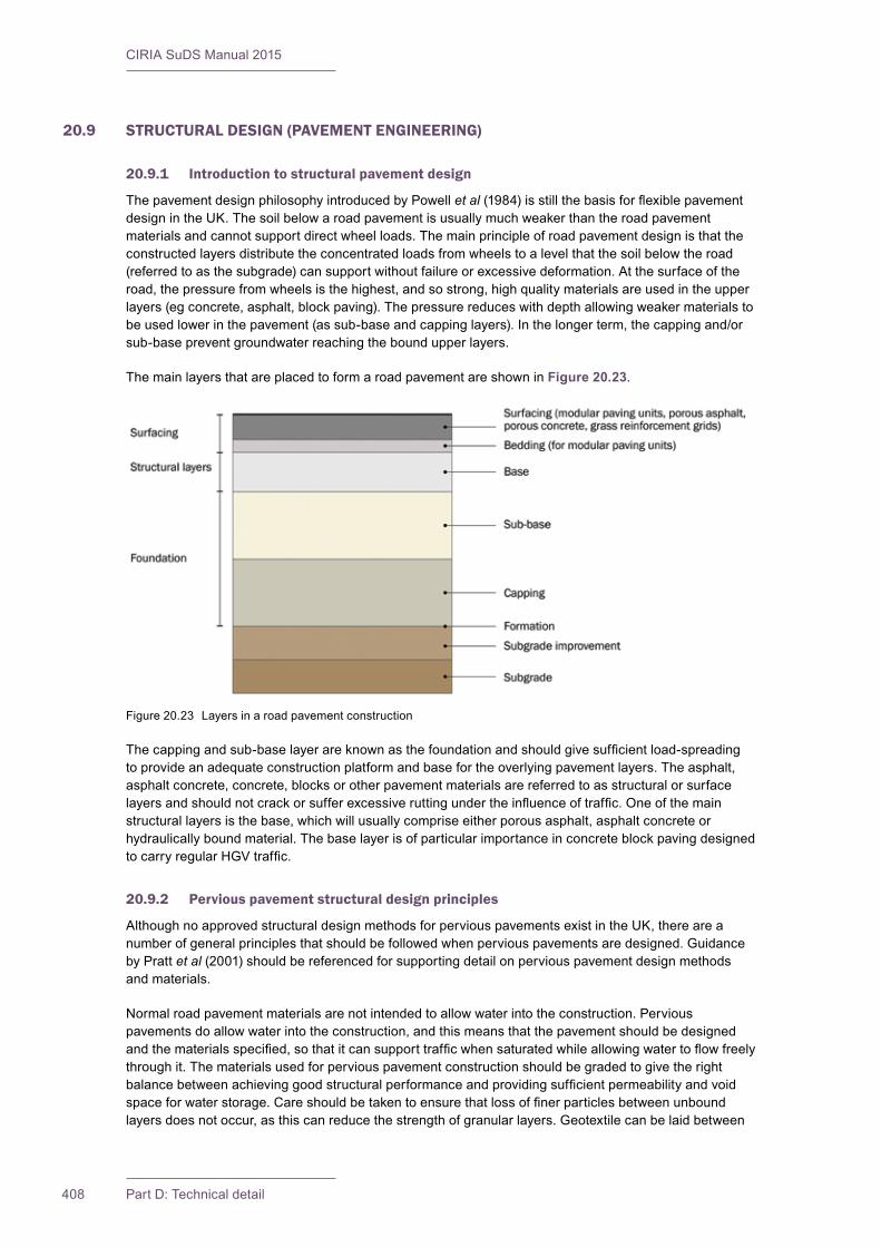
CIRIA SuDS Manual 2015
408 Part D: Technical detail
20.9 STRUCTURAL DESIGN (PAVEMENT ENGINEERING)
20.9.1 Introduction to structural pavement design
ThepavementdesignphilosophyintroducedbyPowellet al(1984)isstillthebasisforflexiblepavementdesignintheUK.Thesoilbelowaroadpavementisusuallymuchweakerthantheroadpavementmaterialsandcannotsupportdirectwheelloads.Themainprincipleofroadpavementdesignisthattheconstructedlayersdistributetheconcentratedloadsfromwheelstoalevelthatthesoilbelowtheroad(referredtoasthesubgrade)cansupportwithoutfailureorexcessivedeformation.Atthesurfaceoftheroad,thepressurefromwheelsisthehighest,andsostrong,highqualitymaterialsareusedintheupperlayers(egconcrete,asphalt,blockpaving).Thepressurereduceswithdepthallowingweakermaterialstobeusedlowerinthepavement(assub-baseandcappinglayers).Inthelongerterm,thecappingand/orsub-basepreventgroundwaterreachingtheboundupperlayers.
ThemainlayersthatareplacedtoformaroadpavementareshowninFigure 20.23.
Thecappingandsub-baselayerareknownasthefoundationandshouldgivesufficientload-spreadingtoprovideanadequateconstructionplatformandbasefortheoverlyingpavementlayers.Theasphalt,asphaltconcrete,concrete,blocksorotherpavementmaterialsarereferredtoasstructuralorsurfacelayersandshouldnotcrackorsufferexcessiveruttingundertheinfluenceoftraffic.Oneofthemainstructurallayersisthebase,whichwillusuallycompriseeitherporousasphalt,asphaltconcreteorhydraulically bound material. The base layer is of particular importance in concrete block paving designed tocarryregularHGVtraffic.
20.9.2 Pervious pavement structural design principles
AlthoughnoapprovedstructuraldesignmethodsforperviouspavementsexistintheUK,thereareanumberofgeneralprinciplesthatshouldbefollowedwhenperviouspavementsaredesigned.Guidanceby Pratt et al(2001)shouldbereferencedforsupportingdetailonperviouspavementdesignmethodsand materials.
Normalroadpavementmaterialsarenotintendedtoallowwaterintotheconstruction.Perviouspavementsdoallowwaterintotheconstruction,andthismeansthatthepavementshouldbedesignedandthematerialsspecified,sothatitcansupporttrafficwhensaturatedwhileallowingwatertoflowfreelythrough it. The materials used for pervious pavement construction should be graded to give the right balancebetweenachievinggoodstructuralperformanceandprovidingsufficientpermeabilityandvoidspaceforwaterstorage.Careshouldbetakentoensurethatlossoffinerparticlesbetweenunboundlayersdoesnotoccur,asthiscanreducethestrengthofgranularlayers.Geotextilecanbelaidbetween
Figure20.23 Layersinaroadpavementconstruction

409Chapter 20: Pervious pavements
CIRIA SuDS Manual 2015
unboundlayerstopreventthisfromoccurring.Whereageotextileisnotprovidedbetweenlayingcourseandsub-base,theaggregatesshouldmeetstandardgeotechnicalfiltercriteria(Section 30.5.3).
Theotheroverridingconsiderationisthatthesurfacingwillbesufficientlydurableandcanwithstandthelikelyturningandimpactforcesfromtrafficwithdamage(egspreadingofblocksunderexcessivetrafficshear forces).
Ingeneral,theapproachtakentoallsurfacesisasfollows,followingKnaptonet al(2012):
1 Forlightlytraffickedpavements,theloadsappliedbywheelsarethecriticalfactor,andtheguidanceforthosepavementsisbaseduponwheelloads.
2 Formoreheavilytraffickedhighwaypavements,thepavementsaredesignedonthebasisofthecumulativenumberofstandard8000kgaxles.
20.9.3 Determination of the CBR value for design of pervious pavements
Design CBR value
Californianbearingratio(CBR)variesinverselywithmoisturecontent(asthelatterincreasestheCBRvalue decreases). The equilibrium CBR value is the long-term value that occurs once the pavement is constructedandthemoisturecontentofthesubgradesoilcomesintoequilibriumwiththesuctionforceswithinsubgradeporeairspaces.Suctionforcescanoccurasaresultofunloadingduetoexcavation.Changesingroundwaterlevelsorwettingasaresultofwaterstorageinthesub-basewillalsoaffecttheequilibrium CBR value. Equilibrium CBR values should be used for permeable pavement design. This can bedeterminedbycarryingoutlaboratoryCBRtestsinaccordancewithBS1377-4:1990attheequilibriummoisturecontentasdescribedbyPowellet al (1984). For Type A and B pavements the CBR should be testedaftersaturation.TheICPI(2011)recommendsa96-hoursaturationperiod.
Alternatively,thevalueshouldbeestimatedbasedonthetypeofsoil(plasticityindexandgrading)followingtheguidancebyPowellet al(1984)andBS7533-13:2009,asprovidedinTable 20.4.
TABLE20.4
Equilibrium subgrade CBR estimation
Soil type Plasticity index Guideline equilibrium CBR Value for pervious surface design1, 3 (%)
Heavy clay
70 2
60 2
50 2
40 2.5
Silty clay 30 3
Sandy clay20 4
10 3
Silt2 – 1
Sand (poorly graded) – 7
Sand(wellgraded) – 10
Sandygravel(wellgraded) – 15
Note1 Assumesthinconstruction.Ifpavementthickness(fromsurfacetosubgrade)isgreaterthan1200mm(seeHA,2009).2 Estimatedassumingsomeprobabilityofmaterialsaturating.3 TheseCBRvaluesassumeahighwatertableandthatthesubgrademaybewettedduringthelifeofthepavement.

CIRIA SuDS Manual 2015
410 Part D: Technical detail
Thehighestvaluesofplasticityindexmeasuredonasiteshouldbeused(togivethelowestCBRvalue)forthedesign,unlessthereareasubstantialnumberofresultsavailabletoallowthemeanorotherstatisticalvaluetobeusedwithconfidence,butifthemeanisused,therewillbeanincreasedriskofpavementfailureinsomeareas.ItmaybepossibletoremovesoftspotsandthereforeignorethoselowCBRvalueswhichrelatetotheremovedmaterial.
OnsiteswheretheCBRvariesfromplacetoplace,appropriatedesignsmaybeprovidedfordifferentpartsofthesiteusingthelowestCBRrecordedineachpart.
Oncethesubgradeisexposedduringconstruction,theCBRvalueofthesoilshouldbeconfirmedbylaboratorytestingofCBRsamples(BS1377-4:1990)orusingin situmethods(BS1377-9:1990).Thisistheshort-termCBRvalueatthetimeofconstruction.IfitisfoundtobelessthanthedesignCBR,thesubgradeshouldeitherbeimprovedtoachievethedesignCBR,orthefoundationthicknessshouldberedesigned.ThereasonforthisisbecauseconstructionduringverywetweathercanadverselyaffectthesoilstrengthandleadtolowerequilibriumCBRvalues.
InsummarythefinaldesignCBRvalueshouldbethelowerof:
1 the equilibrium CBR value obtained from CBR tests at equilibrium moisture content (saturated for 96 hours for Type A and B) or based on plasticity and grading results using the correlations above
2 theshorttermCBRvalueobtainedfromCBRtestsonthesubgrade,takenonceitisexposedforconstruction.
Subgrade with low CBR (CBR < 2.5%)
BritishStandardBS7533-101:2015specifiesthattheminimumpermitteddesignCBRis2.5%fornormalpavementsandthisalsoappliestoperviouspavements.SubgradeswithalowerdesignCBRareconsideredunsuitabletosupportapavementfoundation.Inthesecases,asubgradeimprovementlayer should be provided to permanently improve the load-bearing capacity of the subgrade. This can be achievedbyremovingtheweakmaterialtosufficientdepthandreplacingitwithsuitablefillmaterial.Thethicknessremovedmaytypicallybe0.5–1.0m.Althoughthenewmaterialmaybeofbetterquality,thenewdesignCBRshouldbeassumedtobeequivalentto2.5%,inordertoallowforeffectsofanysofterunderlying material and the potential reduction in the strength of the replacement material to its long-term CBR value.
Theexistingsubgradematerialsmayalsobeimprovedbytheadditionoflimeand/orcementtogiveanacceptablelong-termCBRvalueiftheareaswithalowCBRareextensive.ThiswillonlybepossiblewithTypeCpavements(noinfiltration).Theimpactofwateronthestabilisedmaterialsshouldbecarefullyconsidered.
The incorporation of a geosynthetic material into the foundation design may also overcome the issue of aweaksubgrade.SpecialistadviceshouldbesoughttoadoptanalternativedesignCBRvaluethatmaybenecessary,basedontestingorpreviousexperiencewiththespecificgeosyntheticandthematerialsbeing used on the scheme.
20.9.4 Traffic categories
Perviouspavementscanbedesignedtocarryanyvolumeoftrafficloads.Table 20.5definestrafficloadsintermsoftrafficcategories.Thesetrafficcategoriescanbeusedforthedesignofanytypeofsurfacingincluding porous asphalt and other materials and are used as the basis for the structural design of all types of surface discussed in this manual.
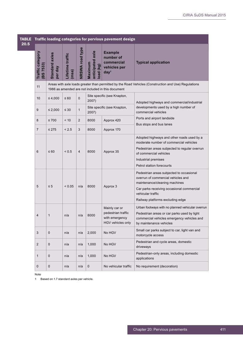
411Chapter 20: Pervious pavements
CIRIA SuDS Manual 2015
Note1 Basedon1.7standardaxlespervehicle.
TABLE20.5
Traffic loading categories for pervious pavement designTr
affic
cat
egor
y (B
S 75
33)
Stan
dard
axl
es
per d
ay
Life
time
traf
fic(m
sa)
NR
SWA
road
type
Max
imum
an
ticip
ated
axl
e lo
ad (k
g)
Example number of commercial vehicles per day1
Typical application
11AreaswithaxleloadsgreaterthanpermittedbytheRoadVehicles(ConstructionandUse)Regulations1986 as amended are not included in this document
10 ≤4,000 ≤60 0Sitespecific(seeKnapton,2007) Adoptedhighwaysandcommercial/industrial
developments used by a high number of commercial vehicles
Ports and airport landside
Bus stops and bus lanes
9 ≤2,000 ≤30 1Sitespecific(seeKnapton,2007)
8 ≤700 < 10 2 8000 Approx420
7 ≤275 <2.5 3 8000 Approx170
6 ≤60 < 0.5 4 8000 Approx35
Adoptedhighwaysandotherroadsusedbyamoderate number of commercial vehicles
Pedestrian areas subjected to regular overrun of commercial vehicles
Industrial premises
Petrol station forecourts
5 ≤5 < 0.05 n/a 8000 Approx3
Pedestrian areas subjected to occasional overrun of commercial vehicles and maintenance/cleaning machines
Car parks receiving occasional commercial vehiculartraffic
Railwayplatformsexcludingedge
4 1 n/a n/a 8000
Mainly car or pedestriantrafficwithemergencyHGVvehiclesonly
Urbanfootwayswithnoplannedvehicularoverrun
Pedestrian areas or car parks used by light commercial vehicles emergency vehicles and by maintenance vehicles
3 0 n/a n/a 2,000 NoHGVSmallcarparkssubjecttocar,lightvanandmotorcycle access
2 0 n/a n/a 1,000 NoHGVPedestrianandcycleareas,domesticdriveways
1 0 n/a n/a 1,000 NoHGVPedestrian-onlyareas,includingdomesticapplications
0 0 n/a n/a 0 Novehiculartraffic Norequirement(decoration)

CIRIA SuDS Manual 2015
412 Part D: Technical detail
No commercial vehicle traffic loading
Sitecategories0,1,2and3shouldonlybeselectedwhereitcanbeensuredthatnocommercialvehiclesusethepavement,forexamplewherebollardsorheightbarriershavebeeninstalled.
Indeterminingthesitecategory,theuseofthesurfaceofthepavementbyanyconstructiontrafficshouldbeassessedandallowedfor.
Pedestrian loading and maintenance vehicles
Openareasarenowbeingincreasinglymaintainedbymechanicalsweepersandothercollectionvehiclesthatcanhavesurprisinglyhighwheelloadingsandotherdetrimentaleffects(egsuctionsweepers)onpavedareas.Theiruseshouldbeassessedindeterminingthetrafficcategoryappropriatetoadoptforthedesign.
Amenity areas
Inareaswherethereisnopossibilityofvehicularaccess(egpatiosandprivategardenpaths),acategory0 or 1 design may be adopted
Site traffic
Wherethesiteistobeusedforconstructiontraffic,thelayertobeusedbythattrafficshouldbeofadequatestrengthfortheuse.Normallythecompletedbaseshouldbeadequate,butincaseofdoubt(egforalarge-scaledevelopment),anestimateofthetrafficshouldbemadeandapavementdesigncarriedout using current design guidance for bound or unbound pavements.
Inareasnotsubjecttocommercialvehicletraffic,thedesignshouldconsiderloadingduringconstructionandmaintenanceofadjacentareas,andothervehiclesthatmightaccessthearea,includingemergencyvehicles.Theiruseshouldbeallowedforinthedesign.
Design life
A20-yeardesignlifeshouldbegenerallyapplicable(structural)unlessaccessforpossiblemaintenanceofthebaseislikelytobedifficultorexpensive,inwhichcasealongerdesignlifemaybeadvisable.Wherethepavementservesafinitearea,zerogrowthintrafficislikelytobeapplicable.Ifcalculatedgrowthfiguresareavailable,theseshouldbeusedtoascertainthenumberofstandardaxles.
20.9.5 Structural design approaches
The philosophy for conventional (ie non-pervious) pavement design is that the sub-base and/or capping layerisonlyinfluencedbythestrengthofthesubgrade,withthethicknessoftheupperstructurallayers(baseandsurfacecourses)influencedbytrafficloadings.ThedesignmethodusedinBS7533-13:2009forconcreteblockpermeablepavingisdifferent,inthatthetrafficloaddoeshaveaninfluenceonthethicknessofthesub-baseand/orcappinglayer.Knaptonet al (2012)havecombinedthetwoapproachesforperviouspavementsandusedmaximumwheelloaddesignforlightlytraffickedareasofperviouspavingandaconventionalaxlefatigueapproachformoreheavilytraffickedpavements.TheyalsoextendedthescopeforperviouspavementstoheavydutyindustrialpavementsbyapplyingthedesignapproachproposedbyInterpave(Knapton,2007).
IntheUK,theestablisheddesignmethodologiesforflexiblepavementswitheitheranasphaltorhydraulicboundbasecanalsobeusedtodesignporousasphaltpavementsforheavilytraffickedroads(ChaddockandNunn,2010).StructuraldesignofpavementsismostimportantforthosesurfacesusedinareassubjecttoheavierormorefrequentHGVtraffic.
Analyticaldesignisbecomingmorewidelyacceptedinpavementengineeringandcanbeappliedtoperviouspavements.Analyticaldesignisaveryusefulapproach,whichallowstheuseofdifferentporousorpermeablematerials,anditshouldbeencouraged.However,itisvitalthatthematerialpropertiesassumed in the design are achieved during construction (eg the stiffness of concrete block permeable

413Chapter 20: Pervious pavements
CIRIA SuDS Manual 2015
pavingshouldreflectnormalconstructionpracticeandnotrelyonveryhighqualityworkmanship)andanappropriatesitetestingregimewillberequired.Also,thematerialsusedinconstructionshouldprovideallthe other necessary attributes (eg durability and providing suitable skid resistance). Most analysis uses asimplifiedmulti-layerlinearelasticmodel,althoughfiniteelementanalysiscanalsobeused(Knaptonet al,2012).Anelementofjudgementwillstillberequiredinthedesign,basedonexperienceoftheperformanceofdifferentmaterials.Thisapproachcanbeusedforawiderangeoftrafficconditions.IntheUSA,theICPI(2011)haspublishedadesignprogramforconcreteblockpermeablepavingcalledPermeableDesignPro.AlthoughthisisbasedonUSAdesignmethods,thereisnoreasonwhyitcannotbeappliedtoUKdesignofconcreteblockpermeablepaving.Oneofthekeydesignparametersinanalyticalapproachesisthestiffnessofthevariousmaterials,andvaluesareprovidedinTable 20.6.
TABLE20.6
Stiffness of various materials used in pervious surface construction
Material Stiffness Source
Porous asphalt2GPa ChaddockandNunn(2010)
3.2–7.1GPa Chopra et al (2011)
Porous concrete Range25–45GPa
Typical 38 GPa
Dynamicmodulus,ChaddockandNunn(2010)
Permeablesub-baseforusebelowall types of surfacing
93–138MPa
250–400MPa(butthesewouldneedreducingtoallowforsaturationby40–70%,whichinworstcasewouldgive100–160MPa)
ICPI(2011)
Shackel(2006)
Concrete block permeable pavers 1000–4500MPadependingontypeofblock Shackel et al(2000)
Resilientmodulusisameasureofstiffnessunderloadsthatareappliedquickly(suchastrafficloads).Shackel et al (2000)foundthattherewaslittledifferenceinresilientmodulusbetweenpermeableandnon-permeableversionsofblockpavingandalsobetweendifferentlayingpatterns.Pavershapewasfoundtohaveasignificantimpactofresilientmodulus.
Notethatwhenmeasuringthestiffnessofpermeablesub-basematerialsonsite,theyarelikelytoreturnlowervaluesthanwhenunconfinedonthesurface.Experience,analysis(Interpave,2007)andalsotesting(ChaddockandNunn,2010)haveshownthatonceconfinedbytheoverlyingpavementconstructionthestiffnesswillincrease.
20.9.6 Structural design considerations for different surface types
Thefollowingsectionsprovidespecificinformationonstructuraldesignforvarioussurfacingmaterials.
Grass reinforcement and resin bound materials
Thissectioncoversreinforcementgridsystemsthatareplasticorconcreteandinfilledwithgrassorgravel.Italsocoversresinboundmaterials.ThereisnorecognisedUKdesignstandardforthesetypesofperviouspavements.Oftendesignersrelyonrecommendationsmadebymanufacturers.However,the surfacing provides very little contribution to the load-bearing capacity of the pavement structure and therefore the sub-base thicknesses used for asphalt or CBPP can be applied to these types of surface (ICPI,2011).
ThesystemsareoftenusedwithnormalType1sub-basebelow(ienotforwaterstorage),inwhichcasestandardpavementdesignapproachesshouldbeused.Ifcoarse-gradedaggregateisusedbelowthesurfacestostorewater,thesub-basedepthsinTable 20.7 can be used. A capping layer or increased thicknessofcoarse-gradedaggregatemayberequiredwheretheCBRvaluesarelessthan5%.Whereusedwithcoarse-gradedaggregatesub-base,ageotextilewillberequiredbetweenthesandbedding/growinglayerandthesub-base,otherwisethesandwillbewasheddownintothesub-base.Thesesurface types are not recommended for load classes above site category 4.

CIRIA SuDS Manual 2015
414 Part D: Technical detail
The sections in Table 20.7applyinthecaseofsubgradesof5%CBRorgreater.ForpavementsoverlowerCBRvaluesthataretraffickedbyvehicles,thefollowingshouldbeprovided:
▪ 1%CBRsubgradeimprovementrequired(Section 20.9.3)
▪ 2%CBRsubgradeimprovementlayerrequired(maybeincorporatedintocappinglayertoprovideatotal layer thickness of 350 mm)
▪ 2.5%CBR300mmcapping
▪ 3%CBR225mmcapping
▪ 4%CBR150mmcapping
Thecappinglayerdesigncanalsoincorporategeogrid(s),whichmayreducetherequiredthicknessofmaterial.However,thesub-baseandcappinglayerthicknessmayneedincreasingtoallowforusebyconstruction vehicles.
Whenusedoveropen-gradedsub-basesuchasType3,ageotextileseparationlayerwillberequiredtopreventthesandinfill/beddinglayerfrombeingwashedintotheunderlyingsub-base.TrialsbyChaddockandJones(2007)haveshownthatgreatcareisneededinlappingthegeotextiletoensurethatwashoutdoesnotoccur.Itisrecommendedthatanoverlapofatleast500mmisprovided,andthatcareistakenattheedgestoensurethatlocalisedwashoutcannotoccur(lapthegeotextileupwardsattheedgesandsuitable folds at corners to contain the bedding sand).
Porous asphalt
Porous asphalt can be designed using analytical pavement design procedures using appropriate values ofresilientmodulusforthematerialsspecifiedinthepavement.Alternatively,theadviceinChaddockandNunn(2010)maybeusedtodesigntheporousasphaltlayers.Anotherapproachistocombinethesub-baseandotherlayerthicknessesspecifiedbyKnaptonet al(2012)butreplacetheconcreteblocksandbeddinglayerswithaporousasphaltlayer.ThislatterapproachisthebasisforTable 20.8. Further advice ontheuseofporousasphaltincarparksandprivatedrivesisprovidedbyMPA(2009).Detailedguidanceonsuitablemixturesshouldalwaysbeobtainedfromthesupplier.
The sections in Table 20.8applyinthecaseofsubgradesof5%CBRorgreater.ForpavementsoverlowerCBRvaluesthataretraffickedbyvehicles,thefollowingshouldbeprovided:
▪ 1%CBRsubgradeimprovementrequired(Section 20.9.3)
▪ 2%CBRsubgradeimprovementlayerrequired(maybeincorporatedintocappinglayertoprovideatotal layer thickness of 350 mm)
▪ 2.5%CBR300mmcapping
▪ 3%CBR225mmcapping
▪ 4%CBR150mmcapping
TABLE20.7
Typical construction thickness for grass reinforcement and resin bound materials over subgrade of 5% CBR or greaterTraffic category(BS 7533)
Grid Bedding layer Sub-baseCGA
4 Varies 50 mm 300 mm
3 Varies 50 mm 225mm
2 Varies 50 mm 150 mm
1 Varies 50 mm 100 mm
0 Varies 50 mmSufficienttoprovidesuitableconstruction base

415Chapter 20: Pervious pavements
CIRIA SuDS Manual 2015
Thecappinglayerdesigncanalsoincorporategeogrid(s),whichmayreducetherequiredthicknessofmaterial.However,thesub-baseandcappinglayerthicknessmayneedincreasingtoallowforusebyconstruction vehicles.
Notethatporousasphaltmaynotbesuitableasasurfacinginsomelocations(egpetrolforecourts,portsor bus stops) due to either the risk of degradation resulting from fuel spills or the nature of the risk of surfacedeformationresultingfromthepossiblerangeoftrafficforces.
Porous concrete
PorousconcreteisnotwidelyusedatpresentintheUK.However,itisusedintheUSA,wherecomprehensivedesignandconstructionguidanceisavailable(egACPA,2011,CRMCA,2009,ACI,2010).Astructuraldesign programme for pervious concrete pavement design is available from the ACPA (called PerviousPave)
TABLE20.8
Typical construction thickness for porous asphalt over subgrade with 5% CBR or greater
Traffic category(BS 7533)
Porous asphalt BaseHBCGA1
Sub-baseCGA2
11AreaswithaxleloadsgreaterthanpermittedbytheRoadVehicles(ConstructionandUse)Regulations 1986 as amended are not included in this document3
10Asphalt requires specialist consideration and specification
SitespecificusingInterpaveguide for heavy duty pavements(Knapton,2007)
150 mm
9Asphalt requires specialist consideration and specification
SitespecificusingInterpaveguide for heavy duty pavements(Knapton,2007)
150 mm
8DesignfollowingChaddockandNunn(2010)4
300 mm HBCGA 150 mm
7DesignfollowingChaddockandNunn(2010)
200mmHBCGA 150 mm
6180 mm
80 mm
–
125mmHBCGA
150 mm
150 mm
5160 mm
80 mm
–
100 mm HBCGA
150 mm
150 mm
4 150 mm – 300 mm
3 120mm – 225mm
2 70 mm (assumes hand lay) – 150 mm
1 70 mm (assumes hand lay) – 100 mm
0 70 mm (assumes hand lay)Sufficienttoprovidesuitable construction base
Note1 HBCGAreferstohydraulicallyboundcoarse-gradedaggregate(conformingtoBSEN14227-1:2013),minimumcementcontent
3%,strengthclassC5/6asdefinedinBSEN14227-1andminimumpermeability10,000mm/hrwhentestedinaccordancewithASTM C1701M-09 or other suitable test).
2 Thesub-baseCGAdepthsareminimumvaluesthatcorrespondwiththeequivalentthicknessesprovidedinTable 20.10 for modular surfacing.Thesub-baseCGAandanycappinglayercanalsobedesignedtoFoundationClass2inaccordancewithHA(2009).
3 Specialvehicles(SV)falloutsidetheRoadVehicles(ConstructionandUse)Regulations1986.SVvehiclescomplywiththeRoadVehicles(AuthorisationofSpecialTypes)(General)Order2003ortheIndividualVehicleSpecialOrders.Theyhavehigheraxleloadsandweightsandarecommonlyknownasabnormalloads.
4 TheChaddockandNunn(2010)reportwasbasedonapilotstudy.Thetablesinthereportshowingpavementdesignsforupto80msa(millionstandardaxels)areanextrapolationoftestdataandhavenotbeenvalidatedinfullsizeschemes.Ifdesignsarerequiredfortrafficcategory7andabove,specialistadviceshouldbeobtainedfromsuppliersaboutwhetherporousasphaltissuitableandtoprovideanappropriatespecification.

CIRIA SuDS Manual 2015
416 Part D: Technical detail
andthiscanbeadaptedtodesignporousconcretepavingforUKconditions.TheequationsusedintheprogrammeandthebackgroundinformationisprovidedbytheACPA(2011).Obla(2007)indicatesthatnumerousapplicationshaveuseda125–150mmthickperviousconcretelayerover150mmsub-base.FieldperformanceoftheseprojectshasshownthattheyareadequatetohandlethetrafficloadsexpectedincarparkswithmainlypassengercarswithveryoccasionalHGVs(trashtrucks).Whereheavierloadsandhighertrafficareexpected,thenUSexperiencesuggestsusingathickerlayerofporousconcrete(200–300mm).
Porousconcreteisanear-zero-slump,open-gradedmaterialconsistingofportlandcement,coarseaggregate,admixturesandwater.Ithaslittleornofineaggregate(ACI,2010).Thecombinationoftheseingredientswillproduceahardenedmaterialwithconnectedpores,2–8mminsize,whichshouldallowwatertopassthrougheasily.Theporositycanbe15–35%,withtypicalcompressivestrengthsof(2.8–28MPa).Porousconcreteislaidasaplainconcreteslabwithoutreinforcement.
Recommended concrete and sub-base CGA thicknesses are provided in Table 20.9.
TABLE20.9
Typical construction thickness for porous concrete over subgrade with 5% CBR or greater
Traffic category(BS 7533)
Porous concrete (plain slab) Sub-baseCGA
11AreaswithaxleloadsgreaterthanpermittedbytheRoadVehicles(ConstructionandUse)Regulations 1986 as amended are not included in this document
10 Sitespecificdesign
9 Sitespecificdesign
8 Sitespecificdesign
7 Sitespecificdesign
6 Sitespecificdesign
5 150 mm 300 mm
4 135 mm 300 mm
3 125mm 225mm
2 125mm 150 mm
1 100 mm 100 mm
0 100 mmSufficienttoprovidesuitableconstruction base
The sections in Table 20.9applyinthecaseofsubgradesof5%CBRorgreater.ForpavementsoverlowerCBRvaluesthataretraffickedbyvehicles,thefollowingshouldbeprovided:
▪ 1%CBRsubgradeimprovementrequired(Section 20.9.3)
▪ 2%CBRsubgradeimprovementlayerrequired(maybeincorporatedintocappinglayertoprovideatotal layer thickness of 350 mm)
▪ 2.5%CBR300mmcapping
▪ 3%CBR225mmcapping
▪ 4%CBR150mmcapping
Thecappinglayerdesigncanalsoincorporategeogrid(s),whichmayreducetherequiredthicknessofmaterial.However,thesub-baseandcappinglayerthicknessmayneedincreasingtoallowforusebyconstruction vehicles.
The designs in Table 20.10havebeenassessedusingACPA(2011)assuminga40-yeardesignlife,0%growth,resilientmodulusofsub-baseCGAis110MPaand28-dayflexuralstrengthofporousconcreteis2.8MPa.ForCBRlessthan5%usethefactorsabovetoincreasecappinglayerthicknessordesignusingACPA(2011).

417Chapter 20: Pervious pavements
CIRIA SuDS Manual 2015
BecausethereiscurrentlynotrackrecordofusingporousconcreteintheUK,itisrecommendedthatexpertadviceisobtainedtoundertakesitespecificdesignsforsitecategories6–10.
Modular surfacing (including concrete block permeable paving)
Thiscanbeusedforawiderangeoftrafficconditionsfromlighttoveryheavydutypavements.BS7533-13:2009providesstandardthicknessesforthepavementlayers,althoughthesecanbeadjustedifmaterialswithadifferentstiffnessareusedfollowingtheapproachdescribedbyKnaptonet al(2012)orusingtheICPI(2011)designapproach.
The structural design of CBPP suggested in Table 20.10 has been developed from the approach of Knaptonet al(2012).Theirapproachisbasedonacombinationoffiniteelementanalysisofstaticwheelloadsandanalysisoffull-scaletestresults.ThemaindifferencebetweenTable 20.12andtheKnaptonet al(2012)approachisthatthetableprovidesthesameconstructionthicknessforallofTypesA,BandCpavements.ThisisbecauseanyeffectofinfiltratingwatershouldhavebeentakenaccountofwhenchoosingthedesignCBRvalue.Ingeneral,TypesAandBpavementswillresultinlowerdesignCBRvaluesbecauseofthepresenceofwaterincontactwiththesubgrade.Thewaterproofinglayerandsandprotectionlayer(orgeotextileprotection)providedinTypeCsystemsdonothaveanyinfluenceonthestructural design and therefore are not included in the table for structural design.
ThedesignlayerthicknesshasbeencheckedusingtheguidanceprovidedbytheICPI(2011).Thisapproachmakesassumptionsaboutthedefaultpropertiesofthematerialsusedineachlayer,whicharesummarised in Table 20.11.

CIRIA SuDS Manual 2015
418 Part D: Technical detail
The sections in Table 20.10applyinthecaseofsubgradesof5%CBRorgreater.ForpavementsoverlowerCBRvaluesthataretraffickedbyvehicles,thefollowingshouldbeprovided(fromKnaptonet al,2012):
▪ 1%CBRsubgradeimprovementrequired(Section 20.9.3)
▪ 2%CBRsubgradeimprovementlayerrequired(maybeincorporatedintocappinglayertoprovideatotal layer thickness of 350 mm)
▪ 2.5%CBR300mmcapping
TABLE20.10
Typical construction thickness for modular paving over subgrade with 5% CBR or greater
Traffic category
Type of surface – minimum thickness
Bedding layer nominal thickness
Base HBCGA1
(porous) or AC (cored)
Sub-baseCGA2
Design basis
Concrete/clay
blocks
Natural stone slab
Concrete flag
Setts
11AreaswithaxleloadsgreaterthanpermittedbytheRoadVehicles(ConstructionandUse)Regulations 1986 as amended are not included in this document3
10SitespecificusingInterpaveguideforheavydutypavements(Knapton,2007)
Knapton(2007)
9SitespecificusingInterpaveguideforheavydutypavements(Knapton,2007)
Knapton(2007)
8 80 mm
Seek advice from supplier
50 mm300 mm HBCGA or 220mmAC32
150 mm
ICPI (2011)
7 80 mm 50 mm200mmHBCGA or 130 mmAC32
150 mm
6 80 mm 50 mm125mmHBCGA or 90 mmAC32
150 mm
5 80 mm 50 mm100 mm HBCGA or 70 mmAC32
150 mm
4 80 mm 50 mm – 300 mm Knapton et al (2012)and ICPI (2011)
3 60 mm 50 mm – 225mm
2 60 mm 50 mm – 150 mm
1 60 mm 50 mm – 100 mm
0 60 mm 50 mm
Sufficientto provide suitable construction base
Note1 HBCGAreferstohydraulicallyboundcoarse-gradedaggregate(conformingtoBSEN14227-1:2013),minimumcementcontent
3%,strengthclassC5/6asdefinedinBSEN14227andminimumpermeability10,000mm/hrwhentestedinaccordancewithASTM C1701M-09 or other suitable test).
2 Thesub-baseCGAdepthsareminimumvaluesthatcorrespondwiththethicknessgivenbyKnaptonet al(2012)orfromcalculationsusingICPI(2011).Thesub-baseCGAandanycappinglayercanalsobedesignedtoFoundationClass2inaccordancewithHA(2009).
3 Specialvehicles(SV)falloutsidetheRoadVehicles(ConstructionandUse)Regulations1986.SVvehiclescomplywiththeRoadVehicles(AuthorisationofSpecialTypes)(General)Order2003ortheIndividualVehicleSpecialOrders.Theyhavehigheraxleloadsandweightsandarecommonlyknownasabnormalloads.

419Chapter 20: Pervious pavements
CIRIA SuDS Manual 2015
TABLE20.11
Properties assumed in generic concrete block permeable paving design in Table 20.10
Material Elastic modulus (MPa) Structural layer coefficient for use in ICPI (2011)
Poisson’s ratio
Permeable pavers on a 50 mm bedding layer that meets requirements ofBS7533-13:2009
1000 (based on Shackel et al,2000).
NotethatevidencefromKnapton(2008)is that the modulus of the surface layer has very little effect on the predicted stress on the subgrade and performance of the pavement.
Increasing elastic modulus values of the surface layer to justify a reduction in pavement depth is not normally recommended,asitrequiresextremelyhighconstructionquality,andthereisnoguaranteethatallthejointswillbecompletely full of jointing material for the life of the pavement to maintain an elevated elastic modulus.
0.3 0.40
AC32 6000 0.3–0.44 0.30
HBCGA (hydraulically-bound CGA) meets requirements of cement bound material category 3 (CBGM3) clause 800 series(DfT,1998)
4000 0.24 0.25
Sub-base–coarsegraded aggregate in accordancewithBS7533-13:2009
1000
Notethatthemainfactorthataffectsstiffness is not the Los Angeles test (LA test) value but the grading and angular nature of the particles
0.09 0.35
5%CBRsubgrade 50 n/a 0.45
▪ 3%CBR225mmcapping
▪ 4%CBR150mmcapping
Thecappinglayerdesigncanalsoincorporategeogrid(s)whichmayreducetherequiredthicknessofmaterial.However,thesub-baseandcappinglayerthicknessmayneedincreasingtoallowforusebyconstruction vehicles.
ACreferstoasphaltconcrete(AC32dense40/60designedinaccordancewithBSEN13108-1:2006.
Forloadclass5andabove,concreteblockpermeablepavingshouldonlybelaidinaherringbonepattern.
NoteforinfiltrationTypeAsystemsthecappinglayermaterialshouldbesufficientlypermeabletoallowwatertopercolatethroughit,withoutitlosingstrength.Itshouldalsohaveaninfiltrationratethatisgreaterthanthematerialbelowit.Itshouldalsobesufficientlydurableandwear-resistant.Alternatively,anincreasedthicknessofcoarse-gradedaggregatecanbeused.Thegradingfor6F2capping(DfT,1998)canbemodifiedtoreducetheamountoffinesandmakeitmorepermeable(ielessthan5%passingthe63micronssieveand0–25%bymasspassingthe600micronssieve).Thishasbeenusedsuccessfullybelowinfiltratingpavements.
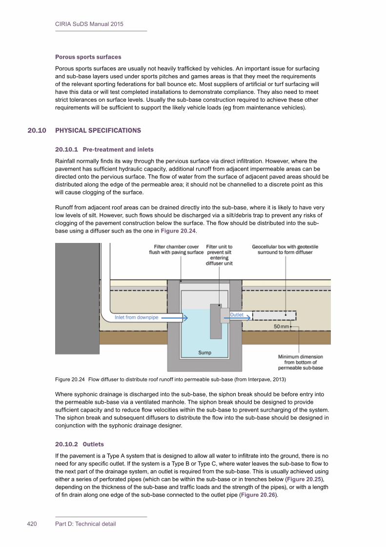
CIRIA SuDS Manual 2015
420 Part D: Technical detail
Porous sports surfaces
Poroussportssurfacesareusuallynotheavilytraffickedbyvehicles.Animportantissueforsurfacingand sub-base layers used under sports pitches and games areas is that they meet the requirements oftherelevantsportingfederationsforballbounceetc.Mostsuppliersofartificialorturfsurfacingwillhavethisdataorwilltestcompletedinstallationstodemonstratecompliance.Theyalsoneedtomeetstricttolerancesonsurfacelevels.Usuallythesub-baseconstructionrequiredtoachievetheseotherrequirementswillbesufficienttosupportthelikelyvehicleloads(egfrommaintenancevehicles).
20.10 PHYSICAL SPECIFICATIONS
20.10.1 Pre-treatment and inlets
Rainfallnormallyfindsitswaythroughthepervioussurfaceviadirectinfiltration.However,wherethepavementhassufficienthydrauliccapacity,additionalrunofffromadjacentimpermeableareascanbedirectedontothepervioussurface.Theflowofwaterfromthesurfaceofadjacentpavedareasshouldbedistributedalongtheedgeofthepermeablearea;itshouldnotbechannelledtoadiscretepointasthiswillcausecloggingofthesurface.
Runofffromadjacentroofareascanbedraineddirectlyintothesub-base,whereitislikelytohaveverylowlevelsofsilt.However,suchflowsshouldbedischargedviaasilt/debristraptopreventanyrisksofcloggingofthepavementconstructionbelowthesurface.Theflowshouldbedistributedintothesub-base using a diffuser such as the one in Figure 20.24.
Wheresyphonicdrainageisdischargedintothesub-base,thesiphonbreakshouldbebeforeentryintothe permeable sub-base via a ventilated manhole. The siphon break should be designed to provide sufficientcapacityandtoreduceflowvelocitieswithinthesub-basetopreventsurchargingofthesystem.Thesiphonbreakandsubsequentdiffuserstodistributetheflowintothesub-baseshouldbedesignedinconjunctionwiththesyphonicdrainagedesigner.
20.10.2 Outlets
IfthepavementisaTypeAsystemthatisdesignedtoallowallwatertoinfiltrateintotheground,thereisnoneedforanyspecificoutlet.IfthesystemisaTypeBorTypeC,wherewaterleavesthesub-basetoflowtothenextpartofthedrainagesystem,anoutletisrequiredfromthesub-base.Thisisusuallyachievedusingeitheraseriesofperforatedpipes(whichcanbewithinthesub-baseorintrenchesbelow(Figure 20.25),dependingonthethicknessofthesub-baseandtrafficloadsandthestrengthofthepipes),orwithalengthoffindrainalongoneedgeofthesub-baseconnectedtotheoutletpipe(Figure 20.26).
Figure20.24 Flowdiffusertodistributeroofrunoffintopermeablesub-base(fromInterpave,2013)
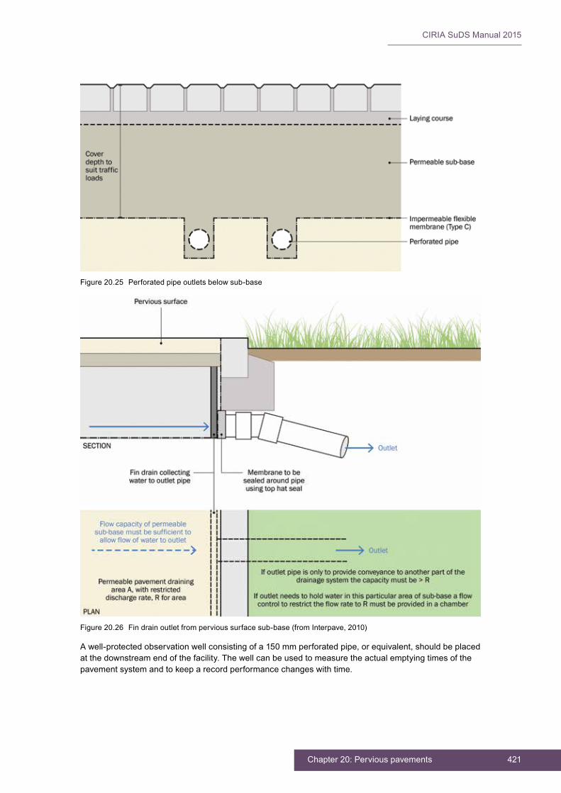
421Chapter 20: Pervious pavements
CIRIA SuDS Manual 2015
Awell-protectedobservationwellconsistingofa150mmperforatedpipe,orequivalent,shouldbeplacedatthedownstreamendofthefacility.Thewellcanbeusedtomeasuretheactualemptyingtimesofthepavementsystemandtokeeparecordperformancechangeswithtime.
Figure20.25 Perforatedpipeoutletsbelowsub-base
Figure20.26 Findrainoutletfrompervioussurfacesub-base(fromInterpave,2010)

CIRIA SuDS Manual 2015
422 Part D: Technical detail
20.11 MATERIALS
The sub-base beneath pervious surfacing systems has a large proportion of interconnected voids throughwhichwatercanmovefreelyandcanalsobestored.Thismaterialisdifferentfromastandardpavementsub-baseandhastobespecifiedsothatithassufficientpermeability,porosity,strengthandresistance to abrasion.
Thissectionprovidesspecificationsforsomeofthekeyelementsofpervioussurfacessuchasbeddingandjointingmaterialandsub-base.Itdoesnotprovideacomprehensivespecificationforallelementsthat are required to meet recognised standards (eg the concrete blocks in concrete block permeable paving should meet all the same performance standards as normal concrete blocks).
20.11.1 Bedding layer and jointing material for concrete block permeable paving
Beddingandjointingmaterialneedstobefree-drainingandhavesufficientdurabilitytoresistwearfromsmallmovementsbetweenblocks.AtypicalgradingspecificationisgiveninTable 20.12,butadviceshouldalwaysbesoughtfromtheperviouspavementmanufacturerwithregardtotheexactmaterialtypethatissuitableforeachsystem.Thejointingmaterialinsomesystemsmayhavesmaller,3mmparticlesifthejointsbetweenblocksaresmaller.
ThematerialshouldalsomeetthedurabilityrequirementsinBS7533-13:2009(Section 20.11.4).
20.11.2 Sand infill and bedding layer for grass reinforcement
Sandinfilltoreinforcedgrasssystemsneedstobefree-drainingbutwithsufficientorganiccontentto support plants. A root zone material (Chapter 30)issuitable,andtherearealsomanyothermixesrecommendedbysuppliersofthegrids.Normaltopsoilisnotsuitable.
20.11.3 Geotextile filter characteristics
Geotextilesthatactasfiltersshouldallowfreeflowofwater,thatiswithzerobreakthroughhead.Theyshouldbemanufacturedfrompolyethylene,polypropyleneorothersuitablemonofilamentthatcanwithstandtheloadsappliedduringconstructionandshouldhaveadesignlifeequivalenttothepavementdesignlife.Theyshouldnotbeadverselyaffectedbypollutants,alkalineoracidicgroundwater.
Geotextilesplacedhighinthepavementconstruction(egbetweenthebeddinglayerandsub-baseofCBPP) are subject to higher stresses than those deeper in the construction (eg at the bottom of the sub-base). This needs to be evaluated and considered in the design.
FurtherguidanceongeotextilesisgiveninChapter 30.
20.11.4 Sub-base aggregate characteristics
Thesub-baseshouldhaveaminimumporositythatisconsistentwiththedesigncalculations(normallyatleast30%).Thesub-baseshouldalsohaveaminimumpermeabilityof6×10−2m/swhentestedinaccordancewithHA(1990).
TABLE20.12
Bedding and jointing layer specification (2/6.3 to BS 7533-13:2009)
BS sieve size (mm) Percentage passing
14 100
10 90–100
6.3 80–99
2.0 0–20
1.0 0–5
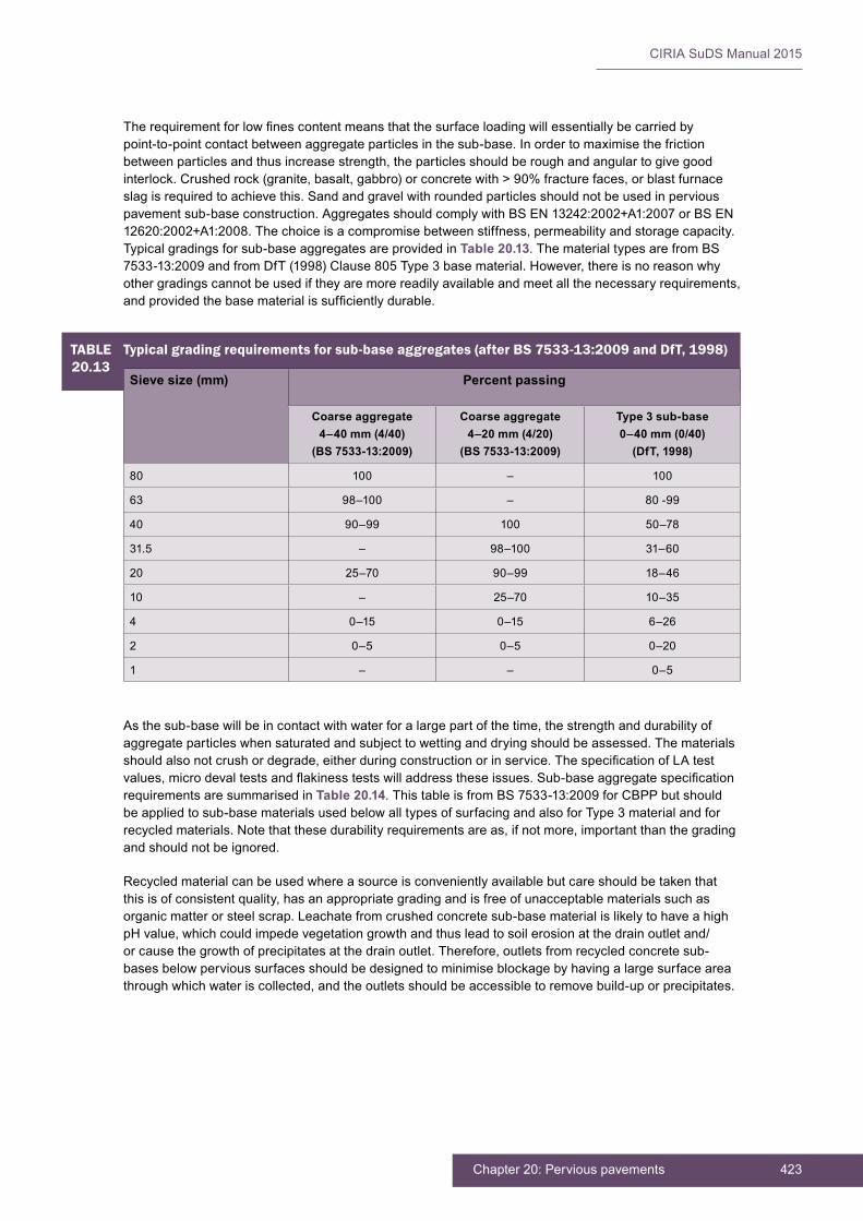
423Chapter 20: Pervious pavements
CIRIA SuDS Manual 2015
TABLE20.13
Typical grading requirements for sub-base aggregates (after BS 7533-13:2009 and DfT, 1998)
Sieve size (mm) Percent passing
Coarse aggregate4–40 mm (4/40)
(BS 7533-13:2009)
Coarse aggregate4–20 mm (4/20)
(BS 7533-13:2009)
Type 3 sub-base0–40 mm (0/40)
(DfT, 1998)
80 100 – 100
63 98–100 – 80 -99
40 90–99 100 50–78
31.5 – 98–100 31–60
20 25–70 90–99 18–46
10 – 25–70 10–35
4 0–15 0–15 6–26
2 0–5 0–5 0–20
1 – – 0–5
Therequirementforlowfinescontentmeansthatthesurfaceloadingwillessentiallybecarriedbypoint-to-pointcontactbetweenaggregateparticlesinthesub-base.Inordertomaximisethefrictionbetweenparticlesandthusincreasestrength,theparticlesshouldberoughandangulartogivegoodinterlock.Crushedrock(granite,basalt,gabbro)orconcretewith>90%fracturefaces,orblastfurnaceslagisrequiredtoachievethis.Sandandgravelwithroundedparticlesshouldnotbeusedinperviouspavementsub-baseconstruction.AggregatesshouldcomplywithBSEN13242:2002+A1:2007orBSEN12620:2002+A1:2008.Thechoiceisacompromisebetweenstiffness,permeabilityandstoragecapacity.Typical gradings for sub-base aggregates are provided in Table 20.13. The material types are from BS 7533-13:2009andfromDfT(1998)Clause805Type3basematerial.However,thereisnoreasonwhyothergradingscannotbeusediftheyaremorereadilyavailableandmeetallthenecessaryrequirements,andprovidedthebasematerialissufficientlydurable.
Asthesub-basewillbeincontactwithwaterforalargepartofthetime,thestrengthanddurabilityofaggregateparticleswhensaturatedandsubjecttowettinganddryingshouldbeassessed.Thematerialsshouldalsonotcrushordegrade,eitherduringconstructionorinservice.ThespecificationofLAtestvalues,microdevaltestsandflakinesstestswilladdresstheseissues.Sub-baseaggregatespecificationrequirements are summarised in Table 20.14.ThistableisfromBS7533-13:2009forCBPPbutshouldbeappliedtosub-basematerialsusedbelowalltypesofsurfacingandalsoforType3materialandforrecycledmaterials.Notethatthesedurabilityrequirementsareas,ifnotmore,importantthanthegradingand should not be ignored.
Recycledmaterialcanbeusedwhereasourceisconvenientlyavailablebutcareshouldbetakenthatthisisofconsistentquality,hasanappropriategradingandisfreeofunacceptablematerialssuchasorganic matter or steel scrap. Leachate from crushed concrete sub-base material is likely to have a high pHvalue,whichcouldimpedevegetationgrowthandthusleadtosoilerosionatthedrainoutletand/orcausethegrowthofprecipitatesatthedrainoutlet.Therefore,outletsfromrecycledconcretesub-basesbelowpervioussurfacesshouldbedesignedtominimiseblockagebyhavingalargesurfaceareathroughwhichwateriscollected,andtheoutletsshouldbeaccessibletoremovebuild-uporprecipitates.

CIRIA SuDS Manual 2015
424 Part D: Technical detail
Notethatboththeresistancetowearandresistancetofragmentationareimportant.TheLAtestisanindicationoftheresistancetofragmentationandcanonlybecarriedoutondryaggregate.TheMicro-Devaltest(MDtest)measurestheresistancetoabrasionwheninterlockingparticlesaresubjecttorepeatedloadinginthepresenceofwaterwhichisanimportantpropertyforsub-basesbelowperviouspavements.
Impermeable membrane characteristics
Thesearetypicallymanufacturedfromhighdensitypolyethylene(HDPE),polypropyleneorethylenepropylenedienemonomerrubber(EPDM)andshouldbe:
▪ durable,robustandabletowithstandconstructionandoperationalloads
▪ resistanttopuncture,multi-axialstressesandstrainsassociatedwithmovementandenvironmentalstresscracking(orprotectedbygeotextileorsandlayersaboveandbelowasrequired–thegreatestrisk of puncture is often from the sub-base material laid on top of the membranes)
▪ unaffected by potential pollutants
▪ installedwithfullywatertightjointsanddischargeoutlets.Weldedjointsshouldbetestedtoensurethe integrity of the system and provide a more robust jointing method. The membrane should be able to resist the punching stresses caused by sharp points of contact from the aggregate sub-base.Itshouldalsohavesufficientstrengthtoresisttheimposedtensileforcesfromtrafficorotherloading.Wheretherisksassociatedwithpunctureareparticularlyhigh,considerationcanbegiventoprotectingmembraneswithgeotextilefleeces.
FurtherguidanceongeomembranesandgeotextilesisgiveninChapter 30.
TABLE20.14
Sub-base aggregate specification requirements (after BS 7533-13:2009)
Properties Category toBS EN 13242:2002 or BS 12620:2002
Grading Grading4/40,Gc85-15,GTc20/17.5
Fines content f4
Shape FI20
Resistance to fragmentation LA30
Durability:
▪ waterabsorptiontoBSEN1097-6:2000,Clause7
▪ forWA.2%,magnesiumsulphatesoundness
WA242
MS18
Resistancetowear MDE20
Acid-solublesulphatecontent:
▪ aggregates other than air-cooled blast-furnace slag
▪ air-cooled blast-furnace slag
AS0.2
AS1.0
Totalsulphur:
▪ aggregates other than air-cooled blast-furnace slag
▪ air-cooled blast-furnace slag
≤1%bymass
≤2%bymass
Volumestabilityofblast-furnaceandsteelslags:
▪ air-cooled blast-furnace slag
▪ steel slag
Free from dicalcium silicate and iron disintegration (BSEN13242:2002,6.4.2.2)
V5
Leaching of contaminants
Blast furnace slag and other recycled materials should meet the requirements of the Environment Agency WasteAcceptanceCriteria(WAC)forinertwastewhenleachatetestedinaccordancewithBSEN12457-3:2002
425Chapter 20: Pervious pavements
CIRIA SuDS Manual 2015
Porous asphalt
ExamplespecificationrequirementsforporousasphaltareprovidedbyKorkealaakso(2014).
Thesurfaceinfiltrationrate(orpermeability)forporousasphaltquotedbyKorkealaakso(2014)arebasedonmeasurementusingthetestmethoddescribedinSeries900ofDfT(1998).However,itisrecommendedthatforconsistencyinfuture,thesurfacepermeabilityofporousasphaltismeasuredusingthesamemethodasporousconcretefromASTMC1701M-09,althoughthespecificationlimitswouldrequireamendingtoreflectthedifferenttestmethod.
Porous concrete
AspecificationforporousconcreteisprovidedbyCRMCA(2009).
Thekeyrequirementsare:
▪ compressivestrength–specifiedbypavementdesigner,typicallybetween3MPaand27MPa(FHA,2012)
▪ cementcontent267–326kg/m3
▪ porosity15–25%
▪ water:cementratio0.26–0.35.
AlsototherequirementsintheCRMCAspecificationitisrecommendedthatthesurfaceinfiltrationrateisaminimumof250mm/hwhenmeasuredinaccordancewithASTMC1701M-09.
20.12 LANDSCAPE DESIGN AND PLANTING
Permeablepavementsdonotoftensupportvegetationaspartofthesurfacing(exceptforgrassreinforcedpavements),butthelandscapecanbedesignedandintegratedeitheraroundtheedgeofpavementsystems,orinzoneswithinthepavementsurfacelayout.
Iftreesorwoodyshrubsaredesired,theyshouldbecarefullyselected.Iftreesandshrubsareplantedclosetopermeablepavingitmayrequiremoreregularsweepingtomaintainthesurfaceinfiltrationrate,althoughthisisnotlikelytobeexcessive.
Permeablepavementsareanexcellentformofconstructionneartrees,becausetheyallowairandwatertoenterthesoil,whichisbeneficialtotreegrowth.Iftreerootshavesufficientwaterandairinthesoil,they are unlikely to damage the permeable pavement construction.
Wheregrassisanintrinsicpartoftheporoussurface(egFigure 20.8),itshouldbeestablishedbeforetrafficking,andthesurfaceshouldbekeptfreeofsedimentuntilthegrassisestablished.Thechoiceofgrassisimportant,anditshouldhaveahightolerancetowearanddrought,andalowtendencytothatchbuild-up(forplantingguidance,seeChapter 29).Wherereinforcedgrassisused,itisimportanttomakesurethattheinfillsoilislowerthanthegrids.
Whereverpossible,itissuggestedthatareasinandaroundperviouspavementsshouldhaveatopsoillevelthatisatleast50mmbelowthetopofthekerbadjacenttotheperviouspavement.Preferably,theareasshouldslopeawayfromtheperviouspavement(Figure 20.27).Whereareasdrainontoaperviouspavement,theirsurfacesshouldbestabilisedsothatthemobilisationofsiltandotherfinedebrisisminimised.
Ifthiscannotbeachieved(buttherearemanyexamplesofpermeablepavingworkingsatisfactorilynexttostandardlandscapes),theriskofcloggingshouldbeminimisedthroughmorefrequentsweepingregimes.Therequiredfrequencyofsweepingshouldbeestablishedthroughvisualmonitoringofthesurface,particularlyfollowingintenserainfall.
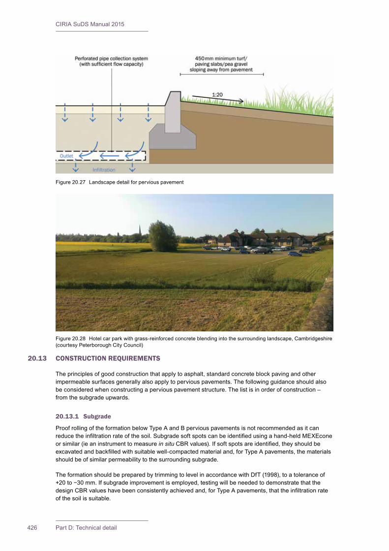
CIRIA SuDS Manual 2015
426 Part D: Technical detail
Figure20.27 Landscapedetailforperviouspavement
Figure20.28 Hotelcarparkwithgrass-reinforcedconcreteblendingintothesurroundinglandscape,Cambridgeshire(courtesy Peterborough City Council)
20.13 CONSTRUCTION REQUIREMENTS
Theprinciplesofgoodconstructionthatapplytoasphalt,standardconcreteblockpavingandotherimpermeablesurfacesgenerallyalsoapplytoperviouspavements.Thefollowingguidanceshouldalsobeconsideredwhenconstructingaperviouspavementstructure.Thelistisinorderofconstruction–fromthesubgradeupwards.
20.13.1 Subgrade
ProofrollingoftheformationbelowTypeAandBperviouspavementsisnotrecommendedasitcanreducetheinfiltrationrateofthesoil.Subgradesoftspotscanbeidentifiedusingahand-heldMEXEconeor similar (ie an instrument to measure in situCBRvalues).Ifsoftspotsareidentified,theyshouldbeexcavatedandbackfilledwithsuitablewell-compactedmaterialand,forTypeApavements,thematerialsshould be of similar permeability to the surrounding subgrade.
TheformationshouldbepreparedbytrimmingtolevelinaccordancewithDfT(1998),toatoleranceof+20to−30mm.Ifsubgradeimprovementisemployed,testingwillbeneededtodemonstratethatthedesignCBRvalueshavebeenconsistentlyachievedand,forTypeApavements,thattheinfiltrationrateof the soil is suitable.

427Chapter 20: Pervious pavements
CIRIA SuDS Manual 2015
TheformationbelowTypeApavementsshouldbeprotectedfromanyoperationsthatcouldreducetheinfiltrationrateofthesoil(egheavyconstructiontraffic,stockpilingfinematerials,mixingconcreteonit).
20.13.2 Geomembrane and/or geotextile
Anyimpermeablemembraneshouldbecorrectlyspecified,installedandtreatedwithcaretoensurethatit is not damaged during construction (Chapter 30).
Geotextilesshouldbelaidinaccordancewithmanufacturers’instructionsandwithoverlapsbetweenadjacentstripsof300mmwithoutanyfoldsorcreases.Itisrecommendedthatspecialistadvicebesoughtfromthemanufacturerorsupplierofthegeosyntheticfilter(Section 20.11.3).
20.13.3 Capping layer and sub-base
Thefinesinaconventionalimpermeablematerialhelptobindthedifferentsizeparticlestogether,andacttorestrictthepassageofwater.Inthecaseofperviouspavementmaterials(whichlackfines),thereispotential for segregation of materials during the transportation and construction process. Care should be takentoavoidsegregation,butthematerialshouldbeturnedoverbyanexcavatorifthisoccurs.Theriskofsegregationcanbeminimisedbyusinganangular,crushedmaterialwithhighsurfacefriction.
Thelackoffinesandtheopenmatrixstructurecanresultinsurfacemovementwhenconstructiontrafficpassesoverthesub-base,anditcanbemoredifficulttoformtotherequiredgrades.Thismovementcanbeminimisedbyblindingthesurfacewithalayingcourseorothersmallersizeaggregatetofillinthevoidsat the surface and stabilise it. The depth of the sub-base should be adjusted to include this blinding layer.
Thesub-baseshouldbelaidin100–150mmlayersandcompactedtoensurethatthemaximumdensityisachievedfortheparticularmaterialtypeandgrading,withoutcrushingtheindividualparticles,orreducingtheporositybelowthedesignvalue.Thereshouldbeatoleranceof+20to−15mmonthedesignsurfacelevelofthesub-baselayer.Compactionwithvibratingrollerscanbedifficult,asitresultsinmovementofthesurfaceandoftendead-weightrollersaremoreeffective.Sitetrialsarethebestwayto determine the appropriate compaction method.
Oncelaid,thesub-baseshouldnotbetrafficked.This is to prevent it rutting and also to prevent it cloggingwithmudandotherconstructionmaterials.Ifithastobetrafficked,itshouldbeprotectedusingoneofthefollowingmethods:
▪ alayerofDBMthatcanthenbeallowedforas part of the structural design of pavement (Section 20.9)–thisshouldbepuncturedwith75mmdiameterholes,onanorthogonalgridof 750 mm (Figure 20.29)
▪ ageotextileandsacrificialaggregatelayer–removedbeforelayingfinalblockwork
▪ forTypeCpavementsonly,anormalcappinglayer for construction and then construct the pervious surface once its use as a construction surface is no longer required.
Base
HBCGAshouldnotbemixedinconcretemixerson site. It needs to be produced in batching plants ormixedatthequarry.Carefulmixingisrequiredbecauseofthelowcementcontent,andthereisaneed to ensure that it is evenly spread throughout
Figure20.29 LayerofprotectiveDBMoversub-baseafter coring and before laying concrete block permeable paving (courtesy Peterborough City Council)

CIRIA SuDS Manual 2015
428 Part D: Technical detail
thematerialandnotsegregated.LayingHBCGAshouldnotbecarriedoutinweatherthatistoohot,orinheavyrain.TheguidanceprovidedbyACPA(2011)onlayingporousconcretesurfacingshouldbefollowedasitisapplicabletoHBCGA.
AsphaltbasematerialsshouldbelaidinaccordancewithDfT(1998).
Surfacing
Generally,concreteblockpavementsshouldbeconstructedinaccordancewithcurrentindustryguidancesuchasthatprovidedbyUK-basedmanufacturerandcontractorassociations(egInterpaveandInterlay).Adviceshouldbesoughtfromthespecificmanufactureronanyproduct-specificrequirements,layingandjointingmaterials,blockpatternsandblocklayingprocedures.Inaccordancewithgoodpractice,theblocksurfacelayershouldbefullycompactedandjointedtowithin1mofthelayingfaceattheendofeach day. Other pavement surfaces should be constructed according to the relevant British Standards and/orthemanufacturer’sguidance.
Once concrete blocks are laid on the screeded bedding layer they should be vibrated into the bedding layer.Thiscausesgrittofillthelowerpartofthejoints.Gritshouldbebrushedintothetopofthejointsandtheblocksvibratedagain.Theremaybesettlementofgritinthejointsoverthefirstfewmonthsofuseanditiswisetoallowfortheblockstobegrittedagainafterafewmonthsinservice.
Porous concrete used as a surfacing may need joints forming in it. The ACPA recommends that the joints arenotformedbysawcutting,asthisleadstodust-blockingoftheadjacentareasofsurfacing.Thejointsshould be formed using a “pizza cutter” roller before the concrete has set. Compaction of the porous concrete (and HBCGA) should be undertaken using rollers and not vibrating plate compactors.
PorousasphaltshouldbelaidinaccordancewithDfT(1998).
Resin-boundgravelshouldbelaidinaccordancewiththemanufacturer’srecommendations.
Forgrassreinforcementsystems,thebeddingsandthicknessshouldbekepttoaminimum.Amaximumthicknessof20mmisrecommended.Itisdifficulttocutgrassreinforcementsystemsofanykindtofitcomplicatedshapeswithoutlossofintegrity.Thisshouldbeconsideredinthedesignandconstruction.Thegrassgridsshouldnotbeoverfilledwithsoilbecauseitleadstocompaction,andthegrasswillnotgrow.Atleast25mmdepthshouldbeleftbetweenthetopofthegridandtheinfillsoil.Foroptimumvegetationcoveragethepaverorgridneedstohaveinexcessof30%ofitsareaavailableforgrassgrowth.Concretepaverscanbeheavyandmayneedtobemachinelaid.Unlessproduct-specificskidresistancedataisavailable,theyshouldonlybeusedinlow-speedsituations.Sometimesconcretegrassgridswillcrackduetounevensupportinthebeddingsandorsub-base,butonceitiscracked,thepaverwillbedintothesandandwillusuallycontinuetoprovidesupporttotraffic.Plasticgridsneedexpansionjointsorallowanceformovementintheconstructionastheycanexpandandbuckleinhotweather.
Preventingsoilandmudandothercontaminantsfromenteringthepavementsurface,sub-baseandsubgrade,bothduringandafterconstruction,isimperativetoensurethatthepavementremainspermeablethroughoutitsdesignlife.Constructionequipmentshouldbekeptawayfromthearea,andsiltfences,stagedexcavationworksandtemporarydrainageswales(whichdivertrunoffawayfromthearea)should all be considered to manage these risks. Landscaping activities should be carefully designed andcarriedouttopreventdepositionoftopsoil,turfandothermaterialsonthesurfaceofthepavement.Infiltrationsurfacesshouldnotbecompactedandshouldbeprotectedatalltimes.
Further detail on construction activities and the programming of construction activities is provided in Chapter 31.
AconstructionphasehealthandsafetyplanisrequiredundertheConstruction(DesignandManagement)Regulations(CDM)2015.Thisshouldensurethatallconstructionriskshavebeenidentified,eliminated,reducedand/orcontrolledwhereappropriate.
Generic health and safety considerations are presented in Chapter 36.
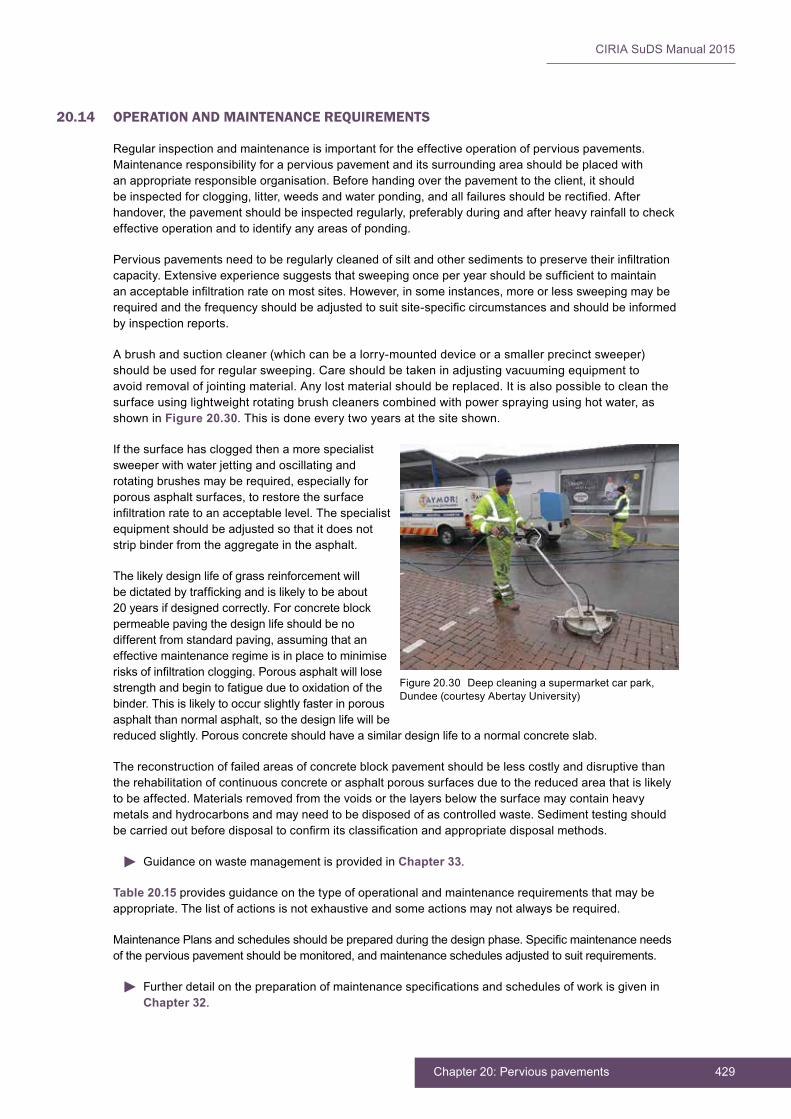
429Chapter 20: Pervious pavements
CIRIA SuDS Manual 2015
20.14 OPERATION AND MAINTENANCE REQUIREMENTS
Regular inspection and maintenance is important for the effective operation of pervious pavements. Maintenanceresponsibilityforaperviouspavementanditssurroundingareashouldbeplacedwithanappropriateresponsibleorganisation.Beforehandingoverthepavementtotheclient,itshouldbeinspectedforclogging,litter,weedsandwaterponding,andallfailuresshouldberectified.Afterhandover,thepavementshouldbeinspectedregularly,preferablyduringandafterheavyrainfalltocheckeffective operation and to identify any areas of ponding.
Perviouspavementsneedtoberegularlycleanedofsiltandothersedimentstopreservetheirinfiltrationcapacity.Extensiveexperiencesuggeststhatsweepingonceperyearshouldbesufficienttomaintainanacceptableinfiltrationrateonmostsites.However,insomeinstances,moreorlesssweepingmayberequiredandthefrequencyshouldbeadjustedtosuitsite-specificcircumstancesandshouldbeinformedby inspection reports.
Abrushandsuctioncleaner(whichcanbealorry-mounteddeviceorasmallerprecinctsweeper)shouldbeusedforregularsweeping.Careshouldbetakeninadjustingvacuumingequipmenttoavoid removal of jointing material. Any lost material should be replaced. It is also possible to clean the surfaceusinglightweightrotatingbrushcleanerscombinedwithpowersprayingusinghotwater,asshowninFigure 20.30.Thisisdoneeverytwoyearsatthesiteshown.
If the surface has clogged then a more specialist sweeperwithwaterjettingandoscillatingandrotatingbrushesmayberequired,especiallyforporousasphaltsurfaces,torestorethesurfaceinfiltrationratetoanacceptablelevel.Thespecialistequipment should be adjusted so that it does not strip binder from the aggregate in the asphalt.
Thelikelydesignlifeofgrassreinforcementwillbedictatedbytraffickingandislikelytobeabout20yearsifdesignedcorrectly.Forconcreteblockpermeable paving the design life should be no differentfromstandardpaving,assumingthataneffective maintenance regime is in place to minimise risksofinfiltrationclogging.Porousasphaltwilllosestrengthandbegintofatigueduetooxidationofthebinder. This is likely to occur slightly faster in porous asphaltthannormalasphalt,sothedesignlifewillbereduced slightly. Porous concrete should have a similar design life to a normal concrete slab.
The reconstruction of failed areas of concrete block pavement should be less costly and disruptive than the rehabilitation of continuous concrete or asphalt porous surfaces due to the reduced area that is likely tobeaffected.Materialsremovedfromthevoidsorthelayersbelowthesurfacemaycontainheavymetalsandhydrocarbonsandmayneedtobedisposedofascontrolledwaste.Sedimenttestingshouldbecarriedoutbeforedisposaltoconfirmitsclassificationandappropriatedisposalmethods.
GuidanceonwastemanagementisprovidedinChapter 33.
Table 20.15 provides guidance on the type of operational and maintenance requirements that may be appropriate.Thelistofactionsisnotexhaustiveandsomeactionsmaynotalwaysberequired.
MaintenancePlansandschedulesshouldbepreparedduringthedesignphase.Specificmaintenanceneedsoftheperviouspavementshouldbemonitored,andmaintenanceschedulesadjustedtosuitrequirements.
FurtherdetailonthepreparationofmaintenancespecificationsandschedulesofworkisgiveninChapter 32.
Figure20.30 Deepcleaningasupermarketcarpark,Dundee(courtesyAbertayUniversity)

CIRIA SuDS Manual 2015
430 Part D: Technical detail
Manyofthespecificmaintenanceactivitiesforperviouspavementscanbeundertakenaspartofageneralsitecleaningcontract(manycarparksorroadsareswepttoremovelitterandforvisualreasonstokeepthemtidy)andtherefore,iflittermanagementisalreadyrequiredatsite,thisshouldhavemarginalcostimplications.
Generally,perviouspavementsrequirelessfrequentgrittinginwintertopreventiceformation.Thereisalsolessriskoficeformationaftersnowmelt,asthemeltwaterdrainsdirectlyintotheunderlyingsub-base and does not have chance to refreeze. A slight frost may occur more frequently on the surface of perviouspavementscomparedtoadjacentimpermeablesurfaces,butthisisonlylikelytolastforafewhours.Itdoesnothappeninallinstallationsand,ifnecessary,thiscanbedealtwithbyapplicationofsalt.It is not likely to pose a hazard to vehicle movements.
Generic health and safety guidance is presented in Chapter 36.
CDM2015requiresdesignerstoensurethatallmaintenanceriskshavebeenidentified,eliminated,reducedand/orcontrolledwhereappropriate.Thisinformationwillberequiredaspartofthehealthandsafetyfile.
TABLE20.15
Operation and maintenance requirements for pervious pavements
Maintenance schedule Required action Typical frequency
Regular maintenanceBrushing and vacuuming (standard cosmeticsweepoverwholesurface)
Onceayear,afterautumnleaffall,orreducedfrequencyasrequired,basedonsite-specificobservationsofcloggingormanufacturer’srecommendations–payparticularattentiontoareaswherewaterruns onto pervious surface from adjacent impermeable areas as this area is most likely to collect the most sediment
Occasional maintenance
Stabiliseandmowcontributingandadjacent areas
As required
Removalofweedsormanagementusingglyphospateapplieddirectlyintotheweedsby an applicator rather than spraying
Asrequired–onceperyearonlessfrequently used pavements
Remedial Actions
Remediateanylandscapingwhich,through vegetation maintenance or soil slip,hasbeenraisedtowithin50mmofthe level of the paving
As required
Remedialworktoanydepressions,rutting and cracked or broken blocks considered detrimental to the structural performanceorahazardtousers,andreplace lost jointing material
As required
Rehabilitation of surface and upper substructurebyremedialsweeping
Every 10 to 15 years or as required (if infiltrationperformanceisreducedduetosignificantclogging)
Monitoring
Initial inspection Monthly for three months after installation
Inspect for evidence of poor operation and/orweedgrowth–ifrequired,takeremedial action
Three-monthly,48hafterlargestormsinfirstsixmonths
Inspect silt accumulation rates and establish appropriate brushing frequencies
Annually
Monitor inspection chambers Annually

431Chapter 20: Pervious pavements
CIRIA SuDS Manual 2015
20.15 REFERENCES
ACI(2010)Report on pervious concrete,ACI522R-10,ACICommittee522,AmericanConcreteInstitute,FarmingtonHills,MI,USA(ISBN:978-0-87031-364-6)
ACPA(2011)PerviousPave, background, purpose, assumptions and equations, American Concrete Pavement Association,Rosemont,IL,USA.Goto:www.acpa.org/PerviousPave/About%20PerviousPave.pdf
BEAN,EZ,HUNT,WFandBIDELSPACH,DA(2007)“EvaluationoffourpermeablepavementsitesineasternNorthCarolinaforrunoffreductionandwaterqualityimpacts”Journal of Irrigation and Drainage Engineering,vol133,6,AmericanSocietyofCivilEngineers,Reston,VA,USA,pp583–592
BEECHAM,S,LUCKE,TandMYERS,B(2010)“Designingporousandpermeablepavementsforstormwaterharvestingandre-use”.In:Proc first int European congress of the International Association for Hydro-Environment Engineering and Research,4–6May2010,Edinburgh,Scotland
BEELDENS,AandHERRIER,G(2006)“Waterperviouspavementblocks:theBelgianexperience”.In:Proc eighth int conf on concrete block paving,6–8November2006,SanFrancisco,CaliforniaUSA.Goto:www.sept.org/techpapers/1293.pdf
BORGWARDT,S(2006)“Long-termin-situinfiltrationperformanceofpermeableconcreteblockpavement”.In:Proc of the eighth int conf on concrete block paving,6–8November2006,SanFrancisco,CaliforniaUSA.Goto:www.icpi.org/sites/default/files/techpapers/1303.pdf
BRATTEBO,BOandBOOTH,DB(2003)“Longtermstormwaterquantityandqualityperformanceofpermeable pavement systems” Water Research,vol37,18,ElsevierBV,UK,pp4369–4376
CEDERGREN,HR(1974)Drainage of highway and airfield pavements,JohnWiley&Sons,London,UK(ISBN:978-0-47114-181-5)
CHADDOCK,BandJONES,CR(2007)Structural design and pilot-scale trials of modular cellular paving for greened safe havens and emergency access routes,TransportResearchLaboratory,Berkshire,UK(ISBN:978-1-84608-850-0).Goto:http://tinyurl.com/p6h93xl
CHADDOCK,BandNUNN,B(2010)A pilot scale trial of reservoir pavements for drainage attenuation,PPR482,TransportResearchLaboratory,Berkshire,UK(ISBN:978-1-84608-952-7).Goto:http://tinyurl.com/ovhmbgo
CHOPRA,M,WANIELISTA,M,STUART,E,HARDIN,MandJUJ,I(2011)Pervious pavements – installation, operation and strength. Part 2: porous asphalt systems,FloridaDepartmentofTransportation,Florida,USA
COLLINS,KA,HUNT,WFandHATHAWAY,JM(2008)“HydrologicandwaterqualityevaluationoffourpermeablepavementsinNorthCarolina,USA”.In:Proc 11th int conf on urban drainage,31Augustto5September2008,Edinburgh,Scotland,UK
CRMCA(2009)Specifiers guide for pervious concrete pavement design, version 1.2,ColoradoReadyMixedConcreteAssociation,CO,USA.Goto:http://tinyurl.com/koy9879
DAY,GE,SMITH,DRandBOWERS,J(1981)Runoff and pollution abatement characteristics of concrete grid pavements,Bulletin135,VirginiaPolytechnicInstituteandStateUniversity,USA
DCLG(2007)Manual for streets,ThomasTelfordpublishing,ThomasTelfordLtd,London(ISBN:978-0-72773-501-0).Goto: http://tinyurl.com/qd7qbgn
DRAKE,J,BRADFORD,AANDandSETERS,T(2012)Evaluation of permeable pavements in cold climates. Kortright Centre, Vaughan. Final report,TorontoandRegionConservationAuthority,Ontario,Canada.Goto:http://tinyurl.com/pw8aagc

CIRIA SuDS Manual 2015
432 Part D: Technical detail
FHA(2012)Pervious concrete, TechBrief,FHWA-HIF-13-006,USDepartmentofTransport,FederalHighwayAdministration,WashingtonDC,USA.Goto:http://tinyurl.com/qh3lc4u
HA(1990)“Apermeameterforroaddrainagelayers”.In:Design manual for roads and bridges (DMRB),vol4,Section2,HA41/90,HighwaysAgency,London,UK.Goto:http://tinyurl.com/nfdu66h
HA(2009)Design guidance for road pavement foundations, DraftHD25,InterimAdviceNote73/06Revision1,HighwaysAgency,London,UK.Goto:http://tinyurl.com/p3yq6lv
DfT(1998)Manual of contract documents for highway works, Volume 1 Specification for highway works,HMSO,London,UK(ISBN:978-0-11552-705-0).Goto:www.standardsforhighways.co.uk/mchw/vol1/
ICPI(2011)Permeable interlocking concrete pavements, fourth edition,InterlockingConcretePavementInstitute,Virginia,USA(ISBN:978-1-45078-440-5).Goto:www.icpi.org/node/2962
INTERPAVE(2007)The performance of geotextiles in concrete block permeable pavements, literature review,Interpave,Leicester,UK.Goto:www.paving.org.uk/commercial/research.php
INTERPAVE(2010)Permeable pavements. Guide to the design, construction and maintenance of concrete block permeable pavements, sixth edition,Interpave,Leicester,UK.Goto:http://tinyurl.com/pozgxzc
INTERPAVE(2013)Understanding permeable paving. Guidance for designers, developers, planners and local authorities, fifth edition,Interpave,Leicester,UK.Goto:http://tinyurl.com/pbzz2o4
JAMES,WandSHAHIN,R(1998)“Pollutantsleachedfrompavementsbyacidrain”.InWJames(ed)Advances in modeling the management of stormwater impacts, volume 6,ComputationalHydraulicsInt.,Guelph,Canada,pp321–349
JAYASURIYA,LNN,KADURUPOKUNE,N,OTHMAN,MandJESSE,K(2007)“Contributingtothesustainableuseofstormwater:theroleofperviouspavements”Water Science and Technology,vol56,12,IWAPublishing,London,UK,pp69–75
KELLAGHER,R(2013)SuDS study summary. Interception of 5 mm of rainfall,projectreportBE-030-R2,HRWallingford,Wallingford,Oxon,UK.Goto: http://tinyurl.com/qcyzceu
KEVERN,JT,SCHAEFER,VRandWANG,K(2009)“Temperaturebehaviorofperviousconcretesystems” Transportation Research Record: Journal of the Transportation Research Board,vol2098,TransportationResearchBoardoftheNationalAcademies,Washington,DC,USA,pp94–101
KORKEALAAKSO,J,KUOSA,H,NIEMELÄINEN,EandTIKANMÄKI,M(2014)Review of pervious pavement dimensioning, hydrological models and their parameter needs. State of the Art,researchreportVTT-R-08227-13,VTTTechnicalResearchCentreofFinland,Finland.Goto:http://tinyurl.com/oszsyth
KNAPTON,J(2007)Heavy duty pavements. The structural design of heavy duty pavements for ports and other industries, edition 4,Interpave,Leicester,UK.Goto:http://tinyurl.com/nbr4gxx
KNAPTON,J,MORRELL,DandSIMEUNOVICH,M(2012)“Structuraldesignsolutionsforpermeablepavements”.In:Proc 10th int conf on concrete block paving,24–26November2012,Shanghai,People’sRepublicofChina,pp1–23
LAKECOUNTYFORESTPRESERVES(2003)Permeable paver research summary. Lake County Forest Preserves,Chicago,USA.Goto:http://atfiles.org/files/pdf/PermPavers.PDF
LEGGETT,D,BROWN,R,BREWER,D,STANFIELD,GANDHOLLIDAY,E(2001a)Rainwater and greywater use in buildings. Best practice guidance,C539,CIRIA,London,UK(ISBN:978-0-86017-539-1).Goto:www.ciria.org

433Chapter 20: Pervious pavements
CIRIA SuDS Manual 2015
LEGGETT,D,BROWN,R,BREWER,D,STANFIELD,GandHOLLIDAY,E(2001b)Rainwater and greywater use in buildings – decision making for water conservation,PR80,CIRIA,London,UK(ISBN:978-0-86017-880-4).Goto:www.ciria.org
MPA(2009)Constructing and surfacing of parking areas including private drives,AsphaltApplications,AsphaltInformationService,MineralProductsAssociation,London,UK.Goto:http://tinyurl.com/pwy6avw
OBLA,KH(2007)“Perviousconcreteforsustainabledevelopment.Recentadvancesinconcretetechnology”.In:Proc first int conf on recent advances in concrete technology,September2007,NationalReadyMixedConcreteAssociation,WashingtonDC,USA.Goto:http://tinyurl.com/puygb2s
PRATT,CJ(1999)“Useofpermeable,reservoirpavementconstructionsforstormwatertreatmentandstorage for reuse” Water Science and Technology,vol39,5,ElsevierBV,UK,pp145–151
PRATT,CJ,MANTLE,DGandSCHOFIELD,PA(1995)“UKresearchintotheperformanceofpermeablepavement,reservoirstructuresincontrollingstormwaterdischargequantityandquality”Water Science and Technology, vol32,1,ElsevierBV,UK,pp63–69
PRATT,CJ,NEWMAN,APandBOND,PC(1999)“Mineraloilbiodegradationwithinapermeablepavement:longtermobservations”Water Science Technology,vol39,2,ElsevierBV,UK,pp103–109
PRATT,C,WILSON,SandCOOPER,P(2001)Source control using constructed pervious surfaces.Hydraulic, structural and water quality performance issues,C582,CIRIA,London(ISBN:978-0-86017-582-7).Goto:www.ciria.org
POWELL,WD,POTTER,JF,MAYHEW,HCandNUNN,ME(1984)The structural design of bituminous roads,LR1132,TransportResearchLaboratory,Berkshire,UK.Goto:http://tinyurl.com/q35mzjk
PUEHMEIER,TandNEWMAN,AP(2008)“Oilretainingandtreatinggeotextileforpavementapplications”.In:Proc 11th int conf on urban drainage,31Augustto5September2008,Edinburgh,Scotland,UK
RANKIN,KandBALL,JE(2004)“Areviewoftheperformanceofpermeablepavers”.In: Proc 2004 int conf on water sensitive urban design, WSUD2004: Cities as Catchments,Adelaide,SouthAustralia,pp366–377
RUSHTON,BT(2001)“Low-impactparkinglotdesignreducesrunoffandpollutantloads”Journal of Water Resources Planning and Management,vol127,3,specialissue,AmericanSocietyofCivilEngineers,RestonVA,USA,pp172–179
SHACKEL,B(2006)“Designofpermeablepavingsubjecttotraffic”.In:Proc eighth int conf on concrete block paving,6–8November2006,SanFrancisco,CaliforniaUSA.Goto:www.sept.org/techpapers/1293.pdf
SHACKEL,B,LITZKA,JandZIEGER,M(2000)“Loadingtestsofconventionalandecologicalconcreteblockpaving”.In:Proc sixth int conf on concrete block paving: JIPEA World Congress 2000,17–21September2000,Keio-PlazaIntercontinentalHotel,Tokyo,Japan,pp81–89
URBANWATERWAYS(2008)Permeable pavement research. Research update and design implications, NCCooperativeExtension,StateUniversityandA&TStateUniversity,NorthCarolina,USA.Goto:http://tinyurl.com/bk8rvt9
URBANWATERWAYS(2011)Maintaining permeable pavements,NCCooperativeExtension,StateUniversityandA&TStateUniversity,NorthCarolina,USA.Goto:http://tinyurl.com/navuult
WANIELISTA,MandCHOPRA,M(2007)Performance assessment of Portland Cement pervious pavement. Report 4 of 4: Performance assessment of a pervious concrete pavement used as a shoulder for an Interstate rest area parking lot, final report,FDOTProjectBD521-02,FloridaDepartmentofTransportation,Florida,USA.Goto:http://tinyurl.com/pf7lsgu

CIRIA SuDS Manual 2015
434 Part D: Technical detail
STATUTES
Regulations/Orders
Construction(DesignandManagement)Regulations(CDM)2015
TheRoadVehicles(ConstructionandUse)Regulations1986(No.1078)
TheRoadVehicles(AuthorisationofSpecialTypes)(General)Order2003(No.1998)
British Standards
BS1377-4:1990Methods of tests for soils for civil engineering purposes. Compaction-related tests
BS1377-9:1990Methods of tests for soils for civil engineering purposes. In-situ tests
BS7533-13:2009Pavements constructed with clay, natural stone or concrete pavers. Guide for the design of permeable pavements constructed with concrete paving blocks and flags, natural stone slabs and setts and clay pavers
BS7533-101:2015Pavements constructed with clay, natural stone or concrete paving units. Part 101: Code of practice for the design of pavements using modular paving units (in press)
European Standards
BSEN1097-6:2000 Tests for mechanical and physical properties of aggregates. Determination of particle density and water absorption(withdrawn)
BSEN12457-3:2002Characterisation of waste. Leaching. Compliance test for leaching of granular waste materials and sludges. Two stage batch test at a liquid to solid ratio of 2 l/kg and 8 l/kg for materials with a high solid content and with a particle size below 4 mm (without or with size reduction)
BSEN13108-1:2006Bituminous mixtures. Material specifications. Asphalt concrete
BSEN13242:2002+A1:2007Aggregates for unbound and hydraulically bound materials for use in civil engineering work and road construction
BSEN12620:2002+A1:2008Aggregates for concrete
BSEN14227-1:2013Hydraulically bound mixtures. Specifications. Cement bound granular mixtures
USA Standards
ASTM C1701M-09 Standard test method for infiltration rate of in place pervious concrete
ASTM C1781M-13 Standard test method for surface infiltration rate of permeable unit pavement systems

435Chapter 20: Pervious pavements
CIRIA SuDS Manual 2015
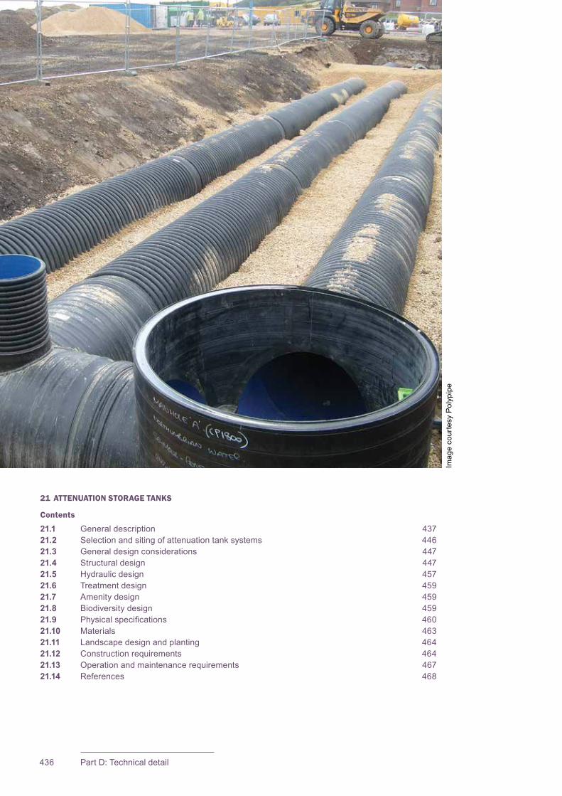
CIRIA SuDS Manual 2015
436 Part D: Technical detail
21 ATTENUATION STORAGE TANKS
Contents
21.1 General description 43721.2 Selection and siting of attenuation tank systems 44621.3 General design considerations 44721.4 Structural design 44721.5 Hydraulic design 45721.6 Treatment design 45921.7 Amenity design 45921.8 Biodiversity design 45921.9 Physicalspecifications 46021.10 Materials 46321.11 Landscape design and planting 46421.12 Construction requirements 46421.13 Operation and maintenance requirements 46721.14 References 468
Imag
e co
urte
sy P
olyp
ipe

437Chapter 21: Attenuation storage tanks
CIRIA SuDS Manual 2015
21.1 GENERAL DESCRIPTION
Attenuation storage tanks are used to create a below-ground void space for the temporarystorageofsurfacewaterbeforeinfiltration,controlledreleaseoruse.Thestorage structure is usually formed using one of the following methods:
▪ geocellular storage systems
▪ plasticcorrugatedarchstructures(constructedoverandbackfilledwithanopen-graded aggregate base)
▪ oversize concrete pipes
▪ oversize plastic pipes
▪ corrugated steel pipes
▪ precast or in situ concreteboxculvertsectionsandtanks(includingflat-packedconcrete panels)
▪ glass-reinforced plastic (GRP) tanks
▪ hybrid structures using reinforced earth walls and concrete roof panels
Thereareothertypesoftanksystemavailable,butthesearenotascommonlyusedandarecoveredbygeneralconstructionspecificationsanddesignrequirements.Thesearenotdiscussedindetailinthischapter.
Theinherentflexibilityinsizeandshape(andinsomecasesmodularity)oftheabovesystemsmeansthattheycanbetailoredtosuitthespecificcharacteristicsandrequirementsofanysite.Theirmainbenefitsare:
1 theirhighstoragevolume(comparedtostructuresfilledwithaggregates)
2 their potential for installation beneath roads and car parks (provided they are designedtowithstandtrafficloadings)andrecreationalareasandotherpublicopenspace.
Important considerations are:
1 level of accessibility and maintainability with some types of system
2 lack of treatment performance when used in isolation
3 cost(comparedtosurfacesystems,assumingthatthesecanbeimplementedinpublicspace,thatiswithoutrequiringextraland-take).
ThesesystemscanbedesignedforuseunderareastraffickedbyHGVsandotherheavyplant,suchasatportsandairports,butitshouldbenotedthattheiruseunderpublic (or adopted) roads will generally be subject to technical approval by the relevant highwayauthority.Thisshouldbesoughtatanearlystageinthedesignprocess.
21Chapter Attenuation storage tanks
This chapter provides guidance on the design of attenuation storage tanks – structures that create a below-ground void space for the temporary storage of surface water before infiltration, controlled release or use.

CIRIA SuDS Manual 2015
438 Part D: Technical detail
Themaintainabilityofattenuationtankstoragesystemsrequirescarefulconsideration.Theyliebeneaththeground,soanyfailuresorblockageswilltendnottobenoticed,whichmayincreaseriskstothesite.Geocellularsystemsandplasticarchestendnottobeeasilyaccessibleforinspectionorcleaning,soveryeffectiveupstreamtreatmentisrequiredtoensureadequatesedimentremoval.Therearesomesystemsthatincorporate“access”tunnelsoramoreopenstructure.However,inpracticetheseonlyprovidelimitedaccess,anditisdifficulttoseebeyondthetunnelsortomanoeuvreCCTVcameraswithinthetanks.Unlesssurfaceaccesspointsareprovidedforeverytunnel,accessforjettingisalsolimited.
Allofthesesystemsrequireintegrationwiththeoverallsurfacewatertreatmentstrategy,astheydonothaveinherenttreatmentcapability.Theycanbespace-efficient,owingtothepotentialforuseofthelandabovethetanks,butastheyarestructuralsystems,thecostofinstallationwilltendtobehighcomparedtostoragesystemsonthesurface.
Most of the methods of providing attenuation are well understood in terms of structural design/performance(iepipesandarchesinvariousmaterialsandculverts).Thestructuraldesignofgeocellularsystems tends to be more complex and there have been a number of collapses of these systems caused by inadequate design (see Mallett et al,2014,andO’Brienet al,inpress).Therefore,thischapterprovidesmoredetailonthestructuraldesignofthistypeoftankstructurethanothers,althoughmanyoftheissuesarerelevanttoallmethods.
Many of the products used to form attenuation tanks can also be used to provide the temporary storage requiredforinfiltrationsystems(Chapters 13 and 25).
21.1.1 Geocellular storage systems
Geocellular storage systems are modular plastic units with a high porosity (generally around 95%) that canbeusedtoefficientlycreateabelow-groundstructureforthetemporarystorageofsurfacewaterbeforecontrolledreleaseoruse.Thestoragestructure(tank)isformedbyassemblingtherequirednumberofindividualunits(sometimesinseverallayers),andwrappingthemineitherageotextileorageomembrane.
Geocellular systems have been used in Europe since 1987 (Le Nouveau et al,2007)inplaceofstone-filledsoakaways,concretetanksoroversizedpipework.Theyarelightandeasilyinstalledwithoutheavymachinery,whichcan lead to time and cost savings in construction (Figure 21.1).
Iftheflowcharacteristicsofthegeocellularunitaresufficientlywellcharacterisedbyhydraulictesting,theycan also be used as a conveyance mechanism.Theirinherentresistancetoflowcanalsobeusedinthedesigntoremovetheneedforflowcontrolson some sites (using measured head–dischargerelationshipsandmodelling).
The modular units have two basic components:
▪ The inner “structural frame” provides basic stiffness and strength and is delivered by the box unit (Figure 21.2).
▪ Theouter“skin”keepsoutsoilandbackfill,andisdeliveredbythegeomembraneorgeotextile(Figure 21.3).
Figure21.1 Geocellularstoragesystemunderconstruction(courtesyPolypipe Limited)
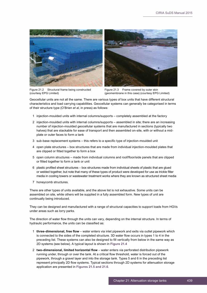
439Chapter 21: Attenuation storage tanks
CIRIA SuDS Manual 2015
Geocellularunitsarenotallthesame.Therearevarioustypesofboxunitsthathavedifferentstructuralcharacteristicsandloadcarryingcapabilities.Geocellularsystemscangenerallybecategorisedintermsoftheirstructuretype(O’Brienet al,inpress)asfollows:
1 injection-moulded units with internal columns/supports – completely assembled at the factory
2 injection-moulded units with internal columns/supports – assembled in site; there are an increasing number of injection-moulded geocellular systems that are manufactured in sections (typically two halves)thatarestackableforeaseoftransportandthenassembledon-site,withorwithoutamid-plate or outer faces to form a tank
3 sub-basereplacementsystems–thisreferstoaspecifictypeofinjection-mouldedunit
4 open plate structures – box structures that are made from individual injection-moulded plates that areclippedorfittedtogethertoformabox
5 opencolumnstructures–madefromindividualcolumnsandroof/floor/sidepanelsthatareclippedorfittedtogethertoformatankorunit
6 plasticprofiledsheetstructures–boxstructuresmadefromindividualsheetsofplasticthataregluedorweldedtogether,butnotethatmanyofthesetypesofproductweredevelopedforuseastricklefiltermedia in cooling towers or wastewater treatment works where they are known as structured sheet media
7 honeycombstructures.
Thereareothertypesofunitsavailable,andtheabovelistisnotexhaustive.Someunitscanbeassembledonsite,whileotherswillbesuppliedinafullyassembledform.Newtypesofunitarecontinuallybeingintroduced.
TheycanbedesignedandmanufacturedwitharangeofstructuralcapacitiestosupportloadsfromHGVsunderareassuchaslorryparks.
Thedirectionofwaterflowthroughtheunitscanvary,dependingontheinternalstructure.Intermsofhydraulicperformance,theunitscanbeclassifiedas:
1 �three-dimensional,�free�flow – water enters via inlet pipework and exits via outlet pipework which isconnectedtothesidesofthecompletedstructure.3Dwaterflowoccursintypes1to4intheprecedinglist.Thesesystemscanalsobedesignedtofillverticallyfrombelowinthesamewayas2Dsystems(seebelow).AtypicallayoutisshowninFigure 21.4
2 two-dimensional,�limited�horizontal�flow – water enters via perforated distribution pipework runningunder,throughoroverthetank.Atacriticalflowthreshold,waterisforcedoutofthepipework,throughagravellayerandintothestoragetank.Types5and6intheprecedinglistrepresentprincipally2Dflowsystems.Typicalsectionsthrough2Dsystemsforattenuationstorageapplication are presented in Figures 21.5 and 21.6.
Figure21.2 Structuralframebeingconstructed(courtesy EPG Limited)
Figure21.3 Framecoveredbyouterskin(geomembrane in this case) (courtesy EPG Limited)
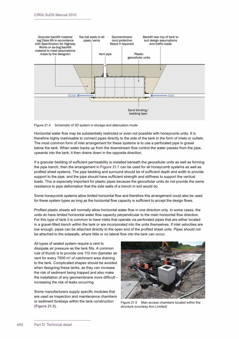
CIRIA SuDS Manual 2015
440 Part D: Technical detail
Horizontalwaterflowmaybesubstantiallyrestrictedorevennotpossiblewithhoneycombunits.Itisthereforehighlyinadvisabletoconnectpipesdirectlytothesideofthetankintheformofinletsoroutlets.The most common form of inlet arrangement for these systems is to use a perforated pipe in gravel belowthetank.Whenwaterbacksupfromthedownstreamflowcontrolthewaterpassesfromthepipe,upwardsintothetank;itthendrainsdownintheoppositedirection.
Ifagranularbeddingofsufficientpermeabilityisinstalledbeneaththegeocellularunitsaswellasformingthepipetrench,thenthearrangementinFigure 21.7 can be used for all honeycomb systems as well as profiledsheetsystems.Thepipebeddingandsurroundshouldbeofsufficientdepthandwidthtoprovidesupporttothepipe,andthepipeshouldhavesufficientstrengthandstiffnesstosupporttheverticalloads.Thisisespeciallyimportantforplasticpipesbecausethegeocellularunitsdonotprovidethesameresistancetopipedeformationthatthesidewallsofatrenchinsoilwoulddo.
Somehoneycombsystemsallowlimitedhorizontalflowandthereforethisarrangementcouldalsobeusedforthesesystemtypesaslongasthehorizontalflowcapacityissufficienttoacceptthedesignflows.
Profiledplasticsheetswillnormallyallowhorizontalwaterflowinonedirectiononly.Insomecases,theunitsdohavelimitedhorizontalwaterflowcapacityperpendiculartothemainhorizontalflowdirection.For this type of tank it is common to have inlets that operate via perforated pipes that are either located inagravel-filledtrenchwithinthetankorareincorporatedintotheunitsthemselves.Ifinletvelocitiesarelowenough,pipescanbeattacheddirectlytotheopenendoftheprofiledsheetunits.Pipesshouldnotbeattachedtothesidewalls,wherelittleornolateralflowintothetankcanoccur.
All types of sealed system require a vent to dissipateairpressureasthetankfills.Acommonruleofthumbistoprovideone110mmdiameterairventforevery7500m2 of catchment area draining tothetank.Complicatedshapesshouldbeavoidedwhendesigningthesetanks,astheycanincreasethe risk of sediment being trapped and also make theinstallationofanygeomembranemoredifficult–increasingtheriskofleaksoccurring.
Somemanufacturerssupplyspecificmodulesthatare used as inspection and maintenance chambers or sediment forebays within the tank construction (Figure 21.5).
Figure21.4 Schematicof3Dsysteminstorageandattenuationmode
Figure21.5 Manaccesschamberslocatedwithinthestructure (courtesy Aco Limited)
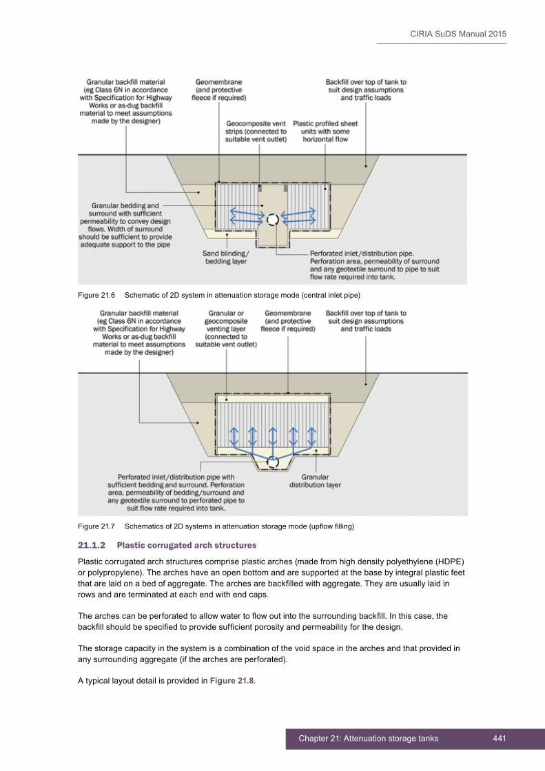
441Chapter 21: Attenuation storage tanks
CIRIA SuDS Manual 2015
21.1.2 Plastic corrugated arch structures
Plasticcorrugatedarchstructurescompriseplasticarches(madefromhighdensitypolyethylene(HDPE)orpolypropylene).Thearcheshaveanopenbottomandaresupportedatthebasebyintegralplasticfeetthatarelaidonabedofaggregate.Thearchesarebackfilledwithaggregate.Theyareusuallylaidinrowsandareterminatedateachendwithendcaps.
Thearchescanbeperforatedtoallowwatertoflowoutintothesurroundingbackfill.Inthiscase,thebackfillshouldbespecifiedtoprovidesufficientporosityandpermeabilityforthedesign.
The storage capacity in the system is a combination of the void space in the arches and that provided in anysurroundingaggregate(ifthearchesareperforated).
A typical layout detail is provided in Figure 21.8.
Figure21.6 Schematicof2Dsysteminattenuationstoragemode(centralinletpipe)
Figure21.7 Schematicsof2Dsystemsinattenuationstoragemode(upflowfilling)
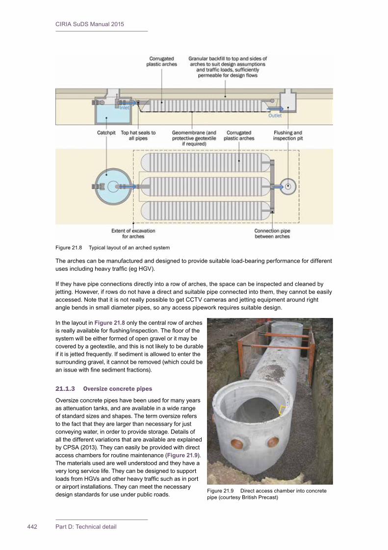
CIRIA SuDS Manual 2015
442 Part D: Technical detail
The arches can be manufactured and designed to provide suitable load-bearing performance for different usesincludingheavytraffic(egHGV).
Iftheyhavepipeconnectionsdirectlyintoarowofarches,thespacecanbeinspectedandcleanedbyjetting.However,ifrowsdonothaveadirectandsuitablepipeconnectedintothem,theycannotbeeasilyaccessed.NotethatitisnotreallypossibletogetCCTVcamerasandjettingequipmentaroundrightanglebendsinsmalldiameterpipes,soanyaccesspipeworkrequiressuitabledesign.
In the layout in Figure 21.8 only the central row of arches isreallyavailableforflushing/inspection.Thefloorofthesystem will be either formed of open gravel or it may be coveredbyageotextile,andthisisnotlikelytobedurableifitisjettedfrequently.Ifsedimentisallowedtoenterthesurroundinggravel,itcannotberemoved(whichcouldbeanissuewithfinesedimentfractions).
21.1.3 Oversize concrete pipes
Oversize concrete pipes have been used for many years asattenuationtanks,andareavailableinawiderangeofstandardsizesandshapes.Thetermoversizerefersto the fact that they are larger than necessary for just conveyingwater,inordertoprovidestorage.Detailsofall the different variations that are available are explained byCPSA(2013).Theycaneasilybeprovidedwithdirectaccess chambers for routine maintenance (Figure 21.9).The materials used are well understood and they have a verylongservicelife.TheycanbedesignedtosupportloadsfromHGVsandotherheavytrafficsuchasinportorairportinstallations.Theycanmeetthenecessarydesignstandardsforuseunderpublicroads.
Figure21.8 Typicallayoutofanarchedsystem
Figure21.9 Directaccesschamberintoconcretepipe (courtesy British Precast)
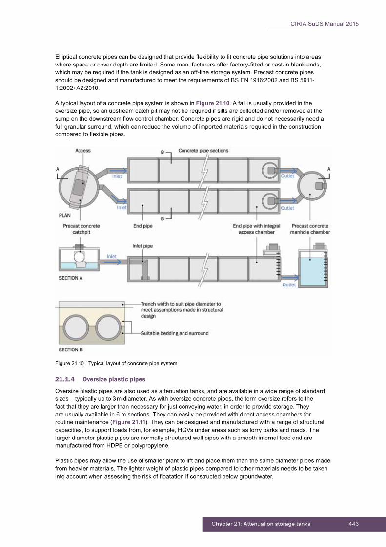
443Chapter 21: Attenuation storage tanks
CIRIA SuDS Manual 2015
Ellipticalconcretepipescanbedesignedthatprovideflexibilitytofitconcretepipesolutionsintoareaswherespaceorcoverdeptharelimited.Somemanufacturersofferfactory-fittedorcast-inblankends,whichmayberequiredifthetankisdesignedasanoff-linestoragesystem.PrecastconcretepipesshouldbedesignedandmanufacturedtomeettherequirementsofBSEN1916:2002andBS5911-1:2002+A2:2010.
A typical layout of a concrete pipe system is shown in Figure 21.10.Afallisusuallyprovidedintheoversizepipe,soanupstreamcatchpitmaynotberequiredifsiltsarecollectedand/orremovedatthesumponthedownstreamflowcontrolchamber.Concretepipesarerigidanddonotnecessarilyneedafullgranularsurround,whichcanreducethevolumeofimportedmaterialsrequiredintheconstructioncomparedtoflexiblepipes.
21.1.4 Oversize plastic pipes
Oversizeplasticpipesarealsousedasattenuationtanks,andareavailableinawiderangeofstandardsizes–typicallyupto3mdiameter.Aswithoversizeconcretepipes,thetermoversizereferstothefactthattheyarelargerthannecessaryforjustconveyingwater,inordertoprovidestorage.Theyareusuallyavailablein6msections.Theycaneasilybeprovidedwithdirectaccesschambersforroutine maintenance (Figure 21.11).Theycanbedesignedandmanufacturedwitharangeofstructuralcapacities,tosupportloadsfrom,forexample,HGVsunderareassuchaslorryparksandroads.Thelarger diameter plastic pipes are normally structured wall pipes with a smooth internal face and are manufacturedfromHDPEorpolypropylene.
Plastic pipes may allow the use of smaller plant to lift and place them than the same diameter pipes made fromheaviermaterials.Thelighterweightofplasticpipescomparedtoothermaterialsneedstobetakenintoaccountwhenassessingtheriskoffloatationifconstructedbelowgroundwater.
Figure21.10 Typicallayoutofconcretepipesystem

CIRIA SuDS Manual 2015
444 Part D: Technical detail
The6mlengthsgiveareducednumberofjoints,whichcanreducetheriskofleakageoccurring.Thejointscanbeconventionalspigotandsocket,orthepipescanbeweldedtogether(handextrusionorelectro-fusionwelding).Theycanalsobeprovidedwithbespokechambersandaccesspointsintothepipes.
The general layout will be similar to that for concrete pipes (shown in Figure 21.11),althoughtheprecisedetailsofbeddingetcwillbespecifictoplasticpipes,whichnormallyrequireafullsurroundofgranularbeddingmaterial(ClassS).
21.1.5 Corrugated steel pipes
Corrugatedsteelpipesareusedtoconstructtanksinasimilarwaytoplasticandconcretepipes.Theperformanceofthesematerialsiswellunderstood,andtheyhavebeeninuseformanyyears.Theyaretypicallyavailableindiametersupto3.6mandcanbedesignedtosuitloadsincludingHGVtrafficunderareassuchasmotorwaysandotherheavilyloadedareas,suchasportsandairports.Theycanmeetthenecessarydesignstandardsforuseunderpublicroads.
Thepipesareusuallygalvanisedwithazinccoatingontheinternalandexternalsurfaces,whichshouldprovideadesignlifeofupto60yearsinsuitableconditions.Thechemistryofthegroundshouldbeassessedtodeterminetheirlikelydurability,butifnecessarytheycanalsobecoatedwithaprotectivesecondarycoatingofapolymer,toincreaseresistancetoaggressivegroundconditions.Theyareoftenprefabricatedtoincludeaccessshafts,andarelikelytohavegasketjoints.AtypicaltankisshowninFigure 21.12.
It might be possible that zinc can leach from galvanised pipes and cause pollution of the surface water runoff(Ogburn,2013).ThesignificanceofthiswilldependonthepHoftherunoff,thevolume-to-surface-arearatioofatankandthecontacttimewiththetankwalls.Ifnecessaryaprotectivesecondarycoatingcanbeappliedorabitumenpavedinvertprovidedtopreventthis.Additivescanalsobeaddedtothezinccoatingtoreducedissolution.
Figure21.11 Installationofoversizedplasticpipeattenuationtanks(courtesyPolypipeLimited)

445Chapter 21: Attenuation storage tanks
CIRIA SuDS Manual 2015
21.1.6 Concrete box culvert/tank
Precastconcreteboxculvertsareavailableinawiderangeofstandardsections.Theycancomewithendwalls,accessshaftsandpreformedinletsandoutlets.Theycanalsohavedryweatherflowchannelsformedinthebaseifneeded.Thejointsarenormallyspigotandsocketjointsthataresealedusingjointingstrips(egrubberbitumen).Thematerialsusedarewellunderstood,andtheytendtohaveaverylongservicelife.TheycanbedesignedtosupportloadsfromHGVsandotherheavytrafficsuchasinportorairportinstallations.Theycanmeetthenecessarydesignstandardsforuseunderpublicroads.Theyarereadilyaccessibleformaintenancetoremoveanysedimentbuild-up.
DesignandmanufacturingrequirementsforboxculvertsareprovidedinBSEN14844:2006+A2:2011.BoxculvertsmanufacturedtoBSEN14844shouldbemonolithicinstructure.
Concrete tanks can also be constructed using precast concrete panels that are assembled on site to form thetank(knownasflatpacktanks)orusingcast-in situconcrete.
21.1.7 Glass-reinforced plastic (GRP) tanks
GRP tanks are usually manufactured as a complete tank unit including all access shafts and inlets/outlets.Theyareavailableinarangeofsizes,typicallyuptoabout300,000litres.Theycanalsobelaidsidebysideandinterconnectedtoformlargertanks.Thetanksareeasilyaccessibleformaintenance.
Theabsenceofsitejointingreducestheriskofleaks,andtheyprovideadurablesolutionwithalongservicelife.GRPtanksarefrequentlyusedasrainwaterharvestingtanks(Chapter 11).Thetankisnormallyplacedonaconcretebaseandsurroundedbyeitheraconcreteorgranularbackfilltoachievetherequiredload-bearingcapacity.TheyarequickandeasytoinstallandcanbeplacedbelowroadsandsimilarareaswithHGVtraffic.
21.1.8 Hybrid tanks
Hybrid tanks use a combination of reinforced earth walls/abutments combined with reinforced concrete roofpanels.Bothelementsarewellunderstoodconstructionmethodsthathavebeenusedsuccessfullyformanyyearsinotherapplications.AtypicallayoutisshowninFigure 21.14. The whole construction is surroundedbyanimpermeablegeomembranetoformatank.
Thereinforcedwallsareconstructedwithopen-gradedstonetoprovidesomeofthestoragecapacity.Thisalsopreventsthebuild-upofexcessporepressureorunevenwaterpressurewithinthefill,andthishelpsmaintainthestabilityofthesystem.Reinforcedearthisadurablematerialthatcanbedesignedandconstructedtoprovidealongdesignlife.
Thesystemprovidesalargeopenchamberthatcanbeaccessedformaintenance,althoughifsiltenters
Figure21.12 Typicalcorrugatedsteeltankunderconstruction(courtesyTubosiderUKLimited)
Figure21.13 PrecastconcreteboxculvertbeinginstalledaspartofaSuDSscheme(courtesyBritishPrecast)
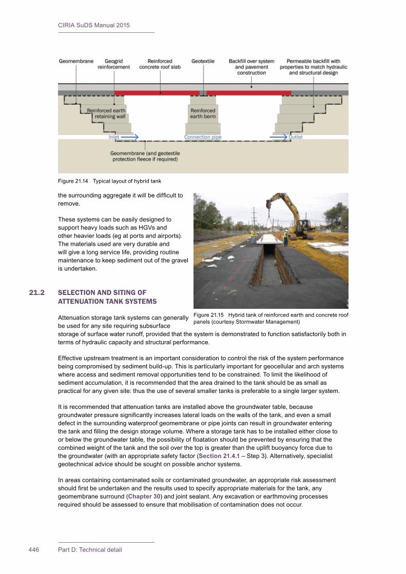
CIRIA SuDS Manual 2015
446 Part D: Technical detail
thesurroundingaggregateitwillbedifficulttoremove.
These systems can be easily designed to supportheavyloadssuchasHGVsandotherheavierloads(egatportsandairports).The materials used are very durable and willgivealongservicelife,providingroutinemaintenance to keep sediment out of the gravel isundertaken.
21.2 SELECTION AND SITING OF ATTENUATION TANK SYSTEMS
Attenuation storage tank systems can generally be used for any site requiring subsurface storageofsurfacewaterrunoff,providedthatthesystemisdemonstratedtofunctionsatisfactorilybothintermsofhydrauliccapacityandstructuralperformance.
Effective upstream treatment is an important consideration to control the risk of the system performance beingcompromisedbysedimentbuild-up.Thisisparticularlyimportantforgeocellularandarchsystemswhereaccessandsedimentremovalopportunitiestendtobeconstrained.Tolimitthelikelihoodofsedimentaccumulation,itisrecommendedthattheareadrainedtothetankshouldbeassmallaspracticalforanygivensite:thustheuseofseveralsmallertanksispreferabletoasinglelargersystem.
Itisrecommendedthatattenuationtanksareinstalledabovethegroundwatertable,becausegroundwaterpressuresignificantlyincreaseslateralloadsonthewallsofthetank,andevenasmalldefect in the surrounding waterproof geomembrane or pipe joints can result in groundwater entering thetankandfillingthedesignstoragevolume.Whereastoragetankhastobeinstalledeitherclosetoorbelowthegroundwatertable,thepossibilityoffloatationshouldbepreventedbyensuringthatthecombined weight of the tank and the soil over the top is greater than the uplift buoyancy force due to the groundwater (with an appropriate safety factor (Section 21.4.1–Step3).Alternatively,specialistgeotechnicaladviceshouldbesoughtonpossibleanchorsystems.
Inareascontainingcontaminatedsoilsorcontaminatedgroundwater,anappropriateriskassessmentshouldfirstbeundertakenandtheresultsusedtospecifyappropriatematerialsforthetank,anygeomembrane surround (Chapter 30)andjointsealant.Anyexcavationorearthmovingprocessesrequiredshouldbeassessedtoensurethatmobilisationofcontaminationdoesnotoccur.
Figure21.14 Typicallayoutofhybridtank
Figure21.15 Hybridtankofreinforcedearthandconcreteroofpanels (courtesy Stormwater Management)
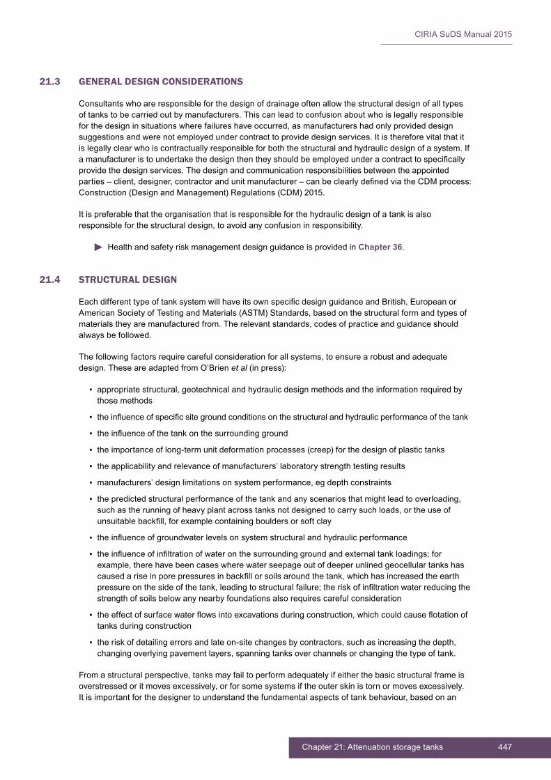
447Chapter 21: Attenuation storage tanks
CIRIA SuDS Manual 2015
21.3 GENERAL DESIGN CONSIDERATIONS
Consultants who are responsible for the design of drainage often allow the structural design of all types oftankstobecarriedoutbymanufacturers.Thiscanleadtoconfusionaboutwhoislegallyresponsibleforthedesigninsituationswherefailureshaveoccurred,asmanufacturershadonlyprovideddesignsuggestionsandwerenotemployedundercontracttoprovidedesignservices.Itisthereforevitalthatitislegallyclearwhoiscontractuallyresponsibleforboththestructuralandhydraulicdesignofasystem.Ifamanufactureristoundertakethedesignthentheyshouldbeemployedunderacontracttospecificallyprovidethedesignservices.Thedesignandcommunicationresponsibilitiesbetweentheappointedparties–client,designer,contractorandunitmanufacturer–canbeclearlydefinedviatheCDMprocess:Construction(DesignandManagement)Regulations(CDM)2015.
It is preferable that the organisation that is responsible for the hydraulic design of a tank is also responsibleforthestructuraldesign,toavoidanyconfusioninresponsibility.
Health and safety risk management design guidance is provided in Chapter 36.
21.4 STRUCTURAL DESIGN
EachdifferenttypeoftanksystemwillhaveitsownspecificdesignguidanceandBritish,EuropeanorAmericanSocietyofTestingandMaterials(ASTM)Standards,basedonthestructuralformandtypesofmaterialstheyaremanufacturedfrom.Therelevantstandards,codesofpracticeandguidanceshouldalwaysbefollowed.
Thefollowingfactorsrequirecarefulconsiderationforallsystems,toensurearobustandadequatedesign.TheseareadaptedfromO’Brienet al (in press):
▪ appropriatestructural,geotechnicalandhydraulicdesignmethodsandtheinformationrequiredbythose methods
▪ theinfluenceofspecificsitegroundconditionsonthestructuralandhydraulicperformanceofthetank
▪ theinfluenceofthetankonthesurroundingground
▪ the importance of long-term unit deformation processes (creep) for the design of plastic tanks
▪ theapplicabilityandrelevanceofmanufacturers’laboratorystrengthtestingresults
▪ manufacturers’designlimitationsonsystemperformance,egdepthconstraints
▪ thepredictedstructuralperformanceofthetankandanyscenariosthatmightleadtooverloading,suchastherunningofheavyplantacrosstanksnotdesignedtocarrysuchloads,ortheuseofunsuitablebackfill,forexamplecontainingbouldersorsoftclay
▪ theinfluenceofgroundwaterlevelsonsystemstructuralandhydraulicperformance
▪ theinfluenceofinfiltrationofwateronthesurroundinggroundandexternaltankloadings;forexample,therehavebeencaseswherewaterseepageoutofdeeperunlinedgeocellulartankshascausedariseinporepressuresinbackfillorsoilsaroundthetank,whichhasincreasedtheearthpressureonthesideofthetank,leadingtostructuralfailure;theriskofinfiltrationwaterreducingthestrength of soils below any nearby foundations also requires careful consideration
▪ theeffectofsurfacewaterflowsintoexcavationsduringconstruction,whichcouldcauseflotationoftanks during construction
▪ theriskofdetailingerrorsandlateon-sitechangesbycontractors,suchasincreasingthedepth,changingoverlyingpavementlayers,spanningtanksoverchannelsorchangingthetypeoftank.
Fromastructuralperspective,tanksmayfailtoperformadequatelyifeitherthebasicstructuralframeisoverstressedoritmovesexcessively,orforsomesystemsiftheouterskinistornormovesexcessively.Itisimportantforthedesignertounderstandthefundamentalaspectsoftankbehaviour,basedonan
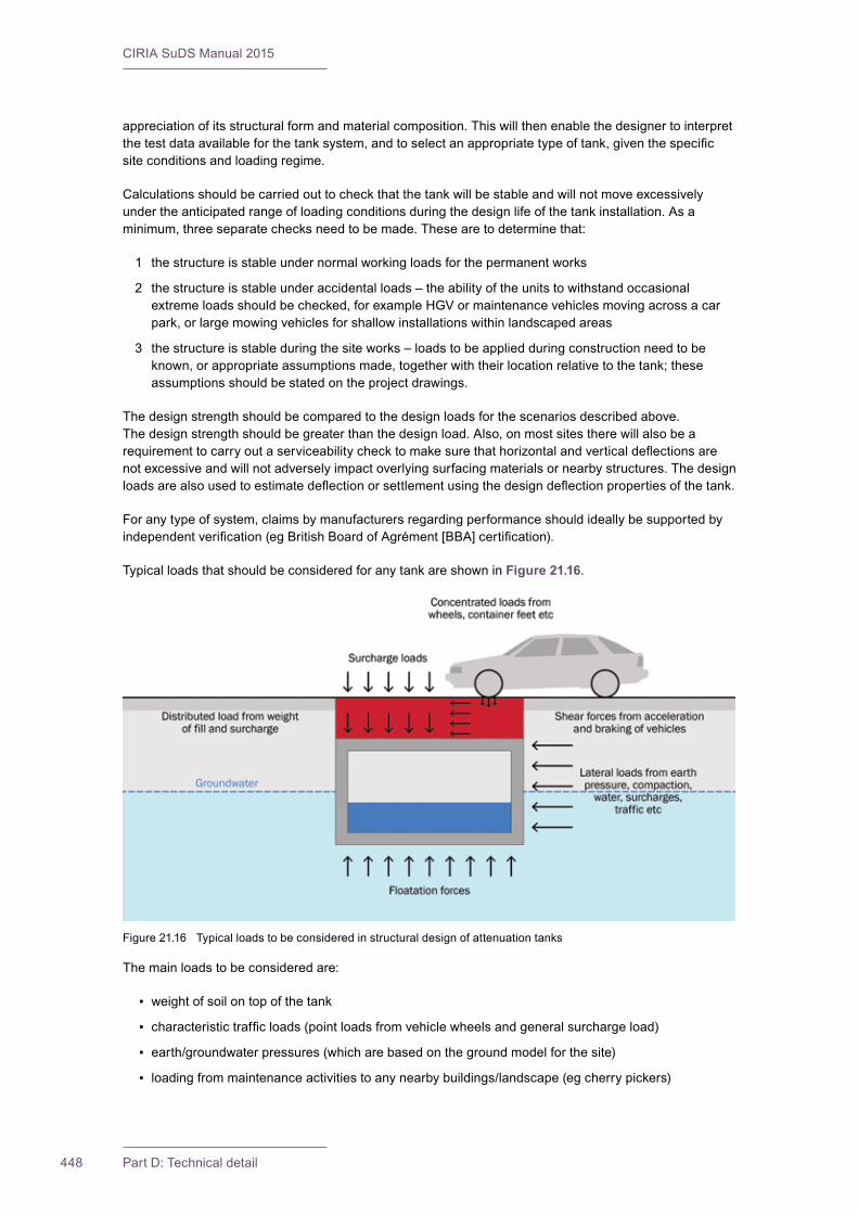
CIRIA SuDS Manual 2015
448 Part D: Technical detail
appreciationofitsstructuralformandmaterialcomposition.Thiswillthenenablethedesignertointerpretthetestdataavailableforthetanksystem,andtoselectanappropriatetypeoftank,giventhespecificsiteconditionsandloadingregime.
Calculations should be carried out to check that the tank will be stable and will not move excessively undertheanticipatedrangeofloadingconditionsduringthedesignlifeofthetankinstallation.Asaminimum,threeseparatechecksneedtobemade.Thesearetodeterminethat:
1 the structure is stable under normal working loads for the permanent works
2 the structure is stable under accidental loads – the ability of the units to withstand occasional extremeloadsshouldbechecked,forexampleHGVormaintenancevehiclesmovingacrossacarpark,orlargemowingvehiclesforshallowinstallationswithinlandscapedareas
3 the structure is stable during the site works – loads to be applied during construction need to be known,orappropriateassumptionsmade,togetherwiththeirlocationrelativetothetank;theseassumptionsshouldbestatedontheprojectdrawings.
Thedesignstrengthshouldbecomparedtothedesignloadsforthescenariosdescribedabove.Thedesignstrengthshouldbegreaterthanthedesignload.Also,onmostsitestherewillalsobearequirementtocarryoutaserviceabilitychecktomakesurethathorizontalandverticaldeflectionsarenotexcessiveandwillnotadverselyimpactoverlyingsurfacingmaterialsornearbystructures.Thedesignloadsarealsousedtoestimatedeflectionorsettlementusingthedesigndeflectionpropertiesofthetank.
Foranytypeofsystem,claimsbymanufacturersregardingperformanceshouldideallybesupportedbyindependentverification(egBritishBoardofAgrément[BBA]certification).
Typical loads that should be considered for any tank are shown in Figure 21.16.
The main loads to be considered are:
▪ weight of soil on top of the tank
▪ characteristictrafficloads(pointloadsfromvehiclewheelsandgeneralsurchargeload)
▪ earth/groundwater pressures (which are based on the ground model for the site)
▪ loading from maintenance activities to any nearby buildings/landscape (eg cherry pickers)
Figure21.16 Typicalloadstobeconsideredinstructuraldesignofattenuationtanks
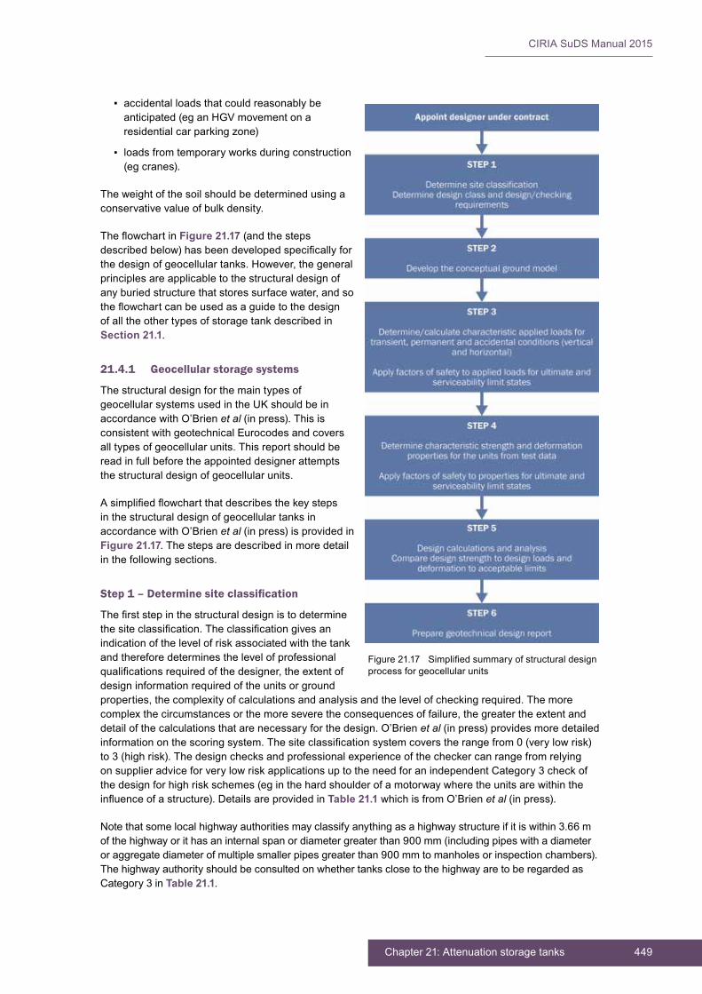
449Chapter 21: Attenuation storage tanks
CIRIA SuDS Manual 2015
▪ accidental loads that could reasonably be anticipated(eganHGVmovementonaresidential car parking zone)
▪ loads from temporary works during construction (egcranes).
The weight of the soil should be determined using a conservativevalueofbulkdensity.
TheflowchartinFigure 21.17 (and the steps describedbelow)hasbeendevelopedspecificallyforthedesignofgeocellulartanks.However,thegeneralprinciples are applicable to the structural design of anyburiedstructurethatstoressurfacewater,andsotheflowchartcanbeusedasaguidetothedesignof all the other types of storage tank described in Section 21.1.
21.4.1 Geocellular storage systems
The structural design for the main types of geocellularsystemsusedintheUKshouldbeinaccordancewithO’Brienet al(inpress).Thisisconsistent with geotechnical Eurocodes and covers alltypesofgeocellularunits.Thisreportshouldberead in full before the appointed designer attempts thestructuraldesignofgeocellularunits.
Asimplifiedflowchartthatdescribesthekeystepsin the structural design of geocellular tanks in accordancewithO’Brienet al (in press) is provided in Figure 21.17.Thestepsaredescribedinmoredetailinthefollowingsections.
Step 1 – Determine site classification
Thefirststepinthestructuraldesignistodeterminethesiteclassification.Theclassificationgivesanindication of the level of risk associated with the tank and therefore determines the level of professional qualificationsrequiredofthedesigner,theextentofdesign information required of the units or ground properties,thecomplexityofcalculationsandanalysisandthelevelofcheckingrequired.Themorecomplexthecircumstancesorthemoreseveretheconsequencesoffailure,thegreatertheextentanddetailofthecalculationsthatarenecessaryforthedesign.O’Brienet al (in press) provides more detailed informationonthescoringsystem.Thesiteclassificationsystemcoverstherangefrom0(verylowrisk)to3(highrisk).Thedesignchecksandprofessionalexperienceofthecheckercanrangefromrelyingon supplier advice for very low risk applications up to the need for an independent Category 3 check of the design for high risk schemes (eg in the hard shoulder of a motorway where the units are within the influenceofastructure).DetailsareprovidedinTable 21.1whichisfromO’Brienet al(inpress).
Notethatsomelocalhighwayauthoritiesmayclassifyanythingasahighwaystructureifitiswithin3.66mofthehighwayorithasaninternalspanordiametergreaterthan900mm(includingpipeswithadiameteroraggregatediameterofmultiplesmallerpipesgreaterthan900mmtomanholesorinspectionchambers).The highway authority should be consulted on whether tanks close to the highway are to be regarded as Category 3 in Table 21.1.
Figure21.17 Simplifiedsummaryofstructuraldesignprocess for geocellular units

CIRIA SuDS Manual 2015
450 Part D: Technical detail
TAB
LE21
.1C
lass
ifica
tion
and
reco
mm
ende
d ca
lcul
atio
ns fo
r geo
cellu
lar s
yste
ms
Site classification
Cri
teri
aEx
ampl
esD
esig
n in
form
atio
n re
quire
dC
alcu
latio
ns a
nd a
naly
sis
requ
ired
Qua
lificatio
ns�
of d
esig
ner
0
Con
sequ
ence
of f
ailu
re/e
xces
sive
deform
ation,incontextofsafety,
areminor.
Siz
e of
inst
alla
tion
is s
mal
l (le
ss th
an 3
m2 ),projectbelow
notificationrequirementsforC
DM
2015.
Dom
esticapplicationssuchasa
soakaw
ayforasinglehouse.
Ser
vice
s se
arch
or c
at s
can
for
services.
Noformaldesigncalculationsrequired.
Unitsuppliertoadviseonapplication
suitabilityofunit.
Unitsupplier
inst
alla
tion
advi
ce u
sual
ly
sufficient
1
Con
sequ
ence
of f
ailu
re/e
xces
sive
deform
ation,incontextofsafety,
are
min
or; u
nits
will
be
inst
alle
d in
competentground,egfirmtostiff
clay
s or
med
ium
to d
ense
san
ds
(orstiffer/stro
ngerground),site
ispredominantlyflat,andunits
are
rem
ote2 ,
fromfoundations,
slopes,retainingwalls.
Loca
ted
in a
gric
ultu
ral l
and
or
remotelan dscaping.
Loca
ted
bene
ath
priv
ate
acce
ss
roads,occasionaluselessthan15
mph.Locatedbeneathora
djacent
tocarparks,w
ithnoHGVtraffic(ie
height/widthbarriersinplace).
Desk study.
Intru
sive
gro
und
inve
stig
atio
n to
verifygeologyandsitehistory.
Sta
ndar
dise
d m
anuf
actu
rer
inform
ationandtesting,based
on d
esig
n lif
e an
d cr
eep
rupt
ure
test
ing
for u
nit c
apac
ity li
kely
to
besufficient.
Undertakecalculationsforvertical
d istributedandconcentratedloading.
Che
ck a
dequ
acy
of c
over
to u
nits
fo
r atte
nuat
ion
of c
once
ntra
ted
load
ing
(sim
ple
load
spr
ead
angl
e)
and
with
resp
ect t
o gr
ound
wat
er
(flotationcheck).
Assess“active”pressures(K
a) fo
r lateralloadoninstallation.
Inco
rpor
ated
or
cha
rtere
d en
gine
er continued...
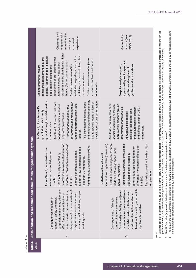
451Chapter 21: Attenuation storage tanks
CIRIA SuDS Manual 2015
TAB
LE21
.1C
lass
ifica
tion
and
reco
mm
ende
d ca
lcul
atio
ns fo
r geo
cellu
lar s
yste
ms
2
Consequencesoffailure,in
contextofsafetyareminor.
Larg
e de
form
atio
n m
ay a
dver
sely
affectfunctionalityoffacility,or
unitslocatedshallowerthan1m,
deep
er th
an 3
m o
r loc
ated
in s
oft
clay
s or
loos
e sa
nds
or lo
cate
d in
vic
inity
1 offoundations,slopes,
retainingwalls.
AsforC
lass1,butsoil–structure
inte
ract
ion
is p
oten
tially
mor
e complex.
Site
func
tiona
lity
affe
cted
by
deform
ationinexcessof50mm
3 or
diffe
rent
ial m
ovem
ents
in e
xces
s of
1in200.
Locatedbeneathpublicro
ads,
subj
ect t
o lo
w to
mod
erat
e sp
eed
(lessthan30mph)traffic.
ParkingareasaccessibletoHGVs.
AsClass1,plussite-specific
q uan
titat
ive
data
to v
erify
gr
ound
stre
ngth
and
def
orm
atio
n characteristics.
AsClass1,pluscreeptestdata
f or g
eoce
llula
r uni
ts to
ass
ess
long-te
rmdeformation.
Gre
ater
und
erst
andi
ng o
f the
pe
rfor
man
ce a
nd m
anuf
actu
rer
test
ing
unde
rtak
en o
f the
uni
ts
required.
Thelikelyloading,fatigue,creep
and
tem
pera
ture
of o
pera
tion
may
leadtospecifictestingorfurth
er
investigationofunitperform
ance.
Slo
ping
gro
und
will
requ
ire
cons
ider
ed a
sses
smen
t of l
ater
al
loading.Recom
mendedtoinclude
slopestabilitycalculations,
asse
ssm
ent o
f pre
-exi
stin
g sh
ear
zonesinslopes.Note:lateral
pressurescanbesignificantlyhigher
thanK
a(forh
orizontalground).
Detailedassessmentofthe
inst
alla
tion
rega
rdin
g co
nstru
ctio
n activities,suchasstockpiles,plant
orcraneoperations.
Detailedassessmentofadjacent
structures,suchasloadpathsof
foundations.
Cha
rtere
d ci
vil
engineer, w
ith
morethanfive
years’post
char
tere
d ex
perie
nce
3
Consequencesoffailure,in
contextofsafety,aresevere.
Func
tiona
lity
of fa
cilit
y or
adj
acen
t pa
vem
ents
/stru
ctur
es s
ensi
tive
to
smalldeformations.U
nitslocated
shallowerthan0.5m,ordeeper
than4m.Locatedingroundwhich
ispotentiallyunstable.
Loca
ted
bene
ath
or a
djac
ent t
o specialistloadingfacilities(cranesetc).
Loca
ted
bene
ath
or a
djac
ent t
o pu
blic
ro
ads
subj
ect t
o hi
gh s
peed
(mor
e than30mph)traffic.
Subjectedtosignificantcyclicloads.
Site
func
tiona
lity
affe
cted
by
deform
ationslessthan50mm
3 or
diffe
rent
ial m
ovem
ents
of l
ess
than
1in200.
Reg
ular
ly e
xpos
ed to
liqu
ids
at h
igh
temperatures.
AsClass2,butmayalsoneed
spec
ialis
t sam
plin
g or
test
s to
m
ore
relia
bly
mea
sure
gro
und
deform
ationcharacteristics.
AsClass2,pluspossibly
specialisttestdatafortank,
or m
easu
rem
ents
of s
treng
th
and
stiff
ness
at h
igh
(> 2
5°C
) temperature.
Bespokeanalysisrequired,
supe
rvis
ed b
y se
nior
spe
cial
ist
geot
echn
ical
eng
inee
r of
geotechnicaladvisorstatus.
Geo
tech
nica
l ad
viso
r (se
e SISG,2012)
Not
es1
Ahigherd
esignclassificationmaybeusedinordertojustifyamoreeconom
icaldesign;forexample,amorerig
orousanalysisofsoilstru
ctureinteractionmayleadtoincreasedconfidenceinthe
p erformanceofatank,andallowlowerqualitybackfilltobeusedaroundthetankoravoidtheneedfora
dditionalmeasurestore
ducetheearthpressureonthesideofthetanks.
2SeeO’Brie
net
al(inpress)fordefinitionsof“remotefro
mfoundations,retainingwalls,slopesetc.”
3Th
edesigncheckre
quirementsareintendedasaminimum
guideforconsiderationandarenotanall-e
ncom
passingexhaustivelist.Furtherrequirementsandchecksmayberequireddepending
ontheparticularcircum
stanceandasdirectedbyacompetentdesigner.
continuedfro
m...

CIRIA SuDS Manual 2015
452 Part D: Technical detail
Step 2 – Develop the conceptual ground model
Manyconstructioncostoverrunsarecausedbyunforeseengroundorgroundwaterconditions,andcollapses of structures including geocellular tanks have occurred because of a lack of understanding ofthegroundorgroundwater.Thedevelopmentofaconceptualgroundmodelisanimportantstepinensuringthesuccessfuldesign,constructionandoperationofgeocellulartanks.
The conceptual ground model shows the possible subsurface conditions that can be predicted from the availabledeskstudyandgroundinvestigationdataforasite(GeologicalSociety,2002).Developingagroundmodel that includes the known and suspected features below and adjacent to a site will help identify the likely implicationsofthegroundforthedesignofatankandensurethatappropriateanalysesarecompleted.
It is often useful to draw the conceptual ground model as a three-dimensional diagram that allows the scaleandlocationofgroundfeaturestobeassessedinrelationtothetank.Themodelshouldincludeacharacterisationofthegeologyinengineeringterms,whichwillallowthegeotechnicalpropertiesandtheirlikelylateralandverticalvariationtobeassessedwithinthecontextofthemodel.
Keyinformationthatshouldfeedintothegroundmodelincludes:
▪ overall site topography and potentially adverse effects of nearby structures/earthworks (eg increased earthpressureatthefootofanembankment),and/orvegetation(egretainingwalls,slopes,temporary,permanentorfutureplannedworksorchangesinmoisturecontentandswellingorshrinkage of soil due to trees)
▪ sitehistoryandgeology(egground/groundwatercontamination,historiclandslipsormining)
▪ groundwaterlevelsandflows
▪ thesoil-structureinteractionbetweenthetankandthesurroundingground.
Step 3 – Design loads and partial factors of safety
Thenextstepinthedesignistodeterminetheappliedloadsfromallsources(horizontalandvertical).
Characteristic loads are a best estimate of the load likely to be placed on a structure during its design life.Thecharacteristicloadsderivedforthepermanentandtemporaryworksneedtobefactoredtoallowforpossiblevariationsanddynamiceffects,inordertocalculatethedesignloads,andguidanceisagainprovidedinO’Brienet al(inpress).Adviceonloadsinareassuchasports,whereveryheavymachineryispresentisprovidedbyInterpave(2010).Itisnormaltoapplydynamicfactorstocontainerloadingequipmentforpavementdesignintheseareas,anditwouldbeprudenttodosoforgeocellulartanks.
Thehorizontalloads(oractions)willdependonthepropertiesofthesurroundingsoils.Whenassessingthegroundpropertiesusedtocalculateearthpressures,theadviceofageotechnicalengineerorengineeringgeologistshouldbesought.Thepresenceofgroundwateratthesiteneedstobeinvestigated,bothatthedeskstudystageandduringthegroundinvestigation,andgivencarefulconsiderationwheninterpretinglikelyfuturesiteconditionsoverthetank’sdesignlife.Whengeotechnicalproblemsoccur,itisoftenduetounforeseengroundwaterproblems.Itisparticularlyimportanttoconsiderthepotentialforseasonalandweather-relatedfluctuationsinthegroundwaterregime.
Standard soil mechanics theory as described in many textbooks is used to determine the applied horizontalloads(egBarnes,2010).Thecharacteristicpropertiesofthesoilshouldbedeterminedfromsiteinvestigationdata,andthesearereducedbytheappropriatepartialfactorsprovidedinO’Brienet al (in press) and also site importance factors which are intended to ensure that the probability of failure is sufficientlyremote,dependinguponthesiteclassificationandassociatedconsequencesoffailure.
Step 4 – Determine design strength and deformation properties for the system
Thestructuralpropertiesforthesystemtobeusedwillberequiredtoallowthedesigntobecompleted.This information should be provided by the supplier or manufacturer of the system being considered and

453Chapter 21: Attenuation storage tanks
CIRIA SuDS Manual 2015
shouldhavebeenderivedviacertifiedtestingprogrammes.Thetestdataandcertificatesfortheunitsarenormallyrequiredbythedesigner.
Thetypeoftestsvaryfromquickcompressionteststolong-termcreeprupturetests,usingbothfullloadplatens(covertheentiresurfaceofthebox)and300mmdiameterloadplatens.Thetestdatarequiredforinstallationsdependsonthesiteclassification–thehigherthesiteclassificationthegreatertheextentoftestdatathatisneeded.
Theresultsfromlaboratorytestsareusedtoarriveatacharacteristicstrength.Thecharacteristicstrengthisreducedbypartialfactorsofsafetytodetermineadesignstrengthfortheunits.ThisprocessisexplainedinO’Brienet al(inpress).Thetestmethodsshouldreplicatethebehaviourofthestructurewhenitisintheground.
Manymanufacturersonlysupplytestdataforsingleunits.Sometypesofunitsmaybehavedifferentlywhenstackedontopofeachother,dependingonthelayoutoftheunitswithinthetankandthenatureoftheappliedloading:thestrengthcanreduce,ordeformationsmayincrease.Thisaspectneedscarefulconsiderationbythedesigner,and,asrecommendedbyO’Brienet al (in press) may necessitate full-scale in situtesting.
Riskofdamagetooverlyingpavementsurfacesisafunctionofelasticshort-termdifferentialmovement,nottotalmovement.However,theuseofallowabletotalmovementcriteriaunderrepeatedtrafficloadsishelpful,forroutinesimpleassessments,andasatriggerforindicatingtheneedformoredetailedanalysis.Theallowablemovementcriterianeedtoberealisticallyassessed,basedonthespecificuseofasite,itsfunctionalityandthenatureofthepavingsystem.
Step 5 – Design calculations and analysis
Once the design loads and design strength/deformation properties have been determined then the designer will need to undertake checks on the following modes of failure for each scenario when designing geocellular unit installations:
1 Global stability and deformation – This is a check on the overall stability of the tank and surroundingground.Itisessentialthattheoverallstabilityanddeformationofthesiteischecked.Thesechecksshouldbesummarisedinthegeotechnicaldesignreport,andwillincludeissuessuchaschecksonthestabilityofanyslopesorretainingwallslocatedonoradjacenttothesite,andareviewofanypotentialgeohazardsorhistoricalactivities(egsolutionfeaturesinchalk,miningorquarryingactivities),whichmayleadtoglobalstabilityorsubsidencerisks.Globaldeformationsmaydevelopbecauseofswellinginthebaseofexcavations,settlementovernon-engineeredfillmaterialorsoft,compressiblesoils,thepresenceofmetastablesoils,volumechangesinclaysoilsduetothepresenceoftrees.Globalmovementsneedtobecarefullyassessedbyanappropriatelyexperiencedgeotechnicalengineer.
2 Interaction checks–Itisessentialthattheunitsaredesigned,takingintoaccountanyinteractions(eitherextraloadingonthetankorpotentialinstabilityduetothetank)withexistingstructures,existingslopes,buildingfoundations,retainingwalls,adjacenthighways/railwaysoranysimilarstructuresorfeatures.Itwilloftenbedesirabletorelocatethelocationofthegeocellularunitwherepossibletominimisetheinteractionswithadjacentstructuresratherthanhavingtodesigntoaccountforthem.
3 Stability of geocellular unit – The stability of the geocellular units should be assessed under the appliedloads.Thisisanultimatelimitstate.Thisshouldincludeacheckthatthedesignverticalandhorizontal strength of the geocellular units is greater than the design vertical and horizontal loads respectively(bothintheshorttermfortemporaryworksandinthelongterm).Itshouldalsoinclude,whereappropriate,theoverallstabilityofthegeocellularunitsintermsofoverturningorshearingoftheunitsthemselves.Flotationshouldbeconsideredfortanksbelowthegroundwatertableorifgroundwaterlevelcouldriseoverthedesignlifeofthetank.
4 Deformation of geocellular unit–Consideringthedeformationisaserviceabilitycheck.Lowerfactorsofsafetythanthoseusedforultimatelimitstateassessmentareappliedtoloads,soilpropertiesandtheunitpropertiesforaserviceabilitycheck.Themagnitudeoftheallowable
CIRIA SuDS Manual 2015
454 Part D: Technical detail
settlement(orhorizontalmovement)ofgeocellularunitswilloftenbecriticaltodesign,duetothelong-termcreepbehaviourofplastics.Itisimportantthatthegeocellularunitdesignerisinvolvedindiscussionswiththeoverallprojectdesigner,beforeanallowablemovementisdecided.Bothlong-termdeformationduetocreepandshort-termelasticdeformationshouldbechecked.AsdiscussedinO’Brienet al(inpress),ifunitsareexposedtosignificanttrafficloading,thenspecialistcyclictestingmayberequiredtoassesstheirbehaviourunderrepeatedloading.Theassessmentofshort-and long-term movements will be particularly important if sensitive services or structures are located inthevicinityofatank.
Step 6 – Prepare geotechnical design report
Thegeotechnicaldesignreportisanimportantdocument,referredtoinBSEN1997-1:2004+A1:2013,which allows those constructing the tanks and managing them during operation to understand the assumptionsandlimitationswithinthedesign(egassumptionsaboutconstructionmethodsorloads).Thereportsummarisesthegroundmodel,data,methodsofcalculationandresultsofcalculations.Itwillalsoidentifythelevelofsupervision,testingormonitoringandmaintenancerequiredduringconstructionoroperation.Thedetailrequiredinthereportwilldependonthecomplexityoftheproject.Forsimpledesigns,asinglepagemaybesufficient,whereascomplexdesignsmayrequireacomprehensivereport(Frank et al,2004).AchecklistofitemstobeprovidedinthegeotechnicaldesignreportisprovidedinBSEN1997-1:2004+A1:2013.
The geotechnical design report should be updated if any changes are made to the design as construction progresses,anditshouldformpartoftherecordsfortheprojectthatareincludedinthehealthandsafetyfile(providedtotheclientattheendoftheproject,asrequiredbyCDM2015).
Further information on the contents of the geotechnical design report is provided in BS EN 1997-1:2004+A1:2013.
21.4.2 Plastic corrugated arch structures
Many of the general requirements for the structural design of geocellular tanks also apply to plastic arch systems.TherearetwoASTMstandardsthatprovideguidanceontherequiredstructuralpropertiesandload testing of plastic arch systems (one for those manufactured from polypropylene and the other for those manufactured from polyethylene):
▪ corrugated arch chambers manufactured from polypropylene – ASTM F2418-13 – the design of these systems are not covered in detail in this manual
▪ corrugated arch chambers manufactured from polyethylene – ASTM F2922-13e1
ThesiteclassificationsystemdescribedinStep1ofthestructuraldesignforgeocellularunitsmayalsobeappliedtoplasticarchsystems,toensurethatthedesigniscarriedoutandapprovedbysomeonewithappropriatequalificationsandexperience.ThedevelopmentofaconceptualgroundmodelasdescribedinStep2forgeocellularsystemsisalsoimportant,asisthegeotechnicaldesignreportdescribedinStep6.
GuidanceonthestructuraldesignofanytypeofplasticarchsystemisprovidedinASTMF2787-13.Thestructuraldesignincludesthedesignofthecompositesystemmadeupofthechamberarch,thechamberfootandthesoilenvelope.Importantfactorsthatshouldbeaddressedinthedesignare:
1 creep deformations over time and the creep rupture strength of the arches
2 globalandlocalbucklingofthearchwalls,tensilestressinwalls,capacityofthefoundationmaterialto support bearing pressure from the chamber foot and the capacity of the subgrade to support the loads from the foot
3 influenceofadjacentarchesoneachother
4 the displacements that will occur under load and the effects that these may have on the surfacing above,thehydraulicperformanceandthedistributionofloadsassumedinthemodelforitem2above

455Chapter 21: Attenuation storage tanks
CIRIA SuDS Manual 2015
5 test results from full-scale testing of completed installations (this does not require testing of every installation)tosupportthechamberdesigncalculations.
Whereappropriate,theloadrequirementsstatedinASTMF2787-13shouldbereplacedbythoseintherelevantEurocodes.ThedesignofplasticarchsystemsshouldalsocomplywithrelevantrequirementsofgeotechnicalEurocodes.
21.4.3 Oversize concrete pipes
The structural design of concrete pipes should follow the guidance provided in BS EN 1295-1:1997 using thenationaldesignmethodinAnnexA.GuidanceonhowtoapplyBSEN1295toconcretepipedesignisprovidedbyCPSA(2013).GuidanceisalsoprovidedinBS9295:2010.AsummaryofthenationaldesignmethodsisprovidedinPDCEN/TR1295-2:2005.
ConcretepipesshouldmeettherequirementsofBSEN1916:2002andBS5911-1:2002+A2:2010.Thestandardsplacepipesintodifferentstrengthclassesbasedontheirmaximumcrushingload,althoughmoststandardpipesavailableintheUKmeettherequirementsforClass120.Thepipesshouldnotcollapseunderthemaximumloadspecifiedwhentestedinaccordancewiththestandards.Proofloadtestsarealsorequired,andreinforcedpipesshouldnotcrackbyspecifiedamountsinthistest(theproofloadtestforunreinforcedpipesisthemaximumload).
Smalldiameterpipesupto300mmdiametercanalsofailduetolongitudinalbending(ieasabeam),andthestandardsalsospecifyminimumvaluesofbendingresistanceforpipes.
Concretepipesarerigidandhaveahighinherentstrength.Theyresistappliedloadingbyabendingactionwithinthepipewalls.Theyaregenerallystifferthanthepipesurroundmaterial,inparticularthesidefill,andthereforesupportahigherloadthanthesidefillmaterial.ThestructuraldesigndescribedinBSEN1295-1:1997considerstheloadsappliedtothepipes(includingtheinfluenceofthetrenchwallsandbackfill)andtheinfluenceofthepipebeddingandsurroundontheappliedloads.Afactorofsafetybetween1.25and1.5isusedinthedesign(thisistheglobalfactorofsafety).
One of the main considerations in the design of any pipe structure is the location in which the pipe is installed.Theseconstructionconditionsarecategorisedas:
▪ narrow trench
▪ widetrenchor“onthesurface”,overwhichanembankmentisthenbuilt
▪ narrow trench over which an embankment is then built
▪ tunnel,headingorwhenthepipeistobeinstalledbyjacking.
Theinstallationlocationhasasignificantinfluenceontheloadsthatthepipewillhavetosupport.Therefore,anyassumptionsmadeinthedesignshouldbemadeclearondrawingsbythedesignersothatconstructionofthetankdoesnotinvalidatethem.Thenarrowtrenchconditionwillgivesuitableworkingspacearoundthesideofthepipeduringinstallation.Ifthetrenchwidthisincreasedsignificantlybeyondthis,therecomesapointwherethefrictionbetweenthebackfillandtrenchwallsnolongercontributestoloadreductiononthepipeandconsequentlyloadsonthepipeincrease.
Forpipesabove600mmdiameter,somepartofthewaterloadunderworkingloadsshouldbeallowedforinthestructuraldesign.Oftenthepipesmaywellbesubjecttothehighestloadsduringconstructionandthisshouldbetakenaccountofinthedesign.
Rigidpipeswilltosomeextentrelyonthebackfillstructuretotransferloadsintothebeddingandanyassumptionsmadeinthedesignregardingtheseaspectsshouldbeclearlystatedonanydesigndrawings.
ThegeneralprinciplesofthesiteclassificationsystemdescribedinStep1ofthestructuraldesignforgeocellularunitsmayalsobeappliedtooversizeconcretepipesystemswithsomemodificationtoensurethatthedesigniscarriedoutandapprovedbysomeonewithappropriatequalificationsandexperience.

CIRIA SuDS Manual 2015
456 Part D: Technical detail
The development of a conceptual ground model as described in Step 2 for geocellular systems is also important,asisthegeotechnicaldesignreportdescribedinStep6.
21.4.4 Oversize plastic pipes
The structural design of plastic pipes should follow the guidance provided in BS EN 1295-1:1997 using thenationaldesignmethodinAnnexeA.GuidanceonhowtoapplyBSEN1295-1toplasticpipedesignisprovidedinBS9295:2010.VariousmanufacturersalsoprovidetheirownguidanceonhowtoapplytheBritishStandard.
Plasticpipesareflexible,anddeformunderloadtoformaslightlyovalshapeintheground.Thedeformationisanimportantpartofdevelopingtheloadcapacityofthepipe/soilsystem.Asthepipemoves outwards horizontally the passive earth pressure increases until the pipe–soil system comes intoequilibrium.
Further deformation will not occur thereafter unless a higher vertical load is applied to the pipe–soil systemorconsolidation(orcreep)ofthematerialsoccursoveralongperiodoftime.Itisinternationallyrecognisedthatwhenapipeisinstalledinaccordancewithanappropriatecodeofpractice,increasesindeflectionvirtuallystopafterashortperiodoftime.Thedurationoftimeisdependentonsoilandinstallationconditionsbutgenerallydoesnotexceedtwoyears.
The performance of the pipe will depend on:
▪ stiffness of the natural soil in which the trench is cut (represented by soil modulus)
▪ density of the overburden
▪ magnitudeofdynamicloadsduetotrafficking
▪ hydrostatic loading
▪ acceptablefactorofsafetyagainstbuckling(typically>2withsoilsupportand>1.5withoutsoilsupport)
▪ stiffness of the pipe bed and surround and the elastic modulus of the surrounding soil
▪ specifiedmaximumlimitofdeflection.
Soilmodulushasasignificanteffectontheresultsandshouldbecarefullyassessed.Wherethesoilsurroundingthetrenchwallsisaweakmaterial,thelevelofsupportprovidedwillbemuchlowerthananyspecifiedpipesurround.Therefore,onlyconsideringthemodulusofthepipebedandsurroundwillover-estimatetheoverallmodulusofthepipe/soilsystem.
Aswithotherplasticsystems,creepisanimportantconsideration,andallpipemanufacturerswillprovidetheresultsofcreeptestsforuseinthedesign.
Alimitonverticaldeformationisnecessarytoensureadequatelong-termperformanceofplasticpipes.Appropriatedeflection(serviceability)limitsshouldbesetonacase-by-casebasis.Forexample,greaterlimitsmaybeallowableinadeeplandfillinstallationcomparedtoapipeburiedatashallowdepthunderaroad.DeflectionlimitswithintheUKvary,dependingontherelevantadoptingauthority.FordesignpurposesDfT(2001)specifiesamaximumallowabledeformationof5%forthermoplasticstructuredwalledpipes,whilethewaterindustrytendstospecify6%basedontherequirementsofBSEN1295-1:1997.
Flexiblepipesrelyonthebackfillstructuretohelpsupportloads,andanyassumptionsmadeinthedesignregardingtheseaspectsshouldbeclearlystatedonanydesigndrawings.
ThegeneralprinciplesofthesiteclassificationsystemdescribedinStep1ofthestructuraldesignforgeocellularunitsmayalsobeappliedtooversizeplasticpipesystems,withsomemodificationtoensurethatthedesigniscarriedoutandapprovedbysomeonewithappropriatequalificationsandexperience.The development of a conceptual ground model as described in Step 2 for geocellular systems is also important,asisthegeotechnicaldesignreportdescribedinStep6.

457Chapter 21: Attenuation storage tanks
CIRIA SuDS Manual 2015
21.4.5 Corrugated steel pipes
CorrugatedsteelpipesareconsideredtobeflexibleandaredesignedfollowingBS1295-1:1997andtheassociatedguidancedocuments.AdviceisalsoprovidedinHA(1991).Thisisroutinelyusedasadesigntoolbysomemanufacturers.Specificadviceisalsoprovidedbymanufacturersofthesesystems.
Intermsofstructuraldesign,theissuesraisedinrelationtoplasticpipesapplytothesesystemsaswell,althoughthemagnitudeofcreepdeformationinsteelstructuresisfarlessthaninplastic.Thedesigndoes however need to take account of the protection provided against corrosion and make a suitable allowanceforcorrosionandlossofsectionoverthedesignlife.
Asperoversizeplasticpipes,flexiblecorrugatedsteelpipesrelyonthebackfillstructuretohelpsupportloads,andanyassumptionsmadeinthedesignregardingtheseaspectsshouldbeclearlystatedonanydesigndrawings.
ThegeneralprinciplesofthesiteclassificationsystemdescribedinStep1ofthestructuraldesignforgeocellularunitsmayalsobeappliedtocorrugatedsteelsystemswithsomemodificationtoensurethatthedesigniscarriedoutandapprovedbysomeonewithappropriatequalificationsandexperience.The development of a conceptual ground model as described in Step 2 for geocellular systems is also important,asisthegeotechnicaldesignreportdescribedinStep6.
21.4.6 Precast concrete box culvert sections (including flat-packed concrete panels)
Precast box culverts should be treated as a structure and the structural design should be undertaken by asuitablyqualifiedstructuralengineer.ThedesignshouldcomplywiththerelevantEurocodesforprecastreinforcedconcreteandBSEN14844:2006+A2:2011.FurtheradviceisprovidedbytheBCA(2014).
21.4.7 Glass-reinforced plastic (GRP) tanks
CircularGRPpipesareconsideredtobeflexiblepipesinaccordancewithBSEN1295-1:1997.Structuraldesignshouldfollowthedesignguidanceinthatdocument,asexplainedaboveforplasticandsteelflexiblepipes.
Asperallothertypesofflexiblepipe,thesepipesrelyonthebackfillstructuretohelpsupportloads,andanyassumptionsmadeinthedesignregardingtheseaspectsshouldbeclearlystatedonanydesigndrawings.
21.4.8 Hybrid tanks using reinforced earth walls and concrete roof panels
Hybrid tanks have two elements:
▪ precast concrete roof panels – designed by a structural engineer to comply with the relevant Eurocodes for precast reinforced concrete described above for box culverts
▪ reinforcedsoilabutments–designedinaccordancewithBS8006-1:2010.Thedesignshouldalsofollow other relevant geotechnical Eurocodes – advice is also provided in HA (1996a)
ThegeneralprinciplesofthesiteclassificationsystemdescribedinStep1ofthestructuraldesignforgeocellular units may also be applied to hybrid systems to ensure that the design is carried out and approvedbysomeonewithappropriatequalificationsandexperience.ThedevelopmentofaconceptualgroundmodelasdescribedinStep2forgeocellularsystemsisalsoimportant,asisthegeotechnicaldesignreportdescribedinStep6.
21.5 HYDRAULIC DESIGN
21.5.1 General
The hydraulic design of on- or off-line storage systems using pipes or tanks should be in accordance with WRc(2007,2010and2012)usingstandardroutingmethods(Section 24.11).UsefulinformationisalsoprovidedinBSEN752:2008.
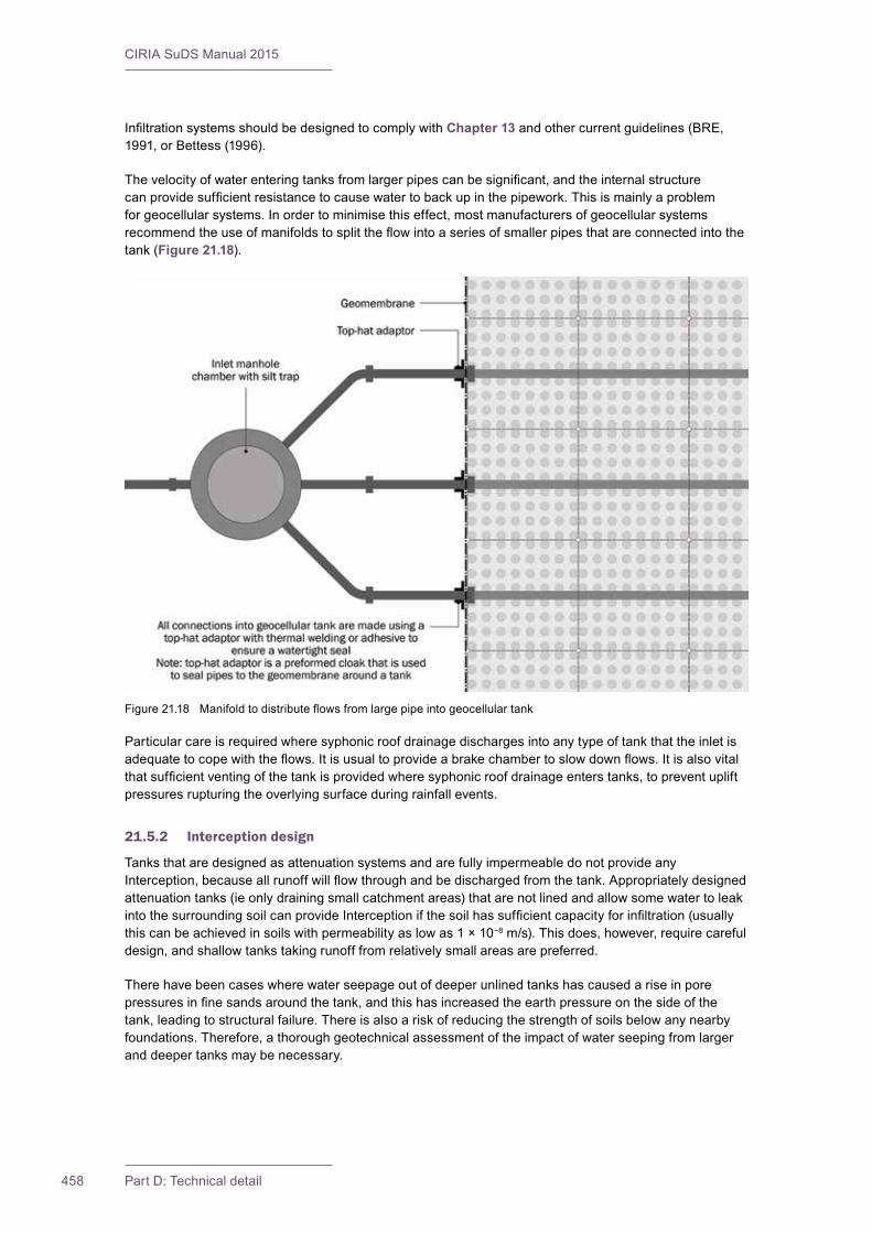
CIRIA SuDS Manual 2015
458 Part D: Technical detail
InfiltrationsystemsshouldbedesignedtocomplywithChapter 13andothercurrentguidelines(BRE,1991,orBettess(1996).
Thevelocityofwaterenteringtanksfromlargerpipescanbesignificant,andtheinternalstructurecanprovidesufficientresistancetocausewatertobackupinthepipework.Thisismainlyaproblemforgeocellularsystems.Inordertominimisethiseffect,mostmanufacturersofgeocellularsystemsrecommendtheuseofmanifoldstosplittheflowintoaseriesofsmallerpipesthatareconnectedintothetank (Figure 21.18).
Particular care is required where syphonic roof drainage discharges into any type of tank that the inlet is adequatetocopewiththeflows.Itisusualtoprovideabrakechambertoslowdownflows.Itisalsovitalthatsufficientventingofthetankisprovidedwheresyphonicroofdrainageenterstanks,topreventupliftpressuresrupturingtheoverlyingsurfaceduringrainfallevents.
21.5.2 Interception design
Tanks that are designed as attenuation systems and are fully impermeable do not provide any Interception,becauseallrunoffwillflowthroughandbedischargedfromthetank.Appropriatelydesignedattenuation tanks (ie only draining small catchment areas) that are not lined and allow some water to leak intothesurroundingsoilcanprovideInterceptionifthesoilhassufficientcapacityforinfiltration(usuallythiscanbeachievedinsoilswithpermeabilityaslowas1×10−8m/s).Thisdoes,however,requirecarefuldesign,andshallowtankstakingrunofffromrelativelysmallareasarepreferred.
There have been cases where water seepage out of deeper unlined tanks has caused a rise in pore pressuresinfinesandsaroundthetank,andthishasincreasedtheearthpressureonthesideofthetank,leadingtostructuralfailure.Thereisalsoariskofreducingthestrengthofsoilsbelowanynearbyfoundations.Therefore,athoroughgeotechnicalassessmentoftheimpactofwaterseepingfromlargeranddeepertanksmaybenecessary.
Figure21.18 Manifoldtodistributeflowsfromlargepipeintogeocellulartank

459Chapter 21: Attenuation storage tanks
CIRIA SuDS Manual 2015
21.5.3 Peak flow control design
Attenuationtankscanhelpreduceflowratesfromasitebyprovidingattenuationstorage.Theavailablestorage volume is provided by the void space in the tank structure:
Available attenuation storage in the tank = Volume of tank × tank porosity
The size of the tank should be determined using the hydraulic design methods described in Section 24.9. Aflowcontrolstructureisgenerallyrequiredtoconstraintherateofwaterdischargedfromthetank.Oftenundergroundtanksaredesignedtoattenuaterainfalleventsupto1:30yeareventgreaterthanthisarestoredaboveground.
Ifthehead–dischargerelationshipsfromhydraulicflumetestsareknownforgeocellularunitstheycanbe also be used to convey water across a site and can in some circumstances provide the necessary dischargecontrol,removingtheneedforotherflowcontrolssuchasorificeplatesorvortexflowcontrols.
It is common practice to oversize the design volume of any tank that is considered to be at risk of sedimentationandhardtomaintainby10%toallowforlossofstorageduetosedimentbuild-up.Thisisa precautionary measure and is not a replacement for effective sediment management upstream of the tank.The10%figureisanarbitraryvalueandmaybeinappropriatelylargeinsomeapplications.Forexample,asystemtakingonlyroofrunoffwouldtake250yearstosuffera10%lossofstoragevolume.Table 21.2providesmoreinformation.
21.5.4 Volume control design
Contribution of storage tank systems to volume control should be evaluated using standard methods –basedonexpectedinfiltrationratesand/oravailableattenuationstorageandspecifiedflowcontrols(Section 24.10).
21.5.5 Exceedance flow design
Anexceedanceflowroutewillberequiredforrainfalleventsthatexceedthedesigncapacityofthetanksystem.Thiscanbeachievedbyinstallinganoverflowpipeabovethedesignwaterstoragelevelinthetankoroverlandflowroutingfromsurchargingcomponentsupstreamofthesystem(Section 24.12).
21.6 TREATMENT DESIGN
Storagetanksystemsdonotprovideanyformoftreatmentofsurfacewaterrunoff,andtheythereforeneed to be combined in a Management Train with other methods that do provide suitable treatment of all relevant pollutants (Chapter 26).Treatmenttoremovecoarsesedimentshouldalwaysbeprovidedupstreamofatank.
21.7 AMENITY DESIGN
Storagetanksystemscanprovideamenityvalueiftheyarestoringwaterforuse.Theycanalsopromotethemulti-functionaluseofspace,byallowingthesurfaceabovethetanktobeusedforrecreationorotheramenityfacilities.Tankscanalsobeusedinconjunctionwithothersurfacefeaturessothatwaterlevel rises in those features can be minimised to maximise their amenity value and minimise health and safetyrisks.
21.8 BIODIVERSITY DESIGN
Storagetanksystemsdonothaveanyinherentbiodiversityvalue,buttheycanhelpreducetheimpactofheavyflowsonthedownstreamsystem,andthiscanhelpfacilitatebiodiversitydeliveryinthoseareas.
CIRIA SuDS Manual 2015
460 Part D: Technical detail
21.9 PHYSICAL SPECIFICATIONS
Attenuationtankstructuresarecommonlyusedcomponentsofdrainagesystems.Thespecificationofthesystemshouldbebasedonitsrequiredperformanceataparticularsite,asdeterminedfromthehydraulicandstructuraldesigncalculationsandmodelsdiscussedearlierinthischapter.
Therearemanystandardspecificationsavailable(egWRc,2012,andDfT,1998)thatmaybeusedforthesetypesofstructure.BritishBoardofAgrément(BBA)orothercertificationcanprovidesomeoftheinformation necessary for design approval but they should be read carefully to understand the limitations imposedbythecertificate(Box 21.1).
21.9.1 Geocellular structures
TherearecurrentlynoBritishorEuropeanstandardsforgeocellularstructuresorunits,althoughthereisworkbeingdoneatthetimeofgoingtopresstodevelopEuropeanproductandtestingstandards.
Specificationofgeocellularormodularstructureswillcomprisethreeparts:
▪ specificationofthestructuralunit
▪ specificationofthewrappingmaterial(geotextileand/orgeomembrane)–seeChapter 30
▪ specificationofthebackfillmaterial–seeSection 21.10
Thefollowingpropertiesshouldbespecifiedforgeocellularunitsandbackfill,sothatdesignerscanevaluatetheirsuitabilityforaspecificdesignapplication:
1 material used in manufacture (including any recycled material)
2 hydraulic properties (including head–discharge relationships if to be used for conveyance)
3 verticalandhorizontallong-termstrengthoveraspecifiedoperationaltime(notethatlong-termstrengthisnotonlyafunctionofelapsedtime,itisalsoafunctionoftheappliedload;aunitloadedwith20kN/m2willhaveahigherstrengthat50yearsthanthesameunitloadedwith70kN/m2
4 verticalandhorizontalstrengthatspecifiedtemperature(ifappropriate,eginhotclimates)
5 impact strength if appropriate (eg in cold climates)
6 verticalelasticdeflectionundershort-termtrafficloadsandunderlong-termloads
BOX21.1
The use of BBA and other certification schemes
BBAcertificates,CEmarkingandothercertificationschemesareonlyintendedtohelpdesigners,procurement professionals and regulators understand the potential performance of a product (DECC,2012).Forexample,theperformanceofaproductcanbestatedintermsofstrength,deflectionunderloadandcreepdeformationsoverspecifieddesignlives.
Certificationestablishesthetechnicalperformanceofaproduct(ora“system”,iftheperformancedependsontheprovisionofdifferentcomponents)forspecifiedloadingconditions.Therequiredperformanceonaparticularsitedependsonwhereitisgoingtobeused(depth,lateralpressure,trafficloadsetc).Thedesignerofthedrainagesystemwillneedtoassesswhetherthelevelofperformancestatedinthecertificatesatisfiestheloadingandallowabledeflectionconditionsthatapplytotheprojectinquestion(DECC,2012).Acertificateisnotaguaranteethataparticularproductisappropriateinanydefinedsituation.Designcalculationsarestillrequiredandshouldbecheckedrigorously.Thecertificateshouldbereadcarefully,especiallywithregardtodesignlifeandlimitationsontheapplicationscoveredbythecertificate.
ItisoftenerroneouslybelievedthatBBAcertificationofproductsisrequiredtocomplywithBuildingRegulationsortogainbuildingcontrolapproval.Thisisnotthecase(DECC,2012).

461Chapter 21: Attenuation storage tanks
CIRIA SuDS Manual 2015
7 horizontaldeflectionundershort-termandlong-termloads
8 fatigueresistancetocyclicloading(wherecoverislessthan1mandsignificantHGVtrafficisexpected)
9 responsetotrafficloadsandpavementdesignparametersfromfull-scaletrials,suchasBenkelmanbeamandfallingweightdeflectometertests(theseroadpavementsurfacetestshavebeenusedtotest the performance of sub-base replacement systems)
10typeofbackfillandanyrequirementsforcompactionplant
11acceptabletestmethodsorteststandardsfortheabove–seeO’Brienet al (in press)
21.9.2 Plastic arches
TherearetwoASTMstandardsthatprovideguidanceonthespecificationofthepropertiesofplasticarchsystems (one for polypropylene and the other for polyethylene):
▪ corrugated arch chambers manufactured from polypropylene – ASTM F2418-13; the design of these systems is not covered in detail in this manual
▪ corrugated arch chambers manufactured from polyethylene – ASTM F2922-13e1
Thechambersareproducedinarchshapesandclassificationsspecifychamberrise,chamberspan,minimumfootwidth,minimumwallthicknessandminimumarchstiffnessconstant.Chambersaremanufacturedwithintegralfootings.
21.9.3 Oversize concrete pipes
ConcretepipesshouldmeettherelevantrequirementsofBSEN1916:2002andBS5911-1:2002+A2:2010.
21.9.4 Oversize plastic pipes
PolypropylenepipesshouldmeettherelevantprovisionsofBSEN1852-1:1998.
AllstructuredwallplasticpipesshouldcomplywiththerelevantprovisionsofBSEN13476-1:2007.
Structuredwallpipeswithasmoothexternalsurface(includesspiral-woundHDPEpipes)shouldcomplywiththerelevantrequirementsofBSEN13476-2:2007.
Structuredwallpipeswithaprofiledexternalsurface(includesribbedpipes)shouldcomplywiththerelevantrequirementsofBSEN13476-3:2007+A1:2009.
Notethatthesespecificationsarelimitedtoamaximumdiameterof900mm.Therelevanceofanyparticularclauseshouldbecarefullyconsideredwhenapplyingthestandardstolargerdiameterpipes.
RequirementsforoversizeplasticpipesarealsodescribedinUKWIR(2008)andrelevantclausesfromthisdocumentcanalsobeusedinspecificationsforSuDS.
Pipesmanufacturedusingnon-virginmaterialsshouldcomplywithPDCEN/TS14541:2013.
21.9.5 Corrugated steel pipes
TherearenoBritishorEuropeanStandardsforflexiblesteelpipes.CorrugatedsteelpipesusedinSuDSshouldcomplywiththerelevantrequirementsoftheSpecificationforHighwayWorks,Series2500,SpecialStructures(DfT,2001).

CIRIA SuDS Manual 2015
462 Part D: Technical detail
21.9.6 Precast concrete box culvert sections (including flat-packed concrete panels)
PrecastconcreteboxculvertsshouldmeettherequirementsofBSEN14844:2006+A2:2011.Thisprovidesguidanceondesign,manufactureandinstallationofculverts.
21.9.7 Glass-reinforced plastic (GRP) tanks
TherearenospecificBritishorEuropeanstandardsthatrelatetotheuseofGRPtanksforstorageofsurfacewater.Importantpropertiesthatshouldbeconsideredbythedesignerandspecifiedinclude:
▪ specificgravityofthematerials
▪ tensile strength and modulus
▪ flexuralstrengthandmodulus
▪ impact strength
▪ shore hardness
▪ shear strength
▪ glass content
▪ coefficientofthermalexpansion
▪ waterabsorption.
RelevantinformationfromBSEN13280:2001shouldalsobeconsidered.
21.9.8 Hybrid structures using reinforced earth walls and concrete roof panels
TheconcreteroofpanelsshouldcomplywiththerelevantEuropeanstandardsforprecastconcrete,BSEN13369:2013.
The reinforced earth construction should comply with the relevant Eurocodes for aggregates and geogrids.GeogridsshouldbeCEmarkedtoarecognisedharmonisedstandardorviatheEuropeanOrganisationforTechnicalAssessment.ThegeogridsshouldcomplywithBSEN13251:2014+A1:2015.The values of properties that have been used in any stability assessment should be clearly stated in the specificationforeachproject.
21.9.9 Upstream treatment and inlets
SuDSshouldbedesignedtopreventorminimisetheriskofsedimentingressintotanksystems,especiallygeocellularandarchstructures.Thisisbecausethereislimitedaccess,anditcanbedifficulttoremovesedimentbuild-uponceitentersthosetypesofstructure.Itisespeciallyimportanttomakesurethatrunoffduringtheconstructionphaseispreventedfromenteringgeocellularandarchtanks,asthishasaveryhighsedimentloadaswellasotherdebris,whichcouldaffecttheoperationofthetank(Chapter 31).
Asabareminimum,foranytankasedimentsumpshouldbeincludedwithinthedesignimmediatelyupstreamofthetankforon-linesystems(egifwaterflowsthroughageocellulartank).Sedimenttrapsshouldnotbeallowedtooverfill,asthismaycausesedimenttobecarriedintothedistributionpipework.Wheresedimentcannotbeeasilyremovedfromtanks,amoreeffectivetreatmentsystemshouldbeprovidedthatisnotasreliantonmaintenanceforitsoperation(egfiltrationintoatankthroughoverlyingsoilorusingtreatmentchannels).Somesystemsareconfiguredtoenableinspectionandjettingofsediments that migrate from upstream pre-treatment (Figure 21.19).Itisimportanttoensurethatpracticalaccesscanbegainedtothesystem.
Off-linestoragesystemsarelesspronetosedimentation(ieday-to-dayflowscarryingthemajorityofsedimentloadsbypassthetank).Thesetypesofsystemincludethe2Dsystemsthatarefilledviaperforatedpipesaswaterbacksupinthepipe.However,ifthewaterhastopassfromtheperforated
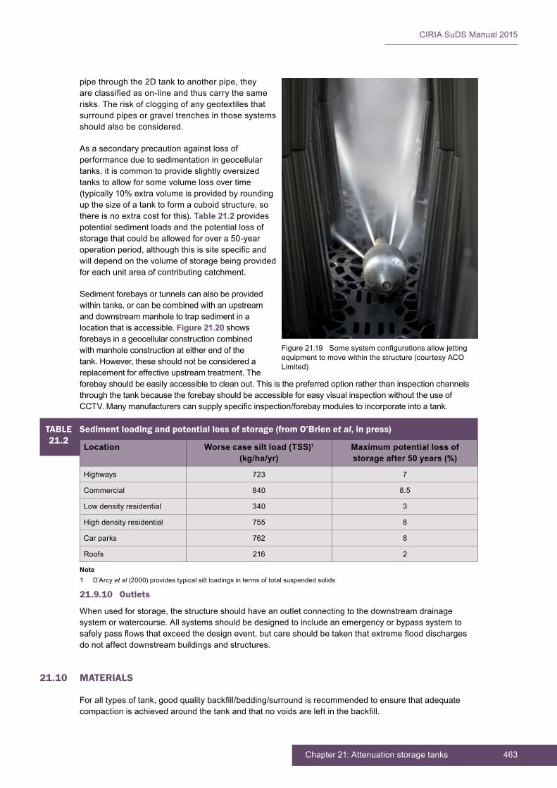
463Chapter 21: Attenuation storage tanks
CIRIA SuDS Manual 2015
pipe through the 2D tank to another pipe, they are classified as on-line and thus carry the same risks. The risk of clogging of any geotextiles that surround pipes or gravel trenches in those systems should also be considered.
As a secondary precaution against loss of performance due to sedimentation in geocellular tanks, it is common to provide slightly oversized tanks to allow for some volume loss over time (typically 10% extra volume is provided by rounding up the size of a tank to form a cuboid structure, so there is no extra cost for this). Table 21.2 provides potential sediment loads and the potential loss of storage that could be allowed for over a 50-year operation period, although this is site specific and will depend on the volume of storage being provided for each unit area of contributing catchment.
Sediment forebays or tunnels can also be provided within tanks, or can be combined with an upstream and downstream manhole to trap sediment in a location that is accessible. Figure 21.20 shows forebays in a geocellular construction combined with manhole construction at either end of the tank. However, these should not be considered a replacement for effective upstream treatment. The forebay should be easily accessible to clean out. This is the preferred option rather than inspection channels through the tank because the forebay should be accessible for easy visual inspection without the use of CCTV. Many manufacturers can supply specific inspection/forebay modules to incorporate into a tank.
Figure 21.19 Some system configurations allow jetting equipment to move within the structure (courtesy ACO Limited)
21.9.10 Outlets
When used for storage, the structure should have an outlet connecting to the downstream drainage system or watercourse. All systems should be designed to include an emergency or bypass system to safely pass flows that exceed the design event, but care should be taken that extreme flood discharges do not affect downstream buildings and structures.
21.10 MATERIALS
For all types of tank, good quality backfill/bedding/surround is recommended to ensure that adequate compaction is achieved around the tank and that no voids are left in the backfill.
TABLE21.2
Sediment loading and potential loss of storage (from O’Brien et al, in press)
Location Worse case silt load (TSS)1 (kg/ha/yr)
Maximum potential loss of storage after 50 years (%)
Highways 723 7
Commercial 840 8.5
Low density residential 340 3
High density residential 755 8
Car parks 762 8
Roofs 216 2
Note1 D’Arcy et al (2000) provides typical silt loadings in terms of total suspended solids
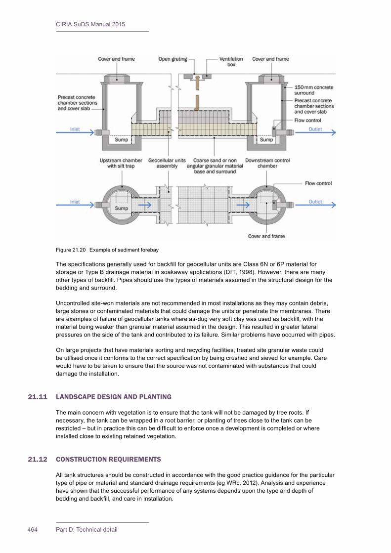
CIRIA SuDS Manual 2015
464 Part D: Technical detail
ThespecificationsgenerallyusedforbackfillforgeocellularunitsareClass6Nor6PmaterialforstorageorTypeBdrainagematerialinsoakawayapplications(DfT,1998).However,therearemanyothertypesofbackfill.Pipesshouldusethetypesofmaterialsassumedinthestructuraldesignforthebeddingandsurround.
Uncontrolledsite-wonmaterialsarenotrecommendedinmostinstallationsastheymaycontaindebris,largestonesorcontaminatedmaterialsthatcoulddamagetheunitsorpenetratethemembranes.Thereareexamplesoffailureofgeocellulartankswhereas-dugverysoftclaywasusedasbackfill,withthematerialbeingweakerthangranularmaterialassumedinthedesign.Thisresultedingreaterlateralpressuresonthesideofthetankandcontributedtoitsfailure.Similarproblemshaveoccurredwithpipes.
Onlargeprojectsthathavematerialssortingandrecyclingfacilities,treatedsitegranularwastecouldbeutilisedonceitconformstothecorrectspecificationbybeingcrushedandsievedforexample.Carewould have to be taken to ensure that the source was not contaminated with substances that could damagetheinstallation.
21.11 LANDSCAPE DESIGN AND PLANTING
Themainconcernwithvegetationistoensurethatthetankwillnotbedamagedbytreeroots.Ifnecessary,thetankcanbewrappedinarootbarrier,orplantingoftreesclosetothetankcanberestricted–butinpracticethiscanbedifficulttoenforceonceadevelopmentiscompletedorwhereinstalledclosetoexistingretainedvegetation.
21.12 CONSTRUCTION REQUIREMENTS
All tank structures should be constructed in accordance with the good practice guidance for the particular typeofpipeormaterialandstandarddrainagerequirements(egWRc,2012).Analysisandexperiencehave shown that the successful performance of any systems depends upon the type and depth of beddingandbackfill,andcareininstallation.
Figure21.20 Exampleofsedimentforebay
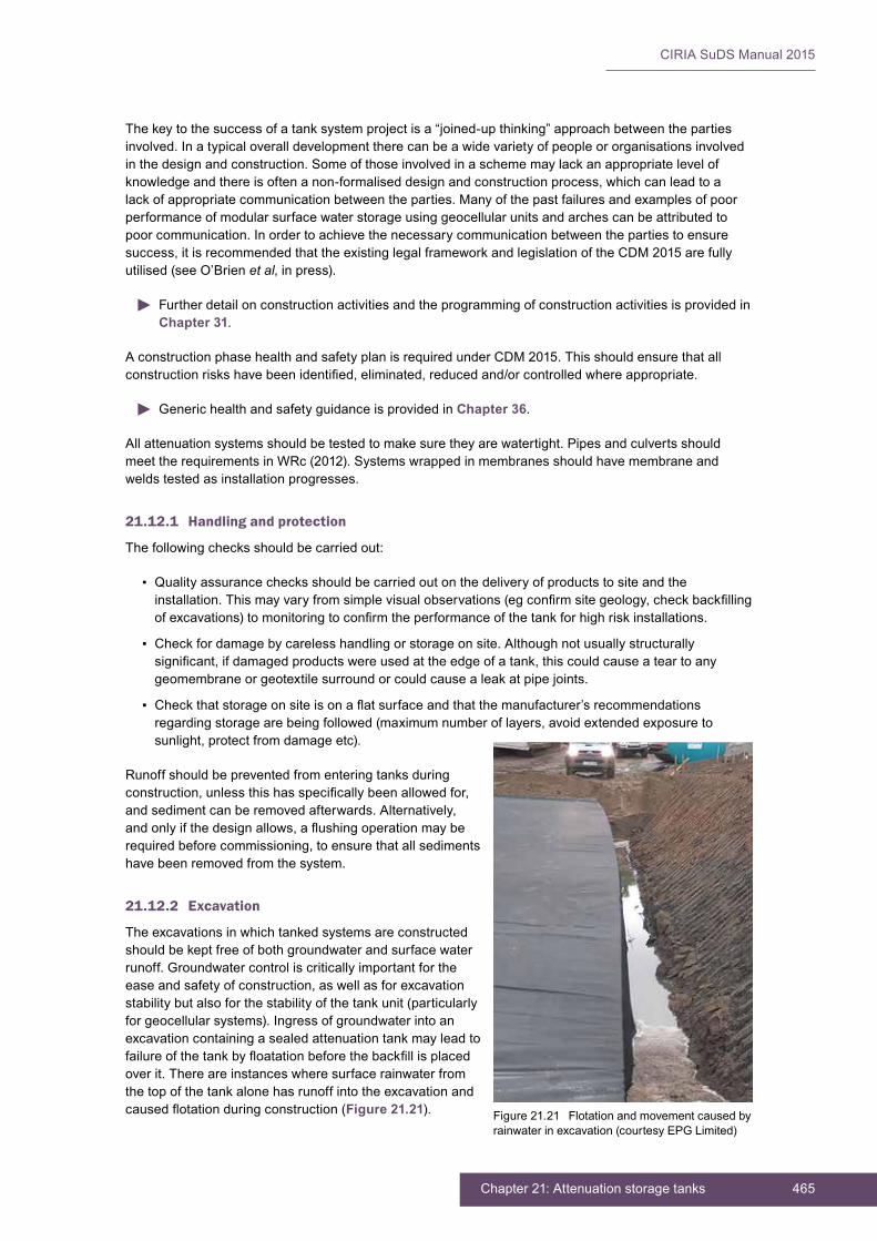
465Chapter 21: Attenuation storage tanks
CIRIA SuDS Manual 2015
The key to the success of a tank system project is a “joined-up thinking” approach between the parties involved.Inatypicaloveralldevelopmenttherecanbeawidevarietyofpeopleororganisationsinvolvedinthedesignandconstruction.Someofthoseinvolvedinaschememaylackanappropriatelevelofknowledgeandthereisoftenanon-formaliseddesignandconstructionprocess,whichcanleadtoalackofappropriatecommunicationbetweentheparties.Manyofthepastfailuresandexamplesofpoorperformance of modular surface water storage using geocellular units and arches can be attributed to poorcommunication.Inordertoachievethenecessarycommunicationbetweenthepartiestoensuresuccess,itisrecommendedthattheexistinglegalframeworkandlegislationoftheCDM2015arefullyutilised(seeO’Brienet al,inpress).
Further detail on construction activities and the programming of construction activities is provided in Chapter 31.
AconstructionphasehealthandsafetyplanisrequiredunderCDM2015.Thisshouldensurethatallconstructionriskshavebeenidentified,eliminated,reducedand/orcontrolledwhereappropriate.
Generic health and safety guidance is provided in Chapter 36.
Allattenuationsystemsshouldbetestedtomakesuretheyarewatertight.PipesandculvertsshouldmeettherequirementsinWRc(2012).Systemswrappedinmembranesshouldhavemembraneandweldstestedasinstallationprogresses.
21.12.1 Handling and protection
The following checks should be carried out:
▪ Quality assurance checks should be carried out on the delivery of products to site and the installation.Thismayvaryfromsimplevisualobservations(egconfirmsitegeology,checkbackfillingofexcavations)tomonitoringtoconfirmtheperformanceofthetankforhighriskinstallations.
▪ Checkfordamagebycarelesshandlingorstorageonsite.Althoughnotusuallystructurallysignificant,ifdamagedproductswereusedattheedgeofatank,thiscouldcauseateartoanygeomembraneorgeotextilesurroundorcouldcausealeakatpipejoints.
▪ Checkthatstorageonsiteisonaflatsurfaceandthatthemanufacturer’srecommendationsregardingstoragearebeingfollowed(maximumnumberoflayers,avoidextendedexposuretosunlight,protectfromdamageetc).
Runoff should be prevented from entering tanks during construction,unlessthishasspecificallybeenallowedfor,andsedimentcanberemovedafterwards.Alternatively,andonlyifthedesignallows,aflushingoperationmayberequiredbeforecommissioning,toensurethatallsedimentshavebeenremovedfromthesystem.
21.12.2 Excavation
The excavations in which tanked systems are constructed should be kept free of both groundwater and surface water runoff.Groundwatercontroliscriticallyimportantfortheeaseandsafetyofconstruction,aswellasforexcavationstability but also for the stability of the tank unit (particularly forgeocellularsystems).Ingressofgroundwaterintoanexcavation containing a sealed attenuation tank may lead to failureofthetankbyfloatationbeforethebackfillisplacedoverit.Thereareinstanceswheresurfacerainwaterfromthe top of the tank alone has runoff into the excavation and causedflotationduringconstruction(Figure 21.21). Figure21.21 Flotationandmovementcausedby
rainwater in excavation (courtesy EPG Limited)

CIRIA SuDS Manual 2015
466 Part D: Technical detail
Geocellularunitsandplasticpipes,forexample,areverylightandtypicallyweighabout45kg/m3.Onlyaverysmalldepthofwaterisrequiredinthebaseofanexcavationtocauseatank,beforebackfillplacement,tofloat.
21.12.3 Formation preparation
Thebaseoftheexcavationonwhichthetankisfoundedshouldbeclean,firmandlevel.Ifthisisnotthecasethentheunits/sections/lengthsofpipewillbedifficulttoplace,astheybecomedisplacedonanunevensurface.Thiscanhavestructuralimplicationsandcouldcausetearingofanymembraneorgeotextilesurroundorleakingjoints.Normallyablindingorbeddinglayerofgranularmaterial(sandorgravel)isplacedinthebottomoftheexcavation.
Thebaseoftheexcavationshouldbeinspectedtoensurethatthematerialsareofsufficientstrengthtosupport the installation and that there are no large stones or other objects that could damage the tank or penetrateanysurroundinggeotextileorgeomembrane.Forclays,ashearstrengthofgreaterthan40kPashouldbeadequate.Inpoorgroundconditions,removalofsoftmaterialsand/orextragranularorblindingmaterialsmayberequiredtoformanadequatefoundation.Sub-basereplacementgeocellularunitsthat act as a raft can often support light loading on soils with a CBR value of 2% and have been used to construct“floating”permeablepavementsoververypoorgroundintheNetherlands.
Also,thebaseconditionsandloadings/supportshouldbeuniformacrosstheinstallation.Mosttypesoftank can be particularly vulnerable to load concentrations that could occur if a tank spanned across old foundationscreatingahardspot,forinstance.
21.12.4 Placing and assembling units/pipes/products
Alltypesoftanksshouldbeplacedandassembledinaccordancewiththerelevantstandards,specificationsandguidance.
Wheregeocellularsystemsarestackedmorethanonelayerhigh,careshouldbetakentoensurethattheunitsarecorrectlypositionedontopofeachotherwithrelevantlayerconnectorsused,ifrequired,toensureadequateloadtransferfromthetoptothebaseoftheinstallation.Somecratesystemsusepillarsofoneformoranother,andfailuretoensurethatthesepillarsarepositioneddirectlyaboveeachotherwillleadtoalowerloadcapabilityoftheinstallation.
21.12.5 Backfilling
Foranytankthebedding,backfillorsurroundiscriticaltothestructuralperformance,anditshouldcomplywithallassumptionsmadebythedesigner.
Inuntraffickedsituations,excavationscangenerallybebackfilledwithselected,as-dugmaterialthatdoesnotcontainlargeparticlesorsharpmaterials.Itshouldthenbewellcompacted.Intraffickedareas,theuseofwell-compactedbackfillandcoverisparticularlyimportant,andthematerialshould,typically,beselectedinaccordancewithstandardhighwayordrainageworksspecifications(egHA,1996b,orWRc,2012).Useofpoorqualitybackfillcansignificantlyincreaselateralearthpressuresontanks,andcausecollapse.Runningheavyplantoverconstructedtanksorstockpilingmaterialoverthemduringconstruction,whensuchloadshavenotbeenincludedwithindesigncalculations,canalsocausecollapse,especiallyiftemporarycoverduringsiteworksislessthanthefinaldesigncoverdepth.Anygeomembranewrappingmayneedtobeprotectedfromthebackfillbyageotextilefleeceinsomeinstances.Inallcases,adviceshouldbesoughtfromindividualmanufacturersregardingspecificrecommendedinstallationandcoverdepths.
Compactingbackfillaroundthesidesofsometypesoftankwithplantthatistooheavycancauselargedeflectionsinthesides,witharesultingstructuralimplication.Lightweightman-operatedplatecompactorsaregenerallyrecommendedfortheperimeterandthefirstlayersabovethetank,ascompactioncanapplyhighlateralpressures.Wherecompactionpressureshavetobeavoided,butastablebackfillisrequired,weaklycementednofinesconcretecanbeconsidered.
467Chapter 21: Attenuation storage tanks
CIRIA SuDS Manual 2015
Heavyvibratingrollersaredefinitelynotrecommendedaroundplasticpipesortanksduetothehighpressuresthattheycangenerate.Thinlayerswithsmallerplantarerecommended.DfT(2009)shouldbereferredtoforguidanceforplantandmethodsforachievingcompaction.Themanufacturers’recommendationsusuallylimitplantsizeabovegeocellularunitstonomorethan2300kg/mwidth.However,theloadingresultingfromthiswillstillneedtobecheckedinthedesign.Ifsuchplantistobeusedadjacenttotheunits,theresultingcompactionpressuresneedtobechecked.
Anyarchorflexiblepipestructuresdependontheevenresistanceprovidedfromsoiloraggregateonbothsidesofthearch/pipefortheirstructuralcapacity.Evenslightdifferencesintheleveloffillingoneachsideofthearch/pipeasitprogressescouldpotentiallycauseunevendeflectionsandincreasethestresswithinthestructureabovedesignvalues.Closesupervisionduringbackfillingisthereforevital.Thebackfillaroundgeocellulartanksshouldalsobebroughtupevenlyaroundallsides.
Beddingdirectlybelowaconcretepipeshouldhaveminimalcompaction.Thefillatthesideofthepipeshouldbewellcompactedtoalevel300mmabovethecrownofthepipe.Onlylightcompactionshouldbeappliedtothebackfilldirectlyoverthecrownofthepipetoapoint300mmaboveit.Withreasonableworkmanshipandsupervision,thebeddingfactorsusedinthedesignshouldberelativelyconservative.
21.12.6 Wrapping
Allstoragetanksshouldbewatertightinaccordancewiththerelevantstandards.Geocellularandsimilarstructuresusinggeomembranestoholdwatershouldbesealedinaccordancewithwaterproofingstandards (ie welded joints rather than adhesive taped) and the integrity of the seal checked on site throughtheuseofnon-destructivetesting,toensurethatitisleak-proof.Adviceonappropriateintegrityandseamtestsforgeomembranes,thatcouldbeadaptedfortestingmembranesaroundstoragetanks,is provided in Mallett et al(2014).Careneedstobetakenduringinstallationtoprotectagainstdamageofboththetankstructureandthegeotextileandthegeomembranewrapping.Follow-ontradescanalsocausedamageandputtheintegrityandperformanceofthestructureatrisk.
21.13 OPERATION AND MAINTENANCE REQUIREMENTS
Regular inspection and maintenance is required to ensure the effective long-term operation of below-groundstoragesystems.Maintenanceresponsibilityforsystemsshouldbeplacedwitharesponsibleorganisation.Table 21.3 provides guidance on the type of operational and maintenance requirements that maybeappropriate.Thelistofactionsisnotexhaustiveandsomeactionsmaynotalwaysberequired.
MaintenancePlansandschedulesshouldbedevelopedduringthedesignphase,andwillbespecifictothetypeoftankthatisadopted.Specificmaintenanceneedsofthesystemshouldbemonitored,andmaintenanceschedulesadjustedtosuitrequirements.FurtherdetailonthepreparationofmaintenancespecificationsandschedulesofworkisgiveninChapter 32.
CDM2015requiresdesignerstoensurethatallmaintenanceriskshavebeenidentified,eliminated,reducedand/orcontrolledwhereappropriate.Thisinformationwillberequiredaspartofthehealthandsafetyfile.
Generic health and safety guidance is provided in Chapter 36.

CIRIA SuDS Manual 2015
468 Part D: Technical detail
21.14 REFERENCES
BARNES,GE(2010)Soil mechanics: principles and practice, third edition,PalgraveMacmillan,Hampshire,UK(ISBN:978-0-23057-980-4)
BCA(2014)Design standards for box culverts,BCATechnicalAdviceNote,BoxCulvertAssociation,Leicester,UK.Goto:http://tinyurl.com/qy6bmfx
BETTESS,R(1996)Infiltration drainage – manual of good practice,R156,CIRIA,London,UK(ISBN:978-0-86017-457-8).Goto:www.ciria.org
BRE (1991) Soakaway design,BREDigest365,BuildingsResearchEstablishment,Bracknell,UK(ISBN:0-85125-502-7)
CPSA(2013)Technical design guide,ConcretePipelineSystemsAssociation,Leicester,UK. Go to:�www.concretepipes.co.uk/page/technical-guide
D’ARCY,B,ELLIS,J,FERNER,R,JENKINS,AandDILS,R(2000)Diffuse pollution impacts, the environmental and economic impacts of diffuse pollution in the UK,TerenceDaltonPublishers,Suffolk,UK(ISBN:978-1-87075-246-6)
DECC(2012)Government response to “Home insulation. A report on the call for evidence carried out by OFT”,DepartmentofEnergyandClimateChange,London,UK.Goto:http://tinyurl.com/n9l4psx
DfT(1998)Manual of contract documents for highway works. Volume 1: Specification for highway works,HMSO,London,UK(ISBN:978-0-11552-705-0).Goto:http://tinyurl.com/nuhk8c3
DfT(2001)Manual of contract documents for highway works. Volume 1: Series 2500 Special structures,HMSO,London,UK.Goto:http://tinyurl.com/l3tap4z
DfT(2009)Manual of contract documents for highway works. Volume 1: Series 600 Earthworks,HMSO,London,UK.Goto:http://tinyurl.com/phx5yj
TABLE21.3
Operation and maintenance requirements for attenuation storage tanks
Maintenance schedule Required action Typical frequency
Regular maintenance
Inspect and identify any areas that are not operating correctly.Ifrequired,takeremedialaction
Monthlyfor3months,thenannually
Remove debris from the catchment surface (where it may cause risks to performance)
Monthly
Forsystemswhererainfallinfiltratesintothetankfromabove,checksurfaceoffilterforblockagebysediment,algaeorothermatter;removeandreplacesurfaceinfiltrationmediumasnecessary.
Annually
Remove sediment from pre-treatment structures and/or internal forebays
Annually,orasrequired
Remedial actions Repair/rehabilitateinlets,outlet,overflowsandvents As required
Monitoring
Inspect/checkallinlets,outlets,ventsandoverflowsto ensure that they are in good condition and operating as designed
Annually
Survey inside of tank for sediment build-up and remove if necessary
Every 5 years or as required

469Chapter 21: Attenuation storage tanks
CIRIA SuDS Manual 2015
FRANK,R,BAUDUIN,C,DRISCOLL,R,KAVVADAS,M,KREBSOVENSEN,N,ORR,TandSCHUPPENER,B(2004)Designer’s guide to EN 1997-1 Eurocode 7: Geotechnical design – general rules,ThomasTelfordLtd,London,UK(ISBN:978-0-72773-154-8)
GEOLOGICALSOCIETY(2002)“Theconceptualgroundmodel”Engineering Geology Special Publications 2002,vol19,TheGeologicalSociety,London,UK,pp51–59
HA(1991)“Designofcorrugatedsteelburiedstructureswithspansgreaterthan0.9mandupto8m”,Design Manual for Roads and Bridges,vol2,Section2,Part6,BD12/01,HMSO,London. Go to: http://tinyurl.com/pogdoet
HA(1996a)“Strengthened/reinforcedsoilsandotherfillsforretainingwallsandbridgeabutments”,Design manual for roads and bridges, vol2,Section1,Part5,BD70/03,HMSO,London,UK.Goto:http://tinyurl.com/pn9de4p
HA(1996b)“Surfaceandsubsurfacedrainagesystemsforhighways”,Design manual for roads and bridges,vol4,Section2,Part3,HD33/06,HMSO,London,UK.Goto:http://tinyurl.com/orz3rlp
HA(2001)“Determinationofpipeandbeddingcombinationsfordrainageworks”,Design manual for roads and bridges, vol4,Section2,Part5,HA40/01,HMSO,London,UK.Goto:http://tinyurl.com/pdmw9zq
INTERPAVE(2010)Permeable pavements. Guide to the design, construction and maintenance of concrete block permeable pavements, sixth edition,Interpave,Leicester,UK.Goto:http://tinyurl.com/pozgxzc
LENOUVEAU,N,MONTAUT,MandGOMEZ,A(2007)“Structuresalveolairesultra-legeres(SAUL)enassainissementpluvial:versuneclassificationdesproduitsetretoursd’experiences”.In:Proc Novatech 2007 – sixth int conf on sustainable techniques and strategies in urban water management,25–28June2007,LyonFrance.Goto:http://tinyurl.com/pwyskta
MALLETT,H,COX,L,WILSON,SandCORBAN,M(2014)Good practice on the testing and verification of protection systems for buildings against hazardous ground gases,CIRIA,C735,London,UK(ISBN:978-0-86017-739-5).Goto:www.ciria.org
O’BRIEN,AS,LILE,CR,PYE,SWandHSU,YS(inpress)Structural and geotechnical design of modular geocellular drainage systems,C737,CIRIA,London,UK(ISBN:978-0-86017-741-8).Goto:www.ciria.org
OGBURN,ONL(2013)Urban water runoff contamination associated with gutter and pipe material degradation,Dissertation,DepartmentofCivil,ConstructionandEnvironmentalEngineering,TheUniversityofAlabama,USA.Goto:http://tinyurl.com/nfz5uca
SISG(2012)UK Specification for ground investigation, second edition,SiteInvestigationSteeringGroup,InstitutionofCivilEngineers,London,UK(ISBN:978-0-72773-506-5)
UKWIR(2008)Specification for thermoplastics structured wall pipe – supplementary test requirements,Issue2,WaterIndustrySpecification,WIS4-35-01,WRc,Swindon,UK.Goto:http://tinyurl.com/p4mdxc5
WRc(2007)Sewers for Scotland, second edition,WRcPublications,Swindon,UK(ISBN:978-1-89892-060-1)
WRc(2010)Sewers for adoption Northern Ireland, first edition,WRcPublications,Swindon,UK(ISBN:978-1-89892-066-3)
WRc(2012)Sewers for adoption, seventh edition,WRcPublications,Swindon,UK(ISBN:978-1-89892-065-6)

CIRIA SuDS Manual 2015
470 Part D: Technical detail
STATUTES
Regulations
Construction(DesignandManagement)Regulations(CDM)2015
British Standards
BS5911-1:2002+A2:2010Concrete pipes and ancillary concrete products. Specification for unreinforced and reinforced concrete pipes (including jacking pipes) and fittings with flexible joints
BS8006-1:2010Code of practice for strengthened/reinforced soils and other fills
BS9295:2010Guide to the structural design of buried pipelines
European Standards
BSEN752:2008Drain and sewer systems outside buildings
BS EN 1295-1:1997 Structural design of buried pipelines under various conditions of loading. General requirements
BS EN 1852-1:1998 Plastics piping systems for non-pressure underground drainage and sewerage. Polypropylene (PP). Specifications for pipes, fittings and the system
BSEN1916:2002Concrete pipes and fittings, unreinforced, steel fibre and reinforced
BSEN1997-1:2004+A1:2013Eurocode 7. Geotechnical design. General rules
BSEN13251:2014+A1:2015Geotextiles and geotextile-related products – characteristics required for use in earthworks, foundations and retaining structures
BSEN13280:2001Specification for glass fibre reinforced cisterns of one-piece and sectional construction, for the storage, above ground, of cold water
BSEN13369:2013Common rules of precast concrete products
BSEN13476-1:2007Plastics piping systems for non-pressure underground drainage and sewerage. Structured-wall piping systems of unplasticized polyvinyl chloride (PVC-U), polypropylene (PP) and polyethylene (PE). General requirements and performance characteristics
BSEN13476-2:2007Plastics piping systems for non-pressure underground drainage and sewerage. Structured-wall piping systems of unplasticized polyvinyl chloride (PVC-U), polypropylene (PP) and polyethylene (PE). Specifications for pipes and fittings with smooth internal and external surface and the system, Type A
BSEN13476-3:2007+A1:2009Plastics piping systems for non-pressure underground drainage and sewerage. Structured-wall piping systems of unplasticized polyvinyl chloride (PVC-U), polypropylene (PP) and polyethylene (PE). Specifications for pipes and fittings with smooth internal and profiled external surface and the system, Type B
BSEN14844:2006+A2:2011Precast concrete products. Box culverts
PDCEN/TR1295-2:2005Structural design of buried pipelines under various conditions of loading. Summary of nationally established methods of design
PDCEN/TS14541:2013Plastics pipes and fittings. Characteristics for utilisation of non-virgin PVC-U, PP and PE materials

471Chapter 21: Attenuation storage tanks
CIRIA SuDS Manual 2015
USA
ASTM F2787-13 Standard practice for structural design of thermoplastic corrugated wall stormwater collection chambers
ASTM F2418-13 Standard specification for polypropylene (PP) corrugated wall stormwater collection chambers
ASTM F2922-13e1 Standard specification for polyethylene (PE) corrugated wall stormwater collection chambers
CIRIA SuDS Manual 2015
472 Part D: Technical detail
22 DETENTION BASINS
Contents
22.1 General description 47322.2 General design considerations 47422.3 Selection and siting of detention basins 47522.4 Hydraulic design 47622.5 Treatment design 47722.6 Amenity design 47822.7 Biodiversity design 47922.8 Physicalspecifications 47922.9 Materials 48022.10 Landscape design and planting 48022.11 Construction requirements 48122.12 Operation and maintenance requirements 48122.13 Reference 483

473Chapter 22: Detention basins
CIRIA SuDS Manual 2015
22.1 GENERAL DESCRIPTION
Detention basins are landscaped depressions that are normally dry except during and immediately following storm events. They can be on-line components where surface runofffromregulareventsisroutedthroughthebasinandwhentheflowsrise,becausetheoutletisrestricted,thebasinfillsandprovidesstorageofrunoffandflowattenuation.Theycanalsobeoff-linecomponentsintowhichrunoffisdivertedonceflowsreachaspecifiedthreshold.
Detention basins can be vegetated depressions (that can provide treatment when designedtomanageregularflows)orhardlandscapedstorageareas(thatwilltendnottoprovideanytreatmentandarenormallydesignedasoff-linecomponents).
Wherethebasinisvegetated,thesoilsurfacecanabsorbsomerunoff,socanbeusedtosupportthepreventionofrunofffromthesiteforsmallrainfallevents(Interception),providedthatsmallamountsofinfiltrationwouldnotposearisktogroundwater.Theprincipalwaterqualitybenefitsofvegetateddetentionbasinsareassociatedwiththeremovalofsedimentandbuoyantmaterials,butlevelsofnutrients,heavymetals,toxicmaterialsandoxygen-demandingmaterialsmayalsobesignificantlyreduced.Thewaterqualitybenefitsofavegetateddetentionbasinincreaseasthedetentiontimeforaneventbecomeslonger.Wheredesignedappropriately,someorallofthebasinareacan also be used as a recreational or other amenity facility (Figure 22.1).
22Chapter Detention basins
This chapter provides guidance on the design of detention basins – landscaped depressions that are normally dry except during and following rainfall events, designed to attenuate runoff and, where vegetated, provide treatment.
Appendix C, Section C.5.3 demonstrates how to design a detention basin for a supermarket.
Figure22.1 Detentionbasinwithlandscapedesignprovidingattractiveamenityspace,Hamilton,Leicester
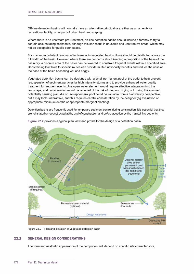
CIRIA SuDS Manual 2015
474 Part D: Technical detail
Off-line detention basins will normally have an alternative principal use: either as an amenity or recreationalfacility,oraspartofurbanhardlandscaping.
Wherethereisnoupstreampre-treatment,on-linedetentionbasinsshouldincludeaforebaytotrytocontainaccumulatingsediments,althoughthiscanresultinunusableandunattractiveareas,whichmaynot be acceptable for public open space.
Formaximumpollutantremovaleffectivenessinvegetatedbasins,flowsshouldbedistributedacrossthefullwidthofthebasin.However,wherethereareconcernsaboutkeepingaproportionofthebaseofthebasindry,adiscreteareaofthebasincanbeloweredtoconstrainfrequenteventswithinaspecifiedarea.Constraininglowflowstospecificroutescanprovidemulti-functionalitybenefitsandreducetherisksofthe base of the basin becoming wet and boggy.
Vegetated detention basins can be designed with a small permanent pool at the outlet to help prevent resuspension of sediment particles by high intensity storms and to provide enhanced water quality treatment for frequent events. Any open water element would require effective integration into the landscape,andconsiderationwouldberequiredoftheriskoftheponddryingoutduringthesummer,potentiallycausingplantdieoff.Anephemeralpoolcouldbevaluablefromabiodiversityperspective,butitmaylookunattractive,andthisrequirescarefulconsiderationbythedesigner(egevaluationofappropriateminimumdepthsorappropriatemarginalplanting).
Detention basins are frequently used for temporary sediment control during construction. It is essential that they are reinstated or reconstructed at the end of construction and before adoption by the maintaining authority.
Figure 22.2 providesatypicalplanviewandprofileforthedesignofadetentionbasin.
22.2 GENERAL DESIGN CONSIDERATIONS
Theformandaestheticappearanceofthecomponentwilldependonspecificsitecharacteristics,
Figure 22.2 Plan and elevation of vegetated detention basin

475Chapter 22: Detention basins
CIRIA SuDS Manual 2015
landscape/amenityobjectivesanddevelopmentdesigncriteria.Unlessusedforasportspitchortofitintosomespecificlandscape,vegetateddetentionbasinsshouldnotnormallyfollowageometricprofile,butthey should have edges with curves and undulations to produce an aesthetically interesting and natural-lookingfeature.
The maximum depth of water in the basin should not normally exceed 2 m in the most extreme design event.However,manyauthoritieswillrequireamuchlowermaximumdepth,forsafetyreasons.
Thebottomofanyvegetatedbasinshouldbefairlyflatwithagentleslope(nomorethan1in100)towardstheoutlet,tomaximisecontactofrunoffwiththevegetationandtopreventstandingwaterconditions from developing. Areas above the normal high water elevations of the basin should also be sloped towards the basin to allow effective drainage. The base of the basin can also be provided with a layerofengineeredsoilorunderdrainstomaintainafirmanddrysurface.
The recommended length/width ratio for on-line vegetated detention basins is between 3:1 and 5:1. Inlets andoutletsshouldbeplacedtomaximisetheflowpaththroughthefacility.Contouredbasescanbeeffectivelyusedtodefineandlengthenareasthatarelikelytobewettedregularly.
Alinermayberequiredtomaintainthewaterlevelinanysmallpermanentwaterfeature,preventinfiltrationofrunoffwherewaterqualityriskassessmentindicatesthatthisisnotacceptableand/ortoprotect an underlying aquifer.
Whereswalesareusedaslowflowchannels,theirdesignshouldfollowguidancesetoutinChapter 17. Filtertrenchescouldalsobeusedtoconveylowflows,butthesewillrequireveryeffectiveupstreampre-treatmentsothattheriskofreducedperformanceduetoblockageiscontrolled,andwilldeliverlimitedtreatmentthemselves.Theuseoffiltertrenchesalsocarrieshighmaintenanceanderosionrisksassociatedwithmovementoffiltermaterialduringmoderatetohighflowevents,andanydesignsshouldensurethatsuchrisksareadequatelymanaged.
Anyembankmentshouldbedesignedinaccordancewithbestpractice,asdescribedinKennardet al (1996).DesignsshouldmeetallrequirementsoftheReservoirAct1975,asamendedbytheFloodandWater Management Act 2010. Even if the impounded basin does not come within the thresholds of the ReservoirsAct,ownersstillhavestatutorydutiesforthesafetyofothersunderlegislationsuchastheHealthandSafetyatWork(etc)Act1974andtheBuildingAct1984.Considerationshouldbegiventothesaferoutingoffloodwaterwhenthedesigneventisexceeded,andtomitigatingtherisksofpotentialembankmentfailure.
Side slopes of any vegetated basin should not usually exceed 1 in 3 unless special site and/or safety arrangementsallowforsteeperslopes(egsteeperslopesmaybeacceptableforveryshallowbasins).Slopesshouldbenosteeperthan1in3wherevermowingisrequired,toreducetherisksassociatedwithmaintenanceactivities.Flatterslopestendtoimprovetheaesthetics,attheexpenseofextraland-take.Hardlandscapedbasinswilloftenhaveverticalsides,butwilltendtobeveryshallow.
There should always be appropriate access to the detention basin for maintenance activities such as grasscuttingandsedimentremovaltobeundertaken,andtoallinlets,outletsandcontrolstructures.Maintenanceaccesscanoftenbeintegratedwithroutesforgeneralpublicaccess,whichcanhelpindiscouragingheavyuseofwiderbasinslopesthatcanpotentiallycreateerosionrisks.
HealthandsafetyriskmanagementdesignguidanceisprovidedinChapter 36. Safety principles in relation to public use are set out in Section 22.6.
22.3 SELECTION AND SITING OF DETENTION BASINS
Detentionbasinsaregenerallyapplicabletomosttypesofdevelopment,andcanbeusedinbothresidentialandnon-residentialareas.Theyarealsoappropriateforuseinretrofitsituations(whereexistingdrainagenetworklevelsandlandavailabilityallow).
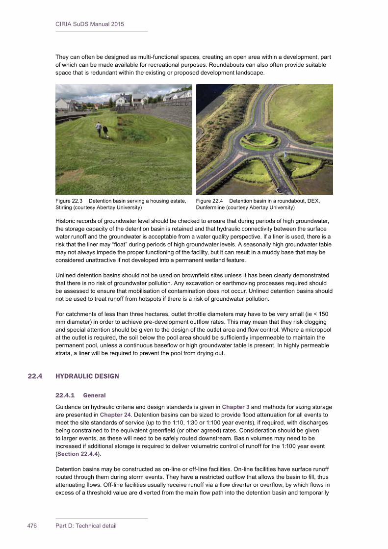
CIRIA SuDS Manual 2015
476 Part D: Technical detail
Theycanoftenbedesignedasmulti-functionalspaces,creatinganopenareawithinadevelopment,partof which can be made available for recreational purposes. Roundabouts can also often provide suitable space that is redundant within the existing or proposed development landscape.
Historicrecordsofgroundwaterlevelshouldbecheckedtoensurethatduringperiodsofhighgroundwater,the storage capacity of the detention basin is retained and that hydraulic connectivity between the surface waterrunoffandthegroundwaterisacceptablefromawaterqualityperspective.Ifalinerisused,thereisariskthatthelinermay“float”duringperiodsofhighgroundwaterlevels.Aseasonallyhighgroundwatertablemaynotalwaysimpedetheproperfunctioningofthefacility,butitcanresultinamuddybasethatmaybeconsidered unattractive if not developed into a permanent wetland feature.
Unlineddetentionbasinsshouldnotbeusedonbrownfieldsitesunlessithasbeenclearlydemonstratedthatthereisnoriskofgroundwaterpollution.Anyexcavationorearthmovingprocessesrequiredshouldbe assessed to ensure that mobilisation of contamination does not occur. Unlined detention basins should notbeusedtotreatrunofffromhotspotsifthereisariskofgroundwaterpollution.
Forcatchmentsoflessthanthreehectares,outletthrottlediametersmayhavetobeverysmall(ie<150mmdiameter)inordertoachievepre-developmentoutflowrates.Thismaymeanthattheyriskcloggingandspecialattentionshouldbegiventothedesignoftheoutletareaandflowcontrol.Whereamicropoolattheoutletisrequired,thesoilbelowthepoolareashouldbesufficientlyimpermeabletomaintainthepermanentpool,unlessacontinuousbasefloworhighgroundwatertableispresent.Inhighlypermeablestrata,alinerwillberequiredtopreventthepoolfromdryingout.
22.4 HYDRAULIC DESIGN
22.4.1 General
Guidance on hydraulic criteria and design standards is given in Chapter 3 and methods for sizing storage are presented in Chapter 24.Detentionbasinscanbesizedtoprovidefloodattenuationforalleventstomeetthesitestandardsofservice(uptothe1:10,1:30or1:100yearevents),ifrequired,withdischargesbeingconstrainedtotheequivalentgreenfield(orotheragreed)rates.Considerationshouldbegiventolargerevents,asthesewillneedtobesafelyrouteddownstream.Basinvolumesmayneedtobeincreased if additional storage is required to deliver volumetric control of runoff for the 1:100 year event (Section 22.4.4).
Detention basins may be constructed as on-line or off-line facilities. On-line facilities have surface runoff routedthroughthemduringstormevents.Theyhavearestrictedoutflowthatallowsthebasintofill,thusattenuatingflows.Off-linefacilitiesusuallyreceiverunoffviaaflowdiverteroroverflow,bywhichflowsinexcessofathresholdvaluearedivertedfromthemainflowpathintothedetentionbasinandtemporarily
Figure22.3 Detentionbasinservingahousingestate,Stirling(courtesyAbertayUniversity)
Figure22.4 Detentionbasininaroundabout,DEX,Dunfermline(courtesyAbertayUniversity)

477Chapter 22: Detention basins
CIRIA SuDS Manual 2015
stored.Thewaterfromthedetentionbasinispassedbackintothemainsystemwhentheinflowfallsbelow the diversion threshold. Off-line detention basins should be avoided where treatment of the runoff isimportant,becauseitisthelowerflowsthatwillgenerallyposethehighestpollutionrisk.
22.4.2 Interception design
Vegetated detention basins can deliver some Interception because there tends to be no runoff from them forthemajorityofsmallrainfallevents.Thewatersoaksintothebasintopsoillayerandisremovedbyevapotranspirationandevenverysmallamountsofinfiltration(wherethisisallowed).Theextentofthevolumetricreductioninrunofftosurfacewaterswilldependontheinfiltrationrateofthesurroundingsoil,thecatchmentarea,theareaanddepthofthesystem,thetypeofvegetationandtheclimate.
Wherethereisinfiltrationcapacity,infiltrationisacceptable,andthedetentionbasinisdesignedtofacilitateevenlimitedinfiltration,thenacheckshouldbemadetodeterminewhetherthebasinisabletodispose of 5 mm rainfall depth over the contributing catchment area.
Wherethereisnoinfiltration,butthenaturalsurfacesoils(orimported/re-engineeredsoils)havewaterstoragecapacity,thenInterceptiondesignshouldfollowtheprinciplessetoutinSection 24.8. Hard landscaped basins will not deliver Interception.
22.4.3 Peakflowcontroldesign
Detentionbasinscanhelpreduceflowratesfromasitebycontrollingthedischargerateandallowingthebasinstoragetofillduringstormevents.Therequiredpeakflowcontrolandstoragevolumecanbedetermined using standard hydraulic assessment (Chapter 24).
22.4.4 Volume control design
Detentionbasinsdonotnormallycontributetovolumetriccontrolofrunoff,butcanbeusedasLong-TermStorageareas,ortodeliverfurtherattenuationwhereLong-TermStorageisnotpractical(Chapter 3).Assessment of volumetric control should follow the normal hydraulic assessment methods in Chapter 24.
22.4.5 Exceedanceflowdesign
Anexceedanceflowroutewillberequiredforrainfalleventsthatexceedthedesigncapacityofthedetentionbasin.Thiscanbeachievedbyinstallinganoverflowpipe,channelorweir/overflowstructureabovethedesignwaterstorageleveltoconveyexcessflowsdownstream.
Theexceedanceflowcapacityoftheoverflowshouldbeconfirmedusingnormalhydraulicassessmentmethodsandanalysis(weir,orificeandpipeflow).Exceedanceflowsbeyondthecapacityoftheoverflowshouldalsobeconfirmed.
Anyexceedanceflowstructureshouldbelocatedasclosetotheinletaspossibletominimisetheflowpathlengthforabove-capacityflows,thusreducingtheriskofscouring.SeeSection 22.8.2 on outlet designfordetails.Theoverflowshouldnotimpedeaccesstoanyinlet/outlet/controlstructurethatmanagesmorefrequentflows.
Detentionbasinsareoftenusedasoff-linesystemstomanageexceedanceflowsfromthemainsurfacewatermanagementsystem.Inthiscase,theywillnormallyhaveanalternativeprincipaluse,forexampleasadedicatedamenity/recreationalfacility.Furtherguidanceondesigningforexceedanceflowmanagement is set out in Section 24.12.
22.5 TREATMENT DESIGN
Vegetateddetentionbasinscanhelpretainrunofffromsmalleventsonsite(iedeliverInterception,Section 22.4.2),helpingreducethecontaminantloadviavolumetriccontrol.Theycanalsotreatthe
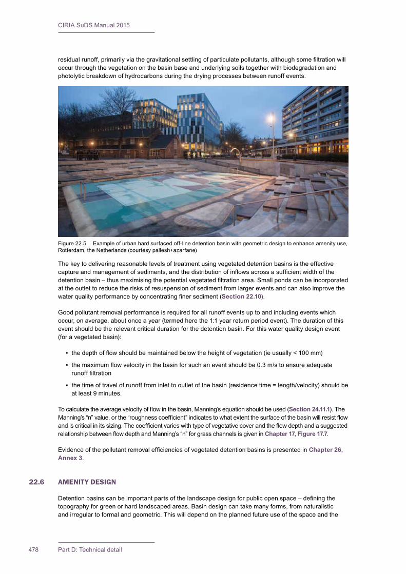
CIRIA SuDS Manual 2015
478 Part D: Technical detail
residualrunoff,primarilyviathegravitationalsettlingofparticulatepollutants,althoughsomefiltrationwilloccur through the vegetation on the basin base and underlying soils together with biodegradation and photolyticbreakdownofhydrocarbonsduringthedryingprocessesbetweenrunoffevents.
Thekeytodeliveringreasonablelevelsoftreatmentusingvegetateddetentionbasinsistheeffectivecaptureandmanagementofsediments,andthedistributionofinflowsacrossasufficientwidthofthedetentionbasin–thusmaximisingthepotentialvegetatedfiltrationarea.Smallpondscanbeincorporatedattheoutlettoreducetherisksofresuspensionofsedimentfromlargereventsandcanalsoimprovethewaterqualityperformancebyconcentratingfinersediment(Section 22.10).
Good pollutant removal performance is required for all runoff events up to and including events which occur,onaverage,aboutonceayear(termedherethe1:1yearreturnperiodevent).Thedurationofthisevent should be the relevant critical duration for the detention basin. For this water quality design event (foravegetatedbasin):
▪ thedepthofflowshouldbemaintainedbelowtheheightofvegetation(ieusually<100mm)
▪ themaximumflowvelocityinthebasinforsuchaneventshouldbe0.3m/stoensureadequaterunofffiltration
▪ thetimeoftravelofrunofffrominlettooutletofthebasin(residencetime=length/velocity)shouldbeat least 9 minutes.
Tocalculatetheaveragevelocityofflowinthebasin,Manning’sequationshouldbeused(Section 24.11.1).TheManning’s“n”value,orthe“roughnesscoefficient”indicatestowhatextentthesurfaceofthebasinwillresistflowandiscriticalinitssizing.ThecoefficientvarieswithtypeofvegetativecoverandtheflowdepthandasuggestedrelationshipbetweenflowdepthandManning’s“n”forgrasschannelsisgiveninChapter 17, Figure 17.7.
EvidenceofthepollutantremovalefficienciesofvegetateddetentionbasinsispresentedinChapter 26, Annex 3.
22.6 AMENITY DESIGN
Detentionbasinscanbeimportantpartsofthelandscapedesignforpublicopenspace–definingthetopographyforgreenorhardlandscapedareas.Basindesigncantakemanyforms,fromnaturalisticand irregular to formal and geometric. This will depend on the planned future use of the space and the
Figure22.5 Exampleofurbanhardsurfacedoff-linedetentionbasinwithgeometricdesigntoenhanceamenityuse,Rotterdam,theNetherlands(courtesypallesh+azarfane)
479Chapter 22: Detention basins
CIRIA SuDS Manual 2015
landscape,amenityandbiodiversityobjectivesforthesite.Thevalueofbasinscanoftenbeenhancedwithfootpathsorcyclepaths,andenhancedwithstructuralanddiverseplants,wetlandplantedareasandwildflowermixestoenhancetheirbeautyandamenitycontribution.
Detentionbasinsmaybeconstructedtoservemorethanonepurpose,andcanbeusedascarparks,playgroundsorsportsfields.Whenconstructedformultiplepurposes,thedetentionbasinshouldbeusable for the function other than surface water detention for most of the time. Where multi-functional useisintended,therecreationalareashouldnormallyhavearelativelylowfloodingfrequencysuchas1–5yearreturnperiod,dependingonitsuse.Interpretationboardsexplainingthattheareaispartofthedrainagesystemandthatitcouldbefilledwithwatermayalsoberequired.
Wheredetentionbasinsformanintegralpartofpublicopenspaceorrecreationalplayareas,itiscruciallyimportant that those using or living near the facility are aware of its functionality and value. How to involve the community in this way is discussed in Chapter 34 and planting best practice is presented in Chapter 29.
Fencingisgenerallynotdesirableasitmayreducetheamenitybenefitsprovidedbythedetentionfacility,provide a barrier to easy maintenance and provide a trap where litter and dead vegetation can collect. Wherefencesarerequired,theyshouldbelow(toddler-proof),butallowmovementofwildlife.Gentleslopesandappropriateplantingcancontributetominimisingpublicsafetyrisks.
Inlet and outlet pipes and culverts should not be accessible. The headwalls of large pipes should be fenced to prevent accidents and deter access. Grilles should also be considered to prevent entry into thepipebutthesetendtoclograpidly,triggeringmoreregularmaintenancerequirementsandpotentiallyaffecting hydraulic performance (Chapter 28).
Life-savingequipmentshouldonlybeprovidedwhererequiredbytheriskassessment,andoperatorswillhavetoinspectsuchequipmentonaregularbasistominimiseanyliabilityrisks.
22.7 BIODIVERSITY DESIGN
By following the biodiversity criteria in Chapter 6,biodiversityvalueofanySuDScomponentcanbemaximised. Vegetated detention basins can include a variety of structurally diverse planting that will helpmakeapositivecontributiontourbanbiodiversity–providinghabitatandfoodforinvertebratesandbirds.Someplantsandanimalsspecificallyrequireephemeralwaterbodiesaspartoftheirlifecycle,andsuitablewildflowermixescanprovideimportantnectarsourcesforinsects.Wherespaceallows,multiplebasinsofvaryingsizeandshapeshouldbecreated,andconsiderationgiventotheinclusionofshelvesandshallowgradedsides,undulatingsurfacesandconvolutededgestoprovidethegreatestwildlifevalue. The ecological value of the system can also be enhanced by including micropools or wetland zones at the base. Further guidance is given in Chapters 6 and 29.
22.8 PHYSICAL SPECIFICATIONS
22.8.1 Pre-treatment and inlets
Foron-linesystems–thenumberofinletstothebasinshouldbelimited,preferablytoone.Theflowpathlength should be maximised from inlet to outlet for all inlets.
Forbasinsservinglargedevelopments,asedimentforebayorupstreampre-treatmentcomponentwillimprove the water quality performance of a vegetated detention basin and reduce long-term maintenance requirements. The plan area of the sedimentation bay should be at least 10% of the total basin area and couldconsistofaseparatebasinorbeformedbybuildinganearthberm,stoneorrock-filledgabionorrip-rapacrosstheupstreamportionofthebasin.Forsystemswithmultipleinlets,pre-treatmentshouldbeprovidedforeachinletthatislikelytocontributeasignificantsedimentload.Eachforebayshouldbeaccessibleandeasilymaintained.Considerationshouldbegiventoinstallingafixedsedimentdepthmarkerintheforebaytomeasuresedimentdepositionwithtime.Thiswillassistwiththedevelopmentofappropriate maintenance schedules.
CIRIA SuDS Manual 2015
480 Part D: Technical detail
Theenergyoftheincomingflowsshouldbedissipatedtominimisetheriskofscouringanderosion.Thiscanbeachievedbystabilisinginflowchannelsusingrip-raporothererosioncontrolsystems.Thescaleoftheerosionmitigationsystemrequiredwillbedependentonincomingflowvelocities,butshouldbe physically and aesthetically proportionate to the size of the basin. Safety grilles may be required if inletpipediametersallowpublicentry,buttheytendtoincreasetherisksofblockageandcanpresentahazardinthemselves;so,whereverpossible,inletinfrastructureshouldbedesignedsothattheyarenotrequired. Inlet designs should blend with the landscape – detailed guidance on inlet designs can be found in Chapter 28.
22.8.2 Underdrains and outlets
Attheoutlet,therewillnormallybearequirementforsomeformofflowcontrolsystem.Amanhole-typeoutlet structure can accommodate a variety of outlet control mechanisms. Detention basins will generally requireanon-clogging,variableflowratecontrolstructureattheoutlet,togetherwithanemergencyoverflow.Lowflowcontrolsaregenerallyprovidedviaprotectedorifices,whichcanthenbecombinedwithoverflowchannelsandoverflowweirsectionsand/orculvertsforlargerevents.Multipleorificesorpipeoutletscanbeusedtoachievethesameobjectives.Trashscreensarenotrecommended,butwheregrillesarenecessarytopreventaccessintothepipework,theyshouldbedesignedsothatdebrisdoesnotundulyobstructorreducedesignflowrates.
Energydissipationmayberequireddownstreamoftheoutlettopreventscouringanderosion,butthiswilldependontheoutflowdischargerates,theoutfalldesignandthevulnerabilityofthereceivingwatercourseorlaketoerosion.
Foroutletpipesthroughembankments,seepagecontrolintheformofcollarsmayneedtobeprovided.
ThedesignofexceedanceflowmanagementcomponentsisdiscussedinSection 22.4.5.
Outlet design should be appropriate and complementary to the local landscape. Detailed guidance on outlet designs can be found in Chapter 28.
22.9 MATERIALS
Therearenouniquematerialsthatareusedindetentionbasins.Subsoil,topsoil,geotextile,geomembraneandfilterdrainaggregatespecificationsareprovidedinChapter 30.
22.10 LANDSCAPE DESIGN AND PLANTING
Detentionbasindesignshouldtakeaccountofthelocallandscapeandlocalenvironment.Itshouldbesitespecific,andindividualdesignsshouldbedevelopedtodelivertherequiredamenityandbiodiversityobjectives for the site.
Detentionbasinsaretypicallygrassedstructures,althoughsomeothervegetationcanenhancetheappearanceandamenityvalueofthebasin,stabilisesideslopesandpreventerosion,serveaswildlifehabitat,andpartiallyconcealunsightlylitteranddebris.Itcanalsohelpincreasetheeffectivenessofsedimentsettlingbyslowingtheflowsacrossthebasin.
Topsoildepthswillvaryfordifferentplantingproposals,so100mmofsubsoilmaybesuitableforwildflowermeadowsurfacing,150mmtopsoilisrequiredforamenitygrassand450mmwillbenecessary for planted areas. This should be a high-quality topsoil with a loam or sandy loam texture.
Wheresmallpoolsareincludedasafeatureofthebasin,theyarenormallyplantedwithwetlandvegetationspecies.Thereisnormallyariskthatthepoolmaydryoutduringsummermonths,sopooldepths and marginal plants should be selected to reduce any potential consequences.
Reinforced grass may be required for maintenance routes where vehicular access is anticipated.

481Chapter 22: Detention basins
CIRIA SuDS Manual 2015
22.11 CONSTRUCTION REQUIREMENTS
The bottom and side slopes of the basin should be carefully prepared to ensure that they are structurally sound and the grading should be uniform and smooth to the correct slope so that water does not pond in depressionsandtominimisetheriskofchannellinganderosionthroughpreferentialflowpaths.Checksshouldbemadethatanyembankmentstructuresmeettheirdesigncriteria.Thepreparationshouldalsoensurethatthebasinwillsatisfactorilymanagedesignflowswithoutsignificanterosiondamage.
Backfillingagainstinletandoutletstructuresneedstobecontrolledsoastominimisesettlementanderosion.Thesoilsusedtofinishthesideslopesneedtobesuitablyfertile,porousandofsufficientdepthtoensurehealthyvegetationgrowth.Ifanimpermeablelinerisused,careshouldbetakentoensurethatit is not damaged during construction.
DuringtheSuDSestablishmentphase,runofffrombaresoilsshouldbeminimised.Forexample:
▪ vegetation on slopes should be rapidly established
▪ base-of-slope trenches should be introduced to retain the inevitable runoff of sediments
▪ construction should be timed to avoid autumn and winter when high runoff rates are to be expected.
Detentionbasinsmaybeusedtomanageconstructionrunoffandtrapconstructionsediments,providedthey are fully rehabilitated to original design formation levels before handover.
Further detail on construction activities and the programming of construction activities is provided in Chapter 31. Generic health and safety guidance is provided in Chapter 36. A construction phase health and safety plan is requiredundertheConstruction(DesignandManagement)Regulations(CDM)2015.Thisshouldensurethatallconstructionriskshavebeenidentified,eliminated,reducedand/orcontrolledwhereappropriate.
22.12 OPERATION AND MAINTENANCE REQUIREMENTS
Detention basins will require ongoing regular maintenance to ensure continuing operation to design performancestandards,andalldesignersshouldprovidedetailedspecificationsandfrequenciesfortherequiredmaintenanceactivitiesalongwithlikelymachineryrequirementsandtypicalannualcosts– within the Maintenance Plan. The treatment performance of bioretention systems is dependent on maintenance,androbustmanagementplanswillberequiredtoensuremaintenanceiscarriedoutinthelongterm.Differentdesignswillhavedifferentoperationandmaintenancerequirements,butthissectiongives some generic guidance.
Maintenanceofdetentionbasinsisrelativelystraightforwardforlandscapecontractors,andtypicallythereshouldonlybeasmallamountofextrawork(ifany)requiredforaSuDSdetentionbasinoverandabove what is necessary for standard public open space.
Figure 22.6 Examples of detention basins with easy access for maintenance (courtesy Peterborough City Council andKentCountyCouncil)

CIRIA SuDS Manual 2015
482 Part D: Technical detail
Maintenance responsibility for a basin should always be placed with an appropriate organisation. Adequateaccessshouldbeprovidedtoalldetentionbasinareasforinspectionandmaintenance,includingforappropriateequipmentandvehicles.LitteranddebrisremovalshouldbeundertakenaspartofgenerallandscapemaintenanceforthesiteandbeforeanyotherSuDSmanagementtask.Alllittershould be removed from site.
The major maintenance requirement for detention basins is usually mowing. Regular mowing in and around detentionbasinsisonlyrequiredalongmaintenanceaccessroutes,amenityareas(egfootpaths),acrossanyembankmentandacrossthemainstoragearea.Theremainingareascanbemanagedas“meadow”,unless additional management is required for landscape/amenity/recreational or aesthetic reasons.
Mowingshouldideallyretaingrasslengthsof75–150mmacrossthemain“treatment”surfacetoassistinfilteringpollutantsandretainingsedimentsandtoreducetheriskofflatteningduringrunoffevents.Longerlengthsofvegetationmaybeappropriate,dependingonthefunctionalityofthecomponent,anditsassociateddesigncriteriaandarenotconsideredtoposeasignificantrisktofunctionality.
Shorterlengthsmayberequiredwhenrecreationalfacilitiesformpartofthebasin,butinthiscasethebasinwillbedealingwithexceedanceflowsonlyandnottreatment.
Grass clippings should be disposed of off-site or outside the detention basin area to remove nutrients andpollutants.Whereadetentionbasinhasasmallpermanentpoolattheoutlet,itssubmergedandemergentaquaticvegetationshouldbemanagedasforpondsorwetlands.Plantmanagement,toachievethedesiredhabitateffect,shouldbeclearlyspecifiedinamaintenanceschedule.Allvegetationmanagementactivitiesshouldtakeaccountoftheneedtomaximisebiosecurityandpreventthespreadof invasive species.
Occasionallysedimentwillneedtoberemoved(egoncedepositsexceed25mmindepth).Sedimentsexcavated from a detention basin that receives runoff from residential or standard road and roof areas are generally not toxic or hazardous and can therefore be safely disposed of by either land application orlandfilling.However,consultationshouldtakeplacewiththeenvironmentalregulatortoconfirmappropriate protocols. Sediment testing may be required before sediment excavation to determine itsclassificationandappropriatedisposalmethods.Forrunofffrombusystreetswithhighvehicletraffic,sedimenttestingwillbeessential.Inthemajorityofcases,itwillbeacceptabletodistributethesediment on-site if there is an appropriate safe and acceptable location to do so. Further detail on waste management is provided in Chapter 32. Any damage due to sediment removal or erosion and scour resulting from major events should be repaired and immediately reseeded or planted.
Table 22.1 provides guidance on the type of operational and maintenance requirements that may be appropriate. The list of actions is not exhaustive and some actions may not always be required.
MaintenancePlansandschedulesshouldbedevelopedduringthedesignphase.Specificmaintenanceneedsofthedetentionbasinsshouldbemonitored,andmaintenanceschedulesadjustedtosuitrequirements.Furtherdetailonthepreparationofmaintenancespecificationsandschedulesofworkisgiven in Chapter 32.
Generic health and safety guidance is provided in Chapter 36. CDM 2015 requires designers to ensure thatallmaintenanceriskshavebeenidentified,eliminated,reducedand/orcontrolledwhereappropriate.Thisinformationwillberequiredaspartofthehealthandsafetyfile.
Manyofthespecificmaintenanceactivitiesfordetentionbasinscanbeundertakenaspartofagenerallandscapemanagementcontractandtherefore,iflandscapemanagementisalreadyrequiredatsite,shouldhavemarginalcostimplications.Ifbasinsareimplementedwithinprivateproperty,ownersshouldbeeducatedontheirroutinemaintenanceneeds,andshouldunderstandthelong-termMaintenancePlanand any legally binding maintenance agreement.
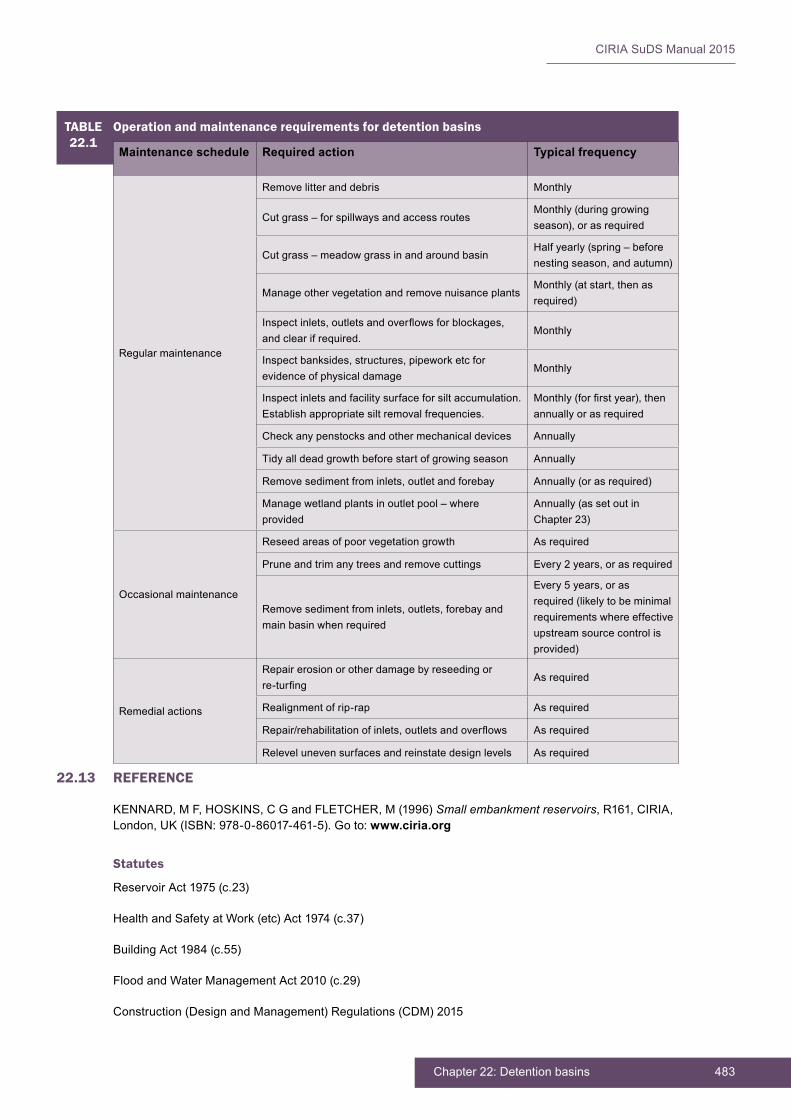
483Chapter 22: Detention basins
CIRIA SuDS Manual 2015
22.13 REFERENCE
KENNARD,MF,HOSKINS,CGandFLETCHER,M(1996)Small embankment reservoirs,R161,CIRIA,London,UK(ISBN:978-0-86017-461-5).Goto: www.ciria.org
Statutes
ReservoirAct1975(c.23)
HealthandSafetyatWork(etc)Act1974(c.37)
BuildingAct1984(c.55)
FloodandWaterManagementAct2010(c.29)
Construction(DesignandManagement)Regulations(CDM)2015
TABLE22.1
Operation and maintenance requirements for detention basins
Maintenance schedule Required action Typical frequency
Regular maintenance
Remove litter and debris Monthly
Cut grass – for spillways and access routesMonthly (during growing season),orasrequired
Cut grass – meadow grass in and around basinHalf yearly (spring – before nestingseason,andautumn)
Manage other vegetation and remove nuisance plantsMonthly(atstart,thenasrequired)
Inspectinlets,outletsandoverflowsforblockages,and clear if required.
Monthly
Inspectbanksides,structures,pipeworketcforevidence of physical damage
Monthly
Inspect inlets and facility surface for silt accumulation. Establish appropriate silt removal frequencies.
Monthly(forfirstyear),thenannually or as required
Checkanypenstocksandothermechanicaldevices Annually
Tidy all dead growth before start of growing season Annually
Removesedimentfrominlets,outletandforebay Annually(orasrequired)
Manage wetland plants in outlet pool – where provided
Annually (as set out in Chapter23)
Occasional maintenance
Reseed areas of poor vegetation growth As required
Prune and trim any trees and remove cuttings Every2years,orasrequired
Removesedimentfrominlets,outlets,forebayandmain basin when required
Every5years,orasrequired(likelytobeminimalrequirements where effective upstream source control is provided)
Remedial actions
Repair erosion or other damage by reseeding or re-turfing
As required
Realignment of rip-rap As required
Repair/rehabilitationofinlets,outletsandoverflows As required
Relevel uneven surfaces and reinstate design levels As required
CIRIA SuDS Manual 2015
484 Part D: Technical detail
23 PONDS AND WETLANDS
Contents
23.1 General description 48523.2 General design considerations 48923.3 Selection and siting of ponds or wetlands 49023.4 Hydraulic design 49123.5 Treatment design 49223.6 Amenity design 49323.7 Biodiversity design 49423.8 Physicalspecifications 49523.9 Materials 49723.10 Landscape design and planting 49823.11 Construction requirements 50023.12 Operation and maintenance requirements 50023.13 References 503

485Chapter 23: Ponds and wetlands
CIRIA SuDS Manual 2015
23.1 GENERAL DESCRIPTION
Ponds and wetlands are features with a permanent pool of water that provide both attenuation and treatment of surface water runoff. They can support emergent and submerged aquatic vegetation along their shoreline and in shallow, marshy (wetland) zones, which helps enhance treatment processes and has amenity and biodiversity benefits.Densestandsofvegetationfacilitatetheadhesionofcontaminantstovegetation, aerobic decomposition of pollutants and can also help stabilise settled sediment and prevent resuspension. The term “wetland” is used to describe bodies of water with larger proportions of the surface area covered by aquatic planting. They also tend to have greater depth variations and may include shallow islands. However, for the purposes of this document, ponds and wetlands are considered together.
Attenuationstorageisprovidedabovethepermanentpoolandwetlandareas.Aflowcontrol system at the outfall controls the rates of discharge for a range of water levels, causingthepondvolumetofillduringstormevents.Runofffromeachrainfalleventisdetainedandtreatedinthepool.Thevolumeofthepoolinfluencestheeffectivenessof the feature in settling out particulate pollutants, with larger volumes providing longer periods of time for sedimentation to occur, and greater opportunities for biodegradation and biological uptake mechanisms.
Ponds and wetlands should always be designed with suitable upstream pre-treatment systems (or separate sediment forebays) in place. This prevents open water features from becoming unsightly and odorous and reduces the risk of rapid silt accumulation, whichisgenerallyexpensiveanddifficulttoextractanddisposeof.Pondsandwetlandsperformavaluablefunctioninsettlingoutresidualfinesiltsandinfinal“polishing”ofsurface water runoff before discharge.
Well-designed and maintained permanent water bodies can offer important aesthetic, amenityandwildlifebenefitstodevelopmentsites.Pondscanbedesignedasnaturalfeatures with shallow, grassed side slopes (Figure 23.1) or can be hard landscaped features that complement the character of dense urban environments. Well-managed pondsandwetlandscanaddsignificanteconomicvaluetoadevelopment,increasingproperty values and attracting business and tourism. Public acceptability of ponds is strongly dependent on their aesthetic quality, on their effective integration within the landscape and on their performance as a community resource, so their form, layout and plantingshouldusuallybedesignedandspecifiedbylandscapearchitects.Theyshouldnot be designed by engineers without landscape architecture expertise.
23Chapter Ponds and wetlands
This chapter provides guidance on the design of ponds – depressions designed to temporarily store surface water above permanently wet pools that permit settlement of suspended solids and biological removal of pollutants. This includes wetlands, which are ponds with a higher proportion of shallow zones that promote the growth of bottom-rooted plants.
Appendix C, Section C.5.4 demonstrates how to design a wetland area for an industrial site.
Appendix C, Section C.5.5 demonstrates how to design a strategic amenity pond.
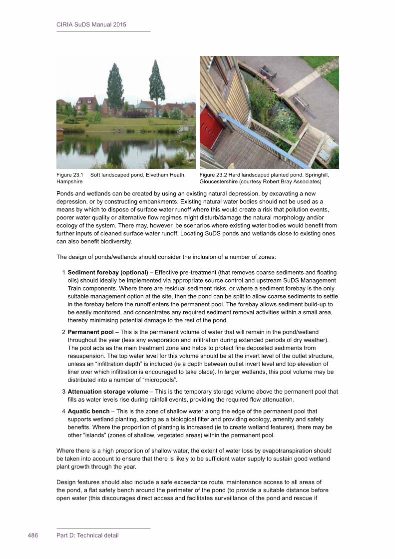
CIRIA SuDS Manual 2015
486 Part D: Technical detail
Ponds and wetlands can be created by using an existing natural depression, by excavating a new depression, or by constructing embankments. Existing natural water bodies should not be used as a means by which to dispose of surface water runoff where this would create a risk that pollution events, poorerwaterqualityoralternativeflowregimesmightdisturb/damagethenaturalmorphologyand/orecologyofthesystem.Theremay,however,bescenarioswhereexistingwaterbodieswouldbenefitfromfurtherinputsofcleanedsurfacewaterrunoff.LocatingSuDSpondsandwetlandsclosetoexistingonescanalsobenefitbiodiversity.
Thedesignofponds/wetlandsshouldconsidertheinclusionofanumberofzones:
1 Sediment forebay (optional) –Effectivepre-treatment(thatremovescoarsesedimentsandfloatingoils)shouldideallybeimplementedviaappropriatesourcecontrolandupstreamSuDSManagementTrain components. Where there are residual sediment risks, or where a sediment forebay is the only suitable management option at the site, then the pond can be split to allow coarse sediments to settle in the forebay before the runoff enters the permanent pool. The forebay allows sediment build-up to be easily monitored, and concentrates any required sediment removal activities within a small area, thereby minimising potential damage to the rest of the pond.
2 Permanent pool–Thisisthepermanentvolumeofwaterthatwillremaininthepond/wetlandthroughouttheyear(lessanyevaporationandinfiltrationduringextendedperiodsofdryweather).Thepoolactsasthemaintreatmentzoneandhelpstoprotectfinedepositedsedimentsfromresuspension. The top water level for this volume should be at the invert level of the outlet structure, unlessan“infiltrationdepth”isincluded(ieadepthbetweenoutletinvertlevelandtopelevationoflineroverwhichinfiltrationisencouragedtotakeplace).Inlargerwetlands,thispoolvolumemaybedistributed into a number of “micropools”.
3 Attenuation storage volume – This is the temporary storage volume above the permanent pool that fillsaswaterlevelsriseduringrainfallevents,providingtherequiredflowattenuation.
4 Aquatic bench – This is the zone of shallow water along the edge of the permanent pool that supportswetlandplanting,actingasabiologicalfilterandprovidingecology,amenityandsafetybenefits.Wheretheproportionofplantingisincreased(ietocreatewetlandfeatures),theremaybeother “islands” (zones of shallow, vegetated areas) within the permanent pool.
Where there is a high proportion of shallow water, the extent of water loss by evapotranspiration should betakenintoaccounttoensurethatthereislikelytobesufficientwatersupplytosustaingoodwetlandplant growth through the year.
Designfeaturesshouldalsoincludeasafeexceedanceroute,maintenanceaccesstoallareasofthepond,aflatsafetybencharoundtheperimeterofthepond(toprovideasuitabledistancebeforeopen water (this discourages direct access and facilitates surveillance of the pond and rescue if
Figure 23.1 Soft landscaped pond, Elvetham Heath, Hampshire
Figure 23.2 Hard landscaped planted pond, Springhill, Gloucestershire (courtesy Robert Bray Associates)
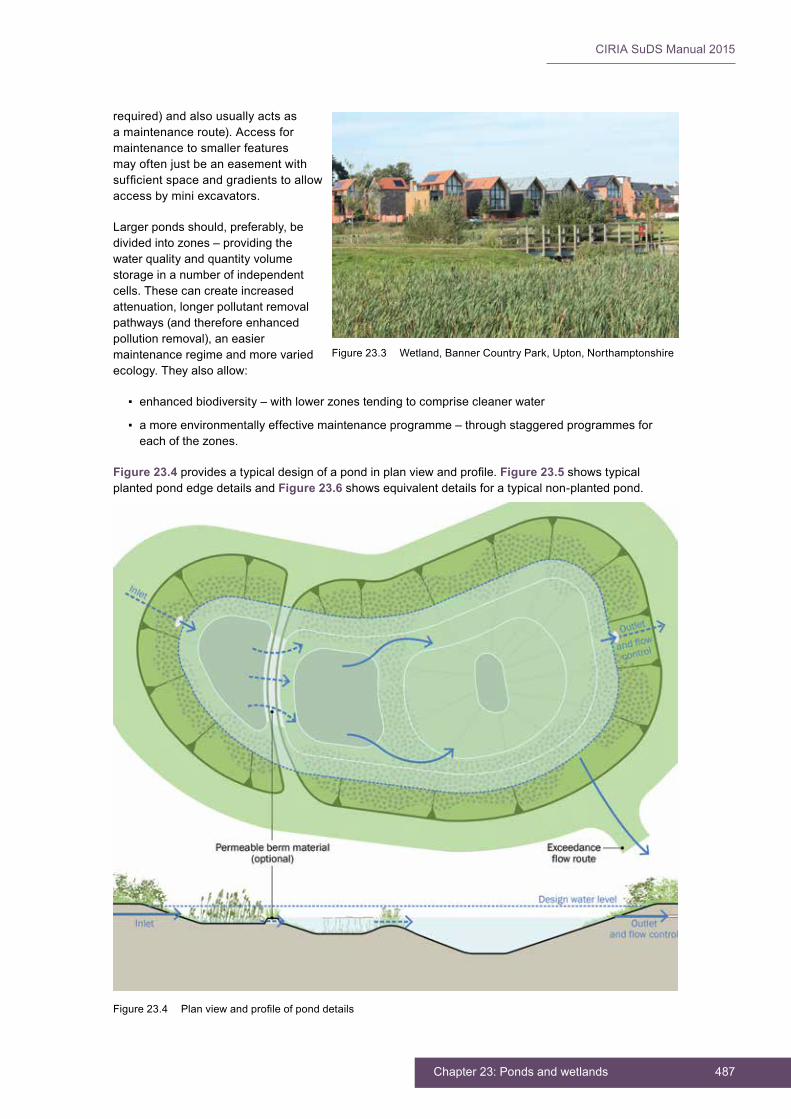
487Chapter 23: Ponds and wetlands
CIRIA SuDS Manual 2015
required) and also usually acts as a maintenance route). Access for maintenance to smaller features may often just be an easement with sufficientspaceandgradientstoallowaccess by mini excavators.
Larger ponds should, preferably, be divided into zones – providing the water quality and quantity volume storage in a number of independent cells. These can create increased attenuation, longer pollutant removal pathways (and therefore enhanced pollution removal), an easier maintenance regime and more varied ecology.Theyalsoallow:
▪ enhanced biodiversity – with lower zones tending to comprise cleaner water
▪ a more environmentally effective maintenance programme – through staggered programmes for each of the zones.
Figure 23.4 providesatypicaldesignofapondinplanviewandprofile.Figure 23.5 shows typical planted pond edge details and Figure 23.6 shows equivalent details for a typical non-planted pond.
Figure 23.3 Wetland, Banner Country Park, Upton, Northamptonshire
Figure23.4 Planviewandprofileofponddetails
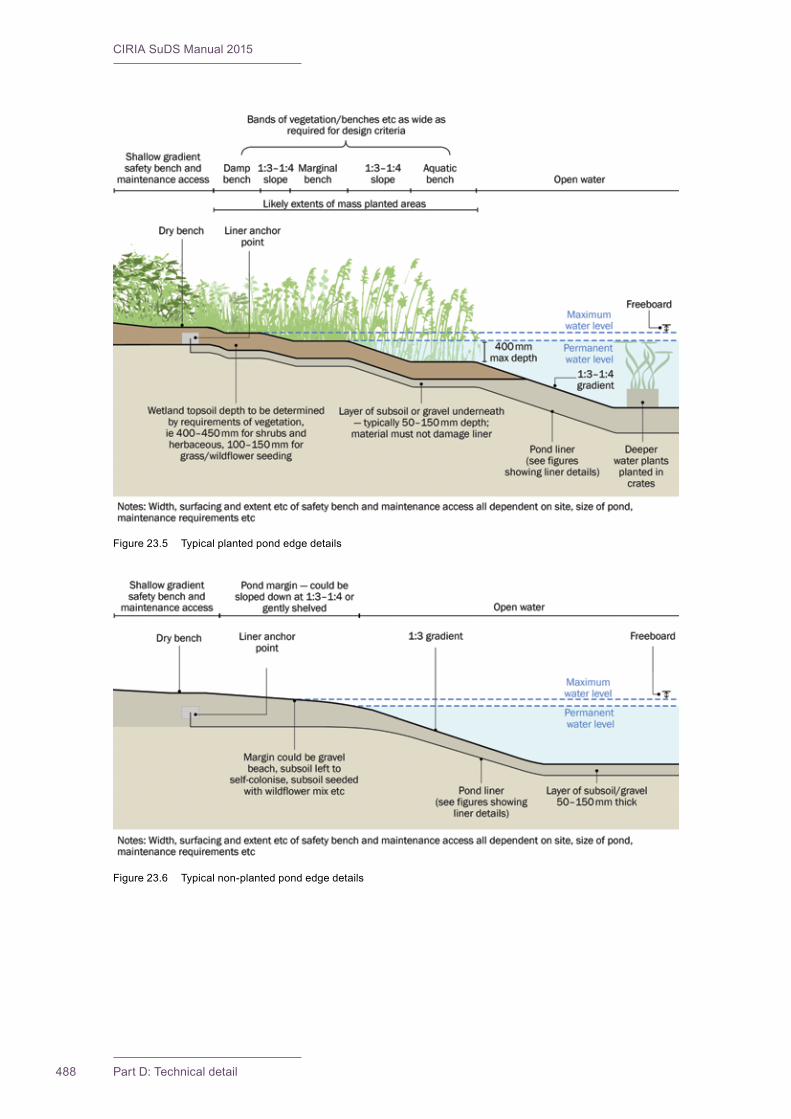
CIRIA SuDS Manual 2015
488 Part D: Technical detail
Figure 23.5 Typical planted pond edge details
Figure 23.6 Typical non-planted pond edge details
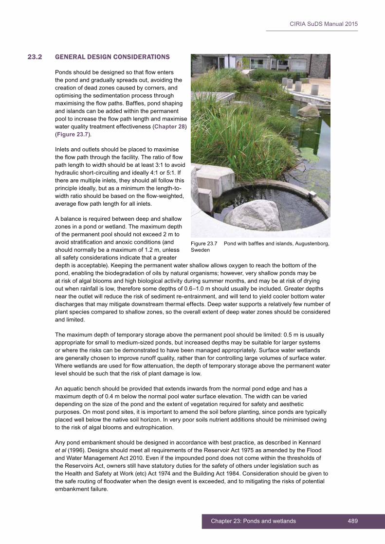
489Chapter 23: Ponds and wetlands
CIRIA SuDS Manual 2015
23.2 GENERAL DESIGN CONSIDERATIONS
Pondsshouldbedesignedsothatflowentersthe pond and gradually spreads out, avoiding the creation of dead zones caused by corners, and optimising the sedimentation process through maximisingtheflowpaths.Baffles,pondshapingand islands can be added within the permanent pooltoincreasetheflowpathlengthandmaximisewater quality treatment effectiveness (Chapter 28) (Figure 23.7).
Inletsandoutletsshouldbeplacedtomaximisetheflowpaththroughthefacility.Theratioofflowpathlengthtowidthshouldbeatleast3:1toavoidhydraulicshort-circuitingandideally4:1or5:1.Ifthere are multiple inlets, they should all follow this principle ideally, but as a minimum the length-to-widthratioshouldbebasedontheflow-weighted,averageflowpathlengthforallinlets.
A balance is required between deep and shallow zones in a pond or wetland. The maximum depth of the permanent pool should not exceed 2 m to avoidstratificationandanoxicconditions(andshould normally be a maximum of 1.2 m, unless all safety considerations indicate that a greater depth is acceptable). Keeping the permanent water shallow allows oxygen to reach the bottom of the pond, enabling the biodegradation of oils by natural organisms; however, very shallow ponds may be at risk of algal blooms and high biological activity during summer months, and may be at risk of drying out when rainfall is low, therefore some depths of 0.6–1.0 m should usually be included. Greater depths near the outlet will reduce the risk of sediment re-entrainment, and will tend to yield cooler bottom water dischargesthatmaymitigatedownstreamthermaleffects.Deepwatersupportsarelativelyfewnumberofplant species compared to shallow zones, so the overall extent of deep water zones should be considered and limited.
Themaximumdepthoftemporarystorageabovethepermanentpoolshouldbelimited:0.5misusuallyappropriate for small to medium-sized ponds, but increased depths may be suitable for larger systems or where the risks can be demonstrated to have been managed appropriately. Surface water wetlands are generally chosen to improve runoff quality, rather than for controlling large volumes of surface water. Wherewetlandsareusedforflowattenuation,thedepthoftemporarystorageabovethepermanentwaterlevel should be such that the risk of plant damage is low.
An aquatic bench should be provided that extends inwards from the normal pond edge and has a maximum depth of 0.4 m below the normal pool water surface elevation. The width can be varied depending on the size of the pond and the extent of vegetation required for safety and aesthetic purposes. On most pond sites, it is important to amend the soil before planting, since ponds are typically placedwellbelowthenativesoilhorizon.Inverypoorsoilsnutrientadditionsshouldbeminimisedowingto the risk of algal blooms and eutrophication.
Any pond embankment should be designed in accordance with best practice, as described in Kennard et al(1996).DesignsshouldmeetallrequirementsoftheReservoirAct1975asamendedbytheFloodand Water Management Act 2010. Even if the impounded pond does not come within the thresholds of the Reservoirs Act, owners still have statutory duties for the safety of others under legislation such as the Health and Safety at Work (etc) Act 1974 and the Building Act 1984. Consideration should be given to thesaferoutingoffloodwaterwhenthedesigneventisexceeded,andtomitigatingtherisksofpotentialembankment failure.
Figure23.7 Pondwithbafflesandislands,Augustenborg,Sweden
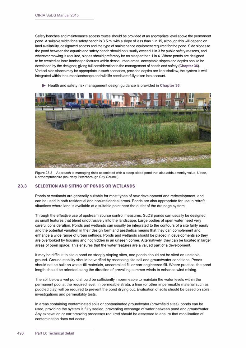
CIRIA SuDS Manual 2015
490 Part D: Technical detail
Safety benches and maintenance access routes should be provided at an appropriate level above the permanent pond. A suitable width for a safety bench is 3.5 m, with a slope of less than 1 in 15, although this will depend on land availability, designated access and the type of maintenance equipment required for the pond. Side slopes to the pond between the aquatic and safety bench should not usually exceed 1 in 3 for public safety reasons, and wherever mowing is required, slopes should preferably be no steeper than 1 in 4. Where ponds are designed to be created as hard landscape features within dense urban areas, acceptable slopes and depths should be developed by the designer, giving full consideration to the management of health and safety (Chapter 36). Vertical side slopes may be appropriate in such scenarios, provided depths are kept shallow, the system is well integrated within the urban landscape and wildlife needs are fully taken into account.
Health and safety risk management design guidance is provided in Chapter 36.
23.3 SELECTION AND SITING OF PONDS OR WETLANDS
Ponds or wetlands are generally suitable for most types of new development and redevelopment, and canbeusedinbothresidentialandnon-residentialareas.Pondsarealsoappropriateforuseinretrofitsituations where land is available at a suitable point near the outlet of the drainage system.
Throughtheeffectiveuseofupstreamsourcecontrolmeasures,SuDSpondscanusuallybedesignedas small features that blend unobtrusively into the landscape. Large bodies of open water need very careful consideration. Ponds and wetlands can usually be integrated to the contours of a site fairly easily and the potential variation in their design form and aesthetics means that they can complement and enhance a wide range of urban settings. Ponds and wetlands should be placed in developments so they are overlooked by housing and not hidden in an unseen corner. Alternatively, they can be located in larger areas of open space. This ensures that the water features are a valued part of a development.
Itmaybedifficulttositeapondonsteeplyslopingsites,andpondsshouldnotbesitedonunstableground.Groundstabilityshouldbeverifiedbyassessingsitesoilandgroundwaterconditions.Pondsshouldnotbebuiltonwaste-fillmaterials,uncontrolledfillornon-engineeredfill.Wherepracticalthepondlength should be oriented along the direction of prevailing summer winds to enhance wind mixing.
Thesoilbelowawetpondshouldbesufficientlyimpermeabletomaintainthewaterlevelswithinthepermanentpoolattherequiredlevel.Inpermeablestrata,aliner(orotherimpermeablematerialsuchaspuddled clay) will be required to prevent the pond drying out. Evaluation of soils should be based on soils investigations and permeability tests.
Inareascontainingcontaminatedsoilsorcontaminatedgroundwater(brownfieldsites),pondscanbeused, providing the system is fully sealed, preventing exchange of water between pond and groundwater. Any excavation or earthmoving processes required should be assessed to ensure that mobilisation of contamination does not occur.
Figure 23.8 Approach to managing risks associated with a steep-sided pond that also adds amenity value, Upton, Northamptonshire (courtesy Peterborough City Council)

491Chapter 23: Ponds and wetlands
CIRIA SuDS Manual 2015
Ifusedonasitewithasensitiveunderlyinggroundwaterzone,orifusedtotreatrunofffromapotential pollution hotspot, a hydrogeological risk assessment will generally be required to determine an appropriate separation distance between the bottom of the pond and the elevation of the annual maximumwatertableunlessalinerisproposed.Ifthesubsurfacesoilsareatallpermeable,aliner(orother impermeable material such as puddle clay) will be required to prevent leakage.
Where the groundwater table is close to the base of the pond, hydraulic connectivity between the water in thepondandthegroundwatershouldbeprevented,unlessthewaterqualityrequirementsforinfiltrationhave been met (Chapter 4).Also,theoperationoftheoutfallshouldbeconfirmedfortheannualmaximum water table level. The maximum expected groundwater level should always be beneath the temporary detention zone.
Ponds and wetlands are not appropriate management measures for runoff from construction sites or for the construction period of the development, when sediment loadings are likely to be very high.
23.4 HYDRAULIC DESIGN
23.4.1 General
Guidance on hydraulic criteria and design standards is given in Chapter 3 and methods for sizing storage are presented in Chapter 24.Thepond/wetlandtemporarystoragevolumeshouldbesizedtoprovidefloodattenuationforalleventstomeetthesitestandardsofservice–uptothe10,30or100/200yearevents (including appropriate climate change and urban creep allowances), if required, with discharges beingconstrainedtotheequivalentgreenfield(orotheragreed)rates.Considerationshouldbegivento larger events, as these should be safely routed downstream. Attenuation volumes may need to be increased if additional storage is required to deliver adequate volumetric control of runoff for the 100 year event (Section 23.4.4).
23.4.2 Interception design
Whereinfiltrationisdesignedtooccurwhenthewaterlevelrisesabovethelevelofthepermanentpool,thensomecontributiontoInterceptiondelivery(thepreventionofrunoffforsmallrainfallevents)maybe achieved. The extent of any volumetric reduction achieved in this way is likely to be very limited and requires careful assessment and design.
23.4.3 Peakflowcontroldesign
Pondsorwetlandscanhelpreduceflowratesfromasitebycontrollingthedischargerateandallowingthetemporarystoragevolumetofillduringstormevents.Therequiredpeakflowcontrolandstoragevolume can be determined using standard hydraulic assessment (Chapter 24).
23.4.4 Volume control design
Ponds and wetlands do not normally contribute to volumetric control of runoff, but they can be used to deliver further attenuation where Long-Term Storage is not practical (Chapter 3). Assessment of volumetric control should follow the normal hydraulic assessment methods in Chapter 24.
23.4.5 Exceedanceflowdesign
Anexceedanceflowroutewillberequiredforrainfalleventsthatexceedthedesigncapacityofthepondorwetlandandtoconveyflowsshouldoutletblockagesoccur.Thiscanbeachievedbyinstallinganoverflowpipeorweir/overflow/spillwaystructureabovethedesignwaterstorageleveltoconveyexcessflowsdownstream.Theyshouldbedesignedtopreventover-toppingofanyembankmentwhichmightcause structural damage, and spillways should be located so that downstream people and property are not put at risk. For small ponds, a simple grass channel integrated into the landscape is usually suitable asanexceedanceroute.Afreeboardof300mmforthedesigneventisusuallysufficientforlarger
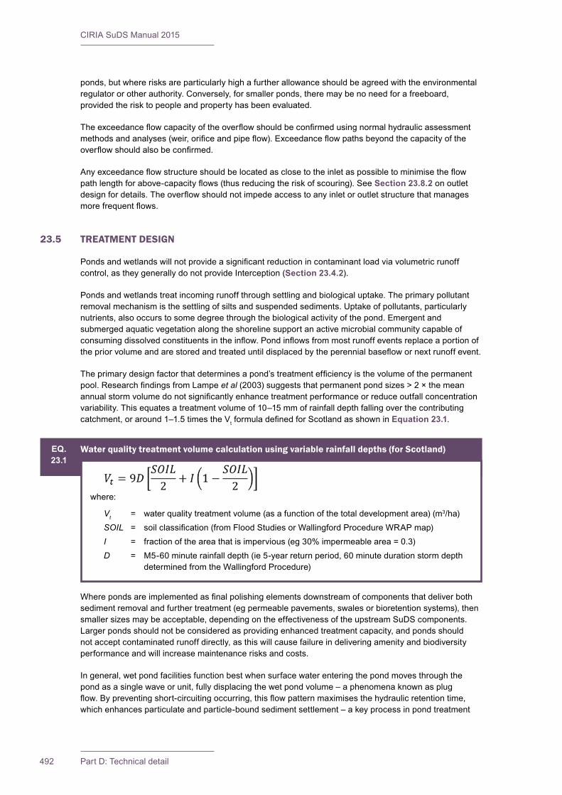
CIRIA SuDS Manual 2015
492 Part D: Technical detail
ponds, but where risks are particularly high a further allowance should be agreed with the environmental regulator or other authority. Conversely, for smaller ponds, there may be no need for a freeboard, provided the risk to people and property has been evaluated.
Theexceedanceflowcapacityoftheoverflowshouldbeconfirmedusingnormalhydraulicassessmentmethodsandanalyses(weir,orificeandpipeflow).Exceedanceflowpathsbeyondthecapacityoftheoverflowshouldalsobeconfirmed.
Anyexceedanceflowstructureshouldbelocatedasclosetotheinletaspossibletominimisetheflowpathlengthforabove-capacityflows(thusreducingtheriskofscouring).SeeSection 23.8.2 on outlet designfordetails.Theoverflowshouldnotimpedeaccesstoanyinletoroutletstructurethatmanagesmorefrequentflows.
23.5 TREATMENT DESIGN
Pondsandwetlandswillnotprovideasignificantreductionincontaminantloadviavolumetricrunoffcontrol,astheygenerallydonotprovideInterception(Section 23.4.2).
Ponds and wetlands treat incoming runoff through settling and biological uptake. The primary pollutant removal mechanism is the settling of silts and suspended sediments. Uptake of pollutants, particularly nutrients, also occurs to some degree through the biological activity of the pond. Emergent and submerged aquatic vegetation along the shoreline support an active microbial community capable of consumingdissolvedconstituentsintheinflow.Pondinflowsfrommostrunoffeventsreplaceaportionofthepriorvolumeandarestoredandtreateduntildisplacedbytheperennialbaseflowornextrunoffevent.
Theprimarydesignfactorthatdeterminesapond’streatmentefficiencyisthevolumeofthepermanentpool.ResearchfindingsfromLampeet al (2003) suggests that permanent pond sizes > 2 × the mean annualstormvolumedonotsignificantlyenhancetreatmentperformanceorreduceoutfallconcentrationvariability. This equates a treatment volume of 10–15 mm of rainfall depth falling over the contributing catchment, or around 1–1.5 times the VtformuladefinedforScotlandasshowninEquation 23.1.
Wherepondsareimplementedasfinalpolishingelementsdownstreamofcomponentsthatdeliverbothsediment removal and further treatment (eg permeable pavements, swales or bioretention systems), then smallersizesmaybeacceptable,dependingontheeffectivenessoftheupstreamSuDScomponents.Larger ponds should not be considered as providing enhanced treatment capacity, and ponds should not accept contaminated runoff directly, as this will cause failure in delivering amenity and biodiversity performance and will increase maintenance risks and costs.
Ingeneral,wetpondfacilitiesfunctionbestwhensurfacewaterenteringthepondmovesthroughthepond as a single wave or unit, fully displacing the wet pond volume – a phenomena known as plug flow.Bypreventingshort-circuitingoccurring,thisflowpatternmaximisesthehydraulicretentiontime,which enhances particulate and particle-bound sediment settlement – a key process in pond treatment
EQ.23.1
Water quality treatment volume calculation using variable rainfall depths (for Scotland)
where:
Vt = water quality treatment volume (as a function of the total development area) (m3/ha)SOIL = soilclassification(fromFloodStudiesorWallingfordProcedureWRAPmap)I = fraction of the area that is impervious (eg 30% impermeable area = 0.3)D = M5-60 minute rainfall depth (ie 5-year return period, 60 minute duration storm depth
determined from the Wallingford Procedure)
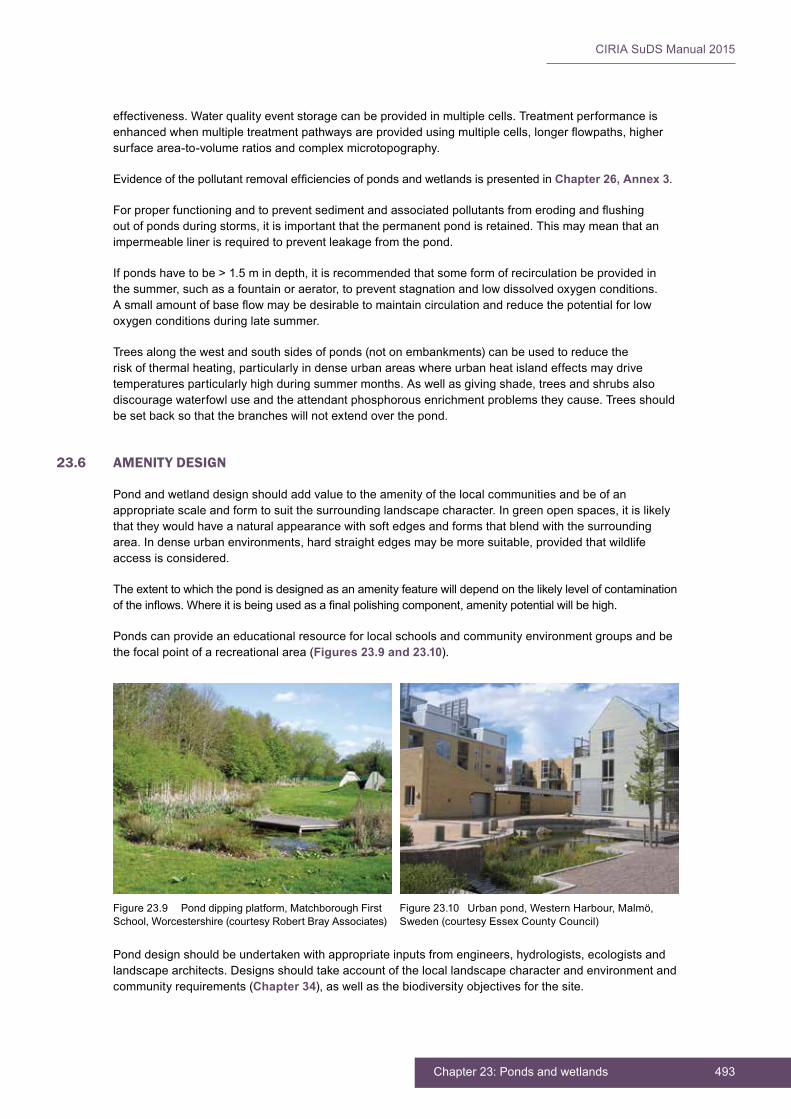
493Chapter 23: Ponds and wetlands
CIRIA SuDS Manual 2015
effectiveness. Water quality event storage can be provided in multiple cells. Treatment performance is enhancedwhenmultipletreatmentpathwaysareprovidedusingmultiplecells,longerflowpaths,highersurface area-to-volume ratios and complex microtopography.
EvidenceofthepollutantremovalefficienciesofpondsandwetlandsispresentedinChapter 26, Annex 3.
Forproperfunctioningandtopreventsedimentandassociatedpollutantsfromerodingandflushingout of ponds during storms, it is important that the permanent pond is retained. This may mean that an impermeable liner is required to prevent leakage from the pond.
Ifpondshavetobe>1.5mindepth,itisrecommendedthatsomeformofrecirculationbeprovidedinthe summer, such as a fountain or aerator, to prevent stagnation and low dissolved oxygen conditions. Asmallamountofbaseflowmaybedesirabletomaintaincirculationandreducethepotentialforlowoxygen conditions during late summer.
Trees along the west and south sides of ponds (not on embankments) can be used to reduce the risk of thermal heating, particularly in dense urban areas where urban heat island effects may drive temperatures particularly high during summer months. As well as giving shade, trees and shrubs also discourage waterfowl use and the attendant phosphorous enrichment problems they cause. Trees should be set back so that the branches will not extend over the pond.
23.6 AMENITY DESIGN
Pond and wetland design should add value to the amenity of the local communities and be of an appropriatescaleandformtosuitthesurroundinglandscapecharacter.Ingreenopenspaces,itislikelythat they would have a natural appearance with soft edges and forms that blend with the surrounding area.Indenseurbanenvironments,hardstraightedgesmaybemoresuitable,providedthatwildlifeaccess is considered.
The extent to which the pond is designed as an amenity feature will depend on the likely level of contamination oftheinflows.Whereitisbeingusedasafinalpolishingcomponent,amenitypotentialwillbehigh.
Ponds can provide an educational resource for local schools and community environment groups and be the focal point of a recreational area (Figures 23.9 and 23.10).
Pond design should be undertaken with appropriate inputs from engineers, hydrologists, ecologists and landscapearchitects.Designsshouldtakeaccountofthelocallandscapecharacterandenvironmentandcommunity requirements (Chapter 34), as well as the biodiversity objectives for the site.
Figure 23.9 Pond dipping platform, Matchborough First School, Worcestershire (courtesy Robert Bray Associates)
Figure 23.10 Urban pond, Western Harbour, Malmö, Sweden (courtesy Essex County Council)
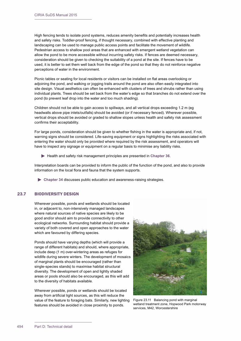
CIRIA SuDS Manual 2015
494 Part D: Technical detail
Highfencingtendstoisolatepondsystems,reducesamenitybenefitsandpotentiallyincreaseshealthand safety risks. Toddler-proof fencing, if thought necessary, combined with effective planting and landscaping can be used to manage public access points and facilitate the movement of wildlife. Pedestrian access to shallow pool areas that are enhanced with emergent wetland vegetation can allowthepondtobemoreaccessiblewithoutincurringsafetyrisks.Iffencesaredeemednecessary,considerationshouldbegiventocheckingthesuitabilityofapondatthesite.Iffenceshavetobeused, it is better to set them well back from the edge of the pond so that they do not reinforce negative perceptions of water in the environment.
Picnictablesorseatingforlocalresidentsorvisitorscanbeinstalledonflatareasoverlookingoradjoining the pond, and walking or jogging trails around the pond are also often easily integrated into site design. Visual aesthetics can often be enhanced with clusters of trees and shrubs rather than using individual plants. Trees should be set back from the water’s edge so that branches do not extend over the pond (to prevent leaf drop into the water and too much shading).
Children should not be able to gain access to spillways, and all vertical drops exceeding 1.2 m (eg headwallsabovepipeinlets/outfalls)shouldbeavoided(orifnecessaryfenced).Whereverpossible,vertical drops should be avoided or graded to shallow slopes unless health and safety risk assessment confirmstheiracceptability.
Forlargeponds,considerationshouldbegiventowhetherfishinginthewaterisappropriateand,ifnot,warning signs should be considered. Life-saving equipment or signs highlighting the risks associated with entering the water should only be provided where required by the risk assessment, and operators will have to inspect any signage or equipment on a regular basis to minimise any liability risks.
Health and safety risk management principles are presented in Chapter 36.
Interpretationboardscanbeprovidedtoinformthepublicofthefunctionofthepond,andalsotoprovideinformationonthelocalfloraandfaunathatthesystemsupports.
Chapter 34 discusses public education and awareness-raising strategies.
23.7 BIODIVERSITY DESIGN
Wherever possible, ponds and wetlands should be located in, or adjacent to, non-intensively managed landscapes where natural sources of native species are likely to be goodand/orshouldaimtoprovideconnectivitytootherecological networks. Surrounding habitat should provide a variety of both covered and open approaches to the water which are favoured by differing species.
Ponds should have varying depths (which will provide a range of different habitats) and should, where appropriate, include deep (1 m) over-wintering areas as refuges for wildlife during severe winters. The development of mosaics of marginal plants should be encouraged (rather than single-species stands) to maximise habitat structural diversity. The development of open and lightly shaded areas or pools should also be encouraged, as this will add to the diversity of habitats available.
Wherever possible, ponds or wetlands should be located awayfromartificiallightsources,asthiswillreducethevalue of the feature to foraging bats. Similarly, new lighting features should be avoided in close proximity to ponds.
Figure 23.11 Balancing pond with marginal wetland treatment zone, Hopwood Park motorway services, M42, Worcestershire
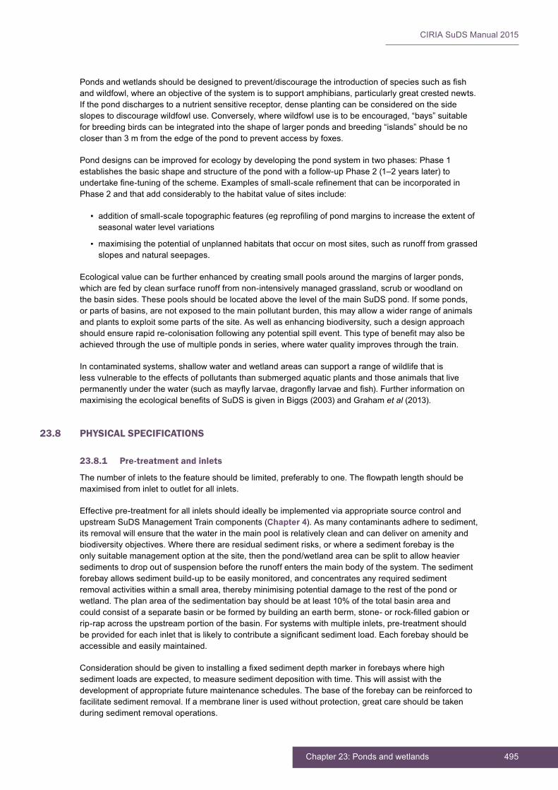
495Chapter 23: Ponds and wetlands
CIRIA SuDS Manual 2015
Pondsandwetlandsshouldbedesignedtoprevent/discouragetheintroductionofspeciessuchasfishand wildfowl, where an objective of the system is to support amphibians, particularly great crested newts. Iftheponddischargestoanutrientsensitivereceptor,denseplantingcanbeconsideredonthesideslopes to discourage wildfowl use. Conversely, where wildfowl use is to be encouraged, “bays” suitable for breeding birds can be integrated into the shape of larger ponds and breeding “islands” should be no closer than 3 m from the edge of the pond to prevent access by foxes.
Ponddesignscanbeimprovedforecologybydevelopingthepondsystemintwophases:Phase1establishes the basic shape and structure of the pond with a follow-up Phase 2 (1–2 years later) to undertakefine-tuningofthescheme.Examplesofsmall-scalerefinementthatcanbeincorporatedinPhase2andthataddconsiderablytothehabitatvalueofsitesinclude:
▪ additionofsmall-scaletopographicfeatures(egreprofilingofpondmarginstoincreasetheextentofseasonal water level variations
▪ maximising the potential of unplanned habitats that occur on most sites, such as runoff from grassed slopes and natural seepages.
Ecological value can be further enhanced by creating small pools around the margins of larger ponds, which are fed by clean surface runoff from non-intensively managed grassland, scrub or woodland on thebasinsides.ThesepoolsshouldbelocatedabovethelevelofthemainSuDSpond.Ifsomeponds,or parts of basins, are not exposed to the main pollutant burden, this may allow a wider range of animals and plants to exploit some parts of the site. As well as enhancing biodiversity, such a design approach shouldensurerapidre-colonisationfollowinganypotentialspillevent.Thistypeofbenefitmayalsobeachieved through the use of multiple ponds in series, where water quality improves through the train.
Incontaminatedsystems,shallowwaterandwetlandareascansupportarangeofwildlifethatisless vulnerable to the effects of pollutants than submerged aquatic plants and those animals that live permanentlyunderthewater(suchasmayflylarvae,dragonflylarvaeandfish).FurtherinformationonmaximisingtheecologicalbenefitsofSuDSisgiveninBiggs(2003)andGrahamet al (2013).
23.8 PHYSICAL SPECIFICATIONS
23.8.1 Pre-treatment and inlets
Thenumberofinletstothefeatureshouldbelimited,preferablytoone.Theflowpathlengthshouldbemaximised from inlet to outlet for all inlets.
Effective pre-treatment for all inlets should ideally be implemented via appropriate source control and upstreamSuDSManagementTraincomponents(Chapter 4). As many contaminants adhere to sediment, its removal will ensure that the water in the main pool is relatively clean and can deliver on amenity and biodiversity objectives. Where there are residual sediment risks, or where a sediment forebay is the onlysuitablemanagementoptionatthesite,thenthepond/wetlandareacanbesplittoallowheaviersediments to drop out of suspension before the runoff enters the main body of the system. The sediment forebay allows sediment build-up to be easily monitored, and concentrates any required sediment removal activities within a small area, thereby minimising potential damage to the rest of the pond or wetland. The plan area of the sedimentation bay should be at least 10% of the total basin area and couldconsistofaseparatebasinorbeformedbybuildinganearthberm,stone-orrock-filledgabionorrip-rap across the upstream portion of the basin. For systems with multiple inlets, pre-treatment should beprovidedforeachinletthatislikelytocontributeasignificantsedimentload.Eachforebayshouldbeaccessible and easily maintained.
Considerationshouldbegiventoinstallingafixedsedimentdepthmarkerinforebayswherehighsediment loads are expected, to measure sediment deposition with time. This will assist with the development of appropriate future maintenance schedules. The base of the forebay can be reinforced to facilitatesedimentremoval.Ifamembranelinerisusedwithoutprotection,greatcareshouldbetakenduring sediment removal operations.
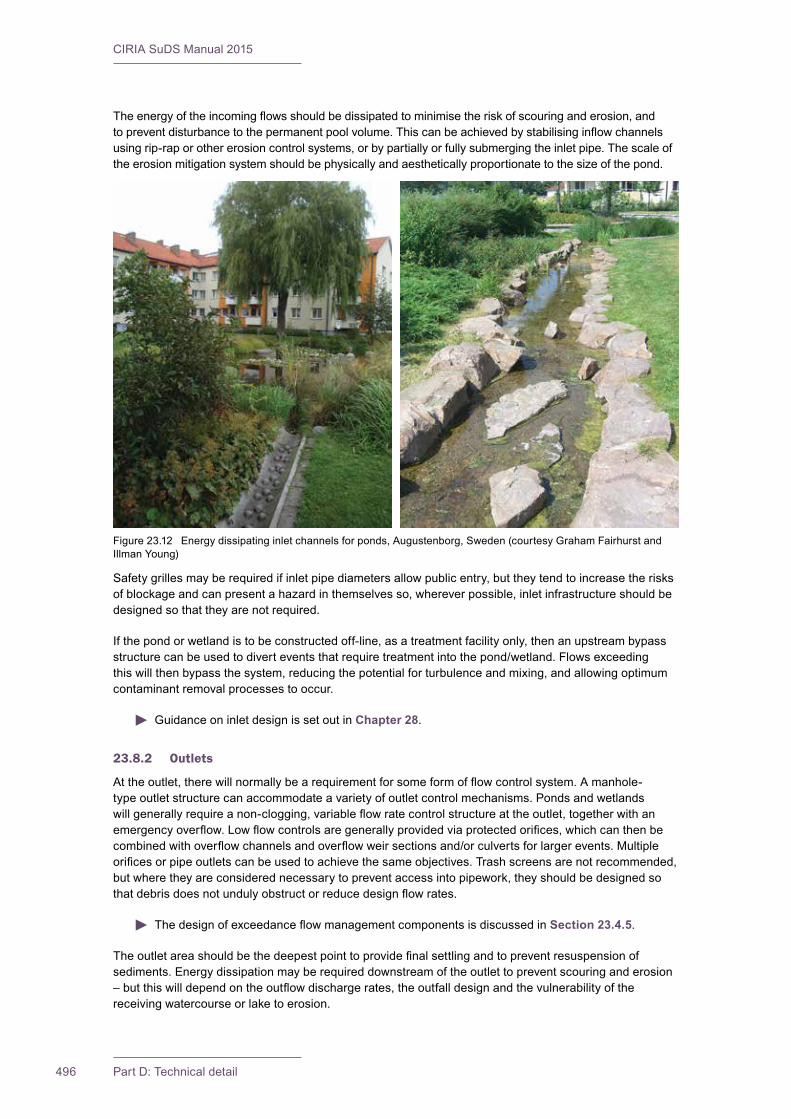
CIRIA SuDS Manual 2015
496 Part D: Technical detail
Theenergyoftheincomingflowsshouldbedissipatedtominimisetheriskofscouringanderosion,andtopreventdisturbancetothepermanentpoolvolume.Thiscanbeachievedbystabilisinginflowchannelsusing rip-rap or other erosion control systems, or by partially or fully submerging the inlet pipe. The scale of the erosion mitigation system should be physically and aesthetically proportionate to the size of the pond.
Safety grilles may be required if inlet pipe diameters allow public entry, but they tend to increase the risks of blockage and can present a hazard in themselves so, wherever possible, inlet infrastructure should be designed so that they are not required.
Ifthepondorwetlandistobeconstructedoff-line,asatreatmentfacilityonly,thenanupstreambypassstructurecanbeusedtodiverteventsthatrequiretreatmentintothepond/wetland.Flowsexceedingthis will then bypass the system, reducing the potential for turbulence and mixing, and allowing optimum contaminant removal processes to occur.
Guidance on inlet design is set out in Chapter 28.
23.8.2 Outlets
Attheoutlet,therewillnormallybearequirementforsomeformofflowcontrolsystem.Amanhole-type outlet structure can accommodate a variety of outlet control mechanisms. Ponds and wetlands willgenerallyrequireanon-clogging,variableflowratecontrolstructureattheoutlet,togetherwithanemergencyoverflow.Lowflowcontrolsaregenerallyprovidedviaprotectedorifices,whichcanthenbecombinedwithoverflowchannelsandoverflowweirsectionsand/orculvertsforlargerevents.Multipleorificesorpipeoutletscanbeusedtoachievethesameobjectives.Trashscreensarenotrecommended,but where they are considered necessary to prevent access into pipework, they should be designed so thatdebrisdoesnotundulyobstructorreducedesignflowrates.
ThedesignofexceedanceflowmanagementcomponentsisdiscussedinSection 23.4.5.
Theoutletareashouldbethedeepestpointtoprovidefinalsettlingandtopreventresuspensionofsediments. Energy dissipation may be required downstream of the outlet to prevent scouring and erosion –butthiswilldependontheoutflowdischargerates,theoutfalldesignandthevulnerabilityofthereceiving watercourse or lake to erosion.
Figure 23.12 Energy dissipating inlet channels for ponds, Augustenborg, Sweden (courtesy Graham Fairhurst and IllmanYoung)
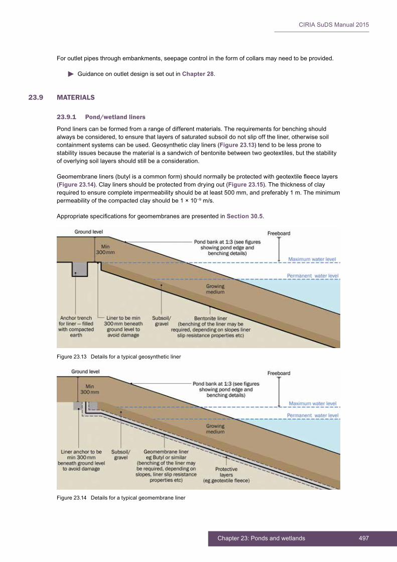
497Chapter 23: Ponds and wetlands
CIRIA SuDS Manual 2015
For outlet pipes through embankments, seepage control in the form of collars may need to be provided.
Guidance on outlet design is set out in Chapter 28.
23.9 MATERIALS
23.9.1 Pond/wetland liners
Pond liners can be formed from a range of different materials. The requirements for benching should always be considered, to ensure that layers of saturated subsoil do not slip off the liner, otherwise soil containment systems can be used. Geosynthetic clay liners (Figure 23.13) tend to be less prone to stability issues because the material is a sandwich of bentonite between two geotextiles, but the stability of overlying soil layers should still be a consideration.
Geomembraneliners(butylisacommonform)shouldnormallybeprotectedwithgeotextilefleecelayers(Figure 23.14). Clay liners should be protected from drying out (Figure 23.15). The thickness of clay required to ensure complete impermeability should be at least 500 mm, and preferably 1 m. The minimum permeability of the compacted clay should be 1 × 10⁻⁹m/s.
AppropriatespecificationsforgeomembranesarepresentedinSection 30.5.
Figure23.13 Detailsforatypicalgeosyntheticliner
Figure23.14 Detailsforatypicalgeomembraneliner
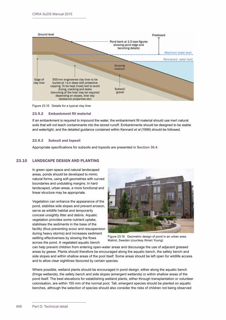
CIRIA SuDS Manual 2015
498 Part D: Technical detail
23.9.2 Embankmentfillmaterial
Ifanembankmentisrequiredtoimpoundthewater,theembankmentfillmaterialshoulduseinertnaturalsoils that will not leach contaminants into the stored runoff. Embankments should be designed to be stable and watertight, and the detailed guidance contained within Kennard et al (1996) should be followed.
23.9.3 Subsoil and topsoil
AppropriatespecificationsforsubsoilsandtopsoilsarepresentedinSection 30.4.
23.10 LANDSCAPE DESIGN AND PLANTING
Ingreenopenspaceandnaturallandscapedareas, ponds should be developed to mimic natural forms, using soft geometries with curved boundariesandundulatingmargins.Inhardlandscaped, urban areas, a more functional and linear structure may be appropriate.
Vegetation can enhance the appearance of the pond, stabilise side slopes and prevent erosion, serve as wildlife habitat and temporarily conceal unsightly litter and debris. Aquatic vegetation provides some nutrient uptake, stabilises the sediments in the base of the facility (thus preventing scour and resuspension during heavy storms) and increases sediment settlingeffectivenessbyslowingtheflowsacross the pond. A vegetated aquatic bench can help prevent children from entering open-water areas and discourage the use of adjacent grassed areas by geese. Plants should therefore be encouraged along the aquatic bench, the safety bench and side slopes and within shallow areas of the pool itself. Some areas should be left open for wildlife access and to allow clear sightlines favoured by certain species.
Where possible, wetland plants should be encouraged in pond design, either along the aquatic bench (fringe wetlands), the safety bench and side slopes (emergent wetlands) or within shallow areas of the pond itself. The best elevations for establishing wetland plants, either through transplantation or volunteer colonisation, are within 150 mm of the normal pool. Tall, emergent species should be planted on aquatic benches, although the selection of species should also consider the risks of children not being observed
Figure23.15 Detailsforatypicalclayliner
Figure 23.16 Geometric design of pond in an urban area, Malmö,Sweden(courtesyIllmanYoung)

499Chapter 23: Ponds and wetlands
CIRIA SuDS Manual 2015
iftheygetintodifficultiesduetobeinghiddenbyvegetation.Theplantsshouldnotrestrictvisibilityofthewater’sedgeorhinderadultsupervision,particularlyinamenityareas.Denseplantingofmarginalfloating-leavedandaquaticplantsshouldbeavoided,andthewetlandshouldbelefttocoloniseasnaturallyaspossible.Over-plantinginitiallywilltendtofillspacethatcouldotherwisebeexploitedbyself-colonising local species, and so reduces the potential ecological value of the wetland. A diversity of plants is very valuable ecologically, and monocultures of, for example, reeds should be avoided. Wetland plants shouldbetolerantoffluctuatingwaterlevels.Idealspeciesarethosethatofferahighdensityofstemsinthe submerged zone, maximising the contact between water and the surface on which microorganisms grow,whileprovidinguniformflowconditions.
Designersshoulddevelopanappropriateplantlist(usuallycomprisingspeciesfoundwithin30kmofthedevelopment site), which may vary, depending on the design and landscape objectives for the scheme.
Non-native species are more likely to be appropriate in more formal or urban settings, but may also be beneficialinenhancingpollinatorsandinprovidingaestheticvalue.Particularcareshouldbetakennottointroduce invasive species to the pond or wetland system, and all plant supplies should be accredited or plant sources known. Were appropriate, the species mix should aim to create habitats that contribute to local, regional and national biodiversity strategies (Chapter 29).
Wetland planting density varies but is typically 4–8 plants per m2. Wetland planting should take place between early April and mid June so that the plants have a full growing season to develop the root reserves they need to survive the winter. Vegetation usually needs to be quickly established once surface waterflowsareintroducedtothesystem,inordertoensurepollutantremovallevelsandtoreducetherisk of bankside erosion. Some ponds at the end of a drainage system may lend themselves to natural colonisation, particularly if linking to existing wetlands or watercourses. The slow colonisation of these ponds can provide valuable successional habitats. However, erosion during establishment of the vegetation needs to be carefully considered.
The soils of a pond buffer are often severely compacted during the construction process. The density of these compacted soils is so great that it effectively prevents root penetration, and therefore may lead to premature mortality or loss of vigour. Consequently, it is advisable to excavate large and deep holes aroundtheproposedplantingsites,andthenbackfillthesewithuncompactedtopsoil.Wherepondsandwetlands have been excavated to subsoils that lack the nutrients and organic matter to support quality growth, topsoil or wetland mulch should be added to all planting areas – taking account of the need to control ongoing nutrient loadings to the water body. A soil depth of 150 mm is usually adequate for grassed areas, but up to 450 mm may be required to support large shrubs.
Figure 23.17 Examples of different types of planting
Herne Bay, Kent (courtesy Kent County Council) DundeeCityCouncilSocialWorkDepartment(courtesyAbertay University)

CIRIA SuDS Manual 2015
500 Part D: Technical detail
23.11 CONSTRUCTION REQUIREMENTS
The bottom and side slopes of the pond, including any benches, should be carefully prepared to ensure that they are structurally sound. Any embankments should be checked to ensure that they meet their design criteria. The preparation should also ensure that the basin will satisfactorily retain the surface waterrunoffwithoutsignificanterosiondamage.
Backfillingagainstinletandoutletstructuresneedstobecontrolledsoastominimisesettlementanderosion.Thesoilsusedtofinishthesideslopesofthepondabovetheretainedlevelneedtobesuitablyfertile,porousandofsufficientdepthtoensurehealthyvegetationgrowth.Ifanimpermeablelinerisused,care should be taken to ensure that it is not damaged during construction.
There are various materials available to help prevent erosion while allowing plants to establish (Section 29.4.3).Ideally,plantingwouldbeplannedoveranumberofyearssothattherateofestablishmentcanbe monitored and densities adjusted accordingly.
Ponds can only be used to manage construction runoff where there is provision made for their complete rehabilitation to original design formation levels before handover. Planting schemes should be delayed until full rehabilitation has been undertaken.
Further detail on construction activities and the programming of construction activities is provided in Chapter 31. Generic health and safety guidance is provided in Chapter 36. A construction phase health andsafetyplanisrequiredunderCDM2015.Thisshouldensurethatallconstructionriskshavebeenidentified,eliminated,reducedand/orcontrolledwhereappropriate.
23.12 OPERATION AND MAINTENANCE REQUIREMENTS
Ponds and wetlands will require regular maintenance to ensure continuing operation to design performancestandards,andalldesignersshouldprovidedetailedspecificationsandfrequenciesforthe required maintenance activities, along with likely machinery requirements and typical annual costs – within the Maintenance Plan. The treatment performance of ponds and wetlands is dependent on maintenance, and robust management plans will be required to ensure maintenance is carried out in the longterm.Differentdesignswillhavedifferentoperationandmaintenancerequirements,butthissectiongives some generic guidance.
Maintenance of ponds is relatively straightforward for landscape contractors, and typically there should onlybeasmallamountofextraworkrequiredforaSuDSpondorwetlandfeatureoverandabovewhatisnecessary for standard public open space.
Regular inspection and maintenance is important for the effective operation of ponds as designed. Maintenance responsibility for a pond and its surrounding area should always be placed with a responsible organisation. Litter and debris removal should be undertaken as part of general landscape maintenance for thesiteandbeforeanyotherSuDSmanagementtask.Alllittershouldberemovedfromsite.
Any invasive maintenance work such as silt or vegetation removal is only required intermittently, but it should be planned to be sympathetic to the requirements of wildlife in a pond. Care should be taken to avoid disturbance to nesting birds during the breeding season and habitats of target species (eg great crested newt and water voles) at critical times. The window for carrying out maintenance to achieve this is usually towardstheendofthegrowingseason(typicallySeptember/October),althoughthiswillvarywithspecies).Invasivesiltandvegetationremovalshouldonlybecarriedouttolimitedareasatanyonetime(25–30%of the pond area on one occasion each year to minimise the impact on biodiversity. Plant management, to achieveparticulardesiredhabitateffects,shouldbeclearlyspecifiedinamaintenanceschedule.
Site vegetation should be trimmed as necessary to keep the pond free of leaves and to maintain the aesthetic appearance of the site. Slope areas that have become bare should be re-vegetated and any eroded areas should be regraded before replanting.

501Chapter 23: Ponds and wetlands
CIRIA SuDS Manual 2015
Maintenance access (or “easement”) should be provided to the pond from a public or private road. An assessment should be made at the planning stage regarding the maintenance and associated access requirements.Ideally,accessshouldbeatleast3.5mwide,haveamaximumcrossfallof1in7,andbesufficientlyrobusttowithstandmaintenanceequipmentandvehicles.However,temporaryaccessroutesfor infrequent operations could be considered where permanent routes are not appropriate. The access should extend to any forebay, safety and aquatic benches, inlet and outlet infrastructure. Consideration should be given as to whether maintenance vehicles will need to turn around. Wherever possible SuDSpondsandwetlandsshouldbedesignedsothatspecialmachineryisnotrequiredtoundertakemaintenance.
Table 23.1 provides guidance on the type of operational and maintenance requirements that may be appropriate. The list of actions is not exhaustive and some actions may not always be required. Consideration should be given to the need to control risks to biosecurity during maintenance operations and guidance is provided in Chapter 29.
Sediments excavated from ponds or forebays that receive runoff from residential or standard road and roof areas should be safely disposed of in accordance with current waste management legislation. However,consultationshouldtakeplacewiththeenvironmentalregulatortoconfirmappropriateprotocols. Chemical testing of the sediment may be required, before sediment excavation, to determine itsclassificationandappropriatedisposalmethods.Forindustrialsiterunoff,sedimenttestingwillbeessential.Inthemajorityofcasesonlow-risksiteswithsourcecontrolandaManagementTrain,itwillbeacceptable to distribute the sediment on site, if there is an appropriate safe and acceptable location to do so. Further detail on waste management is provided in Chapter 33.Ifpondsaretobedrawndown,careshould be taken to prevent downstream discharge of sediments and anoxic water. The environmental regulatorshouldbenotifiedbeforesuchactivities.
New ponds may become rapidly dominated by invasive native plants, particularly common bulrush (Typha latifolia). As it is not desirable for all new ponds to be bulrush dominated, it should be ensured that in thefirstfiveyears,whilevegetationisestablishing,certainplantgrowthiscontrolled.Afterthistime,ponds can usually be allowed to develop naturally recognising that, unless the margins are occasionally managed, they are likely to become dominated by trees and shrubs.
EutrophicationofSuDSpondscanoccurduringthesummermonths.Thisisbestalleviatedbycontrollingthenutrientsourceorprovidingacontinuousbaseflowtothepond.Unlesseutrophicationissevere,aeration can be used as a stop-gap measure to save aquatic animal species and reduce risks to receiving waters. However, the addition of barley straw bales, dredging or rendering the nutrients inactive by chemical means can also be successful.
MaintenancePlansandschedulesshouldbedevelopedduringthedesignphase.Specificmaintenanceneeds of the pond should be monitored, and maintenance schedules adjusted to suit requirements. Further detailonthepreparationofmaintenancespecificationsandschedulesofworkisgiveninChapter 32.
Generic health and safety guidance is provided in Chapter 36.CDM2015requiresdesignerstoensurethatallmaintenanceriskshavebeenidentified,eliminated,reducedand/orcontrolledwhereappropriate.Thisinformationwillberequiredaspartofthehealthandsafetyfile.
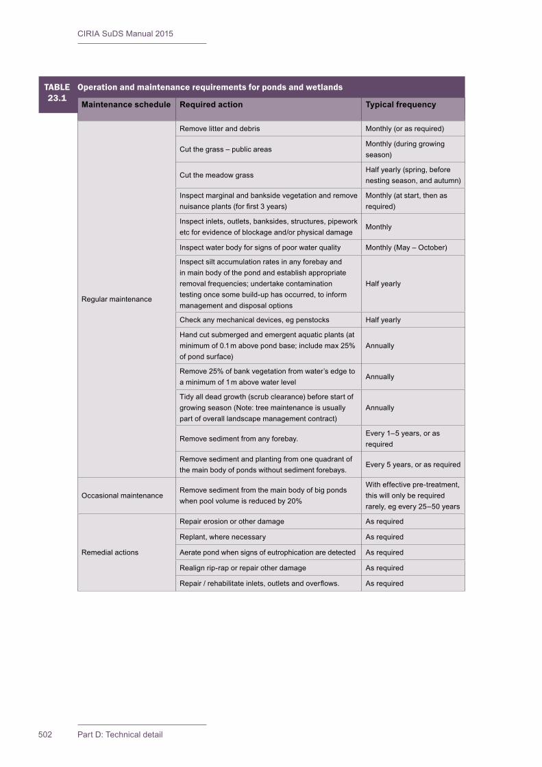
CIRIA SuDS Manual 2015
502 Part D: Technical detail
TABLE23.1
Operation and maintenance requirements for ponds and wetlands
Maintenance schedule Required action Typical frequency
Regular maintenance
Remove litter and debris Monthly (or as required)
Cut the grass – public areasMonthly (during growing season)
Cut the meadow grassHalf yearly (spring, before nesting season, and autumn)
Inspectmarginalandbanksidevegetationandremovenuisanceplants(forfirst3years)
Monthly (at start, then as required)
Inspectinlets,outlets,banksides,structures,pipeworketcforevidenceofblockageand/orphysicaldamage
Monthly
Inspectwaterbodyforsignsofpoorwaterquality Monthly (May – October)
Inspectsiltaccumulationratesinanyforebayandin main body of the pond and establish appropriate removal frequencies; undertake contamination testing once some build-up has occurred, to inform management and disposal options
Half yearly
Check any mechanical devices, eg penstocks Half yearly
Hand cut submerged and emergent aquatic plants (at minimum of 0.1 m above pond base; include max 25% of pond surface)
Annually
Remove 25% of bank vegetation from water’s edge to a minimum of 1 m above water level
Annually
Tidy all dead growth (scrub clearance) before start of growingseason(Note:treemaintenanceisusuallypart of overall landscape management contract)
Annually
Remove sediment from any forebay.Every 1–5 years, or as required
Remove sediment and planting from one quadrant of the main body of ponds without sediment forebays.
Every 5 years, or as required
Occasional maintenanceRemove sediment from the main body of big ponds when pool volume is reduced by 20%
With effective pre-treatment, this will only be required rarely, eg every 25–50 years
Remedial actions
Repair erosion or other damage As required
Replant, where necessary As required
Aerate pond when signs of eutrophication are detected As required
Realign rip-rap or repair other damage As required
Repair/rehabilitateinlets,outletsandoverflows. As required

503Chapter 23: Ponds and wetlands
CIRIA SuDS Manual 2015
23.13 REFERENCES
BIGGS,J(2003)Maximising the ecological benefits of sustainable drainage schemes, SR 625, HR Wallingford,Oxon,UK.Goto:http://tinyurl.com/mfpvgkd
GRAHAM,A,DAY,J,BRAY,BandMACKENZIE,S(2013)Sustainable drainage systems: Maximising the potential for people and wildlife. A guide for local authorities and developers, Royal Society for the ProtectionofBirds(RSPB)andWildfowl&WetlandsTrust(WWT),UK.Goto:http://tinyurl.com/pzwwaaz
KENNARD,MF,HOSKINS,CGandFLETCHER,M(1996)Small embankment reservoirs,R161,CIRIA,London,UK(ISBN:978-0-86017-461-5).Goto:www.ciria.org
LAMPE,L,BARRETT,M,WOODSBALLARD,B,MARTIN,P,GLASS,C,WEINSTEIN,NandJEFFRIES,C(2003)Post-project monitoring of BMPs/SUDs to determine performance and whole-life costs,IWAPublishing,London,UK(ISBN:978-1-78040-418-9)
Statutes
Reservoir Act 1975 (c.23)
Health and Safety at Work (etc) Act 1974 (c.37)
Building Act 1984 (c.55)
Flood and Water Management Act 2010 (c.29)
Construction(DesignandManagement)Regulations(CDM)2015
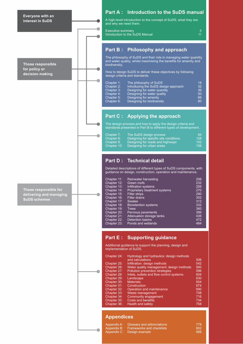
Part C : Applying the approachThe design process and how to apply the design criteria and standards presented in Part B to different types of development.
Chapter 7: The SuDS design process 94Chapter 8: Designing for specific site conditions 128Chapter 9: Designing for roads and highways 142Chapter 10: Designing for urban areas 156
Part D : Technical detailDetailed descriptions of different types of SuDS components, with guidance on design, construction, operation and maintenance.
Chapter 11: Rainwater harvesting 206Chapter 12: Green roofs 232Chapter 13: Infiltration systems 256Chapter 14: Proprietary treatment systems 270Chapter 15: Filter strips 290Chapter 16: Filter drains 302Chapter 17: Swales 312Chapter 18: Bioretention systems 332Chapter 19: Trees 360Chapter 20: Pervious pavements 386Chapter 21: Attenuation storage tanks 436Chapter 22: Detention basins 472Chapter 23: Ponds and wetlands 484
Part A : Introduction to the SuDS manualA high-level introduction to the concept of SuDS, what they are and why we need them.
Executive summary 5Introduction to the SuDS Manual 11
Part B : Philosophy and approachThe philosophy of SuDS and their role in managing water quantity and water quality, whilst maximising the benefits for amenity and biodiversity.
How to design SuDS to deliver these objectives by following design criteria and standards.
Chapter 1: The philosophy of SuDS 18Chapter 2: Introducing the SuDS design approach 32Chapter 3: Designing for water quantity 36Chapter 4: Designing for water quality 50Chapter 5: Designing for amenity 66Chapter 6: Designing for biodiversity 80
Part E : Supporting guidanceAdditional guidance to support the planning, design and implementation of SuDS.
Chapter 24: Hydrology and hydraulics: design methods and calculations 506Chapter 25: Infiltration: design methods 542Chapter 26: Water quality management: design methods 560Chapter 27: Pollution prevention strategies 596Chapter 28: Inlets, outlets and flow control systems 604Chapter 29: Landscape 630Chapter 30: Materials 654Chapter 31: Construction 674Chapter 32: Operation and maintenance 690Chapter 33: Waste management 708Chapter 34: Community engagement 716Chapter 35: Costs and benefits 734Chapter 36: Health and safety 758
AppendicesAppendix A: Glossary and abbreviations 778Appendix B: Frameworks and checklists 802Appendix C: Design example 888
Everyone with an interest in SuDS
Those responsible for delivering and managing SuDS schemes
Those responsible for policy or decision making

505
Supporting guidanceE Audience: Those responsible for delivering and managing a SuDS scheme
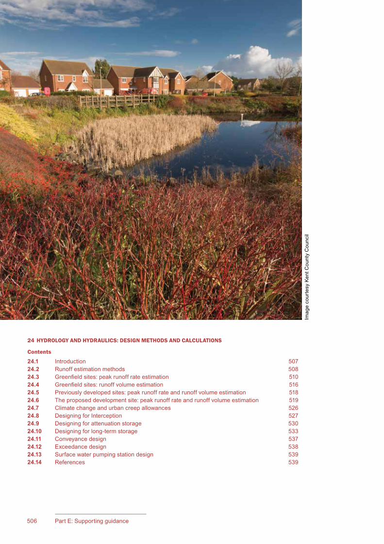
506 Part E: Supporting guidance
24 HYDROLOGY AND HYDRAULICS: DESIGN METHODS AND CALCULATIONS
Contents
24.1 Introduction 50724.2 Runoff estimation methods 50824.3 Greenfield sites: peak runoff rate estimation 51024.4 Greenfield sites: runoff volume estimation 51624.5 Previously developed sites: peak runoff rate and runoff volume estimation 51824.6 The proposed development site: peak runoff rate and runoff volume estimation 51924.7 Climate change and urban creep allowances 52624.8 Designing for Interception 52724.9 Designing for attenuation storage 53024.10 Designing for long-term storage 53324.11 Conveyance design 53724.12 Exceedance design 53824.13 Surface water pumping station design 53924.14 References 539
Imag
e co
urte
sy K
ent C
ount
y C
ounc
il
507Chapter 24: Hydrology and hydraulics
CIRIA SuDS Manual 2015
24.1 INTRODUCTION
The preliminary calculations required to design a SuDS scheme to meet the hydraulic design criteria are:
1 �for�greenfield�and�previously�developed�sites: an estimate of the peak runoff rates and runoff volumes from the site in its greenfield state
2 for previously developed sites: an estimate of the peak runoff rates and volumes from the site in its previously developed state
These runoff rates will dictate the rate to which the runoff from the site should be controlled (as required by water quantity standard 2); and the calculation methods are set out in Sections 24.3 and 24.5.
These runoff volumes will dictate the allowable volume of runoff that can be discharged from the site (as required by water quantity standard 1); and the calculation methods are set out in Sections 24.4 and 24.5.
3 for the proposed development: an estimate of the runoff rates and volumes from the site in its developed state (Section 24.6 for calculation methods), and how these should be adjusted to take account of potential future development and climate change (Section 24.7).
The runoff rates calculated for the proposed development will exceed the allowable discharge rates. Therefore, the SuDS design will need to include attenuation storage that will fill during rainfall events and/or infiltration components that mean that runoff does not occur. Calculation methods for attenuation storage are set out in Section 24.9.
The volume of runoff from the proposed development will also exceed the allowable discharge volumes. Therefore, the SuDS design will need to “use” the runoff (Chapter 11), infiltrate the runoff (Chapter 25) and/or store and tightly control an additional storage volume, referred to as Long-Term Storage (Section 24.10).
24Chapter Hydrology and hydraulics:
design methods and calculationsThis chapter presents the design methods and tools required to size storage and conveyance systems to meet the water quantity design criteria and good practice design standards. This includes how to estimate runoff for the greenfield or previously developed site.
Water quantity design criteria are set out in Chapter 3.
Guidance on the SuDS design process is provided in Chapter 7, with an overview of the process for sizing storage and conveyance system components presented in Figure 7.12.
Guidance on component sizing for water quantity and water quality management is provided in Chapters 11–23.
Chapter 26 covers assessing the suitability of using infiltration to dispose of surface water runoff, testing and infiltration design methods.
Chapter 26 provides guidance on design methods for water quality management.
CIRIA SuDS Manual 2015
508 Part E: Supporting guidance
Where runoff volumes before development are low, this reflects the presence of more permeable soils. Therefore, although the estimated runoff volumes for the proposed development will be significantly greater, it should be possible to infiltrate a large proportion of this volume, provided that the groundwater is adequately protected (Section 26.3).
Designing the site to deliver adequate Interception (the prevention of runoff from the site for the majority of small rainfall events), as required by water quantity standard 1, is set out in Section 24.8.
Section 24.11 describes how to design drainage components that convey flow from one point on the site to another, up to a specified standard of service
Section 24.12 describes design methods for managing flows greater than this standard (ie designing for exceedance flow management).
24.2 RUNOFF ESTIMATION METHODS
24.2.1 An overview of available methods
There are several methods that can be used for estimating peak runoff rates and runoff volumes. Catchment runoff models, adjusted for the size of the site, tend to be used for predicting runoff from greenfield sites. When predicting the response of a developed site, models that represent the existing or proposed drainage system are required, taking account of conveyance and storage capacities of drainage components, flow controls and areas likely to flood and store water during extreme events.
The available methods are summarised in Table 24.1 and described in the sections in this chapter as indicated. Drainage approving bodies may specify the methods that they require to be used for drainage submissions, or they may leave method selection to the designer. The required approach should always be checked at an early stage in the design process.
Some of these methods are old and there are more recent methods likely to produce better runoff estimates. However, these older methods tend to be simpler and are not dependent on software that has to be purchased. Where the expertise and software required to design and approve systems using the more recent methods is available, the newer methods should be used. Different methods are likely to give different runoff estimates, which could influence the storage volumes required for the drainage system and thus the scheme cost and viability.
24.2.2 Runoff areas to be used in calculations
The runoff area used in any of the runoff estimation methods should be consistent; for example, if the whole site area is used in the greenfield runoff rate calculations, the whole site should also be represented in the runoff calculations for the proposed development. If there is a landscaped area in the developed scenario that discharges directly to receiving waters and does not contribute to the drainage system (so is excluded from the calculations) then this area should also be excluded from the greenfield calculations.
24.2.3 Rainfall to be used in calculations
In order for assessments to be made of the likely rate and volume of runoff from a developed site or catchment, a depth of rainfall and/or rainfall profile is required. This is also required for assessment of greenfield rates if a rainfall–runoff modelling approach is adopted. To date, design rainfall event methods have normally been used that are based on the use of fixed rainfall depths for different return period events and standard rainfall profiles (eg the FEH depth-duration-frequency rainfall model – CEH, 1999). The alternative approach, which is becoming more common for some applications, is to use a continuous time series of rainfall to generate a time series of flows from which frequency curves can be generated. These rainfall time series can come from observed rainfall data, if the series is long enough and appropriately quality assured and calibrated, or can be statistically generated from a number of observed datasets. The two approaches are described in the following sections.
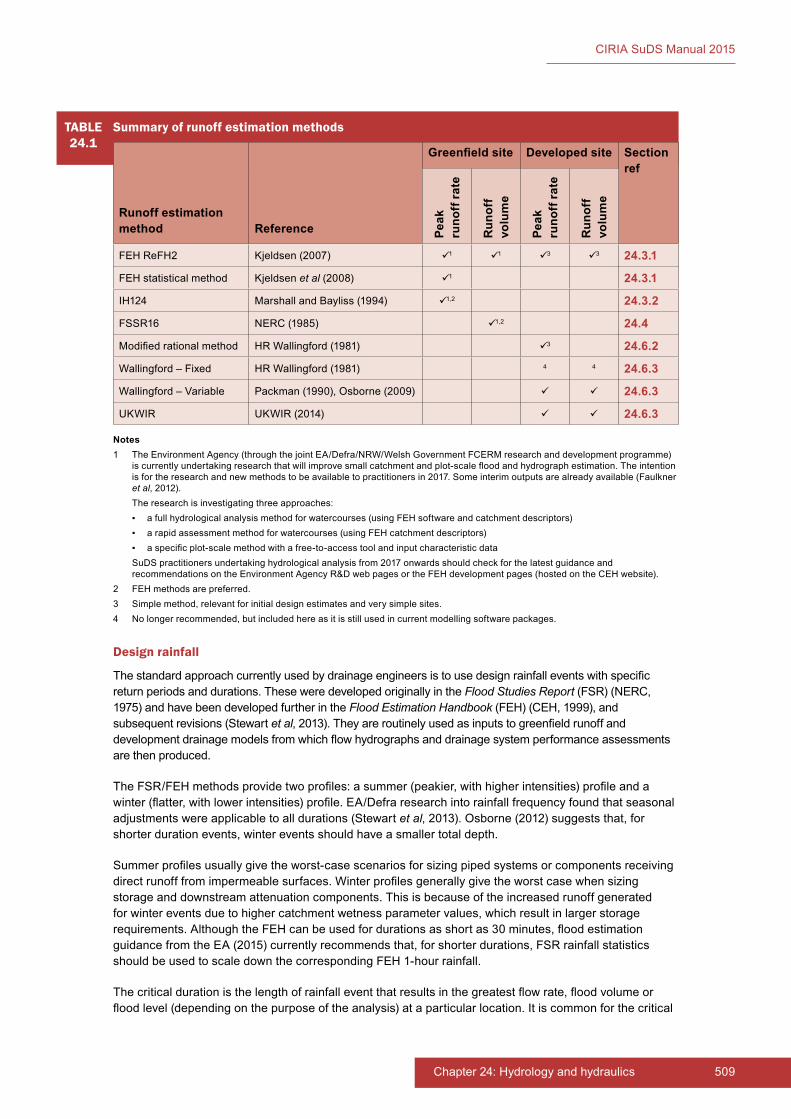
509Chapter 24: Hydrology and hydraulics
CIRIA SuDS Manual 2015
Design rainfall
The standard approach currently used by drainage engineers is to use design rainfall events with specific return periods and durations. These were developed originally in the Flood Studies Report (FSR) (NERC, 1975) and have been developed further in the Flood Estimation Handbook (FEH) (CEH, 1999), and subsequent revisions (Stewart et al, 2013). They are routinely used as inputs to greenfield runoff and development drainage models from which flow hydrographs and drainage system performance assessments are then produced.
The FSR/FEH methods provide two profiles: a summer (peakier, with higher intensities) profile and a winter (flatter, with lower intensities) profile. EA/Defra research into rainfall frequency found that seasonal adjustments were applicable to all durations (Stewart et al, 2013). Osborne (2012) suggests that, for shorter duration events, winter events should have a smaller total depth.
Summer profiles usually give the worst-case scenarios for sizing piped systems or components receiving direct runoff from impermeable surfaces. Winter profiles generally give the worst case when sizing storage and downstream attenuation components. This is because of the increased runoff generated for winter events due to higher catchment wetness parameter values, which result in larger storage requirements. Although the FEH can be used for durations as short as 30 minutes, flood estimation guidance from the EA (2015) currently recommends that, for shorter durations, FSR rainfall statistics should be used to scale down the corresponding FEH 1-hour rainfall.
The critical duration is the length of rainfall event that results in the greatest flow rate, flood volume or flood level (depending on the purpose of the analysis) at a particular location. It is common for the critical
TABLE24.1
Summary of runoff estimation methods
Runoff estimation method Reference
Greenfield�site Developed site Section ref
Peak
ru
noff
rate
Run
off
volu
me
Peak
ru
noff
rate
Run
off
volu
me
FEH ReFH2 Kjeldsen (2007) 1 1 3 3 24.3.1
FEH statistical method Kjeldsen et al (2008) 1 24.3.1
IH124 Marshall and Bayliss (1994) 1,2 24.3.2
FSSR16 NERC (1985) 1,2 24.4
Modified rational method HR Wallingford (1981) 3 24.6.2
Wallingford – Fixed HR Wallingford (1981) 4 4 24.6.3
Wallingford – Variable Packman (1990), Osborne (2009) 24.6.3
UKWIR UKWIR (2014) 24.6.3
Notes1 The Environment Agency (through the joint EA/Defra/NRW/Welsh Government FCERM research and development programme)
is currently undertaking research that will improve small catchment and plot-scale flood and hydrograph estimation. The intention is for the research and new methods to be available to practitioners in 2017. Some interim outputs are already available (Faulkner et al, 2012).
The research is investigating three approaches: ▪ a full hydrological analysis method for watercourses (using FEH software and catchment descriptors) ▪ a rapid assessment method for watercourses (using FEH catchment descriptors) ▪ a specific plot-scale method with a free-to-access tool and input characteristic data
SuDS practitioners undertaking hydrological analysis from 2017 onwards should check for the latest guidance and recommendations on the Environment Agency R&D web pages or the FEH development pages (hosted on the CEH website).
2 FEH methods are preferred.3 Simple method, relevant for initial design estimates and very simple sites.4 No longer recommended, but included here as it is still used in current modelling software packages.
CIRIA SuDS Manual 2015
510 Part E: Supporting guidance
duration to be different at different points in the drainage system, with different SuDS components having different critical durations. This results in a site designer having to use a matrix of events of different return periods and durations to ensure that the design criteria for the system are met at all points. Return periods from 1:1 year to 1:100 years (or 1:200 years in Scotland) and durations from 15 minutes to 48 hours are often required to be assessed.
For greenfield sites, the event duration is not always required, as the estimation of the peak rate of runoff can be based on correlation equations that do not use event rainfall data as an input. However, there are some greenfield runoff models that generate a flow hydrograph from rainfall and, for these, the design event duration is estimated by the models.
Time series rainfall
Continuous rainfall data is a time series of observed (where available) or statistically generated rainfall depths (where observed records are unavailable or too short for the required application). Time series rainfall is not yet routinely used in the design of surface water management systems, due to its inconsistent availability, cost and processing demands. However, in the case of SuDS, time series rainfall allows more accurate estimates of runoff, taking account of infiltration, soil moisture storage and release and evapotranspiration processes. It also allows estimates of subannual event frequencies and associated durations and velocities, which is useful for the assessment of treatment effectiveness.
The length of the rainfall series should be long enough to ensure that the complexity of rainfall characteristics and related aspects, such as dry periods, are properly taken into account. A minimum series length of at least twice, and preferably three times, the design return period of the system is recommended.
24.3 GREENFIELD SITES: PEAK RUNOFF RATE ESTIMATION
Estimated peak runoff rates for the development site in its greenfield condition for a range of return periods are normally used to define the discharge limits for a new development site.
For greenfield sites, the peak runoff rate for any particular return period is related to the site’s catchment characteristics (including soils). The values derived from any analysis should be regarded as approximate, because prediction of runoff from very small catchments will always be imprecise. Furthermore, all runoff estimation methods have been developed using river flow information from much larger catchments than the average development site. However, it has been demonstrated in recent research that there is little evidence that the FEH methods perform less well at smaller scales (Faulkner et al, 2012). It should be understood that the overall objective of using an agreed method is to provide a consistent and reasonable estimate upon which storage design can be based, rather than finding the exact runoff rate for any specific site (which is not possible).
The current approaches recommended for calculating greenfield runoff rates are described in the following sections. However, the method used at a particular site should always be agreed with the drainage approval body. Further guidance is provided in EA (2015) and Faulkner et al (2012).
FEH methods should be the preferred approach for developing runoff estimates for use in surface water management design, but their use currently depends on access to the FEH documentation and software and suitable hydrological modelling expertise. Where FEH tools are not available, and with agreement of the approving body, the Marshall and Bayliss (1994) approach can be used as an alternative method. From 2017, new recommendations for estimating greenfield runoff rates and volumes will be published (see Note (1) for Table 24.1).
It should be noted that Marshall and Bayliss (1994) is more likely to underestimate runoff rates than FEH methods, potentially leading to overdesign of attenuation storage components (Faulkner et al, 2012).
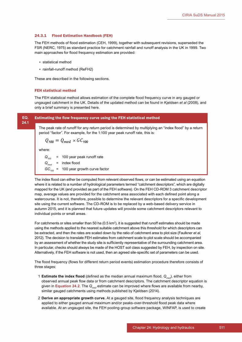
511Chapter 24: Hydrology and hydraulics
CIRIA SuDS Manual 2015
24.3.1 Flood Estimation Handbook (FEH)
The FEH methods of flood estimation (CEH, 1999), together with subsequent revisions, superseded the FSR (NERC, 1975) as standard practice for catchment rainfall and runoff analysis in the UK in 1999. Two main approaches for flood frequency estimation are provided:
▪ statistical method
▪ rainfall-runoff method (ReFH2)
These are described in the following sections.
FEH statistical method
The FEH statistical method allows estimation of the complete flood frequency curve in any gauged or ungauged catchment in the UK. Details of the updated method can be found in Kjeldsen et al (2008), and only a brief summary is presented here.
The index flood can either be computed from relevant observed flows, or can be estimated using an equation where it is related to a number of hydrological parameters termed “catchment descriptors”, which are digitally mapped for the UK (and provided as part of the FEH software). On the FEH CD-ROM 3 catchment descriptor map, average values are provided for the catchment area associated with each defined point along a watercourse. It is not, therefore, possible to determine the relevant descriptors for a specific development site using the current software. The CD-ROM is to be replaced by a web-based delivery service in autumn 2015, and it is planned that future updates will provide some catchment descriptors relevant to individual points or small areas.
For catchments or sites smaller than 50 ha (0.5 km2), it is suggested that runoff estimates should be made using the methods applied to the nearest suitable catchment above this threshold for which descriptors can be extracted, and then the rates are scaled down by the ratio of catchment area to plot size (Faulkner et al, 2012). The decision to translate FEH estimates from catchment scale to plot scale should be accompanied by an assessment of whether the study site is sufficiently representative of the surrounding catchment area. In particular, checks should always be made of the HOST soil class suggested by FEH, by inspection on site. Alternatively, if the FEH software is not used, then an agreed site-specific set of parameters can be used.
The flood frequency (flows for different return period events) estimation procedure therefore consists of three stages:
1 Estimate�the�index�flood�(defined as the median annual maximum flood, Qmed), either from observed annual peak flow data or from catchment descriptors. The catchment descriptor equation is given in Equation 24.2. The Qmed estimate can be improved where flows are available from nearby, similar gauged catchments using methods published by Kjeldsen (2014).
2 Derive an appropriate growth curve. At a gauged site, flood frequency analysis techniques are applied to either gauged annual maximum and/or peaks-over-threshold flood peak data where available. At an ungauged site, the FEH pooling-group software package, WINFAP, is used to create
EQ.24.1
Estimating the flow frequency curve using the FEH statistical method
The peak rate of runoff for any return period is determined by multiplying an “index flood” by a return period “factor”. For example, for the 1:100 year peak runoff rate, this is:
where:
Q100 = 100 year peak runoff rateQmed = index floodGC100 = 100 year growth curve factor
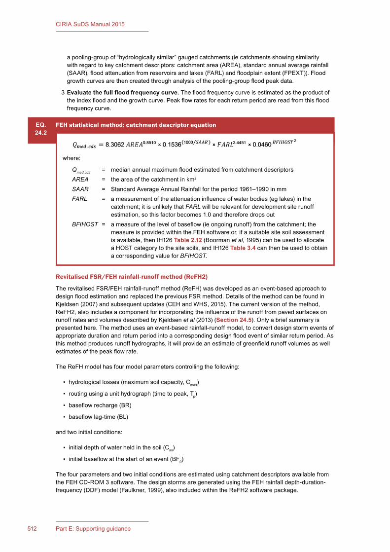
CIRIA SuDS Manual 2015
512 Part E: Supporting guidance
a pooling-group of “hydrologically similar” gauged catchments (ie catchments showing similarity with regard to key catchment descriptors: catchment area (AREA), standard annual average rainfall (SAAR), flood attenuation from reservoirs and lakes (FARL) and floodplain extent (FPEXT)). Flood growth curves are then created through analysis of the pooling-group flood peak data.
3 Evaluate�the�full�flood�frequency�curve. The flood frequency curve is estimated as the product of the index flood and the growth curve. Peak flow rates for each return period are read from this flood frequency curve.
Revitalised FSR/FEH rainfall-runoff method (ReFH2)
The revitalised FSR/FEH rainfall-runoff method (ReFH) was developed as an event-based approach to design flood estimation and replaced the previous FSR method. Details of the method can be found in Kjeldsen (2007) and subsequent updates (CEH and WHS, 2015). The current version of the method, ReFH2, also includes a component for incorporating the influence of the runoff from paved surfaces on runoff rates and volumes described by Kjeldsen et al (2013) (Section 24.5). Only a brief summary is presented here. The method uses an event-based rainfall-runoff model, to convert design storm events of appropriate duration and return period into a corresponding design flood event of similar return period. As this method produces runoff hydrographs, it will provide an estimate of greenfield runoff volumes as well estimates of the peak flow rate.
The ReFH model has four model parameters controlling the following:
▪ hydrological losses (maximum soil capacity, Cmax)
▪ routing using a unit hydrograph (time to peak, Tp)
▪ baseflow recharge (BR)
▪ baseflow lag-time (BL)
and two initial conditions:
▪ initial depth of water held in the soil (Cini)
▪ initial baseflow at the start of an event (BF0)
The four parameters and two initial conditions are estimated using catchment descriptors available from the FEH CD-ROM 3 software. The design storms are generated using the FEH rainfall depth-duration-frequency (DDF) model (Faulkner, 1999), also included within the ReFH2 software package.
EQ.24.2
FEH statistical method: catchment descriptor equation
where:
Qmed.cds = median annual maximum flood estimated from catchment descriptorsAREA = the area of the catchment in km2
SAAR = Standard Average Annual Rainfall for the period 1961–1990 in mmFARL = a measurement of the attenuation influence of water bodies (eg lakes) in the
catchment; it is unlikely that FARL will be relevant for development site runoff estimation, so this factor becomes 1.0 and therefore drops out
BFIHOST = a measure of the level of baseflow (ie ongoing runoff) from the catchment; the measure is provided within the FEH software or, if a suitable site soil assessment is available, then IH126 Table 2.12 (Boorman et al, 1995) can be used to allocate a HOST category to the site soils, and IH126 Table 3.4 can then be used to obtain a corresponding value for BFIHOST.
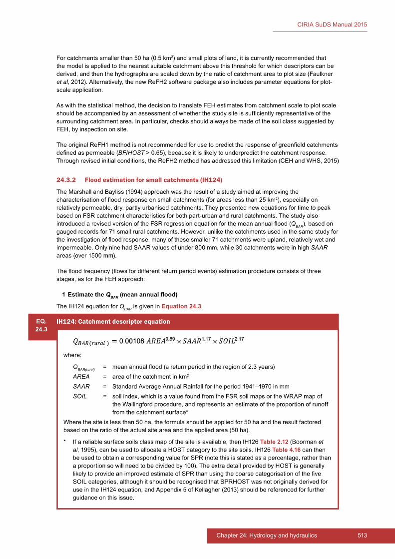
513Chapter 24: Hydrology and hydraulics
CIRIA SuDS Manual 2015
For catchments smaller than 50 ha (0.5 km2) and small plots of land, it is currently recommended that the model is applied to the nearest suitable catchment above this threshold for which descriptors can be derived, and then the hydrographs are scaled down by the ratio of catchment area to plot size (Faulkner et al, 2012). Alternatively, the new ReFH2 software package also includes parameter equations for plot-scale application.
As with the statistical method, the decision to translate FEH estimates from catchment scale to plot scale should be accompanied by an assessment of whether the study site is sufficiently representative of the surrounding catchment area. In particular, checks should always be made of the soil class suggested by FEH, by inspection on site.
The original ReFH1 method is not recommended for use to predict the response of greenfield catchments defined as permeable (BFIHOST > 0.65), because it is likely to underpredict the catchment response. Through revised initial conditions, the ReFH2 method has addressed this limitation (CEH and WHS, 2015)
24.3.2 Flood estimation for small catchments (IH124)
The Marshall and Bayliss (1994) approach was the result of a study aimed at improving the characterisation of flood response on small catchments (for areas less than 25 km2), especially on relatively permeable, dry, partly urbanised catchments. They presented new equations for time to peak based on FSR catchment characteristics for both part-urban and rural catchments. The study also introduced a revised version of the FSR regression equation for the mean annual flood (QBAR), based on gauged records for 71 small rural catchments. However, unlike the catchments used in the same study for the investigation of flood response, many of these smaller 71 catchments were upland, relatively wet and impermeable. Only nine had SAAR values of under 800 mm, while 30 catchments were in high SAAR areas (over 1500 mm).
The flood frequency (flows for different return period events) estimation procedure consists of three stages, as for the FEH approach:
1 Estimate the QBAR�(mean�annual�flood)
The IH124 equation for QBAR is given in Equation 24.3.
EQ.24.3
IH124: Catchment descriptor equation
where:
QBAR(rural) = mean annual flood (a return period in the region of 2.3 years)AREA = area of the catchment in km2
SAAR = Standard Average Annual Rainfall for the period 1941–1970 in mmSOIL = soil index, which is a value found from the FSR soil maps or the WRAP map of
the Wallingford procedure, and represents an estimate of the proportion of runoff from the catchment surface*
Where the site is less than 50 ha, the formula should be applied for 50 ha and the result factored based on the ratio of the actual site area and the applied area (50 ha).
* If a reliable surface soils class map of the site is available, then IH126 Table 2.12 (Boorman et al, 1995), can be used to allocate a HOST category to the site soils. IH126 Table 4.16 can then be used to obtain a corresponding value for SPR (note this is stated as a percentage, rather than a proportion so will need to be divided by 100). The extra detail provided by HOST is generally likely to provide an improved estimate of SPR than using the coarse categorisation of the five SOIL categories, although it should be recognised that SPRHOST was not originally derived for use in the IH124 equation, and Appendix 5 of Kellagher (2013) should be referenced for further guidance on this issue.
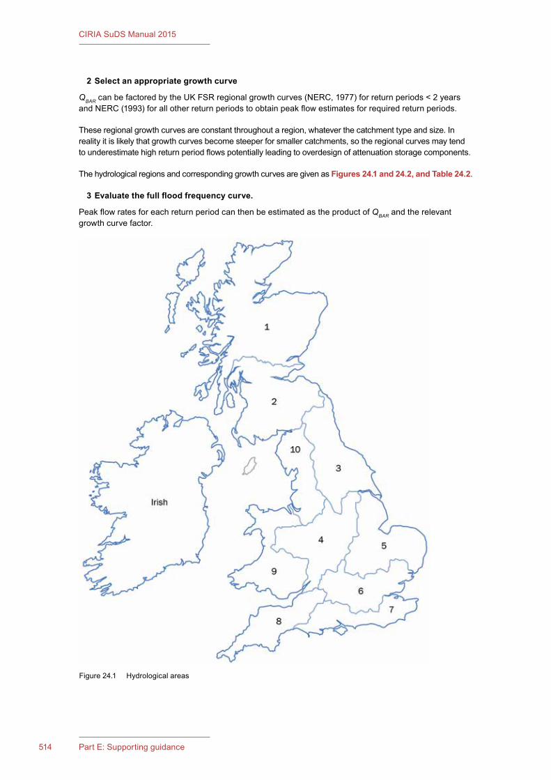
CIRIA SuDS Manual 2015
514 Part E: Supporting guidance
2 Select an appropriate growth curve
QBAR can be factored by the UK FSR regional growth curves (NERC, 1977) for return periods < 2 years and NERC (1993) for all other return periods to obtain peak flow estimates for required return periods.
These regional growth curves are constant throughout a region, whatever the catchment type and size. In reality it is likely that growth curves become steeper for smaller catchments, so the regional curves may tend to underestimate high return period flows potentially leading to overdesign of attenuation storage components.
The hydrological regions and corresponding growth curves are given as Figures 24.1 and 24.2, and Table 24.2.
3� �Evaluate�the�full�flood�frequency�curve.
Peak flow rates for each return period can then be estimated as the product of QBAR and the relevant growth curve factor.
Figure 24.1 Hydrological areas
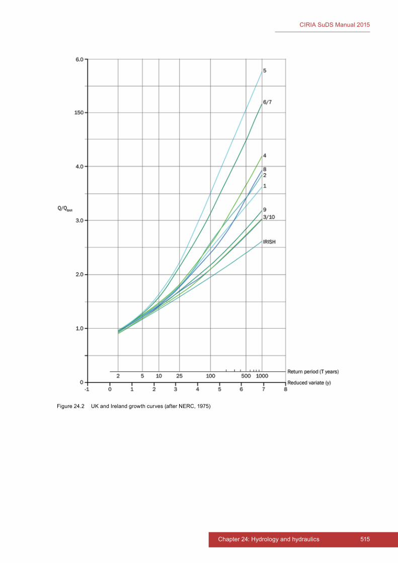
515Chapter 24: Hydrology and hydraulics
CIRIA SuDS Manual 2015
Figure 24.2 UK and Ireland growth curves (after NERC, 1975)
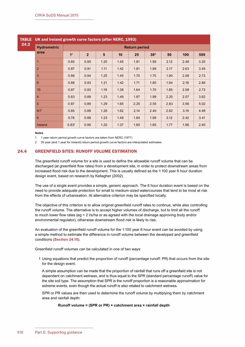
CIRIA SuDS Manual 2015
516 Part E: Supporting guidance
24.4 GREENFIELD SITES: RUNOFF VOLUME ESTIMATION
The greenfield runoff volume for a site is used to define the allowable runoff volume that can be discharged (at greenfield flow rates) from a development site, in order to protect downstream areas from increased flood risk due to the development. This is usually defined as the 1:100 year 6 hour duration design event, based on research by Kellagher (2002).
The use of a single event provides a simple, generic approach. The 6 hour duration event is based on the need to provide adequate protection for small to medium-sized watercourses that tend to be most at risk from the effects of urbanisation. At alternative criterion may be specified locally.
The objective of this criterion is to allow original greenfield runoff rates to continue, while also controlling the runoff volume. The alternative is to accept higher volumes of discharge, but to limit all the runoff to much lower flow rates (eg < 2 l/s/ha or as agreed with the local drainage approving body and/or environmental regulator), otherwise downstream flood risk is likely to rise.
An evaluation of the greenfield runoff volume for the 1:100 year 6 hour event can be avoided by using a simple method to estimate the difference in runoff volume between the developed and greenfield conditions (Section 24.10).
Greenfield runoff volumes can be calculated in one of two ways:
1 Using equations that predict the proportion of runoff (percentage runoff: PR) that occurs from the site for the design event.
A simple assumption can be made that the proportion of rainfall that runs off a greenfield site is not dependent on catchment wetness, and is thus equal to the SPR (standard percentage runoff) value for the site soil type. The assumption that SPR is the runoff proportion is a reasonable approximation for extreme events, even though the actual runoff is also related to catchment wetness.
SPR or PR values are then used to determine the runoff volume by multiplying them by catchment area and rainfall depth:
Runoff�volume�=�(SPR�or�PR)�× catchment area × rainfall depth
TABLE24.2
UK and Ireland growth curve factors (after NERC, 1993)
Hydrometric area
Return period
11 2 5 10 25 302 50 100 500
1 0.85 0.90 1.20 1.45 1.81 1.99 2.12 2.48 3.25
2 0.87 0.91 1.11 1.42 1.81 1.99 2.17 2.63 3.45
3 0.86 0.94 1.25 1.45 1.70 1.75 1.90 2.08 2.73
9 0.88 0.93 1.21 1.42 1.71 1.80 1.94 2.18 2.86
10 0.87 0.93 1.19 1.38 1.64 1.70 1.85 2.08 2.73
4 0.83 0.89 1.23 1.49 1.87 1.99 2.20 2.57 3.62
5 0.87 0.89 1.29 1.65 2.25 2.55 2.83 3.56 5.02
6/7 0.85 0.88 1.28 1.62 2.14 2.40 2.62 3.19 4.49
8 0.78 0.88 1.23 1.49 1.84 1.98 2.12 2.42 3.41
Ireland 0.832 0.95 1.20 1.37 1.60 1.65 1.77 1.96 2.40
Notes1 1 year return period growth curve factors are taken from NERC (1977)2 30 year (and 1 year for Ireland) return period growth curve factors are interpolated estimates
517Chapter 24: Hydrology and hydraulics
CIRIA SuDS Manual 2015
EQ.24.4
Fixed percentage runoff model (from NERC, 1985)
The fixed percentage runoff method correlates runoff volume (as percentage runoff) with soil type, storm depth and other easily derived parameters:
where:
PRRURAL = total percentage runoff for the greenfield catchment for a particular eventSPR = standard percentage runoff, which is the fixed component of the percentage
runoff and can be computed as either a function of the five soil class fractions defined by the FSR WRAP map:
or from the SPR values for each of the FEH HOST soil class fractions:
DPRCWI = the dynamic component of the percentage runoff. This parameter reflects the increase in percentage runoff with increasing catchment wetness. The catchment wetness index (CWI) is a function of the average annual rainfall (Figure�24.3).
The DPRRAIN is the second dynamic component that increases the percentage runoff from large rainfall events.
The PR model from NERC (1985) is presented in Equation 24.4.
2 From design event runoff hydrographs (where rainfall-runoff methods are being used (Section 24.3.1). This should be for the 100 year, 6 hour event. The difference in approach between 1 and 2 is that, in the rainfall-runoff model, the standard and dynamic components of percentage runoff are computed explicitly based on the design estimate of initial soil water content and the dynamic evolution of soil water content during the course of the rainfall event.
An important issue to note is the crucial influence of soil type on runoff volume. In practice, this indicates that developments on sandy soils create significant extra runoff volume compared to the pre-development condition (but it should be possible to manage this volume using infiltration), while developments on clays generate relatively small amounts of extra runoff (where infiltration design is less likely to be appropriate).
continued...
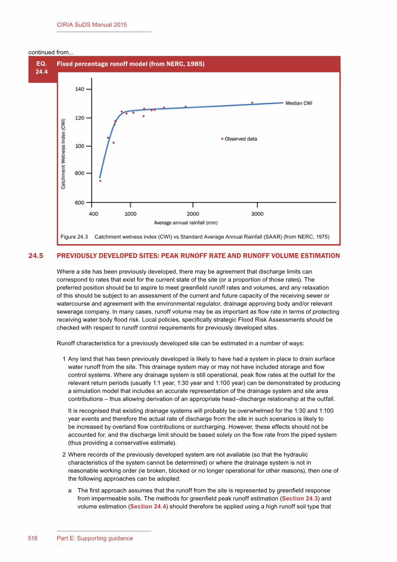
CIRIA SuDS Manual 2015
518 Part E: Supporting guidance
24.5 PREVIOUSLY DEVELOPED SITES: PEAK RUNOFF RATE AND RUNOFF VOLUME ESTIMATION
Where a site has been previously developed, there may be agreement that discharge limits can correspond to rates that exist for the current state of the site (or a proportion of those rates). The preferred position should be to aspire to meet greenfield runoff rates and volumes, and any relaxation of this should be subject to an assessment of the current and future capacity of the receiving sewer or watercourse and agreement with the environmental regulator, drainage approving body and/or relevant sewerage company. In many cases, runoff volume may be as important as flow rate in terms of protecting receiving water body flood risk. Local policies, specifically strategic Flood Risk Assessments should be checked with respect to runoff control requirements for previously developed sites.
Runoff characteristics for a previously developed site can be estimated in a number of ways:
1 Any land that has been previously developed is likely to have had a system in place to drain surface water runoff from the site. This drainage system may or may not have included storage and flow control systems. Where any drainage system is still operational, peak flow rates at the outfall for the relevant return periods (usually 1:1 year, 1:30 year and 1:100 year) can be demonstrated by producing a simulation model that includes an accurate representation of the drainage system and site area contributions – thus allowing derivation of an appropriate head–discharge relationship at the outfall.
It is recognised that existing drainage systems will probably be overwhelmed for the 1:30 and 1:100 year events and therefore the actual rate of discharge from the site in such scenarios is likely to be increased by overland flow contributions or surcharging. However, these effects should not be accounted for, and the discharge limit should be based solely on the flow rate from the piped system (thus providing a conservative estimate).
2 Where records of the previously developed system are not available (so that the hydraulic characteristics of the system cannot be determined) or where the drainage system is not in reasonable working order (ie broken, blocked or no longer operational for other reasons), then one of the following approaches can be adopted:
a The first approach assumes that the runoff from the site is represented by greenfield response from impermeable soils. The methods for greenfield peak runoff estimation (Section 24.3) and volume estimation (Section 24.4) should therefore be applied using a high runoff soil type that
EQ.24.4
Fixed percentage runoff model (from NERC, 1985)
Figure 24.3 Catchment wetness index (CWI) vs Standard Average Annual Rainfall (SAAR) (from NERC, 1975)
continued from...
519Chapter 24: Hydrology and hydraulics
CIRIA SuDS Manual 2015
better represents the high levels of runoff that take place from developed surfaces (eg FSR Soil Type 5 or equivalent lowest permeability soil type for the runoff estimation method used in the design). This approach should only be used if the site is predominantly urbanised, and it would not be appropriate for sites with, for example, permeable soils and limited development. In these situations greenfield runoff rates would normally be a more appropriate target.
b Runoff from the site can be estimated using the urbanisation methods within the ReFH2 software. Using this method, the impervious area can be set to the area of the impervious surfaces in the development site.
24.6 THE PROPOSED DEVELOPMENT SITE: PEAK RUNOFF RATE AND RUNOFF VOLUME ESTIMATION
24.6.1 Introduction
The runoff from the proposed development surfaces will be required as inflows to the drainage system.
Site developments are characterised as having two main categories of surfaces: impermeable (paved and roof) areas and permeable (grassed and vegetated) areas. These surfaces have different runoff characteristics, so both need to be represented in calculations and models.
Surface water management systems should usually be designed to accommodate the predicted effects of future climate change by factoring the design rainfall intensities by a climate change uplift factor. This is discussed in Section 24.7.1. They should also consider likely future development and urban creep on the site, and suggested factors are presented in Section 24.7.2.
An initial assessment of the peak rates of runoff from developed surfaces can be made using either the simple “modified rational” method, described here or the ReFH2 urbanisation method, as described in Section 24.5 for the previously developed site. These methods are useful for assessing peak flow rates for initial sizing of inlets and conveyance systems. However, a volumetric method using a simulation model is normally required for sizing of storage components, owing to the need to determine multiple critical durations for individual points in the drainage system. The modified rational method provides a direct estimate of runoff rate from rainfall intensity, whereas a runoff model is used within a hydraulic simulation model that also describes the routing and attenuation of the collection and conveyance system in order to output a peak flow rate.
Whether a peak flow estimation or a volumetric approach is used, there is a need to make assumptions regarding the proportion of runoff that takes place from both impervious and pervious surfaces for a specified rainfall event. This can be estimated based on fixed values, for example as suggested by WRc (2012), or based on a runoff model.
24.6.2 The modified rational method
The peak runoff rate can be estimated using the equation given in Equation 24.5.
Volumetric and routing coefficients (CV and CR)
The coefficient of runoff was split into two terms when the modified rational method (HR Wallingford, 1981) was originally produced: the volumetric runoff coefficient, CV (of the order of 0.6) and the routing coefficient, CR, (of the order of 1.3). However, the routing coefficient (which addresses the fact that some parts of the site will generate flows to a downstream point faster than others) tends to be ignored.
For paved area runoff, the two coefficients are usually incorporated into a single term with a value of between 0.8 and 1.0 – depending on how effectively the catchment is drained and the level of impermeability.
An equivalent approach is required for the pervious area runoff, with the chosen coefficient reflecting the proportion of contributing and non-contributing pervious areas, the soil type, site gradient, event size, likely antecedent conditions etc.

CIRIA SuDS Manual 2015
520 Part E: Supporting guidance
Guidance on runoff proportions from extreme events for different surfaces is provided in NERC (1985).
WRc (2012) is the industry standard produced by water companies for adoption of drainage for new development. It proposes the use of 100% runoff from impermeable areas and 0% runoff from pervious areas. This is known to be suitably conservative for events of between 1:1 year and 1:5 year. However, it is likely to be less appropriate for larger events when the pervious areas start generating significant runoff. For standard developments that tend to have impermeability ratios of around 50–65%, this assumption is regarded as being acceptable, at least in terms of initial design and analysis, as it avoids having to use the more complicated runoff models.
Rainfall intensity (i)
For the rational method to be used for design purposes, the rainfall intensity (i) for the design time of concentration needs to be known. This gives the maximum flow rate at a point in the network in order to size the conveyance component. The rational method assumes that the whole catchment contributes runoff to a point in the system that has the longest time of concentration of any drainage branch. The rainfall intensity for this duration is used to calculate the flow. Rainfall intensity–duration–frequency curves can be generated using the FSR, the FEH or from appropriate gauged autographic rainfall data.
Alternatively, for an initial assessment of the design of a pipe network (for pipe full flow), a constant rainfall intensity of 35 mm/hr can be assumed, or 50 mm/hr may be required by some approving bodies for a more conservative solution (May and Kellagher, 2004).
For design of piped urban drainage networks a time of entry of 3–5 minutes is assumed, and then the time taken to travel through the network from the furthest point in the catchment at the pipe-full velocity is added. Advice on this is provided in the modified rational method in Volume 4 of the Wallingford Procedure (HR Wallingford, 1981).
24.6.3 UK runoff models
UK runoff models
There are two methods currently recommended for use in the UK for predicting percentage runoff from developed areas for detailed design purposes:
▪ variable UK runoff model
▪ UKWIR UK runoff model
EQ.24.5
Modified rational method equation to determine peak flow rates
where:
Q = design event peak rate of runoff (l/s)C = non-dimensional runoff coefficient which is dependent on the catchment
characteristics
where CV = volumetric runoff coefficient CR = dimensionless routing coefficient
i = rainfall intensity for the design return period (in mm/hr) and for a duration equal to the “time of concentration” of the network
A = total catchment area being drained (ha)Note: 2.78 is a conversion factor to address the rainfall unit being in mm/hr.
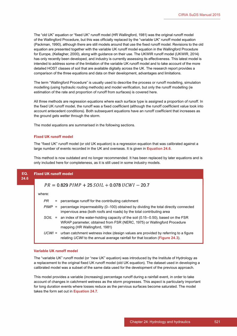
521Chapter 24: Hydrology and hydraulics
CIRIA SuDS Manual 2015
The “old UK” equation or “fixed UK” runoff model (HR Wallingford, 1981) was the original runoff model of the Wallingford Procedure, but this was officially replaced by the “variable UK” runoff model equation (Packman, 1990), although there are still models around that use the fixed runoff model. Revisions to the old equation are presented together with the variable UK runoff model equation in the Wallingford Procedure for Europe, (Kellagher, 2000), along with guidance on their use. The UKWIR runoff model (UKWIR, 2014) has only recently been developed, and industry is currently assessing its effectiveness. This latest model is intended to address some of the limitation of the variable UK runoff model and to take account of the more detailed HOST classes of soil that are available digitally across the UK. The research report provides a comparison of the three equations and data on their development, advantages and limitations.
The term “Wallingford Procedure” is usually used to describe the process or runoff modelling, simulation modelling (using hydraulic routing methods) and model verification, but only the runoff modelling (ie estimation of the rate and proportion of runoff from surfaces) is covered here.
All three methods are regression equations where each surface type is assigned a proportion of runoff. In the fixed UK runoff model, the runoff was a fixed coefficient (although the runoff coefficient value took into account antecedent conditions). Both subsequent equations have an runoff coefficient that increases as the ground gets wetter through the storm.
The model equations are summarised in the following sections.
Fixed UK runoff model
The “fixed UK” runoff model (or old UK equation) is a regression equation that was calibrated against a large number of events recorded in the UK and overseas. It is given in Equation 24.6.
This method is now outdated and no longer recommended. It has been replaced by later equations and is only included here for completeness, as it is still used in some industry models.
Variable UK runoff model
The “variable UK” runoff model (or “new UK” equation) was introduced by the Institute of Hydrology as a replacement to the original fixed UK runoff model (old UK equation). The dataset used in developing a calibrated model was a subset of the same data used for the development of the previous approach.
This model provides a variable (increasing) percentage runoff during a rainfall event, in order to take account of changes in catchment wetness as the storm progresses. This aspect is particularly important for long duration events where losses reduce as the pervious surfaces become saturated. The model takes the form set out in Equation 24.7.
EQ.24.6
Fixed UK runoff model
where:
PR = percentage runoff for the contributing catchmentPIMP = percentage impermeability (0–100) obtained by dividing the total directly connected
impervious area (both roofs and roads) by the total contributing areaSOIL = an index of the water-holding capacity of the soil (0.15–0.50), based on the FSR
WRAP parameter, obtained from FSR (NERC, 1975) or Wallingford Procedure mapping (HR Wallingford, 1981)
UCWI = urban catchment wetness index (design values are provided by referring to a figure relating UCWI to the annual average rainfall for that location (Figure 24.3).
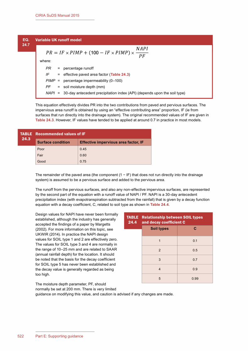
CIRIA SuDS Manual 2015
522 Part E: Supporting guidance
This equation effectively divides PR into the two contributions from paved and pervious surfaces. The impervious area runoff is obtained by using an “effective contributing area” proportion, IF (ie from surfaces that run directly into the drainage system). The original recommended values of IF are given in Table 24.3. However, IF values have tended to be applied at around 0.7 in practice in most models.
The remainder of the paved area (the component (1 − IF) that does not run directly into the drainage system) is assumed to be a pervious surface and added to the pervious area.
The runoff from the pervious surfaces, and also any non-effective impervious surfaces, are represented by the second part of the equation with a runoff value of NAPI / PF. NAPI is a 30-day antecedent precipitation index (with evapotranspiration subtracted from the rainfall) that is given by a decay function equation with a decay coefficient, C, related to soil type as shown in Table 24.4.
Design values for NAPI have never been formally established, although the industry has generally accepted the findings of a paper by Margetts (2002). For more information on this topic, see UKWIR (2014). In practice the NAPI design values for SOIL type 1 and 2 are effectively zero. The values for SOIL type 3 and 4 are normally in the range of 10–25 mm and are related to SAAR (annual rainfall depth) for the location. It should be noted that the basis for the decay coefficient for SOIL type 5 has never been established and the decay value is generally regarded as being too high.
The moisture depth parameter, PF, should normally be set at 200 mm. There is very limited guidance on modifying this value, and caution is advised if any changes are made.
TABLE24.4
Relationship between SOIL types and decay coefficient C
Soil types C
1 0.1
2 0.5
3 0.7
4 0.9
5 0.99
TABLE24.3
Recommended values of IF
Surface condition Effective impervious area factor, IF
Poor
Fair
Good
0.45
0.60
0.75
EQ.24.7
Variable UK runoff model
where:
PR = percentage runoffIF = effective paved area factor (Table 24.3)PIMP = percentage impermeability (0–100)PF = soil moisture depth (mm)NAPI = 30-day antecedent precipitation index (API) (depends upon the soil type)
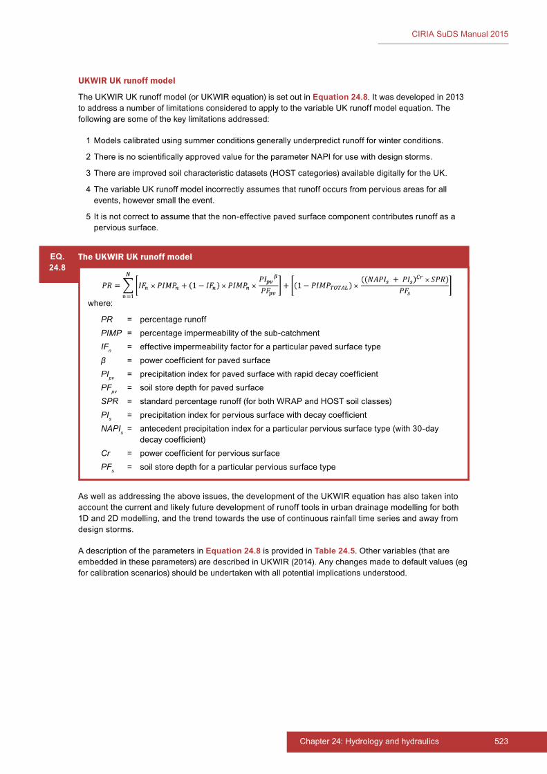
523Chapter 24: Hydrology and hydraulics
CIRIA SuDS Manual 2015
UKWIR UK runoff model
The UKWIR UK runoff model (or UKWIR equation) is set out in Equation 24.8. It was developed in 2013 to address a number of limitations considered to apply to the variable UK runoff model equation. The following are some of the key limitations addressed:
1 Models calibrated using summer conditions generally underpredict runoff for winter conditions.
2 There is no scientifically approved value for the parameter NAPI for use with design storms.
3 There are improved soil characteristic datasets (HOST categories) available digitally for the UK.
4 The variable UK runoff model incorrectly assumes that runoff occurs from pervious areas for all events, however small the event.
5 It is not correct to assume that the non-effective paved surface component contributes runoff as a pervious surface.
EQ.24.8
The UKWIR UK runoff model
where:
PR = percentage runoffPIMP = percentage impermeability of the sub-catchmentIFn = effective impermeability factor for a particular paved surface typeβ = power coefficient for paved surfacePIpv = precipitation index for paved surface with rapid decay coefficientPFpv = soil store depth for paved surfaceSPR = standard percentage runoff (for both WRAP and HOST soil classes)PIs = precipitation index for pervious surface with decay coefficientNAPIs = antecedent precipitation index for a particular pervious surface type (with 30-day
decay coefficient)Cr = power coefficient for pervious surfacePFs = soil store depth for a particular pervious surface type
As well as addressing the above issues, the development of the UKWIR equation has also taken into account the current and likely future development of runoff tools in urban drainage modelling for both 1D and 2D modelling, and the trend towards the use of continuous rainfall time series and away from design storms.
A description of the parameters in Equation 24.8 is provided in Table 24.5. Other variables (that are embedded in these parameters) are described in UKWIR (2014). Any changes made to default values (eg for calibration scenarios) should be undertaken with all potential implications understood.
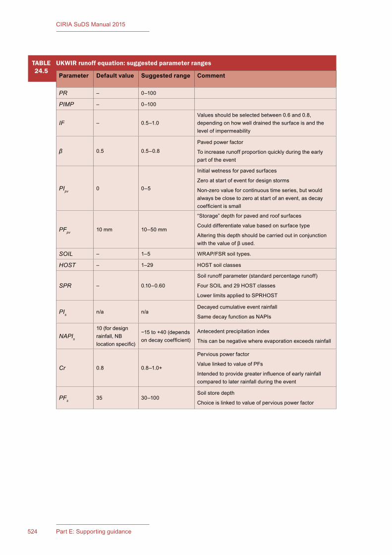
CIRIA SuDS Manual 2015
524 Part E: Supporting guidance
TABLE24.5
UKWIR runoff equation: suggested parameter ranges
Parameter Default value Suggested range Comment
PR – 0–100
PIMP – 0–100
IF – 0.5–1.0Values should be selected between 0.6 and 0.8, depending on how well drained the surface is and the level of impermeability
β 0.5 0.5–0.8
Paved power factor
To increase runoff proportion quickly during the early part of the event
PIpv 0 0–5
Initial wetness for paved surfaces
Zero at start of event for design storms
Non-zero value for continuous time series, but would always be close to zero at start of an event, as decay coefficient is small
PFpv 10 mm 10–50 mm
“Storage” depth for paved and roof surfaces
Could differentiate value based on surface type
Altering this depth should be carried out in conjunction with the value of β used.
SOIL – 1–5 WRAP/FSR soil types.
HOST – 1–29 HOST soil classes
SPR – 0.10–0.60
Soil runoff parameter (standard percentage runoff)
Four SOIL and 29 HOST classes
Lower limits applied to SPRHOST
PIs n/a n/aDecayed cumulative event rainfall
Same decay function as NAPIs
NAPIs
10 (for design rainfall, NB location specific)
−15 to +40 (depends on decay coefficient)
Antecedent precipitation index
This can be negative where evaporation exceeds rainfall
Cr 0.8 0.8–1.0+
Pervious power factor
Value linked to value of PFs
Intended to provide greater influence of early rainfall compared to later rainfall during the event
PFs 35 30–100Soil store depth
Choice is linked to value of pervious power factor

525Chapter 24: Hydrology and hydraulics
CIRIA SuDS Manual 2015
BOX24.1
A summary of the approach to modelling paved surfaces using the UKWIR UK runoff model
▪ Runoff modelling of the paved components of a catchment has a fixed runoff component and a variable runoff component.
▪ The variable runoff component is a function of the rainfall depth and rainfall intensity.
▪ Each paved surface type (road, roof, indirectly drained areas) should be modelled with their own set of parameters:
▪ The fixed runoff component for road surfaces should normally be set to have an effective impermeability of 0.5–0.65.
▪ The fixed runoff component for roofs should normally be set to have an effective impermeability of 0.8.
▪ The variable components should use a decay coefficient of 0.1, and a “soil” depth of 10 mm.
▪ The rainfall depth power factor is set at 0.5 and aims to increase the influence of the early part of the storm in increasing the proportion of runoff.
▪ All parameters can be used to calibrate the model.
Paved runoff (UKWIR runoff model)
The paved component runoff model is very similar to the variable UK runoff model equation. It has a fixed runoff component (IF × PIMP) and a variable runoff component (1 − IF) × PIMP (to represent rainfall that is “lost” on the paved surface). This second term is therefore separated from the pervious component of the model and routed with the paved surface runoff. It will therefore be more responsive to increasing wetness than the pervious runoff.
The increase in the rate of runoff during the event is now assumed to be non-linear to weight the increase in extra runoff to the early part of the storm depth using a power factor of 0.5. The use of a rapid decay coefficient means that the proportion of runoff is now related to the intensity of the rainfall.
As with the pervious component of the variable UK runoff model equation, the wetness of the paved surfaces is a continuously calculated value. It uses a 30-day analysis period, but the decay coefficient is set to 0.1 to ensure the wetness term (NAPI) rapidly reduces to zero after an event. NAPI is allowed to become negative, to prevent runoff from dry pervious catchments from taking place immediately rainfall commences.
The model allows more than one paved surface category and it is expected that three categories of paved surface would commonly be used (roads, roofs, indirectly drained paved areas); each potentially has its own set of parameters.
Pervious runoff (UKWIR runoff model)
The pervious runoff component is addressed in a similar way to the variable UK runoff model equation. This presumes that all the pervious area in a catchment contributes runoff based on an initial wetness measure, with an increasing proportion of runoff linked to rainfall depth. However, there are a number of significant differences built into the UKWIR equation.
Firstly, NAPI is a 30-day calculation, but it is not a function of soil type. The assumption has been made that antecedent wetness can be represented for all soil types by a single decay function. A value of 0.8–0.9 is proposed.
The second major difference is the calculation of NAPI, which now uses evaporation, and this can result in negative NAPI terms (acting rather like a soil moisture model). This has the important advantage of delivering a negative term for dry periods in summer. When the NAPI term is negative, it is assumed that this results in no runoff taking place from pervious surfaces. This approach was produced to provide an increase in differentiation between summer and winter runoff, thus addressing one of the key requirements of revising the variable UK runoff model.
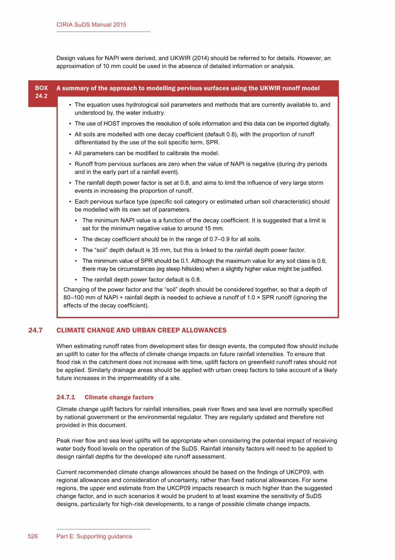
CIRIA SuDS Manual 2015
526 Part E: Supporting guidance
Design values for NAPI were derived, and UKWIR (2014) should be referred to for details. However, an approximation of 10 mm could be used in the absence of detailed information or analysis.
24.7 CLIMATE CHANGE AND URBAN CREEP ALLOWANCES
When estimating runoff rates from development sites for design events, the computed flow should include an uplift to cater for the effects of climate change impacts on future rainfall intensities. To ensure that flood risk in the catchment does not increase with time, uplift factors on greenfield runoff rates should not be applied. Similarly drainage areas should be applied with urban creep factors to take account of a likely future increases in the impermeability of a site.
24.7.1 Climate change factors
Climate change uplift factors for rainfall intensities, peak river flows and sea level are normally specified by national government or the environmental regulator. They are regularly updated and therefore not provided in this document.
Peak river flow and sea level uplifts will be appropriate when considering the potential impact of receiving water body flood levels on the operation of the SuDS. Rainfall intensity factors will need to be applied to design rainfall depths for the developed site runoff assessment.
Current recommended climate change allowances should be based on the findings of UKCP09, with regional allowances and consideration of uncertainty, rather than fixed national allowances. For some regions, the upper end estimate from the UKCP09 impacts research is much higher than the suggested change factor, and in such scenarios it would be prudent to at least examine the sensitivity of SuDS designs, particularly for high-risk developments, to a range of possible climate change impacts.
BOX24.2
A summary of the approach to modelling pervious surfaces using the UKWIR runoff model
▪ The equation uses hydrological soil parameters and methods that are currently available to, and understood by, the water industry.
▪ The use of HOST improves the resolution of soils information and this data can be imported digitally.
▪ All soils are modelled with one decay coefficient (default 0.8), with the proportion of runoff differentiated by the use of the soil specific term, SPR.
▪ All parameters can be modified to calibrate the model.
▪ Runoff from pervious surfaces are zero when the value of NAPI is negative (during dry periods and in the early part of a rainfall event).
▪ The rainfall depth power factor is set at 0.8, and aims to limit the influence of very large storm events in increasing the proportion of runoff.
▪ Each pervious surface type (specific soil category or estimated urban soil characteristic) should be modelled with its own set of parameters.
▪ The minimum NAPI value is a function of the decay coefficient. It is suggested that a limit is set for the minimum negative value to around 15 mm.
▪ The decay coefficient should be in the range of 0.7–0.9 for all soils.
▪ The “soil” depth default is 35 mm, but this is linked to the rainfall depth power factor.
▪ The minimum value of SPR should be 0.1. Although the maximum value for any soil class is 0.6, there may be circumstances (eg steep hillsides) when a slightly higher value might be justified.
▪ The rainfall depth power factor default is 0.8.Changing of the power factor and the “soil” depth should be considered together, so that a depth of 80–100 mm of NAPI + rainfall depth is needed to achieve a runoff of 1.0 × SPR runoff (ignoring the effects of the decay coefficient).
527Chapter 24: Hydrology and hydraulics
CIRIA SuDS Manual 2015
The hyetograph rainfall intensity values for the design storm events should be increased by the relevant climate uplift factor for the required design life of the system.
Normally, residential sites use the 2085–2115 design horizon, but shorter horizons may be appropriate for commercial and industrial developments.
It should be noted that storage volumes will approximately increase by the square of any rainfall uplift factor. This means that a 10% increase in rainfall (an uplift factor of 1.1) will result in a 20% increase in storage (uplift factor of 1.21), while a 40% increase in rainfall will nearly double the storage required.
Other climate change projections, including reduced summer rainfall, may have implications for vegetation resilience and water quality performance of SuDS components (water quality criterion 2, Section 4.2.3)
24.7.2 Urban creep factors
Urban creep is defined as any increase in the impervious area that is drained to an existing drainage system without planning permission being required, and therefore without any consideration of whether the capacity of the receiving sewerage system can accommodate the increased flow. For example, the construction of patios, conservatories, small extensions, paved driveways etc (post initial construction) may all result in an increase in surface runoff and therefore reduce the level of service of the drainage system.
To allow for future urban expansion within the development, an increase in paved surface area of 10% is often suggested if there is no specified value stipulated by the drainage approval body or planning authority.
24.8 DESIGNING FOR INTERCEPTION
Interception can be defined as the capture and retention on site of the first 5 mm (or other specified depth) of the majority of all rainfall events. Designing for Interception has two key benefits:
1 Runoff characteristics from the site will more closely reflect greenfield runoff behaviour (where runoff will not occur for the majority of small rainfall events) and this will help to protect the morphology and ecology of the receiving surface water body.
2 The pollution load to any receiving surface water body that could potentially be associated with the total runoff volume from all such small events will be retained on site – where it will have time to biodegrade and/or be acted on by natural treatment processes.
Interception can be delivered using one or a combination of processes:
▪ rainwater harvesting
▪ infiltration
▪ evapotranspiration using temporary shallow ponding or storage within the soil or upper aggregate layers
Any Interception method that potentially allows the transfer of contaminants to groundwater via the underlying soil pore water or soil matrix should follow the guidance in Section 26.7.
Interception cannot be guaranteed for every rainfall event, due to the variability in evapotranspiration and rainfall through the year and the corresponding variability in soil moisture storage levels. Interception is far less likely to be achievable during extended wet periods where soils are saturated, so for any rainfall event, the design should have an associated probability of delivering Interception for any contributing impermeable area. Receiving streams and rivers are likely to be under greater stress during summer months (with lower available dilution levels and with flora and fauna less likely to be tolerant of rapid flow rates and high water levels at this time of year). It is therefore suggested that any criteria for compliance should differentiate between summer and winter; for example, for a 5 mm Interception depth, compliance for 80% of rainfall events could be required during summer months and 50% compliance during winter months.

CIRIA SuDS Manual 2015
528 Part E: Supporting guidance
Designing systems to achieve specific probabilities of compliance requires analysis using a model of the drainage system and continuous time series rainfall data, which may not be an approach that is accessible or usable by designers. Simple approaches are therefore set out in Box 24.3. Such approaches cannot evaluate the actual probability of compliance, but can provide a useful design aid. Alternatively, some assumed compliance scenarios are set out in Table 24.6.
BOX24.3
Simple approaches to Interception delivery and compliance assessment
Rainwater harvesting onlyRainwater harvesting systems, whether designed for just reducing potable water demand or for surface water management as well, can be assumed to deliver effective Interception for the contributing surfaces.
Infiltration�(where�the�system�is�designed�for�this�purpose)Where SuDS are designed to infiltrate more than 5 mm from the contributing catchment for all events, then Interception will be effectively delivered.
Evapotranspiration onlyAssuming that rainfall is evenly distributed through the year, the effective monthly runoff contribution from 1 m2 of paved surface is:
30 days × (700 mm/365 days) × 50% percentage runoff = 29 mm of effective runoff
(Note: the 700 mm represents the annual average rainfall, this can be varied depending on location; 50% runoff is appropriate for small rainfall events.)
The evaporative capacity of 1 m2 of vegetative surface (without any infiltration capacity) for a peak summer month approximates to:
30 days × 3 mm/day = 90 mm of effective rainfall
(Note: the 3 mm/day is approximately the free surface evaporation rate in mid-summer for the UK.)
Therefore, the area for which Interception can theoretically be delivered by a 1 m2 vegetated surface, in a peak summer month is:
90/29 = 3 m2
The effectiveness of the vegetated surface will be less if the average evapotranspiration capacity is less. In wet periods (whether in mid-summer or at other times), compliance will be less than 100%.
This analysis assumes that all rainfall needs to be retained. In practice, there are a number of events that are greater than 5 mm and in these cases the soil would not be expected to retain all the runoff. If one assumes that 25% of the runoff does not need to be retained to make an allowance for these larger events, this increases the paved area ratio served from 3 to 4.
Where the method is being applied to SuDS components with side slopes (eg swales or detention basins), an allowance should be made for the effective wetted width (ie the width of the surface that would be wetted when conveying runoff for the 5 mm rainfall depth event), rather than just taking the base of the component. For example, although the base of a swale might only be 1 m wide, the effective wetted width might be considered to extend over another 1–2 m. This would increase the area served by the system.
Allowance should be made for the variability in the rainfall, so it is suggested that temporary storage of 50 mm of rainfall is needed in the soil store beneath the vegetated surface. Assuming 20% voids ratio, the depth of available soil needed is 250 mm. Water at depths > 250 mm is much less likely to be lost through evapotranspiration.
Infiltration�(where�the�system�is�not�specifically�designed�for�this�purpose)Unless the vegetated surface is lined, there will usually be small amounts of infiltration taking place from runoff events. A rate of infiltration of 1 × 10⁻⁷ m/s (which is a nominal rate and would not be considered for infiltration design specifically) represents approximately 260 mm of infiltration per month.
continued...
529Chapter 24: Hydrology and hydraulics
CIRIA SuDS Manual 2015
BOX24.3
Simple approaches to Interception delivery and compliance assessment
When this infiltration rate is combined with the evapotranspiration rate in summer (see above), this amounts to a combined depth of 350 mm which, when compared to an effective runoff depth of 29 mm per month, means that the system can deliver Interception for a contributing area of around 12 times the vegetated area. As for evapotranspiration, consideration should be given to the actual wetted area over which infiltration might be considered to occur for small events in non-saturated soils, provided that the design of the component encourages runoff across the full area before discharge.
Research on Interception by Kellagher (2014) showed that factors well in excess of 25 could be achieved using temporary storage depths (< 100 mm) above a 250 mm depth of well-prepared engineered soil and the use of marginal infiltration soil capacities. It can be seen that the infiltration rate is a crucial value for the analysis, so site testing should be undertaken to provide some justification of the rate assumed.
Wherever marginal infiltration is used to deliver Interception, the guidance on appropriate risk management design for Interception to protect groundwater should be followed (Section 26.7).
TABLE24.6
Interception mechanisms
Systems Interception methods that can be assumed to be compliant for zero runoff from the�first�5�mm�rainfall�for�80%�of�events�during�the�summer�and�50%�in�winter
Green roofs All surfaces that have green roofs
Rainwater harvesting systems
All surfaces drained to RWH systems designed to BS 8515:2009+A1:2013 whether for surface water management or just water supply, provided the RWH system design is based on regular daily demand for non-potable water.
Soakaway or other infiltration system2
Areas of the site drained to systems that are designed to infiltrate runoff for events greater than a 1 month return period. Note: design of the infiltration system should be in accordance with Chapters 14 and 25.
Permeable pavements2
All permeable pavements, whether lined or not, can be assumed to comply, provided there is no extra area drained to the permeable pavement.
Where the pavement also drains an adjacent impermeable area, compliance can be assumed for all soil types where the pavement is unlined, as long as the extra paved area is no greater than the permeable pavement area.
Where the infiltration capacity of the ground below the pavement is greater than 1 × 10⁻⁶ m/s, up to 5 times the permeable pavement area can be added as extra contributing area.
Where the permeable pavement also drains an adjacent impermeable area and is lined, compliance cannot be deemed to have been achieved and extra downstream Interception components will be required.*
continued from...
continued...
CIRIA SuDS Manual 2015
530 Part E: Supporting guidance
TABLE24.6
Interception mechanisms
Systems Interception methods that can be assumed to be compliant for zero runoff for the�first�5�mm�rainfall�for�80%�of�events�during�the�summer�and�50%�in�winter
Filter strips/swales2
Roads drained by filters strips/swales, where the longitudinal gradient of the vegetated area is less than 1:100, are suitable for Interception delivery for impermeable surface areas up to 5 times the base of the vegetated surface area receiving the runoff.
Components steeper than 1 in 100 cannot be deemed to provide Interception unless additional effective Interception design can be demonstrated.
Any filter strip/swale that is unlined, has a gradient less than 1 in 100 and has an infiltration capability greater than 1 × 10⁻⁶ m/s can be assumed to comply with Interception for a contributing area up to 25 times the area, or a larger area where infiltration capacities and design characteristics allow.
Interception cannot be deemed to have been provided for impermeable areas draining to a swale within 5 m from the swale outlet, unless the swale is flat and has a slightly raised outlet to create a temporary storage zone to encourage infiltration before runoff takes place.
Greater loading ratios can be achieved by providing flat swales with greater temporary storage and infiltration, but these require detailed design, based on the use of appropriate continuous rainfall time series.
Infiltration trenches2
Roads drained by infiltration trenches can be considered to provide Interception.
Detention basins2
Areas of the site drained to detention basins with a flat unlined base (without specific provision for routing low flows directly to the outlet) can be assumed to comply, where the drained impermeable surface area is less than 5 times the vegetated surface area receiving the runoff for any soil type. The area of the basin that is assumed to contribute to Interception of runoff should be below the outlet level of the basin.
Areas up to 25 times the base area of the basin can be assumed to meet Interception requirements where infiltration rates are greater than 1 × 10⁻⁶ m/s.
Higher loading ratios can be achieved where specific provision is made for water being stored below the outlet pipe and higher infiltration rates exist. Where a basin is designed to infiltrate runoff, specific provision should be made for the upstream control of sediments to minimise risks of waterlogging, high maintenance costs and reduced component amenity value.
Bioretention areas and rain gardens2
Areas of the site drained to unlined bioretention components can be assumed to comply1 where the impermeable surface area is less than 5 times the vegetated surface area receiving the runoff. They can be designed to deliver Interception for larger areas, where suitable infiltration capacity is available.
PondsAreas drained by ponds (with a permanent water pool that is effectively maintained by the outlet structure) are not assumed to deliver Interception.
Notes1 Where individual components do not provide sufficient Interception for the area draining to them, Interception capacity can also
be provided by downstream components. Detailed calculations will be needed to demonstrate compliance in this case.2 Where these systems are unlined or designed for infiltration, appropriate consideration should be given to the adequate
protection of groundwater (Chapter 4, Table 4.3, and Section 26.7).
continued from...
24.9 DESIGNING FOR ATTENUATION STORAGE
24.9.1 General description
Attenuation storage is needed to temporarily store water during periods when the runoff rates from the development site exceed the allowable discharge rates from the site. Attenuation storage volumes are designed to drain at a rate controlled by the outlet structure.
Attenuation storage can be provided on site using structural controls (either above or below the ground surface), non-structural features and/or landscaped depressions. It can be provided by a storage component that is normally dry, or above a permanent water body – that is, a pond or wetland (Figures 24.4 and 24.5).
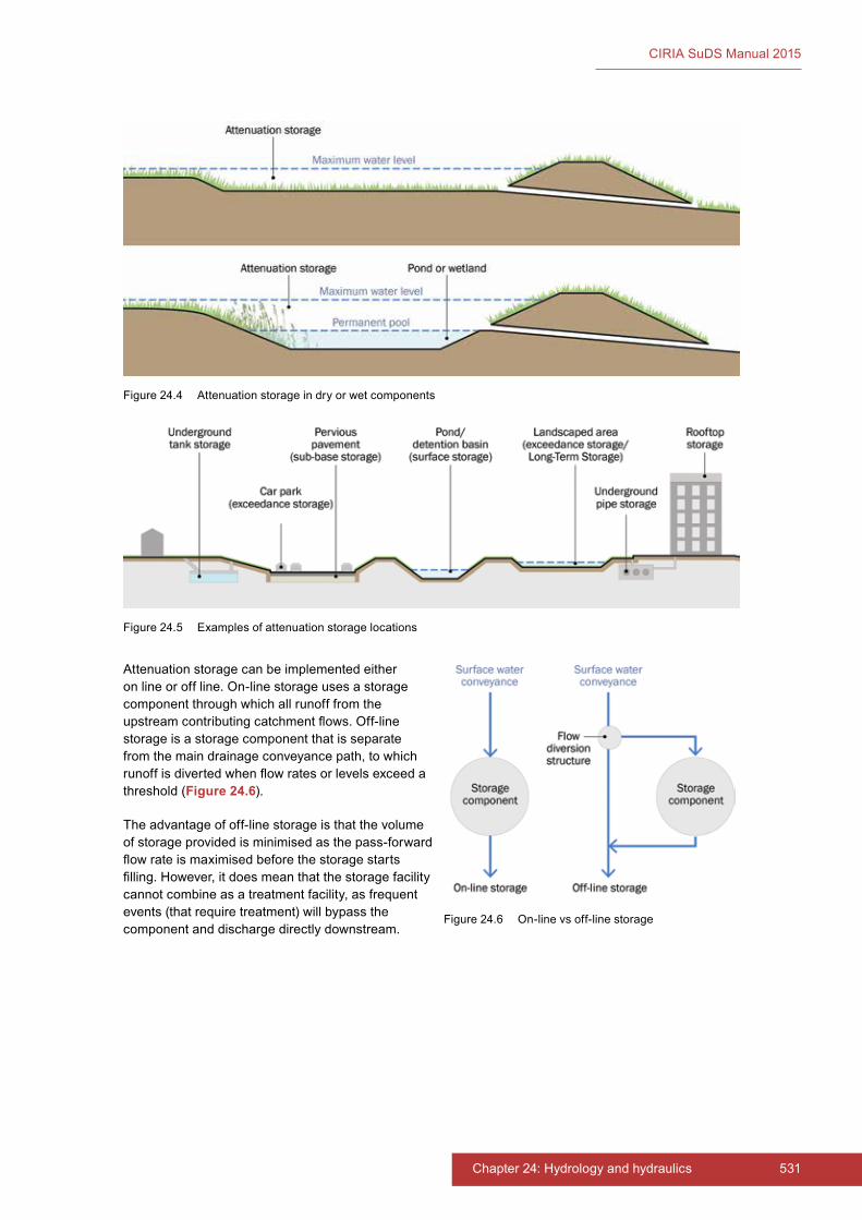
531Chapter 24: Hydrology and hydraulics
CIRIA SuDS Manual 2015
Attenuation storage can be implemented either on line or off line. On-line storage uses a storage component through which all runoff from the upstream contributing catchment flows. Off-line storage is a storage component that is separate from the main drainage conveyance path, to which runoff is diverted when flow rates or levels exceed a threshold (Figure 24.6).
The advantage of off-line storage is that the volume of storage provided is minimised as the pass-forward flow rate is maximised before the storage starts filling. However, it does mean that the storage facility cannot combine as a treatment facility, as frequent events (that require treatment) will bypass the component and discharge directly downstream.
Figure 24.4 Attenuation storage in dry or wet components
Figure 24.5 Examples of attenuation storage locations
Figure 24.6 On-line vs off-line storage
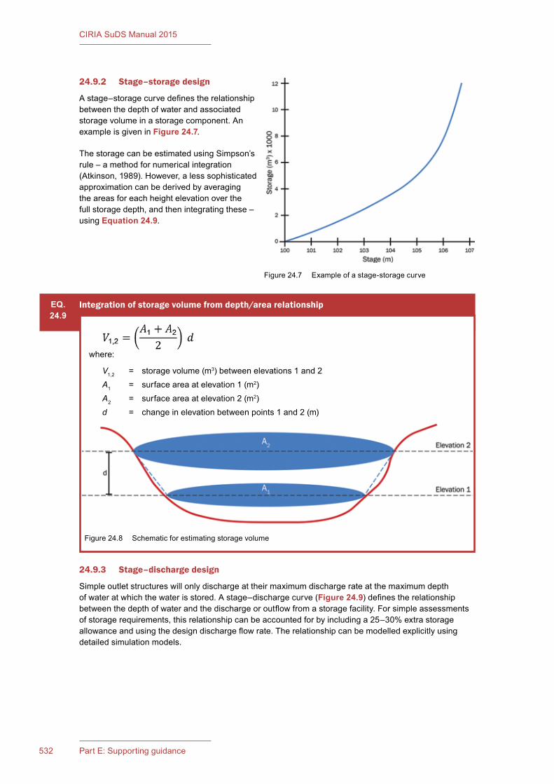
CIRIA SuDS Manual 2015
532 Part E: Supporting guidance
24.9.2 Stage–storage design
A stage–storage curve defines the relationship between the depth of water and associated storage volume in a storage component. An example is given in Figure 24.7.
The storage can be estimated using Simpson’s rule – a method for numerical integration (Atkinson, 1989). However, a less sophisticated approximation can be derived by averaging the areas for each height elevation over the full storage depth, and then integrating these – using Equation 24.9.
Figure 24.7 Example of a stage-storage curve
24.9.3 Stage–discharge design
Simple outlet structures will only discharge at their maximum discharge rate at the maximum depth of water at which the water is stored. A stage–discharge curve (Figure 24.9) defines the relationship between the depth of water and the discharge or outflow from a storage facility. For simple assessments of storage requirements, this relationship can be accounted for by including a 25–30% extra storage allowance and using the design discharge flow rate. The relationship can be modelled explicitly using detailed simulation models.
EQ.24.9
Integration of storage volume from depth/area relationship
where:
V1,2 = storage volume (m3) between elevations 1 and 2A1 = surface area at elevation 1 (m2)A2 = surface area at elevation 2 (m2)d = change in elevation between points 1 and 2 (m)
Figure 24.8 Schematic for estimating storage volume
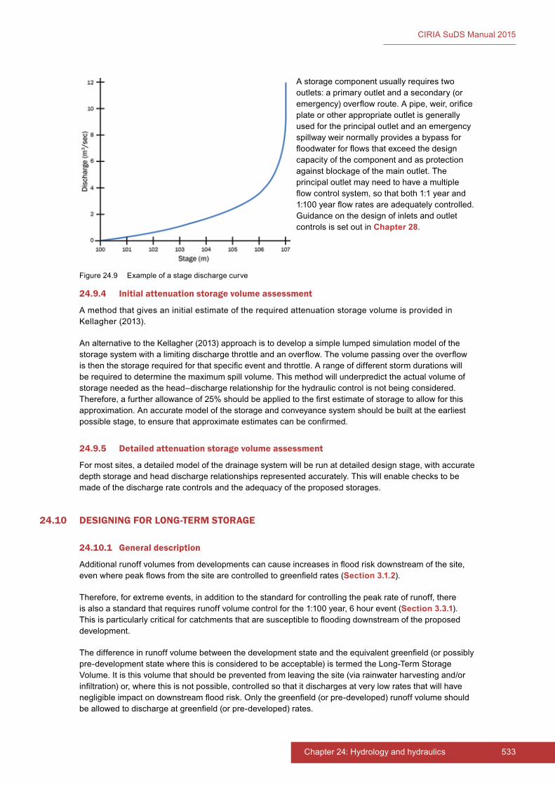
533Chapter 24: Hydrology and hydraulics
CIRIA SuDS Manual 2015
A storage component usually requires two outlets: a primary outlet and a secondary (or emergency) overflow route. A pipe, weir, orifice plate or other appropriate outlet is generally used for the principal outlet and an emergency spillway weir normally provides a bypass for floodwater for flows that exceed the design capacity of the component and as protection against blockage of the main outlet. The principal outlet may need to have a multiple flow control system, so that both 1:1 year and 1:100 year flow rates are adequately controlled. Guidance on the design of inlets and outlet controls is set out in Chapter 28.
Figure 24.9 Example of a stage discharge curve
24.9.4 Initial attenuation storage volume assessment
A method that gives an initial estimate of the required attenuation storage volume is provided in Kellagher (2013).
An alternative to the Kellagher (2013) approach is to develop a simple lumped simulation model of the storage system with a limiting discharge throttle and an overflow. The volume passing over the overflow is then the storage required for that specific event and throttle. A range of different storm durations will be required to determine the maximum spill volume. This method will underpredict the actual volume of storage needed as the head–discharge relationship for the hydraulic control is not being considered. Therefore, a further allowance of 25% should be applied to the first estimate of storage to allow for this approximation. An accurate model of the storage and conveyance system should be built at the earliest possible stage, to ensure that approximate estimates can be confirmed.
24.9.5 Detailed attenuation storage volume assessment
For most sites, a detailed model of the drainage system will be run at detailed design stage, with accurate depth storage and head discharge relationships represented accurately. This will enable checks to be made of the discharge rate controls and the adequacy of the proposed storages.
24.10 DESIGNING FOR LONG-TERM STORAGE
24.10.1 General description
Additional runoff volumes from developments can cause increases in flood risk downstream of the site, even where peak flows from the site are controlled to greenfield rates (Section 3.1.2).
Therefore, for extreme events, in addition to the standard for controlling the peak rate of runoff, there is also a standard that requires runoff volume control for the 1:100 year, 6 hour event (Section 3.3.1). This is particularly critical for catchments that are susceptible to flooding downstream of the proposed development.
The difference in runoff volume between the development state and the equivalent greenfield (or possibly pre-development state where this is considered to be acceptable) is termed the Long-Term Storage Volume. It is this volume that should be prevented from leaving the site (via rainwater harvesting and/or infiltration) or, where this is not possible, controlled so that it discharges at very low rates that will have negligible impact on downstream flood risk. Only the greenfield (or pre-developed) runoff volume should be allowed to discharge at greenfield (or pre-developed) rates.
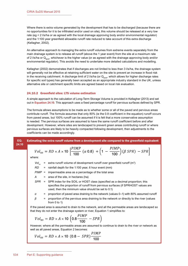
CIRIA SuDS Manual 2015
534 Part E: Supporting guidance
Where there is extra volume generated by the development that has to be discharged (because there are no opportunities for it to be infiltrated and/or used on site), this volume should be released at a very low rate (eg < 2 l/s/ha or as agreed with the local drainage approving body and/or environmental regulator) and the 1:100 year greenfield allowable runoff rate reduced to take account of this extra discharge (Kellagher, 2002).
An alternative approach to managing the extra runoff volumes from extreme events separately from the main drainage system is to release all runoff (above the 1 year event) from the site at a maximum rate of 2 l/s/ha or QBAR, whichever is the higher value (or as agreed with the drainage approving body and/or environmental regulator). This avoids the need to undertake more detailed calculations and modelling.
Kellagher (2002) demonstrates that if discharges are not limited to less than 3 l/s/ha, the drainage system will generally not be effective at retaining sufficient water on the site to prevent an increase in flood risk in the receiving catchment. A discharge limit of 2 l/s/ha (or QBAR, which allows for higher discharge rates for specific soil types) has generally been accepted as an appropriate industry standard in the UK, unless alternative site or catchment specific limits are agreed based on local risk evaluation.
24.10.2 Greenfield sites: LTS volume estimation
A simple approach to the calculation of Long-Term Storage Volume is provided in Kellagher (2013) and set out in Equation 24.10. This approach uses a fixed percentage runoff for pervious surfaces defined by SPR.
The formula allows assumptions to be made as to whether some or all of the paved and pervious areas contribute runoff. The formula assumes that only 80% (ie the 0.8 coefficient in the equation) runoff occurs from paved areas, but 100% runoff can be assumed if it is felt that a more conservative assumption is needed. The pervious surfaces are assumed to have the same runoff coefficient before and after development. However, where sites are landscaped to prevent green areas contributing runoff or where pervious surfaces are likely to be heavily compacted following development, then adjustments to the coefficients can be made accordingly.
EQ.24.10
Estimating the extra runoff volume from a development site compared to the greenfield equivalent
where:
Volxs = extra runoff volume of development runoff over greenfield runoff (m3)RD = rainfall depth for the 1:100 year, 6 hour event (mm)PIMP = impermeable area as a percentage of the total areaA = area of the site, in hectares (ha)SPR = SPR index for the SOIL or HOST class (specified as a decimal proportion; this
specifies the proportion of runoff from pervious surfaces (if SPRHOST values are used, then the minimum value should be set to 0.1)
α = proportion of paved area draining to the network (values 0–1) with 80% assumed runoffβ = proportion of the pervious area draining to the network or directly to the river (values
from 0 to 1)If the paved area is assumed to drain to the network, and all the permeable areas are landscaped so that they do not enter the drainage system or river, Equation 1 simplifies to:
However, where all the permeable areas are assumed to continue to drain to the river or network as well as all paved areas, Equation 2 becomes:
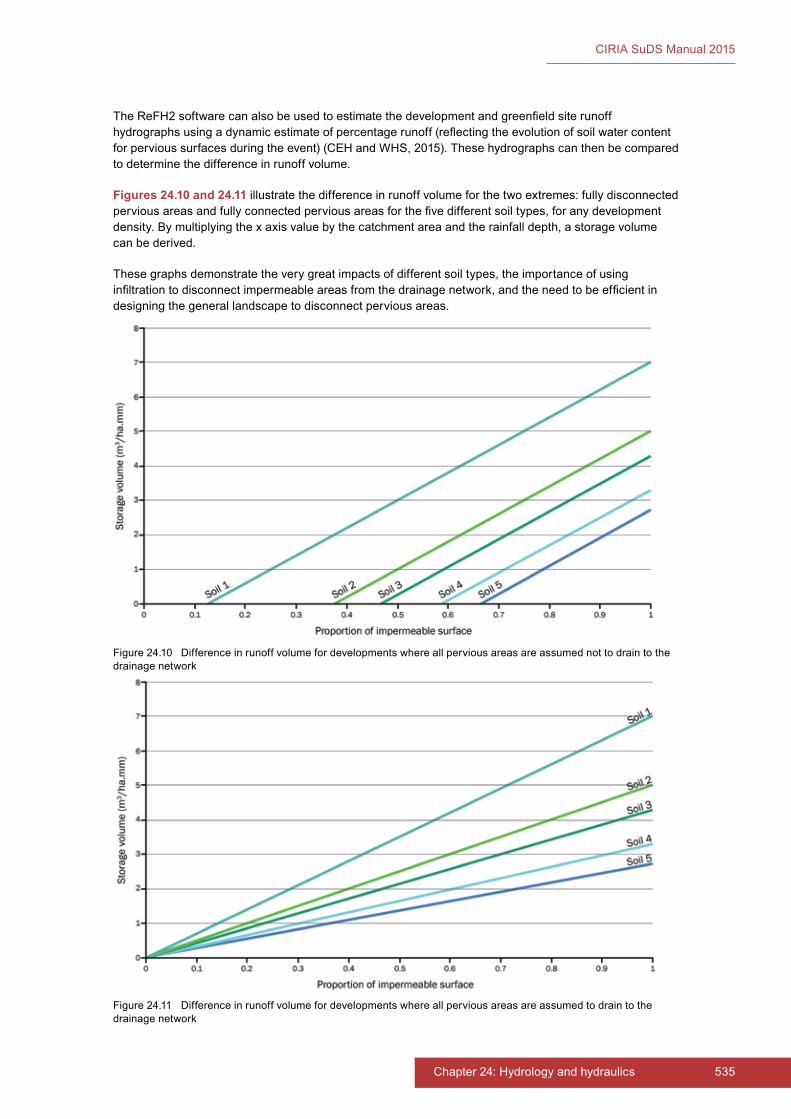
535Chapter 24: Hydrology and hydraulics
CIRIA SuDS Manual 2015
The ReFH2 software can also be used to estimate the development and greenfield site runoff hydrographs using a dynamic estimate of percentage runoff (reflecting the evolution of soil water content for pervious surfaces during the event) (CEH and WHS, 2015). These hydrographs can then be compared to determine the difference in runoff volume.
Figures 24.10 and 24.11 illustrate the difference in runoff volume for the two extremes: fully disconnected pervious areas and fully connected pervious areas for the five different soil types, for any development density. By multiplying the x axis value by the catchment area and the rainfall depth, a storage volume can be derived.
These graphs demonstrate the very great impacts of different soil types, the importance of using infiltration to disconnect impermeable areas from the drainage network, and the need to be efficient in designing the general landscape to disconnect pervious areas.
Figure 24.10 Difference in runoff volume for developments where all pervious areas are assumed not to drain to the drainage network
Figure 24.11 Difference in runoff volume for developments where all pervious areas are assumed to drain to the drainage network
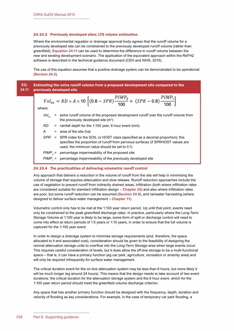
CIRIA SuDS Manual 2015
536 Part E: Supporting guidance
24.10.3 Previously developed sites: LTS volume estimation
Where the environmental regulator or drainage approval body agrees that the runoff volume for a previously developed site can be constrained to the previously developed runoff volume (rather than greenfield), Equation 24.11 can be used to determine the difference in runoff volume between the new and existing development scenario. The application of the equivalent approach within the ReFH2 software is described in the technical guidance document (CEH and WHS, 2015).
The use of this equation assumes that a positive drainage system can be demonstrated to be operational (Section 24.5).
EQ.24.11
Estimating the extra runoff volume from a proposed development site compared to the previously developed site
where:
Volxs = extra runoff volume of the proposed development runoff over the runoff volume from the previously developed site (m3)
RD = rainfall depth for the 1:100 year, 6 hour event (mm)A = area of the site (ha)SPR = SPR index for the SOIL or HOST class (specified as a decimal proportion); this
specifies the proportion of runoff from pervious surfaces (if SPRHOST values are used, the minimum value should be set to 0.1)
PIMP2 = percentage impermeability of the proposed sitePIMP1 = percentage impermeability of the previously developed site
24.10.4 The practicalities of delivering volumetric runoff control
Any approach that delivers a reduction in the volume of runoff from the site will help in minimising the volume of storage that requires attenuation and slow release. Runoff reduction approaches include the use of vegetation to prevent runoff from indirectly drained areas, infiltration (both where infiltration rates are considered suitable for standard infiltration design – Chapter 25) and also where infiltration rates are poor, but some runoff reduction can be assumed (Section 24.8), and rainwater harvesting (where designed to deliver surface water management – Chapter 11).
Volumetric control only has to be met at the 1:100 year return period. Up until that point, events need only be constrained to the peak greenfield discharge rates. In practice, particularly where the Long-Term Storage Volume at 1:100 year is likely to be large, some form of spill or discharge control will need to come into effect at return periods of 1:5 years or 1:10 years, in order to ensure that the full volume is captured for the 1:100 year event.
In order to design a drainage system to minimise storage requirements (and, therefore, the space allocated to it and associated cost), consideration should be given to the feasibility of designing the normal attenuation storage units to overflow into the Long-Term Storage area when large events occur. This requires careful consideration of levels, but it does allow the off-line storage to be a multi-functional space – that is, it can have a primary function (eg car park, agriculture, recreation or amenity area) and will only be required infrequently for surface water management.
The critical duration event for the on-line attenuation system may be less than 6 hours, but more likely it will be much longer (eg around 24 hours). This means that the design needs to take account of two event durations: the critical duration for the attenuation storage system and the 6 hour event, which for the 1:100 year return period should meet the greenfield volume discharge criterion.
Any space that has another primary function should be designed with the frequency, depth, duration and velocity of flooding as key considerations. For example, in the case of temporary car park flooding, a
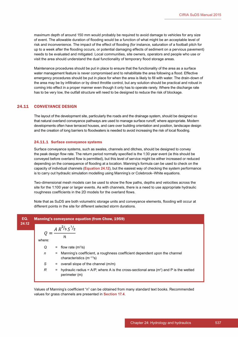
537Chapter 24: Hydrology and hydraulics
CIRIA SuDS Manual 2015
maximum depth of around 150 mm would probably be required to avoid damage to vehicles for any size of event. The allowable duration of flooding would be a function of what might be an acceptable level of risk and inconvenience. The impact of the effect of flooding (for instance, saturation of a football pitch for up to a week after the flooding occurs, or potential damaging effects of sediment on a pervious pavement) needs to be evaluated and mitigated. Local communities, site owners, operators and people who use or visit the area should understand the dual functionality of temporary flood storage areas.
Maintenance procedures should be put in place to ensure that the functionality of the area as a surface water management feature is never compromised and to rehabilitate the area following a flood. Effective emergency procedures should be put in place for when the area is likely to fill with water. The drain-down of the area may be by infiltration or by direct throttle control, but any solution should be practical and robust in coming into effect in a proper manner even though it only has to operate rarely. Where the discharge rate has to be very low, the outfall structure will need to be designed to reduce the risk of blockage.
24.11 CONVEYANCE DESIGN
The layout of the development site, particularly the roads and the drainage system, should be designed so that natural overland conveyance pathways are used to manage surface runoff, where appropriate. Modern developments often have terraced houses, and care over building orientation and position, landscape design and the creation of long barriers to floodwaters is needed to avoid increasing the risk of local flooding.
24.11.1 Surface conveyance systems
Surface conveyance systems, such as swales, channels and ditches, should be designed to convey the peak design flow rate. The return period normally specified is the 1:30 year event (ie this should be conveyed before overland flow is permitted), but this level of service might be either increased or reduced depending on the consequence of flooding at a location. Manning’s formula can be used to check on the capacity of individual channels (Equation 24.12), but the easiest way of checking the system performance is to carry out hydraulic simulation modelling using Manning’s or Colebrook–White equations.
Two-dimensional mesh models can be used to show the flow paths, depths and velocities across the site for the 1:100 year or larger events. As with channels, there is a need to use appropriate hydraulic roughness coefficients in the 2D models for the overland flows.
Note that as SuDS are both volumetric storage units and conveyance elements, flooding will occur at different points in the site for different selected storm durations.
EQ.24.12
Manning’s conveyance equation (from Chow, 1959)
where:
Q = flow rate (m3/s)n = Manning’s coefficient, a roughness coefficient dependent upon the channel
characteristics (m−1/3s)S = overall slope of the channel (m/m)R = hydraulic radius = A/P, where A is the cross-sectional area (m2) and P is the wetted
perimeter (m)
Values of Manning’s coefficient “n” can be obtained from many standard text books. Recommended values for grass channels are presented in Section 17.4.
CIRIA SuDS Manual 2015
538 Part E: Supporting guidance
24.11.2 Pipe conveyance systems
Pipes are still likely to be required to provide some of the conveyance and drainage connectivity for a site. All pipe networks should conform to BS EN 752:2008, which specifies minimum pipe diameters and gradients. In general, pipes should be at least 150 mm in diameter, and these should not be laid on a slope that is flatter than 1 in 150. Where larger pipes are required, pipes can be laid at gradients using the inverse of the pipe diameter, so a 225 mm pipe can be laid at 1 in 225 or steeper and a 300 mm pipe at 1 in 300 or steeper. For pipes larger than 500 mm, gradients should not generally be flatter than 1 in 500 due to construction tolerances. Pipes and manufactured channel components should be sized to carry the maximum design event peak flow rate using product literature, pipe capacity tables or hydraulic simulation modelling. All pipe networks to be adopted should conform to the most up-to-date guidance from the relevant sewerage undertakers (at the time of publication these are WRc 2007, 2010 and 2012). Relevant building regulations should be referenced for specifications for drainage pipework serving single properties.
24.12 EXCEEDANCE DESIGN
Exceedance flow management on the site should be designed to mitigate the risks to people and property associated with:
1 rates of runoff exceeding the designed capacity of the drainage system (for both conveyance and storage components)
2 restrictions on outflows from the drainage system due to high levels in the receiving water body
3 system blockages or other failures.
Very high rainfall intensities can occur for short periods in the UK, and these can overwhelm pipe-based systems for brief periods. SuDS tend to have longer-duration critical events and can often absorb the impact of short thunderstorms much better than pipe-based systems, even though their return period may be high. However, in all cases, there will be events that cause flooding at points in the network if the event is severe enough and is of a relevant duration. The return period to use to evaluate these events is often limited to 1:100 years with a climate change factor. However, dam break risks, nuclear establishments or critical infrastructure all warrant evaluation of the impact of more severe (less frequent) events. The appropriate return period to use should be based on the implications of the consequence of such an event occurring. There are some sources of guidance on this, such as the application of the Reservoirs Act 1975 or the requirements of the nuclear industry, but in most cases this will be a matter for site specific determination.
Particular attention is needed on steep sites, due to focused flow paths and high velocities that might provide a scour risk or a hazard to people. Steep slopes also require attention in terms of modifying the runoff model, as saturated pervious areas can contribute rapid and high levels of runoff.
When the drainage system is overloaded, the surface water runs down to low points on the site. It is, therefore, important to consider this effect, and design the site layout and topography to adequately manage these flood risks. Although it is relatively easy to spot flood risk areas by examining the site contours and layout, the magnitude of flood ponding will be significantly influenced by the characteristics of the site and the drainage system. At the stage of initial evaluation, identifying the extent of flooding at these locations is difficult, as they can only be effectively determined using detailed simulation models.
Sites are particularly at risk during the construction period, as areas stripped of topsoil can act in a similar manner to paved surfaces and can generate very high rates of runoff, as well as contributing high levels of sediment and debris. This requires consideration when designing a temporary surface water management system and environmental protection during the construction phase, and when designing SuDS to manage scenarios where the development is being implemented in phases.
The design of exceedance flow management systems should therefore take account of:
▪ the location, use and capacity of exceedance flood pathways

539Chapter 24: Hydrology and hydraulics
CIRIA SuDS Manual 2015
▪ any low spots within the development that may act as temporary flood storage areas
▪ the location of properties and sensitive/critical infrastructure
▪ potential consequences of exceedance flows to people and/or property.
Surface flood conveyance paths or storage zones for extreme events should:
1 not detract from the primary function of the drainage system
2 be protected and maintained to ensure their continued availability as a flood management feature
3 include a freeboard allowance to allow for uncertainties
4 be designed so that flood depths and velocities are limited to acceptable levels both on site and downstream of it
5 not block pathways that the public would need to use to escape from flooded areas (usually only an issue associated with stream flooding or river floodplains).
Roads may be appropriate to use for storing flood water for brief periods of time on an infrequent basis, subject to their maximum traffic speed and designation. Roads should not be used to store water on a frequent basis or where the speed of the traffic is such that any stored water poses a potential accident risk.
Detail on designing for exceedance can be found in Digman et al (2006) and Digman et al (2014).
24.13 SURFACE WATER PUMPING STATION DESIGN
Where surface water management for the site cannot avoid the use of pumping, the pumping station should be designed in accordance with BS EN 752:2008. Where the pumping station is to be adopted by the sewerage undertaker, it should also be designed in accordance with WRc (2007, 2010 and 2012).
24.14 REFERENCES
ATKINSON, K (1989) An introduction to numerical analysis, second edition, John Wiley & Sons, London, UK (ISBN: 978-0-47162-489-6)
BOORMAN, D, HOLLIS, J and LILLY, A (1995) Hydrology of soil types: a hydrologically-based classification of the soils of the United Kingdom, Report 126, Institute of Hydrology, Wallingford, Oxon, UK
CEH (1999) Flood Estimation Handbook (FEH), Centre for Ecology and Hydrology, Wallingford, Oxon, UK (ISBN: 978-1-90669-800-3). Go to: http://tinyurl.com/o8lslay
CEH and WHS (2015) The Revitalised Flood Hydrograph Model ReFH. Technical guidance, Centre for Ecology & Hydrology, Wallingford, UK. Go to: http://tinyurl.com/o9hg9hl
CHOW, V T (1959) Open-channel hydraulics, McGraw-Hill, New York, USA (ISBN: 978-1-93284-618-8)
DIGMAN, C, BALMFORTH, D, KELLAGHER, R and BUTLER, D (2006) Designing for exceedance in urban drainage – good practice, C635, CIRIA, London (ISBN: 978-0-86017-635-0). Go to: www.ciria.org
DIGMAN, C, ASHLEY, R, HARGREAVES, P and GILL, E (2014) Managing urban flooding from heavy rainfall – encouraging the uptake of designing for exceedance, C738, CIRIA, London, UK (ISBN: 978-0-86017-742-5). Go to: www.ciria.org
EA (2015) Flood estimation guidelines. Operational instruction 197_08, version 5, Environment Agency, Bristol, UK. Go to: http://persona.uk.com/A21Ton/Core_dox/H/H13.pdf

CIRIA SuDS Manual 2015
540 Part E: Supporting guidance
FAULKNER, D (1999) “Rainfall Frequency Estimation”, Flood Estimation Handbook, volume 2, Institute of Hydrology, Wallingford, Oxon, UK (ISBN: 978-1-90669-800-3). Go to: http://tinyurl.com/o8lslay
FAULKNER, D, KJELDSEN, T, PACKMAN, J and STEWART, L (2012) Estimating flood peaks and hydrographs for small catchments: Phase 1, SC090031/R, Environment Agency, Bristol, UK. Go to: http://tinyurl.com/p2l9eax
HR WALLINGFORD (1981) The Wallingford Procedure, WP5, HR Wallingford, Oxon, UK. Go to: http://tinyurl.com/o7azzx4
KELLAGHER, R (2000) Wallingford procedure for Europe: Best practice guide to urban drainage modelling, WP6, HR Wallingford, Wallingford, Oxon, UK. Go to: http://tinyurl.com/o7azzx4
KELLAGHER, R (2002) Storage requirements for rainfall runoff from greenfield development sites. Version 2, SR580, HR Wallingford, Oxon, UK. Go to: http://tinyurl.com/q22bolr
KELLAGHER, R (2013) Rainfall runoff management for developments, Report SCS030219, Environment Agency, Bristol, UK (ISBN: 978-1-84911-309-0)
KJELDSEN, T (2007) The revitalised FSR/FEH rainfall-runoff model, Flood Estimation Handbook, Supplementary Report No. 1, Centre for Ecology & Hydrology, Wallingford, Oxon, UK (ISBN: 0-90374-115-7). Go to: http://tinyurl.com/oztkjjg
KJELDSEN, T (2014) “How reliable are design flood estimates in the UK?” Journal of Flood Risk Management, vol 8, 3, Wiley Online, UK, pp 237–246
KJELDSEN, T, JONES, D and BAYLISS, A (2008) Improving the FEH statistical procedures for flood frequency estimation, Science Report SC050050, Environment Agency, Bristol, UK (ISBN: 978-1-84432-920-5). Go to: http://tinyurl.com/nn6y2ad
KJELDSEN, T, MILLER, J and PACKMAN, J (2013) “Modelling design flood hydrographs in catchments with mixed urban and rural land cover” Hydrology Research, vol 44, 6, IWA Publishing, London, UK, pp 1040–1057
MARGETTS, J (2002) “If the NAPI fits…”. In: WaPUG conference, Coventry, 2002
MARSHALL, D and BAYLISS, A (1994) Flood estimation for small catchments, Report 124, Institute of Hydrology, Wallingford, Oxon, UK (ISBN: 0-94854-062-1). Go to: http://nora.nerc.ac.uk/7367/1/IH_124.pdf
MAY, R and KELLAGHER, R (2004) Drainage of development sites – a guide, X108, CIRIA, London (ISBN: 978-0-86017-900-9). Go to: www.ciria.org
NERC (1975) Flood Studies Report (FSR), Natural Environment Research Council, London, UK
NERC (1977) The estimation of low return period floods, Flood Studies Supplementary Report (FSSR) No. 2, Institute of Hydrology, Wallingford, Oxon, UK
NERC (1985) The FSR rainfall–runoff model parameter estimation equations updated, Flood Studies Supplementary Report (FSSR) No 16, Institute of Hydrology, Wallingford, Oxon, UK
NERC (1993) Regional growth curves reviewed, Flood Studies Supplementary Report (FSSR) No 14, Natural Environment Research Council, Swindon, UK
OSBORNE, M (2009) A new runoff volume model, WaPUG User Note No. 28, Chartered Institution of Water and Environmental Management, London, UK. Go to: http://tinyurl.com/nv27kak
OSBORNE, M (2012) “Design storms – have we been getting it wrong all this time?” In: Proc WaPUG spring conference 2012, Midlands Engineering Centre, Birmingham, 23 May 2012, Chartered Institution of Water and Environmental Management, London, UK. Go to: http://tinyurl.com/oav6ccz

541Chapter 24: Hydrology and hydraulics
CIRIA SuDS Manual 2015
PACKMAN, J C (1990) “New Hydrology model”. In: WaPUG conference, Coventry, 10 June 1990
STEWART, E, JONES, D, SVENSSON, C, MORRIS, D, DEMPSEY, P, DENT, J, COLLIER, C AND ANDERSON, C (2013) Reservoir safety – long return period rainfall, R&D Technical Report WS 194/2/39/TR, Joint Defra/Environment Agency Flood and Coastal Erosion Risk Management Research & Development Programme, Department for Environment, Food and Rural Affairs, London. Go to: http://tinyurl.com/osv9rag
UKWIR (2014) Development of the UKWIR runoff model: Main report, 14/SW/01/6, UK Water Industry Research, London (ISBN: 1-84057-722-3)
WRc (2007) Sewers for Scotland, second edition, WRc Publications, Swindon, UK (ISBN: 978-1-89892-060-1)
WRc (2010) Sewers for adoption Northern Ireland, first edition, WRc Publications, Swindon, UK (ISBN: 978-1-89892-066-3)
WRc (2012) Sewers for adoption, seventh edition, WRc Publications, Swindon, UK (ISBN: 978-1-89892-065-6)
STATUTES
Acts
Reservoirs Act 1975 (c.23)
British Standards
BS 8515:2009+A1:2013 Rainwater harvesting systems. Code of practice
BS EN 752:2008 Drain and sewer systems outside buildings
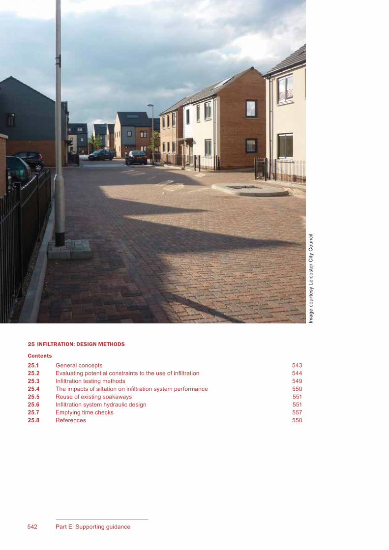
543Chapter 25: Infiltration: design methods542 Part E: Supporting guidance
CIRIA SuDS Manual 2015
25 INFILTRATION: DESIGN METHODS
Contents
25.1 General concepts 54325.2 Evaluating potential constraints to the use of infiltration 54425.3 Infiltration testing methods 54925.4 The impacts of siltation on infiltration system performance 55025.5 Reuse of existing soakaways 55125.6 Infiltration system hydraulic design 55125.7 Emptying time checks 55725.8 References 558
Imag
e co
urte
sy L
eice
ster
City
Cou
ncil
543Chapter 25: Infiltration: design methods542 Part E: Supporting guidance
CIRIA SuDS Manual 2015
25Chapter
25.1 GENERAL CONCEPTS
Infiltration systems allow surface water runoff to infiltrate into the ground over a period of time, thus reducing the volume of runoff during a rainfall event. Infiltration systems can deliver Interception for the upstream contributing catchment surface (Section 24.8) and can also help reduce the attenuation storage volume requirements required for the site (Section 24.9).
The use of infiltration to dispose of surface water runoff also has a number of other important benefits:
▪ It can help replenish aquifers local to the site through deep infiltration and/or act to support local river base flows and wetland systems via shallow infiltration processes.
▪ It can help support local soil moisture levels and vegetation. In urban areas this may reduce the adverse effects that trees can have on foundations by reducing the potential for shrinkage of soils.
For a soil to be suitable for infiltrating design runoff events, it should be:
▪ permeable, and
▪ unsaturated.
Also, it should be of sufficient thickness and extent to disperse the water effectively. Figure 25.1 is a schematic of a typical infiltration system.
There are a number of constraints to the use of infiltration. These should be fully evaluated for any site and any potential infiltration location, to ensure that risks are minimised (Section 25.2). The rate at which infiltration might occur – together with the design standard of service of the system and the contributing catchment area – will influence the area of the infiltration surface and the volume of temporary storage required. Guidance on establishing appropriate infiltration rates is set out in Sections 25.2 and 25.3.
For further detail on the hydraulic design of infiltration systems, see Bettess (1996).
Infiltration: design methodsThis chapter provides guidance on the suitability of using infiltration to dispose of surface water runoff, infiltration testing and design methods.
Water quantity design criteria are set out in Chapter 3.
Requirements for water quality management for groundwater protection are set out in Chapter 4.
Hydrology and hydraulic design methods and calculations are presented in Chapter 24.
Guidance on component sizing for water quantity and water quality management is provided in Chapters 11–23.
Methods for meeting water quality management requirements are presented in Chapter 26.
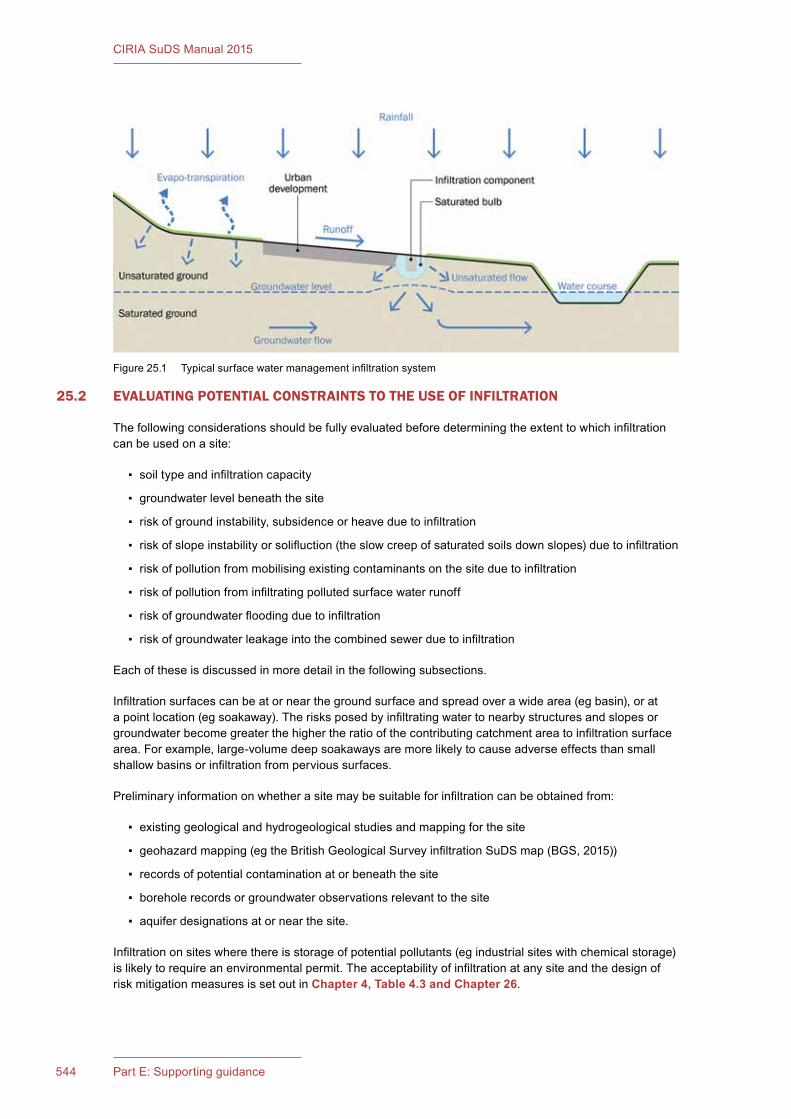
545Chapter 25: Infiltration: design methods544 Part E: Supporting guidance
CIRIA SuDS Manual 2015
25.2 EVALUATING POTENTIAL CONSTRAINTS TO THE USE OF INFILTRATION
The following considerations should be fully evaluated before determining the extent to which infiltration can be used on a site:
▪ soil type and infiltration capacity
▪ groundwater level beneath the site
▪ risk of ground instability, subsidence or heave due to infiltration
▪ risk of slope instability or solifluction (the slow creep of saturated soils down slopes) due to infiltration
▪ risk of pollution from mobilising existing contaminants on the site due to infiltration
▪ risk of pollution from infiltrating polluted surface water runoff
▪ risk of groundwater flooding due to infiltration
▪ risk of groundwater leakage into the combined sewer due to infiltration
Each of these is discussed in more detail in the following subsections.
Infiltration surfaces can be at or near the ground surface and spread over a wide area (eg basin), or at a point location (eg soakaway). The risks posed by infiltrating water to nearby structures and slopes or groundwater become greater the higher the ratio of the contributing catchment area to infiltration surface area. For example, large-volume deep soakaways are more likely to cause adverse effects than small shallow basins or infiltration from pervious surfaces.
Preliminary information on whether a site may be suitable for infiltration can be obtained from:
▪ existing geological and hydrogeological studies and mapping for the site
▪ geohazard mapping (eg the British Geological Survey infiltration SuDS map (BGS, 2015))
▪ records of potential contamination at or beneath the site
▪ borehole records or groundwater observations relevant to the site
▪ aquifer designations at or near the site.
Infiltration on sites where there is storage of potential pollutants (eg industrial sites with chemical storage) is likely to require an environmental permit. The acceptability of infiltration at any site and the design of risk mitigation measures is set out in Chapter 4, Table 4.3 and Chapter 26.
Figure 25.1 Typical surface water management infiltration system
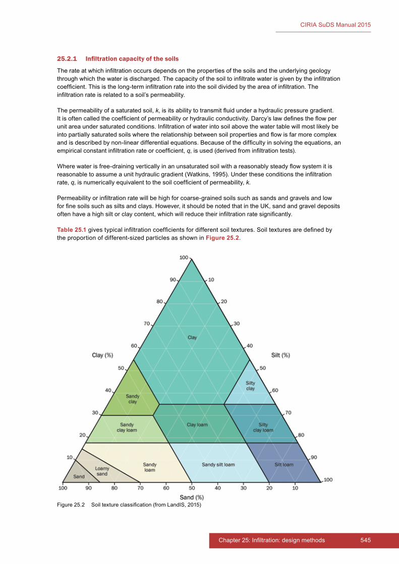
545Chapter 25: Infiltration: design methods544 Part E: Supporting guidance
CIRIA SuDS Manual 2015
25.2.1 Infiltration capacity of the soils
The rate at which infiltration occurs depends on the properties of the soils and the underlying geology through which the water is discharged. The capacity of the soil to infiltrate water is given by the infiltration coefficient. This is the long-term infiltration rate into the soil divided by the area of infiltration. The infiltration rate is related to a soil’s permeability.
The permeability of a saturated soil, k, is its ability to transmit fluid under a hydraulic pressure gradient. It is often called the coefficient of permeability or hydraulic conductivity. Darcy’s law defines the flow per unit area under saturated conditions. Infiltration of water into soil above the water table will most likely be into partially saturated soils where the relationship between soil properties and flow is far more complex and is described by non-linear differential equations. Because of the difficulty in solving the equations, an empirical constant infiltration rate or coefficient, q, is used (derived from infiltration tests).
Where water is free-draining vertically in an unsaturated soil with a reasonably steady flow system it is reasonable to assume a unit hydraulic gradient (Watkins, 1995). Under these conditions the infiltration rate, q, is numerically equivalent to the soil coefficient of permeability, k.
Permeability or infiltration rate will be high for coarse-grained soils such as sands and gravels and low for fine soils such as silts and clays. However, it should be noted that in the UK, sand and gravel deposits often have a high silt or clay content, which will reduce their infiltration rate significantly.
Table 25.1 gives typical infiltration coefficients for different soil textures. Soil textures are defined by the proportion of different-sized particles as shown in Figure 25.2.
Figure 25.2 Soil texture classification (from LandIS, 2015)
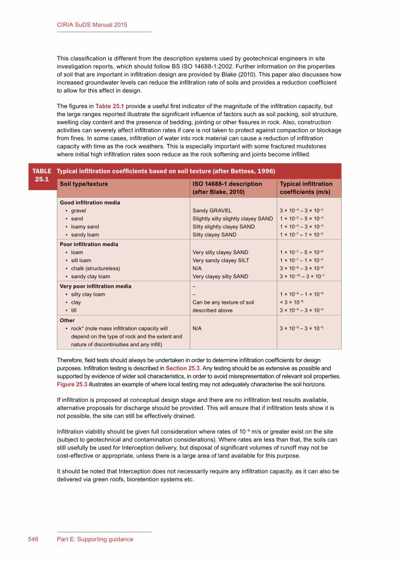
547Chapter 25: Infiltration: design methods546 Part E: Supporting guidance
CIRIA SuDS Manual 2015
Therefore, field tests should always be undertaken in order to determine infiltration coefficients for design purposes. Infiltration testing is described in Section 25.3. Any testing should be as extensive as possible and supported by evidence of wider soil characteristics, in order to avoid misrepresentation of relevant soil properties. Figure 25.3 illustrates an example of where local testing may not adequately characterise the soil horizons.
If infiltration is proposed at conceptual design stage and there are no infiltration test results available, alternative proposals for discharge should be provided. This will ensure that if infiltration tests show it is not possible, the site can still be effectively drained.
Infiltration viability should be given full consideration where rates of 10−6 m/s or greater exist on the site (subject to geotechnical and contamination considerations). Where rates are less than that, the soils can still usefully be used for Interception delivery, but disposal of significant volumes of runoff may not be cost-effective or appropriate, unless there is a large area of land available for this purpose.
It should be noted that Interception does not necessarily require any infiltration capacity, as it can also be delivered via green roofs, bioretention systems etc.
TABLE25.1
Typical infiltration coefficients based on soil texture (after Bettess, 1996)
Soil type/texture ISO 14688-1 description (after Blake, 2010)
Typical infiltration coefficients (m/s)
Good infiltration media ▪ gravel ▪ sand ▪ loamy sand ▪ sandy loam
Sandy GRAVELSlightly silty slightly clayey SANDSilty slightly clayey SANDSilty clayey SAND
3 × 10⁻⁴ – 3 × 10⁻²
1 × 10⁻⁵ – 5 × 10⁻⁵
1 × 10⁻⁴ – 3 × 10⁻⁵
1 × 10⁻⁷ – 1 × 10⁻⁵
Poor infiltration media ▪ loam ▪ silt loam ▪ chalk (structureless) ▪ sandy clay loam
Very silty clayey SANDVery sandy clayey SILTN/AVery clayey silty SAND
1 × 10⁻⁷ – 5 × 10⁻⁶
1 × 10⁻⁷ – 1 × 10⁻⁵
3 × 10⁻⁸ – 3 × 10⁻⁶
3 × 10⁻¹⁰ – 3 × 10⁻⁷
Very poor infiltration media ▪ silty clay loam ▪ clay ▪ till
––Can be any texture of soil described above
1 × 10⁻⁸ – 1 × 10⁻⁶
< 3 × 10⁻⁸
3 × 10⁻⁹ – 3 × 10⁻⁶
Other ▪ rock* (note mass infiltration capacity will
depend on the type of rock and the extent and nature of discontinuities and any infill)
N/A 3 × 10⁻⁹ – 3 × 10⁻⁵
This classification is different from the description systems used by geotechnical engineers in site investigation reports, which should follow BS ISO 14688-1:2002. Further information on the properties of soil that are important in infiltration design are provided by Blake (2010). This paper also discusses how increased groundwater levels can reduce the infiltration rate of soils and provides a reduction coefficient to allow for this effect in design.
The figures in Table 25.1 provide a useful first indicator of the magnitude of the infiltration capacity, but the large ranges reported illustrate the significant influence of factors such as soil packing, soil structure, swelling clay content and the presence of bedding, jointing or other fissures in rock. Also, construction activities can severely affect infiltration rates if care is not taken to protect against compaction or blockage from fines. In some cases, infiltration of water into rock material can cause a reduction of infiltration capacity with time as the rock weathers. This is especially important with some fractured mudstones where initial high infiltration rates soon reduce as the rock softening and joints become infilled.
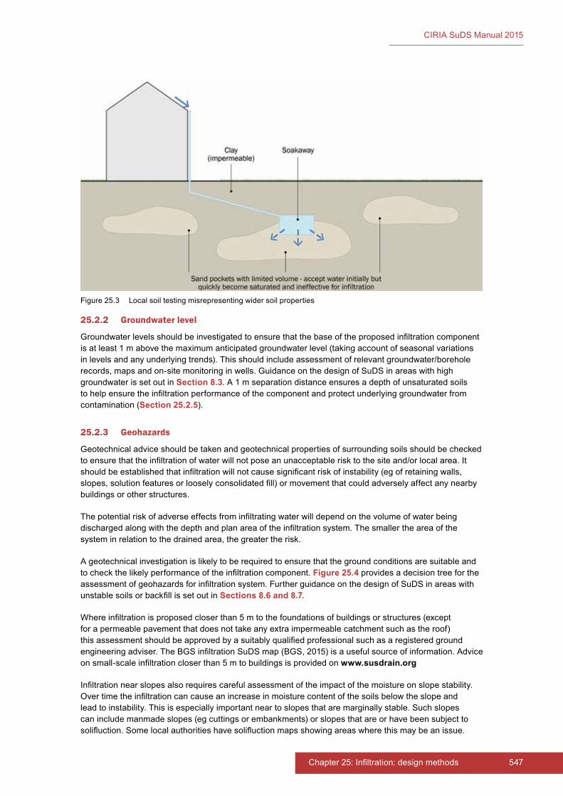
547Chapter 25: Infiltration: design methods546 Part E: Supporting guidance
CIRIA SuDS Manual 2015
Figure 25.3 Local soil testing misrepresenting wider soil properties
25.2.2 Groundwater level
Groundwater levels should be investigated to ensure that the base of the proposed infiltration component is at least 1 m above the maximum anticipated groundwater level (taking account of seasonal variations in levels and any underlying trends). This should include assessment of relevant groundwater/borehole records, maps and on-site monitoring in wells. Guidance on the design of SuDS in areas with high groundwater is set out in Section 8.3. A 1 m separation distance ensures a depth of unsaturated soils to help ensure the infiltration performance of the component and protect underlying groundwater from contamination (Section 25.2.5).
25.2.3 Geohazards
Geotechnical advice should be taken and geotechnical properties of surrounding soils should be checked to ensure that the infiltration of water will not pose an unacceptable risk to the site and/or local area. It should be established that infiltration will not cause significant risk of instability (eg of retaining walls, slopes, solution features or loosely consolidated fill) or movement that could adversely affect any nearby buildings or other structures.
The potential risk of adverse effects from infiltrating water will depend on the volume of water being discharged along with the depth and plan area of the infiltration system. The smaller the area of the system in relation to the drained area, the greater the risk.
A geotechnical investigation is likely to be required to ensure that the ground conditions are suitable and to check the likely performance of the infiltration component. Figure 25.4 provides a decision tree for the assessment of geohazards for infiltration system. Further guidance on the design of SuDS in areas with unstable soils or backfill is set out in Sections 8.6 and 8.7.
Where infiltration is proposed closer than 5 m to the foundations of buildings or structures (except for a permeable pavement that does not take any extra impermeable catchment such as the roof) this assessment should be approved by a suitably qualified professional such as a registered ground engineering adviser. The BGS infiltration SuDS map (BGS, 2015) is a useful source of information. Advice on small-scale infiltration closer than 5 m to buildings is provided on www.susdrain.org
Infiltration near slopes also requires careful assessment of the impact of the moisture on slope stability. Over time the infiltration can cause an increase in moisture content of the soils below the slope and lead to instability. This is especially important near to slopes that are marginally stable. Such slopes can include manmade slopes (eg cuttings or embankments) or slopes that are or have been subject to solifluction. Some local authorities have solifluction maps showing areas where this may be an issue.
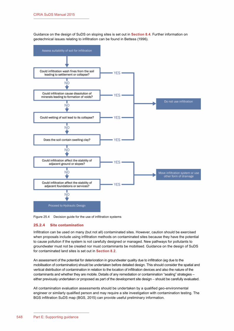
549Chapter 25: Infiltration: design methods548 Part E: Supporting guidance
CIRIA SuDS Manual 2015
Guidance on the design of SuDS on sloping sites is set out in Section 8.4. Further information on geotechnical issues relating to infiltration can be found in Bettess (1996).
25.2.4 Site contamination
Infiltration can be used on many (but not all) contaminated sites. However, caution should be exercised when proposals include using infiltration methods on contaminated sites because they have the potential to cause pollution if the system is not carefully designed or managed. New pathways for pollutants to groundwater must not be created nor must contaminants be mobilised. Guidance on the design of SuDS for contaminated land sites is set out in Section 8.2.
An assessment of the potential for deterioration in groundwater quality due to infiltration (eg due to the mobilisation of contamination) should be undertaken before detailed design. This should consider the spatial and vertical distribution of contamination in relation to the location of infiltration devices and also the nature of the contaminants and whether they are mobile. Details of any remediation or contamination “sealing” strategies – either previously undertaken or proposed as part of the development site design – should be carefully evaluated.
All contamination evaluation assessments should be undertaken by a qualified geo-environmental engineer or similarly qualified person and may require a site investigation with contamination testing. The BGS infiltration SuDS map (BGS, 2015) can provide useful preliminary information.
Figure 25.4 Decision guide for the use of infiltration systems
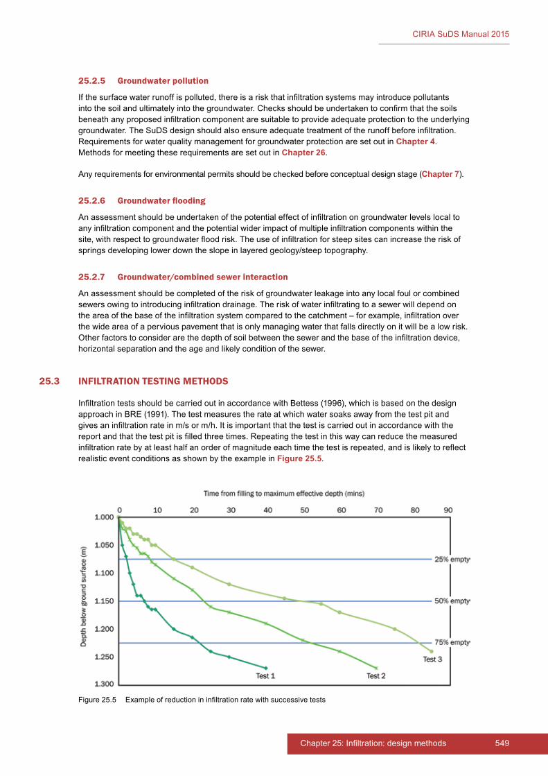
549Chapter 25: Infiltration: design methods548 Part E: Supporting guidance
CIRIA SuDS Manual 2015
25.2.5 Groundwater pollution
If the surface water runoff is polluted, there is a risk that infiltration systems may introduce pollutants into the soil and ultimately into the groundwater. Checks should be undertaken to confirm that the soils beneath any proposed infiltration component are suitable to provide adequate protection to the underlying groundwater. The SuDS design should also ensure adequate treatment of the runoff before infiltration. Requirements for water quality management for groundwater protection are set out in Chapter 4. Methods for meeting these requirements are set out in Chapter 26.
Any requirements for environmental permits should be checked before conceptual design stage (Chapter 7).
25.2.6 Groundwater flooding
An assessment should be undertaken of the potential effect of infiltration on groundwater levels local to any infiltration component and the potential wider impact of multiple infiltration components within the site, with respect to groundwater flood risk. The use of infiltration for steep sites can increase the risk of springs developing lower down the slope in layered geology/steep topography.
25.2.7 Groundwater/combined sewer interaction
An assessment should be completed of the risk of groundwater leakage into any local foul or combined sewers owing to introducing infiltration drainage. The risk of water infiltrating to a sewer will depend on the area of the base of the infiltration system compared to the catchment – for example, infiltration over the wide area of a pervious pavement that is only managing water that falls directly on it will be a low risk. Other factors to consider are the depth of soil between the sewer and the base of the infiltration device, horizontal separation and the age and likely condition of the sewer.
25.3 INFILTRATION TESTING METHODS
Infiltration tests should be carried out in accordance with Bettess (1996), which is based on the design approach in BRE (1991). The test measures the rate at which water soaks away from the test pit and gives an infiltration rate in m/s or m/h. It is important that the test is carried out in accordance with the report and that the test pit is filled three times. Repeating the test in this way can reduce the measured infiltration rate by at least half an order of magnitude each time the test is repeated, and is likely to reflect realistic event conditions as shown by the example in Figure 25.5.
Figure 25.5 Example of reduction in infiltration rate with successive tests

551Chapter 25: Infiltration: design methods550 Part E: Supporting guidance
CIRIA SuDS Manual 2015
In some cases it may not be possible to carry out tests in trial pits due to depth or access constraints. In this case, tests can be carried out in boreholes. The tests should follow the procedure in accordance with BS EN ISO 22282-2:2012. Falling head tests should still be repeated at least three times, as required in BRE (1991). Care should also be taken in the interpretation of the results, as a smaller volume of water is entering the ground during the test. Ideally, falling head tests should be repeated as many times as possible to increase the volume of water entering the ground.
One of the main risks to soakaway performance is inadequate infiltration testing, because of either time constraints at the planning stage or cost. If the water level in a test does not drop sufficiently quickly to do three tests in a day, it indicates low infiltration capacity and potential risks for long-term performance. However, the tests can be extended over two days using water-level loggers. If pits are left open overnight with water in them, then health and safety issues need to be addressed and as a minimum the areas will need to be securely fenced off.
The results of incomplete tests should not be extrapolated to obtain design values of infiltration rates. The head of water in the infiltration test should fall to less than 25% of the initial head of water. If this does not occur, the results should state that the infiltration rate cannot be determined. If other variations to the test method in Bettess (1996) are required, the test results sheet should clearly state what variations have been made to the test and why.
It is rare that sufficient tests are carried out on a site to allow statistical analysis. The worse-case infiltration rate value should be used (not the mean or any other value) unless a sound justification for doing otherwise is demonstrated.
Infiltration test results should always be provided together with trial pit records that include soil/rock descriptions of the materials in which the test has been completed in accordance with BS EN ISO 14688-1:2002 or BS EN ISO 14689-1:2003. The interpretation of the test results should be compared to the soil descriptions and any unusually high or low values assessed against the conceptual site ground model, and then confirmation should be provided that the measured infiltration rates are representative of the wider ground mass (eg the test has not been undertaken in a limited extent of sand within a mass of clay). The likely impact of water on the soil and the long-term infiltration rate should also be assessed.
The infiltration tests should be carried out at the location, depth and head of water that replicates the proposed design. For larger systems, the tests should provide sufficient coverage across the entire area to be occupied by the infiltration system. The test results sheet should state which stratum the results are appropriate to and any limitations in the test – for example, has the infiltration rate been estimated by assuming water only infiltrates into one particular stratum, such as a discrete layer of limestone?
25.4 THE IMPACTS OF SILTATION ON INFILTRATION SYSTEM PERFORMANCE
The soil surrounding an infiltration system can become blinded through ingress of silt, and the infiltration capacity reduced as a result. All infiltration system designs should therefore include appropriate pre-treatment (ie silt/sediment removal systems). Larger systems should also be monitored to check the extent or effects of long-term silt deposition if thought necessary – for example, by providing a monitoring well within the infiltration system that can be used to monitor the drop in water level after a rainfall event, or by providing access for visual inspection. Some blinding can be simply removed if there is access to the infiltration surface, but in other cases (eg deep soakaways) blinding can render the system useless over time. Even with upstream sediment protection it is likely that some silt will always collect in an infiltration device. The risk posed by silt depends on the relative difference in permeability between the silt and the surrounding soil, and on the design method used.
If the surrounding soil has similar permeability to the silt then there will be little effect. Also, if the design is based on the guidance in BRE (1991) then infiltration from the base is ignored and so any silt will also have negligible effect on infiltration rates (Figure 25.6).
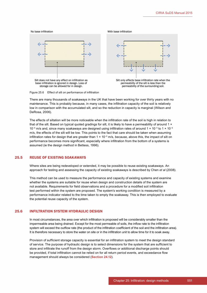
551Chapter 25: Infiltration: design methods550 Part E: Supporting guidance
CIRIA SuDS Manual 2015
There are many thousands of soakaways in the UK that have been working for over thirty years with no maintenance. This is probably because, in many cases, the infiltration capacity of the soil is relatively low in comparison with the accumulated silt, and so the reduction in capacity is marginal (Wilson and DeRosa, 2006).
The effects of siltation will be more noticeable when the infiltration rate of the soil is high in relation to that of the silt. Based on typical quoted gradings for silt, it is likely to have a permeability of around 1 × 10⁻⁶ m/s and, since many soakaways are designed using infiltration rates of around 1 × 10⁻⁵ to 1 × 10⁻⁶ m/s, the effects of the silt will be low. This points to the fact that care should be taken when assuming infiltration rates for design that are greater than 1 × 10⁻⁵ m/s, because, above this, the impact of silt on performance becomes more significant, especially where infiltration from the bottom of a systems is assumed (ie the design method in Bettess, 1996).
25.5 REUSE OF EXISTING SOAKAWAYS
Where sites are being redeveloped or extended, it may be possible to reuse existing soakaways. An approach for testing and assessing the capacity of existing soakaways is described by Chen et al (2008).
This method can be used to measure the performance and capacity of existing systems and examine whether the systems are suitable for reuse when design and construction details of the system are not available. Requirements for field observations and a procedure for a modified soil infiltration test performed within the system are proposed. The system’s working condition is measured by a performance indicator related to the time taken to empty the soakaway. This is then employed to evaluate the potential reuse capacity of the system.
25.6 INFILTRATION SYSTEM HYDRAULIC DESIGN
In most circumstances, the area over which infiltration is proposed will be considerably smaller than the impermeable area being drained. Except for the most permeable of soils, the inflow rate to the infiltration system will exceed the outflow rate (the product of the infiltration coefficient of the soil and the infiltration area). It is therefore necessary to store the water on site or in the infiltration unit to allow time for it to soak away.
Provision of sufficient storage capacity is essential for an infiltration system to meet the design standard of service. The purpose of hydraulic design is to select dimensions for the system that are sufficient to store and infiltrate the runoff from the design storm. Overflows or additional discharge points should be provided, if total infiltration cannot be relied on for all return period events, and exceedance flow management should always be considered (Section 24.12).
Figure 25.6 Effect of silt on performance of infiltration
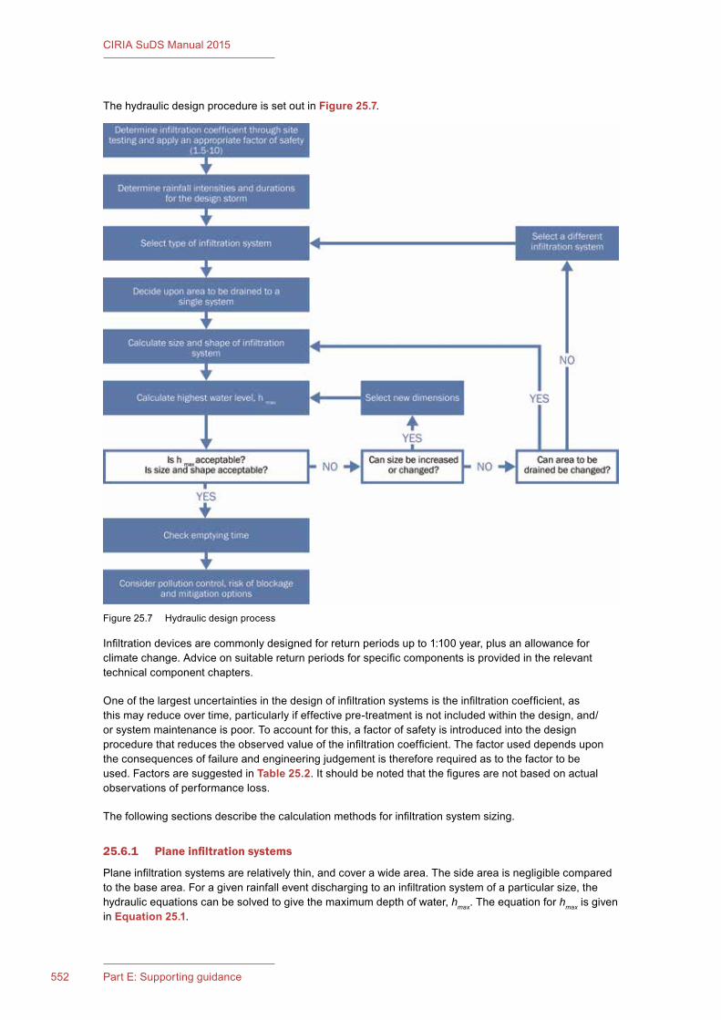
553Chapter 25: Infiltration: design methods552 Part E: Supporting guidance
CIRIA SuDS Manual 2015
The hydraulic design procedure is set out in Figure 25.7.
Infiltration devices are commonly designed for return periods up to 1:100 year, plus an allowance for climate change. Advice on suitable return periods for specific components is provided in the relevant technical component chapters.
One of the largest uncertainties in the design of infiltration systems is the infiltration coefficient, as this may reduce over time, particularly if effective pre-treatment is not included within the design, and/or system maintenance is poor. To account for this, a factor of safety is introduced into the design procedure that reduces the observed value of the infiltration coefficient. The factor used depends upon the consequences of failure and engineering judgement is therefore required as to the factor to be used. Factors are suggested in Table 25.2. It should be noted that the figures are not based on actual observations of performance loss.
The following sections describe the calculation methods for infiltration system sizing.
25.6.1 Plane infiltration systems
Plane infiltration systems are relatively thin, and cover a wide area. The side area is negligible compared to the base area. For a given rainfall event discharging to an infiltration system of a particular size, the hydraulic equations can be solved to give the maximum depth of water, hmax. The equation for hmax is given in Equation 25.1.
Figure 25.7 Hydraulic design process
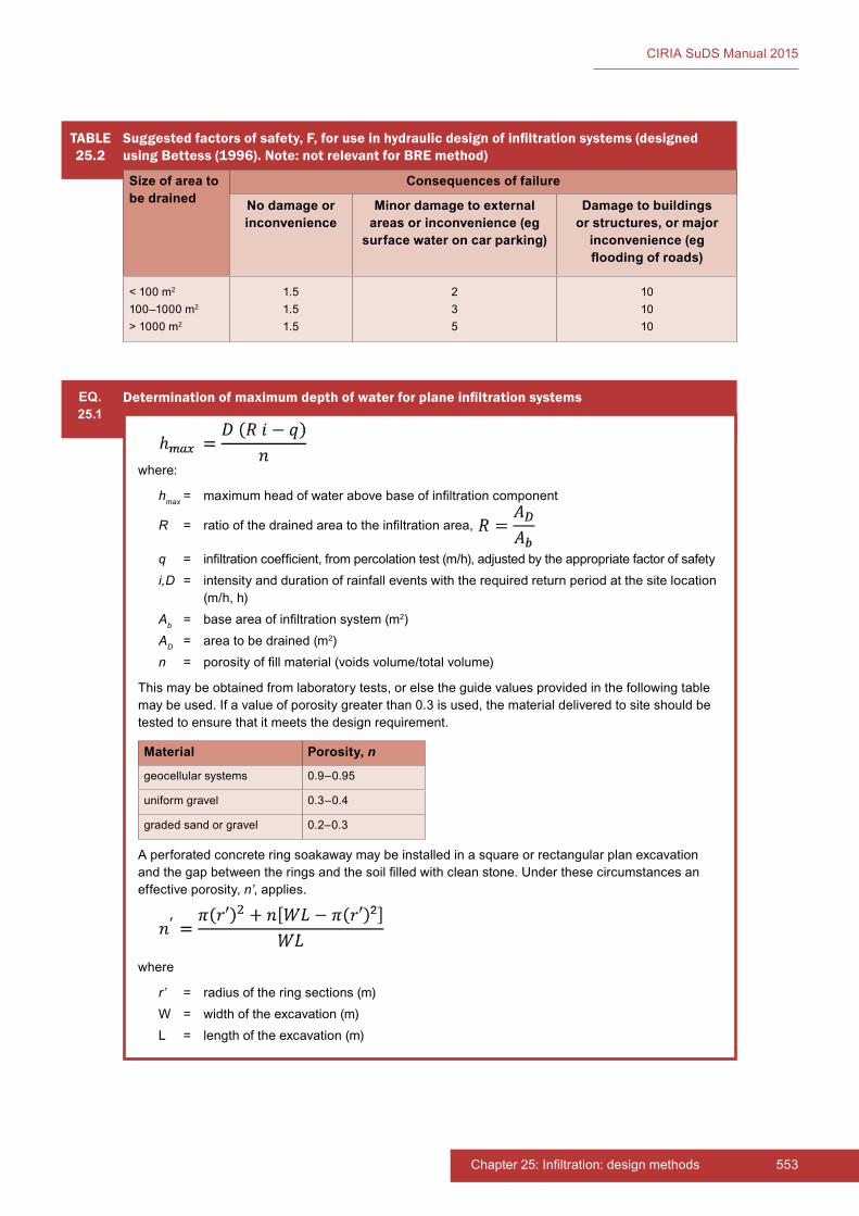
553Chapter 25: Infiltration: design methods552 Part E: Supporting guidance
CIRIA SuDS Manual 2015
TABLE25.2
Suggested factors of safety, F, for use in hydraulic design of infiltration systems (designed using Bettess (1996). Note: not relevant for BRE method)
Size of area to be drained
Consequences of failure
No damage or inconvenience
Minor damage to external areas or inconvenience (eg
surface water on car parking)
Damage to buildings or structures, or major
inconvenience (eg flooding of roads)
< 100 m2
100–1000 m2
> 1000 m2
1.51.51.5
235
101010
EQ.25.1
Determination of maximum depth of water for plane infiltration systems
where:
hmax = maximum head of water above base of infiltration component
R = ratio of the drained area to the infiltration area,
q = infiltration coefficient, from percolation test (m/h), adjusted by the appropriate factor of safetyi,D = intensity and duration of rainfall events with the required return period at the site location
(m/h, h)Ab = base area of infiltration system (m2)AD = area to be drained (m2)n = porosity of fill material (voids volume/total volume)
This may be obtained from laboratory tests, or else the guide values provided in the following table may be used. If a value of porosity greater than 0.3 is used, the material delivered to site should be tested to ensure that it meets the design requirement.
Material Porosity, n
geocellular systems 0.9–0.95
uniform gravel 0.3–0.4
graded sand or gravel 0.2–0.3
A perforated concrete ring soakaway may be installed in a square or rectangular plan excavation and the gap between the rings and the soil filled with clean stone. Under these circumstances an effective porosity, n’, applies.
where
r’ = radius of the ring sections (m)W = width of the excavation (m)L = length of the excavation (m)
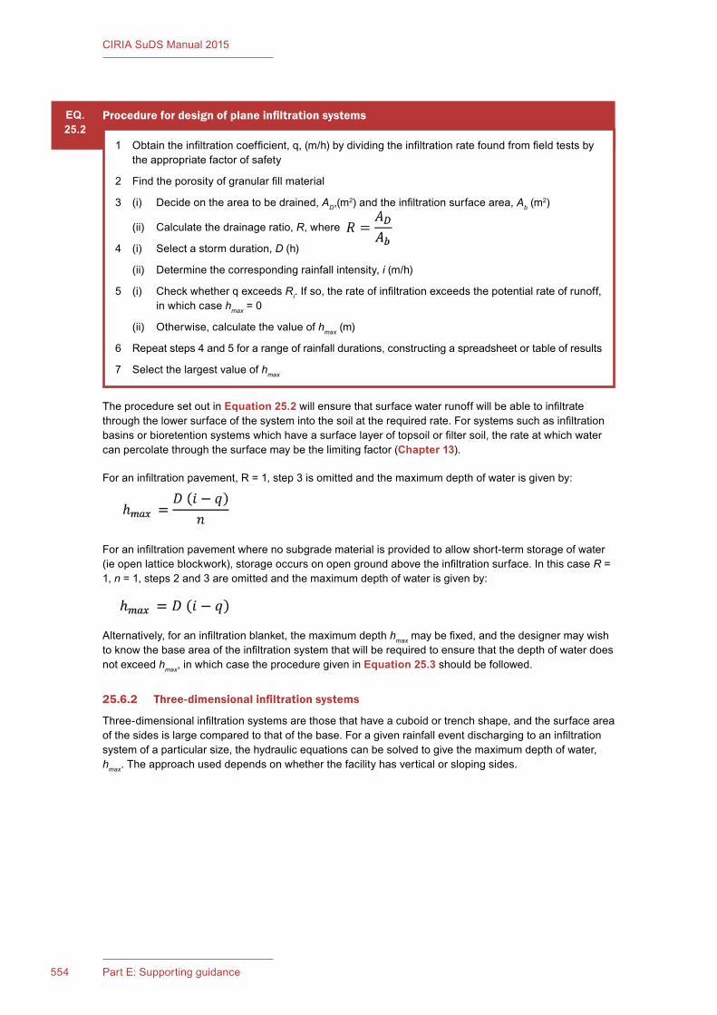
555Chapter 25: Infiltration: design methods554 Part E: Supporting guidance
CIRIA SuDS Manual 2015
The procedure set out in Equation 25.2 will ensure that surface water runoff will be able to infiltrate through the lower surface of the system into the soil at the required rate. For systems such as infiltration basins or bioretention systems which have a surface layer of topsoil or filter soil, the rate at which water can percolate through the surface may be the limiting factor (Chapter 13).
For an infiltration pavement, R = 1, step 3 is omitted and the maximum depth of water is given by:
For an infiltration pavement where no subgrade material is provided to allow short-term storage of water (ie open lattice blockwork), storage occurs on open ground above the infiltration surface. In this case R = 1, n = 1, steps 2 and 3 are omitted and the maximum depth of water is given by:
Alternatively, for an infiltration blanket, the maximum depth hmax may be fixed, and the designer may wish to know the base area of the infiltration system that will be required to ensure that the depth of water does not exceed hmax, in which case the procedure given in Equation 25.3 should be followed.
25.6.2 Three-dimensional infiltration systems
Three-dimensional infiltration systems are those that have a cuboid or trench shape, and the surface area of the sides is large compared to that of the base. For a given rainfall event discharging to an infiltration system of a particular size, the hydraulic equations can be solved to give the maximum depth of water, hmax. The approach used depends on whether the facility has vertical or sloping sides.
EQ.25.2
Procedure for design of plane infiltration systems
1 Obtain the infiltration coefficient, q, (m/h) by dividing the infiltration rate found from field tests by the appropriate factor of safety
2 Find the porosity of granular fill material
3 (i) Decide on the area to be drained, AD,(m2) and the infiltration surface area, Ab (m2)
(ii) Calculate the drainage ratio, R, where
4 (i) Select a storm duration, D (h)
(ii) Determine the corresponding rainfall intensity, i (m/h)
5 (i) Check whether q exceeds Ri. If so, the rate of infiltration exceeds the potential rate of runoff, in which case hmax = 0
(ii) Otherwise, calculate the value of hmax (m)
6 Repeat steps 4 and 5 for a range of rainfall durations, constructing a spreadsheet or table of results
7 Select the largest value of hmax
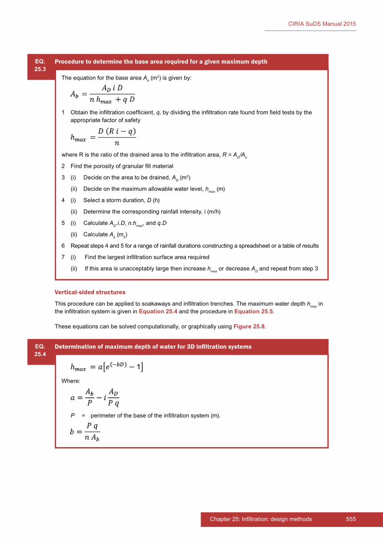
555Chapter 25: Infiltration: design methods554 Part E: Supporting guidance
CIRIA SuDS Manual 2015
Vertical-sided structures
This procedure can be applied to soakaways and infiltration trenches. The maximum water depth hmax in the infiltration system is given in Equation 25.4 and the procedure in Equation 25.5.
These equations can be solved computationally, or graphically using Figure 25.8.
EQ.25.3
Procedure to determine the base area required for a given maximum depth
The equation for the base area Ab (m2) is given by:
1 Obtain the infiltration coefficient, q, by dividing the infiltration rate found from field tests by the appropriate factor of safety
where R is the ratio of the drained area to the infiltration area, R = AD/Ab
2 Find the porosity of granular fill material
3 (i) Decide on the area to be drained, AD (m2)
(ii) Decide on the maximum allowable water level, hmax (m)
4 (i) Select a storm duration, D (h)
(ii) Determine the corresponding rainfall intensity, i (m/h)
5 (i) Calculate AD.i.D, n.hmax, and q.D
(ii) Calculate Ab (m2)
6 Repeat steps 4 and 5 for a range of rainfall durations constructing a spreadsheet or a table of results
7 (i) Find the largest infiltration surface area required
(ii) If this area is unacceptably large then increase hmax or decrease AD and repeat from step 3
EQ.25.4
Determination of maximum depth of water for 3D infiltration systems
Where:
P = perimeter of the base of the infiltration system (m).
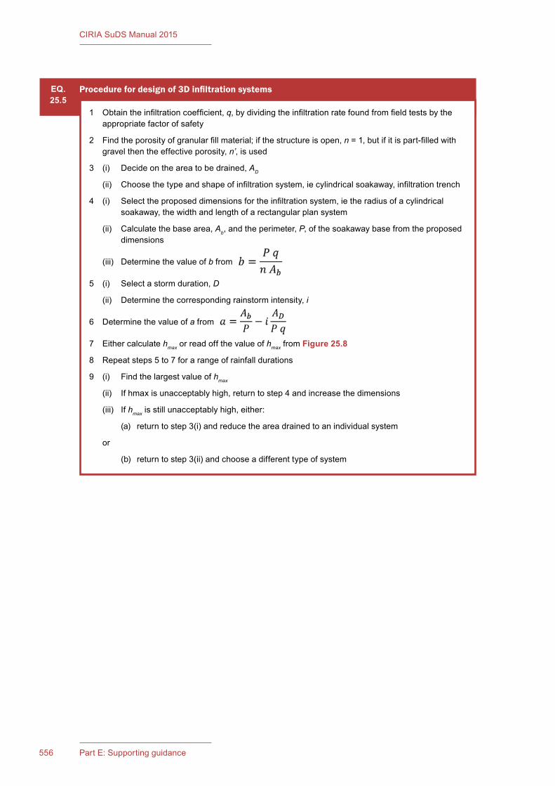
557Chapter 25: Infiltration: design methods556 Part E: Supporting guidance
CIRIA SuDS Manual 2015
EQ.25.5
Procedure for design of 3D infiltration systems
1 Obtain the infiltration coefficient, q, by dividing the infiltration rate found from field tests by the appropriate factor of safety
2 Find the porosity of granular fill material; if the structure is open, n = 1, but if it is part-filled with gravel then the effective porosity, n’, is used
3 (i) Decide on the area to be drained, AD
(ii) Choose the type and shape of infiltration system, ie cylindrical soakaway, infiltration trench
4 (i) Select the proposed dimensions for the infiltration system, ie the radius of a cylindrical soakaway, the width and length of a rectangular plan system
(ii) Calculate the base area, Ab, and the perimeter, P, of the soakaway base from the proposed dimensions
(iii) Determine the value of b from
5 (i) Select a storm duration, D
(ii) Determine the corresponding rainstorm intensity, i
6 Determine the value of a from
7 Either calculate hmax or read off the value of hmax from Figure 25.8
8 Repeat steps 5 to 7 for a range of rainfall durations
9 (i) Find the largest value of hmax
(ii) If hmax is unacceptably high, return to step 4 and increase the dimensions
(iii) If hmax is still unacceptably high, either:
(a) return to step 3(i) and reduce the area drained to an individual system
or
(b) return to step 3(ii) and choose a different type of system
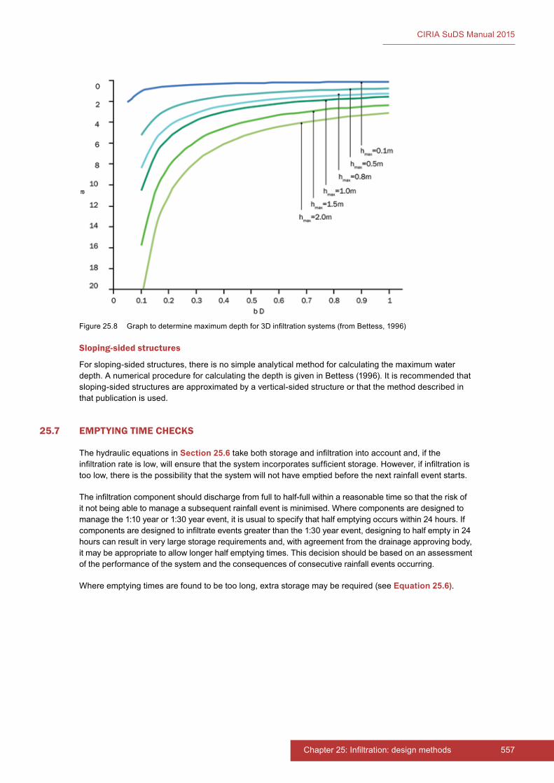
557Chapter 25: Infiltration: design methods556 Part E: Supporting guidance
CIRIA SuDS Manual 2015
Sloping-sided structures
For sloping-sided structures, there is no simple analytical method for calculating the maximum water depth. A numerical procedure for calculating the depth is given in Bettess (1996). It is recommended that sloping-sided structures are approximated by a vertical-sided structure or that the method described in that publication is used.
25.7 EMPTYING TIME CHECKS
The hydraulic equations in Section 25.6 take both storage and infiltration into account and, if the infiltration rate is low, will ensure that the system incorporates sufficient storage. However, if infiltration is too low, there is the possibility that the system will not have emptied before the next rainfall event starts.
The infiltration component should discharge from full to half-full within a reasonable time so that the risk of it not being able to manage a subsequent rainfall event is minimised. Where components are designed to manage the 1:10 year or 1:30 year event, it is usual to specify that half emptying occurs within 24 hours. If components are designed to infiltrate events greater than the 1:30 year event, designing to half empty in 24 hours can result in very large storage requirements and, with agreement from the drainage approving body, it may be appropriate to allow longer half emptying times. This decision should be based on an assessment of the performance of the system and the consequences of consecutive rainfall events occurring.
Where emptying times are found to be too long, extra storage may be required (see Equation 25.6).
Figure 25.8 Graph to determine maximum depth for 3D infiltration systems (from Bettess, 1996)
559Chapter 25: Infiltration: design methods558 Part E: Supporting guidance
CIRIA SuDS Manual 2015
25.8 REFERENCES
BETTESS, R (1996) Infiltration drainage – manual of good practice, R156, CIRIA, London, UK (ISBN: 978-0-86017-457-8). Go to: www.ciria.org
BGS (2015) Infiltration SuDS maps, British Geological Society, London, UK. Go to: http://tinyurl.com/oruu25r
BLAKE, J (2010) “Adjusting soil infiltration coefficients for groundwater level”, Proceedings of the ICE – Water Management, vol 163, 5, Institution of Civil Engineers, London, UK, pp 239–245
BRE (1991) Soakaway design, BRE Digest 365, Building Research Establishment, Bracknell, UK (ISBN: 0-85125-502-7)
CHEN, H, STEVENSON, M and LI, C (2008) “Assessment of existing soakaways for reuse”, Proceedings of the ICE – Water Management, vol 161, 3, Institution of Civil Engineers, London, UK, pp 141–149
LANDIS (2015) Tools and utilities: Soil texture triangle, LandIS, Cranfield University, Cranfield, UK. Go to: www.landis.org.uk/services/tools.cfm
SUSDRAIN (fact sheets): http://www.susdrain.org/resources/factsheets.html
WATKINS, D (1995) Infiltration drainage – literature review, PR21, CIRIA, London, UK (ISBN: 978-0-86017-821-7). Go to: www.ciria.org
WILSON, S and DEROSA, D (2006) “Siltation in SUDS – myth and reality”. In: Proc CIWEM WaPUG 2006, spring conference, Coventry, UK. Go to: http://tinyurl.com/o62fpgh
EQ.25.6
Equations to calculate the time to empty an infiltration system
1 Time for half-emptying a plane infiltration system:
If the time for half-emptying is stipulated to be less than 24 hours and q is measured in m/h, then an acceptable infiltration coefficient is determined by:
2 Time for half-emptying a 3D infiltration system.
If the time for half-emptying is stipulated to be less than 24 hours and q is measured in m/h, then an acceptable infiltration coefficient is given by:

559Chapter 25: Infiltration: design methods558 Part E: Supporting guidance
CIRIA SuDS Manual 2015
STATUTES
British Standards
BS EN ISO 14688-1:2002+A1:2013 Geotechnical investigation and testing – identification and classification of soil. Part 1: identification and description
BS EN ISO 14689-1:2003 Geotechnical investigation and testing. Identification and classification of rock. Part 1: Identification and description
BS EN ISO 22282-2:2012 Geotechnical investigation and testing. Geohydraulic testing. Water permeability tests in a borehole using open systems
CIRIA SuDS Manual 2015
560 Part E: Supporting guidance
26 WATER QUALITY MANAGEMENT: DESIGN METHODS
Contents
26.1 Introduction 56126.2 Protecting surface waters 56126.3 Protecting groundwater 56226.4 The level of pollution in surface water runoff 56326.5 Treatment processes within SuDS 56326.6 Evidence relating to managing water quality risks 56326.7 Methods for managing pollution risks 56526.8 Designing a treatment system using a SuDS Management Train 57426.9 References 576Annex 1 Contaminants in urban runoff and their potential toxicity 579Annex 2 Types of pollutant removal mechanisms in SuDS 585Annex 3 SuDS performance data 587Annex 4 Groundwater protection evidence 589Annex 5 Ellis et al, 2012 591
Imag
e co
urte
sy H
R W
allin
gfor
d

561Chapter 26: Water quality management
CIRIA SuDS Manual 2015
26Chapter
26.1 INTRODUCTION
Managing the quality of surface water runoff so that receiving surface waters and/or groundwater are protected is strongly linked to the hydraulic control of runoff. For the majority of cases, with well-designed SuDS, treatment and pollution removal can be delivered cost-effectively hand in hand with conveyance, attenuation and infiltration, particularly within vegetated surface-based systems.
Any SuDS component should be designed according to the guidance set out in the technical component chapters of this manual (Chapters 11–23), to ensure that treatment processes are effective.
26.2 PROTECTING SURFACE WATERS
Wherever possible, when discharging runoff from the site to surface waters, SuDS should be designed to intercept (ie prevent) runoff (and the associated pollutants) for most rainfall events up to approximately 5 mm in depth (see water quality standard 1 in Chapter 4).
When runoff does occur, treatment within SuDS components is essential for frequent rainfall events, for example up to about a 1:1 year return period event, where urban contaminants are being mobilised and washed off urban surfaces, and the aggregated contribution to the total pollutant load to the receiving surface water body is potentially high.
For rainfall events greater than approximately the 1:1 year event, it is likely that the dilution available in receiving surface waters will be significant, and environmental risks will be reduced, which means that SuDS treatment processes become less crucial. It may, therefore, be efficient to spill higher flow events from the main on-line treatment components into larger off-line conveyance and attenuation systems.
Water quality management: design methodsThis chapter provides guidance on the methods that should be used to design SuDS to meet the water quality design criteria and good practice design standards. This includes: the types of contaminants found in urban runoff; the treatment processes within SuDS components and the performance of different types of SuDS components; methods for evaluating the pollution hazard from different types of land use and the level of treatment required; designing a treatment system using the SuDS Management Train approach.
Water quality design criteria are set out in Chapter 4.
Guidance on component sizing for water quantity and water quality management is provided in Chapters 11–23.
Chapter 24 provides guidance on sizing storage and conveyance systems to deliver the water quantity design criteria.
Chapter 25 includes further guidance on the suitability of using infiltration to dispose of surface water runoff.

CIRIA SuDS Manual 2015
562 Part E: Supporting guidance
It is important that the SuDS design seeks to minimise the risk of remobilisation and washout of any pollutants that have been captured by the system during events larger than those for which the treatment system has been designed.
26.3 PROTECTING GROUNDWATER
The requirement for groundwater pollution risk management varies in different countries of the UK owing to different environmental regulators.
In England and Wales, the requirement for groundwater pollution risk management needs to be considered for all scales of runoff event, that is, for both:
▪ Interception of runoff (ie storing runoff in the upper soil layers of SuDS components from where small amounts of water may infiltrate, but where the component is designed as a storage or conveyance system rather than an infiltration system), and
▪ infiltrating significant volumes of runoff into the ground.
Advice on groundwater protection for England and Wales is provided in GP3 (Environment Agency, 2013).
In Scotland and Northern Ireland, groundwater pollution risk management is only required for SuDS components designed specifically for infiltration (eg soakaways, infiltration trenches or infiltration basins).
Advice on groundwater protection for Scotland and Northern Ireland is set out in SEPA (2009) and EHS (2001) respectively.
At the time of writing, the way in which Northern Ireland’s groundwater protection policy is applied and integrated into SuDS policy development is under consideration, and the guidance in this manual should therefore be considered interim, until Northern Ireland specific policy is available.
The risk posed by surface water runoff to groundwater is often low because of the protection afforded by the layers of unsaturated soils that lie between the infiltration surface and the groundwater receptor. The effectiveness of the protection will depend on:
▪ the depth of the groundwater: a greater depth of unsaturated soil will tend to provide greater protection
▪ the predominant flow type, that is whether the flow occurs between soil grains (intergranular flow) or through larger channels (fracture flow): intergranular flow will tend to provide greater protection
▪ the soil characteristics: those with significant clay mineral and organic content have been demonstrated to offer increased potential for beneficial contaminant attenuation; similarly soil pH affects the mobility of contaminants, low pH soils being generally associated with more mobile contaminants.
The risk will also be dependent on:
▪ the runoff pollutants, their concentrations and how readily they can be degraded
▪ the volume of water infiltrated into the ground
▪ the length of time over which contaminants accumulate.
These factors will dictate the loading of contaminants on the soil, the rate of build-up, the capacity of the soil to retain pollutants and the point at which pollutants are likely to migrate to the groundwater.
Where the risks to groundwater are considered to be unacceptable, upstream (lined) SuDS components can often be used to reduce pollutant levels. If the risk is still considered unacceptable, infiltration should be prevented.
563Chapter 26: Water quality management
CIRIA SuDS Manual 2015
26.4 THE LEVEL OF POLLUTION IN SURFACE WATER RUNOFF
Evidence showing the extent to which surface water runoff is likely to be contaminated is summarised in Annex 1 – presented as a series of tables for selected pollutants. The tables include relevant environmental standards in an attempt to evaluate the likely significance of the measured pollutant concentrations (EA, 2014).
Although there is significant variability in the data presented, the data (particularly that from the UK) shows that surface water runoff from urban areas is polluted and demonstrates the potential need for pollutant levels to be reduced in order to meet environmentally acceptable levels.
26.5 TREATMENT PROCESSES WITHIN SUDS
There are a range of water quality treatment processes that can be exploited within the design of a sustainable drainage system – for example, sedimentation, filtration and biofiltration, separation, adsorption, biodegradation, volatilisation, precipitation, hydrolysis, oxidation, reduction and substitution, plant uptake and photolysis. These are presented in Annex 2.
Treatment effectiveness is strongly linked to the hydraulic control of runoff, in particular:
▪ velocity control: sediment deposition, filtration and other removal processes occurring at low flow velocities during regular rainfall events (ie through the control of velocities in SuDS components during frequent events, such as up to approximately the 1:1 year return period event)
▪ retention time: the removal of contaminants through settling, adsorption and other removal processes occurring (for events up to approximately the 1:1 year return period) over the period of time that the runoff is in contact with SuDS treatment media (eg the surface of a swale, the filtration media within a bioretention system) or held within a permanent water storage volume (eg pond).
It is also heavily dependent on the characteristics of any media through which the runoff filters.
26.6 EVIDENCE RELATING TO MANAGING WATER QUALITY RISKS
26.6.1 The capability of SuDS to reduce pollution levels
A relatively small number of monitoring studies of SuDS performance have been undertaken in the UK, but those that do exist confirm the benefit of SuDS in reducing levels of contamination in surface water runoff (Royal Haskoning, 2012, Woods Ballard et al, 2005, Jefferies, 2004, Jefferies and Napier, 2008, and Jefferies et al, 2008).
Further guidance can be found at http://sudsnet.abertay.ac.uk/downloads.htm
The limited number of studies together with the lack of a consistent monitoring specification between studies mean that these datasets cannot be used alone to derive generic performance levels of different SuDS components. However, the stormwater BMP database <www.bmpdatabase.org> developed in the USA has grown to over 530 monitoring sites and has resulted in improved understanding of component performance in reducing contaminant concentrations to levels that should not pose a risk to the receiving environment (Leisenring et al, 2014). Recently, the project has also been extended to analyse performance of “manufactured devices”. This concluded that performance levels can be comparable with vegetated components, but that manufactured devices only remove the pollutants for which they are designed, for their specified range of design flows. For example, sediment and particulate-bound pollutants may be removed by sedimentation, but dissolved constituents may require adsorptive filtration or some type of biochemical process to be removed effectively. It should be noted that SuDS performance is generally observed in terms of inflow and outflow concentrations of surface flows, rather than concentrations in underlying soil moisture or groundwater.
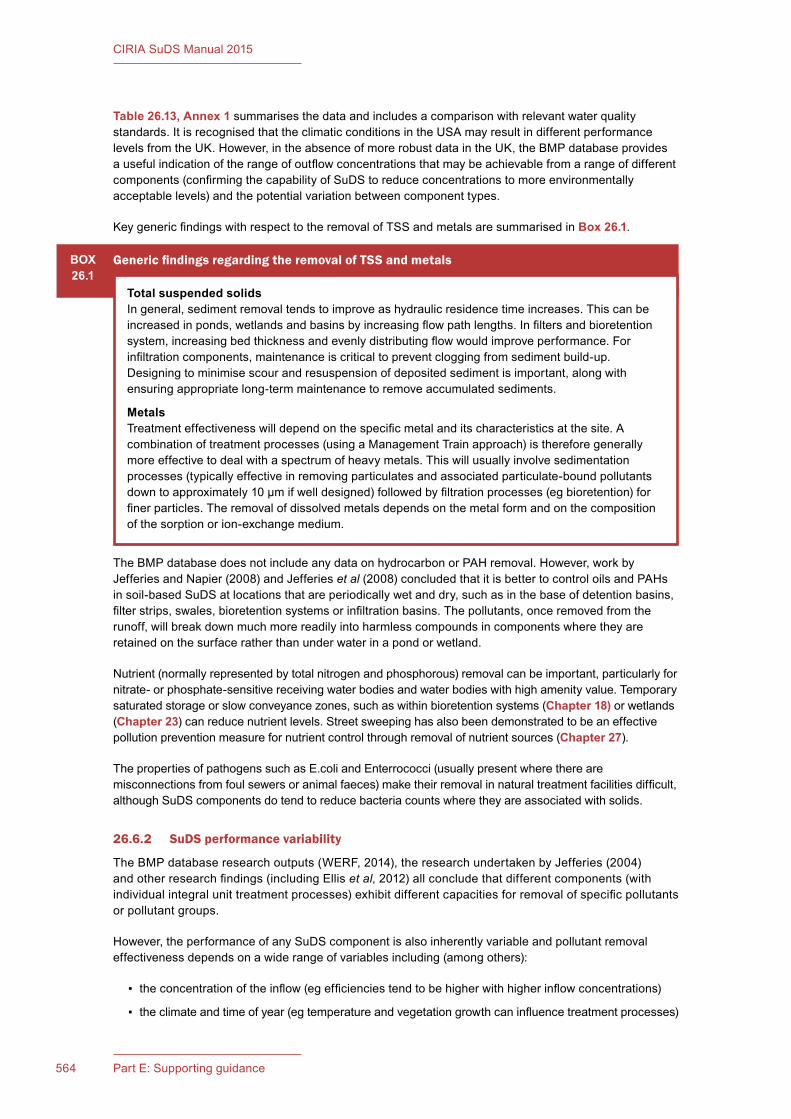
CIRIA SuDS Manual 2015
564 Part E: Supporting guidance
Table 26.13, Annex 1 summarises the data and includes a comparison with relevant water quality standards. It is recognised that the climatic conditions in the USA may result in different performance levels from the UK. However, in the absence of more robust data in the UK, the BMP database provides a useful indication of the range of outflow concentrations that may be achievable from a range of different components (confirming the capability of SuDS to reduce concentrations to more environmentally acceptable levels) and the potential variation between component types.
Key generic findings with respect to the removal of TSS and metals are summarised in Box 26.1.
BOX26.1
Generic findings regarding the removal of TSS and metals
Total suspended solidsIn general, sediment removal tends to improve as hydraulic residence time increases. This can be increased in ponds, wetlands and basins by increasing flow path lengths. In filters and bioretention system, increasing bed thickness and evenly distributing flow would improve performance. For infiltration components, maintenance is critical to prevent clogging from sediment build-up. Designing to minimise scour and resuspension of deposited sediment is important, along with ensuring appropriate long-term maintenance to remove accumulated sediments.
MetalsTreatment effectiveness will depend on the specific metal and its characteristics at the site. A combination of treatment processes (using a Management Train approach) is therefore generally more effective to deal with a spectrum of heavy metals. This will usually involve sedimentation processes (typically effective in removing particulates and associated particulate-bound pollutants down to approximately 10 µm if well designed) followed by filtration processes (eg bioretention) for finer particles. The removal of dissolved metals depends on the metal form and on the composition of the sorption or ion-exchange medium.
The BMP database does not include any data on hydrocarbon or PAH removal. However, work by Jefferies and Napier (2008) and Jefferies et al (2008) concluded that it is better to control oils and PAHs in soil-based SuDS at locations that are periodically wet and dry, such as in the base of detention basins, filter strips, swales, bioretention systems or infiltration basins. The pollutants, once removed from the runoff, will break down much more readily into harmless compounds in components where they are retained on the surface rather than under water in a pond or wetland.
Nutrient (normally represented by total nitrogen and phosphorous) removal can be important, particularly for nitrate- or phosphate-sensitive receiving water bodies and water bodies with high amenity value. Temporary saturated storage or slow conveyance zones, such as within bioretention systems (Chapter 18) or wetlands (Chapter 23) can reduce nutrient levels. Street sweeping has also been demonstrated to be an effective pollution prevention measure for nutrient control through removal of nutrient sources (Chapter 27).
The properties of pathogens such as E.coli and Enterrococci (usually present where there are misconnections from foul sewers or animal faeces) make their removal in natural treatment facilities difficult, although SuDS components do tend to reduce bacteria counts where they are associated with solids.
26.6.2 SuDS performance variability
The BMP database research outputs (WERF, 2014), the research undertaken by Jefferies (2004) and other research findings (including Ellis et al, 2012) all conclude that different components (with individual integral unit treatment processes) exhibit different capacities for removal of specific pollutants or pollutant groups.
However, the performance of any SuDS component is also inherently variable and pollutant removal effectiveness depends on a wide range of variables including (among others):
▪ the concentration of the inflow (eg efficiencies tend to be higher with higher inflow concentrations)
▪ the climate and time of year (eg temperature and vegetation growth can influence treatment processes)
565Chapter 26: Water quality management
CIRIA SuDS Manual 2015
▪ the condition of the component (eg recent maintenance activities and prior frequency of maintenance could influence removal rates)
▪ the design characteristics of the particular component (eg slopes, flow paths, retention times)
▪ the rainfall intensity and duration of any particular event (which will influence flow velocities, scour rates etc).
26.6.3 Groundwater protection
The conclusions of two studies into the extent to which surface water runoff may pose a risk to groundwater are presented in Annex 4. Overall conclusions can be summarised as follows:
▪ The overall risk to groundwater through porous media from the key contaminants associated with highway runoff is low.
▪ The presence of organic matter within the topsoil and underlying soils of surface-based infiltration systems, along with the opportunity for microbial mediated degradation of the PAH and TPH content of highway runoff through a sufficient depth of unsaturated zone, provides a significant degree of protection of underlying groundwater.
▪ The vast majority of heavy metals, PAHs and TPHs are retained in the top 10 cm of soil. An overlying vegetative layer will further reduce the risk of their movement to groundwater.
▪ Repeated delivery of contaminant mass over an extended period of time to an area (or volume) of unsaturated zone will eventually lead to the sorption properties of the material being exhausted. Ultimately, in the case of conservative pollutants such as metals, the soil column under the infiltration area will become saturated and breakthrough to groundwater will occur. The surface area and geometry of the infiltration system are therefore important for reducing risks, together with appropriate monitoring and maintenance programmes. Research presented in Scott Wilson (2010) suggests that, for typical highway loadings, cadmium (as an example) took between 54 and 714 years to move through 1 m of different types of unsaturated aquifer material. It is therefore considered unlikely that soil removal and component rehabilitation would be required during the design life of the system for lower hazard sites.
▪ Source control measures such as grass filter strips, swales and detention areas should be priority features of SuDS networks serving urbanised networks and highways, where oil contamination may be significant (Jefferies and Napier, 2008, and Jefferies et al, 2008).
26.7 METHODS FOR MANAGING POLLUTION RISKS
The risk posed by surface water runoff to the receiving environment is a function of:
▪ the pollution hazard at a particular site (ie the pollutant source)
▪ the effectiveness of SuDS treatment components in reducing levels of pollutants to environmentally acceptable levels, and/or the effectiveness of underlying soil layers in protecting the receiving groundwater (ie the pollutant pathway)
▪ the sensitivity of the receiving environment (ie the environmental receptor).
Land use is the primary influencing factor in the quality of urban surface water runoff (Royal Haskoning, 2010) and can therefore be used to represent the likely significance of the expected pollutant concentrations and loadings generated during rainfall events (ie the pollution hazard posed by the site).
Determining the hazard posed by the land use activities at a site and the extent to which underlying soil layers and/or proposed treatment components reduce the associated risk can be done using a variety of methods that vary in complexity and data requirements. The different generic methods can be summarised as:
▪ simple qualitative methods (using indices of likely pollution levels and SuDS performance capacities)
▪ established risk screening methods
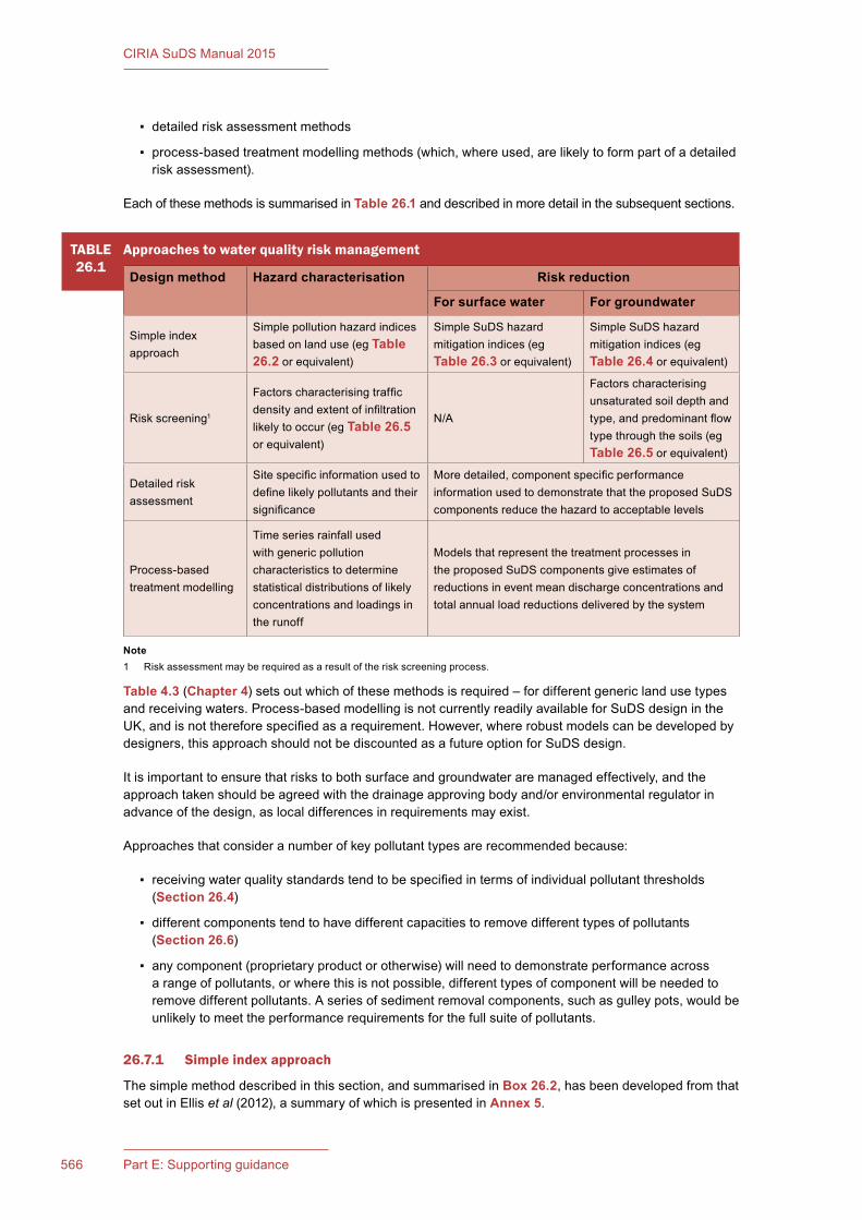
CIRIA SuDS Manual 2015
566 Part E: Supporting guidance
▪ detailed risk assessment methods
▪ process-based treatment modelling methods (which, where used, are likely to form part of a detailed risk assessment).
Each of these methods is summarised in Table 26.1 and described in more detail in the subsequent sections.
Table 4.3 (Chapter 4) sets out which of these methods is required – for different generic land use types and receiving waters. Process-based modelling is not currently readily available for SuDS design in the UK, and is not therefore specified as a requirement. However, where robust models can be developed by designers, this approach should not be discounted as a future option for SuDS design.
It is important to ensure that risks to both surface and groundwater are managed effectively, and the approach taken should be agreed with the drainage approving body and/or environmental regulator in advance of the design, as local differences in requirements may exist.
Approaches that consider a number of key pollutant types are recommended because:
▪ receiving water quality standards tend to be specified in terms of individual pollutant thresholds (Section 26.4)
▪ different components tend to have different capacities to remove different types of pollutants (Section 26.6)
▪ any component (proprietary product or otherwise) will need to demonstrate performance across a range of pollutants, or where this is not possible, different types of component will be needed to remove different pollutants. A series of sediment removal components, such as gulley pots, would be unlikely to meet the performance requirements for the full suite of pollutants.
26.7.1 Simple index approach
The simple method described in this section, and summarised in Box 26.2, has been developed from that set out in Ellis et al (2012), a summary of which is presented in Annex 5.
TABLE26.1
Approaches to water quality risk management
Design method Hazard characterisation Risk reduction
For surface water For groundwater
Simple index approach
Simple pollution hazard indices based on land use (eg Table 26.2 or equivalent)
Simple SuDS hazard mitigation indices (eg Table 26.3 or equivalent)
Simple SuDS hazard mitigation indices (eg Table 26.4 or equivalent)
Risk screening1
Factors characterising traffic density and extent of infiltration likely to occur (eg Table 26.5 or equivalent)
N/A
Factors characterising unsaturated soil depth and type, and predominant flow type through the soils (eg Table 26.5 or equivalent)
Detailed risk assessment
Site specific information used to define likely pollutants and their significance
More detailed, component specific performance information used to demonstrate that the proposed SuDS components reduce the hazard to acceptable levels
Process-based treatment modelling
Time series rainfall used with generic pollution characteristics to determine statistical distributions of likely concentrations and loadings in the runoff
Models that represent the treatment processes in the proposed SuDS components give estimates of reductions in event mean discharge concentrations and total annual load reductions delivered by the system
Note1 Risk assessment may be required as a result of the risk screening process.
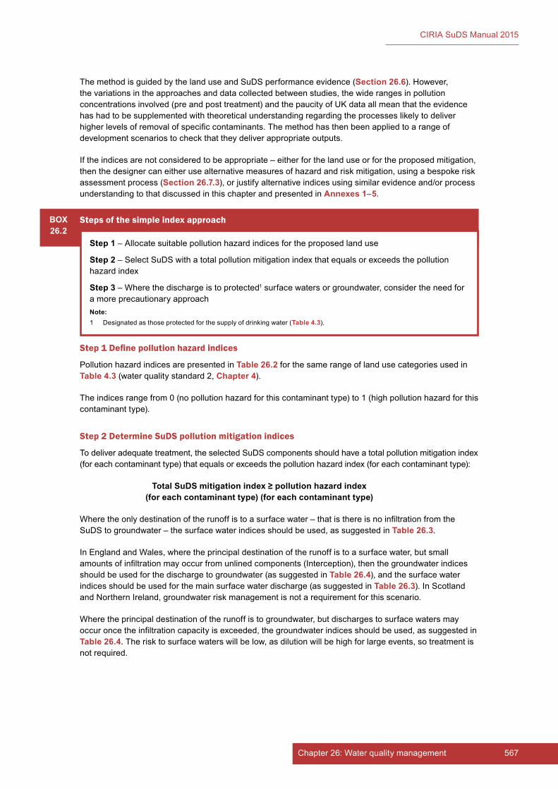
567Chapter 26: Water quality management
CIRIA SuDS Manual 2015
The method is guided by the land use and SuDS performance evidence (Section 26.6). However, the variations in the approaches and data collected between studies, the wide ranges in pollution concentrations involved (pre and post treatment) and the paucity of UK data all mean that the evidence has had to be supplemented with theoretical understanding regarding the processes likely to deliver higher levels of removal of specific contaminants. The method has then been applied to a range of development scenarios to check that they deliver appropriate outputs.
If the indices are not considered to be appropriate – either for the land use or for the proposed mitigation, then the designer can either use alternative measures of hazard and risk mitigation, using a bespoke risk assessment process (Section 26.7.3), or justify alternative indices using similar evidence and/or process understanding to that discussed in this chapter and presented in Annexes 1–5.
BOX26.2
Steps of the simple index approach
Step 1 – Allocate suitable pollution hazard indices for the proposed land use
Step 2 – Select SuDS with a total pollution mitigation index that equals or exceeds the pollution hazard index
Step 3 – Where the discharge is to protected1 surface waters or groundwater, consider the need for a more precautionary approachNote:1 Designated as those protected for the supply of drinking water (Table 4.3).
Step 1 Define pollution hazard indices
Pollution hazard indices are presented in Table 26.2 for the same range of land use categories used in Table 4.3 (water quality standard 2, Chapter 4).
The indices range from 0 (no pollution hazard for this contaminant type) to 1 (high pollution hazard for this contaminant type).
Step 2 Determine SuDS pollution mitigation indices
To deliver adequate treatment, the selected SuDS components should have a total pollution mitigation index (for each contaminant type) that equals or exceeds the pollution hazard index (for each contaminant type):
Total SuDS mitigation index ≥ pollution hazard index (for each contaminant type) (for each contaminant type)
Where the only destination of the runoff is to a surface water – that is there is no infiltration from the SuDS to groundwater – the surface water indices should be used, as suggested in Table 26.3.
In England and Wales, where the principal destination of the runoff is to a surface water, but small amounts of infiltration may occur from unlined components (Interception), then the groundwater indices should be used for the discharge to groundwater (as suggested in Table 26.4), and the surface water indices should be used for the main surface water discharge (as suggested in Table 26.3). In Scotland and Northern Ireland, groundwater risk management is not a requirement for this scenario.
Where the principal destination of the runoff is to groundwater, but discharges to surface waters may occur once the infiltration capacity is exceeded, the groundwater indices should be used, as suggested in Table 26.4. The risk to surface waters will be low, as dilution will be high for large events, so treatment is not required.
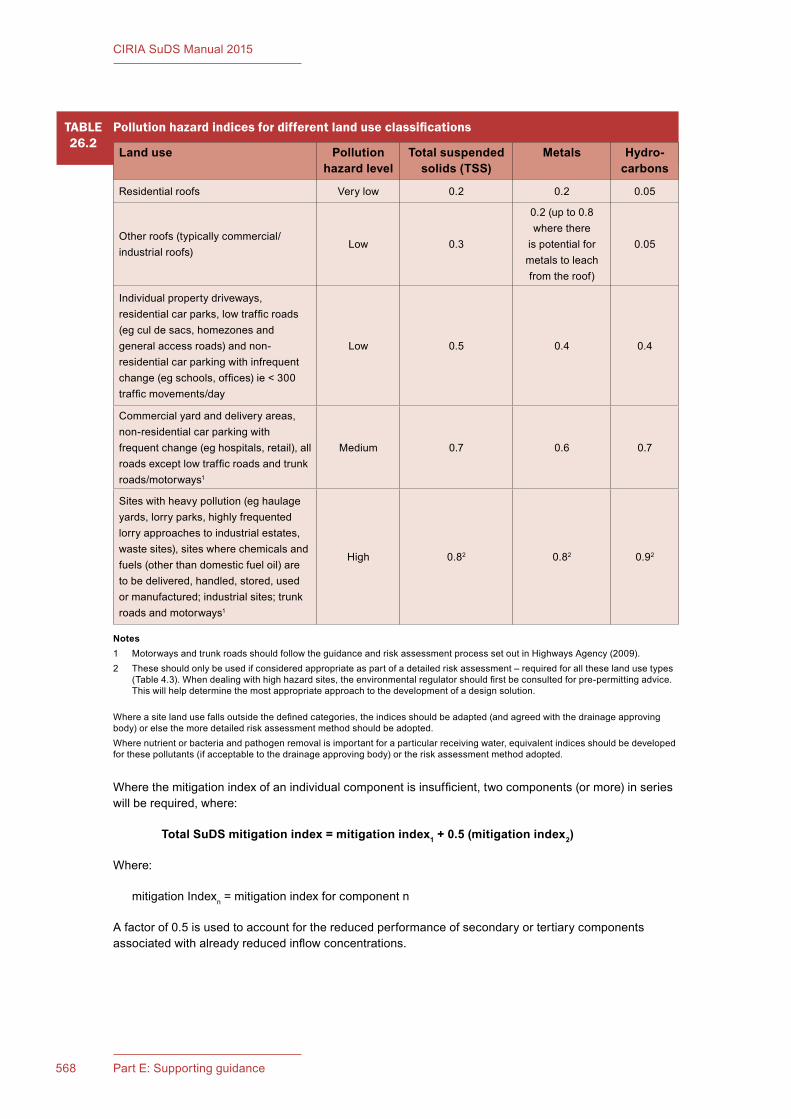
CIRIA SuDS Manual 2015
568 Part E: Supporting guidance
Notes1 Motorways and trunk roads should follow the guidance and risk assessment process set out in Highways Agency (2009).2 These should only be used if considered appropriate as part of a detailed risk assessment – required for all these land use types
(Table 4.3). When dealing with high hazard sites, the environmental regulator should first be consulted for pre-permitting advice. This will help determine the most appropriate approach to the development of a design solution.
Where a site land use falls outside the defined categories, the indices should be adapted (and agreed with the drainage approving body) or else the more detailed risk assessment method should be adopted.Where nutrient or bacteria and pathogen removal is important for a particular receiving water, equivalent indices should be developed for these pollutants (if acceptable to the drainage approving body) or the risk assessment method adopted.
TABLE26.2
Pollution hazard indices for different land use classifications
Land use Pollution hazard level
Total suspended solids (TSS)
Metals Hydro- carbons
Residential roofs Very low 0.2 0.2 0.05
Other roofs (typically commercial/industrial roofs)
Low 0.3
0.2 (up to 0.8 where there
is potential for metals to leach from the roof)
0.05
Individual property driveways, residential car parks, low traffic roads (eg cul de sacs, homezones and general access roads) and non-residential car parking with infrequent change (eg schools, offices) ie < 300 traffic movements/day
Low 0.5 0.4 0.4
Commercial yard and delivery areas, non-residential car parking with frequent change (eg hospitals, retail), all roads except low traffic roads and trunk roads/motorways1
Medium 0.7 0.6 0.7
Sites with heavy pollution (eg haulage yards, lorry parks, highly frequented lorry approaches to industrial estates, waste sites), sites where chemicals and fuels (other than domestic fuel oil) are to be delivered, handled, stored, used or manufactured; industrial sites; trunk roads and motorways1
High 0.82 0.82 0.92
Where the mitigation index of an individual component is insufficient, two components (or more) in series will be required, where:
Total SuDS mitigation index = mitigation index1 + 0.5 (mitigation index2)
Where:
mitigation Indexn = mitigation index for component n
A factor of 0.5 is used to account for the reduced performance of secondary or tertiary components associated with already reduced inflow concentrations.
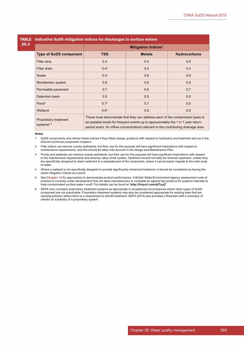
569Chapter 26: Water quality management
CIRIA SuDS Manual 2015
TABLE26.3
Indicative SuDS mitigation indices for discharges to surface waters
Mitigation indices1
Type of SuDS component TSS Metals Hydrocarbons
Filter strip 0.4 0.4 0.5
Filter drain 0.42 0.4 0.4
Swale 0.5 0.6 0.6
Bioretention system 0.8 0.8 0.8
Permeable pavement 0.7 0.6 0.7
Detention basin 0.5 0.5 0.6
Pond4 0.73 0.7 0.5
Wetland 0.83 0.8 0.8
Proprietary treatment systems5,6
These must demonstrate that they can address each of the contaminant types to acceptable levels for frequent events up to approximately the 1 in 1 year return period event, for inflow concentrations relevant to the contributing drainage area.
Notes1 SuDS components only deliver these indices if they follow design guidance with respect to hydraulics and treatment set out in the
relevant technical component chapters.2 Filter drains can remove coarse sediments, but their use for this purpose will have significant implications with respect to
maintenance requirements, and this should be taken into account in the design and Maintenance Plan.3 Ponds and wetlands can remove coarse sediments, but their use for this purpose will have significant implications with respect
to the maintenance requirements and amenity value of the system. Sediment should normally be removed upstream, unless they are specifically designed to retain sediment in a separate part of the component, where it cannot easily migrate to the main body of water.
4 Where a wetland is not specifically designed to provide significantly enhanced treatment, it should be considered as having the same mitigation indices as a pond.
5 See Chapter 14 for approaches to demonstrate product performance. A British Water/Environment Agency assessment code of practice is currently under development that will allow manufacturers to complete an agreed test protocol for systems intended to treat contaminated surface water runoff. Full details can be found at: http://tinyurl.com/qf7yuj7
6 SEPA only considers proprietary treatment systems as appropriate in exceptional circumstances where other types of SuDS component are not practicable. Proprietary treatment systems may also be considered appropriate for existing sites that are causing pollution where there is a requirement to retrofit treatment. SEPA (2014) also provides a flowchart with a summary of checks on suitability of a proprietary system.
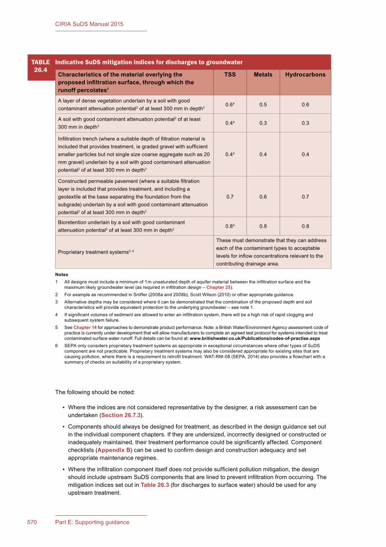
CIRIA SuDS Manual 2015
570 Part E: Supporting guidance
The following should be noted:
▪ Where the indices are not considered representative by the designer, a risk assessment can be undertaken (Section 26.7.3).
▪ Components should always be designed for treatment, as described in the design guidance set out in the individual component chapters. If they are undersized, incorrectly designed or constructed or inadequately maintained, their treatment performance could be significantly affected. Component checklists (Appendix B) can be used to confirm design and construction adequacy and set appropriate maintenance regimes.
▪ Where the infiltration component itself does not provide sufficient pollution mitigation, the design should include upstream SuDS components that are lined to prevent infiltration from occurring. The mitigation indices set out in Table 26.3 (for discharges to surface water) should be used for any upstream treatment.
TABLE26.4
Indicative SuDS mitigation indices for discharges to groundwater
Characteristics of the material overlying the proposed infiltration surface, through which the runoff percolates1
TSS Metals Hydrocarbons
A layer of dense vegetation underlain by a soil with good contaminant attenuation potential2 of at least 300 mm in depth3
0.64 0.5 0.6
A soil with good contaminant attenuation potential2 of at least 300 mm in depth3
0.44 0.3 0.3
Infiltration trench (where a suitable depth of filtration material is included that provides treatment, ie graded gravel with sufficient smaller particles but not single size coarse aggregate such as 20 mm gravel) underlain by a soil with good contaminant attenuation potential2 of at least 300 mm in depth3
0.44 0.4 0.4
Constructed permeable pavement (where a suitable filtration layer is included that provides treatment, and including a geotextile at the base separating the foundation from the subgrade) underlain by a soil with good contaminant attenuation potential2 of at least 300 mm in depth3
0.7 0.6 0.7
Bioretention underlain by a soil with good contaminant attenuation potential2 of at least 300 mm in depth3
0.84 0.8 0.8
Proprietary treatment systems5, 6
These must demonstrate that they can address each of the contaminant types to acceptable levels for inflow concentrations relevant to the contributing drainage area.
Notes1 All designs must include a minimum of 1 m unsaturated depth of aquifer material between the infiltration surface and the
maximum likely groundwater level (as required in infiltration design – Chapter 25).2 For example as recommended in Sniffer (2008a and 2008b), Scott Wilson (2010) or other appropriate guidance.3 Alternative depths may be considered where it can be demonstrated that the combination of the proposed depth and soil
characteristics will provide equivalent protection to the underlying groundwater – see note 1.4 If significant volumes of sediment are allowed to enter an infiltration system, there will be a high risk of rapid clogging and
subsequent system failure.5 See Chapter 14 for approaches to demonstrate product performance. Note: a British Water/Environment Agency assessment code of
practice is currently under development that will allow manufacturers to complete an agreed test protocol for systems intended to treat contaminated surface water runoff. Full details can be found at: www.britishwater.co.uk/Publications/codes-of-practise.aspx
6 SEPA only considers proprietary treatment systems as appropriate in exceptional circumstances where other types of SuDS component are not practicable. Proprietary treatment systems may also be considered appropriate for existing sites that are causing pollution, where there is a requirement to retrofit treatment. WAT-RM-08 (SEPA, 2014) also provides a flowchart with a summary of checks on suitability of a proprietary system.

571Chapter 26: Water quality management
CIRIA SuDS Manual 2015
Step 3 Consider the need for a precautionary approach where discharges are to protected waters
In England and Wales, reference to local planning documents should also be made to identify any additional protection required for sites due to habitat conservation (Chapter 7). The implications of developments on, or in close proximity to, an area with an environmental designation, such as a site of special scientific interest (SSSI), should be considered via consultation with relevant conservation bodies such as Natural England.
In England and Wales, where the discharge is to protected surface waters or groundwater, an additional treatment component (ie over and above that required for standard discharges), or other equivalent protection, is required that provides environmental protection in the event of an unexpected pollution event or poor system performance. Protected surface waters are those designated for drinking water abstraction. In England and Wales, protected groundwater resources are defined as Source Protection Zone 1. In Northern Ireland, a more precautionary approach may be required, and this should be checked with the environmental regulator on a site-by-site basis.
26.7.2 Groundwater risk screening
A risk screening approach is required by the environmental regulators in England and Wales for medium hazard sites (Table 4.3). In Northern Ireland, the environmental regulator should be consulted to determine whether a risk screening approach is required.
The approach allows assessment of scenarios where the infiltration of water from surface runoff may require detailed risk assessment. The risk matrix used in HA (2009b), as updated by Scott Wilson (2010), provides a method for assessing the acceptability of Interception and infiltration SuDS components at a site. The matrix is based on the understanding that the risk posed by the runoff is a function of:
▪ the likely contamination hazard posed by the land use
▪ the amount of water likely to be infiltrated
▪ the attenuation potential of the soil or unsaturated zone for reducing the risk associated with pollutants present in highway runoff that may pose a risk to groundwater.
The matrix from HA (2009b) has been slightly modified here to make it more relevant for general SuDS applications and is presented in Table 26.5. The method requires each risk element (RE) (numbered 1–8 in column 1 and described in column 2) to be assigned a risk score (RS). The risk score will either be low (a score of 1), medium (a score of 2) or high (a score of 3) depending on the site characteristics described in columns 3–5 of the same table. For each risk element (RE), the risk score (RS) is then multiplied by the weighting factor (WF) given in column 6.
The risk scores for each risk element are then added together to give a total risk score for the SuDS component:
Interpretation of the total outcome score is provided in Table 26.6, which guides the designer on the likely acceptability of different design solutions, and appropriate subsequent actions to take.
Where relevant data is not available to the designers, the likely worst-case characteristics should be assumed until suitable investigations have been undertaken.
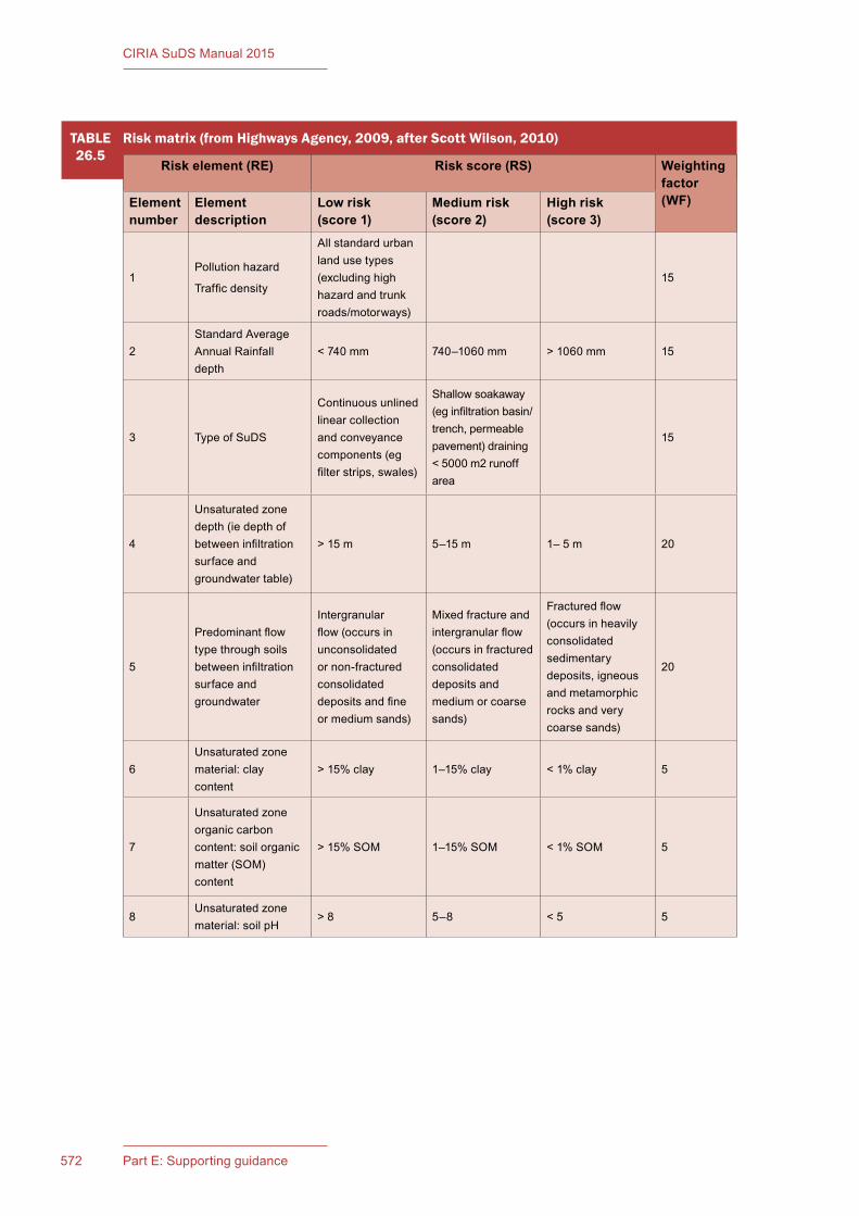
CIRIA SuDS Manual 2015
572 Part E: Supporting guidance
TABLE26.5
Risk matrix (from Highways Agency, 2009, after Scott Wilson, 2010)
Risk element (RE) Risk score (RS) Weighting factor (WF)Element
numberElement description
Low risk (score 1)
Medium risk (score 2)
High risk (score 3)
1Pollution hazard
Traffic density
All standard urban land use types (excluding high hazard and trunk roads/motorways)
15
2Standard Average Annual Rainfall depth
< 740 mm 740–1060 mm > 1060 mm 15
3 Type of SuDS
Continuous unlined linear collection and conveyance components (eg filter strips, swales)
Shallow soakaway (eg infiltration basin/trench, permeable pavement) draining < 5000 m2 runoff area
15
4
Unsaturated zone depth (ie depth of between infiltration surface and groundwater table)
> 15 m 5–15 m 1– 5 m 20
5
Predominant flow type through soils between infiltration surface and groundwater
Intergranular flow (occurs in unconsolidated or non-fractured consolidated deposits and fine or medium sands)
Mixed fracture and intergranular flow (occurs in fractured consolidated deposits and medium or coarse sands)
Fractured flow (occurs in heavily consolidated sedimentary deposits, igneous and metamorphic rocks and very coarse sands)
20
6Unsaturated zone material: clay content
> 15% clay 1–15% clay < 1% clay 5
7
Unsaturated zone organic carbon content: soil organic matter (SOM) content
> 15% SOM 1–15% SOM < 1% SOM 5
8Unsaturated zone material: soil pH
> 8 5–8 < 5 5

573Chapter 26: Water quality management
CIRIA SuDS Manual 2015
26.7.3 Detailed risk assessment
There are situations where a risk assessment method is either required (as defined in water quality standard 2, Table 4.3) or chosen by the designer and/or SuDS approving body as best meeting the needs for designing the appropriate treatment system for the site.
The scale of any risk assessment should be appropriate to the scale of the risk posed by the site: the significance of the potential pollution hazard combined with the sensitivity of the receiving water body. In the situations where the development proposal is heavily influenced by highway traffic in excess of 15,000 AADT, and is not associated with other pollutant sources, an assessment methodology as described in Annex I, Method C of HA (2009b). HA (2009b) or equivalent local authority guidance can be followed and may be required by the drainage approving body. Some guidance on risk assessment for surface water discharges to surface water bodies is set out (for England and Wales) in EA (2014) and (for Scotland) in SEPA (2014). Guidance on risk assessment for discharges of surface water to groundwater is set out (for England and Wales) in EA (2013), for Scotland in SEPA (2009) and for Northern Ireland in EHS (2001).
At the time of writing, the way in which Northern Ireland’s groundwater protection policy is applied and integrated into SuDS policy development is under consideration, and the guidance in this manual should therefore be considered interim until Northern Ireland specific policy is available.
The risk assessment for each outfall or discharge point should:
a) determine and justify the range and likely significance and levels of pollutant(s) that may be washed off the site
b) state the baseline environmental quality, any environmental designations and relevant environmental standards (eg EQSs)
c) in the event of multiple surface water discharges from the same development, take account of any increased risk to the catchment from the cumulative impact of several outfalls
d) determine the scale of the potential risk to groundwater through taking account of the scale of the discharge, the depth of the discharge, the vulnerability of the groundwater body (eg soil and aquifer properties and seasonal variation in depth to water table)
e) determine and justify the effectiveness of the proposed drainage system and/or the unsaturated soil and aquifer layers in reducing the levels of pollutants to acceptable levels, taking account of the inherent uncertainty
f) summarise the residual risk to the receiving environment
g) use supporting data from site investigations
h) meet the requirements of the appropriate drainage approving body and/or environmental regulator.
TABLE26.6
How to interpret the groundwater risk screening results
Total risk score Risks to groundwater Interpretation
< 180 Low or medium
Use simple index approach
Note: For discharges to protected groundwater bodies, implement an upstream treatment component that will provide groundwater protection in the event of an unexpected pollution event or poor system performance
180–250 High
Discharges may require an environmental licence or permit.
Obtain pre-permitting advice first from the environmental regulator. Risk assessment likely to be required
> 250 Very high Unacceptable

CIRIA SuDS Manual 2015
574 Part E: Supporting guidance
The risk screening approach set out in Section 26.7.2 may be used as an initial stage in any groundwater risk assessment. The evidence presented in Annex 4 may also be used where appropriate.
Where compound substances (eg oils) are considered a risk, it is good practice to take a risk indicator (such as benzene) and use that to determine potential impacts within any risk assessment. Benzene has both an EQS and a drinking water standard (DWS). There may also be specific British Standards of relevance eg BS EN 858-1:2002.
26.7.4 Process-based treatment modelling
One way of demonstrating the likely performance of a SuDS component or series of components in reducing pollutant loadings to the receiving water body is to use a long rainfall time series as input to a process-based surface or groundwater model that represents:
1 the pollutant build-up and wash-off processes and the resulting statistical distributions of the likely pollutant loadings entering the SuDS
2 the treatment processes provided by individual and combined SuDS units and/or the soil and aquifer layers between the infiltration surface and the groundwater
3 the impact of climate (including antecedent conditions, soil saturation levels, vegetation state etc).
In this way, a representative picture of the annual load discharged from the system and its variability can be developed and considered for compliance with receiving water body standards (these would need to be set by the local environmental regulator). Such approaches have been adopted in Australia and across the USA, but datasets to calibrate such models are currently sparse in the UK, and experience with their use is limited. However, in the interest of promoting research and scientific development in this area, this approach should not be precluded, and it is included here for completeness and to demonstrate its future potential.
Where designers wish to use a modelling approach, this should be agreed with the approving body and environmental regulator in advance of the design.
26.8 DESIGNING A TREATMENT SYSTEM USING A SUDS MANAGEMENT TRAIN
A number of SuDS components in series (a Management Train) through a development site facilitates the capture, conveyance and storage of surface water runoff while delivering Interception and pollution risk management. The range of SuDS components available provides flexibility to designers to integrate surface water management with urban design and to meet water quantity, amenity and biodiversity design criteria in a range of different ways.
A SuDS Management Train is a robust pollutant removal strategy. Using a number of different SuDS components in series will help target a good range of particulate-bound and dissolved pollutants, will deliver gradual improvement in water quality and will act as a buffer for accidental spills and intermittent high pollutant loads. The suitability of different SuDS components within the Management Train is indicated in Table 26.7. A single SuDS component (eg a bioretention system) which has a high capacity for the removal of pollutants, may be suitable in some scenarios – provided its functionality is protected from sediment build-up and it can deliver the required hydraulic criteria for the contributing catchment.
The Management Train can be adapted or extended to deliver appropriate levels of risk management, depending on the land use and sensitivity of the receiving water body (Table 4.3). Where there are several different land use surfaces on a site, the design should take account of the fact that some areas will potentially need more treatment than others. Where ownership of the site is split (eg a number of industrial units), the design should ensure that adequate treatment is delivered on each plot, so that responsibility for any pollution and associated remedial maintenance from the plot can reside with the plot owner. Pollution prevention strategies may also form part of the risk management approach for industrial sites.

575Chapter 26: Water quality management
CIRIA SuDS Manual 2015
The following guidance should be followed in the development of a robust treatment design for the site:
1 Each component should be designed and constructed to meet the design requirements set out in the individual technical component chapters (Chapters 11–23).
In common with any operational system, long-term maintenance is required in order to maintain their future treatment functionality.
2 Sediment should be removed as far upstream in the drainage system as possible.
Sediment control components that are located close to the runoff surface allow sediment build-up to occur gradually in dry features and at shallow depths, facilitating the breakdown and degradation of the organic particulates and straightforward and cost-effective sediment removal. Sediment trapping provides important removal of a range of contaminants that are adsorbed onto sediment surfaces and upstream sediment controls protect downstream components from damage or poor performance due to sediment build-up either on the surface or within subsurface media or soils. This is particularly important for infiltration systems.
3 Pollution control and treatment should be implemented at a plot level for individually owned or operated plots, with open downstream conveyance systems where practicable, so that any residual contamination is obvious and can be sourced.
Pollution risks should be made the responsibility of the site owner/operator.
TABLE26.7
Indicative suitability of SuDS components within the Management Train
SuDS component Interception1 Close to source/primary treatment
Secondary treatment
Tertiary treatment
Rainwater harvesting Y
Filter strip Y Y
Swale Y Y Y
Filter drain Y Y
Pervious pavements Y Y
Bioretention Y Y Y
Green roof Y Y
Detention basin Y Y Y
Pond 3 Y2 Y Y
Wetland 3 Y2 Y Y
Infiltration system (soakaways/trenches/ blankets/basins)
Y Y Y Y
Attenuation storage tanks Y4
Proprietary treatment systems Y5 Y5 Y5
Notes1 Interception components are also normally also a treatment component (excluding rainwater harvesting which only removes
runoff from the system)2 for roof runoff only3 Interception design may be possible in certain scenarios, but would require detailed justification4 if unlined and design performance can be demonstrated (noting the need to protect groundwater)5 where design performance can be demonstrated

CIRIA SuDS Manual 2015
576 Part E: Supporting guidance
Access roads and transportation routes to and from industrial premises where tanker or other spillage accidents are a pollution risk, should be treated at source where possible to allow easy identification, access, clean-up and remediation, ideally using open (preferably vegetated) conveyance systems.
4 Downstream ponds or wetlands (or other components with permanent water) should be considered with respect to their delivery of the following three key benefits:
▪ a body of water able to help dilute a major pollution accident and provide a quiescent zone (ie normally non-moving) that allows oil separation and retention
▪ a “polishing” treatment component with a long retention time that uses filtration and settling techniques to remove finer sediments and dissolved pollutants from the runoff; this can help pollutant concentrations to reach acceptable environmental quality standards
▪ a suitably clean body of water that can provide an amenity and biodiversity value for the site.
26.9 REFERENCES
ALABASTER, J and LLOYD, R (1980) Water quality criteria for freshwater fish, Butterworth Ltd, London-Boston (ISBN: 0-40810-673-5)
BUTLER, D and CLARK, P (1995) Sediment management in urban drainage catchments, R134, CIRIA, London, UK (ISBN: 978-0-86017-409-7). Go to: www.ciria.org
D’ARCY, B J, ELLIS, J B, FERRIER, R, JENKINS, A and DILS, R (2000) Diffuse pollution impacts: the environmental and economic impacts of diffuse pollution in the UK, Terrence Dalton Publishers Ltd, Suffolk, UK (ISBN: 1-87075-246-5)
DEFRA (2014) Water Framework Directive implementation in England and Wales: new and updated standards to protect the water environment, PB 14163, Department for Environment, Food and Rural Affairs, London, UK. Go to: http://tinyurl.com/qhe4vas (accessed 22/09/2015)
DEP (2006) Pennsylvania stormwater BMP manual, Document 363-0300-002, Department of Environmental Protection, Bureau of Watershed Management, USA. Go to: http://tinyurl.com/q8u4nug
DWI (2010) What are the drinking water standards?, Drinking Water Inspectorate, London, UK. Go to: http://tinyurl.com/q26whly (accessed 22/09/2015)
EA (2011) Additional guidance for hydrogeological risk assessments for landfills and the derivation of groundwater control levels and compliance limits, Annex J3, Horizontal guidance Note H1, Environment Agency, Bristol, UK. Go to: http://tinyurl.com/o82qsuo (accessed 22/09/2015)
EA (2013) Groundwater protection: Principles and practice (GP3), Version 1.1, Environment Agency, Bristol, UK. Go to: http://tinyurl.com/pyvnmjt (accessed 22/09/2015)
EA (2014) Assessment of hazardous pollutants within surface water discharges, version 2.0, H1 Annex D1, Environment Agency, Bristol, UK. Go to: http://tinyurl.com/p89huky (accessed 22/09/2015)
ELLIS, J B, REVITT, M and LUNDY, L (2012) “An impact assessment methodology for urban surface runoff quality following best practice treatment”, Science of the Total Environment, vol 416, February, Elsevier BV, UK, pp 172–179
EHS (2001) Policy and practice for the protection of groundwater in Northern Ireland, Environment and Heritage Service, Department of the Environment Northern Ireland, Belfast. Go to: http://tinyurl.com/nc4esdg (accessed 22/09/2015)

577Chapter 26: Water quality management
CIRIA SuDS Manual 2015
HA (2009a) “Road drainage and the water environment”. In: Design manual for roads and bridges (DMRB), vol 11, Section 3, Part 10, HD 45/09, Highways Agency, London, UK. Go to: http://tinyurl.com/p4yakc9 (accessed 22/09/2015)
HA (2009b) “Method C: Assessment of pollution impacts from routine runoff on groundwater”. In: Design manual for roads and bridges (DMRB), vol 11, Section 3, Part 10, HD 45/09, Annex 1, Highways Agency, London, UK. Go to: http://tinyurl.com/p4yakc9 (accessed 22/09/2015)
HOUSE, M A, ELLIS, J B, HERRICKS, E E, HVITVED-JACOBSEN, T, SEAGER, J, LJKLEMA, L, AALDERINK, H and CLIFFORDE, I T (1993) “Urban drainage: impacts on receiving water quality”, Water Science Technology, IWA Publishing, London, UK, vol 27, 12, pp 117–58
JEFFERIES, C (2004) SuDS in Scotland. The monitoring programme of the Scottish Universities SUDS Monitoring Group, Final Report SR0251, SNIFFER, Edinburgh, Scotland. Go to: http://tinyurl.com/oanggfp
JEFFERIES, C and NAPIER, F (2008) SuDS pollution degradation, Project UEUW02, SNIFFER, Edinburgh, Scotland. Go to: http://tinyurl.com/qda8xoo (accessed 22/09/2015)
JEFFERIES, C, NAPIER, F, FOGG, P and NICHOLSON, F (2008) Source control pollution in sustainable drainage. Final report, Project UEUW01, SNIFFER, Edinburgh, Scotland. Go to: http://tinyurl.com/njlgkx6
LEISENRING, M, CLARY, J and HOBSON, P (2012) International Stormwater BMP Database. Manufactured devices performance summary, WERF, ASCE, EWRI, APWA, FHWA, US EPA, USA. Go to: http://tinyurl.com/qhl57bn (accessed 22/09/2015)
LEISENRING, M, CLARY, J and HOBSON, P (2014) International stormwater best management practices (BMP) database. Pollutant category statistical summary report. Solids, bacteria, nutrients and metals, WERF, ASCE, EWRI, APWA, FHWA, US EPA, USA. Go to: http://tinyurl.com/kqk4weq (accessed 22/09/2015)
LUKER, M and MONTAGUE, K (1994) Control of pollution from highway drainage discharges, R142, CIRIA, London, UK (ISBN: 978-0-86017-415-8). Go to: www.ciria.org
MITCHELL, G (2005) “Mapping hazard from urban non-point pollution: a screening model to support sustainable urban drainage planning”, Journal of Environmental Management, vol 74, 1, Elsevier BV, UK, pp 1–9
MOY, F, CRABTREE, R W and SIMMS, T (2003) Long term monitoring of pollution from highway runoff: final report, R&D Technical Report P2-038/TR1, Environment Agency, Bristol, UK (ISBN: 1-84432-208-4). Go to: http://tinyurl.com/qe63sq2 (accessed 22/09/2015)
OMOE (2003) Stormwater management planning and design manual, Ministry of the Environment, Ontario, Canada (ISBN: 0-77942-969-9). Go to: http://tinyurl.com/lwvh6te
ROYAL HASKONING (2010) Non-agricultural diffuse pollution: evidence base update, Report 9V6524, Environment Agency, Bristol, UK
ROYAL HASKONING (2012) Lamb Drove sustainable drainage systems (SuDS) monitoring project, Final Report 9S7422, Cambridgeshire County Council, Cambridgeshire, UK (unpublished)
SEPA (2009) Groundwater protection policy for Scotland v3, Environmental Policy Number 19, Scottish Environment Protection Agency, Scotland. Go to: http://tinyurl.com/mttlyau (accessed 22/09/2015)
SEPA (2014) Regulatory Method (WAT-RM-08) Sustainable Urban Drainage Systems (SUDS or SUD Systems), version 5.2, Scottish Environment Protection Agency, Scotland. Go to: http://tinyurl.com/otdpkce (accessed 22/09/2015)

CIRIA SuDS Manual 2015
578 Part E: Supporting guidance
SCOTT WILSON (2010) Fate of highway contaminants in the unsaturated zone, final synthesis report, Highways Consultancy Group, Highways Agency, London, UK
SCOTTISH GOVERNMENT (2014) The Scotland River Basin District (Standards) Directions 2014, The Scottish Government, Edinburgh, Scotland (ISBN: 978-1-78412-765-7)
US EPA (2013) Secondary Drinking Water Regulations: guidance for nuisance chemicals, US Environmental Protection Agency, Reston, VA, USA. Go to: http://tinyurl.com/nmu59n8 (accessed 22/09/2015)
WERF (2014) International Stormwater BMP database, Water Environment Research Foundation, VA, USA. Go to: http://www.bmpdatabase.org/performance-summaries.html (accessed 22/09/2015)
WOODS BALLARD, B, ABBOT, C, DIMOVA, G, MANEIRO FRANCO, E, WEISGERBER, A, SMITH, H, KELLAGHER, R and STOVIN, V (2005) Benefits and performance of sustainable drainage system, Report SR 667, Release 2.0, HR Wallingford, Oxon, UK (unpublished)
WRc (2008) Improved determination of pollutants in highway runoff Phase 2 – Final Report, Swindon, UK
STATUTES
British Standards
BS EN 858-1:2002 Separator systems for light liquids (eg oil and petrol). Principles of product design, performance and testing, marking and quality control
Directives
Directive 2008/105/EC of the European Parliament and of the Council of 16 December 2008 on environmental quality standards in the field of water policy, amending and subsequently repealing Council Directives 82/176/EEC, 83/513/EEC, 84/156/EEC, 84/491/EEC, 86/280/EEC and amending Directive 2000/60/EC of the European Parliament and of the Council (Environmental Quality Standards Directive, EQSD)
Directive 2000/60/EC of the European Parliament and of the Council of 23 October 2000 establishing a framework for Community action in the field of water policy (Water Framework Directive, WFD)

579Chapter 25: Infiltration: design methods
CIRIA SuDS Manual 2015
There are few monitoring studies of direct urban runoff in the UK. However, there is a UK database of water quality data from water bodies in small urban catchments (Mitchell, 2005); a few UK studies of SuDS performance where urban runoff data has been monitored as the inflow (eg Woods Ballard et al, 2005, Royal Haskoning, 2012, Jefferies, 2004); the International BMP stormwater database (WERF, 2014), which has collated data from over 530 studies primarily across the US; and urban runoff data held within guidance documents such as DEP (2006) and OMOE (2003).
The Mitchell (2005) dataset is based on UK data, supplemented with northern European data to make the results more statistically robust. Measured pollutant concentrations in surface water runoff for different land uses for total suspended solids, cadmium, copper, zinc and nickel are presented in Tables 26.8 to 26.12. These pollutants have been selected as they are known to be prevalent in surface water runoff at levels that may be toxic in either acute or chronic exposure scenarios (and because the data is available).
In order to provide a comparison, summary data from the USA stormwater BMP database (Leisenring et al, 2014) is also provided. The BMP database provides data from studies looking at different types of SuDS components (rather than different land uses). Therefore, only the average concentrations across all studies are presented here.
WRc (2008) also presents data of suggested average surface water runoff concentrations from trunk roads and motorways. This data is likely to contain higher pollutant concentrations than required to be managed by SuDS in general development scenarios.
The tables then go on to compare concentrations of pollutants measured in surface water runoff with relevant environmental standards in an attempt to determine their likely significance (EA, 2014). Although there is significant variability in the data presented, they show the degree to which surface water runoff from development is polluted and the need for this to be addressed in order to meet environmental standards.
EA (2014) guidance on assessment of hazardous pollutants within surface water discharges provides some direction on appropriate methods to determine the acceptability of pollutants discharged in surface water runoff. Although the principal methods described in the document are applicable to continuous discharges and variable process discharges, the guidance suggests that for rainfall dependent discharges and non-continuous discharges (pertinent to SuDS), it is appropriate to compare likely runoff concentrations to environmental standards of receiving water bodies.
ANNEX 1Contaminants in urban runoff and their potential toxicity
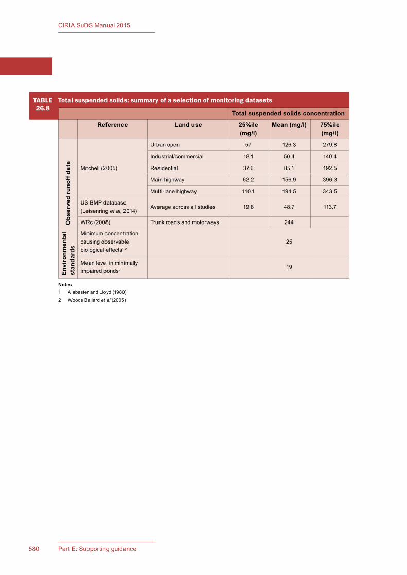
580 Part E: Supporting guidance
CIRIA SuDS Manual 2015
TABLE26.8
Total suspended solids: summary of a selection of monitoring datasets
Total suspended solids concentration
Reference Land use 25%ile (mg/l)
Mean (mg/l) 75%ile (mg/l)
Obs
erve
d ru
noff
dat
a
Mitchell (2005)
Urban open 57 126.3 279.8
Industrial/commercial 18.1 50.4 140.4
Residential 37.6 85.1 192.5
Main highway 62.2 156.9 396.3
Multi-lane highway 110.1 194.5 343.5
US BMP database (Leisenring et al, 2014)
Average across all studies 19.8 48.7 113.7
WRc (2008) Trunk roads and motorways 244
Envi
ronm
enta
l st
anda
rds
Minimum concentration causing observable biological effects1,2
25
Mean level in minimally impaired ponds2
19
Notes1 Alabaster and Lloyd (1980)2 Woods Ballard et al (2005)
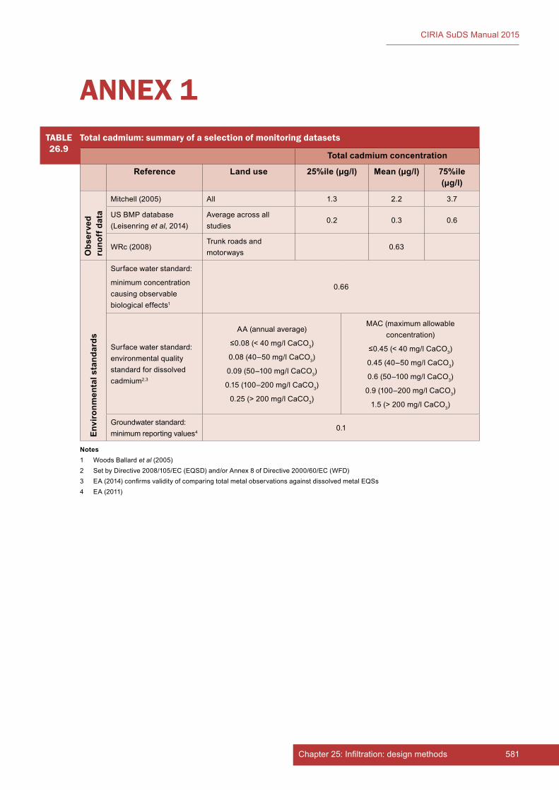
581Chapter 25: Infiltration: design methods
CIRIA SuDS Manual 2015
TABLE26.9
Total cadmium: summary of a selection of monitoring datasets
Total cadmium concentration
Reference Land use 25%ile (µg/l) Mean (µg/l) 75%ile (µg/l)
Obs
erve
d ru
noff
dat
a
Mitchell (2005) All 1.3 2.2 3.7
US BMP database (Leisenring et al, 2014)
Average across all studies
0.2 0.3 0.6
WRc (2008)Trunk roads and motorways
0.63
Envi
ronm
enta
l sta
ndar
ds
Surface water standard:
minimum concentration causing observable biological effects1
0.66
Surface water standard: environmental quality standard for dissolved cadmium2,3
AA (annual average)
≤0.08 (< 40 mg/l CaCO3)
0.08 (40–50 mg/l CaCO3)
0.09 (50–100 mg/l CaCO3)
0.15 (100–200 mg/l CaCO3)
0.25 (> 200 mg/l CaCO3)
MAC (maximum allowable concentration)
≤0.45 (< 40 mg/l CaCO3)
0.45 (40–50 mg/l CaCO3)
0.6 (50–100 mg/l CaCO3)
0.9 (100–200 mg/l CaCO3)
1.5 (> 200 mg/l CaCO3)
Groundwater standard: minimum reporting values4
0.1
ANNEX 1
Notes1 Woods Ballard et al (2005)2 Set by Directive 2008/105/EC (EQSD) and/or Annex 8 of Directive 2000/60/EC (WFD)3 EA (2014) confirms validity of comparing total metal observations against dissolved metal EQSs4 EA (2011)
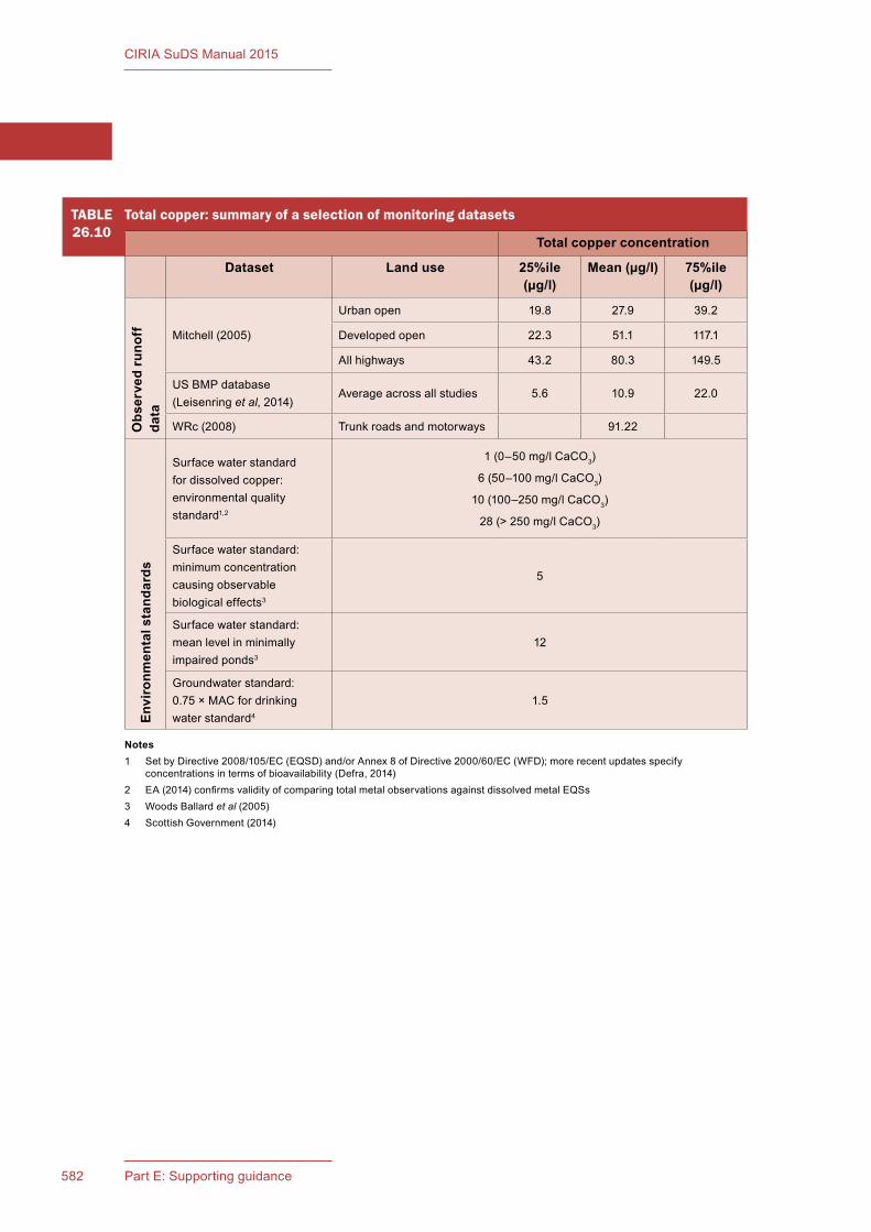
582 Part E: Supporting guidance
CIRIA SuDS Manual 2015
TABLE26.10
Total copper: summary of a selection of monitoring datasets
Total copper concentration
Dataset Land use 25%ile (µg/l)
Mean (µg/l) 75%ile (µg/l)
Obs
erve
d ru
noff
da
ta
Mitchell (2005)
Urban open 19.8 27.9 39.2
Developed open 22.3 51.1 117.1
All highways 43.2 80.3 149.5
US BMP database (Leisenring et al, 2014)
Average across all studies 5.6 10.9 22.0
WRc (2008) Trunk roads and motorways 91.22
Envi
ronm
enta
l sta
ndar
ds
Surface water standard for dissolved copper: environmental quality standard1,2
1 (0–50 mg/l CaCO3)
6 (50–100 mg/l CaCO3)
10 (100–250 mg/l CaCO3)
28 (> 250 mg/l CaCO3)
Surface water standard: minimum concentration causing observable biological effects3
5
Surface water standard: mean level in minimally impaired ponds3
12
Groundwater standard: 0.75 × MAC for drinking water standard4
1.5
Notes1 Set by Directive 2008/105/EC (EQSD) and/or Annex 8 of Directive 2000/60/EC (WFD); more recent updates specify
concentrations in terms of bioavailability (Defra, 2014)2 EA (2014) confirms validity of comparing total metal observations against dissolved metal EQSs3 Woods Ballard et al (2005)4 Scottish Government (2014)
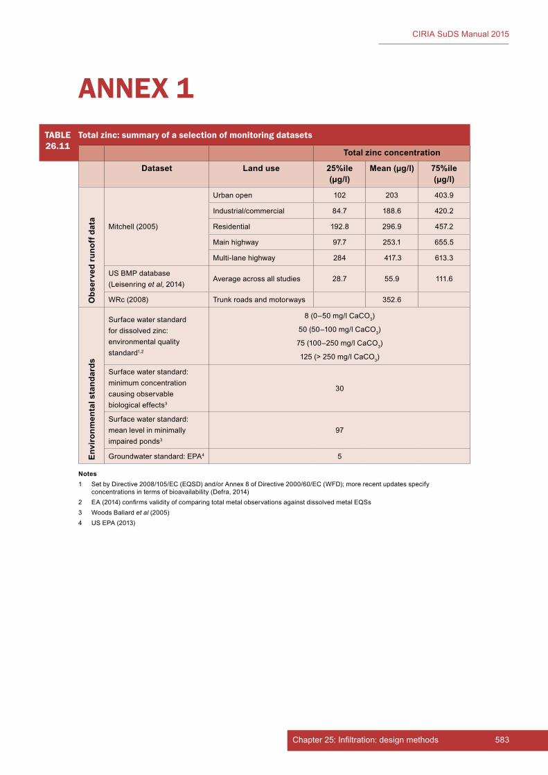
583Chapter 25: Infiltration: design methods
CIRIA SuDS Manual 2015
TABLE26.11
Total zinc: summary of a selection of monitoring datasets
Total zinc concentration
Dataset Land use 25%ile (µg/l)
Mean (µg/l) 75%ile (µg/l)
Obs
erve
d ru
noff
dat
a
Mitchell (2005)
Urban open 102 203 403.9
Industrial/commercial 84.7 188.6 420.2
Residential 192.8 296.9 457.2
Main highway 97.7 253.1 655.5
Multi-lane highway 284 417.3 613.3
US BMP database (Leisenring et al, 2014)
Average across all studies 28.7 55.9 111.6
WRc (2008) Trunk roads and motorways 352.6
Envi
ronm
enta
l sta
ndar
ds
Surface water standard for dissolved zinc: environmental quality standard1,2
8 (0–50 mg/l CaCO3)
50 (50–100 mg/l CaCO3)
75 (100–250 mg/l CaCO3)
125 (> 250 mg/l CaCO3)
Surface water standard: minimum concentration causing observable biological effects3
30
Surface water standard: mean level in minimally impaired ponds3
97
Groundwater standard: EPA4 5
ANNEX 1
Notes1 Set by Directive 2008/105/EC (EQSD) and/or Annex 8 of Directive 2000/60/EC (WFD); more recent updates specify
concentrations in terms of bioavailability (Defra, 2014)2 EA (2014) confirms validity of comparing total metal observations against dissolved metal EQSs3 Woods Ballard et al (2005)4 US EPA (2013)
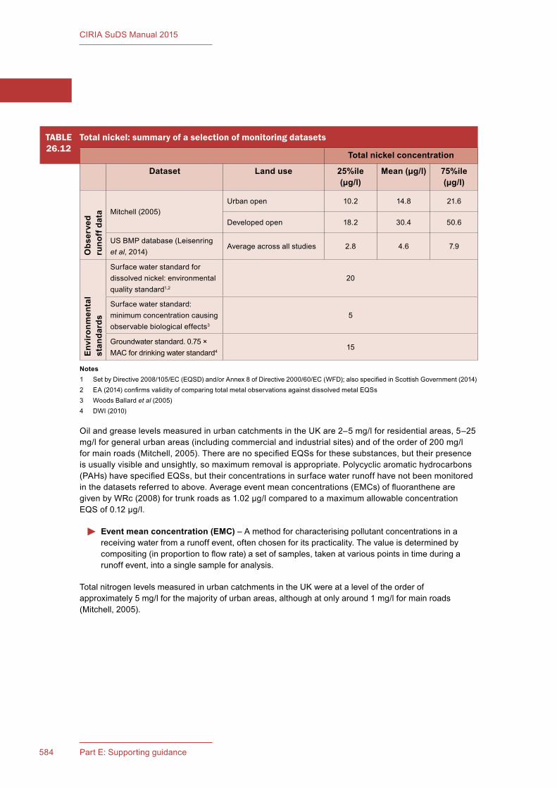
584 Part E: Supporting guidance
CIRIA SuDS Manual 2015
Oil and grease levels measured in urban catchments in the UK are 2–5 mg/l for residential areas, 5–25 mg/l for general urban areas (including commercial and industrial sites) and of the order of 200 mg/l for main roads (Mitchell, 2005). There are no specified EQSs for these substances, but their presence is usually visible and unsightly, so maximum removal is appropriate. Polycyclic aromatic hydrocarbons (PAHs) have specified EQSs, but their concentrations in surface water runoff have not been monitored in the datasets referred to above. Average event mean concentrations (EMCs) of fluoranthene are given by WRc (2008) for trunk roads as 1.02 µg/l compared to a maximum allowable concentration EQS of 0.12 µg/l.
Event mean concentration (EMC) – A method for characterising pollutant concentrations in a receiving water from a runoff event, often chosen for its practicality. The value is determined by compositing (in proportion to flow rate) a set of samples, taken at various points in time during a runoff event, into a single sample for analysis.
Total nitrogen levels measured in urban catchments in the UK were at a level of the order of approximately 5 mg/l for the majority of urban areas, although at only around 1 mg/l for main roads (Mitchell, 2005).
TABLE26.12
Total nickel: summary of a selection of monitoring datasets
Total nickel concentration
Dataset Land use 25%ile (µg/l)
Mean (µg/l) 75%ile (µg/l)
Obs
erve
d ru
noff
dat
a Mitchell (2005) Urban open 10.2 14.8 21.6
Developed open 18.2 30.4 50.6
US BMP database (Leisenring et al, 2014)
Average across all studies 2.8 4.6 7.9
Envi
ronm
enta
l st
anda
rds
Surface water standard for dissolved nickel: environmental quality standard1,2
20
Surface water standard: minimum concentration causing observable biological effects3
5
Groundwater standard. 0.75 × MAC for drinking water standard4
15
Notes1 Set by Directive 2008/105/EC (EQSD) and/or Annex 8 of Directive 2000/60/EC (WFD); also specified in Scottish Government (2014)2 EA (2014) confirms validity of comparing total metal observations against dissolved metal EQSs3 Woods Ballard et al (2005)4 DWI (2010)
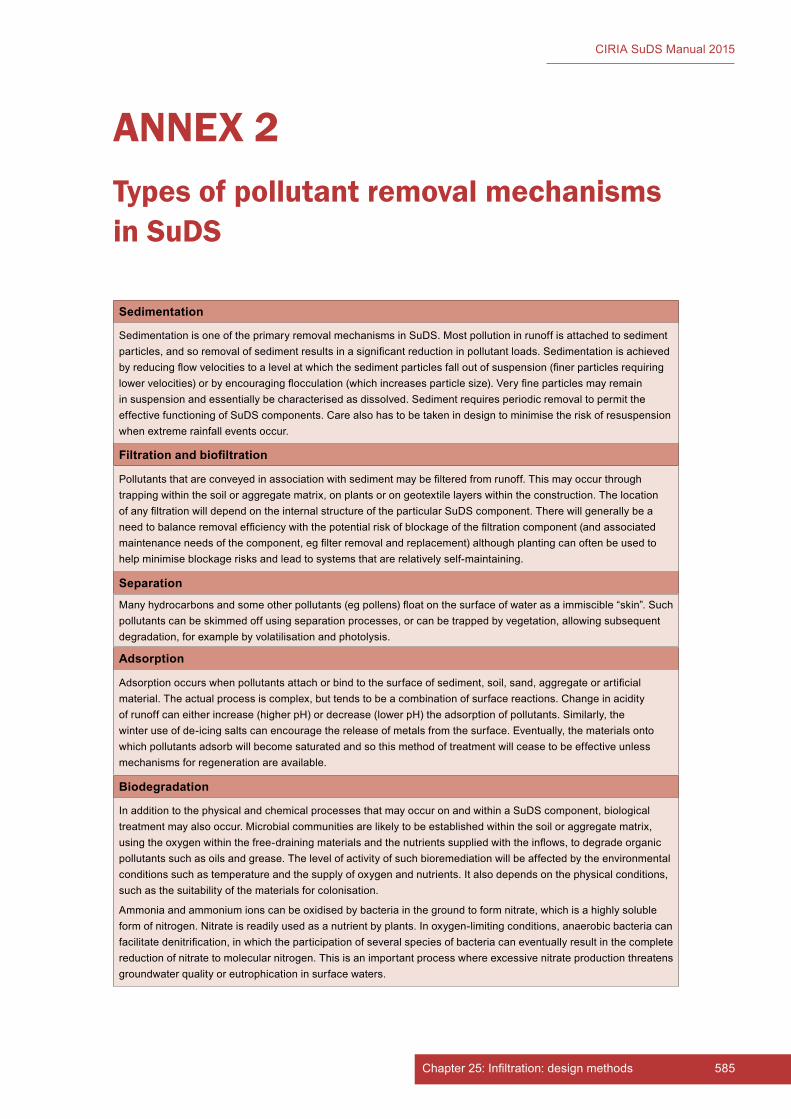
585Chapter 25: Infiltration: design methods
CIRIA SuDS Manual 2015
ANNEX 2Types of pollutant removal mechanisms in SuDS
Sedimentation
Sedimentation is one of the primary removal mechanisms in SuDS. Most pollution in runoff is attached to sediment particles, and so removal of sediment results in a significant reduction in pollutant loads. Sedimentation is achieved by reducing flow velocities to a level at which the sediment particles fall out of suspension (finer particles requiring lower velocities) or by encouraging flocculation (which increases particle size). Very fine particles may remain in suspension and essentially be characterised as dissolved. Sediment requires periodic removal to permit the effective functioning of SuDS components. Care also has to be taken in design to minimise the risk of resuspension when extreme rainfall events occur.
Filtration and biofiltration
Pollutants that are conveyed in association with sediment may be filtered from runoff. This may occur through trapping within the soil or aggregate matrix, on plants or on geotextile layers within the construction. The location of any filtration will depend on the internal structure of the particular SuDS component. There will generally be a need to balance removal efficiency with the potential risk of blockage of the filtration component (and associated maintenance needs of the component, eg filter removal and replacement) although planting can often be used to help minimise blockage risks and lead to systems that are relatively self-maintaining.
Separation
Many hydrocarbons and some other pollutants (eg pollens) float on the surface of water as a immiscible “skin”. Such pollutants can be skimmed off using separation processes, or can be trapped by vegetation, allowing subsequent degradation, for example by volatilisation and photolysis.
Adsorption
Adsorption occurs when pollutants attach or bind to the surface of sediment, soil, sand, aggregate or artificial material. The actual process is complex, but tends to be a combination of surface reactions. Change in acidity of runoff can either increase (higher pH) or decrease (lower pH) the adsorption of pollutants. Similarly, the winter use of de-icing salts can encourage the release of metals from the surface. Eventually, the materials onto which pollutants adsorb will become saturated and so this method of treatment will cease to be effective unless mechanisms for regeneration are available.
Biodegradation
In addition to the physical and chemical processes that may occur on and within a SuDS component, biological treatment may also occur. Microbial communities are likely to be established within the soil or aggregate matrix, using the oxygen within the free-draining materials and the nutrients supplied with the inflows, to degrade organic pollutants such as oils and grease. The level of activity of such bioremediation will be affected by the environmental conditions such as temperature and the supply of oxygen and nutrients. It also depends on the physical conditions, such as the suitability of the materials for colonisation.
Ammonia and ammonium ions can be oxidised by bacteria in the ground to form nitrate, which is a highly soluble form of nitrogen. Nitrate is readily used as a nutrient by plants. In oxygen-limiting conditions, anaerobic bacteria can facilitate denitrification, in which the participation of several species of bacteria can eventually result in the complete reduction of nitrate to molecular nitrogen. This is an important process where excessive nitrate production threatens groundwater quality or eutrophication in surface waters.
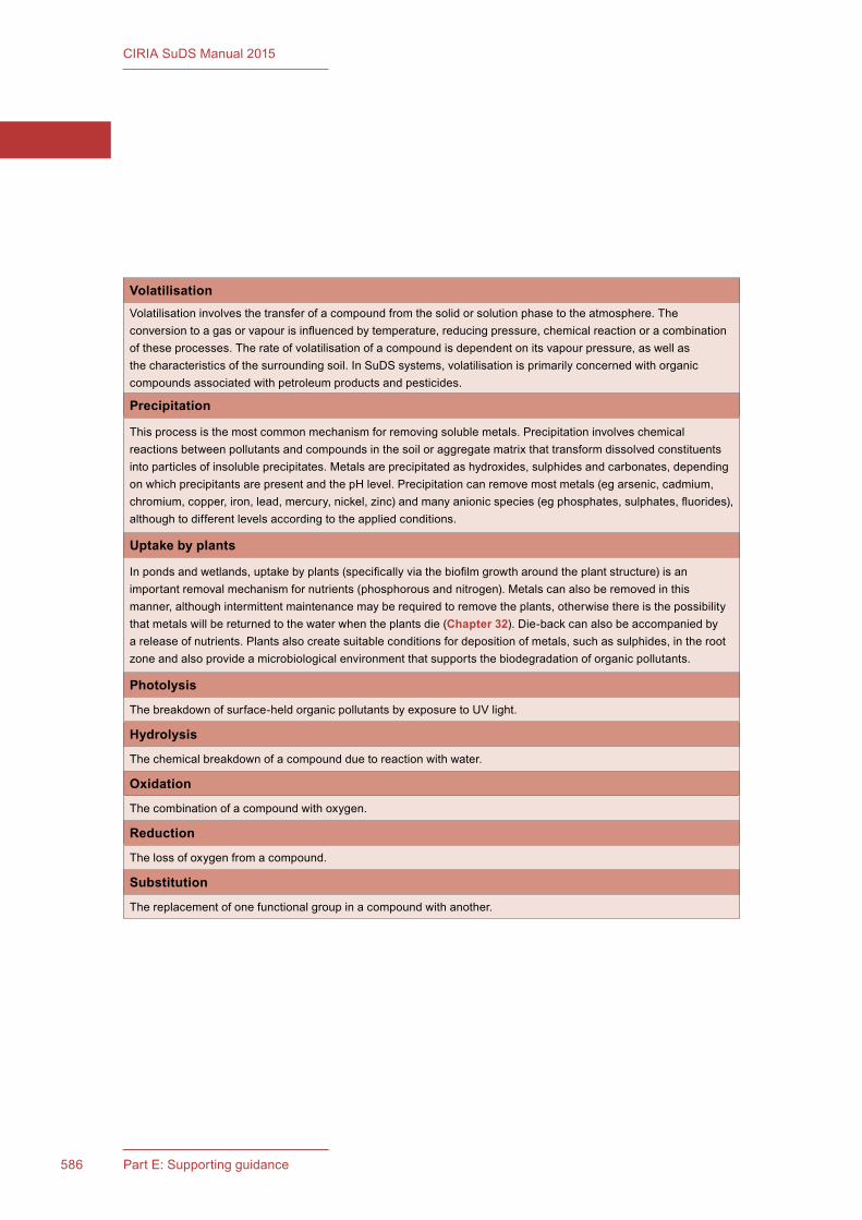
586 Part E: Supporting guidance
CIRIA SuDS Manual 2015
VolatilisationVolatilisation involves the transfer of a compound from the solid or solution phase to the atmosphere. The conversion to a gas or vapour is influenced by temperature, reducing pressure, chemical reaction or a combination of these processes. The rate of volatilisation of a compound is dependent on its vapour pressure, as well as the characteristics of the surrounding soil. In SuDS systems, volatilisation is primarily concerned with organic compounds associated with petroleum products and pesticides.
Precipitation
This process is the most common mechanism for removing soluble metals. Precipitation involves chemical reactions between pollutants and compounds in the soil or aggregate matrix that transform dissolved constituents into particles of insoluble precipitates. Metals are precipitated as hydroxides, sulphides and carbonates, depending on which precipitants are present and the pH level. Precipitation can remove most metals (eg arsenic, cadmium, chromium, copper, iron, lead, mercury, nickel, zinc) and many anionic species (eg phosphates, sulphates, fluorides), although to different levels according to the applied conditions.
Uptake by plants
In ponds and wetlands, uptake by plants (specifically via the biofilm growth around the plant structure) is an important removal mechanism for nutrients (phosphorous and nitrogen). Metals can also be removed in this manner, although intermittent maintenance may be required to remove the plants, otherwise there is the possibility that metals will be returned to the water when the plants die (Chapter 32). Die-back can also be accompanied by a release of nutrients. Plants also create suitable conditions for deposition of metals, such as sulphides, in the root zone and also provide a microbiological environment that supports the biodegradation of organic pollutants.
Photolysis
The breakdown of surface-held organic pollutants by exposure to UV light.
Hydrolysis
The chemical breakdown of a compound due to reaction with water.
Oxidation
The combination of a compound with oxygen.
Reduction
The loss of oxygen from a compound.
Substitution
The replacement of one functional group in a compound with another.
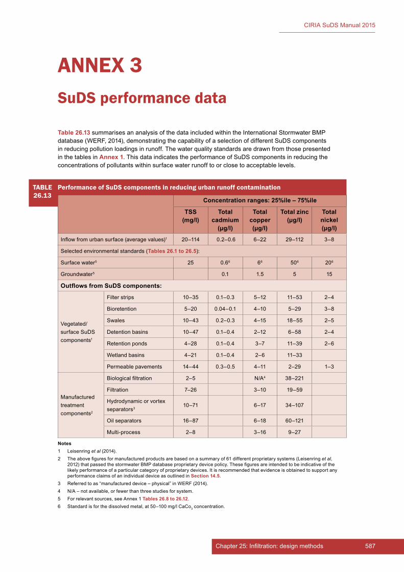
587Chapter 25: Infiltration: design methods
CIRIA SuDS Manual 2015
Table 26.13 summarises an analysis of the data included within the International Stormwater BMP database (WERF, 2014), demonstrating the capability of a selection of different SuDS components in reducing pollution loadings in runoff. The water quality standards are drawn from those presented in the tables in Annex 1. This data indicates the performance of SuDS components in reducing the concentrations of pollutants within surface water runoff to or close to acceptable levels.
Notes1 Leisenring et al (2014).2 The above figures for manufactured products are based on a summary of 61 different proprietary systems (Leisenring et al,
2012) that passed the stormwater BMP database proprietary device policy. These figures are intended to be indicative of the likely performance of a particular category of proprietary devices. It is recommended that evidence is obtained to support any performance claims of an individual device as outlined in Section 14.5.
3 Referred to as “manufactured device – physical” in WERF (2014).4 N/A – not available, or fewer than three studies for system.5 For relevant sources, see Annex 1 Tables 26.8 to 26.12.6 Standard is for the dissolved metal, at 50–100 mg/l CaCo3 concentration.
ANNEX 3SuDS performance data
TABLE26.13
Performance of SuDS components in reducing urban runoff contamination
Concentration ranges: 25%ile – 75%ile
TSS (mg/l)
Total cadmium
(µg/l)
Total copper (µg/l)
Total zinc (µg/l)
Total nickel (µg/l)
Inflow from urban surface (average values)1 20–114 0.2–0.6 6–22 29–112 3–8
Selected environmental standards (Tables 26.1 to 26.5):
Surface water5 25 0.66 66 506 206
Groundwater5 0.1 1.5 5 15
Outflows from SuDS components:
Vegetated/surface SuDS components1
Filter strips 10–35 0.1–0.3 5–12 11–53 2–4
Bioretention 5–20 0.04–0.1 4–10 5–29 3–8
Swales 10–43 0.2–0.3 4–15 18–55 2–5
Detention basins 10–47 0.1–0.4 2–12 6–58 2–4
Retention ponds 4–28 0.1–0.4 3–7 11–39 2–6
Wetland basins 4–21 0.1–0.4 2–6 11–33
Permeable pavements 14–44 0.3–0.5 4–11 2–29 1–3
Manufactured treatment components2
Biological filtration 2–5 N/A4 38–221
Filtration 7–26 3–10 19–59
Hydrodynamic or vortex separators3
10–71 6–17 34–107
Oil separators 16–87 6–18 60–121
Multi-process 2–8 3–16 9–27

588 Part E: Supporting guidance
CIRIA SuDS Manual 2015

589Chapter 25: Infiltration: design methods
CIRIA SuDS Manual 2015
ANNEX 4Groundwater protection evidence
Two recent studies in the UK have examined the potential risks posed to groundwater from runoff from trafficked areas.
Scott Wilson (2010) had the following objectives:
1 to quantify the extent to which contaminants in highway runoff may be leached, degraded or immobilised in the unsaturated zone and within the soakaway systems
2 to review and/or refine the boundary conditions defined for each risk category within HA (2009a) risk assessment method
3 to develop an improved groundwater risk methodology for predicting the risk to groundwater from highway runoff.
This research found the following:
▪ The time taken for contaminants to break through 1 m of different unsaturated aquifer materials varied. For cadmium (likely to be most rapidly conveyed, break through times ranged from 54 years (for oolitic limestone aquifer material) to 714 years for oolitic soils.
▪ Residual concentrations of fluoranthene and pyrene were reduced to below the limit of analytical detection within approximately 0.5 m depth of the unsaturated zone (using assumed biodegradation rates).
▪ The soil organic matter is extremely important in retaining and attenuating contaminant migration.
▪ The total mass of contaminant is more relevant than the concentration of that contaminant.
▪ The total volume of infiltrating water will be the significant influence on downward flux of the contaminant through the soil profile.
The overall conclusions of the research are as follows:
▪ The overall risk to groundwater through porous media from the key contaminants associated with highway runoff is low and the opportunity for microbial mediated degradation of the PAH and TPH content through a sufficient depth of unsaturated zone confers a significant degree of protection to underlying groundwaters.
▪ Organic soil layers will form an important additional barrier to the movement and attenuation of contamination.
The findings support the view that risks posed by lateral drainage collection components such as swales will be smaller than for point source infiltration components, and that Interception components, where infiltration rates are low, will pose a lower risk to groundwater.
The Sniffer project (Jefferies et al, 2008) had the following objectives:
1 to determine the risk of movement of pollutants through soil into groundwater in soft-engineered SuDS
2 to measure the immobilisation and degradation of priority pollutants and fate of nutrients in soft engineering SuDS
3 to identify the degradation products in a range of SuDS components
4 to determine the conditions for the optimal breakdown of oil and PAHs in the range of SuDS investigated.

590 Part E: Supporting guidance
CIRIA SuDS Manual 2015
The project conclusions are very similar to those stated in Scott Wilson (2010) and include the following:
1 The risks to groundwater from passing highway drainage onto soil based SuDS is low. There is evidence of only very low rates of downward movement of contaminants.
2 The vast majority of heavy metals, PAHs and TPHs are retained in the top 10 cm of soil. An overlying vegetative layer would take up some of the pollutants retained in the soil, further reducing the risk of their movement to groundwater.
591Chapter 25: Infiltration: design methods
CIRIA SuDS Manual 2015
Middlesex University has undertaken work on the development of a water quality impact assessment methodology that can be applied to the assessment of SuDS (Ellis et al, 2012) and a summary of the approach proposed in that paper is described below. It should be noted that this method is not suitable for use in designing treatment systems for discharges to groundwaters (ie infiltration systems).
Step 1. Pollution index (PI) assessment
The individual pollutant indexing (Table 26.13) has been developed from consideration of the interquartile range of event mean concentration (EMC) data derived from 71 separate UK studies and referenced against regulatory EU environmental quality standards. The pollution index is then based on a scaling of the reported EMC distribution for the given pollutant group and the likelihood that the 50%ile EMC values will exceed receiving water body EQSs, specified either as maximum allowable concentration or annual average values.
Step 2. SuDS pollution mitigation index (PMI) assessment
The authors then adopt scaling ranges to indicate the removal potential by which different types of SuDS are able to remove different pollutant groups. The ranges adopted are between 0 and 1, and hence are only qualitative, that is a lower index value indicates a better treatment performance, but the allocated scores cannot be used to indicate the magnitude of the difference (Table 26.14).
Step 3. Land use pollution index (LUPI) and site pollution index (SPI) assessment
A land use pollution index (LUPI) (for each pollutant group) for the different land use areas contributing to the discharge point is evaluated by multiplying the pollution index (PI) by the pollution mitigation indices (PMI) for each SuDS component used.
The final site pollution index (SPI) is an aggregation of the different LUPIs weighted by their area.
Step 4. Assessment against an environmental baseline
The final step is to make a comparison of the resulting averaged SPI index against a recognised value or standard for receiving water quality, in order to evaluate any likely risk exposure associated with the site SuDS discharge. The procedure then associates different SPI levels with different receiving water quality levels, for example the EA River Ecosystem Class (REC).
REC standards have now been superseded by WFD standards; the relevant environmental regulator should be contacted to agree appropriate environmental standards.
The research sets out a structured impact assessment methodology, but has some limitations that potentially make it unsuitable for use as a generic SuDS design approach:
1 It does not include the determination of treatment requirements upstream of infiltration components (ie it accounts for the removal of pollutants from the discharge from the site to surface water bodies, but it does not take into consideration the potential need for treatment of the infiltrated water before discharge to groundwaters). This means that there is a risk of the method being misused by implying that the use of infiltration components can protect receiving surface water bodies, without considering the risk to groundwater.
ANNEX 5Ellis et al, 2012

592 Part E: Supporting guidance
CIRIA SuDS Manual 2015
2 The multiplicative procedure used considers the behaviour of each SuDS on a standalone basis rather than as a component in a Management Train. In reality, the removal performance of downstream SuDS components tends to be lower due to lower pollutant exposures and capabilities.
3 The method requires a determination regarding the acceptability of the impact level for different receiving water bodies. If an SPI of < 0.1 is considered appropriate for surface water discharges (ie negligible impact level), then a very high number of components would usually be required. If SPI of < 0.2 is considered acceptable (ie minimal impact level, small reduction in pollution tolerant tax), then this will still tend to require a higher number of components than general good practice might normally suggest.
However, the work provides a potential methodology that could be used in the design of treatment systems and is also a good basis for future studies and assessment. Where it is used, the full paper should be referenced, rather than relying on the information provided here.
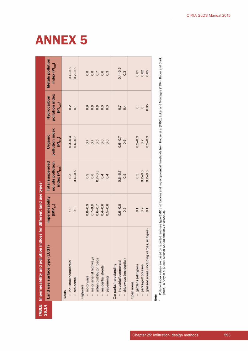
593Chapter 25: Infiltration: design methods
CIRIA SuDS Manual 2015
TAB
LE26
.14
Impe
rmea
bilit
y an
d po
lluti
on in
dice
s fo
r diff
eren
t lan
d us
e ty
pes1
Land
use
sur
face
type
(LU
ST)
Impe
rmea
bilit
y (IM
P RF)
Tota
l sus
pend
ed
solu
ds p
ollu
tion
inde
x (P
I TSS)
Org
anic
po
llutio
n in
dex
(PI O
rg)
Hyd
roca
rbon
po
llutio
n in
dex
(PI PA
H)
Met
als
pollu
tion
inde
x (P
I HM)
Roo
fs ▪in
dust
rial/c
omm
erci
al ▪
resi
dent
ial
1.0
0.9
0.3
0.4–
0.5
0.3–
0.4
0.6–
0.7
0.2
0.1
0.4–
0.8
0.2–
0.5
Hig
hway
s ▪
mot
orw
ays
▪m
ajor
arte
rial h
ighw
ays
▪ur
ban
dist
ribut
or ro
ads
▪re
side
ntia
l stre
ets
▪pa
vem
ents
0.8–
0.9
0.7–
0.8
0.6–
0.7
0.4–
0.6
0.5–
0.6
0.9
0.8
0.7–
0.8
0.4
0.4
0.7
0.7
0.5
0.6
0.6
0.9
0.8
0.8
0.6
0.3
0.8
0.8
0.7
0.6
0.3
Car
par
ks/h
ards
tand
ing
▪in
dust
rial/c
omm
erci
al ▪
driv
eway
s (re
side
ntia
l)0.
6–0.
80.
50.
6–0.
70.
50.
6–0.
70.
60.
70.
40.
4–0.
50.
3
Ope
n ar
eas
▪ga
rden
s (a
ll ty
pes)
▪pa
rks/
golf
cour
ses
▪gr
asse
d ar
eas
(incl
udin
g ve
rges
, all
type
s)
0.1
0.2
0.1
0.3
0.2–
0.3
0.2–
0.3
0.2–
0.3
0.2
0.2–
0.3
0 00.
05
0.01
0.02
0.05
ANNEX 5
Not
e1
Pol
lutio
n in
dex
valu
es a
re b
ased
on
repo
rted
land
use
type
EM
C d
istri
butio
ns a
nd im
pact
pot
entia
l thr
esho
lds
from
Hou
se e
t al (
1993
), Lu
ker a
nd M
onta
gue
(199
4), B
utle
r and
Cla
rk
(199
5), D
’Arc
y et
al (
2000
), M
itche
ll (2
005)
and
Moy
et a
l (20
03).
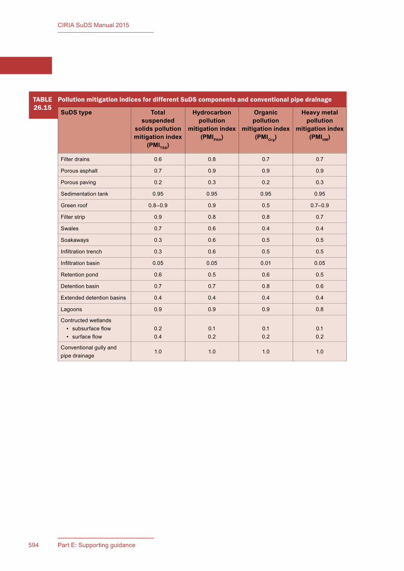
594 Part E: Supporting guidance
CIRIA SuDS Manual 2015
TABLE26.15
Pollution mitigation indices for different SuDS components and conventional pipe drainage
SuDS type Total suspended
solids pollution mitigation index
(PMITSS)
Hydrocarbon pollution
mitigation index (PMIPAH)
Organic pollution
mitigation index (PMIOrg)
Heavy metal pollution
mitigation index (PMIHM)
Filter drains 0.6 0.8 0.7 0.7
Porous asphalt 0.7 0.9 0.9 0.9
Porous paving 0.2 0.3 0.2 0.3
Sedimentation tank 0.95 0.95 0.95 0.95
Green roof 0.8–0.9 0.9 0.5 0.7–0.9
Filter strip 0.9 0.8 0.8 0.7
Swales 0.7 0.6 0.4 0.4
Soakaways 0.3 0.6 0.5 0.5
Infiltration trench 0.3 0.6 0.5 0.5
Infiltration basin 0.05 0.05 0.01 0.05
Retention pond 0.6 0.5 0.6 0.5
Detention basin 0.7 0.7 0.8 0.6
Extended detention basins 0.4 0.4 0.4 0.4
Lagoons 0.9 0.9 0.9 0.8
Contructed wetlands ▪ subsurface flow ▪ surface flow
0.20.4
0.10.2
0.10.2
0.10.2
Conventional gully and pipe drainage
1.0 1.0 1.0 1.0

595Chapter 25: Infiltration: design methods
CIRIA SuDS Manual 2015
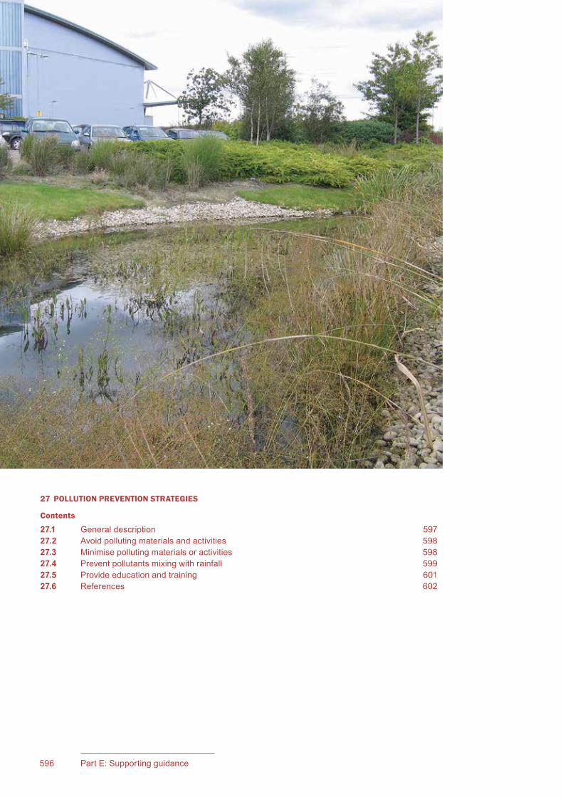
CIRIA SuDS Manual 2015
596 Part E: Supporting guidance
27 POLLUTION PREVENTION STRATEGIES
Contents
27.1 General description 59727.2 Avoid polluting materials and activities 59827.3 Minimise polluting materials or activities 59827.4 Prevent pollutants mixing with rainfall 59927.5 Provide education and training 60127.6 References 602

597Chapter 27: Pollution prevention strategies
CIRIA SuDS Manual 2015
27Chapter Pollution prevention
strategiesThis chapter discusses strategies that can be used to avoid or minimise the generation of pollutants and how to prevent pollutants mixing with runoff before it enters the drainage system.Capturing, treating and removal of pollutants within the drainage system is the purpose of treatment design and is not discussed here. The mobilisation of pollutants from contaminated land is also not covered here.
Guidance on water quality management and treatment design is provided in Chapters 4 and 26 respectively, as well as the individual SuDS component chapters (Chapters 11–23).
Chapter 31 provides details of temporary erosion and sediment control measures required to prevent pollutants from leaving sites during construction. It also provides guidance to help ensure site surface water management systems are appropriately implemented during construction projects.
Managing the risk of mobilising pollutants from contaminated land is covered in Chapter 8.
27.1 GENERAL DESCRIPTION
Pollution prevention strategies are methods used on site to manage pollutants at their source. These strategies may be part of:
▪ the approved site design or operational strategy, required in order to reduce environmental risks to acceptable levels
▪ standard operational best practice of the site users and/or operators
▪ community strategies promoted by local environmental bodies to raise awareness of the risks posed by pollutants in surface runoff and actions that can be taken to minimise them.
Many of these are common sense working practices and are relatively inexpensive and easy to implement. For example, dust and debris can be swept or vacuumed from a work area and disposed of as waste, instead of using a hose to wash it into a surface water drain or SuDS.
SuDS components capture and remove pollutants after they have mixed with rainfall, but they cannot remove 100% of the pollutants (Chapter 4). The most effective way of preventing pollution getting into surface water discharges is to prevent pollutants from entering the surface water drainage system in the first place. With new substances coming onto the market all the time that have the potential to be harmful to the natural environment, pollution prevention is becoming increasingly important. In some cases, pollution prevention strategies can be sufficient to remove the pollution risk downstream almost entirely.
For a high hazard site, pollution prevention may be a regulatory requirement, to ensure that the downstream drainage system does not pose an unacceptable risk to the receiving environment. Many pollution prevention strategies can reduce the maintenance requirements of downstream drainage components or prevent the need for clean-up and rehabilitation works, and may be promoted by drainage system owners/operators and/or local environmental groups.

CIRIA SuDS Manual 2015
598 Part E: Supporting guidance
Pollution prevention should follow a hierarchical approach:
1 Avoid the use of materials and activities that generate pollutants.
2 Minimise the use of materials and activities that generate pollutants.
3 Prevent pollutants mixing with rainfall.
4 Capture pollution within the drainage system for removal, treatment or clean-up and rehabilitation (where required).
Pollution prevention strategies, as discussed here, cover actions 1–3.
Pollution prevention strategies are most effective when they are an integral part of community behaviour and site management processes. This chapter provides information to help:
a) individuals, businesses and local authorities identify strategies for controlling pollutants at source and preventing contamination of surface water runoff
b) designers identify physical measures for preventing the mixing of pollutants with rainfall, or trapping pollutants before they enter SuDS.
The design of pollution prevention strategies needs to take into account the use of the site, the types of pollutants that may be present and the operational processes on the site. Different types of pollutants (as presented in Chapter 4, Table 4.1) may require different strategies.
The rest of this chapter summarises pollution prevention strategies, following the hierarchical approach set out above (Sections 27.2 to 27.4) and the education and training strategies required to facilitate their delivery (Section 27.5).
27.2 AVOID POLLUTING MATERIALS AND ACTIVITIES
Where possible, activities or materials that have the potential to result in pollution should be avoided or substituted.
An example of the effective removal of a pollutant source is the identification and removal of illicit connections of foul water discharges to SuDS. Surface SuDS will help in exposing the location and likely source of any wrongly connected inputs as poor water quality and possibly sewage solids/fungus may be visible. This can help identification of the problem by local homeowners, property owners or maintenance bodies and allow action to be taken. During the lifetime of the SuDS, further wrong connections may occur upstream, which may be identified by SuDS inspection regimes or property surveys.
27.3 MINIMISE POLLUTING MATERIALS OR ACTIVITIES
Where practicable, site users should be encouraged to use materials and undertake activities likely to pose the lowest risk to the receiving environment. This not only helps to keep potential disposal, storage and other pollution problems to a minimum, but can also be more cost-effective.
For example, landscape and road surface management activities often use chemicals that are readily mixed with rainfall and discharged to the surface water management system, potentially causing damage and pollution. The application of fertilisers, pesticides and herbicides can be used during the operational life of the SuDS, if used appropriately and proportionately, having evaluated the risks and provided appropriate mitigation.
De-icing agents can also pose risks, particularly where they are mixed with sand (causing more solids wash-off, which is not desirable). However, calcium magnesium acetate, potassium acetate, or similar materials, cause less adverse environmental impact than urea and sodium chloride in de-icing materials.
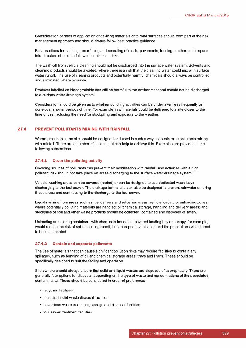
599Chapter 27: Pollution prevention strategies
CIRIA SuDS Manual 2015
Consideration of rates of application of de-icing materials onto road surfaces should form part of the risk management approach and should always follow best practice guidance.
Best practices for painting, resurfacing and resealing of roads, pavements, fencing or other public space infrastructure should be followed to minimise risks.
The wash-off from vehicle cleaning should not be discharged into the surface water system. Solvents and cleaning products should be avoided, where there is a risk that the cleaning water could mix with surface water runoff. The use of cleaning products and potentially harmful chemicals should always be controlled, and eliminated where possible.
Products labelled as biodegradable can still be harmful to the environment and should not be discharged to a surface water drainage system.
Consideration should be given as to whether polluting activities can be undertaken less frequently or done over shorter periods of time. For example, raw materials could be delivered to a site closer to the time of use, reducing the need for stockpiling and exposure to the weather.
27.4 PREVENT POLLUTANTS MIXING WITH RAINFALL
Where practicable, the site should be designed and used in such a way as to minimise pollutants mixing with rainfall. There are a number of actions that can help to achieve this. Examples are provided in the following subsections.
27.4.1 Cover the polluting activity
Covering sources of pollutants can prevent their mobilisation with rainfall, and activities with a high pollutant risk should not take place on areas discharging to the surface water drainage system.
Vehicle washing areas can be covered (roofed) or can be designed to use dedicated wash-bays discharging to the foul sewer. The drainage for the site can also be designed to prevent rainwater entering these areas and contributing to the discharge to the foul sewer.
Liquids arising from areas such as fuel delivery and refuelling areas; vehicle loading or unloading zones where potentially polluting materials are handled; oil/chemical storage, handling and delivery areas; and stockpiles of soil and other waste products should be collected, contained and disposed of safely.
Unloading and storing containers with chemicals beneath a covered loading bay or canopy, for example, would reduce the risk of spills polluting runoff, but appropriate ventilation and fire precautions would need to be implemented.
27.4.2 Contain and separate pollutants
The use of materials that can cause significant pollution risks may require facilities to contain any spillages, such as bunding of oil and chemical storage areas, trays and liners. These should be specifically designed to suit the facility and operation.
Site owners should always ensure that solid and liquid wastes are disposed of appropriately. There are generally four options for disposal, depending on the type of waste and concentrations of the associated contaminants. These should be considered in order of preference:
▪ recycling facilities
▪ municipal solid waste disposal facilities
▪ hazardous waste treatment, storage and disposal facilities
▪ foul sewer treatment facilities.

CIRIA SuDS Manual 2015
600 Part E: Supporting guidance
Many liquid wastes can be discharged to a foul sewer, subject to approval from the sewerage undertaker. If wastes cannot be legally discharged to a foul sewer, one of the other three disposal options (listed above) should be used. Surface water runoff should never be drained to the foul sewer due to risks of overloading.
Sumps or holding tanks may be useful for storing liquid wastes temporarily, but the contents must then be disposed of properly. Dangerous and hazardous wastes must be transported to an appropriate hazardous waste disposal, treatment or storage facility.
Where solid wastes are stored outdoors on site, including recycling waste that is contaminated, then runoff from these areas will need to be treated specifically to manage the pollution risk before discharge to the surface water drainage system.
Walton (2014) provides guidance to assist owners and operators of industrial and commercial facilities in storing substances that may be hazardous to the environment.
An example of containing the supply of pollutants is the implementation of a street sweeping and/or gully inlet/silt trap emptying regime. Such strategies are known to be effective at limiting pollution by capturing and disposing of dust and debris before it enters the surface water management system. General control of litter and other solids, including leaf fall, is also important for a range of urban surfaces, not only streets.
In some scenarios, light liquid/oil/petrol separators may be appropriate for managing low levels of hydrocarbons from, for example, car parks (BS EN 858-1:2002 and BS EN 858-2:2003). All trapped materials should be recycled, where practicable.
Guidance on proprietary products that separate out oils, sediments and other contaminants is provided in Chapter 14.
27.4.3 Manage the pollutant conveyance pathway
Locating potentially polluting activities away from runoff routes will reduce the chance of pollutants mixing with surface water flows. For high risk areas, such as where chemicals are being handled, the provision of flow diversion or cut-off structures, along with instruction notices, can help prevent polluted runoff from entering the surface water drainage system.
Activities located far from known overland runoff routes are less likely to pollute surface water runoff. It will take longer for the pollutants to mix with the runoff and drain into the SuDS components, allowing more time for a response to a spill. Depending on the location of the activity, this may be sufficient to allow substantial clean-up of the area around the activity.
Regardless of the location of the activity, protection of groundwater is crucial, so environmental protection best practice and prompt responses to spills are always important in order to prevent pollution, even in dry weather.
27.4.4 Prevent spills and provide appropriate clean-up
Spills can contribute a variety of pollutants to surface water runoff and are often preventable, if appropriate practices for chemical and waste handling and spill response are implemented. A spill can be a one-off event, a continuous leak or frequent small spills. All types of spill should be addressed.
Leaks and spills of solid or liquid pollutants (including oils, solvents, fuels and dust from manufacturing operations) should be contained promptly, and an appropriate clean-up regime implemented. Appropriate spillage/clean-up kits should always be available, and operational measures may require emergency teams and procedures for responding in the event of a spill incident. This should include due consideration of motor vehicle accidents and vandalism, where appropriate. Spill risks should also be considered during the construction phase and appropriate procedures put in place.
Where a site is deemed to be at risk from catastrophic events, such as a major explosion, this should be taken into consideration, as these can cause acute pollution. There is renewed emphasis on planning
601Chapter 27: Pollution prevention strategies
CIRIA SuDS Manual 2015
for potentially catastrophic events and these are considered further in Gilbertson et al (2011) and ISO 31000:2009.
27.4.5 Move the activity elsewhere
If the above options are too onerous, one alternative is to consider moving the polluting activity off site, and to use a dedicated facility elsewhere.
27.5 PROVIDE EDUCATION AND TRAINING
All businesses operating on sites drained by SuDS should set up and document regimes for site pollution prevention best practice, based on the guidance provided above.
Staff on commercial and industrial premises should be aware of the site pollution prevention strategy, and the operational procedures required to minimise the risks of causing water pollution and the associated legal consequences.
Improving public understanding of the operation of surface water drainage systems and the potential for water pollution using education and information can encourage pollution prevention. Such campaigns can be initiated by the owner of the surface water management system or by a partnership that includes environmental regulators, local authorities and/or other environmental groups. The impact of dog fouling, vehicular washing and the disposal of wastes (eg paints, solvents) to surface water drains should be explained, along with recommendations for alternative forms of disposal. Public education strategies can also promote the benefits of using environmentally friendly substances (Section 27.3).
Signs that highlight the possible impacts, either at or near the SuDS, or at inlet locations, are an effective means of raising community awareness of pollution. The Environment Agency and SEPA promote the Yellow Fish campaign (EA, 2012a and 2012b) as part of their Healthy River Code (EA, nd), for use in public engagement and business and contractor education strategies (Figures 27.1 and 27.2).
Figure 27.1 Examples of signage that can be used on public drains (courtesy Drain Markers)

CIRIA SuDS Manual 2015
602 Part E: Supporting guidance
27.6 REFERENCES
EA (2012a) Yellow fish guidance manual (Education and Community Groups), Environment Agency, Bristol, UK. Go to: http://tinyurl.com/n9wpyqz
EA (2012b) Yellow fish guidance manual: pollution prevention guidance (businesses and constructors), Environment Agency, Bristol, UK. Go to: http://tinyurl.com/pzmjty4
EA (nd) Healthy River Code, Environment Agency, Bristol, UK. Go to: http://tinyurl.com/ptscv75
GILBERTSON, A, KAPPIA, J, BOSHER, L and GIBB, A (2011) Guidance on catastrophic events in construction, C699, CIRIA, London, UK (ISBN: 978-0-86017-669-5). Go to: www.ciria.org
WALTON, I (2014) Containment systems for the prevention of pollution: Secondary, tertiary and other measures for industrial and commercial premises, C736, CIRIA, London, UK (ISBN: 978-0-86017-740-1). Go to: www.ciria.org
STATUTES
British Standards
BS EN 858-1:2002 Separator systems for light liquids (eg oil and petrol). Principles of product design, performance and testing, marking and quality control
BS EN 858-2:2003 Separator systems for light liquids (eg oil and petrol). Selection of nominal size, installation, operation and maintenance
ISO
ISO 31000:2009 Risk management – Principles and guidelines
Figure 27.2 Example of the type of information that can be used in public campaigns (courtesy Love Your River)

603Chapter 27: Pollution prevention strategies
CIRIA SuDS Manual 2015
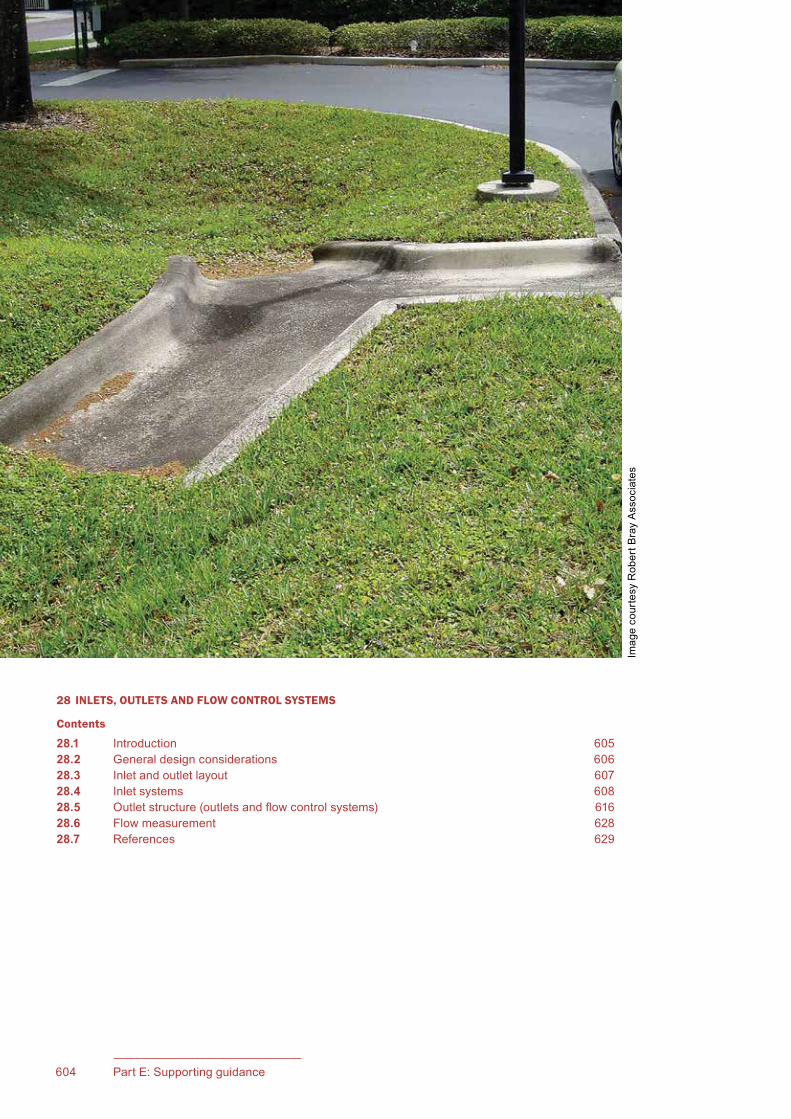
604 Part E: Supporting guidance
CIRIA SuDS Manual 2015
28 INLETS, OUTLETS AND FLOW CONTROL SYSTEMS
Contents
28.1 Introduction 60528.2 General design considerations 60628.3 Inlet and outlet layout 60728.4 Inlet systems 60828.5 Outletstructure(outletsandflowcontrolsystems) 61628.6 Flowmeasurement 62828.7 References 629
Imag
e co
urte
sy R
ober
t Bra
y A
ssoc
iate
s

605Chapter 28: Inlets, outlets and flow control systems
CIRIA SuDS Manual 2015
28Chapter
28.1 INTRODUCTION
InletsandoutletsarethestructuresorlandscapefeaturesthatmanagetheflowintoandoutofaSuDScomponent.Controlstructureslimittheflowthroughtheoutletandareusuallynecessaryinordertomeetthesitedischargerate.LimitingtheflowcauseswatertobackupintheSuDScomponent,allowingtheattenuationstoragevolumetobefilled.
Thereisawidevarietyofdifferenttypesandstylesofstructure/featureavailable,andtheycanbedesignedtoaddinterestandcharactertoanurbansetting,ortoblendintoa natural landscape.
Thesuitabilityofdifferenttypesofinletoroutletwilloftendependonthetypeofcomponenttheyareservingandtheprocessesitsupports.Insomecases,thetypeofcomponent(egpermeablepavementsorattenuationtankstoragesystems)ortheconstraintsofasite,willleadtotheuseofbelow-groundcontrolstructures(sitedinaccesschambers,commonlyadaptedfromstandardinspectionchamberspecificationsfornon-man-entryandstandardmanholespecificationsforman-entryaccess).
Where a SuDS scheme includes Interception components and manages runoff close to source (Chapter 4),velocitiestendtobelow,andcontrolstructurescanbesmall.Keepingrunoffonthesurfacehelpskeepinletsandoutletsshallow,visibleandcost-effective.Headwallsandabutmentsshouldbeassmallaspossibleandcanbedesignedusinglocalmaterials,suchaslocalstone,localbricks,timberetc.Whereconcreteisused,itcanbetexturedorcladtoaddinterestandblendmoreeffectivelywithnearbynaturalfeatures.Sympatheticplantingaroundthestructurescanhelpwiththeirintegrationintothelandscape,butthisshouldnotimpedeoperationorobscuretheireasyviewing,forinspections.Plantingcanalsobeusedtohelppreventerosion,using planting mats and other bioengineered materials that are often deployed for channelbankprotection.Otheroptionsincludeusingstoneorotherrip-rapmaterialsforenergy dissipation.
Inallcases,thehydraulic,structuralandgeotechnicaldesignofinletandoutletstructuresshouldbeundertakenbydesignerswithappropriatetechnical/engineeringexpertise.Guidanceonsizingisprovidedinthischapter,buttextbooks,suchasthosebyChow(1959)andHenderson(1966),shouldbereferencedfordetailedtheoryrelevanttothehydraulicdesign,wherenecessary.
Inlets, outlets and flow control systemsThis chapter provides guidance on the design of inlets, outlets and flow control systems. Inlets and outlets are the structures or landscape features that convey the flow into and out of a SuDS component. Control structures limit the flow through the outlet of a SuDS component.
Guidance on good landscape practice is discussed in Chapter 29.
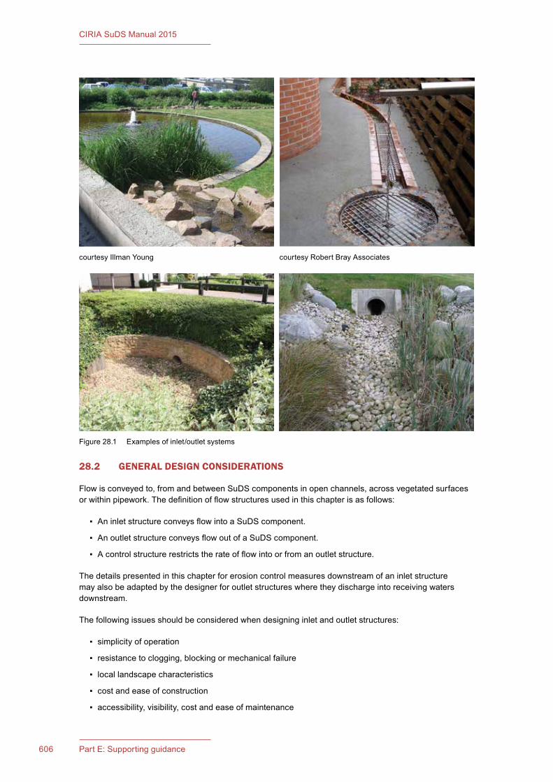
606 Part E: Supporting guidance
CIRIA SuDS Manual 2015
28.2 GENERAL DESIGN CONSIDERATIONS
Flowisconveyedto,fromandbetweenSuDScomponentsinopenchannels,acrossvegetatedsurfacesorwithinpipework.Thedefinitionofflowstructuresusedinthischapterisasfollows:
▪ AninletstructureconveysflowintoaSuDScomponent.
▪ AnoutletstructureconveysflowoutofaSuDScomponent.
▪ Acontrolstructurerestrictstherateofflowintoorfromanoutletstructure.
Thedetailspresentedinthischapterforerosioncontrolmeasuresdownstreamofaninletstructuremayalsobeadaptedbythedesignerforoutletstructureswheretheydischargeintoreceivingwatersdownstream.
Thefollowingissuesshouldbeconsideredwhendesigninginletandoutletstructures:
▪ simplicity of operation
▪ resistancetoclogging,blockingormechanicalfailure
▪ local landscape characteristics
▪ cost and ease of construction
▪ accessibility,visibility,costandeaseofmaintenance
courtesy Illman Young courtesy Robert Bray Associates
Figure28.1 Examplesofinlet/outletsystems
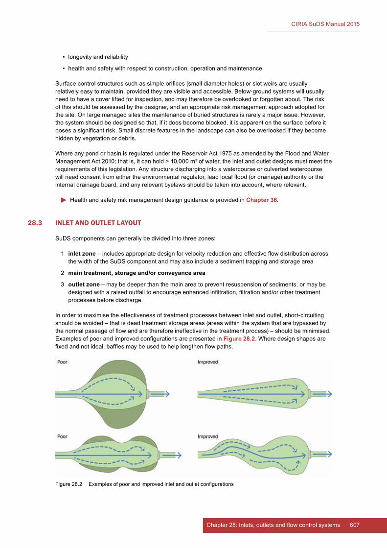
607Chapter 28: Inlets, outlets and flow control systems
CIRIA SuDS Manual 2015
▪ longevity and reliability
▪ healthandsafetywithrespecttoconstruction,operationandmaintenance.
Surfacecontrolstructuressuchassimpleorifices(smalldiameterholes)orslotweirsareusuallyrelativelyeasytomaintain,providedtheyarevisibleandaccessible.Below-groundsystemswillusuallyneedtohaveacoverliftedforinspection,andmaythereforebeoverlookedorforgottenabout.Theriskofthisshouldbeassessedbythedesigner,andanappropriateriskmanagementapproachadoptedforthesite.Onlargemanagedsitesthemaintenanceofburiedstructuresisrarelyamajorissue.However,thesystemshouldbedesignedsothat,ifitdoesbecomeblocked,itisapparentonthesurfacebeforeitposesasignificantrisk.Smalldiscretefeaturesinthelandscapecanalsobeoverlookediftheybecomehidden by vegetation or debris.
WhereanypondorbasinisregulatedundertheReservoirAct1975asamendedbytheFloodandWaterManagementAct2010;thatis,itcanhold>10,000m3ofwater,theinletandoutletdesignsmustmeettherequirementsofthislegislation.Anystructuredischargingintoawatercourseorculvertedwatercoursewillneedconsentfromeithertheenvironmentalregulator,leadlocalflood(ordrainage)authorityortheinternaldrainageboard,andanyrelevantbyelawsshouldbetakenintoaccount,whererelevant.
HealthandsafetyriskmanagementdesignguidanceisprovidedinChapter 36.
28.3 INLET AND OUTLET LAYOUT
SuDScomponentscangenerallybedividedintothreezones:
1 inlet zone–includesappropriatedesignforvelocityreductionandeffectiveflowdistributionacrossthewidthoftheSuDScomponentandmayalsoincludeasedimenttrappingandstoragearea
2 main treatment, storage and/or conveyance area
3 outlet zone–maybedeeperthanthemainareatopreventresuspensionofsediments,ormaybedesignedwitharaisedoutfalltoencourageenhancedinfiltration,filtrationand/orothertreatmentprocesses before discharge.
Inordertomaximisetheeffectivenessoftreatmentprocessesbetweeninletandoutlet,short-circuitingshouldbeavoided–thatisdeadtreatmentstorageareas(areaswithinthesystemthatarebypassedbythenormalpassageofflowandarethereforeineffectiveinthetreatmentprocess)–shouldbeminimised.ExamplesofpoorandimprovedconfigurationsarepresentedinFigure 28.2. Where design shapes are fixedandnotideal,bafflesmaybeusedtohelplengthenflowpaths.
Figure28.2 Examplesofpoorandimprovedinletandoutletconfigurations

608 Part E: Supporting guidance
CIRIA SuDS Manual 2015
28.4 INLET SYSTEMS
ThemechanismbywhichrunoffiscollectedanddeliveredtoaSuDScomponentwillvary,dependingonthecomponenttype,sitelayout,topographyandflowpaths.Perviouspavementsandgreenroofscollectrunoffdirectlywithouttheneedforinlets.Filterstrips,filterdrainsandswalesshouldgenerallyreceiverunoffvialateralinletsystemsthatdistributetheflowalongacontinuousorsemi-continuouslength.Pointinletsfrompipedcollectionsystemsareusuallyrequiredforinflowstopondsanddetentionbasins.Runoffwilloftenbedischargedintobioretentionsystems,andsomeswalesviagapsorholesinkerbing.Therewillalwaysbeothersite-specificscenariosthatwillrequirethemodificationofstandardinletconfigurations,suchasthedeliveryofroofwaterintoaperviouspavementsub-base,andtheintroductionofwaterintoswalesviapointsourceinlets.
28.4.1 Inlet design
Allinletsshouldbedesignedtomeetthefollowingrequirements:
▪ delivertherequiredmaximumflowratefreelyfromtheupstreamcollectionsystem
▪ beassimpleaspossible(takingintoaccountthecharacteristicsofthesiteandthelevelofmanagement)
▪ be easy to construct
▪ be structurally robust
▪ functionalityisclearandobviousforthosewhowillmaintainthemandforthelocalcommunity(whereappropriate)
▪ beeasyandconvenienttomaintain(egeasilyaccessiblefortherequiredoperations,andrequiringmaintenancefrequenciesthatalignwiththesitelandscapemaintenancerequirements)
▪ havelowriskofblockage
▪ havelowriskoferosion
▪ havelowriskstopeople(egnoopenpipeworkaccessibletosmallchildren)
▪ havelowriskstowildlife,takingintoaccountthesite-specificcharacteristicsandlikelybiodiversity(egnoexposedsumps,traps,gulliesoropeninletstosewers)
▪ bevisuallyinterestingorneutral(ienonegativeaesthetics)
▪ havelowriskofvandalism
▪ becost-effective.
SpecificinletdetailsforeachSuDScomponentaresetoutinindividualchapters(Chapters 11–23).Thischapterpresentsgenericconcepts,togetherwithhydrauliccontrolprinciples.
28.4.2 Point inlets
Componentsofastandard,smallpipedinletsystemarelikelytocomprise:
1 conveyance pipeofsuitablediametertoallowunrestrictedflow,laidtoappropriatefall,withbeddingand surround
2 inlet protection tothepipe,suchasasmallconcretesurround,asmallheadwall,stone-filledbasketsorgabionprotection
3 erosion control(ifrequired)suchasconcrete,stoneorsettpad,rip-raporotheraprondevicetoreduceenergywithintheinflowthatmaydamagetheSuDScomponentsurfaceand/orplanting
4 �flow�spreading(ifrequired)suchasahorizontalsillorlowbermtopreventflowchannellingandmaximisetreatmentefficienciesofvegetatedsurfaces.

609Chapter 28: Inlets, outlets and flow control systems
CIRIA SuDS Manual 2015
Inletdesignshouldrecognisethesourceoftheupstreamflow.Wherethesurfacewaterrunoffisdischargedfromafilterdrain,orperviouspavement,itwillbefreefromanydebrisorsedimentthatmightneedtoberemoved,andthereforeagrilleorstoneprotectionfortheinletwouldbeacceptable.Wherewateriscollectedfromanopensystem,suchasaswaleorhardsurface,thereisalwaysariskthatsilt,litterorvegetationcouldblockthepipe,andsoeaseofmaintenanceisfundamentaltothedesign.
Inletsraisedaboveanyadjacentpermanentwaterlevelsaregenerallyrecommended.Submergedinletshavethefollowingpotentialrisks:
▪ surchargingorbackwatereffectontheupstreamsurfacewaterconveyancesystem
▪ scour/resuspensionofthecomponentbaseneartheinlet
▪ clogging of the inlet by sedimentation near the inlet
▪ sediment deposition in the upstream conveyance system.
Also,allconcealedinfrastructureislikelytobeatriskfromblockageorlackofmaintenance.
Hardengineerederosionprotectionsystemscanoftenbereplacedbydeeppoolsandplantedberms.Poolsdissipateenergyandmoderatevelocities,whichinturnhelptolimittheresuspensionofaccumulatedsediments.Plantedrockbermscancreatelowweirsthatareresistanttobreachingandallowdebristoaccumulateupstream.Whereregularsedimentremovalislikelytoberequiredsuchaswithinaforebay,aconcretebasemaybeappropriate.
ExamplesofcurrentgoodpracticeareshowninFigure 28.3.
Wherehighflowsareunavoidableandlargerdiameterpipesareinvolved,concrete,brickorstoneheadwallsmayberequired.Theremayalsobeaneedforsafety/securityscreeningofpipeoutfalls.Insuchsituations,thehardsurfaceshouldbecarefullyintegratedwiththeadjacentlandscapingtoenhanceaestheticimpact,minimisesafetyrisks(egtriphazards)andfacilitatemaintenance.Suchstructuresshouldbeverycarefullydesignediftheyaretobeacceptablefromamaintenance,amenityandsustainabilityperspective.Verticalconcretefacesonoutlets,inparticular,tendtoexacerbateblockagerisks(thisisnotanissueoninlets)andlargeverticaldropscaneasilyposeahealthandsafetyrisk,whichis generally not effectively mitigated through the use of fencing. Siting planting beds above inlets can help todisguisethemfromabove,whilestillallowingaccessfrombelowandmayreducetheneedforfencing.
ErosioncontrolsystemsandmoreformalenergydissipationdevicesforinletsaredescribedinSection 28.4.6.
28.4.3 Lateral inlets
Where runoff is draining laterally from an impermeable surface and is collected by a SuDS component runningalongitsedge(egfilterstrip,swale,filterdrainorbioretentionsystem)thecollectionmechanismshouldprovideanappropriateedgedetailtothepavement,whichallowsthetransferofrunofftotheSuDSandminimisestheriskofflow“channelling”thatcancausedeteriorationinperformanceorfailureofthedownstreamSuDS.
ItisimportantthatgrassgrowthisrobustattheedgeofthedetailtopreventerosionoftheSuDSsurface.Thiswillgenerallyrequiretopsoildepthsof100–150mm,whichmaymeanthatkerbdepthsneedtobeincreased,orarevisededgingdetailused.Also,thereceivinggrasssurfaceshouldbe20–30mmbelowthekerbedge,sothattherunoffcandischargefreelyandthereisnoriskofsedimentaccumulationblockingtheflowpath(Chapter 9).
Gravelstripsortactilepavingblockscanalsobeusedtopre-filterandspreadtheflowdownstreamofkerbedges.Siltiscollectedwithinthegravelstrips,althoughsuchstrips(eventually)tendtoonlyactasflowspreadersasthesiltcannoteasilyberemovedduringoperationandmaintenanceactivities.
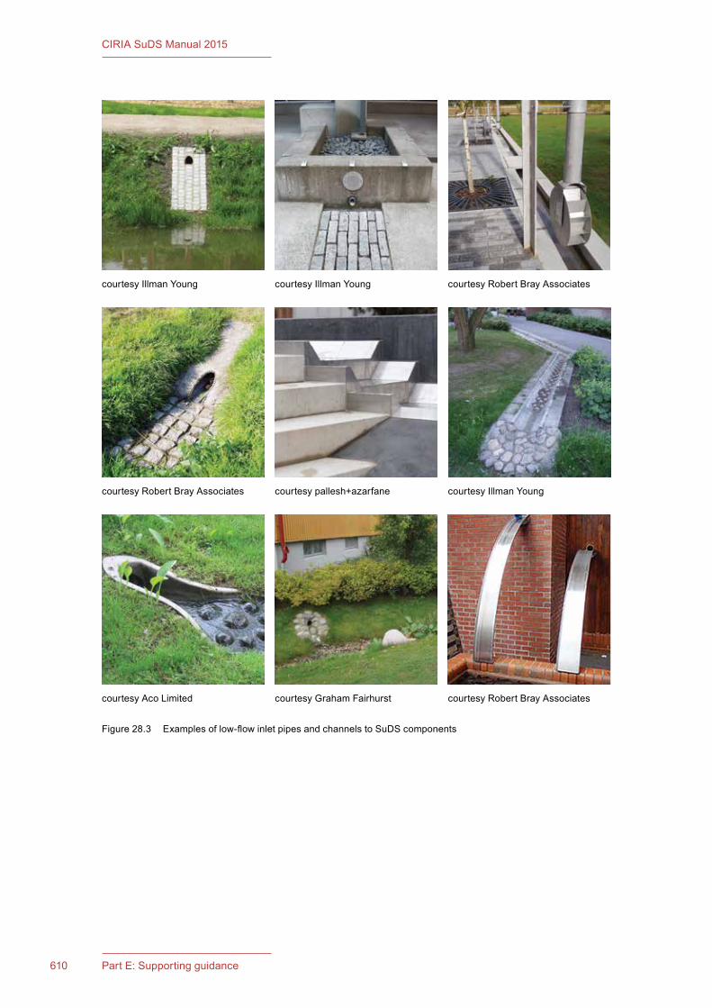
610 Part E: Supporting guidance
CIRIA SuDS Manual 2015
courtesy Illman Young courtesy Robert Bray Associatescourtesy Illman Young
courtesy Robert Bray Associates
courtesy Graham Fairhurstcourtesy Aco Limited
courtesypallesh+azarfane
courtesy Robert Bray Associates
courtesy Illman Young
Figure28.3 Examplesoflow-flowinletpipesandchannelstoSuDScomponents
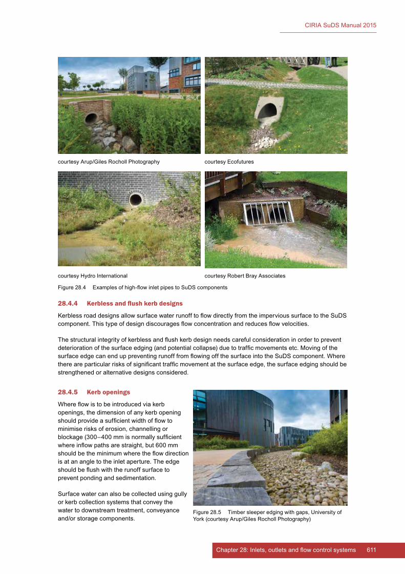
611Chapter 28: Inlets, outlets and flow control systems
CIRIA SuDS Manual 2015
28.4.4 Kerbless and flush kerb designs
KerblessroaddesignsallowsurfacewaterrunofftoflowdirectlyfromtheimpervioussurfacetotheSuDScomponent.Thistypeofdesigndiscouragesflowconcentrationandreducesflowvelocities.
Thestructuralintegrityofkerblessandflushkerbdesignneedscarefulconsiderationinordertopreventdeteriorationofthesurfaceedging(andpotentialcollapse)duetotrafficmovementsetc.MovingofthesurfaceedgecanenduppreventingrunofffromflowingoffthesurfaceintotheSuDScomponent.Wherethereareparticularrisksofsignificanttrafficmovementatthesurfaceedge,thesurfaceedgingshouldbestrengthened or alternative designs considered.
28.4.5 Kerb openings
Whereflowistobeintroducedviakerbopenings,thedimensionofanykerbopeningshouldprovideasufficientwidthofflowtominimiserisksoferosion,channellingorblockage(300–400mmisnormallysufficientwhereinflowpathsarestraight,but600mmshouldbetheminimumwheretheflowdirectionis at an angle to the inlet aperture. The edge shouldbeflushwiththerunoffsurfacetoprevent ponding and sedimentation.
Surfacewatercanalsobecollectedusinggullyorkerbcollectionsystemsthatconveythewatertodownstreamtreatment,conveyanceand/orstoragecomponents.
courtesyArup/GilesRochollPhotography courtesyEcofutures
courtesyHydroInternational courtesy Robert Bray Associates
Figure28.4 Examplesofhigh-flowinletpipestoSuDScomponents
Figure28.5 Timbersleeperedgingwithgaps,UniversityofYork(courtesyArup/GilesRochollPhotography)
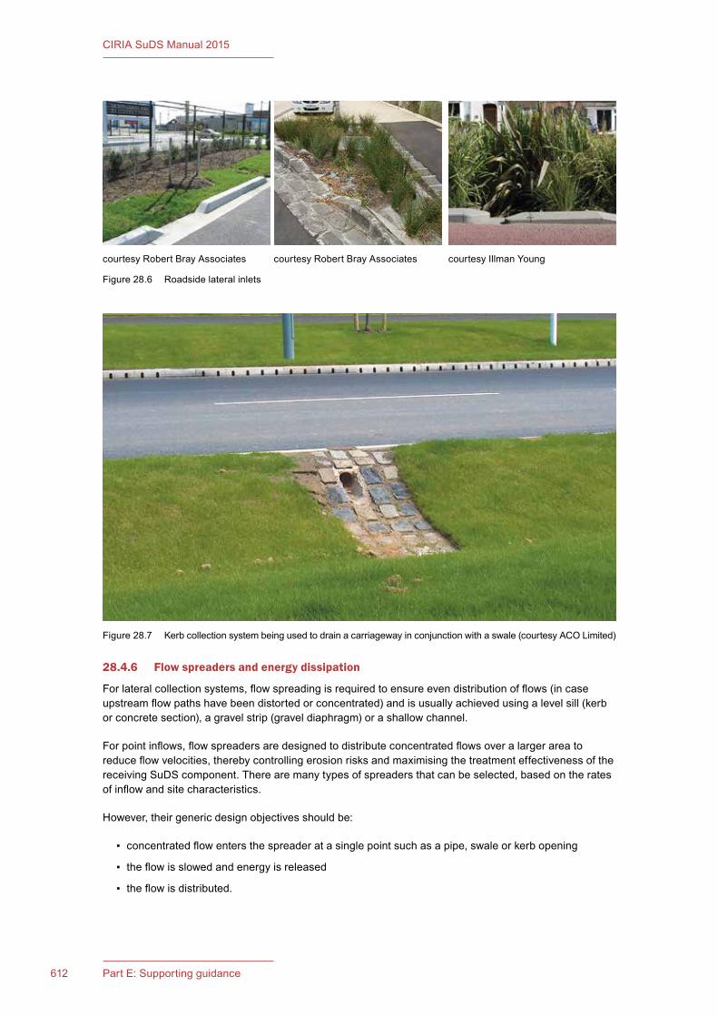
612 Part E: Supporting guidance
CIRIA SuDS Manual 2015
28.4.6 Flow spreaders and energy dissipation
Forlateralcollectionsystems,flowspreadingisrequiredtoensureevendistributionofflows(incaseupstreamflowpathshavebeendistortedorconcentrated)andisusuallyachievedusingalevelsill(kerborconcretesection),agravelstrip(graveldiaphragm)orashallowchannel.
Forpointinflows,flowspreadersaredesignedtodistributeconcentratedflowsoveralargerareatoreduceflowvelocities,therebycontrollingerosionrisksandmaximisingthetreatmenteffectivenessofthereceivingSuDScomponent.Therearemanytypesofspreadersthatcanbeselected,basedontheratesofinflowandsitecharacteristics.
However,theirgenericdesignobjectivesshouldbe:
▪ concentratedflowentersthespreaderatasinglepointsuchasapipe,swaleorkerbopening
▪ theflowisslowedandenergyisreleased
▪ theflowisdistributed.
courtesy Robert Bray Associates courtesy Robert Bray Associates courtesy Illman Young
Figure28.6 Roadsidelateralinlets
Figure28.7 Kerbcollectionsystembeingusedtodrainacarriagewayinconjunctionwithaswale(courtesyACOLimited)
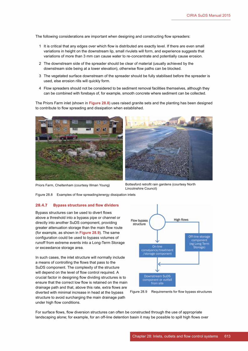
613Chapter 28: Inlets, outlets and flow control systems
CIRIA SuDS Manual 2015
Thefollowingconsiderationsareimportantwhendesigningandconstructingflowspreaders:
1 Itiscriticalthatanyedgesoverwhichflowisdistributedareexactlylevel.Ifthereareevensmallvariationsinheightonthedownstreamlip,smallrivuletswillform,andexperiencesuggeststhatvariationsofmorethan3mmcancausewatertore-concentrateandpotentiallycauseerosion.
2 Thedownstreamsideofthespreadershouldbeclearofmaterial(usuallyachievedbythedownstreamsidebeingatalowerelevation),otherwiseflowpathscanbeblocked.
3 Thevegetatedsurfacedownstreamofthespreadershouldbefullystabilisedbeforethespreaderisused,elseerosionrillswillquicklyform.
4 Flowspreadersshouldnotbeconsideredtobesedimentremovalfacilitiesthemselves,althoughtheycanbecombinedwithforebaysof,forexample,smoothconcretewheresedimentcanbecollected.
ThePriorsFarminlet(showninFigure 28.8)usesraisedgranitesetsandtheplantinghasbeendesignedtocontributetoflowspreadinganddissipationwhenestablished.
28.4.7 Bypass structures and flow dividers
Bypassstructurescanbeusedtodivertflowsabove a threshold into a bypass pipe or channel or directlyintoanotherSuDScomponent,providinggreaterattenuationstoragethanthemainflowroute(forexample,asshowninFigure 28.9).ThesameconfigurationcouldbeusedtobypassvolumesofrunofffromextremeeventsintoaLong-TermStorageorexceedancestoragearea.
Insuchcases,theinletstructurewillnormallyincludeameansofcontrollingtheflowsthatpasstotheSuDScomponent.Thecomplexityofthestructurewilldependonthelevelofflowcontrolrequired.Acrucialfactorindesigningflowdividingstructuresistoensurethatthecorrectlowflowisretainedonthemaindrainagepathandthat,abovethisrate,extraflowsaredivertedwithminimalincreaseinheadatthebypassstructure to avoid surcharging the main drainage path underhighflowconditions.
Forsurfaceflows,flowdiversionstructurescanoftenbeconstructedthroughtheuseofappropriatelandscapingalone;forexample,foranoff-linedetentionbasinitmaybepossibletospillhighflowsover
Bottesfordretrofitraingardens(courtesyNorthLincolnshireCouncil)
PriorsFarm,Cheltenham(courtesyIllmanYoung)
Figure28.8 Examplesofflowspreading/energydissipationinlets
Figure28.9 Requirementsforflowbypassstructures
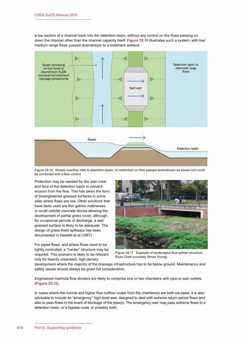
614 Part E: Supporting guidance
CIRIA SuDS Manual 2015
alowsectionofachannelbankintothedetentionbasin,withoutanycontrolontheflowspassingondownthechannelotherthanthechannelcapacityitself.Figure 28.10 illustratessuchasystem,withlow/mediumrangeflowspasseddownstreamtoatreatmentwetland.
Protectionmaybeneededfortheweircrestand face of the detention basin to prevent erosionfromtheflow.Thishastakentheformof bioengineered grassed surfaces in some siteswhereflowsarelow.Othersolutionsthathave been used are thin gabion mattresses orsmallcellularconcreteblocksallowingthedevelopmentofpartialgrasscover,although,foroccasionalperiodsofdischarge,awellgrassedsurfaceislikelytobeadequate.Thedesignofgrass-linedspillwayshasbeendocumentedinHewlettet al(1987).
Forpipedflows,andwhereflowsneedtobetightlycontrolled,a“harder”structuremayberequired.Thisscenarioislikelytoberelevantonlyforheavilyurbanised,highdensitydevelopmentwherethemajorityofthedrainageinfrastructurehastobebelowground.Maintenanceandsafetyissuesshouldalwaysbegivenfullconsideration.
Engineeredmanholeflowdividersarelikelytocompriseoneortwochamberswithpipeorweiroutlets(Figure 28.12).
Incaseswherethenormalandhigherflowoutflowroutesfromthechamber(s)arebothviapipes,itisalsoadvisabletoincludean“emergency”high-levelweir,designedtodealwithextremereturnperiodflowsandalsotopassflowsintheeventofblockageofthepipe(s).Theemergencyweirmaypassextremeflowstoadetentionbasin,orabypassroute,orpossiblyboth.
Figure28.10 Simpleoverflowinlettodetentionbasin;norestrictiononflowpasseddownstreamasshownbutcouldbecombinedwithaflowcontrol
Figure28.11 Exampleoflandscapedflowsplitterstructure,RiverChelt(courtesyIllmanYoung)
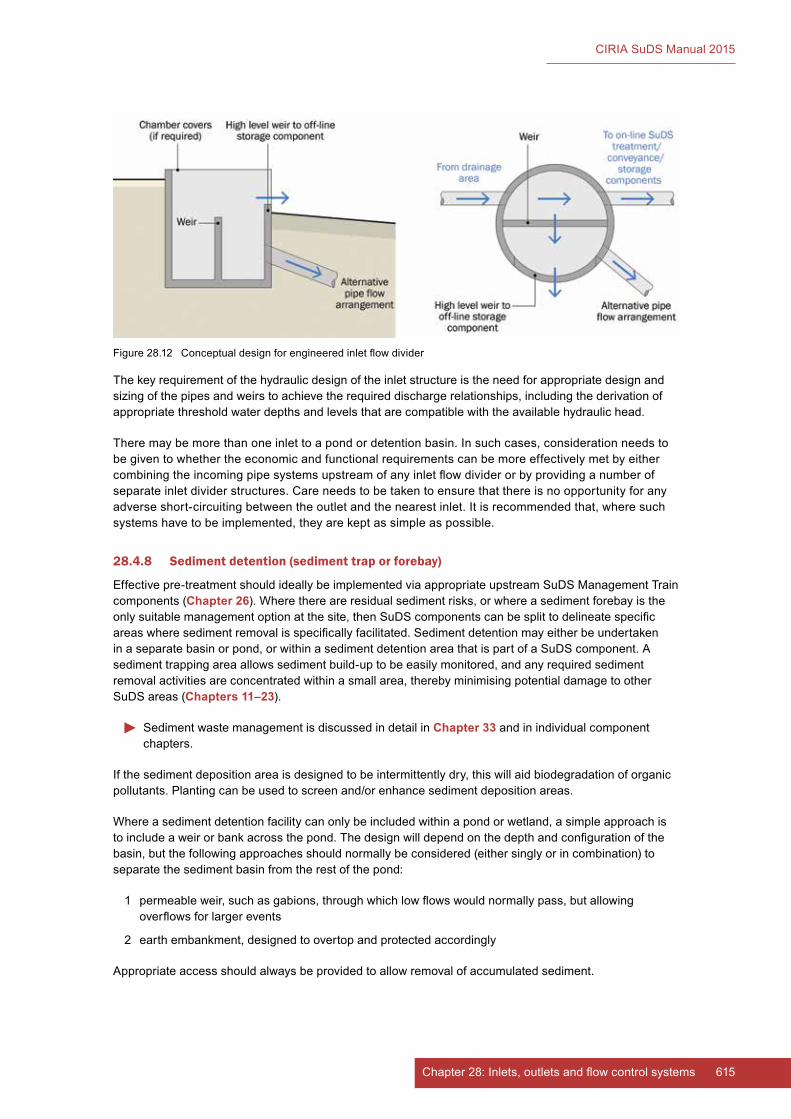
615Chapter 28: Inlets, outlets and flow control systems
CIRIA SuDS Manual 2015
Thekeyrequirementofthehydraulicdesignoftheinletstructureistheneedforappropriatedesignandsizingofthepipesandweirstoachievetherequireddischargerelationships,includingthederivationofappropriatethresholdwaterdepthsandlevelsthatarecompatiblewiththeavailablehydraulichead.
Theremaybemorethanoneinlettoapondordetentionbasin.Insuchcases,considerationneedstobegiventowhethertheeconomicandfunctionalrequirementscanbemoreeffectivelymetbyeithercombiningtheincomingpipesystemsupstreamofanyinletflowdividerorbyprovidinganumberofseparateinletdividerstructures.Careneedstobetakentoensurethatthereisnoopportunityforanyadverseshort-circuitingbetweentheoutletandthenearestinlet.Itisrecommendedthat,wheresuchsystemshavetobeimplemented,theyarekeptassimpleaspossible.
28.4.8 Sediment detention (sediment trap or forebay)
Effectivepre-treatmentshouldideallybeimplementedviaappropriateupstreamSuDSManagementTraincomponents (Chapter 26).Wherethereareresidualsedimentrisks,orwhereasedimentforebayistheonlysuitablemanagementoptionatthesite,thenSuDScomponentscanbesplittodelineatespecificareaswheresedimentremovalisspecificallyfacilitated.Sedimentdetentionmayeitherbeundertakeninaseparatebasinorpond,orwithinasedimentdetentionareathatispartofaSuDScomponent.Asedimenttrappingareaallowssedimentbuild-uptobeeasilymonitored,andanyrequiredsedimentremovalactivitiesareconcentratedwithinasmallarea,therebyminimisingpotentialdamagetootherSuDS areas (Chapters 11–23).
SedimentwastemanagementisdiscussedindetailinChapter 33 and in individual component chapters.
Ifthesedimentdepositionareaisdesignedtobeintermittentlydry,thiswillaidbiodegradationoforganicpollutants.Plantingcanbeusedtoscreenand/orenhancesedimentdepositionareas.
Whereasedimentdetentionfacilitycanonlybeincludedwithinapondorwetland,asimpleapproachistoincludeaweirorbankacrossthepond.Thedesignwilldependonthedepthandconfigurationofthebasin,butthefollowingapproachesshouldnormallybeconsidered(eithersinglyorincombination)toseparatethesedimentbasinfromtherestofthepond:
1 permeableweir,suchasgabions,throughwhichlowflowswouldnormallypass,butallowingoverflowsforlargerevents
2 earthembankment,designedtoovertopandprotectedaccordingly
Appropriateaccessshouldalwaysbeprovidedtoallowremovalofaccumulatedsediment.
Figure28.12 Conceptualdesignforengineeredinletflowdivider

616 Part E: Supporting guidance
CIRIA SuDS Manual 2015
28.5 OUTLET STRUCTURE (OUTLETS AND FLOW CONTROL SYSTEMS)
OutletstructuresconveyandcontroltheflowoutoftheSuDScomponentsand,therefore,determinetheabilityofthesystemtomanagebothlowandhighflows.Outletscaneitherbeonthesurface(openchannelsbuiltintothevisibleedgeofthecomponent),pipedsystems(conveyingwaterthroughtheedgeofthecomponent)orslowseepagesystems(conveyingwaterslowlythroughaporousmedium).
Lowreturnperiodflowsarenormallycontrolledwithsmaller,oftenprotected,outletstructures,suchasorificeslocatedwithinscreenedpipesorrisers,perforatedplatesorrisers,smallpipes,reverse-slopepipesandV-notchweirs.Largerflowsaretypicallycontrolledusingoverflows,suchasflowsoveraweirwithinamanholeoracrossaspillway/weirthroughanembankment.Overflowweirscanbeofvariedheightsandconfiguredtohandlecontrolofmultipledesignflows.
Vortexflowcontrolsystemscanalsobeusedtomanagearangeofflows(Section 28.5.7).
OutletsareusuallybuiltintothedownstreambanksideofSuDScomponentswitheasyaccessformaintenance.
Forpipedsystems,aboxormanholeoutletstructuredownstreamoftheoutletcanaccommodateavarietyofflowcontrolmechanisms,althoughthedepthofsuchstructuresshouldbeconsideredcarefullyinthecontextofaccess,easeofmaintenanceandconfinedentryrequirements.Anypipebeddingand/orsurroundmaterialcanbeaconveyanceroute,andwhereflowcontrolsareincludedwithinthedesign,imperviousfill/protectionagainstseepageisrequired.
Similar techniques to those described for inlets can be employed to integrate outlet structures into the overalllandscape.Naturalstoneandplantmaterialcanbeusedinplaceofconcreteandhardstructurestomeetaesthetic,amenity,ecologyandsustainabilityobjectives.Anyoutletdesignshouldminimisetheriskofcloggingandblockage,andtheirsitingshouldallowaccessforeaseofmaintenance.
28.5.1 Outlet system design
Thesizingofoutletstructuresistypicallyaprocesswhereiterationisusedtorefinethedesigndetails. A stage discharge curve is usually established for a given outlet design. Then calculations are undertakenoramodelisruntodeterminewhetherthepeakoutflowforarangeofreturnperiodsflowsis adequately controlled.
Akeystepistoidentifyclearlythedutiesthatthestructureneedstoperformandthereforethe components that need to be included. Table 28.1 gives a broad indication of the principal componentsthatmayberequired.Ingeneral,outletstructuresshouldbedesignedtobeassimpleaspossibletoconstruct,operateandmaintain.Themainconcernforalloutletsshouldbeminimisingtheriskofblockage.
Inthefollowingsections,arangeofoutletsystemsaredescribedthataregenerallyappropriateformaximumwaterdepthsofuptoabout2m.SuDSdesignsshouldnotinvolvegreaterdepthsofwater.However,shouldlargerstructuresberequired,designersshouldfollowtheguidancegiveninHallet al (1993),whichcontainsacomprehensiveaccountofthetypesofcontrolstructuresthatmaybedeployedfortheoutletstructuresofon-lineandoff-linefloodstoragereservoirs.
28.5.2 Orifices
Anorificeisacircularorrectangularopeningofaprescribedshapeandsizethatallowsacontrolledrateofoutflowwhentheorificeissubmerged.Whenitisnotsubmerged,theopeningactsasaweir.Theflowratedependsontheheightofthewaterabovetheopening(hydraulichead)andthesizeandedgetreatmentoftheorifice.Whenusingasimpleorificeplate,theflowratepassingthroughthecontrolisdirectly proportional to the square root of the upstream head (Equation 28.1 and Figure 28.13),soasthewaterlevelincreases,theflowalsoincreasessteadily.
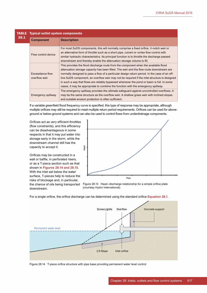
617Chapter 28: Inlets, outlets and flow control systems
CIRIA SuDS Manual 2015
TABLE28.1
Typical outlet system components
Component Description
Flowcontroldevice
FormostSuDScomponents,thiswillnormallycompriseafixedorifice,V-notchweiroranalternativeformofthrottlesuchasashortpipe,culvertorvortexflowcontrolwithsimilar hydraulic characteristics. Its principal function is to throttle the discharge passed downstreamandtherebyenabletheattenuationstoragevolumetofill.
Exceedanceflowoverflowweir
Thisprovidestheflooddischargeroutefromthecomponentwhentheavailablefloodattenuationstoragecapacityhasbeenfilled.Theweirandtheflowroutedownstreamarenormallydesignedtopassaflowofaparticulardesignreturnperiod.Inthecaseofanoff-lineSuDScomponent,anoverflowweirmaynotberequirediftheinletstructureisdesignedinsuchawaythatflowsarereliablybypassedwheneverthepondorbasinisfull.Insomecases,itmaybeappropriatetocombinethefunctionwiththeemergencyspillway.
EmergencyspillwayTheemergencyspillwayprovidestheultimatesafeguardagainstuncontrolledoverflows.Itmaybethesamestructureastheoverflowweir.Ashallowgrassweirwithinclinedslopesandsuitableerosionprotectionisoftensufficient.
Ifavariablegreenfieldfloodfrequencycurveisspecified,thistypeofresponsemaybeappropriate,althoughmultipleorificesmaystillberequiredtomeetmultiplereturnperiodrequirements.Orificescanbeusedforabove-groundorbelow-groundsystemsandcanalsobeusedtocontrolflowsfromunderdrainagecomponents.
Orificesactasveryefficientthrottles(flowconstraints),andthisefficiencycan be disadvantageous in some respectsinthatitmayputwaterintostorageearlyinthestorm,whilethedownstreamchannelstillhasthecapacity to accept it.
Orificesmaybeconstructedinawallorbaffle,inperforatedrisers,orasaT-piecesectionsuchasthatshowninFigures 28.14 and 28.15. Withtheinletsetbelowthewatersurface,T-pieceshelptoreducetherisksofblockageand,inparticular,the chance of oils being transported downstream.
Forasingleorifice,theorificedischargecanbedeterminedusingthestandardorificeEquation 28.1.
Figure28.13 Head–dischargerelationshipforasimpleorificeplate(courtesyHydroInternational)
Figure28.14 T-pieceorificestructurewithpipebaseprovidingpermanentwaterlevelcontrol
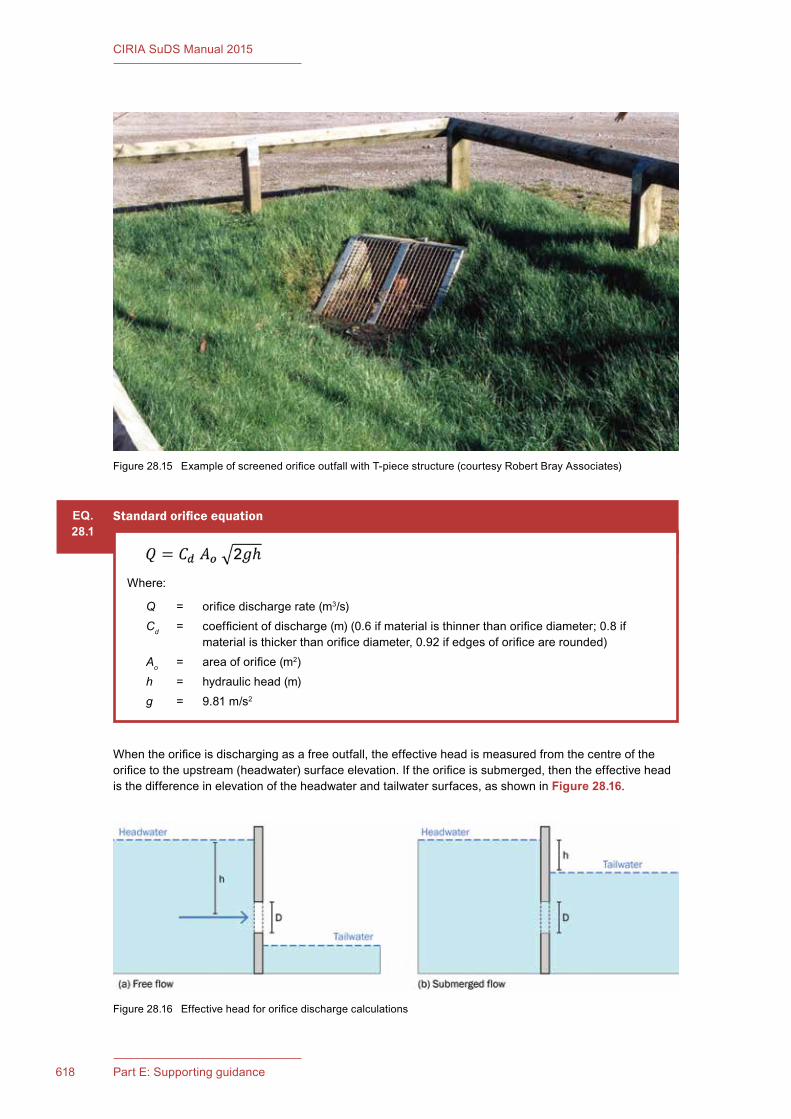
618 Part E: Supporting guidance
CIRIA SuDS Manual 2015
Whentheorificeisdischargingasafreeoutfall,theeffectiveheadismeasuredfromthecentreoftheorificetotheupstream(headwater)surfaceelevation.Iftheorificeissubmerged,thentheeffectiveheadisthedifferenceinelevationoftheheadwaterandtailwatersurfaces,asshowninFigure 28.16.
Figure28.15 ExampleofscreenedorificeoutfallwithT-piecestructure(courtesyRobertBrayAssociates)
Figure28.16 Effectiveheadfororificedischargecalculations
EQ.28.1
Standard orifice equation
Where:
Q = orificedischargerate(m3/s)Cd = coefficientofdischarge(m)(0.6ifmaterialisthinnerthanorificediameter;0.8if
materialisthickerthanorificediameter,0.92ifedgesoforificearerounded)Ao = areaoforifice(m2)h = hydraulichead(m)g = 9.81m/s2
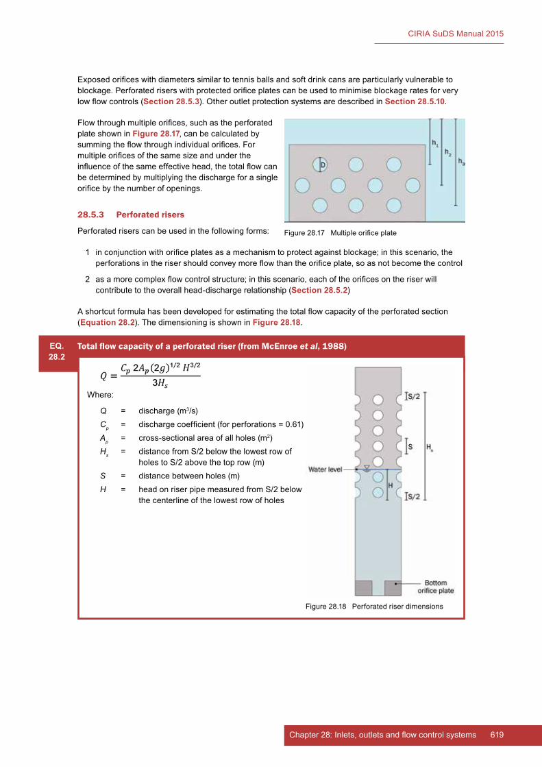
619Chapter 28: Inlets, outlets and flow control systems
CIRIA SuDS Manual 2015
Exposedorificeswithdiameterssimilartotennisballsandsoftdrinkcansareparticularlyvulnerabletoblockage.Perforatedriserswithprotectedorificeplatescanbeusedtominimiseblockageratesforverylowflowcontrols(Section 28.5.3).OtheroutletprotectionsystemsaredescribedinSection 28.5.10.
Flowthroughmultipleorifices,suchastheperforatedplateshowninFigure 28.17,canbecalculatedbysummingtheflowthroughindividualorifices.Formultipleorificesofthesamesizeandundertheinfluenceofthesameeffectivehead,thetotalflowcanbe determined by multiplying the discharge for a single orificebythenumberofopenings.
28.5.3 Perforated risers
Perforatedriserscanbeusedinthefollowingforms:
1 inconjunctionwithorificeplatesasamechanismtoprotectagainstblockage;inthisscenario,theperforationsintherisershouldconveymoreflowthantheorificeplate,soasnotbecomethecontrol
2 asamorecomplexflowcontrolstructure;inthisscenario,eachoftheorificesontheriserwillcontributetotheoverallhead-dischargerelationship(Section 28.5.2)
Ashortcutformulahasbeendevelopedforestimatingthetotalflowcapacityoftheperforatedsection(Equation 28.2).ThedimensioningisshowninFigure 28.18.
Figure28.17 Multipleorificeplate
EQ.28.2
Total flow capacity of a perforated riser (from McEnroe et al, 1988)
Where:
Q = discharge (m3/s)Cp = dischargecoefficient(forperforations=0.61)Ap = cross-sectionalareaofallholes(m2)Hs = distancefromS/2belowthelowestrowof
holestoS/2abovethetoprow(m)S = distancebetweenholes(m)H = headonriserpipemeasuredfromS/2below
thecenterlineofthelowestrowofholes
Figure28.18 Perforatedriserdimensions
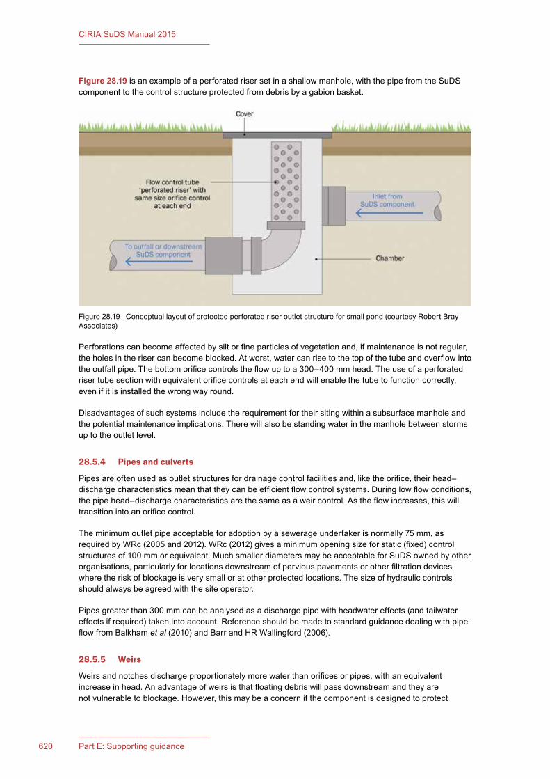
620 Part E: Supporting guidance
CIRIA SuDS Manual 2015
Figure 28.19isanexampleofaperforatedrisersetinashallowmanhole,withthepipefromtheSuDScomponenttothecontrolstructureprotectedfromdebrisbyagabionbasket.
Perforationscanbecomeaffectedbysiltorfineparticlesofvegetationand,ifmaintenanceisnotregular,theholesintherisercanbecomeblocked.Atworst,watercanrisetothetopofthetubeandoverflowintotheoutfallpipe.Thebottomorificecontrolstheflowuptoa300–400mmhead.Theuseofaperforatedrisertubesectionwithequivalentorificecontrolsateachendwillenablethetubetofunctioncorrectly,evenifitisinstalledthewrongwayround.
Disadvantagesofsuchsystemsincludetherequirementfortheirsitingwithinasubsurfacemanholeandthepotentialmaintenanceimplications.Therewillalsobestandingwaterinthemanholebetweenstormsup to the outlet level.
28.5.4 Pipes and culverts
Pipesareoftenusedasoutletstructuresfordrainagecontrolfacilitiesand,liketheorifice,theirhead–dischargecharacteristicsmeanthattheycanbeefficientflowcontrolsystems.Duringlowflowconditions,thepipehead–dischargecharacteristicsarethesameasaweircontrol.Astheflowincreases,thiswilltransitionintoanorificecontrol.
Theminimumoutletpipeacceptableforadoptionbyasewerageundertakerisnormally75mm,asrequiredbyWRc(2005and2012).WRc(2012)givesaminimumopeningsizeforstatic(fixed)controlstructuresof100mmorequivalent.MuchsmallerdiametersmaybeacceptableforSuDSownedbyotherorganisations,particularlyforlocationsdownstreamofperviouspavementsorotherfiltrationdeviceswheretheriskofblockageisverysmalloratotherprotectedlocations.Thesizeofhydrauliccontrolsshouldalwaysbeagreedwiththesiteoperator.
Pipesgreaterthan300mmcanbeanalysedasadischargepipewithheadwatereffects(andtailwatereffectsifrequired)takenintoaccount.ReferenceshouldbemadetostandardguidancedealingwithpipeflowfromBalkhamet al(2010)andBarrandHRWallingford(2006).
28.5.5 Weirs
Weirsandnotchesdischargeproportionatelymorewaterthanorificesorpipes,withanequivalentincreaseinhead.Anadvantageofweirsisthatfloatingdebriswillpassdownstreamandtheyarenotvulnerabletoblockage.However,thismaybeaconcernifthecomponentisdesignedtoprotect
Figure28.19 Conceptuallayoutofprotectedperforatedriseroutletstructureforsmallpond(courtesyRobertBrayAssociates)
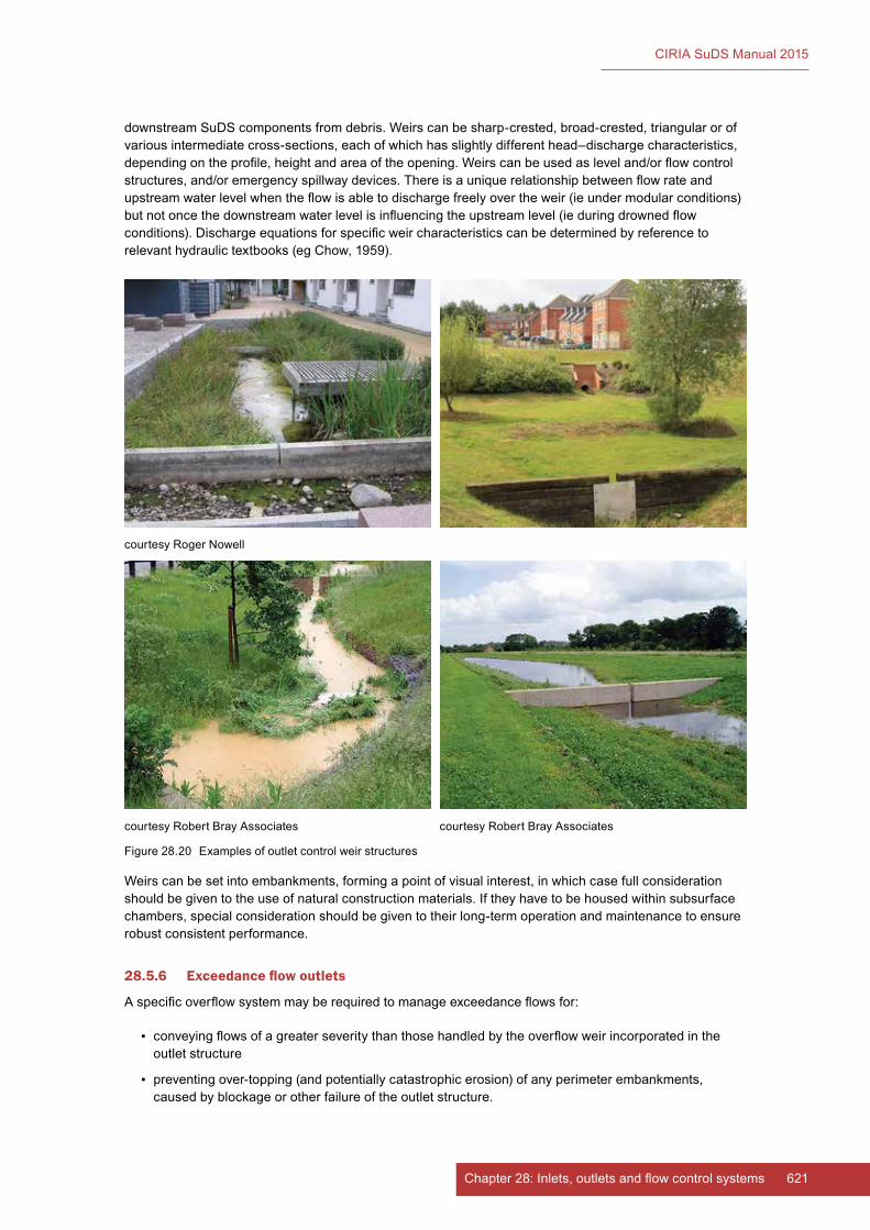
621Chapter 28: Inlets, outlets and flow control systems
CIRIA SuDS Manual 2015
downstreamSuDScomponentsfromdebris.Weirscanbesharp-crested,broad-crested,triangularorofvariousintermediatecross-sections,eachofwhichhasslightlydifferenthead–dischargecharacteristics,dependingontheprofile,heightandareaoftheopening.Weirscanbeusedasleveland/orflowcontrolstructures,and/oremergencyspillwaydevices.Thereisauniquerelationshipbetweenflowrateandupstreamwaterlevelwhentheflowisabletodischargefreelyovertheweir(ieundermodularconditions)butnotoncethedownstreamwaterlevelisinfluencingtheupstreamlevel(ieduringdrownedflowconditions).Dischargeequationsforspecificweircharacteristicscanbedeterminedbyreferencetorelevanthydraulictextbooks(egChow,1959).
Weirscanbesetintoembankments,formingapointofvisualinterest,inwhichcasefullconsiderationshouldbegiventotheuseofnaturalconstructionmaterials.Iftheyhavetobehousedwithinsubsurfacechambers,specialconsiderationshouldbegiventotheirlong-termoperationandmaintenancetoensurerobust consistent performance.
28.5.6 Exceedance flow outlets
Aspecificoverflowsystemmayberequiredtomanageexceedanceflowsfor:
▪ conveyingflowsofagreaterseveritythanthosehandledbytheoverflowweirincorporatedintheoutlet structure
▪ preventingover-topping(andpotentiallycatastrophicerosion)ofanyperimeterembankments,causedbyblockageorotherfailureoftheoutletstructure.
courtesyRogerNowell
courtesy Robert Bray Associates courtesy Robert Bray Associates
Figure28.20 Examplesofoutletcontrolweirstructures
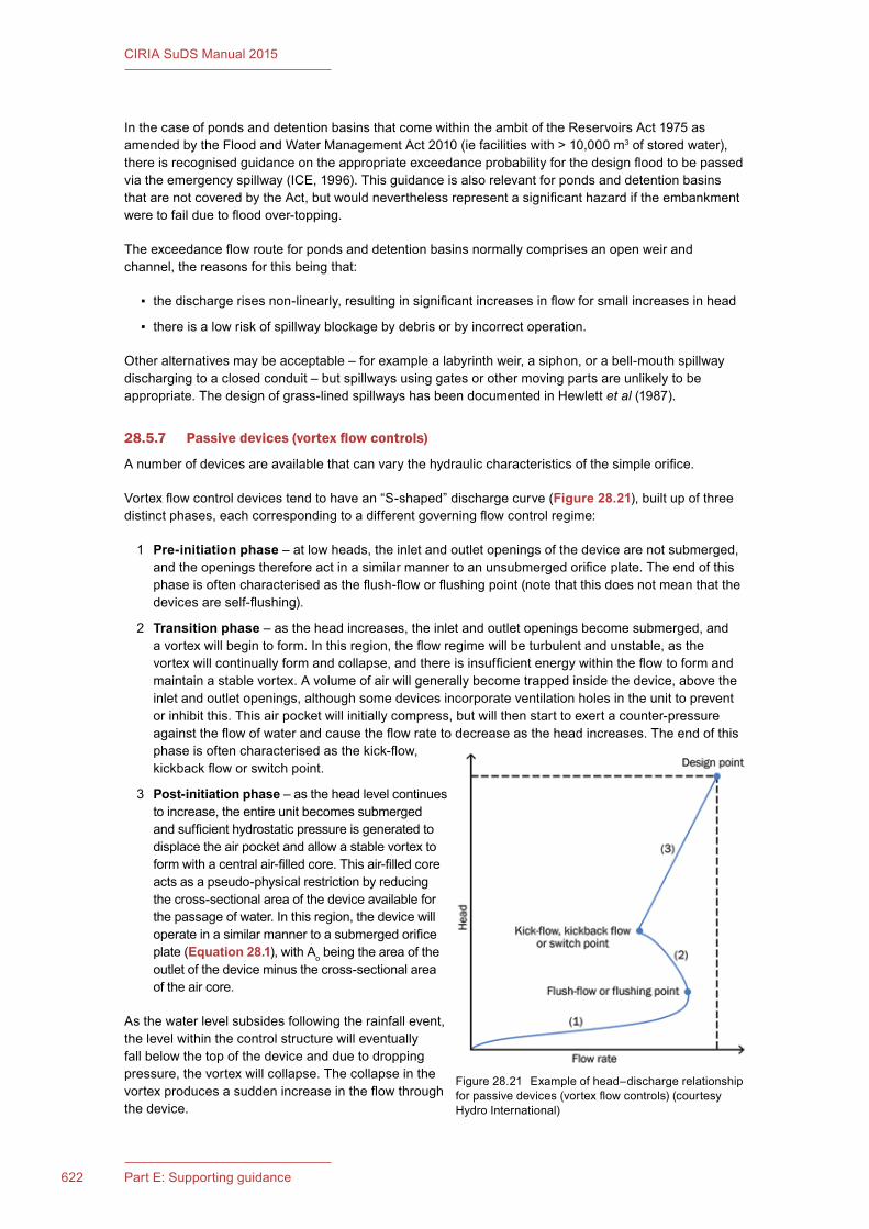
622 Part E: Supporting guidance
CIRIA SuDS Manual 2015
InthecaseofpondsanddetentionbasinsthatcomewithintheambitoftheReservoirsAct1975asamendedbytheFloodandWaterManagementAct2010(iefacilitieswith>10,000m3ofstoredwater),thereisrecognisedguidanceontheappropriateexceedanceprobabilityforthedesignfloodtobepassedviatheemergencyspillway(ICE,1996).ThisguidanceisalsorelevantforpondsanddetentionbasinsthatarenotcoveredbytheAct,butwouldneverthelessrepresentasignificanthazardiftheembankmentweretofailduetofloodover-topping.
Theexceedanceflowrouteforpondsanddetentionbasinsnormallycomprisesanopenweirandchannel,thereasonsforthisbeingthat:
▪ thedischargerisesnon-linearly,resultinginsignificantincreasesinflowforsmallincreasesinhead
▪ thereisalowriskofspillwayblockagebydebrisorbyincorrectoperation.
Otheralternativesmaybeacceptable–forexamplealabyrinthweir,asiphon,orabell-mouthspillwaydischargingtoaclosedconduit–butspillwaysusinggatesorothermovingpartsareunlikelytobeappropriate.Thedesignofgrass-linedspillwayshasbeendocumentedinHewlettet al (1987).
28.5.7 Passive devices (vortex flow controls)
Anumberofdevicesareavailablethatcanvarythehydrauliccharacteristicsofthesimpleorifice.
Vortexflowcontroldevicestendtohavean“S-shaped”dischargecurve(Figure 28.21),builtupofthreedistinctphases,eachcorrespondingtoadifferentgoverningflowcontrolregime:
1 Pre-initiation phase –atlowheads,theinletandoutletopeningsofthedevicearenotsubmerged,andtheopeningsthereforeactinasimilarmannertoanunsubmergedorificeplate.Theendofthisphaseisoftencharacterisedastheflush-floworflushingpoint(notethatthisdoesnotmeanthatthedevicesareself-flushing).
2 Transition phase–astheheadincreases,theinletandoutletopeningsbecomesubmerged,andavortexwillbegintoform.Inthisregion,theflowregimewillbeturbulentandunstable,asthevortexwillcontinuallyformandcollapse,andthereisinsufficientenergywithintheflowtoformandmaintainastablevortex.Avolumeofairwillgenerallybecometrappedinsidethedevice,abovetheinletandoutletopenings,althoughsomedevicesincorporateventilationholesintheunittopreventorinhibitthis.Thisairpocketwillinitiallycompress,butwillthenstarttoexertacounter-pressureagainsttheflowofwaterandcausetheflowratetodecreaseastheheadincreases.Theendofthisphaseisoftencharacterisedasthekick-flow,kickbackfloworswitchpoint.
3 Post-initiation phase – as the head level continues toincrease,theentireunitbecomessubmergedandsufficienthydrostaticpressureisgeneratedtodisplacetheairpocketandallowastablevortextoformwithacentralair-filledcore.Thisair-filledcoreactsasapseudo-physicalrestrictionbyreducingthecross-sectionalareaofthedeviceavailableforthepassageofwater.Inthisregion,thedevicewilloperateinasimilarmannertoasubmergedorificeplate (Equation 28.1),withAo being the area of the outletofthedeviceminusthecross-sectionalareaof the air core.
Asthewaterlevelsubsidesfollowingtherainfallevent,thelevelwithinthecontrolstructurewilleventuallyfallbelowthetopofthedeviceandduetodroppingpressure,thevortexwillcollapse.Thecollapseinthevortexproducesasuddenincreaseintheflowthroughthe device.
Figure28.21 Exampleofhead–dischargerelationshipforpassivedevices(vortexflowcontrols)(courtesyHydroInternational)
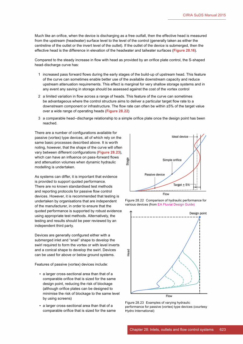
623Chapter 28: Inlets, outlets and flow control systems
CIRIA SuDS Manual 2015
Muchlikeanorifice,whenthedeviceisdischargingasafreeoutfall,thentheeffectiveheadismeasuredfromtheupstream(headwater)surfaceleveltothelevelofthecontrol(generallytakenaseitherthecentrelineoftheoutletortheinvertleveloftheoutlet).Iftheoutletofthedeviceissubmerged,thentheeffectiveheadisthedifferenceinelevationoftheheadwaterandtailwatersurfaces(Figure 28.16).
Comparedtothesteadyincreaseinflowwithheadasprovidedbyanorificeplatecontrol,theS-shapedhead-dischargecurvehas:
1 increasedpassforwardflowsduringtheearlystagesofthebuild-upofupstreamhead.Thisfeatureofthecurvecansometimesenablebetteruseoftheavailabledownstreamcapacityandreduceupstreamattenuationrequirements.Thiseffectismarginalforveryshallowstoragesystemsandinanyeventanysavinginstorageshouldbeassessedagainstthecostofthevortexcontrol
2 alimitedvariationinflowacrossarangeofheads.Thisfeatureofthecurvecansometimesbeadvantageouswherethecontrolstructureaimstodeliveraparticulartargetflowratetoadownstreamcomponentorinfrastructure.Theflowratecanoftenbewithin±5%ofthetargetvalueoverawiderangeofoperatingheads(Figure 28.22)
3 acomparablehead–dischargerelationshiptoasimpleorificeplateoncethedesignpointhasbeenreached.
Thereareanumberofconfigurationsavailableforpassive(vortex)typedevices,allofwhichrelyonthesamebasicprocessesdescribedabove.Itisworthnoting,however,thattheshapeofthecurvewilloftenvarybetweendifferentconfigurations(Figure 28.23),whichcanhaveaninfluenceonpass-forwardflowsandattenuationvolumeswhendynamichydraulicmodellingisundertaken.
Assystemscandiffer,itisimportantthatevidenceis provided to support quoted performance. Therearenoknownstandardisedtestmethodsandreportingprotocolsforpassiveflowcontroldevices.However,itisrecommendedthattestingisundertakenbyorganisationsthatareindependentofthemanufacturer,inordertoensurethatthequoted performance is supported by robust evidence usingappropriatetestmethods.Alternatively,thetestingandresultsshouldbepeerreviewedbyanindependent third party.
Devicesaregenerallyconfiguredeitherwithasubmergedinletand“snail”shapetodeveloptheswirlrequiredtoformthevortexorwithlevelinvertsandaconicalshapetodeveloptheswirl.Devicescanbeusedforaboveorbelowgroundsystems.
Featuresofpassive(vortex)devicesinclude:
▪ alargercross-sectionalareathanthatofacomparableorificethatissizedforthesamedesignpoint,reducingtheriskofblockage(althoughorificeplatescanbedesignedtominimisetheriskofblockagetothesamelevelbyusingscreens)
▪ alargercross-sectionalareathanthatofacomparableorificethatissizedforthesame
Figure28.22 Comparisonofhydraulicperformanceforvarious devices (from EAFluvialDesignGuide)
Figure28.23 Examplesofvaryinghydraulicperformanceforpassive(vortex)typedevices(courtesyHydroInternational)
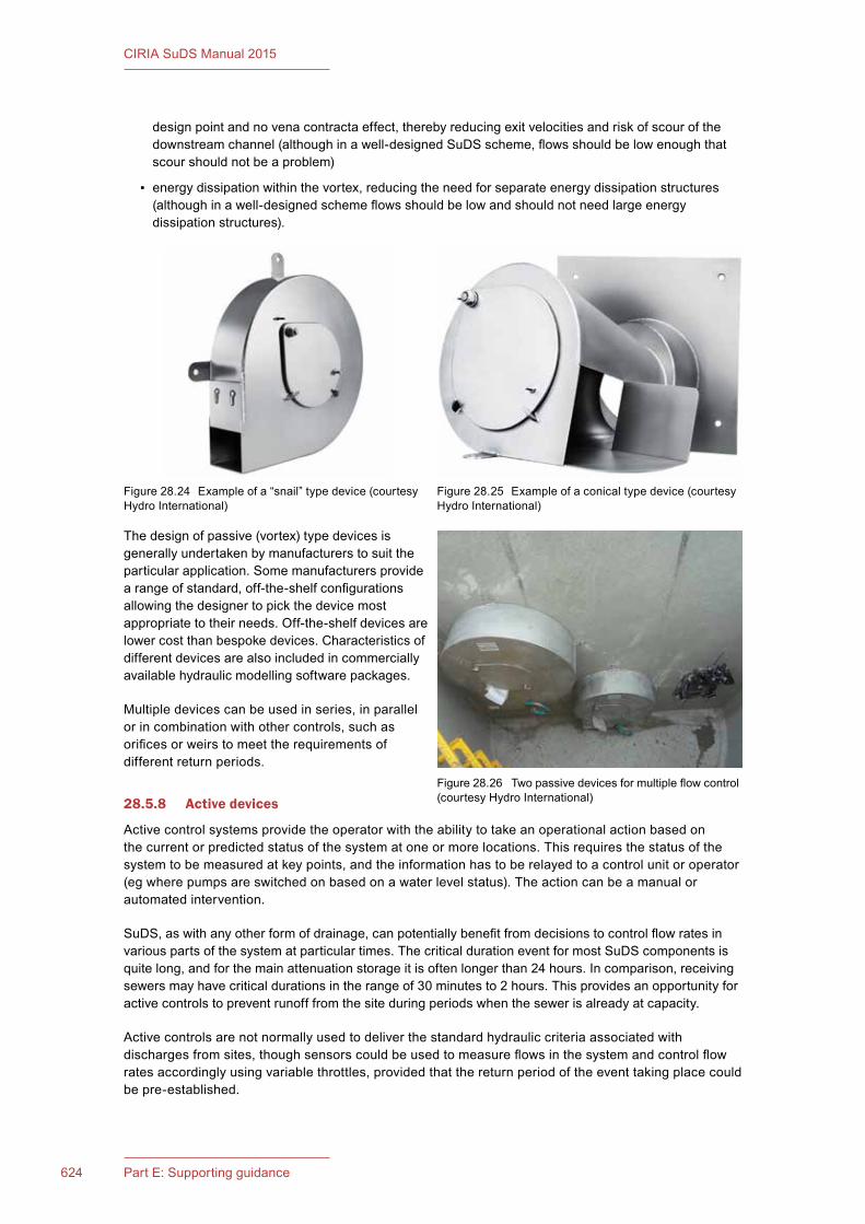
624 Part E: Supporting guidance
CIRIA SuDS Manual 2015
designpointandnovenacontractaeffect,therebyreducingexitvelocitiesandriskofscourofthedownstreamchannel(althoughinawell-designedSuDSscheme,flowsshouldbelowenoughthatscourshouldnotbeaproblem)
▪ energydissipationwithinthevortex,reducingtheneedforseparateenergydissipationstructures(althoughinawell-designedschemeflowsshouldbelowandshouldnotneedlargeenergydissipationstructures).
Thedesignofpassive(vortex)typedevicesisgenerallyundertakenbymanufacturerstosuittheparticular application. Some manufacturers provide arangeofstandard,off-the-shelfconfigurationsallowingthedesignertopickthedevicemostappropriatetotheirneeds.Off-the-shelfdevicesarelowercostthanbespokedevices.Characteristicsofdifferent devices are also included in commercially availablehydraulicmodellingsoftwarepackages.
Multipledevicescanbeusedinseries,inparallelorincombinationwithothercontrols,suchasorificesorweirstomeettherequirementsofdifferent return periods.
28.5.8 Active devices
Activecontrolsystemsprovidetheoperatorwiththeabilitytotakeanoperationalactionbasedonthe current or predicted status of the system at one or more locations. This requires the status of the systemtobemeasuredatkeypoints,andtheinformationhastoberelayedtoacontrolunitoroperator(egwherepumpsareswitchedonbasedonawaterlevelstatus).Theactioncanbeamanualorautomated intervention.
SuDS,aswithanyotherformofdrainage,canpotentiallybenefitfromdecisionstocontrolflowratesinvarious parts of the system at particular times. The critical duration event for most SuDS components is quitelong,andforthemainattenuationstorageitisoftenlongerthan24hours.Incomparison,receivingsewersmayhavecriticaldurationsintherangeof30minutesto2hours.Thisprovidesanopportunityforactivecontrolstopreventrunofffromthesiteduringperiodswhenthesewerisalreadyatcapacity.
Activecontrolsarenotnormallyusedtodeliverthestandardhydrauliccriteriaassociatedwithdischargesfromsites,thoughsensorscouldbeusedtomeasureflowsinthesystemandcontrolflowratesaccordinglyusingvariablethrottles,providedthatthereturnperiodoftheeventtakingplacecouldbepre-established.
Figure28.24 Exampleofa“snail”typedevice(courtesyHydroInternational)
Figure28.25 Exampleofaconicaltypedevice(courtesyHydroInternational)
Figure28.26 Twopassivedevicesformultipleflowcontrol(courtesyHydroInternational)

625Chapter 28: Inlets, outlets and flow control systems
CIRIA SuDS Manual 2015
Theperformanceofactivecontrolunitscanbedesignedtomeettheflowrequirementsforarangeofreturnperiodswithasingledevicethusavoidingmultipleunits.
Floatordisplacementcontrolsystemsgenerallymakeuseofadjustablegatesattachedtoafloatorcounterbalance.Risingwaterlevelswillcausethefloattoriseorwillexertgreaterforceagainstthecounterbalancetoprogressivelyreducethecross-sectionalareaoftheoutletopening.Therecanbeproblemswithdebrisoriceaffectingthemovementofthegate,andmaintenanceregimeswillneedtoberobust to ensure the continued operation of the control device.
Activesystemsthatoperateinrealtimewillneedtoincorporatesophisticatedcontrolandfeedbacksystemsthatdetectwaterlevelswithinthedrainagesystemandadjusttheflowcontrolsettingsaccordingly.Thistypeofsystemallowstheflowcharacteristicstobeclosetoideallymatchedtothesiterequirementsandcanoftenbeprogrammedtomeettherequirementsofarangeofconditions,butwillincludesignificantadditionalcostsforbothinstallationandoperationandmaintenance.Also,thereisaneedtomakesurethatthereisafailsafestatethatoperatesifpowerfailureorotherproblemoccurs.
PumpscanbeusedonSuDSwhererequired,butinmostcasesitisbettertokeepwateratorclosetothesurfaceandusegravityflowsystemswhereverpossibletominimiseenergyuseandtoreducetherisksassociatedwithpowerfailure.
28.5.9 Energy dissipation
Theprimaryobjectiveoferosionprotectionatpipeoutletsisthereductionofvelocity.Therefore,akeyconsiderationinselectingthetypeofoutletprotectionisthedesignoutletvelocityforthepipesorchannelsinvolved.Thiswillbedependentontheflowprofileassociatedwiththedesignstorm.Whereflowshavebeeneffectivelymanagedatsource,energydissipationstructuresshouldusuallyonlyberequiredforoverflowsandemergencyspillwaystructures.
Examplesofenergydissipationoptionsinclude:
▪ reducingoutletvelocitiesusingupstreamSuDScomponentand/orflowcontrols
▪ reducingpipegradient(butnotlessthantherequiredself-cleansingvelocity)
▪ rip-rapapronsandbasins
▪ loose stone
▪ gabions
▪ reinforced grass
▪ granite setts
▪ concrete stilling basins
▪ baffleblockswithinaheadwall.
ForSuDSdesigns,hardsystemssuchasconcretestillingbasinsandbaffleblocksshouldnotberequiredasvelocitiesshouldberelativelylow.Flowalignmentandoutfallsetbackcanbeconsideredinconjunctionwithenergydissipationinsensitivereceivingenvironments.
Afewoftheoptionsaredescribedinmoredetailinthesectionsbelow.Furtherguidance(includingdetaileddesignequations)isavailableinHA(2004),Balkhamet al(2010)andKirby et al(2015).
Rip-rap aprons
Arip-rapliningisaflexiblestonelayer.Itwilladjusttosettlement,canalsoservetotrapsedimentandreduceflowvelocitiesthroughahigherManning’sroughnesscoefficient.ThevelocitiesfromSuDScomponentsshouldbesufficientlylowthatprotectionsuchasapronsisrarelyneeded.Wherepipedflowsproduce erosive conditions that cannot be avoided appropriate hard engineering designs need to be developedusingstandardguidelinesandmanufacturer’sdesignguidance.

626 Part E: Supporting guidance
CIRIA SuDS Manual 2015
Gabions
Gabionscanbeusedasanerosiondissipatingsurfacebeneathanoutfall.TheboxesshouldeitherbemanufacturedofstainlesssteelorofgalvanisedsteelwirewithaPVCcoatingtopreventzincfromenteringthewater.Therockorgravelfillshouldbeofasufficientdiametertopreventwashout(usuallysinglesizedstone)andthedimensionsoftheblanketshouldfollowasimilardesignprocesstothatgivenin Equation 28.1.
GabionsinSuDSareusuallynotload-bearingandthereforethinmattresstypes(150mmorso)areusuallysufficient.Thesealsoallowvegetationtobecomeestablished,whichactstoaidtheirfunctioninthe system.
28.5.10 Outlet protection
Ifnotadequatelyprotected,small,lowfloworificescaneasilyblock,preventingthestructuralcontrolfrommeetingitsdesignpurposeandpotentiallycausingfloodingandotheradverseimpacts.Thereareanumberofdifferentanti-cloggingdesignapproaches,including:
▪ gravel surround
▪ gabion protection
▪ reverseslopeoutletpipeforapondorwetlandwithapermanentpool;thesubmergedinletpreventsfloatablesfromcloggingthepipe,andthisalsoavoidsdischargingwarmerwateratthesurfaceofthepond,butthisdesignoptionisnoteasilyvisibleandthereforeitsmaintenancetendstogetoverlooked,increasedlong-termblockagerisks
▪ orificesprotectedwithinperforatedrisersorT-pieces
▪ debrisguards(stainlesssteelguardopentopandbottom)
▪ “hooded”outlets
ExamplesofdebrisguardsareshowninFigure 28.27.
28.5.11 Trash screens and safety grilles
Balkhamet al(2010)andGrahamet al(2009)containguidanceontheuseanddesignofscreens(trashscreensandsecuritygrilles),appropriatetoUKconditions.
Thereasonsforprovidingascreenareto:
▪ excludetrashwhichmightotherwiseblocktheconduit
▪ capturedebrisinsuchawaythatrelativelyeasyremovalispossible
▪ preventunauthorisedaccess,particularlybychildrenandsmallmammals(egdogs).
TrashscreensandsecuritygrillesrequireregularmaintenanceandingeneraldonotreflectSuDSbestpractice.Itisrecommendedthatsuchsystemsareonlyusedinexceptionalcircumstances.
Figure28.27 Examplesofdebrisguardsoverlow-flowoutletcontrolstructures(courtesyRobertBrayAssociates)
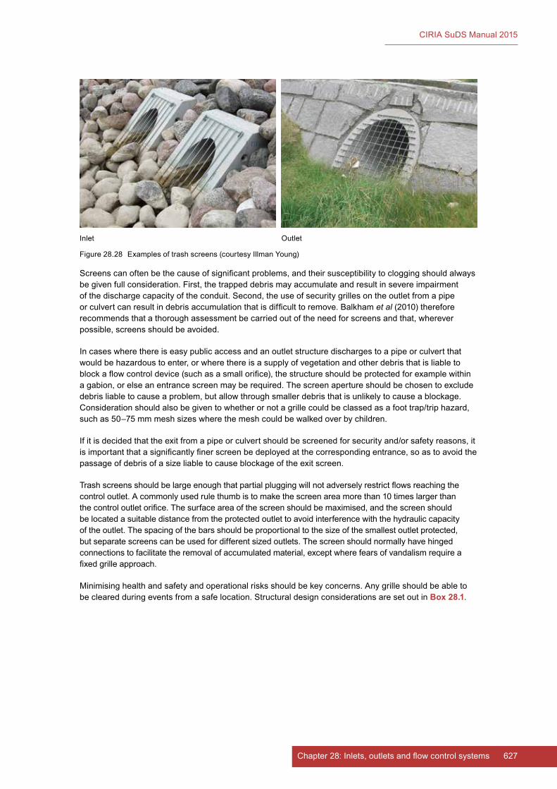
627Chapter 28: Inlets, outlets and flow control systems
CIRIA SuDS Manual 2015
Screenscanoftenbethecauseofsignificantproblems,andtheirsusceptibilitytocloggingshouldalwaysbegivenfullconsideration.First,thetrappeddebrismayaccumulateandresultinsevereimpairmentofthedischargecapacityoftheconduit.Second,theuseofsecuritygrillesontheoutletfromapipeorculvertcanresultindebrisaccumulationthatisdifficulttoremove.Balkhamet al (2010)thereforerecommendsthatathoroughassessmentbecarriedoutoftheneedforscreensandthat,whereverpossible,screensshouldbeavoided.
Incaseswherethereiseasypublicaccessandanoutletstructuredischargestoapipeorculvertthatwouldbehazardoustoenter,orwherethereisasupplyofvegetationandotherdebristhatisliabletoblockaflowcontroldevice(suchasasmallorifice),thestructureshouldbeprotectedforexamplewithinagabion,orelseanentrancescreenmayberequired.Thescreenapertureshouldbechosentoexcludedebrisliabletocauseaproblem,butallowthroughsmallerdebristhatisunlikelytocauseablockage.Considerationshouldalsobegiventowhetherornotagrillecouldbeclassedasafoottrap/triphazard,suchas50–75mmmeshsizeswherethemeshcouldbewalkedoverbychildren.
Ifitisdecidedthattheexitfromapipeorculvertshouldbescreenedforsecurityand/orsafetyreasons,itisimportantthatasignificantlyfinerscreenbedeployedatthecorrespondingentrance,soastoavoidthepassageofdebrisofasizeliabletocauseblockageoftheexitscreen.
Trashscreensshouldbelargeenoughthatpartialpluggingwillnotadverselyrestrictflowsreachingthecontroloutlet.Acommonlyusedrulethumbistomakethescreenareamorethan10timeslargerthanthecontroloutletorifice.Thesurfaceareaofthescreenshouldbemaximised,andthescreenshouldbelocatedasuitabledistancefromtheprotectedoutlettoavoidinterferencewiththehydrauliccapacityoftheoutlet.Thespacingofthebarsshouldbeproportionaltothesizeofthesmallestoutletprotected,butseparatescreenscanbeusedfordifferentsizedoutlets.Thescreenshouldnormallyhavehingedconnectionstofacilitatetheremovalofaccumulatedmaterial,exceptwherefearsofvandalismrequireafixedgrilleapproach.
Minimisinghealthandsafetyandoperationalrisksshouldbekeyconcerns.Anygrilleshouldbeabletobe cleared during events from a safe location. Structural design considerations are set out in Box 28.1.
Figure28.28 Examplesoftrashscreens(courtesyIllmanYoung)
Inlet Outlet
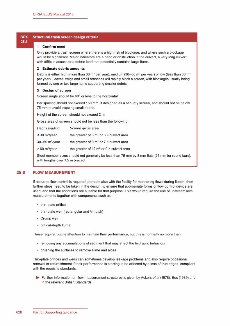
628 Part E: Supporting guidance
CIRIA SuDS Manual 2015
28.6 FLOW MEASUREMENT
Ifaccurateflowcontrolisrequired,perhapsalsowiththefacilityformonitoringflowsduringfloods,thenfurtherstepsneedtobetakeninthedesign,toensurethatappropriateformsofflowcontroldeviceareused,andthattheconditionsaresuitableforthatpurpose.Thiswouldrequiretheuseofupstreamlevelmeasurementstogetherwithcomponentssuchas:
▪ thin-plateorifice
▪ thin-plateweir(rectangularandV-notch)
▪ Crumpweir
▪ critical-depthflume.
Theserequireroutineattentiontomaintaintheirperformance,butthisisnormallynomorethan:
▪ removing any accumulations of sediment that may affect the hydraulic behaviour
▪ brushing the surfaces to remove slime and algae.
Thin-plateorificesandweirscansometimesdevelopleakageproblemsandalsorequireoccasionalrenewalorrefurbishmentiftheirperformanceisstartingtobeaffectedbyalossoftrueedges,compliantwiththerequisitestandards.
FurtherinformationonflowmeasurementstructuresisgivenbyAckerset al (1978),Bos(1989)andin the relevant British Standards.
BOX28.1
Structural trash screen design criteria
1� Confirm�needOnlyprovideatrashscreenwherethereisahighriskofblockage,andwheresuchablockagewouldbesignificant.Majorindicatorsareabendorobstructionintheculvert,averylongculvertwithdifficultaccessoradebrisloadthatpotentiallycontainslargeitems.
2 Estimate debris amountsDebris is either high (more than 60 m3peryear),medium(30–60m3peryear)orlow(lessthan30m3 peryear).Leaves,twigsandsmallbrancheswillrapidlyblockascreen,withblockagesusuallybeingformedbyoneortwolargeitemssupportingsmallerdebris.
3 Design of screenScreenangleshouldbe60°orlesstothehorizontal.
Barspacingshouldnotexceed150mm,ifdesignedasasecurityscreen,andshouldnotbebelow75 mm to avoid trapping small debris.
Heightofthescreenshouldnotexceed2m.
Grossareaofscreenshouldnotbelessthanthefollowing:
Debris loading Screen gross area
< 30 m3/year thegreaterof6m2 or 3 × culvert area
30–60 m3/year thegreaterof9m2 or 7 × culvert area
>60m3/year thegreaterof12m2or9×culvertarea
Steelmembersizesshouldnotgenerallybelessthan75mmby8mmflats(25mmforroundbars),withlengthsover1.5mbraced.

629Chapter 28: Inlets, outlets and flow control systems
CIRIA SuDS Manual 2015
28.7 REFERENCES
ACKERS,P,WHITE,WR,PERKINS,JAandHARRISON,AJM(1978)Weirs and flumes for flow measurement,Wiley-Blackwell,Chichester,UK(ISBN:978-0-47199-637-8)
BALKHAM,M,FOSBEARY,C,KITCHEN,AandRICKARD,C(2010)Culvert design and operation guide, C689,CIRIA,London,UK(ISBN:978-0-86017-689-3).Goto:www.ciria.org
BARR,DIHandHRWALLINGFORD(2006)Tables for the hydraulic design of pipes, sewers and channels, 8th edition,ThomasTelfordPublishing,London,UK(ISBN:978-0-72773-355-9)
BOS,MG(ed)(1989)Discharge measurement structures, third revised edition,Publication20,InternationalInstituteforLandReclamationandImprovement/ILRI,Wageningen,TheNetherlands. Goto:http://tinyurl.com/ptnvpdn
CHOW,VT(1959)Open-channel hydraulics,McGraw-Hill,NewYork,USA(ISBN:978-1-93284-618-8)
GRAHAM,M,MAGENIS,S,RAMSBOTTOM,D,RICKARD,C,ROBINSON,P,WHITING,MandWICKS,H(2009)Trash and security screen guide 2009,EnvironmentAgency,Bristol,UK(ISBN:978-1-84911-138-6).Goto: http://tinyurl.com/lug53s7
HA(2004)“Designofoutfallandculvertdetails”,Design Manual for Roads and Bridges, Volume 4, Section 2, Part 7, HA 107/04,HighwaysAgency,London,UK.Goto:http://tinyurl.com/l5pylt8
HALL,MJ,HOCKIN,DLandELLIS,JB(1993)Design of flood storage reservoirs,B14,CIRIA,London,UK(ISBN:978-0-86017-393-9).Goto:www.ciria.org
HENDERSON,FM(1966)Open channel flow,Macmillan,NewYork,USA(ISBN:978-0-02353-510-9)
HEWLETT,HWM,BOORMAN,LAandBRAMLEY,ME(1987)Design of reinforced grass waterways,R116,CIRIA,London,UK(ISBN:978-0-86017-285-7).Goto:www.ciria.org
ICE(1996)Floods and reservoir safety, third edition,ThomasTelfordPublishing,London,UK(ISBN:978-0-72772-503-5
KIRBY,AM,ROCA,M,KITCHEN,A,ESCARAMEIA,MandCHESTERTON,OJ(2015)Manual on scour at bridges and other hydraulic structures, second edition,C742,CIRIA,London(ISBN:978-0-86017-747-0).Goto:www.ciria.org
MCENROE,BM,STEICHEN,JMandSCHWEIGER,RM(1988)“Hydraulicsofperforatedriserinletsforundergroundoutletterraces”,Transcript of the ASABE,vol31,4,AmericanSocietyofAgricultiuralandBiologicalEngineers,Michigan,USA
WRc(2005)Sewers for Scotland, second edition,WRcPublications,Swindon,UK(ISBN:978-1-89892-060-1)
WRc(2012)Sewers for adoption, seventh edition,WRcPublications,Swindon,UK(ISBN:978-1-89892-065-6)
STATUTES
Acts
FloodandWaterManagementAct2010(c.29)
ReservoirsAct1975(c.23)
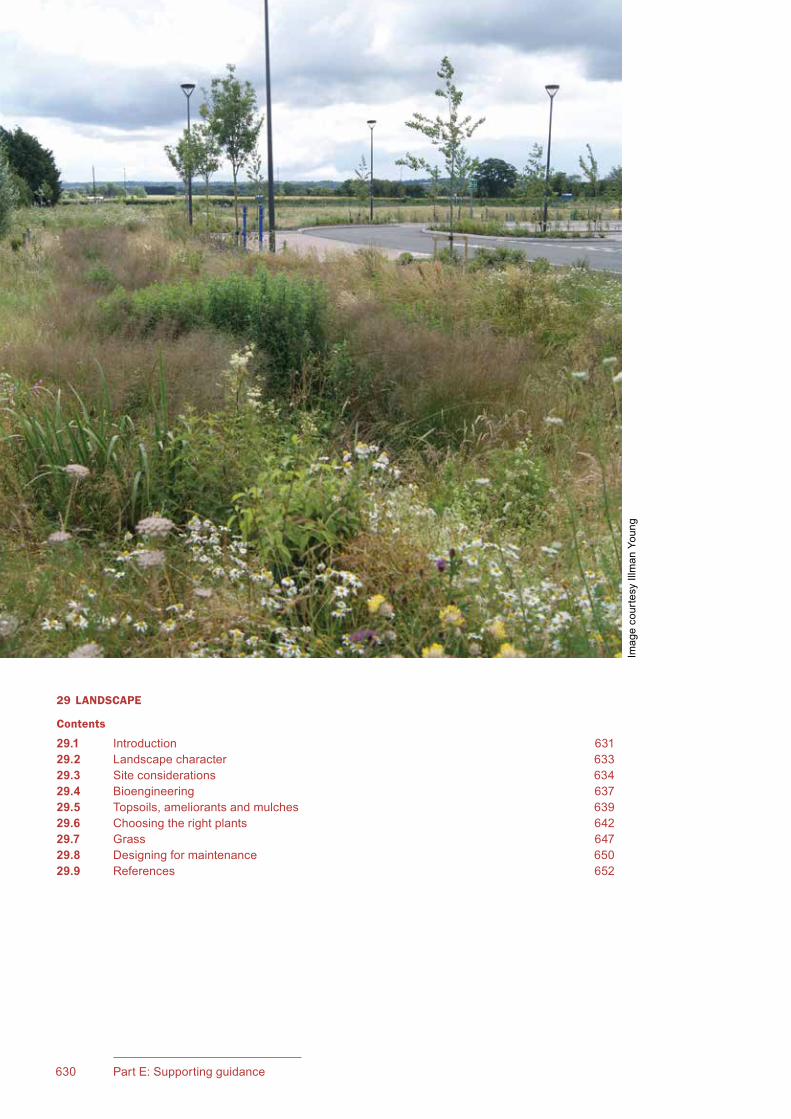
631Chapter 29: Landscape630 Part E: Supporting guidance
CIRIA SuDS Manual 2015
29 LANDSCAPE
Contents
29.1 Introduction 63129.2 Landscape character 63329.3 Site considerations 63429.4 Bioengineering 63729.5 Topsoils, ameliorants and mulches 63929.6 Choosing the right plants 64229.7 Grass 64729.8 Designing for maintenance 65029.9 References 652
Imag
e co
urte
sy Il
lman
You
ng

631Chapter 29: Landscape630 Part E: Supporting guidance
CIRIA SuDS Manual 2015
29Chapter
29.1 INTRODUCTION
The term “landscape” encompasses the entirety of all external space, whether urban or rural. Considering the character and qualities of the existing landscape, and the way in which new elements or development are assimilated within this greater landscape allows them to be designed appropriately from concept to detail.
The design of the landscape element of SuDS is a critical part of its delivery, both in functional and aesthetic terms. Depending on the scale and location of a site, hard or soft landscape elements may comprise almost the totality of the drainage system, provide a range of specific components, or may be limited to just one or two particular uses. Regardless of this, the same attention to detail is required in designing both the hard and soft landscape as is required of the engineering.
To achieve the optimum result that allows landform, hard materials and soft landscape to play their roles in delivering the Management Train, and particularly the amenity and biodiversity elements, the landscape architect should have a fully integrated role within the design team. Where a scheme is predominantly a “soft” planted system, the landscape architect or landscape manager, may play the leading role.
However, this should be determined on a project-by-project basis, the most important factors being the need for effective communications within the design team and a shared vision over the design and its delivery. This will help ensure that multi-functional benefits can be achieved, because integrated design is most effective when it is an inherent part of the site master planning process (Chapter 7). For example, the production of a planting and management plan for an unsympathetically engineered balancing pond does not fulfil the ethos of integrated SuDS or its design criteria.
Design of the landscape should include:
▪ assessment of the value of existing trees or habitats for retention, and their protection throughout the project
▪ consideration of landscape/townscape character, both of the site itself and its broader setting
▪ understanding the requirements of the users in terms of access, circulation and their intended use of the site
▪ appropriate responses to the site constraints and opportunities, including slopes and gradients, soils and aspect, and how levels relate to the buildings and the intended use of the open areas
▪ review of a range of potential solutions and the way that hard and soft solutions can be effectively integrated to meet the site’s requirements
LandscapeThis chapter discusses landscape within the context of SuDS design and its overarching design principles.
Chapter 10 provides further discussion related to the design of SuDS in an urban context.
Chapters 11–23 provide guidance on the engineering and technical design issues related to landscape and planting for different types of SuDS component.
633Chapter 29: Landscape632 Part E: Supporting guidance
CIRIA SuDS Manual 2015
▪ agreement over the extent of land needed for soft elements
▪ agreeing capital and maintenance costs
▪ addressing health and safety factors, and maintenance requirements.
Landscape architecture or design encompasses both the hard and soft elements of the natural and built environment. These should be designed together, if they are to work most effectively and to achieve a visually harmonious result. The SuDS should therefore be integrated within the greater landscape concept in its entirety, so that the range of hard landscape and paving materials (their functional properties, scale, colour, texture and use) is used consistently around the site, in a way that is complementary to those used for any buildings on the site. Elements that may be specific to the SuDS, such as railings, fencing, headwalls and signage, should similarly be considered as an integral part of the overall design palette.
29.1.1 Objectives for a landscape scheme
A comprehensive SuDS landscape plan should therefore consider the extent to which it can achieve the following objectives:
1 Designforeffectiveattenuation,flowcontrolandexceedance
A wide range of soft landscape features can be used to provide space for infiltration or attenuation storage.
While flow control measures will usually require hard structures (Chapter 28), where these are above ground, they should be designed in an attractive manner as part of the overall landscape, using locally appropriate materials. However, ground form can also be used, and densely vegetated surfaces on shallow gradients can significantly slow flows through their hydraulic roughness.
All schemes should consider exceedance flows, and these can often be channelled through soft landscape areas (ideally grassland) via shallow and subtle ground modelling.
2 Improvewaterquality
A wide range of water quality improvements can be achieved by using vegetated surfaces as part of the Management Train (Chapter 26). Grass is particularly effective at dealing with sediments and pollution where sheet flow is used, and planted components that dry out between each rainfall event are an efficient means of promoting bioremediation. However, planting and grassland generally can be used to provide a wide range of water quality improvements by providing good erosion protection to banksides and slopes, optimising silt interception and minimising resuspension, and providing a bioremediation substrate for the treatment of pollution.
3 Provideanattractivenewfeatureinthelocallandscape
The aesthetic appeal of a SuDS component or scheme is an important part of its public and social acceptability (Chapters5and10). This can be achieved using carefully considered ground contouring, planting and the design of both the hard landscape and open water features. The overall layout, planting and ground modelling can be used to create or restrict views of attractive features, both within and external to the site or to screen unsightly elements.
An understanding of the local urban/landscape character, and both its positive attributes and detractors, should also inform the design process to ensure that the new feature is locally appropriate.
4 Improveecologicalfunctionandbiodiversity
SuDS introduces the opportunity for adding or enhancing wetland habitat (Chapter 6), which can increase a site’s biodiversity potential, particularly where habitat creation includes new features such as damp wetland or permanently wet areas already. Enhancing biodiversity requires that a variety of habitats are provided within a site, incorporating new, ecologically appropriate features.

633Chapter 29: Landscape
CIRIA SuDS Manual 2015
Wherever natural habitats of value exist, these should be preserved and should only be incorporated within SuDS schemes where there are no risks to their ecological status, and they are compatible with the SuDS and a clear benefit will be achieved.
It is essential that the right soil and ground conditions are provided related to the habitats to be created, and that the establishment and maintenance specification for the planting recognises any specific requirements (particularly seasonality) or horticultural operations for doing so.
5 Uselandefficientlyandenhancelandvalues
The use of soft landscaped SuDS within a site can allow the efficient use of land by providing multi-functional uses, where, for example, permanent ponds with a storage function can become attractive and biodiverse landscape features (Chapters5and10).
Provided that the design and scale of these SuDS components fit appropriately within an area of public open space (POS), they can form part of the general POS requirement. However, visually dominating or fenced engineered ponds are unlikely to form part of a POS requirement; indeed, they may be unacceptable to the local authority and will not provide multi-functional landscapes.
Small-scale SuDS components, such as rain gardens, can be incorporated within gardens, and provide both Interception and attenuation to at least the 1:1 year requirement, and potentially to 1:30 years or more, thereby reducing the storage requirement further down the system.
Sites with good quality landscape schemes are known to enhance public health and well-being, as well as increasing land values and improving their saleability, with housing developers reporting that properties facing onto SuDS sell quicker and/or for higher values than the same properties elsewhere. Conversely, poor landscape can contribute to a poorer quality of life for residents, and contribute towards the value of the site falling.
All landscape should have a clear, effective and practical design and management plan to allow the benefits to be maintained in the long term.
6 Assessriskandreflecttheresponsewithinthedesign
The risk inherent in open water features should be assessed for each site individually (Chapter36) and the appropriate measures incorporated within the design.
Simple design principles around good sightlines into water areas, shallow gradients at the water line and defensive planting can contribute much towards reducing risk.
Maintenance operations should also be considered to ensure that any machinery necessary for both routine and periodic maintenance is able to access the SuDS easily and safely.
29.2 LANDSCAPE CHARACTER
Landscape character identifies and describes the specific character of each landscape, that is the unique combination and pattern of elements and features that makes each distinctive to its local area and different from others.
Landscape character areas have been mapped at a regional, district and local scale, along with seascapes, the description of which also shows how the landscape is perceived, experienced and valued by people. National Character Areas (Natural England, 2012) can be downloaded from their website. County or local character assessments are available on-line from local planning authorities.
Understanding what makes a landscape locally distinctive should be a fundamental part of determining new interventions or designing within it; for new development it may have been the subject of a landscape and visual impact assessment. The character and visual quality of SuDS in rural and semi-rural

635Chapter 29: Landscape634 Part E: Supporting guidance
CIRIA SuDS Manual 2015
landscapes should be carefully considered, as poorly conceived designs can form alien or unnatural features, out of character with the local landscape. This can be particularly true of ground modelling, where modelling is viewed against the skyline, or where the local topography is naturally steep or shallow. Similarly, planting will require careful consideration.
The rationale for how and why the SuDS landscape design has been developed, and the way it responds to landscape character, should form a key part of the design and access statement accompanying any planning application, and should support the way that these principles have been applied to the landscape more generally.
29.2.1 Urban and suburban considerations
While landscape character descriptions apply to the wider landscape rather than urban areas, the principle of understanding the local vernacular, its character and the historic, cultural and social influences on an area, should influence design wherever it is located.
Information on townscape character can be found within local authority documents, such as townscape assessments, conservation area statements, village design statements or development briefs for individual sites.
Understanding the vernacular, particularly in relation to hard materials, their methods of use and locally typical planting should form an important design consideration. This does not undermine the designer’s desire to create something modern or in contrast to the local vernacular, but it should be informed by a thorough understanding and appreciation of it. In many instances, creating a positive design statement that is well informed by local influences can contribute to enhancing local distinctiveness and identity (see also Chapter10).
29.3 SITE CONSIDERATIONS
Achieving an attractive and functional soft SuDS scheme is dependent on fully understanding the site’s character: the conditions of slope, gradient, ground modelling, geology and soils, and natural drainage patterns alongside the value of retaining existing natural site features such as trees, hedgerows or areas of important habitat. The character of the site itself should also be considered in the context of the surrounding land uses or landscape.
Preliminary understanding the characteristics of the site should be undertaken at the conceptual design stage, as described in Section 7.6.1. More detailed assessment and design approaches will be undertaken as the design progresses through outline and/or detailed design (Sections7.7and7.8).
29.3.1 Existing natural features on site
Existing natural features on site may include trees or hedgerows, or habitats of ecological value. Where the site will be subject to development, and such features potentially affected, they should be subject to the appropriate survey, which should inform the design and development process. Initial checks should be made with the local planning authority to ascertain whether such features are already covered by protective designations:
▪ trees – by either individual or group tree preservation orders (TPO), or automatically by virtue of their being located within a conservation area
▪ hedgerows – may come within the scope of The Hedgerow Regulations 1997
▪ habitats – the site may be designated as a site of special scientific interest (SSSI), site of importance for nature conservation (SINC), local nature reserve or may contain protected species.
Existingtreesonsite should be subject to a pre-development tree survey in accordance with BS 5837:2012, and this should be undertaken by a “competent” person, as defined by the standard. The
635Chapter 29: Landscape634 Part E: Supporting guidance
CIRIA SuDS Manual 2015
outcome of the survey should be recorded on an accurate topographic survey with accompanying schedules, recording all the trees or tree groups, their species, height, spread, girth, current condition, likely useful life expectancy and an assessment of their value for retention from A to C. Trees in very poor condition are classified as U, and consideration should be given to measures for their removal or for them to be made safe. The survey also establishes the root protection area for each tree, which should not be damaged by excavation or building works without prior agreement. All grade A trees should be retained, as many grade B as possible and grade C trees if so desired.
Existinghedgerows should be surveyed for their continuity, quality and species mix, and graded in line with guidance from Defra (2007).
Existinghabitats should be subject to a phase 1 habitat survey. Where protected species are either present or assessed as being likely to be present, then further detailed species-based surveys should be undertaken to inform the location of any development works and necessary mitigation measures. Such works may be subject to a licence from Natural England. Surveys can only be undertaken at the appropriate time of year, and the timings vary depending on the species involved.
All features to be retained should have appropriate protective fencing (or other measures) as per the relevant guidelines, put in place before any works commences, and should be retained intact for the duration of the works or as specified in any licence. Some works may also be restricted during certain months of the year to prevent undue disturbance to wildlife.
29.3.2 Gradients and ground modelling
Successfully integrating SuDS invariably requires areas of ground modelling to accommodate swales, bioretention areas, detention basins, or larger permanent wetlands, ponds and lakes as well as general regrading for the built development. On development sites excess fill may also need to be reprofiled within areas of public open space adjacent to the SuDS to balance the overall cut and fill operation.
Integration of the proposed landform, therefore, requires the ground form beyond the SuDS component to be considered, and its contouring adjusted to allow the levels to flow around and into it, in a naturalistic manner that is visually attractive, and accords with the local surrounding landscape. Features should be located to fit within the landscape and its natural contours, noting that the largest features will invariably be found towards the downstream end of the site.
Slopes at constant gradients tend to look over-engineered and unnatural, when used in naturalistically designed schemes, unless such slopes are locally typical. Therefore, consideration should be given to where these can be made more variable, without undermining the performance or safety of the SuDS component.
Overly steep slopes may create adverse impacts on the character of the landscape or visually, if the features are of sufficient size or create a notably alien feature. Slopes steeper than 1 in 3 may require stabilisation through bioengineering (or other means), dependent on the height and the strength of the superficial geology. In such cases, advice should be sought from an engineering geologist or geotechnical engineer. Ideally a range of gradients should be used that reflect the natural landform outside the feature, while internally they should be used not only to create variety to the banks, but also to develop areas around the base and its edges that will encourage a more diverse range of species. Wetland and aquatic plants naturally colonise in a relative narrow range of (normal) water levels, so that even slight variations in level will encourage greater plant diversity.
Banks on the “downward” side of ponds, where water is being held above natural ground levels should be avoided where possible and can be the most difficult to assimilate successfully, so that these slopes may require extensive planting to help mask their inherently unnatural qualities. The top and toe of slopes also require extra space to allow a more gentle transition between the slope and the adjacent ground.
Gradients around permanent water bodies should respect health and safety requirements for shallow slopes at the water line and safety benches (see Chapter 36). Changes to landform should also respect the protected root protection zones of trees to be retained as defined in the tree protection plan, and

637Chapter 29: Landscape636 Part E: Supporting guidance
CIRIA SuDS Manual 2015
set-off distances of (ideally) 4 m to the centreline of retained hedgerows. Maintenance requirements for access should also be considered.
29.3.3 Soils
Natural soil is a precious, expensive and limited resource, and should be treated with the necessary care to enable it to be stored and reused on site in good condition. Defra (2009) deals with the assessment, handling and management of soils, but generally the following key issues should be addressed:
▪ Unwanted existing vegetation on areas to be stripped and stored should be cut down and/or sprayed out with contact herbicide before stripping.
▪ Topsoil and subsoil should be stripped and stored separately and should not be compacted.
▪ Wet soils should be stockpiled no higher than 2 m, and ideally 1.5 m, in linear rows with the top and sides profiled to shed water (Defra, 2009).
▪ Dry soils can be stockpiled higher and the stockpile surface should be compacted to seal it from wet weather (Defra, 2009).
▪ Stockpiles should be sown with a clover mix if they are to be left for more than six months before use, or any weeds that grow should be regularly sprayed with herbicide to prevent the build-up of weed seeds.
▪ Stockpiles should be protected from contamination by rubbish, rubble or building operations, particularly chemicals or leachate from site works.
▪ Soil should only be stripped, stored or spread in appropriate weather conditions, and operations ceased if the ground is waterlogged, or during periods of heavy rain.
Before spreading subsoil or topsoil, the ground should be prepared by clearing any existing weeds (if spreading subsoil, then strip any topsoil first), and ripping through the soil to allow good cohesion between the existing and new soil. Soil should be spread in layers no greater than 300 mm depth (HA, 1981 and Defra, 2009) and lightly consolidated, not compacted. A degree of natural settlement should be anticipated when setting finished levels, so tolerances in specified levels should reflect this.
29.3.4 Contaminated soils
While contaminated land is dealt with in Chapter 8, contamination should be considered in terms of its potential impact on both humans and plants. Some contaminants will radically affect the development of plants, but may be sufficiently remediated by soil treatment and/or the use of fertilisers and organic composts. Alternatively, a capping layer incorporating a layer of clean soil (and possibly a geomembrane) may be required between the contaminated ground and plants, to prevent uptake of the contaminants. However, this is a specialist area, and detailed and comprehensive soil sampling will be required. Advice should be sought from a soil or landscape scientist, with expertise in plant establishment as well as contaminated land professionals.
29.3.5 Compaction and soil condition
Before undertaking any groundworks on site, all trees to be retained should have their protective fencing erected at the recommended distance as determined in the tree protection drawing (as defined in BS 5837:2012), to avoid damage to either the tree’s canopy or root system (Section 29.3.1).
Soil compaction is very common on development sites (Chapter 31), and can inhibit or even prevent plant growth and reduce the soil’s ability to infiltrate and percolate water. Heavy machinery can create solid pans or glazed surfaces between soil layers, which act as impermeable barriers to both water and root growth. Soil surfaces should, therefore, be ripped (with a three-tine subsoiler or chisel plough if space allows (Figure 29.1), in transverse directions, or thoroughly loosened with an excavator fitted with a ripper tine attachment on small sites) before the spreading of subsoil and/or topsoil, and the whole soil profile re-ripped on completion before final cultivations. The depth and route of any underground utilities should be taken into account during these operations.
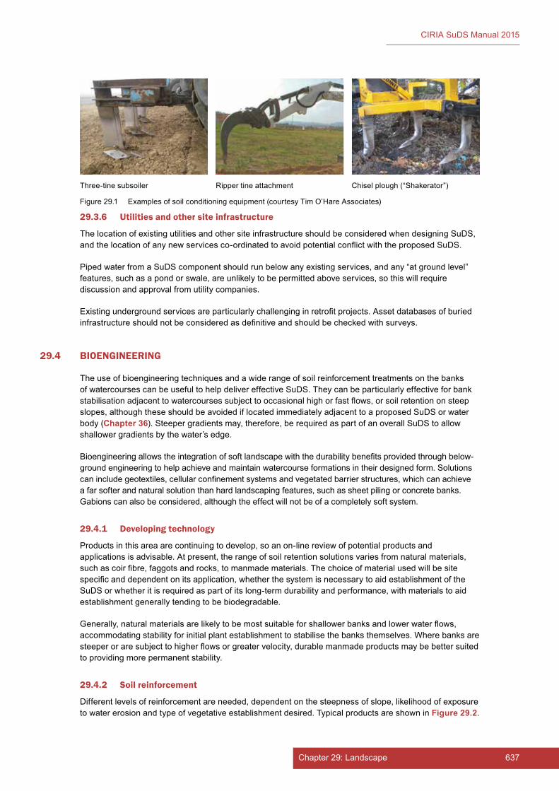
637Chapter 29: Landscape636 Part E: Supporting guidance
CIRIA SuDS Manual 2015
29.3.6 Utilities and other site infrastructure
The location of existing utilities and other site infrastructure should be considered when designing SuDS, and the location of any new services co-ordinated to avoid potential conflict with the proposed SuDS.
Piped water from a SuDS component should run below any existing services, and any “at ground level” features, such as a pond or swale, are unlikely to be permitted above services, so this will require discussion and approval from utility companies.
Existing underground services are particularly challenging in retrofit projects. Asset databases of buried infrastructure should not be considered as definitive and should be checked with surveys.
29.4 BIOENGINEERING
The use of bioengineering techniques and a wide range of soil reinforcement treatments on the banks of watercourses can be useful to help deliver effective SuDS. They can be particularly effective for bank stabilisation adjacent to watercourses subject to occasional high or fast flows, or soil retention on steep slopes, although these should be avoided if located immediately adjacent to a proposed SuDS or water body (Chapter 36). Steeper gradients may, therefore, be required as part of an overall SuDS to allow shallower gradients by the water’s edge.
Bioengineering allows the integration of soft landscape with the durability benefits provided through below-ground engineering to help achieve and maintain watercourse formations in their designed form. Solutions can include geotextiles, cellular confinement systems and vegetated barrier structures, which can achieve a far softer and natural solution than hard landscaping features, such as sheet piling or concrete banks. Gabions can also be considered, although the effect will not be of a completely soft system.
29.4.1 Developing technology
Products in this area are continuing to develop, so an on-line review of potential products and applications is advisable. At present, the range of soil retention solutions varies from natural materials, such as coir fibre, faggots and rocks, to manmade materials. The choice of material used will be site specific and dependent on its application, whether the system is necessary to aid establishment of the SuDS or whether it is required as part of its long-term durability and performance, with materials to aid establishment generally tending to be biodegradable.
Generally, natural materials are likely to be most suitable for shallower banks and lower water flows, accommodating stability for initial plant establishment to stabilise the banks themselves. Where banks are steeper or are subject to higher flows or greater velocity, durable manmade products may be better suited to providing more permanent stability.
29.4.2 Soil reinforcement
Different levels of reinforcement are needed, dependent on the steepness of slope, likelihood of exposure to water erosion and type of vegetative establishment desired. Typical products are shown in Figure 29.2.
Three-tine subsoiler Chisel plough (“Shakerator”)Ripper tine attachment
Figure 29.1 Examples of soil conditioning equipment (courtesy Tim O’Hare Associates)
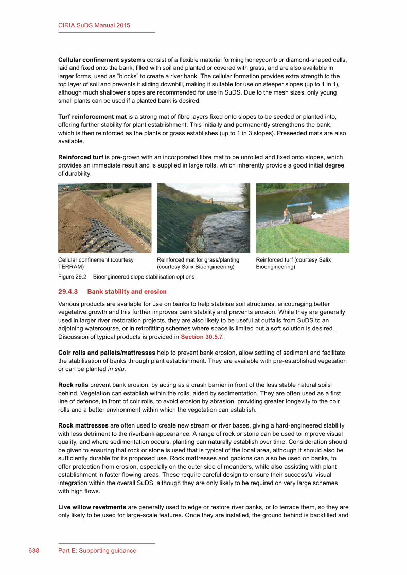
638 Part E: Supporting guidance
CIRIA SuDS Manual 2015
Cellular confinement systems consist of a flexible material forming honeycomb or diamond-shaped cells, laid and fixed onto the bank, filled with soil and planted or covered with grass, and are also available in larger forms, used as “blocks” to create a river bank. The cellular formation provides extra strength to the top layer of soil and prevents it sliding downhill, making it suitable for use on steeper slopes (up to 1 in 1), although much shallower slopes are recommended for use in SuDS. Due to the mesh sizes, only young small plants can be used if a planted bank is desired.
Turf reinforcement mat is a strong mat of fibre layers fixed onto slopes to be seeded or planted into, offering further stability for plant establishment. This initially and permanently strengthens the bank, which is then reinforced as the plants or grass establishes (up to 1 in 3 slopes). Preseeded mats are also available.
Reinforced turf is pre-grown with an incorporated fibre mat to be unrolled and fixed onto slopes, which provides an immediate result and is supplied in large rolls, which inherently provide a good initial degree of durability.
29.4.3 Bank stability and erosion
Various products are available for use on banks to help stabilise soil structures, encouraging better vegetative growth and this further improves bank stability and prevents erosion. While they are generally used in larger river restoration projects, they are also likely to be useful at outfalls from SuDS to an adjoining watercourse, or in retrofitting schemes where space is limited but a soft solution is desired. Discussion of typical products is provided in Section 30.5.7.
Coir rolls and pallets/mattresses help to prevent bank erosion, allow settling of sediment and facilitate the stabilisation of banks through plant establishment. They are available with pre-established vegetation or can be planted in situ.
Rock rolls prevent bank erosion, by acting as a crash barrier in front of the less stable natural soils behind. Vegetation can establish within the rolls, aided by sedimentation. They are often used as a first line of defence, in front of coir rolls, to avoid erosion by abrasion, providing greater longevity to the coir rolls and a better environment within which the vegetation can establish.
Rock mattresses are often used to create new stream or river bases, giving a hard-engineered stability with less detriment to the riverbank appearance. A range of rock or stone can be used to improve visual quality, and where sedimentation occurs, planting can naturally establish over time. Consideration should be given to ensuring that rock or stone is used that is typical of the local area, although it should also be sufficiently durable for its proposed use. Rock mattresses and gabions can also be used on banks, to offer protection from erosion, especially on the outer side of meanders, while also assisting with plant establishment in faster flowing areas. These require careful design to ensure their successful visual integration within the overall SuDS, although they are only likely to be required on very large schemes with high flows.
Live willow revetments are generally used to edge or restore river banks, or to terrace them, so they are only likely to be used for large-scale features. Once they are installed, the ground behind is backfilled and
Cellular confinement (courtesy TERRAM)
Reinforced turf (courtesy Salix Bioengineering)
Reinforced mat for grass/planting (courtesy Salix Bioengineering)
Figure 29.2 Bioengineered slope stabilisation options
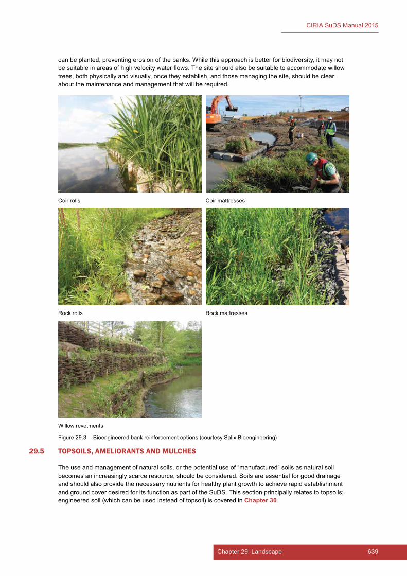
639Chapter 29: Landscape638 Part E: Supporting guidance
CIRIA SuDS Manual 2015
can be planted, preventing erosion of the banks. While this approach is better for biodiversity, it may not be suitable in areas of high velocity water flows. The site should also be suitable to accommodate willow trees, both physically and visually, once they establish, and those managing the site, should be clear about the maintenance and management that will be required.
Coir rolls Coir mattresses
Rock mattressesRock rolls
Willow revetments
Figure 29.3 Bioengineered bank reinforcement options (courtesy Salix Bioengineering)
29.5 TOPSOILS, AMELIORANTS AND MULCHES
The use and management of natural soils, or the potential use of “manufactured” soils as natural soil becomes an increasingly scarce resource, should be considered. Soils are essential for good drainage and should also provide the necessary nutrients for healthy plant growth to achieve rapid establishment and ground cover desired for its function as part of the SuDS. This section principally relates to topsoils; engineered soil (which can be used instead of topsoil) is covered in Chapter30.

641Chapter 29: Landscape640 Part E: Supporting guidance
CIRIA SuDS Manual 2015
29.5.1 British Standards
BS 3882:2015 specifies requirements for topsoils that are moved or traded. It is not intended (or appropriate) for the grading, classification or standardisation of in situ topsoil or subsoil that is already present on site. The standard classifies soil into two grades, multipurpose and specific-purpose topsoil. As well as topsoil grading, the standard also provides guidance on soil sampling and analysis, as well as handling and storage of soil.
Multipurposetopsoil is capable of sustainably supporting grass, trees, shrubs, herbaceous plants and other plantings, and is therefore suitable for the majority of landscape applications.
Specific-purposetopsoils are topsoils that have low fertility or are acidic or calcareous, and are specified when there is a particular specialist need. It should be noted that these soils are not appropriate for general landscaping applications and are more suited to particular ecological applications where a specific soil is used to obtain maximum biodiversity benefit, and therefore may be appropriate for particular SuDS applications.
When specifying topsoils, it is important to consider the predominant soil type in the locality and the intended use of the site, so that the properties specified are compatible with the requirements of the soft landscaping elements proposed. Wildflower areas require an impoverished (low phosphorus) soil with preferably a low weed seed bank, so fertile topsoils and most “natural” topsoils are less favourable than “manufactured” topsoils with a low seed bank.
29.5.2 Texturalclassificationofsoil
Texture describes the mixture of different particle sizes in soils, and names such as loamy sand and clay describe the constituent mix. Soils can also be referred to as heavy (clay/silty) and light (sandy) to indicate their ease of cultivation. Texture is a fundamental soil property which influences key aspects such as drainage, water storage, workability and susceptibility to soil erosion and thereby its suitability for different uses. It also plays a major part in defining the need and the strength of a soil’s structure. Structure is the term used to describe the aggregation of soil particles (clay, silt, sand) into “peds” which can vary in size from small crumbs to large blocks.
The texture class of a soil is defined by its relative proportions of sand, silt and clay. The UK uses a system of classification developed by the former Soil Survey of England and Wales (Figure 25.2, Chapter 25). This is different from other classifications in use around the world.
Soil structure is more critical in heavy textured soils. Without a defined soil structure, clayey/silty soils tend to be less permeable and porous than sandy soils and as a result offer limited opportunity for infiltration within part of a SuDS scheme.
For further information on soil texture, see Natural England (2008).
29.5.3 Topsoil manufacture
Multipurpose topsoil for general landscape use can also be made from a mixture of compost, sand and subsoil because manufactured soil provides a suitable alternative for sites where there are limited amounts of natural topsoil present on site. The process can be suited to bigger schemes where the economies of scale allow for blending of soils on site. Manufactured soils are a mixture of existing, available materials (sometimes including remediated soils from previously contaminated ground), with inorganic and organic materials such as PAS 100:2011 compliant green compost, to create a general-purpose or specific-purpose soil. Manufactured soils are also widely available to buy. Advice from a soil or landscape scientist should be considered to ensure that soils are blended to achieve the desired plant growth as well as being suited to the specific SuDS functions proposed.
PAS 100 is a specification established by the Waste and Resources Action Programme (WRAP), for composted materials produced by large-scale, licensed composting facilities that compost household and garden waste into usable compost. The Landscape Institute and WRAP (2012) have also developed another standard, specifically for landscape applications.

641Chapter 29: Landscape640 Part E: Supporting guidance
CIRIA SuDS Manual 2015
29.5.4 Use of fertilisers
Dependent on the quality of the topsoil being specified, certain fertilisers may be required, in order to obtain a nutrient level within the soil that will facilitate healthy and sustained plant growth. Soil fertility is represented scientifically by NPK values, which quantify the levels of nitrogen, phosphorus and potassium within the soil, and are essential for healthy plant establishment and growth:
▪ Nitrogen is an essential growth nutrient and is required for the growth of leaves and stems.
▪ Phosphorus is essential for root growth and development.
▪ Potassium performs an important photosynthetic function within the plant, while also promoting flower and fruit development.
The nutrient value of a soil can be ascertained through an appropriate soil test (as specified within BS 3882:2015) and specific fertilisers applied to restore a balance within the soil, ensuring that it will provide suitable conditions for successful establishment of the various plants, trees and grass.
Generally, bulk fertiliser comprising organic material will be used for new planting, with inorganic fertilisers of the appropriate NPK composition added to address any soil nutrient deficiencies. Inorganic fertilisers are only required for grass establishment, and wildflower grass should receive no extra fertiliser treatment (unless recommended through soil analysis due to either contamination or severe nutrient depletion).
Where fertilisers are used within SuDS, they should be worked into the soil during cultivation, rather than scattered on the soil surface, to reduce rapid runoff.
Use of fertiliser in the context of a SuDS should give due consideration to potential contamination of the receiving watercourse. Excessive or incorrect application of fertilisers can result in nutrients not being taken up by plants at the point of application and being washed downstream where effects such as algal bloom can occur in the SuDS themselves and/or the receiving watercourse. Slow-release fertilisers are preferable to soluble fertilisers.
29.5.5 Use of mulches
Mulches are used to aid plant establishment, primarily by covering the soil with a layer of material, which has the function of:
▪ preventing weed seeds from germinating and thereby competing with plants for light, space, soil, nutrients and moisture
▪ reducing evaporation of water from the soil, particularly during summer months when there may be prolonged periods without rainfall, but the plants are in active growth.
While soil evaporation is part of how SuDS function, this does not take priority during the plant establishment period, as it is more important to encourage the plants to achieve a sufficiently mature size, so that they can contribute effectively to the functional and visual quality of the system. Once plants are established, their ability to draw moisture from the soil outweighs any loss of evaporation from the surface due to mulches.
In landscape schemes designed for amenity purposes, chipped or pulverised tree bark is commonly used to mulch planting beds. However, within planting beds that are part of a SuDS, where there is a flow of water across a planted area or which has an outlet above ground, bark should not be used, as it will float down the system and accumulate around – or potentially block – the outfall. Similarly, beds mulched with a loose material such as bark should have their finished levels carefully considered when they are located adjacent to pervious paving, to ensure that the mulch does not wash off onto the paving.
Effective alternatives to bark mulch include gravels, pebbles or small rocks. Jute matting or other biodegradable materials can also be considered, provided they are aesthetically appropriate and do not break up into chunks that may block an outlet when they degrade. Such materials will need to be
643Chapter 29: Landscape642 Part E: Supporting guidance
CIRIA SuDS Manual 2015
pinned down into the soil with steel pins or wooden pegs, and will ultimately be covered by the plants as they develop. These are particularly useful for plants that creep either by their roots, stolons or below-ground rhizomes.
29.6 CHOOSING THE RIGHT PLANTS
Planting within SuDS should primarily ensure that the plants selected are suited to the conditions in which they are going to grow, so that they will thrive and deliver the range of benefits required of them. In the public’s eye, the quality of a scheme will be judged on its aesthetics, but while this is an essential factor in securing public support and acceptance for a scheme, it should be combined with functional suitability.
Primary consideration should be given to locally native species, and plants that benefit wildlife through their nectar, fruit or berries. The extent to which they are used on any site will be dependent on the purpose of the planting, its location and the requirements of both the local council through the planning process and the expectations of the public. The planting designer will also wish to have their input to the style and design of the planting.
Generally, the choice of plant species should reflect the usual design decisions relating to their location in terms of aspect, sun or shade, height, form, colour, whether evergreen or deciduous, native or ornamental, and soil factors such as pH, depth, nutrient status and organic content. However, the key consideration has to be their ability to withstand the fluctuations in soil moisture that will occur. Planting plans should be determined by landscape architects or others skilled in detailed planting design.
29.6.1 Restrictions and use of planting
The use of planting may need to be restricted due to their potential impact on adjacent structures – although this primarily relates to tree planting. The use of root barriers should be considered in relation to the proximity of trees to buildings, as well as guidance from the NHBC (1995), regarding soil types, tree species and foundations depths, although the coverage of species is limited.
Generally, the following constraints should be taken into account:
▪ Consideration should be given to the depth of soil within any lined system to ensure that it is sufficient for the plants or trees intended to grow there, and to avoid damage to the liner.
▪ Trees (or shrubs that ultimately grow to the size of small trees) should not generally be planted on water-retaining earth embankments.
▪ Trees should not be planted close to the inlet, outlet or other drainage structures where their roots may affect their structural integrity.
▪ Willows and poplar in particular should not be planted close to structures, pipes, paving, lined pools or water-retaining earth embankments. But they may be planted on the uphill side of natural ponds or lakes where sufficient space allows.
Conversely, planting is frequently used as a low-level barrier at the water’s edge, as a measure to prevent the public – particularly, young children – from inadvertently falling or walking into open water. Planting should not obscure visual observation of the water (which can be important from both a safety and aesthetic perspective) or act as a barrier to rescuing children, should they find a way through.
29.6.2 Invasive species
“Invasive weed” is a term used to cover a number of native and non-native plants. While invasive native plants can quickly dominate sites, they are of much less concern than non-natives, that can significantly impact on our native ecosystems as they spread rapidly, grow strongly and are difficult to control.
The Wildlife and Countryside Act 1981 provides the legislative framework for managing non-native species, as it is an offence under Section 14(2) of the Act to “plant or otherwise cause to grow in the wild”
643Chapter 29: Landscape642 Part E: Supporting guidance
CIRIA SuDS Manual 2015
any plant listed in Schedule 9, Part II, and doing so carries penalties of up to a £5000 fine and/or 2 years’ imprisonment. Listed plants considered of relevance to working in or near fresh water are as follows:
▪ Japanese knotweed – Fallopia japonica
▪ giant hogweed – Heracleum mantegazzianum
▪ Himalayan balsam – Impatiens glandulifera
▪ Australian swamp stonecrop – Crassula helmsii
▪ floating pennywort – Hydrocotyle ranunuculoides
▪ creeping water primrose – Ludwigia grandiflora
▪ parrot’s feather – Myriophyllum aquaticum.
Plants designated as invasive have in the past been notifiable to Defra, but they are now so widespread that this requirement has been abandoned. However, while these plants may be found on a development site, it is a criminal offence to allow them to “escape” its boundary, and they must be eradicated in accordance with the guidance provided by the EA (2010). While all these plants cause major environmental problems, giant hogweed can also prove dangerous to human health (poisonous sap from leaf and stem hairs causes blistering and persistent skin pigmentation). Similarly, Japanese knotweed must be eradicated before any construction or planting works, as it has the ability to regrow through paving or concrete and can seriously damage construction works. As most development sites will be subject to a Phase 1 Habitat Survey as part of the planning process, any such plants will be identified in the ecologist’s report. Landscape professionals should also be able to identify Japanese knotweed, giant hogweed and Himalayan balsam as a minimum.
Plants listed as invasive and methods for their treatment can be found in EA (2010). The RHS has also produced a further list of plants from Schedule 9 that are now banned for use or sale at all RHS shows, as many have been part of normal commercial plant production for many years <http://tinyurl.com/q5omga2>. Those of particular relevance to avoid adjacent to water are:
▪ water fern – Azolla filiculoides
▪ curly waterweed – Lagarosiphon major (or Elodea crispa)
▪ water hyacinth – Eichhornia crassipes
▪ water lettuce – Pistia stratiotes.
There are also a wide range of plants (both native and non-native) that if left unchecked will tend to smother less dominant plants and reduce the planting scheme to a very limited number of species. Invasiveness can also be a product of the space available for the plants within the SuDS, as a large pond or lake may well be capable of supporting plant species that would dominate a smaller water feature, and so success will be dependent on the horticultural knowledge of the designer, an understanding of the SuDS component’s intended use and the anticipated level of maintenance it will need.
Some plants associated with water bodies that are considered potentially dominating are:
▪ bulrush or greater reed mace – Typha latifolia
▪ lesser reed mace – Typha angustifolia
▪ common reed – Phragmites australis
▪ greater spearwort – Ranunculus lingua.
It should be noted that invasive plants can be easily transferred from one site to another through seeds, pieces of plant or contaminated water being transferred by humans or others. Methods to protect against this are described in detail by the NNSS (2015).
645Chapter 29: Landscape644 Part E: Supporting guidance
CIRIA SuDS Manual 2015
29.6.3 Biosecurity
Biosecurity considers the threat to our native flora and ecology as a consequence of introducing disease through plants, insects, viruses or other means. There has been wide public awareness of biosecurity issues for many years since Dutch elm disease destroyed almost all mature elms within the UK. Since 2012, Ash dieback (Chalara fraxinea) has been in the headlines, and over time the disease is expected to lead to the loss of most of our ash trees and significant alterations to the landscape character of many areas.
Chalara is, however, only one of a rapidly growing number of pests and diseases threatening the urban and rural landscapes of the UK, as there are pests, viruses or fungi that affect oak, willow, alder and a wide range of other plants, although most are not fatal. Early government policy development around Chalara has been heavily focused on forestry and woodlands, both in terms of the threats to production and the impacts on ecology, although the effect will clearly be much wider.
Care is therefore needed in both the choice of plant material and its procurement, to ensure that it is free from, or resistant to, all currently known diseases (some of which are only found is certain parts of the country). A requirement for plants to be of UK provenance can be considered, but may not always be possible to achieve. Imported plants pose the greatest risk, although government requirements for border controls, alongside certification in the exporting country, are helping to address this problem. Recent experience has also shown how some diseases are airborne and are therefore able to cross borders despite a ban on importation. It is therefore essential that any species known to be at significant threat of disease are not used within any new schemes until resistant strains are developed.
29.6.4 Plantspecificationandpurchasing
All plants should be specified in line with BS 3936-1:1992, and using the National Plant Specification (NPS) – a design software tool <www.gohelios.co.uk>. This identifies a wide range of species that are commercially available, and the sizes in which they are normally grown. It is essential that planting is specified in line with this document to ensure that it is likely to be commercially available. This is particularly important where plant lists are included on drawings for submission to the planning authority. While there are specialist nurseries for particular ranges of plants which it may be possible to specify, care should be taken to ensure that these will be available in the numbers required at the time they are needed on site, as many specialists do not produce large quantities of plants, so their plant lists can be deceptive. Plants should always be specified using their full botanical name (in Latin), as common names are too variable, and many plants do not have them.
The major nurseries generally participate in the Horticultural Trades Association Nursery Business Improvement Scheme (replacing their old Nursery Accreditation Scheme) <http://tinyurl.com/plot7s3>, working to ensure that nurseries are upholding standards of performance and product quality. Specifications should generally state that all plants should be supplied by enrolled suppliers. This will ensure that the nursery does not substitute alternative plant species or sizes without prior agreement, and they should produce good quality, disease-free plants. Many of the smaller nurseries may not be participating, but provided their quality control and production are acceptable, they may well offer a more extensive range of alternative plants.
Plants may be purchased all year round, but many aquatic plants are only available in any quantities as “bare root” stock during May–July, and many will not be available during the winter. Woody plants are also generally purchased as bare root stock in the dormant season over winter. Most damp species and general landscape plants will be available throughout the year, although stock may be limited at the end of the season. Advance ordering to secure a confirmed supply is recommended.
29.6.5 Selecting the right plants for SuDS
Consideration of the right plants for a SuDS will depend on two issues, over and above normal plant selection procedures:
▪ What is the moisture regime likely to be in the SuDS? This will determine the tolerance of plant selected, and whether a dense rooting system is desirable.
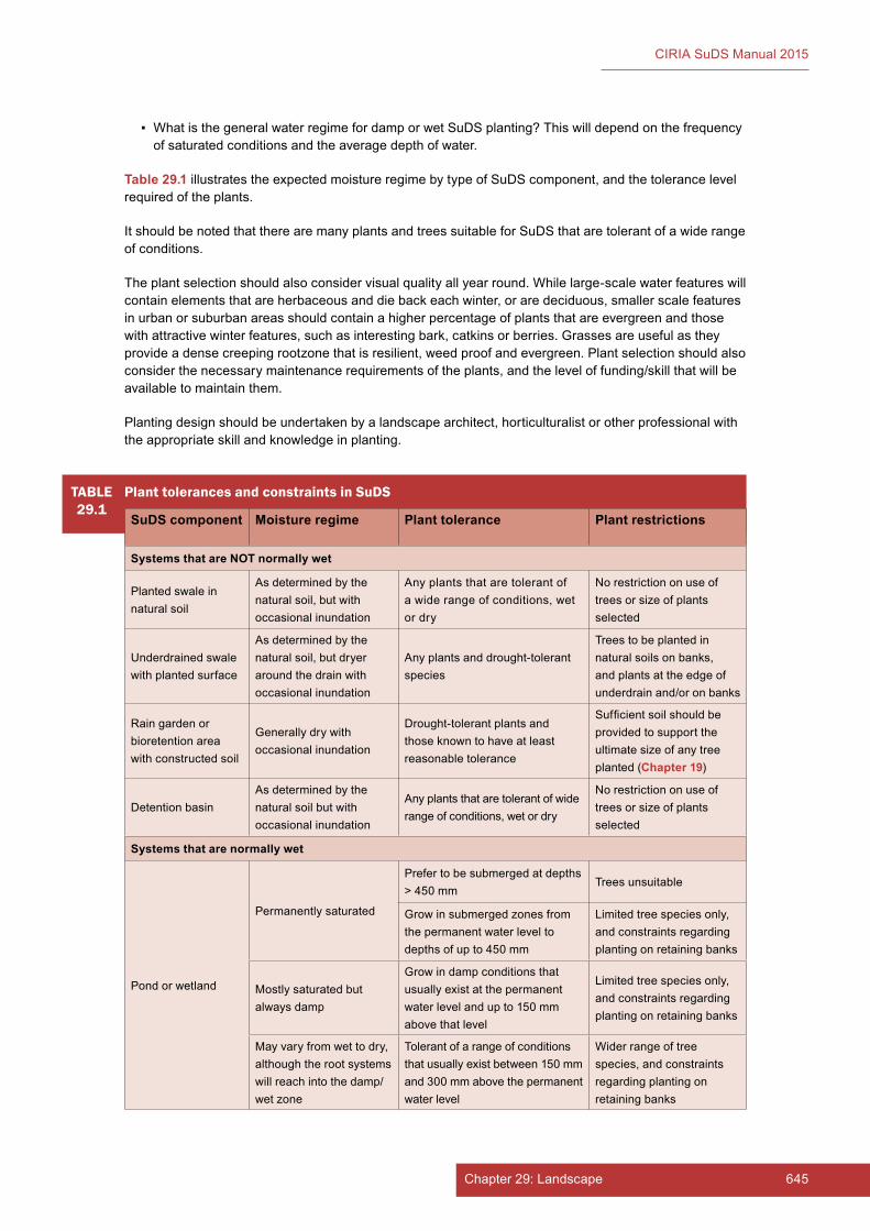
645Chapter 29: Landscape644 Part E: Supporting guidance
CIRIA SuDS Manual 2015
▪ What is the general water regime for damp or wet SuDS planting? This will depend on the frequency of saturated conditions and the average depth of water.
Table29.1 illustrates the expected moisture regime by type of SuDS component, and the tolerance level required of the plants.
It should be noted that there are many plants and trees suitable for SuDS that are tolerant of a wide range of conditions.
The plant selection should also consider visual quality all year round. While large-scale water features will contain elements that are herbaceous and die back each winter, or are deciduous, smaller scale features in urban or suburban areas should contain a higher percentage of plants that are evergreen and those with attractive winter features, such as interesting bark, catkins or berries. Grasses are useful as they provide a dense creeping rootzone that is resilient, weed proof and evergreen. Plant selection should also consider the necessary maintenance requirements of the plants, and the level of funding/skill that will be available to maintain them.
Planting design should be undertaken by a landscape architect, horticulturalist or other professional with the appropriate skill and knowledge in planting.
TABLE29.1
Plant tolerances and constraints in SuDS
SuDS component Moisture regime Planttolerance Plantrestrictions
SystemsthatareNOTnormallywet
Planted swale in natural soil
As determined by the natural soil, but with occasional inundation
Any plants that are tolerant of a wide range of conditions, wet or dry
No restriction on use of trees or size of plants selected
Underdrained swale with planted surface
As determined by the natural soil, but dryer around the drain with occasional inundation
Any plants and drought-tolerant species
Trees to be planted in natural soils on banks, and plants at the edge of underdrain and/or on banks
Rain garden or bioretention area with constructed soil
Generally dry with occasional inundation
Drought-tolerant plants and those known to have at least reasonable tolerance
Sufficient soil should be provided to support the ultimate size of any tree planted (Chapter 19)
Detention basinAs determined by the natural soil but with occasional inundation
Any plants that are tolerant of wide range of conditions, wet or dry
No restriction on use of trees or size of plants selected
Systemsthatarenormallywet
Pond or wetland
Permanently saturated
Prefer to be submerged at depths > 450 mm
Trees unsuitable
Grow in submerged zones from the permanent water level to depths of up to 450 mm
Limited tree species only, and constraints regarding planting on retaining banks
Mostly saturated but always damp
Grow in damp conditions that usually exist at the permanent water level and up to 150 mm above that level
Limited tree species only, and constraints regarding planting on retaining banks
May vary from wet to dry, although the root systems will reach into the damp/wet zone
Tolerant of a range of conditions that usually exist between 150 mm and 300 mm above the permanent water level
Wider range of tree species, and constraints regarding planting on retaining banks

647Chapter 29: Landscape646 Part E: Supporting guidance
CIRIA SuDS Manual 2015
29.6.6 Use of native plants
Native plants should form the backbone of any SuDS planting scheme because of their value in providing habitat and increasing biodiversity. However, smaller-scale SuDS components in suburban or urban areas may offer fewer opportunities for native planting, where year-round visual quality requires a higher percentage of evergreen plants or where natives do not provide a sufficient range of smaller growing plants. However, efforts should be made to include native plants in all schemes and, wherever possible, to maximise their number.
The use of native plants, and ideally plants of native provenance, is particularly important for SuDS components that discharge into natural water systems, owing to the risk of introducing further exotic (and potentially invasive) plants into the natural environment. Where schemes outfall to a surface water or combined sewer this is of lesser importance, and if a site manages water completely by infiltration, then the risk of escapes is very low.
Biodiversity is discussed in detail in Chapter 6.
29.6.7 Establishment issues and natural regeneration
Natural regeneration should be considered as an appropriate method of plant establishment, as the natural seed resource in the soil will reflect the local landscape’s plants, and what will grow there naturally, although not necessarily within the SuDS. However, a balance may need to be struck between the need for an immediate visual impact and allowing areas to regenerate. Wetlands establish particularly quickly through natural regeneration, and plants will colonise those parts of the site to which they are most suited. Management would then ensure that any unwanted or invasive species were removed. The speed at which natural regeneration will occur will also depend on a number of factors:
▪ nutrient levels in the soil
▪ previous use of the ground and therefore
▪ seed resource within the natural soils
▪ proximity to an existing seed resource (even local ditches would provide a suitable seed resource)
▪ use of direct seeding of parts of the wetland, and then allowing this to naturally seed other parts (particularly useful if an area is being developed in phases)
Seed is spread naturally primarily by wind dispersal, but also by wild animals, insects and birds, as well as on the boots of walkers. Damp areas can also be effectively established via a mix of natural regeneration, wildflower seeding and some interplanting, which provides some immediate cover, but mainly relies on regeneration. The techniques selected will depend on the time available for establishment, and when the system needs to be fully functional, alongside the need for a level of visual acceptability for users once access if provided.
Historically, a way to stimulate regeneration has been to introduce “bucketfuls” of mud taken from the margins of existing ponds, which had the benefit of introducing beneficial microorganisms as well as plant seed. However, the increasing problem of invasive species has severely limited this practice, owing to the risk of their inadvertent spread. However, it may be considered appropriate where an existing pond has been monitored and is known to have no invasive species, or where a new pond is being developed on an existing site where the background of the pond’s ecology is known. Advice on this should be sought from an ecologist, but, if in doubt, do not use this practice.
29.6.8 Establishment of plants
All planting operations should be specified in accordance with BS 3936-10:1981, and the requirements related to seasonality, weather and soil conditions, soils, fertilisers, bed preparations, use of fertiliser and mulches, plant handling and planting and the use of all planting ancillaries, such as stakes, ties and guards, should be clearly specified.
647Chapter 29: Landscape646 Part E: Supporting guidance
CIRIA SuDS Manual 2015
29.6.9 Defects liability for planting
All planting carried out under a formal contract – the best form suited for planting contracts being the JCLI (2012) form of agreement – should have a defects rectification period of 12 months, to ensure that the planting has fully established through both its dormant and growing season. Contract conditions should require that any plants that fail during at least the first year (barring vandalism or other exceptional reasons) will be replaced free of charge by the landscape contractor. Where semi-mature trees are used, this period may extend to 2–3 years. However, liability can only be enforced if the contractor who undertook the planting is given responsibility for its maintenance during this establishment period. Where general construction or engineering contract forms are used, appropriate clauses will need to be written into the contract.
29.7 GRASS
It is essential that areas of grass within a SuDS are established properly before being inundated with water, as areas that do not have sufficient grass cover may suffer soil erosion, or damage may be caused to the developing sward. The timing of the implementation of the SuDS is therefore key in determining how the grass sward is best achieved, and whether any temporary diversion of surface water is possible or practical until the grass is sufficiently well established to receive surface water. Grass areas that are established early in the construction process, should be kept free of all debris or waste building materials or site water contaminated by construction use.
29.7.1 Phasing and site considerations
Ideally grass areas would be sown and allowed to develop for 3–6 months in advance of being brought into active use. However, space restrictions on site may mean that this is not practical. Seasonality will also determine the constraints to producing the necessary grass cover. Ideal methods of growing grass will also depend on whether an amenity grass area is required, or wildflower grass.
The cheapest option (and best if undertaken correctly) is to seed, and is economically the only practical option on larger sites. However, grass can only be sown in the growing season when the soils are sufficiently warm and damp to allow germination. While there are guidelines for sowing, these timings may be reduced or extended in any year dependent on the actual weather conditions. Also note that sowing in the middle of summer is likely to be highly dependent on very regular watering if the summer is dry – but then if drought conditions are declared, watering may not be permitted.
Table29.2 identifies the constraints governing grass establishment and the options that may be considered.
Where early establishment of grass SuDS has not been possible, and they are required to be utilised fairly soon after construction/planting, then consideration should be given to turfing (say) the base of swales, but seeding the sides, above anticipated normal water levels. Where wildflower grass is desired (but wildflower turf is not affordable), amenity turf can have wildflowers plugged into it once established, while seed from adjacent wildflower areas will gradually seed in naturally if the site conditions are suitable.
29.7.2 Selecting the right seed mix
A wide range of seed mixes are available, and turf can also be grown to the individual producer’s own seed specification. Advice can be sought from the suppliers related to soil type, pH, moisture, whether sited in sun or shade and the proposed use. Low-maintenance mixes that require less cutting may be appropriate, or specific sports mixes for detention basins intended to be used for field events. Consideration should also be given to seed provenance, particularly for wildflower mixes, to ensure that the species mixes are suitable and of native origin.
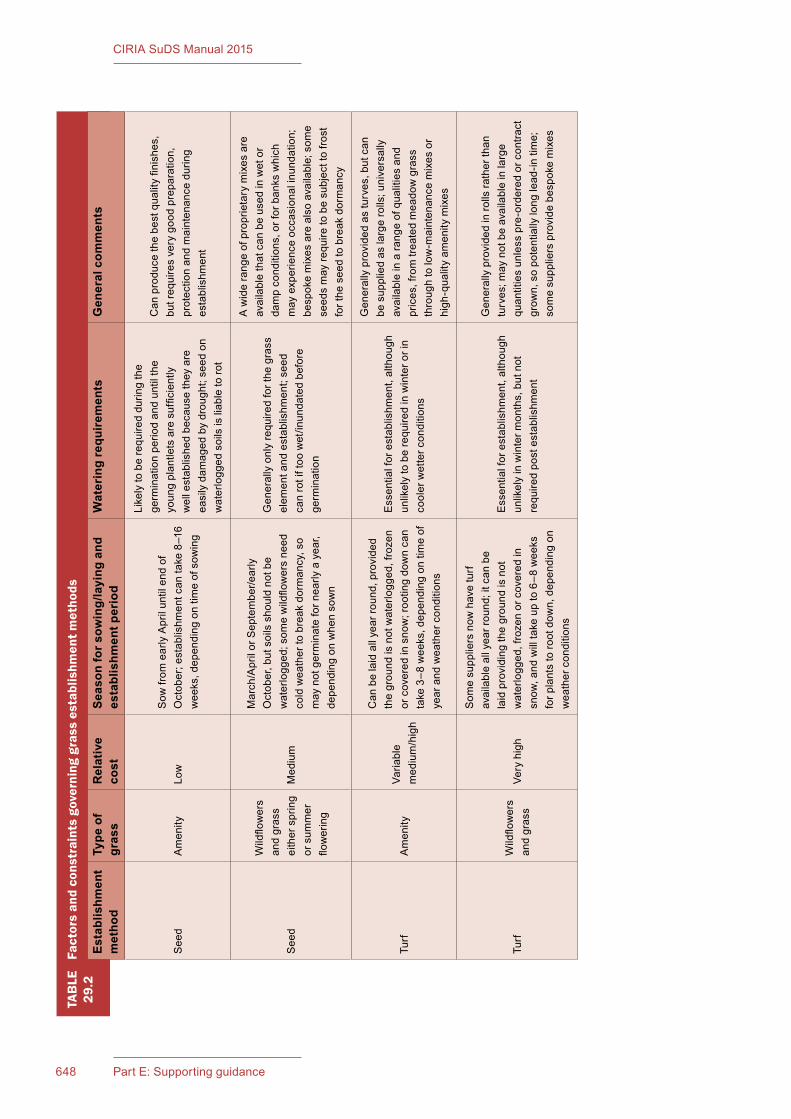
649Chapter 29: Landscape648 Part E: Supporting guidance
CIRIA SuDS Manual 2015
TAB
LE29
.2Fa
ctor
s an
d co
nstr
aint
s go
vern
ing
gras
s es
tabl
ishm
ent m
etho
ds
Establishm
ent
metho
dType
of
gras
sRelative
cost
Season
fors
owing/laying
and
establishm
entp
eriod
Wateringrequ
iremen
tsGen
eralcom
men
ts
See
dA
men
ityLo
wS
ow fr
om e
arly
Apr
il un
til e
nd o
f O
ctob
er; e
stab
lishm
ent c
an ta
ke 8
–16
wee
ks, d
epen
ding
on
time
of s
owin
g
Like
ly to
be
requ
ired
durin
g th
e ge
rmin
atio
n pe
riod
and
until
the
youn
g pl
antle
ts a
re s
uffic
ient
ly
wel
l est
ablis
hed
beca
use
they
are
ea
sily
dam
aged
by
drou
ght;
seed
on
wat
erlo
gged
soi
ls is
liab
le to
rot
Can
pro
duce
the
best
qua
lity
finis
hes,
bu
t req
uire
s ve
ry g
ood
prep
arat
ion,
pr
otec
tion
and
mai
nten
ance
dur
ing
esta
blis
hmen
t
See
d
Wild
flow
ers
and
gras
s ei
ther
spr
ing
or s
umm
er
flow
erin
g
Med
ium
Mar
ch/A
pril
or S
epte
mbe
r/ear
ly
Oct
ober
, but
soi
ls s
houl
d no
t be
wat
erlo
gged
; som
e w
ildflo
wer
s ne
ed
cold
wea
ther
to b
reak
dor
man
cy, s
o m
ay n
ot g
erm
inat
e fo
r nea
rly a
yea
r, de
pend
ing
on w
hen
sow
n
Gen
eral
ly o
nly
requ
ired
for t
he g
rass
el
emen
t and
est
ablis
hmen
t; se
ed
can
rot i
f too
wet
/inun
date
d be
fore
ge
rmin
atio
n
A w
ide
rang
e of
pro
prie
tary
mix
es a
re
avai
labl
e th
at c
an b
e us
ed in
wet
or
dam
p co
nditi
ons,
or f
or b
anks
whi
ch
may
exp
erie
nce
occa
sion
al in
unda
tion;
be
spok
e m
ixes
are
als
o av
aila
ble;
som
e se
eds
may
requ
ire to
be
subj
ect t
o fro
st
for t
he s
eed
to b
reak
dor
man
cy
Turf
Am
enity
Varia
ble
med
ium
/hig
h
Can
be
laid
all
year
roun
d, p
rovi
ded
the
grou
nd is
not
wat
erlo
gged
, fro
zen
or c
over
ed in
sno
w; r
ootin
g do
wn
can
take
3–8
wee
ks, d
epen
ding
on
time
of
year
and
wea
ther
con
ditio
ns
Ess
entia
l for
est
ablis
hmen
t, al
thou
gh
unlik
ely
to b
e re
quire
d in
win
ter o
r in
cool
er w
ette
r con
ditio
ns
Gen
eral
ly p
rovi
ded
as tu
rves
, but
can
be
sup
plie
d as
larg
e ro
lls; u
nive
rsal
ly
avai
labl
e in
a ra
nge
of q
ualit
ies
and
pric
es, f
rom
trea
ted
mea
dow
gra
ss
thro
ugh
to lo
w-m
aint
enan
ce m
ixes
or
high
-qua
lity
amen
ity m
ixes
Turf
Wild
flow
ers
and
gras
sVe
ry h
igh
Som
e su
pplie
rs n
ow h
ave
turf
avai
labl
e al
l yea
r rou
nd; i
t can
be
laid
pro
vidi
ng th
e gr
ound
is n
ot
wat
erlo
gged
, fro
zen
or c
over
ed in
sn
ow, a
nd w
ill ta
ke u
p to
6–8
wee
ks
for p
lant
s to
root
dow
n, d
epen
ding
on
wea
ther
con
ditio
ns
Ess
entia
l for
est
ablis
hmen
t, al
thou
gh
unlik
ely
in w
inte
r mon
ths,
but
not
re
quire
d po
st e
stab
lishm
ent
Gen
eral
ly p
rovi
ded
in ro
lls ra
ther
than
tu
rves
; may
not
be
avai
labl
e in
larg
e qu
antit
ies
unle
ss p
re-o
rder
ed o
r con
tract
gr
own,
so
pote
ntia
lly lo
ng le
ad-in
tim
e;
som
e su
pplie
rs p
rovi
de b
espo
ke m
ixes
649Chapter 29: Landscape648 Part E: Supporting guidance
CIRIA SuDS Manual 2015
29.7.3 Amenity grass
Amenity grass may be used in situations where occasional inundation is planned, such as swales or grass detention basins. Here, it is expected that any standing water will drain away within 24–48 hours. A standard robust amenity mix is therefore likely to be adequate. Mixes containing finer turf grasses are generally less likely to be able to withstand repeated inundation. Turf can be supplied as individual turves or in larger rolls. Local supplies of cultivated meadow turf (meadows that have been sprayed with herbicide to kill most field weeds) are generally available, but this is much more variable in its quality, although it is often sold as a cheaper alternative.
29.7.4 Wildflowergrass
A range of wildflower grass seed mixes are commonly available. Care should be taken in the provenance of wildflower seed, as much seed is produced abroad, and is not necessarily suitable for use within the UK due to its impact on our native flora – see also Section 29.6.3 on biosecurity. Mixes are generally a combination of grass and wildflower seeds, and can be selected to reflect the type of habitat required, existing species, the soil pH and the likely degree of inundation it will receive. Wildflower seed can also be purchased without grass seed, but these tend to be for specific applications. Wildflower seed mixes should reflect existing species. Custom-designed seed mixes can also be produced for sites if there is a particular plant ecology that is required. Such mixes may have been proposed by the ecologist as part of a Phase 1 Habitat Survey, on sites where this is appropriate, or may be developed to reflect the typical species mix in local meadows.
Almost all wildflower grass is produced from seed, but turf can also be bought. This is relatively costly, but may be appropriate in specific locations, although this is only available from a few specialist suppliers. Previously, wildflower turf was lifted slightly thicker than normal turf, as it requires a greater depth to allow the wildflower root systems to be cut and lifted without causing damage, but most turf is now grown on plastic trays, which produces a strong mat of roots below the bottom of the turf. This encourages rapid establishment, provided the turf is well watered.
Wildflower grass can also be created by overseeding and interplanting existing grass areas, but can take several seasons to achieve. One of the main problems is that the existing grasses can be very vigorous and may out-compete wild flowers. A method to reduce the vigour of established grassland, is to introduce semi-parasitic plants such as Rhinanthus species (rattle), Euphrasia species (eyebright) and Pedicularis palustris and P. sylvatica (lousewort). The most useful is Rhinanthus minor (yellow rattle). In late summer or autumn seed is broadcast onto grass that has been cut short. As it is an annual it can be eliminated from grassland in a year if prevented from seeding by cutting it down once flower heads have formed.
29.7.5 Reinforced grass for access
Grass may be reinforced to provide a more durable surface for access. The presence or absence of a mesh backing should be stated in the grass specification. It should be noted that some grass seed mixes are also more suitable for heavy wear than others, and may be adequate on their own, dependent on the anticipated frequency and weight loading. Amenity grass that is grown with a fine plastic mesh backing is not considered to be “reinforced” – this assists in allowing turves to be cut thinner with less soil, and be more able to withstand handling, but does not provide any structural reinforcement.
Reinforced grass is generally used:
▪ to provide access for heavy machinery within SuDS where a continuous grass surface is required
▪ to provide a permeable surface for parking
▪ for areas of heavy foot traffic.
Further guidance on bioengineering for reinforced grass for use on banks and slopes is given in Section 29.4.
651Chapter 29: Landscape650 Part E: Supporting guidance
CIRIA SuDS Manual 2015
The construction materials that provide structural stability for grass need a suitable substrate and turf, or a seed mix that is appropriate for their particular reinforcement technique. Establishing a good quality grass sward is particularly important, both to provide an attractive appearance, and to ensure that the surface is sufficiently even for pedestrians. Typical reinforcement techniques are:
▪ rigid concrete or plastic units
▪ flexible polypropylene cellular sheeting
▪ plastic mesh
▪ substrate containing mesh reinforcement fibres.
All of these options, with the exception of the plastic mesh, may require a sub-base layer, dependent on the weight loadings anticipated, along with positive drainage as part of the sub-base design in accordance with the respective manufacturer’s recommendations. Where sub-bases are used, the amount of soil available in the cellular or rigid units is reduced to what can be provided within the containment system alone. This can allow little space for the grass to root, and will make it more vulnerable to drought. The nutrient supply for the grass will also be low and will require fertilising to maintain a good quality cover.
The most important factor for establishment is creating a good friable seed bed. Hard-wearing grass species should be used with an ability for the seed to adapt to changing circumstances with some degree of drought tolerance, shade tolerance, tensile strength and binding abilities. Clover might be a useful addition if the lawn needs to look after itself, as it enhances the ability of sward to withstand stress, such as lower nutrient content. Use slow-release fertiliser in the seed bed and (at least) annually for an established lawn where volume of substrate is low or likely to be of low nutrient status.
Generally seed or turf can be used for most reinforcement products, and the various parameters are summarised in Table29.3.
Where turf is used, it would ideally be grown on a soil with high sand fraction to ensure integration with the substrate below.
29.7.6 Establishment
Wildflower areas require an impoverished (nutrient poor) soil, so topsoil should not be used as the main substrate. Also note that if the soils are naturally very fertile (or are currently arable land), wildflower meadows may not be appropriate, and would be very difficult to establish, and would require long-term management to establish properly. Depending on the quality and condition of the subsoil, a skim of topsoil may be required to provide a good quality tilth and to aid germination.
All grass is vulnerable to drying out and deterioration during the establishment period. Turf in particular should only be imported to site in sufficient quantities that it can be laid as soon as possible after delivery, and should be handled, stored and protected during this period. Watering will be essential during the establishment period, unless the soil is already moist, and rainfall is expected. Areas should not be over-watered, as it may wash out parts of the seed bed or may waterlog the turf, potentially damaging its root system.
29.8 DESIGNING FOR MAINTENANCE
While overall maintenance operations are dealt with in Chapter30, maintenance considerations that influence how a scheme is designed should be developed in tandem with the scheme. It is important that the principle of who will maintain a site, and the anticipated resources likely to be available to do so, are anticipated from the outset. As the soft landscape may be delivering part or all of the drainage for a site, this should be treated as part of the site’s infrastructure, with the necessary operations planned accordingly. As the SuDS will normally form part of a larger landscape scheme, the two elements should be completely integrated within the design, and (ideally) maintained jointly to avoid any areas being missed or maintained to a different regime. Visual quality and hydraulic performance should both be addressed within the management and Maintenance Plans.
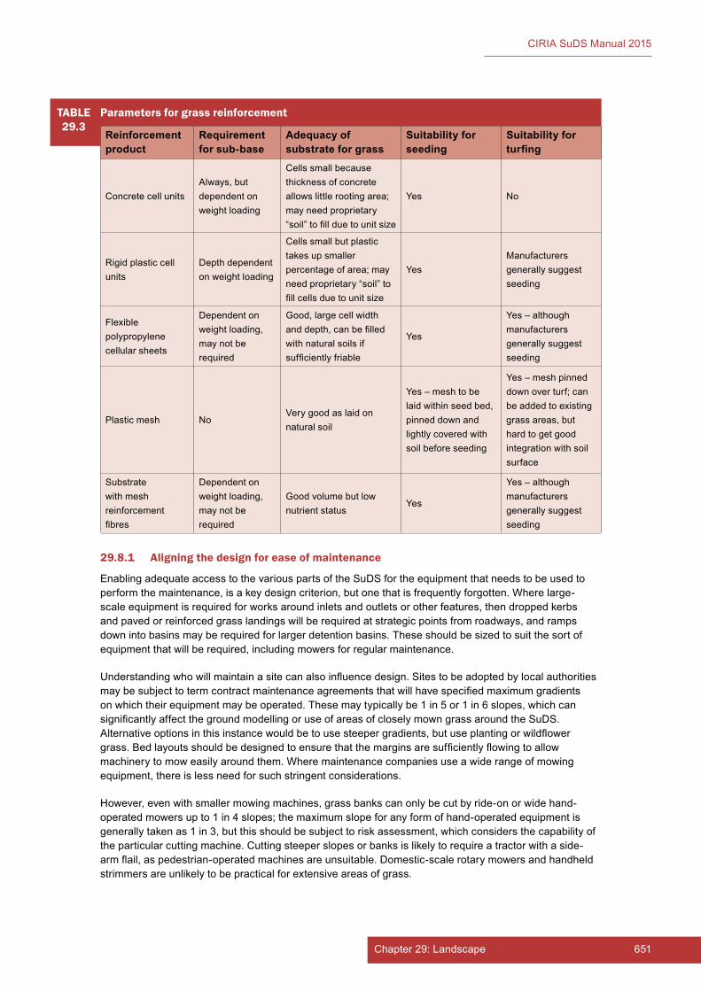
651Chapter 29: Landscape650 Part E: Supporting guidance
CIRIA SuDS Manual 2015
TABLE29.3
Parameters for grass reinforcement
Reinforcement product
Requirementforsub-base
Adequacyofsubstrateforgrass
Suitabilityforseeding
Suitabilityforturfing
Concrete cell unitsAlways, but dependent on weight loading
Cells small because thickness of concrete allows little rooting area; may need proprietary “soil” to fill due to unit size
Yes No
Rigid plastic cell units
Depth dependent on weight loading
Cells small but plastic takes up smaller percentage of area; may need proprietary “soil” to fill cells due to unit size
YesManufacturers generally suggest seeding
Flexible polypropylene cellular sheets
Dependent on weight loading, may not be required
Good, large cell width and depth, can be filled with natural soils if sufficiently friable
Yes
Yes – although manufacturers generally suggest seeding
Plastic mesh NoVery good as laid on natural soil
Yes – mesh to be laid within seed bed, pinned down and lightly covered with soil before seeding
Yes – mesh pinned down over turf; can be added to existing grass areas, but hard to get good integration with soil surface
Substrate with mesh reinforcement fibres
Dependent on weight loading, may not be required
Good volume but low nutrient status
Yes
Yes – although manufacturers generally suggest seeding
29.8.1 Aligning the design for ease of maintenance
Enabling adequate access to the various parts of the SuDS for the equipment that needs to be used to perform the maintenance, is a key design criterion, but one that is frequently forgotten. Where large-scale equipment is required for works around inlets and outlets or other features, then dropped kerbs and paved or reinforced grass landings will be required at strategic points from roadways, and ramps down into basins may be required for larger detention basins. These should be sized to suit the sort of equipment that will be required, including mowers for regular maintenance.
Understanding who will maintain a site can also influence design. Sites to be adopted by local authorities may be subject to term contract maintenance agreements that will have specified maximum gradients on which their equipment may be operated. These may typically be 1 in 5 or 1 in 6 slopes, which can significantly affect the ground modelling or use of areas of closely mown grass around the SuDS. Alternative options in this instance would be to use steeper gradients, but use planting or wildflower grass. Bed layouts should be designed to ensure that the margins are sufficiently flowing to allow machinery to mow easily around them. Where maintenance companies use a wide range of mowing equipment, there is less need for such stringent considerations.
However, even with smaller mowing machines, grass banks can only be cut by ride-on or wide hand-operated mowers up to 1 in 4 slopes; the maximum slope for any form of hand-operated equipment is generally taken as 1 in 3, but this should be subject to risk assessment, which considers the capability of the particular cutting machine. Cutting steeper slopes or banks is likely to require a tractor with a side-arm flail, as pedestrian-operated machines are unsuitable. Domestic-scale rotary mowers and handheld strimmers are unlikely to be practical for extensive areas of grass.

653Chapter 29: Landscape652 Part E: Supporting guidance
CIRIA SuDS Manual 2015
Cutting grass can also only be done effectively when the ground is dry, so areas intended to be damp on a regular basis should have the choice of surface vegetation carefully considered, as close mown grass is unlikely to be suitable.
There are restrictions on the use of chemicals adjacent to watercourses, so only approved herbicides or pesticides should be used, and these operations should only be undertaken by those qualified in their use.
29.8.2 Management plans
Management plans for the first five years after planting are usually required as a standard landscape condition to a planning consent, but these essentially cover “establishment maintenance” and do not address the issues of long-term maintenance. Longer-term management plans should be established for all sites, but particularly where those involved in its initial design and establishment are unlikely to have a longer-term involvement. This will ensure that specific requirements related to how the SuDS function as a planted system will be identified within the plan.
Detailed guidance on the production of management plans is provided in Chapter30. Generally, the overarching aims and objectives should be established, and the plan worked through from the broader landscape setting and its objectives, down to the detailed maintenance operations. Review of the performance of the SuDS and the effectiveness of maintenance should be undertaken on a regular basis, and the plan reviewed in line with its findings, bearing in mind the original overarching intention of the SuDS and the broader landscape in which it sits.
29.9 REFERENCES
DEFRA (2007) Hedgerow survey handbook. As standard procedure for local surveys in the UK, second edition, PB11951, Department for Environment, Food and Rural Affairs, London, UK. Go to: http://tinyurl.com/ozb6c2x
DEFRA (2009) Construction code of practice for the sustainable use of soils on construction sites, PB13298, Department for Environment, Food and Rural Affairs, London, UK. Go to: http://tinyurl.com/ky2rcpv
EA (2010) Managing invasive non-native plants. Revised edition, Environment Agency, Bristol, UK. Go to: http://tinyurl.com/q5jalsy
HA (1981) “The planting of trees and shrubs”, Design Manual for Roads and Bridges, vol 5, Section 2, Part 4, HA 13/81, Highways Agency, London, UK. Go to: http://tinyurl.com/oldlzgo
JCLI (2012) Landscape works contract, Landscape Institute, London, UK. Go to: http://tinyurl.com/obpqx8b
NATURAL ENGLAND (2008) Soil texture, Technical Information Note (TIN)037, first edition, Natural England, London, UK. Go to: http://publications.naturalengland.org.uk/file/83081
NATURAL ENGLAND (2012) National Character Areas, Natural England, London, UK. Go to:http://tinyurl.com/q6cry4t
NHBC (1995) NHBC Standards Chapter 4.2 Building near Trees, National House Builders Council, Amersham, UK. Go to: http://tinyurl.com/on93elb
NNSS (2015) Help stop the spread of invasive plants and animals in British waters, web page, GB Non-native Species Secretariat, York, UK. Go to: http://tinyurl.com/kunatbv
THE LANDSCAPE INSTITUTE and WRAP (2002) Compost specification for the landscape industry, The Landscape Institute, London (ISBN: 1-84405-064-5). Go to: http://tinyurl.com/pql7ba5

653Chapter 29: Landscape652 Part E: Supporting guidance
CIRIA SuDS Manual 2015
STATUTES
Acts
The Hedgerows Regulations 1997 (No.1160)
Wildlife and Countryside Act 1981 (c.69)
British Standards
BS 3882:2015 Specification for topsoil
BS 3936-1:1992 Nursery stock. Specification for trees and shrubs
BS 3936-10:1981 Nursery stock. Specification for ground cover plants
BS 5837:2012 Trees in relation to design, demolition and construction. Recommendations
PAS 100:2011 Compost specification
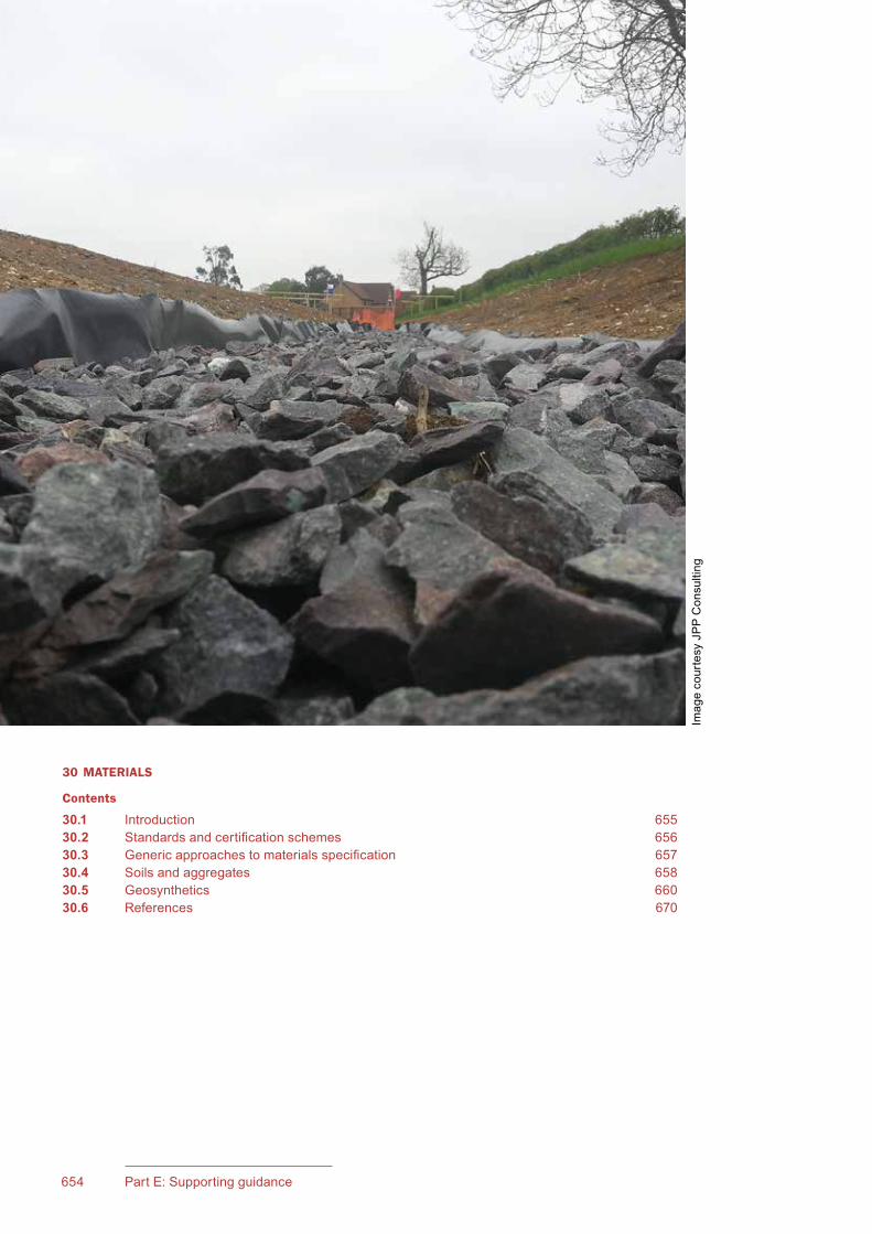
654 Part E: Supporting guidance
CIRIA SuDS Manual 2015
30 MATERIALS
Contents
30.1 Introduction 65530.2 Standardsandcertificationschemes 65630.3 Genericapproachestomaterialsspecification 65730.4 Soilsandaggregates 65830.5 Geosynthetics 66030.6 References 670
ImagecourtesyJPPConsulting

655Chapter 30: Materials
CIRIA SuDS Manual 2015
30Chapter
30.1 INTRODUCTION
Thischapterconsidersthefollowingtypesofgeneralmaterialsorproductsthatmaybeused in SuDS:
▪ soils and aggregates –usedasdrainagelayersorasengineeredsoilsbelowbasins,filterstrips,swalesetc
▪ geosynthetics–geotextiles,geomembranes,erosioncontrolproducts(includingproductsmadewithnaturalmaterialssuchascoir)
Therearerecognisedandacceptedspecificationsformostofthematerialsorproducts,whichhavebeendevelopedovermanyyears.Itispreferabletouseexistingspecificationclauseswhereverpossible,ratherthanhavinganarrayofdifferentbespokespecifications.Thereshouldbeallowancewithinthespecificationtoinsertsite-specific,performance-basedvaluesforkeyproperties.
AlistofthemostcommonmaterialsusedinSuDSandrelevantchaptersofthismanualwherefurtherinformationontheirusecanbefoundisprovidedinTable 30.1.
MaterialsThis chapter provides guidance on certain soils, aggregates and geosynthetics that might be used in SuDS design.
Materials that are specific to a particular SuDS component (eg bioretention soils, sub-base below pervious surfaces, filter drain materials) are discussed in Chapters 11–23.
Topsoil, subsoil and other landscape materials are covered in Chapter 29.
Guidance on good landscaping practice is discussed in Chapter 29.
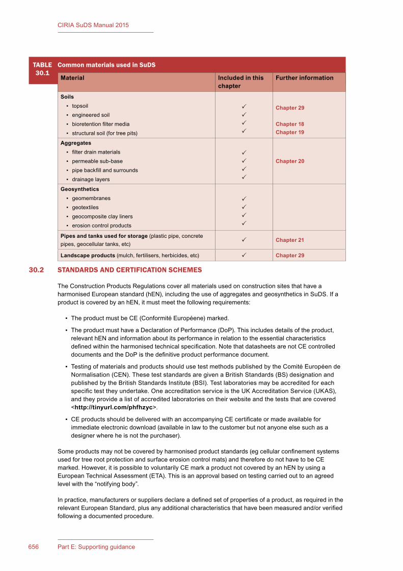
656 Part E: Supporting guidance
CIRIA SuDS Manual 2015
30.2 STANDARDS AND CERTIFICATION SCHEMES
TheConstructionProductsRegulationscoverallmaterialsusedonconstructionsitesthathaveaharmonisedEuropeanstandard(hEN),includingtheuseofaggregatesandgeosyntheticsinSuDS.IfaproductiscoveredbyanhEN,itmustmeetthefollowingrequirements:
▪ TheproductmustbeCE(ConformitéEuropéene)marked.
▪ TheproductmusthaveaDeclarationofPerformance(DoP).Thisincludesdetailsoftheproduct,relevanthENandinformationaboutitsperformanceinrelationtotheessentialcharacteristicsdefinedwithintheharmonisedtechnicalspecification.NotethatdatasheetsarenotCEcontrolleddocumentsandtheDoPisthedefinitiveproductperformancedocument.
▪ TestingofmaterialsandproductsshouldusetestmethodspublishedbytheComitéEuropéendeNormalisation(CEN).TheseteststandardsaregivenaBritishStandards(BS)designationandpublishedbytheBritishStandardsInstitute(BSI).Testlaboratoriesmaybeaccreditedforeachspecifictesttheyundertake.OneaccreditationserviceistheUKAccreditationService(UKAS),andtheyprovidealistofaccreditedlaboratoriesontheirwebsiteandtheteststhatarecovered<http://tinyurl.com/phfhzyc>.
▪ CEproductsshouldbedeliveredwithanaccompanyingCEcertificateormadeavailableforimmediateelectronicdownload(availableinlawtothecustomerbutnotanyoneelsesuchasadesignerwhereheisnotthepurchaser).
Someproductsmaynotbecoveredbyharmonisedproductstandards(egcellularconfinementsystemsusedfortreerootprotectionandsurfaceerosioncontrolmats)andthereforedonothavetobeCEmarked.However,itispossibletovoluntarilyCEmarkaproductnotcoveredbyanhENbyusingaEuropeanTechnicalAssessment(ETA).Thisisanapprovalbasedontestingcarriedouttoanagreedlevelwiththe“notifyingbody”.
Inpractice,manufacturersorsuppliersdeclareadefinedsetofpropertiesofaproduct,asrequiredintherelevantEuropeanStandard,plusanyadditionalcharacteristicsthathavebeenmeasuredand/orverifiedfollowingadocumentedprocedure.
TABLE30.1
Common materials used in SuDS
Material Included in this chapter
Further information
Soils ▪ topsoil
▪ engineeredsoil
▪ bioretentionfiltermedia
▪ structuralsoil(fortreepits)
Chapter 29
Chapter 18Chapter 19
Aggregates ▪ filterdrainmaterials
▪ permeablesub-base
▪ pipebackfillandsurrounds
▪ drainagelayers
Chapter 20
Geosynthetics ▪ geomembranes
▪ geotextiles
▪ geocompositeclayliners
▪ erosioncontrolproducts
Pipes and tanks used for storage(plasticpipe,concretepipes,geocellulartanks,etc) Chapter 21
Landscape products(mulch,fertilisers,herbicides,etc) Chapter 29
657Chapter 30: Materials
CIRIA SuDS Manual 2015
CEmarkingisaself-certificationschemethatindicatesthataproductconformstorelevantEuropeanCommissionDirectivesandthatthepropertiesmatchthosepublishedbythemanufacturer.Itwillallowchecksonsitetodeterminethemanufacturingoriginoftheproductanditsbatchnumberandofferstheopportunitytorequestthefactoryqualitycontroldataforthatbatchofmaterial.ByprovidingaDoP,themanufacturerassumeslegalresponsibilityfortheconformityoftheproducttotherelevanthEN.
CEmarkingshouldnotbeusedonitsowntodetermineifaproductissuitableforagivenapplication.Itisanindicationofqualitycontrolduringmanufacture,butitisnoguaranteethataproductisrightforanygivenapplication.Forexample,adamp-proofmembranecanhaveaCEmark,butitdoesnotmeanthatitissuitableasawaterproofmembranebelowthesharpaggregateofapermeablepavement.FurtherinformationontherequirementsofCEmarkingisprovidedbytheBritishStandardsInstitute(BSI,2008).
Fitnessforpurposecanbeassessedbythird-partyaccreditation.However,third-partyaccreditationcertificates(egBritishBoardofAgrément–BBA)shouldalsobeusedinanappropriateway.SimplyaskingforaproductwithaBBAcertificatedoesnotgiveadequateassurancethataproductissuitableforaparticularuse.TheBBAcertificateshouldbecheckedforeachspecificapplicationtomakesurethattherequirementsinthecertificatearebeingfollowedduringinstallation(egmanyBBAcertificatesformembranesspecifytheuseofprotectionlayerstopreventdamage)andthatthedesigner’srequirementsarebeingmet.
30.3 GENERIC APPROACHES TO MATERIALS SPECIFICATION
ThethreemostcommonlyusedspecificationdocumentsaresummarisedinTable 30.2.
TABLE30.2
Commonly used specifications
Specification Comments
NationalBuildingSpecification(NBS)
▪ referstotheSHWformanyearthworksmaterialsandaggregates
▪ notnecessarilyperformancebasedandallowsreferencetospecificproductsandmanufacturers’references
▪ availableatacost
▪ wellestablishedandwidelyusedbyengineers,architectsandlandscapearchitects.
SpecificationforHighwayWorks(SHW)(HA,2005a)
▪ canbefreelydownloaded
▪ recipeorperformancebased
▪ wellestablishedandwidelyusedbyhighwaysauthoritiesandmanydevelopersandengineers;notcommonlyusedbylandscapeprofessionals
▪ providesarobustspecificationfordrainage,earthworksandpavementmaterials;NBSusestheSHWasareferenceformanyoftheseitems
▪ generallyupdatedeveryquarter.
CivilEngineeringSpecificationfortheWaterIndustry(CESWI)(WRc,2011)
▪ performance-andrecipe-basedspecification(doesnotrefertospecificmanufacturers)
▪ availableatasmallcost
▪ wellestablishedandusedincivilengineeringcontractsletbywatercompaniesacrosstheUK.
NoneofthesecurrentlyincludespecificclausesforSuDSconstruction.However,theydocontainclausesformostofthecommonconstructionactivitiesandmaterialsusedinSuDS,orprovisionforincludingthem.ThedifferentitemsrequiredforSuDSwillbefoundindifferentpartsofeachofthestandardspecifications,butthisisnotunusualforanyitemofconstruction.Forexample,ifspecifyingmaterialsforacarparksurfaceanddrainageusingtheSHW,thedesignerwouldcalluponseveraldifferentpartsoftheSHW(HA,2005a),egSeries500(HA,2009a),Series600(HA,2009b),Series700(HA,2009c)andSeries3000(HA,2009d).HA(2005a)will,inturn,referencevariousotherstandardsasnecessary.
658 Part E: Supporting guidance
CIRIA SuDS Manual 2015
ThefollowingprinciplesshouldbefollowedwhenpreparingspecificationsforSuDS:
▪ Thespecificationshouldbeperformance-orrecipe-based(neverbothforthesameproperty)andshouldavoidtherequirementtouseproductsfromaspecificmanufacturer,unlessabsolutelynecessary.Thedesignershouldbeabletoprovidejustificationforanyparticularspecificationrequirement.
▪ ThespecificationrequirementsshouldconsidertheconstructionphaseandmaintenancephaseofSuDS.
▪ Performancerequirementsshouldbebasedonsite-specificestimatesofrequirements.Theyshouldnotbearepeatofvaluesfromasinglemanufacturer’sliterature.
▪ Whereverpossible,thespecificationclausesshouldreferencerelevantBritish/Europeanstandards.
AnyofthesespecificationscanbeadaptedtoincludethespecificationclausesforspecificSuDScomponents.Animportantconsiderationisthatthoseinvolvedinaprojectarefamiliarwiththeparticularspecificationbeingusedandthatstandarddocumentsaresubjecttochangeoutsidetheuser’scontrol.Theversionofadocumentbeingusedshouldbestated,andusersshouldregularlycheckforchangesandupdatestospecifications.
SpecificationsshouldalsotakeaccountoftheConstructionProductsRegulations2013(Section 30.2).
30.4 SOILS AND AGGREGATES
SoilsandaggregatesareusedinSuDSasdrainagelayers,storagelayersorasgeneralengineeredsoilsbelowbasins,filterstrips,swalesetc.Ifrecycledmaterialsareused,theyneedtomeetthesamespecificationrequirementsplusanyadditionalrequirementsfortheparticularmaterial.WRAPprovidesguidanceonqualityprotocolsfortheuseofrecycledmaterialsinconstructionprojects(WRAP,2014).
30.4.1 Aggregates for drainage layers and trenches
BSEN13242:2002definesaggregatesthatcanbeusedinunboundgranularmaterials,whichwillincludedrainagelayersorfillingfordrainagetrenches.Thedocumentprovidesaggregateproperties,categoryrangesandmethodsoftestthatapplytoanyaggregatetypesatisfyingBSEN13242.Specificationswillneedtodefinesuitablecategoriesforpropertiesthatarerelevanttotheparticularenduse.ThereisaguidancedocumentavailablethatexplainshowtoapplyBSEN13242foraggregates,andprovidesrecommendedcategoriesfordifferentenduses.
Standardmaterialsaredefinedintermsofthelowerandupperparticlesizes.Forexample,20mmsinglesizematerialisdefinedas10/20(theminimumparticlesizeis10mmandthemaximumis20mm).
Aggregatesusedasdrainagelayersorintrenchesneedtobesufficientlypermeabletodrainwaterthroughthemandmayalsoberequiredtostorewatertemporarily.Thevolumeofairvoidsbetweenaggregateparticlesinalayerofmaterialwillbeimportant,becausethisiswherewaterisstoredorconveyed.Permeabilitycanbeseverelyaffectedbythepercentageoffines(<0.063mm),forexample5%finescaninsomeinstancesdecreasepermeabilityby95%dependingontheoverallgradingofthematerial.Ifthedrainagelayeristobeusedtosupporttraffic,theaggregateneedstobesufficientlystronganddurabletopreventitfrombreakingdownintosmallerpieces.CommonlyusedmaterialsaresetoutinTable 30.3.
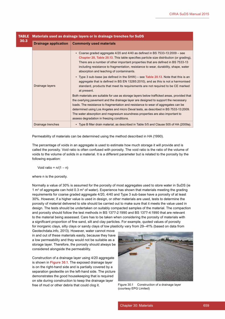
659Chapter 30: Materials
CIRIA SuDS Manual 2015
PermeabilityofmaterialscanbedeterminedusingthemethoddescribedinHA(1990).
Thepercentageofvoidsinanaggregateisusedtoestimatehowmuchstorageitwillprovideandiscalledtheporosity.Voidratioisoftenconfusedwithporosity.Thevoidratioistheratioofthevolumeofvoidstothevolumeofsolidsinamaterial.Itisadifferentparameterbutisrelatedtotheporositybythefollowingequation:
Voidratio=n/(1–n)
wherenistheporosity.
Normallyavalueof30%isassumedfortheporosityofmostaggregatesusedtostorewaterinSuDS(ie1m3ofaggregatecanhold0.3m3ofwater).Experiencehasshownthatmaterialsmeetingthegradingrequirementsforcoarsegradedaggregate4/20,4/40andType3sub-basehaveaporosityofatleast30%.However,ifahighervalueisusedindesign,orothermaterialsareused,teststodeterminetheporosityofmaterialdeliveredtositeshouldbecarriedouttomakesurethatitmeetsthevalueusedindesign.Thetestsshouldbeundertakenonsuitablycompactedsamplesofthematerial.ThecompactionandporosityshouldfollowthetestmethodsinBS1377-2:1990andBS1377-4:1990thatarerelevanttothematerialbeingassessed.Carehastobetakenwhenconsideringtheporosityofmaterialswithasignificantproportionoffinesand,siltandclayparticles.Forexample,quotedvaluesofporosityforinorganicclays,siltyclaysorsandyclaysoflowplasticityvaryfrom29–41%(basedondatafromGeotechdata.info,2013).However,watercannotmoveinandoutofthesematerialseasily,becausetheyhavealowpermeabilityandtheywouldnotbesuitableasastoragelayer.Therefore,theporosityshouldalwaysbeconsideredalongsidethepermeability.
Constructionofadrainagelayerusing4/20aggregateisshowninFigure 30.1.Theexposeddrainagelayerisontheright-handsideandispartiallycoveredbyaseparationgeotextileontheleft-handside.Thepicturedemonstratesthegoodhousekeepingthatisrequiredonsiteduringconstructiontokeepthedrainagelayerfreeofmudorotherdebristhatcouldclogit.
TABLE30.3
Materials used as drainage layers or in drainage trenches for SuDS
Drainage application Commonly used materials
Drainagelayers
▪ Coarsegradedaggregate4/20and4/40asdefinedinBS7533-13:2009–seeChapter 20, Table 20.13.Thistablespecifiesparticlesizedistribution(orgrading),ThereareanumberofotherimportantpropertiesthataredefinedinBS7533-13includingresistancetofragmentation,resistancetowear,durability,shape,waterabsorptionandleachingofcontaminants.
▪ Type3sub-base(asdefinedintheSHW)–seeTable 20.13.NotethatthisisanaggregatethatisdefinedinBSEN13285:2010),andasthisisnotaharmonisedstandard,productsthatmeetitsrequirementsarenotrequiredtobeCEmarkedatpresent.
Bothmaterialsaresuitableforuseasstoragelayersbelowtraffickedareas,providedthattheoverlyingpavementandthedrainagelayeraredesignedtosupportthenecessaryloads.TheresistancetofragmentationandresistancetowearofaggregatescanbedeterminedusingLosAngelesandmicroDevaltests,asdescribedinBS7533-13:2009.Thewaterabsorptionandmagnesiumsoundnesspropertiesarealsoimportanttoassessdegradationinfreezingconditions.
Drainagetrenches ▪ TypeBfilterdrainmaterial,asdescribedinTable5/5andClause505ofHA(2009a).
Figure30.1 Constructionofadrainagelayer(courtesyEPGLimited)

660 Part E: Supporting guidance
CIRIA SuDS Manual 2015
30.4.2 Engineered soils
Asuitabledepthofengineeredsoilcanbeusedoverthebottomofbasins,filterstripsorswalestoreducewaterloggingandimprovethedrainagecharacteristicsofthebasin.(NotethatinBS3882:2007,multipurposetopsoilcanstillbespecifiedforbanksofswalesandbasins,whereplantingisdesired.)Theengineeredsoilwilltendtobeagreaterdepththantypicaltopsoildepths–potentiallyreplacingsomeofthesubsoildepth,whereappropriate.Theimportantpropertiesofthisengineeredsoilareasfollows:
▪ sufficientlypermeabletoallowwatertodraineasily
▪ havingsuitablepropertiesandorganiccontenttosupportplantgrowth.
Anengineeredsoilwilltendtobeasand-basedmediumwithanarrowparticlesizedistribution,highpermeabilityandporosity,andreasonablereservesoforganicmatterandavailableplantnutrients.TheexamplespecificationforabioretentionfiltermediumprovidedinChapter 18, Box 18.3isasuitablesoiltypethatcouldbeconsidered.Rootzonematerials,thatisamixofsandandtopsoilorgreencompost(similartothatusedintheconstructionofsportspitches),canoftenalsobesuitable.Anyspecificationthatisusedshouldbefullyverifiedtoensurethatitmeetssite-specificrequirementsintermsofdrainageperformanceanditsfunctionasgrowingmedia.Inparticular,thesaturatedhydraulicconductivityofthesoilshouldmeetthedesignrequirementsforthedrainagefunction.
30.4.3 Use of recycled and secondary materials as aggregates
RecycledmaterialscanbeusedtoproduceaggregatesforuseinSuDS,providedthattheyhavesuitableproperties.Theycanbeobtainedatsourcefromdemolition(egbricksandconcrete),highwaymaintenance(egasphaltplanings)andotherworks,ortheycanbeboughtfromcentralprocessingcentres.Thequalityoftherecycledaggregateisdependentonthequalityoftheoriginalsourcematerialsthatareprocessed,andtheprocessingthatthesematerialsundergo.Allrecycledmaterialsmustconformwiththerelevantspecifications.
Secondarymaterialsarewasteproductsfromotherprocessesoraremanufacturedfromwasteproducts,forexampleblastfurnaceslag,recycledglassandrecycledtyres.
TheEuropeanstandardsforaggregatesdiscussedabovedonotdiscriminatebetweendifferentsources,and are for “aggregates from natural, recycled and manufactured materials”.Oneofthemostcommonrecycledmaterialsiscrushedconcrete.Whenusedindrainagelayersorfilterdrainbackfill,crushedconcreteshouldmeetthesamerequirementsasnaturalmaterials.
Itisimportantthatrecycledmaterialswillnotdegradeinserviceandwillnotleachpollutantsintosurfacewater.
Theuseofrecycledandsecondaryaggregatesshouldcomplywithallrelevantwastemanagementandotherenvironmentalregulations.FurtherinformationisprovidedontheAggRegainwebsite<http://aggregain.wrap.org.uk/>
30.5 GEOSYNTHETICS
TherearemanytypesofgeosyntheticsusedinSuDS.Theseincludegeotextiles,geomembranes,geocompositeclaylinersandgeocompositedrainageproducts.Erosioncontrolproducts(egproductsmadewithnaturalmaterialssuchascoir)arealsoincludedinthissection.
Oneofthemainproblemsfordesignersisthatdifferentproductsoftenquoteparametersobtainedfromdifferenttestmethodsandfromimplementationwithindifferentcomponents.Thismakesitdifficulttomakeobjectivecomparisonsofperformance.Thisproblemshouldreduceovertime,asCEmarking(Section 30.2)drivesthestandardisationoftestmethods.
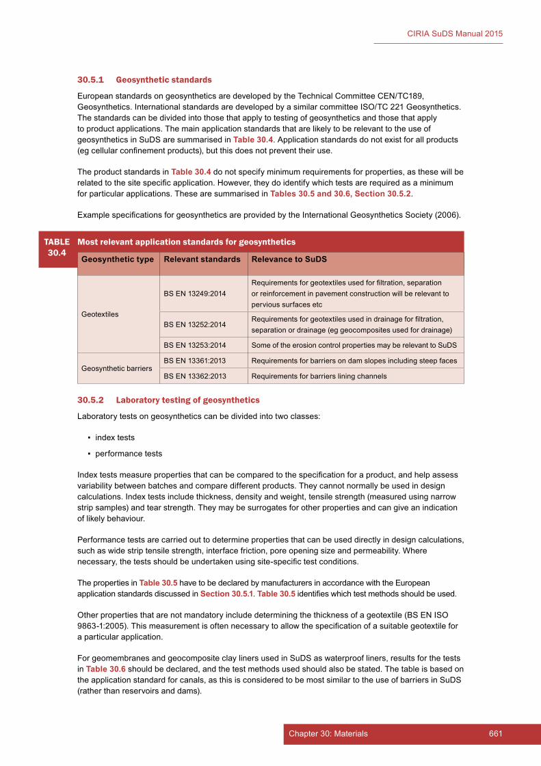
661Chapter 30: Materials
CIRIA SuDS Manual 2015
30.5.1 Geosynthetic standards
EuropeanstandardsongeosyntheticsaredevelopedbytheTechnicalCommitteeCEN/TC189,Geosynthetics.InternationalstandardsaredevelopedbyasimilarcommitteeISO/TC221Geosynthetics.Thestandardscanbedividedintothosethatapplytotestingofgeosyntheticsandthosethatapplytoproductapplications.ThemainapplicationstandardsthatarelikelytoberelevanttotheuseofgeosyntheticsinSuDSaresummarisedinTable 30.4.Applicationstandardsdonotexistforallproducts(egcellularconfinementproducts),butthisdoesnotpreventtheiruse.
TheproductstandardsinTable 30.4donotspecifyminimumrequirementsforproperties,asthesewillberelatedtothesitespecificapplication.However,theydoidentifywhichtestsarerequiredasaminimumforparticularapplications.ThesearesummarisedinTables 30.5 and 30.6, Section 30.5.2.
ExamplespecificationsforgeosyntheticsareprovidedbytheInternationalGeosyntheticsSociety(2006).
TABLE30.4
Most relevant application standards for geosynthetics
Geosynthetic type Relevant standards Relevance to SuDS
Geotextiles
BSEN13249:2014Requirementsforgeotextilesusedforfiltration,separationorreinforcementinpavementconstructionwillberelevanttopervioussurfacesetc
BSEN13252:2014Requirementsforgeotextilesusedindrainageforfiltration,separationordrainage(eggeocompositesusedfordrainage)
BSEN13253:2014 SomeoftheerosioncontrolpropertiesmayberelevanttoSuDS
GeosyntheticbarriersBSEN13361:2013 Requirementsforbarriersondamslopesincludingsteepfaces
BSEN13362:2013 Requirementsforbarriersliningchannels
30.5.2 Laboratory testing of geosynthetics
Laboratorytestsongeosyntheticscanbedividedintotwoclasses:
▪ indextests
▪ performancetests
Indextestsmeasurepropertiesthatcanbecomparedtothespecificationforaproduct,andhelpassessvariabilitybetweenbatchesandcomparedifferentproducts.Theycannotnormallybeusedindesigncalculations.Indextestsincludethickness,densityandweight,tensilestrength(measuredusingnarrowstripsamples)andtearstrength.Theymaybesurrogatesforotherpropertiesandcangiveanindicationoflikelybehaviour.
Performancetestsarecarriedouttodeterminepropertiesthatcanbeuseddirectlyindesigncalculations,suchaswidestriptensilestrength,interfacefriction,poreopeningsizeandpermeability.Wherenecessary,thetestsshouldbeundertakenusingsite-specifictestconditions.
ThepropertiesinTable 30.5havetobedeclaredbymanufacturersinaccordancewiththeEuropeanapplicationstandardsdiscussedinSection 30.5.1.Table 30.5 identifieswhichtestmethodsshouldbeused.
Otherpropertiesthatarenotmandatoryincludedeterminingthethicknessofageotextile(BSENISO9863-1:2005).Thismeasurementisoftennecessarytoallowthespecificationofasuitablegeotextileforaparticularapplication.
ForgeomembranesandgeocompositeclaylinersusedinSuDSaswaterproofliners,resultsforthetestsin Table 30.6shouldbedeclared,andthetestmethodsusedshouldalsobestated.Thetableisbasedontheapplicationstandardforcanals,asthisisconsideredtobemostsimilartotheuseofbarriersinSuDS(ratherthanreservoirsanddams).
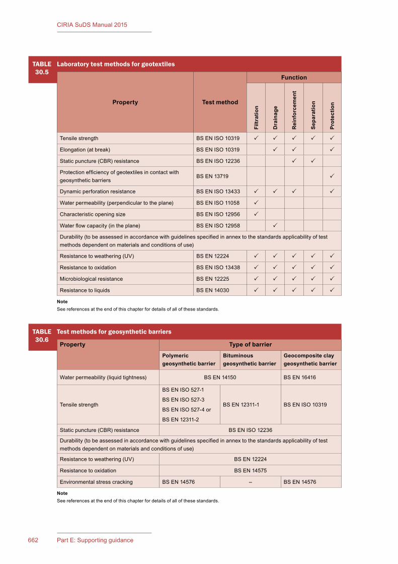
662 Part E: Supporting guidance
CIRIA SuDS Manual 2015
TABLE30.5
Laboratory test methods for geotextiles
Property Test method
Function
Filtr
atio
n
Dra
inag
e
Rei
nfor
cem
ent
Sepa
ratio
n
Prot
ectio
n
Tensilestrength BSENISO10319
Elongation(atbreak) BSENISO10319
Staticpuncture(CBR)resistance BSENISO12236
Protectionefficiencyofgeotextilesincontactwithgeosyntheticbarriers
BSEN13719
Dynamicperforationresistance BSENISO13433
Waterpermeability(perpendiculartotheplane) BSENISO11058
Characteristicopeningsize BSENISO12956
Waterflowcapacity(intheplane) BSENISO12958
Durability(tobeassessedinaccordancewithguidelinesspecifiedinannextothestandardsapplicabilityoftestmethodsdependentonmaterialsandconditionsofuse)
Resistancetoweathering(UV) BSEN12224
Resistancetooxidation BSENISO13438
Microbiologicalresistance BSEN12225
Resistancetoliquids BSEN14030
NoteSeereferencesattheendofthischapterfordetailsofallofthesestandards.
TABLE30.6
Test methods for geosynthetic barriers
Property Type of barrier
Polymeric geosynthetic barrier
Bituminous geosynthetic barrier
Geocomposite clay geosynthetic barrier
Waterpermeability(liquidtightness) BSEN14150 BSEN16416
Tensilestrength
BSENISO527-1
BSENISO527-3
BSENISO527-4or
BSEN12311-2
BSEN12311-1 BSENISO10319
Staticpuncture(CBR)resistance BSENISO12236
Durability(tobeassessedinaccordancewithguidelinesspecifiedinannextothestandardsapplicabilityoftestmethodsdependentonmaterialsandconditionsofuse)
Resistancetoweathering(UV) BSEN12224
Resistancetooxidation BSEN14575
Environmentalstresscracking BSEN14576 – BSEN14576
NoteSeereferencesattheendofthischapterfordetailsofallofthesestandards.
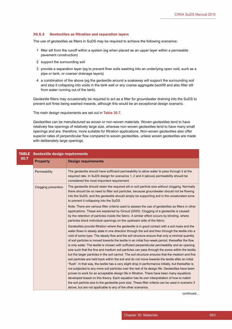
663Chapter 30: Materials
CIRIA SuDS Manual 2015
30.5.3 Geotextiles as filtration and separation layers
TheuseofgeotextilesasfiltersinSuDSmayberequiredtoachievethefollowingscenarios:
1 filtersiltfromtherunoffwithinasystem(egwhenplacedasanupperlayerwithinapermeablepavementconstruction)
2 supportthesurroundingsoil
3 provideaseparationlayer(egtopreventfinersoilswashingintoanunderlyingopenvoid,suchasapipeortank,orcoarserdrainagelayers)
4 acombinationoftheabove(egthegeotextilearoundasoakawaywillsupportthesurroundingsoilandstopitcollapsingintovoidsinthetankwalloranycoarseaggregatebackfillandalsofiltersiltfromwaterrunningoutofthetank).
GeotextilefiltersmayoccasionallyberequiredtoactasafilterforgroundwaterdrainingintotheSuDStopreventsoilfinesbeingwashedinwards,althoughthiswouldbeanexceptionaldesignscenario.
ThemaindesignrequirementsaresetoutinTable 30.7.
Geotextilescanbemanufacturedaswovenornon-wovenmaterials.Wovengeotextilestendtohaverelativelyfewopeningsofrelativelylargesize,whereasnon-wovengeotextilestendtohavemanysmallopeningsandare,therefore,moresuitableforfiltrationapplications.Non-wovengeotextilesalsooffersuperiorratesofperpendicularflowcomparedtowovengeotextiles,unlesswovengeotextilesaremadewithdeliberatelylargeopenings.
TABLE30.7
Geotextile design requirements
Property Design requirements
Permeability Thegeotextileshouldhavesufficientpermeabilitytoallowwatertopassthroughitattherequiredrate.InSuDSdesignforscenarios1,2and4(above)permeabilityshouldbeconsideredthemostimportantrequirement.
Cloggingprevention Thegeotextileshouldretaintherequiredsiltorsoilparticlesizewithoutclogging.Normallythereshouldbenoneedtofiltersoilparticles,becausegroundwatershouldnotbeflowingintotheSuDS,andthegeotextileshouldsimplybesupportingsoilintheunsaturatedzonetopreventitcollapsingintotheSuDS.
Note:Therearevariousfiltercriteriausedtoassesstheuseofgeotextilesasfiltersinotherapplications.TheseareexplainedbyGiroud(2000).Cloggingofageotextileiscausedbytheretentionofparticlesinsidethefabric.Asimilareffectoccursbyblinding,whereparticlesblockindividualopeningsontheupstreamsideofthefabric.
Geotextilesprovidefiltrationwherethegeotextileisingoodcontactwithasoilmassandthewaterflowsinsteadystateinonedirectionthroughthesoilandthenthroughthetextileintoavoidofsometype.Thesteadyflowandthesoilstructureensurethatonlyaminimalquantityofsoilparticlesismovedtowardsthetextileinaninitialfour-weekperiod,thereaftertheflowisonlywater.Thetextileischosenwithsufficientperpendicularpermeabilityandanopeningsizesuchthatthefineandmediumsoilparticlescanpassthroughtheporeswithinthetextile,butthelargerparticlesinthesoilcannot.Thesoilstructureensuresthatthemediumandfinesoilparticlesareheldbackwithinthesoilanddonotmovetowardsthetextileafteraninitial“flush”.Inthatway,thetextilehasaveryslightdropinperformanceinitially,butthereafterisnotsubjectedtoanymoresoilparticlesovertherestofitsdesignlife.Geotextileshavebeenproventoworkforanacceptabledesignlifeinfiltration.Therehavebeenmanyequationsdevelopedbasedonthistheory.Eachequationhasitsowninterpretationofhowtomatchthesoilparticlesizetothegeotextileporesize.Thesefiltercriteriacanbeusedinscenario3above,butarenotapplicabletoanyoftheotherscenarios.
continued...
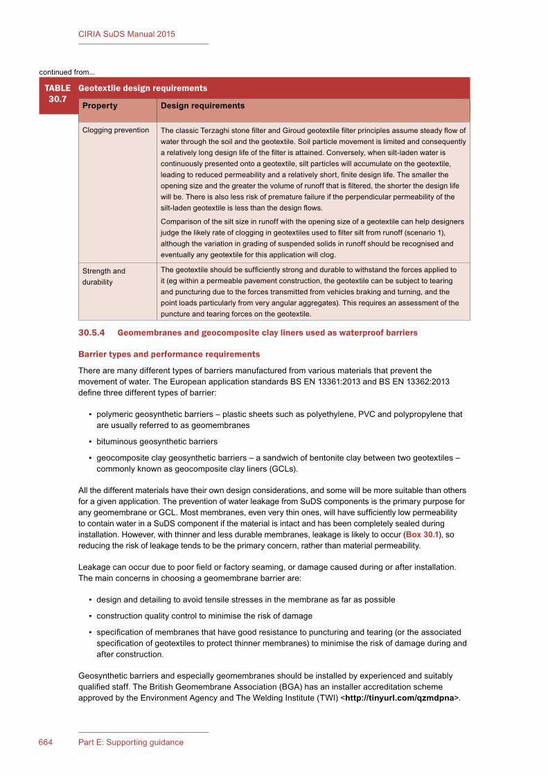
664 Part E: Supporting guidance
CIRIA SuDS Manual 2015
TABLE30.7
Geotextile design requirements
Property Design requirements
Cloggingprevention TheclassicTerzaghistonefilterandGiroudgeotextilefilterprinciplesassumesteadyflowofwaterthroughthesoilandthegeotextile.Soilparticlemovementislimitedandconsequentlyarelativelylongdesignlifeofthefilterisattained.Conversely,whensilt-ladenwateriscontinuouslypresentedontoageotextile,siltparticleswillaccumulateonthegeotextile,leadingtoreducedpermeabilityandarelativelyshort,finitedesignlife.Thesmallertheopeningsizeandthegreaterthevolumeofrunoffthatisfiltered,theshorterthedesignlifewillbe.Thereisalsolessriskofprematurefailureiftheperpendicularpermeabilityofthesilt-ladengeotextileislessthanthedesignflows.
Comparisonofthesiltsizeinrunoffwiththeopeningsizeofageotextilecanhelpdesignersjudgethelikelyrateofcloggingingeotextilesusedtofiltersiltfromrunoff(scenario1),althoughthevariationingradingofsuspendedsolidsinrunoffshouldberecognisedandeventuallyanygeotextileforthisapplicationwillclog.
Strengthanddurability
Thegeotextileshouldbesufficientlystronganddurabletowithstandtheforcesappliedtoit(egwithinapermeablepavementconstruction,thegeotextilecanbesubjecttotearingandpuncturingduetotheforcestransmittedfromvehiclesbrakingandturning,andthepointloadsparticularlyfromveryangularaggregates).Thisrequiresanassessmentofthepunctureandtearingforcesonthegeotextile.
30.5.4 Geomembranes and geocomposite clay liners used as waterproof barriers
Barrier types and performance requirements
Therearemanydifferenttypesofbarriersmanufacturedfromvariousmaterialsthatpreventthemovementofwater.TheEuropeanapplicationstandardsBSEN13361:2013andBSEN13362:2013definethreedifferenttypesofbarrier:
▪ polymericgeosyntheticbarriers–plasticsheetssuchaspolyethylene,PVCandpolypropylenethatareusuallyreferredtoasgeomembranes
▪ bituminousgeosyntheticbarriers
▪ geocompositeclaygeosyntheticbarriers–asandwichofbentoniteclaybetweentwogeotextiles–commonlyknownasgeocompositeclayliners(GCLs).
Allthedifferentmaterialshavetheirowndesignconsiderations,andsomewillbemoresuitablethanothersforagivenapplication.ThepreventionofwaterleakagefromSuDScomponentsistheprimarypurposeforanygeomembraneorGCL.Mostmembranes,evenverythinones,willhavesufficientlylowpermeabilitytocontainwaterinaSuDScomponentifthematerialisintactandhasbeencompletelysealedduringinstallation.However,withthinnerandlessdurablemembranes,leakageislikelytooccur(Box 30.1),soreducingtheriskofleakagetendstobetheprimaryconcern,ratherthanmaterialpermeability.
Leakagecanoccurduetopoorfieldorfactoryseaming,ordamagecausedduringorafterinstallation.Themainconcernsinchoosingageomembranebarrierare:
▪ designanddetailingtoavoidtensilestressesinthemembraneasfaraspossible
▪ constructionqualitycontroltominimisetheriskofdamage
▪ specificationofmembranesthathavegoodresistancetopuncturingandtearing(ortheassociatedspecificationofgeotextilestoprotectthinnermembranes)tominimisetheriskofdamageduringandafterconstruction.
Geosyntheticbarriersandespeciallygeomembranesshouldbeinstalledbyexperiencedandsuitablyqualifiedstaff.TheBritishGeomembraneAssociation(BGA)hasaninstalleraccreditationschemeapprovedbytheEnvironmentAgencyandTheWeldingInstitute(TWI)<http://tinyurl.com/qzmdpna>.
continuedfrom...
665Chapter 30: Materials
CIRIA SuDS Manual 2015
Itisimportantthatalljointsandseamsarevisuallyinspectedandtestedonsitetoensurethattheymeettherequiredstandard.Themainplaceswhereleaksarelikelytooccurisaroundpenetrations,suchaswhereapipepassesthroughthematerial(egwhereapipepassesintoalinedtank).
GCLsaregenerallyusedincombinationwithanexistingclaybarrierorincombinationwithageomembraneinapplicationsinwhichasignificantwaterheadismaintained.GCLsarenotrecommendedforuseontheirownaroundgeocellulartanks.However,wheretheyareusedundershallowSuDSwatercomponents,theymaybesuitableontheirown(egtopreventsignificantinfiltrationfromaswalewithalowheadofwater).
Design considerations
KeyissuestobeconsideredforanybarriersystemaresetoutinTable 30.8,togetherwiththeappropriatedesignapproaches.
BOX30.1
Geomembranes and construction
Acriticalpropertyofanywaterproofbarrierisitsabilitytosurvivetheconstructionprocessintactandinagoodcondition,soastoreducethesubsequentpermeationofwatertoacceptablelevels.Thekeyphysicalparametersofbarrierstobeconsideredare:
▪ thematerialitismanufacturedfrom
▪ itsphysicalproperties(tensilestrength,punctureresistance,tearresistance)
▪ itspermeability.
Thicknessalsobecomesakeyparameter,ifjointsofpolymericbarriersarewelded–seeMallettet al(2014).Protectionofbarriersduringconstructionmayberequiredtoensurethattheyhaveretainedtheirintegrity.
Particularcareisrequiredinspecifyingmembranesbelowpermeablepavementswherethecoarse-gradedaggregateislocateddirectlyonthemembrane.Thinmembraneslessthan0.5mmthickarenotlikelytosurviveinthissituationwithoutholesoccurring.
TABLE30.8
Design considerations for waterproof barriers in SuDS
Design consideration Design approach for the application of waterproof barriers in SuDS
Slopestability
FormostSuDSapplications,slopesshouldbelow,whichwillminimisetheriskofinstability,butwheregeomembranesandgeotextilesaretobelaidonslopes,astabilityassessmentshouldbeundertakenbyasuitablyqualifiedgeotechnicalengineerorengineeringgeologist.
Tree root penetration
Ifthesystemiswellconstructedanddoesnotleakandnearbytreeshavesufficientandsuitablesoilaroundtheroots,thenrootpenetrationthroughgeomembranesshouldnotbeaproblem.Riskoftreerootpenetrationcanbeminimisedbylocatingtanksoutsidetherootingareaoftreesor,wherethiscannotbeachieved,byprovidingrootbarrierstoprotectmembranes.
Temperatureeffects(thermalstressesinpolymericmembranesandfreeze/thawinGCLs)andUVlight
GeomembranesusedinSuDSshouldnormallynotbeexposedatgroundlevelandwillbecoveredbysoiloraggregate.Temperatureeffectscanbeminimisedbyensuringanadequatethicknessofcoveringsoil.Thethicknessrequiredwilldependonthelocalclimate.However,experiencewithgreenroofshasshownthatevenathincoveringofsoil(150mmorgreater)canimprovethelifespanofwaterproofingbarrierssignificantlybyprotectingthemfromextremechangesintemperatureandtheassociatedstresses,aswellasfromUVlight(Edgeet al,2007).
DryingandwettingeffectsforGCLs
Geocompositeclaylinersincludealayerofbentonitethathastobehydratedtoformthebarriertowater.IftheGCLdriesout,thebentoniteshrinksandcracks.However,thebentonitewillswellagainonrehydrationwhenitcomesintocontactwithwater,sothereshouldnotbeanysignificanteffect.MostGCLmanufacturersshouldhavetestdatatoshowthattheGCLscanselfheal,iftheydryoutandarerehydrated.
continued...
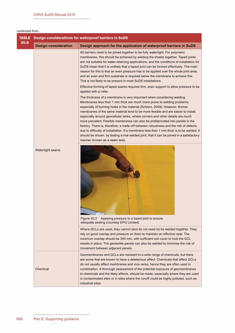
666 Part E: Supporting guidance
CIRIA SuDS Manual 2015
TABLE30.8
Design considerations for waterproof barriers in SuDS
Design consideration Design approach for the application of waterproof barriers in SuDS
Watertightseams
Allbarriersneedtobejoinedtogethertobefullywatertight.Forpolymericmembranes,thisshouldbeachievedbyweldingthesheetstogether.Tapedjointsarenotsuitableforwater-retainingapplications,andtheconditionsofinstallationforSuDSmeanthatitisunlikelythatatapedjointcanbeformedeffectively.Themainreasonforthisisthatanevenpressurehastobeappliedoverthewholejointarea,andanevenandfirmsubstrateisrequiredbelowthemembranetoachievethis.ThisisnotlikelytobepresentinmostSuDSinstallations.
Effectiveformingoftapedseamsrequiresfirm,evensupporttoallowpressuretobeappliedwitharoller.
Thethicknessofamembraneisveryimportantwhenconsideringwelding.Membraneslessthan1mmthickaremuchmorepronetoweldingproblems,especiallyofburningholesinthematerial(Schiers,2009).However,thinnermembranesofthesamematerialtendtobemoreflexibleandareeasiertoinstall,especiallyaroundgeocellulartanks,wherecornersandotherdetailsaremuchmoreprevalent.Flexiblemembranescanalsobeprefabricatedintopanelsinthefactory.Thereis,therefore,atrade-offbetweenrobustnessandtheriskofdefectsduetodifficultyofinstallation.Ifamembranelessthan1mmthickistobewelded,itshouldbeshown,bytestingatrialweldedjoint,thatitcanbejoinedinasatisfactorymanner(knownasaseamtest).
WhereGCLsareused,theycannot(anddonotneedto)beweldedtogether.Theyrelyongoodoverlapandpressureonthemtomaintainaneffectiveseal.Theminimumoverlapshouldbe300mm,withsufficientsoilcovertoholdtheGCLsheetsinplace.Thegeotextilepanelscanalsobeweldedtominimisetheriskofmovementbetweenadjacentpanels.
Chemical
GeomembranesandGCLsareresistanttoawiderangeofchemicals,buttherearesomethatareknowntohaveadeleteriouseffect.ChemicalsthataffectGCLsdonotusuallyaffectmembranesandviceversa,hencetheyareoftenusedincombination.Athoroughassessmentofthepotentialexposureofgeomembranestochemicalsandthelikelyeffects,shouldbemade,especiallywheretheyareusedincontaminatedsitesorinsiteswheretherunoffcouldbehighlypolluted,suchasindustrialsites.
Figure30.2 Applyingpressuretoatapedjointtoensureadequatesealing(courtesyEPGLimited)
continuedfrom...
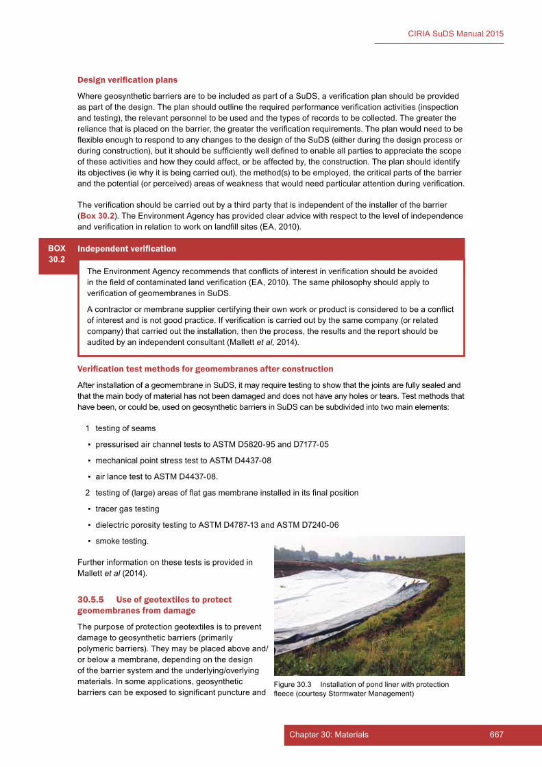
667Chapter 30: Materials
CIRIA SuDS Manual 2015
Design verification plans
WheregeosyntheticbarriersaretobeincludedaspartofaSuDS,averificationplanshouldbeprovidedaspartofthedesign.Theplanshouldoutlinetherequiredperformanceverificationactivities(inspectionandtesting),therelevantpersonneltobeusedandthetypesofrecordstobecollected.Thegreaterthereliancethatisplacedonthebarrier,thegreatertheverificationrequirements.TheplanwouldneedtobeflexibleenoughtorespondtoanychangestothedesignoftheSuDS(eitherduringthedesignprocessorduringconstruction),butitshouldbesufficientlywelldefinedtoenableallpartiestoappreciatethescopeoftheseactivitiesandhowtheycouldaffect,orbeaffectedby,theconstruction.Theplanshouldidentifyitsobjectives(iewhyitisbeingcarriedout),themethod(s)tobeemployed,thecriticalpartsofthebarrierandthepotential(orperceived)areasofweaknessthatwouldneedparticularattentionduringverification.
Theverificationshouldbecarriedoutbyathirdpartythatisindependentoftheinstallerofthebarrier(Box 30.2).TheEnvironmentAgencyhasprovidedclearadvicewithrespecttothelevelofindependenceandverificationinrelationtoworkonlandfillsites(EA,2010).
BOX30.2
Independent verification
TheEnvironmentAgencyrecommendsthatconflictsofinterestinverificationshouldbeavoidedinthefieldofcontaminatedlandverification(EA,2010).ThesamephilosophyshouldapplytoverificationofgeomembranesinSuDS.
Acontractorormembranesuppliercertifyingtheirownworkorproductisconsideredtobeaconflictofinterestandisnotgoodpractice.Ifverificationiscarriedoutbythesamecompany(orrelatedcompany)thatcarriedouttheinstallation,thentheprocess,theresultsandthereportshouldbeauditedbyanindependentconsultant(Mallettet al,2014).
Verification test methods for geomembranes after construction
AfterinstallationofageomembraneinSuDS,itmayrequiretestingtoshowthatthejointsarefullysealedandthatthemainbodyofmaterialhasnotbeendamagedanddoesnothaveanyholesortears.Testmethodsthathavebeen,orcouldbe,usedongeosyntheticbarriersinSuDScanbesubdividedintotwomainelements:
1 testingofseams
▪ pressurisedairchannelteststoASTMD5820-95andD7177-05
▪ mechanicalpointstresstesttoASTMD4437-08
▪ airlancetesttoASTMD4437-08.
2 testingof(large)areasofflatgasmembraneinstalledinitsfinalposition
▪ tracergastesting
▪ dielectricporositytestingtoASTMD4787-13andASTMD7240-06
▪ smoketesting.
FurtherinformationonthesetestsisprovidedinMallettet al(2014).
30.5.5 Use of geotextiles to protect geomembranes from damage
Thepurposeofprotectiongeotextilesistopreventdamagetogeosyntheticbarriers(primarilypolymericbarriers).Theymaybeplacedaboveand/orbelowamembrane,dependingonthedesignofthebarriersystemandtheunderlying/overlyingmaterials.Insomeapplications,geosyntheticbarrierscanbeexposedtosignificantpunctureand
Figure30.3 Installationofpondlinerwithprotectionfleece(courtesyStormwaterManagement)
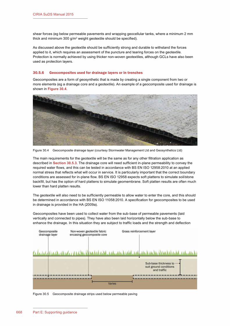
668 Part E: Supporting guidance
CIRIA SuDS Manual 2015
shearforces(egbelowpermeablepavementsandwrappinggeocellulartanks,whereaminimum2mmthickandminimum300g/m2weightgeotextileshouldbespecified).
Asdiscussedabovethegeotextileshouldbesufficientlystronganddurabletowithstandtheforcesappliedtoit,whichrequiresanassessmentofthepunctureandtearingforcesonthegeotextile.Protectionisnormallyachievedbyusingthickernon-wovengeotextiles,althoughGCLshavealsobeenusedasprotectionlayers.
30.5.6 Geocomposites used for drainage layers or in trenches
Geocompositesareaformofgeosyntheticthatismadebycreatingasinglecomponentfromtwoormoreelements(egadrainagecoreandageotextile).AnexampleofageocompositeusedfordrainageisshowninFigure 30.4.
ThemainrequirementsforthegeotextilewillbethesameasforanyotherfiltrationapplicationasdescribedinSection 30.5.3.Thedrainagecorewillneedsufficientin-planepermeabilitytoconveytherequiredwaterflows,andthiscanbetestedinaccordancewithBSENISO12958:2010atanappliednormalstressthatreflectswhatwilloccurinservice.Itisparticularlyimportantthatthecorrectboundaryconditionsareassessedforin-planeflow.BSENISO12958expectssoftplattenstosimulatesoil/stonebackfill,buthastheoptionofhardplattenstosimulategeomembrane.Softplattenresultsareoftenmuchlowerthanhardplattenresults.
Thegeotextilewillalsoneedtobesufficientlypermeabletoallowwatertoenterthecore,andthisshouldbedeterminedinaccordancewithBSENISO11058:2010.AspecificationforgeocompositestobeusedindrainageisprovidedintheHA(2009a).
Geocompositeshavebeenusedtocollectwaterfromthesub-baseofpermeablepavements(laidverticallyandconnectedtopipes).Theyhavealsobeenlaidhorizontallybelowthesub-basetoenhancethedrainage.Inthissituationtheyaresubjecttotrafficloadsandthestrengthanddeflection
Figure30.5 Geocompositedrainagestripsusedbelowpermeablepaving
Figure30.4 Geocompositedrainagelayer(courtesyStormwaterManagementLtdandGeosyntheticsLtd)

669Chapter 30: Materials
CIRIA SuDS Manual 2015
characteristicswillhavetobeassessedtoensurethatthegeocompositecansupporttheloadsandthepavementmaterialscantoleratethedeflectionsthatoccurinthecompositeundertrafficloadings.
30.5.7 Geosynthetics and natural materials used for erosion control
ErosioncontrolisanimportantconsiderationinSuDSdesignandconstruction.Itisespeciallyimportantimmediatelyafterconstructionwhenvegetationisnotfullyestablished.MaterialsusedaserosioncontrolblanketsinSuDSincludejutenetting,coirblanketsandsyntheticproducts.Theyallowthequickestablishmentofvegetationonslopesandchannelssubjecttoerosionfromwateractionandcanalsoslowdownthevelocityofwaterflowingacrossasurface(Chapter 29).
Allerosioncontrolblanketsworkbyprovidingsomemechanicalanchoragetotopsoil/sedimentsandseeds.Thechoiceofasuitablespecificationwilldependonwhethertheerosionprotectionisrequiredtobetemporaryorpermanent.
Erosioncontrolblanketsusuallycomprisebiodegradablemesh-likeproducts,whichwilldisappearinonetofiveseasons,dependingonthematerial,andhencearesuitablefortheestablishmentoflow-growingvegetation.Juteandsimilarproductswilldegradeinoneortwogrowingseasonandareusuallydesignedtohelpestablishgrass/turfinlocationswherethereisnotlikelytobehighwaterflows.Thelonger-lastingproducts,suchasthosemadeofcoir(wovencoconutfibremesh),canbeusedforliningofswalesandpondswhereslightlylonger-termabrasion/erosionprotectionisrequiredtoensurethatvegetationcanbecomefullyestablished.IftheerosioncontrolblanketsarerequiredtooperateoverthefullservicelifeoftheSuDS,thenthematerialsusedshouldnotbebiodegradable,andasyntheticmatshouldbeused.Non-biodegradableproductsaresyntheticmaterialsandusuallycomprise3Drandomfibrematsorhoneycombwebs.Somesyntheticproductsarealsophotodegradable,andthesameprinciplesapply:theproductshouldlastforthefullservicelifeoftheSuDS.
Erosioncontrolblanketscanbesuppliedontheirownorcanbepreplanted.
Theimportantparameterstoconsiderwhenspecifyingerosioncontrolmattingare:
▪ weight–givessomeindicationofdurability
▪ yarnthicknessandnumberofthreads–givessomeindicationofdurabilityandstrength
▪ openarea–affectswaterpermeabilityandsoilretentionproperties
▪ yarnquality–affectshowlongthemeshtakestodegrade,itswaterretentionanditsflexibility
▪ functionwheninstalled–willitbeplantedupforeventualself-sustainabilityandcohesionwithnewdevelopingrootsystems(inwhichcaseabiodegradablematerialissuitable)orwillitneedtoactaserosioncontrolinthelongerterm,suchasfortopsoilretentiononslopes(inwhichcasetheproductshouldnotdegradeovertheservicelifeoftheSuDS)?
TherearenoUKorEuropeanstandardsrelatingtotheuseoferosioncontrolmatting.BSEN13253:2014doesnotcoversurfaceerosion,wherethegeotextileorgeotextile-relatedproductislocatedatthesurface.ExamplesoferosioncontrolproductsareshowninFigures 30.6 to 30.8.
670 Part E: Supporting guidance
CIRIA SuDS Manual 2015
30.6 REFERENCES
BSI(2008)Construction products. A guide to the requirements and CE marking,TH42097,BritishStandardsInstitute,London,UK
EA(2010)Verification of remediation of land contamination,ScienceReportSC030114/R1,EnvironmentAgency,Bristol,UK(ISBN:978-1-84911-175-1).Goto:http://tinyurl.com/nc4am2x
EDGE,P,GEDGE,D,NEWTON,JandWILSON,S(2007)Building Greener. Guidance on the use of green roofs, green walls and complimentary features on buildings,C644,CIRIA,London,UK(ISBN:978-0-86017-644-2).Goto:www.ciria.org
GEOTECHDATA.INFO(2013)Soil porosity.Goto:http://geotechdata.info/parameter/soil-porosity.html
GIROUD,JP(2000)“Filtercriteria”.In:HBrandl(ed)Jubilee Volume 75th Anniversary of K Terzaghi’s Erdbaumechanik (Soil Mechanics),vol5/2000,TechnicalUniversity,Vienna,Austria
HA(1990)“Apermeameterforroaddrainagelayers”,DesignManualforRoadsandBridges,Volume4,Section2,Part4,HA41/90,HighwaysAgency,London,UK.Goto:http://tinyurl.com/nfdu66h
HA(2005a)“Specificationforhighwayworks”,Manual of Contract Documents for Highway Works (MCHW),vol1,TheStationeryOffice,London,UK(ISBN:978-0-11552-705-0).Goto:http://tinyurl.com/p4pb5pz (accessed23/09/2015)
HA(2005b)“NotesforguidanceontheSpecificationforhighwayworks(consolidatededition)”,Manual of Contract Documents for Highway Works (MCHW),vol2,TheStationeryOffice,London,UK(ISBN:978-0-11552-706-7).Goto:http://tinyurl.com/pfub7op(accessed23/09/2015)
HA(2009a)“Series500Drainageandserviceducts”,Specification for Highway Works,vol1,TheStationeryOffice,London,UK.Goto:http://tinyurl.com/pflnom7
Figure30.6 Exampleoftopsoilretentiononslopeusingcellularconfinement(courtesyEPGLimited)
Figure30.8 Exampleofsyntheticmatting(courtesyABG)
Figure30.7 Exampleofcoirmattingforaswale(courtesyStormwaterManagement)

671Chapter 30: Materials
CIRIA SuDS Manual 2015
HA(2009b)“Series600Earthworks”,Specification for Highway Works,vol1,TheStationeryOffice,London,UK.Goto:http://tinyurl.com/phx5yj
HA(2009c)“Series700Roadpavements–general”,Specification for Highway Works,vol1,TheStationeryOffice,London,UK.Goto:http://tinyurl.com/oy96kev
HA(2009d)“Series3000Landscapeandecology”,Specification for Highway Works,vol1,TheStationeryOffice,London,UK.Goto:http://tinyurl.com/okb9tcx
MALLETT,H,COX,L,WILSON,SandCORBAN,M(2014)Good practice on the testing and verification of protection systems for buildings against hazardous ground gases,C735,CIRIA,London,UK(ISBN:978-0-86017-739-5).Goto:www.ciria.org
SCHIERS,J(2009)A guide to polymeric geomembranes: A practical approach,Wiley,Chichester,UK(ISBN:978-0-47051-920-2)
WRAP(2014)Quality protocols,WRAP,Oxon,UK.Goto:www.wrap.org.uk/content/quality-protocols
WRc(2011)Civil Engineering Specification for the Water Industry (CESWI), 7th edition,WRc,Swindon,UK.Goto:http://ceswi.wrcplc.co.uk
STATUTES
Regulations
TheConstructionProductsRegulations2013(No.1387)
British Standards
BS1377-2:1990Methods of test for soils for civil engineering purposes. Classification tests
BS1377-3:1990Methods of test for soils for civil engineering purposes. Chemical and electro-chemical tests
BS1377-4:1990 Methods of test for soils for civil engineering purposes. Compaction-related tests
BS3882:2007Specification for topsoil and requirements for use
BS7533-13:2009Pavements constructed with clay, natural stone or concrete pavers. Guide for the design of permeable pavements constructed with concrete paving blocks and flags, natural stone slabs and setts and clay pavers
European
BSEN12224:2000Geotextiles and geotextile-related products. Determination of the resistance to weathering
BSEN12225:2000Geotextiles and geotextile-related products. Method for determining the microbiological resistance by a soil burial test
BSEN12311-2:2013Flexible sheets for waterproofing. Determination of tensile properties. Plastic and rubber sheets for roof waterproofing
BSEN12311-1:2000Flexible sheets for waterproofing. Determination of tensile properties. Bitumen sheets for roof waterproofing
BSEN13242:2002+A1:2007Aggregates for unbound and hydraulically bound materials for use in civil engineering work and road construction (as amended)

672 Part E: Supporting guidance
CIRIA SuDS Manual 2015
BSEN13249:2014Geotextiles and geotextile-related products. Characteristics required for use in the construction of roads and other trafficked areas (excluding railways and asphalt)
BSEN13252:2014Geotextiles and geotextile-related products. Characteristics required for use in drainage systems
BSEN13253:2014Geotextiles and geotextile-related products. Characteristics required for use in erosion control works (coastal protection, bank revetments)
BSEN13285:2010Unbound mixtures – specification
BSEN13361:2013Geosynthetic barriers. Characteristics required for use in the construction of reservoirs and dams
BSEN13362:2013Geosynthetic barriers. Characteristics required for use in the construction of canals
BSEN13719:2002Geotextiles and geotextile-related products. Determination of the long term protection efficiency of geotextiles in contact with geosynthetic barriers
BSEN14030:2001Geotextiles and geotextile-related products. Screening test method for determining the resistance to acid and alkaline liquids
BSEN14150:2006Geosynthetic barriers. Determination of permeability to liquids
BSEN14575:2005Geosynthetic barriers. Screening test method for determining the resistance to oxidation
BSEN14576:2005Geosynthetics. Test method for determining the resistance of polymeric geosynthetic barriers to environmental stress cracking
BSEN16416:2013Geosynthetic clay barriers. Determination of water flux index. Flexible wall permeameter method at constant head
International
BSENISO527-1:2012Plastics. Determination of tensile properties. General principles
BSENISO527-3:1996BS2782-3:Method326E:1995Plastics. Determination of tensile properties. Test conditions for films and sheets
BSENISO527-4:1997,BS2782-3:Method326F:1997Plastics. Determination of tensile properties. Test conditions for isotropic and orthotropic fibre-reinforced plastic composites
BSENISO9863-1:2005Geosynthetics. Determination of thickness at specified pressures. Single layers
BSENISO10319:2015Geosynthetics. Wide-width tensile test
BSENISO11058:2010Geotextiles and geotextile-related products. Determination of water permeability characteristics normal to the plane, without load
BSENISO12236:2006Geosynthetics. Static puncture test (CBR test)
BSENISO12956:2010Geotextiles and geotextile-related products. Determination of the characteristic opening size
BSENISO12958:2010Geotextiles and geotextile-related products. Determination of water flow capacity in their plane
BSENISO13433:2006Geosynthetics. Dynamic perforation test (cone drop test)
BSENISO13438:2004Geotextiles and geotextile-related products. Screening test method for determining the resistance to oxidation

673Chapter 30: Materials
CIRIA SuDS Manual 2015
USA
ASTMD4437-08Standard practice for non-destructive testing (NDT) for determining the integrity of seams used in joining flexible polymeric sheet geomembranes
ASTMD4787-13Standard practice for continuity verification of liquid or sheet linings applied to concrete substrates
ASTMD5820-95Standard practice for pressurized air channel evaluation of dual seamed geomembranes
ASTMD7177-05Standard specification for air channel evaluation of polyvinyl chloride (PVC) dual track seamed geomembranes
ASTMD7240-06Standard practice for leak location using geomembranes with an insulating layer in intimate contact with a conductive layer via electrical capacitance technique (conductive geomembrane spark test)
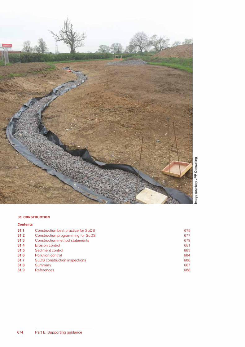
675Chapter 31: Construction674 Part E: Supporting guidance
CIRIA SuDS Manual 2015
31 CONSTRUCTION
Contents
31.1 Construction best practice for SuDS 67531.2 Construction programming for SuDS 67731.3 Construction method statements 67931.4 Erosion control 68131.5 Sediment control 68331.6 Pollution control 68431.7 SuDS construction inspections 68631.8 Summary 68731.9 References 688
Imag
e co
urte
sy J
PP
Con
sulti
ng

675Chapter 31: Construction674 Part E: Supporting guidance
CIRIA SuDS Manual 2015
31Chapter
31.1 CONSTRUCTION BEST PRACTICE FOR SUDS
The construction of SuDS usually only requires the use of standard civil engineering and landscaping operations such as excavation, filling, grading, pipe-laying, chamber construction, topsoiling, seeding and planting. These operations are specified in various standard construction documents, such as WRc (2011). However, there are some specific process and programming considerations required for their application to SuDS construction, as described in Box 31.1.
The same attention to detail (including tolerances) for SuDS construction is required as for other forms of construction. Contractors will become familiar with the specific issues and construction techniques as the use of SuDS becomes more widespread.
ConstructionThis chapter provides general good practice guidance on the construction of SuDS schemes.
Construction checklists are provided in Appendix B.
Guidance on construction for specific types of SuDS component can be found in Chapters 11–23.
BOX31.1
General construction issues relating to SuDS
1 ProgrammingThe programming of SuDS construction needs to be considered at all stages of the site construction process. Subsurface piped drainage networks are usually one of the first facilities to be constructed on a site. For SuDS, although the form of the drainage will be constructed during the earthworks phase, the final construction should not take place until the end of the development programme, unless adequate provision is made to remove any silt that is deposited during construction operations and to refurbish any areas that have been subject to over-compaction.
Method statements and pre-construction site planning operations will form an essential part of pre-construction activities to ensure successful completion of the SuDS.
The construction of swales, basins and ponds at an early stage in the construction can assist in managing runoff and help settle out the high volumes of sediments created during construction. However, complete reinstatement of these components will be required once construction is finished. The contract is likely to stipulate establishment of vegetation and sediment removal sometime after site works have been completed and before the start of the maintenance period.
2 Pollution and sediment controlRunoff from a construction site should not be allowed to enter SuDS or flow off site unless it has been allowed for in the design and specification. Construction runoff is heavily laden with sediment, which can clog infiltration systems, build up in storage systems and pollute receiving waters. Certain SuDS components should not be used to
continued...
677Chapter 31: Construction676 Part E: Supporting guidance
CIRIA SuDS Manual 2015
BOX31.1
General construction issues relating to SuDS
manage construction runoff, for example pervious surfaces. No traffic should be allowed to run on pervious surface components if it is likely to introduce sediment onto the pavement surface from dusty or muddy areas, or result in over-compaction. One way of protecting permeable sub-base construction, so that it can be used for construction traffic, is to cover it with a layer of asphalt concrete that is cored through before laying the blocks to make it permeable (Chapter 20).
3 Access and storage areasTraditional car parking and other paved areas are usually constructed (or partially constructed) during the initial stages of the development, and then used as access roads and storage areas. If pervious surfaces are proposed, pavement construction should be carried out at the end of the development programme, unless adequate protection is provided to preventing clogging or blinding.
Ease of access for the construction of other components needs to be considered at the design and programming stage.
4 SkillsThe contractor and all relevant operatives should have a general understanding of how SuDS work and the purpose of the specific SuDS components being used on a site, to ensure that appropriate construction practice and component protection is used. “Toolbox talks” for workers are a particularly effective way of increasing awareness of appropriate construction of SuDS.
5 InfiltrationsystemprotectionIf SuDS components do not allow infiltration, the use of hardcore for structural purposes below the level of any liner or other impermeable layer may be acceptable. However, the use of hardcore is not advised if infiltration is intended, due to the high proportion of fines generally present in such fill material. Total exclusion zones may be required for construction traffic over infiltration surfaces to prevent compaction and other damage to the ground that will affect the infiltration performance. This may include complete isolation from runoff during construction if the component is located at a low point on the site. Proof rolling of pavement formations is not recommended as this will compact the ground and reduce the infiltration rate, so other methods of identifying soft spots should be used.
6 LandscapingGood landscape construction practices are fundamental to SuDS construction. As SuDS are normally surface systems, attention to detail and aesthetics should be given a high priority. The seasonal and physical requirements of planting and the requirements for establishing vegetation and preventing soil erosion should be given careful consideration. Appropriately skilled and experienced operatives are required with an understanding of all aspects of vegetation establishment. Adjacent ground levels to components should be designed to prevent any overland sediment wash-off during high intensity rainfall events, or groundwater seepage during particularly wet periods. Settlement of soils should also be taken into consideration. Further guidance is provided in Chapter 29.
7 Erosion controlBefore runoff is allowed to flow through vegetated SuDS, they should be fully stabilised by planting or temporary erosion protection. This will prevent erosion of the sides and base or the clogging of downstream components.
8 Construction and handover inspectionProvision should be made in the construction contract for inspections at key stages, and on completion of construction, to ensure that the system has been constructed in accordance with the approved design and specification. As-constructed drawings should be produced and an as-constructed survey undertaken to ensure that design levels have been achieved. A construction checklist is provided in Appendix B.
9 SpecificationsandbillsofquantitiesDesigners should highlight particular matters associated with the above points that are likely to impact the operation and performance of specific SuDS components. The type of specification and/or bills of quantities will depend upon the form of construction contract being used for the specific project.
continued from...
continued...
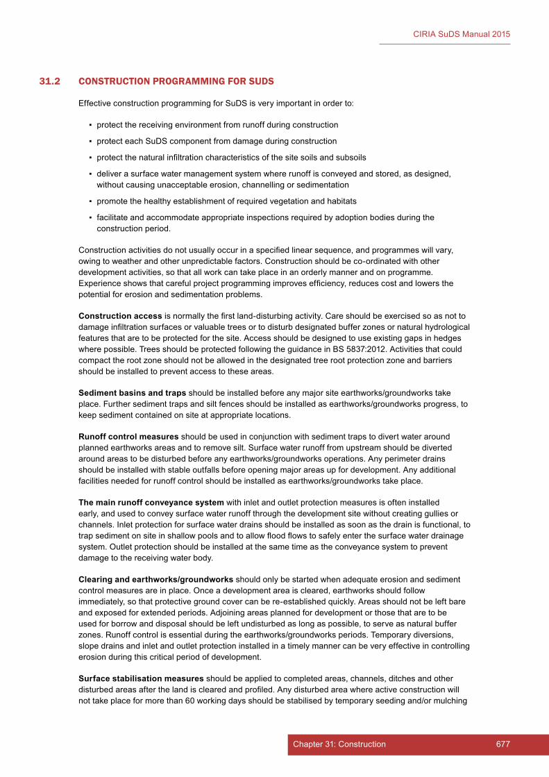
677Chapter 31: Construction676 Part E: Supporting guidance
CIRIA SuDS Manual 2015
31.2 CONSTRUCTION PROGRAMMING FOR SUDS
Effective construction programming for SuDS is very important in order to:
▪ protect the receiving environment from runoff during construction
▪ protect each SuDS component from damage during construction
▪ protect the natural infiltration characteristics of the site soils and subsoils
▪ deliver a surface water management system where runoff is conveyed and stored, as designed, without causing unacceptable erosion, channelling or sedimentation
▪ promote the healthy establishment of required vegetation and habitats
▪ facilitate and accommodate appropriate inspections required by adoption bodies during the construction period.
Construction activities do not usually occur in a specified linear sequence, and programmes will vary, owing to weather and other unpredictable factors. Construction should be co-ordinated with other development activities, so that all work can take place in an orderly manner and on programme. Experience shows that careful project programming improves efficiency, reduces cost and lowers the potential for erosion and sedimentation problems.
Construction access is normally the first land-disturbing activity. Care should be exercised so as not to damage infiltration surfaces or valuable trees or to disturb designated buffer zones or natural hydrological features that are to be protected for the site. Access should be designed to use existing gaps in hedges where possible. Trees should be protected following the guidance in BS 5837:2012. Activities that could compact the root zone should not be allowed in the designated tree root protection zone and barriers should be installed to prevent access to these areas.
Sedimentbasinsandtraps should be installed before any major site earthworks/groundworks take place. Further sediment traps and silt fences should be installed as earthworks/groundworks progress, to keep sediment contained on site at appropriate locations.
Runoffcontrolmeasures should be used in conjunction with sediment traps to divert water around planned earthworks areas and to remove silt. Surface water runoff from upstream should be diverted around areas to be disturbed before any earthworks/groundworks operations. Any perimeter drains should be installed with stable outfalls before opening major areas up for development. Any additional facilities needed for runoff control should be installed as earthworks/groundworks take place.
Themainrunoffconveyancesystemwith inlet and outlet protection measures is often installed early, and used to convey surface water runoff through the development site without creating gullies or channels. Inlet protection for surface water drains should be installed as soon as the drain is functional, to trap sediment on site in shallow pools and to allow flood flows to safely enter the surface water drainage system. Outlet protection should be installed at the same time as the conveyance system to prevent damage to the receiving water body.
Clearing and earthworks/groundworks should only be started when adequate erosion and sediment control measures are in place. Once a development area is cleared, earthworks should follow immediately, so that protective ground cover can be re-established quickly. Areas should not be left bare and exposed for extended periods. Adjoining areas planned for development or those that are to be used for borrow and disposal should be left undisturbed as long as possible, to serve as natural buffer zones. Runoff control is essential during the earthworks/groundworks periods. Temporary diversions, slope drains and inlet and outlet protection installed in a timely manner can be very effective in controlling erosion during this critical period of development.
Surfacestabilisationmeasures should be applied to completed areas, channels, ditches and other disturbed areas after the land is cleared and profiled. Any disturbed area where active construction will not take place for more than 60 working days should be stabilised by temporary seeding and/or mulching
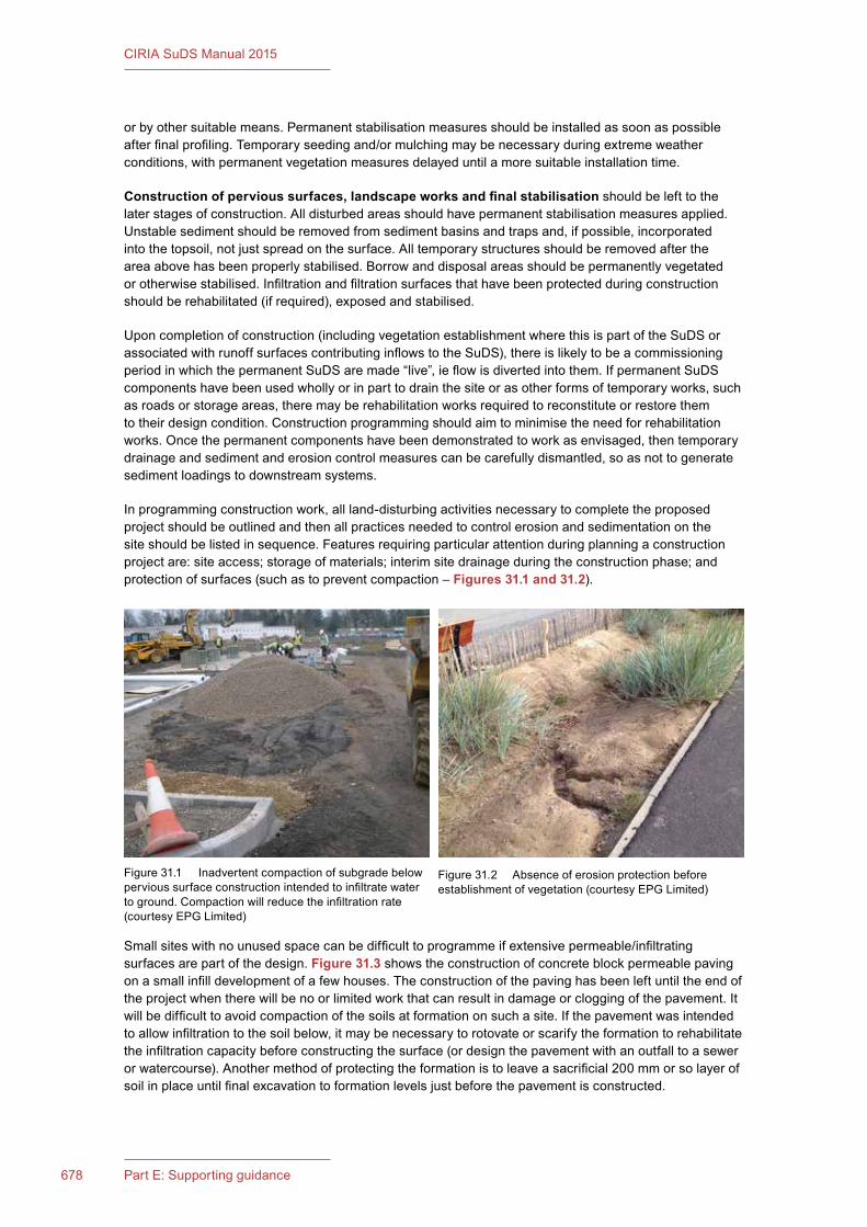
679Chapter 31: Construction678 Part E: Supporting guidance
CIRIA SuDS Manual 2015
or by other suitable means. Permanent stabilisation measures should be installed as soon as possible after final profiling. Temporary seeding and/or mulching may be necessary during extreme weather conditions, with permanent vegetation measures delayed until a more suitable installation time.
Constructionofpervioussurfaces,landscapeworksandfinalstabilisation should be left to the later stages of construction. All disturbed areas should have permanent stabilisation measures applied. Unstable sediment should be removed from sediment basins and traps and, if possible, incorporated into the topsoil, not just spread on the surface. All temporary structures should be removed after the area above has been properly stabilised. Borrow and disposal areas should be permanently vegetated or otherwise stabilised. Infiltration and filtration surfaces that have been protected during construction should be rehabilitated (if required), exposed and stabilised.
Upon completion of construction (including vegetation establishment where this is part of the SuDS or associated with runoff surfaces contributing inflows to the SuDS), there is likely to be a commissioning period in which the permanent SuDS are made “live”, ie flow is diverted into them. If permanent SuDS components have been used wholly or in part to drain the site or as other forms of temporary works, such as roads or storage areas, there may be rehabilitation works required to reconstitute or restore them to their design condition. Construction programming should aim to minimise the need for rehabilitation works. Once the permanent components have been demonstrated to work as envisaged, then temporary drainage and sediment and erosion control measures can be carefully dismantled, so as not to generate sediment loadings to downstream systems.
In programming construction work, all land-disturbing activities necessary to complete the proposed project should be outlined and then all practices needed to control erosion and sedimentation on the site should be listed in sequence. Features requiring particular attention during planning a construction project are: site access; storage of materials; interim site drainage during the construction phase; and protection of surfaces (such as to prevent compaction – Figures 31.1 and 31.2).
Small sites with no unused space can be difficult to programme if extensive permeable/infiltrating surfaces are part of the design. Figure 31.3 shows the construction of concrete block permeable paving on a small infill development of a few houses. The construction of the paving has been left until the end of the project when there will be no or limited work that can result in damage or clogging of the pavement. It will be difficult to avoid compaction of the soils at formation on such a site. If the pavement was intended to allow infiltration to the soil below, it may be necessary to rotovate or scarify the formation to rehabilitate the infiltration capacity before constructing the surface (or design the pavement with an outfall to a sewer or watercourse). Another method of protecting the formation is to leave a sacrificial 200 mm or so layer of soil in place until final excavation to formation levels just before the pavement is constructed.
Figure 31.1 Inadvertent compaction of subgrade below pervious surface construction intended to infiltrate water to ground. Compaction will reduce the infiltration rate (courtesy EPG Limited)
Figure 31.2 Absence of erosion protection before establishment of vegetation (courtesy EPG Limited)
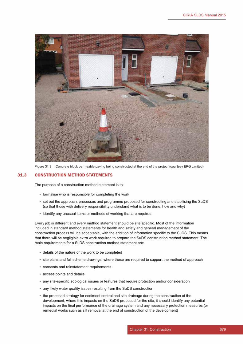
679Chapter 31: Construction678 Part E: Supporting guidance
CIRIA SuDS Manual 2015
31.3 CONSTRUCTION METHOD STATEMENTS
The purpose of a construction method statement is to:
▪ formalise who is responsible for completing the work
▪ set out the approach, processes and programme proposed for constructing and stabilising the SuDS (so that those with delivery responsibility understand what is to be done, how and why)
▪ identify any unusual items or methods of working that are required.
Every job is different and every method statement should be site specific. Most of the information included in standard method statements for health and safety and general management of the construction process will be acceptable, with the addition of information specific to the SuDS. This means that there will be negligible extra work required to prepare the SuDS construction method statement. The main requirements for a SuDS construction method statement are:
▪ details of the nature of the work to be completed
▪ site plans and full scheme drawings, where these are required to support the method of approach
▪ consents and reinstatement requirements
▪ access points and details
▪ any site-specific ecological issues or features that require protection and/or consideration
▪ any likely water quality issues resulting from the SuDS construction
▪ the proposed strategy for sediment control and site drainage during the construction of the development, where this impacts on the SuDS proposed for the site; it should identify any potential impacts on the final performance of the drainage system and any necessary protection measures (or remedial works such as silt removal at the end of construction of the development)
Figure 31.3 Concrete block permeable paving being constructed at the end of the project (courtesy EPG Limited)
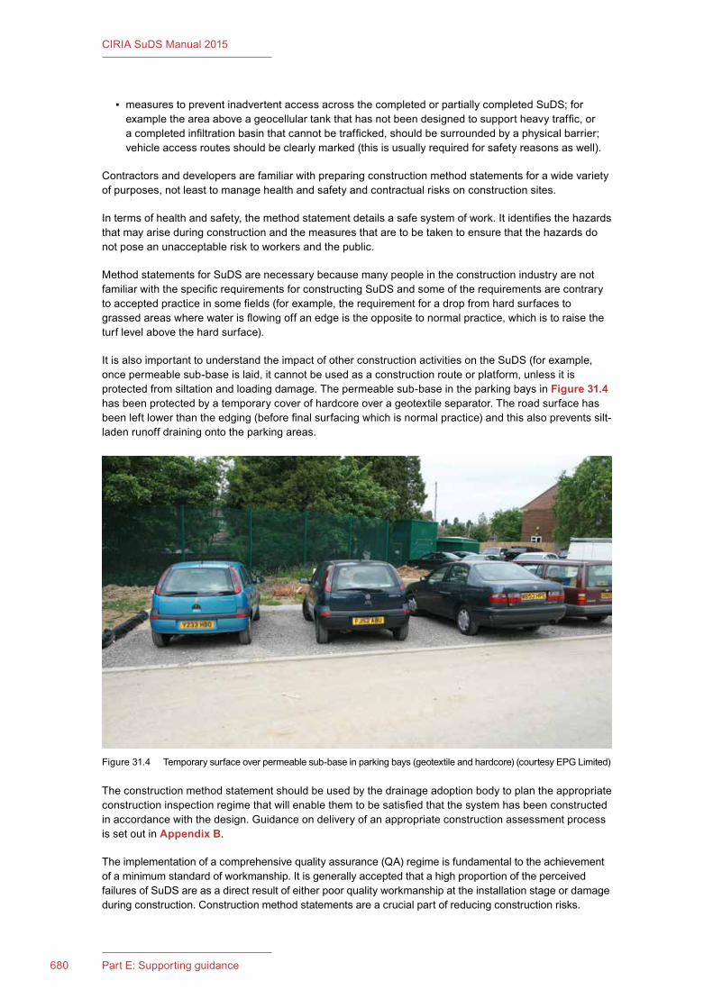
681Chapter 31: Construction680 Part E: Supporting guidance
CIRIA SuDS Manual 2015
▪ measures to prevent inadvertent access across the completed or partially completed SuDS; for example the area above a geocellular tank that has not been designed to support heavy traffic, or a completed infiltration basin that cannot be trafficked, should be surrounded by a physical barrier; vehicle access routes should be clearly marked (this is usually required for safety reasons as well).
Contractors and developers are familiar with preparing construction method statements for a wide variety of purposes, not least to manage health and safety and contractual risks on construction sites.
In terms of health and safety, the method statement details a safe system of work. It identifies the hazards that may arise during construction and the measures that are to be taken to ensure that the hazards do not pose an unacceptable risk to workers and the public.
Method statements for SuDS are necessary because many people in the construction industry are not familiar with the specific requirements for constructing SuDS and some of the requirements are contrary to accepted practice in some fields (for example, the requirement for a drop from hard surfaces to grassed areas where water is flowing off an edge is the opposite to normal practice, which is to raise the turf level above the hard surface).
It is also important to understand the impact of other construction activities on the SuDS (for example, once permeable sub-base is laid, it cannot be used as a construction route or platform, unless it is protected from siltation and loading damage. The permeable sub-base in the parking bays in Figure 31.4 has been protected by a temporary cover of hardcore over a geotextile separator. The road surface has been left lower than the edging (before final surfacing which is normal practice) and this also prevents silt-laden runoff draining onto the parking areas.
The construction method statement should be used by the drainage adoption body to plan the appropriate construction inspection regime that will enable them to be satisfied that the system has been constructed in accordance with the design. Guidance on delivery of an appropriate construction assessment process is set out in Appendix B.
The implementation of a comprehensive quality assurance (QA) regime is fundamental to the achievement of a minimum standard of workmanship. It is generally accepted that a high proportion of the perceived failures of SuDS are as a direct result of either poor quality workmanship at the installation stage or damage during construction. Construction method statements are a crucial part of reducing construction risks.
Figure 31.4 Temporary surface over permeable sub-base in parking bays (geotextile and hardcore) (courtesy EPG Limited)
681Chapter 31: Construction680 Part E: Supporting guidance
CIRIA SuDS Manual 2015
Correct construction of SuDS is of equal importance to design if the systems are to be successfully implemented, and the key to this is conveying information to site staff (management and operatives). They should be made aware of how the SuDS scheme operates, the design requirements and how their actions on site can affect the final performance of the scheme. It is important to talk to people on site, especially operatives, and to ensure that all subcontractors and their staff are also involved in this process. Site staff and operatives should also be taught how to install critical items, if necessary, for example where geotextiles and geomembranes are to be placed in the construction. Clogging, blinding or over-compaction of permeable surfaces due to unconsidered construction activities are common risks. The preparation and dissemination of appropriately detailed method statements emphasising the differences from traditional construction activities is seen as an important communication channel, to be used in conjunction with toolbox talks and direct briefings to operatives. To assist in these processes a construction site handbook is available (Woods Ballard et al, 2007)
31.4 EROSION CONTROL
31.4.1 Factorsinfluencingerosionduringconstruction
Any activity that disturbs the natural soil and vegetation has the potential to increase erosion, because bare loose soil is easily moved by wind or water.
Factors affecting the erosion potential of any site include soil type, geology, vegetative cover, topography, climate and land use. Physical properties of soils, such as particle size, cohesiveness, and density, affect its erodibility. Loose silt and sand-sized particles are more susceptible to erosion than clay soils. Coarser soils are less susceptible to wind erosion, but are often found on steeper slopes that are subject to water erosion. When surface cover and soil structure are disturbed, the soil’s erodibility potential increases. Construction activities disrupt the soil structure and its vegetative cover.
Vegetation plays an important role in controlling erosion. Roots bind soil particles together, and the leaves or blades of grass reduce raindrop impact forces on the soil. Grass litter and other ground cover traps rain, which allows infiltration and reduces runoff velocity. Also carefully sited vegetation can steer pedestrian movement away from vulnerable areas to prevent erosion.
Vegetation reduces wind velocities at the ground surface and provides a rougher surface that will trap particles moving along the ground. Once vegetation is removed, erosion can proceed unchecked.
The factors that influence land erosion by water are:
▪ runoff velocity
▪ runoff volume
▪ soil type
▪ vegetation cover
▪ machinery and plant
▪ de-watering outlets.
Land erosion is caused by the runoff being of sufficient velocity to strip fine silts and soils. Table31.1 shows how different type of soils and vegetation coverage can affect the velocity needed to cause erosion.
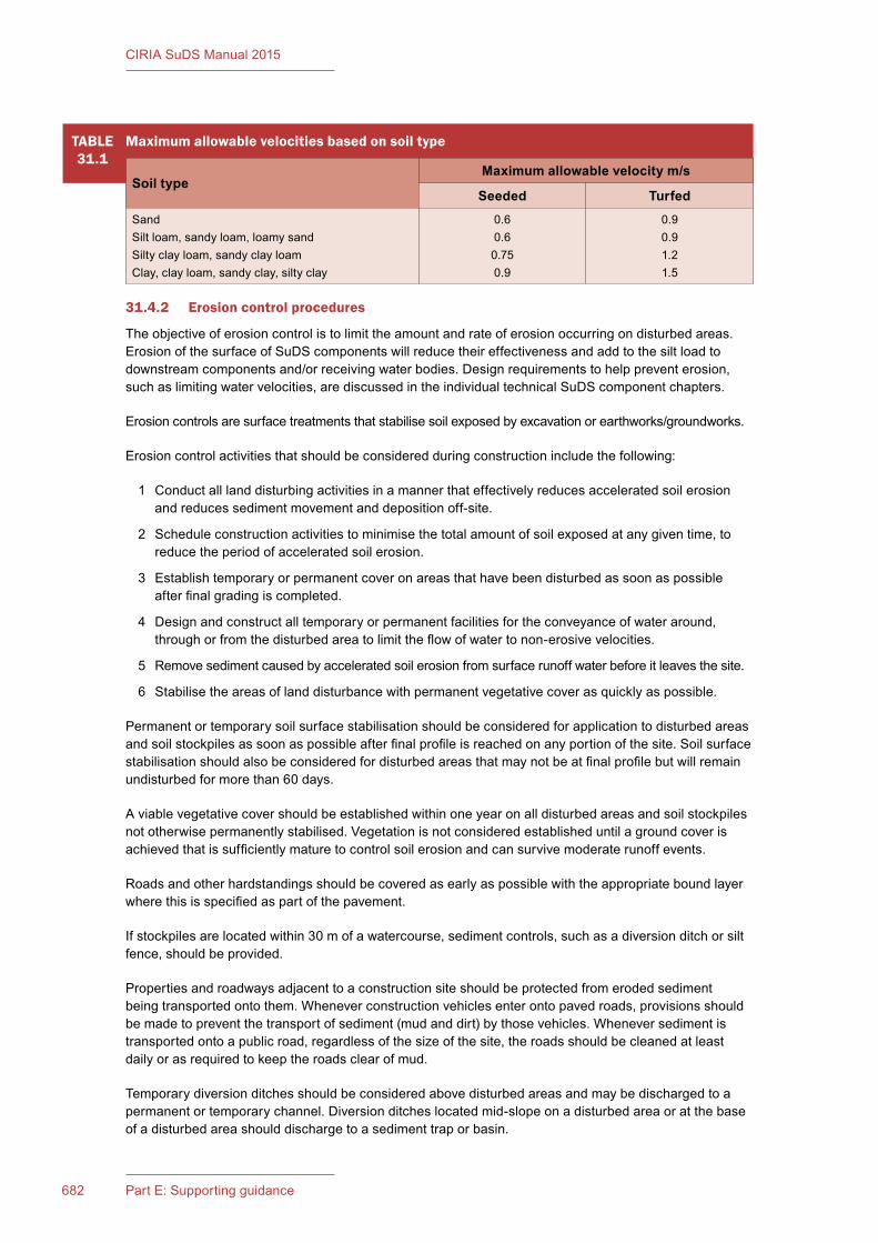
683Chapter 31: Construction682 Part E: Supporting guidance
CIRIA SuDS Manual 2015
TABLE31.1
Maximumallowablevelocitiesbasedonsoiltype
SoiltypeMaximumallowablevelocitym/s
Seeded TurfedSandSilt loam, sandy loam, loamy sandSilty clay loam, sandy clay loamClay, clay loam, sandy clay, silty clay
0.60.60.750.9
0.90.91.21.5
31.4.2 Erosioncontrolprocedures
The objective of erosion control is to limit the amount and rate of erosion occurring on disturbed areas. Erosion of the surface of SuDS components will reduce their effectiveness and add to the silt load to downstream components and/or receiving water bodies. Design requirements to help prevent erosion, such as limiting water velocities, are discussed in the individual technical SuDS component chapters.
Erosion controls are surface treatments that stabilise soil exposed by excavation or earthworks/groundworks.
Erosion control activities that should be considered during construction include the following:
1 Conduct all land disturbing activities in a manner that effectively reduces accelerated soil erosion and reduces sediment movement and deposition off-site.
2 Schedule construction activities to minimise the total amount of soil exposed at any given time, to reduce the period of accelerated soil erosion.
3 Establish temporary or permanent cover on areas that have been disturbed as soon as possible after final grading is completed.
4 Design and construct all temporary or permanent facilities for the conveyance of water around, through or from the disturbed area to limit the flow of water to non-erosive velocities.
5 Remove sediment caused by accelerated soil erosion from surface runoff water before it leaves the site.
6 Stabilise the areas of land disturbance with permanent vegetative cover as quickly as possible.
Permanent or temporary soil surface stabilisation should be considered for application to disturbed areas and soil stockpiles as soon as possible after final profile is reached on any portion of the site. Soil surface stabilisation should also be considered for disturbed areas that may not be at final profile but will remain undisturbed for more than 60 days.
A viable vegetative cover should be established within one year on all disturbed areas and soil stockpiles not otherwise permanently stabilised. Vegetation is not considered established until a ground cover is achieved that is sufficiently mature to control soil erosion and can survive moderate runoff events.
Roads and other hardstandings should be covered as early as possible with the appropriate bound layer where this is specified as part of the pavement.
If stockpiles are located within 30 m of a watercourse, sediment controls, such as a diversion ditch or silt fence, should be provided.
Properties and roadways adjacent to a construction site should be protected from eroded sediment being transported onto them. Whenever construction vehicles enter onto paved roads, provisions should be made to prevent the transport of sediment (mud and dirt) by those vehicles. Whenever sediment is transported onto a public road, regardless of the size of the site, the roads should be cleaned at least daily or as required to keep the roads clear of mud.
Temporary diversion ditches should be considered above disturbed areas and may be discharged to a permanent or temporary channel. Diversion ditches located mid-slope on a disturbed area or at the base of a disturbed area should discharge to a sediment trap or basin.
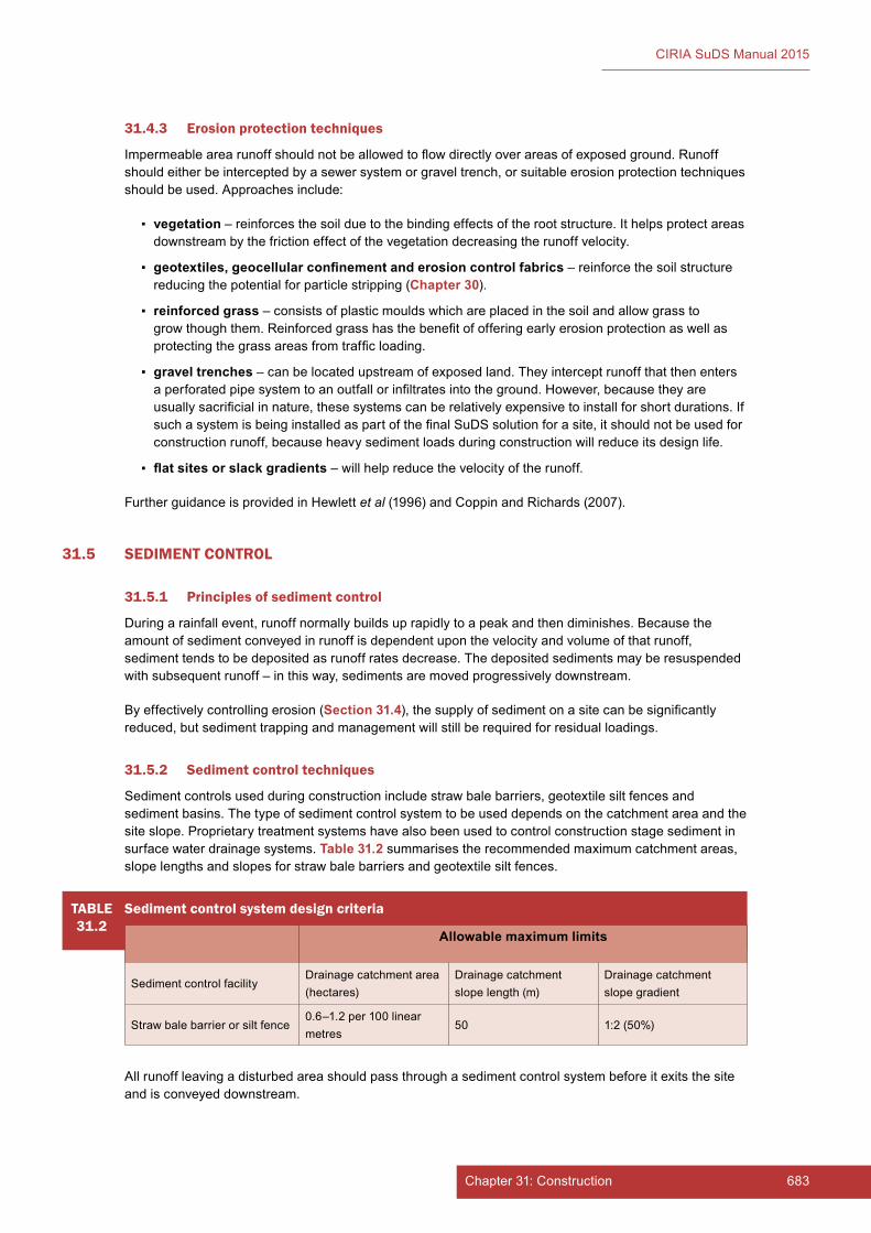
683Chapter 31: Construction682 Part E: Supporting guidance
CIRIA SuDS Manual 2015
31.4.3 Erosion protection techniques
Impermeable area runoff should not be allowed to flow directly over areas of exposed ground. Runoff should either be intercepted by a sewer system or gravel trench, or suitable erosion protection techniques should be used. Approaches include:
▪ vegetation – reinforces the soil due to the binding effects of the root structure. It helps protect areas downstream by the friction effect of the vegetation decreasing the runoff velocity.
▪ geotextiles,geocellularconfinementanderosioncontrolfabrics – reinforce the soil structure reducing the potential for particle stripping (Chapter 30).
▪ reinforcedgrass – consists of plastic moulds which are placed in the soil and allow grass to grow though them. Reinforced grass has the benefit of offering early erosion protection as well as protecting the grass areas from traffic loading.
▪ gravel trenches – can be located upstream of exposed land. They intercept runoff that then enters a perforated pipe system to an outfall or infiltrates into the ground. However, because they are usually sacrificial in nature, these systems can be relatively expensive to install for short durations. If such a system is being installed as part of the final SuDS solution for a site, it should not be used for construction runoff, because heavy sediment loads during construction will reduce its design life.
▪ flatsitesorslackgradients – will help reduce the velocity of the runoff.
Further guidance is provided in Hewlett et al (1996) and Coppin and Richards (2007).
31.5 SEDIMENT CONTROL
31.5.1 Principlesofsedimentcontrol
During a rainfall event, runoff normally builds up rapidly to a peak and then diminishes. Because the amount of sediment conveyed in runoff is dependent upon the velocity and volume of that runoff, sediment tends to be deposited as runoff rates decrease. The deposited sediments may be resuspended with subsequent runoff – in this way, sediments are moved progressively downstream.
By effectively controlling erosion (Section 31.4), the supply of sediment on a site can be significantly reduced, but sediment trapping and management will still be required for residual loadings.
31.5.2 Sedimentcontroltechniques
Sediment controls used during construction include straw bale barriers, geotextile silt fences and sediment basins. The type of sediment control system to be used depends on the catchment area and the site slope. Proprietary treatment systems have also been used to control construction stage sediment in surface water drainage systems. Table31.2 summarises the recommended maximum catchment areas, slope lengths and slopes for straw bale barriers and geotextile silt fences.
All runoff leaving a disturbed area should pass through a sediment control system before it exits the site and is conveyed downstream.
TABLE31.2
Sedimentcontrolsystemdesigncriteria
Allowablemaximumlimits
Sediment control facility Drainage catchment area (hectares)
Drainage catchment slope length (m)
Drainage catchment slope gradient
Straw bale barrier or silt fence 0.6–1.2 per 100 linear metres
50 1:2 (50%)

685Chapter 31: Construction684 Part E: Supporting guidance
CIRIA SuDS Manual 2015
Straw bale barriers or silt fences may be used for small sites. When the catchment area is greater than that specified in the table, runoff should be collected in diversion ditches and routed through temporary sediment basins.
Straw bales can be placed at the base of a slope to act as a sediment barrier. Straw bales are temporary in nature and may only perform for a period of weeks or months. Proper installation and maintenance is necessary to ensure their performance.
A silt fence is made of a woven synthetic material, geotextile, and acts to filter runoff. Silt fencing can be placed as a temporary barrier along the contour at the base of a disturbed area. The material is durable and will last for more than one season if properly installed and maintained. Silt fencing is not intended to be used as a perimeter fence or in areas of concentrated flow paths. If concentrated flow conditions exist, a more robust filter should be considered.
Silt barriers can also be temporarily installed in or around any road gullies of partially constructed roads to prevent sediment movement into downstream drainage systems.
Where some sediment loads are still likely to be transported into the construction drainage system, sediment basins, proprietary systems or other facilities should be designed to trap it and facilitate its easy removal. Consideration should be given to the risk of sediment resuspension during storm events, and appropriate risk management measures should be put in place. Suitable sediment removal regimes should be identified to ensure that the storage capacity of the component is not exceeded. Where there is a risk of sediment contamination, it may be necessary to line the basin to prevent any risks of contamination of underlying soils and/or groundwater. Where basins, proprietary treatment systems or other methods are to be included as permanent features in the SuDS design, they will require complete clean-out (and rehabilitation if necessary) once construction is complete.
31.6 POLLUTION CONTROL
31.6.1 Pollution prevention
Detailed guidance on prevention of pollution during construction is provided in Masters-Williams et al (2001) and also in the pollution prevention guidelines produced by the EA et al (2012).
The main requirements are to control pollution loads from surface water runoff and pumped water from construction sites to ensure that risks to the environment are minimised. The safe storage of materials and fuels is also important so that if spills occur they are contained (by the use of berms, check ditches or other containment techniques) and do not cause mix with runoff and thus increase pollution risks.
Before mobilisation, the construction site layout should be planned so as to fully consider issues such as the location of stockpiles, fuel stores, storage areas, waste disposal, refuelling points and wash down areas. These should be located in areas where they are least likely to affect receiving water bodies (including groundwater). Planning should also address subjects such as the diversion of watercourses, prevention of upstream runoff entering the site and the design of haul roads, including the use of road bridges over watercourses to stop vehicles fording streams and rivers.
An environmental pollution protection plan should also be put in place. The plan should include:
▪ location of foul drainage disposal routes
▪ location of surface water systems that discharge into watercourses
▪ requirements for discharge and abstraction licences
▪ location of spillage kits
▪ an action plan in the event of an environmental incident (including a list of relevant telephone contact numbers).

685Chapter 31: Construction684 Part E: Supporting guidance
CIRIA SuDS Manual 2015
31.6.2 Constructionpollutionsourcesandcontrols
Sediment
Sediment is one of the major sources of construction site pollution. The following list indicates a number of sources and the measures that can be taken to help prevent pollution:
▪ Excavated ground and exposed ground – The effect of having no vegetation and being recently disturbed allows for relatively low velocity runoff to erode the surface. To help prevent the pollution from entering a watercourse, silt fences, hay bales or stilling ponds should be placed downstream. To limit the volume of runoff reaching the exposed ground, runoff diversion or interception devices should be placed upstream.
▪ Stockpiles – The effects of erosion on a stockpile will depend on the type of material being stored. Fine sand and topsoil stockpiles will be eroded far more readily than heavy granular materials. Stockpiles should be located away from a watercourse or site drainage system. Protective coverings will help prevent runoff stripping the stockpile.
▪ Plant and wheel washing – Plant and wheel washing should take place in designated locations. The area should be tanked and should not be allowed to discharge into a watercourse or infiltrate groundwater, as the wastewater from these devices is highly contaminated with silts, sands and hydrocarbons. Some proprietary vehicle washing systems offer a recycling facility, which filters and settles solids, with the effluent being pumped back into the system. The solid waste materials from this process need to be treated as contaminated waste due to the high hydrocarbon content.
▪ Haul roads – The runoff from haul roads contains a large amount of suspended solids as well as hydrocarbons. Haul roads should be designed so that the length is kept to a minimum, while still serving its purpose. The gradient should be shallow to prevent increasing runoff velocity and, if possible, bunds and/or discrete ditches should be constructed to intercept the runoff. Haul roads should be sprayed regularly to keep down dust. If any section of a haul road is hard surfaced, then it should be swept on a regular basis to prevent the accumulation of dust and mud.
▪ Disturbanceofriverbedsorbanks – Excavation of riverbanks or beds can generate silty water, as the excavated and exposed material is washed downstream. The amount of such excavation needs to be limited and, if undertaken, the water area downstream needs to be protected by booms. For larger projects, consideration should be given to diverting the river while such excavations take place.
▪ De-watering operations – Groundwater discharge due to excavation activity is likely to be heavily polluted with suspended solids and should not be discharged directly into a watercourse. To help reduce the amount of suspended solids within the runoff a number of techniques can be adopted:
▪ passing the discharge water over a grass area, but the discharge velocity has to be monitored and kept sufficiently low to promote settlement
▪ passing the discharge water though a temporary gravel strip
▪ controlled use of skips and/or tanks to act as stilling basins
▪ controlled use of stilling ponds.
Oilsandhydrocarbons
The use of oils and hydrocarbons on construction sites creates an inherent risk of leakages and spillages, which could potentially lead to pollution incidents. Table31.3 details the potential sources of hydrocarbon pollution.
Simple measures can be taken to prevent oil and hydrocarbons becoming entrained in surface runoff, such as:
▪ appropriate maintenance of machinery and plant
▪ drip trays
▪ regular checking of machinery and plant for oil leaks
▪ correct storage facilities
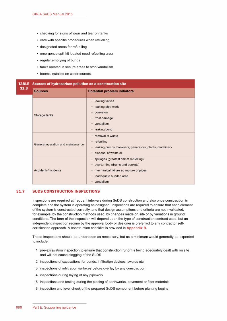
687Chapter 31: Construction686 Part E: Supporting guidance
CIRIA SuDS Manual 2015
▪ checking for signs of wear and tear on tanks
▪ care with specific procedures when refuelling
▪ designated areas for refuelling
▪ emergence spill kit located need refuelling area
▪ regular emptying of bunds
▪ tanks located in secure areas to stop vandalism
▪ booms installed on watercourses.
31.7 SUDS CONSTRUCTION INSPECTIONS
Inspections are required at frequent intervals during SuDS construction and also once construction is complete and the system is operating as designed. Inspections are required to ensure that each element of the system is constructed correctly, and that design assumptions and criteria are not invalidated, for example, by the construction methods used, by changes made on site or by variations in ground conditions. The form of the inspection will depend upon the type of construction contract used, but an independent inspection regime by the approval body or designer is preferred to any contractor self-certification approach. A construction checklist is provided in Appendix B.
These inspections should be undertaken as necessary, but as a minimum would generally be expected to include:
1 pre-excavation inspection to ensure that construction runoff is being adequately dealt with on site and will not cause clogging of the SuDS
2 inspections of excavations for ponds, infiltration devices, swales etc
3 inspections of infiltration surfaces before overlay by any construction
4 inspections during laying of any pipework
5 inspections and testing during the placing of earthworks, pavement or filter materials
6 inspection and level check of the prepared SuDS component before planting begins
TABLE31.3
Sourcesofhydrocarbonpollutiononaconstructionsite
Sources Potentialprobleminitiators
Storage tanks
▪ leaking valves
▪ leaking pipe work
▪ corrosion
▪ frost damage
▪ vandalism
▪ leaking bund
General operation and maintenance
▪ removal of waste
▪ refuelling
▪ leaking pumps, browsers, generators, plants, machinery
▪ disposal of waste oil
Accidents/incidents
▪ spillages (greatest risk at refuelling)
▪ overturning (drums and buckets)
▪ mechanical failure eg rupture of pipes
▪ inadequate bunded area
▪ vandalism
687Chapter 31: Construction686 Part E: Supporting guidance
CIRIA SuDS Manual 2015
7 inspection of completed SuDS after surfacing or planting
8 final inspection before handover, to ensure that all construction silt has been removed, the final construction is in accordance with the design and there are no visible defects.
The contractor installing the SuDS scheme should be made fully aware of the requirement for inspections, to avoid work being undertaken that cannot be validated. Final inspection should take place at the end of the maintenance period as defined in the contract (typically 1 year).
On completion of construction, the approving body or designer should provide a verification report that discusses the inspections, the reasons for any variations made to the design, any non-compliances that are identified and how they were rectified. During the first year of operation there may be a need for monitoring to identify any modifications that may be required to optimise performance, if this has been required and stated as part of the design. The scope of the monitoring will be site specific and depends on the sensitivity of the design and the consequences if the SuDS does not perform as expected.
31.8 SUMMARY
In summary the following issues should be considered by those responsible for the design, programming and construction of SuDS.
Designers
▪ avoid using infiltration or pervious surfaces in area likely be required for construction traffic
▪ design to allow drainage of site during construction
▪ dissemination of information to contractors to ensure SuDS are constructed correctly
▪ design for ease of construction.
Site managers
▪ effective programming
▪ prepare construction method statements
▪ dissemination of information to supervisors and operatives to ensure that SuDS are constructed correctly
▪ arrange construction access so that it will not adversely affect SuDS performance
▪ arrange for effective silt and pollution control during construction
▪ arrange for prompt planting and establishment of landscaped SuDS features
▪ ensure that appropriate erosion control is in place
▪ arrange for construction checks and inspections at appropriate times.
Constructionsupervisorsandoperatives
▪ understand requirements for construction and ask for information from site manager if not clear
▪ do not compact areas for infiltration
▪ ensure that required erosion, pollution and silt control is in place before starting work
▪ minimise exposed areas of bare soil
▪ avoid placing construction materials on completed SuDS (eg topsoil on pervious surfaces).

689Chapter 31: Construction688 Part E: Supporting guidance
CIRIA SuDS Manual 2015
31.9 REFERENCES
COPPIN, N J and RICHARDS, I G (eds) (2007) Use of vegetation in civil engineering, C708, CIRIA, London, UK (ISBN: 978-0-86017-711-1). Go to: www.ciria.org
EA, SEPA, NIEA (2012) Pollution Prevention Guidelines (PPG) 6 Working at construction and demolition sites, second edition, Environment Agency, Bristol, UK. Go to: http://tinyurl.com/nand3q4
HEWLETT, H W M, BOORMAN, L A and BRAMLEY, M E (1996) Design of reinforced grass waterways, R116, CIRIA, London, UK (ISBN: 978-0-86017-285-7). Go to: www.ciria.org
MASTERS-WILLIAMS, H, HEAP, H, KITTS, H, GREENSHAW, L, DAVIES, S, FISHER, P, HENDRIE, M and OWENS, D (2001) Control of water pollution from construction sites. Guidance for consultants and contractors, C532, CIRIA, London, UK (ISBN: 978-0-86017-532-2). Go to: www.ciria.org
WOODS BALLARD, B, KELLAGHER, R, MARTIN, P, JEFFERIES, C, BRAY, R and SHAFFER, P (2007) Site handbook for the construction of SUDS, C698, CIRIA, London, UK (ISBN: 978-0-86017-698-5). Go to: www.ciria.org
WRc (2011) Civil Engineering Specification for the Water Industry, 7th Edition, WRc, Swindon, UK. Go to: http://ceswiwrcplc.co.uk
STATUTES
BritishStandards
BS 5837:2012 Trees in relation to design, demolition and construction. Recommendations

689Chapter 31: Construction688 Part E: Supporting guidance
CIRIA SuDS Manual 2015
691Chapter 32: Operation and maintenance690 Part E: Supporting guidance
CIRIA SuDS Manual 2015
32 OPERATION AND MAINTENANCE
Contents
32.1 Introduction 69132.2 Operation and maintenance manual 69232.3 Level of operation and maintenance 69332.4 Operation and maintenance activity categories 69432.5 Health and safety 69532.6 Regular maintenance 69632.7 Occasional maintenance 69932.8 Remedial maintenance 70332.9 Frequency of maintenance tasks 70432.10 Applying the principles of landscape management 70532.11 References 706
Imag
e co
urte
sy S
imon
Bun
n
691Chapter 32: Operation and maintenance690 Part E: Supporting guidance
CIRIA SuDS Manual 2015
32Chapter
32.1 INTRODUCTION
Many SuDS components are visible on the surface, form part of the overall site landscape and include a range of habitats. Depending on the design, maintenance regimes need to take account of the wider landscape context of amenity and biodiversity, as well as drainage requirements. The maintenance activities required to deliver the desired amenity, for example, may exceed those required to deliver the designed water quantity and water quality performance. In such cases, this needs to be recognised by those responsible for delivering and maintaining that functionality. Where SuDS components are hard surfaces or below ground, the maintenance will generally be based on engineering requirements.
For the purpose of this manual, maintenance refers to:
▪ inspections required to identify performance issues and plan appropriate maintenance needs
▪ operation and maintenance of the drainage system
▪ landscape management
▪ waste management associated with contaminated silt and other waste materials resulting from maintenance.
All maintenance will need to take the protection of habitats and associated ecology into account (Chapter 6). Maintenance regimes should be regularly assessed (eg once per year) to make sure that the approach is still meeting the drainage, landscape and any other objectives. This may result in changes to the maintenance of a feature or area. For example, more frequent vegetation management may be identified where vegetation growth is obstructing highway sight lines.
The function of the surface water management system should be understood by those responsible for maintenance, regardless of whether individual components are below ground or on the surface. When problems occur in vegetated components on the surface, they may be obvious and can be remedied using standard landscape or engineering practices. However, this is not always the case – particularly with more complex systems such as bioretention systems and pervious surfaces. If any system (whether above or below ground) is properly designed, monitored and maintained, performance deterioration can usually be minimised.
Operation and maintenanceThis chapter discusses general good practice for operation and maintenance activities, and the types of documents that can be developed to define the requirements at a particular site.
Specific maintenance requirements for each type of SuDS component are listed in detail towards the end of each of the SuDS component chapters (Chapters 11–23).
Chapter 29 provides further detail on landscape design (including planting) for ease of maintenance.
Chapter 33 provides guidance on waste management, including waste resulting from maintenance.
693Chapter 32: Operation and maintenance692 Part E: Supporting guidance
CIRIA SuDS Manual 2015
Ease of maintenance and access is therefore a necessary and important consideration of SuDS design (not least as part of CDM requirements to ensure that maintenance can be undertaken safely). Sufficient thought should be given to the likely required maintenance over the design life of the SuDS and its funding during the feasibility and planning stages of a scheme (Chapter 35). In particular, the following requirements should be given full consideration:
▪ maintenance access – ensuring appropriate and permanent access to all points in the system where future maintenance may be required
▪ forebays and/or appropriate pre-treatment systems to help trap sediment
▪ appropriate provision for temporary drainage, if required, during sediment management or other maintenance activities
▪ the availability of storage and disposal areas for green waste, such as grass cuttings and organic sediments.
Appropriate legal agreements between adoption and maintenance organisations that define maintenance responsibilities are presented in Shaffer et al (2004). Maintenance Plans will often be required as a condition of planning for the site. For example, many buildings are required to achieve a high BREEAM rating and a landscape management plan (LMP) is a mandatory requirement to achieve this. Planning authorities will include this in a planning condition.
The LMP can also form a useful tool for public or client engagement with SuDS and help them to understand the wider benefits of the system. They can include the provision for ecological re-survey, tree inspection and works and information about how the system delivers multiple benefits.
32.2 OPERATION AND MAINTENANCE MANUAL
Those responsible for SuDS within a development (owner, tenant, local authority, water company etc) should ideally be provided with an operation and maintenance manual by the designer. This could be part of the documentation provided under CDM (part of the health and safety file).
If the user of the system is not responsible for maintenance, then it is important to ensure that they know when the SuDS is not functioning correctly and who to contact if an issue arises, such as a blockage at a SuDS pond seen by a householder on a housing estate or a tenant on an industrial estate.
The operation and maintenance manual should be succinct and easy to use and should include the following:
▪ location of all SuDS components on the site
▪ brief summary of the design intent, how the SuDS components work, their purpose and potential performance risks
▪ depth of silt that will trigger requirement for removal
▪ visual indicators that will trigger maintenance
▪ depth of oil in separators etc that will trigger removal
▪ maintenance requirements (ie the Maintenance Plan) and a maintenance record pro forma
▪ explanation of the objectives of the maintenance proposed and potential implications of not meeting those objectives (it may be useful to split this into planted and hard elements, for clarity)
▪ identification of areas where certain activities are prohibited (eg stockpiling materials on pervious surfaces)
▪ an action plan for dealing with accidental spillages of pollutants
693Chapter 32: Operation and maintenance692 Part E: Supporting guidance
CIRIA SuDS Manual 2015
▪ advice on what to do if alterations are to be made to a development or if service companies need to undertake excavations or other similar works that could affect the SuDS
▪ details of whom to contact in the event that pollution is seen in the system or if it is not working correctly.
The operation and maintenance manual should also include brief details of the design concepts and performance criteria for the scheme and how the owner or operator should ensure that any works undertaken on a development do not compromise this. For example, householders should be made aware that surface water drainage is connected to soakaways, and be given full details and maintenance obligations for any rainwater harvesting systems in the property. This education is part of the wider community engagement process that is vital to the successful uptake of SuDS (Chapter 34). The operation and maintenance manual may also include the LMP.
It is important on industrial estates to clearly identify to everyone which areas drain to SuDS and which to foul sewer. For example, gullies and manhole covers could be colour coded or marked. Owner and tenants should be made aware of what is allowed to drain to the SuDS. Similarly, it is a good idea to use interpretation boards, for example at a pond on a housing estate, to increase householders’ awareness of the purpose and benefits of the SuDS and to encourage them not to put polluting substances down the surface water drainage system (Chapter 27).
32.3 LEVEL OF OPERATION AND MAINTENANCE
There are many factors that will influence the type and frequency of maintenance required for a SuDS component or scheme at any particular site, including:
▪ the type of SuDS components
▪ the size of the contributing catchment in relation to the area of the SuDS components (this will affect the likely sediment loading rates and potential for erosion etc)
▪ the land use associated with the contributing catchment (this will affect the likely build-up of contamination)
▪ the level of continuing construction within the contributing catchment
▪ the SuDS planting scheme
▪ the habitat types that have been created as part of the scheme and how they are anticipated to evolve into a mature landscape
▪ the amenity and visual requirements of the area.
The demands on the SuDS component or scheme to perform a particular aesthetic function may be a key driver, with high frequencies of grass cutting and/or other vegetation management often being required for appearance and amenity value rather than for functional reasons. Specific habitats may dictate the time of year that is suitable for particular activities to be undertaken (eg reed cutting), and/or the extent of the system that should be subject to certain activities at any one time (eg sediment removal). Plants and trees tend to require different periodic management techniques as they mature. This is particularly relevant to coppice areas and woodland, or indeed shrub and herbaceous planting, some of which may require renewal after 10 years or so, depending on the planting and its purpose.
The maintenance regime of a site also needs to consider the response to extreme pollution events. A response action plan should be developed and communicated to all those involved in the operation of a site, so that if a spillage occurs it can be prevented from causing pollution to receiving waters.
It is recommended that SuDS are not handed over to those responsible for maintenance until upstream construction has ceased, the contributing catchment has stabilised, and any necessary rehabilitation of downstream components has been undertaken by the developer/contractor. However, if maintenance agreements have to be put in place in advance of this time, and the level of construction activity in the

695Chapter 32: Operation and maintenance694 Part E: Supporting guidance
CIRIA SuDS Manual 2015
contributing catchment is still high, maintenance specifications should be prepared that take account of high sediment accumulation rates and the increased risks of potential spillages.
32.4 OPERATION AND MAINTENANCE ACTIVITY CATEGORIES
Maintenance activities can be broadly defined as:
1 regular maintenance (including inspections) – Section 32.6
2 occasional maintenance – Section 32.7
3 remedial maintenance – Section 32.8.
There may also be initial one-off requirements sometimes referred to as “establishment maintenance”, particularly for planting (eg weeding and watering). Regular maintenance consists of basic tasks carried out to a frequent and predictable schedule, including inspections/monitoring, silt or oil removal if required more frequently than once per year, vegetation management, sweeping of surfaces and litter and debris removal.
Occasional maintenance comprises tasks that are likely to be required periodically, but on a much less frequent and predictable basis than the regular tasks (eg sediment removal or filter replacement). Table 32.1 summarises the likely maintenance activities required for each SuDS component, and guidance on specific maintenance activities is given in the following sections.
Remedial maintenance describes the intermittent tasks that may be required to rectify faults associated with the system, although the likelihood of faults can be minimised by good design, construction and regular maintenance activities. Where remedial work is found to be necessary, it is likely to be due to site-specific characteristics or unforeseen events, and so timings are difficult to predict. Remedial maintenance can comprise activities such as:
▪ inlet and outlet repairs
▪ erosion repairs
▪ reinstatement or realignment of edgings, barriers, rip-rap or other erosion control
▪ infiltration surface rehabilitation
▪ replacement of blocked filter materials/fabrics
▪ construction stage sediment removal (although this activity should have been undertaken before the start of the maintenance contract)
▪ system rehabilitation immediately following a pollution event.
It is important to note that these remedial activities will not be required for all systems, but for the purpose of estimating whole life maintenance costs, a contingency sum of 15–20% should be added to the annual regular and occasional maintenance costs to cover the risk of these activities being required.
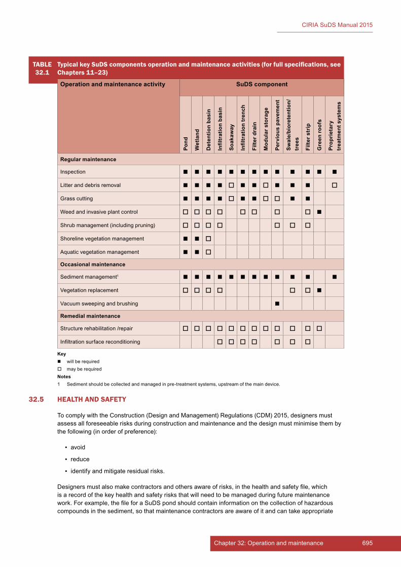
695Chapter 32: Operation and maintenance694 Part E: Supporting guidance
CIRIA SuDS Manual 2015
32.5 HEALTH AND SAFETY
To comply with the Construction (Design and Management) Regulations (CDM) 2015, designers must assess all foreseeable risks during construction and maintenance and the design must minimise them by the following (in order of preference):
▪ avoid
▪ reduce
▪ identify and mitigate residual risks.
Designers must also make contractors and others aware of risks, in the health and safety file, which is a record of the key health and safety risks that will need to be managed during future maintenance work. For example, the file for a SuDS pond should contain information on the collection of hazardous compounds in the sediment, so that maintenance contractors are aware of it and can take appropriate
TABLE32.1
Typical key SuDS components operation and maintenance activities (for full specifications, see Chapters 11–23)
Operation and maintenance activity SuDS component
Pond
Wet
land
Det
entio
n ba
sin
Infil
trat
ion
basi
n
Soak
away
Infil
trat
ion
tren
ch
Filte
r dra
in
Mod
ular
sto
rage
Perv
ious
pav
emen
t
Swal
e/bi
oret
entio
n/tr
ees
Filte
r str
ip
Gre
en ro
ofs
Prop
riet
ary
trea
tmen
t sys
tem
s
Regular maintenance
Inspection
Litter and debris removal
Grass cutting
Weed and invasive plant control
Shrub management (including pruning)
Shoreline vegetation management
Aquatic vegetation management
Occasional maintenance
Sediment management1
Vegetation replacement
Vacuum sweeping and brushing
Remedial maintenance
Structure rehabilitation /repair
Infiltration surface reconditioning
Key will be required may be requiredNotes1 Sediment should be collected and managed in pre-treatment systems, upstream of the main device.

697Chapter 32: Operation and maintenance696 Part E: Supporting guidance
CIRIA SuDS Manual 2015
precautions. During construction, the residual risks must be identified and an action plan developed to deal with them safely (the health and safety plan and site rules).
All those responsible for maintenance should take appropriate health and safety precautions for all activities (including lone working, if relevant), and risk assessments should always be undertaken. Guidance on generic health and safety principles is provided in Chapter 36.
32.6 REGULAR MAINTENANCE
32.6.1 Inspections and reporting
An initial pre-handover inspection of the scheme is required, to ensure that it has been constructed as designed (Chapter 31).
Regular inspections of SuDS will then:
1 help determine optimum future maintenance activities
2 help establish ongoing hydraulic, water quality, amenity and biodiversity performance of the system
3 allow identification of potential performance failures, such as blockage, reduced infiltration and poor water quality resulting from lack of maintenance.
Maintenance of SuDS is carried out by a range of people, which can include school caretakers, highway authorities, facilities management companies and landscape contractors. Pervious surfaces and proprietary systems will most likely be managed by people familiar with highway or drainage maintenance. Landscaped systems will be managed by the landscape contractor, although connecting pipework may be managed by others.
Where the maintenance of a system is carried out by those responsible for the wider landscaped area, the inspections can generally be undertaken during routine site visits (eg for grass cutting, leaf collection and/or litter collection) for little extra cost, although there may need to be dedicated visits during some winter months.
The staff doing the landscape maintenance should have appropriate experience of SuDS maintenance and should be capable of keeping sufficiently detailed records of any inspections. If staff do not have appropriate experience, then specific inspection visits will be necessary.
Those with overall responsibility for the drainage system may not be responsible for maintenance of the wider landscape and in those circumstances specific inspection visits may also be required at a suitable interval.
Specific visits will also be required if the system includes proprietary treatment systems (Chapter 14).
Whichever arrangements are made, the inspections should be recorded, and the records saved for future reference (Section 32.10 and Appendix B).
During the first year of operation of all types of SuDS, inspections should usually be carried out at least monthly (and after significant storm events) to ensure that the system is functioning as designed and that no damage is evident.
Typical routine inspection questions that will indicate when occasional or remedial maintenance activities are required for any type of system include:
▪ Are inlets or outlets blocked?
▪ Does any part of the system appear to be leaking (especially ponds and wetlands)?
▪ Is the vegetation healthy?
697Chapter 32: Operation and maintenance696 Part E: Supporting guidance
CIRIA SuDS Manual 2015
▪ Is there evidence of poor water quality (eg algae, oils, milky froth, odour, unusual colourings)?
▪ Is there evidence of sediment build-up beyond the designer’s stated limits?
▪ Is there visual evidence of oil accumulation?
▪ Is there evidence of ponding above an infiltration surface?
▪ Is there any evidence of structural damage that requires repair?
▪ Are there areas of erosion or channelling over vegetated surfaces?
▪ Is there any visual evidence of regular or unplanned over-topping of banks?
For large sites, it is recommended that an annual maintenance report and record should be prepared by the maintenance contractor, which should be retained with the operation and maintenance manual (Section 32.2). The report should provide the following information:
▪ observations resulting from inspections
▪ measured sediment depths (where appropriate)
▪ monitoring results, if flow or water quality monitoring is undertaken
▪ confirmation that any penstocks or valves are free and working correctly
▪ maintenance and operation activities undertaken during the year
▪ recommendations for inspection and maintenance programme for the following year.
As with any paved area, safety inspections of pervious surfaces will be necessary for tripping hazards. If pervious surfaces are to be used in a shopping centre car park or high footfall area, these should be inspected monthly as a minimum, and repairs made as necessary through the lifetime of the surface. This would apply to any type of surface. Guidance is provided by the Road Liaison Group (2005).
32.6.2 Litter and debris removal
Litter and debris removal is an integral part of SuDS maintenance for surface features, in order to reduce the risks of inlet and outlet blockages, to retain amenity value and to minimise pollution risks. High litter removal frequencies may be required where aesthetics are a major driver, for example on residential sites or at high profile commercial or retail parks. Litter removal is less of an issue for engineered or underground systems, such as pervious surfaces, filter drains and proprietary systems and will normally form part of routine open space maintenance.
32.6.3 Grass cutting
It is recommended that the grass cutting regime around SuDS components is carefully specified to maximise the performance of the SuDS and meet visual requirements. In general, allowing grass to grow tends to enhance water quality performance. Short grass around a wet system, such as a pond or wetland, provides an ideal habitat for nuisance wildlife species such as geese, but allowing the grass to grow is an effective means of discouraging them. Grass around wet pond or wetland systems should not be cut to the edge of the permanent water in order to deter large birds and to reduce the risks of nutrients associated with grass cuttings falling into the water.
Grass cutting is an activity primarily undertaken to enhance the perceived aesthetics of the Figure 32.1 Grass cuttings
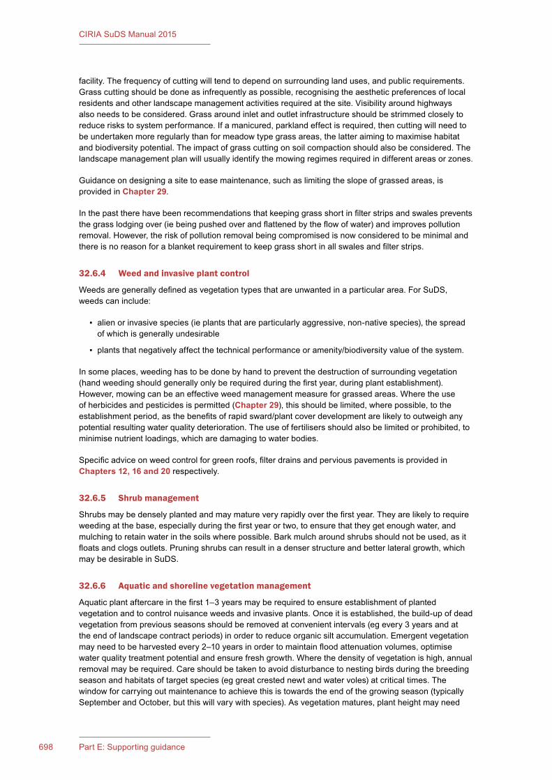
699Chapter 32: Operation and maintenance698 Part E: Supporting guidance
CIRIA SuDS Manual 2015
facility. The frequency of cutting will tend to depend on surrounding land uses, and public requirements. Grass cutting should be done as infrequently as possible, recognising the aesthetic preferences of local residents and other landscape management activities required at the site. Visibility around highways also needs to be considered. Grass around inlet and outlet infrastructure should be strimmed closely to reduce risks to system performance. If a manicured, parkland effect is required, then cutting will need to be undertaken more regularly than for meadow type grass areas, the latter aiming to maximise habitat and biodiversity potential. The impact of grass cutting on soil compaction should also be considered. The landscape management plan will usually identify the mowing regimes required in different areas or zones.
Guidance on designing a site to ease maintenance, such as limiting the slope of grassed areas, is provided in Chapter 29.
In the past there have been recommendations that keeping grass short in filter strips and swales prevents the grass lodging over (ie being pushed over and flattened by the flow of water) and improves pollution removal. However, the risk of pollution removal being compromised is now considered to be minimal and there is no reason for a blanket requirement to keep grass short in all swales and filter strips.
32.6.4 Weed and invasive plant control
Weeds are generally defined as vegetation types that are unwanted in a particular area. For SuDS, weeds can include:
▪ alien or invasive species (ie plants that are particularly aggressive, non-native species), the spread of which is generally undesirable
▪ plants that negatively affect the technical performance or amenity/biodiversity value of the system.
In some places, weeding has to be done by hand to prevent the destruction of surrounding vegetation (hand weeding should generally only be required during the first year, during plant establishment). However, mowing can be an effective weed management measure for grassed areas. Where the use of herbicides and pesticides is permitted (Chapter 29), this should be limited, where possible, to the establishment period, as the benefits of rapid sward/plant cover development are likely to outweigh any potential resulting water quality deterioration. The use of fertilisers should also be limited or prohibited, to minimise nutrient loadings, which are damaging to water bodies.
Specific advice on weed control for green roofs, filter drains and pervious pavements is provided in Chapters 12, 16 and 20 respectively.
32.6.5 Shrub management
Shrubs may be densely planted and may mature very rapidly over the first year. They are likely to require weeding at the base, especially during the first year or two, to ensure that they get enough water, and mulching to retain water in the soils where possible. Bark mulch around shrubs should not be used, as it floats and clogs outlets. Pruning shrubs can result in a denser structure and better lateral growth, which may be desirable in SuDS.
32.6.6 Aquatic and shoreline vegetation management
Aquatic plant aftercare in the first 1–3 years may be required to ensure establishment of planted vegetation and to control nuisance weeds and invasive plants. Once it is established, the build-up of dead vegetation from previous seasons should be removed at convenient intervals (eg every 3 years and at the end of landscape contract periods) in order to reduce organic silt accumulation. Emergent vegetation may need to be harvested every 2–10 years in order to maintain flood attenuation volumes, optimise water quality treatment potential and ensure fresh growth. Where the density of vegetation is high, annual removal may be required. Care should be taken to avoid disturbance to nesting birds during the breeding season and habitats of target species (eg great crested newt and water voles) at critical times. The window for carrying out maintenance to achieve this is towards the end of the growing season (typically September and October, but this will vary with species). As vegetation matures, plant height may need
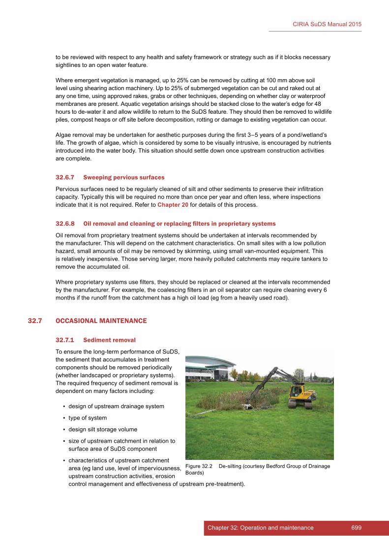
699Chapter 32: Operation and maintenance698 Part E: Supporting guidance
CIRIA SuDS Manual 2015
to be reviewed with respect to any health and safety framework or strategy such as if it blocks necessary sightlines to an open water feature.
Where emergent vegetation is managed, up to 25% can be removed by cutting at 100 mm above soil level using shearing action machinery. Up to 25% of submerged vegetation can be cut and raked out at any one time, using approved rakes, grabs or other techniques, depending on whether clay or waterproof membranes are present. Aquatic vegetation arisings should be stacked close to the water’s edge for 48 hours to de-water it and allow wildlife to return to the SuDS feature. They should then be removed to wildlife piles, compost heaps or off site before decomposition, rotting or damage to existing vegetation can occur.
Algae removal may be undertaken for aesthetic purposes during the first 3–5 years of a pond/wetland’s life. The growth of algae, which is considered by some to be visually intrusive, is encouraged by nutrients introduced into the water body. This situation should settle down once upstream construction activities are complete.
32.6.7 Sweeping pervious surfaces
Pervious surfaces need to be regularly cleaned of silt and other sediments to preserve their infiltration capacity. Typically this will be required no more than once per year and often less, where inspections indicate that it is not required. Refer to Chapter 20 for details of this process.
32.6.8 Oil removal and cleaning or replacing filters in proprietary systems
Oil removal from proprietary treatment systems should be undertaken at intervals recommended by the manufacturer. This will depend on the catchment characteristics. On small sites with a low pollution hazard, small amounts of oil may be removed by skimming, using small van-mounted equipment. This is relatively inexpensive. Those serving larger, more heavily polluted catchments may require tankers to remove the accumulated oil.
Where proprietary systems use filters, they should be replaced or cleaned at the intervals recommended by the manufacturer. For example, the coalescing filters in an oil separator can require cleaning every 6 months if the runoff from the catchment has a high oil load (eg from a heavily used road).
32.7 OCCASIONAL MAINTENANCE
32.7.1 Sediment removal
To ensure the long-term performance of SuDS, the sediment that accumulates in treatment components should be removed periodically (whether landscaped or proprietary systems). The required frequency of sediment removal is dependent on many factors including:
▪ design of upstream drainage system
▪ type of system
▪ design silt storage volume
▪ size of upstream catchment in relation to surface area of SuDS component
▪ characteristics of upstream catchment area (eg land use, level of imperviousness, upstream construction activities, erosion control management and effectiveness of upstream pre-treatment).
Figure 32.2 De-silting (courtesy Bedford Group of Drainage Boards)

701Chapter 32: Operation and maintenance700 Part E: Supporting guidance
CIRIA SuDS Manual 2015
Sediment accumulation will typically be rapid for the entire construction period (including during the period of building, turfing and landscaping of all upstream development plots). Once a catchment is completely developed and all vegetation is well-established, sediment mobility (erosion) and accumulation is likely to drop significantly.
Detailed information on waste management (in particular with respect to sediment removal) is provided in Chapter 33.
For most small features, sediment can be removed either by hand or using small excavators. For any system that has a waterproof liner, the method of sediment removal should be chosen so there is minimal risk of damaging the liner.
For proprietary treatment systems, a suction tanker will be needed to remove the sediment. The size of tanker will depend on the scale of the proprietary system and its location. For small catchments using treatment channels, silt accumulation in the channel can often be removed with hand tools or a small suction tanker.
General sediment removal considerations
Sediment removal from SuDS systems should always be carried out such that no damage is caused to the SuDS, and impacts on ecological systems and aesthetic appearance are minimised. The appropriate method of sediment removal at a particular site will depend on the size of the SuDS component, the access, whether the sediments are submerged or lying on dry ground, the sediment properties, the design characteristics of the SuDS component, visual requirements and wildlife concerns and sediment depths.
For small source-control SuDS components where sediment volumes are likely to be small, it is usually appropriate to remove sediment using hand tools and appropriate protective equipment. Where components and associated sediment volumes are larger, or where the sediment has accumulated in a permanent water body, then mechanical equipment may be required.
In particular, it is recommended to do the following:
1 Establish how the structure is lined and avoid damage to clay puddle layers or waterproof membranes.
2 Undertake work between September and March to minimise impacts on receiving water bodies (high suspended solids can cause reduced dissolved oxygen levels, which causes particular problems during elevated summer temperatures). Where required, works may be restricted to September and October, in order to protect breeding or hibernating wildlife.
3 Where machinery or pumping is to be used, agree the sediment removal and management plan in advance with the environmental regulator.
4 Where machinery is used to excavate sediment, undertake the operation in dry weather when the surrounding ground is firm, and ideally operate from a hard surface.
5 Use machinery with an extending arm to avoid contact with edges, banks and other features within a minimum distance of 1 m from the edge. Use a bucket without teeth to avoid puncturing clay layers or waterproof membranes.
6 Secure consent for any de-watering operations with the environmental regulator, if required.
Specific requirements of different SuDS components are presented in subsequent sections. Individual SuDS component chapters should be referenced for further details.
Sediment removal from retention ponds
Ponds and wetlands may eventually accumulate sufficient sediment to impact on the storage capacity of the permanent pool. This loss of capacity can affect both the appearance and the pollution removal efficiency of the pond. The rate at which this occurs will depend on allowances made during storage
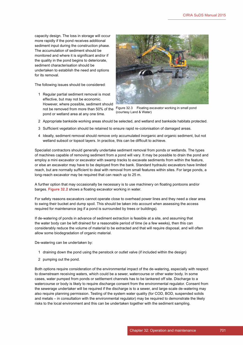
701Chapter 32: Operation and maintenance700 Part E: Supporting guidance
CIRIA SuDS Manual 2015
capacity design. The loss in storage will occur more rapidly if the pond receives additional sediment input during the construction phase. The accumulation of sediment should be monitored and where it is significant and/or if the quality in the pond begins to deteriorate, sediment characterisation should be undertaken to establish the need and options for its removal.
The following issues should be considered:
1 Regular partial sediment removal is most effective, but may not be economic. However, where possible, sediment should not be removed from more than 50% of the pond or wetland area at any one time.
2 Appropriate bankside working areas should be selected, and wetland and bankside habitats protected.
3 Sufficient vegetation should be retained to ensure rapid re-colonisation of damaged areas.
4 Ideally, sediment removal should remove only accumulated inorganic and organic sediment, but not wetland subsoil or topsoil layers. In practice, this can be difficult to achieve.
Specialist contractors should generally undertake sediment removal from ponds or wetlands. The types of machines capable of removing sediment from a pond will vary. It may be possible to drain the pond and employ a mini excavator or excavator with swamp tracks to excavate sediments from within the feature, or else an excavator may have to be deployed from the bank. Standard hydraulic excavators have limited reach, but are normally sufficient to deal with removal from small features within sites. For large ponds, a long-reach excavator may be required that can reach up to 25 m.
A further option that may occasionally be necessary is to use machinery on floating pontoons and/or barges. Figure 32.2 shows a floating excavator working in water.
For safety reasons excavators cannot operate close to overhead power lines and they need a clear area to swing their bucket and dump spoil. This should be taken into account when assessing the access required for maintenance (eg if a pond is surrounded by trees or buildings).
If de-watering of ponds in advance of sediment extraction is feasible at a site, and assuming that the water body can be left drained for a reasonable period of time (ie a few weeks), then this can considerably reduce the volume of material to be extracted and that will require disposal, and will often allow some biodegradation of organic material.
De-watering can be undertaken by:
1 draining down the pond using the penstock or outlet valve (if included within the design)
2 pumping out the pond.
Both options require consideration of the environmental impact of the de-watering, especially with respect to downstream receiving waters, which could be a sewer, watercourse or other water body. In some cases, water pumped from ponds or settlement channels has to be tankered off site. Discharge to a watercourse or body is likely to require discharge consent from the environmental regulator. Consent from the sewerage undertaker will be required if the discharge is to a sewer, and large-scale de-watering may also require planning permission. Testing of the system water quality (for COD, BOD, suspended solids and metals – in consultation with the environmental regulator) may be required to demonstrate the likely risks to the local environment and this can be undertaken together with the sediment sampling.
Figure 32.3 Floating excavator working in small pond (courtesy Land & Water)

703Chapter 32: Operation and maintenance702 Part E: Supporting guidance
CIRIA SuDS Manual 2015
The water may contain high concentrations of suspended solids that are either already in suspension or become entrained as a result of the pumping process. Adequate sediment control should therefore be provided before the pumped water is discharged. Once the pumped water is running clear then the sediment control devices may be bypassed as long as sediment is not reintroduced into the system. Appropriate sediment control systems include:
▪ temporary traps formed by constructing an earth embankment with a gravel filled outlet across a swale
▪ sediment basins (this can include the use of floodable fields)
▪ sumps (either constructed or mobile proprietary units)
▪ geotextile filters.
A dump truck with a watertight tailgate is likely to be required to remove the sediment from the site.
Sediment removal from detention basins
Dry basins accumulate sediment with time that will gradually reduce the storage capacity available and can in some cases also reduce sediment trapping efficiency. Also, sediment may tend to accumulate around the control device, which increases the risk that either the orifice may become clogged or that sediment may become re-entrained into the outflow. Where basins are amenity features, sediment accumulation is likely to be unsightly and reduce the amenity value of the component. Sediment accumulation should be monitored as part of the inspection regime for the surface water management system and appropriate frequencies determined for removal and disposal. Small volumes of sediment can usually be removed by landscape contractors using hand tools. Sediment excavation using front-end loaders or backhoes is simple, if appropriate access is available for the equipment. Sediment removal will usually damage the vegetation, and re-establishment may be required.
Sediment removal from filter strips and swales
Sediment accumulation should be monitored as part of the inspection regime for the surface water management system and appropriate frequencies determined for removal and disposal. Filter strips and swales will only accumulate very small volumes of sediment which can be removed by landscape contractors using hand tools at appropriate frequencies depending on the impact of the accumulation on the performance of the component in terms of hydraulics (eg sheet flow characteristics), water quality (eg vegetation cover) and amenity (eg visual).
Sediment removal from infiltration basins
Infiltration basins should always have source control, a pre-treatment or other sediment trapping system upstream. Even with low sediment loads, the system performance can still become significantly impaired in a relatively short space of time. The sediment deposits reduce the storage capacity and may also clog the surface soils. Dense vegetation can minimise the risk of surface clogging (Chapter 13, Section 13.12).
Methods of removing sediment from infiltration basins are different from detention basins. Removal should not start until the basin has dried out, at which point the top layer should then be removed using lightweight equipment, with care being taken not to unduly compact the basin surface. The remaining soil can then be scarified or tilled to restore the surface infiltration capacity (see Chapter 13 for detail of these methods). Vegetated areas disturbed during sediment removal should be replanted or re-sown immediately to reduce the risk of erosion. Suitable erosion control should also be provided.
Sediment removal from proprietary systems
Proprietary systems should be cleaned out regularly to prevent re-entry of any residuals or pollutants into the downstream system. The frequency will depend on the site-specific pollutant load, but most suppliers/manufacturers recommend that cleaning operations should take place every 6 months. They can be cleaned by vacuum pumping which transfers a slurry of water and sediment to a tanker, or by adding chemicals to help solidify the residuals, which can then be removed using appropriate methods.
703Chapter 32: Operation and maintenance702 Part E: Supporting guidance
CIRIA SuDS Manual 2015
Maintenance of pervious pavement systems involves removing sediment from the pavement surface using vacuum sweeping. It is recommended that the pavement be vacuum swept once a year, and the collected sediments will require appropriate handling and disposal.
Sediment removal from filter drains
Filter drains will require occasional removal of the gravel infill which can be either cleaned and reused, or new material used as a replacement. The geotextile surrounds to the trench and to pipes may also require replacement at this time.
Small lengths would probably be cleaned using a small excavator to remove the material and replace it with clean. There are specialist companies that can clean long lengths of linear filter drain (eg alongside roads) using specialist machinery. The machinery can easily deal with single size material of 40 mm and Type B filter material (Chapter 30). It may require adapting, or the settings changed to deal with other infill materials. The machinery lifts the filter material from the trench, segregates and cleans it and then returns it to the trench. Typically the machines will clean the gravel to depths of 300 mm or exceptionally 600 mm.
Disposal of silt and debris that is removed is achieved via a belt which can discharge to a truck running alongside, or it can be deposited well back on the verge if permitted. The amount of spoil is usually in the order of 5–10 tonnes for every 100 m of drain cleaned to 300 mm depth.
32.7.2 Vegetation and plant replacement
Some replacement of plants may be required in the first 12 months after installation (ie the defects liability/rectification period), possibly after storm events. Dead or damaged plants should be removed and replaced, to restore the prescribed number of living plants per m2. The responsibility for doing this should be made clear in the construction contract.
Inspection programmes should identify areas of filtration, or infiltration surfaces where vegetation growth is poor and likely to cause a reduced level of system performance. Such areas can then be rehabilitated, and plant growth repaired.
32.8 REMEDIAL MAINTENANCE
32.8.1 Structure rehabilitation and repair
The need for component rehabilitation (eg to remove clogged filters, geotextiles and gravels) will typically be 10–25 years, depending on the component design and factors such as the type of catchment and sediment load. The SuDS design should allow for vehicle access to undertake this work and consider how to implement such overhauls without causing major disruption to the functionality of the drainage system. For example, if geotextiles are used at a high level within a pervious surface, then reconstruction of the surface and bedding layer is all that is required if they become clogged, rather than reconstruction of the whole pavement depth.
Some form of rehabilitation is likely to be required at some point where component functionality relies on filtration through soils or aggregates. However, for many SuDS components, routine maintenance is sufficient.
Rehabilitation activities for each SuDS component are described in the individual component chapters. The requirements should be identified in the operation and maintenance manual.
32.8.2 Infiltration surface rehabilitation
Inspections should look for signs of infiltration surfaces becoming clogged, such as if water is standing for long periods on the surface or if it is flowing via an overflow channel and bypassing the basin. In the event that grassed surface permeability is unacceptably reduced, there are a number of landscape techniques that can be used to open the surface to encourage infiltration. Such activities are likely to be required in

705Chapter 32: Operation and maintenance704 Part E: Supporting guidance
CIRIA SuDS Manual 2015
circumstances where silt has not been effectively managed upstream, or the infiltration surface has been compacted by foot traffic (eg if a basin is also used as a recreational area).
Scarifying to remove “thatch”
Thatch is a tightly intermingled organic layer of dead and living shoots, stems and roots, developing between the zone of green vegetation and the soil surface. Scarifying with tractor-drawn or self-propelled equipment to a depth of at least 50 mm breaks up silt deposits, removes dead grass and other organic matter and relieves compaction of the soil surface.
Spiking or tining the soil, using aerating equipment to encourage water percolation
This is particularly effective where a hollow tine machine is used, and sand is dressed in, and is best undertaken when the soil is moist (note: the removal and disposal of the dried cores will be necessary). Spiking or tining with tractor-drawn or self-propelled equipment penetrates and perforates soil layers to a depth of at least 100 mm (at 100 mm centres) and allows the entry of air, water, nutrients and top dressing materials.
Air pressure treatment
If the infiltration capacity has reduced due to compaction, it may be possible to rehabilitate it using air pressure treatment. This process breaks up subsoil layers by driving probes into the ground. The probe is connected to a high pressure gas source (typically nitrogen bottles) and a high pressure stream of gas is quickly introduced into the soil. This causes the soil to rupture both vertically and horizontally.
As a last resort, it may be necessary to remove and replace the grass and topsoil by:
▪ removing accumulated silt and (subject to a toxicity test) applying to land or dispose off site
▪ removing damaged turf, which should be composted or disposed off site
▪ cultivating remaining topsoil to required levels
▪ re-turfing (using turf of a quality and appearance to match existing) or reseeding (to Clause 12.6 of BS 7370-3:1991) using seed to match existing turf) area to required levels. It may be necessary to supply and fix erosion protection to protect seeded soil. The placing or grading of turf and seeded areas should be undertaken carefully to ensure that final design levels are achieved. Watering will be required to promote successful germination and/or establishment.
32.9 FREQUENCY OF MAINTENANCE TASKS
Landscape maintenance contract periods are usually of 1–3 years in duration. The 3-year cycle is increasingly common to ensure continuity and commitment to long-term landscape care. The frequency of regular landscape maintenance tasks in a contract period can range from daily to once in the contract period. In practice, most site tasks are based on monthly or fortnightly site visits, except where grass or weed growth requires a higher frequency of work. In many cases, a performance specification is used with terms such as “beds shall be maintained weed-free” or “grass shall be cut to a height of 50 mm with a minimum height of 35 mm and a maximum height of 100 mm” to obtain the required standards.
Frequency can be specified within the schedule to include occasional items, such as “‘meadow grass’ – cut twice annually in July and September to a height of 75–100 mm (or to supplier’s recommendations), all arisings raked off and removed to wildlife features, compost facility or other recycling facility”, which provides flexibility for work that is not critical to the management of the site.
Maintenance tasks that suit a performance approach commonly include plant growth, grass cutting, pruning and tree maintenance. However, work tasks, such as sweeping paths, regular litter collection and cleaning road surfaces, will require work at an agreed frequency, with more specific timings such as weekly, monthly or annually. Where the frequency and timing of tasks is critical, a mixture of performance and frequency specification is necessary to provide effective maintenance.
705Chapter 32: Operation and maintenance704 Part E: Supporting guidance
CIRIA SuDS Manual 2015
SuDS maintenance generally tends towards a frequency requirement to ensure a predictable standard of care, which can be recorded on site and provides a reasonable basis for pricing work. A convenient frequency for many tasks is at a monthly inspection, as this is the usual minimum site attendance required in a landscape specification. The monthly frequency should provide for an inspection of all SuDS components and for the checking of all inlets and outlets. The inspection should be carried out by someone familiar with the operation of the specific SuDS components, and it should be recorded.
However, certain SuDS maintenance tasks fall outside this monthly cycle and need to be accommodated in the contract. The most obvious are:
▪ wetland vegetation maintenance
▪ silt management
▪ filter replacement in proprietary systems
▪ sweeping of pervious surfaces (unless loose, gravel surfaces).
There are other tasks associated with ensuring the long-term performance of the systems that may be more difficult to predict, and may even fall outside any contract period. It may, therefore, be more appropriate to review requirements, for example, for system rehabilitation at interim periods, when contracts are falling due for renewal.
The vast majority of well-designed SuDS, whether “hard” or “soft”, do not seem to suffer from problems with excessive and rapid silt accumulation, if they apply the key concepts of the SuDS philosophy: source control with a correctly designed Management Train. The frequency of sediment removal will increase as the area of the catchment increases in relation to the surface area of the SuDS where sediment accumulates (whether this is within a proprietary system or a landscape feature).
32.10 APPLYING THE PRINCIPLES OF LANDSCAPE MANAGEMENT
Typical landscape management documentation and its potential application to SuDS is summarised in the following subsections.
32.10.1 Management plan
This document should include a clear statement of design intent and an explanation of each of the SuDS components and the benefits being delivered by the SuDS for the site. The document should describe the management objectives for the site over time, and the management strategies that should be employed to realise these objectives and reconcile any potential conflicts that may arise.
Where the drainage system has an impact on the wildlife value or public use of a site, the document should explain any habitat enhancement goals, health and safety issues and long-term management implications.
For SuDS, the management plan should include a Maintenance Plan, which will be required so that maintenance aspirations can be costed, in order to secure their long-term financing. The Maintenance Plan can also establish changes in maintenance regimes that may be required to match changes in objectives such as the need to adapt operation and maintenance practices to accommodate specific wildlife habitats that may develop.
Sites with special wildlife or amenity interest may require detailed management plans that monitor habitat development, infrastructure changes or damage to sites, and ensure rapid responses to such changes, should they occur. In these cases the management plan should be prepared in collaboration with an ecologist. Ecological supervision may be required for certain works.
It is common for smaller commercial, industrial and housing sites to have a simple maintenance statement. In this case, a single page explaining the site management (including the SuDS) would be useful for all parties involved in the care of the development.

707Chapter 32: Operation and maintenance706 Part E: Supporting guidance
CIRIA SuDS Manual 2015
An important part of a management plan is an annual and 3–5 yearly review of the Maintenance Plan (when maintenance contracts are typically renewed). This should apply to all types of SuDS, but is particularly important for the soft landscape element, as plants and trees require different periodic management techniques as they develop. The review should involve those responsible for the maintenance and those undertaking the work.
The management plan should be a living document that is reviewed periodically with reference to changes on site, as well as changes to adjacent sites that might impact the site.
Further guidance and an example of a Maintenance Plan (in the form of a checklist) is provided in Appendix B.
32.10.2 Conditions of Contract
Appropriate conditions of contract will be required. Advice can be sought from the Landscape Institute which publishes specific landscape maintenance contracts. Guidance is also provided in Shaffer et al (2004).
32.10.3 Specification
The specification details the materials to be used and the standard of work required.
A specification, usually preceded by preliminaries, details how work shall be carried out, and contains clauses that give general instructions to the contractor. It will normally be accompanied by a schedule of work (Section 32.10.4). Specific SuDS maintenance clauses may be included in a general specification or as a separate “SuDS maintenance specification” section either within or referenced by the management plan (Section 32.10.1).
32.10.4 Schedule of work
The schedule of work itemises the tasks to be undertaken and the frequency at which they will be performed.
The tasks required to maintain the site and the frequency necessary to achieve an acceptable standard should be set out in the schedule of work.
This document (and Section 32.10.3) will often form the basis of a pricing framework, and can also act as a checklist to ensure that the work has been carried out satisfactorily.
For further information on the development of appropriate schedules, see HR Wallingford (2004).
32.10.5 Maintenance record
It is vital that a record is kept of the inspections and maintenance work that has been carried out. This allows the response of the system to different maintenance regimes to be assessed in future, and also provides protection against legal claims should the capacity of the system be exceeded during a rainfall event and flooding occurs elsewhere as a result.
32.11 REFERENCES
HR WALLINGFORD (2004) The operation and maintenance of sustainable drainage systems (and associated costs), SR 626, HR Wallingford, UK. Go to: http://tinyurl.com/lcot2g6
ROAD LIASON GROUP (2005) Well-maintained highways. Code of practice for highway maintenance management, The Stationery Office, London, UK (ISBN: 0-11552-643-9). Go to: http://tinyurl.com/osm2juc
SHAFFER, P, ELLIOTT, C, REED, J, HOLMES, J and WARD, M (2004) Model agreements for sustainable water management systems. Model agreements for SuDS, C625, CIRIA, London, UK (ISBN: 978-0-86017-625-1). Go to: www.ciria.org

707Chapter 32: Operation and maintenance706 Part E: Supporting guidance
CIRIA SuDS Manual 2015
STATUTES
British Standards
BS 7370-3:1991 Grounds maintenance. Recommendations for maintenance of amenity and functional turf (other than sports turf)
Regulations
Construction (design and Management) Regulations (CDM) 2015
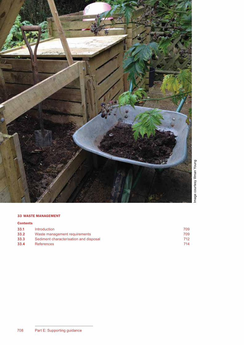
709Chapter 33: Waste management708 Part E: Supporting guidance
CIRIA SuDS Manual 2015
33 WASTE MANAGEMENT
Contents
33.1 Introduction 70933.2 Waste management requirements 70933.3 Sediment characterisation and disposal 71233.4 References 714
Imag
e co
urte
sy Il
lman
You
ng

709Chapter 33: Waste management708 Part E: Supporting guidance
CIRIA SuDS Manual 2015
33Chapter
33.1 INTRODUCTION
SuDS remove pollutants from runoff, thereby minimising the impacts on receiving water quality. A key part of this process is sediment management. Sediment accumulates in SuDS for two main reasons:
▪ surface water runoff brings debris and silt loadings from hard surfaces
▪ green areas and vegetated systems generate organic waste, due to plant growth and die-off.
If sediment is not removed from the drainage system at appropriate frequencies, there is a risk that the following problems could develop:
1 SuDS components can become sources of pollutants as the inorganic and organic sediments that accumulate on their base become resuspended during storm events.
2 Storage capacity may be reduced.
3 The risk of inlets and outlets blocking may increase.
4 Amenity and aesthetic value could decrease because of odours and vectors (organisms that carry disease-causing microorganisms from one host to another).
To prevent these problems, SuDS (and their pre-treatment structures, if present) should be periodically inspected, the level of sediment (and other waste) accumulation should be monitored and the systems cleaned when appropriate. Sediment and vegetation that is grown in components where contaminant loadings are high may contain a variety of pollutants, and proper handling and disposal of these materials is essential.
Materials such as sediment, vegetation, contaminated geotextiles and other structural material arising from the maintenance of SuDS may be classified as “controlled wastes” and where this is the case, their removal and disposal must always be in accordance with the latest regulations and legislation. This chapter refers to legislation that is current at the time of writing (2015), but may be amended over time. It is, therefore, the responsibility of the SuDS operator to keep abreast of the latest information and requirements. The environmental regulator should be contacted to confirm the required protocols for the proper handling of any sediment or other waste at a particular site.
33.2 WASTE MANAGEMENT REQUIREMENTS
33.2.1 General
There are usually three types of waste arising from regular SuDS maintenance: litter, green waste (vegetation) and sediment. Litter should be disposed of as for any open space. Green waste management is described in Section 33.2.2 and sediment management is described in Section 33.2.3.
Directive 2008/98/EC (the Waste Framework Directive) requires all member states to take the necessary measures to ensure that waste is recovered or disposed of
Waste managementThis chapter discusses the principles of good practice for the management of waste resulting from maintenance of SuDS.

711Chapter 33: Waste management710 Part E: Supporting guidance
CIRIA SuDS Manual 2015
without endangering human health or causing harm to the environment. This includes requirements for permitting, registration and inspection of waste disposal facilities and operations.
UK waste legislation is derived predominantly from European Union (EU) laws and transposed into UK law via various statutory instruments specific to England and Wales, Scotland or Northern Ireland. The current regulatory constraints and obligations for waste management and disposal should be established through consultation with the environmental regulator.
The guidance on complying with the latest regulations is summarised on the following websites:
▪ England and Wales: https://www.gov.uk/waste-legislation-and-regulations
▪ Scotland: www.sepa.org.uk/waste.aspx
▪ Northern Ireland: www.doeni.gov.uk/waste
Where waste is removed from site, it will be subject to the relevant waste management legislation for the country. In brief, this generally means that those responsible for generating waste must:
1 adequately characterise and describe the waste to allow for its safe disposal
2 only allow the waste to be removed and transported by those who are licensed to do so
3 ensure that it is disposed at a suitably licensed waste disposal or treatment facility.
The producer of the waste will be required to undertake analysis of the waste, including the CEN leaching test, so as to properly characterise the waste as hazardous, non-hazardous or inert, to assign a classification in accordance with the European List of Wastes (EC, 2000) and to provide a full description for the receiving landfill. There is a further requirement to pre-treat hazardous waste for volume reduction, to make it non-reactive and to improve its physical stability. A landfill can only accept waste provided that the appropriate waste acceptance criteria are met. More information is available from the WRAP website: www.wrap.org.uk
If wastes arising from the maintenance of SuDS are to be disposed of through beneficial reuse, the proposed activity will need to meet the requirements of an appropriate exemption and, having done so, be registered. The exemption registration process requires a burden of proof in demonstrating that the conditions of the particular exemption are met and that the activity is unlikely to cause pollution of the environment or harm to human health.
Waste disposal options that may be possible include the following:
▪ Non-contaminated sediments or sediments with low levels of contamination arising from SuDS could possibly be placed on the land surrounding the SuDS (without planning permission), provided that (1) the disposal area is within the operational land of the SuDS owner (2) the land is not used for agriculture and (3) it can be demonstrated that the deposit results in an ecological improvement to the land. See EA position statement requirements (Section 33.3).
▪ Green waste may be composted on site under an appropriate exemption. Alternatively, green wastes may be collected by a commercial operator for processing into compost at their own site.
▪ If SuDS could be excavated in the dry, then recovered sediments could be beneficially reused as “building material”, for example to raise banks or for other landscaping. However, if wet excavation occurs, the material can only be used in land drainage works.
▪ Direct dredging of the sediments to the surrounding banks may be possible if there is demonstrable benefit to agriculture or ecology.
The waste disposal route and proposals should always be confirmed with the environmental regulator before sediment or green waste is removed from the site or applied onto land within it.
In some landscape features with specific habitats, sediment removal operations may require adequate method statements that are prepared in liaison with an ecologist. The method statement should take
711Chapter 33: Waste management710 Part E: Supporting guidance
CIRIA SuDS Manual 2015
account of the time of year, sequence of operations on site and disposal of waste. In some places, waste material may need to be retained on site for a period of time to manage movement and relocation of invertebrates. Adequate time and resources may also have to be allocated, to transplant vegetation in sensitive zones.
33.2.2 Green waste management
The relevant waste management regulations must be followed when removing and disposing of green waste. Where green waste is cut from areas subject to low levels of contaminants, it may be possible to compost and reuse it.
Larger corporate sites or public open spaces and communal residential land with dedicated management facilities may incorporate composting facilities of a suitable scale using contained structures/bins (with ventilation) or open bays. For efficient compost management, at least two or three bins/bays are required, and the compost needs to be mixed/turned by suitable machinery (eg JCB bucket) at a regular frequency (see below).
A compost facility allows all green waste, particularly grass cuttings and prunings, to be recycled and to provide compost for mulching ornamental plant beds. The following process should be followed for composting:
▪ shred all arisings from site
▪ combine all arisings in active compost bin with grass cuttings not exceeding 70%
▪ turn and mix active compost when bin is > 50% full, at weekly intervals for at least 4 weeks
▪ turn and mix full bin every 28 days until used
▪ combine adjacent compost bins/bays when contents are settled to 50% volume reduction
▪ use compost after 3–4 months.
Where there is no facility for composting on site, green waste can be removed to an off-site dedicated composting facility where the material is used to make compost to PAS 100:2011 or to the Compost Quality Protocol by EA (2012). Any third-party sites need to be appropriately permitted.
Some prunings (supplemented with occasional grass and other non-woody cuttings during the summer) can be used to create or enhance hibernaculae or other facilities on the development site, where this is part of the landscape or biodiversity strategy. Such facilities can provide refuges, hibernation shelter, food and egg laying sites for a large number of animals (commonly known as wildlife piles) (RSPB, 2015).
33.2.3 Sediment management
Silt/sediment collected from a SuDS component will often contain low levels of metals, hydrocarbons and other pollutants.
Any sediment removed from SuDS must meet the requirements of relevant waste management legislation.
The Environment Agency has adopted a risk-based approach in relation to removal of sediment from SuDS in England and Wales (EA, 2011), but at the time of writing there is no comparable SuDS-specific approach in Scotland or Northern Ireland.
The approach within the position statement can be summarised as follows:
1 Evaluate whether the silt/sediment collected in the system is likely to have a high risk of being defined as “hazardous waste”. This will mainly be based on the land use within the catchment (eg industrial or heavy vehicle management areas or end-of-pipe ponds without source control; basins etc without source control).

713Chapter 33: Waste management712 Part E: Supporting guidance
CIRIA SuDS Manual 2015
2 If this is the case, then proceed to “hazardous waste” disposal. This will require chemical analysis of the silt and compliance with all relevant legislation and guidance.
3 Where there is low risk of pollution (eg housing, schools, commercial sites with source control) then a “sustainable” approach to waste management should be agreed with the environmental regulator. This may require confirmation of the levels of contaminants but, provided that they are below acceptable limits, should allow removal and land application to suitable vegetated surfaces outside the SuDS design profile but still close by (eg within 20 m of the SuDS component). For any adverse silt accumulation in wetlands and ponds (this should be very low if effective source control/pre-treatment is in place), the material should be removed, allowed to de-water by the side of the SuDS component for 24–48 hours and then land applied in a similar manner. These activities will need consideration of the potential impacts to amenity (particularly aesthetic) and biodiversity performance, and specific constraints (eg relating to protected species and specific habitats, Chapter 32).
If land application is not appropriate for low-risk sites, the sediment will have to be disposed off site. If material is removed off site, the site owner and those carrying out the work must comply with the required legislation (Section 33.2.1).
The waste disposal route and proposals should be confirmed with the environmental regulator before silt is removed from site.
33.3 SEDIMENT CHARACTERISATION AND DISPOSAL
Sediments in surface water runoff have properties that are site specific, and it is extremely difficult to give “typical” sediment characteristics. The surface layer (approximately the top 5 cm) is likely to be high in organic matter, have a high water content, and a low density.
Testing for the presence, concentration and toxicity of metals in both the UK and the USA has indicated that extracted sediments tend to be non-hazardous to human health as defined by current standards (environmental quality standards). Nutrient concentrations in pond sediments are generally significantly lower than nutrient concentrations found in combined sewer overflows. Currently, there are few datasets available on the presence of total petrohydrocarbon (TPH) and polyaromatic hydrocarbon (PAH) concentrations in sediments. Urban surface water sediments may also contain bacteria and viruses, including faecal streptococcus and faecal coliform from animal and human wastes – particularly where there are foul sewer misconnections in the catchment.
Surface water runoff may also contain traces of fertilisers, herbicides and household substances such as paints and cleaning materials, which may contain substances that are potentially hazardous.
Sediment disposal options will depend largely on the concentrations of the pollutants in the sediment. The decision-making process is summarised in Figure 33.1. This flowchart applies to sites where the EA position statement (the deposit and de-watering of non-hazardous sites from SuDS on land) does not apply. The EA (2011) position statement allows the land application of sediment from SuDS in low-risk sites (to an area outside the design profile of the SuDS).
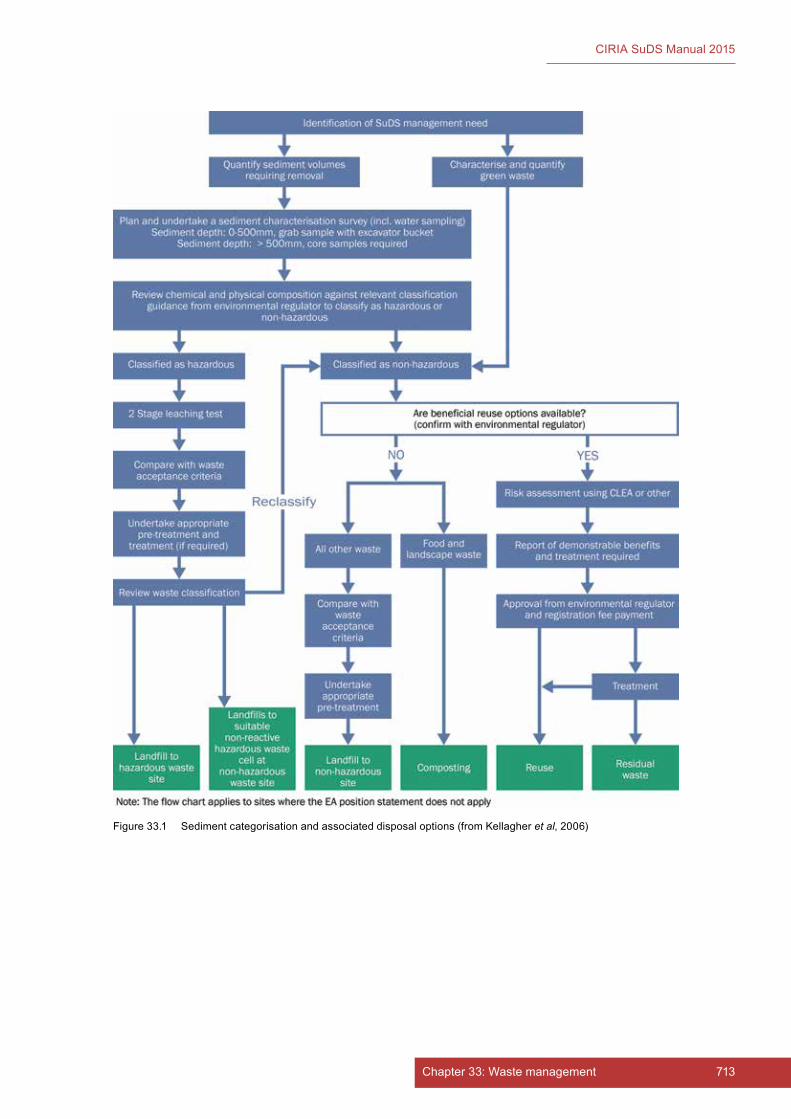
713Chapter 33: Waste management712 Part E: Supporting guidance
CIRIA SuDS Manual 2015
Figure 33.1 Sediment categorisation and associated disposal options (from Kellagher et al, 2006)

715Chapter 33: Waste management714 Part E: Supporting guidance
CIRIA SuDS Manual 2015
33.4 REFERENCES
EA (2011) Regulatory Position Statement. The deposit and de-watering of non-hazardous silts from sustainable drainage systems (SUDS) on land, MWRP RPS 055, Version 2.0, Environment Agency, Bristol, UK. Go to: http://tinyurl.com/p4478yo
EA (2012) Quality Protocol. Compost. End of waste criteria for the production and use of quality compost from source-segregated biodegradable waste, Environment Agency, London, UK . Go to: http://tinyurl.com/p958bql
EC (2000) List of Waste, web page, European Commission, Brussels. Go to: http://tinyurl.com/oaprqj6
KELLAGHER, R, WOODS BALLARD, B and BARNFORD, S (2006) SUDS – Increased liability for the water industry – Phase 2, UK Water Industry Research (UKWIR), London, UK (ISBN: 1-84057-417-8). Go to: http://tinyurl.com/pxrtu9h
RSPB (2015) Building a hibernacoulum, web page, Royal Society for the Protection of Birds, Bedfordshire, UK. Go to: http://tinyurl.com/qfljcx9
STATUTES
Directives
Directive 2008/98/EC of the European Parliament and of the Council of 19 November 2008 on waste and repealing certain Directives (Text with EEA relevance) (Waste Framework Directive)
Standards
BSI PAS 100:2011 Compost specification

715Chapter 33: Waste management714 Part E: Supporting guidance
CIRIA SuDS Manual 2015

716 Part E: Supporting guidance
CIRIA SuDS Manual 2015
34 COMMUNITY ENGAGEMENT
Contents
34.1 Introduction – what is community engagement? 71734.2 Thebenefitsofsuccessfulengagement 71834.3 Developinganengagementplan 71934.4 Deliveringengagement 72234.5 References 732
ImagecourtesyUniversityofN
ortham
pton

717Chapter 34: Community engagement
CIRIA SuDS Manual 2015
34Chapter
34.1 INTRODUCTION – WHAT IS COMMUNITY ENGAGEMENT?
Communityengagementisaplannedprocessofworkingwithspecificgroupsofpeople(connectedbylocation,particularinterestsormembershipofanorganisation)toaddressissuesaffectingtheirlocalenvironmentandtounlockopportunitiestoimproveit.Itcantakemanyformsandcoverabroadrangeofactivities,which(intheSuDScontext)willhelptoensurethatthecommunityunderstandsandengageswithproposalsthatareintendedtobenefitthem,suchasreducingfloodrisk(Section 34.2).
Effectivecommunityengagementrequiresabroadsectionofthecommunitytoparticipate.Thiscanbeencouragediftheprocessisopen,welcomingtoallmembersofthecommunity,hascleargoalsandiswellorganised.
SuDScanbeintegratedwithinnewdevelopmentstodeliverdrainageaspartofattractivesustainableenvironmentsorretrofittedintoexistingdevelopmenttoaddressfloodingorseweragecapacityproblemsexperiencedwithinthecommunity.Thesetwotypesofprojecthavedifferentneedsandoutcomesfromcommunityengagement:
▪ For new build,pre-projectengagementwillfocusontheimpactandintegrationoftheproposeddevelopment(includingtheSuDS)andthenewcommunityonthosealreadylivinginorvisitingthearea.ItisessentialthatnewownersareinformedthattheirpropertyisdrainedbySuDS,andhowthedrainageworks.However,oncenewresidentsmovein,theremaythenbeconsiderablebenefitforthedeveloper/SuDSownerinengagingwiththem,sothattheyunderstandhowtheirsystemfunctions,itsimportance,itsmaintenancerequirementsandanychargesorresponsibilitiesthatmayfalltothem.Thiscouldalsobeanopportunitytoaddressanyspecificconcernstheymayhave,forexamplerelatingtohealthandsafety(Chapter 36).
▪ For retrofit schemes,pre-projectengagementwilltendtobemorefocusedontheobjectivesofthescheme,theneedsoftheexistingcommunityandpotentialdesignoptions.Thisisnecessarytoensurethatthefinalschememaximisesbenefitsforthecommunity,tosecuresupportandacceptancebythecommunitybeforeimplementation,andtoencourageparticipationinanymaintenancerequirementsfollowingconstruction.
WhileSuDSisthefocusofthisdocument,itislikelythatinsomesituationsSuDSmayonlybeaminorpartofalargerdevelopment,surfacewaterorfloodriskmanagementprojectthatrequirescommunityengagement.
Communityengagementcantakemanyformsandcancoverabroadrangeofactivities.Ingeneralterms,engagementcantakeoneormoreofthefollowingforms,andsometimescanprogressfromonetothenextastheprojectdevelops:
▪ Informingthecommunityaboutaplannedproject(eganewdevelopmentnearbyoraplannedretrofitsurfacewatermanagementscheme)isnottrue
Community engagementThis chapter provides an overview of good practice, including two case studies for SuDS schemes.
Many other documents are available that provide more detailed guidance on community engagement in general or for other water related projects, including Daly et al (2015a and 2015b), EA (nd) and Cornell (2006).

718 Part E: Supporting guidance
CIRIA SuDS Manual 2015
engagement,althoughitissometimesnecessary,andcanbeusedinthepreparatorystagesofanengagementprocess.
▪ Consultingthecommunitycanbepartofaprocesstodevelopplans/designoptionsforaprojectoractivity,ortobuildcommunityawarenessandunderstandingaroundaparticularissue(egregardinghealthandsafetyconcernsovernewbodiesofopenwaterclosetotheirhomes).
▪ Involvingthecommunityinaproject(egaSuDSplantingday,settingupaSuDSmaintenancegroup,orinitiatinganenvironmentalgrouplinkedtotheSuDSfloraandfauna)oractivitycanhelptoensurethattheirissuesandconcernsareunderstoodandconsideredaspartofthedecision-makingprocess(egalocalSuDSdiscussiongroupthatincludesthedesignersandpromotersofthescheme).
▪ Collaboratingwiththecommunitytodeveloppartnershipscanthenbeusedtodevelopoptionsandproviderecommendationsaroundtheprojectorinitiative(eginputstosettingtherequiredmaintenanceregime,mechanismsforraisingconcernsovertheperformanceofthesystem,ordesignsforarangeofpotentialretrofitoptions).
▪ Empoweringthecommunitycanenablethemtomakeinformeddecisionsandtoimplementandmanagechange(egeducatingthecommunityaboutsustainabilityissuesandhowmanagingsurfacewaterintherightwaycanprotecttheenvironmentanddeliverbenefitstothem).
Theformofengagementundertakenwilldependonwhattheengagingorganisationwishestoachieve,eitherasanendresultorataparticularstageintheengagementprocess(Section 34.4.1).
Understandingwhatlevelofparticipationisneededisalsoimportantandwilldeterminethemostappropriatewaytogoaboutit(Section 34.3).
34.2 THE BENEFITS OF SUCCESSFUL ENGAGEMENT
Wherecommunityengagementismostsuccessful,boththecommunityandtheengagingorganisationwillbenefit.
34.2.1 Communitybenefits
Awell-plannedcommunityengagementprocessshouldensurethatawidediversityofopinionsareheardandconsideredintheprocess,sothatthecommunityasawholefeelsthatitsinputisvalued.
Benefitsforthecommunitymayincludethefollowing:
▪ Communitiescanbeassistedtoidentifyprioritiesforthemselves,suchaswhichpartsofanestateneedtoberetrofittedfirst,ifaprojectisundertakeninphases.
▪ Theengagementprocessprovidesamechanismforincreasingacommunity’sknowledgeofenvironmentalandsustainabilityissues,andisanopportunitytolearnforthemselvesandtheirfamilies.Communitiescanusetheprocessasatriggertofacilitatethesettingupofenvironmental/SuDSworkinggroupstohelpinspect,maintainorpromoteeducationalinitiativesrelatingtothebiodiversityassociatedwiththescheme.
▪ Engagementcanhelpdevelopa“localvoice”,andestablishalonger-terminputtolocaldecisionmaking.
▪ Whereacommunitysharesinthedecision-makingprocess,theyaremuchmorelikelytotakeownershipoftheoutcome,whetheritisrelatedtoacurrentfloodingproblemorplanstomaketheircommunitymoreresilientforthefuture.
▪ Participatingintheengagementprocesscanfosteragreatersenseofbelongingandoverallcommunitycohesion,withbenefitsbeyondtheremitofaspecificengagement.
▪ Ultimately,individualsmaybecomeempoweredthroughtheprocess,andbecomeaproactivepartofthegroupdeterminingtheissuesaffectingtheircommunityorbyleadingcommunityinitiatives.
719Chapter 34: Community engagement
CIRIA SuDS Manual 2015
34.2.2 Benefitsfortheengagingorganisation
Thebenefitsfortheengagingorganisation(plusclientandfunders)fromaneffectivecommunityengagementexercisecanbesubstantial,notonlybenefitingthespecificprojectbuttheorganisationmoregenerallytoo.Communityengagementcanoftenbeseenasariskyanddifficultaspectofaproject,butifundertakenwellandwhenstartedearlyinthedesignprocess,itcanaddrealvalue,andenabletheprojecttoproceedmoresmoothly.
Benefitsfortheengagingorganisationmayincludethefollowing:
▪ Communityinputcanensurethattheproposalsareframedtosuitthecommunity’spreferences,aswellasdeliveringtheoverallobjectivesofthescheme.
▪ Potentialissuesofcommunityconcern,particularlyaroundsubjectssuchassafetyorparking,arelikelytobeidentifiedearlierintheprocess,therebyincreasingthelikelihoodofaviableandacceptablescheme.
▪ CommunityunderstandingofthepurposeandfunctionofthedrainagesystemisimportantineducatingthepublictoembracetheinclusionofSuDSandtoencouragethemtotakeownershipandpotentiallytobeinvolvedinitslonger-termmaintenance
▪ Engagingwithcommunitiescanenabletheorganisationtoexplorewaysinwhichtheycanworkmorecloselyonissuesofconcerntothecommunity.Theseconcernscanoftenbedifferentfromthosetheorganisationmayhaveanticipated.
▪ Earlyengagementintheplanningprocesscanhelptoensurethatanorganisationdealswithlocalconcernsinaproactiveway,insteadofneedingtoreacttopartialorpoorinformationinlaterprojectstages,whichcouldgeneratedistrust,tensionsordelaysandextracost.
▪ Addressinglocalconcernsmayallowbroadermultiplebenefitstobeexploredandincorporatedwithinthescheme,resultinginbettervalueformoney.
▪ Goodengagementcanenhancethereputationoftheengagingorganisationasbeingabodyopenandwillingtolisten,andcanhelptoensurethatanyfutureengagementsandprojectsarepotentiallyapproachedwithapositiveattitudebythecommunity.Italsomeansthattheorganisationismorelikelytosecurepositivepublicityfromtheproject.
34.3 DEVELOPING AN ENGAGEMENT PLAN
Communityengagementshouldnotbeundertakenwithoutawellthoughtoutengagementplanandtherightteamtoimplementitfromtheengagingorganisation.
Eachengagementplanwillbedifferentandwillbedependentonthesizeandcomplexityoftheproject(Section 34.3.1)whowillbeengaged(Section 34.3.2)andtheresourcesavailabletotheengagingorganisation(Section 34.3.4).
34.3.1 Definingwhatneedstobedone
Thereasonsforengagingwiththelocalcommunitywillvaryfromoneprojectorsitetoanother.Thereshouldbeclarityandagreementwithintheprojectteamfromthebeginningregardingwhatthecommunityengagementexerciseisexpectedtodeliverandwhatwouldbedeemedasuccess(Section 34.3.3).
Ifthepurposeoftheengagementprocessiscleartotheprojectteam,thereisabetterchancethatitcanalsobemadecleartothecommunity;soitisimportantthatthereisclarityregardingroleswithintheengagementprocesswithinboththeprojectteamandthecommunity(Sections 34.3.2 and 34.3.4).
Theengagementprocessshouldfocusondeliveringanoverallaim(egwewanttoreducefloodriskforthelocalcommunity)ratherthanspecificoutcomes(egwewanttobuild20raingardens).Careshouldbetakentoensurethatthecommunitydoesnotfeelthatspecificoutcomeshavebeenpredetermined.Therefore,wheretheengagementseekstoenablethecommunitytoinfluencedesigndecisions,it
720 Part E: Supporting guidance
CIRIA SuDS Manual 2015
shouldbeclearaboutwhichaspectsofthedesignareflexibleandwhicharefixed.Thereislittlepointinengagingifthereisnoflexibilityintheoutcomeandthedesignteamneedstoopentoallowingengagementtoshapetheoutcome.
Thetypeandscaleofengagementneededwillvarydependingonthesizeofproject(iehowlargeacommunitywillitaffect)andcomplexity(eghowunusualistheschemebeingproposedorhowcomplexaretheproblemsbeingaddressed).Asmallinfilldevelopmentwillnotneedsignificantcommunityengagement.AlargeurbanregenerationprojectthatwillbelookingtomaximisetheopportunitiestoretrofitSuDSmayrequirearelativelylargecommunityengagementexercisewithmultiplestagesandinvolvingasmuchofthecommunityaspossible.Whereawiderangeoforganisationsorgroupsareinvitedtoparticipate,theyshouldeachbeencouragedtopresentasingleviewwhereverpossible,ratherthanpresentingtheviewsofindividuals.
TheengagementneededwillalsovaryduringdifferentstagesoftheSuDSdesignprocess(Chapter 7).Wheretheengagementistakingplaceduringtheearlystagesofthedesignprocess,itisusuallybeneficialtohaveawiderangeofparticipantstoensurethatawiderangeofopinionsareconsidered.Whereengagementistakingplaceduringthelaterstagesofthedesignprocess,itmaybemoreappropriatetohavemorefocusedgroupsofparticipantstolookatspecificissues.
Flexibilityisanimportantrequirementtofactorintotheengagementplan.Theoutcomeofengagingwiththepubliccanneverbefullypredicted.Furtherstagesmayberequiredifunexpectedissuesarise.Alternativeformsofengagementmayberequiredifoneformofengagementisnotassuccessfulasanticipated(Section 34.4.3).
Forlargeprojects,itcanbeusefultoplantheengagementprocesswiththeassistanceofthecommunity(iethefirstengagementstageistoplantheotherstages).
Oncethepurposeoftheengagementhasbeenagreedandthetype(s)ofengagementhavebeenconsidered(Section 34.1),thentheplanfordeliveryshouldreflectthatfocusthroughout,including:
▪ beingclearabouttheroleofthecommunity
▪ involvingthecommunityinappropriatewaysthataremeaningful
▪ clarifyingtheextenttowhichpeoplecaninfluencedecisions
▪ explainingthestages,andatwhichstagedifferentdecisionswillbemade
▪ managingexpectationsovertheoutcomebybeingrealisticaboutwhatcanbeachieved.
Beingrealisticisparticularlyimportant,otherwisetheprocesscanlosecredibilityiftheexpectedoutcomesarenotmet.
Thescopeoftheengagementexerciseshouldbedefinedintermsoftheengagementstages,howtheyaredelivered,theresourcesavailabletodeliverthem,andthetimescalewithinwhichanoutcomeneedstobedelivered.Section 34.4providesguidanceondeliveringengagement.
34.3.2 Identifyingwhoneedstobeinvolved
Togetthemostvaluefromcommunityengagement,thefirststepistounderstandwhoispartofthecommunity.Thisprocessofstakeholderanalysiscanpotentiallycoverawiderangeofindividualsandorganisationscomingfromarangeofsectors,suchas:
▪ publicandprivatesectororganisations,localtrustsorvoluntarybodiesandenvironmental,conservation or community organisations
▪ utilitycompaniesandserviceprovidersinthearea,suchasthewatercompany,highwaysauthorityandlocaltrash/recyclingcompanies
▪ allpotentiallyaffectedlandowners

721Chapter 34: Community engagement
CIRIA SuDS Manual 2015
▪ thosewhohavearoleinlocaldecisionmakingorregulation,suchastheplanningauthority,theenvironmentalregulatorortheinternaldrainageboard
▪ thosewholiveorworkwithinaspecificgeographicarea,suchasthosewhomaylivewithinanareawithaknownfloodrisk,includingboththosewhoarelikelytobeaffectedandthosewhothinktheymay be
▪ thosewhomayhavetheabilitytoaffecttheprojectintheirownright,orwhoareknowntobeinfavourof,oragainsttheproject(suchasmembersofparliament,localcouncillorsandcommunityleaders).
Considerationindefiningwhotoengagewithcanusefullybeundertakenthroughthecommunityitself,asinmanyinstancesitcanbebetterplacedtohelpidentifythebroadestrangeofstakeholders.Careshouldalsobetakentoensurethatthoseengagedincludethewidestrangeofpeopleintermsofdiversity,includingage,gender,ethnicity,vulnerabilityanddisability.Somesectionsofthecommunitymaybelessvocalthanothersandasuitablemeansforthemtoprovidetheirviewsshouldbeconsidered.
Ifanengagementeventneedstobefocusedonaspecificissue,itmaybeappropriatetotargetspecificorganisationsandindividualstoparticipate.Thiscanbeimportantatcriticalstagesoftheengagementprocesstoensureitseffectiveness.Shouldthisbenecessary,theremaybeaneedtofollowthisupwithmoreinclusiveeventstoretaincollectiveownershipwithinthecommunity.
Adatabasethatcanbecross-referencedforpeopleandorganisationsorotherassociationsshouldbesetupearlyintheprocess.AnydatabasemustbesetuphavingfullyunderstoodtherequirementsoftheDataProtectionAct1998.Thisdatabaseshouldhavedetailsofwhohasbeencontacted,whothenengagedintheprocess,whenandhow.Thisprovidesaveryusefultoolforensuringthatpeopleremainengaged(asappropriate)andcanbeusedforevaluatingeffectiveness(Section 34.4.3).
Individualsorgroupsshouldbegiventheopportunitytodecidehowtheywanttobeinvolved–whetherdirectlyorthroughtheirgroup,andwhethertheywishtobeactiveortojustreceiveinformationabouttheproject.
Otherissuesthatshouldinformhowtheengagementishandledwiththestakeholders/communitycouldinclude:
▪ discoveringhowpreviousengagementswiththiscommunitymayhavebeenhandled,andtheirdegreeofsuccess,whilenotassumingthatthisprojectwillbethesame
▪ understandingwhatelseishappeningwithinboththecommunityandlocalcommunitygroupstoensurethatthereisnoconfusionbetweentheprojectandanyotheractivitieslocally,andwhetherthereareanypotentialsynergieswithsuchactivities(egarethereanyopportunitiestoshareaplatform?)
▪ workingwithexistinglocalpartnershipstoaccessparticularsectorsofthecommunity;theymayalsobeabletoassistwithdevelopingtheengagementplan
▪ ensuringthatthosemostvocalareinvolved,butnotallowedtodominate
▪ ensuringthatanyengagedgroupisproperlyrepresentative
▪ decidinghowtoincludepeopleatvariousstagesiftheybecomeinterestedlaterintheprocess
▪ consideringhowtoworkwithotherdecision-makersorregulatorsandatwhatstageintheprocess;anearlydiscussionaroundthisislikelytobehelpful.
34.3.3 Encouraging participation
Thelevelofparticipation(iethedegreetowhichcommittees,groupsorindividualsareactivelyinvolvedinformulatingaspecificprojectoroutcome)needstobecarefullyconsidered.
Generally,wherethelevelofparticipationishigh,withpeoplelearningandmakingdecisionstogether,thelevelofownershipofthosedecisionsisalsolikelytobehigherand,consequently,theprojectislikelytobemoresuccessful.Also,thegreatertheinvolvementofthepublicwithintheengagement,thegreatertheirimpactcanbeontheoutcome.
722 Part E: Supporting guidance
CIRIA SuDS Manual 2015
However,ahighlevelofparticipationbringswithitresponsibilities.Itisimportanttoavoidpromisingorimplyingalevelofparticipationordecisionmakingthatisnotintendedornotachievable.Processesthatclaimtobeempoweringbutmerelyoffer“token”levelsofparticipationshouldbeavoided,asthiscanunderminetheengagementprocess.
34.3.4 Havingtherightengagingteam
Goodleadershipthatisconsistentthroughouttheprojectisessential,toensurethataconsistentclearmessageisgivenandthatthepublicknowwhotocontact.
Project/engagementteammembersmaycomefromwithinanorganisation,ortheymaybeexternal,dependingontheskillsrequired.Thereareorganisationsthatcanbebroughtintoaprojectteamtoundertakedetailedengagementwithcommunities.
Thecompositionoftheprojectteammayalsochangethroughoutthedevelopmentandimplementationoftheengagementplanandshouldreflecttheskillsrequiredateachstage.Theearlystagesmayneedthosewithgoodexternalrelationshipskills,whereasthelaterstagesmayrequirethosewithmoretechnicalexpertise(seeCase study 34.2).Wherecommunitiesareencouragedtotakeanactiverole,someindividualswithinthecommunitymayneedtrainingorassistancetoenablethemtocontributefully,asitisimportanttohaveindividualswhoaregoodlistenersandcommunicators.
Thoseinvolvedintheprojectwillneedarangeofexperienceandskills,whichcouldinclude:localknowledge,familiaritywithcommunityengagementprocessesorexistingrelationshipswiththecommunityorotherstakeholders.Considerationshouldalsobegiventothelevelofdiversitywithintheteamandhowthatmayreflectthecommunity(andwhetheritneedsto).
34.3.5 Managing risks
Thereisalwaysariskwhenundertakingcommunityengagementthatitmaynotachieveanacceptableoutcomefortheorganisation,orthatthecommunitydoesnotengageinawaythatallowstheprocesstobeeffective.Identifyingthekeyindividualsinthecommunityorfindingalocal“champion”canhelptoreducethisrisk;thisisusuallyeffectiveandisgoodpractice.
Shouldanyconflictsorproblemsariseaspartoftheengagementprocess,thisshouldbeaddressedopenlyandinatimelywaytoreducetheriskofitdamagingeithercommunityrelationsortheoutcomeoftheprocess.Aspartofthisprocess,atimeframeordeadlineshouldbeagreedtorespondtoanyconcernsraised.
Risksarebestmanagedbyhavingamonitoring/evaluationprocessinplaceduringtheengagementprocess(Section 34.4.3).
34.4 DELIVERING ENGAGEMENT
Awiderangeofmethodsortoolsareavailabletosupporttheengagementprocess.Thoseselectedwillbedependentonthedesiredoutcomeateachstageintheprocess.Earlyintheengagementprocessmethodsandtoolsselectedmaybemoregeneral,whereasatalaterstagediscussionandinformationwillbeneededinmuchgreaterdetailandmuchmorefocused,tosupporttheevolutionoftheprocess.
34.4.1 Communicatingeffectively
Communicatingeffectivelywiththecommunityisakeypartoftheengagementprocess.Communicationcanbeoneway(providinginformation)ortwoway(involvingdiscussion,problem-solvingetc).
Whenprovidinginformationtoacommunityaboutaproject,itisessentialtoknowwhotheinformationisfor,howtheyaremostlikelytoaccessitandwhatisthebestwaytoensureunderstanding.

723Chapter 34: Community engagement
CIRIA SuDS Manual 2015
Ateverystageallinformationshouldbe:
▪ highquality
▪ consistent in the message it is communicating
▪ appropriatetothespecificstageofengagement
▪ timely,ieprovidedattherighttimeintheproject
▪ targetedtowardsthepeoplewhowillreceiveit
▪ clear,interestingandeasilyunderstoodbythosereceivingit
▪ explicitaboutwhetheraresponseisrequiredand,ifso,howtodoso
▪ clearaboutthecontactdetailsforfurtherinformation.
Asindividualsaccessinformationdifferently,itmaybenecessarytoprovideitinseveraldifferentformats,suchasonawebsite,throughanexhibitionorbyapaperdistribution.Informationshouldalsoacknowledgelocalculturalandsocialneedsincludinglanguage,timesofavailabilityandlocalreligiousorculturaleventssuchasfestivals,whichcouldpreventparticipation.Practicalapproachesthatdemonstratehowaschememayworkorlook(usingmodels,markingitoutonthegroundorusingamock-up)canbehighlyeffective,particularlyforthemanypeoplewhoarenotfamiliarwithinterpretingtwo-dimensionalplansandelevations.Theuseofclearandconcisecasestudiesofsimilarprojectscanalsobeveryusefultoshowthatsuccessfuloutcomescanbeachievedandwhattheylooklike.
Transparencyinallcommunicationsisvital.Issuesthatarecurrentlyadverselyaffectingmembersofthecommunity,suchasflooding,orcouldadverselyaffectthecommunityasaresultoftheproject,suchasaccessorparkingforvehicles,andhealthandsafetyconcernsregardingopenwater,shouldbetreatedwithsensitivity.Thiswillthenencouragetrustandaco-operativeworkingrelationship.Accesstostatisticalinformationregardingspecificconcerns,suchasparking,isparticularlyhelpfultoenablediscussionstobebasedonfactsratherthanspeculationorperception.Thisinformationcanthenalsobeusedtohelpmeasurethesubsequentsuccessoftheproject.
Thetechniquesforcommunicationsareextremelyvaried,andwillincludebothmeetingsandotherevents,aswellastheprovisionofinformation(eitherbytheengagingorganisationorbythecommunity).Examplesinclude:
Meetingsandotherevents
▪ openhousesessions
▪ publicmeetings
▪ workshops/designcharrette1
▪ site visits
▪ smallerfocusgroups
▪ one-to-onesessions
▪ surveys/questionnaires
▪ interviews.
Note:1 Atypeofworkshopusedaspartoftheplanningprocesstoengagestakeholders,usuallypublicengagementevents.
Provisionofinformation
▪ website–maybeadedicatedsitefortheproject,orpartofanexistingorganisation’swebsite
▪ localTVorradio–localinterestfeatures,announcementoflocalevents

724 Part E: Supporting guidance
CIRIA SuDS Manual 2015
▪ blogsorsocialmedia–usefultokeeppeopleupdatedthroughouttheprocess
▪ videos
▪ newspaperarticles
▪ interpretationboards–atdifferentstagesoftheproject,toinformpeople,andinthelongtermforeducationalpurposesaroundtheSuDSpurpose,anditsneedforlong-termmanagementand maintenance
▪ manneddisplays/exhibitions
▪ models–bothtodemonstratewhataschemewilllooklike,butalsoaspartofinteractivedesignsessions
▪ factsheets/leaflets
▪ letters
▪ doorknocking.
GuidanceonawiderangeoftechniquesforcommunicationandengagementisprovidedinDalyet al (2015b).
Ensuringthatinformationabouttheprojectandeventsreachesthetargetaudienceisfundamentaltoitssuccess,sousinglocalchannelsofcommunication,particularlythroughcommunitygroups,canbeveryeffective.Considerationshouldalsobegiventotheneedtoprovideinformation/translationintodifferentlanguages.Thetimingandlocationofeventsormeetingsshouldbearrangedtomakethemaccessiblebythewidestrangeofpeople,andshouldideallybelocaltotheprojectandincludeoptionsformeeting/attendingoutsideworkinghoursoratweekends.
Thequalityandabilitiesofindividualfacilitatorsatpublicmeetingsisalsocrucialindeliveringeffectiveoutcomes.Theyshouldunderstandandbeabletousearangeoftechniqueswhichencourageattendeestoovercomebarriers,whetherrealorperceived,sotheycanparticipateeffectively.
Whereresponsesarerequestedthroughaquestionnaireorinterview,suchinformationshouldbedealtwithappropriatelyandsensitively,alsobearinginmindtheprovisionsoftheDataProtectionAct1998.Questionnairesshouldbecarefullyconstructedtoensurethatthequestionsareclear,simpleandunambiguous,donotleadtherespondenttospecificanswers,arerelativelyshortinlengthandstateclearlythatthereplieswillbekeptanonymous.
34.4.2 Maintainingengagementandeducation
Oncetheengagementprocesshasbeenstarted,regularreportingbothwithintheengagingorganisationandtothecommunitywillbeimportanttomaintaintrustandtokeepchannelsofcommunicationopenandeffective.Allengagementactivitiesshouldhaveafollow-upstep,wheretheoutcomesaresharedandprogressisreported.
Wheregroupshavebeensetupforcollaborativeengagement,thesewillrequiremanagementtomaintaintheirinterest,commitmentandenthusiasm.
Wheregroupshavebeenempoweredtoactindependentlywithinagreedguidelines,thesewillalsoneedongoingliaisontoensurethattheyadheretotheirstatedintentionandpurpose,andthattheyarepreparedtocontinuewiththeprojectstheyhavetakenon.
CommunityengagementforallSuDSprojectsshouldincludemakingthepublicawareofthewiderobjectivesofsustainablewatermanagementandthereasonswhytheSuDSschemeisimportantandneedstobemaintainedthroughoutitslifetime(insomecaseswiththeirinvolvement).Methodsofprovidingalong-termeducationalresourceorremindersshouldbeconsidered.Workingwithschoolsorcommunitygroupscanbeeffectiveinthisrespect,aschildrenareausefulconduitforeducatingtheirparentsandsecuringtheirinvolvement.
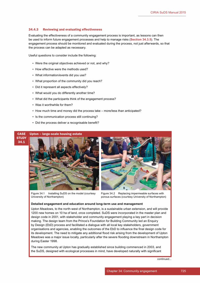
725Chapter 34: Community engagement
CIRIA SuDS Manual 2015
34.4.3 Reviewingandevaluatingeffectiveness
Evaluatingtheeffectivenessofacommunityengagementprocessisimportant,aslessonscanthenbeusedtoinformfutureengagementprocessesandhelptomanagerisks(Section 34.3.5).Theengagementprocessshouldbemonitoredandevaluatedduringtheprocess,notjustafterwards,sothattheprocesscanbeadaptedasnecessary.
Usefulquestionstoconsiderincludethefollowing:
▪ Weretheoriginalobjectivesachievedornot,andwhy?
▪ Howeffectivewerethemethodsused?
▪ Whatinformation/eventsdidyouuse?
▪ Whatproportionofthecommunitydidyoureach?
▪ Diditrepresentallaspectseffectively?
▪ Whatwouldyoudodifferentlyanothertime?
▪ Whatdidtheparticipantsthinkoftheengagementprocess?
▪ Wasitworthwhileforthem?
▪ Howmuchtimeandmoneydidtheprocesstake–more/lessthananticipated?
▪ Isthecommunicationprocessstillcontinuing?
▪ Didtheprocessdeliverarecognisablebenefit?
Detailed engagement and education around long-term use and managementUptonMeadows,tothenorth-westofNorthampton,isasustainableurbanextension,andwillprovide1200newhomeson10haofland,oncecompleted.SuDSwereincorporatedinthemasterplananddesigncodein2001,withstakeholderandcommunityengagementplayingakeypartindecisionmaking.ThedesignteamfromthePrince’sFoundationforBuildingCommunityledanEnquirybyDesign(EbD)processandfacilitatedadialoguewithalllocalkeystakeholders,governmentorganisationsandagencies,enablingtheoutcomesoftheEbDtoinfluencethefinaldesigncodeforitsdevelopment.TheneedtomitigateanyadditionalfloodriskarisingfromthedevelopmentofUptonMeadowswasamajorissuelocally,particularlyaftertheseverefloodingdownstreaminNorthamptonduringEaster1998.
ThenewcommunityatUptonhasgraduallyestablishedsincebuildingcommencedin2003,andtheSuDS,designedwithecologicalprocessesinmind,havedevelopednaturallywithsignificant
Upton–large-scalehousingestateCASE STUDY34.1
Figure34.1 InstallingSuDSonthemodel(courtesyUniversityofNorthampton)
Figure34.2 Replacingimpermeablesurfaceswithporoussurfaces(courtesyUniversityofNorthampton)
continued...

726 Part E: Supporting guidance
CIRIA SuDS Manual 2015
biodiversitygainsovertime.Since2003,environmentalandsocialimpactsofthesitehavebeenstudied,andin2012thePrince’sFoundationforBuildingCommunity,workingwiththeUniversityofNorthampton,setuparesearchprojecttounderstandhowtoengagethecommunitywiththenaturalcapital(theSuDSandgreenspaces)withinUpton.Theprojectexplored:
▪ thelevelofappreciationofresidentsoftheurbandesignfeatureswithinthedevelopment,includingtheSuDS
▪ whethertheresidentsvaluedthegreenspacesandusedthem
▪ whetherresidentsconnectedthegreenspacesandnaturalcapitalatUptontotheirownhealthandwell-being
▪ thelevelofawarenessamongresidentsofhowtheSuDSatUptonwork,andhowthesesystemscontributetothenaturalcapitalwithintheirresidentialdevelopment.
Stage 1 – QuestionnaireAquestionnairewasdeliveredtoover170homesovera2-monthperiod,with58householdsreturningthem(34%completionrate).Thequestionnairewassplitintofivesections,oneofwhichdealtspecificallywithattitudesaroundSuDS.Responsesrelatedtogreenspacegenerally,whichincludesSuDSwere:
▪ 77%oftheresidentsthoughtthegreenspacesaroundthedevelopmentwereimportant
▪ 91.4%oftheresidentssaidtheyactuallygooutandenjoythesurroundinggreenspaceatUptonMeadows
▪ 81%ofresidentsbelievedthatthegreenspacemakesUptonahealthierplacetolive
▪ 74%thoughtthattheirqualityoflifehadimproved.
SpecificresponsesrelatedtotheSuDSwere:
▪ over58%ofresidentsstatedthattheybelievedtheyknewhowtheirdrainagesystemswork,yetonly34%saidthattheyweregivenanyformalinformationonSuDSbeforemovingintotheirproperties
▪ 3%feltthattheswalesandpondscouldbeahealthrisk
▪ 69%ofresidentsenjoyedseeingdragonfliesthere
▪ 83%alsolikedtheideathatfrogsandnewtswerefoundintheswalesandponds
▪ only7%ofrespondentsfearedthatblockageswouldcauseflooding.
Therewasahighlypositivecorrelationthatindicatedthatthesameresidentswhothoughtthewatermadethedevelopmentmoreattractivealsodidnotmindtheswales,and29%ofresidentsperceivedthattheirpropertyvaluehasincreasedduetothedesignoftheswalesandpondssurroundingUptonMeadows.
Theseresponsesinformedhowthefollowingactivitiesweredeveloped.
Stage 2 – STEM activity day and community SuDS fairBasedonthepositiveresponsestothequestionnaire,thenaturalcapitalprojectteamorganisedtwoeventstostimulatecommunitylearningandengagement:
▪ ascience,technology,engineeringandmaths(STEM)activitydataatUptonMeadowsSchool
▪ acommunitySuDSfair.
STEM activity dayArangeofstakeholderswereinvolvedinthisday,whichwasheldatUptonMeadowsPrimarySchoolfortheirstaffandpupils.Thefollowingorganisationsandpeoplewereinvolved:
▪ thePrince’sFoundationorganisedsponsorshipandtheloanofalargeSuDSmodelfromHeriotWatt University
Upton–large-scalehousingestateCASE STUDY34.1
continuedfrom...
continued...

727Chapter 34: Community engagement
CIRIA SuDS Manual 2015
▪ stafffromAnglianWater
▪ fourUniversityofNorthamptonSTEMambassadors
▪ 20schoolstaffandover70children.
TheaimsoftheSTEMeventweretoraiseawarenesswiththeschoolchildrenregarding:
▪ howoururbanlandscapescancausesurfacewaterflooding
▪ whatSuDSareandhowtheywork
▪ howSuDScanalleviateadditionalriskoffloodingfromurbanlandscapes.
Thelessonplanwasdesignedtohelpthechildrendevelopabetterunderstandingofhowthewatercycle(whichtheyhadpreviouslystudied)couldbelinkedtofloodinginurbandevelopments.ItalsoincorporatedhowfloodriskcouldbemitigatedusingSuDS,alongsidethebiodiversityandgreenspacebenefits.ThemodelallowedthemtorelatetheexercisedirectlytoUpton.
TheSuDSmodelwasthecentralfocusfortheSTEMactivity,andaftertheevent,theschoolalsousedittoengageotherchildrenwithintheschool.Themodelactivelydemonstratedhowwaterflowedaroundthebuildingsandwithinthelandscape,andhowpartsofthemodelwouldfloodwhenitrained(simulatedusingsprayarms).TheengineeringissuesandhowSuDSworkwerethenexplained,andthechildrenwereinvitedtoretrofitthemodelwithmoresustainableoptionstopreventflooding.Greenspongeswereusedtoreplicateporoussurfacessuchasgrassandgreenroofs(Figures 34.1 and 34.2).Eachsessionwas45minuteswithagroupof10–15children,repeatedthroughouttheday,andwithagroupofteachersattheend(Figure 34.3).
TheSTEMactivitydaydevelopedalegacyoflearningattheschool,thatisbeingbuiltintotheprimaryschoolcurriculumforfuturechildrenwhowillgrowupintheUptonarea.
Community SuDS FairThefairwasabroaderevent,involvingawiderangeofstakeholdersthateitherprovidedorparticipatedinthevariousplannedeventsbasedattheElgarCommunityCentre.Theseincluded:
▪ thePrince’sFoundationguidedarchitecturaltours
▪ UniversityofNorthamptonstudentambassadorshelpedwithmanytasksthroughouttheday
▪ MinilablookingatinvertebratesfoundwithintheSuDSponds
▪ MicroDrainagedemonstratingtheUptonMeadowsSuDSdrainagecomputermodel
▪ “loveeverydrop”activitiesfromAnglianWater
▪ willowweaving
Upton–large-scalehousingestateCASE STUDY34.1
Figure34.3 Theteachers’SuDSsession(courtesyUniversityofNorthampton)
Figure34.4 BannerproducedtoadvertisetheSuDSFair(courtesyThePrince’sFoundationforBuildingCommunity/UniversityofNorthampton
continuedfrom...
continued...
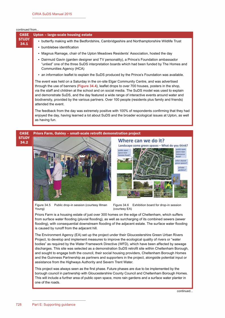
728 Part E: Supporting guidance
CIRIA SuDS Manual 2015
▪ butterflymakingwiththeBedfordshire,CambridgeshireandNorthamptonshireWildlifeTrust
▪ bumblebeeidentification
▪ MagnusRamage,chairoftheUptonMeadowsResidents’Association,hostedtheday
▪ DairmuidGavin(gardendesignerandTVpersonality),aPrince’sFoundationambassador“untied”oneofthethreeSuDSinterpretationboardswhichhadbeenfundedbyTheHomesandCommunitiesAgency(HCA)
▪ aninformationleaflettoexplaintheSuDSproducedbythePrince’sFoundationwasavailable.
TheeventwasheldonaSaturdayintheon-siteElgarCommunityCentre,andwasadvertisedthroughtheuseofbanners(Figure 34.4),leafletdropstoover700houses,postersintheshop,viathestaffandchildrenattheschoolandonsocialmedia.TheSuDSmodelwasusedtoexplainanddemonstrateSuDS,andthedayfeaturedawiderangeofinteractiveeventsaroundwaterandbiodiversity,providedbythevariouspartners.Over100people(residentsplusfamilyandfriends)attendedtheevent.
Thefeedbackfromthedaywasextremelypositivewith100%ofrespondentsconfirmingthattheyhadenjoyedtheday,havinglearnedalotaboutSuDSandthebroaderecologicalissuesatUpton,aswellashavingfun.
Upton–large-scalehousingestateCASE STUDY34.1
PriorsFarmisahousingestateofjustover300homesontheedgeofCheltenham,whichsuffersfromsurfacewaterflooding(pluvialflooding),aswellassurchargingofitscombinedsewers(sewerflooding),withconsequentialdownstreamfloodingoftheadjacentestate.Thesurfacewaterfloodingiscausedbyrunofffromtheadjacenthill.
TheEnvironmentAgency(EA)setuptheprojectundertheirGloucestershireGreenUrbanRiversProject,todevelopandimplementmeasurestoimprovetheecologicalqualityofriversor“waterbodies”asrequiredbytheWaterFrameworkDirective(WFD),whichhavebeenaffectedbysewagedischarges.ThissitewasselectedasademonstrationSuDSretrofitsitewithinCheltenhamBorough,andsoughttoengageboththecouncil,theirsocialhousingproviders,CheltenhamBoroughHomesandtheGuinnessPartnershipaspartnersandsupportersintheproject,alongsidepotentialinputorassistancefromtheHighwaysAuthorityandSevernTrentWater.
Thisprojectwasalwaysseenasthefirstphase.FuturephasesareduetobeimplementedbytheboroughcouncilinpartnershipwithGloucestershireCountyCouncilandCheltenhamBoroughHomes.Thiswillincludeafurtherareaofpublicopenspace,moreraingardensandasurfacewaterplanterinoneoftheroads.
PriorsFarm,Oakley–small-scaleretrofitdemonstrationprojectCASE STUDY34.2
Figure34.5 Publicdrop-insession(courtesyIllmanYoung)
Figure34.6 Exhibitionboardfordrop-insession(courtesyEA)
continuedfrom...
continued...
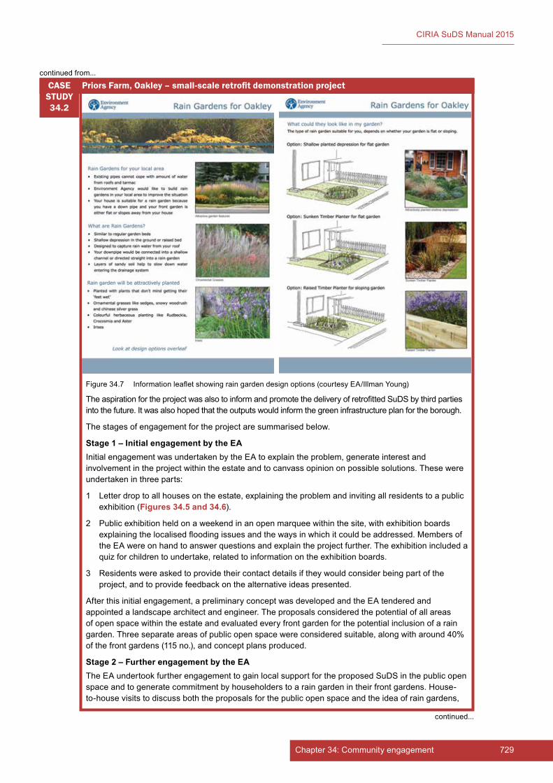
729Chapter 34: Community engagement
CIRIA SuDS Manual 2015
TheaspirationfortheprojectwasalsotoinformandpromotethedeliveryofretrofittedSuDSbythirdpartiesintothefuture.Itwasalsohopedthattheoutputswouldinformthegreeninfrastructureplanfortheborough.
Thestagesofengagementfortheprojectaresummarisedbelow.
Stage 1 – Initial engagement by the EAInitialengagementwasundertakenbytheEAtoexplaintheproblem,generateinterestandinvolvementintheprojectwithintheestateandtocanvassopiniononpossiblesolutions.Thesewereundertakeninthreeparts:
1 Letterdroptoallhousesontheestate,explainingtheproblemandinvitingallresidentstoapublicexhibition(Figures 34.5 and 34.6).
2 Publicexhibitionheldonaweekendinanopenmarqueewithinthesite,withexhibitionboardsexplainingthelocalisedfloodingissuesandthewaysinwhichitcouldbeaddressed.MembersoftheEAwereonhandtoanswerquestionsandexplaintheprojectfurther.Theexhibitionincludedaquizforchildrentoundertake,relatedtoinformationontheexhibitionboards.
3 Residentswereaskedtoprovidetheircontactdetailsiftheywouldconsiderbeingpartoftheproject,andtoprovidefeedbackonthealternativeideaspresented.
Afterthisinitialengagement,apreliminaryconceptwasdevelopedandtheEAtenderedandappointedalandscapearchitectandengineer.Theproposalsconsideredthepotentialofallareasofopenspacewithintheestateandevaluatedeveryfrontgardenforthepotentialinclusionofaraingarden.Threeseparateareasofpublicopenspacewereconsideredsuitable,alongwitharound40%ofthefrontgardens(115no.),andconceptplansproduced.
Stage 2 – Further engagement by the EATheEAundertookfurtherengagementtogainlocalsupportfortheproposedSuDSinthepublicopenspaceandtogeneratecommitmentbyhouseholderstoaraingardenintheirfrontgardens.House-to-housevisitstodiscussboththeproposalsforthepublicopenspaceandtheideaofraingardens,
PriorsFarm,Oakley–small-scaleretrofitdemonstrationprojectCASE STUDY34.2
Figure34.7 Informationleafletshowingraingardendesignoptions(courtesyEA/IllmanYoung)
continuedfrom...
continued...
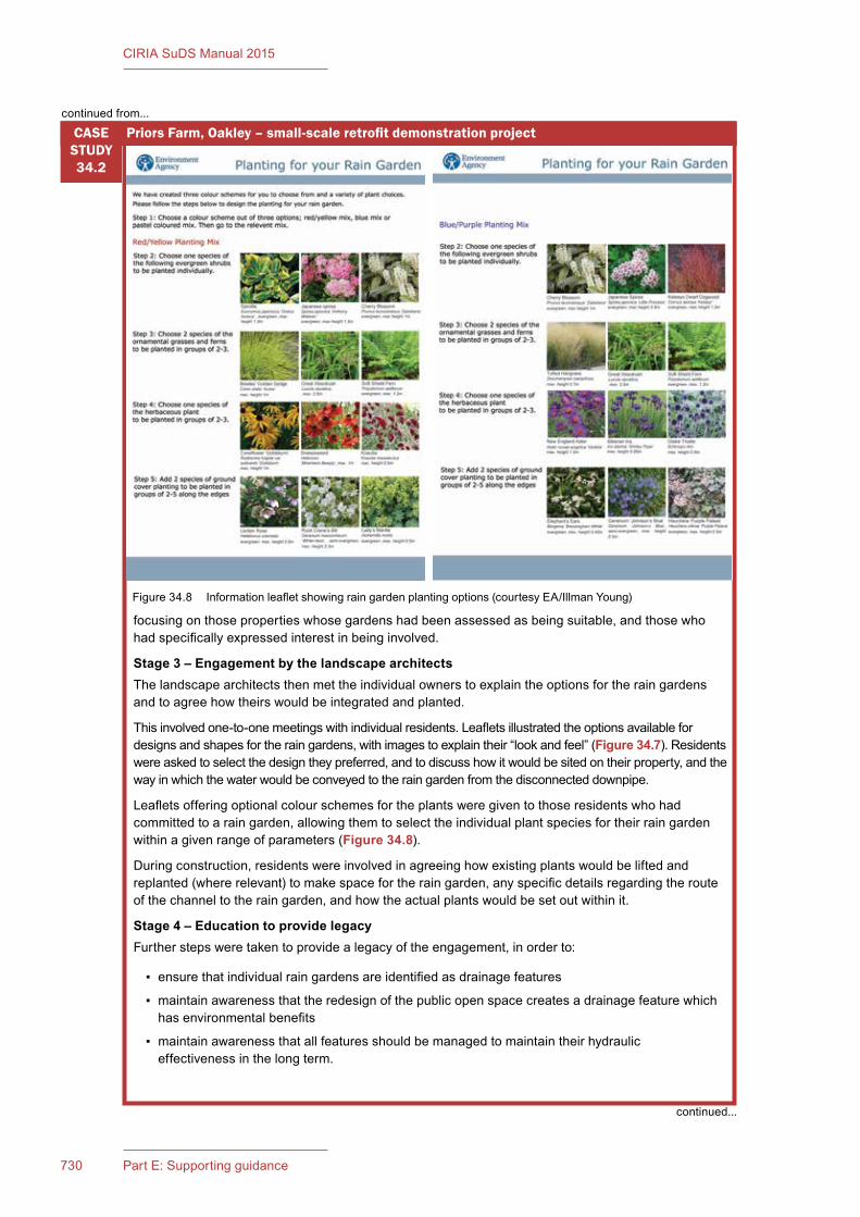
730 Part E: Supporting guidance
CIRIA SuDS Manual 2015
focusingonthosepropertieswhosegardenshadbeenassessedasbeingsuitable,andthosewhohadspecificallyexpressedinterestinbeinginvolved.
Stage 3 – Engagement by the landscape architectsThelandscapearchitectsthenmettheindividualownerstoexplaintheoptionsfortheraingardensandtoagreehowtheirswouldbeintegratedandplanted.
Thisinvolvedone-to-onemeetingswithindividualresidents.Leafletsillustratedtheoptionsavailablefordesignsandshapesfortheraingardens,withimagestoexplaintheir“lookandfeel”(Figure 34.7).Residentswereaskedtoselectthedesigntheypreferred,andtodiscusshowitwouldbesitedontheirproperty,andthewayinwhichthewaterwouldbeconveyedtotheraingardenfromthedisconnecteddownpipe.
Leafletsofferingoptionalcolourschemesfortheplantsweregiventothoseresidentswhohadcommittedtoaraingarden,allowingthemtoselecttheindividualplantspeciesfortheirraingardenwithinagivenrangeofparameters(Figure 34.8).
Duringconstruction,residentswereinvolvedinagreeinghowexistingplantswouldbeliftedandreplanted(whererelevant)tomakespacefortheraingarden,anyspecificdetailsregardingtherouteofthechanneltotheraingarden,andhowtheactualplantswouldbesetoutwithinit.
Stage 4 – Education to provide legacyFurtherstepsweretakentoprovidealegacyoftheengagement,inorderto:
▪ ensurethatindividualraingardensareidentifiedasdrainagefeatures
▪ maintainawarenessthattheredesignofthepublicopenspacecreatesadrainagefeaturewhichhasenvironmentalbenefits
▪ maintainawarenessthatallfeaturesshouldbemanagedtomaintaintheirhydraulic effectivenessinthelongterm.
PriorsFarm,Oakley–small-scaleretrofitdemonstrationprojectCASE STUDY34.2
Figure34.8 Informationleafletshowingraingardenplantingoptions(courtesyEA/IllmanYoung)
continuedfrom...
continued...
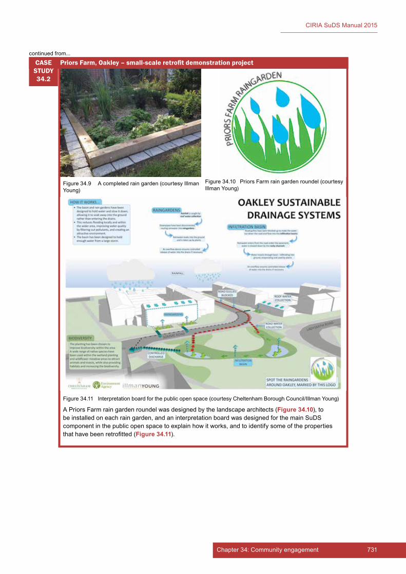
731Chapter 34: Community engagement
CIRIA SuDS Manual 2015
APriorsFarmraingardenroundelwasdesignedbythelandscapearchitects(Figure 34.10),tobeinstalledoneachraingarden,andaninterpretationboardwasdesignedforthemainSuDScomponentinthepublicopenspacetoexplainhowitworks,andtoidentifysomeofthepropertiesthathavebeenretrofitted(Figure 34.11).
PriorsFarm,Oakley–small-scaleretrofitdemonstrationprojectCASE STUDY34.2
Figure34.9 Acompletedraingarden(courtesyIllmanYoung)
Figure34.10 PriorsFarmraingardenroundel(courtesyIllmanYoung)
Figure34.11 Interpretationboardforthepublicopenspace(courtesyCheltenhamBoroughCouncil/IllmanYoung)
continuedfrom...

732 Part E: Supporting guidance
CIRIA SuDS Manual 2015
34.5 REFERENCES
CORNELL,S(2006)Improving stakeholder engagement in flood risk management decision making and delivery,R&DTechnicalReportSC040033/SR2,JointDefra/EnvironmentAgencyFloodandCoastalErosionRiskManagementR&DProgramme,EnvironmentAgency,Bristol,UK
DALY,D,JODIERI,R,MCCARTHY,S,PYGOTT,KandWRIGHT,M(2015a)Communication and engagement in local flood risk management,C751,CIRIA,London,UK(ISBN:978-0-86017-757-9).Goto:www.ciria.org
DALY,D,JODIERI,R,MCCARTHY,S,PYGOTT,KandWRIGHT,M(2015b)Communication and engagement techniques in local flood risk management,C752,CIRIA,London,UK(ISBN:978-0-86017-758-9).Goto:www.ciria.org
EA(nd)Building trust with communities – A guide for staff,CommunityRelationsTeam,EnvironmentAgency,Bristol,UK
STATUTES
Acts
DataProtectionAct1998

733Chapter 34: Community engagement
CIRIA SuDS Manual 2015
735Chapter 35: Costs and benefits734 Part E: Supporting guidance
CIRIA SuDS Manual 2015
35 COSTS AND BENEFITS
Contents
35.1 Introduction 73535.2 Key concepts for assessing costs and benefits 73835.3 Estimating costs 74135.4 Assessing benefits 74835.5 Comparing costs and benefits 75135.6 References 756
Imag
e co
urte
sy S
tudi
o E
ngle
back

735Chapter 35: Costs and benefits734 Part E: Supporting guidance
CIRIA SuDS Manual 2015
35Chapter
35.1 INTRODUCTION
35.1.1 Whyassesscostsandbenefits?
SuDS can deliver multiple benefits (Chapter 1), and the overarching principle of SuDS design is that surface water runoff should be managed to maximise these benefits (Chapter 2). Achieving this is dependent on good design, good engagement and good decision making.
A vital part of good decision making is the ability to understand both the costs and the benefits associated with the decision being made. This needs to be based on the best evidence available, bearing in mind that the information will never be complete or perfect. Recognising and dealing with uncertainty has always been an intrinsic part of decision making.
Costs, to a larger extent, are relatively straightforward to quantify, but benefits are generally not so easy. However, comparing costs and benefits can prove very worthwhile. For example, although the cost of implementing a SuDS scheme will generally be borne by the developer, in some scenarios it could be shared by other partners where they will benefit, eg a sewerage undertaker, local authority or other interested party.
Many stakeholders can potentially benefit from a SuDS scheme, especially if opportunities are identified at feasibility stage and appropriate engagement is undertaken. As the benefits of SuDS are now better understood, partnerships for delivering schemes are becoming more common. Partnerships have the advantages that there may be (a) more than one source of capital funding and (b) a shared responsibility for long-term costs. Potential partners will want to know how and why they should help with funding and what the benefits will be for them. Details of potential beneficiaries and types of potential funding groups are provided in Digman et al (2015).
CostsandbenefitsThis chapter provides an overview of key concepts in estimating the costs and benefits of SuDS schemes and how these can be compared. This chapter does not provide unit costs or benefit values.
Reference is made to several other publications that provide further guidance and tools in Sections 35.3.10, 35.4.7 and 35.5.5.
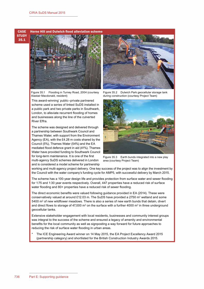
737Chapter 35: Costs and benefits736 Part E: Supporting guidance
CIRIA SuDS Manual 2015
This award-winning* public–private partnered scheme used a series of linked SuDS installed in a public park and two private parks in Southwark, London, to alleviate recurrent flooding of homes and businesses along the line of the culverted River Effra.
The scheme was designed and delivered through a partnership between Southwark Council and Thames Water, with support from the Environment Agency (EA), with the £4.28 m costs shared by the Council (5%), Thames Water (54%) and the EA mediated flood defence grant in aid (41%). Thames Water have provided funding to Southwark Council for long-term maintenance. It is one of the first multi-agency SuDS schemes delivered in London and is considered a model scheme for partnership
HerneHillandDulwichfloodalleviationschemeCASE STUDY35.1
Figure 35.1 Flooding in Turney Road, 2004 (courtesy Alastair Macdonald, resident)
Figure 35.2 Dulwich Park geocellular storage tank during construction (courtesy Project Team)
Figure 35.3 Earth bunds integrated into a new play area (courtesy Project Team)
working and multi-agency project delivery. One key success of the project was to align the investment by the Council with the water company’s funding cycle for AMP5, with successful delivery by March 2015.
The scheme has a 100-year design life and provides protection from surface water and sewer flooding for 1:75 and 1:30 year events respectively. Overall, 447 properties have a reduced risk of surface water flooding and 80+ properties have a reduced risk of sewer flooding.
The direct economic benefits were valued following guidance provided in EA (2014). These were conservatively valued at around £12.03 m. The SuDS have provided a 2750 m2 wetland and some 5400 m2 of new wildflower meadows. There is also a series of new earth bunds that detain, divert and direct flows to storage of 47,000 m3 on the surface with a further 4000 m3 in three underground geocellular tanks.
Extensive stakeholder engagement with local residents, businesses and community interest groups was integral to the success of the scheme and ensured a legacy of amenity and environmental benefits for the local community as well as signposting a way forward for future approaches to reducing the risk of surface water flooding in urban areas.
* The ICE Engineering Award winner on 14 May 2015, the EA Project Excellency Award 2015 (partnership category) and shortlisted for the British Construction Industry Awards 2015.

737Chapter 35: Costs and benefits736 Part E: Supporting guidance
CIRIA SuDS Manual 2015
35.1.2 Whatcanbeassessed?
Costs are estimated in order to understand one or more of the following:
▪ the likely capital cost of a proposed scheme
▪ the likely operation and maintenance costs of a proposed scheme – annually or over the design life of the scheme
▪ the total cost of a proposed scheme over its lifetime (ie whole-life cost)
▪ how different elements of the proposed scheme might contribute towards the capital or maintenance costs and, therefore, how costs might be optimised (eg looking at options that reduce long-term maintenance costs)
▪ where and when costs might accrue to different stakeholders
▪ how costs of alternative SuDS schemes compare with one another or compare to a conventional piped drainage scheme
▪ how costs might best be reduced.
In order to understand “the return on the investment” of a scheme (ie how much benefit is gained from the cost incurred), it is also necessary to assess the benefits.
In general terms, benefits can be assessed in order to understand:
▪ the type and scale of benefits of a proposed scheme
▪ where and when benefits might accrue to different stakeholders
▪ how different elements of the proposed scheme contribute towards the delivery of the overall benefits of the scheme and therefore how benefits might best be maximised or optimised
▪ how benefits of alternative SuDS schemes compare with one another or compare to a conventional piped drainage scheme.
When both the costs and benefits are assessed together, this enables the SuDS design to be optimised (ie to manage, treat and make best use of surface water in order to maximise benefits at reasonable cost) and should form part of the option appraisal process.
Where a comparison is being made between alternative SuDS options or a SuDS scheme is being compared with a below-ground piped drainage system, it is important to ensure that like is being compared with like. For example, either the water quantity and water quality performance of each option has to be identical or the benefits that can be attributed to that performance (such as improved water quality or reduced flood risk) need to be estimated separately for each option.
35.1.3 Whenshouldanassessmentbecarriedout?
The usefulness and effectiveness of assessing costs and benefits is greatest when it forms part of an early stage of the design process (Chapter 7), so that scheme viability and affordability can be addressed up front. Once the main planning and design decisions have been made for a site, the type of options (decision alternatives) that can be assessed and compared become more limited.
Project partners, clients or funders and other key stakeholders should agree on whether such an assessment is required, why, when and to what level of detail (Section 35.1.4), as schemes are usually defined and designed to meet specific objectives (local or national standards, local planning objectives etc).
35.1.4 Howcancostsandbenefitsbeassessed?
The level of detail appropriate for an assessment will depend greatly on the drivers for the assessment, the scale of the scheme, the extent of the likely benefits that can be realised and what stage of the design process has been reached.

739Chapter 35: Costs and benefits738 Part E: Supporting guidance
CIRIA SuDS Manual 2015
Both costs and benefits are highly context specific and will vary significantly (in monetary terms) depending on the site characteristics, the use(s) of the site and the specific composition of the SuDS scheme.
It is important for any assessment to be robust, transparent and open to scrutiny. This will lead to increased buy-in from stakeholders and more opportunities for shared funding.
The remainder of this chapter provides an overview of key concepts in estimating costs and benefits (Section 35.2). Then the chapter summarises best practice for estimating costs (Section 35.3) and assessing benefits (Section 35.4), and subsequently how costs and benefits can be compared (Section 35.5).
This chapter does not provide unit costs or benefit values. Several of the publications listed in this chapter do provide unit costs and/or benefits, but these should be used with caution. These sources of information are often based on studies carried out more than ten years ago or are based on a limited number of case studies, so are likely to be subject to high levels of uncertainty. If using this information, checks are needed to ensure that inflation is accounted for, that the case studies used to generate the unit costs/benefits are representative of the characteristics of the site to be assessed and that there are no specific features of the scheme that are likely to have a significant impact on the cost/benefit. For example, whether or not an impermeable liner is required beneath a detention basin will have a significant impact on cost; whether or not the permanent pond volume (in addition to the attenuation storage volume) is included as part of the volume calculations for a pond component will also have a significant impact on cost.
Defra (2007) and HM Treasury (2011) provide a number of supporting documents for how to assess costs and benefits under the Green Book series. Publications on benefit transfer methods, and the limitations of doing this, are particularly relevant, because SuDS benefits are frequently determined based on transference from seemingly equivalent or comparable schemes. Digman et al (2015) provides guidance on how to do this.
There are a number of other publications that provide guidance on estimating costs and benefits relevant for SuDS. These are listed in Section 35.3.10.
35.2 KEY CONCEPTS FOR ASSESSING COSTS AND BENEFITS
35.2.1 Whole-lifevaluation
If whole-life costs and benefits are considered early enough in the development of a scheme (ie at the feasibility stage), this can have a number of advantages. By having an improved understanding of long-term investment requirements (rather than just capital costs), it is also possible to secure:
▪ more robust decision-making at option appraisal stage
▪ improved assessment of long-term risks to SuDS scheme performance and inclusion of monitoring and management plans to minimise these risks
▪ reduced uncertainty associated with adoption agreements and commuted sum contributions.
Whole-life costing (sometimes referred to as life-cycle costing) considers the total cost of a scheme over its lifetime. Figure 35.4 shows a conceptual schematic of a potential cost profile for a SuDS scheme. This not only covers feasibility studies, site investigation, design and construction, but also includes operation, maintenance, adaptation and (depending on the planning conditions for the site) disposal and decommissioning activities.
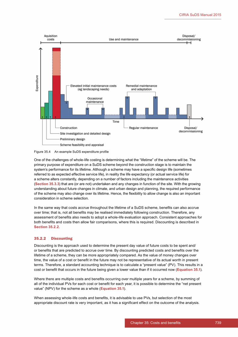
739Chapter 35: Costs and benefits738 Part E: Supporting guidance
CIRIA SuDS Manual 2015
One of the challenges of whole-life costing is determining what the “lifetime” of the scheme will be. The primary purpose of expenditure on a SuDS scheme beyond the construction stage is to maintain the system’s performance for its lifetime. Although a scheme may have a specific design life (sometimes referred to as expected effective service life), in reality the life expectancy (or actual service life) for a scheme alters constantly, depending on a number of factors including the maintenance activities (Section 35.3.3) that are (or are not) undertaken and any changes in function of the site. With the growing understanding about future changes in climate, and urban design and planning, the required performance of the scheme may also change over its lifetime. Hence, the flexibility to allow change is also an important consideration in scheme selection.
In the same way that costs accrue throughout the lifetime of a SuDS scheme, benefits can also accrue over time; that is, not all benefits may be realised immediately following construction. Therefore, any assessment of benefits also needs to adopt a whole-life evaluation approach. Consistent approaches for both benefits and costs then allow fair comparisons, where this is required. Discounting is described in Section 35.2.2.
35.2.2 Discounting
Discounting is the approach used to determine the present day value of future costs to be spent and/or benefits that are predicted to accrue over time. By discounting predicted costs and benefits over the lifetime of a scheme, they can be more appropriately compared. As the value of money changes over time, the value of a cost or benefit in the future may not be representative of its actual worth in present terms. Therefore, a standard accounting technique is to calculate a “present value” (PV). This results in a cost or benefit that occurs in the future being given a lower value than if it occurred now (Equation 35.1).
Where there are multiple costs and benefits occurring over multiple years for a scheme, by summing of all of the individual PVs for each cost or benefit for each year, it is possible to determine the “net present value” (NPV) for the scheme as a whole (Equation 35.1).
When assessing whole-life costs and benefits, it is advisable to use PVs, but selection of the most appropriate discount rate is very important, as it has a significant effect on the outcome of the analysis.
Figure 35.4 An example SuDS expenditure profile
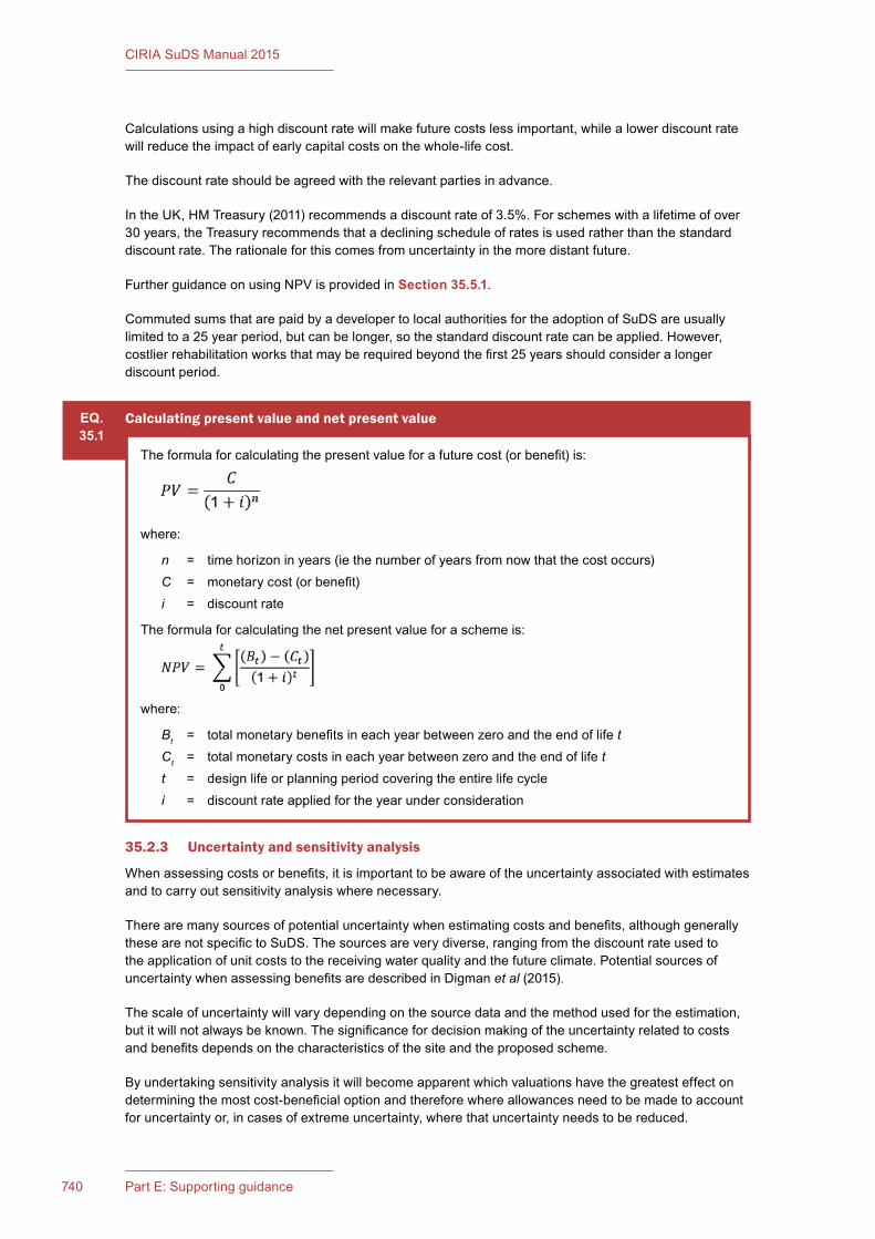
741Chapter 35: Costs and benefits740 Part E: Supporting guidance
CIRIA SuDS Manual 2015
Calculations using a high discount rate will make future costs less important, while a lower discount rate will reduce the impact of early capital costs on the whole-life cost.
The discount rate should be agreed with the relevant parties in advance.
In the UK, HM Treasury (2011) recommends a discount rate of 3.5%. For schemes with a lifetime of over 30 years, the Treasury recommends that a declining schedule of rates is used rather than the standard discount rate. The rationale for this comes from uncertainty in the more distant future.
Further guidance on using NPV is provided in Section 35.5.1.
Commuted sums that are paid by a developer to local authorities for the adoption of SuDS are usually limited to a 25 year period, but can be longer, so the standard discount rate can be applied. However, costlier rehabilitation works that may be required beyond the first 25 years should consider a longer discount period.
EQ.35.1
Calculatingpresentvalueandnetpresentvalue
The formula for calculating the present value for a future cost (or benefit) is:
where:
n = time horizon in years (ie the number of years from now that the cost occurs)C = monetary cost (or benefit)i = discount rate
The formula for calculating the net present value for a scheme is:
where:
Bt = total monetary benefits in each year between zero and the end of life tCt = total monetary costs in each year between zero and the end of life tt = design life or planning period covering the entire life cyclei = discount rate applied for the year under consideration
35.2.3 Uncertaintyandsensitivityanalysis
When assessing costs or benefits, it is important to be aware of the uncertainty associated with estimates and to carry out sensitivity analysis where necessary.
There are many sources of potential uncertainty when estimating costs and benefits, although generally these are not specific to SuDS. The sources are very diverse, ranging from the discount rate used to the application of unit costs to the receiving water quality and the future climate. Potential sources of uncertainty when assessing benefits are described in Digman et al (2015).
The scale of uncertainty will vary depending on the source data and the method used for the estimation, but it will not always be known. The significance for decision making of the uncertainty related to costs and benefits depends on the characteristics of the site and the proposed scheme.
By undertaking sensitivity analysis it will become apparent which valuations have the greatest effect on determining the most cost-beneficial option and therefore where allowances need to be made to account for uncertainty or, in cases of extreme uncertainty, where that uncertainty needs to be reduced.

741Chapter 35: Costs and benefits740 Part E: Supporting guidance
CIRIA SuDS Manual 2015
In its simplest form, sensitivity analysis can consist of using different values from those used in the initial assessment and seeing what affect this has on the outcome. However, if there are a lot of parameters, sensitivity analysis by varying each parameter in turn can be time consuming. In such circumstances, it is worthwhile looking at available tools for economic appraisal that provide a degree of automation to the process, such as from Digman et al (2015).
Sensitivity analysis can also be applied to assessments that do not result in quantification. For example, where stakeholders are involved in a qualitative assessment, they are likely to have different views of what is most important and score benefits differently. Sensitivity analysis can help to determine whether these differences would affect the final decision. Often they do not, and so sensitivity analysis can help to resolve any disagreements between interested parties (Maxwell et al, 2011).
Further guidance on dealing with uncertainty and sensitivity testing can be found in HM Treasury (2011), Shamier (2013), DCLG (2009) and Maxwell et al (2011), among others.
35.3 ESTIMATING COSTS
35.3.1 Feasibility, appraisal and design costs
Feasibility, appraisal and preliminary design costs can sometimes be greater for SuDS schemes than for below-ground piped drainage systems, as there are more issues to be considered. However, some of these costs may be attributed to landscape and building design. Good SuDS design should look at how to maximise the various benefits offered by SuDS, which may require the appraisal of a range of options. Further details on the planning and design process are provided in Chapter 7.
The cost of the land within a site required for the SuDS scheme (known as “land-take”) can be one of the most significant factors influencing the cost of implementing a SuDS scheme and therefore should be considered as early as possible. With good design of multi-functional space, the effective cost of the land for a scheme can be minimal, for example where the site has multiple uses such as a car park or recreational area, or where the scheme forms part of a required public open space area. However, in high-density settings the value of land can far outweigh construction costs and the land-take associated with specific SuDS components may determine the selection of drainage options. Whether or not the cost of land should be included within a whole-life cost assessment will depend on whether the use of the land is dedicated to SuDS alone; whether the land can serve multiple functions (because of using SuDS); or whether the land would otherwise be developable if not used for SuDS, that is its value could be realised in another way (Section 35.3.8).
35.3.2 Construction costs
Construction costs to be considered in any costing process should include:
▪ material costs
▪ land costs
▪ construction (labour and equipment costs)
▪ planting and landscaping costs
▪ erosion and sediment control of the SuDS during construction and any subsequent rehabilitation
▪ relocation of existing utility assets (if required – generally only for retrofit schemes).
The cost of constructing a SuDS scheme will depend primarily on the size of the contributing catchment area, but will also be influenced by:
▪ soil type (eg excavation costs are likely to be significantly higher in rocky soils; infiltration opportunities will vary)

743Chapter 35: Costs and benefits742 Part E: Supporting guidance
CIRIA SuDS Manual 2015
▪ groundwater vulnerability (eg sensitive groundwater zones may require impermeable geomembrane liners to be included within the design)
▪ design criteria (these will determine component sizes and the extent of Management Train needed)
▪ design features (eg heavily planted ponds can be more expensive than ponds left to colonise naturally)
▪ access and space requirements
▪ location (eg material and labour costs vary regionally, and local rainfall characteristics will affect sizing)
▪ inlet and outlet hydraulic control characteristics
▪ any off-site works required for exceedance flow management.
In general, the total volume or area of a SuDS component is likely to be a strong predictor of cost. However, there are economies of scale associated with construction, due to costs of inlet and outlet structures, and mobilisation of equipment that are relatively similar regardless of component size.
As with any drainage scheme, consideration should also be given to the impacts of the scheme during the construction period on the site and the surrounding area (whether these can be monetised or not), such as noise, disruption or inconvenience to residents and others.
Guidance on construction of individual SuDS components is provided in Chapters 11–23. Guidance on construction good practice is provided in Chapter 31.
When employing a quantity surveyor, it can be helpful to discuss with them how costs for the SuDS components can be determined separately from other external works. For example, there will be a need to differentiate between generic soft landscape works and those that are part of the drainage system works. This will enable correct costing, billing and allocation of maintenance resources.
35.3.3 Operationandmaintenancecosts
Although the greatest part of the total cost for a scheme is usually the capital cost, SuDS schemes also require a finance stream to cover long-term operation and maintenance costs (as does a below-ground piped system). An estimate has to be made regarding what these costs are likely to be, and funding requirements need to be agreed by the parties involved.
As many SuDS schemes utilise natural planting and are designed to support ecosystems and biodiversity, there needs to be a period of intensive maintenance of the emerging vegetation to ensure that it grows and provides the expected service. This will usually require specialist horticultural expertise and will incur costs beyond the construction phase. It is recommended that this is included in the construction contract and is the responsibility of the contractor (Chapter 29). Where the SuDS have more than one use, such as for recreation, there may also be a period of initial setting up and commissioning of the recreational area that will incur costs, although these costs would be expected to accrue to the operators of the recreational facilities rather than the developer.
SuDS schemes then require maintenance, in order to ensure short-term operation and minimise risks to long-term performance.
Operation and maintenance activities can be classified as follows:
▪ inspection and reporting (eg regular visits which are generally undertaken at the same time as regular maintenance; this may also include monitoring at larger sites, if required)
▪ regular maintenance (eg clearing inlets and outlets, collecting trash and debris, grass-cutting, vegetation management, brushing of permeable surfaces, emptying of silt traps)
▪ occasional maintenance (eg responding to problems such as blocked culverts or trash racks, pollution incidents, vegetation death, structural damage, responding and clean-up after extreme events)

743Chapter 35: Costs and benefits742 Part E: Supporting guidance
CIRIA SuDS Manual 2015
▪ remedial maintenance (eg for major during-life refurbishment such as geotextile replacement, vegetation replacement, soakaway replacement, major sediment removal activities)
▪ adaptation actions (eg responding to changes in drainage requirements for the site, especially if the life of the SuDS scheme is to be extended, although this can only be costed if planned).
Operation and maintenance costs will normally comprise:
▪ labour and equipment costs
▪ material and/or replacement product costs
▪ replacement and/or extra planting costs
▪ disposal costs of, for example, contaminated sediments and vegetation (Chapter 33).
Where pollution prevention strategies such as street sweeping and public education programmes are included as part of a SuDS scheme (Chapter 27), these costs should be included as an continuing operation cost.
The cost of operation and maintenance activities can vary substantially, depending on:
▪ location (this will influence material, labour and equipment charges)
▪ ease of access (confined sites can be much more expensive to maintain due to requirements for specialist equipment)
▪ upstream activities (in particular, any ongoing development, as this will influence the rate of sediment accumulation in the system)
▪ use of the SuDS (where it is multi-functional, such as an additional amenity or ecological function, specific maintenance may be required to ensure that functionality is maintained, but these costs may be shared between various partners, such as the local authority or volunteer community groups)
▪ quality of on-site construction or off-site manufacture of products
▪ the need for off-site disposal of waste
▪ the effectiveness of the design of the scheme to mitigate the above costs.
Guidance on designing for maintenance for individual SuDS components is provided in Chapters 11–23. Guidance on maintenance good practice is provided in Chapter 32.
Where SuDS are part of or provide multiple functions, there may be important social considerations and risks associated with their normal functioning. Where, for example, a SuDS component provides a storage area for exceedance flows that functions infrequently and is also used for other purposes, such as recreation, there may be a number of additional costs to consider, such as:
▪ provision of permanent signage to warn of infrequent inundation of the area
▪ educating the local community of the function of the SuDS component and encouraging local ownership and appropriate use
▪ warning the local population when inundation is imminent and erection of temporary warning signs or barriers
▪ policing the area when the area is inundated, to ensure public safety
▪ where the design does not provide for it, pumping out and restoration of the temporarily inundated area, including verifying that the ground does not present a health risk
▪ engagement with local communities before, during and after an inundation event.
Reference should be made to best practice in designing and managing for exceedance as defined in Digman et al (2006) and Digman et al (2014) and to ISO 31000:2009 for risk assessment and

745Chapter 35: Costs and benefits744 Part E: Supporting guidance
CIRIA SuDS Manual 2015
management. These costs will vary depending on local circumstances and the particular use of the land, which may or may not be multi-functional.
35.3.4 Monitoring costs
For large or high risk schemes, the environmental regulator may require a long-term monitoring regime as a condition of planning. At such sites, the capital and ongoing costs for monitoring also need to be included in the economic evaluation.
35.3.5 Disposalanddecommissioning
At the end of its design life, it is likely that a SuDS scheme would either be:
a) fully rehabilitated, in which case the cost would be borne by the drainage owner or adoption body, or
b) redeveloped, in which case the disposal and decommissioning costs would be accepted by the next developer.
Such costs will generally be small, due to the landscaped nature of most SuDS schemes and the lack of significant “hard” infrastructure.
35.3.6 Residualvalue
In a full economic evaluation, the residual value of the drainage system should be included in the analysis. The land occupied by the system could theoretically have residual or “reclaim” value, if the function of the drainage system is no longer required at the end of the design life. However, in reality, the following factors mean that it is more appropriate to assume this value to be low or zero:
1 The land areas are too small and distributed to be of value for alternative use.
2 The land is part of public open space required by planning conditions.
There is a high likelihood that the space will be required to fulfil a drainage function after the allocated design life.
35.3.7 Costsavoided
When the proposed drainage scheme prevents a future cost, this is called an avoided cost (if it is reasonably certain that the cost would have appeared otherwise).
Costs avoided can be a useful means of comparing a SuDS scheme with either an alternative SuDS scheme or with a below-ground piped drainage system. In order to do this, it is important to ensure that like is being compared with like. For example, the total cost of a SuDS scheme should not be compared with only the capital and operational costs of the below-ground piped drainage system, as invariably the SuDS scheme provides much more than just the drainage for the site. The hard and soft landscaping and additional functions provided by the SuDS scheme (such as recreational space or overlying car park) should be compared with the equivalent for the site should a below-ground piped drainage system be used instead. This will identify any costs avoided due to the multi-functionality of the SuDS scheme and the reduced need for kerbing, manholes etc.
35.3.8 Opportunity costs
Opportunity costs can also provide a useful means of comparing alternative drainage schemes, but again, care needs to be taken to ensure that like is being compared with like.
Unlike the costs avoided discussed in Section 35.3.7, an opportunity cost is the gain that would be realised by choosing a different course of action. For example, if land was not being used as part of the SuDS scheme, what would it be used for instead and what gain would it bring?

745Chapter 35: Costs and benefits744 Part E: Supporting guidance
CIRIA SuDS Manual 2015
35.3.9 Optimismbias
Optimism bias is a well-known phenomenon whereby project appraisers tend to be over-optimistic about the outcomes from the decisions they make.
HM Treasury (2013) sets out how to compensate for this bias in the estimation of capital costs. Depending on the project type, the range of bias varies. This can be accounted for by either (a) applying a percentage uplift figure to the original cost estimate or (b) identifying the contributory factors that lead to the bias and reducing these, which in turn justifies the percentage uplift to be reduced.
There is no similar specific guidance in the supplementary guide for dealing with optimism bias when estimating operation and maintenance costs or benefits. Sensitivity analysis is recommended instead that enables decision-makers to consider to what extent their decisions would change if the actual cost (or benefit) was significantly greater or less than estimated. For example, how much can maintenance costs increase if the option is to remain worthwhile?
Guidance on the application of this approach to the assessment of SuDS schemes (for both costs and benefits) is provided in Digman et al (2015).
35.3.10 Tools and further guidance
Royal Haskoning (2012) provides a literature review of costs and benefits of SuDS in the UK (including available case study evidence), a unit cost database (based on sources used in the literature review) and a review of the cost effectiveness of SuDS.
Guidance by Pittner and Allerton (2009) is supported by a whole life cost and whole life carbon tool (SCOTSNET, 2010) which can be used to support the SuDS selection process for different sites. The tool calculates capital and maintenance costs and in turn calculates the whole life cost of the scheme. It can also calculate whole life carbon.
A simpler, higher level costing tool is available on the UKSuDS website: www.uksuds.com (SuDS construction and maintenance cost calculator). This provides indicative costs for different types of SuDS components, but can also be used with site-specific costs input by the user to calculate whole-life costs for a SuDS scheme.
A number of documents are available that provide further data on costs and guidance on their usage, including Kellagher et al (2013), Gordon-Walker et al (2007), UKWIR (2005) and HR Wallingford (2004). For the most part, these are cited in Royal Haskoning (2012).
There is also a series of Defra case studies looking at comparative costings for surface water sewers and SuDS. Details can be found on: www.susdrain.org.
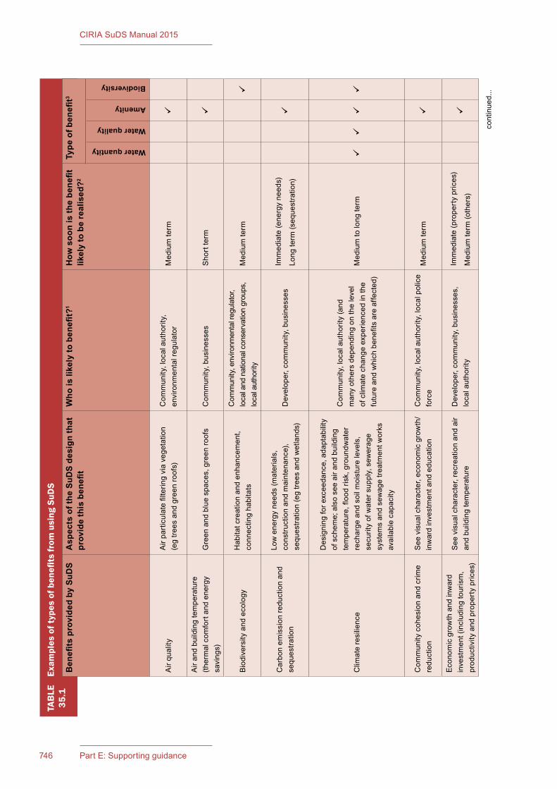
747Chapter 35: Costs and benefits746 Part E: Supporting guidance
CIRIA SuDS Manual 2015
TAB
LE35
.1Exam
plesoftypesofbenefitsfrom
usingSuD
S
Ben
efits
pro
vide
d by
SuD
SA
spec
ts o
f the
SuD
S de
sign
that
pr
ovid
e th
is b
enefi
tW
ho is
like
ly to
ben
efit?
1H
ow s
oon
is th
e be
nefit
lik
ely
to b
e re
alis
ed?2
Type
of b
enefi
t3
Water quantity
Water quality
Amenity
Biodiversity
Air
qual
ityA
ir pa
rtic
ulat
e fil
terin
g vi
a ve
geta
tion
(eg
trees
and
gre
en ro
ofs)
Com
mun
ity, l
ocal
aut
horit
y,
envi
ronm
enta
l reg
ulat
orM
ediu
m te
rm
Air
and
build
ing
tem
pera
ture
(th
erm
al c
omfo
rt an
d en
ergy
sa
ving
s)G
reen
and
blu
e sp
aces
, gre
en ro
ofs
Com
mun
ity, b
usin
esse
sS
hort
term
Bio
dive
rsity
and
eco
logy
Hab
itat c
reat
ion
and
enha
ncem
ent,
conn
ectin
g ha
bita
ts
Com
mun
ity, e
nviro
nmen
tal r
egul
ator
, lo
cal a
nd n
atio
nal c
onse
rvat
ion
grou
ps,
loca
l aut
horit
yM
ediu
m te
rm
Car
bon
emis
sion
redu
ctio
n an
d se
ques
tratio
n
Low
ene
rgy
need
s (m
ater
ials
, co
nstru
ctio
n an
d m
aint
enan
ce),
sequ
estra
tion
(eg
trees
and
wet
land
s)
Dev
elop
er, c
omm
unity
, bus
ines
ses
Imm
edia
te (e
nerg
y ne
eds)
Long
term
(seq
uest
ratio
n)
Clim
ate
resi
lienc
e
Des
igni
ng fo
r exc
eeda
nce,
ada
ptab
ility
of
sch
eme;
als
o se
e ai
r and
bui
ldin
g te
mpe
ratu
re, fl
ood
risk,
gro
undw
ater
re
char
ge a
nd s
oil m
oist
ure
leve
ls,
secu
rity
of w
ater
sup
ply,
sew
erag
e sy
stem
s an
d se
wag
e tre
atm
ent w
orks
av
aila
ble
capa
city
Com
mun
ity, l
ocal
aut
horit
y (a
nd
man
y ot
hers
dep
endi
ng o
n th
e le
vel
of c
limat
e ch
ange
exp
erie
nced
in th
e fu
ture
and
whi
ch b
enefi
ts a
re a
ffect
ed)
Med
ium
to lo
ng te
rm
Com
mun
ity c
ohes
ion
and
crim
e re
duct
ion
See
vis
ual c
hara
cter
, eco
nom
ic g
row
th/
inw
ard
inve
stm
ent a
nd e
duca
tion
Com
mun
ity, l
ocal
aut
horit
y, lo
cal p
olic
e fo
rce
Med
ium
term
Econ
omic
gro
wth
and
inw
ard
inve
stm
ent (
incl
udin
g to
uris
m,
prod
uctiv
ity a
nd p
rope
rty
pric
es)
See
vis
ual c
hara
cter
, rec
reat
ion
and
air
and
build
ing
tem
pera
ture
Dev
elop
er, c
omm
unity
, bus
ines
ses,
lo
cal a
utho
rity
Imm
edia
te (p
rope
rty
pric
es)
Med
ium
term
(oth
ers)
cont
inue
d...
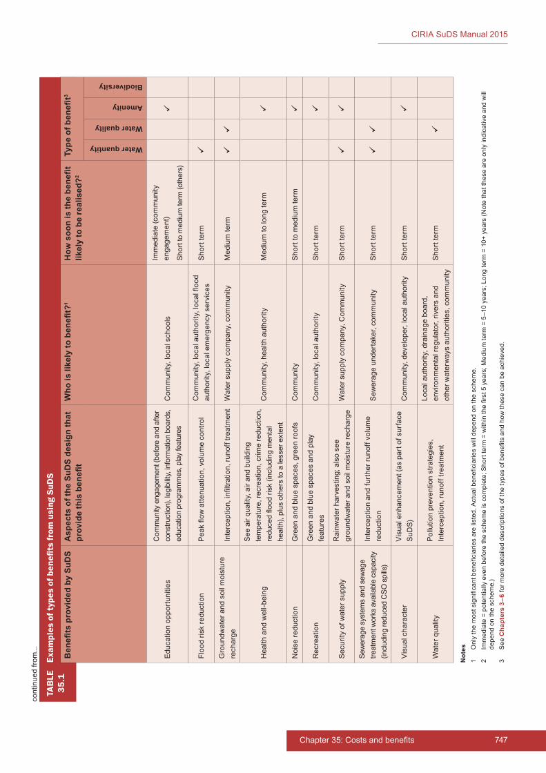
747Chapter 35: Costs and benefits
CIRIA SuDS Manual 2015
TAB
LE35
.1Ex
ampl
es o
f typ
es o
f ben
efits
from
usi
ng S
uDS
Ben
efits
pro
vide
d by
SuD
SA
spec
ts o
f the
SuD
S de
sign
that
pr
ovid
e th
is b
enefi
tW
ho is
like
ly to
ben
efit?
1H
ow s
oon
is th
e be
nefit
lik
ely
to b
e re
alis
ed?2
Type
of b
enefi
t3
Water quantity
Water quality
Amenity
Biodiversity
Educ
atio
n op
port
uniti
esC
omm
unity
eng
agem
ent (
befo
re a
nd a
fter
cons
truct
ion)
, leg
ibilit
y, in
form
atio
n bo
ards
, ed
ucat
ion
prog
ram
mes
, pla
y fe
atur
esC
omm
unity
, loc
al s
choo
ls
Imm
edia
te (c
omm
unity
en
gage
men
t)
Shor
t to
med
ium
term
(oth
ers)
Floo
d ris
k re
duct
ion
Peak
flow
atte
nuat
ion,
vol
ume
cont
rol
Com
mun
ity, l
ocal
aut
horit
y, lo
cal fl
ood
auth
ority
, loc
al e
mer
genc
y se
rvic
esS
hort
term
Gro
undw
ater
and
soi
l moi
stur
e re
char
ge
Inte
rcep
tion,
infil
tratio
n, ru
noff
treat
men
tW
ater
sup
ply
com
pany
, com
mun
ityM
ediu
m te
rm
Hea
lth a
nd w
ell-b
eing
See
air
qual
ity, a
ir an
d bu
ildin
g te
mpe
ratu
re, r
ecre
atio
n, c
rime
redu
ctio
n,
redu
ced
flood
risk
(inc
ludi
ng m
enta
l he
alth
), pl
us o
ther
s to
a le
sser
ext
ent
Com
mun
ity, h
ealth
aut
horit
yM
ediu
m to
long
term
Noi
se re
duct
ion
Gre
en a
nd b
lue
spac
es, g
reen
roof
sC
omm
unity
Sho
rt to
med
ium
term
Rec
reat
ion
Gre
en a
nd b
lue
spac
es a
nd p
lay
feat
ures
Com
mun
ity, l
ocal
aut
horit
yS
hort
term
Sec
urity
of w
ater
sup
ply
Rai
nwat
er h
arve
stin
g; a
lso
see
grou
ndw
ater
and
soi
l moi
stur
e re
char
geW
ater
sup
ply
com
pany
, Com
mun
ityS
hort
term
Sew
erag
e sy
stem
s an
d se
wag
e tre
atm
ent w
orks
ava
ilabl
e ca
paci
ty
(incl
udin
g re
duce
d C
SO s
pills
)
Inte
rcep
tion
and
furt
her r
unof
f vol
ume
redu
ctio
nS
ewer
age
unde
rtak
er, c
omm
unity
Sho
rt te
rm
Vis
ual c
hara
cter
Vis
ual e
nhan
cem
ent (
as p
art o
f sur
face
S
uDS)
Com
mun
ity, d
evel
oper
, loc
al a
utho
rity
Sho
rt te
rm
Wat
er q
ualit
yP
ollu
tion
prev
entio
n st
rate
gies
, In
terc
eptio
n, ru
noff
treat
men
t
Loca
l aut
horit
y, d
rain
age
boar
d,
envi
ronm
enta
l reg
ulat
or, r
iver
s an
d ot
her w
ater
way
s au
thor
ities
, com
mun
ityS
hort
term
Not
es1
Onl
y th
e m
ost s
igni
fican
t ben
efici
arie
s ar
e lis
ted.
Act
ual b
enefi
ciar
ies
will
dep
end
on th
e sc
hem
e.2
Imm
edia
te =
pot
entia
lly e
ven
befo
re th
e sc
hem
e is
com
plet
e; S
hort
term
= w
ithin
the
first
5 y
ears
; Med
ium
term
= 5
–10
year
s; L
ong
term
= 1
0+ y
ears
(Not
e th
at th
ese
are
only
indi
cativ
e an
d w
ill
depe
nd o
n th
e sc
hem
e.)
3 S
ee C
hapt
ers
3–6
for m
ore
deta
iled
desc
riptio
ns o
f the
type
s of
ben
efits
and
how
thes
e ca
n be
ach
ieve
d.
cont
inue
d fro
m...
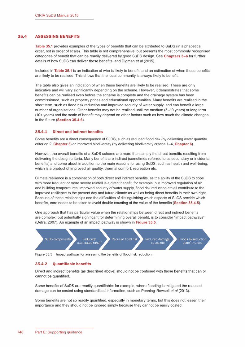
748 Part E: Supporting guidance
CIRIA SuDS Manual 2015
35.4 ASSESSING BENEFITS
Table 35.1 provides examples of the types of benefits that can be attributed to SuDS (in alphabetical order, not in order of scale). This table is not comprehensive, but presents the most commonly recognised categories of benefit that can be readily delivered by good SuDS design. See Chapters 3–6 for further details of how SuDS can deliver these benefits, and Digman et al (2015).
Included in Table 35.1 is an indication of who is likely to benefit, and an estimation of when these benefits are likely to be realised. This shows that the local community is always likely to benefit.
The table also gives an indication of when these benefits are likely to be realised. These are only indicative and will vary significantly depending on the scheme. However, it demonstrates that some benefits can be realised even before the scheme is complete and the drainage system has been commissioned, such as property prices and educational opportunities. Many benefits are realised in the short term, such as flood risk reduction and improved security of water supply, and can benefit a large number of organisations. Other benefits may not be realised until the medium (5–10 years) or long term (10+ years) and the scale of benefit may depend on other factors such as how much the climate changes in the future (Section 35.4.6).
35.4.1 Directandindirectbenefits
Some benefits are a direct consequence of SuDS, such as reduced flood risk (by delivering water quantity criterion 2, Chapter 3) or improved biodiversity (by delivering biodiversity criteria 1–4, Chapter 6).
However, the overall benefits of a SuDS scheme are more than simply the direct benefits resulting from delivering the design criteria. Many benefits are indirect (sometimes referred to as secondary or incidental benefits) and come about in addition to the main reasons for using SuDS, such as health and well-being, which is a product of improved air quality, thermal comfort, recreation etc.
Climate resilience is a combination of both direct and indirect benefits, as the ability of the SuDS to cope with more frequent or more severe rainfall is a direct benefit, for example, but improved regulation of air and building temperatures, improved security of water supply, flood risk reduction etc all contribute to the improved resilience to the present day and future climate as well as being direct benefits in their own right. Because of these relationships and the difficulties of distinguishing which aspects of SuDS provide which benefits, care needs to be taken to avoid double counting of the value of the benefits (Section 35.4.5).
One approach that has particular value when the relationships between direct and indirect benefits are complex, but potentially significant for determining overall benefit, is to consider “impact pathways” (Defra, 2007). An example of an impact pathway is shown in Figure 35.5.
35.4.2 Quantifiablebenefits
Direct and indirect benefits (as described above) should not be confused with those benefits that can or cannot be quantified.
Some benefits of SuDS are readily quantifiable: for example, where flooding is mitigated the reduced damage can be costed using standardised information, such as Penning-Rowsell et al (2013).
Some benefits are not so readily quantified, especially in monetary terms, but this does not lessen their importance and they should not be ignored simply because they cannot be easily costed.
Figure 35.5 Impact pathway for assessing the benefits of flood risk reduction
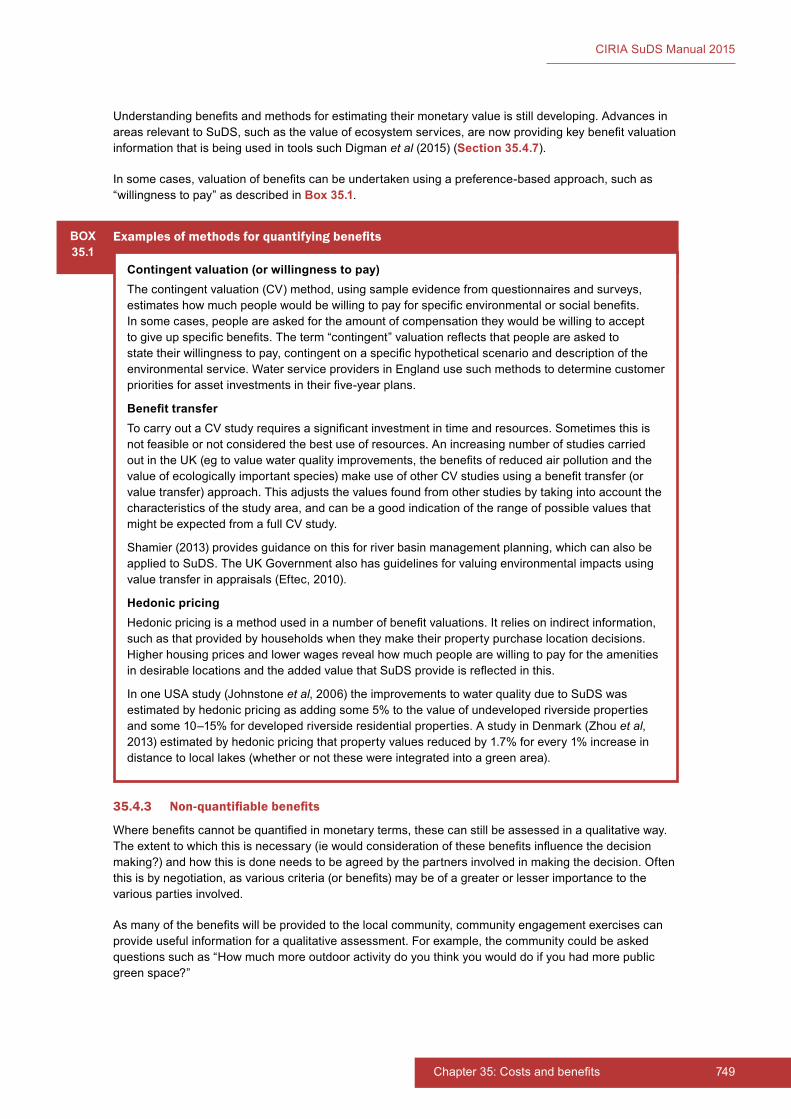
749Chapter 35: Costs and benefits748 Part E: Supporting guidance
CIRIA SuDS Manual 2015
Understanding benefits and methods for estimating their monetary value is still developing. Advances in areas relevant to SuDS, such as the value of ecosystem services, are now providing key benefit valuation information that is being used in tools such Digman et al (2015) (Section 35.4.7).
In some cases, valuation of benefits can be undertaken using a preference-based approach, such as “willingness to pay” as described in Box 35.1.
BOX35.1
Examplesofmethodsforquantifyingbenefits
Contingent valuation (or willingness to pay)The contingent valuation (CV) method, using sample evidence from questionnaires and surveys, estimates how much people would be willing to pay for specific environmental or social benefits. In some cases, people are asked for the amount of compensation they would be willing to accept to give up specific benefits. The term “contingent” valuation reflects that people are asked to state their willingness to pay, contingent on a specific hypothetical scenario and description of the environmental service. Water service providers in England use such methods to determine customer priorities for asset investments in their five-year plans.
Benefit transferTo carry out a CV study requires a significant investment in time and resources. Sometimes this is not feasible or not considered the best use of resources. An increasing number of studies carried out in the UK (eg to value water quality improvements, the benefits of reduced air pollution and the value of ecologically important species) make use of other CV studies using a benefit transfer (or value transfer) approach. This adjusts the values found from other studies by taking into account the characteristics of the study area, and can be a good indication of the range of possible values that might be expected from a full CV study.
Shamier (2013) provides guidance on this for river basin management planning, which can also be applied to SuDS. The UK Government also has guidelines for valuing environmental impacts using value transfer in appraisals (Eftec, 2010).
Hedonic pricingHedonic pricing is a method used in a number of benefit valuations. It relies on indirect information, such as that provided by households when they make their property purchase location decisions. Higher housing prices and lower wages reveal how much people are willing to pay for the amenities in desirable locations and the added value that SuDS provide is reflected in this.
In one USA study (Johnstone et al, 2006) the improvements to water quality due to SuDS was estimated by hedonic pricing as adding some 5% to the value of undeveloped riverside properties and some 10–15% for developed riverside residential properties. A study in Denmark (Zhou et al, 2013) estimated by hedonic pricing that property values reduced by 1.7% for every 1% increase in distance to local lakes (whether or not these were integrated into a green area).
35.4.3 Non-quantifiablebenefits
Where benefits cannot be quantified in monetary terms, these can still be assessed in a qualitative way. The extent to which this is necessary (ie would consideration of these benefits influence the decision making?) and how this is done needs to be agreed by the partners involved in making the decision. Often this is by negotiation, as various criteria (or benefits) may be of a greater or lesser importance to the various parties involved.
As many of the benefits will be provided to the local community, community engagement exercises can provide useful information for a qualitative assessment. For example, the community could be asked questions such as “How much more outdoor activity do you think you would do if you had more public green space?”

750 Part E: Supporting guidance
CIRIA SuDS Manual 2015
At its simplest level, a qualitative assessment can compare the relative scale of benefits, such as:
1 no added benefit
2 some benefit
3 medium benefit
4 significant benefit.
Qualitative assessments like this need to be considered separately in the decision-making process from the quantitative outcomes described above.
However, in cases where some (but not all) of the benefits can be directly monetised, a qualitative assessment can act as the starting point for quantifying the remaining benefits by providing “switching” or “implied” monetary values. This becomes a worthwhile exercise where the non-monetised benefits have a score of 3 or 4 based on the scale given above.
For example, where the monetised benefits amount to say, £9 m for a scheme costing £10 m, the non-monetised benefits would need to have an implied value of at least £1 m to have a positive benefit–cost ratio (Section 35.5.2).
Alternatively, the monetised benefits can be used as a benchmark for benefits that are not directly quantifiable. For example, stakeholder engagement can be used to score and weight non-monetised benefits against benefits that have been monetised and provide an estimated “implied” monetary value (Section 35.5.1). This process should include sensitivity analysis to check the relative significance of the results from the scoring and weighting exercise, and any other assumptions used. An appropriate uncertainty range can then be applied to the resultant estimations.
This process is most worthwhile if the non-monetised benefits are likely to have a significant effect on the determination of the preferred option. Depending on the information readily available for quantifying some benefits, it can also be a less costly alternative to using contingent valuation, benefit transfer etc methods (Box 35.2) or can be used to validate the results from these methods (Penning-Rowsell et al, 2013).
Some benefits are sometimes deemed as inappropriate to monetise, depending on the purpose of the analysis and with whom it will be communicated, in which case a cost-effectiveness analysis approach can be adopted (Section 35.5.3).
35.4.4 Benefitattribution
Although there are many potential benefits provided by SuDS, these do not necessarily only come about by delivering a SuDS scheme. For example, green areas alone can provide a number of the benefits, even where SuDS are not included in these areas, such as recreational space and urban heat island mitigation. It is therefore important that benefits are attributed correctly and only to where they are provided by SuDS components alone, especially if comparing development options with and without SuDS.
35.4.5 Doublecounting
There are two main potential sources of double counting when estimating benefits:
1 overlap between benefit categories (Table 35.1) and/or using the same population for different benefit categories, such as for both recreation and health and well-being
2 using benefit transfer values or similar (Box 35.2) that include more than just the specific benefit being valued
These need to be taken into consideration when identifying which benefits are going to be assessed and the best estimation method to adopt. All assumptions should be made clear, along with the implications of these assumptions.

751Chapter 35: Costs and benefits750 Part E: Supporting guidance
CIRIA SuDS Manual 2015
35.4.6 Timingandscalingbenefits
The timing and physical scale of SuDS use is important in assessing relative benefits. The benefits provided by an individual component, such as a tree pit, cannot be assumed to be linearly scalable upward where larger or multiple components are being used. This is especially true where biodiversity is considered, as interconnectedness of green spaces is a major determining factor in supporting ecosystems. Therefore, where there is a gradual implementation of green SuDS over time and space, there may be a step change in benefits when these reach a particular level of interconnectedness.
Also, the future is unknown and, therefore, the future benefits that are realised may not be as anticipated. In other words, in the future, one or more of the expected benefits considered valuable today may become less or more important in response to changes in circumstances (whether economic, social or environmental). The most “flexible” option is the option that can still provide benefit value even under future changes.
Guidance on how to include timescales and flexibility in benefit assessment is included in Digman et al (2015).
35.4.7 Tools and further guidance
Royal Haskoning (2012) provides a literature review of costs and benefits of SuDS in the UK (including available case study evidence), but information on the monetary value of benefits is limited.
A detailed description of the multiple benefits of SuDS is provided in Digman et al (2015), together with recommendations for considering temporal and spatial scales and uncertainties.
Digman et al (2015) provides a freely available spreadsheet tool designed for those interested in assessing SuDS benefits. This tool, together with its accompanying guidance, enables a wide range of financial, social and environmental benefits of SuDS to be captured and included in decision-making for drainage infrastructure investments. The tool provides a practical means of assessing and, where feasible, monetising the multiple benefits of SuDS schemes (from small to large schemes). The tool enables alternative SuDS designs to be compared with each other or to a conventional drainage design or any base case.
The tool includes 20 benefit categories, of which the monetary value can be assessed for 18 of these. A database of monetary values is included, although locally derived values should be used as far as practicable.
Jayasooriya and Ng (2014) provide an international review of other available tools for assessing costs and benefits related to SuDS.
35.5 COMPARING COSTS AND BENEFITS
In order to carry out an assessment that compares costs and benefits, it is important to consider whole-life costs (Section 35.2.1) based on appropriate discounting (Section 35.2.2), and it is also important to consider the benefits alongside costs in a way that they can be readily compared (economic or multi-criteria analysis).
Each of the partners in a scheme may take a different approach to economic analysis (in some cases due to regulatory regime requirements) and it is therefore important to establish from the outset how the economic assessment will be carried out. There are no regulatory standards for economic analysis for SuDS, rather there are standards set out for the various interested parties (eg the Environment Agency for river basin management planning or water service providers for asset management), each of which will need to be satisfied if their organisation is to be a partner in a particular scheme.
Some of the most common methods are described below. These are often used in combination in scheme appraisals.
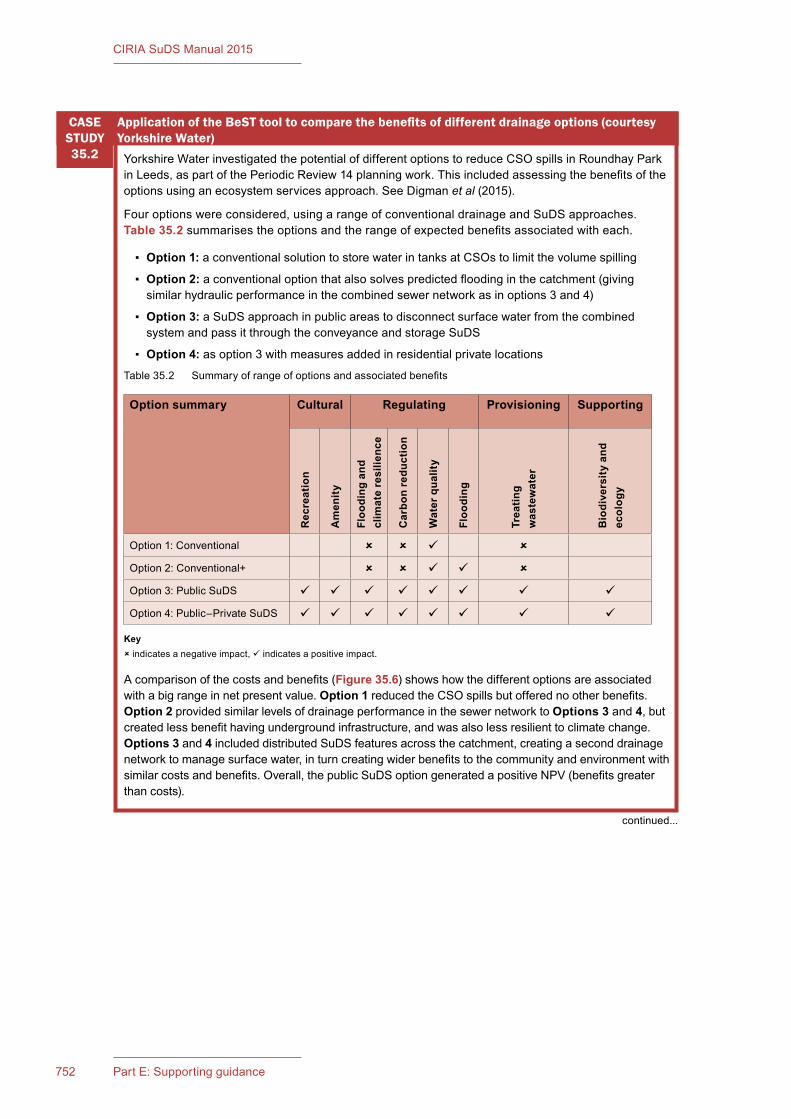
753Chapter 35: Costs and benefits752 Part E: Supporting guidance
CIRIA SuDS Manual 2015
Yorkshire Water investigated the potential of different options to reduce CSO spills in Roundhay Park in Leeds, as part of the Periodic Review 14 planning work. This included assessing the benefits of the options using an ecosystem services approach. See Digman et al (2015).
Four options were considered, using a range of conventional drainage and SuDS approaches. Table 35.2 summarises the options and the range of expected benefits associated with each.
▪ Option 1: a conventional solution to store water in tanks at CSOs to limit the volume spilling
▪ Option 2: a conventional option that also solves predicted flooding in the catchment (giving similar hydraulic performance in the combined sewer network as in options 3 and 4)
▪ Option 3: a SuDS approach in public areas to disconnect surface water from the combined system and pass it through the conveyance and storage SuDS
▪ Option 4: as option 3 with measures added in residential private locations
Table 35.2 Summary of range of options and associated benefits
Option summary Cultural Regulating Provisioning Supporting
Rec
reat
ion
Am
enity
Floo
ding
and
cl
imat
e re
silie
nce
Car
bon
redu
ctio
n
Wat
er q
ualit
y
Floo
ding
Trea
ting
was
tew
ater
Bio
dive
rsity
and
ec
olog
y
Option 1: Conventional
Option 2: Conventional+
Option 3: Public SuDS
Option 4: Public–Private SuDS
ApplicationoftheBeSTtooltocomparethebenefitsofdifferentdrainageoptions(courtesyYorkshire Water)
CASE STUDY35.2
Key indicates a negative impact, indicates a positive impact.
A comparison of the costs and benefits (Figure 35.6) shows how the different options are associated with a big range in net present value. Option 1 reduced the CSO spills but offered no other benefits. Option 2 provided similar levels of drainage performance in the sewer network to Options 3 and 4, but created less benefit having underground infrastructure, and was also less resilient to climate change. Options 3 and 4 included distributed SuDS features across the catchment, creating a second drainage network to manage surface water, in turn creating wider benefits to the community and environment with similar costs and benefits. Overall, the public SuDS option generated a positive NPV (benefits greater than costs).
continued...
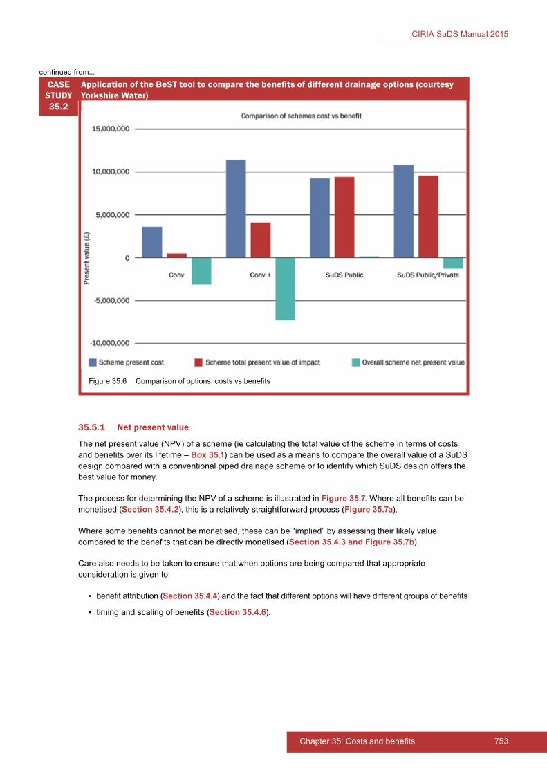
753Chapter 35: Costs and benefits752 Part E: Supporting guidance
CIRIA SuDS Manual 2015
35.5.1 Netpresentvalue
The net present value (NPV) of a scheme (ie calculating the total value of the scheme in terms of costs and benefits over its lifetime – Box 35.1) can be used as a means to compare the overall value of a SuDS design compared with a conventional piped drainage scheme or to identify which SuDS design offers the best value for money.
The process for determining the NPV of a scheme is illustrated in Figure 35.7. Where all benefits can be monetised (Section 35.4.2), this is a relatively straightforward process (Figure 35.7a).
Where some benefits cannot be monetised, these can be “implied” by assessing their likely value compared to the benefits that can be directly monetised (Section 35.4.3 and Figure 35.7b).
Care also needs to be taken to ensure that when options are being compared that appropriate consideration is given to:
▪ benefit attribution (Section 35.4.4) and the fact that different options will have different groups of benefits
▪ timing and scaling of benefits (Section 35.4.6).
Figure 35.6 Comparison of options: costs vs benefits
ApplicationoftheBeSTtooltocomparethebenefitsofdifferentdrainageoptions(courtesyYorkshire Water)
CASE STUDY35.2
continued from...
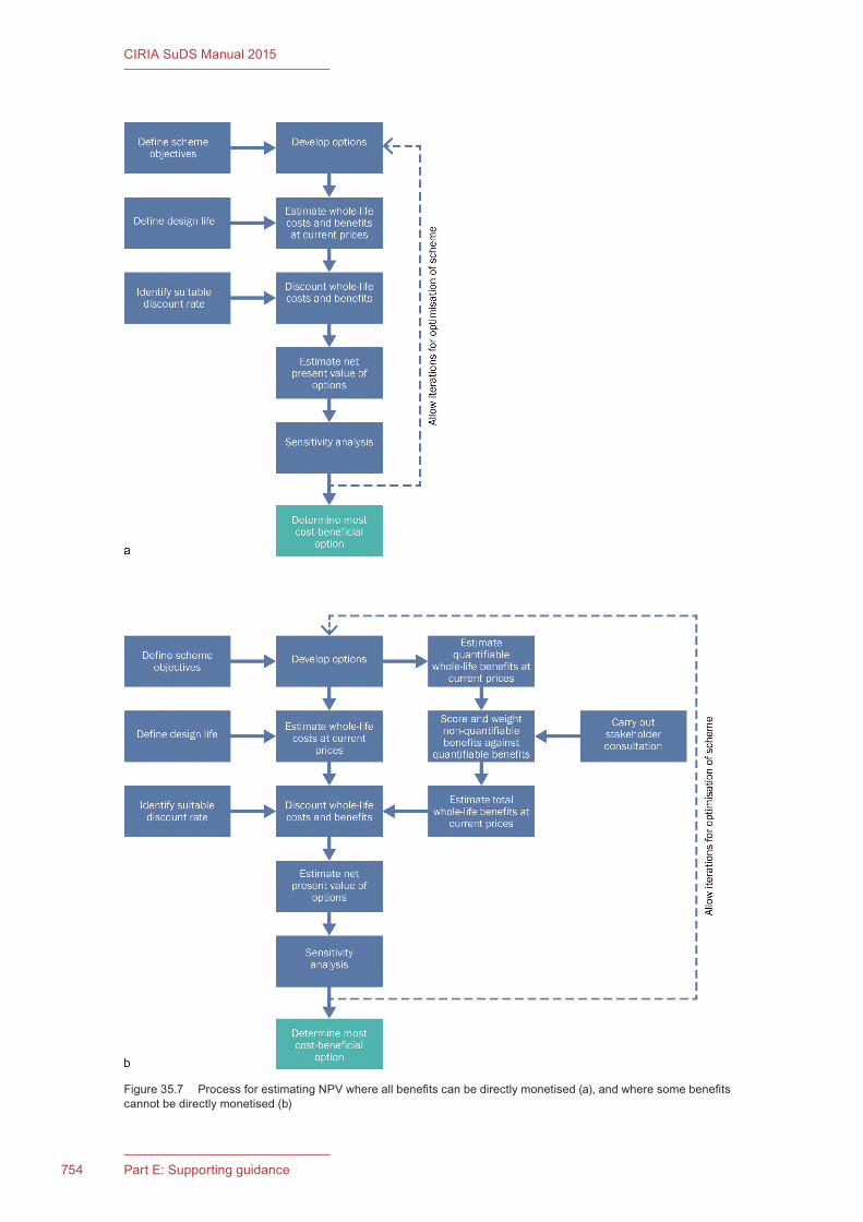
754 Part E: Supporting guidance
CIRIA SuDS Manual 2015
Figure 35.7 Process for estimating NPV where all benefits can be directly monetised (a), and where some benefits cannot be directly monetised (b)
755Chapter 35: Costs and benefits
CIRIA SuDS Manual 2015
35.5.2 Benefit–costratio
The benefit–cost ratio (BCR) is the ratio between the benefits and costs for a scheme can be used to determine whether it is value for money. This type of analysis does require all costs and benefits to be quantified (whether directly or implied), as per the NPV analysis.
The benefits included in the assessment need to be agreed and applied consistently, if different schemes are being compared, but importantly they can be multiple in nature. For example, a benefit to cost ratio (BCR) of 8:1 has been applied to flood defence related decision-making in England for a number of years. In this instance, benefits include wider considerations, including cultural services as part of ecosystem services valuation (ie it is not just about flood defence – see Eftec, 2010).
35.5.3 Cost-effectivenessanalysis
Cost-effectiveness analysis (CEA) is a form of economic analysis that compares the relative cost to benefit, sometimes described as the change in outcome for a unit of investment. For example, “What is the reduction in flooding as a result of a unit increase in storage volume?” This is typically used where there is only a single criterion (or benefit) being measured.
This type of analysis may be particularly helpful when considering the incremental increase in benefit value over time, for example, the impact of street tree growth on the gradual improvement in air quality.
35.5.4 Multi-criteriaanalysis
Multi-criteria analysis (MCA) is an umbrella term used for applying non-quantitative assessment techniques (alongside quantitative results where available), where stakeholders believe that there are significant benefits beyond those that can be monetised, and these should be included in the decision-making process.
MCA provides an open and explicit way of presenting monetised and non-monetised impacts of a scheme (ie costs and benefits) to decision-makers, which has a number of advantages over informal judgement. These include the provision of an audit trail, a useful means of communicating complex ideas, scores and weights that can be compared with other studies (to improve confidence) and the possibility of applying sensitivity testing.
35.5.5 Toolsandfurtherguidance
Many of the concepts introduced in this chapter are discussed in more detail in Penning-Rowsell et al (2013). This document (known as the Multi-Coloured Manual) presents a range of techniques and data that can be used in a practical way to assess costs and benefits related to flood risk management and coastal erosion. The techniques and much of the data is equally relevant to SuDS. The manual also provides details of the derivation of the data presented and the limitations of benefit–cost analysis. Complementary to this manual is a handbook that provides a step-by-step guide to assessing benefits, which is available online (Penning-Rowsell et al, 2015).
DCLG (2009) provides useful (relatively non-technical) guidance on BCR, CEA and MCA techniques, and Maxwell et al (2011) provides guidance on MCA specifically focusing on social impacts and well-being.
Digman et al (2015) allows both financial (eg capital equipment, operating expenditure and opportunity cost of providing land for SuDS) and other costs (eg social or environmental costs such as embodied carbon in materials) for SuDS options to be compared with their benefits (see the case study above).
757Chapter 35: Costs and benefits756 Part E: Supporting guidance
CIRIA SuDS Manual 2015
35.6 REFERENCES
DCLG (2009) Multi-criteria analysis: A manual, Department of Communities and Local Government, London, UK (ISBN: 978-1-40981-023-0). Go to: http://tinyurl.com/ohvl6zk
DEFRA (2007) An introductory guide to valuing ecosystem services, PB12852, Department for Environment Food and Rural Affairs, London, UK. Go to: http://tinyurl.com/nr2emgy
DIGMAN, C, BALMFORTH, D, KELLAGHER, R and BUTLER, D (2006) Designing for exceedance in urban drainage – good practice, C635, CIRIA, London, UK (ISBN: 978-0-86017-635-0). Go to: www.ciria.org
DIGMAN, C, ASHLEY, R, HARGREAVES, P and GILL, E (2014) Managing urban flooding from heavy rainfall – encouraging the uptake of designing for exceedance, C738, CIRIA, London, UK (ISBN: 978-0-86017-742-5). Go to: www.ciria.org
DIGMAN, C, HORTON, B, ASHLEY, R and GILL, E (2015) Benefits of SuDS Tool (BeST), W045, CIRIA, London, UK (ISBN: 978-0-86017-767-8). Go to: www.ciria.org
EA (2014) Flood and coastal defence: develop a project business case, Environment Agency, Bristol, UK. Go to: https://www.gov.uk/guidance/flood-and-coastal-defence-appraisal-of-projects
EFTEC (2010) Valuing environmental impacts: practical guidelines for the use of value transfer in policy and project appraisal, Eftec, London, UK. Go to: http://tinyurl.com/ojyvaqq
GORDON-WALKER, S, HARLE, T and NAISMITH, I (2007) Cost–benefit of SuDS retrofit in urban areas, SC060024, Environment Agency, Bristol, UK (ISBN: 978-1-84432-888-8). Go to: http://tinyurl.com/oudjxz6
HM TREASURY (2011) Green Book: appraisal and evaluation in central government, The Stationery Office, London, UK. Go to: http://tinyurl.com/pyvl9m7
HM TREASURY (2013) Supplementary Green Book guidance – optimism bias, The Stationery Office, London, UK. Go to: http://tinyurl.com/nw5zr3w
HR WALLINGFORD (2004) Whole life costing for sustainable drainage, Report SR627, Department for Trade and Industry, London, UK. Go to: http://tinyurl.com/ogzm6f9
JAYASOORIYA, V M and NG, A W M (2014) “Tools for modeling of stormwater management and economics of green infrastructure practices: a review”, Water Air and Soil Pollution, 225:2055, August, Springer, USA
JOHNSTONE, D M, BRADEN, J B and PRICE, T H (2006) “Downstream economic benefits of conservation development”, Journal of Water Resources Planning and Management, vol 132, 1, American Society of Civil Engineers, Reston, VA, USA, pp 35–43
KELLAGHER, R, WILSON, S and THOMSON, R J C (2013) Surface water drainage report, WT1505, Department for Environment Food and Rural Affairs, London, UK. Go to: http://tinyurl.com/p3omec5
MAXWELL, S, HENDERSON, D, MCCLOY, R and HARPER, G (2011) Social impacts and wellbeing: multi-criteria analysis techniques for integrating non-monetary evidence in valuation and appraisal. A discussion of current approaches and opportunities, Paper 5, Defra Evidence and Analysis Series, Paper 5, Department for Environment Food and Rural Affairs, London, UK. Go to: http://tinyurl.com/n35lc2c
PENNING-ROWSELL, E, PRIEST, S, PARKER, D, MORRIS, J, TUNSTALL, S, VIAVATTENE, C, CHATTERTON, J and OWEN, D (2013) Flood and coastal erosion risk management: a manual for economic appraisal, Flood Hazard Research Centre and Environment Agency, Routledge, Abingdon, UK (ISBN: 978-0-41581-515-4)

757Chapter 35: Costs and benefits756 Part E: Supporting guidance
CIRIA SuDS Manual 2015
PENNING-ROWSELL, E, PRIEST, S, PARKER, D, MORRIS, J, TUNSTALL, S, VIAVATTENE, C, CHATTERTON, J and OWEN, D (2015) Flood and coastal erosion risk management: handbook and data for economic appraisal, Flood Hazard Research Centre and Environment Agency, Routledge, Abingdon, UK. Go to: www.mcm-online.co.uk/handbook/
PITTNER, C and ALLERTON, G (2009) SuDS for roads, WSP Development and Transportation, Edinburgh, Scotland. Go to: http://tinyurl.com/kveukel
ROYAL HASKONING (2012) Costs and benefits of sustainable drainage systems, final report, 9X1055, Committee on Climate Change, London, UK. Go to: http://tinyurl.com/qzd35zm
SCOTSNET (2010) SUDS for roads. Whole life cost and whole life carbon toolkit, SCOTS, Scotland. Go to: www.scotsnet.org.uk/best-practice.php
SHAMIER, N (2013) Water appraisal guidance; assessing costs and benefits for river basin management planning, Final Draft, Environment Agency, Bristol, UK. Go to: http://tinyurl.com/oymk3gj
UKWIR (2005) Performance and whole life costs of best management practices and sustainable urban drainage systems, UK Water Industry Research, London, UK (ISBN: 1-94339-743-9)
ZHOU, Q, PANDURO, T E, THORSEN, B J and ARNBJERG-NIELSEN, K (2013) “Adaption to extreme rainfall with open urban drainage system: an integrated hydrological cost-benefit analysis” Environmental Management, vol 51, Springer, USA, pp 586–601
STATUTES
International Standards
ISO – 31000:2009 Risk management – Principles and guidelines
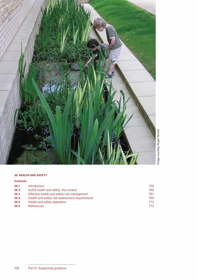
758 Part E: Supporting guidance
CIRIA SuDS Manual 2015
36 HEALTH AND SAFETY
Contents
36.1 Introduction 75936.2 SuDS health and safety: the context 76036.3 Effective health and safety risk management 76136.4 Health and safety risk assessment requirements 76936.5 Health and safety legislation 77236.6 References 773
Imag
e co
urte
sy R
oger
Now
ell

759Chapter 36: Health and safety758 Part E: Supporting guidance
CIRIA SuDS Manual 2015
36Chapter
36.1 INTRODUCTION
36.1.1 Why should health and safety be considered?
The planning, design, construction and management of sustainable drainage systems falls under the requirements of the Construction, Design and Management (CDM) Regulations 2015. This and other relevant regulations and legislation are presented in Section 36.5. This chapter can be used in helping to ensure that SuDS designs fulfil regulatory and legal requirements, and SuDS health and safety risk assessments are in line with BS EN 31010:2010.
This chapter only covers specific health and safety issues relating to the provision of open water components (both permanent and temporary) as part of SuDS. It does not cover general issues and regulation associated with standard health and safety at work principles and conventional drainage design (eg confined spaces – although these are discussed briefly for completeness). Also, it does not cover issues such as highway safety audits that may include some parts of a SuDS scheme (eg permeable pavements or swales adjacent to highways).
36.1.2 When should health and safety be considered?
The SuDS designer has a responsibility to address health and safety under CDM 2015, and must demonstrate this. Health and safety assessment will be a continuous process; it does not just stop once the boxes are ticked. It should be discussed, and principles agreed, at conceptual and outline design stages as part of the CDM designer’s risk assessment process. The risk assessment should then be developed and reviewed at all stages of design, construction and maintenance.
A health and safety assessment should be undertaken by the organisation approving the drainage (drainage approving body) when assessing the design of a SuDS scheme. It should also be reviewed following construction and also on a regular basis during operation. The review should consider any changes that have been made to the approved design during construction or operation (see HSE, 2015).
Health and safetyThis chapter provides guidance on health and safety principles and practices relevant to SuDS. The chapter is intended to provide guidance to designers, drainage approval and adoption bodies, and the public on health and safety aspects associated with SuDS, including:• balancing the benefits of SuDS with any potential health and safety risks• good practice design approaches and principles to support the
appropriate management of risk to low levels• background information to allow drainage approval bodies to be
confident that drainage assets will not pose a liability in either the short or long term
• health and safety risk assessment of schemes in-line with BS EN 31010:2010.
The guidance in this chapter is supported by the health and safety risk management checklist included in Appendix B.
760 Part E: Supporting guidance
CIRIA SuDS Manual 2015
36.2 SUDS HEALTH AND SAFETY: THE CONTEXT
SuDS aim to manage the runoff from development sites, following rainfall, in a way that:
▪ mimics natural drainage processes
▪ minimises negative impacts on the natural environment
▪ reduces the risks of flooding both on site and downstream
▪ supports the adaptability of the development to the negative effects of climate change
▪ provides amenity, biodiversity and educational value for the site.
Well-designed SuDS components include features that are no more hazardous than those found in the existing urban landscape, for example ponds in parks. Where communities understand and support the above principles and values, then it is reasonable to expect them to embrace the improved landscape and respond to such hazards in a positive, reasonable and responsible manner.
36.2.1 Balancingrisksandbenefits
It is important to recognise the inherent tension between the individual leisure user and the various permission givers, regulators and duty holders. Leisure, by definition, is to be free from drudgery, to enjoy freedoms, to play and relax. Consumed (ie paid for) leisure can trigger regulations, imposing qualified duties to manage risk.
An undesirable result can be the duty holder adopting an overly paternalistic approach, resulting from a complex mix of misunderstanding, fear of prosecution or liability to negligence, or as a proxy for other concerns such as a lack of resources and desire for privacy.
Counter-intuitively, the key to challenging risk aversion is the application of balanced risk assessment. There is a need to accept that uncertainty is inherent in adventure and this contains the possibility of adverse outcomes. The Royal Society for the Prevention of Accidents (RoSPA) sums up this approach as follows: “We must try to make life as safe as necessary, not as safe as possible.”
When dealing with the design of public amenity space, it is important to weigh up the risk of harm against the benefits of provision, that is with the objective of balancing positive attributes against the inevitable risk of injury which any public activity generates (Ball and Ball-King, 2011). Publicly accessible green and blue infrastructure (including SuDS) supports important societal benefits including health and well-being benefits relating to improved quality of life, and recreational and educational benefits for children and adults.
As a society, we are prepared to broadly tolerate the risks posed by our road network, because of the benefits and support it provides to our daily lifestyle. SuDS components that are on the surface (eg ponds, basins, swales), if managed correctly and if the public are made aware of the risks, should come to be accepted as important, necessary and beneficial ways of managing our societal impacts.
The benefits of providing a well-designed SuDS scheme are local and regional. The risks that need to be considered should look at the local and regional situation and expectations, and balance these risks appropriately.
36.2.2 Managingandinformingpublicperception
The perception of SuDS, and in particular components that comprise bodies of open water, is important as a driver for setting appropriate risk management principles.
A survey of residents living in areas with SuDS ponds was undertaken in 2002/3 (HR Wallingford, 2003). The study confirmed the following:
▪ The level of education about sustainable water management, and SuDS in particular, was an important factor to the perceived level of risk posed by the drainage system. Informed residents
761Chapter 36: Health and safety760 Part E: Supporting guidance
CIRIA SuDS Manual 2015
tended to be much more positive than residents whose knowledge about the function of their local SuDS scheme was non-existent or poor.
▪ Natural aesthetics were shown to play an extremely important role in formulating public attitudes. The more aesthetically pleasing the SuDS pond and the more natural it looked, the more it tended to be welcomed by a community and the lower the importance attached to health and safety risks.
▪ The effectiveness of the maintenance schedule (in particular relating to litter, pollution and silt accumulation) was crucial in determining the community view of the system.
▪ In general, the community valued SuDS ponds and felt that they added value to the area and to their homes. The majority of those interviewed would prefer the pond to remain, irrespective of any concerns they might have.
The main concerns about SuDS ponds were related to health and safety risks, and this outcome was confirmed by a more recent study (Bastien et al, 2011).
Both studies confirmed that public education and good design and maintenance are crucial in managing and addressing perceived risks. Education strategies should cover:
▪ the functionality of the surface water management system – where the water flows, where and why it is stored, where it is released to, what would happen if it wasn’t there, how it will operate and how it is likely to look in different seasons
▪ the benefits afforded to the local community and wider society by the SuDS scheme, including children’s education opportunities
▪ the design measures in place to mitigate health and safety risks
▪ how and when the system is maintained
▪ the actions that the local community and amenity users should take to further minimise health and safety risks (including effective litter control)
▪ contact information if a health and safety or maintenance concern is identified.
Also, to allay concerns about open water, it should be clear to those using the surrounding amenity space why it is important to manage and treat the runoff from our development areas and how it is collected and stored. All flow and volume control components should be designed and operate in a predictable and safe manner.
36.3 EFFECTIVE HEALTH AND SAFETY RISK MANAGEMENT
36.3.1 The principles
Competent, best practice SuDS design should mean that health and safety risks are considered throughout the design process. The results should be that risks are reduced to acceptable levels by designing out hazards. The following sections summarise the key best practice SuDS design principles that support the appropriate management and mitigation of risk. They are part of the standard SuDS design practice recommended in the individual technical component chapters and are provided here for completeness. The sections relate to the mitigation of risk related to specific potential hazards. All the recommendations in this chapter should be confirmed as appropriate through site-specific risk assessment.
36.3.2 Drowning risk management
Drowning can occur in permanent bodies of water or in normally dry areas when they contain water temporarily during and after rainfall events. Drowning more frequently occurs from accidentally falling in rather than by deliberately accessing a body of water and then getting into difficulty. The risk may be increased during the hours of darkness and when there is unsupervised access to open water, particularly by younger children or those under the influence of alcohol or drugs.

763Chapter 36: Health and safety762 Part E: Supporting guidance
CIRIA SuDS Manual 2015
The risk of drowning is also exacerbated when features such as steep banks, deep bankside or water-edge silt and/or overhanging branches are present. Fast flowing water or areas that become inundated very quickly with a rapid rise in water level may also increase the risk of drowning. Such hazards should always be avoided in SuDS designs.
In 2011, there were 407 reported cases of drowning. Of these deaths, 22 were recorded as occurring in ponds or ditches/burns. The best available information suggests that three hospitalisations occur for every death.
Drowning of very young children is obviously a significant concern. The latest statistics for drowning in the UK show that, of the 0–4-year-old children drowned, the majority were walking or running next to water, rather than being involved in a water-based activity (NWSF, 2012).
In practice, a variety of risk controls will likely be implemented. The exact controls will, of course, be site specific. In many cases simple controls will ensure that the hazards are easy to recognise, avoid and do not pose a significant risk.
Fencing
It is not reasonable, practical or desirable to attempt to prevent drowning by denying access to every piece of water across the UK. Fencing may be an effective but comparatively expensive option which does not remove all the risks arising from water.
The early response to water features in the landscape was to deny access through metal fencing, hedging and planting barriers. However, although physical barriers might be suitable where the risks are high, the provision of pedestrian fencing is frequently challenged by designers, health and safety experts and often by the local community itself. Barriers can prevent or obstruct visual observance of the water body, and the provision of help in an emergency.
Where the water is accessible, the edge gradient above and below the water line, and the depth profile of the water are of critical importance (see Access to the water).
If the risk is high, either due to the required nature of the edge, the hinterland activity or a combination of the two then fencing may be deemed necessary. The height and nature of the fence along with location in relation to the water feature are important considerations. At lower risk sites the function of a barrier may be merely to deflect the public from the water’s edge. At particularly sensitive locations, such as pinch points or where water is deeper, more substantial fencing may be required.
Where it is considered likely that unsupervised young children could gain access to the water, then a toddler-proof fence 600–750 mm high should be provided to prevent toddlers getting to the water but allow adult entry to step across when necessary. The fence should be a vertical pale type rather than horizontal rail construction which could be used as a climbing frame.
Where fences are provided, full responsibility for maintenance must be established to ensure that liability risks are minimised.
If fencing is not appropriate, different types of planting at the margin can provide an element of physical protection and create a clearly identifiable visual border. If it is not possible to provide a planted margin then clear identification of the edge of the water can be beneficial.
Siting
Careful consideration as to the positioning and design of a SuDS pond is important in terms of minimising misuse and vandalism, and increasing natural surveillance.
An open and accessible situation with local roads, footpaths and houses providing a high degree of natural surveillance from surrounding properties and residents will serve to reduce risks and maximise potential amenity benefits.

763Chapter 36: Health and safety762 Part E: Supporting guidance
CIRIA SuDS Manual 2015
Access to the water
Where the water is accessible, the edge gradient above and below the water line and the depth profile of the water are important. In many situations, paddling in the water would be considered acceptable and safe. However, swimming in SuDS components should be actively discouraged. A safe approach is to design the edge of the permanent or temporary body of water with:
1 a “dry bench” before the component to provide a level surface for an individual to assess the surroundings; this could be designed with a reverse slope to stop anyone slipping or riding unhindered into the water
2 all slopes (where people have direct access) not greater than 1 in 3, to allow unaided movement in either direction for able-bodied visitors or maintenance personnel to mow and clear vegetation
3 a level “wet bench” at or just below the normal water surface level which will be both clearly wet and uncomfortable underfoot for anyone who has accessed the water body; this may dry out occasionally in exceptionally dry periods but by and large will remain boggy; the appropriate width of this bench will be dependent on the size of the water body, but a reasonable minimum is considered to be 1.5 m
4 clear identification of the water edge, for example using planting or soft or hard edging (where appropriate).
Access to the water can be discouraged where appropriate through the use of:
▪ shallow, muddy margins
▪ reeds and shrubs that do not obstruct visibility, but provide a safe deterrent and barrier to paddling and swimming.
It is important that barrier planting does not obstruct visibility of the water from the surrounding area.
An appropriate maintenance strategy for the bank edges of the water body should be established to ensure long-term public safety.
Consideration should be given to the structure’s intended use, the local profile and the needs of residents in terms of things like lighting, disabled access, visibility of waterside edges, changes in levels, as is appropriate for the location and the requirements of the Disability Discrimination Act 1995 and associated duties.
Waterbodyandfloodexceedancestorageorconveyancedesign
Most SuDS designs should not be using components close to houses or other buildings where normal still water depths are greater than 600 mm, or normal velocities are greater than 0.5 m/s.
Where deeper and larger components are required, such as regional water features in recreational areas or parks, it is recommended that a level bench should be provided at a depth of 0.6 m before descent to a maximum depth of 1.5 m, at a maximum gradient of 1 in 2.5. It is considered that a reasonable minimum width is 1.5 m. Where practicable, shallower gradients should be considered to suit the surface area of the pond.
Water velocities in SuDS should not be high if an efficient drainage scheme using source control in sub-catchments is provided. The maximum water velocity in an open component should be low enough so that if anyone inadvertently enters the water’s edge they can remain standing. The same principle should be applied to flood flows for events up to the 1:100 year (1% annual probability of occurrence) or 1:200 year event (0.5% annual probability of occurrence), where floodwater may be conveyed and stored in exceedance zones.
Table 36.1 gives an interpretation of the guidance provided by Defra (2006) for SuDS application.
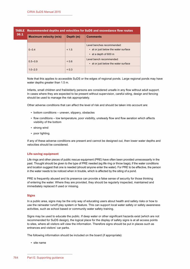
765Chapter 36: Health and safety764 Part E: Supporting guidance
CIRIA SuDS Manual 2015
Note that this applies to accessible SuDS or the edges of regional ponds. Large regional ponds may have water depths greater than 1.5 m.
Infants, small children and frail/elderly persons are considered unsafe in any flow without adult support. In cases where they are expected to be present without supervision, careful siting, design and fencing should be used to manage the risk appropriately.
Other adverse conditions that can affect the level of risk and should be taken into account are:
▪ bottom conditions – uneven, slippery, obstacles
▪ flow conditions – low temperature, poor visibility, unsteady flow and flow aeration which affects visibility of the bottom
▪ strong wind
▪ poor lighting.
If any of these adverse conditions are present and cannot be designed out, then lower water depths and velocities should be considered.
Life-savingequipment
Life rings and other pieces of public rescue equipment (PRE) have often been provided unnecessarily in the past. Thought should be given to the type of PRE needed (eg life ring or throw bags), if the water conditions and location suggest that one is needed (should anyone enter the water). For PRE to be effective, the person in the water needs to be noticed when in trouble, which is affected by the siting of a pond.
PRE is frequently abused and its presence can provide a false sense of security for those thinking of entering the water. Where they are provided, they should be regularly inspected, maintained and immediately replaced if used or missing.
Signs
In a public area, signs may be the only way of educating users about health and safety risks or how to use the rainwater runoff play system or feature. This can support local water safety or safety awareness activities, such as school based or community water safety training.
Signs may be used to educate the public. If deep water or other significant hazards exist (which are not recommended for SuDS design), the logical place for the display of safety signs is at all access points to sites, where all visitors will view the information. Therefore signs should be put in places such as entrances and visitors’ car parks.
The following information should be included on the board (if appropriate):
▪ site name
TABLE36.1
RecommendeddepthsandvelocitiesforSuDSandexceedanceflowroutes
Maximum velocity (m/s) Depth (m) Comments
0–0.4 < 1.5
Level benches recommended:
▪ at or just below the water surface
▪ at a depth of 600 m
0.5–0.9 < 0.6Level bench recommended:
▪ at or just below the water surface
1.0–2.0 < 0.3

765Chapter 36: Health and safety764 Part E: Supporting guidance
CIRIA SuDS Manual 2015
▪ emergency instruction: “Dial 999 in an emergency”
▪ main hazard and prohibition symbols and supplementary text
▪ details of site supervision services and contact details
▪ location and postcode (needs to be understood by local emergency services)
▪ site map showing, rescue equipment, first aid and supervisory help, telephones
▪ organisational logos.
Signs and information are commonly provided with any PRE that is provided to form a “safety point” or “safety station”.
As well as the information provided at access points, provision should be made to repeat the message along routes adjacent to the water’s edge, where specific higher risk situations exist. These are known as “nag signs”, and are repeat messages, small reinforcement messages of key hazard or prohibition messages given previously on the primary or secondary signs. They should relate directly to the hazard that they are in close proximity to and should be predominantly symbol-based messages with reinforcing text. They are normally located next to the hazard, at places where visitors are most likely to access the water. These could be (for example):
▪ pinch points on walkways or paths
▪ jetties or platforms
▪ locations where entry might be expected
▪ viewing platforms
▪ other key hazards determined on site.
There will be many locations on site where nag signs can be placed. However, it is crucial, that only the key locations are signed; using too many nag signs will have a detrimental effect on the overall message.
Where the system includes significant areas of open water, the site will require monitoring for ice formation, and appropriate temporary warning signs will be needed (RoSPA should be approached for advice in such scenarios).
36.3.3 Slip and fall risk management
Physical injuries, such as falls, slips, trips and entrapment, should be no more prevalent at SuDS components than at any other natural or amenity feature, provided that good design principles have been followed and that consideration has been given to the potentially increased likelihood of wet and slippery conditions.
Of the 407 reported cases of drowning in 2011 (NWSF, 2012), 87 resulted from walking or running next to water. The steepness of the bank, freeboard, condition of the pathways and additional hazards should all be given significant consideration to ensure that a trip or stumble does not result in a fall into deep or fast flowing water. This includes consideration of the perception and abilities of the very young, very old and people with disabilities, as much as lighting and the expected site activities.
Accessible surfaces that convey runoff, or through which runoff is designed to pass, may be more vulnerable to a deterioration in structural integrity or build-up of algae that can cause the surface to become slippery, and potentially result in ice formation during winter months.
Structural integrity
All SuDS components should be structurally sound for use, taking into account the likelihood of vandalism or misuse, the durability of materials and the planned maintenance regime.

767Chapter 36: Health and safety766 Part E: Supporting guidance
CIRIA SuDS Manual 2015
Any structural surfaces designed for accessibility should be suitably slip resistant, particularly those where surface water flow can be expected. The risks associated with ice formation should also be considered and managed appropriately, but the same considerations as for general water safety will apply – shallow water features are preferred.
Vertical drops and steep-sided structures
Good SuDS design should avoid the need for high vertical drops or deep steep-sided structures. In many cases, such hazards can be avoided by sensible profiling slopes of headwalls, or risks reduced by locating such structures away from open water. High headwalls should not be necessary in an efficient drainage design where flows are managed in sub-catchments.
If steep slopes and high vertical drops cannot be removed from the design, consideration should be given to how the risk is managed effectively and to access arrangements for maintenance (this is a CDM requirement). Vehicle movements should also be given careful consideration where SuDS are close to roadways.
Levelchanges
Unexpected changes in level, particularly if not immediately visible, should be avoided. Slopes should be gentle, at 1 in 3 or less, where accessible, and other changes in level visible and expected.
Inlets, outlets and safety grilles
Safety grilles are only required on pipes of ≥350 mm diameter (WRc, 2012). An efficient SuDS design should not require large pipes in most cases. Where grilles are provided, they should follow the guidance in WRc (2012).
36.3.4 Ill health from untreated or polluted water risk management
Rainwater runoff in SuDS components is no different from the water that runs across roads and car parks and stands as puddles for lengthy periods after rainfall. Many existing water features in parks and public open spaces already take highway runoff. Indeed, with good SuDS design and effective source control, accessible SuDS components should contain “treated” runoff, and therefore any pollution levels should be very low.
However, as with any natural water bodies, water in SuDS could potentially contain toxins that could potentially cause ill health, and there are management principles that should be followed to minimise potential risks.
Blue-green algae, leptospirosis, cryptosporidium and E. coli are examples of possible toxins. However, as with pollutants, the risks associated with the presence of these in SuDS components should be, at worst, no greater than in, for example, recreational ponds in parks, and it should be lower in a well-designed SuDS Management Train that removes pollution at source. Robust routine inspection and operation and maintenance practices should deal with the low risks associated with these hazards.
Weil’s disease and blue-green algae
Weil’s disease is a form of bacterial infection also known as leptospirosis which is carried by animals, most commonly in rats and cattle. It can be caught by humans through contact with rat or cattle urine, present in contaminated fresh water, including ponds, lakes, rivers and canals. Infection of humans usually occurs where open wounds are immersed in contaminated water.
Employees who work near water should be provided with a workers’ card that can be presented to their doctor if symptoms appear. This means that they can be diagnosed and treated quickly, reducing the likelihood of severe infection.

767Chapter 36: Health and safety766 Part E: Supporting guidance
CIRIA SuDS Manual 2015
Blue-green algae tends to occur in warm water bodies with high nutrient content. “Stagnant” water is polluted water with a high nutrient content.
Water in SuDS should not be stagnant, but have low nutrient levels and be relatively clean. Nutrient removal upstream of pond systems should be considered in the design.
Disease-carrying and/or nuisance insects
There are a number of nuisance insects that use temporary water to lay eggs with the characteristic comma-shaped larvae changing into adults in 2–3 weeks in summer. Mosquitos are one of these insects, but the high-risk diseases that they are known to carry (eg malaria, West Nile virus) are not found in the UK, and mosquitos here are not currently implicated in the transmission of any diseases. Mosquitos are a natural part of the ecosystem, and many species such as bats, birds, invertebrates and amphibians, plus dragon fly nymphs predate on them. The most likely habitat for mosquitoes will be features such as water butts, which should therefore be covered at all times, blocked roof drainage gullies or other small stagnant water-containing features occurring in or around gardens.
There are measures that can reduce the nuisance of breeding insects. Their larvae are often predated by other living things within a balanced pond habitat and this should be the objective of any permanent or temporary water body design.
Gastro-intestinaldisordersresultingfromtouching(andsubsequentaccidentalingestion)ofroof-harvestedrainwater
Theoretically, such disorders could result from children playing with rainwater harvested from roofs, where the roof is contaminated by bird and/or animal faeces. However, a literature review of potential health risks from roof harvested rainwater suggests that the hazard is likely to be very low.
In summary:
▪ faecal contamination indicators for roof runoff have been found to be insignificant or very low
▪ faecal coliform counts from roofs have been found to be significantly lower than for streets and driveways
▪ the risk associated with the use of harvested runoff for showering and/or hosing gardens has been gauged to be well below acceptable levels (and therefore even lower for SuDS where the pathogens are not aerosolised)
▪ the health risk associated with direct ingestion of a harvested supply due to cross-connections associated with a rainwater harvesting system has been gauged to be lower than the risk of being struck by lightning.
Safe working practices
The risk of contaminated, stagnant water occurring in well-designed SuDS components/schemes is very low, and the subsequent risk of a resultant adverse health issue is even lower. Those most likely to be at risk will be maintenance staff, and safe systems of work should be observed to mitigate any remaining risk. Checking for open cuts, and the use of nitrile gloves, waterproof plasters or other skin coverings should be considered wherever working in or near any open water body, including SuDS.
For maintenance operatives, employers have a duty to employees to inform them about the risks of their work environment and to decrease the risk as far as is reasonably practicable. This includes personal protective equipment (PPE) provision and policy implementation based on risk assessment. Employees who work near water should be provided with a workers’ card that can be presented to their doctor if symptoms that relate to water body exposure appear. This means that they can be diagnosed and treated quickly, reducing the likelihood of severity of infection.
769Chapter 36: Health and safety768 Part E: Supporting guidance
CIRIA SuDS Manual 2015
Litter management
A robust litter management strategy should be implemented for all sites, as part of good landscape maintenance practice, through the provision of litter bins and regular litter collection and site litter picks. This will reduce the risks of rats frequenting the area looking for food. The importance of litter removal and the potential risks associated with waterborne diseases should be addressed as part of public education material.
Waterqualitymanagement
Where water bodies are accessible amenity features, the upstream SuDS Management Train should have removed the majority of contaminants, delivering a relatively clean flow of freshwater to the pond or wetland component.
Where rainwater is captured in amenity play features, this water is likely to contain contaminants, and therefore drinking by children should be actively discouraged. However, roof water is relatively clean, and contact should not normally be a problem, although it is recommended that measures are taken to discourage the use of large roofs by large colonies of flocking birds or rodents where the runoff is to be harvested for use. If the design of the SuDS uses the conveyance or storage of rainwater to provide further intermittent play opportunities for slightly longer periods of time after it has rained, the water should be treated at least once, if it is not roof water, using SuDS treatment measures such as gravel filters or vegetation filters. If runoff is captured from busy roads, it should go through at least two cleaning stages before it is suitable for play.
Rainwaterharvestingsystemdesign
RWHs should be designed to BS 8515:2009+A1:2003 so that the collection and storage facility is fit for purpose and includes all appropriate features to guard against undue risk. Any mains water supply that may be installed for example to ensure continuity of supply in dry spells, must be configured with backflow protection in accordance with the Water Supply (Water Fittings) Regulations 1999. The stored water is certain to contain some foreign material from the catchment surfaces and this could include guano, plant and animal remains, and legionella has also been identified in harvested rainwater. It is therefore a requirement of the Control of Substances Hazardous to Health Regulations 2002 to carry out a suitable and sufficient assessment of the risks constituted by any potentially pathogenic microbes in the context of the installation, its mode of operation and the proposed use of the water.
36.3.5 Aircraft safety risk management
Arrangements for airport safeguarding are explained in ODPM (2003), which includes the text of the Town and Country Planning (Safeguarded Aerodromes, Technical Sites and Military Explosives Storage Areas) Direction 2002. Consultation is required within a 13 km zone around an aerodrome where a proposed development is likely to attract birds. Note that the term “aerodrome” is defined in the Civil Aviation Act 1982 and is essentially an area of land or water set aside for aircraft to land or take off. Airport is defined in the Airports Act 1986, and is the aerodrome plus all the buildings and facilities.
Generally, decisions concerning local land use and planning issues, including cases where local aerodromes may be affected, are the responsibility of the local planning authorities. The Civil Aviation Authority (CAA) is not routinely a statutory consultee for planning applications. The CAA does have a role in providing relevant aviation safety advice upon request.
In all cases, aerodrome safeguarding responsibility rests with the aerodrome licence holder/operator (not the CAA). Therefore, any local planning authority enquiry concerning a specific development that might have aerodrome safeguarding implications should be forwarded directly to the relevant aerodrome licence holder/operator.
The CAA has identified SuDS components, in particular ponds, wetlands and green roofs, as a potential hazard to aircraft. Although the main concern is wildfowl including flocks of ducks, geese and swans, there is also concern about other flocking species such as rooks, starlings and gulls. Further advice is provided in AOA and GAAC (2006).

769Chapter 36: Health and safety768 Part E: Supporting guidance
CIRIA SuDS Manual 2015
The risk to aircraft can be mitigated by good ecological design including:
▪ long grass rather than the short grass preferred by geese
▪ small pools and ponds with edges accessible by predators such as foxes
▪ planting design to reduce the risk of roosting by birds in large numbers.
The use of certain SuDS components near to aerodromes will also depend on the site-specific circumstances such as location relative to the aerodrome and location of other features in the area that are attractive to birds.
This is a complex subject, and specialists in bird strike prevention and safeguarding aerodromes should be consulted. Smaller open SuDS components, such as small swales and small shallow ponds, and associated features, such as rills and small canals or channels, are not likely to attract birds any more than a garden pond or lawn.
36.4 HEALTH AND SAFETY RISK ASSESSMENT REQUIREMENTS
36.4.1 Background
Good SuDS design and risk management processes during design (following the guidance and principles set out earlier in this chapter) should deliver drainage systems that are safe. The requirements of the CDM hierarchy should be adopted: identify, eliminate, reduce, control.
There will, however, remain a need for designers of drainage systems to check (and also demonstrate and record) that health and safety risks have been considered and suitably mitigated by the design. Those bodies approving and adopting SuDS will also require a health and safety check so that the long-term safety of the local community, those visiting the site and operation and maintenance operatives are not compromised. Such records are essential to minimise the risk of being held liable for any future health and safety incident that occurred on a site.
The following section sets out a proposed approach to consistent health and safety risk assessment for SuDS, in-line with the principles set out in BS EN 31010:2010. The guidance and principles set out in Section 6 should be referred to when assessing the level of risk for any particular item. Legislation relevant to health and safety risk management for SuDS is summarised in Section 36.5, for context and ease of reference.
36.4.2 Risk assessment
There is a need to be able to determine the following issues with respect to risk at any particular drainage site:
▪ Which site/system characteristics potentially represent hazards?
▪ When might these hazards represent a “risk” (either independently or together)?
▪ To what extent might the local/visiting population be vulnerable to the hazard?
▪ What is the likelihood of a “consequence” occurring?
▪ At what level is the risk, and how acceptable is it, taking the local cultural context into account?
▪ Would mitigation of the risk reduce the societal benefit derived from the SuDS?
▪ Are the risks small enough to be acceptable?
Risk assessment involves systematically identifying hazards (ie anything that has the potential to cause harm), the evaluation of the risks related to those hazards and the establishment of control measures in order to reduce the risk to as low as is necessary or appropriate.
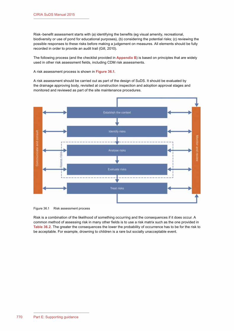
771Chapter 36: Health and safety770 Part E: Supporting guidance
CIRIA SuDS Manual 2015
Risk–benefit assessment starts with (a) identifying the benefits (eg visual amenity, recreational, biodiversity or use of pond for educational purposes), (b) considering the potential risks; (c) reviewing the possible responses to these risks before making a judgement on measures. All elements should be fully recorded in order to provide an audit trail (Gill, 2010).
The following process (and the checklist provided in Appendix B) is based on principles that are widely used in other risk assessment fields, including CDM risk assessments.
A risk assessment process is shown in Figure 36.1.
A risk assessment should be carried out as part of the design of SuDS. It should be evaluated by the drainage approving body, revisited at construction inspection and adoption approval stages and monitored and reviewed as part of the site maintenance procedures.
Risk is a combination of the likelihood of something occurring and the consequences if it does occur. A common method of assessing risk in many other fields is to use a risk matrix such as the one provided in Table 36.2. The greater the consequences the lower the probability of occurrence has to be for the risk to be acceptable. For example, drowning to children is a rare but socially unacceptable event.
Figure 36.1 Risk assessment process
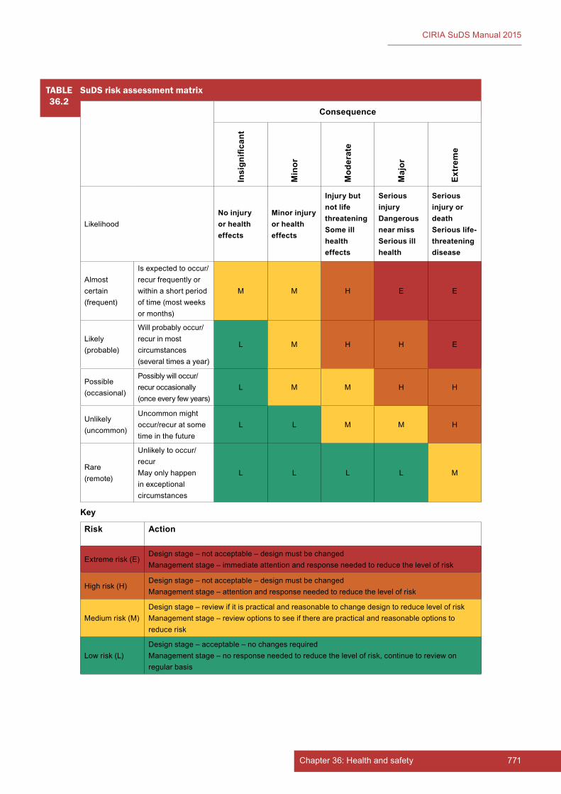
771Chapter 36: Health and safety770 Part E: Supporting guidance
CIRIA SuDS Manual 2015
TABLE36.2
SuDSriskassessmentmatrix
Consequence
Insign
ificant
Min
or
Mod
erat
e
Maj
or
Extr
eme
LikelihoodNo injury or health effects
Minor injury or health effects
Injury but not life threateningSome ill health effects
Serious injuryDangerous near missSerious ill health
Serious injury or deathSerious life-threatening disease
Almost certain (frequent)
Is expected to occur/recur frequently or within a short period of time (most weeks or months)
M M H E E
Likely (probable)
Will probably occur/recur in most circumstances (several times a year)
L M H H E
Possible (occasional)
Possibly will occur/recur occasionally (once every few years)
L M M H H
Unlikely (uncommon)
Uncommon might occur/recur at some time in the future
L L M M H
Rare (remote)
Unlikely to occur/recurMay only happen in exceptional circumstances
L L L L M
Key
Risk Action
Extreme risk (E)Design stage – not acceptable – design must be changedManagement stage – immediate attention and response needed to reduce the level of risk
High risk (H)Design stage – not acceptable – design must be changedManagement stage – attention and response needed to reduce the level of risk
Medium risk (M)Design stage – review if it is practical and reasonable to change design to reduce level of riskManagement stage – review options to see if there are practical and reasonable options to reduce risk
Low risk (L)Design stage – acceptable – no changes requiredManagement stage – no response needed to reduce the level of risk, continue to review on regular basis
773Chapter 36: Health and safety772 Part E: Supporting guidance
CIRIA SuDS Manual 2015
36.5 HEALTH AND SAFETY LEGISLATION
The UK health and safety laws are designed to ensure that those in control of premises do what is reasonably practicable to ensure the safety of employees, contractors and the public.
The following statutory instruments impose obligations and duties to ensure that staff and members of the public are not exposed to risks to their health and safety:
▪ The Health and Safety at Work etc Act 1974
▪ The Management of Health and Safety at Work Regulations 1999
▪ The Occupier’s Liability Acts of 1957 and 1984
▪ The Public Health Act 1936.
Health and safety of structures, including SuDS, starts with design, and all SuDS designers must be familiar with and follow the specific requirements of CDM 2015. CDM 2015 is aimed at improving the overall management and co-ordination of health, safety and welfare throughout all stages of a construction project and the Regulations place duties on all those who can contribute to the health and safety of a structure. Risk assessments at the design stage are an important step and should include the identification of any hazards in the design, suitable actions to eliminate or reduce the risks to builders, maintainers and users of the structure (eg the public) and the information required regarding residual risks in order that they may be effectively controlled on site. Early design decisions and assumptions affect health and safety because they influence the choice of materials, construction methods and the build programme, as well as design characteristics and SuDS locations. In addition to the CDM Regulations, designers should consider the implications of the Building Regulations in terms of access and protection from falls and any additional requirements that may be relevant to meet the requirements of the Management of Health and Safety at Work Regulations 1999. The Workplace (Health, Safety and Welfare) Regulations 1992 will also apply as the SuDS scheme will become a workplace from time to time during maintenance.
Consideration needs to be given to the whole SuDS scheme and not just any ponds that may be created. For example:
▪ Will roof maintenance be needed on a green roof. If so, how will this be conducted safely? For example, will harness eye bolts be needed?
▪ Will permeable paving become uneven quickly? How will this be inspected and managed?
▪ Will rills be used for paddling? How will this be encouraged safely?
The asset owner or occupier is ultimately responsible for conducting a suitable and sufficient assessment of the SuDS for the use, inspection and maintenance of the system. However, the owner will need sufficient information from the designer and developer to conduct this assessment and to be confident that the system meets the required standards prior to adoption.
Under common law, the SuDS owner or occupier has a duty to potential visitors “to take reasonable care to avoid acts or omissions which you can reasonably foresee would be likely to injure your neighbour”. Reasonable care is defined as “what a reasonable person would have foreseen as being necessary” and acknowledges that a certain level of risk is acceptable and it is expected that appropriate safety measures will be applied in each circumstance. Each location and SuDS scheme will be different and therefore blanket designs, features and characteristics will not necessarily be effective or appropriate.
The Occupiers’ Liability Acts (OLA) of 1957 and 1984 govern to what extent landowners are responsible for the health and safety of visitors and trespasses to their premises. Case law should be referenced to clarify the specific implications of each of the Acts for SuDS owners and operators.

773Chapter 36: Health and safety772 Part E: Supporting guidance
CIRIA SuDS Manual 2015
36.6 REFERENCES
AOA and GAAC (2006) Potential bird hazards from sustainable drainage schemes (SuDS). Safeguarding of aerodromes, Advice Note 6, Airport Operators Association and General Aviation Awareness Council, London, UK. Go to: http://tinyurl.com/paflha7
BALL, D and BALL-KING, L (2011) Public safety and risk assessment: improving decision making, Earthscan, Abindgon, Oxon, UK (ISBN: 978-1-84971-380-1)
BASTIEN, N R P, ARTHUR, S and MCLOUGHLIN, M (2011) “Valuing amenity: public perceptions of sustainable drainage systems ponds” Water and Environment Journal, vol 26, 1, Wiley Online, London, pp 19-29
DEFRA (2006) Flood risks to people phase 2, FD2321/TR2. Guidance document, Defra/Environment Agency Flood and Coastal Defence R&D Programme, Department for Environment Food and Rural Affairs, London and Environment Agency, Bristol, UK. Go to: http://tinyurl.com/ptxewt8
GILL, T (2010) Nothing ventured… Balancing risks and benefits in the outdoors, English Outdoor Council, Nottingham, UK. Go to: http://tinyurl.com/q7eernq
HR WALLINGFORD (2003) An assessment of the social impacts of sustainable drainage systems in the UK, Report SR622, Department for Trade and Industry, London, UK. Go to: http://tinyurl.com/ob35hcy
HSE (2015) Managing health and safety in construction. Construction (Design and Management) Regulations 2015, L153, Health and Safety Executive, London, UK (ISBN: 978-0-71766-626-3). Go to: www.hse.gov.uk/pubns/priced/L153.pdf
NWSF (2012) UK water related fatalities 2011, Water incident database report, National Water Safety Forum, UK. Go to: http://tinyurl.com/oxq76mk
ODPM (2003) Safeguarding aerodromes, technical sites and military explosives storage areas, DfT/ODPM Circular 1/2003 – advice to local planning authorities on safeguarding aerodromes and military explosives storage areas, Office of the Deputy Prime Minister, London, UK. Go to: http://tinyurl.com/babba3l
WRC (2012) Sewers for adoption, seventh edition, WRc Publications, Swindon, UK (ISBN: 978-1-89892-065-6)
STATUTES
Acts
Airports Act 1986 (c.31)
Disability Discrimination Act 1995 (c.50)
The Control of Substances Hazardous to Health Regulations 2002 (No.2677)
Health and Safety at Work etc Act 1974 (c.37)
The Management of Health and Safety at Work Regulations 1999 (No.3242)
Occupier’s Liability Act 1957 (c.31)
Occupier’s Liability Act 1984 (c.3)
Public Health Act 1936 (c.49)

775Chapter 36: Health and safety774 Part E: Supporting guidance
CIRIA SuDS Manual 2015
Water Supply (Water Fittings) Regulations 1999 (No.1148)
Workplace (Health, Safety and Welfare) Regulations 1992 (No.3004)
Regulations
Construction (Design and Management) (CDM) Regulations 2015
Standards
BS 8515:2009+A1:2003 Rainwater harvesting systems. Code of Practice
BS EN 31010:2010 Risk management. Risk assessment techniques

775Chapter 36: Health and safety774 Part E: Supporting guidance
CIRIA SuDS Manual 2015
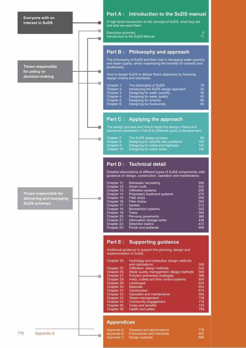
776 Appendix A
Part C : Applying the approachThe design process and how to apply the design criteria and standards presented in Part B to different types of development.
Chapter 7: The SuDS design process 94Chapter 8: Designing for specific site conditions 128Chapter 9: Designing for roads and highways 142Chapter 10: Designing for urban areas 156
Part D : Technical detailDetailed descriptions of different types of SuDS components, with guidance on design, construction, operation and maintenance.
Chapter 11: Rainwater harvesting 206Chapter 12: Green roofs 232Chapter 13: Infiltration systems 256Chapter 14: Proprietary treatment systems 270Chapter 15: Filter strips 290Chapter 16: Filter drains 302Chapter 17: Swales 312Chapter 18: Bioretention systems 332Chapter 19: Trees 360Chapter 20: Pervious pavements 386Chapter 21: Attenuation storage tanks 436Chapter 22: Detention basins 472Chapter 23: Ponds and wetlands 484
Part A : Introduction to the SuDS manualA high-level introduction to the concept of SuDS, what they are and why we need them.
Executive summary 5Introduction to the SuDS Manual 11
Part B : Philosophy and approachThe philosophy of SuDS and their role in managing water quantity and water quality, whilst maximising the benefits for amenity and biodiversity.
How to design SuDS to deliver these objectives by following design criteria and standards.
Chapter 1: The philosophy of SuDS 18Chapter 2: Introducing the SuDS design approach 32Chapter 3: Designing for water quantity 36Chapter 4: Designing for water quality 50Chapter 5: Designing for amenity 66Chapter 6: Designing for biodiversity 80
Part E : Supporting guidanceAdditional guidance to support the planning, design and implementation of SuDS.
Chapter 24: Hydrology and hydraulics: design methods and calculations 506Chapter 25: Infiltration: design methods 542Chapter 26: Water quality management: design methods 560Chapter 27: Pollution prevention strategies 596Chapter 28: Inlets, outlets and flow control systems 604Chapter 29: Landscape 630Chapter 30: Materials 654Chapter 31: Construction 674Chapter 32: Operation and maintenance 690Chapter 33: Waste management 708Chapter 34: Community engagement 716Chapter 35: Costs and benefits 734Chapter 36: Health and safety 758
AppendicesAppendix A: Glossary and abbreviations 778Appendix B: Frameworks and checklists 802Appendix C: Design example 888
Everyone with an interest in SuDS
Those responsible for delivering and managing SuDS schemes
Those responsible for policy or decision-making
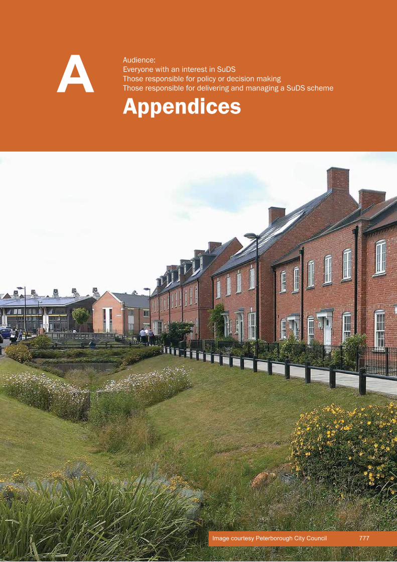
CIRIA SuDS Manual 2015
AppendicesA Audience:
Everyone with an interest in SuDSThose responsible for policy or decision makingThose responsible for delivering and managing a SuDS scheme
777Image courtesy Peterborough City Council
779Appendix A: Glossary and Abbreviations778 Appendix A
CIRIA SuDS Manual 2015
APPENDIX A GLOSSARY AND ABBREVIATIONS
Contents
Glossary 779Abbreviations 794
Imag
e co
urte
sy A
rup

779Appendix A: Glossary and Abbreviations778 Appendix A
CIRIA SuDS Manual 2015
AGlossary and Abbreviations
Appendix
GLOSSARY
Adopting/adoption body
The organisation responsible for taking ownership of the SuDS.
Adaptability The degree to which a system can be adapted to better suit changing circumstances or conditions (see flexibility).
Adsorption The adherence of gas, vapour or dissolved matter to the surface of solids.
Amenity The quality of being pleasant, attractive, desirable and/or useful.
Approving/approval body
The organisation responsible for approving the SuDS.
Aquatic bench A flat or almost flat surface around the inside perimeter of a permanent pond. Normally vegetated with emergent plants, the bench augments pollution removal, provides habitat and enhances safety.
Aquifer A subsurface zone or formation of rock or soil containing a body of groundwater.
Asphalt European standard description of all mixtures of mineral aggregates bound with bituminous materials used in the construction and maintenance of paved surfaces.
Attenuation Reduction of peak flow rate and increased duration of a flow event.
Attenuation storage
Volume in which runoff is stored when the inflow to the storage is greater than the controlled outflow.
Baffle A device designed to extend flow paths through a pond.
Base flow The sustained flow in a channel or drainage system.
Basin A ground depression that is normally dry, designed to store surface water before infiltration (see infiltration basin) and/or provide attenuation (see detention basin).
Benefit–cost ratio
The ratio between the benefits and costs of a scheme; used to determine whether it is value for money.
Benefit transfer A method for transferring the values ascribed to a good, service or attribute from one survey or study in relevant ways to another decision or policy context, thereby avoiding the need to repeat the survey or study.
Bentonite A colloidal clay, largely made up of the mineral sodium montmorillonite, a hydrated aluminium silicate.
Berm A shelf or raised barrier separating two areas.
Binder course European standard description of the second layer of an asphalt pavement currently known in the UK as basecourse.
Biochemical oxygen demand (BOD)
The measure of the concentration of biodegradable organic carbon compounds in solution. Used as a water quality indicator.

781Appendix A: Glossary and Abbreviations780 Appendix A
CIRIA SuDS Manual 2015
Biodegradable Capable of being decomposed by bacteria or other living organisms.
Biodegradation Decomposition of organic matter by microorganisms and other living things.
Biodiversity The diversity of plant and animal life in the world, an area or a particular habitat – a high level of which is usually considered to be important or desirable.
Biofiltration Filtration using living materials (see filtration).
Bioretention system A shallow planted depression that allows runoff to pond temporarily on the surface, before filtering through vegetation and underlying soils prior to collection or infiltration. In its simplest form, it is often referred to as a rain garden. Engineered soils (gravel and sand layers) and enhanced vegetation can be used to improve treatment performance.
Bitumen A hydrocarbon binder. A virtually non-volatile adhesive material derived from crude petroleum that is used to coat mineral aggregate for use in construction and maintenance of paved surfaces.
Block paving Paving designed to allow rainwater falling onto the surface or runoff discharged over the surface to infiltrate through the joints or voids between the blocks into the underlying pavement structure (see permeable pavements).
Blue roof A roof construction that stores water; can include open water surfaces, storage within or beneath a porous media or modular surface or below a raised decking surface or cover.
Blue space Similar to green space, but it is an area of water rather than vegetation.
Breakthrough head The water pressure required to cause a flow of water through the material (eg geotextile).
Brownfield site A site that has been previously developed.
Brown roof A roof that incorporates a substrate (laid over a waterproof membrane) that is non-planted and allowed to colonise naturally. Sometimes referred to as an alternative roof.
Buffer Something that helps reduce the scale of an impact.
Bund A barrier, dam or mound usually formed from earthworks material and used to contain or exclude water (or other liquids) in/from an area of the site.
California bearing ratio (CBR)
An empirical measure of the stiffness and strength of soils, used in road pavement design.
Capping layer A layer of unbound aggregate of lower quality than sub-base, that is used to improve the performance of the foundation soils before laying the sub-base, and to protect the subgrade from damage by construction traffic.
Carriageway That part of the road used to carry vehicular traffic.
Catchment The area contributing surface water flow to a point on a drainage or river system. Can be divided into sub-catchments.
Catchpit A small chamber incorporating a sediment collection sump that the runoff flows through.
Chemical oxygen demand (COD)
The measure of the amount of oxygen taken up by chemical oxidation of a substance in solution. Used as a water quality indicator.
Climate change A change in the state of the climate that can be identified (eg by using statistical tests) by changes in the mean and/or the variability of its properties, and that persists for an extended period, typically decades or longer. Climate change may be due to natural internal processes, to external forcings or to persistent anthropogenic changes in the composition of the atmosphere, ocean or in land use.
Climate change scenarios A coherent, internally consistent and plausible description of possible future changes in climate, usually based on specific assumptions.
Climate resilience The capacity of a system to cope with a hazardous climate event or trend or disturbance, responding or reorganising in ways that maintain (or recover) its essential function, identity and structure, while also maintaining the capacity for adaptation (see adaptability).

781Appendix A: Glossary and Abbreviations780 Appendix A
CIRIA SuDS Manual 2015
Coliform Bacteria found in the intestines, faeces, nutrient rich waters, soil and decaying plant matter.
Combined sewer An underground pipe designed to carry both foul sewage and surface water runoff.
Combined sewer overflow (CSO)
A structure on a combined or partially separate sewer system that allows the discharge of flow in excess of that which the sewer is designed to carry, usually to a receiving surface water body.
Construction quality assurance (CQA)
A documented management system designed to provide adequate confidence that items or services meet contractual requirements and will perform adequately in service. CQA usually includes inspection and testing of installed components and recording the results.
Contaminated ground Ground that has the presence of substances that, when present in sufficient quantities or concentrations, could cause significant harm to people or protected species or significant pollution of surface waters or groundwater.
Contingent valuation A method, using sample evidence from questionnaires and surveys, that estimates how much people would be willing to pay for specific environmental or social benefits.
Continuously graded A soil or aggregate with a balanced range of particle sizes with significant proportions of all fractions from the maximum nominal size down.
Control structure A structure to control the volume or rate of flow of water through or over it.
Conventional drainage The method of draining surface water using subsurface pipes and storage tanks.
Conveyance Movement of water from one location to another.
Cost-effective Something that is value for money. In economic terms, the benefits received and/or services delivered are worth at least what is paid for them.
Cost-effectiveness analysis (CEA)
A form of economic analysis that compares the relative cost to benefit, sometimes described as the change in outcome for a unit of investment.
Costs avoided Future costs that will not appear as a result of an action, where it is reasonably certain that the cost would have appeared otherwise.
Creep A load placed on a polymer material will result in an initial deformation, but with the load remaining over time, further deformation will continue to occur. The rate of creep becomes greater as the applied load increases.
Critical duration event The duration of rainfall event likely to cause the highest peak flows or levels at a particular location, for a specified return period event.
Cross-contamination Pipes carrying mains water connected to pipes carrying non-potable water.
Curtilage Land area within property boundaries.
Degradation Being broken down to a less complex/lower state.
Denitrification A microbial process that reduces nitrate to nitrite and then nitrite to nitrogen gas.
Deposition Laying down of matter via a natural process.
Designated drainage system
All parts of a drainage system (including above-ground conveyance and storage areas that may only be used relatively infrequently) that form the management of surface water runoff up to the designed level of service.
Design criteria A set of agreed criteria that the proposed system should be designed to satisfy.
Design event A synthetic rainfall event of a given duration and return period that has been derived by statistical analysis.
Designing for exceedance See exceedance design.
Detention The temporary storage of water to attenuate flows.
Detention basin A landscaped depression that is normally dry except during and following rainfall events. Constructed to store water temporarily, to attenuate flows and, where vegetated, provide treatment.

783Appendix A: Glossary and Abbreviations782 Appendix A
CIRIA SuDS Manual 2015
Development Any area of land that has been or is being developed (ie land use change that includes construction). This includes new developments, redevelopments, infill and retrofit.
Development plan Sets out the policies and proposals for the development, conservation and use of land and buildings in a particular local planning authority (LPA) area. It is the most important consideration for LPAs when they decide on a planning application. The plan generally includes development plan documents that are part of a LPAs local plan.
De-watering The lowering of groundwater/surface water levels or the removal of water from a substance.
Diffuse pollution Pollution arising from land-use activities (urban and rural) that are dispersed across a catchment, or sub-catchment, and do not arise as a process effluent, municipal sewage effluent or an effluent discharge from farm buildings.
Discharge consent Permission to discharge effluent, subject to conditions laid down in the consent, issued by the relevant environment regulator.
Discounting A method to compare the benefits and costs that arise over the appraisal period. The discount rate converts all costs and benefits to the present day to determine the present value (PV) or whole life cost (WLC) so that they can be evaluated consistently.
Dissolved oxygen (DO) The amount of oxygen dissolved in water. Oxygen is vital for aquatic life, so this measurement is a test of the health of a river. Used as a water quality indicator.
Double counting Where costs are included more than once in a valuation exercise.
Duty of care To take reasonable care to avoid acts or omissions which you can reasonably foresee would be likely to injure your neighbour.
Ecology The study of plants (flora) and animals (fauna) and the relationships between them and their physical environment.
Ecosystem A biological community and its physical environment.
Ecosystem services The benefits provided by ecosystems that contribute to making human life both possible and worth living. Examples of ecosystem services include products such as food and water, regulation of floods, soil erosion and disease outbreaks, and non-material benefits such as recreational and spiritual benefits in natural areas.
Environmental regulator The primary environmental regulators in the UK are: the Environment Agency in England, Natural Resources Wales, the Scottish Environment Protection Agency and the Northern Ireland Environment Agency. Other organisations that have regulatory responsibilities relating to the environment include local authorities (with respect to, for example, contaminated land and tree preservation), Natural England and Scottish Natural Heritage (with respect to nature conservation).
Erosion The group of natural processes, including weathering, dissolution, abrasion, corrosion and transportation, by which material is worn away from the earth’s surface
Estuary A semi-enclosed body of water in which seawater is substantially diluted with freshwater entering from land drainage.
Eutrophication Water pollution caused by excessive plant nutrients that results in reduced oxygen levels. The nutrients are powerful stimulants to algal growth which in turn use up oxygen in water. The excessive growth, or “blooms”, of algae promoted by these phosphates change the water quality in lakes and ponds which can kill fish.
Evapotranspiration The process by which the Earth’s surface or soil loses moisture by evaporation of water and by uptake and then transpiration from plants.
Exceedance design Designing a system to manage effectively events that exceed (ie are bigger and rarer than) the drainage system’s required level of service.
Exceedance event A rainfall or flow event that exceeds (ie is bigger and rarer than) the design event, not to be confused with an extreme event.
Extreme event A rainfall or flow event that is relatively rare, generally considered to be an event with a return period of 30 years or more, not to be confused with an exceedance event.

783Appendix A: Glossary and Abbreviations782 Appendix A
CIRIA SuDS Manual 2015
Fatigue Fatigue is loss of strength that occurs due to repeated application of traffic or other loads which may reduce the strength of the units in the long term.
Filter drain A linear drain consisting of a trench filled with a permeable material, often with a perforated pipe in the base of the trench to assist drainage.
Filter strip A vegetated area of gently sloping ground designed to drain water evenly off impermeable areas and to filter out silt and other particulates.
Filtration The act of removing sediment or other contaminants from a fluid by passing it through a filter.
Fines Small soil particles less than 63 microns in size.
First flush The initial runoff from a site or catchment following the start of a rainfall event. As runoff travels over a catchment it will collect or dissolve pollutants, and the “first flush” portion of the flow may be the most contaminated as a result. This is especially the case for intense storms and in small or more uniform catchments. In larger or more complex catchments pollution wash-off may contaminate runoff throughout a rainfall event.
Flexibility The ability to cope with a range of conditions or requirements.
Flood Consequence Assessment (FCA)
The Welsh Government’s requirement for assessing the potential consequence of flooding on a development or caused by the development, as set out in TAN 15. Similar to a Flood Risk Assessment (FRA).
Flood frequency The concept of the probable frequency of occurrence of a flood event of a given size.
Floodplain The area that would naturally be affected by flooding (ie in the absence of flood defences or certain other manmade structures and channel improvements) if a river rises above its banks or high tides and stormy seas cause flooding in coastal areas.
Flood Risk Assessment (FRA)
An assessment of the risk of flooding on a development or caused by the development required as part of the planning application process in England, Scotland and Northern Ireland (see Flood Consequence Assessment for Welsh equivalent).
Flood risk management Holistic and continuous analysis, assessment and reduction of flood risk.
Flood routing Design and consideration of above-ground areas that act as pathways permitting water to run safely overland to minimise the adverse effect of flooding. This is required when the design capacity of the drainage system has been exceeded.
Flow control device A device used to limit the flow through the outlet from a SuDS component, usually necessary to meet a required discharge rate.
Forebay A small basin or pond upstream (or at the upstream end) of the main drainage component, with the function of trapping sediment.
Formation level Surface of an excavation prepared to support a pavement or other overlying structure.
Foul drainage The infrastructure that drains the water and sewage that is discharged from within houses.
Foul sewer An underground pipe designed to carry only foul sewage.
Freeboard Distance between the design water level and the top of a structure, provided as a precautionary safety measure against early system failure.
Frequent (rainfall) event Rainfall events that happen more often than once a year.
Geocellular storage systems
Modular plastic units with a high porosity (generally around 95%) that can be used to create a below-ground structure for the temporary storage of surface water before controlled release or use. The storage structure (tank) is formed by assembling the required number of individual units (sometimes in several layers) and wrapping them in either a geotextile or a geomembrane.
Geocomposite A form of geosynthetic that is made by creating a single component from two or more elements (eg a drainage core and a geotextile).
Geogrid Plastic grid structure used to increase the strength of soils or aggregates.
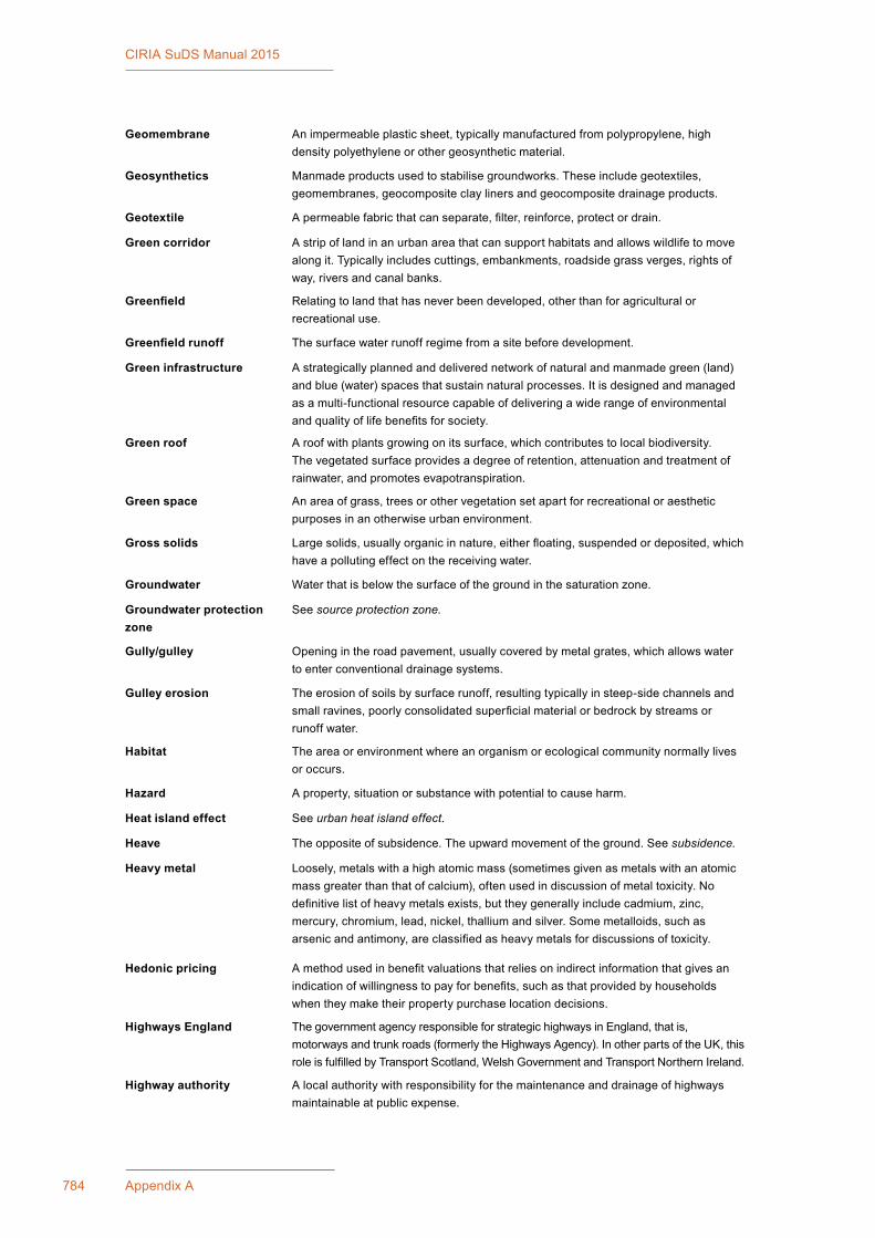
785Appendix A: Glossary and Abbreviations784 Appendix A
CIRIA SuDS Manual 2015
Geomembrane An impermeable plastic sheet, typically manufactured from polypropylene, high density polyethylene or other geosynthetic material.
Geosynthetics Manmade products used to stabilise groundworks. These include geotextiles, geomembranes, geocomposite clay liners and geocomposite drainage products.
Geotextile A permeable fabric that can separate, filter, reinforce, protect or drain.
Green corridor A strip of land in an urban area that can support habitats and allows wildlife to move along it. Typically includes cuttings, embankments, roadside grass verges, rights of way, rivers and canal banks.
Greenfield Relating to land that has never been developed, other than for agricultural or recreational use.
Greenfield runoff The surface water runoff regime from a site before development.
Green infrastructure A strategically planned and delivered network of natural and manmade green (land) and blue (water) spaces that sustain natural processes. It is designed and managed as a multi-functional resource capable of delivering a wide range of environmental and quality of life benefits for society.
Green roof A roof with plants growing on its surface, which contributes to local biodiversity. The vegetated surface provides a degree of retention, attenuation and treatment of rainwater, and promotes evapotranspiration.
Green space An area of grass, trees or other vegetation set apart for recreational or aesthetic purposes in an otherwise urban environment.
Gross solids Large solids, usually organic in nature, either floating, suspended or deposited, which have a polluting effect on the receiving water.
Groundwater Water that is below the surface of the ground in the saturation zone.
Groundwater protection zone
See source protection zone.
Gully/gulley Opening in the road pavement, usually covered by metal grates, which allows water to enter conventional drainage systems.
Gulley erosion The erosion of soils by surface runoff, resulting typically in steep-side channels and small ravines, poorly consolidated superficial material or bedrock by streams or runoff water.
Habitat The area or environment where an organism or ecological community normally lives or occurs.
Hazard A property, situation or substance with potential to cause harm.
Heat island effect See urban heat island effect.
Heave The opposite of subsidence. The upward movement of the ground. See subsidence.
Heavy metal Loosely, metals with a high atomic mass (sometimes given as metals with an atomic mass greater than that of calcium), often used in discussion of metal toxicity. No definitive list of heavy metals exists, but they generally include cadmium, zinc, mercury, chromium, lead, nickel, thallium and silver. Some metalloids, such as arsenic and antimony, are classified as heavy metals for discussions of toxicity.
Hedonic pricing A method used in benefit valuations that relies on indirect information that gives an indication of willingness to pay for benefits, such as that provided by households when they make their property purchase location decisions.
Highways England The government agency responsible for strategic highways in England, that is, motorways and trunk roads (formerly the Highways Agency). In other parts of the UK, this role is fulfilled by Transport Scotland, Welsh Government and Transport Northern Ireland.
Highway authority A local authority with responsibility for the maintenance and drainage of highways maintainable at public expense.
785Appendix A: Glossary and Abbreviations784 Appendix A
CIRIA SuDS Manual 2015
Highway drain A component draining the highway on highway land that is maintainable at the public expense; vested in the highway authority.
Hydraulics A term for fluid mechanics used in the context of water engineering, and is the study of flows. In the context of this manual, hydraulics covers the storage, conveyance and control of flows within the proposed drainage network.
Hydrogeology The study of water below the ground surface and geological aspects of surface water. In the context of this manual, it covers the dissipation of the rainfall-runoff beneath a permeable soil surface.
Hydrograph A graph illustrating changes in the rate of flow from a catchment with time.
Hydrology The study of the waters of the Earth, their occurrence, circulation and distribution; their chemical and physical properties; and their relation with the environment, including their relation to living things.
Hydrolysis The chemical breakdown of a compound due to reaction with water.
Hyetograph Temporal rainfall profile.
Impermeable Will not allow water to pass through it.
Impermeable area The area within a defined catchment that is impermeable, usually given as a percentage.
Impermeable surface An artificial non-porous surface that generates a surface water runoff after rainfall.
Indicator A means of measuring, at least in part, the extent to which design criteria are achieved.
Infiltration (to a sewer) The entry of groundwater to a sewer.
Infiltration (to the ground) The passage of surface water into the ground.
Infiltration basin A dry basin designed to promote infiltration of surface water to the ground.
Infiltration component A component specifically designed to aid infiltration of surface water into the ground.
Infiltration trench A trench, usually filled with permeable granular material, designed to promote infiltration of surface water to the ground.
Initial rainfall loss The amount of rain that falls on a surface before water begins to flow off the surface.
Inlet A structure or landscape feature that manages the flow into a SuDS component.
Interception The prevention of runoff from the site for the majority of small (frequent) rainfall events (or for the initial depth of rainfall for larger events).
Interception storage The capture and/or storage of small rainfall depths before infiltration, evapotranspiration or use.
Interflow Shallow movement of water through upper soil layers, from where it may infiltrate vertically to an aquifer, move horizontally to a watercourse or be stored and subsequently evapotranspired.
Joint probability The calculated probability of two or more specific events occurring together.
Landscape A term that encompasses the entirety of all external space, whether urban or rural, often considered in terms of their aesthetic appeal.
Land use The main activity that takes place on an area of land based on economic, geographic or demographic use, such as residential, industrial, agricultural or commercial.
Lateral drain That part of a drain that runs from the curtilage of a building (or buildings or yards within the same curtilage) to the sewer with which the drain communicates or is to communicate; or (if different and the context so requires) the part of a drain identified in a declaration of vesting made under section 102 or in an agreement made under Section 104 of the Water Industry Act 1991.
Leaching The process during which soluble minerals may be removed from the soil by water percolating through it.

786 Appendix A
CIRIA SuDS Manual 2015
Lead local flood authority Unitary authorities or county councils responsible for developing, maintaining and applying a strategy for local flood risk management in their areas and for maintaining a register of flood risk assets. Also responsible for managing the risk of flooding from surface water, groundwater and ordinary watercourses.
Leakage The flow of water from one hydrologic unit to another. The leakage may be natural (as through a semi-impervious confining layer) or manmade (as through an uncased well).
Legibility The degree to which a system can be readily understood by the public.
Legionella A bacterium named Legionella pneumophila that can cause legionnaires’ disease (lung infection) in humans.
Level of service The performance of a system, either designed or measured. Also referred to as Standard of service.
List I substance A controlled substance as defined under the Groundwater Regulations 1998 and Directive 76/464/EEC (Dangerous Substances Directive). List I substances are considered the most dangerous in terms of toxicity, bioaccumulation and persistence. These controls prevent their discharge to the environment.
List II substance A controlled substance as defined under the Groundwater Regulations 1998 and the Directive 76/464/EEC (Dangerous Substances Directive). They are less toxic than List I substances but are still capable of harm, hence their discharge to the environment is limited.
Liveability The degree to which a scheme enhances a community’s quality of life, health and well-being, such as providing a link between the built and natural environments; providing educational, cultural, entertainment and recreational potential; and helping to support economic prosperity, social stability and equity.
Local flood risk management strategy
A local strategy for flood and coastal erosion risk management developed by the lead local flood authority, which acts as the evidence base for decisions and actions required to manage flood risk.
Local planning authority (LPA)
The local authority or council that is empowered by law to exercise town planning functions for a particular area of the UK. In Scotland, where all of the local authorities are unitary, the term “planning authority” is used without the “local” prefix.
Long-Term Storage Volume The difference in runoff volume between the developed site and its greenfield (or previously developed) state. This is the volume that should be prevented from leaving the site (via rainwater harvesting and/or infiltration) or, where this is not possible, controlled so that it discharges at very low rates that will have negligible impact on downstream flood risk.
Macrophyte Plants easily visible to the naked eye.
Maintainability The ease with which a scheme can be safely and effectively maintained.
Management Train The sequence of drainage components that collect, convey, store and treat runoff as it drains through the site.
Master plan An overarching planning document and spatial layout that is used to structure future land use and development.
Mean annual flood (QBAR) The mean of the series of peak annual flow rates observed or estimated for a river at a particular location. Statistically, rivers and streams will equal or exceed the mean annual flood once every 2.33 years.
Micropool Pool at the outlet from a pond or wetland that is permanently wet and improves the pollutant removal of the system.
Misconnection An incorrect connection of an inlet or drain to a drain or sewer that is not designed to carry that element of flow (eg foul sewage entering a surface water system or surface water entering a separate foul system).
Model agreement A legal document that can be completed to form the basis of an agreement between two or more parties regarding the maintenance and operation of sustainable water management systems.

787Appendix A: Glossary and Abbreviations786 Appendix A
CIRIA SuDS Manual 2015
Modular storage systems A storage system designed as a series of standardised units that can be linked together to increase capacity.
Morphology The characteristics, configuration and evolution of a river.
Multi-criteria analysis (MCA)
An umbrella term used for applying non-quantitative assessment techniques (alongside quantitative results where available), where stakeholders believe there are significant benefits beyond those that can be monetised that should be included in the decision-making process.
Multi-functional Something that has or fulfils more than one function.
Multi-functionality The degree to which a system can have or perform multiple functions.
Natural capital The elements of nature that produce value to people, such as the stock of forests, water, land, minerals and oceans. These provide many benefits, by providing food, clean air, wildlife, energy, wood, recreation and protection from hazards.
Nature conservation bodies The four organisations that have regional responsibility for promoting the conservation of wildlife and natural features: Natural England, Natural Resources Wales, Scottish Natural Heritage and Northern Ireland Environment Agency.
Net present value (NPV) The difference between the present value of benefits and the present value of costs (see present value).
Non-potable water Water not suitable for drinking.
Non-return valve A pipe-fitting that limits flow to one direction only.
Nutrient A substance providing nourishment for living organisms (such as nitrogen and phosphorus).
Off-line A part of the drainage system that does not receive flows during frequent events.
Oil separator A component designed to separate gross amounts of oil and sediments from surface water runoff.
On-line A part of the drainage system that receives flows during all frequent events.
Organic pollution A general term describing the type of pollution that, through the action of bacteria, consumes the dissolved oxygen in rivers. The effects of organic pollution are described by the levels of biochemical oxygen demand, ammonia and dissolved oxygen found in a water body.
Orifice plate Structure with a fixed aperture to control the flow of water.
Outfall The point, location or structure where surface water runoff discharges from a drainage system.
Outlet A structure or landscape feature that manages the flow out of a SuDS component.
Overflow The flow of water from a conveyance or storage component once the capacity of that component is exceeded. Not to be confused with a combined sewer overflow.
Oxidation The combination of a compound with oxygen.
Pathogen An organism that causes disease.
Pathway The route by which potential contaminants may reach targets.
Pavement The road or car park surface and underlying structure, usually asphalt, concrete or block paving. Note that the path next to the road for pedestrians (the UK colloquial term of pavement) is the footway.
Peak flow The point at which the flow of water from a given event is at its highest.
Penstock A sliding plate that moves vertically to vary the size of an aperture (or close it completely).
Percentage runoff The percentage of the rainfall volume falling on a specified area that then runs off that surface.
Percolation The passing of water (or other liquid) through a porous substance or small holes (eg soil or geotextile fabric).

788 Appendix A
CIRIA SuDS Manual 2015
Permeability A measure of the ease with which a fluid can flow through a porous medium. It depends on the physical properties of the medium, for example grain size, porosity and pore shape.
Permeable pavement A surface that is formed of material that is itself impervious to water, but is laid to provide void space through the surface to the sub-base.
Pervious area Area of ground that allows infiltration of water, although some surface runoff may still occur.
Pervious pavement A surface that provides a pavement suitable for pedestrian and/or vehicular traffic, while allowing rainwater to infiltrate through the surface and into the underlying structural layers.
Pervious surface A surface that allows inflow of rainwater into the underlying construction or soil.
Photolysis The breakdown of surface-held organic pollutants by exposure to ultraviolet light.
Phytoremediation The treatment of pollutants in soils, water or air through the use of plants.
Place-making A multi-faceted approach to the planning, design and management of public spaces with the intention of creating public spaces that promote people’s health and well-being.
Point source pollution Pollution that arises from an easily identifiable source, usually an effluent discharge pipe.
Pollution A change in the physical, chemical, radiological or biological quality of a resource (air, water or land) caused by man or man’s activities that is injurious to existing, intended or potential uses of the resource.
Pollution prevention strategies
Site design and management to stop or reduce the occurrence of pollution of surface water runoff.
Pond Permanently wet depression designed to temporarily store surface water runoff above the permanent pool and permit settlement of suspended solids and biological removal of pollutants.
Porosity The percentage of the bulk volume of a rock or soil that is occupied by voids, whether isolated or connected.
Porous asphalt An asphalt material used to make pavement layers pervious, with open voids to allow water to pass through (previously known as pervious macadam).
Porous pavement A permeable surface that allows water to infiltrate across the entire surface material through voids that are integral to the pavement.
Porous surface A surface that infiltrates water to the sub-base across the entire surface of the material forming the surface, for example grass and gravel surfaces, porous concrete and porous asphalt.
Potable water Water suitable for drinking.
Precipitation 1 (meteorology) Any product of the condensation of atmospheric water vapour that falls under gravity, including rain, sleet, snow and hail.
2 (chemistry) A chemical reaction between pollutants and compounds in the soil or aggregate matrix that transforms dissolved constituents into insoluble particles.
Pre-treatment The removal of contaminants (usually sediments) that may reduce the treatment performance of a specific downstream component.
Present value (PV) The value in the present, of a sum of money; in contrast to some future value it will have when it has been invested and accrued compound interest. If a cost is assumed to be required at some future date, then that cost should be discounted to determine its present value (see discounting).
Previously developed land Land that is, or was, occupied by a permanent structure (excluding agricultural or forestry buildings) and associated fixed surface infrastructure, including the curtilage of the development.
Priority substances Individual pollutants or groups of pollutants posing a significant risk to or via the aquatic environment, including waters used for the abstraction of drinking water.

789Appendix A: Glossary and Abbreviations788 Appendix A
CIRIA SuDS Manual 2015
Proprietary treatment systems
Subsurface and surface structures designed to provide treatment of water through the removal of contaminants. Type and design is usually specific to each manufacturer and is often covered by patents.
Public open space (POS) The open space required under the local authority’s open space and recreation standard, defined as any land laid out as a public garden or used for the purposes of public recreation. This means space that has unimpeded public access and that is of suitable size and nature for sport, active or passive recreation or children and teenagers’ play. Private or shared amenity areas, for example in a development of flats or buffer landscape areas are not included as public open space.
Public sewer A sewer that is vested and maintained by the sewerage undertaker.
Rainfall event A single occurrence of rainfall before and after which there is a dry period that is sufficient to allow its effect on the drainage system to be defined.
Rainfall intensity Amount of rainfall occurring in an unit of time generally expressed in mm/hr.
Rain garden See bioretention system.
Rainwater butt Small-scale garden water storage device that collects rainwater from the roof via the drainpipe.
Rainwater harvesting system A system that collects rainwater from where it falls and stores it for use.
Recharge The addition of water to the groundwater system by natural or artificial processes.
Recurrence interval The average time between runoff events that have a certain flow rate; for example, a flow of 2 m/s might have a recurrence interval of two years.
Recycling Collecting and separating materials from waste and processing them to produce marketable products.
Reduction (chemistry) The loss of oxygen from a compound.
Reed bed Area of grass-like marsh plants, primarily adjacent to freshwater. Artificially constructed reed beds can be used to accumulate suspended particles and associated heavy metals or to treat small quantities of partially treated sewage effluent.
Residual value The land occupied by a system can theoretically have residual or “reclaim” value, if the function of the drainage system is no longer required at the end of the design life. In reality, however, it is generally appropriate to assume this value to be low or zero.
Resilience The ability to recover quickly from an event or series of events.
Return period An estimate of the likelihood of a particular event occurring. A 100-year storm refers to the storm that occurs on average once every hundred years. In other words, its annual probability of exceedance is 1% (1:100).
Rhyne A drainage ditch or canal used to turn areas of wetland at around sea level into useful pasture.
Riffle A rocky shoal or sandbar lying just below the surface of a watercourse.
Rill A small, shallow channel with flowing water.
Riparian Of, on, or relating to the banks of a natural course of water.
Risk The combination of the probability of that potential hazard being realised, the severity of the outcome if it is, and the numbers of people exposed to the hazard.
Risk assessment “A carefully considered judgement” requiring an evaluation of the consequences that may arise from the hazards identified, combining the various factors contributing to the risk and then evaluating their significance. It can be quantitative or qualitative.
Risk control The definition of the measures necessary to control the risk, coupled with their implementation; the management of the risk. The risk management process must include the arrangements for monitoring the effectiveness of the control measures together with their review to ensure continuing relevance.
791Appendix A: Glossary and Abbreviations790 Appendix A
CIRIA SuDS Manual 2015
River basin management plan (RBMP)
A plan that sets out measures to improve water in rivers, lakes, estuaries, coasts and groundwater, within a designated river basin district as a requirement of the Water Framework Directive.
Road pavement See pavement.
Runoff Water flow over the ground surface to the drainage system. This occurs if the ground is impermeable, is saturated or if rainfall is particularly intense.
Runoff coefficient A measure of the amount of rainfall that is converted to runoff.
Scour Localised erosion.
Sediment Sediments are the layers of particles that cover the bottom of water bodies such as lakes, ponds, rivers and reservoirs.
Sedimentation The process of deposition and consolidation of suspended material carried by water, wastewater or other liquids, by gravity.
Separate sewer A sewer for surface water or foul sewage, but not a combination of both.
Sewer A pipe or channel taking domestic foul and/or surface water from buildings and associated paths and hardstandings from two or more curtilages and having a proper outfall.
Sewerage undertaker A collective term relating to the statutory undertaking of water companies that are responsible for sewerage and sewage disposal, including surface water from roofs and yards of premises.
Sewer flooding The blockage or overflowing of a sewer causing it to flood.
Sewers for Adoption A guide agreed between sewerage undertakers and developers (through the House Builders Federation) specifying the standards to which private sewers need to be constructed to facilitate adoption.
Sewers for Scotland The objective is the same as Sewers for Adoption (ie defining construction standards for drainage systems), but varying in technical legal detail.
Silt The generic term for waterborne particles with a grain size of 4–63 μm, ie between clay and sand.
Single size grading (single size material)
The majority of the soil or aggregate particles are of one nominal size, although there may be small proportions of other sizes.
Site of special scientific interest (SSSI)
An area of land or water notified under the Wildlife and Countryside Act 1981 (as amended) as being of geological or nature conservation importance in the opinion of Countryside Council for Wales, Natural England, Scottish Natural Heritage or the Environment and Heritage Service (Northern Ireland).
Soakaway A subsurface structure into which surface water is conveyed, designed to promote infiltration.
Soil The terrestrial medium on which many organisms depend, which is a mixture of minerals (produced by chemical, physical and biological weathering of rocks), organic matter and water. It often contains large populations of bacteria, fungi and animals such as earthworms.
Soil moisture deficit A measure of soil wetness, calculated by the Meteorological Office in the UK, to indicate the capacity of the soil to absorb rainfall.
Solifluction The gradual movement of wet soil or other material.
Sorption A physical and chemical process by which one substance becomes attached to another. It includes adsorption and absorption.
Source control The control of runoff at or near its source, so that it does not enter the drainage system or is delayed and attenuated before it enters the drainage system.
Source protection zone (SPZ)
Areas where groundwater supplies are at risk from potentially polluting activities and accidental releases of pollutants. They are a policy tool used to control activities close to water supplies intended for human consumption.

791Appendix A: Glossary and Abbreviations790 Appendix A
CIRIA SuDS Manual 2015
Special area of conservation (SAC)
Established under Directive 92/43/EEC (the Habitats Directive), implemented in the UK by The Conservation (Natural Habitats, &c.) Regulations 1994 and The Conservation (Nature Habitats, etc.) Regulations (Northern Ireland) 1995. The sites are significant in habitat type and species and are considered in greatest need of conservation at a European Level. All UK SACs are based on SSSIs, but may cover several separate but related sites.
Stakeholder Person or organisation with a specific interest (commercial, professional or personal) in a particular issue (political, regulatory, economic, financial, social, environmental etc).
Standard Minimum performance target or level of service that SuDS designs should meet.
Storm An occurrence of rainfall, snow or hail.
Sub-base A layer of material on the subgrade that provides a foundation for a pavement surface.
Sub-catchment A division of a catchment, to allow runoff to be managed as near to the source as is reasonable.
Subgrade Material, usually natural in situ, but may include capping layer, below formation level of a pavement.
Subsidence The vertical downward movement of a building foundation caused by the loss of support of the ground beneath the foundations.
Subsoil The layer of soil under the topsoil on the surface of the ground. Like topsoil, it is composed of a variable mixture of small particles such as sand, silt and/or clay, but it lacks the organic matter and humus content of topsoil.
Substitution (chemistry) The replacement of one functional group in a compound with another.
Substrate An underlying layer; a substratum.
SuDS component An individual element of the drainage system that conveys, stores and/or treats surface water runoff.
Sump A pit that may be lined or unlined and is used to collect water and sediments before being pumped out.
Supplementary planning documents (SPD)
Prepared by district or unitary authorities, these documents form part of the local plan for an area. They usually provide more detail on policies in development plan documents (see development plan). They are not part of the formal development plan, but are a material consideration when deciding on a planning application.
Surface course European standard description of the top layer of an asphalt pavement, currently known in UK as wearing course.
Surface water Water bodies or flows that appear as a result of rainfall.
Surface water body Permanent flows or bodies of water on the surface, such as lakes, rivers, streams, standing water or ponds.
Surface water runoff See runoff.
Surface water sewer An underground pipe design to convey only surface water runoff.
Suspended solids (or total suspended solids) (SS/TSS)
General term describing suspended material, used as a water quality indicator.
Sustainable drainage system (SuDS)
Drainage systems that are considered to be environmentally beneficial, causing minimal or no long-term detrimental impact.
Swale A shallow vegetated channel designed to convey, treat and occasionally store surface water, and may also permit infiltration.
Time series rainfall (TSR) A continuous or discontinuous record of individual rainfall events generated artificially, or selected real historical events, that are representative of the rainfall in that area.
Time of entry Time taken for runoff from rainfall to reach an inlet into the drainage system.

793Appendix A: Glossary and Abbreviations792 Appendix A
CIRIA SuDS Manual 2015
Topsoil The upper, outermost layer of soil, usually the top 5–20 cm. It has the highest concentration of organic matter and microorganisms.
Toxic material Material capable of causing injury or death to plants and animals (including humans), especially by chemical means; poisonous.
Trash rack Rack of bars installed to trap litter or debris to minimise risks of blockage of a conveyance path (eg pipe).
Treatment Improving the quality of water by physical, chemical or biological means.
Tree pit A constructed underground structure that is used to create voided space to contain a soil and/or storage volume, and protect the root system of one or more trees when located within a paved area.
Tree planter Bioretention systems with trees planted within them to enhance their capacity and performance and/or to deliver additional amenity and biodiversity benefits.
Turbidity Reduced transparency of a liquid, caused by the presence of un-dissolved matter.
Type 1 sub-base Specification for the most commonly used sub-base material in conventional pavements, from the Specification for Highway Works.
Unsaturated zone The soil layer between the land surface and the groundwater level.
Urban cooling Reduction of the urban heat island effect (see urban heat island effect).
Urban creep The increasing density of development, due to extensions, paving over of gardens and other permeable areas, and the addition or extension of roads or buildings, which increases the impermeability of developed areas and causes rates and volumes of runoff to rise.
Urban heat island effect Where a town or city is significantly warmer than its surrounding rural areas due to human activities and the modification of land surfaces. The temperature difference is usually larger at night than during the day.
Void ratio The ratio of open air space to solid particles in a soil or aggregate.
Volatilisation The transfer of a compound from the solid or solution phase to the atmosphere.
Vortex flow control The induction of a spiral/vortex flow of water in a chamber used to control or restrict the flow.
Wash-off The transport of pollutant mass from the catchment surface during a rainfall event.
Waste Any substance or object that the holder discards, intends to discard or is required to discard.
Wastewater Water used as part of a process that is not retained but discharged. This includes water from sinks, baths, showers, WCs and water used in industrial and commercial processes.
Wastewater treatment works Installation to treat and make less toxic domestic and/or industrial effluent.
Water body A body of water forming a physiographical feature. In the WFD this covers: rivers, lakes, transitional waters, coastal waters and groundwater (aquifers).
Watercourse A term including all rivers, streams, ditches, drains, cuts, culverts, dykes, sluices and passages through which water flows.
Water Framework Directive (WFD)
Directive 2000/60/EC of the European Parliament and Council designed to integrate the way water bodies are managed across Europe. It requires all inland and coastal waters to reach “good status” by 2015, through a catchment-based system of river basin management plans, incorporating a programme of measures to improve the status of all natural water bodies.
Water quality The chemical, physical and biological characteristics of water with respect to its suitability for a particular purpose.
Water quality treatment volume
The permanent pond volume required to ensure that a pond provides suitable residence times of runoff, to promote contaminant reduction.

793Appendix A: Glossary and Abbreviations792 Appendix A
CIRIA SuDS Manual 2015
Water sensitive urban design (WSUD)
The integration of water cycle management into urban planning and design.
Water table The point where the surface of groundwater can be detected. The water table may change with the seasons and the annual rainfall.
Weir Horizontal structure of predetermined height to control flow.
Well Any excavation that is drilled, cored, bored, washed, fractured, driven, dug, jetted or otherwise constructed when the intended use is for the location, monitoring, de-watering, observation, diversion, artificial recharge or acquisition of groundwater or for conducting a pumping aquifer test.
Wetland A pond with a high proportion of shallow zones that promote the growth of bottom-rooted plants.
Wetted perimeter The length of the line of contact between the liquid and the channel boundary at that section.
Whole life cost (WLC) The present day value of total costs of a structure throughout its likely operating life.

795Appendix A: Glossary and Abbreviations794 Appendix A
CIRIA SuDS Manual 2015
ABBREVIATIONS
A area
AA annual average
AADT annual average daily traffic
AAR average annual rainfall
AC asphalt concrete
ACI American Concrete Institute
ACPA American Concrete Pavement Association
AMP5 Asset management plan for the 5-year period 2010–2015
API antecedent precipitation index
API30 30-day antecedent precipitation index
ASAE American Society of Agricultural Engineers
ASCE American Society of Civil Engineers
ASTM American Society for Testing and Materials
BBA British Board of Agrément
BCR benefit–cost ratio
BeST Benefits of SuDS Tool
BFIHOST base flow index (hydrology of soil types)
BGA British Geomembrane Association
BGS British Geological Survey
BMP Best Management Practice
BOD biochemical oxygen demand
BRE Building Research Establishment
BREEAM Building Research Establishment Environmental Assessment Methodology
BS British Standard
BSI British Standards Institution
CAA Civil Aviation Authority
CABE Chartered Association of Building Engineers
CAR Controlled Activity Regulations
CaCO3 calcium carbonate
CaSO4 calcium sulphate
CBGM cement bound granular mixture
CBPP concrete block permeable paving
CBR Californian bearing ratio
CCTV closed-circuit television
CDM Construction (Design and Management) Regulations (2015)
CE Conformité Européene
CEA cost-effectiveness analysis
CEH Centre for Ecology and Hydrology (formerly Institute of Hydrology)

795Appendix A: Glossary and Abbreviations
CIRIA SuDS Manual 2015
CEN Comité Européen de Normalisation (European Committee for Standardization).
CESWI Civil Engineering Specification for the Water Industry
CGA coarse-graded aggregate
CIHT Chartered Institute of Highways and Transportation
CIRIA Construction Industry Research and Information Association
CIWEM Chartered Institution of Water and Environmental Management
CLG Communities and Local Government
CMHC Canada Mortgage and Housing Corporation
CO2 carbon dioxide
COD chemical oxygen demand
CPSA Concrete Pipeline Systems Association
CPTED crime prevention through environmental design
CRMCA Colorado Ready Mixed Concrete Association
CRoW Countryside and Rights of Way (Act, 2000)
CRWA Charles River Watershed Association
CSO combined sewer overflow
CV contingent valuation
CWI catchment wetness index
D 1 demand2 storm duration
DA drainage assessment
DBM dense bitumen macadam
DCLG Department for Communities and Local Government
DDF depth-duration-frequency
DECC Department of Energy and Climate Change
Defra Department for Environment, Food and Rural Affairs
DEP Department of Environmental Protection (Pennsylvania)
DETR (the former) Department for Environment, Transport and the Regions
DfT Department for Transport
DiBT Deutsches Institut fur Bautechnik
DMRB Design Manual for Roads and Bridges
DoE (the former) Department of the Environment
DoP declaration of performance
DTLR (the former) Department for Transport, Local Government and the Regions
DW dry weight
DWS drinking water standard
EA Environment Agency (England)
EbD enquiry by design
EC European Commissionelectrical conductivity

797Appendix A: Glossary and Abbreviations796 Appendix A
CIRIA SuDS Manual 2015
EHSNI Environment and Heritage Service Northern Ireland
EIA Environmental Impact Assessment
EMC event mean concentration
EPDM ethylene propylene diene monomer rubber
EPA Environmental Protection Agency
EQS environmental quality standard
EQSD Environmental Quality Standards Directive (2008/105/EC)
ETA European Technical Assessment
EU European Union
FARL flood attenuation from reservoirs and lakes
FAWB Facility for Advancing Water Biofiltration (Australia)
FCA Flood Consequence Assessment (Wales)
FCERM flood and coastal erosion risk management
FEH Flood Estimation Handbook (developed by CEH, published in 1999)
FLL Forschungsgesellschaft Landschaftsentwicklung Landschaftsbau e.V. (The Landscape Research, Development and Construction Society, Germany)
FOS factor of safety
FRA Flood Risk Assessment
FSR flood studies report
FSSR flood studies supplementary report
FWMA Flood and Water Management Act (2010)
GBR general binding rules
GCL geocomposite clay liners
GIS geographic information system
GP3 Groundwater projection: principles and practice (Environment Agency, 2013)
GRO Green Roof Organisation
GRP glass-reinforced plastic
GSA General Services Administration (USA)
h hydraulic head
hmax maximum depth of water that will occur in the storage medium
HA Highways Agency
HAWRAT Highways Agency Water Risk Assessment Tool
HBCGA hydraulically bound coarse graded aggregate
HC hydrocarbons
HCA Homes and Communities Agency
HDPE high density polyethylene
hEN Harmonised European Standard
HGV heavy good vehicle
HMSO Her Majesty’s Stationery Office
HOST hydrology of soil types

797Appendix A: Glossary and Abbreviations796 Appendix A
CIRIA SuDS Manual 2015
HSE Health and Safety Executive
i rainfall intensity
ICE Institute of Civil Engineers
ICPI Interlocking Concrete Pavement Institute
IDB internal drainage board
IF effective paved area factor
IGS International Geosynthetics Society
IoH (or IH) Institute of Hydrology (now Centre for Ecology and Hydrology)
ISO International Organization for Stardardization
IUCN International Union of Conservation of Nature
JCLI Joint Council for Landscape Industries
JNCC Joint Nature Conservation Committee
k coefficient of permeability
LA local authorityLos Angeles (as in the LA test)
LHA local highway authority
LMP landscape management plan
LNAPL light non-aqueous phase liquid
LPA Local planning authority
LTS Long-Term Storage
LUPI land use pollution index
LUST land use surface type
M5-2d 2 day rainfall of 5 year return period (mm)
M5-60 60 minute rainfall of 5 year return period (mm)
MAC maximum allowable concentration
MCA multi-criteria analysis
MCERTS monitoring certificate scheme
MCHW Manual of Contract Documents for Highway Works
MD micro deval
MDR minimum design requirement
MPPS macro pervious surfaces
MTBE methyl tert-butyl ether
MWHC maximum water holding capacity
n 1 porosity2 Manning’s coefficient
NAPI normalised antecedent precipitation index (see API30)
NBS National Building Specification
NERC Natural Environment Research Council
NHBC National House Builders Council
NIEA Northern Ireland Environment Agency

799Appendix A: Glossary and Abbreviations798 Appendix A
CIRIA SuDS Manual 2015
NJCAT New Jersey Corporation for Advanced Technology
NJUG National Joint Utilities Group
NNSS Non-Native Species Secretariat
NPK nitrogen-phosphorous-potassium
NPS national plant specification
NPV net present value
NRSWA New Roads and Street Works Act (1991)
NRW Natural Resources Wales
O2 oxygen
ODPM (the former) Office of the Deputy Prime Minister
OLA Occupiers’ Liability Act (1957 and 1984)
OMOE Ontario Ministry of the Environment
ONS Office of National Statistics
P perimeter
PAH polycyclic aromatic hydrocarbon
PAS publicly available specification
PE polyethylene
PF soil moisture depth
PI pollution index
PIMP percentage impermeability
POS public open space
PP polypropylene
PPC pollution prevention and control
PPE personal protective equipment
PPG pollution prevention guidelines
PR percentage runoff
PRE public rescue equipment
PSD particle size distribution
PV present value
PVC polyvinyl chloride
PVC-U polyvinyl chloride (unplasticised)
q infiltration rate
Q flow rate
QA quality assurance
QBAR the (arithmetic) mean annual maximum flood (m3/s)
RE risk element
REC river ecosystem class
ReFH revitalised flood hydrograph
RHS Royal Horticultural Society
RIBA Royal Institute of British Architects

799Appendix A: Glossary and Abbreviations798 Appendix A
CIRIA SuDS Manual 2015
RoSPA Royal Society for the Prevention of Accidents
RS risk score
RSPB Royal Society for the Protection of Birds
RVTS roadside vegetated treatment sites
RWH rainwater harvesting
S slope
SAAR Standard Average Annual Rainfall (mm)
SAC Special Area of Conservation
SCOTS Society of Chief Officers of Transport in Scotland
SED special engineering difficulties
SEPA Scottish Environment Protection Agency
SHW Specification for Highway Works
SISG Site Investigation Steering Group
SINC site of importance for nature conservation
SMD soil moisture deficit
SOM soil organic matter
SPD supplementary planning document
SPI site pollution index
SPR standard percentage runoff
SPRHOST HOST related standard percentage runoff (see HOST)
SPZ source protection zone
SRN strategic road network
SSSI site of special scientific interest
STEM science, technology, engineering and maths
STEP Sustainable Technologies Evaluation Program
SuDS sustainable drainage system
SWM surface water management
T return period for storm event
TAN15 Technical Advice Note 15 Development and flood risk (Welsh Government, 2004)
TDAG Trees and Design Action Group
TOC total organic carbon
TPH total petroleum hydrocarbon
TPO tree preservation order
TRCA Toronto and Region Conservation Authority
TRL Transport Research Laboratory (formerly Transport and Road Research Laboratory, TRRL; and Road Research Laboratory, RRL)
TSR time series rainfall
TSS total suspended solids
TWI The Welding Institute
UCWI urban catchment wetness index

801Appendix A: Glossary and Abbreviations800 Appendix A
CIRIA SuDS Manual 2015
UKAS UK Accreditation Service
UKCP09 UK Climate Projections 2009
UKWIR UK Water Industry Research
USACE US Army Corps of Engineers
USDA US Department of Agriculture
USEPA United States Environmental Protection Agency
UV ultraviolet
V 1 velocity2 storage volume
VSC storage required for surface water management
Vt water quality treatment volume
WaPUG Wallingford Procedure Users Group (superseded by the CIWEM Urban Drainage Group)
WHS Wallingford HydroSolutions
WIS Water Industry Specification
WF weighting factor
WFD Water Framework Directive (2000/60/EC)
WLC Whole life cost
WRAP 1 winter rainfall acceptance potential2 Waste and Resource Action Programme
WSUD water sensitive urban design
WWT Wildfowl & Wetlands Trust
Y yield
YR runoff yield
ɳ hydraulic filter efficiency (ratio)
µm micrometre (ie 1 × 10⁻⁶ m)

801Appendix A: Glossary and Abbreviations800 Appendix A
CIRIA SuDS Manual 2015
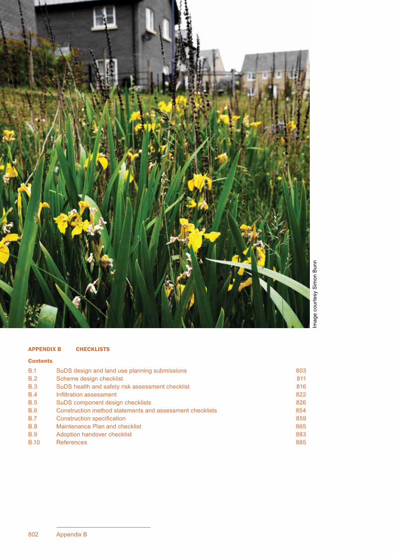
802 Appendix B
CIRIA SuDS Manual 2015
APPENDIX B CHECKLISTS
Contents
B.1 SuDS design and land use planning submissions 803B.2 Scheme design checklist 811B.3 SuDS health and safety risk assessment checklist 816B.4 Infiltrationassessment 822B.5 SuDS component design checklists 826B.6 Construction method statements and assessment checklists 854B.7 Constructionspecification 859B.8 Maintenance Plan and checklist 865B.9 Adoptionhandoverchecklist 883B.10 References 885
Imag
e co
urte
sy S
imon
Bun
n

803Appendix B: Checklists
CIRIA SuDS Manual 2015
BChecklistsAppendix
This appendix provides a series of checklists that can be used by designers or drainage system approving bodies to ensure that all relevant design, construction and maintenance considerations have been taken into account and documented in a consistent way.
B.1 SUDS DESIGN AND LAND USE PLANNING SUBMISSIONS
The SuDS design process is set out in Chapter 7, including the integration and links with the (land use) planning process.
Eachstageoftheplanningprocesswillrequireadifferentlevelofsubmissiondetailin terms of the design of the surface water management system, but the issues are relevantforallscalesofdevelopment.Thefollowingthreesubsectionsincludeguidanceandchecklistsrelevanttoeachofthekeystagesthatcouldbeusedbytheplanningauthorityortheorganisationresponsiblefordrainageapprovalandadoptionintheirconsultation and planning process.
Thescaleofthesubmissionswillbedependentonthescaleofthedevelopmentsiteandthelevelofpotentialenvironmentalriskposedbythesurfacewatermanagementsystem.Theproposedchecklistswillensurethatallissueshavebeenconsideredatthecorrectstageofplanning.However,forsmallsites,manyoftheitemsmaynotberelevant,ormayonlyrequirecursoryconsideration.AsindicatedinChapter 7, Figure 7.2, the outline planning stage may not be required for small sites, and for many sites the Flood Risk Assessmentmayincludetheconceptualdrainagedesignstrategy.
Where earlier stages are omitted, the submission requirements for that stage should be included for consideration at subsequent stages to ensure that the planning process for the system has taken all aspects into consideration.
B.1.1 Pre-application
Developersshouldengageinpre-applicationdiscussionswiththedrainagesystemapprovingbody,eitherdirectlyoraspartofamulti-disciplinaryteaminvolvedwiththeplanningapplicationtothelocalplanningauthority.Effectivepre-applicationdiscussionsandmasterplanningshouldensurearobust,viableandcost-effectiveschemefromtheoutset,wherethedevelopmentobjectivesareinformedbythesurfacewatermanagementstrategy,andviceversa
Forlargersitesormulti-plotdevelopments,wherethelandissubdividedintoseparateplotsownedbydifferentlandowners,orwherethereisanintentiontodevelopthelandinphases,thespecificationforadrainagemasterplanshouldbeagreedatthisstage.Themasterplanshouldbedesignedtoensureeffectivecommunicationbetweenalldevelopersandidentifiedstakeholdersinestablishingtheselection,implementationand phasing of source control, site and regional SuDS components. It should also set outtheresponsibilitiesfor,deliveryofandmaintenanceoftemporarysitedrainagemeasures required during the construction process.
Table B.1providesachecklistofinformationthatshouldbeprovidedandagreedbetweenallpartiesatthepre-applicationstage.

804 Appendix B
CIRIA SuDS Manual 2015
TAB
LEB
.1Su
gges
ted
pre-
appl
icat
ion
disc
ussi
on m
ater
ial
Ref
Req
uire
men
tsD
etai
ls (o
r ref
eren
ce
docu
men
tatio
n)A
ccep
ted?
(a)
Anyplanningandenvironm
entalobjectivesforthesitethatshouldinfluencethe
surfacewatermanagem
entstra
tegy–theseobjectivescanbeputforwardbyboththe
developera
ndtheapprovingbody/LPA
andshouldbeagreedbyallparties
(b)
Thelikelyenvironm
entalortechnicalconstraintstoSuD
Sdesignforthesite–these
shou
ld b
e ag
reed
by
all p
artie
s
(c)
The requirementsofthelocalS
uDSapprovalandadoptionprocesses.Theseshouldbe
providedtothedeveloperbythedrainageapprovingbody
(d)
The
suite
of d
esig
n cr
iteria
to b
e ap
plie
d to
the
SuD
S sc
hem
e (ta
king
acc
ount
of (
a) to
(c))
(e)
Evidencethattheinitialdevelopmentdesignproposalshaveconsideredtheintegration
and
linka
ge o
f the
sur
face
wat
er m
anag
emen
t with
stre
et la
yout
s, a
rchi
tect
ural
and
la
ndsc
ape
prop
osal
s
(f)Anassessmentofstra
tegicopportunitiesforthesurfacewatermanagem
entsystem
todelivermultiplebenefitsforthesite–thisshouldbeprovidedbythedevelopera
nd
shou
ld in
clud
e th
e st
rate
gic
use
of p
ublic
ope
n sp
ace
for S
uDS
(h)
Thestatutoryandrecommendednon-statutoryconsulteesforthedesignproposals–
thisshouldbeprovidedbytheapprovalbodyorLPA
(i)Th
e lik
ely
land
and
infra
stru
ctur
e ow
ners
hip
for d
rain
age
rout
es a
nd p
oint
s of
dis
char
ge
(incl
udin
g se
wer
age
asse
ts)
(j)Anassessmentofstatutoryconsulteeresponsibilitiesandrequirements,including
timescalesfora
nylikelyre
quiredapprovals/consents
(k)
Anypotentiallocalcom
munityim
pacts,healthandsafetyissuesorspecificlocal
communityconcernsanddrainageapprovingbodyrequirementsthatshouldbe
addr
esse
d by
the
deta
iled
desi
gn
(m)
Anassessmentofcostimplicationsofstakeholderobligations
(n)
Anagreedapproachtothedesignandmaintenanceofthesurfacewatermanagem
ent
for t
he p
ropo
sed
site
Not
eAlloftheaboveshouldbeagreed(w
herere
levant)w
iththeLP
A,internaldrainageboard,environm
entalregulator,w
atercom
paniesandsew
erageundertakers.TheSuD
Splanningprocessshouldbe
closelylinkedtothedevelopm
entplanningprocess,andthedrainagedesignshouldbeintegratedwherepossiblewithinthedesignofthedevelopmentasawhole.

805Appendix B: Checklists
CIRIA SuDS Manual 2015
B.1.2 Outline planning
Ifanoutlineplanningapplicationistobesubmittedtothelocalplanningauthority,thedevelopershouldincludeaconceptualsudsdesignstrategywhichcanbereviewedbythedrainageapprovingbodyandtheirconsultees,orothersaffectedbytheproposals(egthelocalplanningauthority,environmentalregulatorandthewaterandseweragecompany).Forsomedevelopments,thisconceptualstrategymayformpartoftheFRA/FCAforthesite.
Where a drainage master plan (or site surface water drainage strategy) is required or conditioned, at this stage (for larger sites) this should also include:
▪ details of the proposed phasing of the SuDS system
▪ individualplotdischargesandstorages
▪ definitionofresponsibilitiesforconstruction,maintenanceandadoptionofeachelementofthescheme.
Table B.2providesachecklistthatcanbeusedtodocumentandverifythattherelevantinformationhasbeenprovided.Notethatifapre-applicationconsultationhasbeenundertaken,muchofthematerialshouldhavebeenagreedatthatstage.
Thisinformationisrequiredtobeprovidedintheformofareport,togetherwithappropriateplans.

806 Appendix B
CIRIA SuDS Manual 2015
TAB
LEB
.2C
once
ptua
l dra
inag
e de
sign
doc
umen
tati
on s
ugge
sted
for s
ubm
issi
on a
t out
line
plan
ning
Ref
Req
uire
men
tsD
etai
ls (o
r ref
eren
ce
docu
men
tatio
n)A
ccep
ted?
(a)
Definitionofthenaturaldrainagecharacteristicswithin,andhydrologicallylinkedto,
the
site
and
dem
onst
ratio
n th
at th
e dr
aina
ge p
ropo
sals
will
inte
grat
e w
ith a
nd n
ot
comprom
isethefunctionofthenaturaldrainagesystem
s–naturalflow
pathsfor
surfacewaterru
noffshouldbeidentifiedonaplanwhereappropriate
(b)
Definitionofstate,perform
anceandownershipofanyexistingsitesurfacewater
drai
nage
infra
stru
ctur
e an
d de
mon
stra
tion
that
the
drai
nage
pro
posa
ls c
onsi
der,
use
or
prot
ect t
hese
sys
tem
s (w
here
app
ropr
iate
)
(c)
Proposedstrategicapproachtomanagingon-sitefloodriskfro
mallsources(aspartof
orinalignm
entw
iththeFloodRiskAssessm
ent/floodconsequencesassessm
ent),and
implicationsofexistingfloodriskforp
roposedSuD
Sdesign
(d)
Outlineassessmentofexistinggeology,groundconditions(includingcontam
ination
andstability)a
ndpermeabilitythroughdesk-basedre
search(egareview
ofgeological/
hydrogeologicalm
aps,infiltra
tionpotentialm
apsandsitevisitobservations)–to
determ
inethesuitabilityofinfiltra
tiondrainageforthesiteru
noff.Infiltra
tiontestsshould
becarriedoutatthisstagewhereverp
ossible.Ifinfiltra
tionisproposedbuttestsare
notavailableanalternativeoutfa
llshouldbeidentifiedincasefuturetestsshow
that
infiltra
tionisnotpossible
(e)
Identificationoftherequirementsofanyenvironm
entallysensitivepotentialreceiving
wat
er b
odie
s fo
r the
runo
ff (e
g gr
ound
wat
er p
rote
ctio
n zo
nes,
arc
haeo
logi
cal f
eatu
res,
receivingwaterbodyenvironm
entaldesignations)
(f)Th
e im
pact
of a
ny s
take
hold
er e
ngag
emen
t on
the
desi
gn a
nd p
ropo
sed
com
mun
ity
enga
gem
ent p
lans
(g)
Confirmationofdischargepoints(ietoground,watercourseorp
ublicsew
er)forall
returnperiodevents
(h)
Confirmation ofthedesigncriteriafortheSuD
Ssystem(includinganassessmentofthe
needandopportunityforrainw
aterharvestinganduse),includingclim
atechangeand
urba
n cr
eep
allo
wan
ces
(i)ConceptualS
uDSdesignincludingInterception,treatment,conveyance,peakflowand
volumecontrol,storageandexceedancero
utesandcom
ponents(anddem
onstration
thatre
quiredindicativestoragesandconveyanceflowscanbedeliveredonsite)
cont
inue
d...

807Appendix B: Checklists
CIRIA SuDS Manual 2015
TAB
LEB
.2C
once
ptua
l dra
inag
e de
sign
doc
umen
tati
on s
ugge
sted
for s
ubm
issi
on a
t out
line
plan
ning
Ref
Req
uire
men
tsD
etai
ls (o
r ref
eren
ce
docu
men
tatio
n)A
ccep
ted?
(j)
Proposedmulti-functionaluseofS
uDSspacetomeetcom
munityandenvironm
ental
r equ
irem
ents
(whe
re p
ossi
ble
gree
n in
frast
ruct
ure)
and
the
pote
ntia
l con
tribu
tion
of
thesurfacewatermanagem
entsystem(egBREEAMCom
munity,D
CLG
,200
8,and
BirkbeckandKruczkowski,2012)tothedevelopm
entdesignobjectivesforsustainability
(incl
udin
g cl
imat
e re
silie
nce)
(k)
ProposedsplitoftheSuD
Sbetweenprivateandpublic
(l)Confirmationofapprovalandadoptionarrangem
entsfora
llSuD
Scom
ponents
(m)
Detailsofanyre
quiredoff-siteworksandconsents
(n)
AppropriateconsiderationofthemaintainabilityoftheproposedSuD
S
(o)
Appropriateconsiderationoftheconstru
ctabilityoftheproposedSuD
S(includingthe
requ
irem
ents
for p
hasi
ng o
r pro
tect
ion
of c
ompo
nent
s)
(p)
An initialhealthandsafetyriskassessment
cont
inue
d fro
m...

808 Appendix B
CIRIA SuDS Manual 2015
B.1.3 Full planning (or reserved matters)
Thedeveloperwillberequiredtosubmitadetaileddrainagesubmissiontothedrainageapprovingbody,tobeconsideredalongsidetheplanningapplication.Thefinalsubmissiononthedetaileddesignand layout of the surface water management system should update and enhance the conceptual SuDS strategy and any surface water management master plan for the site and should be in line with any conditions set by the outline planning application.
Allrelevantstatutoryandidentifiednon-statutorystakeholderconsultationsshouldbeundertakenandtakenintoaccountwhenputtingtogetherthefinalproposals.
Table B.3providesachecklistthatcanbeusedtodocumentandverifythattherelevantinformationhasbeenprovided.

809Appendix B: Checklists
CIRIA SuDS Manual 2015
TAB
LEB
.3D
etai
led
drai
nage
des
ign
docu
men
tati
on s
ugge
sted
for s
ubm
issi
on a
t ful
l pla
nnin
g
Ref
Req
uire
men
tsD
etai
ls (o
r ref
eren
ce
docu
men
tatio
n)A
ccep
ted?
(a)
Whereinfiltra
tionisproposed,anacceptableInfiltra
tionAssessm
enthasbeen
subm
itted,includinganygeotechnicaltestresultsandevaluations
(b)
Aschem
edesignassessm
entw
ithappropriatesupportingcalculationsthathasbeen
subm
itted
that
dem
onst
rate
s de
sign
con
form
ity w
ith th
e re
quire
d de
sign
crit
eria
for t
he
site;justificationofanynon-com
pliancetonationalorlocallysetstandards
(c)
Pla
ns o
f the
pro
pose
d dr
aina
ge s
yste
m, s
how
ing:
▪drainagecatchmentandsub-catchmentareas(includingim
perm
eableand
perm
eabl
e zo
nes,
and
any
pha
sing
det
ails
) ▪existingandproposedsitesectionsandlevels
▪l ong-a
ndcross-sectionsfortheproposeddrainagesystem(includingexceedance
fl owmanagem
entroutes)andfinalbuildingfinishedfloorlevels
▪d e
tails
for c
onne
ctio
ns to
wat
erco
urse
s an
d se
wer
s ▪
mai
nten
ance
acc
ess
and
any
aris
ings
sto
rage
and
dis
posa
l arr
ange
men
ts ▪
oper
atio
nal c
hara
cter
istic
s of
any
mec
hani
cal f
eatu
res
(d)
Allnecessaryconsentsre
quiredforo
ff-siteworks
(e)
Com
mitm
entsfora
pprovalandadoptionarrangem
entsfora
llelem
entsofthesystem
(includingexceedanceflow
managem
entcom
ponents);com
mitm
entstoanycost
contributions,valuationandsecurityofanyre
quirednon-performancebond
(f)Appropriateconsiderationandmanagem
entofanyhealthandsafetyissuesre
latingto
SuD
S im
plem
enta
tion
(g)
The
desi
gn o
f eac
h el
emen
t und
erta
ken
in a
ccor
danc
e w
ith b
est p
ract
ice
(usi
ng d
etai
led
desi
gn c
heck
lists
, whe
re re
quire
d)
(h)
Specificationspreparedandapprovedfora
llmaterialsusedinthedesign
(i)
Aconstructionmethodstatem
entfortheproposedSuD
Ssystemsubmittedincluding:
▪constru
ctionprocessestoprotecttheSuD
Sfunctionality(includingtheprovisionof
any
requ
ired
tem
pora
ry d
rain
age
syst
ems)
▪pr
ogra
mm
ing
to p
rote
ct th
e S
uDS
func
tiona
lity
▪la
ndsc
ape
plan
ting
▪considerationofaccessforinspectionsbytheapprovingoradoptingorganisation
cont
inue
d...

810 Appendix B
CIRIA SuDS Manual 2015
TAB
LEB
.3Ta
ble
B.3
Det
aile
d dr
aina
ge d
esig
n do
cum
enta
tion
sug
gest
ed fo
r sub
mis
sion
at f
ull p
lann
ing
Ref
Req
uire
men
tsD
etai
ls (o
r ref
eren
ce
docu
men
tatio
n)A
ccep
ted?
(j)
AMaintenancePlanfortheproposedSuD
Ssubmittedincluding:
▪adescriptionofthesystem
andhow
eachpartofthesystem
isexpectedtowork
▪managem
entobjectivesforthesite
▪in
spec
tion
and
mai
nten
ance
sch
edul
es, m
ater
ial,
tool
s an
d in
itial
cos
t est
imat
es ▪
mai
nten
ance
acc
ess
poin
ts, e
asem
ents
and
out
falls
(k)
Aninform
ationandcommunicationsplanfortheproposedSuD
Sschem
esubm
itted,
whe
re a
ppro
pria
te, i
nclu
ding
:
▪communicationwithandeducationofexistingresidents
▪co
mm
unic
atio
n w
ith a
nd e
duca
tion
of n
ew re
side
nts
▪siteandSuD
Scom
ponentspecificinform
ationboards
▪lo
cal c
omm
unity
edu
catio
n an
d ed
ucat
ion
stra
tegi
es (e
g th
roug
h sc
hool
s).
Note:thisisonlylikelytoberequiredonlargersitesandmaybeprovidedbythe
drainageapprovingbodyorthedeveloper(tobeagreedbetweenthem
)
cont
inue
d fro
m...

811Appendix B: Checklists
CIRIA SuDS Manual 2015
B.2 SCHEME DESIGN CHECKLIST
Table B.4providesachecklistthatshouldbeusedwhenassessingthedesignofaproposedSuDSschemeforapproval.Itencouragesaconsistentassessmentoftheschemeagainstthecriteriaandstandards set out in this manual.
This checklist will need to be supported by:
▪ a scheme health and safety risk assessment (Section B.3)
▪ detailedinfiltrationassessment(ifinfiltrationcomponentsformpartofthescheme)(Section B.4)
▪ detailed design checks for the proposed SuDS components (Section B.5)
▪ a construction method statement for the scheme (Section B.6)
▪ a Maintenance Plan for the scheme (Section B.8).
Table B.4couldbeusedasachecklistbyorganisationsresponsiblefortheapprovalandadoptionofSuDS to support their assessment of schemes, or it could be used as part of the required submissions fromthedeveloper.

812 Appendix B
CIRIA SuDS Manual 2015
TAB
LEB
.4Sc
hem
e de
sign
ass
essm
ent c
heck
list
Req
uire
men
ts
Site
ID
Sitelocationandco-ordinates
Site
des
crip
tion
Dra
win
g re
fere
nce(
s)
Dat
e of
ass
essm
ent
Specificationreference
Typeofdevelopment
Site
are
a
SuD
S m
anua
l se
ctio
nY
NSu
mm
ary
of d
etai
lsC
omm
ents
/rem
edia
l ac
tions
Wat
er q
uant
ity
Is s
urfa
ce w
ater
use
d as
a re
sour
ce, w
here
app
ropr
iate
?3.
2.2
Doe
s th
e de
sign
mee
t the
follo
win
g di
scha
rge
hier
arch
y (w
ith a
ccep
tabl
e justificationform
ovingbetweenlevels):
1infiltra
tiontothemaximum
extentthatispractical–whereitissafeand
acce
ptab
le to
do
so
2 di
scha
rge
to s
urfa
ce w
ater
s
3 di
scha
rge
to s
urfa
ce w
ater
sew
er
4 di
scha
rge
to c
ombi
ned
sew
er (l
ast r
esor
t)
3.2.
3
Ifinfiltra
tionisused:confirmthatanacceptableinfiltra
tionassessmenthas
been
und
erta
ken
and
subm
itted
If dischargetoasew
erageassetisproposed,hasevidencebeenprovided
thatthedesigncriteriahavebeenagreedwiththesewerageundertakerand
that
an
appr
opria
te c
onne
ctio
n de
tail
has
been
agr
eed?
Hasru
noffandfloodingfro
mallsources(bothonandoffsite)b
een
cons
ider
ed a
nd ta
ken
into
acc
ount
in th
e de
sign
?3.
3.3
Does theschemedesigndem
onstrateon-sitere
tentionofapproximatelythe
first5mmofrunofffromim
perm
eablesurfacesform
ostevents?
How
isInterceptiontobedelivered(eginfiltra
tion,greenro
ofs,permeable
pavements,vegetatedsurfaces,bespokedesign–providedetails)?
3.3.
1
4.3.
1
cont
inue
d...
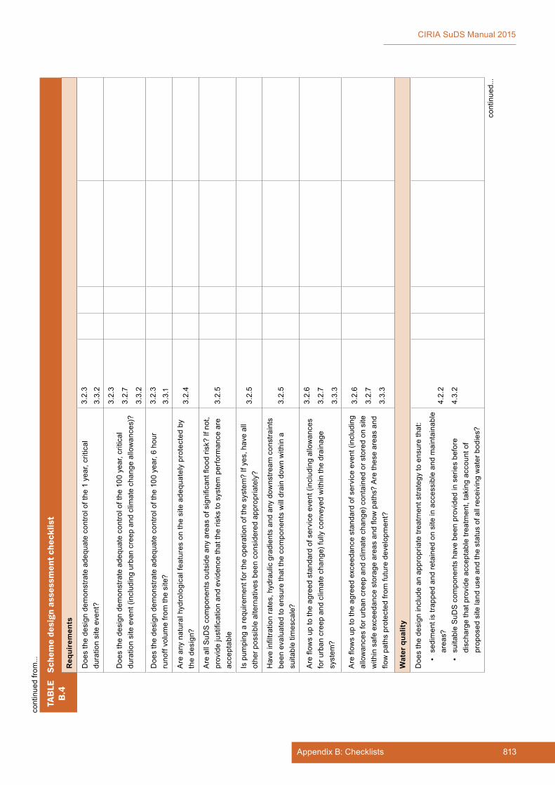
813Appendix B: Checklists
CIRIA SuDS Manual 2015
TAB
LEB
.4Sc
hem
e de
sign
ass
essm
ent c
heck
list
Req
uire
men
ts
Doe
s th
e de
sign
dem
onst
rate
ade
quat
e co
ntro
l of t
he 1
yea
r, cr
itica
l durationsiteevent?
3.2.
3
3.3.
2
Doe
s th
e de
sign
dem
onst
rate
ade
quat
e co
ntro
l of t
he 1
00 y
ear,
criti
cal
durationsiteevent(includingurbancreepandclim
atechangeallowances)?
3.2.
3
3.2.
7
3.3.
2
Doe
s th
e de
sign
dem
onst
rate
ade
quat
e co
ntro
l of t
he 1
00 y
ear,
6 ho
ur
runoffvolumefro
mthesite?
3.2.
3
3.3.
1
Areanynaturalhydrologicalfeaturesonth
esiteadequatelyprotectedby
the
desi
gn?
3.2.
4
AreallSuD
Scom
ponentsoutsideanyareasofsignificantfloodrisk?Ifnot,
providejustificationandevidencethattheriskstosystemperform
anceare
acce
ptab
le3.
2.5
Ispum
pingare
quirementfortheoperationofthesystem
?Ifyes,haveall
otherp
ossiblealternativesbeenconsideredappropriately?
3.2.
5
Haveinfiltra
tionrates,hydraulicgradientsandanydow
nstre
amconstraints
beenevaluatedtoensurethatthecomponentswilldraindow
nwithina
suita
ble
times
cale
?3.
2.5
Areflow
suptotheagreedstandardofserviceevent(includingallowances
foru
rbancreepandclim
atechange)fullyconveyedwithinthedrainage
syst
em?
3.2.
6
3.2.
7
3.3.
3
Areflow
suptotheagreedexceedancestandardofserviceevent(including
allo
wan
ces
for u
rban
cre
ep a
nd c
limat
e ch
ange
) con
tain
ed o
r sto
red
on s
ite
withinsafeexceedancestorageareasandflow
paths?Aretheseareasand
flowpathsprotectedfrom
futuredevelopment?
3.2.
6
3.2.
7
3.3.
3
Wat
er q
ualit
y
Doe
s th
e de
sign
incl
ude
an a
ppro
pria
te tr
eatm
ent s
trate
gy to
ens
ure
that
:
▪se
dim
ent i
s tra
pped
and
reta
ined
on
site
in a
cces
sibl
e an
d m
aint
aina
ble
area
s? ▪suitableSuD
Scom
ponentshavebeenprovidedinseriesbefore
dischargethatprovideacceptabletre
atment,takingaccountof
p roposedsitelanduseandthestatusofallreceivingwaterbodies?
4.2.
2
4.3.
2
cont
inue
d fro
m...
cont
inue
d...

814 Appendix B
CIRIA SuDS Manual 2015
TAB
LEB
.4Sc
hem
e de
sign
ass
essm
ent c
heck
list
Hasconsiderationbeengiventothepotentialimplicationsofclim
atechange
onthecapabilityoftheSuD
Scomponentstoprovidetherequiredtre
atment?
4.2.
3
Req
uire
men
ts
Am
enity
cri
teri
a
Wherethedrainagesystemservesmorethanoneproperty,ispublic
spac
e us
ed a
nd in
tegr
ated
with
the
drai
nage
sys
tem
in a
n ap
prop
riate
and
beneficialw
ay?
5.2.
2
Doestheproposedschem
eenhancethevisualcharacterofthedevelopment?
5.2.
3
Aretheproposedcom
ponentssafefora
nyproposedam
enityuse?Hasa
heal
th a
nd s
afet
y ris
k as
sess
men
t bee
n un
dert
aken
?
5.2.
4
Cha
pter
36
Che
cklis
t B.3
Haveopportunitiesbeentakentousethedrainagesystemtoenhance
developm
entresiliencetofutureclim
atechangescenarios?
5.2.
5
Isthestructureandfunctionofthedrainagesystemclearandobvioustothe
l oca
l com
mun
ity?
5.2.
6
Dothedesignproposalsincludesufficientprovisionforcom
munity
enga
gem
ent a
nd a
war
enes
s ra
isin
g?5.
2.7
Bio
dive
rsity
cri
teri
a
Will
the
drai
nage
sys
tem
sup
port
and
prot
ect n
atur
al lo
cal h
abita
ts a
nd s
peci
es?
6.2.
1
Willthedrainagesystemcontributetothedeliveryoflocalbiodiversityobjectives?
6.2.
2
Doesthedesignsupportlocal(andwiderwherepossible)habitatconnectivity?
6.2.
3
Does thedesignpromotethecreationofdiverse,self-sustainingand
resi
lient
eco
syst
ems?
6.2.
4
Con
stru
ctab
ility
Has
an
acce
ptab
le c
onst
ruct
ion
met
hod
stat
emen
t bee
n su
bmitt
ed a
nd
approved?
Cha
pter
31
cont
inue
d fro
m...
cont
inue
d...
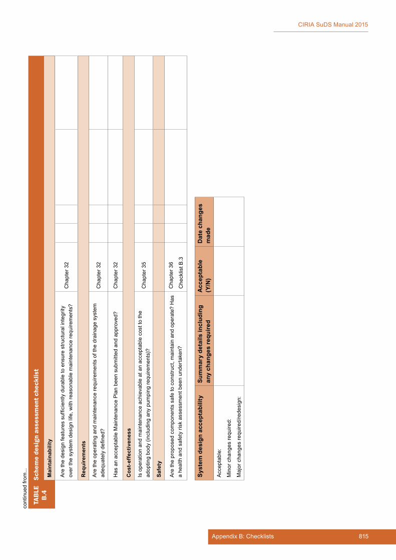
815Appendix B: Checklists
CIRIA SuDS Manual 2015
TAB
LEB
.4Sc
hem
e de
sign
ass
essm
ent c
heck
list
Mai
ntai
nabi
lity
Arethedesignfeaturessufficientlydurabletoensurestructuralintegrity
overthesystem
designlife,withre
asonablemaintenancere
quirements?
Cha
pter
32
Req
uire
men
ts
Aretheoperatingandmaintenancere
quirementsofthedrainagesystem
a dequatelydefined?
Cha
pter
32
HasanacceptableMaintenancePlanbeensubmittedandapproved?
Cha
pter
32
Cos
t-ef
fect
iven
ess
Isoperationandmaintenanceachievableatanacceptablecosttothe
adop
ting
body
(inc
ludi
ng a
ny p
umpi
ng re
quire
men
ts)?
Cha
pter
35
Safe
ty
Aretheproposedcom
ponentssafetoconstruct,m
aintainandoperate?Has
a he
alth
and
saf
ety
risk
asse
ssm
ent b
een
unde
rtak
en?
Cha
pter
36
Che
cklis
t B.3
Syst
em d
esig
n ac
cept
abili
tySu
mm
ary
deta
ils in
clud
ing
any
chan
ges
requ
ired
Acc
epta
ble
(Y/N
)D
ate
chan
ges
mad
e
Acceptable:
Min
or c
hang
es re
quire
d:
Majorchangesre
quired/redesign:
cont
inue
d fro
m...

816 Appendix B
CIRIA SuDS Manual 2015
TABLEB.5
SuDS health and safety risk assessment checklist
Site/system overview
Site ID
AssetID
Location
SuDS component
Assessmentdate
Dateofnextassessment
1 Establish context
Generaldescriptionofcomponentanditsoperation
2 Identify potential hazards Arehazardspresent?(Y/N)
Drowning or falling through ice in winter IfYEScompleteSection3
Slips, trips and falls IfYEScompleteSection4
Entryintopipesorconfinedspaces(notethisisforinadvertentpublicaccess;followrelevantlegislationandguidanceforworkeraccess)
IfYEScompleteSection5
Water quality – health risk IfYEScompleteSection6
B.3 SUDS HEALTH AND SAFETY RISK ASSESSMENT CHECKLIST
Table B.5providesachecklistthatcanbeusedaspartofariskassessmenttodocumentandverifythatrelevanthealthandsafetyhazardshavebeenidentified,consideredandmanaged.Itshouldbeexpandedoramendedtoensurethatitisrelevanttositespecificscenariosandthatallpotentialhazardsareincluded.Guidanceonhealthandsafetyriskmanagementisprovidedin Chapter 36.
continued...
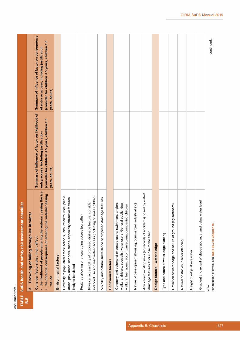
817Appendix B: Checklists
CIRIA SuDS Manual 2015
TAB
LEB
.5Su
DS
heal
th a
nd s
afet
y ri
sk a
sses
smen
t che
cklis
t
3 D
row
ning
or f
allin
g th
roug
h ic
e in
win
ter
Con
side
r fac
tors
that
mig
ht a
ffec
t:•
the
likel
ihoo
d of
peo
ple
ente
ring
the
wat
er/a
cces
sing
the
ice
• th
e po
tent
ial c
onse
quen
ce o
f ent
erin
g th
e w
ater
/acc
essi
ng
the
ice
Sum
mar
y of
influ
ence
of f
acto
r on
likel
ihoo
d of
en
try/
acce
ss, i
nclu
ding
just
ifica
tion
(con
side
r for
chi
ldre
n <
5 ye
ars,
chi
ldre
n ≥
5 ye
ars,
adu
lts)
Sum
mar
y of
influ
ence
of f
acto
r on
cons
eque
nce
of e
ntry
or a
cces
s, in
clud
ing
just
ifica
tion
(con
side
r for
chi
ldre
n <
5 ye
ars,
chi
ldre
n ≥
5 ye
ars,
adu
lts)
Envi
ronm
enta
l fac
tors
Proximitytopopulatedareas:schools,inns,re
tail/tourism,picnic
areas,playareas,carpark,ro
ads,especiallyattractivefeatures
likelytobevisited
Feat
ures
allo
win
g or
enc
oura
ging
acc
ess
(eg
path
s)
Phy
sica
l acc
essi
bilit
y of
pro
pose
d dr
aina
ge fe
atur
e: c
onsi
der
intendeduseandinadverte
ntaccess(includingofsmallchildren)
Visibilityandnaturalsurveillanceofproposeddrainagefeatures
Beh
avio
ural
fact
ors
Categoryandvolumeofexpectedusers:swimmers,anglers,
walkers,drivers,specialistw
aterusers,G
eneralpublic,dog
walkers,teenagers,accom
panied/unaccom
paniedchildren
Natureofdevelopment(housing,com
mercial,industrialetc)
Anyknownexistingrisks(egrecordsofaccidents)p
osedbywater/
drai
nage
feat
ures
at o
r clo
se to
the
site
?
Des
ign
fact
ors
– w
ater
’s e
dge
Typeandnatureofwater-edgeplanting
Definitionofwateredgeandnatureofground(egsoft/hard)
Naturalobstacles,barriers/fencing
Heightofedgeabovewater
Gradientandextentofslopesabove,atandbelow
waterlevel
cont
inue
d...
Not
eFo
rdefinitionoflevels,seeT
able
36.
2 in
Cha
pter
36.
cont
inue
d fro
m...
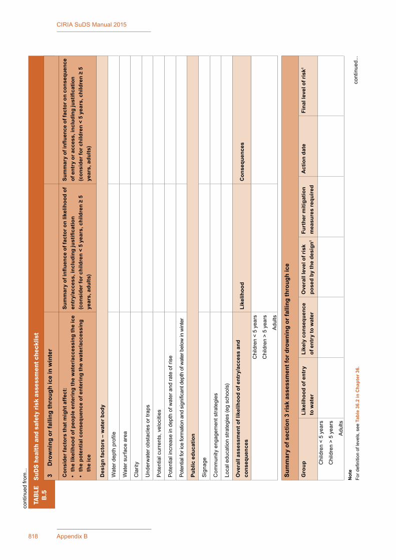
818 Appendix B
CIRIA SuDS Manual 2015
TAB
LEB
.5Su
DS
heal
th a
nd s
afet
y ri
sk a
sses
smen
t che
cklis
t
3 D
row
ning
or f
allin
g th
roug
h ic
e in
win
ter
Con
side
r fac
tors
that
mig
ht a
ffec
t:•
the
likel
ihoo
d of
peo
ple
ente
ring
the
wat
er/a
cces
sing
the
ice
• th
e po
tent
ial c
onse
quen
ce o
f ent
erin
g th
e w
ater
/acc
essi
ng
the
ice
Sum
mar
y of
influ
ence
of f
acto
r on
likel
ihoo
d of
en
try/
acce
ss, i
nclu
ding
just
ifica
tion
(con
side
r for
chi
ldre
n <
5 ye
ars,
chi
ldre
n ≥
5 ye
ars,
adu
lts)
Sum
mar
y of
influ
ence
of f
acto
r on
cons
eque
nce
of e
ntry
or a
cces
s, in
clud
ing
just
ifica
tion
(con
side
r for
chi
ldre
n <
5 ye
ars,
chi
ldre
n ≥
5 ye
ars,
adu
lts)
Des
ign
fact
ors
– w
ater
bod
y
Waterdepthprofile
Wat
er s
urfa
ce a
rea
Cla
rity
Und
erw
ater
obs
tacl
es o
r tra
ps
Potential currents,velocities
Pot
entia
l inc
reas
e in
dep
th o
f wat
er a
nd ra
te o
f ris
e
Potentialforiceformationandsignificantdepthofw
aterbelow
inwinter
Publ
ic e
duca
tion
Sig
nage
Com
mun
ity e
ngag
emen
t stra
tegi
es
Localeducationstrategies(egschools)
Ove
rall
asse
ssm
ent o
f lik
elih
ood
of e
ntry
/acc
ess
and
cons
eque
nces
Like
lihoo
dC
onse
quen
ces
Chi
ldre
n <
5 ye
ars
Chi
ldre
n >
5 ye
ars
Adults
Sum
mar
y of
sec
tion
3 ri
sk a
sses
smen
t for
dro
wni
ng o
r fal
ling
thro
ugh
ice
Gro
upLi
kelih
ood
of e
ntry
to
wat
erLi
kely
con
sequ
ence
of
ent
ry to
wat
erO
vera
ll le
vel o
f ris
k po
sed
by th
e de
sign
1
Furt
her m
itiga
tion
mea
sure
s re
quir
edA
ctio
n da
teFi
nal l
evel
of r
isk1
Chi
ldre
n <
5 ye
ars
Chi
ldre
n >
5 ye
ars
Adults
cont
inue
d...
Not
eFo
rdefinitionoflevels,seeT
able
36.
2 in
Cha
pter
36.
cont
inue
d fro
m...
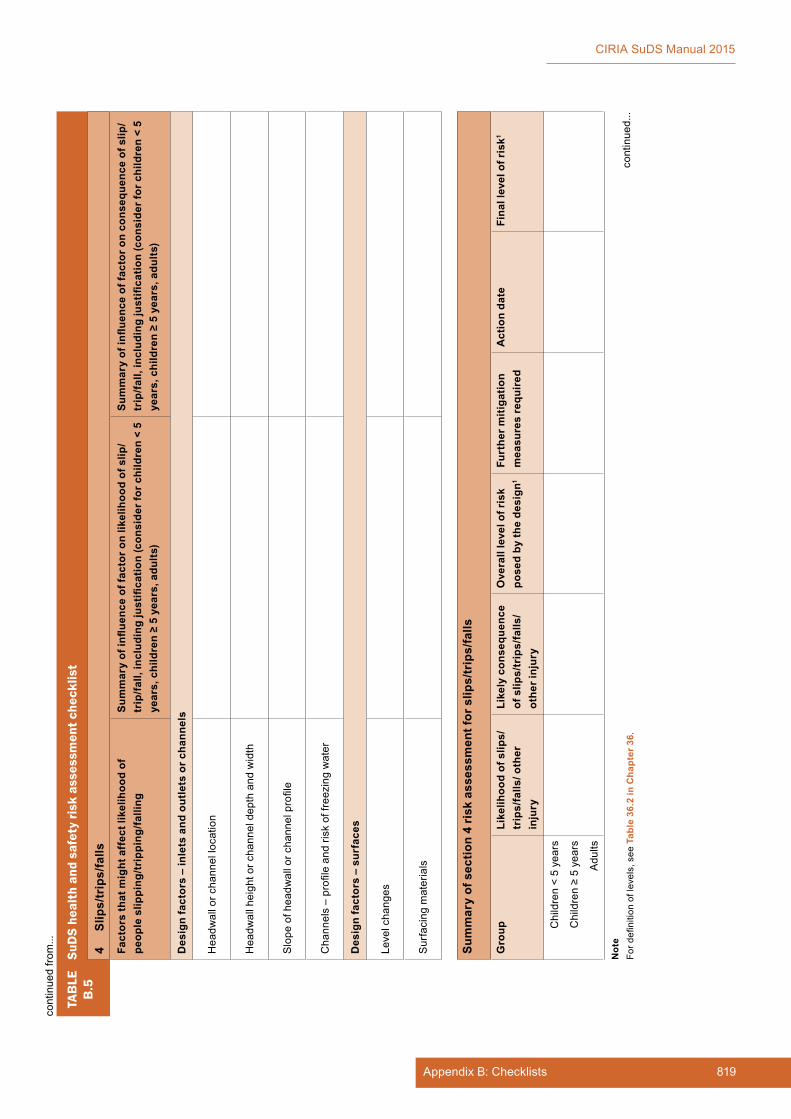
819Appendix B: Checklists
CIRIA SuDS Manual 2015
TAB
LEB
.5Su
DS
heal
th a
nd s
afet
y ri
sk a
sses
smen
t che
cklis
t
4 Sl
ips/
trip
s/fa
lls
Fact
ors
that
mig
ht a
ffec
t lik
elih
ood
of
peop
le s
lippi
ng/tr
ippi
ng/fa
lling
Sum
mar
y of
influ
ence
of f
acto
r on
likel
ihoo
d of
slip
/tr
ip/fa
ll, in
clud
ing
just
ifica
tion
(con
side
r for
chi
ldre
n <
5 ye
ars,
chi
ldre
n ≥
5 ye
ars,
adu
lts)
Sum
mar
y of
influ
ence
of f
acto
r on
cons
eque
nce
of s
lip/
trip
/fall,
incl
udin
g ju
stifi
catio
n (c
onsi
der f
or c
hild
ren
< 5
year
s, c
hild
ren
≥ 5
year
s, a
dults
)
Des
ign
fact
ors
– in
lets
and
out
lets
or c
hann
els
Hea
dwal
l or c
hann
el lo
catio
n
Hea
dwal
l hei
ght o
r cha
nnel
dep
th a
nd w
idth
Slopeofheadw
allorchannelprofile
Channels–profileandriskoffreezingwater
Des
ign
fact
ors
– su
rfac
es
Level changes
Sur
faci
ng m
ater
ials
Sum
mar
y of
sec
tion
4 ri
sk a
sses
smen
t for
slip
s/tr
ips/
falls
Gro
upLi
kelih
ood
of s
lips/
trip
s/fa
lls/ o
ther
in
jury
Like
ly c
onse
quen
ce
of s
lips/
trip
s/fa
lls/
othe
r inj
ury
Ove
rall
leve
l of r
isk
pose
d by
the
desi
gn1
Furt
her m
itiga
tion
mea
sure
s re
quir
edA
ctio
n da
teFi
nal l
evel
of r
isk1
Chi
ldre
n <
5 ye
ars
Children≥5years
Adults
cont
inue
d fro
m...
cont
inue
d...
Not
eFo
rdefinitionoflevels,seeT
able
36.
2 in
Cha
pter
36.
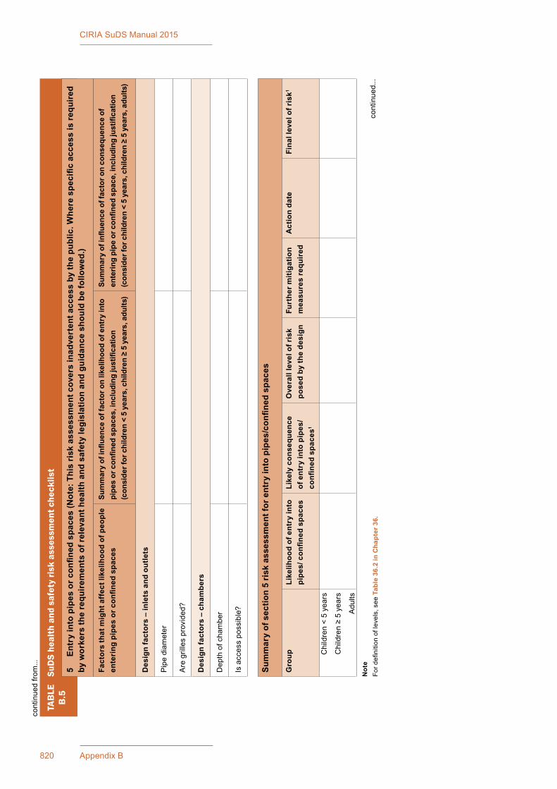
820 Appendix B
CIRIA SuDS Manual 2015
TAB
LEB
.5Su
DS
heal
th a
nd s
afet
y ri
sk a
sses
smen
t che
cklis
t
5 En
try
into
pip
es o
r con
fined
spa
ces
(Not
e: T
his
risk
ass
essm
ent c
over
s in
adve
rten
t acc
ess
by th
e pu
blic
. Whe
re s
peci
fic a
cces
s is
requ
ired
by w
orke
rs th
e re
quire
men
ts o
f rel
evan
t hea
lth a
nd s
afet
y le
gisl
atio
n an
d gu
idan
ce s
houl
d be
follo
wed
.)
Fact
ors
that
mig
ht a
ffec
t lik
elih
ood
of p
eopl
e en
teri
ng p
ipes
or c
onfin
ed s
pace
sSu
mm
ary
of in
fluen
ce o
f fac
tor o
n lik
elih
ood
of e
ntry
into
pi
pes
or c
onfin
ed s
pace
s, in
clud
ing
just
ifica
tion
(con
side
r for
chi
ldre
n <
5 ye
ars,
chi
ldre
n ≥
5 ye
ars,
adu
lts)
Sum
mar
y of
influ
ence
of f
acto
r on
cons
eque
nce
of
ente
ring
pipe
or c
onfin
ed s
pace
, inc
ludi
ng ju
stifi
catio
n(c
onsi
der f
or c
hild
ren
< 5
year
s, c
hild
ren
≥ 5
year
s, a
dults
)
Des
ign
fact
ors
– in
lets
and
out
lets
Pip
e di
amet
er
Aregrillesprovided?
Des
ign
fact
ors
– ch
ambe
rs
Dep
th o
f cha
mbe
r
Is a
cces
s po
ssib
le?
Sum
mar
y of
sec
tion
5 ri
sk a
sses
smen
t for
ent
ry in
to p
ipes
/con
fined
spa
ces
Gro
upLi
kelih
ood
of e
ntry
into
pi
pes/
con
fined
spa
ces
Like
ly c
onse
quen
ce
of e
ntry
into
pip
es/
confi
ned
spac
es1
Ove
rall
leve
l of r
isk
pose
d by
the
desi
gnFu
rthe
r miti
gatio
n m
easu
res
requ
ired
Act
ion
date
Fina
l lev
el o
f ris
k1
Chi
ldre
n <
5 ye
ars
Children≥5years
Adults
cont
inue
d...
Not
eFo
rdefinitionoflevels,seeT
able
36.
2 in
Cha
pter
36.
cont
inue
d fro
m...
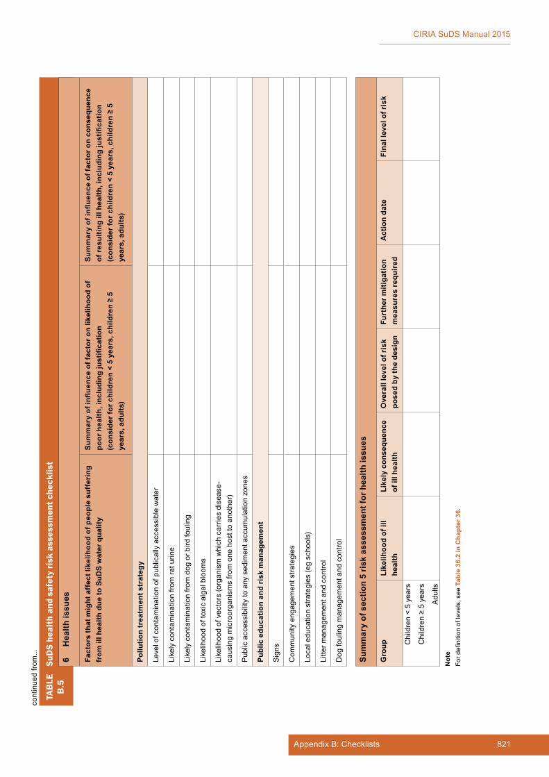
821Appendix B: Checklists
CIRIA SuDS Manual 2015
TAB
LEB
.5Su
DS
heal
th a
nd s
afet
y ri
sk a
sses
smen
t che
cklis
t
6 H
ealth
issu
es
Fact
ors
that
mig
ht a
ffec
t lik
elih
ood
of p
eopl
e su
ffer
ing
from
ill h
ealth
due
to S
uDS
wat
er q
ualit
ySu
mm
ary
of in
fluen
ce o
f fac
tor o
n lik
elih
ood
of
poor
hea
lth, i
nclu
ding
just
ifica
tion
(con
side
r for
chi
ldre
n <
5 ye
ars,
chi
ldre
n ≥
5 ye
ars,
adu
lts)
Sum
mar
y of
influ
ence
of f
acto
r on
cons
eque
nce
of re
sulti
ng il
l hea
lth, i
nclu
ding
just
ifica
tion
(con
side
r for
chi
ldre
n <
5 ye
ars,
chi
ldre
n ≥
5 ye
ars,
adu
lts)
Pollu
tion
trea
tmen
t str
ateg
y
Levelofcontaminationofpublicallyaccessiblewater
Likelycontaminationfro
mra
turine
Likelycontaminationfro
mdogorb
irdfouling
Likelihood oftoxicalgalbloom
s
Likelihoodofvectors(organismwhichcarriesdisease-
caus
ing
mic
roor
gani
sms
from
one
hos
t to
anot
her)
Pub
lic a
cces
sibi
lity
to a
ny s
edim
ent a
ccum
ulat
ion
zone
s
Publ
ic e
duca
tion
and
risk
man
agem
ent
Sig
ns
Com
mun
ity e
ngag
emen
t stra
tegi
es
Localeducationstrategies(egschools)
Litterm
anagem
entandcontro
l
Dog
foul
ing
man
agem
ent a
nd c
ontro
l
Sum
mar
y of
sec
tion
5 ri
sk a
sses
smen
t for
hea
lth is
sues
Gro
upLi
kelih
ood
of il
l he
alth
Like
ly c
onse
quen
ce
of il
l hea
lthO
vera
ll le
vel o
f ris
k po
sed
by th
e de
sign
Furt
her m
itiga
tion
mea
sure
s re
quir
edA
ctio
n da
teFi
nal l
evel
of r
isk
Chi
ldre
n <
5 ye
ars
Children≥5years
Adults
Not
eFo
rdefinitionoflevels,seeT
able
36.
2 in
Cha
pter
36.
cont
inue
d fro
m...
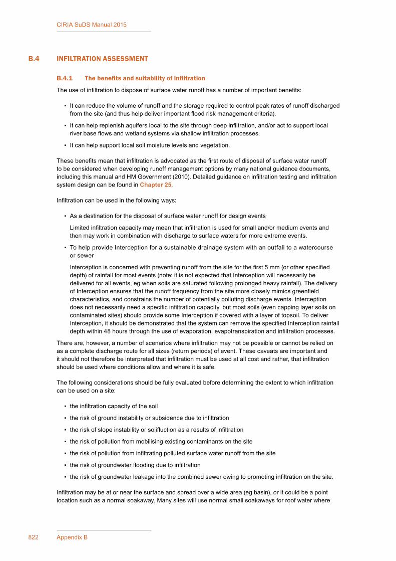
822 Appendix B
CIRIA SuDS Manual 2015
B.4 INFILTRATION ASSESSMENT
B.4.1 Thebenefitsandsuitabilityofinfiltration
Theuseofinfiltrationtodisposeofsurfacewaterrunoffhasanumberofimportantbenefits:
▪ Itcanreducethevolumeofrunoffandthestoragerequiredtocontrolpeakratesofrunoffdischargedfromthesite(andthushelpdeliverimportantfloodriskmanagementcriteria).
▪ Itcanhelpreplenishaquiferslocaltothesitethroughdeepinfiltration,and/oracttosupportlocalriverbaseflowsandwetlandsystemsviashallowinfiltrationprocesses.
▪ Itcanhelpsupportlocalsoilmoisturelevelsandvegetation.
Thesebenefitsmeanthatinfiltrationisadvocatedasthefirstrouteofdisposalofsurfacewaterrunofftobeconsideredwhendevelopingrunoffmanagementoptionsbymanynationalguidancedocuments,includingthismanualandHMGovernment(2010).Detailedguidanceoninfiltrationtestingandinfiltrationsystem design can be found in Chapter 25.
Infiltrationcanbeusedinthefollowingways:
▪ Asadestinationforthedisposalofsurfacewaterrunofffordesignevents
Limitedinfiltrationcapacitymaymeanthatinfiltrationisusedforsmalland/ormediumeventsandthenmayworkincombinationwithdischargetosurfacewatersformoreextremeevents.
▪ TohelpprovideInterceptionforasustainabledrainagesystemwithanoutfalltoawatercourseor sewer
Interceptionisconcernedwithpreventingrunofffromthesiteforthefirst5mm(orotherspecifieddepth)ofrainfallformostevents(note:itisnotexpectedthatInterceptionwillnecessarilybedeliveredforallevents,egwhensoilsaresaturatedfollowingprolongedheavyrainfall).ThedeliveryofInterceptionensuresthattherunofffrequencyfromthesitemorecloselymimicsgreenfieldcharacteristics,andconstrainsthenumberofpotentiallypollutingdischargeevents.Interceptiondoesnotnecessarilyneedaspecificinfiltrationcapacity,butmostsoils(evencappinglayersoilsoncontaminatedsites)shouldprovidesomeInterceptionifcoveredwithalayeroftopsoil.TodeliverInterception,itshouldbedemonstratedthatthesystemcanremovethespecifiedInterceptionrainfalldepthwithin48hoursthroughtheuseofevaporation,evapotranspirationandinfiltrationprocesses.
Thereare,however,anumberofscenarioswhereinfiltrationmaynotbepossibleorcannotbereliedonasacompletedischargerouteforallsizes(returnperiods)ofevent.Thesecaveatsareimportantanditshouldnotthereforebeinterpretedthatinfiltrationmustbeusedatallcostandrather,thatinfiltrationshould be used where conditions allow and where it is safe.
Thefollowingconsiderationsshouldbefullyevaluatedbeforedeterminingtheextenttowhichinfiltrationcan be used on a site:
▪ theinfiltrationcapacityofthesoil
▪ theriskofgroundinstabilityorsubsidenceduetoinfiltration
▪ theriskofslopeinstabilityorsolifluctionasaresultsofinfiltration
▪ theriskofpollutionfrommobilisingexistingcontaminantsonthesite
▪ theriskofpollutionfrominfiltratingpollutedsurfacewaterrunofffromthesite
▪ theriskofgroundwaterfloodingduetoinfiltration
▪ theriskofgroundwaterleakageintothecombinedsewerowingtopromotinginfiltrationonthesite.
Infiltrationmaybeatornearthesurfaceandspreadoverawidearea(egbasin),oritcouldbeapointlocation such as a normal soakaway. Many sites will use normal small soakaways for roof water where

823Appendix B: Checklists
CIRIA SuDS Manual 2015
possible.Theissueslistedabovebecomemoreofariskthemoreanywaterisconcentratedintoapointdischarge.Thus,large-volumedeepsoakawaysposemoreofariskthansmallshallowbasins,forexample.
Preliminaryinformationonwhetherasitemaybesuitableforinfiltration,ortoidentifyissuesthatshouldbeconsidered,canbeobtainedfromtheBritishGeologicalSurvey(BGS)InfiltrationSuDSMap.Thismap allows users to determine the:
▪ likelypresenceofconstraintsthatoughttobeconsideredwhenplanninginfiltrationSuDS
▪ likelypotentialforthegroundtoacceptinfiltration
▪ likelypotentialforgroundinstabilitywhenwaterisinfiltrated
▪ likely issues around groundwater quality protection.
Theacceptabilityofinfiltrationwithrespecttogroundwaterprotectionandsystemdesignmethodsispresented in Chapters 4 and 26.
B.4.2 The objectives of the checklist
Thisinfiltrationassessmentchecklistisintendedtobeusedbyorganisationsapprovingthedrainagescheme(drainageapprovingbodies)tohelpassesssubmissionsfordrainageapprovalthatincludeinfiltrationsystems.Asdiscussedabovetheremaybescenariosthatprecludeinfiltrationasthemainoutfallforsurfacewater.Ifitcanbeshownthatinfiltrationisnotsuitableforthemaindestinationforsurface water from a site (eg because of the presence of contamination that could be mobilised and could pose a risk to groundwater or other receptors) then completing this checklist is not necessary and infiltrationtestswillnotberequired.Onmarginalsiteswhereitisnotclearwhetherinfiltrationispossibleornot,infiltrationtestsmaybenecessarytoshowthatinfiltrationcannotberelieduponasthemainoutfallfor surface water.
It is intended to facilitate a consistent assessment process and to ensure that designs meet the key design requirements set out in this manual.
Itisalsointendedtohelpdesignersensurethattheyhaveprovidedallrelevantinformationtothedrainageapprovingbodyintheirsubmissionsforapproval.
Theuseofinfiltrationshouldbeapprovedbyageotechnicalengineerorengineeringgeologist(egaregisteredgroundengineeradviserorsimilar):
▪ onlargersitesorsub-catchments(>1000m2 drainingtoaninfiltrationdevice)
▪ inareaswheretherearelikelytobeissueswiththeuseofinfiltration(egduetopotentialsolution features)
▪ wheretheconsequencesoffailurearesignificant(egdamagetobuildings).
Thisrequirementisparticularlyimportantwhereinfiltrationtestshavenotbeenundertakenbyaspecialistsiteinvestigationcompany.Normally,acompanycarryingoutsiteinvestigationsandinfiltrationtestswillincludeageotechnicalengineerorengineeringgeologist,andtheycanadviseofanypotentialsignificantissuesandadviseonthesuitabilityofinfiltrationandanyconstraintsthatshouldbeappliedtoasite.Thiscanbeincludedinthereportprovidedbythespecialistcompanyforverylittlecost.
Ifinfiltrationisproposedatconceptualdesignstageandtherearenoinfiltrationtestresultsavailable,alternativeproposalsfordischargeshouldbeprovidedsothatintheeventthatinfiltrationtestsshowthatinfiltrationisnotpossible,thesitecanstillbeeffectivelydrained.
Theinfiltrationchecklistcanbeappliedtoallsites.However,forlowerrisksituations,approvingauthoritiesmaywishtoreducetheextentofthechecklist.Thiswillbeadecisionmadebyindividualauthoritiesbasedontheirknowledgeoflocalconditions.Suchcasescouldincludethefollowing,subject

824 Appendix B
CIRIA SuDS Manual 2015
totherebeingnosignificantgeotechnical,contaminationorgroundwaterfloodingissuesintheareainwhich the site is located:
▪ lessthantenpropertieswithindividualsoakawaysforroofdrainagewitheachsoakawaydrainingless than 100 m2 of roof area
▪ small car parks or similar areas less than 1000 m2.
Thischecklistisdesignedtobeusedforsiteswhereinfiltrationisasignificantdestinationforsurfacewater.ItisnotintendedtobeusedforsiteswhereinfiltrationwillonlybeusedtohelpprovideInterception(eg water leaking from the base of swales or basins). Some of the items discussed may need to be consideredwhendecidingifanyinfiltrationisacceptable(egwheretherearerisksofmobilisingcontamination in the subsoils).
TABLEB.6
Infiltrationassessmentchecklist
Requirements
Site ID
AssetID
Infiltrationcomponentlocation
Infiltrationcomponenttype
Infiltration capacity Details Acceptable submission?
Further requirements
Confirmthatinfiltrationtestresultshavebeenprovided,alongwithtrialpitrecordswithsoil/rockdescriptionsofthematerialsin which the test has been completed in accordance with BS ENISO14688-1:2002+A1:2013orBSENISO14689-1:2003
Confirmthattheinfiltrationtestshavebeenundertakenatthe location, depth and with a head of water that replicates the proposed design
Confirmthatinfiltrationtestsstatewhichstratumtheresults are appropriate to and any limitations in the test. Forexample,hastheinfiltrationratebeenestimatedbyassumingwateronlyinfiltratesintooneparticularstratumsuch as a discrete layer of limestone?
ConfirmthattheinfiltrationtestsfollowBRE(1991)orBettess(1996)asfarasisrelevanttothedesign.Ifnot,statewhatvariationshavebeenmadetothetestandwhy
Confirmthattheheadofwaterintheinfiltrationtestfallstoless than 25% of the initial head of water.
(Note:ifthisdoesnotoccurtheresultsshouldnotbeextrapolated–theresultsshouldstate“Infiltrationtestcannot be determined.”)
Confirmthataccounthasbeentakenofthesoildescriptionsand an assessment of the likely impact of water on the soilandlong-terminfiltrationratehasbeenincluded(eghighinitialinfiltrationratesindrymudstonemaynotberepresentativeoflong-termvalueswhensoakingwaterhascaused weathering)
continued...
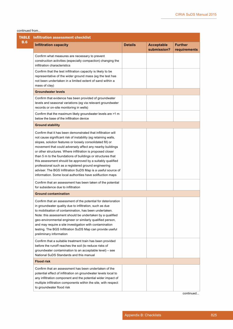
825Appendix B: Checklists
CIRIA SuDS Manual 2015
TABLEB.6
Infiltrationassessmentchecklist
Infiltration capacity Details Acceptable submission?
Further requirements
Confirmwhatmeasuresarenecessarytopreventconstructionactivities(especiallycompaction)changingtheinfiltrationcharacteristics
Confirmthatthetestinfiltrationcapacityislikelytoberepresentativeofthewidergroundmass(egthetesthasnotbeenundertakeninalimitedextentofsandwithinamass of clay)
Groundwater levels
Confirmthatevidencehasbeenprovidedofgroundwaterlevelsandseasonalvariations(egviarelevantgroundwaterrecordsoron-sitemonitoringinwells)
Confirmthatthemaximumlikelygroundwaterlevelsare>1mbelowthebaseoftheinfiltrationdevice
Ground stability
Confirmthatithasbeendemonstratedthatinfiltrationwillnotcausesignificantriskofinstability(egretainingwalls,slopes,solutionfeaturesorlooselyconsolidatedfill)ormovementthatcouldadverselyaffectanynearbybuildingsorotherstructures.Whereinfiltrationisproposedcloserthan 5 m to the foundations of buildings or structures that thisassessmentshouldbeapprovedbyasuitablyqualifiedprofessional such as a registered ground engineering adviser.TheBGSInfiltrationSuDSMapisausefulsourceofinformation.Somelocalauthoritieshavesolifluctionmaps
Confirmthatanassessmenthasbeentakenofthepotentialforsubsidenceduetoinfiltration
Ground contamination
Confirmthatanassessmentofthepotentialfordeteriorationingroundwaterqualityduetoinfiltration,suchasdueto mobilisation of contamination, has been undertaken. Note:thisassessmentshouldbeundertakenbyaqualifiedgeo-environmentalengineerorsimilarlyqualifiedperson,andmayrequireasiteinvestigationwithcontaminationtesting.TheBGSInfiltrationSuDSMapcanprovideusefulpreliminary information
Confirmthatasuitabletreatmenttrainhasbeenprovidedbefore the runoff reaches the soil (to reduce risks of groundwatercontaminationtoanacceptablelevel)–seeNationalSuDSStandardsandthismanual
Flood risk
Confirmthatanassessmenthasbeenundertakenofthepotentialeffectofinfiltrationongroundwaterlevelslocaltoanyinfiltrationcomponentandthepotentialwiderimpactofmultipleinfiltrationcomponentswithinthesite,withrespecttogroundwaterfloodrisk
continued...
continued from...

826 Appendix B
CIRIA SuDS Manual 2015
TABLEB.6
Infiltrationassessmentchecklist
Infiltration capacity Details Acceptable submission?
Further requirements
Confirmthatanassessmenthasbeenundertakenoftheriskofspringsdevelopinginlayeredgeology/steeptopographyduetotheproposedinfiltration
Confirmthatdetailsofoverflowsoradditionaldischargepointsiftotalinfiltrationcannotbereliedonforallreturnperiodeventshavebeenprovided
Combined sewer risk
Confirmthatanassessmenthasbeenundertakenoftheriskof groundwater leakage into any local combined sewers
B.5 SUDS COMPONENT DESIGN CHECKLISTS
B.5.1 Proprietary treatment systems
Thischecklistcanbeusedbytheorganisationapprovingthedrainagescheme(drainageapprovingbody)tohelpassesssubmissionsfordrainageapproval.
Thischecklistisaimedatprovidingaconsistentassessmentprocessandensuringthatdesignsmeetthekey design requirements set out in Chapter 14.Thedesignguidanceinthemanualprovidesdetailsthatsupporttheimplementationofthischecklistsothatdesignsandcomplianceassessmentcanbedeliveredeffectively.Appropriatesectionreferencesfromthemanualareprovidedinthechecklist.
Thischecklistshouldformpartofasuiteofdocumentsrequiredforasubmissionfordrainageapproval,including (but not limited to):
▪ a scheme design assessment
▪ detailedinfiltrationassessment(whereinfiltrationcomponentsareproposed)
▪ a scheme health and safety risk assessment (if required)
▪ a scheme construction method statement
▪ a scheme Maintenance Plan.
ItcanbeusedasachecklistbyorganisationsresponsiblefortheapprovalandadoptionofSuDStosupport their assessment of schemes, or it can be used as part of the required submissions from the developer.Itcanalsohelpdesignersensurethattheyhaveprovidedallrelevantinformationtothedrainageapprovingbodyintheirsubmissionsforapproval.
The checklist can be used for a single system or groups of systems with the same characteristics.
continued from...
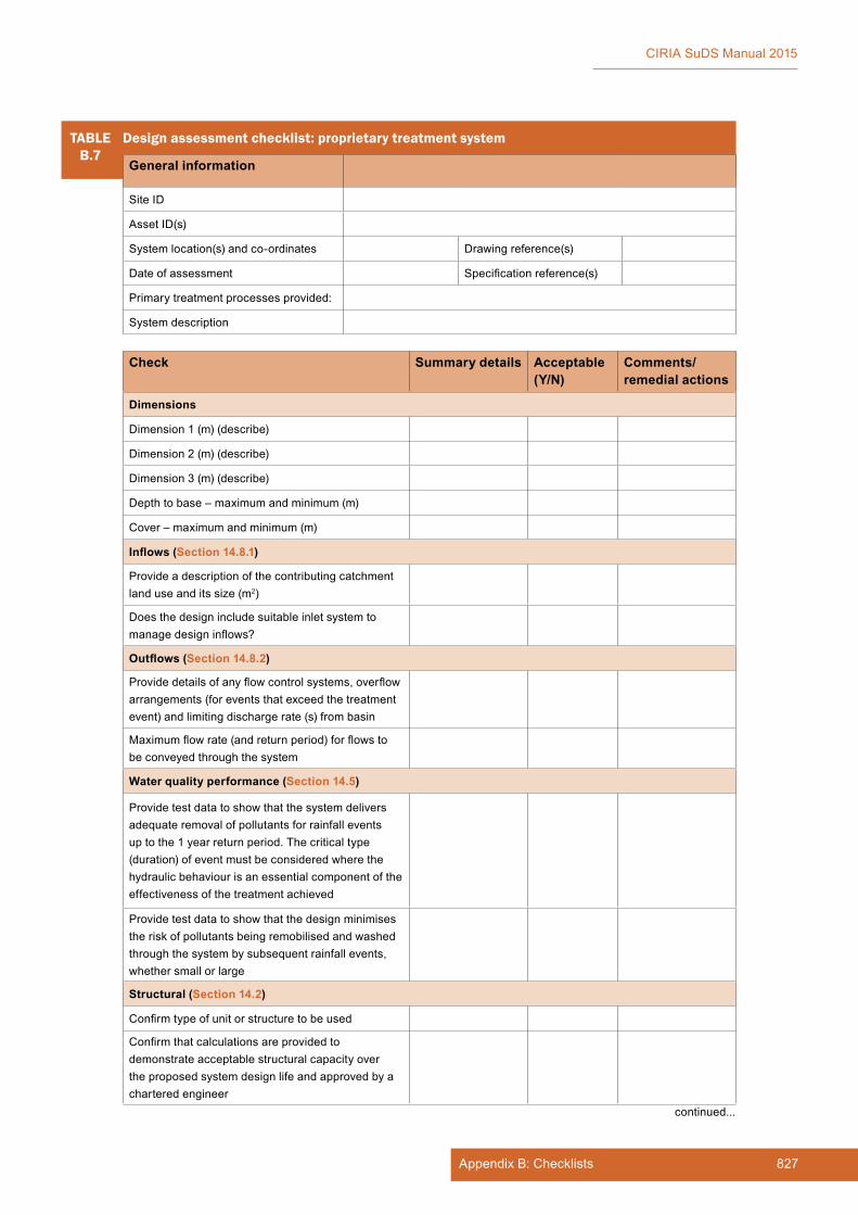
827Appendix B: Checklists
CIRIA SuDS Manual 2015
TABLEB.7
Design assessment checklist: proprietary treatment system
General information
Site ID
AssetID(s)
Systemlocation(s)andco-ordinates Drawing reference(s)
Date of assessment Specificationreference(s)
Primarytreatmentprocessesprovided:
System description
Check Summary details Acceptable (Y/N)
Comments/ remedial actions
Dimensions
Dimension 1 (m) (describe)
Dimension 2 (m) (describe)
Dimension 3 (m) (describe)
Depthtobase–maximumandminimum(m)
Cover–maximumandminimum(m)
Inflows (Section 14.8.1)
Provideadescriptionofthecontributingcatchmentland use and its size (m2)
Does the design include suitable inlet system to managedesigninflows?
Outflows (Section 14.8.2)
Providedetailsofanyflowcontrolsystems,overflowarrangements(foreventsthatexceedthetreatmentevent)andlimitingdischargerate(s)frombasin
Maximumflowrate(andreturnperiod)forflowstobeconveyedthroughthesystem
Water quality performance (Section 14.5)
Providetestdatatoshowthatthesystemdeliversadequateremovalofpollutantsforrainfalleventsup to the 1 year return period. The critical type (duration)ofeventmustbeconsideredwherethehydraulicbehaviourisanessentialcomponentoftheeffectivenessofthetreatmentachieved
Providetestdatatoshowthatthedesignminimisesthe risk of pollutants being remobilised and washed throughthesystembysubsequentrainfallevents,whether small or large
Structural (Section 14.2)
Confirmtypeofunitorstructuretobeused
Confirmthatcalculationsareprovidedtodemonstrateacceptablestructuralcapacityovertheproposedsystemdesignlifeandapprovedbyachartered engineer
continued...

828 Appendix B
CIRIA SuDS Manual 2015
B.5.2 Filter strips
Thischecklistcanbeusedbytheorganisationapprovingthedrainagescheme(drainageapprovingbody)tohelpassesssubmissionsfordrainageapproval.
Thischecklistisaimedatprovidingaconsistentassessmentprocess,andensuringthatdesignsmeetthekey design requirements set out in Chapter 15.Thedesignguidanceinthemanualprovidesdetailsthatsupporttheimplementationofthischecklistsothatdesignsandcomplianceassessmentcanbedeliveredeffectively.Appropriatesectionreferencesfromthemanualareprovidedinthechecklist.
Thischecklistshouldformpartofasuiteofdocumentsrequiredforasubmissionfordrainageapproval,including (but not limited to):
▪ a scheme design assessment
▪ detailedinfiltrationassessment(whereinfiltrationcomponentsareproposed)
▪ a scheme health and safety risk assessment (if required)
▪ a scheme construction method statement
▪ a scheme Maintenance Plan.
TABLEB.7
Design assessment checklist: proprietary treatment system
Check Summary details Acceptable (Y/N)
Comments/ remedial actions
Critical materials and product specifications (Section 14.9)
Geomembrane
Geotextile(non-woven)
Topsoil
Other (including proprietary systems)
Constructability (Section 14.11)
Arethereanyidentifiableconstructionrisks?Ifyes,stateandconfirmthatacceptableriskmanagementmeasures are proposed
Maintainability (Section 14.12)
Confirmthataccessformaintenanceisacceptableand summarise details
Aretherespecificfeaturesthatarelikelytoposemaintenancedifficulties?Ifyes,identifymitigationmeasures required
Confirmrequiredmaintenancefrequencyandcostofreplacementfiltersetc
Identify any custom items required for maintenance thatmaybedifficulttoobtainfromothersuppliers
System design acceptability Summary details including any changes required
Acceptable (Y/N) Date changes made
Acceptable:
Minor changes required:
Majorchangesrequired/redesign:
continued from...
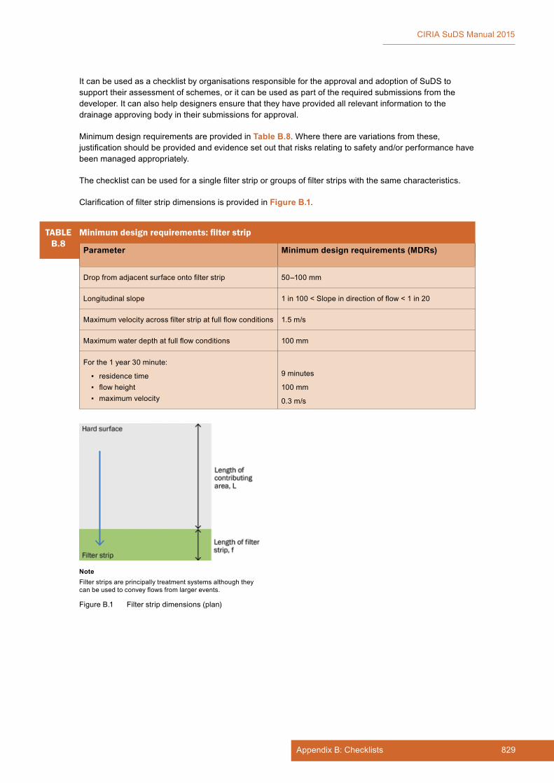
829Appendix B: Checklists
CIRIA SuDS Manual 2015
ItcanbeusedasachecklistbyorganisationsresponsiblefortheapprovalandadoptionofSuDStosupport their assessment of schemes, or it can be used as part of the required submissions from the developer.Itcanalsohelpdesignersensurethattheyhaveprovidedallrelevantinformationtothedrainageapprovingbodyintheirsubmissionsforapproval.
MinimumdesignrequirementsareprovidedinTable B.8.Wheretherearevariationsfromthese,justificationshouldbeprovidedandevidencesetoutthatrisksrelatingtosafetyand/orperformancehavebeen managed appropriately.
Thechecklistcanbeusedforasinglefilterstriporgroupsoffilterstripswiththesamecharacteristics.
ClarificationoffilterstripdimensionsisprovidedinFigure B.1.
TABLEB.8
Minimumdesignrequirements:filterstrip
Parameter Minimum design requirements (MDRs)
Dropfromadjacentsurfaceontofilterstrip 50–100 mm
Longitudinalslope 1in100<Slopeindirectionofflow<1in20
Maximumvelocityacrossfilterstripatfullflowconditions 1.5m/s
Maximumwaterdepthatfullflowconditions 100 mm
For the 1 year 30 minute:
▪ residence time ▪ flowheight ▪ maximumvelocity
9minutes
100 mm
0.3m/s
Figure B.1 Filter strip dimensions (plan)
NoteFilter strips are principally treatment systems although they canbeusedtoconveyflowsfromlargerevents.
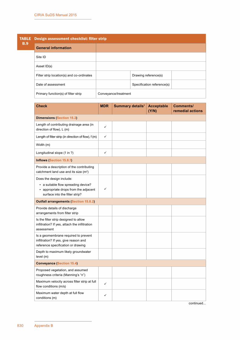
830 Appendix B
CIRIA SuDS Manual 2015
TABLEB.9
Designassessmentchecklist:filterstrip
General information
Site ID
AssetID(s)
Filterstriplocation(s)andco-ordinates Drawing reference(s)
Date of assessment Specificationreference(s)
Primaryfunction(s)offilterstrip Conveyance/treatment
Check MDR Summary details1 Acceptable (Y/N)
Comments/ remedial actions
Dimensions (Section 15.2)
Lengthofcontributingdrainagearea(indirectionofflow),L(m)
Lengthoffilterstrip(indirectionofflow),f(m)
Width (m)
Longitudinalslope(1in?)
Inflows (Section 15.8.1)
Provideadescriptionofthecontributingcatchment land use and its size (m2)
Does the design include:
▪ asuitableflowspreadingdevice? ▪ appropriatedropsfromtheadjacentsurfaceintothefilterstrip?
Outfall arrangements (Section 15.8.2)
Providedetailsofdischargearrangementsfromfilterstrip
Isthefilterstripdesignedtoallowinfiltration?Ifyes,attachtheinfiltrationassessment
Isageomembranerequiredtopreventinfiltration?Ifyes,givereasonandreferencespecificationordrawing
Depthtomaximumlikelygroundwaterlevel(m)
Conveyance (Section 15.4)
Proposedvegetation,andassumedroughnesscriteria(Manning’s“n”)
Maximumvelocityacrossfilterstripatfullflowconditions(m/s)
Maximumwaterdepthatfullflowconditions (m)
continued...
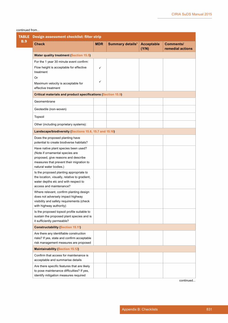
831Appendix B: Checklists
CIRIA SuDS Manual 2015
TABLEB.9
Designassessmentchecklist:filterstrip
Check MDR Summary details1 Acceptable (Y/N)
Comments/ remedial actions
Water quality treatment (Section 15.5)
Forthe1year30minuteeventconfirm:
Flowheightisacceptableforeffectivetreatment
Or
Maximumvelocityisacceptableforeffectivetreatment
Critical materials and product specifications (Section 15.9)
Geomembrane
Geotextile(non-woven)
Topsoil
Other (including proprietary systems):
Landscape/biodiversity (Sections 15.6, 15.7 and 15.10)
Doestheproposedplantinghavepotentialtocreatebiodiversehabitats?
Havenativeplantspeciesbeenused?(Noteifornamentalspeciesareproposed,givereasonsanddescribemeasuresthatpreventtheirmigrationtonatural water bodies.)
Is the proposed planting appropriate to thelocation,visually,relativetogradient,water depths etc and with respect to access and maintenance?
Whererelevant,confirmplantingdesigndoesnotadverselyimpacthighwayvisibilityandsafetyrequirements(checkwith highway authority)
Istheproposedtopsoilprofilesuitabletosustain the proposed plant species and is itsufficientlypermeable?
Constructability (Section 15.11)
Arethereanyidentifiableconstructionrisks?Ifyes,stateandconfirmacceptablerisk management measures are proposed
Maintainability (Section 15.12)
Confirmthataccessformaintenanceisacceptable and summarise details
Aretherespecificfeaturesthatarelikelytoposemaintenancedifficulties?Ifyes,identify mitigation measures required
continued from...
continued...

832 Appendix B
CIRIA SuDS Manual 2015
B.5.3 Filter drains
Thischecklistcanbeusedbytheorganisationapprovingthedrainagescheme(drainageapprovingbody)tohelpassesssubmissionsfordrainageapproval.
Thischecklistisaimedatprovidingaconsistentassessmentprocessandensuringthatdesignsmeetthekey design requirements set out in Chapter 16.Thedesignguidanceinthemanualprovidesdetailsthatsupporttheimplementationofthischecklistsothatdesignsandcomplianceassessmentcanbedeliveredeffectively.Appropriatesectionreferencesfromthemanualareprovidedinthechecklist.
Thischecklistshouldformpartofasuiteofdocumentsrequiredforasubmissionfordrainageapproval,including (but not limited to):
▪ a scheme design assessment
▪ detailedinfiltrationassessment(whereinfiltrationcomponentsareproposed)
▪ a scheme health and safety risk assessment (if required)
▪ a scheme construction method statement
▪ a scheme Maintenance Plan.
ItcanbeusedasachecklistbyorganisationsresponsiblefortheapprovalandadoptionofSuDStosupport their assessment of schemes, or it can be used as part of the required submissions from the developer.Itcanalsohelpdesignersensurethattheyhaveprovidedallrelevantinformationtothedrainageapprovingbodyintheirsubmissionsforapproval.
MinimumdesignrequirementsareprovidedinTable B.10.Wheretherearevariationsfromthese,justificationshouldbeprovidedandevidencesetoutthatrisksrelatingtosafetyand/orperformancehavebeen managed appropriately.
The checklist can be used for a single drain or groups of drains with the same characteristics.
TABLEB.9
Designassessmentchecklist:filterstrip
Note1 IfthereisanMDR(asindicated)confirmwhetherornotthisismetandprovidedetailsofanyvariations.
TABLEB.10
Minimumdesignrequirements:filterdrain
Drain parameter Minimum design requirements (MDRs)
Width Width > 0.3 m
Depth Depth > 1 m
Fillspecification HA(2009a)orequivalent
continued from...
Filter strip design acceptability
Summary details including any changes required
Acceptable (Y/N) Date changes made
Acceptable:
Minor changes required:
Majorchangesrequired/redesign:
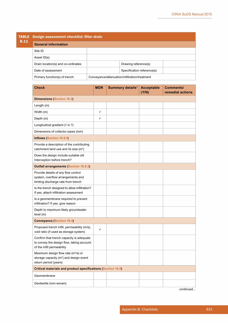
833Appendix B: Checklists
CIRIA SuDS Manual 2015
TABLEB.11
Designassessmentchecklist:filterdrain
General information
Site ID
AssetID(s)
Drainlocation(s)andco-ordinates Drawing reference(s)
Date of assessment Specificationreference(s)
Primary function(s) of trench: Conveyance/attenuation/infiltration/treatment
Check MDR Summary details1 Acceptable (Y/N)
Comments/ remedial actions
Dimensions (Section 16.2)
Length(m)
Width (m)
Depth (m)
Longitudinalgradient(1in?)
Dimensions of collector pipes (mm)
Inflows (Section 16.8.1)
Provideadescriptionofthecontributingcatchment land use and its size (m2)
Does the design include suitable silt Interception before trench?
Outfall arrangements (Section 16.8.2)
Providedetailsofanyflowcontrolsystem,overflowarrangementsandlimiting discharge rate from trench
Isthetrenchdesignedtoallowinfiltration?Ifyes,attachinfiltrationassessment
Isageomembranerequiredtopreventinfiltration?Ifyes,givereason
Depthtomaximumlikelygroundwaterlevel(m)
Conveyance (Section 16.4)
Proposedtrenchinfill,permeability(m/s),voidratio(ifusedasstoragesystem)
Confirmthattrenchcapacityisadequatetoconveythedesignflow,takingaccountoftheinfillpermeability
Maximumdesignflowrate(m3/s)orstorage capacity (m3)anddesigneventreturn period (years)
Critical materials and product specifications (Section 16.9)
Geomembrane
Geotextile(non-woven)
continued...

834 Appendix B
CIRIA SuDS Manual 2015
B.5.4 Swales
Thischecklistcanbeusedbytheorganisationapprovingthedrainagescheme(drainageapprovingbody)tohelpassesssubmissionsfordrainageapproval.
Thischecklistisaimedatprovidingaconsistentassessmentprocessandensuringthatdesignsmeetthekey design requirements set out in Chapter 17.Thedesignguidanceinthemanualprovidesdetailsthatsupporttheimplementationofthischecklistsothatdesignsandcomplianceassessmentcanbedeliveredeffectively.Appropriatesectionreferencesfromthemanualareprovidedinthechecklist.
Thischecklistshouldformpartofasuiteofdocumentsrequiredforasubmissionfordrainageapproval,including (but not limited to):
▪ a scheme design assessment
▪ detailedinfiltrationassessment(whereinfiltrationcomponentsareproposed)
▪ a scheme health and safety risk assessment (if required)
▪ a scheme construction method statement
▪ a scheme Maintenance Plan.
ItcanbeusedasachecklistbyorganisationsresponsiblefortheapprovalandadoptionofSuDStosupport their assessment of schemes, or it can be used as part of the required submissions from the developer.Itcanalsohelpdesignersensurethattheyhaveprovidedallrelevantinformationtothedrainageapprovingbodyintheirsubmissionsforapproval.
Note1 IfthereisanMDR(asindicated)confirmwhetherornotthisismetandprovidedetailsofanyvariations.
TABLEB.11
Designassessmentchecklist:filterdrain
Check MDR Summary details1 Acceptable (Y/N)
Comments/ remedial actions
Topsoil
Gravelfill
Perforated pipework
Other (including proprietary systems)
Constructability (Section 16.11)
Arethereanyidentifiableconstructionrisks?Ifyes,stateriskandconfirmacceptable risk management measures are proposed
Maintainability (Section 16.12)
Confirmthataccessformaintenanceisacceptable and summarise details
Aretherespecificfeaturesthatarelikelytoposemaintenancedifficulties?Ifyes,identify mitigation measures required
Drain design acceptabilitySummary details including any changes required
Acceptable (Y/N)
Date changes made
Acceptable:
Minor changes required:
Majorchangesrequired/redesign:
continued from...

835Appendix B: Checklists
CIRIA SuDS Manual 2015
MinimumdesignrequirementsareprovidedinTable B.12.Wheretherearevariationsfromthese,justificationshouldbeprovidedandevidencesetoutthatrisksrelatingtosafetyand/orperformancehavebeen managed appropriately.
The checklist can be used for a single swale or groups of swales with the same characteristics.
TABLEB.12
Minimum design requirements: swale
Parameter Minimum design requirements (MDR’s)
Dropfromadjacentsurfaceontoswale(fordirectlateralinflows) 50–100 mm
Base width 0.5 m < base width < 2 m
Side slope Side slope < 1 in 3
Longitudinalslope Bed slope < 1 in 40
Maximumvelocityinswaleatfullflowconditions 2m/s
Maximumwaterdepthatfullflowconditions 600 mm
Forthe1year,30minevent: ▪ averageresidencetimeinswale ▪ flowheight ▪ maximumvelocity
> 10 minutes< 100 mm<0.3m/s
Forinfiltration/underdrainedswales:permeabilityoftopsoil > permeability of underlying soils
TABLEB.13
Design assessment checklist: swale
General information
Site ID
AssetID(s)
Swalelocation(s)andco-ordinates Drawing reference(s)
Date of assessment Specificationreference(s)
Primary function(s) of swale Conveyance/attenuation/infiltration/treatment/otherdualuse(specify)
Check MDR Summary details1 Acceptable (Y/N)
Comments/ remedial actions
Dimensions (Section 17.2)
Length(m)
Width – at top and at base (m)
Side slopes (1 in ?)
Depth–maximumandminimum(m)
Freeboard (m)
Longitudinalslope(1in?)
Distance between check dams (if provided)(m)
Dimensions of any underdrain (m)
Dimensions of any perforated pipe within underdrain (mm)
continued...
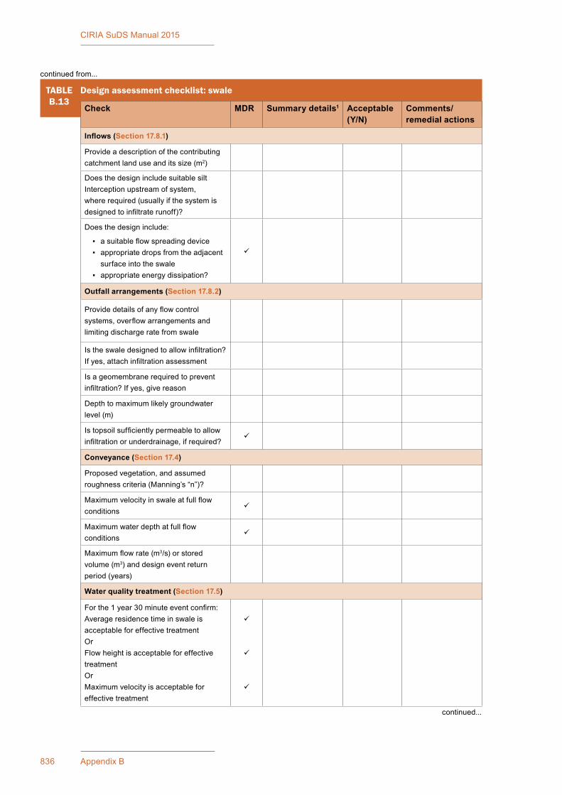
836 Appendix B
CIRIA SuDS Manual 2015
TABLEB.13
Design assessment checklist: swale
Check MDR Summary details1 Acceptable (Y/N)
Comments/ remedial actions
Inflows (Section 17.8.1)
Provideadescriptionofthecontributingcatchment land use and its size (m2)
Does the design include suitable silt Interception upstream of system, where required (usually if the system is designedtoinfiltraterunoff)?
Does the design include:
▪ asuitableflowspreadingdevice ▪ appropriatedropsfromtheadjacent
surface into the swale ▪ appropriate energy dissipation?
Outfall arrangements (Section 17.8.2)
Providedetailsofanyflowcontrolsystems,overflowarrangementsandlimiting discharge rate from swale
Istheswaledesignedtoallowinfiltration?Ifyes,attachinfiltrationassessment
Isageomembranerequiredtopreventinfiltration?Ifyes,givereason
Depthtomaximumlikelygroundwaterlevel(m)
Istopsoilsufficientlypermeabletoallowinfiltrationorunderdrainage,ifrequired?
Conveyance (Section 17.4)
Proposedvegetation,andassumedroughnesscriteria(Manning’s“n”)?
Maximumvelocityinswaleatfullflowconditions
Maximumwaterdepthatfullflowconditions
Maximumflowrate(m3/s)orstoredvolume(m3)anddesigneventreturnperiod (years)
Water quality treatment (Section 17.5)
Forthe1year30minuteeventconfirm:AverageresidencetimeinswaleisacceptableforeffectivetreatmentOrFlowheightisacceptableforeffectivetreatmentOrMaximumvelocityisacceptableforeffectivetreatment
continued...
continued from...

837Appendix B: Checklists
CIRIA SuDS Manual 2015
TABLEB.13
Design assessment checklist: swale
Check MDR Summary details1 Acceptable (Y/N)
Comments/ remedial actions
Landscape/biodiversity (Sections 17.6, 17.7 and 17.10)
Does the swale planting include: ▪ grassed ▪ othernativespecies ▪ other species or features?
Provideaplantingscheduleshowingspecies and planting preferences.
Is the planting demonstrated to be appropriateforthehabitatspecified?
Will plantings be established or rely on natural colonisation?
Havelocallyappropriatenativeplantspecies been used?
Indicate the number of different plant species used (not a monoculture)
Is the proposed swale planting appropriate to the location, and with respect to access and maintenance?
Whererelevant,confirmthatplantingdesigndoesnotadverselyimpacthighwayvisibilityandsafetyrequirements(check with highway authority)
Istheproposedtopsoilprofilesuitabletosustain the proposed plant species?
Critical materials and product specifications (Section 17.9)
Geomembrane
Geotextile(non-woven)
Topsoil
Other (including underdrain material):
Constructability (Section 17.11)
Arethereanyidentifiableconstructionrisks?Ifyes,stateandconfirmacceptable risk management measures are proposed
Maintainability (Section 17.12)
Confirmthataccessformaintenanceisacceptable and summarise details
Aretherespecificfeaturesthatarelikelytoposemaintenancedifficulties?Ifyes,identify mitigation measures required
continued...
continued from...

838 Appendix B
CIRIA SuDS Manual 2015
B.5.5 Bioretention systems
Thischecklistcanbeusedbytheorganisationapprovingthedrainagescheme(drainageapprovingbody)tohelpassesssubmissionsfordrainageapproval.
Thischecklistisaimedatprovidingaconsistentassessmentprocessandensuringthatdesignsmeetthekey design requirements set out in Chapter 18.Thedesignguidanceinthemanualprovidesdetailsthatsupporttheimplementationofthischecklistsothatdesignsandcomplianceassessmentcanbedeliveredeffectively.Appropriatesectionreferencesfromthemanualareprovidedinthechecklist.
Thischecklistshouldformpartofasuiteofdocumentsrequiredforasubmissionfordrainageapproval,including (but not limited to):
▪ a scheme design assessment
▪ detailedinfiltrationassessment(whereinfiltrationcomponentsareproposed)
▪ a scheme health and safety risk assessment (if required)
▪ a scheme construction method statement
▪ a scheme Maintenance Plan.
ItcanbeusedasachecklistbyorganisationsresponsiblefortheapprovalandadoptionofSuDStosupport their assessment of schemes, or it can be used as part of the required submissions from the developer.Itcanalsohelpdesignersensurethattheyhaveprovidedallrelevantinformationtothedrainageapprovingbodyintheirsubmissionsforapproval.
Minimumdesignrequirements(MDRs)areprovidedinTable B.14.Wheretherearevariationsfromthese,justificationshouldbeprovidedandevidencesetoutthatrisksrelatingtosafetyand/orperformancehavebeen managed appropriately.
The checklist can be used for a single bioretention systems or groups of similar features with the same characteristics.
Note:Bioretentionsystemsareprincipallytreatmentsystemsandshouldnotbeusedasaflowpathwayfordesignflowevents.
Note1 IfthereisanMDR(asindicated)confirmwhetherornotthisismetandprovidedetailsofanyvariations.
TABLEB.13
Design assessment checklist: swale
continued from...
Swale design acceptability Summary details including any changes required
Acceptable (Y/N) Date changes made
Acceptable:
Minor changes required:
Majorchangesrequired/redesign:
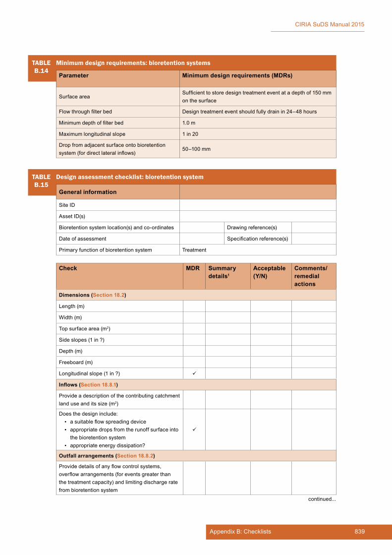
839Appendix B: Checklists
CIRIA SuDS Manual 2015
TABLEB.14
Minimum design requirements: bioretention systems
Parameter Minimum design requirements (MDRs)
Surface areaSufficienttostoredesigntreatmenteventatadepthof150mmon the surface
Flowthroughfilterbed Designtreatmenteventshouldfullydrainin24–48hours
Minimumdepthoffilterbed 1.0 m
Maximumlongitudinalslope 1 in 20
Dropfromadjacentsurfaceontobioretentionsystem(fordirectlateralinflows)
50–100 mm
TABLEB.15
Design assessment checklist: bioretention system
General information
Site ID
AssetID(s)
Bioretentionsystemlocation(s)andco-ordinates Drawing reference(s)
Date of assessment Specificationreference(s)
Primary function of bioretention system Treatment
Check MDR Summary details1
Acceptable (Y/N)
Comments/ remedial actions
Dimensions (Section 18.2)
Length(m)
Width (m)
Top surface area (m2)
Side slopes (1 in ?)
Depth (m)
Freeboard (m)
Longitudinalslope(1in?)
Inflows (Section 18.8.1)
Provideadescriptionofthecontributingcatchmentland use and its size (m2)
Does the design include: ▪ asuitableflowspreadingdevice ▪ appropriate drops from the runoff surface into
the bioretention system ▪ appropriate energy dissipation?
Outfall arrangements (Section 18.8.2)
Providedetailsofanyflowcontrolsystems,overflowarrangements(foreventsgreaterthanthe treatment capacity) and limiting discharge rate from bioretention system
continued...
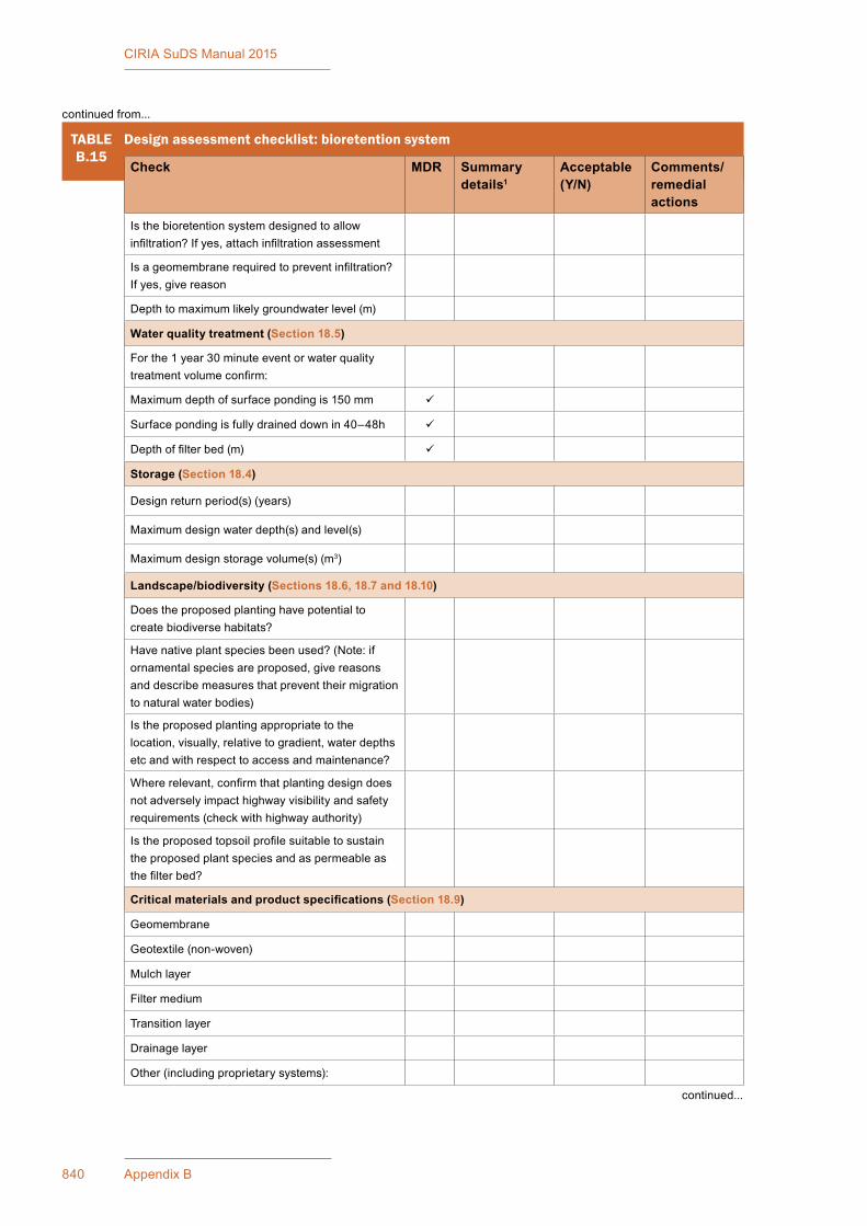
840 Appendix B
CIRIA SuDS Manual 2015
TABLEB.15
Design assessment checklist: bioretention system
Check MDR Summary details1
Acceptable (Y/N)
Comments/ remedial actions
Is the bioretention system designed to allow infiltration?Ifyes,attachinfiltrationassessment
Isageomembranerequiredtopreventinfiltration?Ifyes,givereason
Depthtomaximumlikelygroundwaterlevel(m)
Water quality treatment (Section 18.5)
Forthe1year30minuteeventorwaterqualitytreatmentvolumeconfirm:
Maximumdepthofsurfacepondingis150mm
Surface ponding is fully drained down in 40–48h
Depthoffilterbed(m)
Storage (Section 18.4)
Design return period(s) (years)
Maximumdesignwaterdepth(s)andlevel(s)
Maximumdesignstoragevolume(s)(m3)
Landscape/biodiversity (Sections 18.6, 18.7 and 18.10)
Doestheproposedplantinghavepotentialtocreatebiodiversehabitats?
Havenativeplantspeciesbeenused?(Note:ifornamentalspeciesareproposed,givereasonsanddescribemeasuresthatpreventtheirmigrationto natural water bodies)
Is the proposed planting appropriate to the location,visually,relativetogradient,waterdepthsetc and with respect to access and maintenance?
Whererelevant,confirmthatplantingdesigndoesnotadverselyimpacthighwayvisibilityandsafetyrequirements (check with highway authority)
Istheproposedtopsoilprofilesuitabletosustainthe proposed plant species and as permeable as thefilterbed?
Critical materials and product specifications (Section 18.9)
Geomembrane
Geotextile(non-woven)
Mulch layer
Filter medium
Transition layer
Drainage layer
Other (including proprietary systems):
continued from...
continued...

841Appendix B: Checklists
CIRIA SuDS Manual 2015
TABLEB.15
Design assessment checklist: bioretention system
Check MDR Summary details1
Acceptable (Y/N)
Comments/ remedial actions
Constructability (Section 18.11)
Arethereanyidentifiableconstructionrisks?Ifyes,stateandconfirmacceptableriskmanagementmeasures are proposed
Maintainability (Section 18.12)
Confirmthataccessformaintenanceisacceptableand summarise details
Aretherespecificfeaturesthatarelikelytoposemaintenancedifficulties?Ifyes,identifymitigationmeasures required
Bioretention design acceptabilitySummary details including any changes required
Acceptable (Y/N)
Date changes made
Acceptable:Minor changes required:Majorchangesrequired/redesign:
Note1 IfthereisanMDR(asindicated)confirmwhetherornotthisismetandprovidedetailsofanyvariations.
B.5.6 Pervious pavements
Thischecklistcanbeusedbytheorganisationapprovingthedrainagescheme(drainageapprovingbody)tohelpassesssubmissionsfordrainageapproval.
Thischecklistisaimedatprovidingaconsistentassessmentprocessandensuringthatdesignsmeetthekey design requirements set out in Chapter 20.Thedesignguidanceinthemanualprovidesdetailsthatsupporttheimplementationofthischecklistsothatdesignsandcomplianceassessmentcanbedeliveredeffectively.Appropriatesectionreferencesfromthemanualareprovidedinthechecklist.
Thischecklistshouldformpartofasuiteofdocumentsrequiredforasubmissionfordrainageapproval,including (but not limited to):
▪ a scheme design assessment
▪ detailedinfiltrationassessment(whereinfiltrationcomponentsareproposed)
▪ a scheme health and safety risk assessment (if required)
▪ a scheme construction method statement
▪ a scheme Maintenance Plan.
ItcanbeusedasachecklistbyorganisationsresponsiblefortheapprovalandadoptionofSuDStosupport their assessment of schemes, or it can be used as part of the required submissions from the developer.Itcanalsohelpdesignersensurethattheyhaveprovidedallrelevantinformationtothedrainageapprovingbodyintheirsubmissionsforapproval.
Thechecklistcanbeusedforasinglepavementsorgroupsofpavementswiththesamecharacteristics.
continued from...
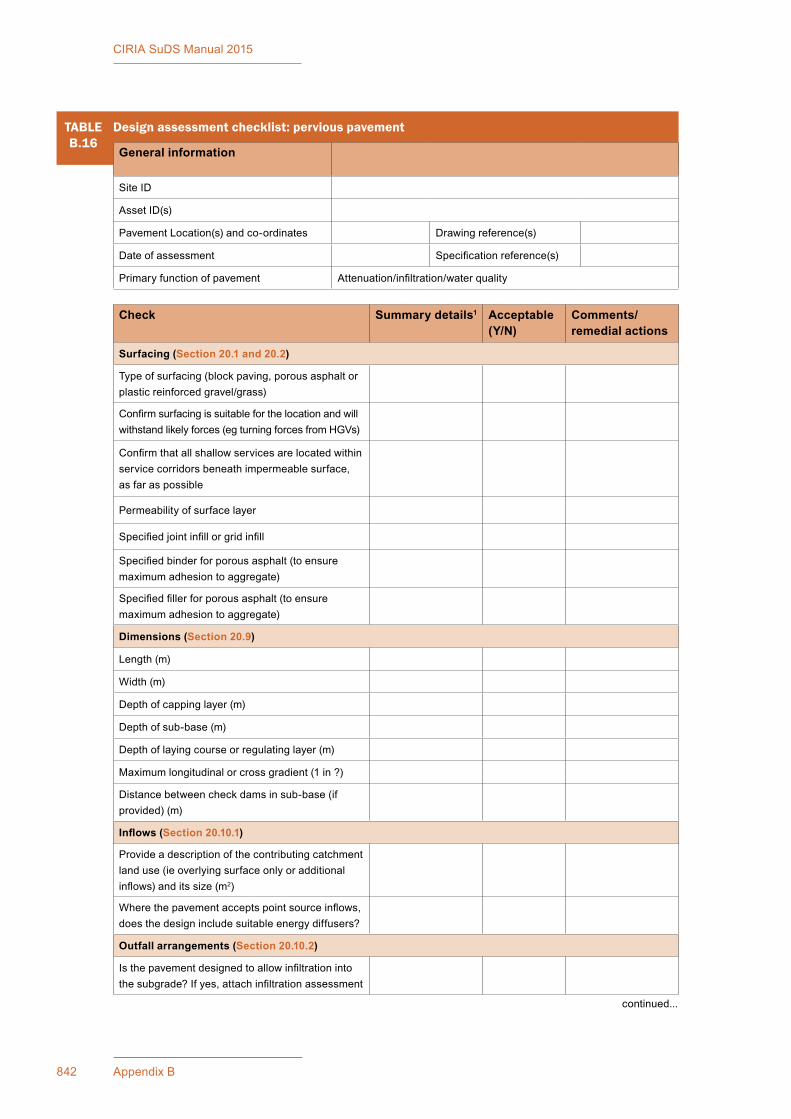
842 Appendix B
CIRIA SuDS Manual 2015
TABLEB.16
Design assessment checklist: pervious pavement
General information
Site ID
AssetID(s)
PavementLocation(s)andco-ordinates Drawing reference(s)
Date of assessment Specificationreference(s)
Primaryfunctionofpavement Attenuation/infiltration/waterquality
Check Summary details1 Acceptable (Y/N)
Comments/ remedial actions
Surfacing (Section 20.1 and 20.2)
Typeofsurfacing(blockpaving,porousasphaltorplasticreinforcedgravel/grass)
Confirmsurfacingissuitableforthelocationandwillwithstandlikelyforces(egturningforcesfromHGVs)
Confirmthatallshallowservicesarelocatedwithinservicecorridorsbeneathimpermeablesurface,as far as possible
Permeability of surface layer
Specifiedjointinfillorgridinfill
Specifiedbinderforporousasphalt(toensuremaximumadhesiontoaggregate)
Specifiedfillerforporousasphalt(toensuremaximumadhesiontoaggregate)
Dimensions (Section 20.9)
Length(m)
Width (m)
Depth of capping layer (m)
Depthofsub-base(m)
Depth of laying course or regulating layer (m)
Maximumlongitudinalorcrossgradient(1in?)
Distancebetweencheckdamsinsub-base(ifprovided)(m)
Inflows (Section 20.10.1)
Provideadescriptionofthecontributingcatchmentlanduse(ieoverlyingsurfaceonlyoradditionalinflows)anditssize(m2)
Wherethepavementacceptspointsourceinflows,does the design include suitable energy diffusers?
Outfall arrangements (Section 20.10.2)
Isthepavementdesignedtoallowinfiltrationintothesubgrade?Ifyes,attachinfiltrationassessment
continued...
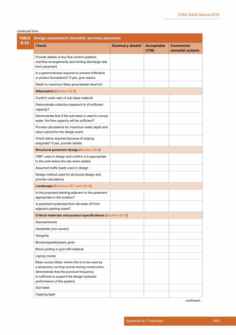
843Appendix B: Checklists
CIRIA SuDS Manual 2015
TABLEB.16
Design assessment checklist: pervious pavement
Check Summary details1 Acceptable (Y/N)
Comments/ remedial actions
Providedetailsofanyflowcontrolsystems,overflowarrangementsandlimitingdischargeratefrompavement
Isageomembranerequiredtopreventinfiltrationorprotectfoundations?Ifyes,givereason
Depthtomaximumlikelygroundwaterlevel(m)
Attenuation (Section 20.5)
Confirmvoidsratioofsub-basematerial
Demonstratecollectionpipeworkisofsufficientcapacity?
Demonstratethatifthesub-baseisusedtoconveywater,theflowcapacitywillbesufficient?
Providecalculationsformaximumwaterdepthandreturnperiodforthedesignevent
Check dams required because of sloping subgrade?Ifyes,providedetails
Structural pavement design (Section 20.9)
CBR*usedindesignandconfirmitisappropriateto the soils below the site when wetted
Assumedtrafficloadsusedindesign
Design method used for structural design and providecalculations
Landscape (Sections 20.7 and 20.12)
Istheproposedplantingadjacenttothepavementappropriate to the location?
Ispavementprotectedfromsiltwashofffromadjacentplantingareas?
Critical materials and product specifications (Section 20.11)
Geomembrane
Geotextile(non-woven)
Geogrids
Blocks/asphalt/plasticgrids
Blockjointingorgridinfillmaterial
Layingcourse
Basecourse(Note:wherethisistobeusedasa temporary running course during construction, demonstrate that the puncture frequency issufficienttosupportthedesignhydraulicperformance of the system)
Sub-base
Capping layer
continued...
continued from...

844 Appendix B
CIRIA SuDS Manual 2015
B.5.7 Attenuation storage tanks
Thischecklistcanbeusedbytheorganisationapprovingthedrainagescheme(drainageapprovingbody)tohelpassesssubmissionsfordrainageapproval.
Thischecklistisaimedatprovidingaconsistentassessmentprocessandensuringthatdesignsmeetthekey design requirements set out in Chapter 21.Thedesignguidanceinthemanualprovidesdetailsthatsupporttheimplementationofthischecklistsothatdesignsandcomplianceassessmentcanbedeliveredeffectively.Appropriatesectionreferencesfromthemanualareprovidedinthechecklist.
Thischecklistshouldformpartofasuiteofdocumentsrequiredforasubmissionfordrainageapproval,including (but not limited to):
▪ a scheme design assessment
▪ detailedinfiltrationassessment(whereinfiltrationcomponentsareproposed)
▪ a scheme health and safety risk assessment (if required)
▪ a scheme construction method statement
▪ a scheme Maintenance Plan.
ItcanbeusedasachecklistbyorganisationsresponsiblefortheapprovalandadoptionofSuDStosupport their assessment of schemes, or it can be used as part of the required submissions from the developer.Itcanalsohelpdesignersensurethattheyhaveprovidedallrelevantinformationtothedrainageapprovingbodyintheirsubmissionsforapproval.
The checklist can be used for a single system or groups of systems with the same characteristics.
TABLEB.16
Design assessment checklist: pervious pavement
Check Summary details1 Acceptable (Y/N)
Comments/ remedial actions
Topsoil
Other (including proprietary systems)
Constructability (Section 20.13)
Arethereanyidentifiableconstructionrisks?Ifyes,stateandconfirmacceptableriskmanagementmeasuresareproposed.(Note:keyrequirementtoprotect permeable surface during construction.)
Maintainability (Section 20.14)
Confirmthataccessformaintenanceisacceptableand summarise details
Aretherespecificfeaturesthatarelikelytoposemaintenancedifficulties?Ifyes,identifymitigationmeasures required
Pavement design acceptability
Summary details including any changes required
Acceptable (Y/N) Date changes made
Acceptable:
Minor changes required:
Majorchangesrequired/redesign:
Note1 CBR=Californiabearingratio.Thisisapenetrationtestforevaluationofthemechanicalstrengthofsubgradesandbasecourses.
continued from...
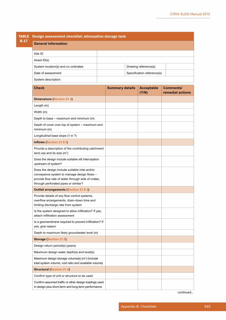
845Appendix B: Checklists
CIRIA SuDS Manual 2015
TABLEB.17
Design assessment checklist: attenuation storage tank
General information
Site ID
AssetID(s)
Systemlocation(s)andco-ordinates Drawing reference(s)
Date of assessment Specificationreference(s)
System description:
Check Summary details Acceptable (Y/N)
Comments/ remedial actions
Dimensions (Section 21.4)
Length(m)
Width (m)
Depthtobase–maximumandminimum(m)
Depthofcoverovertopofsystem–maximumandminimum (m)
Longitudinalbaseslope(1in?)
Inflows (Section 21.9.1)
Provideadescriptionofthecontributingcatchmentland use and its size (m2)
Does the design include suitable silt Interception upstream of system?
Doesthedesignincludesuitableinletand/orconveyancesystemtomanagedesignflows–provideflowrateofwaterthroughsideofcrates,through perforated pipes or similar?
Outfall arrangements (Section 21.9.2)
Providedetailsofanyflowcontrolsystems,overflowarrangements,drain-downtimeandlimiting discharge rate from system
Isthesystemdesignedtoallowinfiltration?Ifyes,attachinfiltrationassessment
Isageomembranerequiredtopreventinfiltration?Ifyes,givereason
Depthtomaximumlikelygroundwaterlevel(m)
Storage (Section 21.5)
Design return period(s) (years)
Maximumdesignwaterdepth(s)andlevel(s)
Maximumdesignstoragevolume(s)(m3) (include totalsystemvolume,voidratioandavailablevolume)
Structural (Section 21.4)
Confirmtypeofunitorstructuretobeused
Confirmassumedtrafficorotherdesignloadingsusedindesignplusshort-termandlong-termperformance
continued...
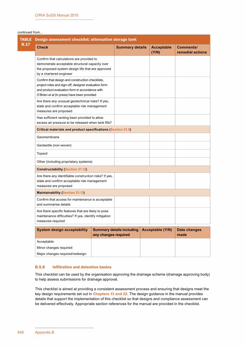
846 Appendix B
CIRIA SuDS Manual 2015
B.5.8 Infiltrationanddetentionbasins
Thischecklistcanbeusedbytheorganisationapprovingthedrainagescheme(drainageapprovingbody)tohelpassesssubmissionsfordrainageapproval.
Thischecklistisaimedatprovidingaconsistentassessmentprocessandensuringthatdesignsmeetthekey design requirements set out in Chapters 13 and 22.Thedesignguidanceinthemanualprovidesdetails that support the implementation of this checklist so that designs and compliance assessment can bedeliveredeffectively.Appropriatesectionreferencesforthemanualareprovidedinthechecklist.
TABLEB.17
Design assessment checklist: attenuation storage tank
Check Summary details Acceptable (Y/N)
Comments/ remedial actions
Confirmthatcalculationsareprovidedtodemonstrateacceptablestructuralcapacityovertheproposedsystemdesignlifethatareapprovedby a chartered engineer
Confirmthatdesignandconstructionchecklists,projectrolesandsign-off,designerevaluationformandproductevaluationforminaccordancewithO’Brien et al(inpress)havebeenprovided
Arethereanyunusualgeotechnicalrisks?Ifyes,stateandconfirmacceptableriskmanagementmeasures are proposed
Hassufficientventingbeenprovidedtoallowexcessairpressuretobereleasedwhentankfills?
Critical materials and product specifications (Section 21.9)
Geomembrane
Geotextile(non-woven)
Topsoil
Other (including proprietary systems):
Constructability (Section 21.12)
Arethereanyidentifiableconstructionrisks?Ifyes,stateandconfirmacceptableriskmanagementmeasures are proposed
Maintainability (Section 21.13)
Confirmthataccessformaintenanceisacceptableand summarise details
Aretherespecificfeaturesthatarelikelytoposemaintenancedifficulties?Ifyes,identifymitigationmeasures required
System design acceptability Summary details including any changes required
Acceptable (Y/N) Date changes made
Acceptable:
Minor changes required:
Majorchangesrequired/redesign:
continued from...

847Appendix B: Checklists
CIRIA SuDS Manual 2015
Thischecklistshouldformpartofasuiteofdocumentsrequiredforasubmissionfordrainageapproval,including (but not limited to):
▪ a scheme design assessment
▪ detailedinfiltrationassessment(whereinfiltrationcomponentsareproposed)
▪ a scheme health and safety risk assessment (if required)
▪ a scheme construction method statement
▪ a scheme Maintenance Plan.
ItcanbeusedasachecklistbyorganisationsresponsiblefortheapprovalandadoptionofSuDStosupport their assessment of schemes, or it can be used as part of the required submissions from the developer.Itcanalsohelpdesignersensurethattheyhaveprovidedallrelevantinformationtothedrainageapprovingbodyintheirsubmissionsforapproval.
Minimumdesignrequirements(MDRs)areprovidedinTable B.18.Wheretherearevariationsfromthese,justificationshouldbeprovidedandevidencesetoutthatrisksrelatingtosafetyandperformancehavebeen managed appropriately.
Thechecklistcanbeusedforaninfiltration/detentionbasinorgroupsofsuchbasinswiththesamecharacteristics.
TABLEB.18
Minimum design requirements: basin
Basin Parameter Minimum design requirements (MDRs)
Infiltration Detention
Length:widthratio N/A > 2:1
Side slope Side slope < 1 in 3 Side slope < 1 in 3
Longitudinalslope Bed slope < 1 in 40 Bed slope < 1 in 40
Maximumwaterdepthfor1in100yearevent 1 m 1 m
Permeability of topsoil > permeability of underlying soils N/A
Forthe1year30minuteevent: ▪ averageresidencetimeinbasin ▪ flowheight ▪ velocity
N/A>9minutes<100 mm<0.3m/s
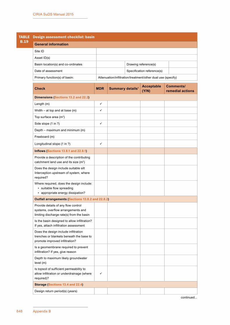
848 Appendix B
CIRIA SuDS Manual 2015
TABLEB.19
Design assessment checklist: basin
General information
Site ID
AssetID(s)
Basinlocation(s)andco-ordinates Drawing reference(s)
Date of assessment Specificationreference(s)
Primary function(s) of basin: Attenuation/infiltration/treatment/otherdualuse(specify)
Check MDR Summary details1 Acceptable (Y/N)
Comments/ remedial actions
Dimensions (Sections 13.2 and 22.2)
Length(m)
Width – at top and at base (m)
Top surface area (m2)
Side slope (1 in ?)
Depth–maximumandminimum(m)
Freeboard (m)
Longitudinalslope(1in?)
Inflows (Sections 13.8.1 and 22.8.1)
Provideadescriptionofthecontributingcatchment land use and its size (m2)
Does the design include suitable silt Interception upstream of system, where required?
Where required, does the design include: ▪ suitableflowspreading ▪ appropriate energy dissipation?
Outfall arrangements (Sections 13.8.2 and 22.8.2)
Providedetailsofanyflowcontrolsystems,overflowarrangementsandlimiting discharge rate(s) from the basin
Isthebasindesignedtoallowinfiltration?Ifyes,attachinfiltrationassessment
Doesthedesignincludeinfiltrationtrenches or blankets beneath the base to promoteimprovedinfiltration?
Isageomembranerequiredtopreventinfiltration?Ifyes,givereason
Depthtomaximumlikelygroundwaterlevel(m)
Istopsoilofsufficientpermeabilitytoallowinfiltrationorunderdrainage(whererequired)?
Storage (Sections 13.4 and 22.4)
Design return period(s) (years)
continued...

849Appendix B: Checklists
CIRIA SuDS Manual 2015
TABLEB.19
Design assessment checklist: basin
Check MDR Summary details1 Acceptable (Y/N)
Comments/ remedial actions
Maximumdesignwaterdepth(s)andlevel(s)
Maximumdesignstoragevolume(s)(m3)
Note:Itwouldbeunusualforthisvolumetoexceed10,000m3. If it does, the design mayhavetocomplywiththeReservoirsAct1975(asamendedbytheFloodandWaterManagementAct(FWMA)2010).Checks should be made of the design to confirmsuitabilityofsuchalargevolume
Levelsaroundtheedgeofthepond/wetland appropriate to contain design depths of water?
Water quality treatment (Sections 13.5 and 22.5)
Forthe1year,30mineventconfirm:
AverageresidencetimeindetentionbasinisacceptableforeffectivetreatmentOrMaximumvelocityisacceptableforeffectivetreatment
Landscape/biodiversity (Sections 13.6, 13.7, 13.10, 22.6, 22.7 and 22.10)
Doestheproposedplantinghavepotentialtocreatebiodiversehabitats?
Havenativeplantspeciesbeenused?(Note:ifornamentalspeciesareproposed,givereasonsanddescribemeasuresthatpreventtheirmigrationtonatural water bodies.)
Is the proposed planting appropriate to thelocation,visually,relativetogradient,water depths etc and with respect to access and maintenance?
Whererelevant,confirmplantingdesigndoesnotadverselyimpacthighwayvisibilityandsafetyrequirements(checkwith highway authority)
Istheproposedtopsoilprofilesuitabletosustain the proposed plant species and aspermeableasthefilterbed?
Critical materials and product specifications (Sections 13.9 and 22.9)
Geomembrane
Geotextile(non-woven)
Topsoil
Other (including proprietary systems)
continued...
continued from...

850 Appendix B
CIRIA SuDS Manual 2015
TABLEB.19
Design assessment checklist: basin
Check MDR Summary details1 Acceptable (Y/N)
Comments/ remedial actions
Constructability (Sections 13.11 and 22.11)
Arethereanyidentifiableconstructionrisks?Ifyes,stateandconfirmacceptablerisk management measures are proposed
Maintainability (Sections 13.12 and 22.12)
Confirmthataccessformaintenanceisacceptable and summarise details
Aretherespecificfeaturesthatarelikelytoposemaintenancedifficulties?Ifyes,identify mitigation measures required
Basin design acceptabilitySummary details including any changes required
Acceptable (Y/N)
Date changes made
Acceptable:Minor changes required:Majorchangesrequired/redesign:
Note1 IfthereisanMDR(asindicated)confirmwhetherornotthisismetandprovidedetailsofanyvariations.
continued from...
B.5.9 Ponds and wetlands
Thischecklistcanbeusedbytheorganisationapprovingthedrainagescheme(drainageapprovingbody)tohelpassesssubmissionsfordrainageapproval.
Thischecklistisaimedatprovidingaconsistentassessmentprocessandensuringthatdesignsmeetthekey design requirements set out in Chapter 23.Thedesignguidanceinthemanualprovidesdetailsthatsupporttheimplementationofthischecklistsothatdesignsandcomplianceassessmentcanbedeliveredeffectively.Appropriatesectionreferencesfromthemanualareprovidedinthechecklist.
Thischecklistshouldformpartofasuiteofdocumentsrequiredforasubmissionfordrainageapproval,including (but not limited to):
▪ a scheme design assessment
▪ detailedinfiltrationassessment(whereinfiltrationcomponentsareproposed)
▪ a scheme health and safety risk assessment (if required)
▪ a scheme construction method statement
▪ a scheme Maintenance Plan.
ItcanbeusedasachecklistbyorganisationsresponsiblefortheapprovalandadoptionofSuDStosupport their assessment of schemes, or it can be used as part of the required submissions from the developer.Itcanalsohelpdesignersensurethattheyhaveprovidedallrelevantinformationtothedrainageapprovingbodyintheirsubmissionsforapproval.
MinimumdesignrequirementsareprovidedinTable B.20.Wheretherearevariationsfromthese,justificationshouldbeprovidedandevidencesetoutthatrisksrelatingtosafetyand/orperformancehavebeen managed appropriately.
Thechecklistcanbeusedforasinglepond/wetlandsorgroupsofsimilarfeatureswiththesamecharacteristics.
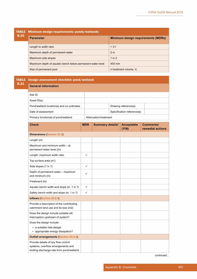
851Appendix B: Checklists
CIRIA SuDS Manual 2015
TABLEB.20
Minimum design requirements: ponds/wetlands
Parameter Minimum design requirements (MDRs)
Lengthtowidthratio > 3:1
Maximumdepthofpermanentwater 2 m
Maximumsideslopes 1 in 3
Maximumdepthofaquaticbenchbelowpermanentwaterlevel 400 mm
Size of permanent pool ≥treatmentvolume,Vt
TABLEB.21
Design assessment checklist: pond/wetland
General information
Site ID
AssetID(s)
Pond/wetlandlocation(s)andco-ordinates Drawing reference(s)
Date of assessment Specificationreference(s)
Primaryfunction(s)ofpond/wetland Attenuation/treatment
Check MDR Summary details1 Acceptable (Y/N)
Comments/ remedial actions
Dimensions (Section 23.2)
Length(m)
Maximumandminimumwidth–atpermanentwaterlevel(m)
Length:maximumwidthratio
Top surface area (m2)
Side slopes (1 in ?)
Depthofpermanentwater–maximumand minimum (m)
Freeboard (m)
Aquaticbenchwidthandslope(m,1in?)
Safety bench width and slope (m, 1 in ?)
Inflows (Section 23.8.1)
Provideadescriptionofthecontributingcatchment land use and its size (m2)
Does the design include suitable silt Interception upstream of system?
Does the design include:
▪ a suitable inlet design ▪ appropriate energy dissipation?
Outfall arrangements (Section 23.8.2)
Providedetailsofanyflowcontrolsystems,overflowarrangementsandlimitingdischargeratefrompond/wetland
continued...

852 Appendix B
CIRIA SuDS Manual 2015
TABLEB.21
Design assessment checklist: pond/wetland
Check MDR Summary details1 Acceptable (Y/N)
Comments/ remedial actions
Isageomembranerequiredtopreventinfiltration?Ifyes,givereason
Depthtomaximumlikelygroundwaterlevel(m)
Storage (Section 23.4)
Designeventreturnperiod(s)(years)
Maximumriseinwaterlevel(s)forthedesignevent(s)(mm)
Maximumwaterdepth(s)atdesigneventconditions (m)
Maximumdesignstoragevolume(s)(m3)
Levelsaroundtheedgeofthepond/wetland appropriate to contain design depths of water?
Water quality treatment (Section 23.5)
Forthe1year,30mineventconfirm:
PermanentpoolvolumeissufficientforeffectivetreatmentOrFlowvelocityisacceptableforeffectivetreatment
Landscape/biodiversity (Sections 23.6, 23.7 and 23.10)
Istheresufficienttreatmentupstreamof the pond to allow design amenity and biodiversityobjectivestobedelivered?
Doesthevariationinpermanentwaterdepthhavethepotentialtocreatebiodiversehabitats?
Doesthedesignofthepondfulfilobjectivesofavailabilityofdifferenthabitats including:
▪ deep water ▪ marginal ▪ dry/damp ▪ other
Aplantingscheduleisprovided,showingspecies and planting preferences. Is the planting demonstrated appropriate for the habitatspecified?
Will plantings be established or rely on natural colonisation?
Havelocallyappropriatenativeplantspecies been used?
Indicate the number of different plant species used (not a monoculture)
continued...
continued from...
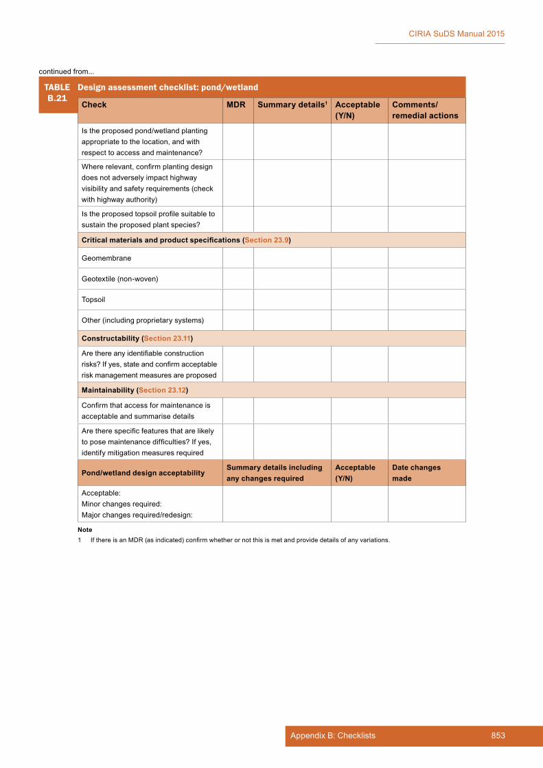
853Appendix B: Checklists
CIRIA SuDS Manual 2015
Note1 IfthereisanMDR(asindicated)confirmwhetherornotthisismetandprovidedetailsofanyvariations.
TABLEB.21
Design assessment checklist: pond/wetland
Check MDR Summary details1 Acceptable (Y/N)
Comments/ remedial actions
Istheproposedpond/wetlandplantingappropriate to the location, and with respect to access and maintenance?
Whererelevant,confirmplantingdesigndoesnotadverselyimpacthighwayvisibilityandsafetyrequirements(checkwith highway authority)
Istheproposedtopsoilprofilesuitabletosustain the proposed plant species?
Critical materials and product specifications (Section 23.9)
Geomembrane
Geotextile(non-woven)
Topsoil
Other (including proprietary systems)
Constructability (Section 23.11)
Arethereanyidentifiableconstructionrisks?Ifyes,stateandconfirmacceptablerisk management measures are proposed
Maintainability (Section 23.12)
Confirmthataccessformaintenanceisacceptable and summarise details
Aretherespecificfeaturesthatarelikelytoposemaintenancedifficulties?Ifyes,identify mitigation measures required
Pond/wetland design acceptabilitySummary details including any changes required
Acceptable (Y/N)
Date changes made
Acceptable:Minor changes required:Majorchangesrequired/redesign:
continued from...

854 Appendix B
CIRIA SuDS Manual 2015
B.6 CONSTRUCTION METHOD STATEMENTS AND ASSESSMENT CHECKLISTS
B.6.1 Guidance on construction method statements
Why is a construction method statement such an important part of the drainage submission process?
The purpose of a construction method statement is to:
▪ formalise who is responsible for completing the work
▪ set out the approach, processes and programme proposed for constructing and stabilising the SuDS (sothatthosewithdeliveryresponsibilityunderstandwhatistobedone,howandwhy)
▪ identify any unusual items or methods of working that are required.
Contractorsanddevelopersarefamiliarwithpreparingconstructionmethodstatementsforawidevarietyof purposes, not least to manage health and safety and contractual risks on construction sites.
In terms of health and safety, the method statement should detail a safe system of work. It should identify the hazards that may arise during construction and the measures that should be taken to ensure that the hazards do not pose an unacceptable risk to workers and the public.
Method statements for SuDS are necessary because many people in the construction industry are not familiarwiththespecificrequirementsforconstructingSuDS,andsomeoftherequirementsarecontrarytoacceptedpracticeinsomefields(forexample,therequirementforadropfromhardsurfacestograssedareaswherewaterisflowingoffanedgeistheoppositetonormallandscapepractice,whichistoraisetheturflevelabovethehardsurface).
ItisalsoimportanttounderstandtheimpactofotherconstructionactivitiesontheSuDS(forexample,oncepermeablesub-baseislaid,itcannotbeusedasaconstructionrouteorplatformunlessitisprotected from siltation and loading damage).
The construction method statement can be used by the drainage adoption body to assess the constructabilityoftheproposeddesign,toevaluatetheconstructionimplicationsandtoplantheappropriate construction inspection regime that will enable an assessment that the system has been constructed in accordance with the design.
What needs to be included?
Everyjobisdifferentandeverymethodstatementshouldbesitespecific.Mostoftheinformationincluded in standard method statements for health and safety and general management of the constructionprocesswillbeacceptable,withtheadditionofinformationspecifictotheSuDS.ThismeansthattherewillbenegligibleextraworkrequiredtopreparetheSuDSconstructionmethodstatement.
The main requirements for a construction method statement are:
▪ details of the nature of the work to be completed
▪ site plans and full scheme drawings, where these are required to support the method of approach
▪ consents and reinstatement requirements
▪ access points and details
▪ anysite-specificecologicalissuesorfeaturesthatrequireprotectionand/orconsideration
▪ any likely water quality issues resulting from the SuDS construction
▪ the proposed strategy for sediment control and site drainage during the construction of the development,wherethisimpactsontheSuDSproposedforthesite;itshouldidentifyanypotentialimpactsonthefinalperformanceofthedrainagesystemandanynecessaryprotectionmeasures(orremedialworkssuchassiltremovalattheendofconstructionofthedevelopment)
855Appendix B: Checklists
CIRIA SuDS Manual 2015
▪ a detailed programme for construction of the drainage works (including stabilisation and planting of exposedsurfaces);theprogrammeshouldhighlightkeypointsatwhichinspectionisrecommended
▪ specificdetailswheretheproposedconstructionprocessesareunusual,uniqueorrequiredbyaspecificproductmanufacturer
▪ what plant is required and how it will be used
▪ simple illustrations, where necessary, to aid understanding of what is required
▪ full contact information for:
▪ site manager
▪ the name of the person on site (usually a foreman) who will be responsible for the work
▪ otherrelevantprofessionalcontacts,egarchaeologist,ecologist,drainageapprovingbody,environmentalregulator
▪ emergency contact details.
Thecontractorordevelopershouldprovidethemethodstatementtothedrainageapprovingbodybefore starting the drainage construction, and the statement should be discussed and agreed withthecontractoratapre-contractmeeting.Theinformationinthemethodstatementshouldbecommunicatedtositestaffviaatoolboxtalk–whichwouldroutinelyberequiredaspartofthehealthand safety requirements for a site.
Theremaybeageneralhigh-levelmethodstatementthatdealswith,forexample,phasingofdifferentpartsoftheSuDS.Severalmoredetailedstatementsthatrelatetospecificworkitemsmayalsobeprovided.Genericmethodstatementsshouldbeavoided;theyshouldbewrittenforthesiteinquestion.
Wheretofindmoreinformation?
DetailedinformationontherequirementsforSuDSconstructionandmethodstatementsisprovidedinChapter 31 and in Woods Ballard et al (2007).
Also,therearenumerousmethodstatementsontheinternet,andthebestapproachistoreadafewofthosetogainanideaofwhatinformationisprovided,thenapplythatknowledgetotheSuDSmethodstatement for the particular site.
B.6.2 Construction inspection and assessment
Objectives
Theobjectiveofaconstructionassessmentistoverifythatthedrainagesystemisconstructedinaccordancewiththeapproveddesignandspecification.Verificationcanbeundertakenbythedrainageapprovingbody,byindependentconsultantsemployedbythedrainageapprovingbodyordeveloper,oracombinationofthese.Iftheverificationvisitsandreportareundertakenbyaconsultantemployedbythedeveloper,thereshouldbeacontractuallinktothedrainageapprovingbodyviaawarrantyfromtheconsultant, or some other mechanism.
Conflictsofinterestshouldbeavoidedintheverificationprocess.Acontractor,supplier(egpermeablepavements)ordevelopercertifyingtheirownworkorproductisconsideredtobeaconflictofinterestandisnotgoodpractice.Verificationalsorequiresafullunderstandingofthedrainagesystemforthesite,howitfitsinwiththeoverallfloodriskstrategyandthephilosophyunderpinningthedesign.Acontractoremployedtoinstalldrainageorasupplierofmaterialsorcomponentsisnotlikelytohavethislevelofunderstandingofthesite.Self-certificationofconstructionisnotacceptable.
Itisintendedthatthesuggestedchecklistprovidedheregivesabroadoutlineoftheitemsthatwillrequirechecking.Theprecisedetailswillvaryfromschemetoscheme,andthelistshouldbeadaptedtosuiteachsite.Thiswillrequiretheremovaloradditionofitemsasnecessary.

856 Appendix B
CIRIA SuDS Manual 2015
Programme and method of approach
Workshouldnotstartonsiteuntilthedrainageapprovingbodyhasformallyapprovedthedrainagedesignplans,methodstatementandspecificationinwriting.Furthertothisapprovalbeinggiven,thedrainageapprovingbodyshouldthenbegivenatleasttwoweeks’noticeoftheproposedstartofconstructionofthedevelopmentandforlargersitesshouldbeprovidedwithaprogrammeofworks.Forsmallersites48hours’noticeofanyworksrequiringinspectionshouldbesufficient.Thedrainageapprovingbodyshouldbenotifiedimmediately,andwithsufficientnotice,ofanysignificantchangestotheprogramme.Thisistoallowthedrainageapprovingbodysufficientopportunitytoinspecttheworks.
TheconstructionmethodstatementshoulddetailthespecificSuDSconstructionmethodsandprocesses,andthe construction programme, including key points at which inspection is recommended (eg when subsequent coverageofelementswouldmeaninspectioncouldnotthenbeundertakenwithoutremovalofmaterial).
Changes to design during construction
Itisinevitablethattherewillbechangestothedesignduringconstruction.Thisisanormalpartofconstruction.However,itisimportantthatchangesarenotmadewithoutreferencetothedrainageapprovingbody/ownerand/orthedesigner.Majorchangesshouldbeagreedwithboththeapprovingbodyandthedesignerbeforeimplementingthem(majorchangesarethingsthatcanhaveasignificantimpactontheoveralloperationandmaintenanceoftheSuDS,egchangingapondtoabasin).Minorchanges should be agreed with the designer, and the changes and agreement recorded for inclusion in theverificationreport(seebelow).
Verificationreport
Averificationreportshouldbepreparedattheendofconstructionbythepartywhohascarriedouttheinspectionvisits.Thisshouldconfirmifthedrainagesystemhasbeenconstructedinaccordancewiththeapproveddesign.Itshouldidentifyanychangesthathavebeenmadetothedesignandthereasonsforthosechanges,togetherwithconfirmationofanylikelyimpactontheperformanceofthesystem(ifanadverseimpactisexpectedthennecessaryremedialworksshouldbespecified).Evidenceoftheagreementofthedrainageapprovingbodyand/ordesignertothechangesshouldbeincluded.
Theverificationvisitreportsshouldindicateanydefectsinconstructionandfollowuponanyremedialworksthatarenecessarytoconfirmthattheyhavebeencompleted.
Theformatofthereportwillbesitespecific,butasaminimumitwillbeexpectedtoincludethefollowing:
▪ photographsofexcavations,confirmationofsoilconditions,confirmationoflevels,profilesandGeneralearthworks
▪ photographs and full manufacturers’ details (if appropriate) of inlets, outlets and any control structures associated with any feature to be adopted
▪ confirmationoftopsoilsourceswithappropriatecertificates
▪ fullplantinglistsandconfirmationofplantsources,plantingmethodstatementandinitialmaintenance regime
▪ confirmationofsubsoilandtopsoildepths
▪ confirmationofgravelfill/sub-basespecificationandsources,installationmethodstatementoffilterdrains/permeablepavements
▪ confirmationofsourceandtestcertificatesformembranelinersifused(Membranesshallhaveweldedjointsandshallbeinspectedandthejointstestedafterinstallation.Recordsofthetestsshallbeprovided.Integritytestsmaybenecessaryifthemembraneperformanceiscritical.)
▪ photographs of the feature before and after planting
▪ fullas-constructeddrawingsandatopographicalsurveyoftheas-constructedsystem
▪ confirmationofinitialmaintenanceregimes.
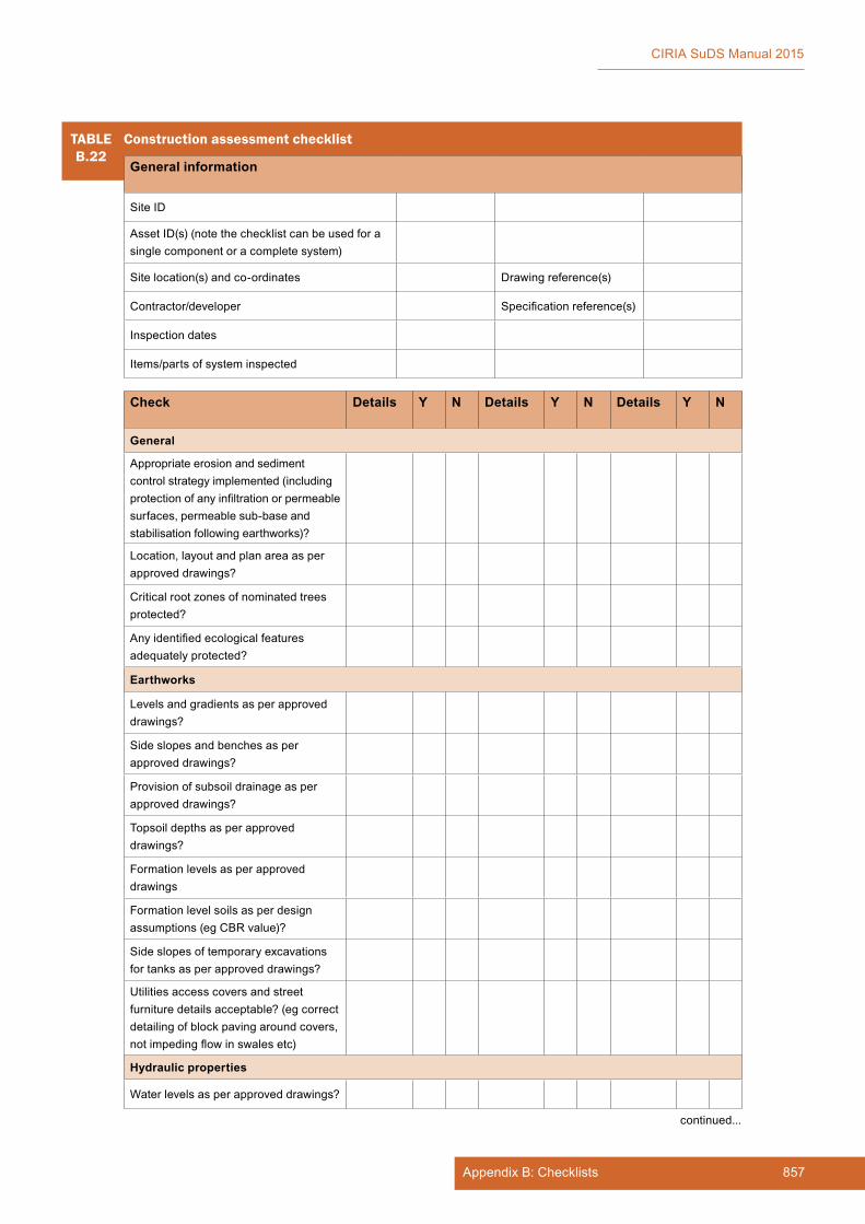
857Appendix B: Checklists
CIRIA SuDS Manual 2015
TABLEB.22
Construction assessment checklist
General information
Site ID
AssetID(s)(notethechecklistcanbeusedforasingle component or a complete system)
Sitelocation(s)andco-ordinates Drawing reference(s)
Contractor/developer Specificationreference(s)
Inspection dates
Items/partsofsysteminspected
Check Details Y N Details Y N Details Y N
General
Appropriateerosionandsedimentcontrol strategy implemented (including protectionofanyinfiltrationorpermeablesurfaces,permeablesub-baseandstabilisation following earthworks)?
Location,layoutandplanareaasperapproveddrawings?
Critical root zones of nominated trees protected?
Anyidentifiedecologicalfeaturesadequately protected?
Earthworks
Levelsandgradientsasperapproveddrawings?
Side slopes and benches as per approveddrawings?
Provisionofsubsoildrainageasperapproveddrawings?
Topsoildepthsasperapproveddrawings?
Formationlevelsasperapproveddrawings
Formationlevelsoilsasperdesignassumptions(egCBRvalue)?
Sideslopesoftemporaryexcavationsfortanksasperapproveddrawings?
Utilitiesaccesscoversandstreetfurniture details acceptable? (eg correct detailingofblockpavingaroundcovers,notimpedingflowinswalesetc)
Hydraulic properties
Waterlevelsasperapproveddrawings?
continued...

858 Appendix B
CIRIA SuDS Manual 2015
TABLEB.22
Construction assessment checklist
Check Details Y N Details Y N Details Y N
Flowcontrolsasperapproveddesign?
Structural components
Checkdams/weirs/overflowsasperdesign?
Serviceorothercrossingsasperdesign?
Pipe connections as per design?
Inlets – as per design, appropriate installation (including concrete and reinforcement works, erosion protection,levelspreaders,bufferstrips, kerbing and drops)
Outlets – as per design, appropriate installation (including concrete and reinforcement works, erosion protection)
Anyrequiredgeotextile/geomembranetestcertificatesprovidedandinaccordancewithapproveddrawingsand/orspecification?
Materials
Topsoilmeetsapprovedspecification(tested and ameliorated if required, certificatesverifyingsourceandcontent)?
Plantingimplementedasperapproveddrawings and landscape schedules?
Geocellularstorageunitsasperapproveddesigndrawingsandspecification?
Permeablesub-baseasperapproveddrawingsandspecification?
Rootzonematerials,filtersandetcasperapproveddrawingandspecification?
Perforatedpipesasperapproveddrawingsandspecification?
Final inspection
Confirminletandoutletlevels
Confirmstructuralcomponents
Confirmslopes
Confirmcorrectplanting/turfingestablished
Confirmnounevensettlingofsoil,channelling, unwanted ponding or erosion of bed or side slopes
Confirmnoevidenceofconstructionsedimentorunexpectedlyrapidbuild-upof sediment
continued from...
continued...
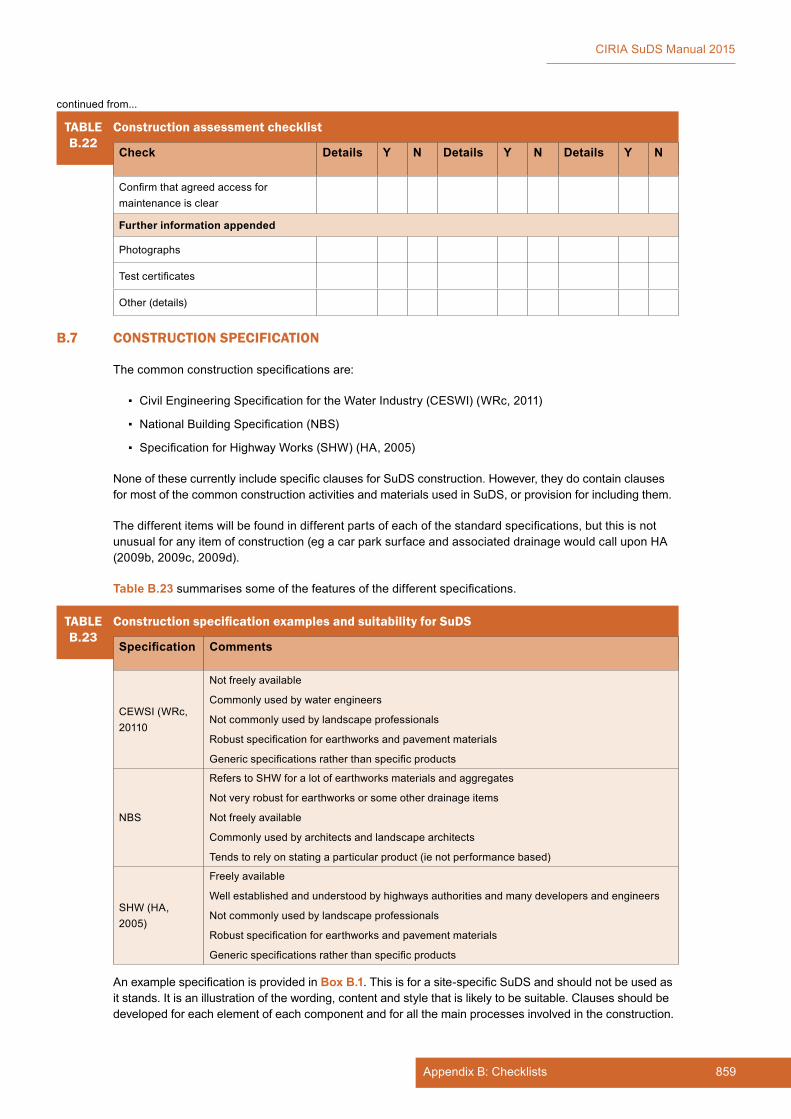
859Appendix B: Checklists
CIRIA SuDS Manual 2015
TABLEB.22
Construction assessment checklist
Check Details Y N Details Y N Details Y N
Confirmthatagreedaccessformaintenance is clear
Further information appended
Photographs
Testcertificates
Other (details)
continued from...
B.7 CONSTRUCTION SPECIFICATION
Thecommonconstructionspecificationsare:
▪ CivilEngineeringSpecificationfortheWaterIndustry(CESWI)(WRc,2011)
▪ NationalBuildingSpecification(NBS)
▪ SpecificationforHighwayWorks(SHW)(HA,2005)
NoneofthesecurrentlyincludespecificclausesforSuDSconstruction.However,theydocontainclausesformostofthecommonconstructionactivitiesandmaterialsusedinSuDS,orprovisionforincludingthem.
Thedifferentitemswillbefoundindifferentpartsofeachofthestandardspecifications,butthisisnotunusualforanyitemofconstruction(egacarparksurfaceandassociateddrainagewouldcalluponHA(2009b,2009c,2009d).
Table B.23summarisessomeofthefeaturesofthedifferentspecifications.
TABLEB.23
ConstructionspecificationexamplesandsuitabilityforSuDS
Specification Comments
CEWSI (WRc, 20110
Notfreelyavailable
Commonly used by water engineers
Notcommonlyusedbylandscapeprofessionals
Robustspecificationforearthworksandpavementmaterials
Genericspecificationsratherthanspecificproducts
NBS
Refers to SHW for a lot of earthworks materials and aggregates
Notveryrobustforearthworksorsomeotherdrainageitems
Notfreelyavailable
Commonly used by architects and landscape architects
Tends to rely on stating a particular product (ie not performance based)
SHW(HA,2005)
Freelyavailable
Wellestablishedandunderstoodbyhighwaysauthoritiesandmanydevelopersandengineers
Notcommonlyusedbylandscapeprofessionals
Robustspecificationforearthworksandpavementmaterials
Genericspecificationsratherthanspecificproducts
AnexamplespecificationisprovidedinBox B.1.Thisisforasite-specificSuDSandshouldnotbeusedasit stands. It is an illustration of the wording, content and style that is likely to be suitable. Clauses should be developedforeachelementofeachcomponentandforallthemainprocessesinvolvedintheconstruction.

860 Appendix B
CIRIA SuDS Manual 2015
BOXB.1
An example SuDS specification
Theexamplespecificationthatfollowsisforasite-specificSuDSandshouldnotbeusedasitstands. It is an illustration of the wording, content and style that is likely to be suitable. Clauses shouldbedevelopedforeachelementofeachcomponentandforallthemainprocessesinvolvedinthe construction.
Base specificationThebasespecificationshallbeHA(2005),supplementedbythefollowingrequirements.
General clauses
Erosion protectionThecontractorisresponsibleforpreventingerosionofthesustainabledrainagesystemuntilallthevegetationwithinitisfullyestablished.Thisistobeachievedbyprotectingthesideslopesandbaseofswales,wetlandsandotherareaswherewaterflows,withfullybiodegradablematting.
If erosion occurs in any part of the systems the contractor shall repair these areas to the satisfaction of the client.
Planting
Limitations on plantingPlantingistobecarriedoutbetweenAprilandSeptember.Seedingandturfingistobeundertakeninspringorautumninsuitableweatherconditions.Thecontractorshallobtaintheapprovaloftheclienttoundertakeplanting,seedingorturfing.
Plantstockshouldbesourcedfromapprovednurseriesthatonlygrownativespeciesoflocalprovenance,toavoidtheintroductionofalienspecies.
Topsoilisnottobeplacedwithin300mmofthepermanentwaterlevelinthewetland.Wetlandplants are to be directly planted into the subsoil.
Fertilisers and pesticides are not to be used.
Swale plantingThefollowingplantingmixshallbeprovidedintheswale:
▪ 10% – Iris pseudacorus (water iris)
▪ 10% – Carex riparia (great pond sedge)
▪ 10% – Carex nigra (common sedge)
▪ 10% – Carex acutiformis (lesser pond sedge)
▪ 50% – Sparganium erectum(branchedbur-reed)
▪ 10% – Typha angustifolia (lesser reed mace)
Inthegrassguardsystem,thetopsoilshallbecarefullyhandrammedintothevoidsleavinga25mmspaceatthetop.Theseedsshallbemixedwiththetopsoil,placedinthe25mmvoidandlightlycompacted.
Theedgesoftheswalesshouldbeseededwithanormalamenitygrassmixwithawildflowercomponent.
Wetland plantingThefollowingplantingmixshallbeprovidedintheforebayarea:
▪ 10% – Iris pseudacorus (water iris)
▪ 10% – Carex riparia (great pond sedge)
▪ 10% – Carex nigra (common sedge)
▪ 10% – Carex acutiformis (lesser pond sedge)
continued...
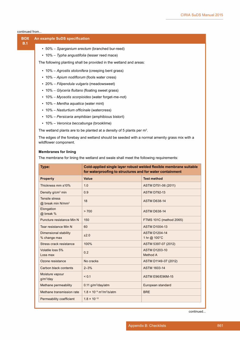
861Appendix B: Checklists
CIRIA SuDS Manual 2015
BOXB.1
An example SuDS specification
▪ 50% – Sparganium erectum (branchedbur-reed)
▪ 10% – Typha angustifolia (lesser reed mace)
Thefollowingplantingshallbeprovidedinthewetlandandareas:
▪ 10% – Agrostis stolonifera (creeping bent grass)
▪ 10% – Apium nodiflorum (fools water cress)
▪ 20% – Filipendula vulgaris (meadowsweet)
▪ 10% – Glyceria fluitans(floatingsweetgrass)
▪ 10% – Myosotis scorpioides(waterforget-me-not)
▪ 10% – Mentha aquatica (water mint)
▪ 10% – Nasturtium officinale (watercress)
▪ 10% – Persicaria amphibian (amphibious bistort)
▪ 10% – Veronica beccabunga (brooklime)
The wetland plants are to be planted at a density of 5 plants per m2.
Theedgesoftheforebayandwetlandshouldbeseededwithanormalamenitygrassmixwithawildflowercomponent.
Membranes for liningThe membrane for lining the wetland and swale shall meet the following requirements:
Type: Cold-applied single layer robust welded flexible membrane suitable for waterproofing to structures and for water containment
Property Value Test method
Thickness mm ±10% 1.0 ASTMD751-06(2011)
Densityg/cm3 min 0.9 ASTMD792-13
Tensile stress@breakminN/mm2
18 ASTMD638-14
Elongation@ break %
> 700 ASTMD638-14
PunctureresistanceMinN 150 FTMS 101C (method 2065)
TearresistanceMinN 60 ASTMD1004-13
Dimensional stability%changemax
±2.0ASTMD1204-141 hr @ 100°C
Stress crack resistance 100% ASTM5397-07(2012)
Volatile loss 5%Lossmax
0.2ASTMD1203-10MethodA
Ozone resistance Nocracks ASTMD1149-07(2012)
Carbon black contents 2–3% ASTM1603-14
Moisturevapourg/m2/day
< 0.1 ASTME96/E96M-15
Methane permeability 0.11g/m2/day/atm European standard
Methane transmission rate 1.8 × 10⁻⁹ m3/m2/s/atm BRE
Permeabilitycoefficient 1.8 × 10⁻¹²
continued from...
continued...

862 Appendix B
CIRIA SuDS Manual 2015
BOXB.1
An example SuDS specification
Applicationtemperatureofthemembraneshallbegreaterthan4°C.
Primer not required.
Numberoflayers:One(1).
Laps–minimum120mm.
Jointing: Shall be generally formed using twin seam fusion welding in accordance with manufacturers recommendations.
Extrusionweldingshallbeacceptedonlyinareaswheretwinseamweldingisinappropriate.
General workmanshipPrelaying checks: surface acceptability
▪ Before laying check that substrate surfaces are:
▪ structurally sound
▪ free from ridges and undulations
▪ surface dry
▪ cleanedoflooseandextraneousmaterial.
Construction acceptability:
▪ Before laying check that construction allows membrane continuity to be maintained.
Layingmembrane:
▪ Membranetobeinstalledbyqualifiedoperativesrecommendedbymembranemanufacturerand/orprefabricatedintopanelswhereappropriatetosuitsiterequirements.
▪ Laidstrictlyinaccordancewithmanufacturers’recommendations.
▪ Applymembranefirmlytosubstrateensuringthattrappedairisremovedasapplicationproceeds.
▪ Overlapandbondconsecutivesheetsasspecifiedusingrecommendedtwinwedgehotairjointingmethodstoensurefullbondingatlaps.
▪ Whentemperatureis4°Candfalling,ahotairpre-heatsystemofweldingshallbeadopted.
Protection generally:
▪ Protectfinishedsheetingadequatelywherenecessarytopreventpuncturingduringfollowingworks.
▪ Coversheetingwithpermanentoverlyingconstructionassoonaspossible.
▪ Immediatelybeforecovering,checkfordamageandrepairasnecessary.
Penetrations:
▪ Allpenetrationsthroughthemembraneshallbesealedwithproprietarywaterresistantpreformed cloaks.
▪ Thecloaksshallbecompatiblewiththemembraneandapprovedbytheengineer.
GeotextilesProtection of membranes.
Thegeotextilestobeusedinthesystemtoprotectlinersandactasfiltersshallmeetthefollowingrequirements:
continued...
continued from...
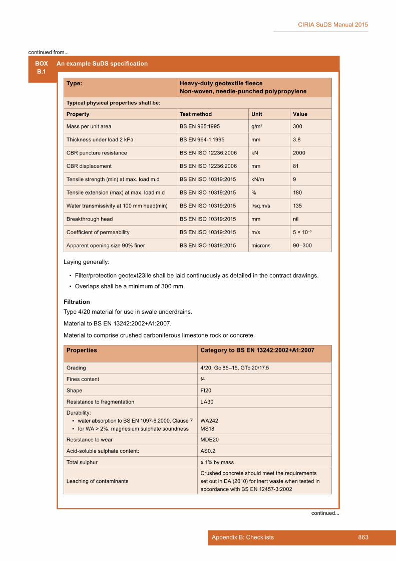
863Appendix B: Checklists
CIRIA SuDS Manual 2015
BOXB.1
An example SuDS specification
Type: Heavy-duty geotextile fleeceNon-woven, needle-punched polypropylene
Typical physical properties shall be:
Property Test method Unit Value
Mass per unit area BSEN965:1995 g/m2 300
Thickness under load 2 kPa BSEN964-1:1995 mm 3.8
CBR puncture resistance BSENISO12236:2006 kN 2000
CBR displacement BSENISO12236:2006 mm 81
Tensilestrength(min)atmax.loadm.d BSENISO10319:2015 kN/m 9
Tensileextension(max)atmax.loadm.d BSENISO10319:2015 % 180
Watertransmissivityat100mmhead(min) BSENISO10319:2015 l/sq.m/s 135
Breakthrough head BSENISO10319:2015 mm nil
Coefficientofpermeability BSENISO10319:2015 m/s 5 × 10⁻³
Apparentopeningsize90%finer BSENISO10319:2015 microns 90–300
Layinggenerally:
▪ Filter/protectiongeotext23ileshallbelaidcontinuouslyasdetailedinthecontractdrawings.
▪ Overlapsshallbeaminimumof300mm.
FiltrationType4/20materialforuseinswaleunderdrains.
MaterialtoBSEN13242:2002+A1:2007.
Material to comprise crushed carboniferous limestone rock or concrete.
Properties Category to BS EN 13242:2002+A1:2007
Grading 4/20,Gc85–15,GTc20/17.5
Fines content f4
Shape FI20
Resistance to fragmentation LA30
Durability: ▪ waterabsorptiontoBSEN1097-6:2000,Clause7 ▪ forWA>2%,magnesiumsulphatesoundness
WA242MS18
Resistance to wear MDE20
Acid-solublesulphatecontent: AS0.2
Total sulphur ≤1%bymass
LeachingofcontaminantsCrushed concrete should meet the requirements setoutinEA(2010)forinertwastewhentestedinaccordancewithBSEN12457-3:2002
continued from...
continued...
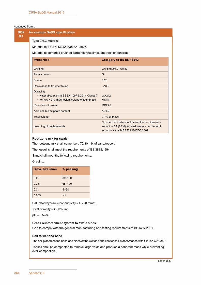
864 Appendix B
CIRIA SuDS Manual 2015
BOXB.1
An example SuDS specification
Type2/6.3material.
MaterialtoBSEN13242:2002+A1:2007.
Material to comprise crushed carboniferous limestone rock or concrete.
Properties Category to BS EN 13242
Grading Grading2/6.3,Gc80
Fines content f4
Shape FI20
Resistance to fragmentation LA30
Durability: ▪ waterabsorptiontoBSEN1097-6:2013,Clause7 ▪ forWA>2%,magnesiumsulphatesoundness
WA242MS18
Resistance to wear MDE20
Acid-solublesulphatecontent AS0.2
Total sulphur ≤1%bymass
LeachingofcontaminantsCrushed concrete should meet the requirements setoutinEA(2010)forinertwastewhentestedinaccordancewithBSEN12457-3:2002
Root zone mix for swaleTherootzonemixshallcomprisea70/30mixofsand/topsoil.
ThetopsoilshallmeettherequirementsofBS3882:1994.
Sand shall meet the following requirements:
Grading:
Sieve size (mm) % passing
5.00 89–100
2.36 65–100
0.3 5–50
0.063 < 4
Saturatedhydraulicconductivity–>220mm/h.
Totalporosity–>30%v/v.
pH – 6.5–8.5.
Grass reinforcement system to swale sidesGridtocomplywiththegeneralmanufacturingandtestingrequirementsofBS6717:2001.
Soil to wetland baseThesoilplacedonthebaseandsidesofthewetlandshallbetopsoilinaccordancewithClauseQ28/340.
Topsoilshallbecompactedtoremovelargevoidsandproduceacoherentmasswhilepreventingover-compaction.
continued...
continued from...

865Appendix B: Checklists
CIRIA SuDS Manual 2015
BOXB.1
An example SuDS specification
TolerancesThesidesslopesoftheswaleshouldhavealongitudinalandtransversetoleranceof10mmin3mtopromotesheetflowfromthedrainedsurfacedowntheslopetopreventerosionoccurring.
Contractor design elementsThe wet well pumping station at end of swale is to be designed by the contractor in accordance with WRc(2011)includingchamber,inletandoutlet,pumpsandcontrols.Thepumpsprovidedaretoprovideacapacityofatleast94l/swithadutyandstandbypumpprovided.
Provisionistobemadeinthepumpingstationtoaddlimedosingequipmentatalaterdateifrequired.
Thewetwellshouldbedesignedsothatittrapsandpreventsfloatingdebris(sawdustandwoodchip)fromenteringthepumpsandameansofremovingthedebrisprovided.
B.8 MAINTENANCE PLAN AND CHECKLIST
B.8.1 Why is a Maintenance Plan needed?
ThepurposeofaMaintenancePlanistoensurethatallthoseinvolvedinthemaintenanceandoperationof the SuDS system understand its functionality and maintenance requirements in terms of supporting long-termperformancetothedesigncriteriatowhichitwasdesigned.
AMaintenancePlandeliveredaspartofadrainagesubmission:
▪ confirmsthatthedesignerhastakenmaintenanceintoaccountwithinthedesign
▪ demonstrates the competence of the designer
▪ providesaguidetotheadoptionteamastowhatthemaintenancerequirementsofthesystemareandhowtheycanbemetmostefficiently
▪ providesabasisforcostinglong-termmaintenancebudgets(andcommutedsums,ifrequired)
▪ providesaworkingdocumentforuseonsite
▪ detailsproceduresfordealingwithemergencyspillages,vandalismetc;itshouldincludethelocalenvironmentalregulatortelephonenumber,whichshouldbecalledincaseofspillagesorotherpollution incidents.
TheMaintenancePlanforthedrainagesystemshouldbedesignedinco-operationwiththeadoptingorganisation,andtheinformationthereinshouldbepresentedanddiscussedverballywithallthoseinvolvedininspectingandmaintainingthedrainagesystems.
B.8.2 What should a Maintenance Plan include?
TheSuDSMaintenancePlanshouldcoverandclarifythefollowingissues:
▪ a description of the site – concentrating on describing how the drainage system works in practice andwhatitistryingtoachieve.Thisislikelytoincludeflowroutes,sub-catchments,SuDScomponents,flowcontrolfeaturesandoutfallarrangements.Itshouldalsoexplainthevisualandbiodiversityaspectsofascheme,asthesecaneasilybecompromisedbyinappropriatemaintenance.
▪ aplanofthesitethatidentifiesrunoffsub-catchments,SuDScomponents,criticalwaterlevels,controlstructures,flowroutes(includingexceedancerouting)andoutfalls
continued from...

866 Appendix B
CIRIA SuDS Manual 2015
▪ aplanclearlyshowingtheextentoftheadoptedareaalongwitheasementsandrightsofwayforaccess to carry out maintenance. If other parties are responsible for different parts of a scheme, this should be clearly shown on the plan.
▪ the access that is required to each surface water management component for maintenance purposesandaplanforthesafeandsustainableremovalanddisposalofwasteperiodicallyarisingfrom the drainage system
▪ areviewoftheworktobeundertaken,basedonregularday-to-daymaintenance,occasionaltasksand remedial work. Details of the likely maintenance requirements for each SuDS element are providedinthisManual.Maintenancerequirementsforproprietarysystemsshouldbeprovidedbythe manufacturer or supplier.
▪ themaintenancespecification–detailingthematerialstobeusedandthestandardofworkrequired.Aspecificationshoulddescribehowtheworkshouldbecarriedoutandshouldcontainclausesgivinggeneralinstructionstothemaintenancecontractor.
▪ the maintenance schedule of work – itemising the tasks to be undertaken and the frequency at whichtheyshouldbeperformedsothatanacceptablelong-termperformancestandardissecured.This schedule can then be priced and checked on site, and it can form the basis of an inspection logwhereappropriate.Thescheduleshouldbealivingdocumentbecauseitmaychange,whereinspectionsadvisechangestotheschememaintenancerequirements.
▪ contactsheetandanyextraguidancenotes–egactionplanfordealingwithaccidentalspillages
▪ photographicrecordsoftheinspections.Thiscanpickuplong-termchangesthatmightnotbeapparentonasinglevisit,especiallywhereinspectionsarecarriedoutbydifferentmembersofstaff.
Note: An example of a Maintenance Plan is available in Box B.2.
B.8.3 Maintenance inspection checklist
Thischecklistisagenericlistthatcanbeaddedto,orhaveitemsremovedfromit,tosuitaparticularsite.TheexactcontentofthechecklistwilldependonthecombinationofdifferentSuDScomponentsusedina scheme. Checklists should be selected based on the combination of elements in the drainage system to provideabespokeinspectionreport.
Theobjectiveofthischecklististo:
▪ confirmthatappropriateroutinemaintenanceofthesystemisbeingundertaken
▪ confirmthatthesystemiscontinuingtooperateeffectively
▪ identify any remedial works required
▪ provideaconsistentrecordoftheconditionandperformanceofthesystem.
Itisnotachecklistofmaintenanceitems,whichiscoveredinChapters 11 to 23 of this manual (Table B.24). It is a checklist to facilitate consistent inspection of the condition of the system. It can beusedbyanyorganisationresponsibleforthelong-termmaintenanceoftheSuDSsystemasarecording process, or by a subcontracted organisation as part of their client reporting procedures.
Inspectionsshouldcomplywithallrelevanthealthandsafetylegislation(TheManagementofHealthandSafetyatWorkRegulations1999)includingthedevelopmentofriskassessmentsforworkingclosetoorin water.
Inspectionsshouldideallybecarriedoutmonthly(andnolessthanthree-monthly),atthesametimeasotherroutinemaintenanceactivities.

867Appendix B: Checklists
CIRIA SuDS Manual 2015
TABLEB.24
Wheretofindinformationonmaintenanceactivitiesandfrequencies
Component Ref (within this manual)
Greenroofs Section 12.12
Infiltrationsystems Section 13.12
Proprietary systems Section 14.12
Filter strips Section 15.12
Filter drains Section 16.12
Swales Section 17.12
Bioretention systems Section 18.12
Trees Section19.12
Perviouspavements Section 20.14
Attenuationstoragetanks Section 21.13
Detention basins Section 22.12
Ponds and wetlands Section 23.12
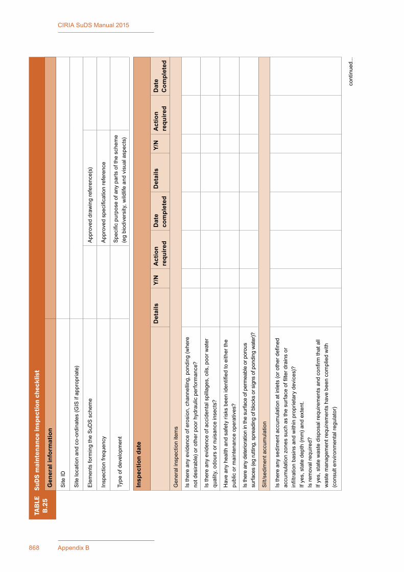
868 Appendix B
CIRIA SuDS Manual 2015
TAB
LEB
.25
SuD
S m
aint
enan
ce in
spec
tion
che
cklis
t
Gen
eral
info
rmat
ion
Site
ID
Sitelocationandco-ordinates(G
ISifappropriate)
Ele
men
ts fo
rmin
g th
e S
uDS
sch
eme
Approveddraw
ingreference(s)
Insp
ectio
n fre
quen
cyApproved specificationreference
Typeofdevelopment
Specificpurposeofanypartsoftheschem
e(egbiodiversity,w
ildlifeandvisualaspects)
Insp
ectio
n da
te
Det
ails
Y/N
Act
ion
requ
ired
Dat
e co
mpl
eted
Det
ails
Y/N
Act
ion
requ
ired
Dat
e C
ompl
eted
Generalinspectionitems
Isthereanyevidenceoferosion,channelling,ponding(w
here
not d
esira
ble)
or o
ther
poo
r hyd
raul
ic p
erfo
rman
ce?
Isthereanyevidenceofaccidentalspillages,oils,poorw
ater
qual
ity, o
dour
s or
nui
sanc
e in
sect
s?
Have anyhealthandsafetyrisksbeenidentifiedtoeitherthe
p ublicorm
aintenanceoperatives?
Is th
ere
any
dete
riora
tion
in th
e su
rface
of p
erm
eabl
e or
por
ous
surfa
ces
(eg
rutti
ng, s
prea
ding
of b
lock
s or
sig
ns o
f pon
ding
wat
er)?
Silt/sedimentaccum
ulation
Isthereanysedimentaccum
ulationatinlets(oro
therdefined
accumulationzonessuchasthesurfaceoffilterd
rainsor
infiltra
tionbasinsandwithinproprietarydevices)?
Ifyes,statedepth(m
m)a
ndextent.
Isre
movalre
quired?
Ifyes,statewastedisposalrequirementsandconfirmthatall
wastemanagem
entrequirementshavebeencom
pliedwith
(consultenvironm
entalregulator)
cont
inue
d...
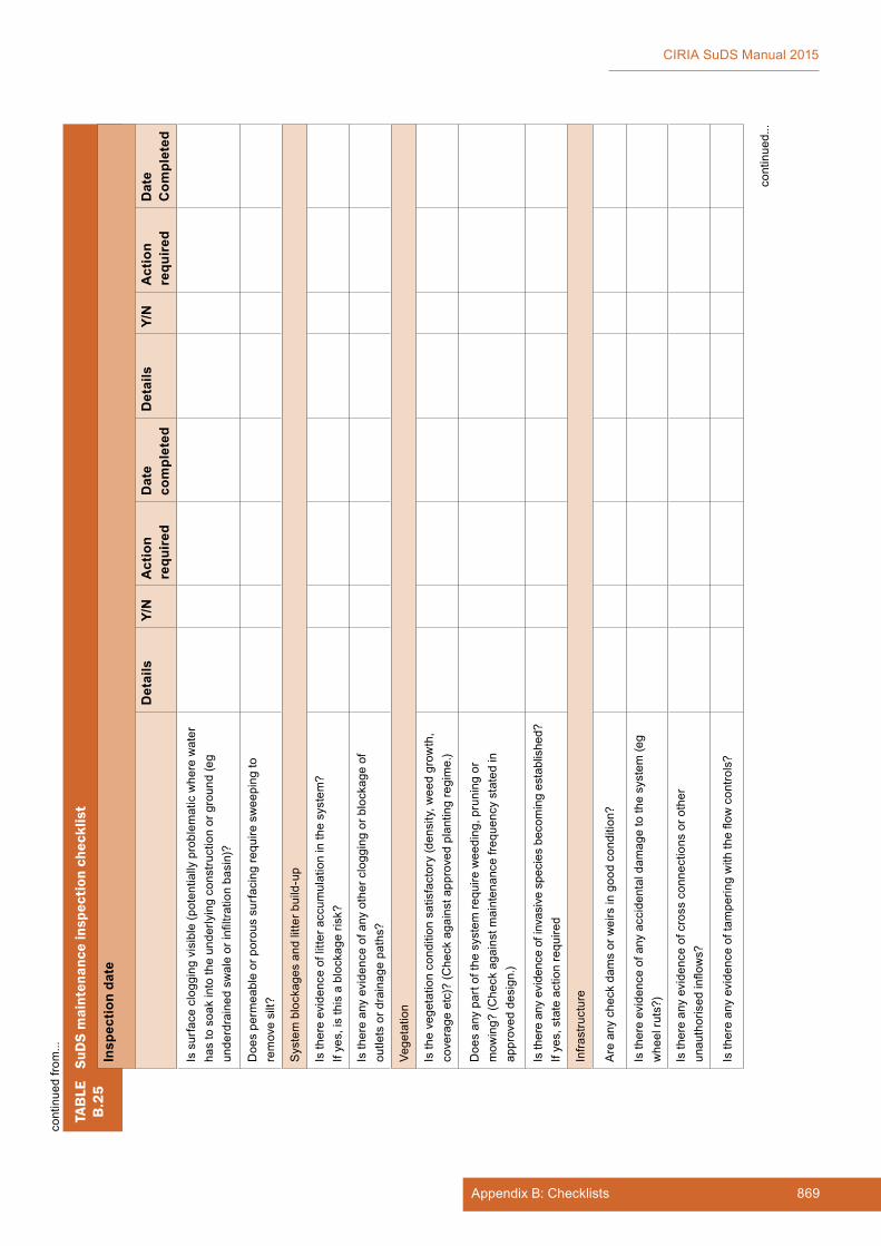
869Appendix B: Checklists
CIRIA SuDS Manual 2015
TAB
LEB
.25
SuD
S m
aint
enan
ce in
spec
tion
che
cklis
t
Insp
ectio
n da
te
Det
ails
Y/N
Act
ion
requ
ired
Dat
e co
mpl
eted
Det
ails
Y/N
Act
ion
requ
ired
Dat
e C
ompl
eted
Issurfacecloggingvisible(potentiallyproblem
aticwherewater
has
to s
oak
into
the
unde
rlyin
g co
nstru
ctio
n or
gro
und
(eg
underdrainedswaleorinfiltra
tionbasin)?
Doe
s pe
rmea
ble
or p
orou
s su
rfac
ing
requ
ire s
wee
ping
to
removesilt?
Systemblockagesandlitterb
uild-up
Isthereevidenceoflitteraccum
ulationinthesystem
?If
yes,
is th
is a
blo
ckag
e ris
k?
Isthereanyevidenceofanyothercloggingorblockageof
outle
ts o
r dra
inag
e pa
ths?
Vege
tatio
n
Isthevegetationconditionsatisfactory(density,w
eedgrow
th,
coverageetc)?(C
heckagainstapprovedplantingregime.)
Doe
s an
y pa
rt of
the
syst
em re
quire
wee
ding
, pru
ning
or
mow
ing?
(Che
ck a
gain
st m
aint
enan
ce fr
eque
ncy
stat
ed in
approveddesign.)
Isthereanyevidenceofinvasivespeciesbecomingestablished?
If ye
s, s
tate
act
ion
requ
ired
Infra
stru
ctur
e
Areanycheckdam
sorweirsingoodcondition?
Isthereevidenceofanyaccidentaldam
agetothesystem
(eg
whe
el ru
ts?)
Isthereanyevidenceofcrossconnectionsoro
ther
unauthorisedinflows?
Isthereanyevidenceoftam
peringwiththeflowcontro
ls?
cont
inue
d...
cont
inue
d fro
m...

870 Appendix B
CIRIA SuDS Manual 2015
TAB
LEB
.25
SuD
S m
aint
enan
ce in
spec
tion
che
cklis
t
Insp
ectio
n da
te
Det
ails
Y/N
Act
ion
requ
ired
Dat
e co
mpl
eted
Det
ails
Y/N
Act
ion
requ
ired
Dat
e C
ompl
eted
Arethereanyotherm
attersthatcouldaffe
cttheperformance
ofthesystem
inre
lationtothedesignobjectivesforhydraulic,
waterquality,biodiversityandvisualaspects?(Specify.)
Otherobservations
Info
rmat
ion
appe
nded
(eg
phot
os)
Sui
tabi
lity
of c
urre
nt m
aint
enan
ce re
gim
e
Con
tinue
as
curr
ent
Incr
ease
mai
nten
ance
Dec
reas
e m
aint
enan
ce
Nextinspection
Proposeddateforn
extinspection
cont
inue
d fro
m...

871Appendix B: Checklists
CIRIA SuDS Manual 2015
BOXB.2
Example SuDS Maintenance Plan for Robinswood Primary School
An introduction to sustainable drainage systems or SuDSSuDSareanewenvironmentallyfriendlyapproachtomanagingrainfallthatuseslandscapefeatures to deal with surface water. SuDS aim to:
▪ controltheflow,volumeandfrequencyofwaterleavingadevelopmentarea
▪ preventpollutionbyinterceptingsiltandcleaningrunofffromhardsurfaces
▪ provideattractivesurroundingsforthecommunity
▪ create opportunities for wildlife.
SuDS at Robinswood Primary School and Matson ParkTheSuDSaredesignedtopreventfloodingofRobinswoodPrimarySchoolandtocontroltheflowofwaterfromspringsinMatsonParkusingattractivelandscapefeatures.
▪ Alowbankhasbeenconstructedintheparkasadamwhenwaterflowsdowntherouteofanoldditchduringheavyrain.
▪ Theeverydayflowfromspringsabovethepathintheparkhasbeendirectedalonganewstream in the park, which keeps a new wildlife pond full of water but also allows it to soak into thegroundorflowonwardtoacontrolledoutfallintotheschoolgrounds.
▪ Thecontrolledoutfallintotheschoolgroundsallowsheavyrainfalltoleavetheparkslowlyandmakeitswaythroughgreenspaceabovetheschoolplayingfield.
▪ Exceptionalstormsorprolongedheavyraincanoverflowfromtheparkacrossagrassweironthebankintothe“environmentspace”atthetopoftheplayingfieldretainedbyalowbankrunning along the contour to the old oak tree.
▪ Theschoolwildlifepond,withatoddlerfencearoundit,giveschildrenintheschoolanopportunitytolearnaboutanimalsandplantsthatliveinwaterandtounderstandhowtheSuDScontrol system works.
▪ WaterwillslowlysoakintothegroundasittravelsalongtheSuDSsystem,butinexceptionalstormssomewatermayoverflowdownthesideoftheplayingfieldtowardstheroadasitdidinthepastbutwithoutgoingthroughtheschoolfirst.
Managing the SuDSTheSuDSatRobinswoodPrimarySchoolhavebeendesignedforeasymaintenancetocomprise:
▪ regularday-to-daycare–littercollection,grasscuttingandcheckingtheinletsandoutletswherewaterentersorleavesaSuDSfeature
▪ occasionaltasks–managingpondvegetationandremovinganysiltthatbuildsupintheSuDS features
▪ remedial work – repairing damage where necessary.
continued...
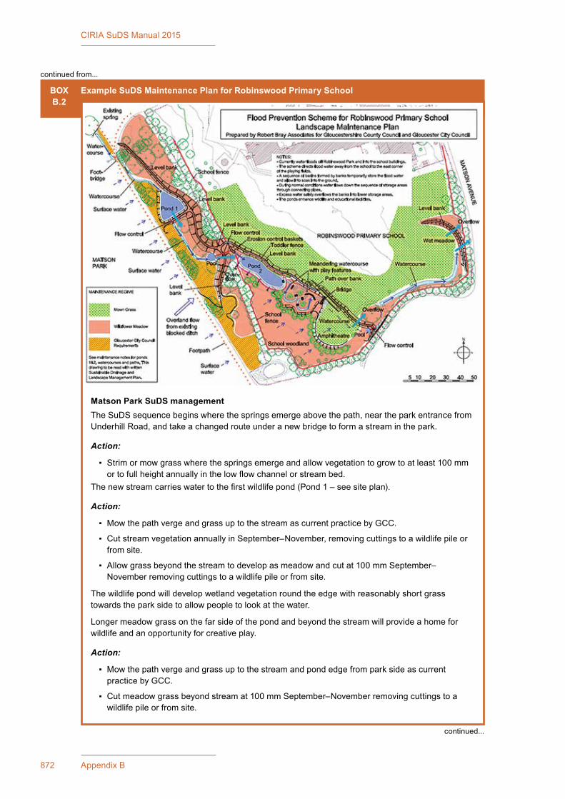
872 Appendix B
CIRIA SuDS Manual 2015
BOXB.2
Example SuDS Maintenance Plan for Robinswood Primary School
Matson Park SuDS managementTheSuDSsequencebeginswherethespringsemergeabovethepath,neartheparkentrancefromUnderhill Road, and take a changed route under a new bridge to form a stream in the park.
Action:
▪ Strimormowgrasswherethespringsemergeandallowvegetationtogrowtoatleast100mmortofullheightannuallyinthelowflowchannelorstreambed.
Thenewstreamcarrieswatertothefirstwildlifepond(Pond1–seesiteplan).
Action:
▪ MowthepathvergeandgrassuptothestreamascurrentpracticebyGCC.
▪ CutstreamvegetationannuallyinSeptember–November,removingcuttingstoawildlifepileorfrom site.
▪ Allowgrassbeyondthestreamtodevelopasmeadowandcutat100mmSeptember–Novemberremovingcuttingstoawildlifepileorfromsite.
Thewildlifepondwilldevelopwetlandvegetationroundtheedgewithreasonablyshortgrasstowards the park side to allow people to look at the water.
Longermeadowgrassonthefarsideofthepondandbeyondthestreamwillprovideahomeforwildlifeandanopportunityforcreativeplay.
Action:
▪ MowthepathvergeandgrassuptothestreamandpondedgefromparksideascurrentpracticebyGCC.
▪ Cutmeadowgrassbeyondstreamat100mmSeptember–Novemberremovingcuttingstoawildlife pile or from site.
continued from...
continued...

873Appendix B: Checklists
CIRIA SuDS Manual 2015
BOXB.2
Example SuDS Maintenance Plan for Robinswood Primary School
▪ Monitorhowthepondedgedevelops,andcut30%ofvegetationat100mmeachyearduringSeptember–November,ifrequired,removingcuttingstowildlifepilesorfromsite.
▪ Occasionallyremovepondvegetation,ifitspreadsacrossthepond,byhandclearing,rakingormachineclearance,usinga1–3tonnetrackedvehicle,withcuttingsremovedtowildlifepilesorfrom site.
▪ Check the outlet from the pond and the inlet on the other side of the bank are clear.
Thestreamflowsonwardfromthepondthroughgrasstoa“micropool”,beforeitleavestheparkthroughafinaloutletintotheschoolgrounds“environmentspace”atthetopoftheplayingfield.
Thereisagrassoverflowweiroverthebankdowntotheschoolfencewhichshouldbecutannuallytoensurethaterosiondoesnotoccur.Bramblesshouldbeallowedtore-colonisethebaseofthebank on the school side for security reasons.
Action:
▪ MowpathvergeandgrasstothestreamfromtheparksideascurrentpracticebyGCC.
▪ Cutmeadowgrassbeyondstreamat100mmSeptember–Novemberremovingcuttingstoawildlife pile or from site.
▪ Cut“micropool”vegetationannuallySeptember–November,ifrequired,removingcuttingstoawildlife pile or from site.
▪ Cutoverflowweirasmeadowgrassat100mmSeptember–Novemberremovingcuttingstoawildlife pile or from site.
Robinswood Primary School SuDS managementWaterfromtheMatsonParkflowsslowlythroughthebank,oroverflowsoveragrassweirinexceptionalrainfall.Thewaterarrivesontheschoolsitethroughthefenceontoastone-filledbasketchannelflowingalongagrassswaletothesecondwildlifepondand“environmentspace”(Pond2see site plan).
Action:
▪ Strimormowgrassaroundstone-filledbasketchannelandalongtheswaletothepondat100mmwithgrassatmaximumheight150mm.
Theschoolwildlifepondwilldevelopawetlandedgealongthe1mwidewetledgebeforerisinguptoaflatdryledge(orbench)providedforsafety.
Action:
▪ Allowgrassbeyondthepondandawayfromtheschoolsidetodevelopasmeadowandcutat100mminSeptember–Novemberremovingcuttingstoawildlifepileonsite.
▪ Ontheschoolside,cutthegrassregularlyat100mmwithgrassatmaximumheight150mmforaccess.
▪ Monitorpondvegetationandcut30%ofedgeat100mmeachyear,ifnecessary,duringSeptember–November,removingcuttingstowildlifepiles.
▪ Occasionallyremovepondvegetationifitspreadsacrossthepondbyhandclearingorrakingbeing careful not to damage the pond liner.
Thewaterleavesthepondunderasmallbridgeintoaswalemazeflowingtoaflatactivityarea.
Waterleavesthesouthernendoftheenvironmentspacethroughanoutletinthebankwithamicropool in front of it.
continued from...
continued...

874 Appendix B
CIRIA SuDS Manual 2015
BOXB.2
Example SuDS Maintenance Plan for Robinswood Primary School
Action:
▪ Cutthegrassintheswalemazechannelonceeachyear,September–November,at100mmremovingcuttingstowildlifepiles.
▪ Cutgrasspaths,vergesandtheflatactivityareaat35–50mmwith75mmmaximum,leavingcuttings in situ orremovetowildlifepiles.
▪ Cutallotherareaswithintheenvironmentspaceasmeadowcutat100mminSeptember–Novemberremovingcuttingstoawildlifepileonsiteduringschoolsummerholiday.
▪ Check that the outlet and the inlet on each side of the bank is clear.
Shouldwaterreachtheoutletfromtheenvironmentspacethenitwillflowdownagrassswale,aflatbottomedgrasschannel,toanotherholdingbasinbeforeoverflowingslowlythroughtheboundaryonto the road.
Action:
▪ Cuttheshallowswaleandmeadowaspartofnormalplayingfieldmaintenance.
SuDS and landscape maintenance – summary
Frequency Unit Rate Total
Regular maintenance
1 Litter management
1.1PickupalllitterinSuDSandlandscapeareasandremovefrom site
12visitsmonthly
2 Grass maintenance – all cuttings to wildlife piles
2.1Mowallgrassverges,pathsandamenityat35–50mmwith75mmmax,leavinggrassin situ
Asrequiredormonthly
2.2
Mow all dry swales, dry SuDS basins and margins to low flowchannelsandotherSuDSfeaturesat100mmwith150mmmaxCutwetswalesorbasinsannuallyaswildflowerareas
4–8visitsasrequired
Annually
2.3
Wildflowerareasstrimmedto50mminSeptemberoratthe end of school holidaysOrWildflowerareasstrimmedto50mmon3yearrotation30% each year
1visitannually
1visitannually
3 Inlets and outlets
3.1Inspectmonthly,removesiltfromslabapronsanddebris,strim 1 m round for access
12visitsmonthly
4 Hard surfaces – not applicable
4.1Sweepallpavingregularly,sweepandsuctionbrushpermeablepavinginautumnafterleaffall
1visit
Occasional tasks
5 Inspection and control chambers – not applicable
5.1 Annualinspection,removesiltandcheckfreeflow 1visit
continued from...
continued...

875Appendix B: Checklists
CIRIA SuDS Manual 2015
BOXB.2
Example SuDS Maintenance Plan for Robinswood Primary School
Frequency Unit Rate Total
6 Wetland and pond vegetation
6.1Wetlandvegetationtobecutat100mmon3–5yearrotation,30%eachyear,allcuttingstoberemovedtowildlife piles or from site
Asrequired
7 Silt management
7.1 Inspect swales, ponds, wetlands annually for silt accumulation 1visit
7.2Excavatesilt,stackanddrywithin10moftheSuDSfeature,butoutsidethedesignprofilewherewaterflows,spread,rakeandoverseed
Asrequired
8 Native planting
8.1Removelowerbrancheswherenecessarytoensuregoodgroundcovertoprotectsoilprofilefromerosion
1visitannually
Remedial work
9Inspect SuDS system regularly to check for damage or failureUndertake remedial work as required
As required
SuDS scheme checklistSuDS schemesincludelandscapefeaturesandcontrolstructurestomanagerunoffasitflowstositeoutfalls.ThefollowingliststheSuDScomponentsandextrafeatureswhichmaybefoundonasite.
▪ Filter stripsaregrassvergesthatallowrunofftoflowthroughvegetationtoaswale,wetland,infiltrationareaorotherSuDScomponent.
▪ Swalesarelinear,flat-bottomedgrassedorvegetatedchannelsthatconveywaterfromoneplace to another. They can also store water and allow it to soak into the ground.
▪ Underdrained swalesarestone-filledtrencheswithaperforatedpipeinthebottomcoveredbyengineered sandy soil and turf. These intercept dirty water and allow it to soak into the ground or lead it to a water storage feature.
▪ Filter drains clean,storeandconveywatertoanotherfeatureorallowittosoakintotheground.Theyarestone-filledtrenches,sometimeswithaperforatedpipeinthebottom.Thesemaybeenlarged to treat dirty water, as treatment trenches, or increase soakage into the ground, as infiltrationtrenches.
▪ Permeable surfaces arepermeableblockpaving,porousasphalt,gravelorfree-drainingsoilsthat allow rain to percolate through the surface into underlying drainage layers. They should be protected from silt, sand, compost, mulch etc.
▪ Infiltration basins, trenches, soakaways and most of the preceding SuDS features allow water to soak into the ground.
▪ Basins, ponds and wetlands are depressions in the ground where water is stored and treated. Waterlevelsriseafterrainandthendroptothenormallevelastheexcesssoaksintotheground or is released slowly to a watercourse or drain. Some water may be held back as a pond forfinaltreatment,amenityorwildlifeinterest.
▪ Bioretention areasareplantedareaswithengineeredtopsoiloverdrainagelayersthatallowwater to soak into the ground.
continued from...
continued...
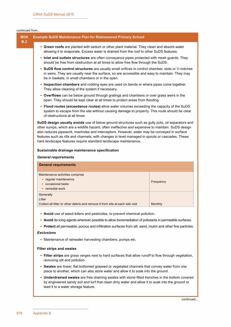
876 Appendix B
CIRIA SuDS Manual 2015
BOXB.2
Example SuDS Maintenance Plan for Robinswood Primary School
▪ Green roofs are planted with sedum or other plant material. They clean and absorb water allowingittoevaporate.ExcesswaterisdrainedfromtherooftootherSuDSfeatures.
▪ Inlet and outlets structuresareoftenconveyancepipesprotectedwithmeshguards.TheyshouldbefreefromobstructionatalltimestoallowfreeflowthroughtheSuDS.
▪ SuDS flow control structuresareusuallysmallorificesincontrolchamber,slotsorV-notchesin weirs. They are usually near the surface, so are accessible and easy to maintain. They may be in baskets, in small chambers or in the open.
▪ Inspection chambers and rodding eyes are used on bends or where pipes come together. They allow cleaning of the system if necessary.
▪ Overflowscanbebelowgroundthroughgratingsandchambersorovergrassweirsintheopen.Theyshouldbekeptclearatalltimestoprotectareasfromflooding.
▪ Flood routes (exceedance routes)allowwatervolumesexceedingthecapacityoftheSuDSsystem to escape from the site without causing damage to property. This route should be clear of obstructions at all times.
SuDS design usually avoidsuseofbelow-groundstructuressuchasgullypots,oilseparatorsandothersumps,whichareawildlifehazard,oftenineffectiveandexpensivetomaintain.SuDSdesignalsoreducespipework,manholesandinterceptors.However,watermaybeconveyedinsurfacefeaturessuchasrillsandchannels,withchangesinlevelmanagedinspoutsorcascades.Thesehard landscape features require standard landscape maintenance.
Sustainable drainage maintenance specification
General requirements
General requirements
Maintenanceactivitiescomprise ▪ regular maintenance ▪ occasional tasks ▪ remedial work
Frequency
GenerallyLitterCollectalllitterorotherdebrisandremoveitfromsiteateachsitevisit Monthly
▪ Avoiduseofweed-killersandpesticides,topreventchemicalpollution.
▪ Avoidde-icingagentswhereverpossibletoallowbioremediationofpollutantsinpermeablesurfaces.
▪ Protectallpermeable,porousandinfiltrationsurfacesfromsilt,sand,mulchandotherfineparticles.
Exclusions
▪ Maintenanceofrainwaterharvestingchambers,pumpsetc.
Filter strips and swales
▪ Filter stripsaregrassvergesnexttohardsurfacesthatallowrunofftoflowthroughvegetation,removingsiltandpollution.
▪ Swalesarelinear,flat-bottomedgrassedorvegetatedchannelsthatconveywaterfromoneplace to another, which can also store water and allow it to soak into the ground.
▪ Underdrained swales arefree-drainingswaleswithstone-filledtrenchesinthebottomcoveredby engineered sandy soil and turf that clean dirty water and allow it to soak into the ground or lead it to a water storage feature.
continued from...
continued...
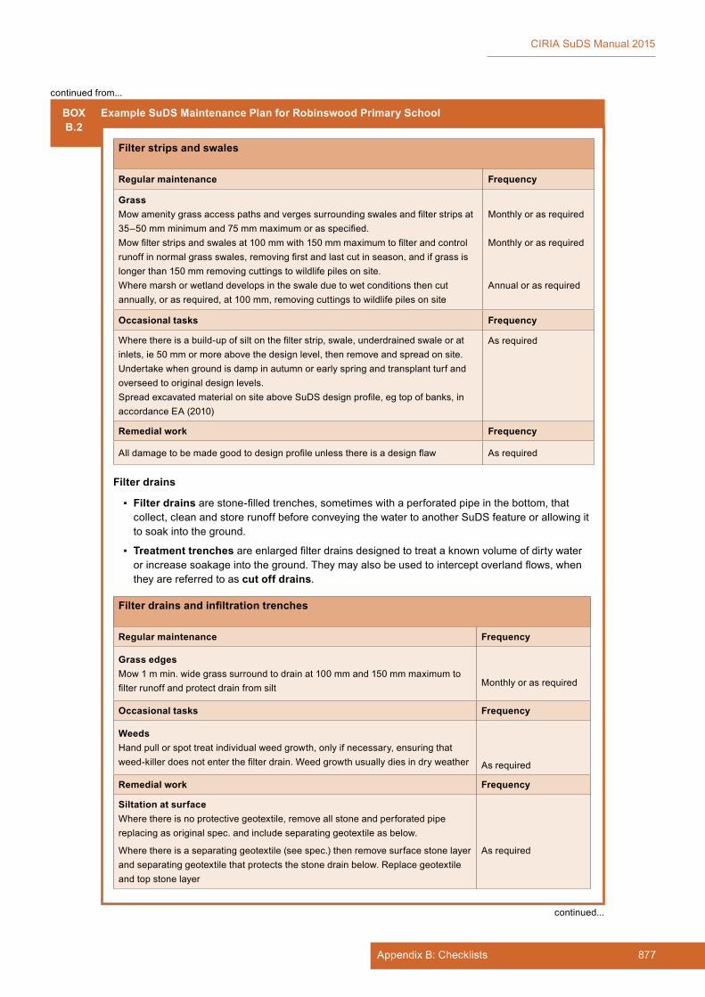
877Appendix B: Checklists
CIRIA SuDS Manual 2015
BOXB.2
Example SuDS Maintenance Plan for Robinswood Primary School
Filter strips and swales
Regular maintenance Frequency
GrassMowamenitygrassaccesspathsandvergessurroundingswalesandfilterstripsat35–50mmminimumand75mmmaximumorasspecified.Mowfilterstripsandswalesat100mmwith150mmmaximumtofilterandcontrolrunoffinnormalgrassswales,removingfirstandlastcutinseason,andifgrassislongerthan150mmremovingcuttingstowildlifepilesonsite.Wheremarshorwetlanddevelopsintheswaleduetowetconditionsthencutannually,orasrequired,at100mm,removingcuttingstowildlifepilesonsite
Monthly or as required
Monthly or as required
Annualorasrequired
Occasional tasks Frequency
Wherethereisabuild-upofsiltonthefilterstrip,swale,underdrainedswaleoratinlets,ie50mmormoreabovethedesignlevel,thenremoveandspreadonsite.Undertake when ground is damp in autumn or early spring and transplant turf and overseedtooriginaldesignlevels.SpreadexcavatedmaterialonsiteaboveSuDSdesignprofile,egtopofbanks,inaccordanceEA(2010)
Asrequired
Remedial work Frequency
Alldamagetobemadegoodtodesignprofileunlessthereisadesignflaw Asrequired
Filter drains
▪ Filter drainsarestone-filledtrenches,sometimeswithaperforatedpipeinthebottom,thatcollect,cleanandstorerunoffbeforeconveyingthewatertoanotherSuDSfeatureorallowingitto soak into the ground.
▪ Treatment trenchesareenlargedfilterdrainsdesignedtotreataknownvolumeofdirtywaterorincreasesoakageintotheground.Theymayalsobeusedtointerceptoverlandflows,whenthey are referred to as cut off drains.
Filter drains and infiltration trenches
Regular maintenance Frequency
Grass edgesMow1mmin.widegrasssurroundtodrainat100mmand150mmmaximumtofilterrunoffandprotectdrainfromsilt Monthly or as required
Occasional tasks Frequency
WeedsHandpullorspottreatindividualweedgrowth,onlyifnecessary,ensuringthatweed-killerdoesnotenterthefilterdrain.Weedgrowthusuallydiesindryweather Asrequired
Remedial work Frequency
Siltation at surfaceWherethereisnoprotectivegeotextile,removeallstoneandperforatedpipereplacingasoriginalspec.andincludeseparatinggeotextileasbelow.
Wherethereisaseparatinggeotextile(seespec.)thenremovesurfacestonelayerandseparatinggeotextilethatprotectsthestonedrainbelow.Replacegeotextileand top stone layer
Asrequired
continued from...
continued...
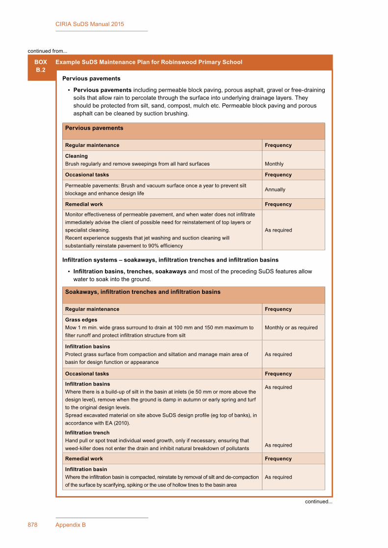
878 Appendix B
CIRIA SuDS Manual 2015
BOXB.2
Example SuDS Maintenance Plan for Robinswood Primary School
Pervious pavements
▪ Pervious pavements includingpermeableblockpaving,porousasphalt,gravelorfree-drainingsoils that allow rain to percolate through the surface into underlying drainage layers. They shouldbeprotectedfromsilt,sand,compost,mulchetc.Permeableblockpavingandporousasphalt can be cleaned by suction brushing.
Pervious pavements
Regular maintenance Frequency
CleaningBrushregularlyandremovesweepingsfromallhardsurfaces Monthly
Occasional tasks Frequency
Permeablepavements:Brushandvacuumsurfaceonceayeartopreventsiltblockage and enhance design life
Annually
Remedial work Frequency
Monitoreffectivenessofpermeablepavement,andwhenwaterdoesnotinfiltrateimmediatelyadvisetheclientofpossibleneedforreinstatementoftoplayersorspecialist cleaning.Recentexperiencesuggeststhatjetwashingandsuctioncleaningwillsubstantiallyreinstatepavementto90%efficiency
Asrequired
Infiltration systems – soakaways, infiltration trenches and infiltration basins
▪ Infiltration basins, trenches, soakaways and most of the preceding SuDS features allow water to soak into the ground.
Soakaways, infiltration trenches and infiltration basins
Regular maintenance Frequency
Grass edgesMow1mmin.widegrasssurroundtodrainat100mmand150mmmaximumtofilterrunoffandprotectinfiltrationstructurefromsilt
Monthly or as required
Infiltration basinsProtect grass surface from compaction and siltation and manage main area of basin for design function or appearance
Asrequired
Occasional tasks Frequency
Infiltration basinsWherethereisabuild-upofsiltinthebasinatinlets(ie50mmormoreabovethedesignlevel),removewhenthegroundisdampinautumnorearlyspringandturftotheoriginaldesignlevels.SpreadexcavatedmaterialonsiteaboveSuDSdesignprofile(egtopofbanks),inaccordancewithEA(2010).
Infiltration trenchHandpullorspottreatindividualweedgrowth,onlyifnecessary,ensuringthatweed-killerdoesnotenterthedrainandinhibitnaturalbreakdownofpollutants
Asrequired
Asrequired
Remedial work Frequency
Infiltration basinWheretheinfiltrationbasiniscompacted,reinstatebyremovalofsiltandde-compactionof the surface by scarifying, spiking or the use of hollow tines to the basin area
Asrequired
continued from...
continued...
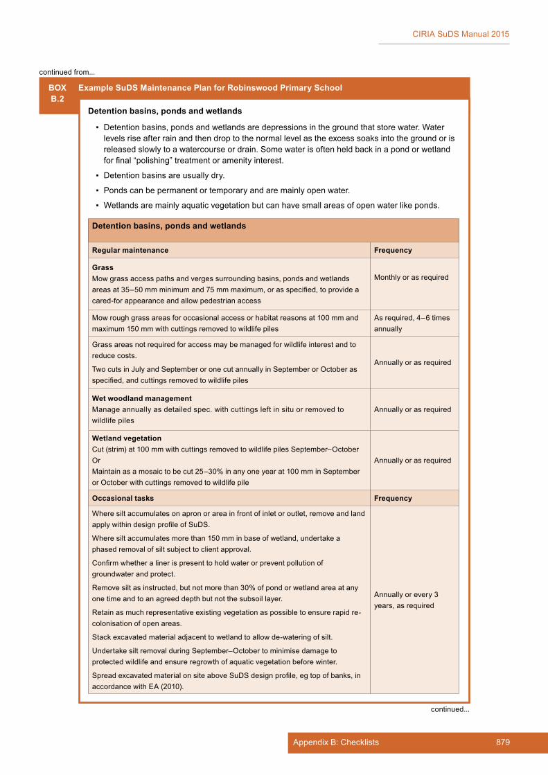
879Appendix B: Checklists
CIRIA SuDS Manual 2015
BOXB.2
Example SuDS Maintenance Plan for Robinswood Primary School
Detention basins, ponds and wetlands
▪ Detention basins, ponds and wetlands are depressions in the ground that store water. Water levelsriseafterrainandthendroptothenormallevelastheexcesssoaksintothegroundorisreleased slowly to a watercourse or drain. Some water is often held back in a pond or wetland forfinal“polishing”treatmentoramenityinterest.
▪ Detention basins are usually dry.
▪ Ponds can be permanent or temporary and are mainly open water.
▪ Wetlandsaremainlyaquaticvegetationbutcanhavesmallareasofopenwaterlikeponds.
Detention basins, ponds and wetlands
Regular maintenance Frequency
GrassMowgrassaccesspathsandvergessurroundingbasins,pondsandwetlandsareasat35–50mmminimumand75mmmaximum,orasspecified,toprovideacared-forappearanceandallowpedestrianaccess
Monthly or as required
Mow rough grass areas for occasional access or habitat reasons at 100 mm and maximum150mmwithcuttingsremovedtowildlifepiles
Asrequired,4–6timesannually
Grassareasnotrequiredforaccessmaybemanagedforwildlifeinterestandtoreduce costs.
Two cuts in July and September or one cut annually in September or October as specified,andcuttingsremovedtowildlifepiles
Annuallyorasrequired
Wet woodland managementManageannuallyasdetailedspec.withcuttingsleftinsituorremovedtowildlife piles
Annuallyorasrequired
Wetland vegetationCut(strim)at100mmwithcuttingsremovedtowildlifepilesSeptember–OctoberOrMaintain as a mosaic to be cut 25–30% in any one year at 100 mm in September orOctoberwithcuttingsremovedtowildlifepile
Annuallyorasrequired
Occasional tasks Frequency
Wheresiltaccumulatesonapronorareainfrontofinletoroutlet,removeandlandapplywithindesignprofileofSuDS.
Where silt accumulates more than 150 mm in base of wetland, undertake a phasedremovalofsiltsubjecttoclientapproval.
Confirmwhetheralinerispresenttoholdwaterorpreventpollutionofgroundwater and protect.
Removesiltasinstructed,butnotmorethan30%ofpondorwetlandareaatanyone time and to an agreed depth but not the subsoil layer.
Retainasmuchrepresentativeexistingvegetationaspossibletoensurerapidre-colonisation of open areas.
Stackexcavatedmaterialadjacenttowetlandtoallowde-wateringofsilt.
UndertakesiltremovalduringSeptember–Octobertominimisedamagetoprotectedwildlifeandensureregrowthofaquaticvegetationbeforewinter.
SpreadexcavatedmaterialonsiteaboveSuDSdesignprofile,egtopofbanks,inaccordancewithEA(2010).
Annuallyorevery3years, as required
continued from...
continued...
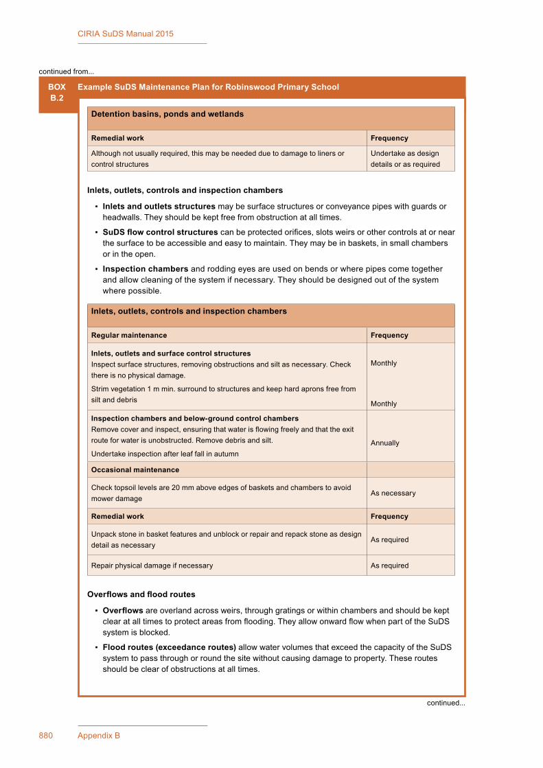
880 Appendix B
CIRIA SuDS Manual 2015
BOXB.2
Example SuDS Maintenance Plan for Robinswood Primary School
Detention basins, ponds and wetlands
Remedial work Frequency
Althoughnotusuallyrequired,thismaybeneededduetodamagetolinersorcontrol structures
Undertake as design details or as required
Inlets, outlets, controls and inspection chambers
▪ Inlets and outlets structuresmaybesurfacestructuresorconveyancepipeswithguardsorheadwalls. They should be kept free from obstruction at all times.
▪ SuDS flow control structurescanbeprotectedorifices,slotsweirsorothercontrolsatornearthe surface to be accessible and easy to maintain. They may be in baskets, in small chambers or in the open.
▪ Inspection chambers and rodding eyes are used on bends or where pipes come together and allow cleaning of the system if necessary. They should be designed out of the system where possible.
Inlets, outlets, controls and inspection chambers
Regular maintenance Frequency
Inlets, outlets and surface control structuresInspectsurfacestructures,removingobstructionsandsiltasnecessary.Checkthere is no physical damage.
Strimvegetation1mmin.surroundtostructuresandkeephardapronsfreefromsilt and debris
Monthly
Monthly
Inspection chambers and below-ground control chambersRemovecoverandinspect,ensuringthatwaterisflowingfreelyandthattheexitrouteforwaterisunobstructed.Removedebrisandsilt.
Undertake inspection after leaf fall in autumnAnnually
Occasional maintenance
Checktopsoillevelsare20mmaboveedgesofbasketsandchamberstoavoidmower damage
Asnecessary
Remedial work Frequency
Unpack stone in basket features and unblock or repair and repack stone as design detail as necessary
Asrequired
Repair physical damage if necessary Asrequired
Overflows and flood routes
▪ Overflowsareoverlandacrossweirs,throughgratingsorwithinchambersandshouldbekeptclearatalltimestoprotectareasfromflooding.TheyallowonwardflowwhenpartoftheSuDSsystem is blocked.
▪ Flood routes (exceedance routes)allowwatervolumesthatexceedthecapacityoftheSuDSsystem to pass through or round the site without causing damage to property. These routes should be clear of obstructions at all times.
continued from...
continued...
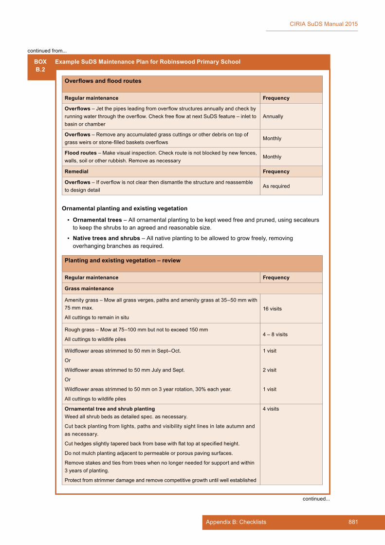
881Appendix B: Checklists
CIRIA SuDS Manual 2015
BOXB.2
Example SuDS Maintenance Plan for Robinswood Primary School
Overflows and flood routes
Regular maintenance Frequency
Overflows–Jetthepipesleadingfromoverflowstructuresannuallyandcheckbyrunningwaterthroughtheoverflow.CheckfreeflowatnextSuDSfeature–inlettobasin or chamber
Annually
Overflows–Removeanyaccumulatedgrasscuttingsorotherdebrisontopofgrassweirsorstone-filledbasketsoverflows
Monthly
Flood routes –Makevisualinspection.Checkrouteisnotblockedbynewfences,walls,soilorotherrubbish.Removeasnecessary
Monthly
Remedial Frequency
Overflows–Ifoverflowisnotclearthendismantlethestructureandreassembleto design detail
Asrequired
Ornamental planting and existing vegetation
▪ Ornamental trees–Allornamentalplantingtobekeptweedfreeandpruned,usingsecateursto keep the shrubs to an agreed and reasonable size.
▪ Native trees and shrubs –Allnativeplantingtobeallowedtogrowfreely,removingoverhangingbranchesasrequired.
Planting and existing vegetation – review
Regular maintenance Frequency
Grass maintenance
Amenitygrass–Mowallgrassverges,pathsandamenitygrassat35–50mmwith75mmmax.
Allcuttingstoremaininsitu
16visits
Roughgrass–Mowat75–100mmbutnottoexceed150mm
Allcuttingstowildlifepiles4–8visits
Wildflowerareasstrimmedto50mminSept–Oct.
Or
Wildflowerareasstrimmedto50mmJulyandSept.
Or
Wildflowerareasstrimmedto50mmon3yearrotation,30%eachyear.
Allcuttingstowildlifepiles
1visit
2visit
1visit
Ornamental tree and shrub plantingWeed all shrub beds as detailed spec. as necessary.
Cutbackplantingfromlights,pathsandvisibilitysightlinesinlateautumnandas necessary.
Cuthedgesslightlytaperedbackfrombasewithflattopatspecifiedheight.
Donotmulchplantingadjacenttopermeableorporouspavingsurfaces.
Removestakesandtiesfromtreeswhennolongerneededforsupportandwithin3 years of planting.
Protectfromstrimmerdamageandremovecompetitivegrowthuntilwellestablished
4visits
continued from...
continued...
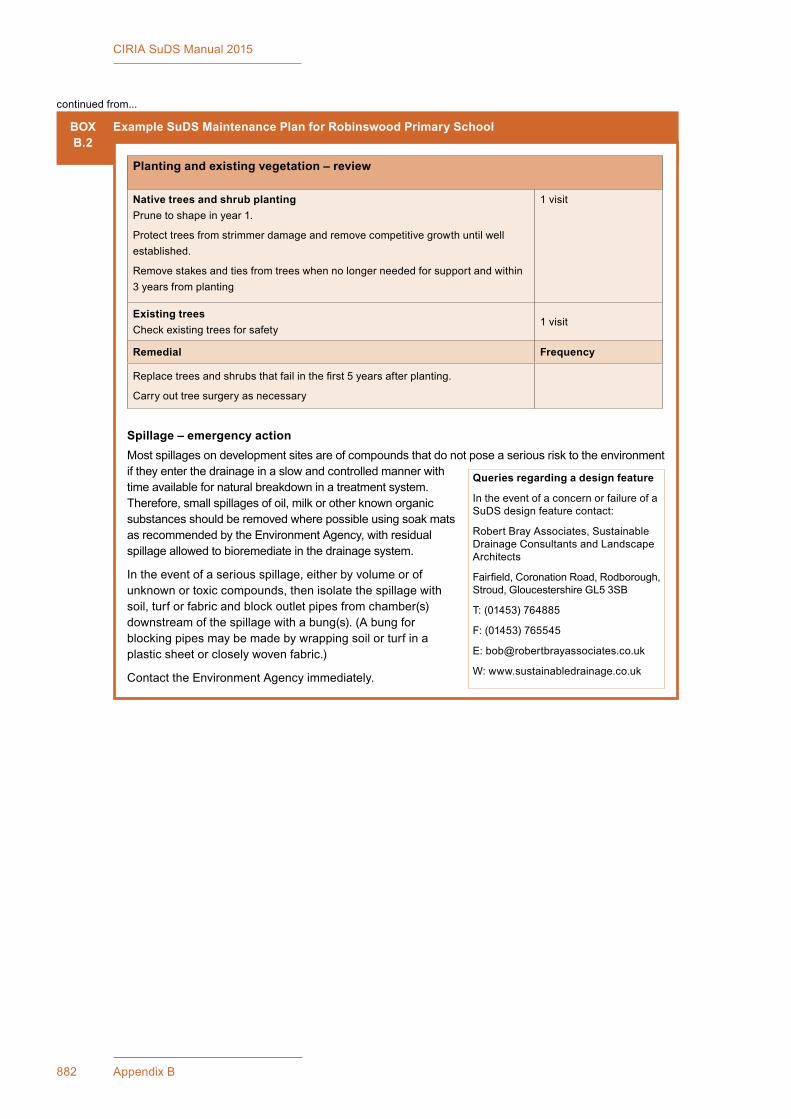
882 Appendix B
CIRIA SuDS Manual 2015
BOXB.2
Example SuDS Maintenance Plan for Robinswood Primary School
Planting and existing vegetation – review
Native trees and shrub plantingPrune to shape in year 1.
Protecttreesfromstrimmerdamageandremovecompetitivegrowthuntilwellestablished.
Removestakesandtiesfromtreeswhennolongerneededforsupportandwithin3 years from planting
1visit
Existing treesCheckexistingtreesforsafety
1visit
Remedial Frequency
Replacetreesandshrubsthatfailinthefirst5yearsafterplanting.
Carry out tree surgery as necessary
Spillage – emergency actionMostspillagesondevelopmentsitesareofcompoundsthatdonotposeaseriousrisktotheenvironmentif they enter the drainage in a slow and controlled manner with timeavailablefornaturalbreakdowninatreatmentsystem.Therefore, small spillages of oil, milk or other known organic substancesshouldberemovedwherepossibleusingsoakmatsasrecommendedbytheEnvironmentAgency,withresidualspillage allowed to bioremediate in the drainage system.
Intheeventofaseriousspillage,eitherbyvolumeorofunknownortoxiccompounds,thenisolatethespillagewithsoil, turf or fabric and block outlet pipes from chamber(s) downstreamofthespillagewithabung(s).(Abungforblocking pipes may be made by wrapping soil or turf in a plasticsheetorcloselywovenfabric.)
ContacttheEnvironmentAgencyimmediately.
Queries regarding a design feature
IntheeventofaconcernorfailureofaSuDS design feature contact:
RobertBrayAssociates,SustainableDrainageConsultantsandLandscapeArchitects
Fairfield,CoronationRoad,Rodborough,Stroud,GloucestershireGL53SB
T: (01453) 764885
F: (01453) 765545
W: www.sustainabledrainage.co.uk
continued from...
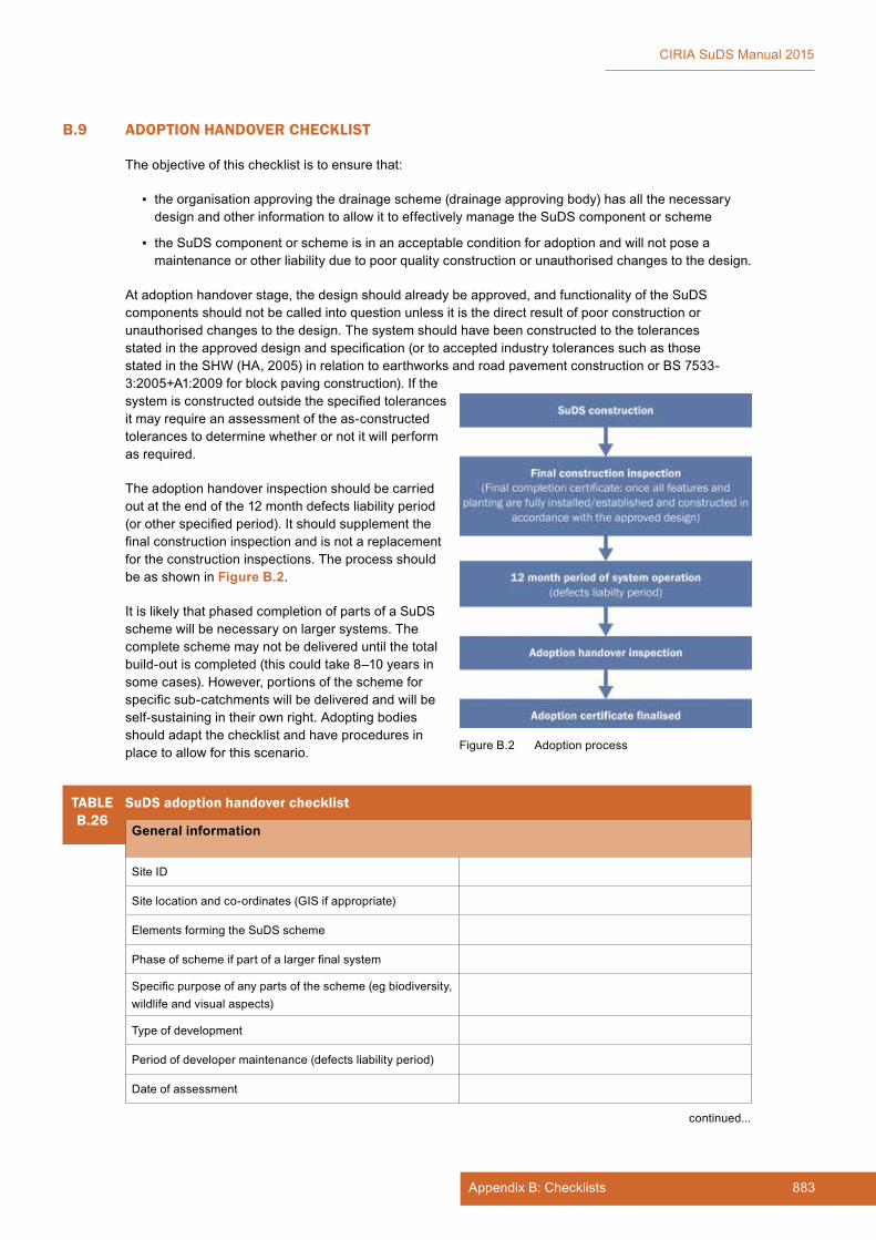
883Appendix B: Checklists
CIRIA SuDS Manual 2015
B.9 ADOPTION HANDOVER CHECKLIST
Theobjectiveofthischecklististoensurethat:
▪ theorganisationapprovingthedrainagescheme(drainageapprovingbody)hasallthenecessarydesignandotherinformationtoallowittoeffectivelymanagetheSuDScomponentorscheme
▪ the SuDS component or scheme is in an acceptable condition for adoption and will not pose a maintenance or other liability due to poor quality construction or unauthorised changes to the design.
Atadoptionhandoverstage,thedesignshouldalreadybeapproved,andfunctionalityoftheSuDScomponents should not be called into question unless it is the direct result of poor construction or unauthorisedchangestothedesign.Thesystemshouldhavebeenconstructedtothetolerancesstatedintheapproveddesignandspecification(ortoacceptedindustrytolerancessuchasthosestatedintheSHW(HA,2005)inrelationtoearthworksandroadpavementconstructionorBS7533-3:2005+A1:2009forblockpavingconstruction).Ifthesystemisconstructedoutsidethespecifiedtolerancesitmayrequireanassessmentoftheas-constructedtolerances to determine whether or not it will perform as required.
Theadoptionhandoverinspectionshouldbecarriedout at the end of the 12 month defects liability period (orotherspecifiedperiod).Itshouldsupplementthefinalconstructioninspectionandisnotareplacementfor the construction inspections. The process should be as shown in Figure B.2.
It is likely that phased completion of parts of a SuDS scheme will be necessary on larger systems. The completeschememaynotbedelivereduntilthetotalbuild-outiscompleted(thiscouldtake8–10yearsinsomecases).However,portionsoftheschemeforspecificsub-catchmentswillbedeliveredandwillbeself-sustainingintheirownright.Adoptingbodiesshouldadaptthechecklistandhaveproceduresinplace to allow for this scenario. FigureB.2 Adoptionprocess
TABLEB.26
SuDS adoption handover checklist
General information
Site ID
Sitelocationandco-ordinates(GISifappropriate)
Elements forming the SuDS scheme
Phaseofschemeifpartofalargerfinalsystem
Specificpurposeofanypartsofthescheme(egbiodiversity,wildlifeandvisualaspects)
Typeofdevelopment
Periodofdevelopermaintenance(defectsliabilityperiod)
Date of assessment
continued...

884 Appendix B
CIRIA SuDS Manual 2015
TABLEB.26
SuDS adoption handover checklist
Check Details Acceptable (Y/N)
Details of corrective action required
Corrective action completed (date)
General
Designapprovalcheckssatisfactory?
Construction inspection checks satisfactory?
Asset information
As-constructedplansandsurveysubmitted?
As-constructeddrainagecalculations/modelssubmittedifnecessary(egoutsidespecifiedtolerances)?
Proprietary product information submitted, where applicable?
Assetlistedonassetregisterordatabase?
Maintenance information
Full Maintenance Plan submitted?
Inspection and maintenance records indicate stated maintenance undertaken during 12 month maintenance period?
Handover inspection
Confirmthatinletsandoutletsareclear.
Confirmthatcorrectplantinginaccordancewithapproveddesignisfullyestablished.
Confirmthatnounevensettlingofsoil,channelling,unwanted ponding or erosion of bed or side slopes.
Ifyes,givereasonfordefect(designorconstruction).
Confirmthatnoevidenceofconstructionsedimentorunexpectedlyrapidbuild-upofsediment.
Confirmthatagreedmaintenanceaccessisclear.
Confirmthatpermeable/poroussurfacesaredrainingeffectivelyandthatthereisnounacceptable settlement.
Confirmthatanypermanentwaterlevelsareinaccordancewiththeapproveddesign.
Suitability for adoption
Goodcondition–acceptable
Minordefects–acceptablesubjecttominorworks(indicate, with reasons, whether cost should fall to developeroradoptingbody)
Majordefects–Notacceptablewithoutsubstantialrepair works (indicate, with reasons, whether cost shouldfalltodeveloperoradoptingbody)
continued from...

885Appendix B: Checklists
CIRIA SuDS Manual 2015
B.10 REFERENCES
DCLG(2008)Code for sustainable homes,DepartmentforCommunitiesandLocalGovernment,London,UK.Goto:http://tinyurl.com/cwjmpfa
BETTESS,R(1996)Infiltration drainage – manual of good practice,R156,CIRIA,London,UK(ISBN:978-0-86017-457-8).Goto:www.ciria.org
BIRKBECK, D, KRUCZKOWSKI, S (2012) Building for life 12. The sign of a good place to live, first edition,NottinghamTrentUniversity,UK(ISBN:978-0-95760-096-6).Goto:http://tinyurl.com/q8eenlv
BRE(1991)Soakaway design,BREDigest365,BuildingResearchEstablishment,Bracknell,UK(ISBN:978-0-85125-502-7)
EA(2010)Waste acceptance at landfills. Guidance on waste acceptance procedures and criteria, EnvironmentAgency,Bristol,UK.Goto:http://tinyurl.com/p48sjku
HA(2005a)“Specificationforhighwayworks”,Manual of Contract Documents for Highway Works (MCHW), vol1,TheStationeryOffice,London,UK(ISBN:978-0-11552-705-0).Goto:http://tinyurl.com/p4pb5pz
HA(2009a)“Roaddrainageandthewaterenvironment”,Design manual for roads and bridges (DMRB), vol11,Section3,Part10,HD45/09,HighwaysAgency,London,UK.Goto:http://tinyurl.com/p4yakc9
HA(2009b)“Series500Drainageandserviceducts”,Specification for Highway Works,vol1,TheStationeryOffice,London,UK.Goto:http://tinyurl.com/pflnom7
HA(2009c)“Series600Earthworks”,Specification for Highway Works,vol1,TheStationeryOffice,London,UK.Goto:http://tinyurl.com/phx5yj
HA(2009d)“Series700Roadpavements–general”,Specification for Highway Works,vol1,TheStationeryOffice,London,UK.Goto:http://tinyurl.com/oy96kev
HMGOVERNMENT(2010)The Building Regulations 2010, Drainage and waste disposal, Approved Document H,RIBAEnterprisesLtd,London,UK(ISBN:978-1-85946-208-9).Goto:http://tinyurl.com/lbwgwg8
WOODSBALLARD,B,KELLAGHER,R,MARTIN,P,JEFFERIES,C,BRAY,RandSHAFFER,P92007)Site handbook for the construction of SUDS,C698,CIRIA,London,UK(ISBN:978-0-86017-698-5). Goto:www.ciria.org
WRc (2011) Civil Engineering Specification for the Water Industry (CESWI), 7th edition, WRc, Swindon, UK.Goto:http://ceswi.wrcplc.co.uk
Statutes
ReservoirsAct1975(c.23)
FloodandWaterManagementAct2010(c.29)
TheManagementofHealthandSafetyatWorkRegulations1999(No.3242)
British Standards
BS3882:1994Specification for topsoil (withdrawn)
BS7533-3:2005+A1:2009Pavements constructed with clay, natural stone or concrete pavers. Code of practice for laying precast concrete paving blocks and clay pavers for flexible pavements

886 Appendix B
CIRIA SuDS Manual 2015
BSEN964-1:1995Geotextiles and geotextile-related products. Determination of thickness at specified pressures. Single layers (withdrawn)
BSEN965:1995Geotextiles and geotextile-related products. Determination of mass per unit area (withdrawn)
BSENISO12236:2006Geosynthetics. Static puncture test (CBR test)
BSENISO10319:2015Geosynthetics. Wide-width tensile test
BSEN12457-3:2002Characterisation of waste. Leaching. Compliance test for leaching of granular waste materials and sludges. Two stage batch test at a liquid to solid ratio of 2 l/kg and 8 l/kg for materials with a high solid content and with a particle size below 4 mm (without or with size reduction)
BSEN13242:2002+A1:2007Aggregates for unbound and hydraulically bound materials for use in civil engineering work and road construction
BSENISO14688-1:2002+A1:2013Geotechnical investigation and testing. Identification and classification of soil. Identification and description
BSENISO14689-1:2003Geotechnical investigation and testing. Identification and classification of rock. Identification and description
USA
ASTMD638-14Standard test method for tensile properties of plastics
ASTMD751-06(2011)Standard test methods for coated fabrics
ASTMD792-13Standard test methods for density and specific gravity (relative density) of plastics by displacement
ASTMD1004-13Standard test method for tear resistance (graves tear) of plastic film and sheeting
ASTMD1149-07(2012)Standard test methods for rubber deterioration—cracking in an ozone controlled environment
ASTMD1203-10Standard test methods for volatile loss from plastics using activated carbon methods
ASTMD1204-14Standard test method for linear dimensional changes of nonrigid thermoplastic sheeting or film at elevated temperature
ASTMD5397-07(2012)Standard test method for evaluation of stress crack resistance of polyolefin geomembranes using notched constant tensile load test
ASTMD1603-14Standard test method for carbon black content in olefin plastics
ASTME96/E96M-15Standard test methods for water vapor transmission of materials
FTMS101C-Method2065Puncture Test Federal Test Method Standard

887Appendix B: Checklists
CIRIA SuDS Manual 2015
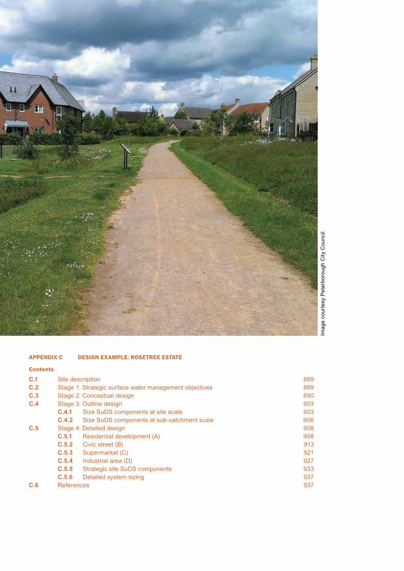
APPENDIX C DESIGN EXAMPLE: ROSETREE ESTATE
Contents
C.1 Site description 889C.2 Stage 1: Strategic surface water management objectives 889C.3 Stage 2: Conceptual design 890C.4 Stage 3: Outline design 903
C.4.1 Size SuDS components at site scale 903C.4.2 Size SuDS components at sub-catchment scale 906
C.5 Stage 4: Detailed design 908C.5.1 Residential development (A) 908C.5.2 Civic street (B) 913C.5.3 Supermarket (C) 921C.5.4 Industrial area (D) 927C.5.5 Strategic site SuDS components 933C.5.6 Detailed system sizing 937
C.6 References 937
Imag
e co
urte
sy P
eter
boro
ugh
City
Cou
ncil
889Appendix C: Design example
CIRIA SuDS Manual 2015
CDesign example: Rosetree Estate
Appendix
This design example is based on a hypothetical site, developed to demonstrate:1 the design process (Chapter 7)2 the detailed hydraulic and treatment design of individual components
(Chapters 11–23).
It does not cover landscape works, amenity or biodiversity design, construction programming and processes, costs and benefits or operation and maintenance requirements, health and safety, community engagement etc. It does not include appraisal of different design options or the evaluation of alternative SuDS components in delivering the required design criteria. The site layout and features have been developed specifically to allow the incorporation of a range of preselected SuDS components and it does not purport to be a realistic development layout.
The example works through the conceptual design of the scheme to meet the design criteria, as presented in this manual, and sizing of a number of representative SuDS components. It does not cover detailed scheme design or component detailing.
C.1 SITE DESCRIPTION
Rosetree Estate is a hypothetical 31 ha greenfield development site in central England, with proposals agreed for mixed use development, including:
A medium-density residential development
B shopping area including a civic street
C large supermarket site
D light industrial area including a factory and a lorry park
E further development area for which there are no current development proposals.
The site will be developed in phases with surface water managed at the sub-catchment level as far as possible. A strategic site drainage system will collect runoff from sub-catchments and local surfaces, and convey it to the River Springbourne to the south of the site.
This design example follows the process set out in Chapter 7.
C.2 STAGE 1: STRATEGIC SURFACE WATER MANAGEMENT OBJECTIVES
Pre-application discussions have occurred between the developer and the local planning authority, and an Environmental Impact Assessment and Flood Risk Assessment (FRA) have been undertaken for the development as a whole. Together with initial consultations with the environmental regulator and local community associations, the strategic site surface water management objectives listed in Table C.1 have been agreed.

890 Appendix C
CIRIA SuDS Manual 2015
C.3 STAGE 2: CONCEPTUAL DESIGN
Step 1 Site and development characterisation
Following the guidance set out in Section 7.5.1, the characteristics set out in Tables C.2 and C.3 relating to surface water management were established for the site and the development respectively. The layout of the site and development are illustrated in Figures C.1 and C.2 respectively.
TABLEC.1
Strategic surface water management objectives
Delivery area Strategic objective
Water resource
There are insufficient drivers for residential rainwater harvesting systems. The site is not in an area of water stress and there are good infiltration opportunities for much of the site, which provides a more cost-effective means of managing runoff volumes.
The supermarket chain with the right to development on this site has a policy of using rainwater harvesting for all stores and is keen to use the system to manage surface water from the roof to the maximum extent possible.
Flood risk
Rates and volumes of surface water discharge from the site to be controlled to greenfield values, as per the water quantity design standards set out in Section 3.3.
The FRA requires that there is no encroachment of the development into the existing Zone 3 river floodplain. Roads and the surface water management system are acceptable within Flood Zone 2. The discharge from the SuDS to the River Springbourne will, of necessity, have to be constructed within the Zone 3 floodplain.
Water qualityThe River Springbourne at the site is a sensitive water body due to a downstream drinking water abstraction point. Appropriate treatment of surface water discharges will be required.
Amenity
For providing appropriate amenity value in the SuDS design, opportunities include:
▪ a “green” civic street – where planting is a feature of the community space and retail environment and can be incorporated in the SuDS design
▪ a landscaped parkland area that offers amenity and recreational value, where water is a feature and again can be incorporated in the SuDS design.
Habitat and biodiversity
The local biodiversity strategy has identified the need for:
▪ more trees to support specified bird species ▪ wetland areas to replace previous local wetland areas that have been lost, and to
enhance and protect amphibian populations.There are habitat corridors that link to the site to the north, and the provision of a habitat link from north to south across the site is important. All of these objectives can be incorporated into the SuDS design.
Climate resilienceThe development is in a low density suburban environment. Urban cooling is not, therefore a key driver. However, strategic objectives for water resources, flood risk, habitat and biodiversity will all contribute to climate resilience.
Approval and adoption
The local planning authority will be the approving body for the surface water management system, and will approve the scheme against a set of locally agreed standards (that match those set out in this manual).
The local sewerage undertaker has agreed to adopt and maintain the strategic drainage components that lie within public open space, including both surface components and subsurface pipework. The drainage within the commercial and industrial plots will be owned and maintained by the relevant site owners. The soakaways in private gardens will be the responsibility of the property owner.
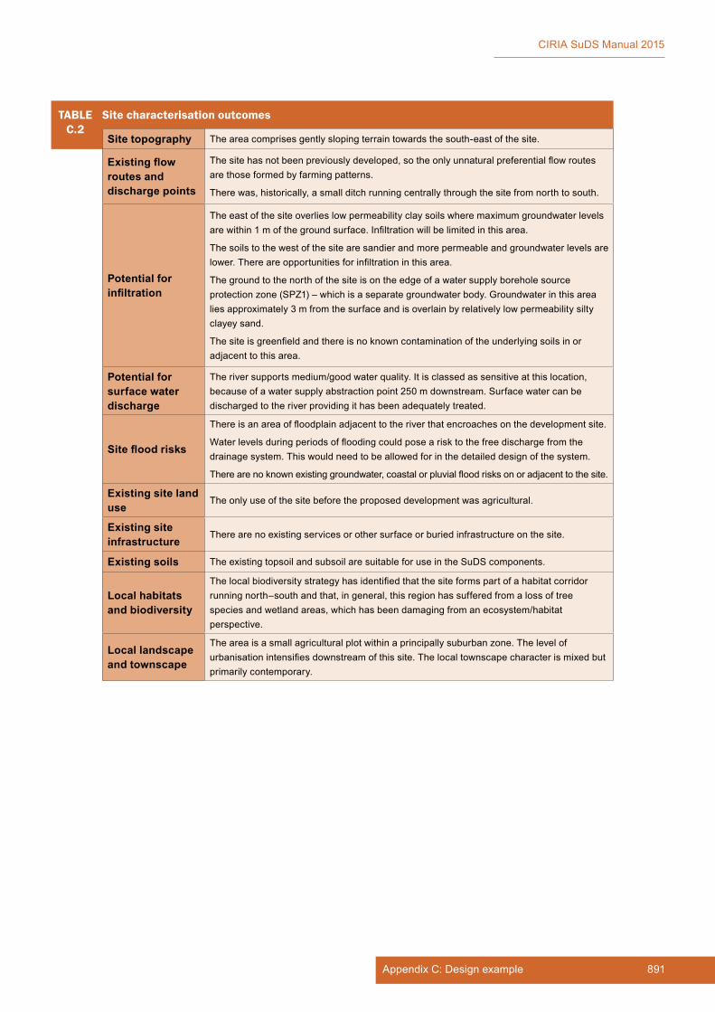
891Appendix C: Design example
CIRIA SuDS Manual 2015
TABLEC.2
Site characterisation outcomes
Site topography The area comprises gently sloping terrain towards the south-east of the site.
Existing flow routes and discharge points
The site has not been previously developed, so the only unnatural preferential flow routes are those formed by farming patterns.
There was, historically, a small ditch running centrally through the site from north to south.
Potential for infiltration
The east of the site overlies low permeability clay soils where maximum groundwater levels are within 1 m of the ground surface. Infiltration will be limited in this area.
The soils to the west of the site are sandier and more permeable and groundwater levels are lower. There are opportunities for infiltration in this area.
The ground to the north of the site is on the edge of a water supply borehole source protection zone (SPZ1) – which is a separate groundwater body. Groundwater in this area lies approximately 3 m from the surface and is overlain by relatively low permeability silty clayey sand.
The site is greenfield and there is no known contamination of the underlying soils in or adjacent to this area.
Potential for surface water discharge
The river supports medium/good water quality. It is classed as sensitive at this location, because of a water supply abstraction point 250 m downstream. Surface water can be discharged to the river providing it has been adequately treated.
Site flood risks
There is an area of floodplain adjacent to the river that encroaches on the development site.
Water levels during periods of flooding could pose a risk to the free discharge from the drainage system. This would need to be allowed for in the detailed design of the system.
There are no known existing groundwater, coastal or pluvial flood risks on or adjacent to the site.
Existing site land use
The only use of the site before the proposed development was agricultural.
Existing site infrastructure
There are no existing services or other surface or buried infrastructure on the site.
Existing soils The existing topsoil and subsoil are suitable for use in the SuDS components.
Local habitats and biodiversity
The local biodiversity strategy has identified that the site forms part of a habitat corridor running north–south and that, in general, this region has suffered from a loss of tree species and wetland areas, which has been damaging from an ecosystem/habitat perspective.
Local landscape and townscape
The area is a small agricultural plot within a principally suburban zone. The level of urbanisation intensifies downstream of this site. The local townscape character is mixed but primarily contemporary.
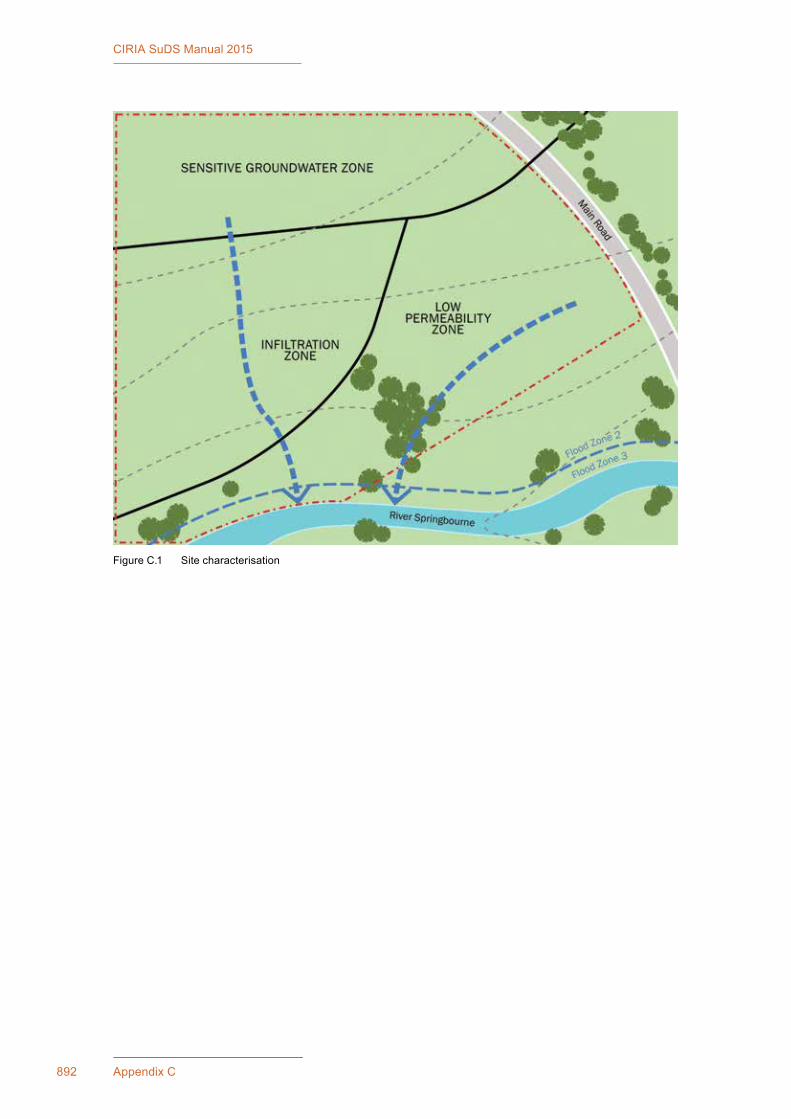
892 Appendix C
CIRIA SuDS Manual 2015
Figure C.1 Site characterisation

893Appendix C: Design example
CIRIA SuDS Manual 2015
TABLEC.3
Development characterisation outcomes
Proposed topography, land use and landscape characteristics
The development master plan has split the area into five sub-catchments using distributor roads. There is likely to be some reprofiling of the site slopes to facilitate construction of the supermarket and industrial areas. The residential and civic street areas will be designed on a gentle slope. The natural drainage patterns on the site have influenced the sub-catchment definition, allowing storage to be provided along the contours to make maximum use of the storage availability across the site.
The five sub-catchments reflect different land uses, facilitating the “clustering” of land use types for pollution management purposes.
The residential area will include houses at densities of 30–40 houses per hectare with shared parking areas.
The civic street will be lined with shops with flats above. Open space will be provided at street level for amenity and retail purposes.
To the south-west of the development, closer to the river, the land has been designated as an area of public open space.
Proposed flood risk management strategy
SuDS components can lie within Flood Zone 2, but the combined probability of fluvial and site flooding events will need consideration when checking the impact of flooding on the functionality of the system. SuDS components that are conveying water to the river for discharge can lie in Flood Zone 3.
Proposed site infrastructure
The surface water management system will need to be integrated with the network of proposed services and planned road infrastructure.
Proposed building use, style and form
The civic street requires amenity and biodiversity enhancement with vegetated features and trees.
Amenity sports pitches could be used to store volumes of floodwater during extreme events.
A green corridor north–south through the site could add significant amenity and biodiversity value and should be used to convey surface water where possible.
Proposed adoption and maintenance
See Table C.1.
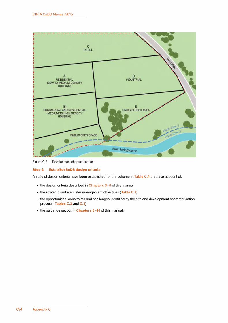
894 Appendix C
CIRIA SuDS Manual 2015
Figure C.2 Development characterisation
Step 2 Establish SuDS design criteria
A suite of design criteria have been established for the scheme in Table C.4 that take account of:
▪ the design criteria described in Chapters 3–6 of this manual
▪ the strategic surface water management objectives (Table C.1)
▪ the opportunities, constraints and challenges identified by the site and development characterisation process (Tables C.2 and C.3)
▪ the guidance set out in Chapters 8–10 of this manual.
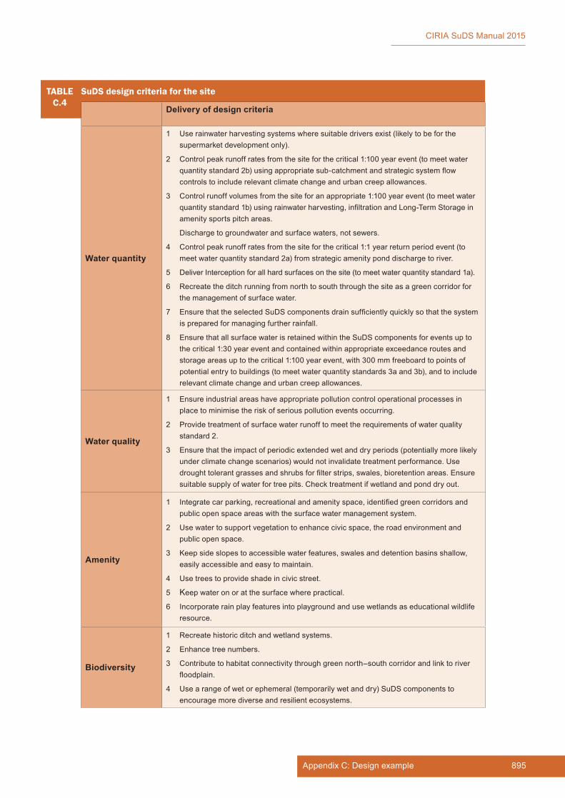
895Appendix C: Design example
CIRIA SuDS Manual 2015
TABLEC.4
SuDS design criteria for the site
Delivery of design criteria
Water quantity
1 Use rainwater harvesting systems where suitable drivers exist (likely to be for the supermarket development only).
2 Control peak runoff rates from the site for the critical 1:100 year event (to meet water quantity standard 2b) using appropriate sub-catchment and strategic system flow controls to include relevant climate change and urban creep allowances.
3 Control runoff volumes from the site for an appropriate 1:100 year event (to meet water quantity standard 1b) using rainwater harvesting, infiltration and Long-Term Storage in amenity sports pitch areas.
Discharge to groundwater and surface waters, not sewers.
4 Control peak runoff rates from the site for the critical 1:1 year return period event (to meet water quantity standard 2a) from strategic amenity pond discharge to river.
5 Deliver Interception for all hard surfaces on the site (to meet water quantity standard 1a).
6 Recreate the ditch running from north to south through the site as a green corridor for the management of surface water.
7 Ensure that the selected SuDS components drain sufficiently quickly so that the system is prepared for managing further rainfall.
8 Ensure that all surface water is retained within the SuDS components for events up to the critical 1:30 year event and contained within appropriate exceedance routes and storage areas up to the critical 1:100 year event, with 300 mm freeboard to points of potential entry to buildings (to meet water quantity standards 3a and 3b), and to include relevant climate change and urban creep allowances.
Water quality
1 Ensure industrial areas have appropriate pollution control operational processes in place to minimise the risk of serious pollution events occurring.
2 Provide treatment of surface water runoff to meet the requirements of water quality standard 2.
3 Ensure that the impact of periodic extended wet and dry periods (potentially more likely under climate change scenarios) would not invalidate treatment performance. Use drought tolerant grasses and shrubs for filter strips, swales, bioretention areas. Ensure suitable supply of water for tree pits. Check treatment if wetland and pond dry out.
Amenity
1 Integrate car parking, recreational and amenity space, identified green corridors and public open space areas with the surface water management system.
2 Use water to support vegetation to enhance civic space, the road environment and public open space.
3 Keep side slopes to accessible water features, swales and detention basins shallow, easily accessible and easy to maintain.
4 Use trees to provide shade in civic street.
5 Keep water on or at the surface where practical.
6 Incorporate rain play features into playground and use wetlands as educational wildlife resource.
Biodiversity
1 Recreate historic ditch and wetland systems.
2 Enhance tree numbers.
3 Contribute to habitat connectivity through green north–south corridor and link to river floodplain.
4 Use a range of wet or ephemeral (temporarily wet and dry) SuDS components to encourage more diverse and resilient ecosystems.
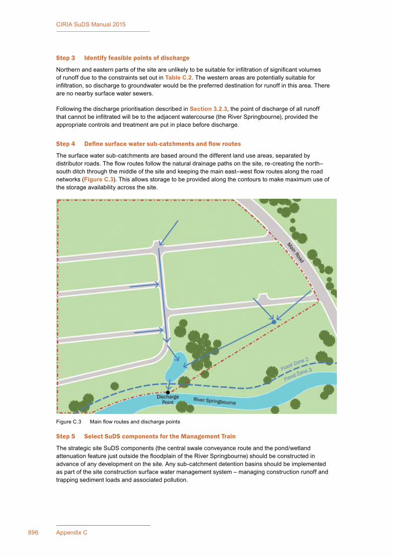
896 Appendix C
CIRIA SuDS Manual 2015
Step 3 Identify feasible points of discharge
Northern and eastern parts of the site are unlikely to be suitable for infiltration of significant volumes of runoff due to the constraints set out in Table C.2. The western areas are potentially suitable for infiltration, so discharge to groundwater would be the preferred destination for runoff in this area. There are no nearby surface water sewers.
Following the discharge prioritisation described in Section 3.2.3, the point of discharge of all runoff that cannot be infiltrated will be to the adjacent watercourse (the River Springbourne), provided the appropriate controls and treatment are put in place before discharge.
Step 4 Define surface water sub-catchments and flow routes
The surface water sub-catchments are based around the different land use areas, separated by distributor roads. The flow routes follow the natural drainage paths on the site, re-creating the north–south ditch through the middle of the site and keeping the main east–west flow routes along the road networks (Figure C.3). This allows storage to be provided along the contours to make maximum use of the storage availability across the site.
Step 5 Select SuDS components for the Management Train
The strategic site SuDS components (the central swale conveyance route and the pond/wetland attenuation feature just outside the floodplain of the River Springbourne) should be constructed in advance of any development on the site. Any sub-catchment detention basins should be implemented as part of the site construction surface water management system – managing construction runoff and trapping sediment loads and associated pollution.
Figure C.3 Main flow routes and discharge points
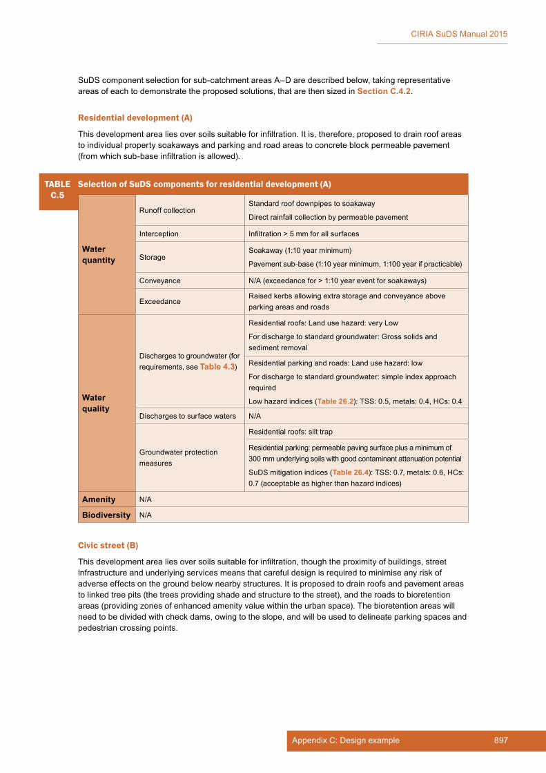
897Appendix C: Design example
CIRIA SuDS Manual 2015
SuDS component selection for sub-catchment areas A–D are described below, taking representative areas of each to demonstrate the proposed solutions, that are then sized in Section C.4.2.
Residential development (A)
This development area lies over soils suitable for infiltration. It is, therefore, proposed to drain roof areas to individual property soakaways and parking and road areas to concrete block permeable pavement (from which sub-base infiltration is allowed).
TABLEC.5
Selection of SuDS components for residential development (A)
Water quantity
Runoff collectionStandard roof downpipes to soakaway
Direct rainfall collection by permeable pavement
Interception Infiltration > 5 mm for all surfaces
StorageSoakaway (1:10 year minimum)
Pavement sub-base (1:10 year minimum, 1:100 year if practicable)
Conveyance N/A (exceedance for > 1:10 year event for soakaways)
ExceedanceRaised kerbs allowing extra storage and conveyance above parking areas and roads
Water quality
Discharges to groundwater (for requirements, see Table 4.3)
Residential roofs: Land use hazard: very Low
For discharge to standard groundwater: Gross solids and sediment removal
Residential parking and roads: Land use hazard: low
For discharge to standard groundwater: simple index approach required
Low hazard indices (Table 26.2): TSS: 0.5, metals: 0.4, HCs: 0.4
Discharges to surface waters N/A
Groundwater protection measures
Residential roofs: silt trap
Residential parking: permeable paving surface plus a minimum of 300 mm underlying soils with good contaminant attenuation potential
SuDS mitigation indices (Table 26.4): TSS: 0.7, metals: 0.6, HCs: 0.7 (acceptable as higher than hazard indices)
Amenity N/A
Biodiversity N/A
Civic street (B)
This development area lies over soils suitable for infiltration, though the proximity of buildings, street infrastructure and underlying services means that careful design is required to minimise any risk of adverse effects on the ground below nearby structures. It is proposed to drain roofs and pavement areas to linked tree pits (the trees providing shade and structure to the street), and the roads to bioretention areas (providing zones of enhanced amenity value within the urban space). The bioretention areas will need to be divided with check dams, owing to the slope, and will be used to delineate parking spaces and pedestrian crossing points.
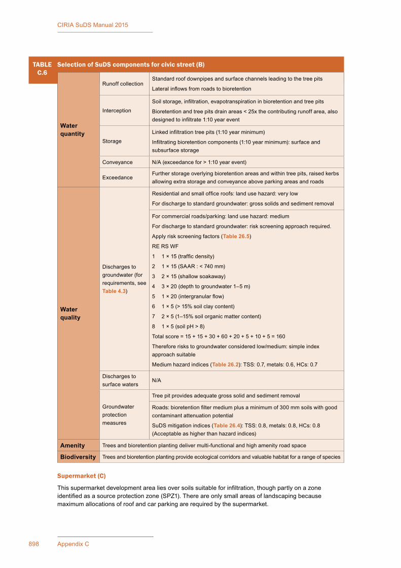
898 Appendix C
CIRIA SuDS Manual 2015
Supermarket (C)
This supermarket development area lies over soils suitable for infiltration, though partly on a zone identified as a source protection zone (SPZ1). There are only small areas of landscaping because maximum allocations of roof and car parking are required by the supermarket.
TABLEC.6
Selection of SuDS components for civic street (B)
Water quantity
Runoff collectionStandard roof downpipes and surface channels leading to the tree pits
Lateral inflows from roads to bioretention
Interception
Soil storage, infiltration, evapotranspiration in bioretention and tree pits
Bioretention and tree pits drain areas < 25x the contributing runoff area, also designed to infiltrate 1:10 year event
Storage
Linked infiltration tree pits (1:10 year minimum)
Infiltrating bioretention components (1:10 year minimum): surface and subsurface storage
Conveyance N/A (exceedance for > 1:10 year event)
ExceedanceFurther storage overlying bioretention areas and within tree pits, raised kerbs allowing extra storage and conveyance above parking areas and roads
Water quality
Discharges to groundwater (for requirements, see Table 4.3)
Residential and small office roofs: land use hazard: very low
For discharge to standard groundwater: gross solids and sediment removal
For commercial roads/parking: land use hazard: medium
For discharge to standard groundwater: risk screening approach required.
Apply risk screening factors (Table 26.5)
RE RS WF
1 1 × 15 (traffic density)
2 1 × 15 (SAAR : < 740 mm)
3 2 × 15 (shallow soakaway)
4 3 × 20 (depth to groundwater 1–5 m)
5 1 × 20 (intergranular flow)
6 1 × 5 (> 15% soil clay content)
7 2 × 5 (1–15% soil organic matter content)
8 1 × 5 (soil pH > 8)
Total score = 15 + 15 + 30 + 60 + 20 + 5 + 10 + 5 = 160
Therefore risks to groundwater considered low/medium: simple index approach suitable
Medium hazard indices (Table 26.2): TSS: 0.7, metals: 0.6, HCs: 0.7
Discharges to surface waters
N/A
Groundwater protection measures
Tree pit provides adequate gross solid and sediment removal
Roads: bioretention filter medium plus a minimum of 300 mm soils with good contaminant attenuation potential
SuDS mitigation indices (Table 26.4): TSS: 0.8, metals: 0.8, HCs: 0.8 (Acceptable as higher than hazard indices)
Amenity Trees and bioretention planting deliver multi-functional and high amenity road space
Biodiversity Trees and bioretention planting provide ecological corridors and valuable habitat for a range of species
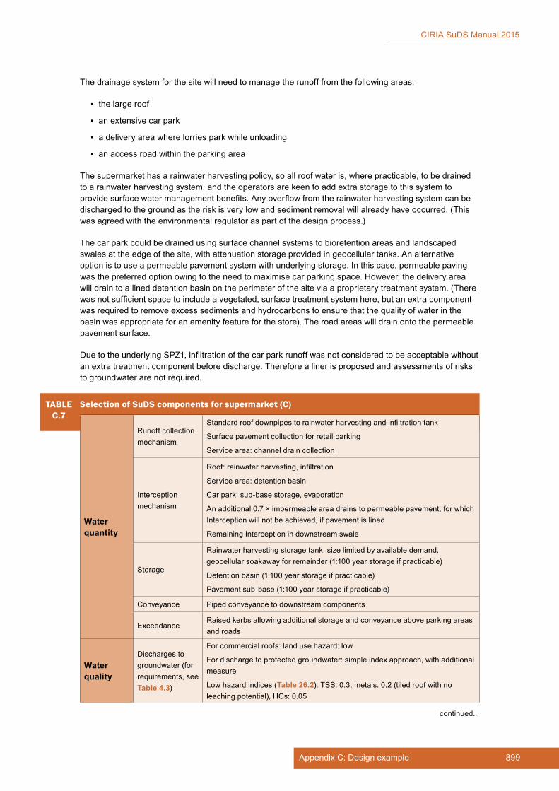
899Appendix C: Design example
CIRIA SuDS Manual 2015
The drainage system for the site will need to manage the runoff from the following areas:
▪ the large roof
▪ an extensive car park
▪ a delivery area where lorries park while unloading
▪ an access road within the parking area
The supermarket has a rainwater harvesting policy, so all roof water is, where practicable, to be drained to a rainwater harvesting system, and the operators are keen to add extra storage to this system to provide surface water management benefits. Any overflow from the rainwater harvesting system can be discharged to the ground as the risk is very low and sediment removal will already have occurred. (This was agreed with the environmental regulator as part of the design process.)
The car park could be drained using surface channel systems to bioretention areas and landscaped swales at the edge of the site, with attenuation storage provided in geocellular tanks. An alternative option is to use a permeable pavement system with underlying storage. In this case, permeable paving was the preferred option owing to the need to maximise car parking space. However, the delivery area will drain to a lined detention basin on the perimeter of the site via a proprietary treatment system. (There was not sufficient space to include a vegetated, surface treatment system here, but an extra component was required to remove excess sediments and hydrocarbons to ensure that the quality of water in the basin was appropriate for an amenity feature for the store). The road areas will drain onto the permeable pavement surface.
Due to the underlying SPZ1, infiltration of the car park runoff was not considered to be acceptable without an extra treatment component before discharge. Therefore a liner is proposed and assessments of risks to groundwater are not required.
TABLEC.7
Selection of SuDS components for supermarket (C)
Water quantity
Runoff collection mechanism
Standard roof downpipes to rainwater harvesting and infiltration tank
Surface pavement collection for retail parking
Service area: channel drain collection
Interception mechanism
Roof: rainwater harvesting, infiltration
Service area: detention basin
Car park: sub-base storage, evaporation
An additional 0.7 × impermeable area drains to permeable pavement, for which Interception will not be achieved, if pavement is lined
Remaining Interception in downstream swale
Storage
Rainwater harvesting storage tank: size limited by available demand, geocellular soakaway for remainder (1:100 year storage if practicable)
Detention basin (1:100 year storage if practicable)
Pavement sub-base (1:100 year storage if practicable)
Conveyance Piped conveyance to downstream components
ExceedanceRaised kerbs allowing additional storage and conveyance above parking areas and roads
Water quality
Discharges to groundwater (for requirements, see Table 4.3)
For commercial roofs: land use hazard: low
For discharge to protected groundwater: simple index approach, with additional measure
Low hazard indices (Table 26.2): TSS: 0.3, metals: 0.2 (tiled roof with no leaching potential), HCs: 0.05
continued...
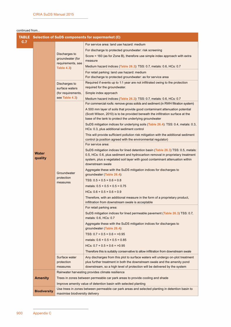
900 Appendix C
CIRIA SuDS Manual 2015
TABLEC.7
Selection of SuDS components for supermarket (C)
Water quality
Discharges to groundwater (for requirements, see Table 4.3)
For service area: land use hazard: medium
For discharge to protected groundwater: risk screening
Score = 160 (as for Zone B), therefore use simple index approach with extra measure
Medium hazard indices (Table 26.2): TSS: 0.7, metals: 0.6, HCs: 0.7
For retail parking: land use hazard: mediumFor discharge to protected groundwater: as for service area
Discharges to surface waters (for requirements, see Table 4.3)
Required if events up to 1:1 year are not infiltrated owing to the protection required for the groundwater.
Simple index approach
Medium hazard indices (Table 26.2): TSS: 0.7, metals: 0.6, HCs: 0.7
Groundwater protection measures
For commercial roofs: remove gross solids and sediment (in RWH filtration system)
A 500 mm layer of soils that provide good contaminant attenuation potential (Scott Wilson, 2010) is to be provided beneath the infiltration surface at the base of the tank to protect the underlying groundwater
SuDS mitigation indices for underlying soils (Table 26.4): TSS: 0.4, metals: 0.3, HCs: 0.3, plus additional sediment control
This will provide sufficient pollution risk mitigation with the additional sediment control (a position agreed with the environmental regulator)For service area:
SuDS mitigation indices for lined detention basin (Table 26.3) TSS: 0.5, metals: 0.5, HCs: 0.6, plus sediment and hydrocarbon removal in proprietary treatment system, plus a vegetated soil layer with good contaminant attenuation within downstream swale
Aggregate these with the SuDS mitigation indices for discharges to groundwater (Table 26.4):
TSS: 0.5 + 0.5 × 0.6 = 0.8
metals: 0.5 + 0.5 × 0.5 = 0.75
HCs: 0.6 + 0.5 × 0.6 = 0.9
Therefore, with an additional measure in the form of a proprietary product, infiltration from downstream swale is acceptable
For retail parking area:
SuDS mitigation indices for lined permeable pavement (Table 26.3) TSS: 0.7, metals: 0.6, HCs: 0.7
Aggregate these with the SuDS mitigation indices for discharges to groundwater (Table 26.4):
TSS: 0.7 + 0.5 × 0.6 = >0.95
metals: 0.6 + 0.5 × 0.5 = 0.85
HCs: 0.7 + 0.5 × 0.6 = >0.95
Therefore this is suitably conservative to allow infiltration from downstream swale
Surface water protection measures
Any discharges from this plot to surface waters will undergo on-plot treatment plus further treatment in both the downstream swale and the amenity pond downstream, so a high level of protection will be delivered by the system
AmenityRainwater harvesting provides climate resilience
Trees in zones between permeable car park areas to provide cooling and shade
Improve amenity value of detention basin with selected planting
BiodiversityUse trees in zones between permeable car park areas and selected planting in detention basin to maximise biodiversity delivery
continued from...
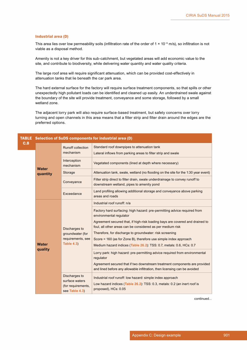
901Appendix C: Design example
CIRIA SuDS Manual 2015
Industrial area (D)
This area lies over low permeability soils (infiltration rate of the order of 1 × 10⁻⁶ m/s), so infiltration is not viable as a disposal method.
Amenity is not a key driver for this sub-catchment, but vegetated areas will add economic value to the site, and contribute to biodiversity, while delivering water quantity and water quality criteria.
The large roof area will require significant attenuation, which can be provided cost-effectively in attenuation tanks that lie beneath the car park area.
The hard external surface for the factory will require surface treatment components, so that spills or other unexpectedly high pollutant loads can be identified and cleaned up easily. An underdrained swale against the boundary of the site will provide treatment, conveyance and some storage, followed by a small wetland zone.
The adjacent lorry park will also require surface-based treatment, but safety concerns over lorry turning and open channels in this area means that a filter strip and filter drain around the edges are the preferred options.
TABLEC.8
Selection of SuDS components for industrial area (D)
Water quantity
Runoff collection mechanism
Standard roof downpipes to attenuation tank
Lateral inflows from parking areas to filter strip and swale
Interception mechanism
Vegetated components (lined at depth where necessary)
Storage Attenuation tank, swale, wetland (no flooding on the site for the 1:30 year event)
ConveyanceFilter strip direct to filter drain, swale underdrainage to convey runoff to downstream wetland, pipes to amenity pond
ExceedanceLand profiling allowing additional storage and conveyance above parking areas and roads
Water quality
Discharges to groundwater (for requirements, see Table 4.3)
Industrial roof runoff: n/a
Factory hard surfacing: high hazard: pre-permitting advice required from environmental regulator
Agreement secured that, if high-risk loading bays are covered and drained to foul, all other areas can be considered as per medium risk
Therefore, for discharge to groundwater: risk screening
Score = 160 (as for Zone B), therefore use simple index approach
Medium hazard indices (Table 26.2): TSS: 0.7, metals: 0.6, HCs: 0.7
Lorry park: high hazard: pre-permitting advice required from environmental regulator
Agreement secured that if two downstream treatment components are provided and lined before any allowable infiltration, then licensing can be avoided
Discharges to surface waters (for requirements, see Table 4.3)
Industrial roof runoff: low hazard: simple index approach
Low hazard indices (Table 26.2): TSS: 0.3, metals: 0.2 (an inert roof is proposed), HCs: 0.05
continued...
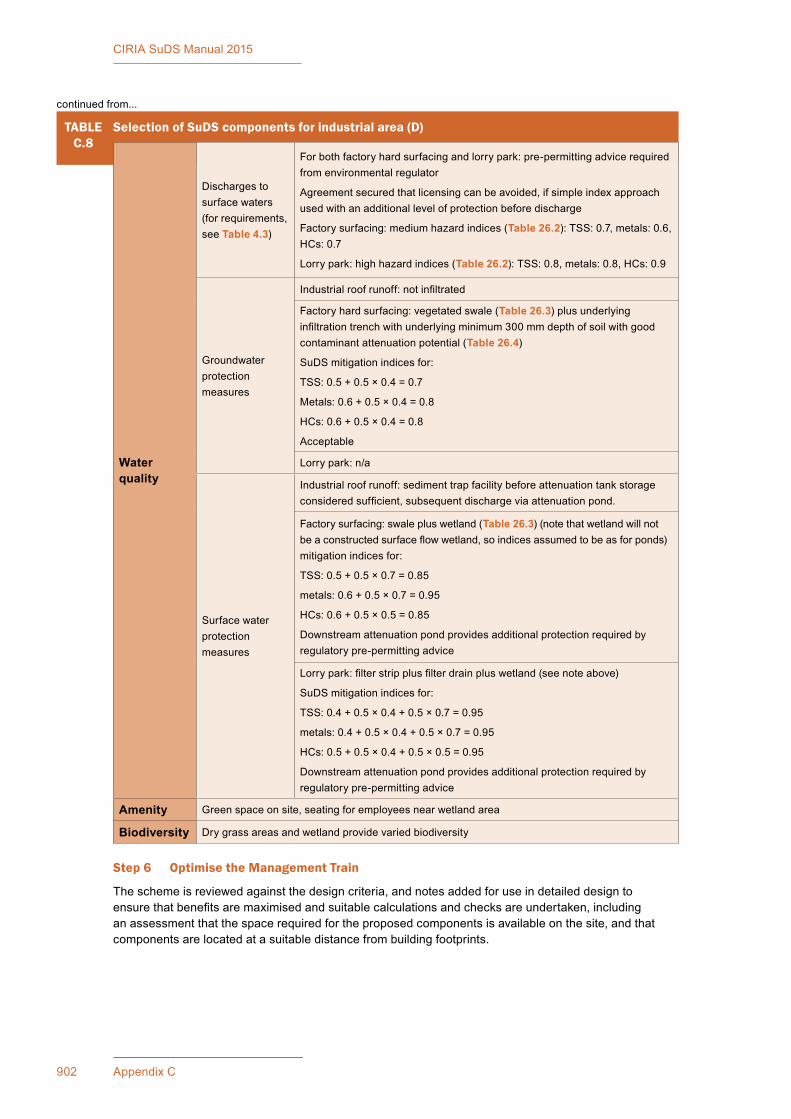
902 Appendix C
CIRIA SuDS Manual 2015
Step 6 Optimise the Management Train
The scheme is reviewed against the design criteria, and notes added for use in detailed design to ensure that benefits are maximised and suitable calculations and checks are undertaken, including an assessment that the space required for the proposed components is available on the site, and that components are located at a suitable distance from building footprints.
TABLEC.8
Selection of SuDS components for industrial area (D)
Water quality
Discharges to surface waters (for requirements, see Table 4.3)
For both factory hard surfacing and lorry park: pre-permitting advice required from environmental regulator
Agreement secured that licensing can be avoided, if simple index approach used with an additional level of protection before discharge
Factory surfacing: medium hazard indices (Table 26.2): TSS: 0.7, metals: 0.6, HCs: 0.7
Lorry park: high hazard indices (Table 26.2): TSS: 0.8, metals: 0.8, HCs: 0.9
Groundwater protection measures
Industrial roof runoff: not infiltrated
Factory hard surfacing: vegetated swale (Table 26.3) plus underlying infiltration trench with underlying minimum 300 mm depth of soil with good contaminant attenuation potential (Table 26.4)
SuDS mitigation indices for:
TSS: 0.5 + 0.5 × 0.4 = 0.7
Metals: 0.6 + 0.5 × 0.4 = 0.8
HCs: 0.6 + 0.5 × 0.4 = 0.8
Acceptable
Lorry park: n/a
Surface water protection measures
Industrial roof runoff: sediment trap facility before attenuation tank storage considered sufficient, subsequent discharge via attenuation pond.
Factory surfacing: swale plus wetland (Table 26.3) (note that wetland will not be a constructed surface flow wetland, so indices assumed to be as for ponds)mitigation indices for:
TSS: 0.5 + 0.5 × 0.7 = 0.85
metals: 0.6 + 0.5 × 0.7 = 0.95
HCs: 0.6 + 0.5 × 0.5 = 0.85
Downstream attenuation pond provides additional protection required by regulatory pre-permitting advice
Lorry park: filter strip plus filter drain plus wetland (see note above)
SuDS mitigation indices for:
TSS: 0.4 + 0.5 × 0.4 + 0.5 × 0.7 = 0.95
metals: 0.4 + 0.5 × 0.4 + 0.5 × 0.7 = 0.95
HCs: 0.5 + 0.5 × 0.4 + 0.5 × 0.5 = 0.95
Downstream attenuation pond provides additional protection required by regulatory pre-permitting advice
Amenity Green space on site, seating for employees near wetland area
Biodiversity Dry grass areas and wetland provide varied biodiversity
continued from...
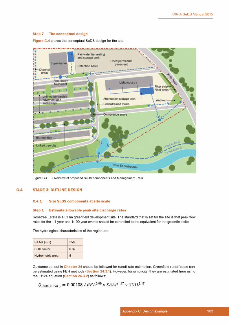
903Appendix C: Design example
CIRIA SuDS Manual 2015
Step 7 The conceptual design
Figure C.4 shows the conceptual SuDS design for the site.
C.4 STAGE 3: OUTLINE DESIGN
C.4.1 Size SuDS components at site scale
Step 1 Estimate allowable peak site discharge rates
Rosetree Estate is a 31 ha greenfield development site. The standard that is set for the site is that peak flow rates for the 1:1 year and 1:100 year events should be controlled to the equivalent for the greenfield site.
The hydrological characteristics of the region are:
SAAR (mm) 556
SOIL factor 0.37
Hydrometric area 5
Guidance set out in Chapter 24 should be followed for runoff rate estimation. Greenfield runoff rates can be estimated using FEH methods (Section 24.3.1). However, for simplicity, they are estimated here using the IH124 equation (Section 24.3.2) as follows:
Figure C.4 Overview of proposed SuDS components and Management Train

904 Appendix C
CIRIA SuDS Manual 2015
As shown in Equation 24.3 (Section 24.3.2), since the site is less than 50 ha, the formula should be applied for 50 ha and the result factored based on the ratio of areas.
= 0.11 m3/s
= 110 l/s for 50 ha site
= 110/50
= 2.2 l/s/ha
Although the whole site measures 31.1 ha, there is 2.4 ha of land adjacent to the floodplain which will be parkland and will drain directly to the river at greenfield rates without the need for storage. Therefore the area to be considered in these calculations is 31.1 ha – 2.4 ha = 28.7 ha.
The total allowable QBAR from the site is therefore: 2.2 × 28.7 = 63 l/s.
To get the 1:1 and 1:100 year allowable peak flow rates, the growth curve factors from Table 24.2 are used:
1 year factor = 0.87
30 year factor = 2.55
100 year factor = 3.56
Greenfield limiting discharge rates for the site are therefore as given in Table C.9.
TABLEC.9
Greenfield runoff rates
Return period Whole site (l/s) Unit value (l/s/m2)
1 year 55 0.00019
30 year 161 0.00056
100 year 224 0.00078
These discharge limits will be required at detailed design stage, to size the flow control components for each sub-catchment and from the amenity attenuation pond.
Step 2 Estimate whole site attenuation storage volumes
There are two methods of undertaking preliminary assessments of the attenuation storage volumes required for a site (Section 24.9.4). For simplicity, the Kellagher (2013) approximate approach is used here.
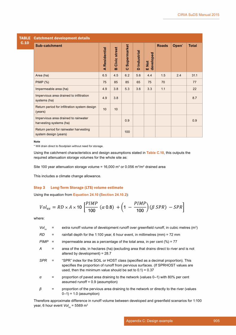
905Appendix C: Design example
CIRIA SuDS Manual 2015
Using the catchment characteristics and design assumptions stated in Table C.10, this outputs the required attenuation storage volumes for the whole site as:
Site 100 year attenuation storage volume = 16,000 m3 or 0.056 m3/m2 drained area
This includes a climate change allowance.
Step 3 Long-Term Storage (LTS) volume estimate
Using the equation from Equation 24.10 (Section 24.10.2):
where:
Volxs = extra runoff volume of development runoff over greenfield runoff, in cubic metres (m3)
RD = rainfall depth for the 1:100 year, 6 hour event, in millimetres (mm) = 72 mm
PIMP = impermeable area as a percentage of the total area, in per cent (%) = 77
A = area of the site, in hectares (ha) (excluding area that drains direct to river and is not altered by development) = 28.7
SPR = “SPR” index for the SOIL or HOST class (specified as a decimal proportion). This specifies the proportion of runoff from pervious surfaces. (If SPRHOST values are used, then the minimum value should be set to 0.1) = 0.37
α = proportion of paved area draining to the network (values 0–1) with 80% per cent assumed runoff = 0.9 (assumption)
β = proportion of the pervious area draining to the network or directly to the river (values 0–1) = 1.0 (assumption)
Therefore approximate difference in runoff volume between developed and greenfield scenarios for 1:100 year, 6 hour event Volxs = 5569 m3
TABLEC.10
Catchment development details
Sub-catchment
A R
esid
entia
l
B C
ivic
str
eet
C S
uper
mar
ket
D In
dust
rial
E N
ot
deve
lope
d
Roads Open* Total
Area (ha) 6.5 4.5 6.2 5.6 4.4 1.5 2.4 31.1
PIMP (%) 75 85 85 65 75 70 77
Impermeable area (ha) 4.9 3.8 5.3 3.6 3.3 1.1 22
Impervious area drained to infiltration systems (ha)
4.9 3.8 8.7
Return period for infiltration system design (years)
10 10
Impervious area drained to rainwater harvesting systems (ha)
0.9 0.9
Return period for rainwater harvesting system design (years)
100
Note* Will drain direct to floodplain without need for storage.
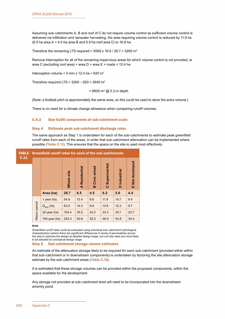
906 Appendix C
CIRIA SuDS Manual 2015
Assuming sub-catchments A, B and roof of C do not require volume control as sufficient volume control is delivered via infiltration and rainwater harvesting, the area requiring volume control is reduced by 11.9 ha (6.5 ha area A + 4.5 ha area B and 0.9 ha roof area C) to 16.8 ha.
Therefore the remaining LTS required = 5569 x 16.8 / 28.7 = 3260 m3
Remove Interception for all of the remaining impervious areas for which volume control is not provided, ie area C (excluding roof area) + area D + area E + roads = 12.4 ha
Interception volume = 5 mm x 12.4 ha = 620 m3
Therefore required LTS = 3260 – 620 = 2640 m3
= 8800 m2 @ 0.3 m depth
(Note: a football pitch is approximately the same area, so this could be used to store the extra volume.)
There is no need for a climate change allowance when comparing runoff volumes.
C.4.2 Size SuDS components at sub-catchment scale
Step 4 Estimate peak sub-catchment discharge rates
The same approach as Step 1 is undertaken for each of the sub-catchments to estimate peak greenfield runoff rates from each of the areas, in order that sub-catchment attenuation can be implemented where possible (Table C.11). This ensures that the space on the site is used most effectively.
Step 5 Sub-catchment storage volume estimates
An estimate of the attenuation storage likely to be required for each sub-catchment (provided either within that sub-catchment or in downstream components) is undertaken by factoring the site attenuation storage estimate by the sub-catchment areas (Table C.12).
It is estimated that these storage volumes can be provided within the proposed components, within the space available for the development.
Any storage not provided at sub-catchment level will need to be incorporated into the downstream amenity pond.
TABLEC.11
Greenfield runoff rates for each of the sub-catchments
Who
le s
ite
A R
esid
entia
l
B C
ivic
str
eet
C S
uper
mar
ket
D In
dust
rial
E N
ot d
evel
oped
Area (ha) 28.7 6.5 4.5 6.2 5.6 4.4
Ret
urn
perio
d
1 year (l/s) 54.8 12.4 8.6 11.8 10.7 8.4
QBAR (l/s) 63.0 14.3 9.9 13.6 12.3 9.7
30 year (l/s) 154.4 35.0 24.2 33.3 30.1 23.7
100 year (l/s) 224.3 50.8 35.2 48.5 43.8 34.4
NoteGreenfield runoff rates could be evaluated using individual sub-catchment hydrological characteristics (where there are significant differences in levels of permeability across the site) to optimise the design at detailed design stage, but unit site rates are more likely to be adopted at conceptual design stage.
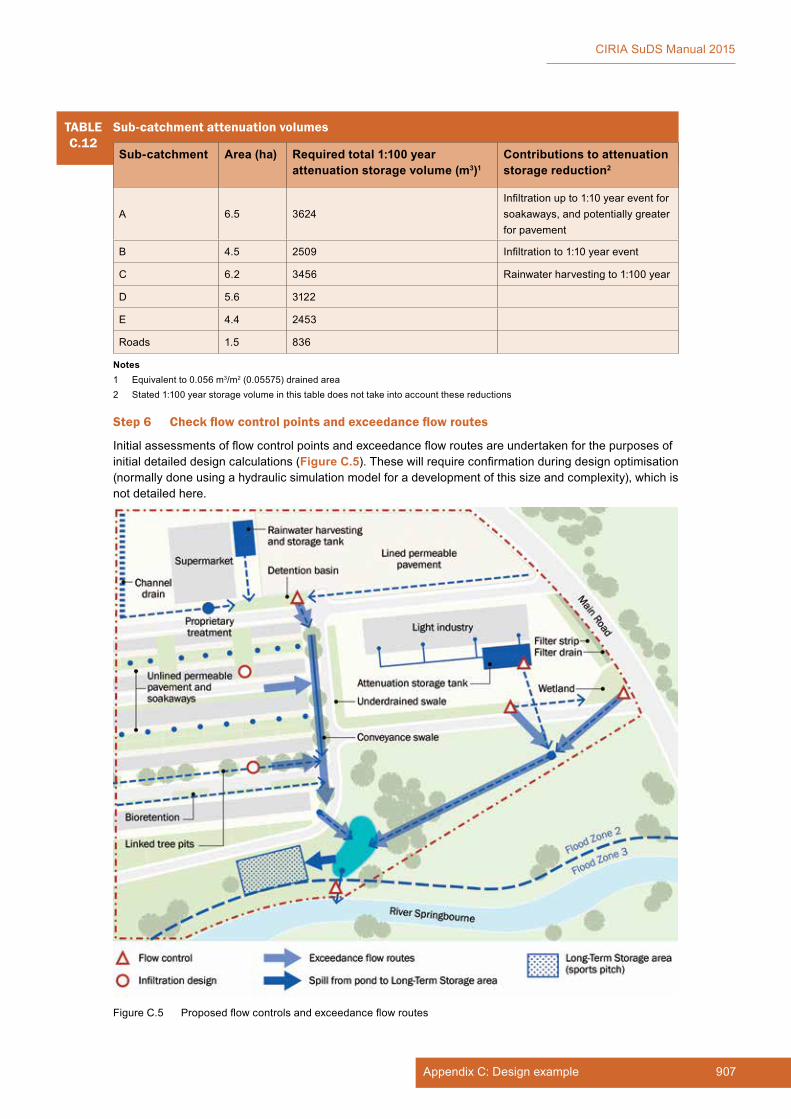
907Appendix C: Design example
CIRIA SuDS Manual 2015
Step 6 Check flow control points and exceedance flow routes
Initial assessments of flow control points and exceedance flow routes are undertaken for the purposes of initial detailed design calculations (Figure C.5). These will require confirmation during design optimisation (normally done using a hydraulic simulation model for a development of this size and complexity), which is not detailed here.
TABLEC.12
Sub-catchment attenuation volumes
Sub-catchment Area (ha) Required total 1:100 year attenuation storage volume (m3)1
Contributions to attenuation storage reduction2
A 6.5 3624Infiltration up to 1:10 year event for soakaways, and potentially greater for pavement
B 4.5 2509 Infiltration to 1:10 year event
C 6.2 3456 Rainwater harvesting to 1:100 year
D 5.6 3122
E 4.4 2453
Roads 1.5 836
Notes1 Equivalent to 0.056 m3/m2 (0.05575) drained area2 Stated 1:100 year storage volume in this table does not take into account these reductions
Figure C.5 Proposed flow controls and exceedance flow routes

908 Appendix C
CIRIA SuDS Manual 2015
C.5 STAGE 4: DETAILED DESIGN
The “critical duration” is the length of rainfall event that results in the greatest flow rate, flood volume or flood level (depending on the purpose of the analysis) at a particular location. The critical duration will probably be different at different points in the drainage system, with different SuDS components having different critical durations. The complexity of the site means that it would require detailed modelling to find the critical duration rainfall event for each of the components. Rainwater harvesting systems and infiltration systems will have very different critical duration events from swales or detention basins, and this cannot be easily established using simple hand calculations.
Some representative flow rates and volumes have therefore been assumed in order to demonstrate the technical design of each of the components.
C.5.1 Residential development (A)
A1 Residential soakaway
This example follows the design method for infiltration systems that is described in Chapter 25.
A geocellular soakaway system is proposed for the individual house soakaways that allows infiltration from both the vertical sides and the base. Therefore the procedure in Equation 25.5 for 3D systems is used (Section 25.6.2). The design could also be undertaken using commercially available drainage design software. The design is for a 1:10 year rainfall event. Each soakaway will be required to drain a roof area of 150 m2 (ie the roof of a single house).
Step 1 Estimate infiltration rate
A site investigation was carried out across the residential development area in Area A to confirm the conceptual design assumption that there were silty sands beneath the area that would be suitable for infiltration.
The investigation included infiltration tests that followed the guidance in BRE (1991) (Section 25.3). The tests were spread evenly over the residential area and were carried out at a depth and with a head of water similar to the anticipated design layout of the soakaway. All the tests were repeated three times at each location.
The results of the testing are summarised in Table C.13.
TABLEC.13
Summary of infiltration test results for residential area
Test location/ reference
Infiltration rate (lowest of the three tests) (m/s)
Soil description over zone where infiltration was occurring
Comment
SA01 1.2 × 10⁻⁵ Silty sandy gravelInfiltration rate is consistent with soil descriptions
SA02 2.6 × 10⁻⁵ Silty sandy gravelInfiltration rate is consistent with soil descriptions
SA03 1.2 × 10⁻³Silty sandy gravel with lenses of sandy gravel
Higher infiltration rate is influenced by sandy gravel lenses so not representative.
SA04 7.3 × 10⁻⁶ Clayey sandy gravelInfiltration rate is consistent with soil descriptions
SA05 1.9 × 10⁻⁵ Silty sandy gravelInfiltration rate is consistent with soil descriptions

909Appendix C: Design example
CIRIA SuDS Manual 2015
There are insufficient tests to allow statistical analysis so a precautionary approach was taken and the lowest measured value of infiltration rate of 7.3 × 10⁻⁶ m/s was used for the design. This design value for the infiltration rate was approved by an experienced ground engineering professional.
A factor of safety was then applied to the infiltration rate to account for possible long-term reductions in performance. Table 25.2 (Section 25.6) indicates that a factor of safety (FOS) of 1.5 is appropriate for a drained area of 150 m2 and minor inconvenience or damage if the capacity of the soakaway is exceeded (exceedance routes from the area drained by soakaways have been considered in the site layout).
The factored design infiltration coefficient (q) is 7.3 × 10⁻⁶ m/s ÷ 1.5 = 4.9 × 10⁻⁶ m/s.
= 0.018 m/h
Step 2 Estimate suitable soakaway dimensions
Rectangular geocellular systems are proposed for the design with a porosity (n) of 0.95. The invert level of the incoming downpipes will be 0.8 m below ground level. The soakaway dimensions will be 2 m × 2 m × 2 m.
Step 3 Check the maximum likely depth of water in the soakaway for the design rainfall event, for the proposed soakaway dimensions
(i) Calculate the base area, Ab, and the perimeter, P, from the proposed dimensions
Ab = 4 m2
P = 8 m
(ii) Calculate b
where:
(Equation 25.4, Section 25.6.2)
n = porosity = 0.95
q = assumed infiltration rate = 0.018 m/h
b = (8 × 0.018)/(4 × 0.95) = 0.038 h−1
(iii) Select a range of storm durations and determine corresponding rainfall intensity and hmax
hmax is calculated for a range of durations from 5 minutes up 24 hours.
where:
(Equation 25.4), AD = area of drainage area = 150 m2
(Equation 25.4)
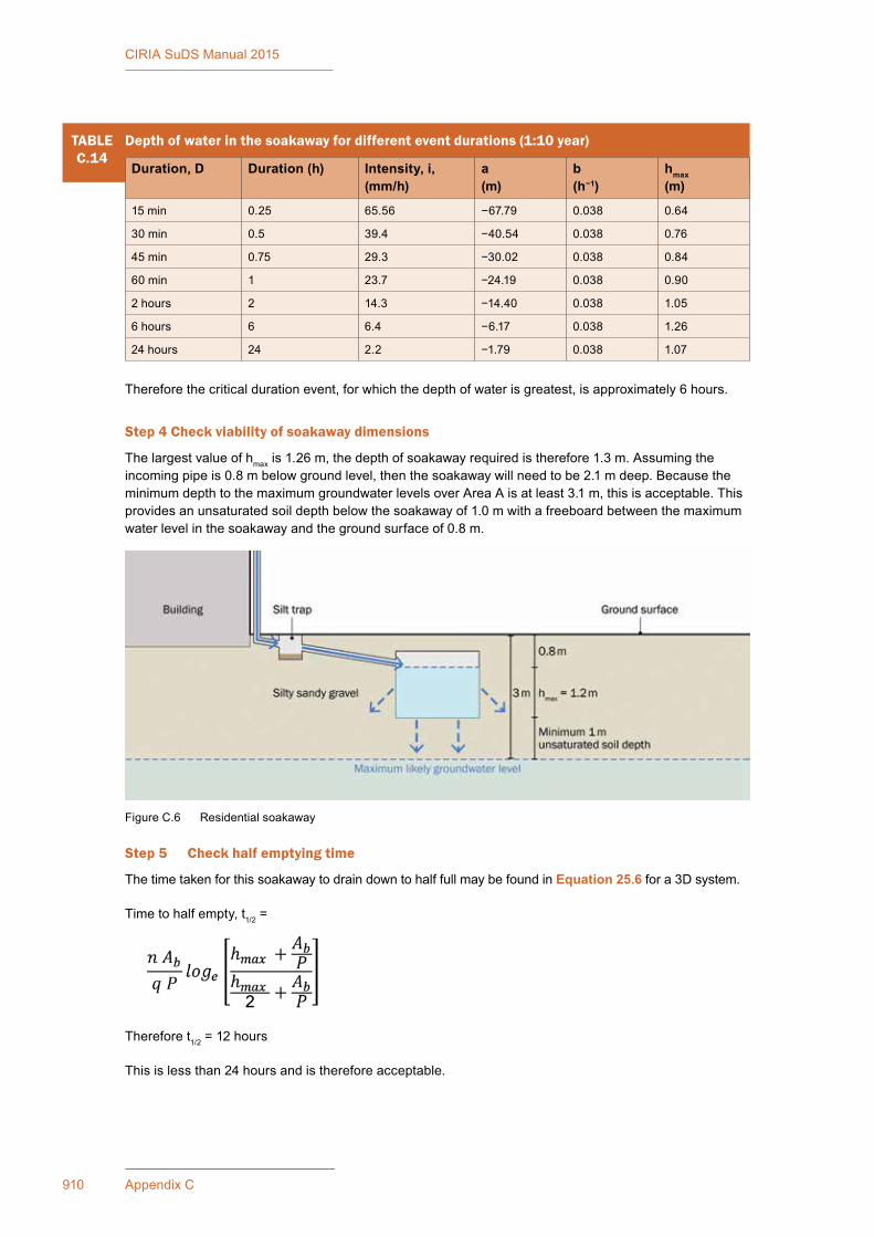
910 Appendix C
CIRIA SuDS Manual 2015
TABLEC.14
Depth of water in the soakaway for different event durations (1:10 year)
Duration, D Duration (h) Intensity, i, (mm/h)
a(m)
b(h−1)
hmax(m)
15 min 0.25 65.56 −67.79 0.038 0.64
30 min 0.5 39.4 −40.54 0.038 0.76
45 min 0.75 29.3 −30.02 0.038 0.84
60 min 1 23.7 −24.19 0.038 0.90
2 hours 2 14.3 −14.40 0.038 1.05
6 hours 6 6.4 −6.17 0.038 1.26
24 hours 24 2.2 −1.79 0.038 1.07
Therefore the critical duration event, for which the depth of water is greatest, is approximately 6 hours.
Step 4 Check viability of soakaway dimensions
The largest value of hmax is 1.26 m, the depth of soakaway required is therefore 1.3 m. Assuming the incoming pipe is 0.8 m below ground level, then the soakaway will need to be 2.1 m deep. Because the minimum depth to the maximum groundwater levels over Area A is at least 3.1 m, this is acceptable. This provides an unsaturated soil depth below the soakaway of 1.0 m with a freeboard between the maximum water level in the soakaway and the ground surface of 0.8 m.
Step 5 Check half emptying time
The time taken for this soakaway to drain down to half full may be found in Equation 25.6 for a 3D system.
Time to half empty, t1/2 =
Therefore t1/2 = 12 hours
This is less than 24 hours and is therefore acceptable.
Figure C.6 Residential soakaway

911Appendix C: Design example
CIRIA SuDS Manual 2015
A2 INFILTRATING PERVIOUS PAVEMENT
A concrete block permeable paving system is proposed for the car parks in the residential development which allows infiltration from the base of the pavement construction into the ground below. This example follows the design method for planar infiltration systems that is described in Chapters 20 and 25. The parking areas will be a maximum of 12.5 m by 16 m. Note that the calculations would be similar for other types of surfacing material (porous asphalt or concrete) with the exception that Step 3 below would refer to the relevant table for the surfacing material in Chapter 20.
Structural design
Step 1 Estimate subgrade strength
The ground conditions at formation level (ie immediately beneath the base of the pavement) comprise silty sandy gravels. Laboratory testing has determined that it is non-plastic. From Table 20.4 (Section 20.9.3), the guideline equilibrium CBR value for the pavement is 7%. The actual subgrade CBR value will require confirmation by site testing when the subgrade is exposed during construction (Section 20.9.3).
Step 2 Determine loading category
The pavement design is for small residential car parks that will be trafficked by cars or light commercial vehicles. There may be very occasional HGVs that end up turning or parking in the car park, but there will not be any regular HGV traffic. The site is therefore classified as Site Category 4 (Table 20.5, Section 20.9.4).
Step 3 Determine construction thickness
The construction thickness requirements are taken from Table 20.10 (Section 20.9.6) for traffic category 4, as follows:
▪ 80 mm concrete permeable pavers
▪ 50 mm bedding layer 2/6.3 aggregate
▪ 300 mm sub-base coarse-graded aggregate (CGA), which acts as the water storage layer.
The CBR is greater than 5% and therefore subgrade improvement is not required.
Hydraulic design
The system allows infiltration from the base of the pavement. Infiltration from the sides is negligible as the depth is so shallow. Therefore the infiltration design procedure described in Equation 25.2 (Section 25.6.1) for plane systems is used. The design could also be undertaken using commercially available drainage design software. The hydraulic design is for a 1:100 year rainfall event. Climate change allowance will be managed by exceedance routing to the site pond.
The site is flat and the pervious pavement does not take runoff from any adjacent areas, so no adjustment to the depth of the sub-base CGA will be required. The CGA sub-base will be constructed using 4/20 material which typically has a porosity (n) of 0.3.
Step 4 Estimate likely infiltration rate
This process is described in Section C.5.1 (A1 for residential soakaways). This gives a design infiltration coefficient (q) of 4.9 × 10⁻⁶ m/s or 0.018 m/h.
Step 5 Confirm pavement system type
The infiltration rate is greater than 1 × 10⁻⁶ m/s and therefore a system type A (total Infiltration) may be used (Table 20.1, Section 20.3).

912 Appendix C
CIRIA SuDS Manual 2015
Step 6 Check the maximum likely depth of water in the pavement for the design rainfall event, for the proposed soakaway dimensions
Select a range of storm durations and determine corresponding rainfall intensity and hmax.
hmax is calculated for a range of durations from 5 minutes up 24 hours
where (from Equation 25.1, Section 25.6.1)
where the drainage ratio, R = AD/Ab = 200/200 = 1
TABLEC.15
Depth of water in the pavement for different event durations
Duration, D Duration (h) Intensity, i, (mm/h) hmax (m)
15 min 0.25 150.32 0.11
30 min 0.5 86.60 0.11
45 min 0.75 62.80 0.11
60 min 1 50.00 0.11
2 hours 2 28.80 0.07
6 hours 6 12.03 −0.12
24 hours 24 3.76 −1.14
The largest value of hmax is 0.11 m which occurs during a 15, 30, 45 and 60 minute storms. The depth of CGA sub-base of 300 mm required for the traffic loads is therefore sufficient for the hydraulic design.
Step 7 Check viability of pavement dimensions
As the minimum depth to annual maximum groundwater levels over area A is at least 3 m, this is acceptable. This provides an unsaturated soil depth below the soakaway of at least 1.0 m with a freeboard between the maximum water level and the ground surface of 0.35 m (the total pavement thickness is 430 mm).
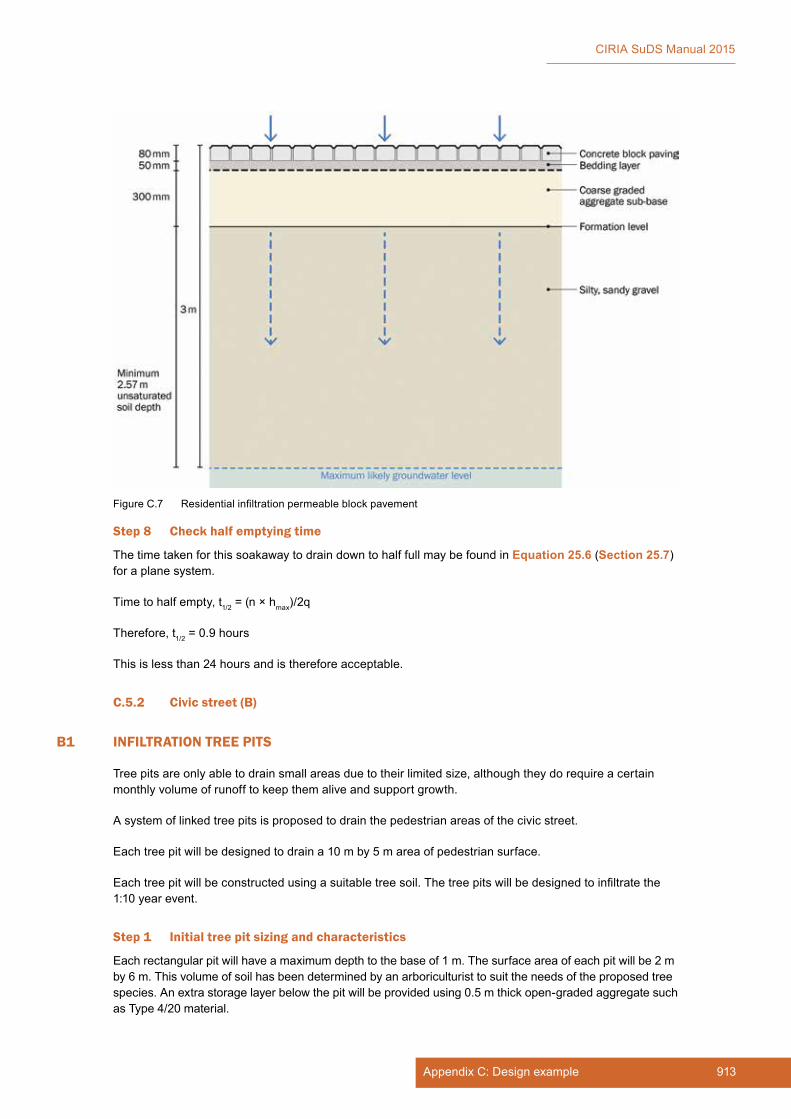
913Appendix C: Design example
CIRIA SuDS Manual 2015
Step 8 Check half emptying time
The time taken for this soakaway to drain down to half full may be found in Equation 25.6 (Section 25.7) for a plane system.
Time to half empty, t1/2 = (n × hmax)/2q
Therefore, t1/2 = 0.9 hours
This is less than 24 hours and is therefore acceptable.
C.5.2 Civic street (B)
B1 INFILTRATION TREE PITS
Tree pits are only able to drain small areas due to their limited size, although they do require a certain monthly volume of runoff to keep them alive and support growth.
A system of linked tree pits is proposed to drain the pedestrian areas of the civic street.
Each tree pit will be designed to drain a 10 m by 5 m area of pedestrian surface.
Each tree pit will be constructed using a suitable tree soil. The tree pits will be designed to infiltrate the 1:10 year event.
Step 1 Initial tree pit sizing and characteristics
Each rectangular pit will have a maximum depth to the base of 1 m. The surface area of each pit will be 2 m by 6 m. This volume of soil has been determined by an arboriculturist to suit the needs of the proposed tree species. An extra storage layer below the pit will be provided using 0.5 m thick open-graded aggregate such as Type 4/20 material.
Figure C.7 Residential infiltration permeable block pavement

914 Appendix C
CIRIA SuDS Manual 2015
Step 2 Water flow into pit and through the tree soil
Tree pit soil specification in Box 19.3 gives limits on the permeability of the soil between 25 mm/h and 115 mm/h.
Each pit will have a surface depression where water will be temporarily stored before if flows down through the tree pit soil. This depression will be sized to hold the excess water from a 1:1 year, critical duration event (assumed here to be a 15 minute event) – for water quality treatment. Events greater than this can flow directly to the drainage layer via an overflow.
The rainfall intensity for the 1:1 year, 15 min event is 20 mm/h.
Volume of runoff entering the pit (assuming a runoff factor of 0.9) over 15 minutes:
= 0.9 × 50 × (20/1000) × 15/60
= 0.225 m3
Volume of water soaking into the tree soil over 15 minutes assuming permeability of tree pit soil is 25 mm/h:
= 12 × 0.025 × 15/60
= 0.075 m3
Therefore, the storage depth required on the surface of the pit = (0.225 − 0.075)/12 = 0.012 m
Provide a 100 mm deep depression to store water on surface of pit.
Step 3 Estimate likely infiltration rate
Ground conditions in the civic street area are slightly different from the adjacent residential development area and comprise a mantle of head deposits (about 2 m thick) overlying chalk marl. The head deposits comprise clayey (sometimes very clayey) slightly silty sand. The chalk marl comprises silty clay. This was proven to a depth of 3.85 m below ground level by the site investigation. During this investigation no groundwater was encountered.
Three infiltration tests were undertaken in the area where the tree pits are proposed. Two tests were in the shallow head deposits and one in the underlying chalk marl. The results of the testing are summarised in Table C.16.

915Appendix C: Design example
CIRIA SuDS Manual 2015
Consideration of the ground conditions and the tests indicates that there is a shallow layer beneath the development that is suitable for some infiltration. However, the full lateral extent is not known and it is underlain by clay that is not suitable for infiltration. There is only 1 m of the sand between the base of the 1 m deep pit plus 0.5 m deep drainage layer and the chalk marl. This will limit the volume of water that the head deposits can accept.
Therefore the tree pits will be designed as an infiltration system, but with an overflow system to collect and convey the runoff for exceedance events greater than a 1:10 year event to downstream components.
Table C.16 shows that for the second and third tests, the infiltration reduced each time. Using the lowest value from the test in SA01 gives a site infiltration rate of 1.08 × 10⁻⁶ m/s.
A factor of safety was then applied to the infiltration rate to account for possible long-term reductions in performance. Table 25.2 indicates that a FOS of 1.5 is appropriate for a drained area of 50 m2 and minor inconvenience or damage if the capacity of the tree pit is exceeded (exceedance routes from the area drained by the tree pits have been considered in the site layout).
The design infiltration coefficient (q) is therefore 1.08 × 10⁻⁶ m/s ÷ 1.5 = 7.2 × 10⁻⁷ m/s
= 0.0026 m/h
Step 4 Estimate suitable tree pit dimensions
Rectangular pits are proposed for the design 2 m × 6 m × 1.5 m deep. The aggregate drainage layer will have a porosity of 0.3.
Step 5 Check the maximum likely depth of water in the tree pit for the design rainfall event, for the proposed tree pit dimensions
(i) Calculate the base area, Ab, and the perimeter, P, from the proposed dimensions
Ab = 12 m2
P = 16 m
TABLEC.16
Summary of infiltration test results for civic street area
Test location (depth)
Test number
Soil infiltration rate (q)
Soil description over zone where infiltration was occurring
Comment
SA01
(1.0 m)
Test #1 6.88 × 10⁻⁶ m/s Head deposits – very clayey (sometimes clayey) slightly silty sand
Infiltration rate is consistent with soil descriptions
Test #2 3.16 × 10⁻⁶ m/s
Test #3 1.08 × 10⁻⁶ m/s
SA02
(1.0 m)
Test #1 4.23 × 10⁻⁴ m/s
Head deposits – very clayey (sometimes clayey) slightly silty sand
Infiltration rates are not consistent with soil description and appear high for a very clayey sand. May be localised less clayey (ie more permeable) area. Do not use these results for design as they are not representative of the whole mass.
Test #2 8.33 × 10⁻⁵ m/s
Test #3 2.39 × 10⁻⁵ m/s
SA03
(2.5 m)Test #1
Test failed – did not achieve 75% or 25% effective depth
Chalk marl – silty clayStratum is not suitable for infiltration drainage
916 Appendix C
CIRIA SuDS Manual 2015
(ii) Calculate b
where: (Equation 25.4) n = porosity, q = assumed infiltration rate
b = (16 × 0.0026)/(12 × 0.3) = 0.012 h−1.
(iii) Select a range of storm duration and determine corresponding rainfall intensity and hmax
hmax is calculated for a range of durations from 5 minutes up 24 hours.
where: (Equation 25.4), AD = area of drainage area = 50 m2
(Equation 25.4)
TABLEC.17
Depth of water in the tree pit for different event durations
Duration, D Duration (h) Intensity, i, (mm/h)
a (m) b(h−1)
hmax(m)
15 min 0.25 65.56 −78.05 0.012 0.23
30 min 0.5 39.4 −46.61 0.012 0.28
45 min 0.75 29.3 −34.47 0.012 0.31
60 min 1 23.7 −27.74 0.012 0.33
2 hours 2 14.3 −16.44 0.012 0.39
6 hours 6 6.4 −6.94 0.012 0.48
24 hours 24 2.2 −1.89 0.012 0.47
48 hours 48 1.2 −0.69 0.012 0.30
Therefore the critical duration event, for which the depth of water is greatest, is approximately 6 hours.
Step 6 Check viability of soakaway dimensions
The largest value of hmax is 0.48 m, which occurs during a 6 hour storm. The depth of water is less than the depth of the proposed drainage layer and therefore below the level of the tree soil which will minimise the risks of the soil becoming saturated. An overflow pipe that discharges to a system of underdrains will be provided above the level of the drainage layer.
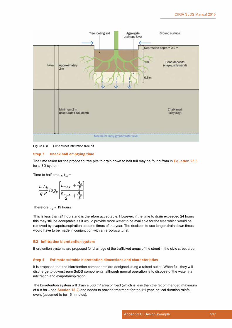
917Appendix C: Design example
CIRIA SuDS Manual 2015
Step 7 Check half emptying time
The time taken for the proposed tree pits to drain down to half full may be found from in Equation 25.6 for a 3D system.
Time to half empty, t1/2 =
Therefore t1/2 = 19 hours
This is less than 24 hours and is therefore acceptable. However, if the time to drain exceeded 24 hours this may still be acceptable as it would provide more water to be available for the tree which would be removed by evapotranspiration at some times of the year. The decision to use longer drain down times would have to be made in conjunction with an arboroculturist.
B2 Infiltration bioretention system
Bioretention systems are proposed for drainage of the trafficked areas of the street in the civic street area.
Step 1 Estimate suitable bioretention dimensions and characteristics
It is proposed that the bioretention components are designed using a raised outlet. When full, they will discharge to downstream SuDS components, although normal operation is to dispose of the water via infiltration and evapotranspiration.
The bioretention system will drain a 500 m2 area of road (which is less than the recommended maximum of 0.8 ha – see Section 18.2) and needs to provide treatment for the 1:1 year, critical duration rainfall event (assumed to be 15 minutes).
Figure C.8 Civic street infiltration tree pit
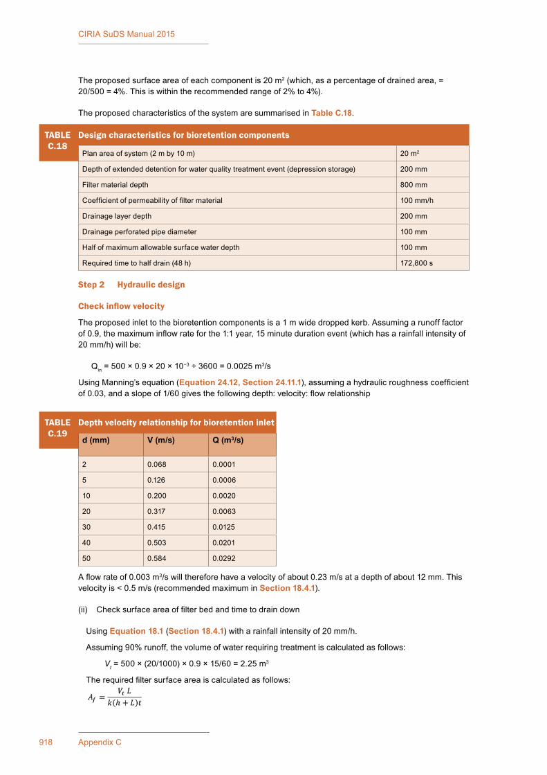
918 Appendix C
CIRIA SuDS Manual 2015
The proposed surface area of each component is 20 m2 (which, as a percentage of drained area, = 20/500 = 4%. This is within the recommended range of 2% to 4%).
The proposed characteristics of the system are summarised in Table C.18.
A flow rate of 0.003 m3/s will therefore have a velocity of about 0.23 m/s at a depth of about 12 mm. This velocity is < 0.5 m/s (recommended maximum in Section 18.4.1).
(ii) Check surface area of filter bed and time to drain down
Using Equation 18.1 (Section 18.4.1) with a rainfall intensity of 20 mm/h.
Assuming 90% runoff, the volume of water requiring treatment is calculated as follows:
Vt = 500 × (20/1000) × 0.9 × 15/60 = 2.25 m3
The required filter surface area is calculated as follows:
TABLEC.18
Design characteristics for bioretention components
Plan area of system (2 m by 10 m) 20 m2
Depth of extended detention for water quality treatment event (depression storage) 200 mm
Filter material depth 800 mm
Coefficient of permeability of filter material 100 mm/h
Drainage layer depth 200 mm
Drainage perforated pipe diameter 100 mm
Half of maximum allowable surface water depth 100 mm
Required time to half drain (48 h) 172,800 s
Step 2 Hydraulic design
Check inflow velocity
The proposed inlet to the bioretention components is a 1 m wide dropped kerb. Assuming a runoff factor of 0.9, the maximum inflow rate for the 1:1 year, 15 minute duration event (which has a rainfall intensity of 20 mm/h) will be:
Qin = 500 × 0.9 × 20 × 10−3 ÷ 3600 = 0.0025 m3/s
Using Manning’s equation (Equation 24.12, Section 24.11.1), assuming a hydraulic roughness coefficient of 0.03, and a slope of 1/60 gives the following depth: velocity: flow relationship
TABLEC.19
Depth velocity relationship for bioretention inlet
d (mm) V (m/s) Q (m3/s)
2 0.068 0.0001
5 0.126 0.0006
10 0.200 0.0020
20 0.317 0.0063
30 0.415 0.0125
40 0.503 0.0201
50 0.584 0.0292
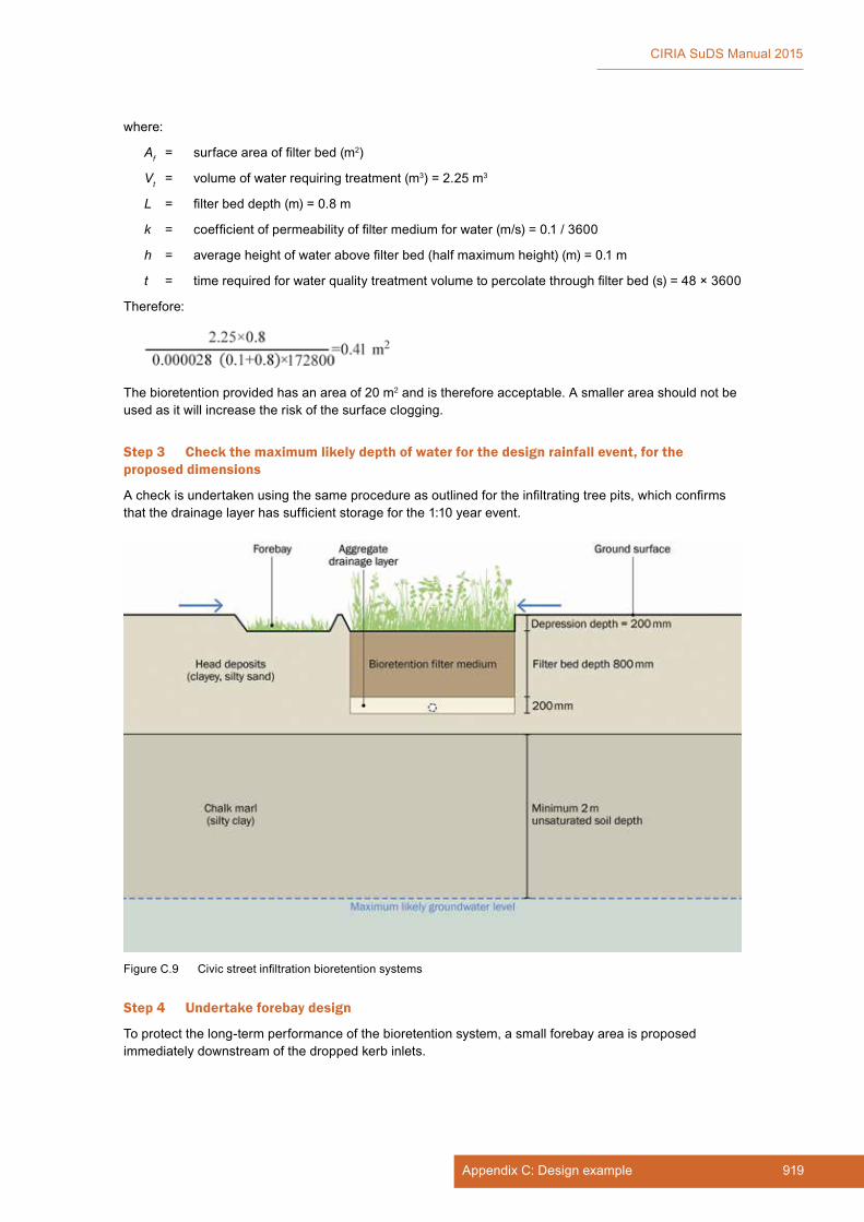
919Appendix C: Design example
CIRIA SuDS Manual 2015
where:
Af = surface area of filter bed (m2)
Vt = volume of water requiring treatment (m3) = 2.25 m3
L = filter bed depth (m) = 0.8 m
k = coefficient of permeability of filter medium for water (m/s) = 0.1 / 3600
h = average height of water above filter bed (half maximum height) (m) = 0.1 m
t = time required for water quality treatment volume to percolate through filter bed (s) = 48 × 3600
Therefore:
The bioretention provided has an area of 20 m2 and is therefore acceptable. A smaller area should not be used as it will increase the risk of the surface clogging.
Step 3 Check the maximum likely depth of water for the design rainfall event, for the proposed dimensions
A check is undertaken using the same procedure as outlined for the infiltrating tree pits, which confirms that the drainage layer has sufficient storage for the 1:10 year event.
Step 4 Undertake forebay design
To protect the long-term performance of the bioretention system, a small forebay area is proposed immediately downstream of the dropped kerb inlets.
Figure C.9 Civic street infiltration bioretention systems

920 Appendix C
CIRIA SuDS Manual 2015
Using Equation 18.2 (Section 18.8.1), the volume of the forebay is determined using the following equation:
where:
Vs = volume of forebay sediment storage required (m3)
Ac = contributing catchment area (ha) = 500/10000 = 0.05 ha
R = 0.8
Lo = 3.1 m3/ha/y (based on 5000 kg/ha/yr – from Wilson et al (2004) for AADT of 5000–15000 and a density of 1600 kg/m3)
Fc = 5 years
Therefore, volume of forebay = 0.05 × 0.8 × 3.1 × 5 = 0.6 m3
The area of the forebay is determined using the following equation which is modified from Fair and Gayer (1954):
where:
R = 0.8 target value
vs = settling velocity for coarse sediment (63 micron to 500 micron) = 0.07 m/s at 10°C (from Hall et al, 1993) (which is based on Stoke’s Law).
Q = 1:1 year 15 minute event flow into system = 0.0025 m3/s based on 20 mm/h rainfall intensity
Af = 1 m2 (assume a 1 m2 area is provided as a forebay)
n = 0.5
Proportion of sediment captured
R = 0.87 which is greater than target value of 0.8
Therefore, a small 1 m2 forebay is sufficient.
However, for a forebay of these dimensions with the sediment loading rate above, the sediment depth accumulated in the component = 0.6 m3/1 m2 = 0.6 m which is too deep.
To limit to 200 mm depth, the forebay area must be increased to 3 m2 or the contributing area reduced (ie a greater number of systems provided).
Step 5 Check capacity of the underdrains is sufficient.
The underdrains should then be designed using standard pipe design methods (not covered here). The flow capacity along the pipes should be checked, as well as the flow capacity into the perforations (taking account of the permeability of any geotextile surround).
Step 6 Landscape and biodiversity design
Once the basic layout and dimensions are achieved, the planting and specific detailed layout and materials would be designed by the landscape architect or planner to fit the overall streetscape.

921Appendix C: Design example
CIRIA SuDS Manual 2015
C.5.3 Supermarket (C)
C1 Rainwater harvesting system
The supermarket is keen to use harvested rainwater for non-potable uses on the site and to size the rainwater harvesting system to manage surface water runoff from the roof as far as possible.
Roof runoff poses a very low risk to groundwater, and the excess runoff that cannot be harvested will spill to a separate tank for infiltration.
Designing the rainwater harvesting system to manage surface runoff follows the guidance in Chapter 11, Section 11.3.3.
Step 1 Check that the demand (volume to be used) will exceed the yield (runoff volume from the roof)
1 Estimate demand (of non-potable water)
Toilet use
where:
DN = total annual property demand for non-potable water (l)
Pd = daily demand per person (l)
n = number of occupants in the property
Number of people using the store per day: 8000
% of people who use the toilet: 5%
Volume used per flush: 6 l
Daily demand: (5/100) × 8000 × 6 = 2400*
* This figure is assumed to include staff use
Surface wash down
Volume used for daily washdown: 400 l
Total annual demand, D: (2400 + 400) × 365 = 1,022,000 l
2 Estimate yield (runoff from roof)
where:
YR = runoff volume (yield) (l)
A = collecting runoff area (m2)
e = runoff (yield) coefficient
AAR = average annual rainfall depth (mm)
ƞ = hydraulic filter efficiency (ratio)
Roof area: 9000 m2
Annual average rainfall: 556 mm
Roof runoff coefficient: 0.95
Filter coefficient: 0.9

922 Appendix C
CIRIA SuDS Manual 2015
Total annual yield, Y: 9000 × (556/1000) × 0.95 × 0.9 × 1000 = 4,278,420 l
3 Yield: Demand ratio, YR/DN = 4.2
The YR/DN ratio needs to be < 0.95 for effective surface water management. Therefore, the maximum area of roof from which runoff can be harvested is
= (0.95 × 1,022,000)/(0.556 × 0.95 × 0.9 × 1000) = 2042 m2
The roof area is split naturally into two independent sections, one of which has an area of 1900 m2. Therefore, this smaller area is drained to the rainwater harvesting system, and the remaining roof area is drained to a separate soakaway tank (not designed here).
Step 2 Estimate the rainwater harvesting storage tank capacity required to deliver both supply and surface water management
YR/DN for the system (where the contributing roof area = 1900 m2) is 0.88, therefore the detailed method design approach has to be taken (Box 11.6, Section 11.3.3).
Vtotal = VSC
VSC = ((Rd − SP50 + Ad) × A/(CP50 × 1000)) + 1.0
Rd = net effective rainfall depth of the design storm (mm) (ie design storm depth × design event filter and runoff coefficients = 60 mm × 0.95 × 0.9 = 51.3 mm
Net rainfall depth that is served by a 1 m3 storage tank (mm), SP50 = (1/A) × Cs × 1000
Cs is a coefficient which is a function of YR/DN = −0.677 × (YR/DN) + 1.40 (if YR/DN ratio is between 0.6 and 0.9 for AAR < 750 mm and r > 0.35)
Cs = (−0.677 × 0.88) + 1.40
= 0.80
SP50 = (1/1900) × 0.80 × 1000
= 0.42
Extra net rainfall depth allowance to cater for the uncertainty of storage availability for the design storm event:
Ad = 31.06 (YR/DN)2 + 15.08 (YR/DN) + 0.36
Ad = 31.06 × (0.88)2 + 15.08 × (0.88) + 0.36
= 37.68 mm
The CP50 value takes into account the fact that the effective storage volume provided is less than the actual storage:
CP50 = –3.29 (YR/DN)2 + 4.16 (YR/DN) – 0.3
(if YR/DN ratio is between 0.6 and 0.9 for AAR < 750 mm and r > 0.35)
CP50 = −3.29 × (0.88)2 + 4.16 × (0.88) − 0.3
= 0.81
Tank size required for surface water management
Vsc = [((51.3 − 0.42 + 37.68) × 1900)/(1000 × 0.81)]+1.0
= 209 m3
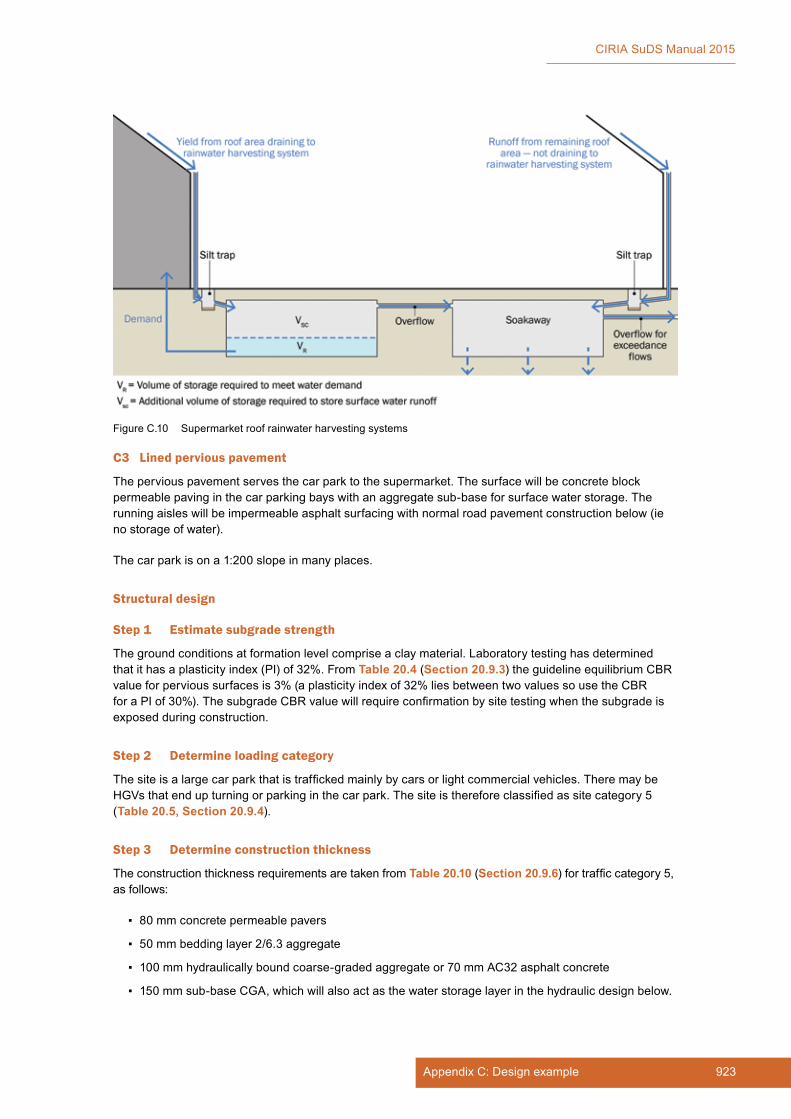
923Appendix C: Design example
CIRIA SuDS Manual 2015
C3 Lined pervious pavement
The pervious pavement serves the car park to the supermarket. The surface will be concrete block permeable paving in the car parking bays with an aggregate sub-base for surface water storage. The running aisles will be impermeable asphalt surfacing with normal road pavement construction below (ie no storage of water).
The car park is on a 1:200 slope in many places.
Structural design
Step 1 Estimate subgrade strength
The ground conditions at formation level comprise a clay material. Laboratory testing has determined that it has a plasticity index (PI) of 32%. From Table 20.4 (Section 20.9.3) the guideline equilibrium CBR value for pervious surfaces is 3% (a plasticity index of 32% lies between two values so use the CBR for a PI of 30%). The subgrade CBR value will require confirmation by site testing when the subgrade is exposed during construction.
Step 2 Determine loading category
The site is a large car park that is trafficked mainly by cars or light commercial vehicles. There may be HGVs that end up turning or parking in the car park. The site is therefore classified as site category 5 (Table 20.5, Section 20.9.4).
Step 3 Determine construction thickness
The construction thickness requirements are taken from Table 20.10 (Section 20.9.6) for traffic category 5, as follows:
▪ 80 mm concrete permeable pavers
▪ 50 mm bedding layer 2/6.3 aggregate
▪ 100 mm hydraulically bound coarse-graded aggregate or 70 mm AC32 asphalt concrete
▪ 150 mm sub-base CGA, which will also act as the water storage layer in the hydraulic design below.
Figure C.10 Supermarket roof rainwater harvesting systems

924 Appendix C
CIRIA SuDS Manual 2015
The CBR is 3% and therefore subgrade improvement is required that is 225 mm thick. In this case, the improvement layer will be provided using an additional depth of CGA material to provide extra storage capacity.
Alternative surfacing materials in the parking bays could comprise:
▪ porous asphalt (Table 20.8, Section 20.9.6) which would mean a requirement for:
▪ 160 mm porous asphalt
▪ 150 mm sub-base CGA
▪ 225 mm subgrade improvement layer (use CGA)
▪ porous concrete (Table 20.9, Section 20.9.6) which would mean a requirement for:
▪ 150 mm plain porous concrete
▪ 300 mm sub-base CGA
▪ 225 mm subgrade improvement layer (use CGA).
Step 4 Hydraulic design
The pavement needs to be designed to store the 1:100 year event. The car park covers an area of 35,000 m2 and the aisles (ie impermeable areas) comprise 40% of the total parking area.
The estimated total storage for the whole development site is 16,000 m3 (Section C.4.1, Step 2).
The total impermeable area is 22 ha (Table C.10).
Therefore the storage required is 16,000 × (3.5/22) = 2545 m3
The porosity of the sub-base is assumed to be 0.3 for materials meeting the specification in Table 20.14 (Section 20.11.4).
The aisles will drain onto the parking bays as far as possible, and at 40% of the overall area, this meets the limiting ratio of 2:1 impermeable to permeable.
Depth of sub-base = volume of storage required/(area of parking bays × porosity of sub-base)
Depth of sub-base = 2545/(0.6 × 35,000 × 0.3) = 0.405 m or 405 mm.
As long as the subgrade improvement layer is provided using CGA material, the depth of the storage within the CGA will be sufficient. For block paving, the sub-base and subgrade improvement layer is a total of 375 mm thick and this will require increasing to 410 mm to meet the hydraulic requirements.
However, the site is on a 1:200 slope. The water will run to one end unless check dams or terracing are provided. The detailed design of this would depend on the detailed layout of the car park (Section 20.5) and is not covered here.
C4 Proprietary treatment system
The lorry parking and service area of the retail store site will drain to the detention basin. However, this basin is a surface component and part of the amenity space, so although the runoff will pass through several subsequent treatment components before discharge, it should not have visible pollution as this could damage the appearance of the detention basin. As a minimum therefore, the system should be designed to trap sediments and hydrocarbons.
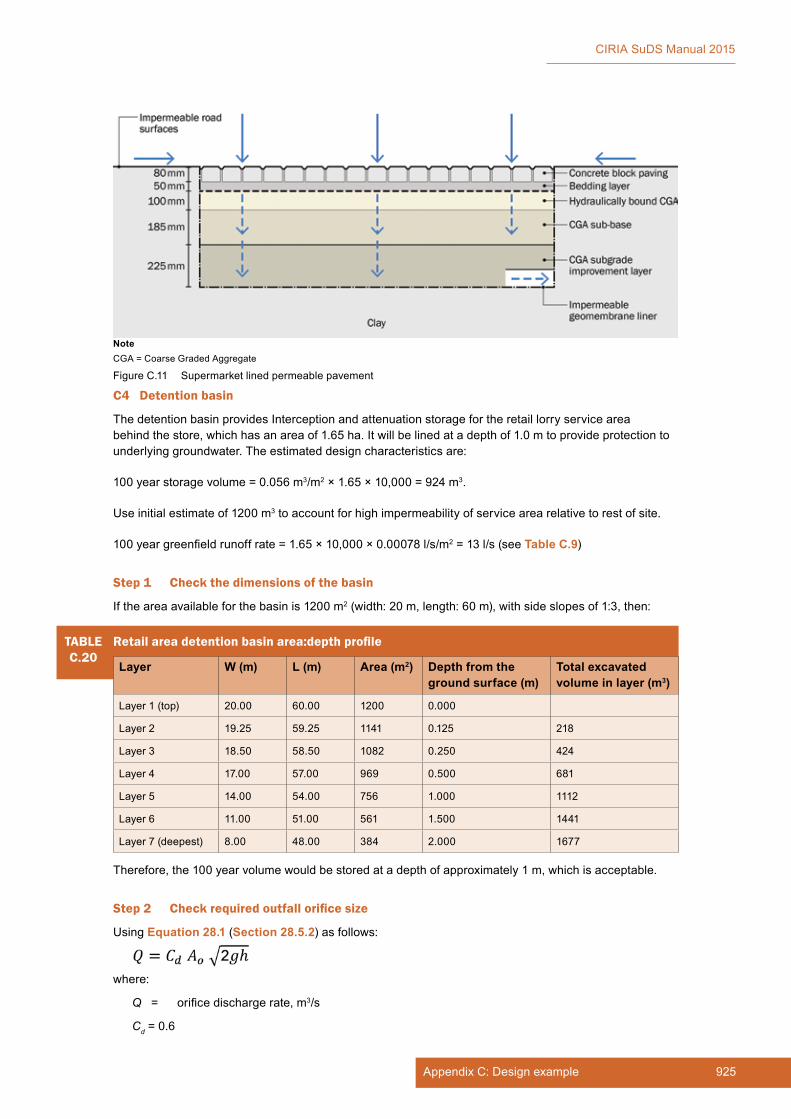
925Appendix C: Design example
CIRIA SuDS Manual 2015
C4 Detention basin
The detention basin provides Interception and attenuation storage for the retail lorry service area behind the store, which has an area of 1.65 ha. It will be lined at a depth of 1.0 m to provide protection to underlying groundwater. The estimated design characteristics are:
100 year storage volume = 0.056 m3/m2 × 1.65 × 10,000 = 924 m3.
Use initial estimate of 1200 m3 to account for high impermeability of service area relative to rest of site.
100 year greenfield runoff rate = 1.65 × 10,000 × 0.00078 l/s/m2 = 13 l/s (see Table C.9)
Step 1 Check the dimensions of the basin
If the area available for the basin is 1200 m2 (width: 20 m, length: 60 m), with side slopes of 1:3, then:
Figure C.11 Supermarket lined permeable pavement
NoteCGA = Coarse Graded Aggregate
TABLEC.20
Retail area detention basin area:depth profile
Layer W (m) L (m) Area (m2) Depth from the ground surface (m)
Total excavated volume in layer (m3)
Layer 1 (top) 20.00 60.00 1200 0.000
Layer 2 19.25 59.25 1141 0.125 218
Layer 3 18.50 58.50 1082 0.250 424
Layer 4 17.00 57.00 969 0.500 681
Layer 5 14.00 54.00 756 1.000 1112
Layer 6 11.00 51.00 561 1.500 1441
Layer 7 (deepest) 8.00 48.00 384 2.000 1677
Therefore, the 100 year volume would be stored at a depth of approximately 1 m, which is acceptable.
Step 2 Check required outfall orifice size
Using Equation 28.1 (Section 28.5.2) as follows:
where:
Q = orifice discharge rate, m3/s
Cd = 0.6
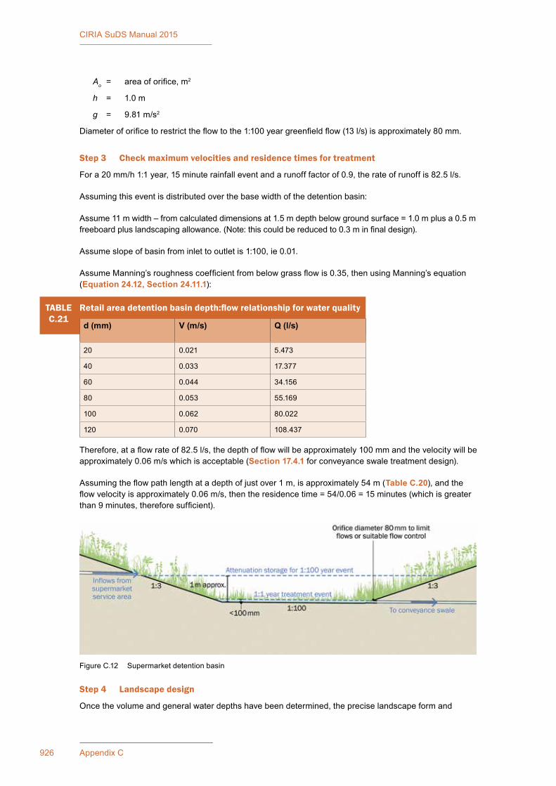
926 Appendix C
CIRIA SuDS Manual 2015
Ao = area of orifice, m2
h = 1.0 m
g = 9.81 m/s2
Diameter of orifice to restrict the flow to the 1:100 year greenfield flow (13 l/s) is approximately 80 mm.
Step 3 Check maximum velocities and residence times for treatment
For a 20 mm/h 1:1 year, 15 minute rainfall event and a runoff factor of 0.9, the rate of runoff is 82.5 l/s.
Assuming this event is distributed over the base width of the detention basin:
Assume 11 m width – from calculated dimensions at 1.5 m depth below ground surface = 1.0 m plus a 0.5 m freeboard plus landscaping allowance. (Note: this could be reduced to 0.3 m in final design).
Assume slope of basin from inlet to outlet is 1:100, ie 0.01.
Assume Manning’s roughness coefficient from below grass flow is 0.35, then using Manning’s equation (Equation 24.12, Section 24.11.1):
TABLEC.21
Retail area detention basin depth:flow relationship for water quality
d (mm) V (m/s) Q (l/s)
20 0.021 5.473
40 0.033 17.377
60 0.044 34.156
80 0.053 55.169
100 0.062 80.022
120 0.070 108.437
Therefore, at a flow rate of 82.5 l/s, the depth of flow will be approximately 100 mm and the velocity will be approximately 0.06 m/s which is acceptable (Section 17.4.1 for conveyance swale treatment design).
Assuming the flow path length at a depth of just over 1 m, is approximately 54 m (Table C.20), and the flow velocity is approximately 0.06 m/s, then the residence time = 54/0.06 = 15 minutes (which is greater than 9 minutes, therefore sufficient).
Step 4 Landscape design
Once the volume and general water depths have been determined, the precise landscape form and
Figure C.12 Supermarket detention basin
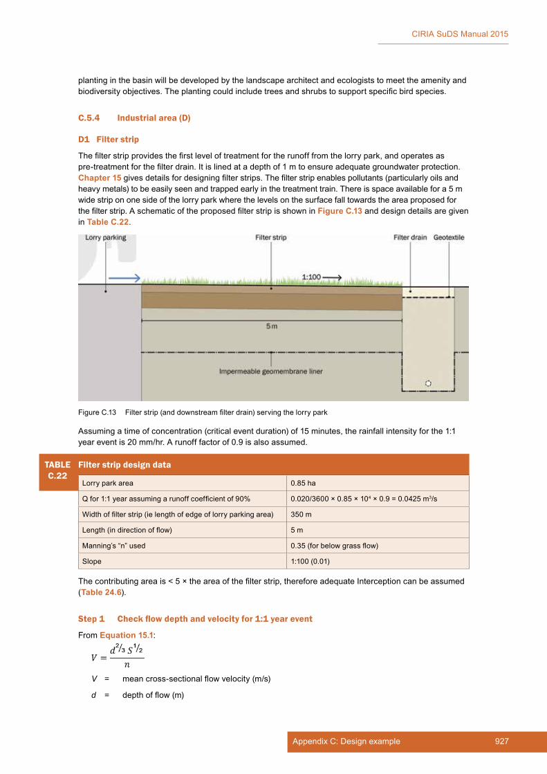
927Appendix C: Design example
CIRIA SuDS Manual 2015
planting in the basin will be developed by the landscape architect and ecologists to meet the amenity and biodiversity objectives. The planting could include trees and shrubs to support specific bird species.
C.5.4 Industrial area (D)
D1 Filter strip
The filter strip provides the first level of treatment for the runoff from the lorry park, and operates as pre-treatment for the filter drain. It is lined at a depth of 1 m to ensure adequate groundwater protection. Chapter 15 gives details for designing filter strips. The filter strip enables pollutants (particularly oils and heavy metals) to be easily seen and trapped early in the treatment train. There is space available for a 5 m wide strip on one side of the lorry park where the levels on the surface fall towards the area proposed for the filter strip. A schematic of the proposed filter strip is shown in Figure C.13 and design details are given in Table C.22.
Assuming a time of concentration (critical event duration) of 15 minutes, the rainfall intensity for the 1:1 year event is 20 mm/hr. A runoff factor of 0.9 is also assumed.
Figure C.13 Filter strip (and downstream filter drain) serving the lorry park
TABLEC.22
Filter strip design data
Lorry park area 0.85 ha
Q for 1:1 year assuming a runoff coefficient of 90% 0.020/3600 × 0.85 × 104 × 0.9 = 0.0425 m3/s
Width of filter strip (ie length of edge of lorry parking area) 350 m
Length (in direction of flow) 5 m
Manning’s “n” used 0.35 (for below grass flow)
Slope 1:100 (0.01)
The contributing area is < 5 × the area of the filter strip, therefore adequate Interception can be assumed (Table 24.6).
Step 1 Check flow depth and velocity for 1:1 year event
From Equation 15.1:
V = mean cross-sectional flow velocity (m/s)
d = depth of flow (m)

928 Appendix C
CIRIA SuDS Manual 2015
S = longitudinal slope of filter strip (ie in the direction of flow) (m/m)
n = Manning’s “n” roughness coefficient (m−1/3s)
Assuming a Manning’s “n” value for below grass flow of 0.35, gives the following results:
TABLEC.23
Industrial area filter strip depth:flow relationship for water quality
d (mm) V (m/s) Q (l/s) Q (m3/s)
5 0.008 15 0.015
10 0.013 46 0.046
15 0.017 91 0.091
20 0.021 147 0.147
25 0.024 214 0.214
30 0.028 290 0.290
35 0.031 374 0.374
This demonstrates that the 1:1 year treatment event will flow at a depth of < 15 mm (ie below the height of the vegetation), with a velocity of less than 0.3 m. This means that design criteria for the treatment event are met.
Step 2 Check residence time for 1:1 year event
The flow velocity is approximately 0.01 m/s, therefore the time to travel 5 m filter strip is just over 8 minutes. This is just acceptable, but if there is scope to increase the width of strip that would be better.
Step 3 Check flow velocities for more extreme events
A check is required that velocities remain below 1.5 m/s for extreme flows to prevent erosion.
Assuming a rainfall intensity of 150 mm/hr for the 1:100 year event:
Q = 0.150/3600 × 0.85 × 104 × 0.9 ×1000 = 323 l/s which meets the design criteria of < 1.5 m/s for the extreme event.
D2 Filter drain
The proposed filter drain is 1 m wide and 2 m deep, as shown in Figure C.14.
The ground profile adjacent to the filter drain will be such as to direct flows in excess of the 1:10 year storm towards downstream components. This will also act as a failsafe mechanism should lack of maintenance result in the drain becoming blocked.
The sand/pea gravel layer above the filter material will also act as treatment in preventing ingress of fine material from the car park. This layer can be removed and replaced together with the underlying geotextile, if required.
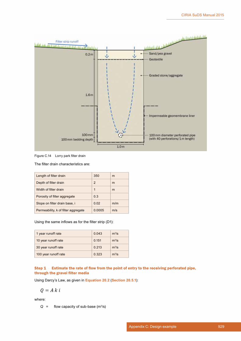
929Appendix C: Design example
CIRIA SuDS Manual 2015
The filter drain characteristics are:
Length of filter drain 350 m
Depth of filter drain 2 m
Width of filter drain 1 m
Porosity of filter aggregate 0.3
Slope on filter drain base, i 0.02 m/m
Permeability, k of filter aggregate 0.0005 m/s
Using the same inflows as for the filter strip (D1):
1 year runoff rate 0.043 m3/s
10 year runoff rate 0.151 m3/s
30 year runoff rate 0.213 m3/s
100 year runoff rate 0.323 m3/s
Step 1 Estimate the rate of flow from the point of entry to the receiving perforated pipe, through the gravel filter media
Using Darcy’s Law, as given in Equation 20.2 (Section 20.5.1):
where:
Q = flow capacity of sub-base (m3/s)
Figure C.14 Lorry park filter drain

930 Appendix C
CIRIA SuDS Manual 2015
A = cross-sectional flow area, ie height × width of sub-base through which water is flowing (m2)
k = coefficient of permeability of sub-base (m/s)
i = hydraulic gradient (m/m) (the hydraulic gradient is the head of water driving the flow. It is generally accepted that for vertical flow over short distances i = 1)
Q = 350 × 1 × 0.0005 × 1 = 0.175 m3/s which represents somewhere between a 1:10 and a 1:30 year event, which is acceptable.
Step 2 Check capacity of perforated pipe collection system
Using Equation 28.1 (Section 28.5.2) to represent the orifice flow through a perforation as follows:
Where:
Q = Orifice discharge rate, m3/s
Cd = Coefficient of discharge, m (0.6 if material is thinner than orifice diameter; 0.8 if material is thicker than orifice diameter, 0.92 if edges of orifice are rounded)
Ao = area of orifice, m2
h = hydraulic head, m
g = 9.81 m/s2
This gives the following:
Cd 0.6
Perforation diameter 5 mm
Perforation radius 2.5 mm
Perforation area19.6375 mm2
1.96375 × 10⁻⁵ m2
Head – assume a minimum of the diameter of the pipe 0.1 m
Number of perforations 40 per m length of pipe
Total number of perforations = 350 × 40 =14,000
Q per perforation 1.65039 × 10⁻⁵ m3/s
Q total 0.23 m3/s
This flow rate exceeds the rate of flow through the filter aggregate, therefore the design is acceptable. Standard design tables can then be used to check the capacity of the 100 mm diameter perforated pipe to carry the design flows.
D3 Underdrained swale
The swale is draining the car park and delivery area for the industrial unit, together with the external service areas for the industrial site.
An underdrained swale has been agreed as an appropriate precautionary approach, as it means that there is a low risk of silts being transferred downstream and it delivers a high level of treatment.
The swale drains an area of 4.1 ha. The swale lies adjacent to the road and will be inaccessible from that side. Therefore a vertical roadside edge is acceptable, with a 1:3 slope on the industrial site side.
The swale is 600 m long, 3 m wide and has a longitudinal slope of 1:100 (0.01).
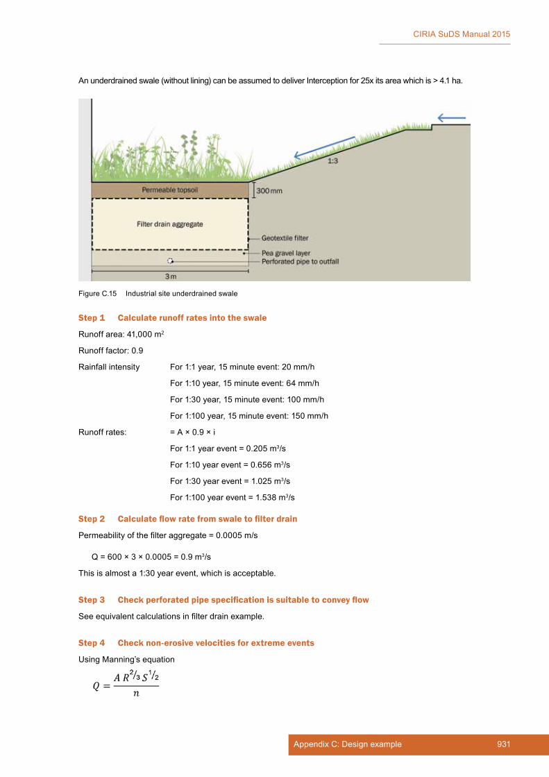
931Appendix C: Design example
CIRIA SuDS Manual 2015
An underdrained swale (without lining) can be assumed to deliver Interception for 25x its area which is > 4.1 ha.
Step 1 Calculate runoff rates into the swale
Runoff area: 41,000 m2
Runoff factor: 0.9
Rainfall intensity For 1:1 year, 15 minute event: 20 mm/h
For 1:10 year, 15 minute event: 64 mm/h
For 1:30 year, 15 minute event: 100 mm/h
For 1:100 year, 15 minute event: 150 mm/h
Runoff rates: = A × 0.9 × i
For 1:1 year event = 0.205 m3/s
For 1:10 year event = 0.656 m3/s
For 1:30 year event = 1.025 m3/s
For 1:100 year event = 1.538 m3/s
Step 2 Calculate flow rate from swale to filter drain
Permeability of the filter aggregate = 0.0005 m/s
Q = 600 × 3 × 0.0005 = 0.9 m3/s
This is almost a 1:30 year event, which is acceptable.
Step 3 Check perforated pipe specification is suitable to convey flow
See equivalent calculations in filter drain example.
Step 4 Check non-erosive velocities for extreme events
Using Manning’s equation
Figure C.15 Industrial site underdrained swale

932 Appendix C
CIRIA SuDS Manual 2015
Where
below grass flow, n = 0.35
at depth 200 mm, n = 0.1
at depth 400 mm, n = 0.04
Gives:
The 1:100 year flow rate has a velocity below 1.5 m/s, which is acceptable.
The runoff rates and depths would need confirmation via modelling at detailed design stage.
D4 Wetland area
A small wetland area is required to provide additional treatment of the industrial area runoff before discharge to the amenity pond. A rough rule of thumb for sizing a pond/wetland for treatment is to make sure that the volume of permanent water is equal to the volume of water that requires treatment (known as the treatment volume).
Area available for the wetland = 800 m2
Assume runoff factor = 0.8
Combined lorry park and factory hard standing area = 4.95 ha (this is 0.85 lorry park area plus 4.1 factory hard standing area)
Volume of water requiring treatment (known as the treatment volume) = 4.95 × 104 × 15 × 10-3 × 0.8 = 600 m3
(where 15 mm is the upper limit rainfall depth recommended in Section 23.5)
Average depth of permanent pool = 600/800 = 0.75 m, which is acceptable.
In order to protect wetland planting, the attenuation storage depth (above the permanent water level) was limited to 0.4 m, which provides a maximum attenuation storage volume of 320 m3 for the component.
TABLEC.24
Industrial site underdrained swale depth: flow relationship
d (mm) V (m/s) Q (m3/s)
50 0.039 0.006
60 0.044 0.008
70 0.049 0.010
80 0.053 0.013
90 0.057 0.015
100 0.062 0.018
150 0.282 0.127
200 0.342 0.205
250 0.397 0.298
300 0.448 0.403
325 0.591 0.576
350 0.828 0.869
400 1.357 1.629
450 1.468 1.982

933Appendix C: Design example
CIRIA SuDS Manual 2015
C.5.5 Strategic site SuDS components
S1 Strategic conveyance swale running north–south through the site
This swale drains excess flows from the residential zone, the civic street zone and the supermarket – together with all the runoff from the roads.
Assume:
▪ residential area: infiltrates to 1:10 year
▪ civic street area: infiltrates to 1:10 year
▪ supermarket area: managed to 1:100 year greenfield
▪ roads: unmanaged
For 1:30 year event:
(Note that these are relatively crude conservative estimates for initial design purposes.)
For residential and civic street areas (ie areas A and B)
▪ rainfall intensity = 100 mm/h
▪ runoff factor = 0.8
Q = 100 x 10-3 × 0.8 × (6.5 + 4.5) × 104/3600 = 2.44 m3/s
For supermarket area (area C)
Runoff controlled to greenfield runoff rates (see Table C.11) = 0.033 m3/s
For roads
▪ rainfall intensity = 100 mm/h
▪ runoff factor = 0.9
Q = 100 × 10-3 × 0.9 × 1.5 × 104/3600 = 0.375 m3/s
Estimated total flow to swale for 1:30 year event = 2.44 + 0.033 + 0.375 = 2.85 m3/s
This would need confirmation via modelling at detailed design stage.
A 3 m width of swale over 1000 m = 3000 m2. Average slope = 0.01
Interception delivery = 3000 × 25 × 10-4 = 7.5 ha
This is acceptable for retail service area (1.65 ha) and impermeable areas draining to permeable pavement (1.4 ha).
Step 1 Check capacity of the swale for the 30 year event
Assume average Manning’s n = 0.15 for high flows
Assume average flow width = 6 m
(This takes account of flow across the side slopes. At a 1 m depth of flow, with side slopes of 3:1, the effective width would be 3 + (2 × 3 × 1) = 9 m, which gives an average width of (3 + 9)/2 = 6 m)
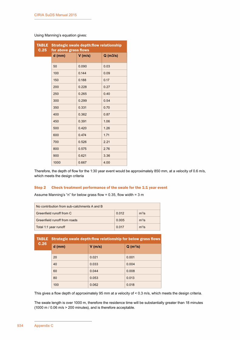
934 Appendix C
CIRIA SuDS Manual 2015
Using Manning’s equation gives:
This gives a flow depth of approximately 95 mm at a velocity of < 0.3 m/s, which meets the design criteria.
The swale length is over 1000 m, therefore the residence time will be substantially greater than 18 minutes (1000 m / 0.06 m/s > 200 minutes), and is therefore acceptable.
TABLEC.26
Strategic swale depth:flow relationship for below grass flows
d (mm) V (m/s) Q (m3/s)
20 0.021 0.001
40 0.033 0.004
60 0.044 0.008
80 0.053 0.013
100 0.062 0.018
TABLEC.25
Strategic swale depth:flow relationship for above grass flowsd (mm) V (m/s) Q (m3/s)
50 0.090 0.03
100 0.144 0.09
150 0.188 0.17
200 0.228 0.27
250 0.265 0.40
300 0.299 0.54
350 0.331 0.70
400 0.362 0.87
450 0.391 1.06
500 0.420 1.26
600 0.474 1.71
700 0.526 2.21
800 0.575 2.76
900 0.621 3.36
1000 0.667 4.00
Therefore, the depth of flow for the 1:30 year event would be approximately 850 mm, at a velocity of 0.6 m/s, which meets the design criteria
Step 2 Check treatment performance of the swale for the 1:1 year event
Assume Manning’s “n” for below grass flow = 0.35, flow width = 3 m
No contribution from sub-catchments A and B
Greenfield runoff from C 0.012 m3/s
Greenfield runoff from roads 0.005 m3/s
Total 1:1 year runoff 0.017 m3/s
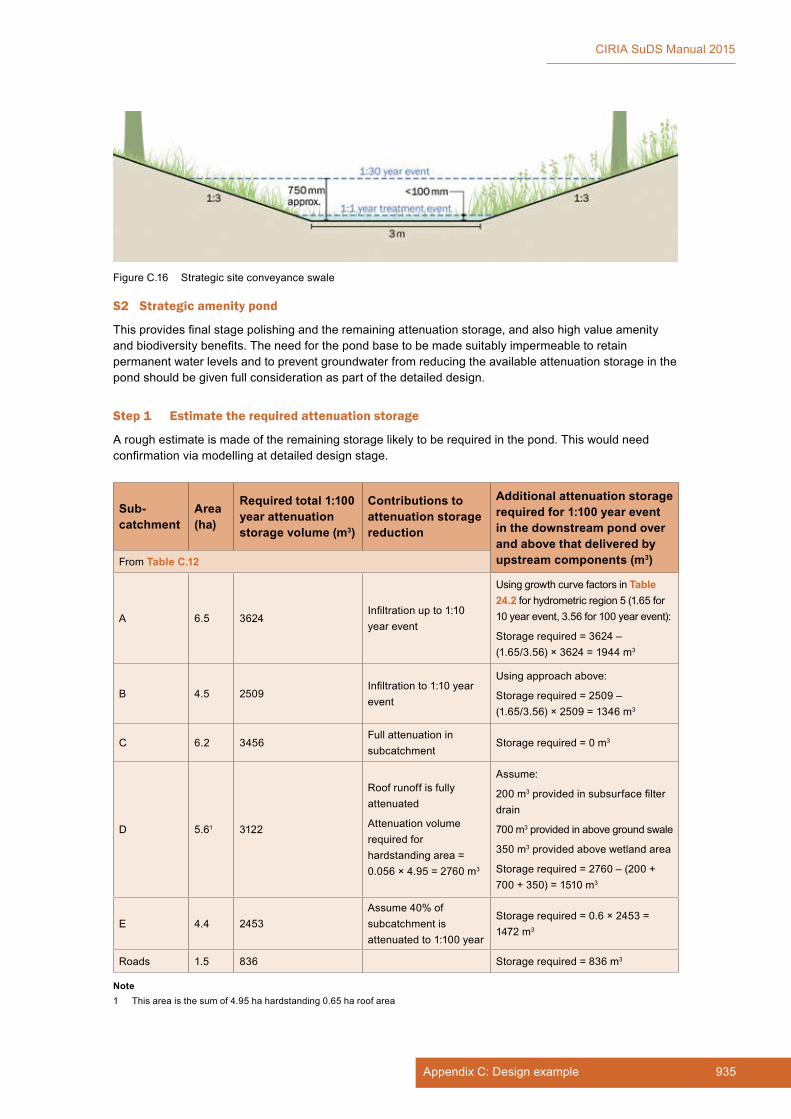
935Appendix C: Design example
CIRIA SuDS Manual 2015
S2 Strategic amenity pond
This provides final stage polishing and the remaining attenuation storage, and also high value amenity and biodiversity benefits. The need for the pond base to be made suitably impermeable to retain permanent water levels and to prevent groundwater from reducing the available attenuation storage in the pond should be given full consideration as part of the detailed design.
Step 1 Estimate the required attenuation storage
A rough estimate is made of the remaining storage likely to be required in the pond. This would need confirmation via modelling at detailed design stage.
Sub-catchment
Area (ha)
Required total 1:100 year attenuation storage volume (m3)
Contributions to attenuation storage reduction
Additional attenuation storage required for 1:100 year event in the downstream pond over and above that delivered by upstream components (m3)From Table C.12
A 6.5 3624Infiltration up to 1:10 year event
Using growth curve factors in Table 24.2 for hydrometric region 5 (1.65 for 10 year event, 3.56 for 100 year event):
Storage required = 3624 – (1.65/3.56) × 3624 = 1944 m3
B 4.5 2509Infiltration to 1:10 year event
Using approach above:
Storage required = 2509 – (1.65/3.56) × 2509 = 1346 m3
C 6.2 3456Full attenuation in subcatchment
Storage required = 0 m3
D 5.61 3122
Roof runoff is fully attenuated
Attenuation volume required for hardstanding area = 0.056 × 4.95 = 2760 m3
Assume:
200 m3 provided in subsurface filter drain
700 m3 provided in above ground swale
350 m3 provided above wetland area
Storage required = 2760 – (200 + 700 + 350) = 1510 m3
E 4.4 2453Assume 40% of subcatchment is attenuated to 1:100 year
Storage required = 0.6 × 2453 = 1472 m3
Roads 1.5 836 Storage required = 836 m3
Note1 This area is the sum of 4.95 ha hardstanding 0.65 ha roof area
Figure C.16 Strategic site conveyance swale

936 Appendix C
CIRIA SuDS Manual 2015
Total attenuation storage required in the pond = 1944 + 1346 + 0 + 1510 + 1472 + 836 = 7108 m3
Section 24.9.4 suggests that an additional 25% should be added to initial storage volume estimates to allow for lack of inclusion of head discharge relationships.
Therefore total attenuation storage required in the pond = 8885 m3
For a uniform pond area of about 5000 m2, this would mean 1.8 m depth. Based on a bank slope of 1 in 5, however, the actual depth will be around 1.5 m.
This is indicated as acceptable for this scale of event by the site health and safety risk assessment.
Step 2 Calculate treatment volume
A rough rule of thumb for sizing a pond for treatment is to make sure the volume of permanent water in the pond is equal to the volume of water that requires treatment (known as the treatment volume).
For a 1:1 year return period (required for treatment) areas A, B and the supermarket roof would not be contributing. Therefore:
Total area = 31.1 – (6.5 + 4.5 + 0.9) = 19.2 ha
If assume
▪ rainfall depth that requires treatment is 15 mm (based on maximum recommended treatment volume, Section 23.5)
▪ average runoff factor = 0.5
Treatment volume = 19.2 × 104 × 15 × 10-3 × 0.5 = 1440 m3
Based on a pond area of about 5000 m2, the average depth would be approximately 0.3 m (see Figure C.11).
Step 3 Confirm spill levels to Long-Term Storage
To adequately control the volumes of runoff from the site, a spill will be required into a Long-Term Storage area (probably the adjacent sports pitches), or else the runoff rate will need constraining further and the attenuation storage volume increased.
A detailed model will be required to determine which option would be preferable with respect to the performance of the system.
The depth of inundation of the estimated 2640 m3 of Long-Term Storage (see Section C.4.1, Step 3) would be 0.2 m, if spread over 2 × 7000 m2 football pitches.
Figure C.17 Strategic amenity pond

937Appendix C: Design example
CIRIA SuDS Manual 2015
C.5.6 Detailed system sizing
A detailed model of the contributing catchment and drainage system is required in order to check that all criteria have been achieved. The calculations above provide initial sizing information and allow a first estimate to be modelled, which can then be refined to achieve the required results. The particular checks that should now be made with the detailed model are as follows:
▪ greenfield discharge rates achieved for 1:1, 1:10 and 1:100 year
▪ no unplanned flooding on the site for the 1:30 year critical site event (short duration, high intensity event)
▪ no flooding of property from the site drainage system for the 1:100 year critical site event (short duration, high intensity event)
▪ no flooding of property for key “blockage” scenarios
▪ the possible impact and performance of the pond for the maximum 1:100 year river level for a range of return period events (a joint probability analysis may be required depending on this assessment).
C.6 REFERENCES
BRE (1991) Soakaway design, BRE Digest 365, Building Research Establishment, Bracknell, UK (ISBN: 0-85125-502-7)
FAIR, G M and GEYER, J C (1954) Water supply and waste-water disposal, John Wiley & Sons, Inc., New York, USA (ISBN: 978-0-47125-115-6)
HALL, M, HOCKIN, D and ELLIS, J (1993) Design of flood storage reservoirs, B14, CIRIA, London, UK (ISBN: 978-0-86017-393-9). Go to: www.ciria.org
KELLAGHER, R (2013) Rainfall runoff management for developments, SCS030219, Flood ad Coastal Erosion Risk Management R&D Programme, Environment Agency, Bristol, UK (ISBN: 978-1-84911-309-0)
SCOTT WILSON (2010) Fate of highway contaminants in the unsaturated zone, final synthesis report, Highways Consultancy Group, Highways Agency, London, UK
WILSON, S, BRAY, R and COOPER, P (2004) Sustainable drainage systems: hydraulic structural and water quality advice, C609, CIRIA, London, UK (ISBN: 978-0-86017-609-1). Go to: www.ciria.org

AECOM Ltd
Arup Group Ltd
Atkins Consultants Limited
Balfour Beatty Civil Engineering Ltd
BAM Nuttall Ltd
Black & Veatch Ltd
Buro Happold Engineers Limited
BWB Consulting Ltd
Cardiff University
CH2M
Environment Agency
Galliford Try plc
Gatwick Airport Ltd
Geotechnical Consulting Group
Golder Associates (Europe) Ltd
Heathrow Airport Holdings Ltd
High Speed Two (HS2)
Highways England
HR Wallingford Ltd
Imperial College London
Institution of Civil Engineers
Laing O’Rourke Civil Engineering Ltd
London Underground Ltd
Loughborough University
Maccaferri Ltd
Ministry of Justice
Morgan Sindall (Infrastructure) Plc
Mott MacDonald Group Ltd
Mouchel
MWH
National Grid UK Ltd
Network Rail
Northumbrian Water Limited
Rail Safety and Standards Board
Royal HaskoningDHV Ltd
RSK Group Ltd
RWE Npower plc
Scottish Water
Sellafield Ltd
Sir Robert McAlpine Ltd
SLR Consulting Ltd
Tarmac
Temple Group Ltd
Thames Water Utilities Ltd
United Utilities Plc
University College London
University of Reading
University of Sheffield
University of Southampton
WYG Group (Nottingham Office)
November 2015
Core and Associate members

Project funders

This guidance covers the planning, design, construction and maintenance of Sustainable DrainageSystems (SuDS) to assist with their effective implementation within both new and existing developments.It looks at how to maximise amenity and biodiversity benefits, and deliver the key objectives of managingflood risk and water quality. There is also supporting information covering topics such as materials,landscape design, maintenance, community engagement and costs and benefits.
The information presented in this publication is a compendium of good practice, based on existingguidance and research both in the UK and internationally, and the practical experience of the authors,project steering group and industry.
This guidance provides the framework for designing SuDS with confidence and to maximise benefits. Itscontents are relevant for a wide-range of professions and roles and it highlights that through engagementand collaboration SuDS can be integrated into the design of urban areas, to create high quality places forfuture generations.
The key message is that SuDS should be designed to maximise the opportunities and benefits that can besecured from surface water management.
C753
Th
eS
uD
SM
an
ual
CIR
IA
The SuDSManual
� ������ ������C753
������� ����� ���� ������ �� ��� �
ACO
Campbell Reith
Concrete Pipeline System Association
DARD Rivers Agency Northern Ireland
Department for Environment, Food and RuralAffairs
Dŵr Cymru/Welsh Water
Environment Agency
Highways England
Hydro International
Llywodraeth Cymru/Welsh Government
London Drainage Engineering Group
NHBC Foundation
Northern Ireland Environment Agency
Permavoid
Polypipe
Scottish Environment Protection Agency
Stormwater Management
WSP Parsons Brinckerhoff
XP Solutions